US12295845B2 - Device, system, and method for transcatheter treatment of valvular regurgitation - Google Patents
Device, system, and method for transcatheter treatment of valvular regurgitationDownload PDFInfo
- Publication number
- US12295845B2 US12295845B2US16/918,295US202016918295AUS12295845B2US 12295845 B2US12295845 B2US 12295845B2US 202016918295 AUS202016918295 AUS 202016918295AUS 12295845 B2US12295845 B2US 12295845B2
- Authority
- US
- United States
- Prior art keywords
- assistance element
- coaptation assistance
- anchor
- coaptation
- annular
- Prior art date
- Legal status (The legal status is an assumption and is not a legal conclusion. Google has not performed a legal analysis and makes no representation as to the accuracy of the status listed.)
- Active, expires
Links
Images


Classifications
- A—HUMAN NECESSITIES
- A61—MEDICAL OR VETERINARY SCIENCE; HYGIENE
- A61F—FILTERS IMPLANTABLE INTO BLOOD VESSELS; PROSTHESES; DEVICES PROVIDING PATENCY TO, OR PREVENTING COLLAPSING OF, TUBULAR STRUCTURES OF THE BODY, e.g. STENTS; ORTHOPAEDIC, NURSING OR CONTRACEPTIVE DEVICES; FOMENTATION; TREATMENT OR PROTECTION OF EYES OR EARS; BANDAGES, DRESSINGS OR ABSORBENT PADS; FIRST-AID KITS
- A61F2/00—Filters implantable into blood vessels; Prostheses, i.e. artificial substitutes or replacements for parts of the body; Appliances for connecting them with the body; Devices providing patency to, or preventing collapsing of, tubular structures of the body, e.g. stents
- A61F2/02—Prostheses implantable into the body
- A61F2/24—Heart valves ; Vascular valves, e.g. venous valves; Heart implants, e.g. passive devices for improving the function of the native valve or the heart muscle; Transmyocardial revascularisation [TMR] devices; Valves implantable in the body
- A61F2/2442—Annuloplasty rings or inserts for correcting the valve shape; Implants for improving the function of a native heart valve
- A61F2/246—Devices for obstructing a leak through a native valve in a closed condition
- A—HUMAN NECESSITIES
- A61—MEDICAL OR VETERINARY SCIENCE; HYGIENE
- A61F—FILTERS IMPLANTABLE INTO BLOOD VESSELS; PROSTHESES; DEVICES PROVIDING PATENCY TO, OR PREVENTING COLLAPSING OF, TUBULAR STRUCTURES OF THE BODY, e.g. STENTS; ORTHOPAEDIC, NURSING OR CONTRACEPTIVE DEVICES; FOMENTATION; TREATMENT OR PROTECTION OF EYES OR EARS; BANDAGES, DRESSINGS OR ABSORBENT PADS; FIRST-AID KITS
- A61F2/00—Filters implantable into blood vessels; Prostheses, i.e. artificial substitutes or replacements for parts of the body; Appliances for connecting them with the body; Devices providing patency to, or preventing collapsing of, tubular structures of the body, e.g. stents
- A61F2/02—Prostheses implantable into the body
- A61F2/24—Heart valves ; Vascular valves, e.g. venous valves; Heart implants, e.g. passive devices for improving the function of the native valve or the heart muscle; Transmyocardial revascularisation [TMR] devices; Valves implantable in the body
- A61F2/2442—Annuloplasty rings or inserts for correcting the valve shape; Implants for improving the function of a native heart valve
- A61F2/2466—Delivery devices therefor
- A—HUMAN NECESSITIES
- A61—MEDICAL OR VETERINARY SCIENCE; HYGIENE
- A61F—FILTERS IMPLANTABLE INTO BLOOD VESSELS; PROSTHESES; DEVICES PROVIDING PATENCY TO, OR PREVENTING COLLAPSING OF, TUBULAR STRUCTURES OF THE BODY, e.g. STENTS; ORTHOPAEDIC, NURSING OR CONTRACEPTIVE DEVICES; FOMENTATION; TREATMENT OR PROTECTION OF EYES OR EARS; BANDAGES, DRESSINGS OR ABSORBENT PADS; FIRST-AID KITS
- A61F2210/00—Particular material properties of prostheses classified in groups A61F2/00 - A61F2/26 or A61F2/82 or A61F9/00 or A61F11/00 or subgroups thereof
- A61F2210/0014—Particular material properties of prostheses classified in groups A61F2/00 - A61F2/26 or A61F2/82 or A61F9/00 or A61F11/00 or subgroups thereof using shape memory or superelastic materials, e.g. nitinol
- A—HUMAN NECESSITIES
- A61—MEDICAL OR VETERINARY SCIENCE; HYGIENE
- A61F—FILTERS IMPLANTABLE INTO BLOOD VESSELS; PROSTHESES; DEVICES PROVIDING PATENCY TO, OR PREVENTING COLLAPSING OF, TUBULAR STRUCTURES OF THE BODY, e.g. STENTS; ORTHOPAEDIC, NURSING OR CONTRACEPTIVE DEVICES; FOMENTATION; TREATMENT OR PROTECTION OF EYES OR EARS; BANDAGES, DRESSINGS OR ABSORBENT PADS; FIRST-AID KITS
- A61F2220/00—Fixations or connections for prostheses classified in groups A61F2/00 - A61F2/26 or A61F2/82 or A61F9/00 or A61F11/00 or subgroups thereof
- A61F2220/0008—Fixation appliances for connecting prostheses to the body
- A61F2220/0016—Fixation appliances for connecting prostheses to the body with sharp anchoring protrusions, e.g. barbs, pins, spikes
- A—HUMAN NECESSITIES
- A61—MEDICAL OR VETERINARY SCIENCE; HYGIENE
- A61F—FILTERS IMPLANTABLE INTO BLOOD VESSELS; PROSTHESES; DEVICES PROVIDING PATENCY TO, OR PREVENTING COLLAPSING OF, TUBULAR STRUCTURES OF THE BODY, e.g. STENTS; ORTHOPAEDIC, NURSING OR CONTRACEPTIVE DEVICES; FOMENTATION; TREATMENT OR PROTECTION OF EYES OR EARS; BANDAGES, DRESSINGS OR ABSORBENT PADS; FIRST-AID KITS
- A61F2220/00—Fixations or connections for prostheses classified in groups A61F2/00 - A61F2/26 or A61F2/82 or A61F9/00 or A61F11/00 or subgroups thereof
- A61F2220/0025—Connections or couplings between prosthetic parts, e.g. between modular parts; Connecting elements
- A61F2220/0075—Connections or couplings between prosthetic parts, e.g. between modular parts; Connecting elements sutured, ligatured or stitched, retained or tied with a rope, string, thread, wire or cable
- A—HUMAN NECESSITIES
- A61—MEDICAL OR VETERINARY SCIENCE; HYGIENE
- A61F—FILTERS IMPLANTABLE INTO BLOOD VESSELS; PROSTHESES; DEVICES PROVIDING PATENCY TO, OR PREVENTING COLLAPSING OF, TUBULAR STRUCTURES OF THE BODY, e.g. STENTS; ORTHOPAEDIC, NURSING OR CONTRACEPTIVE DEVICES; FOMENTATION; TREATMENT OR PROTECTION OF EYES OR EARS; BANDAGES, DRESSINGS OR ABSORBENT PADS; FIRST-AID KITS
- A61F2230/00—Geometry of prostheses classified in groups A61F2/00 - A61F2/26 or A61F2/82 or A61F9/00 or A61F11/00 or subgroups thereof
- A61F2230/0002—Two-dimensional shapes, e.g. cross-sections
- A61F2230/0004—Rounded shapes, e.g. with rounded corners
- A61F2230/0006—Rounded shapes, e.g. with rounded corners circular
- A—HUMAN NECESSITIES
- A61—MEDICAL OR VETERINARY SCIENCE; HYGIENE
- A61F—FILTERS IMPLANTABLE INTO BLOOD VESSELS; PROSTHESES; DEVICES PROVIDING PATENCY TO, OR PREVENTING COLLAPSING OF, TUBULAR STRUCTURES OF THE BODY, e.g. STENTS; ORTHOPAEDIC, NURSING OR CONTRACEPTIVE DEVICES; FOMENTATION; TREATMENT OR PROTECTION OF EYES OR EARS; BANDAGES, DRESSINGS OR ABSORBENT PADS; FIRST-AID KITS
- A61F2230/00—Geometry of prostheses classified in groups A61F2/00 - A61F2/26 or A61F2/82 or A61F9/00 or A61F11/00 or subgroups thereof
- A61F2230/0063—Three-dimensional shapes
- A61F2230/0091—Three-dimensional shapes helically-coiled or spirally-coiled, i.e. having a 2-D spiral cross-section
- A—HUMAN NECESSITIES
- A61—MEDICAL OR VETERINARY SCIENCE; HYGIENE
- A61F—FILTERS IMPLANTABLE INTO BLOOD VESSELS; PROSTHESES; DEVICES PROVIDING PATENCY TO, OR PREVENTING COLLAPSING OF, TUBULAR STRUCTURES OF THE BODY, e.g. STENTS; ORTHOPAEDIC, NURSING OR CONTRACEPTIVE DEVICES; FOMENTATION; TREATMENT OR PROTECTION OF EYES OR EARS; BANDAGES, DRESSINGS OR ABSORBENT PADS; FIRST-AID KITS
- A61F2250/00—Special features of prostheses classified in groups A61F2/00 - A61F2/26 or A61F2/82 or A61F9/00 or A61F11/00 or subgroups thereof
- A61F2250/0014—Special features of prostheses classified in groups A61F2/00 - A61F2/26 or A61F2/82 or A61F9/00 or A61F11/00 or subgroups thereof having different values of a given property or geometrical feature, e.g. mechanical property or material property, at different locations within the same prosthesis
- A61F2250/0018—Special features of prostheses classified in groups A61F2/00 - A61F2/26 or A61F2/82 or A61F9/00 or A61F11/00 or subgroups thereof having different values of a given property or geometrical feature, e.g. mechanical property or material property, at different locations within the same prosthesis differing in elasticity, stiffness or compressibility
- A—HUMAN NECESSITIES
- A61—MEDICAL OR VETERINARY SCIENCE; HYGIENE
- A61F—FILTERS IMPLANTABLE INTO BLOOD VESSELS; PROSTHESES; DEVICES PROVIDING PATENCY TO, OR PREVENTING COLLAPSING OF, TUBULAR STRUCTURES OF THE BODY, e.g. STENTS; ORTHOPAEDIC, NURSING OR CONTRACEPTIVE DEVICES; FOMENTATION; TREATMENT OR PROTECTION OF EYES OR EARS; BANDAGES, DRESSINGS OR ABSORBENT PADS; FIRST-AID KITS
- A61F2250/00—Special features of prostheses classified in groups A61F2/00 - A61F2/26 or A61F2/82 or A61F9/00 or A61F11/00 or subgroups thereof
- A61F2250/0058—Additional features; Implant or prostheses properties not otherwise provided for
- A61F2250/0096—Markers and sensors for detecting a position or changes of a position of an implant, e.g. RF sensors, ultrasound markers
- A61F2250/0098—Markers and sensors for detecting a position or changes of a position of an implant, e.g. RF sensors, ultrasound markers radio-opaque, e.g. radio-opaque markers
Definitions
- the present disclosuregenerally provides improved medical devices, systems, and methods, typically for treatment of heart valve disease and/or for altering characteristics of one or more valves of the body.
- Embodimentsinclude implants for treatment of mitral valve regurgitation.
- the human heartreceives blood from the organs and tissues via the veins, pumps that blood through the lungs where the blood becomes enriched with oxygen, and propels the oxygenated blood out of the heart to the arteries so that the organ systems of the body can extract the oxygen for proper function. Deoxygenated blood flows back to the heart where it is once again pumped to the lungs.
- the heartincludes four chambers: the right atrium (RA), the right ventricle (RV), the left atrium (LA) and the left ventricle (LV).
- the pumping action of the left and right sides of the heartoccurs generally in synchrony during the overall cardiac cycle.
- the hearthas four valves generally configured to selectively transmit blood flow in the correct direction during the cardiac cycle.
- the valves that separate the atria from the ventriclesare referred to as the atrioventricular (or AV) valves.
- the AV valve between the left atrium and the left ventricleis the mitral valve.
- the AV valve between the right atrium and the right ventricleis the tricuspid valve.
- the pulmonary valvedirects blood flow to the pulmonary artery and thence to the lungs; blood returns to the left atrium via the pulmonary veins.
- the aortic valvedirects flow through the aorta and thence to the periphery. There are normally no direct connections between the ventricles or between the atria.
- the mechanical heartbeatis triggered by an electrical impulse, which spreads throughout the cardiac tissue. Opening and closing of heart valves may occur primarily as a result of pressure differences between chambers, those pressures resulting from either passive filling or chamber contraction. For example, the opening and closing of the mitral valve may occur as a result of the pressure differences between the left atrium and the left ventricle.
- ventricular fillingthe aortic and pulmonary valves are closed to prevent back flow from the arteries into the ventricles.
- the AV valvesopen to allow unimpeded flow from the atria into the corresponding ventricles.
- ventricular systolei.e., ventricular emptying
- the tricuspid and mitral valvesnormally shut, forming a seal, which prevents flow from the ventricles back into the corresponding atria.
- the AV valvesmay become damaged or may otherwise fail to function properly, resulting in improper closing.
- the AV valvesare complex structures that generally include an annulus, leaflets, chordae and a support structure. Each atrium interfaces with its valve via an atrial vestibule.
- the mitral valvehas two leaflets; the analogous structure of the tricuspid valve has three leaflets, and apposition or engagement of corresponding surfaces of leaflets against each other helps provide closure or sealing of the valve to prevent blood flowing in the wrong direction. Failure of the leaflets to seal during ventricular systole is known as malcoaptation, and may allow blood to flow backward through the valve (regurgitation).
- Heart valve regurgitationcan have serious consequences to a patient, often resulting in cardiac failure, decreased blood flow, lower blood pressure, and/or a diminished flow of oxygen to the tissues of the body. Mitral regurgitation can also cause blood to flow back from the left atrium to the pulmonary veins, causing congestion. Severe valvular regurgitation, if untreated, can result in permanent disability or death.
- a variety of therapieshave been applied for treatment of mitral valve regurgitation, and still other therapies may have been proposed but not yet actually used to treat patients. While several of the known therapies have been found to provide benefits for at least some patients, still further options would be desirable.
- pharmacologic agentssuch as diuretics and vasodilators
- medicationscan suffer from lack of patient compliance.
- a significant number of patientsmay occasionally (or even regularly) fail to take medications, despite the potential seriousness of chronic and/or progressively deteriorating mitral valve regurgitation.
- Pharmacological therapies of mitral valve regurgitationmay also be inconvenient, are often ineffective (especially as the condition worsens), and can be associated with significant side effects (such as low blood pressure).
- open-heart surgerycan replace or repair a dysfunctional mitral valve.
- annuloplasty ring repairthe posterior mitral annulus can be reduced in size along its circumference, optionally using sutures passed through a mechanical surgical annuloplasty sewing ring to provide coaptation.
- Open surgerymight also seek to reshape the leaflets and/or otherwise modify the support structure.
- open mitral valve surgeryis generally a very invasive treatment carried out with the patient under general anesthesia while on a heart-lung machine and with the chest cut open.
- Theseinclude devices which seek to re-shape the mitral annulus from within the coronary sinus; devices that attempt to reshape the annulus by cinching either above to below the native annulus; devices to fuse the leaflets (imitating the Alfieri stitch); devices to re-shape the left ventricle, and the like.
- mitral valve replacement implantshave been developed, with these implants generally replacing (or displacing) the native leaflets and relying on surgically implanted structures to control the blood flow paths between the chambers of the heart. While these various approaches and tools have met with differing levels of acceptance, none has yet gained widespread recognition as an ideal therapy for most or all patients suffering from mitral valve regurgitation.
- the disclosuregenerally provides improved medical devices, systems, and methods.
- New coaptation assistance elements, systems, and methods for treatment of mitral valve regurgitation and other valve diseasesare disclosed.
- the coaptation assistance elementmay remain within the blood flow path as the valve moves back and forth between an open-valve configuration and a closed valve configuration.
- the coaptation assistance elementsmay be relatively thin, elongate (along the blood flow path), and/or conformable structures which extend laterally across some, most, or all of the width of the valve opening, allowing coaptation between at least one of the native leaflets and the coaptation assistance element.
- the devices described hereincan be used with any valve of the human body, including valves with two leaflets or three leaflets.
- an advantageis the ability to retrieve the coaptation assistance element.
- the coaptation assistance elementhas a single anchor, which can engage or disengage tissue.
- the anchoris captive within an annular hub of the coaptation assistance element.
- the captive anchoris removed simultaneously with the removal of the coaptation assistance element.
- the coaptation assistance elementcan include secondary anchors.
- the coaptation assistance elementcan include passive anchors.
- engagement of the anchor with the tissuepositions one or more passive anchors into engagement with tissue.
- an advantageis to retrieve the coaptation assistance element during a procedure.
- the coaptation assistance elementcan be repositioned during a surgical procedure.
- the coaptation assistance elementcan be removed from the patient during a subsequent surgical procedure. In some embodiments, the coaptation assistance element can be replaced by another device during a subsequent surgical procedure. In some embodiments, a single annular anchor facilitates the ability to retrieve the coaptation assistance element. In some embodiments, the location of the annular anchor facilitates the ability to retrieve the coaptation assistance element. In some embodiments, the ability to collapse the coaptation assistance element with the purse-string suture as described herein facilitates the ability to retrieve the coaptation assistance element.
- an advantageis the connection between the coaptation assistance element and the delivery catheter.
- the coaptation assistance elementincludes an annular hub with features to engage the delivery catheter.
- the coaptation assistance element and the delivery catheterare removably coupled such that the coaptation assistance element can be released from the delivery catheter during a procedure.
- one or more secondary structurescouples the coaptation assistance element and the delivery catheter after the coaptation assistance element is released from the delivery catheter.
- the one or more secondary structuresinclude the purse-string suture as descried herein.
- the one or more secondary structuresfacilitate the collapse and/or expansion of the coaptation assistance element.
- the coaptation assistance element and the delivery catheterare rotationally fixed relative to each other when coupled. In some embodiments, relative motion of the delivery catheter causes motion of the coaptation assistance element.
- an advantageis the coaptation assistance element can be delivered with a hub-leading orientation.
- the annular hubcan be moved into position relative to the anatomical structures.
- the ventricular end of the coaptation assistance elementcan be retained within the delivery catheter until the annular hub is positioned.
- the coaptation assistance elementcan be expanded.
- the ventricular end of the coaptation assistance elementcan be positioned.
- an advantageis the coaptation assistance element can be delivered with a strut-leading orientation.
- one or more of the struts of the coaptation assistance elementcan be moved into position relative to the anatomical structures prior to the positioning of the annular hub.
- the coaptation assistance elementcan be expanded or partially expanded prior to the engagement of the annular anchor.
- the annular hubcan be retained within the delivery catheter until one or more of the struts are positioned.
- the annular anchorcan be engaged with the tissue.
- annular anchorcan be rotated independently of the coaptation assistance element.
- the coaptation assistance elementis coupled to one portion of the delivery catheter.
- the annular anchoris independently coupled to another portion of the delivery catheter, such as a driver disposed with the delivery catheter.
- the annular anchorcan be rotated independently of the annular hub.
- the annular hubcan remain stationary as the annular anchor is rotated to engage tissue.
- the annular anchorcan be driven into the tissue while the delivery catheter retains the position of the annular hub.
- an advantageis the ability to collapse the coaptation assistance element.
- the coaptation assistance elementis fully collapsed.
- the fully collapsed configurationcan be the insertion configuration or a low profile configuration.
- the coaptation assistance elementis partially collapsed.
- the partially collapsed configurationcan be a partially deployed configuration.
- the partially collapsed configurationcan allow the coaptation assistance element to be selectively deployed within the heart.
- the partially collapsed configurationcan allow the coaptation assistance element to be moved into position within the heart.
- the configurations of the coaptation assistance elementcan be monitored such as by imaging to ensure proper deployment.
- one or more purse-string sutures, or portions thereofare tensioned to collapse or partially collapse the coaptation assistance element.
- the partially collapsed configurationcan allow rotation of the coaptation assistance element.
- the fully collapsed configurationcan allow rotation of the coaptation assistance element.
- the coaptation assistance elementcan be rotated with a delivery catheter or portion thereof. In some embodiments, the coaptation assistance element can be rotated about a central location such as the annular hub.
- an advantageis the ability to expand the coaptation assistance element.
- one or more purse-string sutures, or portions thereof,are released to expand the coaptation assistance element.
- release of the purse-string sutureallows one or more struts to assume a neutral configuration.
- the release of the purse-string sutureallows one or more struts to assume a pre-shaped curve.
- the one or more strutscomprise NiTi.
- the purse-string suturecan be repeatedly tensioned and/or released.
- the purse-string sutureis captive within the coaptation assistance element.
- the purse-string sutureis tensioned to remove the coaptation assistance element from a patient. In some embodiments, the purse-string suture is released to deploy the coaptation assistance element within the heart of a patient. In some embodiments, the purse-string suture can be selective deployed to expand a portion of coaptation assistance element while another portion of the coaptation assistance element remains collapsed or partially collapsed.
- an advantageis the ability to adjust the coaptation assistance element.
- the coaptation assistance elementcan be held by a central location. In some embodiments, the central location is the anchor. In some embodiments, the central location is the hub. In some embodiments, the hub and/or the anchor are located generally near a mid-point of the diameter of the coaptation assistance element. In some embodiments, the hub and/or the anchor are generally located near a mid-point and/or central location of the annular portion of the coaptation assistance element. In some embodiments, the coaptation assistance element can be held at a neutral position. In some embodiments, the coaptation assistance element can be rotated by rotating a delivery catheter connected to the annular hub. In some embodiments, the coaptation assistance element can be moved longitudinally by corresponding longitudinal motion of a delivery catheter connected to the annular hub.
- an advantageis the coaptation assistance element can be retained by a delivery catheter after the coaptation assistance element is positioned.
- the coaptation assistance elementcan be fully deployed within the mitral valve but still tethered to a delivery catheter.
- the coaptation assistance elementcan be adjusted after the coaptation assistance element is fully deployed within the mitral valve.
- the coaptation assistance elementcan be rotated about the hub after the coaptation assistance element is fully deployed.
- the anchorcan be disengaged and/or reengaged with the tissue after the coaptation assistance element is fully deployed.
- the purse-string suturescan collapse and/or expand the coaptation assistance element or a portion thereof after the coaptation assistance element is fully deployed.
- the coaptation assistance elementcan be recaptured after the coaptation assistance element is fully deployed.
- the coaptation assistance elementcan be removed after the coaptation assistance element is fully deployed.
- an advantageis the coaptation assistance element does not require ventricular attachment. In some embodiments, the coaptation assistance element only requires annular attachment. In some embodiments, the coaptation assistance element only requires attachment of an annular anchor through an annular hub. In some embodiments, the coaptation assistance element only requires attachment of an annular anchor through an annular hub and annular barbs. In some embodiments, the coaptation assistance element only requires attachment of an annular anchor through an annular hub, annular barbs, and/or commissural barbs.
- an advantageis the radially extending frame.
- the framecomprises an annular hub and one or more struts.
- the strutsextend radially from the annular hub.
- the frameis constructed from a single, planar sheet of material.
- the frameis precisely cut using water jet, laser etching or similar technology.
- the frameis constructed by forming the annular hub with an edge of the frame.
- the planar sheet of materialis formed into a loop which becomes the annular hub.
- the strutsare bent to the desired configuration.
- the strutsare equally spaced about the circumference of the annular hub.
- the strutsare unequally spaced about the circumference of the annular hub. In some embodiments, the struts extending along a portion of the circumference of the annular hub are different than struts extending along another portion of the circumference of the annular hub. In some embodiments, one or more designated portions of the struts are designed to be placed near the annular region of the heart. In some embodiments, one or more designated portions of the struts are designed to be placed near the commissure region of the heart. In some embodiments, one or more designated portions of the struts are designed to be placed near the ventricular region of the heart. In some embodiments, the struts of the radially outward frame do not intersect.
- the struts of the radially outward framedo not form a mesh. In some embodiments, the struts of the radially outward frame extend in a line from the hub to an edge of the coaptation assistance element. In some embodiments, the struts of the radially outward frame have a sharpened edge. In some embodiments, the sharpened edge extends in a straight line from the edge of the coaptation assistance element. In some embodiments, the sharpened edge is integrally formed in the strut. In some embodiments, a strut of the radially outward frame has one or more radii of curvature.
- a strut of the radially outward framecan be concave or convex or both concave and convex along the length of the strut. In some embodiments, a strut of the radially outward frame has one or more inflection points.
- an advantageis the curvature of the frame.
- the annular hubis radially extending.
- the annular hubextends from the coaptation assistance element away from the annulus.
- the annular hubextends from a surface of the coaptation assistance element above a planar surface of the struts.
- an edge of the coaptation assistance elementis curved.
- one or more strutsmay curve laterally from the annular hub toward the superior edge.
- the superior edge of the coaptation assistance elementcan curve upward from the annulus.
- the superior edge of the coaptation assistance elementcan curve upward from the posterior leaflet.
- the superior edge of the coaptation assistance elementcan curve downward toward the annulus. In some embodiments, the superior edge of the coaptation assistance element can curve downward toward the posterior leaflet. In some embodiments, one or more struts may curve laterally from the annular hub toward the inferior edge. In some embodiments, the inferior edge of the coaptation assistance element can curve away from the posterior leaflet. In some embodiments, the inferior edge of the coaptation assistance element can curve toward the posterior leaflet.
- a coaptation assistance elementfor treating mal-coaptation of a heart valve in provided.
- the heart valvehas an annulus.
- the coaptation assistance elementcan include a body that includes an annular section and a coaptation section.
- the annular sectionis configured to be implanted within a heart superior to a valve annulus.
- the coaptation zoneconfigured to be implanted within a heart and traversing a plane of the valve annulus.
- the coaptation assistance elementcan include a first coaptation surface, and an opposed second surface. In some embodiments, each surface is bounded by a first lateral edge, a second lateral edge, an inferior edge, and a superior edge.
- the superior edgeforms a lip and cupped downward toward the inferior edge or upward from the annular section.
- the coaptation assistance elementcan include a hub and an anchor coupled to the hub and carried by the annular section.
- the anchoris selectively deployable at a first target location.
- the coaptation assistance elementcan include a plurality of struts extending radially outward from the hub.
- the plurality of strutscomprise at least a first strut residing within the annular section and a second strut extending from the annular section to the coaptation section, wherein the second strut has a total length that is longer than that of the first strut, such as, for example, a total length that is about, or at least about 110%, 120%, 130%, 140%, 150%, 160%, 170%, 180%, 190%, 200%, 225%, 250% or more of the total length of the first strut.
- the total length of the second strutis between about 125% and about 300%, or between about 125% and 200% of the total length of the first strut.
- At least one strut of the plurality of strutshas a sharpened tip configured to engage tissue.
- the plurality of strutscomprises Nitinol.
- the anchoris helical-shaped.
- the coaptation assistance elementcan include one or more additional anchors.
- the one or more additional anchorsare active anchors.
- the hubcomprises a cross-pin configured to extend through a helix of the anchor.
- the hubis configured to mate with a delivery catheter, wherein the delivery catheter is configured to position the hub near the first target location.
- the delivery catheteris configured to rotate the anchor independently of the hub.
- the coaptation assistance elementcan include a radiopaque marker.
- the coaptation assistance elementcan include a plurality of radiopaque markers near the superior edge.
- the superior edge forming a lipis cupped downward toward the inferior edge.
- the superior edge forming a lipis cupped upward from the annular section.
- the hubextends upward from the annular section.
- the inferior edgecurves backwards toward the hub.
- a method for treating mal-coaptation of a heart valve in a patienthas an annulus.
- the annulusfurther defines a valve plane, the valve plane separating an atrium proximally and a ventricle distally.
- the methodcan include coupling a delivery catheter to a hub of a coaptation assistance element.
- the methodcan include positioning the hub near the annulus.
- the methodcan include rotating an anchor through the hub and into heart tissue distal to the annulus.
- the methodcan include expanding the coaptation assistance element by allowing a plurality of struts to expand radially outward from the hub.
- the coaptation assist bodyis suspended such that the coaptation surface coapts with a first leaflet and a leaflet surface of the coaptation assist body overlays a second leaflet such that mal-coaptation is mitigated.
- the methodcan include engaging a sharpened end of a strut of the plurality of struts with heart tissue distal to the annulus.
- the methodcan include monitoring the position of the coaptation assistance element with one or more markers.
- the methodcan include monitoring the position of the coaptation assistance element with a plurality of markers near a superior edge of the coaptation assistance element.
- a tip of the anchoris recessed in the hub during positioning the hub near the annulus.
- a coaptation assistance element for treating mal-coaptation of a heart valve of a heartcan include a first coaptation surface and an opposed second surface.
- the coaptation assistance elementcan include a first lateral edge, a second lateral edge, an inferior edge, and a superior edge.
- the coaptation assistance elementcan include a superior zone and an inferior zone.
- the superior zoneis configured to reside in the plane of an annulus of the heart valve.
- the inferior zonecomprises the first coaptation surface and the opposed second surface.
- the inferior zonecomprises a laminate layer such that a thickness of the inferior zone is greater than a thickness of a portion of the superior zone.
- the laminate layercomprises ePTFE.
- the thickness of the inferior zoneis at least about 25% thicker than the thickness of the portion of the superior zone. In some embodiments, the thickness of the inferior zone is at least about 50% thicker than the thickness of the portion of the superior zone.
- the peripheral edge of the coaptation assistance elementcomprises a raised atraumatic edge surrounding only partially around the coaptation assistance element. In some embodiments, the peripheral edge of the coaptation assistance element comprises a raised atraumatic edge surrounding only the inferior zone of the coaptation assistance element. In some embodiments, the raised edge comprises a suture.
- the peripheral edge of the coaptation assistance elementcomprises spaced apart barbs extending radially outwardly from the peripheral edge of only the superior zone of the coaptation assistance element.
- the coaptation assistance elementcan include a hub spaced inward from each of the first lateral edge, the second lateral edge, the inferior edge, and the superior edge.
- the coaptation assistance elementcan include an active anchor configured to couple to the hub and configured to be rotated relative to the hub to selectively deploy the active anchor at a first target location.
- the coaptation assistance elementcan include a plurality of struts spaced around the hub and extending outward from the hub, the plurality of struts comprising at least a first strut configured to be implanted within the heart and a second strut configured to be implanted within the heart such that the first coaptation surface coapts with a first leaflet of the heart valve and the opposed second surface overlays a second leaflet of the heart valve.
- the coaptation assistance elementcomprises a layer of mesh.
- a coaptation assistance element delivery systemfor treating mal-coaptation of a heart valve.
- the heart valvehas an annulus.
- the coaptation assistance element delivery systemcan include a coaptation assistance element comprising a first surface and an opposed second surface. In some embodiments, each surface bounded by a first lateral edge, a second lateral edge, an inferior edge, and a superior edge.
- the coaptation assistance elementcan include a hub.
- the coaptation assistance element delivery systemcan include a primary anchor disposed within a primary anchor housing. In some embodiments, the primary anchor is configured to extend through the hub to engage the annulus.
- the coaptation assistance element delivery systemcan include a release wire extending through the primary anchor housing and configured to be positioned adjacent to the annulus.
- the coaptation assistance element delivery systemcan include a primary anchor driver disposed within the primary anchor housing.
- the primary anchor driveris configured to rotate, but not translate, relative to the primary anchor housing.
- the primary anchor drivercomprises two extensions, wherein the two extensions are configured to engage a cross-bar of the primary anchor.
- the coaptation assistance element delivery systemcan include two release wires extending through the primary anchor housing.
- the two release wiresare configured to be positioned adjacent to the annulus, extending from the hub in opposite directions.
- the two release wirescross.
- the coaptation assistance element delivery systemcan include a secondary anchor tether extending through the coaptation assistance element.
- the secondary anchor tetherextends around the release wire.
- the coaptation assistance element delivery systemcan include at least two secondary anchor tethers extending through the coaptation assistance element. In some embodiments, at least two secondary anchor tethers extend around the release wire. In some embodiments, at least one secondary anchor tether extends around the release wire and at least one secondary anchor tether extends around a second release wire.
- the coaptation assistance element delivery systemcan include a secondary anchor guide rail. In some embodiments, the secondary anchor guide rail is configured to lock a secondary anchor driver to a secondary anchor. In some embodiments, the secondary anchor guide rail is configured to prevent entanglement between a secondary anchor and an adjacent secondary anchor tether. In some embodiments, the secondary anchor guide rail is configured to slide along a secondary anchor tether to deliver a secondary anchor.
- the coaptation assistance element delivery systemcan include a secondary anchor driver.
- the secondary anchor drivercomprises at least one locking tab configured to engage a window of a secondary anchor.
- the coaptation assistance element delivery systemcan include a secondary anchor.
- the secondary anchoris configured to be delivered by sliding the secondary anchor along a secondary anchor tether looped around the release wire.
- the secondary anchoris configured to be rotated to engage the annulus.
- the secondary anchorhas a smaller diameter than the primary anchor.
- the release wireis configured to be retracted after the primary anchor engages the annulus.
- the release wireis configured to be retracted after the primary anchor and at least one secondary anchor engages the annulus.
- the primary anchor housingis configured to be retracted after the release wire is retracted, wherein the primary anchor driver retracts with the primary anchor housing.
- the trajectory of the primary anchoris through the hub.
- a cross-pin of the hubis configured to couple the primary anchor to the coaptation assistance element.
- at least one secondary anchoris configured to have two or more trajectories.
- the trajectory of at least one secondary anchoris determined by the orientation of a respective secondary anchor guide rail.
- the secondary anchor guide railcomprises a curved distal end, wherein the curved distal end defines the trajectory.
- the coaptation assistance element delivery systemcan include a proximal assembly configured to lock the position of a secondary anchor guide rail relative to a secondary anchor to prevent entanglement of a secondary anchor tether.
- the coaptation assistance element delivery systemcan include a proximal assembly configured to lock the position of a secondary anchor guide rail relative to a secondary anchor driver to facilitate coupling of the secondary anchor driver to a secondary anchor.
- the coaptation assistance element delivery systemcan include a proximal assembly configured to lock the position of a secondary anchor tether, wherein the secondary anchor tether is coupled to the release wire.
- the coaptation assistance element delivery systemcan include a proximal assembly configured to lock the position of a secondary anchor tether to apply tension to the secondary anchor tether to define a trajectory for a secondary anchor.
- the coaptation assistance element delivery systemcan include an anti-rotation feature.
- a secondary anchorcomprises the anti-rotation feature.
- a coaptation assistance element for treating mal-coaptation of a heart valveis provided.
- the heart valvehas an annulus.
- the coaptation assistance elementcan include a first surface and an opposed second surface, each surface bounded by a first lateral edge, a second lateral edge, an inferior edge, and a superior edge.
- the coaptation assistance elementcan include a hub.
- the coaptation assistance elementcan include a plurality of struts spaced around the hub and extending outward from the hub, the plurality of struts comprising at least a first strut configured to be implanted within a heart superior to a valve annulus and a second strut configured to be implanted within a heart and traversing a plane of the valve annulus.
- the coaptation assistance elementcomprises at least one layer of ePTFE. In some embodiments, the coaptation assistance element comprises at least one layer of mesh. In some embodiments, the coaptation assistance element comprises at least one layer of UHMWPE mesh. In some embodiments, the coaptation assistance element comprises at least one layer of fabric. In some embodiments, the coaptation assistance element comprises at least one layer of polyester fabric. In some embodiments, the first surface is reinforced. In some embodiments, the second surface is reinforced. In some embodiments, a ventricular surface is reinforced. In some embodiments, a coaptation surface is reinforced. In some embodiments, an anchor zone is reinforced. In some embodiments, at least one edge comprises a raised edge. In some embodiments, the coaptation assistance element is configured to minimize contact with a posterior leaflet. In some embodiments, the coaptation assistance element is configured to engage and embed within the annulus.
- a method of delivering a coaptation assistance elementcan include delivering a coaptation assistance element to a heart of a patient.
- the coaptation assistance elementis coupled to a coaptation assistance element delivery system.
- the coaptation assistance element delivery systemcomprising a primary anchor disposed within a primary anchor housing.
- the coaptation assistance element delivery systemcomprising at least one release wire.
- the methodcan include expanding the coaptation assistance element within the heart.
- the methodcan include anchoring the coaptation assistance element to an annulus of the heart valve by rotating the primary anchor.
- the methodcan include rotating a primary anchor driver within the primary anchor housing.
- the at least one release wireis coupled to the primary anchor housing and extends under the coaptation assistance element when the coaptation assistance element is expanded.
- at least one secondary anchor tetherextends through the coaptation assistance element when the coaptation assistance element is expanded.
- at least one secondary anchor tetherloops around the at least one release wire when the coaptation assistance element is expanded.
- the coaptation assistance elementis delivered in a low profile configuration.
- the at least one release wireis configured to maintain the position of the primary anchor housing relative to the coaptation assistance element.
- the at least one release wireis configured to maintain the position of at least one secondary anchor tether relative to the coaptation assistance element.
- the coaptation assistance elementis delivered via a delivery catheter.
- a telescoping actionis configured to position the coaptation assistance element relative to a location to engage the primary anchor with the annulus.
- the methodcan include rotating the primary anchor to engage the annulus.
- the methodcan include rotating a primary anchor driver within the primary anchor housing, wherein the primary anchor driver is configured to rotate by not translate relative to the primary anchor housing.
- the methodcan include sliding a secondary anchor assembly toward the annulus, along a secondary anchor tether.
- the methodcan include maintaining engagement between a secondary anchor driver and a secondary anchor with a secondary anchor guide rail.
- the methodcan include preventing entanglement between a secondary anchor and a secondary anchor tether with a secondary anchor guide rail.
- the methodcan include coupling a secondary anchor driver to a secondary anchor.
- the methodcan include partially retracting a secondary anchor guide rail before the secondary anchor engages tissue.
- the methodcan include retracting a secondary anchor guide rail after the secondary anchor engages tissue.
- the methodcan include retracting a secondary anchor driver after retracting a secondary anchor guide rail.
- the methodcan include retracting the at least one release wire.
- a coaptation assistance element for treating mal-coaptation of a heart valveis provided, the heart valve having an annulus.
- the coaptation assistance elementcan include a first coaptation surface and an opposed second surface, each surface bounded by a first lateral edge, a second lateral edge, an inferior edge, and a superior edge.
- the coaptation assistance elementcan include a hub.
- the coaptation assistance elementcan include an anchor coupled to the hub and configured to be rotated relative to the hub to selectively deploy the anchor at a first target location.
- the coaptation assistance elementcan include a plurality of struts spaced around the hub and extending outward from the hub.
- the second struthas a total length that is longer than that of the first strut.
- the hubis spaced radially inward from each of the first lateral edge, the second lateral edge, the inferior edge, and the superior edge.
- the plurality of strutsare spaced circumferentially around the hub.
- the superior edgeforms a lip cupped downward toward the inferior edge or upward from the inferior edge.
- at least one strut of the plurality of strutshas a sharpened tip configured to engage tissue.
- the plurality of strutscomprise Nitinol.
- the anchoris helical-shaped.
- the coaptation assistance elementcan include one or more additional anchors.
- the one or more additional anchorsare active anchors.
- the hubcomprises a cross-pin configured to extend through a helix of the anchor.
- the hubis configured to mate with a delivery catheter, wherein the delivery catheter is configured to position the hub near the first target location.
- the delivery catheteris configured to rotate the anchor independently of the hub.
- the coaptation assistance elementcan include a radiopaque marker.
- the coaptation assistance elementcan include a plurality of radiopaque markers near the superior edge.
- the lipis cupped downward toward the inferior edge. In some embodiments, the lip is cupped upward from the inferior edge.
- the hubextends upward from the first coaptation surface. In some embodiments, the inferior edge curves backwards toward the hub. In some embodiments, the hub is tubular. In some embodiments, the struts and the hub are integrally formed. In some embodiments, the coaptation assistance element is configured to be collapsed relative to the hub. In some embodiments, the active anchor is configured to be selectively coupled and decoupled from tissue.
- a coaptation assistance element for treating mal-coaptation of a heart valveis provided, the heart valve having an annulus.
- the coaptation assistance elementcan include a first coaptation surface and an opposed second surface. In some embodiments, each surface bounded by a first lateral edge, a second lateral edge, an inferior edge, and a superior edge.
- the coaptation assistance elementcan include a hub.
- the coaptation assistance elementcan include an anchor coupled to the hub.
- the anchoris configured to be rotated in a first direction to selectively deploy the active anchor to engage tissue.
- the active anchoris configured to be rotated in a second direction, opposite the first direction, to selectively disengage tissue.
- the coaptation assistance elementcan include a plurality of struts spaced around the hub.
- the plurality of strutscomprises at least a first strut configured to be implanted within a heart superior to a valve annulus and a second strut configured to be implanted within a heart and traversing a plane of the valve annulus.
- a coaptation assistance element for treating mal-coaptation of a heart valveis provided.
- the heart valvehas an annulus, an anterior leaflet, and a posterior leaflet.
- the coaptation assistance elementcan include a first coaptation surface and an opposed second surface. In some embodiments, each surface bounded by a first lateral edge, a second lateral edge, an inferior edge, and a superior edge.
- the coaptation assistance elementcan include a hub.
- the coaptation assistance elementcan include an anchor coupled to the hub and configured to be rotated relative to the hub to selectively deploy the anchor at a first target location. In some embodiments, the anchor is configured to be selectively deployed in the annulus.
- the coaptation assistance elementcan include a plurality of struts spaced around the hub.
- the plurality of strutscomprising at least a first strut configured to be implanted within a heart superior to a valve annulus and a second strut configured to be implanted within a heart and traversing a plane of the valve annulus.
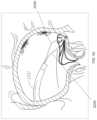
- FIGS. 1 A- 1 Fschematically illustrate some of the tissues of the heart and mitral valve, as described in the Background section and below, and which may interact with the implants and systems described herein.
- FIG. 2 Aillustrates a simplified cross-section of a heart, schematically showing mitral valve function during diastole.
- FIG. 2 Billustrates a simplified cross-section of a heart, schematically showing mitral valve function during systole.
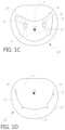
- FIGS. 3 A- 3 Billustrate a simplified cross-section of a heart, schematically showing mitral valve regurgitation during systole in the setting of mal-coaptation of the mitral valve leaflets.
- FIG. 4 Aillustrates a stylized cross section of a heart, showing mitral valve mal-coaptation in the setting of functional mitral valve regurgitation.
- FIG. 4 Billustrates a stylized cross section of a heart, showing mitral valve mal-coaptation in the setting of degenerative mitral valve regurgitation.
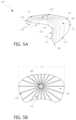
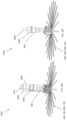
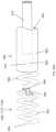
- FIG. 5 Aillustrates a perspective view of an embodiment of a coaptation assistance element.
- FIG. 5 Billustrates the top view of the coaptation assistance element of FIG. 5 A .
- FIGS. 5 C- 5 Dillustrates an embodiment of the struts of a coaptation assistance element.
- FIGS. 5 E- 5 Gillustrate the coaptation assistance element of FIG. 5 A without annular anchor site.
- FIGS. 5 H- 5 Jillustrate the coaptation assistance element of FIG. 5 A with leaflet anchor sites.
- FIG. 5 Killustrates dimensions of the coaptation assistance element of FIG. 5 A .
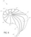
- FIG. 6illustrates a perspective view of an embodiment of a coaptation assistance element.
- FIG. 7 Aillustrates a perspective view of an embodiment of a coaptation assistance element showing a first surface disposed toward a mal-coapting native leaflet.
- FIG. 7 Billustrates another perspective view of the coaptation assistance element of FIG. 7 A showing a second surface which can include a coaptation surface.
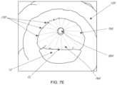
- FIG. 7 Cillustrates a top view of the coaptation assistance element of FIG. 7 A .
- FIG. 7 Dillustrates the coaptation assistance element of FIG. 7 A implanted within a model of a mitral valve.
- FIG. 7 Eillustrates a top view of the coaptation assistance element of FIG. 7 A implanted within a model of a mitral valve.
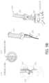
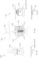
- FIG. 8A schematically illustrates an embodiment of control handle of a delivery system for a transcatheter technique.
- FIG. 8 Bschematically illustrates a top view and a side view a coaptation assistance element coupled to the delivery system of FIG. 8 A .
- FIG. 8 Cschematically illustrates the connection between an annular hub of the coaptation assistance element and a tip of the delivery catheter.
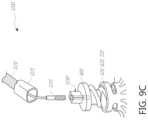
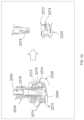
- FIG. 9 Aschematically illustrates the anchor manipulation of the delivery system of FIG. 8 A .
- FIGS. 9 B- 9 Eschematically illustrates embodiments of the connection between an annular anchor and a driver.
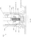
- FIG. 10schematically illustrates a method for a transcatheter technique showing transeptal crossing.
- FIG. 11schematically illustrates a method for a transcatheter technique showing initial coaptation assistance element advancement.
- FIG. 12schematically illustrates a method for a transcatheter technique showing partial coaptation assistance element opening.
- FIG. 13schematically illustrates a method for a transcatheter technique showing coaptation assistance element collapsing.
- FIG. 14schematically illustrates a method for a transcatheter technique showing a cross-sectional view of the coaptation assistance element.
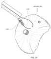
- FIG. 15schematically illustrates a method for a transcatheter technique showing secondary anchor placement.
- FIG. 16illustrates a method for implant delivery showing loading of an implant.
- FIG. 17illustrates a method for inserting an introducer.
- FIG. 18illustrates a method for connecting the introducer of FIG. 17 to a transeptal sheath.
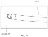
- FIG. 19illustrates a method for advancing the transeptal sheath of FIG. 18 .
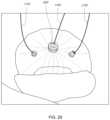
- FIG. 20illustrates a method for positioning the transeptal sheath of FIG. 19 .
- FIG. 21illustrates a method for delivering an anchor.
- FIGS. 22 A- 22 Dillustrate a method for deploying the implant.
- FIG. 23illustrates a method for utilizing one or more secondary anchor guidewires.
- FIG. 24illustrates a method for removing an anchor driver.
- FIG. 25illustrates a method for advancing secondary anchor guiderails.
- FIG. 26illustrates a method for delivering a secondary anchor.
- FIG. 27illustrates a method for inserting a secondary anchor.
- FIG. 28illustrates a method for delivering another secondary anchor.
- FIG. 29illustrates the anchored implant with guidewires.
- FIG. 30illustrates the anchored implant.
- FIGS. 31 A- 31 Fillustrate a method for retrieving the implant.
- FIG. 32illustrates a method for inserting a secondary anchor.
- FIG. 33illustrates a method for delivering another secondary anchor.
- FIG. 34illustrates a method for inserting another secondary anchor.
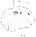
- FIG. 35illustrates the anchored implant.
- FIG. 36illustrates an embodiment of lamination.
- FIG. 37illustrates an embodiment of lamination.
- FIG. 38illustrates an embodiment of 3D forming.
- FIG. 39illustrates an embodiment of 3D forming.
- FIG. 40illustrates an implant
- FIG. 41illustrates an embodiment of a barb.
- FIGS. 42 A- 42 Iillustrate an embodiment of an implant delivery system.
- FIGS. 43 A- 43 Eillustrate an embodiment of an implant delivery system.
- FIGS. 44 A- 44 Eillustrate an embodiment of an implant delivery system.
- FIGS. 45 A- 45 Killustrate an embodiment of an implant delivery system.
- FIGS. 46 A- 46 Cillustrate an embodiment of an anchor delivery system.
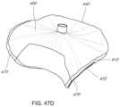
- FIGS. 47 A- 47 Eillustrate views of an embodiment of a coaptation assistance element.
- FIG. 48illustrates an embodiment of implant construction.
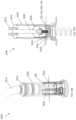
- FIG. 49illustrates an embodiment of an implant delivery system.
- FIG. 50illustrates a method of delivery.
- FIG. 51illustrates an embodiment of a primary anchor driver.
- FIG. 52illustrates an embodiment of a secondary anchor guide rail.
- FIGS. 53 A- 53 Billustrate an embodiment of a secondary anchor guide rail to prevent entanglement.
- FIG. 54illustrates an embodiment of a secondary anchor guide rail to facilitate the trajectory for a secondary anchor.
- FIGS. 55 A- 55 Cillustrate an embodiment of a proximal assembly.
- FIG. 56illustrates an embodiment of an anti-rotation feature.
- FIGS. 57 A- 57 Billustrates an embodiment of posterior leaflet augmentation and restoration.
- the present inventionin some embodiments, generally provides improved medical devices, systems, and methods, often for treatment of mitral valve regurgitation and other valve diseases including tricuspid regurgitation. While the description that follows includes reference to the anterior leaflet in a valve with two leaflets such as the mitral valve, it is understood that “anterior leaflet” could refer to one or more leaflets in valve with multiple leaflets. For example, the tricuspid valve has 3 leaflets so the “anterior” could refer to one or two of the medial, lateral, and posterior leaflets.
- the coaptation assistance elements described hereinwill generally include a coaptation assist body (sometimes referred to herein as a valve body) which is generally along the blood flow path as the leaflets of the valve move back and forth between an open-valve configuration (with the anterior leaflet separated from valve body) and a closed-valve configuration (with the anterior leaflet engaging opposed surfaces of the valve body).
- the valve bodywill be disposed between the native leaflets to close the gap caused by mal-coaptation of the native leaflets by providing a surface for at least one of the native leaflets to coapt against, while effectively replacing a second native leaflet in the area of the valve which, were it functioning normally, it would occlude during systole.
- the gapsmay be lateral (such as may be caused by a dilated left ventricle and/or mitral valve annulus) and/or axial (such as where one leaflet prolapses or is pushed by fluid pressure beyond the annulus when the valve should close).
- the coaptation assist elementsmay completely assist one, two, or more valve leaflets, or in some embodiments partially assist a valve leaflet, for example, covering only one or more of the A 1 , A 2 , and/or A 3 scallops of the anterior leaflet, and/or one or more of the P 1 , P 2 , and/or P 3 scallops of the posterior leaflet.
- the coaptation assistance elements, and methods described hereinmay be configured for treating functional and/or degenerative mitral valve regurgitation (MR) by creating an artificial or new coaptation zone within which at least one of the native mitral valve leaflets can seal.
- MRdegenerative mitral valve regurgitation
- the structures and methods hereinwill largely be tailored to this application, though alternative embodiments might be configured for use in other valves of the heart and/or body, including the tricuspid valve, valves of the peripheral vasculature, the inferior vena cava, or the like.
- the mitral valve 60is disposed between the left atrium 10 and left ventricle 30 . Also shown are the tricuspid valve 50 which separates the right atrium 20 and right ventricle 40 , the aortic valve 80 , and the pulmonary valve 70 .
- the mitral valve 60is composed of two leaflets, the anterior leaflet 12 and posterior leaflet 14 . In a healthy heart, the two leaflets appose during systole at the coaptation zone 16 .
- the fibrous annulus 120provides attachment for the two leaflets of the mitral valve, referred to as the anterior leaflet 12 and the posterior leaflet 14 .
- the leafletsare axially supported by attachment to the chordae tendinae 32 .
- the chordaeattach to one or both of the papillary muscles 34 , 36 of the left ventricle.
- the chordae support structurestether the mitral valve leaflets, allowing the leaflets to open easily during diastole but to resist the high pressure developed during ventricular systole.
- the shape and tissue consistency of the leafletshelps promote an effective seal or coaptation.
- the leading edges of the anterior and posterior leafletcome together along a funnel-shaped zone of coaptation 16 , with a lateral cross-section 160 of the three-dimensional coaptation zone (CZ) being shown schematically in FIG. 1 E .
- the anterior and posterior mitral leafletsare dissimilarly shaped.
- the anterior leafletis more firmly attached to the annulus overlying the central fibrous body (cardiac skeleton), and is somewhat stiffer than the posterior leaflet, which is attached to the more mobile posterior mitral annulus.
- Approximately 80 percent of the closing areais the anterior leaflet.
- Adjacent to the commissures 110 , 114 , on or anterior to the annulus 120lie the left (lateral) 124 and right (septal) 126 fibrous trigones which are formed where the mitral annulus is fused with the base of the non-coronary cusp of the aorta ( FIG. 1 F ).
- the fibrous trigones 124 , 126form the septal and lateral extents of the central fibrous body 128 .
- the fibrous trigones 124 , 126may have an advantage, in some embodiments, as providing a firm zone for stable engagement with one or more annular or atrial anchors.
- the coaptation zone CL between the leaflets 12 , 14is not a simple line, but rather a curved funnel-shaped surface interface.
- the first 110 (lateral or left) and second 114 (septal or right) commissuresare where the anterior leaflet 12 meets the posterior leaflet 14 at the annulus 120 . As seen most clearly in the axial views from the atrium of FIGS.
- an axial cross-section of the coaptation zonegenerally shows the curved line CL that is separated from a centroid of the annulus CA as well as from the opening through the valve during diastole CO.
- the leaflet edgesare scalloped, more so for the posterior versus the anterior leaflet.
- Mal-coaptationcan occur between one or more of these A-P (anterior-posterior) segment pairs A 1 /P 1 , A 2 /P 2 , and A 3 /P 3 , so that mal-coaptation characteristics may vary along the curve of the coaptation zone CL.
- a properly functioning mitral valve 60 of a heartis open during diastole to allow blood to flow along a flow path FP from the left atrium toward the left ventricle 30 and thereby fill the left ventricle.
- the functioning mitral valve 60closes and effectively seals the left ventricle 30 from the left atrium 10 during systole, first passively then actively by increase in ventricular pressure, thereby allowing contraction of the heart tissue surrounding the left ventricle to advance blood throughout the vasculature.
- FIGS. 3 A- 3 B and 4 A- 4 Bthere are several conditions or disease states in which the leaflet edges of the mitral valve fail to oppose sufficiently and thereby allow blood to regurgitate in systole from the ventricle into the atrium. Regardless of the specific etiology of a particular patient, failure of the leaflets to seal during ventricular systole is known as mal-coaptation and gives rise to mitral regurgitation.
- mal-coaptationcan result from either excessive tethering by the support structures of one or both leaflets, or from excessive stretching or tearing of the support structures.
- Other, less common causesinclude infection of the heart valve, congenital abnormalities, and trauma.
- Valve malfunctioncan result from the chordae tendinae becoming stretched, known as mitral valve prolapse, and in some cases tearing of the chordae 215 or papillary muscle, known as a flail leaflet 220 , as shown in FIG. 3 A .
- the leaflet tissue itselfthe valves may prolapse so that the level of coaptation occurs higher into the atrium, opening the valve higher in the atrium during ventricular systole 230 . Either one of the leaflets can undergo prolapse or become flail. This condition is sometimes known as degenerative mitral valve regurgitation.
- annular dilation 240Such functional mitral regurgitation generally results from heart muscle failure and concomitant ventricular dilation. And the excessive volume load resulting from functional mitral regurgitation can itself exacerbate heart failure, ventricular and annular dilation, thus worsening mitral regurgitation.
- FIG. 4 A- 4 Billustrate the backflow BF of blood during systole in functional mitral valve regurgitation ( FIG. 4 A ) and degenerative mitral valve regurgitation ( FIG. 4 B ).
- the increased size of the annulus in FIG. 4 Acoupled with increased tethering due to hypertrophy of the ventricle 320 and papillary muscle 330 , prevents the anterior leaflet 312 and posterior leaflet 314 from apposing, thereby preventing coaptation.
- the tearing of the chordae 215causes prolapse of the posterior leaflet 344 upward into the left atrium, which prevents apposition against the anterior leaflet 342 . In either situation, the result is backflow of blood into the atrium, which decreases the effectiveness of left ventricle compression.
- the coaptation assistance elements described hereinmay be deployed to overlie the posterior leaflet, the chordae and papillary muscle.
- the coaptation assistance elementattaches superiorly to the posterior aspect of the annulus and inferiorly to the posterior aspect of the left ventricle via annular anchor and/or ventricular anchor.
- more than one annular anchor and/or more than one ventricular anchormay be used to attach the coaptation assistance element.
- the one or more annular anchorsmay be replaced by or supplemented with one or more atrial or commissural anchors, which can be annular in some embodiments.
- the coaptation assistance elementmay attach to the superior surface of the posterior annulus, the posterior atrial wall, or the annulus itself.
- a coaptation zonehas been established between the coaptation assistance element and the native anterior leaflet.
- Similar coaptation assistance elementscan be used in both functional and degenerative mitral valve regurgitation because the failure of leaflet coaptation occurs in both, regardless of the mechanism behind the dysfunction.
- differently sized coaptation assistance elementscan be placed such that the native anterior leaflet apposes the coaptation element at the appropriately established coaptation point, blocking flow of blood during contraction of the ventricle.
- a variety of sizes of coaptation assistance elementsmay be provided, with differing dimensions configured to fit varying anatomies.
- the coaptation assistance elementmay stay in substantially the same position, while movement of the native anterior leaflet opens the valve, permitting flow of blood from the left atrium to the left ventricle with minimal restriction.
- the surface of the coaptation assistance elementmay balloon or stretch upwards during ventricular systole, while the anchors remain unmoved. This may be advantageous as enhancing the seal between the anterior or coaptation surface of the element and the native leaflet at the coaptation zone during systole.
- the surfacemay return to an initial position in which it lies more anteriorly, toward the anterior leaflet. This may provide an improved blood flow path between the atrium and ventricle during diastole, improving outflow from the atrium past the coaptation assist element.
- the native posterior leafletis left in position, and the coaptation assistance element is attached superiorly to the posterior annulus or adjacent atrial wall. Many possible alternate embodiments may have differing attachment mechanisms.
- the posterior leafletis not present, having been removed surgically or the result of disease.
- the native leafletattaches to the posterior surface of the coaptation assistance element.
- the coaptation assistance elementmay attach to the anterior surface of the posterior leaflet, rather than the annulus or atrial wall.
- an anchoring structure(not shown) could pass from the coaptation assistance element, through the atrial wall into the coronary sinus, wherein the anchoring structure attaches to a mating structure in the coronary sinus.
- the anchoring structurewhich could be a mechanical structure or a simple suture, can pass through the atrial wall and be anchored by a knot or mechanical element, such as a clip, on the epicardial surface of the heart.
- attachment inferiorlymay be to the ventricular muscle, through the apex into the epicardium or pericardium and secured from outside, or at other attachment sites using alternative attachment means.
- the coaptation assistance element described hereinmay exhibit a number of desirable characteristics. Some embodiments need not rely on reshaping of the mitral annulus (such as by thermal shrinking of annular tissue, implantation of an annular ring prosthesis, and/or placement of a cinching mechanism either above or beneath the valve plane, or in the coronary sinus or related blood vessels). Advantageously, they also need not disrupt the leaflet structure or rely on locking together or fusing of the mitral leaflets. Many embodiments can avoid reliance on ventricular reshaping, and after implantation represent passive implanted devices with limited excursion which may result in very long fatigue life. Thus, the coaptation assistance element can be secured across a posterior leaflet while otherwise leaving native heart (e.g., ventricular, mitral annulus, etc.) anatomy intact.
- native hearte.g., ventricular, mitral annulus, etc.
- Mitigation of mitral valve mal-coaptationmay be effective irrespective of which leaflet segment(s) exhibit mal-coaptation.
- the treatments described hereinwill make use of coaptation assistance elements that are repositionable during the procedure, and even removable after complete deployment and/or tissue response begins or is completed, often without damaging the valve structure. Nonetheless, the coaptation assistance element described herein may be combined with one or more therapies that do rely on one or more of the attributes described above as being obviated.
- the coaptation assistance elementcan exhibit benign tissue healing and rapid endothelialization which inhibits migration, thromboembolism, infection, and/or erosion. In some cases, the coaptation assistance element will exhibit no endothelialization but its surface will remain inert, which can also inhibit migration, thromboembolism, infection and/or erosion.
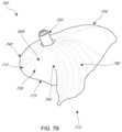
- FIGS. 5 A- 5 Bshow two views of an embodiment of a coaptation assistance element 500 .
- the coaptation assistance element 500can include a first surface 505 disposed toward a mal-coapting native leaflet, in the instance of a mitral valve, the posterior leaflet and a second surface 515 which may be disposed toward the anterior leaflet.
- the second surface 515can include a coaptation surface 560 .
- the superior edge 540 of the coaptation assistance element 500may be curved to match the general shape of the annulus or adjoining atrial wall, as described herein.
- the superior edge 540can be curved downward, toward the posterior leaflet, as shown in FIG. 5 A , or curved upward, toward the atrial wall to match the general shape of the left atrial wall, as shown in FIG. 6 and described herein.
- the coaptation assistance element 500can have a geometry which permits it to traverse the valve between attachment sites in the atrium and ventricle. In some embodiments, the attachment sites are only in the atrium. In some embodiments, the attachment sites are only near the annulus and the commissures of the valve.
- the coaptation assistance element 500can be unattached near the inferior edge 580 . The coaptation assistance element 500 does not require ventricular attachment.
- the geometry of the coaptation assistance element 500helps to maintain the position of the coaptation assistance element 500 within the valve.
- the coaptation assistance element 500is curved to cup the posterior leaflet. In some embodiments, the coaptation assistance element 500 is curved backwards toward the superior edge 540 .
- the coaptation assistance element 500may provide the coaptation surface 560 for the anterior leaflet to coapt against.
- FIGS. 5 A and 5 Billustrate that geometry.
- the posterior leafletcan be left intact.
- the coaptation assistance element 500may attach to the atrium or annulus such that it effectively seals off the posterior leaflet.
- the posterior leafletcan be removed.
- the coaptation assistance element 500may, in the instance that the leaflet is or has been removed, replace the posterior leaflet.
- the coaptation assistance element 500only requires annular attachment.
- the coaptation assistance element 500only requires attachment at a single point.
- the single pointmay be a central location of the coaptation assistance element 500 , for instance, a centrally-located hub.
- the coaptation assistance element 500may attach to the atrium or annulus along an edge.
- the coaptation assistance element 500may attach to the atrium or annulus at a location separated from the edge of the coaptation assistance element 500 , for instance, at a centrally-located hub.
- the coaptation assistance element 500can include an annular hub 520 engaging an annular anchor 800 .
- the annular anchor 800may be engaged at a proximal end by a driver, described herein.
- the annular anchor 800can include a sharpened tip to engage tissue.
- the tip of the annular anchor 800is within the annular hub 520 during delivery of the coaptation assistance element 500 .
- the tip of the annular anchor 800is above the annular section 510 during delivery. The tip of the annular anchor 800 can remain recessed within the annular hub 520 until the annular anchor 800 is rotated to engage tissue.
- the coaptation assistance element 500can be assembled extra-corporeally, engaging the annular anchor 800 to the coaptation assistance element 500 via the annular hub 520 and the drivers to the annular anchor 800 .
- the driverscan then be withdrawn into a delivery catheter, with the coaptation assistance element 500 in a collapsed position.
- the driversmay be separately manipulated by the operator to place the annular anchor 800 in the appropriate position.
- the annular anchor 800may be engaged to the coaptation assistance element 500 and/or the driver sequentially, either before or after deployment through the delivery catheter.
- the coaptation assistance element 500 after placementcan entirely cover the posterior leaflet so that the coaptation assistance element 500 coapts with the anterior leaflet during systole and, with the native anterior leaflet, maintains the valve seal at the annular ring.
- the annular anchor 800is an active anchor.
- the usercan selectively engage or disengage the annular anchor 800 from tissue.
- an active anchorcan be activated such as by rotation in order to engage tissue.
- the annular anchor 800allows placement of the coaptation assistance element 500 prior to engagement of the annular anchor 800 .
- the coaptation assistance element 500can make contact with the tissue without any adhesion of the annular anchor 800 .
- the annular anchor 800 and corresponding hub 520are centrally located on the coaptation assistance element 500 .
- the annular anchor 800 and corresponding hub 520are spaced apart from any edge of the coaptation assistance element 500 .
- the location of the annular anchor 800 and corresponding hub 520can be at a neutral center to prevent swinging of the coaptation assistance element 500 when the coaptation assistance element 500 is held by the annular hub 520 .
- the corresponding hub 520provides a convenient location to hold and move the coaptation assistance element 500 .
- the annular hub 520may have a built-in or coupled annular anchor 800 .
- the annular anchor 800can be retained by a cross-pin, described herein, within the annular hub 520 .
- the cross-pinmay pass through the helical structure of the annular anchor 800 to prevent dislodgement of the annular anchor 800 from the annular hub 520 by a blunt force.
- the annular anchor 800may comprise a helix rotatable with respect to the annular hub 520 . In some embodiments, other anchors may be used.
- the annular anchor 800may be in the form of a tether or other attachment means extending from the coaptation assistance element 500 thru the ventricle septum to the right ventricle.
- the annular anchor 800may be in the form of a tether or other attachment means extending thru the apex into the epicardium or pericardium.
- the annular anchor 800may be secured from outside the heart in and combined endo/epi procedure.
- helical anchorsWhen helical anchors are used, they may comprise bio-inert materials such as Platinum/Ir, a Nitinol alloy, and/or stainless steel.
- the coaptation assistance element 500can include a single central annular anchor 800 inside the annular hub 520 .
- the coaptation assistance element 500can be delivered percutaneously as described herein by attachment of a delivery catheter to the annular hub 520 .
- the coaptation assistance element 500can be configured for adjustable positioning by removing and reattachment of the annular anchor 800 .
- the coaptation assistance element 500can be recapturable by removal of the annular anchor 800 and withdrawal of the coaptation assistance element 500 .
- the coaptation assistance element 500may also include secondary anchors including commissural anchors, ventricular anchor, annular anchors, barbs, tethers or any other known fixation device.
- the coaptation assistance element 500can include a plurality of struts 530 .
- one or more of the struts 530have one end terminating at the hub 520 and the other end extending radially outwardly toward one of the superior edge 540 , the lateral edges 570 and 575 , and the inferior edge 580 of the coaptation assistance element 500 .
- the struts 530may extend outward in various directions from the hub 520 , and can be spaced apart from adjacent struts 530 at regular or irregular intervals.
- adjacent struts 530extend outward from the hub at an angle of between about 5 degrees and about 45 degrees, between about 10 degrees and about 30 degrees, or about 5, 10, 15, 20, 25, or 30 degrees with respect to an adjacent strut 530 .
- the struts 530may be arranged generally parallel to the longitudinal axis of the coaptation assistance element 500 to assist in maintaining the shape of the coaptation assistance element 500 upon placement.
- the struts 530may allow the coaptation assistance element 500 to assume a reduced configuration for deployment through a catheter.
- the struts 530 that form a portion of the coaptation zone of the implant 500have a maximum length that is greater than struts 530 that only form a portion of the annular zone of the implant.
- the struts 530 that form a portion of the coaptation zone of the implantcan be, for example, at least about 10%, 20%, 30%, 40%, 50%, 75%, 100%, 125%, or 150% longer than the struts 530 that form a portion of the annular zone of the implant.
- FIG. 5 Ashows a view of the coaptation assistance element 500 with an annular anchor site 535 .
- the annular anchor site 535can be a portion of the struts 530 .
- the annular anchor site 535is shown extending downward from the coaptation assistance element 500 in FIG. 5 A .
- the annular anchor site 535may extend in other directions from the coaptation assistance element 500 to engage tissue.
- the annular anchor site 535comprises one or more barbs having a sharpened tip.
- the annular anchor site 535may be a passive anchor.
- the coaptation assistance element 500can include one or more retractable barbs.
- the barbscan be retracted during delivery of the coaptation assistance element 500 .
- the barbscan be advanced after the coaptation assistance element 500 is positioned relative to the anatomical structures.
- the barbsare actively retracted and/or advanced.
- the delivery catheter described hereincan include a mechanism coupled to the barbs designed to retract and/or advance the barbs.
- the barbsare passively advanced and/or retracted.
- the coaptation assistance element 500is delivered with the barbs in a retracted state.
- the barbscan be covered by the valve body covering as described herein.
- the interface between the tissue and the valve body coveringpushes back the valve body covering and exposes the barbs.
- the tissuedissolves and/or absorbs a portion of the valve body covering and exposes the barbs.
- the motion of the purse-string suture, described hereinadvances the barbs.
- the motion of the purse-string suturecauses motion of the valve body covering to expose the barbs. Other configurations are contemplated.
- the annular anchor site 535may define a diameter D 1 shown in FIG. 5 B , which may in some embodiments correspond to the distance between the medial and lateral commissures of the native valve or the intracommissural distance (ICD).
- D 1may range between 20-60 mm with, in some embodiments, a preferred length between 35-45 mm, as corresponding most closely to the widest range of human mitral ICD.
- D 1may be the distance from the right to left fibrous trigones.
- the coaptation assistance element 500can include a generally annular section 510 .
- the annular section 510can be positioned above the native leaflets when the coaptation assistance element 500 is deployed.
- the annular section 510may be curved toward the annulus or curved away from the annulus.
- the annular section 510can be concave.
- the annular section 510may be substantially flat with respect to the annulus.
- One or more of the struts 530may curve laterally from the hub 520 toward the superior edge 540 to assist in maintaining the shape of the annular section 510 of the coaptation assistance element 500 upon deployment.
- the coaptation assistance element 500can curve downward from the hub 520 toward the annular anchor site 535 .
- the coaptation assistance element 500does not rest against the posterior leaflet.
- the annular anchor site 535is the only point of contact between the posterior annulus of the mitral valve and the coaptation assistance element 500 .
- the superior edge 540can include an annular radius of curvature.
- the annular curve radiuscan curve toward the annulus.
- the annular curve radiuscan curve toward the coaptation surface 560 .
- the annular curve radiuscan be between 0 mm-5 mm, 5 mm-10 mm, 10 mm-15 mm, 15 mm-20 mm, 20 mm-25 mm, 25 mm-30 mm, etc.
- the struts 530may be composed of a radio-opaque material.
- the struts 530are composed of resiliently deformable materials such as a shape memory metal, e.g., Nitinol or a shape memory polymer.
- the materialis Elgiloy.
- the struts 530may be composed of other materials to include stainless steel, polypropylene, high density polyethylene (PE), Dacron, acellular collagen matrix such as SIS, or other plastics, etc.
- the struts 530may be a combination such as a high density PE sheath around a core of ePTFE, Dacron, and/or polypropylene.
- the struts 530may have a circular cross section, an oval cross section, or be ribbon-like. In some embodiments, the struts 530 are coiled springs or zig-zag shaped. The struts 530 may have a constant stiffness. In some embodiments, one or more struts 530 can have differing stiffness along the length of the one or more struts 530 . The struts 530 may be stiffer at the annular end than at the ventricular end of the coaptation assistance element 500 . The struts 530 may be less stiff at the annular end than at the ventricular end of the coaptation assistance element 500 .
- the struts 530may be stiffer at a midpoint, for instance at an inflection point or curve.
- the struts 530along with one or more other support structures, can form a frame.
- one or more support structuresmay be provided which run parallel to the superior edge 540 of the coaptation assistance element 500 and assist in maintaining the shape of the superior edge 540 .
- the struts 530 and/or other support structures of the framecan be laser-cut from a Nitinol tube in some embodiments.
- the coaptation assistance element body covering 550may be comprised of a material such as ePTFE.
- Other materials for the coaptation assistance element body covering 550include polyester, polyurethane foam, polycarbonate foam, biologic tissue such as porcine pericardium, processed bovine pericardium, pleura, peritoneum, silicone, Dacron, acellular collagen matrix, etc.
- the coaptation assistance element body covering 550can include a foam material surrounded by ePTFE. Use of sponge or foam material enhances the capability of having the coaptation assistance element 500 to fold to a small enough diameter to pass through a catheter.
- the coaptation assistance element body covering 550has no pores.
- the coaptation assistance element body covering 550may have micropores to enhance endothelialization and cellular attachment.
- the coaptation assistance element body covering 550may also incorporate a radiopaque material or an echo-enhancement material for better visualization.
- Any support structures of the coaptation assistance element 500 including the struts 530 or support interface including the hub 520may be coated with radio-opaque materials such as gold or platinum or impregnated with barium.
- the coaptation surface 560may be coated with an echo enhancement material.
- the coaptation assistance element body covering 550may be coated with a material to inhibit thrombosis, such as heparin bonding or quinoline and quinoxaline compounds, or with a material to accelerate endothelialization, or with antibiotic to inhibit infection.
- the purse-string suture 1010 described hereincan incorporate a radiopaque material or an echo-enhancement material for better visualization.
- the struts 530may be sandwiched between layers of coaptation assistance element body covering 550 .
- the coaptation assistance element body covering 550may be composed of the same material on the first surface 505 and the second surface 515 .
- the coaptation assistance element body covering 550may be composed of different materials on the first surface 505 , or a portion thereof, and the second surface 515 , or a portion thereof.
- the struts 530may be attached to or embedded in the first surface 505 or the second surface 515 of a single layer of coaptation assistance element body covering 550 .
- the struts 530may be “stitched” through the coaptation assistance element body covering 550 .
- the annular anchor site 535can be exposed ends of the struts 530 from the coaptation assistance element body covering 550 .
- the coaptation assistance element 500can include a purse-string suture 1010 .
- the purse-string suture 1010can extend along a portion of the coaptation assistance element 500 .
- the purse-string suture 1010can extend along the superior edge 540 , or a portion thereof.
- the purse-string suture 1010can extend along the lateral edge 570 , or a portion thereof.
- the purse-string suture 1010can extend along the lateral edge 575 , or a portion thereof.
- the purse-string suture 1010can extend along the inferior edge 580 , or a portion thereof.
- the purse-string suture 1010can extend along a perimeter, or a portion thereof, of the coaptation assistance element 500 .
- the purse-string suture 1010can extend along one or more struts 530 .
- the purse-string suture 1010can extend in a linear path, a non-linear path, a curve, a semi-circle or any open or closed shape.
- the purse-string suture 1010may be sandwiched between layers of valve body covering 550 .
- the purse-string suture 1010can be disposed in a lumen between layers of coaptation assistance element body covering 550 .
- the purse-string suture 1010may be attached to or embedded in the first surface 505 or the second surface 515 of a single layer of valve body covering 550 .
- the purse-string suture 1010may be “stitched” through the coaptation assistance element body covering 550 .
- the purse-string suture 1010can pass from the first surface 505 to the second surface 515 and back to the first surface 505 .
- the purse-string suture 1010can include one or more exposed ends from the coaptation assistance element body covering 550 .
- the purse-string suture 1010is a loop
- the purse-string suturecan include one or more exposed sections of the loop from the valve body covering.
- the coaptation assistance element 500may be collapsed by tightening the purse-string suture 1010 .
- the coaptation assistance element 500may be expanded by loosening the purse-string suture 1010 .
- the one or more exposed ends or loopscan be manipulated by a delivery catheter or other tool to tighten or loosen the purse-string suture 1010 .
- the ability to collapse or expand the coaptation assistance element 500may be beneficial for recapture of the coaptation assistance element 500 and/or repositioning of the coaptation assistance element 500 .
- the coaptation assistance element 500may be rotated by tightening one or more purse-string suture 1010 and/or loosening one or more purse-string suture 1010 .
- tightening one or more purse-string suture 1010 on the lateral edge 570 and/or loosening one or more purse-string suture 1010 on the lateral edge 575may cause the coaptation assistance element 500 to rotate.
- One or more purse-string sutures 1010may be coupled to the coaptation assistance element 500 to enable multi-directional rotation.
- the coaptation assistance element 500may be expanded by loosening the purse-string suture 1010 .
- the one or more exposed ends or loopscan be manipulated by a delivery catheter or other tool to tighten or loosen the purse-string suture 1010 .
- the ability to collapse or expand the coaptation assistance element 500may be beneficial for recapture of the coaptation assistance element 500 and/or repositioning of the coaptation assistance element 500 .
- the coaptation surface 560 of the coaptation assistance element 500may be adjusted by motion of the purse-string suture 1010 .
- the one or more exposed ends or loopscan be manipulated by a delivery catheter or other tool to tighten or loosen the purse-string suture 1010 to change the curvature of the coaptation surface 560 in situ.
- the ability to adjust the curvature of the coaptation assistance element 500may be beneficial to conform to the geometry of heart including the geometry of the anterior leaflet.
- the annular dimension of the coaptation assistance element 500may be adjusted by motion of the purse-string suture 1010 .
- the one or more exposed ends or loopscan be manipulated by a delivery catheter or other tool to tighten or loosen the purse-string suture 1010 to change one or more dimensions of the coaptation assistance element 500 in situ.
- the ability to adjust dimensions of the coaptation assistance element 500may be beneficial to conform to the geometry of the heart.
- the coaptation assistance element 500can include one or more purse-string sutures 1010 .
- the coaptation assistance element 500includes one purse-string suture, two purse-string sutures, three purse-string sutures, four purse-string sutures, five purse-string sutures, six purse-string suture, seven purse-string sutures, eight purse-string sutures, nine purse-string sutures, ten purse-string sutures, etc.
- a purse-string suture 1010can extend along each edge of the coaptation assistance element 500 .
- the purse-string sutures 1010can act together to change the configuration of the coaptation assistance element 500 .
- the purse-string sutures 1010can act independently to change the configuration of the coaptation assistance element 500 .
- FIG. 5 Afurther illustrates a coaptation element height, corresponding to the distance between the inferior edge 580 and the annular hub 520 as measured perpendicular to the plane defined by the annulus of the valve.
- Coaptation element height of some embodimentsmay be 10-80 mm, with some embodiments ranging between 40-55 mm.
- the coaptation element heightcan be between 10-20 mm, 20-30 mm, 30-40 mm, 40-50 mm, 50-60 mm, 60-70 mm, 70-80 mm, etc.
- FIG. 5 Aillustrates the generally triangular shape of coaptation assistance element 500 , such that the coaptation assistance element 500 has a superior edge 540 , lateral edges 570 and 575 , and inferior edge 580 .
- the superior edge 540has a length greater than that of inferior edge 580 , such that the transverse distance between lateral edges 570 and 575 generally decreases from superior to inferior on the coaptation assistance element 500 .
- the length of the superior edge 540may be in the range of 15-50 mm, or 25-35 mm, while the length of the inferior edge 580 may be in the range of 1-15 mm, or 2-6 mm.
- the annular hub 520may be a hub, an eyelet, or any other tether site known in the art. In some embodiments, the annular hub 520 is located at a midpoint of the distance D 1 . In some embodiments, the annular hub 520 is located at a neutral center to prevent swinging of the coaptation assistance element 500 when the coaptation assistance element 500 is held by the annular hub 520 . In other embodiments, the annular hub 520 is located at one of the commissures. While only one annular anchor 800 is shown, in other embodiments, two or more annular hubs 520 may be provided.
- the struts 530can comprise NiTi tubing. In some embodiments, the struts 530 can be laser cut from the tubing. In some embodiments, the frame including one or more struts 530 and/or one or more support structures can be laser cut from a single piece of material. In some embodiments, the frame including one or more struts 530 , the annular hub 520 , and/or one or more support structures can be integrally formed. In some embodiments, the coaptation assistance element body covering 550 comprises ePTFE lamination. The lamination can surround one or more of the struts 530 and/or one or more support structures (e.g., one side, two sides, first side 505 , second side 515 ).
- the struts 530 and/or one or more support structurescan be encased by two or more layers of lamination.
- the perimeter of the annular section 510 of the coaptation assistance element 500can be cupped down.
- the perimeter of the annular section 510 of the coaptation assistance element 500can be cupped up.
- the perimeter of the annular section 510 of the coaptation assistance element 500can include secondary anchors such as the annular anchor site 535 .
- the annular anchor 800 and the annular hub 520form a single central anchor system.
- the coaptation assistance element 500is affixed to the tissue by only one annular anchor 800 which passes through the hub 520 . In other embodiments, additional fixation is included.
- the coaptation assistance element 500is affixed to the tissue by the one anchor 800 which passes through the hub 520 and the annular anchor site 535 as described herein.
- the systemcan include features to allow rotational adjustment of the coaptation assistance element 500 .
- the hub 520 and/or the annular anchor 800can be coupled to the delivery catheter to allow the transmission of axial movement and/or torque.
- the coaptation assistance element 500can be immovably grasped by a delivery catheter such that rotation of a feature of the delivery catheter, such as a handle, causes rotation of the coaptation assistance element 500 .
- the coaptation assistance element 500can be immovably grasped by a delivery catheter such that axial movement of a feature of the delivery catheter, such as a drive shaft, causes axial movement of the coaptation assistance element 500 .
- the hub 520is located at a neutral position on the coaptation assistance element 500 .
- the neutral positioncan be a central location on the annular section 510 .
- the neutral positioncan be between the lateral edges 505 , 515 .
- the neutral positioncan be between the superior edge 540 and the cooptation surface 560 .
- the neutral positioncan enhance stability of the coaptation assistance element 500 when the coaptation assistance element 500 is grasped at a single location such as the hub 520 and/or the annular anchor 800 .
- the neutral positioncan be aligned with a structure of the mitral valve.
- the neutral positioncan be aligned along the coaptation zone.
- the coaptation assistance element 500is delivered percutaneously as described herein.
- the coaptation assistance element 500is adjustable via a delivery catheter.
- the coaptation assistance element 500can be expanded and/or collapsed by the delivery catheter.
- the coaptation assistance element 500can be rotated about a fixed position of the annular hub 520 .
- the coaptation assistance element 500can be recapturable.
- the coaptation assistance element 500can be engaged and reengaged by the delivery catheter.
- the annular anchor 800can be disengaged from the tissue and the delivery catheter can recapture the coaptation assistance element 500 .
- FIGS. 5 C- 5 Dillustrate embodiments of a frame 565 of the coaptation assistance element 500 . These figures illustrated the flattened patterns of the frame 565 prior to bending and/or shape setting.
- the frame 565is cut from a tubular stock. In other embodiments, the frame 565 is cut from flat stock such as a flat sheet of material. The frame 565 including portions thereof can be laser cut.
- the frame 565can include one or more struts 530 . In the embodiment shown in FIG.
- the frame 565includes twenty struts 530 but other configurations are contemplated (e.g., one strut, two struts, three struts, four struts, five struts, between five and ten struts, between ten and fifteen struts, between fifteen and twenty struts, between twenty and twenty-five struts, between twenty-five and thirty struts, between two and thirty struts, between five and thirty struts, etc.).
- other configurationsare contemplated (e.g., one strut, two struts, three struts, four struts, five struts, between five and ten struts, between ten and fifteen struts, between fifteen and twenty struts, between twenty and twenty-five struts, between twenty-five and thirty struts, between two and thirty struts, between five and thirty struts, etc.).
- the frame 565can include about, at least about, or no more than about 1, 2, 3, 4, 5, 6, 7, 8, 9, 10, 11, 12, 13, 14, 15, 16, 17, 18, 19, 20, 21, 22, 23, 24, 25, 26, 27, 28, 29, 30, or more struts, or a range incorporating any two of the aforementioned values.
- the length of the struts extending to the superior upwardly or downwardly cupping lipare shorter than, such as less than about 80%, 70%, 60%, 50%, 40%, 30%, 20%, or less than the longest inferior-extending strut.
- one, two, or more struts 530are coupled to a backing 585 .
- the backing 585is transverse to the direction of the struts 530 .
- the backing 585is vertical or generally vertical and the struts 530 are horizontal or generally horizontal.
- the backing 585is the annular hub 520 .
- the two ends of the backing 585can be joined using methods known in the art to form the annular hub 520 . The two ends are joined, for instance, if the frame 565 is cut from flat stock. In other embodiments, the frame 565 is formed from tubular stock.
- the backing 585can be a portion of uncut tubular stock.
- the two ends of the backing 585may not need to be joined if the frame 565 is formed from tubular stock.
- the uncut tubular stockcan form the annular hub 520 .
- the patters of the frame 565 as shown in FIG. 5 Dcan be cut from tubular stock, thereby eliminating the need to join the two ends of the backing.
- Other modes of manufacturingare contemplated to form the frame 565 .
- the backing 585forms at least a portion of the annular hub 520 .
- the backing 585surrounds at least a portion of the annular hub 520 .
- the backing 585can be formed into a shape of a circle.
- the struts 530extend radially outward from the backing 585 once the backing 585 is shaped into a circle.
- the backing 585can include one or more openings designed to accept a cross-pin, as disclosed herein. In some methods of manufacturing, the backing 585 is removed.
- a plurality of struts 530can extend from the annular hub 520 to the inferior end 580 .
- these struts 530are longer than other struts 530 of the frame 565 .
- the struts 530might include an anchor or barb that interacts with the subvalvular structure, including the ventricular wall.
- these strutsengage the posterior leaflet or another anatomical structure.
- the ventricular anchoringis passive.
- a plurality of struts 530can extend from the annular hub 520 to the superior end 540 .
- these struts 530are shorter than other struts 530 of the frame 565 .
- these struts 530form an atrial anchor and/or the annular anchor site 535 described herein.
- these strutsengage the annulus or another anatomical structure.
- the annular anchoringis passive.
- a plurality of struts 530can extend from the annular hub 520 to the lateral edges 570 and 575 .
- these struts 530have a mid-length between the ventricular struts and the atrial struts.
- these strutsengage the commissures or another anatomical structure.
- the commissural anchoringis passive.
- the struts 530can have a variety of lengths based on the desired shape of the coaptation assistance element 500 . As shown in FIGS. 5 C- 5 D , two or more struts 530 have a different length. As shown in FIGS. 5 C- 5 D , two or more struts 530 have the same length.
- FIG. 5 Cshows a schematic model of the frame 565 .
- One or more of the top three strutscan form the coaptation surface 560 and extend to the inferior edge.
- One or more of the bottom three strutscan form the annular portion and extend to the superior edge.
- the struts 530can be laser-cut from a tube.
- the lengthcan be measured from the annular hub 520 to an edge of the coaptation assistance element 500 .
- the range of the strut lengthcan be 1 mm to 50 mm.
- the range of the strut lengthcan be 5 mm to 35 mm for the annular portion 510 .
- the strut lengthcan be about 15 mm for the annular portion 510 .
- the range of the strut lengthcan be 20 mm to 35 mm for the coaptation surface 560 .
- the strut lengthcan be about 30 mm for the coaptation surface 560 .
- strut lengthe.g., 5 mm to 45 mm, 10 mm to 40 mm, 15 mm to 35 mm, about 5 mm, about 10 mm, about 15 mm, about 20 mm, about 25 mm, about 30 mm, about 35 mm, about 40 mm, about 45 mm, about 50 mm, about 55 mm, about 60 mm, 1 mm to 10 mm, 5 mm to 15 mm, 10 mm to 20 mm, 15 mm to 25 mm, 20 mm to 30 mm, 25 mm to 35 mm, 30 mm to 40 mm, etc.
- the widthcan be measured perpendicular to the strut length.
- the range of the strut widthcan be 0.1 mm to 2 mm.
- One or more strutscan have an outer diameter or width of about 0.1 mm, 0.2 mm, 0.3 mm, 0.4 mm, 0.5 mm, 0.6 mm, 0.7 mm, 0.8 mm, 0.9 mm, 1 mm, 1.1 mm, 1.2 mm, 1.3 mm, 1.4 mm, 1.5 mm, 1.6 mm, 1.7 mm, 1.8 mm, 1.9 mm, 2 mm, less than 0.5 mm, less than 1 mm, less than 1.5 mm, less than 2 mm, etc.
- One or more struts 530can have a varying width along the strut length. In some embodiment, one or more struts 530 taper near an edge of the coaptation assistance element 500 . In some embodiments, one or more struts 530 taper near the annular hub 520 . The one or more struts 530 can include a reduced diameter or taper at the connection between the one or more struts 530 the annular hub 520 . The taper near the annular hub 520 can aid in collapsing the coaptation assistance element 500 . The taper near the annular hub 520 can facilitate insertion of the coaptation assistance element 500 into the delivery catheter. The taper can reduce stress and/or strain in the strut 530 during collapse.
- one or more struts 530include a varying width taper. The width of the strut 530 can vary along the length of the strut 530 .
- One or more struts 530can include eyelets along the length of the strut 530 . In some embodiments, the eyelets can reduce stress of the struts 530 . In some embodiments, the eyelets can facilitate adhesion between the strut 530 and the valve body covering 550 .
- the thicknesscan be measured perpendicular to the strut length and strut width.
- the thicknesscan be determined by the thickness of the material of the frame, as described herein.
- the range of the strut thicknesscan be 0.2 mm to 0.5 mm.
- One or more strutscan have a thickness of about 0.1 mm, 0.2 mm, 0.3 mm, 0.4 mm, 0.5 mm, 0.6 mm, 0.7 mm, 0.8 mm, 0.9 mm, 1 mm, 1.1 mm, 1.2 mm, 1.3 mm, 1.4 mm, 1.5 mm, 1.6 mm, 1.7 mm, 1.8 mm, 1.9 mm, 2 mm, less than 0.5 mm, less than 1 mm, less than 1.5 mm, less than 2 mm, etc.
- One or more the struts 530can include barbs.
- the barbscan be configured for placement near the ventricular end of the coaptation assistance element 500 .
- the barbscan be bent out of the plane of the strut 530 .
- the barbcan have a bayonet configuration.
- the barbscan have a sharped tip.
- one or more struts 530can be bifurcated.
- one or more struts 530can include one or more zigzag sections.
- the zigzag sectionreduces stress and/or increases flexibility of the strut 530 .
- the zigzag sectionfacilitates adhesion between the strut 530 and the coaptation assistance element body covering 550 .
- one or more struts 530can include supplemental barbs.
- the supplemental barbscan be bent out of the plane of the strut 530 .
- one or more portions of the strut lengthare bent out of the plane of the strut. For instance, a portion of the strut can be twisted or bent during manufacturing. In some embodiments, the portion that is bent out of plane is shaped to engage tissue.
- one or more struts 530can include increased widths to compensate for electropolishing or other post manufacturing processes.
- the backing 585can include one or more features to engage the delivery catheter described herein.
- the backing 585can include one or more notches designed to interface with a locking tab or other feature of the delivery catheter as described herein.
- one or more struts 530can include a greater width than other struts 530 .
- the frame 565includes two or more struts 530 that have a greater width than other struts 530 .
- the two or more struts 530can facilitate visualization of the coaptation assistance element 500 .
- the two or more struts 530 that have a greater widthare designed to be placed near the commissures when the coaptation assistance element 500 is deployed.
- one or more struts 530can have smaller width compared with one or more other struts. In some embodiments, each strut 530 has the same width near the annular hub 520 .
- the backing 585can be modified to interface with the delivery catheter, as described herein. The backing 585 can be designed to allow independent rotation of the anchor 800 within the hub of the coaptation assistance element 500 .
- FIGS. 5 E, 5 F, and 5 Gshow an embodiment of the coaptation assistance element 500 without barbs.
- FIG. 5 Eshows a schematic perspective view of the coaptation assistance element 500 .
- FIG. 5 Fshows a schematic perspective view of the first surface 505 disposed toward a mal-coapting native leaflet.
- FIG. 5 Gshows a schematic cross-sectional view including the anchor 800 .
- FIGS. 5 H, 5 I, and 5 Jshow an embodiment of the coaptation assistance element 500 with leaflet anchor sites 545 .
- the annular anchor sites 535such as barbs can extend along an edge of the coaptation assistance element 500 .
- FIGS. 5 H, 5 I, and 5 Jshow an embodiment of the coaptation assistance element 500 with leaflet anchor sites 545 extending from the first surface 505 disposed toward a mal-coapting native leaflet.
- FIG. 5 Hshows a schematic perspective view of the coaptation assistance element 500 including an enlarged section showing the leaflet anchor sites 545 .
- FIG. 5 Ishows a schematic perspective view of the first surface 505 disposed toward a mal-coapting native leaflet.
- FIG. 5 Jshows a schematic cross-sectional view including the anchor 800 .
- the leaflet anchor sites 545comprise one or more barbs having a sharpened tip.
- the leaflet anchor sites 545may be a passive anchor.
- the coaptation assistance element 500can include one or more retractable barbs.
- the leaflet anchor sites 545can be retracted during delivery of the coaptation assistance element 500 .
- the leaflet anchor sites 545can be advanced after the coaptation assistance element 500 is positioned relative to the anatomical structures.
- the leaflet anchor sites 545are actively retracted and/or advanced.
- the delivery catheter described hereincan include a mechanism coupled to the leaflet anchor sites 545 designed to retract and/or advance the barbs.
- the leaflet anchor sites 545are passively advanced and/or retracted.
- the leaflet anchor sites 545can be covered by the valve body covering as described herein.
- the interface between the tissue and the valve body coveringpushes back the valve body covering and exposes the leaflet anchor sites 545 .
- the tissuedissolves and/or absorbs a portion of the valve body covering and exposes the leaflet anchor sites 545 .
- the motion of the purse-string suturedescribed herein, advances the leaflet anchor sites 545 .
- the motion of the purse-string suturecauses motion of the valve body covering to expose the leaflet anchor sites 545 .
- Other configurationsare contemplated.
- One or more struts 530may have one or more barbs along the length of the strut 530 .
- five struts 530each have four leaflet anchor sites 545 along the length of the struts.
- Other configurationsare contemplated varying the number of struts 530 (e.g., one strut, two struts, three struts, four struts, five struts, six struts, seven struts, eight struts, nine struts, ten struts, etc.) and varying the number of leaflet anchor sites 545 per strut 530 (e.g., one barb, two barbs, three barbs, four barbs, five barbs, six barbs, seven barbs, eight barbs, nine barbs, ten barbs, etc.).
- One or more struts 530can have the same number of leaflet anchor sites 545 . Two or more struts 530 can have a different number of leaflet anchor sites 545 .
- the leaflet anchor sites 545can be disposed to engage the posterior leaflet.
- the struts 530may be sandwiched between layers of valve body covering 550 .
- the struts 530may be attached to or embedded in the first surface 505 or the second surface 515 of a single layer of valve body covering 550 .
- the struts 530may be “stitched” through the valve body covering 550 .
- the first surface 505can include one or more openings for the leaflet anchor sites 545 .
- the leaflet anchor sites 545can push through the valve body covering 550 .
- the leaflet anchor sites 545can have a pre-set curve which can exert a force on the first surface 505 .
- the leaflet anchor sites 545can be sharpened to cut through the valve body covering 550 .
- the frame 565can have many advantages.
- the frame 565can be formed from a flattened pattern.
- the frame 565can include an edge which forms the annular hub 520 .
- the edgecan include a longitudinal strip or backing 585 .
- One or more struts 530can extend from the backing 585 .
- the one or more struts 530are perpendicular to the longitudinal strip.
- the struts 530are generally parallel.
- the struts 530are generally perpendicular to the backing 585 that forms the annular hub 520 .
- the struts 530form an angle with the backing 585 .
- the longitudinal axis of the struts 530can form an acute angle with the backing 585 . The angle can aid in the collapse of the struts 530 into the delivery catheter.
- the frame 565can be constructed from a single, planar sheet of material.
- the frame 565can be precisely cut using water jet, laser etching or similar technology.
- the details of the struts 530including barbs, can be machined into the struts 530 .
- the frame 565can be bent and/or shape set to achieve the desired geometry.
- the backing 585is folded to form a loop.
- the frame 565can be rolled into a tubular shape.
- the backing 585can be welded or otherwise secured.
- the backing 565 when secured end to end to form a loopcan be considered the annular hub 520 .
- the struts 530are bent to the desired configuration.
- the struts 530can form one or more curves.
- the struts 530can have one or more inflection points.
- the struts 530can have concave portions and/or convex portions.
- One or more struts 530can include a radially outward flare beginning at an inflection point.
- the superior edge 540is curved upward away from the inferior edge 580 .
- the superior edge 540is curved downward toward the inferior edge 580 .
- one or more struts 530can be substantially flat.
- the struts 530 near the commissurescan be substantially flat.
- the inferior edge 580is curved backward toward the superior edge 540 .
- the inferior edge 580is curved forward away from the superior edge 540 .
- the struts 530can be equally spaced about the circumference of the annular hub 520 .
- the struts 530can be unequally spaced about the circumference of the annular hub 520 .
- the struts 530 extending along a portion of the circumference of the annular hub 520are different than struts extending along another portion of the circumference of the annular hub 520 .
- One or more designated portions of the struts 530can be designed to be placed near the annular region of the heart.
- One or more designated portions of the struts 530can be designed to be placed near the commissure region of the heart.
- One or more designated portions of the struts 530can be designed to be placed near the ventricular region of the heart.
- the geometry of the radially extending struts 530can be shaped to match the geometry of the patient.
- the geometryis patient specific.
- the operatorcan shape one or more struts 530 based on the geometry of the heart.
- the operatorcan modify the shape of one or more struts 530 based on the geometry of the patient.
- FIG. 5 Killustrates dimensions of the coaptation assistance element 500 .
- the coaptation assistance element 500can include a dimension A.
- the dimension Acan be a linear projected dimension or posterior projection.
- the range of dimension Acan be 1 mm to 40 mm. In some embodiments, the range of dimension A can be 4 mm to 24 mm.
- the dimension Acan be 0 mm if no posterior projection, for instance if the coaptation assistance element 500 is straight.
- the coaptation assistance element 500can include a dimension B.
- the dimension Bcan be a radius of curvature.
- the radius of curvaturecan be concave or convex, as described herein.
- the range of dimension Bcan be 1/16 inch to 1 ⁇ 2 inch.
- the range of dimension Bcan be 1.5 mm to 13 mm.
- the range of dimension Bcan be 1 ⁇ 4 inch to 3 ⁇ 8 inch.
- the range of dimension Bcan be 6 mm to 9.5 mm.
- the range of dimension Bcan be 1 mm to 15 mm.
- the dimension Bcan be 0 mm if no curvature, for instance if the coaptation assistance element 500 is straight.
- the coaptation assistance element 500can include a dimension C.
- the dimension Ccan be a radius of curvature near the superior edge 540 .
- the range of dimension Ccan be 1 mm to 10 mm. In some embodiments, the range of dimension C can be 1 mm to 5 mm.
- the dimension Ccan be 0 mm if no curvature, for instance if the coaptation assistance element 500 is straight.
- the coaptation assistance element 500can include a dimension D.
- the dimension Dcan be a coaptation element height.
- the dimension Dcan correspond to the distance between the inferior edge 580 and the atrial anchor site or annular hub 520 as measured perpendicular to the plane defined by the annulus of the valve.
- the range of dimension Dcan be 10 mm to 80 mm. In some embodiments, the range of dimension D can be 40 mm to 55 mm.
- range of dimension Dis contemplated e.g., 5 mm to 105 mm, 10 mm to 100 mm, 15 mm to 95 mm, 20 mm to 90 mm, 25 mm to 85 mm, 30 mm to 80 mm, 35 mm to 75 mm, 40 mm to 70 mm, 45 mm to 65 mm, 50 mm to 60 mm, about 10 mm, about 20 mm, about 30 mm, about 40 mm, about 50 mm, about 60 mm, about 70 mm, about 80 mm, about 90 mm, about 100 mm, 10 mm to 50 mm, 20 mm to 60 mm, 30 mm to 70 mm, 40 mm to 80 mm, 50 mm to 90 mm, 60 mm to 100 mm, 70 mm to 110 mm, etc.
- the coaptation assistance element 500can include a dimension E.
- the dimension Ecan be a linear projected dimension or anterior projection.
- the range of dimension Ecan be 2 mm to 20 mm. In some embodiments, the range of dimension E can be 5 mm to 10 mm.
- the struts 530 of the coaptation assistance element 500can form a posterior curve of the coaptation surface 560 .
- the posterior bendcan have a bend length of the distal 30-100% of the strut. In some embodiments, the posterior bend can have a bend length of at least the distal 40% of the strut.
- the angle of the posterior bendcan be in the range of 0 degrees to 90 degrees with respect to the longitudinal axis of the coaptation assistance element 500 . In some embodiments, the angle of the posterior bend can be in the range 45 degrees to 90 degrees.
- FIG. 6illustrates an embodiment of a coaptation assistance element 600 .
- the coaptation assistance element 600can be similar to the coaptation assistance element 500 , and include any features of the coaptation assistance element 500 described herein, with certain additional features described below.
- the coaptation assistance element 600can include an annular hub 620 engaging an annular anchor (not shown).
- the annular hub 620may have a built-in or coupled annular anchor, such as annular anchor 800 described herein.
- the annular anchormay include a helix rotatable with respect to the annular hub 620 .
- the coaptation assistance element 600can include a single annular anchor inside the annular hub 620 .
- the coaptation assistance element 600can be delivered percutaneously as described herein by attachment of a delivery catheter to the annular hub 620 .
- the coaptation assistance element 600can include struts 630 .
- one, two, or more struts 630have one end terminating at the annular hub 620 and the other end extending radially outwardly toward the superior edge 640 , the lateral edges 670 and 675 , and the inferior edge 680 of the coaptation assistance element 600 .
- the struts 630may extend outward from the hub 620 .
- the struts 630may be arranged generally parallel to the longitudinal axis of the coaptation assistance element 600 to assist in maintaining the shape of the coaptation assistance element 600 upon placement.
- the struts 630may allow the coaptation assistance element 600 to assume a reduced configuration for deployment through a catheter.
- the coaptation assistance element 600can include an annular section 610 .
- the annular section 610can be positioned above the annulus of the native leaflet when the coaptation assistance element 600 is deployed and form a lip as shown.
- the annular section 610may be may be curved upwardly, e.g., away from the annulus and in a direction substantially opposite from, and substantially parallel to the coaptation surface 660 , and form the superior-most portion of the coaptation assist element 600 when implanted.
- the annular section 610can be convex. In other embodiments, the annular section 610 may be may be substantially flat with respect to the annulus.
- One or more of the struts 630may curve laterally from the annular hub 620 toward the superior edge 640 to assist in maintaining the shape of the annular section 610 of the coaptation assistance element 600 upon deployment.
- the coaptation assistance element 600can curve upward from the annular hub 620 .
- the superior edge 640does not rest against the posterior leaflet.
- the superior edge 640can include an annular radius of curvature.
- the annular curve radiuscan curve away from the annulus.
- the annular curve radiuscan curve toward the coaptation surface 660 .
- the annular curve radiuscan be between 0 mm-5 mm, 5 mm-10 mm, 10 mm-15 mm, 15 mm-20 mm, 20 mm-25 mm, 25 mm-30 mm, etc., or ranges incorporating any two of the previous values.
- the coaptation assistance element body covering 650may be similar to the coaptation assistance element body covering 550 described herein.
- the perimeter of the annular section 610is cupped upward and in a direction substantially opposite to the longitudinal axis of the coaptation surface 660 .
- the coaptation assistance element 600includes annular anchor site similar to annular anchor site 535 . In other embodiments, the coaptation assistance element 600 does not include annular anchor site as shown in FIG. 6 .
- FIGS. 7 A- 7 Eillustrate an embodiment of a coaptation assistance element 700 .
- the coaptation assistance element 700can be similar to the coaptation assistance elements 500 or 600 , and can include any feature described herein, with certain elements described below.
- the coaptation assistance element 700can include a first surface 705 and a second surface 715 .
- FIG. 7 Aillustrates a perspective view of the first surface 705 or inferior surface disposed toward a mal-coapting native leaflet, in the instance of a mitral valve, the posterior leaflet.
- FIG. 7 Billustrates a perspective view of the second surface 715 or superior surface which may be disposed toward the anterior leaflet.
- the second surface 715can include a coaptation surface 760 .
- the superior edge 740 of the coaptation assistance element 700may be curved to match the general shape of the annulus or adjoining atrial wall.
- the superior edge 740can be curved downward, toward the posterior leaflet, as shown in FIG. 7 B .
- FIG. 7 Cillustrates a top view of the coaptation assistance element 700 .
- FIGS. 7 A- 7 Cshow a view of the coaptation assistance element 700 with an annular hub 720 .
- the coaptation assistance element 700can include the annular hub 720 designed to engage the annular anchor 800 .
- the annular anchor 800may be engaged at a proximal end by a driver, described herein.
- the annular hub 720may have a built-in or coupled annular anchor 800 .
- the annular anchor 800may comprise a helix rotatable with respect to the annular hub 720 .
- the coaptation assistance element 700can be delivered percutaneously as described herein by attachment of a delivery catheter to the annular hub 720 .
- the coaptation assistance element 700can include struts 730 .
- one or more struts 730have one end terminating at the annular hub 720 and the other end extending radially outwardly toward the superior edge 740 , the lateral edges 770 and 775 , and the inferior edge 780 of the coaptation assistance element 700 shown in FIG. 7 B .
- the annular anchor site 735is shown extending downward from the body of the coaptation assistance element 700 in FIG. 7 B .
- the annular anchor 800can be an active anchor.
- the annular anchor sites 735can be a passive anchor, such as barbs.
- the annular anchor sites 735can be at the distal ends of one or more struts 730 .
- the annular section 710can be positioned above the native leaflets when the coaptation assistance element 700 is deployed.
- the annular section 710may be may be curved toward the annulus or atrial wall.
- One or more of the struts 730may curve laterally from the hub 720 toward the superior edge 740 to assist in maintaining the shape of the annular section 710 of the coaptation assistance element 700 upon deployment.
- the coaptation assistance element 700can curve downward from the annular hub 720 toward the annular anchor site 735 .
- the annular section 710can be concave.
- one or more support structuresmay be provided which run parallel to the superior edge 740 of the coaptation assistance element 700 and assist in maintaining the shape of the superior edge 740 .
- the struts 730 and/or other support structures of the framecan be laser-cut from a Nitinol tube in some embodiments.
- the valve body covering 750may be comprised of a material as described herein.
- the coaptation assistance element 700includes an active anchor such as annular anchor 800 .
- the coaptation assistance element 700includes a passive anchor such as annular anchor site 735 .
- the annular anchor site 735can include barbs at the tip of one or more struts 730 .
- the coaptation assistance element 700can include one or more markers 900 .
- the marker 900can be positioned on any portion of the coaptation assistance element 500 , 600 , 700 or any element thereof, such as the struts 530 , 630 , 730 , the annular hub 520 , 620 , 720 , the purse-string suture 1010 , and/or the annular anchor sites 535 , 735 .
- the marker 900is positioned on the annular anchor 800 .
- the marker 900is integrally formed with the coaptation assistance element 500 , 600 , 700 or the annular anchor 800 .
- a plurality of markers 900can be arranged in specific patterns, on the coaptation assistance element, to provide a fluoroscopic visual aid for the operator to accurately orient and position the coaptation assistance element 500 , 600 , 700 and/or the annular anchor 800 within the heart of a patient.
- the markers 900may be radio-opaque or they may be covered by a radio graphic marker.
- the markers 900may be visualized if a fluoroscope is used.
- the marker 900can help position the coaptation assistance element 500 , 600 , 700 and/or the annular anchor 800 within the heart of a patient.
- torquecan be applied to the annular anchor 800 such that the annular anchor 800 is driven into the tissue.
- fluoroscopic markers 900may be present on the annular anchor 800 .
- the markersmay be located at the proximal end.
- markers 900may inform the medical team about how far the annular anchor 800 may have traveled towards the annular hub 520 , 620 , 720 and may be informative about when the annular anchor 800 is securely in place.
- the torque level at a handlemay spike as the annular anchor 800 bottoms out on the annular hub 520 , 620 , 720 .
- the systems described hereincan include one or more markers 900 (e.g., one, two, three, four, five, six, seven, eight, nine, ten, more than one, more than two, more than three, more than four, etc.).
- the systems described hereincan include two or more different markers 900 .
- the different markerscan indicate different components of the system, different portions of the coaptation assistance element 500 , 600 , 700 or positioning points such as the most proximal point, most distal point, midline, etc.
- FIGS. 7 D- 7 Eillustrate an embodiment of the coaptation assistance element 700 deployed within the heart mitral valve model.
- the coaptation zone CL between the leafletsis not a simple line, but rather a curved funnel-shaped surface interface as shown in FIG. 7 C .
- the first 110 (Anterio-lateral or left) and second 114 (Posterio-medial or right) commissuresare where the anterior leaflet 12 meets the posterior leaflet at the coaptation zone, which form the coaptation line (CL).
- CLcoaptation line
- an axial cross-section of the coaptation zonegenerally shows the curved line CL that is separated from a centroid of the annulus as well as from the opening through the valve during diastole.
- the leaflet edgesare scalloped, more so for the posterior versus the anterior leaflet.
- Mal-coaptationcan occur between one or more of these A-P (anterior-posterior) segment pairs A 1 /P 1 , A 2 /P 2 , and A 3 /P 3 , so that mal-coaptation characteristics may vary along the curve of the coaptation zone CL, as shown in FIG. 1 F .
- the coaptation assistance element 700is placed over the posterior leaflet to create a new surface onto which the native leaflet, here the anterior leaflet, can coapt.
- the mitral valveis shown with the anterior leaflet 12 .
- the zone of coaptationoccurs between the anterior leaflet 12 and the coaptation surface 760 of the coaptation assistance element 700 .
- the delivery catheter 1000can include a control handle.
- the delivery catheter 1000can include a tip deflection control 1001 .
- the tip deflection control 1001can allow a distal portion of the delivery catheter 1000 to deflect. This may be advantageous to place the coaptation assistance element 500 , 600 , 700 within the mitral valve.
- the delivery catheter 1000can be inserted into a transeptal sheath (not shown). The transeptal sheath allows the introduction of the delivery catheter into the left atrium.
- the delivery catheter 1000may further include one or more ports 1002 , such as a flush, irrigation and/or aspiration port to remove the air from the system and allow injection of fluids such as saline or contrast media to the site of implantation.
- the catheter 1000can include a catheter shaft 1006 .
- the catheter 1000can include an implant inserter 1007 .
- the delivery catheter 1000may include an implant control knob 1003 .
- the implant control knob 1003can control the movements of the coaptation assistance element 500 , 600 , 700 .
- the implant control knob 1003may enable the collapse of the coaptation assistance element 500 , 600 , 700 .
- the implant control knob 1003may enable the expansion of the coaptation assistance element 500 , 600 , 700 .
- the arrow 1003 aindicates the direction of movement of the implant control knob 1003 for the coaptation assistance element 500 , 600 , 700 to be collapsed by the delivery catheter 1000 and/or expanded by the delivery catheter 1000 .
- the implant control knob 1003may enable the rotation of the coaptation assistance element 500 , 600 , 700 .
- the arrow 1003 bindicates the direction of movement of the implant control knob 1003 for the coaptation assistance element 500 , 600 , 700 to be rotated.
- the implant control knob 1003can be internally connected to the coaptation assistance element 500 , 600 , 700 to allow the transmission of axial movement and/or torque.
- the implant control knob 1003 of the delivery catheter 1000can be coupled to the annular hub 520 , 620 , 720
- the implant control knob 1003can be connected to one or more purse-string suture 1010 which may control the deployment of the coaptation assistance element 500 , 600 , 700 .
- the purse-string suture 1010may facilitate the collapse and/or expansion of the coaptation assistance element 500 , 600 , 700 as described herein.
- the purse-string suture 1010may facilitate the rotation of the coaptation assistance element 500 , 600 , 700 as described herein.
- the delivery catheter 1000releasably engages coaptation assistance element 500 , 600 , 700 such that axial movement and torque can be transmitted from the delivery catheter 1000 to the coaptation assistance element 500 , 600 , 700
- a tip 1300 of the delivery catheter 1000is releasably coupled to the annular hub 520 , 620 , 720
- the tip 1300 of the delivery catheter 1000can lock onto the annular hub 520 , 620 , 720 such that movement of the delivery catheter 1000 causes movement of the coaptation assistance element 500 , 600 , 700 .
- the systemincludes a release mechanism between the delivery catheter 1000 and the annular hub 520 , 620 , 720 .
- the annular hub 520 , 620 , 720may have features, which can lock with the tip 1300 of the delivery catheter 1000 .
- the annular hub 520 , 620 , 720can include one or more features to engage a portion of the delivery catheter 1000 .
- the featurecan include one or more notches in the hub 520 of the Implant as shown in FIG. 5 A .
- the featurecan include an internal lip as shown in FIG. 9 A .
- the featurecan include windows accessible from the outside of the hub 520 , 620 , 720 , as shown in FIG. 8 C .
- the featurecan include any structure or mechanism capable of coupling the annular hub 520 , 620 , 720 and a portion of the delivery catheter 1000 .
- the annular hub 520 , 620 , 720 and the delivery catheter 1000are coupled via a screw mechanism.
- the annular hub 520 , 620 , 720can include a female thread and the distal end of the delivery catheter 1000 can include a male thread.
- the annular hub 520 , 620 , 720 and the delivery catheter 1000are coupled via a noose and pin configuration.
- the annular hub 520 , 620 , 720can include a pin such as an outwardly extending pin and the distal end of the delivery catheter 1000 can include a loop or noose designed to be tightened around the pin. Other configurations are contemplated.
- FIG. 8 Bshows the coaptation assistance element 500 , 600 , 700 coupled to the delivery catheter 1000 .
- the coaptation assistance element 500 , 600 , 700can be collapsed as shown or expanded as shown by the dashed lines by movement along arrow 1003 a .
- the coaptation assistance element 500 , 600 , 700can be rotated as shown by the dashed lines by movement along arrow 1003 b.
- the delivery catheter 1000can include the tip 1300 .
- the distal end of the tip 1300can include distal locking tabs.
- the tip 1300includes a plurality of pre-bent or shape-set locking tabs.
- the tipincludes two locking tabs, three locking tabs, four locking tabs, five locking tabs, a plurality of locking tabs, a multitude of locking tabs, etc.
- This “AT-lock”axial-torsional lock
- the locking tabs of the tip 1300can be actuated by a sheath 1350 .
- the sheath 1350is hollow to allow movement of other components such as the driver described herein.
- the movement sheath 1350can force the locking tabs inward into engagement with the annular hub 520 , 620 , 720 .
- the locking tabs of the tip 1300engage a feature such as a window or lip of the annular hub 520 , 620 , 720 .
- movement of the sheath 1350 in the opposite directioncan cause the release of the annular hub 520 , 620 , 720 from the tip.
- the locking tabs of the tip 1300can be actuated by a central pin inserted within tip 1300 (not shown).
- the central pinis hollow to allow movement of other components such as the driver described herein. The movement of the central pin can force the locking tabs outward into engagement with the annular hub 520 , 620 , 720 .
- the distal end of the tip 1300can be actuated to lock the delivery catheter 1000 to the annular hub 520 , 620 , 720 . In some embodiments, the distal end of the tip 1300 can be actuated to unlock the delivery catheter 1000 from the annular hub 520 , 620 , 720 .
- secondary structuressuch as the purse-string sutures may remain coupled to the coaptation assistance element 500 , 600 , 700 after the annular hub 520 , 620 , 720 is released from the tip 1300 .
- one or more secondary structuressuch as the purse-string sutures described herein can retain a relative position between the delivery catheter 1000 and the annular hub 520 , 620 , 720 .
- the tip 1300may be repeatedly locked and unlocked.
- the delivery catheter 1000can include the anchor control knob 1004 .
- the anchor control knob 1004can enable the release of the annular anchor 800 and/or the coaptation assistance element 500 , 600 , 700 .
- the anchor control knob 1004can enable the engagement of the annular anchor 800 for instance to rotate the annular anchor 800 and/or to axially move the annular anchor 800 .
- the anchor control knob 1004can enable the disengagement of the annular anchor 800 .
- the anchor control knob 1004can control a driver 1200 configured to apply torque.
- the anchor control knob 1004can control a driver 1200 configured to apply tension and/or release the coaptation assistance element 500 , 600 , 700 . In some embodiments, the anchor control knob 1004 can control a driver 1200 configured to apply tension and torque.
- the anchor control knob 1004 of the delivery catheter 1000may be coupled to the annular anchor 800 to allow transmission of torque to the annular anchor 800 .
- the anchor control knob 1004may enable simple manipulation of the torque or position of the annular anchor 800 .
- the arrow 1004 aindicates the direction of movement of the anchor control knob 1004 for the annular anchor 800 to be engaged or disengaged. For instance, moving the anchor control knob 1004 toward the annular anchor 800 may engage a driver 1200 with the annular anchor 800 .
- the arrow 1004 bindicates the direction of movement of the anchor control knob 1004 for the transmission of torque to the annular anchor 800 . In some embodiments, the arrow 1004 b indicates the direction to release the annular anchor 800 . For instance, the further application of torque may twist the driver 1200 out of engagement with the annular anchor 800 .
- annular anchor 800An embodiment of an annular anchor 800 is illustrated in detail in FIG. 9 A .
- Other components of the delivery catheter 1000are not shown in FIG. 9 A , such as the component which engages the annular hub 520 , 620 , 720 .
- the annular anchor 800may be coupled to the driver 1200 in various ways, as described herein.
- the annular anchor 800may be coupled to the coaptation assistance element 500 , 600 , 700 in various ways.
- the annular hub 520 , 620 , 720may have a cross-pin 820 .
- the cross-pin 820can provide a site about which a helical structure 815 of the annular anchor 800 may wrap around as shown.
- the annular anchor 800can have a shoulder 805 .
- the shoulder 805may fit around the outside of a driver 1200 of the delivery catheter 1000 .
- the driver 1200is releasably coupled to the annular anchor 800 .
- the driver 1200can be coupled and/or controlled by the anchor control knob 1004 described herein.
- One or more drivers 1200can deliver torque to drive the annular anchor 800 into tissue.
- One or more drivers 1200can deliver tension to hold and/or release the annular anchor 800 .
- a single driver 1200delivers torque and tension.
- two or more drivers 1200deliver torque and tension.
- the driver 1200can lock onto the annular anchor 800 such that movement of the driver 1200 causes movement of the annular anchor 800 .
- the systemincludes a release mechanism between the driver 1200 and the annular anchor 800 .
- the distal end of the driver 1200can be actuated to lock the driver 1200 to the annular anchor 800 . In some embodiments, the distal end of the driver 1200 can be actuated to unlock the driver 1200 from the annular anchor 800 . In some embodiments, when the driver 1200 is unlocked, one or more secondary structures such as the purse-string sutures can retain a relative position between the delivery catheter 1000 and the annular anchor 800 . During a procedure, the driver 1200 may be repeatedly locked and unlocked.
- FIG. 9 Billustrates an embodiment of a driver 1200 .
- the driver 1200can include a torque shaft 1205 .
- the torque shaft 1205can include a loop 1210 .
- the loop 1210can engage a pin 1215 extending and looping around the tension cross-pin 1270 and through the anchor 800 .
- the rotation of the torque shaft 1205can cause a torque to be applied to a torque cross-pin 1275 , thereby causing rotation of the annular anchor 800 .
- the annular anchor 800can include a torque cross-pin and a tension cross-pin.
- Another driver(not shown) can apply a torque to the tension cross-pin to apply tension to the annular anchor 800 .
- One or more drivers 1200can engage the annular anchor 800 to deliver torque.
- One or more drivers 1200can engage the annular anchor 800 to deliver tension.
- delivery of the annular anchor 800is independent of rotation of the coaptation assistance element 500 , 600 , 700 .
- FIG. 9 Cillustrates an embodiment of a driver 1200 .
- the driver 1200can include a torque shaft 1220 .
- the torque shaft 1220can include an anchor docking cap 1225 .
- the anchor docking cap 1225can engage the annular anchor 800 in a single orientation or one of a plurality of orientations.
- the annular anchor 800includes a protrusion 1230 and the anchor docking cap 1225 is designed to accept the protrusion 1230 .
- the annular anchor 800includes a recess (not shown) to accept a mating protrusion on the anchor docking cap 1225 (not shown).
- the rotation of the torque shaft 1220can cause a torque to be applied to the annular anchor 800 .
- Another driver 1235can apply tension to the annular anchor 800 .
- the driver 1235can include a release screw.
- the loop and pin release mechanism described in FIG. 9 Bmay be used.
- the release screwcan be rotated to release the annular anchor 800 .
- One or more drivers 1200can engage the annular anchor 800 to deliver torque.
- One or more drivers 1200can engage the annular anchor 800 to deliver tension.
- FIG. 9 Dillustrates an embodiment of a driver 1200 and the annular anchor 800 .
- the driver 1200can include a torque shaft 1220 .
- the torque shaft 1220can include an anchor docking cap 1225 .
- the annular anchor 800includes a protrusion 1230 and the anchor docking cap 1225 is designed to accept the protrusion 1230 .
- the annular anchor 800includes a recess (not shown) to accept a mating protrusion on the anchor docking cap 1225 (not shown).
- Two or more wires 1240 , 1245can apply tension to the annular anchor 800 .
- the wire 1240acts as a pin, and the wire 1245 terminates in a ball.
- the wires 1240 , 1245are both positioned within an opening in the annular anchor 800 .
- the openingis too small to allow the pin and ball end of wires 1240 , 1245 to pass side by side.
- the wire 1240is retracted first.
- the retraction of the wire 1240yields sufficient room to allow retraction of the wire 1245 .
- the wires 1240 , 1245can be actuated to release the annular anchor 800 .
- One or more drivers 1200can engage the annular anchor 800 to deliver torque.
- One or more drivers 1200can engage the annular anchor 800 to deliver tension
- FIG. 9 Eillustrates an embodiment of the driver 1200 .
- the driver 1200can include a torque shaft 1255 .
- the shoulder 805may have features such as windows 810 which can lock with one or more distal locking tabs 1265 of the torque shaft 1255 .
- the distal locking tabs 1265may include nitinol material such as a Shape-set NiTi clip.
- the distal locking tabs 1265may be pushed outward into the windows 810 by a driver 1260 .
- the driver 1260acts as a release mechanism. The longitudinal movement of the driver 1260 toward the annular anchor 800 may push the distal locking tabs 1265 outward toward the windows 810 .
- the longitudinal movement of the driver 1260 away from the annular anchor 800may allow the distal locking tabs 1265 to regain a neutral configuration and disengage from the windows 810 .
- the distal locking tabs 1265 engaged with the windows 810 of the annular anchor 800can allow the transmission of axial movement between the torque shaft 1255 and the annular anchor 800 .
- the distal locking tabs 1265 engaged with the windows 810 of the annular anchor 800can allow the transmission of torque between the torque shaft 1255 and the annular anchor 800 .
- the distal locking tabs 1265 engaged with the windows 810can allow the transmission of axial movement between the delivery catheter and the coaptation assistance element 500 , 600 , 700 .
- annular anchor 800can be rotated independently of the coaptation assistance element 500 , 600 , 700 .
- the coaptation assistance element 500 , 600 , 700is coupled to the delivery catheter 1000 .
- the annular anchor 800is independently coupled to the driver 1200 .
- the annular anchor 800can be rotated independently of the annular hub 520 , 620 , 720 .
- the annular hub 520 , 620 , 720can remain stationary as the annular anchor 800 is rotated to engage tissue.
- the annular anchor 800can be preloaded onto the coaptation assistance element 500 , 600 , 700 and coupled to the driver 1200 during the process of mounting the coaptation assistance element 500 , 600 , 700 onto the delivery catheter 1000 . This can occur before the coaptation assistance element 500 , 600 , 700 is pulled into an implant sheath and/or another portion of the delivery catheter 1000 and is being readied for insertion into the femoral vein.
- torquecan be applied such that the annular anchor 800 is driven into the tissue.
- the torque level at the handlemay spike as the annular anchor 800 bottoms out on the annular hub 520 , 620 , 720 .
- radiopaque markingsmay aid in visually determining the level of anchor engagement within tissue.
- the markingscan be located on the annular anchor 800 and/or the coaptation assistance element 500 , 600 , 700 .
- an advantageis the coaptation assistance element 500 , 600 , 700 can be delivered with a hub-leading orientation.
- the annular hub 520 , 620 , 720can be moved into position relative to the anatomical structures prior to another portion of the coaptation assistance element 500 , 600 , 700 .
- the ventricular end of the coaptation assistance element 500 , 600 , 700can be retained within the delivery catheter 1000 until the annular hub 520 , 620 , 720 is positioned.
- the coaptation assistance element 500 , 600 , 700can be expanded.
- the annular hub 520 , 620 , 720 and/or the annular anchor 800are engaged with the tissue, the ventricular end of the coaptation assistance element 500 , 600 , 700 can be positioned.
- an advantageis the coaptation assistance element 500 , 600 , 700 can be delivered with a strut-leading orientation.
- one or more of the struts 530 , 630 , 730 of the coaptation assistance element 500 , 600 , 700can be moved into position relative to the anatomical structures prior to another portion of the coaptation assistance element 500 , 600 , 700 .
- the coaptation assistance element 500 , 600 , 700can be expanded or partially expanded prior to the positioning of the annular hub 520 , 620 , 720 .
- the annular hub 520 , 620 , 720can be retained within the delivery catheter until one or more of the struts 530 , 630 , 730 are positioned. In some methods of use, once the struts 530 , 630 , 730 are positioned, the annular anchor 800 is engaged with the tissue.
- FIG. 10illustrates an embodiment of transeptal crossing.
- the methodmay include femoral vein access. Access may be gained through a vessel such as the femoral vein in order to reach a chamber of the heart such as the right atrium 1300 .
- the left ventricle 1380 and its papillary musclesare also shown 1360 .
- the methodmay include transeptal puncture and crossing with standard transeptal kit 1330 to the left atrium 1320 .
- the methodmay include exchanging for custom transeptal sheath and delivery catheter 1000 , as described herein.
- a transeptal puncture kitmay be exchanged for a transeptal sheath and dilator, and the dilator may be exchanged for an implant delivery catheter which may be as disclosed herein and in U.S. Pat. No.
- the methodmay include removing a dilator.
- the methodmay include advancing the delivery catheter 1000 .
- other approachessuch as transapical, transatrial, femoral artery, brachial artery, and the like are also within the scope of the invention.
- FIG. 11illustrates initial advancement of the coaptation assistance element 500 , 600 , 700 .
- the methodmay include advancing the coaptation assistance element 500 , 600 , 700 inside the retrieval sheath.
- the retrieval sheathcan include a tip having a plurality of petals radiating from a central hub 1420 .
- the retrieval sheathmay be positioned within a transeptal sheath 1400 .
- the mitral valveis show at the base of the left atrium 1440 .
- the methodmay include advancing the annular section 510 , 610 , 710 toward the annulus before advancing the coaptation surface 560 , 660 , 760 toward the annulus.
- the methodmay include deploying the ventricular end or inferior surface 580 after deploying the annular portion 510 .
- FIG. 12illustrates partial deployment of the coaptation assistance element 500 , 600 , 700 .
- the coaptation assistance element 500 , 600 , 700may be advanced in proximity to the target location under imaging guidance such as ultrasound or fluoroscopy.
- the annular anchor 800 coupled with the coaptation assistance element 500 , 600 , 700is engaged in tissue.
- An anchor torque shaft 1540may be rotated internally and independent of the rotation of an implant torque shaft (not shown). Controlled release of a purse-string suture 1010 around the perimeter of the coaptation assistance element 500 , 600 , 700 may cause the coaptation assistance element 500 , 600 , 700 to expand.
- rotational adjustment of the coaptation assistance element 500 , 600 , 700may be performed to align the interior (ventricular) section of the coaptation assistance element 500 , 600 , 700 with a valve opening 1580 .
- the methodmay include advancing the coaptation assistance element 500 , 600 , 700 toward a target location.
- the methodmay include advancing the annular hub 520 , 620 , 720 toward a target location.
- the methodmay include advancing the annular anchor 800 , which is coupled to the annular hub 520 , 620 , 720 , toward a target location.
- the methodmay include echo or fluoroscopic guidance of the annular anchor 800 , the hub 520 , 620 , 720 , and/or the coaptation assistance element 500 , 600 , 700 .
- the methodmay include engaging the annular anchor 800 in tissue.
- the methodmay include rotating the anchor control knob 1004 to rotate the annular anchor 800 .
- the methodmay include the independent rotation of the annular anchor 800 from the hub 520 , 620 , 720 .
- the methodmay include holding the hub 520 , 620 , 720 stationary during rotation of the annular anchor 800 .
- the methodmay include controlled release of the purse-string suture 1010 .
- the releasemay cause the coaptation assistance element 500 , 600 , 700 to expand.
- the purse-string suture 1010may be disposed within the coaptation assistance element 500 , 600 , 700 and/or along a perimeter of the coaptation assistance element 500 , 600 , 700 .
- the purse-string suture 1010can facilitate the collapse and/or expansion of the coaptation assistance element 500 , 600 , 700 .
- the methodmay include rotational adjustment of the coaptation assistance element 500 , 600 , 700 to align an inferior edge 580 , 680 , 780 or ventricular section of the coaptation assistance element 500 , 600 , 700 with the valve opening.
- the methodmay include rotational adjustment of the coaptation assistance element 500 , 600 , 700 to align an inferior edge 580 , 680 , 780 or ventricular section around the posterior leaflet.
- FIG. 13illustrates recapture of the coaptation assistance element 500 , 600 , 700 .
- the coaptation assistance element 500 , 600 , 700may be recaptured by tightening a purse-string suture 1010 around a portion of the perimeter 1620 of the coaptation assistance element 500 , 600 , 700 to collapse the coaptation assistance element 500 , 600 , 700 .
- the perimetercan include any edge, any combination of edges, or all of the edges described herein.
- a recapture sheath and transeptal sheath 1600may be advanced over the collapsed coaptation assistance element 500 , 600 , 700 .
- Recapture sheath petals that radiate from a central hubmay roll over the coaptation assistance element 500 , 600 , 700 allowing the coaptation assistance element 500 , 600 , 700 to be retracted into the transeptal sheath.
- the annular anchor 800may be unscrewed or otherwise released, and the system may be removed.
- the prolapsed or partially encapsulated coaptation assistance element 500 , 600 , 700 by the recapture sheath petalscan be another mode of delivery.
- the encapsulated-first delivery modecan be in contrast to the hub-first and the strut-delivery modes described herein.
- recaptureis an optional method.
- the methodmay include tightening of the purse-string suture 1010 . This tightening may collapse the coaptation assistance element 500 , 600 , 700 .
- the methodmay include advancing the recapture sheath and/or the transeptal sheath over the collapsed coaptation assistance element 500 , 600 , 700 .
- the recapture sheathcan fold outward to roll over the coaptation assistance element 500 , 600 , 700 .
- the methodmay include retracting the coaptation assistance element 500 , 600 , 700 into the transeptal sheath.
- the methodmay include rotating the annular anchor 800 to disengage tissue.
- the methodmay include removing the coaptation assistance element 500 , 600 , 700 and the annular anchor 800 .
- FIG. 14illustrates a cross-section view of the deployed coaptation assistance element 500 , 600 , 700 .
- the methodmay include releasing of the coaptation assistance element 500 , 600 , 700 .
- the methodmay include retraction of the delivery catheter 1000 .
- FIG. 15illustrates deployment of secondary anchors.
- deployment of secondary anchorsis an optional method.
- the methodmay include engaging annular attachment sites 535 , 735 to the annulus.
- the methodmay include engaging ventricular anchors.
- the methodmay include engaging commissural anchors 1650 .
- the methodmay include deploying markers on strategic locations on the coaptation assistance element 500 , 600 , 700 and/or the annular anchor 800 .
- the methodmay include detecting markers, such as detecting radiopaque markers.
- the methodmay include facilitating the placement of anchor 800 under fluoroscopy.
- the methodmay include locating radiopaque markers along the perimeter of the coaptation assistance element 500 , 600 , 700 to indicate the shape of coaptation assistance element 500 , 600 , 700 .
- the manufacturerprovides instructions for use of the system including one or more of the steps disclose herein, or any step previously described or inherent in the drawings.
- FIGS. 16 - 30show various methods, which may be performed during a method of use of the coaptation assistance element 500 , 600 , 700 .
- the methodcan include any step disclosed herein, according to some embodiments of the invention.
- the methodcan include any step disclosed herein for manufacturing and/or deploying the coaptation assistance element 500 , 600 , 700 .
- the methodcan include collapsing the coaptation assistance element 500 , 600 , 700 .
- FIG. 16illustrates a method for implant delivery showing loading of the coaptation assistance element 500 , 600 , 700 .
- the coaptation assistance element 500 , 600 , 700can be collapsed, as described herein.
- the collapsed coaptation assistance element 500 , 600 , 700can be loaded into a transeptal sheath introducer 1700 .
- the transeptal sheath introducer 1700can include a sheath having a lumen to accommodate the collapsed coaptation assistance element 500 , 600 , 700 .
- the collapsed coaptation assistance element 500 , 600 , 700can be inverted within the transeptal sheath introducer 1700 .
- the annular hub 520 , 620 , 720can be positioned near the edge 1705 of the transeptal sheath introducer 1700 .
- the transeptal sheath introducer 1700can include a multilumen catheter 1710 connected to the coaptation assistance element 500 , 600 , 700 .
- the methodcan include loading of the coaptation assistance element 500 , 600 , 700 into the transeptal sheath introducer 1700 .
- FIG. 17illustrates a method for inserting the transeptal sheath introducer 1700 into a transeptal sheath 1715 .
- the transeptal sheath introducer 1700can include the multilumen catheter 1710 .
- the multilumen catheter 1710 and/or the transeptal sheath introducer 1700can include a hub 1720 .
- the hub 1720can connect with the transeptal sheath 1715 .
- the proximal end of the transeptal sheath 1715is shown in FIG. 17 .
- the transeptal sheath introducer 1700is not connected to the transeptal sheath 1715 .
- the transeptal sheath introducer 1700is connected to the transeptal sheath 1715 .
- the methodcan include connecting the transeptal sheath introducer 1700 to the transeptal sheath 1715 .
- the methodcan include connecting an assembly comprising the coaptation assistance element 500 , 600 , 700 to the transeptal sheath
- FIG. 19illustrates a method for advancing the transeptal sheath introducer 1700 .
- the transeptal sheath introducer 1700can be advanced to the distal end of the transeptal sheath 1715 .
- the coaptation assistance element 500 , 600 , 700can be advanced through the transeptal sheath 1715 .
- the collapsed coaptation assistance element 500 , 600 , 700can be inverted while advancing through the transeptal sheath 1715 .
- the coaptation assistance element 500 , 600 , 700is at the distal end of the transeptal sheath 1715 .
- FIG. 20illustrates a method for positioning the transeptal sheath 1715 .
- the coaptation assistance element 500 , 600 , 700can be located at the distal end of the transeptal sheath 1715 during positioning.
- the transeptal sheath 1715can be positioned in the annulus.
- the transeptal sheath 1715can be positioned over the posterior leaflet.
- the transeptal sheath 1715can be centered over P 2 described herein.
- the methodcan include locating the coaptation assistance element 500 , 600 , 700 to the posterior leaflet.
- the methodcan include locating the coaptation assistance element 500 , 600 , 700 centered over P 2 .
- the methodcan include locating the coaptation assistance element 500 , 600 , 700 in the annulus.
- the transeptal sheath 1715can be rotated as shown by the arrows.
- the transeptal sheath 1715can position the coaptation assistance element 500 , 600 , 700 by rotating.
- the transeptal sheath 1715can correct atrial/ventricle orientation.
- the transeptal sheath 1715can include one or more markings/indicia 1725 .
- the markings 1725can enable a user to guide the rotation of the transeptal sheath 1715 .
- the markings 1725can enable a user to provide correct orientation of an annulus portion of the coaptation assistance element 500 , 600 , 700 .
- the markings 1725can enable a user to provide correct orientation of a ventricle portion of the coaptation assistance element 500 , 600 , 700 .
- the marking 1725can include a radiopaque marker.
- FIG. 20shows the coaptation assistance element 500 , 600 , 700 and the transeptal sheath 1715 centered over P 2 in the annulus of a mitral valve.
- FIG. 20shows rotation of the coaptation assistance element 500 , 600 , 700 and the transeptal sheath 1715 .
- FIG. 21illustrates a method for delivering the anchor 800 .
- the anchor 800can include any of the features of the anchors described herein.
- the anchor 800can be considered a P 2 anchor based on the location of the anchor 800 after deployment.
- the anchor 800can extend through the annular hub 520 , 620 , 720 as described herein.
- the methodcan include delivering in the anchor 800 while the coaptation assistance element 500 , 600 , 700 is within the transeptal sheath 1715 .
- the anchor 800is coupled to the annular hub 520 , 620 , 720 of the coaptation assistance element 500 , 600 , 700 before loading into the transeptal sheath 1715 .
- the anchor 800is coupled to the annular hub 520 , 620 , 720 of the coaptation assistance element 500 , 600 , 700 while within the transeptal sheath 1715 .
- the anchor 800is coupled to the annular hub 520 , 620 , 720 of the coaptation assistance element 500 , 600 , 700 after the transeptal sheath 1715 is positioned within the annulus.
- the methodcan include delivering the anchor 800 while the coaptation assistance element 500 , 600 , 700 is within the transeptal sheath 1715 .
- the coaptation assistance element 500 , 600 , 700can be centered over P 2 in the annulus during delivery of the anchor 800 .
- the anchor 800can be inserted by rotating the anchor 800 into the tissue of the annulus, as described herein.
- FIGS. 22 A- 22 Dillustrate a method for deploying the coaptation assistance element 500 , 600 , 700 .
- the coaptation assistance element 500 , 600 , 700can be deployed by retracting the transeptal sheath 1715 .
- the transeptal sheath 1715can be retracted by moving the transeptal sheath 1715 proximally from the anchor 800 .
- the coaptation assistance element 500 , 600 , 700can be inverted within the transeptal sheath 1715 .
- the annular portion near the annular hub 520 , 620 , 70 of the coaptation assistance element 500 , 600 , 700can be deployed first as shown in FIG. 22 A .
- the ventricular portion of the coaptation assistance element 500 , 600 , 700can be deployed next as shown in FIG. 22 B .
- the coaptation assistance element 500 , 600 , 700can be inverted such that the ventricular portion extends proximally from the annular portion.
- the coaptation assistance element 500 , 600 , 700can expand outward from P 2 as the coaptation assistance element 500 , 600 , 700 is deployed as shown in FIG. 22 C .
- the coaptation assistance element 500 , 600 , 700can be inverted such that the ventricular portion extends proximally from the annular portion.
- the coaptation assistance element 500 , 600 , 700can be inverted such that the ventricular portion extends toward the transeptal sheath 1715 .
- the coaptation assistance element 500 , 600 , 700can be folded back as shown in FIG. 22 D .
- the coaptation assistance element 500 , 600 , 700can be reversed from the initially deployed configuration such that the ventricular portion extends distally from the annular portion.
- the coaptation assistance element 500 , 600 , 700can be positioned such that the ventricular portion extends away from the transeptal sheath 1715 .
- the methodcan include deploying the coaptation assistance element 500 , 600 , 700 by retracting the transeptal sheath 1715 .
- FIGS. 22 A- 22 Dshow deployment of the coaptation assistance element 500 , 600 , 700 .
- FIGS. 23 - 30illustrate deploying one or more secondary anchors 850 .
- the secondary anchor 850can include any of the features of the anchor 800 .
- the secondary anchor 850can comprise a helix or helical structure.
- the secondary anchor 850can be designed to engage the tissue of heart, such as the tissue of the annulus.
- the secondary anchor 850can comprise bio-inert materials such as Platinum/Ir, a Nitinol alloy, and/or stainless steel.
- FIG. 23illustrates a method for utilizing one or more secondary anchor guidewires.
- the coaptation assistance element 500 , 600 , 700can include one or more secondary anchor guidewires.
- the coaptation assistance element 500 , 600 , 700can include the first guidewire 1730 and the second guidewire 1735 .
- the coaptation assistance element 500 , 600 , 700can include any number of secondary anchor guidewires (e.g., about or at least about one, two, three, four, five, etc.).
- the number of secondary anchor guidewirescorresponds to (equals) the number of secondary anchors (e.g., one guidewire for one secondary anchor, two guidewires for two secondary anchors, etc.).
- FIG. 23illustrates an embodiment of a docking tube 1740 .
- the docking tube 1740can include any of the features described herein, including those shown in FIGS. 42 A- 45 K .
- FIG. 23illustrates a tether mode.
- the tether modecan correspond to one or more methods to evaluate the coaptation assistance element 500 , 600 , 700 .
- the tether modecan correspond to one or more methods to evaluate the function of the coaptation assistance element 500 , 600 , 700 without one or more delivery systems.
- the tether modecan correspond to one or more methods to evaluate the function of the coaptation assistance element 500 , 600 , 700 without the transeptal sheath 1715 .
- the tether modecan evaluate function without the bulk of the delivery system attached.
- FIG. 23shows the deployed coaptation assistance element 500 , 600 , 700 .
- FIG. 23shows the coaptation assistance element 500 , 600 , 700 going to tether mode by retracting an implant shaft.
- FIG. 23shows the coaptation assistance element 500 , 600 , 700 going to tether mode by retracting the transeptal sheath 1715 .
- FIG. 24illustrates a method involving the docking tube 1740 .
- the docking tube 1740can include internal threads.
- the docking tube 1740can include an internally threaded DS hub for coupling to an externally threaded portion 525 , 625 , 725 of the annular hub 520 , 620 , 720 .
- the docking tube 1740can include an internally threaded hub for coupling to the coaptation assistance element 500 , 600 , 700 .
- the docking tube 1740is removed for tether mode.
- FIG. 24shows the coaptation assistance element 500 , 600 , 700 going to tether mode by retracting the docking tube 1740 .
- FIG. 24illustrates a method involving an anchor driver 1745 .
- the anchor driver 1745can be disposed within the docking tube 1740 .
- the anchor driver 1745can include any of the features described herein, including those shown in FIGS. 42 A- 45 K .
- the anchor driver 1745can rotate the anchor 800 during the method shown in FIG. 21 .
- the anchor driver 1745can rotate the anchor 800 through the annular hub 520 , 620 , 720 .
- the anchor driver 1745is removed for tether mode.
- FIG. 24shows the coaptation assistance element 500 , 600 , 700 going to tether mode by retracting the anchor driver 1745 .
- the anchor driver 1745can include a tether rail 1750 .
- the tether rail 1750can include any of the features described herein, including those shown in FIGS. 42 A- 45 K .
- the tether rail 1750can be secured to the anchor 800 .
- the tether rail 1750can allow for a minimal force evaluation of the effective of the coaptation assistance element 500 , 600 , 700 prior to releasing the coaptation assistance element 500 , 600 , 700 .
- the usercan verify that the coaptation assistance element 500 , 600 , 700 is functional.
- the usercan verify that the native leaflet is coapting against the coaptation assistance element 500 , 600 , 700 .
- the usercan verify that the force exerted on the coaptation assistance element 500 , 600 , 700 is within an acceptable range. As one example, the user can verify that the coaptation assistance element 500 , 600 , 700 is not deforming under the force of the native leaflet. As one example, the user can verify that the coaptation assistance element 500 , 600 , 700 is deployed. As one example, the user can verify that the coaptation assistance element 500 , 600 , 700 spans the mitral valve.
- the docking tube 1740can be retracted as shown. As shown in FIG. 24 , the tether rail 1750 can remain coupled to the anchor 800 during tether mode.
- FIG. 25illustrates a method for advancing secondary anchor guiderails.
- the methodcan include the first guiderail 1755 and the second guidewire 1760 .
- the coaptation assistance element 500 , 600 , 700can include any number of secondary anchor guiderails (e.g., one, two, three, four, five, etc.).
- the number of secondary anchor guiderailscorresponds to the number of secondary guidewires (e.g., one guiderail for one secondary guidewire, two guiderails for two secondary guidewires, etc.).
- the first guiderail 1755can be advance along the first guidewire 1730 .
- the second guiderail 1760can be advanced along the second guidewire 1735 .
- the methodcan involve advancing both secondary anchor guiderails 1755 , 1760 .
- the secondary anchor guiderails 1755 , 1760are over the guidewires 1730 , 1735 in FIG. 25 .
- each secondary anchor guiderail 1755 , 1760can be threaded. In some embodiments, the distal end 1765 of each secondary anchor guiderail 1755 , 1760 engages tissue in the annulus. The distal end 1765 can be threaded to temporarily secure the secondary anchor to the guiderail 1755 , 1760 during delivery. In some embodiments, the distal end 1765 of each secondary anchor guiderail 1755 , 1760 can reduce the likelihood that the secondary anchor inadvertently comes off the secondary anchor guiderail 1755 , 1760 . The secondary anchor guiderails 1755 , 1760 can reduce the likelihood that the secondary anchors get tangled with the guide wires 1730 , 1735 . In some embodiments, the diameter of the secondary anchor guiderails 1755 , 1760 is greater than or equal to the secondary anchor pitch.
- the docking tube 1740can be coupled to the coaptation assistance element 500 , 600 , 700 .
- the attachmentcan allow for recess of the anchor 800 during delivery of the coaptation assistance element 500 , 600 , 700 .
- the secondary anchor guiderails 1755 , 1760are advanced over guidewires 1730 , 1735 prior to deploying the anchor 800 .
- the secondary anchor guiderails 1755 , 1760are advanced over guidewires 1730 , 1735 after deploying the anchor 800 .
- FIG. 25shows the coaptation assistance element 500 , 600 , 700 secured to the annulus with the anchor 800 with secondary anchor guiderails advanced to the surface of the coaptation assistance element 500 , 600 , 700 .
- FIG. 26illustrates a method for delivering a secondary anchor 1770 .
- the secondary anchor 1770is advanced over the first guiderail 1755 .
- the secondary anchor 1770can be advanced toward the coaptation assistance element 500 , 600 , 700 .
- the secondary anchor 1770can be installed with a driver 1775 .
- the driver 1775can translate the secondary anchor 1770 along the first guiderail 1755 .
- FIG. 27illustrates a method for inserting the secondary anchor 1770 .
- the driver 1775can rotate the secondary anchor 1770 along the first guiderail 1755 .
- the secondary anchor 1770can be threaded through the coaptation assistance element 500 , 600 , 700 .
- the secondary anchor 1770can be rotated to engage tissue underneath the coaptation assistance element 500 , 600 , 700 .
- FIG. 26shows the coaptation assistance element 500 , 600 , 700 secured to the annulus with the anchor 800 when the secondary anchor 1770 is delivered.
- FIG. 26shows the coaptation assistance element 500 , 600 , 700 secured to the annulus with the anchor 800 when the secondary anchor 1770 is inserted into tissue.
- the driver 1775is still attached as shown in FIG. 27
- the secondary anchor 1770can be a medial anchor.
- the secondary anchor 1770can be positioned on a medial side of the anchor 800 .
- FIG. 28illustrates a method for delivering a secondary anchor 1780 .
- the secondary anchor 1780is advanced over the second guiderail 1760 .
- the secondary anchor 1780can be advanced toward the coaptation assistance element 500 , 600 , 700 .
- the secondary anchor 1780can be installed with a driver 1775 .
- the driver 1775can be retracted along the first guide rail 1755 prior to being advanced along the second guiderail 1760 .
- the secondary anchor 1780is installed with a different driver than the secondary anchor 1770 .
- the driver 1775can translate the secondary anchor 1780 along the first guiderail 1760 .
- the secondary anchor 1770can be previously inserted into the tissue.
- the driver 1775can rotate the secondary anchor 1780 along the second guiderail 1760 .
- the secondary anchor 1780can be threaded through the coaptation assistance element 500 , 600 , 700 .
- the secondary anchor 1780can be rotated to engage tissue underneath the coaptation assistance element 500 , 600 , 700 .
- FIG. 28shows the coaptation assistance element 500 , 600 , 700 secured to the annulus with the anchor 800 and the secondary anchor 1770 when the secondary anchor 1780 is delivered.
- FIG. 26shows the coaptation assistance element 500 , 600 , 700 secured to the annulus with the anchor 800 and the secondary anchor 1770 when the secondary anchor 1780 is inserted into tissue.
- the secondary anchor 1780can be a lateral anchor.
- the secondary anchor 1780can be positioned on a lateral side of the anchor 800 .
- FIG. 29illustrates the coaptation assistance element 500 , 600 , 700 with secondary anchor guidewires 1730 , 1735 .
- the tether rail 1750can remain coupled to the anchor 800 .
- the secondary anchor guidewires 1730 , 1735remain connected.
- the delivery systemcan be re-attached.
- one or more guiderails 1755 , 1760can be re-attached.
- the driver 1775is re-attached.
- One or more secondary anchors 1770 , 1780can be removed.
- One or more secondary anchors 1770 , 1780can be repositioned.
- the docking tube 1740can be re-attached.
- the anchor driver 1745can be re-attached.
- the anchor 800can be removed.
- the anchor 800can be repositioned.
- the anchor 800 and the secondary anchors 1770 , 1780can be removed.
- the coaptation assistance element 500 , 600 , 700can be retrieved.
- FIG. 29shows the deployed and anchored coaptation assistance element 500 , 600 , 700 with the secondary anchor guidewires 1730 , 1735 and the tether rail 1750 remaining, allowing for retrieval.
- FIG. 30illustrates the anchored coaptation assistance element 500 , 600 , 700 .
- the secondary anchor guidewires 1730 , 1735are removed.
- the tether rail 1750is removed.
- the tether rail 1750is rotated and retracted.
- the coaptation assistance element 500 , 600 , 700is shown completely deployed and anchored. In some methods of use, retrieval is no longer possible. In some methods of use, retrieval through the method described in FIGS. 31 A- 31 F is no longer possible.
- FIGS. 31 A- 31 Fillustrate methods for retrieving the coaptation assistance element 500 , 600 , 700 .
- the coaptation assistance element 500 , 600 , 700can be retrieved through the transeptal sheath 1715 .
- the coaptation assistance element 500 , 600 , 700can be retrieved after the anchor 800 is removed.
- the coaptation assistance element 500 , 600 , 700can be retrieved after the anchor 800 and all the secondary anchors 1770 , 1780 are removed.
- the coaptation assistance element 500 , 600 , 700is being retrieved through the transeptal sheath 1715 in FIGS. 31 A- 31 F .
- the retrievalis optional.
- the retrievaloccurs after the method shown in FIG. 29 and before the method shown in FIG. 30 .
- FIGS. 32 - 35illustrate a method for installing one or more secondary anchors.
- One or more methodscan be used in conjunction with methods described herein.
- One or more methodscan be as an alternative to methods described herein.
- one or more methods shown in FIGS. 32 - 35can replace one or more methods shown in FIGS. 23 - 30 .
- the secondary anchors described hereincan be delivered using guidewires and/or guiderails with a variety of designs.
- each secondary anchorcan have a dedicated lumen (e.g., two secondary anchors use two lumens; four secondary anchors use four lumens, etc.).
- each secondary anchorcan have a dedicated guidewire (e.g., two secondary anchors use two guidewires, four secondary anchor use four guidewires, etc.).
- two secondary anchorsshare a lumen (e.g., two secondary anchors in one lumen, four secondary anchors in two lumens; two guidewires in one lumen, four guidewires in two lumens, etc.)
- each of the two guidewires in the shared lumenis covered by a guiderail.
- the guiderailcan reduce secondary anchor entanglement.
- the guiderailcan reduce secondary anchor entanglement with the two or more guidewires in the lumen.
- FIG. 32illustrates a method for inserting a secondary anchor.
- the secondary anchor 1770is inserted as described herein.
- the guidewire 1735can extend from the secondary anchor 1770 .
- the guidewire 1735can extend into a lumen or a shared lumen.
- the secondary anchor 1770is inserted as described herein.
- One or more secondary anchors 1170 , 1780can be inserted.
- one guidewire 1735can be used for two secondary anchors. In some methods of sue, to facilitate removal of the guidewire 1735 after delivery of the first secondary anchor 1770 , the guidewire 1735 can be snared and removed. In some embodiments, the guidewire 1735 forms a loop. In some embodiments, a portion of the loop of the guidewire 1735 is contained within the coaptation assistance element 500 , 600 , 700 . In some embodiments, the loop threads through the coaptation assistance element 500 , 600 , 700 . In some embodiments, a snare 1785 can be positioned along the guidewire 1735 . In some embodiments, the snare 1785 forms a loop.
- a portion of the loop of the guidewire 1735is contained within loop of the snare 1785 .
- the methodcan include using the snare 1785 .
- the snare 1785can be for unthreading the guidewire 1735 .
- the snare 1785can be retracted.
- the snare 1785can be pulled proximally through a lumen.
- FIG. 33illustrates a method for delivering a secondary anchor 1790 .
- the snare 1785has been retracted within the lumen.
- the snare 1785has pulled the guidewire 1735 proximally.
- the driver 1775 or another drivercan advance the secondary anchor 1790 along the guidewire 1735 .
- the secondary anchor 1790is to be delivered with the guidewire 1735 removed using the snare 1785 from the anchor 1770 .
- FIG. 34illustrates a method for inserting the secondary anchor 1790 .
- the secondary anchor 1790can be rotated.
- the secondary anchor 1790can be threaded through the coaptation assistance element 500 , 600 , 700 .
- the secondary anchor 1790can be rotated to engage tissue underneath the coaptation assistance element 500 , 600 , 700 .
- FIG. 34shows the coaptation assistance element 500 , 600 , 700 secured to the annulus with the anchor 800 and the secondary anchor 1770 when the secondary anchor 1790 is delivered.
- the secondary anchor 1790can be a medial anchor.
- the secondary anchor 1790can be positioned on a medial side of the anchor 800 .
- the secondary anchor 1790can be positioned between the anchor 800 and the secondary anchor 1770 .
- FIG. 35illustrates the anchored coaptation assistance element 500 , 600 , 700 .
- the methodscan be repeated to install one or more additional secondary anchors.
- one or more additional secondary anchorscan be positioned between the secondary anchor 1780 and the anchor 800 as shown in FIG. 30 .
- one or more additional secondary anchorscan be positioned between the secondary anchor 1770 and the anchor 800 as shown in FIG. 30 .
- one or more additional secondary anchorscan be positioned anywhere on the annular portion of the coaptation assistance element 500 , 600 , 700 .
- the coaptation assistance element 500 , 600 , 700comprises a multi-layer laminate on the entire, or only a portion of the coaptation assistance element.
- the multi-layer laminatecan comprise two or more layers of laminate (e.g., two, three, four, five, etc.). Two or more layers of the multi-layer laminate can comprise the same material. Two or more layers of the multi-layer laminate can comprise different materials. Two or more layers of the multi-layer laminate can comprise the same dimensions (e.g., length, width, thickness, diameter, etc.). Two or more layers of the multi-layer laminate can comprise one or more different dimensions.
- the laminatecan be variable, depending on the zone of the coaptation assistance element 500 , 600 , 700 .
- the cooptation zonecan have additional protective layers.
- the coaptation surface 560 , 660 , 760includes one or more additional layers than another portion of the coaptation assistance element 500 , 600 , 700 .
- FIG. 38shows the additional layer 1795 only in the coaptation zone (e.g., inferior zone) of the coaptation assistance element 500 , 600 , 700 .
- the inferior coaptation zonecan be thicker than that of the superior zone of the coaptation assistance element residing proximate the heart valve annulus, such at least about 10%, 25%, 50%, 75%, 100%, 150%, 200%, 250%, 300%, or more thicker than that of the superior zone, or ranges incorporating any two of the aforementioned values.
- the multi-layer laminatecan be fabricated in 2D lamination methods. In some methods of use, two or more layers are bonded together. The layers can be bonded by heat. The layers can be bonded by adhesive. The layers can be bonded together through any mechanical or chemical change.
- the coaptation assistance element 500 , 600 , 700can have a generally 2D shape.
- the coaptation assistance element 500 , 600 , 700can be flat or generally flat.
- one or more layerscomprise high density polyethylene (PE), polypropylene Dacron, acellular collagen matrix such as SIS, or other plastics.
- the multi-layer laminatecan be fabricated in 3D shape forming methods.
- the coaptation assistance element 500 , 600 , 700can be shaped.
- the coaptation assistance element 500 , 600 , 700can comprise struts 530 , 630 , 730 .
- the struts 530 , 630 , 730are composed of resiliently deformable materials such as a shape memory metal, e.g., Nitinol or a shape memory polymer.
- the materialis Elgiloy.
- the struts 530may be composed of other materials to include stainless steel, polypropylene, high density polyethylene (PE), Dacron, acellular collagen matrix such as SIS, or other plastics, etc.
- the 3D formingcan involve molding the shape of the struts 530 , 630 , 730 .
- the 3D formingcan include adjusting the shape memory metal into the appropriate shape.
- the shapecan be set with appropriate molds which bend the struts 530 , 630 , 730 into the desired shape.
- Shape setting or shape trainingmay include constraining the coaptation assistance element 500 , 600 , 700 on a fixture or within a mold.
- an appropriate heat treatmentis applied to the coaptation assistance element 500 , 600 , 700 while on the fixture or within the mold.
- the temperature, time and/or other parametersare adjusted to heat set the coaptation assistance element 500 , 600 , 700 .
- the temperature for heat settingis greater than 300° C., greater than 400° C., greater than 500° C., greater than 600° C., etc.
- the time for heat settingis 1 minute, 2 minutes, 3 minutes, 4 minutes, 5 minutes, 6 minutes, 7 minutes, 8 minutes, 9 minutes, 10 minutes, more than 2 minutes, more than 5 minutes, more than 10 minutes, etc.
- the methodcan include rapid cooling. In some embodiments, the method can include rapid cooling via water or air.
- FIG. 40illustrates a coaptation assistance element 400 .
- the coaptation assistance element 400can include any of the features of the coaptation assistance elements described herein.
- the coaptation assistance element 400can include an annular hub 420 to facilitate attachment to a delivery system, similar to the annular hubs described herein.
- the annular hub 425can include an externally threaded portion 425 .
- the coaptation assistance element 400can include struts 430 .
- the struts 430can be atrial arms that may be bend in the superior and/or inferior direction.
- the coaptation assistance element 400can include an annular anchor site 435 .
- the annular anchor site 435can be a portion of the struts 430 .
- the annular anchor site 435comprises one or more barbs having a sharpened tip.
- the annular anchor site 435can be a passive anchor.
- the barbscan be exposed fully and shaped as shown in FIG. 40 .
- the barbsextend from the multi-layer laminate.
- the barbscan be the free ends of the struts 430 .
- the barbscan lay on the surface of the coaptation assistance element 400 .
- the barbscan engage tissue with push-back of laminate. For instance, the multi-layer laminate can be pushed back as shown in FIG. 41 .
- FIG. 41illustrates an embodiment of a barb. In some methods of use, engagement of the barb with tissue may cause the multi-layer laminate to push back.
- the coaptation assistance element 400can include a knotless sutured edge 455 .
- the edgemay reduce trauma to the native tissue.
- the coaptation assistance element 400can include one or more rounded edges that reduce trauma.
- the lateral edges of the coaptation assistance element 400are rounded.
- the superior edge of the coaptation assistance element 400is rounded.
- the inferior edge of the coaptation assistance element 400is rounded.
- the coaptation assistance element 400can include a coaptation surface 460 .
- the coaptation surface 460can include additional protective layers.
- the coaptation surface 460can include one or more additional layers of the multi-layer laminate.
- the coaptation surface 460can include one or more different layers of the multi-layer laminate.
- the one or more layers of the coaptation surface 460can be designed to facilitate longevity of the coaptation assistance element 400 .
- the one or more layers of the coaptation surface 460can be designed to facilitate coaptation with the native leaflet.
- FIGS. 42 A- 45 Killustrate embodiments of implant delivery systems.
- the implant delivery systemscan include any coaptation assistance element described herein.
- the implant delivery systemscan be designed to position the coaptation assistance element within the heart.
- the implant delivery systemscan include any anchor described herein.
- the implant delivery systemscan be designed to engage the anchor with tissue.
- the implant delivery systemscan be designed to rotate the anchor.
- FIGS. 42 A- 42 iillustrate an embodiment of implant delivery system 1800 .
- the implant delivery system 1800can include a docking tube 1805 .
- the docking tube 1805is connected to an implant torque shaft 1810 .
- the implant torque shaft 1810can be rigidly coupled to the docking tube 1805 .
- the implant torque shaft 1810is welded or soldered to the docking tube 1805 .
- the implant torque shaft 1810can transmit torque to the docking tube 1805 , as described herein.
- the docking tube 1805can be coupled to the coaptation assistance element 400 , 500 , 600 , 700 . In the illustrated embodiment, only a portion of the struts 430 , 530 , 630 , 730 are shown.
- the docking tube 1805can include one or more slots 1815 .
- the docking tube 1805can include one slot 1815 , but other configurations are contemplated (e.g., two slots, three slots, four slots, two diametrically opposed slots, four radially spaced slots, etc.).
- the slot 1815can extend through the docking tube 1815 .
- the docking tube 1805can include one or more grooves, which do not extend through the docking tube.
- the slots 1815can extend along the length of the docking tube 1805 , or a portion thereof.
- the slots 1815can extend between a distal end and a proximal end of the docking tube 1805 .
- the docking tube 1805can include a pin 1820 disposed within the slot 1815 .
- the docking tube 1805can include a spring 1825 disposed within the slot 1815 .
- the pin 1820can be coupled to a pullwire 1830 .
- the pullwire 1830can cause the pin 1820 to move within the slot 1815 , as described herein.
- the annular hub 420 , 520 , 620 , 720can include a groove 1835 .
- the groove 1835 in the annular hub 420 , 520 , 620 , 720can align with the slot 1815 in the docking tube 1805 .
- the pin 1820can be disposed within the groove 1835 .
- the annular hub 420 , 520 , 620 , 720can include an externally threaded portion 425 , 525 , 625 , 725 .
- the docking tube 1805can include an internally threaded portion 1840 . In some methods of use, the docking tube 1805 is rotated to engage the docking tube 1805 to the annular hub 420 , 520 , 620 , 720 .
- the internally threaded portion 1840engages the externally threaded portion 425 , 525 , 625 , 725 .
- the groove 1835can be cut on the outer diameter of the threads on the externally threaded portion 425 , 525 , 625 , 725 .
- the slot 1815can be cut on the inner diameter of the internally threaded portion 1840 of the docking tube 1805 .
- the slot 1815can align with the groove 1835 .
- the slot 1815can align with the groove 1835 when the docking tube 1805 is bottomed out against the coaptation assistance element 400 , 500 , 600 , 700 .
- FIGS. 42 A- 42 Billustrate a neutral position of the pin 1820 .
- the spring 1825biases the pin 1820 downward and into engagement with the groove 1835 .
- the pin 1835spans between the docking tube 1805 and the annular hub 420 , 520 , 620 , 720 .
- the natural stateis with the pin 1820 forward. In this state, the pin 1820 is locking the threaded connection between the internally threaded portion 1840 of the docking tube 1805 and the externally threaded portion 425 , 525 , 625 , 725 of the annular hub 420 , 520 , 620 , 720 .
- the pin 1820allows the user to torque the coaptation assistance element 400 , 500 , 600 , 700 in both directions via the docking tube 1805 and the implant torque shaft 1810 .
- the pin 1820allows the user to rotate the coaptation assistance element 400 , 500 , 600 , 700 clockwise or counterclockwise by rotating the docking tube 1805 .
- the pin 1820can facilitate movement of the coaptation assistance element 400 , 500 , 600 , 700 via the docking tube 1805 .
- the spring-loaded pin 1820can slip into the groove 1835 and essentially jam the threads.
- FIG. 42 Ashows the pin 1820 forward such that the docking tube 1805 and the coaptation assistance element 400 , 500 , 600 , 700 are locked together.
- FIG. 42 Bshows a cross-sectional view of the locking pin 1820 in its natural forward position.
- FIG. 42 C- 42 Dshow the release of the pin 1820 .
- the pin 1820can be pulled back via the pullwire 1830 .
- the pin 1820can compress the spring 1825 .
- the pin 1820can be removed from the groove 1835 .
- the pin 1820slides along the slot 1815 .
- the docking tube 1805can be unscrewed from the coaptation assistance element 400 , 500 , 600 , 700 .
- the internally threaded portion 1840can be disengaged from the externally threaded portion 425 , 525 , 625 , 725 by rotation of the docking tube 1805 .
- FIG. 42 Cshows a cross-sectional view of the retracted pin 1820 .
- FIG. 42 A- 42 Dillustrate that the docking hub 1805 can be coupled to the coaptation assistance element 400 , 500 , 600 , 700 in order to position the coaptation assistance element 400 , 500 , 600 , 700 .
- FIG. 42 A- 42 Dillustrate that the docking hub 1805 can be coupled to the coaptation assistance element 400 , 500 , 600 , 700 in order to rotate the coaptation assistance element 400 , 500 , 600 , 700 .
- FIG. 42 E- 42 iillustrate the use of the anchor 800 with the implant delivery system 1800 .
- the anchor 800is located within the docking hub 1805 as shown in FIG. 42 E .
- the anchor 800is in a retracted state within the docking hub 1805 .
- the anchor 800is internal to the locking mechanism or pin 1820 .
- the docking hub 1805is shown in line form, or penciled in.
- the docking hub 1805 and the implant torque shaft 1810 shown in FIG. 42 Eare removed in FIG. 42 F for clarity.
- the anchor 800can be screwed in at the anatomical P 2 position on the posterior leaflet, as described herein.
- the anchor 800can be considered the P 2 anchor.
- the anchor 800can be driven by a driver 1845 .
- FIG. 42 Gshows a close-up view of the driver 1845 .
- the driver 1845has driven the anchor 800 fully into the issue and down onto the annular hub 420 , 520 , 620 , 720 of the coaptation assistance element 400 , 500 , 600 , 700 .
- the driver 1845is connected to an internal torque shaft 1850 .
- the driver 1845 and the anchor 800are fully housed within the docking hub 1805 as described herein.
- the internal torque shaft 1850can extend through the implant torque shaft 1810 , see FIG. 42 E .
- FIG. 42 Hshows an internal, cross-sectional view of the anchor 800 .
- the anchor 800can be tensioned against the driver 1845 by a tether rail 1855 .
- the tether rail 1855can include a guidewire with a small screw or externally threaded portion 1860 at the distal tip.
- the externally threaded portion 1860 of the tether rail 1855is configured to engage an internally threaded portion 1865 of the anchor 800 .
- the internal view of the tether rail 1855 as well as the connection between the anchor 800 and the annular hub 420 , 520 , 620 , 720is shown in FIG. 42 H
- FIG. 42 Halso shows a square recess 1870 of the head of the anchor 800 .
- the driver 1845can include a square portion (not shown) configured to engage the square recess 1870 in the head of the anchor 800 .
- Other designs for mating the anchor 800 and the driver 1845are contemplated (e.g., any non-round shape, polygonal, hex, Philips, elliptical, etc.).
- the anchor 800can include a shoulder 1875 . Once the anchor 800 is completely driven into the tissue, the shoulder 1875 of the anchor 800 pushes the annular hub 420 , 520 , 620 , 720 down to secure the coaptation assistance element 400 , 500 , 600 , 700 .
- FIG. 42 ishows the view of the anchored coaptation assistance element 400 , 500 , 600 , 700 .
- FIGS. 43 A- 43 Eillustrate an embodiment of an implant delivery system 1900 .
- the implant delivery system 1900can include a docking tube 1905 .
- the docking tube 1905can be cylindrical.
- the docking tube 1905is connected to an implant torque shaft 1910 .
- the implant torque shaft 1910can be rigidly coupled to the docking tube 1905 .
- the implant torque shaft 1910is welded or soldered to the docking tube 1905 .
- the implant torque shaft 1910can transmit torque to the docking tube 1905 , as described herein.
- the docking tube 1905can be coupled to the coaptation assistance element 400 , 500 , 600 , 700 . In the illustrated embodiment, only a portion of the struts 430 , 530 , 630 , 730 are shown.
- the docking tube 1905can include two or more hypotubes 1915 embedded in the wall.
- the hypotubes 1915can include a lumen.
- the hypotubes 1915can be diametrically opposed.
- the hypotubes 1915can be spaced 180° apart.
- the hypotubes 1915can extend within a slot.
- the hypotubes 1915can extend along a portion of the length of the docking tube 1905 .
- the docking tube 1905comprises two or more lumens.
- the lumensare monolithically or integrally formed with the docking tube 1905 .
- the docking tube 1905can include two hypotubes 1915 , but other configurations are contemplated (e.g., four hypotubes, etc.).
- the docking tube 1905can include tether 1920 disposed within the hypotubes 1915 .
- the tether 1920can be looped through opposing gaps in the coaptation assistance element 400 , 500 , 600 , 700 .
- the tether 1920can be threaded between struts 430 , 530 , 630 , 730 in the coaptation assistance element 400 , 500 , 600 , 700 .
- the tether 1920can extend through one hypotube 1915 , through the coaptation assistance element 400 , 500 , 600 , 700 , underneath the annular hub 420 , 520 , 620 , 720 , through the coaptation assistance element 400 , 500 , 600 , 700 , and through the other hypotube 1915 .
- the tether 1920can loop through the coaptation assistance element 400 , 500 , 600 , 700 .
- the tether 1920can loop through the coaptation assistance element 400 , 500 , 600 , 700 and back up to the proximal or handle end of the system.
- FIGS. 43 A- 43 Billustrate an initial position of the tether 1920 .
- the tether 1920holds the docking tube 1905 and coaptation assistance element 400 , 500 , 600 , 700 together.
- the tether 1920allows the user to torque the coaptation assistance element 400 , 500 , 600 , 700 in both directions via the docking tube 1905 and the implant torque shaft 1910 .
- the tether 1920allows the user to rotate the coaptation assistance element 400 , 500 , 600 , 700 clockwise or counterclockwise by rotating the docking tube 1905 .
- the tether 1920can facilitate movement of the coaptation assistance element 400 , 500 , 600 , 700 via the docking tube 1905 .
- the tether 1920can be released.
- FIG. 43 A- 43 Billustrates that the docking hub 1905 can be coupled to the coaptation assistance element 400 , 500 , 600 , 700 in order to position the coaptation assistance element 400 , 500 , 600 , 700 .
- FIG. 43 A- 43 Billustrate that the docking hub 1805 can be coupled to the coaptation assistance element 400 , 500 , 600 , 700 in order to rotate the coaptation assistance element 400 , 500 , 600 , 700 .
- FIG. 43 C- 43 Eillustrate the use of the anchor 800 with the implant delivery system 1900 .
- the anchor 800is located within the docking hub 1905 as shown in FIG. 43 C .
- the anchor 800is in a retracted state within the docking hub 1905 .
- the anchor 800is internal to the locking mechanism or tether 1920 .
- the docking hub 1905is shown in line form in FIG. 43 B .
- the anchor 800can be screwed in at the anatomical P 2 position on the posterior leaflet, as described herein.
- the anchor 800can be considered the P 2 anchor.
- the anchor 800can be driven by a driver 1945 .
- FIG. 43 Dshows a close-up view of the driver 1945 .
- the driverhas driven the anchor 800 fully into the tissue and down onto the annular hub 420 , 520 , 620 , 720 of the coaptation assistance element 400 , 500 , 600 , 700 .
- the driver 1945is connected to an internal torque shaft 1950 .
- the internal torque shaft 1950is welded or soldered to the driver 1945 .
- the driver 1945 and the anchor 800are fully housed within the docking hub 1905 .
- the internal torque shaft 1950can extend through the implant torque shaft 1910 .
- FIG. 43 Cillustrates advancement of the anchor 800 prior to full seating of the anchor 800 .
- FIG. 43 Dshows the anchor 800 screwed down into tissue.
- FIG. 43 Calso shows an internal, cross-sectional view of the anchor 800 .
- the anchor 800can be tensioned against the driver 1945 by a tether rail 1955 .
- the tether rail 1955can include a guidewire with a small screw or externally threaded portion 1960 at the distal tip.
- the externally threaded portion 1960 of the tether rail 1955is configured to engage an internally threaded portion 1965 of the anchor 800 .
- the internal view of the tether rail 1955 as well as the connection between the anchor 800 and the annular hub 420 , 520 , 620 , 720is shown in FIG. 42 C .
- the tether rail 1955can allow for minimal force evaluation of the effectiveness of the coaptation assistance element 400 , 500 , 600 , 700 prior to release of the coaptation assistance element 400 , 500 , 600 , 700 .
- the tether rail 1955can allow for minimal force evaluation of the effectiveness of the coaptation assistance element 400 , 500 , 600 , 700 prior to release of tether 1920 .
- FIG. 43 Cillustrates a cross-sectional view showing the path of the tether 1920 .
- FIG. 43 Eshows the view of the implanted anchor 800 .
- FIG. 42 Ealso shows a square recess 1970 of the head of the anchor 800 .
- the driver 1945can include a square portion (not shown) configured to engage the square recess 1970 in the head of the anchor 800 .
- Other designs for mating the anchor 800 and the driver 1945are contemplated (e.g., any non-round shape, polygonal, hex, Philips, elliptical, etc.).
- the anchor 800can comprise an anchor hub.
- the hubcan include the internally threaded portion 1965 of the anchor 800 to allow for a connection to the tether rail 1955 .
- the anchor 800can include an anchor helix.
- the anchor helixcan include a ground tip for optimal tissue penetration.
- the coaptation assistance element 400 , 500 , 600 , 700can include some cutouts to minimize the sliding friction of the tether 1920 .
- the anchor 800can be screwed into the tissue and bottomed out on the hub 420 , 520 , 620 , 720 .
- the usercan retract the docking tube 1905 leaving behind the two ends of the tether 1920 .
- the tethercan be connected via a connecting inner torque shaft. If the user is satisfied with the performance of the coaptation assistance element 400 , 500 , 600 , 700 , the user can remove the tether 1920 .
- the usercan re-dock the implant delivery system 1900 with the tether 1920 . If the user is unsatisfied with the performance of the coaptation assistance element 400 , 500 , 600 , 700 , the user can thread the tether 1920 through the hypotubes 1915 . If the user is unsatisfied with the performance of the coaptation assistance element 400 , 500 , 600 , 700 , the user can remove the anchor 800 and/or remove the coaptation assistance element 400 , 500 , 600 , 700 entirely.
- FIGS. 44 A- 44 Eillustrate an embodiment of an implant delivery system 2000 .
- the implant delivery system 2000can include a docking tube 2005 .
- the docking tube 2005can be a desired shape, such as cylindrical for example.
- the docking tube 2005is connected to an implant torque shaft 2010 .
- the implant torque shaft 2010can be rigidly coupled to the docking tube 2005 .
- the implant torque shaft 2010is welded or soldered to the docking tube 2005 .
- the implant torque shaft 2010can transmit torque to the docking tube 2005 , as described herein.
- the docking tube 2005can include a docking endcap 2015 .
- the docking tube 2005can include one, two, or more retention arms 2020 cut out at the distal end.
- the one, two, or more retention arms 2020can allow for the transfer of torque as well as push/push to the coaptation assistance element 400 , 500 , 600 , 700 via the implant torque shaft 2010 .
- the docking tube 2005can include three retention arms 2020 .
- the retention arms 2020can be equally spaced around the docking tube 2005 .
- the retention arms 2020can be spaced about, at least about, or no more than about 120° apart or another desired angle.
- the retention arms 2020can extend along a portion of the length of the docking tube 2005 .
- the retention arms 2020are monolithically or integrally formed with the docking tube 2005 .
- the docking tube 2005can include three retention arms 2020 , but other configurations are contemplated (e.g., one retention arm, two retention arms, four retention arms, five retention arms, etc.).
- the retention arms 2020can be formed from a U-shaped cut in the docking tube 2005 .
- FIGS. 44 B- 44 Cillustrate an initial position of the retention arms 2020 .
- the retention arms 2020hold the docking tube 2005 and coaptation assistance element 400 , 500 , 600 , 700 together.
- the retention arms 2020allow the user to torque the coaptation assistance element 400 , 500 , 600 , 700 in both directions via the docking tube 2005 and the implant torque shaft 2010 .
- the retention arms 2020allow the user to rotate the coaptation assistance element 400 , 500 , 600 , 700 clockwise or counterclockwise by rotating the docking tube 2005 .
- the retention arms 2020can facilitate movement of the coaptation assistance element 400 , 500 , 600 , 700 via the docking tube 2005 .
- the retention arms 2020engage windows 2025 in the head of the anchor 800 .
- the windows 2025are laser cut windows.
- the windows 2025extend through the annular hub 420 , 520 , 620 , 720 .
- the windows 2025are slots or grooves.
- the number of windows 2025can correspond to the number of retention arms 2020 .
- each retention arms 2020engages a window 2025 .
- the windows 2025can be shaped to accept a portion of a retention arm 2020 such as a tab 2030 .
- each retention arm 2020can include an inwardly facing tab 2030 .
- the tab 2030can have an increased thickness relative to the retention arm 2020 .
- the tab 2030can be shaped to engage the window 2025 .
- the tab 2030can be a distal inner section of the retention arm 2020 .
- FIG. 44 B- 44 Dillustrate the use of the anchor 800 with the implant delivery system 2000 .
- the anchor 800is located within the docking hub 2005 as shown in FIG. 44 B .
- the anchor 800is in a retracted state within the docking hub 2005 .
- the anchor 800is internal to the locking mechanism or tabs 2030 of the retention arms 2020 .
- the docking hub 2005is shown in line form in FIG. 44 B .
- FIG. 44 Cshows advance of the anchor 800 .
- FIG. 44 Cillustrate anchor 800 advancement prior to full seating of the anchor 800 and prior to flexing of the retention arms 2020 .
- the anchor 800can be screwed in, for example, at the anatomical P 2 position on the posterior leaflet, as described herein.
- the anchor 800can be considered the P 2 anchor.
- the anchor 800can be driven by a driver 2045 .
- FIG. 44 Dshows a close-up view of the driver 2045 .
- the driver 2045has driven the anchor 800 fully into the issue and down onto the annular hub 420 , 520 , 620 , 720 of the coaptation assistance element 400 , 500 , 600 , 700 .
- the driver 2045is connected to an internal torque shaft 2050 .
- the internal torque shaft 2050is welded or soldered to the driver 2045 .
- the driver 2045 and the anchor 800are fully housed within the docking hub 2005 as shown in FIG. 44 B .
- the internal torque shaft 2050can extend through the implant torque shaft 2010 .
- FIG. 44 Dshows an internal, cross-sectional view of the anchor 800 .
- the anchor 800can be tensioned against the driver 2045 by a tether rail 2055 .
- the tether rail 2055can include a guidewire with a small screw or externally threaded portion 2060 at the distal tip.
- the externally threaded portion 2060 of the tether rail 2055is configured to engage an internally threaded portion 2065 of the anchor 800 .
- the internal view of the tether rail 2055 as well as the connection between the anchor 800 and the annular hub 420 , 520 , 620 , 720is shown in FIG. 44 D .
- the tether rail 2055can allow for minimal force evaluation of the effectiveness of the coaptation assistance element 400 , 500 , 600 , 700 prior to release of the coaptation assistance element 400 , 500 , 600 , 700 .
- the tether rail 2055can allow for minimal force evaluation of the effectiveness of the coaptation assistance element 400 , 500 , 600 , 700 prior to release of retention arms 2020 .
- FIG. 44 Dillustrates a cross-sectional view showing the release of the retention arms 2020 .
- the annular hub 420 , 520 , 620 , 720makes contact with the tabs 2030 of the retention arms 2020 .
- the retention arms 2020can bend outward from the windows 2025 of the anchor 800 due to the distal movement of the annular hub 420 , 520 , 620 , 720 .
- the tabs 2030can include angled faces 2035 which allow for easy removal of the docking tube 2005 from the annular hub 420 , 520 , 620 , 720 when the retention arms 2020 are bent outward.
- FIG. 44 Dillustrate anchor 800 advancement wherein the retention arms 2020 bend outward as the anchor 800 is fully driven in.
- FIG. 44 Dillustrates that the docking hub 2005 can be uncoupled to the coaptation assistance element 400 , 500 , 600 , 700 .
- FIGS. 44 A- 44 Cillustrates that the docking hub 2005 can be coupled to the coaptation assistance element 400 , 500 , 600 , 700 in order to position the coaptation assistance element 400 , 500 , 600 , 700 .
- FIGS. 44 A- 44 Cillustrate that the docking hub 2005 can be coupled to the coaptation assistance element 400 , 500 , 600 , 700 in order to rotate the coaptation assistance element 400 , 500 , 600 , 700 .
- FIG. 44 Eshows the view of the implanted anchor 800 .
- FIG. 44 Ealso shows a square recess 2070 of the head of the anchor 800 .
- the driver 2045can include a square portion (not shown) configured to engage the square recess 2070 in the head of the anchor 800 .
- Other designs for mating the anchor 800 and the driver 2045are contemplated (e.g., any non-round shape, polygonal, hex, Philips, elliptical, etc.).
- the anchor 800can comprise an anchor hub.
- the hubcan include the internally threaded portion 2065 of the anchor 800 to allow for a connection to the tether rail 2055 .
- the anchor 800can include an anchor helix.
- the anchor 800can include the windows 2025 .
- the windows 2025allow the retention arms 2020 to snap in and hold onto the annular hub 420 , 520 , 620 , 720 .
- the windows 2025allow the retention arms 2020 hold onto the annular hub 420 , 520 , 620 , 720 in compression, tension and torsion.
- FIGS. 45 A- 45 Killustrate an embodiment of an implant delivery system 2100 .
- the implant delivery system 2100can include a docking tube 2105 .
- the docking tube 2105can be cylindrical.
- the docking tube 2105is connected to an implant torque shaft 2110 .
- the implant torque shaft 2110can be rigidly coupled to the docking tube 2105 .
- the implant torque shaft 2110is welded or soldered to the docking tube 2105 .
- the implant torque shaft 2110can transmit torque to the docking tube 2105 , as described herein.
- the docking tube 2105can include a docking endcap 2115 .
- the docking tube 2105can include one or more slots 2120 cut out at the distal end.
- the slot 2120can be a bayonet slot.
- the slot 2120can have a bayonet configuration.
- the one or more slots 2120can allow for the transfer of torque as well as push/push to the coaptation assistance element 400 , 500 , 600 , 700 via the implant torque shaft 2110 .
- the docking tube 2105can include three slots 2120 .
- the slots 2120can be equally spaced around the docking tube 2105 .
- the slots 2120can be spaced 120° apart.
- the slots 2120can extend along a portion of the length of the docking tube 2105 .
- the slots 2120are monolithically or integrally formed with the docking tube 2105 .
- the docking tube 2105can include three slots 2120 , but other configurations are contemplated (e.g., one slot, two slots, four slots, five slots, etc.).
- the slots 2120can be formed from a J-shaped cut in the docking tube 2105 .
- the docking tube 2105can include a flared ring 2125 shown in FIG. 45 B .
- the flared ring 2125can ensure that the slots 2120 do not weaken the distal end of the docking tube 2105 .
- the flared ring 2125can ensure the ease of re-docking.
- the flared ring 2125can be welded or soldered to the distal end of the docking tube 2105 .
- the slots 2120engage retention pins 2030 in the head of the anchor 800 .
- the retention pins 2030protrude a sufficient amount to ensure proper interface with the slots 2120 at the tip of the docking tube 2105 .
- the retention pins 2030extend radially outward from the annular hub 420 , 520 , 620 , 720 .
- the retention pins 2030are cylindrical.
- the number of retention pins 2030can correspond to the number of slots 2120 .
- each slot 2120engages a retention pin 2025 .
- the slots 2120can be shaped to accept and guide the retention pins 2030 .
- FIGS. 45 B- 45 Cillustrate an initial position of the slots 2120 relative to retention pins 2030 .
- the slots 2120 and retention pins 2030hold the docking tube 2005 and coaptation assistance element 400 , 500 , 600 , 700 together.
- the slots 2120 and retention pins 2030allows the user to torque the coaptation assistance element 400 , 500 , 600 , 700 in both directions via the docking tube 2005 and the implant torque shaft 2010 .
- the slots 2120 and retention pins 2030allow the user to rotate the coaptation assistance element 400 , 500 , 600 , 700 clockwise or counterclockwise by rotating the docking tube 2005 .
- the slots 2120 and retention pins 2030can facilitate movement of the coaptation assistance element 400 , 500 , 600 , 700 via the docking tube 2105 .
- FIG. 45 B- 45 Eillustrate the use of the anchor 800 with the implant delivery system 2100 .
- the anchor 800is located within the docking hub 2105 as shown in FIG. 45 B .
- the anchor 800is in a retracted state within the docking hub 2105 .
- the anchor 800is internal to the locking mechanism or the slots 2120 .
- the docking hub 2105is shown in line form in FIG. 45 B .
- FIG. 45 Cshows advancement of the anchor 800 .
- the anchor 800can be screwed in at the anatomical P 2 position on the posterior leaflet, as described herein.
- the anchor 800can be considered the P 2 anchor.
- the anchor 800can be driven by a driver 2145 .
- FIG. 45 Dshows a close-up view of the driver 2145 .
- the driver 2145has driven the anchor 800 fully into the tissue and down onto the annular hub 420 , 520 , 620 , 720 of the coaptation assistance element 400 , 500 , 600 , 700 .
- the driver 2145is connected to an internal torque shaft 2150 .
- the internal torque shaft 2150is welded or soldered to the driver 2145 .
- the driver 2145 and the anchor 800are fully housed within the docking hub 2105 as shown in FIG. 45 B .
- the internal torque shaft 2150can extend through the implant torque shaft 2110 .
- FIG. 45 Eshows an internal, cross-sectional view of the anchor 800 .
- the anchor 800can be tensioned against the driver 2145 by a tether rail 2155 .
- the tether rail 2155can include a guidewire with a small screw or externally threaded portion 2160 at the distal tip.
- the externally threaded portion 2160 of the tether rail 2155is configured to engage an internally threaded portion 2165 of the anchor 800 .
- the internal view of the tether rail 2055 as well as the connection between the anchor 800 and the annular hub 420 , 520 , 620 , 720is shown in FIG. 45 E .
- the tether rail 2155can allow for minimal force evaluation of the effectiveness of the coaptation assistance element 400 , 500 , 600 , 700 prior to release of the coaptation assistance element 400 , 500 , 600 , 700 .
- the tether rail 2155can allow for minimal force evaluation of the effectiveness of the coaptation assistance element 400 , 500 , 600 , 700 prior to release of retention pins 2030 .
- the retention pins 2030 of the annular hub 420 , 520 , 620 , 720moves proximally within the slots 2120 .
- the docking tube 2005can be rotated, thereby moving the retention pins 2030 of the annular hub 420 , 520 , 620 , 720 laterally within the slots 2120 .
- the docking tube 2005can be moved proximally, thereby moving the retention pins 2030 of the annular hub 420 , 520 , 620 , 720 distally within the slots 2120 . Further movement of the docking tube 2005 proximally can release the docking tube 2105 from the annular hub 420 , 520 , 620 , 720 .
- FIGS. 45 A- 45 Cillustrate that the docking hub 2005 can be coupled to the coaptation assistance element 400 , 500 , 600 , 700 in order to position the coaptation assistance element 400 , 500 , 600 , 700 .
- FIGS. 45 A- 45 Cillustrate that the docking hub 2105 can be coupled to the coaptation assistance element 400 , 500 , 600 , 700 in order to rotate the coaptation assistance element 400 , 500 , 600 , 700 .
- FIG. 45 E- 45 Fshow the view of the implanted anchor 800 .
- FIG. 45 Ealso shows a square recess 2170 of the head of the anchor 800 .
- the driver 2145can include a square portion (not shown) configured to engage the square recess 2170 in the head of the anchor 800 .
- Other designs for mating the anchor 800 and the driver 2145are contemplated (e.g., any non-round shape, polygonal, hex, Philips, elliptical, etc.).
- the anchor 800can comprise an anchor hub.
- the hubcan include the internally threaded portion 2165 of the anchor 800 to allow for a connection to the tether rail 2155 .
- the anchor 800can include an anchor helix.
- the annular hub 420 , 520 , 620 , 720can include three laser cut holes to accept the three retention pins 2130 .
- the retention pins 2130can be welded to the holes.
- the retention pins 2130are nitinol.
- FIGS. 45 G- 45 Kshow additional views.
- FIGS. 45 A- 45 Cillustrate deploying one or more secondary anchors 850 , 1770 , 1780 .
- the secondary anchor 850 , 1770 , 1780can include any of the features of the anchor 800 .
- the secondary anchor 850 , 1770 , 1780can comprise a helix or helical structure 852 .
- the secondary anchor 850 , 1770 , 1780can be designed to engage the tissue of heart, such as the tissue of the annulus.
- the secondary anchor 850 , 1770 , 1780can include a tip 854 designed to engage tissue.
- the tip 854can be sharpened.
- the tip 854can be ground for optimal penetration.
- the secondary anchor 850 , 1770 , 1780can include a hub 856 .
- the hub 856can be an annular hub having any of the features of annular hub 420 , 520 , 620 , 720 described herein.
- the hub 856can include one or more mating features 858 .
- the mating feature 858can be a cutout.
- the mating feature 858can create two semi-circular portions at different heights.
- the mating feature 858can include a first circular portion and a second circular portion. The first and second circular portions can be separated by a perpendicular cut.
- the mating feature 858can include any configuration which allows torque to be transmitted to the secondary anchor 850 , 1770 , 1780 .
- FIGS. 46 A- 46 Cillustrate a delivery catheter 860 designed for deploying one or more secondary anchors 850 , 1770 , 1780 .
- the distal end of the delivery catheter 860is shown in the figures.
- the delivery catheter 860can include a proximal end outside the body of the patient.
- the proximal endcan include one or more controls to manipulate the delivery catheter 860 .
- the delivery catheter 860can include a torque shaft 862 .
- the torque shaft 862can rotate the secondary anchors 850 , 1770 , 1780 in either direction.
- the torque shaft 862can include a lumen 864 .
- the torque shaft 862can include a helix or helical structure 866 .
- the helix or helical structure 866 of the torque shaft 862can have the same or similar features as the helix or helical structure 852 of the one or more secondary anchors 850 , 1770 , 1780 .
- the helix or helical structure 866 of the torque shaft 862can have the same pitch as the helix or helical structure 852 of the one or more secondary anchors 850 , 1770 , 1780 .
- the helix or helical structure 866 of the torque shaft 862can have the same diameter as the helix or helical structure 852 of the one or more secondary anchors 850 , 1770 , 1780 .
- the helix or helical structure 866 of the torque shaft 862can have the same wire diameter as the helix or helical structure 852 of the one or more secondary anchors 850 , 1770 , 1780 .
- the delivery catheter 860can include a locking hub 868 .
- the locking hub 868can be an annular hub.
- the locking hub 868can include one or more mating features 870 .
- the mating feature 870can be designed to lock with the mating feature 858 of the hub 856 .
- the mating feature 870can create two semi-circular portions at different heights.
- the mating feature 870can include a first circular portion and a second circular portion. The first and second circular portions can be separated by a perpendicular cut.
- the mating feature 870can include any configuration which allows torque to be transmitted to the hub 856 of the one or more secondary anchors 850 , 1770 , 1780 .
- the locking hub 868can be coupled to a locking shaft 872 .
- FIG. 46 Ashows a configuration in which the delivery catheter 860 is not engaged with the secondary anchor 850 , 1770 , 1780 .
- FIG. 46 Bshows a configuration in which the delivery catheter 860 is engaged with the secondary anchor 850 , 1770 , 1780 .
- the helix or helical structure 866can engage the helix or helical structure 852 of the secondary anchor 850 , 1770 , 1780 .
- both helicescan have the same pitch and diameter. Because both helices have same pitch and diameter, the combined profile will be the same as the profile of the secondary anchor 850 , 1770 , 1780 .
- the helix or helical structure 866can interlock with the helix or helical structure 852 of the secondary anchor 850 , 1770 , 1780 .
- the helix or helical structure 866can fit within the voids of the helix or helical structure 852 of the secondary anchor 850 , 1770 , 1780 .
- the diameter of the combined structurecan be the same as the diameter of the helix or helical structure 852 of the secondary anchor 850 , 1770 , 1780 .
- the torque shaft 862can be rotated to engage the helix or helical structure 866 with the helix or helical structure 852 of the secondary anchor 850 , 1770 , 1780 .
- the secondary anchor 850 , 1770 , 1780can be rotated to engage the helix or helical structure 852 of the secondary anchor 850 , 1770 , 1780 with the helix or helical structure 866 .
- FIG. 46 Bshows the engaged helices.
- the locking hub 868is engaged with the hub 856 of the secondary anchor 850 , 1770 , 1780 .
- the locking hub 868can be translated within the lumen 864 of the torque shaft 862 toward the secondary anchor 850 , 1770 , 1780 .
- the mating feature 870 of the locking hub 868can interlock with the mating feature 858 of the hub 565 of the secondary anchor 850 , 1770 , 1780 .
- the locking hub 868can engage the secondary anchor 850 , 1770 , 1780 .
- the hub 856 of the secondary anchor 850 , 1770 , 1780 and the locking hub 868are engaged to connect the secondary anchor 850 , 1770 , 1780 to the delivery catheter 860 .
- the locking shaft 872can advance or withdraw the locking hub 868 .
- FIG. 46 Cshows the locking hub 868 engaged with the hub 856 of the secondary anchor 850 , 1770 , 1780 .
- the locking hub 868 engaged with the hub 856allow rotation of the secondary anchor 850 , 1770 , 1780 .
- the locking hub 868 engaged with the hub 856can reduce the likelihood of disengagement of the delivery catheter 860 from the secondary anchor 850 , 1770 , 1780 during delivery.
- the locking hub 868 engaged with the hub 856allow counter-clockwise rotation of the secondary anchor 850 , 1770 , 1780 without disengaging from the delivery catheter 860 .
- the secondary anchor 850 , 1770 , 1780can be rotated counter-clockwise to be driven into tissue.
- the delivery catheter 860can be disengaged from the secondary anchor 850 , 1770 , 1780 .
- the locking hub 868can be disengaged with the hub 856 of the secondary anchor 850 , 1770 , 1780 .
- the locking hub 868can be translated within the lumen 864 of the torque shaft 862 away from the secondary anchor 850 , 1770 , 1780 .
- the locking shaft 872can withdraw the locking hub 868 .
- the torque shaft 862can be rotated to disengage the helices.
- the torque shaft 862can be rotated to disengage the helix or helical structure 866 with the helix or helical structure 852 of the secondary anchor 850 , 1770 , 1780 .
- the coaptation assistance element 400 , 500 , 600 , 700can include an annular section configured to be implanted within a heart superior to a valve annulus.
- the coaptation assistance element 400 , 500 , 600 , 700can include a plurality of struts comprising at least a first strut residing within the annular section and a second strut having a total length that is longer than that of the first strut.
- the coaptation assistance element 400 , 500 , 600 , 700can include a superior edge which is cupped and carried by annular section.
- the coaptation assistance element 400 , 500 , 600 , 700can improve the entire length coaptation without disrupting the anatomy.
- the coaptation assistance element 400 , 500 , 600 , 700can include a plurality of radial struts. In some embodiments, the coaptation assistance element 400 , 500 , 600 , 700 can include a plurality of radial struts comprising first struts residing within the annular section and second struts having a total length that is longer than that of the first struts. In some embodiments, the coaptation assistance element 400 , 500 , 600 , 700 includes a superior edge which is cupped. In some embodiments, the coaptation assistance element 400 , 500 , 600 , 700 can include a hub positioned near the annulus.
- the coaptation assistance element 400 , 500 , 600 , 700can include struts which are radially expanding. In some embodiments, the coaptation assistance element 400 , 500 , 600 , 700 can include improving coaptation of struts over the entire length without disrupting the anatomy. In some embodiments, the coaptation assistance element 400 , 500 , 600 , 700 can be expanded via the struts.
- the methodcan include positioning the hub near the annulus. In some methods, the struts are radially expanding. In some methods, the method can include improving coaptation of struts over the entire length without disrupting anatomy. In some methods, the method can include expansion of the coaptation element carried via the struts extending radially outward. In some methods, the method can include expansion of the coaptation element carried via the struts extending radially outward to form an annulus section. In some methods, the method can include expansion of the coaptation element carried via the struts forming an annulus section.
- the annular hub 420 , 520 , 620 , 720is spaced inward from the lateral edges of the coaptation assistance element 400 , 500 , 600 , 700 . In some embodiments, the annular hub 420 , 520 , 620 , 720 is spaced inward from the superior edge of the coaptation assistance element 400 , 500 , 600 , 700 . In some embodiments, the annular hub 420 , 520 , 620 , 720 is spaced inward from the inferior edge of the coaptation assistance element 400 , 500 , 600 , 700 . In some embodiments, the annular hub 420 , 520 , 620 , 720 is not expandable.
- the annular hub 420 , 520 , 620 , 720has a fixed circumference. In some embodiments, the annular hub 420 , 520 , 620 , 720 retains the shape during expansion of the coaptation assistance element 400 , 500 , 600 , 700 . In some embodiments, the annular hub 420 , 520 , 620 , 720 is formed from a tube. The struts 430 , 530 , 630 , 730 can be laser cut from the tube. The cuts can extend from one end of the tubing toward the second end. The uncut portion of the tubing can be annular hub 420 , 520 , 620 , 720 .
- the coaptation assistance element 400 , 500 , 600 , 700can be formed from a sheet of material.
- the sheetcan be laser cut to include the struts 430 , 530 , 630 , 730 .
- the sheetcan be rolled to form a tube.
- the tubecan be welded or otherwise held together.
- the uncut portion of the sheetcan form the annular hub 420 , 520 , 620 , 720 .
- the anchor 800is an active anchor.
- the anchor 800can be coupled to the annular hub 420 , 520 , 620 , 720 .
- the anchor 800can be coupled to the annular hub 420 , 520 , 620 , 720 by interlocking the helix of the anchor 800 with a structure of the annular hub 420 , 520 , 620 , 720 .
- the anchor 800can be configured to be rotated relative to the annular hub 420 , 520 , 620 , 720 .
- the anchor 800can be configured to be rotated relative to the annular hub 420 , 520 , 620 , 720 when coupled to the annular hub 420 , 520 , 620 , 720 .
- the anchor 800is configured to be rotated to be selectively deployed.
- the anchor 800is configured to be rotated to engage tissue.
- the anchor 800is configured to be rotated to engage the annulus.
- the anchor 800is configured to be rotated through the annulus.
- the anchor 800is configured to be rotated in a first direction relative the annular hub 420 , 520 , 620 , 720 .
- the anchor 800is configured to be rotated in a first direction to selectively deploy the anchor 800 .
- the anchor 800is configured to be rotated to deploy the anchor 800 at a first target location.
- the anchor 800is configured to be rotated to engage tissue in the annulus.
- the anchor 800can be selectively deployed in the annulus.
- the annular hub 420 , 520 , 620 , 720can remain stationary as the anchor 800 is rotated to engage tissue.
- the non-expandable, annular hub 420 , 520 , 620 , 720can remain stationary as the anchor 800 is rotated to engage tissue.
- the anchor 800is configured to be rotated in a second direction relative the annular hub 420 , 520 , 620 , 720 .
- the anchor 800is configured to be rotated in a second direction to selectively disengage the anchor 800 .
- the anchor 800is configured to be rotated to disengage the anchor 800 from the first target location.
- the anchor 800is configured to be rotated to disengage tissue in the annulus.
- the annular hub 420 , 520 , 620 , 720can remain stationary as the anchor 800 is rotated to disengage tissue.
- the non-expandable, annular hub 420 , 520 , 620 , 720can remain stationary as the anchor 800 is rotated to disengage tissue.
- the second directioncan be opposite the first direction.
- the first directioncan be clockwise and the second direction can be counter-clockwise.
- the first directioncan be counter-clockwise and the second direction can be clockwise.
- the plurality of struts 430 , 530 , 630 , 730are spaced circumferentially around the annular hub 420 , 520 , 620 , 720 . In some embodiments, the plurality of struts 430 , 530 , 630 , 730 are evenly spaced around the annular hub 420 , 520 , 620 , 720 . In some embodiments, the plurality of struts 430 , 530 , 630 , 730 are unevenly spaced around the annular hub 420 , 520 , 620 , 720 .
- the struts 430 , 530 , 630 , 730 comprising the annular sectionare evenly spaced around the annular hub 420 , 520 , 620 , 720 . In some embodiments, the struts 430 , 530 , 630 , 730 comprising the annular section are unevenly spaced around the annular hub 420 , 520 , 620 , 720 . In some embodiments, the struts 430 , 530 , 630 , 730 forming the superior edge are evenly spaced around the annular hub 420 , 520 , 620 , 720 .
- the struts 430 , 530 , 630 , 730 forming the superior edgeare unevenly spaced around the annular hub 420 , 520 , 620 , 720 .
- the struts 430 , 530 , 630 , 730 comprising the ventricular sectionare evenly spaced around the annular hub 420 , 520 , 620 , 720 .
- the struts 430 , 530 , 630 , 730 comprising the ventricular sectionare unevenly spaced around the annular hub 420 , 520 , 620 , 720 .
- the struts 430 , 530 , 630 , 730 forming the inferior edgeare evenly spaced around the annular hub 420 , 520 , 620 , 720 . In some embodiments, the struts 430 , 530 , 630 , 730 forming the inferior edge are unevenly spaced around the annular hub 420 , 520 , 620 , 720 . In some embodiments, two or more struts 430 , 530 , 630 , 730 are evenly spaced around the annular hub 420 , 520 , 620 , 720 . In some embodiments, two or more 430 , 530 , 630 , 730 are unevenly spaced around the annular hub 420 , 520 , 620 , 720 .
- the plurality of struts 430 , 530 , 630 , 730extend outward from the annular hub 420 , 520 , 620 , 720 . In some embodiments, the plurality of struts 430 , 530 , 630 , 730 have a portion near the annular hub 420 , 520 , 620 , 720 which is radial. In some embodiments, the plurality of struts 430 , 530 , 630 , 730 are placed along a radius. In some embodiments, the plurality of struts 430 , 530 , 630 , 730 diverge from a center.
- the plurality of struts 430 , 530 , 630 , 730diverge from the annular hub 420 , 520 , 620 , 720 . In some embodiments, the plurality of struts 430 , 530 , 630 , 730 develop uniformly around a central axis. In some embodiments, the plurality of struts 430 , 530 , 630 , 730 develop uniformly around the annular hub 420 , 520 , 620 , 720 . In some embodiments, the plurality of struts 430 , 530 , 630 , 730 develop uniformly around the anchor 800 .
- the plurality of struts 430 , 530 , 630 , 730can form spokes. In some embodiments, the plurality of struts 430 , 530 , 630 , 730 extend from the center outward. In some embodiments, the plurality of struts 430 , 530 , 630 , 730 extend from the edge of the coaptation assistance element 400 , 500 , 600 , 700 inward. In some embodiments, the plurality of struts 430 , 530 , 630 , 730 are branched. In some embodiments, the plurality of struts 430 , 530 , 630 , 730 are outspread.
- the plurality of struts 430 , 530 , 630 , 730are radiating. In some embodiments, the plurality of struts 430 , 530 , 630 , 730 spread outward. In some embodiments, the plurality of struts 430 , 530 , 630 , 730 can include an inflection point. In some embodiments, a strut 430 , 530 , 630 , 730 can include an inflection point. In some embodiments, the plurality of struts 430 , 530 , 630 , 730 can include a curved shape.
- a strut 430 , 530 , 630 , 730can include a curved shape. In some embodiments, a strut 430 , 530 , 630 , 730 can include a U-shaped curve. In some embodiments, a strut 430 , 530 , 630 , 730 can include a C-shaped curve. In some embodiments, a strut 430 , 530 , 630 , 730 can include an S-shaped curve. In some embodiments, a strut 430 , 530 , 630 , 730 can include an L-shaped curve.
- the plurality of struts 430 , 530 , 630 , 730increase the volume of the coaptation assistance element 400 , 500 , 600 , 700 when deployed. In some embodiments, the plurality of struts 430 , 530 , 630 , 730 increase the thickness of the coaptation assistance element 400 , 500 , 600 , 700 when deployed. In some embodiments, the plurality of struts 430 , 530 , 630 , 730 increase the length of the coaptation assistance element 400 , 500 , 600 , 700 when deployed.
- the plurality of struts 430 , 530 , 630 , 730increase the height of the coaptation assistance element 400 , 500 , 600 , 700 when deployed. In some embodiments, the plurality of struts 430 , 530 , 630 , 730 increase the width of the coaptation assistance element 400 , 500 , 600 , 700 when deployed.
- the plurality of struts 430 , 530 , 630 , 730can include a first strut.
- the first strutcan be configured to be implanted within a heart superior to a valve annulus.
- the first strutcan be an annular strut.
- the plurality of struts 430 , 530 , 630 , 730can include a second strut.
- the second strutcan be configured to be implanted within a heart inferior to a valve annulus.
- the second strutcan be a ventricular strut.
- the second strutcan traverse the mitral valve.
- the second strutcan traverse a plane of the valve annulus.
- the first strut and the second struthave different lengths. In some embodiments, the second strut is longer than the first strut.
- the superior edge of the coaptation assistance element 400 , 500 , 600 , 700forms a curve. In some embodiments, the superior edge forms a lip. In some embodiments, the superior edge is cupped downward toward the inferior edge. In some embodiments, the superior edge is cupped upward from the inferior edge. In some embodiments, the annular hub 420 , 520 , 620 , 720 extends upward from the inferior edge. In some embodiments, the annular hub 420 , 520 , 620 , 720 extends upward from the superior edge. In some embodiments, the annular hub 420 , 520 , 620 , 720 extends upward from the annular portion of the coaptation assistance element 400 , 500 , 600 , 700 .
- the annular hub 420 , 520 , 620 , 720extends upward from the coaptation surface of the coaptation assistance element 400 , 500 , 600 , 700 .
- the annular hub 420 , 520 , 620 , 720is tubular.
- the annular hub 420 , 520 , 620 , 720forms a circle.
- the annular hub 420 , 520 , 620 , 720has the form of a ring.
- the hub 420 , 520 , 620 , 720is non-annular.
- the hub 420 , 520 , 620 , 720forms a polygon (e.g., triangular, square, rectangular, hexagonal, octagonal, etc.). In some embodiments, the hub 420 , 520 , 620 , 720 forms a non-round shape. In some embodiments, the hub 420 , 520 , 620 , 720 forms an elliptical shape.
- FIGS. 47 A- 47 Eillustrates embodiments of implant features.
- FIGS. 47 A- 47 Eillustrate some nonlimiting potentially clinically relevant aspects of the implant.
- the coaptation assistance element 400is illustrated, any of the coaptation assistance elements described herein can include the features described herein.
- the coaptation assistance element 400can include any of the features of the coaptation assistance elements described herein with respect to other embodiments, for example.
- the coaptation assistance element 400can include the annular hub 420 which can be relatively centrally located.
- the coaptation assistance element 400can have a generally elongate shape, but other shapes are contemplated, for example, polygonal, circular, elliptical, rounded, rectangular, triangular, etc.
- the coaptation assistance element 400can have a superior edge 440 , lateral edges 470 and 475 , and inferior edge 480 .
- the superior edge 440has a length greater than that of inferior edge 480 , such that the transverse distance between lateral edges 470 and 475 generally decreases from superior to inferior on the coaptation assistance element 400 .
- the superior edge 440 of the coaptation assistance element 400can be curved to match the general shape of the annulus or adjoining atrial wall.
- the coaptation assistance element 400can include a first surface 405 configured to be disposed toward a mal-coapting native leaflet, in use, and a second surface 415 configured to be disposed toward the anterior leaflet.
- the second surface 415can include a coaptation surface 460 .
- the coaptation assistance element 400can include one or more struts 430 .
- the plurality of struts 430can provide structural support for the coaptation assistance element 400 .
- the plurality of struts 430can provide the deployed shape for the coaptation assistance element 400 .
- the plurality of strutscan comprise a shape memory material, such as a shape memory metal or plastic.
- a first strut 430 of the plurality of strutsextends from the annular hub 420 to or toward the superior edge 440 .
- a second strut 430 of the plurality of strutsextends from the annular hub 420 to or toward the inferior edge 480 .
- a third strut 430 of the plurality of strutsextends from the annular hub 420 to or toward the lateral edge 470 .
- a fourth strut 430 of the plurality of strutsextends from the annular hub 420 to or toward the lateral edge 475 .
- any two or more of the first strut, the second strut, the third strut, or the fourth strutcan include the same features, including material, length, width, thickness, configuration, pre-formed bend, curvature, etc. Any two or more of the first strut, the second strut, the third strut, or the fourth strut can include different features, including material, length, width, thickness, configuration, pre-formed bend, curvature, etc.
- at least one of the struts, e.g., in the superior zone of the implantcan extend radially outwardly of, and protrude from the covering 450 of the implant 400 to act as spaced-apart barbs and can assist with anchoring and/or tissue ingrowth in the valve annulus.
- the barbsextend only in the annular zone (e.g., superior zone) of the implant but are not present in the inferior (leaflet) copation zone which is atraumatic in some embodiments. In some embodiments, the entire peripheral edge of the implant can be atraumatic.
- the struts 430can be covered with one, two, or more layers of coaptation assistance element body covering 450 .
- the coaptation assistance element body covering 450can include a layer or a plurality of layers (e.g., one layer, two layers, three layers, four layers, five layers, or more, or ranges incorporating any two of the foregoing values).
- the first surface 405can include one or more layers.
- the second surface 415can include one or more layers. Any two or more layers of the plurality of layers can include the same or different features, including material, length, width, thickness, etc.
- one or more layersextend along the entire, or only a portion of the first surface 405 .
- one or more layersextend along the entire, or only a portion of the second surface 415 .
- the layerscan be formed from any process described herein.
- the coaptation assistance element body covering 450may be comprised of a material such as a polymer, e.g., ePTFE.
- a materialsuch as a polymer, e.g., ePTFE.
- Other materials for the coaptation assistance element body covering 450include polyester, polyurethane foam, polycarbonate foam, biologic tissue such as porcine pericardium, processed bovine pericardium, pleura, peritoneum, silicone, Dacron, acellular collagen matrix, combinations thereof, etc.
- the coaptation assistance element body covering 450can include a foam material surrounded by ePTFE.
- FIG. 47 Aillustrates the coaptation surface 460 , which can define a relatively inferior zone of the implant.
- the anterior ventricular coaption surfacecan be reinforced.
- the coaptation surface 460can contact a leaflet of the patient.
- the coaptation assistance element 400after placement, can entirely cover the posterior leaflet so that the anterior leaflet coapts with the coaptation surface 460 during systole.
- the coaptation assistance element 400 and anterior leafletcan maintain the valve seal at the annular ring.
- the second surface 415is reinforced.
- the coaptation surface 460is reinforced.
- the second surface 415 including but not limited to the coaptation surface 460can be reinforced with one or more additional layers.
- the one or more additional layerscan extend over the second surface 415 or a portion thereof.
- the one or more additional layerscan extend over the coaptation surface 460 or a portion thereof.
- the one or more additional layerscan extend over a portion of the second surface 415 including the coaptation surface 460 .
- the one or more additional layerscan extend over a portion of the second surface 415 larger than the coaptation surface 460 .
- the coaptation surface 460can be reinforced with any material described herein.
- the coaptation surface 460can be reinforced with ePTFE.
- the coaptation surface 460can be reinforced any material of the coaptation assistance element body covering 450 , such as ePTFE, Dacron, and/or polypropylene.
- FIG. 47 Billustrates the first surface 405 .
- the posterior ventricular coaption surfacecan be reinforced.
- the first surface 405can contact a leaflet of the patient.
- the coaptation assistance element 400after placement, can entirely cover the posterior leaflet with the first surface 405 .
- the first surface 405can be opposite the second surface 415 which includes the coaptation surface 460 .
- the first surface 405is reinforced.
- the first surface 405can be reinforced with one or more additional layers.
- the one or more additional layerscan extend over the first surface 405 or a portion thereof.
- the one or more additional layerscan be diametrically opposed to the one or more additional layers that extend over the second surface 415 .
- the one or more additional layerscan extend over a portion of the first surface 405 opposite the coaptation surface 460 .
- the one or more additional layerscan extend over a portion of the first surface 405 larger than the contact area with the posterior leaflet.
- the first surface 405can be reinforced with any material described herein.
- the first surface 405or a portion thereof, can be reinforced with ePTFE.
- the first surface 405can be reinforced with any material of the coaptation assistance element body covering 450 , such as ePTFE, Dacron, and/or polypropylene, which can advantageously create an atraumatic surface to reduce the risk of native leaflet damage from repeated coaptation against the coaptation surface of the coaptation assist body.
- FIGS. 47 C- 47 Dillustrate an edge of the coaptation assistance element 400 .
- the coaptation assistance element 400can include a reinforced edge with increased thickness, e.g., the knotless sutured edge 455 .
- the superior edge 440 , the lateral edges 470 and 475 , and/or the inferior edge 480 of the coaptation assistance element 400can include a raised edge or bumper.
- only one, two, or more edges of the superior edge 440 , the lateral edges 470 and 475 , or the inferior edge 480can include a raised edge or bumper.
- the raised edge or bumpercan comprise Gore-Tex.
- the raised edge or bumperis circumferential or at least partially circumferential around the peripheral edge of the inferior zone, or the entire coaptation assist body.
- the raised edge or bumpercan be formed from a suture.
- the suturecan be wrapped around the edge to form a raised edge or bumper.
- the raised edge or bumpermay have features, such as increased thickness and/or softness for example reduce trauma to the native tissue.
- the raised edge or bumpercan reduce contact between the coaptation assistance element 400 and the anatomy of the patient.
- the raised edge or bumpercan reduce contact between the coaptation assistance element 400 and posterior leaflet, in the case of the mitral valve.
- only the first surface 405includes the raised edge.
- both the first surface 405 and the second surface 415include the raised edge.
- the raised edge or bumpercan be at or near the edge of the first surface 405 or the second surface 415 .
- the raised edge or bumpercan be spaced inward from the first surface 405 or the second surface 415 .
- FIG. 47 Cillustrates the posterior surface.
- FIG. 47 Dillustrates the anterior surface.
- the raised edge or bumpercan include one or more rounded edges that reduce contact between the coaptation assistance element 400 and the underlying anatomy of the patient. In some embodiments, contact is reduced between the coaptation assistance element 400 and the posterior leaflet. In some embodiments, contact is not reduced between the coaptation assistance element 400 and the annulus. In some embodiments, the coaptation assistance element 400 is configured to minimize contact with the posterior leaflet but maximize contact with the annulus. Other configurations are contemplated.
- FIG. 47 Eillustrates an anchor zone.
- the coaptation assistance element 400can include a generally annular superior section 410 .
- the anchor zonecan be located within the annular section 410 , and can comprise two sections spaced apart from and extending laterally from the hub 420 .
- the annular section 410can be positioned relative to the annulus when the coaptation assistance element 400 is deployed. In some embodiments, the annular section 410 may be curved toward the annulus or curved away from the annulus. In other embodiments, the annular section 410 may be substantially flat with respect to the annulus.
- the annular section 410can be configured to accept one or more secondary anchors.
- the secondary anchorscan be advanced over a guide rail which can be coupled to the coaptation assistance element 400 as described herein.
- the secondary anchorscan be rotated to penetrate the annular section 410 .
- the secondary anchorcan engage the tissue disposed under the coaptation assistance element 400 .
- the annular section 410such as an anchor zone can be reinforced to have an increased thickness with respect to the rest of the superior zone, and more than, equal to, or less than the thickness of the inferior coaptation zone of the implant.
- the annular section 410can be reinforced in the area configured to accept one, two, three, four, or more secondary anchors.
- the first surface 405 of the coaptation assistance element 400can lie against the annulus after placement with the heart of the patient.
- the second surface 415can face upward from the annulus.
- the annular section 410 or a portion thereofis reinforced.
- the annular section 410can be reinforced with one or more additional layers. The one or more additional layers can extend over the annular section 410 or a portion thereof.
- the one or more additional layerscan be diametrically opposed relative to the annular hub 420 .
- the one or more additional layerscan extend over a portion of the first surface 405 .
- the one or more additional layerscan extend over a portion of the second surface 415 .
- the anchor zonecan be near the annular hub 420 .
- the anchor zonecan include one or more separate zones.
- the annular section 410can be reinforced with any material described herein.
- the annular section 410 , or a portion thereof,can be reinforced with ePTFE.
- the annular section 410 , or a portion thereof,can be reinforced with velour.
- the annular section 410can be reinforced any material of the coaptation assistance element body covering 450 , such as ePTFE, Dacron, and/or polypropylene.
- the one or more additionally layerscan extend outward from the annular hub 420 .
- the one or more additionally layersbe any shape sufficient to cover an area larger than the area engaged by the one or more secondary anchors.
- the annular portion 410can include a sharper edge than another edge of the coaptation assistance element 400 .
- the superior edge 440is thinner and/or sharper than another edge of the coaptation assistance element 400 (e.g., the lateral edge 470 , the lateral edge 474 , or the inferior edge 480 ).
- the annular portion 410 and/or the superior edge 440can be irritating to or engaging with the tissue.
- the annular portion 410is configured to be implanted near the annulus.
- the annular portion 410is configured to promote an immune response.
- the annular portion 410is configured to promote tissue ingrowth.
- FIG. 48illustrates an exploded view of an embodiment of a covering surrounding part of the implant, and includes the laminate. While the coaptation assistance element 400 is illustrated, any of the coaptation assistance elements described herein can include any number of the features described herein, can exclude/omit any of the features as described herein, or be placed in a different order relative to each other. In addition, the coaptation assistance element 400 can include or exclude/omit any of the features of the coaptation assistance elements described herein.
- the exploded viewillustrates the thick reinforcement layer for the anterior and posterior ventricular portions. The exploded view illustrates the single velour anchor zone. The raised edge or bumper is not shown. The raised edge or bumper can be added in the final stage of assembly.
- the laminate 1100 described hereincan form the coaptation assistance element body covering 450 .
- the laminate 1100can include one or more layers as described herein.
- the laminate 1100can include one or more layers in any order.
- the coaptation assistance element 400can include a posterior layer 1102 .
- the posterior layercan form the first surface 405 .
- the posterior layer 1102is thin relative to other layers.
- the posterior layer 1102is ePTFE.
- the posterior layer 1102has a thickness (e.g., about 0.001′′, about 0.0015′′, about 0.002′′, about 0.0025′′, about 0.003′′, or any range including two of the foregoing values).
- the posterior layer 1102can include an opening for the anchor 800 to extend there through.
- the posterior layer 1102can be any shape including rectangular, polygonal, triangular, circular, and elliptical. In some embodiments, the posterior layer 1102 is not the final shape of the coaptation assistance element 400 .
- the coaptation assistance element 400can include a first supporting structure layer 1104 .
- the first supporting structure 1104can be a mesh.
- the first supporting structure layer 1104comprises UHMPE.
- the first supporting structure 1104can be disposed over the posterior layer 1102 .
- the first supporting structure layer 1104can be disposed on the posterior side of the struts 430 .
- the first supporting structure layer 1104can include an opening for the anchor 800 to extend there through.
- the coaptation assistance element 400can include a first fabric layer 1106 .
- the first fabric layer 1106can be relatively thin, and in some cases has a thickness (e.g., about 0.001′′, about 0.0015′′, about 0.002′′, about 0.0025′′, about 0.003′′, about 0.004′′, about 0.005′′, about 0.01′′ or any range including two of the foregoing values).
- the first fabric layer 1106comprises a polyester fabric.
- the first fabric layer 1106can be disposed over the first supporting structure layer 1104 .
- the first fabric layer 1106can be disposed on the posterior side of the struts 430 .
- the first fabric layer 1106can include an opening for the anchor 800 to extend there through.
- the first fabric layer 1106extends only along a portion of the coaptation assistance element 400 .
- the first fabric layer 1106includes a cut out portion.
- the coaptation assistance element 400can include a first ventricular layer 1108 .
- the ventricular surface layer 1108can be the reinforcement layer for the first surface 405 .
- the first ventricular layer 1108is thick relative to other layers.
- the first ventricular layer 1108is ePTFE.
- the first ventricular layer 1108has a thickness (e.g., about 0.01′′, 0 . 02 ′′ 0 . 03 ′′, about 0.035′′, about 0.040′′, about 0.045′′, about 0.05′′, about 0.07′′, about 0.10′′ or any range including two of the foregoing values).
- the first ventricular layer 1108can be any shape including rectangular, polygonal, triangular, circular, elliptical, etc.
- the first ventricular layer 1108can be disposed on the posterior side of the struts 430 .
- the coaptation assistance element 400can include an anchor layer 1110 .
- the anchor layer 1110can be the reinforcement layer for the one or more secondary anchor. In some embodiments, the anchor layer 1110 is thick relative to other layers. In some embodiments, the anchor layer 1110 is ePTFE. In some embodiments, the anchor layer 1110 is velour. In some embodiments, the anchor layer 1110 has a thickness (e.g., about 0.01′′, 0.02′′, 0.03′′, about 0.035′′, about 0.040′′, about 0.045′′, about 0.05′′, about 0.07′′, about 0.10′′ or any range including two of the foregoing values).
- the anchor layer 1110can be any shape including rectangular, polygonal, triangular, circular, elliptical, etc.
- the coaptation assistance element 400includes a single anchor zone which forms the anchor layer 1110 . In some embodiments, the coaptation assistance element 400 includes two or more separate anchor zones which form the anchor layer 1110 .
- the anchor layer 1110can be disposed on the posterior side of the struts 430 as shown. In the illustrate embodiment, the ventricular surface layer 1108 and the anchor layer 1110 can be sandwiched between the same two adjoining layers. In some embodiments, the ventricular surface layer 1108 and the anchor layer 1110 are separated by one or more layers.
- the coaptation assistance element 400can include a second supporting structure layer 1112 .
- the second supporting structure layer 1112can be a mesh.
- the second supporting structure layer 1112comprises UHMPE.
- the second supporting structure layer 1112can be disposed over the ventricular surface layer 1108 .
- the second supporting structure layer 1112can be disposed on the posterior side of the struts 430 .
- the second supporting structure layer 1112extends only along a portion of the coaptation assistance element 400 .
- the second supporting structure layer 1112extends only along the ventricular portion of the coaptation assistance element 400 .
- the frame 465 including the struts 430 thereofcan comprise a resiliently deformable material such as a shape memory metal, e.g., Nitinol or a shape memory polymer.
- the materialis Elgiloy.
- the frame 465can comprise of other materials including stainless steel, polypropylene, high density polyethylene (PE), Dacron, acellular collagen matrix such as SIS, or other plastics, etc.
- the struts 430can include shape memory material and a strut covering.
- the strut coveringcan be any material described herein and can cover the entire strut 430 or a portion thereof.
- the struts 430can comprise Nitinol and a LDPE tubing or covering over each strut 430 .
- the frame 465can be considered a layer.
- the coaptation assistance element 400can include a second ventricular layer 1114 .
- the second ventricular layer 1114can be the reinforcement layer for the second surface 415 .
- the second ventricular layer 1114is thick relative to other layers.
- the second ventricular layer 1114is ePTFE.
- the second ventricular layer 1114has a thickness (e.g., about 0.03′′, about 0.035′′, about 0.040′′, about 0.045′′, about 0.05′′, or any range including two of the foregoing values or other thickness values as described with respect to other layers herein).
- second ventricular layer 1114can be any shape including rectangular, polygonal, triangular, circular, elliptical, etc.
- the second ventricular layer 1114can be disposed on the anterior side of the struts 430 . In some embodiments, the second ventricular layer 1114 extends only along a portion of the coaptation assistance element 400 . In some embodiments, the second ventricular layer 1114 extends only along the ventricular portion of the coaptation assistance element 400 . In some embodiments, the first ventricular layer 1108 and second ventricular layer 1114 are the same shape.
- the coaptation assistance element 400can include a third supporting structure layer 1116 .
- the a third supporting structure layer 1116can be a mesh.
- the a third supporting structure layer 1116can comprise UHMPE.
- the third supporting structure layer 1116can be disposed over the second ventricular layer 1114 .
- the third supporting structure layer 1116can be disposed on the anterior side of the struts 430 .
- the third supporting structure layer 1116extends only along a portion of the coaptation assistance element 400 .
- the third supporting structure layer 1116extends only along the ventricular portion of the coaptation assistance element 400 .
- the coaptation assistance element 400can include a second fabric layer 1118 .
- the second fabric layer 1118can be thin relative to other layers.
- the second fabric layer 1118has a thickness (e.g., about 0.001′′, about 0.0015′′, about 0.002′′, about 0.0025′′, about 0.003′′, or any range including two of the foregoing values).
- the second fabric layer 1118comprises a polyester fabric.
- the second fabric layer 1118can be disposed over the third supporting structure layer 1116 .
- the second fabric layer 1118can be disposed on the anterior side of the struts 430 .
- the second fabric layer 1118can include an opening for the anchor 800 to extend there through.
- the coaptation assistance element 400can include a fourth supporting structure layer 1120 .
- the fourth supporting structure layer 1120can be a mesh.
- the fourth supporting structure layer 1120can comprise UHMPE.
- the fourth supporting structure layer 1120can be disposed over the second fabric layer 1118 .
- the fourth supporting structure layer 1120can be disposed on the anterior side of the struts 430 .
- the fourth supporting structure layer 1120can include an opening for the anchor 800 to extend there through.
- the first supporting structure layer 1104 and the fourth supporting structure layer 1120are the same shape.
- the coaptation assistance element 400can include an anterior layer 1122 .
- the anterior layer 1122can form the second surface 415 .
- the anterior layer 1122is thin relative to other layers.
- the anterior layer 1122is ePTFE.
- the anterior layer 1122has a thickness (e.g., about 0.001′′, about 0.0015′′, about 0.002′′, about 0.0025′′, about 0.003′′, or any range including two of the foregoing values, or other thickness values as described with respect to other layers herein).
- the anterior layer 1122can include an opening for the anchor 800 to extend there through.
- the anterior layer 1122can be any shape including rectangular, polygonal, triangular, circular, and elliptical.
- the anterior layer 1122is not the final shape of the coaptation assistance element 400 .
- the posterior layer 1102 and the anterior layer 1122are the same shape.
- FIG. 49illustrate an embodiment of implant delivery system 2200 .
- the implant delivery system 2200can include any of the features of implant delivery systems described herein.
- the implant delivery system 2200can include a primary anchor housing 2202 .
- the primary anchor housing 2202is a docking tube.
- the primary anchor housing 2202can be cylindrical.
- the primary anchor housing 2202can include a central lumen.
- the primary anchor housing 2202can be disposed around the annular hub 420 , 520 , 620 , 720 of the coaptation assistance element 400 , 500 , 600 , 700 .
- the implant delivery system 2200can include a primary anchor driver 2204 .
- the primary anchor housing 2202can be dimensioned to fit the primary anchor driver 2204 .
- the primary anchor driver 2204is a torque shaft.
- the primary anchor driver 2204is configured to rotate relative to the primary anchor housing 2202 .
- the primary anchor driver 2204is not configured to translate relative to the primary anchor housing 2202 .
- the primary anchor driver 2204can be considered a primary anchor fork driver, as described herein.
- the primary anchor driver 2204can designed to engage and rotate the anchor 800 .
- the anchor 800can be considered a primary anchor 800 to distinguish from one or more secondary anchors.
- the implant delivery system 2200can include one or more release wires 2206 , 2208 .
- the implant delivery system 2200can include two release wires 2206 , 2208 , but other configurations are contemplated (e.g., one release wire, two release wires, three release wires, four release wires, five release wires, six release wires, etc.).
- the release wires 2206 , 2208can extend proximally from the primary anchor housing 2202 . In some embodiments, the release wires 2206 , 2208 can extend beyond the implant surface.
- the release wires 2206 , 2208can extend through at least a portion of the primary anchor housing 2202 .
- the release wires 2206 , 2208can extend through one or more channels or tubes within the primary anchor housing 2202 .
- the release wires 2206 , 2208can be diametrically opposed within the primary anchor housing 2202 .
- the release wires 2206 , 2208can extend outside of the primary anchor housing 2202 .
- the primary anchor housing 2202can include slots 2210 , 2212 that allow the release wires 2206 , 2208 to extend there through.
- the release wires 2206 , 2208can extend from inside the primary anchor housing 2202 to outside of the primary anchor housing 2202 through the slots 2210 , 2212 (e.g., the release wire 2206 can extend through slot 2210 , the release wire 2208 can extend through slot 2212 ).
- the release wires 2206 , 2208can extend back inside the primary anchor housing 2202 .
- the primary anchor housing 2202can include slots 2214 , 2216 that allow the release wires 2206 , 2208 to extend there through.
- the release wires 2206 , 2208can extend from outside the primary anchor housing 2202 to inside of the primary anchor housing 2202 through the slots 2214 , 2216 (e.g., the release wire 2206 can extend through slot 2214 , the release wire 2208 can extend through slot 2216 ).
- the release wires 2206 , 2208can weave in and out of the primary anchor housing 2202 .
- the release wires 2206 , 2208can couple to the primary anchor housing 2202 .
- the release wires 2206 , 2208can extend through the anchor 800 .
- the release wires 2206 , 2208can cross.
- the release wires 2206 , 2208can extend along the coaptation assistance element 400 , 500 , 600 , 700 .
- the release wires 2206 , 2208can extend along the annular surface 410 , 510 , 610 , 710 .
- the release wires 2206 , 2208can extend underneath the coaptation assistance element 400 , 500 , 600 , 700 .
- the release wires 2206 , 2208can extend in opposite directions.
- the release wires 2206 , 2208can be diametrically opposed.
- the release wires 2206 , 2208can be coaxial.
- the release wires 2206 , 2208can be generally along a line.
- the release wires 2206 , 2208can be adjacent to the annulus.
- the release wires 2206 , 2208can contact the annulus.
- the release wires 2206 , 2208can facilitate coupling between the implant delivery system 2200 and the coaptation assistance element 400 , 500 , 600 , 700 .
- the release wires 2206 , 2208can rigidly hold the primary anchor housing 2202 against the annular hub 420 , 520 , 620 , 720 of the coaptation assistance element 400 , 500 , 600 , 700 .
- the release wires 2206 , 2208can extend from the anterior side to the posterior side of the coaptation assistance element 400 , 500 , 600 , 700 .
- the ends of the release wires 2206 , 2208wrap around the coaptation assistance element 400 , 500 , 600 , 700 .
- the ends of the release wires 2206 , 2208are curved or form a c-shaped configuration.
- the implant delivery system 2200can include one or more secondary anchors 2220 , 2222 , 2224 , 2226 (e.g., one secondary anchor, two secondary anchors, three secondary anchors, four secondary anchors (as shown), five secondary anchors, six secondary anchors, seven secondary anchors, eight secondary anchors, etc.).
- two or more secondary anchors 2220 , 2222 , 2224 , 2226are the same.
- two or more secondary anchors 2220 , 2222 , 2224 , 2226are different (e.g., different pitch, different diameter, different material, different shoulder, different window, etc.).
- the secondary anchor 2220 , 2222 , 2224 , 2226can be helical anchors.
- the secondary anchor 2220 , 2222 , 2224 , 2226can have a smaller diameter than the primary anchor 800 .
- the secondary anchor 2220 , 2222 , 2224 , 2226can have a smaller pitch than the primary anchor 800 .
- the secondary anchor 2220 , 2222 , 2224 , 2226can be configured to rotate to engage tissue in the annulus.
- the implant delivery system 2200can include one or more secondary anchor drivers 2230 , 2232 , 2234 , 2236 (e.g., one secondary anchor driver, two secondary anchor drivers, three secondary anchor drivers, four secondary anchor drivers (as shown), five secondary anchor drivers, six secondary anchor drivers, seven secondary anchor drivers, eight secondary anchor drivers, etc.).
- two or more secondary anchor drivers 2230 , 2232 , 2234 , 2236are the same.
- two or more secondary anchor drivers 2230 , 2232 , 2234 , 2236are different (e.g., different configuration, mirror image, different anchor coupled therewith, etc.).
- the secondary anchor driver 2230 , 2232 , 2234 , 2236is a torque shaft.
- the secondary anchor driver 2230 , 2232 , 2234 , 2236is configured to rotate the respective secondary anchor 2220 , 2222 , 2224 , 2226 . In some embodiments, the secondary anchor driver 2230 , 2232 , 2234 , 2236 is configured to translate the respective secondary anchor 2220 , 2222 , 2224 , 2226 .
- the secondary anchor driver 2230 , 2232 , 2234 , 2236can be coupled to the respective secondary anchor 2220 , 2222 , 2224 , 2226 according to any embodiment described herein.
- each secondary anchor drivers 2230 , 2232 , 2234 , 2236couples to a respective secondary anchor 2220 , 2222 , 2224 , 2226 .
- each secondary anchor drivers 2230 , 2232 , 2234 , 2236couples to two or more secondary anchors 2220 , 2222 , 2224 , 2226 .
- a single secondary anchor driver, for example 2230couples to all of the secondary anchors 2220 , 2222 , 2224 , 2226 .
- the implant delivery system 2200can include one or more secondary anchor guide rails 2240 , 2242 , 2244 , 2246 (e.g., one secondary anchor guide rail, two secondary anchor guide rails, three secondary anchor guide rails, four secondary anchor guide rails (as shown), five secondary anchor guide rails, six secondary anchor guide rails, seven secondary anchor guide rails, eight secondary anchor guide rails, etc.).
- the number of secondary anchor guide rails 2240 , 2242 , 2244 , 2246can correspond to the number of secondary anchors 2220 , 2222 , 2224 , 2226 .
- the secondary anchor 2220 , 2222 , 2224 , 2226can include a passageway there through.
- the passagewaycan extend through the middle of the helical wire of the secondary anchor 2220 , 2222 , 2224 , 2226 .
- the secondary anchor guide rail 2240 , 2242 , 2244 , 2246can be configured to extend through the respective passageway.
- the implant delivery system 2200can include one or more secondary anchor tethers 2250 , 2252 , 2254 , 2256 (e.g., one secondary anchor tether, two secondary anchor tethers, three secondary anchor tethers, four secondary anchor tethers (as shown), five secondary anchor tethers, six secondary anchor tethers, seven secondary anchor tethers, eight secondary anchor tethers, etc.).
- the number of secondary anchor tethers 2250 , 2252 , 2254 , 2256can correspond to the number of secondary anchors 2220 , 2222 , 2224 , 2226 .
- the secondary anchor tethers 2250 , 2252 , 2254 , 2256can form a loop.
- Each secondary anchor tether 2250 , 2252 , 2254 , 2256can include a first strand, a second strand, and an arc there between. Each secondary anchor tether 2250 , 2252 , 2254 , 2256 can loop around a respective release wire 2206 , 2208 as described herein.
- the secondary anchor tethers 2250 , 2252 , 2254 , 2256can extend through the coaptation assistance element 400 , 500 , 600 , 700 .
- the coaptation assistance element 400 , 500 , 600 , 700can include one or more passageways to facilitate passage of the secondary anchor tether 2250 , 2252 , 2254 , 2256 there through.
- the secondary anchor guide rails 2240 , 2242 , 2244 , 2246can include a passageway there through.
- the passagewaycan extend through the middle of the secondary anchor guide rails 2240 , 2242 , 2244 , 2246 .
- the secondary anchor tethers 2250 , 2252 , 2254 , 2256can be configured to extend through the passageway of the secondary anchor guide rails 2240 , 2242 , 2244 , 2246 .
- each secondary anchor tethers 2250 , 2252 , 2254 , 2256extends through a respective secondary anchor guide rails 2240 , 2242 , 2244 , 2246 .
- the secondary anchor drivers 2230 , 2232 , 2234 , 2236can include a passageway there through.
- the passagewaycan extend through the middle of the secondary anchor drivers 2230 , 2232 , 2234 , 2236 .
- the secondary anchor tethers 2250 , 2252 , 2254 , 2256can be configured to extend through the passageway of the secondary anchor drivers 2230 , 2232 , 2234 , 2236 .
- the release wires 2206 , 2208can maintain the connection to the coaptation assistance element 400 , 500 , 600 , 700 .
- the release wires 2206 , 2208can maintain the connection between the coaptation assistance element 400 , 500 , 600 , 700 and the primary anchor 800 .
- the release wires 2206 , 2208can maintain the connection between the coaptation assistance element 400 , 500 , 600 , 700 and the primary anchor driver 2204 .
- the release wires 2206 , 2208can maintain the connection between the coaptation assistance element 400 , 500 , 600 , 700 and the secondary anchor tethers 2250 , 2252 , 2254 , 2256 .
- FIG. 50illustrates the telescoping action to access the primary anchor location according to some embodiments of the invention.
- the primary anchor 800can be positioned near the leaflets.
- the primary anchor 800can be positioned near the annulus.
- accessis achieved with the transeptal sheath 1400 .
- the transeptal sheath 1400can include a lumen for the passage of one or more additional catheters.
- the coaptation assistance element 400 , 500 , 600 , 700 described hereincan be delivered via a delivery catheter 1402 .
- the coaptation assistance element 400 , 500 , 600 , 700can be within the delivery catheter 1402 .
- the delivery catheter 1402can telescope relative to the transeptal sheath 1400 .
- the delivery catheter 1402can telescope relative to the transeptal sheath 1400 to extend outward relative to the transeptal sheath 1400 for delivery of the coaptation assistance element 400 , 500 , 600 , 700 .
- the coaptation assistance element 400 , 500 , 600 , 700can telescope relative to the delivery catheter 1402 to extend outward relative to the delivery catheter 1402 for delivery of the coaptation assistance element 400 , 500 , 600 , 700 .
- FIG. 51illustrates the rotation of the primary anchor driver 2204 according to some embodiments of the invention.
- FIG. 51illustrates a progression of engaging the primary anchor 800 .
- the primary anchor 800can be proximal the tissue in a proximal position.
- the primary anchor driver 2204is rotated to rotate the primary anchor 800 .
- the primary anchor 800rotates and translates relative to the primary anchor driver 2204 .
- the primary anchor 800engages the tissue.
- the primary anchor 800is further rotated to engage tissue.
- the primary anchor 800can be reversible.
- the primary anchor 800can be rotated in one direction to engage tissue, and rotated in a second, opposite direction to disengage tissue.
- the primary anchor driver 2204can engage and rotate the primary anchor 800 .
- the primary anchor driver 2204can be disposed within the primary anchor housing 2202 .
- the primary anchor 800can be disposed within the primary anchor housing 2202 .
- the release wires 2206 , 2208can extend through at least a portion of the primary anchor housing 2202 . As the primary anchor 800 is rotates, the helixes of the primary anchor pass around the release wires 2206 , 2208 .
- the release wires 2206 , 2208maintain their position as the primary anchor 800 rotates.
- the primary anchor 800can be advanced to engage tissue when the coaptation assistance element 400 , 500 , 600 , 700 is adjacent to the annulus.
- the primary anchor driver 2204can include a hub 2260 and one or more extensions 2262 , 2264 .
- the primary anchor driver 2204can include two extensions 2262 , 2264 , but other configurations are contemplated.
- the extensions 2262 , 2264can be perpendicular to the hub 2560 or extend at other angles.
- the primary anchor driver 2204can be a fork driver.
- the primary anchor 800can include a cross-bar 802 .
- the cross-bar 802can form the proximal part of the primary anchor 800 .
- the cross-bar 802can be formed from a helix of the helical anchor.
- the two extensions 2262 , 2264can be configured to slide within the passageway of the primary anchor 800 on either side of the cross-bar 802 .
- the cross-bar 802can be disposed between the extensions 2262 , 2264 .
- Other configurations of coupling the primary anchor driver 2204 to the primary anchor 800are contemplated including any of the mating configurations described
- the primary anchor driver 2204rotates but does not move in the axial direction. In some embodiments, the primary anchor driver 2204 rotates but does not translate relative to the primary anchor housing 2202 . The fork of the primary anchor driver 2204 rotates to drive the primary anchor 800 . In some embodiments, the primary anchor driver 2204 does not advance axially. In some embodiments, the primary anchor driver 2204 is retained within the primary anchor housing 2202 . In some embodiments, an advantage is to limit translation of the primary anchor driver 2204 . The limit related to axial movement of the primary anchor driver 2204 can reduce or prevent inadvertent interaction of the primary anchor driver 2204 with the tissue. The limit related to axial movement of the primary anchor driver 2204 can reduce or prevent inadvertent interaction of the primary anchor driver 2204 with the release wires 2206 , 2208 .
- FIG. 52illustrates the connection between the secondary anchor driver 2230 and the respective secondary anchor 2220 according to some embodiments. While the secondary anchor driver 2230 and the secondary anchor 2220 are illustrated, each secondary anchor drivers 2230 , 2232 , 2234 , 2236 can couple to a respective secondary anchor 2220 , 2222 , 2224 , 2226 .
- the secondary anchor 2220can include a helical body 2270 .
- the secondary anchor 2220can include a shoulder 2272 .
- the shoulder 2272can be configured to engage the secondary anchor driver 2230 .
- the shoulder 2272can have features such as one or more windows 2274 .
- the windows 2274can be diametrically opposed, equally spaced, or otherwise spaced apart. While two windows 2274 are shown, other configurations of windows are contemplated (e.g., one window, two windows (shown), three windows, four windows, five windows, six windows, etc.).
- the secondary anchor driver 2230can include an elongated shaft 2276 .
- the elongated shaftcan include a lumen for passage of the secondary anchor guide rail 2240 there through.
- the secondary anchor driver 2230can include one or more locking tabs 2278 .
- the locking tabs 2278can be diametrically opposed, equally spaced, or otherwise spaced apart. While two locking tabs 2278 are shown, other configurations of locking tabs are contemplated (e.g., one locking tab, two locking tabs (shown), three locking tabs, four locking tabs, five locking tabs, six locking tabs, etc.).
- the number and configuration of the locking tabscan correspond to the number of windows.
- the locking tabs 2278can include a shape memory or springy material.
- the locking tabs 2278can be designed to flex outward into engagement with the windows 2274 .
- the secondary anchor guide rail 2240can activate the lock mechanism between the secondary anchor driver 2230 and the respective secondary anchor 2220 .
- the lock mechanismcan be an axial-torsional lock. Once coupled, the axial movement of the secondary anchor driver 2230 can cause axial movement of the secondary anchor 2220 . Once coupled, the torsional movement of the secondary anchor driver 2230 can cause torsional movement of the secondary anchor 2220 .
- the secondary anchor guide rail 2240can lock the secondary anchor driver 2230 to the secondary anchor 2220 . This lock can be temporary. This lock can be reversible.
- the secondary anchor guide rail 2240can push outward the locking tabs 2278 .
- the locking tabs 2278can be pushed outward into the windows 2274 by the secondary anchor guide rail 2240 .
- the secondary anchor guide rail 2240can maintain the locking tabs 2278 in the open position to keep the locking tabs 2278 engaged with the windows 2274 in the secondary anchor 2230 .
- the longitudinal movement of the secondary anchor guide rail 2240 toward the secondary anchor 2220can push the locking tabs 2278 outward toward the windows 2274 .
- the longitudinal movement of the secondary anchor guide rail 2240 away from the secondary anchor 2220can allow the locking tabs 2278 to regain a neutral configuration and disengage from the windows 2274 .
- the locking tabs 2278 engaged with the windows 2274 of the secondary anchor 2220can allow the transmission of axial movement between the secondary anchor driver 2230 and the secondary anchor 2220 .
- the locking tabs 2278 engaged with the windows 2274 of the secondary anchor 2220can allow the transmission of torque between the secondary anchor driver 2230 and the secondary anchor 2220 .
- an advantageis the secondary anchor 2220 can be rotated independently of the rotation of the primary anchor 800 .
- an advantageis the secondary anchor 2220 can be rotated independently of the rotation of one or more other secondary anchors 2232 , 2234 , 2236 .
- FIGS. 53 A- 53 Billustrates the relationship between the secondary anchor guide rail 2240 , secondary anchor tether 2250 , and the respective secondary anchor 2220 according to some embodiments. While the secondary anchor guide rail 2240 , secondary anchor tether 2250 , and the secondary anchor 2220 are illustrated, each secondary anchor guide rail 2240 , 2242 , 2244 , 2246 can engage a respective secondary anchor 2220 , 2222 , 2224 , 2226 .
- the secondary anchor guide rail 2240can limit or prevent anchor and tether engagement.
- FIGS. 53 A- 53 Billustrate the secondary anchor tether 2250 and an adjacent secondary anchor tether 2252 . Each secondary anchor tether can include two strands and an arc there between, see secondary anchor tether 2252 .
- the secondary anchor 2220can be a helical anchor.
- the helical anchorcan include a pitch and a diameter.
- the helical anchorcan include an open distal end.
- the pitch of the secondary anchor 2220can be larger than a strand of the secondary anchor tether (e.g., secondary anchor tether 2252 ).
- the open end of the secondary anchor 2220can be larger than a strand of the secondary anchor tether (e.g., secondary anchor tether 2252 ).
- the dimension of the open endcan be defined by the pitch.
- This configurationmay allow the secondary anchor 2220 and the secondary anchor tether 2252 to become tangled as shown in FIG. 53 A . In this figure, the secondary anchor tether 2252 and the secondary anchor 2220 can become entangled because the secondary anchor guide rail 2240 is proximal, exposing the open end of the secondary anchor 2220 .
- FIG. 53 Billustrates the secondary anchor guide rail 2240 extending through the open end of the pitch the secondary anchor 2220 , according to some embodiments of the invention.
- the pitch of the secondary anchor 2220can be smaller than a strand of the secondary anchor tether (e.g., secondary anchor tether 2252 ).
- the open end of the secondary anchor 2220can be smaller than a strand of the secondary anchor tether (e.g., secondary anchor tether 2252 ).
- the space between the secondary anchor guide rail 2240 and the secondary anchor 2220can be advantageously too small to allow the entanglement of the secondary anchor tether 2252 . This configuration may prevent the secondary anchor 2220 and the secondary anchor tether 2252 from becoming tangled.
- the open end of the secondary anchoris protected from entanglement.
- FIG. 54illustrates the secondary anchor guide rail 2240 , according to some embodiments of the invention. While the secondary anchor guide rail 2240 is illustrated, one or more secondary anchor guide rails 2240 , 2242 , 2244 , 2246 can be deployed.
- the secondary anchor guide rail 2240 , 2242 , 2244 , 2246can include a pre-shaped material.
- the secondary anchor guide rail 2240 , 2242 , 2244 , 2246can include a shape memory material such as a shape memory metal or plastic.
- the secondary anchor guide rail 2240 , 2242 , 2244 , 2246can include any shape including one or more linear segments and one or more non-linear segments such as one or more curved segments.
- the pre-shape of the secondary anchor guide rail 2240 , 2242 , 2244 , 2246can facilitate the trajectory for the respective secondary anchor 2220 , 2222 , 2224 , 2226 .
- the pre-shaped distal end of the secondary anchor guide rail 2240 , 2242 , 2244 , 2246can influence the anchoring trajectory for the secondary anchor 2220 .
- the secondary anchor guide rail 2240is pre-shaped to include a distal curve.
- the secondary anchor guide rail 2240is shown in two different orientations. The orientation of the secondary anchor guide rail 2240 can allow the ability to define different secondary anchor trajectories. In some embodiments, two or more trajectories can be defined by secondary anchor guide rail 2240 .
- FIGS. 55 A- 55 Cillustrates the proximal assembly for secondary anchors, according to some embodiments of the invention.
- the proximal assemblycan include one or more guide rail locks.
- the secondary anchor guide rails 2240 , 2242 , 2244 , 2246can be locked to limit or prevent axial movement. Locking of the secondary anchor guide rails 2240 , 2242 , 2244 , 2246 can ensure that the secondary anchor guide rails 2240 , 2242 , 2244 , 2246 will be distal to the secondary anchor 2220 , 2222 , 2224 , 2226 , see FIG. 53 B .
- the secondary anchor guide rails 2240 , 2242 , 2244 , 2246can be locked in a position wherein at least a portion is distal to the open end of the secondary anchor 2220 , 2222 , 2224 , 2226 .
- the secondary anchor guide rails 2240 , 2242 , 2244 , 2246can be locked to ensure that the secondary anchor 2220 , 2222 , 2224 , 2226 does not become entangled with the secondary anchor tethers 2250 , 2252 , 2254 , 2256 .
- the secondary anchor guide rails 2240 , 2242 , 2244 , 2246can be locked to ensure that the secondary anchor 2220 , 2222 , 2224 , 2226 remains coupled to a respective secondary anchor drivers 2230 , 2232 , 2234 , 2236 .
- the secondary anchor guide rails 2240 , 2242 , 2244 , 2246can be locked to ensure that the secondary anchor 2220 , 2222 , 2224 , 2226 does not become prematurely released.
- the proximal assemblycan include one or more tether locks.
- the secondary anchor tethers 2250 , 2252 , 2254 , 2256can be locked to ensure appropriate tension is maintained.
- applying appropriate tension to the secondary anchor tethers 2250 , 2252 , 2254 , 2256defines the desired trajectory for the secondary anchor 2220 , 2222 , 2224 , 2226 .
- Locking the secondary anchor tethers 2250 , 2252 , 2254 , 2256 after tension is appliedcan ensure that the tension is reliably maintained during the delivery of the secondary anchor 2220 , 2222 , 2224 , 2226 .
- FIG. 55 Aillustrates the proximal assembly coupled to the secondary anchor driver 2230 . While secondary anchor driver 2230 is illustrated, each secondary anchor driver 2230 , 2232 , 2234 , 2236 can be coupled to a proximal assembly. In some embodiments, two or more secondary anchor drivers 2230 , 2232 , 2234 , 2236 can be coupled to the same proximal assembly in order to lock two or more respective secondary anchor guide rails or two or more respective secondary anchor tethers.
- the proximal assemblycan include the secondary anchor guide rail lock 2280 .
- the proximal assemblycan include the secondary anchor tether lock 2282 .
- the secondary anchor guide rail lock 2280can include a threaded bolt configured to engage a threaded nut.
- the secondary anchor guide rail lock 2280can limit proximal motion by functioning as a stop when locked.
- the secondary anchor guide rail lock 2280can allow proximal motion when unlocked.
- the secondary anchor guide rails 2240can be removed in the unlocked position.
- the secondary anchor guide rails 2240can be removed to release the secondary anchor driver 2230 from the secondary anchor 2220 .
- FIG. 55 Cillustrates the secondary anchor tether lock 2282 in an unlocked position wherein the secondary anchor tether 2250 can move proximally.
- the secondary anchor tether lock 2282can include a threaded bolt configured to engage a threaded nut.
- the secondary anchor tether lock 2282can limit any proximal motion by functioning as a stop when locked.
- the secondary anchor tether 2250can be removed in the unlocked position.
- the secondary anchor tether 2250can be removed after the secondary anchor 2220 is delivered.
- the secondary anchor tether 2250can be pulled from outside of the body of the patient.
- the secondary anchor tether 2250can allow the user to perform a suture count.
- FIG. 56illustrates an anti-rotation feature on the secondary anchor 2220 , 2222 , 2224 , 2226 .
- the secondary anchor 2220can include the shoulder 2272 .
- the shoulder 2272can be configured to engage the secondary anchor driver 2230 as described herein.
- the shoulder 2272can have features such as one or more anti-rotation features 2284 .
- the anti-rotation feature 2284can include one or more barbs configured to engage tissue. While one anti-rotation feature 2284 is shown, other configurations of anti-rotation features are contemplated (e.g., one anti-rotation feature (shown), two anti-rotation features, three anti-rotation features, four anti-rotation features, five anti-rotation features, six anti-rotation features, etc.).
- Two or more anti-rotation features 2284can be diametrically opposed, equally spaced, or otherwise spaced apart.
- the anti-rotation feature 2284prevents further rotation of the secondary anchor 2220 , 2222 , 2224 , 2226 .
- the secondary anchor 2220 , 2222 , 2224 , 2226is configured for left-handed rotation.
- the secondary anchor 2220 , 2222 , 2224 , 2226is configured for right-handed rotation.
- the anti-rotation feature 2284is configured for reduce or limit left-handed rotation.
- the anti-rotation feature 2284is configured for reduce or limit right-handed rotation.
- FIG. 57illustrates posterior leaflet augmentation and restoration in diastole.
- FIG. 57illustrates posterior leaflet augmentation and restoration in systole.
- the coaptation assistance element 400 , 500 , 600 , 700can be delivered to the valve annulus.
- the primary anchor 800can be disposed within the primary anchor housing 2202 .
- the primary anchor driver 2204can be disposed within the primary anchor housing 2202 .
- the one or more release wires 2206 , 2208can engage the primary anchor housing 2202 .
- the release wires 2206 , 2208can engage the primary anchor 800 .
- the release wires 2206 , 2208can be disposed on the annular side of the coaptation assistance element 400 , 500 , 600 , 700 .
- the secondary anchor tethers 2250 , 2252 , 2254 , 2256can extend through the coaptation assistance element 400 , 500 , 600 , 700 .
- the secondary anchor tethers 2250 , 2252 , 2254 , 2256can form a loop around the release wires 2206 , 2208 .
- the secondary anchor tethers 2250 , 2252 , 2254 , 2256can extend proximally.
- the secondary anchor tethers 2250 , 2252can extend around release wire 2208 .
- the secondary anchor tethers 2250 , 2252can be spaced apart along the release wire 2208 .
- the secondary anchor tethers 2254 , 2256can extend around release wire 2206 .
- the secondary anchor tethers 2254 , 2256can be spaced apart along the release wire 2206 .
- the coaptation assistance element 400 , 500 , 600 , 700can be delivered in a low profile configuration.
- the coaptation assistance element 400 , 500 , 600 , 700can rolled, compressed, folded, or otherwise reduced in size for delivery.
- the release wires 2206 , 2208help to maintain the position of the primary anchor driver 2204 relative to the coaptation assistance element 400 , 500 , 600 , 700 .
- the release wires 2206 , 2208help to maintain the position of the primary anchor 800 relative to the coaptation assistance element 400 , 500 , 600 , 700 .
- the release wires 2206 , 2208help to maintain the position of the secondary anchor tethers 2250 , 2252 , 2254 , 2256 relative to the coaptation assistance element 400 , 500 , 600 , 700 .
- the ends of the release wires 2206 , 2208wrap around the coaptation assistance element 400 , 500 , 600 , 700 to maintain the position of the release wires 2206 , 2208 relative to the coaptation assistance element 400 , 500 , 600 , 700 .
- the coaptation assistance element 400 , 500 , 600 , 700can be delivered via the delivery catheter 1402 as shown in FIG. 50 .
- the telescoping actioncan position the coaptation assistance element 400 , 500 , 600 , 700 relative to a location to engage the primary anchor 800 with tissue.
- the coaptation assistance element 400 , 500 , 600 , 700can be expanded, or partially expanded within the heart valve.
- the primary anchor 800can be rotated to engage tissue as shown in FIG. 51 .
- the primary anchor driver 2204can rotate to rotate the primary anchor 800 .
- the primary anchor driver 2204can rotate, but in some embodiments, does not translate.
- the primary anchor driver 2204can engage the cross-bar 802 of the primary anchor 800 .
- the primary anchor driver 2204can include forked configuration to engage either side of the cross-bar 802 .
- the primary anchor 800can be removed by rotating the primary anchor driver 2204 in the opposite direction.
- the coaptation assistance element 400 , 500 , 600 , 700can be functionally tested prior to engaging one or more secondary anchors 2220 , 2222 , 2224 , 2226 . In some embodiments, only the primary anchor 800 is utilized.
- only one or more secondary anchors 2220 , 2222 , 2224 , 2226are utilized. In some embodiments, one or more secondary anchors 2220 , 2222 , 2224 , 2226 engage tissue after the primary anchor 800 engages tissue.
- the secondary anchor assemblyis moved toward the annulus.
- the secondary anchor drivers 2230 , 2232 , 2234 , 2236can engage a respective secondary anchor 2220 , 2222 , 2224 , 2226 .
- the secondary anchor guide rails 2240 , 2242 , 2244 , 2246can maintain the engagement between the secondary anchor drivers 2230 , 2232 , 2234 , 2236 and the respective secondary anchors 2220 , 2222 , 2224 , 2226 .
- the secondary anchor guide rails 2240 , 2242 , 2244 , 2246can keep the locking tabs 2278 engaged with the windows 2274 . Referring to FIG.
- the secondary anchor guide rails 2240 , 2242 , 2244 , 2246can extend beyond the open end of the secondary anchor 2220 , 2222 , 2224 , 2226 .
- the secondary anchor guide rail 2240 , 2242 , 2244 , 2246can prevent entanglement between the secondary anchor 2220 , 2222 , 2224 , 2226 and an adjacent tether.
- the guide rail lock 2280can reduce or prevent proximal movement of the secondary anchor guide rails 2240 , 2242 , 2244 , 2246 .
- FIG. 48illustrates the delivery of the secondary anchor 2224 .
- the secondary anchor driver 2234can be coupled with the secondary anchor 2224 .
- the secondary anchor guide rail 2244can extend beyond the open end of the secondary anchor 2224 .
- the secondary anchor guide rail 2244can facilitate the coupling between the secondary anchor driver 2234 and the secondary anchor 2224 .
- the secondary anchor guide rail 2244can reduce or prevent tangling between the secondary anchor 2224 and the adjacent secondary anchor tethers 2256 .
- the secondary anchor guide rail 2244can slide along the secondary anchor tethers 2254 toward the annulus.
- the secondary anchor guide rail 2244can be partially retracted when the secondary anchor 2224 is near the coaptation assistance element 400 , 500 , 600 , 700 .
- the secondary anchor guide rail 2244can facilitate the coupling between the secondary anchor driver 2234 and the secondary anchor 2224 when partially retracted.
- the secondary anchor guide rail 2244can be partially retracted along the helical length of the secondary anchor 2224 , however, the secondary anchor guide rail 2244 can still be positioned to interact with the locking tabs 2278 (see position in FIG. 52 ).
- the secondary anchor driver 2234can rotate to engage the secondary anchor 2224 with tissue.
- the secondary anchor 2224can penetrate the coaptation assistance element 400 , 500 , 600 , 700 .
- the secondary anchor 2224can include one or more anti-rotation feature 2284 .
- the secondary anchor 2224can be rotated until the anti-rotation feature 2284 is adjacent or engages tissue.
- the secondary anchor 2224can be rotated until the anti-rotation feature 2284 is adjacent or engages the coaptation assistance element 400 , 500 , 600 , 700 .
- the secondary anchor guide rail 2244can be removed which can allow the secondary anchor driver 2234 to decouple from the secondary anchor 2224 .
- the secondary anchor driver 2234can be removed.
- the anchor tether 2254can be removed by pulling on an extracorporeal end of a strand of the tether 2254 .
- the secondary anchors 2220 , 2222 , 2224 , 2226can be similarly deployed using the respective secondary anchor drivers 2230 , 2232 , 2234 , 2236 , secondary anchor guide rails 2240 , 2242 , 2244 , 2246 , and secondary anchor tethers 2250 , 2252 , 2254 , 2256 .
- the secondary anchors 2220 , 2222 , 2224 , 2226can be independently rotated to engage tissue.
- the secondary anchors 2220 , 2222 , 2224 , 2226can be simultaneously rotated to engage tissue.
- the secondary anchors 2220 , 2222 , 2224 , 2226can be sequentially rotated to engage tissue.
- the release wires 2206 , 2208can be removed.
- the release wires 2206 , 2208can be removed by pulling on the extracorporeal end of the release wire 2206 , 2208 .
- the primary anchor housing 2202can be removed with the primary anchor driver 2204 disposed therein.
Landscapes
- Health & Medical Sciences (AREA)
- Cardiology (AREA)
- Oral & Maxillofacial Surgery (AREA)
- Transplantation (AREA)
- Engineering & Computer Science (AREA)
- Biomedical Technology (AREA)
- Heart & Thoracic Surgery (AREA)
- Vascular Medicine (AREA)
- Life Sciences & Earth Sciences (AREA)
- Animal Behavior & Ethology (AREA)
- General Health & Medical Sciences (AREA)
- Public Health (AREA)
- Veterinary Medicine (AREA)
- Prostheses (AREA)
Abstract
Description
Claims (20)
Priority Applications (2)
| Application Number | Priority Date | Filing Date | Title |
|---|---|---|---|
| US16/918,295US12295845B2 (en) | 2017-03-13 | 2020-07-01 | Device, system, and method for transcatheter treatment of valvular regurgitation |
| US18/343,337US12419747B2 (en) | 2017-03-13 | 2023-06-28 | Device, system, and method for transcatheter treatment of valvular regurgitation |
Applications Claiming Priority (4)
| Application Number | Priority Date | Filing Date | Title |
|---|---|---|---|
| US201762470684P | 2017-03-13 | 2017-03-13 | |
| US15/918,988US10123874B2 (en) | 2017-03-13 | 2018-03-12 | Device, system, and method for transcatheter treatment of valvular regurgitation |
| US16/185,419US10702386B2 (en) | 2017-03-13 | 2018-11-09 | Device, system, and method for transcatheter treatment of valvular regurgitation |
| US16/918,295US12295845B2 (en) | 2017-03-13 | 2020-07-01 | Device, system, and method for transcatheter treatment of valvular regurgitation |
Related Parent Applications (1)
| Application Number | Title | Priority Date | Filing Date |
|---|---|---|---|
| US16/185,419ContinuationUS10702386B2 (en) | 2017-03-13 | 2018-11-09 | Device, system, and method for transcatheter treatment of valvular regurgitation |
Related Child Applications (1)
| Application Number | Title | Priority Date | Filing Date |
|---|---|---|---|
| US18/343,337ContinuationUS12419747B2 (en) | 2017-03-13 | 2023-06-28 | Device, system, and method for transcatheter treatment of valvular regurgitation |
Publications (2)
| Publication Number | Publication Date |
|---|---|
| US20200397567A1 US20200397567A1 (en) | 2020-12-24 |
| US12295845B2true US12295845B2 (en) | 2025-05-13 |
Family
ID=63446749
Family Applications (4)
| Application Number | Title | Priority Date | Filing Date |
|---|---|---|---|
| US15/918,988ActiveUS10123874B2 (en) | 2017-03-13 | 2018-03-12 | Device, system, and method for transcatheter treatment of valvular regurgitation |
| US16/185,419ActiveUS10702386B2 (en) | 2017-03-13 | 2018-11-09 | Device, system, and method for transcatheter treatment of valvular regurgitation |
| US16/918,295Active2041-02-27US12295845B2 (en) | 2017-03-13 | 2020-07-01 | Device, system, and method for transcatheter treatment of valvular regurgitation |
| US18/343,337Active2038-09-19US12419747B2 (en) | 2017-03-13 | 2023-06-28 | Device, system, and method for transcatheter treatment of valvular regurgitation |
Family Applications Before (2)
| Application Number | Title | Priority Date | Filing Date |
|---|---|---|---|
| US15/918,988ActiveUS10123874B2 (en) | 2017-03-13 | 2018-03-12 | Device, system, and method for transcatheter treatment of valvular regurgitation |
| US16/185,419ActiveUS10702386B2 (en) | 2017-03-13 | 2018-11-09 | Device, system, and method for transcatheter treatment of valvular regurgitation |
Family Applications After (1)
| Application Number | Title | Priority Date | Filing Date |
|---|---|---|---|
| US18/343,337Active2038-09-19US12419747B2 (en) | 2017-03-13 | 2023-06-28 | Device, system, and method for transcatheter treatment of valvular regurgitation |
Country Status (6)
| Country | Link |
|---|---|
| US (4) | US10123874B2 (en) |
| EP (1) | EP3595587A4 (en) |
| JP (3) | JP7159230B2 (en) |
| CN (3) | CN115040289A (en) |
| CA (1) | CA3056423A1 (en) |
| WO (1) | WO2018169878A1 (en) |
Families Citing this family (64)
| Publication number | Priority date | Publication date | Assignee | Title |
|---|---|---|---|---|
| US8888843B2 (en) | 2011-01-28 | 2014-11-18 | Middle Peak Medical, Inc. | Device, system, and method for transcatheter treatment of valve regurgitation |
| US8845717B2 (en) | 2011-01-28 | 2014-09-30 | Middle Park Medical, Inc. | Coaptation enhancement implant, system, and method |
| AU2014268631B2 (en) | 2013-05-20 | 2019-08-01 | Twelve, Inc. | Implantable heart valve devices, mitral valve repair devices and associated systems and methods |
| US10166098B2 (en) | 2013-10-25 | 2019-01-01 | Middle Peak Medical, Inc. | Systems and methods for transcatheter treatment of valve regurgitation |
| EP3157469B2 (en) | 2014-06-18 | 2024-10-02 | Polares Medical Inc. | Mitral valve implants for the treatment of valvular regurgitation |
| CA2958065C (en) | 2014-06-24 | 2023-10-31 | Middle Peak Medical, Inc. | Systems and methods for anchoring an implant |
| US10238490B2 (en) | 2015-08-21 | 2019-03-26 | Twelve, Inc. | Implant heart valve devices, mitral valve repair devices and associated systems and methods |
| US9592121B1 (en) | 2015-11-06 | 2017-03-14 | Middle Peak Medical, Inc. | Device, system, and method for transcatheter treatment of valvular regurgitation |
| US11833034B2 (en) | 2016-01-13 | 2023-12-05 | Shifamed Holdings, Llc | Prosthetic cardiac valve devices, systems, and methods |
| WO2017189276A1 (en)* | 2016-04-29 | 2017-11-02 | Medtronic Vascular Inc. | Prosthetic heart valve devices with tethered anchors and associated systems and methods |
| US10653524B2 (en) | 2017-03-13 | 2020-05-19 | Polares Medical Inc. | Device, system, and method for transcatheter treatment of valvular regurgitation |
| JP7159230B2 (en) | 2017-03-13 | 2022-10-24 | ポラレス・メディカル・インコーポレイテッド | Devices, systems and methods for transcatheter treatment of valvular regurgitation |
| US10478303B2 (en) | 2017-03-13 | 2019-11-19 | Polares Medical Inc. | Device, system, and method for transcatheter treatment of valvular regurgitation |
| CN110603007A (en) | 2017-03-27 | 2019-12-20 | 维维泰生物医药有限公司 | Devices and methods for transcatheter mitral and tricuspid valve repair |
| US10702378B2 (en) | 2017-04-18 | 2020-07-07 | Twelve, Inc. | Prosthetic heart valve device and associated systems and methods |
| US11571305B2 (en) | 2017-07-24 | 2023-02-07 | Emory University | Cardiac valve leaflet enhancer devices and systems |
| US11083572B2 (en) | 2017-08-31 | 2021-08-10 | Half Moon Medical, Inc. | Prosthetic leaflet device |
| WO2019195860A2 (en) | 2018-04-04 | 2019-10-10 | Vdyne, Llc | Devices and methods for anchoring transcatheter heart valve |
| AU2019325548B2 (en) | 2018-08-21 | 2025-06-26 | Shifamed Holdings, Llc | Prosthetic cardiac valve devices, systems, and methods |
| US12029650B2 (en)* | 2018-09-06 | 2024-07-09 | Edwards Lifesciences Corporation | System for treating hypertrophic cardiomyopathy and left ventricular outflow tract obstruction |
| WO2020055811A1 (en) | 2018-09-12 | 2020-03-19 | Polares Medical Inc. | Device, system, and method for transcatheter treatment of valvular regurgitation |
| US10595994B1 (en) | 2018-09-20 | 2020-03-24 | Vdyne, Llc | Side-delivered transcatheter heart valve replacement |
| US11344413B2 (en) | 2018-09-20 | 2022-05-31 | Vdyne, Inc. | Transcatheter deliverable prosthetic heart valves and methods of delivery |
| US11071627B2 (en) | 2018-10-18 | 2021-07-27 | Vdyne, Inc. | Orthogonally delivered transcatheter heart valve frame for valve in valve prosthesis |
| US12186187B2 (en) | 2018-09-20 | 2025-01-07 | Vdyne, Inc. | Transcatheter deliverable prosthetic heart valves and methods of delivery |
| US11278437B2 (en) | 2018-12-08 | 2022-03-22 | Vdyne, Inc. | Compression capable annular frames for side delivery of transcatheter heart valve replacement |
| US10321995B1 (en) | 2018-09-20 | 2019-06-18 | Vdyne, Llc | Orthogonally delivered transcatheter heart valve replacement |
| CN113260337A (en) | 2018-10-05 | 2021-08-13 | 施菲姆德控股有限责任公司 | Prosthetic heart valve devices, systems, and methods |
| CN113056302B (en) | 2018-10-19 | 2023-03-28 | 施菲姆德控股有限责任公司 | Adjustable medical device |
| US11109969B2 (en) | 2018-10-22 | 2021-09-07 | Vdyne, Inc. | Guidewire delivery of transcatheter heart valve |
| US11678983B2 (en)* | 2018-12-12 | 2023-06-20 | W. L. Gore & Associates, Inc. | Implantable component with socket |
| US11253359B2 (en) | 2018-12-20 | 2022-02-22 | Vdyne, Inc. | Proximal tab for side-delivered transcatheter heart valves and methods of delivery |
| US10653522B1 (en) | 2018-12-20 | 2020-05-19 | Vdyne, Inc. | Proximal tab for side-delivered transcatheter heart valve prosthesis |
| WO2020146842A1 (en) | 2019-01-10 | 2020-07-16 | Vdyne, Llc | Anchor hook for side-delivery transcatheter heart valve prosthesis |
| JP2022518028A (en) | 2019-01-16 | 2022-03-11 | ハーフ ムーン メディカル インコーポレイテッド | Implantable joining support equipment with sensors and related systems and methods |
| US11273032B2 (en) | 2019-01-26 | 2022-03-15 | Vdyne, Inc. | Collapsible inner flow control component for side-deliverable transcatheter heart valve prosthesis |
| US11185409B2 (en) | 2019-01-26 | 2021-11-30 | Vdyne, Inc. | Collapsible inner flow control component for side-delivered transcatheter heart valve prosthesis |
| CN109752517B (en)* | 2019-02-15 | 2019-12-03 | 中山大学 | A kind of identification method of human heart mitral annulus separation |
| WO2020181154A2 (en) | 2019-03-05 | 2020-09-10 | Vdyne, Inc. | Tricuspid regurgitation control devices for orthogonal transcatheter heart valve prosthesis |
| JP7595021B2 (en) | 2019-03-12 | 2024-12-05 | ハーフ ムーン メディカル インコーポレイテッド | HEART VALVE REPAIR DEVICE WITH ANNULOPLASTIC FEATURES AND ASSOCIATED SYSTEMS AND METHODS - Patent application |
| US11173027B2 (en) | 2019-03-14 | 2021-11-16 | Vdyne, Inc. | Side-deliverable transcatheter prosthetic valves and methods for delivering and anchoring the same |
| US10758346B1 (en) | 2019-03-14 | 2020-09-01 | Vdyne, Inc. | A2 clip for side-delivered transcatheter mitral valve prosthesis |
| US11076956B2 (en) | 2019-03-14 | 2021-08-03 | Vdyne, Inc. | Proximal, distal, and anterior anchoring tabs for side-delivered transcatheter mitral valve prosthesis |
| US10631983B1 (en) | 2019-03-14 | 2020-04-28 | Vdyne, Inc. | Distal subannular anchoring tab for side-delivered transcatheter valve prosthesis |
| EP3941391B1 (en) | 2019-03-19 | 2024-12-04 | Shifamed Holdings, LLC | Prosthetic cardiac valve devices, systems |
| CA3138875A1 (en) | 2019-05-04 | 2020-11-12 | Vdyne, Inc. | Cinch device and method for deployment of a side-delivered prosthetic heart valve in a native annulus |
| EP4480458A3 (en) | 2019-08-20 | 2025-04-09 | Vdyne, Inc. | Delivery devices for side-deliverable transcatheter prosthetic valves |
| CN114269292A (en)* | 2019-08-21 | 2022-04-01 | 波士顿科学国际有限公司 | Anchor design with adaptive length control |
| CN120531525A (en) | 2019-08-26 | 2025-08-26 | 维迪内股份有限公司 | Laterally deliverable transcatheter prosthetic valve and method for its delivery and anchoring |
| US11883291B2 (en)* | 2019-09-19 | 2024-01-30 | Half Moon Medical, Inc. | Valve repair devices with coaptation structures and multiple leaflet capture clips |
| US20210196462A1 (en)* | 2019-12-31 | 2021-07-01 | Polares Medical Inc. | Device, system, and method for transcatheter treatment of valvular regurgitation |
| US11234813B2 (en) | 2020-01-17 | 2022-02-01 | Vdyne, Inc. | Ventricular stability elements for side-deliverable prosthetic heart valves and methods of delivery |
| IT202000012562A1 (en) | 2020-05-27 | 2021-11-27 | Milano Politecnico | DEVICE AND ASSEMBLY FOR REPAIRING A HEART VALVE |
| WO2022006087A2 (en)* | 2020-06-30 | 2022-01-06 | Edwards Lifesciences Corporation | Systems and methods for heart valve leaflet repair |
| CN116456937A (en) | 2020-08-31 | 2023-07-18 | 施菲姆德控股有限责任公司 | Prosthetic Valve Delivery System |
| CN116710029A (en) | 2020-11-20 | 2023-09-05 | 半月医疗有限公司 | Tricuspid valve repair device and related systems and methods |
| US12329635B2 (en) | 2020-12-04 | 2025-06-17 | Shifamed Holdings, Llc | Flared prosthetic cardiac valve delivery devices and systems |
| US11464634B2 (en) | 2020-12-16 | 2022-10-11 | Polares Medical Inc. | Device, system, and method for transcatheter treatment of valvular regurgitation with secondary anchors |
| US12201521B2 (en) | 2021-03-22 | 2025-01-21 | Shifamed Holdings, Llc | Anchor position verification for prosthetic cardiac valve devices |
| US11759321B2 (en) | 2021-06-25 | 2023-09-19 | Polares Medical Inc. | Device, system, and method for transcatheter treatment of valvular regurgitation |
| CN116269941B (en)* | 2023-05-11 | 2023-08-08 | 科瑞迈吉(北京)医疗科技有限公司 | Valve annulus contraction operation system with adjustable annulus contraction force single point |
| US12433749B2 (en) | 2023-08-25 | 2025-10-07 | Emory University | Systems, devices, and methods for reducing heart valve regurgitation |
| US12171662B1 (en) | 2023-10-26 | 2024-12-24 | Approxima Srl | Heart chamber reshaping and valve repair system |
| US12396855B1 (en) | 2024-07-25 | 2025-08-26 | Nyra Medical, Inc. | Systems, devices, and methods for reducing heart valve regurgitation |
Citations (426)
| Publication number | Priority date | Publication date | Assignee | Title |
|---|---|---|---|---|
| US3491376A (en) | 1965-10-06 | 1970-01-27 | Donald P Shiley | Heart valve with separate suturing ring sub-assembly |
| US3503079A (en) | 1967-09-05 | 1970-03-31 | Charles A Smith | Heart valve having a guided valve float |
| US3656185A (en) | 1969-02-04 | 1972-04-18 | Rhone Poulenc Sa | Cardiac valvular support prosthesis |
| US3671979A (en) | 1969-09-23 | 1972-06-27 | Univ Utah | Catheter mounted artificial heart valve for implanting in close proximity to a defective natural heart valve |
| US3874388A (en) | 1973-02-12 | 1975-04-01 | Ochsner Med Found Alton | Shunt defect closure system |
| US3898701A (en) | 1974-01-17 | 1975-08-12 | Russa Joseph | Implantable heart valve |
| US3938197A (en) | 1974-09-03 | 1976-02-17 | Simcha Milo | Central flow prosthetic cardiac valve |
| US4007743A (en) | 1975-10-20 | 1977-02-15 | American Hospital Supply Corporation | Opening mechanism for umbrella-like intravascular shunt defect closure device |
| US4011601A (en) | 1975-10-14 | 1977-03-15 | Research Corporation | Prosthetic heart valve |
| US4042979A (en) | 1976-07-12 | 1977-08-23 | Angell William W | Valvuloplasty ring and prosthetic method |
| US4078268A (en) | 1975-04-24 | 1978-03-14 | St. Jude Medical, Inc. | Heart valve prosthesis |
| JPS5488693A (en) | 1977-09-22 | 1979-07-13 | Fresenius Eduard Dr | Artificial valve substituted for mitral and tricuspid valve membranes in human heart |
| US4204283A (en) | 1977-05-05 | 1980-05-27 | National Research Development Corporation | Prosthetic valve |
| US4261342A (en) | 1978-10-26 | 1981-04-14 | Iker Aranguren Duo | Process for installing mitral valves in their anatomical space by attaching cords to an artificial stent |
| US4263680A (en) | 1978-04-12 | 1981-04-28 | Beiersdorf, Ag | Prosthetic closure devices to replace the valves in human hearts |
| US4275469A (en) | 1979-12-13 | 1981-06-30 | Shelhigh Inc. | Prosthetic heart valve |
| USRE31040E (en) | 1975-04-24 | 1982-09-28 | St. Jude Medical, Inc. | Heart valve prosthesis |
| US4352211A (en) | 1980-01-16 | 1982-10-05 | Roberto Parravicini | Cardiac valve prosthesis |
| US4488318A (en) | 1982-04-07 | 1984-12-18 | Kaster Robert L | Prosthetic heart valve |
| US4490859A (en) | 1982-01-20 | 1985-01-01 | University Of Sheffield | Artificial heart valves |
| US4491986A (en) | 1976-05-12 | 1985-01-08 | Shlomo Gabbay | Heart valve |
| US4561129A (en) | 1982-10-14 | 1985-12-31 | Pro. Bio. Spe. S.R.L. | Low-profile biological bicuspid valve |
| US4687483A (en) | 1984-09-28 | 1987-08-18 | University Court Of The University Of Glasgow | Heart valve prosthesis |
| US4705516A (en) | 1983-04-20 | 1987-11-10 | Barone Hector D | Setting for a cardiac valve |
| US4759758A (en) | 1984-12-07 | 1988-07-26 | Shlomo Gabbay | Prosthetic heart valve |
| US4790843A (en) | 1986-06-16 | 1988-12-13 | Baxter Travenol Laboratories, Inc. | Prosthetic heart valve assembly |
| US4960424A (en) | 1988-06-30 | 1990-10-02 | Grooters Ronald K | Method of replacing a defective atrio-ventricular valve with a total atrio-ventricular valve bioprosthesis |
| US4994077A (en) | 1989-04-21 | 1991-02-19 | Dobben Richard L | Artificial heart valve for implantation in a blood vessel |
| US5002567A (en) | 1988-01-12 | 1991-03-26 | Sorin Biomedica S.P.A. | Prosthetic heart valve |
| US5078737A (en) | 1988-10-11 | 1992-01-07 | Sorin Biomedica S.P.A. | Obturator for heart valve prostheses, a heart valve prosthesis provided with such an obturator, and a method for the manufacture thereof |
| US5131905A (en) | 1990-07-16 | 1992-07-21 | Grooters Ronald K | External cardiac assist device |
| US5197980A (en) | 1990-08-14 | 1993-03-30 | Gorshkov Jury V | Cardiac valve prosthesis |
| US5217484A (en) | 1991-06-07 | 1993-06-08 | Marks Michael P | Retractable-wire catheter device and method |
| US5258023A (en) | 1992-02-12 | 1993-11-02 | Reger Medical Development, Inc. | Prosthetic heart valve |
| US5332402A (en) | 1992-05-12 | 1994-07-26 | Teitelbaum George P | Percutaneously-inserted cardiac valve |
| US5344442A (en) | 1991-05-16 | 1994-09-06 | Mures Cardiovasular Research, Inc. | Cardiac valve |
| US5370662A (en) | 1993-06-23 | 1994-12-06 | Kevin R. Stone | Suture anchor assembly |
| US5397347A (en) | 1990-06-22 | 1995-03-14 | Fabrique D'implants Et D'instruments Chirurgicaux Sarl | Artificial heart valve |
| US5397348A (en) | 1993-12-13 | 1995-03-14 | Carbomedics, Inc. | Mechanical heart valve with compressible stiffening ring |
| US5413599A (en) | 1988-09-20 | 1995-05-09 | Nippon Zeon Co., Ltd. | Medical valve apparatus |
| US5487760A (en) | 1994-03-08 | 1996-01-30 | Ats Medical, Inc. | Heart valve prosthesis incorporating electronic sensing, monitoring and/or pacing circuitry |
| US5522886A (en) | 1994-07-29 | 1996-06-04 | Milo; Simcha | Heart valve prostheses |
| US5554186A (en) | 1994-12-22 | 1996-09-10 | Baxter International Inc. | Bileaflet mechanical heart valve having cropped slot pivot configuration and method for preventing blood stagnation therein |
| US5582616A (en) | 1994-08-05 | 1996-12-10 | Origin Medsystems, Inc. | Surgical helical fastener with applicator |
| US5593435A (en) | 1994-07-29 | 1997-01-14 | Baxter International Inc. | Distensible annuloplasty ring for surgical remodelling of an atrioventricular valve and nonsurgical method for post-implantation distension thereof to accommodate patient growth |
| WO1997007744A1 (en) | 1995-08-22 | 1997-03-06 | Ortho Helix Limited | Open helical organic tissue anchor and method of facilitating healing |
| US5626613A (en) | 1995-05-04 | 1997-05-06 | Arthrex, Inc. | Corkscrew suture anchor and driver |
| US5658313A (en) | 1995-06-06 | 1997-08-19 | Thal; Raymond | Knotless suture anchor assembly |
| US5662704A (en) | 1995-12-01 | 1997-09-02 | Medtronic, Inc. | Physiologic mitral valve bioprosthesis |
| US5716370A (en) | 1996-02-23 | 1998-02-10 | Williamson, Iv; Warren | Means for replacing a heart valve in a minimally invasive manner |
| US5733331A (en) | 1992-07-28 | 1998-03-31 | Newcor Industrial S.A. | Total mitral heterologous bioprosthesis to be used in mitral or tricuspid heat replacement |
| US5824066A (en) | 1995-12-01 | 1998-10-20 | Medtronic, Inc. | Annuloplasty prosthesis |
| US5855601A (en) | 1996-06-21 | 1999-01-05 | The Trustees Of Columbia University In The City Of New York | Artificial heart valve and method and device for implanting the same |
| US5957949A (en) | 1997-05-01 | 1999-09-28 | World Medical Manufacturing Corp. | Percutaneous placement valve stent |
| WO1999053869A1 (en) | 1998-04-20 | 1999-10-28 | St. Jude Medical, Inc. | Two piece prosthetic heart valve |
| US6007577A (en) | 1995-06-07 | 1999-12-28 | St. Jude Medical, Inc. | Prosthetic heart valve with increased valve lumen |
| US6024096A (en) | 1998-05-01 | 2000-02-15 | Correstore Inc | Anterior segment ventricular restoration apparatus and method |
| US6045573A (en) | 1999-01-21 | 2000-04-04 | Ethicon, Inc. | Suture anchor having multiple sutures |
| US6045497A (en) | 1997-01-02 | 2000-04-04 | Myocor, Inc. | Heart wall tension reduction apparatus and method |
| US6063114A (en) | 1997-09-04 | 2000-05-16 | Kensey Nash Corporation | Connector system for vessels, ducts, lumens or hollow organs and methods of use |
| US6066160A (en) | 1998-11-23 | 2000-05-23 | Quickie Llc | Passive knotless suture terminator for use in minimally invasive surgery and to facilitate standard tissue securing |
| US6086612A (en) | 1996-06-24 | 2000-07-11 | Adiam Medizintechnik Gmbh & Co. Kg | Mitral valve prosthesis |
| US6113631A (en) | 1996-06-24 | 2000-09-05 | Adiam Medizintechnik Gmbh & Co. Kg | Mitral valve prosthesis |
| US6162233A (en) | 1996-02-23 | 2000-12-19 | Cardiovascular Technologies, Llc | Wire fasteners for use in minimally invasive surgery and means and methods for handling those fasteners |
| US6217610B1 (en) | 1994-07-29 | 2001-04-17 | Edwards Lifesciences Corporation | Expandable annuloplasty ring |
| US6221104B1 (en) | 1998-05-01 | 2001-04-24 | Cor Restore, Inc. | Anterior and interior segment cardiac restoration apparatus and method |
| US6250308B1 (en) | 1998-06-16 | 2001-06-26 | Cardiac Concepts, Inc. | Mitral valve annuloplasty ring and method of implanting |
| US20010007956A1 (en) | 1996-12-31 | 2001-07-12 | Brice Letac | Valve prosthesis for implantation in body channels |
| US6264602B1 (en) | 1998-07-29 | 2001-07-24 | Myocor, Inc. | Stress reduction apparatus and method |
| US6287339B1 (en) | 1999-05-27 | 2001-09-11 | Sulzer Carbomedics Inc. | Sutureless heart valve prosthesis |
| US20010021872A1 (en) | 1999-12-31 | 2001-09-13 | Bailey Steven R. | Endoluminal cardiac and venous valve prostheses and methods of manufacture and delivery thereof |
| US6296662B1 (en) | 1999-05-26 | 2001-10-02 | Sulzer Carbiomedics Inc. | Bioprosthetic heart valve with balanced stent post deflection |
| US6299637B1 (en) | 1999-08-20 | 2001-10-09 | Samuel M. Shaolian | Transluminally implantable venous valve |
| US6312464B1 (en) | 1999-04-28 | 2001-11-06 | NAVIA JOSé L. | Method of implanting a stentless cardiac valve prosthesis |
| US6312447B1 (en) | 1999-10-13 | 2001-11-06 | The General Hospital Corporation | Devices and methods for percutaneous mitral valve repair |
| US6332893B1 (en) | 1997-12-17 | 2001-12-25 | Myocor, Inc. | Valve to myocardium tension members device and method |
| US6358277B1 (en) | 2000-06-21 | 2002-03-19 | The International Heart Institute Of Montana Foundation | Atrio-ventricular valvular device |
| US6383147B1 (en) | 1999-01-26 | 2002-05-07 | Edwards Lifesciences Corporation | Anatomical orifice sizers and methods of orifice sizing |
| US20020058995A1 (en) | 1991-07-16 | 2002-05-16 | Stevens John H. | Endovascular aortic valve replacement |
| US6391053B1 (en) | 1995-06-07 | 2002-05-21 | St. Jude Medical, Inc. | Prosthetic heart valve with increased valve lumen |
| US6402679B1 (en) | 1998-09-21 | 2002-06-11 | Myocor, Inc. | External stress reduction device and method |
| US6402780B2 (en) | 1996-02-23 | 2002-06-11 | Cardiovascular Technologies, L.L.C. | Means and method of replacing a heart valve in a minimally invasive manner |
| US6409758B2 (en) | 2000-07-27 | 2002-06-25 | Edwards Lifesciences Corporation | Heart valve holder for constricting the valve commissures and methods of use |
| US6419695B1 (en) | 2000-05-22 | 2002-07-16 | Shlomo Gabbay | Cardiac prosthesis for helping improve operation of a heart valve |
| US20020116024A1 (en) | 2001-02-20 | 2002-08-22 | Uresil Corporation | Blood clot filtering system |
| US6451024B1 (en) | 1995-06-14 | 2002-09-17 | Dexterity Surgical, Inc. | Surgical method for treating urinary incontinence, and apparatus for use in same |
| US6454799B1 (en) | 2000-04-06 | 2002-09-24 | Edwards Lifesciences Corporation | Minimally-invasive heart valves and methods of use |
| US20020138135A1 (en) | 2001-03-21 | 2002-09-26 | Duerig Thomas W. | Stent-based venous valves |
| US6482228B1 (en) | 2000-11-14 | 2002-11-19 | Troy R. Norred | Percutaneous aortic valve replacement |
| US20020188301A1 (en) | 2001-06-11 | 2002-12-12 | Dallara Mark Douglas | Tissue anchor insertion system |
| US20030023248A1 (en) | 1998-03-13 | 2003-01-30 | Parodi Juan C. | Systems and methods for applying a suture within a blood vesel lumen |
| US6540782B1 (en) | 2000-02-02 | 2003-04-01 | Robert V. Snyders | Artificial heart valve |
| US6544167B2 (en) | 1998-05-01 | 2003-04-08 | Correstore, Inc. | Ventricular restoration patch |
| US6569198B1 (en) | 2000-03-31 | 2003-05-27 | Richard A. Wilson | Mitral or tricuspid valve annuloplasty prosthetic device |
| US20030100943A1 (en) | 2001-11-28 | 2003-05-29 | Lee Bolduc | Endovascular aneurysm repair system |
| US20030105474A1 (en) | 2001-12-03 | 2003-06-05 | Bonutti Peter M. | Magnetic suturing system and method |
| US20030135263A1 (en) | 2000-10-20 | 2003-07-17 | Rourke Jonathan M. | Selectively thinned coiled-sheet stents and methods for making them |
| US6602288B1 (en) | 2000-10-05 | 2003-08-05 | Edwards Lifesciences Corporation | Minimally-invasive annuloplasty repair segment delivery template, system and method of use |
| US6602289B1 (en) | 1999-06-08 | 2003-08-05 | S&A Rings, Llc | Annuloplasty rings of particular use in surgery for the mitral valve |
| US6626930B1 (en) | 1999-10-21 | 2003-09-30 | Edwards Lifesciences Corporation | Minimally invasive mitral valve repair method and apparatus |
| US6629534B1 (en) | 1999-04-09 | 2003-10-07 | Evalve, Inc. | Methods and apparatus for cardiac valve repair |
| US20030191497A1 (en) | 2002-04-05 | 2003-10-09 | Cook Incorporated | Sliding suture anchor |
| US20030199975A1 (en) | 2000-05-22 | 2003-10-23 | Shlomo Gabbay | Low invasive implantable cardiac prosthesis and method for helping improve operation of a heart valve |
| US6676698B2 (en) | 2000-06-26 | 2004-01-13 | Rex Medicol, L.P. | Vascular device with valve for approximating vessel wall |
| US6682559B2 (en) | 2000-01-27 | 2004-01-27 | 3F Therapeutics, Inc. | Prosthetic heart valve |
| US20040082956A1 (en) | 2000-08-02 | 2004-04-29 | Orthopaedic Biosystems Ltd, Inc. A Delaware Corporation | Medical screw and method of installation |
| US20040088047A1 (en) | 2000-02-02 | 2004-05-06 | Paul A. Spence | Heart valve repair apparatus and methods |
| US6752813B2 (en) | 1999-04-09 | 2004-06-22 | Evalve, Inc. | Methods and devices for capturing and fixing leaflets in valve repair |
| US6764510B2 (en) | 2002-01-09 | 2004-07-20 | Myocor, Inc. | Devices and methods for heart valve treatment |
| US20040143323A1 (en) | 2003-01-16 | 2004-07-22 | Chawla Surenda K. | Valve repair device |
| US6780200B2 (en) | 2000-09-19 | 2004-08-24 | Adiam Life Science Ag | Prosthetic mitral heart valve |
| US20040172046A1 (en) | 2002-10-21 | 2004-09-02 | Hlavka Edwin J. | Method and apparatus for performing catheter-based annuloplasty using local plications |
| US6790237B2 (en) | 2001-10-09 | 2004-09-14 | Scimed Life Systems, Inc. | Medical stent with a valve and related methods of manufacturing |
| US20040193217A1 (en) | 1996-09-13 | 2004-09-30 | Tendon Technology, Ltd. | Apparatus and methods for tendon or ligament repair |
| US6800090B2 (en) | 2001-05-14 | 2004-10-05 | Cardiac Dimensions, Inc. | Mitral valve therapy device, system and method |
| US6805710B2 (en) | 2001-11-13 | 2004-10-19 | Edwards Lifesciences Corporation | Mitral valve annuloplasty ring for molding left ventricle geometry |
| US20040210307A1 (en) | 2003-04-18 | 2004-10-21 | Alexander Khairkhahan | Percutaneous transcatheter heart valve replacement |
| US6821297B2 (en) | 2000-02-02 | 2004-11-23 | Robert V. Snyders | Artificial heart valve, implantation instrument and method therefor |
| WO2004100803A1 (en) | 2003-05-12 | 2004-11-25 | Cardiokinetix, Inc. | A system for improving cardiac function |
| WO2004103162A2 (en) | 1999-04-09 | 2004-12-02 | Evalve, Inc. | Fixation devices, systems and methods for engaging tissue |
| US20050004668A1 (en) | 2003-07-02 | 2005-01-06 | Flexcor, Inc. | Annuloplasty rings and methods for repairing cardiac valves |
| US20050004665A1 (en) | 2003-07-02 | 2005-01-06 | Lishan Aklog | Annuloplasty rings and methods for repairing cardiac valves |
| US6840246B2 (en) | 2000-06-20 | 2005-01-11 | University Of Maryland, Baltimore | Apparatuses and methods for performing minimally invasive diagnostic and surgical procedures inside of a beating heart |
| US20050010287A1 (en) | 2000-09-20 | 2005-01-13 | Ample Medical, Inc. | Devices, systems, and methods for supplementing, repairing, or replacing a native heart valve leaflet |
| US20050075727A1 (en) | 2001-10-29 | 2005-04-07 | Wheatley David John | Mitral valve prosthesis |
| US20050096740A1 (en) | 2001-01-30 | 2005-05-05 | Edwards Lifesciences Ag | Transluminal mitral annuloplasty |
| US20050107871A1 (en) | 2003-03-30 | 2005-05-19 | Fidel Realyvasquez | Apparatus and methods for valve repair |
| US6908478B2 (en) | 2001-12-05 | 2005-06-21 | Cardiac Dimensions, Inc. | Anchor and pull mitral valve device and method |
| US20050159810A1 (en) | 2004-01-15 | 2005-07-21 | Farzan Filsoufi | Devices and methods for repairing cardiac valves |
| US6926730B1 (en) | 2000-10-10 | 2005-08-09 | Medtronic, Inc. | Minimally invasive valve repair procedure and apparatus |
| US20050177180A1 (en) | 2001-11-28 | 2005-08-11 | Aptus Endosystems, Inc. | Devices, systems, and methods for supporting tissue and/or structures within a hollow body organ |
| US20050228495A1 (en) | 2004-01-15 | 2005-10-13 | Macoviak John A | Suspended heart valve devices, systems, and methods for supplementing, repairing, or replacing a native heart valve |
| US6966925B2 (en) | 2000-12-21 | 2005-11-22 | Edwards Lifesciences Corporation | Heart valve holder and method for resisting suture looping |
| US20050261708A1 (en) | 2004-05-20 | 2005-11-24 | Pankaj Jay Pasricha | Medical treatment device |
| US20050283232A1 (en) | 2003-03-25 | 2005-12-22 | Shlomo Gabbay | Sizing apparatus |
| US6991649B2 (en) | 2003-08-29 | 2006-01-31 | Hans-Hinrich Sievers | Artificial heart valve |
| US20060030885A1 (en) | 2002-10-15 | 2006-02-09 | Hyde Gregory M | Apparatuses and methods for heart valve repair |
| US20060058871A1 (en) | 2004-09-14 | 2006-03-16 | Edwards Lifesciences, Ag | Device and method for treatment of heart valve regurgitation |
| WO2006041877A2 (en) | 2004-10-05 | 2006-04-20 | Ample Medical, Inc. | Atrioventricular valve annulus repair systems and methods including retro-chordal anchors |
| US7048754B2 (en) | 2002-03-01 | 2006-05-23 | Evalve, Inc. | Suture fasteners and methods of use |
| US20060122608A1 (en) | 2004-12-08 | 2006-06-08 | Fallin T W | System and method for anchoring suture to bone |
| US7070618B2 (en) | 2000-10-25 | 2006-07-04 | Viacor, Inc. | Mitral shield |
| US20060149368A1 (en) | 2000-02-02 | 2006-07-06 | Spence Paul A | Heart valve repair apparatus and methods |
| US7077861B2 (en) | 2000-07-06 | 2006-07-18 | Medtentia Ab | Annuloplasty instrument |
| US7083628B2 (en) | 2002-09-03 | 2006-08-01 | Edwards Lifesciences Corporation | Single catheter mitral valve repair device and method for use |
| WO2006086434A1 (en) | 2005-02-07 | 2006-08-17 | Evalve, Inc. | Methods, systems and devices for cardiac valve repair |
| US20060190030A1 (en) | 2002-06-13 | 2006-08-24 | John To | Methods and devices for termination |
| US7122043B2 (en) | 2003-05-19 | 2006-10-17 | Stout Medical Group, L.P. | Tissue distention device and related methods for therapeutic intervention |
| US20060252984A1 (en) | 2000-09-20 | 2006-11-09 | Ample Medical, Inc. | Devices, systems, and methods for reshaping a heart valve annulus |
| US20070005069A1 (en) | 2005-06-29 | 2007-01-04 | Contiliano Joseph H | Suture anchor with improved torsional drive head |
| US7160322B2 (en) | 2003-08-13 | 2007-01-09 | Shlomo Gabbay | Implantable cardiac prosthesis for mitigating prolapse of a heart valve |
| US20070049942A1 (en) | 2005-08-30 | 2007-03-01 | Hindrichs Paul J | Soft body tissue remodeling methods and apparatus |
| US20070049970A1 (en) | 2005-09-01 | 2007-03-01 | Ovalis Inc. | Suture-based systems and methods for treating septal defects |
| US7195641B2 (en) | 1999-11-19 | 2007-03-27 | Advanced Bio Prosthetic Surfaces, Ltd. | Valvular prostheses having metal or pseudometallic construction and methods of manufacture |
| US20070093890A1 (en) | 2005-10-26 | 2007-04-26 | Eliasen Kenneth A | Heart valve implant |
| US7217284B2 (en) | 1999-06-25 | 2007-05-15 | Houser Russell A | Apparatus and methods for treating tissue |
| US20070112352A1 (en) | 2005-11-14 | 2007-05-17 | Sorensen Peter K | Multiple offset eyelet suture anchor |
| US20070112425A1 (en) | 2005-04-22 | 2007-05-17 | Laurent Schaller | Catheter-based tissue remodeling devices and methods |
| US20070118151A1 (en) | 2005-11-21 | 2007-05-24 | The Brigham And Women's Hospital, Inc. | Percutaneous cardiac valve repair with adjustable artificial chordae |
| CN1984621A (en) | 2004-06-30 | 2007-06-20 | 爱德华兹生命科学Pvt公司 | Detection, sealing, and prevention of perivalvular leaks |
| US20070185571A1 (en) | 2006-02-06 | 2007-08-09 | The Cleveland Clinic Foundation | Apparatus and method for treating a regurgitant valve |
| US20070233239A1 (en) | 2005-07-15 | 2007-10-04 | The Cleveland Clinic Foundation | Apparatus and method for reducing cardiac valve regurgitation |
| US20070239272A1 (en) | 2003-05-20 | 2007-10-11 | Navia Jose L | Apparatus and methods for repair of a cardiac valve |
| US20070244555A1 (en) | 2006-04-12 | 2007-10-18 | Medtronic Vascular, Inc. | Annuloplasty Device Having a Helical Anchor and Methods for its Use |
| US20070244554A1 (en) | 2006-04-12 | 2007-10-18 | Medtronic Vascular, Inc. | Annuloplasty Device Having a Helical Anchor and Methods for its Use |
| US20070250160A1 (en) | 2006-04-21 | 2007-10-25 | Medtronic Vascular, Inc. | Device, system, and method for treating cardiac valve regurgitation |
| US20070255399A1 (en) | 2005-10-26 | 2007-11-01 | Eliasen Kenneth A | Balloon Mitral Spacer |
| US7291168B2 (en) | 2001-10-01 | 2007-11-06 | Ample Medical, Inc. | Methods and devices for heart valve treatments |
| CN101068508A (en) | 2004-05-14 | 2007-11-07 | 安普尔医药公司 | Devices, systems, and methods for reshaping a heart valve annulus |
| US7294148B2 (en) | 2004-04-29 | 2007-11-13 | Edwards Lifesciences Corporation | Annuloplasty ring for mitral valve prolapse |
| US20070265702A1 (en) | 2006-01-27 | 2007-11-15 | Lattouf Omar M | Percutaneous treatment for heart valves |
| US20070265658A1 (en) | 2006-05-12 | 2007-11-15 | Aga Medical Corporation | Anchoring and tethering system |
| US20070265700A1 (en) | 2005-10-26 | 2007-11-15 | Eliasen Kenneth A | Safety for Mitral Valve Plug |
| US7296577B2 (en) | 2000-01-31 | 2007-11-20 | Edwards Lifescience Ag | Transluminal mitral annuloplasty with active anchoring |
| WO2007135101A1 (en) | 2006-05-18 | 2007-11-29 | Edwards Lifesciences Ag | Device and method for improving heart valve function |
| WO2007140470A2 (en) | 2006-06-01 | 2007-12-06 | Edwards Lifesciences Corporation | Prosthetic insert for improving heart valve function |
| US20070282375A1 (en) | 2006-05-03 | 2007-12-06 | St. Jude Medical, Inc. | Soft body tissue remodeling methods and apparatus |
| US20070293943A1 (en) | 2006-06-15 | 2007-12-20 | Mednua Limited | Medical device suitable for use in treatment of a valve |
| US7316706B2 (en) | 2003-06-20 | 2008-01-08 | Medtronic Vascular, Inc. | Tensioning device, system, and method for treating mitral valve regurgitation |
| US7320704B2 (en) | 2004-05-05 | 2008-01-22 | Direct Flow Medical, Inc. | Nonstented temporary valve for cardiovascular therapy |
| US7335213B1 (en) | 2002-11-15 | 2008-02-26 | Abbott Cardiovascular Systems Inc. | Apparatus and methods for heart valve repair |
| US7341584B1 (en) | 2003-05-30 | 2008-03-11 | Thomas David Starkey | Device and method to limit filling of the heart |
| US7357814B2 (en) | 2003-03-25 | 2008-04-15 | Shlomo Gabbay | Method of determining size of cardiac prosthesis |
| US20080109075A1 (en) | 2004-12-15 | 2008-05-08 | Olli Keranen | Device and Method for Improving the Function of a Heart Valve |
| JP2008517672A (en) | 2004-10-22 | 2008-05-29 | トランス1 インコーポレイテッド | Spinal motion retention assembly |
| US20080125860A1 (en) | 2002-11-15 | 2008-05-29 | Webler William E | Valve aptation assist device |
| WO2008068756A2 (en) | 2006-12-05 | 2008-06-12 | Valtech Cardio, Ltd. | Segmented ring placement |
| US7396364B2 (en) | 2004-06-29 | 2008-07-08 | Micardia Corporation | Cardiac valve implant with energy absorbing material |
| US20080195205A1 (en) | 2004-03-03 | 2008-08-14 | Schwartz Bomedical Llc | Articular Cartilage Fixation Device and Method |
| EP1959865A1 (en) | 2005-12-15 | 2008-08-27 | The Cleveland Clinic Foundation | Apparatus and method for treating a regurgitant valve |
| US7455689B2 (en) | 2005-08-25 | 2008-11-25 | Edwards Lifesciences Corporation | Four-leaflet stented mitral heart valve |
| US20090012354A1 (en) | 2007-07-06 | 2009-01-08 | The General Hospital Corporation D/B/A Massachusetts General Hospital | System and method for intraventricular treatment |
| US7485143B2 (en) | 2002-11-15 | 2009-02-03 | Abbott Cardiovascular Systems Inc. | Apparatuses and methods for heart valve repair |
| US20090088836A1 (en) | 2007-08-23 | 2009-04-02 | Direct Flow Medical, Inc. | Translumenally implantable heart valve with formed in place support |
| US7527646B2 (en) | 2000-09-20 | 2009-05-05 | Ample Medical, Inc. | Devices, systems, and methods for retaining a native heart valve leaflet |
| US20090177277A1 (en) | 2001-12-21 | 2009-07-09 | Simcha Milo | Implantation system for annuloplasty rings |
| US7559936B2 (en) | 2002-08-13 | 2009-07-14 | The General Hospital Corporation | Cardiac devices and methods for percutaneous repair of atrioventricular valves |
| US20090234404A1 (en) | 2004-04-30 | 2009-09-17 | Mitralsolutions, Inc. | Methods and devices for modulation of heart valve function |
| US7591847B2 (en) | 2002-10-10 | 2009-09-22 | The Cleveland Clinic Foundation | Stentless bioprosthetic valve having chordae for replacing a mitral valve |
| US20090259304A1 (en) | 2008-04-15 | 2009-10-15 | Medtronic Vascular, Inc. | Devices and Methods for Treating Valvular Regurgitation |
| US7611534B2 (en) | 2005-08-25 | 2009-11-03 | The Cleveland Clinic Foundation | Percutaneous atrioventricular valve and method of use |
| US20090287304A1 (en) | 2008-05-13 | 2009-11-19 | Kardium Inc. | Medical Device for Constricting Tissue or a Bodily Orifice, for example a mitral valve |
| US7621948B2 (en) | 2003-07-21 | 2009-11-24 | The Trustees Of The University Of Pennsylvania | Percutaneous heart valve |
| US20090326648A1 (en) | 2004-05-14 | 2009-12-31 | Ample Medical, Inc. | Devices, systems, and methods for reshaping a heart valve annulus, including the use of an adjustable bridge implant system |
| US20100010538A1 (en) | 2008-07-11 | 2010-01-14 | Maquet Cardiovascular Llc | Reshaping the mitral valve of a heart |
| US7666224B2 (en) | 2002-11-12 | 2010-02-23 | Edwards Lifesciences Llc | Devices and methods for heart valve treatment |
| US7674286B2 (en) | 2001-05-17 | 2010-03-09 | Edwards Lifesciences Corporation | Annular prosthesis for a mitral valve |
| US20100069954A1 (en) | 2003-04-11 | 2010-03-18 | St. Jude Medical Cardiovascular Division | Closure devices, related delivery methods and related methods of use |
| US7682391B2 (en) | 2005-07-13 | 2010-03-23 | Edwards Lifesciences Corporation | Methods of implanting a prosthetic mitral heart valve having a contoured sewing ring |
| US7691144B2 (en) | 2003-10-01 | 2010-04-06 | Mvrx, Inc. | Devices, systems, and methods for reshaping a heart valve annulus |
| US7699892B2 (en) | 2006-04-12 | 2010-04-20 | Medtronic Vascular, Inc. | Minimally invasive procedure for implanting an annuloplasty device |
| US20100121435A1 (en) | 2008-04-16 | 2010-05-13 | Cardiovascular Technologies, Llc | Percutaneous transvalvular intrannular band for mitral valve repair |
| US20100131057A1 (en) | 2008-04-16 | 2010-05-27 | Cardiovascular Technologies, Llc | Transvalvular intraannular band for aortic valve repair |
| US20100161047A1 (en) | 2008-12-22 | 2010-06-24 | Valtech Cardio, Ltd. | Adjustable partial annuloplasty ring and mechanism therefor |
| US20100161043A1 (en) | 2008-12-22 | 2010-06-24 | Valtech Cardio, Ltd. | Implantation of repair chords in the heart |
| US7758491B2 (en) | 2004-04-05 | 2010-07-20 | Genesee Biomedical, Inc. | Method and apparatus for the surgical treatment of congestive heart failure |
| US7785366B2 (en) | 2005-10-26 | 2010-08-31 | Maurer Christopher W | Mitral spacer |
| US7799038B2 (en) | 2006-01-20 | 2010-09-21 | Boston Scientific Scimed, Inc. | Translumenal apparatus, system, and method |
| WO2010106438A2 (en) | 2009-03-17 | 2010-09-23 | Biomedxl | Heart valve prosthesis with collapsible valve and method of delivery thereof |
| US7803187B2 (en) | 2005-09-09 | 2010-09-28 | Edwards Lifesciences Corporation | Device and method for reshaping mitral valve annulus |
| US20100249947A1 (en) | 2009-03-27 | 2010-09-30 | Evera Medical, Inc. | Porous implant with effective extensibility and methods of forming an implant |
| US20100262233A1 (en) | 2009-04-12 | 2010-10-14 | Texas Tech University System | Mitral Valve Coaptation Plate For Mitral Valve Regurgitation |
| US20100280605A1 (en) | 2009-05-04 | 2010-11-04 | Valtech Cardio, Ltd. | Deployment techniques for annuloplasty ring |
| US20100286767A1 (en) | 2009-05-07 | 2010-11-11 | Valtech Cardio, Ltd. | Annuloplasty ring with intra-ring anchoring |
| US20100298929A1 (en) | 2005-02-07 | 2010-11-25 | Thornton Troy L | Methods, systems and devices for cardiac valve repair |
| US20100312333A1 (en) | 2009-04-29 | 2010-12-09 | The Cleveland Clinic Foundation | Apparatus and method for replacing a diseased cardiac valve |
| US20110004299A1 (en) | 2006-02-18 | 2011-01-06 | The Cleveland Clinic Foundation | Apparatus and method for replacing a diseased cardiac valve |
| CN101947146A (en) | 2003-12-23 | 2011-01-19 | 萨德拉医学公司 | Relocatable heart valve |
| WO2011037891A2 (en) | 2009-09-25 | 2011-03-31 | Edwards Lifesciences Corporation | Leaflet contacting apparatus and method |
| US20110082538A1 (en) | 2009-10-01 | 2011-04-07 | Jonathan Dahlgren | Medical device, kit and method for constricting tissue or a bodily orifice, for example, a mitral valve |
| WO2011047168A1 (en) | 2009-10-14 | 2011-04-21 | Cardiovascular Technologies, Llc | Percutaneous transvalvular intraannular band for mitral valve repair |
| US7935144B2 (en) | 2006-10-19 | 2011-05-03 | Direct Flow Medical, Inc. | Profile reduction of valve implant |
| US7935145B2 (en) | 2001-05-17 | 2011-05-03 | Edwards Lifesciences Corporation | Annuloplasty ring for ischemic mitral valve insuffuciency |
| US20110106247A1 (en) | 2009-10-29 | 2011-05-05 | Valtech Cardio, Ltd. | Tissue anchor for annuloplasty device |
| US20110106245A1 (en) | 2009-10-29 | 2011-05-05 | Valtech Cardio, Ltd. | Apparatus for guide-wire based advancement of a rotation assembly |
| US7938827B2 (en) | 2001-11-15 | 2011-05-10 | Evalva, Inc. | Cardiac valve leaflet attachment device and methods thereof |
| CN102065777A (en) | 2006-05-10 | 2011-05-18 | 剑桥心血管医疗有限公司 | Heart valve repair |
| US7951196B2 (en) | 2004-04-29 | 2011-05-31 | Edwards Lifesciences Corporation | Annuloplasty ring for mitral valve prolapse |
| US7955385B2 (en) | 2005-02-28 | 2011-06-07 | Medtronic Vascular, Inc. | Device, system, and method for aiding valve annuloplasty |
| US20110137397A1 (en) | 2009-12-04 | 2011-06-09 | Edwards Lifesciences Corporation | Prosthetic valve for replacing mitral valve |
| US7959673B2 (en) | 2007-02-09 | 2011-06-14 | Edwards Lifesciences Corporation | Degenerative valvular disease specific annuloplasty rings |
| US20110166649A1 (en) | 2008-06-16 | 2011-07-07 | Valtech Cardio Ltd. | Annuloplasty devices and methods of deliver therefor |
| US20110184510A1 (en) | 2010-01-22 | 2011-07-28 | 4Tech, Sarl | Tricuspid valve repair using tension |
| US7993396B2 (en) | 2002-07-08 | 2011-08-09 | Edwards Lifesciences Corporation | Mitral valve annuloplasty ring having an offset posterior bow |
| US8012202B2 (en) | 2004-07-27 | 2011-09-06 | Alameddine Abdallah K | Mitral valve ring for treatment of mitral valve regurgitation |
| US20110224785A1 (en) | 2010-03-10 | 2011-09-15 | Hacohen Gil | Prosthetic mitral valve with tissue anchors |
| US20110282361A1 (en) | 2009-12-02 | 2011-11-17 | Eran Miller | Delivery tool for implantation of spool assembly coupled to a helical anchor |
| US8062355B2 (en) | 2005-11-04 | 2011-11-22 | Jenavalve Technology, Inc. | Self-expandable medical instrument for treating defects in a patient's heart |
| CN102256568A (en) | 2008-12-19 | 2011-11-23 | 爱德华兹生命科学公司 | Quick connect prosthetic heart valve and method |
| US20110288635A1 (en) | 2010-05-24 | 2011-11-24 | Valtech Cardio, Ltd. | Adjustable artificial chordeae tendineae with suture loops |
| US20110319989A1 (en) | 2010-05-05 | 2011-12-29 | Neovasc, Inc. | Transcatheter mitral valve prosthesis |
| US20120016468A1 (en) | 2010-05-19 | 2012-01-19 | Direct Flow Medical, Inc. | Low crossing profile delivery catheter for cardiovascular prosthetic implant |
| US20120022557A1 (en) | 2010-07-26 | 2012-01-26 | Valtech Cardio, Ltd. | Multiple anchor delivery tool |
| US20120022644A1 (en) | 2008-12-22 | 2012-01-26 | Valtech Cardio, Ltd. | Partially-adjustable annuloplasty structure |
| EP2410948A2 (en) | 2005-02-07 | 2012-02-01 | Abbott Vascular | Methods, systems and devices for cardiac valve repair |
| US8128691B2 (en) | 2005-09-07 | 2012-03-06 | Medtentia International Ltd. Oy | Device and method for improving the function of a heart valve |
| US8142495B2 (en) | 2006-05-15 | 2012-03-27 | Edwards Lifesciences Ag | System and a method for altering the geometry of the heart |
| US20120078360A1 (en) | 2010-09-23 | 2012-03-29 | Nasser Rafiee | Prosthetic devices, systems and methods for replacing heart valves |
| US8147542B2 (en) | 2008-12-22 | 2012-04-03 | Valtech Cardio, Ltd. | Adjustable repair chords and spool mechanism therefor |
| US8152844B2 (en) | 2008-05-09 | 2012-04-10 | Edwards Lifesciences Corporation | Quick-release annuloplasty ring holder |
| US8163013B2 (en) | 2001-10-01 | 2012-04-24 | Mvrx, Inc. | Devices, systems, and methods for reshaping a heart valve annulus, including the use of magnetic tools |
| WO2012061809A2 (en) | 2010-11-06 | 2012-05-10 | Mehr Medical Llc | Methods and systems for delivering prostheses using rail techniques |
| CN102458309A (en) | 2009-06-26 | 2012-05-16 | 爱德华兹生命科学公司 | Unitary quick-connect prosthetic heart valve and deployment system and methods |
| JP2012511402A (en) | 2008-12-09 | 2012-05-24 | ウィルソン−クック・メディカル・インコーポレーテッド | Retractable anchoring device |
| US8187207B2 (en) | 2003-10-01 | 2012-05-29 | Mvrx, Inc. | Devices, systems, and methods for reshaping a heart valve annulus, including the use of magnetic tools |
| US20120136436A1 (en) | 2008-12-22 | 2012-05-31 | Valtech Cardio, Ltd. | Adjustable annuloplasty devices and adjustment mechanisms therefor |
| US8204605B2 (en) | 2008-02-07 | 2012-06-19 | Cardiac Pacemakers, Inc. | Multi-site atrial electrostimulation |
| US8206439B2 (en) | 2004-02-23 | 2012-06-26 | International Heart Institute Of Montana Foundation | Internal prosthesis for reconstruction of cardiac geometry |
| US20120165930A1 (en) | 2010-12-23 | 2012-06-28 | The Foundy, Llc | System for mitral valve repair and replacement |
| WO2012092437A1 (en) | 2010-12-29 | 2012-07-05 | Chidren's Hospital- Boston | Curved fiber arrangement for prosthetic heart valves |
| US8216303B2 (en) | 2007-11-19 | 2012-07-10 | The Cleveland Clinic Foundation | Apparatus and method for treating a regurgitant heart valve |
| US8216256B2 (en) | 1999-04-09 | 2012-07-10 | Evalve, Inc. | Detachment mechanism for implantable fixation devices |
| US8216302B2 (en) | 2005-10-26 | 2012-07-10 | Cardiosolutions, Inc. | Implant delivery and deployment system and method |
| WO2012102928A1 (en) | 2011-01-28 | 2012-08-02 | Middle Peak Medical, Inc. | Coaptation enhancement implant, system, and method |
| US20120203336A1 (en) | 2009-04-10 | 2012-08-09 | Annest Lon Sutherland | Device and method for temporary or permanent suspension of an implantable scaffolding containing an orifice for placement of a prosthetic or bio-prosthetic valve |
| US8252051B2 (en) | 2009-02-25 | 2012-08-28 | Edwards Lifesciences Corporation | Method of implanting a prosthetic valve in a mitral valve with pulmonary vein anchoring |
| US8262725B2 (en) | 2008-04-16 | 2012-09-11 | Cardiovascular Technologies, Llc | Transvalvular intraannular band for valve repair |
| CN102665612A (en) | 2009-11-05 | 2012-09-12 | 宾夕法尼亚大学理事会 | Valve prosthesis |
| US20120245604A1 (en) | 2011-03-25 | 2012-09-27 | Kardium Inc. | Medical kit for constricting tissue or a bodily orifice, for example, a mitral valve |
| US8287591B2 (en) | 2008-09-19 | 2012-10-16 | Edwards Lifesciences Corporation | Transformable annuloplasty ring configured to receive a percutaneous prosthetic heart valve implantation |
| US8292884B2 (en) | 2002-08-01 | 2012-10-23 | Levine Robert A | Cardiac devices and methods for minimally invasive repair of ischemic mitral regurgitation |
| US20120283757A1 (en) | 2009-10-29 | 2012-11-08 | Valtech Cardio, Ltd. | Tissue anchor for annuloplasty device |
| CN102781790A (en) | 2009-12-18 | 2012-11-14 | 爱德华兹生命科学公司 | Prosthetic heart valve packaging and deployment system |
| US8323336B2 (en) | 2008-04-23 | 2012-12-04 | Medtronic, Inc. | Prosthetic heart valve devices and methods of valve replacement |
| US8337390B2 (en) | 2008-07-30 | 2012-12-25 | Cube S.R.L. | Intracardiac device for restoring the functional elasticity of the cardiac structures, holding tool for the intracardiac device, and method for implantation of the intracardiac device in the heart |
| US20120330411A1 (en) | 2011-06-23 | 2012-12-27 | Valtech Cardio, Ltd. | Closed band for percutaneous annuloplasty |
| US20120330410A1 (en) | 2011-06-23 | 2012-12-27 | Valtech Cardio, Ltd. | Closure element for use with an annuloplasty structure |
| US8353956B2 (en) | 2009-02-17 | 2013-01-15 | Valtech Cardio, Ltd. | Actively-engageable movement-restriction mechanism for use with an annuloplasty structure |
| US20130023985A1 (en) | 2011-01-28 | 2013-01-24 | Middle Peak Medical, Inc. | Device, system, and method for transcatheter treatment of valve regurgitation |
| CN102905648A (en) | 2010-05-12 | 2013-01-30 | 爱德华兹生命科学公司 | Low gradient prosthetic heart valve |
| CN102933175A (en) | 2010-03-25 | 2013-02-13 | 辛纳吉奥股份公司 | Device and method for controllably assisting mitral valve movement |
| US8382828B2 (en) | 2006-10-06 | 2013-02-26 | Edwards Lifesciences Corporation | Mitral annuloplasty rings |
| US8382829B1 (en) | 2008-03-10 | 2013-02-26 | Mitralign, Inc. | Method to reduce mitral regurgitation by cinching the commissure of the mitral valve |
| US8398708B2 (en) | 2010-03-05 | 2013-03-19 | Edwards Lifesciences Corporation | Retaining mechanisms for prosthetic valves |
| US8408214B2 (en) | 2010-07-08 | 2013-04-02 | Benjamin Spenser | Method for implanting prosthetic valve |
| US8414644B2 (en) | 2009-04-15 | 2013-04-09 | Cardiaq Valve Technologies, Inc. | Vascular implant and delivery system |
| US8413573B2 (en) | 2007-05-18 | 2013-04-09 | Petrolvalves Llc | Helical spline actuators |
| US20130096672A1 (en) | 2009-10-29 | 2013-04-18 | Valtech Cardio, Ltd. | Apparatus and method for guide-wire based advancement of a rotation assembly |
| WO2013059747A1 (en) | 2011-10-19 | 2013-04-25 | Foundry Newco Xii, Inc. | Prosthetic heart valve devices, prosthetic mitral valves and associated systems and methods |
| US20130116780A1 (en) | 2011-11-04 | 2013-05-09 | Valtech Cardio, Ltd. | Implant having multiple rotational assemblies |
| US20130116776A1 (en) | 2011-11-04 | 2013-05-09 | Valtech Cardio, Ltd. | External aortic ring and spool mechanism therefor |
| CN103118602A (en) | 2010-06-11 | 2013-05-22 | 随行医疗技术公司 | System and method for transapical access and closure |
| US8470028B2 (en) | 2005-02-07 | 2013-06-25 | Evalve, Inc. | Methods, systems and devices for cardiac valve repair |
| US20130190861A1 (en) | 2012-01-23 | 2013-07-25 | Tendyne Holdings, Inc. | Prosthetic Valve for Replacing Mitral Valve |
| WO2013131069A1 (en) | 2012-03-02 | 2013-09-06 | Mehr Medical Llc | Prostheses |
| US20130238024A1 (en) | 2012-03-10 | 2013-09-12 | Cook Medical Technologies Llc | Suture retention devices and associated products and methods |
| US20130282028A1 (en) | 2011-12-19 | 2013-10-24 | Edwards Lifesciences Corporation | Side-entry knotless suture anchoring clamps and deployment tools |
| EP2661239A1 (en) | 2011-01-04 | 2013-11-13 | The Cleveland Clinic Foundation | Apparatus and method for treating a regurgitant heart valve |
| WO2013173587A1 (en) | 2012-05-16 | 2013-11-21 | Edwards Lifesciences Corporation | Devices and methods for reducing cardiac valve regurgitation |
| EP2667824A2 (en) | 2011-01-25 | 2013-12-04 | Emory University | Devices and methods for surgical and percutaneous repair of heart valve lesions |
| US20130325110A1 (en) | 2012-05-16 | 2013-12-05 | Edwards Lifesciences Corporation | Systems and methods for placing a coapting member between valvular leaflets |
| WO2013178335A1 (en) | 2012-06-01 | 2013-12-05 | Universität Duisburg-Essen | Implantable device for improving or rectifying a heart valve insufficiency |
| US8608797B2 (en) | 2005-03-17 | 2013-12-17 | Valtech Cardio Ltd. | Mitral valve treatment techniques |
| US20130338763A1 (en) | 2012-05-16 | 2013-12-19 | Edwards Lifesciences Corporation | Devices and methods for reducing cardiac valve regurgitation |
| WO2013192107A1 (en) | 2012-06-22 | 2013-12-27 | Middle Peak Medical, Inc. | Device, system, and method for transcatheter treatment of valve regurgitation |
| US20140018906A1 (en) | 2010-09-23 | 2014-01-16 | Nasser Rafiee | Methods and systems for delivering prostheses using rail techniques |
| US20140025163A1 (en) | 2011-01-25 | 2014-01-23 | Emory University | Systems, devices and methods for surgical and precutaneous replacement of a valve |
| US8657872B2 (en) | 2010-07-19 | 2014-02-25 | Jacques Seguin | Cardiac valve repair system and methods of use |
| US20140067054A1 (en) | 2012-09-06 | 2014-03-06 | Edwards Lifesciences Corporation | Heart Valve Sealing Devices |
| US20140128965A1 (en) | 2011-09-22 | 2014-05-08 | Nasser Rafiee | Devices, systems and methods for repairing lumenal systems |
| US20140243963A1 (en) | 2009-05-04 | 2014-08-28 | Valtech Cardio, Ltd. | Annuloplasty ring delivery cathethers |
| US20140277088A1 (en) | 2013-03-15 | 2014-09-18 | W. L. Gore & Associates, Inc. | Vascular filtration device |
| US20140276648A1 (en) | 2013-03-14 | 2014-09-18 | Valtech Cardio, Ltd. | Guidewire feeder |
| US20140309661A1 (en) | 2011-11-08 | 2014-10-16 | Valtech Cardio, Ltd. | Controlled steering functionality for implant-delivery tool |
| WO2014181336A1 (en) | 2013-05-09 | 2014-11-13 | Mitrassist Medical Ltd. | Heart valve assistive prosthesis |
| JP2014231015A (en) | 2006-11-13 | 2014-12-11 | メドテンティア インターナショナル アェルテーデー オーイュー | Device and method for improving function of heart valve |
| US20140379075A1 (en) | 2007-11-15 | 2014-12-25 | Cardiosolutions, Inc. | Implant delivery system and method |
| WO2014207575A2 (en) | 2013-06-14 | 2014-12-31 | Hazu Gmbh | Method and device for treatment of valve regurgitation |
| WO2015020971A1 (en) | 2013-08-04 | 2015-02-12 | Mehr Medical Llc | Devices, systems and methods for repairing lumenal systems |
| US20150057682A1 (en) | 2012-02-01 | 2015-02-26 | St. Jude Medical, Inc. | Clip delivery system for heart valve repair and method of use |
| CN104394803A (en) | 2012-04-27 | 2015-03-04 | 爱普贡股份有限公司 | Heart valve prosthesis |
| US20150100116A1 (en) | 2013-10-07 | 2015-04-09 | Medizinische Universitat Wien | Implant and method for improving coaptation of an atrioventricular valve |
| US9005279B2 (en) | 2010-11-12 | 2015-04-14 | Shlomo Gabbay | Beating heart buttress and implantation method to prevent prolapse of a heart valve |
| WO2015052570A1 (en) | 2013-10-07 | 2015-04-16 | Medizinische Universität Wien | Implant and method for improving coaptation of an atrioventricular valve |
| US20150112432A1 (en) | 2011-06-23 | 2015-04-23 | Valtech Cardio, Ltd. | Closed band for percutaneous annuloplasty |
| WO2015061533A1 (en) | 2013-10-25 | 2015-04-30 | Middle Peak Medical, Inc. | Systems and methods for transcatheter treatment of valve regurgitation |
| US9056006B2 (en) | 2012-07-02 | 2015-06-16 | Boston Scientific Scimed, Inc. | Prosthetic heart valve formation |
| US20150182336A1 (en) | 2013-12-26 | 2015-07-02 | Valtech Cardio, Ltd. | Implantation of flexible implant |
| US20150257877A1 (en) | 2014-03-17 | 2015-09-17 | Evalve, Inc. | Double orifice device for transcatheter mitral valve replacement |
| US20150272734A1 (en) | 2012-10-23 | 2015-10-01 | Valtech Cardio, Ltd. | Controlled steering functionality for implant-delivery tool |
| US20150272586A1 (en) | 2012-10-23 | 2015-10-01 | Valtech Cardio, Ltd. | Percutaneous tissue anchor techniques |
| US20150297212A1 (en) | 2012-12-06 | 2015-10-22 | Valtech Cardio, Ltd. | Techniques for guide-wire based advancement of a tool |
| WO2015195823A1 (en) | 2014-06-18 | 2015-12-23 | Middle Peak Medical, Inc. | Mitral valve implants for the treatment of valvular regurgitation |
| US20150366556A1 (en) | 2014-06-24 | 2015-12-24 | Middle Peak Medical, Inc. | Systems and methods for anchoring an implant |
| US20160030176A1 (en) | 2014-08-04 | 2016-02-04 | Medizinische Universität Wien | Implant and method for improving coaptation of an atrioventricular valve |
| EP2995279A1 (en) | 2013-05-06 | 2016-03-16 | Pusan National University Industry - University Cooperation Foundation | Cardiac valve fixing device |
| US20160106437A1 (en) | 1998-11-06 | 2016-04-21 | Atritech, Inc. | Method for left atrial appendage occlusion |
| WO2016059639A1 (en) | 2014-10-14 | 2016-04-21 | Valtech Cardio Ltd. | Leaflet-restraining techniques |
| US20160158008A1 (en) | 2008-12-22 | 2016-06-09 | Valtech Cardio, Ltd. | Implantation of repair chords in the heart |
| US20160157862A1 (en) | 2014-12-04 | 2016-06-09 | Edwards Lifesciences Corporation | Percutaneous clip for repairing a heart valve |
| US20160262755A1 (en) | 2013-10-23 | 2016-09-15 | Valtech Cardio, Ltd. | Anchor magazine |
| US20160324639A1 (en) | 2015-05-04 | 2016-11-10 | Jacques Seguin | Apparatus and methods for treating cardiac valve regurgitation |
| WO2016183485A1 (en) | 2015-05-14 | 2016-11-17 | Edwards Lifesciences Corporation | Heart valve sealing devices and delivery devices therefor |
| US20160361169A1 (en) | 2006-12-05 | 2016-12-15 | Valtech Cardio, Ltd. | Implantation of repair devices in the heart |
| JP2017018675A (en) | 2010-05-25 | 2017-01-26 | イエナバルブ テクノロジー インク | Endoprosthesis |
| US9554906B2 (en) | 2010-11-18 | 2017-01-31 | Pavillion Medical Innovations, LLC | Tissue restraining devices and methods of use |
| US9592121B1 (en) | 2015-11-06 | 2017-03-14 | Middle Peak Medical, Inc. | Device, system, and method for transcatheter treatment of valvular regurgitation |
| US20170086975A1 (en) | 2014-06-19 | 2017-03-30 | 4Tech Inc. | Cardiac tissue cinching |
| US20170105839A1 (en) | 2008-04-16 | 2017-04-20 | Heart Repair Technologies, Inc. | Transvalvular intraannular band for mitral valve repair |
| US20170112618A1 (en) | 2014-07-07 | 2017-04-27 | Ningbo Jenscare Biotechnology Co., Ltd. | Prosthesis for preventing valve regurgitation |
| US20170135816A1 (en) | 2015-11-17 | 2017-05-18 | Millipede, Inc. | Implantable device and delivery system for reshaping a heart valve annulus |
| US20170189186A1 (en) | 2015-12-30 | 2017-07-06 | Werner Mohl | Implant and Method for Improving Coaptation of an Atrioventricular Valve |
| WO2017136596A1 (en) | 2016-02-04 | 2017-08-10 | Millipede, Inc. | Mitral valve inversion prostheses |
| US20170354500A1 (en) | 2016-06-08 | 2017-12-14 | Cook Medical Technologies Llc | Mitral prolapse valve restrictor |
| US20180008409A1 (en) | 2016-07-08 | 2018-01-11 | Valtech Cardio Ltd. | Adjustable annuloplasty device with alternating peaks and troughs |
| US20180014933A1 (en) | 2009-10-29 | 2018-01-18 | Valtech Cardio, Ltd. | Tissue anchor for annuloplasty device |
| US20180049875A1 (en) | 2015-04-30 | 2018-02-22 | Valtech Cardio, Ltd. | Annuloplasty technologies |
| US10028832B2 (en) | 2013-07-10 | 2018-07-24 | Medtronic, Inc. | Helical coil mitral valve annuloplasty systems and methods |
| EP3372198A1 (en) | 2017-03-06 | 2018-09-12 | Werner Mohl | Implant for improving coaptation of an atrioventricular valve |
| US20180256865A1 (en)* | 2017-02-26 | 2018-09-13 | Corvia Medical, Inc. | Devices and methods for treating heart failure |
| US20180256318A1 (en) | 2017-03-13 | 2018-09-13 | Middle Peak Medical, Inc. | Device, system, and method for transcatheter treatment of valvular regurgitation |
| US20180325670A1 (en) | 2014-12-09 | 2018-11-15 | Didier De Canniere | Intracardiac device to correct mitral regurgitation |
| US20190076249A1 (en) | 2017-03-13 | 2019-03-14 | Middle Peak Medical, Inc. | Device, system, and method for transcatheter treatment of valvular regurgitation |
| US20190076247A1 (en) | 2017-09-08 | 2019-03-14 | Edwards Lifesciences Corporation | Axisymmetric adjustable device for treating mitral regurgitation |
| US20190125325A1 (en) | 2017-11-02 | 2019-05-02 | Valtech Cardio, Ltd. | Implant-cinching devices and systems |
| US20190151093A1 (en) | 2017-11-20 | 2019-05-23 | Valtech Cardio, Ltd. | Cinching of dilated heart muscle |
| US20190167425A1 (en) | 2011-06-23 | 2019-06-06 | Valtech Cardio, Ltd. | Closed band for percutaneous annuloplasty |
| US20190175344A1 (en) | 2017-03-13 | 2019-06-13 | Middle Peak Medical, Inc. | Device, system, and method for transcatheter treatment of valvular regurgitation |
| US20190183644A1 (en) | 2011-08-05 | 2019-06-20 | Cardiovalve Ltd. | Implant for heart valve |
| WO2019116322A1 (en) | 2017-12-14 | 2019-06-20 | Meacor Sal | Helical anchor driving system |
| US20190201191A1 (en) | 2017-08-31 | 2019-07-04 | Half Moon Medical, Inc. | Prosthetic leaflet device |
| US10368982B2 (en) | 2016-05-19 | 2019-08-06 | Boston Scientific Scimed, Inc. | Prosthetic valves, valve leaflets and related methods |
| US10383726B2 (en) | 2015-01-13 | 2019-08-20 | George Kramer | Implantable transcatheter intracardiac devices and methods for treating incompetent atrioventricular valves |
| US20190269512A9 (en) | 2012-09-14 | 2019-09-05 | Millipede, Inc. | Mitral valve inversion prostheses |
| US20190290431A1 (en) | 2018-03-20 | 2019-09-26 | Medtronic Vascular, Inc. | Flexible canopy valve repair systems and methods of use |
| US20190298522A1 (en) | 2008-04-16 | 2019-10-03 | Heart Repair Technologies, Inc. | Transvalvular intraanular band and chordae cutting for ischemic and dilated cardiomyopathy |
| US20190336288A1 (en) | 2006-12-05 | 2019-11-07 | Valtech Cardio, Ltd. | Implantation of repair devices in the heart |
| WO2019222694A1 (en) | 2018-05-18 | 2019-11-21 | Elixir Medical Corporation | Methods and devices for heart valve repair |
| WO2019241777A1 (en) | 2018-06-15 | 2019-12-19 | Dura Llc | Heart valve leaflet replacement device and multi-stage, multi-lumen heart valve delivery system and method for the same |
| US20200015971A1 (en) | 2018-07-12 | 2020-01-16 | Valtech Cardio, Ltd. | Annuloplasty systems and locking tools therefor |
| US10543088B2 (en) | 2012-09-14 | 2020-01-28 | Boston Scientific Scimed, Inc. | Mitral valve inversion prostheses |
| US10548731B2 (en) | 2017-02-10 | 2020-02-04 | Boston Scientific Scimed, Inc. | Implantable device and delivery system for reshaping a heart valve annulus |
| WO2020055811A1 (en) | 2018-09-12 | 2020-03-19 | Polares Medical Inc. | Device, system, and method for transcatheter treatment of valvular regurgitation |
| EP3658075A1 (en) | 2017-07-24 | 2020-06-03 | Emory University | Cardiac valve leaflet enhancer devices and systems |
| US20200222185A1 (en) | 2019-01-16 | 2020-07-16 | Half Moon Medical, Inc. | Implantable coaptation assist devices with sensors and associated systems and methods |
| US20200275974A1 (en) | 2017-09-14 | 2020-09-03 | Half Moon Medical, Inc. | Devices and methods for remodeling tissue |
| US20200289265A1 (en) | 2019-03-12 | 2020-09-17 | Half Moon Medical, Inc. | Cardiac valve repair devices with annuloplasty features and associated systems and methods |
| US20200330229A1 (en) | 2017-11-15 | 2020-10-22 | Tel Hashomer Medical Research, Infrastructure And Services Ltd. | Mitral brace |
| US20210085462A1 (en) | 2019-09-19 | 2021-03-25 | Half Moon Medical, Inc. | Valve repair devices with coaptation structures and multiple leaflet capture clips |
| US20210196462A1 (en) | 2019-12-31 | 2021-07-01 | Polares Medical Inc. | Device, system, and method for transcatheter treatment of valvular regurgitation |
| EP3852681A1 (en) | 2018-09-20 | 2021-07-28 | Medtentia International Ltd Oy | A medical device for improving function of a heart valve |
| EP3880124A1 (en) | 2018-11-14 | 2021-09-22 | Half Moon Medical, Inc. | Leaflet extension for cardiac valve leaflet |
| US20210353418A1 (en) | 2018-09-07 | 2021-11-18 | Avvie Gmbh | Implant for improving coaptation of an atrioventricular valve |
| EP3912595A1 (en) | 2020-05-19 | 2021-11-24 | AVVie GmbH | Implant for improving coaptation of an atrioventricular valve |
| EP3911272A1 (en) | 2019-01-14 | 2021-11-24 | MTEx Cardio AG | Cardiac leaflet coapters |
| WO2022006087A2 (en) | 2020-06-30 | 2022-01-06 | Edwards Lifesciences Corporation | Systems and methods for heart valve leaflet repair |
| WO2022018494A1 (en) | 2020-07-22 | 2022-01-27 | Mtex Cardio Ag | Cardiac leaflet coapters |
| US20220079755A1 (en) | 2020-09-17 | 2022-03-17 | Half Moon Medical, Inc. | Delivery systems for cardiac valve devices, and associated methods of operation |
| US20220079753A1 (en) | 2020-09-17 | 2022-03-17 | Half Moon Medical, Inc. | Delivery systems for cardiac valve devices, and associated methods of operation |
| US20220096234A1 (en) | 2019-02-06 | 2022-03-31 | Orsus, Llc | Anchored Leaflet Device And Methods For Transcatheter Valve Repair |
| US20220160499A1 (en) | 2020-11-20 | 2022-05-26 | Half Moon Medical, Inc. | Tricuspid valve repair devices and associated systems and methods |
| US20220160508A1 (en) | 2020-11-20 | 2022-05-26 | Half Moon Medical, Inc. | Cardiac valve repair devices and associated systems and methods |
| US20220183837A1 (en) | 2008-03-18 | 2022-06-16 | Medtronic Ventor Technologies, Ltd. | Valve suturing and implantation procedures |
| US20220183839A1 (en) | 2020-12-16 | 2022-06-16 | Polares Medical Inc. | Device, system, and method for transcatheter treatment of valvular regurgitation with secondary anchors |
| US20220192822A1 (en) | 2019-05-20 | 2022-06-23 | Half Moon Medical, Inc. | Delivery systems for cardiac valve devices |
| US11419719B2 (en) | 2017-02-06 | 2022-08-23 | Mtex Cardio Ag | Methods and systems for assisting or repairing prosthetic cardiac valves |
| US20220273433A1 (en) | 2019-08-08 | 2022-09-01 | Mtex Cardio Ag | Leaflet coaptation-assistance devices |
| US20220296368A1 (en) | 2006-09-19 | 2022-09-22 | Medtronic, Inc. | Sinus-Engaging Valve Fixation Member |
| US20220409372A1 (en) | 2021-06-25 | 2022-12-29 | Polares Medical Inc. | Device, system, and method for transcatheter treatment of valvular regurgitation |
| US20230107129A1 (en) | 2020-03-03 | 2023-04-06 | Avvie Gmbh | Annuloplasty device |
| US20230132907A1 (en) | 2021-11-04 | 2023-05-04 | Half Moon Medical, Inc. | Cardiac valve repair devices, and associated methods and systems |
| US11672660B2 (en) | 2020-03-03 | 2023-06-13 | Avvie Gmbh | Annuloplasty device |
| WO2023105334A1 (en) | 2021-12-07 | 2023-06-15 | Avvie Gmbh | Implant for improving coaptation of an atrioventricular valve |
| WO2023114289A1 (en) | 2021-12-17 | 2023-06-22 | Edwards Lifesciences Corporation | Systems and techniques for heart valve leaflet repair |
| WO2023218127A1 (en) | 2022-05-09 | 2023-11-16 | Hvr Cardio Oy | A medical device for improving function of a heart valve |
| US20240016473A1 (en) | 2020-12-01 | 2024-01-18 | ROB'E GmbH | Improvements in or relating to the guiding of elongate flexible medical instruments |
Family Cites Families (7)
| Publication number | Priority date | Publication date | Assignee | Title |
|---|---|---|---|---|
| JPH11221229A (en) | 1997-09-24 | 1999-08-17 | Eclipse Surgical Technol Inc | Catheter |
| US8162897B2 (en) | 2003-12-19 | 2012-04-24 | Ethicon Endo-Surgery, Inc. | Audible and tactile feedback |
| US20100121437A1 (en) | 2008-04-16 | 2010-05-13 | Cardiovascular Technologies, Llc | Transvalvular intraannular band and chordae cutting for ischemic and dilated cardiomyopathy |
| US9554897B2 (en) | 2011-04-28 | 2017-01-31 | Neovasc Tiara Inc. | Methods and apparatus for engaging a valve prosthesis with tissue |
| US11266502B1 (en)* | 2020-12-14 | 2022-03-08 | Versa Vascular Inc. | System and method for cardiac valve repair |
| US20240366379A1 (en) | 2023-05-04 | 2024-11-07 | Polares Medical Inc. | Device, system, and method with an adaptive leaflet |
| WO2025072452A1 (en) | 2023-09-27 | 2025-04-03 | Half Moon Medical, Inc. | Delivery systems for cardiac valve repair devices |
- 2018
- 2018-03-12JPJP2019572351Apatent/JP7159230B2/enactiveActive
- 2018-03-12USUS15/918,988patent/US10123874B2/enactiveActive
- 2018-03-12CACA3056423Apatent/CA3056423A1/enactivePending
- 2018-03-12CNCN202210297939.3Apatent/CN115040289A/enactivePending
- 2018-03-12CNCN202210297940.6Apatent/CN114587711A/enactivePending
- 2018-03-12CNCN201880031519.2Apatent/CN110913801B/enactiveActive
- 2018-03-12WOPCT/US2018/022043patent/WO2018169878A1/ennot_activeCeased
- 2018-03-12EPEP18768736.3Apatent/EP3595587A4/enactivePending
- 2018-11-09USUS16/185,419patent/US10702386B2/enactiveActive
- 2020
- 2020-07-01USUS16/918,295patent/US12295845B2/enactiveActive
- 2022
- 2022-10-12JPJP2022164138Apatent/JP7491975B2/enactiveActive
- 2023
- 2023-06-28USUS18/343,337patent/US12419747B2/enactiveActive
- 2024
- 2024-05-16JPJP2024080097Apatent/JP2024107021A/enactivePending
Patent Citations (805)
| Publication number | Priority date | Publication date | Assignee | Title |
|---|---|---|---|---|
| US3491376A (en) | 1965-10-06 | 1970-01-27 | Donald P Shiley | Heart valve with separate suturing ring sub-assembly |
| US3503079A (en) | 1967-09-05 | 1970-03-31 | Charles A Smith | Heart valve having a guided valve float |
| US3656185A (en) | 1969-02-04 | 1972-04-18 | Rhone Poulenc Sa | Cardiac valvular support prosthesis |
| US3671979A (en) | 1969-09-23 | 1972-06-27 | Univ Utah | Catheter mounted artificial heart valve for implanting in close proximity to a defective natural heart valve |
| US3874388A (en) | 1973-02-12 | 1975-04-01 | Ochsner Med Found Alton | Shunt defect closure system |
| US3898701A (en) | 1974-01-17 | 1975-08-12 | Russa Joseph | Implantable heart valve |
| US3938197A (en) | 1974-09-03 | 1976-02-17 | Simcha Milo | Central flow prosthetic cardiac valve |
| USRE31040E (en) | 1975-04-24 | 1982-09-28 | St. Jude Medical, Inc. | Heart valve prosthesis |
| US4078268A (en) | 1975-04-24 | 1978-03-14 | St. Jude Medical, Inc. | Heart valve prosthesis |
| US4011601A (en) | 1975-10-14 | 1977-03-15 | Research Corporation | Prosthetic heart valve |
| US4007743A (en) | 1975-10-20 | 1977-02-15 | American Hospital Supply Corporation | Opening mechanism for umbrella-like intravascular shunt defect closure device |
| US4491986A (en) | 1976-05-12 | 1985-01-08 | Shlomo Gabbay | Heart valve |
| US4042979A (en) | 1976-07-12 | 1977-08-23 | Angell William W | Valvuloplasty ring and prosthetic method |
| US4204283A (en) | 1977-05-05 | 1980-05-27 | National Research Development Corporation | Prosthetic valve |
| US4218783A (en) | 1977-09-22 | 1980-08-26 | Dr. E. Fresenius, Chem.-Pharm. Industrie KG | Prosthetic closure element for the replacement of the mitral and tricuspid valve in the human heart |
| JPS5488693A (en) | 1977-09-22 | 1979-07-13 | Fresenius Eduard Dr | Artificial valve substituted for mitral and tricuspid valve membranes in human heart |
| US4263680A (en) | 1978-04-12 | 1981-04-28 | Beiersdorf, Ag | Prosthetic closure devices to replace the valves in human hearts |
| US4261342A (en) | 1978-10-26 | 1981-04-14 | Iker Aranguren Duo | Process for installing mitral valves in their anatomical space by attaching cords to an artificial stent |
| US4275469A (en) | 1979-12-13 | 1981-06-30 | Shelhigh Inc. | Prosthetic heart valve |
| US4352211A (en) | 1980-01-16 | 1982-10-05 | Roberto Parravicini | Cardiac valve prosthesis |
| US4490859A (en) | 1982-01-20 | 1985-01-01 | University Of Sheffield | Artificial heart valves |
| US4488318A (en) | 1982-04-07 | 1984-12-18 | Kaster Robert L | Prosthetic heart valve |
| US4561129A (en) | 1982-10-14 | 1985-12-31 | Pro. Bio. Spe. S.R.L. | Low-profile biological bicuspid valve |
| US4705516A (en) | 1983-04-20 | 1987-11-10 | Barone Hector D | Setting for a cardiac valve |
| US4687483A (en) | 1984-09-28 | 1987-08-18 | University Court Of The University Of Glasgow | Heart valve prosthesis |
| US4759758A (en) | 1984-12-07 | 1988-07-26 | Shlomo Gabbay | Prosthetic heart valve |
| US4790843A (en) | 1986-06-16 | 1988-12-13 | Baxter Travenol Laboratories, Inc. | Prosthetic heart valve assembly |
| US5002567A (en) | 1988-01-12 | 1991-03-26 | Sorin Biomedica S.P.A. | Prosthetic heart valve |
| US4960424A (en) | 1988-06-30 | 1990-10-02 | Grooters Ronald K | Method of replacing a defective atrio-ventricular valve with a total atrio-ventricular valve bioprosthesis |
| US5413599A (en) | 1988-09-20 | 1995-05-09 | Nippon Zeon Co., Ltd. | Medical valve apparatus |
| US5078737A (en) | 1988-10-11 | 1992-01-07 | Sorin Biomedica S.P.A. | Obturator for heart valve prostheses, a heart valve prosthesis provided with such an obturator, and a method for the manufacture thereof |
| US4994077A (en) | 1989-04-21 | 1991-02-19 | Dobben Richard L | Artificial heart valve for implantation in a blood vessel |
| US5397347A (en) | 1990-06-22 | 1995-03-14 | Fabrique D'implants Et D'instruments Chirurgicaux Sarl | Artificial heart valve |
| US5131905A (en) | 1990-07-16 | 1992-07-21 | Grooters Ronald K | External cardiac assist device |
| US5197980A (en) | 1990-08-14 | 1993-03-30 | Gorshkov Jury V | Cardiac valve prosthesis |
| US5344442A (en) | 1991-05-16 | 1994-09-06 | Mures Cardiovasular Research, Inc. | Cardiac valve |
| US5500015A (en) | 1991-05-16 | 1996-03-19 | Mures Cardiovascular Research, Inc. | Cardiac valve |
| US5217484A (en) | 1991-06-07 | 1993-06-08 | Marks Michael P | Retractable-wire catheter device and method |
| US20020058995A1 (en) | 1991-07-16 | 2002-05-16 | Stevens John H. | Endovascular aortic valve replacement |
| US5258023A (en) | 1992-02-12 | 1993-11-02 | Reger Medical Development, Inc. | Prosthetic heart valve |
| US5332402A (en) | 1992-05-12 | 1994-07-26 | Teitelbaum George P | Percutaneously-inserted cardiac valve |
| US5733331A (en) | 1992-07-28 | 1998-03-31 | Newcor Industrial S.A. | Total mitral heterologous bioprosthesis to be used in mitral or tricuspid heat replacement |
| US5370662A (en) | 1993-06-23 | 1994-12-06 | Kevin R. Stone | Suture anchor assembly |
| US5397348A (en) | 1993-12-13 | 1995-03-14 | Carbomedics, Inc. | Mechanical heart valve with compressible stiffening ring |
| US5487760A (en) | 1994-03-08 | 1996-01-30 | Ats Medical, Inc. | Heart valve prosthesis incorporating electronic sensing, monitoring and/or pacing circuitry |
| US5522886A (en) | 1994-07-29 | 1996-06-04 | Milo; Simcha | Heart valve prostheses |
| US5593435A (en) | 1994-07-29 | 1997-01-14 | Baxter International Inc. | Distensible annuloplasty ring for surgical remodelling of an atrioventricular valve and nonsurgical method for post-implantation distension thereof to accommodate patient growth |
| US6391054B2 (en) | 1994-07-29 | 2002-05-21 | Edwards Lifesciences Corporation | Expandable annuloplasty ring |
| US5888240A (en) | 1994-07-29 | 1999-03-30 | Baxter International Inc. | Distensible annuloplasty ring for surgical remodelling of an atrioventricular valve and nonsurgical method for post-implantation distension thereof to accomodate patient growth |
| US6217610B1 (en) | 1994-07-29 | 2001-04-17 | Edwards Lifesciences Corporation | Expandable annuloplasty ring |
| US5582616A (en) | 1994-08-05 | 1996-12-10 | Origin Medsystems, Inc. | Surgical helical fastener with applicator |
| US5554186A (en) | 1994-12-22 | 1996-09-10 | Baxter International Inc. | Bileaflet mechanical heart valve having cropped slot pivot configuration and method for preventing blood stagnation therein |
| US5626613A (en) | 1995-05-04 | 1997-05-06 | Arthrex, Inc. | Corkscrew suture anchor and driver |
| US5658313A (en) | 1995-06-06 | 1997-08-19 | Thal; Raymond | Knotless suture anchor assembly |
| US6719790B2 (en) | 1995-06-07 | 2004-04-13 | St. Jude Medical, Inc. | Prosthetic heart valve with increased valve lumen |
| US6391053B1 (en) | 1995-06-07 | 2002-05-21 | St. Jude Medical, Inc. | Prosthetic heart valve with increased valve lumen |
| US6007577A (en) | 1995-06-07 | 1999-12-28 | St. Jude Medical, Inc. | Prosthetic heart valve with increased valve lumen |
| US6451024B1 (en) | 1995-06-14 | 2002-09-17 | Dexterity Surgical, Inc. | Surgical method for treating urinary incontinence, and apparatus for use in same |
| US5662683A (en) | 1995-08-22 | 1997-09-02 | Ortho Helix Limited | Open helical organic tissue anchor and method of facilitating healing |
| WO1997007744A1 (en) | 1995-08-22 | 1997-03-06 | Ortho Helix Limited | Open helical organic tissue anchor and method of facilitating healing |
| US5662704A (en) | 1995-12-01 | 1997-09-02 | Medtronic, Inc. | Physiologic mitral valve bioprosthesis |
| US5824066A (en) | 1995-12-01 | 1998-10-20 | Medtronic, Inc. | Annuloplasty prosthesis |
| US5824067A (en) | 1995-12-01 | 1998-10-20 | Medtronic, Inc. | Physiologic mitral valve bioprosthesis |
| US5824065A (en) | 1995-12-01 | 1998-10-20 | Medtronic, Inc. | Sewing tube for a xenograft mitral valve |
| US6402780B2 (en) | 1996-02-23 | 2002-06-11 | Cardiovascular Technologies, L.L.C. | Means and method of replacing a heart valve in a minimally invasive manner |
| USRE44075E1 (en) | 1996-02-23 | 2013-03-12 | Medtronic, Inc. | Means and method of replacing a heart valve in a minimally invasive manner |
| US5716370A (en) | 1996-02-23 | 1998-02-10 | Williamson, Iv; Warren | Means for replacing a heart valve in a minimally invasive manner |
| US6042607A (en) | 1996-02-23 | 2000-03-28 | Cardiovascular Technologies Llc | Means and method of replacing a heart valve in a minimally invasive manner |
| US6162233A (en) | 1996-02-23 | 2000-12-19 | Cardiovascular Technologies, Llc | Wire fasteners for use in minimally invasive surgery and means and methods for handling those fasteners |
| USRE40377E1 (en) | 1996-02-23 | 2008-06-10 | Cardiovascular Technologies Llc | Means and method of replacing a heart valve in a minimally invasive manner |
| US5855601A (en) | 1996-06-21 | 1999-01-05 | The Trustees Of Columbia University In The City Of New York | Artificial heart valve and method and device for implanting the same |
| US6086612A (en) | 1996-06-24 | 2000-07-11 | Adiam Medizintechnik Gmbh & Co. Kg | Mitral valve prosthesis |
| US6113631A (en) | 1996-06-24 | 2000-09-05 | Adiam Medizintechnik Gmbh & Co. Kg | Mitral valve prosthesis |
| US20040193217A1 (en) | 1996-09-13 | 2004-09-30 | Tendon Technology, Ltd. | Apparatus and methods for tendon or ligament repair |
| US7846203B2 (en) | 1996-12-31 | 2010-12-07 | Edwards Lifesciences Pvt, Inc. | Implanting a stent valve prosthesis at the native aortic valve |
| US20010007956A1 (en) | 1996-12-31 | 2001-07-12 | Brice Letac | Valve prosthesis for implantation in body channels |
| US6045497A (en) | 1997-01-02 | 2000-04-04 | Myocor, Inc. | Heart wall tension reduction apparatus and method |
| US5957949A (en) | 1997-05-01 | 1999-09-28 | World Medical Manufacturing Corp. | Percutaneous placement valve stent |
| US6063114A (en) | 1997-09-04 | 2000-05-16 | Kensey Nash Corporation | Connector system for vessels, ducts, lumens or hollow organs and methods of use |
| US8187323B2 (en) | 1997-12-17 | 2012-05-29 | Edwards Lifesciences, Llc | Valve to myocardium tension members device and method |
| US8226711B2 (en) | 1997-12-17 | 2012-07-24 | Edwards Lifesciences, Llc | Valve to myocardium tension members device and method |
| US6332893B1 (en) | 1997-12-17 | 2001-12-25 | Myocor, Inc. | Valve to myocardium tension members device and method |
| US20020029080A1 (en) | 1997-12-17 | 2002-03-07 | Myocor, Inc. | Valve to myocardium tension members device and method |
| US20030023248A1 (en) | 1998-03-13 | 2003-01-30 | Parodi Juan C. | Systems and methods for applying a suture within a blood vesel lumen |
| WO1999053869A1 (en) | 1998-04-20 | 1999-10-28 | St. Jude Medical, Inc. | Two piece prosthetic heart valve |
| US6544167B2 (en) | 1998-05-01 | 2003-04-08 | Correstore, Inc. | Ventricular restoration patch |
| US6439237B1 (en) | 1998-05-01 | 2002-08-27 | Correstore, Inc. | Anterior segment coronary restoration apparatus and method |
| US7056280B2 (en) | 1998-05-01 | 2006-06-06 | Correstore, Inc. | Anterior segment ventricular restoration apparatus and method |
| US6221104B1 (en) | 1998-05-01 | 2001-04-24 | Cor Restore, Inc. | Anterior and interior segment cardiac restoration apparatus and method |
| US6024096A (en) | 1998-05-01 | 2000-02-15 | Correstore Inc | Anterior segment ventricular restoration apparatus and method |
| US6837247B2 (en) | 1998-05-01 | 2005-01-04 | Correstore, Inc. | Method of using ventricular restoration patch |
| US7275546B2 (en) | 1998-05-01 | 2007-10-02 | Buckberg Gerald D | Anterior and inferior segment ventricular restoration apparatus and method |
| US6450171B1 (en) | 1998-05-01 | 2002-09-17 | Correstore, Inc. | Anterior and inferior segment ventricular restoration apparatus and method |
| US6250308B1 (en) | 1998-06-16 | 2001-06-26 | Cardiac Concepts, Inc. | Mitral valve annuloplasty ring and method of implanting |
| US6565603B2 (en) | 1998-06-16 | 2003-05-20 | Cardiac Concepts, Inc. | Mitral valve annuloplasty ring |
| US6264602B1 (en) | 1998-07-29 | 2001-07-24 | Myocor, Inc. | Stress reduction apparatus and method |
| US6402679B1 (en) | 1998-09-21 | 2002-06-11 | Myocor, Inc. | External stress reduction device and method |
| US20160106437A1 (en) | 1998-11-06 | 2016-04-21 | Atritech, Inc. | Method for left atrial appendage occlusion |
| US6066160A (en) | 1998-11-23 | 2000-05-23 | Quickie Llc | Passive knotless suture terminator for use in minimally invasive surgery and to facilitate standard tissue securing |
| US6045573A (en) | 1999-01-21 | 2000-04-04 | Ethicon, Inc. | Suture anchor having multiple sutures |
| US6846324B2 (en) | 1999-01-26 | 2005-01-25 | Edwards Lifesciences Corporation | Combination anatomical orifice sizer and heart valve |
| US6383147B1 (en) | 1999-01-26 | 2002-05-07 | Edwards Lifesciences Corporation | Anatomical orifice sizers and methods of orifice sizing |
| US7909866B2 (en) | 1999-01-26 | 2011-03-22 | Edwards Lifesciences Corporation | Heart valve sizers dimensioned larger than corresponding heart valves |
| US6629534B1 (en) | 1999-04-09 | 2003-10-07 | Evalve, Inc. | Methods and apparatus for cardiac valve repair |
| US8029518B2 (en) | 1999-04-09 | 2011-10-04 | Evalve, Inc. | Methods and devices for capturing and fixing leaflets in valve repair |
| US7608091B2 (en) | 1999-04-09 | 2009-10-27 | Evalve, Inc. | Methods and apparatus for cardiac valve repair |
| US7655015B2 (en) | 1999-04-09 | 2010-02-02 | Evalve, Inc. | Fixation devices, systems and methods for engaging tissue |
| US7753923B2 (en) | 1999-04-09 | 2010-07-13 | Evalve, Inc. | Leaflet suturing |
| US7563273B2 (en) | 1999-04-09 | 2009-07-21 | Evalve, Inc. | Methods and devices for capturing and fixing leaflets in valve repair |
| US7563267B2 (en) | 1999-04-09 | 2009-07-21 | Evalve, Inc. | Fixation device and methods for engaging tissue |
| US8216256B2 (en) | 1999-04-09 | 2012-07-10 | Evalve, Inc. | Detachment mechanism for implantable fixation devices |
| US7998151B2 (en) | 1999-04-09 | 2011-08-16 | Evalve, Inc. | Leaflet suturing |
| US7736388B2 (en) | 1999-04-09 | 2010-06-15 | Evalve, Inc. | Fixation devices, systems and methods for engaging tissue |
| US8187299B2 (en) | 1999-04-09 | 2012-05-29 | Evalve, Inc. | Methods and apparatus for cardiac valve repair |
| US6752813B2 (en) | 1999-04-09 | 2004-06-22 | Evalve, Inc. | Methods and devices for capturing and fixing leaflets in valve repair |
| US7704269B2 (en) | 1999-04-09 | 2010-04-27 | Evalve, Inc. | Methods and apparatus for cardiac valve repair |
| JP2006528911A (en) | 1999-04-09 | 2006-12-28 | エヴァルヴ インコーポレイテッド | Fastening device, device and method for engaging tissue |
| WO2004103162A2 (en) | 1999-04-09 | 2004-12-02 | Evalve, Inc. | Fixation devices, systems and methods for engaging tissue |
| US7226467B2 (en) | 1999-04-09 | 2007-06-05 | Evalve, Inc. | Fixation device delivery catheter, systems and methods of use |
| US8057493B2 (en) | 1999-04-09 | 2011-11-15 | Evalve, Inc. | Fixation devices, systems and methods for engaging tissue |
| US6312464B1 (en) | 1999-04-28 | 2001-11-06 | NAVIA JOSé L. | Method of implanting a stentless cardiac valve prosthesis |
| US6296662B1 (en) | 1999-05-26 | 2001-10-02 | Sulzer Carbiomedics Inc. | Bioprosthetic heart valve with balanced stent post deflection |
| US6287339B1 (en) | 1999-05-27 | 2001-09-11 | Sulzer Carbomedics Inc. | Sutureless heart valve prosthesis |
| US6602289B1 (en) | 1999-06-08 | 2003-08-05 | S&A Rings, Llc | Annuloplasty rings of particular use in surgery for the mitral valve |
| US7217284B2 (en) | 1999-06-25 | 2007-05-15 | Houser Russell A | Apparatus and methods for treating tissue |
| US20070129758A1 (en) | 1999-06-25 | 2007-06-07 | Vahid Saadat | Apparatus and methods for treating tissue |
| US6299637B1 (en) | 1999-08-20 | 2001-10-09 | Samuel M. Shaolian | Transluminally implantable venous valve |
| US6312447B1 (en) | 1999-10-13 | 2001-11-06 | The General Hospital Corporation | Devices and methods for percutaneous mitral valve repair |
| US7758595B2 (en) | 1999-10-21 | 2010-07-20 | Edwards Lifesciences Corporation | Minimally invasive mitral valve repair method and apparatus |
| US7112207B2 (en) | 1999-10-21 | 2006-09-26 | Edwards Lifesciences Corporation | Minimally invasive mitral valve repair method and apparatus |
| US6626930B1 (en) | 1999-10-21 | 2003-09-30 | Edwards Lifesciences Corporation | Minimally invasive mitral valve repair method and apparatus |
| US7744609B2 (en) | 1999-10-21 | 2010-06-29 | Edwards Lifesciences Corporation | Minimally invasive mitral valve repair method and apparatus |
| US8361086B2 (en) | 1999-10-21 | 2013-01-29 | Edwards Lifesciences Corporation | Minimally invasive mitral valve repair method and apparatus |
| US7195641B2 (en) | 1999-11-19 | 2007-03-27 | Advanced Bio Prosthetic Surfaces, Ltd. | Valvular prostheses having metal or pseudometallic construction and methods of manufacture |
| US6458153B1 (en) | 1999-12-31 | 2002-10-01 | Abps Venture One, Ltd. | Endoluminal cardiac and venous valve prostheses and methods of manufacture and delivery thereof |
| US7018408B2 (en) | 1999-12-31 | 2006-03-28 | Abps Venture One, Ltd. | Endoluminal cardiac and venous valve prostheses and methods of manufacture and delivery thereof |
| US20010021872A1 (en) | 1999-12-31 | 2001-09-13 | Bailey Steven R. | Endoluminal cardiac and venous valve prostheses and methods of manufacture and delivery thereof |
| US6652578B2 (en) | 1999-12-31 | 2003-11-25 | Abps Venture One, Ltd. | Endoluminal cardiac and venous valve prostheses and methods of manufacture and delivery thereof |
| US8221493B2 (en) | 1999-12-31 | 2012-07-17 | Abps Venture One, Ltd. | Endoluminal cardiac and venous valve prostheses and methods of manufacture and delivery thereof |
| US7338520B2 (en) | 1999-12-31 | 2008-03-04 | Abps Venture One, Ltd. | Endoluminal cardiac and venous valve prostheses and methods of manufacture and delivery thereof |
| US7037333B2 (en) | 2000-01-27 | 2006-05-02 | 3F Therapeutics, Inc. | Prosthetic heart valve |
| US6911043B2 (en) | 2000-01-27 | 2005-06-28 | 3F Therapeutics, Inc. | Prosthetic heart value |
| US6682559B2 (en) | 2000-01-27 | 2004-01-27 | 3F Therapeutics, Inc. | Prosthetic heart valve |
| US7296577B2 (en) | 2000-01-31 | 2007-11-20 | Edwards Lifescience Ag | Transluminal mitral annuloplasty with active anchoring |
| US7166126B2 (en) | 2000-02-02 | 2007-01-23 | Paul A. Spence | Heart valve repair apparatus and methods |
| US7527647B2 (en) | 2000-02-02 | 2009-05-05 | Spence Paul A | Heart valve repair apparatus and methods |
| US20060149368A1 (en) | 2000-02-02 | 2006-07-06 | Spence Paul A | Heart valve repair apparatus and methods |
| US6540782B1 (en) | 2000-02-02 | 2003-04-01 | Robert V. Snyders | Artificial heart valve |
| US20040088047A1 (en) | 2000-02-02 | 2004-05-06 | Paul A. Spence | Heart valve repair apparatus and methods |
| US6821297B2 (en) | 2000-02-02 | 2004-11-23 | Robert V. Snyders | Artificial heart valve, implantation instrument and method therefor |
| US6797002B2 (en) | 2000-02-02 | 2004-09-28 | Paul A. Spence | Heart valve repair apparatus and methods |
| US6569198B1 (en) | 2000-03-31 | 2003-05-27 | Richard A. Wilson | Mitral or tricuspid valve annuloplasty prosthetic device |
| US6454799B1 (en) | 2000-04-06 | 2002-09-24 | Edwards Lifesciences Corporation | Minimally-invasive heart valves and methods of use |
| US6869444B2 (en) | 2000-05-22 | 2005-03-22 | Shlomo Gabbay | Low invasive implantable cardiac prosthesis and method for helping improve operation of a heart valve |
| EP1294310A1 (en) | 2000-05-22 | 2003-03-26 | Shlomo Gabbay | Cardiac prosthesis for helping improve operation of a heart valve |
| US6419695B1 (en) | 2000-05-22 | 2002-07-16 | Shlomo Gabbay | Cardiac prosthesis for helping improve operation of a heart valve |
| US20030199975A1 (en) | 2000-05-22 | 2003-10-23 | Shlomo Gabbay | Low invasive implantable cardiac prosthesis and method for helping improve operation of a heart valve |
| US7374572B2 (en) | 2000-05-22 | 2008-05-20 | Shlomo Gabbay | Method for helping improve operation of a heart valve |
| US6840246B2 (en) | 2000-06-20 | 2005-01-11 | University Of Maryland, Baltimore | Apparatuses and methods for performing minimally invasive diagnostic and surgical procedures inside of a beating heart |
| US6358277B1 (en) | 2000-06-21 | 2002-03-19 | The International Heart Institute Of Montana Foundation | Atrio-ventricular valvular device |
| US6676698B2 (en) | 2000-06-26 | 2004-01-13 | Rex Medicol, L.P. | Vascular device with valve for approximating vessel wall |
| US7077861B2 (en) | 2000-07-06 | 2006-07-18 | Medtentia Ab | Annuloplasty instrument |
| US7819915B2 (en) | 2000-07-27 | 2010-10-26 | Edwards Lifesciences Corporation | Heart valve holders and handling clips therefor |
| US6409758B2 (en) | 2000-07-27 | 2002-06-25 | Edwards Lifesciences Corporation | Heart valve holder for constricting the valve commissures and methods of use |
| US6702852B2 (en) | 2000-07-27 | 2004-03-09 | Edwards Lifesciences Corporation | Method for retrofitting a heart valve holder |
| US20040082956A1 (en) | 2000-08-02 | 2004-04-29 | Orthopaedic Biosystems Ltd, Inc. A Delaware Corporation | Medical screw and method of installation |
| US6780200B2 (en) | 2000-09-19 | 2004-08-24 | Adiam Life Science Ag | Prosthetic mitral heart valve |
| US9610161B2 (en) | 2000-09-20 | 2017-04-04 | Mvrx, Inc. | Devices, systems, and methods for supplementing, repairing or replacing a native heart valve leaflet |
| US20060252984A1 (en) | 2000-09-20 | 2006-11-09 | Ample Medical, Inc. | Devices, systems, and methods for reshaping a heart valve annulus |
| US20080065204A1 (en) | 2000-09-20 | 2008-03-13 | Ample Medical, Inc. | Devices, systems, and methods for supplementing, repairing, or replacing a native heart valve leaflet |
| US7527646B2 (en) | 2000-09-20 | 2009-05-05 | Ample Medical, Inc. | Devices, systems, and methods for retaining a native heart valve leaflet |
| US8016882B2 (en) | 2000-09-20 | 2011-09-13 | Mvrx, Inc. | Devices, systems, and methods for supplementing, repairing, or replacing a native heart valve leaflet |
| US7381220B2 (en) | 2000-09-20 | 2008-06-03 | Ample Medical, Inc. | Devices, systems, and methods for supplementing, repairing, or replacing a native heart valve leaflet |
| US20050267573A9 (en) | 2000-09-20 | 2005-12-01 | Ample Medical, Inc. | Devices, systems, and methods for supplementing, repairing, or replacing a native heart valve leaflet |
| US20050010287A1 (en) | 2000-09-20 | 2005-01-13 | Ample Medical, Inc. | Devices, systems, and methods for supplementing, repairing, or replacing a native heart valve leaflet |
| US20110319990A1 (en) | 2000-09-20 | 2011-12-29 | Mvrx, Inc. | Devices, systems, and methods for supplementing, repairing or replacing a native heart valve leaflet |
| US8142494B2 (en) | 2000-09-20 | 2012-03-27 | Mvrx, Inc. | Devices, systems, and methods for retaining a native heart valve leaflet |
| US6602288B1 (en) | 2000-10-05 | 2003-08-05 | Edwards Lifesciences Corporation | Minimally-invasive annuloplasty repair segment delivery template, system and method of use |
| US6926730B1 (en) | 2000-10-10 | 2005-08-09 | Medtronic, Inc. | Minimally invasive valve repair procedure and apparatus |
| US20030135263A1 (en) | 2000-10-20 | 2003-07-17 | Rourke Jonathan M. | Selectively thinned coiled-sheet stents and methods for making them |
| US7070618B2 (en) | 2000-10-25 | 2006-07-04 | Viacor, Inc. | Mitral shield |
| US6482228B1 (en) | 2000-11-14 | 2002-11-19 | Troy R. Norred | Percutaneous aortic valve replacement |
| US6966925B2 (en) | 2000-12-21 | 2005-11-22 | Edwards Lifesciences Corporation | Heart valve holder and method for resisting suture looping |
| US7658763B2 (en) | 2000-12-21 | 2010-02-09 | Edwards Lifesciences Corporation | Heart valve holder and method for resisting suture looping |
| US7510576B2 (en) | 2001-01-30 | 2009-03-31 | Edwards Lifesciences Ag | Transluminal mitral annuloplasty |
| US20050096740A1 (en) | 2001-01-30 | 2005-05-05 | Edwards Lifesciences Ag | Transluminal mitral annuloplasty |
| US20020116024A1 (en) | 2001-02-20 | 2002-08-22 | Uresil Corporation | Blood clot filtering system |
| US20020138135A1 (en) | 2001-03-21 | 2002-09-26 | Duerig Thomas W. | Stent-based venous valves |
| US6800090B2 (en) | 2001-05-14 | 2004-10-05 | Cardiac Dimensions, Inc. | Mitral valve therapy device, system and method |
| US7674286B2 (en) | 2001-05-17 | 2010-03-09 | Edwards Lifesciences Corporation | Annular prosthesis for a mitral valve |
| US7935145B2 (en) | 2001-05-17 | 2011-05-03 | Edwards Lifesciences Corporation | Annuloplasty ring for ischemic mitral valve insuffuciency |
| US20020188301A1 (en) | 2001-06-11 | 2002-12-12 | Dallara Mark Douglas | Tissue anchor insertion system |
| US8163013B2 (en) | 2001-10-01 | 2012-04-24 | Mvrx, Inc. | Devices, systems, and methods for reshaping a heart valve annulus, including the use of magnetic tools |
| US7291168B2 (en) | 2001-10-01 | 2007-11-06 | Ample Medical, Inc. | Methods and devices for heart valve treatments |
| US6790237B2 (en) | 2001-10-09 | 2004-09-14 | Scimed Life Systems, Inc. | Medical stent with a valve and related methods of manufacturing |
| US20050075727A1 (en) | 2001-10-29 | 2005-04-07 | Wheatley David John | Mitral valve prosthesis |
| US6805710B2 (en) | 2001-11-13 | 2004-10-19 | Edwards Lifesciences Corporation | Mitral valve annuloplasty ring for molding left ventricle geometry |
| US7938827B2 (en) | 2001-11-15 | 2011-05-10 | Evalva, Inc. | Cardiac valve leaflet attachment device and methods thereof |
| US8216230B2 (en) | 2001-11-15 | 2012-07-10 | Evalve, Inc. | Cardiac valve leaflet attachment device and methods thereof |
| US20030100943A1 (en) | 2001-11-28 | 2003-05-29 | Lee Bolduc | Endovascular aneurysm repair system |
| US20050177180A1 (en) | 2001-11-28 | 2005-08-11 | Aptus Endosystems, Inc. | Devices, systems, and methods for supporting tissue and/or structures within a hollow body organ |
| US20110238088A1 (en) | 2001-11-28 | 2011-09-29 | Aptus Endosystems, Inc. | Devices, systems, and methods for supporting tissue and/or structures within a hollow body organ |
| US20030105474A1 (en) | 2001-12-03 | 2003-06-05 | Bonutti Peter M. | Magnetic suturing system and method |
| US6908478B2 (en) | 2001-12-05 | 2005-06-21 | Cardiac Dimensions, Inc. | Anchor and pull mitral valve device and method |
| US20090177277A1 (en) | 2001-12-21 | 2009-07-09 | Simcha Milo | Implantation system for annuloplasty rings |
| US7678145B2 (en) | 2002-01-09 | 2010-03-16 | Edwards Lifesciences Llc | Devices and methods for heart valve treatment |
| US8506624B2 (en) | 2002-01-09 | 2013-08-13 | Edwards Lifesciences, Llc | Devices and methods for heart valve treatment |
| US8070805B2 (en) | 2002-01-09 | 2011-12-06 | Edwards Lifesciences Llc | Devices and methods for heart valve treatment |
| US7077862B2 (en) | 2002-01-09 | 2006-07-18 | Myocor, Inc. | Devices and methods for heart valve treatment |
| US6764510B2 (en) | 2002-01-09 | 2004-07-20 | Myocor, Inc. | Devices and methods for heart valve treatment |
| US7048754B2 (en) | 2002-03-01 | 2006-05-23 | Evalve, Inc. | Suture fasteners and methods of use |
| US7981139B2 (en) | 2002-03-01 | 2011-07-19 | Evalve, Inc | Suture anchors and methods of use |
| US20030191497A1 (en) | 2002-04-05 | 2003-10-09 | Cook Incorporated | Sliding suture anchor |
| US20060190030A1 (en) | 2002-06-13 | 2006-08-24 | John To | Methods and devices for termination |
| US7993396B2 (en) | 2002-07-08 | 2011-08-09 | Edwards Lifesciences Corporation | Mitral valve annuloplasty ring having an offset posterior bow |
| US8292884B2 (en) | 2002-08-01 | 2012-10-23 | Levine Robert A | Cardiac devices and methods for minimally invasive repair of ischemic mitral regurgitation |
| WO2004014258A1 (en) | 2002-08-09 | 2004-02-19 | Shlomo Gabbay | Low invasive implantable cardiac prosthesis and method for helping improve operation of a heart valve |
| JP2005535384A (en) | 2002-08-09 | 2005-11-24 | シュロモ・ギャバイ | Minimally invasive implantable heart prosthesis and method to help improve the function of the heart valve |
| US7559936B2 (en) | 2002-08-13 | 2009-07-14 | The General Hospital Corporation | Cardiac devices and methods for percutaneous repair of atrioventricular valves |
| US7083628B2 (en) | 2002-09-03 | 2006-08-01 | Edwards Lifesciences Corporation | Single catheter mitral valve repair device and method for use |
| US7887552B2 (en) | 2002-09-03 | 2011-02-15 | Edwards Lifesciences Corporation | Single catheter mitral valve repair device and method for use |
| US8241304B2 (en) | 2002-09-03 | 2012-08-14 | Edwards Lifesciences Corporation | Single catheter mitral valve repair device and method for use |
| US7591847B2 (en) | 2002-10-10 | 2009-09-22 | The Cleveland Clinic Foundation | Stentless bioprosthetic valve having chordae for replacing a mitral valve |
| US7740638B2 (en) | 2002-10-15 | 2010-06-22 | Abbott Cardiovascular Systems Inc. | Apparatuses and methods for heart valve repair |
| US20060030885A1 (en) | 2002-10-15 | 2006-02-09 | Hyde Gregory M | Apparatuses and methods for heart valve repair |
| US8133272B2 (en) | 2002-10-15 | 2012-03-13 | Advanced Cardiovascular Systems, Inc. | Apparatuses and methods for heart valve repair |
| US7087064B1 (en) | 2002-10-15 | 2006-08-08 | Advanced Cardiovascular Systems, Inc. | Apparatuses and methods for heart valve repair |
| US20040172046A1 (en) | 2002-10-21 | 2004-09-02 | Hlavka Edwin J. | Method and apparatus for performing catheter-based annuloplasty using local plications |
| US7666224B2 (en) | 2002-11-12 | 2010-02-23 | Edwards Lifesciences Llc | Devices and methods for heart valve treatment |
| US20080125861A1 (en) | 2002-11-15 | 2008-05-29 | Webler William E | Valve aptation assist device |
| US8070804B2 (en) | 2002-11-15 | 2011-12-06 | Abbott Cardiovascular Systems Inc. | Apparatus and methods for heart valve repair |
| US7942928B2 (en) | 2002-11-15 | 2011-05-17 | Advanced Cardiovascular Systems, Inc. | Valve aptation assist device |
| US7485143B2 (en) | 2002-11-15 | 2009-02-03 | Abbott Cardiovascular Systems Inc. | Apparatuses and methods for heart valve repair |
| US20080125860A1 (en) | 2002-11-15 | 2008-05-29 | Webler William E | Valve aptation assist device |
| US7927370B2 (en) | 2002-11-15 | 2011-04-19 | Advanced Cardiovascular Systems, Inc. | Valve aptation assist device |
| US7335213B1 (en) | 2002-11-15 | 2008-02-26 | Abbott Cardiovascular Systems Inc. | Apparatus and methods for heart valve repair |
| US7404824B1 (en) | 2002-11-15 | 2008-07-29 | Advanced Cardiovascular Systems, Inc. | Valve aptation assist device |
| US6997950B2 (en) | 2003-01-16 | 2006-02-14 | Chawla Surendra K | Valve repair device |
| US20040143323A1 (en) | 2003-01-16 | 2004-07-22 | Chawla Surenda K. | Valve repair device |
| US7357814B2 (en) | 2003-03-25 | 2008-04-15 | Shlomo Gabbay | Method of determining size of cardiac prosthesis |
| US20050283232A1 (en) | 2003-03-25 | 2005-12-22 | Shlomo Gabbay | Sizing apparatus |
| US7510573B2 (en) | 2003-03-25 | 2009-03-31 | Shlomo Gabbay | Sizing apparatus |
| US20050107871A1 (en) | 2003-03-30 | 2005-05-19 | Fidel Realyvasquez | Apparatus and methods for valve repair |
| US8382796B2 (en) | 2003-04-11 | 2013-02-26 | St. Jude Medical, Cardiology Division, Inc. | Closure devices, related delivery methods and related methods of use |
| US20100069954A1 (en) | 2003-04-11 | 2010-03-18 | St. Jude Medical Cardiovascular Division | Closure devices, related delivery methods and related methods of use |
| US20040210307A1 (en) | 2003-04-18 | 2004-10-21 | Alexander Khairkhahan | Percutaneous transcatheter heart valve replacement |
| US7175656B2 (en) | 2003-04-18 | 2007-02-13 | Alexander Khairkhahan | Percutaneous transcatheter heart valve replacement |
| WO2004100803A1 (en) | 2003-05-12 | 2004-11-25 | Cardiokinetix, Inc. | A system for improving cardiac function |
| US7648532B2 (en) | 2003-05-19 | 2010-01-19 | Septrx, Inc. | Tissue distention device and related methods for therapeutic intervention |
| US7122043B2 (en) | 2003-05-19 | 2006-10-17 | Stout Medical Group, L.P. | Tissue distention device and related methods for therapeutic intervention |
| US7914576B2 (en) | 2003-05-20 | 2011-03-29 | The Cleveland Clinic Foundation | Apparatus and methods for repair of a cardiac valve |
| US20070239272A1 (en) | 2003-05-20 | 2007-10-11 | Navia Jose L | Apparatus and methods for repair of a cardiac valve |
| US7341584B1 (en) | 2003-05-30 | 2008-03-11 | Thomas David Starkey | Device and method to limit filling of the heart |
| US7530998B1 (en) | 2003-05-30 | 2009-05-12 | Thomas David Starkey | Device and method to control volume of a ventricle |
| US7316706B2 (en) | 2003-06-20 | 2008-01-08 | Medtronic Vascular, Inc. | Tensioning device, system, and method for treating mitral valve regurgitation |
| US20050004665A1 (en) | 2003-07-02 | 2005-01-06 | Lishan Aklog | Annuloplasty rings and methods for repairing cardiac valves |
| US8052751B2 (en) | 2003-07-02 | 2011-11-08 | Flexcor, Inc. | Annuloplasty rings for repairing cardiac valves |
| US20050004668A1 (en) | 2003-07-02 | 2005-01-06 | Flexcor, Inc. | Annuloplasty rings and methods for repairing cardiac valves |
| US7621948B2 (en) | 2003-07-21 | 2009-11-24 | The Trustees Of The University Of Pennsylvania | Percutaneous heart valve |
| US8118866B2 (en) | 2003-07-21 | 2012-02-21 | The Trustees Of The University Of Pennsylvania | Method for heart valve implantation |
| US7160322B2 (en) | 2003-08-13 | 2007-01-09 | Shlomo Gabbay | Implantable cardiac prosthesis for mitigating prolapse of a heart valve |
| US6991649B2 (en) | 2003-08-29 | 2006-01-31 | Hans-Hinrich Sievers | Artificial heart valve |
| US7691144B2 (en) | 2003-10-01 | 2010-04-06 | Mvrx, Inc. | Devices, systems, and methods for reshaping a heart valve annulus |
| US8187207B2 (en) | 2003-10-01 | 2012-05-29 | Mvrx, Inc. | Devices, systems, and methods for reshaping a heart valve annulus, including the use of magnetic tools |
| CN101947146A (en) | 2003-12-23 | 2011-01-19 | 萨德拉医学公司 | Relocatable heart valve |
| US20080319541A1 (en) | 2004-01-15 | 2008-12-25 | Mount Sinai School Of Medicine Of New York University | Devices and methods for repairing cardiac valves |
| US20050159810A1 (en) | 2004-01-15 | 2005-07-21 | Farzan Filsoufi | Devices and methods for repairing cardiac valves |
| WO2005069875A2 (en) | 2004-01-15 | 2005-08-04 | Mount Sinai School Of Medicine Of New York University | Devices and methods for repairing cardiac valves |
| US20050228495A1 (en) | 2004-01-15 | 2005-10-13 | Macoviak John A | Suspended heart valve devices, systems, and methods for supplementing, repairing, or replacing a native heart valve |
| JP2007518492A (en) | 2004-01-15 | 2007-07-12 | マウント シナイ スクール オブ メディシン オブ ニューヨーク ユニバーシティー | Devices and methods for heart valve repair |
| US8206439B2 (en) | 2004-02-23 | 2012-06-26 | International Heart Institute Of Montana Foundation | Internal prosthesis for reconstruction of cardiac geometry |
| US20080195205A1 (en) | 2004-03-03 | 2008-08-14 | Schwartz Bomedical Llc | Articular Cartilage Fixation Device and Method |
| US7758491B2 (en) | 2004-04-05 | 2010-07-20 | Genesee Biomedical, Inc. | Method and apparatus for the surgical treatment of congestive heart failure |
| US7294148B2 (en) | 2004-04-29 | 2007-11-13 | Edwards Lifesciences Corporation | Annuloplasty ring for mitral valve prolapse |
| US7951196B2 (en) | 2004-04-29 | 2011-05-31 | Edwards Lifesciences Corporation | Annuloplasty ring for mitral valve prolapse |
| US20090234404A1 (en) | 2004-04-30 | 2009-09-17 | Mitralsolutions, Inc. | Methods and devices for modulation of heart valve function |
| US7658762B2 (en) | 2004-05-05 | 2010-02-09 | Direct Flow Medical, Inc. | Nonstented temporary valve for cardiovascular therapy |
| US7534259B2 (en) | 2004-05-05 | 2009-05-19 | Direct Flow Medical, Inc. | Nonstented heart valves with formed in situ support |
| US7556645B2 (en) | 2004-05-05 | 2009-07-07 | Direct Flow Medical, Inc. | Translumenally implantable heart valve with formed in place support |
| US7320704B2 (en) | 2004-05-05 | 2008-01-22 | Direct Flow Medical, Inc. | Nonstented temporary valve for cardiovascular therapy |
| US8308796B2 (en) | 2004-05-05 | 2012-11-13 | Direct Flow Medical, Inc. | Method of in situ formation of translumenally deployable heart valve support |
| US8012201B2 (en) | 2004-05-05 | 2011-09-06 | Direct Flow Medical, Inc. | Translumenally implantable heart valve with multiple chamber formed in place support |
| US7445630B2 (en) | 2004-05-05 | 2008-11-04 | Direct Flow Medical, Inc. | Method of in situ formation of translumenally deployable heart valve support |
| US7435257B2 (en) | 2004-05-05 | 2008-10-14 | Direct Flow Medical, Inc. | Methods of cardiac valve replacement using nonstented prosthetic valve |
| US8377118B2 (en) | 2004-05-05 | 2013-02-19 | Direct Flow Medical, Inc. | Unstented heart valve with formed in place support structure |
| US20090326648A1 (en) | 2004-05-14 | 2009-12-31 | Ample Medical, Inc. | Devices, systems, and methods for reshaping a heart valve annulus, including the use of an adjustable bridge implant system |
| CN101068508A (en) | 2004-05-14 | 2007-11-07 | 安普尔医药公司 | Devices, systems, and methods for reshaping a heart valve annulus |
| US20050261708A1 (en) | 2004-05-20 | 2005-11-24 | Pankaj Jay Pasricha | Medical treatment device |
| US7396364B2 (en) | 2004-06-29 | 2008-07-08 | Micardia Corporation | Cardiac valve implant with energy absorbing material |
| CN1984621A (en) | 2004-06-30 | 2007-06-20 | 爱德华兹生命科学Pvt公司 | Detection, sealing, and prevention of perivalvular leaks |
| US8012202B2 (en) | 2004-07-27 | 2011-09-06 | Alameddine Abdallah K | Mitral valve ring for treatment of mitral valve regurgitation |
| EP1796597A2 (en) | 2004-09-14 | 2007-06-20 | Edwards Lifesciences AG | Device and method for treatment of heart valve regurgitation |
| US7704277B2 (en) | 2004-09-14 | 2010-04-27 | Edwards Lifesciences Ag | Device and method for treatment of heart valve regurgitation |
| US20150202043A1 (en) | 2004-09-14 | 2015-07-23 | Edwards Lifesciences Ag | Device and method for treatment of heart valve regurgitation |
| WO2006032051A2 (en) | 2004-09-14 | 2006-03-23 | Edwards Lifesciences Ag | Device and method for treatment of heart valve regurgitation |
| US20060058871A1 (en) | 2004-09-14 | 2006-03-16 | Edwards Lifesciences, Ag | Device and method for treatment of heart valve regurgitation |
| CN101056596A (en) | 2004-09-14 | 2007-10-17 | 爱德华兹生命科学股份公司 | Device and method for treating heart valve regurgitation |
| WO2006041877A2 (en) | 2004-10-05 | 2006-04-20 | Ample Medical, Inc. | Atrioventricular valve annulus repair systems and methods including retro-chordal anchors |
| JP2008517672A (en) | 2004-10-22 | 2008-05-29 | トランス1 インコーポレイテッド | Spinal motion retention assembly |
| US7951195B2 (en) | 2004-11-19 | 2011-05-31 | Medtentia International Ltd. Oy | Annuloplasty instrument |
| US20060122608A1 (en) | 2004-12-08 | 2006-06-08 | Fallin T W | System and method for anchoring suture to bone |
| US20080109075A1 (en) | 2004-12-15 | 2008-05-08 | Olli Keranen | Device and Method for Improving the Function of a Heart Valve |
| WO2006086434A1 (en) | 2005-02-07 | 2006-08-17 | Evalve, Inc. | Methods, systems and devices for cardiac valve repair |
| EP2410948A2 (en) | 2005-02-07 | 2012-02-01 | Abbott Vascular | Methods, systems and devices for cardiac valve repair |
| US20100298929A1 (en) | 2005-02-07 | 2010-11-25 | Thornton Troy L | Methods, systems and devices for cardiac valve repair |
| US8470028B2 (en) | 2005-02-07 | 2013-06-25 | Evalve, Inc. | Methods, systems and devices for cardiac valve repair |
| US7955385B2 (en) | 2005-02-28 | 2011-06-07 | Medtronic Vascular, Inc. | Device, system, and method for aiding valve annuloplasty |
| US20170135815A1 (en) | 2005-03-17 | 2017-05-18 | Valtech Cardio Ltd. | Mitral valve treatment techniques |
| US10561498B2 (en) | 2005-03-17 | 2020-02-18 | Valtech Cardio, Ltd. | Mitral valve treatment techniques |
| US9526613B2 (en) | 2005-03-17 | 2016-12-27 | Valtech Cardio Ltd. | Mitral valve treatment techniques |
| US20140148898A1 (en) | 2005-03-17 | 2014-05-29 | Valtech Cardio Ltd. | Mitral valve treatment techniques |
| US8608797B2 (en) | 2005-03-17 | 2013-12-17 | Valtech Cardio Ltd. | Mitral valve treatment techniques |
| US20070112425A1 (en) | 2005-04-22 | 2007-05-17 | Laurent Schaller | Catheter-based tissue remodeling devices and methods |
| US20070005069A1 (en) | 2005-06-29 | 2007-01-04 | Contiliano Joseph H | Suture anchor with improved torsional drive head |
| US7682391B2 (en) | 2005-07-13 | 2010-03-23 | Edwards Lifesciences Corporation | Methods of implanting a prosthetic mitral heart valve having a contoured sewing ring |
| US7776084B2 (en) | 2005-07-13 | 2010-08-17 | Edwards Lifesciences Corporation | Prosthetic mitral heart valve having a contoured sewing ring |
| US20070233239A1 (en) | 2005-07-15 | 2007-10-04 | The Cleveland Clinic Foundation | Apparatus and method for reducing cardiac valve regurgitation |
| US7455689B2 (en) | 2005-08-25 | 2008-11-25 | Edwards Lifesciences Corporation | Four-leaflet stented mitral heart valve |
| US7611534B2 (en) | 2005-08-25 | 2009-11-03 | The Cleveland Clinic Foundation | Percutaneous atrioventricular valve and method of use |
| US20070049942A1 (en) | 2005-08-30 | 2007-03-01 | Hindrichs Paul J | Soft body tissue remodeling methods and apparatus |
| US20070049970A1 (en) | 2005-09-01 | 2007-03-01 | Ovalis Inc. | Suture-based systems and methods for treating septal defects |
| US8128691B2 (en) | 2005-09-07 | 2012-03-06 | Medtentia International Ltd. Oy | Device and method for improving the function of a heart valve |
| US7803187B2 (en) | 2005-09-09 | 2010-09-28 | Edwards Lifesciences Corporation | Device and method for reshaping mitral valve annulus |
| US8449606B2 (en) | 2005-10-26 | 2013-05-28 | Cardiosolutions, Inc. | Balloon mitral spacer |
| US8216302B2 (en) | 2005-10-26 | 2012-07-10 | Cardiosolutions, Inc. | Implant delivery and deployment system and method |
| US8888844B2 (en) | 2005-10-26 | 2014-11-18 | Cardiosolutions, Inc. | Heart valve implant |
| US20070093890A1 (en) | 2005-10-26 | 2007-04-26 | Eliasen Kenneth A | Heart valve implant |
| US8092525B2 (en) | 2005-10-26 | 2012-01-10 | Cardiosolutions, Inc. | Heart valve implant |
| US20070255399A1 (en) | 2005-10-26 | 2007-11-01 | Eliasen Kenneth A | Balloon Mitral Spacer |
| US20070265700A1 (en) | 2005-10-26 | 2007-11-15 | Eliasen Kenneth A | Safety for Mitral Valve Plug |
| US9232999B2 (en) | 2005-10-26 | 2016-01-12 | Cardiosolutions Inc. | Mitral spacer |
| US7785366B2 (en) | 2005-10-26 | 2010-08-31 | Maurer Christopher W | Mitral spacer |
| US8062355B2 (en) | 2005-11-04 | 2011-11-22 | Jenavalve Technology, Inc. | Self-expandable medical instrument for treating defects in a patient's heart |
| US20070112352A1 (en) | 2005-11-14 | 2007-05-17 | Sorensen Peter K | Multiple offset eyelet suture anchor |
| US20070118151A1 (en) | 2005-11-21 | 2007-05-24 | The Brigham And Women's Hospital, Inc. | Percutaneous cardiac valve repair with adjustable artificial chordae |
| WO2007062054A2 (en) | 2005-11-21 | 2007-05-31 | The Brigham And Women's Hospital, Inc. | Percutaneous cardiac valve repair with adjustable artificial chordae |
| US7901454B2 (en) | 2005-12-15 | 2011-03-08 | The Cleveland Clinic Foundation | Apparatus and method for treating a regurgitant valve |
| EP1959865A1 (en) | 2005-12-15 | 2008-08-27 | The Cleveland Clinic Foundation | Apparatus and method for treating a regurgitant valve |
| US7799038B2 (en) | 2006-01-20 | 2010-09-21 | Boston Scientific Scimed, Inc. | Translumenal apparatus, system, and method |
| US20070265702A1 (en) | 2006-01-27 | 2007-11-15 | Lattouf Omar M | Percutaneous treatment for heart valves |
| US20070185571A1 (en) | 2006-02-06 | 2007-08-09 | The Cleveland Clinic Foundation | Apparatus and method for treating a regurgitant valve |
| US20110004299A1 (en) | 2006-02-18 | 2011-01-06 | The Cleveland Clinic Foundation | Apparatus and method for replacing a diseased cardiac valve |
| US20070244555A1 (en) | 2006-04-12 | 2007-10-18 | Medtronic Vascular, Inc. | Annuloplasty Device Having a Helical Anchor and Methods for its Use |
| US20070244554A1 (en) | 2006-04-12 | 2007-10-18 | Medtronic Vascular, Inc. | Annuloplasty Device Having a Helical Anchor and Methods for its Use |
| US8454683B2 (en) | 2006-04-12 | 2013-06-04 | Medtronic Vascular, Inc. | Annuloplasty device having a helical anchor and methods for its use |
| US20070244556A1 (en) | 2006-04-12 | 2007-10-18 | Medtronic Vascular, Inc. | Annuloplasty Device Having a Helical Anchor and Methods for its Use |
| US7699892B2 (en) | 2006-04-12 | 2010-04-20 | Medtronic Vascular, Inc. | Minimally invasive procedure for implanting an annuloplasty device |
| US20070250160A1 (en) | 2006-04-21 | 2007-10-25 | Medtronic Vascular, Inc. | Device, system, and method for treating cardiac valve regurgitation |
| US20070282375A1 (en) | 2006-05-03 | 2007-12-06 | St. Jude Medical, Inc. | Soft body tissue remodeling methods and apparatus |
| CN102065777A (en) | 2006-05-10 | 2011-05-18 | 剑桥心血管医疗有限公司 | Heart valve repair |
| US20070265658A1 (en) | 2006-05-12 | 2007-11-15 | Aga Medical Corporation | Anchoring and tethering system |
| US8142495B2 (en) | 2006-05-15 | 2012-03-27 | Edwards Lifesciences Ag | System and a method for altering the geometry of the heart |
| WO2007135101A1 (en) | 2006-05-18 | 2007-11-29 | Edwards Lifesciences Ag | Device and method for improving heart valve function |
| WO2007140470A2 (en) | 2006-06-01 | 2007-12-06 | Edwards Lifesciences Corporation | Prosthetic insert for improving heart valve function |
| US10583009B2 (en) | 2006-06-01 | 2020-03-10 | Edwards Lifesciences Corporation | Mitral valve prosthesis |
| US8968395B2 (en) | 2006-06-01 | 2015-03-03 | Edwards Lifesciences Corporation | Prosthetic insert for treating a mitral valve |
| US20070293943A1 (en) | 2006-06-15 | 2007-12-20 | Mednua Limited | Medical device suitable for use in treatment of a valve |
| US20220296368A1 (en) | 2006-09-19 | 2022-09-22 | Medtronic, Inc. | Sinus-Engaging Valve Fixation Member |
| US8382828B2 (en) | 2006-10-06 | 2013-02-26 | Edwards Lifesciences Corporation | Mitral annuloplasty rings |
| US7935144B2 (en) | 2006-10-19 | 2011-05-03 | Direct Flow Medical, Inc. | Profile reduction of valve implant |
| JP2014231015A (en) | 2006-11-13 | 2014-12-11 | メドテンティア インターナショナル アェルテーデー オーイュー | Device and method for improving function of heart valve |
| US20080262609A1 (en) | 2006-12-05 | 2008-10-23 | Valtech Cardio, Ltd. | Segmented ring placement |
| US20180263776A1 (en) | 2006-12-05 | 2018-09-20 | Valtech Cardio, Ltd. | Implantation of repair devices in the heart |
| US20160361168A1 (en) | 2006-12-05 | 2016-12-15 | Valtech Cardio, Ltd. | Implantation of repair devices in the heart |
| US20160361169A1 (en) | 2006-12-05 | 2016-12-15 | Valtech Cardio, Ltd. | Implantation of repair devices in the heart |
| US10357366B2 (en) | 2006-12-05 | 2019-07-23 | Valtech Cardio, Ltd. | Implantation of repair devices in the heart |
| US10363137B2 (en) | 2006-12-05 | 2019-07-30 | Valtech Cardio, Ltd. | Implantation of repair devices in the heart |
| US20150081014A1 (en) | 2006-12-05 | 2015-03-19 | Valtech Cardio, Ltd. | Implant and anchor placement |
| US9872769B2 (en) | 2006-12-05 | 2018-01-23 | Valtech Cardio, Ltd. | Implantation of repair devices in the heart |
| US9883943B2 (en) | 2006-12-05 | 2018-02-06 | Valtech Cardio, Ltd. | Implantation of repair devices in the heart |
| US9974653B2 (en) | 2006-12-05 | 2018-05-22 | Valtech Cardio, Ltd. | Implantation of repair devices in the heart |
| US20190336288A1 (en) | 2006-12-05 | 2019-11-07 | Valtech Cardio, Ltd. | Implantation of repair devices in the heart |
| US7988725B2 (en) | 2006-12-05 | 2011-08-02 | Valtech Cardio, Ltd. | Segmented ring placement |
| US8926695B2 (en) | 2006-12-05 | 2015-01-06 | Valtech Cardio, Ltd. | Segmented ring placement |
| US20090259307A1 (en) | 2006-12-05 | 2009-10-15 | Valtech Cardio, Ltd. | Segmented ring placement |
| WO2008068756A2 (en) | 2006-12-05 | 2008-06-12 | Valtech Cardio, Ltd. | Segmented ring placement |
| US20180263777A1 (en) | 2006-12-05 | 2018-09-20 | Valtech Cardio, Ltd. | Implantation of repair devices in the heart |
| JP2010511469A (en) | 2006-12-05 | 2010-04-15 | バルテック カーディオ,リミティド | Segmented ring placement |
| US9351830B2 (en) | 2006-12-05 | 2016-05-31 | Valtech Cardio, Ltd. | Implant and anchor placement |
| US20170000609A1 (en) | 2006-12-05 | 2017-01-05 | Valtech Cardio, Ltd. | Implantation of repair devices in the heart |
| US7959673B2 (en) | 2007-02-09 | 2011-06-14 | Edwards Lifesciences Corporation | Degenerative valvular disease specific annuloplasty rings |
| WO2008141322A1 (en) | 2007-05-14 | 2008-11-20 | Cardiosolutions, Inc. | Balloon mitral spacer |
| US8413573B2 (en) | 2007-05-18 | 2013-04-09 | Petrolvalves Llc | Helical spline actuators |
| US20090012354A1 (en) | 2007-07-06 | 2009-01-08 | The General Hospital Corporation D/B/A Massachusetts General Hospital | System and method for intraventricular treatment |
| US20090088836A1 (en) | 2007-08-23 | 2009-04-02 | Direct Flow Medical, Inc. | Translumenally implantable heart valve with formed in place support |
| US20140379075A1 (en) | 2007-11-15 | 2014-12-25 | Cardiosolutions, Inc. | Implant delivery system and method |
| US8216303B2 (en) | 2007-11-19 | 2012-07-10 | The Cleveland Clinic Foundation | Apparatus and method for treating a regurgitant heart valve |
| US8784483B2 (en) | 2007-11-19 | 2014-07-22 | The Cleveland Clinic Foundation | Apparatus and method for treating a regurgitant heart valve |
| US8204605B2 (en) | 2008-02-07 | 2012-06-19 | Cardiac Pacemakers, Inc. | Multi-site atrial electrostimulation |
| US8382829B1 (en) | 2008-03-10 | 2013-02-26 | Mitralign, Inc. | Method to reduce mitral regurgitation by cinching the commissure of the mitral valve |
| US20220183837A1 (en) | 2008-03-18 | 2022-06-16 | Medtronic Ventor Technologies, Ltd. | Valve suturing and implantation procedures |
| US8795352B2 (en) | 2008-04-15 | 2014-08-05 | Medtronic Vascular, Inc. | Devices and methods for treating valvular regurgitation |
| US10130472B2 (en) | 2008-04-15 | 2018-11-20 | Medtronic Vascular, Inc. | Devices and methods for treating valvular regurgitation |
| US20090259304A1 (en) | 2008-04-15 | 2009-10-15 | Medtronic Vascular, Inc. | Devices and Methods for Treating Valvular Regurgitation |
| US9452048B2 (en) | 2008-04-15 | 2016-09-27 | Medtronic Vascular, Inc. | Devices and methods for treating valvular regurgitation |
| US8262725B2 (en) | 2008-04-16 | 2012-09-11 | Cardiovascular Technologies, Llc | Transvalvular intraannular band for valve repair |
| US20100121435A1 (en) | 2008-04-16 | 2010-05-13 | Cardiovascular Technologies, Llc | Percutaneous transvalvular intrannular band for mitral valve repair |
| US20170105839A1 (en) | 2008-04-16 | 2017-04-20 | Heart Repair Technologies, Inc. | Transvalvular intraannular band for mitral valve repair |
| US20100131057A1 (en) | 2008-04-16 | 2010-05-27 | Cardiovascular Technologies, Llc | Transvalvular intraannular band for aortic valve repair |
| US20190298522A1 (en) | 2008-04-16 | 2019-10-03 | Heart Repair Technologies, Inc. | Transvalvular intraanular band and chordae cutting for ischemic and dilated cardiomyopathy |
| US8323336B2 (en) | 2008-04-23 | 2012-12-04 | Medtronic, Inc. | Prosthetic heart valve devices and methods of valve replacement |
| US8152844B2 (en) | 2008-05-09 | 2012-04-10 | Edwards Lifesciences Corporation | Quick-release annuloplasty ring holder |
| US20090287304A1 (en) | 2008-05-13 | 2009-11-19 | Kardium Inc. | Medical Device for Constricting Tissue or a Bodily Orifice, for example a mitral valve |
| US20110166649A1 (en) | 2008-06-16 | 2011-07-07 | Valtech Cardio Ltd. | Annuloplasty devices and methods of deliver therefor |
| US9192472B2 (en) | 2008-06-16 | 2015-11-24 | Valtec Cardio, Ltd. | Annuloplasty devices and methods of delivery therefor |
| US20100010538A1 (en) | 2008-07-11 | 2010-01-14 | Maquet Cardiovascular Llc | Reshaping the mitral valve of a heart |
| US8337390B2 (en) | 2008-07-30 | 2012-12-25 | Cube S.R.L. | Intracardiac device for restoring the functional elasticity of the cardiac structures, holding tool for the intracardiac device, and method for implantation of the intracardiac device in the heart |
| US8287591B2 (en) | 2008-09-19 | 2012-10-16 | Edwards Lifesciences Corporation | Transformable annuloplasty ring configured to receive a percutaneous prosthetic heart valve implantation |
| JP2012511402A (en) | 2008-12-09 | 2012-05-24 | ウィルソン−クック・メディカル・インコーポレーテッド | Retractable anchoring device |
| CN102256568A (en) | 2008-12-19 | 2011-11-23 | 爱德华兹生命科学公司 | Quick connect prosthetic heart valve and method |
| US20160158008A1 (en) | 2008-12-22 | 2016-06-09 | Valtech Cardio, Ltd. | Implantation of repair chords in the heart |
| US10470882B2 (en) | 2008-12-22 | 2019-11-12 | Valtech Cardio, Ltd. | Closure element for use with annuloplasty structure |
| US20100161043A1 (en) | 2008-12-22 | 2010-06-24 | Valtech Cardio, Ltd. | Implantation of repair chords in the heart |
| US20140142695A1 (en) | 2008-12-22 | 2014-05-22 | Valtech Cardio, Ltd. | Contractible annuloplasty structures |
| US9662209B2 (en) | 2008-12-22 | 2017-05-30 | Valtech Cardio, Ltd. | Contractible annuloplasty structures |
| US20200038186A1 (en) | 2008-12-22 | 2020-02-06 | Valtech Cardio, Ltd. | Closure element for use with annuloplasty structure |
| US8241351B2 (en) | 2008-12-22 | 2012-08-14 | Valtech Cardio, Ltd. | Adjustable partial annuloplasty ring and mechanism therefor |
| US20120136436A1 (en) | 2008-12-22 | 2012-05-31 | Valtech Cardio, Ltd. | Adjustable annuloplasty devices and adjustment mechanisms therefor |
| US20120022644A1 (en) | 2008-12-22 | 2012-01-26 | Valtech Cardio, Ltd. | Partially-adjustable annuloplasty structure |
| US8808368B2 (en) | 2008-12-22 | 2014-08-19 | Valtech Cardio, Ltd. | Implantation of repair chords in the heart |
| US9713530B2 (en) | 2008-12-22 | 2017-07-25 | Valtech Cardio, Ltd. | Adjustable annuloplasty devices and adjustment mechanisms therefor |
| US9277994B2 (en) | 2008-12-22 | 2016-03-08 | Valtech Cardio, Ltd. | Implantation of repair chords in the heart |
| US9011530B2 (en) | 2008-12-22 | 2015-04-21 | Valtech Cardio, Ltd. | Partially-adjustable annuloplasty structure |
| US8926696B2 (en) | 2008-12-22 | 2015-01-06 | Valtech Cardio, Ltd. | Adjustable annuloplasty devices and adjustment mechanisms therefor |
| US20100161047A1 (en) | 2008-12-22 | 2010-06-24 | Valtech Cardio, Ltd. | Adjustable partial annuloplasty ring and mechanism therefor |
| US20150105855A1 (en) | 2008-12-22 | 2015-04-16 | Valtech Cardio, Ltd. | Adjustable annuloplasty devices and adjustment mechanisms therefor |
| US20140094903A1 (en) | 2008-12-22 | 2014-04-03 | Valtech Cardio, Ltd. | Implantation of repair chords in the heart |
| US9636224B2 (en) | 2008-12-22 | 2017-05-02 | Valtech Cardio, Ltd. | Deployment techniques for annuloplasty ring and over-wire rotation tool |
| US10517719B2 (en) | 2008-12-22 | 2019-12-31 | Valtech Cardio, Ltd. | Implantation of repair devices in the heart |
| US20170296340A1 (en) | 2008-12-22 | 2017-10-19 | Valtech Cardio, Ltd. | Closure element for use with annuloplasty sturucture |
| US20170367825A1 (en) | 2008-12-22 | 2017-12-28 | Valtech Cardio, Ltd. | Adjustable annuloplasty devices and adjustment mechanisms therefor |
| US8147542B2 (en) | 2008-12-22 | 2012-04-03 | Valtech Cardio, Ltd. | Adjustable repair chords and spool mechanism therefor |
| US8252050B2 (en) | 2008-12-22 | 2012-08-28 | Valtech Cardio Ltd. | Implantation of repair chords in the heart |
| US20130131792A1 (en) | 2009-02-17 | 2013-05-23 | Eran Miller | Actively-engageable movement-restriction mechanism for use with an annuloplasty structure |
| US10350068B2 (en) | 2009-02-17 | 2019-07-16 | Valtech Cardio, Ltd. | Actively-engageable movement-restriction mechanism for use with an annuloplasty structure |
| US20190274830A1 (en) | 2009-02-17 | 2019-09-12 | Valtech Cardio, Ltd. | Actively-engageable movement-restriction mechanism for use with an annuloplasty structure |
| US9561104B2 (en) | 2009-02-17 | 2017-02-07 | Valtech Cardio, Ltd. | Actively-engageable movement-restriction mechanism for use with an annuloplasty structure |
| US20170100249A1 (en) | 2009-02-17 | 2017-04-13 | Valtech Cardio, Ltd. | Actively-engageable movement-restriction mechanism for use with an annuloplasty structure |
| US8353956B2 (en) | 2009-02-17 | 2013-01-15 | Valtech Cardio, Ltd. | Actively-engageable movement-restriction mechanism for use with an annuloplasty structure |
| US8252051B2 (en) | 2009-02-25 | 2012-08-28 | Edwards Lifesciences Corporation | Method of implanting a prosthetic valve in a mitral valve with pulmonary vein anchoring |
| US20100280606A1 (en) | 2009-03-17 | 2010-11-04 | Biomedxl | Heart valve prosthesis with collapsible valve and method of delivery thereof |
| JP2012520716A (en) | 2009-03-17 | 2012-09-10 | ミトラシスト メディカル リミテッド | Artificial valve having a folding valve and its delivery method |
| WO2010106438A2 (en) | 2009-03-17 | 2010-09-23 | Biomedxl | Heart valve prosthesis with collapsible valve and method of delivery thereof |
| US20100249947A1 (en) | 2009-03-27 | 2010-09-30 | Evera Medical, Inc. | Porous implant with effective extensibility and methods of forming an implant |
| US20120203336A1 (en) | 2009-04-10 | 2012-08-09 | Annest Lon Sutherland | Device and method for temporary or permanent suspension of an implantable scaffolding containing an orifice for placement of a prosthetic or bio-prosthetic valve |
| US20100262233A1 (en) | 2009-04-12 | 2010-10-14 | Texas Tech University System | Mitral Valve Coaptation Plate For Mitral Valve Regurgitation |
| US8414644B2 (en) | 2009-04-15 | 2013-04-09 | Cardiaq Valve Technologies, Inc. | Vascular implant and delivery system |
| US20100312333A1 (en) | 2009-04-29 | 2010-12-09 | The Cleveland Clinic Foundation | Apparatus and method for replacing a diseased cardiac valve |
| US9474606B2 (en) | 2009-05-04 | 2016-10-25 | Valtech Cardio, Ltd. | Over-wire implant contraction methods |
| US20100280603A1 (en) | 2009-05-04 | 2010-11-04 | Valtech Cardio, Ltd. | Implantation of repair chords in the heart |
| US20180256334A1 (en) | 2009-05-04 | 2018-09-13 | Valtech Cardio, Ltd. | Annuloplasty ring delivery catheters |
| US8500800B2 (en) | 2009-05-04 | 2013-08-06 | Valtech Cardio Ltd. | Implantation of repair chords in the heart |
| US9968452B2 (en) | 2009-05-04 | 2018-05-15 | Valtech Cardio, Ltd. | Annuloplasty ring delivery cathethers |
| US20100280604A1 (en) | 2009-05-04 | 2010-11-04 | Valtech Cardio, Ltd. | Over-wire rotation tool |
| US20100280605A1 (en) | 2009-05-04 | 2010-11-04 | Valtech Cardio, Ltd. | Deployment techniques for annuloplasty ring |
| US20140243963A1 (en) | 2009-05-04 | 2014-08-28 | Valtech Cardio, Ltd. | Annuloplasty ring delivery cathethers |
| US20170258588A1 (en) | 2009-05-04 | 2017-09-14 | Valtech Cardio, Ltd. | Deployment techniques for annuloplasty ring and over-wire rotation tool |
| US20200113685A1 (en) | 2009-05-04 | 2020-04-16 | Valtech Cardio, Ltd. | Implantation of repair chords in the heart |
| US8545553B2 (en) | 2009-05-04 | 2013-10-01 | Valtech Cardio, Ltd. | Over-wire rotation tool |
| US10548729B2 (en) | 2009-05-04 | 2020-02-04 | Valtech Cardio, Ltd. | Deployment techniques for annuloplasty ring and over-wire rotation tool |
| US8911494B2 (en) | 2009-05-04 | 2014-12-16 | Valtech Cardio, Ltd. | Deployment techniques for annuloplasty ring |
| US9937042B2 (en) | 2009-05-07 | 2018-04-10 | Valtech Cardio, Ltd. | Multiple anchor delivery tool |
| US20100286767A1 (en) | 2009-05-07 | 2010-11-11 | Valtech Cardio, Ltd. | Annuloplasty ring with intra-ring anchoring |
| US20190269513A9 (en) | 2009-05-07 | 2019-09-05 | Valtech Cardio, Ltd. | Multiple anchor delivery tool |
| US20160008132A1 (en) | 2009-05-07 | 2016-01-14 | Valtech Cardio, Ltd. | Multiple anchor delivery tool |
| US9592122B2 (en) | 2009-05-07 | 2017-03-14 | Valtech Cardio, Ltd | Annuloplasty ring with intra-ring anchoring |
| US8715342B2 (en) | 2009-05-07 | 2014-05-06 | Valtech Cardio, Ltd. | Annuloplasty ring with intra-ring anchoring |
| US9119719B2 (en) | 2009-05-07 | 2015-09-01 | Valtech Cardio, Ltd. | Annuloplasty ring with intra-ring anchoring |
| US20180256333A1 (en) | 2009-05-07 | 2018-09-13 | Valtech Cardio, Ltd. | Multiple anchor delivery tool |
| US20140343668A1 (en) | 2009-05-07 | 2014-11-20 | Valtech Cardio, Ltd. | Annuloplasty ring with intra-ring anchoring |
| US20130190866A1 (en) | 2009-05-07 | 2013-07-25 | Valtech Cardio, Ltd. | Annuloplasty ring with intra-ring anchoring |
| CN102458309A (en) | 2009-06-26 | 2012-05-16 | 爱德华兹生命科学公司 | Unitary quick-connect prosthetic heart valve and deployment system and methods |
| CN202821715U (en) | 2009-09-17 | 2013-03-27 | 雅培心血管系统公司 | Device for replacing chordae tendineae |
| WO2011037891A2 (en) | 2009-09-25 | 2011-03-31 | Edwards Lifesciences Corporation | Leaflet contacting apparatus and method |
| US20190008641A1 (en) | 2009-10-01 | 2019-01-10 | Kardium Inc. | Medical device, kit and method for constricting tissue or a bodily orifice, for example, a mitral valve |
| US20180125657A1 (en) | 2009-10-01 | 2018-05-10 | Kardium Inc. | Medical device, kit and method for constricting tissue or a bodily orifice, for example, a mitral valve |
| US9204964B2 (en) | 2009-10-01 | 2015-12-08 | Kardium Inc. | Medical device, kit and method for constricting tissue or a bodily orifice, for example, a mitral valve |
| US20110082538A1 (en) | 2009-10-01 | 2011-04-07 | Jonathan Dahlgren | Medical device, kit and method for constricting tissue or a bodily orifice, for example, a mitral valve |
| WO2011047168A1 (en) | 2009-10-14 | 2011-04-21 | Cardiovascular Technologies, Llc | Percutaneous transvalvular intraannular band for mitral valve repair |
| US20180250133A1 (en) | 2009-10-29 | 2018-09-06 | Valtech Cardio, Ltd. | Apparatus and method for guide-wire based advancement of an adjustable implant |
| US20130096672A1 (en) | 2009-10-29 | 2013-04-18 | Valtech Cardio, Ltd. | Apparatus and method for guide-wire based advancement of a rotation assembly |
| US9968454B2 (en) | 2009-10-29 | 2018-05-15 | Valtech Cardio, Ltd. | Techniques for guide-wire based advancement of artificial chordae |
| US20110301698A1 (en) | 2009-10-29 | 2011-12-08 | Valtech Cardio, Ltd. | Method for guide-wire based advancement of a rotation assembly |
| US9180007B2 (en) | 2009-10-29 | 2015-11-10 | Valtech Cardio, Ltd. | Apparatus and method for guide-wire based advancement of an adjustable implant |
| US20180116797A9 (en) | 2009-10-29 | 2018-05-03 | Valtech Cardio, Ltd. | Tissue anchor for annuloplasty device |
| US10098737B2 (en) | 2009-10-29 | 2018-10-16 | Valtech Cardio, Ltd. | Tissue anchor for annuloplasty device |
| US8690939B2 (en) | 2009-10-29 | 2014-04-08 | Valtech Cardio, Ltd. | Method for guide-wire based advancement of a rotation assembly |
| US20150230924A1 (en) | 2009-10-29 | 2015-08-20 | Valtech Cardio, Ltd. | Tissue anchor for annuloplasty device |
| US20110106247A1 (en) | 2009-10-29 | 2011-05-05 | Valtech Cardio, Ltd. | Tissue anchor for annuloplasty device |
| US20110106245A1 (en) | 2009-10-29 | 2011-05-05 | Valtech Cardio, Ltd. | Apparatus for guide-wire based advancement of a rotation assembly |
| US8940042B2 (en) | 2009-10-29 | 2015-01-27 | Valtech Cardio, Ltd. | Apparatus for guide-wire based advancement of a rotation assembly |
| US20180014933A1 (en) | 2009-10-29 | 2018-01-18 | Valtech Cardio, Ltd. | Tissue anchor for annuloplasty device |
| US9414921B2 (en) | 2009-10-29 | 2016-08-16 | Valtech Cardio, Ltd. | Tissue anchor for annuloplasty device |
| US20190046318A1 (en) | 2009-10-29 | 2019-02-14 | Valtech Cardio, Ltd. | Tissue anchor for annuloplasty device |
| US8277502B2 (en) | 2009-10-29 | 2012-10-02 | Valtech Cardio, Ltd. | Tissue anchor for annuloplasty device |
| US20160058557A1 (en) | 2009-10-29 | 2016-03-03 | Valtech Cardio, Ltd. | Apparatus and method for guide-wire based advancement of a rotation assembly |
| US20120283757A1 (en) | 2009-10-29 | 2012-11-08 | Valtech Cardio, Ltd. | Tissue anchor for annuloplasty device |
| US9011520B2 (en) | 2009-10-29 | 2015-04-21 | Valtech Cardio, Ltd. | Tissue anchor for annuloplasty device |
| CN102665612A (en) | 2009-11-05 | 2012-09-12 | 宾夕法尼亚大学理事会 | Valve prosthesis |
| US9622861B2 (en) | 2009-12-02 | 2017-04-18 | Valtech Cardio, Ltd. | Tool for actuating an adjusting mechanism |
| US20170209270A1 (en) | 2009-12-02 | 2017-07-27 | Valtech Cardio, Ltd. | Tool for actuating an adjusting mechanism |
| US20140222137A1 (en) | 2009-12-02 | 2014-08-07 | Valtech Cardio, Ltd. | Tool for actuating an adjusting mechanism |
| US8734467B2 (en) | 2009-12-02 | 2014-05-27 | Valtech Cardio, Ltd. | Delivery tool for implantation of spool assembly coupled to a helical anchor |
| US20110282361A1 (en) | 2009-12-02 | 2011-11-17 | Eran Miller | Delivery tool for implantation of spool assembly coupled to a helical anchor |
| US10492909B2 (en) | 2009-12-02 | 2019-12-03 | Valtech Cardio, Ltd. | Tool for actuating an adjusting mechanism |
| US20200100899A1 (en) | 2009-12-02 | 2020-04-02 | Valtech Cardio, Ltd. | Delivery tool for implantation of spool assembly coupled to a helical anchor |
| US20110137397A1 (en) | 2009-12-04 | 2011-06-09 | Edwards Lifesciences Corporation | Prosthetic valve for replacing mitral valve |
| US20120323316A1 (en) | 2009-12-04 | 2012-12-20 | Edwards Lifesciences Corporation | Prosthetic apparatus for implantation at mitral valve |
| CN102781790A (en) | 2009-12-18 | 2012-11-14 | 爱德华兹生命科学公司 | Prosthetic heart valve packaging and deployment system |
| US20110184510A1 (en) | 2010-01-22 | 2011-07-28 | 4Tech, Sarl | Tricuspid valve repair using tension |
| US8398708B2 (en) | 2010-03-05 | 2013-03-19 | Edwards Lifesciences Corporation | Retaining mechanisms for prosthetic valves |
| US20110224785A1 (en) | 2010-03-10 | 2011-09-15 | Hacohen Gil | Prosthetic mitral valve with tissue anchors |
| CN102933175A (en) | 2010-03-25 | 2013-02-13 | 辛纳吉奥股份公司 | Device and method for controllably assisting mitral valve movement |
| CN105287050A (en) | 2010-05-05 | 2016-02-03 | 内奥瓦斯克迪亚拉公司 | Transcatheter mitral valve prosthesis |
| US20110319989A1 (en) | 2010-05-05 | 2011-12-29 | Neovasc, Inc. | Transcatheter mitral valve prosthesis |
| CN102905648A (en) | 2010-05-12 | 2013-01-30 | 爱德华兹生命科学公司 | Low gradient prosthetic heart valve |
| US20120016468A1 (en) | 2010-05-19 | 2012-01-19 | Direct Flow Medical, Inc. | Low crossing profile delivery catheter for cardiovascular prosthetic implant |
| US20110288635A1 (en) | 2010-05-24 | 2011-11-24 | Valtech Cardio, Ltd. | Adjustable artificial chordeae tendineae with suture loops |
| US8790394B2 (en) | 2010-05-24 | 2014-07-29 | Valtech Cardio, Ltd. | Adjustable artificial chordeae tendineae with suture loops |
| JP2017018675A (en) | 2010-05-25 | 2017-01-26 | イエナバルブ テクノロジー インク | Endoprosthesis |
| CN103118602A (en) | 2010-06-11 | 2013-05-22 | 随行医疗技术公司 | System and method for transapical access and closure |
| US8408214B2 (en) | 2010-07-08 | 2013-04-02 | Benjamin Spenser | Method for implanting prosthetic valve |
| US8657872B2 (en) | 2010-07-19 | 2014-02-25 | Jacques Seguin | Cardiac valve repair system and methods of use |
| US20120022557A1 (en) | 2010-07-26 | 2012-01-26 | Valtech Cardio, Ltd. | Multiple anchor delivery tool |
| US8523881B2 (en) | 2010-07-26 | 2013-09-03 | Valtech Cardio, Ltd. | Multiple anchor delivery tool |
| US20120078360A1 (en) | 2010-09-23 | 2012-03-29 | Nasser Rafiee | Prosthetic devices, systems and methods for replacing heart valves |
| US20140018906A1 (en) | 2010-09-23 | 2014-01-16 | Nasser Rafiee | Methods and systems for delivering prostheses using rail techniques |
| WO2012061809A2 (en) | 2010-11-06 | 2012-05-10 | Mehr Medical Llc | Methods and systems for delivering prostheses using rail techniques |
| US9005279B2 (en) | 2010-11-12 | 2015-04-14 | Shlomo Gabbay | Beating heart buttress and implantation method to prevent prolapse of a heart valve |
| US9554906B2 (en) | 2010-11-18 | 2017-01-31 | Pavillion Medical Innovations, LLC | Tissue restraining devices and methods of use |
| US20120165930A1 (en) | 2010-12-23 | 2012-06-28 | The Foundy, Llc | System for mitral valve repair and replacement |
| WO2012092437A1 (en) | 2010-12-29 | 2012-07-05 | Chidren's Hospital- Boston | Curved fiber arrangement for prosthetic heart valves |
| EP2661239A1 (en) | 2011-01-04 | 2013-11-13 | The Cleveland Clinic Foundation | Apparatus and method for treating a regurgitant heart valve |
| EP2667824A2 (en) | 2011-01-25 | 2013-12-04 | Emory University | Devices and methods for surgical and percutaneous repair of heart valve lesions |
| US20140025163A1 (en) | 2011-01-25 | 2014-01-23 | Emory University | Systems, devices and methods for surgical and precutaneous replacement of a valve |
| US20140039615A1 (en) | 2011-01-25 | 2014-02-06 | Emory University | Devices and methods for surgical and percutaneous repair of heart valve lesions |
| US20170265995A1 (en) | 2011-01-28 | 2017-09-21 | Middle Peak Medical, Inc. | Coaptation enhancement implant, system, and method |
| US11419722B2 (en) | 2011-01-28 | 2022-08-23 | Polares Medical Inc. | Device, system, and method for transcatheter treatment of valve regurgitation |
| WO2012102928A1 (en) | 2011-01-28 | 2012-08-02 | Middle Peak Medical, Inc. | Coaptation enhancement implant, system, and method |
| US11648120B2 (en) | 2011-01-28 | 2023-05-16 | Polares Medical Inc. | Coaptation enhancement implant, system, and method |
| US20120197388A1 (en) | 2011-01-28 | 2012-08-02 | Alex Khairkhahan | Coaptation enhancement implant, system, and method |
| US20170245994A1 (en) | 2011-01-28 | 2017-08-31 | Middle Peak Medical, Inc. | Device, system, and method for transcatheter treatment of valve regurgitation |
| US11648119B2 (en) | 2011-01-28 | 2023-05-16 | Polares Medical Inc. | Coaptation enhancement implant, system, and method |
| US10512542B2 (en) | 2011-01-28 | 2019-12-24 | Polares Medical Inc. | Device, system, and method for transcatheter treatment of valve regurgitation |
| US8888843B2 (en) | 2011-01-28 | 2014-11-18 | Middle Peak Medical, Inc. | Device, system, and method for transcatheter treatment of valve regurgitation |
| US20150112429A1 (en) | 2011-01-28 | 2015-04-23 | Middle Peak Medical, Inc. | Coaptation enhancement implant, system, and method |
| US11678986B2 (en) | 2011-01-28 | 2023-06-20 | Polares Medical Inc. | Device, system, and method for transcatheter treatment of valve regurgitation |
| US20130023985A1 (en) | 2011-01-28 | 2013-01-24 | Middle Peak Medical, Inc. | Device, system, and method for transcatheter treatment of valve regurgitation |
| US20220362012A1 (en) | 2011-01-28 | 2022-11-17 | Polares Medical Inc. | Coaptation enhancement implant, system, and method |
| US20200205966A1 (en) | 2011-01-28 | 2020-07-02 | Polares Medical Inc. | Coaptation enhancement implant, system, and method |
| US12109116B2 (en) | 2011-01-28 | 2024-10-08 | Polares Medical Inc. | Coaptation enhancement implant, system, and method |
| US10470883B2 (en) | 2011-01-28 | 2019-11-12 | Polares Medical Inc. | Coaptation enhancement implant, system, and method |
| US8845717B2 (en) | 2011-01-28 | 2014-09-30 | Middle Park Medical, Inc. | Coaptation enhancement implant, system, and method |
| US20230293299A1 (en) | 2011-01-28 | 2023-09-21 | Polares Medical Inc. | Coaptation enhancement implant, system, and method |
| US20220354648A1 (en) | 2011-01-28 | 2022-11-10 | Polares Medical Inc. | Device, system, and method for transcatheter treatment of valve regurgitation |
| US20220354637A1 (en) | 2011-01-28 | 2022-11-10 | Polares Medical Inc. | Coaptation enhancement implant, system, and method |
| JP2014510563A (en) | 2011-01-28 | 2014-05-01 | ミドル・ピーク・メディカル・インコーポレイテッド | Joint-enhanced implants, systems, and methods |
| US20200214841A1 (en) | 2011-01-28 | 2020-07-09 | Polares Medical Inc. | Device, system, and method for transcatheter treatment of valve regurgitation |
| US11426279B2 (en) | 2011-01-28 | 2022-08-30 | Polares Medical Inc. | Coaptation enhancement implant, system, and method |
| US20150164637A1 (en) | 2011-01-28 | 2015-06-18 | Middle Peak Medical, Inc. | Device, system, and method for transcatheter treatment of valve regurgitation |
| US9592118B2 (en) | 2011-01-28 | 2017-03-14 | Middle Peak Medical, Inc. | Device, system, and method for transcatheter treatment of valve regurgitation |
| US9610163B2 (en) | 2011-01-28 | 2017-04-04 | Middle Peak Medical, Inc. | Coaptation enhancement implant, system, and method |
| US20230293298A1 (en) | 2011-01-28 | 2023-09-21 | Polares Medical Inc. | Device, system, and method for transcatheter treatment of valve regurgitation |
| US20220039944A1 (en) | 2011-01-28 | 2022-02-10 | Polares Medical Inc. | Coaptation enhancement implant, system, and method |
| US11413145B2 (en) | 2011-01-28 | 2022-08-16 | Polares Medical Inc. | Coaptation enhancement implant, system, and method |
| US20120245604A1 (en) | 2011-03-25 | 2012-09-27 | Kardium Inc. | Medical kit for constricting tissue or a bodily orifice, for example, a mitral valve |
| US8926697B2 (en) | 2011-06-23 | 2015-01-06 | Valtech Cardio, Ltd. | Closed band for percutaneous annuloplasty |
| US20190167425A1 (en) | 2011-06-23 | 2019-06-06 | Valtech Cardio, Ltd. | Closed band for percutaneous annuloplasty |
| US20120330411A1 (en) | 2011-06-23 | 2012-12-27 | Valtech Cardio, Ltd. | Closed band for percutaneous annuloplasty |
| US20120330410A1 (en) | 2011-06-23 | 2012-12-27 | Valtech Cardio, Ltd. | Closure element for use with an annuloplasty structure |
| US20150112432A1 (en) | 2011-06-23 | 2015-04-23 | Valtech Cardio, Ltd. | Closed band for percutaneous annuloplasty |
| US8940044B2 (en) | 2011-06-23 | 2015-01-27 | Valtech Cardio, Ltd. | Closure element for use with an annuloplasty structure |
| US9918840B2 (en) | 2011-06-23 | 2018-03-20 | Valtech Cardio, Ltd. | Closed band for percutaneous annuloplasty |
| US20190183644A1 (en) | 2011-08-05 | 2019-06-20 | Cardiovalve Ltd. | Implant for heart valve |
| US20150039083A1 (en) | 2011-09-22 | 2015-02-05 | Mehr Medical Llc | Devices, systems and methods for repairing lumenal systems |
| US20140358223A1 (en) | 2011-09-22 | 2014-12-04 | Mehr Medical Llc | Prostheses |
| US10449046B2 (en) | 2011-09-22 | 2019-10-22 | Transmural Systems Llc | Devices, systems and methods for repairing lumenal systems |
| US20140128965A1 (en) | 2011-09-22 | 2014-05-08 | Nasser Rafiee | Devices, systems and methods for repairing lumenal systems |
| US9549817B2 (en) | 2011-09-22 | 2017-01-24 | Transmural Systems Llc | Devices, systems and methods for repairing lumenal systems |
| WO2013059747A1 (en) | 2011-10-19 | 2013-04-25 | Foundry Newco Xii, Inc. | Prosthetic heart valve devices, prosthetic mitral valves and associated systems and methods |
| US20130116776A1 (en) | 2011-11-04 | 2013-05-09 | Valtech Cardio, Ltd. | External aortic ring and spool mechanism therefor |
| US20190336289A1 (en) | 2011-11-04 | 2019-11-07 | Valtech Cardio, Ltd. | Implant having multiple adjusting mechanisms |
| US10363136B2 (en) | 2011-11-04 | 2019-07-30 | Valtech Cardio, Ltd. | Implant having multiple adjustment mechanisms |
| US20180014934A1 (en) | 2011-11-04 | 2018-01-18 | Valtech Cardio, Ltd. | Implant having multiple adjustment mechanisms |
| US8858623B2 (en) | 2011-11-04 | 2014-10-14 | Valtech Cardio, Ltd. | Implant having multiple rotational assemblies |
| US9775709B2 (en) | 2011-11-04 | 2017-10-03 | Valtech Cardio, Ltd. | Implant having multiple adjustable mechanisms |
| US20130116780A1 (en) | 2011-11-04 | 2013-05-09 | Valtech Cardio, Ltd. | Implant having multiple rotational assemblies |
| US9265608B2 (en) | 2011-11-04 | 2016-02-23 | Valtech Cardio, Ltd. | Implant having multiple rotational assemblies |
| US20160113767A1 (en) | 2011-11-04 | 2016-04-28 | Valtech Cardio, Ltd. | Implant having multiple rotational assemblies |
| US20150012087A1 (en) | 2011-11-04 | 2015-01-08 | Valtech Cardio, Ltd. | Implant having multiple rotational assemblies |
| US10568738B2 (en) | 2011-11-08 | 2020-02-25 | Valtech Cardio, Ltd. | Controlled steering functionality for implant-delivery tool |
| US20170325959A1 (en) | 2011-11-08 | 2017-11-16 | Valtech Cardio, Ltd. | Controlled steering functionality for implant-delivery tool |
| US20140309661A1 (en) | 2011-11-08 | 2014-10-16 | Valtech Cardio, Ltd. | Controlled steering functionality for implant-delivery tool |
| US9724192B2 (en) | 2011-11-08 | 2017-08-08 | Valtech Cardio, Ltd. | Controlled steering functionality for implant-delivery tool |
| US20130282028A1 (en) | 2011-12-19 | 2013-10-24 | Edwards Lifesciences Corporation | Side-entry knotless suture anchoring clamps and deployment tools |
| US20130190861A1 (en) | 2012-01-23 | 2013-07-25 | Tendyne Holdings, Inc. | Prosthetic Valve for Replacing Mitral Valve |
| US20150057682A1 (en) | 2012-02-01 | 2015-02-26 | St. Jude Medical, Inc. | Clip delivery system for heart valve repair and method of use |
| WO2013131069A1 (en) | 2012-03-02 | 2013-09-06 | Mehr Medical Llc | Prostheses |
| US20130238024A1 (en) | 2012-03-10 | 2013-09-12 | Cook Medical Technologies Llc | Suture retention devices and associated products and methods |
| CN104394803A (en) | 2012-04-27 | 2015-03-04 | 爱普贡股份有限公司 | Heart valve prosthesis |
| US20130325110A1 (en) | 2012-05-16 | 2013-12-05 | Edwards Lifesciences Corporation | Systems and methods for placing a coapting member between valvular leaflets |
| US20230105858A1 (en) | 2012-05-16 | 2023-04-06 | Edwards Lifesciences Corporation | Systems for placing a coapting member between valvular leaflets |
| WO2013173587A1 (en) | 2012-05-16 | 2013-11-21 | Edwards Lifesciences Corporation | Devices and methods for reducing cardiac valve regurgitation |
| US20130338763A1 (en) | 2012-05-16 | 2013-12-19 | Edwards Lifesciences Corporation | Devices and methods for reducing cardiac valve regurgitation |
| WO2013178335A1 (en) | 2012-06-01 | 2013-12-05 | Universität Duisburg-Essen | Implantable device for improving or rectifying a heart valve insufficiency |
| JP2015523898A (en) | 2012-06-22 | 2015-08-20 | ミドル・ピーク・メディカル・インコーポレイテッド | Devices, systems, and methods for transcatheter treatment of valvular reflux |
| CN104582637A (en) | 2012-06-22 | 2015-04-29 | 中峰医疗公司 | Devices, systems and methods for transcatheter treatment of valvular regurgitation |
| WO2013192107A1 (en) | 2012-06-22 | 2013-12-27 | Middle Peak Medical, Inc. | Device, system, and method for transcatheter treatment of valve regurgitation |
| US9814572B2 (en) | 2012-07-02 | 2017-11-14 | Boston Scientific Scimed, Inc. | Prosthetic heart valve formation |
| US10433955B2 (en) | 2012-07-02 | 2019-10-08 | Boston Scientific Scimed, Inc. | Prosthetic heart valve formation |
| US9056006B2 (en) | 2012-07-02 | 2015-06-16 | Boston Scientific Scimed, Inc. | Prosthetic heart valve formation |
| US20140067054A1 (en) | 2012-09-06 | 2014-03-06 | Edwards Lifesciences Corporation | Heart Valve Sealing Devices |
| US20140067048A1 (en) | 2012-09-06 | 2014-03-06 | Edwards Lifesciences Corporation | Heart Valve Sealing Devices |
| US20190269512A9 (en) | 2012-09-14 | 2019-09-05 | Millipede, Inc. | Mitral valve inversion prostheses |
| US10543088B2 (en) | 2012-09-14 | 2020-01-28 | Boston Scientific Scimed, Inc. | Mitral valve inversion prostheses |
| US20150272586A1 (en) | 2012-10-23 | 2015-10-01 | Valtech Cardio, Ltd. | Percutaneous tissue anchor techniques |
| US10376266B2 (en) | 2012-10-23 | 2019-08-13 | Valtech Cardio, Ltd. | Percutaneous tissue anchor techniques |
| US9949828B2 (en) | 2012-10-23 | 2018-04-24 | Valtech Cardio, Ltd. | Controlled steering functionality for implant-delivery tool |
| US20180228608A1 (en) | 2012-10-23 | 2018-08-16 | Valtech Cardio, Ltd. | Controlled steering functionality for implant delivery tool |
| US20190321049A1 (en) | 2012-10-23 | 2019-10-24 | Valtech Cardio, Ltd. | Percutaneous tissue anchor techniques |
| US20150272734A1 (en) | 2012-10-23 | 2015-10-01 | Valtech Cardio, Ltd. | Controlled steering functionality for implant-delivery tool |
| US20190254821A1 (en) | 2012-11-07 | 2019-08-22 | Mehr Medical Llc | Devices, systems and methods for repairing lumenal systems |
| US20190380834A1 (en) | 2012-11-07 | 2019-12-19 | Transmural Systems Llc | Devices, systems and methods for repairing lumenal systems |
| US10610360B2 (en) | 2012-12-06 | 2020-04-07 | Valtech Cardio, Ltd. | Techniques for guide-wire based advancement of a tool |
| US9730793B2 (en) | 2012-12-06 | 2017-08-15 | Valtech Cardio, Ltd. | Techniques for guide-wire based advancement of a tool |
| US20150297212A1 (en) | 2012-12-06 | 2015-10-22 | Valtech Cardio, Ltd. | Techniques for guide-wire based advancement of a tool |
| US20170325958A1 (en) | 2012-12-06 | 2017-11-16 | Valtech Cardio Ltd | Techniques for guide-wire based advancement of a tool |
| US10449333B2 (en) | 2013-03-14 | 2019-10-22 | Valtech Cardio, Ltd. | Guidewire feeder |
| US20190374750A1 (en) | 2013-03-14 | 2019-12-12 | Valtech Cardio, Ltd. | Guidewire feeder |
| US20140276648A1 (en) | 2013-03-14 | 2014-09-18 | Valtech Cardio, Ltd. | Guidewire feeder |
| US20140277088A1 (en) | 2013-03-15 | 2014-09-18 | W. L. Gore & Associates, Inc. | Vascular filtration device |
| US20160089233A1 (en) | 2013-05-06 | 2016-03-31 | Pusan National University Industry-University Cooperation Foundation | Cardiac valve fixing device |
| EP2995279A1 (en) | 2013-05-06 | 2016-03-16 | Pusan National University Industry - University Cooperation Foundation | Cardiac valve fixing device |
| US20160074164A1 (en) | 2013-05-09 | 2016-03-17 | Mitrassist Medical Ltd. | Heart valve assistive prosthesis |
| WO2014181336A1 (en) | 2013-05-09 | 2014-11-13 | Mitrassist Medical Ltd. | Heart valve assistive prosthesis |
| CN105451688A (en) | 2013-06-14 | 2016-03-30 | 哈祖有限公司 | Methods and devices for treating valvular regurgitation |
| WO2014207575A2 (en) | 2013-06-14 | 2014-12-31 | Hazu Gmbh | Method and device for treatment of valve regurgitation |
| US10751180B2 (en) | 2013-06-14 | 2020-08-25 | Mtex Cardio Ag | Method and device for treatment of valve regurgitation |
| US20200383776A1 (en) | 2013-06-14 | 2020-12-10 | Mtex Cardio Ag | Method and device for treatment of valve regurgitation |
| US10028832B2 (en) | 2013-07-10 | 2018-07-24 | Medtronic, Inc. | Helical coil mitral valve annuloplasty systems and methods |
| US20180318080A1 (en) | 2013-07-10 | 2018-11-08 | Medtronic, Inc. | Helical coil mitral valve annuloplasty systems and methods |
| WO2015020971A1 (en) | 2013-08-04 | 2015-02-12 | Mehr Medical Llc | Devices, systems and methods for repairing lumenal systems |
| WO2015052570A1 (en) | 2013-10-07 | 2015-04-16 | Medizinische Universität Wien | Implant and method for improving coaptation of an atrioventricular valve |
| US20150100116A1 (en) | 2013-10-07 | 2015-04-09 | Medizinische Universitat Wien | Implant and method for improving coaptation of an atrioventricular valve |
| US20190133586A1 (en) | 2013-10-23 | 2019-05-09 | Veltech Cardio, Ltd. | Anchor magazine |
| US10299793B2 (en) | 2013-10-23 | 2019-05-28 | Valtech Cardio, Ltd. | Anchor magazine |
| US20160262755A1 (en) | 2013-10-23 | 2016-09-15 | Valtech Cardio, Ltd. | Anchor magazine |
| WO2015061533A1 (en) | 2013-10-25 | 2015-04-30 | Middle Peak Medical, Inc. | Systems and methods for transcatheter treatment of valve regurgitation |
| JP2016533798A (en) | 2013-10-25 | 2016-11-04 | ミドル・ピーク・メディカル・インコーポレイテッド | System and method for transcatheter treatment of valve regurgitation |
| US10166098B2 (en) | 2013-10-25 | 2019-01-01 | Middle Peak Medical, Inc. | Systems and methods for transcatheter treatment of valve regurgitation |
| US20190282364A1 (en) | 2013-10-25 | 2019-09-19 | Middle Peak Medical, Inc. | Systems and methods for transcatheter treatment of valve regurgitation |
| US20210298901A1 (en) | 2013-10-25 | 2021-09-30 | Polares Medical Inc. | Systems and methods for transcatheter treatment of valve regurgitation |
| US20220039951A1 (en) | 2013-10-25 | 2022-02-10 | Polares Medical Inc. | Systems and methods for transcatheter treatment of valve regurgitation |
| US20150119981A1 (en) | 2013-10-25 | 2015-04-30 | Middle Peak Medical, Inc. | Systems and methods for transcatheter treatment of valve regurgitation |
| US11000372B2 (en) | 2013-10-25 | 2021-05-11 | Polares Medical Inc. | Systems and methods for transcatheter treatment of valve regurgitation |
| US11497606B2 (en) | 2013-10-25 | 2022-11-15 | Polares Medical Inc. | Systems and methods for transcatheter treatment of valve regurgitation |
| US20170196691A1 (en) | 2013-12-26 | 2017-07-13 | Valtech Cardio, Ltd. | Implantation of flexible implant |
| US10265170B2 (en) | 2013-12-26 | 2019-04-23 | Valtech Cardio, Ltd. | Implantation of flexible implant |
| US20150182336A1 (en) | 2013-12-26 | 2015-07-02 | Valtech Cardio, Ltd. | Implantation of flexible implant |
| US9610162B2 (en) | 2013-12-26 | 2017-04-04 | Valtech Cardio, Ltd. | Implantation of flexible implant |
| US20190216600A1 (en) | 2013-12-26 | 2019-07-18 | Valtech Cardio, Ltd. | Implantation of flexible implant |
| US20150257877A1 (en) | 2014-03-17 | 2015-09-17 | Evalve, Inc. | Double orifice device for transcatheter mitral valve replacement |
| US10500048B2 (en) | 2014-06-18 | 2019-12-10 | Polares Medical Inc. | Mitral valve implants for the treatment of valvular regurgitation |
| US20240341957A1 (en) | 2014-06-18 | 2024-10-17 | Polares Medical Inc. | Mitral valve implants for the treatment of valvular regurgitation |
| US20200205980A1 (en) | 2014-06-18 | 2020-07-02 | Polares Medical Inc. | Mitral valve implants for the treatment of valvular regurgitation |
| US11974921B2 (en) | 2014-06-18 | 2024-05-07 | Polares Medical Inc. | Mitral valve implants for the treatment of valvular regurgitation |
| US20150366666A1 (en)* | 2014-06-18 | 2015-12-24 | Middle Peak Medical, Inc. | Mitral valve implants for the treatment of valvular regurgitation |
| WO2015195823A1 (en) | 2014-06-18 | 2015-12-23 | Middle Peak Medical, Inc. | Mitral valve implants for the treatment of valvular regurgitation |
| US20170086975A1 (en) | 2014-06-19 | 2017-03-30 | 4Tech Inc. | Cardiac tissue cinching |
| US11622759B2 (en) | 2014-06-24 | 2023-04-11 | Polares Medical Inc. | Systems and methods for anchoring an implant |
| US20230277169A1 (en) | 2014-06-24 | 2023-09-07 | Polares Medical Inc. | Systems and methods for anchoring an implant |
| JP2020127779A (en) | 2014-06-24 | 2020-08-27 | ポラレス・メディカル・インコーポレイテッド | System and method for securing an implant |
| EP3160396A1 (en) | 2014-06-24 | 2017-05-03 | Middle Peak Medical, Inc. | Systems and methods for anchoring an implant |
| US10251635B2 (en) | 2014-06-24 | 2019-04-09 | Middle Peak Medical, Inc. | Systems and methods for anchoring an implant |
| US20150366556A1 (en) | 2014-06-24 | 2015-12-24 | Middle Peak Medical, Inc. | Systems and methods for anchoring an implant |
| US20190298332A1 (en) | 2014-06-24 | 2019-10-03 | Middle Peak Medical, Inc. | Systems and methods for anchoring an implant |
| JP6740140B2 (en) | 2014-06-24 | 2020-08-12 | ポラレス・メディカル・インコーポレイテッド | System and method for securing an implant |
| WO2015200497A1 (en) | 2014-06-24 | 2015-12-30 | Middle Peak Medical, Inc. | Systems and methods for anchoring an implant |
| US20170112618A1 (en) | 2014-07-07 | 2017-04-27 | Ningbo Jenscare Biotechnology Co., Ltd. | Prosthesis for preventing valve regurgitation |
| EP3167846A1 (en) | 2014-07-07 | 2017-05-17 | Ningbo Jenscare Biotechnology Co., Ltd. | Prosthesis for preventing valve regurgitation |
| US10449049B2 (en) | 2014-07-07 | 2019-10-22 | Ningbo Jenscare Biotechnology Co., Ltd. | Prosthesis for preventing valve regurgitation |
| US20160030176A1 (en) | 2014-08-04 | 2016-02-04 | Medizinische Universität Wien | Implant and method for improving coaptation of an atrioventricular valve |
| US10195030B2 (en) | 2014-10-14 | 2019-02-05 | Valtech Cardio, Ltd. | Leaflet-restraining techniques |
| US20190151090A1 (en) | 2014-10-14 | 2019-05-23 | Valtech Cardio, Ltd. | Leaflet-restraining techniques |
| US20170245993A1 (en) | 2014-10-14 | 2017-08-31 | Valtech Cardio, Ltd. | Leaflet-restraining techniques |
| WO2016059639A1 (en) | 2014-10-14 | 2016-04-21 | Valtech Cardio Ltd. | Leaflet-restraining techniques |
| US20160157862A1 (en) | 2014-12-04 | 2016-06-09 | Edwards Lifesciences Corporation | Percutaneous clip for repairing a heart valve |
| US20180325670A1 (en) | 2014-12-09 | 2018-11-15 | Didier De Canniere | Intracardiac device to correct mitral regurgitation |
| US10383726B2 (en) | 2015-01-13 | 2019-08-20 | George Kramer | Implantable transcatheter intracardiac devices and methods for treating incompetent atrioventricular valves |
| US20190070004A1 (en) | 2015-04-30 | 2019-03-07 | Valtech Cardio, Ltd. | Annuloplasty technologies |
| US20180049875A1 (en) | 2015-04-30 | 2018-02-22 | Valtech Cardio, Ltd. | Annuloplasty technologies |
| US20160324639A1 (en) | 2015-05-04 | 2016-11-10 | Jacques Seguin | Apparatus and methods for treating cardiac valve regurgitation |
| WO2016178136A1 (en) | 2015-05-04 | 2016-11-10 | Jacques Seguin | Apparatus and methods for treating cardiac valve regurgitation |
| US20160331523A1 (en) | 2015-05-14 | 2016-11-17 | Edwards Lifesciences Corporation | Heart valve sealing devices and delivery devices therefor |
| WO2016183485A1 (en) | 2015-05-14 | 2016-11-17 | Edwards Lifesciences Corporation | Heart valve sealing devices and delivery devices therefor |
| US20170258590A1 (en) | 2015-11-06 | 2017-09-14 | Middle Peak Medical, Inc. | Device, system, and method for transcatheter treatment of valvular regurgitation |
| WO2017079279A1 (en) | 2015-11-06 | 2017-05-11 | Middle Peak Medical, Inc. | Device, system, and method for transcatheter treatment of valvular regurgitation |
| US9592121B1 (en) | 2015-11-06 | 2017-03-14 | Middle Peak Medical, Inc. | Device, system, and method for transcatheter treatment of valvular regurgitation |
| US10376365B2 (en) | 2015-11-06 | 2019-08-13 | Middle Peak Medical, Inc. | Device, system, and method for transcatheter treatment of valvular regurgitation |
| US20220054269A1 (en) | 2015-11-06 | 2022-02-24 | Polares Medical Inc. | Device, system, and method for transcatheter treatment of valvular regurgitation |
| US11160656B2 (en) | 2015-11-06 | 2021-11-02 | Polares Medical Inc. | Device, system, and method for transcatheter treatment of valvular regurgitation |
| US20200030097A1 (en) | 2015-11-06 | 2020-01-30 | Polares Medical, Inc. | Device, system, and method for transcatheter treatment of valvular regurgitation |
| US20190374343A1 (en) | 2015-11-17 | 2019-12-12 | Boston Scientific Scimed, Inc. | Implantable device and delivery system for reshaping a heart valve annulus |
| US20170135816A1 (en) | 2015-11-17 | 2017-05-18 | Millipede, Inc. | Implantable device and delivery system for reshaping a heart valve annulus |
| US20170189186A1 (en) | 2015-12-30 | 2017-07-06 | Werner Mohl | Implant and Method for Improving Coaptation of an Atrioventricular Valve |
| US11076957B2 (en) | 2015-12-30 | 2021-08-03 | Avvie Gmbh | Implant and method for improving coaptation of an atrioventricular valve |
| US10426619B2 (en) | 2015-12-30 | 2019-10-01 | Avvie Gmbh | Implant and method for improving coaptation of an atrioventricular valve |
| WO2017136596A1 (en) | 2016-02-04 | 2017-08-10 | Millipede, Inc. | Mitral valve inversion prostheses |
| US10368982B2 (en) | 2016-05-19 | 2019-08-06 | Boston Scientific Scimed, Inc. | Prosthetic valves, valve leaflets and related methods |
| US20190350703A1 (en) | 2016-05-19 | 2019-11-21 | Boston Scientific Scimed, Inc. | Prosthetic valves, valve leaflets and related methods |
| US20170354500A1 (en) | 2016-06-08 | 2017-12-14 | Cook Medical Technologies Llc | Mitral prolapse valve restrictor |
| US10226342B2 (en) | 2016-07-08 | 2019-03-12 | Valtech Cardio, Ltd. | Adjustable annuloplasty device with alternating peaks and troughs |
| US20190159898A1 (en) | 2016-07-08 | 2019-05-30 | Valtech Cardio, Ltd. | Adjustable annuloplasty device with alternating peaks and troughs |
| US20180008409A1 (en) | 2016-07-08 | 2018-01-11 | Valtech Cardio Ltd. | Adjustable annuloplasty device with alternating peaks and troughs |
| US11419719B2 (en) | 2017-02-06 | 2022-08-23 | Mtex Cardio Ag | Methods and systems for assisting or repairing prosthetic cardiac valves |
| US10548731B2 (en) | 2017-02-10 | 2020-02-04 | Boston Scientific Scimed, Inc. | Implantable device and delivery system for reshaping a heart valve annulus |
| US20180256865A1 (en)* | 2017-02-26 | 2018-09-13 | Corvia Medical, Inc. | Devices and methods for treating heart failure |
| EP3372198A1 (en) | 2017-03-06 | 2018-09-12 | Werner Mohl | Implant for improving coaptation of an atrioventricular valve |
| US11432928B2 (en) | 2017-03-06 | 2022-09-06 | Avvie Gmbh | Implant and method for improving coaptation of an atrioventricular valve |
| US20200205975A1 (en) | 2017-03-13 | 2020-07-02 | Polares Medical Inc. | Device, system, and method for transcatheter treatment of valvular regurgitation |
| US10478303B2 (en) | 2017-03-13 | 2019-11-19 | Polares Medical Inc. | Device, system, and method for transcatheter treatment of valvular regurgitation |
| US11534302B2 (en) | 2017-03-13 | 2022-12-27 | Polares Medical Inc. | Device, system, and method for transcatheter treatment of valvular regurgitation |
| US20230248518A1 (en) | 2017-03-13 | 2023-08-10 | Polares Medical Inc. | Device, system, and method for transcatheter treatment of valvular regurgitation |
| US20230147741A1 (en) | 2017-03-13 | 2023-05-11 | Polares Medical Inc. | Device, system, and method for transcatheter treatment of valvular regurgitation |
| US20200337843A1 (en) | 2017-03-13 | 2020-10-29 | Polares Medical Inc. | Device, system, and method for transcatheter treatment of valvular regurgitation |
| US10653524B2 (en) | 2017-03-13 | 2020-05-19 | Polares Medical Inc. | Device, system, and method for transcatheter treatment of valvular regurgitation |
| US20180256318A1 (en) | 2017-03-13 | 2018-09-13 | Middle Peak Medical, Inc. | Device, system, and method for transcatheter treatment of valvular regurgitation |
| WO2018169878A1 (en) | 2017-03-13 | 2018-09-20 | Middle Peak Medical, Inc. | Device, system, and method for transcatheter treatment of valvular regurgitation |
| US20190175344A1 (en) | 2017-03-13 | 2019-06-13 | Middle Peak Medical, Inc. | Device, system, and method for transcatheter treatment of valvular regurgitation |
| US20190282358A1 (en) | 2017-03-13 | 2019-09-19 | Middle Peak Medical, Inc. | Device, system, and method for transcatheter treatment of valvular regurgitation |
| US20220354647A1 (en) | 2017-03-13 | 2022-11-10 | Polares Medical Inc. | Device, system, and method for transcatheter treatment of valvular regurgitation |
| US10123874B2 (en) | 2017-03-13 | 2018-11-13 | Middle Peak Medical, Inc. | Device, system, and method for transcatheter treatment of valvular regurgitation |
| US11298229B2 (en) | 2017-03-13 | 2022-04-12 | Polares Medical Inc. | Device, system, and method for transcatheter treatment of valvular regurgitation |
| US20220233311A1 (en) | 2017-03-13 | 2022-07-28 | Polares Medical Inc. | Device, system, and method for transcatheter treatment of valvular regurgitation |
| US20200397567A1 (en) | 2017-03-13 | 2020-12-24 | Polares Medical Inc. | Device, system, and method for transcatheter treatment of valvular regurgitation |
| US10702386B2 (en) | 2017-03-13 | 2020-07-07 | Polares Medical Inc. | Device, system, and method for transcatheter treatment of valvular regurgitation |
| US20230404757A1 (en) | 2017-03-13 | 2023-12-21 | Polares Medical Inc. | Device, system, and method for transcatheter treatment of valvular regurgitation |
| US11672659B2 (en) | 2017-03-13 | 2023-06-13 | Polares Medical Inc. | Device, system, and method for transcatheter treatment of valvular regurgitation |
| US20190076249A1 (en) | 2017-03-13 | 2019-03-14 | Middle Peak Medical, Inc. | Device, system, and method for transcatheter treatment of valvular regurgitation |
| US20200205978A1 (en) | 2017-07-24 | 2020-07-02 | Emory University | Cardiac Valve Leaflet Enhancer Devices and Systems |
| EP3658075A1 (en) | 2017-07-24 | 2020-06-03 | Emory University | Cardiac valve leaflet enhancer devices and systems |
| US20230138388A1 (en) | 2017-07-24 | 2023-05-04 | Emory University | Cardiac Valve Leaflet Enhancer Devices and Systems |
| US11571305B2 (en) | 2017-07-24 | 2023-02-07 | Emory University | Cardiac valve leaflet enhancer devices and systems |
| US20190201191A1 (en) | 2017-08-31 | 2019-07-04 | Half Moon Medical, Inc. | Prosthetic leaflet device |
| US12053373B2 (en) | 2017-08-31 | 2024-08-06 | Half Moon Medical, Inc. | Prosthetic leaflet device |
| US20220125579A1 (en) | 2017-08-31 | 2022-04-28 | Half Moon Medical, Inc. | Prosthetic leaflet device |
| US20190076247A1 (en) | 2017-09-08 | 2019-03-14 | Edwards Lifesciences Corporation | Axisymmetric adjustable device for treating mitral regurgitation |
| US20200275974A1 (en) | 2017-09-14 | 2020-09-03 | Half Moon Medical, Inc. | Devices and methods for remodeling tissue |
| US20190125325A1 (en) | 2017-11-02 | 2019-05-02 | Valtech Cardio, Ltd. | Implant-cinching devices and systems |
| US20200330229A1 (en) | 2017-11-15 | 2020-10-22 | Tel Hashomer Medical Research, Infrastructure And Services Ltd. | Mitral brace |
| US20190151093A1 (en) | 2017-11-20 | 2019-05-23 | Valtech Cardio, Ltd. | Cinching of dilated heart muscle |
| WO2019116322A1 (en) | 2017-12-14 | 2019-06-20 | Meacor Sal | Helical anchor driving system |
| US11026791B2 (en) | 2018-03-20 | 2021-06-08 | Medtronic Vascular, Inc. | Flexible canopy valve repair systems and methods of use |
| US20190290431A1 (en) | 2018-03-20 | 2019-09-26 | Medtronic Vascular, Inc. | Flexible canopy valve repair systems and methods of use |
| EP3768195A1 (en) | 2018-03-20 | 2021-01-27 | Medtronic Vascular, Inc. | Flexible canopy valve repair systems and methods of use |
| US11701228B2 (en) | 2018-03-20 | 2023-07-18 | Medtronic Vascular, Inc. | Flexible canopy valve repair systems and methods of use |
| US20210290390A1 (en) | 2018-03-20 | 2021-09-23 | Medtronic Vascular, Inc. | Flexible canopy valve repair systems and methods of use |
| WO2019222694A1 (en) | 2018-05-18 | 2019-11-21 | Elixir Medical Corporation | Methods and devices for heart valve repair |
| WO2019241777A1 (en) | 2018-06-15 | 2019-12-19 | Dura Llc | Heart valve leaflet replacement device and multi-stage, multi-lumen heart valve delivery system and method for the same |
| US20200015971A1 (en) | 2018-07-12 | 2020-01-16 | Valtech Cardio, Ltd. | Annuloplasty systems and locking tools therefor |
| US20210353418A1 (en) | 2018-09-07 | 2021-11-18 | Avvie Gmbh | Implant for improving coaptation of an atrioventricular valve |
| WO2020055811A1 (en) | 2018-09-12 | 2020-03-19 | Polares Medical Inc. | Device, system, and method for transcatheter treatment of valvular regurgitation |
| US20210346159A1 (en) | 2018-09-20 | 2021-11-11 | Medtentia International Ltd Oy | A medical device for improving function of a heart valve |
| EP3852681A1 (en) | 2018-09-20 | 2021-07-28 | Medtentia International Ltd Oy | A medical device for improving function of a heart valve |
| EP3880124A1 (en) | 2018-11-14 | 2021-09-22 | Half Moon Medical, Inc. | Leaflet extension for cardiac valve leaflet |
| US20220000621A1 (en) | 2018-11-14 | 2022-01-06 | Half Moon Medical, Inc. | Leaflet extension for cardiac valve leaflet |
| EP3911272A1 (en) | 2019-01-14 | 2021-11-24 | MTEx Cardio AG | Cardiac leaflet coapters |
| US20220096236A1 (en) | 2019-01-14 | 2022-03-31 | Mtex Cardio Ag | Cardiac leaflet coapters |
| US20230329865A1 (en) | 2019-01-16 | 2023-10-19 | Half Moon Medical, Inc. | Implantable coaptation assist devices with sensors and associated systems and methods |
| US11633281B2 (en) | 2019-01-16 | 2023-04-25 | Half Moon Medical, Inc. | Implantable coaptation assist devices with sensors and associated systems and methods |
| US20200222185A1 (en) | 2019-01-16 | 2020-07-16 | Half Moon Medical, Inc. | Implantable coaptation assist devices with sensors and associated systems and methods |
| US20220096234A1 (en) | 2019-02-06 | 2022-03-31 | Orsus, Llc | Anchored Leaflet Device And Methods For Transcatheter Valve Repair |
| US20200289265A1 (en) | 2019-03-12 | 2020-09-17 | Half Moon Medical, Inc. | Cardiac valve repair devices with annuloplasty features and associated systems and methods |
| US11504237B2 (en) | 2019-03-12 | 2022-11-22 | Half Moon Medical, Inc. | Cardiac valve repair devices with annuloplasty features and associated systems and methods |
| US20220192822A1 (en) | 2019-05-20 | 2022-06-23 | Half Moon Medical, Inc. | Delivery systems for cardiac valve devices |
| US20220273433A1 (en) | 2019-08-08 | 2022-09-01 | Mtex Cardio Ag | Leaflet coaptation-assistance devices |
| US20210085462A1 (en) | 2019-09-19 | 2021-03-25 | Half Moon Medical, Inc. | Valve repair devices with coaptation structures and multiple leaflet capture clips |
| WO2021055983A1 (en) | 2019-09-19 | 2021-03-25 | Half Moon Medical, Inc. | Valve repair devices with coaptation structures and multiple leaflet capture clips |
| US11883291B2 (en) | 2019-09-19 | 2024-01-30 | Half Moon Medical, Inc. | Valve repair devices with coaptation structures and multiple leaflet capture clips |
| US20240033083A1 (en) | 2019-12-31 | 2024-02-01 | Polares Medical Inc. | Device, system, and method for transcatheter treatment of valvular regurgitation |
| US20210196462A1 (en) | 2019-12-31 | 2021-07-01 | Polares Medical Inc. | Device, system, and method for transcatheter treatment of valvular regurgitation |
| US11672660B2 (en) | 2020-03-03 | 2023-06-13 | Avvie Gmbh | Annuloplasty device |
| US20230107129A1 (en) | 2020-03-03 | 2023-04-06 | Avvie Gmbh | Annuloplasty device |
| EP3912595A1 (en) | 2020-05-19 | 2021-11-24 | AVVie GmbH | Implant for improving coaptation of an atrioventricular valve |
| US20230181313A1 (en) | 2020-05-19 | 2023-06-15 | Avvie Gmbh | Implant for improving coaptation of an atrioventricular valve |
| WO2022006087A2 (en) | 2020-06-30 | 2022-01-06 | Edwards Lifesciences Corporation | Systems and methods for heart valve leaflet repair |
| US20230142064A1 (en) | 2020-06-30 | 2023-05-11 | Edwards Lifesciences Corporation | Systems and methods for heart valve leaflet repair |
| EP4171443A2 (en) | 2020-06-30 | 2023-05-03 | Edwards Lifesciences Corporation | Systems and methods for heart valve leaflet repair |
| WO2022018494A1 (en) | 2020-07-22 | 2022-01-27 | Mtex Cardio Ag | Cardiac leaflet coapters |
| US20230270549A1 (en) | 2020-07-22 | 2023-08-31 | Mtex Cardio Ag | Cardiac leaflet coapters |
| US20220079753A1 (en) | 2020-09-17 | 2022-03-17 | Half Moon Medical, Inc. | Delivery systems for cardiac valve devices, and associated methods of operation |
| US20220079755A1 (en) | 2020-09-17 | 2022-03-17 | Half Moon Medical, Inc. | Delivery systems for cardiac valve devices, and associated methods of operation |
| US20220160508A1 (en) | 2020-11-20 | 2022-05-26 | Half Moon Medical, Inc. | Cardiac valve repair devices and associated systems and methods |
| US20220160499A1 (en) | 2020-11-20 | 2022-05-26 | Half Moon Medical, Inc. | Tricuspid valve repair devices and associated systems and methods |
| US20240016473A1 (en) | 2020-12-01 | 2024-01-18 | ROB'E GmbH | Improvements in or relating to the guiding of elongate flexible medical instruments |
| US20230040410A1 (en) | 2020-12-16 | 2023-02-09 | Polares Medical Inc. | Device, system, and method for transcatheter treatment of valvular regurgitation with secondary anchors |
| US20220183839A1 (en) | 2020-12-16 | 2022-06-16 | Polares Medical Inc. | Device, system, and method for transcatheter treatment of valvular regurgitation with secondary anchors |
| US11464634B2 (en) | 2020-12-16 | 2022-10-11 | Polares Medical Inc. | Device, system, and method for transcatheter treatment of valvular regurgitation with secondary anchors |
| US11759321B2 (en) | 2021-06-25 | 2023-09-19 | Polares Medical Inc. | Device, system, and method for transcatheter treatment of valvular regurgitation |
| US20240041601A1 (en) | 2021-06-25 | 2024-02-08 | Polares Medical Inc. | Device, system, and method for transcatheter treatment of valvular regurgitation |
| US20220409372A1 (en) | 2021-06-25 | 2022-12-29 | Polares Medical Inc. | Device, system, and method for transcatheter treatment of valvular regurgitation |
| US20230132907A1 (en) | 2021-11-04 | 2023-05-04 | Half Moon Medical, Inc. | Cardiac valve repair devices, and associated methods and systems |
| WO2023105334A1 (en) | 2021-12-07 | 2023-06-15 | Avvie Gmbh | Implant for improving coaptation of an atrioventricular valve |
| WO2023114289A1 (en) | 2021-12-17 | 2023-06-22 | Edwards Lifesciences Corporation | Systems and techniques for heart valve leaflet repair |
| WO2023218127A1 (en) | 2022-05-09 | 2023-11-16 | Hvr Cardio Oy | A medical device for improving function of a heart valve |
Non-Patent Citations (125)
| Title |
|---|
| Biocina et al., Mitral Valve Repair With the New Mitrofast® Repair System, Dubrava University Hospital, Zagreb, Crotia, Mitrofast Abstract European Soc CVS 55th Congress—May 11-14, 2006 Suppl 1 to vol. 5. |
| Biocina, The arteficial coaptation surface concept in mitral valve repair, University of Zagreb School of Medicine, Department of Cardiac Surgery, Savudrija Mitrofast 2010. |
| Chiam et al., Percutaneous Transcatheter Mitral Valve Repair, The American College of Cardiology Foundation, JACC: Cardiovascular Interventions, vol. 4 No. 1, Jan. 2011:1-13. |
| Extended European Search Report, EP 12738989.8, dated May 24, 2016. |
| Extended European Search Report, EP 13806272.4, dated Nov. 11, 2015. |
| Extended European Search Report, EP 14856738.1, dated Jun. 7, 2017. |
| Extended European Search Report, EP 15809346.8, dated Feb. 13, 2018. |
| Extended European Search Report, EP 15812032.9, dated Oct. 18, 2017. |
| Extended European Search Report, EP 16862864.2, dated May 10, 2019. |
| Extended European Search Report, EP 18768736.3, dated Oct. 9, 2020. |
| Extended European Search Report, EP 19860754.1 dated Jun. 1, 2022. |
| Extended European Search Report, EP 20910735.8, dated Jan. 8, 2024. |
| Extended European Search Report, EP 22214458, dated Mar. 24, 2023. |
| Extended European Search Report, EP21907438.2, dated Sep. 30, 2024. |
| Hill, Arthur C et al. "Novel mitral repair device for the treatment of severe mitral regurgitation: preclinical ovine acute and chronic implantation model." Innovations (Philadelphia, Pa.) vol. 9,6 (2014): 432-8. doi: 10.1177/155698451400900607. |
| Iaizzo, Paul A. Handbook of Cardiac Anatomy, Physiology, and Devices. United States, Humana Press, 2009. |
| Interlocutory Decision EP 15809346.8, dated Mar. 19, 2024. |
| International Preliminary Report on Patentability for PCT/US2012/021744 dated Aug. 8, 2013 in 15 pages. |
| International Search Report and Written Opinion for Application No. PCT/US2024/027244 dated Sep. 25, 2024 in 16 pages. |
| International Search Report for Application No. PCT/US2013/046173 dated Oct. 4, 2013 in 15 pages. |
| International Search Report for Application No. PCT/US2014/061901 dated Jan. 26, 2015 in 14 pages. |
| International Search Report for Application No. PCT/US2015/036260 dated Oct. 1, 2015 in 20 pages. |
| International Search Report for Application No. PCT/US2015/037451 dated Oct. 6, 2015 in 12 pages. |
| International Search Report for Application No. PCT/US2016/060094 dated Feb. 9, 2017 in 8 pages. |
| International Search Report for Application No. PCT/US2018/022043 dated Jun. 25, 2018 in 13 pages. |
| International Search Report for Application No. PCT/US2019/050331 dated Jan. 23, 2020 in 9 pages. |
| International Search Report for Application No. PCT/US2020/065261 dated Apr. 13, 2021 in 13 pages. |
| International Search Report for Application No. PCT/US2021/016248 dated Mar. 29, 2022 in 15 pages. |
| International Search Report for Application No. PCT/US2022/071235 dated Jun. 27, 2022 in 13 pages. |
| Invitation to Pay Additional Search Fees for PCT/US2024/027244 dated Jul. 30, 2024. |
| Jassar et al., Posterior Leaflet Augmentation in Ischemic Mitral Regurgitation Increases Leaflet Coaptation and Mobility, The Society of Thoracic Surgeons, Ann Thorac Surg 2012; 94:1438-45. |
| Langer et al., Posterior mitral leaflet extension: An adjunctive repair option for ischemic mitral regurgitation?, Surgery for Acquired Cardiovascular Disease, The Journal of Thoracic and Cardiovascular Surgery, Apr. 2006, downloaded Jun. 18, 2011. |
| Lasala, John M., and Jason H. Rogers. Interventional Procedures for Adult Structural Heart Disease. Elsevier/Saunders, 2014. |
| Mohl et al., An Innovative Concept for Transcatheter Treatment of Annular Dilatation and Restrictive Leaflet Motion in Mitral Insufficiency, Medical University of Vienna, 1 page. |
| Mohl et al., The Angel Valve Concept, Vienna University of Technology, Medical University of Vienna, Technology Offer, 1 page. |
| Office Action for 2016-573983 dated Apr. 1, 2019. |
| Office Action for 2016-573983 dated May 11, 2020. |
| Office Action for 2016-573983 dated Nov. 11, 2019. |
| Office Action for 2019-572351 dated Feb. 28, 2022. |
| Office Action for 2019-572351 dated Sep. 12, 2022. |
| Office Action for 2020-041944 dated Feb. 13, 2023. |
| Office Action for 2020-041944 dated Feb. 21, 2022. |
| Office Action for 2020-041944 dated Jul. 22, 2022. |
| Office Action for 2021-513859 dated Jun. 14, 2023. |
| Office Action for 2021-513859 dated Mar. 18, 2024. |
| Office Action for 2023-213880 dated Jul. 16, 2024. |
| Office Action for CA 2,825,520 dated Aug. 21, 2018. |
| Office Action for CA 2,825,520 dated Nov. 27, 2017. |
| Office Action for CA 2,877,344 dated Dec. 23, 2020. |
| Office Action for CA 2,877,344 dated Jul. 21, 2020. |
| Office Action for CA 2,877,344 dated Mar. 12, 2019. |
| Office Action for CA 2,877,344 dated Oct. 9, 2019. |
| Office Action for CA 2,934, 182 dated Dec. 9, 2020. |
| Office Action for CA 2,934,182 dated Jun. 30, 2021. |
| Office Action for CA 2,934,182 dated Mar. 2, 2022. |
| Office Action for CA 2,958,065 dated Jul. 9, 2021. |
| Office Action for CA 2,958,065 dated Mar. 2, 2022. |
| Office Action for CA 2,958,065 dated Nov. 18, 2022. |
| Office Action for CA 3,004,418 dated Dec. 13, 2022. |
| Office Action for CA 3,056,426 dated Feb. 16, 2024. |
| Office Action for CN 201280006673.7 dated Dec. 10, 2014. |
| Office Action for CN 201280006673.7 dated Feb. 1, 2016. |
| Office Action for CN 201280006673.7 dated Sep. 22, 2015. |
| Office Action for CN 201380044122.4 dated Aug. 24, 2016. |
| Office Action for CN 201380044122.4 dated Nov. 4, 2015. |
| Office Action for CN 201480070933.6 dated Apr. 17, 2019. |
| Office Action for CN 201480070933.6 dated Aug. 10, 2018. |
| Office Action for CN 201480070933.6 dated Dec. 25, 2017. |
| Office Action for CN 201480070933.6 dated May 10, 2017. |
| Office Action for CN 201580044329.0 dated Aug. 26, 2020. |
| Office Action for CN 201580044329.0 dated Jan. 17, 2018. |
| Office Action for CN 201580044329.0 dated Jul. 29, 2019. |
| Office Action for CN 201580044329.0 dated Mar. 3, 2020. |
| Office Action for CN 201580045375.2 dated Mar. 29, 2018. |
| Office Action for CN 201580045375.2 dated Nov. 12, 2018. |
| Office Action for CN 201680077877.8 dated Aug. 15, 2019. |
| Office Action for CN 201880031519.2 dated May 19, 2021. |
| Office Action for CN 201980059862.2 dated Nov. 29, 2023. |
| Office Action for CN 202010539957.9 dated Mar. 22, 2023. |
| Office Action for CN 202010539957.9 dated Nov. 3, 2022. |
| Office Action for CN 202110375324.3 dated Apr. 30, 2024. |
| Office Action for EP 12738989.8 dated Mar. 3, 2017. |
| Office Action for EP 12738989.8 dated Sep. 19, 2017. |
| Office Action for EP 13806272.4, dated Mar. 23, 2021. |
| Office Action for EP 14856738.1, dated Apr. 23, 2021. |
| Office Action for EP 15812032.9, dated Jul. 6, 2020. |
| Office Action for EP 15812032.9, dated Oct. 10, 2019. |
| Office Action for EP19860754.1 dated May 29, 2024. |
| Office Action for JP 2013-552015 dated Dec. 7, 2015. |
| Office Action for JP 2013-552015 dated Jun. 5, 2017. |
| Office Action for JP 2013-552015 dated Oct. 7, 2016. |
| Office Action for JP 2015-518499 dated Aug. 20, 2018. |
| Office Action for JP 2015-518499 dated Aug. 31, 2017. |
| Office Action for JP 2015-518499 dated Feb. 27, 2017. |
| Office Action for JP 2016-525999 dated Jul. 9, 2018. |
| Office Action for JP 2016-525999 dated Jun. 27, 2019. |
| Office Action for JP 2016-525999 dated Mar. 16, 2020. |
| Office Action for JP 2016-574967 dated Dec. 26, 2019. |
| Office Action for JP 2016-574967 dated Jun. 29, 2020. |
| Office Action for JP 2016-574967 dated May 7, 2019. |
| Office Action for JP 2018-543021 dated Oct. 27, 2020. |
| Office Action for JP 2018-543021 dated Oct. 4, 2021. |
| Office Action for JP 2020-082001 dated Mar. 29, 2021. |
| Office Action for JP 2020-082001 dated Nov. 29, 2021. |
| Office Action for JP 2020-085273 dated Aug. 23, 2021. |
| Office Action for JP 2020-085273 dated May 31, 2021. |
| Office Action for JP 2021-153169 dated Dec. 26, 2022. |
| Office Action for JP 2021-153169 dated Jul. 3, 2023. |
| Office Action for JP 2021-176431 dated Jan. 6, 2023. |
| Office Action for JP 2021-176431 dated Jul. 24, 2023. |
| Office Action for JP 2021-212699 dated Dec. 6, 2022. |
| Office Action for JP 2021-212699 dated Mar. 18, 2024. |
| Office Action for JP 2021-212699 dated Sep. 19, 2023. |
| Office Action for JP 2022-164138 dated Jul. 31, 2023. |
| Office Action for JP 2022-164138 dated Mar. 18, 2024. |
| Office Action for JP 2022-537714 dated Oct. 21, 2024. |
| Office Action for JP 2023-039771 dated Aug. 13, 2024. |
| Office Action for JP 2023-039771 dated Dec. 4, 2023. |
| Opposition to EP 3157469 filed Sep. 14, 2022. |
| Opposition to EP 3370650 filed Sep. 21, 2023. |
| Piemonte et al., Cardiovascular™: The Mitral Valve Spacer, Presented at Transcatheter Cardiovascular Therapeutics Conference—TCT Conference, Oct. 2008. |
| Rumel et al., The Correction of Mitral Insufficiency with a Trans-Valvular Polyvinyl Formalinized Plastic (Ivalon) Sponge Prosthesis: A Preliminary Report, American College of Chest Physicians, 1958;33;401-413, Dec. 2, 2010. |
| Sonne, Carolin et al. "Age and body surface area dependency of mitral valve and papillary apparatus parameters: assessment by real-time three-dimensional echocardiography." European journal of echocardiography: the journal of the Working Group on Echocardiography of the European Society of Cardiology vol. 10,2 (2009): 287-94. doi: 10.1093/ejechocard/jen237. |
| Summons to Attend Oral Proceedings, EP 13806272.4, dated Feb. 9, 2024. |
| Summons to attend oral proceedings, EP 15809346.8, dated Jun. 7, 2023. |
Also Published As
| Publication number | Publication date |
|---|---|
| US12419747B2 (en) | 2025-09-23 |
| CN110913801B (en) | 2022-04-15 |
| US20190282358A1 (en) | 2019-09-19 |
| US10702386B2 (en) | 2020-07-07 |
| CA3056423A1 (en) | 2018-09-20 |
| JP2022183234A (en) | 2022-12-08 |
| JP7159230B2 (en) | 2022-10-24 |
| EP3595587A4 (en) | 2020-11-11 |
| JP2020512165A (en) | 2020-04-23 |
| US20200397567A1 (en) | 2020-12-24 |
| CN110913801A (en) | 2020-03-24 |
| CN114587711A (en) | 2022-06-07 |
| US10123874B2 (en) | 2018-11-13 |
| EP3595587A1 (en) | 2020-01-22 |
| JP2024107021A (en) | 2024-08-08 |
| WO2018169878A1 (en) | 2018-09-20 |
| US20180256318A1 (en) | 2018-09-13 |
| US20230404757A1 (en) | 2023-12-21 |
| CN115040289A (en) | 2022-09-13 |
| JP7491975B2 (en) | 2024-05-28 |
Similar Documents
| Publication | Publication Date | Title |
|---|---|---|
| US12419747B2 (en) | Device, system, and method for transcatheter treatment of valvular regurgitation | |
| US12285336B2 (en) | Device, system, and method for transcatheter treatment of valvular regurgitation | |
| US11534302B2 (en) | Device, system, and method for transcatheter treatment of valvular regurgitation | |
| US20220054269A1 (en) | Device, system, and method for transcatheter treatment of valvular regurgitation | |
| US20240033083A1 (en) | Device, system, and method for transcatheter treatment of valvular regurgitation | |
| US20230040410A1 (en) | Device, system, and method for transcatheter treatment of valvular regurgitation with secondary anchors | |
| US20240041601A1 (en) | Device, system, and method for transcatheter treatment of valvular regurgitation | |
| WO2020055811A1 (en) | Device, system, and method for transcatheter treatment of valvular regurgitation | |
| US20240366379A1 (en) | Device, system, and method with an adaptive leaflet |
Legal Events
| Date | Code | Title | Description |
|---|---|---|---|
| FEPP | Fee payment procedure | Free format text:ENTITY STATUS SET TO UNDISCOUNTED (ORIGINAL EVENT CODE: BIG.); ENTITY STATUS OF PATENT OWNER: SMALL ENTITY | |
| FEPP | Fee payment procedure | Free format text:ENTITY STATUS SET TO SMALL (ORIGINAL EVENT CODE: SMAL); ENTITY STATUS OF PATENT OWNER: SMALL ENTITY | |
| AS | Assignment | Owner name:MIDDLE PEAK MEDICAL, INC., CALIFORNIA Free format text:ASSIGNMENT OF ASSIGNORS INTEREST;ASSIGNORS:KHAIRKHAHAN, ALEXANDER K.;ROBINSON, JANINE C.;KLENK, ALAN R.;AND OTHERS;SIGNING DATES FROM 20180511 TO 20180515;REEL/FRAME:053739/0630 | |
| STPP | Information on status: patent application and granting procedure in general | Free format text:DOCKETED NEW CASE - READY FOR EXAMINATION | |
| AS | Assignment | Owner name:POLARES MEDICAL INC., CALIFORNIA Free format text:CHANGE OF NAME;ASSIGNOR:MIDDLE PEAK MEDICAL INC.;REEL/FRAME:058264/0345 Effective date:20180518 | |
| STPP | Information on status: patent application and granting procedure in general | Free format text:NON FINAL ACTION MAILED | |
| ZAAA | Notice of allowance and fees due | Free format text:ORIGINAL CODE: NOA | |
| ZAAB | Notice of allowance mailed | Free format text:ORIGINAL CODE: MN/=. | |
| STPP | Information on status: patent application and granting procedure in general | Free format text:RESPONSE TO NON-FINAL OFFICE ACTION ENTERED AND FORWARDED TO EXAMINER | |
| STPP | Information on status: patent application and granting procedure in general | Free format text:NON FINAL ACTION MAILED | |
| STPP | Information on status: patent application and granting procedure in general | Free format text:RESPONSE TO NON-FINAL OFFICE ACTION ENTERED AND FORWARDED TO EXAMINER | |
| STPP | Information on status: patent application and granting procedure in general | Free format text:NOTICE OF ALLOWANCE MAILED -- APPLICATION RECEIVED IN OFFICE OF PUBLICATIONS | |
| STCF | Information on status: patent grant | Free format text:PATENTED CASE | |
| CC | Certificate of correction |