US12295744B2 - Micro vein enhancer with two lasers and two optical detectors configured for removing surface topology - Google Patents
Micro vein enhancer with two lasers and two optical detectors configured for removing surface topologyDownload PDFInfo
- Publication number
- US12295744B2 US12295744B2US18/135,798US202318135798AUS12295744B2US 12295744 B2US12295744 B2US 12295744B2US 202318135798 AUS202318135798 AUS 202318135798AUS 12295744 B2US12295744 B2US 12295744B2
- Authority
- US
- United States
- Prior art keywords
- laser
- light
- skin surface
- signal
- scanner
- Prior art date
- Legal status (The legal status is an assumption and is not a legal conclusion. Google has not performed a legal analysis and makes no representation as to the accuracy of the status listed.)
- Active
Links
Images


Classifications
- A—HUMAN NECESSITIES
- A61—MEDICAL OR VETERINARY SCIENCE; HYGIENE
- A61B—DIAGNOSIS; SURGERY; IDENTIFICATION
- A61B5/00—Measuring for diagnostic purposes; Identification of persons
- A61B5/0059—Measuring for diagnostic purposes; Identification of persons using light, e.g. diagnosis by transillumination, diascopy, fluorescence
- A61B5/0062—Arrangements for scanning
- A61B5/0064—Body surface scanning
- A—HUMAN NECESSITIES
- A61—MEDICAL OR VETERINARY SCIENCE; HYGIENE
- A61B—DIAGNOSIS; SURGERY; IDENTIFICATION
- A61B5/00—Measuring for diagnostic purposes; Identification of persons
- A61B5/0059—Measuring for diagnostic purposes; Identification of persons using light, e.g. diagnosis by transillumination, diascopy, fluorescence
- A61B5/0075—Measuring for diagnostic purposes; Identification of persons using light, e.g. diagnosis by transillumination, diascopy, fluorescence by spectroscopy, i.e. measuring spectra, e.g. Raman spectroscopy, infrared absorption spectroscopy
- A—HUMAN NECESSITIES
- A61—MEDICAL OR VETERINARY SCIENCE; HYGIENE
- A61B—DIAGNOSIS; SURGERY; IDENTIFICATION
- A61B5/00—Measuring for diagnostic purposes; Identification of persons
- A61B5/0059—Measuring for diagnostic purposes; Identification of persons using light, e.g. diagnosis by transillumination, diascopy, fluorescence
- A61B5/0082—Measuring for diagnostic purposes; Identification of persons using light, e.g. diagnosis by transillumination, diascopy, fluorescence adapted for particular medical purposes
- A—HUMAN NECESSITIES
- A61—MEDICAL OR VETERINARY SCIENCE; HYGIENE
- A61B—DIAGNOSIS; SURGERY; IDENTIFICATION
- A61B5/00—Measuring for diagnostic purposes; Identification of persons
- A61B5/48—Other medical applications
- A61B5/4887—Locating particular structures in or on the body
- A61B5/489—Blood vessels
- A—HUMAN NECESSITIES
- A61—MEDICAL OR VETERINARY SCIENCE; HYGIENE
- A61B—DIAGNOSIS; SURGERY; IDENTIFICATION
- A61B90/00—Instruments, implements or accessories specially adapted for surgery or diagnosis and not covered by any of the groups A61B1/00 - A61B50/00, e.g. for luxation treatment or for protecting wound edges
- A61B90/36—Image-producing devices or illumination devices not otherwise provided for
- A61B2090/364—Correlation of different images or relation of image positions in respect to the body
- A61B2090/366—Correlation of different images or relation of image positions in respect to the body using projection of images directly onto the body
- A—HUMAN NECESSITIES
- A61—MEDICAL OR VETERINARY SCIENCE; HYGIENE
- A61B—DIAGNOSIS; SURGERY; IDENTIFICATION
- A61B2562/00—Details of sensors; Constructional details of sensor housings or probes; Accessories for sensors
- A61B2562/02—Details of sensors specially adapted for in-vivo measurements
- A61B2562/0257—Proximity sensors
- A—HUMAN NECESSITIES
- A61—MEDICAL OR VETERINARY SCIENCE; HYGIENE
- A61B—DIAGNOSIS; SURGERY; IDENTIFICATION
- A61B5/00—Measuring for diagnostic purposes; Identification of persons
- A61B5/15—Devices for taking samples of blood
- A61B5/150007—Details
- A61B5/150748—Having means for aiding positioning of the piercing device at a location where the body is to be pierced
- A—HUMAN NECESSITIES
- A61—MEDICAL OR VETERINARY SCIENCE; HYGIENE
- A61B—DIAGNOSIS; SURGERY; IDENTIFICATION
- A61B5/00—Measuring for diagnostic purposes; Identification of persons
- A61B5/72—Signal processing specially adapted for physiological signals or for diagnostic purposes
- A61B5/7221—Determining signal validity, reliability or quality
- A—HUMAN NECESSITIES
- A61—MEDICAL OR VETERINARY SCIENCE; HYGIENE
- A61M—DEVICES FOR INTRODUCING MEDIA INTO, OR ONTO, THE BODY; DEVICES FOR TRANSDUCING BODY MEDIA OR FOR TAKING MEDIA FROM THE BODY; DEVICES FOR PRODUCING OR ENDING SLEEP OR STUPOR
- A61M5/00—Devices for bringing media into the body in a subcutaneous, intra-vascular or intramuscular way; Accessories therefor, e.g. filling or cleaning devices, arm-rests
- A61M5/42—Devices for bringing media into the body in a subcutaneous, intra-vascular or intramuscular way; Accessories therefor, e.g. filling or cleaning devices, arm-rests having means for desensitising skin, for protruding skin to facilitate piercing, or for locating point where body is to be pierced
- A61M5/427—Locating point where body is to be pierced, e.g. vein location means using ultrasonic waves, injection site templates
Definitions
- the invention described hereinrelates generally to an imaging device, in particular, an imaging means for enhancing visualization of veins, arteries and other subcutaneous structures of the body for facilitating fluid insertion into or extraction from the body or otherwise visualizing subcutaneous structures for diagnosis of the medical condition of a patient or administration of medical treatment to a patient.
- vascular accessis, the insertion of a needle or catheter into a patient's vein or artery.
- These proceduresmay be required for the following reasons: to administer fluids, drugs or solutions, to obtain and monitor vital signs, to place long-term access devices, and to perform simple venipunctures.
- Vascular accessranks as the most commonly performed invasive, medical procedure in the U.S—over 1.4 billion procedures annually—as well as the top patient complaint among clinical procedures. The overwhelming majority of vascular access procedures is performed without the aid of any visualization device and relies on what is observed through the patient's skin and by the clinician's ability to feel the vessel.
- Luminetxis currently marketing such a device under the name “Veinviewer Imaging System” and information related thereto is available on its website, which is incorporated herein by reference.
- the Luminetx Vein Contrast Enhancer(hereinafter referred to as LVCE) utilizes an infrared light source for flooding the region to be enhanced with infrared light generated by an array of LEDs.
- a CCD imageris then used to capture an image of the infrared light reflected off the patient.
- the resulting captured imageis then projected by a visible light projector onto the patient in a position closely aligned with the image capture system. Given that the CCD imager and the image projector are both two dimensional, and do not occupy the same point in space, it is relatively difficult to design and build a system that closely aligns the captured image and the projected image.
- a further characteristic of the LVCEis that both the imaging CCD and the projector have fixed focal lengths. Accordingly, the patient must be at a relatively fixed distance relative to the LVCE. This necessitates that the LVCE be positioned at a fixed distance from the region of the patient to be enhanced.
- the combination of the size of the LVCE and the fixed focal arrangementprecludes using the LVCE as small portable units that are hand held:
- venous penetrationwhether for an injection or drip, it is essential to stick a vein in exactly the right location. If a practitioner is only slightly off center, the needle will more then likely just roll of.
- the present inventionis a Miniature Vein Enhancer that includes a Miniature Projection Head.
- the Miniature Projection Head of the present inventionimplements a polarized laser light. This diminishes the effects of specular reflection off the surface of the skin.
- the Veinviewer Imaging Systemproduced by Luminetx, uses a polarized filter to polarize the LED light. This polarized LED light is then rotated 90° in front of the camera, thus causing increased power loss.
- the IR and visible lasers in the present inventioncan be modulated to allow a regular photodiode to detect the different signals from each wavelength separately.
- the IR laser power of the present inventionis dynamically altered during each scan line, thus increasing the working range of the photodiode, and allowing for constant DC gain.
- a hot mirroris a specialized dielectric mirror, a dichromatic interference filter often employed to protect optical systems by reflecting heat back into the light source.
- hot mirrorscan be designed to be inserted into at optical system at an incidence angle varying between zero and 45 degrees. Hot mirrors are useful in a variety of applications where heat build-up can damage components or adversely affect spectral characteristics of the illumination source. These characteristics, although useful in some applications, are not particularly important within the context of the present invention.
- wavelengths reflected by an infrared hot mirrorrange from about 750 to 1250 nanometers.
- hot mirrorsBy transmitting visible light wavelengths while reflecting infrared, hot mirrors can also serve as dichromatic beam splitters for specialized applications in fluorescence microscopy, as in the present invention.
- hot mirrorsare mirrors that may be coated with a Dichroic material, or the like.
- a Dichroic materialis either one which causes visible light to be split up into distinct beams of different wavelengths, or one which light rays having different polarizations are absorbed by different amounts, the former is implemented in the present invention.
- the present inventionalso improves on the Crane Patent.
- the vein enhancerimplements two separate devices, one for illumination and/or transillumination and a separate device used for detecting the low light. Such a configuration is awkward and difficult to operate. In addition, having two separate devices increases the likelihood losing one of them.
- the present inventioncan implement multiple photo detectors spatially separated so as to increase sensitivity, reduce speckle, and reduce specular reflection.
- multiple photo detectorsspatially separated so as to increase sensitivity, reduce speckle, and reduce specular reflection.
- the scanning method implemented with the present inventionis unique. In general, the lower level of precision required, the easier it is to produce the pattern.
- the present invention(the embodiment without image memory), as opposed to a traditional laser projectors known in the art, there is no need for a reproducible scan pattern, that is, from frame to frame the laser scan lines do not need to fall reproducibly upon the scan lines of the prior frame, thus, there is no need to know the instantaneous position of the laser.
- the visible light of the present inventionis coaxially aligned to the 740 un laser. The visible light is a function of the received image in real time. Accordingly, whatever location is being imaged is instantaneously being projected.
- the present inventionalso implements a scanner.
- the scanner of the present inventioncan include an amplitude modulated circular mirror.
- a mirroris arranged to run at resonance in a circular or oval pattern.
- the magnitude of the circleis then amplitude modulated at a rate in excess of 30 Hz (to avoid appearance of flicker).
- a scan patternis formed which starts with small concentric circles and grows sequentially larger, until reaching a limit and than collapsing sequentially to the smallest circle.
- the miniature vein enhancer of the present inventionmay be used by a practitioner to locate a vein, particularly useful when trying to locate a vein in the very old or very young. More then fifty percent of attempts to find a vein, in old people, who have a generally high percentage of loose, fatty tissue, and children, who have a generally high percentage of small veins and “puppy fat”, are unsuccessful.
- the present inventionis aimed at reducing and/or preventing the discomfort and delay associated with botched attempts to pierce veins for injections and blood tests.
- the present inventioncan cut the time it takes to set up potentially life-saving intravenous drip.
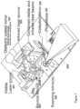
- FIG. 1is a perspective view of the Vein Enhancer of the present invention.
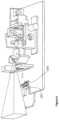
- FIG. 2is a perspective view of a prior art scanning laser based camera (SLBC) that implements a MEMS scanner with three photoreceptors.
- SLBCscanning laser based camera
- FIG. 3is a perspective view of the Vein Enhancer of the present invention with a MEMS scanner that implements two photodiodes.
- FIG. 4is a functional block diagram that illustrates the present invention operating in Alternating Frame Mode (AFM).
- FAMAlternating Frame Mode
- FIG. 5is a functional block diagram that illustrates the present invention operating in Dual Buffer Mode (DBM).
- DBMDual Buffer Mode
- FIG. 6is a functional block diagram that illustrates the present invention operating in Real-Time Mode (RTM).
- RTMReal-Time Mode
- FIG. 7is a functional block diagram that illustrates the interfaces between different components of the present invention.
- FIG. 8is a perspective view of the present invention with a polarizing filter and an infrared filter placed in front of the photodiode.
- the present inventioncan be arranged as either a binary system or grayscale system.
- a grayscale systemthe 740 nm signal received by the PD is simply echoed and re-transmitted by the visible 638 nm laser 201 .
- various levels of intensitycan be shown.
- the image of a veinmay vary in intensity as a function of the magnitude of signal received.
- the projected imageis either on or off.
- a comparator with a trip pointis placed after the photodiode. If the signal crosses the trip point the output laser 638 nm 201 is turned on and vice versa.
- a user dial or press buttoncould be placed on the device, and the user can manually adjust the trip point (essentially making the device more or less sensitive).
- the vein enhancer of the present inventionimplements at least two lasers, 201 and 202 , contained in the same housing, as seen in FIG. 1 , which makes for easier operability and maintainability, that is, less chance of losing one of the devices, as in citied prior art.
- the present inventionhas: improved beam combiner glass, higher power IR, improved mirrors, smaller photo diode setup; used for collection optics, cables for electronic hook-up, AGC, and a microprocessor; used for mirror control and laser calibration.
- Laser projection deviceshave agency regulations dictating power output limitations. Generally, the power of a laser is limited to a threshold level so as to protect the user's eye from injury. If, however, the user's eye is prevented from getting too close to the laser, then the power of the laser may be increased.
- Prior art in the pasthave implemented physical barriers that are incorporated into the design of the laser. These barriers help prevent the user's eye from getting too close to the origin of the laser projections, thus laser power may be increased. For example, previous prior art have used protruding bars (similar to those used in football helmets) that are placed in the direction of the optical path. This prevents the user from placing an eye too close to the laser.
- signal processingcan be utilized to control the power output.
- the acquired image patternis stored in a computer memory.
- the imageis then processed to determine whether veins are present, and only upon confirmation of the vein being present is the image projected. In this manner, the visible laser will not be turned on if the laser is in the direction of the user.
- the power of the 740 nm laser 202can be set to an initially low setting. Once the laser detects a vein, the power of the 740 nm laser 202 can be increased and the 638 nm laser 201 turned on.
- the lasercan be configured so that the laser will only be activated when a proximity sensor 220 determines the surface, or eye of a user.
- the interface of proximity sensor 220 and the main electronics 260may be seen in FIG. 7 .
- vein enhancer of the present inventionmay be configured to operate in a multitude of ways, it includes at least one laser, one photo diode and at least one mirror. Depending on the desired output and/or operating costs additional components may be incorporated into the design of the present invention. Two embodiments that have been found useful in the vein enhancement art will now be discussed, a discussion of alternative embodiments will follow.
- Both embodimentsimplement 2 photo diodes (hereinafter PDs) and at least two lasers.
- PDsphoto diodes
- Co-axially aligning the two laserscan be achieved in a multitude of ways. Two methods that have proven to be effective include implementing, either, a dielectric mirror or a polarizer.
- the first configurationincludes a first laser calibrated to transmit light in the Infrared (hereinafter IF) spectrum, that is 740 nm, and a second laser calibrated to transmit a light in the red color spectrum, that is ⁇ 638 nm.
- the first configurationimplements a hot mirror 204 coated with a Dichroic substance, which separates and directs the light onto two separate diodes. This system allows the visible and IR laser reflections in real-time without the use of a memory chip.
- the 638 nm laser 201is oriented behind the dielectric mirror. The dielectric mirror is selected so that the 638 nm laser light passed through but the 740 nm is reflected.
- the 740 nm laseris aimed at the front of the dielectric mirror and is angled and aimed so that the refection of the 740 nm laser is coaxial with the 638 nm laser passing through the dielectric.
- the 638 nm laseris polarized in a first orientation and is placed behind the polarized element.
- the polarized elementis selected so that the first polarized orientation passes through, but the second polarized angle is reflected.
- the 740 nmis polarized to the second polarized angle and is aimed at the front of the polarized element and is angled and aimed so that the reflection of the 740 nm laser is coaxial with the 638 nm laser passing through the polarized element.
- the two lasersare multiplexed.
- the signal received by the 740 nm PD of the present inventionis representative of both the veins and the surface topology of the patient.
- the surface of the patientaffects the reflected signal. This is not desirable, in that the area of interest is the veins of the patient and not the surface topology of the patient.
- the microprocessor 250 or state machine circuitcan record the reflection from the visible laser and the IR laser can be turned on for one frame, every other frame, or every other scan line. Hence, a new signal would contain a combined laser reflection. The new signal would then be subtracted from the visible signal only, thus leaving the IF signal.
- the advantage hereis that the visible laser does not have to be turned off, which has the benefit of not attenuating the visible light while reading the IF laser reflection.
- a Multi laser arraymay replace the single visible laser and single IR laser.
- the linear array of visible lasers and linear array of IR lasersare reflected off a single mirror that oscillates.
- An advantage of this laser configurationis twofold. First, the mirrors being implemented are less complex. Second, the collection means of the reflected IR light can be obtained by a retro collective mirror.
- a retro collective mirroris a mirror that has a field of view that corresponds to the array of lasers and moves in concert with the movement of the array of lasers.
- SNRsignal to noise ratio
- PD 207it may be desired to implement one PD 207 , as can be seen in FIGS. 1 and 8 .
- that PDis usually responsive to the 740 nm wavelength but not the 638 nm wavelength. In this manner both lasers can be on at the same time without having the 638 laser couple into the PD.
- the same resultscan also be achieved via opposite modulation.
- the, 638 nm and 740 nm, lasersmay be modulated oppositely.
- the PDwill also be responsive to the, 638 nm and 740 nnm, laser, but the lasers will be modulated in opposite directions. More specifically, both the lasers can be pulsed on and off at high rates without affecting the apparent quality of the image (638 nm projection), or the quality of the acquired image (the reflections of the 740 nm laser).
- the image acquisition circuitsBy synchronizing the two lasers so that the modulation is in opposite directions (the 638 nm on and 740 nm off, followed by, 638 nm off and 740 nm on), the image acquisition circuits (PD and amplifiers, if implemented) can be arranged to ignore signals when the 638 nm laser is on. In this embodiment, the visible 638 nm laser does not interfere at all with the image acquisition apparatus.
- the present inventionalso includes a means for gain control.
- Two possible methods of adjusting the gain of the systemare possible.
- a prior art method of adjusting gainis to fix the 740 nm laser output and to adjust the gain of the photo detection circuitry so as to get an appropriate signal (not too low and not saturated).
- An alternative approach, as in the present inventionis to fix the gain of the photo detection circuitry, as in prior art, but adjust the power output of the 740 nm laser so that an appropriate signal is outputted from the photo detection circuitry (once again not too low, but not saturated). It is much easier to design circuits that adjust the 740 nm lasers due to the extremely high modulation bandwidth of the lasers.
- the 740 nm lasermay be modulated as needed to prevent saturation of the photo detector circuitry.
- the amplitude of the 740 nm lasercan be adjusted to provide appropriate signal out of the photo detection circuitry.
- adjusting the power of either the 638 nm laser, or 740 nm lasercan be achieved by either adjusting the current to the lasers, or alternatively, modulating the lasers on and off at a rapid rate.
- modulationdepending upon the duty cycle (pulse-width-modulation), the average laser intensity will be changed.
- the human eyeWith respect to the visible 638 nm laser, the human eye will integrate the signal and, provided the frequency of the PWM is faster than the eye integration time, the laser will appear dimmer as the on cycle time decreases, and vice versa.
- the power of the 740 nm lasermay be also be adjusted by PWM, this modulation will have the same effect upon the received signal as if the current was decreased to the laser.
- FIG. 2shows a prior art scanning laser-based camera (hereinafter SLBC) 170 of Microvision, Inc.
- FIG. 17is taken from Microvision's website: (http://www.microvision.com/technology/imaging_works.html) dated Jan. 7, 2006, herein incorporated by reference.
- the SLBC 170includes a laser source 171 which gets reflected off mirror 172 to a MEMS scanner 173 .
- the MEMS scanner 173has a reflective surface that can be oscillated in both the X and Y axis.
- the oscillation of the MEMS scanner 173is controlled by electronics (not shown) so that the reflected laser beam is moved in a raster pattern.
- the laser sourceis a combination of a red, green and blue laser, thereby forming the color white.
- Three photodetectors, one responsive to red 175 R, one responsive to blue 175 B, and one responsive to green 175 Gare positioned on the SLBC 170 and receive the rastered laser light reflected off object 176 .
- the output of the photodetectors 175 R, 175 B, and 175 Bprovide an analog rastered image representative of the object 176 .
- the outputs of the photodetectorsare converted from an analog signal to a digital signal by D/A converters (not shown).
- a controller(not shown) determines the instantaneous rastered laser light position and converts that to an appropriate pixel location.
- the controllerthen writes the digitized RGB values to an appropriate pixel memory location. By repeating this step for each pixel location, a digitized version of the object is stored in memory. Each raster sweep of the field of view 4 results in a new image being stored. By sweeping at video rates, video images can be captured.
- FIGS. 4 - 6Drawing one's attention to FIGS. 4 - 6 are three different modes of operation that the present invention may be used, a brief description of each mode of operation follows.
- a first mode of operationwhich will be referred to hereinafter as an “Alternating Frame Mode” (AFM) may be seen in FIG. 4 .
- AFMAlternating Frame Mode
- an electronic block 192 for driving the MEMS driver and for sensing the position of the raster scanneris provided 192 .
- This blockgenerates the signals required to drive the MEMS scanner 173 in a raster pattern, and also determines the exact instantaneous location of the MEMS scanner and communicates this information to an image memory 191 .
- This electronic block 192also generates output signals and indicates whether the current frame (a frame is a complete raster of the field of view) is an odd number Frame 1 or an even number Frame 2 (essentially the two signals are opposite and switch polarity every other frame). The operation is as follows.
- the MEMS 173is driven in a raster pattern.
- the first full frame after achieving a stable raster patternwill be identified as an odd number frame and the laser driver 195 for the 740 nm laser 183 is turned on for the entire frame.
- the laser drive 194 for the 630 nm laseris turned off.
- the light from the 740 nmis absorbed by the veins in a patient's body and reflected by the skin of the patient, thus forming a contrasted image that is then sensed and converted into an analog signal by 740 nm photodetector 182 .
- the analog signalis then passed through an A/D converter 190 which outputs a digital representation to image memory 191 .
- Image memory 191also receives instantaneous position information from the electronic block 192 , and based upon such information, the digital representation is stored in a memory location corresponding to a particular pixel. This is repeated for each pixel within the odd frame. Upon completion of the odd frame, the image memory contains the image of the veins within the field of view of the MPH. During the even number frame, the laser driver 195 to the 740 nm laser is turned off. The data in the image memory 191 is read out as a function of the instantaneous position information provide by the electronic block 192 and provide to a D/A converter 193 which outputs an analog signal to laser drive 194 which drives the 630 nm laser. In this manner, the image that was stored in the odd number frame is projected by the 630 nm laser 180 in the even number frame. In this manner, the veins that are in the field of view become visible to the practitioner.
- a second mode of operationis shown in FIG. 5 .
- This modeshall be referred to hereinafter as the “Dual Buffer Mode” (DBM).
- DBMa second image memory called image memory two 196 is added.
- the laser driver to the 740 nm laseris turned on for every frame and in each frame the image of the veins is captured and stored in image memory 191 exactly as described previously in the AFM mode.
- the electronic block 192provides an end of frame indication to both image memory two 196 and image memory 191 which causes the entire image stored in the image memory 191 to be transferred to image memory two 196 during the blanking time of the raster scan (the time after the raster scan is completed but before the next raster scan starts).
- the DBM modeis advantaged as compared to the AFM in that the visible laser is on every frame, and therefore is twice as bright.
- the AFM modeis advantaged in that it only requires a single memory buffer and therefore is more cost effective than the DBM mode.
- RTMReal Time Mode
- the MEMS 173is driven in a raster pattern by a MEMS driver 210 .
- the laser driver 195 to the 740 nm laseris turned on all the time.
- the reflected lightis received by the 740 nm photodetector 182 and the analog signal produced is connected to the laser driver 194 for the 630 nm laser 180 .
- the red laser 180projects nearly instantaneously the signal that is being received by the photodetector 182 .
- the only delayis dictated by the speed of the photodetector and the laser drive 194 circuitry.
- FIG. 1is a preferred embodiment 200 of a MPH the present invention.
- This embodimentreplaces the MEMS scanner with a two dimensional mirror.
- One such two dimensional mirroris provided by Fraunhofer IPMS. In a press release dated Jan. 3, 2005 they described a two dimensional mirror as follows:
- the two-dimensional mirror of Fraunhofer IPMScreates a Lissajous pattern with high density instead of the raster pattern.
- the visible laserwill simply follow nearly instantaneously the image detected by the 740 nm laser detector.
- the MPH 200may also include two laser sources.
- a first laser source 201having a wavelength in the visible light spectrum, preferably ⁇ 632 nm, and a second laser 202 having a wavelength preferably ⁇ 740 nm, that is IR.
- Lasers 201 and 202may be any suitable lasers known in the art.
- Combiner 203may have at least one bounce mirror. In a preferred embodiment there can be two bounce mirrors, 203 a and 203 b . In the preferred embodiment combiner 203 may also include a dielectric coated mirror 204 . Mirror 204 may be any suitable type of dielectric coated mirror known in the available art. In a preferred embodiment mirror 204 was coated with a material that reflects IR and transmits other wavelengths. As mentioned above, the embodiment as depicted in FIG. 1 replaces the MEMS scanner with a two dimensional scanning mirror 205 , such as the type provided by Fraunhofer IPMS. With this embodiment there can also be a collection mirror 206 , and at least one PD 207 .
- the embodiment as depicted in FIG. 1operates as previously discussed, that is, in any of the three operating modes; however, it performs optimally in RTM.
- the laserscan be multiplexed, in which case the visible laser would not have to be turned off.
- all componentswould function in a similar manner as previously mentioned embodiments.
- the microprocessor or state machine 250 in this embodimentcan record the reflection of the visible laser 201 and then the IR laser 202 can be turned on for any interval time duration, and combined with the visible laser.
- the resultant beam 240would be a combination of both lasers. Beam 240 would be then subtracted from the previously recorded visible laser.
- the advantage hereis that the projected visible laser would not be reduced by turning off the visible laser to read the infrared laser reflection.
- Mirror 206is preferably coated with a dichroic coating. This acts as a beam splitter. In normal operation mirror 206 will direct the light onto two separate PDs. With this type of embodiment all other previously mentioned components may operate in the same manner.
- laser 202will transmit IR light 220 which will bounce off of bounce mirror 203 a . At which time laser 202 will begin to transmit light 221 at 632 nm. Light 221 will pass through dielectric coated mirror 204 and light 220 will reflect of mirror 204 , resulting in a beam of light 222 that is a combination of both lights, as seen in FIG. 1 .
- Beam 222will then be reflected of bounce mirror 203 b .
- the angle at which beam 222 is reflectedwill depend on the angle at which bounce mirror 203 b is placed. This will be determined by the manufacturer's design requirements.
- beam 222will be projected onto the area of interest, that is, the area where the vein is located, via two dimensional scanning-mirrors 205 .
- the projected beam 222will then be collected by collection mirror 206 . After which, collected beam will then be passed through hot mirror 206 to separate and direct beam 222 onto two PDs 207 .
- This embodimentcompares the visible light and the IR laser reflections in real-time, without a memory chip.
- FIG. 3Other embodiments may implement a MEMS scanner, as seen in FIG. 3 , to perform the same function as the two dimensional mirrors. This will depend on economic as well as practicable considerations.
- polarizing filters and/or infrared filterslocated between the collection mirror and the photodiode, as seen in FIG. 8 .
- the visible light transmittedwas a red laser.
- any visible color or combination of colorcould be transmitted.
- three laser RGBcould be utilized to transmit full color images onto the field of view.
- the outgoing laser beamscan be bounced first off a one dimensional high speed scanning mirror and then off a second lower speed mirror scanning in the opposite direction.
- the outgoing laser beamscan be bounced first off a one dimensional high speed scanning mirror and then off a second lower speed mirror scanning in the opposite direction.
Landscapes
- Health & Medical Sciences (AREA)
- Life Sciences & Earth Sciences (AREA)
- Physics & Mathematics (AREA)
- Molecular Biology (AREA)
- Animal Behavior & Ethology (AREA)
- Pathology (AREA)
- Engineering & Computer Science (AREA)
- Biomedical Technology (AREA)
- Heart & Thoracic Surgery (AREA)
- Medical Informatics (AREA)
- Veterinary Medicine (AREA)
- Surgery (AREA)
- Biophysics (AREA)
- General Health & Medical Sciences (AREA)
- Public Health (AREA)
- Vascular Medicine (AREA)
- Nuclear Medicine, Radiotherapy & Molecular Imaging (AREA)
- Radiology & Medical Imaging (AREA)
- Spectroscopy & Molecular Physics (AREA)
- Measurement Of The Respiration, Hearing Ability, Form, And Blood Characteristics Of Living Organisms (AREA)
- Eye Examination Apparatus (AREA)
Abstract
Description
- “Projection devices based on laser scanning are a very interesting alternative to matrix displays. A modulated laser and a deflection unit are necessary. Using micro scanning mirrors for implementing the laser beam deflection in a projection device has many advantages. In particular, micro scanning mirrors, which operate resonantly in both directions, enable the development of systems with very small size, high deflection angles with low voltage and low power consumption. The presented demonstrator uses a commercial laser module and a 2D micro scanning mirror operated with deflection frequencies of 9.4 kHz and 1.4 kHz. The device uses both axes to perform a sinusoidal oscillation, which causes a beam trajectory that describes a Lissajous pattern with high density, instead of the usually implemented linear scanning. Therefore, mirrors with low ratio of horizontal and vertical deflection frequency can be used. This kind of micro scanning mirrors can be fabricated easily and cost effective. The control circuit is developed with an FPGA and provides a resolution of 256.times.256 monochromatic pixels. Programmable counters are used for generating the mirror driving signals and for determining the beam position. Mirror excitation and image synchronization work without feedback loop. This means, no complicated optical or electronic synchronization techniques are needed. This simplifies micro scanning mirror and control circuit and enables low cost production. Applications of the projection device are displays, laser marking and laser exposure.”
Claims (13)
Priority Applications (1)
| Application Number | Priority Date | Filing Date | Title |
|---|---|---|---|
| US18/135,798US12295744B2 (en) | 2006-01-10 | 2023-04-18 | Micro vein enhancer with two lasers and two optical detectors configured for removing surface topology |
Applications Claiming Priority (9)
| Application Number | Priority Date | Filing Date | Title |
|---|---|---|---|
| US75770406P | 2006-01-10 | 2006-01-10 | |
| US81762306P | 2006-06-29 | 2006-06-29 | |
| US11/478,322US8478386B2 (en) | 2006-01-10 | 2006-06-29 | Practitioner-mounted micro vein enhancer |
| US11/700,729US8838210B2 (en) | 2006-06-29 | 2007-01-31 | Scanned laser vein contrast enhancer using a single laser |
| US11/985,343US8255040B2 (en) | 2006-06-29 | 2007-11-14 | Micro vein enhancer |
| US13/444,940US8750970B2 (en) | 2006-01-10 | 2012-04-12 | Micro vein enhancer |
| US14/249,462US10813588B2 (en) | 2006-01-10 | 2014-04-10 | Micro vein enhancer |
| US17/027,972US11638558B2 (en) | 2006-01-10 | 2020-09-22 | Micro vein enhancer |
| US18/135,798US12295744B2 (en) | 2006-01-10 | 2023-04-18 | Micro vein enhancer with two lasers and two optical detectors configured for removing surface topology |
Related Parent Applications (1)
| Application Number | Title | Priority Date | Filing Date |
|---|---|---|---|
| US17/027,972ContinuationUS11638558B2 (en) | 2006-01-10 | 2020-09-22 | Micro vein enhancer |
Publications (2)
| Publication Number | Publication Date |
|---|---|
| US20230404479A1 US20230404479A1 (en) | 2023-12-21 |
| US12295744B2true US12295744B2 (en) | 2025-05-13 |
Family
ID=89170451
Family Applications (1)
| Application Number | Title | Priority Date | Filing Date |
|---|---|---|---|
| US18/135,798ActiveUS12295744B2 (en) | 2006-01-10 | 2023-04-18 | Micro vein enhancer with two lasers and two optical detectors configured for removing surface topology |
Country Status (1)
| Country | Link |
|---|---|
| US (1) | US12295744B2 (en) |
Citations (302)
| Publication number | Priority date | Publication date | Assignee | Title |
|---|---|---|---|---|
| US3136310A (en) | 1960-01-18 | 1964-06-09 | Bausch & Lomb | Optical catheter |
| US3349762A (en) | 1964-10-21 | 1967-10-31 | Optics Technology Inc | Blood flow indicator and process |
| US3511227A (en) | 1967-02-27 | 1970-05-12 | Univ Utah | Measurement of blood flow using coherent radiation and doppler effect |
| US3527932A (en) | 1967-11-16 | 1970-09-08 | James J Thomas | Transilluminating flashlight |
| GB1298707A (en) | 1969-05-31 | 1972-12-06 | Siemens Ag | An apparatus for locating a fluid carrying passage or organ in a human or an animal body to permit insertion of an injection needle into the passage or organ |
| US3818129A (en) | 1971-06-30 | 1974-06-18 | Hitachi Ltd | Laser imaging device |
| FR2289149A1 (en) | 1974-11-04 | 1976-05-28 | Siemens Ag | DEVICE FOR PRECISELY AND RAPID LOCATION OF VESSELS CROSSED BY LIQUIDS IN THE HUMAN BODY AND FOR PRECISELY INTRODUCING A PUNCTURE CANNULA IN THESE VESSELS |
| US3984629A (en) | 1974-12-23 | 1976-10-05 | Rca Corporation | Flying spot scanner unaffected by ambient light |
| US4030209A (en) | 1974-03-07 | 1977-06-21 | Andre Dreiding | Molecular models |
| US4057784A (en) | 1976-09-27 | 1977-11-08 | Sperry Rand Corporation | Bi-directional scanner assembly |
| US4109647A (en) | 1977-03-16 | 1978-08-29 | The United States Of America As Represented By The Secretary Of The Department Of Health, Education And Welfare | Method of and apparatus for measurement of blood flow using coherent light |
| US4162405A (en) | 1978-05-23 | 1979-07-24 | Britton Chance | Flying spot fluoro-meter for oxidized flavoprotein and reduced pyridine nucleotide |
| US4182322A (en) | 1978-08-04 | 1980-01-08 | Miller Larry C | Head harness device |
| US4185808A (en) | 1975-02-10 | 1980-01-29 | Cbs Inc. | Connector hardware for percussive instruments |
| US4213678A (en) | 1977-09-29 | 1980-07-22 | Retina Foundation | Scanning ophthalmoscope for examining the fundus of the eye |
| US4265227A (en) | 1979-10-03 | 1981-05-05 | The Hospital And Welfare Board Of Hillsborough County | Infant extremity positioner and illuminator |
| US4312357A (en) | 1976-12-03 | 1982-01-26 | Sinus Medical Equipment Ab | Transillumination diagnostic method and apparatus |
| US4315318A (en) | 1978-12-26 | 1982-02-09 | Fuji Photo Film Co., Ltd. | Method and apparatus for processing a radiation image |
| US4321930A (en) | 1977-06-28 | 1982-03-30 | Duke University, Inc. | Apparatus for monitoring metabolism in body organs |
| US4393366A (en) | 1981-02-17 | 1983-07-12 | Eye-D Development Ii Ltd. | Rotating beam ocular identification apparatus and method |
| US4495949A (en) | 1982-07-19 | 1985-01-29 | Spectrascan, Inc. | Transillumination method |
| US4502075A (en) | 1981-12-04 | 1985-02-26 | International Remote Imaging Systems | Method and apparatus for producing optical displays |
| JPS60108043A (en) | 1983-11-18 | 1985-06-13 | キヤノン株式会社 | Blood vessel position indicating device |
| US4536790A (en) | 1982-11-26 | 1985-08-20 | Thomson-Csf Broadcast, Inc. | Apparatus and method for fluoroscopic imaging of a body |
| US4565968A (en) | 1983-02-16 | 1986-01-21 | Albert Macovski | Blood vessel projection imaging system using nuclear magnetic resonance |
| US4567896A (en) | 1984-01-20 | 1986-02-04 | Elscint, Inc. | Method and apparatus for calibrating a biopsy attachment for ultrasonic imaging apparatus |
| US4576175A (en) | 1983-09-06 | 1986-03-18 | Moshe Epstein | Biopsy attachment for ultrasonic probe |
| US4586190A (en) | 1982-11-19 | 1986-04-29 | Shimadzu Corporation | Blood cell discriminator and counter utilizing transmitted and scattered light |
| US4590948A (en) | 1984-01-20 | 1986-05-27 | Perimed Kb | Method and apparatus for measuring the blood flow in the superficial blood vessels of tissue |
| US4596254A (en) | 1984-12-18 | 1986-06-24 | Tsi Research Associates Limited Partnership | Laser Doppler flow monitor |
| US4619249A (en) | 1985-07-24 | 1986-10-28 | Kim Landry | Transcutaneous intravenous illuminator |
| US4669467A (en) | 1985-03-22 | 1987-06-02 | Massachusetts Institute Of Technology | Mode mixer for a laser catheter |
| US4697147A (en) | 1985-11-14 | 1987-09-29 | Metriflow, Inc. | Blood flow imaging using a CW NMR technique |
| US4699149A (en) | 1984-03-20 | 1987-10-13 | Joseph Rice | Apparatus for the identification of individuals |
| US4703758A (en) | 1982-09-30 | 1987-11-03 | Yoshiaki Omura | Non-invasive monitoring of blood flow and cerebral blood pressure using ultra miniature reflection type photoelectric plethysmographic sensors or ultrasonic doppler flow meter |
| US4766299A (en) | 1986-03-28 | 1988-08-23 | Spectra-Physics, Inc. | Hand-mounted bar code reader |
| US4771308A (en) | 1986-03-25 | 1988-09-13 | Asahi Kogaku Kogyo Kabushiki Kaisha | Auxiliary light projecting apparatus for a focus detecting system |
| US4780919A (en) | 1987-10-20 | 1988-11-01 | Harrison Mildred B | Hospital bed |
| US4799103A (en) | 1986-10-10 | 1989-01-17 | Seton Health Care Foundation | Three-dimensional laser driven display apparatus |
| US4817622A (en) | 1986-07-22 | 1989-04-04 | Carl Pennypacker | Infrared imager for viewing subcutaneous location of vascular structures and method of use |
| US4846183A (en) | 1987-12-02 | 1989-07-11 | The Boc Group, Inc. | Blood parameter monitoring apparatus and methods |
| US4861973A (en) | 1987-06-18 | 1989-08-29 | Spectra-Physics, Inc. | Optical scan pattern generating arrangement for a laser scanner |
| US4862894A (en) | 1987-03-03 | 1989-09-05 | Hitoshi Fujii | Apparatus for monitoring bloodstream |
| US4901019A (en) | 1986-08-18 | 1990-02-13 | The General Hospital Corporation | Three-dimensional imaging |
| US4899756A (en) | 1988-07-18 | 1990-02-13 | Sonek Jiri D | Articulated needle guide for ultrasound imaging and method of using same |
| US4926867A (en) | 1986-05-27 | 1990-05-22 | Sumitomo Electric Industries, Ltd. | Light-reflecting and heating type oximeter |
| US4938205A (en) | 1988-05-27 | 1990-07-03 | The University Of Connecticut | Endoscope with traced raster and elemental photodetectors |
| US5074642A (en) | 1989-11-14 | 1991-12-24 | Hicks John W | Multifiber endoscope with fibers having different indices of refraction |
| US5088493A (en) | 1984-08-07 | 1992-02-18 | Sclavo, S.P.A. | Multiple wavelength light photometer for non-invasive monitoring |
| US5103497A (en) | 1989-11-14 | 1992-04-07 | Hicks John W | Flying spot endoscope |
| JPH0442944B2 (en) | 1988-12-26 | 1992-07-15 | Akai Electric | |
| US5146923A (en) | 1986-12-18 | 1992-09-15 | Dhawan Atam P | Apparatus and method for skin lesion examination |
| US5159225A (en) | 1991-10-18 | 1992-10-27 | Aura Systems, Inc. | Piezoelectric actuator |
| US5174298A (en) | 1987-07-03 | 1992-12-29 | General Electric Cgr S.A. | Imaging process and system for transillumination with photon frequency marking |
| US5184188A (en) | 1990-01-23 | 1993-02-02 | Medical Devices Corporation | Optical blood hemostatic analysis apparatus and method |
| US5214458A (en) | 1992-01-14 | 1993-05-25 | Matsubara Kenki Kogyo Kabushiki Kaisha | Display apparatus |
| US5222495A (en) | 1990-02-02 | 1993-06-29 | Angiomedics Ii, Inc. | Non-invasive blood analysis by near infrared absorption measurements using two closely spaced wavelengths |
| US5261581A (en) | 1992-04-10 | 1993-11-16 | Harden Sr Ralph E | Holster for bow string release or tool |
| US5293873A (en) | 1991-08-29 | 1994-03-15 | Siemens Aktiengesellschaft | Measuring arrangement for tissue-optical examination of a subject with visible, NIR or IR light |
| US5339817A (en) | 1989-10-31 | 1994-08-23 | Gert Nilsson | System and a method for measurement and presentation of fluid flow movements, particularly the flow of blood through a body organ |
| WO1994022370A1 (en) | 1993-04-01 | 1994-10-13 | British Technology Group Limited | Biometric identification of individuals |
| US5371347A (en) | 1991-10-15 | 1994-12-06 | Gap Technologies, Incorporated | Electro-optical scanning system with gyrating scan head |
| US5406070A (en) | 1993-12-16 | 1995-04-11 | International Business Machines Corporation | Method and apparatus for scanning an object and correcting image data using concurrently generated illumination data |
| US5418546A (en) | 1991-08-20 | 1995-05-23 | Mitsubishi Denki Kabushiki Kaisha | Visual display system and exposure control apparatus |
| US5423091A (en) | 1994-09-22 | 1995-06-13 | The Tram Corporation | Headband following a wearer's hairline |
| US5436655A (en) | 1991-08-09 | 1995-07-25 | Olympus Optical Co., Ltd. | Endoscope apparatus for three dimensional measurement for scanning spot light to execute three dimensional measurement |
| US5445157A (en) | 1992-02-20 | 1995-08-29 | Asahi Kogaku Kogyo Kabushiki Kaisha | Thermographic endoscope |
| USD362910S (en) | 1994-04-21 | 1995-10-03 | Creaghan Jr Frank C | Instrument for viewing subcutaneous venous structures |
| JPH07255847A (en) | 1994-03-25 | 1995-10-09 | Otax Kk | Blood vessel sensor |
| US5485530A (en) | 1991-01-24 | 1996-01-16 | Joseph R. Lakowicz | Method and apparatus for multi-dimensional phase fluorescence lifetime imaging |
| JPH0823501A (en) | 1994-07-11 | 1996-01-23 | Fujitsu General Ltd | Projection type image display device |
| US5487740A (en) | 1994-03-02 | 1996-01-30 | Energy Life Systems Corporation | Laser device for ablation of human tissue |
| US5494032A (en) | 1991-07-12 | 1996-02-27 | Sandia Corporation | Oximeter for reliable clinical determination of blood oxygen saturation in a fetus |
| US5497769A (en) | 1993-12-16 | 1996-03-12 | I.S.S. (Usa) Inc. | Photosensor with multiple light sources |
| US5501680A (en) | 1992-01-15 | 1996-03-26 | The University Of Pittsburgh | Boundary and proximity sensor apparatus for a laser |
| US5504316A (en) | 1990-05-08 | 1996-04-02 | Symbol Technologies, Inc. | Laser scanning system and scanning method for reading 1-D and 2-D barcode symbols |
| US5519208A (en) | 1994-09-29 | 1996-05-21 | Esparza; Joel | Infrared aided method and apparatus for venous examination |
| JPH08164123A (en) | 1994-12-15 | 1996-06-25 | Nikon Corp | Blood sampling device |
| US5541820A (en) | 1995-01-26 | 1996-07-30 | Mclaughlin; Michael K. | Combined lamp and movie projector |
| US5542421A (en) | 1992-07-31 | 1996-08-06 | Frederick Erdman Association | Method and apparatus for cardiovascular diagnosis |
| WO1996039925A1 (en) | 1995-06-07 | 1996-12-19 | University Of Arkansas | Method and apparatus for detecting electro-magnetic reflection from biological tissue |
| US5598842A (en) | 1993-09-03 | 1997-02-04 | Toa Medical Electronics Co., Ltd. | Non-invasive blood analyzer and method using the same |
| US5603328A (en) | 1993-01-18 | 1997-02-18 | The State Of Israel, Ministry Of Defence, Armament Development Authority | Infra-red vascular angiography system |
| US5608210A (en) | 1994-09-29 | 1997-03-04 | Esparza; Joel | Infrared aided method and apparatus for venous examination |
| US5610387A (en) | 1992-05-15 | 1997-03-11 | Symbol Technologies, Inc. | Portable optical scanning system worn by a user for reading indicia of differing light reflectivity |
| US5625458A (en) | 1994-11-10 | 1997-04-29 | Research Foundation Of City College Of New York | Method and system for imaging objects in turbid media using diffusive fermat photons |
| US5631976A (en) | 1994-04-29 | 1997-05-20 | International Business Machines Corporation | Object imaging system |
| US5655530A (en) | 1995-08-09 | 1997-08-12 | Rio Grande Medical Technologies, Inc. | Method for non-invasive blood analyte measurement with improved optical interface |
| US5678555A (en) | 1996-04-08 | 1997-10-21 | O'connell; Peter | Method of locating and marking veins |
| US5716796A (en) | 1990-01-23 | 1998-02-10 | Medical Devices Corporation | Optical blood hemostatic analysis apparatus and method |
| US5719399A (en) | 1995-12-18 | 1998-02-17 | The Research Foundation Of City College Of New York | Imaging and characterization of tissue based upon the preservation of polarized light transmitted therethrough |
| US5740801A (en) | 1993-03-31 | 1998-04-21 | Branson; Philip J. | Managing information in an endoscopy system |
| US5747789A (en) | 1993-12-01 | 1998-05-05 | Dynamics Imaging, Inc. | Method for investigation of distribution of physiological components in human body tissues and apparatus for its realization |
| US5756981A (en) | 1992-02-27 | 1998-05-26 | Symbol Technologies, Inc. | Optical scanner for reading and decoding one- and-two-dimensional symbologies at variable depths of field including memory efficient high speed image processing means and high accuracy image analysis means |
| US5758650A (en) | 1996-09-30 | 1998-06-02 | Siemens Medical Systems, Inc. | Universal needle guide for ultrasonic transducers |
| WO1998026583A1 (en) | 1996-12-09 | 1998-06-18 | Zeman Herbert D | Contrast enhancing illuminator |
| US5772593A (en) | 1995-07-12 | 1998-06-30 | Fuji Photo Film Co., Ltd. | Surgical operation aiding system |
| US5814040A (en) | 1994-04-05 | 1998-09-29 | The Regents Of The University Of California | Apparatus and method for dynamic cooling of biological tissues for thermal mediated surgery |
| US5836877A (en) | 1997-02-24 | 1998-11-17 | Lucid Inc | System for facilitating pathological examination of a lesion in tissue |
| US5860967A (en) | 1993-07-21 | 1999-01-19 | Lucid, Inc. | Dermatological laser treatment system with electronic visualization of the area being treated |
| US5865828A (en) | 1997-08-08 | 1999-02-02 | Jeng; James C. | Coaxial dual laser |
| US5929443A (en) | 1995-12-18 | 1999-07-27 | The Research Foundation City College Of New York | Imaging of objects based upon the polarization or depolarization of light |
| US5946220A (en) | 1993-08-25 | 1999-08-31 | Lemelson; Jerome H. | Computer operated material processing systems and method |
| US5947906A (en) | 1997-11-14 | 1999-09-07 | Dawson, Jr.; Fredric O. | Apparatus for enhanced visual venous examination |
| WO1999048420A1 (en) | 1998-03-23 | 1999-09-30 | Veino-Med Ltd. | Instrument and method for locating and marking a 'hot spot' in a person's body tissue |
| US5966204A (en) | 1996-07-02 | 1999-10-12 | Olympus Optical Co., Ltd. | Near-infrared microscope |
| US5966230A (en) | 1990-05-29 | 1999-10-12 | Symbol Technologies, Inc. | Integrated scanner on a common substrate |
| US5982553A (en) | 1997-03-20 | 1999-11-09 | Silicon Light Machines | Display device incorporating one-dimensional grating light-valve array |
| US5988817A (en) | 1997-02-28 | 1999-11-23 | Rds Corporation | Multiprojection system |
| US5995866A (en) | 1995-03-21 | 1999-11-30 | Lemelson; Jerome | Method and apparatus for scanning and evaluating matter |
| US5995856A (en) | 1995-11-22 | 1999-11-30 | Nellcor, Incorporated | Non-contact optical monitoring of physiological parameters |
| US6006126A (en) | 1991-01-28 | 1999-12-21 | Cosman; Eric R. | System and method for stereotactic registration of image scan data |
| US6056692A (en) | 1998-07-08 | 2000-05-02 | Schwartz; John Q. | Apparatus and method for locating and marking blood vessels |
| US6061583A (en) | 1995-12-27 | 2000-05-09 | Sysmex Corporation And Ken Ishihara | Noninvasive blood analyzer |
| US6083486A (en) | 1998-05-14 | 2000-07-04 | The General Hospital Corporation | Intramolecularly-quenched near infrared fluorescent probes |
| US6101036A (en) | 1998-06-23 | 2000-08-08 | Silicon Light Machines | Embossed diffraction grating alone and in combination with changeable image display |
| US6113536A (en) | 1998-09-30 | 2000-09-05 | A-Med Systems, Inc. | Device and method of attaching a blood pump and tubes to a surgical retractor |
| US6122042A (en) | 1997-02-07 | 2000-09-19 | Wunderman; Irwin | Devices and methods for optically identifying characteristics of material objects |
| US6132379A (en) | 1998-11-04 | 2000-10-17 | Patacsil; Estelito G. | Method and apparatus for ultrasound guided intravenous cannulation |
| US6135599A (en) | 1999-03-26 | 2000-10-24 | Fang; Chen-Tai | Projection ornament |
| US6142650A (en) | 1997-07-10 | 2000-11-07 | Brown; David C. | Laser flashlight |
| US6141985A (en) | 1998-03-06 | 2000-11-07 | Societe Cryonic Medical | Self-contained and portable cryogenic apparatus using carbon dioxide in liquid/solid phases |
| JP2000316866A (en) | 1999-05-06 | 2000-11-21 | Yoshiko Sashide | Recognizing method and recognizing device for blood vessel |
| US6149061A (en) | 1997-07-30 | 2000-11-21 | Intermec Ip Corp. | Optoelectronic device for multidirectional capture of images of plane objects, in particular bar codes |
| US6149644A (en) | 1998-02-17 | 2000-11-21 | Altralight, Inc. | Method and apparatus for epidermal treatment with computer controlled moving focused infrared light |
| US6178340B1 (en) | 1998-08-24 | 2001-01-23 | Eduardo Svetliza | Three-dimensional infrared imager for subcutaneous puncture and study of vascular network |
| US6179260B1 (en) | 1998-06-10 | 2001-01-30 | N. Sean Ohanian | Device for coupling an IV stand to a patient transport |
| US6230046B1 (en) | 1995-05-16 | 2001-05-08 | The United States Of America As Represented By The Secretary Of The Air Force | System and method for enhanced visualization of subcutaneous structures |
| US6240309B1 (en) | 1995-10-06 | 2001-05-29 | Hitachi, Ltd. | Optical measurement instrument for living body |
| US6251073B1 (en) | 1999-08-20 | 2001-06-26 | Novasonics, Inc. | Miniaturized ultrasound apparatus and method |
| US20010006426A1 (en) | 1996-07-18 | 2001-07-05 | Korea Institute Of Science And Technology | Holographic projection screen for displaying a three-dimensional color images and optical display system using the holographic screen |
| US6263227B1 (en) | 1996-05-22 | 2001-07-17 | Moor Instruments Limited | Apparatus for imaging microvascular blood flow |
| US6272376B1 (en) | 1999-01-22 | 2001-08-07 | Cedars-Sinai Medical Center | Time-resolved, laser-induced fluorescence for the characterization of organic material |
| US6301375B1 (en) | 1997-04-14 | 2001-10-09 | Bk Systems | Apparatus and method for identifying individuals through their subcutaneous vein patterns and integrated system using said apparatus and method |
| US6305804B1 (en) | 1999-03-25 | 2001-10-23 | Fovioptics, Inc. | Non-invasive measurement of blood component using retinal imaging |
| US6314311B1 (en) | 1999-07-28 | 2001-11-06 | Picker International, Inc. | Movable mirror laser registration system |
| WO2001082786A2 (en) | 2000-05-03 | 2001-11-08 | Flock Stephen T | Optical imaging of subsurface anatomical structures and biomolecules |
| US20010056237A1 (en) | 1996-11-19 | 2001-12-27 | Cane Michael Roger | Method of and apparatus for investigating tissue histology |
| US6334850B1 (en) | 1997-11-19 | 2002-01-01 | Seiko Epson Corporation | Method of detecting pulse wave, method of detecting artery position, and pulse wave detecting apparatus |
| US6353753B1 (en) | 1998-05-05 | 2002-03-05 | Stephen Thomas Flock | Optical imaging of deep anatomic structures |
| US6424858B1 (en) | 1998-11-12 | 2002-07-23 | John L. Williams | Apparatus and method for viewing vasculature of a human being |
| US6438396B1 (en) | 1998-11-05 | 2002-08-20 | Cytometrics, Inc. | Method and apparatus for providing high contrast imaging |
| US6436655B1 (en) | 1998-02-09 | 2002-08-20 | Medical Devices Corporation | Rapid quantitative measurement of soluble fibrin in opaque body fluids |
| US20020118338A1 (en) | 2001-02-19 | 2002-08-29 | Yoshimi Kohayakawa | Ophthalmologic apparatus |
| US6463309B1 (en) | 2000-05-11 | 2002-10-08 | Hanna Ilia | Apparatus and method for locating vessels in a living body |
| JP2002328428A (en) | 2001-05-01 | 2002-11-15 | Sony Corp | Projector and image projection system |
| JP2002345953A (en) | 2001-05-28 | 2002-12-03 | Fusao Terada | Vein detector |
| US20020188203A1 (en) | 2001-04-30 | 2002-12-12 | University Of Alabama | Method and apparatus for measuring blood oxygen saturation in a retinal vessel by separately detecting single pass optical signals |
| US20030018271A1 (en) | 2001-07-02 | 2003-01-23 | Kimble Allan Wayne | Simplified and lightweight system for enhanced visualization of subcutaneous hemoglobin-containing structures |
| WO2003009750A2 (en) | 2001-07-25 | 2003-02-06 | Sarnoff Corporation | System and method for determining brain oxygenation |
| US6523955B1 (en) | 1997-07-07 | 2003-02-25 | Heinrich A. Eberl | Method for improving optic perceptive faculty by modifying the retinal image |
| US20030037375A1 (en) | 2001-08-23 | 2003-02-27 | Riley Carl W. | Hospital bed equipment support apparatus |
| KR20030020152A (en) | 2001-09-03 | 2003-03-08 | 주식회사 테크스피어 | Apparatus and the method for verification of blood vessel-patterns of the back of the hand for person identification |
| US20030047683A1 (en) | 2000-02-25 | 2003-03-13 | Tej Kaushal | Illumination and imaging devices and methods |
| US20030052105A1 (en) | 2001-09-10 | 2003-03-20 | Fuji Photo Film Co., Ltd. | Laser sintering apparatus |
| US6542246B1 (en) | 1998-11-20 | 2003-04-01 | Fuji Photo Film Co., Ltd. | Blood vessel imaging system |
| US6556858B1 (en) | 2000-01-19 | 2003-04-29 | Herbert D. Zeman | Diffuse infrared light imaging system |
| US6556854B1 (en) | 1998-11-20 | 2003-04-29 | Fuji Photo Film Co., Ltd. | Blood vessel imaging system using homodyne and heterodyne effects |
| US20030120154A1 (en) | 2001-11-28 | 2003-06-26 | Frank Sauer | Method and apparatus for ultrasound guidance of needle biopsies |
| US20030125629A1 (en) | 2002-01-02 | 2003-07-03 | Ustuner E. Tuncay | Ultrasound system and method |
| US6599247B1 (en) | 2000-07-07 | 2003-07-29 | University Of Pittsburgh | System and method for location-merging of real-time tomographic slice images with human vision |
| US20030156260A1 (en) | 2002-01-04 | 2003-08-21 | Neurok Llc | Three-dimensional image projection employing retro-reflective screens |
| US6631286B2 (en) | 2000-11-28 | 2003-10-07 | Pulsion Medical Systems Ag | Device for the determination of tissue perfusion and operative use thereof |
| US20030210810A1 (en) | 2002-05-08 | 2003-11-13 | Gee, James W. | Method and apparatus for detecting structures of interest |
| US6648227B2 (en) | 2000-10-20 | 2003-11-18 | Symbol Technologies, Inc. | Scanning module for a bar code reader with a focusing lens |
| US20040015062A1 (en) | 2000-11-27 | 2004-01-22 | Vasilis Ntziachristos | Fluorescence-mediated molecular tomography |
| US20040015158A1 (en) | 2002-07-19 | 2004-01-22 | To-Mu Chen | Transilluminator device |
| US20040022421A1 (en) | 2002-07-31 | 2004-02-05 | Fujitsu Limited | Processor with personal verification function and operating device |
| US6690964B2 (en) | 2000-07-12 | 2004-02-10 | Siemens Aktiengesellschaft | Method and device for visualization of positions and orientation of intracorporeally guided instruments during a surgical intervention |
| US6689075B2 (en) | 2000-08-25 | 2004-02-10 | Healthsouth Corporation | Powered gait orthosis and method of utilizing same |
| JP2004042944A (en) | 2002-07-11 | 2004-02-12 | Nippon Hozai Kk | Packing seal device |
| US6702749B2 (en) | 2001-07-24 | 2004-03-09 | Siemens Corporate Research, Inc. | Optical needle guide for ultrasound guided needle biopsy |
| US20040046031A1 (en) | 1990-09-17 | 2004-03-11 | Metrologic Instruments, Inc. | Bar code scanning system with wireless communication links |
| US6719257B1 (en) | 2003-01-09 | 2004-04-13 | Tim L. Greene | Adjustable stop for telescoping tubes |
| US6755789B2 (en) | 2002-02-05 | 2004-06-29 | Inceptio Medical Technologies, Llc | Ultrasonic vascular imaging system and method of blood vessel cannulation |
| US6782161B2 (en) | 2001-02-05 | 2004-08-24 | Derma Laser Inc. | Laser diode apparatus provided with an aiming beam and injection method therefor |
| JP2004237051A (en) | 2003-02-06 | 2004-08-26 | Ogawa Hiroteru | Blood vessel visualizing method and apparatus |
| US20040171923A1 (en) | 2002-12-06 | 2004-09-02 | Kalafut John F. | Devices, systems and methods for improving vessel access |
| US20040222301A1 (en) | 2003-05-05 | 2004-11-11 | Willins Bruce A. | Arrangement for and method of collecting and displaying information in real time along a line of sight |
| US20040237051A1 (en) | 2003-05-23 | 2004-11-25 | Clauson Todd A. | Dynamic menu reordering |
| JP2004329786A (en) | 2003-05-12 | 2004-11-25 | Kawasumi Lab Inc | Vessel projector and vessel projection method |
| US20050003323A1 (en) | 2003-01-14 | 2005-01-06 | J. Morita Manufacturing Corporation | Diagnostic imaging apparatus |
| US6845190B1 (en) | 2000-11-27 | 2005-01-18 | University Of Washington | Control of an optical fiber scanner |
| US20050017924A1 (en) | 2002-12-20 | 2005-01-27 | Utt Steven W. | Display system having a three-dimensional convex display surface |
| US20050023356A1 (en) | 2003-07-29 | 2005-02-03 | Microvision, Inc., A Corporation Of The State Of Washington | Method and apparatus for illuminating a field-of-view and capturing an image |
| US20050033145A1 (en) | 2003-07-02 | 2005-02-10 | Graham John S. | Wearable tissue viability diagnostic unit |
| US20050043596A1 (en) | 1996-07-12 | 2005-02-24 | Non-Invasive Technology, Inc., A Delaware Corporation | Optical examination device, system and method |
| US20050047134A1 (en) | 1997-08-26 | 2005-03-03 | Color Kinetics | Controlled lighting methods and apparatus |
| US6882875B1 (en) | 1997-09-29 | 2005-04-19 | Boston Scientific Corporation | Visible display for an interventional device |
| US20050085802A1 (en) | 2001-07-25 | 2005-04-21 | Gruzdev Valentin A. | Portable laser device |
| US20050085732A1 (en) | 2003-06-20 | 2005-04-21 | Sevick-Muraca Eva M. | Method and system for near-infrared fluorescence contrast-enhanced imaging with area illumination and area detection |
| US20050113650A1 (en) | 2000-06-16 | 2005-05-26 | Christopher Pacione | System for monitoring and managing body weight and other physiological conditions including iterative and personalized planning, intervention and reporting capability |
| WO2005053773A1 (en) | 2003-12-03 | 2005-06-16 | Thomas Chen | Blood vessel seeking method and vein seeking device |
| US20050131291A1 (en) | 2003-12-10 | 2005-06-16 | Sonosite, Inc. | Device for assisting the positioning of medical devices |
| US20050135102A1 (en) | 2001-06-26 | 2005-06-23 | Allan Gardiner | Illuminator with peak wavelength variation |
| US20050141069A1 (en) | 2003-12-31 | 2005-06-30 | Wood Frederick F. | Method and apparatus for conserving power in a laser projection display |
| US6913202B2 (en) | 1999-06-07 | 2005-07-05 | Metrologic Instruments, Inc. | Planar laser illumination and imaging (PLIIM) engine |
| US20050146765A1 (en) | 2002-07-08 | 2005-07-07 | Turner Arthur M. | Resonant scanning mirror with inertially coupled activation |
| US20050154303A1 (en) | 2002-03-08 | 2005-07-14 | Walker William F. | Intuitive ultrasonic imaging system and related method thereof |
| US20050157939A1 (en) | 2004-01-16 | 2005-07-21 | Mark Arsenault | Processes, products and systems for enhancing images of blood vessels |
| US20050161051A1 (en) | 2003-01-08 | 2005-07-28 | Cyberheart, Inc. | System for non-invasive heart treatment |
| US6923762B1 (en) | 2001-11-01 | 2005-08-02 | Frank C. Creaghan, Jr. | Venoscope apparatus |
| US20050168980A1 (en) | 2004-01-30 | 2005-08-04 | Dryden Paul E. | Vein locator |
| US20050173770A1 (en) | 2004-02-09 | 2005-08-11 | Linden Kelly D. | Method and apparatus for making a MEMS scanner |
| US20050174777A1 (en) | 2004-02-10 | 2005-08-11 | Rita Cooper | Sensor-activated audible story lamp |
| US20050175048A1 (en) | 2003-12-31 | 2005-08-11 | Symbol Technologies, Inc. | Method and apparatus for controllably reducing power delivered by a laser projection display |
| US20050187477A1 (en) | 2002-02-01 | 2005-08-25 | Serov Alexander N. | Laser doppler perfusion imaging with a plurality of beams |
| US20050215875A1 (en) | 2004-03-19 | 2005-09-29 | Sroy Khou | Method and device for locating position of veins on body |
| US20050265586A1 (en) | 2004-06-01 | 2005-12-01 | Lumidigm, Inc. | Multispectral biometric imaging |
| US6971579B2 (en) | 2003-10-02 | 2005-12-06 | Symbol Technologies, Inc. | Dynamic omni-directional scan pattern generating arrangement and method in electro-optical readers |
| US20050281445A1 (en) | 2004-01-16 | 2005-12-22 | Ronald Marcotte | System and method for locating and accessing a blood vessel |
| US6980852B2 (en) | 2002-01-25 | 2005-12-27 | Subqiview Inc. | Film barrier dressing for intravascular tissue monitoring system |
| US20060007134A1 (en) | 2004-06-11 | 2006-01-12 | Albert Ting | Pointing input system and method using one or more array sensors |
| US20060020212A1 (en) | 2004-07-26 | 2006-01-26 | Tianning Xu | Portable vein locating device |
| US20060025679A1 (en) | 2004-06-04 | 2006-02-02 | Viswanathan Raju R | User interface for remote control of medical devices |
| US20060052690A1 (en) | 2004-09-08 | 2006-03-09 | Sirohey Saad A | Contrast agent imaging-driven health care system and method |
| US20060081252A1 (en) | 2004-10-19 | 2006-04-20 | Wood Thomas J | Headgear |
| JP2006102360A (en) | 2004-10-08 | 2006-04-20 | Matsushita Electric Ind Co Ltd | Biological information presentation device |
| US20060100523A1 (en) | 2004-11-08 | 2006-05-11 | Ogle John S | Noninvasive blood vessel location device and method |
| US20060103811A1 (en) | 2004-11-12 | 2006-05-18 | Hewlett-Packard Development Company, L.P. | Image projection system and method |
| US20060122515A1 (en) | 2000-01-19 | 2006-06-08 | Luminetx Corporation | Projection of subsurface structure onto an object's surface |
| US20060129038A1 (en) | 2004-12-14 | 2006-06-15 | Zelenchuk Alex R | Optical determination of in vivo properties |
| US20060129037A1 (en) | 2004-12-14 | 2006-06-15 | Kaufman Howard B | Optical determination of in vivo properties |
| US20060151449A1 (en) | 2004-12-30 | 2006-07-13 | Warner Raymond M Jr | Parallel-beam scanning for surface patterning of materials |
| US20060173351A1 (en) | 2005-01-03 | 2006-08-03 | Ronald Marcotte | System and method for inserting a needle into a blood vessel |
| US7092087B2 (en) | 2003-09-16 | 2006-08-15 | Mississippi State University | Laser-induced breakdown spectroscopy for specimen analysis |
| US20060184040A1 (en) | 2004-12-09 | 2006-08-17 | Keller Kurtis P | Apparatus, system and method for optically analyzing a substrate |
| US20060206027A1 (en) | 2005-03-09 | 2006-09-14 | Malone K S | Assessing athlete injuries |
| US7113817B1 (en) | 2001-10-04 | 2006-09-26 | Wintec, Llc | Optical imaging of blood circulation velocities |
| US20060232660A1 (en) | 2002-07-02 | 2006-10-19 | Tomohiro Nakajima | Optical scanner and image forming apparatus |
| US20060247514A1 (en) | 2004-11-29 | 2006-11-02 | Panasyuk Svetlana V | Medical hyperspectral imaging for evaluation of tissue and tumor |
| US20060253010A1 (en) | 2004-09-28 | 2006-11-09 | Donald Brady | Monitoring device, method and system |
| US20060271028A1 (en) | 2005-02-18 | 2006-11-30 | Palomar Medical Technologies, Inc. | Dermatological treatment device |
| US20060276712A1 (en) | 2003-10-15 | 2006-12-07 | Lynn Stothers | Methods and apparatus for urodynamic analysis |
| US7158859B2 (en) | 2003-01-15 | 2007-01-02 | Intouch Technologies, Inc. | 5 degrees of freedom mobile robot |
| US20070016079A1 (en) | 2005-04-04 | 2007-01-18 | Freeman Jenny E | Hyperspectral imaging in diabetes and peripheral vascular disease |
| US20070015980A1 (en) | 2005-07-12 | 2007-01-18 | Sysmex Corporation | Non-invasive living body measuring device |
| US20070070302A1 (en) | 2005-09-29 | 2007-03-29 | Govorkov Sergei V | Speckle reduction in laser illuminated projection displays having a one-dimensional spatial light modulator |
| US7204424B2 (en) | 2005-05-31 | 2007-04-17 | Symbol Technologies, Inc. | Retro-reflective scanner having exit window with positive optical power |
| US20070115435A1 (en) | 2003-12-15 | 2007-05-24 | Koninklojke Philips Electronics N.V. | Projector and method of projecting an image having multiple image sizes |
| US7227611B2 (en) | 2004-08-23 | 2007-06-05 | The Boeing Company | Adaptive and interactive scene illumination |
| US20070129634A1 (en) | 2005-10-17 | 2007-06-07 | Hickey Katherine M | Biomedical positioning and stabilization system |
| US7239909B2 (en) | 2000-01-19 | 2007-07-03 | Luminetx Technologies Corp. | Imaging system using diffuse infrared light |
| WO2007078447A2 (en) | 2006-01-01 | 2007-07-12 | Venous Light, Llc | Micro vein enhancer |
| US7247832B2 (en) | 2005-09-09 | 2007-07-24 | Silicon Light Machines Corporation | Signal processing circuit and method using analog voltage signal to pulse width modulation conversion |
| US20070176851A1 (en) | 2005-12-06 | 2007-08-02 | Willey Stephen R | Projection display with motion compensation |
| US20070225582A1 (en) | 1997-04-14 | 2007-09-27 | Masimo Corporation | Method and apparatus for demodulating signals in a pulse oximetry system |
| JP2007255847A (en) | 2006-03-24 | 2007-10-04 | Sanyo Electric Co Ltd | Air conditioner, and control method and program of air conditioner |
| US7280860B2 (en) | 2003-02-13 | 2007-10-09 | Sysmex Corporation | Noninvasive living body measuring apparatuses |
| US20070238957A1 (en) | 2005-12-22 | 2007-10-11 | Visen Medical, Inc. | Combined x-ray and optical tomographic imaging system |
| US7283181B2 (en) | 2002-01-31 | 2007-10-16 | Hewlett-Packard Development Company, L.P. | Selectable color adjustment for image display |
| US7302174B2 (en) | 2003-12-31 | 2007-11-27 | Symbol Technologies, Inc. | Method and apparatus for capturing images using a color laser projection display |
| US20080039701A1 (en) | 1999-01-25 | 2008-02-14 | Masimo Corporation | Dual-mode pulse oximeter |
| US7333213B2 (en) | 1998-05-28 | 2008-02-19 | The General Hospital Corporation | Confocal microscopy |
| US20080045841A1 (en) | 2006-06-29 | 2008-02-21 | Fred Wood | Scanned laser vein contrast enhancer |
| USD566283S1 (en) | 2006-12-08 | 2008-04-08 | Luminetx Technologies Corporation | Vein imaging apparatus |
| US7376456B2 (en) | 2002-08-05 | 2008-05-20 | Infraredx, Inc. | Near-infrared spectroscopic analysis of blood vessel walls |
| US20080147147A1 (en) | 2006-12-18 | 2008-06-19 | Medrad, Inc. | Vein locating device for vascular access procedures |
| JP2008164123A (en) | 2006-12-28 | 2008-07-17 | Gkn ドライブライン トルクテクノロジー株式会社 | Power transmission device |
| US20080194930A1 (en) | 2007-02-09 | 2008-08-14 | Harris Melvyn L | Infrared-visible needle |
| US20080214940A1 (en) | 2007-03-02 | 2008-09-04 | Benaron David A | Medical imaging lens system, and method with high-efficiency light collection and collinear illumination |
| US7431695B1 (en) | 2004-08-03 | 2008-10-07 | Venoscope, Llc | Neonatal transilluminator apparatus |
| US7448995B2 (en) | 2003-06-23 | 2008-11-11 | Microvision, Inc. | Scanning endoscope |
| US20090018414A1 (en) | 2007-03-23 | 2009-01-15 | Mehrdad Toofan | Subcutanous Blood Vessels Imaging System |
| US20090028461A1 (en) | 2004-02-19 | 2009-01-29 | Nederlandse Organisatie Voor Toegepastnatuurwetenschappelijk Onderzoek Tno | Imaging of buried structures |
| US20090082629A1 (en) | 2004-05-14 | 2009-03-26 | G.I. View Ltd. | Omnidirectional and forward-looking imaging device |
| US7545837B2 (en) | 2004-04-22 | 2009-06-09 | Sony Corporation | One-dimensional illumination apparatus and imaging apparatus |
| US20090171205A1 (en) | 2006-01-03 | 2009-07-02 | Koninklijke Philips Electronics N.V. | Method and system for locating blood vessels |
| US7559895B2 (en) | 2000-07-07 | 2009-07-14 | University Of Pittsburgh-Of The Commonwealth System Of Higher Education | Combining tomographic images in situ with direct vision using a holographic optical element |
| US7608057B2 (en) | 1997-08-20 | 2009-10-27 | B. Braun Meisungen Ag | Protective device for an injection needle |
| US20100020078A1 (en) | 2007-01-21 | 2010-01-28 | Prime Sense Ltd | Depth mapping using multi-beam illumination |
| US20100051808A1 (en) | 2007-10-19 | 2010-03-04 | Luminetx Corporation | Imaging System Using Infrared Light |
| US20100061598A1 (en) | 2007-05-07 | 2010-03-11 | Innozest Inc. | Apparatus and method for recognizing subcutaneous vein pattern |
| US7708695B2 (en) | 2004-04-29 | 2010-05-04 | Koninklijke Philips Electronics N.V. | Apparatus and method for detecting blood flow |
| US20100177184A1 (en) | 2007-02-14 | 2010-07-15 | Chrustie Medical Holdings, Inc. | System And Method For Projection of Subsurface Structure Onto An Object's Surface |
| US7792334B2 (en) | 2008-03-31 | 2010-09-07 | Immersion Corporation | Locating blood vessels |
| US7791561B2 (en) | 2005-04-01 | 2010-09-07 | Prysm, Inc. | Display systems having screens with optical fluorescent materials |
| US7846103B2 (en) | 2004-09-17 | 2010-12-07 | Medical Equipment Diversified Services, Inc. | Probe guide for use with medical imaging systems |
| US7848103B2 (en) | 2009-04-13 | 2010-12-07 | Hong Fu Jin Precision Industry (Shenzhen) Co., Ltd. | Computer enclosure |
| US20100312120A1 (en) | 2008-07-18 | 2010-12-09 | Meier Joseph H | Handheld imaging devices and related methods |
| US7904139B2 (en) | 1999-08-26 | 2011-03-08 | Non-Invasive Technology Inc. | Optical examination of biological tissue using non-contact irradiation and detection |
| US7925332B2 (en) | 2005-05-13 | 2011-04-12 | Infrared Imaging Systems, Inc. | Disposable light source patch for enhanced visualization of subcutaneous structures |
| US7966051B2 (en) | 2005-01-11 | 2011-06-21 | Olympus Corporation | Fluorescent agent concentration measuring apparatus, dose control apparatus, administration system, fluorescent agent concentration measuring method, and dose control method |
| US8032205B2 (en) | 2005-09-16 | 2011-10-04 | Mullani Nizar A | Transilluminator light shield |
| US20110275932A1 (en) | 2009-01-20 | 2011-11-10 | Frederic Leblond | Method And Apparatus For Depth-Resolved Fluorescence, Chromophore, and Oximetry Imaging For Lesion Identification During Surgery |
| US8187189B2 (en) | 2006-04-28 | 2012-05-29 | The Invention Science Fund I, Llc | Imaging via blood vessels |
| US8199189B2 (en) | 2006-04-07 | 2012-06-12 | Novarix Ltd. | Vein navigation device |
| US8320998B2 (en) | 2009-05-14 | 2012-11-27 | Sony Corporation | Vein imaging apparatus, positional displacement interpolation method, and program |
| US8336839B2 (en) | 2006-09-28 | 2012-12-25 | Stryker Corporation | Medical equipment transfer arrangement |
| US8364246B2 (en) | 2007-09-13 | 2013-01-29 | Sure-Shot Medical Device, Inc. | Compact feature location and display system |
| US20130147916A1 (en) | 2009-03-18 | 2013-06-13 | University Of Utah Research Foundation | Microscopy system and method for creating three dimensional images using probe molecules |
| US8467855B2 (en) | 2008-06-16 | 2013-06-18 | Nory Co., Ltd. | Syringe needle guiding apparatus |
| US8480662B2 (en) | 2007-08-22 | 2013-07-09 | Cardiac Pacemakers, Inc. | Systems and devices for photoablation |
| US8494616B2 (en) | 2000-01-19 | 2013-07-23 | Christie Medical Holdings, Inc. | Method and apparatus for projection of subsurface structure onto an object's surface |
| US8498694B2 (en) | 2009-07-13 | 2013-07-30 | Entrotech, Inc. | Subcutaneous access device and related methods |
| US8509495B2 (en) | 2011-04-15 | 2013-08-13 | Xerox Corporation | Subcutaneous vein pattern detection via multi-spectral IR imaging in an identity verification system |
| US8537203B2 (en) | 2005-11-23 | 2013-09-17 | University Of Washington | Scanning beam with variable sequential framing using interrupted scanning resonance |
| US8548572B2 (en) | 2006-10-11 | 2013-10-01 | The United States Of America, As Represented By The Secretary Of The Air Force | Determining inserted catheter end location and orientation |
| US20140039309A1 (en) | 2012-04-26 | 2014-02-06 | Evena Medical, Inc. | Vein imaging systems and methods |
| US8649848B2 (en) | 2006-03-28 | 2014-02-11 | The United States Of America, As Represented By The Secretary Of The Air Force | Synchronization of illumination source and sensor for improved visualization of subcutaneous structures |
| US20140046291A1 (en) | 2012-04-26 | 2014-02-13 | Evena Medical, Inc. | Vein imaging systems and methods |
| US20140194747A1 (en) | 2012-05-01 | 2014-07-10 | Empire Technology Development Llc | Infrared scanner and projector to indicate cancerous cells |
- 2023
- 2023-04-18USUS18/135,798patent/US12295744B2/enactiveActive
Patent Citations (328)
| Publication number | Priority date | Publication date | Assignee | Title |
|---|---|---|---|---|
| US3136310A (en) | 1960-01-18 | 1964-06-09 | Bausch & Lomb | Optical catheter |
| US3349762A (en) | 1964-10-21 | 1967-10-31 | Optics Technology Inc | Blood flow indicator and process |
| US3511227A (en) | 1967-02-27 | 1970-05-12 | Univ Utah | Measurement of blood flow using coherent radiation and doppler effect |
| US3527932A (en) | 1967-11-16 | 1970-09-08 | James J Thomas | Transilluminating flashlight |
| GB1298707A (en) | 1969-05-31 | 1972-12-06 | Siemens Ag | An apparatus for locating a fluid carrying passage or organ in a human or an animal body to permit insertion of an injection needle into the passage or organ |
| US3818129A (en) | 1971-06-30 | 1974-06-18 | Hitachi Ltd | Laser imaging device |
| US4030209A (en) | 1974-03-07 | 1977-06-21 | Andre Dreiding | Molecular models |
| GB1507329A (en) | 1974-11-04 | 1978-04-12 | Siemens Ag | Device for locating a position on the skin of a patient below which position lies a vessel through which body fluid flows and for the introduction of a puncturing cannula into the vessel |
| FR2289149A1 (en) | 1974-11-04 | 1976-05-28 | Siemens Ag | DEVICE FOR PRECISELY AND RAPID LOCATION OF VESSELS CROSSED BY LIQUIDS IN THE HUMAN BODY AND FOR PRECISELY INTRODUCING A PUNCTURE CANNULA IN THESE VESSELS |
| US3984629A (en) | 1974-12-23 | 1976-10-05 | Rca Corporation | Flying spot scanner unaffected by ambient light |
| US4185808A (en) | 1975-02-10 | 1980-01-29 | Cbs Inc. | Connector hardware for percussive instruments |
| US4057784A (en) | 1976-09-27 | 1977-11-08 | Sperry Rand Corporation | Bi-directional scanner assembly |
| US4312357A (en) | 1976-12-03 | 1982-01-26 | Sinus Medical Equipment Ab | Transillumination diagnostic method and apparatus |
| US4109647A (en) | 1977-03-16 | 1978-08-29 | The United States Of America As Represented By The Secretary Of The Department Of Health, Education And Welfare | Method of and apparatus for measurement of blood flow using coherent light |
| US4321930A (en) | 1977-06-28 | 1982-03-30 | Duke University, Inc. | Apparatus for monitoring metabolism in body organs |
| US4510938A (en) | 1977-06-28 | 1985-04-16 | Duke University, Inc. | Body-mounted light source-detector apparatus |
| US4213678A (en) | 1977-09-29 | 1980-07-22 | Retina Foundation | Scanning ophthalmoscope for examining the fundus of the eye |
| US4162405A (en) | 1978-05-23 | 1979-07-24 | Britton Chance | Flying spot fluoro-meter for oxidized flavoprotein and reduced pyridine nucleotide |
| US4182322A (en) | 1978-08-04 | 1980-01-08 | Miller Larry C | Head harness device |
| US4315318A (en) | 1978-12-26 | 1982-02-09 | Fuji Photo Film Co., Ltd. | Method and apparatus for processing a radiation image |
| US4265227A (en) | 1979-10-03 | 1981-05-05 | The Hospital And Welfare Board Of Hillsborough County | Infant extremity positioner and illuminator |
| US4393366A (en) | 1981-02-17 | 1983-07-12 | Eye-D Development Ii Ltd. | Rotating beam ocular identification apparatus and method |
| US4502075A (en) | 1981-12-04 | 1985-02-26 | International Remote Imaging Systems | Method and apparatus for producing optical displays |
| US4495949A (en) | 1982-07-19 | 1985-01-29 | Spectrascan, Inc. | Transillumination method |
| US4703758A (en) | 1982-09-30 | 1987-11-03 | Yoshiaki Omura | Non-invasive monitoring of blood flow and cerebral blood pressure using ultra miniature reflection type photoelectric plethysmographic sensors or ultrasonic doppler flow meter |
| US4586190A (en) | 1982-11-19 | 1986-04-29 | Shimadzu Corporation | Blood cell discriminator and counter utilizing transmitted and scattered light |
| US4536790A (en) | 1982-11-26 | 1985-08-20 | Thomson-Csf Broadcast, Inc. | Apparatus and method for fluoroscopic imaging of a body |
| US4565968A (en) | 1983-02-16 | 1986-01-21 | Albert Macovski | Blood vessel projection imaging system using nuclear magnetic resonance |
| US4576175A (en) | 1983-09-06 | 1986-03-18 | Moshe Epstein | Biopsy attachment for ultrasonic probe |
| JPS60108043A (en) | 1983-11-18 | 1985-06-13 | キヤノン株式会社 | Blood vessel position indicating device |
| US4590948A (en) | 1984-01-20 | 1986-05-27 | Perimed Kb | Method and apparatus for measuring the blood flow in the superficial blood vessels of tissue |
| US4567896A (en) | 1984-01-20 | 1986-02-04 | Elscint, Inc. | Method and apparatus for calibrating a biopsy attachment for ultrasonic imaging apparatus |
| US4699149A (en) | 1984-03-20 | 1987-10-13 | Joseph Rice | Apparatus for the identification of individuals |
| US5088493A (en) | 1984-08-07 | 1992-02-18 | Sclavo, S.P.A. | Multiple wavelength light photometer for non-invasive monitoring |
| US4596254A (en) | 1984-12-18 | 1986-06-24 | Tsi Research Associates Limited Partnership | Laser Doppler flow monitor |
| US4669467A (en) | 1985-03-22 | 1987-06-02 | Massachusetts Institute Of Technology | Mode mixer for a laser catheter |
| US4619249A (en) | 1985-07-24 | 1986-10-28 | Kim Landry | Transcutaneous intravenous illuminator |
| USRE33234E (en) | 1985-07-24 | 1990-06-19 | Kim Landry | Transcutaneous intravenous illuminator |
| US4697147A (en) | 1985-11-14 | 1987-09-29 | Metriflow, Inc. | Blood flow imaging using a CW NMR technique |
| US4771308A (en) | 1986-03-25 | 1988-09-13 | Asahi Kogaku Kogyo Kabushiki Kaisha | Auxiliary light projecting apparatus for a focus detecting system |
| US4766299A (en) | 1986-03-28 | 1988-08-23 | Spectra-Physics, Inc. | Hand-mounted bar code reader |
| US4926867A (en) | 1986-05-27 | 1990-05-22 | Sumitomo Electric Industries, Ltd. | Light-reflecting and heating type oximeter |
| US4817622A (en) | 1986-07-22 | 1989-04-04 | Carl Pennypacker | Infrared imager for viewing subcutaneous location of vascular structures and method of use |
| US4901019A (en) | 1986-08-18 | 1990-02-13 | The General Hospital Corporation | Three-dimensional imaging |
| US4799103A (en) | 1986-10-10 | 1989-01-17 | Seton Health Care Foundation | Three-dimensional laser driven display apparatus |
| US5146923A (en) | 1986-12-18 | 1992-09-15 | Dhawan Atam P | Apparatus and method for skin lesion examination |
| US4862894A (en) | 1987-03-03 | 1989-09-05 | Hitoshi Fujii | Apparatus for monitoring bloodstream |
| US4861973A (en) | 1987-06-18 | 1989-08-29 | Spectra-Physics, Inc. | Optical scan pattern generating arrangement for a laser scanner |
| US5174298A (en) | 1987-07-03 | 1992-12-29 | General Electric Cgr S.A. | Imaging process and system for transillumination with photon frequency marking |
| US4780919A (en) | 1987-10-20 | 1988-11-01 | Harrison Mildred B | Hospital bed |
| US4846183A (en) | 1987-12-02 | 1989-07-11 | The Boc Group, Inc. | Blood parameter monitoring apparatus and methods |
| US4938205A (en) | 1988-05-27 | 1990-07-03 | The University Of Connecticut | Endoscope with traced raster and elemental photodetectors |
| US4899756A (en) | 1988-07-18 | 1990-02-13 | Sonek Jiri D | Articulated needle guide for ultrasound imaging and method of using same |
| JPH0442944B2 (en) | 1988-12-26 | 1992-07-15 | Akai Electric | |
| US5339817A (en) | 1989-10-31 | 1994-08-23 | Gert Nilsson | System and a method for measurement and presentation of fluid flow movements, particularly the flow of blood through a body organ |
| US5103497A (en) | 1989-11-14 | 1992-04-07 | Hicks John W | Flying spot endoscope |
| US5074642A (en) | 1989-11-14 | 1991-12-24 | Hicks John W | Multifiber endoscope with fibers having different indices of refraction |
| US5716796A (en) | 1990-01-23 | 1998-02-10 | Medical Devices Corporation | Optical blood hemostatic analysis apparatus and method |
| US5184188A (en) | 1990-01-23 | 1993-02-02 | Medical Devices Corporation | Optical blood hemostatic analysis apparatus and method |
| US5222495A (en) | 1990-02-02 | 1993-06-29 | Angiomedics Ii, Inc. | Non-invasive blood analysis by near infrared absorption measurements using two closely spaced wavelengths |
| US5504316A (en) | 1990-05-08 | 1996-04-02 | Symbol Technologies, Inc. | Laser scanning system and scanning method for reading 1-D and 2-D barcode symbols |
| US5966230A (en) | 1990-05-29 | 1999-10-12 | Symbol Technologies, Inc. | Integrated scanner on a common substrate |
| US20040046031A1 (en) | 1990-09-17 | 2004-03-11 | Metrologic Instruments, Inc. | Bar code scanning system with wireless communication links |
| US5485530A (en) | 1991-01-24 | 1996-01-16 | Joseph R. Lakowicz | Method and apparatus for multi-dimensional phase fluorescence lifetime imaging |
| US6006126A (en) | 1991-01-28 | 1999-12-21 | Cosman; Eric R. | System and method for stereotactic registration of image scan data |
| US5494032A (en) | 1991-07-12 | 1996-02-27 | Sandia Corporation | Oximeter for reliable clinical determination of blood oxygen saturation in a fetus |
| US5436655A (en) | 1991-08-09 | 1995-07-25 | Olympus Optical Co., Ltd. | Endoscope apparatus for three dimensional measurement for scanning spot light to execute three dimensional measurement |
| US5418546A (en) | 1991-08-20 | 1995-05-23 | Mitsubishi Denki Kabushiki Kaisha | Visual display system and exposure control apparatus |
| US5293873A (en) | 1991-08-29 | 1994-03-15 | Siemens Aktiengesellschaft | Measuring arrangement for tissue-optical examination of a subject with visible, NIR or IR light |
| US5371347A (en) | 1991-10-15 | 1994-12-06 | Gap Technologies, Incorporated | Electro-optical scanning system with gyrating scan head |
| US5159225A (en) | 1991-10-18 | 1992-10-27 | Aura Systems, Inc. | Piezoelectric actuator |
| US5214458A (en) | 1992-01-14 | 1993-05-25 | Matsubara Kenki Kogyo Kabushiki Kaisha | Display apparatus |
| US5501680A (en) | 1992-01-15 | 1996-03-26 | The University Of Pittsburgh | Boundary and proximity sensor apparatus for a laser |
| US5445157A (en) | 1992-02-20 | 1995-08-29 | Asahi Kogaku Kogyo Kabushiki Kaisha | Thermographic endoscope |
| US5756981A (en) | 1992-02-27 | 1998-05-26 | Symbol Technologies, Inc. | Optical scanner for reading and decoding one- and-two-dimensional symbologies at variable depths of field including memory efficient high speed image processing means and high accuracy image analysis means |
| US5261581A (en) | 1992-04-10 | 1993-11-16 | Harden Sr Ralph E | Holster for bow string release or tool |
| US5610387A (en) | 1992-05-15 | 1997-03-11 | Symbol Technologies, Inc. | Portable optical scanning system worn by a user for reading indicia of differing light reflectivity |
| US5542421A (en) | 1992-07-31 | 1996-08-06 | Frederick Erdman Association | Method and apparatus for cardiovascular diagnosis |
| US5603328A (en) | 1993-01-18 | 1997-02-18 | The State Of Israel, Ministry Of Defence, Armament Development Authority | Infra-red vascular angiography system |
| US5740801A (en) | 1993-03-31 | 1998-04-21 | Branson; Philip J. | Managing information in an endoscopy system |
| WO1994022370A1 (en) | 1993-04-01 | 1994-10-13 | British Technology Group Limited | Biometric identification of individuals |
| US5787185A (en) | 1993-04-01 | 1998-07-28 | British Technology Group Ltd. | Biometric identification of individuals by use of subcutaneous vein patterns |
| US5860967A (en) | 1993-07-21 | 1999-01-19 | Lucid, Inc. | Dermatological laser treatment system with electronic visualization of the area being treated |
| US5946220A (en) | 1993-08-25 | 1999-08-31 | Lemelson; Jerome H. | Computer operated material processing systems and method |
| US5598842A (en) | 1993-09-03 | 1997-02-04 | Toa Medical Electronics Co., Ltd. | Non-invasive blood analyzer and method using the same |
| US5747789A (en) | 1993-12-01 | 1998-05-05 | Dynamics Imaging, Inc. | Method for investigation of distribution of physiological components in human body tissues and apparatus for its realization |
| US5406070A (en) | 1993-12-16 | 1995-04-11 | International Business Machines Corporation | Method and apparatus for scanning an object and correcting image data using concurrently generated illumination data |
| US5497769A (en) | 1993-12-16 | 1996-03-12 | I.S.S. (Usa) Inc. | Photosensor with multiple light sources |
| US5487740A (en) | 1994-03-02 | 1996-01-30 | Energy Life Systems Corporation | Laser device for ablation of human tissue |
| JPH07255847A (en) | 1994-03-25 | 1995-10-09 | Otax Kk | Blood vessel sensor |
| US6171301B1 (en) | 1994-04-05 | 2001-01-09 | The Regents Of The University Of California | Apparatus and method for dynamic cooling of biological tissues for thermal mediated surgery |
| US5814040A (en) | 1994-04-05 | 1998-09-29 | The Regents Of The University Of California | Apparatus and method for dynamic cooling of biological tissues for thermal mediated surgery |
| USD362910S (en) | 1994-04-21 | 1995-10-03 | Creaghan Jr Frank C | Instrument for viewing subcutaneous venous structures |
| US5631976A (en) | 1994-04-29 | 1997-05-20 | International Business Machines Corporation | Object imaging system |
| JPH0823501A (en) | 1994-07-11 | 1996-01-23 | Fujitsu General Ltd | Projection type image display device |
| US5423091A (en) | 1994-09-22 | 1995-06-13 | The Tram Corporation | Headband following a wearer's hairline |
| US5608210A (en) | 1994-09-29 | 1997-03-04 | Esparza; Joel | Infrared aided method and apparatus for venous examination |
| US5519208A (en) | 1994-09-29 | 1996-05-21 | Esparza; Joel | Infrared aided method and apparatus for venous examination |
| US5625458A (en) | 1994-11-10 | 1997-04-29 | Research Foundation Of City College Of New York | Method and system for imaging objects in turbid media using diffusive fermat photons |
| JPH08164123A (en) | 1994-12-15 | 1996-06-25 | Nikon Corp | Blood sampling device |
| US5541820A (en) | 1995-01-26 | 1996-07-30 | Mclaughlin; Michael K. | Combined lamp and movie projector |
| US5995866A (en) | 1995-03-21 | 1999-11-30 | Lemelson; Jerome | Method and apparatus for scanning and evaluating matter |
| US6230046B1 (en) | 1995-05-16 | 2001-05-08 | The United States Of America As Represented By The Secretary Of The Air Force | System and method for enhanced visualization of subcutaneous structures |
| WO1996039925A1 (en) | 1995-06-07 | 1996-12-19 | University Of Arkansas | Method and apparatus for detecting electro-magnetic reflection from biological tissue |
| US6032070A (en) | 1995-06-07 | 2000-02-29 | University Of Arkansas | Method and apparatus for detecting electro-magnetic reflection from biological tissue |
| US5772593A (en) | 1995-07-12 | 1998-06-30 | Fuji Photo Film Co., Ltd. | Surgical operation aiding system |
| US5655530A (en) | 1995-08-09 | 1997-08-12 | Rio Grande Medical Technologies, Inc. | Method for non-invasive blood analyte measurement with improved optical interface |
| US6240309B1 (en) | 1995-10-06 | 2001-05-29 | Hitachi, Ltd. | Optical measurement instrument for living body |
| US5995856A (en) | 1995-11-22 | 1999-11-30 | Nellcor, Incorporated | Non-contact optical monitoring of physiological parameters |
| US5929443A (en) | 1995-12-18 | 1999-07-27 | The Research Foundation City College Of New York | Imaging of objects based upon the polarization or depolarization of light |
| US5847394A (en) | 1995-12-18 | 1998-12-08 | Research Foundation Of City College Of New York | Imaging of objects based upon the polarization or depolarization of light |
| US5719399A (en) | 1995-12-18 | 1998-02-17 | The Research Foundation Of City College Of New York | Imaging and characterization of tissue based upon the preservation of polarized light transmitted therethrough |
| US6061583A (en) | 1995-12-27 | 2000-05-09 | Sysmex Corporation And Ken Ishihara | Noninvasive blood analyzer |
| US5678555A (en) | 1996-04-08 | 1997-10-21 | O'connell; Peter | Method of locating and marking veins |
| US6263227B1 (en) | 1996-05-22 | 2001-07-17 | Moor Instruments Limited | Apparatus for imaging microvascular blood flow |
| US5966204A (en) | 1996-07-02 | 1999-10-12 | Olympus Optical Co., Ltd. | Near-infrared microscope |
| US20050043596A1 (en) | 1996-07-12 | 2005-02-24 | Non-Invasive Technology, Inc., A Delaware Corporation | Optical examination device, system and method |
| US20010006426A1 (en) | 1996-07-18 | 2001-07-05 | Korea Institute Of Science And Technology | Holographic projection screen for displaying a three-dimensional color images and optical display system using the holographic screen |
| US5758650A (en) | 1996-09-30 | 1998-06-02 | Siemens Medical Systems, Inc. | Universal needle guide for ultrasonic transducers |
| US20010056237A1 (en) | 1996-11-19 | 2001-12-27 | Cane Michael Roger | Method of and apparatus for investigating tissue histology |
| US5969754A (en) | 1996-12-09 | 1999-10-19 | Zeman; Herbert D. | Contrast enhancing illuminator |
| WO1998026583A1 (en) | 1996-12-09 | 1998-06-18 | Zeman Herbert D | Contrast enhancing illuminator |
| US6122042A (en) | 1997-02-07 | 2000-09-19 | Wunderman; Irwin | Devices and methods for optically identifying characteristics of material objects |
| US5836877A (en) | 1997-02-24 | 1998-11-17 | Lucid Inc | System for facilitating pathological examination of a lesion in tissue |
| US5988817A (en) | 1997-02-28 | 1999-11-23 | Rds Corporation | Multiprojection system |
| US5982553A (en) | 1997-03-20 | 1999-11-09 | Silicon Light Machines | Display device incorporating one-dimensional grating light-valve array |
| US20070225582A1 (en) | 1997-04-14 | 2007-09-27 | Masimo Corporation | Method and apparatus for demodulating signals in a pulse oximetry system |
| US6301375B1 (en) | 1997-04-14 | 2001-10-09 | Bk Systems | Apparatus and method for identifying individuals through their subcutaneous vein patterns and integrated system using said apparatus and method |
| US6523955B1 (en) | 1997-07-07 | 2003-02-25 | Heinrich A. Eberl | Method for improving optic perceptive faculty by modifying the retinal image |
| US6142650A (en) | 1997-07-10 | 2000-11-07 | Brown; David C. | Laser flashlight |
| US6149061A (en) | 1997-07-30 | 2000-11-21 | Intermec Ip Corp. | Optoelectronic device for multidirectional capture of images of plane objects, in particular bar codes |
| US5865828A (en) | 1997-08-08 | 1999-02-02 | Jeng; James C. | Coaxial dual laser |
| US7608057B2 (en) | 1997-08-20 | 2009-10-27 | B. Braun Meisungen Ag | Protective device for an injection needle |
| US20100087787A1 (en) | 1997-08-20 | 2010-04-08 | Kevin Woehr | Protective device for an injection needle |
| US20050047134A1 (en) | 1997-08-26 | 2005-03-03 | Color Kinetics | Controlled lighting methods and apparatus |
| US6882875B1 (en) | 1997-09-29 | 2005-04-19 | Boston Scientific Corporation | Visible display for an interventional device |
| US5947906A (en) | 1997-11-14 | 1999-09-07 | Dawson, Jr.; Fredric O. | Apparatus for enhanced visual venous examination |
| US6334850B1 (en) | 1997-11-19 | 2002-01-01 | Seiko Epson Corporation | Method of detecting pulse wave, method of detecting artery position, and pulse wave detecting apparatus |
| US6436655B1 (en) | 1998-02-09 | 2002-08-20 | Medical Devices Corporation | Rapid quantitative measurement of soluble fibrin in opaque body fluids |
| US6777199B2 (en) | 1998-02-09 | 2004-08-17 | Medical Devices Corporation | Rapid quantitative measurement of soluble fibrin in opaque body fluids |
| US6149644A (en) | 1998-02-17 | 2000-11-21 | Altralight, Inc. | Method and apparatus for epidermal treatment with computer controlled moving focused infrared light |
| US6141985A (en) | 1998-03-06 | 2000-11-07 | Societe Cryonic Medical | Self-contained and portable cryogenic apparatus using carbon dioxide in liquid/solid phases |
| WO1999048420A1 (en) | 1998-03-23 | 1999-09-30 | Veino-Med Ltd. | Instrument and method for locating and marking a 'hot spot' in a person's body tissue |
| US6464646B1 (en) | 1998-03-23 | 2002-10-15 | Veino-Med Ltd. | Instrument and method for locating and marking a hot spot in a person's body tissue |
| US6353753B1 (en) | 1998-05-05 | 2002-03-05 | Stephen Thomas Flock | Optical imaging of deep anatomic structures |
| US6083486A (en) | 1998-05-14 | 2000-07-04 | The General Hospital Corporation | Intramolecularly-quenched near infrared fluorescent probes |
| US7333213B2 (en) | 1998-05-28 | 2008-02-19 | The General Hospital Corporation | Confocal microscopy |
| US6179260B1 (en) | 1998-06-10 | 2001-01-30 | N. Sean Ohanian | Device for coupling an IV stand to a patient transport |
| US6101036A (en) | 1998-06-23 | 2000-08-08 | Silicon Light Machines | Embossed diffraction grating alone and in combination with changeable image display |
| US6056692A (en) | 1998-07-08 | 2000-05-02 | Schwartz; John Q. | Apparatus and method for locating and marking blood vessels |
| US6178340B1 (en) | 1998-08-24 | 2001-01-23 | Eduardo Svetliza | Three-dimensional infrared imager for subcutaneous puncture and study of vascular network |
| US6113536A (en) | 1998-09-30 | 2000-09-05 | A-Med Systems, Inc. | Device and method of attaching a blood pump and tubes to a surgical retractor |
| US6132379A (en) | 1998-11-04 | 2000-10-17 | Patacsil; Estelito G. | Method and apparatus for ultrasound guided intravenous cannulation |
| US6438396B1 (en) | 1998-11-05 | 2002-08-20 | Cytometrics, Inc. | Method and apparatus for providing high contrast imaging |
| US6650916B2 (en) | 1998-11-05 | 2003-11-18 | Cytoprop, L.L.C. | Method and apparatus for providing high contrast imaging |
| US6424858B1 (en) | 1998-11-12 | 2002-07-23 | John L. Williams | Apparatus and method for viewing vasculature of a human being |
| US6556854B1 (en) | 1998-11-20 | 2003-04-29 | Fuji Photo Film Co., Ltd. | Blood vessel imaging system using homodyne and heterodyne effects |
| US6542246B1 (en) | 1998-11-20 | 2003-04-01 | Fuji Photo Film Co., Ltd. | Blood vessel imaging system |
| US6272376B1 (en) | 1999-01-22 | 2001-08-07 | Cedars-Sinai Medical Center | Time-resolved, laser-induced fluorescence for the characterization of organic material |
| US20080039701A1 (en) | 1999-01-25 | 2008-02-14 | Masimo Corporation | Dual-mode pulse oximeter |
| US6305804B1 (en) | 1999-03-25 | 2001-10-23 | Fovioptics, Inc. | Non-invasive measurement of blood component using retinal imaging |
| US6135599A (en) | 1999-03-26 | 2000-10-24 | Fang; Chen-Tai | Projection ornament |
| JP2000316866A (en) | 1999-05-06 | 2000-11-21 | Yoshiko Sashide | Recognizing method and recognizing device for blood vessel |
| US6913202B2 (en) | 1999-06-07 | 2005-07-05 | Metrologic Instruments, Inc. | Planar laser illumination and imaging (PLIIM) engine |
| US6314311B1 (en) | 1999-07-28 | 2001-11-06 | Picker International, Inc. | Movable mirror laser registration system |
| US6251073B1 (en) | 1999-08-20 | 2001-06-26 | Novasonics, Inc. | Miniaturized ultrasound apparatus and method |
| US7904139B2 (en) | 1999-08-26 | 2011-03-08 | Non-Invasive Technology Inc. | Optical examination of biological tissue using non-contact irradiation and detection |
| US20060122515A1 (en) | 2000-01-19 | 2006-06-08 | Luminetx Corporation | Projection of subsurface structure onto an object's surface |
| US7239909B2 (en) | 2000-01-19 | 2007-07-03 | Luminetx Technologies Corp. | Imaging system using diffuse infrared light |
| US8494616B2 (en) | 2000-01-19 | 2013-07-23 | Christie Medical Holdings, Inc. | Method and apparatus for projection of subsurface structure onto an object's surface |
| US6556858B1 (en) | 2000-01-19 | 2003-04-29 | Herbert D. Zeman | Diffuse infrared light imaging system |
| US8078263B2 (en) | 2000-01-19 | 2011-12-13 | Christie Medical Holdings, Inc. | Projection of subsurface structure onto an object's surface |
| US20030047683A1 (en) | 2000-02-25 | 2003-03-13 | Tej Kaushal | Illumination and imaging devices and methods |
| US7579592B2 (en) | 2000-02-25 | 2009-08-25 | Qinetiq Limited | Illumination and imaging devices and methods |
| US20050143662A1 (en) | 2000-05-03 | 2005-06-30 | Rocky Mountain Biosystems, Inc. | Optical imaging of subsurface anatomical structures and biomolecules |
| US6889075B2 (en) | 2000-05-03 | 2005-05-03 | Rocky Mountain Biosystems, Inc. | Optical imaging of subsurface anatomical structures and biomolecules |
| WO2001082786A2 (en) | 2000-05-03 | 2001-11-08 | Flock Stephen T | Optical imaging of subsurface anatomical structures and biomolecules |
| US20020016533A1 (en) | 2000-05-03 | 2002-02-07 | Marchitto Kevin S. | Optical imaging of subsurface anatomical structures and biomolecules |
| US6463309B1 (en) | 2000-05-11 | 2002-10-08 | Hanna Ilia | Apparatus and method for locating vessels in a living body |
| US20050113650A1 (en) | 2000-06-16 | 2005-05-26 | Christopher Pacione | System for monitoring and managing body weight and other physiological conditions including iterative and personalized planning, intervention and reporting capability |
| US6599247B1 (en) | 2000-07-07 | 2003-07-29 | University Of Pittsburgh | System and method for location-merging of real-time tomographic slice images with human vision |
| US7559895B2 (en) | 2000-07-07 | 2009-07-14 | University Of Pittsburgh-Of The Commonwealth System Of Higher Education | Combining tomographic images in situ with direct vision using a holographic optical element |
| US6690964B2 (en) | 2000-07-12 | 2004-02-10 | Siemens Aktiengesellschaft | Method and device for visualization of positions and orientation of intracorporeally guided instruments during a surgical intervention |
| US6689075B2 (en) | 2000-08-25 | 2004-02-10 | Healthsouth Corporation | Powered gait orthosis and method of utilizing same |
| US6648227B2 (en) | 2000-10-20 | 2003-11-18 | Symbol Technologies, Inc. | Scanning module for a bar code reader with a focusing lens |
| US6845190B1 (en) | 2000-11-27 | 2005-01-18 | University Of Washington | Control of an optical fiber scanner |
| US20040015062A1 (en) | 2000-11-27 | 2004-01-22 | Vasilis Ntziachristos | Fluorescence-mediated molecular tomography |
| US6631286B2 (en) | 2000-11-28 | 2003-10-07 | Pulsion Medical Systems Ag | Device for the determination of tissue perfusion and operative use thereof |
| US6782161B2 (en) | 2001-02-05 | 2004-08-24 | Derma Laser Inc. | Laser diode apparatus provided with an aiming beam and injection method therefor |
| US20020118338A1 (en) | 2001-02-19 | 2002-08-29 | Yoshimi Kohayakawa | Ophthalmologic apparatus |
| US20020188203A1 (en) | 2001-04-30 | 2002-12-12 | University Of Alabama | Method and apparatus for measuring blood oxygen saturation in a retinal vessel by separately detecting single pass optical signals |
| JP2002328428A (en) | 2001-05-01 | 2002-11-15 | Sony Corp | Projector and image projection system |
| JP2002345953A (en) | 2001-05-28 | 2002-12-03 | Fusao Terada | Vein detector |
| US20050135102A1 (en) | 2001-06-26 | 2005-06-23 | Allan Gardiner | Illuminator with peak wavelength variation |
| US20030018271A1 (en) | 2001-07-02 | 2003-01-23 | Kimble Allan Wayne | Simplified and lightweight system for enhanced visualization of subcutaneous hemoglobin-containing structures |
| US6702749B2 (en) | 2001-07-24 | 2004-03-09 | Siemens Corporate Research, Inc. | Optical needle guide for ultrasound guided needle biopsy |
| WO2003009750A2 (en) | 2001-07-25 | 2003-02-06 | Sarnoff Corporation | System and method for determining brain oxygenation |
| US20050085802A1 (en) | 2001-07-25 | 2005-04-21 | Gruzdev Valentin A. | Portable laser device |
| US20030037375A1 (en) | 2001-08-23 | 2003-02-27 | Riley Carl W. | Hospital bed equipment support apparatus |
| KR20030020152A (en) | 2001-09-03 | 2003-03-08 | 주식회사 테크스피어 | Apparatus and the method for verification of blood vessel-patterns of the back of the hand for person identification |
| US20030052105A1 (en) | 2001-09-10 | 2003-03-20 | Fuji Photo Film Co., Ltd. | Laser sintering apparatus |
| US7113817B1 (en) | 2001-10-04 | 2006-09-26 | Wintec, Llc | Optical imaging of blood circulation velocities |
| US6923762B1 (en) | 2001-11-01 | 2005-08-02 | Frank C. Creaghan, Jr. | Venoscope apparatus |
| US20030120154A1 (en) | 2001-11-28 | 2003-06-26 | Frank Sauer | Method and apparatus for ultrasound guidance of needle biopsies |
| US20030125629A1 (en) | 2002-01-02 | 2003-07-03 | Ustuner E. Tuncay | Ultrasound system and method |
| US20030156260A1 (en) | 2002-01-04 | 2003-08-21 | Neurok Llc | Three-dimensional image projection employing retro-reflective screens |
| US6980852B2 (en) | 2002-01-25 | 2005-12-27 | Subqiview Inc. | Film barrier dressing for intravascular tissue monitoring system |
| US7283181B2 (en) | 2002-01-31 | 2007-10-16 | Hewlett-Packard Development Company, L.P. | Selectable color adjustment for image display |
| US20050187477A1 (en) | 2002-02-01 | 2005-08-25 | Serov Alexander N. | Laser doppler perfusion imaging with a plurality of beams |
| US6755789B2 (en) | 2002-02-05 | 2004-06-29 | Inceptio Medical Technologies, Llc | Ultrasonic vascular imaging system and method of blood vessel cannulation |
| US20050154303A1 (en) | 2002-03-08 | 2005-07-14 | Walker William F. | Intuitive ultrasonic imaging system and related method thereof |
| US7699776B2 (en) | 2002-03-08 | 2010-04-20 | University Of Virginia Patent Foundation | Intuitive ultrasonic imaging system and related method thereof |
| US20030210810A1 (en) | 2002-05-08 | 2003-11-13 | Gee, James W. | Method and apparatus for detecting structures of interest |
| US7158660B2 (en) | 2002-05-08 | 2007-01-02 | Gee Jr James W | Method and apparatus for detecting structures of interest |
| US20060232660A1 (en) | 2002-07-02 | 2006-10-19 | Tomohiro Nakajima | Optical scanner and image forming apparatus |
| US20050146765A1 (en) | 2002-07-08 | 2005-07-07 | Turner Arthur M. | Resonant scanning mirror with inertially coupled activation |
| JP2004042944A (en) | 2002-07-11 | 2004-02-12 | Nippon Hozai Kk | Packing seal device |
| US20040015158A1 (en) | 2002-07-19 | 2004-01-22 | To-Mu Chen | Transilluminator device |
| US7359531B2 (en) | 2002-07-31 | 2008-04-15 | Fujitsu Limited | Processor with personal verification function and operating device |
| US20040022421A1 (en) | 2002-07-31 | 2004-02-05 | Fujitsu Limited | Processor with personal verification function and operating device |
| US7376456B2 (en) | 2002-08-05 | 2008-05-20 | Infraredx, Inc. | Near-infrared spectroscopic analysis of blood vessel walls |
| US20040171923A1 (en) | 2002-12-06 | 2004-09-02 | Kalafut John F. | Devices, systems and methods for improving vessel access |
| US20050017924A1 (en) | 2002-12-20 | 2005-01-27 | Utt Steven W. | Display system having a three-dimensional convex display surface |
| US20050161051A1 (en) | 2003-01-08 | 2005-07-28 | Cyberheart, Inc. | System for non-invasive heart treatment |
| US6719257B1 (en) | 2003-01-09 | 2004-04-13 | Tim L. Greene | Adjustable stop for telescoping tubes |
| US20050003323A1 (en) | 2003-01-14 | 2005-01-06 | J. Morita Manufacturing Corporation | Diagnostic imaging apparatus |
| US7158859B2 (en) | 2003-01-15 | 2007-01-02 | Intouch Technologies, Inc. | 5 degrees of freedom mobile robot |
| JP2004237051A (en) | 2003-02-06 | 2004-08-26 | Ogawa Hiroteru | Blood vessel visualizing method and apparatus |
| US7280860B2 (en) | 2003-02-13 | 2007-10-09 | Sysmex Corporation | Noninvasive living body measuring apparatuses |
| US20040222301A1 (en) | 2003-05-05 | 2004-11-11 | Willins Bruce A. | Arrangement for and method of collecting and displaying information in real time along a line of sight |
| JP2004329786A (en) | 2003-05-12 | 2004-11-25 | Kawasumi Lab Inc | Vessel projector and vessel projection method |
| US20040237051A1 (en) | 2003-05-23 | 2004-11-25 | Clauson Todd A. | Dynamic menu reordering |
| US20050085732A1 (en) | 2003-06-20 | 2005-04-21 | Sevick-Muraca Eva M. | Method and system for near-infrared fluorescence contrast-enhanced imaging with area illumination and area detection |
| US7448995B2 (en) | 2003-06-23 | 2008-11-11 | Microvision, Inc. | Scanning endoscope |
| US20050033145A1 (en) | 2003-07-02 | 2005-02-10 | Graham John S. | Wearable tissue viability diagnostic unit |
| US7428997B2 (en) | 2003-07-29 | 2008-09-30 | Microvision, Inc. | Method and apparatus for illuminating a field-of-view and capturing an image |
| US20050023356A1 (en) | 2003-07-29 | 2005-02-03 | Microvision, Inc., A Corporation Of The State Of Washington | Method and apparatus for illuminating a field-of-view and capturing an image |
| US7092087B2 (en) | 2003-09-16 | 2006-08-15 | Mississippi State University | Laser-induced breakdown spectroscopy for specimen analysis |
| US6971579B2 (en) | 2003-10-02 | 2005-12-06 | Symbol Technologies, Inc. | Dynamic omni-directional scan pattern generating arrangement and method in electro-optical readers |
| US20060276712A1 (en) | 2003-10-15 | 2006-12-07 | Lynn Stothers | Methods and apparatus for urodynamic analysis |
| WO2005053773A1 (en) | 2003-12-03 | 2005-06-16 | Thomas Chen | Blood vessel seeking method and vein seeking device |
| US20050131291A1 (en) | 2003-12-10 | 2005-06-16 | Sonosite, Inc. | Device for assisting the positioning of medical devices |
| US20070115435A1 (en) | 2003-12-15 | 2007-05-24 | Koninklojke Philips Electronics N.V. | Projector and method of projecting an image having multiple image sizes |
| US7302174B2 (en) | 2003-12-31 | 2007-11-27 | Symbol Technologies, Inc. | Method and apparatus for capturing images using a color laser projection display |
| US20050141069A1 (en) | 2003-12-31 | 2005-06-30 | Wood Frederick F. | Method and apparatus for conserving power in a laser projection display |
| US20050175048A1 (en) | 2003-12-31 | 2005-08-11 | Symbol Technologies, Inc. | Method and apparatus for controllably reducing power delivered by a laser projection display |
| US7532746B2 (en) | 2004-01-16 | 2009-05-12 | Vue Tek Scientific, Llc | System and method for locating and accessing a blood vessel |
| US20050281445A1 (en) | 2004-01-16 | 2005-12-22 | Ronald Marcotte | System and method for locating and accessing a blood vessel |
| US20050157939A1 (en) | 2004-01-16 | 2005-07-21 | Mark Arsenault | Processes, products and systems for enhancing images of blood vessels |
| US20050168980A1 (en) | 2004-01-30 | 2005-08-04 | Dryden Paul E. | Vein locator |
| US20050173770A1 (en) | 2004-02-09 | 2005-08-11 | Linden Kelly D. | Method and apparatus for making a MEMS scanner |
| US20050174777A1 (en) | 2004-02-10 | 2005-08-11 | Rita Cooper | Sensor-activated audible story lamp |
| US8630465B2 (en) | 2004-02-19 | 2014-01-14 | Nederlandse Organisatie Voor Toegepast-Natuurwetenschappelijk Onderzoek Tno | Imaging of buried structures |
| US20090028461A1 (en) | 2004-02-19 | 2009-01-29 | Nederlandse Organisatie Voor Toegepastnatuurwetenschappelijk Onderzoek Tno | Imaging of buried structures |
| US20050215875A1 (en) | 2004-03-19 | 2005-09-29 | Sroy Khou | Method and device for locating position of veins on body |
| US7545837B2 (en) | 2004-04-22 | 2009-06-09 | Sony Corporation | One-dimensional illumination apparatus and imaging apparatus |
| US7708695B2 (en) | 2004-04-29 | 2010-05-04 | Koninklijke Philips Electronics N.V. | Apparatus and method for detecting blood flow |
| US20090082629A1 (en) | 2004-05-14 | 2009-03-26 | G.I. View Ltd. | Omnidirectional and forward-looking imaging device |
| US20050265586A1 (en) | 2004-06-01 | 2005-12-01 | Lumidigm, Inc. | Multispectral biometric imaging |
| US20060025679A1 (en) | 2004-06-04 | 2006-02-02 | Viswanathan Raju R | User interface for remote control of medical devices |
| US20060007134A1 (en) | 2004-06-11 | 2006-01-12 | Albert Ting | Pointing input system and method using one or more array sensors |
| US20060020212A1 (en) | 2004-07-26 | 2006-01-26 | Tianning Xu | Portable vein locating device |
| US7431695B1 (en) | 2004-08-03 | 2008-10-07 | Venoscope, Llc | Neonatal transilluminator apparatus |
| US7227611B2 (en) | 2004-08-23 | 2007-06-05 | The Boeing Company | Adaptive and interactive scene illumination |
| US20060052690A1 (en) | 2004-09-08 | 2006-03-09 | Sirohey Saad A | Contrast agent imaging-driven health care system and method |
| US7846103B2 (en) | 2004-09-17 | 2010-12-07 | Medical Equipment Diversified Services, Inc. | Probe guide for use with medical imaging systems |
| US20060253010A1 (en) | 2004-09-28 | 2006-11-09 | Donald Brady | Monitoring device, method and system |
| JP2006102360A (en) | 2004-10-08 | 2006-04-20 | Matsushita Electric Ind Co Ltd | Biological information presentation device |
| US20060081252A1 (en) | 2004-10-19 | 2006-04-20 | Wood Thomas J | Headgear |
| US20060100523A1 (en) | 2004-11-08 | 2006-05-11 | Ogle John S | Noninvasive blood vessel location device and method |
| US20060103811A1 (en) | 2004-11-12 | 2006-05-18 | Hewlett-Packard Development Company, L.P. | Image projection system and method |
| US20060247514A1 (en) | 2004-11-29 | 2006-11-02 | Panasyuk Svetlana V | Medical hyperspectral imaging for evaluation of tissue and tumor |
| US20060184040A1 (en) | 2004-12-09 | 2006-08-17 | Keller Kurtis P | Apparatus, system and method for optically analyzing a substrate |
| US20060129038A1 (en) | 2004-12-14 | 2006-06-15 | Zelenchuk Alex R | Optical determination of in vivo properties |
| US20060129037A1 (en) | 2004-12-14 | 2006-06-15 | Kaufman Howard B | Optical determination of in vivo properties |
| US7225005B2 (en) | 2004-12-14 | 2007-05-29 | Intelligent Medical Devices, Inc. | Optical determination of in vivo properties |
| US20060151449A1 (en) | 2004-12-30 | 2006-07-13 | Warner Raymond M Jr | Parallel-beam scanning for surface patterning of materials |
| US20060173351A1 (en) | 2005-01-03 | 2006-08-03 | Ronald Marcotte | System and method for inserting a needle into a blood vessel |
| US7966051B2 (en) | 2005-01-11 | 2011-06-21 | Olympus Corporation | Fluorescent agent concentration measuring apparatus, dose control apparatus, administration system, fluorescent agent concentration measuring method, and dose control method |
| US20060271028A1 (en) | 2005-02-18 | 2006-11-30 | Palomar Medical Technologies, Inc. | Dermatological treatment device |
| US20060206027A1 (en) | 2005-03-09 | 2006-09-14 | Malone K S | Assessing athlete injuries |
| US7791561B2 (en) | 2005-04-01 | 2010-09-07 | Prysm, Inc. | Display systems having screens with optical fluorescent materials |
| US20070016079A1 (en) | 2005-04-04 | 2007-01-18 | Freeman Jenny E | Hyperspectral imaging in diabetes and peripheral vascular disease |
| US7925332B2 (en) | 2005-05-13 | 2011-04-12 | Infrared Imaging Systems, Inc. | Disposable light source patch for enhanced visualization of subcutaneous structures |
| US7204424B2 (en) | 2005-05-31 | 2007-04-17 | Symbol Technologies, Inc. | Retro-reflective scanner having exit window with positive optical power |
| US20070015980A1 (en) | 2005-07-12 | 2007-01-18 | Sysmex Corporation | Non-invasive living body measuring device |
| US7247832B2 (en) | 2005-09-09 | 2007-07-24 | Silicon Light Machines Corporation | Signal processing circuit and method using analog voltage signal to pulse width modulation conversion |
| US8032205B2 (en) | 2005-09-16 | 2011-10-04 | Mullani Nizar A | Transilluminator light shield |
| US20070070302A1 (en) | 2005-09-29 | 2007-03-29 | Govorkov Sergei V | Speckle reduction in laser illuminated projection displays having a one-dimensional spatial light modulator |
| US20070129634A1 (en) | 2005-10-17 | 2007-06-07 | Hickey Katherine M | Biomedical positioning and stabilization system |
| US8537203B2 (en) | 2005-11-23 | 2013-09-17 | University Of Washington | Scanning beam with variable sequential framing using interrupted scanning resonance |
| US20070176851A1 (en) | 2005-12-06 | 2007-08-02 | Willey Stephen R | Projection display with motion compensation |
| US20070238957A1 (en) | 2005-12-22 | 2007-10-11 | Visen Medical, Inc. | Combined x-ray and optical tomographic imaging system |
| WO2007078447A2 (en) | 2006-01-01 | 2007-07-12 | Venous Light, Llc | Micro vein enhancer |
| US20090171205A1 (en) | 2006-01-03 | 2009-07-02 | Koninklijke Philips Electronics N.V. | Method and system for locating blood vessels |
| US20190239798A1 (en)* | 2006-01-10 | 2019-08-08 | Accuvein, Inc. | Scanned Laser Vein Contrast Enhancer Utilizing Surface Topology |
| US7904138B2 (en) | 2006-01-10 | 2011-03-08 | Accuvein Llc | Micro vein enhancer |
| JP2007255847A (en) | 2006-03-24 | 2007-10-04 | Sanyo Electric Co Ltd | Air conditioner, and control method and program of air conditioner |
| US8649848B2 (en) | 2006-03-28 | 2014-02-11 | The United States Of America, As Represented By The Secretary Of The Air Force | Synchronization of illumination source and sensor for improved visualization of subcutaneous structures |
| US8199189B2 (en) | 2006-04-07 | 2012-06-12 | Novarix Ltd. | Vein navigation device |
| US8187189B2 (en) | 2006-04-28 | 2012-05-29 | The Invention Science Fund I, Llc | Imaging via blood vessels |
| US20080045841A1 (en) | 2006-06-29 | 2008-02-21 | Fred Wood | Scanned laser vein contrast enhancer |
| US8336839B2 (en) | 2006-09-28 | 2012-12-25 | Stryker Corporation | Medical equipment transfer arrangement |
| US8548572B2 (en) | 2006-10-11 | 2013-10-01 | The United States Of America, As Represented By The Secretary Of The Air Force | Determining inserted catheter end location and orientation |
| USD566283S1 (en) | 2006-12-08 | 2008-04-08 | Luminetx Technologies Corporation | Vein imaging apparatus |
| US20080147147A1 (en) | 2006-12-18 | 2008-06-19 | Medrad, Inc. | Vein locating device for vascular access procedures |
| JP2008164123A (en) | 2006-12-28 | 2008-07-17 | Gkn ドライブライン トルクテクノロジー株式会社 | Power transmission device |
| US20100020078A1 (en) | 2007-01-21 | 2010-01-28 | Prime Sense Ltd | Depth mapping using multi-beam illumination |
| US20080194930A1 (en) | 2007-02-09 | 2008-08-14 | Harris Melvyn L | Infrared-visible needle |
| US20100177184A1 (en) | 2007-02-14 | 2010-07-15 | Chrustie Medical Holdings, Inc. | System And Method For Projection of Subsurface Structure Onto An Object's Surface |
| US20080214940A1 (en) | 2007-03-02 | 2008-09-04 | Benaron David A | Medical imaging lens system, and method with high-efficiency light collection and collinear illumination |
| US20090018414A1 (en) | 2007-03-23 | 2009-01-15 | Mehrdad Toofan | Subcutanous Blood Vessels Imaging System |
| US20100061598A1 (en) | 2007-05-07 | 2010-03-11 | Innozest Inc. | Apparatus and method for recognizing subcutaneous vein pattern |
| US8480662B2 (en) | 2007-08-22 | 2013-07-09 | Cardiac Pacemakers, Inc. | Systems and devices for photoablation |
| US8364246B2 (en) | 2007-09-13 | 2013-01-29 | Sure-Shot Medical Device, Inc. | Compact feature location and display system |
| US20100051808A1 (en) | 2007-10-19 | 2010-03-04 | Luminetx Corporation | Imaging System Using Infrared Light |
| US7792334B2 (en) | 2008-03-31 | 2010-09-07 | Immersion Corporation | Locating blood vessels |
| US8467855B2 (en) | 2008-06-16 | 2013-06-18 | Nory Co., Ltd. | Syringe needle guiding apparatus |
| US20100312120A1 (en) | 2008-07-18 | 2010-12-09 | Meier Joseph H | Handheld imaging devices and related methods |
| US20110275932A1 (en) | 2009-01-20 | 2011-11-10 | Frederic Leblond | Method And Apparatus For Depth-Resolved Fluorescence, Chromophore, and Oximetry Imaging For Lesion Identification During Surgery |
| US20130147916A1 (en) | 2009-03-18 | 2013-06-13 | University Of Utah Research Foundation | Microscopy system and method for creating three dimensional images using probe molecules |
| US7848103B2 (en) | 2009-04-13 | 2010-12-07 | Hong Fu Jin Precision Industry (Shenzhen) Co., Ltd. | Computer enclosure |
| US8320998B2 (en) | 2009-05-14 | 2012-11-27 | Sony Corporation | Vein imaging apparatus, positional displacement interpolation method, and program |
| US8498694B2 (en) | 2009-07-13 | 2013-07-30 | Entrotech, Inc. | Subcutaneous access device and related methods |
| US8509495B2 (en) | 2011-04-15 | 2013-08-13 | Xerox Corporation | Subcutaneous vein pattern detection via multi-spectral IR imaging in an identity verification system |
| US20140039309A1 (en) | 2012-04-26 | 2014-02-06 | Evena Medical, Inc. | Vein imaging systems and methods |
| US20140046291A1 (en) | 2012-04-26 | 2014-02-13 | Evena Medical, Inc. | Vein imaging systems and methods |
| US20140194747A1 (en) | 2012-05-01 | 2014-07-10 | Empire Technology Development Llc | Infrared scanner and projector to indicate cancerous cells |
Non-Patent Citations (5)
| Title |
|---|
| http://sciencegeekgirl.wordpress.com/category/science-myths/page/2/ Myth 7: Blood is Blue. |
| http://www.exploratorium.edu/sports/hnds_up/hands6.html "Hands Up! To Do & Notice: Getting the Feel of Your Hand". |
| http://www.wikihow.com/See-Blook-Veins-in-Your-Hand-With-a- Flashlight "How to See Blood Veins in Your Hand With a Flashlight". |
| Nikbin, Darius, "Ipms Targets Colour Laser Projectors," Optics & Laser Europe, Mar. 1006, Isue 137, p. 11. |
| Wiklof, Chris, "Display Technology Spawns Laser Camera," LaserFocusWorld, Dec. 1, 2004, vol. 40, Issue 12, PennWell Corp., USA. |
Also Published As
| Publication number | Publication date |
|---|---|
| US20230404479A1 (en) | 2023-12-21 |
Similar Documents
| Publication | Publication Date | Title |
|---|---|---|
| US8750970B2 (en) | Micro vein enhancer | |
| US20240407721A1 (en) | Scanned Laser Vein Contrast Enhancer with Eye Safety Protection with Respect to Emitted Laser Light | |
| US11399768B2 (en) | Scanned laser vein contrast enhancer utilizing surface topology | |
| US20240335165A1 (en) | Scanned Laser Vein Contrast Enhancer with Image Averaging | |
| US8244333B2 (en) | Scanned laser vein contrast enhancer | |
| US12193838B2 (en) | Scanned laser vein contrast enhancer with reduced laser intensity during scan line reversals | |
| US11253198B2 (en) | Stand-mounted scanned laser vein contrast enhancer | |
| US11278240B2 (en) | Trigger-actuated laser vein contrast enhancer | |
| US12295744B2 (en) | Micro vein enhancer with two lasers and two optical detectors configured for removing surface topology | |
| US12048560B2 (en) | Vein scanner configured for single-handed lifting and use | |
| US11638558B2 (en) | Micro vein enhancer | |
| US20240415453A1 (en) | Scanned Laser Vein Contrast Enhancer with Full Stopping of Scanner Movement During Scan Line Reversals |
Legal Events
| Date | Code | Title | Description |
|---|---|---|---|
| FEPP | Fee payment procedure | Free format text:ENTITY STATUS SET TO UNDISCOUNTED (ORIGINAL EVENT CODE: BIG.); ENTITY STATUS OF PATENT OWNER: SMALL ENTITY | |
| FEPP | Fee payment procedure | Free format text:ENTITY STATUS SET TO SMALL (ORIGINAL EVENT CODE: SMAL); ENTITY STATUS OF PATENT OWNER: SMALL ENTITY | |
| AS | Assignment | Owner name:ACCUVEIN, INC., NEW YORK Free format text:ASSIGNMENT OF ASSIGNORS INTEREST;ASSIGNORS:GOLDMAN, RON;MARSHALL, GRAHAM;CONLON, STEPHEN P.;AND OTHERS;SIGNING DATES FROM 20140107 TO 20140508;REEL/FRAME:064206/0316 | |
| STPP | Information on status: patent application and granting procedure in general | Free format text:DOCKETED NEW CASE - READY FOR EXAMINATION | |
| STPP | Information on status: patent application and granting procedure in general | Free format text:NON FINAL ACTION MAILED | |
| STPP | Information on status: patent application and granting procedure in general | Free format text:FINAL REJECTION MAILED | |
| STPP | Information on status: patent application and granting procedure in general | Free format text:DOCKETED NEW CASE - READY FOR EXAMINATION | |
| STPP | Information on status: patent application and granting procedure in general | Free format text:NOTICE OF ALLOWANCE MAILED -- APPLICATION RECEIVED IN OFFICE OF PUBLICATIONS | |
| STCF | Information on status: patent grant | Free format text:PATENTED CASE |