US12295714B2 - Needle assembly including an aligned magnetic element - Google Patents
Needle assembly including an aligned magnetic elementDownload PDFInfo
- Publication number
- US12295714B2 US12295714B2US16/734,011US202016734011AUS12295714B2US 12295714 B2US12295714 B2US 12295714B2US 202016734011 AUS202016734011 AUS 202016734011AUS 12295714 B2US12295714 B2US 12295714B2
- Authority
- US
- United States
- Prior art keywords
- needle
- magnetic element
- magnetic
- catheter
- stylet
- Prior art date
- Legal status (The legal status is an assumption and is not a legal conclusion. Google has not performed a legal analysis and makes no representation as to the accuracy of the status listed.)
- Active, expires
Links
Images


Classifications
- A—HUMAN NECESSITIES
- A61—MEDICAL OR VETERINARY SCIENCE; HYGIENE
- A61B—DIAGNOSIS; SURGERY; IDENTIFICATION
- A61B5/00—Measuring for diagnostic purposes; Identification of persons
- A61B5/06—Devices, other than using radiation, for detecting or locating foreign bodies ; Determining position of diagnostic devices within or on the body of the patient
- A61B5/061—Determining position of a probe within the body employing means separate from the probe, e.g. sensing internal probe position employing impedance electrodes on the surface of the body
- A61B5/062—Determining position of a probe within the body employing means separate from the probe, e.g. sensing internal probe position employing impedance electrodes on the surface of the body using magnetic field
- A—HUMAN NECESSITIES
- A61—MEDICAL OR VETERINARY SCIENCE; HYGIENE
- A61B—DIAGNOSIS; SURGERY; IDENTIFICATION
- A61B34/00—Computer-aided surgery; Manipulators or robots specially adapted for use in surgery
- A61B34/20—Surgical navigation systems; Devices for tracking or guiding surgical instruments, e.g. for frameless stereotaxis
- A—HUMAN NECESSITIES
- A61—MEDICAL OR VETERINARY SCIENCE; HYGIENE
- A61B—DIAGNOSIS; SURGERY; IDENTIFICATION
- A61B5/00—Measuring for diagnostic purposes; Identification of persons
- A61B5/06—Devices, other than using radiation, for detecting or locating foreign bodies ; Determining position of diagnostic devices within or on the body of the patient
- A—HUMAN NECESSITIES
- A61—MEDICAL OR VETERINARY SCIENCE; HYGIENE
- A61B—DIAGNOSIS; SURGERY; IDENTIFICATION
- A61B5/00—Measuring for diagnostic purposes; Identification of persons
- A61B5/15—Devices for taking samples of blood
- A61B5/150007—Details
- A61B5/150748—Having means for aiding positioning of the piercing device at a location where the body is to be pierced
- A—HUMAN NECESSITIES
- A61—MEDICAL OR VETERINARY SCIENCE; HYGIENE
- A61B—DIAGNOSIS; SURGERY; IDENTIFICATION
- A61B5/00—Measuring for diagnostic purposes; Identification of persons
- A61B5/24—Detecting, measuring or recording bioelectric or biomagnetic signals of the body or parts thereof
- A61B5/25—Bioelectric electrodes therefor
- A61B5/279—Bioelectric electrodes therefor specially adapted for particular uses
- A61B5/28—Bioelectric electrodes therefor specially adapted for particular uses for electrocardiography [ECG]
- A61B5/283—Invasive
- A—HUMAN NECESSITIES
- A61—MEDICAL OR VETERINARY SCIENCE; HYGIENE
- A61B—DIAGNOSIS; SURGERY; IDENTIFICATION
- A61B5/00—Measuring for diagnostic purposes; Identification of persons
- A61B5/68—Arrangements of detecting, measuring or recording means, e.g. sensors, in relation to patient
- A61B5/6846—Arrangements of detecting, measuring or recording means, e.g. sensors, in relation to patient specially adapted to be brought in contact with an internal body part, i.e. invasive
- A61B5/6847—Arrangements of detecting, measuring or recording means, e.g. sensors, in relation to patient specially adapted to be brought in contact with an internal body part, i.e. invasive mounted on an invasive device
- A61B5/6852—Catheters
- A—HUMAN NECESSITIES
- A61—MEDICAL OR VETERINARY SCIENCE; HYGIENE
- A61B—DIAGNOSIS; SURGERY; IDENTIFICATION
- A61B8/00—Diagnosis using ultrasonic, sonic or infrasonic waves
- A61B8/08—Clinical applications
- A61B8/0833—Clinical applications involving detecting or locating foreign bodies or organic structures
- A61B8/0841—Clinical applications involving detecting or locating foreign bodies or organic structures for locating instruments
- A—HUMAN NECESSITIES
- A61—MEDICAL OR VETERINARY SCIENCE; HYGIENE
- A61B—DIAGNOSIS; SURGERY; IDENTIFICATION
- A61B34/00—Computer-aided surgery; Manipulators or robots specially adapted for use in surgery
- A61B34/20—Surgical navigation systems; Devices for tracking or guiding surgical instruments, e.g. for frameless stereotaxis
- A61B2034/2046—Tracking techniques
- A61B2034/2051—Electromagnetic tracking systems
- A—HUMAN NECESSITIES
- A61—MEDICAL OR VETERINARY SCIENCE; HYGIENE
- A61B—DIAGNOSIS; SURGERY; IDENTIFICATION
- A61B90/00—Instruments, implements or accessories specially adapted for surgery or diagnosis and not covered by any of the groups A61B1/00 - A61B50/00, e.g. for luxation treatment or for protecting wound edges
- A61B90/36—Image-producing devices or illumination devices not otherwise provided for
- A61B90/37—Surgical systems with images on a monitor during operation
- A61B2090/378—Surgical systems with images on a monitor during operation using ultrasound
- A—HUMAN NECESSITIES
- A61—MEDICAL OR VETERINARY SCIENCE; HYGIENE
- A61B—DIAGNOSIS; SURGERY; IDENTIFICATION
- A61B90/00—Instruments, implements or accessories specially adapted for surgery or diagnosis and not covered by any of the groups A61B1/00 - A61B50/00, e.g. for luxation treatment or for protecting wound edges
- A61B90/39—Markers, e.g. radio-opaque or breast lesions markers
- A61B2090/3954—Markers, e.g. radio-opaque or breast lesions markers magnetic, e.g. NMR or MRI
- A—HUMAN NECESSITIES
- A61—MEDICAL OR VETERINARY SCIENCE; HYGIENE
- A61B—DIAGNOSIS; SURGERY; IDENTIFICATION
- A61B5/00—Measuring for diagnostic purposes; Identification of persons
- A61B5/15—Devices for taking samples of blood
- A61B5/150992—Blood sampling from a fluid line external to a patient, such as a catheter line, combined with an infusion line; Blood sampling from indwelling needle sets, e.g. sealable ports, luer couplings or valves
Definitions
- embodiments of the present inventionare directed to an integrated catheter placement system configured for accurately placing a catheter within the vasculature of a patient.
- the integrated systememploys at least two modalities for improving catheter placement accuracy: 1) ultrasound-assisted guidance for introducing the catheter into the patient's vasculature; and 2) a tip location system (“TLS”), or magnetically-based (e.g., via permanent magnet(s) or electromagnet(s)) tracking of the catheter tip during its advancement through the vasculature to detect and facilitate correction of any tip malposition during such advancement.
- TLStip location system
- the integrated systemcomprises a system console including a control processor, a tip location sensor for temporary placement on a portion of a body of the patient, and an ultrasound probe.
- the tip location sensorsenses a magnetic field of a stylet disposed in a lumen of the catheter when the catheter is disposed in the vasculature.
- the ultrasound probeultrasonically images a portion of the vasculature prior to introduction of the catheter into the vasculature.
- the ultrasound probeincludes user input controls for controlling use of the ultrasound probe in an ultrasound mode and use of the tip location sensor in a tip location mode.
- a third modalityi.e., ECG signal-based catheter tip guidance, is included in the system to enable guidance of the catheter tip to a desired position with respect to a node of the patient's heart from which the ECG signals originate.
- embodiments of the present disclosureare also directed to a guidance system for assisting with the insertion of a needle or other medical component into the body of a patient.
- the guidance systemutilizes ultrasound imaging or other suitable imaging technology.
- the guidance systemcomprises an imaging device including a probe for producing an image of an internal body portion target, such as a subcutaneous vessel, for instance.
- One or more sensorsare included with the probe. The sensors sense a detectable characteristic related to the needle, such as a magnetic field of a magnet included with the needle.
- the systemincludes a processor that uses data relating to the detectable characteristic sensed by the sensors to determine a position and/or orientation of the needle in three spatial dimensions.
- the systemincludes a display for depicting the position and/or orientation of the needle together with the image of the target.
- magnet-based detectionIn addition to magnet-based detection, other modalities for detecting the medical component are disclosed, including optically-based and electromagnetic signal-based systems.
- a stylet including one or more magnetic elementsis removably inserted into the needle to enable tracking of the needle via detection of the magnetic elements by a sensor included with the ultrasound probe.
- the sensoris a ring sensor disposed about a portion of the ultrasound probe.
- the styletcan additionally include a strain sensor that detects bending of the needle during insertion into the patient. Feedback from the strain sensor can be input into the system and accounted for in order to more accurately depict needle location on the display.
- the magnetic elementis configured as a donut-shaped passive magnet defining a hole through which the cannula of the needle passes.
- a needle assemblyincluding a hub, cannula, and magnetic element is also disclosed, wherein a magnetic axis of the magnetic element is configured to be coaxially aligned with the needle cannula. Fixtures and devices for aligning such a magnetic element are also disclosed.
- FIG. 1is a block diagram depicting various elements of an integrated system for intravascular placement of a catheter, according to one example embodiment of the present invention
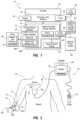
- FIG. 2is a simplified view of a patient and a catheter being inserted therein with assistance of the integrated system of FIG. 1 ;
- FIGS. 3 A and 3 Bare views of a probe of the integrated system of FIG. 1 ;
- FIG. 4is a screenshot of an ultrasound image as depicted on a display of the integrated system of FIG. 1 ;
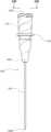
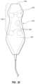
- FIG. 5is a perspective view of a stylet employed in connection with the system of FIG. 1 in placing a catheter within a patient vasculature;
- FIG. 6is an icon as depicted on a display of the integrated system of FIG. 1 , indicating a position of a distal end of the stylet of FIG. 5 during catheter tip placement procedures;
- FIGS. 7 A- 7 Edepict various example icons that can be depicted on the display of the integrated system of FIG. 1 during catheter tip placement procedures;
- FIGS. 8 A- 8 Care screenshots of images depicted on a display of the integrated system of FIG. 1 during catheter tip placement procedures;
- FIG. 9is a block diagram depicting various elements of an integrated system for intravascular placement of a catheter, according to another example embodiment of the present invention.
- FIG. 10is a simplified view of a patient and a catheter being inserted therein with assistance of the integrated system of FIG. 9 ;
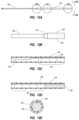
- FIG. 11is a perspective view of a stylet employed in connection with the integrated system of FIG. 9 in placing a catheter within a patient vasculature;
- FIGS. 12 A- 12 Eare various views of portions of the stylet of FIG. 11 ;
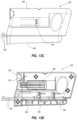
- FIGS. 13 A- 13 Dare various views of a fin connector assembly for use with the integrated system of FIG. 9 ;
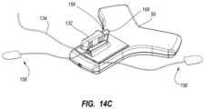
- FIGS. 14 A- 14 Care views showing the connection of a stylet tether and fin connector to a sensor of the integrated system of FIG. 9 ;
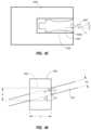
- FIG. 15is a cross sectional view of the connection of the stylet tether, fin connector, and sensor shown in FIG. 14 C ;
- FIG. 16is simplified view of an ECG trace of a patient
- FIG. 17is a screenshot of an image depicted on a display of the integrated system of FIG. 9 during catheter tip placement procedures;
- FIG. 18is a block diagram depicting various elements of an ultrasound-based guidance system for needles and other medical components, according to one embodiment
- FIG. 19is a simplified view of a patient and a catheter being inserted therein, showing one possible environment in which the guidance system of FIG. 18 can be practiced;
- FIG. 20is a top view of the ultrasound probe of the guidance system of FIG. 18 ;
- FIG. 21 Ais a side view of a needle for use with the guidance system of FIG. 18 , according to one embodiment
- FIG. 21 Bis an end view of the needle of FIG. 21 A ;
- FIGS. 22 A and 22 Bare simplified views of the ultrasound probe of the guidance system being used to guide a needle toward a vessel within the body of a patient;
- FIGS. 23 A and 23 Bshow possible screenshots for depiction on the display of the guidance system, showing the position and orientation of a needle according to one embodiment
- FIG. 24shows various stages of a method for guiding a needle to a desired target within the body of a patient according to one embodiment
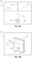
- FIG. 25shows a sensor array for attachment to an ultrasound probe and associated display, according to one embodiment
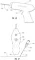
- FIG. 26is a simplified view of a needle holder gun for use with the guidance system of FIG. 18 , according to one embodiment
- FIG. 27is a simplified view of an ultrasound probe and needle including elements of an optical guidance system, according to one embodiment
- FIG. 28shows operation of the ultrasound probe and needle of FIG. 27 , according to one embodiment
- FIG. 29is a simplified view of an ultrasound probe and needle including elements of an electromagnetic signal-based guidance system, according to one embodiment
- FIG. 30is a simplified view of an ultrasound probe and needle including elements of an electromagnetic signal-based guidance system, according to another embodiment
- FIGS. 31 A- 31 Dare various views of a needle and associated components for use with a needle guidance system, according to one embodiment
- FIG. 32is a side view of a needle for use with a needle guidance system, according to one embodiment
- FIGS. 33 A and 33 Bare various views of a needle for use with a needle guidance system, according to one embodiment
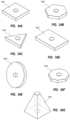
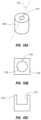
- FIGS. 34 A- 34 Gare views of variously shaped magnetic elements for use with a needle guidance system according to one embodiment
- FIG. 35is a perspective view of a distal portion of a needle cannula including a magnet-bearing stylet disposed therein, according to one embodiment
- FIG. 36shows the needle of FIG. 35 in use with an ultrasound probe including a ring sensor, according to one embodiment
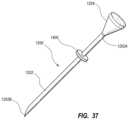
- FIG. 37is a perspective view of a needle including a donut magnet disposed on the cannula, according to one embodiment
- FIG. 38is a side view of a stylet including a strain gauge according to one embodiment
- FIGS. 39 A- 39 Bshow the stylet and strain gauge of FIG. 38 under bending stress
- FIG. 40is a side view of a stylet including a flex sensor according to one embodiment
- FIGS. 41 A- 41 Care various views of a needle assembly according to one embodiment
- FIG. 42is a perspective view showing various aspects of a magnetic element
- FIG. 43is a side view of a needle cannula and magnetic element according to one embodiment
- FIG. 44is a top view of a jig, needle hub, and magnetic element according to one embodiment
- FIG. 45is a top view of a jig, needle hub, and magnetic element according to one embodiment
- FIG. 46is a simplified view of a magnetic element and cannula according to one embodiment
- FIGS. 47 A- 48 Bare various views of a fixture for mating a magnetic element to a portion of a needle assembly according to one embodiment
- FIG. 49is a side view of a bar of magnetic material used in forming a magnetic element according to one embodiment
- FIG. 50shows a portion of the bar of magnetic material of FIG. 49 ;
- FIG. 51shows formation of a magnetic element according to one embodiment
- FIGS. 52 A and 52 Bshows various views of an alignment coil assembly according to one embodiment
- FIGS. 53 A and 53 Bshows a fixture of the alignment coil assembly of FIGS. 52 A and 52 B ;
- FIGS. 54 A- 54 Cshows various details of the fixture of FIGS. 53 A and 53 B according to one embodiment
- FIGS. 55 A- 55 Cshows various views of a magnetic element and cap according to one embodiment
- FIG. 56shows a cap and magnetic element configuration according to one embodiment
- FIG. 57shows a cap and magnetic element configuration according to one embodiment
- FIG. 58shows a cap and magnetic element configuration according to one embodiment
- FIG. 59shows details of a method for aligning a magnetic element in accordance with one embodiment.
- proximalrefers to a direction relatively closer to a clinician using the device to be described herein
- distalrefers to a direction relatively further from the clinician.
- end of a needle placed within the body of a patientis considered a distal end of the needle, while the needle end remaining outside the body is a proximal end of the needle.
- the words “including,” “has,” and “having,” as used herein, including the claims,shall have the same meaning as the word “comprising.”
- Embodiments of the present inventionare generally directed to a catheter placement system configured for accurately placing a catheter within the vasculature of a patient.
- the catheter placement systememploys at least two modalities for improving catheter placement accuracy: 1) ultrasound-assisted guidance for introducing the catheter into the patient's vasculature; and 2) a tip location/navigation system (“TLS”), or magnetically-based tracking of the catheter tip during its advancement through the tortuous vasculature path to detect and facilitate correction of any tip malposition during such advancement.
- TLStip location/navigation system
- the ultrasound guidance and tip location features of the present systemaccording to one embodiment are integrated into a single device for use by a clinician placing the catheter.
- the integrated catheter placement systemenables ultrasound and TLS activities to be viewed from a single display of the integrated system.
- controls located on an ultrasound probe of the integrated devicewhich probe is maintained within the sterile field of the patient during catheter placement, can be used to control functionality of the system, thus precluding the need for a clinician to reach out of the sterile field in order to control the system.
- a third modalityi.e., ECG signal-based catheter tip guidance
- ECG signal-based catheter tip guidanceis included in the integrated system to enable guidance of the catheter tip to a desired position with respect to a node of the patient's heart from which the ECG signals originate.
- ECG-based positional assistanceis also referred to herein as “tip confirmation.”
- Combination of the three modalities aboveenables the catheter placement system to facilitate catheter placement within the patient's vasculature with a relatively high level of accuracy, i.e., placement of the distal tip of the catheter in a predetermined and desired position. Moreover, because of the ECG-based guidance of the catheter tip, correct tip placement may be confirmed without the need for a confirmatory X-ray. This, in turn, reduces the patient's exposure to potentially harmful x-rays, the cost and time involved in transporting the patient to and from the x-ray department, costly and inconvenient catheter repositioning procedures, etc.
- FIGS. 1 and 2depict various components of a catheter placement system (“system”), generally designated at 10 , configured in accordance with one example embodiment of the present invention.
- the system 10generally includes a console 20 , display 30 , probe 40 , and sensor 50 , each of which is described in further detail below.
- FIG. 2shows the general relation of these components to a patient 70 during a procedure to place a catheter 72 into the patient vasculature through a skin insertion site 73 .
- the catheter 72generally includes a proximal portion 74 that remains exterior to the patient and a distal potion 76 that resides within the patient vasculature after placement is complete.
- the system 10is employed to ultimately position a distal tip 76 A of the catheter 72 in a desired position within the patient vasculature.
- the desired position for the catheter distal tip 76 Ais proximate the patient's heart, such as in the lower one-third (1 ⁇ 3 rd ) portion of the Superior Vena Cava (“SVC”).
- SVCSuperior Vena Cava
- the catheter proximal portion 74further includes a hub 74 A that provides fluid communication between the one or more lumens of the catheter 72 and one or more extension legs 74 B extending proximally from the hub.
- FIG. 8 CAn example implementation of the console 20 is shown in FIG. 8 C , though it is appreciated that the console can take one of a variety of forms.
- a processor 22including non-volatile memory such as EEPROM for instance, is included in the console 20 for controlling system function during operation of the system 10 , thus acting as a control processor.
- a digital controller/analog interface 24is also included with the console 20 and is in communication with both the processor 22 and other system components to govern interfacing between the probe 40 , sensor 50 , and other system components.
- the system 10further includes ports 52 for connection with the sensor 50 and optional components 54 including a printer, storage media, keyboard, etc.
- the ports in one embodimentare USB ports, though other port types or a combination of port types can be used for this and the other interfaces connections described herein.
- a power connection 56is included with the console 20 to enable operable connection to an external power supply 58 .
- An internal battery 60can also be employed, either with or exclusive of an external power supply.
- Power management circuitry 59is included with the digital controller/analog interface 24 of the console to regulate power use and distribution.
- the display 30 in the present embodimentis integrated into the console 20 and is used to display information to the clinician during the catheter placement procedure.
- the displaymay be separate from the console.
- the content depicted by the display 30changes according to which mode the catheter placement system is in: US, TLS, or in other embodiments, ECG tip confirmation.
- a console button interface 32(see FIGS. 1 , 8 C ) and buttons included on the probe 40 can be used to immediately call up a desired mode to the display 30 by the clinician to assist in the placement procedure.
- information from multiple modes, such as TLS and ECGmay be displayed simultaneously, such as in FIG. 17 .
- the single display 30 of the system console 20can be employed for ultrasound guidance in accessing a patient's vasculature, TLS guidance during catheter advancement through the vasculature, and (as in later embodiments) ECG-based confirmation of catheter distal tip placement with respect to a node of the patient's heart.
- the display 30is an LCD device.
- FIGS. 3 A and 3 Bdepict features of the probe 40 according to one embodiment.
- the probe 40is employed in connection with the first modality mentioned above, i.e., ultrasound (“US”)-based visualization of a vessel, such as a vein, in preparation for insertion of the catheter 72 into the vasculature.
- USultrasound
- Such visualizationgives real time ultrasound guidance for introducing the catheter into the vasculature of the patient and assists in reducing complications typically associated with such introduction, including inadvertent arterial puncture, hematoma, pneumothorax, etc.
- the handheld probe 40includes a head 80 that houses a piezoelectric array for producing ultrasonic pulses and for receiving echoes thereof after reflection by the patient's body when the head is placed against the patient's skin proximate the prospective insertion site 73 ( FIG. 2 ).
- the probe 40further includes a plurality of control buttons 84 , which can be included on a button pad 82 .
- the modality of the system 10can be controlled by the control buttons 84 , thus eliminating the need for the clinician to reach out of the sterile field, which is established about the patient insertion site prior to catheter placement, to change modes via use of the console button interface 32 .
- a clinicianemploys the first (US) modality to determine a suitable insertion site and establish vascular access, such as with a needle or introducer, then with the catheter.
- the cliniciancan then seamlessly switch, via button pushes on the probe button pad 82 , to the second (TLS) modality without having to reach out of the sterile field.
- the TLS modecan then be used to assist in advancement of the catheter 72 through the vasculature toward an intended destination.
- FIG. 1shows that the probe 40 further includes button and memory controller 42 for governing button and probe operation.
- the button and memory controller 42can include non-volatile memory, such as EEPROM, in one embodiment.
- the button and memory controller 42is in operable communication with a probe interface 44 of the console 20 , which includes a piezo input/output component 44 A for interfacing with the probe piezoelectric array and a button and memory input/output component 44 B for interfacing with the button and memory controller 42 .
- FIG. 4shows an example screenshot 88 as depicted on the display 30 while the system 10 is in its first ultrasound modality.
- An image 90 of a subcutaneous region of the patient 70is shown, depicting a cross section of a vein 92 .
- the image 90is produced by operation of the piezoelectric array of the probe 40 .
- a depth scale indicator 94also included on the display screenshot 88 is a depth scale indicator 94 , providing information regarding the depth of the image 90 below the patient's skin, a lumen size scale 96 that provides information as to the size of the vein 92 relative to standard catheter lumen sizes, and other indicia 98 that provide information regarding status of the system 10 or possible actions to be taken, e.g., freeze frame, image templates, data save, image print, power status, image brightness, etc.
- the US mode shown in FIG. 4can be simultaneously depicted on the display 30 with other modes, such as the TLS mode, if desired.
- aural informationsuch as beeps, tones, etc.
- the buttons included on the probe 40 and the console button interface 32can be configured in a variety of ways, including the use of user input controls in addition to buttons, such as slide switches, toggle switches, electronic or touch-sensitive pads, etc. Additionally, both US and TLS activities can occur simultaneously or exclusively during use of the system 10 .
- the handheld ultrasound probe 40is employed as part of the integrated catheter placement system 10 to enable US visualization of the peripheral vasculature of a patient in preparation for transcutaneous introduction of the catheter.
- the probeis also employed to control functionality of the TLS portion, or second modality, of the system 10 when navigating the catheter toward its desired destination within the vasculature as described below.
- the probe 40is a dual-purpose device, enabling convenient control of both US and TLS functionality of the system 10 from the sterile field.
- the probecan also be employed to control some or all ECG-related functionality, or third modality, of the catheter placement system 10 , as described further below.
- the catheter placement system 10further includes the second modality mentioned above, i.e., the magnetically-based catheter TLS, or tip location system.
- the TLSenables the clinician to quickly locate and confirm the position and/or orientation of the catheter 72 , such as a peripherally-inserted central catheter (“PICC”), central venous catheter (“CVC”), or other suitable catheter, during initial placement into and advancement through the vasculature of the patient 70 .
- the TLS modalitydetects a magnetic field generated by a magnetic element-equipped tip location stylet, which is pre-loaded in one embodiment into a longitudinally defined lumen of the catheter 72 , thus enabling the clinician to ascertain the general location and orientation of the catheter tip within the patient body.
- the magnetic assemblycan be tracked using the teachings of one or more of the following U.S. Pat. Nos. 5,775,322; 5,879,297; 6,129,668; 6,216,028; and 6,263,230.
- the contents of the afore-mentioned U.S. patentsare incorporated herein by reference in their entireties.
- the TLSalso displays the direction in which the catheter tip is pointing, thus further assisting accurate catheter placement.
- the TLSfurther assists the clinician in determining when a malposition of the catheter tip has occurred, such as in the case where the tip has deviated from a desired venous path into another vein.
- FIG. 5gives an example of such a stylet 100 , which includes a proximal end 100 A and a distal end 100 B.
- a handle 102is included at the stylet proximal end 100 A, with a core wire 104 extending distally therefrom.
- a magnetic assemblyis disposed distally of the core wire 104 .
- the magnetic assemblyincludes one or more magnetic elements 106 disposed adjacent one another proximate the stylet distal end 100 B and encapsulated by tubing 108 .
- a plurality of magnetic elements 106is included, each element including a solid, cylindrically shaped ferromagnetic stacked end-to-end with the other magnetic elements.
- An adhesive tip 110can fill the distal tip of the tubing 108 , distally to the magnetic elements 106 .
- the magnetic elementsmay vary from the design in not only shape, but also composition, number, size, magnetic type, and position in the stylet distal segment.
- the plurality of ferromagnetic magnetic elementsis replaced with an electromagnetic assembly, such as an electromagnetic coil, which produces a magnetic field for detection by the sensor.
- an assembly usable herecan be found in U.S. Pat. No. 5,099,845, titled “Medical Instrument Location Means,” which is incorporated herein by reference in its entirety.
- stylets including magnetic elements that can be employed with the TLS modalitycan be found in U.S. Pat. No. 8,784,336, filed Aug.
- styletas used herein can include any one of a variety of devices configured for removable placement within a lumen of the catheter to assist in placing a distal end of the catheter in a desired location within the patient's vasculature.
- the TLS sensor 50is employed by the system 10 during TLS operation to detect a magnetic field produced by the magnetic elements 106 of the stylet 100 .
- the TLS sensor 50is placed on the chest of the patient during catheter insertion.
- the TLS sensor 50is placed on the chest of the patient in a predetermined location, such as through the use of external body landmarks, to enable the magnetic field of the stylet magnetic elements 106 , disposed in the catheter 72 as described above, to be detected during catheter transit through the patient vasculature.
- detection by the TLS sensor 50 of the magnetic field of the magnetic elementsprovides information to the clinician as to the position and orientation of the catheter distal end during its transit.
- the TLS sensor 50is operably connected to the console 20 of the system 10 via one or more of the ports 52 , as shown in FIG. 1 .
- the magnetic elements 106are employed in the stylet 100 to enable the position of the catheter distal end 76 A ( FIG. 2 ) to be observable relative to the TLS sensor 50 placed on the patient's chest. Detection by the TLS sensor 50 of the stylet magnetic elements 106 is graphically displayed on the display 30 of the console 20 during TLS mode.
- a clinician placing the catheteris able to generally determine the location of the catheter distal end 76 A within the patient vasculature relative o the TLS sensor 50 and detect when catheter malposition, such as advancement of the catheter along an undesired vein, is occurring.
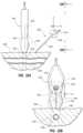
- FIGS. 6 and 7 A- 7 Eshow examples of icons that can be used by the console display 30 to depict detection of the stylet magnetic elements 106 by the TLS sensor 50 .
- FIG. 6shows an icon 114 that depicts the distal portion of the stylet 100 , including the magnetic elements 106 as detected by the TLS sensor 50 when the magnetic elements are positioned under the TLS sensor.
- the iconindicates the position and orientation of the catheter distal end.
- FIG. 7 A- 7 Eshow various icons that can be depicted on the on the console display 30 when the magnetic elements 106 of the stylet 100 are not positioned directly under a portion of the TLS sensor 50 , but are nonetheless detected nearby.
- the iconscan include half-icons 114 A and quarter-icons 114 B that are displayed according to the position of the stylet magnetic assembly, i.e., the magnetic elements 106 in the present embodiment, relative to the TLS sensor 50 .
- FIGS. 8 A- 8 Cdepict screenshots taken from the display 30 of the system 10 while in TLS mode, showing how the magnetic assembly of the stylet 100 is depicted.
- the screenshot 118 of FIG. 8 Ashows a representative image 120 of the TLS sensor 50 .
- Other informationis provided on the display screenshot 118 , including a depth scale indicator 124 , status/action indicia 126 , and icons 128 corresponding to the button interface 32 included on the console 20 ( FIG. 8 C ).
- the icons 128 in the present embodimentare simply indicators to guide the user in identifying the purpose of the corresponding buttons of the button interface 32
- the displaycan be made touch-sensitive so that the icons themselves can function as button interfaces and can change according to the mode the system is in.
- the display screenshotwill indicate “no signal,” indicating that the magnetic field from the stylet magnetic assembly has not been detected.
- the magnetic assembly proximate the stylet distal end 100 Bhas advanced sufficiently close to the TLS sensor 50 to be detected thereby, though it is not yet under the sensor. This is indicated by the half-icon 114 A shown to the left of the sensor image 120 , representing the stylet magnetic assembly being positioned to the right of the TLS sensor 50 from the perspective of the patient.
- the magnetic assembly proximate the stylet distal end 100 Bhas advanced under the TLS sensor 50 such that its position and orientation relative thereto is detected by the TLS sensor. This is indicated by the icon 114 on the sensor image 120 .
- the button icons 128provide indications of the actions that can be performed by pressing the corresponding buttons of the console button interface 32 . As such, the button icons 128 can change according to which modality the system 10 is in, thus providing flexibility of use for the button interface 32 .
- the button pad 82 of the probe 40FIG.
- buttons 84that mimic several of the buttons of the button interface 32 , the button icons 128 on the display 30 provide a guide to the clinician for controlling the system 10 with the probe buttons 84 while remaining in the sterile field. For instance, if the clinician has need to leave TLS mode and return to US (ultrasound) mode, the appropriate control button 84 on the probe button pad 82 can be depressed, and the US mode can be immediately called up, with the display 30 refreshing to accommodate the visual information needed for US functionality, such as that shown in FIG. 4 . This is accomplished without a need for the clinician to reach out of the sterile field.
- the integrated system 10includes the console 20 , display 30 , probe 40 for US functionality, and the TLS sensor 50 for tip location functionality as described above. Note that the system 10 depicted in FIGS. 9 and 10 is similar in many respects to the system shown in FIGS. 1 and 2 . As such, only selected differences will be discussed below.
- 9 and 10includes additional functionality wherein determination of the proximity of the catheter distal tip 76 A relative to a sino-atrial (“SA”) or other electrical impulse-emitting node of the heart of the patient 70 can be determined, thus providing enhanced ability to accurately place the catheter distal tip in a desired location proximate the node.
- SAsino-atrial
- ECGECG-based tip confirmation
- this third modality of the system 10enables detection of ECG signals from the SA node in order to place the catheter distal tip in a desired location within the patient vasculature.
- the US, TLS, and ECG modalitiesare seamlessly combined in the present system 10 and can be employed in concert or individually to assist in catheter placement.
- FIGS. 9 and 10show the addition to the system 10 of a stylet 130 configured in accordance with the present embodiment.
- the catheter stylet 130is removably predisposed within the lumen of the catheter 72 being inserted into the patient 70 via the insertion site 73 .
- the stylet 130in addition to including a magnetic assembly for the magnetically-based TLS modality, includes an ECG sensor assembly proximate its distal end and including a portion that is co-terminal with the distal end of the catheter tip for sensing ECG signals produced by the SA node.
- the stylet 130includes a tether 134 extending from its proximal end that operably connects to the TLS sensor 50 .
- the stylet tether 134permits ECG signals detected by the ECG sensor assembly included on a distal portion of the stylet 130 to be conveyed to the TLS sensor 50 during confirmation of the catheter tip location as part of the ECG signal-based tip confirmation modality.
- Reference and ground ECG lead/electrode pairs 158attach to the body of the body of the patient 70 and are operably attached to the TLS sensor 50 to enable the system to filter out high level electrical activity unrelated to the electrical activity of the SA node of the heart, thus enabling the ECG-based tip confirmation functionality.
- the ECG signals sensed by the stylet ECG sensor assemblyare received by the TLS sensor 50 positioned on the patient's chest ( FIG. 10 ).
- the TLS sensor 50 and/or console processor 22can process the ECG signal data to produce an electrocardiogram waveform on the display 30 , as will be described.
- a processoris included therein to perform the intended functionality. If the console 20 processes the ECG signal data, the processor 22 , controller 24 , or other processor can be utilized in the console to process the data.
- the catheter 72 equipped with the stylet 130 as described abovecan advance under the TLS sensor 50 , which is positioned on the chest of the patient as shown in FIG. 10 .
- Thisenables the TLS sensor 50 to detect the position of the magnetic assembly of the stylet 130 , which is substantially co-terminal with the distal tip 76 A of the catheter as located within the patient's vasculature.
- the detection by the TLS sensor 50 of the stylet magnetic assemblyis depicted on the display 30 during ECG mode.
- the display 30further depicts during ECG mode an ECG electrocardiogram waveform produced as a result of patient heart's electrical activity as detected by the ECG sensor assembly of the stylet 130 .
- the ECG electrical activity of the SA nodeis detected by the ECG sensor assembly of the stylet (described below) and forwarded to the TLS sensor 50 and console 20 .
- the ECG electrical activityis then processed for depiction on the display 30 .
- clinician placing the cathetercan then observe the ECG data to determine optimum placement of the distal tip 76 A of the catheter 72 , such as proximate the SA node in one embodiment.
- the console 20which includes the electronic components, such as the processor 22 ( FIG. 9 ) necessary to receive and process the signals detected by the stylet ECG sensor assembly.
- the TLS sensor 50can include the necessary electronic components processing the ECG signals.
- the display 30is used to display information to the clinician during the catheter placement procedure.
- the content of the display 30changes according to which mode the catheter placement system is in: US, TLS, or ECG. Any of the three modes can be immediately called up to the display 30 by the clinician, and in some cases information from multiple modes, such as TLS and ECG, may be displayed simultaneously.
- the mode the system is inmay be controlled by the control buttons 84 included on the handheld probe 40 , thus eliminating the need for the clinician to reach out of the sterile field (such as touching the button interface 32 of the console 20 ) to change modes.
- the probe 40is employed to also control some or all ECG-related functionality of the system 10 .
- buttons interface 32 or other input configurationscan also be used to control system functionality.
- aural informationsuch as beeps, tones, etc., can also be employed by the system to assist the clinician during catheter placement.
- FIGS. 11 - 12 Ein describing various details of one embodiment of the stylet 130 that is removably loaded into the catheter 72 and employed during insertion to position the distal tip 76 A of the catheter in a desired location within the patient vasculature.
- the stylet 130 as removed from the catheterdefines a proximal end 130 A and a distal end 130 B.
- a connector 132is included at the proximal stylet end 130 A, and a tether 134 extends distally from the connector and attaches to a handle 136 .
- a core wire 138extends distally from the handle 136 .
- the stylet 130is pre-loaded within a lumen of the catheter 72 in one embodiment such that the distal end 130 B is substantially flush, or co-terminal, with the catheter opening at the distal end 76 A thereof ( FIG. 10 ), and such that a proximal portion of the core wire 138 , the handle 136 , and the tether 134 extend proximally from a selected one of the extension tubes 74 B.
- a guidewire or other catheter guiding apparatuscould include the principles of the embodiment described herein.
- the core wire 138defines an elongate shape and is composed of a suitable stylet material including stainless steel or a memory material such as, in one embodiment, a nickel and titanium-containing alloy commonly known by the acronym “nitinol.” Though not shown here, manufacture of the core wire 138 from nitinol in one embodiment enables the portion of the core wire corresponding to a distal segment of the stylet to have a pre-shaped bent configuration so as to urge the distal portion of the catheter 72 into a similar bent configuration. In other embodiments, the core wire includes no pre-shaping.
- the nitinol constructionlends torqueability to the core wire 138 to enable a distal segment of the stylet 130 to be manipulated while disposed within the lumen of the catheter 72 , which in turn enables the distal portion of the catheter to be navigated through the vasculature during catheter insertion.
- the handle 136is provided to enable insertion/removal of the stylet from the catheter 72 .
- the handle 136further enables the core wire to be rotated within the lumen of the catheter 72 , to assist in navigating the catheter distal portion through the vasculature of the patient 70 .
- the handle 136attaches to a distal end of the tether 134 .
- the tether 134is a flexible, shielded cable housing one or more conductive wires electrically connected both to the core wire 138 , which acts as the ECG sensor assembly referred to above, and the tether connector 132 .
- the tether 134provides a conductive pathway from the distal portion of the core wire 138 through to the tether connector 132 at proximal end 130 A of the stylet 130 .
- the tether connector 132is configured for operable connection to the TLS sensor 50 on the patient's chest for assisting in navigation of the catheter distal tip 76 A to a desired location within the patient vasculature.
- a distal portion of the core wire 138is gradually tapered, or reduced in diameter, distally from a junction point 142 .
- a sleeve 140is slid over the reduced-diameter core wire portion. Though of relatively greater diameter here, the sleeve in another embodiment can be sized to substantially match the diameter of the proximal portion of the stylet core wire.
- the stylet 130further includes a magnetic assembly disposed proximate the distal end 130 B thereof for use during TLS mode.
- the magnetic assembly in the illustrated embodimentincludes a plurality of magnetic elements 144 interposed between an outer surface of the reduced-diameter core wire 138 and an inner surface of the sleeve 140 proximate the stylet distal end 130 B.
- the magnetic elements 144include 20 ferromagnetic magnets of a solid cylindrical shape stacked end-to-end in a manner similar to the stylet 100 of FIG. 2 .
- the magnetic element(s)may vary from this design in not only shape, but also composition, number, size, magnetic type, and position in the stylet.
- the plurality of magnets of the magnetic assemblyis replaced with an electromagnetic coil that produces a magnetic field for detection by the TLS sensor.
- the magnetic elements 144are employed in the stylet 130 distal portion to enable the position of the stylet distal end 130 B to be observable relative to the TLS sensor 50 placed on the patient's chest.
- the TLS sensor 50is configured to detect the magnetic field of the magnetic elements 144 as the stylet advances with the catheter 72 through the patient vasculature. In this way, a clinician placing the catheter 72 is able to generally determine the location of the catheter distal end 76 A within the patient vasculature and detect when catheter malposition is occurring, such as advancement of the catheter along an undesired vein, for instance.
- the stylet 130further includes the afore-mentioned ECG sensor assembly, according to one embodiment.
- the ECG sensor assemblyenables the stylet 130 , disposed in a lumen of the catheter 72 during insertion, to be employed in detecting an intra-atrial ECG signal produced by an SA or other node of the patient's heart, thereby allowing for navigation of the distal tip 76 A of the catheter 72 to a predetermined location within the vasculature proximate the patient's heart.
- the ECG sensor assemblyserves as an aide in confirming proper placement of the catheter distal tip 76 A.
- the ECG sensor assemblyincludes a distal portion of the core wire 138 disposed proximate the stylet distal end 130 B.
- the core wire 138being electrically conductive, enables ECG signals to be detected by the distal end thereof and transmitted proximally along the core wire.
- a conductive material 146such as a conductive epoxy, fills a distal portion of the sleeve 140 adjacent the distal termination of the core wire 138 so as to be in conductive communication with the distal end of the core wire. This in turn increases the conductive surface of the distal end 130 B of the stylet 130 so as to improve its ability to detect ECG signals.
- the stylet 130is loaded into a lumen of the catheter 72 .
- the stylet 130can come preloaded in the catheter lumen from the manufacturer, or loaded into the catheter by the clinician prior to catheter insertion.
- the stylet 130is disposed within the catheter lumen such that the distal end 130 B of the stylet 130 is substantially co-terminal with the distal tip 76 A of the catheter 72 , thus placing the distal tips of both the stylet and the catheter in substantial alignment with one another.
- the co-terminality of the catheter 72 and stylet 130enables the magnetic assembly to function with the TLS sensor 50 in TLS mode to track the position of the catheter distal tip 76 A as it advances within the patient vasculature, as has been described.
- the distal end 130 B of the stylet 130need not be co-terminal with the catheter distal end 76 A. Rather, all that is required is that a conductive path between the vasculature and the ECG sensor assembly, in this case the core wire 138 , be established such that electrical impulses of the SA node or other node of the patient's heart can be detected.
- This conductive pathin one embodiment can include various components including saline solution, blood, etc.
- the TLS mode of the system 10can be employed as already described to advance the catheter distal tip 76 A toward its intended destination proximate the SA node.
- the system 10can be switched to ECG mode to enable ECG signals emitted by the SA node to be detected.
- the electrically conductive ECG sensor assemblyincluding the distal end of the core wire 138 and the conductive material 146 , begins to detect the electrical impulses produced by the SA node.
- the ECG sensor assemblyserves as an electrode for detecting the ECG signals.
- the elongate core wire 138 proximal to the core wire distal endserves as a conductive pathway to convey the electrical impulses produced by the SA node and received by the ECG sensor assembly to the tether 134 .
- the tether 134conveys the ECG signals to the TLS sensor 50 temporarily placed on the patient's chest.
- the tether 134is operably connected to the TLS sensor 50 via the tether connector 132 or other suitable direct or indirect connective configuration.
- the ECG signalcan then be process and depicted on the system display 30 ( FIG. 9 , 10 ).
- Monitoring of the ECG signal received by the TLS sensor 50 and displayed by the display 30enables a clinician to observe and analyze changes in the signal as the catheter distal tip 76 A advances toward the SA node.
- the cliniciancan determine that the catheter distal tip 76 A has reached a desired position with respect to the SA node. As mentioned, in one embodiment this desired position lies within the lower one-third (1 ⁇ 3 rd ) portion of the SVC.
- the ECG sensor assembly and magnetic assemblycan work in concert in assisting a clinician in placing a catheter within the vasculature.
- the magnetic assembly of the stylet 130assists the clinician in generally navigating the vasculature from initial catheter insertion so as to place the distal end 76 A of the catheter 72 in the general region of the patient's heart.
- the ECG sensor assemblycan then be employed to guide the catheter distal end 76 A to the desired location within the SVC by enabling the clinician to observe changes in the ECG signals produced by the heart as the stylet ECG sensor assembly approaches the SA node.
- the cliniciancan determine that the distal ends of both the stylet 130 and the catheter 72 have arrived at the desired location with respect to the patient's heart.
- the catheter 72may be secured in place and the stylet 130 removed from the catheter lumen.
- the styletmay include one of a variety of configurations in addition to what is explicitly described herein.
- the styletcan attach directly to the console instead of an indirect attachment via the TLS sensor.
- the structure of the stylet 130 that enables its TLS and ECG-related functionalitiescan be integrated into the catheter structure itself.
- the magnetic assembly and/or ECG sensor assemblycan, in one embodiment, be incorporated into the wall of the catheter.
- FIGS. 13 A- 15describe various details relating to the passage of ECG signal data from the stylet tether 134 to the TLS sensor 50 positioned on the patient's chest, according the present embodiment.
- this embodimentis concerned with passage of ECG signal data from a sterile field surrounding the catheter 72 and insertion site 73 , which includes the stylet 130 and tether 134 , and a non-sterile field, such as the patient's chest on which the TLS sensor is positioned.
- Such passageshould not disrupt the sterile field so that the sterility thereof is compromised.
- a sterile drape that is positioned over the patient 70 during the catheter insertion proceduredefines the majority of the sterile field: areas above the drape are sterile, while areas below (excluding the insertion site and immediately surrounding region) are non-sterile.
- the discussion belowincludes at least a first communication node associated with the stylet 130 , and a second communication node associated with the TLS sensor 50 that operably connect with one another to enable ECG signal data transfer therebetween.
- FIGS. 13 A- 15depict a “through-drape” implementation also referred to as a “shark fin” implementation.
- FIG. 14 Ashows the TLS sensor 50 as described above for placement on the chest of the patient during a catheter insertion procedure.
- the TLS sensor 50includes on a top surface thereof a connector base 152 defining a channel 152 A in which are disposed three electrical base contacts 154 .
- a fin connector 156also shown in FIGS. 13 A- 13 D , is sized to be slidingly received by the channel 152 A of the connector base 152 , as shown in FIG.
- Two ECG lead/electrode pairs 158extend from the fin connector 156 for placement on the shoulder and torso or other suitable external locations on the patient body.
- the drape-piercing tether connector 132is configured to slidingly mate with a portion of the fin connector 156 , as will be described further below, to complete a conductive pathway from the stylet 120 , through the sterile field to the TLS sensor 50 .
- FIGS. 13 A- 13 Dshow further aspects of the fin connector 156 .
- the fin connector 156defines a lower barrel portion 160 that is sized to be received in the channel 152 A of the connector base 152 ( FIGS. 14 B, 15 ).
- a hole 162 surrounded by a centering cone 164is included on a back end of an upper barrel portion 166 .
- the upper barrel portion 166is sized to receive the tether connector 132 of the stylet 130 ( FIGS. 14 C, 15 ) such that a pin contact 170 extending into a channel 172 of the tether connector 132 ( FIG.
- An engagement featuresuch as the engagement feature 169 shown in FIGS. 13 C and 13 D , can be included on the fin connector 156 to engage with a corresponding feature on the tether connector 132 to assist with maintaining a mating between the two components.
- FIG. 13 Dshows that the fin connector 156 includes a plurality of electrical contacts 168 .
- three contacts 168are included: the two forward-most contact each electrically connecting with a terminal end of one of the ECG leads 158 , and the rear contact extending into axial proximity of the hole 162 so as to electrically connect with the pin contact 170 of the tether connector 132 when the latter is mated with the fin connector 156 ( FIG. 15 ).
- a bottom portion of each contact 168 of the fin connector 156is positioned to electrically connect with a corresponding one of the base contacts 154 of the TLS sensor connector base 152 .
- FIG. 14 Bshows a first connection stage, wherein the fin connector 156 is removably mated with the TLS sensor connector base 152 by the sliding engagement of the lower barrel portion 160 of the fin connector with the connector base channel 152 A. This engagement electrically connects the connector base contacts 154 with the corresponding fin contacts 168 .
- FIG. 14 Cshows a second connection stage, wherein the tether connector 132 is removably mated with the fin connector 156 by the sliding engagement of the tether connector channel 172 with the upper barrel portion 166 of the fin connector. This engagement electrically connects the tether connector pin contact 170 with the back contact 168 of the fin connector 156 , as best seen in FIG. 15 .
- the horizontal sliding movement of the tether connector 132 with respect to the fin connector 156is in the same engagement direction as when the fin connector is slidably mated to the sensor connector base channel 152 A ( FIG. 14 B ).
- one or both of the stylet 130 /tether connector 132 and the fin connector 156are disposable.
- the tether connector in one embodimentcan be mated to the fin connector after the fin connector has been mated to the TLS sensor, while in another embodiment the tether connector can be first mated to the fin connector through the surgical drape before the fin connector is mated to the TLS sensor.
- the stylet 130is operably connected to the TLS sensor 50 via the tether connector 132 , thus enabling the ECG sensor assembly of the stylet to communicate ECG signals to the TLS sensor.
- the ECG lead/electrode pairs 158are operably connected to the TLS sensor 50 .
- the tether connector 132is referred to as a first communication node for the stylet 130
- the fin connector 156is referred to as a second communication node for the TLS sensor 50 .
- the tether connectorcan use a slicing contact instead of a pin contact to pierce the drape.
- the fin connectorcan be integrally formed with the TLS sensor.
- a sterile drape 174 used during catheter placement to establish a sterile fieldis interposed between the interconnection of the tether connector 132 with the fin connector 156 .
- the tether connector 132includes the pin contact 170 that is configured to pierce the drape 174 when the two components are mated. This piercing forms a small hole, or perforation 175 , in the sterile drape 174 that is occupied by the pin contact 170 , thus minimizing the size of the drape perforation by the pin contact.
- the fit between the tether connector 132 and the fin connector 156is such that the perforation in sterile drape made by piercing of the pin contact 170 is enclosed by the tether connector channel 172 , thus preserving the sterility of the drape and preventing a breach in the drape that could compromise the sterile field established thereby.
- the tether connector channel 172is configured so as to fold the sterile drape 174 down prior to piercing by the pin contact 170 such that the pin contact does not pierce the drape until it is disposed proximate the hole 162 of the fin connector 156 . It is noted here that the tether connector 132 and fin connector 156 are configured so as to facilitate alignment therebetween blindly through the opaque sterile drape 174 , i.e., via palpation absent visualization by the clinician of both components.
- the fin contacts 168 of the fin connector 156 as shown in FIG. 15are configured to mate with the sensor base contacts 154 in such a way as to assist in retaining the fin connector in engagement with the sensor base channel 152 A. This in turn reduces the need for additional apparatus to secure the fin connector 156 to the TLS sensor 50 .
- FIG. 16shows a typical ECG waveform 176 , including a P-wave and a QRS complex.
- the amplitude of the P-wavevaries as a function of distance of the ECG sensor assembly from the SA node, which produces the waveform 176 .
- a cliniciancan use this relationship in determining when the catheter tip is properly positioned proximate the heart. For instance, in one implementation the catheter tip is desirably placed within the lower one-third (1 ⁇ 3 rd ) of the superior vena cava, as has been discussed.
- the ECG data detected by the ECG sensor assembly of the stylet 130is used to reproduce waveforms such as the waveform 176 , for depiction on the display 30 of the system 10 during ECG mode.
- the screenshot 178 of the display 30includes elements of the TLS modality, including a representative image 120 of the TLS sensor 50 , and can the icon 114 corresponding to the position of the distal end of the stylet 130 during transit through the patient vasculature.
- the screenshot 178further includes a window 180 in which the current ECG waveform captured by the ECG sensor assembly of the stylet 130 and processed by the system 10 is displayed. The window 180 is continually refreshed as new waveforms are detected.
- Window 182includes a successive depiction of the most recent detected ECG waveforms, and includes a refresh bar 182 A, which moves laterally to refresh the waveforms as they are detected.
- Window 184 Ais used to display a baseline ECG waveform, captured before the ECG sensor assembly is brought into proximity with the SA node, for comparison purposes to assist the clinician in determining when the desired catheter tip location has been achieved.
- Windows 184 B and 184 Ccan be filed by user-selected detected ECG waveforms when the user pushes a predetermined button on the probe 40 or the console button interface 32 . The waveforms in the windows 184 B and 184 C remain until overwritten by new waveforms as a result of user selection via button pushes or other input.
- the depth scale 124As in previous modes, the depth scale 124 , status/action indicia 126 , and button icons 128 are included on the display 30 .
- An integrity indicator 186is also included on the display 30 to give an indication of whether the ECG lead/electrode pairs 158 are operably connected to the TLS sensor 50 .
- the display 30depicts in one embodiment elements of both the TLS and ECG modalities simultaneously on a single screen, thus offering the clinician ample data to assist in placing the catheter distal tip in a desired position.
- a printout of the screenshot or selected ECG or TLS datacan be saved, printed, or otherwise preserved by the system 10 to enable documentation of proper catheter placement.
- Embodiments of the present invention described hereinare generally directed to a guidance system for locating and guiding a needle or other medical component during ultrasound-based or other suitable procedures for accessing with the needle a subcutaneous vessel of a patient, for instance.
- the guidance systemenables the position, orientation, and advancement of the needle to be superimposed in real-time atop the ultrasound image of the vessel, thus enabling a clinician to accurately guide the needle to the intended target.
- the guidance systemtracks the needle's position in five degrees of motion: x, y, and z spatial coordinate space, needle pitch, and needle yaw. Such tracking enables the needle to be guided and placed with relatively high accuracy.
- FIGS. 18 and 19depict various components of an ultrasound-based needle guidance system (“system”), generally designated at 1110 , configured in accordance with one embodiment of the present invention.
- the system 1110generally includes an ultrasound (“US”) imaging portion including a console 1120 , display 1130 , and probe 1140 , each of which is described in further detail below.
- USBultrasound
- the system 1110bears similarity to the system 10 shown in FIG. 1 with respect to some components, in one embodiment.
- the ultrasound imaging portioncan be configured in one of a variety of ways in addition to what is shown and described herein.
- the ultrasound imaging portion of the system 1110is employed to image a targeted internal portion of a body of a patient prior to percutaneous insertion of a needle or other device to access the target. As described below, in one embodiment insertion of the needle is performed prior to the subsequent insertion of a catheter into a vein or other portion of the vasculature of the patient. It is appreciated, however, that insertion of a needle into the body of a patient can be performed for a variety of medical purposes.
- FIG. 19shows the general relation of the above-described components to a patient 1170 during a procedure to ultimately place a catheter 1172 into the patient vasculature through a skin insertion site 1173 , according to one embodiment.
- the catheter 1172generally includes a proximal portion 1174 that remains exterior to the patient and a distal potion 1176 that resides within the patient vasculature after placement is complete.
- the system 1110is employed to ultimately position a distal tip 1176 A of the catheter 1172 in a desired position within the patient vasculature.
- the desired position for the catheter distal tip 1176 Ais proximate the patient's heart, such as in the lower one-third (1 ⁇ 3 rd ) portion of the Superior Vena Cava (“SVC”).
- SVCSuperior Vena Cava
- the system 1110can be employed to place the catheter distal tip in other locations.
- the catheter proximal portion 1174further includes a hub 1174 A that provides fluid communication between the one or more lumens of the catheter 1172 and one or more extension legs 1174 B extending proximally from the hub.
- a hub 1174 Athat provides fluid communication between the one or more lumens of the catheter 1172 and one or more extension legs 1174 B extending proximally from the hub.
- the above discussionis only one example for use of the system 1110 ; indeed it can be employed for a variety of uses, such as the placement of needles preparatory to insertion of a catheter as above, the insertion of a needle for other uses, or for the insertion of other medical components into the body of a patient, including x-ray or ultrasound markers, biopsy sheaths, ablation components, bladder scanning components, vena cava filters, etc.
- the console 1120houses a variety of components of the system 1110 and it is appreciated that the console can take one of a variety of forms.
- a processor 1122including non-volatile memory such as EEPROM for instance, is included in the console 1120 for controlling system function and executing various algorithms during operation of the system 1110 , thus acting as a control processor.
- a digital controller/analog interface 1124is also included with the console 1120 and is in communication with both the processor 1122 and other system components to govern interfacing between the probe 1140 and other system components.
- the system 1110further includes ports 1152 for connection with additional components such as optional components 1154 including a printer, storage media, keyboard, etc.
- the portsin one embodiment are USB ports, though other port types or a combination of port types can be used for this and the other interfaces connections described herein.
- a power connection 1156is included with the console 1120 to enable operable connection to an external power supply 1158 .
- An internal battery 1160can also be employed, either with or exclusive of an external power supply.
- Power management circuitry 1159is included with the digital controller/analog interface 1124 of the console to regulate power use and distribution.
- the display 1130 in the present embodimentis integrated into the console 1120 and is used to display information to the clinician during the placement procedure, such as an ultrasound image of the targeted internal body portion attained by the probe 1140 .
- the displaymay be separate from the console.
- a console button interface 1132 and control buttons 1184 ( FIG. 19 ) included on the probe 1140can be used to immediately call up a desired mode to the display 1130 by the clinician to assist in the placement procedure.
- the display 1130is an LCD device.
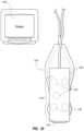
- FIG. 19further depicts a needle 1200 used to gain initial access to the patient vasculature via the insertion site 1173 .
- the needle 1200is configured to cooperate with the system 1110 in enabling the system to detect the position, orientation, and advancement of the needle during an ultrasound-based placement procedure.
- FIG. 20depicts features of the probe 1140 according to one embodiment.
- the probe 1140is employed in connection with ultrasound-based visualization of a vessel, such as a vein, in preparation for insertion of the needle 1200 and/or catheter 1172 into the vasculature.
- a vesselsuch as a vein
- Such visualizationgives real time ultrasound guidance and assists in reducing complications typically associated with such introduction, including inadvertent arterial puncture, hematoma, pneumothorax, etc.
- the handheld probe 1140includes a head 1180 that houses a piezoelectric array for producing ultrasonic pulses and for receiving echoes thereof after reflection by the patient's body when the head is placed against the patient's skin proximate the prospective insertion site 1173 ( FIG. 19 ).
- the probe 1140further includes a plurality of control buttons 1184 ( FIG. 19 ) for controlling the system, thus eliminating the need for the clinician to reach out of the sterile field, which is established about the patient insertion site prior to establishment of the insertion site, to control the system 1110 .
- a clinicianemploys the ultrasound imaging portion of the system 1110 to determine a suitable insertion site and establish vascular access, such as with the needle 1200 , prior to introduction of the catheter 1172 for ultimate advancement thereof through the vasculature toward an intended destination.
- FIG. 18shows that the probe 1140 further includes a button and memory controller 1142 for governing button and probe operation.
- the button and memory controller 1142can include non-volatile memory, such as EEPROM, in one embodiment.
- the button and memory controller 1142is in operable communication with a probe interface 1144 of the console 1120 , which includes a piezo input/output component 1144 A for interfacing with the probe piezoelectric array and a button and memory input/output component 1144 B for interfacing with the button and memory controller 1142 .
- the probe 1140includes a sensor array 1190 for detecting the position, orientation, and movement of the needle 1200 during ultrasound imaging procedures, such as those described above.
- the sensor arrayincludes a plurality of magnetic sensors 1192 embedded within the housing of the probe.
- the sensors 1192are configured to detect a magnetic field associated with the needle 1200 and enable the system 1110 to track the needle. Though configured here as magnetic sensors, it is appreciated that the sensors 1192 can be sensors of other types and configurations, as will be described.
- the sensors 1192 of the sensor array 1190can be included in a component separate from the probe, such as a separate handheld device.
- the sensors 1192are disposed in a planar configuration below a top face 1182 of the probe 1140 , though it is appreciated that the sensors can be arranged in other configurations, such as in an arched or semi-circular arrangement.
- each of the sensors 1192includes three orthogonal sensor coils for enabling detection of a magnetic field in three spatial dimensions.
- Such three dimensional (“3-D”) magnetic sensorscan be purchased, for example, from Honeywell Sensing and Control of Morristown, NJ. Further, the sensors 1192 of the present embodiment are configured as Hall-effect sensors, though other types of magnetic sensors could be employed. Further, instead of 3-D sensors, a plurality of one dimensional magnetic sensors can be included and arranged as desired to achieve 1-, 2-, or 3-D detection capability.
- five sensors 1192are included in the sensor array 1190 so as to enable detection of the needle 1200 in not only the three spatial dimensions (i.e., X, Y, Z coordinate space), but also the pitch and yaw orientation of the needle itself.
- orthogonal sensing components of two or more of the sensors 1192enable the pitch and yaw attitude of the magnetic element 1210 , and thus the needle 1200 , to be determined.
- fewer or more sensorscan be employed in the sensor array. More generally, it is appreciated that the number, size, type, and placement of the sensors of the sensor array can vary from what is explicitly shown here.
- FIGS. 21 A and 21 Bshow details of one example of the needle 1200 that can be used in connection with the guidance system 1110 in accessing a targeted internal body portion of the patient, as shown in FIG. 19 , according to one embodiment.
- the needle 1200includes a hollow cannula 1202 , which defines a proximal end 1202 A and a distal end 1202 B.
- a hub 1204is attached to the proximal end 1202 A of the cannula 1202 and includes an open end 1204 A that is configured as a connector for connecting with various devices, in the present embodiment.
- the open end 1204 A of the hub 1204is in communication with the hollow cannula 1202 such that a guide wire, stylet, or other component may be passed through the hub into the cannula.
- a magnetic element 1210is included with the hub 1204 .
- the magnetic element 1210 in the present embodimentis a permanent magnet, including a ferromagnetic substance for instance, and is ring-shaped so as to define hole 1212 that is aligned with the hollow cannula 1202 . So configured, the magnetic element 1210 produces a magnetic field that is detectable by the sensor array 1190 of the ultrasound probe 1140 so as to enable the location, orientation, and movement of the needle 1200 to be tracked by the system 1110 , as described further below.
- FIGS. 22 A and 22 Bshow the ultrasound probe 1140 of the system 1110 and the needle 1200 in position and ready for insertion thereof through a skin surface 1220 of a patient to access a targeted internal body portion.
- the probe 1140is shown with its head 1180 placed against the patient skin and producing an ultrasound beam 1222 so as to ultrasonically image a portion of a vessel 1226 beneath the patient skin surface 1220 .
- the ultrasonic image of the vessel 1226can be depicted on the display 1130 of the system 1110 ( FIG. 19 ).
- the system 1110 in the present embodimentis configured to detect the position, orientation, and movement of the needle 1200 described above.
- the sensor array 1190 of the probe 1140is configured to detect a magnetic field of the magnetic element 1210 included with the needle 1200 .
- Each of the sensors 1192 of the sensor array 1190is configured to spatially detect the magnetic element 1210 in three dimensional space.
- magnetic field strength data of the needle's magnetic element 1210 sensed by each of the sensors 1192is forwarded to a processor, such as the processor 1122 of the console 1120 ( FIG. 18 ), which computes in real-time the position and/or orientation of the magnetic element 1210 .
- the position of the magnetic element 1210 in X, Y, and Z coordinate space with respect to the sensor array 1190can be determined by the system 1110 using the magnetic field strength data sensed by the sensors 1192 .
- FIG. 22 Ashows that the pitch of the magnetic element 1210 can also be determined
- FIG. 22 Bshows that the yaw of the magnetic element can be determined.
- Suitable circuitry of the probe 1140 , the console 1120 , or other component of the systemcan provide the calculations necessary for such position/orientation.
- the magnetic element 210can be tracked using the teachings of one or more of the following U.S. Pat. Nos. 5,775,322; 5,879,297; 6,129,668; 6,216,028; and 6,263,230. The contents of the afore-mentioned U.S. patents are incorporated herein by reference in their entireties.
- the above position and orientation information determined by the system 1110together with the length of the cannula 1202 and position of the magnetic element 1210 with respect to the distal needle tip as known by or input into the system, enable the system to accurately determine the location and orientation of the entire length of the needle 1200 with respect to the sensor array 1190 .
- the distance between the magnetic element 1210 and the distal needle tipis known by or input into the system 1110 .
- Thisenables the system 1110 to superimpose an image of the needle 1200 on to an image produced by the ultrasound beam 1222 of the probe 1140 .
- FIGS. 23 A and 23 Bshow examples of such a superimposition of the needle onto an ultrasound image. Specifically, FIGS.
- FIG. 23 A and 23 Beach show a screenshot 1230 that can be depicted on the display 1130 ( FIG. 19 ), for instance.
- an ultrasound image 1232is shown, including depiction of the patient skin surface 1220 , and the subcutaneous vessel 1226 .
- the ultrasound image 1232corresponds to an image acquired by the ultrasound beam 1222 shown in FIGS. 22 A and 22 B , for instance.
- the screenshot 1230further shows a needle image 1234 representing the position and orientation of the actual needle 1200 as determined by the system 1110 as described above. Because the system is able to determine the location and orientation of the needle 1200 with respect to the sensor array 1190 , the system is able to accurately determine the position and orientation of the needle 1200 with respect to the ultrasound image 1232 and superimpose it thereon for depiction as the needle image 1234 on the display 1130 . Coordination of the positioning of the needle image 1234 on the ultrasound image 1232 is performed by suitable algorithms executed by the processor 1122 or other suitable component of the system 1110 .
- the sensors 1192are configured to continuously detect the magnetic field of the magnetic element 1210 of the needle 1200 during operation of the system 1110 . This enables the system 1110 to continuously update the position and orientation of the needle image 1234 for depiction on the display 1130 . Thus, advancement or other movement of the needle 1200 is depicted in real-time by the needle image 1234 on the display 1130 . Note that the system 1110 is capable of continuously updating both the ultrasound image 1232 and the needle image 1234 on the display 1130 as movements of the probe 1140 and the needle 1200 occur during a placement procedure or other activity.
- FIG. 23 Afurther shows that in one embodiment the system 1110 can depict a projected path 1236 based on the current position and orientation of the needle 1200 as depicted by the needle image 1234 .
- the projected path 1236assists a clinician in determining whether the current orientation of the needle 1200 , as depicted by the needle image 1234 on the display 1130 , will result in arriving at the desired internal body portion target, such as the vessel 1226 shown here.
- the projected path 1236is correspondingly modified by the system 1110 .
- a target 1238indicating the point where the projected path 1236 crosses the plane of the ultrasound image 1232 , can also be depicted on the display 1130 by the system 1110 . As shown in FIG.
- the target 1238is located within the vessel 1226 depicted in the ultrasound image 1232 .
- the position of the target 1238 on the display 1130can also be modified as the needle 1200 and/or the ultrasound image 1232 are adjusted.
- the screenshot 1230also includes an area of probability 1239 , here depicted as a box, which indicates any possible margin of error of the system due to needle length, needle rigidity and flex, field strength of the magnetic element, magnetic interference, possible discrepancy in alignment of the magnetic axis of the magnetic element with the longitudinal axis of the needle, orientation of the sensor array with respect to the ultrasound imaging plane, etc.
- FIG. 23 Bshows that, in one embodiment, the screenshot 1230 can be configured such that the ultrasound image 1232 and the needle image 1234 are oriented so as to be displayed in a three dimensional aspect. This enables the angle and orientation of the needle 1200 , as depicted by the needle image 1234 , to be ascertained and compared with the intended target imaged by the ultrasound image 1232 .
- the screenshots 1230are merely examples of possible depictions produced by the system 1110 for display; indeed, other visual depictions can be used.
- the particular area of the body being imagedis merely an example; the system can be used to ultrasonically image a variety of body portions, and should not be limited to what is explicitly depicted in the accompanying figures.
- system as depicted and described hereincan be included as a component of a larger system, if desired, or can be configured as a stand-alone device.
- aural informationsuch as beeps, tones, etc., can also be employed by the system 1110 to assist the clinician during positioning and insertion of the needle into the patient.
- the system 1110it is necessary for the system 1110 to know the total length of the needle 1200 and the location of the magnetic element 1210 thereon in order to enable an accurate depiction of the needle image 1234 and other features of the screenshots 1230 of FIGS. 23 A and 23 B to be made.
- the system 1110can be informed these and/or other pertinent parameters in various ways, including scanning by the system of a barcode included on or with the needle, the inclusion of a radiofrequency identification (“RFID”) chip with the needle for scanning by the system, color coding of the needle, manual entry of the parameters by the clinician into the system, etc.
- RFIDradiofrequency identification
- an RFID chip 1354is included on the needle 1200 shown in FIG. 33 A .
- a length of the needle(or other aspect of a medical component) can be determined by measurement by the probe/system of a characteristic of the magnetic element, such as its field strength.
- the magnetic element of the needlecan be positioned at a predetermined distance from the probe or at a predetermined location with respect to the probe. With the magnetic element so positioned, the sensor array of the probe detects and measures the field strength of the magnetic element. The system can compare the measured field strength with a stored list of possible field strengths corresponding to different lengths of needles. The system can match the two strengths and determine the needle length. The needle location and subsequent needle insertion can then proceed as described herein.
- the magnetic elementinstead of holding the magnetic element stationary at a predetermined location, the magnetic element can be moved about the probe such that multiple field strength readings are taken by the probe.
- aspects that can be modified so as to impart different field strengths to a set of magnetic elementinclude size, shape, and composition of the magnetic element, etc.
- the system 1110in guiding a needle or other medical device in connection with ultrasonic imaging of a targeted internal body portion (“target”) of a patient, according to one embodiment.
- the probeWith the magnetic element-equipped needle 1200 positioned a suitable distance (e.g., two or more feet) away from the ultrasound probe 1140 including the sensor array 1190 , the probe is employed to ultrasonically image, for depiction on the display 1130 of the system 1110 , the target within the patient that the needle is intended to intersect via percutaneous insertion.
- a calibration of the system 1110is then initiated, in which algorithms are executed by the processor 1122 of the console 1120 to determine a baseline for any ambient magnetic fields in the vicinity of where the procedure will be performed.
- the system 1110is also informed of the total length of the needle 1200 , and/or position of the magnetic element with respect to the distal needle tip such as by user input, automatic detection, or in another suitable manner, as has been discussed above.
- the needle 1200is then brought into the range of the sensors 1192 of the sensor array 1190 of the probe 1140 .
- Each of the sensors 1192detects the magnetic field strength associated with the magnetic element 1210 of the needle 1200 , which data is forwarded to the processor 1122 .
- datacan be stored in memory until needed by the processor.
- suitable algorithmsare performed by the processor 1122 to calculate a magnetic field strength of the magnetic element 1210 of the needle 1200 at predicted points in space in relationship to the probe.
- the processor 1122compares the actual magnetic field strength data detected by the sensors 1192 to the calculated field strength values. Note that this process is further described by the U.S. patents identified above.
- This processcan be iteratively performed until the calculated value for a predicted point matches the measured data. Once this match occurs, the magnetic element 1210 has been positionally located in three dimensional space. Using the magnetic field strength data as detected by the sensors 1192 , the pitch and yaw (i.e., orientation) of the magnetic element 1210 can also be determined. Together with the known length of the needle 1200 and the position of the distal tip of the needle with respect to the magnetic element, this enables an accurate representation of the position and orientation of the needle can be made by the system 1110 and depicted as a virtual model, i.e., the needle image 1234 , on the display 1130 . Note that the predicted and actual detected values must match within a predetermined tolerance or confidence level in one embodiment for the system 1110 to enable needle depiction to occur.
- Depiction of the virtual needle image 1234 of the needle 1200 as described aboveis performed in the present embodiment by overlaying the needle image on the ultrasound image 1232 of the display 1130 ( FIGS. 23 A, 23 B ).
- Suitable algorithms of the system 1110 as executed by the processor 1122 or other suitable componentfurther enable the projected path 1236 , the target 1238 , and area of probability 1239 ( FIGS. 23 A, 23 B ) to be determined and depicted on the display 1130 atop the ultrasound image 1232 of the target.
- the above prediction, detection, comparison, and depiction processis iteratively performed to continue tracking the movement of the needle 1200 in real-time.
- a method 1240 for guiding a needle or other medical componentincludes various stages.
- a targeted internal body portion of a patientis imaged by an imaging system, such as an ultrasound imaging device for instance.
- a detectable characteristic of a medical componentsuch as a needle is sensed by one or more sensors included with the imaging system.
- the detectable characteristic of the needleis a magnetic field of the magnetic element 1210 included with the needle 1200 and the sensors are magnetic sensors included in the sensor array 1190 included with the ultrasound probe 1140 .
- a position of the medical component with respect to the targeted internal body portionis determined in at least two spatial dimensions via sensing of the detectable characteristic. As described above, such determination is made in the present embodiment by the processor 1122 of the console 1120 .
- stage 1248an image representing the position of the medical component is combined with the image of the targeted internal body portion for depiction on a display.
- Stage 1250shows that stages 1244 - 1248 can be iteratively repeated to depict advancement or other movement of the medical component with respect to the imaged target, such as percutaneous insertion of the needle 1200 toward the vessel 1226 ( FIGS. 23 A, 23 B ), for instance.
- processor 1122 or other suitable componentcan calculate additional aspects, including the area of probability 1239 and the target 1238 ( FIGS. 23 A, 23 B ) for depiction on the display 1130 .
- FIG. 25shows one example of this, wherein an attachable sensor module 1260 including the sensors 1192 of the sensor array 1190 is shown attached to the ultrasound probe 1140 .
- the sensor module 1260in one embodiment includes a processor and algorithms suitable for locating and tracking the needle or other medical component and for depicting on a display the virtual image of the needle for overlay on to the ultrasound image.
- the sensor module 1260can be included with a module display 1262 for depiction of the needle tracking.
- FIG. 26shows that in one embodiment, a needle holder can be employed to hold and advance the needle 1200 during the ultrasound imaging and needle guidance procedure performed by the system 1110 as has been described.
- the needle holder 1270is pistol-shaped and includes a trigger 1272 for selectively advancing the needle 1200 or other suitable medical component by moving the needle longitudinally away from the barrel of the holder upon pressing of the trigger. So configured, the needle holder 1270 facilitates ease of needle handling with one hand of the clinician while the other hand is grasping and manipulating the ultrasound probe 1140 .
- the needle holder 1270can provide needle movement/rotation assistance such as via a motor, ratcheting, hydraulic/pneumatic drivers, etc.
- a clocking featurecan be included on the needle holder 1270 to assist with determining the orientation of the distal tip of the needle 1200 and for facilitating rotation of the needle.
- the needle holder 1270can be operably connected to the system 1110 such that advancement by the needle holder is automatically stopped when the distal end 1202 B of the needle cannula 1202 reaches the targeted internal body portion or the needle intercepts the ultrasound plane.
- the magnetic elementcan be included with the needle holder instead of the needle itself. The needle, when temporarily attached to the needle holder, can thus be located and guided by the guidance system without the need for a magnetic element to be attached directly to the needle.
- an annular sensorcan be configured to receive through a hole defined thereby the cannula of the needle. So disposed, a magnetic element of the needle is positioned proximate the annular sensor, which enables ready detection of the magnetic element and location of the needle by the system.
- the annular sensorcan be attached to a surface of the probe, in one embodiment.
- FIGS. 27 and 28depict components of the guidance system 1110 according to another embodiment, wherein an optical-based interaction between the probe 1140 and the needle 1200 is employed to enable tracking and guidance of the needle.
- the probe 1140includes a optical/light source, such as an LED 1280 , and a photodetector 1282 positioned on the probe surface.
- the light source and detectorcan be configured to produce and detect light signals of a variety of ranges including visible, infrared, etc.
- the needle hub 1204includes a reflective surface 1286 capable of reflecting light produced by the LED 1280 and incident thereon. As shown in FIG. 28 , light emitted by the LED 1280 is reflected by the reflective surface 1286 of the needle 1200 , a portion of which is received and sensed by the photodetector 1282 . As in previous embodiments, the processor 1122 of the system console 1120 can be employed to receive the sensed data of the photodetector 1282 and compute the position and or orientation of the needle 1200 . As before, the length of the needle 1200 and/or the position of the reflective surface with respect to the distal end of the needle 1200 are input into or otherwise detectable or known by the system 1110 . Note that the reflective surface can be included at other locations on the needle.
- the needle or medical componentcan include one or more of these or other detectable characteristics to enable the needle to be tracked and guided toward a target within the body of the patient.
- detectable characteristic modalitiesinclude electromagnetic or radiofrequency (“RF”) (see, e.g., FIGS. 29 - 30 below), and radioactivity.
- RF modalitiesit is appreciated that one or more synchronously or asynchronously pulsed frequency sources can be included with the needle as to enable detection thereof by a suitable sensor(s).
- an RF first sourcecan be coupled with a passive magnet as a second source.
- FIGS. 29 and 30depict components of a guidance system according to one embodiment, wherein EM signal interaction between the probe 1140 and the needle 1200 is employed to enable tracking and guidance of the needle.
- the needle 1200includes a stylet 1298 disposed therein.
- the stylet 1298includes an EM coil 1290 that is operably connected to the probe 1140 via a tether 1292 .
- the EM coil 1290can be driven by suitable components included in the probe 1140 or system console 1120 such that the EM coil emits an EM signal during operation.
- a sensor 1294 suitable for detecting EM signals emitted by the EM coil 1290 of the stylet 1298is included in the probe 1140 .
- the sensor 1294is a three-axis sensor for detecting corresponding orthogonal components of the EM signal, though other coil and sensor configurations can also be employed. So configured, the position and orientation of the needle 1200 can be determined, by EM signal triangulation or other suitable process, and displayed by the system in a manner similar to that already described above.
- the processor 1122 of the system console 1120FIG. 18
- the processor 1122 of the system console 1120can be employed to receive the sensed data of the EM sensor 1294 and compute the position and/or orientation of the needle 1200 .
- the length of the needle 1200 and/or the position of the EM coil 1290 with respect to the distal end of the needle 1200are input into or otherwise detectable or known by the system.
- FIG. 30shows a variation of the EM configuration of FIG. 29 , wherein the respective positions of the EM components is reversed: the EM coil 1290 is included in the probe 1140 and the EM sensor 1294 is included with the stylet 1298 disposed in the needle 1200 .
- the operable connection between the EM coil 1290 and the EM sensor 1294 via the tether 1292enables the component disposed in the stylet 1298 to be driven by the system 1110 .
- Thisalso enables correspondence of the particular EM frequency/frequencies emitted by the EM coil 1290 and detected by the EM sensor 1294 to be made.
- the probe/systemincludes suitable signal processing components configured to detect the EM signal emitted by the EM coil and to process it as necessary in order to locate the needle.
- the EM coil and EM sensorscan be included at other locations than what is depicted herein.
- the EM coilcan be included on the needle itself, or on a connector that is attachable to the proximal end of the needle.
- FIGS. 31 A- 31 Dgive further details of the needle 1200 configured according to one embodiment, wherein the needle includes a hub 1304 from which extends the cannula 1202 .
- a magnetic element 1310 defining a hole 1312is included in a cavity 1314 A of a housing 1314 .
- the housing 1314includes threads so as to threadably engage the needle hub 1304 or other suitable component of the needle or medical component. In this way, the magnetic element 1310 is removably attachable to the needle 1200 via the housing 1314 .
- the magnetic element 1310need not be permanently affixed or included with the needle 1200 , but rather can be removed therefrom when magnetic-based needle guidance is no longer needed.
- the needle 1200further includes a distally slidable needle safety component 1320 for safely isolating the distal tip of the needle upon removal of the needle from the patient.
- a distally slidable needle safety component 1320for safely isolating the distal tip of the needle upon removal of the needle from the patient.
- FIGS. 32 - 33 Bgive further examples of the needle 1200 including a magnetic element.
- two bar-like magnetic elements 1340are disposed so as to orthogonally extend from a hub 1334 of the needle 1200 , illustrating that the magnetic element need not be oriented parallel to the longitudinal axis of the needle.
- four magnetic elements 1350are included in the needle hub 1344 , showing that more than one magnetic element can be included with the needle.
- Such a configurationmay be employed, for example, where limited space prevents one magnetic element from being used. Note the number, shape, and placement of the magnetic elements here is only one example of many possible configurations.
- FIGS. 34 A- 34 Ggive various example configurations of a magnetic element 1360 that defines a hole for receiving the cannula of the needle therethrough.
- Various shape configurations for the magnetic element 1360are shown, including a square ( FIG. 34 A ), a hexagon ( FIG. 34 B ), a triangle ( FIG. 34 C ), a rectangle ( FIG. 34 D ), an oval ( FIG. 34 E ), an octagon ( FIG. 34 F ), and a four-sided pyramid ( FIG. 34 G ).
- the magnetic elements shown in the accompanying figuresare merely examples of the broad number of geometric and other shapes that can be used to define the magnetic element; indeed other shapes not shown explicitly herein are also contemplated.
- FIGS. 35 and 36depict yet another embodiment, wherein a stylet 1390 is included for removable insertion into the hollow cannula 1202 of the needle 1200 .
- a plurality of permanent magnets 1392such as solid, cylindrically shaped ferromagnets stacked end-to-end with each other, is included at a distal end of the stylet 1390 .
- the stylet 1390is received within the needle cannula 1202 during insertion of the needle 1200 into the patient.
- a sensor ring 1396 or other suitable magnetic sensorcan be included with or in proximity to the probe 1140 to enable detection of the magnetic field of the magnets 1392 , thus enabling the guidance system to detect the position and orientation of the needle 1200 and superimpose an image thereof atop the ultrasound image produced by the probe 1140 in a manner similar to that described in connection with FIGS. 5 A- 7 .
- FIGS. 35 and 36thus illustrate that the magnetic element(s) can be configured in any one of a variety of ways.
- the magnetic elementscan be disposed more proximally along the stylet length.
- the styletitself can be magnetized or composed of magnetic materials. It is appreciated that the stylet can be configured in one of many different ways, analogous examples of which can be found in U.S. Pat. No. 5,099,845, titled “Medical Instrument Location Means,” and U.S. Pat. No. 8,784,336, filed Aug. 23, 2006, titled “Stylet Apparatuses and Methods of Manufacture,” both of which are incorporated herein by reference in their entireties. These and other variations are therefore contemplated.
- styletcan include any one of a variety of devices, including guidewires, configured for removable placement within a lumen of the needle to assist in the placement thereof within the patient.
- the styletcan include a sharp end that distally extends past a blunt distal end of the needle cannula so as to enable a blunt needle to be inserted into a patient.
- the styletin one embodiment stiffens the needle so as to minimize unintended bending thereof during insertion.
- FIG. 37depicts yet another possible embodiment, wherein the needle 1200 includes an annular or donut-shaped magnet 1400 disposed distal to a proximal end 1202 A of the needle cannula 1202 .
- the magnet 1400can be positioned in one of several positions along the length of the cannula 1202 , in other embodiments. Positioning of the magnet 1400 relatively closer to the distal needle tip reduces the effects that unintended bending of the needle has on determining and displaying the position of the needle.
- the needleitself can be magnetized. Note further that the relative places of the sensor and source (e.g., magnet) of the system can be reversed. These and other configurations are also contemplated. Further, note that the discussion herein can be applied to other imaging modalities in addition to ultrasound, including MRI, x-ray and CT scanning, etc.
- FIG. 38depicts a strain gauge 1410 included on a stylet, such as the stylet 1390 shown in FIGS. 35 and 36 for instance.
- the strain gauge 1410can be operably connected to the probe 1140 , console 1120 ( FIG. 18 ), or other component of the system 1110 via a conductive path 1414 .
- One example of the conductive path 1414includes one or more conductive wires disposed in or along the stylet 1390 , for instance. So connected, the strain gauge 1410 acts as a transducer and can provide data relating to bending of the needle in which the stylet 1390 is disposed during needle insertion procedures, given that bending of the needle 1200 will cause similar bending to occur in the stylet 1390 .
- FIG. 39 Ashows flexure of the strain gauge 1410 in one direction as caused by bending of the stylet 1390
- FIG. 39 Bshows flexure of the strain gauge in another direction.
- Such stylet bendingis thus detected by the strain gauge 1410 (via changes in electrical resistance within the strain gauge in one embodiment) and forwarded to the system 1110 for use in computing needle position.
- suitable sensors and gaugescan optionally be used for measuring needle/stylet bending, including a flex sensor 1420 , as shown in FIG. 40 for instance, and capacitance and fiber optic-based strain gauges/sensors.
- the sensor/gaugemay be placed directly on the needle/medical component, in one embodiment.
- FIGS. 41 - 59depict various embodiments generally directed to the inclusion of a magnetic element, such as a permanent magnet with a needle, needle-related component, or other medical device.
- a magnetic elementsuch as a permanent magnet with a needle, needle-related component, or other medical device.
- embodimentsare disclosed for providing a needle assembly with a magnetic element whose magnetic axis is coaxially aligned with the longitudinal axis of the needle cannula.
- Such a magnetic element-equipped needle assemblycan be spatially tracked by a suitable magnetic-based needle insertion guidance tracking system, in preparation for insertion of the needle into the body of a patient, for instance, as already described above.
- FIGS. 41 A- 41 Cshow various details regarding a needle assembly 1610 that serves as one example of a medical device or component that can be guided by the above-described guidance system, in accordance with one embodiment.
- the needle assembly 1610includes a hollow cannula 1612 and a safety can 1616 disposed at a proximal end of the cannula.
- a carriage 1618 and binding element 1620 of a needle safety componentare shown for disposal within the safety can 1616 .
- a cap 1622covers a proximal end of the safety can 1616 , and the safety can is sized for insertion into and affixation within a needle hub 1626 .
- a magnetic element 1630such as a permanent magnet, is also included and is sized such that the cannula 1612 can pass through a hole 1632 defined therein and such that the magnetic element is securely disposed within a recess defined in the safety can 1616 .
- the magnetic element 1630 in the present embodimentis cylindrically shaped with the hole 1632 defined along its central axis.
- the magnetic element 1630is oriented within the recess of the safety can 1616 such that its magnetic axis, which may not align with its central axis, is coaxially aligned with the longitudinal axis of the cannula 12 .
- the permanent magnet serving as the magnetic element 1630 shown in FIGS. 41 A- 41 Cis shown in FIG. 41 C as tilted with respect to the needle assembly cannula 1612 such that its magnetic axis is substantially coaxially aligned with the longitudinal axis of the cannula. This alignment enables the needle insertion guidance system described further above to accurately track the distal needle tip.
- magnetic element alignmentcan be applied to needle assemblies/medical devices of varying configurations, designs, etc. As such, the discussion to follow should not be considered limiting in any way.
- the magnetic elementcan be disposed/positioned in other ways as well.
- safety canas used herein can be understood to refer to a hub, housing, or any other object in which or with which a magnetic element can be disposed.
- the cannula 1612includes a material of low magnetic permeability.
- the cannula 1612includes an austenitic alloy including nickel and chromium, such as the material marketed under the name INCONEL® 625, by Special Metals Corporation, New Hartford, New York, U.S.A.
- INCONEL® 625the material marketed under the name INCONEL® 625, by Special Metals Corporation, New Hartford, New York, U.S.A.
- Such materialshows a reduced tendency to become temporarily magnetized and attracted by the magnetic material, thus preserving the integrity of the magnetic field and leading to more accurate results when the needle is tracked using a magnetic-based guidance system.
- Other possible materialsinclude low magnetic-permeability stainless steel, other variations of stainless steel, etc.
- the magnetic element 1630is a permanent magnet including neodynium-iron-boron.
- a permanent magnetmay further include dysprosium and other rare-earth elements.
- the permanent magnetis formed from a powder, which is first oriented by an applied magnetic field, then compressed at high pressure before being sintered in a furnace. It is appreciated that a permanent magnet can be composed of other materials, including samarium-cobalt, and manufactured in ways other than pressed and sintered powders. As such, it is appreciated that the examples of magnetic elements given herein are not considered limiting. In another embodiment, an N52 MGOe rare-earth neodynium magnet is employed.
- the needle 10 or other medical device to be tracked by a magnetic-based guidance system referred to hereinincludes an RFID chip that can be read by an RFID reader included with a probe or other component of the guidance system.
- the RFID chip of the needlecan include information of the needle including the needle name, type, distance from the needle magnetic element to the needle distal tip, the strength and/or size of the magnetic element, and other useful information. Such information can be used by the guidance system to adjust its operating parameters to match the type of needle being used.
- the information regarding the needleis manually input into the guidance system.
- a barcodecan be included on or with the needle to enable the guidance system to determine pertinent information regarding the needle.
- the systemincludes a memory location for storing a database of characteristics of needles that may be used with the guidance system.
- FIG. 42shows a permanent magnet as the magnetic element 1630 including a hole 1632 and is similar to the magnetic element shown in FIGS. 41 A- 41 C .
- the magnetic element 1630includes a physical axis, indicated by P.A., which extends through the body of the magnetic element.
- P.A.physical axis
- M.A.magnetic axis, indicated by M.A., which extends through the cylindrical body of the magnetic element 1630 at an angle with respect to the physical axis P.A., and thus is not coaxial with the physical axis.
- the magnetic elementmay be physically oriented at an angle with respect to the needle cannula in cases where the magnetic element receives the cannula through a hole defined therein. This instance is shown in FIG.
- the magnetic element 1630is shown with the needle assembly cannula 1612 disposed through the magnetic element hole 1632 and the magnetic element angularly skewed so that the magnetic axis of the magnetic element is substantially coaxially aligned with the longitudinal axis of the cannula.
- the hole 1632is of sufficient diameter to enable such orienting of the magnetic element 1630 on the cannula 1612 . Suitable measurements can be made to determine the angular offset of the magnetic axis, if any, so as to determine the amount of skewing/tilting necessary for each magnetic element.
- FIGS. 44 and 45show orientation of the magnetic element 1630 with respect to a portion of a needle assembly according to one embodiment.
- FIG. 44shows a jig 1640 that includes a cavity 1642 that is angularly offset at an angle ⁇ from parallel P, as shown.
- the magnitude of the offset angle ⁇corresponds with the deviation of the magnetic axis of the magnetic element from its physical axis.
- the needle assembly hub 1626including a recess 1626 A, is disposed in the angled cavity 1642 .
- the magnetic element 1630is then inserted into the hub recess 1626 A in a direction parallel to P such that it seats within the hub recess in an angled orientation.
- the magnetic element 1630is affixed within the hub recess 1626 A in this orientation. Later, when the proximal end of the cannula is received into the hub recess 1626 A and the hole of the magnetic element 1630 , its longitudinal axis will be substantially coaxially aligned with the magnetic axis of the magnetic element, as desired.
- the configuration of the jig 1640 in FIG. 45differs from that in FIG. 44 in that the cavity 1642 is parallel to P while the magnetic element 1630 is inserted into the hub recess 1626 A at the offset angle ⁇ that corresponds to its angle of magnetic axis deviation from its physical axis.
- the magnetic axis 1630can be affixed within the hub recess 1626 A in this orientation. Note that, though shown in FIGS. 44 and 45 as being inserted into a recess directly defined in the needle assembly hub, the magnetic element can be inserted in this manner into a safety can or other component of the needle assembly or suitable medical device.
- FIG. 46geometrically shows the extent of possible angular deviation between the magnetic element 1630 and the needle cannula 1612 when the cannula is received through the magnetic element hole 1632 .
- the offset angle ⁇ of deviation between the cannula 1612 and the magnetic element 1630is shown, together with the diameter d of the hole 1632 .
- the needle cannula diameter, ndis also shown.
- a right triangleis formed, including the offset angle ⁇ , the adjacent side length x, hypotenuse h, and opposite side d ⁇ y, where y is measured at an angle across the cannula 1612 , as shown.
- the offset angle ⁇can be determined by using the known values for d, nd, and x to solve for y, then substitute y back into the equations to determine ⁇ .
- Knowledge of the maximum offset angle ⁇ for a given size of magnetic elementenables a specification for the magnetic element to be made, which specification details the maximum variance possible between the physical axis and the magnetic axis of the magnetic element.
- FIGS. 47 A- 47 Bshow details of a magnetic element insertion fixture 1650 for inserting magnetic elements into the safety can 1616 ( FIGS. 41 A- 41 C ), according to one embodiment.
- the fixture 1650includes a base 1652 that has a slide portion 1654 slidably attached thereto via two slide posts 1656 .
- Two cavities 1658are defined in the base 1652 .
- a post 1660is included in each cavity 1658 that is sized to accept thereon the safety can 1616 .
- a guide pin 1662upwardly extends from each post 1660 .
- the slide portion 1654includes two downwardly extending, angled insertion posts 1664 that are each configured to releasably hold a corresponding one of the magnetic elements 1630 .
- Notches 1666are included on each angled insertion post 1664 to enable orientation of the magnetic elements.
- the insertion posts 1664are angled to match the angle of deviation of the magnetic axis of the magnetic element placed thereon from its physical axis.
- the deviation between the physical axis and the magnetic axis of the magnetic element 1630is known so as to enable it to be matched with a properly angled insertion post 1664 .
- initial sorting of the magnetic elements according to the magnitude of deviation between the physical and magnetic axescan be performed in one embodiment.
- the angle of the insertion posts 1664can be adjusted to suit the magnetic axis deviation in the magnetic elements. If needed, the notches 1666 can be used as reference features to properly orient the magnetic elements on the angled insertion posts 1664 .
- FIGS. 48 A and 48 Bshow use of the insertion fixture 1650 in inserting magnetic elements 1630 into corresponding safety cans 1616 .
- the slide portion 1654is lowered via the slide posts 1656 until the magnetic element is received into a recess of the safety can 1616 .
- the magnetic elementis inserted into the safety can recess at the desired angled orientation so that its magnetic axis is properly aligned with the safety can and the longitudinal axis of a cannula that will be subsequently attached with the safety can.
- Adhesive or other fixation mediumcan be used to affix the magnetic element 1630 in place at its angled orientation.
- the slide portion 1654can then be raised so as to release the angled insertion post 1664 from engagement with the magnetic element 1630 and safety can 1616 .
- the number of insertion posts and cavities on the insertion fixturecan be varied in one embodiment so as to simultaneously perform a desired number of magnetic element insertion procedures.
- FIGS. 49 - 51depict a manner for substantially aligning a magnetic axis of a magnetic element with its physical axis, according to one embodiment.
- FIG. 49shows a bored cylindrical magnetic rod 1670 including a magnetic material.
- An orientation mark 1672is included along the length of the rod 1670 .
- the rod 1670is sliced orthogonally to its central axis along cut lines 1674 to yield a plurality of magnetic elements 1630 including a hole 1632 , one of which is shown in FIG. 50 .
- the magnetic axis M.A. of the magnetic element 1630is shown.
- two magnetic elements 1630 cut from the rod 1670are rotated 180 degrees with respect to one another such that their respective orientation marks 1672 are opposed to one another.
- the two magnetic elementsare mated to one another, such as via adhesive.
- This rotationresults in placing the magnetic axes M.A. of the magnetic elements 1630 opposite one another such that the opposing components of their magnetic axes cancel out one another.
- This results in a net magnetic axis for the joined magnetic elements 1630that is substantially coaxially aligned with the central physical axis P.A. of the joined magnetic elements, as desired.
- P.A. of the joined magnetic elementsas desired.
- discrete magnetic elements that are not cut from the same bar of magnetic material but have similar magnetic axis-to-physical axis deviationscan be grouped together to be joined in the manner just described, in one embodiment.
- FIGS. 52 A- 54 Cdepict various details regarding an alignment coil assembly 1680 that can be used in orienting magnetic elements for inclusion with a needle assembly, such as the needle assembly 1610 shown in FIGS. 41 A- 41 C , according to one embodiment.
- the alignment coil assembly 1680includes a base 1682 ( FIG. 52 B ) on which a plurality of components are attached together in a stacked configuration, including a mount 1684 , a lower coil bobbin 1686 , a centerplate 1688 , an upper coil bobbin 1690 , and a top plate 1692 .
- These componentsin one embodiment include a non-magnetically conductive material, such as aluminum and/or brass, and cooperate to define a central bore 1694 of the assembly 1680 .
- Each of the lower coil bobbin 1686 and the upper coil bobbin 1690includes windings 1696 that, when electrically energized, produce an electromagnetic field in an around the alignment coil assembly 1680 .
- the windings 1696in one embodiment are secured in place with an adhesive, such as epoxy.
- the electromagnetic field produced by the windings 1696is substantially parallel to the longitudinal axis of the central bore 1694 within the volume of the central bore. Operation of the alignment coil assembly 1680 is thus similar in some respects to a single-axis Helmholtz coil.
- the upper coil bobbin 1690further defines a plurality of access holes 1698 for providing access to the central bore 1694 from outside the alignment coil assembly 1680 .
- FIGS. 52 A, 53 A, and 53 Bshow that the alignment coil assembly 1680 further includes a fixture 1700 for holding the safety can 1616 from the needle assembly 1610 ( FIGS. 41 A- 41 C ) and for inserting the safety can into and withdrawing it from the central bore 1694 of the assembly via manual handling of the fixture, though an automated process is also contemplated.
- the fixture 1700includes a handle 1702 and two extension posts that extend from the handle to a base 1706 .
- FIG. 54 Ashows that the base 1706 in turn includes a post 1708 for releasably holding the safety can 1616 , as seen in FIG. 53 A , and a guide pin 1710 upwardly extending from the post.
- FIG. 52 A, 53 A, and 53 Bshow that the alignment coil assembly 1680 further includes a fixture 1700 for holding the safety can 1616 from the needle assembly 1610 ( FIGS. 41 A- 41 C ) and for inserting the safety can into and withdrawing it from the central bore 1694 of the assembly via manual handling of
- the fixture 1700includes a suitable non-magnetically conductive material, such as aluminum or brass.
- FIG. 54 Bshows the manner of placement of the safety can 1616 on the post 1708 of the base 1706 .
- the guide pin 1710extends through a cannula conduit 1714 ( FIG. 54 C ) and into a recess 1712 defined by the safety can 1616 to assist in eventual placement of a magnetic element in the recess.
- the safety can 1616includes additional features, including orientation features 1718 for enabling the safety can to be oriented as desired in the alignment coil assembly and/or needle assembly, and an adhesive insertion hole for enabling adhesive to be injected into the safety can recess 1712 either before or after the magnetic axis of the magnetic element has been aligned.
- the safety canis first placed on the post 1708 of the fixture 1700 , as shown in FIG. 54 B .
- the magnetic element 1630is placed in the safety can recess 1712 and is left unsecured therein.
- the safety can recess 1712includes a concavely rounded feature 1699 on the bottom surface of the recess to facilitate movement/orientation of the magnetic element 1630 during the alignment procedure described here.
- the fixture 1700is then manually inserted into the central bore 1694 of the alignment coil assembly 1680 , similar to that shown in FIG. 53 B .
- the windings 1696 of the alignment coil assembly 1680are then energized, which produces a uniform magnetic field within the central bore 1694 of the alignment coil assembly 1680 .
- the direction of the uniform magnetic fieldruns parallel to the longitudinal axis of the central bore 1694 , which direction is the same as the longitudinal axis of the needle cannula 1612 ( FIGS. 41 A and 41 B ) that will be passed through the safety can when assembly is complete, and which direction is the desired direction for the magnetic axis of the magnetic element to be aligned with.
- This fieldcauses the magnetic element 1630 to orient itself such that its magnetic axis aligns itself with the uniform magnetic field present in the central bore 1694 .
- Such alignmentmay cause the magnetic element to skew with respect to the guide pin 1710 , which guide pin is present to preserve the ability of the needle cannula 1612 ( FIGS. 41 A and 41 B ) to pass through the hole 1632 of the magnetic element when needle assembly is complete.
- the rounded feature 1699 within the recess 1712assists with orientation of the magnetic element 1630 by the uniform magnetic field present in the central bore 1694 .
- a vibrating componentsuch as a vibratory motor 1683 that includes a projection 1683 A to contact a portion of the fixture base 1706 , is included with the alignment coil assembly 1680 as shown in FIG. 52 B to provide vibration to the fixture 1700 and safety can 1616 disposed thereon.
- a vibrating componentsuch as a vibratory motor 1683 that includes a projection 1683 A to contact a portion of the fixture base 1706 .
- a quick-set, UV light-activated epoxywhich was previously introduced into the safety can recess 1712 via the adhesive insertion hole 1716 defined in the housing of the safety can 1616 can be set by exposure to a UV light source introduced into the safety can region within the central bore 1694 .
- access to the adhesive insertion hole 1716 of the safety can 1616can be made via the access holes 1698 of the upper coil bobbin 1690 of the alignment coil assembly 1680 .
- the use of such a light-cured epoxyenables relatively quick fixation of the magnetic element 1630 within the safety can 1616 in the magnetically aligned orientation.
- the cannula 1612can be passed through the safety can, which can be joined to the needle hub 1626 , and the rest of the elements can be incorporated to define the needle assembly 1610 as shown in FIGS. 41 A- 41 C .
- the magnetic axis of the magnetic element 1630will be substantially coaxially aligned with the longitudinal axis of the needle cannula 1612 , as desired.
- the configuration of the safety can, needle, hub, magnetic element, etc.can vary from what is shown and described herein while still residing within the principles of the present disclosure.
- the magnetic elementcan be incorporated directly into the needle hub or cannula without the presence of a safety can.
- other winding configurationsare also possible, including square windings and windings of other shapes, three or more windings instead of two, and other configurations that can produce a uniform magnetic field in the central bore of the alignment coil assembly.
- FIGS. 55 A- 55 Cshow alignment of the magnetic element 1630 according to one embodiment, wherein an orientation mark 1724 is placed on the magnetic element to indicate the orientation of its magnetic axis M.A.
- a cap 1720also includes an orientation mark 1724 , and further defines a recess 1722 into which the magnetic element 1630 is to be secured. Alignment of the two orientation marks 1724 can enable an observer to suitably manipulate the magnetic element 1630 within the recess 1722 before affixation of the element into place such that the magnetic axis thereof is directed in the desired direction.
- FIGS. 56 - 58show additional features for enabling manipulation of the magnetic element 1630 within a recess of the cap 1720 , which cap is representative of a variety of recesses for receiving the magnetic element in a needle assembly or other suitable medical device, for use with a needle tracking system such as is described further above.
- the magnetic element 1630includes a pointed end that enables the element to be more easily manipulated during procedures to orient its magnetic axis.
- FIG. 57shows the cap 1720 including a pointed feature on the base of the recess 1732 to ease manipulation of the magnetic element.
- FIG. 58includes a convexly-rounded feature on the base of the recess to ease magnetic element manipulation. In another embodiment, a concavely-rounded feature can be employed.
- FIG. 59shows alignment of a magnetic axis of the magnetic element 1630 according to another embodiment, wherein the magnetic element 1630 the needle hub 1626 or other suitable component is positioned directly above an electromagnetic or other suitable magnetic coil 1740 such that the magnetic element is positioned within a symmetrical magnetic field as represented by magnetic field lines 1742 of FIG. 59 .
- Such positioningenables the magnetic element to align its magnetic axis with the magnetic field of the coil 1740 , thus enabling the magnetic axis of the magnetic element to substantially and coaxially align with the longitudinal axis of the needle cannula 1612 , as desired.
- This processdoes not require placement of the magnetic element 1630 into an internal magnetic field such as is found in the bore of the alignment coil assembly 1680 described in connection with FIGS. 52 A- 54 C , but rather utilizes a potentially more convenient external magnetic field.
Landscapes
- Health & Medical Sciences (AREA)
- Life Sciences & Earth Sciences (AREA)
- Engineering & Computer Science (AREA)
- Surgery (AREA)
- Veterinary Medicine (AREA)
- General Health & Medical Sciences (AREA)
- Public Health (AREA)
- Biomedical Technology (AREA)
- Heart & Thoracic Surgery (AREA)
- Medical Informatics (AREA)
- Molecular Biology (AREA)
- Animal Behavior & Ethology (AREA)
- Physics & Mathematics (AREA)
- Pathology (AREA)
- Biophysics (AREA)
- Nuclear Medicine, Radiotherapy & Molecular Imaging (AREA)
- Human Computer Interaction (AREA)
- Radiology & Medical Imaging (AREA)
- Robotics (AREA)
- Vascular Medicine (AREA)
- Hematology (AREA)
- Cardiology (AREA)
- Ultra Sonic Daignosis Equipment (AREA)
Abstract
Description
Sin θ=d−y/h (1)
Cos θ=nd/y (2)
Tan θ=Sin θ/Cos θ=d−y/x (3)
h=x{circumflex over ( )}2+[(d−y){circumflex over ( )}2]½ (4)
θ=cos{circumflex over ( )}−1*nd/y (5)
Claims (10)
Priority Applications (1)
| Application Number | Priority Date | Filing Date | Title |
|---|---|---|---|
| US16/734,011US12295714B2 (en) | 2007-11-26 | 2020-01-03 | Needle assembly including an aligned magnetic element |
Applications Claiming Priority (14)
| Application Number | Priority Date | Filing Date | Title |
|---|---|---|---|
| US99024207P | 2007-11-26 | 2007-11-26 | |
| US4594408P | 2008-04-17 | 2008-04-17 | |
| US9123308P | 2008-08-22 | 2008-08-22 | |
| US9545108P | 2008-09-09 | 2008-09-09 | |
| US9592108P | 2008-09-10 | 2008-09-10 | |
| US12/323,273US8388541B2 (en) | 2007-11-26 | 2008-11-25 | Integrated system for intravascular placement of a catheter |
| US34977110P | 2010-05-28 | 2010-05-28 | |
| US13/118,033US9554716B2 (en) | 2007-11-26 | 2011-05-27 | Insertion guidance system for needles and medical components |
| US13/118,138US9456766B2 (en) | 2007-11-26 | 2011-05-27 | Apparatus for use with needle insertion guidance system |
| US201261707782P | 2012-09-28 | 2012-09-28 | |
| US201261709877P | 2012-10-04 | 2012-10-04 | |
| US201361774512P | 2013-03-07 | 2013-03-07 | |
| US14/040,205US10524691B2 (en) | 2007-11-26 | 2013-09-27 | Needle assembly including an aligned magnetic element |
| US16/734,011US12295714B2 (en) | 2007-11-26 | 2020-01-03 | Needle assembly including an aligned magnetic element |
Related Parent Applications (1)
| Application Number | Title | Priority Date | Filing Date |
|---|---|---|---|
| US14/040,205DivisionUS10524691B2 (en) | 2007-11-26 | 2013-09-27 | Needle assembly including an aligned magnetic element |
Publications (2)
| Publication Number | Publication Date |
|---|---|
| US20200138332A1 US20200138332A1 (en) | 2020-05-07 |
| US12295714B2true US12295714B2 (en) | 2025-05-13 |
Family
ID=49998893
Family Applications (2)
| Application Number | Title | Priority Date | Filing Date |
|---|---|---|---|
| US14/040,205Active2032-07-30US10524691B2 (en) | 2007-11-26 | 2013-09-27 | Needle assembly including an aligned magnetic element |
| US16/734,011Active2030-05-14US12295714B2 (en) | 2007-11-26 | 2020-01-03 | Needle assembly including an aligned magnetic element |
Family Applications Before (1)
| Application Number | Title | Priority Date | Filing Date |
|---|---|---|---|
| US14/040,205Active2032-07-30US10524691B2 (en) | 2007-11-26 | 2013-09-27 | Needle assembly including an aligned magnetic element |
Country Status (1)
| Country | Link |
|---|---|
| US (2) | US10524691B2 (en) |
Cited By (2)
| Publication number | Priority date | Publication date | Assignee | Title |
|---|---|---|---|---|
| US20210401456A1 (en)* | 2007-11-26 | 2021-12-30 | C. R. Bard, Inc. | Apparatus for Use with Needle Insertion Guidance System |
| US12440238B2 (en)* | 2021-09-09 | 2025-10-14 | C. R. Bard, Inc. | Apparatus for use with needle insertion guidance system |
Families Citing this family (116)
| Publication number | Priority date | Publication date | Assignee | Title |
|---|---|---|---|---|
| US8784336B2 (en) | 2005-08-24 | 2014-07-22 | C. R. Bard, Inc. | Stylet apparatuses and methods of manufacture |
| US8388546B2 (en) | 2006-10-23 | 2013-03-05 | Bard Access Systems, Inc. | Method of locating the tip of a central venous catheter |
| US7794407B2 (en) | 2006-10-23 | 2010-09-14 | Bard Access Systems, Inc. | Method of locating the tip of a central venous catheter |
| US9521961B2 (en) | 2007-11-26 | 2016-12-20 | C. R. Bard, Inc. | Systems and methods for guiding a medical instrument |
| US8781555B2 (en) | 2007-11-26 | 2014-07-15 | C. R. Bard, Inc. | System for placement of a catheter including a signal-generating stylet |
| US10449330B2 (en)* | 2007-11-26 | 2019-10-22 | C. R. Bard, Inc. | Magnetic element-equipped needle assemblies |
| US9636031B2 (en) | 2007-11-26 | 2017-05-02 | C.R. Bard, Inc. | Stylets for use with apparatus for intravascular placement of a catheter |
| ES2465915T3 (en) | 2007-11-26 | 2014-06-09 | C.R. Bard, Inc. | Integrated system for intravascular catheter placement |
| US9649048B2 (en) | 2007-11-26 | 2017-05-16 | C. R. Bard, Inc. | Systems and methods for breaching a sterile field for intravascular placement of a catheter |
| US8849382B2 (en) | 2007-11-26 | 2014-09-30 | C. R. Bard, Inc. | Apparatus and display methods relating to intravascular placement of a catheter |
| US10751509B2 (en) | 2007-11-26 | 2020-08-25 | C. R. Bard, Inc. | Iconic representations for guidance of an indwelling medical device |
| US9901714B2 (en) | 2008-08-22 | 2018-02-27 | C. R. Bard, Inc. | Catheter assembly including ECG sensor and magnetic assemblies |
| US8437833B2 (en) | 2008-10-07 | 2013-05-07 | Bard Access Systems, Inc. | Percutaneous magnetic gastrostomy |
| US10863970B2 (en) | 2008-12-18 | 2020-12-15 | C. R. Bard, Inc. | Needle guide including enhanced visibility entrance |
| JP5795576B2 (en) | 2009-06-12 | 2015-10-14 | バード・アクセス・システムズ,インコーポレーテッド | Method of operating a computer-based medical device that uses an electrocardiogram (ECG) signal to position an intravascular device in or near the heart |
| US9532724B2 (en) | 2009-06-12 | 2017-01-03 | Bard Access Systems, Inc. | Apparatus and method for catheter navigation using endovascular energy mapping |
| EP2464407A4 (en) | 2009-08-10 | 2014-04-02 | Bard Access Systems Inc | Devices and methods for endovascular electrography |
| WO2011097312A1 (en) | 2010-02-02 | 2011-08-11 | C.R. Bard, Inc. | Apparatus and method for catheter navigation and tip location |
| EP4122385A1 (en) | 2010-05-28 | 2023-01-25 | C. R. Bard, Inc. | Insertion guidance system for needles and medical components |
| EP2912999B1 (en) | 2010-05-28 | 2022-06-29 | C. R. Bard, Inc. | Apparatus for use with needle insertion guidance system |
| BR112013002431B1 (en) | 2010-08-20 | 2021-06-29 | C.R. Bard, Inc | SYSTEM FOR RECONFIRMING THE POSITION OF A CATHETER INSIDE A PATIENT |
| US8801693B2 (en) | 2010-10-29 | 2014-08-12 | C. R. Bard, Inc. | Bioimpedance-assisted placement of a medical device |
| EP4032486A1 (en) | 2010-11-16 | 2022-07-27 | TVA Medical, Inc. | Devices for forming a fistula |
| RU2609203C2 (en) | 2011-07-06 | 2017-01-30 | Си.Ар. Бард, Инк. | Determination and calibration of needle length for needle guidance system |
| US9486276B2 (en) | 2012-10-11 | 2016-11-08 | Tva Medical, Inc. | Devices and methods for fistula formation |
| US10188831B2 (en) | 2013-03-14 | 2019-01-29 | Angiodynamics, Inc. | Systems and methods for catheter tip placement using ECG |
| CN105228683B (en) | 2013-03-14 | 2022-06-10 | Tva医疗公司 | Fistula-forming device and method for forming fistula |
| WO2015120256A2 (en) | 2014-02-06 | 2015-08-13 | C.R. Bard, Inc. | Systems and methods for guidance and placement of an intravascular device |
| US10695534B2 (en) | 2014-03-14 | 2020-06-30 | Tva Medical, Inc. | Fistula formation devices and methods therefor |
| US20150282734A1 (en) | 2014-04-08 | 2015-10-08 | Timothy Schweikert | Medical device placement system and a method for its use |
| WO2015155644A1 (en)* | 2014-04-11 | 2015-10-15 | Koninklijke Philips N.V. | Automatic configuration detection for sensor equipped needle |
| WO2016033374A1 (en) | 2014-08-27 | 2016-03-03 | Tva Medical, Inc. | Cryolipopysis devices and methods therefor |
| US10973584B2 (en) | 2015-01-19 | 2021-04-13 | Bard Access Systems, Inc. | Device and method for vascular access |
| US10603040B1 (en) | 2015-02-09 | 2020-03-31 | Tva Medical, Inc. | Methods for treating hypertension and reducing blood pressure with formation of fistula |
| WO2016210325A1 (en) | 2015-06-26 | 2016-12-29 | C.R. Bard, Inc. | Connector interface for ecg-based catheter positioning system |
| EP3344146B1 (en) | 2015-08-31 | 2020-05-06 | Buljubasic, Neda | Systems and methods for providing ultrasound guidance to target structures within a body |
| US10548666B2 (en) | 2015-11-17 | 2020-02-04 | Covidien Lp | Systems and methods for ultrasound image-guided ablation antenna placement |
| WO2017120477A1 (en) | 2016-01-08 | 2017-07-13 | Boston Scientific Scimed, Inc. | Surgical guidance devices, systems and methods |
| WO2017124062A1 (en) | 2016-01-15 | 2017-07-20 | Tva Medical, Inc. | Devices and methods for forming a fistula |
| US10874422B2 (en) | 2016-01-15 | 2020-12-29 | Tva Medical, Inc. | Systems and methods for increasing blood flow |
| CN114042224B (en) | 2016-01-15 | 2024-09-17 | Tva医疗公司 | Device and method for advancing a wire |
| JP7219090B2 (en) | 2016-01-15 | 2023-02-07 | ティーブイエー メディカル, インコーポレイテッド | Systems and methods for gluing vessels |
| US11000207B2 (en) | 2016-01-29 | 2021-05-11 | C. R. Bard, Inc. | Multiple coil system for tracking a medical device |
| US10980979B2 (en) | 2016-05-13 | 2021-04-20 | Becton, Dickinson And Company | Magnetic shield for medical devices |
| US11344220B2 (en) | 2016-05-13 | 2022-05-31 | Becton, Dickinson And Company | Invasive medical device cover with magnet |
| US10327667B2 (en) | 2016-05-13 | 2019-06-25 | Becton, Dickinson And Company | Electro-magnetic needle catheter insertion system |
| US11826522B2 (en) | 2016-06-01 | 2023-11-28 | Becton, Dickinson And Company | Medical devices, systems and methods utilizing permanent magnet and magnetizable feature |
| US11413429B2 (en) | 2016-06-01 | 2022-08-16 | Becton, Dickinson And Company | Medical devices, systems and methods utilizing permanent magnet and magnetizable feature |
| US11116419B2 (en) | 2016-06-01 | 2021-09-14 | Becton, Dickinson And Company | Invasive medical devices including magnetic region and systems and methods |
| US20170347914A1 (en) | 2016-06-01 | 2017-12-07 | Becton, Dickinson And Company | Invasive Medical Devices Including Magnetic Region And Systems And Methods |
| US10032552B2 (en) | 2016-08-30 | 2018-07-24 | Becton, Dickinson And Company | Cover for tissue penetrating device with integrated magnets and magnetic shielding |
| CN109982652B (en) | 2016-09-25 | 2022-08-05 | Tva医疗公司 | Vascular stent device and method |
| JP6931393B2 (en)* | 2016-11-21 | 2021-09-01 | セント・ジュード・メディカル・インターナショナル・ホールディング・エスエーアールエルSt. Jude Medical International Holding S.a,r.l. | Perspective transparent magnetic field generator |
| US11375889B2 (en)* | 2016-12-27 | 2022-07-05 | The Charlotte-Mecklenburg Hospital Authority | Devices, systems, and methods for image guided laparoscopic surgery |
| GB2561144A (en)* | 2017-01-15 | 2018-10-10 | Mastantuono Fabio | Ultrasound precision alignment device for percutaneous infiltration, byopsy, cryo and thermal ablation procedures |
| US11369410B2 (en)* | 2017-04-27 | 2022-06-28 | Bard Access Systems, Inc. | Magnetizing system for needle assemblies including orientation key system for positioning needle tray in magnetizer |
| US10992078B2 (en) | 2018-01-29 | 2021-04-27 | Bard Access Systems, Inc. | Connection system for establishing an electrical connection through a drape and methods thereof |
| WO2019198061A1 (en) | 2018-04-13 | 2019-10-17 | Universidade Do Minho | Guidance system, method and devices thereof |
| EP3793464A4 (en) | 2018-05-18 | 2021-07-21 | Bard Access Systems, Inc. | CONNECTION SYSTEM AND METHOD FOR MAKING AN ELECTRICAL CONNECTION THROUGH A COVERING CLOTH |
| EP3840636B1 (en) | 2018-08-22 | 2024-10-23 | Bard Access Systems, Inc. | Systems for infrared-enhanced ultrasound visualization |
| US10992079B2 (en) | 2018-10-16 | 2021-04-27 | Bard Access Systems, Inc. | Safety-equipped connection systems and methods thereof for establishing electrical connections |
| US20200237403A1 (en) | 2019-01-30 | 2020-07-30 | Bard Access Systems, Inc. | Systems And Methods For Tracking Medical Devices |
| CN112206400B (en) | 2019-07-12 | 2025-02-28 | 巴德阿克塞斯系统股份有限公司 | Catheter tracking and placement system including a light emitting diode array |
| CN114174878B (en) | 2019-07-29 | 2024-07-30 | 巴德阿克塞斯系统股份有限公司 | Connection system and method for establishing optical and electrical connections through a drape |
| WO2021017816A1 (en)* | 2019-07-30 | 2021-02-04 | 杭州诺茂医疗科技有限公司 | Mapping guide wire, and three-dimensional mapping system using same |
| US12029498B2 (en) | 2019-08-08 | 2024-07-09 | Bard Access Systems, Inc. | Optical-fiber connector modules including shape-sensing systems and methods thereof |
| CN112438800A (en)* | 2019-09-04 | 2021-03-05 | 巴德阿克塞斯系统股份有限公司 | Needle guidance systems, devices including RFID technology and methods thereof |
| US11633170B2 (en) | 2019-09-04 | 2023-04-25 | Bard Access Systems, Inc. | Systems and methods for ultrasound probe needle tracking status indicators |
| US11759166B2 (en) | 2019-09-20 | 2023-09-19 | Bard Access Systems, Inc. | Automatic vessel detection tools and methods |
| US11759235B2 (en) | 2019-09-27 | 2023-09-19 | Bard Access Systems, Inc. | Constant-torque intraosseous access devices and methods thereof |
| CN212879505U (en) | 2019-09-27 | 2021-04-06 | 巴德阿克塞斯系统股份有限公司 | Intraosseous access device |
| CN212879457U (en) | 2019-09-27 | 2021-04-06 | 巴德阿克塞斯系统股份有限公司 | Self-advancing intraosseous access device and intraosseous access device |
| US20210128869A1 (en) | 2019-10-30 | 2021-05-06 | Bard Access Systems, Inc. | Catheter Patency Device |
| CN215461207U (en) | 2020-02-28 | 2022-01-11 | 巴德阿克塞斯系统股份有限公司 | Catheter and medical instrument monitoring system |
| US11474310B2 (en)* | 2020-02-28 | 2022-10-18 | Bard Access Systems, Inc. | Optical connection systems and methods thereof |
| CN113332561A (en) | 2020-03-03 | 2021-09-03 | 巴德阿克塞斯系统股份有限公司 | System and method for optical shape sensing and electrical signal conduction |
| WO2021202589A1 (en) | 2020-03-30 | 2021-10-07 | Bard Access Systems, Inc. | Optical and electrical diagnostic systems and methods thereof |
| WO2021216521A1 (en) | 2020-04-21 | 2021-10-28 | Bard Access Systems , Inc. | Reusable push-activated intraosseous access device |
| CN113749724A (en) | 2020-06-03 | 2021-12-07 | 巴德阿克塞斯系统股份有限公司 | Intraosseous device including sensing obturator |
| US11766190B2 (en) | 2020-06-12 | 2023-09-26 | CloudNav Inc. | Location and orientation estimation of devices incorporating permanent magnets |
| US11877810B2 (en) | 2020-07-21 | 2024-01-23 | Bard Access Systems, Inc. | System, method and apparatus for magnetic tracking of ultrasound probe and generation of 3D visualization thereof |
| EP4185209A1 (en) | 2020-08-04 | 2023-05-31 | Bard Access Systems, Inc. | System and method for optimized medical component insertion monitoring and imaging enhancement |
| WO2022035760A1 (en) | 2020-08-10 | 2022-02-17 | Bard Access Systems, Inc. | System and method for generating vessel representations in mixed reality/virtual reality |
| CN216628654U (en) | 2020-08-25 | 2022-05-31 | 巴德阿克塞斯系统股份有限公司 | Angled intraosseous access system |
| US11890139B2 (en) | 2020-09-03 | 2024-02-06 | Bard Access Systems, Inc. | Portable ultrasound systems |
| US11992363B2 (en) | 2020-09-08 | 2024-05-28 | Bard Access Systems, Inc. | Dynamically adjusting ultrasound-imaging systems and methods thereof |
| CN215839325U (en) | 2020-09-09 | 2022-02-18 | 巴德阿克塞斯系统股份有限公司 | Suction device for an intraosseous access system |
| CN216257185U (en) | 2020-09-10 | 2022-04-12 | 巴德阿克塞斯系统股份有限公司 | Ultrasound Probes and Ultrasound Systems |
| WO2022067101A1 (en) | 2020-09-25 | 2022-03-31 | Bard Access Systems, Inc. | Minimum catheter length tool |
| EP4216824A1 (en) | 2020-09-29 | 2023-08-02 | Bard Access Systems, Inc. | Hands-free ultrasound probes, assemblies, systems, and methods |
| EP4216804B1 (en) | 2020-09-30 | 2024-10-30 | Bard Access Systems, Inc. | Rfid enabled medical devices and associated systems |
| WO2022072727A2 (en) | 2020-10-02 | 2022-04-07 | Bard Access Systems, Inc. | Ultrasound systems and methods for sustained spatial attention |
| EP4228516A1 (en) | 2020-10-15 | 2023-08-23 | Bard Access Systems, Inc. | Ultrasound imaging system for generation of a three-dimensional ultrasound image |
| EP4231909A1 (en) | 2020-11-06 | 2023-08-30 | Bard Access Systems, Inc. | Medical devices with a quick release drive connector |
| US11911140B2 (en) | 2020-11-09 | 2024-02-27 | Bard Access Systems, Inc. | Medical device magnetizer |
| CN114464394A (en) | 2020-11-10 | 2022-05-10 | 巴德阿克塞斯系统股份有限公司 | Devices, systems and methods for magnetizing medical devices while maintaining their sterility |
| CN114518075A (en) | 2020-11-18 | 2022-05-20 | 巴德阿克塞斯系统股份有限公司 | fiber optic stylet holder |
| WO2022115624A1 (en) | 2020-11-24 | 2022-06-02 | Bard Access Systems, Inc. | Steerable fiber optic shape sensing enabled elongated medical instrument |
| CN216933458U (en) | 2020-11-24 | 2022-07-12 | 巴德阿克塞斯系统股份有限公司 | Object recognition and needle guidance system |
| CN114569156A (en) | 2020-12-01 | 2022-06-03 | 巴德阿克塞斯系统股份有限公司 | Ultrasound imaging system and method for identifying one or more of a plurality of blood vessels |
| CN114569155A (en) | 2020-12-01 | 2022-06-03 | 巴德阿克塞斯系统股份有限公司 | Ultrasound imaging system and method for obtaining ultrasound image by the same |
| US11420042B2 (en) | 2020-12-11 | 2022-08-23 | Advanced Neuromodulation Systems, Inc. | Systems and methods for delivering neurostimulation using exogenous electrodes |
| EP4258997A1 (en) | 2020-12-14 | 2023-10-18 | Bard Access Systems, Inc. | Securement of hands-free ultrasound probe |
| CN217960227U (en) | 2021-02-08 | 2022-12-06 | 巴德阿克塞斯系统股份有限公司 | Intraosseous access system |
| CN217960146U (en) | 2021-04-15 | 2022-12-06 | 巴德阿克塞斯系统股份有限公司 | Ultrasound imaging system |
| US20220354462A1 (en)* | 2021-05-10 | 2022-11-10 | Excera, Inc. | Multiscale ultrasound tracking and display |
| CN218419895U (en) | 2021-06-22 | 2023-02-03 | 巴德阿克塞斯系统股份有限公司 | Ultrasound imaging system configured to guide insertion of medical device |
| EP4358836A1 (en) | 2021-06-22 | 2024-05-01 | Bard Access Systems, Inc. | Medical device magnetizer system with indicators |
| EP4377976A1 (en) | 2021-07-26 | 2024-06-05 | Bard Access Systems, Inc. | Medical-device magnetizer systems and methods |
| CN116058873A (en) | 2021-11-03 | 2023-05-05 | 巴德阿克塞斯系统股份有限公司 | Interoperation optimization function through Doppler and image-based vessel discrimination |
| US12318149B2 (en) | 2022-03-08 | 2025-06-03 | Bard Access Systems, Inc. | Medical shape sensing devices and systems |
| US12426956B2 (en) | 2022-03-16 | 2025-09-30 | Bard Access Systems, Inc. | Medical system and method for monitoring medical device insertion and illumination patterns |
| US12433567B2 (en) | 2022-03-16 | 2025-10-07 | Bard Access Systems, Inc. | Ultrasound imaging system |
| US12102481B2 (en) | 2022-06-03 | 2024-10-01 | Bard Access Systems, Inc. | Ultrasound probe with smart accessory |
| US12137989B2 (en) | 2022-07-08 | 2024-11-12 | Bard Access Systems, Inc. | Systems and methods for intelligent ultrasound probe guidance |
| US20240374770A1 (en) | 2023-05-09 | 2024-11-14 | Bard Access Systems, Inc. | Medical Device Sterilizer and Magnetizer |
Citations (185)
| Publication number | Priority date | Publication date | Assignee | Title |
|---|---|---|---|---|
| US4445501A (en) | 1981-05-07 | 1984-05-01 | Mccormick Laboratories, Inc. | Circuits for determining very accurately the position of a device inside biological tissue |
| US4905698A (en) | 1988-09-13 | 1990-03-06 | Pharmacia Deltec Inc. | Method and apparatus for catheter location determination |
| US5042486A (en) | 1989-09-29 | 1991-08-27 | Siemens Aktiengesellschaft | Catheter locatable with non-ionizing field and method for locating same |
| US5211165A (en) | 1991-09-03 | 1993-05-18 | General Electric Company | Tracking system to follow the position and orientation of a device with radiofrequency field gradients |
| US5255680A (en) | 1991-09-03 | 1993-10-26 | General Electric Company | Automatic gantry positioning for imaging systems |
| US5265610A (en) | 1991-09-03 | 1993-11-30 | General Electric Company | Multi-planar X-ray fluoroscopy system using radiofrequency fields |
| US5377678A (en) | 1991-09-03 | 1995-01-03 | General Electric Company | Tracking system to follow the position and orientation of a device with radiofrequency fields |
| US5398691A (en) | 1993-09-03 | 1995-03-21 | University Of Washington | Method and apparatus for three-dimensional translumenal ultrasonic imaging |
| US5437277A (en) | 1991-11-18 | 1995-08-01 | General Electric Company | Inductively coupled RF tracking system for use in invasive imaging of a living body |
| US5445150A (en) | 1991-11-18 | 1995-08-29 | General Electric Company | Invasive system employing a radiofrequency tracking system |
| US5592939A (en) | 1995-06-14 | 1997-01-14 | Martinelli; Michael A. | Method and system for navigating a catheter probe |
| US5638819A (en) | 1995-08-29 | 1997-06-17 | Manwaring; Kim H. | Method and apparatus for guiding an instrument to a target |
| US5645065A (en) | 1991-09-04 | 1997-07-08 | Navion Biomedical Corporation | Catheter depth, position and orientation location system |
| US5682890A (en) | 1995-01-26 | 1997-11-04 | Picker International, Inc. | Magnetic resonance stereotactic surgery with exoskeleton tissue stabilization |
| US5711299A (en) | 1996-01-26 | 1998-01-27 | Manwaring; Kim H. | Surgical guidance method and system for approaching a target within a body |
| US5727552A (en) | 1996-01-11 | 1998-03-17 | Medtronic, Inc. | Catheter and electrical lead location system |
| US5729129A (en) | 1995-06-07 | 1998-03-17 | Biosense, Inc. | Magnetic location system with feedback adjustment of magnetic field generator |
| US5727553A (en) | 1996-03-25 | 1998-03-17 | Saad; Saad A. | Catheter with integral electromagnetic location identification device |
| US5730129A (en) | 1995-04-03 | 1998-03-24 | General Electric Company | Imaging of interventional devices in a non-stationary subject |
| US5748767A (en) | 1988-02-01 | 1998-05-05 | Faro Technology, Inc. | Computer-aided surgery apparatus |
| US5752513A (en) | 1995-06-07 | 1998-05-19 | Biosense, Inc. | Method and apparatus for determining position of object |
| US5762064A (en) | 1995-01-23 | 1998-06-09 | Northrop Grumman Corporation | Medical magnetic positioning system and method for determining the position of a magnetic probe |
| US5769843A (en) | 1996-02-20 | 1998-06-23 | Cormedica | Percutaneous endomyocardial revascularization |
| US5776064A (en) | 1992-11-30 | 1998-07-07 | The Cleveland Clinic Foundation | Frameless stereotaxy system for indicating the position and axis of a surgical probe |
| US5833608A (en) | 1993-10-06 | 1998-11-10 | Biosense, Inc. | Magnetic determination of position and orientation |
| US5843076A (en) | 1995-06-12 | 1998-12-01 | Cordis Webster, Inc. | Catheter with an electromagnetic guidance sensor |
| US5899860A (en) | 1996-09-12 | 1999-05-04 | Siemens Elema Ab | Method and device for determining the position of a catheter inside the body of a patient |
| US5902238A (en) | 1993-09-14 | 1999-05-11 | University Of Washington | Medical tube and apparatus for locating the same in the body of a patient |
| US5944022A (en) | 1997-04-28 | 1999-08-31 | American Cardiac Ablation Co. Inc. | Catheter positioning system |
| US5944023A (en) | 1995-12-07 | 1999-08-31 | Sims Deltec, Inc. | Systems and methods for determining the location of an implanted device including a magnet |
| US5983126A (en) | 1995-11-22 | 1999-11-09 | Medtronic, Inc. | Catheter location system and method |
| US5997473A (en) | 1996-09-06 | 1999-12-07 | Olympus Optical Co., Ltd. | Method of locating a coil which consists of determining the space occupied by a source coil generating a magnetic field |
| US6052610A (en) | 1998-01-09 | 2000-04-18 | International Business Machines Corporation | Magnetic catheter tracker and method therefor |
| US6073043A (en) | 1997-12-22 | 2000-06-06 | Cormedica Corporation | Measuring position and orientation using magnetic fields |
| US6082366A (en) | 1995-09-05 | 2000-07-04 | Aesculap Meditec Gmbh | Method and arrangement for determining the position of a marker in an organic cavity |
| US6211666B1 (en) | 1996-02-27 | 2001-04-03 | Biosense, Inc. | Object location system and method using field actuation sequences having different field strengths |
| US6226547B1 (en) | 1997-11-15 | 2001-05-01 | Roke Manor Research Limited | Catheter tracking system |
| US6248074B1 (en) | 1997-09-30 | 2001-06-19 | Olympus Optical Co., Ltd. | Ultrasonic diagnosis system in which periphery of magnetic sensor included in distal part of ultrasonic endoscope is made of non-conductive material |
| US6266552B1 (en) | 1996-06-28 | 2001-07-24 | Siemens-Elema Ab | Method and arrangement for locating a measurement and/or treatment catheter in a vessel or organ of a patient |
| US6275724B1 (en) | 1998-03-27 | 2001-08-14 | Intravascular Research Limited | Medical ultrasonic imaging |
| JP2001514533A (en) | 1996-12-03 | 2001-09-11 | サージカル ナビゲイション スペシャリスト インク. | Ultrasonic image visualization method and apparatus |
| US6298261B1 (en) | 1997-11-15 | 2001-10-02 | Roke Manor Research Limited | Catheter tracking system |
| US6370411B1 (en) | 1998-02-10 | 2002-04-09 | Biosense, Inc. | Catheter calibration |
| US6373240B1 (en) | 1998-10-15 | 2002-04-16 | Biosense, Inc. | Metal immune system for tracking spatial coordinates of an object in the presence of a perturbed energy field |
| US6427079B1 (en) | 1999-08-09 | 2002-07-30 | Cormedica Corporation | Position and orientation measuring with magnetic fields |
| JP2002529133A (en) | 1998-11-06 | 2002-09-10 | ルーセント メディカル システムズ, インコーポレイテッド | Determining the position and orientation of an indwelling medical device |
| US6466815B1 (en) | 1999-03-30 | 2002-10-15 | Olympus Optical Co., Ltd. | Navigation apparatus and surgical operation image acquisition/display apparatus using the same |
| US20020156363A1 (en) | 1999-10-28 | 2002-10-24 | Hunter Mark W. | Registration of human anatomy integrated for electromagnetic localization |
| US6474341B1 (en) | 1999-10-28 | 2002-11-05 | Surgical Navigation Technologies, Inc. | Surgical communication and power system |
| US6484118B1 (en) | 2000-07-20 | 2002-11-19 | Biosense, Inc. | Electromagnetic position single axis system |
| US6493573B1 (en) | 1999-10-28 | 2002-12-10 | Winchester Development Associates | Method and system for navigating a catheter probe in the presence of field-influencing objects |
| US6507751B2 (en) | 1997-11-12 | 2003-01-14 | Stereotaxis, Inc. | Method and apparatus using shaped field of repositionable magnet to guide implant |
| US6522909B1 (en) | 1998-08-07 | 2003-02-18 | Stereotaxis, Inc. | Method and apparatus for magnetically controlling catheters in body lumens and cavities |
| US20030036696A1 (en) | 1997-08-01 | 2003-02-20 | Cardiac Pathways Corporation | System for electrode localization using ultrasound |
| US6528991B2 (en) | 2001-07-03 | 2003-03-04 | Ascension Technology Corporation | Magnetic position measurement system with field containment means |
| US6529761B2 (en) | 1997-11-12 | 2003-03-04 | Stereotaxis, Inc. | Digital magnetic system for magnetic surgery |
| US6542766B2 (en) | 1999-05-13 | 2003-04-01 | Andrew F. Hall | Medical devices adapted for magnetic navigation with magnetic fields and gradients |
| US20030073901A1 (en) | 1999-03-23 | 2003-04-17 | Simon David A. | Navigational guidance via computer-assisted fluoroscopic imaging |
| US20030120150A1 (en) | 2001-12-21 | 2003-06-26 | Assaf Govari | Wireless position sensor |
| US6611141B1 (en) | 1998-12-23 | 2003-08-26 | Howmedica Leibinger Inc | Hybrid 3-D probe tracked by multiple sensors |
| US20030163142A1 (en) | 1997-11-27 | 2003-08-28 | Yoav Paltieli | System and method for guiding the movements of a device to a target particularly for medical applications |
| US6615155B2 (en) | 2000-03-09 | 2003-09-02 | Super Dimension Ltd. | Object tracking using a single sensor or a pair of sensors |
| US6662034B2 (en) | 2000-11-15 | 2003-12-09 | Stereotaxis, Inc. | Magnetically guidable electrophysiology catheter |
| US20030236445A1 (en) | 2002-06-21 | 2003-12-25 | Couvillon Lucien Alfred | Universal programmable guide catheter |
| US6701179B1 (en) | 1999-10-28 | 2004-03-02 | Michael A. Martinelli | Coil structures and methods for generating magnetic fields |
| US20040059217A1 (en) | 1999-10-28 | 2004-03-25 | Paul Kessman | Method of detecting organ matter shift in a patient |
| US20040097803A1 (en) | 2002-11-20 | 2004-05-20 | Dorin Panescu | 3-D catheter localization using permanent magnets with asymmetrical properties about their longitudinal axis |
| US20040097804A1 (en) | 2002-11-18 | 2004-05-20 | Mediguide Ltd. | Method and system for mounting an MPS sensor on a catheter |
| US6757557B1 (en) | 1992-08-14 | 2004-06-29 | British Telecommunications | Position location system |
| US20040147837A1 (en) | 2001-02-06 | 2004-07-29 | Macaulay Patrick E | Methods and apparatus for guided transluminal interventions using vessel wall penetrating catheters and other apparatus |
| US6772001B2 (en) | 2002-01-29 | 2004-08-03 | Siemens Aktiengesellschaft | Medical examination and/or treatment system |
| US20040162487A1 (en) | 2002-11-29 | 2004-08-19 | Klaus Klingenbeck-Regn | Medical examination and/or treatment system |
| US20050004450A1 (en) | 1996-02-01 | 2005-01-06 | Shlomo Ben-Haim | Method using implantable wireless transponder using position coordinates for assessing functionality of a heart valve |
| US6856823B2 (en) | 2002-06-18 | 2005-02-15 | Ascension Technology Corporation | Spiral magnetic transmitter for position measurement system |
| US20050049486A1 (en) | 2003-08-28 | 2005-03-03 | Urquhart Steven J. | Method and apparatus for performing stereotactic surgery |
| US20050075561A1 (en) | 2003-10-01 | 2005-04-07 | Lucent Medical Systems, Inc. | Method and apparatus for indicating an encountered obstacle during insertion of a medical device |
| US20050085715A1 (en)* | 2003-10-17 | 2005-04-21 | Dukesherer John H. | Method and apparatus for surgical navigation |
| US6911026B1 (en) | 1999-07-12 | 2005-06-28 | Stereotaxis, Inc. | Magnetically guided atherectomy |
| US6934575B2 (en) | 1994-09-15 | 2005-08-23 | Ge Medical Systems Global Technology Company, Llc | Position tracking and imaging system for use in medical applications |
| US6947788B2 (en) | 1998-08-02 | 2005-09-20 | Super Dimension Ltd. | Navigable catheter |
| US20050245811A1 (en)* | 2004-04-30 | 2005-11-03 | University Of Basel | Magnetic field sensor-based navigation system to track MR image-guided interventional procedures |
| US6968846B2 (en) | 2002-03-07 | 2005-11-29 | Stereotaxis, Inc. | Method and apparatus for refinably accurate localization of devices and instruments in scattering environments |
| US6980843B2 (en) | 2003-05-21 | 2005-12-27 | Stereotaxis, Inc. | Electrophysiology catheter |
| US20050288586A1 (en) | 2004-06-28 | 2005-12-29 | Bozidar Ferek-Petric | Electrode location mapping system and method |
| US7020512B2 (en) | 2002-01-14 | 2006-03-28 | Stereotaxis, Inc. | Method of localizing medical devices |
| US20060149134A1 (en) | 2003-12-12 | 2006-07-06 | University Of Washington | Catheterscope 3D guidance and interface system |
| WO2006074509A1 (en) | 2005-01-14 | 2006-07-20 | Micronix Pty Ltd | Tubing assembly for use with a catheter position guidance system |
| WO2006074510A1 (en) | 2005-01-14 | 2006-07-20 | Micronix Pty Ltd | Guiding insert assembly for a catheter used with a catheter position guidance system |
| WO2006078677A2 (en) | 2005-01-18 | 2006-07-27 | Traxtal Technologies Inc. | Electromagnetically tracked k-wire device |
| US7096148B2 (en) | 2002-03-27 | 2006-08-22 | Ge Medical Systems Global Technology Company, Llc | Magnetic tracking system |
| US20060241397A1 (en) | 2005-02-22 | 2006-10-26 | Assaf Govari | Reference pad for position sensing |
| EP1717601A2 (en) | 2005-04-26 | 2006-11-02 | Biosense Webster, Inc. | Display of catheter tip with beam direction for ultrasound system |
| US20060253029A1 (en) | 2005-04-26 | 2006-11-09 | Altmann Andres C | Display of two-dimensional ultrasound fan |
| US20060258895A1 (en) | 2005-05-12 | 2006-11-16 | Siemens Aktiengesellschaft | Catheter, catheter device and imaging diagnostic apparatus |
| US20060287595A1 (en) | 2005-06-16 | 2006-12-21 | Michael Maschke | Medical system for inserting a catheter into a vessel |
| US20070016013A1 (en) | 2005-06-17 | 2007-01-18 | Estelle Camus | Device for controlling a magnetic element in the body of a patient |
| US20070013540A1 (en) | 2005-07-14 | 2007-01-18 | Altmann Andres C | Wireless position transducer with digital signaling |
| US7167738B2 (en) | 2000-08-01 | 2007-01-23 | Stryker Leibinger Gmbh & Co., Kg | Method for navigating in the interior of the body using three-dimensionally visualized structures |
| US7174201B2 (en) | 1999-03-11 | 2007-02-06 | Biosense, Inc. | Position sensing system with integral location pad and position display |
| US20070049817A1 (en) | 2005-08-30 | 2007-03-01 | Assaf Preiss | Segmentation and registration of multimodal images using physiological data |
| US20070055141A1 (en) | 2003-05-21 | 2007-03-08 | Sascha Kruger | Apparatus and method for navigating a catheter |
| US20070066888A1 (en) | 2004-11-15 | 2007-03-22 | Siemens Aktiengesellschaft | Catheter device with a position sensor system for treating a vessel blockage using image monitoring |
| US20070135886A1 (en) | 2005-12-12 | 2007-06-14 | Siemens Aktiengesellschaft | Catheter device |
| US20070167743A1 (en) | 2004-03-29 | 2007-07-19 | Olympus Corporation | Intra-subject position detection system |
| US20070197905A1 (en) | 2003-05-21 | 2007-08-23 | Holger Timinger | Apparatus and method for navigating a catheter |
| US20070225589A1 (en) | 2005-01-11 | 2007-09-27 | Viswanathan Raju R | Single catheter diagnosis, navigation and treatment of arrhythmias |
| US20070232896A1 (en) | 1998-09-24 | 2007-10-04 | Super Dimension Ltd. | System and method of recording and displaying in context of an image a location of at least one point-of-interest in a body during an intra-body medical procedure |
| US20070232882A1 (en) | 2006-03-31 | 2007-10-04 | Glossop Neil D | System, Methods, and Instrumentation for Image Guided Prostate Treatment |
| US20070238984A1 (en) | 2005-07-21 | 2007-10-11 | Michael Maschke | Implant, device and method for determining a position of the implant in a body |
| US20070249911A1 (en) | 2006-04-21 | 2007-10-25 | Simon David A | Method and apparatus for optimizing a therapy |
| US20070265526A1 (en) | 2006-05-11 | 2007-11-15 | Assaf Govari | Low-profile location pad |
| US20070282197A1 (en) | 2006-05-19 | 2007-12-06 | Siemens Aktiengesellschaft | Instrument, imaging position fixing system and position fixing method |
| US20070299352A1 (en) | 2006-06-13 | 2007-12-27 | Doron Harlev | Non-contact cardiac mapping, including moving catheter and multi-beat integration |
| US7321228B2 (en) | 2003-07-31 | 2008-01-22 | Biosense Webster, Inc. | Detection of metal disturbance in a magnetic tracking system |
| US20080033282A1 (en) | 2006-08-07 | 2008-02-07 | Bar-Tal Meir | Distortion-immune position tracking using redundant measurements |
| US7366563B2 (en) | 2003-12-15 | 2008-04-29 | Siemens Aktiengesellschaft | Catheter device |
| US20080171934A1 (en) | 2007-01-12 | 2008-07-17 | Medtronic Vascular, Inc. | Vessel Position and Configuration Imaging Apparatus and Methods |
| US20080190438A1 (en) | 2007-02-08 | 2008-08-14 | Doron Harlev | Impedance registration and catheter tracking |
| US20080255446A1 (en) | 2007-04-16 | 2008-10-16 | General Electric Company | System and method of integrating electromagnetic microsensors in guidewires |
| US20080262338A1 (en) | 2007-04-23 | 2008-10-23 | Medtronic Navigation, Inc | Method and apparatus for electromagnetic navigation of a magnetic stimulation probe |
| US20090115406A1 (en) | 2007-11-01 | 2009-05-07 | General Electric Company | System and method for minimizing mutual inductance coupling between coils in an electromagnetic tracking system |
| US7543239B2 (en) | 2004-06-04 | 2009-06-02 | Stereotaxis, Inc. | User interface for remote control of medical devices |
| US20090182224A1 (en) | 1999-05-18 | 2009-07-16 | Mediguide Ltd. | Method and apparatus for invasive device tracking using organ timing signal generated from MPS sensors |
| US20100036238A1 (en) | 2008-06-13 | 2010-02-11 | Medtronic, Inc. | Device and method for assessing extension of a deployable object |
| US7668583B2 (en) | 2002-06-10 | 2010-02-23 | Rayonex Schwingungstechnik Gmbh | Method and apparatus for control and location of an instrument or appliance |
| US20100057157A1 (en) | 2008-08-28 | 2010-03-04 | Assaf Govari | Pacemaker with position sensing |
| US20100060472A1 (en) | 2006-09-28 | 2010-03-11 | Olympus Medical Systems Corp. | Position detection system for detection object and position detection method for detection object |
| US20100106011A1 (en) | 2004-11-23 | 2010-04-29 | Charles Bryan Byrd | Method and apparatus for localizing an ultrasound catheter |
| US7729743B2 (en) | 2003-01-07 | 2010-06-01 | Koninklijke Philips Electronics N.V. | Method and arrangement for tracking a medical instrument |
| US20100160772A1 (en) | 2008-12-18 | 2010-06-24 | Medtronic, Inc. | Adaptable Image Guided Delivery System |
| US20100168557A1 (en) | 2008-12-30 | 2010-07-01 | Deno D Curtis | Multi-electrode ablation sensing catheter and system |
| CA2420676C (en) | 2000-08-23 | 2010-07-06 | Micronix Pty. Ltd. | Catheter locator apparatus and method of use |
| RU2009101949A (en) | 2006-06-22 | 2010-07-27 | Амедо Смарт Трэкинг Солюшнс Гмбх (De) | SYSTEM FOR DETERMINING THE POSITION OF A MEDICAL INSTRUMENT |
| US20100198048A1 (en)* | 2007-10-31 | 2010-08-05 | Olympus Corporation | Medicinal-solution administration system and medicinal-solution administration cannula |
| US7774051B2 (en) | 2006-05-17 | 2010-08-10 | St. Jude Medical, Atrial Fibrillation Division, Inc. | System and method for mapping electrophysiology information onto complex geometry |
| US20100234724A1 (en)* | 2009-03-10 | 2010-09-16 | Medtronic Xomed, Inc. | Navigating A Surgical Instrument |
| US7822464B2 (en) | 2004-12-01 | 2010-10-26 | Siemens Aktiengesellschaft | Guidewire for vascular catheters |
| US20100274150A1 (en) | 2009-04-23 | 2010-10-28 | Rhythmia Medical, Inc. | Multi-Electrode Mapping System |
| US7831294B2 (en) | 2004-10-07 | 2010-11-09 | Stereotaxis, Inc. | System and method of surgical imagining with anatomical overlay for navigation of surgical devices |
| US8055327B2 (en) | 2004-03-08 | 2011-11-08 | Mediguide Ltd. | Automatic guidewire maneuvering system and method |
| US20120016316A1 (en)* | 2010-01-08 | 2012-01-19 | Bo Zhuang | Spatial needle guidance system and associated methods |
| US20120035539A1 (en) | 2010-08-04 | 2012-02-09 | Tegg Troy T | Magnetically guided catheters |
| US8200313B1 (en) | 2008-10-01 | 2012-06-12 | Bioquantetics, Inc. | Application of image-based dynamic ultrasound spectrography in assisting three dimensional intra-body navigation of diagnostic and therapeutic devices |
| US8255035B2 (en) | 2007-12-31 | 2012-08-28 | St. Jude Medical, Atrial Fibrillation Division, Inc. | Coated hypodermic needle |
| US8346343B2 (en) | 2005-08-08 | 2013-01-01 | Olympus Corporation | Medical device magnetic guidance/position detection system |
| US20130006100A1 (en) | 2007-04-06 | 2013-01-03 | Magnetecs, Inc. | Method and apparatus for controlling catheter positioning and orientation |
| US8391956B2 (en) | 2010-11-18 | 2013-03-05 | Robert D. Zellers | Medical device location systems, devices and methods |
| WO2013034175A1 (en) | 2011-09-06 | 2013-03-14 | Ezono Ag | Imaging probe and method of obtaining position and/or orientation information |
| US8401616B2 (en) | 2002-11-19 | 2013-03-19 | Medtronic Navigation, Inc. | Navigation system for cardiac therapies |
| US20130079628A1 (en) | 2007-10-02 | 2013-03-28 | General Electric Company | Dynamic reference method and system for interventional procedures |
| US8442621B2 (en) | 2006-05-17 | 2013-05-14 | Nuvasive, Inc. | Surgical trajectory monitoring system and related methods |
| US8447384B2 (en) | 2008-06-20 | 2013-05-21 | Koninklijke Philips Electronics N.V. | Method and system for performing biopsies |
| US20130131503A1 (en) | 2011-11-22 | 2013-05-23 | Ascension Technology Corporation | Tracking a guidewire |
| US20130169272A1 (en) | 2011-12-30 | 2013-07-04 | Uzi Eichler | Roll detection and six degrees of freedom sensor assembly |
| US20130223702A1 (en) | 2012-02-22 | 2013-08-29 | Veran Medical Technologies, Inc. | Systems, methods and devices for forming respiratory-gated point cloud for four dimensional soft tissue navigation |
| US8538509B2 (en) | 2008-04-02 | 2013-09-17 | Rhythmia Medical, Inc. | Intracardiac tracking system |
| US8556815B2 (en) | 2009-05-20 | 2013-10-15 | Laurent Pelissier | Freehand ultrasound imaging systems and methods for guiding fine elongate instruments |
| US20130296691A1 (en) | 2012-05-04 | 2013-11-07 | Ascension Technology Corporation | Magnetically tracked surgical needle assembly |
| US20130303945A1 (en) | 2012-05-14 | 2013-11-14 | Intuitive Surgical Operations, Inc. | Electromagnetic tip sensor |
| US20130303896A1 (en) | 2010-03-25 | 2013-11-14 | Medtronic, Inc. | Method And Apparatus For Guiding An External Needle To An Implantable Device |
| US20140094768A1 (en) | 2010-08-05 | 2014-04-03 | St. Jude Medical, Atrial Fibrillation Division, Inc. | Movable magnet for magnetically guided catheter |
| US8690776B2 (en) | 2009-02-17 | 2014-04-08 | Inneroptic Technology, Inc. | Systems, methods, apparatuses, and computer-readable media for image guided surgery |
| US8721655B2 (en) | 2002-04-10 | 2014-05-13 | Stereotaxis, Inc. | Efficient closed loop feedback navigation |
| US8734440B2 (en) | 2007-07-03 | 2014-05-27 | St. Jude Medical, Atrial Fibrillation Division, Inc. | Magnetically guided catheter |
| US20140180074A1 (en) | 2012-01-30 | 2014-06-26 | Inneroptic Technology, Inc. | Multiple medical device guidance |
| US20140187917A1 (en) | 2012-12-31 | 2014-07-03 | Biosense Webster (Israel), Ltd. | Catheter with serially connected sensing structures and methods of calibration and detection |
| US20140249428A1 (en) | 2010-10-01 | 2014-09-04 | Angiodynamics, Inc. | Method for locating a catheter tip using audio detection |
| US20140253270A1 (en) | 2013-03-05 | 2014-09-11 | Ezono Ag | Magnetization device and method |
| US20140257080A1 (en) | 2013-03-05 | 2014-09-11 | Ezono Ag | System for ultrasound image guided procedure |
| US20140275957A1 (en) | 2013-03-14 | 2014-09-18 | St. Jude Medical, Atrial Fibrillation Division, Inc. | Device, system, and method for intracardiac diagnosis or therapy with localization |
| US20140275990A1 (en) | 2013-03-15 | 2014-09-18 | Soma Access Systems, Llc | Ultrasound Guidance System Including Tagged Probe Assembly |
| US20140276010A1 (en) | 2008-10-31 | 2014-09-18 | General Electric Company | Systems and Methods for Tracking Objects Using Magnetoresistance |
| US20150025365A1 (en) | 2010-12-30 | 2015-01-22 | Biosense Webster, Inc. | Catheter with single axial sensors |
| US8942784B2 (en) | 2005-12-30 | 2015-01-27 | Medtronic, Inc. | Therapy delivery system including a navigation element |
| US8965490B2 (en) | 2012-05-07 | 2015-02-24 | Vasonova, Inc. | Systems and methods for detection of the superior vena cava area |
| US9014794B2 (en) | 2011-09-08 | 2015-04-21 | Apn Health, Llc | R-wave detection method |
| US20150173723A1 (en) | 2013-12-20 | 2015-06-25 | General Electric Company | Method and system for automatic needle recalibration detection |
| US20150223775A1 (en) | 2012-01-11 | 2015-08-13 | Angiodynamics, Inc. | Methods, assemblies, and devices for positioning a catheter tip using an ultrasonic imaging system |
| US20150282734A1 (en) | 2014-04-08 | 2015-10-08 | Timothy Schweikert | Medical device placement system and a method for its use |
| US9179860B2 (en) | 2008-04-18 | 2015-11-10 | Medtronic, Inc. | Determining a location of a member |
| US20170086782A1 (en) | 2010-09-20 | 2017-03-30 | Soma Research, Llc | Probe and system for use with an ultrasound device |
| US20170151022A1 (en) | 1999-10-28 | 2017-06-01 | Medtronic Navigation, Inc. | Method And Apparatus For Surgical Navigation |
| EP2170162B1 (en) | 2007-06-26 | 2017-08-23 | Vasonova, Inc. | Apparatus for endovascular device guiding and positioning using physiological parameters |
| US20180116723A1 (en) | 2016-10-28 | 2018-05-03 | Medtronic Ardian Luxembourg S.A.R.L. | Methods and Systems for Optimizing Perivascular Neuromodulation Therapy Using Computational Fluid Dynamics |
| US20180145443A1 (en) | 2016-11-21 | 2018-05-24 | Lucent Medical Systems, Inc. | Connector and methods for making and using the connector |
Family Cites Families (1239)
| Publication number | Priority date | Publication date | Assignee | Title |
|---|---|---|---|---|
| US3133244A (en) | 1960-09-15 | 1964-05-12 | Gen Precision Inc | Magnetic field detector and resolver having a two section housing for the detector |
| US3297020A (en) | 1963-09-30 | 1967-01-10 | Mathiesen Erik | Apparatus for detecting estrus in animals |
| US3625200A (en) | 1969-08-26 | 1971-12-07 | Us Catheter & Instr Corp | Controlled curvable tip member |
| SE336642B (en) | 1969-10-28 | 1971-07-12 | Astra Meditec Ab | |
| US4370983A (en) | 1971-01-20 | 1983-02-01 | Lichtenstein Eric Stefan | Computer-control medical care system |
| US3817241A (en) | 1972-02-16 | 1974-06-18 | Henry And Carol Grausz | Disposable central venous catheter and method of use |
| US3896373A (en) | 1972-11-30 | 1975-07-22 | Stein Paul D | Method and apparatus for determining cross-sectional area of a blood conduit and volumetric flow therethrough |
| JPS5214081B2 (en) | 1973-05-25 | 1977-04-19 | ||
| US3847157A (en) | 1973-06-18 | 1974-11-12 | J Caillouette | Medico-surgical tube |
| US3902501A (en) | 1973-06-21 | 1975-09-02 | Medtronic Inc | Endocardial electrode |
| US3868565A (en) | 1973-07-30 | 1975-02-25 | Jack Kuipers | Object tracking and orientation determination means, system and process |
| US3995623A (en) | 1974-12-23 | 1976-12-07 | American Hospital Supply Corporation | Multipurpose flow-directed catheter |
| US4003369A (en) | 1975-04-22 | 1977-01-18 | Medrad, Inc. | Angiographic guidewire with safety core wire |
| US3986373A (en) | 1975-06-27 | 1976-10-19 | The Maytag Company | Drive system for a laundry apparatus |
| US4175566A (en) | 1975-08-07 | 1979-11-27 | Millar Instruments, Inc. | Catheter fluid-velocity flow probe |
| US4063561A (en) | 1975-08-25 | 1977-12-20 | The Signal Companies, Inc. | Direction control device for endotracheal tube |
| US4181120A (en) | 1976-04-23 | 1980-01-01 | Tokyo Shibaura Electric Co., Ltd. | Vessel for ultrasonic scanner |
| LU77252A1 (en) | 1976-05-06 | 1977-08-22 | ||
| US4114601A (en) | 1976-08-09 | 1978-09-19 | Micro Tec Instrumentation, Inc. | Medical and surgical implement detection system |
| US4072146A (en) | 1976-09-08 | 1978-02-07 | Howes Randolph M | Venous catheter device |
| US4173228A (en) | 1977-05-16 | 1979-11-06 | Applied Medical Devices | Catheter locating device |
| US4224949A (en) | 1977-11-17 | 1980-09-30 | Cornell Research Foundation, Inc. | Method and electrical resistance probe for detection of estrus in bovine |
| DE10130427A1 (en) | 2001-06-23 | 2003-03-27 | Reinmar Peppmoeller | Stable, water-swellable and absorbent anionic polymers with a sponge structure and their production and use |
| JPS54112585A (en) | 1978-02-22 | 1979-09-03 | Tokyo Shibaura Electric Co | Ultrasonic wave probe for ultrasonic wave diagnosis device |
| US4244362A (en) | 1978-11-29 | 1981-01-13 | Anderson Charles C | Endotracheal tube control device |
| US4327722A (en) | 1979-08-20 | 1982-05-04 | Groshong Leroy E | Methods and apparatus for intravenous therapy and hyperalimentation |
| US4317078A (en) | 1979-10-15 | 1982-02-23 | Ohio State University Research Foundation | Remote position and orientation detection employing magnetic flux linkage |
| US4380237A (en) | 1979-12-03 | 1983-04-19 | Massachusetts General Hospital | Apparatus for making cardiac output conductivity measurements |
| US4365639A (en) | 1980-02-07 | 1982-12-28 | Applied Cardiac Electrophysiology | Catheter, cardiac pacemaker and method of pacing |
| US4327723A (en) | 1980-05-13 | 1982-05-04 | Arrow International, Inc. | Catheter shield |
| US4431214A (en) | 1980-09-15 | 1984-02-14 | Federal Paper Board Co., Inc. | Data guide device |
| US4429693A (en) | 1980-09-16 | 1984-02-07 | Blake L W | Surgical fluid evacuator |
| US4362166A (en) | 1980-11-04 | 1982-12-07 | Mallinckrodt, Inc. | Disposable medical probe and connector |
| DE3109040A1 (en) | 1981-03-10 | 1982-09-30 | Siemens AG, 1000 Berlin und 8000 München | ULTRASONIC APPLICATOR |
| US4710708A (en) | 1981-04-27 | 1987-12-01 | Develco | Method and apparatus employing received independent magnetic field components of a transmitted alternating magnetic field for determining location |
| US4431005A (en) | 1981-05-07 | 1984-02-14 | Mccormick Laboratories, Inc. | Method of and apparatus for determining very accurately the position of a device inside biological tissue |
| US4459854A (en) | 1981-07-24 | 1984-07-17 | National Research Development Corporation | Ultrasonic transducer coupling member |
| US4417886A (en) | 1981-11-05 | 1983-11-29 | Arrow International, Inc. | Catheter introduction set |
| US4407294A (en) | 1982-01-07 | 1983-10-04 | Technicare Corporation | Ultrasound tissue probe localization system |
| JPS5930213U (en) | 1982-08-17 | 1984-02-24 | 株式会社東芝 | Puncture type ultrasound probe adapter |
| US4469106A (en) | 1982-09-02 | 1984-09-04 | Advanced Technology Laboratories, Inc. | Needle guide for use with medical ultrasonic scanning apparatus |
| IL67660A (en) | 1983-01-11 | 1987-07-31 | Fidelity Medical Ltd | Signal processing apparatus and high resolution electrocardiograph equipment including same |
| DK148405C (en) | 1983-02-07 | 1986-04-21 | Medical Innovation Co | CONTINUED FOR ULTRA SOUND SCANNER HEADS |
| US4770185A (en) | 1983-02-14 | 1988-09-13 | The Board Of Regents Of The University Of Washington | Method and apparatus for endoscopic blood flow detection by the use of ultrasonic energy |
| US4582067A (en) | 1983-02-14 | 1986-04-15 | Washington Research Foundation | Method for endoscopic blood flow detection by the use of ultrasonic energy |
| US4681117A (en) | 1983-02-15 | 1987-07-21 | Brodman Richard F | Intracardiac catheter and a method for detecting myocardial ischemia |
| US4652820A (en) | 1983-03-23 | 1987-03-24 | North American Philips Corporation | Combined position sensor and magnetic motor or bearing |
| JPS59147508U (en) | 1983-03-25 | 1984-10-02 | 株式会社東芝 | Ultrasonic probe adapter |
| US4619247A (en) | 1983-03-31 | 1986-10-28 | Sumitomo Electric Industries, Ltd. | Catheter |
| FR2545349B1 (en) | 1983-05-04 | 1986-09-26 | Duret Francois | PROCESS FOR INPUT OF THE FORM OF HUMAN ORGANS OR PATHOLOGICAL ABNORMALITIES AND DEVICE FOR IMPLEMENTING SAME |
| US4608992A (en) | 1983-08-18 | 1986-09-02 | Salomon Hakim | External magnetic detection of physiopathological and other parameters |
| US4593687A (en) | 1983-10-31 | 1986-06-10 | Gray Leo C | Endotracheal catheter |
| US4577634A (en) | 1983-11-22 | 1986-03-25 | Gessman Lawrence J | Method and apparatus for alleviating paroxysmal atrail tachycardia |
| US4595012A (en) | 1984-01-13 | 1986-06-17 | American Hospital Supply Corporation | Lumen mounted electrodes for pacing and intra-cardiac ECG sensing |
| US4588394A (en) | 1984-03-16 | 1986-05-13 | Pudenz-Schulte Medical Research Corp. | Infusion reservoir and pump system |
| US4622644A (en) | 1984-05-10 | 1986-11-11 | Position Orientation Systems, Ltd. | Magnetic position and orientation measurement system |
| JPS60244161A (en) | 1984-05-18 | 1985-12-04 | Fuji Photo Optical Co Ltd | Endoscope |
| US4572198A (en) | 1984-06-18 | 1986-02-25 | Varian Associates, Inc. | Catheter for use with NMR imaging systems |
| US4587975A (en) | 1984-07-02 | 1986-05-13 | Cardiac Pacemakers, Inc. | Dimension sensitive angioplasty catheter |
| US4697595A (en) | 1984-07-24 | 1987-10-06 | Telectronics N.V. | Ultrasonically marked cardiac catheters |
| YU132884A (en) | 1984-07-26 | 1987-12-31 | Branko Breyer | Electrode cateter with ultrasonic marking |
| GB8420116D0 (en) | 1984-08-08 | 1984-09-12 | Elchemtec Ltd | Apparatus for monitoring redox reactions |
| US4798588A (en) | 1984-12-03 | 1989-01-17 | Rene Aillon | Central venous pressure catheter and method for using |
| US4601706A (en) | 1984-12-03 | 1986-07-22 | Rene Aillon | Central venous pressure catheter for preventing air embolism and method of making |
| US4733669A (en) | 1985-05-24 | 1988-03-29 | Cardiometrics, Inc. | Blood flow measurement catheter |
| US4856529A (en) | 1985-05-24 | 1989-08-15 | Cardiometrics, Inc. | Ultrasonic pulmonary artery catheter and method |
| US4660571A (en) | 1985-07-18 | 1987-04-28 | Cordis Corporation | Percutaneous lead having radially adjustable electrode |
| US4681106A (en) | 1985-08-12 | 1987-07-21 | Intravascular Surgical Instruments, Inc. | Catheter based surgical methods and apparatus therefor |
| US4790809A (en) | 1985-08-29 | 1988-12-13 | Medical Engineering Corporation | Ureteral stent |
| US4674518A (en) | 1985-09-06 | 1987-06-23 | Cardiac Pacemakers, Inc. | Method and apparatus for measuring ventricular volume |
| US4889128A (en) | 1985-09-13 | 1989-12-26 | Pfizer Hospital Products | Doppler catheter |
| US4665925A (en) | 1985-09-13 | 1987-05-19 | Pfizer Hospital Products Group, Inc. | Doppler catheter |
| US4957111A (en) | 1985-09-13 | 1990-09-18 | Pfizer Hospital Products Group, Inc. | Method of using a doppler catheter |
| US4644960A (en) | 1985-09-23 | 1987-02-24 | Arrow International, Inc. | Device for making electrical connection to an electrolyte, and system employing same |
| DE3641107A1 (en) | 1985-12-03 | 1987-06-11 | Vladimir Feingold | SUBCUTANEOUS INPUT DEVICE |
| US4737794A (en) | 1985-12-09 | 1988-04-12 | Mcdonnell Douglas Corporation | Method and apparatus for determining remote object orientation and position |
| US4742356A (en) | 1985-12-09 | 1988-05-03 | Mcdonnell Douglas Corporation | Method and apparatus for determining remote object orientation and position |
| US5045071A (en) | 1985-12-17 | 1991-09-03 | Mbo Laboratories, Inc. | Double wall catheter with internal printing and embedded marker |
| US5000185A (en) | 1986-02-28 | 1991-03-19 | Cardiovascular Imaging Systems, Inc. | Method for intravascular two-dimensional ultrasonography and recanalization |
| US4834709A (en) | 1986-03-26 | 1989-05-30 | Sherwood Medical Company | Preformable catheter |
| US4809681A (en) | 1986-03-28 | 1989-03-07 | Aisin Seiki Kabushiki Kaisha | Electrocardiographic measurement method for controlling an intra-aortic balloon pump |
| US4692148A (en) | 1986-03-28 | 1987-09-08 | Aisin Seiki Kabushiki Kaisha | Intra-aortic balloon pump apparatus and method of using same |
| US5040548A (en) | 1989-06-01 | 1991-08-20 | Yock Paul G | Angioplasty mehtod |
| FR2597351B1 (en) | 1986-04-16 | 1994-03-25 | Celsa Composants Electriques | IMPLANTABLE DRUG DELIVERY CAPSULE AND METHOD AND DEVICE TO FACILITATE ITS USE. |
| US4821731A (en) | 1986-04-25 | 1989-04-18 | Intra-Sonix, Inc. | Acoustic image system and method |
| US5078140A (en) | 1986-05-08 | 1992-01-07 | Kwoh Yik S | Imaging device - aided robotic stereotaxis system |
| US4676249A (en) | 1986-05-19 | 1987-06-30 | Cordis Corporation | Multi-mode guidewire |
| US4798598A (en) | 1986-05-23 | 1989-01-17 | Sarcem S.A. | Guide for a catheter |
| US4771788A (en) | 1986-07-18 | 1988-09-20 | Pfizer Hospital Products Group, Inc. | Doppler tip wire guide |
| JPS6336172A (en) | 1986-07-29 | 1988-02-16 | Toshiba Corp | Ultrasonic coupler |
| US4867169A (en) | 1986-07-29 | 1989-09-19 | Kaoru Machida | Attachment attached to ultrasound probe for clinical application |
| US4741356A (en) | 1986-08-08 | 1988-05-03 | Assured Flow Sales, Inc. | Hydrant variable riser and restraint |
| US4796632A (en) | 1986-08-11 | 1989-01-10 | General Electric Company | Standoff adapter for ultrasound probe |
| US4852580A (en) | 1986-09-17 | 1989-08-01 | Axiom Medical, Inc. | Catheter for measuring bioimpedance |
| US4887606A (en) | 1986-09-18 | 1989-12-19 | Yock Paul G | Apparatus for use in cannulation of blood vessels |
| US4794930A (en) | 1986-10-03 | 1989-01-03 | Kabushiki Kaisha Toshiba | Attachment for diagnostic ultrasound probe |
| US4849692A (en) | 1986-10-09 | 1989-07-18 | Ascension Technology Corporation | Device for quantitatively measuring the relative position and orientation of two bodies in the presence of metals utilizing direct current magnetic fields |
| US4945305A (en) | 1986-10-09 | 1990-07-31 | Ascension Technology Corporation | Device for quantitatively measuring the relative position and orientation of two bodies in the presence of metals utilizing direct current magnetic fields |
| US4700997A (en) | 1986-11-14 | 1987-10-20 | Minnesota Mining And Manufacturing Company | Electrical connector |
| US5231995A (en) | 1986-11-14 | 1993-08-03 | Desai Jawahar M | Method for catheter mapping and ablation |
| US4966148A (en) | 1986-11-14 | 1990-10-30 | Millar Instruments, Inc. | Assembly for positioning diagnostic devices in a biological vessel |
| US5046497A (en) | 1986-11-14 | 1991-09-10 | Millar Instruments, Inc. | Structure for coupling a guidewire and a catheter |
| US4850358A (en) | 1986-11-14 | 1989-07-25 | Millar Instruments, Inc. | Method and assembly for introducing multiple devices into a biological vessel |
| US4836214A (en) | 1986-12-01 | 1989-06-06 | Bomed Medical Manufacturing, Ltd. | Esophageal electrode array for electrical bioimpedance measurement |
| US5050607A (en) | 1987-03-04 | 1991-09-24 | Huntington Medical Research Institutes | High resolution magnetic resonance imaging of body cavities |
| US4793361A (en) | 1987-03-13 | 1988-12-27 | Cardiac Pacemakers, Inc. | Dual channel P-wave detection in surface electrocardiographs |
| JPH0197440A (en) | 1987-03-19 | 1989-04-14 | Toshiba Corp | Ultrasonic probe device |
| US5174295A (en) | 1987-04-10 | 1992-12-29 | Cardiometrics, Inc. | Apparatus, system and method for measuring spatial average velocity and/or volumetric flow of blood in a vessel and screw joint for use therewith |
| US4967753A (en) | 1987-04-10 | 1990-11-06 | Cardiometrics, Inc. | Apparatus, system and method for measuring spatial average velocity and/or volumetric flow of blood in a vessel |
| US4943770A (en) | 1987-04-21 | 1990-07-24 | Mccormick Laboratories, Inc. | Device for accurately detecting the position of a ferromagnetic material inside biological tissue |
| US5025799A (en) | 1987-05-13 | 1991-06-25 | Wilson Bruce C | Steerable memory alloy guide wires |
| US4841977A (en) | 1987-05-26 | 1989-06-27 | Inter Therapy, Inc. | Ultra-thin acoustic transducer and balloon catheter using same in imaging array subassembly |
| US4787396A (en) | 1987-06-18 | 1988-11-29 | Fiberoptic Sensor Technologies, Inc. | Fiberoptic pressure transducer |
| US4989608A (en) | 1987-07-02 | 1991-02-05 | Ratner Adam V | Device construction and method facilitating magnetic resonance imaging of foreign objects in a body |
| US4840622A (en) | 1987-10-06 | 1989-06-20 | Menlo Care, Inc. | Kink resistant catheter |
| US4860757A (en) | 1987-10-28 | 1989-08-29 | Medical Parameters, Incorporated | Guidewire advancement system |
| US4809713A (en) | 1987-10-28 | 1989-03-07 | Joseph Grayzel | Catheter with magnetic fixation |
| US5273042A (en) | 1987-10-28 | 1993-12-28 | Medical Parameters, Inc. | Guidewire advancement method |
| US4911173A (en) | 1987-11-13 | 1990-03-27 | Diasonics, Inc. | Biopsy attachment for ultrasound probe |
| US4989610A (en) | 1987-11-16 | 1991-02-05 | Spacelabs, Inc. | Method and system of ECG data review and analysis |
| US4901725A (en) | 1988-01-29 | 1990-02-20 | Telectronics N.V. | Minute volume rate-responsive pacemaker |
| US4869263A (en) | 1988-02-04 | 1989-09-26 | Cardiometrics, Inc. | Device and method for measuring volumetric blood flow in a vessel |
| CN2031655U (en) | 1988-02-08 | 1989-02-01 | 山东医科大学 | Multifunction composite type cardiac catheter |
| US4813729A (en) | 1988-02-10 | 1989-03-21 | Speckhart Frank H | Magnetic retrieval tool |
| US5212988A (en) | 1988-02-29 | 1993-05-25 | The Reagents Of The University Of California | Plate-mode ultrasonic structure including a gel |
| US5522878A (en) | 1988-03-25 | 1996-06-04 | Lectec Corporation | Solid multipurpose ultrasonic biomedical couplant gel in sheet form and method |
| US4840182A (en) | 1988-04-04 | 1989-06-20 | Rhode Island Hospital | Conductance catheter |
| US4869718A (en) | 1988-04-04 | 1989-09-26 | Brader Eric W | Transcricothyroid catheterization device |
| US5202985A (en) | 1988-04-14 | 1993-04-13 | Racal-Datacom, Inc. | Apparatus and method for displaying data communication network configuration after searching the network |
| US4856317A (en) | 1988-05-02 | 1989-08-15 | Fiberoptic Sensor Technologies, Inc. | Vacuum calibration system and method for fiberoptic pressure transducer |
| US4873987A (en) | 1988-06-30 | 1989-10-17 | Ljubomir Djordjevich | Noninvasive continuous monitor of arterial blood pressure waveform |
| US4899756A (en) | 1988-07-18 | 1990-02-13 | Sonek Jiri D | Articulated needle guide for ultrasound imaging and method of using same |
| US5239464A (en) | 1988-08-04 | 1993-08-24 | Blair Preston E | Interactive video system providing repeated switching of multiple tracks of actions sequences |
| US5067489A (en) | 1988-08-16 | 1991-11-26 | Flexmedics Corporation | Flexible guide with safety tip |
| WO1990001902A1 (en) | 1988-08-30 | 1990-03-08 | Fujitsu Limited | Acoustic coupler |
| US4947852A (en) | 1988-10-05 | 1990-08-14 | Cardiometrics, Inc. | Apparatus and method for continuously measuring volumetric blood flow using multiple transducer and catheter for use therewith |
| US5078148A (en) | 1988-10-05 | 1992-01-07 | Cardiometrics, Inc. | Apparatus and method for continuously measuring volumetric blood flow using multiple transducers and catheter for use therewith |
| JPH0299040A (en) | 1988-10-06 | 1990-04-11 | Toshiba Corp | X-ray diagnostic equipment |
| US4961433A (en) | 1988-11-02 | 1990-10-09 | Cardiometrics, Inc. | Guide wire assembly with electrical functions and male and female connectors for use therewith |
| US4995396A (en) | 1988-12-08 | 1991-02-26 | Olympus Optical Co., Ltd. | Radioactive ray detecting endoscope |
| US4887615A (en) | 1988-12-28 | 1989-12-19 | Microtek Medical Inc. | Sterile drape for ultrasound probe |
| US4998916A (en) | 1989-01-09 | 1991-03-12 | Hammerslag Julius G | Steerable medical device |
| US4924870A (en) | 1989-01-13 | 1990-05-15 | Fiberoptic Sensor Technologies, Inc. | Fiber optic sensors |
| US5099850A (en) | 1989-01-17 | 1992-03-31 | Olympus Optical Co., Ltd. | Ultrasonic diagnostic apparatus |
| US4917669A (en) | 1989-02-08 | 1990-04-17 | Safetyject | Catheter inserter |
| US4977886A (en) | 1989-02-08 | 1990-12-18 | Olympus Optical Co., Ltd. | Position controlling apparatus |
| US4911174A (en) | 1989-02-13 | 1990-03-27 | Cardiac Pacemakers, Inc. | Method for matching the sense length of an impedance measuring catheter to a ventricular chamber |
| US5004456A (en) | 1989-03-10 | 1991-04-02 | Arrow International Investment Corporation | In-dwelling catheter |
| US4957110A (en) | 1989-03-17 | 1990-09-18 | C. R. Bard, Inc. | Steerable guidewire having electrodes for measuring vessel cross-section and blood flow |
| US5016173A (en) | 1989-04-13 | 1991-05-14 | Vanguard Imaging Ltd. | Apparatus and method for monitoring visually accessible surfaces of the body |
| US5240004A (en) | 1989-04-28 | 1993-08-31 | Thomas Jefferson University | Intravascular, ultrasonic imaging catheters and methods for making same |
| AU642647B2 (en) | 1989-05-24 | 1993-10-28 | Micronix Pty Ltd | Medical instrument location means |
| CN1049287A (en)* | 1989-05-24 | 1991-02-20 | 住友电气工业株式会社 | The treatment conduit |
| US5029585A (en) | 1989-07-14 | 1991-07-09 | Baxter International Inc. | Comformable intralumen electrodes |
| US6344053B1 (en) | 1993-12-22 | 2002-02-05 | Medtronic Ave, Inc. | Endovascular support device and method |
| US5570671A (en) | 1989-09-18 | 1996-11-05 | The Research Foundation Of State University Of New York | Method for positioning esophageal catheter for determining pressures associated with the left atrium |
| US5220924A (en) | 1989-09-28 | 1993-06-22 | Frazin Leon J | Doppler-guided retrograde catheterization using transducer equipped guide wire |
| US5190045A (en) | 1989-09-28 | 1993-03-02 | Frazin Leon J | Method and device for doppler-guided and imaged retrograde catheterization |
| EP0420758B1 (en) | 1989-09-29 | 1995-07-26 | Terumo Kabushiki Kaisha | Ultrasonic coupler and method for production thereof |
| US5084022A (en) | 1989-10-04 | 1992-01-28 | Lake Region Manufacturing Company, Inc. | Graduated guidewire |
| US5125410A (en) | 1989-10-13 | 1992-06-30 | Olympus Optical Co., Ltd. | Integrated ultrasonic diagnosis device utilizing intra-blood-vessel probe |
| US5005592A (en) | 1989-10-27 | 1991-04-09 | Becton Dickinson And Company | Method and apparatus for tracking catheters |
| US5057095A (en) | 1989-11-16 | 1991-10-15 | Fabian Carl E | Surgical implement detector utilizing a resonant marker |
| US5105829A (en) | 1989-11-16 | 1992-04-21 | Fabian Carl E | Surgical implement detector utilizing capacitive coupling |
| JP2976379B2 (en) | 1989-11-30 | 1999-11-10 | 株式会社島津製作所 | Ultrasound diagnostic equipment |
| US5272513A (en) | 1991-12-06 | 1993-12-21 | Optical Air Data Systems, L.P. | Laser doppler velocimeter |
| US5058595A (en) | 1990-01-31 | 1991-10-22 | St. Louis University | Judkins-type angiographic catheter with Doppler crystal, and method of use |
| US5114401A (en) | 1990-02-23 | 1992-05-19 | New England Deaconess Hospital Corporation | Method for central venous catheterization |
| US5214615A (en) | 1990-02-26 | 1993-05-25 | Will Bauer | Three-dimensional displacement of a body with computer interface |
| US5078714A (en) | 1990-03-02 | 1992-01-07 | Jefferson Katims | Method and apparatus for placement of a probe in the body and the medical procedure for guiding and locating a catheter or probe in the body |
| US5121750A (en) | 1990-03-02 | 1992-06-16 | Katims Jefferson J | Apparatus for locating a catheter adjacent to a pacemaker node of the heart |
| US5078678A (en) | 1990-03-02 | 1992-01-07 | Jefferson Katims | Method and apparatus for locating a catheter adjacent to a pacemaker node of the heart |
| US5109862A (en) | 1990-03-19 | 1992-05-05 | Del Mar Avionics | Method and apparatus for spectral analysis of electrocardiographic signals |
| CH681351A5 (en) | 1990-04-12 | 1993-03-15 | Hans Baer Dr | |
| JP2750201B2 (en) | 1990-04-13 | 1998-05-13 | オリンパス光学工業株式会社 | Endoscope insertion state detection device |
| US5146151A (en) | 1990-06-08 | 1992-09-08 | United Technologies Corporation | Floating voltage reference having dual output voltage |
| US5360443A (en) | 1990-06-11 | 1994-11-01 | Barone Hector D | Aortic graft for repairing an abdominal aortic aneurysm |
| US5092341A (en) | 1990-06-18 | 1992-03-03 | Del Mar Avionics | Surface ecg frequency analysis system and method based upon spectral turbulence estimation |
| US5100387A (en) | 1990-07-02 | 1992-03-31 | Ng Raymond C | Disposable universal needle guide apparatus (for amniocentesis) |
| US5058583A (en) | 1990-07-13 | 1991-10-22 | Geddes Leslie A | Multiple monopolar system and method of measuring stroke volume of the heart |
| US5158086A (en) | 1990-07-20 | 1992-10-27 | W. L. Gore & Associates, Inc. | Invasive probe system |
| US5160342A (en) | 1990-08-16 | 1992-11-03 | Evi Corp. | Endovascular filter and method for use thereof |
| GB9018660D0 (en) | 1990-08-24 | 1990-10-10 | Imperial College | Probe system |
| US5076278A (en) | 1990-10-15 | 1991-12-31 | Catheter Technology Co. | Annular ultrasonic transducers employing curved surfaces useful in catheter localization |
| US5211636A (en) | 1990-10-31 | 1993-05-18 | Lake Region Manufacturing Co., Inc. | Steerable infusion guide wire |
| DE9015857U1 (en) | 1990-11-21 | 1991-02-07 | B. Braun Melsungen Ag, 3508 Melsungen | Guide probe |
| US5348020A (en) | 1990-12-14 | 1994-09-20 | Hutson William H | Method and system for near real-time analysis and display of electrocardiographic signals |
| US5531664A (en) | 1990-12-26 | 1996-07-02 | Olympus Optical Co., Ltd. | Bending actuator having a coil sheath with a fixed distal end and a free proximal end |
| US5134370A (en) | 1991-01-08 | 1992-07-28 | Northwest Marine Technology Inc. | Apparatus for the detection of magnetic tags |
| US5184627A (en) | 1991-01-18 | 1993-02-09 | Boston Scientific Corporation | Infusion guidewire including proximal stiffening sheath |
| JP2953079B2 (en) | 1991-02-14 | 1999-09-27 | 富士写真光機株式会社 | Electronic endoscope device |
| US5156151A (en) | 1991-02-15 | 1992-10-20 | Cardiac Pathways Corporation | Endocardial mapping and ablation system and catheter probe |
| US5350352A (en) | 1991-02-21 | 1994-09-27 | Siemens Aktiengesellschaft | Acoustic pressure pulse generator |
| US5235987A (en) | 1991-02-22 | 1993-08-17 | Dymax Corporation | Needle guide |
| US6541756B2 (en) | 1991-03-21 | 2003-04-01 | Masimo Corporation | Shielded optical probe having an electrical connector |
| US5161536A (en) | 1991-03-22 | 1992-11-10 | Catheter Technology | Ultrasonic position indicating apparatus and methods |
| US5257636A (en) | 1991-04-02 | 1993-11-02 | Steven J. White | Apparatus for determining position of an endothracheal tube |
| US6733473B1 (en) | 1991-04-05 | 2004-05-11 | Boston Scientific Corporation | Adjustably stiffenable convertible catheter assembly |
| WO1992017240A1 (en) | 1991-04-05 | 1992-10-15 | Medtronic, Inc. | Subcutaneous multi-electrode sensing system |
| US5433729A (en) | 1991-04-12 | 1995-07-18 | Incontrol, Inc. | Atrial defibrillator, lead systems, and method |
| US5144955A (en) | 1991-04-15 | 1992-09-08 | Cordis Corporation | Doppler velocity measuring medical unit |
| US6564087B1 (en) | 1991-04-29 | 2003-05-13 | Massachusetts Institute Of Technology | Fiber optic needle probes for optical coherence tomography imaging |
| US5330496A (en) | 1991-05-06 | 1994-07-19 | Alferness Clifton A | Vascular catheter assembly for tissue penetration and for cardiac stimulation and methods thereof |
| US5233994A (en) | 1991-05-13 | 1993-08-10 | Advanced Technology Laboratories, Inc. | Detection of tissue abnormality through blood perfusion differentiation |
| US6821287B1 (en) | 1991-05-24 | 2004-11-23 | Advanced Cardiovascular Systems, Inc. | Multi-mode vascular catheter system |
| WO1992021285A1 (en) | 1991-05-24 | 1992-12-10 | Ep Technologies, Inc. | Combination monophasic action potential/ablation catheter and high-performance filter system |
| US5261409A (en) | 1991-05-27 | 1993-11-16 | Sulzer Brothers Limited | Puncturing device for blood vessels |
| US5279607A (en) | 1991-05-30 | 1994-01-18 | The State University Of New York | Telemetry capsule and process |
| US5395366A (en) | 1991-05-30 | 1995-03-07 | The State University Of New York | Sampling capsule and process |
| JP2567099Y2 (en) | 1991-06-07 | 1998-03-30 | 山形日本電気株式会社 | Gas supply device |
| US5279309A (en) | 1991-06-13 | 1994-01-18 | International Business Machines Corporation | Signaling device and method for monitoring positions in a surgical operation |
| US5184601A (en) | 1991-08-05 | 1993-02-09 | Putman John M | Endoscope stabilizer |
| US5174299A (en) | 1991-08-12 | 1992-12-29 | Cardiac Pacemakers, Inc. | Thermocouple-based blood flow sensor |
| US5275053A (en) | 1991-08-21 | 1994-01-04 | Fiberoptic Sensor Technologies, Inc. | Fiber optic pressure sensor systems |
| US5251635A (en) | 1991-09-03 | 1993-10-12 | General Electric Company | Stereoscopic X-ray fluoroscopy system using radiofrequency fields |
| US5425367A (en) | 1991-09-04 | 1995-06-20 | Navion Biomedical Corporation | Catheter depth, position and orientation location system |
| US5191891A (en) | 1991-09-10 | 1993-03-09 | Ralin, Inc. | Portable ECG monitor/recorder |
| US5713363A (en) | 1991-11-08 | 1998-02-03 | Mayo Foundation For Medical Education And Research | Ultrasound catheter and method for imaging and hemodynamic monitoring |
| US5325860A (en) | 1991-11-08 | 1994-07-05 | Mayo Foundation For Medical Education And Research | Ultrasonic and interventional catheter and method |
| US5205830A (en) | 1991-11-12 | 1993-04-27 | Arrow International Investment Corporation | Catheter assembly |
| US5289373A (en) | 1991-11-29 | 1994-02-22 | General Electric Company | Method and apparatus for real-time tracking of catheter guide wires in fluoroscopic images during interventional radiological procedures |
| US5274551A (en) | 1991-11-29 | 1993-12-28 | General Electric Company | Method and apparatus for real-time navigation assist in interventional radiological procedures |
| US5366443A (en) | 1992-01-07 | 1994-11-22 | Thapliyal And Eggers Partners | Method and apparatus for advancing catheters through occluded body lumens |
| US5280786A (en) | 1992-01-21 | 1994-01-25 | Fiberoptic Sensor Technologies, Inc. | Fiberoptic blood pressure and oxygenation sensor |
| US6187744B1 (en) | 1992-03-11 | 2001-02-13 | Michael W. Rooney | Methods and compositions for regulating the intravascular flow and oxygenating activity of hemoglobin in a human or animal subject |
| DE4207901C3 (en) | 1992-03-12 | 1999-10-07 | Aesculap Ag & Co Kg | Method and device for displaying a work area in a three-dimensional structure |
| US5246007A (en) | 1992-03-13 | 1993-09-21 | Cardiometrics, Inc. | Vascular catheter for measuring flow characteristics and method |
| US5318025A (en) | 1992-04-01 | 1994-06-07 | General Electric Company | Tracking system to monitor the position and orientation of a device using multiplexed magnetic resonance detection |
| US5217026A (en) | 1992-04-06 | 1993-06-08 | Kingston Technologies, Inc. | Guidewires with lubricious surface and method of their production |
| US5540681A (en) | 1992-04-10 | 1996-07-30 | Medtronic Cardiorhythm | Method and system for radiofrequency ablation of tissue |
| US5247171A (en) | 1992-04-17 | 1993-09-21 | Fiberoptic Sensor Technologies, Inc. | Drift correction for fiberoptic pressure sensors |
| US5422478A (en) | 1992-04-17 | 1995-06-06 | Fiberoptic Sensor Technologies, Inc. | Fiberoptic pressure sensor having drift correction means for insitu calibration |
| US5292342A (en) | 1992-05-01 | 1994-03-08 | Medtronic, Inc. | Low cost implantable medical device |
| US5423877A (en) | 1992-05-04 | 1995-06-13 | David C. Mackey | Method and device for acute pain management by simultaneous spinal cord electrical stimulation and drug infusion |
| JPH06511409A (en) | 1992-05-11 | 1994-12-22 | メディカル イノベイションズ コーポレイション | Improved biliary catheter |
| US5536248A (en) | 1992-05-11 | 1996-07-16 | Arrow Precision Products, Inc. | Method and apparatus for electrosurgically obtaining access to the biliary tree and placing a stent therein |
| US5246426A (en) | 1992-06-17 | 1993-09-21 | Arrow International Investment Corp. | Catheterization system |
| US5271404A (en) | 1992-06-25 | 1993-12-21 | Cardiometrics, Inc. | Method and apparatus for processing signal data to form an envelope on line |
| US5341807A (en) | 1992-06-30 | 1994-08-30 | American Cardiac Ablation Co., Inc. | Ablation catheter positioning system |
| US5449002A (en) | 1992-07-01 | 1995-09-12 | Goldman; Robert J. | Capacitive biofeedback sensor with resilient polyurethane dielectric for rehabilitation |
| US5307072A (en) | 1992-07-09 | 1994-04-26 | Polhemus Incorporated | Non-concentricity compensation in position and orientation measurement systems |
| WO1994002077A2 (en) | 1992-07-15 | 1994-02-03 | Angelase, Inc. | Ablation catheter system |
| US5476090A (en) | 1992-07-15 | 1995-12-19 | Fuji Photo Optical Co., Ltd. | Hard enclosure and sheath for same |
| US5325873A (en) | 1992-07-23 | 1994-07-05 | Abbott Laboratories | Tube placement verifier system |
| JP3204542B2 (en) | 1992-07-24 | 2001-09-04 | 株式会社東芝 | Magnetic field source measurement device |
| US5257979A (en) | 1992-07-27 | 1993-11-02 | Ravindar Jagpal | Instrument for catheterization |
| US5269759A (en) | 1992-07-28 | 1993-12-14 | Cordis Corporation | Magnetic guidewire coupling for vascular dilatation apparatus |
| ZA935569B (en) | 1992-07-31 | 1994-04-12 | Daratech Pty Ltd | Controlled release implants |
| US5588442A (en) | 1992-08-12 | 1996-12-31 | Scimed Life Systems, Inc. | Shaft movement control apparatus and method |
| US5776080A (en) | 1992-08-12 | 1998-07-07 | Scimed Life Systems, Inc. | Shaft movement control apparatus |
| AU675077B2 (en) | 1992-08-14 | 1997-01-23 | British Telecommunications Public Limited Company | Position location system |
| US7930012B2 (en) | 1992-09-23 | 2011-04-19 | St. Jude Medical, Atrial Fibrillation Division, Inc. | Chamber location method |
| US7189208B1 (en) | 1992-09-23 | 2007-03-13 | Endocardial Solutions, Inc. | Method for measuring heart electrophysiology |
| US5333614A (en) | 1992-09-28 | 1994-08-02 | Feiring Andrew J | Measurement of absolute vascular flow |
| US5375596A (en) | 1992-09-29 | 1994-12-27 | Hdc Corporation | Method and apparatus for determining the position of catheters, tubes, placement guidewires and implantable ports within biological tissue |
| US5666473A (en) | 1992-10-08 | 1997-09-09 | Science & Technology Corporation & Unm | Tactile computer aided sculpting device |
| US5287331A (en) | 1992-10-26 | 1994-02-15 | Queen's University | Air coupled ultrasonic transducer |
| US5456718A (en) | 1992-11-17 | 1995-10-10 | Szymaitis; Dennis W. | Apparatus for detecting surgical objects within the human body |
| NL9300028A (en) | 1993-01-07 | 1994-08-01 | Academisch Ziekenhuis Utrecht | Method for measuring the electrical impedance in blood vessels and catheterization system using a catheter to carry out that method. |
| US5337678A (en) | 1993-01-07 | 1994-08-16 | Ergonomic Equipment Pty. Ltd. | Adjustable desk frame |
| US5385146A (en) | 1993-01-08 | 1995-01-31 | Goldreyer; Bruce N. | Orthogonal sensing for use in clinical electrophysiology |
| US5505205A (en) | 1993-01-08 | 1996-04-09 | Hewlett-Packard Company | Interface element for medical ultrasound transducer |
| US5311871A (en) | 1993-01-12 | 1994-05-17 | Yock Paul G | Syringe with ultrasound emitting transducer for flow-directed cannulation of arteries and veins |
| JPH07506997A (en) | 1993-01-18 | 1995-08-03 | ダーデル,エリック | Blood vessel localization and puncture device |
| US5651047A (en) | 1993-01-25 | 1997-07-22 | Cardiac Mariners, Incorporated | Maneuverable and locateable catheters |
| US5706809A (en) | 1993-01-29 | 1998-01-13 | Cardima, Inc. | Method and system for using multiple intravascular sensing devices to detect electrical activity |
| US5453575A (en) | 1993-02-01 | 1995-09-26 | Endosonics Corporation | Apparatus and method for detecting blood flow in intravascular ultrasonic imaging |
| US5919170A (en) | 1993-02-01 | 1999-07-06 | Mentor Corporation | Urinary catheter |
| US5423334A (en) | 1993-02-01 | 1995-06-13 | C. R. Bard, Inc. | Implantable medical device characterization system |
| GB9302387D0 (en) | 1993-02-06 | 1993-03-24 | Osprey Metals Ltd | Production of powder |
| US5329927A (en) | 1993-02-25 | 1994-07-19 | Echo Cath, Inc. | Apparatus and method for locating an interventional medical device with a ultrasound color imaging system |
| JP3860227B2 (en) | 1993-03-10 | 2006-12-20 | 株式会社東芝 | Ultrasonic therapy device used under MRI guide |
| US6522905B2 (en) | 1993-03-11 | 2003-02-18 | Jawahar M. Desai | Apparatus and method for cardiac ablation |
| US5433198A (en) | 1993-03-11 | 1995-07-18 | Desai; Jawahar M. | Apparatus and method for cardiac ablation |
| US5394877A (en) | 1993-04-01 | 1995-03-07 | Axon Medical, Inc. | Ultrasound medical diagnostic device having a coupling medium providing self-adherence to a patient |
| US5411485A (en) | 1993-04-19 | 1995-05-02 | Hyprotek | Catheter access system and method |
| US5368048A (en) | 1993-04-19 | 1994-11-29 | Stoy; George P. | Method of making radio-opaque tipped, sleeved guidewire and product |
| EP0700269B1 (en) | 1993-04-22 | 2002-12-11 | Image Guided Technologies, Inc. | System for locating relative positions of objects |
| DE9422172U1 (en) | 1993-04-26 | 1998-08-06 | St. Louis University, St. Louis, Mo. | Specify the location of a surgical probe |
| US5357961A (en) | 1993-05-12 | 1994-10-25 | Hdc Corporation | Catheter guidewire and flushing apparatus and method of insertion |
| WO1994027501A1 (en) | 1993-05-24 | 1994-12-08 | Boston Scientific Corporation | Medical acoustic imaging catheter and guidewire |
| US5465724A (en) | 1993-05-28 | 1995-11-14 | Acuson Corporation | Compact rotationally steerable ultrasound transducer |
| DE4409797C2 (en) | 1993-06-02 | 1997-07-03 | Dornier Medizintechnik | Connector |
| DE4319033C1 (en) | 1993-06-08 | 1994-06-30 | Braun Melsungen Ag | Seldinger device with vein catheterisation |
| US5526812A (en) | 1993-06-21 | 1996-06-18 | General Electric Company | Display system for enhancing visualization of body structures during medical procedures |
| US5715817A (en) | 1993-06-29 | 1998-02-10 | C.R. Bard, Inc. | Bidirectional steering catheter |
| US5438873A (en) | 1993-07-01 | 1995-08-08 | Fiberoptic Sensor Technologies, Inc. | Fiberoptic sensor using tapered and bundled fibers |
| US5840031A (en) | 1993-07-01 | 1998-11-24 | Boston Scientific Corporation | Catheters for imaging, sensing electrical potentials and ablating tissue |
| US5738096A (en) | 1993-07-20 | 1998-04-14 | Biosense, Inc. | Cardiac electromechanics |
| US6285898B1 (en) | 1993-07-20 | 2001-09-04 | Biosense, Inc. | Cardiac electromechanics |
| US5391199A (en) | 1993-07-20 | 1995-02-21 | Biosense, Inc. | Apparatus and method for treating cardiac arrhythmias |
| US5427114A (en) | 1993-08-19 | 1995-06-27 | Fiberoptic Sensor Technologies, Inc. | Dual pressure sensing catheter |
| US5425382A (en) | 1993-09-14 | 1995-06-20 | University Of Washington | Apparatus and method for locating a medical tube in the body of a patient |
| US5417208A (en) | 1993-10-12 | 1995-05-23 | Arrow International Investment Corp. | Electrode-carrying catheter and method of making same |
| US5555618A (en) | 1993-10-12 | 1996-09-17 | Arrow International Investment Corp. | Method of making electrode-carrying catheter |
| US6129724A (en) | 1993-10-14 | 2000-10-10 | Ep Technologies, Inc. | Systems and methods for forming elongated lesion patterns in body tissue using straight or curvilinear electrode elements |
| US6059718A (en) | 1993-10-18 | 2000-05-09 | Olympus Optical Co., Ltd. | Endoscope form detecting apparatus in which coil is fixedly mounted by insulating member so that form is not deformed within endoscope |
| US5840024A (en) | 1993-10-18 | 1998-11-24 | Olympus Optical Co., Ltd. | Endoscope form detecting apparatus in which coil is fixedly mounted by insulating member so that form is not deformed within endoscope |
| US5695479A (en) | 1993-11-01 | 1997-12-09 | Jagpal; Ravindar | Instrument, system, kit and method for catheterization procedures |
| US5456256A (en) | 1993-11-04 | 1995-10-10 | Ultra-Scan Corporation | High resolution ultrasonic imaging apparatus and method |
| US5464629A (en) | 1993-11-16 | 1995-11-07 | Georgetown University | Method of forming hydrogel particles having a controlled size using liposomes |
| JPH07136162A (en) | 1993-11-17 | 1995-05-30 | Fujitsu Ltd | Ultrasonic coupler |
| US5429617A (en) | 1993-12-13 | 1995-07-04 | The Spectranetics Corporation | Radiopaque tip marker for alignment of a catheter within a body |
| EP0683926A4 (en) | 1993-12-14 | 1996-05-15 | Plc Medical Systems Inc | Unitary ecg monitor lead and needle electrode system. |
| DE69417580T2 (en) | 1993-12-22 | 1999-12-16 | Sulzer Osypka Gmbh | ULTRASONICALLY MARKED INTRACARDIAL ABLATION CATHETER |
| HRP940025A2 (en) | 1994-01-14 | 1996-06-30 | Branko Breyer | A blood flow velocity measurement system perpendicular to a single probing beam |
| US6099524A (en) | 1994-01-28 | 2000-08-08 | Cardiac Pacemakers, Inc. | Electrophysiological mapping and ablation catheter and method |
| US5413107A (en) | 1994-02-16 | 1995-05-09 | Tetrad Corporation | Ultrasonic probe having articulated structure and rotatable transducer head |
| EP0673621B1 (en) | 1994-03-18 | 1998-03-04 | Schneider (Europe) Ag | A magnetic resonance imaging system for tracking a medical appliance |
| US5425370A (en) | 1994-03-23 | 1995-06-20 | Echocath, Inc. | Method and apparatus for locating vibrating devices |
| US5517989A (en) | 1994-04-01 | 1996-05-21 | Cardiometrics, Inc. | Guidewire assembly |
| US5474065A (en) | 1994-04-04 | 1995-12-12 | Graphic Controls Corporation | Non-invasive fetal probe |
| US5833622A (en) | 1994-04-04 | 1998-11-10 | Graphic Controls Corporation | Non-invasive fetal probe having improved mechanical and electrical properties |
| US5540230A (en) | 1994-04-15 | 1996-07-30 | Echocath, Inc. | Diffracting doppler-transducer |
| US5546949A (en) | 1994-04-26 | 1996-08-20 | Frazin; Leon | Method and apparatus of logicalizing and determining orientation of an insertion end of a probe within a biotic structure |
| NO942222D0 (en) | 1994-06-14 | 1994-06-14 | Vingmed Sound As | Method for determining blood flow velocity / time spectrum |
| US5394876A (en) | 1994-06-30 | 1995-03-07 | Spacelabs Medical, Inc. | Method and apparatus for aiming a doppler flow sensing device |
| US5600330A (en) | 1994-07-12 | 1997-02-04 | Ascension Technology Corporation | Device for measuring position and orientation using non-dipole magnet IC fields |
| US5623582A (en) | 1994-07-14 | 1997-04-22 | Immersion Human Interface Corporation | Computer interface or control input device for laparoscopic surgical instrument and other elongated mechanical objects |
| US5654864A (en) | 1994-07-25 | 1997-08-05 | University Of Virginia Patent Foundation | Control method for magnetic stereotaxis system |
| US5669383A (en) | 1994-07-28 | 1997-09-23 | Sims Deltec, Inc. | Polyimide sheath for a catheter detector and method |
| AU1693095A (en) | 1994-08-19 | 1996-03-14 | Biosense, Inc. | Medical diagnosis, treatment and imaging systems |
| US5492538A (en) | 1994-08-25 | 1996-02-20 | Johlin, Jr.; Frederick C. | Method for transferring the exit site of a catheter from the mouth to the nose and instrumentation useful therefor |
| US5701898A (en) | 1994-09-02 | 1997-12-30 | The United States Of America As Represented By The Department Of Health And Human Services | Method and system for Doppler ultrasound measurement of blood flow |
| EP0779790A1 (en) | 1994-09-06 | 1997-06-25 | Sims Deltec, Inc. | Method and apparatus for location of a catheter tip |
| DE69531994T2 (en) | 1994-09-15 | 2004-07-22 | OEC Medical Systems, Inc., Boston | SYSTEM FOR POSITION DETECTION BY MEANS OF A REFERENCE UNIT ATTACHED TO A PATIENT'S HEAD FOR USE IN THE MEDICAL AREA |
| US5941251A (en) | 1994-10-11 | 1999-08-24 | Ep Technologies, Inc. | Systems for locating and guiding operative elements within interior body regions |
| US5740808A (en) | 1996-10-28 | 1998-04-21 | Ep Technologies, Inc | Systems and methods for guilding diagnostic or therapeutic devices in interior tissue regions |
| US5623931A (en) | 1994-10-11 | 1997-04-29 | Siemens Medical Systems, Inc. | Needle guide for use with ultrasound imaging systems |
| US5578873A (en) | 1994-10-12 | 1996-11-26 | Micron Technology, Inc. | Integrated circuitry having a thin film polysilicon layer in ohmic contact with a conductive layer |
| US6678552B2 (en) | 1994-10-24 | 2004-01-13 | Transscan Medical Ltd. | Tissue characterization based on impedance images and on impedance measurements |
| US5453576A (en) | 1994-10-24 | 1995-09-26 | Transonic Systems Inc. | Cardiovascular measurements by sound velocity dilution |
| US5919141A (en) | 1994-11-15 | 1999-07-06 | Life Sensing Instrument Company, Inc. | Vital sign remote monitoring device |
| US5624430A (en) | 1994-11-28 | 1997-04-29 | Eton; Darwin | Magnetic device to assist transcorporeal guidewire placement |
| US5622184A (en) | 1994-11-29 | 1997-04-22 | Applied Medical Resources Corporation | Guidewire and method of manufacture |
| US5630419A (en) | 1994-12-20 | 1997-05-20 | Tetrad Corporation | Sealing connector for multiconductor cables |
| US6690963B2 (en) | 1995-01-24 | 2004-02-10 | Biosense, Inc. | System for determining the location and orientation of an invasive medical instrument |
| JP3539645B2 (en) | 1995-02-16 | 2004-07-07 | 株式会社日立製作所 | Remote surgery support device |
| US5626554A (en) | 1995-02-21 | 1997-05-06 | Exogen, Inc. | Gel containment structure |
| US6019724A (en) | 1995-02-22 | 2000-02-01 | Gronningsaeter; Aage | Method for ultrasound guidance during clinical procedures |
| US6374670B1 (en) | 1995-03-13 | 2002-04-23 | University Of Washington | Non-invasive gut motility monitor |
| US5797849A (en) | 1995-03-28 | 1998-08-25 | Sonometrics Corporation | Method for carrying out a medical procedure using a three-dimensional tracking and imaging system |
| US5515853A (en) | 1995-03-28 | 1996-05-14 | Sonometrics Corporation | Three-dimensional digital ultrasound tracking system |
| US5795298A (en) | 1995-03-28 | 1998-08-18 | Sonometrics Corporation | System for sharing electrocardiogram electrodes and transducers |
| US6246898B1 (en) | 1995-03-28 | 2001-06-12 | Sonometrics Corporation | Method for carrying out a medical procedure using a three-dimensional tracking and imaging system |
| US5817022A (en) | 1995-03-28 | 1998-10-06 | Sonometrics Corporation | System for displaying a 2-D ultrasound image within a 3-D viewing environment |
| US5868673A (en) | 1995-03-28 | 1999-02-09 | Sonometrics Corporation | System for carrying out surgery, biopsy and ablation of a tumor or other physical anomaly |
| US5779638A (en) | 1995-03-28 | 1998-07-14 | Sonometrics Corporation | Ultrasound-based 3-D tracking system using a digital signal processor |
| GB9506909D0 (en) | 1995-04-04 | 1995-05-24 | Scient Generics Ltd | Spatial magnetic interrogation system |
| US5666958A (en) | 1995-04-06 | 1997-09-16 | Rothenberg; Peter M. | Interface module for electrically connecting medical equipment |
| US6100026A (en) | 1995-04-25 | 2000-08-08 | Irori | Matrices with memories and uses thereof |
| US6340588B1 (en) | 1995-04-25 | 2002-01-22 | Discovery Partners International, Inc. | Matrices with memories |
| US6284459B1 (en) | 1995-04-25 | 2001-09-04 | Discovery Partners International | Solid support matrices with memories and combinatorial libraries therefrom |
| US6017496A (en) | 1995-06-07 | 2000-01-25 | Irori | Matrices with memories and uses thereof |
| US5494038A (en) | 1995-04-25 | 1996-02-27 | Abbott Laboratories | Apparatus for ultrasound testing |
| US6319668B1 (en) | 1995-04-25 | 2001-11-20 | Discovery Partners International | Method for tagging and screening molecules |
| US6329139B1 (en) | 1995-04-25 | 2001-12-11 | Discovery Partners International | Automated sorting system for matrices with memory |
| US5961923A (en) | 1995-04-25 | 1999-10-05 | Irori | Matrices with memories and uses thereof |
| US5713858A (en) | 1995-04-28 | 1998-02-03 | Medtronic, Inc. | Permanently implantable guiding catheter |
| US5742291A (en) | 1995-05-09 | 1998-04-21 | Synthonics Incorporated | Method and apparatus for creation of three-dimensional wire frames |
| US6230046B1 (en) | 1995-05-16 | 2001-05-08 | The United States Of America As Represented By The Secretary Of The Air Force | System and method for enhanced visualization of subcutaneous structures |
| US5699801A (en) | 1995-06-01 | 1997-12-23 | The Johns Hopkins University | Method of internal magnetic resonance imaging and spectroscopic analysis and associated apparatus |
| US5691898A (en) | 1995-09-27 | 1997-11-25 | Immersion Human Interface Corp. | Safe and low cost computer peripherals with force feedback for consumer applications |
| US5718241A (en) | 1995-06-07 | 1998-02-17 | Biosense, Inc. | Apparatus and method for treating cardiac arrhythmias with no discrete target |
| US6032070A (en) | 1995-06-07 | 2000-02-29 | University Of Arkansas | Method and apparatus for detecting electro-magnetic reflection from biological tissue |
| US5702433A (en) | 1995-06-27 | 1997-12-30 | Arrow International Investment Corp. | Kink-resistant steerable catheter assembly for microwave ablation |
| KR19990029038A (en) | 1995-07-16 | 1999-04-15 | 요아브 빨띠에리 | Free aiming of needle ceramic |
| WO1997003603A1 (en) | 1995-07-21 | 1997-02-06 | Respironics, Inc. | Method and apparatus for diode laser pulse oximetry using multifiber optical cables and disposable fiber optic probes |
| US6023638A (en) | 1995-07-28 | 2000-02-08 | Scimed Life Systems, Inc. | System and method for conducting electrophysiological testing using high-voltage energy pulses to stun tissue |
| US5842986A (en) | 1995-08-16 | 1998-12-01 | Proton Sciences Corp. | Ferromagnetic foreign body screening method and apparatus |
| US5700889A (en) | 1995-08-17 | 1997-12-23 | E. I. Du Pont De Nemours And Company | Process for polymerization of copolymers of tetrafluoroethylene and hexafluoropropylene |
| US5669388A (en) | 1995-09-06 | 1997-09-23 | Echocath, Inc. | Apparatus and method for automatic placement of transducer |
| US6071300A (en) | 1995-09-15 | 2000-06-06 | Sub-Q Inc. | Apparatus and method for percutaneous sealing of blood vessel punctures |
| US6615071B1 (en) | 1995-09-20 | 2003-09-02 | Board Of Regents, The University Of Texas System | Method and apparatus for detecting vulnerable atherosclerotic plaque |
| US6763261B2 (en) | 1995-09-20 | 2004-07-13 | Board Of Regents, The University Of Texas System | Method and apparatus for detecting vulnerable atherosclerotic plaque |
| JPH0994298A (en) | 1995-09-28 | 1997-04-08 | Terumo Corp | Guide wire |
| AU4362496A (en) | 1995-09-29 | 1997-04-17 | Swee Chuan Tjin | Fiber optic catheter for accurate flow measurements |
| USD383968S (en) | 1995-09-29 | 1997-09-23 | Siemens Medical Systems, Inc. | Ultrasound transducer probe holder |
| USD375450S (en) | 1995-09-29 | 1996-11-12 | Siemens Medical Systems Inc. | Ultrasound transducer probe holder with groove |
| US6375615B1 (en) | 1995-10-13 | 2002-04-23 | Transvascular, Inc. | Tissue penetrating catheters having integral imaging transducers and their methods of use |
| US5733323A (en) | 1995-11-13 | 1998-03-31 | Cordis Corporation | Electrically conductive unipolar vascular sheath |
| US5716389A (en) | 1995-11-13 | 1998-02-10 | Walinsky; Paul | Cardiac ablation catheter arrangement with movable guidewire |
| US5598846A (en) | 1995-12-21 | 1997-02-04 | Hewlett-Packard Company | Rotatable ultrasound transducer finger probe |
| US6569103B2 (en) | 1995-12-22 | 2003-05-27 | Arrow International Investment Corp. | Device for determining a characteristic point in the cardiac cycle |
| NL1001979C1 (en) | 1995-12-22 | 1997-06-24 | Cardiovasculair Research Insti | Device for determining a characteristic point in the heart cycle. |
| US5617866A (en) | 1996-01-05 | 1997-04-08 | Acuson Corporation | Modular transducer system |
| US7452358B2 (en) | 1996-01-05 | 2008-11-18 | Thermage, Inc. | RF electrode assembly for handpiece |
| DE29601310U1 (en) | 1996-01-26 | 1997-06-05 | B. Braun Melsungen Ag, 34212 Melsungen | Catheter set with ECG lead possibility |
| US5795632A (en) | 1996-02-06 | 1998-08-18 | Parker Laboratories | Protective cover set for a medical probe |
| US6618612B1 (en) | 1996-02-15 | 2003-09-09 | Biosense, Inc. | Independently positionable transducers for location system |
| AU706052B2 (en) | 1996-02-15 | 1999-06-10 | Biosense, Inc. | Movable transmit or receive coils for location system |
| AU709081B2 (en) | 1996-02-15 | 1999-08-19 | Biosense, Inc. | Medical procedures and apparatus using intrabody probes |
| AU720441B2 (en) | 1996-02-15 | 2000-06-01 | Biosense, Inc. | Catheter with lumen |
| IL125755A (en) | 1996-02-15 | 2003-05-29 | Biosense Inc | Catheter calibration and usage monitoring system |
| US5991693A (en) | 1996-02-23 | 1999-11-23 | Mindcraft Technologies, Inc. | Wireless I/O apparatus and method of computer-assisted instruction |
| US5824031A (en) | 1996-02-28 | 1998-10-20 | Cardio Source | Apparatus and method for deflecting a tip of a lead or catheter |
| WO1997032277A1 (en) | 1996-02-29 | 1997-09-04 | Acuson Corporation | Multiple ultrasound image registration system, method and transducer |
| US5731996A (en) | 1996-03-05 | 1998-03-24 | Hughes Electronics | Dipole moment detector and localizer |
| US5665103A (en) | 1996-03-07 | 1997-09-09 | Scimed Life Systems, Inc. | Stent locating device |
| US6050718A (en) | 1996-03-28 | 2000-04-18 | Immersion Corporation | Method and apparatus for providing high bandwidth force feedback with improved actuator feel |
| US5727550A (en) | 1996-04-09 | 1998-03-17 | Lectec Corporation | Dual purpose ultrasonic biomedical couplant pad and electrode |
| US7678098B2 (en) | 1996-04-10 | 2010-03-16 | Endoscopic Technologies, Inc. | Venous cannula and cardiopulmonary bypass system |
| US5800410A (en) | 1996-04-19 | 1998-09-01 | Becton Dickinson And Company | Catheter with stress distribution fingers |
| US5928145A (en) | 1996-04-25 | 1999-07-27 | The Johns Hopkins University | Method of magnetic resonance imaging and spectroscopic analysis and associated apparatus employing a loopless antenna |
| US7236816B2 (en) | 1996-04-25 | 2007-06-26 | Johns Hopkins University | Biopsy and sampling needle antennas for magnetic resonance imaging-guided biopsies |
| JP4636634B2 (en) | 1996-04-26 | 2011-02-23 | ボストン サイエンティフィック サイムド,インコーポレイテッド | Intravascular stent |
| US5810733A (en) | 1996-05-07 | 1998-09-22 | Acuson Corporation | Encapsulated ultrasound transducer probe assembly |
| WO1997044089A1 (en) | 1996-05-17 | 1997-11-27 | Biosense Inc. | Self-aligning catheter |
| CA2256365A1 (en) | 1996-05-22 | 1997-11-27 | Diversified Pharmaceuticals, Inc. | Compositions, methods and devices for the transdermal delivery of drugs |
| DE19622078A1 (en) | 1996-05-31 | 1997-12-04 | Siemens Ag | Active current localising appts. for heart |
| US5767669A (en) | 1996-06-14 | 1998-06-16 | Ascension Technology Corporation | Magnetic field position and orientation measurement system with dynamic eddy current rejection |
| US5767960A (en) | 1996-06-14 | 1998-06-16 | Ascension Technology Corporation | Optical 6D measurement system with three fan-shaped beams rotating around one axis |
| US5742394A (en) | 1996-06-14 | 1998-04-21 | Ascension Technology Corporation | Optical 6D measurement system with two fan shaped beams rotating around one axis |
| WO1997048438A2 (en) | 1996-06-17 | 1997-12-24 | Lucent Medical Systems, Inc. | Medical tube for insertion and detection within the body of a patient |
| US5775322A (en) | 1996-06-27 | 1998-07-07 | Lucent Medical Systems, Inc. | Tracheal tube and methods related thereto |
| US6569101B2 (en) | 2001-04-19 | 2003-05-27 | Sonosite, Inc. | Medical diagnostic ultrasound instrument with ECG module, authorization mechanism and methods of use |
| US6416475B1 (en) | 1996-06-28 | 2002-07-09 | Sonosite, Inc. | Ultrasonic signal processor for a hand held ultrasonic diagnostic instrument |
| US6135961A (en) | 1996-06-28 | 2000-10-24 | Sonosite, Inc. | Ultrasonic signal processor for a hand held ultrasonic diagnostic instrument |
| US5893363A (en) | 1996-06-28 | 1999-04-13 | Sonosight, Inc. | Ultrasonic array transducer transceiver for a hand held ultrasonic diagnostic instrument |
| US6575908B2 (en) | 1996-06-28 | 2003-06-10 | Sonosite, Inc. | Balance body ultrasound system |
| US5817024A (en) | 1996-06-28 | 1998-10-06 | Sonosight, Inc. | Hand held ultrasonic diagnostic instrument with digital beamformer |
| US5722412A (en) | 1996-06-28 | 1998-03-03 | Advanced Technology Laboratories, Inc. | Hand held ultrasonic diagnostic instrument |
| US6962566B2 (en) | 2001-04-19 | 2005-11-08 | Sonosite, Inc. | Medical diagnostic ultrasound instrument with ECG module, authorization mechanism and methods of use |
| US7819807B2 (en) | 1996-06-28 | 2010-10-26 | Sonosite, Inc. | Balance body ultrasound system |
| US6496715B1 (en) | 1996-07-11 | 2002-12-17 | Medtronic, Inc. | System and method for non-invasive determination of optimal orientation of an implantable sensing device |
| JPH1043310A (en) | 1996-08-02 | 1998-02-17 | Terumo Corp | Catheter apparatus |
| CA2212275C (en) | 1996-08-05 | 2007-07-03 | Cordis Corporation | Guidewire having a distal tip that can change its shape within a vessel |
| US5713362A (en) | 1996-08-19 | 1998-02-03 | Echocath, Inc. | Higher-order quadrature driven diffraction grating doppler transducers |
| US5842998A (en) | 1996-08-21 | 1998-12-01 | Cleveland Clinic Foundation | Apparatus for determining the conductivity of blood |
| US5827192A (en) | 1996-08-21 | 1998-10-27 | Cleveland Clinic Foundation | Method of determining the conductivity of blood |
| US5844140A (en) | 1996-08-27 | 1998-12-01 | Seale; Joseph B. | Ultrasound beam alignment servo |
| US5744953A (en) | 1996-08-29 | 1998-04-28 | Ascension Technology Corporation | Magnetic motion tracker with transmitter placed on tracked object |
| US5831260A (en) | 1996-09-10 | 1998-11-03 | Ascension Technology Corporation | Hybrid motion tracker |
| US5795297A (en) | 1996-09-12 | 1998-08-18 | Atlantis Diagnostics International, L.L.C. | Ultrasonic diagnostic imaging system with personal computer architecture |
| US5971933A (en) | 1996-09-17 | 1999-10-26 | Cleveland Clinic Foundation | Method and apparatus to correct for electric field non-uniformity in conductance catheter volumetry |
| US6293955B1 (en) | 1996-09-20 | 2001-09-25 | Converge Medical, Inc. | Percutaneous bypass graft and securing system |
| US5830145A (en) | 1996-09-20 | 1998-11-03 | Cardiovascular Imaging Systems, Inc. | Enhanced accuracy of three-dimensional intraluminal ultrasound (ILUS) image reconstruction |
| US6197001B1 (en) | 1996-09-27 | 2001-03-06 | Becton Dickinson And Company | Vascular access device |
| US5758650A (en) | 1996-09-30 | 1998-06-02 | Siemens Medical Systems, Inc. | Universal needle guide for ultrasonic transducers |
| US6136274A (en) | 1996-10-07 | 2000-10-24 | Irori | Matrices with memories in automated drug discovery and units therefor |
| WO1998017299A1 (en) | 1996-10-18 | 1998-04-30 | The Board Of Trustees Of The Leland Stanford Junior University | Isozyme-specific activators of protein kinase c, methods and compositions |
| JP2000504976A (en) | 1996-11-04 | 2000-04-25 | コーニンクレッカ フィリップス エレクトロニクス エヌ ヴィ | MR system and invasive device for interventional treatment |
| US5676159A (en) | 1996-11-05 | 1997-10-14 | Janin Group | Ultrasound cover |
| US6406442B1 (en) | 1996-11-07 | 2002-06-18 | Prolifix Medical, Inc. | Guidewire for precision catheter positioning |
| US7302288B1 (en) | 1996-11-25 | 2007-11-27 | Z-Kat, Inc. | Tool position indicator |
| US5967991A (en) | 1996-12-03 | 1999-10-19 | Echocath, Inc. | Drive apparatus for an interventional medical device used in an ultrasonic imaging system |
| US6325762B1 (en) | 1996-12-09 | 2001-12-04 | Swee Chuan Tjin | Method and apparatus for continuous cardiac output monitoring |
| US6275258B1 (en) | 1996-12-17 | 2001-08-14 | Nicholas Chim | Voice responsive image tracking system |
| US5782767A (en) | 1996-12-31 | 1998-07-21 | Diagnostic Ultrasound Corporation | Coupling pad for use with medical ultrasound devices |
| USD391838S (en) | 1997-01-02 | 1998-03-10 | Siemens Medical Systems, Inc. | Fitted ultrasound transducer probe holder |
| IL126016A (en) | 1997-01-03 | 2003-06-24 | Biosense Inc | Conformal catheter |
| SI0901341T1 (en) | 1997-01-03 | 2005-04-30 | Biosense Webster, Inc. | Bend-responsive catheter |
| US5951598A (en) | 1997-01-14 | 1999-09-14 | Heartstream, Inc. | Electrode system |
| US6122538A (en) | 1997-01-16 | 2000-09-19 | Acuson Corporation | Motion--Monitoring method and system for medical devices |
| US5935160A (en) | 1997-01-24 | 1999-08-10 | Cardiac Pacemakers, Inc. | Left ventricular access lead for heart failure pacing |
| WO1998033136A1 (en) | 1997-01-27 | 1998-07-30 | Immersion Human Interface Corporation | Method and apparatus for providing high bandwidth, realistic force feedback including an improved actuator |
| IL120228A0 (en) | 1997-02-16 | 1997-06-10 | Technion Res & Dev Foundation | Blood vessel cross-sectional detector and compliance measurement device and method |
| US6019725A (en) | 1997-03-07 | 2000-02-01 | Sonometrics Corporation | Three-dimensional tracking and imaging system |
| JP4430744B2 (en) | 1997-03-14 | 2010-03-10 | ユニヴァーシティ・オヴ・アラバマ・アト・バーミンガム・リサーチ・ファンデイション | Implantable system for patients in need of such treatment with cardiac cardioversion |
| US6266563B1 (en) | 1997-03-14 | 2001-07-24 | Uab Research Foundation | Method and apparatus for treating cardiac arrhythmia |
| US5836882A (en) | 1997-03-17 | 1998-11-17 | Frazin; Leon J. | Method and apparatus of localizing an insertion end of a probe within a biotic structure |
| US5833605A (en) | 1997-03-28 | 1998-11-10 | Shah; Ajit | Apparatus for vascular mapping and methods of use |
| US5984908A (en) | 1997-04-10 | 1999-11-16 | Chase Medical Inc | Venous return catheter having integral support member |
| JPH10290839A (en) | 1997-04-21 | 1998-11-04 | Terumo Corp | Guide wire |
| US5876328A (en) | 1997-04-23 | 1999-03-02 | Endolap, Inc. | Surgical camera drape assembly and method |
| US5782773A (en) | 1997-05-05 | 1998-07-21 | Chih-Wei Chen | Three-dimensional electrocardiogram display method |
| US5879297A (en) | 1997-05-08 | 1999-03-09 | Lucent Medical Systems, Inc. | System and method to determine the location and orientation of an indwelling medical device |
| US6129668A (en) | 1997-05-08 | 2000-10-10 | Lucent Medical Systems, Inc. | System and method to determine the location and orientation of an indwelling medical device |
| US5971983A (en) | 1997-05-09 | 1999-10-26 | The Regents Of The University Of California | Tissue ablation device and method of use |
| US6635027B1 (en) | 1997-05-19 | 2003-10-21 | Micro Therepeutics, Inc. | Method and apparatus for intramural delivery of a substance |
| AU7690598A (en) | 1997-05-21 | 1998-12-11 | Lucent Medical Systems, Inc. | Non-invasive sensing of a physical parameter |
| US5769881A (en) | 1997-05-22 | 1998-06-23 | Sulzer Intermedics Inc. | Endocardial lead with multiple branches |
| EP0880108A1 (en) | 1997-05-23 | 1998-11-25 | Koninklijke Philips Electronics N.V. | Image processing method including a chaining step and medical imaging apparatus including means for carrying out this method |
| US6514249B1 (en) | 1997-07-08 | 2003-02-04 | Atrionix, Inc. | Positioning system and method for orienting an ablation element within a pulmonary vein ostium |
| SE9702678D0 (en) | 1997-07-11 | 1997-07-11 | Siemens Elema Ab | Device for mapping electrical activity in the heart |
| CA2240757C (en) | 1997-07-14 | 2001-08-28 | Matsushita Electric Industrial Co., Ltd. | Blood vessel puncturing device |
| US5843153A (en) | 1997-07-15 | 1998-12-01 | Sulzer Intermedics Inc. | Steerable endocardial lead using magnetostrictive material and a magnetic field |
| US5800497A (en) | 1997-07-17 | 1998-09-01 | Medtronic, Inc. | Medical electrical lead with temporarily stiff portion |
| AU8619698A (en) | 1997-07-25 | 1999-02-16 | Ban C. H. Tsui | Devices, systems and methods for determining proper placement of epidural catheters |
| US6115624A (en) | 1997-07-30 | 2000-09-05 | Genesis Technologies, Inc. | Multiparameter fetal monitoring device |
| EP1014858A4 (en) | 1997-08-19 | 2005-07-13 | John D Mendlein | Ultrasonic transmission films and devices, particularly for hygienic transducer surfaces |
| GB9717574D0 (en) | 1997-08-19 | 1997-10-22 | Flying Null Ltd | Catheter location |
| US5913830A (en) | 1997-08-20 | 1999-06-22 | Respironics, Inc. | Respiratory inductive plethysmography sensor |
| US6528954B1 (en) | 1997-08-26 | 2003-03-04 | Color Kinetics Incorporated | Smart light bulb |
| US6459919B1 (en) | 1997-08-26 | 2002-10-01 | Color Kinetics, Incorporated | Precision illumination methods and systems |
| US7038398B1 (en) | 1997-08-26 | 2006-05-02 | Color Kinetics, Incorporated | Kinetic illumination system and methods |
| US6292901B1 (en) | 1997-08-26 | 2001-09-18 | Color Kinetics Incorporated | Power/data protocol |
| US20020113555A1 (en) | 1997-08-26 | 2002-08-22 | Color Kinetics, Inc. | Lighting entertainment system |
| US6016038A (en) | 1997-08-26 | 2000-01-18 | Color Kinetics, Inc. | Multicolored LED lighting method and apparatus |
| US6720745B2 (en) | 1997-08-26 | 2004-04-13 | Color Kinetics, Incorporated | Data delivery track |
| US6211626B1 (en) | 1997-08-26 | 2001-04-03 | Color Kinetics, Incorporated | Illumination components |
| US7352339B2 (en) | 1997-08-26 | 2008-04-01 | Philips Solid-State Lighting Solutions | Diffuse illumination systems and methods |
| US6015414A (en) | 1997-08-29 | 2000-01-18 | Stereotaxis, Inc. | Method and apparatus for magnetically controlling motion direction of a mechanically pushed catheter |
| US6128174A (en) | 1997-08-29 | 2000-10-03 | Stereotaxis, Inc. | Method and apparatus for rapidly changing a magnetic field produced by electromagnets |
| US5941904A (en) | 1997-09-12 | 1999-08-24 | Sulzer Intermedics Inc. | Electromagnetic acceleration transducer for implantable medical device |
| US6248072B1 (en) | 1997-09-19 | 2001-06-19 | John M. Murkin | Hand controlled scanning device |
| US5836990A (en) | 1997-09-19 | 1998-11-17 | Medtronic, Inc. | Method and apparatus for determining electrode/tissue contact |
| US6027451A (en) | 1997-09-26 | 2000-02-22 | Ep Technologies, Inc. | Method and apparatus for fixing the anatomical orientation of a displayed ultrasound generated image |
| CA2304735A1 (en) | 1997-10-01 | 1999-04-08 | Boston Scientific Limited | Preinsertion measurement of catheters |
| US5953683A (en) | 1997-10-09 | 1999-09-14 | Ascension Technology Corporation | Sourceless orientation sensor |
| US6138681A (en) | 1997-10-13 | 2000-10-31 | Light Sciences Limited Partnership | Alignment of external medical device relative to implanted medical device |
| US5941889A (en) | 1997-10-14 | 1999-08-24 | Civco Medical Instruments Inc. | Multiple angle disposable needle guide system |
| US6259941B1 (en) | 1997-10-20 | 2001-07-10 | Irvine Biomedical, Inc. | Intravascular ultrasound locating system |
| JPH11128237A (en) | 1997-10-27 | 1999-05-18 | Toshiba Medical Seizo Kk | Puncture adapter |
| US5935063A (en) | 1997-10-29 | 1999-08-10 | Irvine Biomedical, Inc. | Electrode catheter system and methods thereof |
| US6139540A (en) | 1997-10-30 | 2000-10-31 | Lake Region Manufacturing, Inc. | Guidewire with disposition to coil |
| US6099481A (en) | 1997-11-03 | 2000-08-08 | Ntc Technology, Inc. | Respiratory profile parameter determination method and apparatus |
| EP1044002A4 (en) | 1997-11-07 | 2003-05-02 | Univ Johns Hopkins | METHODS OF TREATING CARDIAC CONTRACTILITY DISORDERS |
| WO1999024097A1 (en) | 1997-11-12 | 1999-05-20 | Stereotaxis, Inc. | Intracranial bolt and method of placing and using an intracranial bolt to position a medical device |
| US6014580A (en) | 1997-11-12 | 2000-01-11 | Stereotaxis, Inc. | Device and method for specifying magnetic field for surgical applications |
| US7066924B1 (en)* | 1997-11-12 | 2006-06-27 | Stereotaxis, Inc. | Method of and apparatus for navigating medical devices in body lumens by a guide wire with a magnetic tip |
| US6157853A (en) | 1997-11-12 | 2000-12-05 | Stereotaxis, Inc. | Method and apparatus using shaped field of repositionable magnet to guide implant |
| US6224571B1 (en) | 1997-11-14 | 2001-05-01 | Venetec International, Inc. | Medical line securement device |
| US6233994B1 (en) | 1997-11-24 | 2001-05-22 | Morgan Construction Company | Apparatus for and method of processing billets in a rolling mill |
| IL122336A0 (en) | 1997-11-27 | 1998-04-05 | Ultra Guide Ltd | System and method for guiding the movements of a device to a target particularly for medical applications |
| US5931788A (en) | 1997-12-05 | 1999-08-03 | Keen; Richard R. | Method and apparatus for imaging internal organs and vascular structures through the gastrointestinal wall |
| US7132804B2 (en) | 1997-12-17 | 2006-11-07 | Color Kinetics Incorporated | Data delivery track |
| US5931863A (en) | 1997-12-22 | 1999-08-03 | Procath Corporation | Electrophysiology catheter |
| US5916209A (en) | 1997-12-24 | 1999-06-29 | Mick; Matthew J. | Coronary catheters for use in a transradial catheterization |
| DE19800416C2 (en) | 1998-01-08 | 2002-09-19 | Storz Karl Gmbh & Co Kg | Device for the treatment of body tissue, in particular soft tissue close to the surface, by means of ultrasound |
| US5865748A (en) | 1998-01-16 | 1999-02-02 | Guidant Corporation | Guided directional coronary atherectomy distal linear encoder |
| AU1927399A (en) | 1998-01-16 | 1999-08-02 | Lumend, Inc. | Catheter apparatus for treating arterial occlusions |
| EP0973440B1 (en) | 1998-01-22 | 2006-08-02 | Biosense Webster, Inc. | Intrabody measurement |
| CA2318771A1 (en) | 1998-01-26 | 1999-07-29 | Scimed Life Systems, Inc. | Catheter assembly with distal end inductive coupler and embedded transmission line |
| US6505062B1 (en) | 1998-02-09 | 2003-01-07 | Stereotaxis, Inc. | Method for locating magnetic implant by source field |
| US5997481A (en) | 1998-02-17 | 1999-12-07 | Ultra Sound Probe Covers, Llc | Probe cover with deformable membrane gel reservoir |
| US6176829B1 (en) | 1998-02-26 | 2001-01-23 | Echocath, Inc. | Multi-beam diffraction grating imager apparatus and method |
| US6471700B1 (en) | 1998-04-08 | 2002-10-29 | Senorx, Inc. | Apparatus and method for accessing biopsy site |
| US6148228A (en) | 1998-03-05 | 2000-11-14 | Fang; Dan Oun | System and method for detecting and locating heart disease |
| US6006137A (en) | 1998-03-06 | 1999-12-21 | Medtronic, Inc. | Method for single elecrode bi-atrial pacing |
| US6165144A (en) | 1998-03-17 | 2000-12-26 | Exogen, Inc. | Apparatus and method for mounting an ultrasound transducer |
| US5910113A (en) | 1998-03-24 | 1999-06-08 | Pruter; Rick L. | Sheath for ultrasound probe |
| SE9801006D0 (en) | 1998-03-25 | 1998-03-25 | Siemens Elema Ab | Method and arrangement for determining the location of a catheter within an animal body |
| WO1999049407A1 (en) | 1998-03-26 | 1999-09-30 | Boston Scientific Corporation | Interactive systems and methods for controlling the use of diagnostic or therapeutic instruments in interior body regions |
| JP2002511292A (en) | 1998-04-13 | 2002-04-16 | プロリフィックス メディカル, インコーポレイテッド | Guidewire for accurate catheter positioning |
| US6173199B1 (en) | 1998-05-05 | 2001-01-09 | Syncro Medical Innovations, Inc. | Method and apparatus for intubation of a patient |
| US6266555B1 (en) | 1998-05-07 | 2001-07-24 | Medtronic, Inc. | Single complex electrogram display having a sensing threshold for an implantable medical device |
| US5957857A (en) | 1998-05-07 | 1999-09-28 | Cardiac Pacemakers, Inc. | Apparatus and method for automatic sensing threshold determination in cardiac pacemakers |
| US6306105B1 (en) | 1998-05-14 | 2001-10-23 | Scimed Life Systems, Inc. | High performance coil wire |
| US6259938B1 (en) | 1998-05-15 | 2001-07-10 | Respironics, Inc. | Monitoring catheter and method of using same |
| US6107699A (en) | 1998-05-22 | 2000-08-22 | Scimed Life Systems, Inc. | Power supply for use in electrophysiological apparatus employing high-voltage pulses to render tissue temporarily unresponsive |
| US6231518B1 (en) | 1998-05-26 | 2001-05-15 | Comedicus Incorporated | Intrapericardial electrophysiological procedures |
| US6022342A (en) | 1998-06-02 | 2000-02-08 | Mukherjee; Dipankar | Catheter introducer for antegrade and retrograde medical procedures |
| EP1109591A4 (en) | 1998-06-12 | 2004-08-18 | Cardiac Pacemakers Inc | Modified guidewire for left ventricular access lead |
| US6064905A (en) | 1998-06-18 | 2000-05-16 | Cordis Webster, Inc. | Multi-element tip electrode mapping catheter |
| US5910120A (en) | 1998-06-23 | 1999-06-08 | Incontrol, Inc. | Method and system for detecting dislodgment of an implanted right atrial endocardial lead |
| US6039694A (en) | 1998-06-25 | 2000-03-21 | Sonotech, Inc. | Coupling sheath for ultrasound transducers |
| US6149595A (en) | 1998-07-02 | 2000-11-21 | Seitz; Walter S. | Noninvasive apparatus and method for the determination of cardiac valve function |
| GB9814400D0 (en) | 1998-07-02 | 1998-09-02 | Nokia Telecommunications Oy | Amplifier circuitry |
| US6113504A (en) | 1998-07-10 | 2000-09-05 | Oblon, Spivak, Mcclelland, Maier & Neustadt, P.C. | Golf ball locator |
| US6438411B1 (en) | 1998-07-23 | 2002-08-20 | Cardio Technologies, Inc. | Digital ECG detection system |
| US6950689B1 (en) | 1998-08-03 | 2005-09-27 | Boston Scientific Scimed, Inc. | Dynamically alterable three-dimensional graphical model of a body region |
| US6315709B1 (en) | 1998-08-07 | 2001-11-13 | Stereotaxis, Inc. | Magnetic vascular defect treatment system |
| US6132378A (en) | 1998-08-10 | 2000-10-17 | Marino; Sharon | Cover for ultrasound probe |
| US6332874B1 (en) | 1998-08-28 | 2001-12-25 | C.R. Bard, Inc. | Coupling and stabilization system for proximal end of catheter |
| US6385472B1 (en) | 1999-09-10 | 2002-05-07 | Stereotaxis, Inc. | Magnetically navigable telescoping catheter and method of navigating telescoping catheter |
| US6361499B1 (en) | 1998-09-16 | 2002-03-26 | Civco Medical Instruments Inc. | Multiple angle needle guide |
| US6379307B1 (en) | 1998-09-16 | 2002-04-30 | Roy Filly | Adjustable needle guide apparatus and method |
| US6261231B1 (en) | 1998-09-22 | 2001-07-17 | Dupont Pharmaceuticals Company | Hands-free ultrasound probe holder |
| DE29817053U1 (en) | 1998-09-23 | 2000-02-17 | B. Braun Melsungen Ag, 34212 Melsungen | Connection device for intra-atrial ECG lead |
| US6167765B1 (en) | 1998-09-25 | 2001-01-02 | The Regents Of The University Of Michigan | System and method for determining the flow rate of blood in a vessel using doppler frequency signals |
| US6063032A (en) | 1998-09-28 | 2000-05-16 | Scimed Systems, Inc. | Ultrasound imaging with zoom having independent processing channels |
| US6200305B1 (en) | 1998-09-30 | 2001-03-13 | Medtronic Ave, Inc. | Catheter having a variable length shaft segment and method of use |
| US6428551B1 (en) | 1999-03-30 | 2002-08-06 | Stereotaxis, Inc. | Magnetically navigable and/or controllable device for removing material from body lumens and cavities |
| US6120445A (en) | 1998-10-02 | 2000-09-19 | Scimed Life Systems, Inc. | Method and apparatus for adaptive cross-sectional area computation of IVUS objects using their statistical signatures |
| AU6279299A (en) | 1998-10-02 | 2000-04-26 | Stereotaxis, Inc. | Magnetically navigable and/or controllable device for removing material from body lumens and cavities |
| US6203499B1 (en) | 1998-10-05 | 2001-03-20 | Atl Ultrasound Inc. | Multiple angle needle guide |
| US6375639B1 (en) | 1998-10-09 | 2002-04-23 | Renee F. Duplessie | Intravenous stabilizing device |
| FR2799633B1 (en) | 1999-10-14 | 2002-03-22 | Sometec | METHOD AND DEVICE FOR IMPROVING THE PRECISION OF MEASUREMENT OF A SPEED OF A FLUID |
| US8788020B2 (en) | 1998-10-23 | 2014-07-22 | Varian Medical Systems, Inc. | Method and system for radiation application |
| US6132379A (en) | 1998-11-04 | 2000-10-17 | Patacsil; Estelito G. | Method and apparatus for ultrasound guided intravenous cannulation |
| US6545678B1 (en) | 1998-11-05 | 2003-04-08 | Duke University | Methods, systems, and computer program products for generating tissue surfaces from volumetric data thereof using boundary traces |
| US6277077B1 (en) | 1998-11-16 | 2001-08-21 | Cardiac Pathways Corporation | Catheter including ultrasound transducer with emissions attenuation |
| DE19854905C2 (en) | 1998-11-27 | 2002-08-14 | Siemens Ag | Method for displaying the tip of a medical instrument located in the body of a patient |
| US6522906B1 (en) | 1998-12-08 | 2003-02-18 | Intuitive Surgical, Inc. | Devices and methods for presenting and regulating auxiliary information on an image display of a telesurgical system to assist an operator in performing a surgical procedure |
| US6538634B1 (en) | 1998-12-18 | 2003-03-25 | Kent Ridge Digital Labs | Apparatus for the simulation of image-guided surgery |
| WO2000037955A2 (en) | 1998-12-23 | 2000-06-29 | Jakab Peter D | Magnetic resonance scanner with electromagnetic position and orientation tracking device |
| EP1057140A1 (en) | 1998-12-29 | 2000-12-06 | Koninklijke Philips Electronics N.V. | Image processing method and x-ray apparatus having image processing means for extracting a thread-like structure in a noisy digital image |
| US6139502A (en) | 1998-12-30 | 2000-10-31 | G.E. Vingmed Ultrasound A/S | Ultrasonic transducer probe and handle housing and stand-off pad |
| WO2000040155A1 (en) | 1999-01-01 | 2000-07-13 | Dymax Corporation | Slotted needle guide |
| JP4417459B2 (en) | 1999-01-11 | 2010-02-17 | 株式会社東芝 | X-ray diagnostic equipment |
| US6241673B1 (en) | 1999-01-26 | 2001-06-05 | Acuson Corporation | Diagnostic medical ultrasound system with wireless communication device |
| US6986744B1 (en) | 1999-02-02 | 2006-01-17 | Transonic Systems, Inc. | Method and apparatus for determining blood flow during a vascular corrective procedure |
| US6236883B1 (en) | 1999-02-03 | 2001-05-22 | The Trustees Of Columbia University In The City Of New York | Methods and systems for localizing reentrant circuits from electrogram features |
| US6330467B1 (en) | 1999-02-04 | 2001-12-11 | Stereotaxis, Inc. | Efficient magnet system for magnetically-assisted surgery |
| US6544251B1 (en) | 1999-02-10 | 2003-04-08 | Michael K. Crawford | Peripherally inserted catheter |
| US6193743B1 (en) | 1999-02-18 | 2001-02-27 | Intermedics Inc. | Apparatus for manufacturing an endocardial defibrillation lead with multi-lumen lead body and method |
| US6719724B1 (en) | 1999-02-19 | 2004-04-13 | Alsius Corporation | Central venous line catheter having multiple heat exchange elements and multiple infusion lumens |
| WO2000049942A2 (en) | 1999-02-25 | 2000-08-31 | Minimed, Inc. | Test plug and cable for a glucose monitor |
| US6173715B1 (en) | 1999-03-01 | 2001-01-16 | Lucent Medical Systems, Inc. | Magnetic anatomical marker and method of use |
| US6471656B1 (en) | 1999-06-25 | 2002-10-29 | Florence Medical Ltd | Method and system for pressure based measurements of CFR and additional clinical hemodynamic parameters |
| US6112115A (en) | 1999-03-09 | 2000-08-29 | Feldman; Marc D. | Method and apparatus for determining cardiac performance in a patient |
| US6494832B1 (en) | 1999-03-09 | 2002-12-17 | Conductance Technologies, Inc. | Multifrequency conductance catheter-based system and method to determine LV function in a patient |
| US6346081B1 (en) | 1999-03-12 | 2002-02-12 | Echocath Inc. | Angle-independent continuous wave doppler device |
| US6296604B1 (en) | 1999-03-17 | 2001-10-02 | Stereotaxis, Inc. | Methods of and compositions for treating vascular defects |
| US6148823A (en) | 1999-03-17 | 2000-11-21 | Stereotaxis, Inc. | Method of and system for controlling magnetic elements in the body using a gapped toroid magnet |
| US6375606B1 (en) | 1999-03-17 | 2002-04-23 | Stereotaxis, Inc. | Methods of and apparatus for treating vascular defects |
| US6075442A (en) | 1999-03-19 | 2000-06-13 | Lucent Technoilogies Inc. | Low power child locator system |
| FR2791249B1 (en) | 1999-03-25 | 2001-06-15 | Edap Technomed | COUPLING MEDIUM FOR POWER ULTRASOUND |
| US6546787B1 (en) | 1999-03-25 | 2003-04-15 | Regents Of The University Of Minnesota | Means and method for modeling and treating specific tissue structures |
| US6398736B1 (en) | 1999-03-31 | 2002-06-04 | Mayo Foundation For Medical Education And Research | Parametric imaging ultrasound catheter |
| US6593754B1 (en) | 1999-04-01 | 2003-07-15 | Actuant Corporation | Compact subsurface object locator |
| USD424693S (en) | 1999-04-08 | 2000-05-09 | Pruter Rick L | Needle guide for attachment to an ultrasound transducer probe |
| US6612990B1 (en) | 1999-04-08 | 2003-09-02 | Rick L. Pruter | Method and apparatus for guiding needles |
| US7452331B1 (en) | 1999-04-08 | 2008-11-18 | Rick L Pruter | Vascular adjustable multi-gauge tilt-out method and apparatus for guiding needles |
| US7226467B2 (en) | 1999-04-09 | 2007-06-05 | Evalve, Inc. | Fixation device delivery catheter, systems and methods of use |
| US6902528B1 (en) | 1999-04-14 | 2005-06-07 | Stereotaxis, Inc. | Method and apparatus for magnetically controlling endoscopes in body lumens and cavities |
| AU3985400A (en) | 1999-04-15 | 2000-11-02 | Ultra-Guide Ltd. | Apparatus and method for detecting the bending of medical invasive tools in medical interventions |
| US6031765A (en) | 1999-04-22 | 2000-02-29 | Aplus Flash Technology, Inc. | Reversed split-gate cell array |
| US6139496A (en) | 1999-04-30 | 2000-10-31 | Agilent Technologies, Inc. | Ultrasonic imaging system having isonification and display functions integrated in an easy-to-manipulate probe assembly |
| US6364839B1 (en) | 1999-05-04 | 2002-04-02 | Sonosite, Inc. | Ultrasound diagnostic instrument having software in detachable scanhead |
| WO2000069490A1 (en) | 1999-05-18 | 2000-11-23 | Sonometrics Corporation | System for incorporating sonomicrometer functions into medical instruments and implantable biomedical devices |
| US6233476B1 (en) | 1999-05-18 | 2001-05-15 | Mediguide Ltd. | Medical positioning system |
| US6417839B1 (en) | 1999-05-20 | 2002-07-09 | Ascension Technology Corporation | System for position and orientation determination of a point in space using scanning laser beams |
| DE19925853A1 (en) | 1999-06-02 | 2000-12-07 | Biotronik Mess & Therapieg | Cardioversion arrangement |
| NL1012223C2 (en) | 1999-06-03 | 2000-12-06 | Martil Instr B V | Cardiac pacemaker as well as pacemaker unit and electric wire therefor. |
| EP1185200B1 (en) | 1999-06-05 | 2008-01-09 | Wilson-Cook Medical Inc. | Indicia for an endoscopic medical device |
| US6288704B1 (en) | 1999-06-08 | 2001-09-11 | Vega, Vista, Inc. | Motion detection and tracking system to control navigation and display of object viewers |
| US6478793B1 (en) | 1999-06-11 | 2002-11-12 | Sherwood Services Ag | Ablation treatment of bone metastases |
| US6306097B1 (en) | 1999-06-17 | 2001-10-23 | Acuson Corporation | Ultrasound imaging catheter guiding assembly with catheter working port |
| US6423002B1 (en) | 1999-06-24 | 2002-07-23 | Acuson Corporation | Intra-operative diagnostic ultrasound multiple-array transducer probe and optional surgical tool |
| US7426409B2 (en) | 1999-06-25 | 2008-09-16 | Board Of Regents, The University Of Texas System | Method and apparatus for detecting vulnerable atherosclerotic plaque |
| JP2001061861A (en) | 1999-06-28 | 2001-03-13 | Siemens Ag | System and medical workstation with image capturing means |
| US6471655B1 (en) | 1999-06-29 | 2002-10-29 | Vitalwave Corporation | Method and apparatus for the noninvasive determination of arterial blood pressure |
| US6270493B1 (en) | 1999-07-19 | 2001-08-07 | Cryocath Technologies, Inc. | Cryoablation structure |
| US6246231B1 (en) | 1999-07-29 | 2001-06-12 | Ascension Technology Corporation | Magnetic field permeable barrier for magnetic position measurement system |
| US6142987A (en) | 1999-08-03 | 2000-11-07 | Scimed Life Systems, Inc. | Guided filter with support wire and methods of use |
| US7033603B2 (en) | 1999-08-06 | 2006-04-25 | Board Of Regents The University Of Texas | Drug releasing biodegradable fiber for delivery of therapeutics |
| DE19938558A1 (en) | 1999-08-17 | 2001-02-22 | Axel Muntermann | Catheters with improved electrical properties and treatment methods for improving the electrical properties of catheters |
| US20020173721A1 (en) | 1999-08-20 | 2002-11-21 | Novasonics, Inc. | User interface for handheld imaging devices |
| US6360123B1 (en) | 1999-08-24 | 2002-03-19 | Impulse Dynamics N.V. | Apparatus and method for determining a mechanical property of an organ or body cavity by impedance determination |
| AU3885801A (en) | 1999-09-20 | 2001-04-24 | Stereotaxis, Inc. | Magnetically guided myocardial treatment system |
| US6385476B1 (en) | 1999-09-21 | 2002-05-07 | Biosense, Inc. | Method and apparatus for intracardially surveying a condition of a chamber of a heart |
| US6368285B1 (en) | 1999-09-21 | 2002-04-09 | Biosense, Inc. | Method and apparatus for mapping a chamber of a heart |
| US6535625B1 (en) | 1999-09-24 | 2003-03-18 | Magnetus Llc | Magneto-acoustic imaging |
| US6315727B1 (en) | 1999-09-29 | 2001-11-13 | Cornel Research Foundation, Inc. | Method and apparatus for ultrasound corneal scanning |
| US6975197B2 (en) | 2002-01-23 | 2005-12-13 | Stereotaxis, Inc. | Rotating and pivoting magnet for magnetic navigation |
| US7019610B2 (en) | 2002-01-23 | 2006-03-28 | Stereotaxis, Inc. | Magnetic navigation system |
| US6702804B1 (en) | 1999-10-04 | 2004-03-09 | Stereotaxis, Inc. | Method for safely and efficiently navigating magnetic devices in the body |
| US6672308B1 (en) | 1999-10-08 | 2004-01-06 | Jnc Medical, Llc | Endotracheal intubation control assembly |
| US6102044A (en) | 1999-10-08 | 2000-08-15 | Medical Concepts Development, Inc. | Electrode carrying surgical drape and method |
| US6463121B1 (en) | 1999-10-13 | 2002-10-08 | General Electric Company | Interactive x-ray position and exposure control using image data as reference information |
| US8239001B2 (en) | 2003-10-17 | 2012-08-07 | Medtronic Navigation, Inc. | Method and apparatus for surgical navigation |
| US8644907B2 (en)* | 1999-10-28 | 2014-02-04 | Medtronic Navigaton, Inc. | Method and apparatus for surgical navigation |
| US6172499B1 (en) | 1999-10-29 | 2001-01-09 | Ascension Technology Corporation | Eddy current error-reduced AC magnetic position measurement system |
| US6325540B1 (en) | 1999-11-29 | 2001-12-04 | General Electric Company | Method and apparatus for remotely configuring and servicing a field replaceable unit in a medical diagnostic system |
| US6574518B1 (en) | 1999-11-29 | 2003-06-03 | General Electric Company | Method and apparatus for communicating operational data for a system unit in a medical diagnostic system |
| US6579533B1 (en) | 1999-11-30 | 2003-06-17 | Bioasborbable Concepts, Ltd. | Bioabsorbable drug delivery system for local treatment and prevention of infections |
| GB9928695D0 (en) | 1999-12-03 | 2000-02-02 | Sinvent As | Tool navigator |
| JP4488568B2 (en) | 1999-12-14 | 2010-06-23 | 東芝メディカル製造株式会社 | Puncture adapter |
| US6366804B1 (en) | 1999-12-29 | 2002-04-02 | Ge Medical Systems Information Technologies, Inc. | Method of and apparatus for Identifying a portion of a waveform representing a physiological event |
| US6412980B1 (en) | 1999-12-30 | 2002-07-02 | Ge Medical Systems Global Technology Company, Llc | Method and apparatus for configuring and monitoring a system unit in a medical diagnostic system |
| US6552841B1 (en) | 2000-01-07 | 2003-04-22 | Imperium Advanced Ultrasonic Imaging | Ultrasonic imager |
| KR20010102550A (en) | 2000-01-11 | 2001-11-15 | 겜마 아키라 | Microgels and external preparations containing the same |
| US6354999B1 (en) | 2000-01-14 | 2002-03-12 | Florence Medical Ltd. | System and method for detecting, localizing, and characterizing occlusions and aneurysms in a vessel |
| US8241274B2 (en) | 2000-01-19 | 2012-08-14 | Medtronic, Inc. | Method for guiding a medical device |
| US8221402B2 (en) | 2000-01-19 | 2012-07-17 | Medtronic, Inc. | Method for guiding a medical device |
| US6556858B1 (en) | 2000-01-19 | 2003-04-29 | Herbert D. Zeman | Diffuse infrared light imaging system |
| US6711428B2 (en) | 2000-01-27 | 2004-03-23 | Biosense Webster, Inc. | Catheter having mapping assembly |
| US6628976B1 (en) | 2000-01-27 | 2003-09-30 | Biosense Webster, Inc. | Catheter having mapping assembly |
| US6487916B1 (en) | 2000-02-02 | 2002-12-03 | Bechtel Bxwt Idaho, Llc | Ultrasonic flow metering system |
| US6816266B2 (en) | 2000-02-08 | 2004-11-09 | Deepak Varshneya | Fiber optic interferometric vital sign monitor for use in magnetic resonance imaging, confined care facilities and in-hospital |
| US6514226B1 (en) | 2000-02-10 | 2003-02-04 | Chf Solutions, Inc. | Method and apparatus for treatment of congestive heart failure by improving perfusion of the kidney |
| US6515657B1 (en) | 2000-02-11 | 2003-02-04 | Claudio I. Zanelli | Ultrasonic imager |
| US6401723B1 (en) | 2000-02-16 | 2002-06-11 | Stereotaxis, Inc. | Magnetic medical devices with changeable magnetic moments and method of navigating magnetic medical devices with changeable magnetic moments |
| AU2000231869A1 (en) | 2000-03-01 | 2001-09-12 | Transscan Medical Ltd. | Uniform, disposable, interface for mutli-element probe |
| US6607488B1 (en) | 2000-03-02 | 2003-08-19 | Acuson Corporation | Medical diagnostic ultrasound system and method for scanning plane orientation |
| US6406422B1 (en) | 2000-03-02 | 2002-06-18 | Levram Medical Devices, Ltd. | Ventricular-assist method and apparatus |
| US6456874B1 (en) | 2000-03-13 | 2002-09-24 | Arrow International Inc. | Instrument for delivery of anaesthetic drug |
| US7386341B2 (en) | 2000-03-13 | 2008-06-10 | Arrow International, Inc. | Instrument and method for delivery of anaesthetic drugs |
| US6475152B1 (en) | 2000-03-13 | 2002-11-05 | Koninklijke Philips Electronics N.V. | Biopsy needle guide for attachment to an ultrasound transducer |
| US8611993B2 (en) | 2000-03-13 | 2013-12-17 | Arrow International, Inc. | Pre-loaded lockable stimulating catheter for delivery of anaesthetic drugs |
| US6491671B1 (en) | 2000-03-14 | 2002-12-10 | Vanderbilt University | Microcatheter with hemodynamic guide structure |
| US6584343B1 (en) | 2000-03-15 | 2003-06-24 | Resolution Medical, Inc. | Multi-electrode panel system for sensing electrical activity of the heart |
| DE10015826A1 (en) | 2000-03-30 | 2001-10-11 | Siemens Ag | Image generating system for medical surgery |
| US6238344B1 (en) | 2000-03-30 | 2001-05-29 | Acuson Corporation | Medical diagnostic ultrasound imaging system with a wirelessly-controlled peripheral |
| US6733500B2 (en) | 2000-03-31 | 2004-05-11 | Medtronic, Inc. | Method and system for delivering a medical electrical lead within a venous system |
| US6958677B1 (en) | 2000-03-31 | 2005-10-25 | Ge Medical Systems Information Technologies, Inc. | Object location monitoring system |
| AU2001248914A1 (en) | 2000-04-06 | 2001-10-23 | Martil Instruments B.V. | Catheter for measuring the impedance of surrounding blood |
| US6940379B2 (en) | 2000-04-11 | 2005-09-06 | Stereotaxis, Inc. | Magnets with varying magnetization direction and method of making such magnets |
| US6626902B1 (en) | 2000-04-12 | 2003-09-30 | University Of Virginia Patent Foundation | Multi-probe system |
| US7146209B2 (en) | 2000-05-08 | 2006-12-05 | Brainsgate, Ltd. | Stimulation for treating eye pathologies |
| US8133698B2 (en) | 2000-05-15 | 2012-03-13 | Silver James H | Sensors for detecting substances indicative of stroke, ischemia, infection or inflammation |
| US6508802B1 (en) | 2000-05-23 | 2003-01-21 | Cornell Research Foundation, Inc. | Remote sensing gene therapy delivery device and method of administering a therapeutic solution to a heart |
| US6277326B1 (en) | 2000-05-31 | 2001-08-21 | Callaway Golf Company | Process for liquid-phase sintering of a multiple-component material |
| JP2001340334A (en) | 2000-06-01 | 2001-12-11 | Ge Medical Systems Global Technology Co Llc | Piercing needle guiding utensil, ultrasonic probe and ultrasonic imaging device |
| US6689119B1 (en) | 2000-06-02 | 2004-02-10 | Scimed Life Systems, Inc. | Self-aligning medical device |
| US6869390B2 (en) | 2000-06-05 | 2005-03-22 | Mentor Corporation | Automated implantation system for radioisotope seeds |
| US6961608B2 (en) | 2000-06-05 | 2005-11-01 | Kabushiki Kaisha Toshiba | Interventional MR imaging with detection and display of device position |
| US6537192B1 (en) | 2000-06-05 | 2003-03-25 | Mentor Corporation | Automated radioisotope seed loader system for implant needles |
| AU2001275511A1 (en) | 2000-06-07 | 2001-12-17 | Stereotaxis, Inc. | Guide for medical devices |
| US6423050B1 (en) | 2000-06-16 | 2002-07-23 | Zbylut J. Twardowski | Method and apparatus for locking of central-vein catheters |
| US20020019447A1 (en) | 2000-07-03 | 2002-02-14 | Renn Donald Walter | Physical forms of clarified hydrocolloids of undiminished properties and method of producing same |
| US6569160B1 (en) | 2000-07-07 | 2003-05-27 | Biosense, Inc. | System and method for detecting electrode-tissue contact |
| US6546270B1 (en) | 2000-07-07 | 2003-04-08 | Biosense, Inc. | Multi-electrode catheter, system and method |
| DE10033723C1 (en) | 2000-07-12 | 2002-02-21 | Siemens Ag | Surgical instrument position and orientation visualization device for surgical operation has data representing instrument position and orientation projected onto surface of patient's body |
| US6511474B1 (en) | 2000-07-12 | 2003-01-28 | Corpak, Inc. | Bolus for non-occluding high flow enteral feeding tube |
| CA2414258C (en) | 2000-07-13 | 2006-10-17 | Wilson Cook Medical, Inc. | System of indicia for a medical device |
| US6569097B1 (en) | 2000-07-21 | 2003-05-27 | Diagnostics Ultrasound Corporation | System for remote evaluation of ultrasound information obtained by a programmed application-specific data collection device |
| WO2002009037A2 (en) | 2000-07-24 | 2002-01-31 | Reflex Systems Inc. | Modeling human beings by symbol manipulation |
| WO2002007794A2 (en)* | 2000-07-24 | 2002-01-31 | Stereotaxis, Inc. | Magnetically navigated pacing leads, and methods for delivering medical devices |
| US8055329B2 (en) | 2001-01-22 | 2011-11-08 | Spectrum Dynamics Llc | Ingestible device for radioimaging of the gastrointestinal tract |
| US8036731B2 (en) | 2001-01-22 | 2011-10-11 | Spectrum Dynamics Llc | Ingestible pill for diagnosing a gastrointestinal tract |
| NL1016122C2 (en) | 2000-09-07 | 2002-03-11 | Jozef Reinier Cornelis Jansen | Method and device for determining the segmental volume and the electrical parallel conduction of a heart chamber or blood vessel of a patient, as well as a catheter for use in this method or device. |
| US6524303B1 (en) | 2000-09-08 | 2003-02-25 | Stereotaxis, Inc. | Variable stiffness magnetic catheter |
| AU2001296873A1 (en) | 2000-09-14 | 2002-03-26 | Leland Stanford Junior University | Technique for manipulating medical images |
| US6350160B1 (en) | 2000-09-20 | 2002-02-26 | Robert Feuersanger | Medical connector system and method of use |
| NL1016247C2 (en) | 2000-09-22 | 2002-03-25 | Martil Instr B V | Heart-lung machine provided with an electrical impedance measurement device for signaling microemboli and / or fibrinogen concentration. |
| US6398738B1 (en) | 2000-09-25 | 2002-06-04 | Millar Instruments, Inc. | Method and apparatus for reconstructing a high fidelity pressure waveform with a balloon catheter |
| NL1016320C2 (en) | 2000-10-03 | 2002-04-04 | Jozef Reinier Cornelis Jansen | Device for controlling heart supporting devices. |
| US7106479B2 (en) | 2000-10-10 | 2006-09-12 | Stryker Corporation | Systems and methods for enhancing the viewing of medical images |
| US20030149368A1 (en) | 2000-10-24 | 2003-08-07 | Hennemann Willard W. | Method and apparatus for locating and detecting vascular plaque via impedence and conductivity measurements, and for cryogenically passivating vascular plaque and inhibiting vascular plaque progression and rupture |
| US6537196B1 (en) | 2000-10-24 | 2003-03-25 | Stereotaxis, Inc. | Magnet assembly with variable field directions and methods of magnetically navigating medical objects |
| US7231243B2 (en) | 2000-10-30 | 2007-06-12 | The General Hospital Corporation | Optical methods for tissue analysis |
| US6944495B2 (en) | 2000-11-10 | 2005-09-13 | C.R. Bard, Inc. | Methods for processing electrocardiac signals having superimposed complexes |
| US6941166B2 (en) | 2000-11-10 | 2005-09-06 | C.R. Bard, Inc. | Software controlled electrophysiology data management |
| EP1208799A1 (en) | 2000-11-16 | 2002-05-29 | Kretztechnik Aktiengesellschaft | Method for determining the insertion direction of a biopsy needle and for controlling its trajectory |
| US6677752B1 (en) | 2000-11-20 | 2004-01-13 | Stereotaxis, Inc. | Close-in shielding system for magnetic medical treatment instruments |
| US7103205B2 (en) | 2000-11-24 | 2006-09-05 | U-Systems, Inc. | Breast cancer screening with ultrasound image overlays |
| AU2002222102A1 (en) | 2000-11-28 | 2002-06-11 | Roke Manor Research Limited. | Optical tracking systems |
| US6517520B2 (en) | 2000-12-21 | 2003-02-11 | Ethicon Endo Surgery, Inc. | Peripherally inserted catheter with flushable guide-tube |
| US6597943B2 (en) | 2000-12-26 | 2003-07-22 | Ge Medical Systems Information Technologies, Inc. | Method of using spectral measures to distinguish among atrialfibrillation, atrial-flutter and other cardiac rhythms |
| US6540679B2 (en) | 2000-12-28 | 2003-04-01 | Guided Therapy Systems, Inc. | Visual imaging system for ultrasonic probe |
| DE10100975C1 (en) | 2001-01-11 | 2002-07-25 | Horst Pajunk | Clamping adapter for a catheter comprises an electrically conductive contact sleeve which proximally adjoins the clamping element and is provided with an electrical connection |
| US6352363B1 (en) | 2001-01-16 | 2002-03-05 | Stereotaxis, Inc. | Shielded x-ray source, method of shielding an x-ray source, and magnetic surgical system with shielded x-ray source |
| US6602241B2 (en) | 2001-01-17 | 2003-08-05 | Transvascular, Inc. | Methods and apparatus for acute or chronic delivery of substances or apparatus to extravascular treatment sites |
| US20020099326A1 (en) | 2001-01-24 | 2002-07-25 | Wilson Jon S. | Multi-lumen catheter with attachable hub |
| US7300430B2 (en) | 2001-01-24 | 2007-11-27 | Arrow International, Inc. | Multi-lumen catheter with attachable hub |
| US6626834B2 (en) | 2001-01-25 | 2003-09-30 | Shane Dunne | Spiral scanner with electronic control |
| US20020103430A1 (en) | 2001-01-29 | 2002-08-01 | Hastings Roger N. | Catheter navigation within an MR imaging device |
| US7630750B2 (en) | 2001-02-05 | 2009-12-08 | The Research Foundation For The State University Of New York | Computer aided treatment planning |
| JP2002224069A (en) | 2001-02-07 | 2002-08-13 | Japan Science & Technology Corp | Body surface multi-lead electrocardiogram device and analysis method using the same |
| DE60103360T2 (en) | 2001-03-01 | 2005-06-02 | Pulsion Medical Systems Ag | Device, computer program and central vein catheter for hemodynamic monitoring |
| US6560473B2 (en) | 2001-03-02 | 2003-05-06 | Steven Dominguez | Disposable ECG chest electrode template with built-in defibrillation electrodes |
| ITSV20010008A1 (en) | 2001-03-05 | 2002-09-05 | Esaote Spa | NEEDLE GUIDE DEVICE IN PARTICULAR FOR ECHOGRAPHIC PROBES AND COMBINATION OF ECHOGRAPHIC PROBE AND SAID NEEDLE GUIDE DEVICE |
| US6679857B1 (en) | 2001-03-06 | 2004-01-20 | Conair Corporation | Massagers having gel coverings |
| WO2002073526A2 (en) | 2001-03-13 | 2002-09-19 | Wide Horizon Holdings Inc. | Cerebral programming |
| JP2002270118A (en) | 2001-03-14 | 2002-09-20 | Hitachi Ltd | Panel ground electrode and display device |
| US6485426B2 (en) | 2001-03-14 | 2002-11-26 | Sandhu Navparkash | Needle guide for ultrasound transducer |
| US6695786B2 (en) | 2001-03-16 | 2004-02-24 | U-Systems, Inc. | Guide and position monitor for invasive medical instrument |
| US6645148B2 (en) | 2001-03-20 | 2003-11-11 | Vermon | Ultrasonic probe including pointing devices for remotely controlling functions of an associated imaging system |
| US6785571B2 (en) | 2001-03-30 | 2004-08-31 | Neil David Glossop | Device and method for registering a position sensor in an anatomical body |
| US20030018251A1 (en) | 2001-04-06 | 2003-01-23 | Stephen Solomon | Cardiological mapping and navigation system |
| US6773412B2 (en) | 2001-04-13 | 2004-08-10 | Chf Solutions, Inc. | User interface for blood treatment device |
| US6969373B2 (en) | 2001-04-13 | 2005-11-29 | Tricardia, Llc | Syringe system |
| JP2003010138A (en) | 2001-04-16 | 2003-01-14 | Nippon Koden Corp | Medical telemeter system |
| WO2002085442A1 (en) | 2001-04-19 | 2002-10-31 | Radi Medical Systems Ab | Combined pressure-volume sensor and guide wire assembly |
| US6685644B2 (en) | 2001-04-24 | 2004-02-03 | Kabushiki Kaisha Toshiba | Ultrasound diagnostic apparatus |
| US6512958B1 (en) | 2001-04-26 | 2003-01-28 | Medtronic, Inc. | Percutaneous medical probe and flexible guide wire |
| US6610058B2 (en) | 2001-05-02 | 2003-08-26 | Cardiac Pacemakers, Inc. | Dual-profile steerable catheter |
| US6605086B2 (en) | 2001-05-02 | 2003-08-12 | Cardiac Pacemakers, Inc. | Steerable catheter with torque transfer system |
| US6652506B2 (en) | 2001-05-04 | 2003-11-25 | Cardiac Pacemakers, Inc. | Self-locking handle for steering a single or multiple-profile catheter |
| US6648875B2 (en) | 2001-05-04 | 2003-11-18 | Cardiac Pacemakers, Inc. | Means for maintaining tension on a steering tendon in a steerable catheter |
| DK1389958T3 (en) | 2001-05-06 | 2009-01-12 | Stereotaxis Inc | Catheter delivery system |
| US6511413B2 (en) | 2001-05-16 | 2003-01-28 | Levram Medical Devices, Ltd. | Single cannula ventricular-assist method and apparatus |
| US20040243118A1 (en) | 2001-06-01 | 2004-12-02 | Ayers Gregory M. | Device and method for positioning a catheter tip for creating a cryogenic lesion |
| US6755822B2 (en) | 2001-06-01 | 2004-06-29 | Cryocor, Inc. | Device and method for the creation of a circumferential cryogenic lesion in a pulmonary vein |
| JP2002368224A (en) | 2001-06-04 | 2002-12-20 | Sony Corp | Functional device and method of manufacturing the same |
| US7141812B2 (en) | 2002-06-05 | 2006-11-28 | Mikro Systems, Inc. | Devices, methods, and systems involving castings |
| EP1420693A4 (en) | 2001-06-05 | 2007-05-30 | Barnev Ltd | Probe anchor |
| US20030208142A1 (en) | 2001-06-12 | 2003-11-06 | Boudewijn Alexander C | Vascular guidewire for magnetic resonance and /or fluoroscopy |
| US6473167B1 (en) | 2001-06-14 | 2002-10-29 | Ascension Technology Corporation | Position and orientation determination using stationary fan beam sources and rotating mirrors to sweep fan beams |
| WO2002103409A2 (en) | 2001-06-19 | 2002-12-27 | The Trustees Of The University Of Pennsylvania | Optical guidance system for invasive catheter placement |
| JP4854137B2 (en) | 2001-06-21 | 2012-01-18 | 株式会社東芝 | Medical diagnostic imaging equipment |
| US6666828B2 (en) | 2001-06-29 | 2003-12-23 | Medtronic, Inc. | Catheter system having disposable balloon |
| AU2002320187A1 (en) | 2001-06-29 | 2003-03-03 | A.B. Korkor Medical, Inc. | Catheter introducer having an expandable tip |
| DE10132332A1 (en) | 2001-07-02 | 2003-02-06 | Heiko Fiebig | Isometric exercise machine has two handles with holes through and joined by cable, with cable-clamps with hole through and screw fixtures |
| US20030013986A1 (en) | 2001-07-12 | 2003-01-16 | Vahid Saadat | Device for sensing temperature profile of a hollow body organ |
| US6786900B2 (en) | 2001-08-13 | 2004-09-07 | Cryovascular Systems, Inc. | Cryotherapy methods for treating vessel dissections and side branch occlusion |
| JP2003061752A (en) | 2001-08-23 | 2003-03-04 | Katsuhiko Yamagishi | Rotary brush for shower hose |
| AU2002324775A1 (en) | 2001-08-23 | 2003-03-10 | Sciperio, Inc. | Architecture tool and methods of use |
| JP4443079B2 (en) | 2001-09-13 | 2010-03-31 | 株式会社日立メディコ | Magnetic resonance imaging apparatus and RF receiving coil for magnetic resonance imaging apparatus |
| EP1432345B1 (en) | 2001-09-24 | 2011-11-09 | Given Imaging Ltd. | System for controlling a device in vivo |
| US6733458B1 (en) | 2001-09-25 | 2004-05-11 | Acuson Corporation | Diagnostic medical ultrasound systems and methods using image based freehand needle guidance |
| US6684176B2 (en) | 2001-09-25 | 2004-01-27 | Symbol Technologies, Inc. | Three dimensional (3-D) object locator system for items or sites using an intuitive sound beacon: system and method of operation |
| IL145700A0 (en) | 2001-09-30 | 2002-06-30 | Younis Imad | Electrode system for neural applications |
| US6976962B2 (en) | 2001-10-10 | 2005-12-20 | Bullis James K | Enhanced focusing of propagating waves by compensation for medium attenuation |
| WO2003032837A1 (en) | 2001-10-12 | 2003-04-24 | University Of Florida | Computer controlled guidance of a biopsy needle |
| US6980299B1 (en) | 2001-10-16 | 2005-12-27 | General Hospital Corporation | Systems and methods for imaging a sample |
| GB0124887D0 (en) | 2001-10-17 | 2001-12-05 | Qinetiq Ltd | Metal detection apparatus |
| JP2003126093A (en) | 2001-10-23 | 2003-05-07 | Olympus Optical Co Ltd | Ultrasonic diagnostic apparatus |
| US7308303B2 (en) | 2001-11-01 | 2007-12-11 | Advanced Bionics Corporation | Thrombolysis and chronic anticoagulation therapy |
| CA2464737A1 (en) | 2001-11-02 | 2003-05-15 | Vincent B. Ho | Cardiac gating method and system |
| US20030088195A1 (en) | 2001-11-02 | 2003-05-08 | Vardi Gil M | Guidewire having measurement indicia |
| US6959214B2 (en) | 2001-11-28 | 2005-10-25 | Medtronic, Inc. | Implantable medical device for measuring mechanical heart function |
| US6689067B2 (en) | 2001-11-28 | 2004-02-10 | Siemens Corporate Research, Inc. | Method and apparatus for ultrasound guidance of needle biopsies |
| US7065403B1 (en) | 2001-12-03 | 2006-06-20 | Pacesetter, Inc. | System and method for measuring lead impedance in an implantable stimulation device employing pulse-train waveforms |
| CA2468835A1 (en) | 2001-12-03 | 2003-06-12 | Ekos Corporation | Small vessel ultrasound catheter |
| EP1319366A1 (en) | 2001-12-14 | 2003-06-18 | BrainLAB AG | Magnetic navigation for a catheter |
| US7670302B2 (en) | 2001-12-18 | 2010-03-02 | Boston Scientific Scimed, Inc. | Super elastic guidewire with shape retention tip |
| KR20030058423A (en) | 2001-12-31 | 2003-07-07 | 주식회사 메디슨 | Method and apparatus for observing biopsy needle and guiding the same toward target object in three-dimensional ultrasound diagnostic system using interventional ultrasound |
| JP4090741B2 (en) | 2002-01-07 | 2008-05-28 | イビケン株式会社 | Shipping management system and shipping management program |
| EP1468245B1 (en) | 2002-01-11 | 2011-03-30 | The General Hospital Corporation | Apparatus for OCT imaging with axial line focus for improved resolution and depth of field |
| US6999821B2 (en) | 2002-01-18 | 2006-02-14 | Pacesetter, Inc. | Body implantable lead including one or more conductive polymer electrodes and methods for fabricating same |
| AU2003207615A1 (en) | 2002-01-18 | 2003-12-02 | Std Manufacturing, Inc. | Ablation technology for catheter based delivery systems |
| TWI220386B (en) | 2002-01-21 | 2004-08-21 | Matsushita Electric Works Ltd | Ultrasonic transdermal permeation device |
| US7091412B2 (en) | 2002-03-04 | 2006-08-15 | Nanoset, Llc | Magnetically shielded assembly |
| US20040210289A1 (en) | 2002-03-04 | 2004-10-21 | Xingwu Wang | Novel nanomagnetic particles |
| US7161453B2 (en) | 2002-01-23 | 2007-01-09 | Stereotaxis, Inc. | Rotating and pivoting magnet for magnetic navigation |
| WO2003061752A1 (en) | 2002-01-24 | 2003-07-31 | Quinn David G | Catheter and stylet assembly and method of catheter insertion |
| US7355716B2 (en) | 2002-01-24 | 2008-04-08 | The General Hospital Corporation | Apparatus and method for ranging and noise reduction of low coherence interferometry LCI and optical coherence tomography OCT signals by parallel detection of spectral bands |
| US7169107B2 (en) | 2002-01-25 | 2007-01-30 | Karen Jersey-Willuhn | Conductivity reconstruction based on inverse finite element measurements in a tissue monitoring system |
| US6755789B2 (en) | 2002-02-05 | 2004-06-29 | Inceptio Medical Technologies, Llc | Ultrasonic vascular imaging system and method of blood vessel cannulation |
| US6719699B2 (en) | 2002-02-07 | 2004-04-13 | Sonotech, Inc. | Adhesive hydrophilic membranes as couplants in ultrasound imaging applications |
| US6711431B2 (en) | 2002-02-13 | 2004-03-23 | Kinamed, Inc. | Non-imaging, computer assisted navigation system for hip replacement surgery |
| US7027634B2 (en) | 2002-02-13 | 2006-04-11 | Ascension Technology Corporation | Range adaptable system for determining the angular position and distance of a radiating point source and method of employing |
| US6599249B1 (en) | 2002-02-14 | 2003-07-29 | Koninklijke Philips Electronics N.V. | Intraoperative ultrasound probe with an integrated acoustic standoff |
| US6701918B2 (en) | 2002-02-19 | 2004-03-09 | Ibionics Corporation | Magnetically guided device for insertion through a nasal passageway |
| US20030220557A1 (en) | 2002-03-01 | 2003-11-27 | Kevin Cleary | Image guided liver interventions based on magnetic tracking of internal organ motion |
| US6889091B2 (en) | 2002-03-06 | 2005-05-03 | Medtronic, Inc. | Method and apparatus for placing a coronary sinus/cardiac vein pacing lead using a multi-purpose side lumen |
| US7846157B2 (en) | 2002-03-15 | 2010-12-07 | C.R. Bard, Inc. | Method and apparatus for control of ablation energy and electrogram acquisition through multiple common electrodes in an electrophysiology catheter |
| US6784660B2 (en) | 2002-03-18 | 2004-08-31 | Ascension Technology Corporation | Magnetic position and orientation measurement system with magnetic field permeable attenuator |
| NL1021183C2 (en) | 2002-03-20 | 2003-09-23 | Martil Instr B V | Catheter with integrated signal processing device. |
| JP4282979B2 (en) | 2002-03-25 | 2009-06-24 | テルモ株式会社 | Guide wire |
| DE50209767D1 (en) | 2002-03-27 | 2007-05-03 | Brainlab Ag | Medical navigation or pre-operative treatment planning with the support of generic patient data |
| US7163533B2 (en) | 2002-04-04 | 2007-01-16 | Angiodynamics, Inc. | Vascular treatment device and method |
| US6704590B2 (en) | 2002-04-05 | 2004-03-09 | Cardiac Pacemakers, Inc. | Doppler guiding catheter using sensed blood turbulence levels |
| JP3967950B2 (en) | 2002-04-10 | 2007-08-29 | ジーイー・メディカル・システムズ・グローバル・テクノロジー・カンパニー・エルエルシー | Puncture needle guide, ultrasonic probe, and ultrasonic imaging apparatus |
| US20050256398A1 (en) | 2004-05-12 | 2005-11-17 | Hastings Roger N | Systems and methods for interventional medicine |
| US8244327B2 (en) | 2002-04-22 | 2012-08-14 | The Johns Hopkins University | Apparatus for insertion of a medical device during a medical imaging process |
| SE519337C2 (en) | 2002-04-26 | 2003-02-18 | Kvaerner Pulping Tech | Diffusion washer for pulp, has air removal channel extending above highest point of each screen assembly |
| EP1499380A2 (en) | 2002-05-01 | 2005-01-26 | Venetec International, Inc. | Medical line securement device |
| US7008418B2 (en) | 2002-05-09 | 2006-03-07 | Stereotaxis, Inc. | Magnetically assisted pulmonary vein isolation |
| US6908433B1 (en) | 2002-05-10 | 2005-06-21 | Rick L. Pruter | Adhesive method and apparatus for guiding needles |
| US7022082B2 (en) | 2002-05-13 | 2006-04-04 | Sonek Jiri D | Needle guide systems and methods |
| JP4388255B2 (en) | 2002-05-21 | 2009-12-24 | アロカ株式会社 | Ultrasound probe for puncture |
| AU2003232433A1 (en) | 2002-05-30 | 2003-12-19 | University Of Washington | Solid hydrogel coupling for ultrasound imaging and therapy |
| US6676605B2 (en) | 2002-06-07 | 2004-01-13 | Diagnostic Ultrasound | Bladder wall thickness measurement system and methods |
| US6875179B2 (en) | 2002-06-17 | 2005-04-05 | Board Of Trustees Of The University Of Arkansas | Ultrasonic guided catheter deployment system |
| US7640053B2 (en) | 2002-06-26 | 2009-12-29 | Endosense S.A. | Catheterization method and system for controlling tip displacement |
| US7248914B2 (en) | 2002-06-28 | 2007-07-24 | Stereotaxis, Inc. | Method of navigating medical devices in the presence of radiopaque material |
| US7189198B2 (en) | 2002-07-03 | 2007-03-13 | Stereotaxis, Inc. | Magnetically guidable carriers and methods for the targeted magnetic delivery of substances in the body |
| US7096059B2 (en) | 2002-07-03 | 2006-08-22 | Bioanalytical Systems, Inc. | Device and method for electrocardiography on freely moving animals |
| CA2492140A1 (en) | 2002-07-12 | 2004-01-22 | Iscience Surgical Corporation | Ultrasound interfacing device for tissue imaging |
| US7096057B2 (en) | 2002-08-02 | 2006-08-22 | Barnes Jewish Hospital | Method and apparatus for intracorporeal medical imaging using a self-tuned coil |
| US7604608B2 (en) | 2003-01-14 | 2009-10-20 | Flowcardia, Inc. | Ultrasound catheter and methods for making and using same |
| US6860422B2 (en) | 2002-09-03 | 2005-03-01 | Ricoh Company, Ltd. | Method and apparatus for tracking documents in a workflow |
| GB0220986D0 (en) | 2002-09-10 | 2002-10-23 | Univ Bristol | Ultrasound probe |
| US6962580B2 (en) | 2002-09-17 | 2005-11-08 | Transoma Medical, Inc. | Vascular access port with needle detector |
| US7106043B1 (en) | 2002-09-17 | 2006-09-12 | Bioluminate, Inc. | Low capacitance measurement probe |
| US7123954B2 (en) | 2002-09-19 | 2006-10-17 | Sanjiv Mathur Narayan | Method for classifying and localizing heart arrhythmias |
| US7128734B1 (en) | 2002-09-20 | 2006-10-31 | Arrow International, Inc. | Apparatus and method for reverse tunneling a multi-lumen catheter in a patient |
| US7107105B2 (en) | 2002-09-24 | 2006-09-12 | Medtronic, Inc. | Deployable medical lead fixation system and method |
| US7082335B2 (en) | 2002-09-30 | 2006-07-25 | Medtronic, Inc. | Multipolar pacing method and apparatus |
| US7534223B2 (en) | 2002-10-08 | 2009-05-19 | Boston Scientific Scimed, Inc. | Catheter with formed guide wire ramp |
| US7252633B2 (en) | 2002-10-18 | 2007-08-07 | Olympus Corporation | Remote controllable endoscope system |
| JP3821435B2 (en) | 2002-10-18 | 2006-09-13 | 松下電器産業株式会社 | Ultrasonic probe |
| US20040082916A1 (en) | 2002-10-29 | 2004-04-29 | Jenkins Jane A. | Catheter support system |
| US6794667B2 (en) | 2002-10-31 | 2004-09-21 | Ge Medical Systems Global Technology Company, Llc | Source pin loading methods and apparatus for positron emission tomography |
| US6754596B2 (en) | 2002-11-01 | 2004-06-22 | Ascension Technology Corporation | Method of measuring position and orientation with improved signal to noise ratio |
| US7599730B2 (en) | 2002-11-19 | 2009-10-06 | Medtronic Navigation, Inc. | Navigation system for cardiac therapies |
| WO2004047627A2 (en) | 2002-11-27 | 2004-06-10 | Z-Tech (Canada) Inc. | Eliminating interface artifact errors in bioimpedance measurements |
| US7153277B2 (en) | 2002-12-03 | 2006-12-26 | Scimed Life Systems, Inc. | Composite medical device with markers |
| WO2004049970A2 (en) | 2002-12-04 | 2004-06-17 | Lake Region Manufacturing, Inc. | Marked guidewires |
| US7267650B2 (en) | 2002-12-16 | 2007-09-11 | Cardiac Pacemakers, Inc. | Ultrasound directed guiding catheter system and method |
| US7455660B2 (en) | 2002-12-18 | 2008-11-25 | Medical Components, Inc. | Locking guidewire straightener |
| US7043293B1 (en) | 2002-12-24 | 2006-05-09 | Cardiodynamics International Corporation | Method and apparatus for waveform assessment |
| US7351205B2 (en) | 2003-01-03 | 2008-04-01 | Civco Medical Instruments Co., Inc. | Shallow angle needle guide apparatus and method |
| US20040133130A1 (en) | 2003-01-06 | 2004-07-08 | Ferry Steven J. | Magnetically navigable medical guidewire |
| US6815651B2 (en) | 2003-01-10 | 2004-11-09 | Ascension Technology Corporation | Optical position measurement system employing one or more linear detector arrays |
| US6843771B2 (en) | 2003-01-15 | 2005-01-18 | Salutron, Inc. | Ultrasonic monitor for measuring heart rate and blood flow rate |
| JP2004215992A (en)* | 2003-01-16 | 2004-08-05 | Uchihashi Estec Co Ltd | Detecting device for position and posture of medical insertion instrument into body cavity and detecting method thereof |
| US7270662B2 (en) | 2004-01-21 | 2007-09-18 | Naheed Visram | Surgical perforation device with electrocardiogram (ECG) monitoring ability and method of using ECG to position a surgical perforation device |
| US7112197B2 (en) | 2003-01-21 | 2006-09-26 | Baylis Medical Company Inc. | Surgical device with pressure monitoring ability |
| US7947040B2 (en) | 2003-01-21 | 2011-05-24 | Baylis Medical Company Inc | Method of surgical perforation via the delivery of energy |
| US7048733B2 (en) | 2003-09-19 | 2006-05-23 | Baylis Medical Company Inc. | Surgical perforation device with curve |
| JP4465349B2 (en) | 2003-01-24 | 2010-05-19 | プロテウス バイオメディカル インコーポレイテッド | Method and system for measuring cardiac parameters |
| US7236820B2 (en) | 2003-01-29 | 2007-06-26 | Sandhill Scientific, Inc. | Standardized swallow challenge medium and method of use for esophageal function testing |
| US7660623B2 (en) | 2003-01-30 | 2010-02-09 | Medtronic Navigation, Inc. | Six degree of freedom alignment display for medical procedures |
| US7098907B2 (en) | 2003-01-30 | 2006-08-29 | Frantic Films Corporation | Method for converting explicitly represented geometric surfaces into accurate level sets |
| US7542791B2 (en) | 2003-01-30 | 2009-06-02 | Medtronic Navigation, Inc. | Method and apparatus for preplanning a surgical procedure |
| US7591786B2 (en) | 2003-01-31 | 2009-09-22 | Sonosite, Inc. | Dock for connecting peripheral devices to a modular diagnostic ultrasound apparatus |
| US9603545B2 (en) | 2003-02-21 | 2017-03-28 | 3Dt Holdings, Llc | Devices, systems, and methods for removing targeted lesions from vessels |
| US8185194B2 (en) | 2003-02-21 | 2012-05-22 | Dtherapeutics, Llc | Systems and methods for determining phasic cardiac cycle measurements |
| US8632469B2 (en) | 2003-02-21 | 2014-01-21 | 3Dt Holdings, Llc | Devices, systems, and methods for mapping organ profiles |
| US8078274B2 (en) | 2003-02-21 | 2011-12-13 | Dtherapeutics, Llc | Device, system and method for measuring cross-sectional areas in luminal organs |
| AU2004216229B2 (en) | 2003-02-21 | 2010-12-09 | Electro-Cat, Llc | System and method for measuring cross-sectional areas and pressure gradients in luminal organs |
| US7182735B2 (en) | 2003-02-26 | 2007-02-27 | Scimed Life Systems, Inc. | Elongated intracorporal medical device |
| US20070055142A1 (en) | 2003-03-14 | 2007-03-08 | Webler William E | Method and apparatus for image guided position tracking during percutaneous procedures |
| US20040185066A1 (en) | 2003-03-17 | 2004-09-23 | Yuh-Jye Uang | Antifreeze gel in a deformable container |
| US20040186461A1 (en) | 2003-03-17 | 2004-09-23 | Dimatteo Kristian | Catheter with an adjustable cuff |
| US7054228B1 (en) | 2003-03-25 | 2006-05-30 | Robert Hickling | Sound source location and quantification using arrays of vector probes |
| US7028387B1 (en) | 2003-03-26 | 2006-04-18 | Advanced Neuromodulation Systems, Inc. | Method of making a miniaturized positional assembly |
| US20040199069A1 (en) | 2003-04-02 | 2004-10-07 | Connelly Patrick R. | Device and method for preventing magnetic resonance imaging induced damage |
| US20050149002A1 (en) | 2003-04-08 | 2005-07-07 | Xingwu Wang | Markers for visualizing interventional medical devices |
| US7651469B2 (en) | 2003-04-25 | 2010-01-26 | Cook Incorporated | Low friction coated marked wire guide for over the wire insertion of a catheter |
| US20040225233A1 (en) | 2003-05-09 | 2004-11-11 | Frankowski Brian J. | Magnetic guidewires |
| ATE411836T1 (en) | 2003-05-19 | 2008-11-15 | Ust Inc | GEOMETRIC SHAPED HYDROGEL COUPLING BODY FOR HIGH-INTENSITY FOCUSED ULTRASOUND TREATMENT |
| US7909815B2 (en) | 2003-05-23 | 2011-03-22 | Civco Medical Instruments Co., Inc. | Instrument guide for use with needles and catheters |
| US7090639B2 (en) | 2003-05-29 | 2006-08-15 | Biosense, Inc. | Ultrasound catheter calibration system |
| US7850613B2 (en) | 2003-05-30 | 2010-12-14 | Orison Corporation | Apparatus and method for three dimensional ultrasound breast imaging |
| SE525289C2 (en) | 2003-06-02 | 2005-01-25 | Moelnlycke Health Care Ab | Surface product for surgical procedures |
| US7546158B2 (en) | 2003-06-05 | 2009-06-09 | The Regents Of The University Of California | Communication methods based on brain computer interfaces |
| US7494459B2 (en) | 2003-06-26 | 2009-02-24 | Biophan Technologies, Inc. | Sensor-equipped and algorithm-controlled direct mechanical ventricular assist device |
| WO2005008418A2 (en) | 2003-07-11 | 2005-01-27 | C.R. Bard, Inc. | Multi-color overlay system for processing and displaying electrocardiac signals |
| US7766839B2 (en) | 2003-07-22 | 2010-08-03 | Peter H. Rogers | Needle insertion systems and methods |
| EP1653852A4 (en) | 2003-07-24 | 2010-06-09 | Dune Medical Devices Ltd | Method and apparatus for examining a substance,particularly tissue, to characterize its type |
| US7001341B2 (en) | 2003-08-13 | 2006-02-21 | Scimed Life Systems, Inc. | Marking biopsy sites |
| US20050159676A1 (en) | 2003-08-13 | 2005-07-21 | Taylor James D. | Targeted biopsy delivery system |
| KR100506543B1 (en) | 2003-08-14 | 2005-08-05 | 주식회사 제닉 | Temperature Sensitive State-Changing Hydrogel Composition and Method for their Preparation |
| US20050143689A1 (en) | 2003-08-17 | 2005-06-30 | Ramsey Maynard Iii | Internal compression tourniquet catheter system and method for wound track navigation and hemorrhage control |
| US8123691B2 (en) | 2003-08-19 | 2012-02-28 | Kabushiki Kaisha Toshiba | Ultrasonic diagnostic apparatus for fixedly displaying a puncture probe during 2D imaging |
| US20050043640A1 (en) | 2003-08-21 | 2005-02-24 | Chang Alexander C. | Remote electrocardiogram for early detection of coronary heart disease |
| US8000771B2 (en) | 2003-09-02 | 2011-08-16 | Cardiac Pacemakers, Inc. | Method and apparatus for catheterization by detecting signals indicating proximity to anatomical features |
| DE202004021953U1 (en) | 2003-09-12 | 2013-06-19 | Vessix Vascular, Inc. | Selectable eccentric remodeling and / or ablation of atherosclerotic material |
| US20050075696A1 (en) | 2003-10-02 | 2005-04-07 | Medtronic, Inc. | Inductively rechargeable external energy source, charger, system and method for a transcutaneous inductive charger for an implantable medical device |
| WO2005033574A1 (en) | 2003-10-03 | 2005-04-14 | Micronix Pty Ltd | Universal ball joint tensioning mechanism |
| WO2005033524A1 (en) | 2003-10-03 | 2005-04-14 | Micronix Pty Ltd | Universal equipment clamp |
| JP4167162B2 (en) | 2003-10-14 | 2008-10-15 | アロカ株式会社 | Ultrasonic diagnostic equipment |
| US7840253B2 (en) | 2003-10-17 | 2010-11-23 | Medtronic Navigation, Inc. | Method and apparatus for surgical navigation |
| US7951081B2 (en) | 2003-10-20 | 2011-05-31 | Boston Scientific Scimed, Inc. | Transducer/sensor assembly |
| US7280863B2 (en) | 2003-10-20 | 2007-10-09 | Magnetecs, Inc. | System and method for radar-assisted catheter guidance and control |
| US20050085718A1 (en) | 2003-10-21 | 2005-04-21 | Ramin Shahidi | Systems and methods for intraoperative targetting |
| US7029446B2 (en) | 2003-10-30 | 2006-04-18 | Martin Edmund Wendelken | Standoff holder and standoff pad for ultrasound probe |
| US7244234B2 (en) | 2003-11-11 | 2007-07-17 | Soma Development Llc | Ultrasound guided probe device and method of using same |
| US7285096B2 (en) | 2003-11-12 | 2007-10-23 | Esi, Inc. | Ultrasound probe positioning immersion shell |
| US7106431B2 (en) | 2003-11-13 | 2006-09-12 | Ascension Technology Corporation | Sensor for determining the angular position of a radiating point source in two dimensions |
| US7161686B2 (en) | 2003-11-13 | 2007-01-09 | Ascension Technology Corporation | Sensor for determining the angular position of a radiating point source in two dimensions and method of operation |
| US20050208095A1 (en) | 2003-11-20 | 2005-09-22 | Angiotech International Ag | Polymer compositions and methods for their use |
| CN1905842A (en) | 2003-11-21 | 2007-01-31 | 阿尔扎公司 | Ultrasound assisted transdermal vaccine delivery method and system |
| US20050113700A1 (en) | 2003-11-26 | 2005-05-26 | Koji Yanagihara | Ultrasonic probe |
| DE10355275B4 (en) | 2003-11-26 | 2009-03-05 | Siemens Ag | catheter device |
| JP5214883B2 (en) | 2003-11-28 | 2013-06-19 | ザ ジェネラル ホスピタル コーポレイション | Method and apparatus for three-dimensional spectrally encoded imaging |
| US7237313B2 (en) | 2003-12-05 | 2007-07-03 | Boston Scientific Scimed, Inc. | Elongated medical device for intracorporal use |
| US7349732B1 (en) | 2003-12-12 | 2008-03-25 | Pacesetter, Inc. | System and method for emulating a surface EKG using internal cardiac signals sensed by an implantable medical device |
| JP3873285B2 (en) | 2003-12-24 | 2007-01-24 | 有限会社エスアールジェイ | Endoscope device |
| US20050154308A1 (en) | 2003-12-30 | 2005-07-14 | Liposonix, Inc. | Disposable transducer seal |
| US7026927B2 (en) | 2003-12-31 | 2006-04-11 | Calypso Medical Technologies, Inc. | Receiver used in marker localization sensing system and having dithering in excitation pulses |
| US7104980B1 (en) | 2004-01-16 | 2006-09-12 | Dennis M Laherty | Catheterization assist device and method of use |
| WO2005072616A2 (en) | 2004-01-20 | 2005-08-11 | Therus Corporation | Interface for use between medical instrumentation and a patient |
| DE602005023833D1 (en) | 2004-01-20 | 2010-11-11 | Philips Intellectual Property | DEVICE AND METHOD FOR NAVIGATING A CATHETER |
| US8620406B2 (en) | 2004-01-23 | 2013-12-31 | Boston Scientific Scimed, Inc. | Medical devices visible by magnetic resonance imaging |
| US20050165313A1 (en) | 2004-01-26 | 2005-07-28 | Byron Jacquelyn M. | Transducer assembly for ultrasound probes |
| US7341569B2 (en) | 2004-01-30 | 2008-03-11 | Ekos Corporation | Treatment of vascular occlusions using ultrasonic energy and microbubbles |
| US7922652B2 (en) | 2004-02-18 | 2011-04-12 | Osaka University | Endoscope system |
| US7299086B2 (en) | 2004-03-05 | 2007-11-20 | Cardiac Pacemakers, Inc. | Wireless ECG in implantable devices |
| US7699782B2 (en) | 2004-03-09 | 2010-04-20 | Angelsen Bjoern A J | Extended, ultrasound real time 3D image probe for insertion into the body |
| FR2867396B1 (en) | 2004-03-10 | 2006-12-22 | P2A | PERFORATING PERFORMER WITH STERILE CONNECTION |
| US20050205081A1 (en) | 2004-03-18 | 2005-09-22 | American Permanent Ware Corporation | Drawer for a heated food cabinet |
| US7594911B2 (en) | 2004-03-18 | 2009-09-29 | C. R. Bard, Inc. | Connector system for a proximally trimmable catheter |
| US7699829B2 (en) | 2004-03-25 | 2010-04-20 | Boston Scientific Scimed, Inc. | Catheter with sensor tip and method of use of same |
| US7565208B2 (en) | 2004-03-25 | 2009-07-21 | Boston Scientific Scimed, Inc. | Catheter with sensor tips, tool and device and methods of use of same |
| CN1938754B (en) | 2004-04-02 | 2010-10-06 | 皇家飞利浦电子股份有限公司 | Intracavity probe with continuous shielding of acoustic window |
| JP4537756B2 (en) | 2004-04-30 | 2010-09-08 | オリンパス株式会社 | Ultrasonic diagnostic equipment |
| US20050256541A1 (en) | 2004-04-30 | 2005-11-17 | Medtronic, Inc. | Catheter with temporary stimulation electrode |
| DE102004022628A1 (en) | 2004-05-07 | 2005-12-15 | Sensient Imaging Technologies Gmbh | FRET bioassay |
| US20050288599A1 (en) | 2004-05-17 | 2005-12-29 | C.R. Bard, Inc. | High density atrial fibrillation cycle length (AFCL) detection and mapping system |
| US20080027320A1 (en) | 2004-05-18 | 2008-01-31 | Siemens Medical Solutions Usa, Inc. | Multidimensional transducer systems and methods for intra patient probes |
| US8204580B2 (en) | 2004-05-25 | 2012-06-19 | Kurzweil Technologies, Inc. | Use of patterns in processing on mobile monitoring device and computer system |
| WO2005117690A1 (en) | 2004-05-26 | 2005-12-15 | Martil Instruments B.V. | Catheter and portable data managing device |
| EP1750607A2 (en) | 2004-06-02 | 2007-02-14 | Medtronic, Inc. | Loop ablation apparatus and method |
| AU2005253770A1 (en) | 2004-06-16 | 2005-12-29 | Greater Glasgow Nhs Board | Ultrasound waveguide |
| USD520140S1 (en) | 2004-06-18 | 2006-05-02 | Visualsonics Inc. | Nosepiece |
| USD525363S1 (en) | 2004-06-18 | 2006-07-18 | Visual Sonics | Nosepiece |
| USD520139S1 (en) | 2004-06-18 | 2006-05-02 | Visualsonics Inc. | Nosepiece |
| USD518574S1 (en) | 2004-06-18 | 2006-04-04 | Visualsonics Inc. | Nosepiece |
| US20050283216A1 (en) | 2004-06-21 | 2005-12-22 | Pyles Stephen T | Apparatus and method for displacing tissue obstructions |
| US7840268B2 (en) | 2004-06-21 | 2010-11-23 | Advanced Neuromodulation Systems, Inc. | System and method of managing medical device historical data |
| US8241315B2 (en) | 2004-06-24 | 2012-08-14 | Boston Scientific Scimed, Inc. | Apparatus and method for treating occluded vasculature |
| AU2005270037B2 (en) | 2004-07-02 | 2012-02-09 | The General Hospital Corporation | Endoscopic imaging probe comprising dual clad fibre |
| JP4109272B2 (en) | 2004-07-09 | 2008-07-02 | 直彦 徳本 | Puncture adapter |
| US7402134B2 (en) | 2004-07-15 | 2008-07-22 | Micardia Corporation | Magnetic devices and methods for reshaping heart anatomy |
| ITMI20041448A1 (en) | 2004-07-20 | 2004-10-20 | Milano Politecnico | APPARATUS FOR THE MERGER AND NAVIGATION OF ECOGRAPHIC AND VOLUMETRIC IMAGES OF A PATIENT USING A COMBINATION OF ACTIVE AND PASSIVE OPTICAL MARKERS FOR THE LOCALIZATION OF ECHOGRAPHIC PROBES AND SURGICAL INSTRUMENTS COMPARED TO THE PATIENT |
| US7373271B1 (en) | 2004-09-20 | 2008-05-13 | Ascension Technology Corporation | System and method for measuring position and orientation using distortion-compensated magnetic fields |
| KR101257100B1 (en) | 2004-09-29 | 2013-04-22 | 더 제너럴 하스피탈 코포레이션 | System and Method for Optical Coherence Imaging |
| US7096870B2 (en) | 2004-09-30 | 2006-08-29 | Lonnie Jay Lamprich | Disposable sterile surgical drape and attached instruments |
| US20060068074A1 (en) | 2004-09-30 | 2006-03-30 | Stefandl Roland E | Shelf stable gelatinous product |
| US7875049B2 (en) | 2004-10-04 | 2011-01-25 | Medtronic, Inc. | Expandable guide sheath with steerable backbone and methods for making and using them |
| US7327872B2 (en) | 2004-10-13 | 2008-02-05 | General Electric Company | Method and system for registering 3D models of anatomical regions with projection images of the same |
| US7190819B2 (en) | 2004-10-29 | 2007-03-13 | Stereotaxis, Inc. | Image-based medical device localization |
| WO2006050453A1 (en) | 2004-11-02 | 2006-05-11 | The General Hospital Corporation | Fiber-optic rotational device, optical system and method for imaging a sample |
| US7653427B2 (en) | 2004-11-12 | 2010-01-26 | Intra-Medical Imaging LLC | Method and instrument for minimally invasive sentinel lymph node location and biopsy |
| US7798970B2 (en) | 2004-11-17 | 2010-09-21 | Salutron, Inc | Ultrasonic monitor for measuring blood flow and pulse rates |
| US20060116576A1 (en) | 2004-12-01 | 2006-06-01 | Scimed Life Systems, Inc. | System and use thereof to provide indication of proximity between catheter and location of interest in 3-D space |
| JP5111112B2 (en) | 2004-12-08 | 2012-12-26 | エックスルミナ, インコーポレイテッド | Device for performing needle-guided therapy |
| EP1833390B1 (en)* | 2004-12-09 | 2010-05-12 | Stryker Corporation | Wireless system for providing instrument and implant data to a surgical navigation unit |
| US7869865B2 (en) | 2005-01-07 | 2011-01-11 | Biosense Webster, Inc. | Current-based position sensing |
| US20070032746A1 (en) | 2005-01-10 | 2007-02-08 | Stereotaxis, Inc. | Guide wire with magnetically adjustable bent tip and method for using the same |
| US7976518B2 (en) | 2005-01-13 | 2011-07-12 | Corpak Medsystems, Inc. | Tubing assembly and signal generator placement control device and method for use with catheter guidance systems |
| US8622908B2 (en) | 2005-01-26 | 2014-01-07 | Hitachi Medical Corporation | Pressing member, ultrasonic probe and ultrasonic diagnosing device |
| US20080021336A1 (en) | 2006-04-24 | 2008-01-24 | Dobak John D Iii | Devices and methods for accelerometer-based characterization of cardiac synchrony and dyssynchrony |
| WO2006086223A2 (en) | 2005-02-08 | 2006-08-17 | Blue Belt Technologies, Inc. | Augmented reality device and method |
| US20060241432A1 (en) | 2005-02-15 | 2006-10-26 | Vanderbilt University | Method and apparatus for calibration, tracking and volume construction data for use in image-guided procedures |
| CA2599168A1 (en) | 2005-02-24 | 2006-08-31 | Ernest E. Braxton | Apparatus and method for non-invasive measurement of intracranial pressure |
| WO2006092767A1 (en) | 2005-03-02 | 2006-09-08 | Koninklijke Philips Electronics N.V. | Zero power standby mode monitor |
| US10362947B2 (en) | 2005-03-15 | 2019-07-30 | Integra LifeSciences Switzerland Sarl | Pressure sensing devices |
| US20080260818A1 (en) | 2005-03-28 | 2008-10-23 | Dexcel Pharma Technologies Ltd. | Controlled Absorption of Statins in the Intestine |
| EP1890598A1 (en) | 2005-03-31 | 2008-02-27 | Gregersen Enterprises 2005 Aps | Apparatus and method for a global model of hollow internal organs including the determination of cross-sectional areas and volume in internal hollow organs and wall properties |
| US7542800B2 (en) | 2005-04-05 | 2009-06-02 | Cardiac Pacemakers, Inc. | Method and apparatus for synchronizing neural stimulation to cardiac cycles |
| FR2883982B1 (en) | 2005-04-05 | 2009-05-29 | Centre Nat Rech Scient | METHOD AND IMAGING DEVICE USING SHEAR WAVES |
| CN1672649A (en) | 2005-04-16 | 2005-09-28 | 何明利 | Cerebrospinal fluid puncturing drainer |
| EP1874211B1 (en) | 2005-04-21 | 2017-05-31 | Boston Scientific Scimed, Inc. | Control devices for energy delivery |
| WO2006121883A1 (en) | 2005-05-05 | 2006-11-16 | Boston Scientific Scimed, Inc. | Steerable catheter for performing medical procedure adjacent pulmonary vein ostia |
| US20090118612A1 (en) | 2005-05-06 | 2009-05-07 | Sorin Grunwald | Apparatus and Method for Vascular Access |
| US20070016069A1 (en) | 2005-05-06 | 2007-01-18 | Sorin Grunwald | Ultrasound sensor |
| US20070060992A1 (en) | 2005-06-02 | 2007-03-15 | Carlo Pappone | Methods and devices for mapping the ventricle for pacing lead placement and therapy delivery |
| JP2006338526A (en) | 2005-06-03 | 2006-12-14 | Dentsu Kiko Kk | Pointing device, motion sensor, character recognition device, and position data computing method |
| JP2007000226A (en) | 2005-06-22 | 2007-01-11 | Toshiba Corp | Medical diagnostic imaging equipment |
| US20080214931A1 (en) | 2005-06-28 | 2008-09-04 | Timm Dickfeld | Method and System for Guiding a Probe in a Patient for a Medical Procedure |
| JP2009500086A (en) | 2005-07-01 | 2009-01-08 | ハンセン メディカル,インク. | Robotic guide catheter system |
| US9314222B2 (en) | 2005-07-07 | 2016-04-19 | Stereotaxis, Inc. | Operation of a remote medical navigation system using ultrasound image |
| US7536218B2 (en) | 2005-07-15 | 2009-05-19 | Biosense Webster, Inc. | Hybrid magnetic-based and impedance-based position sensing |
| US20080227873A1 (en) | 2005-08-04 | 2008-09-18 | Laneuville Ballester Sandra I | Gelation of Undenatured Proteins with Polysaccharides |
| JP2007068989A (en) | 2005-08-11 | 2007-03-22 | Toshiba Corp | Ultrasonic diagnostic device, ultrasonic probe and puncture adapter |
| CN100556367C (en) | 2005-08-11 | 2009-11-04 | 株式会社东芝 | Ultrasonic diagnostic device, ultrasonic probe, and puncture adapter |
| US8150522B2 (en) | 2005-08-19 | 2012-04-03 | The Trustees Of The University Of Pennsylvania | Active control of epileptic seizures and diagnosis based on critical systems-like behavior |
| US8784336B2 (en) | 2005-08-24 | 2014-07-22 | C. R. Bard, Inc. | Stylet apparatuses and methods of manufacture |
| US8147408B2 (en) | 2005-08-31 | 2012-04-03 | Sonosite, Inc. | Medical device guide locator |
| US8852111B2 (en) | 2005-09-02 | 2014-10-07 | Ultrasound Ventures, Llc | Ultrasound guidance system |
| JP2009507617A (en) | 2005-09-14 | 2009-02-26 | ネオガイド システムズ, インコーポレイテッド | Method and apparatus for performing transluminal and other operations |
| NL1032272C2 (en) | 2005-09-15 | 2007-05-16 | Martil Instr B V | Method and device for determining the flow in a blood vessel. |
| GB0519391D0 (en) | 2005-09-22 | 2005-11-02 | Aion Diagnostics Ltd | Imaging agents |
| WO2007040172A1 (en) | 2005-10-04 | 2007-04-12 | Hitachi Medical Corporation | Ultrasonic probe and ultrasonic diagnostic device employing same |
| EP1931222B1 (en) | 2005-10-05 | 2012-02-15 | FMC Biopolymer AS | Gelling compositions and methods |
| JP5348889B2 (en) | 2005-10-06 | 2013-11-20 | 株式会社日立メディコ | Puncture treatment support device |
| CA2625162C (en) | 2005-10-11 | 2017-01-17 | Carnegie Mellon University | Sensor guided catheter navigation system |
| US7988633B2 (en) | 2005-10-12 | 2011-08-02 | Volcano Corporation | Apparatus and method for use of RFID catheter intelligence |
| DE102005050344A1 (en) | 2005-10-20 | 2007-05-03 | Siemens Ag | Cryocatheter for medical investigation and treatment equipment for e.g. diagnosis and treatment of heart infarcts, has image capture device that maps region of vessel around balloon arranged near catheter tip |
| US7850623B2 (en) | 2005-10-27 | 2010-12-14 | Boston Scientific Scimed, Inc. | Elongate medical device with continuous reinforcement member |
| US7574255B1 (en) | 2005-11-07 | 2009-08-11 | Pacesetter, Inc. | Criteria for monitoring intrathoracic impedance |
| US7774055B1 (en) | 2005-11-07 | 2010-08-10 | Pacesetter, Inc. | Left atrial pressure-based criteria for monitoring intrathoracic impedance |
| US7867169B2 (en) | 2005-12-02 | 2011-01-11 | Abbott Cardiovascular Systems Inc. | Echogenic needle catheter configured to produce an improved ultrasound image |
| US8303505B2 (en) | 2005-12-02 | 2012-11-06 | Abbott Cardiovascular Systems Inc. | Methods and apparatuses for image guided medical procedures |
| KR20070058785A (en) | 2005-12-05 | 2007-06-11 | 주식회사 메디슨 | Ultrasound System for Interventional Procedures |
| BRPI0621017A2 (en) | 2005-12-06 | 2011-11-29 | St Jude Medical Atrial Fibrill Div | tissue ablation electrode junction evaluation |
| US8050739B2 (en) | 2005-12-15 | 2011-11-01 | Koninklijke Philips Electronics N.V. | System and method for visualizing heart morphology during electrophysiology mapping and treatment |
| JP2007175431A (en) | 2005-12-28 | 2007-07-12 | Olympus Medical Systems Corp | Ultrasonic diagnostic equipment |
| US8060214B2 (en) | 2006-01-05 | 2011-11-15 | Cardiac Pacemakers, Inc. | Implantable medical device with inductive coil configurable for mechanical fixation |
| CA2635746C (en) | 2006-01-12 | 2017-01-10 | Arrow International, Inc. | Adaptive real time ecg triggering and uses thereof |
| US9084556B2 (en) | 2006-01-19 | 2015-07-21 | Toshiba Medical Systems Corporation | Apparatus for indicating locus of an ultrasonic probe, ultrasonic diagnostic apparatus |
| AU2007208252A1 (en) | 2006-01-25 | 2007-08-02 | Dtherapeutics | Devices, systems and methods for determining sizes of vessels |
| US7627376B2 (en) | 2006-01-30 | 2009-12-01 | Medtronic, Inc. | Intravascular medical device |
| US7616992B2 (en) | 2006-01-30 | 2009-11-10 | Medtronic, Inc. | Intravascular medical device |
| US7519424B2 (en) | 2006-01-30 | 2009-04-14 | Medtronic, Inc. | Intravascular medical device |
| JP5680829B2 (en) | 2006-02-01 | 2015-03-04 | ザ ジェネラル ホスピタル コーポレイション | A device that irradiates a sample with multiple electromagnetic radiations |
| JP2009537024A (en) | 2006-02-01 | 2009-10-22 | ザ ジェネラル ホスピタル コーポレイション | Apparatus for controlling at least one of at least two sites of at least one fiber |
| US7637163B2 (en) | 2006-02-02 | 2009-12-29 | The Boeing Company | Thin-film ultrasonic probe |
| US7869854B2 (en) | 2006-02-23 | 2011-01-11 | Magnetecs, Inc. | Apparatus for magnetically deployable catheter with MOSFET sensor and method for mapping and ablation |
| US7729753B2 (en) | 2006-03-14 | 2010-06-01 | Cardionet, Inc. | Automated analysis of a cardiac signal based on dynamical characteristics of the cardiac signal |
| US7792563B2 (en) | 2006-03-16 | 2010-09-07 | Massachusetts Institute Of Technology | Method and apparatus for the guided ablative therapy of fast ventricular arrhythmia |
| US20070225610A1 (en) | 2006-03-27 | 2007-09-27 | Boston Scientific Scimed, Inc. | Capturing electrical signals with a catheter needle |
| US20070244413A1 (en) | 2006-04-12 | 2007-10-18 | Medtronic Vascular, Inc. | Medical guidewire tip construction |
| US20070247454A1 (en) | 2006-04-19 | 2007-10-25 | Norbert Rahn | 3D visualization with synchronous X-ray image display |
| US8221390B2 (en) | 2006-04-20 | 2012-07-17 | Cook Medical Technologies Llc | Medical device delivery system having a sheath with a flared strain relief member operatively coupled by a unidirectional handle |
| US20070255270A1 (en) | 2006-04-27 | 2007-11-01 | Medtronic Vascular, Inc. | Intraluminal guidance system using bioelectric impedance |
| US20080009720A1 (en) | 2006-05-12 | 2008-01-10 | General Electric Company | Catheter connector |
| JP5143375B2 (en) | 2006-05-26 | 2013-02-13 | フクダ電子株式会社 | ECG analyzer |
| US8118743B2 (en) | 2006-05-26 | 2012-02-21 | Ultrasound Ventures, Llc | Sterile cover |
| US7727143B2 (en) | 2006-05-31 | 2010-06-01 | Allergan, Inc. | Locator system for implanted access port with RFID tag |
| US7505810B2 (en) | 2006-06-13 | 2009-03-17 | Rhythmia Medical, Inc. | Non-contact cardiac mapping, including preprocessing |
| WO2007144894A1 (en) | 2006-06-15 | 2007-12-21 | Yissum Research Development Company Of The Hebrew University Of Jerusalem | Hydrocolloid carrier beads with inert filler material |
| US8560047B2 (en) | 2006-06-16 | 2013-10-15 | Board Of Regents Of The University Of Nebraska | Method and apparatus for computer aided surgery |
| US20080008745A1 (en) | 2006-06-21 | 2008-01-10 | University Of Kentucky Research Foundation | Transdermal delivery of naltrexone hydrochloride, naltrexol hydrochloride, and bis(hydroxy-methyl)propionyl-3-0 ester naltrexone using microneedles |
| US9039712B2 (en) | 2006-06-28 | 2015-05-26 | Medtronic Cryocath Lp | Shape modification system for a cooling chamber of a medical device |
| US8892196B2 (en) | 2006-07-06 | 2014-11-18 | Los Angeles Biomedial Research Institute At Harbor-Ucla Medical Center | Device and method for screening congenital heart disease |
| DE102006033229B4 (en) | 2006-07-18 | 2013-05-08 | Ezono Ag | Ultrasonic probe and method for the optical detection of ultrasonic waves |
| US20090074917A2 (en) | 2006-07-26 | 2009-03-19 | Remington Direct Lp | Low-calorie, no laxation bulking system |
| US20080045908A1 (en) | 2006-08-16 | 2008-02-21 | Boston Scientific Scimed, Inc. | Medical device including a metallic tube fillet welded to a core member |
| US7833564B2 (en) | 2006-08-24 | 2010-11-16 | Boston Scientific Scimed, Inc. | Elongate medical device and method of coating the same |
| US20080051626A1 (en) | 2006-08-28 | 2008-02-28 | Olympus Medical Systems Corp. | Fistulectomy method between first duct and second duct, ultrasonic endoscope, catheter with balloon, magnet retaining device, and magnet set |
| JP2010502314A (en) | 2006-09-08 | 2010-01-28 | ミクロニックス ピーティーワイ リミテッド | Guide wire and guide insert placement assembly for over-the-wire catheter placement and methods of use |
| EP2069009A1 (en) | 2006-09-28 | 2009-06-17 | Medtronic, Inc. | Implantable medical device with sensor self-test feature |
| JP4943796B2 (en) | 2006-09-29 | 2012-05-30 | テルモ株式会社 | Medical device |
| US8068920B2 (en) | 2006-10-03 | 2011-11-29 | Vincent A Gaudiani | Transcoronary sinus pacing system, LV summit pacing, early mitral closure pacing, and methods therefor |
| EP2455036B1 (en) | 2006-10-18 | 2015-07-15 | Vessix Vascular, Inc. | Tuned RF energy and electrical tissue characterization for selective treatment of target tissues |
| US8388546B2 (en) | 2006-10-23 | 2013-03-05 | Bard Access Systems, Inc. | Method of locating the tip of a central venous catheter |
| US7794407B2 (en) | 2006-10-23 | 2010-09-14 | Bard Access Systems, Inc. | Method of locating the tip of a central venous catheter |
| WO2009100158A1 (en) | 2008-02-05 | 2009-08-13 | Rothenberg Peter M | Method of locating the tip of a central venous catheter |
| US9642986B2 (en) | 2006-11-08 | 2017-05-09 | C. R. Bard, Inc. | Resource information key for an insertable medical device |
| WO2008061010A1 (en) | 2006-11-10 | 2008-05-22 | Draeger Medical Systems, Inc. | An ecg system for use in ecg signal measurement of intra-cardiac ecg using a catheter |
| JP2008136655A (en) | 2006-12-01 | 2008-06-19 | Omron Healthcare Co Ltd | Sphygmometric electrode unit and sphygmometer |
| US8320991B2 (en)* | 2006-12-01 | 2012-11-27 | Medtronic Navigation Inc. | Portable electromagnetic navigation system |
| US20080139944A1 (en) | 2006-12-08 | 2008-06-12 | Weymer Raymond F | Devices for covering ultrasound probes of ultrasound machines |
| US7831076B2 (en) | 2006-12-08 | 2010-11-09 | Biosense Webster, Inc. | Coloring electroanatomical maps to indicate ultrasound data acquisition |
| US20080146941A1 (en) | 2006-12-13 | 2008-06-19 | Ep Medsystems, Inc. | Catheter Position Tracking for Intracardiac Catheters |
| US20080146942A1 (en) | 2006-12-13 | 2008-06-19 | Ep Medsystems, Inc. | Catheter Position Tracking Methods Using Fluoroscopy and Rotational Sensors |
| US20080146940A1 (en) | 2006-12-14 | 2008-06-19 | Ep Medsystems, Inc. | External and Internal Ultrasound Imaging System |
| EP1935334B1 (en) | 2006-12-22 | 2015-07-01 | Pulsion Medical Systems AG | Patient monitoring apparatus for determining a parameter representing an intrathoracic volume compartment of a patient |
| US9220439B2 (en) | 2006-12-29 | 2015-12-29 | St. Jude Medical, Atrial Fibrillation Division, Inc. | Navigational reference dislodgement detection method and system |
| CA2672621A1 (en) | 2007-01-03 | 2008-07-17 | Tyco Healthcare Group, Lp | Surgical system having a magnetic entry |
| USD585556S1 (en) | 2007-01-10 | 2009-01-27 | Kabushiki Kaisha Toshiba | Probe connector cover for an ultrasonic diagnosis apparatus |
| US7996057B2 (en) | 2007-01-31 | 2011-08-09 | Biosense Webster, Inc. | Ultrasound catheter calibration with enhanced accuracy |
| US20080188830A1 (en) | 2007-02-06 | 2008-08-07 | Arrow International, Inc. | Selectively reinforced medical devices |
| US7665893B2 (en) | 2007-02-16 | 2010-02-23 | Parker Laboratories, Inc. | Protective cover set for a medical probe |
| US8303502B2 (en) | 2007-03-06 | 2012-11-06 | General Electric Company | Method and apparatus for tracking points in an ultrasound image |
| US9468396B2 (en) | 2007-03-19 | 2016-10-18 | University Of Virginia Patent Foundation | Systems and methods for determining location of an access needle in a subject |
| EP2136702B1 (en) | 2007-03-26 | 2015-07-01 | Boston Scientific Limited | High resolution electrophysiology catheter |
| US20080236598A1 (en) | 2007-03-30 | 2008-10-02 | Fred Gobel | Drape for open tracheal suctioning |
| EP2134403B1 (en) | 2007-04-11 | 2012-12-12 | Elcam Medical Agricultural Cooperative Association Ltd. | System for accurate placement of a catheter tip in a patient |
| WO2008131017A2 (en) | 2007-04-16 | 2008-10-30 | C. R. Bard, Inc. | Guidewire-assisted catheter placement system |
| GB0707906D0 (en) | 2007-04-24 | 2007-05-30 | Apparatus for detecting the position of a catheter | |
| EP2140235A4 (en) | 2007-04-24 | 2014-08-20 | Scisense Inc | Method and apparatus for measuring blood volume |
| US20080269611A1 (en) | 2007-04-24 | 2008-10-30 | Gianni Pedrizzetti | Flow characteristic imaging in medical diagnostic ultrasound |
| US8463359B2 (en) | 2007-04-25 | 2013-06-11 | Nidus Medical, Llc | Shape-sensing expandable member |
| US20090080738A1 (en) | 2007-05-01 | 2009-03-26 | Dror Zur | Edge detection in ultrasound images |
| US20080275765A1 (en) | 2007-05-02 | 2008-11-06 | Edward Kuchar | Configurable gis data system |
| WO2008136008A2 (en) | 2007-05-08 | 2008-11-13 | Mediguide Ltd. | Method for producing an electrophysiological map of the heart |
| US8934961B2 (en)* | 2007-05-18 | 2015-01-13 | Biomet Manufacturing, Llc | Trackable diagnostic scope apparatus and methods of use |
| US8480653B2 (en) | 2007-05-23 | 2013-07-09 | Biosense Webster, Inc. | Magnetically guided catheter with concentric needle port |
| US7976469B2 (en) | 2007-06-04 | 2011-07-12 | Medtronic, Inc. | Percutaneous needle guide |
| DE102007029229A1 (en) | 2007-06-22 | 2008-12-24 | Pajunk Gmbh & Co. Kg Besitzverwaltung | Clamping adapter for a catheter |
| US20100185097A1 (en) | 2007-06-22 | 2010-07-22 | Koninklijke Philips Electronics N.V. | Acoustic offset for tranducer |
| US8784338B2 (en) | 2007-06-22 | 2014-07-22 | Covidien Lp | Electrical means to normalize ablational energy transmission to a luminal tissue surface of varying size |
| BRPI0813883A2 (en) | 2007-06-25 | 2015-01-13 | Equallogic Inc | STORAGE NETWORK WITH TARGET SIDE RECOGNITION AND ROUTE TABLE SENDING. |
| US20100204614A1 (en) | 2007-06-26 | 2010-08-12 | Zurlin Technologies Holdings, Llc | Electronic snore recording device and associated methods |
| US8057394B2 (en) | 2007-06-30 | 2011-11-15 | St. Jude Medical, Atrial Fibrillation Division, Inc. | Ultrasound image processing to render three-dimensional images from two-dimensional images |
| WO2009009064A1 (en) | 2007-07-09 | 2009-01-15 | Orison Corporation | Ultrasound coupling material |
| EP2015105B1 (en) | 2007-07-13 | 2011-06-08 | eZono AG | Opto-electrical ultrasound sensor and system |
| US20090024018A1 (en) | 2007-08-07 | 2009-01-22 | Searete Llc, A Limited Liability Corporation Of The State Of Delaware | Anatomical imaging system |
| US8226562B2 (en) | 2007-08-10 | 2012-07-24 | Ultrasonix Medical Corporation | Hand-held ultrasound system having sterile enclosure |
| JP2010537744A (en) | 2007-08-30 | 2010-12-09 | シンクロ メディカル イノベーションズ, インコーポレイテッド | Guided catheter with removable magnetic guide |
| JP5127371B2 (en) | 2007-08-31 | 2013-01-23 | キヤノン株式会社 | Ultrasound image diagnostic system and control method thereof |
| US7828528B2 (en) | 2007-09-06 | 2010-11-09 | Asante Solutions, Inc. | Occlusion sensing system for infusion pumps |
| US20090101577A1 (en) | 2007-09-28 | 2009-04-23 | Fulkerson Barry N | Methods and Systems for Controlling Ultrafiltration Using Central Venous Pressure Measurements |
| US20090082661A1 (en) | 2007-09-20 | 2009-03-26 | General Electric Company | System and method to automatically assist mobile image acquisition |
| US8485980B2 (en) | 2007-09-28 | 2013-07-16 | Maquet Critical Care Ab | Electrode positioning |
| US8088072B2 (en) | 2007-10-12 | 2012-01-03 | Gynesonics, Inc. | Methods and systems for controlled deployment of needles in tissue |
| GB0722406D0 (en) | 2007-11-15 | 2007-12-27 | Smiths Group Plc | Medico-surgical assemblies and methods |
| WO2009067654A1 (en) | 2007-11-21 | 2009-05-28 | Edda Technology, Inc. | Method and system for interactive percutaneous pre-operation surgical planning |
| US8849382B2 (en) | 2007-11-26 | 2014-09-30 | C. R. Bard, Inc. | Apparatus and display methods relating to intravascular placement of a catheter |
| US10751509B2 (en) | 2007-11-26 | 2020-08-25 | C. R. Bard, Inc. | Iconic representations for guidance of an indwelling medical device |
| US8781555B2 (en) | 2007-11-26 | 2014-07-15 | C. R. Bard, Inc. | System for placement of a catheter including a signal-generating stylet |
| US20180116551A1 (en) | 2007-11-26 | 2018-05-03 | C. R. Bard, Inc. | Needles For Use With System For Guiding A Medical Instrument |
| US10449330B2 (en)* | 2007-11-26 | 2019-10-22 | C. R. Bard, Inc. | Magnetic element-equipped needle assemblies |
| ES2465915T3 (en) | 2007-11-26 | 2014-06-09 | C.R. Bard, Inc. | Integrated system for intravascular catheter placement |
| US9521961B2 (en) | 2007-11-26 | 2016-12-20 | C. R. Bard, Inc. | Systems and methods for guiding a medical instrument |
| US9636031B2 (en) | 2007-11-26 | 2017-05-02 | C.R. Bard, Inc. | Stylets for use with apparatus for intravascular placement of a catheter |
| US9649048B2 (en) | 2007-11-26 | 2017-05-16 | C. R. Bard, Inc. | Systems and methods for breaching a sterile field for intravascular placement of a catheter |
| EP2067498B1 (en) | 2007-12-03 | 2012-02-01 | BrainLAB AG | Catheter with catheter receptacle lumen |
| US20090171217A1 (en) | 2007-12-27 | 2009-07-02 | Jeong Hwan Kim | Ultrasound system for diagnosing breast cancer |
| CN101475790B (en) | 2008-01-04 | 2012-10-10 | 杨光 | Novel timber adhesive and preparation thereof |
| US8478382B2 (en) | 2008-02-11 | 2013-07-02 | C. R. Bard, Inc. | Systems and methods for positioning a catheter |
| EP2259740A2 (en) | 2008-02-20 | 2010-12-15 | Guided Delivery Systems, Inc. | Electrophysiology catheter system |
| US20090221908A1 (en) | 2008-03-01 | 2009-09-03 | Neil David Glossop | System and Method for Alignment of Instrumentation in Image-Guided Intervention |
| US8016814B2 (en) | 2008-03-10 | 2011-09-13 | Medtronic Vascular, Inc. | Guidewires and delivery catheters having fiber optic sensing components and related systems and methods |
| US8287520B2 (en) | 2008-04-10 | 2012-10-16 | Medtronic, Inc. | Automated integrity tests |
| CA2721715C (en) | 2008-04-17 | 2018-01-30 | C.R. Bard, Inc. | Systems and methods for breaching a sterile field for intravascular placement of a catheter |
| US8260395B2 (en) | 2008-04-18 | 2012-09-04 | Medtronic, Inc. | Method and apparatus for mapping a structure |
| WO2009129477A1 (en) | 2008-04-18 | 2009-10-22 | Medtronic, Inc. | Method and apparatus for mapping a structure |
| US8340751B2 (en) | 2008-04-18 | 2012-12-25 | Medtronic, Inc. | Method and apparatus for determining tracking a virtual point defined relative to a tracked member |
| EP2285287B1 (en) | 2008-04-22 | 2015-04-01 | eZono AG | Ultrasound imaging system and method for providing assistance in an ultrasound imaging system |
| US8814798B2 (en) | 2008-04-25 | 2014-08-26 | Medtronic, Inc. | Implantable device and method for monitoring venous diameter |
| JP5214319B2 (en) | 2008-04-30 | 2013-06-19 | オリンパスメディカルシステムズ株式会社 | Imaging device |
| US20090275828A1 (en) | 2008-05-01 | 2009-11-05 | Magnetecs, Inc. | Method and apparatus for creating a high resolution map of the electrical and mechanical properties of the heart |
| US20090312629A1 (en) | 2008-06-13 | 2009-12-17 | Inneroptic Technology Inc. | Correction of relative tracking errors based on a fiducial |
| US20100076305A1 (en) | 2008-06-25 | 2010-03-25 | Deutsches Krebsforschungszentrum Stiftung Des Offentlichen Rechts | Method, system and computer program product for targeting of a target with an elongate instrument |
| US20100004543A1 (en) | 2008-07-03 | 2010-01-07 | Ahlund Patrick | Ultrasound probe cover and method for its manufacture |
| US20100010612A1 (en) | 2008-07-09 | 2010-01-14 | Daniel Gelbart | Lumen diameter and stent apposition sensing |
| US20100016726A1 (en) | 2008-07-18 | 2010-01-21 | Meier Joseph H | Handheld Imaging Device And Method For Manufacture Thereof |
| US20100041973A1 (en) | 2008-07-23 | 2010-02-18 | Vu William Minh | Catheter radio frequency adapter for wireless communication |
| US20100041984A1 (en) | 2008-08-12 | 2010-02-18 | James Edward Shapland | Impedance sensing device and catheter system |
| EP2326249B1 (en) | 2008-08-13 | 2017-01-18 | Koninklijke Philips N.V. | Dynamical visualization of coronary vessels and myocardial perfusion information |
| US9901714B2 (en) | 2008-08-22 | 2018-02-27 | C. R. Bard, Inc. | Catheter assembly including ECG sensor and magnetic assemblies |
| WO2010027349A1 (en) | 2008-09-03 | 2010-03-11 | Transdermal Innovations Inc. | Multipurpose hydrogel compositions and products |
| JP5702723B2 (en) | 2008-09-04 | 2015-04-15 | ザ ジェネラル ホスピタル コーポレイション | Hydrogels for strengthening and repairing vocal cords and soft tissues |
| US20100063401A1 (en) | 2008-09-09 | 2010-03-11 | Olympus Medical Systems Corp. | Ultrasound endoscope system and ultrasound observation method |
| US8456182B2 (en) | 2008-09-30 | 2013-06-04 | Biosense Webster, Inc. | Current localization tracker |
| US8437833B2 (en) | 2008-10-07 | 2013-05-07 | Bard Access Systems, Inc. | Percutaneous magnetic gastrostomy |
| US20100114573A1 (en) | 2008-10-30 | 2010-05-06 | Motorola, Inc. | Method and Device for Verifying a User |
| US20110034798A1 (en) | 2008-10-30 | 2011-02-10 | Payner Troy D | Systems and methods for guiding a medical instrument |
| US8400164B2 (en) | 2008-11-12 | 2013-03-19 | Biosense Webster, Inc. | Calibration and compensation for errors in position measurement |
| USD603050S1 (en) | 2009-01-06 | 2009-10-27 | Tung Thih Electronic Co., Ltd. | Ultrasound transducer |
| US8641621B2 (en) | 2009-02-17 | 2014-02-04 | Inneroptic Technology, Inc. | Systems, methods, apparatuses, and computer-readable media for image management in image-guided medical procedures |
| US20100234733A1 (en) | 2009-03-13 | 2010-09-16 | Paul Wahlheim | Sterile Ultrasound Probe Cover and Method of Releasing Coupling Agent from a Sealed Compartment |
| US20100249598A1 (en) | 2009-03-25 | 2010-09-30 | General Electric Company | Ultrasound probe with replaceable head portion |
| US8298149B2 (en) | 2009-03-31 | 2012-10-30 | Boston Scientific Scimed, Inc. | Systems and methods for making and using a motor distally-positioned within a catheter of an intravascular ultrasound imaging system |
| WO2010143196A1 (en) | 2009-04-03 | 2010-12-16 | Cavinkare Pvt Ltd. | Novel synergistic transparent / translucent hydrogel composition; method of preparing it and a sheet / film made thereform |
| US8326419B2 (en) | 2009-04-07 | 2012-12-04 | Pacesetter, Inc. | Therapy optimization via multi-dimensional mapping |
| MX2011011514A (en) | 2009-04-28 | 2011-11-18 | Alltranz Inc | CANABIDIOL FORMULATIONS AND METHODS TO USE THEM. |
| US8608481B2 (en) | 2009-05-13 | 2013-12-17 | Medtronic Navigation, Inc. | Method and apparatus for identifying an instrument location based on measuring a characteristic |
| US20130085571A1 (en) | 2009-05-14 | 2013-04-04 | Anja Mueller | Composition and method of preparation of polysaccharide gel-based artificial, biodegradable skin scaffolds |
| US10039527B2 (en) | 2009-05-20 | 2018-08-07 | Analogic Canada Corporation | Ultrasound systems incorporating spatial position sensors and associated methods |
| JP5795576B2 (en) | 2009-06-12 | 2015-10-14 | バード・アクセス・システムズ,インコーポレーテッド | Method of operating a computer-based medical device that uses an electrocardiogram (ECG) signal to position an intravascular device in or near the heart |
| US9532724B2 (en) | 2009-06-12 | 2017-01-03 | Bard Access Systems, Inc. | Apparatus and method for catheter navigation using endovascular energy mapping |
| US20110015527A1 (en) | 2009-07-15 | 2011-01-20 | Cardinal Health - Neurocare | Flat doppler probe and method of the same |
| EP2464407A4 (en) | 2009-08-10 | 2014-04-02 | Bard Access Systems Inc | Devices and methods for endovascular electrography |
| CA2770743C (en) | 2009-08-14 | 2018-05-01 | Ethicon Endo-Surgery, Inc. | Ultrasonic surgical apparatus and silicon waveguide and methods for use thereof |
| HUE034235T2 (en) | 2009-08-31 | 2018-02-28 | Zynerba Pharmaceuticals Inc | Use of cannabidiol prodrugs in topical and transdermal administration with microneedles |
| US9642534B2 (en) | 2009-09-11 | 2017-05-09 | University Of Virginia Patent Foundation | Systems and methods for determining location of an access needle in a subject |
| US8215907B2 (en) | 2009-09-30 | 2012-07-10 | General Electric Company | Method and apparatus for controlling acoustic emissions of a wind turbine |
| WO2011044421A1 (en) | 2009-10-08 | 2011-04-14 | C. R. Bard, Inc. | Spacers for use with an ultrasound probe |
| US8496592B2 (en) | 2009-10-09 | 2013-07-30 | Stephen F. Ridley | Clamp for a medical probe device |
| US8761862B2 (en) | 2009-10-09 | 2014-06-24 | Stephen F. Ridley | Ultrasound guided probe device and sterilizable shield for same |
| US9211403B2 (en) | 2009-10-30 | 2015-12-15 | Advanced Bionics, Llc | Steerable stylet |
| US20110112396A1 (en) | 2009-11-09 | 2011-05-12 | Magnetecs, Inc. | System and method for targeting catheter electrodes |
| EP2327450A1 (en) | 2009-11-27 | 2011-06-01 | Theraclion SAS | A cover, a treatment device and a method of use of such a device |
| US8439873B1 (en) | 2009-12-17 | 2013-05-14 | Gail Marie Donovan | Catheter with position indicator |
| CA2784407A1 (en) | 2009-12-17 | 2011-07-14 | Cima Labs Inc. | Abuse-resistant formulations |
| WO2011097312A1 (en) | 2010-02-02 | 2011-08-11 | C.R. Bard, Inc. | Apparatus and method for catheter navigation and tip location |
| US8706209B2 (en) | 2010-02-05 | 2014-04-22 | 3Dt Holdings, Llc | Devices, systems, and methods for measuring parallel tissue conductance, luminal cross-sectional areas, fluid velocity, and/or determining plaque vulnerability using temperature |
| USD630756S1 (en) | 2010-03-10 | 2011-01-11 | Kabushiki Kaisha Toshiba | Probe for an ultrasonic diagnosis apparatus |
| USD630757S1 (en) | 2010-03-10 | 2011-01-11 | Kabushiki Kaisha Toshiba | Probe for an ultrasonic diagnosis apparatus |
| US20110245659A1 (en) | 2010-04-01 | 2011-10-06 | Sonosite, Inc. | Systems and methods to assist with internal positioning of instruments |
| CN102215476B (en) | 2010-04-02 | 2016-03-30 | 中兴通讯股份有限公司 | The information transferring method of relayed communications network and system |
| DE102010014869A1 (en) | 2010-04-13 | 2011-10-13 | Lts Lohmann Therapie-Systeme Ag | Hydrogel for natural cosmetic purposes |
| USD684265S1 (en) | 2010-04-20 | 2013-06-11 | Ge Sensing & Inspection Technologies Gmbh | Ultrasonic probe device |
| US8694074B2 (en) | 2010-05-11 | 2014-04-08 | Rhythmia Medical, Inc. | Electrode displacement determination |
| US8932258B2 (en) | 2010-05-14 | 2015-01-13 | C. R. Bard, Inc. | Catheter placement device and method |
| US20130102890A1 (en) | 2010-05-26 | 2013-04-25 | Nabil Dib | System and Method for Visualizing Catheter Placement in a Vasculature |
| EP2912999B1 (en)* | 2010-05-28 | 2022-06-29 | C. R. Bard, Inc. | Apparatus for use with needle insertion guidance system |
| EP4122385A1 (en)* | 2010-05-28 | 2023-01-25 | C. R. Bard, Inc. | Insertion guidance system for needles and medical components |
| USD629527S1 (en) | 2010-06-04 | 2010-12-21 | Medicis Technologies Corporation | Ultrasound therapy cap connection |
| USD629526S1 (en) | 2010-06-04 | 2010-12-21 | Medicis Technologies Corporation | Therapy cap for ultrasonic therapy head |
| JP2013534841A (en) | 2010-06-13 | 2013-09-09 | アンジオメトリックス コーポレーション | Diagnostic kit and method for measuring balloon dimensions in vivo |
| US20120101369A1 (en) | 2010-06-13 | 2012-04-26 | Angiometrix Corporation | Methods and systems for determining vascular bodily lumen information and guiding medical devices |
| US8675939B2 (en) | 2010-07-13 | 2014-03-18 | Stryker Leibinger Gmbh & Co. Kg | Registration of anatomical data sets |
| US8244339B2 (en) | 2010-08-09 | 2012-08-14 | Medtronic, Inc. | Wireless cardiac pulsatility sensing |
| CN103228219B (en) | 2010-08-09 | 2016-04-27 | C·R·巴德股份有限公司 | Support and Covering Structures for Ultrasound Probe Heads |
| BR112013002431B1 (en) | 2010-08-20 | 2021-06-29 | C.R. Bard, Inc | SYSTEM FOR RECONFIRMING THE POSITION OF A CATHETER INSIDE A PATIENT |
| US8634896B2 (en) | 2010-09-20 | 2014-01-21 | Apn Health, Llc | 3D model creation of anatomic structures using single-plane fluoroscopy |
| JP6405090B2 (en) | 2010-09-23 | 2018-10-17 | シー・アール・バード・インコーポレーテッドC R Bard Incorporated | Medical system for tracking the position of a medical device within a patient's vasculature and method for operating the medical system |
| EP2433564A1 (en) | 2010-09-23 | 2012-03-28 | BIOTRONIK SE & Co. KG | Positioning catheters using impedance measurement |
| US8801693B2 (en) | 2010-10-29 | 2014-08-12 | C. R. Bard, Inc. | Bioimpedance-assisted placement of a medical device |
| CN106902443B (en) | 2010-12-17 | 2020-06-02 | C·R·巴德股份有限公司 | Catheter introducer device including valve and valve actuator |
| ES2900584T3 (en) | 2010-12-23 | 2022-03-17 | Bard Access Systems Inc | System for guiding a rigid instrument |
| US20120172727A1 (en) | 2010-12-30 | 2012-07-05 | Boston Scientific Scimed, Inc. | Imaging system |
| US20130324866A1 (en) | 2011-02-14 | 2013-12-05 | Vita-Sentry Ltd. | Indications of cross-section of small branched blood vessels |
| CA2839158A1 (en) | 2011-06-13 | 2012-12-20 | Angiometrix Corporation | Multifunctional guidewire assemblies and system for analyzing anatomical and functional parameters |
| US10506948B2 (en) | 2011-07-05 | 2019-12-17 | Cardioinsight Technologies, Inc. | Localization for electrocardiographic mapping |
| RU2609203C2 (en) | 2011-07-06 | 2017-01-30 | Си.Ар. Бард, Инк. | Determination and calibration of needle length for needle guidance system |
| US9615759B2 (en) | 2011-07-12 | 2017-04-11 | Bard Access Systems, Inc. | Devices and methods for ECG guided vascular access |
| EP2741659A1 (en) | 2011-08-10 | 2014-06-18 | Cardiac Pacemakers, Inc. | Determining physiological parameters using cervical impedance |
| US10791950B2 (en) | 2011-09-30 | 2020-10-06 | Biosense Webster (Israel) Ltd. | In-vivo calibration of contact force-sensing catheters using auto zero zones |
| US11109835B2 (en) | 2011-12-18 | 2021-09-07 | Metritrack Llc | Three dimensional mapping display system for diagnostic ultrasound machines |
| US10159531B2 (en) | 2012-04-05 | 2018-12-25 | C. R. Bard, Inc. | Apparatus and methods relating to intravascular positioning of distal end of catheter |
| US9375195B2 (en) | 2012-05-31 | 2016-06-28 | Siemens Medical Solutions Usa, Inc. | System and method for real-time ultrasound guided prostate needle biopsy based on biomechanical model of the prostate from magnetic resonance imaging data |
| EP2861153A4 (en) | 2012-06-15 | 2016-10-19 | Bard Inc C R | Apparatus and methods for detection of a removable cap on an ultrasound probe |
| RU2669621C2 (en) | 2012-09-28 | 2018-10-12 | Си. Ар. БАРД, ИНК. | Needle assembly including an aligned magnetic element |
| CA2887877A1 (en) | 2012-10-18 | 2014-04-24 | C.R. Bard, Inc. | Magnetic element-equipped needle assemblies |
| US9332941B2 (en) | 2012-12-31 | 2016-05-10 | Tosense, Inc. | Body-worn sensor for characterizing patients with heart failure |
| US9220432B2 (en) | 2013-03-02 | 2015-12-29 | C. R. Bard, Inc. | Method and system of utilizing ECG signal for central venous catheter tip positioning |
| CN105072989A (en) | 2013-03-08 | 2015-11-18 | C·R·巴德股份有限公司 | Iconic representations relating to systems for placing a medical device |
| US10660667B2 (en) | 2013-03-13 | 2020-05-26 | The University Of British Columbia | Apparatus, system and method for imaging a medical instrument |
| JP2015008777A (en) | 2013-06-27 | 2015-01-19 | ジーイー・メディカル・システムズ・グローバル・テクノロジー・カンパニー・エルエルシー | Ultrasonic diagnostic apparatus and control program for the same |
| WO2015106088A1 (en) | 2014-01-10 | 2015-07-16 | Soma Access Systems, Llc | Needle guidance systems for use with ultrasound devices |
| WO2015120256A2 (en) | 2014-02-06 | 2015-08-13 | C.R. Bard, Inc. | Systems and methods for guidance and placement of an intravascular device |
| US9854992B2 (en) | 2014-04-04 | 2018-01-02 | Bard Access Systems, Inc. | Apparatus and method for intravascular catheter navigation using the electrical conduction system of the heart and control electrodes |
| WO2016210325A1 (en) | 2015-06-26 | 2016-12-29 | C.R. Bard, Inc. | Connector interface for ecg-based catheter positioning system |
| WO2018112252A1 (en) | 2016-12-14 | 2018-06-21 | C.R. Bard, Inc. | Needles for use with system for guiding a medical instrument |
- 2013
- 2013-09-27USUS14/040,205patent/US10524691B2/enactiveActive
- 2020
- 2020-01-03USUS16/734,011patent/US12295714B2/enactiveActive
Patent Citations (186)
| Publication number | Priority date | Publication date | Assignee | Title |
|---|---|---|---|---|
| US4445501A (en) | 1981-05-07 | 1984-05-01 | Mccormick Laboratories, Inc. | Circuits for determining very accurately the position of a device inside biological tissue |
| US5748767A (en) | 1988-02-01 | 1998-05-05 | Faro Technology, Inc. | Computer-aided surgery apparatus |
| US4905698A (en) | 1988-09-13 | 1990-03-06 | Pharmacia Deltec Inc. | Method and apparatus for catheter location determination |
| US4905698B1 (en) | 1988-09-13 | 1991-10-01 | Pharmacia Deltec Inc | |
| US5042486A (en) | 1989-09-29 | 1991-08-27 | Siemens Aktiengesellschaft | Catheter locatable with non-ionizing field and method for locating same |
| US5255680A (en) | 1991-09-03 | 1993-10-26 | General Electric Company | Automatic gantry positioning for imaging systems |
| US5377678A (en) | 1991-09-03 | 1995-01-03 | General Electric Company | Tracking system to follow the position and orientation of a device with radiofrequency fields |
| US5211165A (en) | 1991-09-03 | 1993-05-18 | General Electric Company | Tracking system to follow the position and orientation of a device with radiofrequency field gradients |
| US5265610A (en) | 1991-09-03 | 1993-11-30 | General Electric Company | Multi-planar X-ray fluoroscopy system using radiofrequency fields |
| US5645065A (en) | 1991-09-04 | 1997-07-08 | Navion Biomedical Corporation | Catheter depth, position and orientation location system |
| US5437277A (en) | 1991-11-18 | 1995-08-01 | General Electric Company | Inductively coupled RF tracking system for use in invasive imaging of a living body |
| US5445150A (en) | 1991-11-18 | 1995-08-29 | General Electric Company | Invasive system employing a radiofrequency tracking system |
| US6757557B1 (en) | 1992-08-14 | 2004-06-29 | British Telecommunications | Position location system |
| US5776064A (en) | 1992-11-30 | 1998-07-07 | The Cleveland Clinic Foundation | Frameless stereotaxy system for indicating the position and axis of a surgical probe |
| US5398691A (en) | 1993-09-03 | 1995-03-21 | University Of Washington | Method and apparatus for three-dimensional translumenal ultrasonic imaging |
| US5902238A (en) | 1993-09-14 | 1999-05-11 | University Of Washington | Medical tube and apparatus for locating the same in the body of a patient |
| US5833608A (en) | 1993-10-06 | 1998-11-10 | Biosense, Inc. | Magnetic determination of position and orientation |
| US6934575B2 (en) | 1994-09-15 | 2005-08-23 | Ge Medical Systems Global Technology Company, Llc | Position tracking and imaging system for use in medical applications |
| US5762064A (en) | 1995-01-23 | 1998-06-09 | Northrop Grumman Corporation | Medical magnetic positioning system and method for determining the position of a magnetic probe |
| US5682890A (en) | 1995-01-26 | 1997-11-04 | Picker International, Inc. | Magnetic resonance stereotactic surgery with exoskeleton tissue stabilization |
| US5730129A (en) | 1995-04-03 | 1998-03-24 | General Electric Company | Imaging of interventional devices in a non-stationary subject |
| US5729129A (en) | 1995-06-07 | 1998-03-17 | Biosense, Inc. | Magnetic location system with feedback adjustment of magnetic field generator |
| US5752513A (en) | 1995-06-07 | 1998-05-19 | Biosense, Inc. | Method and apparatus for determining position of object |
| US5843076A (en) | 1995-06-12 | 1998-12-01 | Cordis Webster, Inc. | Catheter with an electromagnetic guidance sensor |
| US5592939A (en) | 1995-06-14 | 1997-01-14 | Martinelli; Michael A. | Method and system for navigating a catheter probe |
| US5638819A (en) | 1995-08-29 | 1997-06-17 | Manwaring; Kim H. | Method and apparatus for guiding an instrument to a target |
| US6082366A (en) | 1995-09-05 | 2000-07-04 | Aesculap Meditec Gmbh | Method and arrangement for determining the position of a marker in an organic cavity |
| US5983126A (en) | 1995-11-22 | 1999-11-09 | Medtronic, Inc. | Catheter location system and method |
| US5944023A (en) | 1995-12-07 | 1999-08-31 | Sims Deltec, Inc. | Systems and methods for determining the location of an implanted device including a magnet |
| US5727552A (en) | 1996-01-11 | 1998-03-17 | Medtronic, Inc. | Catheter and electrical lead location system |
| US5711299A (en) | 1996-01-26 | 1998-01-27 | Manwaring; Kim H. | Surgical guidance method and system for approaching a target within a body |
| US20050004450A1 (en) | 1996-02-01 | 2005-01-06 | Shlomo Ben-Haim | Method using implantable wireless transponder using position coordinates for assessing functionality of a heart valve |
| US5769843A (en) | 1996-02-20 | 1998-06-23 | Cormedica | Percutaneous endomyocardial revascularization |
| US6211666B1 (en) | 1996-02-27 | 2001-04-03 | Biosense, Inc. | Object location system and method using field actuation sequences having different field strengths |
| US5727553A (en) | 1996-03-25 | 1998-03-17 | Saad; Saad A. | Catheter with integral electromagnetic location identification device |
| US6266552B1 (en) | 1996-06-28 | 2001-07-24 | Siemens-Elema Ab | Method and arrangement for locating a measurement and/or treatment catheter in a vessel or organ of a patient |
| US5997473A (en) | 1996-09-06 | 1999-12-07 | Olympus Optical Co., Ltd. | Method of locating a coil which consists of determining the space occupied by a source coil generating a magnetic field |
| US5899860A (en) | 1996-09-12 | 1999-05-04 | Siemens Elema Ab | Method and device for determining the position of a catheter inside the body of a patient |
| JP2001514533A (en) | 1996-12-03 | 2001-09-11 | サージカル ナビゲイション スペシャリスト インク. | Ultrasonic image visualization method and apparatus |
| US5944022A (en) | 1997-04-28 | 1999-08-31 | American Cardiac Ablation Co. Inc. | Catheter positioning system |
| US20030036696A1 (en) | 1997-08-01 | 2003-02-20 | Cardiac Pathways Corporation | System for electrode localization using ultrasound |
| US6248074B1 (en) | 1997-09-30 | 2001-06-19 | Olympus Optical Co., Ltd. | Ultrasonic diagnosis system in which periphery of magnetic sensor included in distal part of ultrasonic endoscope is made of non-conductive material |
| US6529761B2 (en) | 1997-11-12 | 2003-03-04 | Stereotaxis, Inc. | Digital magnetic system for magnetic surgery |
| US6507751B2 (en) | 1997-11-12 | 2003-01-14 | Stereotaxis, Inc. | Method and apparatus using shaped field of repositionable magnet to guide implant |
| US6298261B1 (en) | 1997-11-15 | 2001-10-02 | Roke Manor Research Limited | Catheter tracking system |
| US6226547B1 (en) | 1997-11-15 | 2001-05-01 | Roke Manor Research Limited | Catheter tracking system |
| US20030163142A1 (en) | 1997-11-27 | 2003-08-28 | Yoav Paltieli | System and method for guiding the movements of a device to a target particularly for medical applications |
| US6073043A (en) | 1997-12-22 | 2000-06-06 | Cormedica Corporation | Measuring position and orientation using magnetic fields |
| US6052610A (en) | 1998-01-09 | 2000-04-18 | International Business Machines Corporation | Magnetic catheter tracker and method therefor |
| US6370411B1 (en) | 1998-02-10 | 2002-04-09 | Biosense, Inc. | Catheter calibration |
| US6275724B1 (en) | 1998-03-27 | 2001-08-14 | Intravascular Research Limited | Medical ultrasonic imaging |
| US6947788B2 (en) | 1998-08-02 | 2005-09-20 | Super Dimension Ltd. | Navigable catheter |
| US6522909B1 (en) | 1998-08-07 | 2003-02-18 | Stereotaxis, Inc. | Method and apparatus for magnetically controlling catheters in body lumens and cavities |
| US20070232896A1 (en) | 1998-09-24 | 2007-10-04 | Super Dimension Ltd. | System and method of recording and displaying in context of an image a location of at least one point-of-interest in a body during an intra-body medical procedure |
| US6373240B1 (en) | 1998-10-15 | 2002-04-16 | Biosense, Inc. | Metal immune system for tracking spatial coordinates of an object in the presence of a perturbed energy field |
| JP2002529133A (en) | 1998-11-06 | 2002-09-10 | ルーセント メディカル システムズ, インコーポレイテッド | Determining the position and orientation of an indwelling medical device |
| US6611141B1 (en) | 1998-12-23 | 2003-08-26 | Howmedica Leibinger Inc | Hybrid 3-D probe tracked by multiple sensors |
| US7174201B2 (en) | 1999-03-11 | 2007-02-06 | Biosense, Inc. | Position sensing system with integral location pad and position display |
| US20030073901A1 (en) | 1999-03-23 | 2003-04-17 | Simon David A. | Navigational guidance via computer-assisted fluoroscopic imaging |
| US6466815B1 (en) | 1999-03-30 | 2002-10-15 | Olympus Optical Co., Ltd. | Navigation apparatus and surgical operation image acquisition/display apparatus using the same |
| US6542766B2 (en) | 1999-05-13 | 2003-04-01 | Andrew F. Hall | Medical devices adapted for magnetic navigation with magnetic fields and gradients |
| US20090182224A1 (en) | 1999-05-18 | 2009-07-16 | Mediguide Ltd. | Method and apparatus for invasive device tracking using organ timing signal generated from MPS sensors |
| US6911026B1 (en) | 1999-07-12 | 2005-06-28 | Stereotaxis, Inc. | Magnetically guided atherectomy |
| US6427079B1 (en) | 1999-08-09 | 2002-07-30 | Cormedica Corporation | Position and orientation measuring with magnetic fields |
| US20040059217A1 (en) | 1999-10-28 | 2004-03-25 | Paul Kessman | Method of detecting organ matter shift in a patient |
| US6493573B1 (en) | 1999-10-28 | 2002-12-10 | Winchester Development Associates | Method and system for navigating a catheter probe in the presence of field-influencing objects |
| US20170151022A1 (en) | 1999-10-28 | 2017-06-01 | Medtronic Navigation, Inc. | Method And Apparatus For Surgical Navigation |
| US6701179B1 (en) | 1999-10-28 | 2004-03-02 | Michael A. Martinelli | Coil structures and methods for generating magnetic fields |
| US20020156363A1 (en) | 1999-10-28 | 2002-10-24 | Hunter Mark W. | Registration of human anatomy integrated for electromagnetic localization |
| US6474341B1 (en) | 1999-10-28 | 2002-11-05 | Surgical Navigation Technologies, Inc. | Surgical communication and power system |
| US6615155B2 (en) | 2000-03-09 | 2003-09-02 | Super Dimension Ltd. | Object tracking using a single sensor or a pair of sensors |
| US6484118B1 (en) | 2000-07-20 | 2002-11-19 | Biosense, Inc. | Electromagnetic position single axis system |
| US7167738B2 (en) | 2000-08-01 | 2007-01-23 | Stryker Leibinger Gmbh & Co., Kg | Method for navigating in the interior of the body using three-dimensionally visualized structures |
| CA2420676C (en) | 2000-08-23 | 2010-07-06 | Micronix Pty. Ltd. | Catheter locator apparatus and method of use |
| US6662034B2 (en) | 2000-11-15 | 2003-12-09 | Stereotaxis, Inc. | Magnetically guidable electrophysiology catheter |
| US20040147837A1 (en) | 2001-02-06 | 2004-07-29 | Macaulay Patrick E | Methods and apparatus for guided transluminal interventions using vessel wall penetrating catheters and other apparatus |
| US6528991B2 (en) | 2001-07-03 | 2003-03-04 | Ascension Technology Corporation | Magnetic position measurement system with field containment means |
| US20030120150A1 (en) | 2001-12-21 | 2003-06-26 | Assaf Govari | Wireless position sensor |
| US7020512B2 (en) | 2002-01-14 | 2006-03-28 | Stereotaxis, Inc. | Method of localizing medical devices |
| US6772001B2 (en) | 2002-01-29 | 2004-08-03 | Siemens Aktiengesellschaft | Medical examination and/or treatment system |
| US6968846B2 (en) | 2002-03-07 | 2005-11-29 | Stereotaxis, Inc. | Method and apparatus for refinably accurate localization of devices and instruments in scattering environments |
| US7096148B2 (en) | 2002-03-27 | 2006-08-22 | Ge Medical Systems Global Technology Company, Llc | Magnetic tracking system |
| US8721655B2 (en) | 2002-04-10 | 2014-05-13 | Stereotaxis, Inc. | Efficient closed loop feedback navigation |
| US7668583B2 (en) | 2002-06-10 | 2010-02-23 | Rayonex Schwingungstechnik Gmbh | Method and apparatus for control and location of an instrument or appliance |
| US6856823B2 (en) | 2002-06-18 | 2005-02-15 | Ascension Technology Corporation | Spiral magnetic transmitter for position measurement system |
| US20030236445A1 (en) | 2002-06-21 | 2003-12-25 | Couvillon Lucien Alfred | Universal programmable guide catheter |
| US20040097804A1 (en) | 2002-11-18 | 2004-05-20 | Mediguide Ltd. | Method and system for mounting an MPS sensor on a catheter |
| US8401616B2 (en) | 2002-11-19 | 2013-03-19 | Medtronic Navigation, Inc. | Navigation system for cardiac therapies |
| US20040097803A1 (en) | 2002-11-20 | 2004-05-20 | Dorin Panescu | 3-D catheter localization using permanent magnets with asymmetrical properties about their longitudinal axis |
| US20040162487A1 (en) | 2002-11-29 | 2004-08-19 | Klaus Klingenbeck-Regn | Medical examination and/or treatment system |
| US7729743B2 (en) | 2003-01-07 | 2010-06-01 | Koninklijke Philips Electronics N.V. | Method and arrangement for tracking a medical instrument |
| US20070197905A1 (en) | 2003-05-21 | 2007-08-23 | Holger Timinger | Apparatus and method for navigating a catheter |
| US20070055141A1 (en) | 2003-05-21 | 2007-03-08 | Sascha Kruger | Apparatus and method for navigating a catheter |
| US6980843B2 (en) | 2003-05-21 | 2005-12-27 | Stereotaxis, Inc. | Electrophysiology catheter |
| US7321228B2 (en) | 2003-07-31 | 2008-01-22 | Biosense Webster, Inc. | Detection of metal disturbance in a magnetic tracking system |
| US20050049486A1 (en) | 2003-08-28 | 2005-03-03 | Urquhart Steven J. | Method and apparatus for performing stereotactic surgery |
| US20050075561A1 (en) | 2003-10-01 | 2005-04-07 | Lucent Medical Systems, Inc. | Method and apparatus for indicating an encountered obstacle during insertion of a medical device |
| US20050085715A1 (en)* | 2003-10-17 | 2005-04-21 | Dukesherer John H. | Method and apparatus for surgical navigation |
| US20060149134A1 (en) | 2003-12-12 | 2006-07-06 | University Of Washington | Catheterscope 3D guidance and interface system |
| US7366563B2 (en) | 2003-12-15 | 2008-04-29 | Siemens Aktiengesellschaft | Catheter device |
| US8055327B2 (en) | 2004-03-08 | 2011-11-08 | Mediguide Ltd. | Automatic guidewire maneuvering system and method |
| US20070167743A1 (en) | 2004-03-29 | 2007-07-19 | Olympus Corporation | Intra-subject position detection system |
| US20050245811A1 (en)* | 2004-04-30 | 2005-11-03 | University Of Basel | Magnetic field sensor-based navigation system to track MR image-guided interventional procedures |
| US7543239B2 (en) | 2004-06-04 | 2009-06-02 | Stereotaxis, Inc. | User interface for remote control of medical devices |
| US20050288586A1 (en) | 2004-06-28 | 2005-12-29 | Bozidar Ferek-Petric | Electrode location mapping system and method |
| US7831294B2 (en) | 2004-10-07 | 2010-11-09 | Stereotaxis, Inc. | System and method of surgical imagining with anatomical overlay for navigation of surgical devices |
| US20070066888A1 (en) | 2004-11-15 | 2007-03-22 | Siemens Aktiengesellschaft | Catheter device with a position sensor system for treating a vessel blockage using image monitoring |
| US20100106011A1 (en) | 2004-11-23 | 2010-04-29 | Charles Bryan Byrd | Method and apparatus for localizing an ultrasound catheter |
| US7822464B2 (en) | 2004-12-01 | 2010-10-26 | Siemens Aktiengesellschaft | Guidewire for vascular catheters |
| US20070225589A1 (en) | 2005-01-11 | 2007-09-27 | Viswanathan Raju R | Single catheter diagnosis, navigation and treatment of arrhythmias |
| WO2006074509A1 (en) | 2005-01-14 | 2006-07-20 | Micronix Pty Ltd | Tubing assembly for use with a catheter position guidance system |
| WO2006074510A1 (en) | 2005-01-14 | 2006-07-20 | Micronix Pty Ltd | Guiding insert assembly for a catheter used with a catheter position guidance system |
| WO2006078677A2 (en) | 2005-01-18 | 2006-07-27 | Traxtal Technologies Inc. | Electromagnetically tracked k-wire device |
| US20060241397A1 (en) | 2005-02-22 | 2006-10-26 | Assaf Govari | Reference pad for position sensing |
| US20060253029A1 (en) | 2005-04-26 | 2006-11-09 | Altmann Andres C | Display of two-dimensional ultrasound fan |
| EP1717601A2 (en) | 2005-04-26 | 2006-11-02 | Biosense Webster, Inc. | Display of catheter tip with beam direction for ultrasound system |
| US20060258895A1 (en) | 2005-05-12 | 2006-11-16 | Siemens Aktiengesellschaft | Catheter, catheter device and imaging diagnostic apparatus |
| US20060287595A1 (en) | 2005-06-16 | 2006-12-21 | Michael Maschke | Medical system for inserting a catheter into a vessel |
| US20070016013A1 (en) | 2005-06-17 | 2007-01-18 | Estelle Camus | Device for controlling a magnetic element in the body of a patient |
| US20070013540A1 (en) | 2005-07-14 | 2007-01-18 | Altmann Andres C | Wireless position transducer with digital signaling |
| US20070238984A1 (en) | 2005-07-21 | 2007-10-11 | Michael Maschke | Implant, device and method for determining a position of the implant in a body |
| US8346343B2 (en) | 2005-08-08 | 2013-01-01 | Olympus Corporation | Medical device magnetic guidance/position detection system |
| US20070049817A1 (en) | 2005-08-30 | 2007-03-01 | Assaf Preiss | Segmentation and registration of multimodal images using physiological data |
| US20070135886A1 (en) | 2005-12-12 | 2007-06-14 | Siemens Aktiengesellschaft | Catheter device |
| US8942784B2 (en) | 2005-12-30 | 2015-01-27 | Medtronic, Inc. | Therapy delivery system including a navigation element |
| US20070232882A1 (en) | 2006-03-31 | 2007-10-04 | Glossop Neil D | System, Methods, and Instrumentation for Image Guided Prostate Treatment |
| US20070249911A1 (en) | 2006-04-21 | 2007-10-25 | Simon David A | Method and apparatus for optimizing a therapy |
| US20070265526A1 (en) | 2006-05-11 | 2007-11-15 | Assaf Govari | Low-profile location pad |
| US7774051B2 (en) | 2006-05-17 | 2010-08-10 | St. Jude Medical, Atrial Fibrillation Division, Inc. | System and method for mapping electrophysiology information onto complex geometry |
| US8442621B2 (en) | 2006-05-17 | 2013-05-14 | Nuvasive, Inc. | Surgical trajectory monitoring system and related methods |
| US20070282197A1 (en) | 2006-05-19 | 2007-12-06 | Siemens Aktiengesellschaft | Instrument, imaging position fixing system and position fixing method |
| US20070299352A1 (en) | 2006-06-13 | 2007-12-27 | Doron Harlev | Non-contact cardiac mapping, including moving catheter and multi-beat integration |
| RU2009101949A (en) | 2006-06-22 | 2010-07-27 | Амедо Смарт Трэкинг Солюшнс Гмбх (De) | SYSTEM FOR DETERMINING THE POSITION OF A MEDICAL INSTRUMENT |
| US20080033282A1 (en) | 2006-08-07 | 2008-02-07 | Bar-Tal Meir | Distortion-immune position tracking using redundant measurements |
| US20100060472A1 (en) | 2006-09-28 | 2010-03-11 | Olympus Medical Systems Corp. | Position detection system for detection object and position detection method for detection object |
| US20080171934A1 (en) | 2007-01-12 | 2008-07-17 | Medtronic Vascular, Inc. | Vessel Position and Configuration Imaging Apparatus and Methods |
| US20080190438A1 (en) | 2007-02-08 | 2008-08-14 | Doron Harlev | Impedance registration and catheter tracking |
| US20130006100A1 (en) | 2007-04-06 | 2013-01-03 | Magnetecs, Inc. | Method and apparatus for controlling catheter positioning and orientation |
| US20080255446A1 (en) | 2007-04-16 | 2008-10-16 | General Electric Company | System and method of integrating electromagnetic microsensors in guidewires |
| US20080262338A1 (en) | 2007-04-23 | 2008-10-23 | Medtronic Navigation, Inc | Method and apparatus for electromagnetic navigation of a magnetic stimulation probe |
| EP2170162B1 (en) | 2007-06-26 | 2017-08-23 | Vasonova, Inc. | Apparatus for endovascular device guiding and positioning using physiological parameters |
| US8734440B2 (en) | 2007-07-03 | 2014-05-27 | St. Jude Medical, Atrial Fibrillation Division, Inc. | Magnetically guided catheter |
| US20130079628A1 (en) | 2007-10-02 | 2013-03-28 | General Electric Company | Dynamic reference method and system for interventional procedures |
| US20100198048A1 (en)* | 2007-10-31 | 2010-08-05 | Olympus Corporation | Medicinal-solution administration system and medicinal-solution administration cannula |
| US20090115406A1 (en) | 2007-11-01 | 2009-05-07 | General Electric Company | System and method for minimizing mutual inductance coupling between coils in an electromagnetic tracking system |
| US8255035B2 (en) | 2007-12-31 | 2012-08-28 | St. Jude Medical, Atrial Fibrillation Division, Inc. | Coated hypodermic needle |
| US8538509B2 (en) | 2008-04-02 | 2013-09-17 | Rhythmia Medical, Inc. | Intracardiac tracking system |
| US9179860B2 (en) | 2008-04-18 | 2015-11-10 | Medtronic, Inc. | Determining a location of a member |
| US20100036238A1 (en) | 2008-06-13 | 2010-02-11 | Medtronic, Inc. | Device and method for assessing extension of a deployable object |
| US8447384B2 (en) | 2008-06-20 | 2013-05-21 | Koninklijke Philips Electronics N.V. | Method and system for performing biopsies |
| US20100057157A1 (en) | 2008-08-28 | 2010-03-04 | Assaf Govari | Pacemaker with position sensing |
| US8200313B1 (en) | 2008-10-01 | 2012-06-12 | Bioquantetics, Inc. | Application of image-based dynamic ultrasound spectrography in assisting three dimensional intra-body navigation of diagnostic and therapeutic devices |
| US20140276010A1 (en) | 2008-10-31 | 2014-09-18 | General Electric Company | Systems and Methods for Tracking Objects Using Magnetoresistance |
| US20100160772A1 (en) | 2008-12-18 | 2010-06-24 | Medtronic, Inc. | Adaptable Image Guided Delivery System |
| US20100168557A1 (en) | 2008-12-30 | 2010-07-01 | Deno D Curtis | Multi-electrode ablation sensing catheter and system |
| US8690776B2 (en) | 2009-02-17 | 2014-04-08 | Inneroptic Technology, Inc. | Systems, methods, apparatuses, and computer-readable media for image guided surgery |
| US20100234724A1 (en)* | 2009-03-10 | 2010-09-16 | Medtronic Xomed, Inc. | Navigating A Surgical Instrument |
| US20100274150A1 (en) | 2009-04-23 | 2010-10-28 | Rhythmia Medical, Inc. | Multi-Electrode Mapping System |
| US8556815B2 (en) | 2009-05-20 | 2013-10-15 | Laurent Pelissier | Freehand ultrasound imaging systems and methods for guiding fine elongate instruments |
| US20120016316A1 (en)* | 2010-01-08 | 2012-01-19 | Bo Zhuang | Spatial needle guidance system and associated methods |
| US20130303896A1 (en) | 2010-03-25 | 2013-11-14 | Medtronic, Inc. | Method And Apparatus For Guiding An External Needle To An Implantable Device |
| US20120035539A1 (en) | 2010-08-04 | 2012-02-09 | Tegg Troy T | Magnetically guided catheters |
| US20140094768A1 (en) | 2010-08-05 | 2014-04-03 | St. Jude Medical, Atrial Fibrillation Division, Inc. | Movable magnet for magnetically guided catheter |
| US20170086782A1 (en) | 2010-09-20 | 2017-03-30 | Soma Research, Llc | Probe and system for use with an ultrasound device |
| US20140249428A1 (en) | 2010-10-01 | 2014-09-04 | Angiodynamics, Inc. | Method for locating a catheter tip using audio detection |
| US8391956B2 (en) | 2010-11-18 | 2013-03-05 | Robert D. Zellers | Medical device location systems, devices and methods |
| US20150025365A1 (en) | 2010-12-30 | 2015-01-22 | Biosense Webster, Inc. | Catheter with single axial sensors |
| WO2013034175A1 (en) | 2011-09-06 | 2013-03-14 | Ezono Ag | Imaging probe and method of obtaining position and/or orientation information |
| US9014794B2 (en) | 2011-09-08 | 2015-04-21 | Apn Health, Llc | R-wave detection method |
| US20130131503A1 (en) | 2011-11-22 | 2013-05-23 | Ascension Technology Corporation | Tracking a guidewire |
| US20130169272A1 (en) | 2011-12-30 | 2013-07-04 | Uzi Eichler | Roll detection and six degrees of freedom sensor assembly |
| US20150223775A1 (en) | 2012-01-11 | 2015-08-13 | Angiodynamics, Inc. | Methods, assemblies, and devices for positioning a catheter tip using an ultrasonic imaging system |
| US20140180074A1 (en) | 2012-01-30 | 2014-06-26 | Inneroptic Technology, Inc. | Multiple medical device guidance |
| US20130223702A1 (en) | 2012-02-22 | 2013-08-29 | Veran Medical Technologies, Inc. | Systems, methods and devices for forming respiratory-gated point cloud for four dimensional soft tissue navigation |
| US20130296691A1 (en) | 2012-05-04 | 2013-11-07 | Ascension Technology Corporation | Magnetically tracked surgical needle assembly |
| US8965490B2 (en) | 2012-05-07 | 2015-02-24 | Vasonova, Inc. | Systems and methods for detection of the superior vena cava area |
| US20130303945A1 (en) | 2012-05-14 | 2013-11-14 | Intuitive Surgical Operations, Inc. | Electromagnetic tip sensor |
| US20140187917A1 (en) | 2012-12-31 | 2014-07-03 | Biosense Webster (Israel), Ltd. | Catheter with serially connected sensing structures and methods of calibration and detection |
| US20140257080A1 (en) | 2013-03-05 | 2014-09-11 | Ezono Ag | System for ultrasound image guided procedure |
| US20140253270A1 (en) | 2013-03-05 | 2014-09-11 | Ezono Ag | Magnetization device and method |
| US20140275957A1 (en) | 2013-03-14 | 2014-09-18 | St. Jude Medical, Atrial Fibrillation Division, Inc. | Device, system, and method for intracardiac diagnosis or therapy with localization |
| US20140275990A1 (en) | 2013-03-15 | 2014-09-18 | Soma Access Systems, Llc | Ultrasound Guidance System Including Tagged Probe Assembly |
| US20150173723A1 (en) | 2013-12-20 | 2015-06-25 | General Electric Company | Method and system for automatic needle recalibration detection |
| US20150282734A1 (en) | 2014-04-08 | 2015-10-08 | Timothy Schweikert | Medical device placement system and a method for its use |
| US20180116723A1 (en) | 2016-10-28 | 2018-05-03 | Medtronic Ardian Luxembourg S.A.R.L. | Methods and Systems for Optimizing Perivascular Neuromodulation Therapy Using Computational Fluid Dynamics |
| US20180145443A1 (en) | 2016-11-21 | 2018-05-24 | Lucent Medical Systems, Inc. | Connector and methods for making and using the connector |
Cited By (2)
| Publication number | Priority date | Publication date | Assignee | Title |
|---|---|---|---|---|
| US20210401456A1 (en)* | 2007-11-26 | 2021-12-30 | C. R. Bard, Inc. | Apparatus for Use with Needle Insertion Guidance System |
| US12440238B2 (en)* | 2021-09-09 | 2025-10-14 | C. R. Bard, Inc. | Apparatus for use with needle insertion guidance system |
Also Published As
| Publication number | Publication date |
|---|---|
| US20140031674A1 (en) | 2014-01-30 |
| US10524691B2 (en) | 2020-01-07 |
| US20200138332A1 (en) | 2020-05-07 |
Similar Documents
| Publication | Publication Date | Title |
|---|---|---|
| US12295714B2 (en) | Needle assembly including an aligned magnetic element | |
| US20210353173A1 (en) | Needles For Use With System For Guiding A Medical Instrument | |
| US20200054858A1 (en) | Magnetic Element-Equipped Needle Assemblies | |
| EP3730177B1 (en) | Needles for use with system for guiding a medical instrument | |
| EP2900131B1 (en) | Method for manufacturing a needle assembly including an aligned magnetic element | |
| US10342575B2 (en) | Apparatus for use with needle insertion guidance system | |
| US10231753B2 (en) | Insertion guidance system for needles and medical components | |
| CN104853799B (en) | Needle Assemblies with Magnetics | |
| US20130006102A1 (en) | Needle Length Determination and Calibration for Insertion Guidance System | |
| US12440238B2 (en) | Apparatus for use with needle insertion guidance system | |
| US20210401456A1 (en) | Apparatus for Use with Needle Insertion Guidance System |
Legal Events
| Date | Code | Title | Description |
|---|---|---|---|
| FEPP | Fee payment procedure | Free format text:ENTITY STATUS SET TO UNDISCOUNTED (ORIGINAL EVENT CODE: BIG.); ENTITY STATUS OF PATENT OWNER: LARGE ENTITY | |
| STPP | Information on status: patent application and granting procedure in general | Free format text:DOCKETED NEW CASE - READY FOR EXAMINATION | |
| STPP | Information on status: patent application and granting procedure in general | Free format text:NON FINAL ACTION MAILED | |
| STPP | Information on status: patent application and granting procedure in general | Free format text:RESPONSE TO NON-FINAL OFFICE ACTION ENTERED AND FORWARDED TO EXAMINER | |
| STPP | Information on status: patent application and granting procedure in general | Free format text:NON FINAL ACTION MAILED | |
| STPP | Information on status: patent application and granting procedure in general | Free format text:FINAL REJECTION MAILED | |
| STPP | Information on status: patent application and granting procedure in general | Free format text:DOCKETED NEW CASE - READY FOR EXAMINATION | |
| STPP | Information on status: patent application and granting procedure in general | Free format text:NON FINAL ACTION MAILED | |
| STPP | Information on status: patent application and granting procedure in general | Free format text:RESPONSE TO NON-FINAL OFFICE ACTION ENTERED AND FORWARDED TO EXAMINER | |
| STPP | Information on status: patent application and granting procedure in general | Free format text:NON FINAL ACTION MAILED | |
| STPP | Information on status: patent application and granting procedure in general | Free format text:RESPONSE TO NON-FINAL OFFICE ACTION ENTERED AND FORWARDED TO EXAMINER | |
| STPP | Information on status: patent application and granting procedure in general | Free format text:NOTICE OF ALLOWANCE MAILED -- APPLICATION RECEIVED IN OFFICE OF PUBLICATIONS | |
| STPP | Information on status: patent application and granting procedure in general | Free format text:NOTICE OF ALLOWANCE MAILED -- APPLICATION RECEIVED IN OFFICE OF PUBLICATIONS | |
| STCF | Information on status: patent grant | Free format text:PATENTED CASE |