US12295672B2 - Robotic systems for determining a roll of a medical device in luminal networks - Google Patents
Robotic systems for determining a roll of a medical device in luminal networksDownload PDFInfo
- Publication number
- US12295672B2 US12295672B2US18/237,411US202318237411AUS12295672B2US 12295672 B2US12295672 B2US 12295672B2US 202318237411 AUS202318237411 AUS 202318237411AUS 12295672 B2US12295672 B2US 12295672B2
- Authority
- US
- United States
- Prior art keywords
- virtual
- depth
- depth map
- shape
- pixel
- Prior art date
- Legal status (The legal status is an assumption and is not a legal conclusion. Google has not performed a legal analysis and makes no representation as to the accuracy of the status listed.)
- Active
Links
Images


Classifications
- A—HUMAN NECESSITIES
- A61—MEDICAL OR VETERINARY SCIENCE; HYGIENE
- A61B—DIAGNOSIS; SURGERY; IDENTIFICATION
- A61B34/00—Computer-aided surgery; Manipulators or robots specially adapted for use in surgery
- A61B34/20—Surgical navigation systems; Devices for tracking or guiding surgical instruments, e.g. for frameless stereotaxis
- A—HUMAN NECESSITIES
- A61—MEDICAL OR VETERINARY SCIENCE; HYGIENE
- A61B—DIAGNOSIS; SURGERY; IDENTIFICATION
- A61B1/00—Instruments for performing medical examinations of the interior of cavities or tubes of the body by visual or photographical inspection, e.g. endoscopes; Illuminating arrangements therefor
- A61B1/00002—Operational features of endoscopes
- A61B1/00004—Operational features of endoscopes characterised by electronic signal processing
- A61B1/00009—Operational features of endoscopes characterised by electronic signal processing of image signals during a use of endoscope
- A—HUMAN NECESSITIES
- A61—MEDICAL OR VETERINARY SCIENCE; HYGIENE
- A61B—DIAGNOSIS; SURGERY; IDENTIFICATION
- A61B1/00—Instruments for performing medical examinations of the interior of cavities or tubes of the body by visual or photographical inspection, e.g. endoscopes; Illuminating arrangements therefor
- A61B1/00147—Holding or positioning arrangements
- A61B1/00154—Holding or positioning arrangements using guiding arrangements for insertion
- A—HUMAN NECESSITIES
- A61—MEDICAL OR VETERINARY SCIENCE; HYGIENE
- A61B—DIAGNOSIS; SURGERY; IDENTIFICATION
- A61B1/00—Instruments for performing medical examinations of the interior of cavities or tubes of the body by visual or photographical inspection, e.g. endoscopes; Illuminating arrangements therefor
- A61B1/267—Instruments for performing medical examinations of the interior of cavities or tubes of the body by visual or photographical inspection, e.g. endoscopes; Illuminating arrangements therefor for the respiratory tract, e.g. laryngoscopes, bronchoscopes
- A—HUMAN NECESSITIES
- A61—MEDICAL OR VETERINARY SCIENCE; HYGIENE
- A61B—DIAGNOSIS; SURGERY; IDENTIFICATION
- A61B34/00—Computer-aided surgery; Manipulators or robots specially adapted for use in surgery
- A61B34/30—Surgical robots
- A—HUMAN NECESSITIES
- A61—MEDICAL OR VETERINARY SCIENCE; HYGIENE
- A61B—DIAGNOSIS; SURGERY; IDENTIFICATION
- A61B34/00—Computer-aided surgery; Manipulators or robots specially adapted for use in surgery
- A61B34/70—Manipulators specially adapted for use in surgery
- A—HUMAN NECESSITIES
- A61—MEDICAL OR VETERINARY SCIENCE; HYGIENE
- A61B—DIAGNOSIS; SURGERY; IDENTIFICATION
- A61B5/00—Measuring for diagnostic purposes; Identification of persons
- A61B5/06—Devices, other than using radiation, for detecting or locating foreign bodies ; Determining position of diagnostic devices within or on the body of the patient
- A61B5/061—Determining position of a probe within the body employing means separate from the probe, e.g. sensing internal probe position employing impedance electrodes on the surface of the body
- A61B5/062—Determining position of a probe within the body employing means separate from the probe, e.g. sensing internal probe position employing impedance electrodes on the surface of the body using magnetic field
- A—HUMAN NECESSITIES
- A61—MEDICAL OR VETERINARY SCIENCE; HYGIENE
- A61B—DIAGNOSIS; SURGERY; IDENTIFICATION
- A61B6/00—Apparatus or devices for radiation diagnosis; Apparatus or devices for radiation diagnosis combined with radiation therapy equipment
- A61B6/04—Positioning of patients; Tiltable beds or the like
- A61B6/0487—Motor-assisted positioning
- A—HUMAN NECESSITIES
- A61—MEDICAL OR VETERINARY SCIENCE; HYGIENE
- A61B—DIAGNOSIS; SURGERY; IDENTIFICATION
- A61B6/00—Apparatus or devices for radiation diagnosis; Apparatus or devices for radiation diagnosis combined with radiation therapy equipment
- A61B6/12—Arrangements for detecting or locating foreign bodies
- B—PERFORMING OPERATIONS; TRANSPORTING
- B25—HAND TOOLS; PORTABLE POWER-DRIVEN TOOLS; MANIPULATORS
- B25J—MANIPULATORS; CHAMBERS PROVIDED WITH MANIPULATION DEVICES
- B25J9/00—Programme-controlled manipulators
- B25J9/16—Programme controls
- B25J9/1694—Programme controls characterised by use of sensors other than normal servo-feedback from position, speed or acceleration sensors, perception control, multi-sensor controlled systems, sensor fusion
- A—HUMAN NECESSITIES
- A61—MEDICAL OR VETERINARY SCIENCE; HYGIENE
- A61B—DIAGNOSIS; SURGERY; IDENTIFICATION
- A61B17/00—Surgical instruments, devices or methods
- A61B2017/00477—Coupling
- A—HUMAN NECESSITIES
- A61—MEDICAL OR VETERINARY SCIENCE; HYGIENE
- A61B—DIAGNOSIS; SURGERY; IDENTIFICATION
- A61B17/00—Surgical instruments, devices or methods
- A61B2017/00743—Type of operation; Specification of treatment sites
- A61B2017/00809—Lung operations
- A—HUMAN NECESSITIES
- A61—MEDICAL OR VETERINARY SCIENCE; HYGIENE
- A61B—DIAGNOSIS; SURGERY; IDENTIFICATION
- A61B34/00—Computer-aided surgery; Manipulators or robots specially adapted for use in surgery
- A61B34/10—Computer-aided planning, simulation or modelling of surgical operations
- A61B2034/101—Computer-aided simulation of surgical operations
- A61B2034/105—Modelling of the patient, e.g. for ligaments or bones
- A—HUMAN NECESSITIES
- A61—MEDICAL OR VETERINARY SCIENCE; HYGIENE
- A61B—DIAGNOSIS; SURGERY; IDENTIFICATION
- A61B34/00—Computer-aided surgery; Manipulators or robots specially adapted for use in surgery
- A61B34/20—Surgical navigation systems; Devices for tracking or guiding surgical instruments, e.g. for frameless stereotaxis
- A61B2034/2046—Tracking techniques
- A61B2034/2051—Electromagnetic tracking systems
- A—HUMAN NECESSITIES
- A61—MEDICAL OR VETERINARY SCIENCE; HYGIENE
- A61B—DIAGNOSIS; SURGERY; IDENTIFICATION
- A61B34/00—Computer-aided surgery; Manipulators or robots specially adapted for use in surgery
- A61B34/20—Surgical navigation systems; Devices for tracking or guiding surgical instruments, e.g. for frameless stereotaxis
- A61B2034/2046—Tracking techniques
- A61B2034/2055—Optical tracking systems
- A—HUMAN NECESSITIES
- A61—MEDICAL OR VETERINARY SCIENCE; HYGIENE
- A61B—DIAGNOSIS; SURGERY; IDENTIFICATION
- A61B34/00—Computer-aided surgery; Manipulators or robots specially adapted for use in surgery
- A61B34/20—Surgical navigation systems; Devices for tracking or guiding surgical instruments, e.g. for frameless stereotaxis
- A61B2034/2046—Tracking techniques
- A61B2034/2065—Tracking using image or pattern recognition
- A—HUMAN NECESSITIES
- A61—MEDICAL OR VETERINARY SCIENCE; HYGIENE
- A61B—DIAGNOSIS; SURGERY; IDENTIFICATION
- A61B34/00—Computer-aided surgery; Manipulators or robots specially adapted for use in surgery
- A61B34/20—Surgical navigation systems; Devices for tracking or guiding surgical instruments, e.g. for frameless stereotaxis
- A61B2034/2072—Reference field transducer attached to an instrument or patient
- A—HUMAN NECESSITIES
- A61—MEDICAL OR VETERINARY SCIENCE; HYGIENE
- A61B—DIAGNOSIS; SURGERY; IDENTIFICATION
- A61B34/00—Computer-aided surgery; Manipulators or robots specially adapted for use in surgery
- A61B34/30—Surgical robots
- A61B2034/301—Surgical robots for introducing or steering flexible instruments inserted into the body, e.g. catheters or endoscopes
- A—HUMAN NECESSITIES
- A61—MEDICAL OR VETERINARY SCIENCE; HYGIENE
- A61B—DIAGNOSIS; SURGERY; IDENTIFICATION
- A61B90/00—Instruments, implements or accessories specially adapted for surgery or diagnosis and not covered by any of the groups A61B1/00 - A61B50/00, e.g. for luxation treatment or for protecting wound edges
- A61B90/30—Devices for illuminating a surgical field, the devices having an interrelation with other surgical devices or with a surgical procedure
- A61B2090/306—Devices for illuminating a surgical field, the devices having an interrelation with other surgical devices or with a surgical procedure using optical fibres
- A—HUMAN NECESSITIES
- A61—MEDICAL OR VETERINARY SCIENCE; HYGIENE
- A61B—DIAGNOSIS; SURGERY; IDENTIFICATION
- A61B90/00—Instruments, implements or accessories specially adapted for surgery or diagnosis and not covered by any of the groups A61B1/00 - A61B50/00, e.g. for luxation treatment or for protecting wound edges
- A61B90/30—Devices for illuminating a surgical field, the devices having an interrelation with other surgical devices or with a surgical procedure
- A61B2090/309—Devices for illuminating a surgical field, the devices having an interrelation with other surgical devices or with a surgical procedure using white LEDs
- A—HUMAN NECESSITIES
- A61—MEDICAL OR VETERINARY SCIENCE; HYGIENE
- A61B—DIAGNOSIS; SURGERY; IDENTIFICATION
- A61B90/00—Instruments, implements or accessories specially adapted for surgery or diagnosis and not covered by any of the groups A61B1/00 - A61B50/00, e.g. for luxation treatment or for protecting wound edges
- A61B90/36—Image-producing devices or illumination devices not otherwise provided for
- A61B90/361—Image-producing devices, e.g. surgical cameras
- A61B2090/3614—Image-producing devices, e.g. surgical cameras using optical fibre
- A—HUMAN NECESSITIES
- A61—MEDICAL OR VETERINARY SCIENCE; HYGIENE
- A61B—DIAGNOSIS; SURGERY; IDENTIFICATION
- A61B6/00—Apparatus or devices for radiation diagnosis; Apparatus or devices for radiation diagnosis combined with radiation therapy equipment
- A61B6/02—Arrangements for diagnosis sequentially in different planes; Stereoscopic radiation diagnosis
- A61B6/03—Computed tomography [CT]
- A61B6/032—Transmission computed tomography [CT]
- A—HUMAN NECESSITIES
- A61—MEDICAL OR VETERINARY SCIENCE; HYGIENE
- A61B—DIAGNOSIS; SURGERY; IDENTIFICATION
- A61B6/00—Apparatus or devices for radiation diagnosis; Apparatus or devices for radiation diagnosis combined with radiation therapy equipment
- A61B6/10—Safety means specially adapted therefor
- A61B6/102—Protection against mechanical damage, e.g. anti-collision devices
- A—HUMAN NECESSITIES
- A61—MEDICAL OR VETERINARY SCIENCE; HYGIENE
- A61B—DIAGNOSIS; SURGERY; IDENTIFICATION
- A61B6/00—Apparatus or devices for radiation diagnosis; Apparatus or devices for radiation diagnosis combined with radiation therapy equipment
- A61B6/44—Constructional features of apparatus for radiation diagnosis
- A61B6/4429—Constructional features of apparatus for radiation diagnosis related to the mounting of source units and detector units
- A61B6/4435—Constructional features of apparatus for radiation diagnosis related to the mounting of source units and detector units the source unit and the detector unit being coupled by a rigid structure
- A61B6/4441—Constructional features of apparatus for radiation diagnosis related to the mounting of source units and detector units the source unit and the detector unit being coupled by a rigid structure the rigid structure being a C-arm or U-arm
- A—HUMAN NECESSITIES
- A61—MEDICAL OR VETERINARY SCIENCE; HYGIENE
- A61B—DIAGNOSIS; SURGERY; IDENTIFICATION
- A61B6/00—Apparatus or devices for radiation diagnosis; Apparatus or devices for radiation diagnosis combined with radiation therapy equipment
- A61B6/46—Arrangements for interfacing with the operator or the patient
- A61B6/461—Displaying means of special interest
- A61B6/463—Displaying means of special interest characterised by displaying multiple images or images and diagnostic data on one display
- A—HUMAN NECESSITIES
- A61—MEDICAL OR VETERINARY SCIENCE; HYGIENE
- A61B—DIAGNOSIS; SURGERY; IDENTIFICATION
- A61B6/00—Apparatus or devices for radiation diagnosis; Apparatus or devices for radiation diagnosis combined with radiation therapy equipment
- A61B6/46—Arrangements for interfacing with the operator or the patient
- A61B6/461—Displaying means of special interest
- A61B6/466—Displaying means of special interest adapted to display 3D data
- A—HUMAN NECESSITIES
- A61—MEDICAL OR VETERINARY SCIENCE; HYGIENE
- A61B—DIAGNOSIS; SURGERY; IDENTIFICATION
- A61B6/00—Apparatus or devices for radiation diagnosis; Apparatus or devices for radiation diagnosis combined with radiation therapy equipment
- A61B6/48—Diagnostic techniques
- A61B6/486—Diagnostic techniques involving generating temporal series of image data
- A61B6/487—Diagnostic techniques involving generating temporal series of image data involving fluoroscopy
- A—HUMAN NECESSITIES
- A61—MEDICAL OR VETERINARY SCIENCE; HYGIENE
- A61B—DIAGNOSIS; SURGERY; IDENTIFICATION
- A61B6/00—Apparatus or devices for radiation diagnosis; Apparatus or devices for radiation diagnosis combined with radiation therapy equipment
- A61B6/48—Diagnostic techniques
- A61B6/488—Diagnostic techniques involving pre-scan acquisition
Definitions
- the systems and methods disclosed hereinare directed to medical procedures, and more particularly to navigation-assisted medical devices.
- Endoscopye.g., bronchoscopy
- a flexible tubular toolsuch as, for example, an endoscope
- an instrumentcan be passed through the endoscope to a tissue site identified for diagnosis and/or treatment.
- Bronchoscopyis a medical procedure that allows a physician to examine the inside conditions of a patient's lung airways, such as bronchi and bronchioles.
- a thin, flexible tubular toolknown as a bronchoscope
- the bronchoscopecan have an interior lumen (a “working channel”) providing a pathway to the tissue site, and catheters and various medical tools can be inserted through the working channel to the tissue site.
- An endoscopy navigation systemcan use a fusion of different sensing modalities (e.g., scope imaging data, electromagnetic (EM) position data, robotic position data, etc.) modeled, for example, through adaptively-adjusted probabilities.
- a probabilistic navigation approach or other navigation approachmay depend on an initial estimate of “where” the tip of the endoscope is—for example, an estimate of which airway, how deep into this airway, and how much roll in this airway—in order to begin tracking the tip of the endoscope.
- Some endoscopy techniquescan involve a three-dimensional (3D) model of a patient's anatomy, and can guide navigation using an EM field and position sensors.
- the precise alignment(e.g., registration) between the virtual space of the 3D model, the physical space of the patient's anatomy represented by the 3D model, and the EM field may be unknown.
- endoscope positions within the patient's anatomycannot be mapped with precision to corresponding locations within the 3D model.
- a navigation systemrequires the physician to undergo a series of initialization steps in order to generate this initial estimate. This can involve, for example, instructing the physician to position a bronchoscope at a number of specific positions and orientations relative to landmark(s) within the bronchial tree (e.g., by touching the main carina, the left carina, and the right carina).
- Another optionrequires the physician to perform an initial airway survey, for example, starting in the mid-trachea and entering each lobe while attempting to maintain a centered position of the bronchoscope tip within each airway.
- Such initialization stepscan provide an initial estimate of the endoscope position; however, such an approach may have several potential drawbacks including adding additional time requirements to the beginning of the procedure.
- Another potential drawbackrelates to the fact that, after the initialization has been completed and tracking is occurring, an adverse event (e.g., patient coughing, dynamic airway collapse) can create uncertainty about the actual position of the endoscope. This can necessitate determination of a new “initial” position, and accordingly the navigation system may require the physician to navigate back to the trachea to re-perform the initialization steps.
- Such backtrackingadds additional time requirements that can be particularly burdensome if the adverse event occurs after the endoscope has been navigated through the smaller peripheral airways toward a target site.
- the disclosed techniquescan generate a 3D model of a virtual luminal network representing the patient's anatomical luminal network and can determine a number of locations within the virtual luminal network at which to position a virtual camera.
- the disclosed techniquescan generate a virtual depth map representing distances between the internal surfaces of the virtual luminal network and the virtual camera positioned at a determined location.
- Featurescan be extracted from these virtual depth maps, for example, peak-to-peak distance in the case of a virtual depth map representing an airway bifurcation, and the extracted features can be stored in association with the location of the virtual camera.
- the distal end of an endoscopecan be provided with an imaging device, and the disclosed navigation techniques can generate a depth map based on image data received from the imaging devices.
- the disclosed techniquescan derive features from the generated depth map, calculate correspondence between the extracted features with the stored features extracted from one of the virtual depth maps, and then use the associated virtual camera location as the initial position of the distal end of the instrument.
- such techniquesallow a probabilistic navigation system (or other navigation systems) to obtain an initial estimate of scope position without requiring the manual initialization steps described above.
- the disclosed techniquescan be used throughout a procedure to refine registration and, in some embodiments, can provide an additional “initial estimate” after an adverse event without requiring navigation back through the luminal network to a landmark anatomical feature.
- one aspectrelates to a method of facilitating navigation of an anatomical luminal network of a patient, the method, executed by a set of one or more computing devices, comprising receiving imaging data captured by an imaging device at a distal end of an instrument positioned within the anatomical luminal network; accessing a virtual feature derived from a virtual image simulated from a viewpoint of a virtual imaging device positioned at a virtual location within a virtual luminal network representative of the anatomical luminal network; calculating a correspondence between a feature derived from the imaging data and the virtual feature derived from the virtual image; and determining a pose of the distal end of the instrument within the anatomical luminal network based on the virtual location associated with the virtual feature.
- the methodfurther comprises generating a depth map based on the imaging data, wherein the virtual feature is derived from a virtual depth map associated with the virtual image, and wherein calculating the correspondence is based at least partly on correlating one or more features of the depth map and one or more features of the virtual depth map.
- the methodfurther comprises generating the depth map by calculating, for each pixel of a plurality of pixels of the imaging data, a depth value representing an estimated distance between the imaging device and a tissue surface within the anatomical luminal network corresponding to the pixel; identifying a first pixel of the plurality of pixels corresponding to a first depth criterion in the depth map and a second pixel of the plurality of pixels corresponding to a second depth criterion in the depth map; calculating a first value representing a distance between the first and second pixels; wherein the virtual depth map comprises, for each virtual pixel of a plurality of virtual pixels, a virtual depth value representing a virtual distance between the virtual imaging device and a portion of the virtual luminal network represented by the virtual pixel, and wherein accessing the virtual feature derived from the virtual image comprises accessing a second value representing a distance between first and second depth criteria in the virtual depth map; and calculating the correspondence based on comparing the first value to the second value.
- the methodfurther comprises accessing a plurality of values representing distances between first and second depth criteria in a plurality of virtual depth maps each representing a different one of a plurality of virtual locations within the virtual luminal network; and calculating the correspondence based on the second value corresponding more closely to the first value than other values of the plurality of values.
- the anatomical luminal networkcomprises airways and the imaging data depicts a bifurcation of the airways
- the methodfurther comprises identifying one of the first and second depth criteria as a right bronchus in each of the depth map and the virtual depth map; and determining a roll of the instrument based on an angular distance between a first position of the right bronchus in the depth map and a second position of the right bronchus in the virtual depth map, wherein the pose of the distal end of the instrument within the anatomical luminal network comprises the determined roll.
- the methodfurther comprises identifying three or more depth criteria in each of the depth map and the virtual depth map; determining a shape and location of a polygon connecting the depth criteria in each of the depth map and the virtual depth map; and calculating the correspondence based on comparing the shape and location of the polygon of the depth map to the shape and location of the polygon of the virtual depth map.
- generating the depth mapis based on photoclinometry.
- the methodfurther comprises calculating a probabilistic state of the instrument within the anatomical luminal network based on a plurality of inputs comprising the position; and guiding navigation of the instrument through the anatomical luminal network based at least partly on the probabilistic state.
- the methodfurther comprises initializing a navigation system configured to calculate the probabilistic state and guide the navigation of the anatomical luminal network based on the probabilistic state, wherein the initializing of the navigation system comprises setting a prior of a probability calculator based on the position.
- the methodfurther comprises receiving additional data representing an updated pose of the distal end of the instrument; setting a likelihood function of the probability calculator based on the additional data; and determining the probabilistic state using the probability calculator based on the prior and the likelihood function.
- the methodfurther comprises providing the plurality of inputs to a navigation system configured to calculate the probabilistic state, a first input comprising the pose of the distal end of the instrument and at least one additional input comprising one or both of robotic position data from a robotic system actuating movement of the instrument and data received from a position sensor at the distal end of the instrument; and calculating the probabilistic state of the instrument based on the first input and the at least one additional input.
- the methodfurther comprises determining a registration between a coordinate frame of the virtual luminal network and a coordinate frame of an electromagnetic field generated around the anatomical luminal network based at least partly on the pose of the distal end of the instrument within the anatomical luminal network determined based on the calculated correspondence. In some embodiments, determining the position comprises determining a distance that the distal end of the instrument is advanced within a segment of the anatomical luminal network.
- Another aspectrelates to a system configured to facilitate navigation of an anatomical luminal network of a patient, the system comprising an imaging device at a distal end of an instrument; at least one computer-readable memory having stored thereon executable instructions; and one or more processors in communication with the at least one computer-readable memory and configured to execute the instructions to cause the system to at least receive imaging data captured by the imaging device with the distal end of the instrument positioned within the anatomical luminal network; access a virtual feature derived from a virtual image simulated from a viewpoint of a virtual imaging device positioned at a virtual location within a virtual luminal network representative of the anatomical luminal network; calculate a correspondence between a feature derived from the imaging data and the virtual feature derived from the virtual image; and determine a pose of the distal end of the instrument relative within the anatomical luminal network based on the virtual location associated with the virtual feature.
- the one or more processorsare configured to execute the instructions to cause the system to at least generate a depth map based on the imaging data, wherein the virtual image represents a virtual depth map; and determine the correspondence based at least partly on correlating one or more features of the depth map and one or more features of the virtual depth map.
- the one or more processorsare configured to execute the instructions to cause the system to at least generate the depth map by calculating, for each pixel of a plurality of pixels of the imaging data, a depth value representing an estimated distance between the imaging device and a tissue surface within the anatomical luminal network corresponding to the pixel; identify a first pixel of the plurality of pixels corresponding to a first depth criterion in the depth map and a second pixel of the plurality of pixels corresponding to a second depth criterion in the depth map; calculate a first value representing a distance between the first and second pixels; wherein the virtual depth map comprises, for each virtual pixel of a plurality of virtual pixels, a virtual depth value representing a virtual distance between the virtual imaging device and a portion of the virtual luminal network represented by the virtual pixel, and wherein the feature derived from the virtual image comprises a second value representing a distance between first and second depth criteria in the virtual depth map; and determine the correspondence based on comparing the first value to the second value.
- the one or more processorsare configured to execute the instructions to cause the system to at least access a plurality of values representing distances between first and second depth criteria in a plurality of virtual depth maps each representing a different one of a plurality of virtual locations within the virtual luminal network; and calculate the correspondence based on the second value corresponding more closely to the first value than other values of the plurality of values identify the second value as a closest match to the first value among the plurality of values.
- the anatomical luminal networkcomprises airways and the imaging data depicts a bifurcation of the airways
- the one or more processorsare configured to execute the instructions to cause the system to at least identify one of the first and second depth criteria as a right bronchus in each of the depth map and the virtual depth map; and determine a roll of the instrument based on an angular distance between a first position of the right bronchus in the depth map and a second position of the right bronchus in the virtual depth map, wherein the pose of the distal end of the instrument within the anatomical luminal network comprises the determined roll.
- the one or more processorsare configured to execute the instructions to cause the system to at least identify three or more depth criteria in each of the depth map and the virtual depth map; determine a shape and location of a polygon connecting the three or more depth criteria in each of the depth map and the virtual depth map; and calculate the correspondence based on comparing the shape and location of the polygon of the depth map to the shape and location of the polygon of the virtual depth map.
- the one or more processorsare configured to execute the instructions to cause the system to at least generate the depth map based on photoclinometry.
- the one or more processorsare configured to communicate with a navigation system, and wherein the one or more processors are configured to execute the instructions to cause the system to at least calculate a probabilistic state of the instrument within the anatomical luminal network using the navigation system based at least partly on a plurality of inputs comprising the position; and guide navigation of the instrument through the anatomical luminal network based at least partly on the probabilistic state calculated by the navigation system.
- Some embodiments of the systemfurther comprise a robotic system configured to guide movements of the instrument during the navigation.
- the plurality of inputscomprise robotic position data received from the robotic system, and wherein the one or more processors are configured to execute the instructions to cause the system to at least calculate the probabilistic state of the instrument using the navigation system based at least partly on the position and on the robotic position data.
- Some embodiments of the systemfurther comprise a position sensor at the distal end of an instrument, the plurality of inputs comprise data received from the position sensor, and wherein the one or more processors are configured to execute the instructions to cause the system to at least calculate the probabilistic state of the instrument using the navigation system based at least partly on the position and on the data received from the position sensor.
- the one or more processorsare configured to execute the instructions to cause the system to at least determine a registration between a coordinate frame of the virtual luminal network and a coordinate frame of an electromagnetic field generated around the anatomical luminal network based at least partly on the position.
- Another aspectrelates to a non-transitory computer readable storage medium having stored thereon instructions that, when executed, cause at least one computing device to at least access a virtual three-dimensional model of internal surfaces of an anatomical luminal network of a patient; identify a plurality of virtual locations within the virtual three-dimensional model; for each virtual location of the plurality of virtual locations within the virtual three-dimensional model generate a virtual depth map representing virtual distances between a virtual imaging device positioned at the virtual location and a portion of the internal surfaces within a field of view of the virtual imaging device when positioned at the virtual location, and derive at least one virtual feature from the virtual depth map; and generate a database associating the plurality of virtual locations with the at least one virtual feature derived from the corresponding virtual depth map.
- the instructionswhen executed, cause the at least one computing device to at least provide the database to a navigation system configured to guide navigation of an instrument through the anatomical luminal network during a medical procedure.
- the instructionswhen executed, cause the at least one computing device to at least access data representing an imaging device positioned at a distal end of the instrument; identify image capture parameters of the imaging device; and set virtual image capture parameters of the virtual imaging device to correspond to the image capture parameters of the imaging device.
- the instructionswhen executed, cause the at least one computing device to at least generate the virtual depth maps based on the virtual image capture parameters.
- the image capture parameterscomprise one or more of field of view, lens distortion, focal length, and brightness shading.
- the instructionswhen executed, cause the at least one computing device to at least for each virtual location of the plurality of virtual locations identify first and second depth criteria in the virtual depth map, and calculate a value representing a distance between the first and second depth criteria; and create the database by associating the plurality of virtual locations with the corresponding value.
- the instructionswhen executed, cause the at least one computing device to at least for each virtual location of the plurality of virtual locations identify three or more depth criteria in the virtual depth map, and determine a shape and location of a polygon connecting the three or more depth criteria; and create the database by associating the plurality of virtual locations with the shape and location of the corresponding polygon.
- the instructionswhen executed, cause the at least one computing device to at least generate a three-dimensional volume of data from a series of two-dimensional images representing the anatomical luminal network of the patient; and form the virtual three-dimensional model of the internal surfaces of the anatomical luminal network from the three-dimensional volume of data.
- the instructionswhen executed, cause the at least one computing device to at least control a computed tomography imaging system to capture the series of two-dimensional images. In some embodiments the instructions, when executed, cause the at least one computing device to at least form the virtual three-dimensional model by applying volume segmentation to the three-dimensional volume of data.
- generating the stereoscopic image setcomprises positioning an imaging device at a distal end of an instrument at a first location within the anatomical luminal network; capturing a first image of an interior of the anatomical luminal network with the imaging device positioned at the first location; robotically controlling the imaging device to move a known distance to a second location within the anatomical luminal network; and capturing a second image of the interior of the anatomical luminal network with the imaging device positioned at the second location.
- robotically controlling the imaging device to move the known distancecomprises one or both of retracting the imaging device and angularly rolling the imaging device.
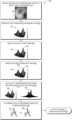
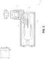
- FIG. 1illustrates an embodiment of a cart-based robotic system arranged for diagnostic and/or therapeutic bronchoscopy procedure(s).
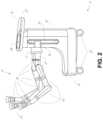
- FIG. 2depicts further aspects of the robotic system of FIG. 1 .
- FIG. 3illustrates an embodiment of the robotic system of FIG. 1 arranged for ureteroscopy.
- FIG. 4illustrates an embodiment of the robotic system of FIG. 1 arranged for a vascular procedure.
- FIG. 5illustrates an embodiment of a table-based robotic system arranged for a bronchoscopy procedure.
- FIG. 6provides an alternative view of the robotic system of FIG. 5 .
- FIG. 7illustrates an example system configured to stow robotic arm(s).
- FIG. 8illustrates an embodiment of a table-based robotic system configured for a ureteroscopy procedure.
- FIG. 9illustrates an embodiment of a table-based robotic system configured for a laparoscopic procedure.
- FIG. 10illustrates an embodiment of the table-based robotic system of FIGS. 5 - 9 with pitch or tilt adjustment.
- FIG. 11provides a detailed illustration of the interface between the table and the column of the table-based robotic system of FIGS. 5 - 10 .
- FIG. 12illustrates an exemplary instrument driver.
- FIG. 13illustrates an exemplary medical instrument with a paired instrument driver.
- FIG. 14illustrates an alternative design for an instrument driver and instrument where the axes of the drive units are parallel to the axis of the elongated shaft of the instrument.
- FIG. 15depicts a block diagram illustrating a localization system that estimates a location of one or more elements of the robotic systems of FIGS. 1 - 10 , such as the location of the instrument of FIGS. 13 - 14 , in accordance to an example embodiment.
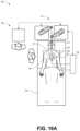
- FIG. 16 Aillustrates an example operating environment implementing the disclosed navigation systems and techniques.
- FIG. 16 Billustrates an example luminal network navigated in the environment of FIG. 16 A .
- FIG. 16 Cillustrates an example robotic arm for guiding instrument movement in through the luminal network of FIG. 16 B .
- FIG. 17illustrates an example command console for the example medical robotic system, according to one embodiment.
- FIG. 18illustrates an example endoscope having imaging and EM sensing capabilities as described herein.
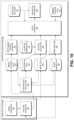
- FIG. 19depicts a schematic block diagram of a navigation system as described herein.
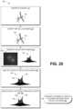
- FIG. 20depicts a flowchart of an example process for generating an extracted virtual feature data set.
- FIG. 21depicts a flowchart of an example intra-operative process for generating depth information based on captured endoscopic images and calculated correspondence between features of the depth information with the extracted virtual feature data set of FIG. 20 .
- aspects of the present disclosuremay be integrated into a robotically-enabled medical system capable of performing a variety of medical procedures, including both minimally invasive, such as laparoscopy, and non-invasive, such as endoscopy, procedures.
- minimally invasivesuch as laparoscopy
- non-invasivesuch as endoscopy
- the systemmay be capable of performing bronchoscopy, ureteroscopy, gastroenterology, etc.
- the systemmay provide additional benefits, such as enhanced imaging and guidance to assist the physician. Additionally, the system may provide the physician with the ability to perform the procedure from an ergonomic position without the need for awkward arm motions and positions. Still further, the system may provide the physician with the ability to perform the procedure with improved ease of use such that one or more of the instruments of the system can be controlled by a single user.
- FIG. 1illustrates an embodiment of a cart-based robotically-enabled system 10 arranged for a diagnostic and/or therapeutic bronchoscopy procedure.
- the system 10may comprise a cart 11 having one or more robotic arms 12 to deliver a medical instrument, such as a steerable endoscope 13 , which may be a procedure-specific bronchoscope for bronchoscopy, to a natural orifice access point (i.e., the mouth of the patient positioned on a table in the present example) to deliver diagnostic and/or therapeutic tools.
- a medical instrumentsuch as a steerable endoscope 13
- a natural orifice access pointi.e., the mouth of the patient positioned on a table in the present example
- the cart 11may be positioned proximate to the patient's upper torso in order to provide access to the access point.
- the robotic arms 12may be actuated to position the bronchoscope relative to the access point.
- the arrangement in FIG. 1may also be utilized when performing a gastro-intestinal (GI) procedure with a gastroscope, a specialized endoscope for GI procedures.
- FIG. 2depicts an example embodiment of the cart in greater detail.
- the robotic arms 12may insert the steerable endoscope 13 into the patient robotically, manually, or a combination thereof.
- the steerable endoscope 13may comprise at least two telescoping parts, such as an inner leader portion and an outer sheath portion, each portion coupled to a separate instrument driver from the set of instrument drivers 28 , each instrument driver coupled to the distal end of an individual robotic arm.
- This linear arrangement of the instrument drivers 28which facilitates coaxially aligning the leader portion with the sheath portion, creates a “virtual rail” 29 that may be repositioned in space by manipulating the one or more robotic arms 12 into different angles and/or positions.
- the virtual rails described hereinare depicted in the Figures using dashed lines, and accordingly the dashed lines do not depict any physical structure of the system.
- Translation of the instrument drivers 28 along the virtual rail 29telescopes the inner leader portion relative to the outer sheath portion or advances or retracts the endoscope 13 from the patient.
- the angle of the virtual rail 29may be adjusted, translated, and pivoted based on clinical application or physician preference. For example, in bronchoscopy, the angle and position of the virtual rail 29 as shown represents a compromise between providing physician access to the endoscope 13 while minimizing friction that results from bending the endoscope 13 into the patient's mouth.
- the endoscope 13may be directed down the patient's trachea and lungs after insertion using precise commands from the robotic system until reaching the target destination or operative site. In order to enhance navigation through the patient's lung network and/or reach the desired target, the endoscope 13 may be manipulated to telescopically extend the inner leader portion from the outer sheath portion to obtain enhanced articulation and greater bend radius.
- the use of separate instrument drivers 28also allows the leader portion and sheath portion to be driven independent of each other.
- the endoscope 13may be directed to deliver a biopsy needle to a target, such as, for example, a lesion or nodule within the lungs of a patient.
- the needlemay be deployed down a working channel that runs the length of the endoscope to obtain a tissue sample to be analyzed by a pathologist.
- additional toolsmay be deployed down the working channel of the endoscope for additional biopsies.
- the endoscope 13may endoscopically deliver tools to resect the potentially cancerous tissue.
- diagnostic and therapeutic treatmentsmay need to be delivered in separate procedures.
- the endoscope 13may also be used to deliver a fiducial to “mark” the location of the target nodule as well. In other instances, diagnostic and therapeutic treatments may be delivered during the same procedure.
- the system 10may also include a movable tower 30 , which may be connected via support cables to the cart 11 to provide support for controls, electronics, fluidics, optics, sensors, and/or power to the cart 11 . Placing such functionality in the tower 30 allows for a smaller form factor cart 11 that may be more easily adjusted and/or re-positioned by an operating physician and his/her staff. Additionally, the division of functionality between the cart/table and the support tower 30 reduces operating room clutter and facilitates improving clinical workflow. While the cart 11 may be positioned close to the patient, the tower 30 may be stowed in a remote location to stay out of the way during a procedure.
- the tower 30may include component(s) of a computer-based control system that stores computer program instructions, for example, within a non-transitory computer-readable storage medium such as a persistent magnetic storage drive, solid state drive, etc.
- the execution of those instructionsmay control the entire system or sub-system(s) thereof.
- the instructionswhen executed by a processor of the computer system, the instructions may cause the components of the robotics system to actuate the relevant carriages and arm mounts, actuate the robotics arms, and control the medical instruments.
- the motors in the joints of the robotics armsmay position the arms into a certain posture.
- the tower 30may also include a pump, flow meter, valve control, and/or fluid access in order to provide controlled irrigation and aspiration capabilities to system that may be deployed through the endoscope 13 . These components may also be controlled using the computer system of tower 30 . In some embodiments, irrigation and aspiration capabilities may be delivered directly to the endoscope 13 through separate cable(s).
- the tower 30may include a voltage and surge protector designed to provide filtered and protected electrical power to the cart 11 , thereby avoiding placement of a power transformer and other auxiliary power components in the cart 11 , resulting in a smaller, more moveable cart 11 .
- the tower 30may also include support equipment for the sensors deployed throughout the robotic system 10 .
- the tower 30may include opto-electronics equipment for detecting, receiving, and processing data received from the optical sensors or cameras throughout the robotic system 10 . In combination with the control system, such opto-electronics equipment may be used to generate real-time images for display in any number of consoles deployed throughout the system, including in the tower 30 .
- the tower 30may also include an electronic subsystem for receiving and processing signals received from deployed electromagnetic (EM) sensors.
- EMelectromagnetic
- the tower 30may also be used to house and position an EM field generator for detection by EM sensors in or on the medical instrument.
- the tower 30may also include a console 31 in addition to other consoles available in the rest of the system, e.g., console mounted on top of the cart.
- the console 31may include a user interface and a display screen, such as a touchscreen, for the physician operator.
- Consoles in system 10are generally designed to provide both robotic controls as well as pre-operative and real-time information of the procedure, such as navigational and localization information of the endoscope 13 .
- the console 31When the console 31 is not the only console available to the physician, it may be used by a second operator, such as a nurse, to monitor the health or vitals of the patient and the operation of system, as well as provide procedure-specific data, such as navigational and localization information.
- the tower 30may be coupled to the cart 11 and endoscope 13 through one or more cables or connections (not shown).
- the support functionality from the tower 30may be provided through a single cable to the cart 11 , simplifying and de-cluttering the operating room.
- specific functionalitymay be coupled in separate cabling and connections. For example, while power may be provided through a single power cable to the cart, the support for controls, optics, fluidics, and/or navigation may be provided through a separate cable.
- FIG. 2provides a detailed illustration of an embodiment of the cart from the cart-based robotically-enabled system shown in FIG. 1 .
- the cart 11generally includes an elongated support structure 14 (often referred to as a “column”), a cart base 15 , and a console 16 at the top of the column 14 .
- the column 14may include one or more carriages, such as a carriage 17 (alternatively “arm support”) for supporting the deployment of one or more robotic arms 12 (three shown in FIG. 2 ).
- the carriage 17may include individually configurable arm mounts that rotate along a perpendicular axis to adjust the base of the robotic arms 12 for better positioning relative to the patient.
- the carriage 17also includes a carriage interface 19 that allows the carriage 17 to vertically translate along the column 14 .
- the carriage interface 19is connected to the column 14 through slots, such as slot 20 , that are positioned on opposite sides of the column 14 to guide the vertical translation of the carriage 17 .
- the slot 20contains a vertical translation interface to position and hold the carriage at various vertical heights relative to the cart base 15 .
- Vertical translation of the carriage 17allows the cart 11 to adjust the reach of the robotic arms 12 to meet a variety of table heights, patient sizes, and physician preferences.
- the individually configurable arm mounts on the carriage 17allow the robotic arm base 21 of robotic arms 12 to be angled in a variety of configurations.
- the slot 20may be supplemented with slot covers that are flush and parallel to the slot surface to prevent dirt and fluid ingress into the internal chambers of the column 14 and the vertical translation interface as the carriage 17 vertically translates.
- the slot coversmay be deployed through pairs of spring spools positioned near the vertical top and bottom of the slot 20 .
- the coversare coiled within the spools until deployed to extend and retract from their coiled state as the carriage 17 vertically translates up and down.
- the spring-loading of the spoolsprovides force to retract the cover into a spool when carriage 17 translates towards the spool, while also maintaining a tight seal when the carriage 17 translates away from the spool.
- the coversmay be connected to the carriage 17 using, for example, brackets in the carriage interface 19 to ensure proper extension and retraction of the cover as the carriage 17 translates.
- the column 14may internally comprise mechanisms, such as gears and motors, that are designed to use a vertically aligned lead screw to translate the carriage 17 in a mechanized fashion in response to control signals generated in response to user inputs, e.g., inputs from the console 16 .
- the robotic arms 12may generally comprise robotic arm bases 21 and end effectors 22 , separated by a series of linkages 23 that are connected by a series of joints 24 , each joint comprising an independent actuator, each actuator comprising an independently controllable motor.
- Each independently controllable jointrepresents an independent degree of freedom available to the robotic arm.
- Each of the arms 12have seven joints, and thus provide seven degrees of freedom. A multitude of joints result in a multitude of degrees of freedom, allowing for “redundant” degrees of freedom. Redundant degrees of freedom allow the robotic arms 12 to position their respective end effectors 22 at a specific position, orientation, and trajectory in space using different linkage positions and joint angles. This allows for the system to position and direct a medical instrument from a desired point in space while allowing the physician to move the arm joints into a clinically advantageous position away from the patient to create greater access, while avoiding arm collisions.
- the cart base 15balances the weight of the column 14 , carriage 17 , and arms 12 over the floor. Accordingly, the cart base 15 houses heavier components, such as electronics, motors, power supply, as well as components that either enable movement and/or immobilize the cart.
- the cart base 15includes rollable wheel-shaped casters 25 that allow for the cart to easily move around the room prior to a procedure. After reaching the appropriate position, the casters 25 may be immobilized using wheel locks to hold the cart 11 in place during the procedure.
- the console 16allows for both a user interface for receiving user input and a display screen (or a dual-purpose device such as, for example, a touchscreen 26 ) to provide the physician user with both pre-operative and intra-operative data.
- Potential pre-operative data on the touchscreen 26may include pre-operative plans, navigation and mapping data derived from pre-operative computerized tomography (CT) scans, and/or notes from pre-operative patient interviews.
- Intra-operative data on displaymay include optical information provided from the tool, sensor and coordinate information from sensors, as well as vital patient statistics, such as respiration, heart rate, and/or pulse.
- the console 16may be positioned and tilted to allow a physician to access the console from the side of the column 14 opposite carriage 17 . From this position the physician may view the console 16 , robotic arms 12 , and patient while operating the console 16 from behind the cart 11 .
- the console 16also includes a handle 27 to assist with maneuvering and stabilizing cart 11 .
- FIG. 3illustrates an embodiment of a robotically-enabled system 10 arranged for ureteroscopy.
- the cart 11may be positioned to deliver a ureteroscope 32 , a procedure-specific endoscope designed to traverse a patient's urethra and ureter, to the lower abdominal area of the patient.
- the ureteroscope 32may be directly aligned with the patient's urethra to reduce friction and forces on the sensitive anatomy in the area.
- the cart 11may be aligned at the foot of the table to allow the robotic arms 12 to position the ureteroscope 32 for direct linear access to the patient's urethra. From the foot of the table, the robotic arms 12 may insert ureteroscope 32 along the virtual rail 33 directly into the patient's lower abdomen through the urethra.
- the ureteroscope 32may be navigated into the bladder, ureters, and/or kidneys for diagnostic and/or therapeutic applications.
- the ureteroscope 32may be directed into the ureter and kidneys to break up kidney stone build up using laser or ultrasonic lithotripsy device deployed down the working channel of the ureteroscope 32 .
- the resulting stone fragmentsmay be removed using baskets deployed down the ureteroscope 32 .
- FIG. 4illustrates an embodiment of a robotically-enabled system similarly arranged for a vascular procedure.
- the system 10may be configured such the cart 11 may deliver a medical instrument 34 , such as a steerable catheter, to an access point in the femoral artery in the patient's leg.
- the femoral arterypresents both a larger diameter for navigation as well as relatively less circuitous and tortuous path to the patient's heart, which simplifies navigation.
- the cart 11may be positioned towards the patient's legs and lower abdomen to allow the robotic arms 12 to provide a virtual rail 35 with direct linear access to the femoral artery access point in the patient's thigh/hip region.
- the medical instrument 34may be directed and inserted by translating the instrument drivers 28 .
- the cartmay be positioned around the patient's upper abdomen in order to reach alternative vascular access points, such as, for example, the carotid and brachial arteries near the shoulder and wrist.
- Embodiments of the robotically-enabled medical systemmay also incorporate the patient's table. Incorporation of the table reduces the amount of capital equipment within the operating room by removing the cart, which allows greater access to the patient.
- FIG. 5illustrates an embodiment of such a robotically-enabled system arranged for a bronchoscopy procedure.
- System 36includes a support structure or column 37 for supporting platform 38 (shown as a “table” or “bed”) over the floor.
- the end effectors of the robotic arms 39 of the system 36comprise instrument drivers 42 that are designed to manipulate an elongated medical instrument, such as a bronchoscope 40 in FIG. 5 , through or along a virtual rail 41 formed from the linear alignment of the instrument drivers 42 .
- a C-arm for providing fluoroscopic imagingmay be positioned over the patient's upper abdominal area by placing the emitter and detector around table 38 .
- FIG. 6provides an alternative view of the system 36 without the patient and medical instrument for discussion purposes.
- the column 37may include one or more carriages 43 shown as ring-shaped in the system 36 , from which the one or more robotic arms 39 may be based.
- the carriages 43may translate along a vertical column interface 44 that runs the length of the column 37 to provide different vantage points from which the robotic arms 39 may be positioned to reach the patient.
- the carriage(s) 43may rotate around the column 37 using a mechanical motor positioned within the column 37 to allow the robotic arms 39 to have access to multiples sides of the table 38 , such as, for example, both sides of the patient.
- the carriagesmay be individually positioned on the column and may translate and/or rotate independent of the other carriages.
- carriages 43need not surround the column 37 or even be circular, the ring-shape as shown facilitates rotation of the carriages 43 around the column 37 while maintaining structural balance. Rotation and translation of the carriages 43 allows the system to align the medical instruments, such as endoscopes and laparoscopes, into different access points on the patient.
- the arms 39may be mounted on the carriages through a set of arm mounts 45 comprising a series of joints that may individually rotate and/or telescopically extend to provide additional configurability to the robotic arms 39 .
- the arm mounts 45may be positioned on the carriages 43 such that, when the carriages 43 are appropriately rotated, the arm mounts 45 may be positioned on either the same side of table 38 (as shown in FIG. 6 ), on opposite sides of table 38 (as shown in FIG. 9 ), or on adjacent sides of the table 38 (not shown).
- the column 37structurally provides support for the table 38 , and a path for vertical translation of the carriages. Internally, the column 37 may be equipped with lead screws for guiding vertical translation of the carriages, and motors to mechanize the translation of said carriages based the lead screws. The column 37 may also convey power and control signals to the carriage 43 and robotic arms 39 mounted thereon.
- the table base 46serves a similar function as the cart base 15 in cart 11 shown in FIG. 2 , housing heavier components to balance the table/bed 38 , the column 37 , the carriages 43 , and the robotic arms 39 .
- the table base 46may also incorporate rigid casters to provide stability during procedures. Deployed from the bottom of the table base 46 , the casters may extend in opposite directions on both sides of the base 46 and retract when the system 36 needs to be moved.
- the system 36may also include a tower (not shown) that divides the functionality of system 36 between table and tower to reduce the form factor and bulk of the table.
- the towermay be provide a variety of support functionalities to table, such as processing, computing, and control capabilities, power, fluidics, and/or optical and sensor processing.
- the towermay also be movable to be positioned away from the patient to improve physician access and de-clutter the operating room. Additionally, placing components in the tower allows for more storage space in the table base for potential stowage of the robotic arms.
- the towermay also include a console that provides both a user interface for user input, such as keyboard and/or pendant, as well as a display screen (or touchscreen) for pre-operative and intra-operative information, such as real-time imaging, navigation, and tracking information.
- a table basemay stow and store the robotic arms when not in use.
- FIG. 7illustrates a system 47 that stows robotic arms in an embodiment of the table-based system.
- carriages 48may be vertically translated into base 49 to stow robotic arms 50 , arm mounts 51 , and the carriages 48 within the base 49 .
- Base covers 52may be translated and retracted open to deploy the carriages 48 , arm mounts 51 , and arms 50 around column 53 , and closed to stow to protect them when not in use.
- the base covers 52may be sealed with a membrane 54 along the edges of its opening to prevent dirt and fluid ingress when closed.
- FIG. 8illustrates an embodiment of a robotically-enabled table-based system configured for a ureteroscopy procedure.
- the table 38may include a swivel portion 55 for positioning a patient off-angle from the column 37 and table base 46 .
- the swivel portion 55may rotate or pivot around a pivot point (e.g., located below the patient's head) in order to position the bottom portion of the swivel portion 55 away from the column 37 .
- the pivoting of the swivel portion 55allows a C-arm (not shown) to be positioned over the patient's lower abdomen without competing for space with the column (not shown) below table 38 .
- the robotic arms 39may directly insert a ureteroscope 56 along a virtual rail 57 into the patient's groin area to reach the urethra.
- stirrups 58may also be fixed to the swivel portion 55 of the table 38 to support the position of the patient's legs during the procedure and allow clear access to the patient's groin area.
- FIG. 9illustrates an embodiment of a robotically-enabled table-based system configured for a laparoscopic procedure. As shown in FIG.
- the carriages 43 of the system 36may be rotated and vertically adjusted to position pairs of the robotic arms 39 on opposite sides of the table 38 , such that laparoscopes 59 may be positioned using the arm mounts 45 to be passed through minimal incisions on both sides of the patient to reach his/her abdominal cavity.
- FIG. 10illustrates an embodiment of the robotically-enabled medical system with pitch or tilt adjustment.
- the system 36may accommodate tilt of the table 38 to position one portion of the table at a greater distance from the floor than the other.
- the arm mounts 45may rotate to match the tilt such that the arms 39 maintain the same planar relationship with table 38 .
- the column 37may also include telescoping portions 60 that allow vertical extension of column 37 to keep the table 38 from touching the floor or colliding with base 46 .
- FIG. 11provides a detailed illustration of the interface between the table 38 and the column 37 .
- Pitch rotation mechanism 61may be configured to alter the pitch angle of the table 38 relative to the column 37 in multiple degrees of freedom.
- the pitch rotation mechanism 61may be enabled by the positioning of orthogonal axes 1 , 2 at the column-table interface, each axis actuated by a separate motor 2 , 4 responsive to an electrical pitch angle command. Rotation along one screw 5 would enable tilt adjustments in one axis 1 , while rotation along the other screw 6 would enable tilt adjustments along the other axis 2 .
- pitch adjustmentsare particularly useful when trying to position the table in a Trendelenburg position, i.e., position the patient's lower abdomen at a higher position from the floor than the patient's lower abdomen, for lower abdominal surgery.
- the Trendelenburg positioncauses the patient's internal organs to slide towards his/her upper abdomen through the force of gravity, clearing out the abdominal cavity for minimally invasive tools to enter and perform lower abdominal surgical procedures, such as laparoscopic prostatectomy.
- the end effectors of the system's robotic armscomprise (i) an instrument driver (alternatively referred to as “instrument drive mechanism” or “instrument device manipulator”) that incorporate electro-mechanical means for actuating the medical instrument and (ii) a removable or detachable medical instrument which may be devoid of any electro-mechanical components, such as motors.
- instrument driveralternatively referred to as “instrument drive mechanism” or “instrument device manipulator”
- instrument device manipulatora removable or detachable medical instrument which may be devoid of any electro-mechanical components, such as motors.
- FIG. 12illustrates an example instrument driver.
- instrument driver 62Positioned at the distal end of a robotic arm, instrument driver 62 comprises of one or more drive units 63 arranged with parallel axes to provide controlled torque to a medical instrument via drive shafts 64 .
- Each drive unit 63comprises an individual drive shaft 64 for interacting with the instrument, a gear head 65 for converting the motor shaft rotation to a desired torque, a motor 66 for generating the drive torque, an encoder 67 to measure the speed of the motor shaft and provide feedback to the control circuitry, and control circuitry 68 for receiving control signals and actuating the drive unit.
- Each drive unit 63being independent controlled and motorized, the instrument driver 62 may provide multiple (four as shown in FIG. 12 ) independent drive outputs to the medical instrument.
- the control circuitry 68would receive a control signal, transmit a motor signal to the motor 66 , compare the resulting motor speed as measured by the encoder 67 with the desired speed, and modulate the motor signal to generate the desired torque
- the robotic systemmay incorporate a drive interface, such as a sterile adapter connected to a sterile drape, that sits between the instrument driver and the medical instrument.
- a drive interfacesuch as a sterile adapter connected to a sterile drape
- the chief purpose of the sterile adapteris to transfer angular motion from the drive shafts of the instrument driver to the drive inputs of the instrument while maintaining physical separation, and thus sterility, between the drive shafts and drive inputs.
- an example sterile adaptermay comprise of a series of rotational inputs and outputs intended to be mated with the drive shafts of the instrument driver and drive inputs on the instrument.
- the sterile drapecomprised of a thin, flexible material such as transparent or translucent plastic, is designed to cover the capital equipment, such as the instrument driver, robotic arm, and cart (in a cart-based system) or table (in a table-based system).
- the capital equipmentsuch as the instrument driver, robotic arm, and cart (in a cart-based system) or table (in a table-based system).
- Use of the drapewould allow the capital equipment to be positioned proximate to the patient while still being located in an area not requiring sterilization (i.e., non-sterile field).
- the medical instrumentmay interface with the patient in an area requiring sterilization (i.e., sterile field).
- FIG. 13illustrates an example medical instrument with a paired instrument driver.
- medical instrument 70comprises an elongated shaft 71 (or elongate body) and an instrument base 72 .
- the instrument base 72also referred to as an “instrument handle” due to its intended design for manual interaction by the physician, may generally comprise rotatable drive inputs 73 , e.g., receptacles, pulleys or spools, that are designed to be mated with drive outputs 74 that extend through a drive interface on instrument driver 75 at the distal end of robotic arm 76 .
- the mated drive inputs 73 of instrument base 72may share axes of rotation with the drive outputs 74 in the instrument driver 75 to allow the transfer of torque from drive outputs 74 to drive inputs 73 .
- the drive outputs 74may comprise splines that are designed to mate with receptacles on the drive inputs 73 .
- the elongated shaft 71is designed to be delivered through either an anatomical opening or lumen, e.g., as in endoscopy, or a minimally invasive incision, e.g., as in laparoscopy.
- the elongated shaft 66may be either flexible (e.g., having properties similar to an endoscope) or rigid (e.g., having properties similar to a laparoscope) or contain a customized combination of both flexible and rigid portions.
- the distal end of a rigid elongated shaftmay be connected to an end effector comprising a jointed wrist formed from a clevis with an axis of rotation and a surgical tool, such as, for example, a grasper or scissors, that may be actuated based on force from the tendons as the drive inputs rotate in response to torque received from the drive outputs 74 of the instrument driver 75 .
- a surgical toolsuch as, for example, a grasper or scissors
- the distal end of a flexible elongated shaftmay include a steerable or controllable bending section that may be articulated and bent based on torque received from the drive outputs 74 of the instrument driver 75 .
- Torque from the instrument driver 75is transmitted down the elongated shaft 71 using tendons within the shaft 71 .
- These individual tendonssuch as pull wires, may be individually anchored to individual drive inputs 73 within the instrument handle 72 .
- the tendonsare directed down one or more pull lumens within the elongated shaft 71 and anchored at the distal portion of the elongated shaft 71 .
- these tendonsmay be coupled to a distally mounted end effector, such as a wrist, grasper, or scissor. Under such an arrangement, torque exerted on drive inputs 73 would transfer tension to the tendon, thereby causing the end effector to actuate in some way.
- the tendonmay cause a joint to rotate about an axis, thereby causing the end effector to move in one direction or another.
- the tendonmay be connected to one or more jaws of a grasper at distal end of the elongated shaft 71 , where tension from the tendon cause the grasper to close.
- the tendonsmay be coupled to a bending or articulating section positioned along the elongated shaft 71 (e.g., at the distal end) via adhesive, control ring, or other mechanical fixation.
- a bending or articulating sectionpositioned along the elongated shaft 71 (e.g., at the distal end) via adhesive, control ring, or other mechanical fixation.
- torque exerted on drive inputs 73would be transmitted down the tendons, causing the softer, bending section (sometimes referred to as the articulable section or region) to bend or articulate.
- the angle of the spiraling and/or spacing there betweenmay be altered or engineered for specific purposes, wherein tighter spiraling exhibits lesser shaft compression under load forces, while lower amounts of spiraling results in greater shaft compression under load forces, but also exhibits limits bending.
- the pull lumensmay be directed parallel to the longitudinal axis of the elongated shaft 71 to allow for controlled articulation in the desired bending or articulable sections.
- the elongated shaft 71houses a number of components to assist with the robotic procedure.
- the shaftmay comprise of a working channel for deploying surgical tools, irrigation, and/or aspiration to the operative region at the distal end of the shaft 71 .
- the shaft 71may also accommodate wires and/or optical fibers to transfer signals to/from an optical assembly at the distal tip, which may include of an optical camera.
- the shaft 71may also accommodate optical fibers to carry light from proximally-located light sources, such as light emitting diodes, to the distal end of the shaft.
- the distal tipmay also comprise the opening of a working channel for delivering tools for diagnostic and/or therapy, irrigation, and aspiration to an operative site.
- the distal tipmay also include a port for a camera, such as a fiberscope or a digital camera, to capture images of an internal anatomical space.
- the distal tipmay also include ports for light sources for illuminating the anatomical space when using the camera.
- the drive shaft axesand thus the drive input axes, are orthogonal to the axis of the elongated shaft.
- This arrangementcomplicates roll capabilities for the elongated shaft 71 .
- Rolling the elongated shaft 71 along its axis while keeping the drive inputs 73 staticresults in undesirable tangling of the tendons as they extend off the drive inputs 73 and enter pull lumens within the elongate shaft 71 .
- the resulting entanglement of such tendonsmay disrupt any control algorithms intended to predict movement of the flexible elongate shaft during an endoscopic procedure.
- FIG. 14illustrates an alternative design for an instrument driver and instrument where the axes of the drive units are parallel to the axis of the elongated shaft of the instrument.
- a circular instrument driver 80comprises four drive units with their drive outputs 81 aligned in parallel at the end of a robotic arm 82 .
- the drive units, and their respective drive outputs 81are housed in a rotational assembly 83 of the instrument driver 80 that is driven by one of the drive units within the assembly 83 .
- the rotational assembly 83rotates along a circular bearing that connects the rotational assembly 83 to the non-rotational portion 84 of the instrument driver.
- Power and controls signalsmay be communicated from the non-rotational portion 84 of the instrument driver 80 to the rotational assembly 83 through electrical contacts may be maintained through rotation by a brushed slip ring connection (not shown).
- the rotational assembly 83may be responsive to a separate drive unit that is integrated into the non-rotatable portion 84 , and thus not in parallel to the other drive units.
- the rotational mechanism 83allows the instrument driver 80 to rotate the drive units, and their respective drive outputs 81 , as a single unit around an instrument driver axis 85 .
- an instrument 86may comprise of an elongated shaft portion 88 and an instrument base 87 (shown with a transparent external skin for discussion purposes) comprising a plurality of drive inputs 89 (such as receptacles, pulleys, and spools) that are configured to receive the drive outputs 81 in the instrument driver 80 .
- instrument shaft 88extends from the center of instrument base 87 with an axis substantially parallel to the axes of the drive inputs 89 , rather than orthogonal as in the design of FIG. 13 .
- the medical instrument 86When coupled to the rotational assembly 83 of the instrument driver 80 , the medical instrument 86 , comprising instrument base 87 and instrument shaft 88 , rotates in combination with the rotational assembly 83 about the instrument driver axis 85 . Since the instrument shaft 88 is positioned at the center of instrument base 87 , the instrument shaft 88 is coaxial with instrument driver axis 85 when attached. Thus, rotation of the rotational assembly 83 causes the instrument shaft 88 to rotate about its own longitudinal axis. Moreover, as the instrument base 87 rotates with the instrument shaft 88 , any tendons connected to the drive inputs 89 in the instrument base 87 are not tangled during rotation. Accordingly, the parallelism of the axes of the drive outputs 81 , drive inputs 89 , and instrument shaft 88 allows for the shaft rotation without tangling any control tendons.
- the robotic systems contemplated by this disclosurecan provide for non-radiation-based navigational and localization means to reduce physician exposure to radiation and reduce the amount of equipment within the operating room.
- the term “localization”may refer to determining and/or monitoring the position of objects in a reference coordinate system. Technologies such as pre-operative mapping, computer vision, real-time EM tracking, and robot command data may be used individually or in combination to achieve a radiation-free operating environment. In other cases, where radiation-based imaging modalities are still used, the pre-operative mapping, computer vision, real-time EM tracking, and robot command data may be used individually or in combination to improve upon the information obtained solely through radiation-based imaging modalities.
- FIG. 15is a block diagram illustrating a localization system 90 that estimates a location of one or more elements of the robotic system, such as the location of the instrument, in accordance to an example embodiment.
- the localization system 90may be a set of one or more computer devices configured to execute one or more instructions.
- the computer devicesmay be embodied by a processor (or processors) and computer-readable memory in one or more components discussed above.
- the computer devicesmay be in the tower 30 shown in FIG. 1 , the cart shown in FIGS. 1 - 4 , the beds shown in FIGS. 5 - 10 , etc.
- the localization system 90may include a localization module 95 that processes input data 91 - 94 to generate location data 96 for the distal tip of a medical instrument.
- the location data 96may be data or logic that represents a location and/or orientation of the distal end of the instrument relative to a frame of reference.
- the frame of referencecan be a frame of reference relative to the anatomy of the patient or to a known object, such as an EM field generator (see discussion below for the EM field generator).
- Pre-operative mappingmay be accomplished through the use of the collection of low dose CT scans.
- Pre-operative CT scansgenerate two-dimensional images, each representing a “slice” of a cutaway view of the patient's internal anatomy.
- image-based models for anatomical cavities, spaces and structures of the patient's anatomy, such as a patient lung networkmay be generated.
- Techniquessuch as center-line geometry may be determined and approximated from the CT images to develop a three-dimensional volume of the patient's anatomy, referred to as preoperative model data 91 .
- center-line geometryis discussed in U.S. patent application Ser. No. 14/523,760, the contents of which are herein incorporated in its entirety.
- Network topological modelsmay also be derived from the CT-images, and are particularly appropriate for bronchoscopy.
- the instrumentmay be equipped with a camera to provide vision data 92 .
- the localization module 95may process the vision data to enable one or more vision-based location tracking.
- the preoperative model datamay be used in conjunction with the vision data 92 to enable computer vision-based tracking of the medical instrument (e.g., an endoscope or an instrument advance through a working channel of the endoscope).
- the robotic systemmay generate a library of expected endoscopic images from the model based on the expected path of travel of the endoscope, each image linked to a location within the model. Intra-operatively, this library may be referenced by the robotic system in order to compare real-time images captured at the camera (e.g., a camera at a distal end of the endoscope) to those in the image library to assist localization.
- Some computer vision-based tracking techniquesuse feature tracking to determine motion of the camera, and thus the endoscope.
- Some feature of the localization module 95may identify circular geometries in the preoperative model data 91 that correspond to anatomical lumens and track the change of those geometries to determine which anatomical lumen was selected, as well as the relative rotational and/or translational motion of the camera.
- Use of a topological mapmay further enhance vision-based algorithms or techniques.
- Optical flowanother computer vision-based technique, may analyze the displacement and translation of image pixels in a video sequence in the vision data 92 to infer camera movement. Through the comparison of multiple frames over multiple iterations, movement and location of the camera (and thus the endoscope) may be determined.
- the localization module 95may use real-time EM tracking to generate a real-time location of the endoscope in a global coordinate system that may be registered to the patient's anatomy, represented by the preoperative model.
- EM trackingan EM sensor (or tracker) comprising of one or more sensor coils embedded in one or more locations and orientations in a medical instrument (e.g., an endoscopic tool) measures the variation in the EM field created by one or more static EM field generators positioned at a known location.
- the location information detected by the EM sensorsis stored as EM data 93 .
- the EM field generator(or transmitter), may be placed close to the patient to create a low intensity magnetic field that the embedded sensor may detect.
- the magnetic fieldinduces small currents in the sensor coils of the EM sensor, which may be analyzed to determine the distance and angle between the EM sensor and the EM field generator.
- These distances and orientationsmay be intra-operatively “registered” to the patient anatomy (e.g., the preoperative model) in order to determine the geometric transformation that aligns a single location in the coordinate system with a position in the pre-operative model of the patient's anatomy.
- an embedded EM tracker in one or more positions of the medical instrumente.g., the distal tip of an endoscope
- Robotic command and kinematics data 94may also be used by the localization module 95 to provide localization data 96 for the robotic system.
- Device pitch and yaw resulting from articulation commandsmay be determined during pre-operative calibration. Intra-operatively, these calibration measurements may be used in combination with known insertion depth information to estimate the position of the instrument. Alternatively, these calculations may be analyzed in combination with EM, vision, and/or topological modeling to estimate the position of the medical instrument within the network.
- FIG. 15shows, a number of other input data can be used by the localization module 95 .
- an instrument utilizing shape-sensing fibercan provide shape data that the localization module 95 can use to determine the location and shape of the instrument.
- the localization module 95may use the input data 91 - 94 in combination(s). In some cases, such a combination may use a probabilistic approach where the localization module 95 assigns a confidence weight to the location determined from each of the input data 91 - 94 . Thus, where the EM data may not be reliable (as may be the case where there is EM interference) the confidence of the location determined by the EM data 93 can be decrease and the localization module 95 may rely more heavily on the vision data 92 and/or the robotic command and kinematics data 94 .
- the robotic systems discussed hereinmay be designed to incorporate a combination of one or more of the technologies above.
- the robotic system's computer-based control systembased in the tower, bed and/or cart, may store computer program instructions, for example, within a non-transitory computer-readable storage medium such as a persistent magnetic storage drive, solid state drive, or the like, that, upon execution, cause the system to receive and analyze sensor data and user commands, generate control signals throughout the system, and display the navigational and localization data, such as the position of the instrument within the global coordinate system, anatomical map, etc.
- Embodiments of the disclosurerelate to systems and techniques that facilitate navigation of a medical instrument through luminal networks, for example, lung airways or other anatomical structures having interior open space, by generating and using depth information from endoscope images to determine an initial endoscope position, by analyzing multiple navigation-related data sources to increase accuracy in estimation of location and orientation of a medical instrument within the luminal network, and by generating and using additional depth information to re-initialize the navigation system after an adverse event.
- luminal networksfor example, lung airways or other anatomical structures having interior open space
- a bronchoscopecan include a light source and a small camera that allows a physician to inspect a patient's windpipe and airways. Patient trauma can occur if the precise location of the bronchoscope within the patient airways is not known.
- image-based bronchoscopy guidance systemscan use data from the bronchoscope camera to perform local registrations (e.g., registrations at a particular location within a luminal network) at bifurcations of patient airways and so beneficially can be less susceptible to position errors due to patient breathing motion.
- local registrationse.g., registrations at a particular location within a luminal network
- image-based guidance methodsrely on the bronchoscope video, they can be affected by artifacts in bronchoscope video caused by patient coughing or mucous obstruction, etc.
- Electromagnetic navigation-guided bronchoscopyis a type of bronchoscopic procedure that implements EM technology to localize and guide endoscopic tools or catheters through the bronchial pathways of the lung.
- EMN bronchoscopy systemscan use an EM field generator that emits a low-intensity, varying EM field and establishes the position of the tracking volume around the luminal network of the patient.
- the EM fieldis a physical field produced by electrically charged objects that affects the behavior of charged objects in the vicinity of the field.
- EM sensors attached to objects positioned within the generated fieldcan be used to track locations and orientations of these objects within the EM field. Small currents are induced in the EM sensors by the varying electromagnetic field.
- an EMN bronchoscopy systemcan include an EM field generator, a steerable medical instrument having an EM sensor at or near its distal tip, and a guidance computing system.
- the EM field generatorgenerates an EM field around the luminal network of the patient to be navigated, for example, airways, gastrointestinal tract, or a circulatory pathway.
- the steerable channelis inserted through the working channel of the bronchoscope and tracked in the EM field via the EM sensor.
- a virtual, three-dimensional (3D) bronchial mapcan be obtained for the patient's specific airway structure, for example, from a preoperative CT chest scan.
- physicianscan navigate to a desired location within the lung to biopsy lesions, stage lymph nodes, insert markers to guide radiotherapy or guide brachytherapy catheters.
- a registrationcan be performed at the beginning of a procedure to generate a mapping between the coordinate system of the EM field and the model coordinate system.
- the steerable channel's position in the model coordinate systembecomes nominally known based on position data from the EM sensor.
- a coordinate frameis the frame of reference of a particular sensing modality.
- the EM coordinate frameis the frame of reference defined by the source of the EM field (e.g., the field generator).
- this frame of referenceis based on the frame defined by the scanner.
- the present navigation systemsaddress the problem of navigation of representing (register) these different sources of data (which are in their own frames of reference) to the 3D model (i.e. the CT frame), for example, in order to display the location of the instrument inside the model.
- the disclosed luminal network navigation systems and techniquescan combine input from both image-based navigation systems, robotic systems, and EM navigation systems, as well as input from other patient sensors, in order to mitigate navigational problems and enable more effective endoscopy procedures.
- a navigation fusion systemcan analyze image information received from an instrument camera, position information from an EM sensor on the instrument tip, and robotic position information from a robotic system guiding movement of the instrument. Based on the analysis, the navigation fusion framework can base instrument position estimates and/or navigation decisions on one or more of these types of navigation data. Some implementations of the navigation fusion framework can further determine instrument position relative to a 3D model of the luminal network.
- the initial instrument position used to initialize tracking via the navigation fusion systemcan be generated based on depth information as described herein.
- a “lumen”may refer to the inner open space or cavity of an organ, as of an airway, a blood vessel, a kidney, a heart, an intestine, or any other suitable organ in which a medical procedure is being performed.
- a “luminal network”refers to an anatomical structure having at least one lumen leading towards a target tissue site, for example, the airways of the lungs, the circulatory system, calyx, and the gastrointestinal system.
- the disclosed position estimation aspectsare applicable to other medical systems for navigation of a luminal network of a patient.
- the disclosed systems and techniquescan be used with bronchoscopes, ureteroscopes, gastrointestinal endoscopes, and other suitable medical instruments.
- FIG. 16 Aillustrates an example operating environment 100 implementing one or more aspects of the disclosed navigation systems and techniques.
- the operating environment 100includes patient 101 , a platform 102 supporting the patient 101 , a medical robotic system 110 guiding movement of endoscope 115 , command center 105 for controlling operations of the medical robotic system 110 , EM controller 135 , EM field generator 120 , and EM sensors 125 , 130 .
- FIG. 16 Aalso illustrates an outline of a region of a luminal network 140 within the patient 101 , shown in more detail in FIG. 16 B .
- the medical robotic system 110can include one or more robotic arms for positioning and guiding movement of endoscope 115 through the luminal network 140 of the patient 101 .
- Command center 105can be communicatively coupled to the medical robotic system 110 for receiving position data and/or providing control signals from a user.
- “communicatively coupled”refers to any wired and/or wireless data transfer mediums, including but not limited to a wireless wide area network (WWAN) (e.g., one or more cellular networks), a wireless local area network (WLAN) (e.g., configured for one or more standards, such as the IEEE 802.11 (Wi-Fi)), Bluetooth, data transfer cables, and/or the like.
- WWANwireless wide area network
- WLANwireless local area network
- the medical robotic system 110can be any of the systems described above with respect to FIGS. 1 - 15 . An embodiment of the medical robotic system 110 is discussed in more detail with respect to FIG. 16 C , and the command center 105 is discussed in more detail with respect to FIG. 17 .
- the endoscope 115may be a tubular and flexible surgical instrument that is inserted into the anatomy of a patient to capture images of the anatomy (e.g., body tissue) and provide a working channel for insertion of other medical instruments to a target tissue site.
- the endoscope 115can be a procedure-specific endoscope, for example a bronchoscope, gastroscope, or ureteroscope, or may be a laparoscope or vascular steerable catheter.
- the endoscope 115can include one or more imaging devices (e.g., cameras or other types of optical sensors) at its distal end.
- the imaging devicesmay include one or more optical components such as an optical fiber, fiber array, photosensitive substrate, and/or lens(es).
- the optical componentsmove along with the tip of the endoscope 115 such that movement of the tip of the endoscope 115 results in corresponding changes to the field of view of the images captured by the imaging devices.
- the distal end of the endoscope 115can be provided with one or more EM sensors 125 for tracking the position of the distal end within an EM field generated around the luminal network 140 .
- the distal end of the endoscope 115is further described with reference to FIG. 18 below.
- the EM controller 135can control EM field generator 120 to produce a varying EM field.
- the EM fieldcan be time-varying and/or spatially varying, depending upon the embodiment.
- the EM field generator 120can be an EM field generating board in some embodiments.
- Some embodiments of the disclosed patient navigation systemscan use an EM field generator board positioned between the patient and the platform 102 supporting the patient, and the EM field generator board can incorporate a thin barrier that minimizes any tracking distortions caused by conductive or magnetic materials located below it.
- an EM field generator boardcan be mounted on a robotic arm, for example, similar to those shown in medical robotic system 110 , which can offer flexible setup options around the patient.
- An EM spatial measurement system incorporated into the command center 105 , medical robotic system 110 , and/or EM controller 135can determine the location of objects within the EM field that are embedded or provided with EM sensor coils, for example, EM sensors 125 , 130 .
- EM sensor coilsfor example, EM sensors 125 , 130 .
- voltagesare induced in the sensor coils. These induced voltages can be used by the EM spatial measurement system to calculate the position and orientation of the EM sensor and thus the object having the EM sensor.
- the magnetic fieldsare of a low field strength and can safely pass through human tissue, location measurement of an object is possible without the line-of-sight constraints of an optical spatial measurement system.
- EM sensor 125can be coupled to a distal end of the endoscope 115 in order to track its location within the EM field.
- the EM fieldis stationary relative to the EM field generator, and a coordinate frame of a 3D model of the luminal network can be mapped to a coordinate frame of the EM field.
- a number of additional EM sensors 130can be provided on the body surface of the patient (e.g., in the region of the luminal network 140 ) in order to aid in tracking the location of the EM sensor 125 , for example, by enabling compensation for patient movement including displacement caused by respiration.
- a number of different EM sensors 130can be spaced apart on the body surface.
- FIG. 16 Billustrates an example luminal network 140 that can be navigated in the operating environment 100 of FIG. 16 A .
- the luminal network 140includes the branched structure of the airways 150 of the patient, the trachea 154 leading to the main carina 156 (the first bifurcation encountered during bronchoscopy navigation), and a nodule (or lesion) 155 that can be accessed as described herein for diagnosis and/or treatment.
- the nodule 155is located at the periphery of the airways 150 .
- the endoscope 115has a first diameter and thus its distal end is not able to be positioned through the smaller-diameter airways around the nodule 155 .
- a steerable catheter 155extends from the working channel of the endoscope 115 the remaining distance to the nodule 155 .
- the steerable catheter 145may have a lumen through which instruments, for example, biopsy needles, cytology brushes, and/or tissue sampling forceps, can be passed to the target tissue site of nodule 155 .
- both the distal end of the endoscope 115 and the distal end of the steerable catheter 145can be provided with EM sensors for tracking their position within the airways 150 .
- the overall diameter of the endoscope 115may be small enough to reach the periphery without the steerable catheter 155 , or may be small enough to get close to the periphery (e.g., within 2.5-3 cm) to deploy medical instruments through a non-steerable catheter.
- the medical instruments deployed through the endoscope 115may be equipped with EM sensors, and the position estimation techniques described below can be applied to such medical instruments when they are deployed beyond the distal tip of the endoscope 115 .
- a 2D display of a 3D luminal network model as described herein, or a cross-section of a 3D modelcan resemble FIG. 16 B .
- Estimated position informationcan be overlaid onto such a representation.
- FIG. 16 Cillustrates an example robotic arm 175 of a medical robotic system 110 for guiding instrument movement in through the luminal network 140 of FIG. 16 B .
- the robotic arm 175can be robotic arms 12 , 39 described above in some embodiments, and is coupled to base 180 , which can be cart base 15 , column 37 of patient platform 38 , or a ceiling-based mount in various embodiments.
- the robotic arm 175includes multiple arm segments 170 coupled at joints 165 , which provides the robotic arm 175 multiple degrees of freedom.
- the robotic arm 175may be coupled to an instrument driver 190 , for example instrument driver 62 described above, using a mechanism changer interface (MCI) 160 .
- the instrument driver 190can be removed and replaced with a different type of instrument driver, for example, a first type of instrument driver configured to manipulate an endoscope or a second type of instrument driver configured to manipulate a laparoscope.
- the MCI 160includes connectors to transfer pneumatic pressure, electrical power, electrical signals, and optical signals from the robotic arm 175 to the instrument driver 190 .
- the MCI 160can be a set screw or base plate connector.
- the instrument driver 190manipulates surgical instruments, for example, the endoscope 115 using techniques including direct drive, harmonic drive, geared drives, belts and pulleys, magnetic drives, and the like.
- the MCI 160is interchangeable based on the type of instrument driver 190 and can be customized for a certain type of surgical procedure.
- the robotic 175 armcan include a joint level torque sensing and a wrist at a dis
- Robotic arm 175 of the medical robotic system 110can manipulate the endoscope 115 using tendons as described above to deflect the tip of the endoscope 115 .
- the endoscope 115may exhibit nonlinear behavior in response to forces applied by the elongate movement members.
- the nonlinear behaviormay be based on stiffness and compressibility of the endoscope 115 , as well as variability in slack or stiffness between different elongate movement members.
- the base 180can be positioned such that the robotic arm 175 has access to perform or assist with a surgical procedure on a patient, while a user such as a physician may control the medical robotic system 110 from the comfort of the command console.
- the base 180can be communicatively coupled to the command console 105 shown in FIG. 16 A .
- the base 180can include a source of power 182 , pneumatic pressure 186 , and control and sensor electronics 184 —including components such as a central processing unit, data bus, control circuitry, and memory—and related actuators such as motors to move the robotic arm 175 .
- the electronics 184can implement the navigation control techniques described herein.
- the electronics 184 in the base 180may also process and transmit control signals communicated from the command console.
- the base 180includes wheels 188 to transport the medical robotic system 110 and wheel locks/brakes (not shown) for the wheels 188 . Mobility of the medical robotic system 110 helps accommodate space constraints in a surgical operating room as well as facilitate appropriate positioning and movement of surgical equipment.
- the mobilityallows the robotic arm 175 to be configured such that the robotic arm 175 does not interfere with the patient, physician, anesthesiologist, or any other equipment.
- a usermay control the robotic arm 175 using control devices, for example, the command console.
- FIG. 17illustrates an example command console 200 that can be used, for example, as the command console 105 in the example operating environment 100 .
- the command console 200includes a console base 201 , display modules 202 , e.g., monitors, and control modules, e.g., a keyboard 203 and joystick 204 .
- one or more of the command console 200 functionalitymay be integrated into a base 180 of the medical robotic system 110 or another system communicatively coupled to the medical robotic system 110 .
- a user 205e.g., a physician, remotely controls the medical robotic system 110 from an ergonomic position using the command console 200 .
- the console base 201may include a central processing unit, a memory unit, a data bus, and associated data communication ports that are responsible for interpreting and processing signals such as camera imagery and tracking sensor data, e.g., from the endoscope 115 shown in FIGS. 16 A- 16 C .
- both the console base 201 and the base 180perform signal processing for load-balancing.
- the console base 201may also process commands and instructions provided by the user 205 through the control modules 203 and 204 .
- control modulesmay include other devices, for example, computer mice, trackpads, trackballs, control pads, controllers such as handheld remote controllers, and sensors (e.g., motion sensors or cameras) that capture hand gestures and finger gestures.
- a controllercan include a set of user inputs (e.g., buttons, joysticks, directional pads, etc.) mapped to an operation of the instrument (e.g., articulation, driving, water irrigation, etc.).
- the user 205can control a surgical instrument such as the endoscope 115 using the command console 200 in a velocity mode or position control mode.
- velocity modethe user 205 directly controls pitch and yaw motion of a distal end of the endoscope 115 based on direct manual control using the control modules.
- movement on the joystick 204may be mapped to yaw and pitch movement in the distal end of the endoscope 115 .
- the joystick 204can provide haptic feedback to the user 205 .
- the joystick 204may vibrate to indicate that the endoscope 115 cannot further translate or rotate in a certain direction.
- the command console 200can also provide visual feedback (e.g., pop-up messages) and/or audio feedback (e.g., beeping) to indicate that the endoscope 115 has reached maximum translation or rotation.
- the command console 200uses a 3D map of a patient luminal network and input from navigational sensors as described herein to control a surgical instrument, e.g., the endoscope 115 .
- the command console 200provides control signals to robotic arms 175 of the medical robotic system 110 to manipulate the endoscope 115 to a target location. Due to the reliance on the 3D map, position control mode may require accurate mapping of the anatomy of the patient.
- users 205can manually manipulate robotic arms 175 of the medical robotic system 110 without using the command console 200 .
- the users 205may move the robotic arms 175 , endoscope 115 (or endoscopes), and other surgical equipment to access a patient.
- the medical robotic system 110may rely on force feedback and inertia control from the users 205 to determine appropriate configuration of the robotic arms 175 and equipment.
- the displays 202may include electronic monitors (e.g., LCD displays, LED displays, touch-sensitive displays), virtual reality viewing devices, e.g., goggles or glasses, and/or other display devices.
- the display modules 202are integrated with the control modules, for example, as a tablet device with a touchscreen.
- one of the displays 202can display a 3D model of the patient's luminal network and virtual navigation information (e.g., a virtual representation of the end of the endoscope within the model based on EM sensor position) while the other of the displays 202 can display image information received from the camera or another sensing device at the end of the endoscope 115 .
- the user 205can both view data and input commands to the medical robotic system 110 using the integrated displays 202 and control modules.
- the displays 202can display 2D renderings of 3D images and/or 3D images using a stereoscopic device, e.g., a visor or goggles.
- the 3D imagesprovide an “endo view” (i.e., endoscopic view), which is a computer 3D model illustrating the anatomy of a patient.
- the “endo view”provides a virtual environment of the patient's interior and an expected location of an endoscope 115 inside the patient.
- a user 205compares the “endo view” model to actual images captured by a camera to help mentally orient and confirm that the endoscope 115 is in the correct—or approximately correct—location within the patient.
- the “endo view”provides information about anatomical structures, e.g., the shape of airways, circulatory vessels, or an intestine or colon of the patient, around the distal end of the endoscope 115 .
- the display modules 202can simultaneously display the 3D model and CT scans of the anatomy the around distal end of the endoscope 115 . Further, the display modules 202 may overlay the already determined navigation paths of the endoscope 115 on the 3D model and CT scans.
- a model of the endoscope 115is displayed with the 3D models to help indicate a status of a surgical procedure.
- the CT scansidentify a lesion in the anatomy where a biopsy may be necessary.
- the display modules 202may show a reference image captured by the endoscope 115 corresponding to the current location of the endoscope 115 .
- the display modules 202may automatically display different views of the model of the endoscope 115 depending on user settings and a particular surgical procedure. For example, the display modules 202 show an overhead fluoroscopic view of the endoscope 115 during a navigation step as the endoscope 115 approaches an operative region of a patient.
- FIG. 18illustrates the distal end 300 of an example endoscope having imaging and EM sensing capabilities as described herein, for example, the endoscope 115 of FIGS. 16 A- 16 C .
- the distal end 300 of the endoscopeincludes an imaging device 315 , illumination sources 310 , and ends of EM sensor coils 305 .
- the distal end 300further includes an opening to a working channel 320 of the endoscope through which surgical instruments, such as biopsy needles, cytology brushes, and forceps, may be inserted along the endoscope shaft, allowing access to the area near the endoscope tip.
- surgical instrumentssuch as biopsy needles, cytology brushes, and forceps
- the illumination sources 310provide light to illuminate a portion of an anatomical space.
- the illumination sourcescan each be one or more light-emitting devices configured to emit light at a selected wavelength or range of wavelengths.
- the wavelengthscan be any suitable wavelength, for example, visible spectrum light, infrared light, x-ray (e.g., for fluoroscopy), to name a few examples.
- illumination sources 310can include light-emitting diodes (LEDs) located at the distal end 300 .
- illumination sources 310can include one or more fiber optic fibers extending through a length of the endoscope to transmit light through the distal end 300 from a remote light source, for example, an x-ray generator. Where the distal end 300 includes multiple illumination sources 310 these can each be configured to emit the same or different wavelengths of light as one another.
- the imaging device 315can include any photosensitive substrate or structure configured to convert energy representing received light into electric signals, for example, a charge-coupled device (CCD) or complementary metal-oxide semiconductor (CMOS) image sensor.
- CCDcharge-coupled device
- CMOScomplementary metal-oxide semiconductor
- Some examples of imaging device 315can include one or more optical fibers, for example, a fiber optic bundle, configured to transmit light representing an image from the distal end 300 of the endoscope to an eyepiece and/or image sensor near the proximal end of the endoscope.
- Imaging device 315can additionally include one or more lenses and/or wavelength pass or cutoff filters as required for various optical designs.
- the light emitted from the illumination sources 310allows the imaging device 315 to capture images of the interior of a patient's luminal network. These images can then be transmitted as individual frames or series of successive frames (e.g., a video) to a computer system such as command console 200 for processing as described herein.
- Electromagnetic coils 305 located on the distal end 300may be used with an electromagnetic tracking system to detect the position and orientation of the distal end 300 of the endoscope while it is disposed within an anatomical system.
- the coils 305may be angled to provide sensitivity to electromagnetic fields along different axes, giving the disclosed navigational systems the ability to measure a full 6 degrees of freedom: three positional and three angular.
- only a single coilmay be disposed on or within the distal end 300 with its axis oriented along the endoscope shaft of the endoscope. Due to the rotational symmetry of such a system, it is insensitive to roll about its axis, so only 5 degrees of freedom may be detected in such an implementation.
- FIG. 19illustrates a schematic block diagram of an example navigation fusion system 400 as described herein.
- data from a number of different sourcesis combined and repeatedly analyzed during a surgical procedure to provide an estimation of the real-time movement information and location/orientation information of a surgical instrument (e.g., the endoscope) within the luminal network of the patient and to make navigation decisions.
- a surgical instrumente.g., the endoscope
- the navigation fusion system 400includes a number of data repositories including depth features data repository 405 , endoscope EM sensor data repository 415 , registration data repository 475 , model data repository 425 , endoscope imaging data repository 480 , navigation path data repository 445 , and robotic position data repository 470 . Though shown separately in FIG. 19 for purposes of clarity in the discussion below, it will be appreciated that some or all of the data repositories can be stored together in a single memory or set of memories.
- the system 400also includes a number of processing modules including a registration calculator 465 , depth-based position estimator 410 , location calculator 430 , image analyzer 435 , state estimator 440 , and navigation controller 460 .
- Each modulecan represent a set of computer-readable instructions, stored in a memory, and one or more processors configured by the instructions for performing the features described below together.
- the navigation fusion system 400can be implemented as one or more data storage devices and one or more hardware processors, for example, in the control and sensor electronics 184 and/or console base 201 described above.
- the navigation fusion system 400can be an embodiment of the localization system 90 in some implementations.
- FIG. 19also illustrates modeling system 420 in communication with the navigation fusion system 400 .
- data representing a number of images of a patient's anatomical luminal networkcan be analyzed to build a three-dimensional model of a virtual representation of the anatomical luminal network, and this virtual anatomical luminal network can be used to build the depth features data repository 405 .
- the modeling system 420 and navigation fusion system 400can be combined into a single system.
- the modeling system 420includes a number of processing modules including model generator 440 and feature extractor 450 .
- the model data repository 425 and depth features data repository 405are illustrated within the navigation fusion system 400 , these data repositories can in some implementations be located alternatively or additionally within the modeling system 420 .
- the model generator 440is a module configured to receive data from a medical imaging system (not illustrated), for example, a CT imaging system or magnetic resonance imaging system.
- the received datacan include a series of two-dimensional images representing the anatomical luminal network of the patient.
- the model generator 440can generate a three-dimensional volume of data from the series of two-dimensional images, and can form the virtual three-dimensional model of the internal surfaces of the anatomical luminal network from the three-dimensional volume of data.
- the model generatorcan apply segmentation to identify portions of the data corresponding to the tissue of the anatomical luminal network.
- the resulting modelcan represent the interior surfaces of the tissue of the anatomical luminal network.
- the model data repository 425is a data storage device that stores data representing a model of the luminal network of the patient, for example, the model generated by the model generator 440 .
- a modelcan provide 3D information about the structure and connectivity of the luminal network, including the topography and/or diameters of patient airways in some examples.
- the endoscope imaging data repository 480is a data storage device that stores image data received from a camera at a distal end of an endoscope, for example, the imaging device 315 .
- the image datacan be discrete images or series of image frames in a video sequence in various embodiments.
- the feature extractor 450is a module configured to receive the model from the model generator 440 and build a database of depth features corresponding to a number of different location within the model. For example, the feature extractor 450 can identify a number of different locations within the model, computationally position a virtual imaging device at each of the locations, generate a virtual image at each location, and then derive specified features from the virtual image.
- a “virtual imaging device” as described hereinis not a physical imaging device, but rather a computational simulation of an image capture device. The simulation can generate virtual images based on virtual imaging device parameters including field of view, lens distortion, focal length, and brightness shading, which can in turn be based on parameters of an actual imaging device.
- Each generated virtual imagecan correspond to a virtual depth map representing the distance between the location of the virtual imaging device and tissue of the virtual luminal network within the virtual field of view of the virtual imaging device.
- the feature extractor 450can match the virtual imaging device parameters to the parameters of an actual imaging device that has been identified for use in a medical procedure involving the patient's luminal network. An example process for building the database is described in more detail below with respect to FIG. 20 .
- the feature extractor 450can also receive data from the endoscope imaging data repository 480 , generate a depth map representing the distance between the endoscope imaging device and the imaged tissue represented by pixels of the image, and derive features from the generated depth map.
- the feature extractor 450can use photoclinometry (e.g., shape by shading) processing to generate a depth map based on a single image.
- the feature extractor 450can use a stereoscopic image set depicting the imaged region to generate a depth map.
- Depth features data repository 405is a data storage device that stores a database of features derived from depth maps and/or virtual depth maps, as generated by the feature extractor 450 .
- the featurescan vary based on the nature of the luminal network and/or the use of the features during the navigation procedure.
- the featurescan include, for example, positions of local maxima within the depth map (e.g., representing the farthest virtual tissue visible down a branch of an airway), positions along a curve peak surrounding a local maxima, a value representing the distance (e.g., number of pixels between) separating two local maxima, and/or the size, shape, and orientation of a line or polygon connecting a number of local maxima.
- a curve peakrepresents a region in the depth map at which depth values of pixels on one side of the curve peak are increasing while depth values on the other side of the curve peak are decreasing.
- the curve peakcan include a local maximum where the depth associated with a pixel is greater than depths associated with pixels on either side of the pixel.
- the depth features data repository 405can store the features and associated locations within the virtual luminal network as a tuple, for example, in the following form— ⁇ location n , feature value ⁇ —for each identified location.
- the tuplecan be generated as ⁇ location n (airway segment, depth within airway segment), feature value (distance) ⁇ .
- the extracted features in the databasecan be quickly programmatically evaluated in comparison to features extracted in real-time from images of a navigated anatomical luminal network, and a location corresponding to an identified best or close feature match can be quickly ascertained.
- the depth-based position estimator 410is a module configured to compare the feature(s) extracted in real-time from images of the anatomical luminal network to the pre-computed feature(s) extracted from virtual images.
- the depth-based position estimator 410can scan the depth features data repository 405 for a match of a virtual feature to the feature extracted from an actual image, and can use the location corresponding to the match as the position of the instrument (e.g., an endoscope) within the anatomical luminal network.
- the matchcan be an exact match, the best match among the available features in the depth features data repository 405 , a match within a threshold difference from the extracted feature.
- the depth-based position estimator 410can output the position to the state estimator 440 , for example, for use as an initial position (a “prior”) in a probabilistic evaluation of the position of the instrument, or for use as a prior after occurrence of an adverse event (e.g., coughing) in which the precise location of the instrument becomes unknown.
- the depth-based position estimator 410can output the position to the registration calculator 465 for use in generating an initial registration between the model and an EM field disposed around the patient and/or an updated registration.
- the endoscope EM sensor data repository 415is a data storage device that stores data derived from an EM sensor at the distal end of an endoscope. As described above, such a sensor could include EM sensor 125 , and EM sensor coils 305 and the resulting data can be used to identify position and orientation of the sensor within the EM field. Similar to the data from EM respiration sensors, data for an endoscope EM sensor can be stored as a tuple in the form of ⁇ x, y, z, t n ⁇ where x, y, and z represent the coordinates of the sensor in the EM field at time t n .
- Some embodimentsmay further include roll, pitch, and yaw of the instrument in the EM sensor tuple.
- the endoscope EM sensor data repository 415can store a number of such tuples for each endoscope-based sensor corresponding to a number of different times.
- the registration calculator 465is a module that can identify a registration or mapping between the coordinate frame of the 3D model (e.g., a coordinate frame of the CT scanner used to generate the model) and the coordinate frame of the EM field (e.g., of the EM field generator 120 ).
- the navigation fusion system 400may require a process known as “registration,” by which the registration calculator 465 finds the geometric transformation that aligns a single object between different coordinate systems. For instance, a specific anatomical site on a patient may have a representation in the 3D model coordinates and also in the EM sensor coordinates.
- one implementation of the registration calculator 465can perform registration as described in U.S. application Ser. No.
- the registration calculator 465can receive data from the endoscope imaging data repository 480 and the EM sensor data repository 415 at a number of different points as the endoscope is inserted into the airways of the patient, for example, as the endoscope reaches various bifurcations.
- the image datacan be used to identify when the distal end of the endoscope has reached a bifurcation, for example, via automated feature analysis.
- the registration calculator 465can receive data from the endoscope EM sensor data repository 415 and identify a location of the EM sensor at the distal end of the endoscope as the endoscope is positioned at the bifurcation. Some examples can use not only bifurcations but other points in the patient's airway, and may map such points to corresponding points in a “skeleton” model of the airway.
- the registration calculator 465can use data linking at least three of EM positions to points in the model in order to identify the geometric transformation between the EM field and the model.
- Another embodimentcan involve manual registration, for example, by taking at least 3 from a first bifurcation of the patient's airway and from two more bifurcations in the left and right lungs, and can use the corresponding points to calculate the registration.
- This data to perform the geometric transformation(also referred to as registration data) can be stored in the registration data repository 475 as registration data.
- the registration calculator 465may update its estimate of the registration transform based on received data so as to increase transform accuracy as well as to compensate for changes to the navigation system, e.g., changes due to movement of the patient. In some aspects, the registration calculator 465 may update the estimate of the registration transform continually, at defined intervals, and/or based on the position of the endoscope (or component(s) thereof) in the luminal network.
- Registration data repository 475is a data storage device that stores the registration data that, as just discussed, is usable to perform a geometric transformation from the coordinate frame of the EM field to the coordinate frame of the model. Also discussed above, the registration data may be generated by the registration calculator 465 and may be updated continually or periodically in some implementations.
- the location calculator 430is a module that receives data from the model data repository 425 , registration data repository 475 , and the scope position estimator 420 to translate EM sensor coordinates into 3D model coordinates.
- the scope position estimator 420calculates an initial position of the EM sensor relative to the position of the EM field generator, as described above. This position also corresponds to a location within the 3D model.
- the location calculator 430can access the mapping between the EM coordinate frame and the model coordinate frame (e.g., registration data) as stored in the registration data repository 475 .
- the location calculator 430receives, as input, data representing the topography of the 3D model from the model data repository 425 , data representing the registration between the EM field and the coordinate frame of the 3D model from the registration data repository 475 , and the position of the scope in the EM field from the scope position estimator 420 . Some embodiments can also receive prior estimated state data from the state estimator 440 . Based on the received data, the location calculator 430 may perform, e.g., on-the-fly transformation of the EM sensor position data to a position in the 3D model. This can represent a preliminary estimate of the position of the distal end of the scope within the topography of the 3D model and can be provided as one input to the state estimator 440 for generating a final estimate of the scope position, as described in more detail below.
- the image analyzer 435is a module that receives data from the endoscope imaging data repository 480 and model data repository 425 and can compare this data to determine endoscope positioning.
- the image analyzer 435can access volume-rendered or surface-rendered endoluminal images of the airway tree from the model scans and can compare the rendered images with the real-time image or video frames from the imaging device 315 .
- the imagescan be registered (e.g., using Powell's optimization, simplex or gradient methods, gradient descent algorithms with normalized cross correlation or mutual information as costs), and then weighted normalized sum of square difference errors and normalized mutual information can be used for comparing the registered images obtained from the two sources.
- Similarity between a 2D image from the scan and a 2D image received from the endoscopecan indicate that the endoscope is positioned near the location of the image from the scan.
- image-based navigationcan perform local registrations at bifurcations of patient airways and so can be less susceptible to noise due to patient breathing motion than EM tracking systems.
- the image analyzer 435relies on the endoscope video, the analysis can be affected by artifacts in the images caused by patient coughing or mucous obstruction.
- the image analyzer 435can implement object recognition techniques in some embodiments, by which the image analyzer 435 can detect objects present in the field of view of the image data, such as branch openings, lesions, or particles. Using object recognition, the image analyzer can output object data indicating information about what objects were identified, as well as positions, orientations, and/or sizes of objects represented as probabilities. As one example, object recognition can be used to detect objects that may indicate branch points in a luminal network and then determine their position, size, and/or orientation.
- each branchwill typically appear as a dark, approximately elliptical region, and these regions may be detected automatically by a processor, using region-detection algorithms such as maximally stable extremal regions (MSER) as objects.
- MSERmaximally stable extremal regions
- the image analyzer 435can use light reflective intensity combined with other techniques to identify airways. Further, image analyzer 435 can further track detected objects across a set of sequential image frames to detect which branch has been entered from among a set of possible branches in the luminal network.
- the robotic position data repository 470is a data storage device that stores robotic position data received from medical robotic system 110 , for example, data related to physical movement of the medical instrument or part of the medical instrument (e.g., the instrument tip or distal end) by the medical robotic system 110 within the luminal network.
- Example robotic position datamay include, e.g., command data instructing the instrument tip to reach a specific anatomical site and/or change its orientation (e.g., with a specific pitch, roll, yaw, insertion, and retraction for one or both of a leader and a sheath of an endoscopic instrument) within the luminal network, insertion data representing insertion movement of the part of the medical instrument (e.g., the instrument tip or sheath), instrument driver data, and mechanical data representing mechanical movement of an elongate member of the medical instrument, such as, for example, motion of one or more pull wires, tendons or shafts of the endoscope that drive the actual movement of the endoscope within the luminal network.
- command datainstructing the instrument tip to reach a specific anatomical site and/or change its orientation (e.g., with a specific pitch, roll, yaw, insertion, and retraction for one or both of a leader and a sheath of an endoscopic instrument) within the luminal network
- the navigation path data repository 445is a data storage device that stores data representing a pre-planned navigation path through the luminal network to a target tissue site. Navigating to a particular point in a luminal network of a patient's body may require certain steps to be taken pre-operatively in order to generate the information needed to create the 3D model of the tubular network and to determine a navigation path within it. As described above, a 3D model may be generated of the topography and structure of the specific patient's airways.
- a targetcan be selected, for example, a lesion to biopsy or a portion of organ tissue to repair surgically.
- the useris capable of selecting the location of the target by interfacing with a computer display that can show the 3D model, such as by clicking with a mouse or touching a touchscreen.
- the navigation pathmay be identified programmatically by analysis of the model and an identified lesion site to derive a shortest navigation path to the lesion.
- the pathmay be identified by a physician, or an automatically-identified path may be modified by a physician.
- the navigation pathcan identify a sequence of branches within the luminal network to travel through so as to reach the identified target.
- the state estimator 440is a module that receives inputs and performs analysis of the inputs to determine a state of the medical instrument.
- the state estimator 440can receive, as inputs, data from the depth-based position estimator 410 , location calculator 430 , image analyzer 435 , navigation path data repository 445 , and robotic position data repository 470 .
- the state estimator 440can implement a probabilistic analysis to determine a state and corresponding probability of the medical instrument within the luminal network given the provided inputs.
- Estimated statecan refer to one or more of (1) the x,y,z position of the instrument relative to a coordinate frame of a model of the luminal network, (2) whether the instrument is located in a certain region of the model, for example, a particular airway branch, (3) pitch, roll, yaw, insertion, and/or retraction of the instrument, and (4) distance to target.
- the state estimator 440can provide the estimated state of the instrument (or the distal tip of the instrument) as a function of time.
- the state estimator 440can implement a Bayesian framework to determine the state and corresponding probability.
- Bayesian statistical analysisstarts with a belief, called a prior, and then update that belief with observed data.
- the priorrepresents an estimate of what the Bayesian model parameters might be and can be represented as a parameterized distribution.
- the observed datacan be gathered to obtain evidence about actual values of the parameters.
- the outcome of Bayesian analysisis called a posterior, and represents a probabilistic distribution expressing events in terms of confidence. If further data is obtained the posterior can be treated as the prior and updated with the new data.
- This processemploys the Bayes rule, which indicates a conditional probability, for example, how likely is event A if event B happens.
- the state estimator 440can use previously estimated state data as the prior and can use the inputs from the respiration frequency and/or phase identifier 410 , scope position estimator 420 , location calculator 430 , image analyzer 435 , navigation path data repository 445 , and/or robotic position data repository 470 as observed data.
- the described vision-based initialization techniquescan be used to estimate the initial depth and roll in the trachea, and this estimate output from the depth-based position estimator 410 can be used as the prior.
- the state estimator 440can perform Bayesian statistical analysis of the prior and observed data to generate a posterior distribution representing a probability and confidence value of each of a number of possible states.
- the “probability” of the “probability distribution”, as used herein,refers to a likelihood of an estimation of a possible location and/or orientation of the medical instrument being correct. For example, different probabilities may be calculated by one of the algorithm modules indicating the relative likelihood that the medical instrument is in one of several different possible branches within the luminal network.
- the type of probability distributione.g., discrete distribution or continuous distribution
- is chosen to match features of an estimated statee.g., type of the estimated state, for example, continuous position information vs. discrete branch choice).
- estimated states for identifying which segment the medical instrument is in for a trifurcationmay be represented by a discrete probability distribution, and may include three discrete values of 20%, 30% and 50% representing chance as being in the location inside each of the three branches as determined by one of the algorithm modules.
- the estimated statemay include a roll angle of the medical instrument of 40 ⁇ 5 degrees and a segment depth of the instrument tip within a branch may be is 4 ⁇ 1 mm, each represented by a Gaussian distribution which is a type of continuous probability distribution.
- the “confidence value,” as used herein,reflects a measure of confidence in the estimation of the state provided by one of the modules of FIG. 19 based one or more factors.
- factorssuch as distortion to EM Field, inaccuracy in EM registration, shift or movement of the patient, and respiration of the patient may affect the confidence in estimation of the state.
- the confidence value in estimation of the state provided by the EM-based modulesmay depend on the particular respiration cycle of the patient, movement of the patient or the EM field generators, and the location within the anatomy where the instrument tip locates.
- factors that may affect the confidence value in estimation of the stateinclude illumination condition for the location within the anatomy where the images are captured, presence of fluid, tissue, or other obstructions against or in front of the optical sensor capturing the images, respiration of the patient, condition of the tubular network of the patient itself (e.g., lung) such as the general fluid inside the tubular network and occlusion of the tubular network, and specific operating techniques used in, e.g., navigating or image capturing.
- one factormay be that a particular algorithm has differing levels of accuracy at different depths in a patient's lungs, such that relatively close to the airway opening, a particular algorithm may have a high confidence in its estimations of medical instrument location and orientation, but the further into the bottom of the lung the medical instrument travels that confidence value may drop.
- the confidence valueis based on one or more systemic factors relating to the process by which a result is determined, whereas probability is a relative measure that arises when trying to determine the correct result from multiple possibilities with a single algorithm based on underlying data.
- C EM , C Image , and C Robotrepresents confidence value corresponding to EM-based algorithm, image-based algorithm, and robot-based algorithm
- P i,Em , P i,Image , and P i,Robotrepresent the probabilities for segment i. Because of the probabilistic nature of such a fusion algorithm, respiration can be tracked over time and even predicted to overcome latency and outlier disturbances.
- confidence values for data from the robotic position data 470 , location calculator 435 , and image analyzer 435can be adaptively determined based on the respiration phase from the respiration frequency and/or phase identifier 410 .
- robotic position data and image datacan be affected differently than EM sensor data by respiration motion.
- vision data obtained from the endoscope imaging data repository 430can be used to detect certain kinds of respiratory motion that are not detectable via sensors external to the luminal network, for example, movement of an airway in a cranial-caudal (backward-forward) motion that can be detected through vision processing.
- the navigation controller 460is a module that receives data from the state estimator 440 and the navigation path data repository 445 and uses this data to guide further operation of the medical robotic system 110 .
- the navigation controller 460can plot the estimated state along a predetermined navigation path and can determine a next movement (e.g., extension/retraction distance, roll, actuation of pull wires or other actuating mechanisms) for the instrument to advance along the navigation path.
- the navigation controller 460can automatically control the instrument according to the determined next movement in some embodiments.
- the navigation controller 460can output specific instrument movement instructions and/or instrument driver operation instructions for display to the user, such as by the workstation 200 .
- the navigation controller 460can cause display of side-by-side views of a slice of the 3D model at the estimated position and of the real-time images received from the scope imaging data repository 480 in some embodiments in order to facilitate user-guided navigation.
- FIG. 20depicts a flowchart of an example process 500 for generating an extracted virtual feature data set.
- the process 500can be performed pre-operatively, that is, before the start of a medical procedure that uses the models generated by, and features extracted by, the process 500 .
- the process 500can be implemented in the modeling system 420 FIG. 19 , the control and sensor electronics 184 of FIG. 16 C , and/or the console base 201 of FIG. 17 , or component(s) thereof.
- the graphical depictions within the flowchart of FIG. 20are provided to illustrate and not limit the described blocks, and it will be appreciated that the visual representations of the depicted model 515 , depth maps 532 , 534 , and associated features may or may not be generated and displayed during the course of the process 500 .
- model generator 440can access image data representative of a patient's anatomical luminal network and generate a three-dimensional model 515 .
- CT scans or MM scanscan generate a number of images depicting two-dimensional cross-sections of the anatomical luminal network.
- the model generator 440can segment these two-dimensional images to isolate or segment the tissue of the anatomical luminal network, and can then build a three-dimensional point cloud of data based on the isolated tissue positions in the various images and based on the spatial relationship of the cross-sections depicted in the images.
- the model generator 440can generate the model based on this three-dimensional point cloud.
- the three-dimensional modelcan model the interior surfaces of the anatomical luminal network as a virtual luminal network.
- the model 515can be a segmented map of a patient's airways generated from CT scans in some implementations.
- the modelcan be any two or three dimensional representation of the actual luminal network (or a portion of the luminal network) of the patient.
- the feature extractor 450can identify a number of virtual locations 525 within the model 515 .
- the feature extractor 450can identify a number of locations within a trachea segment of a model representing patient airways, for example, a hundred and twenty locations, or greater or fewer locations depending on the parameters of the navigation system 400 .
- the feature extractor 450can identify locations within other segments of an airway model, for instance locations along a planned navigation path through the airway model, along the planned navigation path and branches within a predetermined proximity to the planned navigation path, or throughout some or all of the airway segments.
- the feature extractor 450can generate a number of virtual depth maps 532 , 534 corresponding to the identified locations. For example, the feature extractor 450 can use the identified locations to set locations of a virtual imaging device within the virtual anatomical luminal network, and can generate a virtual depth map 532 , 534 for each identified location.
- the depicted example virtual depth map 532 and virtual depth map 534depict different representations of the same depth information relating to a virtual representation of a main carina 156 in an airway.
- Each virtual pixel in the two-dimensional representation of virtual depth map 532is depicted with a color corresponding to its depth value, while the three-dimensional representation of virtual depth map 534 depicts a dual-peak shape where each virtual pixel is shown at a height along a z-axis corresponding to its depth value.
- the depicted virtual depth mapsare provided to illustrated the concepts of block 530 , however in some implementations of the process 500 no such visual representations may be generated, as the process 500 may only require the data representing such depth maps in order to derive features as described below.
- the feature extractor 450can access parameters of an imaging device identified for use during a medical procedure during which the luminal network will be navigated, for example, imaging device 315 at the distal end of an endoscope.
- the feature extractor 450can set virtual parameters of the virtual imaging device to match the parameters of the imaging device.
- Such parameterscan include field of view, lens distortion, focal length, and brightness shading, and can be based on calibration data or data obtained by testing the imaging device.
- Brightness shadingalso known as vignetting, is a position dependent variation in the amount of light transmitted by an optical system causing darkening of an image near the edges.
- Vignettingresults in a decrease in the amount of light transmitted by an optical system near the periphery of the lens field-of-view (FOV), causing gradual darkening of an image at the edges. Vignetting can be corrected after image capture by calibrating a lens roll off distortion function of the camera.
- the resulting virtual depth maps 532 , 534may more closely correspond to actual depth maps generated based on images captured by the imaging device.
- the feature extractor 450analyzes the values of the virtual depth maps in order to identify one or more depth criteria.
- a depth criterioncan be, for example, the position of a local maxima within the depth map (e.g., a pixel representing the farthest virtual tissue visible down a branch of an virtual airway model) or any position within a threshold distance from the local maxima along a curve peak surrounding the local maxima.
- the described depth criterion positionscan be virtual pixel locations within the virtual depth map.
- Block 540provides a visual illustration of example depth criterion 522 and 544 as local maxima, corresponding to the most distant virtual tissue visible by the virtual camera within the virtual left bronchus and virtual right bronchus.
- the depth criterion 544corresponds to the most distant depicted virtual tissue within the right bronchus as it has a greater value than depth criterion 542
- the depth criterion 542corresponds to the most distant depicted virtual tissue within the left bronchus.
- Such informationcan assist in identifying roll as described herein.
- the feature extractor 450derives a pre-identified virtual feature from the identified depth criteria. For example, as shown the feature extractor 450 can identify the value of the distance 555 separating the depth criteria 542 , 544 .
- the distance valuecan be represented as a number of pixels in an (x,y) space corresponding to a two-dimensional depth map 532 or an (x,y,z) vector corresponding to the three-dimensional depth map 544 .
- the feature extractor 450can additionally or alternatively derive the identification and positioning of the right and left bronchus as the feature(s).
- the featurecan include the size, shape, and orientation of a polygon connecting three or more local maxima.
- the feature extractor 450can generate a database of the virtual location(s) and associated extracted virtual feature(s). This database can be provided to navigation system 400 for use in calculating real-time instrument position determinations, for example, to automatically initialize a probabilistic state estimation, calculate registrations, and perform other navigation-related calculations.
- FIG. 21depicts a flowchart of an example intra-operative process 600 for generating depth information based on captured endoscopic images and calculated correspondence between features of the depth information with the extracted virtual feature data set of FIG. 20 .
- the process 600can be implemented by the modeling system 420 and/or navigation fusion system 400 FIG. 19 , the control and sensor electronics 184 of FIG. 16 C , and/or the console base 201 of FIG. 17 , or component(s) thereof.
- the feature extractor 450receives imaging data captured by an imaging device at the distal end of an instrument positioned within a patient's anatomical luminal network.
- the imaging devicecan be imaging device 315 described above.
- An example visual representation of the imaging datais shown by image 615 depicting the main carina of patient airways.
- the image 615depicts the anatomical main carina corresponding to the virtual main carina represented by the virtual depth map 532 of FIG. 20 .
- Image 615depicts specific features using a specific visual representation, and image 615 is provided to illustrate and not limit the process 600 .
- Image 615is representative of endoluminal image data suitable for use in the process 600 , and other suitable image data can represent other anatomical structures and/or be depicted as images using different visual representations. Further, some embodiments of the process 600 may operate on imaging data (e.g., values of pixels received from an image sensor of the imaging device) without generating a corresponding visible representation of the image data (e.g., image 615 ).
- imaging datae.g., values of pixels received from an image sensor of the imaging device
- the feature extractor 450generates a depth map 620 corresponding to the imaging data represented by image 615 .
- Feature extractor 450can calculate, for each pixel of the imaging data, a depth value representing an estimated distance between the imaging device and a tissue surface within the anatomical luminal network represented that is corresponding to the pixel.
- the depth valuecan represent an estimate of the physical distance between an entrance pupil of the imaging device's optical system and the imaged tissue depicted by the pixel.
- the feature extractor 450can use photoclinometry (e.g., shape by shading) processing to generate a depth map based on a single image 615 .
- the feature extractor 450can be robust to outliers due to reflectance differences between portions of the tissue that may be covered in fluid (e.g. mucous).
- the feature extractor 450can use a stereoscopic image set depicting the imaged region to generate a depth map.
- a robotically-controlled endoscopecan capture a first image at a first location, be robotically retracted, extended, and/or turned a known distance to a second location, and can capture second image at the second location.
- the feature extractor 450can use the known translation of the robotically-controlled endoscope and the disparity between the first and second images to generate the depth map.
- a depth criterion in a depth map generated based on real image datacan be, for example, the position of a local maxima within the depth map (e.g., a pixel representing the farthest anatomical tissue visible down a branch of an airway of the patient) or any position within a threshold distance from the local maxima along a curve peak surrounding the local maxima.
- the described depth criterion positionscan be pixel locations within the image 615 .
- the depth criterion selected for identification at block 630preferably corresponds to the depth criterion identified at block 540 .
- feature extractor 450can identify a first pixel of the plurality of pixels corresponding to a first depth criterion in the depth map and a second pixel of the plurality of pixels corresponding to a second depth criterion in the depth map, and in some embodiments each depth criterion can correspond to a local maximum in a region of depth values around the identified pixel.
- Block 630provides a visual illustration of example depth criterion 632 and 634 as local maxima, corresponding to the most distant tissue within the left bronchus and right bronchus that is visible by the imaging device 315 .
- depth criterion 634corresponds to a pixel representing the most distant imaged tissue within the right bronchus as it has a greater value than depth criterion 632
- depth criterion 632corresponds a pixel representing to the most distant imaged tissue within the left bronchus.
- Other airway bifurcationscan have similar known depth relationships between different branches.
- the feature extractor 450derives a pre-identified feature from the identified depth criteria. For example, as shown the feature extractor 450 can calculate the value of the distance 645 (e.g., quantity of separation) between the pixels corresponding to depth criteria 632 and 634 .
- the distance valuecan be represented as a number of pixels in an (x,y) space corresponding to a two-dimensional depth map or an (x,y,z) vector corresponding to the three-dimensional depth map 625 , preferably in the same format as the feature identified at block 550 of process 500 .
- the feature extractor 450can additionally or alternatively derive the identification and positioning of the right and left bronchus as the feature(s).
- the featurecan include the size, shape, and orientation of a polygon connecting three or more local maxima.
- the depth-based position estimator 410calculates a correspondence between the feature(s) derived from the imaging data and a number of features in depth features data repository 405 .
- the feature derived from the imaging datacan be the value of distance 645 calculated based on the identified depth criteria of the depth map 625 , as described with respect to block 640 .
- the depth-based position estimator 410can compare the value of distance 645 to distance values associated with a number of locations in the trachea to identify one of the distance values that corresponds to the value of distance 645 .
- These distance valuescan be pre-computed and stored in data repository 405 as described with respect to FIG. 20 above, or can be computed in real-time as the patient's anatomy is being navigated. Values computed in real time may be stored in a working memory during correspondence calculations, or may be added to the data repository 405 and then later accessed if the location corresponding to the value is involved in additional correspondence calculations.
- the depth-based position estimator 410can identify the value of distance 555 (discussed above with respect to block 550 of process 500 ) as an exact match to the value of distance 645 , as the best match (e.g., closest value) to the value of distance 645 among the options in the depth features data repository 405 , or as the first match within a predetermined threshold of the value of distance 645 . It will be appreciated that the navigation system 400 can be preconfigured to look for an exact match, best match, or first within-threshold match, or to dynamically look for one of these options based on current navigation conditions, based on a tradeoff between computation speed and accuracy of the position output.
- the depth-based position estimator 410determines an estimated pose of the distal end of the instrument within the anatomical luminal network based on the virtual location associated with the virtual feature that was identified in the correspondence calculations of block 650 .
- the posecan include the position of the instrument (e.g., insertion depth within a segment of an airway or other luminal network portion), the roll, pitch, and/or yaw of the instrument, or other degrees of freedom.
- the depth features data repository 405can store a database of tuples or associated values including locations and the feature(s) extracted from virtual images generated at the locations.
- block 660the depth-based position estimator 410 can access the location information stored in association with the feature identified at block 650 and output this location as the position of the instrument.
- block 660can include identifying an angular transformation between the positions of the right and left bronchus in image 615 and the virtual positions of the virtual right and left bronchus in virtual depth map 532 . The angular transformation can be used to determine the roll of the instrument within the airway.
- the depth-based position estimator 410outputs the identified pose for use in the navigation system 400 .
- the posecan be output to the state estimator 440 and used as an automatically-determined Bayesian prior during initialization, as opposed to an initialization process that requires the user to reposition the endoscope at a number of specified locations in order to enable the initialization.
- the posecan be output to the registration calculator 465 for use in calculating a registration between the model coordinate frame and the EM coordinate frame.
- the processes 500 and 600enable such calculations without requiring the physician to deviate from a pre-determined navigation path through the patient's airways to the target tissue site.
- a method of facilitating navigation of an anatomical luminal network of a patientexecuted by a set of one or more computing devices, comprising:
- determining the positioncomprises determining a distance that the distal end of the instrument is advanced within a segment of the anatomical luminal network.
- a systemconfigured to facilitate navigation of an anatomical luminal network of a patient, the system comprising:
- a non-transitory computer readable storage mediumhaving stored thereon instructions that, when executed, cause at least one computing device to at least:
- a method of facilitating navigation of an anatomical luminal network of a patientexecuted by a set of one or more computing devices, comprising:
- robotically controlling the imaging device to move the known distancecomprises one or both of retracting the imaging device and angularly rolling the imaging device.
- Implementations disclosed hereinprovide systems, methods and apparatus for improved navigation of luminal networks.
- Couplemay indicate either an indirect connection or a direct connection.
- first componentmay be either indirectly connected to the second component via another component or directly connected to the second component.
- the feature correspondence calculations, position estimation, and robotic motion actuation functions described hereinmay be stored as one or more instructions on a processor-readable or computer-readable medium.
- the term “computer-readable medium”refers to any available medium that can be accessed by a computer or processor.
- a mediummay comprise RAM, ROM, EEPROM, flash memory, CD-ROM or other optical disk storage, magnetic disk storage or other magnetic storage devices, or any other medium that can be used to store desired program code in the form of instructions or data structures and that can be accessed by a computer.
- a computer-readable mediummay be tangible and non-transitory.
- the term “code”may refer to software, instructions, code or data that is/are executable by a computing device or processor.
- the methods disclosed hereincomprise one or more steps or actions for achieving the described method.
- the method steps and/or actionsmay be interchanged with one another without departing from the scope of the claims.
- the order and/or use of specific steps and/or actionsmay be modified without departing from the scope of the claims.
- the term “plurality”denotes two or more. For example, a plurality of components indicates two or more components.
- the term “determining”encompasses a wide variety of actions and, therefore, “determining” can include calculating, computing, processing, deriving, investigating, looking up (e.g., looking up in a table, a database or another data structure), ascertaining and the like. Also, “determining” can include receiving (e.g., receiving information), accessing (e.g., accessing data in a memory) and the like. Also, “determining” can include resolving, selecting, choosing, establishing and the like.
Landscapes
- Health & Medical Sciences (AREA)
- Life Sciences & Earth Sciences (AREA)
- Engineering & Computer Science (AREA)
- Surgery (AREA)
- Medical Informatics (AREA)
- Public Health (AREA)
- Veterinary Medicine (AREA)
- Heart & Thoracic Surgery (AREA)
- Biomedical Technology (AREA)
- Molecular Biology (AREA)
- Animal Behavior & Ethology (AREA)
- General Health & Medical Sciences (AREA)
- Nuclear Medicine, Radiotherapy & Molecular Imaging (AREA)
- Biophysics (AREA)
- Pathology (AREA)
- Physics & Mathematics (AREA)
- Robotics (AREA)
- Radiology & Medical Imaging (AREA)
- Optics & Photonics (AREA)
- High Energy & Nuclear Physics (AREA)
- Human Computer Interaction (AREA)
- Mechanical Engineering (AREA)
- Otolaryngology (AREA)
- Physiology (AREA)
- Pulmonology (AREA)
- Signal Processing (AREA)
- Endoscopes (AREA)
Abstract
Description
S1=CEM*P1,EM+CImage*P1,Image+CRobot*P1,Robot;
S2=CEM*P2,EM+CImage*P2,Image+CRobot*P2,Robot;
S3=CEM*P3,EM+CImage*P3,Image+CRobot*P3,Robot
- receiving imaging data captured by an imaging device at a distal end of an instrument positioned within the anatomical luminal network;
- accessing a virtual feature derived from a virtual image simulated from a viewpoint of a virtual imaging device positioned at a virtual location within a virtual luminal network representative of the anatomical luminal network;
- calculating a correspondence between a feature derived from the imaging data and the virtual feature derived from the virtual image; and
- determining a pose of the distal end of the instrument within the anatomical luminal network based on the virtual location associated with the virtual feature.
- generating the depth map by calculating, for each pixel of a plurality of pixels of the imaging data, a depth value representing an estimated distance between the imaging device and a tissue surface within the anatomical luminal network corresponding to the pixel;
- identifying a first pixel of the plurality of pixels corresponding to a first depth criterion in the depth map and a second pixel of the plurality of pixels corresponding to a second depth criterion in the depth map;
- calculating a first value representing a distance between the first and second pixels;
- wherein the virtual depth map comprises, for each virtual pixel of a plurality of virtual pixels, a virtual depth value representing a virtual distance between the virtual imaging device and a portion of the virtual luminal network represented by the virtual pixel, and wherein accessing the virtual feature derived from the virtual image comprises accessing a second value representing a distance between first and second depth criteria in the virtual depth map; and
- calculating the correspondence based on comparing the first value to the second value.
- accessing a plurality of values representing distances between first and second depth criteria in a plurality of virtual depth maps each representing a different one of a plurality of virtual locations within the virtual luminal network; and
- calculating the correspondence based on the second value corresponding more closely to the first value than other values of the plurality of values.
- identifying one of the first and second depth criteria as a right bronchus in each of the depth map and the virtual depth map; and
- determining a roll of the instrument based on an angular distance between a first position of the right bronchus in the depth map and a second position of the right bronchus in the virtual depth map, wherein the pose of the distal end of the instrument within the anatomical luminal network comprises the determined roll.
- identifying three or more depth criteria in each of the depth map and the virtual depth map;
- determining a shape and location of a polygon connecting the depth criteria in each of the depth map and the virtual depth map; and
- calculating the correspondence based on comparing the shape and location of the polygon of the depth map to the shape and location of the polygon of the virtual depth map.
- calculating a probabilistic state of the instrument within the anatomical luminal network based on a plurality of inputs comprising the position; and
- guiding navigation of the instrument through the anatomical luminal network based at least partly on the probabilistic state.
- receiving additional data representing an updated pose of the distal end of the instrument;
- setting a likelihood function of the probability calculator based on the additional data; and
- determining the probabilistic state using the probability calculator based on the prior and the likelihood function.
- providing the plurality of inputs to a navigation system configured to calculate the probabilistic state, a first input comprising the pose of the distal end of the instrument and at least one additional input comprising one or both of robotic position data from a robotic system actuating movement of the instrument and data received from a position sensor at the distal end of the instrument; and
- calculating the probabilistic state of the instrument based on the first input and the at least one additional input.
- an imaging device at a distal end of an instrument;
- at least one computer-readable memory having stored thereon executable instructions; and
- one or more processors in communication with the at least one computer-readable memory and configured to execute the instructions to cause the system to at least:
- receive imaging data captured by the imaging device with the distal end of the instrument positioned within the anatomical luminal network;
- access a virtual feature derived from a virtual image simulated from a viewpoint of a virtual imaging device positioned at a virtual location within a virtual luminal network representative of the anatomical luminal network;
- calculate a correspondence between a feature derived from the imaging data and the virtual feature derived from the virtual image; and
- determine a pose of the distal end of the instrument relative within the anatomical luminal network based on the virtual location associated with the virtual feature.
- generate a depth map based on the imaging data, wherein the virtual image represents a virtual depth map; and
- determine the correspondence based at least partly on correlating one or more features of the depth map and one or more features of the virtual depth map.
- generate the depth map by calculating, for each pixel of a plurality of pixels of the imaging data, a depth value representing an estimated distance between the imaging device and a tissue surface within the anatomical luminal network corresponding to the pixel;
- identify a first pixel of the plurality of pixels corresponding to a first depth criterion in the depth map and a second pixel of the plurality of pixels corresponding to a second depth criterion in the depth map;
- calculate a first value representing a distance between the first and second pixels;
- wherein the virtual depth map comprises, for each virtual pixel of a plurality of virtual pixels, a virtual depth value representing a virtual distance between the virtual imaging device and a portion of the virtual luminal network represented by the virtual pixel, and wherein the feature derived from the virtual image comprises a second value representing a distance between first and second depth criteria in the virtual depth map; and
- determine the correspondence based on comparing the first value to the second value.
- access a plurality of values representing distances between first and second depth criteria in a plurality of virtual depth maps each representing a different one of a plurality of virtual locations within the virtual luminal network; and
- calculate the correspondence based on the second value corresponding more closely to the first value than other values of the plurality of values identify the second value as a closest match to the first value among the plurality of values.
- identify one of the first and second depth criteria as a right bronchus in each of the depth map and the virtual depth map; and
- determine a roll of the instrument based on an angular distance between a first position of the right bronchus in the depth map and a second position of the right bronchus in the virtual depth map, wherein the pose of the distal end of the instrument within the anatomical luminal network comprises the determined roll.
- identify three or more depth criteria in each of the depth map and the virtual depth map;
- determine a shape and location of a polygon connecting the three or more depth criteria in each of the depth map and the virtual depth map; and
- calculate the correspondence based on comparing the shape and location of the polygon of the depth map to the shape and location of the polygon of the virtual depth map.
- calculate a probabilistic state of the instrument within the anatomical luminal network using the navigation system based at least partly on a plurality of inputs comprising the position; and
- guide navigation of the instrument through the anatomical luminal network based at least partly on the probabilistic state calculated by the navigation system.
- access a virtual three-dimensional model of internal surfaces of an anatomical luminal network of a patient;
- identify a plurality of virtual locations within the virtual three-dimensional model;
- for each virtual location of the plurality of virtual locations within the virtual three-dimensional model:
- generate a virtual depth map representing virtual distances between a virtual imaging device positioned at the virtual location and a portion of the internal surfaces within a field of view of the virtual imaging device when positioned at the virtual location, and
- derive at least one virtual feature from the virtual depth map; and generate a database associating the plurality of virtual locations with the at least one virtual feature derived from the corresponding virtual depth map.
- access data representing an imaging device positioned at a distal end of the instrument;
- identify image capture parameters of the imaging device; and
- set virtual image capture parameters of the virtual imaging device to correspond to the image capture parameters of the imaging device.
- for each virtual location of the plurality of virtual locations:
- identify first and second depth criteria in the virtual depth map, and
- calculate a value representing a distance between the first and second depth criteria; and
- create the database by associating the plurality of virtual locations with the corresponding value.
- for each virtual location of the plurality of virtual locations:
- for each virtual location of the plurality of virtual locations:
- identify three or more depth criteria in the virtual depth map, and
- determine a shape and location of a polygon connecting the three or more depth criteria; and
- create the database by associating the plurality of virtual locations with the shape and location of the corresponding polygon.
- for each virtual location of the plurality of virtual locations:
- generate a three-dimensional volume of data from a series of two-dimensional images representing the anatomical luminal network of the patient; and
- form the virtual three-dimensional model of the internal surfaces of the anatomical luminal network from the three-dimensional volume of data.
- receiving a stereoscopic image set representing an interior of the anatomical luminal network;
- generating a depth map based on the stereoscopic image set;
- accessing a virtual feature derived from a virtual image simulated from a viewpoint of a virtual imaging device positioned at a location within a virtual luminal network;
- calculating a correspondence between a feature derived from the depth map and the virtual feature derived from the virtual image; and
- determining a pose of the distal end of the instrument within the anatomical luminal network based on the virtual location of associated with the virtual feature.
- positioning an imaging device at a distal end of an instrument at a first location within the anatomical luminal network;
- capturing a first image of an interior of the anatomical luminal network with the imaging device positioned at the first location;
- robotically controlling the imaging device to move a known distance to a second location within the anatomical luminal network; and
- capturing a second image of the interior of the anatomical luminal network with the imaging device positioned at the second location.
Claims (20)
Priority Applications (1)
| Application Number | Priority Date | Filing Date | Title |
|---|---|---|---|
| US18/237,411US12295672B2 (en) | 2017-06-23 | 2023-08-24 | Robotic systems for determining a roll of a medical device in luminal networks |
Applications Claiming Priority (5)
| Application Number | Priority Date | Filing Date | Title |
|---|---|---|---|
| US15/631,691US10022192B1 (en) | 2017-06-23 | 2017-06-23 | Automatically-initialized robotic systems for navigation of luminal networks |
| US16/023,877US10159532B1 (en) | 2017-06-23 | 2018-06-29 | Robotic systems for determining a roll of a medical device in luminal networks |
| US16/228,542US11278357B2 (en) | 2017-06-23 | 2018-12-20 | Robotic systems for determining an angular degree of freedom of a medical device in luminal networks |
| US17/138,183US11759266B2 (en) | 2017-06-23 | 2020-12-30 | Robotic systems for determining a roll of a medical device in luminal networks |
| US18/237,411US12295672B2 (en) | 2017-06-23 | 2023-08-24 | Robotic systems for determining a roll of a medical device in luminal networks |
Related Parent Applications (1)
| Application Number | Title | Priority Date | Filing Date |
|---|---|---|---|
| US17/138,183ContinuationUS11759266B2 (en) | 2017-06-23 | 2020-12-30 | Robotic systems for determining a roll of a medical device in luminal networks |
Publications (2)
| Publication Number | Publication Date |
|---|---|
| US20240033009A1 US20240033009A1 (en) | 2024-02-01 |
| US12295672B2true US12295672B2 (en) | 2025-05-13 |
Family
ID=62837432
Family Applications (5)
| Application Number | Title | Priority Date | Filing Date |
|---|---|---|---|
| US15/631,691ActiveUS10022192B1 (en) | 2017-06-23 | 2017-06-23 | Automatically-initialized robotic systems for navigation of luminal networks |
| US16/023,877ActiveUS10159532B1 (en) | 2017-06-23 | 2018-06-29 | Robotic systems for determining a roll of a medical device in luminal networks |
| US16/228,542ActiveUS11278357B2 (en) | 2017-06-23 | 2018-12-20 | Robotic systems for determining an angular degree of freedom of a medical device in luminal networks |
| US17/138,183Active2037-08-21US11759266B2 (en) | 2017-06-23 | 2020-12-30 | Robotic systems for determining a roll of a medical device in luminal networks |
| US18/237,411ActiveUS12295672B2 (en) | 2017-06-23 | 2023-08-24 | Robotic systems for determining a roll of a medical device in luminal networks |
Family Applications Before (4)
| Application Number | Title | Priority Date | Filing Date |
|---|---|---|---|
| US15/631,691ActiveUS10022192B1 (en) | 2017-06-23 | 2017-06-23 | Automatically-initialized robotic systems for navigation of luminal networks |
| US16/023,877ActiveUS10159532B1 (en) | 2017-06-23 | 2018-06-29 | Robotic systems for determining a roll of a medical device in luminal networks |
| US16/228,542ActiveUS11278357B2 (en) | 2017-06-23 | 2018-12-20 | Robotic systems for determining an angular degree of freedom of a medical device in luminal networks |
| US17/138,183Active2037-08-21US11759266B2 (en) | 2017-06-23 | 2020-12-30 | Robotic systems for determining a roll of a medical device in luminal networks |
Country Status (7)
| Country | Link |
|---|---|
| US (5) | US10022192B1 (en) |
| EP (1) | EP3641687B1 (en) |
| JP (2) | JP2020524579A (en) |
| KR (1) | KR102582808B1 (en) |
| CN (2) | CN110831537B (en) |
| AU (1) | AU2018289116B2 (en) |
| WO (1) | WO2018236587A1 (en) |
Families Citing this family (266)
| Publication number | Priority date | Publication date | Assignee | Title |
|---|---|---|---|---|
| US8414505B1 (en) | 2001-02-15 | 2013-04-09 | Hansen Medical, Inc. | Catheter driver system |
| WO2005087128A1 (en) | 2004-03-05 | 2005-09-22 | Hansen Medical, Inc. | Robotic catheter system |
| JP2009500086A (en) | 2005-07-01 | 2009-01-08 | ハンセン メディカル,インク. | Robotic guide catheter system |
| US9232959B2 (en) | 2007-01-02 | 2016-01-12 | Aquabeam, Llc | Multi fluid tissue resection methods and devices |
| US12290277B2 (en) | 2007-01-02 | 2025-05-06 | Aquabeam, Llc | Tissue resection with pressure sensing |
| ES2769535T3 (en) | 2008-03-06 | 2020-06-26 | Aquabeam Llc | Tissue ablation and cauterization with optical energy carried in a fluid stream |
| US8218847B2 (en) | 2008-06-06 | 2012-07-10 | Superdimension, Ltd. | Hybrid registration method |
| US9254123B2 (en) | 2009-04-29 | 2016-02-09 | Hansen Medical, Inc. | Flexible and steerable elongate instruments with shape control and support elements |
| US8672837B2 (en) | 2010-06-24 | 2014-03-18 | Hansen Medical, Inc. | Methods and devices for controlling a shapeable medical device |
| US20120071752A1 (en) | 2010-09-17 | 2012-03-22 | Sewell Christopher M | User interface and method for operating a robotic medical system |
| US20120191079A1 (en) | 2011-01-20 | 2012-07-26 | Hansen Medical, Inc. | System and method for endoluminal and translumenal therapy |
| US20130030363A1 (en) | 2011-07-29 | 2013-01-31 | Hansen Medical, Inc. | Systems and methods utilizing shape sensing fibers |
| US9452276B2 (en) | 2011-10-14 | 2016-09-27 | Intuitive Surgical Operations, Inc. | Catheter with removable vision probe |
| US10238837B2 (en) | 2011-10-14 | 2019-03-26 | Intuitive Surgical Operations, Inc. | Catheters with control modes for interchangeable probes |
| US9387048B2 (en) | 2011-10-14 | 2016-07-12 | Intuitive Surgical Operations, Inc. | Catheter sensor systems |
| US20130303944A1 (en) | 2012-05-14 | 2013-11-14 | Intuitive Surgical Operations, Inc. | Off-axis electromagnetic sensor |
| EP3351196A1 (en) | 2012-02-29 | 2018-07-25 | Procept Biorobotics Corporation | Automated image-guided tissue resection and treatment |
| US10383765B2 (en) | 2012-04-24 | 2019-08-20 | Auris Health, Inc. | Apparatus and method for a global coordinate system for use in robotic surgery |
| US20130317519A1 (en) | 2012-05-25 | 2013-11-28 | Hansen Medical, Inc. | Low friction instrument driver interface for robotic systems |
| US20140148673A1 (en) | 2012-11-28 | 2014-05-29 | Hansen Medical, Inc. | Method of anchoring pullwire directly articulatable region in catheter |
| US10231867B2 (en) | 2013-01-18 | 2019-03-19 | Auris Health, Inc. | Method, apparatus and system for a water jet |
| US9668814B2 (en) | 2013-03-07 | 2017-06-06 | Hansen Medical, Inc. | Infinitely rotatable tool with finite rotating drive shafts |
| US10149720B2 (en) | 2013-03-08 | 2018-12-11 | Auris Health, Inc. | Method, apparatus, and a system for facilitating bending of an instrument in a surgical or medical robotic environment |
| US9057600B2 (en) | 2013-03-13 | 2015-06-16 | Hansen Medical, Inc. | Reducing incremental measurement sensor error |
| US9566414B2 (en) | 2013-03-13 | 2017-02-14 | Hansen Medical, Inc. | Integrated catheter and guide wire controller |
| US20140277334A1 (en) | 2013-03-14 | 2014-09-18 | Hansen Medical, Inc. | Active drives for robotic catheter manipulators |
| US9498601B2 (en) | 2013-03-14 | 2016-11-22 | Hansen Medical, Inc. | Catheter tension sensing |
| US9326822B2 (en) | 2013-03-14 | 2016-05-03 | Hansen Medical, Inc. | Active drives for robotic catheter manipulators |
| US11213363B2 (en) | 2013-03-14 | 2022-01-04 | Auris Health, Inc. | Catheter tension sensing |
| US9173713B2 (en) | 2013-03-14 | 2015-11-03 | Hansen Medical, Inc. | Torque-based catheter articulation |
| US10849702B2 (en) | 2013-03-15 | 2020-12-01 | Auris Health, Inc. | User input devices for controlling manipulation of guidewires and catheters |
| US20140276647A1 (en) | 2013-03-15 | 2014-09-18 | Hansen Medical, Inc. | Vascular remote catheter manipulator |
| US10376672B2 (en) | 2013-03-15 | 2019-08-13 | Auris Health, Inc. | Catheter insertion system and method of fabrication |
| US9014851B2 (en) | 2013-03-15 | 2015-04-21 | Hansen Medical, Inc. | Systems and methods for tracking robotically controlled medical instruments |
| US9452018B2 (en) | 2013-03-15 | 2016-09-27 | Hansen Medical, Inc. | Rotational support for an elongate member |
| US9629595B2 (en) | 2013-03-15 | 2017-04-25 | Hansen Medical, Inc. | Systems and methods for localizing, tracking and/or controlling medical instruments |
| US9283046B2 (en) | 2013-03-15 | 2016-03-15 | Hansen Medical, Inc. | User interface for active drive apparatus with finite range of motion |
| US9271663B2 (en) | 2013-03-15 | 2016-03-01 | Hansen Medical, Inc. | Flexible instrument localization from both remote and elongation sensors |
| US20140276936A1 (en) | 2013-03-15 | 2014-09-18 | Hansen Medical, Inc. | Active drive mechanism for simultaneous rotation and translation |
| US9408669B2 (en) | 2013-03-15 | 2016-08-09 | Hansen Medical, Inc. | Active drive mechanism with finite range of motion |
| US11020016B2 (en) | 2013-05-30 | 2021-06-01 | Auris Health, Inc. | System and method for displaying anatomy and devices on a movable display |
| WO2014201165A1 (en) | 2013-06-11 | 2014-12-18 | Auris Surgical Robotics, Inc. | System for robotic assisted cataract surgery |
| CA2918879A1 (en) | 2013-07-24 | 2015-01-29 | Centre For Surgical Invention & Innovation | Multi-function mounting interface for an image-guided robotic system and quick release interventional toolset |
| US10426661B2 (en) | 2013-08-13 | 2019-10-01 | Auris Health, Inc. | Method and apparatus for laser assisted cataract surgery |
| EP3060157B1 (en) | 2013-10-24 | 2019-12-11 | Auris Health, Inc. | System for robotic-assisted endolumenal surgery |
| EP3243476B1 (en) | 2014-03-24 | 2019-11-06 | Auris Health, Inc. | Systems and devices for catheter driving instinctiveness |
| US10046140B2 (en) | 2014-04-21 | 2018-08-14 | Hansen Medical, Inc. | Devices, systems, and methods for controlling active drive systems |
| US10569052B2 (en) | 2014-05-15 | 2020-02-25 | Auris Health, Inc. | Anti-buckling mechanisms for catheters |
| US10792464B2 (en) | 2014-07-01 | 2020-10-06 | Auris Health, Inc. | Tool and method for using surgical endoscope with spiral lumens |
| US9561083B2 (en) | 2014-07-01 | 2017-02-07 | Auris Surgical Robotics, Inc. | Articulating flexible endoscopic tool with roll capabilities |
| US9744335B2 (en) | 2014-07-01 | 2017-08-29 | Auris Surgical Robotics, Inc. | Apparatuses and methods for monitoring tendons of steerable catheters |
| US9633431B2 (en) | 2014-07-02 | 2017-04-25 | Covidien Lp | Fluoroscopic pose estimation |
| US9603668B2 (en) | 2014-07-02 | 2017-03-28 | Covidien Lp | Dynamic 3D lung map view for tool navigation inside the lung |
| EP3200718A4 (en) | 2014-09-30 | 2018-04-25 | Auris Surgical Robotics, Inc | Configurable robotic surgical system with virtual rail and flexible endoscope |
| US10499999B2 (en) | 2014-10-09 | 2019-12-10 | Auris Health, Inc. | Systems and methods for aligning an elongate member with an access site |
| US10314463B2 (en) | 2014-10-24 | 2019-06-11 | Auris Health, Inc. | Automated endoscope calibration |
| US9974525B2 (en) | 2014-10-31 | 2018-05-22 | Covidien Lp | Computed tomography enhanced fluoroscopic system, device, and method of utilizing the same |
| CN107110631B (en)* | 2015-02-02 | 2020-01-31 | 西安大略大学 | system for tracking objects |
| US11819636B2 (en) | 2015-03-30 | 2023-11-21 | Auris Health, Inc. | Endoscope pull wire electrical circuit |
| US20160287279A1 (en) | 2015-04-01 | 2016-10-06 | Auris Surgical Robotics, Inc. | Microsurgical tool for robotic applications |
| WO2016164824A1 (en) | 2015-04-09 | 2016-10-13 | Auris Surgical Robotics, Inc. | Surgical system with configurable rail-mounted mechanical arms |
| US9622827B2 (en) | 2015-05-15 | 2017-04-18 | Auris Surgical Robotics, Inc. | Surgical robotics system |
| US10674982B2 (en) | 2015-08-06 | 2020-06-09 | Covidien Lp | System and method for local three dimensional volume reconstruction using a standard fluoroscope |
| US10716525B2 (en) | 2015-08-06 | 2020-07-21 | Covidien Lp | System and method for navigating to target and performing procedure on target utilizing fluoroscopic-based local three dimensional volume reconstruction |
| US10702226B2 (en) | 2015-08-06 | 2020-07-07 | Covidien Lp | System and method for local three dimensional volume reconstruction using a standard fluoroscope |
| CN108348133B (en) | 2015-09-09 | 2020-11-13 | 奥瑞斯健康公司 | Instrument Manipulators for Surgical Robotic Systems |
| JP6824967B2 (en) | 2015-09-18 | 2021-02-03 | オーリス ヘルス インコーポレイテッド | Tubular net navigation |
| US10231793B2 (en) | 2015-10-30 | 2019-03-19 | Auris Health, Inc. | Object removal through a percutaneous suction tube |
| US9955986B2 (en) | 2015-10-30 | 2018-05-01 | Auris Surgical Robotics, Inc. | Basket apparatus |
| US9949749B2 (en) | 2015-10-30 | 2018-04-24 | Auris Surgical Robotics, Inc. | Object capture with a basket |
| US10143526B2 (en) | 2015-11-30 | 2018-12-04 | Auris Health, Inc. | Robot-assisted driving systems and methods |
| CN108472096B (en) | 2015-12-31 | 2021-11-16 | 史赛克公司 | System and method for performing a procedure on a patient at a target site defined by a virtual object |
| US10932861B2 (en) | 2016-01-14 | 2021-03-02 | Auris Health, Inc. | Electromagnetic tracking surgical system and method of controlling the same |
| US10932691B2 (en) | 2016-01-26 | 2021-03-02 | Auris Health, Inc. | Surgical tools having electromagnetic tracking components |
| US11324554B2 (en) | 2016-04-08 | 2022-05-10 | Auris Health, Inc. | Floating electromagnetic field generator system and method of controlling the same |
| US10454347B2 (en) | 2016-04-29 | 2019-10-22 | Auris Health, Inc. | Compact height torque sensing articulation axis assembly |
| US11037464B2 (en) | 2016-07-21 | 2021-06-15 | Auris Health, Inc. | System with emulator movement tracking for controlling medical devices |
| US10463439B2 (en) | 2016-08-26 | 2019-11-05 | Auris Health, Inc. | Steerable catheter with shaft load distributions |
| US11241559B2 (en) | 2016-08-29 | 2022-02-08 | Auris Health, Inc. | Active drive for guidewire manipulation |
| KR20230096148A (en) | 2016-08-31 | 2023-06-29 | 아우리스 헬스, 인코포레이티드 | Length conservative surgical instrument |
| US11389360B2 (en)* | 2016-09-16 | 2022-07-19 | Verb Surgical Inc. | Linkage mechanisms for mounting robotic arms to a surgical table |
| WO2018053281A1 (en)* | 2016-09-16 | 2018-03-22 | Verb Surgical Inc. | Table adapters for mounting robotic arms to a surgical table |
| US10650561B2 (en)* | 2016-09-19 | 2020-05-12 | Radlink, Inc. | Composite radiographic image that corrects effects of parallax distortion |
| US10748319B1 (en) | 2016-09-19 | 2020-08-18 | Radlink, Inc. | Composite radiographic image that corrects effects of parallax distortion |
| US9931025B1 (en)* | 2016-09-30 | 2018-04-03 | Auris Surgical Robotics, Inc. | Automated calibration of endoscopes with pull wires |
| US10136959B2 (en) | 2016-12-28 | 2018-11-27 | Auris Health, Inc. | Endolumenal object sizing |
| US10244926B2 (en) | 2016-12-28 | 2019-04-02 | Auris Health, Inc. | Detecting endolumenal buckling of flexible instruments |
| US10543048B2 (en) | 2016-12-28 | 2020-01-28 | Auris Health, Inc. | Flexible instrument insertion using an adaptive insertion force threshold |
| US10650552B2 (en) | 2016-12-29 | 2020-05-12 | Magic Leap, Inc. | Systems and methods for augmented reality |
| US11793579B2 (en) | 2017-02-22 | 2023-10-24 | Covidien Lp | Integration of multiple data sources for localization and navigation |
| CN108934160B (en) | 2017-03-28 | 2021-08-31 | 奥瑞斯健康公司 | Shaft actuating handle |
| WO2018183727A1 (en) | 2017-03-31 | 2018-10-04 | Auris Health, Inc. | Robotic systems for navigation of luminal networks that compensate for physiological noise |
| US10285574B2 (en) | 2017-04-07 | 2019-05-14 | Auris Health, Inc. | Superelastic medical instrument |
| EP3606400B1 (en) | 2017-04-07 | 2022-03-09 | Auris Health, Inc. | Patient introducer alignment |
| KR102643758B1 (en) | 2017-05-12 | 2024-03-08 | 아우리스 헬스, 인코포레이티드 | Biopsy devices and systems |
| KR102576296B1 (en) | 2017-05-17 | 2023-09-08 | 아우리스 헬스, 인코포레이티드 | Interchangeable working channels |
| US10022192B1 (en)* | 2017-06-23 | 2018-07-17 | Auris Health, Inc. | Automatically-initialized robotic systems for navigation of luminal networks |
| WO2019005696A1 (en) | 2017-06-28 | 2019-01-03 | Auris Health, Inc. | Electromagnetic distortion detection |
| US11026758B2 (en) | 2017-06-28 | 2021-06-08 | Auris Health, Inc. | Medical robotics systems implementing axis constraints during actuation of one or more motorized joints |
| US10299870B2 (en) | 2017-06-28 | 2019-05-28 | Auris Health, Inc. | Instrument insertion compensation |
| CN116725667A (en) | 2017-06-28 | 2023-09-12 | 奥瑞斯健康公司 | System for providing positioning information and method for positioning an instrument within an anatomical structure |
| US10699448B2 (en) | 2017-06-29 | 2020-06-30 | Covidien Lp | System and method for identifying, marking and navigating to a target using real time two dimensional fluoroscopic data |
| US10426559B2 (en) | 2017-06-30 | 2019-10-01 | Auris Health, Inc. | Systems and methods for medical instrument compression compensation |
| US10578870B2 (en) | 2017-07-26 | 2020-03-03 | Magic Leap, Inc. | Exit pupil expander |
| US11166764B2 (en)* | 2017-07-27 | 2021-11-09 | Carlsmed, Inc. | Systems and methods for assisting and augmenting surgical procedures |
| US10464209B2 (en) | 2017-10-05 | 2019-11-05 | Auris Health, Inc. | Robotic system with indication of boundary for robotic arm |
| US10016900B1 (en) | 2017-10-10 | 2018-07-10 | Auris Health, Inc. | Surgical robotic arm admittance control |
| EP3694412A4 (en) | 2017-10-10 | 2021-08-18 | Covidien LP | SYSTEM AND METHOD FOR IDENTIFYING AND MARKING A TARGET IN A FLUOROSCOPIC THREE-DIMENSIONAL RECONSTRUCTION |
| US10145747B1 (en) | 2017-10-10 | 2018-12-04 | Auris Health, Inc. | Detection of undesirable forces on a surgical robotic arm |
| US10555778B2 (en) | 2017-10-13 | 2020-02-11 | Auris Health, Inc. | Image-based branch detection and mapping for navigation |
| US11058493B2 (en) | 2017-10-13 | 2021-07-13 | Auris Health, Inc. | Robotic system configured for navigation path tracing |
| US11083586B2 (en) | 2017-12-04 | 2021-08-10 | Carlsmed, Inc. | Systems and methods for multi-planar orthopedic alignment |
| EP3684282B1 (en) | 2017-12-06 | 2024-02-21 | Auris Health, Inc. | Systems to correct for uncommanded instrument roll |
| WO2019113391A1 (en) | 2017-12-08 | 2019-06-13 | Auris Health, Inc. | System and method for medical instrument navigation and targeting |
| JP7208237B2 (en) | 2017-12-08 | 2023-01-18 | オーリス ヘルス インコーポレイテッド | Systems and medical devices for performing medical procedures |
| KR102858869B1 (en) | 2017-12-10 | 2025-09-11 | 매직 립, 인코포레이티드 | Anti-reflective coatings on optical waveguides |
| CN111770736A (en) | 2017-12-11 | 2020-10-13 | 奥瑞斯健康公司 | Systems and methods for instrument-based insertion architectures |
| US11510736B2 (en) | 2017-12-14 | 2022-11-29 | Auris Health, Inc. | System and method for estimating instrument location |
| WO2019125964A1 (en) | 2017-12-18 | 2019-06-27 | Auris Health, Inc. | Methods and systems for instrument tracking and navigation within luminal networks |
| CN111712751B (en) | 2017-12-20 | 2022-11-01 | 奇跃公司 | Insert for augmented reality viewing apparatus |
| USD901018S1 (en) | 2018-01-17 | 2020-11-03 | Auris Health, Inc. | Controller |
| USD901694S1 (en) | 2018-01-17 | 2020-11-10 | Auris Health, Inc. | Instrument handle |
| USD924410S1 (en) | 2018-01-17 | 2021-07-06 | Auris Health, Inc. | Instrument tower |
| KR102264368B1 (en) | 2018-01-17 | 2021-06-17 | 아우리스 헬스, 인코포레이티드 | Surgical platform with adjustable arm support |
| USD932628S1 (en) | 2018-01-17 | 2021-10-05 | Auris Health, Inc. | Instrument cart |
| USD873878S1 (en) | 2018-01-17 | 2020-01-28 | Auris Health, Inc. | Robotic arm |
| EP3740150A4 (en) | 2018-01-17 | 2021-11-03 | Auris Health, Inc. | SURGICAL ROBOTIC SYSTEMS WITH IMPROVED ROBOTIC ARMS |
| US10905498B2 (en) | 2018-02-08 | 2021-02-02 | Covidien Lp | System and method for catheter detection in fluoroscopic images and updating displayed position of catheter |
| US10893842B2 (en) | 2018-02-08 | 2021-01-19 | Covidien Lp | System and method for pose estimation of an imaging device and for determining the location of a medical device with respect to a target |
| US10930064B2 (en) | 2018-02-08 | 2021-02-23 | Covidien Lp | Imaging reconstruction system and method |
| KR20240118200A (en) | 2018-02-13 | 2024-08-02 | 아우리스 헬스, 인코포레이티드 | System and method for driving medical instrument |
| US10755676B2 (en) | 2018-03-15 | 2020-08-25 | Magic Leap, Inc. | Image correction due to deformation of components of a viewing device |
| WO2019191144A1 (en) | 2018-03-28 | 2019-10-03 | Auris Health, Inc. | Systems and methods for registration of location sensors |
| CN117017505A (en) | 2018-03-28 | 2023-11-10 | 奥瑞斯健康公司 | Composite instrument and robotic system |
| JP7225259B2 (en) | 2018-03-28 | 2023-02-20 | オーリス ヘルス インコーポレイテッド | Systems and methods for indicating probable location of instruments |
| US11179213B2 (en) | 2018-05-18 | 2021-11-23 | Auris Health, Inc. | Controllers for robotically-enabled teleoperated systems |
| US10905499B2 (en) | 2018-05-30 | 2021-02-02 | Auris Health, Inc. | Systems and methods for location sensor-based branch prediction |
| MX2020012904A (en) | 2018-05-31 | 2021-02-26 | Auris Health Inc | Image-based airway analysis and mapping. |
| KR102567087B1 (en) | 2018-05-31 | 2023-08-17 | 아우리스 헬스, 인코포레이티드 | Robotic systems and methods for navigation of luminal networks detecting physiological noise |
| JP7371026B2 (en) | 2018-05-31 | 2023-10-30 | オーリス ヘルス インコーポレイテッド | Path-based navigation of tubular networks |
| JP7267309B2 (en) | 2018-06-07 | 2023-05-01 | オーリス ヘルス インコーポレイテッド | Robotic medical system with high-strength instruments |
| WO2020005370A1 (en) | 2018-06-27 | 2020-01-02 | Auris Health, Inc. | Systems and techniques for providing multiple perspectives during medical procedures |
| KR102712920B1 (en) | 2018-06-27 | 2024-10-07 | 아우리스 헬스, 인코포레이티드 | Alignment and attachment systems for medical devices |
| JP7391886B2 (en) | 2018-06-28 | 2023-12-05 | オーリス ヘルス インコーポレイテッド | Medical system incorporating pulley sharing |
| US11579441B2 (en) | 2018-07-02 | 2023-02-14 | Magic Leap, Inc. | Pixel intensity modulation using modifying gain values |
| CN112585581B (en) | 2018-07-10 | 2024-10-18 | 奇跃公司 | Thread weaving for cross-ISA procedure calls |
| WO2020016886A1 (en)* | 2018-07-17 | 2020-01-23 | Bnaiahu Levin | Systems and methods of navigation for robotic colonoscopy |
| CN119197613A (en) | 2018-07-24 | 2024-12-27 | 奇跃公司 | Temperature-dependent calibration of mobile detection equipment |
| US11705238B2 (en) | 2018-07-26 | 2023-07-18 | Covidien Lp | Systems and methods for providing assistance during surgery |
| US11071591B2 (en) | 2018-07-26 | 2021-07-27 | Covidien Lp | Modeling a collapsed lung using CT data |
| CN116820239A (en) | 2018-08-03 | 2023-09-29 | 奇跃公司 | Fusion gesture based drift correction of fusion gestures for totem in a user interaction system |
| WO2020033318A1 (en) | 2018-08-07 | 2020-02-13 | Auris Health, Inc. | Combining strain-based shape sensing with catheter control |
| WO2020036685A1 (en) | 2018-08-15 | 2020-02-20 | Auris Health, Inc. | Medical instruments for tissue cauterization |
| WO2020036686A1 (en) | 2018-08-17 | 2020-02-20 | Auris Health, Inc. | Bipolar medical instrument |
| WO2020041615A1 (en)* | 2018-08-22 | 2020-02-27 | Magic Leap, Inc. | Patient viewing system |
| CN113164184B (en) | 2018-08-24 | 2024-06-14 | 奥瑞斯健康公司 | Medical instrument capable of being controlled manually and robotically |
| JP7427654B2 (en) | 2018-09-17 | 2024-02-05 | オーリス ヘルス インコーポレイテッド | Systems and methods for performing associated medical procedures |
| CN112770689B (en) | 2018-09-26 | 2024-07-19 | 奥瑞斯健康公司 | Systems and instruments for suction and irrigation |
| CN112804933B (en) | 2018-09-26 | 2024-10-18 | 奥瑞斯健康公司 | Articulating medical device |
| KR102852843B1 (en) | 2018-09-28 | 2025-09-03 | 아우리스 헬스, 인코포레이티드 | System and method for docking medical devices |
| WO2020069080A1 (en) | 2018-09-28 | 2020-04-02 | Auris Health, Inc. | Devices, systems, and methods for manually and robotically driving medical instruments |
| CN112804959B (en)* | 2018-09-28 | 2025-01-28 | 奥瑞斯健康公司 | Robotic systems and methods for accompanying endoscopic and percutaneous medical procedures |
| US11944388B2 (en) | 2018-09-28 | 2024-04-02 | Covidien Lp | Systems and methods for magnetic interference correction |
| KR102813673B1 (en)* | 2018-10-05 | 2025-05-30 | 인튜어티브 서지컬 오퍼레이션즈 인코포레이티드 | Systems and methods for deploying medical devices |
| US11576738B2 (en) | 2018-10-08 | 2023-02-14 | Auris Health, Inc. | Systems and instruments for tissue sealing |
| JP7286948B2 (en)* | 2018-11-07 | 2023-06-06 | ソニーグループ株式会社 | Medical observation system, signal processing device and medical observation method |
| US11877806B2 (en) | 2018-12-06 | 2024-01-23 | Covidien Lp | Deformable registration of computer-generated airway models to airway trees |
| US11045075B2 (en) | 2018-12-10 | 2021-06-29 | Covidien Lp | System and method for generating a three-dimensional model of a surgical site |
| US11617493B2 (en) | 2018-12-13 | 2023-04-04 | Covidien Lp | Thoracic imaging, distance measuring, surgical awareness, and notification system and method |
| US11801113B2 (en) | 2018-12-13 | 2023-10-31 | Covidien Lp | Thoracic imaging, distance measuring, and notification system and method |
| US11254009B2 (en) | 2018-12-20 | 2022-02-22 | Auris Health, Inc. | Systems and methods for robotic arm alignment and docking |
| WO2020131529A1 (en) | 2018-12-20 | 2020-06-25 | Auris Health, Inc. | Shielding for wristed instruments |
| CN118409394A (en) | 2018-12-21 | 2024-07-30 | 奇跃公司 | Cavitation structures for promoting total internal reflection in waveguides |
| CN113226202B (en) | 2018-12-28 | 2024-12-03 | 奥瑞斯健康公司 | Percutaneous sheath and method for robotic medical system |
| WO2020139973A1 (en) | 2018-12-28 | 2020-07-02 | Auris Health, Inc. | Medical instrument with articulable segment |
| US11357593B2 (en) | 2019-01-10 | 2022-06-14 | Covidien Lp | Endoscopic imaging with augmented parallax |
| EP3883492B1 (en) | 2019-01-25 | 2025-05-21 | Auris Health, Inc. | Vessel sealer with heating capabilities |
| CN109760055A (en)* | 2019-01-30 | 2019-05-17 | 盈科视控(北京)科技有限公司 | A kind of method and system that the figure for robot communicates |
| US11625825B2 (en) | 2019-01-30 | 2023-04-11 | Covidien Lp | Method for displaying tumor location within endoscopic images |
| US11925333B2 (en) | 2019-02-01 | 2024-03-12 | Covidien Lp | System for fluoroscopic tracking of a catheter to update the relative position of a target and the catheter in a 3D model of a luminal network |
| US11564751B2 (en) | 2019-02-01 | 2023-01-31 | Covidien Lp | Systems and methods for visualizing navigation of medical devices relative to targets |
| US11744643B2 (en) | 2019-02-04 | 2023-09-05 | Covidien Lp | Systems and methods facilitating pre-operative prediction of post-operative tissue function |
| US11857277B2 (en) | 2019-02-08 | 2024-01-02 | Auris Health, Inc. | Robotically controlled clot manipulation and removal |
| CN113453642B (en) | 2019-02-22 | 2025-06-03 | 奥瑞斯健康公司 | Surgical platform with motorized arm for adjustable arm support |
| US10945904B2 (en) | 2019-03-08 | 2021-03-16 | Auris Health, Inc. | Tilt mechanisms for medical systems and applications |
| WO2020197671A1 (en) | 2019-03-22 | 2020-10-01 | Auris Health, Inc. | Systems and methods for aligning inputs on medical instruments |
| EP3908201B1 (en) | 2019-03-25 | 2024-04-24 | Auris Health, Inc. | Instruments for medical stapling |
| US11617627B2 (en) | 2019-03-29 | 2023-04-04 | Auris Health, Inc. | Systems and methods for optical strain sensing in medical instruments |
| US11819285B2 (en) | 2019-04-05 | 2023-11-21 | Covidien Lp | Magnetic interference detection systems and methods |
| EP3952779A4 (en)* | 2019-04-08 | 2023-01-18 | Auris Health, Inc. | SYSTEMS, PROCESSES AND WORKFLOW FOR CONCURRENT PROCEEDINGS |
| EP3955843A4 (en) | 2019-04-15 | 2023-01-04 | Covidien LP | SYSTEM AND METHOD FOR IDENTIFICATION OF ROBOT CARRIAGE ARM ASSEMBLY |
| AU2019441035A1 (en)* | 2019-04-15 | 2021-10-14 | Covidien Lp | System and method for robotic cart arm assembly identification |
| KR102249644B1 (en)* | 2019-04-30 | 2021-05-10 | 울산대학교 산학협력단 | Apparatus and method for controling guidewire rotation |
| CN113271884A (en)* | 2019-05-01 | 2021-08-17 | 直观外科手术操作公司 | System and method for integrating motion with an imaging device |
| WO2020223636A1 (en) | 2019-05-01 | 2020-11-05 | Magic Leap, Inc. | Content provisioning system and method |
| CN114126529A (en) | 2019-06-25 | 2022-03-01 | 奥瑞斯健康公司 | Medical instrument including a wrist with hybrid redirecting surfaces |
| US12023119B2 (en) | 2019-06-26 | 2024-07-02 | Auris Health, Inc. | Systems and methods for robotic arm alignment and docking |
| WO2020263629A1 (en) | 2019-06-27 | 2020-12-30 | Auris Health, Inc. | Systems and methods for a medical clip applier |
| WO2020264418A1 (en) | 2019-06-28 | 2020-12-30 | Auris Health, Inc. | Console overlay and methods of using same |
| WO2020263949A1 (en) | 2019-06-28 | 2020-12-30 | Auris Health, Inc. | Medical instruments including wrists with hybrid redirect surfaces |
| WO2021003401A1 (en) | 2019-07-03 | 2021-01-07 | Stryker Corporation | Obstacle avoidance techniques for surgical navigation |
| WO2021021670A1 (en) | 2019-07-26 | 2021-02-04 | Magic Leap, Inc. | Systems and methods for augmented reality |
| US12089902B2 (en) | 2019-07-30 | 2024-09-17 | Coviden Lp | Cone beam and 3D fluoroscope lung navigation |
| USD975275S1 (en) | 2019-08-15 | 2023-01-10 | Auris Health, Inc. | Handle for a medical instrument |
| WO2021028883A1 (en) | 2019-08-15 | 2021-02-18 | Auris Health, Inc. | Medical device having multiple bending sections |
| US11896330B2 (en) | 2019-08-15 | 2024-02-13 | Auris Health, Inc. | Robotic medical system having multiple medical instruments |
| USD978348S1 (en) | 2019-08-15 | 2023-02-14 | Auris Health, Inc. | Drive device for a medical instrument |
| US11269173B2 (en) | 2019-08-19 | 2022-03-08 | Covidien Lp | Systems and methods for displaying medical video images and/or medical 3D models |
| US12059281B2 (en) | 2019-08-19 | 2024-08-13 | Covidien Lp | Systems and methods of fluoro-CT imaging for initial registration |
| US11207141B2 (en) | 2019-08-30 | 2021-12-28 | Auris Health, Inc. | Systems and methods for weight-based registration of location sensors |
| US11147633B2 (en) | 2019-08-30 | 2021-10-19 | Auris Health, Inc. | Instrument image reliability systems and methods |
| EP4025921A4 (en) | 2019-09-03 | 2023-09-06 | Auris Health, Inc. | DETECTION AND COMPENSATION OF ELECTROMAGNETIC DISTORTION |
| US11931111B2 (en) | 2019-09-09 | 2024-03-19 | Covidien Lp | Systems and methods for providing surgical guidance |
| US11864935B2 (en) | 2019-09-09 | 2024-01-09 | Covidien Lp | Systems and methods for pose estimation of a fluoroscopic imaging device and for three-dimensional imaging of body structures |
| CN114375182A (en) | 2019-09-10 | 2022-04-19 | 奥瑞斯健康公司 | System and method for kinematic optimization using shared robot degrees of freedom |
| US12182928B2 (en)* | 2019-09-18 | 2024-12-31 | Inveox Gmbh | System and methods for generating a 3D model of a pathology sample |
| US11627924B2 (en) | 2019-09-24 | 2023-04-18 | Covidien Lp | Systems and methods for image-guided navigation of percutaneously-inserted devices |
| US10959792B1 (en) | 2019-09-26 | 2021-03-30 | Auris Health, Inc. | Systems and methods for collision detection and avoidance |
| WO2021059100A1 (en) | 2019-09-26 | 2021-04-01 | Auris Health, Inc. | Systems and methods for collision avoidance using object models |
| US11737845B2 (en) | 2019-09-30 | 2023-08-29 | Auris Inc. | Medical instrument with a capstan |
| US11737835B2 (en) | 2019-10-29 | 2023-08-29 | Auris Health, Inc. | Braid-reinforced insulation sheath |
| JP7635230B2 (en) | 2019-11-14 | 2025-02-25 | マジック リープ, インコーポレイテッド | Systems and methods for virtual and augmented reality |
| CN114727850A (en) | 2019-11-21 | 2022-07-08 | 奥瑞斯健康公司 | Systems and methods for draping surgical systems |
| US12119119B2 (en)* | 2019-12-09 | 2024-10-15 | Medtronic Minimed, Inc. | Methods and systems for real-time sensor measurement simulation |
| US12102298B2 (en) | 2019-12-10 | 2024-10-01 | Covidien Lp | Lymphatic system tracking |
| CN114786611A (en)* | 2019-12-19 | 2022-07-22 | 柯惠Lp公司 | Systems and methods for mitigation of collisions in robotic systems |
| WO2021137108A1 (en) | 2019-12-31 | 2021-07-08 | Auris Health, Inc. | Alignment interfaces for percutaneous access |
| WO2021137109A1 (en) | 2019-12-31 | 2021-07-08 | Auris Health, Inc. | Alignment techniques for percutaneous access |
| EP4084721B1 (en) | 2019-12-31 | 2025-10-01 | Auris Health, Inc. | Anatomical feature identification and targeting |
| CN114901188A (en) | 2019-12-31 | 2022-08-12 | 奥瑞斯健康公司 | Dynamic pulley system |
| EP4084724A4 (en) | 2019-12-31 | 2023-12-27 | Auris Health, Inc. | ADVANCED BASKET DRIVE MODE |
| US11847730B2 (en) | 2020-01-24 | 2023-12-19 | Covidien Lp | Orientation detection in fluoroscopic images |
| US11380060B2 (en) | 2020-01-24 | 2022-07-05 | Covidien Lp | System and method for linking a segmentation graph to volumetric data |
| US11737663B2 (en) | 2020-03-30 | 2023-08-29 | Auris Health, Inc. | Target anatomical feature localization |
| US12370002B2 (en) | 2020-03-30 | 2025-07-29 | Auris Health, Inc. | Workspace optimization for robotic surgery |
| EP4134204A4 (en)* | 2020-04-10 | 2024-05-29 | Kawasaki Jukogyo Kabushiki Kaisha | Robot system and method for operating same |
| CN111571611B (en)* | 2020-05-26 | 2021-09-21 | 广州纳丽生物科技有限公司 | Facial operation robot track planning method based on facial and skin features |
| US11087557B1 (en)* | 2020-06-03 | 2021-08-10 | Tovy Kamine | Methods and systems for remote augmented reality communication for guided surgery |
| US12064191B2 (en) | 2020-06-03 | 2024-08-20 | Covidien Lp | Surgical tool navigation using sensor fusion |
| AU2021283341A1 (en)* | 2020-06-03 | 2022-12-22 | Noah Medical Corporation | Systems and methods for hybrid imaging and navigation |
| US11701492B2 (en) | 2020-06-04 | 2023-07-18 | Covidien Lp | Active distal tip drive |
| CN111759464B (en)* | 2020-06-22 | 2022-10-21 | 广东省精格医疗技术有限公司 | Control system and method of vascular robot based on bidirectional feedback |
| CN115802975A (en) | 2020-06-29 | 2023-03-14 | 奥瑞斯健康公司 | System and method for detecting contact between a connecting rod and an external object |
| US11357586B2 (en) | 2020-06-30 | 2022-06-14 | Auris Health, Inc. | Systems and methods for saturated robotic movement |
| CN115734765A (en) | 2020-06-30 | 2023-03-03 | 奥瑞斯健康公司 | Robotic medical system with crash proximity indicator |
| US11950950B2 (en) | 2020-07-24 | 2024-04-09 | Covidien Lp | Zoom detection and fluoroscope movement detection for target overlay |
| US12256923B2 (en) | 2020-08-13 | 2025-03-25 | Covidien Lp | Endoluminal robotic systems and methods for suturing |
| US12383352B2 (en) | 2020-08-13 | 2025-08-12 | Covidien Lp | Endoluminal robotic (ELR) systems and methods |
| US12161309B2 (en) | 2020-09-24 | 2024-12-10 | Covidien Lp | Articulating mechanism for the laparoscopic ablation device for blunt dissection |
| DE102020212086A1 (en)* | 2020-09-25 | 2022-03-31 | Siemens Healthcare Gmbh | Determining the quality of a positioning of an object introduced into a patient's body |
| CN111991085B (en)* | 2020-10-08 | 2022-03-04 | 深圳市精锋医疗科技股份有限公司 | Surgical robot and its graphic control device and graphic display method |
| CN112815932B (en)* | 2021-01-07 | 2023-03-21 | 中铁二院工程集团有限责任公司 | Base checking method and checking method for centering base and control point |
| US11928834B2 (en)* | 2021-05-24 | 2024-03-12 | Stryker Corporation | Systems and methods for generating three-dimensional measurements using endoscopic video data |
| CN113591977B (en)* | 2021-07-29 | 2024-06-18 | 武汉联影智融医疗科技有限公司 | Point-to-point matching method, device, electronic equipment and storage medium |
| CN114305686B (en)* | 2021-12-20 | 2024-07-16 | 杭州堃博生物科技有限公司 | Positioning processing method, device, equipment and medium based on magnetic sensor |
| US12303220B2 (en) | 2022-01-26 | 2025-05-20 | Covidien Lp | Autonomous endobronchial access with an EM guided catheter |
| US20230404670A1 (en)* | 2022-05-27 | 2023-12-21 | Covidien Lp | Creating a navigation pathway to a target in the lung and method of navigating to the target |
| EP4531743A1 (en)* | 2022-05-31 | 2025-04-09 | Noah Medical Corporation | Systems and methods for robotic endoscope with integrated tool-in-lesion-tomosynthesis |
| US12257082B2 (en) | 2022-06-30 | 2025-03-25 | Covidien Lp | Cone beam computed tomography integration for creating a navigation pathway to a target in the lung and method of navigating to the target |
| WO2024100617A1 (en)* | 2022-11-10 | 2024-05-16 | Johnson & Johnson Enterprise Innovation Inc. | Electronically guided precision medical targeting using near infrared fluorescence imaging |
| DE102023101953A1 (en)* | 2023-01-26 | 2024-08-01 | B. Braun New Ventures GmbH | Surgical assistance system and method for data visualization for a surgical procedure |
| CN116342839B (en)* | 2023-03-06 | 2025-09-19 | 沈阳术驰医疗科技有限公司 | Autonomous guiding soft endoscope control method based on space perception |
| WO2024252227A1 (en)* | 2023-06-08 | 2024-12-12 | Covidien Lp | System and method for updating registration and localization during surgical navigation |
| WO2025019373A1 (en)* | 2023-07-14 | 2025-01-23 | Canon U.S.A., Inc. | Autonomous navigation of a continuum robot |
| WO2025074225A1 (en)* | 2023-10-01 | 2025-04-10 | Covidien Lp | Stereoscopic endoscope camera tool depth estimation and point cloud generation for patient anatomy positional registration during lung navigation |
| CN119184849B (en)* | 2024-11-25 | 2025-06-27 | 温州医科大学附属第一医院 | Artificial intelligence combined with airway tools for intelligent multi-mode positioning and early warning system |
Citations (483)
| Publication number | Priority date | Publication date | Assignee | Title |
|---|---|---|---|---|
| US4745908A (en) | 1987-05-08 | 1988-05-24 | Circon Corporation | Inspection instrument fexible shaft having deflection compensation means |
| WO1991009375A1 (en) | 1989-12-11 | 1991-06-27 | Caterpillar Inc. | Integrated vehicle positioning and navigation system, apparatus and method |
| US5273025A (en) | 1990-04-13 | 1993-12-28 | Olympus Optical Co., Ltd. | Apparatus for detecting insertion condition of endoscope |
| US5526812A (en) | 1993-06-21 | 1996-06-18 | General Electric Company | Display system for enhancing visualization of body structures during medical procedures |
| US5550953A (en) | 1994-04-20 | 1996-08-27 | The United States Of America As Represented By The Administrator Of The National Aeronautics And Space Administration | On-line method and apparatus for coordinated mobility and manipulation of mobile robots |
| US5831614A (en) | 1996-07-01 | 1998-11-03 | Sun Microsystems, Inc. | X-Y viewport scroll using location of display with respect to a point |
| US5893045A (en) | 1996-05-17 | 1999-04-06 | Mitsubishi Denki Kabushiki Kaisha | Navigation apparatus with relationship between guide target intersections |
| US5935075A (en) | 1995-09-20 | 1999-08-10 | Texas Heart Institute | Detecting thermal discrepancies in vessel walls |
| US5938586A (en) | 1996-05-16 | 1999-08-17 | Wilk & Nakao Medical Technology, Incorporated | Endoscope biopsy channel liner and associated method |
| US6038467A (en) | 1997-01-24 | 2000-03-14 | U.S. Philips Corporation | Image display system and image guided surgery system |
| US6047080A (en) | 1996-06-19 | 2000-04-04 | Arch Development Corporation | Method and apparatus for three-dimensional reconstruction of coronary vessels from angiographic images |
| US6059718A (en) | 1993-10-18 | 2000-05-09 | Olympus Optical Co., Ltd. | Endoscope form detecting apparatus in which coil is fixedly mounted by insulating member so that form is not deformed within endoscope |
| US6063095A (en) | 1996-02-20 | 2000-05-16 | Computer Motion, Inc. | Method and apparatus for performing minimally invasive surgical procedures |
| US6167292A (en) | 1998-06-09 | 2000-12-26 | Integrated Surgical Systems Sa | Registering method and apparatus for robotic surgery, and a registering device constituting an application thereof |
| US6203493B1 (en) | 1996-02-15 | 2001-03-20 | Biosense, Inc. | Attachment with one or more sensors for precise position determination of endoscopes |
| US6246898B1 (en) | 1995-03-28 | 2001-06-12 | Sonometrics Corporation | Method for carrying out a medical procedure using a three-dimensional tracking and imaging system |
| US6246784B1 (en) | 1997-08-19 | 2001-06-12 | The United States Of America As Represented By The Department Of Health And Human Services | Method for segmenting medical images and detecting surface anomalies in anatomical structures |
| US20010021843A1 (en) | 2000-03-13 | 2001-09-13 | Siemens Aktiengesellschaft | Medical instrument for insertion into an examination subject, and medical examination/treatment device employing same |
| US20010039421A1 (en) | 1992-04-21 | 2001-11-08 | Sofamor Danek Holdings, Inc. | Apparatus and method for photogrammetric surgical localization |
| US6332089B1 (en) | 1996-02-15 | 2001-12-18 | Biosense, Inc. | Medical procedures and apparatus using intrabody probes |
| US20020065455A1 (en) | 1995-01-24 | 2002-05-30 | Shlomo Ben-Haim | Medical diagnosis, treatment and imaging systems |
| US20020077533A1 (en) | 2000-07-12 | 2002-06-20 | Johannes Bieger | Method and device for visualization of positions and orientation of intracorporeally guided instruments during a surgical intervention |
| US6425865B1 (en) | 1998-06-12 | 2002-07-30 | The University Of British Columbia | Robotically assisted medical ultrasound |
| US20020120188A1 (en) | 2000-12-21 | 2002-08-29 | Brock David L. | Medical mapping system |
| US6466198B1 (en) | 1999-11-05 | 2002-10-15 | Innoventions, Inc. | View navigation and magnification of a hand-held device with a display |
| US6464632B1 (en) | 1999-02-13 | 2002-10-15 | James M. Taylor | Flexible inner liner for the working channel of an endoscope |
| US6490467B1 (en) | 1990-10-19 | 2002-12-03 | Surgical Navigation Technologies, Inc. | Surgical navigation systems including reference and localization frames |
| US6553251B1 (en) | 1999-11-05 | 2003-04-22 | Polar Electro Oy | Method and arrangement for heartbeat detection |
| US20030105603A1 (en) | 2001-11-30 | 2003-06-05 | Michael Hardesty | System for calibrating the axes on a computer numeric controlled machining system and method thereof |
| US6580938B1 (en) | 1997-02-25 | 2003-06-17 | Biosense, Inc. | Image-guided thoracic therapy and apparatus therefor |
| US20030125622A1 (en) | 1999-03-16 | 2003-07-03 | Achim Schweikard | Apparatus and method for compensating for respiratory and patient motion during treatment |
| JP2003265408A (en) | 2002-03-19 | 2003-09-24 | Mitsubishi Electric Corp | Endoscope guiding apparatus and method |
| JP2003265409A (en) | 2002-03-15 | 2003-09-24 | Olympus Optical Co Ltd | Endoscope apparatus |
| US20030181809A1 (en) | 2002-03-11 | 2003-09-25 | Hall Andrew F. | 3D imaging for catheter interventions by use of 2D/3D image fusion |
| US20030195664A1 (en) | 1999-04-07 | 2003-10-16 | Intuitive Surgical, Inc. | Grip strength with tactile feedback for robotic surgery |
| US6665554B1 (en) | 1998-11-18 | 2003-12-16 | Steve T. Charles | Medical manipulator for use with an imaging device |
| US20040047044A1 (en) | 2002-06-25 | 2004-03-11 | Dalton Michael Nicholas | Apparatus and method for combining three-dimensional spaces |
| JP2004089484A (en) | 2002-08-30 | 2004-03-25 | Olympus Corp | Endoscope |
| US20040072066A1 (en) | 2002-10-12 | 2004-04-15 | Samsung Sdi Co., Ltd. | Lithium metal anode for lithium battery |
| US20040097806A1 (en) | 2002-11-19 | 2004-05-20 | Mark Hunter | Navigation system for cardiac therapies |
| US6755797B1 (en) | 1999-11-29 | 2004-06-29 | Bowles Fluidics Corporation | Method and apparatus for producing oscillation of a bladder |
| US6775404B1 (en) | 1999-03-18 | 2004-08-10 | University Of Washington | Apparatus and method for interactive 3D registration of ultrasound and magnetic resonance images based on a magnetic position sensor |
| US20040186349A1 (en) | 2002-12-24 | 2004-09-23 | Usgi Medical Corp. | Apparatus and methods for achieving endoluminal access |
| US6812842B2 (en) | 2001-12-20 | 2004-11-02 | Calypso Medical Technologies, Inc. | System for excitation of a leadless miniature marker |
| US20040249267A1 (en) | 2002-04-17 | 2004-12-09 | Pinhas Gilboa | Endoscope structures and techniques for navigating to a target in branched structure |
| US20040263535A1 (en) | 2003-04-25 | 2004-12-30 | Rainer Birkenbach | Visualization device and method for combined patient and object image data |
| US20050027397A1 (en) | 1999-04-07 | 2005-02-03 | Intuitive Surgical, Inc. | Aspects of a control system of a minimally invasive surgical apparatus |
| US20050060006A1 (en) | 2000-03-20 | 2005-03-17 | Pflueger D. Russell | Epidural nerve root access catheter and treatment methods |
| US20050085714A1 (en) | 2003-10-16 | 2005-04-21 | Foley Kevin T. | Method and apparatus for surgical navigation of a multiple piece construct for implantation |
| US20050107679A1 (en) | 2003-07-11 | 2005-05-19 | Bernhard Geiger | System and method for endoscopic path planning |
| US6899672B2 (en) | 2002-11-08 | 2005-05-31 | Scimed Life Systems, Inc. | Endoscopic imaging system including removable deflection device |
| CN1627324A (en) | 2003-12-08 | 2005-06-15 | 西门子公司 | Method of fusing image display |
| EP1543766A1 (en) | 2003-12-19 | 2005-06-22 | Siemens Aktiengesellschaft | System and method for in vivo determining the position and orientation of an endoscopic capsule |
| US20050143649A1 (en) | 2003-12-26 | 2005-06-30 | Olympus Corporation | System for detecting travel state of capsule endoscope in subject |
| US20050143655A1 (en) | 2003-12-26 | 2005-06-30 | Fuji Photo Film Co., Ltd. | Ultrasonic image processing apparatus, ultrasonic image processing method and ultrasonic image processing program |
| US6926709B2 (en) | 2000-05-22 | 2005-08-09 | Siemens Aktiengesellschaft | Fully automatic, robot-assisted camera guidance system employing position sensors for laparoscopic interventions |
| US20050182319A1 (en) | 2004-02-17 | 2005-08-18 | Glossop Neil D. | Method and apparatus for registration, verification, and referencing of internal organs |
| US20050182295A1 (en) | 2003-12-12 | 2005-08-18 | University Of Washington | Catheterscope 3D guidance and interface system |
| WO2005078128A1 (en) | 2004-02-18 | 2005-08-25 | Oy Jurilab Ltd | Method for detecting the risk of preeclampsia by analysing a dimethylarginine dimethylaminohydrolase gene |
| US20050193451A1 (en) | 2003-12-30 | 2005-09-01 | Liposonix, Inc. | Articulating arm for medical procedures |
| US20050197557A1 (en) | 2004-03-08 | 2005-09-08 | Mediguide Ltd. | Automatic guidewire maneuvering system and method |
| WO2005087128A1 (en) | 2004-03-05 | 2005-09-22 | Hansen Medical, Inc. | Robotic catheter system |
| US20050256398A1 (en) | 2004-05-12 | 2005-11-17 | Hastings Roger N | Systems and methods for interventional medicine |
| US20050272975A1 (en) | 2004-03-23 | 2005-12-08 | Mcweeney John O | In-vivo visualization system |
| US20060004286A1 (en) | 2004-04-21 | 2006-01-05 | Acclarent, Inc. | Methods and devices for performing procedures within the ear, nose, throat and paranasal sinuses |
| US20060015096A1 (en) | 2004-05-28 | 2006-01-19 | Hauck John A | Radio frequency ablation servo catheter and method |
| US20060025668A1 (en) | 2004-08-02 | 2006-02-02 | Peterson Thomas H | Operating table with embedded tracking technology |
| US20060058647A1 (en) | 1999-05-18 | 2006-03-16 | Mediguide Ltd. | Method and system for delivering a medical device to a selected position within a lumen |
| US20060058643A1 (en) | 2002-11-13 | 2006-03-16 | Koninklijke Philips Electronics, N.V. | Medical viewing system and method for detecting boundary structures |
| US20060084860A1 (en) | 2004-10-18 | 2006-04-20 | Bernhard Geiger | Method and system for virtual endoscopy with guidance for biopsy |
| US20060095066A1 (en) | 2004-04-21 | 2006-05-04 | Exploramed Nc1, Inc. | Devices, systems and methods for treating disorders of the ear, nose and throat |
| US20060098851A1 (en) | 2002-06-17 | 2006-05-11 | Moshe Shoham | Robot for use with orthopaedic inserts |
| WO2006051523A2 (en) | 2004-11-10 | 2006-05-18 | Mediguide Ltd. | Method and apparatus for invasive device tracking using organ timing signal generated from mps sensors |
| US20060173290A1 (en) | 2003-03-10 | 2006-08-03 | Stephane Lavallee | Localised medical instrument with tilt and swivel screen |
| US20060184016A1 (en) | 2005-01-18 | 2006-08-17 | Glossop Neil D | Method and apparatus for guiding an instrument to a target in the lung |
| US20060189891A1 (en) | 2004-12-15 | 2006-08-24 | Irving Waxman | Flexible elongate surgical needle device having a tissue engaging section being of greater flexibility than an intermediate section, and methods of using the device |
| US20060209019A1 (en) | 2004-06-01 | 2006-09-21 | Energid Technologies Corporation | Magnetic haptic feedback systems and methods for virtual reality environments |
| US20060258938A1 (en) | 2005-05-16 | 2006-11-16 | Intuitive Surgical Inc. | Methods and system for performing 3-D tool tracking by fusion of sensor and/or camera derived data during minimally invasive robotic surgery |
| US20060258935A1 (en) | 2005-05-12 | 2006-11-16 | John Pile-Spellman | System for autonomous robotic navigation |
| US20070015997A1 (en) | 2005-05-23 | 2007-01-18 | Higgins William E | Guidance method based on 3D-2D pose estimation and 3D-CT registration with application to live bronchoscopy |
| US20070013710A1 (en) | 2005-05-23 | 2007-01-18 | Higgins William E | Fast 3D-2D image registration method with application to continuously guided endoscopy |
| US20070032826A1 (en) | 2005-08-02 | 2007-02-08 | Yitzhack Schwartz | Standardization of catheter-based treatment for atrial fibrillation |
| US7180976B2 (en) | 2002-06-04 | 2007-02-20 | Koninklijke Philips Electronics N.V. | Rotational angiography based hybrid 3-D reconstruction of coronary arterial structure |
| US20070055144A1 (en) | 2004-08-12 | 2007-03-08 | Navotek Medical Ltd. | Medical Treatment System and Method |
| US20070055142A1 (en) | 2003-03-14 | 2007-03-08 | Webler William E | Method and apparatus for image guided position tracking during percutaneous procedures |
| US20070055128A1 (en) | 2005-08-24 | 2007-03-08 | Glossop Neil D | System, method and devices for navigated flexible endoscopy |
| US20070073136A1 (en) | 2005-09-15 | 2007-03-29 | Robert Metzger | Bone milling with image guided surgery |
| US20070083193A1 (en) | 2005-08-22 | 2007-04-12 | Werneth Randell L | User interface for tissue ablation system |
| WO2007039905A2 (en) | 2005-10-05 | 2007-04-12 | Uc-Care Ltd. | Method and apparatus for positioning a medical instrument |
| US7206627B2 (en) | 2002-03-06 | 2007-04-17 | Z-Kat, Inc. | System and method for intra-operative haptic planning of a medical procedure |
| US20070106147A1 (en) | 2005-11-01 | 2007-05-10 | Altmann Andres C | Controlling direction of ultrasound imaging catheter |
| US20070123748A1 (en) | 2005-07-14 | 2007-05-31 | Dwight Meglan | Robot for minimally invasive interventions |
| US20070135803A1 (en) | 2005-09-14 | 2007-06-14 | Amir Belson | Methods and apparatus for performing transluminal and other procedures |
| US20070135886A1 (en) | 2005-12-12 | 2007-06-14 | Siemens Aktiengesellschaft | Catheter device |
| US20070156019A1 (en) | 2005-12-30 | 2007-07-05 | Larkin David Q | Robotic surgery system including position sensors using fiber bragg gratings |
| US20070161857A1 (en) | 2005-11-22 | 2007-07-12 | Neoguide Systems, Inc. | Method of determining the shape of a bendable instrument |
| US20070167801A1 (en) | 2005-12-02 | 2007-07-19 | Webler William E | Methods and apparatuses for image guided medical procedures |
| US20070167743A1 (en) | 2004-03-29 | 2007-07-19 | Olympus Corporation | Intra-subject position detection system |
| US20070197896A1 (en) | 2005-12-09 | 2007-08-23 | Hansen Medical, Inc | Robotic catheter system and methods |
| US20070203396A1 (en) | 2006-02-28 | 2007-08-30 | Mccutcheon John G | Endoscopic Tool |
| US20070208252A1 (en) | 2004-04-21 | 2007-09-06 | Acclarent, Inc. | Systems and methods for performing image guided procedures within the ear, nose, throat and paranasal sinuses |
| US20070253599A1 (en) | 2006-04-13 | 2007-11-01 | Nathan White | Motion Estimation Using Hidden Markov Model Processing in MRI and Other Applications |
| US20070269001A1 (en) | 2006-05-08 | 2007-11-22 | Siemens Aktiengesellschaft | X-ray diagnostic device |
| US20070293721A1 (en) | 2004-03-29 | 2007-12-20 | Pinhas Gilboa | Endoscope Structures And Techniques For Navigating To A Target In Branched Structure |
| US20070299353A1 (en) | 2006-06-13 | 2007-12-27 | Doron Harlev | Non-contact cardiac mapping, including preprocessing |
| US20080071140A1 (en) | 2006-09-18 | 2008-03-20 | Abhishek Gattani | Method and apparatus for tracking a surgical instrument during surgery |
| CN101147676A (en) | 2006-09-19 | 2008-03-26 | 上海宏桐实业有限公司 | Endocardium three-dimension navigation system and navigation method |
| US20080079421A1 (en) | 2006-08-15 | 2008-04-03 | General Electric Company | Multi-sensor distortion mapping method and system |
| US20080103389A1 (en) | 2006-10-25 | 2008-05-01 | Rcadia Medical Imaging Ltd. | Method and system for automatic analysis of blood vessel structures to identify pathologies |
| US20080118135A1 (en) | 2006-11-10 | 2008-05-22 | Superdimension, Ltd. | Adaptive Navigation Technique For Navigating A Catheter Through A Body Channel Or Cavity |
| US20080118118A1 (en) | 2006-11-22 | 2008-05-22 | Ralf Berger | Method and Apparatus for Segmenting Images |
| US20080119727A1 (en) | 2006-10-02 | 2008-05-22 | Hansen Medical, Inc. | Systems and methods for three-dimensional ultrasound mapping |
| US20080123921A1 (en) | 2006-09-08 | 2008-05-29 | Medtronic, Inc. | System for identification of anatomical landmarks |
| WO2008065600A2 (en) | 2006-11-27 | 2008-06-05 | Koninklijke Philips Electronics, N.V. | System and method for fusing real-time ultrasound images with pre-acquired medical images |
| US7386339B2 (en) | 1999-05-18 | 2008-06-10 | Mediguide Ltd. | Medical imaging and navigation system |
| US20080147089A1 (en) | 2005-12-20 | 2008-06-19 | Intuitive Surgical, Inc. | Wireless communication in a robotic surgical system |
| WO2008076910A1 (en) | 2006-12-15 | 2008-06-26 | The Board Of Trustees Of The Leland Stanford Junior University | Image mosaicing systems and methods |
| US20080161681A1 (en) | 2006-12-29 | 2008-07-03 | Hauck John A | Navigational reference dislodgement detection method & system |
| US20080183073A1 (en) | 2007-01-31 | 2008-07-31 | The Penn State Research Foundation | Methods and apparatus for 3d route planning through hollow organs |
| US20080183068A1 (en) | 2007-01-25 | 2008-07-31 | Warsaw Orthopedic, Inc. | Integrated Visualization of Surgical Navigational and Neural Monitoring Information |
| US20080183064A1 (en) | 2007-01-30 | 2008-07-31 | General Electric Company | Multi-sensor distortion detection method and system |
| US20080183188A1 (en) | 2007-01-25 | 2008-07-31 | Warsaw Orthopedic, Inc. | Integrated Surgical Navigational and Neuromonitoring System |
| US20080201016A1 (en) | 2005-07-06 | 2008-08-21 | Prosurgics Limited | Robot and Method of Registering a Robot |
| US20080207997A1 (en) | 2007-01-31 | 2008-08-28 | The Penn State Research Foundation | Method and apparatus for continuous guidance of endoscopy |
| US20080212082A1 (en) | 2004-07-16 | 2008-09-04 | Luna Innovations Incorporated | Fiber optic position and/or shape sensing based on rayleigh scatter |
| US20080218770A1 (en) | 2007-02-02 | 2008-09-11 | Hansen Medical, Inc. | Robotic surgical instrument and methods using bragg fiber sensors |
| US20080221425A1 (en) | 2007-03-09 | 2008-09-11 | Olson Eric S | System and method for local deformable registration of a catheter navigation system to image data or a model |
| WO2008111070A2 (en) | 2007-03-12 | 2008-09-18 | David Tolkowsky | Devices and methods for performing medical procedures in tree-like luminal structures |
| US20080243142A1 (en) | 2007-02-20 | 2008-10-02 | Gildenberg Philip L | Videotactic and audiotactic assisted surgical methods and procedures |
| US20080262297A1 (en) | 2004-04-26 | 2008-10-23 | Super Dimension Ltd. | System and Method for Image-Based Alignment of an Endoscope |
| US20080275349A1 (en) | 2007-05-02 | 2008-11-06 | Earlysense Ltd. | Monitoring, predicting and treating clinical episodes |
| US20080287963A1 (en) | 2005-12-30 | 2008-11-20 | Rogers Theodore W | Methods and apparatus to shape flexible entry guides for minimally invasive surgery |
| US20080300478A1 (en) | 2007-05-30 | 2008-12-04 | General Electric Company | System and method for displaying real-time state of imaged anatomy during a surgical procedure |
| US20080306490A1 (en) | 2007-05-18 | 2008-12-11 | Ryan Cameron Lakin | Trackable diagnostic scope apparatus and methods of use |
| US20080312501A1 (en) | 2005-05-26 | 2008-12-18 | Jun Hasegawa | Capsule Medical System |
| US20090030307A1 (en) | 2007-06-04 | 2009-01-29 | Assaf Govari | Intracorporeal location system with movement compensation |
| US20090054729A1 (en) | 2006-05-02 | 2009-02-26 | Olympus Medical Systems Corp. | Endoscope insertion support system and endoscope insertion support method |
| US20090076476A1 (en) | 2007-08-15 | 2009-03-19 | Hansen Medical, Inc. | Systems and methods employing force sensing for mapping intra-body tissue |
| US20090137952A1 (en) | 2007-08-14 | 2009-05-28 | Ramamurthy Bhaskar S | Robotic instrument systems and methods utilizing optical fiber sensor |
| US20090149867A1 (en) | 2006-06-05 | 2009-06-11 | Daniel Glozman | Controlled steering of a flexible needle |
| WO2009097461A1 (en) | 2008-01-29 | 2009-08-06 | Neoguide Systems Inc. | Apparatus and methods for automatically controlling an endoscope |
| WO2009100147A2 (en) | 2008-02-04 | 2009-08-13 | University Hospitals Of Cleveland | Universal handle |
| US20090209817A1 (en) | 2008-02-12 | 2009-08-20 | Superdimension, Ltd. | Controlled Perspective Guidance Method |
| US20090228020A1 (en) | 2008-03-06 | 2009-09-10 | Hansen Medical, Inc. | In-situ graft fenestration |
| US20090227861A1 (en) | 2008-03-06 | 2009-09-10 | Vida Diagnostics, Inc. | Systems and methods for navigation within a branched structure of a body |
| US20090248036A1 (en) | 2008-03-28 | 2009-10-01 | Intuitive Surgical, Inc. | Controlling a robotic surgical tool with a display monitor |
| US20090259230A1 (en) | 2008-04-15 | 2009-10-15 | Medtronic, Inc. | Method And Apparatus For Optimal Trajectory Planning |
| US20090262109A1 (en) | 2008-04-18 | 2009-10-22 | Markowitz H Toby | Illustrating a three-dimensional nature of a data set on a two-dimensional display |
| US20090292166A1 (en) | 2008-05-23 | 2009-11-26 | Olympus Medical Systems Corp. | Medical device |
| US20090295797A1 (en) | 2005-03-04 | 2009-12-03 | Takuya Sakaguchi | Image processing apparatus |
| WO2009148317A1 (en) | 2008-06-05 | 2009-12-10 | Technische Universiteit Delft | Automatic catheter positioning system |
| US20100008555A1 (en) | 2008-05-15 | 2010-01-14 | Superdimension, Ltd. | Automatic Pathway And Waypoint Generation And Navigation Method |
| US20100030061A1 (en) | 2008-07-31 | 2010-02-04 | Canfield Monte R | Navigation system for cardiac therapies using gating |
| US20100039506A1 (en) | 2008-08-15 | 2010-02-18 | Amir Sarvestani | System for and method of visualizing an interior of body |
| US20100054536A1 (en) | 2006-12-01 | 2010-03-04 | Thomson Licensing | Estimating a location of an object in an image |
| US7697972B2 (en) | 2002-11-19 | 2010-04-13 | Medtronic Navigation, Inc. | Navigation system for cardiac therapies |
| WO2010048160A2 (en) | 2008-10-20 | 2010-04-29 | The Johns Hopkins University | Environment property estimation and graphical display |
| US20100113852A1 (en) | 2008-10-31 | 2010-05-06 | Chevron Phillips Chemical Company Lp | Oligomerization catalyst system and process for oligomerizing olefins |
| US20100121139A1 (en) | 2008-11-12 | 2010-05-13 | Ouyang Xiaolong | Minimally Invasive Imaging Systems |
| US20100161129A1 (en) | 2008-12-23 | 2010-06-24 | Intuitive Surgical, Inc. | System and method for adjusting an image capturing device attribute using an unused degree-of-freedom of a master control device |
| US20100161022A1 (en) | 2007-03-08 | 2010-06-24 | Sync-Rx, Ltd. | Pre-deployment positioning of an implantable device within a moving organ |
| WO2010093153A2 (en) | 2009-02-12 | 2010-08-19 | 주식회사 래보 | Surgical navigation apparatus and method for same |
| US7789874B2 (en) | 2005-05-03 | 2010-09-07 | Hansen Medical, Inc. | Support assembly for robotic catheter system |
| US20100225209A1 (en) | 2009-03-09 | 2010-09-09 | Intuitive Surgical, Inc. | Ergonomic surgeon control console in robotic surgical systems |
| US20100240989A1 (en) | 2002-04-25 | 2010-09-23 | Dan Stoianovici | Robot for computed tomography interventions |
| WO2010124285A1 (en) | 2009-04-24 | 2010-10-28 | Medtronic Inc. | Electromagnetic navigation of medical instruments for cardiothoracic surgery |
| US20100292565A1 (en) | 2009-05-18 | 2010-11-18 | Andreas Meyer | Medical imaging medical device navigation from at least two 2d projections from different angles |
| US20100290530A1 (en) | 2009-05-14 | 2010-11-18 | Qualcomm Incorporated | Motion vector processing |
| US20100298641A1 (en) | 2009-01-15 | 2010-11-25 | Olympus Medical Systems Corp. | Endoscope system |
| WO2010133733A1 (en) | 2009-05-22 | 2010-11-25 | Universitat Politècnica De Catalunya | Robotic system for laparoscopic surgery |
| US7850642B2 (en) | 2004-03-05 | 2010-12-14 | Hansen Medical, Inc. | Methods using a robotic catheter system |
| US20100328455A1 (en) | 2008-02-27 | 2010-12-30 | Yun Young Nam | Method for Object Localization Using Visual Images with Reference Coordinates |
| US20110054303A1 (en) | 2000-01-04 | 2011-03-03 | George Mason Intellectual Properties, Inc. | Apparatus for registering and tracking an instrument |
| US7907991B2 (en) | 2005-03-02 | 2011-03-15 | C. R. Bard, Inc. | System and method for marking body cavities |
| US20110092808A1 (en) | 2009-10-20 | 2011-04-21 | Magnetecs, Inc. | Method for acquiring high density mapping data with a catheter guidance system |
| WO2011063266A2 (en) | 2009-11-19 | 2011-05-26 | The Johns Hopkins University | Low-cost image-guided navigation and intervention systems using cooperative sets of local sensors |
| US20110184238A1 (en) | 2010-01-28 | 2011-07-28 | The Penn State Research Foundation | Image-based global registration system and method applicable to bronchoscopy guidance |
| US20110238082A1 (en) | 2008-12-12 | 2011-09-29 | Corindus Inc. | Remote catheter procedure system |
| US20110234780A1 (en) | 2010-02-22 | 2011-09-29 | Olympus Medical Systems Corp. | Medical apparatus |
| US20110245665A1 (en) | 2010-03-30 | 2011-10-06 | Angiodynamics, Inc. | Bronchial catheter and method of use |
| US20110249016A1 (en) | 2009-05-15 | 2011-10-13 | Sharp Kabushiki Kaisha | Image processing device and image processing method |
| US20110248987A1 (en) | 2010-04-08 | 2011-10-13 | Disney Enterprises, Inc. | Interactive three dimensional displays on handheld devices |
| US20110257480A1 (en) | 2009-11-10 | 2011-10-20 | Olympus Medical Systems Corp. | Multijoint manipulator and endoscope system having the same |
| WO2011136867A1 (en) | 2010-04-28 | 2011-11-03 | Medtronic Ablation Frontiers Llc | Systems and methods of performing medical procedures |
| US20110276179A1 (en) | 2008-10-14 | 2011-11-10 | University Of Florida Research Foundation, Inc. | Imaging platform to provide integrated navigation capabilities for surgical guidance |
| US20110319815A1 (en) | 2010-06-24 | 2011-12-29 | Hansen Medical, Inc. | Fiber optic instrument sensing system |
| US20110319910A1 (en) | 2007-08-14 | 2011-12-29 | Hansen Medical, Inc. | Methods and devices for controlling a shapeable instrument |
| US20110319714A1 (en) | 2010-06-24 | 2011-12-29 | Hansen Medical, Inc. | Methods and devices for controlling a shapeable medical device |
| US20120046521A1 (en) | 2010-08-20 | 2012-02-23 | Mark Hunter | Systems, instruments, and methods for four dimensional soft tissue navigation |
| US20120056986A1 (en) | 2009-04-29 | 2012-03-08 | Koninklijke Philips Electronics N.V. | Real-time depth estimation from monocular endoscope images |
| US20120062714A1 (en) | 2009-05-08 | 2012-03-15 | Koninklijke Philips Electronics N.V. | Real-time scope tracking and branch labeling without electro-magnetic tracking and pre-operative scan roadmaps |
| US20120069167A1 (en) | 2009-05-18 | 2012-03-22 | Koninklijke Philips Electronics N.V. | Marker-free tracking registration and calibration for em-tracked endoscopic system |
| US20120071782A1 (en) | 2010-06-13 | 2012-03-22 | Angiometrix Corporation | Methods and systems for determining vascular bodily lumen information and guiding medical devices |
| US20120071895A1 (en) | 2010-09-17 | 2012-03-22 | Stahler Gregory J | Anti-buckling mechanisms and methods |
| US8155403B2 (en) | 2004-05-05 | 2012-04-10 | University Of Iowa Research Foundation | Methods and devices for airway tree labeling and/or matching |
| US20120120305A1 (en) | 2010-11-17 | 2012-05-17 | Olympus Corporation | Imaging apparatus, program, and focus control method |
| US20120165656A1 (en) | 2010-12-22 | 2012-06-28 | Avram Dan Montag | Compensation for magnetic disturbance due to fluoroscope |
| US20120172712A1 (en) | 2010-12-29 | 2012-07-05 | Bar-Tal Meir | Respiratory effect reduction in catheter position sensing |
| US20120191079A1 (en) | 2011-01-20 | 2012-07-26 | Hansen Medical, Inc. | System and method for endoluminal and translumenal therapy |
| US20120209069A1 (en) | 2009-11-04 | 2012-08-16 | Koninklijke Philips Electronics N.V. | Collision avoidance and detection using distance sensors |
| WO2012109760A1 (en) | 2011-02-18 | 2012-08-23 | Traumis Surgical Systems Inc. | Tool with integrated navigation and guidance system and related apparatus and methods |
| US20120215094A1 (en) | 2011-02-18 | 2012-08-23 | Voxel Rad, Ltd. | Systems and methods for 3d stereoscopic angiovision, angionavigation and angiotherapeutics |
| US20120219185A1 (en) | 2009-09-01 | 2012-08-30 | Ucl Business Plc | Apparatus and method for determining a location in a target image |
| WO2012131550A1 (en) | 2011-03-31 | 2012-10-04 | Koninklijke Philips Electronics N.V. | Shape sensing assisted medical procedure |
| US8290571B2 (en) | 2008-08-01 | 2012-10-16 | Koninklijke Philips Electronics N.V. | Auxiliary cavity localization |
| US20120289777A1 (en) | 2011-05-13 | 2012-11-15 | Intuitive Surgical Operations, Inc. | Medical system providing dynamic registration of a model of an anatomical structure for image-guided surgery |
| US20120289783A1 (en) | 2011-05-13 | 2012-11-15 | Intuitive Surgical Operations, Inc. | Medical system with multiple operating modes for steering a medical instrument through linked body passages |
| US8317746B2 (en) | 2008-11-20 | 2012-11-27 | Hansen Medical, Inc. | Automated alignment |
| US20120302869A1 (en) | 2011-04-14 | 2012-11-29 | Koyrakh Lev A | Correction of shift and drift in impedance-based medical device navigation using magnetic field information |
| CN102871729A (en) | 2011-05-20 | 2013-01-16 | 西门子公司 | Device and method for planning an endovascular procedure with a medical instrument |
| US20130060146A1 (en) | 2010-04-28 | 2013-03-07 | Ryerson University | System and methods for intraoperative guidance feedback |
| CN102973317A (en) | 2011-09-05 | 2013-03-20 | 周宁新 | Arrangement structure for mechanical arm of minimally invasive surgery robot |
| WO2013039564A2 (en) | 2011-09-13 | 2013-03-21 | St. Jude Medical, Atrial Fibrillation Division, Inc. | Catheter navigation using impedance and magnetic field measurements |
| US20130072787A1 (en) | 2011-09-16 | 2013-03-21 | Translucent Medical, Inc. | System and method for virtually tracking a surgical tool on a movable display |
| US20130144116A1 (en) | 2006-06-13 | 2013-06-06 | Intuitive Surgical Operations, Inc. | Surgical instrument control and actuation |
| DE102012100848A1 (en) | 2012-02-01 | 2013-08-01 | Christian Hendrich | System for stereoscopic display of images of endoscope using dimensional map, has analyzing unit to test whether detected overexposure is reflection of light by object in spatial area based on three-dimensional model of spatial area |
| US20130197357A1 (en) | 2012-01-30 | 2013-08-01 | Inneroptic Technology, Inc | Multiple medical device guidance |
| US20130204124A1 (en) | 2012-02-03 | 2013-08-08 | Intuitive Surgical Operations, Inc. | Steerable flexible needle with embedded shape sensing |
| JP2013150650A (en) | 2012-01-24 | 2013-08-08 | Fujifilm Corp | Endoscope image diagnosis support device and method as well as program |
| US20130225942A1 (en) | 2012-02-22 | 2013-08-29 | Veran Medical Technologies, Inc. | Surgical catheter having side exiting medical instrument and related systems and methods for four dimensional soft tissue navigation |
| WO2013134782A1 (en) | 2012-03-09 | 2013-09-12 | The Johns Hopkins University | Photoacoustic tracking and registration in interventional ultrasound |
| US20130243153A1 (en) | 2011-09-08 | 2013-09-19 | Apn Health, Llc | Automatically Determining 3D Catheter Location and Orientation Using 2D Fluoroscopy Only |
| US20130246334A1 (en) | 2011-12-27 | 2013-09-19 | Mcafee, Inc. | System and method for providing data protection workflows in a network environment |
| US20130259315A1 (en) | 2010-12-08 | 2013-10-03 | Industrial Technology Research Institute | Methods for generating stereoscopic views from monoscopic endoscope images and systems using the same |
| US20130303892A1 (en) | 2012-05-14 | 2013-11-14 | Intuitive Surgical Operations, Inc. | Systems and Methods for Navigation Based on Ordered Sensor Records |
| CN103417184A (en) | 2012-05-23 | 2013-12-04 | 韦伯斯特生物官能(以色列)有限公司 | Endobronchial catheter |
| US20130345718A1 (en) | 2007-02-16 | 2013-12-26 | Excelsius Surgical, L.L.C. | Surgical robot platform |
| CN103607959A (en) | 2011-04-21 | 2014-02-26 | 皇家飞利浦有限公司 | MPR slice selection for visualization of catheter in three-dimensional ultrasound |
| US20140058406A1 (en) | 2012-08-24 | 2014-02-27 | Nikolaos V. Tsekos | Robotic Device and Systems for Image-Guided and Robot-Assisted Surgery |
| US20140058428A1 (en) | 2012-08-27 | 2014-02-27 | Facet Technologies, Llc | Twist-to-charge mechanism of lancing device |
| US20140072192A1 (en) | 2012-09-12 | 2014-03-13 | Bruce Reiner | Method and apparatus for image-centric standardized tool for quality assurance analysis in medical imaging |
| US20140094648A1 (en) | 2006-05-19 | 2014-04-03 | Intuitive Surgical Operations, Inc. | Methods and apparatus for displaying three-dimensional orientation of a steerable distal tip of an endoscope |
| CN103705307A (en) | 2013-12-10 | 2014-04-09 | 中国科学院深圳先进技术研究院 | Surgical navigation system and medical robot |
| WO2014058838A1 (en) | 2012-10-12 | 2014-04-17 | Intuitive Surgical Operations, Inc. | Determining position of medical device in branched anatomical structure |
| US20140107390A1 (en) | 2012-10-12 | 2014-04-17 | Elekta Ab (Publ) | Implementation and experimental results of real-time 4d tumor tracking using multi-leaf collimator (mlc), and/or mlc-carriage (mlc-bank), and/or treatment table (couch) |
| CN103735313A (en) | 2013-12-11 | 2014-04-23 | 中国科学院深圳先进技术研究院 | Surgical robot and condition monitoring method thereof |
| US20140114180A1 (en) | 2011-06-27 | 2014-04-24 | Koninklijke Philips N.V. | Live 3d angiogram using registration of a surgical tool curve to an x-ray image |
| US20140142591A1 (en) | 2012-04-24 | 2014-05-22 | Auris Surgical Robotics, Inc. | Method, apparatus and a system for robotic assisted surgery |
| CN103874525A (en) | 2011-10-14 | 2014-06-18 | 直观外科手术操作公司 | catheter system |
| US8801601B2 (en) | 2009-03-26 | 2014-08-12 | Intuitive Surgical Operations, Inc. | Method and system for providing visual guidance to an operator for steering a tip of an endoscopic device toward one or more landmarks in a patient |
| US20140235943A1 (en) | 2013-02-15 | 2014-08-21 | Intuitive Surgical Operations, Inc. | Vision Probe with Access Port |
| US20140243849A1 (en) | 2013-02-26 | 2014-08-28 | Remzi Saglam | Remotely-operated robotic control system for use with a medical instrument and associated use thereof |
| US20140257746A1 (en) | 2013-03-05 | 2014-09-11 | Ezono Ag | Magnetic position detection system |
| WO2014138652A1 (en) | 2013-03-08 | 2014-09-12 | C.R. Bard, Inc. | Iconic representations relating to systems for placing a medical device |
| CN104050348A (en) | 2013-03-15 | 2014-09-17 | 柯惠有限合伙公司 | Path planning system and method |
| US20140276937A1 (en) | 2013-03-15 | 2014-09-18 | Hansen Medical, Inc. | Systems and methods for tracking robotically controlled medical instruments |
| US20140277334A1 (en) | 2013-03-14 | 2014-09-18 | Hansen Medical, Inc. | Active drives for robotic catheter manipulators |
| US20140276934A1 (en) | 2013-03-15 | 2014-09-18 | Hansen Medical, Inc. | Touch-free catheter user interface controller |
| US20140276033A1 (en) | 2013-03-15 | 2014-09-18 | Covidien Lp | Microwave energy-device and system |
| US20140275988A1 (en) | 2013-03-15 | 2014-09-18 | Hansen Medical, Inc. | Flexible instrument localization from both remote and elongation sensors |
| US20140276391A1 (en) | 2013-03-15 | 2014-09-18 | Hansen Medical, Inc. | Catheter insertion system and method of fabrication |
| US20140277333A1 (en) | 2013-03-14 | 2014-09-18 | Hansen Medical, Inc. | Active drives for robotic catheter manipulators |
| US20140276392A1 (en) | 2013-03-15 | 2014-09-18 | Hansen Medical, Inc. | Input device for robotic catheter and guide wire system |
| US20140264081A1 (en) | 2013-03-13 | 2014-09-18 | Hansen Medical, Inc. | Reducing incremental measurement sensor error |
| US20140276647A1 (en) | 2013-03-15 | 2014-09-18 | Hansen Medical, Inc. | Vascular remote catheter manipulator |
| US20140276935A1 (en) | 2013-03-15 | 2014-09-18 | Hansen Medical, Inc. | Rotational support for an elongate member |
| US20140276938A1 (en) | 2013-03-15 | 2014-09-18 | Hansen Medical, Inc. | User input devices for controlling manipulation of guidewires and catheters |
| US20140296657A1 (en) | 2013-04-02 | 2014-10-02 | Mediguide Ltd. | Enhanced compensation of motion in a moving organ using processed reference sensor data |
| US20140296655A1 (en) | 2013-03-11 | 2014-10-02 | ROPAMedics LLC | Real-time tracking of cerebral hemodynamic response (rtchr) of a subject based on hemodynamic parameters |
| US8858424B2 (en) | 2007-02-14 | 2014-10-14 | Olympus Medical Systems Corp. | Endoscopic system for surgical instrument position control and position control method thereof |
| US20140309649A1 (en) | 2013-01-18 | 2014-10-16 | Auris Surgical Robotics, Inc. | Method, apparatus and system for a water jet |
| US20140309527A1 (en) | 2013-04-12 | 2014-10-16 | Ninepoint Medical, Inc. | Multiple aperture, multiple modal optical systems and methods |
| US20140343416A1 (en) | 2013-05-16 | 2014-11-20 | Intuitive Surgical Operations, Inc. | Systems and methods for robotic medical system integration with external imaging |
| US8894610B2 (en) | 2012-11-28 | 2014-11-25 | Hansen Medical, Inc. | Catheter having unirail pullwire architecture |
| US20140357984A1 (en) | 2013-05-30 | 2014-12-04 | Translucent Medical, Inc. | System and method for displaying anatomy and devices on a movable display |
| US20140364870A1 (en) | 2013-06-11 | 2014-12-11 | Auris Surgical Robotics, Inc. | Method, apparatus, and a system for robotic assisted cataract surgery |
| US20140364739A1 (en) | 2013-06-06 | 2014-12-11 | General Electric Company | Systems and methods for analyzing a vascular structure |
| US20140379000A1 (en) | 2013-03-08 | 2014-12-25 | Auris Surgical Robotics, Inc. | Method, apparatus, and a system forfacilitating bending of an instrument in asurgical or medical robotic environment |
| US8929631B2 (en) | 2010-03-24 | 2015-01-06 | Siemens Aktiengesellschaft | Method and device for automatically adapting a reference image |
| US20150051482A1 (en) | 2012-02-09 | 2015-02-19 | Koninklijke Philips N.V | Shaft tracker for real-time navigation tracking |
| US20150051592A1 (en) | 2013-08-13 | 2015-02-19 | Auris Surgical Robotics, Inc. | Method and apparatus for laser assisted cataract surgery |
| US20150057498A1 (en) | 2013-03-12 | 2015-02-26 | Olympus Medical Systems Corp. | Endoscope system |
| US20150054929A1 (en) | 2013-03-06 | 2015-02-26 | Olympus Medical Systems Corp. | Endoscope system |
| US20150066053A1 (en) | 2009-06-30 | 2015-03-05 | Intuitive Surgical Operations, Inc. | Ratcheting for master alignment of a teleoperated minimally-invasive surgical instrument |
| WO2015034906A1 (en) | 2013-09-06 | 2015-03-12 | Covidien Lp | System and method for lung visualization using ultrasound |
| US20150078615A1 (en) | 2013-09-18 | 2015-03-19 | Cerner Innovation, Inc. | Marking and tracking an area of interest during endoscopy |
| US20150101442A1 (en) | 2013-03-08 | 2015-04-16 | Auris Surgical Robotics, Inc. | Method, apparatus, and a system for facilitating bending of an instrument in a surgical or medical robotic environment |
| WO2015061756A1 (en) | 2013-10-24 | 2015-04-30 | Auris Surgical Robotics, Inc. | System for robotic-assisted endolumenal surgery and related methods |
| US20150141858A1 (en) | 2013-11-19 | 2015-05-21 | Pacesetter, Inc. | Method and system to measure cardiac motion using a cardiovascular navigation system |
| US20150141808A1 (en) | 2012-06-28 | 2015-05-21 | Koninklijke Philips N.V. | Fiber optic sensor guided navigation for vascular visualization and monitoring |
| WO2015089013A1 (en) | 2013-12-09 | 2015-06-18 | Intuitive Surgical Operations, Inc. | Systems and methods for device-aware flexible tool registration |
| CN104780849A (en) | 2012-08-27 | 2015-07-15 | 休斯顿大学 | Robotic device and system software, hardware and methods of use for image-guided and robot-assisted surgery |
| US9084623B2 (en) | 2009-08-15 | 2015-07-21 | Intuitive Surgical Operations, Inc. | Controller assisted reconfiguration of an articulated instrument during movement into and out of an entry guide |
| US20150223725A1 (en) | 2012-06-29 | 2015-08-13 | Fraunhofer-Gesellschaft Zur Foerderung Der Angewandten Forschung E.V. | Mobile maneuverable device for working on or observing a body |
| US20150223897A1 (en) | 2014-02-11 | 2015-08-13 | KB Medical SA | Sterile handle for controlling a robotic surgical system from a sterile field |
| US20150223902A1 (en) | 2014-02-07 | 2015-08-13 | Hansen Medical, Inc. | Navigation with 3d localization using 2d images |
| WO2015119573A1 (en) | 2014-02-05 | 2015-08-13 | National University Of Singapore | Systems and methods for tracking and displaying endoscope shape and distal end orientation |
| CN104853799A (en) | 2012-10-18 | 2015-08-19 | C·R·巴德股份有限公司 | Magnetic element-equipped needle assemblies |
| US9125639B2 (en) | 2004-11-23 | 2015-09-08 | Pneumrx, Inc. | Steerable device for accessing a target site and methods |
| US20150255782A1 (en) | 2014-03-04 | 2015-09-10 | Hyundai Motor Company | Separation membrane for lithium sulfur batteries |
| US9138129B2 (en) | 2007-06-13 | 2015-09-22 | Intuitive Surgical Operations, Inc. | Method and system for moving a plurality of articulated instruments in tandem back towards an entry guide |
| US9138166B2 (en) | 2011-07-29 | 2015-09-22 | Hansen Medical, Inc. | Apparatus and methods for fiber integration and registration |
| US20150265368A1 (en) | 2014-03-24 | 2015-09-24 | Intuitive Surgical Operations, Inc. | Systems and Methods for Anatomic Motion Compensation |
| US20150265807A1 (en) | 2014-03-24 | 2015-09-24 | Hansen Medical, Inc. | Systems and devices for catheter driving instinctiveness |
| US20150265087A1 (en) | 2004-11-03 | 2015-09-24 | Cambridge International, Inc. | Hanger bar assembly for architectural mesh and the like |
| US20150275986A1 (en) | 2012-11-07 | 2015-10-01 | Dana Automotive Systems Group, Llc | Clutch management system |
| US20150287192A1 (en) | 2012-12-20 | 2015-10-08 | Olympus Corporation | Image processing device, electronic device, endoscope apparatus, information storage device, and image processing method |
| US20150297133A1 (en) | 2012-11-28 | 2015-10-22 | Iee International Electronics & Engineering S.A. | Method and system for determining a ventilatory threshold |
| US20150297864A1 (en) | 2014-04-21 | 2015-10-22 | Hansen Medical, Inc. | Devices, systems, and methods for controlling active drive systems |
| US20150305650A1 (en) | 2014-04-23 | 2015-10-29 | Mark Hunter | Apparatuses and methods for endobronchial navigation to and confirmation of the location of a target tissue and percutaneous interception of the target tissue |
| US20150313503A1 (en) | 2012-11-20 | 2015-11-05 | University Of Washington Through Its Center For Commercialization | Electromagnetic sensor integration with ultrathin scanning fiber endoscope |
| US9183354B2 (en) | 2012-08-15 | 2015-11-10 | Musc Foundation For Research Development | Systems and methods for image guided surgery |
| US20150320514A1 (en) | 2014-05-08 | 2015-11-12 | Samsung Electronics Co., Ltd. | Surgical robots and control methods thereof |
| US20150327939A1 (en) | 2014-05-15 | 2015-11-19 | Hansen Medical, Inc. | Anti-buckling mechanisms for catheters |
| US20150335480A1 (en) | 2012-04-24 | 2015-11-26 | Auris Surgical Robotics, Inc. | Apparatus and method for a global coordinate system for use in robotic surgery |
| RU2569699C2 (en) | 2010-04-07 | 2015-11-27 | Софар Спа | Advanced controlled robotic surgical system |
| US20150374641A1 (en) | 2013-02-13 | 2015-12-31 | Dong-A Pharmaceutical Co., Ltd | Film-forming pharmaceutical composition for wound healing and method for preparing the same |
| US20160000520A1 (en) | 2014-07-02 | 2016-01-07 | Covidien Lp | System and method of providing distance and orientation feedback while navigating in 3d |
| US20160001038A1 (en) | 2014-07-01 | 2016-01-07 | Auris Surgical Robotics, Inc. | Tool and method for using surgical endoscope with spiral lumens |
| WO2016001782A1 (en) | 2014-06-30 | 2016-01-07 | Koninklijke Philips N.V. | Integrated active fixation system for scope navigation |
| US20160000414A1 (en) | 2014-07-02 | 2016-01-07 | Covidien Lp | Methods for marking biopsy location |
| US20160000302A1 (en) | 2014-07-02 | 2016-01-07 | Covidien Lp | System and method for navigating within the lung |
| US20160008033A1 (en) | 2011-08-31 | 2016-01-14 | DePuy Synthes Products, Inc. | Revisable orthopedic anchor and methods of use |
| US9272416B2 (en) | 1999-09-17 | 2016-03-01 | Intuitive Surgical Operations, Inc. | Phantom degrees of freedom for manipulating the movement of mechanical bodies |
| US20160063707A1 (en) | 2014-08-27 | 2016-03-03 | Fujifilm Corporation | Image registration device, image registration method, and image registration program |
| WO2016054256A1 (en) | 2014-09-30 | 2016-04-07 | Auris Surgical Robotics, Inc | Configurable robotic surgical system with virtual rail and flexible endoscope |
| US20160100896A1 (en) | 2014-10-09 | 2016-04-14 | Hansen Medical, Inc. | Systems and methods for aligning an elongate member with an access site |
| CN105511881A (en) | 2015-12-10 | 2016-04-20 | 中国航空工业集团公司西安航空计算技术研究所 | General airborne interactive data management method |
| US20160111192A1 (en) | 2014-10-15 | 2016-04-21 | Vincent Suzara | Magnetic field structures, field generators, navigation and imaging for untethered robotic device enabled medical procedure |
| CN105559850A (en) | 2015-12-17 | 2016-05-11 | 天津工业大学 | Robot-assisted surgery surgical drill instrument with force sensing function |
| US20160128992A1 (en) | 2014-11-11 | 2016-05-12 | Vanderbilt University | Methods for limiting acute kidney injury |
| US20160128781A1 (en) | 2014-10-31 | 2016-05-12 | Lutz Blohm | Method of automatically monitoring the penetration behavior of a trocar held by a robotic arm and monitoring system |
| WO2016077419A1 (en) | 2014-11-13 | 2016-05-19 | Intuitive Surgical Operations, Inc. | Systems and methods for filtering localization data |
| CN105596005A (en) | 2009-03-26 | 2016-05-25 | 直观外科手术操作公司 | System for providing visual guidance for steering a tip of an endoscopic device towards one or more landmarks and assisting an operator in endoscopic navigation |
| EP3025630A1 (en) | 2013-07-26 | 2016-06-01 | Olympus Corporation | Manipulator system |
| US20160183841A1 (en) | 2013-08-15 | 2016-06-30 | Intuitive Surgical Operations Inc. | Graphical User Interface For Catheter Positioning And Insertion |
| US20160199134A1 (en) | 2015-01-12 | 2016-07-14 | Biomet Manufacturing, Llc | Plan Implementation |
| US20160198932A1 (en) | 2009-03-26 | 2016-07-14 | Intuitive Surgical Operations, Inc. | Method And System For Assisting An Operator In Endoscopic Navigation |
| US20160206389A1 (en) | 2005-12-27 | 2016-07-21 | Intuitive Surgical Operations, Inc. | Constraint based control in a minimally invasive surgical apparatus |
| US20160213432A1 (en) | 2013-10-02 | 2016-07-28 | Koninklijke Philips N.V. | Hub design and methods for optical shape sensing registration |
| US9408669B2 (en) | 2013-03-15 | 2016-08-09 | Hansen Medical, Inc. | Active drive mechanism with finite range of motion |
| US20160270865A1 (en) | 2014-07-01 | 2016-09-22 | Auris Surgical Robotics, Inc. | Reusable catheter with disposable balloon attachment and tapered tip |
| US9452276B2 (en) | 2011-10-14 | 2016-09-27 | Intuitive Surgical Operations, Inc. | Catheter with removable vision probe |
| US20160287346A1 (en) | 2013-12-20 | 2016-10-06 | Olympus Corporation | Flexible-manipulator guide member and flexible manipulator |
| US20160287279A1 (en) | 2015-04-01 | 2016-10-06 | Auris Surgical Robotics, Inc. | Microsurgical tool for robotic applications |
| US20160296294A1 (en) | 2014-07-01 | 2016-10-13 | Auris Surgical Robotics, Inc. | Surgical system with configurable rail-mounted mechanical arms |
| US20160314710A1 (en) | 2013-12-20 | 2016-10-27 | Intuitive Surgical Operations, Inc. | Simulator system for medical procedure training |
| US20160331469A1 (en) | 2014-01-24 | 2016-11-17 | Koninklijke Philips N.V. | Virtual image with optical shape sensing device perspective |
| US9504604B2 (en) | 2011-12-16 | 2016-11-29 | Auris Surgical Robotics, Inc. | Lithotripsy eye treatment |
| US20160360947A1 (en) | 2014-02-27 | 2016-12-15 | Olympus Corporation | Medical system and treatment tool calibrating method |
| US20160372743A1 (en) | 2015-06-19 | 2016-12-22 | SolidEnergy Systems | Multi-layer polymer coated li anode for high density li metal battery |
| WO2016203727A1 (en) | 2015-06-19 | 2016-12-22 | Sony Corporation | Medical image processing apparatus, medical image processing method, and medical observation system |
| US20160374541A1 (en) | 2014-10-24 | 2016-12-29 | Auris Surgical Robotics, Inc. | Automated endoscope calibration |
| US20170007337A1 (en) | 2014-07-01 | 2017-01-12 | Auris Surgical Robotics, Inc. | Driver-mounted torque sensing mechanism |
| US20170023423A1 (en) | 2015-07-22 | 2017-01-26 | Cambridge Medical Robotics Limited | Torque sensors |
| WO2017017103A1 (en) | 2015-07-29 | 2017-02-02 | Universal Consulting Gmbh Unternehmensberatung | System for the stereoscopic representation of images of an endoscope |
| US9561083B2 (en) | 2014-07-01 | 2017-02-07 | Auris Surgical Robotics, Inc. | Articulating flexible endoscopic tool with roll capabilities |
| WO2017030916A1 (en) | 2015-08-14 | 2017-02-23 | Schlumberger Technology Corporation | Inline viscosity determination technique |
| WO2017030915A1 (en) | 2015-08-14 | 2017-02-23 | Intuitive Surgical Operations, Inc. | Systems and methods of registration for image-guided surgery |
| US20170055851A1 (en) | 2015-08-31 | 2017-03-02 | Masimo Corporation | Patient-worn wireless physiological sensor |
| US20170065363A1 (en) | 2013-10-24 | 2017-03-09 | Auris Surgical Robotics, Inc. | Instrument device manipulator with back-mounted tool attachment mechanism |
| WO2017036774A1 (en) | 2015-08-28 | 2017-03-09 | Koninklijke Philips N.V. | Apparatus for determining a motion relation |
| US20170071504A1 (en) | 2015-09-16 | 2017-03-16 | Fujifilm Corporation | Endoscope position identifying apparatus, endoscope position identifying method, and recording medium having an endoscope position identifying program recorded therein |
| WO2017048194A1 (en) | 2015-09-17 | 2017-03-23 | Endomaster Pte Ltd | Improved flexible robotic endoscopy system |
| WO2017049163A1 (en) | 2015-09-18 | 2017-03-23 | Auris Surgical Robotics, Inc. | Navigation of tubular networks |
| US9603668B2 (en) | 2014-07-02 | 2017-03-28 | Covidien Lp | Dynamic 3D lung map view for tool navigation inside the lung |
| US9622827B2 (en) | 2015-05-15 | 2017-04-18 | Auris Surgical Robotics, Inc. | Surgical robotics system |
| WO2017066108A1 (en) | 2015-10-13 | 2017-04-20 | Lightlab Imaging, Inc. | Intravascular imaging system and methods to determine cut plane view angle of side branch |
| US20170119481A1 (en) | 2015-10-30 | 2017-05-04 | Auris Surgical Robotics, Inc. | Process for percutaneous operations |
| US20170119411A1 (en) | 2015-10-30 | 2017-05-04 | Auris Surgical Robotics, Inc. | Basket apparatus |
| US20170119412A1 (en) | 2015-10-30 | 2017-05-04 | Auris Surgical Robotics, Inc. | Object capture with a basket |
| CN104758066B (en) | 2015-05-06 | 2017-05-10 | 中国科学院深圳先进技术研究院 | Equipment for surgical navigation and surgical robot |
| WO2017106851A1 (en) | 2015-12-18 | 2017-06-22 | Inovalon, Inc. | System and method for providing an on-demand real-time patient-specific data analysis computing platform |
| US20170189118A1 (en) | 2014-02-04 | 2017-07-06 | Intuitive Surgical Operations Inc. | Systems And Methods For Non-Rigid Deformation Of Tissue For Virtual Navigation Of Interventional Tools |
| US20170202627A1 (en) | 2016-01-14 | 2017-07-20 | Auris Surgical Robotics, Inc. | Electromagnetic tracking surgical system and method of controlling the same |
| US20170209073A1 (en) | 2016-01-26 | 2017-07-27 | Auris Surgical Robotics, Inc. | Surgical tools having electromagnetic tracking components |
| US9717563B2 (en) | 2008-06-27 | 2017-08-01 | Intuitive Surgical Operations, Inc. | Medical robotic system providing an auxilary view including range of motion limitations for articulatable instruments extending out of a distal end of an entry guide |
| US20170215969A1 (en) | 2014-06-11 | 2017-08-03 | Tsinghua University | Human organ movement monitoring method, surgical navigation system and computer readable medium |
| US20170215808A1 (en) | 2016-02-01 | 2017-08-03 | Verily Life Sciences Llc | Machine learnt model to detect rem sleep periods using a spectral analysis of heart rate and motion |
| US20170238807A9 (en) | 2013-03-15 | 2017-08-24 | LX Medical, Inc. | Tissue imaging and image guidance in luminal anatomic structures and body cavities |
| US9744335B2 (en) | 2014-07-01 | 2017-08-29 | Auris Surgical Robotics, Inc. | Apparatuses and methods for monitoring tendons of steerable catheters |
| WO2017146890A1 (en) | 2016-02-26 | 2017-08-31 | Intuitive Surgical Operations, Inc. | System and method for collision avoidance using virtual boundaries |
| US20170258366A1 (en) | 2009-03-30 | 2017-09-14 | Joe P. Tupin, JR. | Apparatus and method for continuous noninvasive measurement of respiratory function and events |
| US20170265956A1 (en) | 2014-08-22 | 2017-09-21 | Intuitive Surgical Operations Inc. | Systems and methods for adaptive input mapping |
| WO2017167754A1 (en) | 2016-03-31 | 2017-10-05 | Koninklijke Philips N.V. | Image guided robot for catheter placement |
| US20170290631A1 (en) | 2016-04-08 | 2017-10-12 | Auris Surgical Robotics, Inc. | Floating electromagnetic field generator system and method of controlling the same |
| US9788910B2 (en) | 2014-07-01 | 2017-10-17 | Auris Surgical Robotics, Inc. | Instrument-mounted tension sensing mechanism for robotically-driven medical instruments |
| US20170296032A1 (en) | 2015-03-06 | 2017-10-19 | Fujifilm Corporation | Branching structure determination apparatus, method, and program |
| US20170296202A1 (en) | 2014-03-17 | 2017-10-19 | Roy Anthony Brown | Surgical targeting systems and methods |
| US20170303941A1 (en) | 2013-03-14 | 2017-10-26 | The General Hospital Corporation | System and method for guided removal from an in vivo subject |
| US9818681B2 (en) | 2014-12-25 | 2017-11-14 | Shinko Electric Industries Co., Ltd. | Wiring substrate |
| EP3246135A1 (en) | 2009-03-31 | 2017-11-22 | Intuitive Surgical Operations Inc. | Synthetic representation of a surgical robot |
| US20170340241A1 (en) | 2015-03-25 | 2017-11-30 | Fujifilm Corporation | Endoscopic examination support device, endoscopic examination support method, and endoscopic examination support program |
| US20170348067A1 (en) | 2016-06-02 | 2017-12-07 | Covidien Lp | Assessment of suture or staple line integrity and localization of potential tissue defects along the suture or staple line |
| US20170360508A1 (en) | 2016-06-20 | 2017-12-21 | General Electric Company | Virtual 4D stent implantation path assessment |
| US20170367782A1 (en) | 2015-09-09 | 2017-12-28 | Auris Surgical Robotics, Inc. | Instrument device manipulator with back-mounted tool attachment mechanism |
| WO2018002109A1 (en) | 2016-06-30 | 2018-01-04 | Koninklijke Philips N.V. | Medical navigation system employing optical position sensing and method of operation thereof |
| US9867635B2 (en) | 2013-03-08 | 2018-01-16 | Auris Surgical Robotics, Inc. | Method, apparatus and system for a water jet |
| US20180025666A1 (en) | 2016-07-21 | 2018-01-25 | Auris Surgical Robotics, Inc. | System with emulator movement tracking for controlling medical devices |
| US20180055576A1 (en) | 2016-09-01 | 2018-03-01 | Covidien Lp | Respiration motion stabilization for lung magnetic navigation system |
| US20180055582A1 (en) | 2016-08-31 | 2018-03-01 | Covidien Lp | Pathway planning for use with a navigation planning and procedure system |
| US20180056044A1 (en) | 2016-08-29 | 2018-03-01 | Hansen Medical, Inc. | Active drive for guidewire manipulation |
| US9931025B1 (en) | 2016-09-30 | 2018-04-03 | Auris Surgical Robotics, Inc. | Automated calibration of endoscopes with pull wires |
| US20180098690A1 (en) | 2015-06-11 | 2018-04-12 | Olympus Corporation | Endoscope apparatus and method for operating endoscope apparatus |
| US9962228B2 (en) | 2016-08-31 | 2018-05-08 | Auris Surgical Robotics, Inc. | Length conservative surgical instrument |
| US20180177561A1 (en) | 2016-12-28 | 2018-06-28 | Auris Surgical Robotics, Inc. | Endolumenal object sizing |
| US20180177383A1 (en) | 2016-12-28 | 2018-06-28 | Auris Surgical Robotics, Inc. | Detecting endolumenal buckling of flexible instruments |
| US20180177556A1 (en) | 2016-12-28 | 2018-06-28 | Auris Surgical Robotics, Inc. | Flexible instrument insertion using an adaptive insertion force threshold |
| US20180185113A1 (en) | 2016-09-09 | 2018-07-05 | GYS Tech, LLC d/b/a Cardan Robotics | Methods and Systems for Display of Patient Data in Computer-Assisted Surgery |
| US10016900B1 (en) | 2017-10-10 | 2018-07-10 | Auris Health, Inc. | Surgical robotic arm admittance control |
| US10022192B1 (en) | 2017-06-23 | 2018-07-17 | Auris Health, Inc. | Automatically-initialized robotic systems for navigation of luminal networks |
| US20180217734A1 (en) | 2017-01-31 | 2018-08-02 | Medtronic Navigation, Inc. | Method and Apparatus for Image-Based Navigation |
| US20180225884A1 (en) | 2015-09-09 | 2018-08-09 | Fujifilm Corporation | Mapping image display control device, method, and program |
| US20180240237A1 (en) | 2015-08-14 | 2018-08-23 | Intuitive Surgical Operations, Inc. | Systems and Methods of Registration for Image-Guided Surgery |
| CN104931059B (en) | 2014-03-21 | 2018-09-11 | 比亚迪股份有限公司 | Vehicle-mounted rescue navigation system and method |
| US20180263714A1 (en) | 2017-03-16 | 2018-09-20 | KB Medical SA | Robotic navigation of robotic surgical systems |
| US20180286108A1 (en) | 2017-03-29 | 2018-10-04 | Fujifilm Corporation | Three-dimensional image processing apparatus, three-dimensional image processing method, and three-dimensional image processing program |
| US20180279852A1 (en) | 2017-03-31 | 2018-10-04 | Auris Health, Inc. | Robotic systems for navigation of luminal networks that compensate for physiological noise |
| US20180280660A1 (en) | 2017-03-28 | 2018-10-04 | Auris Health, Inc. | Shaft actuating handle |
| US20180289243A1 (en) | 2017-04-07 | 2018-10-11 | Auris Health, Inc. | Superelastic medical instrument |
| US20180289431A1 (en) | 2017-04-07 | 2018-10-11 | Auris Health, Inc. | Patient introducer alignment |
| US20180308232A1 (en) | 2017-04-21 | 2018-10-25 | Biosense Webster (Israel) Ltd. | Registration of an anatomical image with a position-tracking coordinate system based on proximity to bone tissue |
| US20180308247A1 (en) | 2017-04-25 | 2018-10-25 | Best Medical International, Inc. | Tissue imaging system and method for tissue imaging |
| US10123843B2 (en) | 2013-03-15 | 2018-11-13 | Auris Health, Inc. | Input device for controlling a catheter |
| US20180325499A1 (en) | 2017-05-12 | 2018-11-15 | Auris Health, Inc. | Biopsy apparatus and system |
| US20180333044A1 (en) | 2017-05-17 | 2018-11-22 | Auris Health, Inc. | Exchangeable working channel |
| US10136950B2 (en) | 2007-06-19 | 2018-11-27 | Biomet Manufacturing, Llc | Patient-matched surgical component and methods of use |
| US10143526B2 (en) | 2015-11-30 | 2018-12-04 | Auris Health, Inc. | Robot-assisted driving systems and methods |
| US10145747B1 (en) | 2017-10-10 | 2018-12-04 | Auris Health, Inc. | Detection of undesirable forces on a surgical robotic arm |
| US20190000559A1 (en) | 2017-06-28 | 2019-01-03 | Auris Health, Inc. | Electromagnetic field generator alignment |
| US20190000560A1 (en) | 2017-06-28 | 2019-01-03 | Auris Health, Inc. | Electromagnetic distortion detection |
| US20190000566A1 (en) | 2017-06-30 | 2019-01-03 | Auris Health, Inc. | Systems and methods for medical instrument compression compensation |
| US20190000576A1 (en) | 2017-06-28 | 2019-01-03 | Auris Health, Inc. | Medical robotics systems implementing axis constraints during actuation of one or more motorized joints |
| US20190000568A1 (en) | 2017-06-28 | 2019-01-03 | Auris Health, Inc. | Instrument insertion compensation |
| US20190008595A1 (en) | 2015-12-29 | 2019-01-10 | Koninklijke Philips N.V. | System, controller and method using virtual reality device for robotic surgery |
| US20190046814A1 (en) | 2016-03-24 | 2019-02-14 | Koninklijke Philips N.V. | Treatment assessment device |
| US20190066314A1 (en) | 2017-08-23 | 2019-02-28 | Kamyar ABHARI | Methods and systems for updating an existing landmark registration |
| US20190083183A1 (en) | 2015-04-09 | 2019-03-21 | Auris Health, Inc. | Surgical system with configurable rail-mounted mechanical arms |
| US20190086349A1 (en) | 2015-02-20 | 2019-03-21 | Teleflex Medical Devices S.À R.L. | Medical device position location systems, devices and methods |
| US20190099178A1 (en) | 2017-09-29 | 2019-04-04 | Ethicon Llc | Systems and methods for providing alerts according to the operational state of a surgical instrument |
| US20190110843A1 (en) | 2017-10-13 | 2019-04-18 | Auris Health, Inc. | Image-based branch detection and mapping for navigation |
| US20190110839A1 (en) | 2017-10-13 | 2019-04-18 | Auris Health, Inc. | Robotic system configured for navigation path tracing |
| US10278778B2 (en) | 2016-10-27 | 2019-05-07 | Inneroptic Technology, Inc. | Medical device navigation using a virtual 3D space |
| US20190142519A1 (en) | 2017-08-15 | 2019-05-16 | Holo Surgical Inc. | Graphical user interface for displaying automatically segmented individual parts of anatomy in a surgical navigation system |
| US20190167366A1 (en) | 2017-12-06 | 2019-06-06 | Auris Health, Inc. | Systems and methods to correct for uncommanded instrument roll |
| US20190175287A1 (en) | 2017-12-11 | 2019-06-13 | Auris Health, Inc. | Systems and methods for instrument based insertion architectures |
| US20190175799A1 (en) | 2017-12-08 | 2019-06-13 | Auris Health, Inc. | Directed fluidics |
| US20190175062A1 (en) | 2017-12-08 | 2019-06-13 | Auris Health, Inc. | System and method for medical instrument navigation and targeting |
| US20190183587A1 (en) | 2017-12-18 | 2019-06-20 | Auris Health, Inc. | Methods and systems for instrument tracking and navigation within luminal networks |
| US20190183585A1 (en) | 2017-12-14 | 2019-06-20 | Auris Health, Inc. | System and method for estimating instrument location |
| US20190216576A1 (en) | 2018-01-17 | 2019-07-18 | Auris Health, Inc. | Surgical platform with adjustable arm supports |
| US20190216550A1 (en) | 2018-01-17 | 2019-07-18 | Auris Health, Inc. | Surgical robotics systems with improved robotic arms |
| US20190246882A1 (en) | 2018-02-13 | 2019-08-15 | Auris Health, Inc. | System and method for driving medical instrument |
| US20190269468A1 (en) | 2018-03-01 | 2019-09-05 | Auris Health, Inc. | Methods and systems for mapping and navigation |
| US20190287673A1 (en) | 2018-03-13 | 2019-09-19 | Sony Olympus Medical Solutions Inc. | Medical image processing device, medical observation apparatus, and medical observation apparatus operation method |
| US20190298460A1 (en) | 2018-03-28 | 2019-10-03 | Auris Health, Inc. | Medical instruments with variable bending stiffness profiles |
| US20190298465A1 (en) | 2018-03-29 | 2019-10-03 | Auris Health, Inc. | Robotically-enabled medical systems with multifunction end effectors having rotational offsets |
| US20190298160A1 (en) | 2018-03-28 | 2019-10-03 | Auris Health, Inc. | Systems and methods for displaying estimated location of instrument |
| US20190298458A1 (en) | 2018-03-28 | 2019-10-03 | Auris Health, Inc. | Systems and methods for registration of location sensors |
| US10464209B2 (en) | 2017-10-05 | 2019-11-05 | Auris Health, Inc. | Robotic system with indication of boundary for robotic arm |
| US20190365479A1 (en) | 2018-05-30 | 2019-12-05 | Auris Health, Inc. | Systems and methods for location sensor-based branch prediction |
| US20190365209A1 (en) | 2018-05-31 | 2019-12-05 | Auris Health, Inc. | Robotic systems and methods for navigation of luminal network that detect physiological noise |
| US20190365486A1 (en) | 2018-05-31 | 2019-12-05 | Auris Health, Inc. | Path-based navigation of tubular networks |
| US20190375383A1 (en) | 2018-06-06 | 2019-12-12 | Sensata Technologies, Inc. | Electromechanical braking connector |
| US20190374297A1 (en) | 2018-06-07 | 2019-12-12 | Auris Health, Inc. | Robotic medical systems with high force instruments |
| US20190380787A1 (en) | 2018-05-31 | 2019-12-19 | Auris Health, Inc. | Image-based airway analysis and mapping |
| US20200000533A1 (en) | 2018-06-28 | 2020-01-02 | Auris Health, Inc. | Medical systems incorporating pulley sharing |
| US20200000530A1 (en) | 2018-06-27 | 2020-01-02 | Auris Health, Inc. | Systems and techniques for providing multiple perspectives during medical procedures |
| CN106821498B (en) | 2015-12-07 | 2020-02-07 | 柯惠有限合伙公司 | Non-transitory computer-readable storage medium |
| US20200046434A1 (en) | 2018-08-07 | 2020-02-13 | Auris Health, Inc. | Combining strain-based shape sensing with catheter control |
| US20200054405A1 (en) | 2018-08-17 | 2020-02-20 | Auris Health, Inc. | Bipolar medical instrument |
| US20200054408A1 (en) | 2018-08-15 | 2020-02-20 | Auris Health, Inc. | Medical instruments for tissue cauterization |
| US20200060516A1 (en) | 2018-08-24 | 2020-02-27 | Auris Health, Inc. | Manually and robotically controllable medical instruments |
| US20200078103A1 (en) | 2016-06-30 | 2020-03-12 | Intuitive Surgical Operations, Inc. | Graphical user interface for displaying guidance information in a plurality of modes during an image-guided procedure |
| US20200085516A1 (en) | 2018-09-17 | 2020-03-19 | Auris Health, Inc. | Systems and methods for concomitant medical procedures |
| US20200093549A1 (en) | 2018-09-26 | 2020-03-26 | Auris Health, Inc. | Systems and instruments for suction and irrigation |
| US20200093554A1 (en) | 2018-09-26 | 2020-03-26 | Auris Health, Inc. | Articulating medical instruments |
| US20200100853A1 (en) | 2018-09-28 | 2020-04-02 | Auris Health, Inc. | Systems and methods for docking medical instruments |
| US20200100855A1 (en) | 2018-09-28 | 2020-04-02 | Auris Health, Inc. | Robotic systems and methods for concomitant endoscopic and percutaneous medical procedures |
| US20200100845A1 (en) | 2018-09-28 | 2020-04-02 | Auris Health, Inc. | Devices, systems, and methods for manually and robotically driving medical instruments |
| US20200107894A1 (en) | 2018-10-08 | 2020-04-09 | Auris Health, Inc. | Systems and instruments for tissue sealing |
| US20200197112A1 (en) | 2018-12-20 | 2020-06-25 | Auris Health, Inc. | Shielding for wristed instruments |
| US20200206472A1 (en) | 2018-12-28 | 2020-07-02 | Auris Health, Inc. | Percutaneous sheath for robotic medical systems and methods |
| US20200268460A1 (en) | 2019-02-22 | 2020-08-27 | Auris Health, Inc. | Surgical platform with motorized arms for adjustable arm supports |
| US20200281787A1 (en) | 2019-03-08 | 2020-09-10 | Auris Health, Inc. | Tilt mechanisms for medical systems and applications |
| US20200297444A1 (en) | 2019-03-21 | 2020-09-24 | The Board Of Trustees Of The Leland Stanford Junior University | Systems and methods for localization based on machine learning |
| US20200297437A1 (en) | 2019-03-22 | 2020-09-24 | Auris Health, Inc. | Systems and methods for aligning inputs on medical instruments |
| US20200305989A1 (en) | 2019-03-25 | 2020-10-01 | Auris Health, Inc. | Systems and methods for medical stapling |
| US20200305983A1 (en) | 2019-03-29 | 2020-10-01 | Auris Health, Inc. | Systems and methods for optical strain sensing in medical instruments |
| US20200315723A1 (en) | 2019-04-08 | 2020-10-08 | Auris Health, Inc. | Systems, methods, and workflows for concomitant procedures |
| US10820954B2 (en) | 2018-06-27 | 2020-11-03 | Auris Health, Inc. | Alignment and attachment systems for medical instruments |
| US11067387B2 (en) | 2014-02-28 | 2021-07-20 | Koninklijke Philips N.V. | Adaptive instrument kinematic model optimization for optical shape sensed instruments |
| US20220230303A1 (en) | 2021-01-15 | 2022-07-21 | Boston Scientific Scimed Inc. | Methods and apparatuses for generating anatomical models using diagnostic images |
Family Cites Families (1)
| Publication number | Priority date | Publication date | Assignee | Title |
|---|---|---|---|---|
| CN106137103A (en)* | 2016-07-18 | 2016-11-23 | 王存金 | Endoscope and endoscopic system |
- 2017
- 2017-06-23USUS15/631,691patent/US10022192B1/enactiveActive
- 2018
- 2018-06-06JPJP2019571226Apatent/JP2020524579A/enactivePending
- 2018-06-06KRKR1020207002269Apatent/KR102582808B1/enactiveActive
- 2018-06-06CNCN201880044512.4Apatent/CN110831537B/enactiveActive
- 2018-06-06WOPCT/US2018/036329patent/WO2018236587A1/ennot_activeCeased
- 2018-06-06AUAU2018289116Apatent/AU2018289116B2/enactiveActive
- 2018-06-06EPEP18821509.9Apatent/EP3641687B1/enactiveActive
- 2018-06-06CNCN202310638475.2Apatent/CN116725669B/enactiveActive
- 2018-06-29USUS16/023,877patent/US10159532B1/enactiveActive
- 2018-12-20USUS16/228,542patent/US11278357B2/enactiveActive
- 2020
- 2020-12-30USUS17/138,183patent/US11759266B2/enactiveActive
- 2022
- 2022-07-14JPJP2022113040Apatent/JP2022141792A/enactivePending
- 2023
- 2023-08-24USUS18/237,411patent/US12295672B2/enactiveActive
Patent Citations (700)
| Publication number | Priority date | Publication date | Assignee | Title |
|---|---|---|---|---|
| US4745908A (en) | 1987-05-08 | 1988-05-24 | Circon Corporation | Inspection instrument fexible shaft having deflection compensation means |
| WO1991009375A1 (en) | 1989-12-11 | 1991-06-27 | Caterpillar Inc. | Integrated vehicle positioning and navigation system, apparatus and method |
| US5273025A (en) | 1990-04-13 | 1993-12-28 | Olympus Optical Co., Ltd. | Apparatus for detecting insertion condition of endoscope |
| US6490467B1 (en) | 1990-10-19 | 2002-12-03 | Surgical Navigation Technologies, Inc. | Surgical navigation systems including reference and localization frames |
| US20010039421A1 (en) | 1992-04-21 | 2001-11-08 | Sofamor Danek Holdings, Inc. | Apparatus and method for photogrammetric surgical localization |
| US5526812A (en) | 1993-06-21 | 1996-06-18 | General Electric Company | Display system for enhancing visualization of body structures during medical procedures |
| US6059718A (en) | 1993-10-18 | 2000-05-09 | Olympus Optical Co., Ltd. | Endoscope form detecting apparatus in which coil is fixedly mounted by insulating member so that form is not deformed within endoscope |
| US5550953A (en) | 1994-04-20 | 1996-08-27 | The United States Of America As Represented By The Administrator Of The National Aeronautics And Space Administration | On-line method and apparatus for coordinated mobility and manipulation of mobile robots |
| US6690963B2 (en) | 1995-01-24 | 2004-02-10 | Biosense, Inc. | System for determining the location and orientation of an invasive medical instrument |
| US20020065455A1 (en) | 1995-01-24 | 2002-05-30 | Shlomo Ben-Haim | Medical diagnosis, treatment and imaging systems |
| US6246898B1 (en) | 1995-03-28 | 2001-06-12 | Sonometrics Corporation | Method for carrying out a medical procedure using a three-dimensional tracking and imaging system |
| US5935075A (en) | 1995-09-20 | 1999-08-10 | Texas Heart Institute | Detecting thermal discrepancies in vessel walls |
| US6332089B1 (en) | 1996-02-15 | 2001-12-18 | Biosense, Inc. | Medical procedures and apparatus using intrabody probes |
| US6203493B1 (en) | 1996-02-15 | 2001-03-20 | Biosense, Inc. | Attachment with one or more sensors for precise position determination of endoscopes |
| US6063095A (en) | 1996-02-20 | 2000-05-16 | Computer Motion, Inc. | Method and apparatus for performing minimally invasive surgical procedures |
| US5938586A (en) | 1996-05-16 | 1999-08-17 | Wilk & Nakao Medical Technology, Incorporated | Endoscope biopsy channel liner and associated method |
| US5893045A (en) | 1996-05-17 | 1999-04-06 | Mitsubishi Denki Kabushiki Kaisha | Navigation apparatus with relationship between guide target intersections |
| US6047080A (en) | 1996-06-19 | 2000-04-04 | Arch Development Corporation | Method and apparatus for three-dimensional reconstruction of coronary vessels from angiographic images |
| US5831614A (en) | 1996-07-01 | 1998-11-03 | Sun Microsystems, Inc. | X-Y viewport scroll using location of display with respect to a point |
| US6038467A (en) | 1997-01-24 | 2000-03-14 | U.S. Philips Corporation | Image display system and image guided surgery system |
| US6580938B1 (en) | 1997-02-25 | 2003-06-17 | Biosense, Inc. | Image-guided thoracic therapy and apparatus therefor |
| US6246784B1 (en) | 1997-08-19 | 2001-06-12 | The United States Of America As Represented By The Department Of Health And Human Services | Method for segmenting medical images and detecting surface anomalies in anatomical structures |
| US6167292A (en) | 1998-06-09 | 2000-12-26 | Integrated Surgical Systems Sa | Registering method and apparatus for robotic surgery, and a registering device constituting an application thereof |
| US6425865B1 (en) | 1998-06-12 | 2002-07-30 | The University Of British Columbia | Robotically assisted medical ultrasound |
| US6665554B1 (en) | 1998-11-18 | 2003-12-16 | Steve T. Charles | Medical manipulator for use with an imaging device |
| US6464632B1 (en) | 1999-02-13 | 2002-10-15 | James M. Taylor | Flexible inner liner for the working channel of an endoscope |
| US20030125622A1 (en) | 1999-03-16 | 2003-07-03 | Achim Schweikard | Apparatus and method for compensating for respiratory and patient motion during treatment |
| US6775404B1 (en) | 1999-03-18 | 2004-08-10 | University Of Washington | Apparatus and method for interactive 3D registration of ultrasound and magnetic resonance images based on a magnetic position sensor |
| US20050027397A1 (en) | 1999-04-07 | 2005-02-03 | Intuitive Surgical, Inc. | Aspects of a control system of a minimally invasive surgical apparatus |
| US20030195664A1 (en) | 1999-04-07 | 2003-10-16 | Intuitive Surgical, Inc. | Grip strength with tactile feedback for robotic surgery |
| US8442618B2 (en) | 1999-05-18 | 2013-05-14 | Mediguide Ltd. | Method and system for delivering a medical device to a selected position within a lumen |
| US7386339B2 (en) | 1999-05-18 | 2008-06-10 | Mediguide Ltd. | Medical imaging and navigation system |
| US20060058647A1 (en) | 1999-05-18 | 2006-03-16 | Mediguide Ltd. | Method and system for delivering a medical device to a selected position within a lumen |
| US9272416B2 (en) | 1999-09-17 | 2016-03-01 | Intuitive Surgical Operations, Inc. | Phantom degrees of freedom for manipulating the movement of mechanical bodies |
| US6553251B1 (en) | 1999-11-05 | 2003-04-22 | Polar Electro Oy | Method and arrangement for heartbeat detection |
| US6466198B1 (en) | 1999-11-05 | 2002-10-15 | Innoventions, Inc. | View navigation and magnification of a hand-held device with a display |
| US6755797B1 (en) | 1999-11-29 | 2004-06-29 | Bowles Fluidics Corporation | Method and apparatus for producing oscillation of a bladder |
| US20110054303A1 (en) | 2000-01-04 | 2011-03-03 | George Mason Intellectual Properties, Inc. | Apparatus for registering and tracking an instrument |
| US20010021843A1 (en) | 2000-03-13 | 2001-09-13 | Siemens Aktiengesellschaft | Medical instrument for insertion into an examination subject, and medical examination/treatment device employing same |
| US20050060006A1 (en) | 2000-03-20 | 2005-03-17 | Pflueger D. Russell | Epidural nerve root access catheter and treatment methods |
| US6926709B2 (en) | 2000-05-22 | 2005-08-09 | Siemens Aktiengesellschaft | Fully automatic, robot-assisted camera guidance system employing position sensors for laparoscopic interventions |
| US20020077533A1 (en) | 2000-07-12 | 2002-06-20 | Johannes Bieger | Method and device for visualization of positions and orientation of intracorporeally guided instruments during a surgical intervention |
| US6690964B2 (en) | 2000-07-12 | 2004-02-10 | Siemens Aktiengesellschaft | Method and device for visualization of positions and orientation of intracorporeally guided instruments during a surgical intervention |
| US20020120188A1 (en) | 2000-12-21 | 2002-08-29 | Brock David L. | Medical mapping system |
| US20030105603A1 (en) | 2001-11-30 | 2003-06-05 | Michael Hardesty | System for calibrating the axes on a computer numeric controlled machining system and method thereof |
| US6812842B2 (en) | 2001-12-20 | 2004-11-02 | Calypso Medical Technologies, Inc. | System for excitation of a leadless miniature marker |
| US7206627B2 (en) | 2002-03-06 | 2007-04-17 | Z-Kat, Inc. | System and method for intra-operative haptic planning of a medical procedure |
| US20030181809A1 (en) | 2002-03-11 | 2003-09-25 | Hall Andrew F. | 3D imaging for catheter interventions by use of 2D/3D image fusion |
| JP2003265409A (en) | 2002-03-15 | 2003-09-24 | Olympus Optical Co Ltd | Endoscope apparatus |
| JP2003265408A (en) | 2002-03-19 | 2003-09-24 | Mitsubishi Electric Corp | Endoscope guiding apparatus and method |
| US20100160733A1 (en) | 2002-04-17 | 2010-06-24 | Pinhas Gilboa | Endoscope Structures And Techniques For Navigating To A Target In Branched Structure |
| US20040249267A1 (en) | 2002-04-17 | 2004-12-09 | Pinhas Gilboa | Endoscope structures and techniques for navigating to a target in branched structure |
| US7233820B2 (en) | 2002-04-17 | 2007-06-19 | Superdimension Ltd. | Endoscope structures and techniques for navigating to a target in branched structure |
| US20100240989A1 (en) | 2002-04-25 | 2010-09-23 | Dan Stoianovici | Robot for computed tomography interventions |
| US7180976B2 (en) | 2002-06-04 | 2007-02-20 | Koninklijke Philips Electronics N.V. | Rotational angiography based hybrid 3-D reconstruction of coronary arterial structure |
| US20060098851A1 (en) | 2002-06-17 | 2006-05-11 | Moshe Shoham | Robot for use with orthopaedic inserts |
| US20040047044A1 (en) | 2002-06-25 | 2004-03-11 | Dalton Michael Nicholas | Apparatus and method for combining three-dimensional spaces |
| JP2004089484A (en) | 2002-08-30 | 2004-03-25 | Olympus Corp | Endoscope |
| US20040072066A1 (en) | 2002-10-12 | 2004-04-15 | Samsung Sdi Co., Ltd. | Lithium metal anode for lithium battery |
| US6899672B2 (en) | 2002-11-08 | 2005-05-31 | Scimed Life Systems, Inc. | Endoscopic imaging system including removable deflection device |
| US20060058643A1 (en) | 2002-11-13 | 2006-03-16 | Koninklijke Philips Electronics, N.V. | Medical viewing system and method for detecting boundary structures |
| US7697972B2 (en) | 2002-11-19 | 2010-04-13 | Medtronic Navigation, Inc. | Navigation system for cardiac therapies |
| US20040097806A1 (en) | 2002-11-19 | 2004-05-20 | Mark Hunter | Navigation system for cardiac therapies |
| US20120065481A1 (en) | 2002-11-19 | 2012-03-15 | Medtronic Navigation, Inc. | Navigation System for Cardiac Therapies |
| US20040186349A1 (en) | 2002-12-24 | 2004-09-23 | Usgi Medical Corp. | Apparatus and methods for achieving endoluminal access |
| US20060173290A1 (en) | 2003-03-10 | 2006-08-03 | Stephane Lavallee | Localised medical instrument with tilt and swivel screen |
| US20070055142A1 (en) | 2003-03-14 | 2007-03-08 | Webler William E | Method and apparatus for image guided position tracking during percutaneous procedures |
| US20040263535A1 (en) | 2003-04-25 | 2004-12-30 | Rainer Birkenbach | Visualization device and method for combined patient and object image data |
| US20050107679A1 (en) | 2003-07-11 | 2005-05-19 | Bernhard Geiger | System and method for endoscopic path planning |
| US20050085714A1 (en) | 2003-10-16 | 2005-04-21 | Foley Kevin T. | Method and apparatus for surgical navigation of a multiple piece construct for implantation |
| US20050203420A1 (en) | 2003-12-08 | 2005-09-15 | Martin Kleen | Method for merging medical images |
| CN1627324A (en) | 2003-12-08 | 2005-06-15 | 西门子公司 | Method of fusing image display |
| US20060149134A1 (en) | 2003-12-12 | 2006-07-06 | University Of Washington | Catheterscope 3D guidance and interface system |
| US7901348B2 (en) | 2003-12-12 | 2011-03-08 | University Of Washington | Catheterscope 3D guidance and interface system |
| US20050182295A1 (en) | 2003-12-12 | 2005-08-18 | University Of Washington | Catheterscope 3D guidance and interface system |
| EP1543766A1 (en) | 2003-12-19 | 2005-06-22 | Siemens Aktiengesellschaft | System and method for in vivo determining the position and orientation of an endoscopic capsule |
| US20050143649A1 (en) | 2003-12-26 | 2005-06-30 | Olympus Corporation | System for detecting travel state of capsule endoscope in subject |
| US20050143655A1 (en) | 2003-12-26 | 2005-06-30 | Fuji Photo Film Co., Ltd. | Ultrasonic image processing apparatus, ultrasonic image processing method and ultrasonic image processing program |
| US20050193451A1 (en) | 2003-12-30 | 2005-09-01 | Liposonix, Inc. | Articulating arm for medical procedures |
| US20050182319A1 (en) | 2004-02-17 | 2005-08-18 | Glossop Neil D. | Method and apparatus for registration, verification, and referencing of internal organs |
| WO2005078128A1 (en) | 2004-02-18 | 2005-08-25 | Oy Jurilab Ltd | Method for detecting the risk of preeclampsia by analysing a dimethylarginine dimethylaminohydrolase gene |
| US7850642B2 (en) | 2004-03-05 | 2010-12-14 | Hansen Medical, Inc. | Methods using a robotic catheter system |
| JP2007527296A (en) | 2004-03-05 | 2007-09-27 | ハンセン メディカル,インク. | Robotic guide catheter system |
| US8394054B2 (en) | 2004-03-05 | 2013-03-12 | Hansen Medical, Inc. | Robotic catheter system |
| US20050222554A1 (en) | 2004-03-05 | 2005-10-06 | Wallace Daniel T | Robotic catheter system |
| US20110230896A1 (en) | 2004-03-05 | 2011-09-22 | Hansen Medical, Inc. | Robotic catheter system |
| US7972298B2 (en) | 2004-03-05 | 2011-07-05 | Hansen Medical, Inc. | Robotic catheter system |
| US20170215978A1 (en) | 2004-03-05 | 2017-08-03 | Hansen Medical, Inc. | Robotic catheter system |
| US9629682B2 (en) | 2004-03-05 | 2017-04-25 | Hansen Medical, Inc. | Robotic catheter system |
| WO2005087128A1 (en) | 2004-03-05 | 2005-09-22 | Hansen Medical, Inc. | Robotic catheter system |
| US20050197557A1 (en) | 2004-03-08 | 2005-09-08 | Mediguide Ltd. | Automatic guidewire maneuvering system and method |
| US20050272975A1 (en) | 2004-03-23 | 2005-12-08 | Mcweeney John O | In-vivo visualization system |
| US20070167743A1 (en) | 2004-03-29 | 2007-07-19 | Olympus Corporation | Intra-subject position detection system |
| US20070293721A1 (en) | 2004-03-29 | 2007-12-20 | Pinhas Gilboa | Endoscope Structures And Techniques For Navigating To A Target In Branched Structure |
| US20060095066A1 (en) | 2004-04-21 | 2006-05-04 | Exploramed Nc1, Inc. | Devices, systems and methods for treating disorders of the ear, nose and throat |
| US20070208252A1 (en) | 2004-04-21 | 2007-09-06 | Acclarent, Inc. | Systems and methods for performing image guided procedures within the ear, nose, throat and paranasal sinuses |
| US20060004286A1 (en) | 2004-04-21 | 2006-01-05 | Acclarent, Inc. | Methods and devices for performing procedures within the ear, nose, throat and paranasal sinuses |
| US20080262297A1 (en) | 2004-04-26 | 2008-10-23 | Super Dimension Ltd. | System and Method for Image-Based Alignment of an Endoscope |
| US8155403B2 (en) | 2004-05-05 | 2012-04-10 | University Of Iowa Research Foundation | Methods and devices for airway tree labeling and/or matching |
| US20050256398A1 (en) | 2004-05-12 | 2005-11-17 | Hastings Roger N | Systems and methods for interventional medicine |
| US20060015096A1 (en) | 2004-05-28 | 2006-01-19 | Hauck John A | Radio frequency ablation servo catheter and method |
| US20060209019A1 (en) | 2004-06-01 | 2006-09-21 | Energid Technologies Corporation | Magnetic haptic feedback systems and methods for virtual reality environments |
| US20080212082A1 (en) | 2004-07-16 | 2008-09-04 | Luna Innovations Incorporated | Fiber optic position and/or shape sensing based on rayleigh scatter |
| US20060025668A1 (en) | 2004-08-02 | 2006-02-02 | Peterson Thomas H | Operating table with embedded tracking technology |
| US20070055144A1 (en) | 2004-08-12 | 2007-03-08 | Navotek Medical Ltd. | Medical Treatment System and Method |
| US20060084860A1 (en) | 2004-10-18 | 2006-04-20 | Bernhard Geiger | Method and system for virtual endoscopy with guidance for biopsy |
| US20150265087A1 (en) | 2004-11-03 | 2015-09-24 | Cambridge International, Inc. | Hanger bar assembly for architectural mesh and the like |
| WO2006051523A2 (en) | 2004-11-10 | 2006-05-18 | Mediguide Ltd. | Method and apparatus for invasive device tracking using organ timing signal generated from mps sensors |
| US9125639B2 (en) | 2004-11-23 | 2015-09-08 | Pneumrx, Inc. | Steerable device for accessing a target site and methods |
| US20060189891A1 (en) | 2004-12-15 | 2006-08-24 | Irving Waxman | Flexible elongate surgical needle device having a tissue engaging section being of greater flexibility than an intermediate section, and methods of using the device |
| US20060184016A1 (en) | 2005-01-18 | 2006-08-17 | Glossop Neil D | Method and apparatus for guiding an instrument to a target in the lung |
| US7907991B2 (en) | 2005-03-02 | 2011-03-15 | C. R. Bard, Inc. | System and method for marking body cavities |
| US20090295797A1 (en) | 2005-03-04 | 2009-12-03 | Takuya Sakaguchi | Image processing apparatus |
| US7789874B2 (en) | 2005-05-03 | 2010-09-07 | Hansen Medical, Inc. | Support assembly for robotic catheter system |
| US8968333B2 (en) | 2005-05-03 | 2015-03-03 | Hansen Medical, Inc. | Support assembly for robotic catheter system |
| US20060258935A1 (en) | 2005-05-12 | 2006-11-16 | John Pile-Spellman | System for autonomous robotic navigation |
| WO2006124388A1 (en) | 2005-05-16 | 2006-11-23 | Intuitive Surgical, Inc | Methods and system for performing 3-d tool tracking by fusion of sensor and/or camera derived data during minimally invasive robotic surgery |
| US20170079726A1 (en) | 2005-05-16 | 2017-03-23 | Intuitive Surgical Operations, Inc. | Methods and System for Performing 3-D Tool Tracking by Fusion of Sensor and/or Camera Derived Data During Minimally Invasive Robotic Surgery |
| CN109077699A (en) | 2005-05-16 | 2018-12-25 | 直观外科手术操作公司 | The method and system that data realize 3-D tool tracking is exported by combination sensor and/or camera |
| CN101222882A (en) | 2005-05-16 | 2008-07-16 | 直观外科手术公司 | Method and system for 3-D tool tracking via sensor and/or camera-derived data in combination during minimally invasive mechanical surgery |
| US20060258938A1 (en) | 2005-05-16 | 2006-11-16 | Intuitive Surgical Inc. | Methods and system for performing 3-D tool tracking by fusion of sensor and/or camera derived data during minimally invasive robotic surgery |
| US20170079725A1 (en) | 2005-05-16 | 2017-03-23 | Intuitive Surgical Operations, Inc. | Methods and System for Performing 3-D Tool Tracking by Fusion of Sensor and/or Camera Derived Data During Minimally Invasive Robotic Surgery |
| US20070015997A1 (en) | 2005-05-23 | 2007-01-18 | Higgins William E | Guidance method based on 3D-2D pose estimation and 3D-CT registration with application to live bronchoscopy |
| US7756563B2 (en) | 2005-05-23 | 2010-07-13 | The Penn State Research Foundation | Guidance method based on 3D-2D pose estimation and 3D-CT registration with application to live bronchoscopy |
| US20070013710A1 (en) | 2005-05-23 | 2007-01-18 | Higgins William E | Fast 3D-2D image registration method with application to continuously guided endoscopy |
| US20120082351A1 (en) | 2005-05-23 | 2012-04-05 | The Penn State Research Foundation | Fast 3d-2d image registration method with application to continuously guided endoscopy |
| US20080312501A1 (en) | 2005-05-26 | 2008-12-18 | Jun Hasegawa | Capsule Medical System |
| US20080201016A1 (en) | 2005-07-06 | 2008-08-21 | Prosurgics Limited | Robot and Method of Registering a Robot |
| US20070123748A1 (en) | 2005-07-14 | 2007-05-31 | Dwight Meglan | Robot for minimally invasive interventions |
| US20070032826A1 (en) | 2005-08-02 | 2007-02-08 | Yitzhack Schwartz | Standardization of catheter-based treatment for atrial fibrillation |
| US20070083193A1 (en) | 2005-08-22 | 2007-04-12 | Werneth Randell L | User interface for tissue ablation system |
| US20070055128A1 (en) | 2005-08-24 | 2007-03-08 | Glossop Neil D | System, method and devices for navigated flexible endoscopy |
| US20070135803A1 (en) | 2005-09-14 | 2007-06-14 | Amir Belson | Methods and apparatus for performing transluminal and other procedures |
| US20070073136A1 (en) | 2005-09-15 | 2007-03-29 | Robert Metzger | Bone milling with image guided surgery |
| EP1779779A2 (en) | 2005-09-16 | 2007-05-02 | Mediguide Ltd. | Method and system for delivering a medical device to a selected position within a lumen |
| JP2007083038A (en) | 2005-09-16 | 2007-04-05 | Mediguide Ltd | Method and system for delivering medical device to selected position within lumen |
| WO2007039905A2 (en) | 2005-10-05 | 2007-04-12 | Uc-Care Ltd. | Method and apparatus for positioning a medical instrument |
| US20070106147A1 (en) | 2005-11-01 | 2007-05-10 | Altmann Andres C | Controlling direction of ultrasound imaging catheter |
| US20070161857A1 (en) | 2005-11-22 | 2007-07-12 | Neoguide Systems, Inc. | Method of determining the shape of a bendable instrument |
| US20070167801A1 (en) | 2005-12-02 | 2007-07-19 | Webler William E | Methods and apparatuses for image guided medical procedures |
| US20070197896A1 (en) | 2005-12-09 | 2007-08-23 | Hansen Medical, Inc | Robotic catheter system and methods |
| US8190238B2 (en) | 2005-12-09 | 2012-05-29 | Hansen Medical, Inc. | Robotic catheter system and methods |
| US20070135886A1 (en) | 2005-12-12 | 2007-06-14 | Siemens Aktiengesellschaft | Catheter device |
| US20080147089A1 (en) | 2005-12-20 | 2008-06-19 | Intuitive Surgical, Inc. | Wireless communication in a robotic surgical system |
| US20160206389A1 (en) | 2005-12-27 | 2016-07-21 | Intuitive Surgical Operations, Inc. | Constraint based control in a minimally invasive surgical apparatus |
| US20070156019A1 (en) | 2005-12-30 | 2007-07-05 | Larkin David Q | Robotic surgery system including position sensors using fiber bragg gratings |
| US20080287963A1 (en) | 2005-12-30 | 2008-11-20 | Rogers Theodore W | Methods and apparatus to shape flexible entry guides for minimally invasive surgery |
| US20070203396A1 (en) | 2006-02-28 | 2007-08-30 | Mccutcheon John G | Endoscopic Tool |
| US20070253599A1 (en) | 2006-04-13 | 2007-11-01 | Nathan White | Motion Estimation Using Hidden Markov Model Processing in MRI and Other Applications |
| US20090054729A1 (en) | 2006-05-02 | 2009-02-26 | Olympus Medical Systems Corp. | Endoscope insertion support system and endoscope insertion support method |
| US20070269001A1 (en) | 2006-05-08 | 2007-11-22 | Siemens Aktiengesellschaft | X-ray diagnostic device |
| US20140094648A1 (en) | 2006-05-19 | 2014-04-03 | Intuitive Surgical Operations, Inc. | Methods and apparatus for displaying three-dimensional orientation of a steerable distal tip of an endoscope |
| US20090149867A1 (en) | 2006-06-05 | 2009-06-11 | Daniel Glozman | Controlled steering of a flexible needle |
| US20070299353A1 (en) | 2006-06-13 | 2007-12-27 | Doron Harlev | Non-contact cardiac mapping, including preprocessing |
| US20130144116A1 (en) | 2006-06-13 | 2013-06-06 | Intuitive Surgical Operations, Inc. | Surgical instrument control and actuation |
| US20080079421A1 (en) | 2006-08-15 | 2008-04-03 | General Electric Company | Multi-sensor distortion mapping method and system |
| US20080123921A1 (en) | 2006-09-08 | 2008-05-29 | Medtronic, Inc. | System for identification of anatomical landmarks |
| US20080071140A1 (en) | 2006-09-18 | 2008-03-20 | Abhishek Gattani | Method and apparatus for tracking a surgical instrument during surgery |
| CN101147676A (en) | 2006-09-19 | 2008-03-26 | 上海宏桐实业有限公司 | Endocardium three-dimension navigation system and navigation method |
| US20080119727A1 (en) | 2006-10-02 | 2008-05-22 | Hansen Medical, Inc. | Systems and methods for three-dimensional ultrasound mapping |
| US20080103389A1 (en) | 2006-10-25 | 2008-05-01 | Rcadia Medical Imaging Ltd. | Method and system for automatic analysis of blood vessel structures to identify pathologies |
| US20080118135A1 (en) | 2006-11-10 | 2008-05-22 | Superdimension, Ltd. | Adaptive Navigation Technique For Navigating A Catheter Through A Body Channel Or Cavity |
| US20080118118A1 (en) | 2006-11-22 | 2008-05-22 | Ralf Berger | Method and Apparatus for Segmenting Images |
| WO2008065600A2 (en) | 2006-11-27 | 2008-06-05 | Koninklijke Philips Electronics, N.V. | System and method for fusing real-time ultrasound images with pre-acquired medical images |
| WO2008065600A3 (en) | 2006-11-27 | 2009-11-26 | Koninklijke Philips Electronics, N.V. | System and method for fusing real-time ultrasound images with pre-acquired medical images |
| US20100054536A1 (en) | 2006-12-01 | 2010-03-04 | Thomson Licensing | Estimating a location of an object in an image |
| WO2008076910A1 (en) | 2006-12-15 | 2008-06-26 | The Board Of Trustees Of The Leland Stanford Junior University | Image mosaicing systems and methods |
| US20080161681A1 (en) | 2006-12-29 | 2008-07-03 | Hauck John A | Navigational reference dislodgement detection method & system |
| US20080183068A1 (en) | 2007-01-25 | 2008-07-31 | Warsaw Orthopedic, Inc. | Integrated Visualization of Surgical Navigational and Neural Monitoring Information |
| US20080183188A1 (en) | 2007-01-25 | 2008-07-31 | Warsaw Orthopedic, Inc. | Integrated Surgical Navigational and Neuromonitoring System |
| US20080183064A1 (en) | 2007-01-30 | 2008-07-31 | General Electric Company | Multi-sensor distortion detection method and system |
| US20080207997A1 (en) | 2007-01-31 | 2008-08-28 | The Penn State Research Foundation | Method and apparatus for continuous guidance of endoscopy |
| US20080183073A1 (en) | 2007-01-31 | 2008-07-31 | The Penn State Research Foundation | Methods and apparatus for 3d route planning through hollow organs |
| US9566201B2 (en) | 2007-02-02 | 2017-02-14 | Hansen Medical, Inc. | Mounting support assembly for suspending a medical instrument driver above an operating table |
| US20080245946A1 (en) | 2007-02-02 | 2008-10-09 | Hansen Medical, Inc. | Mounting support assembly for suspending a medical instrument driver above an operating table |
| US20080218770A1 (en) | 2007-02-02 | 2008-09-11 | Hansen Medical, Inc. | Robotic surgical instrument and methods using bragg fiber sensors |
| US8146874B2 (en) | 2007-02-02 | 2012-04-03 | Hansen Medical, Inc. | Mounting support assembly for suspending a medical instrument driver above an operating table |
| US20120241576A1 (en) | 2007-02-02 | 2012-09-27 | Hansen Medical, Inc. | Mounting support assembly for suspending a medical instrument driver above an operating table |
| US8858424B2 (en) | 2007-02-14 | 2014-10-14 | Olympus Medical Systems Corp. | Endoscopic system for surgical instrument position control and position control method thereof |
| US20130345718A1 (en) | 2007-02-16 | 2013-12-26 | Excelsius Surgical, L.L.C. | Surgical robot platform |
| US20080243142A1 (en) | 2007-02-20 | 2008-10-02 | Gildenberg Philip L | Videotactic and audiotactic assisted surgical methods and procedures |
| US20100161022A1 (en) | 2007-03-08 | 2010-06-24 | Sync-Rx, Ltd. | Pre-deployment positioning of an implantable device within a moving organ |
| US20080221425A1 (en) | 2007-03-09 | 2008-09-11 | Olson Eric S | System and method for local deformable registration of a catheter navigation system to image data or a model |
| US20100041949A1 (en) | 2007-03-12 | 2010-02-18 | David Tolkowsky | Devices and methods for performing medical procedures in tree-like luminal structures |
| US8821376B2 (en) | 2007-03-12 | 2014-09-02 | David Tolkowsky | Devices and methods for performing medical procedures in tree-like luminal structures |
| WO2008111070A2 (en) | 2007-03-12 | 2008-09-18 | David Tolkowsky | Devices and methods for performing medical procedures in tree-like luminal structures |
| US20080275349A1 (en) | 2007-05-02 | 2008-11-06 | Earlysense Ltd. | Monitoring, predicting and treating clinical episodes |
| US20080306490A1 (en) | 2007-05-18 | 2008-12-11 | Ryan Cameron Lakin | Trackable diagnostic scope apparatus and methods of use |
| US20080300478A1 (en) | 2007-05-30 | 2008-12-04 | General Electric Company | System and method for displaying real-time state of imaged anatomy during a surgical procedure |
| US20090030307A1 (en) | 2007-06-04 | 2009-01-29 | Assaf Govari | Intracorporeal location system with movement compensation |
| US9138129B2 (en) | 2007-06-13 | 2015-09-22 | Intuitive Surgical Operations, Inc. | Method and system for moving a plurality of articulated instruments in tandem back towards an entry guide |
| US10136950B2 (en) | 2007-06-19 | 2018-11-27 | Biomet Manufacturing, Llc | Patient-matched surgical component and methods of use |
| US20130165945A9 (en) | 2007-08-14 | 2013-06-27 | Hansen Medical, Inc. | Methods and devices for controlling a shapeable instrument |
| US20130090530A1 (en) | 2007-08-14 | 2013-04-11 | Koninklijke Philips Electronics N.V. | Instrument systems and methods utilizing optical fiber sensor |
| US9186046B2 (en) | 2007-08-14 | 2015-11-17 | Koninklijke Philips Electronics N.V. | Robotic instrument systems and methods utilizing optical fiber sensor |
| US20090137952A1 (en) | 2007-08-14 | 2009-05-28 | Ramamurthy Bhaskar S | Robotic instrument systems and methods utilizing optical fiber sensor |
| US20110319910A1 (en) | 2007-08-14 | 2011-12-29 | Hansen Medical, Inc. | Methods and devices for controlling a shapeable instrument |
| US20090076476A1 (en) | 2007-08-15 | 2009-03-19 | Hansen Medical, Inc. | Systems and methods employing force sensing for mapping intra-body tissue |
| WO2009097461A1 (en) | 2008-01-29 | 2009-08-06 | Neoguide Systems Inc. | Apparatus and methods for automatically controlling an endoscope |
| WO2009100147A2 (en) | 2008-02-04 | 2009-08-13 | University Hospitals Of Cleveland | Universal handle |
| WO2009100147A4 (en) | 2008-02-04 | 2009-11-26 | University Hospitals Of Cleveland | Universal handle |
| US20090209817A1 (en) | 2008-02-12 | 2009-08-20 | Superdimension, Ltd. | Controlled Perspective Guidance Method |
| US20100328455A1 (en) | 2008-02-27 | 2010-12-30 | Yun Young Nam | Method for Object Localization Using Visual Images with Reference Coordinates |
| US20090227861A1 (en) | 2008-03-06 | 2009-09-10 | Vida Diagnostics, Inc. | Systems and methods for navigation within a branched structure of a body |
| US20090228020A1 (en) | 2008-03-06 | 2009-09-10 | Hansen Medical, Inc. | In-situ graft fenestration |
| US20090248036A1 (en) | 2008-03-28 | 2009-10-01 | Intuitive Surgical, Inc. | Controlling a robotic surgical tool with a display monitor |
| US20090259230A1 (en) | 2008-04-15 | 2009-10-15 | Medtronic, Inc. | Method And Apparatus For Optimal Trajectory Planning |
| US20090262109A1 (en) | 2008-04-18 | 2009-10-22 | Markowitz H Toby | Illustrating a three-dimensional nature of a data set on a two-dimensional display |
| US20100008555A1 (en) | 2008-05-15 | 2010-01-14 | Superdimension, Ltd. | Automatic Pathway And Waypoint Generation And Navigation Method |
| US20090292166A1 (en) | 2008-05-23 | 2009-11-26 | Olympus Medical Systems Corp. | Medical device |
| US8298135B2 (en) | 2008-05-23 | 2012-10-30 | Olympus Medical Systems Corp. | Medical device with endoscope and insertable instrument |
| WO2009148317A1 (en) | 2008-06-05 | 2009-12-10 | Technische Universiteit Delft | Automatic catheter positioning system |
| US9717563B2 (en) | 2008-06-27 | 2017-08-01 | Intuitive Surgical Operations, Inc. | Medical robotic system providing an auxilary view including range of motion limitations for articulatable instruments extending out of a distal end of an entry guide |
| US20100030061A1 (en) | 2008-07-31 | 2010-02-04 | Canfield Monte R | Navigation system for cardiac therapies using gating |
| US8290571B2 (en) | 2008-08-01 | 2012-10-16 | Koninklijke Philips Electronics N.V. | Auxiliary cavity localization |
| US20100039506A1 (en) | 2008-08-15 | 2010-02-18 | Amir Sarvestani | System for and method of visualizing an interior of body |
| US20110276179A1 (en) | 2008-10-14 | 2011-11-10 | University Of Florida Research Foundation, Inc. | Imaging platform to provide integrated navigation capabilities for surgical guidance |
| WO2010048160A2 (en) | 2008-10-20 | 2010-04-29 | The Johns Hopkins University | Environment property estimation and graphical display |
| KR101713676B1 (en) | 2008-10-20 | 2017-03-08 | 더 존스 홉킨스 유니버시티 | Environment Property Estimation And Graphical Display |
| US20100113852A1 (en) | 2008-10-31 | 2010-05-06 | Chevron Phillips Chemical Company Lp | Oligomerization catalyst system and process for oligomerizing olefins |
| US20100121139A1 (en) | 2008-11-12 | 2010-05-13 | Ouyang Xiaolong | Minimally Invasive Imaging Systems |
| US8317746B2 (en) | 2008-11-20 | 2012-11-27 | Hansen Medical, Inc. | Automated alignment |
| US20110238082A1 (en) | 2008-12-12 | 2011-09-29 | Corindus Inc. | Remote catheter procedure system |
| US20100161129A1 (en) | 2008-12-23 | 2010-06-24 | Intuitive Surgical, Inc. | System and method for adjusting an image capturing device attribute using an unused degree-of-freedom of a master control device |
| US20100298641A1 (en) | 2009-01-15 | 2010-11-25 | Olympus Medical Systems Corp. | Endoscope system |
| WO2010093153A2 (en) | 2009-02-12 | 2010-08-19 | 주식회사 래보 | Surgical navigation apparatus and method for same |
| CN102316817A (en) | 2009-02-12 | 2012-01-11 | 伊顿株式会社 | Surgical navigation apparatus and method for same |
| US20100225209A1 (en) | 2009-03-09 | 2010-09-09 | Intuitive Surgical, Inc. | Ergonomic surgeon control console in robotic surgical systems |
| US20160198932A1 (en) | 2009-03-26 | 2016-07-14 | Intuitive Surgical Operations, Inc. | Method And System For Assisting An Operator In Endoscopic Navigation |
| US20140350391A1 (en) | 2009-03-26 | 2014-11-27 | Intuitive Surgical Operations, Inc. | Method And System For Providing Visual Guidance To An Operator For Steering A Tip Of An Endoscopic Device Towards One Or More Landmarks In A Patient |
| CN105596005A (en) | 2009-03-26 | 2016-05-25 | 直观外科手术操作公司 | System for providing visual guidance for steering a tip of an endoscopic device towards one or more landmarks and assisting an operator in endoscopic navigation |
| US8801601B2 (en) | 2009-03-26 | 2014-08-12 | Intuitive Surgical Operations, Inc. | Method and system for providing visual guidance to an operator for steering a tip of an endoscopic device toward one or more landmarks in a patient |
| US20170258366A1 (en) | 2009-03-30 | 2017-09-14 | Joe P. Tupin, JR. | Apparatus and method for continuous noninvasive measurement of respiratory function and events |
| EP3246135A1 (en) | 2009-03-31 | 2017-11-22 | Intuitive Surgical Operations Inc. | Synthetic representation of a surgical robot |
| WO2010124285A1 (en) | 2009-04-24 | 2010-10-28 | Medtronic Inc. | Electromagnetic navigation of medical instruments for cardiothoracic surgery |
| US20120056986A1 (en) | 2009-04-29 | 2012-03-08 | Koninklijke Philips Electronics N.V. | Real-time depth estimation from monocular endoscope images |
| US20120062714A1 (en) | 2009-05-08 | 2012-03-15 | Koninklijke Philips Electronics N.V. | Real-time scope tracking and branch labeling without electro-magnetic tracking and pre-operative scan roadmaps |
| US20100290530A1 (en) | 2009-05-14 | 2010-11-18 | Qualcomm Incorporated | Motion vector processing |
| US20110249016A1 (en) | 2009-05-15 | 2011-10-13 | Sharp Kabushiki Kaisha | Image processing device and image processing method |
| US20100292565A1 (en) | 2009-05-18 | 2010-11-18 | Andreas Meyer | Medical imaging medical device navigation from at least two 2d projections from different angles |
| US20120069167A1 (en) | 2009-05-18 | 2012-03-22 | Koninklijke Philips Electronics N.V. | Marker-free tracking registration and calibration for em-tracked endoscopic system |
| CN102458295A (en) | 2009-05-22 | 2012-05-16 | 加泰罗尼亚理工大学 | Robotic system for laparoscopic surgery |
| US9119653B2 (en) | 2009-05-22 | 2015-09-01 | Universitat Politecnica De Catalunya | Robotic system for laparoscopic surgery |
| WO2010133733A1 (en) | 2009-05-22 | 2010-11-25 | Universitat Politècnica De Catalunya | Robotic system for laparoscopic surgery |
| US20150066053A1 (en) | 2009-06-30 | 2015-03-05 | Intuitive Surgical Operations, Inc. | Ratcheting for master alignment of a teleoperated minimally-invasive surgical instrument |
| US9084623B2 (en) | 2009-08-15 | 2015-07-21 | Intuitive Surgical Operations, Inc. | Controller assisted reconfiguration of an articulated instrument during movement into and out of an entry guide |
| US20120219185A1 (en) | 2009-09-01 | 2012-08-30 | Ucl Business Plc | Apparatus and method for determining a location in a target image |
| US20110092808A1 (en) | 2009-10-20 | 2011-04-21 | Magnetecs, Inc. | Method for acquiring high density mapping data with a catheter guidance system |
| US20120209069A1 (en) | 2009-11-04 | 2012-08-16 | Koninklijke Philips Electronics N.V. | Collision avoidance and detection using distance sensors |
| US20110257480A1 (en) | 2009-11-10 | 2011-10-20 | Olympus Medical Systems Corp. | Multijoint manipulator and endoscope system having the same |
| WO2011063266A2 (en) | 2009-11-19 | 2011-05-26 | The Johns Hopkins University | Low-cost image-guided navigation and intervention systems using cooperative sets of local sensors |
| US20110184238A1 (en) | 2010-01-28 | 2011-07-28 | The Penn State Research Foundation | Image-based global registration system and method applicable to bronchoscopy guidance |
| US20110234780A1 (en) | 2010-02-22 | 2011-09-29 | Olympus Medical Systems Corp. | Medical apparatus |
| US8929631B2 (en) | 2010-03-24 | 2015-01-06 | Siemens Aktiengesellschaft | Method and device for automatically adapting a reference image |
| US20110245665A1 (en) | 2010-03-30 | 2011-10-06 | Angiodynamics, Inc. | Bronchial catheter and method of use |
| RU2569699C2 (en) | 2010-04-07 | 2015-11-27 | Софар Спа | Advanced controlled robotic surgical system |
| US20110248987A1 (en) | 2010-04-08 | 2011-10-13 | Disney Enterprises, Inc. | Interactive three dimensional displays on handheld devices |
| CN102946801A (en) | 2010-04-28 | 2013-02-27 | 麦德托尼克消融前沿有限公司 | Systems and methods for performing medical procedures |
| US20130060146A1 (en) | 2010-04-28 | 2013-03-07 | Ryerson University | System and methods for intraoperative guidance feedback |
| WO2011136867A1 (en) | 2010-04-28 | 2011-11-03 | Medtronic Ablation Frontiers Llc | Systems and methods of performing medical procedures |
| US20120071782A1 (en) | 2010-06-13 | 2012-03-22 | Angiometrix Corporation | Methods and systems for determining vascular bodily lumen information and guiding medical devices |
| US8672837B2 (en) | 2010-06-24 | 2014-03-18 | Hansen Medical, Inc. | Methods and devices for controlling a shapeable medical device |
| US20190125164A1 (en) | 2010-06-24 | 2019-05-02 | Auris Health, Inc. | Methods and devices for controlling a shapeable medical device |
| US10143360B2 (en) | 2010-06-24 | 2018-12-04 | Auris Health, Inc. | Methods and devices for controlling a shapeable medical device |
| US20140357953A1 (en) | 2010-06-24 | 2014-12-04 | Hansen Medical, Inc. | Methods and devices for controlling a shapeable medical device |
| US20110319714A1 (en) | 2010-06-24 | 2011-12-29 | Hansen Medical, Inc. | Methods and devices for controlling a shapeable medical device |
| US20110319815A1 (en) | 2010-06-24 | 2011-12-29 | Hansen Medical, Inc. | Fiber optic instrument sensing system |
| US8460236B2 (en) | 2010-06-24 | 2013-06-11 | Hansen Medical, Inc. | Fiber optic instrument sensing system |
| US20120046521A1 (en) | 2010-08-20 | 2012-02-23 | Mark Hunter | Systems, instruments, and methods for four dimensional soft tissue navigation |
| US20120059248A1 (en) | 2010-08-20 | 2012-03-08 | Troy Holsing | Apparatus and method for airway registration and navigation |
| US9314306B2 (en) | 2010-09-17 | 2016-04-19 | Hansen Medical, Inc. | Systems and methods for manipulating an elongate member |
| US20120071895A1 (en) | 2010-09-17 | 2012-03-22 | Stahler Gregory J | Anti-buckling mechanisms and methods |
| US20150142013A1 (en) | 2010-09-17 | 2015-05-21 | Hansen Medical, Inc. | Systems and methods for positioning an elongate member inside a body |
| US20120120305A1 (en) | 2010-11-17 | 2012-05-17 | Olympus Corporation | Imaging apparatus, program, and focus control method |
| US20130259315A1 (en) | 2010-12-08 | 2013-10-03 | Industrial Technology Research Institute | Methods for generating stereoscopic views from monoscopic endoscope images and systems using the same |
| US20120165656A1 (en) | 2010-12-22 | 2012-06-28 | Avram Dan Montag | Compensation for magnetic disturbance due to fluoroscope |
| US20120172712A1 (en) | 2010-12-29 | 2012-07-05 | Bar-Tal Meir | Respiratory effect reduction in catheter position sensing |
| US20160279394A1 (en) | 2011-01-20 | 2016-09-29 | Hansen Medical, Inc. | System and method for endoluminal and translumenal therapy |
| US20120191079A1 (en) | 2011-01-20 | 2012-07-26 | Hansen Medical, Inc. | System and method for endoluminal and translumenal therapy |
| WO2012109760A1 (en) | 2011-02-18 | 2012-08-23 | Traumis Surgical Systems Inc. | Tool with integrated navigation and guidance system and related apparatus and methods |
| US20140148808A1 (en) | 2011-02-18 | 2014-05-29 | DePuy Synthes Products, LLC | Tool with integrated navigation and guidance system and related apparatus and methods |
| US20120215094A1 (en) | 2011-02-18 | 2012-08-23 | Voxel Rad, Ltd. | Systems and methods for 3d stereoscopic angiovision, angionavigation and angiotherapeutics |
| KR20140009359A (en) | 2011-02-18 | 2014-01-22 | 디퍼이 신테스 프로덕츠, 엘엘씨 | Tool with integrated navigation and guidance system and related apparatus and methods |
| WO2012131550A1 (en) | 2011-03-31 | 2012-10-04 | Koninklijke Philips Electronics N.V. | Shape sensing assisted medical procedure |
| US20120302869A1 (en) | 2011-04-14 | 2012-11-29 | Koyrakh Lev A | Correction of shift and drift in impedance-based medical device navigation using magnetic field information |
| CN103607959A (en) | 2011-04-21 | 2014-02-26 | 皇家飞利浦有限公司 | MPR slice selection for visualization of catheter in three-dimensional ultrasound |
| CN103648361A (en) | 2011-05-13 | 2014-03-19 | 直观外科手术操作公司 | Medical system providing dynamic registration of a model of an anatomical structure for image-guided surgery |
| US20120289777A1 (en) | 2011-05-13 | 2012-11-15 | Intuitive Surgical Operations, Inc. | Medical system providing dynamic registration of a model of an anatomical structure for image-guided surgery |
| US20120289783A1 (en) | 2011-05-13 | 2012-11-15 | Intuitive Surgical Operations, Inc. | Medical system with multiple operating modes for steering a medical instrument through linked body passages |
| WO2012158324A2 (en) | 2011-05-13 | 2012-11-22 | Intuitive Surgical Operations, Inc. | Medical system providing dynamic registration of a model of an anatomical structure for image-guided surgery |
| CN102871729A (en) | 2011-05-20 | 2013-01-16 | 西门子公司 | Device and method for planning an endovascular procedure with a medical instrument |
| US20140114180A1 (en) | 2011-06-27 | 2014-04-24 | Koninklijke Philips N.V. | Live 3d angiogram using registration of a surgical tool curve to an x-ray image |
| US20160007881A1 (en) | 2011-07-29 | 2016-01-14 | Hansen Medical, Inc. | Apparatus and methods for fiber integration and registration |
| US9138166B2 (en) | 2011-07-29 | 2015-09-22 | Hansen Medical, Inc. | Apparatus and methods for fiber integration and registration |
| US20160374590A1 (en) | 2011-07-29 | 2016-12-29 | Hansen Medical, Inc. | Apparatus and methods for fiber integration and registration |
| US20160008033A1 (en) | 2011-08-31 | 2016-01-14 | DePuy Synthes Products, Inc. | Revisable orthopedic anchor and methods of use |
| CN102973317A (en) | 2011-09-05 | 2013-03-20 | 周宁新 | Arrangement structure for mechanical arm of minimally invasive surgery robot |
| US20130243153A1 (en) | 2011-09-08 | 2013-09-19 | Apn Health, Llc | Automatically Determining 3D Catheter Location and Orientation Using 2D Fluoroscopy Only |
| CN103813748B (en) | 2011-09-13 | 2018-04-17 | 圣犹达医疗用品电生理部门有限公司 | Utilize the catheter navigation of impedance and magnetic-field measurement |
| WO2013039564A2 (en) | 2011-09-13 | 2013-03-21 | St. Jude Medical, Atrial Fibrillation Division, Inc. | Catheter navigation using impedance and magnetic field measurements |
| WO2013039564A3 (en) | 2011-09-13 | 2014-05-01 | St. Jude Medical, Atrial Fibrillation Division, Inc. | Catheter navigation using impedance and magnetic field measurements |
| US9918681B2 (en) | 2011-09-16 | 2018-03-20 | Auris Surgical Robotics, Inc. | System and method for virtually tracking a surgical tool on a movable display |
| US20130072787A1 (en) | 2011-09-16 | 2013-03-21 | Translucent Medical, Inc. | System and method for virtually tracking a surgical tool on a movable display |
| US9452276B2 (en) | 2011-10-14 | 2016-09-27 | Intuitive Surgical Operations, Inc. | Catheter with removable vision probe |
| CN103874525A (en) | 2011-10-14 | 2014-06-18 | 直观外科手术操作公司 | catheter system |
| US9504604B2 (en) | 2011-12-16 | 2016-11-29 | Auris Surgical Robotics, Inc. | Lithotripsy eye treatment |
| US20130246334A1 (en) | 2011-12-27 | 2013-09-19 | Mcafee, Inc. | System and method for providing data protection workflows in a network environment |
| US20140336501A1 (en) | 2012-01-24 | 2014-11-13 | Fujifilm Corporation | Diagnostic endoscopic imaging support apparatus and method, and non-transitory computer readable medium on which is recorded diagnostic endoscopic imaging support program |
| JP2013150650A (en) | 2012-01-24 | 2013-08-08 | Fujifilm Corp | Endoscope image diagnosis support device and method as well as program |
| US20130197357A1 (en) | 2012-01-30 | 2013-08-01 | Inneroptic Technology, Inc | Multiple medical device guidance |
| DE102012100848A1 (en) | 2012-02-01 | 2013-08-01 | Christian Hendrich | System for stereoscopic display of images of endoscope using dimensional map, has analyzing unit to test whether detected overexposure is reflection of light by object in spatial area based on three-dimensional model of spatial area |
| US20130204124A1 (en) | 2012-02-03 | 2013-08-08 | Intuitive Surgical Operations, Inc. | Steerable flexible needle with embedded shape sensing |
| US20150051482A1 (en) | 2012-02-09 | 2015-02-19 | Koninklijke Philips N.V | Shaft tracker for real-time navigation tracking |
| US20130225942A1 (en) | 2012-02-22 | 2013-08-29 | Veran Medical Technologies, Inc. | Surgical catheter having side exiting medical instrument and related systems and methods for four dimensional soft tissue navigation |
| US20190220976A1 (en) | 2012-02-22 | 2019-07-18 | Veran Medical Technologies, Inc. | Surgical Catheter Having Side Exiting Medical Instrument and Related Systems and Methods for Four Dimensional Soft Tissue Navigation |
| WO2013134782A1 (en) | 2012-03-09 | 2013-09-12 | The Johns Hopkins University | Photoacoustic tracking and registration in interventional ultrasound |
| US20140142591A1 (en) | 2012-04-24 | 2014-05-22 | Auris Surgical Robotics, Inc. | Method, apparatus and a system for robotic assisted surgery |
| US20150335480A1 (en) | 2012-04-24 | 2015-11-26 | Auris Surgical Robotics, Inc. | Apparatus and method for a global coordinate system for use in robotic surgery |
| US10383765B2 (en) | 2012-04-24 | 2019-08-20 | Auris Health, Inc. | Apparatus and method for a global coordinate system for use in robotic surgery |
| US20130303892A1 (en) | 2012-05-14 | 2013-11-14 | Intuitive Surgical Operations, Inc. | Systems and Methods for Navigation Based on Ordered Sensor Records |
| CN103417184A (en) | 2012-05-23 | 2013-12-04 | 韦伯斯特生物官能(以色列)有限公司 | Endobronchial catheter |
| US20150141808A1 (en) | 2012-06-28 | 2015-05-21 | Koninklijke Philips N.V. | Fiber optic sensor guided navigation for vascular visualization and monitoring |
| US20150223725A1 (en) | 2012-06-29 | 2015-08-13 | Fraunhofer-Gesellschaft Zur Foerderung Der Angewandten Forschung E.V. | Mobile maneuverable device for working on or observing a body |
| US9183354B2 (en) | 2012-08-15 | 2015-11-10 | Musc Foundation For Research Development | Systems and methods for image guided surgery |
| US20140058406A1 (en) | 2012-08-24 | 2014-02-27 | Nikolaos V. Tsekos | Robotic Device and Systems for Image-Guided and Robot-Assisted Surgery |
| US20140058428A1 (en) | 2012-08-27 | 2014-02-27 | Facet Technologies, Llc | Twist-to-charge mechanism of lancing device |
| CN104780849A (en) | 2012-08-27 | 2015-07-15 | 休斯顿大学 | Robotic device and system software, hardware and methods of use for image-guided and robot-assisted surgery |
| US20140072192A1 (en) | 2012-09-12 | 2014-03-13 | Bruce Reiner | Method and apparatus for image-centric standardized tool for quality assurance analysis in medical imaging |
| US20140107390A1 (en) | 2012-10-12 | 2014-04-17 | Elekta Ab (Publ) | Implementation and experimental results of real-time 4d tumor tracking using multi-leaf collimator (mlc), and/or mlc-carriage (mlc-bank), and/or treatment table (couch) |
| WO2014058838A1 (en) | 2012-10-12 | 2014-04-17 | Intuitive Surgical Operations, Inc. | Determining position of medical device in branched anatomical structure |
| US20140180063A1 (en) | 2012-10-12 | 2014-06-26 | Intuitive Surgical Operations, Inc. | Determining position of medical device in branched anatomical structure |
| CN104853799A (en) | 2012-10-18 | 2015-08-19 | C·R·巴德股份有限公司 | Magnetic element-equipped needle assemblies |
| US20150275986A1 (en) | 2012-11-07 | 2015-10-01 | Dana Automotive Systems Group, Llc | Clutch management system |
| US20150313503A1 (en) | 2012-11-20 | 2015-11-05 | University Of Washington Through Its Center For Commercialization | Electromagnetic sensor integration with ultrathin scanning fiber endoscope |
| US8894610B2 (en) | 2012-11-28 | 2014-11-25 | Hansen Medical, Inc. | Catheter having unirail pullwire architecture |
| US20150297133A1 (en) | 2012-11-28 | 2015-10-22 | Iee International Electronics & Engineering S.A. | Method and system for determining a ventilatory threshold |
| US20150287192A1 (en) | 2012-12-20 | 2015-10-08 | Olympus Corporation | Image processing device, electronic device, endoscope apparatus, information storage device, and image processing method |
| US20140309649A1 (en) | 2013-01-18 | 2014-10-16 | Auris Surgical Robotics, Inc. | Method, apparatus and system for a water jet |
| US10231867B2 (en) | 2013-01-18 | 2019-03-19 | Auris Health, Inc. | Method, apparatus and system for a water jet |
| US20190151148A1 (en) | 2013-01-18 | 2019-05-23 | Auris Health, Inc. | Method, apparatus and system for a water jet |
| US20150374641A1 (en) | 2013-02-13 | 2015-12-31 | Dong-A Pharmaceutical Co., Ltd | Film-forming pharmaceutical composition for wound healing and method for preparing the same |
| US20140235943A1 (en) | 2013-02-15 | 2014-08-21 | Intuitive Surgical Operations, Inc. | Vision Probe with Access Port |
| US20140243849A1 (en) | 2013-02-26 | 2014-08-28 | Remzi Saglam | Remotely-operated robotic control system for use with a medical instrument and associated use thereof |
| US20140257746A1 (en) | 2013-03-05 | 2014-09-11 | Ezono Ag | Magnetic position detection system |
| US9459087B2 (en) | 2013-03-05 | 2016-10-04 | Ezono Ag | Magnetic position detection system |
| US20150054929A1 (en) | 2013-03-06 | 2015-02-26 | Olympus Medical Systems Corp. | Endoscope system |
| US20180360435A1 (en) | 2013-03-08 | 2018-12-20 | Auris Health, Inc. | Method, apparatus, and system for facilitating bending of an instrument in a surgical or medical robotic environment |
| US20150101442A1 (en) | 2013-03-08 | 2015-04-16 | Auris Surgical Robotics, Inc. | Method, apparatus, and a system for facilitating bending of an instrument in a surgical or medical robotic environment |
| US20140379000A1 (en) | 2013-03-08 | 2014-12-25 | Auris Surgical Robotics, Inc. | Method, apparatus, and a system forfacilitating bending of an instrument in asurgical or medical robotic environment |
| US10149720B2 (en) | 2013-03-08 | 2018-12-11 | Auris Health, Inc. | Method, apparatus, and a system for facilitating bending of an instrument in a surgical or medical robotic environment |
| WO2014138652A1 (en) | 2013-03-08 | 2014-09-12 | C.R. Bard, Inc. | Iconic representations relating to systems for placing a medical device |
| US10080576B2 (en) | 2013-03-08 | 2018-09-25 | Auris Health, Inc. | Method, apparatus, and a system for facilitating bending of an instrument in a surgical or medical robotic environment |
| US9867635B2 (en) | 2013-03-08 | 2018-01-16 | Auris Surgical Robotics, Inc. | Method, apparatus and system for a water jet |
| US20140296655A1 (en) | 2013-03-11 | 2014-10-02 | ROPAMedics LLC | Real-time tracking of cerebral hemodynamic response (rtchr) of a subject based on hemodynamic parameters |
| US20150057498A1 (en) | 2013-03-12 | 2015-02-26 | Olympus Medical Systems Corp. | Endoscope system |
| US20200155084A1 (en) | 2013-03-13 | 2020-05-21 | Auris Health, Inc. | Reducing incremental measurement sensor error |
| US20190117176A1 (en) | 2013-03-13 | 2019-04-25 | Auris Health, Inc. | Reducing incremental measurement sensor error |
| US9289578B2 (en) | 2013-03-13 | 2016-03-22 | Hansen Medical, Inc. | Reducing incremental measurement sensor error |
| US10492741B2 (en) | 2013-03-13 | 2019-12-03 | Auris Health, Inc. | Reducing incremental measurement sensor error |
| US20180184988A1 (en) | 2013-03-13 | 2018-07-05 | Hansen Medical, Inc. | Reducing incremental measurement sensor error |
| US20140264081A1 (en) | 2013-03-13 | 2014-09-18 | Hansen Medical, Inc. | Reducing incremental measurement sensor error |
| US10123755B2 (en) | 2013-03-13 | 2018-11-13 | Auris Health, Inc. | Reducing incremental measurement sensor error |
| US9326822B2 (en) | 2013-03-14 | 2016-05-03 | Hansen Medical, Inc. | Active drives for robotic catheter manipulators |
| US20160235946A1 (en) | 2013-03-14 | 2016-08-18 | Hansen Medical, Inc. | Active drive for robotic catheter manipulators |
| US20140277333A1 (en) | 2013-03-14 | 2014-09-18 | Hansen Medical, Inc. | Active drives for robotic catheter manipulators |
| US20160354582A1 (en) | 2013-03-14 | 2016-12-08 | Hansen Medical, Inc. | Active drives for robotic catheter manipulators |
| US20140277334A1 (en) | 2013-03-14 | 2014-09-18 | Hansen Medical, Inc. | Active drives for robotic catheter manipulators |
| US20170303941A1 (en) | 2013-03-14 | 2017-10-26 | The General Hospital Corporation | System and method for guided removal from an in vivo subject |
| US20140276934A1 (en) | 2013-03-15 | 2014-09-18 | Hansen Medical, Inc. | Touch-free catheter user interface controller |
| US20200170630A1 (en) | 2013-03-15 | 2020-06-04 | Auris Health, Inc. | Systems and methods for tracking robotically controlled medical instruments |
| US20140276935A1 (en) | 2013-03-15 | 2014-09-18 | Hansen Medical, Inc. | Rotational support for an elongate member |
| US9271663B2 (en) | 2013-03-15 | 2016-03-01 | Hansen Medical, Inc. | Flexible instrument localization from both remote and elongation sensors |
| US20170007343A1 (en) | 2013-03-15 | 2017-01-12 | Hansen Medical, Inc. | Rotational support for an elongate member |
| US20140276647A1 (en) | 2013-03-15 | 2014-09-18 | Hansen Medical, Inc. | Vascular remote catheter manipulator |
| US10123843B2 (en) | 2013-03-15 | 2018-11-13 | Auris Health, Inc. | Input device for controlling a catheter |
| US20170238807A9 (en) | 2013-03-15 | 2017-08-24 | LX Medical, Inc. | Tissue imaging and image guidance in luminal anatomic structures and body cavities |
| US20170360418A1 (en) | 2013-03-15 | 2017-12-21 | Hansen Medical, Inc. | System and methods for tracking robotically controlled medical instruments |
| US10130345B2 (en) | 2013-03-15 | 2018-11-20 | Auris Health, Inc. | System and methods for tracking robotically controlled medical instruments |
| US20140276033A1 (en) | 2013-03-15 | 2014-09-18 | Covidien Lp | Microwave energy-device and system |
| US20140276937A1 (en) | 2013-03-15 | 2014-09-18 | Hansen Medical, Inc. | Systems and methods for tracking robotically controlled medical instruments |
| US9014851B2 (en) | 2013-03-15 | 2015-04-21 | Hansen Medical, Inc. | Systems and methods for tracking robotically controlled medical instruments |
| US20140275988A1 (en) | 2013-03-15 | 2014-09-18 | Hansen Medical, Inc. | Flexible instrument localization from both remote and elongation sensors |
| US9710921B2 (en) | 2013-03-15 | 2017-07-18 | Hansen Medical, Inc. | System and methods for tracking robotically controlled medical instruments |
| US10531864B2 (en) | 2013-03-15 | 2020-01-14 | Auris Health, Inc. | System and methods for tracking robotically controlled medical instruments |
| US20140276938A1 (en) | 2013-03-15 | 2014-09-18 | Hansen Medical, Inc. | User input devices for controlling manipulation of guidewires and catheters |
| US20160338785A1 (en) | 2013-03-15 | 2016-11-24 | Hansen Medical, Inc. | Active drive mechanism with finite range of motion |
| US20140276392A1 (en) | 2013-03-15 | 2014-09-18 | Hansen Medical, Inc. | Input device for robotic catheter and guide wire system |
| US20170105804A1 (en) | 2013-03-15 | 2017-04-20 | Hansen Medical, Inc. | Vascular remote catheter manipulator |
| US10262416B2 (en) | 2013-03-15 | 2019-04-16 | Covidien Lp | Pathway planning system and method |
| US20140276391A1 (en) | 2013-03-15 | 2014-09-18 | Hansen Medical, Inc. | Catheter insertion system and method of fabrication |
| US20190117203A1 (en) | 2013-03-15 | 2019-04-25 | Auris Health, Inc. | System and methods for tracking robotically controlled medical instruments |
| CN104050348A (en) | 2013-03-15 | 2014-09-17 | 柯惠有限合伙公司 | Path planning system and method |
| US9452018B2 (en) | 2013-03-15 | 2016-09-27 | Hansen Medical, Inc. | Rotational support for an elongate member |
| US9408669B2 (en) | 2013-03-15 | 2016-08-09 | Hansen Medical, Inc. | Active drive mechanism with finite range of motion |
| US20160228032A1 (en) | 2013-03-15 | 2016-08-11 | Hansen Medical, Inc. | Flexible instrument localization from both remote and elongation sensors |
| US20140296657A1 (en) | 2013-04-02 | 2014-10-02 | Mediguide Ltd. | Enhanced compensation of motion in a moving organ using processed reference sensor data |
| US20140309527A1 (en) | 2013-04-12 | 2014-10-16 | Ninepoint Medical, Inc. | Multiple aperture, multiple modal optical systems and methods |
| US20140343416A1 (en) | 2013-05-16 | 2014-11-20 | Intuitive Surgical Operations, Inc. | Systems and methods for robotic medical system integration with external imaging |
| US20140357984A1 (en) | 2013-05-30 | 2014-12-04 | Translucent Medical, Inc. | System and method for displaying anatomy and devices on a movable display |
| US20140364739A1 (en) | 2013-06-06 | 2014-12-11 | General Electric Company | Systems and methods for analyzing a vascular structure |
| US20200360183A1 (en) | 2013-06-11 | 2020-11-19 | Auris Health, Inc. | Method, apparatus, and a system for robotic assisted surgery |
| US10744035B2 (en) | 2013-06-11 | 2020-08-18 | Auris Health, Inc. | Methods for robotic assisted cataract surgery |
| US20140364870A1 (en) | 2013-06-11 | 2014-12-11 | Auris Surgical Robotics, Inc. | Method, apparatus, and a system for robotic assisted cataract surgery |
| EP3025630A1 (en) | 2013-07-26 | 2016-06-01 | Olympus Corporation | Manipulator system |
| US10426661B2 (en) | 2013-08-13 | 2019-10-01 | Auris Health, Inc. | Method and apparatus for laser assisted cataract surgery |
| US20200121502A1 (en) | 2013-08-13 | 2020-04-23 | Auris Health, Inc. | Method and apparatus for laser assisted cataract surgery |
| US20150051592A1 (en) | 2013-08-13 | 2015-02-19 | Auris Surgical Robotics, Inc. | Method and apparatus for laser assisted cataract surgery |
| US20160183841A1 (en) | 2013-08-15 | 2016-06-30 | Intuitive Surgical Operations Inc. | Graphical User Interface For Catheter Positioning And Insertion |
| CN105611881A (en) | 2013-09-06 | 2016-05-25 | 柯惠有限合伙公司 | System and method for lung visualization using ultrasound |
| WO2015034906A1 (en) | 2013-09-06 | 2015-03-12 | Covidien Lp | System and method for lung visualization using ultrasound |
| US20150073266A1 (en) | 2013-09-06 | 2015-03-12 | Covidien Lp | System and method for lung visualization using ultasound |
| US20150078615A1 (en) | 2013-09-18 | 2015-03-19 | Cerner Innovation, Inc. | Marking and tracking an area of interest during endoscopy |
| US20160213432A1 (en) | 2013-10-02 | 2016-07-28 | Koninklijke Philips N.V. | Hub design and methods for optical shape sensing registration |
| US20170065363A1 (en) | 2013-10-24 | 2017-03-09 | Auris Surgical Robotics, Inc. | Instrument device manipulator with back-mounted tool attachment mechanism |
| US20170065364A1 (en) | 2013-10-24 | 2017-03-09 | Auris Surgical Robotics, Inc. | Instrument device manipulator with roll mechanism |
| US10405940B2 (en) | 2013-10-24 | 2019-09-10 | Auris Health, Inc. | Endoscopic device with double-helical lumen design |
| US9844412B2 (en) | 2013-10-24 | 2017-12-19 | Auris Surgical Robotics, Inc. | Methods and apparatus for constructing endoscopic device with helical lumen design |
| US20150164594A1 (en) | 2013-10-24 | 2015-06-18 | Auris Surgical Robotics, Inc. | Endoscopic device with helical lumen design |
| US10405939B2 (en) | 2013-10-24 | 2019-09-10 | Auris Health, Inc. | Endoscopic device with helical lumen design |
| US20150164596A1 (en) | 2013-10-24 | 2015-06-18 | Auris Surgical Robotics, Inc. | Endoscopic device with double-helical lumen design |
| US10219874B2 (en) | 2013-10-24 | 2019-03-05 | Auris Health, Inc. | Instrument device manipulator with tension sensing apparatus |
| US9763741B2 (en) | 2013-10-24 | 2017-09-19 | Auris Surgical Robotics, Inc. | System for robotic-assisted endolumenal surgery and related methods |
| WO2015061756A1 (en) | 2013-10-24 | 2015-04-30 | Auris Surgical Robotics, Inc. | System for robotic-assisted endolumenal surgery and related methods |
| US9980785B2 (en) | 2013-10-24 | 2018-05-29 | Auris Health, Inc. | Instrument device manipulator with surgical tool de-articulation |
| US20150119638A1 (en) | 2013-10-24 | 2015-04-30 | Auris Surgical Robotics, Inc. | Instrument device manipulator with tension sensing apparatus |
| US20150119637A1 (en) | 2013-10-24 | 2015-04-30 | Auris Surgical Robotics, Inc. | System for robotic-assisted endolumenal surgery and related methods |
| US20170065365A1 (en) | 2013-10-24 | 2017-03-09 | Auris Surgical Robotics, Inc. | Instrument Device Manipulator with Surgical Tool De-Articulation |
| US9713509B2 (en) | 2013-10-24 | 2017-07-25 | Auris Surgical Robotics, Inc. | Instrument device manipulator with back-mounted tool attachment mechanism |
| US9993313B2 (en) | 2013-10-24 | 2018-06-12 | Auris Health, Inc. | Instrument device manipulator with roll mechanism |
| US20190223974A1 (en) | 2013-10-24 | 2019-07-25 | Auris Health, Inc. | Endoscopic device with helical lumen design |
| US20190336238A1 (en) | 2013-10-24 | 2019-11-07 | Auris Health, Inc. | Instrument device manipulator with tension sensing apparatus |
| US9737373B2 (en) | 2013-10-24 | 2017-08-22 | Auris Surgical Robotics, Inc. | Instrument device manipulator and surgical drape |
| US20150141858A1 (en) | 2013-11-19 | 2015-05-21 | Pacesetter, Inc. | Method and system to measure cardiac motion using a cardiovascular navigation system |
| WO2015089013A1 (en) | 2013-12-09 | 2015-06-18 | Intuitive Surgical Operations, Inc. | Systems and methods for device-aware flexible tool registration |
| CN103705307A (en) | 2013-12-10 | 2014-04-09 | 中国科学院深圳先进技术研究院 | Surgical navigation system and medical robot |
| CN103735313A (en) | 2013-12-11 | 2014-04-23 | 中国科学院深圳先进技术研究院 | Surgical robot and condition monitoring method thereof |
| US20160314710A1 (en) | 2013-12-20 | 2016-10-27 | Intuitive Surgical Operations, Inc. | Simulator system for medical procedure training |
| US20160287346A1 (en) | 2013-12-20 | 2016-10-06 | Olympus Corporation | Flexible-manipulator guide member and flexible manipulator |
| US20160331469A1 (en) | 2014-01-24 | 2016-11-17 | Koninklijke Philips N.V. | Virtual image with optical shape sensing device perspective |
| US20170189118A1 (en) | 2014-02-04 | 2017-07-06 | Intuitive Surgical Operations Inc. | Systems And Methods For Non-Rigid Deformation Of Tissue For Virtual Navigation Of Interventional Tools |
| WO2015119573A1 (en) | 2014-02-05 | 2015-08-13 | National University Of Singapore | Systems and methods for tracking and displaying endoscope shape and distal end orientation |
| CN106455908A (en) | 2014-02-05 | 2017-02-22 | 新加坡国立大学 | Systems and methods for tracking and displaying endoscope shape and distal end orientation |
| US20150223902A1 (en) | 2014-02-07 | 2015-08-13 | Hansen Medical, Inc. | Navigation with 3d localization using 2d images |
| US20150223897A1 (en) | 2014-02-11 | 2015-08-13 | KB Medical SA | Sterile handle for controlling a robotic surgical system from a sterile field |
| US20160360947A1 (en) | 2014-02-27 | 2016-12-15 | Olympus Corporation | Medical system and treatment tool calibrating method |
| US11067387B2 (en) | 2014-02-28 | 2021-07-20 | Koninklijke Philips N.V. | Adaptive instrument kinematic model optimization for optical shape sensed instruments |
| US20150255782A1 (en) | 2014-03-04 | 2015-09-10 | Hyundai Motor Company | Separation membrane for lithium sulfur batteries |
| US20170296202A1 (en) | 2014-03-17 | 2017-10-19 | Roy Anthony Brown | Surgical targeting systems and methods |
| CN104931059B (en) | 2014-03-21 | 2018-09-11 | 比亚迪股份有限公司 | Vehicle-mounted rescue navigation system and method |
| US20150265368A1 (en) | 2014-03-24 | 2015-09-24 | Intuitive Surgical Operations, Inc. | Systems and Methods for Anatomic Motion Compensation |
| US20150265807A1 (en) | 2014-03-24 | 2015-09-24 | Hansen Medical, Inc. | Systems and devices for catheter driving instinctiveness |
| US20150297864A1 (en) | 2014-04-21 | 2015-10-22 | Hansen Medical, Inc. | Devices, systems, and methods for controlling active drive systems |
| US10046140B2 (en) | 2014-04-21 | 2018-08-14 | Hansen Medical, Inc. | Devices, systems, and methods for controlling active drive systems |
| US20150305650A1 (en) | 2014-04-23 | 2015-10-29 | Mark Hunter | Apparatuses and methods for endobronchial navigation to and confirmation of the location of a target tissue and percutaneous interception of the target tissue |
| US20150320514A1 (en) | 2014-05-08 | 2015-11-12 | Samsung Electronics Co., Ltd. | Surgical robots and control methods thereof |
| US20150327939A1 (en) | 2014-05-15 | 2015-11-19 | Hansen Medical, Inc. | Anti-buckling mechanisms for catheters |
| US20170215969A1 (en) | 2014-06-11 | 2017-08-03 | Tsinghua University | Human organ movement monitoring method, surgical navigation system and computer readable medium |
| WO2016001782A1 (en) | 2014-06-30 | 2016-01-07 | Koninklijke Philips N.V. | Integrated active fixation system for scope navigation |
| US10159533B2 (en) | 2014-07-01 | 2018-12-25 | Auris Health, Inc. | Surgical system with configurable rail-mounted mechanical arms |
| US20190380797A1 (en) | 2014-07-01 | 2019-12-19 | Auris Health, Inc. | Medical instrument having translatable spool |
| US20160001038A1 (en) | 2014-07-01 | 2016-01-07 | Auris Surgical Robotics, Inc. | Tool and method for using surgical endoscope with spiral lumens |
| US20160296294A1 (en) | 2014-07-01 | 2016-10-13 | Auris Surgical Robotics, Inc. | Surgical system with configurable rail-mounted mechanical arms |
| US20170333679A1 (en) | 2014-07-01 | 2017-11-23 | Auris Surgical Robotics, Inc. | Apparatuses and methods for monitoring tendons of steerable catheters |
| US9744335B2 (en) | 2014-07-01 | 2017-08-29 | Auris Surgical Robotics, Inc. | Apparatuses and methods for monitoring tendons of steerable catheters |
| US10493241B2 (en) | 2014-07-01 | 2019-12-03 | Auris Health, Inc. | Apparatuses and methods for monitoring tendons of steerable catheters |
| US20170007337A1 (en) | 2014-07-01 | 2017-01-12 | Auris Surgical Robotics, Inc. | Driver-mounted torque sensing mechanism |
| US20170100199A1 (en) | 2014-07-01 | 2017-04-13 | Auris Surgical Robotics, Inc. | Articulating flexible endoscopic tool with roll capabilities |
| US20200101264A1 (en) | 2014-07-01 | 2020-04-02 | Auris Health, Inc. | Apparatuses and methods for monitoring tendons of steerable catheters |
| US10398518B2 (en) | 2014-07-01 | 2019-09-03 | Auris Health, Inc. | Articulating flexible endoscopic tool with roll capabilities |
| US9561083B2 (en) | 2014-07-01 | 2017-02-07 | Auris Surgical Robotics, Inc. | Articulating flexible endoscopic tool with roll capabilities |
| US9788910B2 (en) | 2014-07-01 | 2017-10-17 | Auris Surgical Robotics, Inc. | Instrument-mounted tension sensing mechanism for robotically-driven medical instruments |
| US20160270865A1 (en) | 2014-07-01 | 2016-09-22 | Auris Surgical Robotics, Inc. | Reusable catheter with disposable balloon attachment and tapered tip |
| US20160000520A1 (en) | 2014-07-02 | 2016-01-07 | Covidien Lp | System and method of providing distance and orientation feedback while navigating in 3d |
| US20160000302A1 (en) | 2014-07-02 | 2016-01-07 | Covidien Lp | System and method for navigating within the lung |
| US9603668B2 (en) | 2014-07-02 | 2017-03-28 | Covidien Lp | Dynamic 3D lung map view for tool navigation inside the lung |
| US20160000414A1 (en) | 2014-07-02 | 2016-01-07 | Covidien Lp | Methods for marking biopsy location |
| US20170265956A1 (en) | 2014-08-22 | 2017-09-21 | Intuitive Surgical Operations Inc. | Systems and methods for adaptive input mapping |
| US20160063707A1 (en) | 2014-08-27 | 2016-03-03 | Fujifilm Corporation | Image registration device, image registration method, and image registration program |
| US20170340396A1 (en) | 2014-09-30 | 2017-11-30 | Auris Surgical Robotics, Inc. | Configurable robotic surgical system with virtual rail and flexible endoscope |
| US20160184032A1 (en) | 2014-09-30 | 2016-06-30 | Auris Surgical Robotics, Inc. | Configurable robotic surgical system with virtual rail and flexible endoscope |
| US10667871B2 (en) | 2014-09-30 | 2020-06-02 | Auris Health, Inc. | Configurable robotic surgical system with virtual rail and flexible endoscope |
| US20200261172A1 (en) | 2014-09-30 | 2020-08-20 | Auris Health, Inc. | Configurable robotic surgical system with virtual rail and flexible endoscope |
| US9737371B2 (en) | 2014-09-30 | 2017-08-22 | Auris Surgical Robotics, Inc. | Configurable robotic surgical system with virtual rail and flexible endoscope |
| WO2016054256A1 (en) | 2014-09-30 | 2016-04-07 | Auris Surgical Robotics, Inc | Configurable robotic surgical system with virtual rail and flexible endoscope |
| US20160100896A1 (en) | 2014-10-09 | 2016-04-14 | Hansen Medical, Inc. | Systems and methods for aligning an elongate member with an access site |
| US20160111192A1 (en) | 2014-10-15 | 2016-04-21 | Vincent Suzara | Magnetic field structures, field generators, navigation and imaging for untethered robotic device enabled medical procedure |
| US10314463B2 (en) | 2014-10-24 | 2019-06-11 | Auris Health, Inc. | Automated endoscope calibration |
| US20160374541A1 (en) | 2014-10-24 | 2016-12-29 | Auris Surgical Robotics, Inc. | Automated endoscope calibration |
| CN105559886B (en) | 2014-10-31 | 2019-06-07 | 西门子公司 | The monitoring system into behavior of automatic monitoring sleeve needle |
| US20160128781A1 (en) | 2014-10-31 | 2016-05-12 | Lutz Blohm | Method of automatically monitoring the penetration behavior of a trocar held by a robotic arm and monitoring system |
| US20160128992A1 (en) | 2014-11-11 | 2016-05-12 | Vanderbilt University | Methods for limiting acute kidney injury |
| US20170325896A1 (en) | 2014-11-13 | 2017-11-16 | Intuitive Surgical Operations, Inc. | Systems and methods for filtering localization data |
| WO2016077419A1 (en) | 2014-11-13 | 2016-05-19 | Intuitive Surgical Operations, Inc. | Systems and methods for filtering localization data |
| US9818681B2 (en) | 2014-12-25 | 2017-11-14 | Shinko Electric Industries Co., Ltd. | Wiring substrate |
| US20160199134A1 (en) | 2015-01-12 | 2016-07-14 | Biomet Manufacturing, Llc | Plan Implementation |
| US20190086349A1 (en) | 2015-02-20 | 2019-03-21 | Teleflex Medical Devices S.À R.L. | Medical device position location systems, devices and methods |
| US20170296032A1 (en) | 2015-03-06 | 2017-10-19 | Fujifilm Corporation | Branching structure determination apparatus, method, and program |
| US20170340241A1 (en) | 2015-03-25 | 2017-11-30 | Fujifilm Corporation | Endoscopic examination support device, endoscopic examination support method, and endoscopic examination support program |
| US20170165011A1 (en) | 2015-04-01 | 2017-06-15 | Auris Surgical Robotics, Inc. | Microsurgical tool for robotic applications |
| US20160287279A1 (en) | 2015-04-01 | 2016-10-06 | Auris Surgical Robotics, Inc. | Microsurgical tool for robotic applications |
| US10639109B2 (en) | 2015-04-01 | 2020-05-05 | Auris Health, Inc. | Microsurgical tool for robotic applications |
| US20200315717A1 (en) | 2015-04-01 | 2020-10-08 | Auris Health, Inc. | Microsurgical tool for robotic applications |
| US20200323596A1 (en) | 2015-04-09 | 2020-10-15 | Auris Health, Inc. | Surgical system with configurable rail-mounted mechanical arms |
| US20190083183A1 (en) | 2015-04-09 | 2019-03-21 | Auris Health, Inc. | Surgical system with configurable rail-mounted mechanical arms |
| US10702348B2 (en) | 2015-04-09 | 2020-07-07 | Auris Health, Inc. | Surgical system with configurable rail-mounted mechanical arms |
| CN104758066B (en) | 2015-05-06 | 2017-05-10 | 中国科学院深圳先进技术研究院 | Equipment for surgical navigation and surgical robot |
| US9636184B2 (en) | 2015-05-15 | 2017-05-02 | Auris Surgical Robotics, Inc. | Swivel bed for a surgical robotics system |
| US10500001B2 (en) | 2015-05-15 | 2019-12-10 | Auris Health, Inc. | Surgical robotics system |
| US20200188043A1 (en) | 2015-05-15 | 2020-06-18 | Auris Health, Inc. | Surgical robotics system |
| US9622827B2 (en) | 2015-05-15 | 2017-04-18 | Auris Surgical Robotics, Inc. | Surgical robotics system |
| US20170172673A1 (en) | 2015-05-15 | 2017-06-22 | Auris Surgical Robotics, Inc. | Surgical robotics system |
| US20180098690A1 (en) | 2015-06-11 | 2018-04-12 | Olympus Corporation | Endoscope apparatus and method for operating endoscope apparatus |
| US20160372743A1 (en) | 2015-06-19 | 2016-12-22 | SolidEnergy Systems | Multi-layer polymer coated li anode for high density li metal battery |
| WO2016203727A1 (en) | 2015-06-19 | 2016-12-22 | Sony Corporation | Medical image processing apparatus, medical image processing method, and medical observation system |
| US20190290109A1 (en) | 2015-06-26 | 2019-09-26 | Auris Health, Inc. | Automated endoscope calibration |
| US20170023423A1 (en) | 2015-07-22 | 2017-01-26 | Cambridge Medical Robotics Limited | Torque sensors |
| WO2017017103A1 (en) | 2015-07-29 | 2017-02-02 | Universal Consulting Gmbh Unternehmensberatung | System for the stereoscopic representation of images of an endoscope |
| US20180240237A1 (en) | 2015-08-14 | 2018-08-23 | Intuitive Surgical Operations, Inc. | Systems and Methods of Registration for Image-Guided Surgery |
| WO2017030916A1 (en) | 2015-08-14 | 2017-02-23 | Schlumberger Technology Corporation | Inline viscosity determination technique |
| WO2017030915A1 (en) | 2015-08-14 | 2017-02-23 | Intuitive Surgical Operations, Inc. | Systems and methods of registration for image-guided surgery |
| WO2017036774A1 (en) | 2015-08-28 | 2017-03-09 | Koninklijke Philips N.V. | Apparatus for determining a motion relation |
| US20170055851A1 (en) | 2015-08-31 | 2017-03-02 | Masimo Corporation | Patient-worn wireless physiological sensor |
| US20180225884A1 (en) | 2015-09-09 | 2018-08-09 | Fujifilm Corporation | Mapping image display control device, method, and program |
| US20180271616A1 (en) | 2015-09-09 | 2018-09-27 | Auris Health, Inc. | Instrument device manipulator with roll mechanism |
| US10631949B2 (en) | 2015-09-09 | 2020-04-28 | Auris Health, Inc. | Instrument device manipulator with back-mounted tool attachment mechanism |
| US20170367782A1 (en) | 2015-09-09 | 2017-12-28 | Auris Surgical Robotics, Inc. | Instrument device manipulator with back-mounted tool attachment mechanism |
| US20170071504A1 (en) | 2015-09-16 | 2017-03-16 | Fujifilm Corporation | Endoscope position identifying apparatus, endoscope position identifying method, and recording medium having an endoscope position identifying program recorded therein |
| WO2017048194A1 (en) | 2015-09-17 | 2017-03-23 | Endomaster Pte Ltd | Improved flexible robotic endoscopy system |
| US10169875B2 (en) | 2015-09-18 | 2019-01-01 | Auris Health, Inc. | Navigation of tubular networks |
| US20190228528A1 (en) | 2015-09-18 | 2019-07-25 | Auris Health, Inc. | Navigation of tubular networks |
| US10482599B2 (en) | 2015-09-18 | 2019-11-19 | Auris Health, Inc. | Navigation of tubular networks |
| US20190228525A1 (en) | 2015-09-18 | 2019-07-25 | Auris Health, Inc. | Navigation of tubular networks |
| US20170365055A1 (en) | 2015-09-18 | 2017-12-21 | Auris Surgical Robotics, Inc. | Navigation of tubular networks |
| US20230012778A1 (en) | 2015-09-18 | 2023-01-19 | Auris Health, Inc. | Navigation of tubular networks |
| US20210049762A1 (en) | 2015-09-18 | 2021-02-18 | Auris Health, Inc. | Navigation of tubular networks |
| WO2017049163A1 (en) | 2015-09-18 | 2017-03-23 | Auris Surgical Robotics, Inc. | Navigation of tubular networks |
| US9727963B2 (en) | 2015-09-18 | 2017-08-08 | Auris Surgical Robotics, Inc. | Navigation of tubular networks |
| US20170084027A1 (en) | 2015-09-18 | 2017-03-23 | Auris Surgical Robotics, Inc. | Navigation of tubular networks |
| WO2017066108A1 (en) | 2015-10-13 | 2017-04-20 | Lightlab Imaging, Inc. | Intravascular imaging system and methods to determine cut plane view angle of side branch |
| US20170119413A1 (en) | 2015-10-30 | 2017-05-04 | Auris Surgical Robotics, Inc. | Object removal through a percutaneous suction tube |
| US9955986B2 (en) | 2015-10-30 | 2018-05-01 | Auris Surgical Robotics, Inc. | Basket apparatus |
| US20180221038A1 (en) | 2015-10-30 | 2018-08-09 | Auris Health, Inc. | Object capture with a basket |
| US20180221039A1 (en) | 2015-10-30 | 2018-08-09 | Auris Health, Inc. | Basket apparatus |
| US10639108B2 (en) | 2015-10-30 | 2020-05-05 | Auris Health, Inc. | Process for percutaneous operations |
| US20170119481A1 (en) | 2015-10-30 | 2017-05-04 | Auris Surgical Robotics, Inc. | Process for percutaneous operations |
| US20170119412A1 (en) | 2015-10-30 | 2017-05-04 | Auris Surgical Robotics, Inc. | Object capture with a basket |
| US20170119411A1 (en) | 2015-10-30 | 2017-05-04 | Auris Surgical Robotics, Inc. | Basket apparatus |
| US10231793B2 (en) | 2015-10-30 | 2019-03-19 | Auris Health, Inc. | Object removal through a percutaneous suction tube |
| US20200330167A1 (en) | 2015-10-30 | 2020-10-22 | Auris Health, Inc. | Process for percutaneous operations |
| US20190274764A1 (en) | 2015-10-30 | 2019-09-12 | Auris Health, Inc. | Object removal through a percutaneous suction tube |
| US9949749B2 (en) | 2015-10-30 | 2018-04-24 | Auris Surgical Robotics, Inc. | Object capture with a basket |
| US10143526B2 (en) | 2015-11-30 | 2018-12-04 | Auris Health, Inc. | Robot-assisted driving systems and methods |
| CN106821498B (en) | 2015-12-07 | 2020-02-07 | 柯惠有限合伙公司 | Non-transitory computer-readable storage medium |
| US11172895B2 (en) | 2015-12-07 | 2021-11-16 | Covidien Lp | Visualization, navigation, and planning with electromagnetic navigation bronchoscopy and cone beam computed tomography integrated |
| CN105511881A (en) | 2015-12-10 | 2016-04-20 | 中国航空工业集团公司西安航空计算技术研究所 | General airborne interactive data management method |
| CN105559850A (en) | 2015-12-17 | 2016-05-11 | 天津工业大学 | Robot-assisted surgery surgical drill instrument with force sensing function |
| WO2017106851A1 (en) | 2015-12-18 | 2017-06-22 | Inovalon, Inc. | System and method for providing an on-demand real-time patient-specific data analysis computing platform |
| US20190008595A1 (en) | 2015-12-29 | 2019-01-10 | Koninklijke Philips N.V. | System, controller and method using virtual reality device for robotic surgery |
| US20170202627A1 (en) | 2016-01-14 | 2017-07-20 | Auris Surgical Robotics, Inc. | Electromagnetic tracking surgical system and method of controlling the same |
| US20170209073A1 (en) | 2016-01-26 | 2017-07-27 | Auris Surgical Robotics, Inc. | Surgical tools having electromagnetic tracking components |
| US20170215808A1 (en) | 2016-02-01 | 2017-08-03 | Verily Life Sciences Llc | Machine learnt model to detect rem sleep periods using a spectral analysis of heart rate and motion |
| WO2017146890A1 (en) | 2016-02-26 | 2017-08-31 | Intuitive Surgical Operations, Inc. | System and method for collision avoidance using virtual boundaries |
| US20190046814A1 (en) | 2016-03-24 | 2019-02-14 | Koninklijke Philips N.V. | Treatment assessment device |
| WO2017167754A1 (en) | 2016-03-31 | 2017-10-05 | Koninklijke Philips N.V. | Image guided robot for catheter placement |
| US20170290631A1 (en) | 2016-04-08 | 2017-10-12 | Auris Surgical Robotics, Inc. | Floating electromagnetic field generator system and method of controlling the same |
| US20170348067A1 (en) | 2016-06-02 | 2017-12-07 | Covidien Lp | Assessment of suture or staple line integrity and localization of potential tissue defects along the suture or staple line |
| US20170360508A1 (en) | 2016-06-20 | 2017-12-21 | General Electric Company | Virtual 4D stent implantation path assessment |
| US20200078103A1 (en) | 2016-06-30 | 2020-03-12 | Intuitive Surgical Operations, Inc. | Graphical user interface for displaying guidance information in a plurality of modes during an image-guided procedure |
| WO2018002109A1 (en) | 2016-06-30 | 2018-01-04 | Koninklijke Philips N.V. | Medical navigation system employing optical position sensing and method of operation thereof |
| US20180025666A1 (en) | 2016-07-21 | 2018-01-25 | Auris Surgical Robotics, Inc. | System with emulator movement tracking for controlling medical devices |
| US20180056044A1 (en) | 2016-08-29 | 2018-03-01 | Hansen Medical, Inc. | Active drive for guidewire manipulation |
| US20180055582A1 (en) | 2016-08-31 | 2018-03-01 | Covidien Lp | Pathway planning for use with a navigation planning and procedure system |
| US20180250083A1 (en) | 2016-08-31 | 2018-09-06 | Auris Health, Inc. | Length conservative surgical instrument |
| US9962228B2 (en) | 2016-08-31 | 2018-05-08 | Auris Surgical Robotics, Inc. | Length conservative surgical instrument |
| US20200305992A1 (en) | 2016-08-31 | 2020-10-01 | Auris Health, Inc. | Length conservative surgical instrument |
| US10682189B2 (en) | 2016-08-31 | 2020-06-16 | Auris Health, Inc. | Length conservative surgical instrument |
| US20180055576A1 (en) | 2016-09-01 | 2018-03-01 | Covidien Lp | Respiration motion stabilization for lung magnetic navigation system |
| US20180185113A1 (en) | 2016-09-09 | 2018-07-05 | GYS Tech, LLC d/b/a Cardan Robotics | Methods and Systems for Display of Patient Data in Computer-Assisted Surgery |
| US9931025B1 (en) | 2016-09-30 | 2018-04-03 | Auris Surgical Robotics, Inc. | Automated calibration of endoscopes with pull wires |
| US20180214011A1 (en) | 2016-09-30 | 2018-08-02 | Auris Health, Inc. | Automated calibration of surgical instruments with pull wires |
| US10278778B2 (en) | 2016-10-27 | 2019-05-07 | Inneroptic Technology, Inc. | Medical device navigation using a virtual 3D space |
| US10136959B2 (en) | 2016-12-28 | 2018-11-27 | Auris Health, Inc. | Endolumenal object sizing |
| US20180177556A1 (en) | 2016-12-28 | 2018-06-28 | Auris Surgical Robotics, Inc. | Flexible instrument insertion using an adaptive insertion force threshold |
| US10543048B2 (en) | 2016-12-28 | 2020-01-28 | Auris Health, Inc. | Flexible instrument insertion using an adaptive insertion force threshold |
| US20180177383A1 (en) | 2016-12-28 | 2018-06-28 | Auris Surgical Robotics, Inc. | Detecting endolumenal buckling of flexible instruments |
| US20180177561A1 (en) | 2016-12-28 | 2018-06-28 | Auris Surgical Robotics, Inc. | Endolumenal object sizing |
| US10244926B2 (en) | 2016-12-28 | 2019-04-02 | Auris Health, Inc. | Detecting endolumenal buckling of flexible instruments |
| US20190175009A1 (en) | 2016-12-28 | 2019-06-13 | Auris Health, Inc. | Endolumenal object sizing |
| US20200268459A1 (en) | 2016-12-28 | 2020-08-27 | Auris Health, Inc. | Flexible instrument insertion using an adaptive insertion force threshold |
| US20190365201A1 (en) | 2016-12-28 | 2019-12-05 | Auris Health, Inc. | Detecting endolumenal buckling of flexible instruments |
| US20180217734A1 (en) | 2017-01-31 | 2018-08-02 | Medtronic Navigation, Inc. | Method and Apparatus for Image-Based Navigation |
| US20180263714A1 (en) | 2017-03-16 | 2018-09-20 | KB Medical SA | Robotic navigation of robotic surgical systems |
| US20180280660A1 (en) | 2017-03-28 | 2018-10-04 | Auris Health, Inc. | Shaft actuating handle |
| US20180286108A1 (en) | 2017-03-29 | 2018-10-04 | Fujifilm Corporation | Three-dimensional image processing apparatus, three-dimensional image processing method, and three-dimensional image processing program |
| US20180279852A1 (en) | 2017-03-31 | 2018-10-04 | Auris Health, Inc. | Robotic systems for navigation of luminal networks that compensate for physiological noise |
| US20200367726A1 (en) | 2017-04-07 | 2020-11-26 | Auris Health, Inc. | Superelastic medical instrument |
| US10743751B2 (en) | 2017-04-07 | 2020-08-18 | Auris Health, Inc. | Superelastic medical instrument |
| US10285574B2 (en) | 2017-04-07 | 2019-05-14 | Auris Health, Inc. | Superelastic medical instrument |
| US20180289243A1 (en) | 2017-04-07 | 2018-10-11 | Auris Health, Inc. | Superelastic medical instrument |
| US20180289431A1 (en) | 2017-04-07 | 2018-10-11 | Auris Health, Inc. | Patient introducer alignment |
| US20190328213A1 (en) | 2017-04-07 | 2019-10-31 | Auris Health, Inc. | Superelastic medical instrument |
| US20180308232A1 (en) | 2017-04-21 | 2018-10-25 | Biosense Webster (Israel) Ltd. | Registration of an anatomical image with a position-tracking coordinate system based on proximity to bone tissue |
| US20180308247A1 (en) | 2017-04-25 | 2018-10-25 | Best Medical International, Inc. | Tissue imaging system and method for tissue imaging |
| US20180325499A1 (en) | 2017-05-12 | 2018-11-15 | Auris Health, Inc. | Biopsy apparatus and system |
| US20180333044A1 (en) | 2017-05-17 | 2018-11-22 | Auris Health, Inc. | Exchangeable working channel |
| US10716461B2 (en) | 2017-05-17 | 2020-07-21 | Auris Health, Inc. | Exchangeable working channel |
| US20200345216A1 (en) | 2017-05-17 | 2020-11-05 | Auris Health, Inc. | Exchangeable working channel |
| US10022192B1 (en) | 2017-06-23 | 2018-07-17 | Auris Health, Inc. | Automatically-initialized robotic systems for navigation of luminal networks |
| US20210113280A1 (en) | 2017-06-23 | 2021-04-22 | Auris Health, Inc. | Robotic systems for determining a roll of a medical device in luminal networks |
| US10159532B1 (en) | 2017-06-23 | 2018-12-25 | Auris Health, Inc. | Robotic systems for determining a roll of a medical device in luminal networks |
| US20180368920A1 (en) | 2017-06-23 | 2018-12-27 | Auris Health, Inc. | Robotic systems for determining a roll of a medical device in luminal networks |
| US20190216548A1 (en) | 2017-06-23 | 2019-07-18 | Auris Health, Inc. | Robotic systems for determining a roll of a medical device in luminal networks |
| US20190000576A1 (en) | 2017-06-28 | 2019-01-03 | Auris Health, Inc. | Medical robotics systems implementing axis constraints during actuation of one or more motorized joints |
| US20190000568A1 (en) | 2017-06-28 | 2019-01-03 | Auris Health, Inc. | Instrument insertion compensation |
| US20190262086A1 (en) | 2017-06-28 | 2019-08-29 | Auris Health, Inc. | Instrument insertion compensation |
| US20190000559A1 (en) | 2017-06-28 | 2019-01-03 | Auris Health, Inc. | Electromagnetic field generator alignment |
| US20190000560A1 (en) | 2017-06-28 | 2019-01-03 | Auris Health, Inc. | Electromagnetic distortion detection |
| US10299870B2 (en) | 2017-06-28 | 2019-05-28 | Auris Health, Inc. | Instrument insertion compensation |
| US10426559B2 (en) | 2017-06-30 | 2019-10-01 | Auris Health, Inc. | Systems and methods for medical instrument compression compensation |
| US20190000566A1 (en) | 2017-06-30 | 2019-01-03 | Auris Health, Inc. | Systems and methods for medical instrument compression compensation |
| US20200038123A1 (en) | 2017-06-30 | 2020-02-06 | Auris Health, Inc. | Systems and methods for medical instrument compression compensation |
| US20190142519A1 (en) | 2017-08-15 | 2019-05-16 | Holo Surgical Inc. | Graphical user interface for displaying automatically segmented individual parts of anatomy in a surgical navigation system |
| US20190066314A1 (en) | 2017-08-23 | 2019-02-28 | Kamyar ABHARI | Methods and systems for updating an existing landmark registration |
| US20190099178A1 (en) | 2017-09-29 | 2019-04-04 | Ethicon Llc | Systems and methods for providing alerts according to the operational state of a surgical instrument |
| US20200171660A1 (en) | 2017-10-05 | 2020-06-04 | Auris Health, Inc. | Robotic system with indication of boundary for robotic arm |
| US10464209B2 (en) | 2017-10-05 | 2019-11-05 | Auris Health, Inc. | Robotic system with indication of boundary for robotic arm |
| US10145747B1 (en) | 2017-10-10 | 2018-12-04 | Auris Health, Inc. | Detection of undesirable forces on a surgical robotic arm |
| US10016900B1 (en) | 2017-10-10 | 2018-07-10 | Auris Health, Inc. | Surgical robotic arm admittance control |
| US10539478B2 (en) | 2017-10-10 | 2020-01-21 | Auris Health, Inc. | Detection of misalignment of robotic arms |
| US20200039086A1 (en) | 2017-10-10 | 2020-02-06 | Auris Health, Inc. | Surgical robotic arm admittance control |
| US20200217733A1 (en) | 2017-10-10 | 2020-07-09 | Auris Health, Inc. | Detection of undesirable forces on a robotic manipulator |
| US10434660B2 (en) | 2017-10-10 | 2019-10-08 | Auris Health, Inc. | Surgical robotic arm admittance control |
| US20190107454A1 (en) | 2017-10-10 | 2019-04-11 | Auris Health, Inc. | Detection of misalignment of robotic arms |
| US20190110843A1 (en) | 2017-10-13 | 2019-04-18 | Auris Health, Inc. | Image-based branch detection and mapping for navigation |
| US20190110839A1 (en) | 2017-10-13 | 2019-04-18 | Auris Health, Inc. | Robotic system configured for navigation path tracing |
| US10555778B2 (en) | 2017-10-13 | 2020-02-11 | Auris Health, Inc. | Image-based branch detection and mapping for navigation |
| US20200170720A1 (en) | 2017-10-13 | 2020-06-04 | Auris Health, Inc. | Image-based branch detection and mapping for navigation |
| US11801105B2 (en)* | 2017-12-06 | 2023-10-31 | Auris Health, Inc. | Systems and methods to correct for uncommanded instrument roll |
| US20190167366A1 (en) | 2017-12-06 | 2019-06-06 | Auris Health, Inc. | Systems and methods to correct for uncommanded instrument roll |
| US10987179B2 (en)* | 2017-12-06 | 2021-04-27 | Auris Health, Inc. | Systems and methods to correct for uncommanded instrument roll |
| US20190175062A1 (en) | 2017-12-08 | 2019-06-13 | Auris Health, Inc. | System and method for medical instrument navigation and targeting |
| US20190175799A1 (en) | 2017-12-08 | 2019-06-13 | Auris Health, Inc. | Directed fluidics |
| US20190175287A1 (en) | 2017-12-11 | 2019-06-13 | Auris Health, Inc. | Systems and methods for instrument based insertion architectures |
| US20200022767A1 (en) | 2017-12-11 | 2020-01-23 | Auris Health, Inc. | Systems and methods for instrument based insertion architectures |
| US10470830B2 (en) | 2017-12-11 | 2019-11-12 | Auris Health, Inc. | Systems and methods for instrument based insertion architectures |
| US20190183585A1 (en) | 2017-12-14 | 2019-06-20 | Auris Health, Inc. | System and method for estimating instrument location |
| US20190183587A1 (en) | 2017-12-18 | 2019-06-20 | Auris Health, Inc. | Methods and systems for instrument tracking and navigation within luminal networks |
| US20190216550A1 (en) | 2018-01-17 | 2019-07-18 | Auris Health, Inc. | Surgical robotics systems with improved robotic arms |
| US20190216576A1 (en) | 2018-01-17 | 2019-07-18 | Auris Health, Inc. | Surgical platform with adjustable arm supports |
| US20200146769A1 (en) | 2018-01-17 | 2020-05-14 | Auris Health, Inc. | Surgical platform with adjustable arm supports |
| US10517692B2 (en) | 2018-01-17 | 2019-12-31 | Auris Health, Inc. | Surgical platform with adjustable arm supports |
| US20190246882A1 (en) | 2018-02-13 | 2019-08-15 | Auris Health, Inc. | System and method for driving medical instrument |
| US20200352420A1 (en) | 2018-02-13 | 2020-11-12 | Auris Health, Inc. | System and method for driving medical instrument |
| US10765303B2 (en) | 2018-02-13 | 2020-09-08 | Auris Health, Inc. | System and method for driving medical instrument |
| US20220125527A1 (en) | 2018-03-01 | 2022-04-28 | Auris Health, Inc. | Methods and systems for mapping and navigation |
| US20190269468A1 (en) | 2018-03-01 | 2019-09-05 | Auris Health, Inc. | Methods and systems for mapping and navigation |
| US20190287673A1 (en) | 2018-03-13 | 2019-09-19 | Sony Olympus Medical Solutions Inc. | Medical image processing device, medical observation apparatus, and medical observation apparatus operation method |
| US10524866B2 (en) | 2018-03-28 | 2020-01-07 | Auris Health, Inc. | Systems and methods for registration of location sensors |
| US20190298458A1 (en) | 2018-03-28 | 2019-10-03 | Auris Health, Inc. | Systems and methods for registration of location sensors |
| US20190298160A1 (en) | 2018-03-28 | 2019-10-03 | Auris Health, Inc. | Systems and methods for displaying estimated location of instrument |
| US20190298460A1 (en) | 2018-03-28 | 2019-10-03 | Auris Health, Inc. | Medical instruments with variable bending stiffness profiles |
| US20190298465A1 (en) | 2018-03-29 | 2019-10-03 | Auris Health, Inc. | Robotically-enabled medical systems with multifunction end effectors having rotational offsets |
| US20190365479A1 (en) | 2018-05-30 | 2019-12-05 | Auris Health, Inc. | Systems and methods for location sensor-based branch prediction |
| US20190380787A1 (en) | 2018-05-31 | 2019-12-19 | Auris Health, Inc. | Image-based airway analysis and mapping |
| US20190365486A1 (en) | 2018-05-31 | 2019-12-05 | Auris Health, Inc. | Path-based navigation of tubular networks |
| US20190365209A1 (en) | 2018-05-31 | 2019-12-05 | Auris Health, Inc. | Robotic systems and methods for navigation of luminal network that detect physiological noise |
| US20190375383A1 (en) | 2018-06-06 | 2019-12-12 | Sensata Technologies, Inc. | Electromechanical braking connector |
| US10751140B2 (en) | 2018-06-07 | 2020-08-25 | Auris Health, Inc. | Robotic medical systems with high force instruments |
| US20190374297A1 (en) | 2018-06-07 | 2019-12-12 | Auris Health, Inc. | Robotic medical systems with high force instruments |
| US20200375678A1 (en) | 2018-06-07 | 2020-12-03 | Auris Health, Inc. | Robotic medical systems with high force instruments |
| US20200000530A1 (en) | 2018-06-27 | 2020-01-02 | Auris Health, Inc. | Systems and techniques for providing multiple perspectives during medical procedures |
| US20200237458A1 (en) | 2018-06-27 | 2020-07-30 | Auris Health, Inc. | Systems and techniques for providing multiple perspectives during medical procedures |
| US10667875B2 (en) | 2018-06-27 | 2020-06-02 | Auris Health, Inc. | Systems and techniques for providing multiple perspectives during medical procedures |
| US10820954B2 (en) | 2018-06-27 | 2020-11-03 | Auris Health, Inc. | Alignment and attachment systems for medical instruments |
| US20200000533A1 (en) | 2018-06-28 | 2020-01-02 | Auris Health, Inc. | Medical systems incorporating pulley sharing |
| US20200046434A1 (en) | 2018-08-07 | 2020-02-13 | Auris Health, Inc. | Combining strain-based shape sensing with catheter control |
| US20200054408A1 (en) | 2018-08-15 | 2020-02-20 | Auris Health, Inc. | Medical instruments for tissue cauterization |
| US10639114B2 (en) | 2018-08-17 | 2020-05-05 | Auris Health, Inc. | Bipolar medical instrument |
| US20200222134A1 (en) | 2018-08-17 | 2020-07-16 | Auris Health, Inc. | Medical instrument with mechanical interlock |
| US20200054405A1 (en) | 2018-08-17 | 2020-02-20 | Auris Health, Inc. | Bipolar medical instrument |
| US20200060516A1 (en) | 2018-08-24 | 2020-02-27 | Auris Health, Inc. | Manually and robotically controllable medical instruments |
| US20200085516A1 (en) | 2018-09-17 | 2020-03-19 | Auris Health, Inc. | Systems and methods for concomitant medical procedures |
| US20200093554A1 (en) | 2018-09-26 | 2020-03-26 | Auris Health, Inc. | Articulating medical instruments |
| US20200093549A1 (en) | 2018-09-26 | 2020-03-26 | Auris Health, Inc. | Systems and instruments for suction and irrigation |
| US20200100855A1 (en) | 2018-09-28 | 2020-04-02 | Auris Health, Inc. | Robotic systems and methods for concomitant endoscopic and percutaneous medical procedures |
| US20200100845A1 (en) | 2018-09-28 | 2020-04-02 | Auris Health, Inc. | Devices, systems, and methods for manually and robotically driving medical instruments |
| US20200100853A1 (en) | 2018-09-28 | 2020-04-02 | Auris Health, Inc. | Systems and methods for docking medical instruments |
| US10765487B2 (en) | 2018-09-28 | 2020-09-08 | Auris Health, Inc. | Systems and methods for docking medical instruments |
| US20200367981A1 (en) | 2018-09-28 | 2020-11-26 | Auris Health, Inc. | Systems and methods for docking medical instruments |
| US20200107894A1 (en) | 2018-10-08 | 2020-04-09 | Auris Health, Inc. | Systems and instruments for tissue sealing |
| US20200197112A1 (en) | 2018-12-20 | 2020-06-25 | Auris Health, Inc. | Shielding for wristed instruments |
| US20200206472A1 (en) | 2018-12-28 | 2020-07-02 | Auris Health, Inc. | Percutaneous sheath for robotic medical systems and methods |
| US20200268460A1 (en) | 2019-02-22 | 2020-08-27 | Auris Health, Inc. | Surgical platform with motorized arms for adjustable arm supports |
| US20200281787A1 (en) | 2019-03-08 | 2020-09-10 | Auris Health, Inc. | Tilt mechanisms for medical systems and applications |
| US20200297444A1 (en) | 2019-03-21 | 2020-09-24 | The Board Of Trustees Of The Leland Stanford Junior University | Systems and methods for localization based on machine learning |
| US20200297437A1 (en) | 2019-03-22 | 2020-09-24 | Auris Health, Inc. | Systems and methods for aligning inputs on medical instruments |
| US20200305989A1 (en) | 2019-03-25 | 2020-10-01 | Auris Health, Inc. | Systems and methods for medical stapling |
| US20200305983A1 (en) | 2019-03-29 | 2020-10-01 | Auris Health, Inc. | Systems and methods for optical strain sensing in medical instruments |
| US20200315723A1 (en) | 2019-04-08 | 2020-10-08 | Auris Health, Inc. | Systems, methods, and workflows for concomitant procedures |
| US20220230303A1 (en) | 2021-01-15 | 2022-07-21 | Boston Scientific Scimed Inc. | Methods and apparatuses for generating anatomical models using diagnostic images |
Non-Patent Citations (139)
| Title |
|---|
| Advisory Action for U.S. Appl. No. 16/289,070, dated Feb. 5, 2020, pp. 1-2. |
| Al-Ahmad et al., dated 2005, Early experience with a computerized robotically controlled catheter system, Journal of Interventional Cardiac Electrophysiology, 12:199-202, 4 pages. |
| Anant S. Vemuri, Stéphane Nicolau, Adrien Sportes, Jacques Marescaux, Luc Soler, et al.. Inter-Operative Biopsy Site Relocalization in Endoluminal Surgery. IEEE Transactions on Biomedical Engineering, 2016, 63 (9), pp. 1862-1873. 10.1109/TBME.2015.2503981. hal-01230752. |
| Australian Examination Report for Application No. 2021203525, dated Feb. 25, 2022, pp. 1-3. |
| Australian Examination Report No. 1 for Application No. 2016323982, dated Jun. 1, 2020, pp. 1-4. |
| Australian Examination Report No. 1 for Application No. 2018289116, dated Jun. 15, 2022, pp. 1-3. |
| Bell et al., 2014, Six DOF Motion Estimation for Teleoperated Flexible Endoscopes Using Optical Flow: A Comparative Study, IEEE International Conference on Robotis and Automation, 8 pages. |
| Bellemare, Marc-Emmanuel, et al. "Depth-map-based scene analysis for active navigation." Medical Imaging 1999: Physiology and Function from Multidimensional Images. vol. 3660. International Society for Optics and Photonics, 1999. (Year: 1999). |
| Cavlu, Vedat, and Paul Brennan. "Determining the position and orientation of in-body medical instruments using near-field magnetic field mapping." IEEE Journal of Electromagnetics, RF and Microwaves in Medicine and Biology 4.1 (2019): 10-16. (Year: 2019). |
| Ciuti et al., 2012, Intra-Operative Monocular 3D Reconstruction for Image-Guided Navigation in Active Locomotion Capsule Endoscopy. Biomedical Robotics and Biomechatronics (Biorob), 4th IEEE Ras & Embs International Conference on IEEE, 7 pages. |
| CN Notification to Grant Patent Right for Invention for Application No. 201980029394.4, dated Aug. 19, 2024, pp. 1-6. |
| CN Office Action and Search Report for Appl. No. 202310638475.2, dated May 24, 2024, 9 pages. |
| CN Office Action and Search Report for Application No. 201980029394.4, dated Sep. 20, 2023, pp. 1-42. |
| CN Office action dated for appl No. 201680061053, dated Jun. 1, 2021, 10 pages. |
| CN Office Action for Appl. No. 201980029394.4, dated Nov. 1, 2023, 15 pages. |
| CN Search Report for Appl. No. 201980029394.4, dated Nov. 1, 2023, 4 pages. |
| CN Second Office Action for Application No. 201980029394.4, dated Feb. 29, 2024, pp. 1-28. |
| CN Third Office Action for Application No. 201980029394.4, dated Jun. 7, 2024, pp. 1-20. |
| Decision of Patent Grant for Korea Application No. 10-2018-7010930, dated Jan. 25, 2024, 1 page. |
| Devin V. Amin et al., "Ultrasound Registration of the Bone Surface for Surgical Navigation," Computer Aided Surgery, 6:1-16, 2003, 17 pages. |
| EP Communication with Search Report and Opinion for Appl. No. 18821509.9, dated Jan. 26, 2021, pp. 1-6. |
| EP Examination Report for Appl. No. 18821509.9, dated Jun. 3, 2024, 6 pages. |
| EP Examination Report for Application No. 22159944.2, dated Apr. 4, 2024, pp. 1-4. |
| EP Extended European Search Report for Application No. 16847447.6, dated Apr. 8, 2019, pp. 1-8. |
| EP Office Action for Application No. 19760402.8, dated May 17, 2024, pp. 1-7. |
| EP Search Report for Application No. 19760402.8, dated Nov. 11, 2021, pp. 1-11. |
| EP Search Report for Application No. 22159944.2, dated Jul. 25, 2022, pp. 1-8. |
| EP Search Report for U.S. Appl. No. 19/777,209, dated Nov. 16, 2021, pp. 1-8. |
| Fallavoliita et al., 2010, Acquiring Multiview C-Arm Images to Assist Cardiac Ablation Procedures, EURASIP Journal on Image and Video Processing, vol. 2010, Article ID 871408, pp. 1-10. |
| Final Office Action for U.S. Appl. No. 16/289,070, dated Aug. 3, 2021, 18 pages. |
| Final Office Action for U.S. Appl. No. 17/518,450, dated Dec. 8, 2023, 11 pages. |
| Final Rejection for Appl. No. 10-2020-700269, dated Mar. 29, 2023, 3 pages. |
| Final Rejection for U.S. Appl. No. 16/222,686 dated Jan. 30, 2020, pp. 1-11. |
| Final Rejection for U.S. Appl. No. 16/228,542, dated Aug. 6, 2020, 8 pages. |
| Final Rejection for U.S. Appl. No. 16/289,070, dated Aug. 3, 2021, pp. 1-18. |
| Final Rejection for U.S. Appl. No. 16/289,070, dated Jul. 13, 2020, pp. 1-16. |
| Final Rejection for U.S. Appl. No. 16/289,070, dated Oct. 19, 2020, pp. 1-17. |
| Final Rejection for U.S. Appl. No. 16/289,070, dated Oct. 23, 2019, pp. 1-16. |
| Gibbs, Jason D., and William E. Higgins. "3D path planning and extension for endoscopic guidance." Medical Imaging 2007: Visualization and Image-Guided Procedures. vol. 6509. SPIE, 2007. (Year: 2007).* |
| Gutierrez et al., Mar. 2008, A Practical Global Distortion Correction Method for an Image Intensifier Based X-Ray Fluoroscopy System, Med. Phys, 35(3):997-1007, 11 pages. |
| Haigron et al., 2004, Depth-map-based scene analysis for active navigation in virtual angioscopy, IEEE Transactions on Medical Imaging, 23( 11 ): 1380-1390, 11 pages. |
| Hansen Medical, Inc. 2005, System Overview, product brochure, 2 pp., dated as available at http://hansenmedical.com/system.aspx on Jul. 14, 2006 (accessed Jun. 25, 2019 using the internet archive way back machine). |
| Hansen Medical, Inc. Bibliography, product brochure, 1 p., dated as available athttp://hansenmedical.com/bibliography.aspx on Jul. 14, 2006 (accessed Jun. 25, 2019 using the internet archive way back machine). |
| Hansen Medical, Inc. dated 2007, Introducing the Sensei Robotic Catheter System, product brochure, 10 pages. |
| Hansen Medical, Inc. dated 2009, Sensei X Robotic Catheter System, product brochure, 3 pp. |
| Hansen Medical, Inc. Technology Advantages, product brochure, 1 p., dated as available at http://hansenmedical.com/advantages.aspx on Jul. 13, 2006 (accessed Jun. 25, 2019 using the internet archive way back machine). |
| Heinz-Theo Luebbers et al., Comparison of different registration methods for surgical navigation in cranio-maxillofacial surgery, Journal of Cranio-Maxillofacial Surgery, 36:109-116, 2008, pp. 1-30. |
| International Preliminary Report on Patentability, Notice, from PCT Application PCT/US2019/20120, dated Sep. 10, 2020, pp. 1-11. |
| International Search Report and Written Opinion dated Sep. 12, 2018 in application No. PCT/US18/39357, 7 pages. |
| International Search Report and Written Opinion in application No. PCT/US2019/20120, dated May 29, 2019. |
| International Search Report for PCT Application No. PCT/US2016/052257, Nov. 29, 2016, 3 pages. |
| International Written Opinion for PCT Application No. PCT/US2016/052257, Nov. 29, 2016, 5 pages. |
| Intuitive, System, Instruments, and Accessories User Manual, pp. 1-91. |
| Jeffrey H. Shuhaiber, Augmented Reality in Surgery, Archive of Surgery, 139:170-174, Feb. 2004, pp. 1-5. |
| JP Office Action for appl No. 2019571226, dated Aug. 25, 2021, 11 pages. |
| JP Office Action for appl No. 2021-003293, dated Dec. 7, 2021, 2 pages. |
| JP Office Action for Appl. No. 2020-545554, dated Aug. 29, 2023, 4 pages. |
| JP Office Action for Appl. No. 2020545554, dated Dec. 6, 2022, 8 pages. |
| JP Office Action for Appl. No. 2021-003293, dated Aug. 23, 2022, 4 pages. |
| JP Office Action for Appl. No. 2022-113040, dated Apr. 24, 2023, 6 pages. |
| JP Office Action for Appl. No. 2022-113040, dated May 2, 2023, 4 pages. |
| JP Office Action for Appl. No. 2022-113040, dated Nov. 10, 2023, 5 pages. |
| JP Office Action for Appl. No. 2023-093821, dated Aug. 6, 2024, 9 pages. |
| Kiraly et al., 2002, Three-dimensional Human Airway Segmentation Methods for Clinical Virtual Bronchoscopy, Acad Radio!, 9:1153-1168, 16 pages. |
| Kiraly et al., Sep. 2004, Three-dimensional path planning for virtual bronchoscopy, IEEE Transactions on Medical Imaging, 23(9):1365-1379, 15 pages. |
| Konen et al., 1998, The VN-project endoscopic image processing for neurosurgery, Computer Aided Surgery, 3:1-6, 6 pages. |
| KR Office Action for Appl. No. 10-2018-7010930, dated Jul. 19, 2023, 9 pages. |
| Kumar et al., 2014, Stereoscopic visualization of laparoscope image using depth information from 3D model, Computer methods and programs in biomedicine 113(3):862-868, 7 pages. |
| Livatino et al., 2015, Stereoscopic visualization and 3-D technologies in medical endoscopic teleoperation, IEEE, 11 pages. |
| Luo et al., 2010, Modified hybrid bronchoscope tracking based on sequential monte carlo sampler: Dynamic phantom validation, Asian Conference on Computer Vision. Springer, Berlin, Heidelberg, 13 pages. |
| Marrouche et al., dated May 6, 2005, AB32-1, Preliminary human experience using a novel robotic catheter remote control, Heart Rhythm, 2(5):S63, 1 page. |
| Matthias Baumhauer et al., Navigation in Endoscopic Soft Tissue Surgery—Perspectives and Limitations, Journal of Endourology, 22(4): 1-15, 2008, 16 pages. |
| Mayo Clinic, Robotic Surgery, https://www.mayoclinic.org/tests-procedures/robotic-surgery/about/pac-20394974?p=1, downloaded from the internet on Jul. 12, 2018, 2 pgs. |
| MicroBIRD Product Brochure, Ascension Technology Corporation, available at http://www.ascension-tech.com/oroducts/microbird.php, Jun. 12, 2019, 3 pages. |
| Mourgues et al., 2002, Flexible calibration of actuated stereoscopic endoscope for overlay in robot 672 assisted surgery, International Conference on Medical Image Computing and Computer-Assisted Intervention. SprinQer, Berlin, HeidelberQ, 10 pages. |
| Nadeem et al., 2016, Depth Reconstruction and Computer-Aided Polyp Detection in Optical Colonoscopy Video Frames, arXiv preprint arXiv:1609.01329, 12 pages. |
| Non Final Rejection for U.S. Appl. No. 16/289,070, dated Apr. 30, 2021, pp. 1-19. |
| Non Final Rejection for U.S. Appl. No. 16/289,070, dated Jul. 15, 2019, pp. 1-15. |
| Non Final Rejection for U.S. Appl. No. 16/289,070, dated Mar. 27, 2020, pp. 1-17. |
| Non-Final Rejection for U.S. Appl. No. 15/631,691, dated Aug. 24, 2017, 30 pages. |
| Non-Final Rejection for U.S. Appl. No. 15/669,258, dated Oct. 19, 2017, pp. 1-6. |
| Non-Final Rejection for U.S. Appl. No. 16/222,686 dated Aug. 21, 2019, pp. 1-10. |
| Non-Final Rejection for U.S. Appl. No. 16/228,542, dated Feb. 6, 2020, 5 pages. |
| Non-Final Rejection for U.S. Appl. No. 16/228,542, dated Mar. 17, 2021, 15 pages. |
| Non-Final Rejection for U.S. Appl. No. 17/004,669, dated Oct. 15, 2021, pp. 1-5. |
| Non-Final Rejection for U.S. Appl. No. 17/138,183, dated Oct. 5, 2022, 8 pages. |
| Notice of Allowability for U.S. Appl. No. 15/669,258, dated May 24, 2018, 8 pages. |
| Notice of Allowability for U.S. Appl. No. 17/004,669, dated Jun. 24, 2022, 8 pages. |
| Notice of Allowance for Appl. No. 17/138,183 dated Jun. 14, 2023, 2 pages. |
| Notice of Allowance for Appl. No. 17/138,183 dated May 17, 2023, 8 pages. |
| Notice of Allowance for Appl. No. 17/138,183, dated Aug. 16, 2023, 2 pages. |
| Notice of Allowance for U.S. Appl. No. 15/268,238, dated Apr. 6, 2017, 8 pages. |
| Notice of Allowance for U.S. Appl. No. 15/631,691, dated Nov. 15, 2017, 9 pages. |
| Notice of Allowance for U.S. Appl. No. 15/669,258, dated Apr. 30, 2018, 8 pages. |
| Notice of Allowance for U.S. Appl. No. 15/669,258, dated Aug. 28, 2018 11 pages. |
| Notice of Allowance for U.S. Appl. No. 16/023,877, dated Aug. 31, 2018, 3 pages. |
| Notice of Allowance for U.S. Appl. No. 16/023,877, dated Jul. 31, 2018, 9 pages. |
| Notice of Allowance for U.S. Appl. No. 16/222,686 dated Jun. 1, 2020, 8 pages. |
| Notice of Allowance for U.S. Appl. No. 16/228,542, dated Jun. 10, 2021, 10 pages. |
| Notice of Allowance for U.S. Appl. No. 16/228,542, dated Nov. 8, 2021, 11 pages. |
| Notice of Allowance for U.S. Appl. No. 16/228,542, dated Sep. 30, 2020, 5 pages. |
| Notice of Allowance for U.S. Appl. No. 16/372,093, dated Jun. 10, 2019, 8 pages. |
| Notice of Allowance for U.S. Appl. No. 17/004,669, dated Mar. 14, 2022, 8 pages. |
| Notice of Allowance for U.S. Appl. No. 17/138,183, dated Jan. 30, 2023, 5 pages. |
| Notice of Allowance for U.S. Appl. No. 17/875,365, dated May 16, 2024, 15 pages. |
| Notice of Termination of Reconsideration by Examiners before Appeal Proceedings for Japan Patent Application No. 2020-545554, dated Nov. 22, 2024, 1 page. |
| Office Action for Korean Application No. 10-2020-7028214, dated Nov. 25, 2024, pp. 1-7. |
| Office Action for Korean Application No. 10-2024-7013625, dated Dec. 11, 2024, pp. 1-27. |
| Office Action for U.S. Appl. No. 16/289,070, dated Apr. 30, 2021, 19 pages. |
| Office Action for U.S. Appl. No. 16/372,093, dated May 2, 2019, 5 pages. |
| Office Action for U.S. Appl. No. 17/004,669, dated Oct. 15, 2021, 5 pages. |
| Office Action for U.S. Appl. No. 17/518,450, dated Aug. 29, 2023, 8 pages. |
| Office Action for U.S. Appl. No. 17/875,365, dated Jan. 11, 2024, 15 pages. |
| Office Action from Mexican Patent Appl. No. MX/a/2020/009075, dated Nov. 30, 2023, pp. 1-12. |
| Office Action in European in Patent Application No. 16847447.6, dated Dec. 10, 2020, 5 pages. |
| Office Action in European Patent Application No. 16847447.6, dated Dec. 16, 2019, 5 pages. |
| Oh et al., dated May 2005, p. 5-75, Novel robotic catheter remote control system: safety and accuracy in delivering RF Lesions in all 4 cardiac chambers, Heart Rhythm, 2(5):S277-S278. |
| Point Cloud, Sep. 10, 2010, Wikipedia, 2 pp. |
| Racadio et al., Dec. 2007, Live 3D guidance in the interventionail radiology suite, AJR, 189:W357-W364, 8 pages. |
| Reconsideration Report by Examiner before Appeal for Japan Patent Application No. 2020-545554, dated Nov. 22, 2024, 3 pages. |
| Reddy et al., May 2005, p. 1-53. Porcine pulmonary vein ablation using a novel robotic catheter control system and real-time integration of CT imaging with electroanatomical mapping, Hearth Rhythm, 2(5):S121, 1 page. |
| Ren et al., 2011, Multisensor data fusion in an integrated tracking system for endoscopic surgery, IEEE Transactions on Information Technology in Biomedicine, 16(1):106-111. |
| Robert Galloway & Terry Peters, Chapter 1: Overview and History of Image-Guided Interventions; David Holmes III et al., Chapter 3: Visualization in Image-Guided Interventions; Ziv Yaniv, Chapter 6: Rigid Registration, in Image-Guided nterventions: Technology and Applications, Terry Peters & Kevin Cleary eds., 2008, 95 pages. |
| Sargent, Dusty & Chen, Chao-I & Wang, Yuanfang, Cross Modality Registration of Video and Magnetic Tracker Data for 30 Appearance and Structure Modeling. Proceedings of SPIE—The International Society for Optical Engineering, 2010, 8 pages. |
| Sato et al., 2016, Techniques of stapler-based navigational thoracoscopic segmentectomy using virtual assisted lung mapping (VAL-MAP), Journal ofThoracic Disease, 8(Suppl 9):S716. |
| Shen et al., 2015, Robust camera localisation with depth reconstruction for bronchoscopic navigation. International Journal of Computer Assisted Radiology and Surgery, 10(6):801-813, 13 pages. |
| Shi et al., Sep. 14-18, 2014, Simultaneous catheter and environment modeling for trans-catheter aortic valve implantation, IEEE/RSJ International Conference on Intelligent Robots and Systems, pp. 2024-2202. |
| Slepian, dated 2010, Robotic Catheter Intervention: the Hansen Medical Sensei Robot Catheter System, PowerPoint presentation, 28 pages. |
| Solheim et ai., May 14, 2009, Navigated resection of giant intracranial meningiomas based on intraoperative 30 ultrasound, Acta Neurochir, 151:1143-1151. |
| Solomon et al., Dec. 2000, Three-dimensional CT- Guided Bronchoscopy With a Real-Time Electromagnetic Position Sensor a Comparison of Two Image Registration Methods, Chest, 118(6): 1783-1787. |
| Song et al., 2012, Autonomous and stable tracking of endoscope instrument tools with monocular camera, Advanced Intelligent Mechatronics (AIM), 2012 IEEE-ASME International Conference on.IEEE, 6 pages. |
| Supplemental Notice of Allowability for U.S. Appl. No. 17/004,669, dated Mar. 25, 2022, 8 pages. |
| Ton by Intuitive, available at https://www.intuitive.com/en-US/products-and-services/ion, last accessed Aug. 12, 2021, pp. 1-6. |
| U.S. Appl. No. 62/185,135, filed Jun. 26, 2015, Inventors: Varun Agrawal et al., 93 pages. |
| Vemuri et al., Dec. 2015, Inter-operative biopsy site relocations in endoluminal surgery, IEEE Transactions on Biomedical Engineering, Institute of Electrical and Electronics Engineers, < 10 .1109/T8ME 2015.2503981 >, 13 pages. |
| Verdaasdonk et al., Jan. 23, 2012, Effect of Microsecond Pulse Length and Tip Shape on Explosive Bubble Formation of 2.78 μm Er,Cr;YSGG and 2.94 μm Er:YAG laser, Proceedings of SPIE, vol. 8221, 12, 1 pages. |
| Wilson et al., 2008, A Buyer's Guide to Electromagnetic Tracking Systems for Clinical Applications, Proc. of SPCI, 6918:691828-1, 12 pages. |
| Yip et al., 2012, Tissue tracking and registration for image-guided surgery, IEEE transactions on medical imaging 31 (11 ):2169-2182, 14 pages. |
| Zhou et al., 2010, Synthesis of stereoscopic views from monocular endoscopic videos, Compute Vision and Pattern Recognition Workshops (CVPRW), 2010 IEEE Computer Society Conference on IEE, 8 pages. |
Also Published As
| Publication number | Publication date |
|---|---|
| EP3641687B1 (en) | 2025-01-22 |
| US20240033009A1 (en) | 2024-02-01 |
| US20180368920A1 (en) | 2018-12-27 |
| CN110831537B (en) | 2023-06-06 |
| KR102582808B1 (en) | 2023-10-04 |
| WO2018236587A1 (en) | 2018-12-27 |
| JP2020524579A (en) | 2020-08-20 |
| CN116725669B (en) | 2025-05-27 |
| JP2022141792A (en) | 2022-09-29 |
| US11759266B2 (en) | 2023-09-19 |
| EP3641687A4 (en) | 2021-02-24 |
| US10022192B1 (en) | 2018-07-17 |
| AU2018289116A1 (en) | 2020-01-16 |
| US11278357B2 (en) | 2022-03-22 |
| CN110831537A (en) | 2020-02-21 |
| US20210113280A1 (en) | 2021-04-22 |
| EP3641687A1 (en) | 2020-04-29 |
| US20190216548A1 (en) | 2019-07-18 |
| AU2018289116B2 (en) | 2022-12-08 |
| KR20200023639A (en) | 2020-03-05 |
| CN116725669A (en) | 2023-09-12 |
| US10159532B1 (en) | 2018-12-25 |
Similar Documents
| Publication | Publication Date | Title |
|---|---|---|
| US12295672B2 (en) | Robotic systems for determining a roll of a medical device in luminal networks | |
| US12171504B2 (en) | Systems and methods for location sensor-based branch prediction | |
| US20240065780A1 (en) | Vector-based luminal network branch mapping | |
| EP3773131B1 (en) | Systems for registration of location sensors | |
| US20200297444A1 (en) | Systems and methods for localization based on machine learning | |
| US11207141B2 (en) | Systems and methods for weight-based registration of location sensors |
Legal Events
| Date | Code | Title | Description |
|---|---|---|---|
| FEPP | Fee payment procedure | Free format text:ENTITY STATUS SET TO UNDISCOUNTED (ORIGINAL EVENT CODE: BIG.); ENTITY STATUS OF PATENT OWNER: LARGE ENTITY | |
| STPP | Information on status: patent application and granting procedure in general | Free format text:DOCKETED NEW CASE - READY FOR EXAMINATION | |
| AS | Assignment | Owner name:AURIS HEALTH, INC., CALIFORNIA Free format text:CHANGE OF NAME;ASSIGNOR:AURIS SURGICAL ROBOTICS, INC.;REEL/FRAME:066241/0218 Effective date:20180316 Owner name:AURIS SURGICAL ROBOTICS, INC., CALIFORNIA Free format text:ASSIGNMENT OF ASSIGNORS INTEREST;ASSIGNOR:UMMALANENI, RITWIK;REEL/FRAME:066065/0605 Effective date:20170622 | |
| STPP | Information on status: patent application and granting procedure in general | Free format text:NON FINAL ACTION MAILED | |
| STPP | Information on status: patent application and granting procedure in general | Free format text:RESPONSE TO NON-FINAL OFFICE ACTION ENTERED AND FORWARDED TO EXAMINER | |
| STPP | Information on status: patent application and granting procedure in general | Free format text:NOTICE OF ALLOWANCE MAILED -- APPLICATION RECEIVED IN OFFICE OF PUBLICATIONS | |
| STPP | Information on status: patent application and granting procedure in general | Free format text:NOTICE OF ALLOWANCE MAILED -- APPLICATION RECEIVED IN OFFICE OF PUBLICATIONS | |
| STPP | Information on status: patent application and granting procedure in general | Free format text:DOCKETED NEW CASE - READY FOR EXAMINATION | |
| STPP | Information on status: patent application and granting procedure in general | Free format text:NOTICE OF ALLOWANCE MAILED -- APPLICATION RECEIVED IN OFFICE OF PUBLICATIONS | |
| STCF | Information on status: patent grant | Free format text:PATENTED CASE |