US12295645B2 - Systems and methods for adhering vessels - Google Patents
Systems and methods for adhering vesselsDownload PDFInfo
- Publication number
- US12295645B2 US12295645B2US16/024,241US201816024241AUS12295645B2US 12295645 B2US12295645 B2US 12295645B2US 201816024241 AUS201816024241 AUS 201816024241AUS 12295645 B2US12295645 B2US 12295645B2
- Authority
- US
- United States
- Prior art keywords
- adhesion
- catheter
- adhesion element
- tissue
- variations
- Prior art date
- Legal status (The legal status is an assumption and is not a legal conclusion. Google has not performed a legal analysis and makes no representation as to the accuracy of the status listed.)
- Active, expires
Links
Images


Classifications
- A—HUMAN NECESSITIES
- A61—MEDICAL OR VETERINARY SCIENCE; HYGIENE
- A61B—DIAGNOSIS; SURGERY; IDENTIFICATION
- A61B18/00—Surgical instruments, devices or methods for transferring non-mechanical forms of energy to or from the body
- A61B18/04—Surgical instruments, devices or methods for transferring non-mechanical forms of energy to or from the body by heating
- A61B18/12—Surgical instruments, devices or methods for transferring non-mechanical forms of energy to or from the body by heating by passing a current through the tissue to be heated, e.g. high-frequency current
- A61B18/14—Probes or electrodes therefor
- A61B18/1492—Probes or electrodes therefor having a flexible, catheter-like structure, e.g. for heart ablation
- A—HUMAN NECESSITIES
- A61—MEDICAL OR VETERINARY SCIENCE; HYGIENE
- A61B—DIAGNOSIS; SURGERY; IDENTIFICATION
- A61B17/00—Surgical instruments, devices or methods
- A61B17/11—Surgical instruments, devices or methods for performing anastomosis; Buttons for anastomosis
- A—HUMAN NECESSITIES
- A61—MEDICAL OR VETERINARY SCIENCE; HYGIENE
- A61B—DIAGNOSIS; SURGERY; IDENTIFICATION
- A61B18/00—Surgical instruments, devices or methods for transferring non-mechanical forms of energy to or from the body
- A61B18/04—Surgical instruments, devices or methods for transferring non-mechanical forms of energy to or from the body by heating
- A61B18/08—Surgical instruments, devices or methods for transferring non-mechanical forms of energy to or from the body by heating by means of electrically-heated probes
- A61B18/082—Probes or electrodes therefor
- A—HUMAN NECESSITIES
- A61—MEDICAL OR VETERINARY SCIENCE; HYGIENE
- A61B—DIAGNOSIS; SURGERY; IDENTIFICATION
- A61B18/00—Surgical instruments, devices or methods for transferring non-mechanical forms of energy to or from the body
- A61B18/04—Surgical instruments, devices or methods for transferring non-mechanical forms of energy to or from the body by heating
- A61B18/08—Surgical instruments, devices or methods for transferring non-mechanical forms of energy to or from the body by heating by means of electrically-heated probes
- A61B18/10—Power sources therefor
- A—HUMAN NECESSITIES
- A61—MEDICAL OR VETERINARY SCIENCE; HYGIENE
- A61B—DIAGNOSIS; SURGERY; IDENTIFICATION
- A61B18/00—Surgical instruments, devices or methods for transferring non-mechanical forms of energy to or from the body
- A61B18/04—Surgical instruments, devices or methods for transferring non-mechanical forms of energy to or from the body by heating
- A61B18/12—Surgical instruments, devices or methods for transferring non-mechanical forms of energy to or from the body by heating by passing a current through the tissue to be heated, e.g. high-frequency current
- A61B18/14—Probes or electrodes therefor
- A61B18/16—Indifferent or passive electrodes for grounding
- A—HUMAN NECESSITIES
- A61—MEDICAL OR VETERINARY SCIENCE; HYGIENE
- A61B—DIAGNOSIS; SURGERY; IDENTIFICATION
- A61B34/00—Computer-aided surgery; Manipulators or robots specially adapted for use in surgery
- A61B34/70—Manipulators specially adapted for use in surgery
- A61B34/73—Manipulators for magnetic surgery
- A—HUMAN NECESSITIES
- A61—MEDICAL OR VETERINARY SCIENCE; HYGIENE
- A61B—DIAGNOSIS; SURGERY; IDENTIFICATION
- A61B17/00—Surgical instruments, devices or methods
- A61B17/32—Surgical cutting instruments
- A61B17/320068—Surgical cutting instruments using mechanical vibrations, e.g. ultrasonic
- A—HUMAN NECESSITIES
- A61—MEDICAL OR VETERINARY SCIENCE; HYGIENE
- A61B—DIAGNOSIS; SURGERY; IDENTIFICATION
- A61B18/00—Surgical instruments, devices or methods for transferring non-mechanical forms of energy to or from the body
- A61B18/18—Surgical instruments, devices or methods for transferring non-mechanical forms of energy to or from the body by applying electromagnetic radiation, e.g. microwaves
- A61B18/20—Surgical instruments, devices or methods for transferring non-mechanical forms of energy to or from the body by applying electromagnetic radiation, e.g. microwaves using laser
- A61B18/22—Surgical instruments, devices or methods for transferring non-mechanical forms of energy to or from the body by applying electromagnetic radiation, e.g. microwaves using laser the beam being directed along or through a flexible conduit, e.g. an optical fibre; Couplings or hand-pieces therefor
- A61B18/24—Surgical instruments, devices or methods for transferring non-mechanical forms of energy to or from the body by applying electromagnetic radiation, e.g. microwaves using laser the beam being directed along or through a flexible conduit, e.g. an optical fibre; Couplings or hand-pieces therefor with a catheter
- A—HUMAN NECESSITIES
- A61—MEDICAL OR VETERINARY SCIENCE; HYGIENE
- A61B—DIAGNOSIS; SURGERY; IDENTIFICATION
- A61B17/00—Surgical instruments, devices or methods
- A61B2017/00367—Details of actuation of instruments, e.g. relations between pushing buttons, or the like, and activation of the tool, working tip, or the like
- A61B2017/00398—Details of actuation of instruments, e.g. relations between pushing buttons, or the like, and activation of the tool, working tip, or the like using powered actuators, e.g. stepper motors, solenoids
- A61B2017/00402—Piezo electric actuators
- A—HUMAN NECESSITIES
- A61—MEDICAL OR VETERINARY SCIENCE; HYGIENE
- A61B—DIAGNOSIS; SURGERY; IDENTIFICATION
- A61B17/00—Surgical instruments, devices or methods
- A61B2017/00477—Coupling
- A—HUMAN NECESSITIES
- A61—MEDICAL OR VETERINARY SCIENCE; HYGIENE
- A61B—DIAGNOSIS; SURGERY; IDENTIFICATION
- A61B17/00—Surgical instruments, devices or methods
- A61B2017/00831—Material properties
- A61B2017/00876—Material properties magnetic
- A—HUMAN NECESSITIES
- A61—MEDICAL OR VETERINARY SCIENCE; HYGIENE
- A61B—DIAGNOSIS; SURGERY; IDENTIFICATION
- A61B17/00—Surgical instruments, devices or methods
- A61B17/11—Surgical instruments, devices or methods for performing anastomosis; Buttons for anastomosis
- A61B2017/1107—Surgical instruments, devices or methods for performing anastomosis; Buttons for anastomosis for blood vessels
- A—HUMAN NECESSITIES
- A61—MEDICAL OR VETERINARY SCIENCE; HYGIENE
- A61B—DIAGNOSIS; SURGERY; IDENTIFICATION
- A61B17/00—Surgical instruments, devices or methods
- A61B17/11—Surgical instruments, devices or methods for performing anastomosis; Buttons for anastomosis
- A61B2017/1139—Side-to-side connections, e.g. shunt or X-connections
- A—HUMAN NECESSITIES
- A61—MEDICAL OR VETERINARY SCIENCE; HYGIENE
- A61B—DIAGNOSIS; SURGERY; IDENTIFICATION
- A61B18/00—Surgical instruments, devices or methods for transferring non-mechanical forms of energy to or from the body
- A61B2018/00053—Mechanical features of the instrument of device
- A61B2018/00059—Material properties
- A61B2018/00071—Electrical conductivity
- A61B2018/00077—Electrical conductivity high, i.e. electrically conducting
- A—HUMAN NECESSITIES
- A61—MEDICAL OR VETERINARY SCIENCE; HYGIENE
- A61B—DIAGNOSIS; SURGERY; IDENTIFICATION
- A61B18/00—Surgical instruments, devices or methods for transferring non-mechanical forms of energy to or from the body
- A61B2018/00053—Mechanical features of the instrument of device
- A61B2018/00107—Coatings on the energy applicator
- A61B2018/00136—Coatings on the energy applicator with polymer
- A—HUMAN NECESSITIES
- A61—MEDICAL OR VETERINARY SCIENCE; HYGIENE
- A61B—DIAGNOSIS; SURGERY; IDENTIFICATION
- A61B18/00—Surgical instruments, devices or methods for transferring non-mechanical forms of energy to or from the body
- A61B2018/00053—Mechanical features of the instrument of device
- A61B2018/00273—Anchoring means for temporary attachment of a device to tissue
- A—HUMAN NECESSITIES
- A61—MEDICAL OR VETERINARY SCIENCE; HYGIENE
- A61B—DIAGNOSIS; SURGERY; IDENTIFICATION
- A61B18/00—Surgical instruments, devices or methods for transferring non-mechanical forms of energy to or from the body
- A61B2018/00315—Surgical instruments, devices or methods for transferring non-mechanical forms of energy to or from the body for treatment of particular body parts
- A61B2018/00345—Vascular system
- A61B2018/00404—Blood vessels other than those in or around the heart
- A—HUMAN NECESSITIES
- A61—MEDICAL OR VETERINARY SCIENCE; HYGIENE
- A61B—DIAGNOSIS; SURGERY; IDENTIFICATION
- A61B18/00—Surgical instruments, devices or methods for transferring non-mechanical forms of energy to or from the body
- A61B2018/00571—Surgical instruments, devices or methods for transferring non-mechanical forms of energy to or from the body for achieving a particular surgical effect
- A61B2018/00589—Coagulation
- A—HUMAN NECESSITIES
- A61—MEDICAL OR VETERINARY SCIENCE; HYGIENE
- A61B—DIAGNOSIS; SURGERY; IDENTIFICATION
- A61B18/00—Surgical instruments, devices or methods for transferring non-mechanical forms of energy to or from the body
- A61B2018/00571—Surgical instruments, devices or methods for transferring non-mechanical forms of energy to or from the body for achieving a particular surgical effect
- A61B2018/00601—Cutting
- A—HUMAN NECESSITIES
- A61—MEDICAL OR VETERINARY SCIENCE; HYGIENE
- A61B—DIAGNOSIS; SURGERY; IDENTIFICATION
- A61B18/00—Surgical instruments, devices or methods for transferring non-mechanical forms of energy to or from the body
- A61B2018/00571—Surgical instruments, devices or methods for transferring non-mechanical forms of energy to or from the body for achieving a particular surgical effect
- A61B2018/00619—Welding
- A—HUMAN NECESSITIES
- A61—MEDICAL OR VETERINARY SCIENCE; HYGIENE
- A61B—DIAGNOSIS; SURGERY; IDENTIFICATION
- A61B18/00—Surgical instruments, devices or methods for transferring non-mechanical forms of energy to or from the body
- A61B2018/00636—Sensing and controlling the application of energy
- A61B2018/00696—Controlled or regulated parameters
- A61B2018/00702—Power or energy
- A—HUMAN NECESSITIES
- A61—MEDICAL OR VETERINARY SCIENCE; HYGIENE
- A61B—DIAGNOSIS; SURGERY; IDENTIFICATION
- A61B18/00—Surgical instruments, devices or methods for transferring non-mechanical forms of energy to or from the body
- A61B2018/00636—Sensing and controlling the application of energy
- A61B2018/00773—Sensed parameters
- A61B2018/00791—Temperature
- A—HUMAN NECESSITIES
- A61—MEDICAL OR VETERINARY SCIENCE; HYGIENE
- A61B—DIAGNOSIS; SURGERY; IDENTIFICATION
- A61B18/00—Surgical instruments, devices or methods for transferring non-mechanical forms of energy to or from the body
- A61B2018/00636—Sensing and controlling the application of energy
- A61B2018/00773—Sensed parameters
- A61B2018/00875—Resistance or impedance
Definitions
- the current inventionrelates to systems and methods for adhering tubular structures within the body, such as vessels.
- a fistulais generally a passageway formed between two internal organs. Forming a fistula between two tubular structures, such as blood vessels, can have one or more beneficial functions. For example, the formation of a fistula between an artery and a vein may provide access to the vasculature for hemodialysis patients. Specifically, forming a fistula between an artery and a vein allows blood to flow quickly between the vessels while bypassing the capillaries.
- a fistulamay be formed between two veins to form a veno-venous fistula.
- fistula formationrequires surgical dissection of a target vein, and transecting and moving the vein for surgical anastomosis to the artery. It may therefore be useful to find improved ways to form a fistula between two blood vessels.
- the tubular structuresmay be any suitable tubular structure, such as an artery, vein, duct, digestive tract, and so forth.
- the devices, systems, and methods disclosed hereinmay increase mechanical adhesion between two blood vessels such as an artery and a vein, a vein and a vein, an artery and an artery, or between a duct and a duct, a digestive tract and a digestive tract, and the like.
- a method for adhering tubular structures described hereincomprises advancing a first catheter into a first tubular structure and a second catheter into a second tubular structure.
- the first cathetermay comprise a first adhesion element and the second catheter may comprise a second adhesion element.
- the first adhesion elementmay be aligned with the second adhesion element.
- the first and second tubular structuresmay be adhered by heating tissue between the two adhesion elements.
- a method of adhering vessels togethercomprises advancing a first catheter comprising a first magnetic adhesion element into a first blood vessel and a second catheter comprising a second magnetic adhesion element into a second blood vessel.
- the first magnetic adhesion elementmay be aligned with the second magnetic adhesion element.
- the first magnetic adhesion elementmay be aligned with the second magnetic adhesion element by fluoroscopically visualizing at least a portion of the first and second catheters.
- the first and/or second cathetersmay comprise one or more rotational indicators. The rotational indicators may be fluoroscopically visualized to align the catheters. Tissue of the first and second blood vessels may be compressed between the first and second magnetic adhesion elements.
- An adhesionmay be formed between the first blood vessel to the second blood vessel by using the magnetic adhesion elements to heat tissue of the first and second blood vessels between the magnetic adhesion elements.
- the tissuemay be heated by delivery of radiofrequency energy from the magnetic adhesion elements.
- the tissuemay be heated by ohmic heating of the magnetic adhesion elements.
- the magnetic adhesion elementsmay comprise a resistor. Heating may occur over a single cycle, or a plurality of cycles.
- impedance between the magnetic adhesion elementsmay be monitored before, after, or during energy delivery. Additionally or alternatively, tissue temperature may be monitored before, after, or during energy delivery.
- a second adhesionmay be formed between the first blood vessel and the second blood vessel.
- the formed adhesion(s)may in some instances have a width between about 0.1 mm and about 15 mm, and a length between about 0.1 mm and about 10 cm.
- a fistulamay be formed through the adhesion.
- a fistulamay be formed through the adhesion using the magnetic adhesion elements.
- a system for adhering two tubular structures togethercomprises a first catheter comprising a first adhesion element and a second catheter comprising a second adhesion element.
- the first adhesion elementmay be magnetic and may comprise a flat contact surface.
- the second adhesion elementmay be magnetic and comprise a flat contact surface.
- a power sourcemay be connected to the first and second adhesion elements.
- the first adhesion elementmay be located at a distal end of the first catheter, and the second adhesion element may be located at a distal end of the second catheter.
- the first and/or second adhesion elementsmay be coated with one or more layers of a fluoropolymer. Additionally or alternatively, the first and/or second magnetic adhesion elements may comprise surface insulation.
- the first adhesion elementmay define a recess.
- the second adhesion elementmay comprise a protrusion complementary to the recess.
- the first and/or second cathetermay comprise a rotational indicator.
- the first cathetermay comprise a proximal portion and a distal portion, wherein the largest cross-sectional dimension of the distal portion is larger than the largest cross-sectional dimension of the proximal portion.
- the first adhesion elementmay be located on the distal portion.
- the second cathetermay comprise a proximal portion and a distal portion, wherein the largest cross-sectional dimension of the distal portion is larger than the largest cross-sectional dimension of the proximal portion.
- the second adhesion elementmay be located on the distal portion.
- at least one of the pushability, flexibility, or torquability of the first and/or second cathetermay be adjustable.
- the first cathetermay comprise a distal portion, an inner proximal portion, and an outer proximal portion.
- the outer proximal portionmay be slidable relative to the distal portion.
- the distal portionmay have a retracted configuration and an extended configuration.
- the distal portionmay be configured to extend away from the outer proximal portion when moved from the retracted configuration to the extended configuration.
- FIG. 1is a block diagram of an illustrative variation of a system.
- FIGS. 2 A- 2 Dare views of an illustrative system described here in vasculature.
- FIGS. 3 - 4are perspective views of a distal portion of an illustrative variation of a catheter comprising an adhesion element described here.
- FIGS. 5 A- 5 Fare perspective views of variations of adhesion elements.
- FIGS. 6 A- 6 Care cross-sectional side views of variations of adhesion elements.
- FIGS. 7 - 8are perspective views of distal portions of variations of catheters comprising adhesion elements described here.
- FIGS. 9 A- 9 Eare side views ( FIGS. 9 A, 9 B, 9 D ) and perspective views ( FIGS. 9 C, 9 E ) of distal portions of a catheter in retracted ( FIGS. 9 A- 9 C ) and extended ( FIGS. 9 D- 9 E ) configurations.
- FIG. 10is a perspective view of an illustrative variation of a distal portion of a catheter comprising a separate magnet and adhesion element.
- FIGS. 11 A- 11 Bare perspective views of an illustrative variation of a system described here.
- FIGS. 12 A- 12 Bare cross-sectional and plan views, respectively, of adhered vessels.
- FIGS. 13 A- 13 Bare cross-sectional and plan views of a vessel comprising a weld and a fistula.
- a systemcomprising multiple catheters may be advanced in a minimally invasive fashion (e.g., for blood vessels, via the vasculature) to a target location and used to adhere the tubular structures together.
- the tubular structuresmay comprise blood vessels such as two arteries, two veins, or a vein and an artery.
- each cathetermay comprise an adhesion element.
- An adhesion elementmay comprise an element capable of adhering tissue, either alone or in combination with another adhesion element.
- An adhesion elementmay be configured to adhere tissue together by heating the tissue.
- an adhesion elementmay heat issue by delivering electrical energy to the tissue.
- the adhesion elementmay comprise a magnet configured to heat tissue by delivering electrical current, as described in more detail herein.
- an adhesion elementmay be heated through resistive heating, which may in turn heat tissue.
- an adhesion elementmay heat tissue using laser energy.
- a cathetermay comprise a fiber optic filament coupled to a laser, such that the adhesion element may be configured to direct laser energy to heat tissue.
- an adhesion elementmay deliver ultrasonic energy to heat tissue.
- the adhesion elementmay comprise a piezoelectric element configured to use ultrasonic vibration to induce heating.
- a first catheter comprising an adhesion elementmay be placed at a target location in a first tubular structure, and a second catheter comprising an adhesion element may be placed at a target location in a second tubular structure.
- the cathetersmay be aligned relative to each other using the adhesion elements, coaption regions, and/or visual alignment aids, as described in more detail herein.
- a first cathetermay be placed in a first blood vessel
- a second cathetermay be placed in a second blood vessel, where the first and second vessels are in proximity to each other, and the two catheters may be aligned to coapt the two vessels.
- Tissue heating due to one or more adhesion elementsmay adhere tissue of the first tubular structure to tissue of the second tubular structure.
- current applied to blood vessel wallsmay denature proteins in each vessel, which may cause them to adhere together.
- Adhesionmay be performed before, during, or after other procedures, such as fistula formation, as described in more detail herein.
- the systems described hereare configured to adhere tubular structures in the body, such as blood vessels.
- the systemscomprise two catheters each comprising one or more adhesion elements.
- An adhesion elementmay comprise an element capable of adhering tissue, either alone or in combination with another adhesion element, and may be configured to adhere tissue together by heating the tissue.
- an adhesion elementmay heat issue by delivering electrical current to the tissue, while in other variations an adhesion element may heat tissue by delivering laser or ultrasonic energy to the tissue.
- an adhesion elementmay be resistively heated, which may in turn heat tissue.
- an adhesion elementmay comprise a magnet configured to deliver energy to tissue, although in other variations it may comprise a non-magnetic element.
- the adhesion elementsmay be configured to be delivered to target locations in tubular structures (e.g., blood vessels) via catheters.
- an adhesion elementWhen an adhesion element is configured to heat tissue by delivering electrical energy, it may comprise a contact surface configured to contact tissue (e.g., a blood vessel wall) or fluid (e.g., blood).
- tissuee.g., a blood vessel wall
- fluide.g., blood
- the contact surfaceWhen the contact surface is in contact with tissue and/or fluid at the target location, it may supply current to and/or carry current from the tissue and/or fluid. This may result in heat, which in turn may facilitate adhesion of one portion of tissue to another.
- current applied to the adhesion elementsmay be configured to heat and/or desiccate tissue to mechanically adhere the vessels together through protein denaturation.
- tissuemay be thermally welded together by applying a coagulation current to an electrode to denature connective tissue proteins and thereby increase adhesion between tissue planes.
- the denatured proteins from each vesselmay intertwine to fuse together and/or shrink the vessel.
- thermal denaturing and weldingmay modify the vessel without removing material as occurs when ablating tissue.
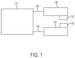
- FIG. 1is a block diagram of one variation of a system comprising a first catheter ( 100 ) and a second catheter ( 104 ).
- the first catheter ( 100 )may comprise a first adhesion element ( 102 ) and the second catheter ( 104 ) may comprise a second adhesion element ( 106 ). At least a portion of the adhesion elements may be exposed to the surrounding environment (i.e., may not be fully encompassed by the catheters).
- the adhesion elements ( 102 , 106 )may comprise electrically conductive magnets, as described in more detail herein, although they need not be magnetic.
- first catheter ( 100 ) and the second catheter ( 104 )may be placed in first and second tubular structures (e.g., blood vessels), respectively, wherein the tubular structures are adjacent, and the adhesion elements ( 102 , 106 ) may interact to adhere the outer wall of the first structure (e.g., blood vessel) to the outer wall of the second structure (e.g., blood vessel).
- the adhesion elementsmay adhere the tissue by delivering electrical energy to the tissue.
- a proximal end of each catheter ( 100 , 104 )may be connected to a power supply ( 110 ) by respective connections ( 108 ).
- the power supply ( 110 )may further comprise a controller (not shown) for controlling energy delivery to the catheters ( 100 , 104 ).
- the power supply ( 110 )may be an AC or DC power supply.
- the power supply ( 110 )may output current to heat and/or desiccate tissue.
- the adhesion elements ( 102 , 106 )may each deliver electrical energy to heat tissue.
- each adhesion elements ( 102 , 106 )may be connected to an active output of the power supply ( 110 ) to deliver current and thus heat adjacent tissue.
- the adhesion elements ( 102 , 106 )may simultaneously heat tissue from opposing sides.
- a ground pade.g., a large metal plate or flexible metalized pad
- the first adhesion element ( 102 )may be connected to the active output of the power supply ( 110 ) and the second adhesion element ( 106 ) may be connected to the return terminal.
- first adhesion element ( 102 )may be connected to an output of the power supply, and the second adhesion element ( 106 ) may be floating, that is, not directly connected to any output of the power supply, in a focused monopolar configuration.
- only the first cathetermay be connected to the power supply in a monopolar configuration.
- only the first adhesion elementmay heat tissue, while the second adhesion element may mechanically contribute to tissue adhesion by pressing tissue toward the first adhesion element while the first adhesion element heats tissue.
- the first adhesion elementmay be connected to an active output of a power supply, and a ground pad affixed to the patient may be connected to a return terminal of the power supply.
- the second adhesion elementmay not be connected to the power supply but may oppose the first adhesion element and compress tissue between the two adhesion elements, promoting heating and adhesion.
- the catheters and adhesion elementsmay be configured to coapt with each other and to compress tissue between the adhesion elements in order to adhere tissue when it is heated.
- a systemmay comprise first and second catheters each having one or more magnets, such that magnets of the first catheter may be attracted to magnets of the second catheter to bring the catheters in closer approximation.
- the adhesion elementsthemselves may be magnets and may be configured to be attracted to each other. As such, the adhesion elements may promote axial and/or rotational alignment of the catheters.
- the cathetersmay comprise coaption regions comprising magnets, and/or may comprise one or more visual alignment aids, to promote tissue coaption as well as axial and/or rotational alignment of the catheters.
- a rotational indicatormay allow catheter alignment to be visualized under fluoroscopy, such that a user may manipulate the catheters into a desired position.
- the cathetersmay also be configured to promote the ability of an adhesion element to press into tissue, as described in more detail herein.
- the cathetersmay have the same configuration of elements, or may have different and/or complementary configurations of elements.
- FIGS. 2 A- 2 Cshow an exemplary system comprising two catheters each comprising an adhesion element comprising a magnet.
- a first catheter ( 200 ) comprising an adhesion element ( 202 )is shown located within a first blood vessel ( 204 ).
- a second catheter ( 206 ) comprising an adhesion element ( 208 )is shown located within a second blood vessel ( 210 ).
- the shape and material of the adhesion elementsmay help to align one catheter in a first vessel with another catheter in a second vessel, and may help to ensure optimal heating and adhesion.
- each of the adhesion elements ( 202 , 208 )comprises a rectangular magnet.
- the adhesion elements ( 202 , 208 )may be configured to be attracted to each other when in proper axial and rotational alignment.
- FIGS. 2 A- 2 Bshow the catheters ( 200 , 206 ) placed in the vessels without coaption due to magnetic attraction
- FIGS. 2 C- 2 Dshow the catheters coapted due to magnetic attraction between the adhesion elements ( 202 , 208 ).
- the walls of vessels ( 204 , 210 )may be compressed between the two adhesion elements ( 202 , 208 ).
- each of the adhesion elements ( 202 , 208 )may comprise a flat contact surface configured to be contact with the interior vessel wall when the catheters are coapted across the vessel walls.
- the adhesion elements ( 202 , 208 )may comprise a conductive material and may be connected to a power supply configured to provide electrical current for heating tissue.
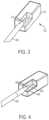
- FIG. 3is a perspective view of a distal end of the catheter ( 200 ) and the adhesion element ( 202 ), shown with a portion of the adhesion element cut away to depict the interior of the adhesion element.
- the adhesion element ( 202 ) shownmay be a magnet that may coapt with another magnet of another catheter (e.g., adhesion element ( 208 ) of catheter ( 206 )) to compress tissue therebetween.
- the adhesion element ( 202 )may comprise one or more flat contact surfaces ( 214 ) for providing flush contact with tissue to be heated.
- a flat contact surfacesuch as contact surface ( 214 ) may allow a lateral magnetic coaption force to be generated and translated into an aligning torque, which may aid rotational alignment, as well as axial alignment, with an adhesion element of a second catheter.
- a wire ( 212 )may be located within the catheter ( 200 ) and may electrically couple the adhesion element ( 202 ) to a power source such as an external power supply. This may allow an external power supply to energize the adhesion element ( 202 ). For example, returning to FIGS.
- one or more of the adhesion elementsmay be energized to apply heat to the vessels ( 204 , 210 ).
- the heat applied to the compressed vessel tissue ( 204 , 210 )may denature proteins in a manner to adhere the vessels together and may form a weld, which may increase the mechanical strength of the vessels.
- the catheters ( 200 , 206 )may be removed.
- heating tissue to 70° C.may result in denaturation.
- the delivered energymay be constant, while in other variations it may be modulated.
- the tissuemay be heated by the delivery of radiofrequency energy to tissue.
- the power sourcemay deliver energy having any suitable waveform to the tissue via the adhesion elements, such as but not limited to waveform having a sinusoidal or square shape. Electrical energy delivered to tissue may have a peak voltage below the ionization threshold of the tissue. For example, when the waveform is a sinusoidal waveform, the peak voltage may in some variations be below about 150 V. It should also be appreciated that in other variations, current need not travel through tissue in order to heat the tissue.
- the tissuemay be heated through ohmic heating of the adhesion elements.
- each adhesion elementmay comprise a resistor resulting in ohmic heating.
- either AC or DC currentmay be used.
- the tissuemay be heated through laser or ultrasonic energy delivery.
- FIG. 4is a perspective view of another variation of a catheter ( 400 ) comprising an adhesion element ( 402 ) comprising a rectangular magnet, and a wire ( 404 ) extending through the catheter ( 400 ) to electrically couple to the adhesion element ( 402 ) to a power supply.
- a surface of the adhesion element ( 402 )may comprise a coating ( 406 ), wherein the coating comprises a material that may facilitate the removal of the adhesion element ( 402 ) from a tissue surface without sticking.
- the coating ( 406 )may comprise one or more layers of PTFE, parylene, silicone, or another fluoropolymer.
- the coating ( 406 )may additionally or alternatively comprise a jacket of material for enhanced biocompatibility or electrical conductivity, such as one or more of gold, platinum, and titanium.
- the adhesion element ( 402 )may be additionally or alternatively partially coated with an insulative coating in order to insulate certain surfaces and leave other surfaces exposed for electrical conduction to the tissue. This may direct and/or isolate energy delivery to a specific region of tissue and/or in a specific shape.
- catheters in the coapted statemay sandwich the tissue interposed between their surfaces with a desired pressure as determined by the size, shape, and material composition of the adhesion elements.
- Adhesion elements having a flat contact surfacemay promote rotational alignment and may better compress tissue for adhesion.
- These flat surfacesmay help to naturally align the adhesion elements with each other, as two flat surfaces may generate a greater aligning torque for a given amount of rotational misalignment than two curved surfaces.
- the aligning torque generated between flat magnetic surfaces at 5 degrees of misalignmentis at least approximately 18 times stronger than that of the aligning torque between magnetic cylinders.
- FIGS. 5 A- 5 Eshow a variety of possible shapes for adhesion elements, each comprising a flat contact surface.
- an adhesion element ( 500 )may have a square cross-section ( FIG. 5 A ); an adhesion element ( 502 ) may have a triangular cross-section ( FIG. 5 B ); an adhesion element ( 504 ) may have a hexagonal cross-section ( FIG. 5 C ); an adhesion element ( 506 ) may have an a rectangular cross-section ( FIG. 5 D ); an adhesion element ( 508 ) may have a semi-circular cross-section ( FIG. 5 E ), or the like to provide a flat contact surface for an adhesion element.
- the adhesion elementsmay not comprise flat contact surfaces.
- FIG. 5 Fillustrates an adhesion element ( 510 ) having a circular cross-section.
- FIGS. 6 A- 6 Billustrate cross-sectional views of two adhesion element pairs, where one adhesion element is configured to be located in a first tubular structure (e.g., a blood vessel), and a second adhesion element is configured to be located in a second tubular structure (e.g., a second blood vessel).
- the adhesion elements shown theremay comprise one or more protrusions and recesses, where the protrusions and recesses may be complementary.
- protrusions and recessesmay form an indent in tissue interposed between the adhesion elements. Pairs of adhesion elements having complementary shapes, as shown in FIGS. 6 A- 6 B , may allow greater pressure to be applied to tissue between the two adhesion elements.
- the protrusions ( 608 , 610 )may have the shape of a block (see adhesion element ( 600 ) in FIG. 6 A ) or a rigid fin (see adhesion element ( 604 ) in FIG. 6 B ) or point.
- the recesses ( 612 , 614 ) of adhesion elements ( 602 , 606 )may have complementary shapes to the protrusions ( 608 , 610 ).
- a pair of adhesion elementsmay have the same shape.
- FIG. 6 Cillustrates a cross-sectional view of a pair of matching adhesion elements ( 616 , 618 ), each having a raised perimeter and a recessed central region ( 620 , 622 ).
- a similar adhesion element having a raised rectangular perimeter and a recessed central regionis shown in FIG. 8 , described in more detail herein.
- the protruding membermay have a hollow interior for decreasing the surface area of the protruding member so that a first current may be applied to adhere tissue and a second current may be supplied to cut an opening through the tissue.
- the adhesion elements described hereinmay be attached to catheters, as shown for example in FIGS. 2 A- 2 D .
- the systemsmay comprise a first catheter for placement in a first tubular structure (e.g., a blood vessel) and a second catheter for placement in a second tubular structure (e.g., a blood vessel), where each catheter may comprise at least one adhesion element.
- the cathetersmay have any suitable diameter.
- the cathetersmay be about 4 French, about 5.7 French, about 6.1 French, about 7 French, about 8.3 French, between about 4 French and about 9 French, between about 4 French and about 7 French, between about 4 French and about 6 French, or the like. In the variation shown in FIGS.
- the widest dimension of the adhesion elements ( 202 , 208 )is greater than the diameter of the catheters ( 200 , 206 ). This may allow the contact surfaces of the adhesion elements ( 202 , 208 ) to more easily contact tissue.
- the catheters described hereinmay be configured to promote the ability of an adhesion element to press into tissue.
- the adhesion elementmay be located on a portion of a catheter having a greater diameter than an adjacent portion of a catheter. This may allow the contact surfaces of the adhesion elements to more easily contact tissue.
- FIG. 7is a perspective view of a variation of a catheter ( 700 ) having an adhesion element ( 706 ) embedded within a portion of the catheter and having an exposed flat contact surface.
- Catheter ( 700 )comprises a proximal portion ( 702 ), a distal portion ( 704 ), and an adhesion element ( 706 ) disposed on the distal portion ( 704 ) and having a flat contact surface.
- the largest cross-sectional dimension of the distal portion ( 704 ) comprising the adhesion element ( 706 )is larger than the largest cross-sectional dimension of the proximal portion ( 702 ) of the catheter.
- the adhesion element ( 706 )may be able to press into tissue without obstruction from contact between the proximal portion ( 702 ) of the catheter ( 700 ) and tissue, for example, a vessel wall.
- FIG. 8illustrates another catheter ( 800 ) comprising a proximal portion ( 802 ) and a distal portion ( 804 ), where the distal portion ( 804 ) has a larger cross-sectional dimension than the proximal portion ( 802 ).
- the catheter ( 800 )further comprises an adhesion element ( 806 ) disposed on the distal portion ( 804 ), where the adhesion element ( 806 ) comprises a raised perimeter with a central rectangular recess. That is, the adhesion element ( 806 ) may define an opening such that, for example, tissue indented against the adhesion element ( 806 ) forms a rectangular indent around the perimeter formed by the raised portion of the adhesion element ( 806 ). Energy may be supplied to activate the adhesion element ( 806 ) to adhere two vessels together.
- an opposing adhesion element on a second cathetermay be configured to fit within the central rectangular recess, which may allow for increased pressure application to tissue located between the adhesion element ( 806 ) and the opposing adhesion element.
- FIGS. 9 A- 9 Eshow side and perspective views of variations of a catheter ( 900 ) similar to catheter ( 700 ) comprising a proximal portion ( 904 ) and a distal portion ( 906 ) comprising an adhesion element ( 908 ) having a flat contact surface.
- the distal portion ( 906 )may be fixedly connected to an inner proximal portion ( 904 ) and may have a larger cross-sectional dimension than the inner proximal portion ( 904 ).
- the inner proximal portion ( 904 )may be slidable within an outer proximal portion ( 902 ), where the outer proximal portion comprises a tubular shape.
- the distal portion ( 906 ) and part of the inner proximal portion ( 904 )may be configured to extend distally from the outer proximal portion ( 902 ) between a retracted position ( FIGS. 9 A- 9 C ) and an extended configuration ( FIGS. 9 D- 9 E ). In the extended configuration shown in FIGS.
- the distal portion ( 906 ) of the catheter ( 900 )may have increased ability to deform and/or press into tissue when the adhesion element ( 908 ) is attracted to a corresponding adhesion element of another catheter, since deformation of the inner proximal portion ( 904 ) is not limited by the outer proximal portion ( 902 ).
- the distal portion ( 906 ) of the catheter ( 900 )may have increased pushability, since deformation of the inner proximal portion ( 904 ) is limited by the outer proximal portion ( 902 ). In this way, either of the extended or retracted configurations (or an intermediate configuration between the extended or retracted configurations) may be selected based on one more requirements related to pushability, flexibility, and/or torquability.
- adhesion elementsare shown at or near a distal end of the catheters. However, it should be appreciated that adhesion elements may be located along any suitable portion of the catheters described herein (e.g., a distal end, an intermediate portion, or combinations thereof). It should also be appreciated that a catheter may have any suitable number (e.g., zero, one, two, three, or four or more) and combination of adhesion elements. In variations in which a catheter comprises two or more adhesion elements, multiple adhesion elements may be used to create multiple adhesion regions, either simultaneously or sequentially. In other variations, multiple adhesion elements may interact to form a single adhesion region.
- an adhesion elementneed not comprise a magnet. While magnetic adhesion elements may help to compress tissue between two catheters, in some variations the adhesion elements may comprise any material suitable for heating tissue to cause adhesion. For example, the adhesion elements may comprise any suitable conductive material.
- the catheters described hereinmay comprise one or more adhesion elements and one or more separate alignment features to assist in coaption and rotational and/or axial alignment of the catheters relative to each other. In some of these variations, alignment features may assist a user in manual positioning of the catheters. Generally, in these variations, the catheters may comprise at least one of a flat coaption surface, a magnet, and a rotational indicator.
- the catheters described hereinmay comprise one or more adhesion elements and a separate coaption region comprising one or more magnets to promote coaption and alignment.
- a cathetermay comprise a magnet and a separate adhesion element comprising an electrode.
- FIG. 10is a perspective view of such a variation of a catheter ( 1000 ) comprising a magnet ( 1002 ) and a separate electrode ( 1006 ). The magnet ( 1002 ) may be separated from the electrode ( 1006 ) by an electrical and/or thermal insulator ( 1004 ).
- the thermal insulatormay comprise, for example, polyimide, PEEK, PTFE, and/or ceramic.
- the magnet ( 1002 )may act to promote tissue compression between the flat contact surface of the adhesion element (electrode ( 1006 )) and an adhesion element in an adjacent vessel and may promote proper alignment between the adhesion elements, while the electrode ( 1006 ) may act as the adhesion element.
- the electrode ( 1006 )may be disposed directly on the magnet ( 1002 ).
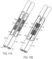
- FIGS. 11 A- 11 Billustrate another variation of a system in vasculature comprising a first catheter ( 1100 ) in a first blood vessel ( 1106 ) and a second catheter ( 1108 ) in a second blood vessel ( 1114 ).
- the first catheter ( 1100 )may comprise a first adhesion element ( 1102 ) that may be a non-magnetic adhesion element, such as a non-magnetic electrode
- the second catheter ( 1108 )may comprise a second adhesion element ( 1110 ) that may be non-magnetic adhesion element, such as a non-magnetic electrode.
- the first and second adhesion elements ( 1102 , 1110 )may comprise magnetic electrodes.
- the adhesion elements ( 1102 , 1110 )may be connected via electrical leads ( 1116 , 1118 ) to a power source (not shown), as described in more detail herein.
- the first catheter ( 1100 )may further comprise a first coaption region ( 1104 ) comprising one or more magnets that may be distal and proximal to the first adhesion element ( 1102 ).
- the second catheter ( 1108 )may further comprise a second coaption region ( 1112 ) comprising one or more magnets that may be distal and proximal to the second adhesion element ( 1110 ).
- the magnetsmay be configured to be attracted to one or more magnetic fields (e.g., produced by one or more magnets of the other catheter).
- the magnetsmay help to align or otherwise reposition the catheters ( 1000 , 1108 ) when placed in the vasculature. Once the first and second catheters ( 1000 , 1108 ) have been positioned, the attractive magnetic forces may also act to maintain the relative positions of the catheters ( 1000 , 1108 ). When the first and second catheters ( 1000 , 1108 ) are placed in respective blood vessels ( 1106 , 1114 ), tissue positioned between the blood vessels and/or limited compliance of the blood vessels may limit the extent to which the magnets of the first and second catheters bring the first and second catheters toward each other. The magnets may additionally or alternatively help to ensure that the catheters ( 1000 , 1108 ) are in proper axial and/or rotational alignment relative to each other. Such axial and/or rotational alignment of the catheters ( 1000 , 1108 ) may also facilitate alignment of the adhesion elements ( 1102 , 1110 ) relative to a target location for vessel adhesion.
- the catheters of the systems described heremay comprise one or more magnets, and each catheter may comprise any number of individual magnets (e.g., one, two, three, four, five, six, seven, or eight or more, etc.).
- one or more magnetsmay act as adhesion elements and be configured to heat tissue (e.g., through delivery of electrical current), while one or more other magnets may not be configured to heat tissue.
- these magnetsmay be grouped into one or more magnet arrays.
- the magnetsmay be located inside and/or outside of a catheter body.
- the magnetsmay be positioned at any suitable location along the length of the catheter.
- the dimensions of the magnets described hereinmay be selected based on the size of the catheters carrying the magnets, which in turn may be selected based on the anatomical dimensions of the blood vessels through which the catheters may be advanced. For example, if the catheter is to be advanced through a blood vessel having an internal diameter of about 3 mm, it may be desirable to configure any magnet to be less than about 3 mm at the widest part of its cross-section, to reduce the risk of injury to vessel walls during advancement and manipulation of the catheter.
- Each magnetmay have any suitable length (e.g., about 5 mm, about 10 mm, about 15 mm, about 20 mm, or the like), although it should be appreciated that in some instances longer magnets may limit the flexibility of the catheter to maneuver through tissue.
- the magnets described here throughoutmay be permanent magnets comprising one or more hard magnetic materials, such as but not limited to alloys of rare earth elements (e.g., samarium-cobalt magnets or neodymium magnets, such as N52 magnets) or alnico.
- the magnetsmay comprise anisotropic magnets; in other variations, the magnets may comprise isotropic magnetics.
- the magnetsmay be formed from compressed powder.
- a portion of the magnets(e.g., a permeable backing) may comprise one or more soft magnetic materials, such as but not limited to iron, cobalt, nickel, or ferrite.
- the magnetsWhen the magnets are configured to deliver electrical current to tissue, the magnets may comprise conductive material and/or comprise a conductive coating. When the magnets are located within the catheter, as in FIGS. 11 A- 11 B for example, given the limitations on magnet size, it may be desirable in some instances to use magnets configured to produce magnetic fields that increase the magnetic force that can be generated with a magnet of a given size.
- the systemmay comprise one or more of the magnets described in U.S. patent application Ser. No. 14/214,503, filed on Mar. 14, 2014, and titled “FISTULA FORMULATION DEVICES AND METHODS THEREFOR,” and/or U.S. patent application Ser. No. 14/657,997, filed on Mar. 13, 2015, and titled “FISTULA FORMATION DEVICES AND METHODS THEREFOR,” each of which is hereby incorporated by reference in its entirety.
- first catheterand a second catheter each comprising one or more permanent magnets (which may or may not be configured to heat tissue)
- first or second cathetermay comprise ferromagnetic elements (i.e., elements attracted to but not generating a permanent magnetic field).
- the first cathetermay include only one or more ferromagnetic elements while the second catheter comprises one or more permanent magnets.
- the second cathetermay include only one or more ferromagnetic elements while the first catheter comprises one or more permanent magnets.
- one or both of the first and second cathetersmay include any suitable combination of ferromagnetic, permanent, and/or other suitable kinds of magnets.
- FIG. 11 A- 11 Bthese figures illustrate the catheters ( 1100 , 1108 ) advanced through respective vessels ( 1106 , 1114 ).
- the attractive magnetic forces of the magnets within the coaption regions ( 1104 , 1112 )may bring the catheters ( 1100 , 1108 ) and blood vessels ( 1106 , 1114 ) in closer approximation, as shown in FIG. 11 B .
- the adhesion elementsmay also bring the catheters together.
- One or more of the adhesion elements ( 1102 , 1108 )may then be energized so as to apply heat to the vessels, as described in more detail herein.
- the systems described hereinmay further comprise one or more additional alignment features to help ensure that the catheters are axially and/or rotationally aligned prior to heating the tissue to achieve adhesion.
- one or both of the first and second cathetersmay comprise a visual alignment aid for indirectly visualizing the alignment of a catheter within a tubular structure or relative to another catheter, such as via fluoroscopy, during positioning and/or alignment thereof.
- the visual alignment aidmay comprise a rotational indicator.
- a rotational indicatormay serve as a visual marker for guiding rotational alignment of two catheters as viewed under fluoroscopy.
- the rotational indicators of each cathetermay be used to rotationally and/or axially position the catheters such that that one or more adhesion elements are properly positioned to adhere tissue.
- a rotational indicatormay be configured such that its rotational orientation is discernable in a two-dimensional fluoroscopic image.
- a rotational indicatormay comprise a radiopaque portion.
- the first cathetermay include a first radiopaque portion and the second catheter may include a corresponding second radiopaque portion.
- An X-ray beammay fluoroscopically image an orientation of the first radiopaque portion and the second radiopaque portion, and the image may be shown on a display for a user. The user may then manipulate one or both of the catheters to align the catheters.
- a rotational indicatormay be provided along any suitable portion of the catheter.
- the rotational indicatormay comprise any radiopaque metal, such as tungsten, platinum iridium, stainless steel, titanium, as well as a tungsten filled polymer, zirconia ceramic, or any suitable radiopaque material.
- the rotational indicatormay comprise a radiopaque film Rotational indicators suitable for use in the catheters described herein are discussed in more detail in U.S.
- the methods described herecomprise accessing a first blood vessel with a first catheter having features as described herein, and advancing the first catheter to a target location within the first blood vessel.
- a second blood vesselmay be accessed with a second catheter having features as described herein, and the second catheter may be advanced to a target location within the second vessel.
- one or more adhesion elementsmay be activated to heat and denature tissue to fuse tissue together and form an adhesion between the two vessels.
- the cathetersmay then be removed.
- a fistulamay be formed through a portion of the welded tissue.
- a fistulamay be formed using the devices, systems, and methods in U.S. patent application Ser. No. 13/298,169, filed on Nov. 16, 2011, and titled “DEVICES AND METHODS FOR FORMING A FISTULA,” which is hereby incorporated by reference in its entirety, and in U.S. patent application Ser. No. 15/406,755, filed Jan.
- a first catheteris advanced into an artery, and a second catheter is advanced into a vein.
- a first catheteris advanced into a first vein, and a second catheter is advanced into a second vein.
- a first catheteris advanced into a first artery and a second catheter is advanced into a second artery.
- a first catheteris advanced into a vein, and the second catheter is advanced into an artery.
- the first and/or second cathetersmay be advanced over a guidewire or in any suitable manner and may or may not occur under indirect visualization (e.g., via fluoroscopy, X-ray, or ultrasound).
- each of the first or second cathetersmay comprise one or more adhesion elements as described herein.
- the adhesion elementsmay or may not be magnetic.
- aligning the first and second cathetersmay comprise axial and/or rotational alignment of the adhesion elements.
- both the first and second catheterscomprise adhesion elements
- the cathetersmay be oriented to align these adhesion elements.
- the cathetersmay be aligned in any suitable manner.
- magnetic adhesion elementsmay generate an attractive force between the first and second catheters, which may pull the catheters toward each other.
- separate coaption regionsmay comprise one or more magnets configured to generate an attracted force between the first and second catheters.
- the catheter systems described hereinmay comprise one or more rotational indicators allowing for indirect visualization of catheter alignment such as through fluoroscopy.
- the markersmay be viewed (e.g., via fluoroscopy, X-ray, or the like) to ensure that the catheters have the proper axial and/or radial orientation relative to each other.
- the catheter and rotational indicatorsmay be visualized fluoroscopically during alignment of the catheters, and in some cases from at least advancement steps through alignment of the catheters.
- the usermay view the rotational indicators in a fluoroscopic image to determine a rotational alignment of the catheters and may rotate the catheters until alignment is achieved.
- the cathetersare viewed as axially aligned based on the position of the rotational indicators or another portion of the catheters, the user may bring the catheters into close approximation.
- one or more adhesion elementsmay be activated to adhere tissue in vessels.
- one or more adhesion elementsmay form a thermal weld ( 1206 ) between a first vessel ( 1202 ) and a second vessel ( 1204 ).
- FIG. 12 Bis a plan view of the vessel ( 1202 ) having a formed weld ( 1206 ) in the shape of the adhesion element in contact with the vessel ( 1202 ).
- tissuemay be heated to form a thermal weld between the intimal, medial, and/or adventitia of the vessels ( 1202 , 1204 ).
- the weld ( 1206 )may form a hermetic seal between the vessels, thereby preventing pressurized fluid from ingress or egress through the weld plane.
- the weldmay also be strong enough to prevent the vessels from being pulled apart under forces that may be applied due to bodily function or motion.
- the weld ( 1206 )may be able to withstand internal hydraulic pressure from dissecting the vessels apart, as discussed in further detail herein.
- the weldmay have a width of about 0.1 mm to about 15 mm and a length ranging from about 0.1 mm to about 10 cm, although the weld length may vary from this range.
- a plurality of discrete weldsmay be produced by a single catheter system using a plurality of adhesion elements.
- the adhesion elementsmay adhere tissue by heating the tissue.
- the adhesion elementsmay heat tissue by delivering radiofrequency energy.
- the adhesion elementsmay be heated through ohmic heating, which may in turn heat tissue.
- the adhesion elementsmay deliver laser energy to heat tissue, or may deliver ultrasonic energy to heat tissue.
- the systems discussed hereinmay comprise an electrosurgical controller coupled to one or more adhesion elements for controlling tissue adhesion.
- a controllermay control the energy delivery to one more adhesion elements to heat tissue based on the selected adhesion parameters.
- Adhesion parametersmay include an energy waveform shape, frequency, amplitude, duration, and so forth.
- a controllermay be configured to deliver a waveform having a frequency between about 300 kHz and about 500 kHz, with a peak voltage of between about 120 V and about 140 V.
- a controllermay be configured to deliver a waveform having a frequency of about 400 kHz, with a peak voltage of about 130 V.
- the waveformmay have any suitable shape, such as a sinusoidal or square shape.
- the controllermay modulate one or more parameters to achieve a desired heating profile. For example, the controller may modulate one or more of the peak voltage or duty cycle of the waveform.
- the electrosurgical controllermay deliver energy for a predetermined duration to achieve the intended adhesion.
- the strength of an adhesion cyclemay be limited in power and/or duration so as to perform a plurality of adhesion cycles. In this manner, the thermal effects of heating may be dispersed over a longer period of time so as to limit collateral thermal injury to the vessel.
- tissue parametersmay be measured and analyzed in order to determine one or more adhesion parameters.
- the electrosurgical controllermay in some instances monitor the impedance during energy delivery to determine a rate of tissue heating. In other instances, termination of adhesion may occur after measuring a predetermined impedance or a predetermined rate of change of impedance.
- the systemmay comprise an impedance metering circuit such as a bipolar sensing circuit with each adhesion element serving as an element. To measure impedance, low power DC or alternating voltage may be applied to the adhesion elements. The resulting current and/or phase may then be measured to determine impedance.
- impedancemay also be measured during a thermal adhesion period by measuring the impedance in a bipolar or monopolar circuit. In this manner, a single heating cycle may be performed without interrupting the energy delivery cycle to measure impedance. Impedances measured before, after, and/or during an adhesion sequence may determine the level of vessel modification provided.
- a cathetermay further comprise a thermocouple or thermistor to monitor tissue temperature as an additional input signal for controlling adhesion by the electrosurgical controller.
- one or more impedance measurements or tissue temperature measurementsmay be outputted to a user as one or more of visual and audio feedback. For example, the system may output an impedance value on a display meter coupled to the catheters.
- Impedance valuesmay be output as audio tones.
- impedance measurements or tissue temperature informationmay be provided to the electrosurgical controller to automatically adjust or stop current delivery. For example, tissue measurements indicating that the temperature has reached 70° C. may indicate that protein denaturation has been achieved.
- a fenestration between the two tubular structuresmay optionally be formed.
- a fenestrationmay be formed using different devices, such as a different catheter system
- a fistula between the two vesselsmay be formed using a system and method as described in U.S. patent application Ser. No. 13/298,169, filed on Nov. 16, 2011, and titled “DEVICES AND METHODS FOR FORMING A FISTULA,” and in U.S. patent application Ser. No. 15/406,755, filed Jan. 15, 2017, titled “DEVICES AND METHODS FOR FORMING A FISTULA” and claiming the benefit of U.S. Provisional Application No.
- a fistulamay be formed using a system comprising a first catheter and a second catheter.
- the first cathetermay comprise a catheter body, one or more magnetic elements, and a fistula-forming element.
- the second cathetermay comprise a catheter body, one or more magnetic elements, and may optionally comprise a fistula-forming element.
- the fistula-forming elementmay comprise an electrode configured to move between a low-profile configuration and an extended configuration in which it extends radially away from the catheter body.
- the fistula-forming elementmay be spring-biased toward the extended configuration, i.e., may be configured to self-expand from the low-profile to the extended configuration, and may be held in the low-profile configuration during placement, for example by an external radially inward force on the electrode from a the catheter body or a vessel wall during delivery.
- a fenestrationmay be formed using the same catheters but using a separate fistula-forming element.
- the separate fistula-forming elementmay be axially displaced along the catheter from the adhesion element, or as another example, a separate fistula-forming element may be located within an adhesion element.
- hemostasismay be created without the need for a separate device or structure (e.g., a suture, stent, shunt, or the like) connecting or joining the blood vessels.
- a fenestrationmay be formed by further activating the adhesion elements to bore through, perforate, or otherwise create a passageway between the two structures (e.g., blood vessels such that blood may flow directly between the two adjoining blood vessels).
- a first currentmay be applied to the adhesion element to adhere tissue together while a second current may be applied to form an opening through the tissue in the shape of the adhesion element.
- the waveformmay be modified to have an increased peak voltage.
- the peak voltagemay be increased to reach an ionization threshold. In one non-limiting example, the peak voltage may be increased to about 180 V.
- energy supplied to an adhesion element for a first time periodmay adhere the two vessels together while continued heating for a second time period beyond the first time period may form a fistula.
- the first time periodmay be up to about 10 seconds, while the second time period may be up to an additional about 5 seconds.
- FIG. 13 Ashows a cross-sectional view of a thermal weld ( 1306 ) surrounding a fistula ( 1308 ) between a first vessel ( 1302 ) and a second vessel ( 1304 ).
- FIG. 13 Ashows a cross-sectional view of a thermal weld ( 1306 ) surrounding a fistula ( 1308 ) between a first vessel ( 1302 ) and a second vessel ( 1304 ).
- FIG. 13 Bshows a plan view of the vessel ( 1302 ) and weld ( 1306 ) and a fistula ( 1308 ) formed therethrough to provide fluid communication through the fistula ( 1308 ) while maintaining a perimeter of welded tissue ( 1306 ) to prevent fluid leakage.
Landscapes
- Health & Medical Sciences (AREA)
- Surgery (AREA)
- Life Sciences & Earth Sciences (AREA)
- Engineering & Computer Science (AREA)
- General Health & Medical Sciences (AREA)
- Biomedical Technology (AREA)
- Heart & Thoracic Surgery (AREA)
- Medical Informatics (AREA)
- Molecular Biology (AREA)
- Animal Behavior & Ethology (AREA)
- Nuclear Medicine, Radiotherapy & Molecular Imaging (AREA)
- Public Health (AREA)
- Veterinary Medicine (AREA)
- Physics & Mathematics (AREA)
- Plasma & Fusion (AREA)
- Otolaryngology (AREA)
- Cardiology (AREA)
- Robotics (AREA)
- Surgical Instruments (AREA)
- Lining Or Joining Of Plastics Or The Like (AREA)
- Adhesives Or Adhesive Processes (AREA)
- Materials For Medical Uses (AREA)
- External Artificial Organs (AREA)
Abstract
Description
Claims (16)
Priority Applications (1)
| Application Number | Priority Date | Filing Date | Title |
|---|---|---|---|
| US16/024,241US12295645B2 (en) | 2016-01-15 | 2018-06-29 | Systems and methods for adhering vessels |
Applications Claiming Priority (3)
| Application Number | Priority Date | Filing Date | Title |
|---|---|---|---|
| US201662279642P | 2016-01-15 | 2016-01-15 | |
| PCT/US2017/013611WO2017124060A1 (en) | 2016-01-15 | 2017-01-15 | Systems and methods for adhering vessels |
| US16/024,241US12295645B2 (en) | 2016-01-15 | 2018-06-29 | Systems and methods for adhering vessels |
Related Parent Applications (1)
| Application Number | Title | Priority Date | Filing Date |
|---|---|---|---|
| PCT/US2017/013611ContinuationWO2017124060A1 (en) | 2016-01-15 | 2017-01-15 | Systems and methods for adhering vessels |
Publications (2)
| Publication Number | Publication Date |
|---|---|
| US20190133678A1 US20190133678A1 (en) | 2019-05-09 |
| US12295645B2true US12295645B2 (en) | 2025-05-13 |
Family
ID=59312188
Family Applications (1)
| Application Number | Title | Priority Date | Filing Date |
|---|---|---|---|
| US16/024,241Active2038-12-03US12295645B2 (en) | 2016-01-15 | 2018-06-29 | Systems and methods for adhering vessels |
Country Status (8)
| Country | Link |
|---|---|
| US (1) | US12295645B2 (en) |
| EP (1) | EP3402426A4 (en) |
| JP (3) | JP7219090B2 (en) |
| CN (1) | CN108778171A (en) |
| AU (1) | AU2017208022B2 (en) |
| CA (1) | CA3011240A1 (en) |
| MX (1) | MX2018008571A (en) |
| WO (1) | WO2017124060A1 (en) |
Families Citing this family (42)
| Publication number | Priority date | Publication date | Assignee | Title |
|---|---|---|---|---|
| GB0419954D0 (en) | 2004-09-08 | 2004-10-13 | Advotek Medical Devices Ltd | System for directing therapy |
| US20130190676A1 (en) | 2006-04-20 | 2013-07-25 | Limflow Gmbh | Devices and methods for fluid flow through body passages |
| EP3973892B1 (en) | 2009-07-15 | 2024-10-23 | GT Metabolic Solutions, Inc. | Incisionless gastric bypass devices |
| BR112012016666A2 (en) | 2010-01-05 | 2018-06-05 | Beacon Endoscopic Corp | methods and apparatus for magnetically induced compression anastomosis between adjacent organs. |
| US8870898B2 (en) | 2010-01-05 | 2014-10-28 | GI Windows, Inc. | Self-assembling magnetic anastomosis device having an exoskeleton |
| EP4032486A1 (en) | 2010-11-16 | 2022-07-27 | TVA Medical, Inc. | Devices for forming a fistula |
| US9486276B2 (en) | 2012-10-11 | 2016-11-08 | Tva Medical, Inc. | Devices and methods for fistula formation |
| US10835367B2 (en) | 2013-03-08 | 2020-11-17 | Limflow Gmbh | Devices for fluid flow through body passages |
| CA2898879C (en) | 2013-03-08 | 2023-05-02 | Limflow Gmbh | Methods and systems for providing or maintaining fluid flow through body passages |
| CN105228683B (en) | 2013-03-14 | 2022-06-10 | Tva医疗公司 | Fistula-forming device and method for forming fistula |
| US10695534B2 (en) | 2014-03-14 | 2020-06-30 | Tva Medical, Inc. | Fistula formation devices and methods therefor |
| US9545263B2 (en) | 2014-06-19 | 2017-01-17 | Limflow Gmbh | Devices and methods for treating lower extremity vasculature |
| WO2016033374A1 (en) | 2014-08-27 | 2016-03-03 | Tva Medical, Inc. | Cryolipopysis devices and methods therefor |
| US10603040B1 (en) | 2015-02-09 | 2020-03-31 | Tva Medical, Inc. | Methods for treating hypertension and reducing blood pressure with formation of fistula |
| US10517600B2 (en) | 2015-03-12 | 2019-12-31 | G.I. Windows, Inc. | Magnetic anastomosis devices with varying magnetic force at a distance |
| JP7219090B2 (en) | 2016-01-15 | 2023-02-07 | ティーブイエー メディカル, インコーポレイテッド | Systems and methods for gluing vessels |
| US10874422B2 (en) | 2016-01-15 | 2020-12-29 | Tva Medical, Inc. | Systems and methods for increasing blood flow |
| WO2017124062A1 (en) | 2016-01-15 | 2017-07-20 | Tva Medical, Inc. | Devices and methods for forming a fistula |
| CN114042224B (en) | 2016-01-15 | 2024-09-17 | Tva医疗公司 | Device and method for advancing a wire |
| CN109982652B (en) | 2016-09-25 | 2022-08-05 | Tva医疗公司 | Vascular stent device and method |
| EP3609415B1 (en) | 2017-04-10 | 2023-08-23 | LimFlow GmbH | Devices for treating lower extremity vasculature |
| US11564728B1 (en)* | 2017-12-14 | 2023-01-31 | Avenu Medical, Inc. | Systems and methods for percutaneous access, formation, and maintenance of arteriovenous fistulas |
| ES2971887T3 (en) | 2018-06-02 | 2024-06-10 | Gi Windows Inc | Devices for forming anastomoses |
| WO2020028848A1 (en) | 2018-08-03 | 2020-02-06 | Avenu Medical, Inc. | Fixation of vessels for percutaneous fistula creation |
| SG11202102500UA (en) | 2018-10-09 | 2021-04-29 | Limflow Gmbh | Devices and methods for catheter alignment |
| WO2020081597A1 (en) | 2018-10-15 | 2020-04-23 | Aharon Alon S | Magnetic puncture access and delivery systems and methods |
| EP4051174A4 (en) | 2019-11-01 | 2023-11-22 | LimFlow GmbH | Devices and methods for increasing blood perfusion to a distal extremity |
| JP7528224B2 (en)* | 2019-12-30 | 2024-08-05 | ティーブイエー メディカル, インコーポレイテッド | System for forming a fistula |
| WO2021221607A1 (en)* | 2020-04-28 | 2021-11-04 | Tva Medical, Inc. | Systems, methods, and catheters for endovascular treatment of a blood vessel |
| US11576676B2 (en) | 2020-09-18 | 2023-02-14 | Gt Metabolic Solutions, Inc. | Anastomosis formation with magnetic devices having temporary retention member |
| WO2022132351A1 (en) | 2020-12-18 | 2022-06-23 | Gt Metabolic Solutions, Inc. | Devices and methods for assisting magnetic compression anastomosis |
| WO2022225923A1 (en) | 2021-04-20 | 2022-10-27 | G.I. Windows, Inc. | Systems, devices, and methods for endoscope or laparoscopic magnetic navigation |
| US11583280B2 (en) | 2021-04-30 | 2023-02-21 | Gt Metabolic Solutions, Inc. | Anastomosis formation with magnetic devices having bioresorbable retention member |
| USD1081998S1 (en) | 2022-03-17 | 2025-07-01 | Gt Metabolic Solutions, Inc. | Anastomosis formation device |
| US20250222240A1 (en)* | 2022-04-01 | 2025-07-10 | Tva Medical Group, Inc. | Catheter and systems with flexible backstop and methods for forming fistulas |
| EP4525759A1 (en)* | 2022-05-19 | 2025-03-26 | TVA Medical, Inc. | Catheter assemblies and systems with interlocking components and methods for forming fistulas |
| EP4536122A1 (en)* | 2022-06-10 | 2025-04-16 | TVA Medical, Inc. | Systems and methods for endovascular treatment of a blood vessel |
| US12201300B2 (en) | 2022-08-05 | 2025-01-21 | G.I. Windows, Inc. | Magnetic compression anastomosis device with multipiece vertebra |
| JP2025529235A (en) | 2022-09-01 | 2025-09-04 | ジーアイ ウィンドウズ, インコーポレイテッド | Pressure Profile Magnetic Compression Anastomosis Device |
| JP2025529236A (en) | 2022-09-02 | 2025-09-04 | ジーアイ ウィンドウズ, インコーポレイテッド | Systems, devices and methods for endoscopic or laparoscopic magnetic navigation |
| EP4626340A1 (en)* | 2022-12-01 | 2025-10-08 | TVA Medical, Inc. | Catheters and systems for endovascular treatment of a blood vessel |
| WO2024205580A1 (en)* | 2023-03-29 | 2024-10-03 | Tva Medical, Inc. | Catheter systems for forming a fistula |
Citations (289)
| Publication number | Priority date | Publication date | Assignee | Title |
|---|---|---|---|---|
| US3649850A (en) | 1969-11-26 | 1972-03-14 | Bell Telephone Labor Inc | Crystal-controlled square wave generator |
| US3827436A (en) | 1972-11-10 | 1974-08-06 | Frigitronics Of Conn Inc | Multipurpose cryosurgical probe |
| US4416664A (en) | 1981-09-11 | 1983-11-22 | Womack Charles E | Catheter securing device |
| US4802475A (en) | 1987-06-22 | 1989-02-07 | Weshahy Ahmed H A G | Methods and apparatus of applying intra-lesional cryotherapy |
| US5313943A (en) | 1992-09-25 | 1994-05-24 | Ep Technologies, Inc. | Catheters and methods for performing cardiac diagnosis and treatment |
| US5383460A (en) | 1992-10-05 | 1995-01-24 | Cardiovascular Imaging Systems, Inc. | Method and apparatus for ultrasound imaging and atherectomy |
| US5429131A (en)* | 1994-02-25 | 1995-07-04 | The Regents Of The University Of California | Magnetized electrode tip catheter |
| WO1997013463A1 (en) | 1995-10-13 | 1997-04-17 | Transvascular, Inc. | Methods and apparatus for bypassing arterial obstructions and/or performing other transvascular procedures |
| WO1997029682A1 (en) | 1996-02-15 | 1997-08-21 | Biosense Inc. | Locatable biopsy needle |
| US5697909A (en) | 1992-01-07 | 1997-12-16 | Arthrocare Corporation | Methods and apparatus for surgical cutting |
| US5782239A (en) | 1992-06-30 | 1998-07-21 | Cordis Webster, Inc. | Unique electrode configurations for cardiovascular electrode catheter with built-in deflection method and central puller wire |
| US5800487A (en) | 1996-07-23 | 1998-09-01 | Endocare, Inc. | Cryoprobe |
| US5830224A (en) | 1996-03-15 | 1998-11-03 | Beth Israel Deaconess Medical Center | Catheter apparatus and methodology for generating a fistula on-demand between closely associated blood vessels at a pre-chosen anatomic site in-vivo |
| US5830222A (en) | 1995-10-13 | 1998-11-03 | Transvascular, Inc. | Device, system and method for intersititial transvascular intervention |
| US5836947A (en) | 1994-10-07 | 1998-11-17 | Ep Technologies, Inc. | Flexible structures having movable splines for supporting electrode elements |
| US5895404A (en) | 1997-09-29 | 1999-04-20 | Ruiz; Carlos E. | Apparatus and methods for percutaneously forming a passageway between adjacent vessels or portions of a vessel |
| EP0923912A2 (en) | 1997-12-18 | 1999-06-23 | Schneider (Usa) Inc. | Stent-graft with bioabsorbable structural support |
| US5971979A (en) | 1997-12-02 | 1999-10-26 | Odyssey Technologies, Inc. | Method for cryogenic inhibition of hyperplasia |
| WO1999056640A1 (en) | 1998-04-30 | 1999-11-11 | Spembly Medical Limited | Improvements relating to cryosurgical apparatus |
| US6004330A (en) | 1989-08-16 | 1999-12-21 | Medtronic, Inc. | Device or apparatus for manipulating matter |
| US6032677A (en) | 1998-07-17 | 2000-03-07 | Blechman; Abraham M. | Method and apparatus for stimulating the healing of medical implants |
| US6039730A (en) | 1996-06-24 | 2000-03-21 | Allegheny-Singer Research Institute | Method and apparatus for cryosurgery |
| US6071274A (en) | 1996-12-19 | 2000-06-06 | Ep Technologies, Inc. | Loop structures for supporting multiple electrode elements |
| JP3127126B2 (en) | 1996-06-24 | 2001-01-22 | 勝久 大山 | Flat tire processing method for waste tires |
| US6197025B1 (en) | 1994-09-30 | 2001-03-06 | Circon Corporation | Grooved slider electrode for a resectoscope |
| US6217575B1 (en) | 1999-02-24 | 2001-04-17 | Scimed Life Systems, Inc. | PMR catheter |
| RU2168951C1 (en) | 1999-12-28 | 2001-06-20 | Московский областной научно-исследовательский клинический институт | Method for creating retrograde arteriovenous fistula |
| US6256525B1 (en) | 1998-02-27 | 2001-07-03 | Ep Technologies, Inc. | Catheter distal end assemblies with bonded surface coatings |
| US6280440B1 (en)* | 1998-05-13 | 2001-08-28 | Olympus Optical Co., Ltd. | Cautery apparatus |
| US6283988B1 (en) | 1997-04-07 | 2001-09-04 | Broncus Technologies, Inc. | Bronchial stenter having expandable electrodes |
| US6287306B1 (en) | 1998-06-22 | 2001-09-11 | Daig Corporation | Even temperature linear lesion ablation catheter |
| US20010029384A1 (en) | 1996-07-23 | 2001-10-11 | United States Surgical Corporation | Anastomosis instrument and method |
| US6302875B1 (en) | 1996-10-11 | 2001-10-16 | Transvascular, Inc. | Catheters and related devices for forming passageways between blood vessels or other anatomical structures |
| US6327505B1 (en) | 1998-05-07 | 2001-12-04 | Medtronic, Inc. | Method and apparatus for rf intraluminal reduction and occlusion |
| US6347247B1 (en) | 1998-05-08 | 2002-02-12 | Genetronics Inc. | Electrically induced vessel vasodilation |
| US6357447B1 (en) | 1993-10-15 | 2002-03-19 | Ep Technologies, Inc. | Surface coatings for catheters, direct contacting diagnostic and therapeutic devices |
| US6379353B1 (en) | 1997-05-19 | 2002-04-30 | Radiotherapeutics Corporation | Apparatus and method for treating tissue with multiple electrodes |
| US6383180B1 (en) | 1999-01-25 | 2002-05-07 | Cryocath Technologies Inc. | Closed loop catheter coolant system |
| US6394956B1 (en) | 2000-02-29 | 2002-05-28 | Scimed Life Systems, Inc. | RF ablation and ultrasound catheter for crossing chronic total occlusions |
| US6400976B1 (en) | 1998-10-20 | 2002-06-04 | Eugene J. Champeau | Catheter with thin film electrodes and method for making same |
| US20020072739A1 (en) | 2000-12-07 | 2002-06-13 | Roberta Lee | Methods and devices for radiofrequency electrosurgery |
| US6428534B1 (en) | 1999-02-24 | 2002-08-06 | Cryovascular Systems, Inc. | Cryogenic angioplasty catheter |
| US20020113678A1 (en) | 2000-04-11 | 2002-08-22 | Creighton Francis M. | Magnets with varying magnetzation direction and method of making such magnets |
| US6461356B1 (en) | 1999-07-01 | 2002-10-08 | C.R. Bard, Inc. | Medical device having an incrementally displaceable electrode |
| US6464665B1 (en) | 2000-07-05 | 2002-10-15 | Richard R. Heuser | Catheter apparatus and method for arterializing a vein |
| US6464723B1 (en) | 1999-04-22 | 2002-10-15 | Advanced Cardiovascular Systems, Inc. | Radiopaque stents |
| US20020151945A1 (en) | 1998-04-21 | 2002-10-17 | Gobin Yves Pierre | Indwelling heat exchange catheter and method of using same |
| US6475226B1 (en) | 1999-02-03 | 2002-11-05 | Scimed Life Systems, Inc. | Percutaneous bypass apparatus and method |
| US6475214B1 (en) | 2000-05-01 | 2002-11-05 | Biosense Webster, Inc. | Catheter with enhanced ablation electrode |
| US20030009163A1 (en) | 2001-07-09 | 2003-01-09 | Scimed Life Systems, Inc. | Clamshell distal catheter assembly |
| US6527724B1 (en) | 1998-12-04 | 2003-03-04 | Consiglio Nazionale Delle Richerche | Catheter guidance by magnetocardiographic mapping |
| US6527769B2 (en) | 1998-03-02 | 2003-03-04 | Atrionix, Inc. | Tissue ablation system and method for forming long linear lesion |
| US6542766B2 (en) | 1999-05-13 | 2003-04-01 | Andrew F. Hall | Medical devices adapted for magnetic navigation with magnetic fields and gradients |
| US6544230B1 (en) | 1998-03-31 | 2003-04-08 | Transvascular, Inc. | Catheters, systems and methods for percutaneous in situ arterio-venous bypass |
| US6569162B2 (en) | 2001-03-29 | 2003-05-27 | Ding Sheng He | Passively self-cooled electrode design for ablation catheters |
| US6579311B1 (en) | 1996-02-02 | 2003-06-17 | Transvascular, Inc. | Method for interstitial transvascular intervention |
| US6585650B1 (en) | 2000-03-20 | 2003-07-01 | Jomed N.V. | Method and system for bypassing an artery block |
| US6592577B2 (en) | 1999-01-25 | 2003-07-15 | Cryocath Technologies Inc. | Cooling system |
| US6629987B1 (en) | 1999-07-30 | 2003-10-07 | C. R. Bard, Inc. | Catheter positioning systems |
| US6635053B1 (en) | 1999-01-25 | 2003-10-21 | Cryocath Technologies Inc. | Cooling system |
| US20030220674A1 (en) | 2002-03-15 | 2003-11-27 | Anderson Richard Rox | Methods and devices for selective disruption of fatty tissue by controlled cooling |
| US6656173B1 (en) | 1996-02-22 | 2003-12-02 | Radio Therapeutics Corporation | Method and device for enhancing vessel occlusion |
| US6663625B1 (en) | 1998-12-14 | 2003-12-16 | Theodore C. Ormsby | Radio-frequency based catheter system and hollow co-axial cable for ablation of body tissues |
| US6673085B1 (en) | 2000-05-23 | 2004-01-06 | St. Jude Medical Atg, Inc. | Anastomosis techniques |
| US6676657B2 (en) | 2000-12-07 | 2004-01-13 | The United States Of America As Represented By The Department Of Health And Human Services | Endoluminal radiofrequency cauterization system |
| US6695878B2 (en) | 2000-06-26 | 2004-02-24 | Rex Medical, L.P. | Vascular device for valve leaflet apposition |
| US6709444B1 (en) | 1996-02-02 | 2004-03-23 | Transvascular, Inc. | Methods for bypassing total or near-total obstructions in arteries or other anatomical conduits |
| US20040059211A1 (en) | 2002-09-24 | 2004-03-25 | Bhavesh Patel | Peripherally inserted central catheter with continuous central venous oximetry and proximal high flow port |
| US6719756B1 (en) | 1999-08-17 | 2004-04-13 | Axel Muntermann | Electrode catheter with reduced noise activity as well as a related processing method for the electrode surface |
| US6736808B1 (en) | 1995-08-22 | 2004-05-18 | Massoud Motamedi | Apparatus for emitting therapeutic energy within tissue |
| US6761708B1 (en) | 2000-10-31 | 2004-07-13 | Advanced Cardiovascular Systems, Inc. | Radiopaque marker for a catheter and method of making |
| US20040167506A1 (en)* | 2003-02-25 | 2004-08-26 | Scimed Life Systems, Inc. | Medical devices employing ferromagnetic heating |
| US20040215220A1 (en) | 2003-04-24 | 2004-10-28 | Dolan Mark J. | Anastomotic stent, apparatus and methods of use thereof |
| US6849073B2 (en) | 1998-07-07 | 2005-02-01 | Medtronic, Inc. | Apparatus and method for creating, maintaining, and controlling a virtual electrode used for the ablation of tissue |
| US20050033401A1 (en) | 2003-07-17 | 2005-02-10 | Brendan Cunniffe | Methods and devices for placing a fistula device in fluid communication with a target vessel |
| US6855143B2 (en) | 1997-06-13 | 2005-02-15 | Arthrocare Corporation | Electrosurgical systems and methods for recanalization of occluded body lumens |
| US20050065509A1 (en) | 2003-09-22 | 2005-03-24 | Scimed Life Systems, Inc. | Flat electrode arrays for generating flat lesions |
| US6911026B1 (en) | 1999-07-12 | 2005-06-28 | Stereotaxis, Inc. | Magnetically guided atherectomy |
| US6932814B2 (en) | 2000-07-10 | 2005-08-23 | The United States Of America As Represented By The Department Of Health And Human Services | Radiofrequency probes for tissue treatment and methods of use |
| US6936024B1 (en) | 1995-01-23 | 2005-08-30 | Russell A. Houser | Percutaneous transmyocardial revascularization (PTMR) system |
| US6960209B2 (en) | 2002-10-23 | 2005-11-01 | Medtronic, Inc. | Electrosurgical methods and apparatus for making precise incisions in body vessels |
| US20050245925A1 (en) | 2003-01-31 | 2005-11-03 | Kobi Iki | Cartilage treatment probe |
| US20050251120A1 (en) | 2002-03-15 | 2005-11-10 | Anderson Richard R | Methods and devices for detection and control of selective disruption of fatty tissue during controlled cooling |
| US6971983B1 (en) | 2004-07-06 | 2005-12-06 | Humberto Cancio | Therapeutically beneficial movable magnetic fields |
| US6981972B1 (en) | 1996-03-05 | 2006-01-03 | Vnus Medical Technologies, Inc. | Apparatus for treating venous insufficiency using directionally applied energy |
| CN1730123A (en) | 2005-08-25 | 2006-02-08 | 深圳市金士吉康复用品科技有限公司 | Combined magnetic body structure |
| US20060079897A1 (en) | 2004-09-29 | 2006-04-13 | Harrison Michael R | Apparatus and methods for magnetic alteration of anatomical features |
| US20060111704A1 (en) | 2004-11-22 | 2006-05-25 | Rox Medical, Inc. | Devices, systems, and methods for energy assisted arterio-venous fistula creation |
| US7060063B2 (en) | 2002-11-13 | 2006-06-13 | Ethicon Endo-Surgery, Inc | Devices and methods for controlling initial movement of an electrosurgical electrode |
| US7094235B2 (en) | 2001-04-26 | 2006-08-22 | Medtronic, Inc. | Method and apparatus for tissue ablation |
| WO2006105008A1 (en) | 2005-03-25 | 2006-10-05 | Ample Medical, Inc. | Device, systems, and methods for reshaping a heart valve annulus |
| US7155293B2 (en) | 2003-01-29 | 2006-12-26 | Cardiac Pacemakers, Inc. | Medical electrical lead employing load bearing sleeve |
| US7214234B2 (en) | 1998-02-13 | 2007-05-08 | Medtronic, Inc. | Delivering a conduit into a heart wall to place a coronary vessel in communication with a heart chamber and removing tissue from the vessel or heart wall to facilitate such communication |
| US7231260B2 (en) | 2004-05-06 | 2007-06-12 | Boston Scientific Scimed, Inc. | Intravascular self-anchoring electrode body with arcuate springs, spring loops, or arms |
| US20070173878A1 (en) | 2006-01-25 | 2007-07-26 | Heuser Richard R | Catheter system for connecting adjacent blood vessels |
| US20070185567A1 (en) | 2006-01-25 | 2007-08-09 | Heuser Richard R | Catheter system with stent device for connecting adjacent blood vessels |
| US20070203515A1 (en) | 2006-01-25 | 2007-08-30 | Heuser Richard R | Catheter system for connecting adjacent blood vessels |
| US20070203572A1 (en) | 2006-01-25 | 2007-08-30 | Heuser Richard R | Catheter system with stent apparatus for connecting adjacent blood vessels |
| US7288075B2 (en) | 2002-06-27 | 2007-10-30 | Ethicon, Inc. | Methods and devices utilizing rheological materials |
| US7306598B2 (en) | 2000-11-24 | 2007-12-11 | Dfine, Inc. | Polymer matrix devices for treatment of vascular malformations |
| US20070293856A1 (en) | 2004-05-27 | 2007-12-20 | Saurav Paul | Side-port sheath for catheter placement and translation |
| US20080021532A1 (en) | 2006-07-21 | 2008-01-24 | Kveen Graig L | Delivery of cardiac stimulation devices |
| WO2008010039A2 (en) | 2006-07-12 | 2008-01-24 | Les Hôpitaux Universitaires De Geneve | Medical device for tissue ablation |
| US20080039830A1 (en)* | 2006-08-14 | 2008-02-14 | Munger Gareth T | Method and Apparatus for Ablative Recanalization of Blocked Vasculature |
| US7335198B2 (en) | 1999-10-15 | 2008-02-26 | Intact Medical Corporation | Accurate cutting about and into tissue volumes with electrosurgically deployed electrodes |
| US20080051626A1 (en) | 2006-08-28 | 2008-02-28 | Olympus Medical Systems Corp. | Fistulectomy method between first duct and second duct, ultrasonic endoscope, catheter with balloon, magnet retaining device, and magnet set |
| US7341063B2 (en) | 2000-02-16 | 2008-03-11 | Stereotaxis, Inc. | Magnetic medical devices with changeable magnetic moments and method of navigating magnetic medical devices with changeable magnetic moments |
| US20080065019A1 (en) | 2006-01-25 | 2008-03-13 | Heuser Richard R | Catheter system for connecting adjacent blood vessels |
| US20080091192A1 (en) | 2004-01-16 | 2008-04-17 | Saurav Paul | Brush electrode and method for ablation |
| US20080119879A1 (en)* | 2005-06-30 | 2008-05-22 | Rox Medical, Inc. | Devices, systems and methods for creation of a peripherally located fistula |
| US20080140061A1 (en) | 2006-09-08 | 2008-06-12 | Arbel Medical Ltd. | Method And Device For Combined Treatment |
| US20080161901A1 (en) | 2006-01-25 | 2008-07-03 | Heuser Richard R | Catheter system with stent apparatus for connecting adjacent blood vessels |
| US20080171944A1 (en) | 2005-07-26 | 2008-07-17 | Rox Medical, Inc. | Devices, systems, and methods for peripheral arteriovenous fistula creation |
| US20080183164A1 (en) | 2005-05-20 | 2008-07-31 | Myoscience, Inc. | Subdermal cryogenic remodeling of muscles, nerves, connective tissue, and/or adipose tissue (fat) |
| US20080188848A1 (en) | 2005-03-17 | 2008-08-07 | Deutmeyer Kurt M | Surgical Tool Arrangement |
| US20080221519A1 (en) | 2005-06-10 | 2008-09-11 | Koninklijke Philips Electronics, N.V. | System for Guiding a Probe Over the Surface of the Skin of a Patient or an Animal |
| US20080275442A1 (en) | 2005-10-27 | 2008-11-06 | Saurav Paul | Systems and Methods for Electrode Contact Assessment |
| US20080312577A1 (en) | 2007-02-05 | 2008-12-18 | Boston Scientific Scimed, Inc. | Expandable dialysis apparatus and method |
| WO2009005644A2 (en) | 2007-06-29 | 2009-01-08 | Zarate Alfredo R | Venous device |
| US20090036872A1 (en) | 2004-10-07 | 2009-02-05 | Fitzgerald Peter J | Methods, Systems and Devices for Establising Communication Between Hollow Organs and Tissue Lumens |
| US20090076324A1 (en) | 2006-07-13 | 2009-03-19 | Hitachi Metals, Ltd. | Magnetic field control method and magnetic field generator |
| US20090093791A1 (en) | 1999-09-17 | 2009-04-09 | Heuser Richard R | Devices and methods for treating chronic total occlusion |
| US7522950B2 (en) | 2001-12-14 | 2009-04-21 | Biosence Webster, Inc. | Basket catheter with improved expansion mechanism |
| US20090112119A1 (en) | 2007-10-31 | 2009-04-30 | Kim Stanley I | Rotating biopsy device and biopsy robot |
| US20090118722A1 (en) | 2006-10-31 | 2009-05-07 | Ebbers Edward A | Method and apparatus for cooling subcutaneous lipid-rich cells or tissue |
| US20090124847A1 (en) | 2007-11-12 | 2009-05-14 | John Richard Doty | Combined endocardial and epicardial magnetically coupled ablation device |
| US20090157014A1 (en) | 2007-12-17 | 2009-06-18 | William Cook Europe Aps | Device for enabling repeated access to a vessel |
| US20090187098A1 (en) | 2004-04-21 | 2009-07-23 | Acclarent, Inc. | Devices, Systems and Methods for Diagnosing and Treating Sinusitis and Other Disorders of the Ears, Nose, and/or Throat |
| US20090198232A1 (en) | 2004-10-28 | 2009-08-06 | Boston Scientific Scimed, Inc. | Ablation probe with flared electrodes |
| US20090248148A1 (en) | 2008-03-25 | 2009-10-01 | Ellipse Technologies, Inc. | Systems and methods for adjusting an annuloplasty ring with an integrated magnetic drive |
| US20090275876A1 (en) | 2004-08-27 | 2009-11-05 | Rox Medical, Inc. | Device and method for establishing an artificial arterio-venous fistula |
| US20090281379A1 (en) | 2008-05-12 | 2009-11-12 | Xlumena, Inc. | System and method for transluminal access |
| US7628768B2 (en) | 2003-04-08 | 2009-12-08 | Rox Medical, Inc. | Implantable arterio-venous shunt devices and methods for their use |
| US20090318849A1 (en) | 2008-06-20 | 2009-12-24 | Angiodynamics, Inc. | Device and Method for the Ablation of Fibrin Sheath Formation on a Venous Catheter |
| US20100004623A1 (en) | 2008-03-27 | 2010-01-07 | Angiodynamics, Inc. | Method for Treatment of Complications Associated with Arteriovenous Grafts and Fistulas Using Electroporation |
| US20100010488A1 (en) | 2007-01-23 | 2010-01-14 | Cvdevices, Llc | Systems and methods for epicardial navigation |
| US20100082058A1 (en) | 2007-01-23 | 2010-04-01 | Kassab Ghassan S | Devices, systems and methods for controlling local blood pressure |
| US7702387B2 (en) | 2006-06-08 | 2010-04-20 | Greatbatch Ltd. | Tank filters adaptable for placement with a guide wire, in series with the lead wires or circuits of active medical devices to enhance MRI compatibility |
| US20100130835A1 (en) | 2008-09-30 | 2010-05-27 | Rox Medical, Inc. | Methods for screening and treating patients with compromised cardiopulmonary function |
| US7744596B2 (en) | 2005-10-13 | 2010-06-29 | Boston Scientific Scimed, Inc. | Magnetically augmented radio frequency ablation |
| US20100198206A1 (en) | 2009-02-05 | 2010-08-05 | Alexander Levin | Cryoprobe With Vibrating Mechanism |
| US20100204691A1 (en) | 2009-02-11 | 2010-08-12 | Bencini Robert F | Insulated ablation catheter devices and methods of use |
| US20100222664A1 (en) | 2008-08-22 | 2010-09-02 | C. R. Bard. Inc. | Catheter assembly including ecg sensor and magnetic assemblies |
| US20100256616A1 (en) | 2007-09-26 | 2010-10-07 | Retrovascular, Inc. | Recanalizing occluded vessels using radiofrequency energy |
| US7811281B1 (en) | 2000-01-04 | 2010-10-12 | Peter Rentrop | Excimer laser catheter |
| US20100280316A1 (en) | 2007-06-28 | 2010-11-04 | Dietz Dennis R | Catheter |
| US20100280514A1 (en) | 2004-09-24 | 2010-11-04 | Boston Scientific Scimed, Inc. | Method of manufacturing rf ablation probe with unibody electrode element |
| US20100286705A1 (en) | 2008-01-31 | 2010-11-11 | Emory University | Vascular access to extra-vascular space |
| US20100292685A1 (en) | 2007-09-26 | 2010-11-18 | Retrovascular, Inc. | Recanalizing occluded vessels using radiofrequency energy |
| US20100298645A1 (en) | 2007-11-26 | 2010-11-25 | Eastern Virginia Medical School | Magnaretractor system and method |
| US7849860B2 (en) | 1996-10-11 | 2010-12-14 | Medtronic Vascular, Inc. | Methods and apparatus for transmyocardial direct coronary revascularization |
| US20100318180A1 (en) | 2009-06-15 | 2010-12-16 | Boston Scientific Scimed, Inc. | Multi-layer stent assembly |
| US7857809B2 (en) | 2005-12-30 | 2010-12-28 | Biosense Webster, Inc. | Injection molded irrigated tip electrode and catheter having the same |
| US7881797B2 (en) | 2006-04-25 | 2011-02-01 | Valentx, Inc. | Methods and devices for gastrointestinal stimulation |
| US20110112427A1 (en) | 2009-11-12 | 2011-05-12 | Neosync, Inc. | Systems and methods for neuro-eeg synchronization therapy |
| US20110118735A1 (en) | 2003-01-21 | 2011-05-19 | Baylis Medical Company | Electrosurgical device for creating a channel through a region of tissue and methods of use thereof |
| US7955326B2 (en) | 2006-12-29 | 2011-06-07 | St. Jude Medical, Atrial Fibrillation Division, Inc. | Pressure-sensitive conductive composite electrode and method for ablation |
| US7967769B2 (en) | 2003-04-08 | 2011-06-28 | Rox Medical Inc. | Implantable arterio-venous shunt devices and methods for their use |
| US7967770B2 (en) | 2007-01-26 | 2011-06-28 | Cook Medical Technologies Llc | Implantable drainage device with planar dual curved portion |
| US20110201990A1 (en) | 2010-02-17 | 2011-08-18 | Novita Therapeutics, Llc | System and method to increase the overall diameter of veins |
| WO2011100625A2 (en) | 2010-02-12 | 2011-08-18 | Stefan Josef Matthias Kraemer | Apparatus and method for gastric bypass surgery |
| US8010208B2 (en) | 2005-06-06 | 2011-08-30 | Nano Biosensors Ltd. | Microelectrode, applications thereof and method of manufacturing |
| US20110213309A1 (en) | 2009-01-29 | 2011-09-01 | Vital Access Corporation | Vascular access ports and related methods |
| US8052680B2 (en) | 1997-06-27 | 2011-11-08 | St. Jude Medical, Atrial Fibrillation Division, Inc. | Process and device for the treatment of atrial arrhythmia |
| US20110288544A1 (en) | 2008-07-17 | 2011-11-24 | Maestroheart Sa | Medical device for tissue ablation |
| US20110288392A1 (en) | 2009-12-31 | 2011-11-24 | De La Rama Alan | Kit for Non-Invasive Electrophysiology Procedures and Method of its Use |
| US8075555B2 (en) | 2004-04-19 | 2011-12-13 | Surgrx, Inc. | Surgical sealing surfaces and methods of use |
| US20110306993A1 (en)* | 2010-06-15 | 2011-12-15 | Baja Research , Llc. | Systems and methods for creating arteriovenous (av) fistulas |
| US20110306959A1 (en) | 2010-06-15 | 2011-12-15 | Baja Research, Llc. | Intravascular arterial to venous anastomosis and tissue welding catheter |
| US20110319976A1 (en) | 2010-01-27 | 2011-12-29 | Sriram Iyer | Device and method for preventing stenosis at an anastomosis site |
| US8088171B2 (en) | 2004-08-27 | 2012-01-03 | Rox Medical, Inc. | Device and method for establishing an artificial arterio-venous fistula |
| US20120022518A1 (en) | 2010-07-20 | 2012-01-26 | Zeltiq Aesthetics, Inc. | Combined modality treatement systems, methods and apparatus for body contouring applications |
| US20120035539A1 (en) | 2010-08-04 | 2012-02-09 | Tegg Troy T | Magnetically guided catheters |
| US8118809B2 (en) | 2007-12-21 | 2012-02-21 | St. Jude Medical, Atrial Fibrillation Division, Inc. | Flexible conductive polymer electrode and method for ablation |
| US20120046678A1 (en) | 2010-06-22 | 2012-02-23 | Lemaitre Vascular, Inc. | Over-the-Wire Valvulotomes |
| US20120059398A1 (en) | 2010-09-03 | 2012-03-08 | Pate Thomas D | Magnetic Ventricular Connector |
| US8135467B2 (en) | 2007-04-18 | 2012-03-13 | Medtronic, Inc. | Chronically-implantable active fixation medical electrical leads and related methods for non-fluoroscopic implantation |
| US20120065652A1 (en) | 2010-09-10 | 2012-03-15 | Cully Edward H | Anastomotic devices and methods |
| US8142454B2 (en) | 2004-09-29 | 2012-03-27 | The Regents Of The University Of California, San Francisco | Apparatus and method for magnetic alteration of anatomical features |
| US20120078342A1 (en) | 2010-09-23 | 2012-03-29 | Biotronik Se & Co. Kg | Positioning catheters using impedance measurement |
| US20120089123A1 (en) | 2010-07-21 | 2012-04-12 | Organ Leslie W | Advanced multi-purpose catheter probes for diagnostic and therapeutic procedures |
| US20120116354A1 (en) | 2010-11-08 | 2012-05-10 | Heuser Richard R | Devices and methods for small vessel access |
| WO2012068273A1 (en) | 2010-11-16 | 2012-05-24 | Tva Medical, Inc. | Devices and methods for forming a fistula |
| US8192425B2 (en) | 2006-09-29 | 2012-06-05 | Baylis Medical Company Inc. | Radiofrequency perforation apparatus |
| US8200466B2 (en) | 2008-07-21 | 2012-06-12 | The Board Of Trustees Of The Leland Stanford Junior University | Method for tuning patient-specific cardiovascular simulations |
| US20120157992A1 (en) | 2010-12-15 | 2012-06-21 | Scott Smith | Off-wall electrode device for renal nerve ablation |
| US8226592B2 (en) | 2004-12-15 | 2012-07-24 | Rox Medical, Inc. | Method of treating COPD with artificial arterio-venous fistula and flow mediating systems |
| US8231618B2 (en) | 2007-11-05 | 2012-07-31 | Stereotaxis, Inc. | Magnetically guided energy delivery apparatus |
| US8236014B2 (en) | 2004-06-14 | 2012-08-07 | Rox Medical, Inc. | Methods for arterio-venous fistula creation |
| US20120209377A1 (en) | 2000-09-20 | 2012-08-16 | Mvrx, Inc. | Devices, systems, and methods for reshaping a heart valve annulus, including the use of magnetic tools |
| US20120215088A1 (en) | 2009-06-02 | 2012-08-23 | Huisun Wang | Catheter having distal sealing member |
| US20120239021A1 (en) | 2007-11-12 | 2012-09-20 | Intermountain Invention Management, Llc | Magnetically coupling devices for mapping and/or ablating |
| US20120281330A1 (en) | 2009-09-11 | 2012-11-08 | Eidengossische Technische Hochschule Zurich ETH Transfer | Magnetic Manipulation and Navigation System for a Magnetic Element |
| US20120289953A1 (en) | 2011-05-11 | 2012-11-15 | Nir Berzak | Coiled heat exchanger for cryosurgical instrument |
| US20120296262A1 (en) | 2007-09-26 | 2012-11-22 | Retrovascular, Inc. | Energy facilitated composition delivery |
| US8328797B2 (en) | 2004-12-23 | 2012-12-11 | C. R. Bard, Inc. | Blood vessel transecting and anastomosis |
| US8333758B2 (en) | 1999-03-15 | 2012-12-18 | Boston Scientific Scimed | Cryosurgical fluid supply |
| US8361061B2 (en) | 2005-02-23 | 2013-01-29 | Covidien Lp | Methods and apparatus for coagulating and/or constricting hollow anatomical structures |
| US20130056876A1 (en) | 2010-05-07 | 2013-03-07 | Thomas HARVEY | Composite electrode and method of manufacture thereof |
| US8409196B2 (en) | 1998-04-15 | 2013-04-02 | Boston Scientific Scimed, Inc. | Electro-cautery catheter |
| US8413664B2 (en) | 2002-12-11 | 2013-04-09 | Angiodynamics, Inc. | Method of thermally treating blood vessels |
| US8414572B2 (en) | 2006-11-02 | 2013-04-09 | Medtronic Advanced Energy Llc | Electrosurgery apparatus with partially insulated electrode and exposed edge |
| US8419681B2 (en) | 2002-11-18 | 2013-04-16 | Stereotaxis, Inc. | Magnetically navigable balloon catheters |
| US20130110105A1 (en) | 2011-10-28 | 2013-05-02 | Peak Surgical, Inc. | Carbon coated electrode for electrosurgery and its method of manufacture |
| US8439909B2 (en) | 2006-12-28 | 2013-05-14 | St. Jude Medical, Atrial Fibrillation Division, Inc. | Cooled ablation catheter with reciprocating flow |
| US8475441B2 (en) | 2008-12-23 | 2013-07-02 | Cryomedix, Llc | Isotherm-based tissue ablation control system |
| US20130172881A1 (en) | 2011-12-29 | 2013-07-04 | Boston Scientific Scimed, Inc. | Off-wall electrode device and methods for nerve modulation |
| US8486064B2 (en) | 2006-09-27 | 2013-07-16 | Electromedical Associates Llc | Electrosurgical device having floating-potential electrode and curvilinear profile |
| US8486062B2 (en) | 2004-05-27 | 2013-07-16 | St. Jude Medical, Atrial Fibrillation Division, Inc. | Curved ablation catheter |
| US20130190754A1 (en) | 2006-12-29 | 2013-07-25 | Saurav Paul | Pressure-sensitive flexible polymer bipolar electrode |
| US20130190744A1 (en) | 2010-02-15 | 2013-07-25 | The General Hospital Corporation | Methods and devices for selective disruption of visceral fat by controlled cooling |
| WO2013112584A1 (en)* | 2012-01-23 | 2013-08-01 | Intermountain Invention Management, Llc | Magnetically coupling devices for mapping and/or ablating |
| US20130216351A1 (en) | 2011-08-24 | 2013-08-22 | Dresser-Rand Company | Magnetically-coupled damper for turbomachinery |
| US20130226170A1 (en) | 2012-02-29 | 2013-08-29 | Boston Scientific Scimed, Inc. | Electrosurgical device and system |
| US20130261368A1 (en) | 2011-09-23 | 2013-10-03 | Alan N. Schwartz | Non-invasive and minimally invasive and tightly targeted minimally invasive therapy methods and devices for parathyroid treatment |
| US20130282000A1 (en) | 2012-04-19 | 2013-10-24 | St. Jude Medical, Cardiology Division, Inc. | Non-electric field renal denervation electrode |
| US20130296704A1 (en) | 2005-02-08 | 2013-11-07 | Volcano Corporation | Apparatus and Methods for Low-Cost Intravascular Ultrasound Imaging and for Crossing Severe Vascular Occlusions |
| US8585700B2 (en) | 2007-08-28 | 2013-11-19 | Terumo Kabushiki Kaisha | Medical device |
| US8608754B2 (en) | 1996-02-02 | 2013-12-17 | The Regents Of The University Of California | Clot capture coil |
| US20140012251A1 (en) | 2011-03-07 | 2014-01-09 | Tidal Wave Technology, Inc. | Ablation devices and methods |
| US20140031674A1 (en) | 2007-11-26 | 2014-01-30 | C. R. Bard, Inc. | Needle Assembly Including an Aligned Magnetic Element |
| US8649879B2 (en) | 2011-02-08 | 2014-02-11 | Boston Scientific Neuromodulation Corporation | Leads with retention features for segmented electrodes and methods of making and using the leads |
| WO2014028306A1 (en) | 2012-08-15 | 2014-02-20 | Abbott Cardiovascular Systems Inc. | Needle catheter for delivery of agents directly into vessel wall |
| US8676309B2 (en) | 2005-07-22 | 2014-03-18 | Medtronic Ardian Luxembourg S.A.R.L. | Systems and methods for neuromodulation for treatment of pain and other disorders associated with nerve conduction |
| WO2014052919A1 (en) | 2012-09-28 | 2014-04-03 | Rox Medical, Inc. | Methods, systems and devices for treating hypertension |
| US20140100557A1 (en) | 2012-10-05 | 2014-04-10 | Medtronic Advanced Energy Llc | Electrosurgical device for cutting and removing tissue |
| US20140100562A1 (en) | 2012-10-10 | 2014-04-10 | Boston Scientific Scimed, Inc. | Renal nerve modulation devices and methods |
| US8700179B2 (en) | 2011-02-02 | 2014-04-15 | Boston Scientific Neuromodulation Corporation | Leads with spiral of helical segmented electrode arrays and methods of making and using the leads |
| US20140107642A1 (en) | 2012-10-11 | 2014-04-17 | Tva Medical, Inc. | Devices and methods for fistula formation |
| US8715281B2 (en) | 2006-03-09 | 2014-05-06 | Olympus Medical Systems Corp. | Treatment device for endoscope |
| US20140166098A1 (en) | 2011-03-11 | 2014-06-19 | Avery Dennison Corporation | Sheet Assembly with Aluminum Based Electrodes |
| US8758334B2 (en) | 2011-12-09 | 2014-06-24 | Metavention, Inc. | Hepatic neuromodulation devices |
| US8771267B2 (en) | 2005-06-20 | 2014-07-08 | Medtronic Ablation Frontiers Llc | Ablation catheter |
| US8784409B2 (en) | 2008-09-03 | 2014-07-22 | Endocare, Inc. | Cryogenic system and method of use |
| US8790341B2 (en) | 2007-05-23 | 2014-07-29 | St. Jude Medical, Atrial Fibrillation Division, Inc. | Ablation catheter with flexible tip |
| US20140276335A1 (en) | 2013-03-14 | 2014-09-18 | Tva Medical, Inc. | Fistula formulation devices and methods therefor |
| US20150005759A1 (en) | 2013-03-14 | 2015-01-01 | Cynosure, Inc. | Current Delivery Systems, Apparatuses and Methods |
| US20150011909A1 (en) | 2008-04-08 | 2015-01-08 | Karolinska Institutet Innovations Ab | Endoluminal medical access device |
| US8951251B2 (en) | 2011-11-08 | 2015-02-10 | Boston Scientific Scimed, Inc. | Ostial renal nerve ablation |
| US20150057687A1 (en)* | 2013-08-23 | 2015-02-26 | Cook Medical Technologies Llc | Endovascular delivery system for magnetic compression vascular anastomosis |
| US20150057654A1 (en) | 2010-04-26 | 2015-02-26 | Medtronic Ardian Luxembourg S.A.R.L. | Catheter Apparatuses, Systems, and Methods for Renal Neuromodulation |
| US20150094645A1 (en) | 2011-08-19 | 2015-04-02 | Omar Omar-Pasha | Apparatus for application of a pulsed radio frequency therapy in a vascular system or another cavity or tissue of the human or animal body |
| US20150112195A1 (en) | 2012-04-30 | 2015-04-23 | Berger Thermal Research Ltd. | Cryocatheter with single phase coolant fluid cooled thermoelectric module and cerebral medical procedures employing local ice ball |
| WO2015061614A1 (en) | 2013-10-25 | 2015-04-30 | Ablative Solutions, Inc. | Intravascular catheter with peri-vascular nerve activity sensors |
| US20150126965A1 (en) | 2012-05-16 | 2015-05-07 | Endovascular Development AB | Assembly with a guide tube, a fixator for attaching to a blood vessel, and a pump |
| US20150134055A1 (en) | 2002-10-21 | 2015-05-14 | Mitralign, Inc. | Tissue fastening systems and methods utilizing magnetic guidance |
| US20150141836A1 (en) | 2013-11-20 | 2015-05-21 | Michael T. Naumann | Intravascular ultrasound needle guide |
| WO2015085119A1 (en) | 2013-12-06 | 2015-06-11 | Rox Medical, Inc. | Methods, systems and devices for treating orthostatic intolerance |
| US20150164573A1 (en) | 2011-06-30 | 2015-06-18 | Angiodynamics, Inc. | Endovascular plasma treatment device and method of use |
| US9072880B2 (en) | 2009-01-29 | 2015-07-07 | Vital Access Corporation | Subcutaneous vascular access ports and related systems and methods |
| US20150196309A1 (en) | 2014-01-14 | 2015-07-16 | Volcano Corporation | Methods and systems for clearing thrombus from a vascular access site |
| US20150196356A1 (en) | 2006-10-10 | 2015-07-16 | St. Jude Medical, Atrial Fibrillation Division, Inc. | Circuit for a catheter or sheath and method of forming same |
| US20150196360A1 (en) | 2013-12-18 | 2015-07-16 | James Aaron Grantham | Medical Device for Revascularization of Vascular Occlusion and Method for Using Same |
| WO2015108984A1 (en) | 2014-01-14 | 2015-07-23 | Volcano Corporation | Catheter assembly for vascular access site creation |
| US20150201962A1 (en) | 2011-11-04 | 2015-07-23 | Avenu Medical, Inc. | Systems and methods for percutaneous intravascular access and guidewire placement |
| US9089316B2 (en) | 2009-11-02 | 2015-07-28 | Endocare, Inc. | Cryogenic medical system |
| US9108018B2 (en) | 2006-04-20 | 2015-08-18 | Limflow Gmbh | Methods for fluid flow through body passages |
| US20150258308A1 (en) | 2014-03-14 | 2015-09-17 | Tva Medical, Inc. | Fistula formation devices and methods therefor |
| US20150320472A1 (en) | 2011-08-05 | 2015-11-12 | Mc10, Inc. | Catheter balloon methods and apparatus employing sensing elements |
| US9204916B2 (en) | 2011-10-27 | 2015-12-08 | Medtronic Cryocath Lp | Cryogenic balloon device with radiofrequency tip |
| US9259340B2 (en) | 2012-04-23 | 2016-02-16 | Pq Bypass, Inc. | Methods and systems for bypassing occlusions in a femoral artery |
| US20160051323A1 (en) | 2014-08-21 | 2016-02-25 | Volcano Corporation | Device and methods for crossing occlusions |
| WO2016033380A1 (en) | 2014-08-28 | 2016-03-03 | The General Hospital Corporation | Compositions and methods for treatment of neurological disorders |
| US20160058452A1 (en) | 2013-01-23 | 2016-03-03 | Rox Medical, Inc. | Methods, systems and devices for treating cardiac arrhythmias |
| US20160058956A1 (en) | 2014-08-27 | 2016-03-03 | Tva Medical, Inc. | Cryolipolysis devices and methods therefor |
| US20160067449A1 (en) | 2012-04-05 | 2016-03-10 | Bard Access Systems, Inc. | Apparatus and Methods Relating to Intravascular Positioning of Distal End of Catheter |
| US20160082234A1 (en) | 2001-07-06 | 2016-03-24 | Syntach Ag | Anti-Arrhythmia Devices And Methods Of Use |
| US20160100840A1 (en) | 2013-06-27 | 2016-04-14 | Rox Medical, Inc. | Methods, systems and devices for treating erectile dysfunction |
| US9314329B2 (en) | 2013-03-08 | 2016-04-19 | Limflow Gmbh | Methods and systems for providing or maintaining fluid flow through body passages |
| WO2016081321A2 (en) | 2014-11-18 | 2016-05-26 | C.R. Bard, Inc. | Ultrasound imaging system having automatic image presentation |
| US9364280B2 (en) | 2002-04-08 | 2016-06-14 | Medtronic Ardian Luxembourg S.A.R.L. | Methods and apparatus for pulsed electric field neuromodulation via an intra-to-extravascular approach |
| US20160184011A1 (en) | 2013-09-17 | 2016-06-30 | Subramaniam C. Krishnan | Dual catheter ablation system |
| US9510901B2 (en) | 2003-09-12 | 2016-12-06 | Vessix Vascular, Inc. | Selectable eccentric remodeling and/or ablation |
| US9623217B2 (en) | 2012-05-30 | 2017-04-18 | Vascular Access Techonlogies, Inc. | Transvascular access methods |
| US20170202603A1 (en) | 2016-01-15 | 2017-07-20 | Tva Medical, Inc. | Systems and methods for increasing blood flow |
| WO2017124060A1 (en) | 2016-01-15 | 2017-07-20 | Tva Medical, Inc. | Systems and methods for adhering vessels |
| WO2017124059A1 (en) | 2016-01-15 | 2017-07-20 | Tva Medical, Inc. | Devices and methods for advancing a wire |
| US20170202616A1 (en) | 2016-01-15 | 2017-07-20 | Tva Medical, Inc. | Devices and methods for forming a fistula |
| US20170232272A1 (en) | 2010-02-04 | 2017-08-17 | Procept Biorobotics Corporation | Cancer treatment apparatus |
| US20170252006A1 (en) | 2016-03-04 | 2017-09-07 | Seiko Epson Corporation | Ultrasonic measurement apparatus and ultrasonic probe |
| US20180000512A1 (en) | 2015-03-10 | 2018-01-04 | Stent Tek Limited | Method for the percutaneous creation of an arteriovenous fistula (avf) |
| US20180083228A1 (en) | 2015-09-01 | 2018-03-22 | Samsung Display Co., Ltd. | Organic light emitting display apparatus |
| WO2018057095A1 (en) | 2016-09-25 | 2018-03-29 | Tva Medical, Inc. | Vascular stent devices and methods |
| US20180116522A1 (en) | 2015-07-10 | 2018-05-03 | Rox Medical, Inc. | Methods, systems and devices for creating a blood flow pathway to treat a patient |
| US10543308B2 (en) | 2017-04-10 | 2020-01-28 | Limflow Gmbh | Methods for routing a guidewire from a first vessel and through a second vessel in lower extremity vasculature |
| US20200038103A1 (en) | 2007-04-04 | 2020-02-06 | St. Jude Medical, Atrial Fibrillation Division, Inc. | Multi-electrode irrigated balloon catheter |
| US10575974B2 (en) | 2014-04-10 | 2020-03-03 | Carag Ag | Kit for placing a bypass |
| US10596356B2 (en) | 2014-06-19 | 2020-03-24 | Limflow Gmbh | Methods for placing a stent-graft to cover collateral vessels in lower extremity vasculature |
| US20200178970A1 (en) | 2015-02-09 | 2020-06-11 | Tva Medical, Inc. | Methods for treating hypertension and reducing blood pressure with formation of fistula |
Family Cites Families (6)
| Publication number | Priority date | Publication date | Assignee | Title |
|---|---|---|---|---|
| US7780973B2 (en)* | 2003-12-15 | 2010-08-24 | Ethicon Endo-Surgery, Inc. | Method and device for minimally invasive implantation of biomaterial |
| US7780663B2 (en)* | 2006-09-22 | 2010-08-24 | Ethicon Endo-Surgery, Inc. | End effector coatings for electrosurgical instruments |
| US9050104B2 (en)* | 2009-03-19 | 2015-06-09 | Seoul National University Hospital | Magnetically-coupled bipolar radiofrequency ablation catheter |
| WO2012047939A2 (en)* | 2010-10-04 | 2012-04-12 | Ind Platforms Llc | Expandable devices, rail systems, and motorized devices |
| WO2012138782A1 (en)* | 2011-04-04 | 2012-10-11 | Stimwave Technologies Incorporated | Implantable lead |
| CN204072325U (en)* | 2014-08-29 | 2015-01-07 | 慈溪舜业医疗器材有限公司 | A kind of coat electrode |
- 2017
- 2017-01-15JPJP2018536443Apatent/JP7219090B2/enactiveActive
- 2017-01-15MXMX2018008571Apatent/MX2018008571A/enunknown
- 2017-01-15AUAU2017208022Apatent/AU2017208022B2/enactiveActive
- 2017-01-15CACA3011240Apatent/CA3011240A1/enactivePending
- 2017-01-15EPEP17739123.2Apatent/EP3402426A4/ennot_activeWithdrawn
- 2017-01-15CNCN201780017044.7Apatent/CN108778171A/enactivePending
- 2017-01-15WOPCT/US2017/013611patent/WO2017124060A1/ennot_activeCeased
- 2018
- 2018-06-29USUS16/024,241patent/US12295645B2/enactiveActive
- 2019
- 2019-12-26JPJP2019235961Apatent/JP2020058844A/enactivePending
- 2021
- 2021-09-17JPJP2021151830Apatent/JP2022000187A/ennot_activeWithdrawn
Patent Citations (384)
| Publication number | Priority date | Publication date | Assignee | Title |
|---|---|---|---|---|
| US3649850A (en) | 1969-11-26 | 1972-03-14 | Bell Telephone Labor Inc | Crystal-controlled square wave generator |
| US3827436A (en) | 1972-11-10 | 1974-08-06 | Frigitronics Of Conn Inc | Multipurpose cryosurgical probe |
| US4416664A (en) | 1981-09-11 | 1983-11-22 | Womack Charles E | Catheter securing device |
| US4802475A (en) | 1987-06-22 | 1989-02-07 | Weshahy Ahmed H A G | Methods and apparatus of applying intra-lesional cryotherapy |
| US6004330A (en) | 1989-08-16 | 1999-12-21 | Medtronic, Inc. | Device or apparatus for manipulating matter |
| US5697909A (en) | 1992-01-07 | 1997-12-16 | Arthrocare Corporation | Methods and apparatus for surgical cutting |
| US5782239A (en) | 1992-06-30 | 1998-07-21 | Cordis Webster, Inc. | Unique electrode configurations for cardiovascular electrode catheter with built-in deflection method and central puller wire |
| US5313943A (en) | 1992-09-25 | 1994-05-24 | Ep Technologies, Inc. | Catheters and methods for performing cardiac diagnosis and treatment |
| US5383460A (en) | 1992-10-05 | 1995-01-24 | Cardiovascular Imaging Systems, Inc. | Method and apparatus for ultrasound imaging and atherectomy |
| US6357447B1 (en) | 1993-10-15 | 2002-03-19 | Ep Technologies, Inc. | Surface coatings for catheters, direct contacting diagnostic and therapeutic devices |
| US5429131A (en)* | 1994-02-25 | 1995-07-04 | The Regents Of The University Of California | Magnetized electrode tip catheter |
| US6197025B1 (en) | 1994-09-30 | 2001-03-06 | Circon Corporation | Grooved slider electrode for a resectoscope |
| US5836947A (en) | 1994-10-07 | 1998-11-17 | Ep Technologies, Inc. | Flexible structures having movable splines for supporting electrode elements |
| US6936024B1 (en) | 1995-01-23 | 2005-08-30 | Russell A. Houser | Percutaneous transmyocardial revascularization (PTMR) system |
| US6736808B1 (en) | 1995-08-22 | 2004-05-18 | Massoud Motamedi | Apparatus for emitting therapeutic energy within tissue |
| US7179270B2 (en) | 1995-10-13 | 2007-02-20 | Medtronic Vascular, Inc. | Methods for bypassing total or near-total obstructions in arteries or other anatomical conduits |
| US5830222A (en) | 1995-10-13 | 1998-11-03 | Transvascular, Inc. | Device, system and method for intersititial transvascular intervention |
| US20040059280A1 (en) | 1995-10-13 | 2004-03-25 | Trans Vascular, Inc. | Methods and apparatus for bypassing arterial obstructions and/or performing other transvascular procedures |
| US7407506B2 (en) | 1995-10-13 | 2008-08-05 | Medtronic Vascular, Inc. | Device, system and method for interstitial transvascular intervention |
| JPH11514269A (en) | 1995-10-13 | 1999-12-07 | トランスバスキュラー インコーポレイテッド | Methods and apparatus for bypassing arterial occlusion and / or performing other transvascular approaches |
| US7846172B2 (en) | 1995-10-13 | 2010-12-07 | Medtronic Vascular, Inc. | Device, system and method for interstitial transvascular intervention |
| US6231587B1 (en) | 1995-10-13 | 2001-05-15 | Transvascular, Inc. | Devices for connecting anatomical conduits such as vascular structures |
| WO1997013463A1 (en) | 1995-10-13 | 1997-04-17 | Transvascular, Inc. | Methods and apparatus for bypassing arterial obstructions and/or performing other transvascular procedures |
| US6068638A (en) | 1995-10-13 | 2000-05-30 | Transvascular, Inc. | Device, system and method for interstitial transvascular intervention |
| US6655386B1 (en) | 1995-10-13 | 2003-12-02 | Transvascular, Inc. | Transluminal method for bypassing arterial obstructions |
| US7059330B1 (en) | 1995-10-13 | 2006-06-13 | Medtronic Vascular, Inc. | Methods and apparatus for bypassing arterial obstructions and/or performing other transvascular procedures |
| US6159225A (en) | 1995-10-13 | 2000-12-12 | Transvascular, Inc. | Device for interstitial transvascular intervention and revascularization |
| US6190353B1 (en) | 1995-10-13 | 2001-02-20 | Transvascular, Inc. | Methods and apparatus for bypassing arterial obstructions and/or performing other transvascular procedures |
| US6579311B1 (en) | 1996-02-02 | 2003-06-17 | Transvascular, Inc. | Method for interstitial transvascular intervention |
| US6709444B1 (en) | 1996-02-02 | 2004-03-23 | Transvascular, Inc. | Methods for bypassing total or near-total obstructions in arteries or other anatomical conduits |
| US8608754B2 (en) | 1996-02-02 | 2013-12-17 | The Regents Of The University Of California | Clot capture coil |
| WO1997029682A1 (en) | 1996-02-15 | 1997-08-21 | Biosense Inc. | Locatable biopsy needle |
| US6656173B1 (en) | 1996-02-22 | 2003-12-02 | Radio Therapeutics Corporation | Method and device for enhancing vessel occlusion |
| US6981972B1 (en) | 1996-03-05 | 2006-01-03 | Vnus Medical Technologies, Inc. | Apparatus for treating venous insufficiency using directionally applied energy |
| US6099542A (en) | 1996-03-15 | 2000-08-08 | Beth Israel Hospital Association Inc. | Catheter apparatus and methodology for generating a fistula on-demand between closely associated blood vessels at a prechosen anatomic site in-vivo |
| US6669709B1 (en) | 1996-03-15 | 2003-12-30 | Transvascular, Inc. | Catheter apparatus and methodology for generating a fistula on-demand between closely associated blood vessels at a pre-chosen anatomic site in-vivo |
| US5830224A (en) | 1996-03-15 | 1998-11-03 | Beth Israel Deaconess Medical Center | Catheter apparatus and methodology for generating a fistula on-demand between closely associated blood vessels at a pre-chosen anatomic site in-vivo |
| US20040236360A1 (en) | 1996-03-15 | 2004-11-25 | Trans Vascular, Inc. | Catheter apparatus and methodology for generating a fistula on-demand between closely associated blood vessels at a pre-chosen anatomic site in-vivo |
| US7387636B2 (en) | 1996-03-15 | 2008-06-17 | Medtronic Vascular, Inc. | Catheter apparatus and methodology for generating a fistula on-demand between closely associated blood vessels at a pre-chosen anatomic site in-vivo |
| US6039730A (en) | 1996-06-24 | 2000-03-21 | Allegheny-Singer Research Institute | Method and apparatus for cryosurgery |
| JP3127126B2 (en) | 1996-06-24 | 2001-01-22 | 勝久 大山 | Flat tire processing method for waste tires |
| US20010029384A1 (en) | 1996-07-23 | 2001-10-11 | United States Surgical Corporation | Anastomosis instrument and method |
| US5800487A (en) | 1996-07-23 | 1998-09-01 | Endocare, Inc. | Cryoprobe |
| US6726697B2 (en) | 1996-07-23 | 2004-04-27 | United States Surgical Corporation | Anastomosis instrument and method |
| US7849860B2 (en) | 1996-10-11 | 2010-12-14 | Medtronic Vascular, Inc. | Methods and apparatus for transmyocardial direct coronary revascularization |
| US6302875B1 (en) | 1996-10-11 | 2001-10-16 | Transvascular, Inc. | Catheters and related devices for forming passageways between blood vessels or other anatomical structures |
| US6071274A (en) | 1996-12-19 | 2000-06-06 | Ep Technologies, Inc. | Loop structures for supporting multiple electrode elements |
| US6283988B1 (en) | 1997-04-07 | 2001-09-04 | Broncus Technologies, Inc. | Bronchial stenter having expandable electrodes |
| US6379353B1 (en) | 1997-05-19 | 2002-04-30 | Radiotherapeutics Corporation | Apparatus and method for treating tissue with multiple electrodes |
| US6855143B2 (en) | 1997-06-13 | 2005-02-15 | Arthrocare Corporation | Electrosurgical systems and methods for recanalization of occluded body lumens |
| US8052680B2 (en) | 1997-06-27 | 2011-11-08 | St. Jude Medical, Atrial Fibrillation Division, Inc. | Process and device for the treatment of atrial arrhythmia |
| US5895404A (en) | 1997-09-29 | 1999-04-20 | Ruiz; Carlos E. | Apparatus and methods for percutaneously forming a passageway between adjacent vessels or portions of a vessel |
| US5971979A (en) | 1997-12-02 | 1999-10-26 | Odyssey Technologies, Inc. | Method for cryogenic inhibition of hyperplasia |
| US6355029B1 (en) | 1997-12-02 | 2002-03-12 | Cryovascular Systems, Inc. | Apparatus and method for cryogenic inhibition of hyperplasia |
| EP0923912A2 (en) | 1997-12-18 | 1999-06-23 | Schneider (Usa) Inc. | Stent-graft with bioabsorbable structural support |
| US20040098095A1 (en) | 1997-12-18 | 2004-05-20 | Burnside Diane K. | Stent-graft with bioabsorbable structural support |
| US7214234B2 (en) | 1998-02-13 | 2007-05-08 | Medtronic, Inc. | Delivering a conduit into a heart wall to place a coronary vessel in communication with a heart chamber and removing tissue from the vessel or heart wall to facilitate such communication |
| US6256525B1 (en) | 1998-02-27 | 2001-07-03 | Ep Technologies, Inc. | Catheter distal end assemblies with bonded surface coatings |
| US6527769B2 (en) | 1998-03-02 | 2003-03-04 | Atrionix, Inc. | Tissue ablation system and method for forming long linear lesion |
| US6544230B1 (en) | 1998-03-31 | 2003-04-08 | Transvascular, Inc. | Catheters, systems and methods for percutaneous in situ arterio-venous bypass |
| US8409196B2 (en) | 1998-04-15 | 2013-04-02 | Boston Scientific Scimed, Inc. | Electro-cautery catheter |
| US20020151945A1 (en) | 1998-04-21 | 2002-10-17 | Gobin Yves Pierre | Indwelling heat exchange catheter and method of using same |
| WO1999056640A1 (en) | 1998-04-30 | 1999-11-11 | Spembly Medical Limited | Improvements relating to cryosurgical apparatus |
| US6327505B1 (en) | 1998-05-07 | 2001-12-04 | Medtronic, Inc. | Method and apparatus for rf intraluminal reduction and occlusion |
| US6347247B1 (en) | 1998-05-08 | 2002-02-12 | Genetronics Inc. | Electrically induced vessel vasodilation |
| US6280440B1 (en)* | 1998-05-13 | 2001-08-28 | Olympus Optical Co., Ltd. | Cautery apparatus |
| US6780181B2 (en) | 1998-06-22 | 2004-08-24 | St. Jude Medical, Daig Division, Inc. | Even temperature linear lesion ablation catheter |
| US6287306B1 (en) | 1998-06-22 | 2001-09-11 | Daig Corporation | Even temperature linear lesion ablation catheter |
| US6849073B2 (en) | 1998-07-07 | 2005-02-01 | Medtronic, Inc. | Apparatus and method for creating, maintaining, and controlling a virtual electrode used for the ablation of tissue |
| US6032677A (en) | 1998-07-17 | 2000-03-07 | Blechman; Abraham M. | Method and apparatus for stimulating the healing of medical implants |
| US6400976B1 (en) | 1998-10-20 | 2002-06-04 | Eugene J. Champeau | Catheter with thin film electrodes and method for making same |
| US6527724B1 (en) | 1998-12-04 | 2003-03-04 | Consiglio Nazionale Delle Richerche | Catheter guidance by magnetocardiographic mapping |
| US6663625B1 (en) | 1998-12-14 | 2003-12-16 | Theodore C. Ormsby | Radio-frequency based catheter system and hollow co-axial cable for ablation of body tissues |
| US6569158B1 (en) | 1999-01-25 | 2003-05-27 | Cryocath Technologies, Inc. | Leak detection system |
| US6761714B2 (en) | 1999-01-25 | 2004-07-13 | Cryocath Technologies Inc. | Leak detection system |
| US6887234B2 (en) | 1999-01-25 | 2005-05-03 | Cryocath Technologies Inc. | Cryogenic catheter system |
| US6682525B2 (en) | 1999-01-25 | 2004-01-27 | Cryocath Technologies Inc. | Closed loop catheter coolant system |
| US6468268B1 (en) | 1999-01-25 | 2002-10-22 | Cryocath Technologies Inc. | Cryogenic catheter system |
| US8454587B2 (en) | 1999-01-25 | 2013-06-04 | Medtronic Cryocath Lp | Closed loop catheter coolant system |
| US6383180B1 (en) | 1999-01-25 | 2002-05-07 | Cryocath Technologies Inc. | Closed loop catheter coolant system |
| US6635053B1 (en) | 1999-01-25 | 2003-10-21 | Cryocath Technologies Inc. | Cooling system |
| USRE43007E1 (en) | 1999-01-25 | 2011-12-06 | Medtronic Cryocath Lp | Cooling system |
| US7303554B2 (en) | 1999-01-25 | 2007-12-04 | Cryocath Technologies Inc. | Closed loop catheter coolant system |
| US6733494B2 (en) | 1999-01-25 | 2004-05-11 | Cryocath Technologies Inc. | Leak detection system |
| US6592577B2 (en) | 1999-01-25 | 2003-07-15 | Cryocath Technologies Inc. | Cooling system |
| US6475226B1 (en) | 1999-02-03 | 2002-11-05 | Scimed Life Systems, Inc. | Percutaneous bypass apparatus and method |
| US6428534B1 (en) | 1999-02-24 | 2002-08-06 | Cryovascular Systems, Inc. | Cryogenic angioplasty catheter |
| US6217575B1 (en) | 1999-02-24 | 2001-04-17 | Scimed Life Systems, Inc. | PMR catheter |
| US8333758B2 (en) | 1999-03-15 | 2012-12-18 | Boston Scientific Scimed | Cryosurgical fluid supply |
| US6464723B1 (en) | 1999-04-22 | 2002-10-15 | Advanced Cardiovascular Systems, Inc. | Radiopaque stents |
| US6542766B2 (en) | 1999-05-13 | 2003-04-01 | Andrew F. Hall | Medical devices adapted for magnetic navigation with magnetic fields and gradients |
| US6461356B1 (en) | 1999-07-01 | 2002-10-08 | C.R. Bard, Inc. | Medical device having an incrementally displaceable electrode |
| US6911026B1 (en) | 1999-07-12 | 2005-06-28 | Stereotaxis, Inc. | Magnetically guided atherectomy |
| US6629987B1 (en) | 1999-07-30 | 2003-10-07 | C. R. Bard, Inc. | Catheter positioning systems |
| US6719756B1 (en) | 1999-08-17 | 2004-04-13 | Axel Muntermann | Electrode catheter with reduced noise activity as well as a related processing method for the electrode surface |
| US20090093791A1 (en) | 1999-09-17 | 2009-04-09 | Heuser Richard R | Devices and methods for treating chronic total occlusion |
| US7335198B2 (en) | 1999-10-15 | 2008-02-26 | Intact Medical Corporation | Accurate cutting about and into tissue volumes with electrosurgically deployed electrodes |
| RU2168951C1 (en) | 1999-12-28 | 2001-06-20 | Московский областной научно-исследовательский клинический институт | Method for creating retrograde arteriovenous fistula |
| US7811281B1 (en) | 2000-01-04 | 2010-10-12 | Peter Rentrop | Excimer laser catheter |
| US7341063B2 (en) | 2000-02-16 | 2008-03-11 | Stereotaxis, Inc. | Magnetic medical devices with changeable magnetic moments and method of navigating magnetic medical devices with changeable magnetic moments |
| US6394956B1 (en) | 2000-02-29 | 2002-05-28 | Scimed Life Systems, Inc. | RF ablation and ultrasound catheter for crossing chronic total occlusions |
| US6585650B1 (en) | 2000-03-20 | 2003-07-01 | Jomed N.V. | Method and system for bypassing an artery block |
| US20020113678A1 (en) | 2000-04-11 | 2002-08-22 | Creighton Francis M. | Magnets with varying magnetzation direction and method of making such magnets |
| US6475214B1 (en) | 2000-05-01 | 2002-11-05 | Biosense Webster, Inc. | Catheter with enhanced ablation electrode |
| US6673085B1 (en) | 2000-05-23 | 2004-01-06 | St. Jude Medical Atg, Inc. | Anastomosis techniques |
| US6695878B2 (en) | 2000-06-26 | 2004-02-24 | Rex Medical, L.P. | Vascular device for valve leaflet apposition |
| US6464665B1 (en) | 2000-07-05 | 2002-10-15 | Richard R. Heuser | Catheter apparatus and method for arterializing a vein |
| US6932814B2 (en) | 2000-07-10 | 2005-08-23 | The United States Of America As Represented By The Department Of Health And Human Services | Radiofrequency probes for tissue treatment and methods of use |
| US20120209377A1 (en) | 2000-09-20 | 2012-08-16 | Mvrx, Inc. | Devices, systems, and methods for reshaping a heart valve annulus, including the use of magnetic tools |
| US6761708B1 (en) | 2000-10-31 | 2004-07-13 | Advanced Cardiovascular Systems, Inc. | Radiopaque marker for a catheter and method of making |
| US7306598B2 (en) | 2000-11-24 | 2007-12-11 | Dfine, Inc. | Polymer matrix devices for treatment of vascular malformations |
| US20020072739A1 (en) | 2000-12-07 | 2002-06-13 | Roberta Lee | Methods and devices for radiofrequency electrosurgery |
| US6676657B2 (en) | 2000-12-07 | 2004-01-13 | The United States Of America As Represented By The Department Of Health And Human Services | Endoluminal radiofrequency cauterization system |
| US6569162B2 (en) | 2001-03-29 | 2003-05-27 | Ding Sheng He | Passively self-cooled electrode design for ablation catheters |
| US8262649B2 (en) | 2001-04-26 | 2012-09-11 | Medtronic, Inc. | Method and apparatus for tissue ablation |
| US7094235B2 (en) | 2001-04-26 | 2006-08-22 | Medtronic, Inc. | Method and apparatus for tissue ablation |
| US20120277736A1 (en) | 2001-04-26 | 2012-11-01 | Medtronics, Inc. | Method and Apparatus for Tissue Ablation |
| US7250051B2 (en) | 2001-04-26 | 2007-07-31 | Medtronic, Inc. | Method and apparatus for tissue ablation |
| US20160082234A1 (en) | 2001-07-06 | 2016-03-24 | Syntach Ag | Anti-Arrhythmia Devices And Methods Of Use |
| US20030009163A1 (en) | 2001-07-09 | 2003-01-09 | Scimed Life Systems, Inc. | Clamshell distal catheter assembly |
| US7522950B2 (en) | 2001-12-14 | 2009-04-21 | Biosence Webster, Inc. | Basket catheter with improved expansion mechanism |
| US20030220674A1 (en) | 2002-03-15 | 2003-11-27 | Anderson Richard Rox | Methods and devices for selective disruption of fatty tissue by controlled cooling |
| US20050251120A1 (en) | 2002-03-15 | 2005-11-10 | Anderson Richard R | Methods and devices for detection and control of selective disruption of fatty tissue during controlled cooling |
| US7367341B2 (en) | 2002-03-15 | 2008-05-06 | The General Hospital Corporation | Methods and devices for selective disruption of fatty tissue by controlled cooling |
| US9364280B2 (en) | 2002-04-08 | 2016-06-14 | Medtronic Ardian Luxembourg S.A.R.L. | Methods and apparatus for pulsed electric field neuromodulation via an intra-to-extravascular approach |
| US7288075B2 (en) | 2002-06-27 | 2007-10-30 | Ethicon, Inc. | Methods and devices utilizing rheological materials |
| US20040059211A1 (en) | 2002-09-24 | 2004-03-25 | Bhavesh Patel | Peripherally inserted central catheter with continuous central venous oximetry and proximal high flow port |
| US20150134055A1 (en) | 2002-10-21 | 2015-05-14 | Mitralign, Inc. | Tissue fastening systems and methods utilizing magnetic guidance |
| US7189231B2 (en) | 2002-10-23 | 2007-03-13 | Medtronic, Inc. | Electrosurgical methods and apparatus for making precise incisions in body vessels |
| US6960209B2 (en) | 2002-10-23 | 2005-11-01 | Medtronic, Inc. | Electrosurgical methods and apparatus for making precise incisions in body vessels |
| US7060063B2 (en) | 2002-11-13 | 2006-06-13 | Ethicon Endo-Surgery, Inc | Devices and methods for controlling initial movement of an electrosurgical electrode |
| US8419681B2 (en) | 2002-11-18 | 2013-04-16 | Stereotaxis, Inc. | Magnetically navigable balloon catheters |
| US8413664B2 (en) | 2002-12-11 | 2013-04-09 | Angiodynamics, Inc. | Method of thermally treating blood vessels |
| US20110118735A1 (en) | 2003-01-21 | 2011-05-19 | Baylis Medical Company | Electrosurgical device for creating a channel through a region of tissue and methods of use thereof |
| US7155293B2 (en) | 2003-01-29 | 2006-12-26 | Cardiac Pacemakers, Inc. | Medical electrical lead employing load bearing sleeve |
| US20050245925A1 (en) | 2003-01-31 | 2005-11-03 | Kobi Iki | Cartilage treatment probe |
| US20040167506A1 (en)* | 2003-02-25 | 2004-08-26 | Scimed Life Systems, Inc. | Medical devices employing ferromagnetic heating |
| US7628768B2 (en) | 2003-04-08 | 2009-12-08 | Rox Medical, Inc. | Implantable arterio-venous shunt devices and methods for their use |
| US7967769B2 (en) | 2003-04-08 | 2011-06-28 | Rox Medical Inc. | Implantable arterio-venous shunt devices and methods for their use |
| US20120010556A1 (en) | 2003-04-08 | 2012-01-12 | Stanford University | Long-Term Implantable Arterio-Venous Shunt Device |
| US20130041306A1 (en) | 2003-04-08 | 2013-02-14 | John Faul | Therapeutic method for treatment of hypertension |
| US8048016B2 (en) | 2003-04-08 | 2011-11-01 | The Board Of Trustees Of The Leland Stanford Junior University | Arterio-venous shunt devices |
| US20110270149A1 (en) | 2003-04-08 | 2011-11-03 | John Faul | Implantable arterio-venous shunt devices and methods for their use |
| US8574185B2 (en) | 2003-04-08 | 2013-11-05 | The Board Trustees Of The Leland Stanford Junior University | Implantable arterio-venous shunt devices and methods for their use |
| US8551032B2 (en) | 2003-04-08 | 2013-10-08 | The Board Of Trustees Of The Leland Stanford Junior University | Therapeutic method for treatment of hypertension |
| US20040215220A1 (en) | 2003-04-24 | 2004-10-28 | Dolan Mark J. | Anastomotic stent, apparatus and methods of use thereof |
| US20050033401A1 (en) | 2003-07-17 | 2005-02-10 | Brendan Cunniffe | Methods and devices for placing a fistula device in fluid communication with a target vessel |
| US7727268B2 (en) | 2003-07-17 | 2010-06-01 | Medtronic Vascular, Inc. | Methods and devices for placing a fistula device in fluid communication with a target vessel |
| US9510901B2 (en) | 2003-09-12 | 2016-12-06 | Vessix Vascular, Inc. | Selectable eccentric remodeling and/or ablation |
| US20050065509A1 (en) | 2003-09-22 | 2005-03-24 | Scimed Life Systems, Inc. | Flat electrode arrays for generating flat lesions |
| US20080091192A1 (en) | 2004-01-16 | 2008-04-17 | Saurav Paul | Brush electrode and method for ablation |
| US8075555B2 (en) | 2004-04-19 | 2011-12-13 | Surgrx, Inc. | Surgical sealing surfaces and methods of use |
| US20090187098A1 (en) | 2004-04-21 | 2009-07-23 | Acclarent, Inc. | Devices, Systems and Methods for Diagnosing and Treating Sinusitis and Other Disorders of the Ears, Nose, and/or Throat |
| US7231260B2 (en) | 2004-05-06 | 2007-06-12 | Boston Scientific Scimed, Inc. | Intravascular self-anchoring electrode body with arcuate springs, spring loops, or arms |
| US20070293856A1 (en) | 2004-05-27 | 2007-12-20 | Saurav Paul | Side-port sheath for catheter placement and translation |
| US8486062B2 (en) | 2004-05-27 | 2013-07-16 | St. Jude Medical, Atrial Fibrillation Division, Inc. | Curved ablation catheter |
| US8236014B2 (en) | 2004-06-14 | 2012-08-07 | Rox Medical, Inc. | Methods for arterio-venous fistula creation |
| US6971983B1 (en) | 2004-07-06 | 2005-12-06 | Humberto Cancio | Therapeutically beneficial movable magnetic fields |
| US20120101423A1 (en) | 2004-08-27 | 2012-04-26 | Rox Medical, Inc. | Device and method for establishing an artificial arterio-venous fistula |
| US20090275876A1 (en) | 2004-08-27 | 2009-11-05 | Rox Medical, Inc. | Device and method for establishing an artificial arterio-venous fistula |
| US8273095B2 (en) | 2004-08-27 | 2012-09-25 | Rox Medical, Inc. | Device and method for establishing an artificial arterio-venous fistula |
| US8088171B2 (en) | 2004-08-27 | 2012-01-03 | Rox Medical, Inc. | Device and method for establishing an artificial arterio-venous fistula |
| US20110015657A1 (en) | 2004-08-27 | 2011-01-20 | Rox Medical, Inc. | Device and method for establishing an artificial arterio-venous fistula |
| US7828814B2 (en) | 2004-08-27 | 2010-11-09 | Rox Medical, Inc. | Device and method for establishing an artificial arterio-venous fistula |
| US20100280514A1 (en) | 2004-09-24 | 2010-11-04 | Boston Scientific Scimed, Inc. | Method of manufacturing rf ablation probe with unibody electrode element |
| US20060079897A1 (en) | 2004-09-29 | 2006-04-13 | Harrison Michael R | Apparatus and methods for magnetic alteration of anatomical features |
| US8142454B2 (en) | 2004-09-29 | 2012-03-27 | The Regents Of The University Of California, San Francisco | Apparatus and method for magnetic alteration of anatomical features |
| US20090036872A1 (en) | 2004-10-07 | 2009-02-05 | Fitzgerald Peter J | Methods, Systems and Devices for Establising Communication Between Hollow Organs and Tissue Lumens |
| US20090198232A1 (en) | 2004-10-28 | 2009-08-06 | Boston Scientific Scimed, Inc. | Ablation probe with flared electrodes |
| US20060111704A1 (en) | 2004-11-22 | 2006-05-25 | Rox Medical, Inc. | Devices, systems, and methods for energy assisted arterio-venous fistula creation |
| US8226592B2 (en) | 2004-12-15 | 2012-07-24 | Rox Medical, Inc. | Method of treating COPD with artificial arterio-venous fistula and flow mediating systems |
| US9307992B2 (en) | 2004-12-23 | 2016-04-12 | C.R. Bard, Inc. | Blood vessel transecting and anastomosis |
| US8328797B2 (en) | 2004-12-23 | 2012-12-11 | C. R. Bard, Inc. | Blood vessel transecting and anastomosis |
| US20130296704A1 (en) | 2005-02-08 | 2013-11-07 | Volcano Corporation | Apparatus and Methods for Low-Cost Intravascular Ultrasound Imaging and for Crossing Severe Vascular Occlusions |
| US8361061B2 (en) | 2005-02-23 | 2013-01-29 | Covidien Lp | Methods and apparatus for coagulating and/or constricting hollow anatomical structures |
| US20080188848A1 (en) | 2005-03-17 | 2008-08-07 | Deutmeyer Kurt M | Surgical Tool Arrangement |
| WO2006105008A1 (en) | 2005-03-25 | 2006-10-05 | Ample Medical, Inc. | Device, systems, and methods for reshaping a heart valve annulus |
| US20080183164A1 (en) | 2005-05-20 | 2008-07-31 | Myoscience, Inc. | Subdermal cryogenic remodeling of muscles, nerves, connective tissue, and/or adipose tissue (fat) |
| US8010208B2 (en) | 2005-06-06 | 2011-08-30 | Nano Biosensors Ltd. | Microelectrode, applications thereof and method of manufacturing |
| US20080221519A1 (en) | 2005-06-10 | 2008-09-11 | Koninklijke Philips Electronics, N.V. | System for Guiding a Probe Over the Surface of the Skin of a Patient or an Animal |
| US8771267B2 (en) | 2005-06-20 | 2014-07-08 | Medtronic Ablation Frontiers Llc | Ablation catheter |
| US8641724B2 (en) | 2005-06-30 | 2014-02-04 | Rox Medical, Inc. | Devices, systems and methods for creation of a peripherally located fistula |
| US20080119879A1 (en)* | 2005-06-30 | 2008-05-22 | Rox Medical, Inc. | Devices, systems and methods for creation of a peripherally located fistula |
| US20180206845A1 (en) | 2005-06-30 | 2018-07-26 | Rox Medical, Inc. | Devices, systems and methods for creation of a peripherally located fistula |
| US8676309B2 (en) | 2005-07-22 | 2014-03-18 | Medtronic Ardian Luxembourg S.A.R.L. | Systems and methods for neuromodulation for treatment of pain and other disorders associated with nerve conduction |
| US20140188028A1 (en) | 2005-07-26 | 2014-07-03 | Rox Medical, Inc. | Devices, systems, and methods for peripheral arteriovenous fistula creation |
| US20080171944A1 (en) | 2005-07-26 | 2008-07-17 | Rox Medical, Inc. | Devices, systems, and methods for peripheral arteriovenous fistula creation |
| US9782533B2 (en) | 2005-07-26 | 2017-10-10 | Rox Medical, Inc. | Devices, systems, and methods for peripheral arteriovenous fistula creation |
| US8382697B2 (en) | 2005-07-26 | 2013-02-26 | Rox Medical, Inc. | Devices, systems, and methods for peripheral arteriovenous fistula creation |
| CN1730123A (en) | 2005-08-25 | 2006-02-08 | 深圳市金士吉康复用品科技有限公司 | Combined magnetic body structure |
| US7744596B2 (en) | 2005-10-13 | 2010-06-29 | Boston Scientific Scimed, Inc. | Magnetically augmented radio frequency ablation |
| US20080275442A1 (en) | 2005-10-27 | 2008-11-06 | Saurav Paul | Systems and Methods for Electrode Contact Assessment |
| US7857809B2 (en) | 2005-12-30 | 2010-12-28 | Biosense Webster, Inc. | Injection molded irrigated tip electrode and catheter having the same |
| US20070203515A1 (en) | 2006-01-25 | 2007-08-30 | Heuser Richard R | Catheter system for connecting adjacent blood vessels |
| US20070185567A1 (en) | 2006-01-25 | 2007-08-09 | Heuser Richard R | Catheter system with stent device for connecting adjacent blood vessels |
| US20080065019A1 (en) | 2006-01-25 | 2008-03-13 | Heuser Richard R | Catheter system for connecting adjacent blood vessels |
| US7374567B2 (en) | 2006-01-25 | 2008-05-20 | Heuser Richard R | Catheter system for connecting adjacent blood vessels |
| US20080161901A1 (en) | 2006-01-25 | 2008-07-03 | Heuser Richard R | Catheter system with stent apparatus for connecting adjacent blood vessels |
| US8062321B2 (en) | 2006-01-25 | 2011-11-22 | Pq Bypass, Inc. | Catheter system for connecting adjacent blood vessels |
| US20070203572A1 (en) | 2006-01-25 | 2007-08-30 | Heuser Richard R | Catheter system with stent apparatus for connecting adjacent blood vessels |
| US20070173878A1 (en) | 2006-01-25 | 2007-07-26 | Heuser Richard R | Catheter system for connecting adjacent blood vessels |
| US8715281B2 (en) | 2006-03-09 | 2014-05-06 | Olympus Medical Systems Corp. | Treatment device for endoscope |
| US9782201B2 (en) | 2006-04-20 | 2017-10-10 | Limflow Gmbh | Methods for fluid flow through body passages |
| US9108018B2 (en) | 2006-04-20 | 2015-08-18 | Limflow Gmbh | Methods for fluid flow through body passages |
| US9326792B2 (en) | 2006-04-20 | 2016-05-03 | Limflow Gmbh | Methods for fluid flow through body passages |
| US7881797B2 (en) | 2006-04-25 | 2011-02-01 | Valentx, Inc. | Methods and devices for gastrointestinal stimulation |
| US7702387B2 (en) | 2006-06-08 | 2010-04-20 | Greatbatch Ltd. | Tank filters adaptable for placement with a guide wire, in series with the lead wires or circuits of active medical devices to enhance MRI compatibility |
| WO2008010039A2 (en) | 2006-07-12 | 2008-01-24 | Les Hôpitaux Universitaires De Geneve | Medical device for tissue ablation |
| JP2009545338A (en) | 2006-07-12 | 2009-12-24 | レ オピトー ユニヴェルシテール ド ジュネーヴ | Medical device for tissue resection |
| US20090076324A1 (en) | 2006-07-13 | 2009-03-19 | Hitachi Metals, Ltd. | Magnetic field control method and magnetic field generator |
| US20080021532A1 (en) | 2006-07-21 | 2008-01-24 | Kveen Graig L | Delivery of cardiac stimulation devices |
| US20080039830A1 (en)* | 2006-08-14 | 2008-02-14 | Munger Gareth T | Method and Apparatus for Ablative Recanalization of Blocked Vasculature |
| US8876699B2 (en) | 2006-08-28 | 2014-11-04 | Olympus Medical Systems Corp. | Fistulectomy method of forming a fistula between a first duct and a second duct |
| US20080051626A1 (en) | 2006-08-28 | 2008-02-28 | Olympus Medical Systems Corp. | Fistulectomy method between first duct and second duct, ultrasonic endoscope, catheter with balloon, magnet retaining device, and magnet set |
| US20080140061A1 (en) | 2006-09-08 | 2008-06-12 | Arbel Medical Ltd. | Method And Device For Combined Treatment |
| US8486064B2 (en) | 2006-09-27 | 2013-07-16 | Electromedical Associates Llc | Electrosurgical device having floating-potential electrode and curvilinear profile |
| US8192425B2 (en) | 2006-09-29 | 2012-06-05 | Baylis Medical Company Inc. | Radiofrequency perforation apparatus |
| US20150196356A1 (en) | 2006-10-10 | 2015-07-16 | St. Jude Medical, Atrial Fibrillation Division, Inc. | Circuit for a catheter or sheath and method of forming same |
| US20090118722A1 (en) | 2006-10-31 | 2009-05-07 | Ebbers Edward A | Method and apparatus for cooling subcutaneous lipid-rich cells or tissue |
| US8414572B2 (en) | 2006-11-02 | 2013-04-09 | Medtronic Advanced Energy Llc | Electrosurgery apparatus with partially insulated electrode and exposed edge |
| US8439909B2 (en) | 2006-12-28 | 2013-05-14 | St. Jude Medical, Atrial Fibrillation Division, Inc. | Cooled ablation catheter with reciprocating flow |
| US7955326B2 (en) | 2006-12-29 | 2011-06-07 | St. Jude Medical, Atrial Fibrillation Division, Inc. | Pressure-sensitive conductive composite electrode and method for ablation |
| US20130190754A1 (en) | 2006-12-29 | 2013-07-25 | Saurav Paul | Pressure-sensitive flexible polymer bipolar electrode |
| US8366707B2 (en) | 2007-01-23 | 2013-02-05 | Cvdevices Llc | Systems and methods for epicardial navigation |
| US20100010488A1 (en) | 2007-01-23 | 2010-01-14 | Cvdevices, Llc | Systems and methods for epicardial navigation |
| US20100082058A1 (en) | 2007-01-23 | 2010-04-01 | Kassab Ghassan S | Devices, systems and methods for controlling local blood pressure |
| US8882765B2 (en) | 2007-01-23 | 2014-11-11 | Cvdevices, Llc | Devices, systems, and methods for epicardial navigation |
| US7967770B2 (en) | 2007-01-26 | 2011-06-28 | Cook Medical Technologies Llc | Implantable drainage device with planar dual curved portion |
| US20080312577A1 (en) | 2007-02-05 | 2008-12-18 | Boston Scientific Scimed, Inc. | Expandable dialysis apparatus and method |
| US20200038103A1 (en) | 2007-04-04 | 2020-02-06 | St. Jude Medical, Atrial Fibrillation Division, Inc. | Multi-electrode irrigated balloon catheter |
| US8135467B2 (en) | 2007-04-18 | 2012-03-13 | Medtronic, Inc. | Chronically-implantable active fixation medical electrical leads and related methods for non-fluoroscopic implantation |
| US8790341B2 (en) | 2007-05-23 | 2014-07-29 | St. Jude Medical, Atrial Fibrillation Division, Inc. | Ablation catheter with flexible tip |
| US20100280316A1 (en) | 2007-06-28 | 2010-11-04 | Dietz Dennis R | Catheter |
| WO2009005644A2 (en) | 2007-06-29 | 2009-01-08 | Zarate Alfredo R | Venous device |
| CN101730557A (en) | 2007-06-29 | 2010-06-09 | 阿尔佛雷德·R·扎拉特 | Intravenous device |
| US8585700B2 (en) | 2007-08-28 | 2013-11-19 | Terumo Kabushiki Kaisha | Medical device |
| US20100256616A1 (en) | 2007-09-26 | 2010-10-07 | Retrovascular, Inc. | Recanalizing occluded vessels using radiofrequency energy |
| US20100292685A1 (en) | 2007-09-26 | 2010-11-18 | Retrovascular, Inc. | Recanalizing occluded vessels using radiofrequency energy |
| US8911435B2 (en) | 2007-09-26 | 2014-12-16 | Retrovascular, Inc. | Recanalizing occluded vessels using radiofrequency energy |
| US9283034B2 (en) | 2007-09-26 | 2016-03-15 | Retrovascular, Inc. | Recanalization system using radiofrequency energy |
| US20120296262A1 (en) | 2007-09-26 | 2012-11-22 | Retrovascular, Inc. | Energy facilitated composition delivery |
| US20160135881A1 (en) | 2007-09-26 | 2016-05-19 | Retrovascular, Inc. | Recanalizing occluded vessels using radiofrequency energy |
| US20090112119A1 (en) | 2007-10-31 | 2009-04-30 | Kim Stanley I | Rotating biopsy device and biopsy robot |
| US8231618B2 (en) | 2007-11-05 | 2012-07-31 | Stereotaxis, Inc. | Magnetically guided energy delivery apparatus |
| US8100899B2 (en) | 2007-11-12 | 2012-01-24 | Ihc Intellectual Asset Management, Llc | Combined endocardial and epicardial magnetically coupled ablation device |
| US20090124847A1 (en) | 2007-11-12 | 2009-05-14 | John Richard Doty | Combined endocardial and epicardial magnetically coupled ablation device |
| US20120239021A1 (en) | 2007-11-12 | 2012-09-20 | Intermountain Invention Management, Llc | Magnetically coupling devices for mapping and/or ablating |
| US20170172679A1 (en) | 2007-11-12 | 2017-06-22 | Intermountain Invention Management, Llc | Magnetically coupling devices for mapping and/or ablating |
| US20100298645A1 (en) | 2007-11-26 | 2010-11-25 | Eastern Virginia Medical School | Magnaretractor system and method |
| US20140031674A1 (en) | 2007-11-26 | 2014-01-30 | C. R. Bard, Inc. | Needle Assembly Including an Aligned Magnetic Element |
| US20090157014A1 (en) | 2007-12-17 | 2009-06-18 | William Cook Europe Aps | Device for enabling repeated access to a vessel |
| US8118809B2 (en) | 2007-12-21 | 2012-02-21 | St. Jude Medical, Atrial Fibrillation Division, Inc. | Flexible conductive polymer electrode and method for ablation |
| US20100286705A1 (en) | 2008-01-31 | 2010-11-11 | Emory University | Vascular access to extra-vascular space |
| US20090248148A1 (en) | 2008-03-25 | 2009-10-01 | Ellipse Technologies, Inc. | Systems and methods for adjusting an annuloplasty ring with an integrated magnetic drive |
| US20100004623A1 (en) | 2008-03-27 | 2010-01-07 | Angiodynamics, Inc. | Method for Treatment of Complications Associated with Arteriovenous Grafts and Fistulas Using Electroporation |
| US20150011909A1 (en) | 2008-04-08 | 2015-01-08 | Karolinska Institutet Innovations Ab | Endoluminal medical access device |
| US20090281379A1 (en) | 2008-05-12 | 2009-11-12 | Xlumena, Inc. | System and method for transluminal access |
| US20090318849A1 (en) | 2008-06-20 | 2009-12-24 | Angiodynamics, Inc. | Device and Method for the Ablation of Fibrin Sheath Formation on a Venous Catheter |
| US20110288544A1 (en) | 2008-07-17 | 2011-11-24 | Maestroheart Sa | Medical device for tissue ablation |
| US8200466B2 (en) | 2008-07-21 | 2012-06-12 | The Board Of Trustees Of The Leland Stanford Junior University | Method for tuning patient-specific cardiovascular simulations |
| US20100222664A1 (en) | 2008-08-22 | 2010-09-02 | C. R. Bard. Inc. | Catheter assembly including ecg sensor and magnetic assemblies |
| US20160022345A1 (en) | 2008-09-03 | 2016-01-28 | Endocare, Inc. | Cryogenic medical system |
| US20150018810A1 (en) | 2008-09-03 | 2015-01-15 | Endocare, Inc. | Cryogenic system and method of use |
| US8784409B2 (en) | 2008-09-03 | 2014-07-22 | Endocare, Inc. | Cryogenic system and method of use |
| US20100130835A1 (en) | 2008-09-30 | 2010-05-27 | Rox Medical, Inc. | Methods for screening and treating patients with compromised cardiopulmonary function |
| US8685014B2 (en) | 2008-12-23 | 2014-04-01 | Cryomedix, Llc | Isotherm-based tissue ablation control method |
| US8475441B2 (en) | 2008-12-23 | 2013-07-02 | Cryomedix, Llc | Isotherm-based tissue ablation control system |
| US20110213309A1 (en) | 2009-01-29 | 2011-09-01 | Vital Access Corporation | Vascular access ports and related methods |
| US9072880B2 (en) | 2009-01-29 | 2015-07-07 | Vital Access Corporation | Subcutaneous vascular access ports and related systems and methods |
| US20100198206A1 (en) | 2009-02-05 | 2010-08-05 | Alexander Levin | Cryoprobe With Vibrating Mechanism |
| US20100204691A1 (en) | 2009-02-11 | 2010-08-12 | Bencini Robert F | Insulated ablation catheter devices and methods of use |
| US20120215088A1 (en) | 2009-06-02 | 2012-08-23 | Huisun Wang | Catheter having distal sealing member |
| US20100318180A1 (en) | 2009-06-15 | 2010-12-16 | Boston Scientific Scimed, Inc. | Multi-layer stent assembly |
| US20120281330A1 (en) | 2009-09-11 | 2012-11-08 | Eidengossische Technische Hochschule Zurich ETH Transfer | Magnetic Manipulation and Navigation System for a Magnetic Element |
| US9089316B2 (en) | 2009-11-02 | 2015-07-28 | Endocare, Inc. | Cryogenic medical system |
| US20110112427A1 (en) | 2009-11-12 | 2011-05-12 | Neosync, Inc. | Systems and methods for neuro-eeg synchronization therapy |
| US20110288392A1 (en) | 2009-12-31 | 2011-11-24 | De La Rama Alan | Kit for Non-Invasive Electrophysiology Procedures and Method of its Use |
| US20110319976A1 (en) | 2010-01-27 | 2011-12-29 | Sriram Iyer | Device and method for preventing stenosis at an anastomosis site |
| US20170232272A1 (en) | 2010-02-04 | 2017-08-17 | Procept Biorobotics Corporation | Cancer treatment apparatus |
| US20110218476A1 (en) | 2010-02-12 | 2011-09-08 | Stefan Josef Matthias Kraemer | Apparatus and method for gastric bypass surgery |
| WO2011100625A2 (en) | 2010-02-12 | 2011-08-18 | Stefan Josef Matthias Kraemer | Apparatus and method for gastric bypass surgery |
| US20130190744A1 (en) | 2010-02-15 | 2013-07-25 | The General Hospital Corporation | Methods and devices for selective disruption of visceral fat by controlled cooling |
| US9155827B2 (en) | 2010-02-17 | 2015-10-13 | Flow Forward Medical, Inc. | System and method to increase the overall diameter of veins |
| US20110201990A1 (en) | 2010-02-17 | 2011-08-18 | Novita Therapeutics, Llc | System and method to increase the overall diameter of veins |
| US20150057654A1 (en) | 2010-04-26 | 2015-02-26 | Medtronic Ardian Luxembourg S.A.R.L. | Catheter Apparatuses, Systems, and Methods for Renal Neuromodulation |
| US20130056876A1 (en) | 2010-05-07 | 2013-03-07 | Thomas HARVEY | Composite electrode and method of manufacture thereof |
| US20110306959A1 (en) | 2010-06-15 | 2011-12-15 | Baja Research, Llc. | Intravascular arterial to venous anastomosis and tissue welding catheter |
| US9452015B2 (en) | 2010-06-15 | 2016-09-27 | Avenu Medical, Inc. | Intravascular arterial to venous anastomosis and tissue welding catheter |
| US20140094791A1 (en) | 2010-06-15 | 2014-04-03 | Baja Research , Llc. | Systems and methods for creating arteriovenous (av) fistulas |
| US9445868B2 (en) | 2010-06-15 | 2016-09-20 | Avenu Medical, Inc. | Systems and methods for creating arteriovenous (AV) fistulas |
| US9439728B2 (en) | 2010-06-15 | 2016-09-13 | Avenu Medical, Inc. | Systems for creating arteriovenous (AV) fistulas |
| US20110306993A1 (en)* | 2010-06-15 | 2011-12-15 | Baja Research , Llc. | Systems and methods for creating arteriovenous (av) fistulas |
| US20120046678A1 (en) | 2010-06-22 | 2012-02-23 | Lemaitre Vascular, Inc. | Over-the-Wire Valvulotomes |
| US20120022518A1 (en) | 2010-07-20 | 2012-01-26 | Zeltiq Aesthetics, Inc. | Combined modality treatement systems, methods and apparatus for body contouring applications |
| US9402560B2 (en) | 2010-07-21 | 2016-08-02 | Diros Technology Inc. | Advanced multi-purpose catheter probes for diagnostic and therapeutic procedures |
| US20120089123A1 (en) | 2010-07-21 | 2012-04-12 | Organ Leslie W | Advanced multi-purpose catheter probes for diagnostic and therapeutic procedures |
| US20120035539A1 (en) | 2010-08-04 | 2012-02-09 | Tegg Troy T | Magnetically guided catheters |
| US20120059398A1 (en) | 2010-09-03 | 2012-03-08 | Pate Thomas D | Magnetic Ventricular Connector |
| US20120065652A1 (en) | 2010-09-10 | 2012-03-15 | Cully Edward H | Anastomotic devices and methods |
| US20120078342A1 (en) | 2010-09-23 | 2012-03-29 | Biotronik Se & Co. Kg | Positioning catheters using impedance measurement |
| US20120116354A1 (en) | 2010-11-08 | 2012-05-10 | Heuser Richard R | Devices and methods for small vessel access |
| US20150313668A1 (en) | 2010-11-16 | 2015-11-05 | Tva Medical, Inc. | Devices and methods for forming a fistula |
| US20150080886A1 (en) | 2010-11-16 | 2015-03-19 | Tva Medical, Inc. | Devices and methods for forming a fistula |
| US9039702B2 (en) | 2010-11-16 | 2015-05-26 | Tva Medical, Inc. | Devices and methods for forming a fistula |
| US20180344396A1 (en) | 2010-11-16 | 2018-12-06 | Tva Medical, Inc. | Devices and methods for forming a fistula |
| JP2014500072A (en) | 2010-11-16 | 2014-01-09 | ティーブイエー メディカル, インコーポレイテッド | Devices and methods for forming folds |
| WO2012068273A1 (en) | 2010-11-16 | 2012-05-24 | Tva Medical, Inc. | Devices and methods for forming a fistula |
| US20120302935A1 (en)* | 2010-11-16 | 2012-11-29 | Miller Gary H | Devices and methods for forming a fistula |
| US9017323B2 (en) | 2010-11-16 | 2015-04-28 | Tva Medical, Inc. | Devices and methods for forming a fistula |
| US10045817B2 (en) | 2010-11-16 | 2018-08-14 | Tva Medical, Inc. | Devices and methods for forming a fistula |
| US20120157992A1 (en) | 2010-12-15 | 2012-06-21 | Scott Smith | Off-wall electrode device for renal nerve ablation |
| US8700179B2 (en) | 2011-02-02 | 2014-04-15 | Boston Scientific Neuromodulation Corporation | Leads with spiral of helical segmented electrode arrays and methods of making and using the leads |
| US8649879B2 (en) | 2011-02-08 | 2014-02-11 | Boston Scientific Neuromodulation Corporation | Leads with retention features for segmented electrodes and methods of making and using the leads |
| US20140012251A1 (en) | 2011-03-07 | 2014-01-09 | Tidal Wave Technology, Inc. | Ablation devices and methods |
| US20140166098A1 (en) | 2011-03-11 | 2014-06-19 | Avery Dennison Corporation | Sheet Assembly with Aluminum Based Electrodes |
| US20120289953A1 (en) | 2011-05-11 | 2012-11-15 | Nir Berzak | Coiled heat exchanger for cryosurgical instrument |
| US20150164573A1 (en) | 2011-06-30 | 2015-06-18 | Angiodynamics, Inc. | Endovascular plasma treatment device and method of use |
| US20150320472A1 (en) | 2011-08-05 | 2015-11-12 | Mc10, Inc. | Catheter balloon methods and apparatus employing sensing elements |
| US20150094645A1 (en) | 2011-08-19 | 2015-04-02 | Omar Omar-Pasha | Apparatus for application of a pulsed radio frequency therapy in a vascular system or another cavity or tissue of the human or animal body |
| US20130216351A1 (en) | 2011-08-24 | 2013-08-22 | Dresser-Rand Company | Magnetically-coupled damper for turbomachinery |
| US20130261368A1 (en) | 2011-09-23 | 2013-10-03 | Alan N. Schwartz | Non-invasive and minimally invasive and tightly targeted minimally invasive therapy methods and devices for parathyroid treatment |
| US9204916B2 (en) | 2011-10-27 | 2015-12-08 | Medtronic Cryocath Lp | Cryogenic balloon device with radiofrequency tip |
| US20130110105A1 (en) | 2011-10-28 | 2013-05-02 | Peak Surgical, Inc. | Carbon coated electrode for electrosurgery and its method of manufacture |
| US20150201962A1 (en) | 2011-11-04 | 2015-07-23 | Avenu Medical, Inc. | Systems and methods for percutaneous intravascular access and guidewire placement |
| US20170071627A1 (en) | 2011-11-04 | 2017-03-16 | Avenu Medical, Inc. | Systems and methods for percutaneous intravascular access and guidewire placement |
| US8951251B2 (en) | 2011-11-08 | 2015-02-10 | Boston Scientific Scimed, Inc. | Ostial renal nerve ablation |
| US9414885B2 (en) | 2011-11-08 | 2016-08-16 | Boston Scientific Scimed, Inc. | Ostial renal nerve ablation |
| US8876815B2 (en) | 2011-12-09 | 2014-11-04 | Metavention, Inc. | Energy delivery devices for hepatic neuromodulation |
| US8758334B2 (en) | 2011-12-09 | 2014-06-24 | Metavention, Inc. | Hepatic neuromodulation devices |
| US20130172881A1 (en) | 2011-12-29 | 2013-07-04 | Boston Scientific Scimed, Inc. | Off-wall electrode device and methods for nerve modulation |
| WO2013112584A1 (en)* | 2012-01-23 | 2013-08-01 | Intermountain Invention Management, Llc | Magnetically coupling devices for mapping and/or ablating |
| US20130226170A1 (en) | 2012-02-29 | 2013-08-29 | Boston Scientific Scimed, Inc. | Electrosurgical device and system |
| US20160067449A1 (en) | 2012-04-05 | 2016-03-10 | Bard Access Systems, Inc. | Apparatus and Methods Relating to Intravascular Positioning of Distal End of Catheter |
| US20130282000A1 (en) | 2012-04-19 | 2013-10-24 | St. Jude Medical, Cardiology Division, Inc. | Non-electric field renal denervation electrode |
| US9259340B2 (en) | 2012-04-23 | 2016-02-16 | Pq Bypass, Inc. | Methods and systems for bypassing occlusions in a femoral artery |
| US20160128855A1 (en) | 2012-04-23 | 2016-05-12 | Pq Bypass, Inc. | Methods and systems for bypassing occlusions in a femoral artery |
| US10265206B2 (en) | 2012-04-23 | 2019-04-23 | Pq Bypass, Inc. | Methods and systems for bypassing occlusions in a femoral artery |
| US20150112195A1 (en) | 2012-04-30 | 2015-04-23 | Berger Thermal Research Ltd. | Cryocatheter with single phase coolant fluid cooled thermoelectric module and cerebral medical procedures employing local ice ball |
| US20150126965A1 (en) | 2012-05-16 | 2015-05-07 | Endovascular Development AB | Assembly with a guide tube, a fixator for attaching to a blood vessel, and a pump |
| US9623217B2 (en) | 2012-05-30 | 2017-04-18 | Vascular Access Techonlogies, Inc. | Transvascular access methods |
| WO2014028306A1 (en) | 2012-08-15 | 2014-02-20 | Abbott Cardiovascular Systems Inc. | Needle catheter for delivery of agents directly into vessel wall |
| CA2883209A1 (en) | 2012-09-28 | 2014-04-03 | Rox Medical, Inc. | Methods, systems and devices for treating hypertension |
| WO2014052919A1 (en) | 2012-09-28 | 2014-04-03 | Rox Medical, Inc. | Methods, systems and devices for treating hypertension |
| US20140100557A1 (en) | 2012-10-05 | 2014-04-10 | Medtronic Advanced Energy Llc | Electrosurgical device for cutting and removing tissue |
| US20140100562A1 (en) | 2012-10-10 | 2014-04-10 | Boston Scientific Scimed, Inc. | Renal nerve modulation devices and methods |
| US9486276B2 (en) | 2012-10-11 | 2016-11-08 | Tva Medical, Inc. | Devices and methods for fistula formation |
| US20170119464A1 (en) | 2012-10-11 | 2017-05-04 | Tva Medical, Inc. | Devices and methods for fistula formation |
| US20140107642A1 (en) | 2012-10-11 | 2014-04-17 | Tva Medical, Inc. | Devices and methods for fistula formation |
| US20160058452A1 (en) | 2013-01-23 | 2016-03-03 | Rox Medical, Inc. | Methods, systems and devices for treating cardiac arrhythmias |
| US20160206317A1 (en) | 2013-03-08 | 2016-07-21 | Limflow Gmbh | Methods for targeting body passages |
| US9314329B2 (en) | 2013-03-08 | 2016-04-19 | Limflow Gmbh | Methods and systems for providing or maintaining fluid flow through body passages |
| US9706998B2 (en) | 2013-03-08 | 2017-07-18 | Limflow Gmbh | Methods for targeting body passages |
| US20150005759A1 (en) | 2013-03-14 | 2015-01-01 | Cynosure, Inc. | Current Delivery Systems, Apparatuses and Methods |
| US20140276335A1 (en) | 2013-03-14 | 2014-09-18 | Tva Medical, Inc. | Fistula formulation devices and methods therefor |
| US20160100840A1 (en) | 2013-06-27 | 2016-04-14 | Rox Medical, Inc. | Methods, systems and devices for treating erectile dysfunction |
| US20150057687A1 (en)* | 2013-08-23 | 2015-02-26 | Cook Medical Technologies Llc | Endovascular delivery system for magnetic compression vascular anastomosis |
| US20160184011A1 (en) | 2013-09-17 | 2016-06-30 | Subramaniam C. Krishnan | Dual catheter ablation system |
| WO2015061614A1 (en) | 2013-10-25 | 2015-04-30 | Ablative Solutions, Inc. | Intravascular catheter with peri-vascular nerve activity sensors |
| US20150141836A1 (en) | 2013-11-20 | 2015-05-21 | Michael T. Naumann | Intravascular ultrasound needle guide |
| WO2015085119A1 (en) | 2013-12-06 | 2015-06-11 | Rox Medical, Inc. | Methods, systems and devices for treating orthostatic intolerance |
| US20150196360A1 (en) | 2013-12-18 | 2015-07-16 | James Aaron Grantham | Medical Device for Revascularization of Vascular Occlusion and Method for Using Same |
| US20150297259A1 (en) | 2014-01-14 | 2015-10-22 | Volcano Corporation | Catheter assembly for vascular access site creation |
| WO2015108984A1 (en) | 2014-01-14 | 2015-07-23 | Volcano Corporation | Catheter assembly for vascular access site creation |
| US20150196309A1 (en) | 2014-01-14 | 2015-07-16 | Volcano Corporation | Methods and systems for clearing thrombus from a vascular access site |
| US20200061338A1 (en) | 2014-03-14 | 2020-02-27 | Tva Medical, Inc. | Fistula formation devices and methods therefor |
| US20150258308A1 (en) | 2014-03-14 | 2015-09-17 | Tva Medical, Inc. | Fistula formation devices and methods therefor |
| US10575974B2 (en) | 2014-04-10 | 2020-03-03 | Carag Ag | Kit for placing a bypass |
| US10596356B2 (en) | 2014-06-19 | 2020-03-24 | Limflow Gmbh | Methods for placing a stent-graft to cover collateral vessels in lower extremity vasculature |
| US20160051323A1 (en) | 2014-08-21 | 2016-02-25 | Volcano Corporation | Device and methods for crossing occlusions |
| US20160058956A1 (en) | 2014-08-27 | 2016-03-03 | Tva Medical, Inc. | Cryolipolysis devices and methods therefor |
| WO2016033380A1 (en) | 2014-08-28 | 2016-03-03 | The General Hospital Corporation | Compositions and methods for treatment of neurological disorders |
| WO2016081321A2 (en) | 2014-11-18 | 2016-05-26 | C.R. Bard, Inc. | Ultrasound imaging system having automatic image presentation |
| US20200178970A1 (en) | 2015-02-09 | 2020-06-11 | Tva Medical, Inc. | Methods for treating hypertension and reducing blood pressure with formation of fistula |
| US20180000512A1 (en) | 2015-03-10 | 2018-01-04 | Stent Tek Limited | Method for the percutaneous creation of an arteriovenous fistula (avf) |
| US10517637B2 (en) | 2015-03-10 | 2019-12-31 | Stent Tek Limited | Surgical system for the percutaneous creation of an arteriovenous fistula (AVF) |
| US20180116522A1 (en) | 2015-07-10 | 2018-05-03 | Rox Medical, Inc. | Methods, systems and devices for creating a blood flow pathway to treat a patient |
| US20180083228A1 (en) | 2015-09-01 | 2018-03-22 | Samsung Display Co., Ltd. | Organic light emitting display apparatus |
| US20170202616A1 (en) | 2016-01-15 | 2017-07-20 | Tva Medical, Inc. | Devices and methods for forming a fistula |
| WO2017124059A1 (en) | 2016-01-15 | 2017-07-20 | Tva Medical, Inc. | Devices and methods for advancing a wire |
| WO2017124060A1 (en) | 2016-01-15 | 2017-07-20 | Tva Medical, Inc. | Systems and methods for adhering vessels |
| US20170202603A1 (en) | 2016-01-15 | 2017-07-20 | Tva Medical, Inc. | Systems and methods for increasing blood flow |
| US20170252006A1 (en) | 2016-03-04 | 2017-09-07 | Seiko Epson Corporation | Ultrasonic measurement apparatus and ultrasonic probe |
| WO2018057095A1 (en) | 2016-09-25 | 2018-03-29 | Tva Medical, Inc. | Vascular stent devices and methods |
| US10543308B2 (en) | 2017-04-10 | 2020-01-28 | Limflow Gmbh | Methods for routing a guidewire from a first vessel and through a second vessel in lower extremity vasculature |
Non-Patent Citations (21)
| Title |
|---|
| "Banasik et al. (2011)." "A rare variant route of the ulnar artery does not contraindicate the creation of a fistula in the wrist of a diabetic patient with end-stage renal disease," "Postepy Hig Med Dosw. 65:654-657." |
| Bharat et al. (2012). "A novel technique of vascular anastomosis to prevent juxta-anastomotic stenosis following arteriovenous fistula creation," J. Vascular Surgery 55(1):274-280. |
| Bode et al. (2011 ). "Clinical study protocol for the arch project Computational modeling for improvement of outcome after vascular access creation," J. Vase. Access 12(4):369-376. |
| Choi, et al., Design of a Halbach Magnet Array Based on Optimization Techniques; IEEE Transactions on Magnetics, vol. 44, No. 10, Oct. 2008, pp. 2361-2366. (Year: 2008). |
| Davidson, I. et al. (2008). "Duplex Ultrasound Evaluation for Dialysis Access Selection and Maintenance: A Practical Guide," The Journal of Vascular Access 9(1 ): 1-9. |
| Extended European Search Report for EP Application No. 17739123.2. |
| Extended European Search Report pertaining to EP Patent Application No. 17853586.0, dated Apr. 29, 2020. |
| Gracz, et al. (1977). "Proximal forearm fistula for maintenance hemodialysis," Kidney International 11 :71-75. |
| Hakim et al., "Ulnar artery-based free forearm flap: Review of Specific anatomic features in 322 cases and related literature," Heand & Neck, Dec. 2013 (published online:2014), Wiley Online Library. |
| International Search Report and Written Opinion pertaining to PCT/US2019/034896, mailed May 12, 2020. |
| Jennings, WC. et al. (2011). "Primary arteriovenous fistula inflow proximalization for patients at high risk for dialysis access-associated ischemic steal syndrome," J. Vase. Surgery 54(2):554-558. |
| Kinnaert, et al. (1971). "Ulnar Arteriovenous Fistula for Maintenance Haemodial Ysis," British J. Surgery 58(9):641-643. |
| Maybury et al., "The Effect of Roll Angle on the Performance of Halbach Arrays," University of California-San Diego, Center for Magnetic Recording Research (2008), 19 pgs. |
| Morale et al. (2011). "Venae comitantes as a potential vascular resource to create native arteriovenous fistulae," J. Vase. Access 12(3):211-214. |
| Office Action dated Dec. 23, 2022, pertaining to Chinese Patent Application No. 201780017044.7. |
| Office Action dated Jun. 4, 2021, pertaining to Japanese Patent Application No. 2019-516190. |
| Office Action pertaining to corresponding Japanese Patent Application No. 2018-536423, dated Feb. 12, 2021. |
| Office Action, dated Feb. 9, 2023, pertaining to Brazil Patent Application No. BR112018014010-4. |
| Shenoy, S. (2009). "Surgical anatomy of upper arm: what is needed for AVF planning," The Journal of Vascular Access 10:223-232. |
| Vachharajani, T. (2010). "Atlas of Dialysis Vascular Access," Wake Forest University School of Medicine, 77 total pages. |
| Whittaker et al. (2011). "Prevention better than cure. Avoiding steal syndrome with proximal radial or ulnar arteriovenous fistulae" J. Vase. Access 12(4):318-320. |
Also Published As
| Publication number | Publication date |
|---|---|
| JP2019503229A (en) | 2019-02-07 |
| CN108778171A (en) | 2018-11-09 |
| CA3011240A1 (en) | 2017-07-20 |
| WO2017124060A1 (en) | 2017-07-20 |
| EP3402426A4 (en) | 2019-08-28 |
| BR112018014010A2 (en) | 2018-12-11 |
| EP3402426A1 (en) | 2018-11-21 |
| JP2022000187A (en) | 2022-01-04 |
| JP7219090B2 (en) | 2023-02-07 |
| US20190133678A1 (en) | 2019-05-09 |
| BR112018014010A8 (en) | 2023-02-23 |
| AU2017208022A1 (en) | 2018-07-19 |
| AU2017208022B2 (en) | 2021-12-02 |
| JP2020058844A (en) | 2020-04-16 |
| MX2018008571A (en) | 2018-11-09 |
Similar Documents
| Publication | Publication Date | Title |
|---|---|---|
| US12295645B2 (en) | Systems and methods for adhering vessels | |
| US11826093B2 (en) | Devices and methods for forming a fistula | |
| US10441342B2 (en) | Multi-mode surgical tool | |
| JP2002507924A (en) | Method and apparatus for therapeutic ablation of a volume of biological tissue | |
| BR112018014010B1 (en) | SYSTEM FOR JOINING TWO TUBULAR STRUCTURES TOGETHER |
Legal Events
| Date | Code | Title | Description |
|---|---|---|---|
| FEPP | Fee payment procedure | Free format text:ENTITY STATUS SET TO UNDISCOUNTED (ORIGINAL EVENT CODE: BIG.); ENTITY STATUS OF PATENT OWNER: LARGE ENTITY | |
| FEPP | Fee payment procedure | Free format text:ENTITY STATUS SET TO SMALL (ORIGINAL EVENT CODE: SMAL); ENTITY STATUS OF PATENT OWNER: LARGE ENTITY | |
| AS | Assignment | Owner name:TVA MEDICAL, INC., TEXAS Free format text:ASSIGNMENT OF ASSIGNORS INTEREST;ASSIGNORS:PATE, THOMAS D.;MESTER, DANA R.;COHN, WILLIAM E.;AND OTHERS;SIGNING DATES FROM 20160421 TO 20160425;REEL/FRAME:046938/0613 | |
| FEPP | Fee payment procedure | Free format text:ENTITY STATUS SET TO UNDISCOUNTED (ORIGINAL EVENT CODE: BIG.); ENTITY STATUS OF PATENT OWNER: LARGE ENTITY | |
| STPP | Information on status: patent application and granting procedure in general | Free format text:DOCKETED NEW CASE - READY FOR EXAMINATION | |
| STPP | Information on status: patent application and granting procedure in general | Free format text:NON FINAL ACTION MAILED | |
| STPP | Information on status: patent application and granting procedure in general | Free format text:RESPONSE TO NON-FINAL OFFICE ACTION ENTERED AND FORWARDED TO EXAMINER | |
| STPP | Information on status: patent application and granting procedure in general | Free format text:NON FINAL ACTION MAILED | |
| AS | Assignment | Owner name:TVA MEDICAL INC., TEXAS Free format text:ASSIGNMENT OF ASSIGNORS INTEREST;ASSIGNORS:PATE, THOMAS D.;TETZLAFF, PHILIP M.;COHN, WILLIAM E.;SIGNING DATES FROM 20160530 TO 20160602;REEL/FRAME:056658/0647 | |
| STPP | Information on status: patent application and granting procedure in general | Free format text:RESPONSE TO NON-FINAL OFFICE ACTION ENTERED AND FORWARDED TO EXAMINER | |
| STPP | Information on status: patent application and granting procedure in general | Free format text:FINAL REJECTION MAILED | |
| STPP | Information on status: patent application and granting procedure in general | Free format text:ADVISORY ACTION MAILED | |
| STPP | Information on status: patent application and granting procedure in general | Free format text:DOCKETED NEW CASE - READY FOR EXAMINATION | |
| STPP | Information on status: patent application and granting procedure in general | Free format text:NON FINAL ACTION MAILED | |
| STPP | Information on status: patent application and granting procedure in general | Free format text:RESPONSE TO NON-FINAL OFFICE ACTION ENTERED AND FORWARDED TO EXAMINER | |
| STPP | Information on status: patent application and granting procedure in general | Free format text:FINAL REJECTION MAILED | |
| STPP | Information on status: patent application and granting procedure in general | Free format text:RESPONSE AFTER FINAL ACTION FORWARDED TO EXAMINER | |
| STPP | Information on status: patent application and granting procedure in general | Free format text:ADVISORY ACTION MAILED | |
| STPP | Information on status: patent application and granting procedure in general | Free format text:DOCKETED NEW CASE - READY FOR EXAMINATION | |
| STPP | Information on status: patent application and granting procedure in general | Free format text:RESPONSE TO NON-FINAL OFFICE ACTION ENTERED AND FORWARDED TO EXAMINER | |
| STPP | Information on status: patent application and granting procedure in general | Free format text:FINAL REJECTION MAILED | |
| STPP | Information on status: patent application and granting procedure in general | Free format text:DOCKETED NEW CASE - READY FOR EXAMINATION | |
| STPP | Information on status: patent application and granting procedure in general | Free format text:NON FINAL ACTION MAILED | |
| STPP | Information on status: patent application and granting procedure in general | Free format text:RESPONSE TO NON-FINAL OFFICE ACTION ENTERED AND FORWARDED TO EXAMINER | |
| STPP | Information on status: patent application and granting procedure in general | Free format text:FINAL REJECTION MAILED | |
| STCV | Information on status: appeal procedure | Free format text:NOTICE OF APPEAL FILED | |
| STCV | Information on status: appeal procedure | Free format text:APPEAL BRIEF (OR SUPPLEMENTAL BRIEF) ENTERED AND FORWARDED TO EXAMINER | |
| STPP | Information on status: patent application and granting procedure in general | Free format text:NOTICE OF ALLOWANCE MAILED -- APPLICATION RECEIVED IN OFFICE OF PUBLICATIONS | |
| STPP | Information on status: patent application and granting procedure in general | Free format text:AWAITING TC RESP., ISSUE FEE NOT PAID | |
| STPP | Information on status: patent application and granting procedure in general | Free format text:NOTICE OF ALLOWANCE MAILED -- APPLICATION RECEIVED IN OFFICE OF PUBLICATIONS | |
| STCF | Information on status: patent grant | Free format text:PATENTED CASE |