US12295572B2 - Knife for surgical stapler and associated method of manufacture with MIM and HIP - Google Patents
Knife for surgical stapler and associated method of manufacture with MIM and HIPDownload PDFInfo
- Publication number
- US12295572B2 US12295572B2US17/155,824US202117155824AUS12295572B2US 12295572 B2US12295572 B2US 12295572B2US 202117155824 AUS202117155824 AUS 202117155824AUS 12295572 B2US12295572 B2US 12295572B2
- Authority
- US
- United States
- Prior art keywords
- pin
- anvil
- instrument
- knife
- channel
- Prior art date
- Legal status (The legal status is an assumption and is not a legal conclusion. Google has not performed a legal analysis and makes no representation as to the accuracy of the status listed.)
- Active, expires
Links
Images


Classifications
- A—HUMAN NECESSITIES
- A61—MEDICAL OR VETERINARY SCIENCE; HYGIENE
- A61B—DIAGNOSIS; SURGERY; IDENTIFICATION
- A61B17/00—Surgical instruments, devices or methods
- A61B17/068—Surgical staplers, e.g. containing multiple staples or clamps
- A61B17/072—Surgical staplers, e.g. containing multiple staples or clamps for applying a row of staples in a single action, e.g. the staples being applied simultaneously
- A61B17/07207—Surgical staplers, e.g. containing multiple staples or clamps for applying a row of staples in a single action, e.g. the staples being applied simultaneously the staples being applied sequentially
- A—HUMAN NECESSITIES
- A61—MEDICAL OR VETERINARY SCIENCE; HYGIENE
- A61B—DIAGNOSIS; SURGERY; IDENTIFICATION
- A61B17/00—Surgical instruments, devices or methods
- A61B17/068—Surgical staplers, e.g. containing multiple staples or clamps
- A61B17/072—Surgical staplers, e.g. containing multiple staples or clamps for applying a row of staples in a single action, e.g. the staples being applied simultaneously
- B—PERFORMING OPERATIONS; TRANSPORTING
- B21—MECHANICAL METAL-WORKING WITHOUT ESSENTIALLY REMOVING MATERIAL; PUNCHING METAL
- B21K—MAKING FORGED OR PRESSED METAL PRODUCTS, e.g. HORSE-SHOES, RIVETS, BOLTS OR WHEELS
- B21K11/00—Making cutlery wares; Making garden tools or the like
- B21K11/02—Making cutlery wares; Making garden tools or the like knives
- A—HUMAN NECESSITIES
- A61—MEDICAL OR VETERINARY SCIENCE; HYGIENE
- A61B—DIAGNOSIS; SURGERY; IDENTIFICATION
- A61B17/00—Surgical instruments, devices or methods
- A61B2017/00526—Methods of manufacturing
- A—HUMAN NECESSITIES
- A61—MEDICAL OR VETERINARY SCIENCE; HYGIENE
- A61B—DIAGNOSIS; SURGERY; IDENTIFICATION
- A61B17/00—Surgical instruments, devices or methods
- A61B2017/00831—Material properties
- A61B2017/0084—Material properties low friction
- A61B2017/00845—Material properties low friction of moving parts with respect to each other
- A—HUMAN NECESSITIES
- A61—MEDICAL OR VETERINARY SCIENCE; HYGIENE
- A61B—DIAGNOSIS; SURGERY; IDENTIFICATION
- A61B17/00—Surgical instruments, devices or methods
- A61B17/068—Surgical staplers, e.g. containing multiple staples or clamps
- A61B17/072—Surgical staplers, e.g. containing multiple staples or clamps for applying a row of staples in a single action, e.g. the staples being applied simultaneously
- A61B2017/07214—Stapler heads
- A61B2017/07257—Stapler heads characterised by its anvil
- A61B2017/07264—Stapler heads characterised by its anvil characterised by its staple forming cavities, e.g. geometry or material
- A—HUMAN NECESSITIES
- A61—MEDICAL OR VETERINARY SCIENCE; HYGIENE
- A61B—DIAGNOSIS; SURGERY; IDENTIFICATION
- A61B17/00—Surgical instruments, devices or methods
- A61B17/068—Surgical staplers, e.g. containing multiple staples or clamps
- A61B17/072—Surgical staplers, e.g. containing multiple staples or clamps for applying a row of staples in a single action, e.g. the staples being applied simultaneously
- A61B2017/07214—Stapler heads
- A61B2017/07271—Stapler heads characterised by its cartridge
- A—HUMAN NECESSITIES
- A61—MEDICAL OR VETERINARY SCIENCE; HYGIENE
- A61B—DIAGNOSIS; SURGERY; IDENTIFICATION
- A61B17/00—Surgical instruments, devices or methods
- A61B17/068—Surgical staplers, e.g. containing multiple staples or clamps
- A61B17/072—Surgical staplers, e.g. containing multiple staples or clamps for applying a row of staples in a single action, e.g. the staples being applied simultaneously
- A61B2017/07214—Stapler heads
- A61B2017/07278—Stapler heads characterised by its sled or its staple holder
- A—HUMAN NECESSITIES
- A61—MEDICAL OR VETERINARY SCIENCE; HYGIENE
- A61B—DIAGNOSIS; SURGERY; IDENTIFICATION
- A61B17/00—Surgical instruments, devices or methods
- A61B17/068—Surgical staplers, e.g. containing multiple staples or clamps
- A61B17/072—Surgical staplers, e.g. containing multiple staples or clamps for applying a row of staples in a single action, e.g. the staples being applied simultaneously
- A61B2017/07214—Stapler heads
- A61B2017/07285—Stapler heads characterised by its cutter
- A—HUMAN NECESSITIES
- A61—MEDICAL OR VETERINARY SCIENCE; HYGIENE
- A61B—DIAGNOSIS; SURGERY; IDENTIFICATION
- A61B17/00—Surgical instruments, devices or methods
- A61B17/28—Surgical forceps
- A61B17/29—Forceps for use in minimally invasive surgery
- A61B2017/2926—Details of heads or jaws
- A61B2017/2927—Details of heads or jaws the angular position of the head being adjustable with respect to the shaft
Definitions
- Endoscopic surgical instrumentsmay include a shaft between the end effector and a handle portion, which is manipulated by the clinician.
- a shaftmay enable insertion through a trocar to a desired depth and rotation about the longitudinal axis of the shaft, thereby facilitating positioning of the end effector within the patient.
- Positioning of an end effectormay be further facilitated through inclusion of one or more articulation joints or features, enabling the end effector to be selectively articulated or otherwise deflected relative to the longitudinal axis of the shaft.
- endoscopic surgical instrumentsinclude surgical staplers. Some such staplers are operable to clamp down on layers of tissue, cut through the clamped layers of tissue, and drive staples through the layers of tissue to substantially seal the severed layers of tissue together near the severed ends of the tissue layers.
- surgical staplersare disclosed in U.S. Pat. No. 7,380,696, entitled “Articulating Surgical Stapling Instrument Incorporating a Two-Piece E-Beam Firing Mechanism,” issued Jun. 3, 2008; U.S. Pat. No. 8,408,439, entitled “Surgical Stapling Instrument with An Articulatable End Effector,” issued Apr. 2, 2013; and U.S. Pat. No.
- Surgical staplersmay also be used in open procedures and/or other non-endoscopic procedures.
- a surgical staplermay be inserted through a thoracotomy and thereby between a patient's ribs to reach one or more organs in a thoracic surgical procedure that does not use a trocar as a conduit for the stapler.
- the vessels leading to an organmay be severed and closed by a stapler before removal of the organ from the thoracic cavity.
- surgical staplersmay be used in various other settings and procedures.
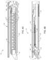
- FIG. 1depicts a perspective view of a first exemplary surgical stapling instrument
- FIG. 2depicts a side view of the instrument of FIG. 1 with a first exemplary end effector
- FIG. 3depicts a perspective view of the end effector of the instrument of FIG. 1 in an open configuration
- FIG. 4 Adepicts a side cross-sectional view of the end effector of FIG. 3 , taken along line 4 - 4 of FIG. 3 , with the firing beam in a proximal position;
- FIG. 4 Bdepicts a side cross-sectional view of the end effector of FIG. 3 , taken along line 4 - 4 of FIG. 3 , with the firing beam in a distal position;
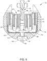
- FIG. 5depicts an end cross-sectional view of the end effector of FIG. 3 , taken along line 5 - 5 of FIG. 3 ;
- FIG. 6depicts an exploded perspective view of the end effector of FIG. 3 ;
- FIG. 7depicts a perspective view of a second exemplary surgical stapling instrument with a second exemplary end effector
- FIG. 8depicts an enlarged side sectional view of the end effector of FIG. 7 ;
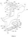
- FIG. 9depicts a top front perspective view of a first exemplary knife of the end effector of FIG. 7 ;
- FIG. 10depicts a bottom front perspective view of knife of FIG. 9 ;
- FIG. 11depicts a left side view of the knife of FIG. 9 ;
- FIG. 12depicts a right side view of the knife of FIG. 9 ;
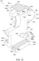
- FIG. 13depicts a top front perspective view of a second exemplary knife that may be incorporated into the end effector of FIG. 7 ;
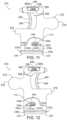
- FIG. 14 Adepicts an enlarged view of the anvil pin of the knife of FIG. 13 prior to being machined
- FIG. 14 Bdepicts an enlarged view of the anvil pin of the knife of FIG. 13 after being machined
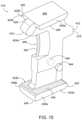
- FIG. 15depicts a top front perspective view of a third exemplary knife that may be incorporated into the end effector of FIG. 7 ;
- FIG. 16depicts an exemplary method of manufacturing a knife that may be incorporated into the end effector of FIG. 7 .
- proximal and distalare defined herein relative to a human or robotic operator of the surgical instrument.
- proximalrefers the position of an element closer to the human or robotic operator of the surgical instrument and further away from the surgical end effector of the surgical instrument.
- distalrefers to the position of an element closer to the surgical end effector of the surgical instrument and further away from the human or robotic operator of the surgical instrument.
- the terms “upper,” “lower,” “lateral,” “transverse,” “bottom,” “top,”are relative terms to provide additional clarity to the figure descriptions provided below. The terms “upper,” “lower,” “lateral,” “transverse,” “bottom,” “top,” are thus not intended to unnecessarily limit the invention described herein.
- first and secondare used herein to distinguish one or more portions of the surgical instrument.
- a first assembly and a second assemblymay be alternatively and respectively described as a second assembly and a first assembly.
- first and second and other numerical designationsare merely exemplary of such terminology and are not intended to unnecessarily limit the invention described herein.
- FIGS. 1 - 6depict a first exemplary surgical stapling and severing instrument ( 10 ) that is sized for insertion through a trocar cannula or an incision (e.g., thoracotomy, etc.) to a surgical site in a patient for performing a surgical procedure.
- Instrument ( 10 ) of the present exampleincludes a handle portion ( 20 ) connected to a shaft ( 22 ), which distally terminates in an articulation joint ( 11 ), which is further coupled with a first exemplary end effector ( 12 ).
- Shaft ( 22 )may be constructed in accordance with at least some of the teachings of U.S. Pat. No. 9,795,379, entitled “Surgical Instrument with Multi-Diameter Shaft,” issued Oct. 24, 2017, the disclosure of which is incorporated by reference herein.
- articulation joint ( 11 ) and end effector ( 12 )may be remotely articulated, as depicted in phantom in FIG. 1 , by an articulation control ( 13 ), such that end effector ( 12 ) may be deflected from the longitudinal axis (LA) of shaft ( 22 ) at a desired angle (a).
- Articulation joint ( 11 ) and/or articulation control ( 13 )may be constructed and operable in accordance with at least some of the teachings of U.S. Pat. No. 9,186,142, entitled “Surgical Instrument End Effector Articulation Drive with Pinion and Opposing Racks,” issued on Nov. 17, 2015, the disclosure of which is incorporated by reference herein; and/or U.S. Pat. No. 9,795,379, the disclosure of which is incorporated by reference herein.
- End effector ( 12 ) of the present exampleincludes a lower jaw ( 16 ) and a pivotable anvil ( 18 ).
- Lower jaw ( 16 )may be constructed in accordance with at least some of the teachings of U.S. Pat. No. 9,808,248, entitled “Installation Features for Surgical Instrument End Effector Cartridge,” issued Nov. 7, 2017, the disclosure of which is incorporated by reference herein.
- Anvil ( 18 )may be constructed in accordance with at least some of the teachings of U.S. Pat. No. 9,517,065, entitled “Integrated Tissue Positioning and Jaw Alignment Features for Surgical Stapler,” issued Dec. 13, 2016, the disclosure of which is incorporated by reference herein; U.S. Pat. No.
- Handle portion ( 20 )includes a pistol grip ( 24 ) and a closure trigger ( 26 ).
- Closure trigger ( 26 )is pivotable toward pistol grip ( 24 ) to cause clamping, or closing, of the anvil ( 18 ) toward lower jaw ( 16 ) of end effector ( 12 ).
- Such closing of anvil ( 18 )is provided through a closure tube ( 32 ) and a closure ring ( 33 ), which both longitudinally translate relative to handle portion ( 20 ) in response to pivoting of closure trigger ( 26 ) relative to pistol grip ( 24 ).
- Closure tube ( 32 )extends along the length of shaft ( 22 ); and closure ring ( 33 ) is positioned distal to articulation joint ( 11 ).
- Articulation joint ( 11 )is operable to communicate/transmit longitudinal movement from closure tube ( 32 ) to closure ring ( 33 ).
- Handle portion ( 20 )also includes a firing trigger ( 28 ) (shown in FIG. 2 ).
- An elongate member(not shown) longitudinally extends through shaft ( 22 ) and communicates a longitudinal firing motion from handle portion ( 20 ) to a firing beam ( 14 ) in response to actuation of firing trigger ( 28 ).
- This distal translation of firing beam ( 14 )causes the stapling and severing of clamped tissue in end effector ( 12 ), as will be described in greater detail below.
- FIGS. 3 - 6depict end effector ( 12 ) employing an E-beam form of firing beam ( 14 ).
- firing beam ( 14 )includes a transversely oriented upper pin ( 38 ), a firing beam cap ( 44 ), a transversely oriented middle pin ( 46 ), and a distally presented cutting edge ( 48 ).
- Upper pin ( 38 )is positioned and translatable within an anvil channel ( 42 ) of anvil ( 18 ).
- Firing beam cap ( 44 )slidably engages a lower surface of lower jaw ( 16 ) by having firing beam ( 14 ) extend through lower jaw channel ( 45 ) (shown in FIG. 4 B ) that is formed through lower jaw ( 16 ).
- Middle pin ( 46 )slidingly engages a top surface of lower jaw ( 16 ), cooperating with firing beam cap ( 44 ).
- Firing beam ( 14 ) and/or associated lockout featuresmay be constructed and operable in accordance with at least some of the teachings of U.S. Pat. No. 9,717,497, entitled “Lockout Feature for Movable Cutting Member of Surgical Instrument,” issued Aug. 1, 2017, the disclosure of which is incorporated by reference herein.
- FIG. 3shows firing beam ( 14 ) of the present example proximally positioned and anvil ( 18 ) pivoted to an open position, allowing an unspent staple cartridge ( 37 ) to be removably installed into a channel of lower jaw ( 16 ).
- staple cartridge ( 37 ) of this exampleincludes a cartridge body ( 70 ), which presents an upper deck ( 72 ) and is coupled with a lower cartridge tray ( 74 ).
- a vertical slot ( 49 )is formed through part of staple cartridge ( 37 ).
- FIG. 3shows firing beam ( 14 ) of the present example proximally positioned and anvil ( 18 ) pivoted to an open position, allowing an unspent staple cartridge ( 37 ) to be removably installed into a channel of lower jaw ( 16 ).
- staple cartridge ( 37 ) of this exampleincludes a cartridge body ( 70 ), which presents an upper deck ( 72 ) and is coupled with a lower cartridge tray ( 74 ).
- a vertical slot ( 49 )is formed through part of staple cartridge
- three rows of staple apertures ( 51 )are formed through upper deck ( 72 ) on one side of vertical slot ( 49 ), with another set of three rows of staple apertures ( 51 ) being formed through upper deck ( 72 ) on the other side of vertical slot ( 49 ).
- a wedge sled ( 41 ) and a plurality of staple drivers ( 43 )are captured between cartridge body ( 70 ) and tray ( 74 ), with wedge sled ( 41 ) being located proximal to staple drivers ( 43 ).
- Wedge sled ( 41 )is movable longitudinally within staple cartridge ( 37 ); while staple drivers ( 43 ) are movable vertically within staple cartridge ( 37 ).
- Staples ( 47 )are also positioned within cartridge body ( 70 ), above corresponding staple drivers ( 43 ). Each staple ( 47 ) is driven vertically within cartridge body ( 70 ) by a staple driver ( 43 ) to drive staple ( 47 ) out through an associated staple aperture ( 51 ). As best seen in FIGS. 4 A- 4 B and 6 , wedge sled ( 41 ) presents inclined cam surfaces that urge staple drivers ( 43 ) upwardly as wedge sled ( 41 ) is driven distally through staple cartridge ( 37 ). Staple cartridge ( 37 ) may be constructed and operable in accordance with at least some of the teachings of U.S. Pat. No. 9,517,065, the disclosure of which is incorporated by reference herein; and/or U.S. Pat. No. 9,808,248, the disclosure of which is incorporated by reference herein.
- firing beam ( 14 )With end effector ( 12 ) closed as depicted in FIGS. 4 A- 4 B by distally advancing closure tube ( 32 ) and closure ring ( 33 ), firing beam ( 14 ) is then advanced in engagement with anvil ( 18 ) by having upper pin ( 38 ) enter anvil channel ( 42 ).
- a pusher block ( 80 )(shown in FIG. 5 ) is located at the distal end of firing beam ( 14 ) and pushes wedge sled ( 41 ) as firing beam ( 14 ) is advanced distally through staple cartridge ( 37 ) when firing trigger ( 28 ) is actuated.
- middle pin ( 46 ) and pusher block ( 80 )together actuate staple cartridge ( 37 ) by entering into vertical slot ( 49 ) within staple cartridge ( 37 ), driving wedge sled ( 41 ) into upward camming contact with staple drivers ( 43 ), which in turn drive staples ( 47 ) out through staple apertures ( 51 ) and into forming contact with staple forming pockets ( 53 ) (shown in FIG. 3 ) on the inner surface of anvil ( 18 ).
- FIG. 4 Bdepicts firing beam ( 14 ) fully distally translated after completing severing and stapling of tissue.
- Staple forming pockets ( 53 )are intentionally omitted from the view in FIGS. 4 A- 4 B ; but are shown in FIG. 3 .
- Anvil ( 18 )is intentionally omitted from the view in FIG. 5 .
- anvil ( 18 )pivots about an axis that is defined by a pin (or similar feature) that slides along an elongate slot or channel as anvil ( 18 ) moves toward lower jaw ( 16 ). In such versions, the pivot axis translates along the path defined by the slot or channel while anvil ( 18 ) simultaneously pivots about that axis.
- Instrument ( 10 )may otherwise be configured and operable in accordance with any of the teachings of any of the patent references cited herein. Additional exemplary modifications that may be provided for instrument ( 10 ) will be described in greater detail below.
- the below teachingsare not limited to instrument ( 10 ) or devices taught in the patents cited herein.
- the below teachingsmay be readily applied to various other kinds of instruments, including instruments that would not be classified as surgical staplers.
- Various other suitable devices and settings in which the below teachings may be appliedwill be apparent to those of ordinary skill in the art in view of the teachings herein.
- FIG. 7shows a perspective view of a second exemplary surgical stapling instrument ( 110 ) with a second exemplary end effector ( 112 ) that is operable to compress, staple, and cut tissue.
- Instrument ( 110 ) and end effector ( 112 )function similarly to instrument ( 10 ) and end effector ( 12 ) described above.
- instrument ( 110 )includes a body (shown as a handle portion ( 120 )), a shaft ( 122 ) extending distally from handle portion ( 120 ), with end effector ( 112 ) extending distally from shaft ( 122 ).
- Shaft ( 122 )distally terminates in an articulation joint ( 111 ), which is coupled with end effector ( 112 ).
- handle portion ( 120 )includes a pistol grip ( 124 ) and a closure trigger ( 126 ).
- Closure trigger ( 126 )is pivotable toward pistol grip ( 124 ) to cause clamping, or closing, of anvil ( 118 ) toward lower jaw ( 116 ) of end effector ( 112 ).
- Such closing of anvil ( 118 )is provided through a closure tube ( 132 ) and a closure ring ( 133 ), which both longitudinally translate relative to handle portion ( 120 ) in response to pivoting of closure trigger ( 126 ) relative to pistol grip ( 124 ).
- Closure tube ( 132 )extends along the length of shaft ( 122 ).
- Closure ring ( 133 )is positioned distal to articulation joint ( 111 ). Articulation joint ( 111 ) is operable to communicate/transmit longitudinal movement from closure tube ( 132 ) to closure ring ( 133 ). Handle portion ( 120 ) also includes a firing trigger ( 128 ). An elongate member (not shown) longitudinally extends through shaft ( 122 ) and communicates a longitudinal firing motion from handle portion ( 120 ) to a firing beam ( 114 ) in response to actuation of firing trigger ( 128 ). This distal translation of firing beam ( 114 ) causes the stapling and severing of clamped tissue in end effector ( 112 ).
- FIG. 8shows an enlarged side sectional view of end effector ( 112 ) of FIG. 7 with a first exemplary knife ( 210 ) as will be described in greater detail below with reference to FIGS. 9 - 12 .
- Lower jaw ( 116 )is configured to receive staple cartridge ( 37 ).
- Lower jaw ( 116 )includes a lower jaw channel ( 145 ), similar to lower jaw channel ( 45 ), that is configured to receive a portion of knife ( 210 ).
- anvil ( 118 )includes an anvil channel ( 142 ) similar to anvil channel ( 42 ).
- FIG. 8instead of using a single firing beam ( 14 ) as shown in FIG.
- firing beam ( 14 )is separated into firing beam ( 114 ) and an exemplary knife ( 210 , 310 , 410 ).
- Firing beam ( 114 ) and knife ( 210 , 310 , 410 )may be coupled together using a variety of different methods including welding and/or mechanical feature(s).
- a distal portion of firing beam ( 114 )includes a coupling feature ( 146 ) that couples with a proximal coupling feature ( 212 ) of knife ( 210 ) as shown in greater detail in FIGS. 9 - 12 .
- knife ( 210 ) of instrument ( 110 )may be machined from a single solid block of material (e.g. metal). As a result, this machining of knife ( 210 ) may be time consuming and expensive, both of which are undesirable. As a result, it is desirable to manufacture knife ( 210 , 310 , 410 ) using a faster, more efficient, and more cost-effective process or system of processes. Conventional machining techniques, being reductive in nature, may also be considered as being inefficient since they may create waste in the material that is removed from the single solid block of material.
- knife ( 210 , 310 , 410 )may have tighter tolerances to enhance the performance of instrument ( 110 ), while other specific portions and features of knife ( 210 , 310 , 410 ) may have looser tolerances where the precise dimensions are of lesser significance.
- tighter tolerancesmay be preferred for surfaces that aid the distal movement of knife ( 210 , 310 , 410 ) in end effector ( 112 ) of instrument ( 110 ).
- instruments ( 10 , 110 )include surgical staplers, it is contemplated that the teachings may be readily applied to knife members for various other kinds of instruments.
- FIG. 9 - 12show knife ( 210 ) as including a body ( 214 ) with distal and proximal ends ( 216 , 218 ).
- Body ( 214 ) of knife ( 210 )includes a projection in the form of an anvil pin ( 220 ) disposed opposite a projection in the form of a channel pin ( 222 ).
- Anvil pin ( 220 )includes outwardly extending flanges ( 224 a - b ).
- Flanges ( 224 a - b )respectively include upper surfaces ( 226 ) separated by upper surface ( 229 ), a lower surface ( 228 ), and lateral side surfaces ( 230 a - b ) disposed therebetween.
- Flanges ( 224 a - b )are configured to interact with anvil channel ( 42 , 142 ). Flanges ( 224 a - b ) function similarly to upper pin ( 38 ) of firing beam ( 14 ). Like upper pin ( 38 ), flanges ( 224 a - b ) are positioned and translatable within anvil channel ( 42 , 142 ) of anvil ( 18 , 118 ). Similar to anvil pin ( 220 ), channel pin ( 222 ) includes outwardly extending flanges ( 232 a - b ).
- Flanges ( 232 a - b )include upper surfaces ( 234 a - c ), a lower surface ( 236 ), and lateral side surfaces ( 238 a - b ) disposed therebetween. Flanges ( 232 a - b ) function similarly to firing beam cap ( 44 ) that slidably engages a lower surface of lower jaw ( 16 ) by having firing beam ( 14 ) extend through lower jaw channel ( 45 ) (shown in FIG. 4 B ) that is formed through lower jaw ( 16 ).
- Flanges ( 224 a - b , 232 a - b )cooperate to maintain end effector ( 12 , 112 ) in a closed state during actuation of the end effector ( 12 , 112 ).
- upper surface ( 234 b )is recessed relative to upper surfaces ( 234 a , 234 c ), resulting in a non-planar surface.
- a cutting edge ( 240 )is disposed adjacent distal end ( 216 ) of knife ( 210 ) and opposite coupling feature ( 212 ).
- Cutting edge ( 240 )is formed by the converging distal termination of opposing cutting surfaces ( 242 ).
- Knife ( 210 )also includes a projection in the form of a middle flange ( 244 ).
- Middle flange ( 244 )functions similar to middle pins ( 46 ) which slidingly engages a top surface of lower jaw ( 16 ), cooperating with firing beam cap ( 44 ).
- Middle flange ( 244 )includes outwardly extending flanges ( 246 a - b ) that are shown as being generally shaped as airfoils.
- Flanges ( 246 a - b )include an upper surface ( 248 ), a lower surface ( 250 a - b ), and lateral side surfaces ( 252 a - b ) disposed therebetween.
- knife ( 210 )may be initially formed using a near net metal injection molding process.
- Metal injection moldingrefers to any metalworking process where finely-powdered metal is mixed with a binder material to create a feedstock that is subsequently shaped and solidified using molding process (such as injection molding). Metal injection molding allows for high volume, complex parts to be shaped.
- knife ( 210 , 310 , 410 ) and each of its featureshave a molded shape, certain features of which are subsequently machined to a machined shape. Machined features may have a finer surface finish than portions of knife ( 210 , 310 , 410 ) that have not been machined.
- Such feature(s) being machined after being formedmay include one or more of cutting edge ( 240 ), upper surface ( 229 ) of anvil pin ( 220 ), upper and lower surfaces ( 226 , 228 ) of anvil pin ( 220 ), lower surface ( 250 a - b ) of middle flange ( 244 ), and upper surface ( 234 ) of channel pin ( 222 ). Machining these features may provide many benefits. For example, upper and lower surfaces ( 226 , 228 ) may be machined to improve the dimensional tolerances of the near net metal injection molding process. Improved dimensional tolerances of certain surfaces may improve the sliding interface between components moving relative to one another.
- Improving the sliding interfacemay reduce the wear associated with upper and lower surfaces ( 226 , 228 ) of anvil pin ( 220 ) slidably interacting with anvil ( 18 , 118 ).
- upper surface ( 234 a - c )may be machined to reduce the wear associated with slidably interacting with lower jaw channel ( 145 ) of lower jaw ( 116 ).
- Opposing cutting surfaces ( 242 )may be machined after being formed using a near net metal injection molding process to increase relative sharpness, which may reduce a cutting force through the tissue. Machining opposing cutting surfaces ( 242 ) may specifically include grinding opposing cutting surfaces ( 242 ). It is also envisioned that other features including other surfaces may also be machined.
- FIG. 13shows a top front perspective view of a second exemplary knife ( 310 ) that may be used in end effector ( 112 ) in place of knife ( 210 ).
- Knife ( 310 )includes a body ( 314 ) with distal and proximal ends ( 316 , 318 ).
- Body ( 314 )includes a projection in the form of an anvil pin ( 320 ) disposed opposite a projection in the form of a channel pin ( 322 ).
- Anvil pin ( 320 )includes outwardly extending flanges ( 324 a - b ).
- Flanges ( 324 a - b )include an upper surface ( 326 ), a lower surface ( 328 ), and lateral side surfaces ( 330 a - b ) disposed therebetween. Flanges ( 324 a - b ) function similarly to upper pin ( 38 ) of firing beam ( 14 ) and flanges ( 224 a - b ) of knife ( 210 ). Like upper pin ( 38 ), flanges ( 324 a - b ) are positioned and translatable within anvil channel ( 42 , 142 ) of anvil ( 18 , 118 ). Similarly, channel pin ( 322 ) includes outwardly extending flanges ( 332 a - b ).
- Flanges ( 332 a - b )include an upper surface ( 334 ), a lower surface ( 336 ), and lateral side surfaces ( 338 a - b ) disposed therebetween.
- Flanges ( 332 a - b )function similarly to firing beam cap ( 44 ) and flanges ( 232 a - b ) of knife ( 210 ).
- Flanges ( 324 a - b , 332 a - b )cooperate to maintain end effector ( 12 , 112 ) in a closed state during actuation of end effector ( 12 , 112 ).
- a cutting edge ( 340 )is disposed adjacent distal end ( 316 ) of knife ( 310 ) and opposite coupling feature ( 312 ).
- Cutting edge ( 340 )is formed by the converging distal termination of opposing cutting surfaces ( 342 ).
- Knife ( 310 )also includes a projection in the form of a middle flange ( 344 ).
- Middle flange ( 344 )includes outwardly extending flanges ( 346 ), with outwardly extending flange ( 346 a ) being shown and another outwardly extending flange being hidden from view.
- Flange ( 346 a )includes an upper surface ( 348 ), a lower surface ( 350 a - b ), and lateral side surface ( 352 a ) disposed therebetween.
- Knife ( 310 )also includes proximal aligning features ( 354 ), which are shown as tab shaped projections in the present example. Proximal aligning features ( 354 ) may be configured to engage firing beam ( 14 , 114 ) of surgical instrument ( 10 , 110 ). While seven proximal aligning features ( 354 ) are shown, more or less aligning features of various shapes and sizes are also envisioned. Additionally, the spacing between adjacent proximal aligning features ( 354 ) may vary.
- certain feature(s)may be machined after being formed.
- Such feature(s)may include one or more of opposing cutting surfaces ( 342 ) of cutting edge ( 340 ), upper and lower surfaces ( 326 , 328 ) of anvil pin ( 320 ), lower surface ( 350 a - b ) of middle flange ( 344 ), and upper surface ( 334 ) of channel pin ( 322 ).
- upper and lower surfaces ( 326 , 328 )may be machined to reduce wear while slidably interacting with anvil ( 18 , 118 ).
- upper surface ( 334 ) of channel pin ( 322 )may be machined to reduce the wear associated with slidably interacting with lower jaw channel ( 145 ) of lower jaw ( 116 ).
- opposing cutting surfaces ( 342 )may be machined (e.g. ground using a grinder) to increase the sharpness of cutting surfaces ( 342 ) which reduces the cutting force through the tissue. It is also envisioned that other features and surfaces may also be machined.
- FIG. 14 Ashows an enlarged view of anvil pin ( 320 ) of knife ( 310 ) of FIG. 13 prior to machining but after being formed using a near net metal injection molding process.
- FIG. 14 Bshows an enlarged view of anvil pin ( 320 ) of knife ( 310 ) after machining.
- upper and lower surfaces ( 326 , 328 )are machined to obtain the upper and lower surfaces ( 326 , 328 ) in FIG. 14 B . Machining removes material from the feature, such that the dimensions of the molded shape are greater than dimensions of machined shape of the specific feature. For example, these reduced dimensions may be seen in FIGS. 14 A- 14 B showing the molded and subsequently machined upper and lower surfaces ( 326 , 328 ) of anvil pin ( 320 ) of knife ( 310 ).
- FIG. 15shows a top front perspective view of a third exemplary knife ( 410 ) that may be used in end effector ( 112 ) in place of knife ( 210 , 310 ).
- Knife ( 410 )includes a body ( 414 ) with distal and proximal ends ( 416 , 418 ).
- Body ( 414 )includes a projection in the form of an anvil pin ( 420 ) disposed opposite a projection in the form of a channel pin ( 422 ).
- Anvil pin ( 420 )includes outwardly extending flanges ( 424 a - b ).
- Flanges ( 424 a - b )include an upper surface ( 426 ), a lower surface ( 428 ), and lateral side surfaces ( 430 a - b ) disposed therebetween.
- Flanges ( 424 a - b )function similarly to upper pin ( 38 ) of firing beam ( 14 ) and flanges ( 224 a - b , 324 a - b ) of knife ( 210 , 310 ).
- flanges ( 324 a - b )are positioned and translatable within anvil channel ( 42 , 142 ) of anvil ( 18 , 118 ).
- channel pin ( 422 )includes outwardly extending flanges ( 432 a - b ).
- Flanges ( 432 a - b )include an upper surface ( 434 ), a lower surface ( 436 ), and lateral side surfaces ( 438 a - b ) disposed therebetween.
- Flanges ( 432 a - b )function similarly to firing beam cap ( 44 ) and flanges ( 232 a - b , 332 a - b )) of knife ( 210 , 310 ).
- Flanges ( 424 a - b , 432 a - b )cooperate to maintain end effector ( 12 , 112 ) in a closed state during actuation of end effector ( 12 , 112 ).
- a cutting edge ( 440 )is disposed adjacent distal end ( 416 ) of knife ( 410 ) and opposite coupling feature ( 412 ).
- Cutting edge ( 440 )is formed by the converging distal termination of opposing cutting surfaces ( 442 ).
- Knife ( 410 )also includes a projection in the form of a middle pin ( 444 ) adjacent proximal end ( 418 ) of knife ( 410 ).
- Middle pin ( 444 )is functionally equivalent to middle pin ( 46 ). Similar to middle pin ( 46 ) that slidingly engages a top surface of lower jaw ( 16 ) cooperating with firing beam cap ( 44 ) described above with reference to FIGS. 1 - 6 , middle pin ( 444 ) is configured to slidingly engage a top surface of lower jaw ( 16 , 116 ), cooperating with flanges ( 424 a - b ).
- certain feature(s)may be machined after being formed.
- Such feature(s)may include one or more of opposing cutting surfaces ( 442 ) of cutting edge ( 440 ), lower surface ( 428 ) of anvil pin ( 420 ), and upper surface ( 434 ) of channel pin ( 422 ).
- upper and lower surfaces ( 426 , 428 )may be machined to reduce the wear associated with slidably interacting with anvil ( 18 , 118 ).
- upper surface ( 434 ) of channel pin ( 422 )may be machined to improve the respective tolerances which may reduce the associated wear while slidably interacting with lower jaw channel ( 145 ) of lower jaw ( 116 ).
- Opposing cutting surfaces ( 442 )may be machined to reduce a cutting force through the tissue. It is also envisioned that other features and surfaces may also be machined.
- FIG. 16shows an exemplary method ( 510 ) of manufacturing knife ( 210 , 310 , 410 ) of end effector ( 12 , 112 ) of surgical instrument ( 10 , 110 ) that includes steps ( 512 , 514 , 516 , 518 ).
- method ( 510 )includes forming knife ( 210 , 310 , 410 ) using metal injection molding using a mold ( 520 ). Knife ( 210 , 310 , 410 ) and each of its features have a molded shape.
- knife ( 210 , 310 , 410 )may be formed using selective laser melting, or direct metal laser sintering, or any other suitable additive manufacturing process.
- method ( 510 )includes hot isostatic pressing knife ( 210 , 310 , 410 ) using a high-pressure vessel ( 522 ).
- Hot isostatic pressingis a manufacturing process that is used to reduce the porosity of metals and increase the density of many ceramic materials. Hot isostatic pressing may result in one or more of densification of powdered components, elimination of internal porosity, improvement of mechanical properties (such as increased resistance to fatigue and temperature extremes, higher resistance to impact, wear and abrasion, and improved ductility), more efficient production (tighter tolerances, reduction in machining, reduction in scrap). Hot isostatic pressing may be used on metal components, ceramic components, and/or composite components.
- knife ( 210 , 310 , 410 )may be placed into high-pressure vessel ( 522 ) and subjected to high pressurized gases and/or high temperatures. While the hot isostatic pressing is shown in FIG. 16 as occurring at a time prior to machining, it is also envisioned that the hot isostatic pressing may occur at a time after machining. In other words, step ( 514 ) may occur before or after step ( 518 ). It is desirable to selectively use hot isostatic pressing on particular structural features of knife ( 210 , 310 , 410 ).
- method ( 510 )includes sintering knife ( 210 , 310 , 410 ) after hot isostatic pressing knife ( 210 , 310 , 410 ). Prior to sintering, knife ( 210 , 310 , 410 ) is considered to be in a “green state.” Sintering may be performed by inserting knife ( 210 , 310 , 410 ) into a furnace ( 524 ).
- method ( 510 )includes machining feature(s) of knife ( 210 , 310 , 410 ) to have a machined shape. It is desirable to machine only specific feature(s) of knife ( 210 , 310 , 410 ) without machining the entire knife ( 210 , 310 , 410 ).
- the feature(s)may include a plurality of drive surfaces and cutting edge ( 240 , 340 , 440 ) of knife ( 210 , 310 , 410 ).
- the feature(s)may include cutting edge ( 240 , 340 , 440 ), anvil pin ( 220 , 320 , 420 ), middle flange ( 244 , 344 ), and channel pin ( 222 , 322 , 422 ) of knife ( 210 , 310 , 410 ).
- the surfaces of the feature(s)may include opposing cutting surfaces ( 242 , 342 , 442 ) of cutting edge ( 240 , 340 , 440 ), upper surface ( 229 ) of anvil pin ( 220 ), upper surface ( 226 , 326 , 426 ) of channel pin ( 222 , 322 , 422 ), lower surface ( 228 , 328 , 428 ) of anvil pin ( 220 , 320 , 420 ), and bottom surface ( 250 a - b , 350 a - b ) of middle flange ( 244 , 344 ). It may be desirable to machine at least two of these surfaces, at least three of these surfaces, at least four of these surfaces, or at least each of these surfaces. If two or more features are imparted, the features may be refined simultaneously or sequentially.
- Machiningremoves material from the feature(s), such that the dimensions of the molded or otherwise pre-machined shape are greater than dimensions of machined shape for the assessed feature. For example, the dimension reductions may be seen in comparing FIG. 14 A showing the molded anvil pin ( 320 ) of knife ( 310 ) and FIG. 14 B showing the subsequently machined anvil pin ( 320 ). Machining specific features, and specific surfaces of specific features, imparts tight tolerances where expressly desired. For example, tight tolerances may be preferred to minimize friction and associated wear of anvil pin ( 220 , 320 , 420 ) and channel pin ( 222 , 322 , 422 ).
- Step ( 518 )may be performed using a variety of machining tools, for example, using a lathe ( 526 ), which may be manually operated or automated. Machining is desired to broadly encompass turning operation(s), milling operation(s), drilling operations(s), and other miscellaneous machining operations.
- machiningmay include grinding opposing cutting surfaces ( 242 , 342 , 442 ) of cutting edge ( 240 , 340 , 440 ).
- Machining specific featuresmay identify material voids adjacent an outer surface of the feature that are present after hot isostatic pressing features of knife ( 210 , 310 , 410 ). Additionally, this secondary clean-up machining allows for initial molded geometries having better mold flow characteristics for the metal injection molding process. These machining operations may leave indication marks on the connected side walls that show where machining was used and the amount of material removed.
- Improved anvil pin ( 220 , 320 , 420 ) and channel pin ( 222 , 322 , 422 ) characteristicsreduce the requisite force to advance knife ( 210 , 310 , 410 ) under loading.
- method ( 510 )provides a superior surface finish than metal injection molding is capable of alone.
- a method of manufacturing a knife of an end effector of a surgical instrumentcomprising: (a) forming the knife using metal injection molding, wherein the knife has at least one feature having a molded shape; (b) machining the at least one feature of the knife to have a machined shape without machining the entire knife; and (c) incorporating the knife into the end effector of the surgical instrument.
- Example 1The method of Example 1, wherein the machining removes material from the at least one feature, such that the dimensions of the molded shape are greater than the dimensions of the machined shape of the at least one feature.
- Examples 1 or 2further comprising: hot isostatic pressing the knife before or after machining the at least one feature.
- Example 3The method of Example 3, wherein hot isostatic pressing occurs before machining the at least one feature.
- Examples 3 or 4further comprising: sintering the knife after hot isostatic pressing the knife and before machining the at least one feature of the knife.
- machining the at least one featurefurther comprises machining a plurality of drive surfaces and cutting surfaces of the knife.
- machining the at least one featureidentifies material voids adjacent an outer surface of the at least one feature present after the hot isostatic pressing of the knife.
- machining the at least one featurefurther comprises machining at least a portion of each of a cutting edge, an anvil pin, a middle flange, and a channel pin of the knife.
- machining the at least one featurefurther comprises machining at least each of a cutting edge, a lower surface of an anvil pin, and an upper surface of a channel pin of the knife.
- Example 9The method of Example 9, wherein the upper surface of the channel pin is non-planar.
- machining the at least one featurefurther comprises machining upper and lower surfaces of an anvil pin of the knife.
- machining the at least one featurefurther comprises machining at least three of a cutting edge, an upper surface of the anvil pin, a lower surface of the anvil pin, a lower surface of the middle flange, or an upper surface of a channel pin of the knife.
- machining the at least one featurefurther comprises machining at least each of a cutting edge, an upper surface of the anvil pin, a lower surface of the anvil pin, a lower surface of the middle flange, and an upper surface of a channel pin of the knife.
- a method of manufacturing a knife of an end effector of a surgical instrumentcomprising: (a) forming the knife using metal injection molding, wherein the knife has at least one feature having a molded shape and a first surface finish; (b) hot isostatic pressing the knife; (c) machining the at least one feature of the knife to have a machined shape and a second surface finish without machining the entire knife, wherein the second surface finish is finer than the first surface finish; and (d) incorporating the knife into the end effector of the surgical instrument.
- machining the at least one featurefurther comprises machining at least each of a cutting edge, a lower surface of an anvil pin, and an upper surface of a channel pin.
- Example 16wherein machining the at least one feature includes grinding a cutting edge of the knife.
- An instrumentcomprising: (a) a handle assembly; (b) a shaft extending from the handle assembly; and (c) an end effector in communication with the shaft, wherein the end effector is operable to compress, staple, and cut tissue, wherein the end effector comprises: (i) a first jaw including a channel and configured to receive a staple cartridge, (ii) a second jaw including an anvil, and (iii) a knife, wherein the knife comprises: (A) a cutting edge including first and second opposing sides, wherein the first and second opposing sides are machined with a configuration to reduce a cutting force through the tissue, (B) an anvil pin including upper and lower surfaces, wherein at least the lower surface is machined with a configuration to reduce wear associated with slidably interacting with the anvil, and (C) a channel pin that includes upper and lower surfaces, wherein at least the upper surface is machined with a configuration to reduce wear associated with slidably interacting with the channel.
- Example 19The instrument of Example 19, wherein the knife further includes a middle flange that includes upper and lower surfaces, wherein the lower surface of the middle flange is machined, wherein both the upper and lower surfaces are machined to reduce the wear associated with slidably interacting with the channel.
- An instrumentcomprising: (a) a handle assembly; (b) a shaft extending from the handle assembly; and (c) an end effector in communication with the shaft, wherein the end effector is operable to compress, staple, and cut tissue, wherein the end effector comprises: (i) a first jaw including a channel and configured to receive a staple cartridge, (ii) a second jaw including an anvil, and (iii) a knife, wherein the knife comprises: (A) a body formed using metal injection molding and having a first surface finish, (B) at least one feature formed in the body and having a molded shape, wherein the at least one feature of the knife is subsequently machined to have a machined shape with a second surface finish without machining the entire knife, wherein the second surface finish is finer than the first surface finish.
- the at least one featurefurther comprises at least a portion of each of a cutting edge, an anvil pin, a middle flange, and a channel pin of the knife.
- the at least one featurefurther comprises at least each of a cutting edge, a lower surface of an anvil pin, and an upper surface of a channel pin of the knife.
- the at least one featurefurther comprises at least three of a cutting edge, an upper surface of the anvil pin, a lower surface of the anvil pin, a lower surface of the middle flange, or an upper surface of a channel pin of the knife.
- the at least one featurefurther comprises at least each of a cutting edge, an upper surface of the anvil pin, a lower surface of the anvil pin, a lower surface of the middle flange, and an upper surface of a channel pin of the knife.
- the knifefurther comprises a plurality of proximal aligning features configured to engage a firing rod of the surgical instrument.
- Versions of the devices described abovemay have application in conventional medical treatments and procedures conducted by a medical professional, as well as application in robotic-assisted medical treatments and procedures.
- various teachings hereinmay be readily incorporated into a robotic surgical system such as the DAVINCITM system by Intuitive Surgical, Inc. of Sunnyvale, Calif.
- Versions of the devices described abovemay be designed to be disposed of after a single use, or they can be designed to be used multiple times. Versions may, in either or both cases, be reconditioned for reuse after at least one use. Reconditioning may include any combination of the steps of disassembly of the device, followed by cleaning or replacement of particular pieces, and subsequent reassembly. In particular, some versions of the device may be disassembled, and any number of the particular pieces or parts of the device may be selectively replaced or removed in any combination. Upon cleaning and/or replacement of particular parts, some versions of the device may be reassembled for subsequent use either at a reconditioning facility or by a user immediately prior to a procedure.
- reconditioning of a devicemay utilize a variety of techniques for disassembly, cleaning/replacement, and reassembly. Use of such techniques, and the resulting reconditioned device, are all within the scope of the present application.
- versions described hereinmay be sterilized before and/or after a procedure.
- the deviceis placed in a closed and sealed container, such as a plastic or TYVEK bag.
- the container and devicemay then be placed in a field of radiation that can penetrate the container, such as gamma radiation, x-rays, or high-energy electrons.
- the radiationmay kill bacteria on the device and in the container.
- the sterilized devicemay then be stored in the sterile container for later use.
- a devicemay also be sterilized using any other technique known in the art, including but not limited to beta or gamma radiation, ethylene oxide, or steam.
Landscapes
- Health & Medical Sciences (AREA)
- Surgery (AREA)
- Life Sciences & Earth Sciences (AREA)
- Engineering & Computer Science (AREA)
- Heart & Thoracic Surgery (AREA)
- Biomedical Technology (AREA)
- Nuclear Medicine, Radiotherapy & Molecular Imaging (AREA)
- Medical Informatics (AREA)
- Molecular Biology (AREA)
- Animal Behavior & Ethology (AREA)
- General Health & Medical Sciences (AREA)
- Public Health (AREA)
- Veterinary Medicine (AREA)
- Mechanical Engineering (AREA)
- Surgical Instruments (AREA)
Abstract
Description
Claims (20)
Priority Applications (1)
| Application Number | Priority Date | Filing Date | Title |
|---|---|---|---|
| US17/155,824US12295572B2 (en) | 2018-12-31 | 2021-01-22 | Knife for surgical stapler and associated method of manufacture with MIM and HIP |
Applications Claiming Priority (2)
| Application Number | Priority Date | Filing Date | Title |
|---|---|---|---|
| US16/236,676US11103245B2 (en) | 2018-12-31 | 2018-12-31 | Knife for surgical stapler and associated method of manufacture with MIM and hip |
| US17/155,824US12295572B2 (en) | 2018-12-31 | 2021-01-22 | Knife for surgical stapler and associated method of manufacture with MIM and HIP |
Related Parent Applications (1)
| Application Number | Title | Priority Date | Filing Date |
|---|---|---|---|
| US16/236,676DivisionUS11103245B2 (en) | 2018-12-31 | 2018-12-31 | Knife for surgical stapler and associated method of manufacture with MIM and hip |
Publications (2)
| Publication Number | Publication Date |
|---|---|
| US20210204940A1 US20210204940A1 (en) | 2021-07-08 |
| US12295572B2true US12295572B2 (en) | 2025-05-13 |
Family
ID=69024445
Family Applications (3)
| Application Number | Title | Priority Date | Filing Date |
|---|---|---|---|
| US16/236,676Active2039-02-01US11103245B2 (en) | 2018-12-31 | 2018-12-31 | Knife for surgical stapler and associated method of manufacture with MIM and hip |
| US17/155,824Active2039-09-07US12295572B2 (en) | 2018-12-31 | 2021-01-22 | Knife for surgical stapler and associated method of manufacture with MIM and HIP |
| US17/155,808Active2039-04-01US12059151B2 (en) | 2018-12-31 | 2021-01-22 | Knife for surgical stapler and associated method of manufacture with MIM and HIP |
Family Applications Before (1)
| Application Number | Title | Priority Date | Filing Date |
|---|---|---|---|
| US16/236,676Active2039-02-01US11103245B2 (en) | 2018-12-31 | 2018-12-31 | Knife for surgical stapler and associated method of manufacture with MIM and hip |
Family Applications After (1)
| Application Number | Title | Priority Date | Filing Date |
|---|---|---|---|
| US17/155,808Active2039-04-01US12059151B2 (en) | 2018-12-31 | 2021-01-22 | Knife for surgical stapler and associated method of manufacture with MIM and HIP |
Country Status (6)
| Country | Link |
|---|---|
| US (3) | US11103245B2 (en) |
| EP (1) | EP3673830B1 (en) |
| JP (1) | JP2022515658A (en) |
| CN (1) | CN113260320A (en) |
| BR (1) | BR112021012562A2 (en) |
| WO (1) | WO2020141380A1 (en) |
Families Citing this family (4)
| Publication number | Priority date | Publication date | Assignee | Title |
|---|---|---|---|---|
| US11103245B2 (en) | 2018-12-31 | 2021-08-31 | Cilag Gmbh International | Knife for surgical stapler and associated method of manufacture with MIM and hip |
| US20230000495A1 (en)* | 2021-06-30 | 2023-01-05 | Covidien Lp | Circular stapling device with tissue grasping members |
| US11992218B2 (en) | 2021-10-18 | 2024-05-28 | Cilag Gmbh International | Metal injection molded anvil for circular surgical stapler |
| WO2024228981A1 (en)* | 2023-05-01 | 2024-11-07 | Intuitive Surgical Operations, Inc. | Components of surgical stapling instruments and methods for manufacturing the same |
Citations (146)
| Publication number | Priority date | Publication date | Assignee | Title |
|---|---|---|---|---|
| US4706866A (en) | 1985-11-21 | 1987-11-17 | Etona Company, Limited | Stapler |
| US4813143A (en) | 1987-06-25 | 1989-03-21 | Alcas Cutlery Corporation | Handle and knives comprising the same |
| US5163945A (en) | 1991-10-18 | 1992-11-17 | Ethicon, Inc. | Surgical clip applier |
| US5205459A (en) | 1991-08-23 | 1993-04-27 | Ethicon, Inc. | Surgical anastomosis stapling instrument |
| US5297746A (en) | 1992-02-06 | 1994-03-29 | Nelmor Company, Inc. | Granulator knife |
| EP0589454A2 (en) | 1992-09-23 | 1994-03-30 | United States Surgical Corporation | Endoscopic surgical instrument |
| US5308576A (en) | 1991-10-18 | 1994-05-03 | United States Surgical Corporation | Injection molded anvils |
| US5333773A (en) | 1991-08-23 | 1994-08-02 | Ethicon, Inc. | Sealing means for endoscopic surgical anastomosis stapling instrument |
| US5342373A (en) | 1992-09-14 | 1994-08-30 | Ethicon, Inc. | Sterile clips and instrument for their placement |
| US5350104A (en) | 1991-08-23 | 1994-09-27 | Ethicon, Inc. | Sealing means for endoscopic surgical anastomosis stapling instrument |
| US5364001A (en) | 1991-10-18 | 1994-11-15 | United States Surgical Corporation | Self contained gas powered surgical apparatus |
| US5403312A (en) | 1993-07-22 | 1995-04-04 | Ethicon, Inc. | Electrosurgical hemostatic device |
| US5411514A (en)* | 1992-09-30 | 1995-05-02 | Linvatec Corporation | Bendable variable angle rotating shaver |
| US5431668A (en) | 1993-04-29 | 1995-07-11 | Ethicon, Inc. | Ligating clip applier |
| US5445167A (en) | 1987-05-14 | 1995-08-29 | Yoon; Inbae | Methods of applying surgical chips and suture tie devices to bodily tissue during endoscopic procedures |
| US5487499A (en)* | 1993-10-08 | 1996-01-30 | United States Surgical Corporation | Surgical apparatus for applying surgical fasteners including a counter |
| US5584845A (en)* | 1994-08-18 | 1996-12-17 | Innovasive Devices, Inc. | Surgical scissor blade and method for making the same |
| US5601573A (en) | 1994-03-02 | 1997-02-11 | Ethicon Endo-Surgery, Inc. | Sterile occlusion fasteners and instruments and method for their placement |
| US5722306A (en) | 1995-06-07 | 1998-03-03 | Alloy Technology International Inc. | Method for making a pelletizer knife and blank |
| US5807338A (en)* | 1995-10-20 | 1998-09-15 | United States Surgical Corporation | Modular trocar system and methods of assembly |
| US5951574A (en) | 1998-10-23 | 1999-09-14 | Ethicon Endo-Surgery, Inc. | Multiple clip applier having a split feeding mechanism |
| US6176021B1 (en) | 1997-03-12 | 2001-01-23 | Mitutoyo Corporation | Micrometer |
| US6185771B1 (en)* | 1999-12-06 | 2001-02-13 | John E. Trusty, Sr. | Pocket tool having slidably extensible pliers |
| US6269714B1 (en) | 1996-05-30 | 2001-08-07 | Kakoh Kiki Co., Ltd. | Cutter knife for thermoplastic resin pelletizer and production method of said cutter knife |
| US20020029910A1 (en) | 1999-02-23 | 2002-03-14 | Hans-Wilm Heinrich | Twist drill having a sintered cemented carbide body, and like tools, and use thereof |
| US20050004568A1 (en) | 1997-11-12 | 2005-01-06 | Lawes Kate R. | Electrosurgical instrument reducing thermal spread |
| US20050139636A1 (en) | 2003-12-30 | 2005-06-30 | Schwemberger Richard F. | Replaceable cartridge module for a surgical stapling and cutting instrument |
| US20050143759A1 (en) | 2003-12-30 | 2005-06-30 | Kelly William D. | Curved cutter stapler shaped for male pelvis |
| US20050149087A1 (en)* | 2003-11-05 | 2005-07-07 | Applied Medical Resources Corporation | Multiple-angle scissor blade |
| US20050145672A1 (en) | 2003-12-30 | 2005-07-07 | Schwemberger Richard F. | Curved cutter stapler with aligned tissue retention feature |
| US6959851B2 (en) | 2003-07-16 | 2005-11-01 | Tyco Healthcare Group Lp | Surgical stapling device with tissue tensioner |
| US6988650B2 (en) | 2003-12-30 | 2006-01-24 | Ethicon Endo-Surgery, Inc. | Retaining pin lever advancement mechanism for a curved cutter stapler |
| US7000818B2 (en) | 2003-05-20 | 2006-02-21 | Ethicon, Endo-Surger, Inc. | Surgical stapling instrument having separate distinct closing and firing systems |
| US20060047309A1 (en) | 2004-08-25 | 2006-03-02 | Cichocki Frank R Jr | Metal injection molded suture needles |
| US20060090603A1 (en)* | 2004-09-24 | 2006-05-04 | Kai U.S.A., Ltd., Dba Kershaw Knives | Knife blade manufacturing process |
| US7043819B1 (en)* | 1996-12-23 | 2006-05-16 | Recast Airfoil Group | Methods for forming metal parts having superior surface characteristics |
| US20060108393A1 (en)* | 2004-10-18 | 2006-05-25 | Russell Heinrich | Structure for applying sprayable wound treatment material |
| US20060135992A1 (en)* | 2004-10-18 | 2006-06-22 | Bettuchi Michael J | Annular adhesive structure |
| US20060219752A1 (en) | 2004-12-13 | 2006-10-05 | Niti Medical Technologies Ltd. | Palm size surgical stapler for single hand operation |
| US7134587B2 (en) | 2003-12-30 | 2006-11-14 | Ethicon Endo-Surgery, Inc. | Knife retraction arm for a curved cutter stapler |
| US7147140B2 (en) | 2003-12-30 | 2006-12-12 | Ethicon Endo - Surgery, Inc. | Cartridge retainer for a curved cutter stapler |
| US20060277967A1 (en)* | 2005-06-13 | 2006-12-14 | Emerson Electric Co. | Identification attachments for compression tools |
| US20070056932A1 (en) | 2005-07-27 | 2007-03-15 | Whitman Michael P | System and method for forming staple pockets of a surgical stapler |
| US7195631B2 (en) | 2004-09-09 | 2007-03-27 | Sherwood Services Ag | Forceps with spring loaded end effector assembly |
| US20070082229A1 (en) | 2005-10-11 | 2007-04-12 | Mirchandani Rajini P | Biocompatible cemented carbide articles and methods of making the same |
| US7204404B2 (en) | 2003-12-30 | 2007-04-17 | Ethicon Endo-Surgery, Inc. | Slotted pins guiding knife in a curved cutter stapler |
| US7207472B2 (en) | 2003-12-30 | 2007-04-24 | Ethicon Endo-Surgery, Inc. | Cartridge with locking knife for a curved cutter stapler |
| US20070169605A1 (en)* | 2006-01-23 | 2007-07-26 | Szymanski David A | Components having sharp edge made of sintered particulate material |
| US20070175955A1 (en) | 2006-01-31 | 2007-08-02 | Shelton Frederick E Iv | Surgical cutting and fastening instrument with closure trigger locking mechanism |
| US7261724B2 (en) | 2005-04-14 | 2007-08-28 | Ethicon Endo-Surgery, Inc. | Surgical clip advancement mechanism |
| JP2007525285A (en) | 2004-02-27 | 2007-09-06 | アプライド メディカル リソーシーズ コーポレイション | System and method for operating a laparoscopic surgical instrument |
| US20080078800A1 (en) | 2006-09-29 | 2008-04-03 | Hess Christopher J | Surgical stapling instruments and staples |
| US7380696B2 (en) | 2003-05-20 | 2008-06-03 | Ethicon Endo-Surgery, Inc. | Articulating surgical stapling instrument incorporating a two-piece E-beam firing mechanism |
| US20080142187A1 (en) | 2006-12-19 | 2008-06-19 | Ethicon Endo-Surgery, Inc. | Support structures for molded parts |
| US7422139B2 (en) | 2006-01-31 | 2008-09-09 | Ethicon Endo-Surgery, Inc. | Motor-driven surgical cutting fastening instrument with tactile position feedback |
| US20080269793A1 (en)* | 2003-04-29 | 2008-10-30 | Scirica Paul A | Surgical Stapling Device with Dissecting Tip |
| US7464849B2 (en) | 2006-01-31 | 2008-12-16 | Ethicon Endo-Surgery, Inc. | Electro-mechanical surgical instrument with closure system and anvil alignment components |
| US20080308605A1 (en) | 2006-10-06 | 2008-12-18 | Tyco Healthcare Group Lp | Surgical instrument having a plastic surface |
| US20090001128A1 (en) | 2007-03-15 | 2009-01-01 | Weisenburgh Ii William B | Washer for use with a surgical stapling instrument |
| US7670334B2 (en) | 2006-01-10 | 2010-03-02 | Ethicon Endo-Surgery, Inc. | Surgical instrument having an articulating end effector |
| US7686820B2 (en) | 2005-04-14 | 2010-03-30 | Ethicon Endo-Surgery, Inc. | Surgical clip applier ratchet mechanism |
| US20100094315A1 (en)* | 2006-09-08 | 2010-04-15 | Beardsley John W | Dissection Tip And Introducer For Surgical Instrument |
| US7699860B2 (en) | 2005-04-14 | 2010-04-20 | Ethicon Endo-Surgery, Inc. | Surgical clip |
| US20100127039A1 (en) | 2008-11-24 | 2010-05-27 | Tyco Healthcare Group Lp | Pouch Used To Deliver Medication When Ruptured |
| US7731724B2 (en) | 2005-04-14 | 2010-06-08 | Ethicon Endo-Surgery, Inc. | Surgical clip advancement and alignment mechanism |
| US7753245B2 (en) | 2007-06-22 | 2010-07-13 | Ethicon Endo-Surgery, Inc. | Surgical stapling instruments |
| US7771425B2 (en) | 2003-06-13 | 2010-08-10 | Covidien Ag | Vessel sealer and divider having a variable jaw clamping mechanism |
| US20100249807A1 (en) | 2007-06-27 | 2010-09-30 | Suzhou Touchstone International Medical Science Co., Ltd. | Surgical purse-string suturing instrument |
| US7845537B2 (en) | 2006-01-31 | 2010-12-07 | Ethicon Endo-Surgery, Inc. | Surgical instrument having recording capabilities |
| US20110068147A1 (en) | 2008-05-05 | 2011-03-24 | Danyel Racenet | Surgical instrument with sequential clamping and cutting |
| US7980443B2 (en) | 2008-02-15 | 2011-07-19 | Ethicon Endo-Surgery, Inc. | End effectors for a surgical cutting and stapling instrument |
| US8021389B2 (en) | 2006-05-17 | 2011-09-20 | Warsaw Orthopedic, Inc. | Surgical staple assembly |
| US8038686B2 (en) | 2005-04-14 | 2011-10-18 | Ethicon Endo-Surgery, Inc. | Clip applier configured to prevent clip fallout |
| US8087562B1 (en) | 2009-06-22 | 2012-01-03 | Cardica, Inc. | Anvil for surgical instrument |
| US20120116422A1 (en) | 2010-11-10 | 2012-05-10 | Medicinelodge, Inc. Dba Imds Co-Innovation | Suture passers |
| US20120143218A1 (en)* | 2006-09-08 | 2012-06-07 | Tyco Healthcare Group Lp | Dissection Tip and Introducer for Surgical Instrument |
| US8210411B2 (en) | 2008-09-23 | 2012-07-03 | Ethicon Endo-Surgery, Inc. | Motor-driven surgical cutting instrument |
| US8220688B2 (en) | 2009-12-24 | 2012-07-17 | Ethicon Endo-Surgery, Inc. | Motor-driven surgical cutting instrument with electric actuator directional control assembly |
| US8262679B2 (en) | 2009-10-09 | 2012-09-11 | Ethicon Endo-Surgery, Inc. | Clip advancer |
| US20120241496A1 (en)* | 2010-09-30 | 2012-09-27 | Ethicon Endo-Surgery, Inc. | Tissue thickness compensator comprising a plurality of capsules |
| US8308040B2 (en) | 2007-06-22 | 2012-11-13 | Ethicon Endo-Surgery, Inc. | Surgical stapling instrument with an articulatable end effector |
| US20120292371A1 (en)* | 2011-05-19 | 2012-11-22 | Ethicon Endo-Surgery, Inc. | Circular stapling instrument having a breakaway washer attachment member |
| US20120292372A1 (en)* | 2011-05-19 | 2012-11-22 | Ethicon Endo-Surgery, Inc. | Low cost anvil assembly for a circular stapler |
| US8393514B2 (en) | 2010-09-30 | 2013-03-12 | Ethicon Endo-Surgery, Inc. | Selectively orientable implantable fastener cartridge |
| US20130105548A1 (en)* | 2011-10-26 | 2013-05-02 | Tyco Healthcare Group Lp | Buttress Release from Surgical Stapler by Knife Pushing |
| US20130105545A1 (en)* | 2011-10-26 | 2013-05-02 | Intuitive Surgical Operations, Inc. | Surgical Instrument with Integral Knife Blade |
| JP2013517891A (en) | 2010-01-29 | 2013-05-20 | エシコン・エンド−サージェリィ・インコーポレイテッド | Surgical stapling instrument with medical substance dispenser |
| US20130172929A1 (en)* | 2006-09-29 | 2013-07-04 | Ethicon Endo-Surgery, Inc. | Method for forming a staple |
| US20130239769A1 (en)* | 2012-03-14 | 2013-09-19 | Andritz Iggesund Tools Inc. | Knife for wood processing and methods for plating and surface treating a knife for wood processing |
| US20130256382A1 (en) | 2012-03-28 | 2013-10-03 | Ethicon Endo-Surgery, Inc. | Movable member for use with a tissue thickness compensator |
| US8561870B2 (en) | 2008-02-13 | 2013-10-22 | Ethicon Endo-Surgery, Inc. | Surgical stapling instrument |
| US8608045B2 (en) | 2008-10-10 | 2013-12-17 | Ethicon Endo-Sugery, Inc. | Powered surgical cutting and stapling apparatus with manually retractable firing system |
| US8733613B2 (en) | 2010-09-29 | 2014-05-27 | Ethicon Endo-Surgery, Inc. | Staple cartridge |
| US20140239037A1 (en) | 2013-02-28 | 2014-08-28 | Ethicon Endo-Surgery, Inc. | Staple forming features for surgical stapling instrument |
| US20140263552A1 (en) | 2013-03-13 | 2014-09-18 | Ethicon Endo-Surgery, Inc. | Staple cartridge tissue thickness sensor system |
| US20150083775A1 (en) | 2013-09-23 | 2015-03-26 | Ethicon Endo-Surgery, Inc. | Surgical stapler with rotary cam drive |
| US20150083773A1 (en) | 2013-09-23 | 2015-03-26 | Ethicon Endo-Surgery, Inc. | Surgical stapling instrument with drive assembly having toggle features |
| US20150083774A1 (en) | 2013-09-23 | 2015-03-26 | Ethicon Endo-Surgery, Inc. | Control features for motorized surgical stapling instrument |
| US20150083772A1 (en) | 2013-09-23 | 2015-03-26 | Ethicon Endo-Surgery, Inc. | Surgical stapler with rotary cam drive and return |
| US9072535B2 (en) | 2011-05-27 | 2015-07-07 | Ethicon Endo-Surgery, Inc. | Surgical stapling instruments with rotatable staple deployment arrangements |
| US9101358B2 (en) | 2012-06-15 | 2015-08-11 | Ethicon Endo-Surgery, Inc. | Articulatable surgical instrument comprising a firing drive |
| JP2015165038A (en) | 2014-02-28 | 2015-09-17 | セイコーエプソン株式会社 | Surgical equipment, metal powder for powder metallurgy, and method for manufacturing surgical equipment |
| US9186142B2 (en) | 2013-02-28 | 2015-11-17 | Ethicon Endo-Surgery, Inc. | Surgical instrument end effector articulation drive with pinion and opposing racks |
| US9192383B2 (en) | 2013-02-04 | 2015-11-24 | Covidien Lp | Circular stapling device including buttress material |
| US9517065B2 (en) | 2013-02-28 | 2016-12-13 | Ethicon Endo-Surgery, Llc | Integrated tissue positioning and jaw alignment features for surgical stapler |
| US20160374672A1 (en) | 2015-06-26 | 2016-12-29 | Ethicon Endo-Surgery, Llc | Method of applying an annular array of staples to tissue |
| US20170027571A1 (en) | 2015-07-30 | 2017-02-02 | Ethicon Endo-Surgery, Llc | Surgical instrument comprising systems for assuring the proper sequential operation of the surgical instrument |
| CN106456164A (en) | 2014-06-25 | 2017-02-22 | 伊西康内外科有限责任公司 | Locking engagement features for surgical staplers |
| US9717497B2 (en) | 2013-02-28 | 2017-08-01 | Ethicon Llc | Lockout feature for movable cutting member of surgical instrument |
| US20170258471A1 (en) | 2013-09-23 | 2017-09-14 | Ethicon Llc | Methods and systems for performing circular stapling |
| US20170265867A1 (en) | 2016-03-21 | 2017-09-21 | Ethicon, Inc. | Temporary Fixation Tools for Use with Circular Anastomotic Staplers |
| US9795379B2 (en) | 2013-02-28 | 2017-10-24 | Ethicon Llc | Surgical instrument with multi-diameter shaft |
| US9808248B2 (en) | 2013-02-28 | 2017-11-07 | Ethicon Llc | Installation features for surgical instrument end effector cartridge |
| EP3241506A1 (en) | 2016-05-04 | 2017-11-08 | Covidien LP | Powered end effector assembly with pivotable channel |
| US9839421B2 (en) | 2013-02-28 | 2017-12-12 | Ethicon Llc | Jaw closure feature for end effector of surgical instrument |
| US9867615B2 (en) | 2013-02-28 | 2018-01-16 | Ethicon Llc | Surgical instrument with articulation lock having a detenting binary spring |
| US20180056095A1 (en) | 2016-08-25 | 2018-03-01 | Ethicon Llc | Ultrasonic transducer to waveguide acoustic coupling, connections, and configurations |
| US20180085932A1 (en) | 2016-09-26 | 2018-03-29 | Hsiu-Man Yu Chen | Cutter |
| US20180132853A1 (en) | 2016-11-14 | 2018-05-17 | Ethicon Endo-Surgery, Llc | Circular surgical stapler with recessed deck |
| US20180132849A1 (en) | 2016-11-14 | 2018-05-17 | Ethicon Endo-Surgery, Llc | Staple forming pocket configurations for circular surgical stapler anvil |
| US20180168647A1 (en)* | 2016-12-21 | 2018-06-21 | Ethicon Endo-Surgery, Llc | Surgical stapling instruments having end effectors with positive opening features |
| CN108472037A (en) | 2015-12-31 | 2018-08-31 | 伊西康有限责任公司 | Surgical stapling device with the variable height driver for consistent nail forming |
| US20180250838A2 (en)* | 2014-01-22 | 2018-09-06 | Mcpherson's Housewares Ip Pty Ltd | Cutting blade |
| US20180310938A1 (en) | 2017-04-28 | 2018-11-01 | Ethicon Llc | Hysteresis removal feature in surgical stapling instrument |
| US20180310939A1 (en) | 2017-04-28 | 2018-11-01 | Ethicon Llc | Liquid-immune trigger circuit for surgical instrument |
| US20180325502A1 (en)* | 2015-08-31 | 2018-11-15 | Devicor Medical Products, Inc. | Multi-faceted needle tip and method of manufacturing |
| US20180368840A1 (en) | 2017-06-27 | 2018-12-27 | Ethicon Llc | Surgical anvil arrangements |
| US20180368841A1 (en)* | 2017-06-27 | 2018-12-27 | Ethicon Llc | Surgical anvil arrangements |
| US20180368839A1 (en) | 2017-06-27 | 2018-12-27 | Ethicon Llc | Surgical anvil manufacturing methods |
| US20180368843A1 (en)* | 2017-06-27 | 2018-12-27 | Ethicon Llc | Surgical firing member arrangements |
| US20180368842A1 (en) | 2017-06-27 | 2018-12-27 | Ethicon Llc | Surgical anvil arrangements |
| US20190000481A1 (en)* | 2017-02-17 | 2019-01-03 | Ethicon Llc | Method of Surgical Stapling with End Effector Component Having a Curved Tip |
| US20190046193A1 (en) | 2017-08-14 | 2019-02-14 | Standard Bariatrics, Inc. | Buttress systems and methods for surgical stapling devices and end effectors |
| US20190059991A1 (en)* | 2017-08-29 | 2019-02-28 | Ethicon Llc | Electrically-powered surgical systems |
| US20190216561A1 (en)* | 2016-10-03 | 2019-07-18 | Intuitive Surgical Operations, Inc. | Surgical instrument with retaining feature for cutting element |
| US20190254679A1 (en)* | 2018-02-18 | 2019-08-22 | Okay Industries, Inc. | Surgical Clip Applicator and Manufacturing Method Therefor |
| US20190341753A1 (en) | 2018-05-03 | 2019-11-07 | Hakko Corporation | Thermal cartridge device |
| US20200206805A1 (en) | 2018-12-31 | 2020-07-02 | Ethicon Llc | Multi-Piece Jaw Assembly for Surgical Clip Applier |
| US20200205816A1 (en)* | 2018-12-31 | 2020-07-02 | Ethicon Llc | Cartridge Receiving Jaw for Surgical Stapler and Associated Method of Manufacture with MIM |
| US20200205815A1 (en)* | 2018-12-31 | 2020-07-02 | Ethicon Llc | Frame for Surgical Stapler and Associated Method of Manufacture with Stamping |
| US20200237368A1 (en)* | 2019-01-30 | 2020-07-30 | Ethicon Llc | Surgical stapler with toggling distal tip |
| US20200237370A1 (en)* | 2019-01-30 | 2020-07-30 | Ethicon Llc | Surgical stapler with deflectable distal tip |
| US20210045772A1 (en)* | 2016-09-01 | 2021-02-18 | Innfocus, Inc. | Tool(s) for Inserting a Glaucoma Shunt |
| US20210161526A1 (en)* | 2019-12-02 | 2021-06-03 | Covidien Lp | Linear Stapling Device With A Gap Locking Member |
| US20210177401A1 (en)* | 2019-12-13 | 2021-06-17 | Covidien Lp | Surgical Stapler with Universal Tip Reload |
| US20210204939A1 (en) | 2018-12-31 | 2021-07-08 | Ethicon Llc | Knife for surgical stapler and associated method of manufacture with mim and hip |
Family Cites Families (46)
| Publication number | Priority date | Publication date | Assignee | Title |
|---|---|---|---|---|
| US2859936A (en)* | 1954-03-03 | 1958-11-11 | Cincinnati Testing & Res Lab | Compressor blade and method of forming same |
| US3031753A (en)* | 1958-06-23 | 1962-05-01 | Bassett W E Co | Nail clipper |
| US4001366A (en)* | 1972-01-03 | 1977-01-04 | Ingrip Fasteners Inc. | Method for making self-gripping devices having integral trains of gripping elements |
| US3946769A (en)* | 1974-03-12 | 1976-03-30 | Panduit Corporation | Automatic cable tie installation tool |
| US4175883A (en)* | 1977-09-02 | 1979-11-27 | Lemelson Jerome H | Composite structural members and fastening methods |
| JPS5565037A (en)* | 1978-11-02 | 1980-05-16 | Kumi Plast Kogyo Kk | Method of manufacturing scissors, and said scissors |
| US4991764A (en)* | 1989-01-23 | 1991-02-12 | Edward Weck Incorporated | Surgical stapling instrument |
| US5431322A (en)* | 1991-10-18 | 1995-07-11 | United States Surgical Corporation | Self contained gas powered surgical apparatus |
| US5426857A (en)* | 1992-11-30 | 1995-06-27 | Fiskars Oy Ab | Pivoted hand-held cutting tool |
| US5636443A (en)* | 1992-11-30 | 1997-06-10 | Fiskars Oy Ab | Snips |
| US5383895A (en)* | 1993-02-10 | 1995-01-24 | Unisurge, Inc. | Endoscopic surgical grasper and method |
| US5392487A (en)* | 1993-12-15 | 1995-02-28 | Yang; Ming-Tung | Universal windshield wiper and wiper arm connector |
| US6282996B1 (en)* | 1999-01-29 | 2001-09-04 | Leatherman Tool Group, Inc. | Multipurpose locking pliers |
| US6145418A (en)* | 1999-06-14 | 2000-11-14 | Meritool Corp. | Laminated hand tool assembly |
| US6319266B1 (en)* | 2000-03-16 | 2001-11-20 | United States Surgical Corporation | Trocar system and method of use |
| US6504114B1 (en)* | 2000-08-22 | 2003-01-07 | Flintec, Inc. | Double bending beam load cell |
| US7276068B2 (en)* | 2002-10-04 | 2007-10-02 | Sherwood Services Ag | Vessel sealing instrument with electrical cutting mechanism |
| AU2003279854B2 (en)* | 2002-10-04 | 2008-12-18 | Covidien Lp | Tool assembly for a surgical stapling device |
| US7494039B2 (en)* | 2003-06-17 | 2009-02-24 | Tyco Healthcare Group Lp | Surgical stapling device |
| DE10335552B4 (en)* | 2003-08-02 | 2005-07-28 | Stephan Machinery Gmbh & Co. | Mixing shaft for mixing and dividing food products and method for producing a coating for such a mixing shaft |
| TWI226292B (en)* | 2003-10-28 | 2005-01-11 | Universal Trim Supply Co Ltd | Method for producing pattern on decorative plate |
| US7565780B2 (en)* | 2005-02-04 | 2009-07-28 | Poly-Clip System Corp. | Clip and clipper |
| US8684253B2 (en)* | 2007-01-10 | 2014-04-01 | Ethicon Endo-Surgery, Inc. | Surgical instrument with wireless communication between a control unit of a robotic system and remote sensor |
| JP2008173424A (en)* | 2007-01-18 | 2008-07-31 | Akio Nishihara | Manufacturing method for titanium and titanium alloy powder injection molding product |
| NL1033944C2 (en)* | 2007-06-06 | 2008-12-09 | Gijsbert Van Dusschoten | Hairdresser's tool. |
| US7988026B2 (en)* | 2007-09-06 | 2011-08-02 | Cardica, Inc. | Endocutter with staple feed |
| US8393516B2 (en)* | 2009-02-26 | 2013-03-12 | Covidien Lp | Surgical stapling apparatus with curved cartridge and anvil assemblies |
| US8157680B2 (en)* | 2010-02-25 | 2012-04-17 | Anderson Jeffrey R | Molded archery arrow for an archery bow with a metal barrel |
| US9055941B2 (en)* | 2011-09-23 | 2015-06-16 | Ethicon Endo-Surgery, Inc. | Staple cartridge including collapsible deck |
| US20140001231A1 (en)* | 2012-06-28 | 2014-01-02 | Ethicon Endo-Surgery, Inc. | Firing system lockout arrangements for surgical instruments |
| JP6297060B2 (en)* | 2012-12-31 | 2018-03-20 | インテュイティブ サージカル オペレーションズ, インコーポレイテッド | Surgical staple cartridge with enhanced knife clearance |
| US9351788B2 (en)* | 2013-06-06 | 2016-05-31 | Ethicon Endo-Surgery, Llc | Surgical instrument having knife band with curved distal edge |
| WO2015096530A1 (en)* | 2013-12-27 | 2015-07-02 | 瑞奇外科器械(中国)有限公司 | Flexible drive element, end effector and surgical instrument |
| US9839955B2 (en)* | 2015-05-15 | 2017-12-12 | Northrop Grumman Systems Corporation | Amorphous metal permanent fastener utilizing a thermoplastically swaged retainer |
| CN107771060B (en)* | 2015-06-18 | 2021-06-04 | 伊西康有限责任公司 | Dual-articulation drive system structure for articulating surgical instruments |
| MX2022009705A (en)* | 2015-08-26 | 2022-11-07 | Ethicon Llc | Surgical staples comprising hardness variations for improved fastening of tissue. |
| US10792064B2 (en)* | 2016-08-12 | 2020-10-06 | Covidien Lp | Energy-based surgical instrument for treating tissue |
| US10582928B2 (en)* | 2016-12-21 | 2020-03-10 | Ethicon Llc | Articulation lock arrangements for locking an end effector in an articulated position in response to actuation of a jaw closure system |
| US10973516B2 (en)* | 2016-12-21 | 2021-04-13 | Ethicon Llc | Surgical end effectors and adaptable firing members therefor |
| US10488281B2 (en)* | 2017-08-05 | 2019-11-26 | Interface, Inc. | Axial force pressure transducer |
| US11589865B2 (en)* | 2018-03-28 | 2023-02-28 | Cilag Gmbh International | Methods for controlling a powered surgical stapler that has separate rotary closure and firing systems |
| US10973520B2 (en)* | 2018-03-28 | 2021-04-13 | Ethicon Llc | Surgical staple cartridge with firing member driven camming assembly that has an onboard tissue cutting feature |
| CN110680436B (en)* | 2019-11-05 | 2025-02-07 | 江苏百纳医疗科技有限公司 | Stapler and its cutting assembly and fixing assembly |
| US11786291B2 (en)* | 2019-12-30 | 2023-10-17 | Cilag Gmbh International | Deflectable support of RF energy electrode with respect to opposing ultrasonic blade |
| EP4114280A4 (en)* | 2020-03-04 | 2024-02-28 | Covidien LP | Anvil assembly with cutting plate |
| US11330920B1 (en)* | 2021-07-07 | 2022-05-17 | Jonathan Lewis Rogers | System of interconnecting display plates and method of use |
- 2018
- 2018-12-31USUS16/236,676patent/US11103245B2/enactiveActive
- 2019
- 2019-12-16CNCN201980087244.9Apatent/CN113260320A/enactivePending
- 2019-12-16JPJP2021538247Apatent/JP2022515658A/enactivePending
- 2019-12-16BRBR112021012562-0Apatent/BR112021012562A2/enunknown
- 2019-12-16WOPCT/IB2019/060817patent/WO2020141380A1/ennot_activeCeased
- 2019-12-30EPEP19220044.2Apatent/EP3673830B1/enactiveActive
- 2021
- 2021-01-22USUS17/155,824patent/US12295572B2/enactiveActive
- 2021-01-22USUS17/155,808patent/US12059151B2/enactiveActive
Patent Citations (165)
| Publication number | Priority date | Publication date | Assignee | Title |
|---|---|---|---|---|
| US4706866A (en) | 1985-11-21 | 1987-11-17 | Etona Company, Limited | Stapler |
| US5445167A (en) | 1987-05-14 | 1995-08-29 | Yoon; Inbae | Methods of applying surgical chips and suture tie devices to bodily tissue during endoscopic procedures |
| US4813143A (en) | 1987-06-25 | 1989-03-21 | Alcas Cutlery Corporation | Handle and knives comprising the same |
| US5205459A (en) | 1991-08-23 | 1993-04-27 | Ethicon, Inc. | Surgical anastomosis stapling instrument |
| US5271544A (en) | 1991-08-23 | 1993-12-21 | Ethicon, Inc. | Surgical anastomosis stapling instrument |
| US5275322A (en) | 1991-08-23 | 1994-01-04 | Ethicon, Inc. | Surgical anastomosis stapling instrument |
| US5285945A (en) | 1991-08-23 | 1994-02-15 | Ethicon, Inc. | Surgical anastomosis stapling instrument |
| US5292053A (en) | 1991-08-23 | 1994-03-08 | Ethicon, Inc. | Surgical anastomosis stapling instrument |
| US5333773A (en) | 1991-08-23 | 1994-08-02 | Ethicon, Inc. | Sealing means for endoscopic surgical anastomosis stapling instrument |
| US5533661A (en) | 1991-08-23 | 1996-07-09 | Ethicon, Inc. | Sealing means for endoscopic surgical anastomosis stapling instrument |
| US5350104A (en) | 1991-08-23 | 1994-09-27 | Ethicon, Inc. | Sealing means for endoscopic surgical anastomosis stapling instrument |
| US5364001A (en) | 1991-10-18 | 1994-11-15 | United States Surgical Corporation | Self contained gas powered surgical apparatus |
| US5163945A (en) | 1991-10-18 | 1992-11-17 | Ethicon, Inc. | Surgical clip applier |
| US5308576A (en) | 1991-10-18 | 1994-05-03 | United States Surgical Corporation | Injection molded anvils |
| US5297746A (en) | 1992-02-06 | 1994-03-29 | Nelmor Company, Inc. | Granulator knife |
| US5342373A (en) | 1992-09-14 | 1994-08-30 | Ethicon, Inc. | Sterile clips and instrument for their placement |
| EP0589454A2 (en) | 1992-09-23 | 1994-03-30 | United States Surgical Corporation | Endoscopic surgical instrument |
| US5411514A (en)* | 1992-09-30 | 1995-05-02 | Linvatec Corporation | Bendable variable angle rotating shaver |
| US5431668A (en) | 1993-04-29 | 1995-07-11 | Ethicon, Inc. | Ligating clip applier |
| US5403312A (en) | 1993-07-22 | 1995-04-04 | Ethicon, Inc. | Electrosurgical hemostatic device |
| US5487499A (en)* | 1993-10-08 | 1996-01-30 | United States Surgical Corporation | Surgical apparatus for applying surgical fasteners including a counter |
| US5601573A (en) | 1994-03-02 | 1997-02-11 | Ethicon Endo-Surgery, Inc. | Sterile occlusion fasteners and instruments and method for their placement |
| US5584845A (en)* | 1994-08-18 | 1996-12-17 | Innovasive Devices, Inc. | Surgical scissor blade and method for making the same |
| US5722306A (en) | 1995-06-07 | 1998-03-03 | Alloy Technology International Inc. | Method for making a pelletizer knife and blank |
| US5807338A (en)* | 1995-10-20 | 1998-09-15 | United States Surgical Corporation | Modular trocar system and methods of assembly |
| US6269714B1 (en) | 1996-05-30 | 2001-08-07 | Kakoh Kiki Co., Ltd. | Cutter knife for thermoplastic resin pelletizer and production method of said cutter knife |
| US7043819B1 (en)* | 1996-12-23 | 2006-05-16 | Recast Airfoil Group | Methods for forming metal parts having superior surface characteristics |
| US6176021B1 (en) | 1997-03-12 | 2001-01-23 | Mitutoyo Corporation | Micrometer |
| US20050004568A1 (en) | 1997-11-12 | 2005-01-06 | Lawes Kate R. | Electrosurgical instrument reducing thermal spread |
| US5951574A (en) | 1998-10-23 | 1999-09-14 | Ethicon Endo-Surgery, Inc. | Multiple clip applier having a split feeding mechanism |
| US20020029910A1 (en) | 1999-02-23 | 2002-03-14 | Hans-Wilm Heinrich | Twist drill having a sintered cemented carbide body, and like tools, and use thereof |
| US6185771B1 (en)* | 1999-12-06 | 2001-02-13 | John E. Trusty, Sr. | Pocket tool having slidably extensible pliers |
| US20080269793A1 (en)* | 2003-04-29 | 2008-10-30 | Scirica Paul A | Surgical Stapling Device with Dissecting Tip |
| US7380696B2 (en) | 2003-05-20 | 2008-06-03 | Ethicon Endo-Surgery, Inc. | Articulating surgical stapling instrument incorporating a two-piece E-beam firing mechanism |
| US7000818B2 (en) | 2003-05-20 | 2006-02-21 | Ethicon, Endo-Surger, Inc. | Surgical stapling instrument having separate distinct closing and firing systems |
| US7771425B2 (en) | 2003-06-13 | 2010-08-10 | Covidien Ag | Vessel sealer and divider having a variable jaw clamping mechanism |
| US6959851B2 (en) | 2003-07-16 | 2005-11-01 | Tyco Healthcare Group Lp | Surgical stapling device with tissue tensioner |
| US20050149087A1 (en)* | 2003-11-05 | 2005-07-07 | Applied Medical Resources Corporation | Multiple-angle scissor blade |
| US7147140B2 (en) | 2003-12-30 | 2006-12-12 | Ethicon Endo - Surgery, Inc. | Cartridge retainer for a curved cutter stapler |
| US7204404B2 (en) | 2003-12-30 | 2007-04-17 | Ethicon Endo-Surgery, Inc. | Slotted pins guiding knife in a curved cutter stapler |
| US20050143759A1 (en) | 2003-12-30 | 2005-06-30 | Kelly William D. | Curved cutter stapler shaped for male pelvis |
| US20050139636A1 (en) | 2003-12-30 | 2005-06-30 | Schwemberger Richard F. | Replaceable cartridge module for a surgical stapling and cutting instrument |
| US20050145672A1 (en) | 2003-12-30 | 2005-07-07 | Schwemberger Richard F. | Curved cutter stapler with aligned tissue retention feature |
| US7134587B2 (en) | 2003-12-30 | 2006-11-14 | Ethicon Endo-Surgery, Inc. | Knife retraction arm for a curved cutter stapler |
| US6988650B2 (en) | 2003-12-30 | 2006-01-24 | Ethicon Endo-Surgery, Inc. | Retaining pin lever advancement mechanism for a curved cutter stapler |
| US7207472B2 (en) | 2003-12-30 | 2007-04-24 | Ethicon Endo-Surgery, Inc. | Cartridge with locking knife for a curved cutter stapler |
| JP2007525285A (en) | 2004-02-27 | 2007-09-06 | アプライド メディカル リソーシーズ コーポレイション | System and method for operating a laparoscopic surgical instrument |
| US20060047309A1 (en) | 2004-08-25 | 2006-03-02 | Cichocki Frank R Jr | Metal injection molded suture needles |
| US7195631B2 (en) | 2004-09-09 | 2007-03-27 | Sherwood Services Ag | Forceps with spring loaded end effector assembly |
| US20060090603A1 (en)* | 2004-09-24 | 2006-05-04 | Kai U.S.A., Ltd., Dba Kershaw Knives | Knife blade manufacturing process |
| US20060108393A1 (en)* | 2004-10-18 | 2006-05-25 | Russell Heinrich | Structure for applying sprayable wound treatment material |
| US20060135992A1 (en)* | 2004-10-18 | 2006-06-22 | Bettuchi Michael J | Annular adhesive structure |
| US20060219752A1 (en) | 2004-12-13 | 2006-10-05 | Niti Medical Technologies Ltd. | Palm size surgical stapler for single hand operation |
| US8038686B2 (en) | 2005-04-14 | 2011-10-18 | Ethicon Endo-Surgery, Inc. | Clip applier configured to prevent clip fallout |
| US7731724B2 (en) | 2005-04-14 | 2010-06-08 | Ethicon Endo-Surgery, Inc. | Surgical clip advancement and alignment mechanism |
| US7261724B2 (en) | 2005-04-14 | 2007-08-28 | Ethicon Endo-Surgery, Inc. | Surgical clip advancement mechanism |
| US7699860B2 (en) | 2005-04-14 | 2010-04-20 | Ethicon Endo-Surgery, Inc. | Surgical clip |
| US7686820B2 (en) | 2005-04-14 | 2010-03-30 | Ethicon Endo-Surgery, Inc. | Surgical clip applier ratchet mechanism |
| US20060277967A1 (en)* | 2005-06-13 | 2006-12-14 | Emerson Electric Co. | Identification attachments for compression tools |
| US20070056932A1 (en) | 2005-07-27 | 2007-03-15 | Whitman Michael P | System and method for forming staple pockets of a surgical stapler |
| US20070082229A1 (en) | 2005-10-11 | 2007-04-12 | Mirchandani Rajini P | Biocompatible cemented carbide articles and methods of making the same |
| US7670334B2 (en) | 2006-01-10 | 2010-03-02 | Ethicon Endo-Surgery, Inc. | Surgical instrument having an articulating end effector |
| US20070169605A1 (en)* | 2006-01-23 | 2007-07-26 | Szymanski David A | Components having sharp edge made of sintered particulate material |
| US7422139B2 (en) | 2006-01-31 | 2008-09-09 | Ethicon Endo-Surgery, Inc. | Motor-driven surgical cutting fastening instrument with tactile position feedback |
| US7464849B2 (en) | 2006-01-31 | 2008-12-16 | Ethicon Endo-Surgery, Inc. | Electro-mechanical surgical instrument with closure system and anvil alignment components |
| US20070175955A1 (en) | 2006-01-31 | 2007-08-02 | Shelton Frederick E Iv | Surgical cutting and fastening instrument with closure trigger locking mechanism |
| US7845537B2 (en) | 2006-01-31 | 2010-12-07 | Ethicon Endo-Surgery, Inc. | Surgical instrument having recording capabilities |
| US8021389B2 (en) | 2006-05-17 | 2011-09-20 | Warsaw Orthopedic, Inc. | Surgical staple assembly |
| US20100094315A1 (en)* | 2006-09-08 | 2010-04-15 | Beardsley John W | Dissection Tip And Introducer For Surgical Instrument |
| US20120143218A1 (en)* | 2006-09-08 | 2012-06-07 | Tyco Healthcare Group Lp | Dissection Tip and Introducer for Surgical Instrument |
| US20130172929A1 (en)* | 2006-09-29 | 2013-07-04 | Ethicon Endo-Surgery, Inc. | Method for forming a staple |
| US20080078800A1 (en) | 2006-09-29 | 2008-04-03 | Hess Christopher J | Surgical stapling instruments and staples |
| US8770458B2 (en) | 2006-10-06 | 2014-07-08 | Covidien Lp | Surgical instrument having a plastic surface |
| US20080308605A1 (en) | 2006-10-06 | 2008-12-18 | Tyco Healthcare Group Lp | Surgical instrument having a plastic surface |
| US20080142187A1 (en) | 2006-12-19 | 2008-06-19 | Ethicon Endo-Surgery, Inc. | Support structures for molded parts |
| US20090001128A1 (en) | 2007-03-15 | 2009-01-01 | Weisenburgh Ii William B | Washer for use with a surgical stapling instrument |
| US7753245B2 (en) | 2007-06-22 | 2010-07-13 | Ethicon Endo-Surgery, Inc. | Surgical stapling instruments |
| US8308040B2 (en) | 2007-06-22 | 2012-11-13 | Ethicon Endo-Surgery, Inc. | Surgical stapling instrument with an articulatable end effector |
| US8408439B2 (en) | 2007-06-22 | 2013-04-02 | Ethicon Endo-Surgery, Inc. | Surgical stapling instrument with an articulatable end effector |
| US20100249807A1 (en) | 2007-06-27 | 2010-09-30 | Suzhou Touchstone International Medical Science Co., Ltd. | Surgical purse-string suturing instrument |
| EP3323358A1 (en)* | 2007-08-31 | 2018-05-23 | Covidien LP | Surgical instrument having a plastic surface |
| US8561870B2 (en) | 2008-02-13 | 2013-10-22 | Ethicon Endo-Surgery, Inc. | Surgical stapling instrument |
| US7980443B2 (en) | 2008-02-15 | 2011-07-19 | Ethicon Endo-Surgery, Inc. | End effectors for a surgical cutting and stapling instrument |
| US20110068147A1 (en) | 2008-05-05 | 2011-03-24 | Danyel Racenet | Surgical instrument with sequential clamping and cutting |
| US8210411B2 (en) | 2008-09-23 | 2012-07-03 | Ethicon Endo-Surgery, Inc. | Motor-driven surgical cutting instrument |
| US8608045B2 (en) | 2008-10-10 | 2013-12-17 | Ethicon Endo-Sugery, Inc. | Powered surgical cutting and stapling apparatus with manually retractable firing system |
| US20100127039A1 (en) | 2008-11-24 | 2010-05-27 | Tyco Healthcare Group Lp | Pouch Used To Deliver Medication When Ruptured |
| US8087562B1 (en) | 2009-06-22 | 2012-01-03 | Cardica, Inc. | Anvil for surgical instrument |
| US8262679B2 (en) | 2009-10-09 | 2012-09-11 | Ethicon Endo-Surgery, Inc. | Clip advancer |
| US8220688B2 (en) | 2009-12-24 | 2012-07-17 | Ethicon Endo-Surgery, Inc. | Motor-driven surgical cutting instrument with electric actuator directional control assembly |
| US8453914B2 (en) | 2009-12-24 | 2013-06-04 | Ethicon Endo-Surgery, Inc. | Motor-driven surgical cutting instrument with electric actuator directional control assembly |
| JP2013517891A (en) | 2010-01-29 | 2013-05-20 | エシコン・エンド−サージェリィ・インコーポレイテッド | Surgical stapling instrument with medical substance dispenser |
| US8733613B2 (en) | 2010-09-29 | 2014-05-27 | Ethicon Endo-Surgery, Inc. | Staple cartridge |
| US8393514B2 (en) | 2010-09-30 | 2013-03-12 | Ethicon Endo-Surgery, Inc. | Selectively orientable implantable fastener cartridge |
| US20120241496A1 (en)* | 2010-09-30 | 2012-09-27 | Ethicon Endo-Surgery, Inc. | Tissue thickness compensator comprising a plurality of capsules |
| US20120116422A1 (en) | 2010-11-10 | 2012-05-10 | Medicinelodge, Inc. Dba Imds Co-Innovation | Suture passers |
| US20120292371A1 (en)* | 2011-05-19 | 2012-11-22 | Ethicon Endo-Surgery, Inc. | Circular stapling instrument having a breakaway washer attachment member |
| US8910847B2 (en) | 2011-05-19 | 2014-12-16 | Ethicon Endo-Surgery, Inc. | Low cost anvil assembly for a circular stapler |
| US8573464B2 (en)* | 2011-05-19 | 2013-11-05 | Ethicon Endo-Surgery, Inc. | Circular stapling instrument having a breakaway washer attachment member |
| US20120292372A1 (en)* | 2011-05-19 | 2012-11-22 | Ethicon Endo-Surgery, Inc. | Low cost anvil assembly for a circular stapler |
| US20120292366A1 (en)* | 2011-05-19 | 2012-11-22 | Ethicon Endo-Surgery, Inc. | Reusable circular stapler handle with open assembly architecture |
| US9072535B2 (en) | 2011-05-27 | 2015-07-07 | Ethicon Endo-Surgery, Inc. | Surgical stapling instruments with rotatable staple deployment arrangements |
| US20130105545A1 (en)* | 2011-10-26 | 2013-05-02 | Intuitive Surgical Operations, Inc. | Surgical Instrument with Integral Knife Blade |
| US20130105548A1 (en)* | 2011-10-26 | 2013-05-02 | Tyco Healthcare Group Lp | Buttress Release from Surgical Stapler by Knife Pushing |
| US20130239769A1 (en)* | 2012-03-14 | 2013-09-19 | Andritz Iggesund Tools Inc. | Knife for wood processing and methods for plating and surface treating a knife for wood processing |
| US20130256382A1 (en) | 2012-03-28 | 2013-10-03 | Ethicon Endo-Surgery, Inc. | Movable member for use with a tissue thickness compensator |
| US9101358B2 (en) | 2012-06-15 | 2015-08-11 | Ethicon Endo-Surgery, Inc. | Articulatable surgical instrument comprising a firing drive |
| US9192383B2 (en) | 2013-02-04 | 2015-11-24 | Covidien Lp | Circular stapling device including buttress material |
| US20140239037A1 (en) | 2013-02-28 | 2014-08-28 | Ethicon Endo-Surgery, Inc. | Staple forming features for surgical stapling instrument |
| US10092292B2 (en) | 2013-02-28 | 2018-10-09 | Ethicon Llc | Staple forming features for surgical stapling instrument |
| US9867615B2 (en) | 2013-02-28 | 2018-01-16 | Ethicon Llc | Surgical instrument with articulation lock having a detenting binary spring |
| US9717497B2 (en) | 2013-02-28 | 2017-08-01 | Ethicon Llc | Lockout feature for movable cutting member of surgical instrument |
| US9839421B2 (en) | 2013-02-28 | 2017-12-12 | Ethicon Llc | Jaw closure feature for end effector of surgical instrument |
| US9186142B2 (en) | 2013-02-28 | 2015-11-17 | Ethicon Endo-Surgery, Inc. | Surgical instrument end effector articulation drive with pinion and opposing racks |
| US9517065B2 (en) | 2013-02-28 | 2016-12-13 | Ethicon Endo-Surgery, Llc | Integrated tissue positioning and jaw alignment features for surgical stapler |
| US9808248B2 (en) | 2013-02-28 | 2017-11-07 | Ethicon Llc | Installation features for surgical instrument end effector cartridge |
| US9795379B2 (en) | 2013-02-28 | 2017-10-24 | Ethicon Llc | Surgical instrument with multi-diameter shaft |
| US20140263552A1 (en) | 2013-03-13 | 2014-09-18 | Ethicon Endo-Surgery, Inc. | Staple cartridge tissue thickness sensor system |
| US9345481B2 (en) | 2013-03-13 | 2016-05-24 | Ethicon Endo-Surgery, Llc | Staple cartridge tissue thickness sensor system |
| US20150083774A1 (en) | 2013-09-23 | 2015-03-26 | Ethicon Endo-Surgery, Inc. | Control features for motorized surgical stapling instrument |
| US9936949B2 (en) | 2013-09-23 | 2018-04-10 | Ethicon Llc | Surgical stapling instrument with drive assembly having toggle features |
| US20150083775A1 (en) | 2013-09-23 | 2015-03-26 | Ethicon Endo-Surgery, Inc. | Surgical stapler with rotary cam drive |
| US20170258471A1 (en) | 2013-09-23 | 2017-09-14 | Ethicon Llc | Methods and systems for performing circular stapling |
| US20150083773A1 (en) | 2013-09-23 | 2015-03-26 | Ethicon Endo-Surgery, Inc. | Surgical stapling instrument with drive assembly having toggle features |
| US9713469B2 (en) | 2013-09-23 | 2017-07-25 | Ethicon Llc | Surgical stapler with rotary cam drive |
| US9907552B2 (en) | 2013-09-23 | 2018-03-06 | Ethicon Llc | Control features for motorized surgical stapling instrument |
| US20150083772A1 (en) | 2013-09-23 | 2015-03-26 | Ethicon Endo-Surgery, Inc. | Surgical stapler with rotary cam drive and return |
| US20180250838A2 (en)* | 2014-01-22 | 2018-09-06 | Mcpherson's Housewares Ip Pty Ltd | Cutting blade |
| JP2015165038A (en) | 2014-02-28 | 2015-09-17 | セイコーエプソン株式会社 | Surgical equipment, metal powder for powder metallurgy, and method for manufacturing surgical equipment |
| CN106456164A (en) | 2014-06-25 | 2017-02-22 | 伊西康内外科有限责任公司 | Locking engagement features for surgical staplers |
| US20160374672A1 (en) | 2015-06-26 | 2016-12-29 | Ethicon Endo-Surgery, Llc | Method of applying an annular array of staples to tissue |
| US20170027571A1 (en) | 2015-07-30 | 2017-02-02 | Ethicon Endo-Surgery, Llc | Surgical instrument comprising systems for assuring the proper sequential operation of the surgical instrument |
| US20180325502A1 (en)* | 2015-08-31 | 2018-11-15 | Devicor Medical Products, Inc. | Multi-faceted needle tip and method of manufacturing |
| CN108472037A (en) | 2015-12-31 | 2018-08-31 | 伊西康有限责任公司 | Surgical stapling device with the variable height driver for consistent nail forming |
| US20170265867A1 (en) | 2016-03-21 | 2017-09-21 | Ethicon, Inc. | Temporary Fixation Tools for Use with Circular Anastomotic Staplers |
| EP3241506A1 (en) | 2016-05-04 | 2017-11-08 | Covidien LP | Powered end effector assembly with pivotable channel |
| US20180056095A1 (en) | 2016-08-25 | 2018-03-01 | Ethicon Llc | Ultrasonic transducer to waveguide acoustic coupling, connections, and configurations |
| US20210045772A1 (en)* | 2016-09-01 | 2021-02-18 | Innfocus, Inc. | Tool(s) for Inserting a Glaucoma Shunt |
| US20180085932A1 (en) | 2016-09-26 | 2018-03-29 | Hsiu-Man Yu Chen | Cutter |
| US20190216561A1 (en)* | 2016-10-03 | 2019-07-18 | Intuitive Surgical Operations, Inc. | Surgical instrument with retaining feature for cutting element |
| US20180132849A1 (en) | 2016-11-14 | 2018-05-17 | Ethicon Endo-Surgery, Llc | Staple forming pocket configurations for circular surgical stapler anvil |
| US20180132853A1 (en) | 2016-11-14 | 2018-05-17 | Ethicon Endo-Surgery, Llc | Circular surgical stapler with recessed deck |
| US20180168647A1 (en)* | 2016-12-21 | 2018-06-21 | Ethicon Endo-Surgery, Llc | Surgical stapling instruments having end effectors with positive opening features |
| US20190000481A1 (en)* | 2017-02-17 | 2019-01-03 | Ethicon Llc | Method of Surgical Stapling with End Effector Component Having a Curved Tip |
| US20180310938A1 (en) | 2017-04-28 | 2018-11-01 | Ethicon Llc | Hysteresis removal feature in surgical stapling instrument |
| US20180310939A1 (en) | 2017-04-28 | 2018-11-01 | Ethicon Llc | Liquid-immune trigger circuit for surgical instrument |
| US20180368839A1 (en) | 2017-06-27 | 2018-12-27 | Ethicon Llc | Surgical anvil manufacturing methods |
| US20180368840A1 (en) | 2017-06-27 | 2018-12-27 | Ethicon Llc | Surgical anvil arrangements |
| US20180368843A1 (en)* | 2017-06-27 | 2018-12-27 | Ethicon Llc | Surgical firing member arrangements |
| US11266405B2 (en)* | 2017-06-27 | 2022-03-08 | Cilag Gmbh International | Surgical anvil manufacturing methods |
| US20180368842A1 (en) | 2017-06-27 | 2018-12-27 | Ethicon Llc | Surgical anvil arrangements |
| US20180368841A1 (en)* | 2017-06-27 | 2018-12-27 | Ethicon Llc | Surgical anvil arrangements |
| US20190046193A1 (en) | 2017-08-14 | 2019-02-14 | Standard Bariatrics, Inc. | Buttress systems and methods for surgical stapling devices and end effectors |
| US20190059991A1 (en)* | 2017-08-29 | 2019-02-28 | Ethicon Llc | Electrically-powered surgical systems |
| US20190254679A1 (en)* | 2018-02-18 | 2019-08-22 | Okay Industries, Inc. | Surgical Clip Applicator and Manufacturing Method Therefor |
| US20190341753A1 (en) | 2018-05-03 | 2019-11-07 | Hakko Corporation | Thermal cartridge device |
| US20210204939A1 (en) | 2018-12-31 | 2021-07-08 | Ethicon Llc | Knife for surgical stapler and associated method of manufacture with mim and hip |
| US20200206805A1 (en) | 2018-12-31 | 2020-07-02 | Ethicon Llc | Multi-Piece Jaw Assembly for Surgical Clip Applier |
| US20200205816A1 (en)* | 2018-12-31 | 2020-07-02 | Ethicon Llc | Cartridge Receiving Jaw for Surgical Stapler and Associated Method of Manufacture with MIM |
| US20200205815A1 (en)* | 2018-12-31 | 2020-07-02 | Ethicon Llc | Frame for Surgical Stapler and Associated Method of Manufacture with Stamping |
| US11103245B2 (en) | 2018-12-31 | 2021-08-31 | Cilag Gmbh International | Knife for surgical stapler and associated method of manufacture with MIM and hip |
| US20200237370A1 (en)* | 2019-01-30 | 2020-07-30 | Ethicon Llc | Surgical stapler with deflectable distal tip |
| US20200237368A1 (en)* | 2019-01-30 | 2020-07-30 | Ethicon Llc | Surgical stapler with toggling distal tip |
| US20210161526A1 (en)* | 2019-12-02 | 2021-06-03 | Covidien Lp | Linear Stapling Device With A Gap Locking Member |
| US20210177401A1 (en)* | 2019-12-13 | 2021-06-17 | Covidien Lp | Surgical Stapler with Universal Tip Reload |
Non-Patent Citations (8)
| Title |
|---|
| Brazil Office Action dated Jul. 5, 2023, for Application No. BR112021012562-0, 4 pages. |
| Chinese Office Action, Notification of Second Office Action, dated Aug. 29, 2024 for Application No. CN 201980087244.9, 8 pgs. |
| Chinese Office Action, Notification of the First Office Action, and First Search dated Dec. 1, 2023 for Application No. CN 201980087244.9, 8 pgs. |
| European Search Report, Extended, and Written Opinion dated Jul. 15, 2020, for Application No. 19220044.2, 14 pages. |
| European Search Report, Partial, and Provisional Written Opinion dated Mar. 12, 2020, for Application No. 19220044.2, 12 pages. |
| Indian Examination Report dated Nov. 15, 2022 for Application No. IN 202117027712, 6 pgs. |
| International Search Report and Written Opinion dated Jun. 15, 2020, for International Application No. PCT/IB2019/060817, 18 pages. |
| Japanese Notification of Reasons for Refusal dated Sep. 26, 2023, for Application No. 2021-538247, 7 pages. |
Also Published As
| Publication number | Publication date |
|---|---|
| JP2022515658A (en) | 2022-02-21 |
| EP3673830A2 (en) | 2020-07-01 |
| EP3673830B1 (en) | 2024-07-17 |
| US20210204940A1 (en) | 2021-07-08 |
| WO2020141380A1 (en) | 2020-07-09 |
| US20210204939A1 (en) | 2021-07-08 |
| BR112021012562A2 (en) | 2021-09-14 |
| US11103245B2 (en) | 2021-08-31 |
| CN113260320A (en) | 2021-08-13 |
| EP3673830A3 (en) | 2020-08-12 |
| US20200205812A1 (en) | 2020-07-02 |
| US12059151B2 (en) | 2024-08-13 |
Similar Documents
| Publication | Publication Date | Title |
|---|---|---|
| US11051809B2 (en) | Cartridge receiving jaw for surgical stapler and associated method of manufacture with MIM | |
| US12295572B2 (en) | Knife for surgical stapler and associated method of manufacture with MIM and HIP | |
| US12133647B2 (en) | Surgical stapler end effector sled having cartridge wall support feature | |
| US11832814B2 (en) | Surgical stapler end effector sled having tapered distal end | |
| US12089843B2 (en) | Surgical stapler end effector sled having staple driver support feature | |
| US11553912B2 (en) | Surgical stapler end effector sled having multiple surface finishes | |
| US12064112B2 (en) | Surgical stapler end effector sled having cartridge biasing feature | |
| US11744585B2 (en) | Cartridge receiving jaw for surgical stapler and associated method of manufacture with stamping |
Legal Events
| Date | Code | Title | Description |
|---|---|---|---|
| FEPP | Fee payment procedure | Free format text:ENTITY STATUS SET TO UNDISCOUNTED (ORIGINAL EVENT CODE: BIG.); ENTITY STATUS OF PATENT OWNER: LARGE ENTITY | |
| STPP | Information on status: patent application and granting procedure in general | Free format text:APPLICATION DISPATCHED FROM PREEXAM, NOT YET DOCKETED | |
| AS | Assignment | Owner name:CILAG GMBH INTERNATIONAL, SWITZERLAND Free format text:ASSIGNMENT OF ASSIGNORS INTEREST;ASSIGNOR:ETHICON LLC;REEL/FRAME:056601/0339 Effective date:20210405 | |
| STPP | Information on status: patent application and granting procedure in general | Free format text:DOCKETED NEW CASE - READY FOR EXAMINATION | |
| STPP | Information on status: patent application and granting procedure in general | Free format text:RESPONSE TO NON-FINAL OFFICE ACTION ENTERED AND FORWARDED TO EXAMINER | |
| STPP | Information on status: patent application and granting procedure in general | Free format text:FINAL REJECTION MAILED | |
| STPP | Information on status: patent application and granting procedure in general | Free format text:RESPONSE AFTER FINAL ACTION FORWARDED TO EXAMINER | |
| STPP | Information on status: patent application and granting procedure in general | Free format text:ADVISORY ACTION MAILED | |
| STPP | Information on status: patent application and granting procedure in general | Free format text:DOCKETED NEW CASE - READY FOR EXAMINATION | |
| STPP | Information on status: patent application and granting procedure in general | Free format text:NON FINAL ACTION MAILED | |
| STPP | Information on status: patent application and granting procedure in general | Free format text:RESPONSE TO NON-FINAL OFFICE ACTION ENTERED AND FORWARDED TO EXAMINER | |
| STPP | Information on status: patent application and granting procedure in general | Free format text:NOTICE OF ALLOWANCE MAILED -- APPLICATION RECEIVED IN OFFICE OF PUBLICATIONS | |
| STPP | Information on status: patent application and granting procedure in general | Free format text:DOCKETED NEW CASE - READY FOR EXAMINATION | |
| STPP | Information on status: patent application and granting procedure in general | Free format text:NOTICE OF ALLOWANCE MAILED -- APPLICATION RECEIVED IN OFFICE OF PUBLICATIONS | |
| STPP | Information on status: patent application and granting procedure in general | Free format text:PUBLICATIONS -- ISSUE FEE PAYMENT VERIFIED | |
| STCF | Information on status: patent grant | Free format text:PATENTED CASE | |
| STPP | Information on status: patent application and granting procedure in general | Free format text:WITHDRAW FROM ISSUE AWAITING ACTION | |
| STPP | Information on status: patent application and granting procedure in general | Free format text:DOCKETED NEW CASE - READY FOR EXAMINATION | |
| STPP | Information on status: patent application and granting procedure in general | Free format text:NOTICE OF ALLOWANCE MAILED -- APPLICATION RECEIVED IN OFFICE OF PUBLICATIONS | |
| STCF | Information on status: patent grant | Free format text:PATENTED CASE |