US12295551B2 - Endoscope with guide - Google Patents
Endoscope with guideDownload PDFInfo
- Publication number
- US12295551B2 US12295551B2US17/109,446US202017109446AUS12295551B2US 12295551 B2US12295551 B2US 12295551B2US 202017109446 AUS202017109446 AUS 202017109446AUS 12295551 B2US12295551 B2US 12295551B2
- Authority
- US
- United States
- Prior art keywords
- endoscope
- instrument
- guide
- shaft
- medical device
- Prior art date
- Legal status (The legal status is an assumption and is not a legal conclusion. Google has not performed a legal analysis and makes no representation as to the accuracy of the status listed.)
- Active, expires
Links
Images


Classifications
- A—HUMAN NECESSITIES
- A61—MEDICAL OR VETERINARY SCIENCE; HYGIENE
- A61B—DIAGNOSIS; SURGERY; IDENTIFICATION
- A61B1/00—Instruments for performing medical examinations of the interior of cavities or tubes of the body by visual or photographical inspection, e.g. endoscopes; Illuminating arrangements therefor
- A61B1/00147—Holding or positioning arrangements
- A61B1/00154—Holding or positioning arrangements using guiding arrangements for insertion
- A—HUMAN NECESSITIES
- A61—MEDICAL OR VETERINARY SCIENCE; HYGIENE
- A61B—DIAGNOSIS; SURGERY; IDENTIFICATION
- A61B1/00—Instruments for performing medical examinations of the interior of cavities or tubes of the body by visual or photographical inspection, e.g. endoscopes; Illuminating arrangements therefor
- A61B1/00064—Constructional details of the endoscope body
- A61B1/00071—Insertion part of the endoscope body
- A61B1/00073—Insertion part of the endoscope body with externally grooved shaft
- A—HUMAN NECESSITIES
- A61—MEDICAL OR VETERINARY SCIENCE; HYGIENE
- A61B—DIAGNOSIS; SURGERY; IDENTIFICATION
- A61B1/00—Instruments for performing medical examinations of the interior of cavities or tubes of the body by visual or photographical inspection, e.g. endoscopes; Illuminating arrangements therefor
- A61B1/00131—Accessories for endoscopes
- A61B1/0014—Fastening element for attaching accessories to the outside of an endoscope, e.g. clips, clamps or bands
- A—HUMAN NECESSITIES
- A61—MEDICAL OR VETERINARY SCIENCE; HYGIENE
- A61B—DIAGNOSIS; SURGERY; IDENTIFICATION
- A61B1/00—Instruments for performing medical examinations of the interior of cavities or tubes of the body by visual or photographical inspection, e.g. endoscopes; Illuminating arrangements therefor
- A61B1/012—Instruments for performing medical examinations of the interior of cavities or tubes of the body by visual or photographical inspection, e.g. endoscopes; Illuminating arrangements therefor characterised by internal passages or accessories therefor
- A61B1/018—Instruments for performing medical examinations of the interior of cavities or tubes of the body by visual or photographical inspection, e.g. endoscopes; Illuminating arrangements therefor characterised by internal passages or accessories therefor for receiving instruments
- A—HUMAN NECESSITIES
- A61—MEDICAL OR VETERINARY SCIENCE; HYGIENE
- A61B—DIAGNOSIS; SURGERY; IDENTIFICATION
- A61B34/00—Computer-aided surgery; Manipulators or robots specially adapted for use in surgery
- A61B34/70—Manipulators specially adapted for use in surgery
- A61B34/72—Micromanipulators
- A—HUMAN NECESSITIES
- A61—MEDICAL OR VETERINARY SCIENCE; HYGIENE
- A61B—DIAGNOSIS; SURGERY; IDENTIFICATION
- A61B17/00—Surgical instruments, devices or methods
- A61B17/00234—Surgical instruments, devices or methods for minimally invasive surgery
- A61B2017/00238—Type of minimally invasive operation
- A61B2017/00278—Transorgan operations, e.g. transgastric
- A—HUMAN NECESSITIES
- A61—MEDICAL OR VETERINARY SCIENCE; HYGIENE
- A61B—DIAGNOSIS; SURGERY; IDENTIFICATION
- A61B17/00—Surgical instruments, devices or methods
- A61B17/00234—Surgical instruments, devices or methods for minimally invasive surgery
- A61B2017/00292—Surgical instruments, devices or methods for minimally invasive surgery mounted on or guided by flexible, e.g. catheter-like, means
- A61B2017/00296—Surgical instruments, devices or methods for minimally invasive surgery mounted on or guided by flexible, e.g. catheter-like, means mounted on an endoscope
- A—HUMAN NECESSITIES
- A61—MEDICAL OR VETERINARY SCIENCE; HYGIENE
- A61B—DIAGNOSIS; SURGERY; IDENTIFICATION
- A61B17/00—Surgical instruments, devices or methods
- A61B17/00234—Surgical instruments, devices or methods for minimally invasive surgery
- A61B2017/00292—Surgical instruments, devices or methods for minimally invasive surgery mounted on or guided by flexible, e.g. catheter-like, means
- A61B2017/003—Steerable
- A—HUMAN NECESSITIES
- A61—MEDICAL OR VETERINARY SCIENCE; HYGIENE
- A61B—DIAGNOSIS; SURGERY; IDENTIFICATION
- A61B17/00—Surgical instruments, devices or methods
- A61B17/00234—Surgical instruments, devices or methods for minimally invasive surgery
- A61B2017/00292—Surgical instruments, devices or methods for minimally invasive surgery mounted on or guided by flexible, e.g. catheter-like, means
- A61B2017/0034—Surgical instruments, devices or methods for minimally invasive surgery mounted on or guided by flexible, e.g. catheter-like, means adapted to be inserted through a working channel of an endoscope
- A—HUMAN NECESSITIES
- A61—MEDICAL OR VETERINARY SCIENCE; HYGIENE
- A61B—DIAGNOSIS; SURGERY; IDENTIFICATION
- A61B17/00—Surgical instruments, devices or methods
- A61B2017/00477—Coupling
- A—HUMAN NECESSITIES
- A61—MEDICAL OR VETERINARY SCIENCE; HYGIENE
- A61B—DIAGNOSIS; SURGERY; IDENTIFICATION
- A61B17/00—Surgical instruments, devices or methods
- A61B17/28—Surgical forceps
- A61B17/29—Forceps for use in minimally invasive surgery
- A61B2017/2901—Details of shaft
- A61B2017/2905—Details of shaft flexible
- A—HUMAN NECESSITIES
- A61—MEDICAL OR VETERINARY SCIENCE; HYGIENE
- A61B—DIAGNOSIS; SURGERY; IDENTIFICATION
- A61B17/00—Surgical instruments, devices or methods
- A61B17/28—Surgical forceps
- A61B17/29—Forceps for use in minimally invasive surgery
- A61B2017/2926—Details of heads or jaws
- A61B2017/2932—Transmission of forces to jaw members
- A61B2017/2943—Toothed members, e.g. rack and pinion
- A—HUMAN NECESSITIES
- A61—MEDICAL OR VETERINARY SCIENCE; HYGIENE
- A61B—DIAGNOSIS; SURGERY; IDENTIFICATION
- A61B90/00—Instruments, implements or accessories specially adapted for surgery or diagnosis and not covered by any of the groups A61B1/00 - A61B50/00, e.g. for luxation treatment or for protecting wound edges
- A61B90/03—Automatic limiting or abutting means, e.g. for safety
- A61B2090/033—Abutting means, stops, e.g. abutting on tissue or skin
- A61B2090/034—Abutting means, stops, e.g. abutting on tissue or skin abutting on parts of the device itself
Definitions
- Embodiments of the present inventionrelate to endoscopes and endoscopic instruments with a guide on an external surface.
- exemplary embodiments of the present inventionrelate to endoscopes and endoscopic instruments that permit delivery of the instruments external to the endoscope.
- Embodiments of the present inventionalso covers methods of using such devices.
- An endoscopeis a flexible instrument introduced into the body to examine the inside of the body.
- typical endoscopesmay also include a plurality of lumens running therethrough for different tasks. These lumens may include an illumination lumen, viewing lumen, irrigation lumen, aspiration lumen and one or more working lumens.
- An endoscopeis introduced into the body through a body orifice (such as, the rectum or mouth) or a small incision. To minimize human discomfort and maintain flexibility of the endoscope, the diameter of an endoscope is minimized. This restriction on size of the endoscope limits the number and size of the lumens.
- Endoscopic instrumentsconfigured to perform different diagnostic and therapeutic tasks, may be delivered to a work site inside the body through the working lumen. From its early use as a purely visual diagnostic tool, endoscopes, along with endoscopic instruments, have grown rapidly to provide an impressive array of therapeutic options.
- the endoscopecan be used for therapeutic purposes in a variety of ways. In some instances, the endoscope serves as a means of access to an appropriate internal body part, allowing the accurate placement of a drug (or other device) on that part, using an endoscopic tool configured for the task.
- An endoscopic instrument configured for other tasksfor example, a biopsy forceps instrument, may also be delivered to the internal body part through the working lumen.
- the biopsy forceps instrumentmay be used to obtain a tissue sample from the body part (for example, the colon). Once the tissue sample has been acquired, the biopsy forceps instrument may be retracted out of the endoscope, and the tissue sample removed from the biopsy forceps instrument.
- Endoscopic tools configured for surgical functionsmay also be delivered through the working lumens of an endoscope to perform endoscopic surgical procedures.
- the form of the endoscope and the associated instrumentsmay impose physical limits on the surgical task that can be accomplished.
- These limitationsmay restrict endoscopic procedures from producing the same anatomical outcome as conventional surgery.
- Some of these limitationsmay include the small physical size and number of endoscopic instruments that may be delivered through the working lumen of the endoscope, and the limited maneuverability of the working ends of the endoscopes and endoscopic instruments.
- There may also be concerns regarding contaminating the working lumens of endoscopeswhich may result in infections.
- a typical endoscopemay possess poor maneuverability.
- the working ends of a typical endoscopemay be restricted to movements involving pushing/pulling or limited torque. Similar constraints may apply to instruments introduced via the working lumens. Effective surgery may require that surgical tools possess the ability to, for example, cut and stitch precisely. These requirements may necessitate the precise movement of endoscopic instruments in multiple dimensions. The limited freedom of movement of the working ends of endoscopes and endoscopic tools may hinder these tasks.
- the working ends of endoscopic toolsmay be configured to move in three dimensions and converge on a given point (a concept referred to as triangulation).
- An embodiment of the inventionmay include an instrument for use with an endoscope.
- the instrumentmay include an elongate section configured to move exterior to the endoscope.
- the elongate sectionmay include a distal end and a proximal end.
- the instrumentmay also include an end effector attached to the distal end of the elongate section, and an actuation device attached to the proximal end of the elongate section.
- the actuation devicemay be configured to operate the end effector.
- the instrumentmay also include a guiding member coupled to the elongate section.
- the guiding membermay be configured to be coupled to an external surface of the endoscope to permit the guiding member to move longitudinally relative to the endoscope.
- the guiding membermay be coupled to the elongate section such that the end effector may extend past a distal end of the endoscope and move in a transverse direction independent of the movement of the distal end of the endoscope.
- the elongate sectionmay be configured to rotate the end effector about one or more axes perpendicular to a longitudinal axis of the endoscope; the guiding member may be further configured to permit the elongate section to rotate about a longitudinal axis of the endoscope; the elongate section may be configured to move relative to the guiding member in a direction parallel to a longitudinal axis of the endoscope; the transverse direction may include two mutually perpendicular directions at an angle to a longitudinal axis of the endoscope; the guiding member may be slidably coupled to the elongate section; the guiding member may be removably coupled to the elongate section; the guiding member may be fixedly attached to the elongate section; the guiding member may be configured to interface with a feature on the external surface of the endoscope to stop the movement of the guiding member along the longitudinal axis of the endoscope; the instrument may include
- the end effectormay extend past the distal end of the endoscope by a distance between about 1 cm to 10 cm; a region of the elongate section between the guiding member and the end effector may be configured to move in one or more directions at an angle to a longitudinal axis of the endoscope independent of movement of the distal end of the endoscope;
- the guiding membermay include one or more rings; the one or more rings may include a first ring configured to fit around the elongate section and a second ring configured to fit around the endoscope; the one or more rings may include a hinge configured to permit one or more rings to open;
- the guiding membermay be an integral part of the elongate section and the guiding member may be configured to mate with a mating feature on the external surface of the endoscope to form a male and female mating connection; the mating feature may be a keyway that extends longitudinally along the endoscope;
- the guiding membermay be coupled to
- An embodiment of the inventionmay include a method of using an endoscopic instrument at a work site internal to a body.
- the methodmay include inserting a distal end of an endoscope into the body and locating the distal end of the endoscope proximate to the worksite.
- the methodmay also include coupling an endoscopic instrument to an external surface of the endoscope.
- the endoscopic instrumentmay have an elongate section and an end effector attached to a distal end of the elongate section.
- the endoscopic instrumentmay also include an actuation device attached to a proximal end of the elongate section to operate the end effector.
- the methodmay further include moving the endoscopic instrument longitudinal to the endoscope so that the end effector extends a first distance away from the distal end of the endoscope, and operating the endoscopic instrument at the worksite.
- the operatingmay include moving the distal end of the elongate section and the end effector in a transverse direction independent of movement of the distal end of the endoscope.
- Various embodiments of the inventionmay also include one or more of the following aspects: coupling a second endoscopic instrument to the external surface of the endoscope, and the second endoscopic instrument may have a second end effector attached to a distal end of a second elongate section; moving the second endoscopic instrument longitudinal to the endoscope so that the second end effector may extend a third distance away from the distal end of the endoscope; positioning the second endoscopic instrument, wherein the positioning may include moving the distal end of the second elongate section and the second end effector in a transverse direction independent of movement of the distal end of the endoscope; positioning the second endoscopic instrument may include moving the distal end of the second elongate section and the second end effector in a transverse direction, independent of movement of the distal end of the endoscope, the distal end of the first elongate section, and the first end effector; operating the endoscopic instrument may include viewing both endoscopic instruments through a viewing lumen of the endoscope; positioning the second endoscopic instrument
- An embodiment of the inventionmay include a medical device including an endoscope with a proximal end, a distal end, and an elongate section connecting the proximal and distal ends.
- the medical devicemay also include an endoscopic instrument with an end effector at a distal end, an actuation device at a proximal end, and a shaft coupling the end effector to the actuation device.
- the endoscopic instrumentmay extend completely external to the endoscope.
- the medical devicemay also include one or more guiding members.
- the guiding membersmay be immovably coupled to the shaft and slidably coupled to the elongate section to permit the end effector to move along a longitudinal axis of the endoscope. These guiding members may be coupled to the shaft such that the end effector may extend past the distal end of the endoscope and move in a transverse direction independent of the movement of the distal end of the endoscope.
- a guiding member closest to the end effectormay be positioned between about 11 cm and about 20 cm from the end effector; at least one of the guiding members may be integral with the shaft; the medical device may further include a stop configured to limit the extension of the end effector past the distal end of the endoscope; the stop may be on the endoscope to prevent at least one of the one or more guiding members from sliding past the stop; the shaft may include a flex section in a region proximate the end effector and the flex section may enable the end effector to move in one or more transverse directions relative to the longitudinal axis of the endoscope.
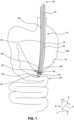
- FIG. 1is a schematic view of an embodiment of an endoscope of the invention performing an exemplary endoscopic surgery.
- FIG. 2is a schematic view of a distal portion of an embodiment of the endoscope of FIG. 1 .
- FIG. 3is a schematic view of a distal portion of another embodiment of the endoscope of FIG. 1 .
- FIG. 4is a schematic view of a distal portion of another embodiment of the endoscope of FIG. 1 .
- FIG. 5 A- 5 Fare cross-sectional views of various embodiments of a guide used to attach the endoscopic instrument to the endoscope of FIG. 1 .
- FIG. 6 Ais a schematic view of an embodiment of the endoscope of FIG. 1 without a guide.
- FIG. 6 Bis a cross-sectional view of the endoscope of FIG. 6 A .
- FIG. 1depicts an exemplary endoscope 10 performing an exemplary endoscopic surgery, such as transgastric gastrojejunal anastomosis.
- the endoscope 10may be inserted into the stomach 100 through the esophagus.
- the endoscope 10may make an incision 80 on the stomach wall 70 , pass through the incision 80 , and operate on a work site 55 .
- the work site 55could include, for instance, part of the small intestine 50 .
- the illustrated application of the endoscope 10 in FIG. 1is exemplary only, and that the endoscopes of the current disclosure may be applied to any endoscopic application known in the art.
- the endoscope 10may include an elongate member 15 extending between a proximal end 40 and a distal end 45 .
- the proximal end 40may include the end of the endoscope 10 external to the body and the distal end 45 may include the end of the endoscope 10 internal to the body.
- the endoscope 10may include a curved external surface 25 .
- the endoscope 10may be constructed of a plurality of materials some of which may be biocompatible. Typically, a part of the endoscope 10 that contacts the internal surfaces of a body may be made substantially of a biocompatible material. In some embodiments, the external surface 25 of the endoscope 10 may be made substantially of a low friction biocompatible material.
- the endoscope 10may include a plurality of lumens 20 running longitudinally therethrough. Each lumen 20 may extend between the proximal end 40 external to the body and the distal end 45 internal to the body. In some embodiments, the longitudinal axis of the lumens may be substantially parallel to the longitudinal axis 12 of the endoscope 10 . Additionally, in some embodiments, the lumens 20 may be formed integrally with the endoscope 10 from the proximal end 40 to the distal end 45 .
- the lumens 20may include one or more of, among others, an aspiration lumen, an irrigation lumen, an illumination lumen, a viewing lumen, and a working lumen.
- the illumination and viewing lumensmay include cables (such as fiber optic cables and light guides) to illuminate the work site 55 , and deliver an image of the work site 55 external to the body. These cables may terminate at the distal end 45 of the endoscope 10 at illumination devices (such as bulbs or other solid state devices) and at imaging means (such as lens for a CCD camera). It is also contemplated that the distal end 45 of the endoscope may include a lens and/or other devices that facilitate illumination and viewing of the work site 55 .
- illumination devicessuch as bulbs or other solid state devices
- imaging meanssuch as lens for a CCD camera
- any of the lumensmay have a substantially circular cross-section. However, it is also contemplated that they may have any suitable shape, size, and/or configuration.
- the shape of the working lumenmay be configured to pass an end effector 32 of the endoscopic instrument 30 through it.
- the irrigation lumenmay be configured to facilitate fluid flow therethrough, for example, from the proximal end 40 to the distal end 45 .
- the proximal end 40 of the irrigation lumenmay be configured to be attached to a source of fluid.
- the distal end 45 of the irrigation lumenmay have a narrow exit. In some embodiments, this narrow exit may be configured in the shape of a nozzle or any other configuration to alter fluid flow.
- the aspiration lumenmay be configured to facilitate suction and/or fluid flow therethrough.
- the flow of fluid through the aspiration lumen and the irrigation lumenmay be in substantially opposite directions.
- fluidmay flow through an irrigation lumen towards the distal end 45
- fluid flow through the aspiration lumenmay be towards the proximal end 40 .
- the aspiration lumenmay also be configured to remove biological material from the distal end 45 of the endoscope 10 to the proximal end 40 .
- a tissue sample along with fluid delivered to the work site 55 via the irrigation lumenmay be extracted out of the body through the aspiration lumen.
- the proximal end 40 of the aspiration channelmay be configured to be attached to a source of suction and/or a container configured, for example, to collect the tissue samples. Fluid flow through an irrigation lumen and an aspiration lumen may be independently operated, or their operation may be coordinated to perform a function, such as the extraction of a tissue sample.
- One or more endoscopic instruments 30may protrude from the distal end 45 of the endoscope 10 .
- the endoscopic instrument 30may pass through (and extend from) the working lumen of the endoscope 10 .
- the endoscopic instrument 30may not pass through an internal working lumen, but extend external to, and along side the endoscope 10 .
- extending “along side” endoscope 10includes extending external to the endoscope 10 . It is also contemplated that, in some embodiments, some endoscopic instruments may be delivered through the working lumen, while other endoscopic instruments may be delivered along side the endoscope 10 .
- the endoscopic instrument 30 passing along side the endoscope 10may be secured to external surface 25 of the endoscope 10 using one or more guides 36 .
- the endoscopic instrument 30may include a shaft 34 having an end effector 32 attached to the distal end of instrument 30 , and an actuation device (not shown) attached to the proximal end of instrument 30 .
- the end effector 32may include a medical instrument configured to perform a task at the work site 55 . In a deployed configuration, the end effector 32 may be internal to the body proximate to the work site 55 , and the actuation device may be external to the body.
- the end effector 32may include any medical instrument that may be used in conjunction with endoscope 10 .
- the end effector 32may be a purely mechanical medical instrument (for example, biopsy forceps, baskets, graspers, snares, surgical knifes, needles, suturing instruments, etc.), while in others, the end effector 32 may also include devices driven by an electric current (for instance, electric motors, heating elements for cauterizing instruments, a laser lithotripter, etc.).
- the end effector 32may also include sensors to indicate the status of a task. These sensors may include any sensors used in the art.
- the end effector 32may be constructed of one or more biocompatible materials.
- the actuation devicemay be configured to operate the end effector 32 . Operation of the end effector may include imparting motion to the end effector 32 .
- the actuation devicemay be configured to move the end effector 32 in two dimensions along a plane perpendicular to the longitudinal axis 12 of endoscope 10 (that is, along the x-axis 2 , y-axis 4 directions of triad 8 ).
- imparting motion to the end effector 32may include translating the end effector 32 along the x-axis 2 , y-axis 4 , and z-axis 6 directions (of triad 8 ).
- imparting motion to the end effector 32may also include rotating the end effector 32 around one or more of the x-axis 2 , y-axis 4 , and z-axis 6 directions. Operation of the end effector 32 may also include imparting motion to one part of the end effector 32 relative to another. That is, move different parts of the end effector 32 such that the end effector 32 may perform its intended function.
- the endoscopic instrument 30may be intended to perform the function of grasping a tissue sample at the work site 55 .
- the end effector 32 for this purposemay include a pair of jaws rotatably coupled to each other.
- the actuation devicemay be configured to rotatably move one of the jaws with respect to the other causing the jaws to open or close.
- the actuation devicemay be controlled manually, electronically, or by a combination of manual and electronic means.
- manual controlan endoscopist (or any human operator) may control the actuation device.
- electronic controlthe endoscopic instrument 30 may be wholly or partly controlled by a computer (or any electronic control mechanism).
- control of the actuation devicemay be based in part on feedback from sensors incorporated in the endoscopic instrument 30 .
- the shaft 34 of the endoscopic instrument 30may include an elongated flexible section made up of one or more parts.
- the shaft 34may be configured to operate the end effector 32 in response to actuation of the actuation device.
- the shaft 34may include a wire and a coil with their proximal ends connected to the actuation device and the distal ends coupled to the jaws. Actuation of the actuation device may move the pull wire or the coil relative to the other, causing the jaws to open and close.
- the actuation device and the shaft 34may also be configured to allow the end effector to perform more complex tasks.
- the shaftmay also include cables that transmit electric signals to and from the end effector 32 .
- the endoscope 10may be inserted into the body (through a natural anatomical opening or a small incision made for the purpose) such that the distal end 45 of the endoscope 10 is proximate to the work site 55 .
- the endoscopic instrument 30may now be delivered to the worksite 55 via the endoscope 10 .
- the endoscopic instrument 30may be delivered via the working lumen within the elongate member 15 of the endoscope 10 , or along side the endoscope 10 .
- the distal end of the endoscopic instrument 30may be placed in the working lumen and slid down the elongate member 15 (of the endoscope 10 ) until the end effector 32 protrudes out of the distal end 45 of the endoscope 10 .
- one or more guides 36may attach the shaft 34 of the endoscopic instrument 30 to the external surface 25 of the endoscope 10 .
- the guides 36may be coupled to the shaft 34 at a sufficient distance away from the end effector 32 .
- a guide closest to the end effector 32may be located between about 11 cm and 20 cm from the end effector 32 .
- the guides 36may be coupled to a location of the shaft 34 such that, when the endoscopic instrument 30 is attached to the endoscope 10 and the end effector 32 delivered to the work site 55 , the end effector 32 may extend past the distal end 45 of the endoscope 10 by a distance sufficient to permit the distal end of the shaft 34 and the end effector 32 to move in the x and y directions.
- the guidemay be a feature, such as a protrusion incorporated on the shaft 34 of the endoscopic instrument 30 to mate with a mating keyway or a slot on the external surface 25 of the endoscope 10 . In such embodiments, these features may be located such that the feature closest to the end effector 32 may be located between about 11 cm and 20 cm from the end effector 32 .
- the guides 36may be attached to the external surface 25 of the endoscope 10 , and the endoscopic instrument 30 slid down the length of the endoscope 10 until the end effector 32 is located at the desired location in the work site 55 .
- the end effector 32may protrude a sufficient distance beyond the distal end 45 of the endoscope 10 .
- the end effector 32may protrude by a distance between about 1 cm to 10 cm. It is contemplated that, in other embodiments of the device, the end effector 32 may protrude by a different distance, for example from 0 cm to 15 cm.
- the distance of protrusion of the end effector 32 past the distal end 45 of the endoscope 10may depend on the focal length of the visual means incorporated in the endoscope 10 .
- the extension of the end effector 32 by a sufficient distance beyond the distal end 45 of the endoscope 10may enable independent freedom of motion to the instrument (independent from the movement of the distal end 45 of the endoscope 10 ) at the working end.
- the endoscope's eyesdistal end of the endoscope with the visual lumen
- the endoscope's eyesmay be free to move independent of the hands (end effector 32 ), thereby enabling the instrument to be used inside the body with improved dexterity.
- the guides 36may be pre-attached to the endoscopic instrument 30 .
- the guidemay be a feature incorporated on the endoscopic instrument 30 to mate with the external surface 25 of the endoscope 10 .
- the guides 36may be a separate part. In these latter embodiments, guides 36 may be attached to both the external surface 25 of the endoscope 10 and the shaft 34 of the endoscopic instrument (in any order), before the endoscopic instrument 30 is slid down the length of the endoscope 10 .
- FIG. 2shows a schematic of an embodiment of the distal end 45 of an endoscope 10 along with an endoscopic instrument 30 delivered along side the endoscope 10 .
- At least one guide 36couples the shaft 34 of the endoscopic instrument 30 to the elongate member 15 of the endoscope 10 .
- the guides 36may be configured to permit relative motion between the endoscope 10 and the endoscopic instrument 30 . The direction of this relative motion may be substantially parallel to the longitudinal axis 12 of the endoscope 10 , that is, along the z-axis indicated by triad 8 .
- the guides 36may be fixedly attached to the endoscopic instrument 30 and movably attached to the external surface 25 of the endoscope 10 .
- Such an attachmentmay permit the guides 36 to slide on the external surface 25 , while being fixedly attached to the endoscopic instrument 30 .
- the texture of the mating surfaces of the guides 36 and the external surface 25may be such that frictional resistance to sliding may be minimized.
- arrows 65indicate the sliding of a guide 36 on the external surface 25 .
- a feature on the endoscopesuch as a locking feature, or a stop 23
- the stop 23may be located such that the end effector 32 may protrude the required distance beyond the distal end 45 of the endoscope 10 .
- pushing the endoscopic instrument 30 into the bodymay cause the guides 36 to slide on the external surface 25 (as indicated by arrows 65 ) until the end effector 32 is located at the desired location in the work site 55 .
- a sensor coupled to the end effector 32may indicate when end effector 32 is at the desired location.
- a tactile indication or a visual indicationmay be used to indicate when the end effector 32 is at the desired location.
- sliding of the guides 36 on the external surface 25may allow the end effector 32 to move in the direction of the z-axis 6 of triad 8 .
- Actuation of the actuation devicemay further move the end effector 32 in the x-axis 2 and the y-axis 4 of triad 8 .
- the end effectormay, thus, be configured to move in three dimensions at the work site 55 .
- movement of the end effector 32 in the x-axis 2 and the y-axis 4may be accomplished by one or more flex sections 38 of the endoscopic instrument 30 .
- the flex sections 38may include a section of the shaft 34 that enables the end effector 32 to move in the x-axis 2 and y-axis 4 directions.
- one flex section 38may enable the end effector 32 to move in the x-axis 2 direction and another flex section 38 may enable the end effector to move in the y-axis direction.
- the flex sections 38may also allow the end effector 32 to rotate around the x-axis 2 , y-axis 4 , and the z-axis 6 .
- the flex sections 38in some embodiments, may be located in the portion of the endoscopic instrument 30 that protrudes from the distal end 45 of the endoscope 10 . Locating the flex sections 38 in this manner may further the ability to move the end effector 32 in a hand like manner, thereby improving dexterity.
- the flex sections 38may include mechanical mechanisms (such as, union joints, gears, linkages, etc.) or electrical devices (motors, stepper motors, actuators, encoders, etc.) that enable the previously described movements of the end effector 32 .
- flex sections 38may also include portions of endoscopic instrument 30 of a lower stiffness (than adjacent portions) that enable the described movements. These portions of lower stiffness may include regions of endoscopic instrument 30 made of different materials, sizes, or shapes than adjacent portions. It is also contemplated that flex sections 38 may include smart materials or smart structures that undergo a change in shape or properties in response to an external stimulii (such as, stress, temperature, current, etc.).
- these flex sections 38may also include sensors (or other feedback devices) that may provide a signal indicative of a position of the end effector 32 .
- the flex sections 38are discrete sections of the shaft 34 that may be located proximate to the distal end 45 of the endoscope 10 . In other embodiments, the flex sections 38 may be more spread out and may encompass a substantial portion of the shaft 34 .
- FIG. 3shows a schematic of another embodiment of the distal end 45 of an endoscope 10 along with an endoscopic instrument 30 delivered along side the endoscope 10 .
- the guides 36may be slidably coupled to both the shaft 34 of endoscopic instrument 30 , and the external surface 25 of the endoscope 10 .
- the endoscopic instrument 30may also slide on the guides 36 (movement indicated by arrow 75 ).
- relative motion between the endoscopic instrument 30 and the endoscope 10may be due to a combination of the guides 36 sliding on the external surface 25 (arrow 65 ), and the endoscopic instrument 30 sliding on the guides 36 (arrow 75 ).
- the mating surfaces of sliding partsmay be such that only the desired level of frictional resistance is achieved.
- the sliding of the guides 36 on the external surface 25may occur before sliding of the endoscopic instrument 30 on the guides 36 (arrow 75 ).
- pushing the endoscopic instrument 30 into the bodymay cause the guides 36 to slide on the external surface 25 (arrow 65 ) until the end effector 32 is located at the desired location in the work site 55 .
- a stop 23 feature on the endoscope 10may stop the sliding of the guide 36 when the end effector 32 protrudes the required distance beyond the distal end 45 of the endoscope 10 .
- the end effector 32may, thus, be configured to move in three dimensions at the work site 55 .
- the end effector 32may also be configured to rotate around the three axes (x-axis 2 , y-axis 4 , and the z-axis 6 ).
- FIG. 4shows a schematic of another embodiment of the distal end of an endoscope 10 along with two endoscopic instruments 30 delivered along side the endoscope 10 .
- other endoscopic instruments 30may be delivered to the work site 55 via the working lumen and/or along side the endoscope 10 .
- the endoscopic instruments 30may also include guides 36 that may be configured to slide on the external surface 25 .
- the shafts 34 of the endoscopic instruments 30may also be configured to slide on the guides 36 .
- the guides 36 of both endoscopic instrumentsmay also be located on the respective shafts such that the both end effectors may extend by a sufficient distance from the distal end of the endoscope 10 .
- extension of the end effectors from the distal end of the endoscope 10may permit the distal ends of the shafts and the end effectors to move in the x and y directions independent of the distal end 45 of the endoscope 10 .
- features on the endoscope(such as the stop 23 of FIG. 2 ) may be positioned to locate the end effectors 32 at a sufficient distance from the distal end 45 of the endoscope 10 .
- Flex sections 38may also be located to enable the end effectors 32 to move and/or rotate in the x, y, and z axes.
- the x-axis 2 , y-axis 4 , and the z-axis 6 movements of the end effectors 32may be coordinated to resemble the movement of a human hand, that is, replicate the elbow and wrist movements of a human hand. Different embodiments of the invention may replicate the movement of the human hand to different levels. For instance, some embodiments or the invention may substantially replicate this human hand movement, while in other embodiments, the x, y and z-axis movement of the end effectors 32 may be less complex.
- the x, y, and z-axis 2 , 4 , and 6 movement of the end effector 32may be controlled by the actuation device.
- some of the end effector 32 movementsmay be substantially controlled by an automated process (for instance, using a computer), while in other embodiments, the end effector 32 movement control may be more manual. Different embodiments of the invention may differ in the level of automated and manual control of the end effector movement. In some embodiments, feedback from sensors incorporated in the end effector 32 (or other parts of the endoscopic instrument 30 ) may assist control of the end effector 32 movement. Other embodiments may use more visual (for example, provided by the viewing lumen and the endoscopic instrument 30 ) and/or tactile indications to control the end effector 32 movement.
- the endoscope 10may also include one or more bendable sections 18 that may be configured to provide x and y-axis 2 , 4 movement to the distal end 45 of the endoscopic instrument 10 .
- Control of the x and y axis movement of the endoscope distal endmay be controlled from the proximal end of the endoscope 10 .
- the x and y-axis movement of the endoscope distal endmay be controlled automatically, manually or using a combination of automatic and manual means.
- the flex sections 38may permit the endoscope distal end to move in the z-axis.
- the endoscope 10may also include mechanical (gears, links, cables, etc.) and/or electrical devices (motors, actuators, etc.) configured to move the endoscope distal end in the desired direction. It is also contemplated that in some embodiments, some (or all) of the x, y and z-axis 2 , 4 , 6 movement of the endoscope distal end may be accomplished by incorporation of suitable smart materials (piezoelectric, electro-rheostatic, magneto-rheostatic shape memory alloys, etc.).
- the movement of the endoscope distal endmay be coordinated with the movement of the end effector 32 . This coordination may be accomplished automatically, manually or using a combination of automatic and manual means. In some embodiments, feedback from sensors may assist in the coordination of the movement. In some embodiments, the movement of endoscope distal end may be based on the movement of the end effector 32 along all three dimensions (x, y and the z-axis 2 , 4 , 6 ). In some other embodiments, the endoscope distal end movement may be based on only movement of the end effector 32 along a certain axis (for instance, the x and y-axis 2 , 4 ).
- This coordinated movement of the end effector 32 and the endoscope distal endmay enable the work site 55 to be well lit and visible to an operator at the proximal end 40 .
- the movement of the endoscope distal endmay replicate the movement of a human head (with the viewing lumen representing the eye).
- the endoscope distal endmay replicate the movement of the human head to different levels. For instance, some embodiments or the invention may substantially replicate the human head movement, while in other embodiments, the x, y and z-axis movement of the endoscope distal end may be less complex.
- guides 36may attach endoscopic instruments 30 to the external surface 25 of the endoscope 10 . These guides 36 may be slidably attached to the endoscope 10 . These guides may also be fixedly or slidably attached to the endoscopic instrument 30 .
- FIG. 5 A through FIG. 5 Fillustrate cross-sectional views of different exemplary embodiments of the guides 36 .
- the embodiments of the guides 36 a - 36 f depicted in FIG. 5 A through 5 Fmay be slidably attached to the endoscope 10 at surface 110 a - 110 f respectively, and slidably or fixedly attached to the endoscopic instrument 30 at surface 130 a - 130 f respectively.
- the guides 36 a - 36 fmay be constructed of one or more biocompatible materials.
- the guide 36 amay include multiple hollow rings 105 a , 125 a .
- One ring 105 amay fit around the elongate section 15 of the endoscope 10 and another ring 125 a may fit around the shaft 34 of the endoscopic instrument 30 .
- Ring 105 amay include a hinge 108 a and a lock 120 a that enables the ring 105 a to be opened to fit around the endoscope 10 . Once the ring 105 a is fit around the endoscope 10 , the ring 105 a may be closed and the lock 120 a engaged.
- hinge 108 amay include a living hinge or other biasing means so that the ring 105 a may be normally closed.
- the ring 105 amay be held open to fit and snap shut around the endoscope 10 .
- the lock 120 amay lock the open sections of the ring 105 a to prevent it from accidentally opening.
- Lock 120 amay include any type of locking feature known in the art.
- Inside surface 110 a of ring 105 amay be sufficiently lubricious to enable the guide 36 a to slide on the external surface 25 .
- ring 125 amay also be opened and closed to removably fit around the shaft 34 of the endoscopic instrument 30 .
- Embodiments of the ring 125 amay also include hinge and lock mechanisms as in ring 105 a . Some of these embodiments may also include a live hinge and/or other biasing means as in the case of ring 105 a .
- the ring 125 amay be pre-attached to the shaft 34 .
- the endoscopic instrument 30may have the guides 36 a permanently attached to it.
- the texture of surface 130 amay be tailored to generate only the required amount of sliding friction.
- the texture of surfaces 110 a and 130 amay be tailored so that the frictional resistance of surface 110 a may be lower than the frictional resistance of the surface 130 a.
- the ring 105 b that fits around the endoscope 10may be open.
- ring 105 bmay snap around the elongate member 15 of endoscope 10 .
- the material of ring 105 bmay be sufficiently elastic to snap over the endoscope 10 without breaking or losing its shape.
- bendable arms 105 cmay be bent over the endoscope 10 .
- the material of the bendable arms 105 cmay be sufficiently inelastic such that they do not spring back open.
- ring 105 dis a feature that fits on a mating track on the external surface 25 of the endoscope 10 .
- Surface 110 d of the featuremay also slide on the mating surfaces of the track.
- This featurecan have any shape that will facilitate sliding on a mating track of the endoscope 10 .
- ring 125 e that is attached to the endoscopic instrument 30may be open.
- the guide 36 emay snap over the endoscopic instrument 30 or may be attached to the endoscopic instrument 30 with a suitable attachment medium.
- ring 125 emay be integrally constructed with the endoscopic instrument 30 .
- ring 125 fmay be a feature that fits on a mating track on the endoscopic instrument 30 . It is also contemplated that other embodiments of the guide 36 f may mix and match any embodiment of ring 105 a - 105 d depicted in FIGS. 5 A- 5 D with any embodiment of ring 125 e - 125 f depicted in FIGS. 5 E- 5 F .
- FIG. 6 Ashows a schematic of an embodiment of the device where the guide is a feature 136 incorporated on the shaft 34 of the endoscopic instrument 30 .
- FIG. 6 Bshows a cross-sectional view of the device through plane A-A shown in FIG. 6 A .
- a first end 150 of the feature 136may be attached to the shaft 34 of the endoscopic instrument 30 and a second end 160 of the feature 136 may mate with a keyway 135 on the external surface 25 of the endoscope 10 .
- the second end 160may have any shape that is configured to mate with the keyway 135 .
- the second end 160 and the keyway 135may have cross-section shaped to resemble a T.
- the endoscopic instrument 30may include one or more features 136 configured to mate with the keyway 135 .
- the feature 136may be located between about 11 cm and 20 cm from the end effector 32 . In an embodiment where multiple features 136 may be present, the feature 136 located closest to the end effector 32 may be located between about 11 cm and 20 cm from the end effector 32 .
- the distal end of the keyway 135may also be positioned such that, when the endoscopic instrument 30 is attached to the endoscope 10 and the end effector 32 delivered to the work site 55 , the end effector 32 may extend past the distal end 45 of the endoscope 10 by a distance sufficient to permit the distal end of the shaft 34 and the end effector 32 to move in the x and y directions.
- this sufficient distancemay be between about 1 cm to 10 cm. It is also contemplated that, in other embodiments of the device, the end effector 32 may protrude by a different distance from the distal end 45 , for example from 0 cm to 15 cm.
- the distal end 45 of an endoscope 10may be inserted through the mouth of a patient.
- the endoscope 10may be gently pushed down the patient's esophagus until the distal end 45 of the endoscope 10 is proximate to a work site 55 (for instance, the wall of the stomach).
- a work site 55for instance, the wall of the stomach.
- Proximity of the distal end 45 to the work site 55may be identified by viewing an image from a viewing lumen of the endoscope 10 , for example, displayed on a monitor.
- An endoscopic instrument 30 with an appropriate end effector 32 (for instance, a forceps) including pre-attached guides 36 on the shaft 34may be snapped over the external surface 25 of the endoscope 10 .
- the endoscopic instrument 30may now be gently pushed into the patient's body (along the z-axis 6 indicated in FIG. 4 ) along side the endoscope 10 .
- the end effector 32 of the endoscopic instrument 30be in a configuration so as not to damage internal tissue of the participant.
- the forceps jawsmay be closed and/or retracted within a sheath.
- the guides 36may slide on the external surface 25 of the endoscope 10 to deliver the end effector 32 to the distal end 45 of the endoscope 10 .
- one or more guides 36may be blocked from further travel by a stop 23 on the external surface 25 of the endoscope 10 .
- the endoscopic instrument 30may be rotated around the longitudinal axis 12 of the endoscope 10 to locate the end effector 32 at a suitable position.
- the end effector 32may now be moved in the x and y-axis 2 , 4 directions to bring the end effector 32 into the field of view of the visual lumen, by actuating the actuation device of the endoscopic instrument 30 .
- the end effector 32may also be moved further in the z-axis 6 direction by gently pushing down the endoscopic instrument 30 . Further movement of the end effector 32 in the z-axis 6 direction may be accomplished by the endoscopic instrument 30 sliding on the guides 36 .
- the actuation devicemay be actuated to operate the end effector 32 as desired (for instance, to open and shut the jaws of the forceps).
- the actuation devicemay be actuated to grasp and remove a tissue sample for biopsy.
- the endoscopic instrument 30may be slowly pulled out of the body to extract the tissue sample for laboratory tests.
- another endoscopic instrument 30 with a suitable end effector 32may also be dispatched to the work site 55 .
- the endoscopic instrument 30 with a cautery end effectormay be attached to the external surface 25 of the endoscope 10 by snapping a removable guide 36 around the shaft 34 of the endoscopic instrument 30 and the external surface 25 of the endoscope 10 .
- the cautery end effectormay also be positioned as desired in the work site 55 by moving the end effector in the x, y and z-axis direction using the actuation device. More end effectors 32 may be similarly dispatched to the work site 55 if desired.
- Dispatching the end effectors 32 to the work site 55 external to the endoscope 10may allow the diameter of the endoscope 10 to be reduced. Reducing the diameter of the endoscope 10 may reduce patient discomfort and increase the flexibility of the endoscope 10 by reducing its flexural rigidity. Since the size of the end effector 32 dispatched external to the endoscope 10 may be independent of the cross-sectional size of the working lumen, increasing end effector size may not increase the endoscope diameter. Dispatching end effectors 32 external to the endoscope may also reduce the likelihood of contamination of the working lumens, and resultant spread of disease.
- the end effectors 32 and the endoscope distal endmay be moved in the x, y, and z-axis directions by controlling the flex sections 38 of the endoscopic instruments 30 , and the bendable sections 18 of the endoscope 10 .
- Controlling the individual movements of the end effectors 32 and the endoscope distal end in a coordinated mannermay allow an operator to form a working triangle between the surgical tools (cautery and forceps end effectors), and the scope's eyes (endoscope distal end).
- the control and dexteritythat may be permitted by the ability to move the surgical instruments in all three dimensions, independently and precisely, may allow an operator to use the instruments within the body, as he may use corresponding instruments in conventional surgery external to the body.
Landscapes
- Health & Medical Sciences (AREA)
- Life Sciences & Earth Sciences (AREA)
- Surgery (AREA)
- Engineering & Computer Science (AREA)
- Animal Behavior & Ethology (AREA)
- Veterinary Medicine (AREA)
- Biomedical Technology (AREA)
- Heart & Thoracic Surgery (AREA)
- Medical Informatics (AREA)
- Molecular Biology (AREA)
- Nuclear Medicine, Radiotherapy & Molecular Imaging (AREA)
- General Health & Medical Sciences (AREA)
- Public Health (AREA)
- Physics & Mathematics (AREA)
- Biophysics (AREA)
- Optics & Photonics (AREA)
- Pathology (AREA)
- Radiology & Medical Imaging (AREA)
- Robotics (AREA)
- Endoscopes (AREA)
- Surgical Instruments (AREA)
Abstract
Description
Claims (20)
Priority Applications (1)
| Application Number | Priority Date | Filing Date | Title |
|---|---|---|---|
| US17/109,446US12295551B2 (en) | 2008-07-18 | 2020-12-02 | Endoscope with guide |
Applications Claiming Priority (7)
| Application Number | Priority Date | Filing Date | Title |
|---|---|---|---|
| US12978808P | 2008-07-18 | 2008-07-18 | |
| US12/504,122US8727967B2 (en) | 2008-07-18 | 2009-07-16 | Endoscope with guide |
| US14/246,283US9737196B2 (en) | 2008-07-18 | 2014-04-07 | Endoscope with guide |
| US15/652,417US10178944B2 (en) | 2008-07-18 | 2017-07-18 | Endoscope with guide |
| US16/221,696US10492666B2 (en) | 2008-07-18 | 2018-12-17 | Endoscope with guide |
| US16/668,124US10881279B2 (en) | 2008-07-18 | 2019-10-30 | Endoscope with guide |
| US17/109,446US12295551B2 (en) | 2008-07-18 | 2020-12-02 | Endoscope with guide |
Related Parent Applications (1)
| Application Number | Title | Priority Date | Filing Date |
|---|---|---|---|
| US16/668,124ContinuationUS10881279B2 (en) | 2008-07-18 | 2019-10-30 | Endoscope with guide |
Publications (2)
| Publication Number | Publication Date |
|---|---|
| US20210076912A1 US20210076912A1 (en) | 2021-03-18 |
| US12295551B2true US12295551B2 (en) | 2025-05-13 |
Family
ID=41138832
Family Applications (6)
| Application Number | Title | Priority Date | Filing Date |
|---|---|---|---|
| US12/504,122Expired - Fee RelatedUS8727967B2 (en) | 2008-07-18 | 2009-07-16 | Endoscope with guide |
| US14/246,283Expired - Fee RelatedUS9737196B2 (en) | 2008-07-18 | 2014-04-07 | Endoscope with guide |
| US15/652,417ActiveUS10178944B2 (en) | 2008-07-18 | 2017-07-18 | Endoscope with guide |
| US16/221,696ActiveUS10492666B2 (en) | 2008-07-18 | 2018-12-17 | Endoscope with guide |
| US16/668,124ActiveUS10881279B2 (en) | 2008-07-18 | 2019-10-30 | Endoscope with guide |
| US17/109,446Active2031-06-03US12295551B2 (en) | 2008-07-18 | 2020-12-02 | Endoscope with guide |
Family Applications Before (5)
| Application Number | Title | Priority Date | Filing Date |
|---|---|---|---|
| US12/504,122Expired - Fee RelatedUS8727967B2 (en) | 2008-07-18 | 2009-07-16 | Endoscope with guide |
| US14/246,283Expired - Fee RelatedUS9737196B2 (en) | 2008-07-18 | 2014-04-07 | Endoscope with guide |
| US15/652,417ActiveUS10178944B2 (en) | 2008-07-18 | 2017-07-18 | Endoscope with guide |
| US16/221,696ActiveUS10492666B2 (en) | 2008-07-18 | 2018-12-17 | Endoscope with guide |
| US16/668,124ActiveUS10881279B2 (en) | 2008-07-18 | 2019-10-30 | Endoscope with guide |
Country Status (4)
| Country | Link |
|---|---|
| US (6) | US8727967B2 (en) |
| EP (2) | EP3108800B1 (en) |
| JP (1) | JP5559785B2 (en) |
| WO (1) | WO2010009292A1 (en) |
Families Citing this family (118)
| Publication number | Priority date | Publication date | Assignee | Title |
|---|---|---|---|---|
| US7960935B2 (en) | 2003-07-08 | 2011-06-14 | The Board Of Regents Of The University Of Nebraska | Robotic devices with agent delivery components and related methods |
| US20110124961A1 (en)* | 2006-05-16 | 2011-05-26 | David Zimmon | Automated actuator for spring based multiple purpose medical instruments |
| US8679096B2 (en) | 2007-06-21 | 2014-03-25 | Board Of Regents Of The University Of Nebraska | Multifunctional operational component for robotic devices |
| WO2007149559A2 (en) | 2006-06-22 | 2007-12-27 | Board Of Regents Of The University Of Nebraska | Magnetically coupleable robotic devices and related methods |
| US9579088B2 (en) | 2007-02-20 | 2017-02-28 | Board Of Regents Of The University Of Nebraska | Methods, systems, and devices for surgical visualization and device manipulation |
| US7655004B2 (en) | 2007-02-15 | 2010-02-02 | Ethicon Endo-Surgery, Inc. | Electroporation ablation apparatus, system, and method |
| US8343171B2 (en) | 2007-07-12 | 2013-01-01 | Board Of Regents Of The University Of Nebraska | Methods and systems of actuation in robotic devices |
| CA2695619C (en) | 2007-08-15 | 2015-11-24 | Board Of Regents Of The University Of Nebraska | Modular and cooperative medical devices and related systems and methods |
| JP2010536435A (en) | 2007-08-15 | 2010-12-02 | ボード オブ リージェンツ オブ ザ ユニバーシティ オブ ネブラスカ | Medical inflation, attachment and delivery devices and associated methods |
| US8888792B2 (en) | 2008-07-14 | 2014-11-18 | Ethicon Endo-Surgery, Inc. | Tissue apposition clip application devices and methods |
| WO2010009292A1 (en) | 2008-07-18 | 2010-01-21 | Boston Scientific Scimed, Inc. | Endoscope with guide |
| US8157834B2 (en) | 2008-11-25 | 2012-04-17 | Ethicon Endo-Surgery, Inc. | Rotational coupling device for surgical instrument with flexible actuators |
| US8361066B2 (en) | 2009-01-12 | 2013-01-29 | Ethicon Endo-Surgery, Inc. | Electrical ablation devices |
| US20100268028A1 (en)* | 2009-04-21 | 2010-10-21 | Ethicon Endo-Surgery, Inc. | Devices and methods for guiding surgical instruments |
| US20110098704A1 (en) | 2009-10-28 | 2011-04-28 | Ethicon Endo-Surgery, Inc. | Electrical ablation devices |
| WO2011075693A1 (en)* | 2009-12-17 | 2011-06-23 | Board Of Regents Of The University Of Nebraska | Modular and cooperative medical devices and related systems and methods |
| US9028483B2 (en) | 2009-12-18 | 2015-05-12 | Ethicon Endo-Surgery, Inc. | Surgical instrument comprising an electrode |
| DE202010018546U1 (en) | 2010-05-11 | 2017-08-07 | Lohmann & Rauscher Gmbh & Co. Kg | External insertion aid for endoscopes |
| EP2600758A1 (en) | 2010-08-06 | 2013-06-12 | Board of Regents of the University of Nebraska | Methods and systems for handling or delivering materials for natural orifice surgery |
| EP2603131A1 (en)* | 2010-08-10 | 2013-06-19 | Cook Medical Technologies LLC | Endoscopic system for resection of tissue |
| US9233241B2 (en) | 2011-02-28 | 2016-01-12 | Ethicon Endo-Surgery, Inc. | Electrical ablation devices and methods |
| US9254169B2 (en) | 2011-02-28 | 2016-02-09 | Ethicon Endo-Surgery, Inc. | Electrical ablation devices and methods |
| US9049987B2 (en) | 2011-03-17 | 2015-06-09 | Ethicon Endo-Surgery, Inc. | Hand held surgical device for manipulating an internal magnet assembly within a patient |
| US9603510B2 (en)* | 2011-05-17 | 2017-03-28 | Mario Ammirati | Method and apparatus for delivering an endoscope via microsurgical instruments while performing microscopic surgery |
| JP6174017B2 (en) | 2011-06-10 | 2017-08-02 | ボード オブ リージェンツ オブ ザ ユニバーシティ オブ ネブラスカ | In vivo vascular seal end effector and in vivo robotic device |
| WO2013009887A1 (en) | 2011-07-11 | 2013-01-17 | Board Of Regents Of The University Of Nebraska | Robotic surgical devices, systems and related methods |
| WO2013052137A2 (en) | 2011-10-03 | 2013-04-11 | Board Of Regents Of The University Of Nebraska | Robotic surgical devices, systems and related methods |
| US20130158348A1 (en)* | 2011-12-14 | 2013-06-20 | Ethicon Endo-Surgery, Inc. | Introducer for an internal magnetic camera |
| US9226741B2 (en)* | 2012-01-09 | 2016-01-05 | Covidien Lp | Triangulation methods with hollow segments |
| WO2013106569A2 (en) | 2012-01-10 | 2013-07-18 | Board Of Regents Of The University Of Nebraska | Methods, systems, and devices for surgical access and insertion |
| EP2816966B1 (en)* | 2012-02-22 | 2023-10-25 | Veran Medical Technologies, Inc. | Steerable surgical catheter comprising a biopsy device at the distal end portion thereof |
| DE102012207090A1 (en)* | 2012-04-27 | 2013-10-31 | Federal-Mogul Nürnberg GmbH | Casting method and tool |
| EP2844181B1 (en) | 2012-05-01 | 2021-03-10 | Board of Regents of the University of Nebraska | Single site robotic device and related systems |
| US9427255B2 (en) | 2012-05-14 | 2016-08-30 | Ethicon Endo-Surgery, Inc. | Apparatus for introducing a steerable camera assembly into a patient |
| CN104349734B (en) | 2012-05-25 | 2016-09-28 | 富士胶片株式会社 | Endoscopic operation device and trocar sheath |
| EP3189948B1 (en) | 2012-06-22 | 2018-10-17 | Board of Regents of the University of Nebraska | Local control robotic surgical devices |
| US9078662B2 (en) | 2012-07-03 | 2015-07-14 | Ethicon Endo-Surgery, Inc. | Endoscopic cap electrode and method for using the same |
| US9545290B2 (en) | 2012-07-30 | 2017-01-17 | Ethicon Endo-Surgery, Inc. | Needle probe guide |
| US10314649B2 (en) | 2012-08-02 | 2019-06-11 | Ethicon Endo-Surgery, Inc. | Flexible expandable electrode and method of intraluminal delivery of pulsed power |
| US12295680B2 (en) | 2012-08-08 | 2025-05-13 | Board Of Regents Of The University Of Nebraska | Robotic surgical devices, systems and related methods |
| US9770305B2 (en) | 2012-08-08 | 2017-09-26 | Board Of Regents Of The University Of Nebraska | Robotic surgical devices, systems, and related methods |
| EP2882331A4 (en) | 2012-08-08 | 2016-03-23 | Univ Nebraska | ROBOTIC SURGICAL SYSTEMS AND DEVICES, AND ASSOCIATED METHODS |
| US9277957B2 (en) | 2012-08-15 | 2016-03-08 | Ethicon Endo-Surgery, Inc. | Electrosurgical devices and methods |
| WO2014054774A1 (en)* | 2012-10-05 | 2014-04-10 | 富士フイルム株式会社 | Holding device and medical observation system |
| US10098527B2 (en) | 2013-02-27 | 2018-10-16 | Ethidcon Endo-Surgery, Inc. | System for performing a minimally invasive surgical procedure |
| US20140275779A1 (en)* | 2013-03-12 | 2014-09-18 | Covidien Lp | Flexible Shaft with Multiple Flexible Portions |
| CA2906672C (en) | 2013-03-14 | 2022-03-15 | Board Of Regents Of The University Of Nebraska | Methods, systems, and devices relating to force control surgical systems |
| CA2905948C (en) | 2013-03-14 | 2022-01-11 | Board Of Regents Of The University Of Nebraska | Methods, systems, and devices relating to robotic surgical devices, end effectors, and controllers |
| CA2906772C (en) | 2013-03-15 | 2021-09-21 | Board Of Regents Of The University Of Nebraska | Robotic surgical devices, systems and related methods |
| WO2014157477A1 (en) | 2013-03-29 | 2014-10-02 | 富士フイルム株式会社 | Endoscopic surgery device |
| US10966700B2 (en) | 2013-07-17 | 2021-04-06 | Virtual Incision Corporation | Robotic surgical devices, systems and related methods |
| DE112014004020B4 (en)* | 2013-09-03 | 2023-12-14 | Fujifilm Corporation | Endoscopic surgical device and overtube |
| DE112014004014B4 (en)* | 2013-09-03 | 2023-12-14 | Fujifilm Corporation | Endoscopic surgical device and overtube |
| JP6068654B2 (en)* | 2013-09-03 | 2017-01-25 | 富士フイルム株式会社 | Endoscopic surgical apparatus and mantle tube |
| WO2015033909A1 (en)* | 2013-09-03 | 2015-03-12 | 富士フイルム株式会社 | Endoscopic surgical device and outer sleeve |
| JP6167181B2 (en)* | 2013-09-03 | 2017-07-19 | 富士フイルム株式会社 | Endoscopic surgical apparatus and mantle tube |
| JP6082469B2 (en) | 2013-09-03 | 2017-02-15 | 富士フイルム株式会社 | Endoscopic surgical apparatus and mantle tube |
| JP6192550B2 (en)* | 2014-01-29 | 2017-09-06 | オリンパス株式会社 | Medical device and medical system |
| EP3123969B1 (en) | 2014-03-27 | 2018-08-01 | Fujifilm Corporation | Outertube and endoscopic surgical device |
| ES2848100T3 (en) | 2014-09-04 | 2021-08-05 | Memic Innovative Surgery Ltd | Device control including mechanical arms |
| EP3189768B1 (en)* | 2014-09-05 | 2019-04-17 | Olympus Corporation | Endoscope system |
| CA2961213A1 (en) | 2014-09-12 | 2016-03-17 | Board Of Regents Of The University Of Nebraska | Quick-release end effectors and related systems and methods |
| EP3202343B1 (en)* | 2014-09-30 | 2019-08-07 | FUJIFILM Corporation | Endoscopic surgical device |
| EP3217890B1 (en) | 2014-11-11 | 2020-04-08 | Board of Regents of the University of Nebraska | Robotic device with compact joint design |
| DE102014118003A1 (en)* | 2014-12-05 | 2016-06-23 | Karl Storz Gmbh & Co. Kg | Endoscopic instrument and endoscopic instrument system |
| CN107205619B (en)* | 2015-01-20 | 2020-04-07 | 奥林巴斯株式会社 | Insertion aid and medical device |
| DE102015204007A1 (en)* | 2015-03-05 | 2016-09-08 | Olympus Winter & Ibe Gmbh | Method and device for determining position in a rotary electric stepping motor |
| MY195396A (en)* | 2015-03-12 | 2023-01-18 | Univ Keio | Treatment-instrument insertion aid |
| SG11201707305PA (en)* | 2015-03-12 | 2017-10-30 | Univ Keio | Treatment-instrument insertion aid |
| WO2016168673A1 (en)* | 2015-04-15 | 2016-10-20 | Trustees Of Boston University | Retractable endoscopic suction tube |
| JP6396595B2 (en) | 2015-07-30 | 2018-09-26 | 富士フイルム株式会社 | Endoscopic surgical device and guide device |
| WO2017024081A1 (en) | 2015-08-03 | 2017-02-09 | Board Of Regents Of The University Of Nebraska | Robotic surgical devices systems and related methods |
| SI3190942T1 (en) | 2015-09-04 | 2020-10-30 | Memic Innovative Surgery Ltd. | Actuation of a device comprising mechanical arms |
| EP3413822B1 (en)* | 2016-02-11 | 2023-08-30 | Arrinex, Inc. | Device for image guided post-nasal nerve ablation |
| US10463438B2 (en) | 2016-03-09 | 2019-11-05 | Memic Innovative Surgery Ltd. | Modular device comprising mechanical arms |
| WO2017164836A1 (en)* | 2016-03-21 | 2017-09-28 | Hege Jr Douglas | Methods and devices for temporarily attaching an optical instrument to a hand instrument |
| CA3024623A1 (en) | 2016-05-18 | 2017-11-23 | Virtual Incision Corporation | Robotic surgical devices, systems and related methods |
| CA3034671A1 (en) | 2016-08-25 | 2018-03-01 | Shane Farritor | Quick-release tool coupler and related systems and methods |
| WO2018045036A1 (en) | 2016-08-30 | 2018-03-08 | Board Of Regents Of The University Of Nebraska | Robotic device with compact joint design and an additional degree of freedom and related systems and methods |
| CN115337111B (en) | 2016-11-22 | 2025-04-25 | 内布拉斯加大学董事会 | Improved coarse positioning device and related system and method |
| WO2018098465A1 (en) | 2016-11-28 | 2018-05-31 | Inventio, Inc. | Endoscope with separable, disposable shaft |
| CN115553922A (en) | 2016-11-29 | 2023-01-03 | 虚拟切割有限公司 | User controller with user presence detection and related systems and methods |
| WO2018112199A1 (en) | 2016-12-14 | 2018-06-21 | Virtual Incision Corporation | Releasable attachment device for coupling to medical devices and related systems and methods |
| AU2018209935A1 (en)* | 2017-01-19 | 2019-05-09 | Csa Medical, Inc. | Systems and methods to prevent or significantly inhibit gas progression during spray cryotherapy |
| US10973592B2 (en) | 2017-03-09 | 2021-04-13 | Memie Innovative Surgery Ltd. | Control console for surgical device with mechanical arms |
| US11779410B2 (en) | 2017-03-09 | 2023-10-10 | Momentis Surgical Ltd | Control console including an input arm for control of a surgical mechanical arm |
| USD867589S1 (en)* | 2017-03-23 | 2019-11-19 | Pioneer Medical Instrument Co., Ltd. | Steerable structure for endoscope |
| DE102017107546A1 (en)* | 2017-04-07 | 2018-10-11 | Ovesco Endoscopy Ag | Endoscope with additional external working channel |
| CN107050620A (en)* | 2017-05-24 | 2017-08-18 | 四川大学华西医院 | Detachable laparoscopic aspirator |
| US20180338676A1 (en)* | 2017-05-26 | 2018-11-29 | Covidien Lp | Bronchoscopy systems and coupling devices thereof |
| US11076745B2 (en)* | 2017-05-26 | 2021-08-03 | Covidien Lp | Bronchoscopy coupling devices |
| DE112018003623T5 (en)* | 2017-07-14 | 2020-05-20 | Actuated Medical, Inc. | DEVICE FOR SUPPORTING THE POSITIONING AND ANCHORING OF AN ENDOSCOPE IN GASTROINTESTINAL INTERVENTIONS |
| CN117017492A (en) | 2017-09-27 | 2023-11-10 | 虚拟切割有限公司 | Robotic surgical device with tracking camera technology and related systems and methods |
| TWI648034B (en)* | 2017-10-19 | 2019-01-21 | 醫百科技股份有限公司 | Assistant clamper having lens |
| CA3087672A1 (en) | 2018-01-05 | 2019-07-11 | Board Of Regents Of The University Of Nebraska | Single-arm robotic device with compact joint design and related systems and methods |
| WO2020068291A1 (en)* | 2018-09-24 | 2020-04-02 | Boston Scientific Scimed, Inc. | Multiple channel flexible ureteroscope |
| WO2020105158A1 (en)* | 2018-11-22 | 2020-05-28 | オリンパス株式会社 | Guide tube, treatment system, and guide tube attachment method |
| WO2020146348A1 (en) | 2019-01-07 | 2020-07-16 | Virtual Incision Corporation | Robotically assisted surgical system and related devices and methods |
| WO2020180678A1 (en)* | 2019-03-01 | 2020-09-10 | Boston Scientific Scimed, Inc. | Systems, devices, and related methods for fastening tissue |
| WO2020227253A1 (en)* | 2019-05-08 | 2020-11-12 | Boston Scientific Scimed, Inc. | Medical systems, devices, and related methods |
| US11628020B2 (en)* | 2019-06-19 | 2023-04-18 | Virtuoso Surgical, Inc. | Insertable robot for minimally invasive surgery |
| DE102019118043A1 (en)* | 2019-07-04 | 2021-01-07 | Ovesco Endoscopy Ag | Treatment instrument for endoscope |
| USD1018844S1 (en) | 2020-01-09 | 2024-03-19 | Adaptivendo Llc | Endoscope handle |
| US20210228062A1 (en)* | 2020-01-28 | 2021-07-29 | Gyrus Acmi, Inc. D/B/A Olympus Surgical Technologies America | Endoscope and endoscope attachments |
| US20210267669A1 (en)* | 2020-02-28 | 2021-09-02 | Olympus Corporation | Device for treating gastroesophageal reflux disease and method for treating gastroesophageal reflux disease |
| US20210339297A1 (en)* | 2020-04-29 | 2021-11-04 | Kevin L. Stephenson | Surgical instrument cleaning brush assembly for use with a borescope |
| JP2023532977A (en) | 2020-07-06 | 2023-08-01 | バーチャル インシジョン コーポレイション | Surgical robotic positioning system and related apparatus and methods |
| EP4228493A4 (en)* | 2020-10-13 | 2025-02-19 | Theragi LLC | Systems and methods for endoscopic surgery |
| US11877936B2 (en)* | 2020-11-13 | 2024-01-23 | William Aaron Kunkle | Facet fusion tube assembly |
| USD1051380S1 (en) | 2020-11-17 | 2024-11-12 | Adaptivendo Llc | Endoscope handle |
| WO2022159957A1 (en) | 2021-01-21 | 2022-07-28 | University Hospitals Cleveland Medical Center | Endoscopic multifunctional accessory channel device |
| USD1031035S1 (en) | 2021-04-29 | 2024-06-11 | Adaptivendo Llc | Endoscope handle |
| USD1070082S1 (en) | 2021-04-29 | 2025-04-08 | Adaptivendo Llc | Endoscope handle |
| USD1066659S1 (en) | 2021-09-24 | 2025-03-11 | Adaptivendo Llc | Endoscope handle |
| US11937799B2 (en) | 2021-09-29 | 2024-03-26 | Cilag Gmbh International | Surgical sealing systems for instrument stabilization |
| JP2024536154A (en)* | 2021-09-29 | 2024-10-04 | シラグ・ゲーエムベーハー・インターナショナル | Surgical system with devices for both intraluminal and extraluminal access - Patents.com |
| CN116999171A (en)* | 2023-08-25 | 2023-11-07 | 深圳康诺思腾科技有限公司 | Surgical instrument and surgical system |
| WO2025090757A1 (en)* | 2023-10-25 | 2025-05-01 | Boston Scientific Scimed, Inc. | Connector for a flexible elongate member insertable into a body |
Citations (107)
| Publication number | Priority date | Publication date | Assignee | Title |
|---|---|---|---|---|
| US3521332A (en) | 1968-03-04 | 1970-07-21 | Roy G Kramer | Double ended clip |
| US3896793A (en) | 1973-06-19 | 1975-07-29 | Olympus Optical Co | Endoscope with view field altering means |
| US4061299A (en) | 1975-05-06 | 1977-12-06 | Nifco Inc. | Cord clamp |
| US4245624A (en) | 1977-01-20 | 1981-01-20 | Olympus Optical Co., Ltd. | Endoscope with flexible tip control |
| US4285376A (en) | 1977-07-07 | 1981-08-25 | Minigrip, Inc. | Reclosable plastic bag construction made from a one piece extrusion |
| US4453353A (en) | 1981-09-14 | 1984-06-12 | Robin Products Company | Guy wire protector |
| US4492230A (en) | 1981-07-07 | 1985-01-08 | Sumitomo Electric Industries, Ltd. | Extension mechanism of adaptor for laser scalpel |
| US4646722A (en) | 1984-12-10 | 1987-03-03 | Opielab, Inc. | Protective endoscope sheath and method of installing same |
| US4669156A (en) | 1984-11-12 | 1987-06-02 | Guido Juergen Dipl Ing | Pipe clip of resilient material |
| US4676229A (en) | 1986-04-09 | 1987-06-30 | Welch Allyn, Inc. | Biopsy channel for an endoscope |
| US4686965A (en) | 1985-02-08 | 1987-08-18 | Richard Wolf Gmbh | Instrument for endoscopic operations |
| US4697576A (en) | 1986-02-18 | 1987-10-06 | Welch Allyn, Inc. | Endoscope forceps elevator cable seal |
| US4741326A (en) | 1986-10-01 | 1988-05-03 | Fujinon, Inc. | Endoscope disposable sheath |
| JPS63292935A (en) | 1987-05-26 | 1988-11-30 | Olympus Optical Co Ltd | Treatment jig guide apparatus for endoscope |
| US4793326A (en) | 1986-12-08 | 1988-12-27 | Olympus Optical Co., Ltd. | Endoscope having insertion end guide means |
| US4886049A (en) | 1988-05-17 | 1989-12-12 | Darras Robert L | Medical instrument cover |
| US4935992A (en) | 1989-04-10 | 1990-06-26 | Micro Plastics, Inc. | Leak reduction hose clamp |
| US5025778A (en) | 1990-03-26 | 1991-06-25 | Opielab, Inc. | Endoscope with potential channels and method of using the same |
| US5037433A (en) | 1990-05-17 | 1991-08-06 | Wilk Peter J | Endoscopic suturing device and related method and suture |
| US5100420A (en) | 1989-07-18 | 1992-03-31 | United States Surgical Corporation | Apparatus and method for applying surgical clips in laparoscopic or endoscopic procedures |
| US5109830A (en) | 1990-04-10 | 1992-05-05 | Candela Laser Corporation | Apparatus for navigation of body cavities |
| US5171222A (en) | 1988-03-10 | 1992-12-15 | Scimed Life Systems, Inc. | Interlocking peel-away dilation catheter |
| US5217001A (en) | 1991-12-09 | 1993-06-08 | Nakao Naomi L | Endoscope sheath and related method |
| US5226876A (en) | 1990-10-11 | 1993-07-13 | Wilson Cook Medical, Inc. | Operating channel/insufflation port assemblies |
| US5259366A (en) | 1992-11-03 | 1993-11-09 | Boris Reydel | Method of using a catheter-sleeve assembly for an endoscope |
| DE4228459A1 (en) | 1992-08-27 | 1994-03-03 | Wolfgang Daum | Mechanism for bending flexible, hose-shaped, medical instruments - has several tubular, profiled, or wire parts with different bends, insertable into each other |
| US5345937A (en) | 1991-02-15 | 1994-09-13 | Raychem Corporation | Steerable cannula |
| JPH06319682A (en) | 1993-05-13 | 1994-11-22 | Olympus Optical Co Ltd | Channeled cover type endoscope system |
| US5383849A (en) | 1992-05-11 | 1995-01-24 | Wilson-Cook Medical, Inc. | Method for selective endoscopic cannulation of ductal structures |
| US5386818A (en) | 1993-05-10 | 1995-02-07 | Schneebaum; Cary W. | Laparoscopic and endoscopic instrument guiding method and apparatus |
| US5423830A (en) | 1993-07-07 | 1995-06-13 | Schneebaum; Cary W. | Polyp retrieval method and associated instrument assembly |
| EP0667126A1 (en) | 1993-08-19 | 1995-08-16 | Vidamed, Inc. | Steerable medical probe with stylets |
| US5503616A (en) | 1991-06-10 | 1996-04-02 | Endomedical Technologies, Inc. | Collapsible access channel system |
| US5538497A (en) | 1992-10-28 | 1996-07-23 | Oktas | Endoscope having parasitic light elements |
| US5607435A (en) | 1994-05-23 | 1997-03-04 | Memory Medical Systems, Inc. | Instrument for endoscopic-type procedures |
| US5624380A (en) | 1992-03-12 | 1997-04-29 | Olympus Optical Co., Ltd. | Multi-degree of freedom manipulator |
| US5662585A (en) | 1994-05-05 | 1997-09-02 | Imagyn Medical, Inc. | Endoscope with protruding member and method of utilizing the same |
| US5746692A (en) | 1994-05-05 | 1998-05-05 | Imagen Medical, Inc. | Catheter and endoscope system with distal protruding ball tip and method |
| US5749889A (en) | 1996-02-13 | 1998-05-12 | Imagyn Medical, Inc. | Method and apparatus for performing biopsy |
| US5749828A (en) | 1995-12-22 | 1998-05-12 | Hewlett-Packard Company | Bending neck for use with invasive medical devices |
| DE19749687A1 (en) | 1996-11-12 | 1998-05-14 | Johnson & Johnson Medical | Flexible endoscope tube with urethane] cover |
| JPH10146316A (en) | 1996-11-20 | 1998-06-02 | Olympus Optical Co Ltd | Endoscope |
| US5810776A (en) | 1996-02-13 | 1998-09-22 | Imagyn Medical, Inc. | Method and apparatus for performing laparoscopy |
| US5820546A (en) | 1996-05-13 | 1998-10-13 | Asahi Kogaku Kogyo Kabushiki Kaisha | Guiding device for treatment accessories of an endoscope |
| US5873550A (en) | 1996-10-22 | 1999-02-23 | Rjp Positioning Clip Limited | Support device |
| US5916147A (en) | 1997-09-22 | 1999-06-29 | Boury; Harb N. | Selectively manipulable catheter |
| US5944654A (en) | 1996-11-14 | 1999-08-31 | Vista Medical Technologies, Inc. | Endoscope with replaceable irrigation tube |
| US5954731A (en) | 1997-07-29 | 1999-09-21 | Yoon; Inbae | Surgical instrument with multiple rotatably mounted spreadable end effectors |
| US5984932A (en) | 1996-11-27 | 1999-11-16 | Yoon; Inbae | Suturing instrument with one or more spreadable needle holders mounted for arcuate movement |
| US5997547A (en) | 1991-11-05 | 1999-12-07 | Nakao; Naomi L. | Surgical retrieval assembly and associated method |
| US6036636A (en) | 1996-11-18 | 2000-03-14 | Olympus Optical Co., Ltd. | Endoscope with tip portion disposed on distal side of insertion portion |
| US6066090A (en) | 1997-06-19 | 2000-05-23 | Yoon; Inbae | Branched endoscope system |
| US6071233A (en) | 1997-10-31 | 2000-06-06 | Olympus Optical Co., Ltd. | Endoscope |
| US6099464A (en) | 1995-04-10 | 2000-08-08 | Olympus Optical Co., Ltd. | Bending sheath for probe |
| US6106521A (en) | 1996-08-16 | 2000-08-22 | United States Surgical Corporation | Apparatus for thermal treatment of tissue |
| US6105216A (en) | 1999-02-25 | 2000-08-22 | Hydra-Zorb Co. | Clamp assembly |
| US6126633A (en) | 1997-07-11 | 2000-10-03 | Olympus Optical Co., Ltd. | Surgical instrument |
| US6179776B1 (en) | 1999-03-12 | 2001-01-30 | Scimed Life Systems, Inc. | Controllable endoscopic sheath apparatus and related method of use |
| US6352503B1 (en) | 1998-07-17 | 2002-03-05 | Olympus Optical Co., Ltd. | Endoscopic surgery apparatus |
| US20030036679A1 (en) | 2001-08-16 | 2003-02-20 | Syntheon, Llc | Methods and apparatus for delivering a medical instrument over an endoscope while the endoscope is in a body lumen |
| JP2003210399A (en) | 2002-01-23 | 2003-07-29 | Olympus Optical Co Ltd | Endoscope |
| US6610007B2 (en) | 2000-04-03 | 2003-08-26 | Neoguide Systems, Inc. | Steerable segmented endoscope and method of insertion |
| JP2003250748A (en) | 2002-03-01 | 2003-09-09 | Fuji Photo Optical Co Ltd | Cover for endoscope |
| US6679872B2 (en) | 1999-08-04 | 2004-01-20 | Edwards Lifesciences Corporation | Clip-on access port and method of use |
| US20040111020A1 (en) | 2002-12-05 | 2004-06-10 | Long Gary L. | Medical device with track and method of use |
| US20040215058A1 (en) | 2002-09-06 | 2004-10-28 | Zirps Christopher T | Endoscopic accessory mounting adaptor |
| US20040230097A1 (en) | 2003-05-16 | 2004-11-18 | David Stefanchik | Endcap for use with an endoscope |
| US20040230095A1 (en) | 2003-05-16 | 2004-11-18 | David Stefanchik | Medical apparatus for use with an endoscope |
| WO2004105593A1 (en) | 2003-05-29 | 2004-12-09 | Kiyoteru Shima | External forceps channel device for endoscope |
| US20040267213A1 (en) | 2003-04-08 | 2004-12-30 | Knapp Tracey E | Ureteral access sheath |
| US6849042B2 (en) | 2000-07-18 | 2005-02-01 | Kent L. Christopher | Endoscope with a removable suction tube |
| JP3628742B2 (en) | 1995-02-22 | 2005-03-16 | オリンパス株式会社 | Medical manipulator |
| US20050065401A1 (en) | 2003-01-15 | 2005-03-24 | Usgi Medical Inc. | Endoluminal tool deployment system |
| JP2005137423A (en) | 2003-11-04 | 2005-06-02 | Olympus Corp | External channel for endoscope and branch member for external channel |
| US20050222492A1 (en) | 2001-05-23 | 2005-10-06 | Boston Scientific Scimed, Inc. | Endoluminal fundoplication device and related method |
| US20050217198A1 (en) | 2004-03-08 | 2005-10-06 | Carraher John M | Swiveling rebar fastener |
| US20050228224A1 (en)* | 2004-04-13 | 2005-10-13 | Olympus Corporation | Endoscope therapeutic device |
| US20050234297A1 (en) | 2004-04-15 | 2005-10-20 | Wilson-Cook Medical, Inc. | Endoscopic surgical access devices and methods of articulating an external accessory channel |
| US20050267335A1 (en) | 2004-05-26 | 2005-12-01 | Olympus Corporation | Endoscope apparatus |
| US20060063973A1 (en) | 2004-04-21 | 2006-03-23 | Acclarent, Inc. | Methods and apparatus for treating disorders of the ear, nose and throat |
| EP1639936A1 (en) | 2004-09-24 | 2006-03-29 | Olympus Corporation | Endoscopic treatment instrument, endoscopic treatment system and supporting adaptor |
| US20060079735A1 (en) | 2002-01-04 | 2006-04-13 | Stephen Martone | Endoscope assemblies having working channels with reduced bending and stretching resistance |
| US7029435B2 (en) | 2003-10-16 | 2006-04-18 | Granit Medical Innovation, Llc | Endoscope having multiple working segments |
| US7060024B2 (en) | 2002-03-15 | 2006-06-13 | Ethicon Endo-Surgery, Inc. | Apparatus for guiding an instrument used with an endoscope |
| JP3806518B2 (en) | 1998-07-17 | 2006-08-09 | オリンパス株式会社 | Endoscopic treatment device |
| US20060178656A1 (en) | 2005-02-09 | 2006-08-10 | Pentax Corporation | Treatment tool for endoscope |
| JP3810177B2 (en) | 1997-03-25 | 2006-08-16 | オリンパス株式会社 | Endoscope system |
| US7156857B2 (en) | 2001-04-04 | 2007-01-02 | Olympus Optical Co., Ltd. | Endoscopic instruments |
| US20070017527A1 (en) | 2005-07-25 | 2007-01-25 | Totz Kenneth A | Device and method for placing within a patient an enteral tube after endotracheal intubation |
| WO2007033379A2 (en) | 2005-09-14 | 2007-03-22 | Neoguide Systems, Inc. | Methods and apparatus for performing transluminal and other procedures |
| US20070156019A1 (en) | 2005-12-30 | 2007-07-05 | Larkin David Q | Robotic surgery system including position sensors using fiber bragg gratings |
| US20070197862A1 (en) | 2004-06-18 | 2007-08-23 | Jacques Deviere | Endoscopic device |
| US7261728B2 (en) | 2002-03-15 | 2007-08-28 | Ethicon Endo-Surgery, Inc. | Biopsy forceps device and method |
| US20070232850A1 (en) | 2006-03-30 | 2007-10-04 | Ethicon Endo-Surgery, Inc. | Endoscopic ancillary attachment devices |
| US20070239171A1 (en) | 2006-03-30 | 2007-10-11 | Ethicon Endo-Surgery, Inc. | Medical snaring device |
| US20070270752A1 (en) | 2006-05-18 | 2007-11-22 | Labombard Denis | Multifunctional instrument introducer |
| WO2007135803A1 (en) | 2006-05-19 | 2007-11-29 | Sharp Kabushiki Kaisha | Active matrix type liquid crystal display device and its drive method |
| US20070299305A1 (en) | 2006-06-23 | 2007-12-27 | Kazushi Murakami | Endoscope treatment system |
| US20080125625A1 (en) | 2005-01-18 | 2008-05-29 | The Regents Of The University Of California | Endoscopic Tube Delivery System |
| US20080132758A1 (en) | 2006-12-05 | 2008-06-05 | Ethicon Endo-Surgery, Inc. | Independent Articulating Accessory Channel |
| US20080277853A1 (en) | 2007-05-09 | 2008-11-13 | Microline Pentax Inc. | Clip for coupling a surgical tool and scope |
| US20080281299A1 (en)* | 2007-05-09 | 2008-11-13 | Microline Pentax Inc. | Endoscopic tool assembly |
| US20090023983A1 (en) | 2007-07-16 | 2009-01-22 | Ethicon Endo-Surgery, Inc. | Surgical methods and devices with movement assistance |
| US20090294600A1 (en) | 2008-06-02 | 2009-12-03 | Robert Dodge | Tube clip |
| JP2009292935A (en) | 2008-06-05 | 2009-12-17 | Pilot Ink Co Ltd | Oil-base ink composition for ballpoint pen, ballpoint pen and ballpoint pen set housing the composition |
| US8932208B2 (en)* | 2005-05-26 | 2015-01-13 | Maquet Cardiovascular Llc | Apparatus and methods for performing minimally-invasive surgical procedures |
| US10178944B2 (en) | 2008-07-18 | 2019-01-15 | Boston Scientific Scimed, Inc. | Endoscope with guide |
- 2009
- 2009-07-16WOPCT/US2009/050803patent/WO2010009292A1/enactiveApplication Filing
- 2009-07-16EPEP16169135.7Apatent/EP3108800B1/enactiveActive
- 2009-07-16USUS12/504,122patent/US8727967B2/ennot_activeExpired - Fee Related
- 2009-07-16JPJP2011518902Apatent/JP5559785B2/enactiveActive
- 2009-07-16EPEP09790519.4Apatent/EP2337488B1/enactiveActive
- 2014
- 2014-04-07USUS14/246,283patent/US9737196B2/ennot_activeExpired - Fee Related
- 2017
- 2017-07-18USUS15/652,417patent/US10178944B2/enactiveActive
- 2018
- 2018-12-17USUS16/221,696patent/US10492666B2/enactiveActive
- 2019
- 2019-10-30USUS16/668,124patent/US10881279B2/enactiveActive
- 2020
- 2020-12-02USUS17/109,446patent/US12295551B2/enactiveActive
Patent Citations (117)
| Publication number | Priority date | Publication date | Assignee | Title |
|---|---|---|---|---|
| US3521332A (en) | 1968-03-04 | 1970-07-21 | Roy G Kramer | Double ended clip |
| US3896793A (en) | 1973-06-19 | 1975-07-29 | Olympus Optical Co | Endoscope with view field altering means |
| US4061299A (en) | 1975-05-06 | 1977-12-06 | Nifco Inc. | Cord clamp |
| US4245624A (en) | 1977-01-20 | 1981-01-20 | Olympus Optical Co., Ltd. | Endoscope with flexible tip control |
| US4285376A (en) | 1977-07-07 | 1981-08-25 | Minigrip, Inc. | Reclosable plastic bag construction made from a one piece extrusion |
| US4492230A (en) | 1981-07-07 | 1985-01-08 | Sumitomo Electric Industries, Ltd. | Extension mechanism of adaptor for laser scalpel |
| US4453353A (en) | 1981-09-14 | 1984-06-12 | Robin Products Company | Guy wire protector |
| US4669156A (en) | 1984-11-12 | 1987-06-02 | Guido Juergen Dipl Ing | Pipe clip of resilient material |
| US4646722A (en) | 1984-12-10 | 1987-03-03 | Opielab, Inc. | Protective endoscope sheath and method of installing same |
| US4686965A (en) | 1985-02-08 | 1987-08-18 | Richard Wolf Gmbh | Instrument for endoscopic operations |
| US4697576A (en) | 1986-02-18 | 1987-10-06 | Welch Allyn, Inc. | Endoscope forceps elevator cable seal |
| US4676229A (en) | 1986-04-09 | 1987-06-30 | Welch Allyn, Inc. | Biopsy channel for an endoscope |
| US4741326A (en) | 1986-10-01 | 1988-05-03 | Fujinon, Inc. | Endoscope disposable sheath |
| US4793326A (en) | 1986-12-08 | 1988-12-27 | Olympus Optical Co., Ltd. | Endoscope having insertion end guide means |
| JPS63292935A (en) | 1987-05-26 | 1988-11-30 | Olympus Optical Co Ltd | Treatment jig guide apparatus for endoscope |
| US5171222A (en) | 1988-03-10 | 1992-12-15 | Scimed Life Systems, Inc. | Interlocking peel-away dilation catheter |
| US4886049A (en) | 1988-05-17 | 1989-12-12 | Darras Robert L | Medical instrument cover |
| US4935992A (en) | 1989-04-10 | 1990-06-26 | Micro Plastics, Inc. | Leak reduction hose clamp |
| US5100420A (en) | 1989-07-18 | 1992-03-31 | United States Surgical Corporation | Apparatus and method for applying surgical clips in laparoscopic or endoscopic procedures |
| US5025778A (en) | 1990-03-26 | 1991-06-25 | Opielab, Inc. | Endoscope with potential channels and method of using the same |
| US5109830A (en) | 1990-04-10 | 1992-05-05 | Candela Laser Corporation | Apparatus for navigation of body cavities |
| US5037433A (en) | 1990-05-17 | 1991-08-06 | Wilk Peter J | Endoscopic suturing device and related method and suture |
| US5226876A (en) | 1990-10-11 | 1993-07-13 | Wilson Cook Medical, Inc. | Operating channel/insufflation port assemblies |
| US5345937A (en) | 1991-02-15 | 1994-09-13 | Raychem Corporation | Steerable cannula |
| US5503616A (en) | 1991-06-10 | 1996-04-02 | Endomedical Technologies, Inc. | Collapsible access channel system |
| US5997547A (en) | 1991-11-05 | 1999-12-07 | Nakao; Naomi L. | Surgical retrieval assembly and associated method |
| US5217001A (en) | 1991-12-09 | 1993-06-08 | Nakao Naomi L | Endoscope sheath and related method |
| US5624380A (en) | 1992-03-12 | 1997-04-29 | Olympus Optical Co., Ltd. | Multi-degree of freedom manipulator |
| US5383849A (en) | 1992-05-11 | 1995-01-24 | Wilson-Cook Medical, Inc. | Method for selective endoscopic cannulation of ductal structures |
| DE4228459A1 (en) | 1992-08-27 | 1994-03-03 | Wolfgang Daum | Mechanism for bending flexible, hose-shaped, medical instruments - has several tubular, profiled, or wire parts with different bends, insertable into each other |
| US5538497A (en) | 1992-10-28 | 1996-07-23 | Oktas | Endoscope having parasitic light elements |
| US5259366A (en) | 1992-11-03 | 1993-11-09 | Boris Reydel | Method of using a catheter-sleeve assembly for an endoscope |
| US5386818A (en) | 1993-05-10 | 1995-02-07 | Schneebaum; Cary W. | Laparoscopic and endoscopic instrument guiding method and apparatus |
| JPH06319682A (en) | 1993-05-13 | 1994-11-22 | Olympus Optical Co Ltd | Channeled cover type endoscope system |
| US5423830A (en) | 1993-07-07 | 1995-06-13 | Schneebaum; Cary W. | Polyp retrieval method and associated instrument assembly |
| EP0667126A1 (en) | 1993-08-19 | 1995-08-16 | Vidamed, Inc. | Steerable medical probe with stylets |
| US5662585A (en) | 1994-05-05 | 1997-09-02 | Imagyn Medical, Inc. | Endoscope with protruding member and method of utilizing the same |
| US5746692A (en) | 1994-05-05 | 1998-05-05 | Imagen Medical, Inc. | Catheter and endoscope system with distal protruding ball tip and method |
| US5607435A (en) | 1994-05-23 | 1997-03-04 | Memory Medical Systems, Inc. | Instrument for endoscopic-type procedures |
| JP3628742B2 (en) | 1995-02-22 | 2005-03-16 | オリンパス株式会社 | Medical manipulator |
| US6099464A (en) | 1995-04-10 | 2000-08-08 | Olympus Optical Co., Ltd. | Bending sheath for probe |
| US5749828A (en) | 1995-12-22 | 1998-05-12 | Hewlett-Packard Company | Bending neck for use with invasive medical devices |
| US5749889A (en) | 1996-02-13 | 1998-05-12 | Imagyn Medical, Inc. | Method and apparatus for performing biopsy |
| US5810776A (en) | 1996-02-13 | 1998-09-22 | Imagyn Medical, Inc. | Method and apparatus for performing laparoscopy |
| US5820546A (en) | 1996-05-13 | 1998-10-13 | Asahi Kogaku Kogyo Kabushiki Kaisha | Guiding device for treatment accessories of an endoscope |
| US6106521A (en) | 1996-08-16 | 2000-08-22 | United States Surgical Corporation | Apparatus for thermal treatment of tissue |
| US5873550A (en) | 1996-10-22 | 1999-02-23 | Rjp Positioning Clip Limited | Support device |
| DE19749687A1 (en) | 1996-11-12 | 1998-05-14 | Johnson & Johnson Medical | Flexible endoscope tube with urethane] cover |
| US5944654A (en) | 1996-11-14 | 1999-08-31 | Vista Medical Technologies, Inc. | Endoscope with replaceable irrigation tube |
| US6036636A (en) | 1996-11-18 | 2000-03-14 | Olympus Optical Co., Ltd. | Endoscope with tip portion disposed on distal side of insertion portion |
| JPH10146316A (en) | 1996-11-20 | 1998-06-02 | Olympus Optical Co Ltd | Endoscope |
| US5984932A (en) | 1996-11-27 | 1999-11-16 | Yoon; Inbae | Suturing instrument with one or more spreadable needle holders mounted for arcuate movement |
| JP3810177B2 (en) | 1997-03-25 | 2006-08-16 | オリンパス株式会社 | Endoscope system |
| US6066090A (en) | 1997-06-19 | 2000-05-23 | Yoon; Inbae | Branched endoscope system |
| US6126633A (en) | 1997-07-11 | 2000-10-03 | Olympus Optical Co., Ltd. | Surgical instrument |
| US5954731A (en) | 1997-07-29 | 1999-09-21 | Yoon; Inbae | Surgical instrument with multiple rotatably mounted spreadable end effectors |
| US5916147A (en) | 1997-09-22 | 1999-06-29 | Boury; Harb N. | Selectively manipulable catheter |
| US6071233A (en) | 1997-10-31 | 2000-06-06 | Olympus Optical Co., Ltd. | Endoscope |
| US6352503B1 (en) | 1998-07-17 | 2002-03-05 | Olympus Optical Co., Ltd. | Endoscopic surgery apparatus |
| JP3806518B2 (en) | 1998-07-17 | 2006-08-09 | オリンパス株式会社 | Endoscopic treatment device |
| US6105216A (en) | 1999-02-25 | 2000-08-22 | Hydra-Zorb Co. | Clamp assembly |
| US6179776B1 (en) | 1999-03-12 | 2001-01-30 | Scimed Life Systems, Inc. | Controllable endoscopic sheath apparatus and related method of use |
| US7070559B2 (en) | 1999-03-12 | 2006-07-04 | Scimed Life Systems, Inc. | Controllable endoscopic sheath apparatus and related method of use |
| US6761685B2 (en) | 1999-03-12 | 2004-07-13 | Scimed Life Systems, Inc. | Controllable endoscopic sheath apparatus and related method of use |
| US20060264705A1 (en) | 1999-03-12 | 2006-11-23 | Boston Scientific Scimed, Inc. | Controllable endoscopic sheath apparatus and related method of use |
| US8444551B2 (en) | 1999-03-12 | 2013-05-21 | Boston Scientific Scimed, Inc. | Controllable endoscopic sheath apparatus and related method of use |
| US7951072B2 (en) | 1999-03-12 | 2011-05-31 | Boston Scientific Scimed, Inc. | Controllable endoscopic sheath apparatus and related method of use |
| US6679872B2 (en) | 1999-08-04 | 2004-01-20 | Edwards Lifesciences Corporation | Clip-on access port and method of use |
| US6610007B2 (en) | 2000-04-03 | 2003-08-26 | Neoguide Systems, Inc. | Steerable segmented endoscope and method of insertion |
| US6849042B2 (en) | 2000-07-18 | 2005-02-01 | Kent L. Christopher | Endoscope with a removable suction tube |
| US7156857B2 (en) | 2001-04-04 | 2007-01-02 | Olympus Optical Co., Ltd. | Endoscopic instruments |
| US20050222492A1 (en) | 2001-05-23 | 2005-10-06 | Boston Scientific Scimed, Inc. | Endoluminal fundoplication device and related method |
| US20030036679A1 (en) | 2001-08-16 | 2003-02-20 | Syntheon, Llc | Methods and apparatus for delivering a medical instrument over an endoscope while the endoscope is in a body lumen |
| US6569085B2 (en) | 2001-08-16 | 2003-05-27 | Syntheon, Llc | Methods and apparatus for delivering a medical instrument over an endoscope while the endoscope is in a body lumen |
| US20060079735A1 (en) | 2002-01-04 | 2006-04-13 | Stephen Martone | Endoscope assemblies having working channels with reduced bending and stretching resistance |
| JP2003210399A (en) | 2002-01-23 | 2003-07-29 | Olympus Optical Co Ltd | Endoscope |
| JP2003250748A (en) | 2002-03-01 | 2003-09-09 | Fuji Photo Optical Co Ltd | Cover for endoscope |
| US7261728B2 (en) | 2002-03-15 | 2007-08-28 | Ethicon Endo-Surgery, Inc. | Biopsy forceps device and method |
| US7060024B2 (en) | 2002-03-15 | 2006-06-13 | Ethicon Endo-Surgery, Inc. | Apparatus for guiding an instrument used with an endoscope |
| US20040215058A1 (en) | 2002-09-06 | 2004-10-28 | Zirps Christopher T | Endoscopic accessory mounting adaptor |
| US20040111020A1 (en) | 2002-12-05 | 2004-06-10 | Long Gary L. | Medical device with track and method of use |
| US20050065401A1 (en) | 2003-01-15 | 2005-03-24 | Usgi Medical Inc. | Endoluminal tool deployment system |
| US20040267213A1 (en) | 2003-04-08 | 2004-12-30 | Knapp Tracey E | Ureteral access sheath |
| US20040230097A1 (en) | 2003-05-16 | 2004-11-18 | David Stefanchik | Endcap for use with an endoscope |
| US20040230095A1 (en) | 2003-05-16 | 2004-11-18 | David Stefanchik | Medical apparatus for use with an endoscope |
| US20040230096A1 (en)* | 2003-05-16 | 2004-11-18 | David Stefanchik | Method of guiding medical devices |
| US20070173687A1 (en) | 2003-05-29 | 2007-07-26 | Kiyoteru Shima | External forceps channel device for endoscope |
| WO2004105593A1 (en) | 2003-05-29 | 2004-12-09 | Kiyoteru Shima | External forceps channel device for endoscope |
| US7029435B2 (en) | 2003-10-16 | 2006-04-18 | Granit Medical Innovation, Llc | Endoscope having multiple working segments |
| JP2005137423A (en) | 2003-11-04 | 2005-06-02 | Olympus Corp | External channel for endoscope and branch member for external channel |
| US20050217198A1 (en) | 2004-03-08 | 2005-10-06 | Carraher John M | Swiveling rebar fastener |
| US20050228224A1 (en)* | 2004-04-13 | 2005-10-13 | Olympus Corporation | Endoscope therapeutic device |
| US20050234297A1 (en) | 2004-04-15 | 2005-10-20 | Wilson-Cook Medical, Inc. | Endoscopic surgical access devices and methods of articulating an external accessory channel |
| US20060063973A1 (en) | 2004-04-21 | 2006-03-23 | Acclarent, Inc. | Methods and apparatus for treating disorders of the ear, nose and throat |
| EP1607037A1 (en) | 2004-05-26 | 2005-12-21 | Olympus Corporation | Endoscope apparatus |
| US20050267335A1 (en) | 2004-05-26 | 2005-12-01 | Olympus Corporation | Endoscope apparatus |
| US20070197862A1 (en) | 2004-06-18 | 2007-08-23 | Jacques Deviere | Endoscopic device |
| US20060069304A1 (en)* | 2004-09-24 | 2006-03-30 | Olympus Corporation | Endoscopic treatment instrument, endoscopic treatment system and supporting adaptor |
| EP1639936A1 (en) | 2004-09-24 | 2006-03-29 | Olympus Corporation | Endoscopic treatment instrument, endoscopic treatment system and supporting adaptor |
| US20080125625A1 (en) | 2005-01-18 | 2008-05-29 | The Regents Of The University Of California | Endoscopic Tube Delivery System |
| US20060178656A1 (en) | 2005-02-09 | 2006-08-10 | Pentax Corporation | Treatment tool for endoscope |
| US8932208B2 (en)* | 2005-05-26 | 2015-01-13 | Maquet Cardiovascular Llc | Apparatus and methods for performing minimally-invasive surgical procedures |
| US20070017527A1 (en) | 2005-07-25 | 2007-01-25 | Totz Kenneth A | Device and method for placing within a patient an enteral tube after endotracheal intubation |
| WO2007033379A2 (en) | 2005-09-14 | 2007-03-22 | Neoguide Systems, Inc. | Methods and apparatus for performing transluminal and other procedures |
| US20070156019A1 (en) | 2005-12-30 | 2007-07-05 | Larkin David Q | Robotic surgery system including position sensors using fiber bragg gratings |
| US20070232850A1 (en) | 2006-03-30 | 2007-10-04 | Ethicon Endo-Surgery, Inc. | Endoscopic ancillary attachment devices |
| US20070239171A1 (en) | 2006-03-30 | 2007-10-11 | Ethicon Endo-Surgery, Inc. | Medical snaring device |
| US20070270752A1 (en) | 2006-05-18 | 2007-11-22 | Labombard Denis | Multifunctional instrument introducer |
| WO2007135803A1 (en) | 2006-05-19 | 2007-11-29 | Sharp Kabushiki Kaisha | Active matrix type liquid crystal display device and its drive method |
| US20070299305A1 (en) | 2006-06-23 | 2007-12-27 | Kazushi Murakami | Endoscope treatment system |
| US20080132758A1 (en) | 2006-12-05 | 2008-06-05 | Ethicon Endo-Surgery, Inc. | Independent Articulating Accessory Channel |
| US20080277853A1 (en) | 2007-05-09 | 2008-11-13 | Microline Pentax Inc. | Clip for coupling a surgical tool and scope |
| US20080281299A1 (en)* | 2007-05-09 | 2008-11-13 | Microline Pentax Inc. | Endoscopic tool assembly |
| US20090023983A1 (en) | 2007-07-16 | 2009-01-22 | Ethicon Endo-Surgery, Inc. | Surgical methods and devices with movement assistance |
| US20090294600A1 (en) | 2008-06-02 | 2009-12-03 | Robert Dodge | Tube clip |
| JP2009292935A (en) | 2008-06-05 | 2009-12-17 | Pilot Ink Co Ltd | Oil-base ink composition for ballpoint pen, ballpoint pen and ballpoint pen set housing the composition |
| US10178944B2 (en) | 2008-07-18 | 2019-01-15 | Boston Scientific Scimed, Inc. | Endoscope with guide |
Non-Patent Citations (5)
| Title |
|---|
| Danis, J., "Theoretical basis for camera control in teleoperating", Surgical Endoscopy, 1996, New York, pp. 804-808. |
| English translation of Notice of Reasons for Rejection for Japanese Application No. 2011-518902 mailed Feb. 7, 2014 (4 pages). |
| International Preliminary Examination Report issued in International Application No. PCT/IB00/00251 (Publication No. WO 00/54653); date of completion—Apr. 25, 2001. |
| International Search Report issued in International Application No. PCT/IB00/00251 (Publication No. WO 00/54653); date of completion—Jun. 29, 2000. |
| Written Opinion issued in International Application No. PCT/IB00/00251 (Publication No. WO 00/54653); date of mailing—Dec. 22, 2000. |
Also Published As
| Publication number | Publication date |
|---|---|
| EP3108800B1 (en) | 2019-01-02 |
| US10178944B2 (en) | 2019-01-15 |
| EP3108800A1 (en) | 2016-12-28 |
| JP5559785B2 (en) | 2014-07-23 |
| EP2337488B1 (en) | 2016-05-25 |
| US10492666B2 (en) | 2019-12-03 |
| US20210076912A1 (en) | 2021-03-18 |
| US20100016659A1 (en) | 2010-01-21 |
| JP2011528576A (en) | 2011-11-24 |
| WO2010009292A1 (en) | 2010-01-21 |
| US10881279B2 (en) | 2021-01-05 |
| EP2337488A1 (en) | 2011-06-29 |
| US9737196B2 (en) | 2017-08-22 |
| US20140221750A1 (en) | 2014-08-07 |
| US20200060524A1 (en) | 2020-02-27 |
| US8727967B2 (en) | 2014-05-20 |
| US20190110668A1 (en) | 2019-04-18 |
| US20170311780A1 (en) | 2017-11-02 |
Similar Documents
| Publication | Publication Date | Title |
|---|---|---|
| US12295551B2 (en) | Endoscope with guide | |
| CN113274139B (en) | Guide apparatus for delivery of elongate devices and methods of use | |
| EP2378987B1 (en) | Steerable surgical access devices | |
| JP5074069B2 (en) | Multi-joint bending mechanism and medical device with multi-joint bending mechanism | |
| JP5407036B2 (en) | Treatment endoscope | |
| US8114119B2 (en) | Surgical grasping device | |
| US20170196546A1 (en) | Surgical instrument guide device | |
| US10265088B2 (en) | Medical retrieval systems and related methods | |
| CN111970985B (en) | Low-friction small medical tool with easy-to-assemble components | |
| US11006936B2 (en) | Control assemblies for medical devices and related methods of use | |
| US20230172435A1 (en) | Endoscope companion devices with locking elements | |
| Traeger et al. | Design of a spine-inspired kinematic for the guidance of flexible instruments in minimally invasive surgery | |
| Lau et al. | Applications of flexible robots in endoscopic surgery | |
| KR102557020B1 (en) | Surgical robot apparatus | |
| WO2025049202A2 (en) | Systems and methods for robotic endoluminal suturing instrument | |
| HK1131875B (en) | Surgical instrument guide device |
Legal Events
| Date | Code | Title | Description |
|---|---|---|---|
| FEPP | Fee payment procedure | Free format text:ENTITY STATUS SET TO UNDISCOUNTED (ORIGINAL EVENT CODE: BIG.); ENTITY STATUS OF PATENT OWNER: LARGE ENTITY | |
| AS | Assignment | Owner name:BOSTON SCIENTIFIC SCIMED, INC., MINNESOTA Free format text:ASSIGNMENT OF ASSIGNORS INTEREST;ASSIGNOR:WEITZNER, BARRY;REEL/FRAME:054524/0169 Effective date:20140731 | |
| STPP | Information on status: patent application and granting procedure in general | Free format text:APPLICATION DISPATCHED FROM PREEXAM, NOT YET DOCKETED | |
| STPP | Information on status: patent application and granting procedure in general | Free format text:DOCKETED NEW CASE - READY FOR EXAMINATION | |
| STPP | Information on status: patent application and granting procedure in general | Free format text:NON FINAL ACTION MAILED | |
| STPP | Information on status: patent application and granting procedure in general | Free format text:RESPONSE TO NON-FINAL OFFICE ACTION ENTERED AND FORWARDED TO EXAMINER | |
| STPP | Information on status: patent application and granting procedure in general | Free format text:FINAL REJECTION MAILED | |
| STPP | Information on status: patent application and granting procedure in general | Free format text:NON FINAL ACTION MAILED | |
| STPP | Information on status: patent application and granting procedure in general | Free format text:RESPONSE TO NON-FINAL OFFICE ACTION ENTERED AND FORWARDED TO EXAMINER | |
| STPP | Information on status: patent application and granting procedure in general | Free format text:NOTICE OF ALLOWANCE MAILED -- APPLICATION RECEIVED IN OFFICE OF PUBLICATIONS | |
| ZAAB | Notice of allowance mailed | Free format text:ORIGINAL CODE: MN/=. | |
| STPP | Information on status: patent application and granting procedure in general | Free format text:PUBLICATIONS -- ISSUE FEE PAYMENT RECEIVED | |
| STPP | Information on status: patent application and granting procedure in general | Free format text:PUBLICATIONS -- ISSUE FEE PAYMENT VERIFIED | |
| STCF | Information on status: patent grant | Free format text:PATENTED CASE |