US12295415B2 - Cartridge for an aerosol-generating system - Google Patents
Cartridge for an aerosol-generating systemDownload PDFInfo
- Publication number
- US12295415B2 US12295415B2US16/184,322US201816184322AUS12295415B2US 12295415 B2US12295415 B2US 12295415B2US 201816184322 AUS201816184322 AUS 201816184322AUS 12295415 B2US12295415 B2US 12295415B2
- Authority
- US
- United States
- Prior art keywords
- compartment
- aerosol
- cartridge
- planar surface
- liquid
- Prior art date
- Legal status (The legal status is an assumption and is not a legal conclusion. Google has not performed a legal analysis and makes no representation as to the accuracy of the status listed.)
- Active, expires
Links
Images


Classifications
- A—HUMAN NECESSITIES
- A24—TOBACCO; CIGARS; CIGARETTES; SIMULATED SMOKING DEVICES; SMOKERS' REQUISITES
- A24F—SMOKERS' REQUISITES; MATCH BOXES; SIMULATED SMOKING DEVICES
- A24F40/00—Electrically operated smoking devices; Component parts thereof; Manufacture thereof; Maintenance or testing thereof; Charging means specially adapted therefor
- A24F40/40—Constructional details, e.g. connection of cartridges and battery parts
- A24F40/42—Cartridges or containers for inhalable precursors
- A—HUMAN NECESSITIES
- A24—TOBACCO; CIGARS; CIGARETTES; SIMULATED SMOKING DEVICES; SMOKERS' REQUISITES
- A24B—MANUFACTURE OR PREPARATION OF TOBACCO FOR SMOKING OR CHEWING; TOBACCO; SNUFF
- A24B15/00—Chemical features or treatment of tobacco; Tobacco substitutes, e.g. in liquid form
- A24B15/10—Chemical features of tobacco products or tobacco substitutes
- A24B15/16—Chemical features of tobacco products or tobacco substitutes of tobacco substitutes
- A24B15/167—Chemical features of tobacco products or tobacco substitutes of tobacco substitutes in liquid or vaporisable form, e.g. liquid compositions for electronic cigarettes
- A—HUMAN NECESSITIES
- A24—TOBACCO; CIGARS; CIGARETTES; SIMULATED SMOKING DEVICES; SMOKERS' REQUISITES
- A24F—SMOKERS' REQUISITES; MATCH BOXES; SIMULATED SMOKING DEVICES
- A24F40/00—Electrically operated smoking devices; Component parts thereof; Manufacture thereof; Maintenance or testing thereof; Charging means specially adapted therefor
- A24F40/30—Devices using two or more structurally separated inhalable precursors, e.g. using two liquid precursors in two cartridges
- A—HUMAN NECESSITIES
- A24—TOBACCO; CIGARS; CIGARETTES; SIMULATED SMOKING DEVICES; SMOKERS' REQUISITES
- A24F—SMOKERS' REQUISITES; MATCH BOXES; SIMULATED SMOKING DEVICES
- A24F40/00—Electrically operated smoking devices; Component parts thereof; Manufacture thereof; Maintenance or testing thereof; Charging means specially adapted therefor
- A24F40/40—Constructional details, e.g. connection of cartridges and battery parts
- A24F40/48—Fluid transfer means, e.g. pumps
- A24F40/485—Valves; Apertures
- A—HUMAN NECESSITIES
- A24—TOBACCO; CIGARS; CIGARETTES; SIMULATED SMOKING DEVICES; SMOKERS' REQUISITES
- A24F—SMOKERS' REQUISITES; MATCH BOXES; SIMULATED SMOKING DEVICES
- A24F40/00—Electrically operated smoking devices; Component parts thereof; Manufacture thereof; Maintenance or testing thereof; Charging means specially adapted therefor
- A24F40/10—Devices using liquid inhalable precursors
- A—HUMAN NECESSITIES
- A24—TOBACCO; CIGARS; CIGARETTES; SIMULATED SMOKING DEVICES; SMOKERS' REQUISITES
- A24F—SMOKERS' REQUISITES; MATCH BOXES; SIMULATED SMOKING DEVICES
- A24F40/00—Electrically operated smoking devices; Component parts thereof; Manufacture thereof; Maintenance or testing thereof; Charging means specially adapted therefor
- A24F40/40—Constructional details, e.g. connection of cartridges and battery parts
- A24F40/46—Shape or structure of electric heating means
Definitions
- the example embodiments disclosed hereinrelate to a cartridge for an aerosol-generating system (also called a “vapour-generating system”) that is configured to heat a liquid aerosol-forming substrate (also called “pre-vapor formulation”) to generate an aerosol (also called a “vapour”).
- a liquid aerosol-forming substratealso called “pre-vapor formulation”
- aerosolalso called a “vapour”.
- the example embodimentsrelate to handheld aerosol-generating systems such as electronically operated smoking systems.
- an electrical heateris used for vaporising a liquid aerosol-forming substrate to generate an aerosol.
- the liquid substrateis usually contained in a replaceable cartridge, having a mouth end through which the generated aerosol is discharged and a connection end opposite the mouth end.
- the electrical heateris a fluid permeable mesh provided at the connection end for connecting to a control unit containing control circuitry and a power supply.
- the liquidis held in a storage compartment between the heater element and the mouth end of the cartridge.
- At least one example embodimentis directed toward a cartridge.
- the cartridge for an aerosol-generating systemincludes a housing having a mouth end opening and an air inlet, a storage compartment within the housing, the storage compartment configured to contain a liquid aerosol-forming substrate, an air flow passage extending from the air inlet to the mouth end opening, a fluid permeable aerosol-generating element within the housing, the fluid permeable aerosol-generating element having a first surface and a second surface opposing the first surface, the second surface being in fluid communication with the storage compartment, and a removable seal having a seal portion and a tab portion in connection with the seal portion, the seal portion in the air flow passage over the first surface of the fluid permeable aerosol-generating element, and the tab portion extending outwardly from the housing through the air inlet.
- removal of the seal portion from over the first surface by applying a pulling force on the tab portionplaces the first surface in fluid communication with the air flow passage.
- the removable sealcomprises a retainer configured to retain the removable seal over the air flow passage until the pulling force is applied on the tab portion.
- the removable sealis removable from the air flow passage through the air inlet.
- the tab portionis flexible and is configured to bend at the air inlet so to conform with an external profile of the housing.
- the seal portionis arranged to provide a hermetic seal between the fluid permeable aerosol-generating element and the air flow passage.
- the storage compartmentcomprises a first compartment and a second compartment, the first compartment and the second compartment being connected by a connector configured to allow liquid to pass from the first compartment to the second compartment through a liquid passage of the connector and the first surface faces the first compartment and the second surface faces the second compartment, with the second surface in fluid communication with the second compartment, so that liquid aerosol-forming substrate in the first compartment can reach the fluid permeable aerosol-generating element only through the second compartment.
- the connector and the first surface of the fluid permeable aerosol-generating elementdefines at least part of the air flow passage.
- the airflow passageextends from the air inlet to the mouth end opening, and between the first compartment and the second compartment.
- the first compartmentis positioned between the fluid permeable aerosol-generating element and the mouth end opening.
- the connectoris connected to the first compartment and/or the second compartment by an interference fit.
- the fluid permeable aerosol-generating elementis a heater element.
- the cartridge ofcomprises a heater assembly, the heater assembly including the heater element and electrical contact portions electrically connected to the heater element, the electrical contact portions being exposed through a connection end of the cartridge.
- the storage compartmentincludes a heater mount, the heater mount being moulded over the heater assembly.
- the cartridge for an aerosol-generating systemincludes a housing having a mouth end opening and an air inlet, a storage compartment within the housing, the storage compartment configured to contain a liquid aerosol-forming substrate; the storage compartment having a first compartment and a second compartment connected by a connector, the connector configured to allow liquid in the first compartment can pass to the second compartment through a liquid passage in said connector, an air flow passage extending from the air inlet to the mouth end opening, the air flow passage passing between the first compartment and the second compartment, and a fluid permeable aerosol-generating element having a first surface and a second surface opposite to the first surface, the first surface of the fluid permeable aerosol-generating element facing the first compartment, the second surface facing the second compartment, the second surface in fluid communication with the second compartment so that liquid aerosol-forming substrate in the first compartment can reach the fluid permeable aerosol-generating element only through the second compartment, the first surface and the connector forming part of the air flow passage, wherein the liquid aerosol-forming substrate in the first compartment can reach the fluid
- Some example embodimentsrelate to an aerosol-generating system.
- the aerosol-generating systemcomprises, the above mentioned embodiments of the cartridge and a control body connected to the cartridge, the control body configured to control a supply of electrical power to the fluid permeable aerosol-generating element.
- the aerosol-generating systemincludes a housing having a mouth end opening and an air inlet, a storage compartment within the housing, the storage compartment configured to contain a liquid aerosol-forming substrate, an air flow passage extending from the air inlet to the mouth end opening, a fluid permeable aerosol-generating element within the housing and having a first surface and a second surface opposing the first surface, the second surface being in fluid communication with the storage compartment, a removable seal having a seal portion and a tab portion in connection with the seal portion, the seal portion in the air flow passage over the first surface of the fluid permeable aerosol-generating element, the tab portion extending outwardly from the housing through the air inlet, and a control body configured to control a supply of electrical power to the fluid permeable aerosol-generating element.
- FIG. 1 ais a schematic illustration of an aerosol-generating system according to an example embodiment
- FIG. 1 bis a schematic illustration of a first cross-section of the cartridge as shown in FIG. 1 a;
- FIG. 1 cis a schematic illustration of a second cross-section of the cartridge as shown in FIG. 1 a;
- FIGS. 2 a and 2 billustrate the fitting of a removable seal to the cartridge of FIGS. 1 a - 1 c;
- FIG. 2 cillustrates the removal of the removable seal as illustrated in FIGS. 2 a and 2 b;
- FIG. 3is a cross-section of a cartridge according to another example embodiment
- FIGS. 4 a and 4 bare a perspective views of a heater assembly for the cartridge as illustrated in FIG. 3 ;
- FIG. 5 ais a perspective view of the cartridge as shown in FIG. 3 ;
- FIG. 5 bis an exploded view of the cartridge as illustrated in FIG. 5 a ;
- FIG. 6is an exploded view of a cartridge according to yet another example embodiment.
- a cartridge for an aerosol-generating system(also called a “vapor-generating system”), the cartridge comprising: a housing having a mouth end opening and an air inlet; a storage compartment within the housing and configured to contain a liquid aerosol-forming substrate (also called a “pre-vapor formulation”); an air flow passage extending from the air inlet to the mouth end opening; a fluid permeable aerosol-generating element (also called a “vapor-generating element”) within the housing, having a first surface and a second surface opposing the first surface, the second surface being in fluid communication with the storage compartment; and a removable seal having a seal portion and a tab portion in connection with the seal portion, the seal portion positioned in the air flow passage over the first surface of the aerosol-generating element, and the tab portion extend outwardly from the housing through the air inlet.
- a liquid aerosol-forming substratealso called a “pre-vapor formulation”
- an air flow passageextending from the air inlet to the mouth end opening
- the aerosol-generating elementmay be a heater element.
- the aerosol-generating elementmay be a mesh heater.
- the mesh heatermay allow liquid aerosol-forming substrate stored in the storage compartment to pass through interstices in the mesh heater from its second surface to its first surface.
- the aerosol-generating elementmay be a vibrating element.
- the removable sealis positioned in the air flow passage over the first surface of the aerosol-generating element during transportation and storage of the cartridge.
- Storageherein can be referred to as long term storage, e.g. storage in warehouses and places of sale and storage before first operation.
- the seal portionserves to cut off fluid communication between the aerosol-generating element and the air flow passage. This may be achieved by sealing the first surface directly, or by sealing off a section of housing adjacent to the first surface, e.g. interior walls of the housing. By sealing off the fluid communication between the first surface and the air flow passage, leakage and evaporation of liquid aerosol-forming substrate can be eliminated or at least reduced during transportation and storage.
- the tab portionforms a part of the removable seal that is accessible. That is, when the seal portion of the removable seal is positioned in the air flow passage over the first surface, the tab portion extends beyond the exterior surface of the housing.
- Extracting the seal portion through the air inletallows a shorter removable seal to be used.
- the seal portionwhen positioned in the air flow passage, forms an air-tight seal in the air flow passage.
- the seal portionmay extend across the air flow passage to form air-tight blockage, in order to prevent air flow in the air flow passage. This prevents dust and dirt from collecting within the air flow passage.
- the seal portionextends from the mouth end opening to the air inlet.
- the seal portionis configured to match the dimension of the air flow passage so to completely block up the air flow passage.
- the tab portion of the removable sealPrior to first operation, the tab portion of the removable seal may be removed from the cartridge by pulling on the tab so to extract the removable seal from the air flow passage.
- the removal of the removable sealestablishes fluid communication between the aerosol-generating element and the air flow passage. This allows generated aerosol (also called “generated vapor”) to be discharged through the mouth end opening.
- the surface of the tab portionmay have indentations and/or protrusions for improved grip on the tab portion.
- the surface area of the tab portionis sufficiently large to be easily gripped by fingers.
- the removable sealis reusable.
- a removed seal portionmay be reinserted into the air flow passage to be positioned in the air flow passage over the first surface of the aerosol-generating element. This permits the cartridge to be resealed for further storage and transportation subsequent to operation.
- the removable sealcomprises a retainer or a configured to retain the removable seal over the first surface of the aerosol-generating element until the pulling force is applied on the tab portion.
- the retaineris configured to retain the removable seal over the first surface of the aerosol generating element until the pulling force is applied on the tab portion.
- the retainermay be any retainer known to the person skilled in the art, for example the retainer may be a mechanical retainer such as a spring clip or a latch that engages with the first surface and/or the housing, or it can be achieved by a bonding technique such as glued sealing, heat sealing or induction heat sealing.
- the tab portionextends outwardly from the housing through the mouth end opening. This allows the mouth end opening to be closed off by the tab portion, and may serve as a reminder to remove the removable seal prior to operation.
- a safety mechanismis provided to prevent the aerosol-generating element from operating before the seal portion is removed from the air flow passage.
- a safety mechanismmay be any mechanism known to the person skilled in the art, for example safety mechanisms such as removable connector seals and interlocks that are formed integrally with the seal portion, or it can be more complicated electronic sensors such as air flow sensors or pressure activated switches in communication with the air flow passage.
- the safety mechanismserves to prevent unintentional heater operation, whilst the seal portion is positioned over the heater element.
- the removable sealmay be produced from thermoplastic elastomer (TPE), styrene ethylene butylene styrene (SEBS), polyethersulfone (PESU), rubber, silicone, or any suitable material known to the person skilled in the art.
- TPEthermoplastic elastomer
- SEBSstyrene ethylene butylene styrene
- PESUpolyethersulfone
- the tab portion and the seal portionmaybe moulded or extruded from a single piece of material, or they may be manufactured from different materials for different purposes.
- the seal portionmay be made of a more elastic material than the tab portion so as to achieve a better seal whilst the tab portion may be manufactured from a more resilient material than the elastic material so as to withstand the pulling force applied during removal of the removable seal.
- the tab portionis flexible and is configured to bend at the air inlet so to conform with an external profile of the housing.
- the tab portionmay be hingedly connected to the seal portion at the air inlet such that the tab portion conforms with an external profile of the housing.
- the tab portionmay be arranged to fold at the air inlet during storage and transportation, such that it extends along the longitudinal axis of the housing. In other words, the tab portion can be stowed away prior to operation. As such, the tab portion causes minimal protrusion and the cartridge can be packed in more compacted packaging.
- the tab portionmay be straightened so that it is not parallel to the housing, before applying a lateral pulling force to remove the removable seal from the housing.
- the seal portionis arranged to provide a hermetic seal between the aerosol-generating element and the air flow passage.
- the provision of the hermetic sealprevents evaporation and/or loss of liquid substrate from the storage compartment to the atmosphere through the air flow passage, as well as inhibiting moisture ingress into the storage compartment that could affect the quality and stability of the liquid substrate.
- the storage compartmentcomprises a first compartment and a second compartment connected to one another by a connector so that liquid in the first compartment can pass to the second compartment through a liquid passage of the connector; and wherein the first surface of the fluid permeable aerosol-generating element faces the first compartment and the second surface faces the second compartment, with the second surface in fluid communication with the second compartment, so that liquid aerosol-forming substrate in the first compartment can reach the fluid permeable aerosol-generating element only through the second compartment.
- the first compartment and the second compartmentmay be connected by a connector configured to allow liquid to pass from the first compartment to the second compartment through a liquid passage of the connector
- the connectorsealingly connects two discrete compartments and provides one or more liquid passages therebetween. More specifically, the connector is separate to both first compartment and the second compartment.
- the connectormay be connected to the first compartment and/or the second compartment by an interference fit, which resiliently deforms to provide a seal at the connection. This enables individual parts to be mass produced cheaply by an extrusion or a moulding processing, before being assembled to form a more complex cartridge design. For example, this allows the aerosol-generating element to be moulded with the second compartment, prior to assembling onto the first compartment via the connector.
- the interference fitcan be any suitable interference fit known to the person skilled in the art, for example the interference fit may be an interlock or it may be a snap fit.
- the connector and the first surface of the fluid permeable aerosol-generating elementdefines at least part of the air flow passage.
- the connectormay define a wall of the air flow passage facing the fluid permeable aerosol-generating element. More specifically, the connector allows the seal portion of the removable seal to be positioned in the air flow passage over the first surface of the aerosol-generating element prior to assembly of the cartridge. This improves the access to the first surface because it is totally exposed when the seal portion is put in place.
- the airflow passageextends from the air inlet to the mouth end opening, and between the first compartment and the second compartment. That is, the connector not only provides liquid passage for the aerosol-generating substrate, it also defines a part of the air flow passage so to guide an air flow over the heater element and towards the mouth end opening.
- the air flow passagemay extend through the first compartment.
- the first compartmentmay have an annular cross section, with the air flow passage extending from the aerosol-generating element to the mouth end opening through the first compartment.
- the air flow passagemay extend from the aerosol-generating element to the mouth end opening adjacent to the first compartment.
- the connectormay be produced from polypropylene (PP), high density polyethylene (HDPE), co-polyester, thermoplastic elastomer (TPE), polysulfone (PSU) styrene ethylene butylene styrene (SEBS), polyethersulfone (PESU), rubber, silicone, or any suitable material known to the person skilled in the art.
- PPpolypropylene
- HDPEhigh density polyethylene
- TPEthermoplastic elastomer
- PSUpolysulfone
- SEBSpolysulfone
- PESUpolyethersulfone
- rubbersilicone, or any suitable material known to the person skilled in the art.
- siliconesilicone
- the connectormay be made from a material that is able to maintain mechanical integrity at temperatures up to 90° C.
- the connectormay be made from a material that is able to maintain mechanical integrity at temperatures up to 120° C.
- the first compartmenthas a larger liquid storage capacity than the second compartment.
- the first compartmentis larger than the second compartment.
- the first compartmentis typically positioned above the aerosol-generating element.
- the first compartmentis positioned between the fluid permeable aerosol-generating element and the mouth end opening.
- the second compartmentcontains a capillary material in contact with the second surface of the aerosol-generating element.
- the capillary materialdelivers liquid aerosol-forming substrate to the aerosol-generating element against the force of gravity.
- the capillary materialmay be made of a material capable of guaranteeing that there is liquid aerosol-forming substrate in contact with at least a portion of the second surface of the aerosol-generating element.
- the capillary materialmay extend into interstices or apertures in the aerosol-generating element.
- the aerosol-generating elementmay draw liquid aerosol-forming substrate into the interstices or apertures by capillary action.
- a capillary materialis a material that actively conveys liquid from one end of the material to another.
- the capillary materialmay have a fibrous or spongy structure.
- the capillary materialcomprises a bundle of capillaries.
- the capillary materialmay comprise a plurality of fibers or threads or other fine bore tubes. The fibers or threads may be generally aligned to convey liquid aerosol-forming substrate towards the aerosol-generating element.
- the capillary materialmay comprise sponge-like or foam-like material.
- the structure of the capillary materialforms a plurality of small bores or tubes, through which the liquid aerosol-forming substrate can be transported by capillary action.
- the capillary materialmay comprise any suitable material or combination of materials.
- suitable materialsare a sponge or foam material, ceramic- or graphite-based materials in the form of fibers or sintered powders, foamed metal or plastics material, a fibrous material, for example made of spun or extruded fibers, such as cellulose acetate, polyester, or bonded polyolefin, polyethylene, ethylene or polypropylene fibers, nylon fibers or ceramic.
- the capillary materialmay have any suitable capillarity and porosity so as to be used with different liquid physical properties.
- the liquid aerosol-forming substratehas physical properties, including but not limited to viscosity, surface tension, density, thermal conductivity, boiling point and vapour pressure, which allow the liquid aerosol-forming substrate to be transported through the capillary medium by capillary action.
- the storage compartmentmay contain a carrier material for holding a liquid aerosol-forming substrate.
- the carrier materialmay be in the first compartment, the second compartment or both the first and second compartment.
- the carrier materialmay be a foam, and sponge of collection of fibers.
- the carrier materialmay be formed from a polymer or co-polymer. In one embodiment, the carrier material is a spun polymer.
- the aerosol-forming substratemay be released into the carrier material during operation.
- the liquid aerosol-forming substratemay be provided in a capsule.
- the cartridgecomprises a heater assembly, the heater assembly comprising the heater element and electrical contact portions, electrically connected to the heater element, wherein the contact portions are exposed through a connection end of the cartridge, so to allow for contact with electrical contact pins in a control body of an aerosol-generating system.
- the connection endis remote to a mouth end featuring the mouth end opening.
- the connection endconfigured to connect to a control body of an aerosol-generating system.
- the second side of the aerosol-generating elementmay face the connection end and the first side of the aerosol-generating element may face the mouth end. Electrical power may be delivered to the aerosol-generating element from a connected control body through the connection end of the housing.
- the electrical contact portionsare two electrically conductive contact pads.
- the electrically conductive contact padsmay be positioned at an edge area of the heater element.
- the at least two electrically conductive contact padsmay be positioned on extremities of the heater element.
- the electrically conductive contact padsmay be fixed directly to electrically conductive filaments of the heater element.
- the electrically conductive contact padmay comprise a tin patch.
- the electrically conductive contact padsmay be integral with the heater element.
- the aerosol-generating elementis closer to the connection end than to the mouth end opening. This allows for a simple and short electrical connection path between a power source in the control body and the aerosol-generating element.
- the storage compartmentmay comprise a heater mount, the heater mount being moulded over the heater assembly.
- the first and second surfaces of the aerosol-generating elementmay be substantially planar.
- the aerosol-generating elementmay be a heater element.
- the heater elementmay comprise a substantially flat heater element to allow for simple manufacture.
- the term “substantially flat” heater elementis used to refer to a heater element that is in the form of a substantially two dimensional plane.
- the substantially flat heater elementextends in two dimensions along a surface substantially more than in a third dimension.
- the dimensions of the substantially flat heater element in the two dimensions within the surfaceis at least five times larger than in the third dimension, normal to the surface.
- An example of a substantially flat heater elementis a structure between two substantially imaginary parallel surfaces, wherein the distance between these two imaginary surfaces is substantially smaller than the extension within the surfaces.
- the substantially flat heater elementis planar.
- the substantially flat heater elementis curved along one or more dimensions, for example forming a dome shape or bridge shape.
- the heater elementmay comprise a plurality of interstices or apertures extending from the second surface to the first surface and through which fluid may pass.
- the heater elementmay comprise a plurality of electrically conductive filaments.
- filamentis used throughout the specification to refer to an electrical path arranged between two electrical contacts.
- a filamentmay arbitrarily branch off and diverge into several paths or filaments, respectively, or may converge from several electrical paths into one path.
- a filamentmay have a round, square, flat or any other form of cross-section.
- a filamentmay be arranged in a straight or curved manner.
- the heater elementmay be an array of filaments, for example arranged parallel to each other.
- the filamentsmay form a mesh.
- the meshmay be woven or non-woven.
- the meshmay be formed using different types of weave or lattice structures.
- the electrically conductive heater elementconsists of an array of filaments or a fabric of filaments.
- the mesh, array or fabric of electrically conductive filamentsmay also be characterized by its ability to retain liquid.
- a substantially flat heater elementmay be constructed from a wire that is formed into a wire mesh.
- the meshhas a plain weave design.
- the heater elementis a wire grill made from a mesh strip.
- the electrically conductive filamentsmay define interstices between the filaments and the interstices may have a width of between 10 micrometres and 100 micrometres.
- the filamentsgive rise to capillary action in the interstices, so that in operation, liquid to be vaporized is drawn into the interstices, increasing the contact area between the heater element and the liquid aerosol-forming substrate.
- the electrically conductive filamentsmay form a mesh of size between 60 and 240 filaments per centimetre (+/ ⁇ 10 percent). In an embodiment, the mesh density is between 100 and 140 filaments per centimetres (+/ ⁇ 10 percent). In another embodiment, the mesh density is approximately 115 filaments per centimetre.
- the width of the intersticesmay be between 100 micrometres and 25 micrometres, or between 80 micrometres and 70 micrometres, or approximately 74 micrometres.
- the percentage of open area of the meshwhich is the ratio of the area of the interstices to the total area of the mesh may be between 40 percent and 90 percent, or between 85 percent and 80 percent, or approximately 82 percent.
- the electrically conductive filamentsmay have a diameter of between 8 micrometres and 100 micrometres, or between 10 micrometres and 50 micrometres, or between 12 micrometres and 25 micrometres, or approximately 16 micrometres.
- the filamentsmay have a round cross section or may have a flattened cross-section.
- the area of the mesh, array or fabric of electrically conductive filamentsmay be small, for example less than or equal to 50 square millimetres, or less than or equal to 25 square millimetres, or approximately 15 square millimetres. The size is chosen such to incorporate the heater element into a handheld system. Sizing of the mesh, array or fabric of electrically conductive filaments less or equal than 50 square millimetres reduces the amount of total power required to heat the mesh, array or fabric of electrically conductive filaments while still ensuring sufficient contact of the mesh, array or fabric of electrically conductive filaments to the liquid aerosol-forming substrate.
- the mesh, array or fabric of electrically conductive filamentsmay, for example, be rectangular and have a length between 2 millimetres to 10 millimetres and a width between 2 millimetres and 10 millimetres. In an embodiment, the mesh has dimensions of approximately 5 millimetres by 3 millimetres.
- the filaments of the heater elementmay be formed from any material with suitable electrical properties.
- Suitable materialsinclude but are not limited to: semiconductors such as doped ceramics, electrically “conductive” ceramics (such as, for example, molybdenum disilicide), carbon, graphite, metals, metal alloys and composite materials made of a ceramic material and a metallic material.
- Such composite materialsmay comprise doped or undoped ceramics.
- suitable doped ceramicsinclude doped silicon carbides.
- suitable metalsinclude titanium, zirconium, tantalum and metals from the platinum group.
- suitable metal alloysinclude stainless steel, constantan, nickel-, cobalt-, chromium-, aluminum-, titanium-, zirconium-, hafnium-, niobium-, molybdenum-, tantalum-, tungsten-, tin-, gallium-, manganese- and iron-containing alloys, and super-alloys based on nickel, iron, cobalt, stainless steel, Timetal®, iron-aluminum based alloys and iron-manganese-aluminum based alloys. Timetal® is a registered trade mark of Titanium Metals Corporation.
- the filamentsmay be coated with one or more insulators. Some materials for the electrically conductive filaments are stainless steel, and graphite.
- material for the electrically conductive filamentsmay be 300 series stainless steel like AISI 304, 316, 304L, 316L.
- the electrically conductive heater elementmay comprise combinations of the above materials.
- a combination of materialsmay be used to improve the control of the resistance of the substantially flat heater element.
- materials with a high intrinsic resistancemay be combined with materials with a low intrinsic resistance. This may be advantageous if one of the materials is beneficial from a standpoint of price, machinability or other physical and chemical parameters.
- a substantially flat filament arrangement with increased resistancereduces parasitic losses.
- high resistivity heatersallow more efficient use of battery energy.
- the filamentsare made of wire.
- the wireis made of metal, such as stainless steel.
- the electrical resistance of the mesh, array or fabric of electrically conductive filaments of the heater elementmay be between 0.3 Ohms and 4 Ohms. Optionally, the electrical resistance is equal or greater than 0.5 Ohms. In an embodiment, the electrical resistance of the mesh, array or fabric of electrically conductive filaments is between 0.6 Ohms and 0.8 Ohms, or about 0.68 Ohms. The electrical resistance of the mesh, array or fabric of electrically conductive filaments is at least an order of magnitude, and or at least two orders of magnitude, greater than the electrical resistance of electrically conductive contact areas. This ensures that the heat generated by passing current through the heater element is localized to the mesh or array of electrically conductive filaments.
- a low resistance, high current systemallows for the delivery of high power to the heater element. This allows the heater element to heat the electrically conductive filaments to a desired temperature quickly.
- the heater elementmay comprise a heating plate in which an array of apertures is formed.
- the aperturesmay be formed by etching or machining, for example.
- the platemay be formed from any material with suitable electrical properties, such as the materials described above in relation to filaments of a heater element.
- the first surface of the aerosol-generating elementmay directly face the mouth end opening. This orientation of a planar aerosol-generating element allows for simple assembly of the cartridge during manufacture.
- the storage compartmentmay comprise a storage compartment housing.
- the storage compartment housingmay comprise a heater mount, the heater mount being moulded over the heater assembly.
- the heater mountmay cover a portion of the first surface of the heater assembly to isolate the electrical contact portions from the airflow passage and may cover at least a portion of the second surface of the heater assembly to isolate the electrical contact portions from the liquid aerosol-forming substrate.
- the heater mountmay comprise at least one wall extending from the second surface of the heater assembly, the at least one wall forming part of the second compartment.
- the heater mountmay define a liquid flow path from a first surface of the heater assembly to a second surface of the heater assembly.
- the liquid storage compartmentmay hold liquid aerosol-forming substrate.
- an aerosol-forming substrateis a substrate capable of releasing volatile compounds that can form an aerosol. Volatile compounds may be released by heating the aerosol-forming substrate. Volatile compounds may be released by moving the aerosol-forming substrate through passages of a vibratable element.
- the aerosol-forming substratemay be liquid at room temperature.
- the aerosol-forming substratemay comprise both liquid and solid components.
- the liquid aerosol-forming substratemay comprise nicotine.
- the nicotine containing liquid aerosol-forming substratemay be a nicotine salt matrix.
- the liquid aerosol-forming substratemay comprise plant-based material.
- the liquid aerosol-forming substratemay comprise tobacco.
- the liquid aerosol-forming substratemay comprise a tobacco-containing material containing volatile tobacco flavour compounds, which are released from the aerosol-forming substrate upon heating.
- the liquid aerosol-forming substratemay comprise homogenised tobacco material.
- the liquid aerosol-forming substratemay comprise a non-tobacco-containing material.
- the liquid aerosol-forming substratemay comprise homogenised plant-based material.
- the liquid aerosol-forming substratemay comprise one or more aerosol-formers.
- An aerosol-formeris any suitable known compound or mixture of compounds that, in operation, facilitates formation of a dense and stable aerosol and that is substantially resistant to thermal degradation at the temperature of operation of the system.
- suitable aerosol formersinclude glycerine and propylene glycol.
- Suitable aerosol-formersare well known in the art and include, but are not limited to: polyhydric alcohols, such as triethylene glycol, 1,3-butanediol and glycerine; esters of polyhydric alcohols, such as glycerol mono-, di- or triacetate; and aliphatic esters of mono-, di- or polycarboxylic acids, such as dimethyl dodecanedioate and dimethyl tetradecanedioate.
- the liquid aerosol-forming substratemay comprise water, solvents, ethanol, plant extracts and natural or artificial flavours.
- the liquid aerosol-forming substratemay comprise nicotine and at least one aerosol former.
- the aerosol formermay be glycerine or propylene glycol.
- the aerosol formermay comprise both glycerine and propylene glycol.
- the liquid aerosol-forming substratemay have a nicotine concentration of between about 0.5% and about 10%, for example about 2%.
- the housingmay be formed form a mouldable plastics material, such as polypropylene (PP) or polyethylene terephthalate (PET).
- PPpolypropylene
- PETpolyethylene terephthalate
- the housingmay form a part or all of a wall of the storage compartment.
- the housing and storage compartmentmay be integrally formed. Alternatively the storage compartment may be formed separately from the housing and assembled to the housing.
- the cartridgemay comprise a removable mouthpiece through which aerosol may be discharged.
- the removable mouthpiecemay cover the mouth end opening.
- the cartridgemay be configured to allow discharge directly on the mouth end opening.
- the cartridgemay be refillable with liquid aerosol-forming substrate.
- the cartridgemay be designed to be disposed of when the storage compartment becomes empty of liquid aerosol-forming substrate.
- a cartridge for an aerosol-generating systemincluding a housing, a storage compartment, an airflow passage, and a fluid permeable aerosol-generating element.
- the housinghas a mouth end opening and an air inlet.
- the storage compartmentis within the housing and is configured to contain a liquid aerosol-forming substrate; the storage compartment having a first compartment and a second compartment connected to one another by a connector so that liquid in the first compartment can pass to the second compartment through a liquid passage in the connector.
- the air flow passageextends from the air inlet to the mouth end opening, the air flow passage passing between the first compartment and the second compartment of the storage compartment.
- the fluid permeable aerosol-generating elementhas a first surface and a second surface opposite to the first surface, wherein the first surface of the fluid permeable aerosol-generating element faces the first compartment and the second surface faces the second compartment, with the second surface in fluid communication with the second compartment, so that liquid aerosol-forming substrate in the first compartment can reach the fluid permeable aerosol-generating element only through the second compartment, wherein the first surface and the connector forms part of the air flow passage.
- the liquid aerosol-forming substrate in the first compartmentcan reach the fluid permeable aerosol-generating element only through the connector and the second compartment.
- an aerosol-generating systemcomprising a cartridge in accordance with any one of the first or second aspect and a control body connected to the cartridge, the control body configured to control a supply of electrical power to the aerosol-generating element.
- the control bodymay comprise at least one electrical contact element configured to provide an electrical connection to the aerosol-generating element when the control body is connected to the cartridge.
- the electrical contact elementmay be elongate.
- the electrical contact elementmay be spring-loaded.
- the electrical contact elementmay contact an electrical contact pad in the cartridge.
- the control bodymay comprise a connecting portion for engagement with the connection end of the cartridge.
- the control bodymay comprise a power supply.
- the control bodymay comprise control circuitry configured to control a supply of power from the power supply to the aerosol-generating element.
- the control circuitrymay comprise a microcontroller.
- the microcontrolleris a programmable microcontroller.
- the control circuitrymay comprise further electronic components.
- the control circuitrymay be configured to regulate a supply of power to the aerosol-generating element. Power may be supplied to the aerosol-generating element continuously following activation of the system or may be supplied intermittently, such as on a puff-by-puff basis. The power may be supplied to the aerosol-generating element in the form of pulses of electrical current.
- the control bodymay comprise a power supply arranged to supply power to at least one of the control system and the aerosol-generating element.
- the aerosol-generating elementmay comprise an independent power supply.
- the aerosol-generating systemmay comprise a first power supply arranged to supply power to the control circuitry and a second power supply configured to supply power to the aerosol-generating element.
- the power supplymay be a DC power supply.
- the power supplymay be a battery.
- the batterymay be a Lithium based battery, for example a Lithium-Cobalt, a Lithium-Iron-Phosphate, a Lithium Titanate or a Lithium-Polymer battery.
- the batterymay be a Nickel-metal hydride battery or a Nickel cadmium battery.
- the power supplymay be another form of charge storage device such as a capacitor. The power supply may require recharging and be configured for many cycles of charge and discharge.
- the power supplymay have a capacity that allows for the storage of enough energy for one or more operations of the system; for example, the power supply may have sufficient capacity to allow for the continuous generation of aerosol for a period of around six minutes, corresponding to the typical time taken to smoke a conventional cigarette, or for a period that is a multiple of six minutes. In another example, the power supply may have sufficient capacity to allow for a predetermined number of puffs or discrete activations of the atomising assembly.
- the aerosol-generating systemmay be a handheld aerosol-generating system configured to allow suction on a mouthpiece to draw an aerosol through the mouth end opening.
- the aerosol-generating systemmay have a size comparable to a conventional cigar or cigarette.
- the aerosol-generating systemmay have a total length between about 30 mm and about 150 mm.
- the aerosol-generating systemmay have an external diameter between about 5 mm and about 30 mm.
- the cartridge or aerosol-generating system in any of the example embodimentsmay comprise a puff detector in communication with the control circuitry.
- the puff detectormay be configured to detect a discharge through the airflow passage.
- the cartridge or aerosol-generating system in any of the example embodimentsmay comprise a temperature sensor in communication with the control circuitry.
- the cartridge or aerosol-generating systemmay comprise an input, such as a switch or button. The input may enable the system to be turned on and off.
- the cartridge or aerosol-generating systemmay also comprise indication means for indicating the determined amount of liquid aerosol-forming substrate held in the liquid storage portion.
- the control circuitrymay be configured to activate the indication means after a determination of the amount of liquid aerosol-forming substrate held in the liquid storage portion has been made.
- the indication meansmay comprise one or more of lights, such as light emitting diodes (LEDs), a display, such as an LCD display and audible indication means, such as a loudspeaker or buzzer and vibrating means.
- the control circuitrymay be configured to light one or more of the lights, display an amount on the display, emit sounds via the loudspeaker or buzzer and vibrate the vibrating means.
- an aerosol-generating systemincluding a housing, a storage compartment, an air flow passage, a fluid permeable aerosol-generating element, and a removable seal.
- the housinghaving a mouth end opening and an air inlet.
- the storage compartmentis within the housing and is configured to contain a liquid aerosol-forming substrate.
- the air flow passageextends from the air inlet to the mouth end opening.
- the fluid permeable aerosol-generating elementis within the housing and has a first surface and a second surface opposing the first surface, the second surface being in fluid communication with the storage compartment.
- the removable sealhas a seal portion and a tab portion in connection with the seal portion, the seal portion positioned in the air flow passage over the first surface of the aerosol-generating element, and the tab portion extend outwardly from the housing through the air inlet.
- the control bodyconfigured to control a supply of electrical power to the aerosol-generating element.
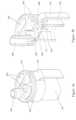
- FIG. 1 ais a schematic illustration of an aerosol-generating system.
- the aerosol-generating systemcomprises two main components, a cartridge 100 and a control body 200 .
- a connection end 115 of the cartridge 100is removably connected to a corresponding connection end 205 of the control body 200 .
- the control body 200contains a battery 210 , which in this example is a rechargeable lithium ion battery, and control circuitry 220 .
- the aerosol-generating deviceis portable and has a size comparable to a conventional cigar or cigarette.
- the cartridge 100comprises a housing 105 containing an atomising assembly (heater assembly) 120 and a liquid storage compartment having a first portion/compartment 130 and a second portion/compartment 135 .
- a liquid aerosol-forming substrateis held in the liquid storage compartment.
- the first portion 130 of the liquid storage compartmentis connected to the second portion 135 of the liquid storage compartment so that liquid in the first portion 130 can pass to the second portion 135 .
- the heater assembly 120receives liquid from the second portion 135 of the liquid storage compartment.
- the heater assembly 120is a generally planar, fluid permeable heater assembly.
- An air flow passage 140(including a vertical portion 145 of the air flow passage 140 ) extends through the cartridge 100 from an air inlet 150 past the heater assembly 120 and from the heater assembly 120 to a mouth end opening 110 in the cartridge housing 105 .
- the components of the cartridge 100are arranged so that the first portion 130 of the liquid storage compartment is between the heater assembly 120 and the mouth end opening 110 , and the second portion 135 of the liquid storage compartment is positioned on an opposite side of the heater assembly 120 to the mouth end opening 110 .
- the heater assembly 120lies between the two portions 130 , 135 of the liquid storage compartment and receives liquid from the second portion 135 , and the first portion 130 of liquid storage compartment is closer to the mouth end opening 110 than the second portion 135 of the liquid storage compartment.
- the air flow passageextends past the heater assembly 120 and between the first and second portion 130 , 135 of the liquid storage compartment.
- the systemis configured so that a puff or suction on the mouth end opening 110 of the cartridge 100 draws aerosol from the system.
- the control circuitry 220controls the supply of electrical power from the battery 210 to the cartridge 100 when the system is activated. Consequently, the amount and properties of the vapour produced by the heater assembly 120 are controlled.
- the control circuitry 220may include an airflow sensor and the control circuitry 220 may supply electrical power to the heater assembly 120 (also called a “vaporizer assembly” or a “vapor generator”) when a puff on the cartridge 100 is detected by the airflow sensor.
- the heater assembly 120is activated and generates a vapour that is entrained in the air flow passing through the air flow passage 140 .
- the vapourcools with in the vertical portion 145 of the air flow passage 140 to form an aerosol, which is then discharged through the mouth end opening 110 .
- the atomizing assembly 120may also be referred to as an “aerosol assembly” or an “aerosol generating assembly.”
- the mouth end opening 110is typically the highest point of the device.
- the construction of the cartridge 100and in particular the arrangement of the heater assembly 120 between first and second portions 130 , 135 of the liquid storage compartment, is advantageous because it exploits gravity to ensure that the liquid substrate is delivered to the heater assembly 120 even as the liquid storage compartment is becoming empty, but prevents an oversupply of liquid to the heater assembly 120 .
- FIG. 1 bis a first cross section of a cartridge 100 for use in the system of FIG. 1 a .
- FIG. 1 cis a second cross section, orthogonal to the cross section of FIG. 1 b.
- the cartridge 100 of FIGS. 1 b and FIG. 1 ccomprises an external housing 105 having a mouth end with a mouth end opening 110 , and a connection end opposite the mouth end.
- the liquid storage compartmentholding a liquid aerosol-forming substrate 131 .
- the liquidis contained in the liquid storage compartment by three components, an upper storage compartment housing 137 , a heater mount 134 and an end cap 138 .
- a heater assembly 120is held in the heater mount 134 .
- a capillary material 136is provided in the second portion 135 of the liquid storage compartment, and abuts the heater element in a central region of the heater assembly 120 .
- the capillary materialis oriented to transport liquid to the heater element.
- the heater element 121comprises a mesh heater element, formed from a plurality of filaments. Details of this type of heater element construction can be found in WO2015/117702 for example.
- An airflow passage 140extends between the first and second portions 130 , 135 of the liquid storage compartment.
- a bottom wall of the airflow passage 140comprises the heater element 121 and the heater mount 134
- side walls of the airflow passage 140comprise portions of the heater mount 134
- a top wall of the airflow passage 140comprises a portion of the upper storage compartment housing 137 .
- the air flow passage 140has the vertical portion 145 that extends through the first portion 130 of the liquid storage compartment, as shown in FIG. 1 b , towards the mouth end opening 110 .
- the heater assembly 120is generally planar and has two faces. A first face of the heater assembly 120 faces the first portion 130 of the liquid storage compartment and the mouth end opening 110 . A second face of the heater assembly 120 is in contact with the capillary material 136 and the liquid 131 in the liquid storage compartment, and faces a connection end 115 of the cartridge 100 . The heater assembly 120 is closer to the connection end so that electrical connection of the heater assembly 120 to a power supply can be easily and robustly achieved, as will be described.
- the first portion 130 of the liquid storage compartmentis larger than the second portion 135 of the liquid storage compartment and occupies a space between the heater assembly 120 and the mouth end opening 110 of the cartridge 100 .
- Liquid in the first portion 130 of the liquid storage compartmentcan travel to the second portion 135 of the liquid storage compartment through liquid channels 133 on either side of the heater assembly 120 .
- Two channelsare provided in this example to provide a symmetric structure, although only one channel is necessary.
- the channelsare enclosed liquid flow paths defined between the upper storage compartment housing 137 and the heater mount 134 .
- FIGS. 2 a , 2 b and 2 cillustrate an example embodiment in relation to the cartridge shown in FIGS. 1 a to 1 c .
- the heater assembly 120is shown being assembled onto the first portion 130 of the storage compartment where a seal portion 320 of a removable seal 310 is positioned over the heater element 121 so to seal off a first side of the heater element 121 that is exposed to the air flow passage 140 .
- FIGS. 2 b and 2 cshow an assembled heater assembly 120 with the first portion 130 of the storage compartment and the finished cartridge respectively.
- a tab portion 330 of the removable seal 310in shown extending outwardly from the air flow passage and protruding from the external surface of the housing 105 . The tab portion 330 allows removal of the seal portion 320 of the removable seal 310 from the air flow passage 140 by pulling on the tab portion 330 , thereby establishing fluid communication between the heater element and the air flow passage 140 .
- FIG. 3is a cross-section of another example embodiment.
- a seal joint 410is provided between the first portion 130 of the storage compartment and the heater assembly 120 , which is moulded with the second portion 135 of the storage compartment.
- the seal joint 410not only simplifies the manufacturing process, since the second portion 135 and the first portion 130 of the storage compartment can be separately produced before being sealingly attached to each other so as to establish the liquid channels 133 , such seal joint 410 also defines part of the air flow passage 140 and this allows the seal portion 320 of the removable seal 310 to be attached to the heater element 121 more easily.
- the seal joint 410can also be shaped in order to direct air flow over the heater element 121 , for example, it can be shaped to create turbulence over the surface of the heater element 121 so as to improve vaporisation.
- FIGS. 4 a and 4 bare perspective views of exterior and cross-section of a heater assembly 120 connected to a seal joint 410 .
- the seal joint 410forms part of the air flow passage 140 , extending from an air inlet end 440 towards a cartridge end 420 .
- the cartridge end 420is configured to cooperate sealingly with a corresponding connection at the housing 105 so to complete the air flow passage 140 .
- the connection between the seal joint 410 to the heater assembly 120 as shown in FIGS. 4 a and 4 b , as well as the connection between the seal joint 140 and the housing 105are both effected by an interference fit in order to provide sealed connections.
- the interference fitshown in FIG.
- the ribs 450are integrally formed with the seal joint 410 where both the ribs and the seal joint 410 are made from the same material. However, the ribs 450 can be replaced by elastomer O-rings or any other materials different to that of the seal joint 410 .
- the seal portion 320 of the removable seal 310engages with the heater assembly 120 by a mechanical seal 340 . That is, a ring of protrusion on the mechanical seal 340 engages with a corresponding grooved ring on the heater assembly 120 , thus locking the seal portion 320 in position.
- the mechanical seal 340is made from resilient material and its attachment to the grooved ring creates a hermetic seal between the heater element 121 and the air flow passage 140 .
- the use of such mechanical seal 340not only prevents leakage of liquid substrate during transportation and storage, it also prevents evaporation of liquid substrate from the second portion 135 of the storage compartment.
- the mechanical seal 340is configured to disengage from the heater assembly upon applying a pulling force on the tab portion 330 .
- the seal portion 320when positioned in the air flow passage 140 , not only covers and seals the first side of the heater element 121 from the air flow passage, it also blocks off the air flow passage 140 so to prevent dust and dirt from collecting therein.
- the seal joint 410also comprises fluid passage connection 430 for connecting sealingly to a corresponding connector at the first portion 130 of the storage compartment by an interference seal, so to provide a sealed liquid passage between the first portion 130 and the second portion 135 of the storage compartment.
- FIG. 5 ais a perspective view of the assembled cartridge shown in FIG. 3 , whereas an exploded view of which is also provided in FIG. 5 b .
- the removable seal 310is placed in the air passage 140 having its seal portion 320 positioned over the heater element 121 , and the tab portion 330 extending beyond the cartridge housing.
- the removable seal 310is shown to have an “L” shaped profile. That is, the removable seal 310 is bent such that the tap portion 330 is arranged perpendicularly to the seal portion 320 so to conform to the exterior profile of the cartridge housing 105 . This ensures more compact cartridges can be produced.
- the tab portion 330Prior to its first operation, the tab portion 330 may be gripped and pull it outwardly away from the housing 105 in order to remove the removable seal 310 from the air passage. This causes the break up of the hermetic seal between the seal portion 320 and the heater element 121 , and allowing the liquid substrate from the second portion 135 of the storage compartment to expose to the atmosphere. Once the removable seal is removed the connection end 115 of the cartridge 100 may be connected to a corresponding connection end 205 of the control body 200 .
- the removable sealalso prevents dirt and dust from collecting in the air flow passage 140 and the heater element.
- the tab portion 330also prevents accidental connection of the cartridge onto the control body 200 prior to its removal because the tab portion 330 would otherwise be in the way of connection. More specifically, the tab portion 330 prevents the heater element being energised before the removable seal is removed.
- FIG. 5 billustrates an exploded view of the exemplary cartridge of FIG. 3 .
- the first portion of the storage compartmentis manufactured integrally with the cartridge housing 105 by an injection moulding process.
- the heater assembly 120is first produced by moulding the heater element with the heater assembly 120 , which forms integrally with the second portion of the storage compartment 135 .
- the heater assembly 120comprises electrical contact pads for providing electrical connection to the control circuitry 220 .
- a retention material 139 and capillary material 136are then inserted into the second portion 135 of the storage compartment before the second portion 135 is closed off by an end cap 138 .
- the retention material 139is a fibrous material provided to contain any incoming liquid substrate from the first portion 130 , before it is drawn towards the capillary material and be consumed at the heater element.
- the end cap 138attaches sealingly onto the second portion 135 by an interference fit to keep the capillary material contained in the second portion, as well as prevent leakage and evaporation of liquid substrate from the second portion 135 of the storage compartment.
- the removable sealis then positioned over the heater element to seal it in place.
- a mechanical sealing means 340is used in this exemplary embodiment, the seal portion 320 of the removable seal 310 may be secured onto the heater element by other cap sealing mechanisms such as induction sealing or glued sealing.
- the seal joint 410may then installed onto the heater assembly 120 by interference fit, to form the example as shown in FIGS. 4 a and 4 b .
- the use of a seal joint 410is particularly beneficial because the heater element is fully exposed during the application of cap seal, thus providing sufficient free space for an induction sealer or a heat sealer to operate on the cap seal.
- the completed heater assembly 120with the seal joint 410 attached, is attached onto the cartridge housing 105 via interference fit to form the cartridge as shown in FIG. 3 and FIG. 5 a.
- FIG. 6shows another example embodiment but without the removable seal 310 in place.
- the cartridge 100 as shown in FIG. 6is of similar construction to the example as shown in FIG. 3 to 5 , as such a removable seal 310 can be applied in a similar manner.
- the embodiment shown in FIG. 6comprises a first portion 130 of storage compartment formed integrally with the housing 105 , a heater assembly formed integrally with a second portion 135 of the storage compartment, and an end cap 138 that is designed to cooperate directly with the housing 105 via an interference fit. That is, the end cap 138 in FIG. 6 is designed to lock onto the housing 105 , instead of the heater assembly as shown in FIGS. 3 and 5 . This further simplifies the manufacturing process.
- the cartridge and liquid storage compartmentmay have a different cross-sectional shape and the heater assembly may have a different shape and configuration.
Landscapes
- Chemical & Material Sciences (AREA)
- Chemical Kinetics & Catalysis (AREA)
- General Chemical & Material Sciences (AREA)
- Containers And Packaging Bodies Having A Special Means To Remove Contents (AREA)
- Nozzles (AREA)
- Catching Or Destruction (AREA)
Abstract
Description
Claims (19)
Priority Applications (1)
| Application Number | Priority Date | Filing Date | Title |
|---|---|---|---|
| US19/086,459US20250212955A1 (en) | 2017-09-18 | 2025-03-21 | Cartridge with first compartment in fluid communication with second compartment |
Applications Claiming Priority (4)
| Application Number | Priority Date | Filing Date | Title |
|---|---|---|---|
| EP17191636 | 2017-09-18 | ||
| EP171916364 | 2017-09-18 | ||
| EP17191636.4 | 2017-09-18 | ||
| PCT/EP2018/071551WO2019052748A1 (en) | 2017-09-18 | 2018-08-08 | A cartridge for an aerosol-generating system |
Related Parent Applications (1)
| Application Number | Title | Priority Date | Filing Date |
|---|---|---|---|
| PCT/EP2018/071551ContinuationWO2019052748A1 (en) | 2017-09-18 | 2018-08-08 | A cartridge for an aerosol-generating system |
Related Child Applications (1)
| Application Number | Title | Priority Date | Filing Date |
|---|---|---|---|
| US19/086,459DivisionUS20250212955A1 (en) | 2017-09-18 | 2025-03-21 | Cartridge with first compartment in fluid communication with second compartment |
Publications (2)
| Publication Number | Publication Date |
|---|---|
| US20190082739A1 US20190082739A1 (en) | 2019-03-21 |
| US12295415B2true US12295415B2 (en) | 2025-05-13 |
Family
ID=59895241
Family Applications (2)
| Application Number | Title | Priority Date | Filing Date |
|---|---|---|---|
| US16/184,322Active2040-05-29US12295415B2 (en) | 2017-09-18 | 2018-11-08 | Cartridge for an aerosol-generating system |
| US19/086,459PendingUS20250212955A1 (en) | 2017-09-18 | 2025-03-21 | Cartridge with first compartment in fluid communication with second compartment |
Family Applications After (1)
| Application Number | Title | Priority Date | Filing Date |
|---|---|---|---|
| US19/086,459PendingUS20250212955A1 (en) | 2017-09-18 | 2025-03-21 | Cartridge with first compartment in fluid communication with second compartment |
Country Status (13)
| Country | Link |
|---|---|
| US (2) | US12295415B2 (en) |
| EP (3) | EP3684203B1 (en) |
| JP (3) | JP7254779B2 (en) |
| KR (2) | KR20240005117A (en) |
| CN (2) | CN111031824B (en) |
| BR (1) | BR112020003506B1 (en) |
| IL (2) | IL272286B2 (en) |
| MX (2) | MX2020002695A (en) |
| MY (1) | MY205447A (en) |
| PH (1) | PH12020500083A1 (en) |
| PL (2) | PL3684203T3 (en) |
| UA (1) | UA127587C2 (en) |
| WO (1) | WO2019052748A1 (en) |
Families Citing this family (23)
| Publication number | Priority date | Publication date | Assignee | Title |
|---|---|---|---|---|
| KR102578396B1 (en)* | 2016-11-14 | 2023-09-14 | 필립모리스 프로덕츠 에스.에이. | Aerosol generating system with variable airflow |
| HUE059840T2 (en) | 2017-02-24 | 2023-01-28 | Philip Morris Products Sa | Moulded mounting for an aerosol-generating element in an aerosol-generating system |
| CN110267556B (en) | 2017-02-24 | 2022-10-18 | 菲利普莫里斯生产公司 | Aerosol-generating system and cartridge for an aerosol-generating system having a two-part liquid storage compartment |
| JP7254779B2 (en) | 2017-09-18 | 2023-04-10 | フィリップ・モーリス・プロダクツ・ソシエテ・アノニム | Cartridges for aerosol generation systems |
| DE102017123868B4 (en) | 2017-10-13 | 2019-05-09 | Hauni Maschinenbau Gmbh | Evaporator unit for an inhaler, in particular for an electronic cigarette product |
| US11259370B2 (en) | 2017-12-08 | 2022-02-22 | Altria Client Services Llc | Multi-component aerosol-generating device with impact absorbing part |
| GB201720849D0 (en)* | 2017-12-14 | 2018-01-31 | Nicoventures Holdings Ltd | Vapour provision systems |
| JP7391876B2 (en)* | 2018-04-26 | 2023-12-05 | フィリップ・モーリス・プロダクツ・ソシエテ・アノニム | Heater assembly with heater element separated from liquid source |
| DE102019103987A1 (en)* | 2019-02-18 | 2020-08-20 | Hauni Maschinenbau Gmbh | Vaporizer device for an inhaler, consumable unit, inhaler and manufacturing method |
| KR102397449B1 (en)* | 2019-07-23 | 2022-05-12 | 주식회사 케이티앤지 | Aerosol generating device |
| US11992048B2 (en)* | 2019-09-04 | 2024-05-28 | Sucipto KOKADIR | Cartridge with separable components for the evaporation and inhalation of a liquid medium |
| GB201913479D0 (en)* | 2019-09-18 | 2019-10-30 | Nicoventures Trading Ltd | A consumable artcile for use with an apparatus for heating aerosolisable material |
| IL293919B2 (en) | 2019-12-19 | 2025-08-01 | Philip Morris Products Sa | Cartridge for an aerosol generation system, an aerosol generation system including a cartridge, and a method for manufacturing a heating assembly and cartridge for an aerosol generation system |
| CN114828671A (en)* | 2019-12-19 | 2022-07-29 | 日本烟草国际股份有限公司 | Aerosol generating device |
| CN115243572A (en)* | 2020-02-28 | 2022-10-25 | 日本烟草国际股份有限公司 | Airflow chimney |
| WO2022034053A1 (en)* | 2020-08-14 | 2022-02-17 | Jt International Sa | Capsule with an airflow path for an electronic cigarette |
| CN115299655A (en)* | 2021-05-07 | 2022-11-08 | 深圳市合元科技有限公司 | Atomizer and electronic atomization device |
| KR102708760B1 (en)* | 2021-06-23 | 2024-09-24 | 주식회사 케이티앤지 | Aerosol generating device and method of operation thereof |
| KR102637144B1 (en)* | 2021-06-23 | 2024-02-16 | 주식회사 케이티앤지 | Aerosol generating device and method of operation thereof |
| CN113729308A (en)* | 2021-10-15 | 2021-12-03 | 北京温致科技有限公司 | Suction nozzle assembly, heater and aerosol generating device |
| KR102615473B1 (en)* | 2021-10-28 | 2023-12-19 | 주식회사 케이티앤지 | Aerosol-generating device comprising flavored cartridge |
| CN216651318U (en)* | 2021-11-22 | 2022-06-03 | 深圳市华诚达精密工业有限公司 | Heating atomization device and electronic atomizer thereof |
| CN115299640A (en)* | 2022-01-25 | 2022-11-08 | 深圳市合元科技有限公司 | Aerosol generating device |
Citations (94)
| Publication number | Priority date | Publication date | Assignee | Title |
|---|---|---|---|---|
| US5167242A (en) | 1990-06-08 | 1992-12-01 | Kabi Pharmacia Aktiebolaq | Nicotine-impermeable container and method of fabricating the same |
| US6790496B1 (en) | 1999-01-26 | 2004-09-14 | Pfizer Health Ab | Materials for packing nicotine-containing products |
| US20110226236A1 (en) | 2008-10-23 | 2011-09-22 | Helmut Buchberger | Inhaler |
| UA67598U (en) | 2011-08-26 | 2012-02-27 | Дмитрий Юрьевич Рогов | Electronic cigarette |
| EP2460424A1 (en) | 2010-12-03 | 2012-06-06 | Philip Morris Products S.A. | An aerosol generating system with leakage prevention |
| US20130074857A1 (en) | 2010-03-10 | 2013-03-28 | Helmut Buchberger | Inhaler component |
| US20130192623A1 (en) | 2012-01-31 | 2013-08-01 | Altria Client Services Inc. | Electronic cigarette |
| RU2489948C2 (en) | 2011-11-17 | 2013-08-20 | Общество с ограниченной ответственностью "Научно-производственное объединение ЗДОРОВЬЕ" ("НПО ЗДОРОВЬЕ") | Smoke-generating composition for electronic devices imitating tobacco smoking, such composition production and application method |
| US20130228191A1 (en) | 2011-06-28 | 2013-09-05 | Kyle D. Newton | Electronic Cigarette With Liquid Reservoir |
| US20130319407A1 (en) | 2012-06-05 | 2013-12-05 | Qiuming Liu | Electronic Cigarette and Inhaling Shell Thereof |
| US20130327327A1 (en)* | 2012-06-06 | 2013-12-12 | Aerodesigns, Inc. | Aerosol dispenser with replaceable cartridge |
| CN203341007U (en) | 2013-06-06 | 2013-12-18 | 深圳市康尔科技有限公司 | Pressed type atomizer |
| CN203341008U (en) | 2013-06-06 | 2013-12-18 | 深圳市康尔科技有限公司 | Leakage-proof atomizer |
| CN103462224A (en) | 2013-08-31 | 2013-12-25 | 卓尔悦(常州)电子科技有限公司 | Electronic cigarette atomizer |
| US20140000638A1 (en) | 2012-06-28 | 2014-01-02 | R.J. Reynolds Tobacco Company | Reservoir and heater system for controllable delivery of multiple aerosolizable materials in an electronic smoking article |
| JP2014511175A (en) | 2011-02-11 | 2014-05-15 | バットマーク・リミテッド | Inhaler components |
| WO2014102092A1 (en) | 2012-12-28 | 2014-07-03 | Philip Morris Products S.A. | Heating assembly for an aerosol generating system |
| WO2014110119A1 (en) | 2013-01-08 | 2014-07-17 | L. Perrigo Company | Electronic cigarette |
| CN103932401A (en) | 2013-09-29 | 2014-07-23 | 深圳市麦克韦尔科技有限公司 | Electronic cigarette |
| CN203969207U (en)* | 2014-07-08 | 2014-12-03 | 深圳市康尔科技有限公司 | The electronic cigarette of heat generating component is changed in fluid injection bottom, top |
| US20150040929A1 (en) | 2012-04-26 | 2015-02-12 | Fontem Holdings 1 B.V. | Electronic cigarette with sealed cartridge |
| US8991402B2 (en) | 2007-12-18 | 2015-03-31 | Pax Labs, Inc. | Aerosol devices and methods for inhaling a substance and uses thereof |
| EP2888963A1 (en) | 2013-12-31 | 2015-07-01 | Shenzhen First Union Technology Co., Ltd. | Atomizer and electronic cigarette having same |
| WO2015100361A1 (en) | 2013-12-23 | 2015-07-02 | Pax Labs, Inc. | Vaporization device systems and methods |
| WO2015114325A1 (en) | 2014-01-29 | 2015-08-06 | Batmark Limited | Aerosol-forming member |
| WO2015117704A1 (en) | 2014-02-10 | 2015-08-13 | Philip Morris Products S.A. | An aerosol-generating system having a heater assembly and a cartridge for an aerosol-generating system having a fluid permeable heater assembly |
| WO2015117705A2 (en) | 2014-02-10 | 2015-08-13 | Philip Morris Products S.A. | Cartridge for an aerosol-generating system |
| WO2015117702A1 (en) | 2014-02-10 | 2015-08-13 | Philip Morris Products S.A. | An aerosol-generating system having a fluid-permeable heater assembly |
| WO2015117700A1 (en) | 2014-02-10 | 2015-08-13 | Philip Morris Products S.A. | An aerosol-generating system comprising a device and a cartridge, in which the device ensures electrical contact with the cartridge |
| CN204617067U (en) | 2015-04-17 | 2015-09-09 | 刘翔 | With the electronic cigarette external member of multiple atomizer |
| US20150272217A1 (en) | 2014-03-27 | 2015-10-01 | Zhiping CHEN | Electronic cigarette |
| JP5815559B2 (en) | 2009-12-30 | 2015-11-17 | フィリップ・モーリス・プロダクツ・ソシエテ・アノニム | An improved heater for an electrically heated aerosol generation system. |
| WO2015179292A1 (en) | 2014-05-23 | 2015-11-26 | R. J. Reynolds Tobacco Company | Cartridge with electronics compartment for an aerosol delivery device and related assembly method |
| WO2015189623A1 (en) | 2014-06-13 | 2015-12-17 | Nicoventures Holdings Limited | Aerosol provision system |
| US20160007654A1 (en) | 2014-07-08 | 2016-01-14 | Xiaochun Zhu | Electronic cigarettes having refillable top and replaceable heating element |
| WO2016005530A1 (en) | 2014-07-11 | 2016-01-14 | Philip Morris Products S.A. | Aerosol-forming cartridge comprising a liquid nicotine source |
| DE202016100917U1 (en) | 2016-02-22 | 2016-03-09 | Türk & Hillinger GmbH | Air and / or aerosol heater |
| US20160073692A1 (en) | 2014-09-17 | 2016-03-17 | Fontem Holdings 2 B.V. | Device for storing and vaporizing liquid media |
| WO2016041206A1 (en) | 2014-09-19 | 2016-03-24 | 惠州市吉瑞科技有限公司 | Vaporization assembly and electronic cigarette |
| DE102014114133A1 (en) | 2014-09-29 | 2016-03-31 | Aie Investments S.A. | Electric cigarette |
| CN105559151A (en) | 2016-03-21 | 2016-05-11 | 湖南中烟工业有限责任公司 | Ultrasonic atomizer and electronic cigarette |
| US20160128386A1 (en) | 2014-08-29 | 2016-05-12 | Shenzhen Smoore Technology Limited | Electronic cigarette and atomizer assembly mounting base thereof |
| WO2016075748A1 (en) | 2014-11-10 | 2016-05-19 | 日本たばこ産業株式会社 | Non-combusting flavor inhaler |
| US20160138795A1 (en) | 2014-10-20 | 2016-05-19 | Numerical Design, Inc. | Microfluidic-based apparatus and method for vaporization of liquids |
| US9351522B2 (en) | 2011-09-29 | 2016-05-31 | Robert Safari | Cartomizer e-cigarette |
| WO2016092261A1 (en) | 2014-12-11 | 2016-06-16 | Nicoventures Holdings Limited | Aerosol provision systems |
| TW201620405A (en) | 2014-12-15 | 2016-06-16 | 菲利浦莫里斯製品股份有限公司 | Aerosol generating system and method for directing airflow in an electrothermal aerosol generating system |
| WO2016096728A1 (en) | 2014-12-15 | 2016-06-23 | Philip Morris Products S.A. | Aerosol-generating system comprising moveable cartridge |
| WO2016096497A1 (en) | 2014-12-15 | 2016-06-23 | Philip Morris Products S.A. | An aerosol-generating system using the venturi effect to deliver substrate to a heating element |
| CN105722416A (en) | 2013-12-05 | 2016-06-29 | 菲利普莫里斯生产公司 | Aerosol-generating article with low resistance air flow path |
| WO2016101141A1 (en) | 2014-12-23 | 2016-06-30 | 惠州市吉瑞科技有限公司 | Electronic cigarette and method for preventing atomizer from shaking relative to battery rod |
| EP3053459A2 (en) | 2015-02-04 | 2016-08-10 | Shenzhen First Union Technology Co., Ltd. | Liquid supply, atomizer and electronic cigarette having same |
| US9420831B2 (en) | 2013-04-03 | 2016-08-23 | Huizhou Kimree Technology Co., Ltd. Shenzhen Branch | Electronic cigarette |
| CN105876873A (en) | 2016-06-30 | 2016-08-24 | 湖南中烟工业有限责任公司 | Combined ultrasonic atomizer and atomization method thereof and electronic cigarette |
| CN205512340U (en) | 2016-01-11 | 2016-08-31 | 常州聚为智能科技有限公司 | Atomising head and electron cigarette thereof |
| US9439455B2 (en) | 2010-04-30 | 2016-09-13 | Fontem Holdings 4 B.V. | Electronic smoking device |
| US20160262454A1 (en) | 2015-03-10 | 2016-09-15 | R.J. Reynolds Tobacco Company | Aerosol delivery device with microfluidic delivery component |
| WO2016145612A1 (en) | 2015-03-17 | 2016-09-22 | 惠州市吉瑞科技有限公司 | Atomizing component and electronic cigarette |
| WO2016156413A1 (en)* | 2015-04-02 | 2016-10-06 | Fontem Holdings 1 B.V. | Electronic smoking device with liquid reservoir including an actuator |
| WO2016156103A1 (en) | 2015-03-31 | 2016-10-06 | Philip Morris Products S.A. | Extended heater and heating assembly for an aerosol generating system |
| WO2016172448A1 (en) | 2015-04-23 | 2016-10-27 | Altria Client Services Llc | Unitary heating element and heater assemblies, cartridges, and e-vapor devices including a unitary heating element |
| WO2016172023A1 (en) | 2015-04-22 | 2016-10-27 | Altria Client Services Llc | Pod assembly, dispensing body, and e-vapor apparatus including the same |
| US20160338410A1 (en) | 2014-02-10 | 2016-11-24 | Philip Morris Products S.A. | Fluid permeable heater assembly for an aerosol-generating system and method for assembling a fluid permeable heater for an aerosol-generating system |
| WO2016198417A1 (en) | 2015-06-12 | 2016-12-15 | Philip Morris Products S.A. | Cartridge for aerosol-generating system |
| US20160374399A1 (en) | 2013-12-23 | 2016-12-29 | James Monsees | Vaporizer apparatus |
| WO2017019402A2 (en) | 2015-07-24 | 2017-02-02 | Rai Strategic Holdings, Inc. | Aerosol delivery device with radiant heating |
| CN106455713A (en) | 2014-05-21 | 2017-02-22 | 菲利普莫里斯生产公司 | Aerosol generating system comprising fluid permeable susceptor element |
| WO2017042081A1 (en) | 2015-09-11 | 2017-03-16 | Philip Morris Products S.A. | A cartridge and a system for an aerosol-forming article including the cartridge |
| WO2017064051A1 (en)* | 2015-10-15 | 2017-04-20 | Fontem Holdings 1 B.V. | Electronic cigarette with multicameral liquid reservoir |
| EP3158882A2 (en) | 2015-10-22 | 2017-04-26 | Shenzhen Smoore Technology Limited | Electronic cigarette and atomizing assembly and atomizing element thereof |
| CN206197017U (en) | 2016-10-12 | 2017-05-31 | 深圳市艾维普思科技股份有限公司 | Electronic cigarette |
| JP2017519492A (en) | 2014-05-21 | 2017-07-20 | フィリップ・モーリス・プロダクツ・ソシエテ・アノニム | Aerosol generation system with planar induction coil |
| CN106998813A (en) | 2014-11-17 | 2017-08-01 | 麦克内尔股份公司 | Disposable sleeve for electronics nicotine delivery system |
| JP2017522021A (en) | 2014-07-11 | 2017-08-10 | フィリップ・モーリス・プロダクツ・ソシエテ・アノニム | Aerosol forming cartridge with protective foil |
| CN107105776A (en) | 2014-06-27 | 2017-08-29 | Jt国际股份公司 | electronic vapor inhaler |
| US20170251718A1 (en)* | 2016-03-07 | 2017-09-07 | Mohannad A. Armoush | Inductive heating apparatus and related method |
| US20170340014A1 (en) | 2016-05-31 | 2017-11-30 | Rui Nuno BATISTA | Aerosol-generating device with integral heater assembly |
| US9936731B2 (en) | 2012-04-12 | 2018-04-10 | Jt International Sa | Aerosol-generation devices |
| US9943114B2 (en) | 2014-07-11 | 2018-04-17 | Philip Morris Products S.A. | Aerosol-forming cartridge comprising a tobacco-containing material |
| UA116828C2 (en) | 2013-07-15 | 2018-05-10 | Ніковенчерз Холдінгс Лімітед | ELECTRONIC COUPLING DEVICE |
| US9986765B2 (en) | 2014-04-30 | 2018-06-05 | Philip Morris Products S.A. | Container having a heater for an aerosol-generating device, and aerosol-generating device |
| WO2018153732A1 (en) | 2017-02-24 | 2018-08-30 | Philip Morris Products S.A. | Moulded mounting for an aerosol-generating element in an aerosol-generating system |
| WO2018153608A1 (en) | 2017-02-24 | 2018-08-30 | Philip Morris Products S.A. | An aerosol-generating system and a cartridge for an aerosol generating system having a two-part liquid storage compartment |
| US10080387B2 (en) | 2016-09-23 | 2018-09-25 | Rai Strategic Holdings, Inc. | Aerosol delivery device with replaceable wick and heater assembly |
| US20180279679A1 (en) | 2015-10-01 | 2018-10-04 | Nicoventures Holdings Limited | Aerosol provision system |
| US10149497B2 (en)* | 2014-02-28 | 2018-12-11 | Beyond Twenty Ltd. | E-cigarette personal vaporizer |
| US20190045837A1 (en) | 2016-02-18 | 2019-02-14 | British American Tobacco (Investments) Limited | Flavor delivery device |
| US10231486B2 (en)* | 2016-03-10 | 2019-03-19 | Pax Labs, Inc. | Vaporization device having integrated games |
| US20190335819A1 (en) | 2017-02-08 | 2019-11-07 | Japan Tobacco Inc. | Cartridge and inhaler |
| US10602780B2 (en) | 2017-01-10 | 2020-03-31 | Shenzhen IVPS Technology Co. Ltd. | Electronic cigarette |
| US10687552B2 (en) | 2014-02-10 | 2020-06-23 | Philip Morris Products S.A. | Cartridge with a heater assembly for an aerosol-generating system |
| US10905161B2 (en)* | 2016-11-28 | 2021-02-02 | Shenzhen Ivps Technology Co., Ltd. | Electronic cigarette and bilayer tobacco liquid storing structure |
| US11134716B2 (en)* | 2016-03-08 | 2021-10-05 | Hauni Maschinenbau Gmbh | Electronic cigarette product and cartridge having a microsystem unit adding device |
| EP3684203B1 (en) | 2017-09-18 | 2023-02-08 | Philip Morris Products S.A. | A cartridge for an aerosol-generating system |
- 2018
- 2018-08-08JPJP2020515922Apatent/JP7254779B2/enactiveActive
- 2018-08-08ILIL272286Apatent/IL272286B2/enunknown
- 2018-08-08BRBR112020003506-8Apatent/BR112020003506B1/enactiveIP Right Grant
- 2018-08-08MXMX2020002695Apatent/MX2020002695A/enunknown
- 2018-08-08WOPCT/EP2018/071551patent/WO2019052748A1/ennot_activeCeased
- 2018-08-08KRKR1020237043818Apatent/KR20240005117A/enactivePending
- 2018-08-08EPEP18752151.3Apatent/EP3684203B1/enactiveActive
- 2018-08-08ILIL302436Apatent/IL302436B2/enunknown
- 2018-08-08CNCN201880055055.9Apatent/CN111031824B/enactiveActive
- 2018-08-08UAUAA202001404Apatent/UA127587C2/enunknown
- 2018-08-08MYMYPI2020000389Apatent/MY205447A/enunknown
- 2018-08-08PLPL18752151.3Tpatent/PL3684203T3/enunknown
- 2018-08-08EPEP24179275.3Apatent/EP4420543A3/enactivePending
- 2018-08-08EPEP22215573.1Apatent/EP4176741B1/enactiveActive
- 2018-08-08PLPL22215573.1Tpatent/PL4176741T3/enunknown
- 2018-08-08KRKR1020207006952Apatent/KR102618375B1/enactiveActive
- 2018-08-08CNCN202310969479.9Apatent/CN116982739A/enactivePending
- 2018-11-08USUS16/184,322patent/US12295415B2/enactiveActive
- 2020
- 2020-01-10PHPH12020500083Apatent/PH12020500083A1/enunknown
- 2020-03-10MXMX2024004908Apatent/MX2024004908A/enunknown
- 2023
- 2023-01-10JPJP2023001599Apatent/JP7454715B2/enactiveActive
- 2024
- 2024-03-11JPJP2024037000Apatent/JP2024057105A/enactivePending
- 2025
- 2025-03-21USUS19/086,459patent/US20250212955A1/enactivePending
Patent Citations (119)
| Publication number | Priority date | Publication date | Assignee | Title |
|---|---|---|---|---|
| US5167242A (en) | 1990-06-08 | 1992-12-01 | Kabi Pharmacia Aktiebolaq | Nicotine-impermeable container and method of fabricating the same |
| US6790496B1 (en) | 1999-01-26 | 2004-09-14 | Pfizer Health Ab | Materials for packing nicotine-containing products |
| US8991402B2 (en) | 2007-12-18 | 2015-03-31 | Pax Labs, Inc. | Aerosol devices and methods for inhaling a substance and uses thereof |
| US20110226236A1 (en) | 2008-10-23 | 2011-09-22 | Helmut Buchberger | Inhaler |
| JP5815559B2 (en) | 2009-12-30 | 2015-11-17 | フィリップ・モーリス・プロダクツ・ソシエテ・アノニム | An improved heater for an electrically heated aerosol generation system. |
| US20130074857A1 (en) | 2010-03-10 | 2013-03-28 | Helmut Buchberger | Inhaler component |
| US9439455B2 (en) | 2010-04-30 | 2016-09-13 | Fontem Holdings 4 B.V. | Electronic smoking device |
| EP2460424A1 (en) | 2010-12-03 | 2012-06-06 | Philip Morris Products S.A. | An aerosol generating system with leakage prevention |
| JP2014511175A (en) | 2011-02-11 | 2014-05-15 | バットマーク・リミテッド | Inhaler components |
| US20130228191A1 (en) | 2011-06-28 | 2013-09-05 | Kyle D. Newton | Electronic Cigarette With Liquid Reservoir |
| UA67598U (en) | 2011-08-26 | 2012-02-27 | Дмитрий Юрьевич Рогов | Electronic cigarette |
| US9351522B2 (en) | 2011-09-29 | 2016-05-31 | Robert Safari | Cartomizer e-cigarette |
| RU2489948C2 (en) | 2011-11-17 | 2013-08-20 | Общество с ограниченной ответственностью "Научно-производственное объединение ЗДОРОВЬЕ" ("НПО ЗДОРОВЬЕ") | Smoke-generating composition for electronic devices imitating tobacco smoking, such composition production and application method |
| RU2608289C2 (en) | 2012-01-31 | 2017-01-17 | Олтриа Клайент Сервисиз Инк. | Improved electronic cigarette and method |
| US20130192623A1 (en) | 2012-01-31 | 2013-08-01 | Altria Client Services Inc. | Electronic cigarette |
| US9936731B2 (en) | 2012-04-12 | 2018-04-10 | Jt International Sa | Aerosol-generation devices |
| US20150040929A1 (en) | 2012-04-26 | 2015-02-12 | Fontem Holdings 1 B.V. | Electronic cigarette with sealed cartridge |
| RU2597531C2 (en) | 2012-04-26 | 2016-09-10 | Фонтем Холдингз 1 Б.В. | Electronic cigarette with sealed cartridge |
| US20130319407A1 (en) | 2012-06-05 | 2013-12-05 | Qiuming Liu | Electronic Cigarette and Inhaling Shell Thereof |
| US20130327327A1 (en)* | 2012-06-06 | 2013-12-12 | Aerodesigns, Inc. | Aerosol dispenser with replaceable cartridge |
| CN104540406A (en) | 2012-06-28 | 2015-04-22 | R.J.雷诺兹烟草公司 | Reservoir and heater system for controllable delivery of multiple aerosolizable materials in electronic smoking articles |
| US20140000638A1 (en) | 2012-06-28 | 2014-01-02 | R.J. Reynolds Tobacco Company | Reservoir and heater system for controllable delivery of multiple aerosolizable materials in an electronic smoking article |
| US20150163859A1 (en) | 2012-12-28 | 2015-06-11 | Philip Morris Products S.A. | Heating assembly for an aerosol generating system |
| WO2014102092A1 (en) | 2012-12-28 | 2014-07-03 | Philip Morris Products S.A. | Heating assembly for an aerosol generating system |
| WO2014110119A1 (en) | 2013-01-08 | 2014-07-17 | L. Perrigo Company | Electronic cigarette |
| US9420831B2 (en) | 2013-04-03 | 2016-08-23 | Huizhou Kimree Technology Co., Ltd. Shenzhen Branch | Electronic cigarette |
| CN203341008U (en) | 2013-06-06 | 2013-12-18 | 深圳市康尔科技有限公司 | Leakage-proof atomizer |
| CN203341007U (en) | 2013-06-06 | 2013-12-18 | 深圳市康尔科技有限公司 | Pressed type atomizer |
| UA116828C2 (en) | 2013-07-15 | 2018-05-10 | Ніковенчерз Холдінгс Лімітед | ELECTRONIC COUPLING DEVICE |
| CN103462224A (en) | 2013-08-31 | 2013-12-25 | 卓尔悦(常州)电子科技有限公司 | Electronic cigarette atomizer |
| WO2015043132A1 (en) | 2013-09-29 | 2015-04-02 | 深圳市麦克韦尔科技有限公司 | Electronic cigarette |
| US20150090279A1 (en) | 2013-09-29 | 2015-04-02 | Shenzhen Smoore Technology Limited | Electronic cigarette |
| CN103932401A (en) | 2013-09-29 | 2014-07-23 | 深圳市麦克韦尔科技有限公司 | Electronic cigarette |
| CN105722416A (en) | 2013-12-05 | 2016-06-29 | 菲利普莫里斯生产公司 | Aerosol-generating article with low resistance air flow path |
| US20160374399A1 (en) | 2013-12-23 | 2016-12-29 | James Monsees | Vaporizer apparatus |
| KR20160102293A (en) | 2013-12-23 | 2016-08-29 | 팍스 랩스, 인크. | Vaporization device systems and methods |
| WO2015100361A1 (en) | 2013-12-23 | 2015-07-02 | Pax Labs, Inc. | Vaporization device systems and methods |
| US20150181943A1 (en) | 2013-12-31 | 2015-07-02 | Shenzhen First Union Technology Co., Ltd. | Atomizer and electronic cigarette having same |
| EP2888963A1 (en) | 2013-12-31 | 2015-07-01 | Shenzhen First Union Technology Co., Ltd. | Atomizer and electronic cigarette having same |
| WO2015114325A1 (en) | 2014-01-29 | 2015-08-06 | Batmark Limited | Aerosol-forming member |
| AR099324A1 (en) | 2014-02-10 | 2016-07-13 | Philip Morris Products Sa | AN AEROSOL GENERATOR SYSTEM THAT HAS A FLUID PERMEABLE HEATER SET |
| WO2015117705A2 (en) | 2014-02-10 | 2015-08-13 | Philip Morris Products S.A. | Cartridge for an aerosol-generating system |
| US10687552B2 (en) | 2014-02-10 | 2020-06-23 | Philip Morris Products S.A. | Cartridge with a heater assembly for an aerosol-generating system |
| WO2015117700A1 (en) | 2014-02-10 | 2015-08-13 | Philip Morris Products S.A. | An aerosol-generating system comprising a device and a cartridge, in which the device ensures electrical contact with the cartridge |
| US10149498B2 (en) | 2014-02-10 | 2018-12-11 | Philip Morris Products S.A. | Fluid permeable heater assembly for an aerosol-generating system and method for assembling a fluid permeable heater for an aerosol-generating system |
| RU2657215C2 (en) | 2014-02-10 | 2018-06-08 | Филип Моррис Продактс С.А. | Generating aerosol system having assembled fluid permeable electric heater |
| WO2015117704A1 (en) | 2014-02-10 | 2015-08-13 | Philip Morris Products S.A. | An aerosol-generating system having a heater assembly and a cartridge for an aerosol-generating system having a fluid permeable heater assembly |
| JP2017506076A (en) | 2014-02-10 | 2017-03-02 | フィリップ・モーリス・プロダクツ・ソシエテ・アノニム | Aerosol generation system with fluid permeable heater assembly |
| US20170027226A1 (en) | 2014-02-10 | 2017-02-02 | Philip Morris Products S.A. | Aerosol-generating system having a fluid-permeable heater assembly |
| TW201534229A (en) | 2014-02-10 | 2015-09-16 | 菲利浦莫里斯製品股份有限公司 | Cartridge for an aerosol-generating system |
| WO2015117702A1 (en) | 2014-02-10 | 2015-08-13 | Philip Morris Products S.A. | An aerosol-generating system having a fluid-permeable heater assembly |
| US20160345630A1 (en) | 2014-02-10 | 2016-12-01 | Philip Morris Products S.A. | Aerosol-generating system having a heater assembly and a cartridge for an aerosol-generating system having a fluid permeable heater assembly |
| US20160338410A1 (en) | 2014-02-10 | 2016-11-24 | Philip Morris Products S.A. | Fluid permeable heater assembly for an aerosol-generating system and method for assembling a fluid permeable heater for an aerosol-generating system |
| KR20160119777A (en) | 2014-02-10 | 2016-10-14 | 필립모리스 프로덕츠 에스.에이. | An aerosol-generating system having a heater assembly and a cartridge for an aerosol-generating system having a fluid permeable heater assembly |
| KR20160119773A (en) | 2014-02-10 | 2016-10-14 | 필립모리스 프로덕츠 에스.에이. | An aerosol-generating system comprising a device and a cartridge, in which the device ensures electrical contact with the cartridge |
| CN105939625A (en) | 2014-02-10 | 2016-09-14 | 菲利普莫里斯生产公司 | Aerosol generating system with heater assembly and cartridge for an aerosol generating system with fluid permeable heater assembly |
| US10149497B2 (en)* | 2014-02-28 | 2018-12-11 | Beyond Twenty Ltd. | E-cigarette personal vaporizer |
| US20150272217A1 (en) | 2014-03-27 | 2015-10-01 | Zhiping CHEN | Electronic cigarette |
| US9986765B2 (en) | 2014-04-30 | 2018-06-05 | Philip Morris Products S.A. | Container having a heater for an aerosol-generating device, and aerosol-generating device |
| CN106455713A (en) | 2014-05-21 | 2017-02-22 | 菲利普莫里斯生产公司 | Aerosol generating system comprising fluid permeable susceptor element |
| JP2017519492A (en) | 2014-05-21 | 2017-07-20 | フィリップ・モーリス・プロダクツ・ソシエテ・アノニム | Aerosol generation system with planar induction coil |
| WO2015179292A1 (en) | 2014-05-23 | 2015-11-26 | R. J. Reynolds Tobacco Company | Cartridge with electronics compartment for an aerosol delivery device and related assembly method |
| WO2015189623A1 (en) | 2014-06-13 | 2015-12-17 | Nicoventures Holdings Limited | Aerosol provision system |
| US10159284B2 (en) | 2014-06-13 | 2018-12-25 | Nicoventures Holdings Limited | Aerosol provision system with an air channel wall with a surface finish to increase wettability, and related method |
| CN107105776A (en) | 2014-06-27 | 2017-08-29 | Jt国际股份公司 | electronic vapor inhaler |
| US20160007654A1 (en) | 2014-07-08 | 2016-01-14 | Xiaochun Zhu | Electronic cigarettes having refillable top and replaceable heating element |
| CN203969207U (en)* | 2014-07-08 | 2014-12-03 | 深圳市康尔科技有限公司 | The electronic cigarette of heat generating component is changed in fluid injection bottom, top |
| WO2016005530A1 (en) | 2014-07-11 | 2016-01-14 | Philip Morris Products S.A. | Aerosol-forming cartridge comprising a liquid nicotine source |
| JP2017522021A (en) | 2014-07-11 | 2017-08-10 | フィリップ・モーリス・プロダクツ・ソシエテ・アノニム | Aerosol forming cartridge with protective foil |
| US20170181472A1 (en) | 2014-07-11 | 2017-06-29 | Philip Morris Products S.A. | Aerosol-forming cartridge comprising a liquid nicotine source |
| US9943114B2 (en) | 2014-07-11 | 2018-04-17 | Philip Morris Products S.A. | Aerosol-forming cartridge comprising a tobacco-containing material |
| JP2017522872A (en) | 2014-07-11 | 2017-08-17 | フィリップ・モーリス・プロダクツ・ソシエテ・アノニム | Aerosol-forming cartridge with liquid nicotine source |
| US20160128386A1 (en) | 2014-08-29 | 2016-05-12 | Shenzhen Smoore Technology Limited | Electronic cigarette and atomizer assembly mounting base thereof |
| US20160073692A1 (en) | 2014-09-17 | 2016-03-17 | Fontem Holdings 2 B.V. | Device for storing and vaporizing liquid media |
| WO2016041206A1 (en) | 2014-09-19 | 2016-03-24 | 惠州市吉瑞科技有限公司 | Vaporization assembly and electronic cigarette |
| DE102014114133A1 (en) | 2014-09-29 | 2016-03-31 | Aie Investments S.A. | Electric cigarette |
| US20160138795A1 (en) | 2014-10-20 | 2016-05-19 | Numerical Design, Inc. | Microfluidic-based apparatus and method for vaporization of liquids |
| WO2016075748A1 (en) | 2014-11-10 | 2016-05-19 | 日本たばこ産業株式会社 | Non-combusting flavor inhaler |
| CN106998813A (en) | 2014-11-17 | 2017-08-01 | 麦克内尔股份公司 | Disposable sleeve for electronics nicotine delivery system |
| WO2016092261A1 (en) | 2014-12-11 | 2016-06-16 | Nicoventures Holdings Limited | Aerosol provision systems |
| TW201620405A (en) | 2014-12-15 | 2016-06-16 | 菲利浦莫里斯製品股份有限公司 | Aerosol generating system and method for directing airflow in an electrothermal aerosol generating system |
| WO2016096728A1 (en) | 2014-12-15 | 2016-06-23 | Philip Morris Products S.A. | Aerosol-generating system comprising moveable cartridge |
| WO2016096497A1 (en) | 2014-12-15 | 2016-06-23 | Philip Morris Products S.A. | An aerosol-generating system using the venturi effect to deliver substrate to a heating element |
| CN106998816A (en) | 2014-12-15 | 2017-08-01 | 菲利普莫里斯生产公司 | Aerosol generating system and method for directing air flow inside an electrically heated aerosol generating system |
| WO2016101141A1 (en) | 2014-12-23 | 2016-06-30 | 惠州市吉瑞科技有限公司 | Electronic cigarette and method for preventing atomizer from shaking relative to battery rod |
| EP3053459A2 (en) | 2015-02-04 | 2016-08-10 | Shenzhen First Union Technology Co., Ltd. | Liquid supply, atomizer and electronic cigarette having same |
| JP2018504132A (en) | 2015-02-04 | 2018-02-15 | フィリップ・モーリス・プロダクツ・ソシエテ・アノニム | Atomizer, electronic cigarette and replaceable liquid storage device |
| US20160262454A1 (en) | 2015-03-10 | 2016-09-15 | R.J. Reynolds Tobacco Company | Aerosol delivery device with microfluidic delivery component |
| WO2016145612A1 (en) | 2015-03-17 | 2016-09-22 | 惠州市吉瑞科技有限公司 | Atomizing component and electronic cigarette |
| WO2016156103A1 (en) | 2015-03-31 | 2016-10-06 | Philip Morris Products S.A. | Extended heater and heating assembly for an aerosol generating system |
| WO2016156413A1 (en)* | 2015-04-02 | 2016-10-06 | Fontem Holdings 1 B.V. | Electronic smoking device with liquid reservoir including an actuator |
| CN204617067U (en) | 2015-04-17 | 2015-09-09 | 刘翔 | With the electronic cigarette external member of multiple atomizer |
| WO2016172023A1 (en) | 2015-04-22 | 2016-10-27 | Altria Client Services Llc | Pod assembly, dispensing body, and e-vapor apparatus including the same |
| WO2016172448A1 (en) | 2015-04-23 | 2016-10-27 | Altria Client Services Llc | Unitary heating element and heater assemblies, cartridges, and e-vapor devices including a unitary heating element |
| WO2016198417A1 (en) | 2015-06-12 | 2016-12-15 | Philip Morris Products S.A. | Cartridge for aerosol-generating system |
| WO2017019402A2 (en) | 2015-07-24 | 2017-02-02 | Rai Strategic Holdings, Inc. | Aerosol delivery device with radiant heating |
| WO2017042081A1 (en) | 2015-09-11 | 2017-03-16 | Philip Morris Products S.A. | A cartridge and a system for an aerosol-forming article including the cartridge |
| US20180279679A1 (en) | 2015-10-01 | 2018-10-04 | Nicoventures Holdings Limited | Aerosol provision system |
| CN108289505A (en) | 2015-10-15 | 2018-07-17 | 方特慕控股第私人有限公司 | Electronic cigarette with multicell liquid memory |
| WO2017064051A1 (en)* | 2015-10-15 | 2017-04-20 | Fontem Holdings 1 B.V. | Electronic cigarette with multicameral liquid reservoir |
| US10869505B2 (en)* | 2015-10-15 | 2020-12-22 | Fontem Holdings 1 B.V. | Electronic cigarette with multicameral liquid reservoir |
| EP3158882A2 (en) | 2015-10-22 | 2017-04-26 | Shenzhen Smoore Technology Limited | Electronic cigarette and atomizing assembly and atomizing element thereof |
| CN205512340U (en) | 2016-01-11 | 2016-08-31 | 常州聚为智能科技有限公司 | Atomising head and electron cigarette thereof |
| US20190045837A1 (en) | 2016-02-18 | 2019-02-14 | British American Tobacco (Investments) Limited | Flavor delivery device |
| DE202016100917U1 (en) | 2016-02-22 | 2016-03-09 | Türk & Hillinger GmbH | Air and / or aerosol heater |
| US20170251718A1 (en)* | 2016-03-07 | 2017-09-07 | Mohannad A. Armoush | Inductive heating apparatus and related method |
| US11134716B2 (en)* | 2016-03-08 | 2021-10-05 | Hauni Maschinenbau Gmbh | Electronic cigarette product and cartridge having a microsystem unit adding device |
| US10231486B2 (en)* | 2016-03-10 | 2019-03-19 | Pax Labs, Inc. | Vaporization device having integrated games |
| CN105559151A (en) | 2016-03-21 | 2016-05-11 | 湖南中烟工业有限责任公司 | Ultrasonic atomizer and electronic cigarette |
| US20170340014A1 (en) | 2016-05-31 | 2017-11-30 | Rui Nuno BATISTA | Aerosol-generating device with integral heater assembly |
| CN105876873A (en) | 2016-06-30 | 2016-08-24 | 湖南中烟工业有限责任公司 | Combined ultrasonic atomizer and atomization method thereof and electronic cigarette |
| US10080387B2 (en) | 2016-09-23 | 2018-09-25 | Rai Strategic Holdings, Inc. | Aerosol delivery device with replaceable wick and heater assembly |
| CN206197017U (en) | 2016-10-12 | 2017-05-31 | 深圳市艾维普思科技股份有限公司 | Electronic cigarette |
| US10905161B2 (en)* | 2016-11-28 | 2021-02-02 | Shenzhen Ivps Technology Co., Ltd. | Electronic cigarette and bilayer tobacco liquid storing structure |
| US10602780B2 (en) | 2017-01-10 | 2020-03-31 | Shenzhen IVPS Technology Co. Ltd. | Electronic cigarette |
| US20190335819A1 (en) | 2017-02-08 | 2019-11-07 | Japan Tobacco Inc. | Cartridge and inhaler |
| WO2018153608A1 (en) | 2017-02-24 | 2018-08-30 | Philip Morris Products S.A. | An aerosol-generating system and a cartridge for an aerosol generating system having a two-part liquid storage compartment |
| WO2018153732A1 (en) | 2017-02-24 | 2018-08-30 | Philip Morris Products S.A. | Moulded mounting for an aerosol-generating element in an aerosol-generating system |
| EP3684203B1 (en) | 2017-09-18 | 2023-02-08 | Philip Morris Products S.A. | A cartridge for an aerosol-generating system |
Non-Patent Citations (122)
| Title |
|---|
| Additional Arguments for Appeal dated Feb. 10, 2022, issued in corresponding Russian Patent No. RU-2,754,483-C2. |
| Aditya Ramgobin et al., ‘A Case Study of Polyether Ether Ketone (I): Investigating the Thermal and Fire Behavior of a High-Performance Material’ Polymers, vol. 12, No. 1789, Aug. 2020. |
| Advisory Action dated Mar. 29, 2021, issued in corresponding U.S. Appl. No. 15/903,659. |
| Allowance Decision dated Jul. 29, 2021, issued in corresponding Taiwanese Application No. 107105796. |
| Allowance Decision dated Nov. 18, 2021, issued in corresponding Taiwanese Application No. 107105602. |
| Allowance decision dated Oct. 22, 2021, issued in corresponding Indonesian Patent Application No. PID201907026. |
| Annex to Additional Arguments for Appeal dated Mar. 4, 2022, issued in corresponding Russian Patent No. RU-2,754,483-C2. |
| Appeal Notice dated Nov. 30, 2021, issued in corresponding Russian Patent No. RU-2,754,483-C2. |
| Brazilian Office Action, dated Apr. 2, 2024, issued in Brazilian Patent Application No. BR112019014300-9. |
| Brazilian Office Action, dated Aug. 1, 2023, issued in corresponding Brazilian Patent Application No. BR112019014300-9. |
| Brazilian Office Action, dated Dec. 4, 2023, issued in Brazilian Patent Application No. BR112019014300-9. |
| Brazilian Office Action, dated Sep. 3, 2024, issued in Brazilian Patent Application No. 1120190143009. |
| Canadian Office Action, dated May 21, 2024, issued in Canadian Patent Applicaiton No. 3,047,676. |
| Canadian Office Action, dated May 24, 2024, issued in Canadian Patent Application No. 3,049,937. |
| Chemical Compatibility Chart by IDEX, 2022, https://www.idex-hs.com/literature-tools/educational-materials/chemical-compatibility/_. |
| Chemical Compatibility Table by Colder, Aug. 2011, https://www.usplastic.com/catalog/files/charts/Colder%20CC.pdf. |
| Chemical Compatibility Table by Colder, Jan. 2010, https://www.tom-parker.co.uk/upload/files/literature/CPC_Chemical_Compatibility_Chart_(261KB).pdf. |
| Chemical Resistance Chart by Burkert, 2018 https://vwww.burkert.com/en/content/download/9318/334992/iile/Chemical-Resistance-Chart.pdf?id=48. |
| Decision of Grant issued on Nov. 16, 2022 in corresponding to Japanese Application No. 2019-546182. |
| Decision to Grant dated Jul. 4, 2022 issued in corresponding Japanese Patent Application No. 2019-545349. |
| European Decision Rejecting the Opposition, dated Dec. 6, 2024, issued in European Patent Application No. 18705140.4. |
| European Notice of Allowance, dated Feb. 1, 2024, issued in European Patent Application No. 22215573.1. |
| European Notice of Opposition, dated Nov. 7, 2023, issued in related European Patent Application No. 18752151.3. |
| European Opposition Letter, dated Sep. 12, 2024, issued in European Patent Application No. 187051404. |
| Examination Report dated Jul. 8, 2021, issued in corresponding Indian Application No. 201917025257. |
| Examination Report dated Nov. 10, 2022, issued in corresponding Malaysian Patent Application No. PI2019004849. |
| Examination Report dated Nov. 17, 2022, issued in corresponding Australian Application No. 2018224736. |
| Examination Report dated Nov. 21, 2022, issued in corresponding Australian Application No. 2018226112. |
| Excerpt from Material Safety Data Sheet for PEEK polymer by polymer manufacturer Victrex: Technical Guide, 2016, https://www.victrex.com/en/msds . |
| Excerpt from PEEK polymer chemical compatibility table by polymer manufacturer Victrex: Chemical Resistance; Victrex Peek Polymers, 2016, https://www.victrex.com/en/technical-guides. |
| Excerpt from technical guides in respect of PEEK polymer properties by polymer manufacturer Victrex: Safety Data Sheet, Nov. 2021, https://www.victrex.com/en/technical-guides. |
| Extended European Search Report #17157957.6 dated Dec. 20, 2017. |
| Extended European Search Report #17157960.0 dated Sep. 21, 2017. |
| Extended European Search Report, dated Nov. 4, 2024, issued in European Patent Application No. 24179275.3. |
| Final Office Action, dated Jun. 4, 2024, issued in U.S. Appl. No. 18/182,466. |
| Gavrilov N.V., Kamenetsky A.S., ZhTF, 2007, vol. 77, issue 3, pp. 12-16. |
| Getmanov V.N. PMTF, 1991, No. 1, p. 3-8. |
| Indian Office Action, dated Jan. 29, 2024, issued in Indian Patent Application No. 201917029535. |
| Indian Office Action, dated Nov. 9, 2023, issued in corresponding Indian Patent Application No. 201917025257. |
| International Preliminary Report on Patentability dated Sep. 6, 2019, issued in corresponding International Application No. PCT/EP2018/053579. |
| International Preliminary Report on Patentability issued Apr. 2, 2020 in International Application No. PCT/EP2018/071551, pp. 1-10. |
| International Search Report and Written Opinion for corresponding European Application No. PCT/EP2018/071551 dated Oct. 29, 2018, pp. 1-9. |
| International Search Report and Written Opinion issued Apr. 19, 2018 in related PCT Application No. PCT/EP2018/053579. |
| International Search Report and Written Opinion issued May 2, 2018 in related PCT Application No. PCT/EP2018/051730. |
| International Standard GOST 25346-2013 (ISO 286-1:2010). |
| Japanese Notice of Allowance, dated Feb. 8, 2024, issued in Japanese Patent Application No. 2023-001599. |
| Machine translation of TW201534229A (translation date: Jun. 16, 2021). |
| Malaysian Notice of Allowance, dated Feb. 9, 2024, issued in Malaysian Patent Application No. PI2019004849. |
| Malaysian Office Action, dated Aug. 30, 2023, issued in corresponding Malaysian Patent Application No. PI2019004849. |
| Malaysian Office Action, dated Jan. 24, 2024, issued in Malaysian Patent Application No. PI2020000389. |
| Mexican Notice of Allowance, dated Jan. 23, 2024, issued in Mexican Patent Application No. MX/a/2019/009433. |
| Mexican Office Action, dated Feb. 22, 2024, issued in Mexican Patent Application No. MX/a/2020/002695. |
| Michael O'Conner, ‘Philip Morris delayed e-vapor launch as vaping fears spread’ S&P Global, Feb. 2020, https://www.spglobal.com/marketintelligence/en/news-insights/latest-news-headlines/philip-morris-delayed-e-vapor-launch-as-vaping-fears-spread-56987277. |
| Notice of Acceptance dated Mar. 27, 2023, issued in corresponding Australian Application No. 2018226112. |
| Notice of Allowance dated Apr. 20, 2022, issued in corresponding U.S. Appl. No. 15/903,659. |
| Notice of Allowance dated Apr. 7, 2022, issued in corresponding U.S. Appl. No. 15/903,659. |
| Notice of Allowance dated Aug. 14, 2023, issued in corresponding Korean Patent Application No. 10-2019-7020165. |
| Notice of Allowance dated Aug. 30, 2022, issued in corresponding U.S. Appl. No. 15/903,612. |
| Notice of Allowance dated Jan. 30, 2023 issued in corresponding Israeli Patent Application No. 272286. |
| Notice of Allowance dated Jul. 22, 2022 issued in corresponding Chinese Patent Application No. 201880009641. |
| Notice of Allowance dated Jul. 25, 2022, issued in corresponding Israeli Patent Application No. 268332. |
| Notice of Allowance dated Jul. 29, 2022, issued in corresponding U.S. Appl. No. 15/903,612. |
| Notice of Allowance dated Mar. 23, 2022, issued in corresponding U.S. Appl. No. 15/903,659. |
| Notice of Allowance dated Mar. 24, 2022, issued in corresponding Israeli Patent Application No. 268334. |
| Notice of Allowance dated Mar. 6, 2023 issued in corresponding Japanese Patent Application No. 2020-515922. |
| Notice of Allowance dated May 3, 2022, issued in corresponding European Patent Application No. 18 705 140.4. |
| Notice of Allowance dated Nov. 10, 2022, issued in corresponding U.S. Appl. No. 15/903,659. |
| Notice of Allowance dated Nov. 22, 2022, issued in corresponding U.S. Appl. No. 15/903,612. |
| Notice of Allowance dated Oct. 21, 2022 issued in corresponding Chinese Patent Application No. 201880009372.7. |
| Notice of Allowance dated Sep. 14, 2022, issued in corresponding U.S. Appl. No. 15/903,659. |
| Notice of Allowance for Korean Application No. 10-2019-7022821 dated Jun. 16, 2023. |
| Notice of Allowance issued Jan. 16, 2025 in U.S. Appl. No. 18/182,466. |
| Notice of Allowance, dated Jan. 2, 2025, issued in U.S. Appl. No. 18/166,761. |
| Notice of Deficiencies dated Mar. 20, 2022, issued in corresponding Israeli Patent Application No. 268332. |
| Notice of Opposition dated Jul. 17, 2023, issued in corresponding European Patent Application No. 18705140.4 / U.S. Pat. No. 3585190. |
| Office Action dated Aug. 17, 2020, issued in corresponding U.S. Appl. No. 15/903,659. |
| Office Action dated Aug. 2, 2022, issued in corresponding Brazilian Patent Application No. 1120190149759. |
| Office Action dated Aug. 26, 2021, issued in corresponding U.S. Appl. No. 15/903,659. |
| Office Action dated Dec. 13, 2022 issued in corresponding Korean Patent Application No. 10-2019-7022821. |
| Office Action dated Dec. 3, 2021 issued in corresponding Chinese Patent Application No. 201880009641. |
| Office Action dated Dec. 6, 2021, issued in corresponding U.S. Appl. No. 15/903,659. |
| Office Action dated Dec. 7, 2021 issued in corresponding Argentine Patent Application No. 20180100438. |
| Office Action dated Feb. 15, 2023 issued in corresponding Korean Patent Application No. 10-2019-7020165. |
| Office Action dated Feb. 21, 2022 issued in corresponding Japanese Patent Application No. 2019-546182. |
| Office Action dated Feb. 23, 2023 issued in corresponding Chinese Patent Application No. 201880055055.9. |
| Office Action dated Feb. 28, 2022 issued in corresponding Japanese Patent Application No. 2019-545349. |
| Office Action dated Jan. 3, 2022, issued in corresponding U.S. Appl. No. 15/903,612. |
| Office Action dated Jul. 12, 2023 issued in corresponding Ukrainian Patent Application No. a 2020 01404. |
| Office Action dated Jul. 21, 2020, issued in corresponding U.S. Appl. No. 15/903,612. |
| Office Action dated Jul. 21, 2022, issued in corresponding Brazilian Patent Application No. 112020003506-8. |
| Office Action dated Jun. 24, 2021, issued in corresponding U.S. Appl. No. 15/903,612. |
| Office Action dated Jun. 8, 2021, issued in corresponding Indian Patent Application No. 201917029535. |
| Office Action dated Mar. 22, 2021, issued in corresponding Taiwanese Patent Application No. 107105796. |
| Office Action dated May 16, 2022, issued in corresponding Chinese Patent Application No. 201880009372.7. |
| Office Action dated May 17, 2021, issued in corresponding Indonesian Patent Application No. PID201907026. |
| Office Action dated May 2, 2023 issued in corresponding Ukrainian Patent Application No. a 2020 01404. |
| Office Action dated May 25, 2021, issued in corresponding Taiwanese Patent Application No. 107105602. |
| Office Action dated Nov. 1, 2021, issued in corresponding Chinese Patent Application No. 201880009372.7. |
| Office Action dated Nov. 10, 2020, issued in corresponding U.S. Appl. No. 15/903,612. |
| Office Action dated Sep. 6, 2022, issued in corresponding Brazilian Patent Application No. 1120190143009. |
| Office Action dated Sep. 7, 2022, issued in corresponding Israeli Patent Application No. 272286. |
| Office Action issued on Oct. 11, 2022 in corresponding Japanese Application No. 2020-515922. |
| Office Action, dated Sep. 20, 2024, issued in U.S. Appl. No. 18/166,761. |
| Official Notification dated Nov. 11, 2021, issued in corresponding Russian Patent Application No. 2020113626/03. |
| Philippines Office Action issued Jan. 31, 2025 in Philippines Patent Application No. 1-2020-500083. |
| Philippines Office Action, dated May 15, 2024, issued in Philippines Patent Application No. 1-2019-501493. |
| Philippines Office Action, dated May 15, 2024, issued in Philippines Patent Application No. 1-2019-501531. |
| Philippines Office Action, dated Nov. 15, 2024, issued in Philippines Patent Application No. 1-2020-500083. |
| Philippines Office Action, dated Sep. 6, 2024, issued in Philippines Patent Application No. 1-2019-501493. |
| Philippines Office Action, dated Sep. 6, 2024, issued in Philippines Patent Application No. 1-2019-501531. |
| Physical Encyclopedia, ed. A.M. Prokhorov, vol. 1, 1994, pp. 119, 614-615. |
| Russian Decision to Grant and Search Report dated Jul. 5, 2021, issued in corresponding Russian Patent Application No. 2019129609. |
| Russian Decision to Grant and Search Report dated May 26, 2021, issued in corresponding Russian Patent Application No. 2019126654. |
| Russian Decision to Grant dated Jul. 6, 2022, issued in corresponding Russian Patent Application No. 2020113626. |
| Russian Decision to Grant dated Jul. 6, 2022, issued in corresponding Russian Patent Application No. 2022103042. |
| Russian Office Action and Search Report dated Apr. 8, 2022, issued in corresponding Russian Patent Application No. 2020113626. |
| Search Report dated Oct. 25, 2022, issued in corresponding Malaysian Patent Application No. PI2019003605. |
| Singapore Decision to Grant dated Sep. 29, 2021, issued in corresponding Singapore Patent Application No. 11201907696Q. |
| Standard GOST 2715-75. |
| Standard GOST 3.1109-82. |
| Ukrainian Decision to Grant dated Aug. 17, 2021, issued in corresponding Ukrainian Patent Application No. a201907116. |
| Ukrainian Decision to Grant dated Aug. 9, 2022, issued in corresponding Ukrainian Patent Application No. a 2019 07117. |
Also Published As
Similar Documents
| Publication | Publication Date | Title |
|---|---|---|
| US20250212955A1 (en) | Cartridge with first compartment in fluid communication with second compartment | |
| AU2018226112B2 (en) | Moulded mounting for an aerosol-generating element in an aerosol-generating system | |
| AU2018224736B2 (en) | An aerosol-generating system and a cartridge for an aerosol generating system having a two-part liquid storage compartment | |
| HK40092269B (en) | A cartridge for an aerosol-generating system | |
| HK40092269A (en) | A cartridge for an aerosol-generating system | |
| RU2781999C2 (en) | Aerosol generating system (options) and cartridge for aerosol generating system | |
| RU2779428C2 (en) | Cartridge for aerosol generating system | |
| HK40027659B (en) | A cartridge for an aerosol-generating system | |
| HK40027659A (en) | A cartridge for an aerosol-generating system | |
| HK40016012A (en) | Moulded mounting for an aerosol-generating element in an aerosol-generating system | |
| HK40016012B (en) | Moulded mounting for an aerosol-generating element in an aerosol-generating system | |
| HK40015461A (en) | An aerosol-generating system and a cartridge for an aerosol generating system having a two-part liquid storage compartment | |
| HK40015461B (en) | An aerosol-generating system and a cartridge for an aerosol generating system having a two-part liquid storage compartment |
Legal Events
| Date | Code | Title | Description |
|---|---|---|---|
| FEPP | Fee payment procedure | Free format text:ENTITY STATUS SET TO UNDISCOUNTED (ORIGINAL EVENT CODE: BIG.); ENTITY STATUS OF PATENT OWNER: LARGE ENTITY | |
| STPP | Information on status: patent application and granting procedure in general | Free format text:DOCKETED NEW CASE - READY FOR EXAMINATION | |
| STPP | Information on status: patent application and granting procedure in general | Free format text:NON FINAL ACTION MAILED | |
| STPP | Information on status: patent application and granting procedure in general | Free format text:RESPONSE TO NON-FINAL OFFICE ACTION ENTERED AND FORWARDED TO EXAMINER | |
| STPP | Information on status: patent application and granting procedure in general | Free format text:FINAL REJECTION MAILED | |
| STPP | Information on status: patent application and granting procedure in general | Free format text:DOCKETED NEW CASE - READY FOR EXAMINATION | |
| STPP | Information on status: patent application and granting procedure in general | Free format text:NON FINAL ACTION MAILED | |
| STPP | Information on status: patent application and granting procedure in general | Free format text:RESPONSE AFTER FINAL ACTION FORWARDED TO EXAMINER | |
| STPP | Information on status: patent application and granting procedure in general | Free format text:ADVISORY ACTION MAILED | |
| STPP | Information on status: patent application and granting procedure in general | Free format text:DOCKETED NEW CASE - READY FOR EXAMINATION | |
| STPP | Information on status: patent application and granting procedure in general | Free format text:NON FINAL ACTION MAILED | |
| STPP | Information on status: patent application and granting procedure in general | Free format text:RESPONSE TO NON-FINAL OFFICE ACTION ENTERED AND FORWARDED TO EXAMINER | |
| STPP | Information on status: patent application and granting procedure in general | Free format text:FINAL REJECTION MAILED | |
| STPP | Information on status: patent application and granting procedure in general | Free format text:RESPONSE AFTER FINAL ACTION FORWARDED TO EXAMINER | |
| STPP | Information on status: patent application and granting procedure in general | Free format text:ADVISORY ACTION MAILED | |
| STPP | Information on status: patent application and granting procedure in general | Free format text:DOCKETED NEW CASE - READY FOR EXAMINATION | |
| STPP | Information on status: patent application and granting procedure in general | Free format text:NOTICE OF ALLOWANCE MAILED -- APPLICATION RECEIVED IN OFFICE OF PUBLICATIONS | |
| ZAAB | Notice of allowance mailed | Free format text:ORIGINAL CODE: MN/=. | |
| STPP | Information on status: patent application and granting procedure in general | Free format text:AWAITING TC RESP., ISSUE FEE NOT PAID | |
| STPP | Information on status: patent application and granting procedure in general | Free format text:NOTICE OF ALLOWANCE MAILED -- APPLICATION RECEIVED IN OFFICE OF PUBLICATIONS | |
| AS | Assignment | Owner name:PHILIP MORRIS PRODUCTS S.A., SWITZERLAND Free format text:ASSIGNMENT OF ASSIGNORS INTEREST;ASSIGNORS:SILVESTRINI, PATRICK CHARLES;ZINOVIK, IHAR NIKOLAEVICH;BRIFCANI, NOORI MOYAD;AND OTHERS;SIGNING DATES FROM 20190609 TO 20190919;REEL/FRAME:070040/0154 | |
| STPP | Information on status: patent application and granting procedure in general | Free format text:NOTICE OF ALLOWANCE MAILED -- APPLICATION RECEIVED IN OFFICE OF PUBLICATIONS | |
| STCF | Information on status: patent grant | Free format text:PATENTED CASE |