US12290631B2 - Electronic smoking article - Google Patents
Electronic smoking articleDownload PDFInfo
- Publication number
- US12290631B2 US12290631B2US14/332,785US201414332785AUS12290631B2US 12290631 B2US12290631 B2US 12290631B2US 201414332785 AUS201414332785 AUS 201414332785AUS 12290631 B2US12290631 B2US 12290631B2
- Authority
- US
- United States
- Prior art keywords
- spi
- electronic article
- heater
- spiral channel
- formulation
- Prior art date
- Legal status (The legal status is an assumption and is not a legal conclusion. Google has not performed a legal analysis and makes no representation as to the accuracy of the status listed.)
- Active, expires
Links
Images


Classifications
- A—HUMAN NECESSITIES
- A61—MEDICAL OR VETERINARY SCIENCE; HYGIENE
- A61M—DEVICES FOR INTRODUCING MEDIA INTO, OR ONTO, THE BODY; DEVICES FOR TRANSDUCING BODY MEDIA OR FOR TAKING MEDIA FROM THE BODY; DEVICES FOR PRODUCING OR ENDING SLEEP OR STUPOR
- A61M15/00—Inhalators
- A61M15/06—Inhaling appliances shaped like cigars, cigarettes or pipes
- A—HUMAN NECESSITIES
- A24—TOBACCO; CIGARS; CIGARETTES; SIMULATED SMOKING DEVICES; SMOKERS' REQUISITES
- A24F—SMOKERS' REQUISITES; MATCH BOXES; SIMULATED SMOKING DEVICES
- A24F40/00—Electrically operated smoking devices; Component parts thereof; Manufacture thereof; Maintenance or testing thereof; Charging means specially adapted therefor
- A24F40/40—Constructional details, e.g. connection of cartridges and battery parts
- A24F40/48—Fluid transfer means, e.g. pumps
- A24F40/485—Valves; Apertures
- A—HUMAN NECESSITIES
- A61—MEDICAL OR VETERINARY SCIENCE; HYGIENE
- A61M—DEVICES FOR INTRODUCING MEDIA INTO, OR ONTO, THE BODY; DEVICES FOR TRANSDUCING BODY MEDIA OR FOR TAKING MEDIA FROM THE BODY; DEVICES FOR PRODUCING OR ENDING SLEEP OR STUPOR
- A61M11/00—Sprayers or atomisers specially adapted for therapeutic purposes
- A61M11/04—Sprayers or atomisers specially adapted for therapeutic purposes operated by the vapour pressure of the liquid to be sprayed or atomised
- A61M11/041—Sprayers or atomisers specially adapted for therapeutic purposes operated by the vapour pressure of the liquid to be sprayed or atomised using heaters
- A61M11/042—Sprayers or atomisers specially adapted for therapeutic purposes operated by the vapour pressure of the liquid to be sprayed or atomised using heaters electrical
- A—HUMAN NECESSITIES
- A24—TOBACCO; CIGARS; CIGARETTES; SIMULATED SMOKING DEVICES; SMOKERS' REQUISITES
- A24F—SMOKERS' REQUISITES; MATCH BOXES; SIMULATED SMOKING DEVICES
- A24F40/00—Electrically operated smoking devices; Component parts thereof; Manufacture thereof; Maintenance or testing thereof; Charging means specially adapted therefor
- A24F40/10—Devices using liquid inhalable precursors
- A—HUMAN NECESSITIES
- A24—TOBACCO; CIGARS; CIGARETTES; SIMULATED SMOKING DEVICES; SMOKERS' REQUISITES
- A24F—SMOKERS' REQUISITES; MATCH BOXES; SIMULATED SMOKING DEVICES
- A24F40/00—Electrically operated smoking devices; Component parts thereof; Manufacture thereof; Maintenance or testing thereof; Charging means specially adapted therefor
- A24F40/40—Constructional details, e.g. connection of cartridges and battery parts
- A24F40/42—Cartridges or containers for inhalable precursors
- A—HUMAN NECESSITIES
- A61—MEDICAL OR VETERINARY SCIENCE; HYGIENE
- A61M—DEVICES FOR INTRODUCING MEDIA INTO, OR ONTO, THE BODY; DEVICES FOR TRANSDUCING BODY MEDIA OR FOR TAKING MEDIA FROM THE BODY; DEVICES FOR PRODUCING OR ENDING SLEEP OR STUPOR
- A61M2205/00—General characteristics of the apparatus
- A61M2205/36—General characteristics of the apparatus related to heating or cooling
- A61M2205/3606—General characteristics of the apparatus related to heating or cooling cooled
- A—HUMAN NECESSITIES
- A61—MEDICAL OR VETERINARY SCIENCE; HYGIENE
- A61M—DEVICES FOR INTRODUCING MEDIA INTO, OR ONTO, THE BODY; DEVICES FOR TRANSDUCING BODY MEDIA OR FOR TAKING MEDIA FROM THE BODY; DEVICES FOR PRODUCING OR ENDING SLEEP OR STUPOR
- A61M2205/00—General characteristics of the apparatus
- A61M2205/82—Internal energy supply devices
- A61M2205/8206—Internal energy supply devices battery-operated
- A—HUMAN NECESSITIES
- A61—MEDICAL OR VETERINARY SCIENCE; HYGIENE
- A61M—DEVICES FOR INTRODUCING MEDIA INTO, OR ONTO, THE BODY; DEVICES FOR TRANSDUCING BODY MEDIA OR FOR TAKING MEDIA FROM THE BODY; DEVICES FOR PRODUCING OR ENDING SLEEP OR STUPOR
- A61M2206/00—Characteristics of a physical parameter; associated device therefor
- A61M2206/10—Flow characteristics
- A61M2206/14—Static flow deviators in tubes disturbing laminar flow in tubes, e.g. archimedes screws
Definitions
- Many of the embodiments disclosed hereincomprise electronic smoking articles, such as electronic cigarettes, operable to deliver liquid from a liquid supply source to a heater.
- the heatervolatilizes a liquid to form an aerosol.
- An electronic smoking article operable to produce an aerosolincludes a liquid supply (or reservoir) including a liquid aerosol formulation; a heater operable to at least partially volatilize the liquid aerosol formulation and form an aerosol; and a spiral path insert (SPI) located downstream of the heater and including at least one channel in an outer periphery of a body of the SPI.
- the at least one channelhas a spiral configuration, an inlet at an upstream end of the channel, and an outlet at a downstream end of the channel through which aerosol produced by the heater travels before exiting the electronic smoking article.
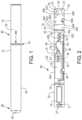
- FIG. 1is a side view of an electronic smoking article constructed according to the teachings herein.
- FIG. 2is a cross-sectional view of an electronic smoking article according to a first embodiment.
- FIG. 3is a cross-sectional view of another embodiment of an electronic smoking article according to a second embodiment.
- FIG. 4is a cross-sectional view of an electronic smoking article according to a third embodiment.
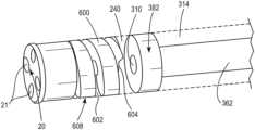
- FIG. 5is a partial, perspective view of an electronic smoking article including spiral path insert (SPI) and having a clear outer casing.
- SPIspiral path insert
- FIG. 6is a perspective view of a SPI as described herein.
- An electronic smoking articleincludes a reservoir containing a liquid aerosol formulation.
- the liquid aerosol formulationis delivered to a heater where the liquid aerosol formulation is heated, volatilized, and forms an aerosol.
- the term “electronic smoking article”is inclusive of all types of electronic smoking articles, regardless of form, size or shape, including electronic cigarettes, electronic cigars, electronic pipes, electronic hookahs and the like.
- the liquid aerosol formulationcan include nicotine or be nicotine free.
- the liquid aerosol formulationcan include tobacco flavors or instead, or in combination include other suitable flavors.
- the aerosolpasses through a spiral path insert (SPI) after formation and prior to passing through a mouth end insert so as to cool the aerosol by forcing the aerosol to travel along a longer path.
- SPIspiral path insert
- heat transfers from the aerosol to the SPIalso occurs to further reduce the temperature of the aerosol.
- the SPIalso increases the residence time of the aerosol within the electronic smoking article. The residence time can be adjusted (increased or decreased) by lengthening or shortening the spiral path or paths along a periphery of the SPI.
- an SPI 600is located downstream of a heater in an electronic smoking article 60 as shown in greater detail in FIGS. 2 , 3 , and 4 .
- the electronic smoking article 60comprises a replaceable cartridge (or first section) 70 and a reusable fixture (or second section) 72 , which are coupled together at a threaded joint 74 or by other convenience such as a snug-fit, snap-fit, detent, clamp and/or clasp.
- the electronic smoking articleis constructed from a single, unitary outer casing, in which case the threaded joint 74 is omitted.
- the first section 70can house a mouth-end insert 20 , a capillary aerosol generator including a capillary (capillary tube) 18 , a heater 19 to heat at least a portion of the capillary 18 , a reservoir 14 and optionally a valve 40 .
- the first section 70can house a mouth end insert 20 , a heater 319 , a flexible, filamentary wick 328 and a reservoir 314 as discussed in further detail below.
- the second section 72can house a power supply 12 (shown in FIGS. 2 , 3 and 4 ), control circuitry 11 , and optionally a puff sensor 16 (shown in FIGS. 3 and 4 ).
- the threaded portion 74 of the second section 72can be connected to a battery charger when not connected to the first section 70 for use so as to charge the battery.
- the electronic smoking article 60can also include a middle section (third section) 73 , which can house the reservoir 14 , heater 19 and valve 40 .
- the middle section 73can be adapted to be fitted with a threaded joint 74 ′ at an upstream end of the first section 70 and a threaded joint 74 at a downstream end of the second section 72 .
- the first section 70houses the mouth-end insert 20
- the second section 72houses the power supply 12 and control circuitry.
- the first section 70 , the second section 72 and the optional third section 73include an outer cylindrical housing 22 extending in a longitudinal direction along the length of the electronic smoking article 60 .
- the middle section 73is disposable and the first section 70 and/or second section 72 are reusable.
- the first section 70can also be replaceable so as to avoid the need for cleaning the capillary 18 and/or heater 19 .
- the sections 70 , 72 , 73can be attached by threaded connections whereby the middle section 73 can be replaced when the reservoir 14 is used up.
- the outer cylindrical housing 22can include a cutout or depression 102 which allows a smoker to manually apply pressure to the reservoir 14 .
- the outer cylindrical housing 22is flexible and/or compressible along the length thereof and fully or partially covers the reservoir 14 .
- the cutout or depression 102can extend partially about the circumference of the outer cylindrical housing 22 .
- the reservoir 14is compressible such that when pressure is applied to the, liquid is pumped from the reservoir 14 to the capillary 18 .
- a pressure activated switch 44can be positioned beneath the reservoir 14 . When pressure is applied to the reservoir 14 to pump liquid, the switch is also pressed and a heater 19 is activated.
- the heater 19can be a portion of the capillary 18 .
- the reservoir 14is a tubular, elongate body formed of an elastomeric material so as to be flexible and/or compressible when squeezed.
- the elastomeric materialcan be selected from the group consisting of silicone, plastic, rubber, latex, and combinations thereof.
- the compressible reservoir 14has an outlet 16 which is in fluid communication with a capillary 18 so that when squeezed, the reservoir 14 can deliver a volume of liquid material to the capillary 18 .
- the power supply 12is activated upon application of manual pressure to the pressure switch and the capillary 18 is heated to form a heated section wherein the liquid material is volatilized.
- the volatilized materialexpands, mixes with air and forms an aerosol.
- the reservoir 14extends longitudinally within the outer cylindrical housing 22 of the first section 70 (shown in FIGS. 3 and 4 ) or the middle section 73 (shown in FIG. 2 ). Moreover, the reservoir 14 comprises a liquid aerosol formulation which is volatilized when heated and forms an aerosol when discharged from the capillary 18 .
- the capillary 18includes an inlet end 62 in fluid communication with the outlet 16 of the reservoir 14 , and an outlet end 63 operable to expel volatilized liquid material from the capillary 18 .
- the reservoir 14may include a valve 40 .
- the valve 40can be a check valve that is operable to maintain the liquid material within the, but opens when the reservoir 14 is squeezed and pressure is applied.
- the check valve 40opens when a critical, minimum pressure is reached so as to avoid inadvertent dispensing of liquid material from the reservoir 14 or activating the heater 19 .
- the valve 40closes. The heated capillary 18 discharges liquid remaining downstream of the valve 40 .
- the valve 40can be a two-way valve and the reservoir 14 can be pressurized.
- the reservoir 14can be pressurized using a pressurization arrangement 405 which applies constant pressure to the reservoir 14 .
- pressurecan be applied to the reservoir 14 using an internal or external spring and plate arrangement which constantly applies pressure to the reservoir 14 .
- the reservoir 14can be compressible and positioned between two plates that are connected by springs or the reservoir 14 could be compressible and positioned between the outer housing and a plate that are connected by a spring so that the plate applies pressure to the reservoir 14 .
- the capillary 18 of FIGS. 2 and 3has an internal diameter of 0.01 to 10 mm, preferably 0.05 to 1 mm, and more preferably 0.05 to 0.4 mm.
- the capillary 18may have a length of about 5 mm to about 72 mm, more preferably about 10 mm to about 60 mm or about 20 mm to about 50 mm.
- the capillary 18is substantially straight.
- the capillary 18is coiled and/or includes one or more bends therein to conserve space and/or accommodate a long capillary.
- the capillary 18is formed of a conductive material, and thus acts as its own heater 19 by passing current through the capillary.
- the capillary 18may be any electrically conductive material capable of being resistively heated, while retaining the necessary structural integrity at the operating temperatures experienced by the capillary 18 , and which is non-reactive with the liquid material.
- Suitable materials for forming the capillary 18are selected from the group consisting of stainless steel, copper, copper alloys, porous ceramic materials coated with film resistive material, Inconel® available from Special Metals Corporation, which is a nickel-chromium alloy, nichrome, which is also a nickel-chromium alloy, and combinations thereof.
- the capillary 18may be a non-metallic tube such as, for example, a glass tube having a conductive material capable of being resistively heated, such as, for example, stainless steel, nichrome or platinum wire, arranged there along.
- a non-metallic tubesuch as, for example, a glass tube having a conductive material capable of being resistively heated, such as, for example, stainless steel, nichrome or platinum wire, arranged there along.
- At least two electrical leads 26are bonded to a metallic capillary 18 by brazing or crimping.
- one electrical lead 26is attached to a first, upstream portion 101 of the capillary 18 and a second electrical lead 26 is attached to a downstream, end portion 104 of the capillary 18 , as shown in FIGS. 2 and 3 .
- the capillary 18is heated and liquid material contained therein is volatilized.
- an electronic smoking article 60preferably comprises a heater 319 , a filamentary wick 328 , and an annular reservoir (liquid supply).
- the first section 70includes an outer tube (or casing) 22 extending in a longitudinal direction and an inner tube (or chimney) 362 coaxially positioned within the outer tube 322 .
- the SPI 600is positioned downstream of the inner tube 362 .
- a nose portion 361 of an upstream gasket (or seal) 320is fitted into an upstream end portion 365 of the inner tube 362 , while at the same time, an outer perimeter 367 of the gasket 320 provides a liquid-tight seal with an interior surface 397 of the outer casing 22 .
- the upstream gasket 320also includes a central, longitudinal air passage 315 , which opens into an interior of the inner tube 362 that defines a central channel 321 .
- a transverse channel 333 at an upstream portion of the gasket 320intersects and communicates with the central channel 315 of the gasket 320 .
- This channel 333assures communication between the central channel 315 and a space 335 defined between the gasket 320 and a threaded connection 74 .
- a nose portion 393 of a downstream gasket 310is fitted into a downstream end portion 381 of the inner tube 362 .
- An outer perimeter 382 of the gasket 310provides a substantially liquid-tight seal with an interior surface 397 of the outer casing 22 .
- the downstream gasket 310includes a central channel 384 disposed between the central passage 321 of the inner tube 362 and the mouth end insert 20 .
- the reservoir 314is contained in an annulus between an inner tube 362 and an outer casing 22 and between the upstream gasket 320 and the downstream gasket 310 .
- the reservoir 314at least partially surrounds the central air passage 321 .
- the reservoir 314comprises a liquid material and optionally a liquid storage medium (not shown) operable to store the liquid material therein.
- the inner tube 362has a central air passage 321 extending therethrough which houses the heater 319 .
- the heater 319is in contact with the filamentary wick 328 , which preferably extends between opposing sections of the reservoir 314 so as to deliver the liquid aerosol formulation from the reservoir to the heater 319 .
- the electronic smoking article 60 of each embodiment described hereinalso includes at least one air inlet 440 .
- the at least one air inlet 440can be located upstream of the heater 319 .
- the at least one air inlet 440is preferably arranged downstream of the capillary 18 so as to minimize drawing air along the capillary and thereby avoid cooling of the capillary 18 during heating cycles.
- the power supply 12 of each embodimentcan include a battery arranged in the electronic smoking article 60 .
- the power supply 12is operable to apply voltage across the heater 19 associated with the capillary 18 , as shown in FIGS. 2 and 3 , or the heater 319 associated with the filamentary wick 328 , as shown in FIG. 4 .
- the heater 19 , 319volatilizes liquid material according to a power cycle of either a predetermined time period, such as a 2 to 10 second period.
- the batterycan be a Lithium-ion battery or one of its variants, for example a Lithium-ion polymer battery.
- the batterymay be a Nickel-metal hydride battery, a Nickel cadmium battery, a Lithium-manganese battery, a Lithium-cobalt battery or a fuel cell.
- the electronic smoking article 60is usable by a smoker until the energy in the power supply is depleted.
- the power supply 12may be rechargeable and include circuitry allowing the battery to be chargeable by an external charging device.
- the control circuitry 11can be programmable and can include an application specific integrated circuit (ASIC). In other embodiments, the control circuitry 11 can include a microprocessor programmed to carry out functions such as heating the capillaries and/or operating the valves.
- ASICapplication specific integrated circuit
- the electronic smoking article 60 of each embodimentalso includes control circuitry which can be on a printed circuit board 11 (shown in FIGS. 2 , 3 and 4 ).
- the control circuitry 11can also include a heater activation light 27 that is operable to glow when the heater 19 , 319 is activated.
- the electronic smoking article 60includes a spiral path insert (SPI) 600 at a location downstream of the heater 19 , 319 .
- the SPI 600includes at least one channel 602 in an outer periphery 608 of an impermeable body 610 of the SPI 600 .
- the SPI 600remains in a fixed position within the electronic smoking article 60 during smoking.
- the channel 602has a spiral configuration.
- the channel 602has an inlet 604 at an upstream end 612 of the SPI 600 and an outlet 606 at a downstream end 614 of the SPI 600 .
- the channel 602includes at least two turns about the outer periphery 608 of the body 610 of the SPI 600 .
- the SPI 600can include two spiral channels (not shown) having inlets at diametrically opposite ends of the SPI 600 such that aerosol can enter the channels at two different locations and crisscross along the SPI 600 as the aerosol travels.
- the channel 602has a variable width and a variable depth along a length of the SPI 600 .
- the channel 602has a substantially uniform width and a substantially uniform depth along a length of the SPI 600 .
- the SPI 600is formed of an air impermeable material.
- the SPI 600is formed of at least one plastic selected from the group consisting of polyethylene, low density polyethylene, polyether ether ketone (PEEK) and combinations thereof.
- the SPI 600can be formed of stainless steel.
- the SPI 600has a length ranging from about 2 mm to about 30 mm. Moreover, the SPI 600 has an outer diameter that is about the same as an inner diameter of the outer housing 22 of the electronic smoking article 60 .
- the at least one channel 602has a width ranging from about 0.1 mm to about 2.0 mm and a depth ranging from about 0.01 mm to about 2.0 mm.
- the SPI 600is preferably air impermeable and the outer diameter of the SPI 600 is about the same as the inner diameter of the outer housing 22 , aerosol is only able to pass from the heater to the mouth end insert 20 via the channel 602 formed in the outer periphery 608 of the SPI 600 .
- the channel 602 of the SPI 600is designed such that the SPI 600 does not contribute any significant change to the overall resistance to draw (RTD) of the electronic smoking article 60 .
- the aerosolDuring smoking, as aerosol travels along the channel 602 , heat transfer occurs between the aerosol and the SPI 600 . Since the channel 602 has a spiral configuration about the outer periphery 608 of the SPI 600 , the aerosol must travel along a longer path as compared to aerosol travelling from a heater to a mouth end insert in an electronic smoking article lacking a SPI 600 . Accordingly, the aerosol has a longer residence time between formation and delivery to the smoker which results in additional cooling of the aerosol prior to reaching the smoker.
- the average temperature in degrees Celsius per puff over 11 puffs for an electronic cigarette as shown in FIG. 4 including the SPI 600 as compared to an electronic cigarette as shown in FIG. 4 , but lacking an SPI 600is shown in Table 1 below.
- the electronic smoking article 60 including the SPI 600has a significant temperature reduction for all puffs as compared to a similar electronic smoking article lacking an SPI 600 .
- the SPI 600can be formed of a plastic and have at least one additive extruded therewith.
- the SPI 600can include a coating along the channel 602 of the SPI 600 .
- the coatingincludes at least one additive selected from the group consisting of flavors, aerosol modifiers, aromatic materials, pH modifying agents, chemesthesis agents, and combinations thereof.
- the additiveis eluted into the aerosol as the aerosol passes along the channel 602 .
- the additivescan be microencapsulated with water soluble materials having varying levels of water solubility so as to provide controlled release of the additive over a period of time.
- the SPI 600can be extruded with additives and include the coating. By including an additive-containing coating along with the additives in the SPI 600 , release of the additives can be staggered during smoking and/or multiple additives can be delivered.
- additivemeans any material or component, which modifies the characteristics of the electronic smoking article 60 when the electronic smoking article 60 is smoked.
- Any appropriate additive material or combination of materialsmay be contained in or on the SPI 600 .
- Such additive materialsinclude flavor materials, aromatic materials, pH modifying agents, chemesthesis agents including cooling agents and warming agents, carbon dioxide formers, commercially available flavor systems, nicotine in liquid, salt or powder form, and other smoke modifiers.
- flavor materialmeans any liquid or solid flavor containing material or formulation that can release flavors and/or aromas into the aerosol stream.
- suitable flavors or flavoringsinclude, but are not limited to, menthol, mint, such as peppermint and spearmint, chocolate, licorice, citrus and other fruit flavors, gamma octalactone, vanillin, ethyl vanillin, breath freshener flavors, spice flavors such as cinnamon, methyl salicylate, linalool, bergamot oil, geranium oil, lemon oil, ginger oil, and tobacco flavor.
- Other suitable flavorsmay include flavor compounds selected from the group consisting of an acid, an alcohol, an ester, an aldehyde, a ketone, a pyrazine, combinations or blends thereof and the like.
- the flavor materialcan be in the form of particles, granules, fibers, capsules, microcapsules, powders, crushed plant material, aromatic barks, seeds, pieces of dried fruits and/or root material, or any other suitable form.
- the flavor materialcan include tobacco beads, flavor beads, mentholated flavor beads, flavor capsules and other flavor materials as used in traditional tobacco smoke filters.
- Suitable flavor materialscan be non-volatile or volatile and can be delivered to the mouth via the condensation of the aerosol in the filter followed by entrapment and/or dissolution of the flavor material in droplets and/or deposition of the droplets to the tongue of the smoker during a puff.
- the dropletscan consist of constituents used to form the aerosol including propylene glycol, glycerin, water and optionally nicotine.
- the flavor materialcan be released into the aerosol.
- the flavor materialscan provide a bitter taste.
- Suitable compounds which provide a bitter tasteinclude, without limitation, caffeine, denatonium benzoate, theobromine, quinine, and naringin.
- the flavor materialscan provide a sour taste.
- Suitable compounds which provide a sour tasteinclude, without limitation, citric acid, malic acid, succinic acid and tartaric acid. While not wishing to be bound by theory, the addition of an acid may also act to lower the pH of the aerosol and reduce harshness of the aerosol.
- the flavor materialscan provide a salty taste.
- Suitable compounds which provide a salty tasteinclude, without limitation, sodium chloride and potassium chloride.
- the flavor materialscan provide a sweet taste.
- Suitable compounds which provide a sweet tasteinclude, without limitation, carbohydrates, including sucrose, and high intensity sweeteners, including sucralose and saccharin.
- the flavor materialscan provide umami and mouth feel.
- Suitable compounds which provide umami and mouth feelinclude, without limitation, monosodium glutamate, gamma-glutamyl peptides, such as gamma-glutamycysteine-beta-alanine, (R)-strombine.
- the additivecan be a chemesthesis agent and/or can be chosen to alter the mouthfeel of the aerosol.
- the additivecan be a chemesthesis agent that provides a warm, tingling sensation and/or a cooling sensation.
- Additivessuch as capsaicin, piperine, alpha-hydroxy-sanshool, and (8)-gingerole can be included to provide a warm, tingling or burning sensation.
- Additivesincluding menthol, menthyl lactate, WS-3 (N-Ethyl-p-menthane-3-carboxamide), WS-23 (2-Isopropyl-N,2,3-trimethylbutyramide) and Evercool 180TM (available from Givaudan SA) can be included to provide a cooling sensation.
- the additivecan include extracts, such as coffee extract, red pepper extract, ginger extract and peppermint oil.
- the SPI 600is located downstream of the heater 19 , 319 so that minimum heat exposure is experienced by the additives.
- the SPI 600is located so that the SPI 600 and/or additives contained therein are not exposed to temperatures above about 150° C.
- the SPI 600is located downstream of the inner tube 362 .
- the electronic smoking article 60includes a mixing chamber 240 that the aerosol must pass through before reaching the SPI 600 .
- the electronic smoking article 60can further include the mouth-end insert 20 having at least two off-axis, preferably diverging outlets 21 .
- the mouth-end insertis located downstream of the tubular filter segment 600 .
- the tubular filter segment 600can be downstream of the mouth-end insert 20 .
- the mouth-end insert 20includes at least two diverging outlets 21 . (e.g, 3, 4, 5, or preferably 6 to 8 outlets or more).
- the outlets 21 of the mouth-end insert 20are located at ends of off-axis passages 23 and are angled outwardly in relation to the longitudinal direction of the electronic smoking article 60 (i.e., divergently).
- the term “off-axis”denotes at an angle to the longitudinal direction of the electronic smoking article.
- the electronic smoking article 60is about the same size as a conventional smoking article.
- the electronic smoking article 60can be about 80 mm to about 110 mm long, preferably about 80 mm to about 100 mm long and about 7 mm to about 8 mm in diameter.
- the electronic smoking articleis about 84 mm long and has a diameter of about 7.8 mm.
- the outer cylindrical housing 22 of the electronic smoking article 60may be formed of any suitable material or combination of materials.
- the outer cylindrical housing 22is formed of metal and is part of the electrical circuit.
- the liquid aerosol formulation for use in each of the electronic smoking articles 60 described hereinincludes at least one aerosol former, water, and flavors.
- the at least one aerosol formeris selected from the group consisting of propylene glycol, glycerin and combinations thereof.
- the at least one aerosol formeris included in an amount ranging from about 40% by weight based on the weight of the liquid formulation to about 90% by weight based on the weight of the liquid formulation (e.g., about 50% to about 80%, about 55% to about 75% or about 60% to about 70%).
- the liquid formulationalso includes water.
- Watercan be included in an amount ranging from about 5% by weight based on the weight of the liquid formulation to about 20% by weight based on the weight of the liquid formulation, more preferably in an amount ranging from about 10% by weight based on the weight of the liquid formulation to about 15% by weight based on the weight of the liquid formulation.
- the liquid aerosol formulationoptionally includes at least one flavorant in an amount ranging from about 0.2% to about 15% by weight (e.g., about 1% to about 12%, about 2% to about 10%, or about 5% to about 8%).
- the at least one flavorantcan be a natural flavorant or an artificial flavorant.
- the at least one flavorantis selected from the group consisting of tobacco flavor, menthol, wintergreen, peppermint, herb flavors, fruit flavors, nut flavors, liquor flavors, and combinations thereof.
- the words “generally” and “substantially”are used in connection with geometric shapes, it is intended that precision of the geometric shape is not required but that latitude for the shape is within the scope of the disclosure.
- the words “generally” and “substantially”are intended to encompass not only features which meet the strict definitions but also features which fairly approximate the strict definitions.
- the inner and outer tubular structures of the embodiments described hereinare preferably cylindrical, they can be instead square, rectangular, triangular, or oval in cross-section, or some other form.
Landscapes
- Health & Medical Sciences (AREA)
- Engineering & Computer Science (AREA)
- Life Sciences & Earth Sciences (AREA)
- Animal Behavior & Ethology (AREA)
- Anesthesiology (AREA)
- Biomedical Technology (AREA)
- Heart & Thoracic Surgery (AREA)
- Hematology (AREA)
- Veterinary Medicine (AREA)
- Public Health (AREA)
- General Health & Medical Sciences (AREA)
- Pulmonology (AREA)
- Bioinformatics & Cheminformatics (AREA)
- Catching Or Destruction (AREA)
- Containers And Packaging Bodies Having A Special Means To Remove Contents (AREA)
- Cigarettes, Filters, And Manufacturing Of Filters (AREA)
Abstract
Description
| TABLE 1 | ||||||||||||||
| Puff | Puff | Std. | ||||||||||||
| Puff 1 | Puff 2 | Puff 3 | Puff 4 | Puff 5 | Puff 6 | Puff 7 | Puff 8 | Puff 9 | 10 | 11 | Average | Dev. | ||
| Cartomizer | 58.1 | 58.4 | 57.2 | 57.2 | 55.9 | 57.4 | 58.7 | 59.7 | 58.4 | 58.2 | 59.1 | 58.0 | 1.0 |
| without | |||||||||||||
| SPI | |||||||||||||
| Cartomizer | 33.8 | 36.1 | 36.9 | 38.4 | 39.0 | 39.2 | 40.0 | 40.0 | 40.4 | 39.8 | 40.2 | 38.5 | 2.1 |
| with SPI | |||||||||||||
Claims (21)
Priority Applications (1)
| Application Number | Priority Date | Filing Date | Title |
|---|---|---|---|
| US14/332,785US12290631B2 (en) | 2013-07-19 | 2014-07-16 | Electronic smoking article |
Applications Claiming Priority (2)
| Application Number | Priority Date | Filing Date | Title |
|---|---|---|---|
| US201361856280P | 2013-07-19 | 2013-07-19 | |
| US14/332,785US12290631B2 (en) | 2013-07-19 | 2014-07-16 | Electronic smoking article |
Publications (2)
| Publication Number | Publication Date |
|---|---|
| US20150020822A1 US20150020822A1 (en) | 2015-01-22 |
| US12290631B2true US12290631B2 (en) | 2025-05-06 |
Family
ID=51263558
Family Applications (1)
| Application Number | Title | Priority Date | Filing Date |
|---|---|---|---|
| US14/332,785Active2037-05-28US12290631B2 (en) | 2013-07-19 | 2014-07-16 | Electronic smoking article |
Country Status (3)
| Country | Link |
|---|---|
| US (1) | US12290631B2 (en) |
| AR (1) | AR096974A1 (en) |
| WO (1) | WO2015009863A1 (en) |
Families Citing this family (72)
| Publication number | Priority date | Publication date | Assignee | Title |
|---|---|---|---|---|
| US20160345631A1 (en) | 2005-07-19 | 2016-12-01 | James Monsees | Portable devices for generating an inhalable vapor |
| US10279934B2 (en) | 2013-03-15 | 2019-05-07 | Juul Labs, Inc. | Fillable vaporizer cartridge and method of filling |
| US10039321B2 (en) | 2013-11-12 | 2018-08-07 | Vmr Products Llc | Vaporizer |
| US10058129B2 (en) | 2013-12-23 | 2018-08-28 | Juul Labs, Inc. | Vaporization device systems and methods |
| DE202014011260U1 (en) | 2013-12-23 | 2018-11-13 | Juul Labs Uk Holdco Limited | Systems for an evaporation device |
| US10159282B2 (en) | 2013-12-23 | 2018-12-25 | Juul Labs, Inc. | Cartridge for use with a vaporizer device |
| USD825102S1 (en) | 2016-07-28 | 2018-08-07 | Juul Labs, Inc. | Vaporizer device with cartridge |
| US10076139B2 (en) | 2013-12-23 | 2018-09-18 | Juul Labs, Inc. | Vaporizer apparatus |
| USD842536S1 (en) | 2016-07-28 | 2019-03-05 | Juul Labs, Inc. | Vaporizer cartridge |
| US20160366947A1 (en) | 2013-12-23 | 2016-12-22 | James Monsees | Vaporizer apparatus |
| WO2015196423A1 (en)* | 2014-06-26 | 2015-12-30 | 深圳市康尔科技有限公司 | Squeezable electronic cigarette |
| EP3560364B1 (en) | 2014-10-29 | 2024-12-04 | Altria Client Services LLC | Apparatus with a body of pre-vapour formulation |
| WO2016069903A1 (en) | 2014-10-29 | 2016-05-06 | Altria Client Services Llc | E-vaping cartridge |
| MX394125B (en) | 2014-12-05 | 2025-03-24 | Juul Labs Inc | CALIBRATED DOSE CONTROL |
| USD754919S1 (en) | 2014-12-19 | 2016-04-26 | Fontem Holdings 4 B.V. | Mouthpiece |
| JP6691547B2 (en)* | 2015-02-05 | 2020-04-28 | トルキーノ,ジョルジョ | A fluid heating device characterized by high energy saving and provided with a microfiltration device for removing lime particles remaining in a fluid and a nozzle or a closed circuit |
| US20210172650A1 (en)* | 2015-02-05 | 2021-06-10 | Giorgio TORCHIO | Capillary Proximity Heater |
| USD861241S1 (en) | 2015-02-18 | 2019-09-24 | Tyger Manufacturing Llc | Smoking device |
| USD860521S1 (en) | 2015-02-18 | 2019-09-17 | Tyger Manufacturing Llc | Smoking device |
| US9968127B2 (en)* | 2015-02-18 | 2018-05-15 | Tyger Manufacturing Llc | Smoking device |
| USD861242S1 (en) | 2015-02-18 | 2019-09-24 | Tyger Manufacturing Llc | Smoking device |
| CN104770878B (en)* | 2015-03-23 | 2017-11-24 | 云南中烟工业有限责任公司 | A kind of electric heating type cigarette smoking device with electronic cigarette pumping function |
| US20160345621A1 (en)* | 2015-06-01 | 2016-12-01 | San Li | Pre-vapor formulation of an electronic vaping device and/or methods of manufacturing the same |
| US10314338B2 (en) | 2015-06-25 | 2019-06-11 | Altria Client Services Llc | Electronic vaping device |
| MX2018001418A (en)* | 2015-08-07 | 2018-04-13 | Philip Morris Products Sa | An aerosol-generating system with enhanced airflow management. |
| CN204949520U (en)* | 2015-08-14 | 2016-01-13 | 深圳威铂利科技有限公司 | Novel electronic cigarette |
| EP4248777B1 (en)* | 2015-08-28 | 2025-09-24 | Fontem Ventures B.V. | Electronic smoking device |
| ES2703233T3 (en) | 2015-08-28 | 2019-03-07 | Fontem Holdings 1 Bv | Liquid reservoir with two storage volumes and atomizer / liquid reservoir portion as well as electronic smoking device with liquid reservoir |
| CA2998538A1 (en)* | 2015-09-16 | 2017-03-23 | Alexandra DILLMANN | A method and a dispensing arrangement for treating a flow of vaporized liquid provided by an e-cigarette and an e-cigarette for the oral intake of vaporized liquid containing an additional composition |
| EP3162228B1 (en)* | 2015-10-28 | 2020-10-28 | Fontem Holdings 1 B.V. | Electronic smoking device |
| GB201522368D0 (en)* | 2015-12-18 | 2016-02-03 | Jt Int Sa | An aerosol generating device |
| WO2017108268A1 (en)* | 2015-12-22 | 2017-06-29 | Philip Morris Products S.A. | An electrically operated aerosol-generating system with a liquid pump |
| US10412996B2 (en) | 2015-12-22 | 2019-09-17 | Altria Client Services Llc | Cartridge for pump-operated aerosol-generating system |
| US10194694B2 (en)* | 2016-01-05 | 2019-02-05 | Rai Strategic Holdings, Inc. | Aerosol delivery device with improved fluid transport |
| CO2018009342A2 (en) | 2016-02-11 | 2018-09-20 | Juul Labs Inc | Secure fixing cartridges for vaporizing devices |
| EP3413960B1 (en) | 2016-02-11 | 2021-03-31 | Juul Labs, Inc. | Fillable vaporizer cartridge and method of filling |
| US10405582B2 (en) | 2016-03-10 | 2019-09-10 | Pax Labs, Inc. | Vaporization device with lip sensing |
| US20170280769A1 (en)* | 2016-04-04 | 2017-10-05 | Altria Client Services Llc | Electronic vaping device and kit |
| EP3445188A4 (en)* | 2016-04-22 | 2020-03-25 | Resolve Digital Health Inc. | An inhalation device, system and method |
| EP3445189A4 (en)* | 2016-04-22 | 2020-03-11 | Resolve Digital Health Inc. | An inhalation device, system and method |
| USD849996S1 (en) | 2016-06-16 | 2019-05-28 | Pax Labs, Inc. | Vaporizer cartridge |
| USD836541S1 (en) | 2016-06-23 | 2018-12-25 | Pax Labs, Inc. | Charging device |
| USD848057S1 (en) | 2016-06-23 | 2019-05-07 | Pax Labs, Inc. | Lid for a vaporizer |
| USD851830S1 (en) | 2016-06-23 | 2019-06-18 | Pax Labs, Inc. | Combined vaporizer tamp and pick tool |
| US10212964B2 (en) | 2016-07-07 | 2019-02-26 | Altria Client Services | Additive assembly for electronic vaping device |
| EP3272236B1 (en)* | 2016-07-22 | 2021-06-16 | Fontem Holdings 1 B.V. | Electronic smoking device |
| US11129413B2 (en) | 2017-03-13 | 2021-09-28 | Altria Client Services Llc | Three-piece electronic vaping device with planar heater |
| US11478590B2 (en)* | 2017-07-21 | 2022-10-25 | Philip Morris Products S.A. | Aerosol generating device with spiral movement for heating |
| TWI650962B (en)* | 2017-08-04 | 2019-02-11 | 財團法人工業技術研究院 | Optical communication system and method thereof, transmission device, and receiving device |
| USD887632S1 (en) | 2017-09-14 | 2020-06-16 | Pax Labs, Inc. | Vaporizer cartridge |
| EP3713627A4 (en) | 2017-11-22 | 2021-10-20 | Juul Labs, Inc. | USER INTERFACE AND USER EXPERIENCE FOR AN EVAPORATOR DEVICE |
| UA129246C2 (en) | 2017-12-21 | 2025-02-26 | Джуул Лебз, Інк. | EVAPORATOR CONTROLS |
| KR102653111B1 (en)* | 2018-01-05 | 2024-04-01 | 필립모리스 프로덕츠 에스.에이. | Cartridges and E-vaping devices |
| WO2019159123A1 (en)* | 2018-02-19 | 2019-08-22 | Philip Morris Products S.A. | Dry powder inhaler |
| AU2019295713B2 (en)* | 2018-06-26 | 2024-06-13 | Juul Labs, Inc. | Devices and methods for cessation of nicotine addiction |
| DE102018127926A1 (en)* | 2018-07-09 | 2020-01-09 | Hauni Maschinenbau Gmbh | Vaporizer head for an inhaler, especially for an electronic cigarette product |
| CN119632302A (en) | 2018-07-31 | 2025-03-18 | 尤尔实验室有限公司 | Cartridge-based heat-without-burn vaporizer |
| GB2576710B (en)* | 2018-08-23 | 2022-06-22 | All Vape Ltd | A pod |
| KR20250048483A (en) | 2018-10-08 | 2025-04-08 | 쥴 랩스, 인크. | Heating element |
| ES2932748T3 (en) | 2018-11-05 | 2023-01-25 | Juul Labs Inc | Cartridges for vaporizer devices |
| WO2020141113A1 (en)* | 2019-01-04 | 2020-07-09 | Nicoventures Trading Limited | Aerosol generation |
| CN109691697B (en)* | 2019-03-01 | 2021-07-30 | 南通醋酸纤维有限公司 | Aerosol generating product, preparation method and application |
| US11395512B2 (en)* | 2019-05-13 | 2022-07-26 | Simrell Collection, Llc | Vaporizer cooling system with a mixing chamber |
| EP3930495B1 (en) | 2019-09-20 | 2024-10-30 | Imperial Tobacco Limited | Smoking substitute apparatus |
| EP3794978A1 (en)* | 2019-09-20 | 2021-03-24 | Nerudia Limited | Smoking substitute apparatus |
| EP4033926B1 (en)* | 2019-09-26 | 2023-06-28 | Philip Morris Products S.A. | Inhaler article with a twisted distal end element |
| EP3799742A1 (en)* | 2019-10-02 | 2021-04-07 | Nerudia Limited | Smoking substitute component |
| CN111772240B (en)* | 2020-06-15 | 2024-12-17 | 深圳麦克韦尔科技有限公司 | Atomizer and liquid storage assembly and electronic atomizing device thereof |
| KR20220048669A (en)* | 2020-10-13 | 2022-04-20 | 주식회사 케이티앤지 | Heater assembly and aerosol generating device including the same |
| KR102537975B1 (en)* | 2020-11-10 | 2023-05-30 | 주식회사 케이티앤지 | Aerosol generating articles |
| CN112890296A (en)* | 2021-03-13 | 2021-06-04 | 深圳御烟实业有限公司 | Deformable aerosol-generating article |
| CN113693266A (en)* | 2021-08-31 | 2021-11-26 | 深圳市真味生物科技有限公司 | Combined type cigarette bullet and production process thereof |
Citations (33)
| Publication number | Priority date | Publication date | Assignee | Title |
|---|---|---|---|---|
| US4135523A (en) | 1976-03-17 | 1979-01-23 | British-American Tobacco Company Limited | Tobacco-smoke filters |
| US4945929A (en) | 1986-06-18 | 1990-08-07 | British-American Tobacco Co., Ltd. | Aerosol device simulating a smoking article |
| US5309900A (en)* | 1991-03-21 | 1994-05-10 | Paul Ritzau Pari-Werk Gmbh | Atomizer particularly for use in devices for inhalation therapy |
| US5591334A (en)* | 1993-10-19 | 1997-01-07 | Geochto Ltd. | Apparatus for generating negative ions |
| US5630409A (en)* | 1995-03-22 | 1997-05-20 | Bono; Michael | Nebulizer and inhalation device containing same |
| WO1998008436A1 (en) | 1996-08-30 | 1998-03-05 | Plasto S.A. | Removable hygienic mouthpiece |
| WO1998023171A1 (en) | 1996-11-25 | 1998-06-04 | Philip Morris Products Inc. | Method and apparatus for using, cleaning, and maintaining electrical heat sources and lighters useful in smoking systems and other apparatuses |
| US5924417A (en) | 1992-02-21 | 1999-07-20 | Innovata Biomed Limited | Metering device for use in transferring a desired volumetric dose of a flowable substance from a storage container |
| US20050045198A1 (en) | 2003-08-28 | 2005-03-03 | Philip Morris Usa, Inc. | Electrically heated cigarette smoking system lighter cartridge dryer |
| US20070062548A1 (en)* | 2003-12-05 | 2007-03-22 | Lts Lohmann Therapie-Systeme Ag | Inhaler for basic pharmaceutical agents and method for the production thereof |
| US20070267032A1 (en) | 2003-11-18 | 2007-11-22 | Yansong Shan | Healthy Pleasurable Inhalation Device |
| US7845359B2 (en) | 2007-03-22 | 2010-12-07 | Pierre Denain | Artificial smoke cigarette |
| US7878963B2 (en)* | 2006-03-28 | 2011-02-01 | Philip Morris Usa Inc. | Smoking article with a restrictor |
| US20110094523A1 (en)* | 2009-10-27 | 2011-04-28 | Philip Morris Usa Inc. | Smoking system having a liquid storage portion |
| KR200454110Y1 (en) | 2011-03-24 | 2011-06-15 | 윤성훈 | Electronic cigarette |
| US20110290267A1 (en)* | 2009-02-23 | 2011-12-01 | Manabu Yamada | Non-heating flavor inhaler |
| WO2012026963A2 (en)* | 2010-08-23 | 2012-03-01 | Darren Rubin | Systems and methods of aerosol delivery with airflow regulation |
| US20120144556A1 (en)* | 2010-10-18 | 2012-06-14 | William Fiebel | Mask or other device having adjustable scent carrier |
| US20120318882A1 (en)* | 2011-06-16 | 2012-12-20 | Vapor Corp. | Vapor delivery devices |
| US20130056012A1 (en)* | 2010-03-03 | 2013-03-07 | Alex Hearn | Simulated cigarette |
| US20130074842A1 (en) | 2011-06-07 | 2013-03-28 | Richard C. Boucher | Methods of treatment |
| EP2599514A1 (en)* | 2011-12-01 | 2013-06-05 | Stobi GmbH & Co. KG | Hot air extraction inhaler with inhalation cooling line |
| US20130142868A1 (en)* | 2010-08-20 | 2013-06-06 | University Of Washington | Circumferential Aerosol Device for Delivering Drugs to Olfactory Epithelium and Brain |
| US20130192615A1 (en)* | 2012-01-31 | 2013-08-01 | Altria Client Services Inc. | Electronic cigarette |
| US20140261492A1 (en) | 2013-03-15 | 2014-09-18 | Altria Client Services Inc. | Electronic smoking article |
| US20140283824A1 (en)* | 2010-12-17 | 2014-09-25 | Vaporfection International Inc. | Portable hand-held vaporizer heating assembly |
| US8869792B1 (en)* | 2010-07-22 | 2014-10-28 | Chung Ju Lee | Portable vaporizer |
| US20150027477A1 (en)* | 2012-02-16 | 2015-01-29 | Kamata Co., Ltd. | Filter containing built-in capsule, cigarette provided with filter and cigarette substitute provided with filter |
| US20150181928A1 (en)* | 2013-04-15 | 2015-07-02 | Kimree Hi-Tech Inc. | Electronic cigarette and mouthpiece cover thereof |
| US20150305406A1 (en)* | 2014-04-28 | 2015-10-29 | Shenzhen First Union Technology Co., Ltd. | Atomizer and electronic cigarette having same |
| US20160007648A1 (en)* | 2013-02-27 | 2016-01-14 | British American Tobacco (Investments) Limited | An inhalation device and component for an inhalation device |
| US20170164653A1 (en)* | 2015-12-15 | 2017-06-15 | Smiss Technology Co., Ltd. | Airflow preheating device |
| US20170368273A1 (en)* | 2010-08-23 | 2017-12-28 | Darren Rubin | Systems and methods of aerosol delivery with airflow regulation |
- 2014
- 2014-07-16USUS14/332,785patent/US12290631B2/enactiveActive
- 2014-07-16WOPCT/US2014/046904patent/WO2015009863A1/enactiveApplication Filing
- 2014-07-18ARARP140102672Apatent/AR096974A1/enunknown
Patent Citations (34)
| Publication number | Priority date | Publication date | Assignee | Title |
|---|---|---|---|---|
| US4135523A (en) | 1976-03-17 | 1979-01-23 | British-American Tobacco Company Limited | Tobacco-smoke filters |
| US4945929A (en) | 1986-06-18 | 1990-08-07 | British-American Tobacco Co., Ltd. | Aerosol device simulating a smoking article |
| US5309900A (en)* | 1991-03-21 | 1994-05-10 | Paul Ritzau Pari-Werk Gmbh | Atomizer particularly for use in devices for inhalation therapy |
| US5924417A (en) | 1992-02-21 | 1999-07-20 | Innovata Biomed Limited | Metering device for use in transferring a desired volumetric dose of a flowable substance from a storage container |
| US5591334A (en)* | 1993-10-19 | 1997-01-07 | Geochto Ltd. | Apparatus for generating negative ions |
| US5630409A (en)* | 1995-03-22 | 1997-05-20 | Bono; Michael | Nebulizer and inhalation device containing same |
| WO1998008436A1 (en) | 1996-08-30 | 1998-03-05 | Plasto S.A. | Removable hygienic mouthpiece |
| WO1998023171A1 (en) | 1996-11-25 | 1998-06-04 | Philip Morris Products Inc. | Method and apparatus for using, cleaning, and maintaining electrical heat sources and lighters useful in smoking systems and other apparatuses |
| US20050045198A1 (en) | 2003-08-28 | 2005-03-03 | Philip Morris Usa, Inc. | Electrically heated cigarette smoking system lighter cartridge dryer |
| US20070267032A1 (en) | 2003-11-18 | 2007-11-22 | Yansong Shan | Healthy Pleasurable Inhalation Device |
| US20070062548A1 (en)* | 2003-12-05 | 2007-03-22 | Lts Lohmann Therapie-Systeme Ag | Inhaler for basic pharmaceutical agents and method for the production thereof |
| US7878963B2 (en)* | 2006-03-28 | 2011-02-01 | Philip Morris Usa Inc. | Smoking article with a restrictor |
| US7845359B2 (en) | 2007-03-22 | 2010-12-07 | Pierre Denain | Artificial smoke cigarette |
| US8127772B2 (en) | 2007-03-22 | 2012-03-06 | Pierre Denain | Nebulizer method |
| US20110290267A1 (en)* | 2009-02-23 | 2011-12-01 | Manabu Yamada | Non-heating flavor inhaler |
| US20110094523A1 (en)* | 2009-10-27 | 2011-04-28 | Philip Morris Usa Inc. | Smoking system having a liquid storage portion |
| US20130056012A1 (en)* | 2010-03-03 | 2013-03-07 | Alex Hearn | Simulated cigarette |
| US8869792B1 (en)* | 2010-07-22 | 2014-10-28 | Chung Ju Lee | Portable vaporizer |
| US20130142868A1 (en)* | 2010-08-20 | 2013-06-06 | University Of Washington | Circumferential Aerosol Device for Delivering Drugs to Olfactory Epithelium and Brain |
| WO2012026963A2 (en)* | 2010-08-23 | 2012-03-01 | Darren Rubin | Systems and methods of aerosol delivery with airflow regulation |
| US20170368273A1 (en)* | 2010-08-23 | 2017-12-28 | Darren Rubin | Systems and methods of aerosol delivery with airflow regulation |
| US20120144556A1 (en)* | 2010-10-18 | 2012-06-14 | William Fiebel | Mask or other device having adjustable scent carrier |
| US20140283824A1 (en)* | 2010-12-17 | 2014-09-25 | Vaporfection International Inc. | Portable hand-held vaporizer heating assembly |
| KR200454110Y1 (en) | 2011-03-24 | 2011-06-15 | 윤성훈 | Electronic cigarette |
| US20130074842A1 (en) | 2011-06-07 | 2013-03-28 | Richard C. Boucher | Methods of treatment |
| US20120318882A1 (en)* | 2011-06-16 | 2012-12-20 | Vapor Corp. | Vapor delivery devices |
| EP2599514A1 (en)* | 2011-12-01 | 2013-06-05 | Stobi GmbH & Co. KG | Hot air extraction inhaler with inhalation cooling line |
| US20130192615A1 (en)* | 2012-01-31 | 2013-08-01 | Altria Client Services Inc. | Electronic cigarette |
| US20150027477A1 (en)* | 2012-02-16 | 2015-01-29 | Kamata Co., Ltd. | Filter containing built-in capsule, cigarette provided with filter and cigarette substitute provided with filter |
| US20160007648A1 (en)* | 2013-02-27 | 2016-01-14 | British American Tobacco (Investments) Limited | An inhalation device and component for an inhalation device |
| US20140261492A1 (en) | 2013-03-15 | 2014-09-18 | Altria Client Services Inc. | Electronic smoking article |
| US20150181928A1 (en)* | 2013-04-15 | 2015-07-02 | Kimree Hi-Tech Inc. | Electronic cigarette and mouthpiece cover thereof |
| US20150305406A1 (en)* | 2014-04-28 | 2015-10-29 | Shenzhen First Union Technology Co., Ltd. | Atomizer and electronic cigarette having same |
| US20170164653A1 (en)* | 2015-12-15 | 2017-06-15 | Smiss Technology Co., Ltd. | Airflow preheating device |
Non-Patent Citations (2)
| Title |
|---|
| International Search Report and Written Opinion dated Nov. 26, 2014. |
| Storz, Markus, "Machine translation of EP 2599514," Translated Jul. 1, 2021, Espacenet.com. (Year: 2021).* |
Also Published As
| Publication number | Publication date |
|---|---|
| US20150020822A1 (en) | 2015-01-22 |
| AR096974A1 (en) | 2016-02-10 |
| WO2015009863A1 (en) | 2015-01-22 |
Similar Documents
| Publication | Publication Date | Title |
|---|---|---|
| US11974602B2 (en) | Electronic smoking article | |
| US12290631B2 (en) | Electronic smoking article | |
| US20150027468A1 (en) | Electronic smoking article | |
| US12193472B2 (en) | Liquid aerosol formulation of an electronic smoking article | |
| US12011534B2 (en) | Electronic smoking article | |
| JP7494257B2 (en) | Flavoured tip or mouth end insert for e-vaping or smokable device and method of manufacture thereof | |
| JP2025134833A (en) | electronic cigarette | |
| CN112367864A (en) | Cigarette with improved smoke exhaust |
Legal Events
| Date | Code | Title | Description |
|---|---|---|---|
| AS | Assignment | Owner name:ALTRIA CLIENT SERVICES INC., VIRGINIA Free format text:ASSIGNMENT OF ASSIGNORS INTEREST;ASSIGNORS:JANARDHAN, SRINIVASAN;KARLES, GEORGIOS D.;PITHAWALLA, YEZDI B.;AND OTHERS;SIGNING DATES FROM 20140722 TO 20140915;REEL/FRAME:033746/0953 | |
| AS | Assignment | Owner name:ALTRIA CLIENT SERVICES LLC, VIRGINIA Free format text:MERGER AND CHANGE OF NAME;ASSIGNORS:ALTRIA CLIENT SERVICES INC.;ALTRIA CLIENT SERVICES LLC;REEL/FRAME:036415/0657 Effective date:20150623 | |
| STPP | Information on status: patent application and granting procedure in general | Free format text:NON FINAL ACTION MAILED | |
| STPP | Information on status: patent application and granting procedure in general | Free format text:RESPONSE TO NON-FINAL OFFICE ACTION ENTERED AND FORWARDED TO EXAMINER | |
| STPP | Information on status: patent application and granting procedure in general | Free format text:FINAL REJECTION MAILED | |
| STPP | Information on status: patent application and granting procedure in general | Free format text:DOCKETED NEW CASE - READY FOR EXAMINATION | |
| STPP | Information on status: patent application and granting procedure in general | Free format text:FINAL REJECTION MAILED | |
| STPP | Information on status: patent application and granting procedure in general | Free format text:RESPONSE AFTER FINAL ACTION FORWARDED TO EXAMINER | |
| STPP | Information on status: patent application and granting procedure in general | Free format text:ADVISORY ACTION MAILED | |
| STPP | Information on status: patent application and granting procedure in general | Free format text:DOCKETED NEW CASE - READY FOR EXAMINATION | |
| STPP | Information on status: patent application and granting procedure in general | Free format text:NON FINAL ACTION MAILED | |
| STPP | Information on status: patent application and granting procedure in general | Free format text:RESPONSE TO NON-FINAL OFFICE ACTION ENTERED AND FORWARDED TO EXAMINER | |
| STPP | Information on status: patent application and granting procedure in general | Free format text:FINAL REJECTION MAILED | |
| STPP | Information on status: patent application and granting procedure in general | Free format text:ADVISORY ACTION MAILED | |
| STPP | Information on status: patent application and granting procedure in general | Free format text:DOCKETED NEW CASE - READY FOR EXAMINATION | |
| STPP | Information on status: patent application and granting procedure in general | Free format text:NON FINAL ACTION MAILED | |
| STPP | Information on status: patent application and granting procedure in general | Free format text:RESPONSE TO NON-FINAL OFFICE ACTION ENTERED AND FORWARDED TO EXAMINER | |
| STPP | Information on status: patent application and granting procedure in general | Free format text:FINAL REJECTION MAILED | |
| STPP | Information on status: patent application and granting procedure in general | Free format text:RESPONSE AFTER FINAL ACTION FORWARDED TO EXAMINER | |
| STPP | Information on status: patent application and granting procedure in general | Free format text:ADVISORY ACTION MAILED | |
| STCV | Information on status: appeal procedure | Free format text:NOTICE OF APPEAL FILED | |
| STCV | Information on status: appeal procedure | Free format text:APPEAL BRIEF (OR SUPPLEMENTAL BRIEF) ENTERED AND FORWARDED TO EXAMINER | |
| ZAAB | Notice of allowance mailed | Free format text:ORIGINAL CODE: MN/=. | |
| STPP | Information on status: patent application and granting procedure in general | Free format text:AWAITING TC RESP., ISSUE FEE NOT PAID | |
| STPP | Information on status: patent application and granting procedure in general | Free format text:NOTICE OF ALLOWANCE MAILED -- APPLICATION RECEIVED IN OFFICE OF PUBLICATIONS | |
| STCF | Information on status: patent grant | Free format text:PATENTED CASE |