US12290363B2 - Fluid control devices and methods of using the same - Google Patents
Fluid control devices and methods of using the sameDownload PDFInfo
- Publication number
- US12290363B2 US12290363B2US17/390,249US202117390249AUS12290363B2US 12290363 B2US12290363 B2US 12290363B2US 202117390249 AUS202117390249 AUS 202117390249AUS 12290363 B2US12290363 B2US 12290363B2
- Authority
- US
- United States
- Prior art keywords
- fluid
- actuator
- housing
- bodily fluid
- state
- Prior art date
- Legal status (The legal status is an assumption and is not a legal conclusion. Google has not performed a legal analysis and makes no representation as to the accuracy of the status listed.)
- Active, expires
Links
Images


Classifications
- A—HUMAN NECESSITIES
- A61—MEDICAL OR VETERINARY SCIENCE; HYGIENE
- A61B—DIAGNOSIS; SURGERY; IDENTIFICATION
- A61B5/00—Measuring for diagnostic purposes; Identification of persons
- A61B5/15—Devices for taking samples of blood
- A61B5/150007—Details
- A61B5/150946—Means for varying, regulating, indicating or limiting the speed or time of blood collection
- A—HUMAN NECESSITIES
- A61—MEDICAL OR VETERINARY SCIENCE; HYGIENE
- A61B—DIAGNOSIS; SURGERY; IDENTIFICATION
- A61B10/00—Instruments for taking body samples for diagnostic purposes; Other methods or instruments for diagnosis, e.g. for vaccination diagnosis, sex determination or ovulation-period determination; Throat striking implements
- A61B10/0045—Devices for taking samples of body liquids
- A—HUMAN NECESSITIES
- A61—MEDICAL OR VETERINARY SCIENCE; HYGIENE
- A61B—DIAGNOSIS; SURGERY; IDENTIFICATION
- A61B5/00—Measuring for diagnostic purposes; Identification of persons
- A61B5/15—Devices for taking samples of blood
- A61B5/150007—Details
- A61B5/150015—Source of blood
- A61B5/15003—Source of blood for venous or arterial blood
- A—HUMAN NECESSITIES
- A61—MEDICAL OR VETERINARY SCIENCE; HYGIENE
- A61B—DIAGNOSIS; SURGERY; IDENTIFICATION
- A61B5/00—Measuring for diagnostic purposes; Identification of persons
- A61B5/15—Devices for taking samples of blood
- A61B5/150007—Details
- A61B5/150053—Details for enhanced collection of blood or interstitial fluid at the sample site, e.g. by applying compression, heat, vibration, ultrasound, suction or vacuum to tissue; for reduction of pain or discomfort; Skin piercing elements, e.g. blades, needles, lancets or canulas, with adjustable piercing speed
- A61B5/150061—Means for enhancing collection
- A61B5/150099—Means for enhancing collection by negative pressure, other than vacuum extraction into a syringe by pulling on the piston rod or into pre-evacuated tubes
- A—HUMAN NECESSITIES
- A61—MEDICAL OR VETERINARY SCIENCE; HYGIENE
- A61B—DIAGNOSIS; SURGERY; IDENTIFICATION
- A61B5/00—Measuring for diagnostic purposes; Identification of persons
- A61B5/15—Devices for taking samples of blood
- A61B5/150007—Details
- A61B5/150206—Construction or design features not otherwise provided for; manufacturing or production; packages; sterilisation of piercing element, piercing device or sampling device
- A61B5/150213—Venting means
- A—HUMAN NECESSITIES
- A61—MEDICAL OR VETERINARY SCIENCE; HYGIENE
- A61B—DIAGNOSIS; SURGERY; IDENTIFICATION
- A61B5/00—Measuring for diagnostic purposes; Identification of persons
- A61B5/15—Devices for taking samples of blood
- A61B5/150007—Details
- A61B5/150206—Construction or design features not otherwise provided for; manufacturing or production; packages; sterilisation of piercing element, piercing device or sampling device
- A61B5/150221—Valves
- A—HUMAN NECESSITIES
- A61—MEDICAL OR VETERINARY SCIENCE; HYGIENE
- A61B—DIAGNOSIS; SURGERY; IDENTIFICATION
- A61B5/00—Measuring for diagnostic purposes; Identification of persons
- A61B5/15—Devices for taking samples of blood
- A61B5/150007—Details
- A61B5/150206—Construction or design features not otherwise provided for; manufacturing or production; packages; sterilisation of piercing element, piercing device or sampling device
- A61B5/150229—Pumps for assisting the blood sampling
- A—HUMAN NECESSITIES
- A61—MEDICAL OR VETERINARY SCIENCE; HYGIENE
- A61B—DIAGNOSIS; SURGERY; IDENTIFICATION
- A61B5/00—Measuring for diagnostic purposes; Identification of persons
- A61B5/15—Devices for taking samples of blood
- A61B5/150007—Details
- A61B5/150206—Construction or design features not otherwise provided for; manufacturing or production; packages; sterilisation of piercing element, piercing device or sampling device
- A61B5/150251—Collection chamber divided into at least two compartments, e.g. for division of samples
- A—HUMAN NECESSITIES
- A61—MEDICAL OR VETERINARY SCIENCE; HYGIENE
- A61B—DIAGNOSIS; SURGERY; IDENTIFICATION
- A61B5/00—Measuring for diagnostic purposes; Identification of persons
- A61B5/15—Devices for taking samples of blood
- A61B5/150007—Details
- A61B5/150351—Caps, stoppers or lids for sealing or closing a blood collection vessel or container, e.g. a test-tube or syringe barrel
- A—HUMAN NECESSITIES
- A61—MEDICAL OR VETERINARY SCIENCE; HYGIENE
- A61B—DIAGNOSIS; SURGERY; IDENTIFICATION
- A61B5/00—Measuring for diagnostic purposes; Identification of persons
- A61B5/15—Devices for taking samples of blood
- A61B5/150007—Details
- A61B5/150755—Blood sample preparation for further analysis, e.g. by separating blood components or by mixing
- A—HUMAN NECESSITIES
- A61—MEDICAL OR VETERINARY SCIENCE; HYGIENE
- A61B—DIAGNOSIS; SURGERY; IDENTIFICATION
- A61B5/00—Measuring for diagnostic purposes; Identification of persons
- A61B5/15—Devices for taking samples of blood
- A61B5/150992—Blood sampling from a fluid line external to a patient, such as a catheter line, combined with an infusion line; Blood sampling from indwelling needle sets, e.g. sealable ports, luer couplings or valves
- A—HUMAN NECESSITIES
- A61—MEDICAL OR VETERINARY SCIENCE; HYGIENE
- A61B—DIAGNOSIS; SURGERY; IDENTIFICATION
- A61B5/00—Measuring for diagnostic purposes; Identification of persons
- A61B5/15—Devices for taking samples of blood
- A61B5/153—Devices specially adapted for taking samples of venous or arterial blood, e.g. with syringes
- B—PERFORMING OPERATIONS; TRANSPORTING
- B01—PHYSICAL OR CHEMICAL PROCESSES OR APPARATUS IN GENERAL
- B01L—CHEMICAL OR PHYSICAL LABORATORY APPARATUS FOR GENERAL USE
- B01L3/00—Containers or dishes for laboratory use, e.g. laboratory glassware; Droppers
- B01L3/50—Containers for the purpose of retaining a material to be analysed, e.g. test tubes
- B01L3/502—Containers for the purpose of retaining a material to be analysed, e.g. test tubes with fluid transport, e.g. in multi-compartment structures
- B—PERFORMING OPERATIONS; TRANSPORTING
- B01—PHYSICAL OR CHEMICAL PROCESSES OR APPARATUS IN GENERAL
- B01L—CHEMICAL OR PHYSICAL LABORATORY APPARATUS FOR GENERAL USE
- B01L2200/00—Solutions for specific problems relating to chemical or physical laboratory apparatus
- B01L2200/02—Adapting objects or devices to another
- B01L2200/026—Fluid interfacing between devices or objects, e.g. connectors, inlet details
- B01L2200/027—Fluid interfacing between devices or objects, e.g. connectors, inlet details for microfluidic devices
- B—PERFORMING OPERATIONS; TRANSPORTING
- B01—PHYSICAL OR CHEMICAL PROCESSES OR APPARATUS IN GENERAL
- B01L—CHEMICAL OR PHYSICAL LABORATORY APPARATUS FOR GENERAL USE
- B01L2200/00—Solutions for specific problems relating to chemical or physical laboratory apparatus
- B01L2200/06—Fluid handling related problems
- B01L2200/0684—Venting, avoiding backpressure, avoid gas bubbles
- B—PERFORMING OPERATIONS; TRANSPORTING
- B01—PHYSICAL OR CHEMICAL PROCESSES OR APPARATUS IN GENERAL
- B01L—CHEMICAL OR PHYSICAL LABORATORY APPARATUS FOR GENERAL USE
- B01L2200/00—Solutions for specific problems relating to chemical or physical laboratory apparatus
- B01L2200/06—Fluid handling related problems
- B01L2200/0689—Sealing
- B—PERFORMING OPERATIONS; TRANSPORTING
- B01—PHYSICAL OR CHEMICAL PROCESSES OR APPARATUS IN GENERAL
- B01L—CHEMICAL OR PHYSICAL LABORATORY APPARATUS FOR GENERAL USE
- B01L2200/00—Solutions for specific problems relating to chemical or physical laboratory apparatus
- B01L2200/14—Process control and prevention of errors
- B01L2200/141—Preventing contamination, tampering
- B—PERFORMING OPERATIONS; TRANSPORTING
- B01—PHYSICAL OR CHEMICAL PROCESSES OR APPARATUS IN GENERAL
- B01L—CHEMICAL OR PHYSICAL LABORATORY APPARATUS FOR GENERAL USE
- B01L2300/00—Additional constructional details
- B01L2300/06—Auxiliary integrated devices, integrated components
- B01L2300/0681—Filter
- B—PERFORMING OPERATIONS; TRANSPORTING
- B01—PHYSICAL OR CHEMICAL PROCESSES OR APPARATUS IN GENERAL
- B01L—CHEMICAL OR PHYSICAL LABORATORY APPARATUS FOR GENERAL USE
- B01L2300/00—Additional constructional details
- B01L2300/14—Means for pressure control
- B—PERFORMING OPERATIONS; TRANSPORTING
- B01—PHYSICAL OR CHEMICAL PROCESSES OR APPARATUS IN GENERAL
- B01L—CHEMICAL OR PHYSICAL LABORATORY APPARATUS FOR GENERAL USE
- B01L2400/00—Moving or stopping fluids
- B01L2400/04—Moving fluids with specific forces or mechanical means
- B01L2400/0475—Moving fluids with specific forces or mechanical means specific mechanical means and fluid pressure
- B01L2400/0478—Moving fluids with specific forces or mechanical means specific mechanical means and fluid pressure pistons
- B—PERFORMING OPERATIONS; TRANSPORTING
- B01—PHYSICAL OR CHEMICAL PROCESSES OR APPARATUS IN GENERAL
- B01L—CHEMICAL OR PHYSICAL LABORATORY APPARATUS FOR GENERAL USE
- B01L2400/00—Moving or stopping fluids
- B01L2400/04—Moving fluids with specific forces or mechanical means
- B01L2400/0475—Moving fluids with specific forces or mechanical means specific mechanical means and fluid pressure
- B01L2400/0487—Moving fluids with specific forces or mechanical means specific mechanical means and fluid pressure fluid pressure, pneumatics
Definitions
- the inventionrelates generally to the parenteral procurement of bodily fluid samples, and more particularly to fluid diversion, sequestration, and/or isolation devices and methods for procuring bodily fluid samples with reduced contaminants such as dermally residing microbes and/or other contaminants exterior to the bodily fluid source.
- Health care practitionersroutinely perform various types of microbial as well as other broad diagnostic tests on patients using parenterally obtained bodily fluids. As advanced diagnostic technologies evolve and improve, the speed, accuracy (both sensitivity and specificity), and value of information that can be provided to clinicians continues to improve. Maintaining the integrity of the bodily fluid sample during and/or after collection also ensures that analytical diagnostic results are representative of the in vivo conditions of a patient.
- diagnostic technologiesthat are reliant on high quality, non-contaminated, and/or unadulterated bodily fluid samples include but are not limited to microbial detection, molecular diagnostics, genetic sequencing (e.g., deoxyribonucleic acid (DNA), ribonucleic acid (RNA), next-generation sequencing (NGS), etc.), biomarker identification, and the like.
- genetic sequencinge.g., deoxyribonucleic acid (DNA), ribonucleic acid (RNA), next-generation sequencing (NGS), etc.
- biomarker identificatione.g., microbial detection, molecular diagnostics, genetic sequencing (e.g., deoxyribonucleic acid (DNA), ribonucleic acid (RNA), next-generation sequencing (NGS), etc.), biomarker identification, and the like.
- DNAdeoxyribonucleic acid
- RNAribonucleic acid
- NGSnext-generation sequencing
- resultant analytical test resultsmay be inaccurate, distorted, adulterated, falsely positive, falsely negative, and/or otherwise not representative of the actual condition of the patient, which in turn, can inform faulty, inaccurate, confused, unsure, low-confidence, and/or otherwise undesired clinical decision making.
- patient samplese.g., bodily fluids
- microbial testingmay include incubating patient samples in one or more sterile and/or non-sterile vessels that may contain culture media, common additives, and/or other types of solutions that are conducive to microbial growth.
- the sample in the vesselmay be analyzed directly (i.e., not incubated) and may not contain culture media or additives associated with incubating the specimen.
- various technologiescan be employed to assist in the detection of the presence of microbes as well as other types of biological matter, specific types of cells, biomarkers, proteins, antigens, enzymes, blood components, and/or the like during diagnostic testing.
- examplesinclude but are not limited to molecular polymerase chain reaction (PCR), magnetic resonance and other magnetic analytical platforms, automated microscopy, spatial clone isolation, flow cytometry, whole blood (“culture free”) specimen analysis (e.g. NGS) and associated technologies, morphokinetic cellular analysis, and/or other common or evolving and advanced technologies utilized in the clinical laboratory environment to characterize patient specimens and/or to detect, identify, type, categorize, and/or characterize specific organisms, antibiotic susceptibilities, and/or the like.
- PCRmolecular polymerase chain reaction
- magnetic resonance and other magnetic analytical platformsinclude automated microscopy, spatial clone isolation, flow cytometry, whole blood (“culture free”) specimen analysis (e.g. NGS) and associated technologies, morphokinetic cellular analysis, and
- the detection of the presence of microbesincludes allowing the microbes and/or organisms to grow for an amount of time (e.g., a variable amount of time from less than an hour to a few hours to several days—which can be longer or shorter depending on the diagnostic technology employed).
- the microbe and/or organism growthcan then be detected by automated, continuous monitoring, and/or other methods specific to the analytical platform and technology used for detection, identification, and/or the like.
- microbesIn culture testing, for example, when microbes are present in the patient sample, the microbes flourish over time in the culture medium and, in some instances, automated monitoring technologies can detect carbon dioxide produced by organism growth.
- the presence of microbes in the culture mediumsuggests the presence of the same microbes in the patient sample which, in turn, suggests the presence of the same microbes in the bodily fluid of the patient from whom the sample was obtained.
- the patientmay be diagnosed and prescribed one or more antibiotics or other treatments specifically designed to treat or otherwise remove the undesired microbes from the patient.
- microbes from a bodily surfacee.g., dermally residing microbes
- a lumen-containing devicesuch as a peripheral IV catheter (PIV), a central line (PICC) and/or other indwelling catheter(s), collection with a syringe or any other suitable means employed to collect a patient specimen
- PIVperipheral IV catheter
- PICCcentral line
- syringeany other suitable means employed to collect a patient specimen
- tissue fragments, hair follicles, sweat glands, and other skin adnexal structurescan be subsequently transferred to a culture medium, test vial, or other suitable specimen collection or transfer vessel with the patient sample and/or included in the specimen that is to be analyzed for non-culture based testing.
- Another possible source of contaminationis from the person drawing the patient sample (e.g., a doctor, phlebotomist, nurse, technician, etc.).
- equipment, supplies, and/or devices used during a patient sample procurement processoften include multiple fluidic interfaces (by way of example, but not limited to, patient to needle, needle to transfer adapter, transfer adapter to sample vessel, catheter hub to syringe, syringe to transfer adapter, needle/tubing to sample vessels, and/or any other fluidic interface or any combination thereof) that can each introduce points of potential contamination.
- such contaminantsmay thrive in a culture medium and/or may be identified by another non-culture based diagnostic technology and eventually may yield a false positive and/or a false negative microbial test result, which may inaccurately reflect the presence or lack of such microbes within the patient (i.e., in vivo).
- devices and/or systemscan be used to reduce the likelihood of contamination, adulteration, and/or the like of bodily fluid samples for testing.
- some known devicescan be configured to collect, divert, separate, and/or isolate or sequester an initial volume of bodily fluid that may be more likely to contain contaminants such as dermally residing microbes or the like.
- Some such devicescan be cumbersome, non-intuitive, perceived as difficult to use, inappropriate or unusable as intended for the target patient population, etc.
- some such devicescan require training, user observation, intervention by more than one user, and/or can otherwise present challenges that can lead to limited efficacy based on variables including environmental, educational, clinician skill, patient condition, and/or the like. In some instances, such challenges can complicate the collection of consistently high quality samples that are non-contaminated, sterile, unadulterated, etc., which in turn, can impact the validity of test result outcomes.
- some known passive diversion devices and/or systemsmay fail to adequately divert, sequester, and/or isolate a clinically desired and efficacious pre-sample volume of bodily fluid due to clinical realities such as, for example, the time required to fill a sequestration reservoir with a meaningful volume of fluid.
- the operation of some known passive devicesis dependent on a positive pressure applied by a bodily fluid source (e.g., a patient's blood pressure).
- the positive pressure applied by the bodily fluid sourcemay be insufficient to result in flow dynamics and/or flow rates that makes use of such devices practical in various clinical settings (including emergency rooms and other intensive settings).
- the patient population with symptoms requiring diagnostic testing noted abovecommonly are in such physical condition that attaining vascular access and/or collection of bodily fluid samples can be difficult due to a hypotensive state (i.e., low blood pressure), hypovolemic state (i.e., low blood volume), and/or other physical challenges (e.g., severe dehydration, obesity, difficult and/or inaccessible vasculature, etc.).
- Such states or physical conditionscan result in difficulty in providing sufficient blood flow and/or pressure to achieve passive filling of a sequestration chamber, channel, reservoir, container (or other diversion volume) consistently with sufficient volume to meet clinically validated, evidence-based efficacy and results in diverting, sequestering, and/or isolating contaminants which otherwise can lead to distorted, inaccurate, falsely positive, falsely negative, and/or otherwise adulterated diagnostic test results.
- Some such devices and methodscan include, for example, bodily fluid collection with the assistance of various sources of external energy and/or negative pressure.
- a systemincludes a housing, a flow controller, and a fluid collection device.
- the housinghas an inlet and an outlet, and forms a sequestration portion.
- the inletis configured to be placed in fluid communication with a bodily fluid source.
- the sequestration portionis configured to receive an initial volume of bodily fluid from the bodily fluid source.
- the flow controlleris at least partially disposed in the sequestration portion of the housing and is configured to transition from a first state to a second state.
- the fluid collection deviceis configured to be fluidically coupled to the outlet to produce a negative pressure differential within at least a portion of the housing. The negative pressure differential is operable to draw the initial volume of bodily fluid into the sequestration portion when the flow controller is in the first state and is operable to draw the sample volume of bodily fluid through the outlet and into the fluid collection device when the flow controller is in the second state.
- FIG. 1is a schematic illustration of a fluid control device according to an embodiment.
- FIGS. 2 - 5are various views of a fluid control device according to an embodiment.
- FIGS. 6 - 8are various views of a fluid control device according to an embodiment.
- FIGS. 9 and 10are front view illustrations of a fluid control device in a first operating mode and a second operating mode, respectively, according to an embodiment.
- FIGS. 11 and 12are front view illustrations of a fluid control device in a first operating mode and a second operating mode, respectively, according to an embodiment.
- FIGS. 13 - 15 Bare various views of a fluid control device according to an embodiment.
- FIGS. 16 - 18are various views of a fluid control device according to an embodiment.
- FIGS. 19 - 25are various views of a fluid control device according to an embodiment.
- FIGS. 26 - 28are each a perspective view of a fluid control device according to different embodiments.
- FIGS. 29 - 34are various views of a fluid control device according to an embodiment.
- FIGS. 35 - 40are various views of a fluid control device according to an embodiment.
- FIGS. 41 - 44are various views of a fluid control device according to an embodiment.
- FIGS. 45 - 50are various views of a fluid control device according to an embodiment.
- FIGS. 51 and 52are cross-sectional views of a fluid control device according to an embodiment.
- FIG. 53is a flowchart illustrating a method of using a fluid control device according to an embodiment.
- a first reservoir, channel, flow path, or portion of the devicecan receive an initial amount of the bodily fluid flow, which then can be substantially or fully sequestered (e.g., contained or retained, circumvented, isolated, segregated, vapor-locked, separated, and/or the like) in or by the first reservoir or first portion of the device.
- contaminantssuch as dermally residing microbes or the like can be included and/or entrained in the initial amount of the bodily fluid and likewise are sequestered in or by the first reservoir or first portion of the device.
- any subsequent amount of the bodily fluid flowcan be diverted, channeled, directed, flow controlled (e.g., manually, automatically, and/or semi-automatically) to a second reservoir, second portion of the device, and/or any additional flow path(s).
- any additional and/or subsequent amount(s) of bodily fluid floware substantially free from contaminants that may otherwise produce inaccurate, distorted, adulterated, falsely positive, falsely negative, etc., results in some diagnostics and/or testing.
- the initial amount of bodily fluidalso can be used, for example, in other testing such as those less affected by the presence of contaminants, can be discarded as a waste volume, can be infused back into the patient, and/or can be used for any other suitable clinical application.
- a feature of the fluid control devices and/or methods described hereinis the use of an external negative pressure source (e.g., provided by a fluid collection device or any other suitable means) to (1) overcome physical patient challenges which can limit and/or prevent a sufficient pressure differential (e.g., a differential in blood pressure to ambient air pressure) to fully engage the sequestration chamber and/or to transition fluid flow to the fluid collection device; (2) result in proper filling of the sequestration chamber with a clinically validated and/or desirable volume of bodily fluid; (3) result in efficient, timely, and/or user-accepted consistency with bodily fluid collection process; and/or (4) provide a means of manipulating and/or automatically transitioning fluid flow (e.g., movement of physical components of the system or changing, switching, engaging, and/or otherwise employing or achieving desired fluid flow dynamics) to enable sequestration and/or isolation of the initial sample and collection of a subsequent sample.
- an external negative pressure sourcee.g., provided by a fluid collection device or any other suitable means
- a fluid control deviceincludes an inlet and an outlet.
- the inletis configured to be placed in fluid communication with a bodily fluid source or an intermediary bodily fluid transfer device and the outlet is configured to be placed in fluid communication with a fluid collection device such as, for example, a sample reservoir, a syringe, a lumen-containing device, and/or any other suitable bodily fluid collection and/or transfer device.
- the fluid control devicehas a first state in which a negative pressure differential produced from an external source (e.g., the fluid collection device such as a sample reservoir, a syringe, a vessel, and/or any suitable intermediary fluid reservoir) is applied to the fluid control device to draw an initial volume of bodily fluid from the bodily fluid source, through the inlet, and into a sequestration and/or diversion portion of the fluid control device (which can be formed by or in the fluid control device or coupled thereto).
- the fluid control devicehas a second state in which (1) the sequestration chamber sequesters the initial volume, and (2) the negative pressure differential draws a subsequent volume of bodily fluid, being substantially free of contaminants, from the bodily fluid source, through the fluid control device, and into the fluid collection device.
- a systemin some embodiments, includes a housing, a flow controller, and a fluid collection device.
- the housinghas an inlet and an outlet, and forms a sequestration portion.
- the inletis configured to be placed in fluid communication with a bodily fluid source.
- the sequestration portionis configured to receive an initial volume of bodily fluid from the bodily fluid source.
- the flow controlleris at least partially disposed in the sequestration portion of the housing and is configured to transition from a first state to a second state.
- the fluid collection deviceis configured to be fluidically coupled to the outlet to produce a negative pressure differential within at least a portion of the housing. The negative pressure differential is operable to draw the initial volume of bodily fluid into the sequestration portion when the flow controller is in the first state and is operable to draw the sample volume of bodily fluid through the outlet and into the fluid collection device when the flow controller is in the second state.
- an apparatusin some embodiments, includes a housing and an actuator coupled to the housing.
- the housinghas an inlet configured to be placed in fluid communication with a bodily fluid source and an outlet configured be placed in fluid communication with a fluid collection device.
- the housingforms a sequestration portion that is configured to receive an initial volume of bodily fluid from the bodily fluid source.
- the actuatorhas a first configuration in which a first fluid flow path places the inlet in fluid communication with the sequestration portion and a second configuration in which a second fluid flow path places the inlet in fluid communication with the outlet.
- the fluid collection deviceis configured to be placed in fluid communication with the outlet to produce a negative pressure differential (1) within the first fluid flow path that is operable to draw the initial volume of bodily fluid into the sequestration portion when the actuator is in the first configuration, and (2) within the second fluid flow path that is operable to draw a sample volume of bodily fluid into the fluid collection device when the actuator is in the second configuration.
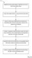
- a method of using a fluid control device to obtain a bodily fluid sample with reduced contaminationincludes establishing fluid communication between a bodily fluid source and an inlet of the fluid control device.
- a fluid collection deviceis coupled to an outlet of the fluid control device and is configured to produce a negative pressure differential within at least a portion of the fluid control device.
- An initial volume of bodily fluidis received from the inlet and into a sequestration portion of the fluid control device in response to the negative pressure differential.
- a flow controller disposed in the sequestration portionis transitioned from a first state in which the flow controller allows a flow of a gas through the flow controller and prevents a flow of bodily fluid through the flow controller, to a second state in which the flow controller prevents a flow of gas and bodily fluid through the flow controller.
- the initial volume of bodily fluidis sequestered in the sequestration portion after the flow controller is transitioned to the second state and a subsequent volume of bodily fluid is transferred from the inlet to an outlet in fluid communication with a fluid collection device.
- a memberis intended to mean a single member or a combination of members
- a materialis intended to mean one or more materials, or a combination thereof.
- the terms “about,” “approximate,” and/or “substantially” when used in connection with stated value and/or other geometric relationshipsis intended to convey that the structure so defined is nominally the value stated and/or the geometric relationship described.
- the terms “about,” “approximately,” and/or “substantially”can generally mean and/or can generally contemplate plus or minus 10% of the value or relationship stated. For example, about 0.01 would include 0.009 and 0.011, about 0.5 would include 0.45 and 0.55, about 10 would include 9 to 11, and about 1000 would include 900 to 1100.
- “bodily fluid”can include any fluid obtained directly or indirectly from a body of a patient.
- “bodily fluid”includes, but is not limited to, blood, cerebrospinal fluid, urine, bile, lymph, saliva, synovial fluid, serous fluid, pleural fluid, amniotic fluid, mucus, sputum, vitreous, air, and the like, or any combination thereof.
- proximal and distalrefer to the direction closer to and away from, respectively, a user who would place the device into contact with a patient.
- distal endthe end of a device first touching the body of the patient
- opposite end of the devicee.g., the end of the device being manipulated by the user
- any of the devices and methodscan be used to procure bodily fluid samples with reduced contamination by, for example, diverting a “pre-sample” volume of bodily fluid prior to collecting a “sample” volume of bodily fluid.
- pre-samplecan be used interchangeably to describe and/or refer to an amount, portion, or volume of bodily fluid that is transferred, diverted, and/or sequestered prior to procuring the “sample” volume.
- the terms “pre-sample,” “first,” and/or “initial”can refer to a predetermined, defined, desired, or given volume, portion, or amount of bodily fluid.
- a predetermined and/or desired pre-sample volume of bodily fluidcan be about 0.1 milliliter (mL), about 0.2 mL, about 0.3 mL, about 0.4 mL, about 0.5 mL, about 1.0 mL, about 2.0 mL, about 3.0 mL, about 4.0 mL, about 5.0 mL, about 10.0 mL, about 20 mL, about 50 mL, and/or any volume or fraction of a volume therebetween.
- the pre-sample volumecan be greater than 50 mL or less than 0.1 mL.
- a predetermined and/or desired pre-sample volumecan be between about 0.1 mL and about 5.0 mL.
- the pre-sample volumecan be, for example, a drop of bodily fluid, a few drops of bodily fluid, a combined volume of any number of lumen that form, for example, a flow path (or portion thereof) from the bodily fluid source to an initial collection chamber, portion, reservoir, etc. (e.g., a sequestration chamber).
- samplewhen used in the context of a volume of bodily fluid can refer to a volume, portion, or amount of bodily fluid that is either a random volume or a predetermined or desired volume of bodily fluid collected after transferring, diverting, sequestering, and/or isolating the pre-sample volume of bodily fluid.
- a desired sample volume of bodily fluidcan be about 10 mL to about 60 mL.
- a desired sample volume of bodily fluidcan be less than 10 mL or greater than 60 mL.
- a sample volumecan be at least partially based on one or more tests, assays, analyses, and/or processes to be performed on the sample volume.
- a fluid collection devicecan include, but is not limited to, any suitable vessel, container, reservoir, bottle, adapter, dish, vial, syringe, device, diagnostic and/or testing machine, and/or the like.
- any of the embodiments and/or methods described hereincan be used to transfer a sample volume into a sample reservoir such as any of those described in detail in U.S. Pat. No. 8,197,420 entitled, “Systems and Methods for Parenterally Procuring Bodily-Fluid Samples with Reduced Contamination,” filed Dec. 13, 2007 (“the '420 patent”), the disclosure of which is incorporated herein by reference in its entirety.
- a sample reservoircan be a sample or culture bottle such as, for example, an aerobic culture bottle or an anaerobic culture bottle.
- the culture bottlecan receive a bodily fluid sample, which can then be tested (e.g., via in vitro diagnostic (IVD) tests, and/or any other suitable test) for the presence of, for example, Gram-Positive bacteria, Gram-Negative bacteria, yeast, fungi, and/or any other organism.
- IVDin vitro diagnostic
- the culture bottlecan receive a bodily fluid sample and the culture medium (disposed therein) can be tested for the presence of any suitable organism.
- the culture mediumcan be subsequently tested using a PCR-based system to identify a specific organism.
- diverting a pre-sample or initial volume of bodily fluidcan reduce and/or substantially eliminate contaminants in the bodily fluid sample that may otherwise lead to inaccurate test results.
- sample containers, reservoirs, bottles, dishes, vials, etc., described hereincan be devoid of contents prior to receiving a sample volume of bodily fluid or can include, for example, any suitable additive, culture medium, substances, enzymes, oils, fluids, and/or the like.
- a sample reservoircan include an aerobic or anaerobic culture medium (e.g., a nutrient rich and/or environmentally controlled medium to promote growth, and/or other suitable medium(s)), which occupies at least a portion of the inner volume defined by the sample reservoir.
- a sample reservoircan include, for example, any suitable additive or the like such as, heparin, citrate, ethylenediaminetetraacetic acid (EDTA), oxalate, SPS, and/or the like, which similarly occupies at least a portion of the inner volume defined by the sample reservoir.
- a sample reservoircan be any suitable container used to collect a specimen.
- culture mediumcan be used to describe a substance configured to react with organisms in a bodily fluid (e.g., microorganisms such as bacteria) and the term “additive” can be used to describe a substance configured to react with portions of the bodily fluid (e.g., constituent cells of blood, serum, synovial fluid, etc.), it should be understood that a sample reservoir can include any suitable substance, liquid, solid, powder, lyophilized compound, gas, etc.
- the additivecould be a culture medium, such as an aerobic culture medium and/or an anaerobic culture medium contained in a culture bottle, an additive and/or any other suitable substance or combination of substances contained in a culture bottle and/or any other suitable reservoir such as those described above. That is to say, the embodiments described herein can be used with any suitable fluid reservoir or the like containing any suitable substance. Furthermore, any of the embodiments and/or methods described herein can be used to transfer a volume of bodily fluid to a reservoir (or the like) that does not contain a culture medium, additive, and/or any other substance prior to receiving a flow of bodily fluid.
- the embodiments described herein and/or portions thereofcan be formed or constructed of one or more biocompatible materials.
- the biocompatible materialscan be selected based on one or more properties of the constituent material such as, for example, stiffness, toughness, durometer, bioreactivity, etc.
- suitable biocompatible materialsinclude metals, glasses, ceramics, or polymers.
- suitable metalsinclude pharmaceutical grade stainless steel, gold, titanium, nickel, iron, platinum, tin, chromium, copper, and/or alloys thereof.
- a polymer materialmay be biodegradable or non-biodegradable.
- suitable biodegradable polymersinclude polylactides, polyglycolides, polylactide-co-glycolides (PLGA), polyanhydrides, polyorthoesters, polyetheresters, polycaprolactones, polyesteramides, poly(butyric acid), poly(valeric acid), polyurethanes, and/or blends and copolymers thereof.
- non-biodegradable polymersinclude nylons, polyesters, polycarbonates, polyacrylates, polymers of ethylene-vinyl acetates and other acyl substituted cellulose acetates, non-degradable polyurethanes, polystyrenes, polyvinyl chloride, polyvinyl fluoride, poly(vinyl imidazole), chlorosulphonate polyolefins, polyethylene oxide, and/or blends and copolymers thereof.
- the embodiments described herein and/or portions thereofcan include components formed of one or more parts, features, structures, etc.
- the componentscan be formed by a singular part having any number of sections, regions, portions, and/or characteristics, or can be formed by multiple parts or features.
- a structuresuch as a wall or chamber
- the structurecan be considered as a single structure with multiple portions, or multiple, distinct substructures or the like coupled to form the structure.
- a monolithically constructed structurecan include, for example, a set of substructures.
- Such a set of substructuresmay include multiple portions that are either continuous or discontinuous from each other.
- a set of substructurescan also be fabricated from multiple items or components that are produced separately and are later joined together (e.g., via a weld, an adhesive, or any suitable method).
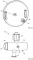
- FIG. 1is a schematic illustration of a fluid control device 100 according to an embodiment.
- the fluid control device 100(also referred to herein as “control device” or “device”) is configured to withdraw bodily fluid from a patient.
- a first portion or amount (e.g., an initial amount) of the withdrawn bodily fluidis sequestered from a second portion or amount (e.g., a subsequent amount) of the withdrawn bodily fluid which can be subsequently used for additional testing, discarded, and/or reinfused into the patient.
- contaminants or the likecan be sequestered within the first portion or amount, leaving the second portion or amount substantially free of contaminants.
- the second portion or amount of bodily fluidcan then be used as a biological sample in one or more tests for the purpose of medical diagnosis and/or treatment (e.g., a blood culture test or the like), as described in more detail herein.
- the first portion or amount of bodily fluidcan be discarded as waste or can be used in any suitable test that is less likely to produce false, inaccurate, distorted, inconsistent, and unreliable results as a result of potential contaminants contained therein. In other instances, the first portion or amount of bodily fluid can be infused back into the patient.
- the control device 100includes a housing 130 that has and/or forms an inlet 131 , at least one outlet 136 , and a sequestration chamber 134 .
- the inlet 131is configured to fluidically couple to a lumen-containing device, which in turn, can place the housing 130 in fluid communication with a bodily fluid source.
- the housing 130can be coupled to and/or can include a lumen-containing device that is in fluid communication with the inlet 131 and that is configured to be percutaneously disposed in a patient (e.g., a butterfly needle, intravenous (IV) catheter, peripherally inserted central catheter (PICC), syringe, sterile tubing, intermediary lumen-containing device, and/or bodily-fluid transfer device or the like).
- a lumen-containing devicethat is in fluid communication with the inlet 131 and that is configured to be percutaneously disposed in a patient (e.g., a butterfly needle, intravenous (IV) catheter, peripherally inserted central catheter (PICC), syringe, sterile tubing, intermediary lumen-containing device, and/or bodily-fluid transfer device or the like).
- IVintravenous
- PICCperipherally inserted central catheter
- syringesterile tubing
- intermediary lumen-containing devicee.g., ster
- the outlet(s) 136can be placed in fluid communication with a fluid collection device 180 (e.g., a fluid or sample reservoir, syringe, evacuated container, etc.).
- a fluid collection device 180e.g., a fluid or sample reservoir, syringe, evacuated container, etc.
- the control device 100can be used and/or manipulated to selectively transfer a volume of bodily fluid from a bodily fluid source, through the inlet 131 , the housing 130 , and the outlet(s) 136 to the fluid collection device 180 , as described in further detail herein.
- the housing 130defines one or more fluid flow paths 133 between the inlet 131 and the sequestration chamber 134 and/or one or more fluid flow paths 154 between the inlet 131 and the outlet 136 .
- the housing 130 of the device 100can be any suitable shape, size, and/or configuration.
- the housing 130can have a size that is at least partially based on a volume of bodily fluid at least temporarily stored, for example, in the sequestration chamber 134 .
- the control device 100 and/or the housing 130can be configured to transition between operating modes such that bodily fluid flows through at least one of the fluid flow paths 133 and/or 154 .
- control device 100 and/or the housing 130can be configured to transition automatically (e.g., based on pressure differential, time, electronically, saturation of a membrane, an absorbent and/or barrier material, etc.) or via intervention (e.g., user intervention, mechanical intervention, or the like).
- the sequestration chamber 134is at least temporarily placed in fluid communication with the inlet 131 via the fluid flow path(s) 133 .
- the sequestration chamber 134is configured to (1) receive a flow and/or volume of bodily fluid from the inlet 131 and (2) sequester (e.g., separate, segregate, contain, retain, isolate, etc.) the flow and/or volume of bodily fluid therein.
- the sequestration chamber 134can have any suitable arrangement such as, for example, those described herein with respect to specific embodiments. It should be understood, however, that the control device 100 and/or the housing 130 can have a sequestration chamber 134 in any suitable arrangement and is not intended to be limited to those shown and described herein.
- the sequestration chamber 134can be at least partially formed by the housing 130 .
- the sequestration chamber 134can be a reservoir placed and/or disposed within a portion of the housing 130 .
- the sequestration chamber 134can be formed and/or defined by a portion of the fluid flow path 133 .
- the housing 130can define one or more lumens and/or can include one or more lumen defining device(s) configured to receive a flow of bodily fluid from the inlet 131 , thereby defining the fluid flow path 133 .
- at least a portion of the lumen and/or a portion of the lumen defining device(s)can form and/or can define the sequestration chamber 134 .
- the sequestration chamber 134can have any suitable volume and/or fluid capacity.
- the sequestration chamber 134can have a volume and/or fluid capacity between about 0.25 mL and about 5.0 mL.
- the sequestration chamber 134can have a volume measured in terms of an amount of bodily fluid (e.g., the initial or first amount of bodily fluid) configured to be transferred in the sequestration chamber 134 .
- the sequestration chamber 134can have a volume sufficient to receive an initial volume of bodily fluid as small as a microliter or less of bodily fluid (e.g., a volume as small as 20 drops of bodily fluid, 10 drops of bodily fluid, 5 drops of bodily fluid, a single drop of bodily fluid, or any suitable volume therebetween).
- the sequestration chamber 134can have a volume sufficient to receive an initial volume of bodily fluid up to, for example, about 5.0 mL, 10.0 mL, 15 mL, 20 mL, 30 mL, 40 mL, 50 mL, or more.
- the sequestration chamber 134can have a volume that is equal to a fraction of and/or a multiple of at least some of the volumes of one or more lumen(s) placing the sequestration chamber 134 in fluid communication with the bodily fluid source.
- the sequestration chamber 134can include any suitable arrangement, configuration, and/or feature, and/or can be formed of one or more materials configured to interact with a portion of the bodily fluid transferred into the sequestration chamber 134 .
- the housing 130can include an absorbent and/or hydrophilic material disposed within the sequestration chamber 134 .
- the absorbent and/or hydrophilic materialcan absorb, attract, retain, expand, and/or otherwise interact with at least a portion of the bodily fluid, which in turn, can sequester and/or retain at least an initial portion of the bodily fluid within the sequestration chamber 134 , as described in further detail herein.
- the sequestration chamber 134can include and/or can be formed of an expandable or collapsible material configured to transition between a first state (e.g., while an initial portion of the bodily fluid is being transferred into the sequestration chamber 134 ) to a second state (e.g., after the initial portion of the bodily fluid is transferred into the sequestration chamber 134 ).
- a force associated with and/or resulting from such a material expanding or collapsingcan be operable to transition the housing 130 and/or the device 100 from a first state, position, configuration, etc. to a second state, position, configuration, etc.
- the sequestration chamber 134 and/or any other suitable portion of the housing 130can include one or more chemicals, compounds, and/or the like configured to chemically interact with bodily fluid transferred through a portion of the housing 130 , which can be operable to transition the control device 100 and/or the housing 130 between the first state and the second state (e.g., via a force or any other suitable means).
- control device 100 and/or the housing 130can include and/or define a flow controller 120 configured to selectively control a flow of fluids (e.g., gas or liquids) through a portion of the control device 100 .
- the flow controller 120can control a flow of bodily fluid through the control device 100 (or housing 130 ) and/or otherwise selectively control a flow of bodily fluid through at least one of the fluid flow paths 133 and/or 154 .
- the flow controller 120can be, for example, a valve, a membrane, a diaphragm, a restrictor, a vent, a selectively permeable member (e.g., a fluid impermeable barrier or seal that at least selectively allows the passage of air or gas therethrough), a port, a junction, an actuator, and/or the like, or any suitable combination thereof.
- the flow controller 120can be configured to selectively control (at least in part) a flow of fluids into and/or out of the sequestration chamber 134 and/or any other suitable portion of the housing 130 .
- the flow of fluidscan be a liquid such as water, oil, dampening fluid, bodily fluid, and/or any other suitable liquid, and/or can be a gas such as air, oxygen, carbon dioxide, helium, nitrogen, ethylene oxide, and/or any other suitable gas.
- a wall or structure of the housing 130can define an opening, aperture, port, orifice, and/or the like that is in fluid communication with the sequestration chamber 134 .
- the flow controller 120can be, for example, a semi-permeable member or membrane disposed in or about the opening to selectively allow a flow of air or gas through the opening while limiting or substantially preventing a flow of fluid (e.g., bodily fluid such as blood) through the opening.
- a semi-permeable member or membranedisposed in or about the opening to selectively allow a flow of air or gas through the opening while limiting or substantially preventing a flow of fluid (e.g., bodily fluid such as blood) through the opening.
- one or more flow controllers 120 or the likecan be configured to facilitate air (or other fluid) displacement through one or more portions of the control device 100 , which in some instances, can result in a pressure differential across one or more portions of the control device 100 or can result in and/or allow for a pressure equalization across one or more portions of the housing 130 .
- the control device 100can be configured to selectively transfer a volume of bodily fluid to the sequestration chamber 134 or to the outlet 136 based at least in part on a pressure differential between two or more portions of the control device 100 .
- the pressure differentialcan result from fluidically coupling the outlet 136 to the fluid collection device 180 , which can define and/or can be configured to produce a negative pressure (e.g., an evacuated reservoir, a syringe, a pressure charged canister, and/or other source or potential energy to create a vacuum or pressure differential).
- a negative pressuree.g., an evacuated reservoir, a syringe, a pressure charged canister, and/or other source or potential energy to create a vacuum or pressure differential.
- the pressure differentialcan result from a change in volume and/or temperature.
- the pressure differentialcan result from at least a portion of the control device 100 , the housing 130 , and/or other portions of the flow path being evacuated and/or charged (e.g., the sequestration chamber 134 and/or any other suitable portion).
- the pressure differentialcan be established automatically or via direct or indirect intervention (e.g., by the user).
- a flow of a fluid (e.g., gas and/or liquid) resulting from a pressure differentialcan be selectively controlled via one or more flow controllers 120 that can, for example, transition between one or more operating conditions to control the fluid flow.
- the flow controller 120can be an actuator or the like configured to transition between one or more operating conditions or states to establish fluid communication between one or more portions of the control device 100 and/or configured to sequester one or more portions of the control device 100 (e.g., the sequestration chamber 134 ).
- the flow controller 120can be member or device formed of an absorbent material configured to selectively allow fluid flow therethrough.
- such an absorbent materialcan be transitioned from a first state in which the material allows a flow of gas (e.g., air) therethrough but prevents a flow of liquid (e.g., bodily fluid) therethrough, to a second state in which the material substantially prevents a flow of gas and liquid therethrough.
- the flow controller 120can include one or more valves, membranes, diaphragms, and/or the like.
- the flow controller 120can include any suitable combination of devices, members, and/or features. It should be understood that the flow controllers included in the embodiments described herein are presented by way of example and not limitation. Thus, while specific flow controllers are described herein, it should be understood that fluid flow can be controlled through the control device 100 by any suitable means.
- the outlet(s) 136is/are in fluid communication with and/or is/are configured to be placed in fluid communication with the fluid flow paths 133 and/or 154 .
- the outlet 136can be any suitable outlet, opening, port, stopcock, lock, seal, coupler, valve (e.g. one-way, check valve, duckbill valve, umbrella valve, and/or the like), etc. and is configured to be fluidically coupled to the fluid collection device 180 (e.g., a fluid reservoir, culture sample bottle, syringe, container, vial, dish, receptacle, pump, adapter, and/or any other suitable collection or transfer device).
- the outlet 136can be monolithically formed with the fluid collection device 180 .
- the outlet 136can be at least temporarily coupled to the fluid collection device 180 via an adhesive, a resistance fit, a mechanical fastener, a threaded coupling, a piercing or puncturing arrangement, any number of mating recesses, and/or any other suitable coupling or combination thereof.
- the outlet 136can be physically (e.g., mechanically) and/or fluidically coupled to the fluid collection device 180 such that an interior volume defined by the fluid collection device 180 is in fluid communication with the outlet 136 .
- the outlet 136can be operably coupled to the fluid collection device 180 via an intervening structure (not shown in FIG. 1 ), such as a flexible sterile tubing.
- the arrangement of the outlet 136can be such that the outlet 136 is physically and/or fluidically sealed prior to coupling to the fluid collection device 180 .
- the outlet 136can be transitioned from a sealed configuration to an unsealed configuration in response to being coupled to the fluid collection device 180 and/or in response to a negative pressure differential between an environment within the outlet 136 and/or housing 130 and an environment within the fluid collection device 180 .
- the fluid collection device 180can be any suitable device for at least temporarily containing a bodily fluid, such as, for example, any of those described in detail above.
- the fluid collection device 180can be a single-use disposable collection tube(s), a syringe, a vacuum-based collection tube(s), an intermediary bodily-fluid transfer device, and/or the like.
- the fluid collection device 180can be substantially similar to or the same as known sample containers such as, for example, a Vacutainer® (manufactured by BD), a BacT/ALERT® SN or BacT/ALERT® FA (manufactured by Biomerieux, Inc.), and/or any suitable reservoir, vial, microvial, microliter vial, nanoliter vial, container, microcontainer, nanocontainer, and/or the like.
- a Vacutainer®manufactured by BD
- BacT/ALERT® SN or BacT/ALERT® FAmanufactured by Biomerieux, Inc.
- the fluid collection device 180can be a sample reservoir that includes a vacuum seal that maintains negative pressure conditions (vacuum conditions) inside the sample reservoir, which in turn, can facilitate withdrawal of bodily fluid from the patient, through the control device 100 , and into the sample reservoir, via a vacuum or suction force, as described in further detail herein.
- negative pressure conditionsvacuum conditions
- the usercan couple the fluid collection device 180 to the outlet 136 to initiate a flow of bodily fluid from the patient such that a first or initial portion of the bodily fluid is transferred into and sequestered by the sequestration chamber 134 and such that any subsequent portion or volume of bodily fluid bypasses and/or is otherwise diverted away from the sequestration chamber 134 and flows into the fluid collection device 180 , as described in further detail herein.
- control device 100can be used in conjunction with any suitable bodily fluid collection device and/or system.
- control device 100 described hereincan be used in any suitable fluid transfer device such as those described in U.S. Patent Publication No. 2015/0342510 entitled, “Sterile Bodily-Fluid Collection Device and Methods,” filed Jun. 2, 2015 (referred to herein as the “'510 publication”), the disclosure of which is incorporated herein by reference in its entirety.
- control device 100can be used in an “all-in-one” or pre-assembled device (e.g., such as those described in the '510 publication) to receive and sequester an initial volume of bodily fluid such that contaminants in subsequent volumes of bodily fluid are reduced and/or eliminated.
- an “all-in-one” or pre-assembled devicee.g., such as those described in the '510 publication
- the device 100can be used to procure a bodily fluid sample having reduced contamination from microbes such as, for example, dermally residing microbes, and/or the like.
- a usersuch as a doctor, physician, nurse, phlebotomist, technician, etc. can manipulate the device 100 to establish fluid communication between the inlet 131 and the bodily fluid source (e.g., a vein of a patient, cerebral spinal fluid (CSF) from the spinal cavity, urine collection, and/or the like).
- the bodily fluid sourcee.g., a vein of a patient, cerebral spinal fluid (CSF) from the spinal cavity, urine collection, and/or the like.
- CSFcerebral spinal fluid
- the inlet 131can be coupled to and/or can include a needle or the like that can be manipulated to puncture the skin of the patient and to insert at least a portion of the needle in the vein of the patient, thereby placing the inlet 131 in fluid communication with the bodily fluid source (e.g., the vein, an IV catheter, a PICC, etc.).
- the bodily fluid sourcee.g., the vein, an IV catheter, a PICC, etc.
- the outlet 136can be fluidically coupled to the fluid collection device 180 .
- the fluid collection device 180can be any suitable reservoir, container, and/or device configured to receive a volume of bodily fluid.
- the fluid collection device 180can be an evacuated reservoir or container that defines a negative pressure and/or can be a syringe that can be manipulated to produce a negative pressure.
- coupling the outlet 136 to the fluid collection device 180selectively exposes at least a portion of the fluid flow paths 133 and/or 154 to the negative pressure, thereby resulting in a negative pressure differential operable in drawing bodily fluid from the bodily fluid source (e.g., the patient), through the inlet 131 , and into the housing 130 .
- the arrangement of the housing 130is such that when a volume of bodily fluid is transferred to and/or through the inlet 131 , an initial portion of the volume of bodily fluid (also referred to herein as an “initial volume” or a “first volume”) flows from the inlet 131 , through at least a portion of the fluid flow path 133 , and into the sequestration chamber 134 . That is to say, in some embodiments, the control device 100 and/or the housing 130 can be in first or initial state in which the initial portion or volume of bodily fluid can flow in or through at least a portion the fluid flow path 133 and into the sequestration chamber 134 .
- the initial state of the control device 100 and/or the housing 130can be one in which one or more flow controllers 120 (e.g., valves, membranes, diaphragms, restrictors, vents, air permeable and fluid impermeable barriers, ports, actuators, and/or the like, or a combination thereof) are in a first state in which the fluid flow path 133 is exposed to the negative pressure differential via the sequestration chamber 134 .
- one or more flow controllers 120e.g., valves, membranes, diaphragms, restrictors, vents, air permeable and fluid impermeable barriers, ports, actuators, and/or the like, or a combination thereof
- the negative pressure within or created by the fluid collection device 180can result in a negative pressure (or negative pressure differential) within at least a portion of the sequestration chamber 134 that is operable in drawing an initial flow of bodily fluid into the sequestration chamber 134 when one or more flow controllers 120 is/are in a first or initial state.
- the flow controller 120can be an actuator or the like that includes a valve (e.g. one-way valve, check valve, duckbill valve, umbrella valve, and/or the like), a selectively permeable member (e.g., a fluid impermeable barrier or seal that allows at least selective passage of gas or air), a selectively permeable membrane, a diaphragm, and/or the like that is at least temporarily fluidically coupled to a flow path between the fluid collection device 180 and the sequestration chamber 134 (e.g., at least a portion of the fluid flow path 154 ).
- a valvee.g. one-way valve, check valve, duckbill valve, umbrella valve, and/or the like
- a selectively permeable membere.g., a fluid impermeable barrier or seal that allows at least selective passage of gas or air
- a selectively permeable membranee.g., a diaphragm, and/or the like that is at least temporarily fluidically coupled to a
- the flow controller 120 examples noted abovecan be, for example, known off-the-shelf components that are used in medical devices to control the flow of fluids and air
- the flow controller 120can be a custom, proprietary, and/or specifically tailored component integrated into the device 100 .
- the flow controller 120can allow a flow of fluid therethrough in response to the negative pressure of the fluid collection device 180 .
- the flow controller 120 or a portion or component thereofis configured to allow only a flow of air or gas through the flow controller 120 and is configured to limit and/or substantially prevent a flow of liquid (e.g., bodily fluid) through the flow controller 120 .
- the fluid collection device 180can produce a negative pressure differential within the sequestration chamber 134 that is operable to draw an initial portion and/or amount of bodily fluid into the sequestration chamber 134 when the flow controller 120 is in a first or initial state without allowing the initial portion of bodily fluid to flow into the fluid flow path 154 and/or otherwise out of the sequestration chamber 134 .
- control device 100 and/or the housing 130can include a member, device, mechanism, feature, etc. configured to modulate a magnitude of the negative pressure to which the sequestration chamber 134 is exposed.
- a housingcan include a valve, a membrane, a porous material, a restrictor, an orifice, and/or any other suitable member, device, and/or feature configured to modulate pressure.
- modulating and/or controlling a magnitude of the pressure to which the sequestration chamber 134 is exposedcan, in turn, modulate a magnitude of pressure exerted on the bodily fluid and/or within a vein of a patient.
- such pressure modulationcan reduce, for example, hemolysis of a blood sample and/or a likelihood of collapsing a vein (e.g., which is particularly important in fragile patients needing microbial and/or other diagnostic testing associated with use of the control device 100 ).
- the modulation of the negative pressurecan, for example, at least partially control a rate at which the control device 100 transitions between a first configuration or state and a second configuration or state.
- modulating the negative pressurecan act like a timer. For example, a time between the introduction of the negative pressure differential and the transitioning of the control device 100 from the first state to the second state can be known, predetermined, calculated, and/or controlled.
- modulating the negative pressurecan at least partially control an amount or volume of bodily fluid transferred into the sequestration chamber 134 (i.e., can control a volume of the initial amount of bodily fluid).
- the initial portion and/or amount of bodily fluidcan be any suitable volume of bodily fluid, as described above.
- the control device 100 and/or the housing 130can remain in the first state until a predetermined and/or desired volume (e.g., the initial volume) of bodily fluid is transferred to the sequestration chamber 134 .
- the initial volumecan be associated with and/or at least partially based on a volume of the sequestration chamber 134 .
- the initial volumecan be associated with and/or at least partially based on an amount or volume of bodily fluid that is sufficient to fully wet or saturate a semi-permeable member or membrane otherwise configured to selectively expose the sequestration chamber 134 to the negative pressure of the fluid collection device 180 (i.e., the flow controller 120 such as an air permeable and liquid impermeable member or membrane).
- the initial volume of bodily fluidcan be a volume sufficient to transition one or more flow controllers 120 to a second state (e.g., a saturated or fully wetted state).
- control device 100 and/or the housing 130can be configured to transfer a volume of bodily fluid (e.g., the initial volume) into the sequestration chamber 134 until a pressure differential between the sequestration chamber 134 and the fluid flow path 133 and/or the bodily fluid source is brought into substantial equilibrium and/or is otherwise reduced below a desired threshold.
- a volume of bodily fluide.g., the initial volume
- the initial volume of bodily fluidis transferred and/or diverted into the sequestration chamber 134 , the initial volume is sequestered, segregated, retained, contained, isolated, etc. in the sequestration chamber 134 .
- the transitioning of the one or more flow controllers 120 from a first state to a second statecan be operable to sequester and/or retain the initial portion of the bodily fluid in the sequestration chamber 134 .
- contaminantssuch as, for example, dermally residing microbes or the like dislodged during the venipuncture event, other external sources of contamination, colonization of catheters and PICC lines that are used to collect samples, and/or the like can be entrained and/or included in the initial volume of the bodily fluid and thus, are sequestered in the sequestration chamber 134 when the initial volume is sequestered therein.
- the device 100can transition to the second state in which a subsequent volume(s) of bodily fluid can flow through at least a portion the fluid flow paths 133 and/or 154 from the inlet 131 to the outlet 136 .
- the control device 100 and/or the housing 130can passively and/or automatically transition (e.g., without user intervention) from the first state to the second state once the initial volume of bodily fluid is sequestered in the sequestration chamber 134 .
- filling the sequestration chamber 134 to capacity and/or fully saturating, wetting, and/or impregnating an absorbent or similar material disposed between the sequestration chamber 134 and the fluid collection device 180can be such that further transfer of bodily fluid into the sequestration chamber 134 is limited and/or substantially prevented due to a removal or diversion of the negative pressure.
- the control device 100 and/or the housing 130can be manually transitioned or transitioned in response to at least an indirect interaction by a user.
- a usercan transition the control device 100 and/or the housing 130 from the first state to the second state by actuating an actuator or the like (e.g., actuating the flow controller 120 or a portion thereof).
- at least a portion of the initial volume of bodily fluidcan transition the control device 100 and/or the housing 130 from the first state to the second state.
- the control device 100can include a flow controller 120 that is and/or that includes a bodily fluid activated switch, valve, port, and/or the like.
- any subsequent volume(s) of the bodily fluidcan flow from the inlet 131 , through at least one of the fluid flow paths 133 and/or 154 , through the outlet 136 , and into the fluid collection device 180 .
- sequestering the initial volume of bodily fluid in the sequestration chamber 134 prior to collecting or procuring one or more sample volumes of bodily fluidreduces and/or substantially eliminates an amount of contaminants in the one or more sample volumes.
- the arrangement of the control device 100 and/or the housing 130can be such that the control device 100 and/or the housing 130 cannot transition to the second state prior to collecting and sequestering the initial volume in the sequestration chamber 134 .
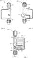
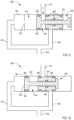
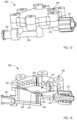
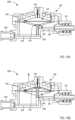
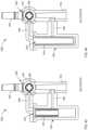
- FIGS. 2 - 5illustrate a fluid control device 200 according to an embodiment.
- the fluid control device 200can be similar in at least form and/or function to the fluid control device 100 described above with reference to FIG. 1 . Accordingly, portions of the fluid control device 200 that can be similar to portions of the fluid control device 100 are not described in further detail herein.
- the fluid control device 200(also referred to herein as “control device” or “device”) includes a housing 230 having an inlet 231 , an outlet 236 , and an actuator 250 .
- the inlet 231is configured to be placed in fluid communication with a bodily fluid source to receive a flow of bodily fluid therefrom (e.g., via a lumen-containing device such as a needle, IV catheter, PICC line, or the like).
- the housing 230defines one or more fluid flow paths 233 between the inlet 231 and a sequestration chamber 234 and/or one or more fluid flow paths 254 between the inlet 231 and the outlet 236 .
- the housing 230 of the device 200can be any suitable shape, size, and/or configuration.
- the housing 230can be substantially similar in at least form and/or function to the housing 130 described above with reference to FIG. 1 .
- the sequestration chamber 234 of the housing 230is at least temporarily placed in fluid communication with the inlet 231 via the fluid flow path(s) 233 .
- the sequestration chamber 234can be selectively placed in fluid communication with the fluid flow path 254 such that at least air or gas can be transferred therebetween, as described in further detail herein.
- the sequestration chamber 234is configured to (1) receive a flow and/or volume of bodily fluid from the inlet 231 and (2) sequester (e.g., separate, segregate, contain, retain, isolate, etc.) the flow and/or volume of bodily fluid therein.
- the sequestration chamber 234can have any suitable shape, size, and/or configuration.
- the sequestration chamber 234can have any suitable size, volume, and/or fluid capacity such as, for example, those described above with reference to the sequestration chamber 134 .
- the sequestration chamber 234can be at least partially formed by the housing 230 that defines a lumen or flow path.
- At least a portion of the fluid flow path 233can extend through a portion of the housing 230 to form and/or define at least a portion of the sequestration chamber 234 .
- the sequestration chamber 234 and/or a portion of the fluid flow path 233 forming the sequestration chamber 234can have a serpentine configuration or the like.
- the sequestration chamber 234can have any suitable arrangement.
- a housingcan include a sequestration chamber that is formed by a flexible tubing or the like that can be arranged in any suitable shape and/or configuration.
- the housing 230 and/or the sequestration chamber 234can include, form, and/or define a flow controller 242 .
- the flow controller 242can be, for example, a valve, membrane, diaphragm, restrictor, vent, a selectively permeable member (e.g., a fluid impermeable barrier or seal that allows at least selective passage of gas or air such as, for example, a blood barrier and/or the like), port, etc. (collectively referred to herein as a “flow controller”) configured to selectively control (at least in part) a flow of fluids into and/or out of the sequestration chamber 234 and/or any other suitable portion of the housing 230 . More particularly, in the embodiment shown in FIGS.
- the flow controller 242is a selectively permeable fluid barrier (e.g., a blood barrier) that includes and/or is formed of a porous material configured to selectively allow a flow of gas therethrough but to prevent a flow of a liquid therethrough.
- a selectively permeable fluid barriere.g., a blood barrier
- the flow controller 242is positioned within the housing 230 to selectively establish fluid communication between the sequestration chamber 234 and the fluid flow path 254 .
- the flow controller 242can be configured to at least temporarily allow a gas or air to transfer between the fluid flow path 254 and the sequestration chamber 234 and can be configured to substantially prevent a flow of liquid between the fluid flow path 254 and the sequestration chamber 234 , as described in further detail herein.
- the outlet 236 of the housing 230is in fluid communication with and/or is configured to be placed in fluid communication with the fluid flow paths 233 and/or 254 .
- the outlet 236can be any suitable outlet, opening, port, lock, seal, coupler, etc. and is configured to be fluidically coupled to a fluid collection device such as a sample reservoir, a syringe, container, and/or other sample vessel.
- the outlet 236can be monolithically formed with the fluid collection device or can be at least temporarily coupled to the fluid collection device, as described above with reference to the outlet 136 of the housing 130 .
- the fluid collection devicecan be any suitable reservoir, container, and/or device for containing a bodily fluid, such as, for example, any of those described in detail above with reference to the fluid collection device 180 .
- the outlet 236can be configured to couple to an evacuated sample reservoir.
- the usercan couple the sample reservoir to the outlet 236 to initiate a flow of bodily fluid from the patient such that a first or initial portion of the bodily fluid is transferred into and sequestered by the sequestration chamber 234 and such that any subsequent portion or volume of bodily fluid bypasses and/or is otherwise diverted away from the sequestration chamber 234 and flows into the sample reservoir.
- the housing 230includes and/or is coupled to the actuator 250 configured to selectively control a flow of bodily fluid through the housing 230 .
- the actuator 250is disposed, for example, between a portion of the fluid flow path 233 and a portion of the fluid flow path 254 .
- the actuator 250is shown in FIGS. 3 - 5 as being positioned apart from, away from, and/or downstream of a junction between the fluid flow path 233 and the sequestration chamber 234 , in other embodiments, the actuator 250 can be disposed at any suitable position within the housing 230 .
- the actuator 250can be positioned at and/or can form at least a portion of a junction between the fluid flow path 233 , the sequestration chamber 234 , and the fluid flow path 254 .
- the actuator 250can be any suitable shape, size, and/or configuration.
- the actuator 250can be any suitable member or device configured to transition between a first state and a second state.
- the actuator 250is configured to isolate, sequester, separate, and/or otherwise prevent fluid communication between the fluid flow path 233 and the fluid flow path 254 when in the first state and is configured to place the fluid flow path 233 in fluid communication with the fluid flow path 254 when in the second state.
- the actuator 250can be a valve, plunger, seal, membrane, flap, plate, and/or the like. As shown, for example, in FIG.
- the actuator 250can include one or more seals 265 configured to selectively establish fluid communication between the fluid flow channels 233 and 254 when the actuator 250 is transitioned from a first state to a second state (e.g., pressed, rotated, moved, activated, switched, slid, etc.).
- a first statee.g., pressed, rotated, moved, activated, switched, slid, etc.
- the control device 200can include any suitable actuator or device configured to selectively establish fluid communication between the fluid flow path 233 and 254 .
- the control device 200is presented by way of example only and not limitation.
- the actuator 250is shown in FIGS. 2 - 5 as being disposed in a given position, in other embodiments, the actuator 250 can be placed at any suitable position along the housing 230 .
- the actuator 250can be disposed at the junction between the fluid flow path 233 , the sequestration chamber 234 , and the inlet 231 .
- a flow of bodily fluidcan flow directly from the inlet 231 and into the sequestration chamber 234 when the actuator 250 is in the first state and can flow directly from the inlet 231 to the fluid flow path 254 when the actuator 250 is in the second state.
- the actuator 250can form a portion of the sequestration chamber 234 such that when the actuator 250 is in the first state, bodily fluid flows from the inlet directly into the sequestration chamber 234 .
- the actuator 250can, for example, allow bodily fluid to flow directly from the inlet 231 to the fluid flow path 233 .
- the actuator 250can prevent the formation of a junction between the inlet 231 , the sequestration chamber 234 , and the fluid flow path 233 . Moreover, when in the second state, the actuator 250 can be operable in at least partially sequestering the sequestration chamber 234 from the inlet 231 and/or the fluid flow path 233 .
- the actuator 250can be actuated and/or transitioned in any suitable manner.
- the actuator 250can transition between the first and the second state in response to a manual actuation by the user (e.g., exerting a manual force on a button, slider, switch, rotational member, etc.).
- the actuator 250can be configured to automatically transition between the first state and the second state in response to a pressure differential (or lack thereof), a change in potential or kinetic energy, a change in composition or configuration (e.g., a portion of the actuator could at least partially dissolve or transform), and/or the like.
- the actuator 250can be mechanically and/or electrically actuated or transitioned based on a predetermined time, volumetric flow rate, flow velocity, etc. While examples of actuators and/or ways in which an actuator can transition are provided herein, it should be understood that they have been presented by way of example only and not limitation. Thus, a control device 200 can include any suitable actuator configured to transition in any suitable manner.
- the device 200can be used to procure a bodily fluid sample having reduced contamination from microbes such as, for example, dermally residing microbes, and/or the like.
- a usersuch as a doctor, physician, nurse, phlebotomist, technician, etc. can manipulate the device 200 to establish fluid communication between the inlet 231 and the bodily fluid source (e.g., a vein of a patient).
- the bodily fluid sourcee.g., a vein of a patient.
- the outlet 236can be fluidically coupled to the fluid collection device.
- the fluid collection devicecan be, for example, an evacuated reservoir or container that defines a negative pressure and/or can be any other suitable negative pressure source.
- Coupling the outlet 236 to the fluid collection deviceselectively exposes at least a portion of the fluid flow path 254 to the negative pressure within the fluid collection device.
- the flow controller 242is in fluid communication with the fluid flow path 254 and the sequestration chamber 234 .
- coupling the outlet 236 to the fluid collection deviceexposes the sequestration chamber to the negative pressure of the fluid collection device, thereby resulting in a negative pressure differential operable in drawing bodily fluid from the bodily fluid source (e.g., the patient), through the inlet 231 , and into the housing 230 .
- the arrangement of the housing 230is such that when a volume of bodily fluid is transferred to and/or through the inlet 231 , an initial portion of the volume of bodily fluid (also referred to herein as an “initial volume” or a “first volume”) flows from the inlet 231 , through at least a portion of the fluid flow path 233 , and into the sequestration chamber 234 . That is to say, in some embodiments, the control device 200 and/or the housing 230 can be in first or initial state in which the initial portion or volume of bodily fluid can flow in or through at least a portion the fluid flow path 233 and into the sequestration chamber 234 .
- the housing 230 and/or the control device 200can be in the initial state when the flow controller 242 and the actuator 250 are in a first state, position, configuration, etc.
- the actuator 250isolates, separates, segregates, sequesters and/or otherwise prevents direct fluid communication between the fluid flow paths 233 and 254 .
- the inlet 231is exposed to the negative pressure differential via the sequestration chamber 234 .
- the negative pressure within the fluid collection devicecan result in a negative pressure (or negative pressure differential) within at least a portion of the sequestration chamber 234 that is operable in drawing an initial flow of bodily fluid from the inlet 233 into the sequestration chamber 234 when the housing 230 and/or control device 200 is in the first or initial state.
- the flow controller 242can allow a flow of fluid (e.g., a gas or air) therethrough in response to the negative pressure of the fluid collection device (e.g., a sample reservoir, a syringe, or other source of potential energy used to create negative pressure), as described above with reference to the housing 130 .
- a flow of fluide.g., a gas or air
- the housing 230defines a restricted flow path 232 that places the flow controller 242 in fluid communication with the fluid flow path 254 . More specifically, the restricted flow path 232 is a fluid flow path having a smaller diameter than at least the fluid flow path 254 .
- the restricted flow path 232can have a diameter of about 0.0005′′, about 0.001′′, about 0.003′′, about 0.005′′, about 0.01′′, about 0.1′′, about 0.5′′ or more. In other embodiments, the restricted flow path 232 can have a diameter less than 0.0005′′ or greater than 0.5′′. In some embodiments, the restricted flow path 232 can have a predetermined and/or desired length of about 0.01′′, about 0.05′′, about 0.1′′, about 0.15′′, about 0.2′′, about 0.5′′, or more. In other embodiments, the restricted flow path 232 can have a predetermined and/or desired length that is less than 0.01′′ or more than about 0.5′′. Moreover, in some embodiments, a restricted flow path 232 can have any suitable combination of diameter and length to allow for and/or to provide a desired flow characteristic through at least a portion of the control device 200 .
- the restricted flow path 232 having a smaller diameterresults in a lower magnitude of negative pressure being applied through the sequestration chamber than a magnitude of negative pressure when the restricted flow path has a larger diameter.
- modulating a magnitude of negative pressurecan control a rate at which bodily fluid is transferred into the sequestration chamber 234 .
- a fluid collection device and/or other suitable negative pressure sourcemay produce a negative pressure differential having a magnitude (e.g., a negative magnitude) of about 0.5 pounds per square inch (PSI), about 1.0 PSI, about 2.0 PSI, about 3.0 PSI, about 4.0 PSI, about 5.0 PSI, about 10 PSI, about 12.5 PSI, or about 14.7 PSI (e.g., at or substantially at atmospheric pressure at about sea level).
- a fluid collection devicesuch as an evacuated container or the like can have a predetermined negative pressure of about 12.0 PSI.
- the amount of negative pressure to which the sequestration chamber 234 is exposed and/or the rate at which the negative pressure is appliedcan be controlled, reduced, and/or otherwise modulated.
- the use of the restricted flow path 232can result in a delay or ramp up of the negative pressure exerted on or in the sequestration chamber.
- the restricted flow path 232is, for example, a gas flow path configured to receive a flow of gas or air but not a flow of a liquid (e.g., bodily fluid).
- the diameter of the restricted flow path 232can be sufficiently small to limit and/or prevent a flow of a liquid therethrough.
- the arrangement of the restricted flow path 232 being disposed between the fluid flow path 254 and the flow controller 242is such that a flow of bodily fluid and/or any other liquid is substantially prevented by the flow controller 242 (e.g., a selectively permeable barrier or seal).
- a control devicecan include any suitable number of restricted flow paths, each of which can have substantially the same diameter or can have varied diameters. For example, in some embodiments, a control device can include up to 100 restricted flow paths or more.
- each of the restricted flow pathscan have a diameter of between about 0.0005′′ and about 0.1′′, between about 0.0005′′ and about 0.05′′, or between about 0.0005′′ and about 0.01′′.
- multiple restricted flow pathscan be configured to (1) selectively provide a flow path between the outlet 236 and the sequestration chamber 234 that exposes the sequestration chamber 234 to the negative pressure differential, and (2) act as a flow controller configured to selectively allow the passage of a gas and/or air while substantially preventing the passage of a liquid (e.g., bodily fluid).
- modulating and/or controlling a magnitude of the pressure to which the sequestration chamber 234 is exposedcan, in turn, modulate a magnitude of pressure exerted on the bodily fluid and/or within a vein of a patient.
- pressure modulationcan reduce, for example, hemolysis of a blood sample and/or a likelihood of collapsing a vein.
- the ability to modulate and/or control an amount or magnitude of negative pressurecan allow the control device 200 to be used across a large spectrum of patients that may have physiological challenges whereby negative pressure is often needed to facilitate collection of bodily fluid such as, for example, blood (i.e. pressure differential between atmospheric pressure and a patient's vascular pressure is not sufficient to facilitate consistent and sufficiently forceful flow) but not so much pressure that a rapid force flattens, collapses, caves-in, and/or otherwise inhibits patency and ability to collect blood.
- the initial portion and/or amount of bodily fluidcan be any suitable volume of bodily fluid, as described in detail above with reference to the control device 100 .
- the initial volumecan be associated with and/or at least partially based on an amount or volume of bodily fluid that is sufficient to fully wet or saturate the flow controller 242 .
- the initial volume of bodily fluidcan be a volume sufficient to transition the flow controller 242 to a second state (e.g., a saturated or fully wetted state).
- the flow controller 242is placed in a sealed configuration when transitioned to the second state.
- the flow controller 242e.g., the semi-permeable material
- the flow controller 242places the flow controller 242 in a sealed configuration in which the flow controller 242 substantially prevents a flow of a liquid and a gas therethrough.
- transitioning the flow controller 242 to the second statesequesters, blocks, isolates, separates, segregates, and/or otherwise prevents flow through the flow controller 242 between the restricted flow path 232 and the sequestration chamber 234 .
- the control device 200 and/or the housing 230can be transitioned to its second state or operating mode to sequester, segregate, retain, contain, isolate, etc. the initial volume in the sequestration chamber 234 .
- the flow controller 242is placed in the sealed configuration.
- the actuator 250can be actuated to transition from its first state to its second state to establish fluid communication between the fluid flow paths 233 and 254 . As such, the negative pressure otherwise exerted on or through the sequestration chamber 234 is now exerted on or through the fluid flow paths 233 and 254 .
- bodily fluidcan flow from the inlet 231 , through the fluid flow paths 233 and 254 , through the outlet 236 , and into the fluid collection device.
- the transitioning of the flow controller 242 and the actuator 250 from their respective first states to their respective second statesis operable to sequester and/or retain the initial portion of the bodily fluid in the sequestration chamber 234 .
- contaminantssuch as, for example, dermally residing microbes or the like dislodged during the venipuncture event, can be entrained and/or included in the initial volume of the bodily fluid and thus, are sequestered in the sequestration chamber 234 when the initial volume is sequestered therein.
- any subsequent volume(s) of the bodily fluidcan flow from the inlet 231 , through the fluid flow paths 233 and 254 , through the outlet 236 , and into the fluid collection device.
- sequestering the initial volume of bodily fluid in the sequestration chamber 234 prior to collecting or procuring one or more sample volumes of bodily fluidreduces and/or substantially eliminates an amount of contaminants in the one or more sample volumes.
- the arrangement of the control device 200 and/or the housing 230can be such that the control device 200 and/or the housing 230 cannot transition to the second state prior to collecting and sequestering the initial volume in the sequestration chamber 234 .
- FIGS. 6 - 8illustrate a fluid control device 300 according to an embodiment.
- the fluid control device 300can be similar in at least form and/or function to the fluid control device 100 described above with reference to FIG. 1 and/or the fluid control device 200 described above with reference to FIGS. 2 - 5 . Accordingly, portions of the fluid control device 300 that can be similar to portions of the fluid control devices 100 and/or 200 are not described in further detail herein.
- the fluid control device 300(also referred to herein as “control device” or “device”) includes a housing 330 having an inlet 331 and an outlet 336 , and including or being coupled to an actuator 350 .
- the inlet 331is configured to be placed in fluid communication with a bodily fluid source to receive a flow of bodily fluid therefrom (e.g., via a lumen-containing device such as a needle or the like).
- the outlet 336is configured to be fluidically coupled to a fluid collection device (not shown in FIGS. 6 - 8 ).
- the housing 330defines one or more fluid flow paths 333 , 354 A, and 354 B configured to selectively place the inlet 331 in fluid communication with the sequestration chamber 334 and/or the outlet 336 .
- the housing 330 of the device 300can be any suitable shape, size, and/or configuration.
- the housing 330can be substantially similar in at least form and/or function to the housings 130 and/or 230 described above.
- the housing 330can have a size that is at least partially based on a volume of bodily fluid at least temporarily stored, for example, in the sequestration chamber 334 .
- the sequestration chamber 334 of the housing 330is at least temporarily placed in fluid communication with the inlet 331 via the fluid flow path(s) 333 . Moreover, the sequestration chamber 334 can be selectively placed in fluid communication with the fluid flow path 354 A such that at least air or gas can be transferred therebetween, as described in further detail herein.
- the sequestration chamber 334is configured to (1) receive a flow and/or volume of bodily fluid from the inlet 331 and (2) sequester (e.g., separate, segregate, contain, retain, isolate, etc.) the flow and/or volume of bodily fluid therein.
- the sequestration chamber 334can have any suitable shape, size, and/or configuration.
- the sequestration chamber 334can be substantially similar to the sequestration chamber 234 described above with reference to FIGS. 2 - 5 and thus, is not described in further detail herein.
- the housing 330 and/or the sequestration chamber 334include, form, and/or define a flow controller 342 that can be substantially similar to the flow controller 242 described above. As such, the flow controller 342 is positioned within the housing 330 to selectively establish fluid communication between the sequestration chamber 334 and the fluid flow path 354 A, as described in further detail herein.
- the outlet 336 of the housing 330is in fluid communication with and/or is configured to be placed in fluid communication with the fluid flow paths 333 , 354 A, and/or 354 B.
- the outlet 336is configured to be fluidically coupled to a fluid collection device such as, for example, a sample reservoir, container, vial, negative pressure source, syringe, and/or intermediate control and/or transfer device (not shown in FIGS. 6 - 8 ).
- the outlet 336 and the fluid collection devicecan each be substantially similar to the outlet 236 and fluid collection device, respectively, described above with reference to the control device 200 . Thus, the outlet 336 and fluid collection device are not described in further detail herein.
- the housing 330includes and/or is coupled to the actuator 350 , which is configured to selectively control a flow of bodily fluid through the housing 330 .
- the actuator 350can be substantially similar in at least function to the actuator 250 described above with reference to FIGS. 2 - 5 .
- the actuator 350is arranged as a plunger and includes a set of seals 365 disposed along an outer surface of the plunger.
- the actuator 350has a substantially annular shape and is configured to at least temporarily receive and/or otherwise be disposed about a portion of the flow controller 342 , as shown in FIG. 8 .
- the actuator 350is configured to isolate, sequester, separate, and/or otherwise prevent fluid communication between the fluid flow path 333 and the fluid flow path 354 B when in the first state and is configured to place the fluid flow path 333 in fluid communication with the fluid flow path 354 B when in the second state.
- the device 300can be used to procure a bodily fluid sample having reduced contamination from microbes such as, for example, dermally residing microbes, and/or the like.
- a usersuch as a doctor, physician, nurse, phlebotomist, technician, etc. can manipulate the device 300 to establish fluid communication between the inlet 331 and the bodily fluid source (e.g., a vein of a patient).
- the bodily fluid sourcee.g., a vein of a patient.
- the outlet 336can be fluidically coupled to the fluid collection device.
- the fluid collection devicecan be, for example, an evacuated reservoir, a syringe, and/or any container that defines a negative pressure.
- Coupling the outlet 336 to the fluid collection deviceselectively exposes at least a portion of the fluid flow paths 354 A and 354 B to the negative pressure within and/or produced by the fluid collection device.
- the arrangement of the actuator 350 when in its first state, configuration, and/or positionis such that the actuator 350 isolates the fluid flow path 354 B from the fluid flow path 333 and as such, the fluid flow path 333 is not exposed to the negative pressure differential produced by the fluid collection device.
- the flow controller 342is in fluid communication with the fluid flow path 354 A and the sequestration chamber 334 . More particularly, the annular arrangement of the actuator 350 allows the flow controller 342 to be in fluid communication with the fluid flow path 354 A (see e.g., FIG. 8 ).
- the outlet 336exposes the sequestration chamber 334 to the negative pressure of the fluid collection device, thereby resulting in a negative pressure differential operable in drawing bodily fluid from the bodily fluid source (e.g., the patient), through the inlet 331 , and into the housing 330 .
- the arrangement of the housing 330is such that when a volume of bodily fluid is transferred to and/or through the inlet 331 , an initial portion of the volume of bodily fluid (also referred to herein as an “initial volume” or a “first volume”) flows from the inlet 331 and into the sequestration chamber 334 . That is to say, in some embodiments, the housing 330 can be in first or initial state in which the initial portion or volume of bodily fluid can flow from the inlet 331 and into the sequestration chamber 334 .
- the housing 330 and/or the control device 300can be in the initial state when the flow controller 342 and the actuator 350 are in a first state, position, configuration, etc.
- the actuator 350isolates, separates, segregates, sequesters and/or otherwise prevents direct fluid communication between the fluid flow paths 333 and 354 B.
- the inlet 331is exposed to the negative pressure differential via the sequestration chamber 334 .
- the negative pressure within or produced by the fluid collection devicecan result in a negative pressure (or negative pressure differential) within at least a portion of the sequestration chamber 334 that is operable in drawing an initial flow of bodily fluid from the inlet 331 into the sequestration chamber 334 when the housing 330 and/or control device 300 is in the first or initial state.
- a negative pressureor negative pressure differential
- the initial portion and/or amount of bodily fluidcan be any suitable volume of bodily fluid, as described in detail above with reference to the control devices 100 and/or 200 .
- the initial volumecan be associated with and/or at least partially based on an amount or volume of bodily fluid that is sufficient to fully wet or saturate the flow controller 342 .
- the initial volume of bodily fluidcan be a volume sufficient to transition the flow controller 342 to a second state (e.g., a saturated or fully wetted state).
- a second statee.g., a saturated or fully wetted state.
- the flow controller 342is placed in a sealed configuration when transitioned to the second state.
- transitioning the flow controller 342 to the second statesequesters, blocks, isolates, separates, segregates, and/or otherwise prevents flow through the flow controller 342 .
- the control device 300 and/or the housing 330can be transitioned to its second state or operating mode to sequester, segregate, retain, contain, isolate, etc. the initial volume in the sequestration chamber 334 .
- the flow controller 342is placed in the sealed configuration and thus, substantially prevents a flow of fluid therethrough.
- the arrangement of the actuator 350is such that when the flow controller 342 is placed in the sealed configuration, at least a portion of the negative pressure otherwise being exerted through the flow controller 342 is instead exerted on the actuator 350 , which in turn, is sufficient to transition the actuator 350 from its first state to its second state.
- moving the actuator 350 to its second positionmoves and/or transitions the seals 365 relative to the fluid flow paths 333 and 354 B such that fluid communication is established therebetween.
- the negative pressure otherwise exerted on or through the sequestration chamber 334is now exerted on or through the fluid flow paths 333 and 354 B.
- bodily fluidcan flow from the inlet 331 , through the fluid flow paths 333 and 354 B, through the outlet 336 , and into the fluid collection device.
- the transitioning of the flow controller 342 and the actuator 350 from their respective first states to their respective second statesis operable to sequester and/or retain the initial portion of the bodily fluid in the sequestration chamber 334 .
- contaminantssuch as, for example, dermally residing microbes or the like dislodged during the venipuncture event, can be entrained and/or included in the initial volume of the bodily fluid and thus, are sequestered in the sequestration chamber 334 when the initial volume is sequestered therein.
- any subsequent volume(s) of the bodily fluidcan flow from the inlet 331 , through the fluid flow paths 333 and 354 B, through the outlet 336 , and into the fluid collection device.
- sequestering the initial volume of bodily fluid in the sequestration chamber 334 prior to collecting or procuring one or more sample volumes of bodily fluidreduces and/or substantially eliminates an amount of contaminants in the one or more sample volumes.
- the arrangement of the housing 330can be such that housing 330 cannot transition to the second state prior to collecting and sequestering the initial volume in the sequestration chamber 334 .
- FIGS. 9 and 10illustrate a fluid control device 400 according to an embodiment.
- the fluid control device 400can be similar in at least form and/or function to the fluid control device 100 described above with reference to FIG. 1 , the fluid control device 200 described above with reference to FIGS. 2 - 5 , and/or the fluid control device 300 described above with reference to FIGS. 6 - 8 . Accordingly, portions of the fluid control device 400 that can be similar to portions of the fluid control devices 100 , 200 , and/or 300 are not described in further detail herein.
- the fluid control device 400(also referred to herein as “control device” or “device”) includes a housing 430 having an inlet 431 and an outlet 436 , and having and/or being coupled to an actuator 450 .
- the inlet 431is configured to be placed in fluid communication with a bodily fluid source to receive a flow of bodily fluid therefrom (e.g., via a lumen-containing device such as a needle or the like).
- the outlet 436is configured to be fluidically coupled to a fluid collection device (not shown in FIGS. 9 and 10 ).
- the housing 430 of the control device 400is configured to (1) receive a flow and/or volume of bodily fluid via the inlet 431 and (2) sequester (e.g., separate, segregate, contain, retain, isolate, etc.) the flow and/or volume of bodily fluid within the sequestration chamber 434 .
- the housing 430can be any suitable shape, size, and/or configuration.
- the housing 430can have a size that is at least partially based on a volume of bodily fluid at least temporarily stored, for example, in the sequestration chamber 434 .
- the housing 430is arranged (at least in part) as a syringe-like device or the like, as described in further detail herein.
- the housing 430defines fluid flow paths 433 and 454 that are selectively in fluid communication with the outlet 436 and that selectively receive a flow of fluid therethrough (e.g., a liquid and/or a gas).
- the outlet 436 of the housing 430is in fluid communication with and/or is configured to be placed in fluid communication with the fluid flow paths 433 and/or 454 .
- the outlet 436is configured to be fluidically coupled to a fluid collection device (not shown in FIGS. 9 and 10 ).
- the outlet 436 and the fluid collection devicecan each be substantially similar to the outlet 236 and fluid collection device, respectively, described above with reference to the control device 200 . Thus, the outlet 436 and fluid collection device are not described in further detail herein.
- the housing 430includes and/or is coupled to the actuator 450 configured to selectively control a flow of bodily fluid through the housing 430 .
- the actuator 450includes a first plunger 460 and a second plunger 461 movably disposed within the housing 430 and configured to at least partially define the sequestration chamber 434 . More specifically, the actuator 450 is configured to move between a first state in which the inlet 431 is placed in fluid communication with the sequestration chamber 434 ( FIG. 9 ) and a second state in which the inlet 431 is placed in fluid communication with the outlet 436 via the fluid flow path 454 ( FIG. 10 ). In this embodiment, when the actuator 450 and/or housing 430 is in the first state, the inlet 431 is in fluid communication with a portion of the housing 430 defined between the first plunger 460 and the second plunger 461 .
- the first plunger 460When in the first state, the first plunger 460 is disposed in a position such that a dampening chamber 437 is defined by the housing 430 on a side of the first plunger 460 opposite the sequestration chamber 434 .
- the dampening chamber 437is configured to be placed in fluid communication with the fluid flow path 433 via a port 435 .
- the port 435can be an opening, a valve, a membrane, a diaphragm, and/or any other suitable flow controller or the like configured to at least selectively establish fluid communication between the fluid flow path 433 and the dampening chamber 437 .
- the dampening chamber 437includes and/or contains a dampening fluid 456 such as a gas (compressed or uncompressed) and/or a liquid (e.g., water, oil, dampening fluid, and/or any other suitable liquid).
- a dampening fluid 456such as a gas (compressed or uncompressed) and/or a liquid (e.g., water, oil, dampening fluid, and/or any other suitable liquid).
- the second plunger 461When the actuator 450 and/or housing 430 are in the first state, the second plunger 461 is disposed in a position within the housing 430 such that one or more seals 465 formed by or coupled to the second plunger 461 fluidically isolate, separate, and/or sequester the inlet 431 from the fluid flow path 454 . In addition, the second plunger 461 and/or the seals 465 formed by or coupled thereto fluidically isolate the fluid flow path 454 from the sequestration chamber 434 . Thus, when the actuator 450 and/or control device 400 are in the first state, the inlet 431 is in fluid communication with the sequestration chamber 434 and is fluidically isolated from the fluid flow paths 433 and 454 as well as the outlet 436 (see FIG. 9 ).
- the actuator 450 and/or the control device 400can be configured to transition to the second state in which the sequestration chamber 434 is sequestered within the housing 430 and the inlet 431 is placed in fluid communication with the fluid flow path 454 (see FIG. 10 ).
- the device 400can be used to procure a bodily fluid sample having reduced contamination from microbes such as, for example, dermally residing microbes, and/or the like.
- a usersuch as a doctor, physician, nurse, phlebotomist, technician, etc. can manipulate the device 400 to establish fluid communication between the inlet 431 and the bodily fluid source (e.g., a vein of a patient).
- the bodily fluid sourcee.g., a vein of a patient.
- the outlet 436can be fluidically coupled to the fluid collection device.
- the fluid collection devicecan be, for example, an evacuated reservoir or container that defines a negative pressure.
- the actuator 450 and/or the control device 400can be in a first or initial state prior to coupling the outlet 436 to the fluid collection device.
- the fluid flow path 433is in fluid communication with the dampening chamber 437 and the fluid flow path 454 is fluidically isolated from the inlet 431 and the sequestration chamber 434 (e.g., via the second plunger 461 ).
- coupling the outlet 436 to the fluid collection deviceexposes at least a portion of the fluid flow paths 433 and 454 to the negative pressure within the fluid collection device.
- the second plunger 461isolates the housing 430 and/or the sequestration chamber 434 from the negative pressure exerted via the fluid flow path 454 .
- the negative pressure exerted through the fluid flow path 433can be operable in exerting at least a portion of the negative pressure on the dampening chamber 437 (e.g., via the port 435 ).
- the port 435can be transitioned from a closed configuration to an open configuration in response to the negative pressure.
- the negative pressure exerted through the fluid flow path 433is operable in transitioning the actuator 450 from a first state to a second state.
- the negative pressure differentialdraws the dampening fluid 456 from the dampening chamber 437 and into the fluid flow path 433 or a secondary chamber or the like.
- the negative pressureurges the first plunger 460 to transition and/or move relative to the housing 430 from a first configuration or position to a second configuration or position.
- the transitioning and/or moving of the first plunger 460can be such that a volume of the housing 430 defined between the first plunger 460 and the second plunger 461 is increased (i.e., a volume of the sequestration chamber 434 is increased).
- the increase in the volume of the sequestration chamber 434results in a negative pressure therein, which in turn, can be operable in drawing an initial volume of bodily fluid through the inlet 431 and into the sequestration chamber 434 .
- the negative pressure of the fluid collection deviceindirectly results in a negative pressure differential between the inlet 431 and the sequestration chamber 434 that is operable in drawing the initial volume of bodily fluid into the sequestration chamber 434 .
- the arrangement of the actuator 450is such that after the first plunger 460 has moved a predetermined amount (and/or after the volume of the sequestration chamber 434 has been increased a predetermined amount) and an initial volume of bodily fluid has been drawn into the sequestration chamber 434 , the second plunger 461 is moved or transitioned from a first position and/or configuration to a second position and/or configuration. As such, the actuator 450 is placed in its second state in which the sequestration chamber 434 is sequestered from the inlet 431 .
- the second plunger 461 and/or the seals 465 coupled theretoplace the inlet 431 in fluid communication with the fluid flow path 454 .
- the negative pressure otherwise exerted on or through the fluid flow path 433is now exerted on or through the fluid flow path 454 .
- bodily fluidcan flow from the inlet 431 , through the fluid flow path 454 , through the outlet 436 , and into the fluid collection device.
- the transitioning of the actuator 450 from the first state to the second stateis operable to sequester and/or retain the initial portion of the bodily fluid in the sequestration chamber 434 .
- contaminantssuch as, for example, dermally residing microbes or the like dislodged during the venipuncture event, can be entrained and/or included in the initial volume of the bodily fluid and thus, are sequestered in the sequestration chamber 434 when the initial volume is sequestered therein.
- the arrangement of the housing 430can be such that housing 430 cannot transition to the second state prior to collecting and sequestering the initial volume in the sequestration chamber 434 .
- the control device 400is configured to modulate an amount of negative pressure exerted on the first plunger 460 when the actuator 450 is in the first state.
- the dampening fluid 456 disposed in the dampening chamber 437reduces a magnitude of the negative pressure exerted on the first plunger 460 .
- the rate at which the actuator 450 and/or control device 400 is transitioned from the first state to the second statecan be controlled.
- exposing the housing 430 to the full magnitude of the negative pressuremay result transitioning the actuator 450 and/or the control device 400 from the first state to the second state prior to receiving the initial volume of bodily fluid in the sequestration chamber 434 .
- modulating the magnitude of the pressurecan ensure a desired volume of bodily fluid is transferred into the sequestration chamber 434 .
- FIGS. 9 and 10show that this is presented by way of example only and not limitation. Any other suitable means of dampening and/or modulating a magnitude of the negative pressure can be used to control the transitioning of the actuator 450 and/or housing 430 .
- FIGS. 11 and 12illustrate a fluid control device 500 according to an embodiment.
- the fluid control device 500can be similar in at least form and/or function to any of the fluid control devices 100 , 200 , 300 , and/or 400 . Accordingly, portions of the fluid control device 500 that can be similar to portions of the fluid control devices 100 , 200 , 300 , and/or 400 are not described in further detail herein. As shown in FIGS.
- the fluid control device 500(also referred to herein as “control device” or “device”) includes a housing 530 having an inlet 531 and an outlet 536 , and having and/or being coupled to an actuator 550 .
- the inlet 531is configured to be placed in fluid communication with a bodily fluid source to receive a fluid of bodily fluid therefrom (e.g., via a lumen-containing device such as a needle or the like).
- the outlet 536is configured to be fluidically coupled to a fluid collection device (not shown in FIGS. 11 and 12 ).
- the inlet 531 , the outlet 536 , and the fluid collection devicecan be substantially similar to those described above and thus, are not described in further detail herein.
- the housing 530 of the control device 500is configured to (1) receive a flow and/or volume of bodily fluid via the inlet 531 and (2) sequester (e.g., separate, segregate, contain, retain, isolate, etc.) the flow and/or volume of bodily fluid within the sequestration chamber 534 .
- the housing 530can be any suitable shape, size, and/or configuration.
- the housing 530can have a size that is at least partially based on a volume of bodily fluid at least temporarily stored, for example, in the sequestration chamber 534 .
- the housing 530can be arranged in a substantially similar manner as the housing 430 described above with reference to FIGS. 9 and 10 .
- the housing 530can differ from the housing 430 , by arranging the actuator 550 as, for example, a diaphragm rather than one or more plungers.
- the housing 530defines a set of fluid flow paths 533 and 554 in fluid communication with the outlet 536 and configured to selectively receive a flow of fluid therethrough (e.g., a liquid and/or a gas).
- the housing 530includes and/or is coupled to the actuator 550 configured to selectively control a flow of bodily fluid through the housing 530 .
- the actuator 550includes a diaphragm 576 movably disposed within the housing 530 and configured to at least partially define the sequestration chamber 534 . More specifically, the actuator 550 is configured to move between a first state in which the inlet 531 is placed in fluid communication with the sequestration chamber 534 ( FIG. 11 ) and a second state in which the inlet 531 is placed in fluid communication with the outlet 536 via the fluid flow path 554 ( FIG. 12 ).
- the inlet 531is in fluid communication with a portion of the housing 530 defined between the diaphragm 576 and one or more seals 565 .
- the diaphragm 576is disposed in a first state such that a dampening chamber 537 is defined by the housing 530 on a side of the diaphragm 576 opposite the sequestration chamber 534 , as described above with reference to the housing 430 .
- the dampening chamber 537is configured to be placed in fluid communication with the fluid flow path 533 via a port 535 .
- the port 535can be an opening, a valve, a membrane, a diaphragm, and/or any other suitable flow controller or the like configured to at least selectively establish fluid communication between the fluid flow path 533 and the dampening chamber 537 .
- the dampening chamber 537includes and/or contains a dampening fluid such as a gas (compressed or uncompressed) and/or a liquid (e.g., water, oil, dampening fluid, and/or any other suitable liquid).
- the arrangement of the dampening chamber 537 , the dampening fluid, and the port 535can be configured to modulate an amount of negative pressure exerted on the diaphragm 576 when the actuator 550 is in the first state.
- modulating the negative pressure via the dampening fluidit should be understood that this is presented by way of example only and not limitation. Any other suitable means of dampening and/or modulating a magnitude of the negative pressure can be used to control the transitioning of the actuator 550 and/or the control device 500 .
- the one or more seals 565are disposed in a position within the housing 530 such that the one or more seals 565 fluidically isolate, separate, and/or sequester the inlet 531 from the fluid flow path 554 .
- the one or more seals 565fluidically isolate the fluid flow path 554 from the sequestration chamber 534 .
- the inlet 531is in fluid communication with the sequestration chamber 534 and fluidically isolated from the fluid flow paths 533 and 554 as well as the outlet 536 (see FIG. 11 ).
- the actuator 550 and/or the control device 500 housing 530can be configured to transition to the second state in which the sequestration chamber 534 is sequestered within the housing 530 and the inlet 531 is placed in fluid communication with the fluid flow path 554 (see FIG. 12 ).
- the device 500can be used to procure a bodily fluid sample having reduced contamination from microbes such as, for example, dermally residing microbes, and/or the like.
- a usercan place the inlet 531 in fluid communication with the bodily fluid source (e.g., the portion of the patient) and can fluidically couple the outlet 536 to the fluid collection device.
- the actuator 550 and/or the device 500can be in a first or initial state prior to coupling the outlet 536 to the fluid collection device.
- the fluid flow path 533is in fluid communication with the dampening chamber 537 and the fluid flow path 554 is fluidically isolated from the inlet 531 and the sequestration chamber 534 (e.g., via the one or more seals 565 ), as described in detail above with reference to the control device 400 of FIGS. 9 and 10 .
- Coupling the outlet 536 to the fluid collection deviceselectively exposes at least a portion of the fluid flow paths 533 and 554 to the negative pressure within and/or produced by the fluid collection device.
- the one or more seals 565isolate the housing 530 and/or the sequestration chamber 534 from the negative pressure exerted via the fluid flow path 554 .
- the negative pressure exerted through the fluid flow path 533can be operable in exerting at least a portion of the negative pressure on the dampening chamber 537 (e.g., via the port 535 ).
- the port 535can be transitioned from a closed configuration to an open configuration in response to the negative pressure.
- the negative pressure exerted through the fluid flow path 533is operable in transitioning the actuator 550 from a first state to a second state.
- the negative pressure differentialdraws the dampening fluid from the dampening chamber 537 and into the fluid flow path 533 .
- the negative pressureurges the diaphragm 576 to transition, flip, move, switch, deform, etc., from a first configuration or state ( FIG. 11 ) to a second configuration or state ( FIG. 12 ).
- the transitioning of the diaphragm 576 from the first state to the second statecan be such that a volume of the housing 530 defined between the diaphragm 576 and the one or more seals 565 is increased (i.e., a volume of the sequestration chamber 534 is increased), which in turn, results in a negative pressure therein that can be operable in drawing an initial volume of bodily fluid through the inlet 531 and into the sequestration chamber 534 .
- movement of the diaphragm 576results in a similar movement of the one or more seals 565 such that the one or more seals 565 are disposed on the same side of the inlet 531 as the diaphragm 576 .
- the sequestration chamber 534is sequestered within the housing 530 .
- moving the one or more seals 565is such that fluid communication is established between the inlet 531 and the fluid flow path 554 .
- the negative pressure otherwise exerted on or through the fluid flow path 533is now exerted on or through the fluid flow path 554 .
- bodily fluidcan flow from the inlet 531 , through the fluid flow path 554 , through the outlet 536 , and into the fluid collection device, as described in detail above.
- the transitioning of the actuator 550 from the first state to the second stateis operable to sequester and/or retain the initial portion of the bodily fluid in the sequestration chamber 534 , which can include contaminants such as, for example, dermally residing microbes or the like dislodged during the venipuncture event.
- sequestering the initial volume of bodily fluid in the sequestration chamber 534 prior to collecting or procuring one or more sample volumes of bodily fluidreduces and/or substantially eliminates an amount of contaminants in the one or more sample volumes.
- the arrangement of the control device 500 and/or the housing 530can be such that the control device 500 and/or the housing 530 cannot transition to the second state prior to collecting and sequestering the initial volume in the sequestration chamber 534 .
- FIGS. 13 - 15illustrate a fluid control device 600 according to an embodiment.
- the fluid control device 600can be similar in at least form and/or function to any of the fluid control devices 100 , 200 , 300 , 400 , and/or 500 . Accordingly, portions of the fluid control device 600 that can be similar to portions of the fluid control devices 100 , 200 , 300 , 400 , and/or 500 are not described in further detail herein.
- the fluid control device 600(also referred to herein as “control device” or “device”) includes a housing 630 having an inlet 631 and an outlet 636 , and having and/or being coupled to an actuator 650 .
- the inlet 631is configured to be placed in fluid communication with a bodily fluid source to receive a fluid of bodily fluid therefrom (e.g., via a lumen-containing device such as a needle or the like).
- the outlet 636is configured to be fluidically coupled to a fluid collection device (not shown in FIGS. 13 - 15 ).
- the inlet 631 , the outlet 636 , and the fluid collection devicecan be substantially similar to those described above and thus, are not described in further detail herein.
- the housing 630 of the control device 600is configured to (1) receive a flow and/or volume of bodily fluid via the inlet 631 and (2) sequester (e.g., separate, segregate, contain, retain, isolate, etc.) the flow and/or volume of bodily fluid within a sequestration chamber 634 included in and/or at least partially formed by the housing 630 .
- the housing 630can be any suitable shape, size, and/or configuration.
- the housing 630can have a size that is at least partially based on a volume of bodily fluid at least temporarily stored, for example, in the sequestration chamber 634 . For example, in the embodiment shown in FIGS.
- the housing 630can be arranged in a substantially similar manner as the housing 530 described above with reference to FIGS. 11 and 12 . That is to say, the housing 630 includes an actuator 650 that is arranged as a diaphragm.
- the housing 630defines a set of fluid flow paths 633 and 654 in fluid communication with the outlet 636 and configured to selectively receive a flow of fluid therethrough (e.g., a liquid and/or a gas).
- the housing 630includes and/or is coupled to the actuator 650 configured to selectively control a flow of bodily fluid through the housing 630 .
- the actuator 650includes a diaphragm 676 movably disposed within the housing 630 and configured to at least partially define the sequestration chamber 634 .
- the actuator 650is configured to move between a first state in which the inlet 631 is placed in fluid communication with the sequestration chamber 634 and a second state in which the inlet 631 is placed in fluid communication with the outlet 636 via the fluid flow path 654 , as described in detail above with reference to the control device 500 .
- the inlet 631is in fluid communication with a portion of the housing 630 defined between the diaphragm 676 and one or more seals 665 .
- the diaphragm 676is disposed in a first state such that a dampening chamber 637 is defined by the housing 630 on a side of the diaphragm 676 opposite the sequestration chamber 634 , as described above with reference to the housing 530 .
- the dampening chamber 637is configured to be placed in fluid communication with the fluid flow path 654 via a port 635 (such as those described above).
- the dampening chamber 637includes and/or contains a dampening fluid such as a gas (compressed or uncompressed) and/or a liquid (e.g., water, oil, dampening fluid, and/or any other suitable liquid), that can be configured to modulate an amount of negative pressure exerted on the diaphragm, as described in detail above with reference to the control device 500 .
- a dampening fluidsuch as a gas (compressed or uncompressed) and/or a liquid (e.g., water, oil, dampening fluid, and/or any other suitable liquid)
- a dampening fluidsuch as a gas (compressed or uncompressed) and/or a liquid (e.g., water, oil, dampening fluid, and/or any other suitable liquid)
- the seal 665when the actuator 650 and/or the device 600 are in the first state, the seal 665 is disposed in a position within the housing 630 such that the seal 665 fluidically isolates, separates, and/or sequesters the inlet 631 from the fluid flow path 654 . In addition, the seal 665 fluidically isolates the fluid flow path 654 from the sequestration chamber 634 . Thus, when the actuator 650 and/or the device 600 are in the first state, the inlet 631 is in fluid communication with the sequestration chamber 634 and fluidically isolated from the fluid flow path 654 as well as the outlet 636 .
- the actuator 650 and/or the device 600can be configured to transition to the second state in which the sequestration chamber 634 is sequestered within the housing 630 and the inlet 631 is placed in fluid communication with the fluid flow path 654 . Accordingly, the device 600 can be used to procure a bodily fluid sample having reduced contamination from microbes (e.g., dermally residing microbes and/or the like), in a substantially similar manner as the device 500 described above with reference to FIGS. 11 and 12 . Thus, the functioning of the device 600 is not described in further detail herein.
- microbese.g., dermally residing microbes and/or the like
- FIGS. 16 - 18illustrate a fluid control device 700 according to an embodiment.
- the fluid control device 700can be similar in at least form and/or function to any of the fluid control devices 100 , 200 , 300 , 400 , 500 , and/or 600 . Accordingly, portions of the fluid control device 700 that can be similar to portions of the fluid control devices 100 , 200 , 300 , 400 , 500 , and/or 600 are not described in further detail herein.
- the fluid control device 700(also referred to herein as “control device” or “device”) includes a housing 730 having an inlet 731 and an outlet 736 , and having or being coupled to an actuator 750 .
- the inlet 731is configured to be placed in fluid communication with a bodily fluid source to receive a fluid of bodily fluid therefrom (e.g., via a lumen-containing device such as a needle or the like).
- the outlet 736is configured to be fluidically coupled to a fluid collection device (not shown in FIGS. 16 - 18 ).
- the inlet 731 , the outlet 736 , and the fluid collection devicecan be substantially similar to those described above and thus, are not described in further detail herein.
- the housing 730 of the control device 700is configured to (1) receive a flow and/or volume of bodily fluid via the inlet 731 and (2) sequester (e.g., separate, segregate, contain, retain, isolate, etc.) the flow and/or volume of bodily fluid within the sequestration chamber 734 .
- the housing 730can be any suitable shape, size, and/or configuration.
- the housing 730can have a size that is at least partially based on a volume of bodily fluid at least temporarily stored, for example, in the sequestration chamber 734 .
- the housing 730can be arranged in a substantially similar manner as the housings 530 and/or 630 . That is to say, the housing 530 includes and/or is coupled to the actuator 750 that is arranged as a diaphragm.
- the housing 730defines a set of fluid flow paths 733 and 754 in fluid communication with the outlet 736 (see e.g., FIGS. 17 A and 17 B ) and configured to selectively receive a flow of fluid therethrough (e.g., a liquid and/or a gas).
- the housing 730includes and/or is coupled to the actuator 750 configured to selectively control a flow of bodily fluid through the housing 730 .
- the actuator 750includes a diaphragm 776 movably disposed within the housing 730 and configured to at least partially define the sequestration chamber 734 .
- the actuator 750is configured to move between a first state in which the inlet 731 is placed in fluid communication with the sequestration chamber 734 and a second state in which the inlet 731 is placed in fluid communication with the outlet 736 via the fluid flow path 754 , as described in detail above with reference to the control device 500 .
- the inlet 731is in fluid communication with the sequestration chamber 734 formed by a portion of the housing 730 defined between the diaphragm 776 and a flow controller 742 (e.g., a selectively permeable fluid barrier or seal, and/or any other flow controller such as any of those described above).
- a flow controller 742e.g., a selectively permeable fluid barrier or seal, and/or any other flow controller such as any of those described above.
- the diaphragm 776is disposed in a first state such that the fluid flow path 733 is in fluid communication with the sequestration chamber 734 .
- the diaphragm 776 and/or the seal 765are disposed in a position within the housing 730 such that the diaphragm 776 and/or the seal 765 fluidically isolate, separate, and/or sequester the inlet 731 from the fluid flow path 754 .
- the diaphragm 776 and/or the seal 765fluidically isolate the fluid flow path 754 from the sequestration chamber 734 .
- the inlet 731is in fluid communication with the sequestration chamber 734 and fluidically isolated from the fluid flow path 754 .
- a negative pressure differential within the sequestration chamber 734can result from the coupling of the fluid collection device to the outlet 736 .
- the fluid flow path 733can be in fluid communication with the outlet 736 and the flow controller 742 .
- the flow controller 742can allow a gas or air to pass therethrough.
- the negative pressure differential within the sequestration chamber 734can result from the coupling of the fluid collection device to the outlet 736 .
- the actuator 750 and/or the device 700can be configured to transition to the second state in which the sequestration chamber 734 is sequestered within the housing 730 and the inlet 731 is placed in fluid communication with the fluid flow path 754 , as described in detail above with reference to the control device 600 . More particularly, an initial volume of bodily fluid can be transferred into the sequestration chamber 734 , which in turn, can saturate, can wet, and/or otherwise can transition the flow controller 742 from the first or open state to a second or closed state. In some embodiments, the transitioning of the flow controller 742 from the first state to the second state is operable in isolating the fluid flow path 733 from the outlet 736 .
- a negative pressure exerted through the fluid flow path 754can be operable in transitioning, switching, flipping, moving, deforming, and/or otherwise reconfiguring the diaphragm 776 such that the actuator 750 is placed in its second state.
- the negative pressure of the fluid collection devicecan draw bodily fluid from the inlet 731 , through the housing 730 (bypassing the sequestration chamber 734 ), through the fluid flow path 754 and the outlet 736 , and into the fluid collection device, as described in detail above.
- the device 700can be used to procure a bodily fluid sample having reduced contamination from microbes (e.g., dermally residing microbes and/or the like), in a manner substantially similar to one or more of the control devices 100 , 200 , 300 , 400 , 500 , and/or 600 described in detail above.
- microbese.g., dermally residing microbes and/or the like
- the functioning of the device 700is not described in further detail herein.
- any of the control devices 100 , 200 , 300 , 400 , 500 , 600 , and/or 700can be formed from any suitable components that can be manufactured, assembled, sterilized, and packaged as an assembly or integrated device.
- a usercan, for example, open a packaging containing such an assembly or integrated device and can use the device as described above with reference to the control devices 100 , 200 , 300 , 400 , 500 , 600 , and/or 700 .
- any of the control devicescan be monolithically formed in whole or at least in part.
- any of the control devicescan be physically coupled, attached, formed, and/or otherwise mated to a fluid collection device (e.g., a sample reservoir, a syringe, a blood culture bottle, a collection vial, a fluid transfer container, and/or any other suitable reservoir, collection device, and/or transfer device) during a manufacturing process.
- a fluid collection devicee.g., a sample reservoir, a syringe, a blood culture bottle, a collection vial, a fluid transfer container, and/or any other suitable reservoir, collection device, and/or transfer device
- Thiscan be done prior to sterilization so the collection pathway(s) and connection interface(s) (e.g., where the control device couples to the fluid collection device) maintain a closed-system, mechanical diversion device within a sterile environment that is not subject to touch-point contamination from external sources.
- the coupling, mating, and/or attachment of the fluid control device to the fluid collection devicecan be executed such that the control device can be removed (physically decoupled, removed with a specific “key,” and/or any other approach used to separate the control device from the fluid collection device) after use to allow access to the fluid collection device, which can then be placed in an incubator and/or any other type of analytical machine, and accessed for analysis and/or otherwise further processed.
- such decouplingmay be blocked, limited, and/or substantially prevented prior to use and unblocked or allowed after use.
- the fluid control device and the fluid collection devicecan be permanently coupled and/or monolithically formed (at least in part) to prevent such decoupling.
- a control devicecan include one or more modular components that can be selected by a user based on a desired use, preference, patient, etc.
- the usercan couple one or more modular components (packaged together or packaged separately) to form the desired fluid control device.
- FIGS. 19 - 25illustrate a modular fluid control device 800 according to an embodiment.
- the fluid control device 800can be similar in at least form and/or function to the fluid control devices described herein. More specifically, portions of the fluid control device 800 can be similar to and/or substantially the same as corresponding portions of the fluid control device 200 described above with reference to FIGS. 2 - 5 . Accordingly, such portions of the fluid control device 800 are not described in further detail herein.
- the fluid control device 800(also referred to herein as “control device” or “device”) includes a housing 830 and an actuator 850 .
- the control device 800can be at least partially monolithically formed or can be otherwise preassembled during manufacturing.
- the control device 800can be at least partially modular such that a user can physically and fluidically couple the housing 830 and the actuator 850 to form the control device 800 .
- the housing 830 of the device 800can be any suitable shape, size, and/or configuration.
- the housing 830can be, for example, relatively thin and substantially rectangular.
- portions of the housing 830can be substantially similar in at least form and/or function to the housing 230 described above with reference to FIGS. 2 - 5 . Thus, while such portions are identified, similar components, features, and/or functions are not described in further detail herein.
- the housing 830forms and/or defines a sequestration chamber 834 that is in selective fluid communication with a first port 845 and a second port 846 .
- the first port 845 and the second port 846are configured to be at least fluidically coupled to a portion of the actuator 850 to allow for selective fluid flow between the housing 830 and the actuator 850 .
- the sequestration chamber 834is configured (1) to receive a selective flow and/or volume of bodily fluid from a portion of the actuator 850 via the first port 845 , and (2) to sequester (e.g., separate, segregate, contain, retain, isolate, etc.) the flow and/or volume of bodily fluid (e.g., an initial or first flow and/or volume of bodily fluid or any portion thereof) within the sequestration chamber 834 .
- the sequestration chamber 834can have any suitable shape, size, and/or configuration.
- the sequestration chamber 834can have any suitable size, volume, and/or fluid capacity such as, for example, those described above with reference to the sequestration chamber 134 .
- the sequestration chamber 834can be, for example, a fluid flow path that extends through and/or that is defined by at least a portion of the housing 830 .
- the sequestration chamber 834can be substantially similar in at least form and/or function to the sequestration chamber 234 described above with reference to FIGS. 2 - 5 and thus, is not described in further detail herein.
- the housing 830includes and/or defines a flow controller 842 and a restricted flow path 832 .
- the flow controller 842can be, for example, a valve, membrane, diaphragm, restrictor, vent, a selectively permeable member, port, etc. configured to selectively control (at least in part) a flow of fluids into and/or out of the sequestration chamber 834 and/or any other suitable portion of the housing 830 .
- the flow controller 842can be a selectively permeable fluid barrier (e.g., a blood barrier) that includes and/or is formed of a porous material configured to selectively allow a flow of gas therethrough but to prevent a flow of a liquid therethrough.
- the flow controller 842can be substantially similar to the flow controller 242 described in detail above with reference to FIGS. 2 - 5 and thus, is not described in further detail herein.
- the restricted flow path 832 defined by the housing 830is in fluid communication with the second port 846 and is positioned between the second port 846 and the flow controller 842 (or a portion of the housing 830 receiving or housing the flow controller 842 ).
- the restricted flow path 832is a fluid flow path having a smaller diameter than, for example, one or more other flow paths defined by the housing 830 and/or actuator 850 .
- the restricted flow path 832can have a diameter between about 0.0005′′ to about 0.5′′ and can have a length between about 0.01′′ and about 0.5′′, as described above with reference to the restricted flow path 232 .
- the smaller diameter of the restricted flow path 832results in a lower magnitude of negative pressure being applied through the sequestration chamber 834 than a magnitude of negative pressure when the restricted flow path 832 has a larger diameter.
- the restricted flow path 832can be configured to modulate an amount of negative pressure to which the sequestration chamber 834 is exposed. In some instances, modulating the amount of negative pressure can control a rate at which bodily fluid is transferred into the sequestration chamber 834 .
- the restricted flow path 832is, for example, a gas flow path configured to receive a flow of gas or air but not a flow of a liquid (e.g., bodily fluid), which can allow for a negative pressure differential sufficient to successfully collect the initial volume of bodily fluid and/or sufficient to transition at least a portion of the control device 800 to a second state, while limiting and/or substantially preventing a portion of the initial or first volume of bodily fluid from being drawn through the sequestration chamber 834 and the second port 846 .
- a liquide.g., bodily fluid
- the actuator 850includes a body 851 and an actuator rod 862 .
- the body 851 of the actuator 850includes an inlet 852 and an outlet 853 .
- the inlet 852 and the outlet 853can be substantially similar in at least form and/or function to the inlet 231 and the outlet 236 , respectively, described above with reference to FIGS. 2 - 5 .
- the inlet 852is configured to be placed in fluid communication with a bodily fluid source to receive a flow of bodily fluid therefrom (e.g., via a lumen-containing device such as a needle, IV catheter, PICC line, or the like).
- the outlet 853is configured to be fluidically coupled to a fluid collection device 880 such as, for example, a sample reservoir, a syringe, and/or other intermediary bodily fluid transfer device, adapter, or vessel (see e.g., FIG. 25 ) such as, for example, a transfer device similar to those described in the '510 publication.
- a fluid collection device 880such as, for example, a sample reservoir, a syringe, and/or other intermediary bodily fluid transfer device, adapter, or vessel (see e.g., FIG. 25 ) such as, for example, a transfer device similar to those described in the '510 publication.
- the body 851 of the actuator 850includes and/or defines a first port 858 and a second port 859 .
- the first port 858is in fluid communication with the inlet 852 and the second port 859 is in fluid communication with the outlet 853 .
- the first port 858 and the second port 859are configured to be at least fluidically coupled to the first port 845 and the second port 846 , respectively, of the housing 830 .
- the actuator 850can be transitioned between a first operating mode or state and a second operating mode or state to selectively control fluid flow through the ports 858 and 859 of the actuator 850 and the ports 845 and 846 of the housing 830 , which in turn, can selectively control a flow of bodily fluid into and/or out of the sequestration chamber 834 of the housing 830 .
- the arrangement of the ports 858 and 859 of the actuator 850 and the ports 845 and 846 of the housing 830can allow for and/or otherwise can provide a means of physically coupling the housing 830 to the actuator 850 as well as fluidically coupling the housing 830 to the actuator 850 .
- the ports 858 and 859 of the actuator 850 and the ports 845 and 846 of the housing 830can form a friction fit, a press fit, an interference fit, and/or the like.
- the ports 858 and 859 of the actuator 850can be coupled to the ports 845 and 846 , respectively, of the housing 830 via an adhesive, a mechanical fastener, an elastomeric coupling, a gasket, an o-ring(s), and/or any other suitable coupling means.
- the ports 858 and 859 of the actuator 850can be physically and fluidically coupled to the ports 845 and 846 , respectively, of the housing 830 via an intervening structure such as, for example, one or more sterile, flexible tubing(s).
- the device 800can be and/or can have, for example, a modular configuration in which the housing 830 can be at least fluidically coupled to the actuator 850 .
- such a modular arrangementcan allow a user to select a housing (or actuator) with one or more desired characteristics based on, for example, the intended purpose and/or use of the assembled device.
- the modular arrangementcan allow and/or facilitate one or more components with desired characteristics to be coupled and/or assembled during manufacturing. For example, in some instances, it may be desirable to select a housing that includes and/or defines a sequestration chamber having a particular or desired volume.
- a housingthat defines and/or includes a sequestration chamber with a smaller volume than may otherwise be selected when the device is being used to procure bodily fluid from a seemingly healthy adult patient.
- a modular arrangementcan allow a user (e.g., a doctor, physician, nurse, technician, phlebotomist, etc.) to select a housing or an actuator having one or more desired characteristics based on, for example, the intended use of the device.
- the modular arrangementcan allow or facilitate assembly of a housing or an actuator having one or more desired characteristics during manufacturing without making significant changes to one or more manufacturing processes.
- the actuator rod 862 of the actuator 850is movably disposed within a portion of the body 851 .
- the actuator rod 862includes a first end portion 863 and a second end portion 864 , at least one of which extends beyond the body 851 of the actuator 850 with the actuator rod 862 is disposed within the body 851 (see e.g., FIGS. 23 and 24 ).
- a portion of the actuator rod 862includes and/or is coupled to a set of seals 865 .
- the seals 865can be, for example, o-rings, elastomeric over-molds, proud or raised dimensions or fittings, and/or the like.
- the arrangement of the actuator 862 and the body 851 of the actuator 850can be such that an inner portion of the seals 865 forms a fluid tight seal with a surface of the actuator rod 862 and an outer portion of the seals 865 forms a fluid tight seal with an inner surface of the body 851 .
- the seals 865form one or more fluid tight seals between the actuator rod 862 and the inner surface of the body 851 .
- the actuator rod 862includes and/or is coupled to three seals 865 which form and/or define a first fluid flow path 833 within the body 851 of the actuator 850 and a second fluid flow path 854 within the body 851 of the actuator 850 .
- the actuator rod 862is configured to be moved or transitioned relative to the body 851 between a first position or configuration and a second position or configuration.
- a forcecan be exerted on the first end portion 863 of the actuator rod 862 to place the actuator rod 862 in its first position and/or configuration, as shown in FIG. 23 .
- the force exerted on the first end portion 863 of the actuator rod 862can come from any suitable source.
- a usercan create the force with his or her hand or finger, a syringe, a positive or negative pressure source, and/or any other external energy source.
- the inlet 852 of the actuator 850When in the first position and/or configuration, the inlet 852 of the actuator 850 is in fluid communication with the first fluid flow path 833 and the outlet 853 of the actuator 850 is in fluid communication with the second fluid flow path 854 .
- a forcecan be exerted on the second end portion 864 of the actuator rod 862 to place the actuator rod 862 in its second position and/or configuration, as shown in FIG. 24 .
- the inlet 852 and the outlet 853 of the actuator 850are each in fluid communication with the second fluid flow path 854 while the first fluid flow path is sequestered, isolated, and/or otherwise not in fluid communication with the inlet 852 and the outlet 853 .
- the first port 858 of the actuator 850is in fluid communication with the first fluid flow path 833 and the second port 859 of the actuator 850 is in fluid communication with the second fluid flow path 854 .
- moving and/or transitioning the actuator rod 862 (or the actuator 850 in general) between the first position and the second positioncan be operable in selectively controlling a flow of fluid (e.g., bodily fluid) between the inlet 852 of the actuator 850 and the housing 830 , or between the inlet 852 of the actuator 850 and the outlet 853 of the actuator 850 , as described in further detail herein.
- a flow of fluide.g., bodily fluid
- the device 800can be used to procure a bodily fluid sample having reduced contamination from microbes such as, for example, dermally residing microbes, microbes external to the bodily fluid source, and/or the like.
- a usersuch as a doctor, physician, nurse, phlebotomist, technician, etc. can manipulate the device 800 to establish fluid communication between the inlet 852 and the bodily fluid source (e.g., a vein of a patient).
- the bodily fluid sourcee.g., a vein of a patient.
- the outlet 853can be fluidically coupled to the fluid collection device 880 .
- the fluid collection device 880can be, for example, a syringe (as shown in FIG. 25 ), and/or any other suitable container or device configured to define or produce a negative pressure or energy source.
- coupling the outlet 853 to the fluid collection device 880selectively exposes at least a portion of the control device 800 to a negative pressure within and/or produced by the fluid collection device 880 . More specifically, in the embodiment shown in FIGS. 19 - 25 , coupling the outlet 853 to the fluid collection device 880 exposes the outlet 853 of the actuator 850 and the second fluid flow path 854 to the negative pressure within and/or produced by the fluid collection device 880 .
- the second port 859 of the actuator 850is in fluid communication with the second fluid flow path 854 and the second port 846 of the housing 830 .
- the second port 846 of the housing 830is in selective fluid communication with the sequestration chamber 834 via the flow controller 842 and the restricted flow path 832 .
- the device 800 and/or the flow controller 842can be in a first operating state or mode in which the flow controller 842 allows a flow of gas (e.g., air) through the flow controller 842 while limiting and/or preventing a flow of liquid (e.g., bodily fluid such as blood) through the flow controller 842 .
- a flow of gase.g., air
- liquide.g., bodily fluid such as blood
- control device 800can be in a first or initial state when the flow controller 842 and/or the actuator 850 are in a first state, position, configuration, etc.
- the actuator rod 862can be in its first position and/or configuration in which the first fluid flow path 833 is in fluid communication with the inlet 852 .
- the first port 858 of the actuator 850 and the first port 845 of the housing 830establish fluid communication between the sequestration chamber 834 and the first fluid flow path 833 .
- the negative pressure within the fluid collection device 880can result in a negative pressure (or negative pressure differential) within at least a portion of the sequestration chamber 834 that is operable in drawing an initial flow, portion, amount, or volume of bodily fluid from the inlet 852 , through the first fluid flow path 833 , and into the sequestration chamber 834 when the actuator 850 and/or control device 800 is in the first or initial state (e.g., when the actuator rod 862 is in its first state, position, and/or configuration).
- a negative pressureor negative pressure differential
- the arrangement of the flow controller 842 and/or the restricted flow path 832can be configured to restrict, limit, control, and/or otherwise modulate an amount or magnitude of negative pressure exerted on or through the sequestration chamber 834 , as described in detail above with reference to the device 200 .
- the initial portion and/or amount of bodily fluidcan be any suitable volume of bodily fluid, as described in detail above with reference to the control device 100 .
- the initial volumecan be associated with and/or at least partially based on an amount or volume of bodily fluid that is sufficient to fully wet or saturate the flow controller 842 .
- the initial volume of bodily fluidcan be a volume sufficient to transition the flow controller 842 from a first state to a second state (e.g., a saturated or fully wetted state).
- the flow controller 842is placed in a sealed configuration when transitioned to the second state.
- the flow controller 842e.g., the semi-permeable material
- the flow controller 842places the flow controller 842 in a sealed configuration in which the flow controller 842 substantially prevents a flow of a liquid and a gas therethrough.
- transitioning the flow controller 842 to the second statesequesters, blocks, isolates, separates, segregates, and/or otherwise prevents flow through the flow controller 842 between the restricted flow path 832 and the sequestration chamber 834 .
- the control device 800 and/or the actuator 850can be transitioned to its second state or operating mode to sequester, segregate, retain, contain, isolate, etc. the initial volume in the sequestration chamber 834 .
- the actuator 850can be actuated to transition from its first state to its second state, for example, by exerting a force on the second end portion 864 of the actuator rod 862 .
- the actuator rod 862is moved and/or transitioned to its second state, position, and/or configuration in which the first fluid flow path 833 is sequestered and/or isolated from the inlet 852 .
- the initial volume of bodily fluidis sequestered in the sequestration chamber 834 .
- contaminantssuch as, for example, dermally residing microbes or the like dislodged during the venipuncture event, can be entrained and/or included in the initial volume of the bodily fluid and thus, are sequestered in the sequestration chamber 834 when the initial volume is sequestered therein.
- moving and/or transitioning the control device 800 and/or the actuator 850 to its second state or configurationestablishes fluid communication between the inlet 852 and the outlet 853 via the second fluid flow path 854 .
- the negative pressure otherwise exerted on or through the sequestration chamber 834is now exerted on or through the fluid flow path 854 .
- bodily fluidcan flow from the inlet 852 , through the fluid flow path 854 , through the outlet 853 , and into the fluid collection device 880 .
- the arrangement of the control device 800can be such that the control device 800 cannot transition to the second state prior to collecting and sequestering the initial volume in the sequestration chamber 834 , thereby reducing the likelihood of contaminants being transferred to the fluid collection device 880 .
- the negative pressure sourcee.g., the fluid collection device 880 from the inlet 853 such as, for example, if it is desirable to collect multiple samples of bodily fluid using multiple fluid collection device 880 (e.g., syringes).
- the usercan engage the actuator 850 and exert a force on the first end portion 863 of the actuator rod 862 to move and/or transition the actuator rod 862 from its second position and/or configuration toward its first position and/or configuration.
- the second fluid flow path 854no longer places the inlet 852 in fluid communication with the outlet 853 .
- the flow controller 842can remain in the sealed state or configuration (e.g., fully saturated, wetted, and/or otherwise preventing flow therethrough) such that the outlet 853 is substantially sequestered or isolated from the rest of the control device 800 .
- the usercan then remove the filled fluid collection device 880 (e.g., syringe) and can couple a new fluid collection device 880 (e.g., syringe) to the outlet 853 .
- the usercan, for example, exert a force on the second end portion 864 of the actuator rod 862 to move and/or transition the actuator rod 862 back to its second position, state, and/or configuration, as described above.
- FIG. 26illustrates a fluid control device 900 .
- the fluid control device 900includes a housing 930 and an actuator 950 , which can be arranged, for example, in a modular configuration or the like.
- the actuator 950includes an inlet 952 configured to be placed in fluid communication with a bodily fluid source and an outlet 953 configured to be coupled to a fluid collection device 980 .
- the fluid collection device 980is a transfer adapter configured to be coupled to one or more reservoirs such as, for example, an evacuated container, a sample bottle, a culture bottle, etc.
- the reservoircan be sealed prior to being coupled to the transfer adapter (i.e., the fluid collection device 980 ) and once coupled the seal can be punctured, displaced, deformed, and/or otherwise unsealed to expose the outlet 953 to the negative pressure within the reservoir.
- the fluid control device 900can function in a substantially similar manner to the control device 800 described above with reference to FIGS. 19 - 25 .
- a control devicecan include an actuator having any suitable configuration.
- the fluid control device 900includes an actuator rod 962 having only a single end portion that extends beyond the body 951 of the actuator 950 , as shown in FIG. 26 .
- the device 900can be used to fill a fluid collection device such as, for example, a sample reservoir, container, bottle, etc.
- the usercan, for example, decouple the inlet 952 from a lumen-containing device and/or any suitable device otherwise placing the inlet 952 in fluid communication with the bodily fluid source. Once decoupled, the user can couple the inlet of a new control device 900 to the lumen-containing device and/or the like and can collect one or more additional samples in a manner similar to that described above with reference to the control device 800 .
- FIG. 27illustrates a modular fluid control device 1000 according to an embodiment.
- the fluid control device(also referred to herein as “device”) includes a housing 1030 forming and/or defining a sequestration chamber 1034 , and an actuator 1050 forming and/or having an inlet 1052 and an outlet 1053 .
- the device 1000can be substantially similar to the control device 800 described in detail above but can be arranged such that housing 1030 is disposed in different position and/or orientation relative to the actuator 1050 . In some embodiments, varying the arrangement may, for example, enhance usability, visibility, and/or the like and/or may otherwise allow for a more compact design.
- FIG. 28illustrates a modular fluid control device 1100 according to an embodiment.
- the fluid control device(also referred to herein as “device”) includes a housing 1130 forming and/or defining a sequestration chamber 1134 , and an actuator 1150 forming and/or having an inlet 1152 and an outlet 1153 .
- the device 1100can be substantially similar to the control device 800 described in detail above but can be arranged such that housing 1130 is disposed in different position and/or orientation relative to the actuator 1150 .
- the actuator 1150can be arranged such that the inlet 1152 and the outlet 1153 are disposed in substantially perpendicular positions relative to one another.
- varying the arrangementmay, for example, enhance usability, visibility, and/or the like and/or may otherwise allow for a more compact design.
- examples of modular fluid control devicesare shown herein, it should be understood that such embodiments are presented by way of example and not limitation. Thus, while specific arrangements and/or orientations may be described herein, the devices and/or concepts described herein are not intended to be limited to those shown herein.
- FIGS. 29 - 34illustrate a fluid control device 1200 according to an embodiment.
- the fluid control device 1200can be similar in at least form and/or function to the fluid control devices described herein.
- portions of the fluid control device 1200can be similar to and/or substantially the same as corresponding portions of the fluid control devices 200 , 300 , 800 , 900 , 1000 , and/or 1100 described above. Accordingly, such portions of the fluid control device 1200 are not described in further detail herein.
- the fluid control device 1200(also referred to herein as “control device” or “device”) includes a housing 1230 and an actuator 1250 . As described above with reference to the control device 800 , the control device 1200 can be arranged in a modular configuration such that the housing 1230 and the actuator 1250 can be physically and fluidically coupled to form the control device 1200 . In other embodiments, the control device 1200 need not be modular. That is to say, in some embodiments, the control device 1200 can be assembled during manufacturing and delivered to a supplier and/or end user as an assembled device. In other embodiments, the control device can be monolithically formed and/or coupled to a fluid collection device in any suitable manner, as described in detail above.
- the housing 1230 of the control device 1200can be any suitable shape, size, and/or configuration.
- the housing 1230can be substantially similar in at least form and/or function to the housing 830 described in detail above. Accordingly, such similar portions of the housing 1230 are identified below but may not be described in further detail herein.
- the housing 1230forms and/or defines a sequestration chamber 1234 that is in selective fluid communication with a first port 1245 and a second port 1246 .
- the second port 1246is configured to receive, include, and/or define a flow controller 1242 (see e.g., FIG. 30 ) and a restricted flow path 1232 (see e.g., FIG. 31 ).
- a housingneed not include or receive a restricted flow path (e.g., when excessive negative pressure being applied to the sequestration chamber 1234 is unlikely or otherwise not intended such as when a fluid collection device is a syringe or the like).
- the first port 1245 and the second port 1246are configured to be at least fluidically coupled to a portion of the actuator 1250 to allow for selective fluid flow between the housing 1230 and the actuator 1250 .
- the sequestration chamber 1234is configured (1) to receive a selective flow and/or volume of bodily fluid from a portion of the actuator 1250 via the first port 1245 , and (2) to sequester (e.g., separate, segregate, contain, retain, isolate, etc.) the flow and/or volume of bodily fluid (e.g., an initial or first flow and/or volume of bodily fluid or any portion thereof) within the sequestration chamber 1234 .
- the sequestration chamber 1234can have any suitable shape, size, and/or configuration.
- the sequestration chamber 1234can have any suitable size, volume, and/or fluid capacity such as, for example, those described above with reference to the sequestration chamber 134 .
- the sequestration chamber 1234can be, for example, a fluid flow path that extends through and/or that is defined by at least a portion of the housing 1230 .
- the sequestration chamber 1234can be substantially similar in at least form and/or function to the sequestration chamber 834 described above with reference to FIGS. 19 - 25 .
- the sequestration chamber 1234 and/or the housing 1230can differ from the sequestration chamber 834 and/or the housing 830 by being arranged in a spiral configuration with the first port 1245 being in fluid communication with, for example, an inner portion of the spiraled sequestration chamber 1234 and the second port 1246 being in fluid communication with, for example, an outer portion of the spiraled sequestration chamber, as shown in FIG. 30 .
- the sequestration chamber 1234can be, for example, a channel or the like formed in a portion of the housing 1230 .
- the channel forming at least a portion of the sequestration chamber 1234can have a relatively small cross-sectional shape and/or size that can reduce and/or substantially prevent a mixing of an initial volume of bodily fluid drawn into the sequestration chamber 1234 (channel) and a volume of air within the sequestration chamber 1234 (e.g., a volume of air that has not been vented or purged, as described in further detail herein).
- the relatively small cross-sectional shape and/or size of the sequestration chamber 1234 (channel), a surface tension associated with the bodily fluid flowing into the sequestration chamber 1234 , and a contact angle between a surface of the housing 1230 forming the sequestration chamber 1234 and the bodily fluid flowing into the sequestration chamber 1234can collectively limit and/or substantially prevent a mixing of the bodily fluid and a volume of air within the sequestration chamber 1234 .
- the housing 1230can include and/or can be coupled to a cover 1238 configured to enclose the channel, thereby forming the sequestration chamber 1234 .
- the cover 1238can be coupled to the housing 1230 in any suitable manner (e.g., via a friction fit, snap fit, interference fit, an adhesive, one or more mechanical fasteners, laser welding, ultrasonic welding, plasma techniques, annealing, heat boding and/or any other suitable coupling means or combination thereof).
- the cover 1238is monolithically formed with and/or coupled to the housing 1230 .
- the cover 1238can be at least partially transparent to allow a user to visualize a flow of bodily fluid through the sequestration chamber 1234 .
- the arrangement of the housing 1230 and the cover 1238can, for example, facilitate one or more manufacturing processes and/or can facilitate use of the control device 1200 .
- the housing 1230includes and/or defines a flow controller 1242 and a restricted flow path 1232 .
- the flow controller 1242can be, for example, a valve, membrane, diaphragm, restrictor, vent, a selectively permeable member, port, etc. configured to selectively control (at least in part) a flow of fluids into and/or out of the sequestration chamber 1234 and/or any other suitable portion of the housing 1230 .
- the flow controller 1242can be a selectively permeable fluid barrier (e.g., a blood barrier) that includes and/or is formed of a porous material configured to selectively allow a flow of gas therethrough but to prevent a flow of a liquid therethrough.
- the flow controller 1242can be configured to vent and/or purge a volume of air within the sequestration chamber 1234 through the flow controller 1242 in response to a negative pressure differential within a portion of the control device 1200 .
- a venting and/or purging of the volume of air within the sequestration chamber 1234can result in a suction force and/or negative pressure differential being exerted and/or applied in or on the sequestration chamber 1234 that is operable to draw in the initial volume of bodily fluid.
- the use of a selectively permeable fluid barriercan allow for the venting and/or purging of air without allowing a volume of bodily fluid to pass through the flow controller 1242 .
- the flow controller 1242can be substantially similar to the flow controller 242 described in detail above with reference to FIGS. 2 - 5 and thus, is not described in further detail herein.
- the actuator 1250 of the control device 1200can be any suitable shape, size, and/or configuration.
- the actuator 1250can be substantially similar in at least form and/or function to the actuator 850 described in detail above. Accordingly, such similar portions of the actuator 1250 are identified below but may not be described in further detail herein.
- the actuator 1250includes a body 1251 and an actuator rod 1262 .
- the body 1251 of the actuator 1250includes an inlet 1252 and an outlet 1253 .
- the inlet 1252 and the outlet 1253can be substantially similar in at least form and/or function to the inlet 852 and the outlet 853 , respectively, described above with reference to FIGS. 19 - 25 .
- the inlet 1252is configured to be placed in fluid communication with a bodily fluid source to receive a flow of bodily fluid therefrom (e.g., via a lumen-containing device such as a needle, IV catheter, PICC line, or the like).
- the outlet 1253is configured to be fluidically coupled to a fluid collection device (not shown in FIGS.
- such a transfer devicecan provide a negative pressure and/or can act as an external energy source to enable desired functionality and fluid flow path dynamics/characteristics of the control device 1200 .
- the body 1251 of the actuator 1250includes and/or defines a first port 1258 and a second port 1259 .
- the first port 1258is in fluid communication with the inlet 1252 and the second port 1259 is in fluid communication with the outlet 1252 .
- the first port 1258 and the second port 1259are configured to be at least fluidically coupled to the first port 1245 and the second port 1246 , respectively, of the housing 1230 .
- the arrangement of the ports 1258 and 1259 of the actuator 1250 and the ports 1245 and 1246 of the housing 1230can allow for and/or otherwise can provide a means of physically coupling the housing 1230 to the actuator 1250 as well as fluidically coupling the housing 1230 to the actuator 1250 .
- the arrangement of the ports 1258 and 1259 of the actuator 1250 and the ports 1245 and 1246 of the housing 1230can allow for a modular configuration or arrangement as described above with reference to the control device 800 .
- the housing 1230 and/or actuator 1250need not be modular.
- the body 1251 and the actuator rod 1262collectively include and/or collectively form a lock configured to at least temporarily lock the actuator 1250 .
- the body 1251 and the actuator rod 1262can each define an opening 1257 in or through which a locking member can be disposed.
- the locking memberwhen the locking member (not shown in FIG. 32 ) is disposed in the openings 1257 , the locking member can limit and/or substantially prevent the actuator rod 1262 from being moved relative to the body 1251 .
- removing the locking member from the openings 1257can allow the actuator rod 1262 to be moved relative to the body 1251 .
- the body 1251 and the actuator rod 1262collectively include and/or collectively form a feature and/or arrangement that can limit and/or substantially prevent the actuator rod 1262 from being pulled out of the body 1251 .
- the featurecan be a snap, a lock, a catch, and/or any other suitable feature and/or arrangement.
- a portion of the actuator rod 1262includes and/or is coupled to a set of seals 1265 .
- the seals 1265can be, for example, o-rings, over-molded elastomeric material, raised protrusions, and/or the like.
- the arrangement of the actuator 1262 and the body 1251 of the actuator 1250can be such that the seals 1265 form one or more fluid tight seals between the actuator rod 1262 and the inner surface of the body 1251 , as described above with reference to the actuator 850 . In the embodiment shown in FIGS.
- the actuator rod 1262includes and/or is coupled to three seals 1265 which form and/or define a first fluid flow path 1233 within the body 1251 of the actuator 1250 and a second fluid flow path 1254 within the body 1251 of the actuator 1250 .
- any number of sealsmay be used to achieve desired performance.
- the device 1200can be used to procure a bodily fluid sample having reduced contamination from microbes such as, for example, dermally residing microbes, microbes external to the bodily fluid source, and/or the like.
- the actuator rod 1262is configured to be moved or transitioned relative to the body 1251 between a first position or configuration and a second position or configuration.
- the transition of the actuator rod 1262can be achieved by and/or can otherwise result from user interaction and manipulation of the actuator rod 1262 , automatically in response to negative pressure and associated flow dynamics within the device 1200 , and/or enacted by or in response to an external energy source which creates dynamics that result in the transitioning of the actuator rod 1262 .
- the inlet 1252 of the actuator 1250when in the first position and/or configuration, is in fluid communication with the first fluid flow path 1233 , which in turn, is in fluid communication with the first port 1258 .
- the outlet 1253 of the actuator 1250is in fluid communication with the second fluid flow path 1254 , which in turn, is in fluid communication with the second port 1259 .
- the negative pressure within the fluid collection devicenot shown in FIGS.
- 29 - 34can result in a negative pressure (or negative pressure differential) within at least a portion of the sequestration chamber 1234 that is operable in drawing at least a portion of an initial flow, amount, or volume of bodily fluid from the inlet 1252 , through the first fluid flow path 1233 , and into the sequestration chamber 1234 .
- the initial volume and/or flow of bodily fluidcan be transferred into the sequestration chamber 1234 until, for example, the bodily fluid disposed within the sequestration chamber 1234 transitions the flow controller 1242 from an open or unsealed configuration or state (e.g., one in which a flow of gas or air can be drawn therethrough) to a sealed configuration or state (e.g., one in which a flow of gas and liquid cannot be drawn therethrough).
- an open or unsealed configuration or statee.g., one in which a flow of gas or air can be drawn therethrough
- a sealed configuration or statee.g., one in which a flow of gas and liquid cannot be drawn therethrough.
- a forcecan be exerted on the end portion 1263 of the actuator rod 1262 to place the actuator rod 1262 and/or actuator 1250 in its second position and/or configuration, as shown in FIG. 34 .
- the actuator 1250may be transitioned from a locked configuration or state to an unlocked configuration or state.
- the inlet 1252 and the outlet 1253 of the actuator 1250are each in fluid communication with the second fluid flow path 1254 while the first fluid flow path 1233 is sequestered, isolated, and/or otherwise not in fluid communication with the inlet 1252 and the outlet 1253 .
- contaminantssuch as, for example, dermally residing microbes or the like dislodged during the venipuncture event or throughout the bodily fluid collection process, can be entrained and/or included in the initial volume of the bodily fluid and thus, are sequestered in the sequestration chamber 1234 when the initial volume is sequestered therein.
- the negative pressure otherwise exerted on or through the sequestration chamber 1234is now exerted on or through the second fluid flow path 1254 .
- bodily fluidcan flow from the inlet 1252 , through the second fluid flow path 1254 , through the outlet 1253 , and into the fluid collection device coupled to the outlet 1253 .
- the device 1200can function in a manner substantially similar to that of the device 800 and thus, the function of the device 1200 is not described in further detail herein.
- FIGS. 35 - 40illustrate a fluid control device 1300 according to an embodiment.
- the fluid control device 1300can be similar in at least form and/or function to the fluid control devices described herein. More specifically, portions of the fluid control device 1300 can be similar to and/or substantially the same as corresponding portions of the fluid control devices 200 , 300 , 800 , 900 , 1000 , 1100 , and/or 1200 described above. Accordingly, such portions of the fluid control device 1300 are not described in further detail herein.
- the fluid control device 1300(also referred to herein as “control device” or “device”) includes a housing 1330 and an actuator 1350 . As described above with reference to the control devices 800 , the control device 1300 can be arranged in a modular configuration such that the housing 1330 and the actuator 1350 can be physically and fluidically coupled to form the control device 1300 . In other embodiments, the control device 1300 need not be modular. That is to say, in some embodiments, the control device 1300 can be assembled during manufacturing and delivered to a supplier and/or end user as an assembled device. In other embodiments, the device 1300 can be monolithically formed and/or collectively formed with, for example, a fluid collection device, as described above.
- the housing 1330 of the control device 1300can be any suitable shape, size, and/or configuration. As shown in FIGS. 35 - 37 , the housing 1330 forms and/or defines a sequestration chamber 1334 that is in selective fluid communication with a first port 1345 and a second port 1346 .
- the second port 1346is configured to receive, include, and/or define a flow controller 1342 (see e.g., FIG. 36 ) and a restricted flow path 1332 (see e.g., FIG. 37 ).
- the first port 1345 and the second port 1346are configured to be at least fluidically coupled to a portion of the actuator 1350 to allow for selective fluid flow between the housing 1330 and the actuator 1350 .
- the sequestration chamber 1334is configured (1) to receive a selective flow and/or volume of bodily fluid from a portion of the actuator 1350 via the first port 1345 , and (2) to sequester (e.g., separate, segregate, contain, retain, isolate, etc.) the flow and/or volume of bodily fluid (e.g., at least a portion of an initial or first flow and/or volume of bodily fluid) within the sequestration chamber 1334 .
- the sequestration chamber 1334can have any suitable shape, size, and/or configuration.
- the sequestration chamber 1334can be, for example, a channel or the like formed in a portion of the housing 1330 and the housing 1330 can include and/or can be coupled to a cover 1338 configured to enclose the channel, thereby forming the sequestration chamber 1334 .
- the housing 1330can be substantially similar in at least form and/or function to the housing 1230 described in detail above with reference to FIGS. 29 - 34 . Accordingly, the housing 1330 is not described in further detail herein.
- the actuator 1350 of the control device 1300can be any suitable shape, size, and/or configuration.
- the actuator 1350can be substantially similar in at least form and/or function to the actuators 850 and/or 1250 described in detail above. Accordingly, such similar portions of the actuator 1350 are identified below but may not be described in further detail herein.
- the actuator 1350includes a body 1351 and an actuator rod 1362 .
- the body 1351 of the actuator 1350includes an inlet 1352 and an outlet 1353 .
- the inlet 1352 and the outlet 1353can be substantially similar in at least form and/or function to the inlet 852 and the outlet 853 , respectively, described above with reference to FIGS. 19 - 25 .
- the inlet 1352is configured to be placed in fluid communication with a bodily fluid source to receive a flow of bodily fluid therefrom (e.g., via a lumen-containing device such as a needle, IV catheter, surgical tubing, other standard bodily-fluid transfer device, PICC line, or the like).
- the outlet 1353is configured to be fluidically coupled to a fluid collection device (not shown in FIGS. 35 - 40 ) such as, for example, a sample reservoir, a syringe, and/or other intermediary bodily fluid transfer device, adapter, or vessel such as, for example, a transfer device similar to those described in the '510 publication.
- a fluid collection devicesuch as, for example, a sample reservoir, a syringe, and/or other intermediary bodily fluid transfer device, adapter, or vessel such as, for example, a transfer device similar to those described in the '510 publication.
- the body 1351 of the actuator 1350includes and/or defines a first port 1358 and a second port 1359 .
- the first port 1358is in fluid communication with the inlet 1352 and the second port 1359 is in fluid communication with the outlet 1353 .
- the first port 1358 and the second port 1359are configured to be at least fluidically coupled to the first port 1345 and the second port 1346 , respectively, of the housing 1330 .
- the arrangement of the ports 1358 and 1359 of the actuator 1350 and the ports 1345 and 1346 of the housing 1330can allow for and/or otherwise can provide a means of physically coupling the housing 1330 to the actuator 1350 as well as fluidically coupling the housing 1330 to the actuator 1350 .
- the arrangement of the ports 1358 and 1359 of the actuator 1350 and the ports 1345 and 1346 of the housing 1330can allow for a modular configuration or arrangement as described above with reference to the control device 800 .
- the housing 1330 and/or actuator 1350need not be modular.
- a portion of the actuator rod 1362includes and/or is coupled to a set of seals 1365 .
- the seals 1365can be, for example, o-rings, elastomeric material, silicone or any other suitable material or configuration as described above with reference to the seals 1265 .
- the arrangement of the actuator 1362 and the body 1351 of the actuator 1350can be such that the seals 1365 form one or more fluid tight seals between the actuator rod 1362 and the inner surface of the body 1351 , as described above with reference to the actuator 850 . In the embodiment shown in FIGS.
- the actuator rod 1362includes and/or is coupled to three seals 1365 which form and/or define a first fluid flow path 1333 within the body 1351 of the actuator 1350 and a second fluid flow path 1354 within the body 1351 of the actuator 1350 .
- the device 1300can be used to procure a bodily fluid sample having reduced contamination from microbes such as, for example, dermally residing microbes, microbes external to the bodily fluid source, and/or the like.
- the actuator rod 1362is configured to be moved or transitioned relative to the body 1351 between a first position or configuration and a second position or configuration. As shown in FIG. 39 , when in the first position and/or configuration, the inlet 1352 of the actuator 1350 is in fluid communication with the first fluid flow path 1333 , which in turn, is in fluid communication with the first port 1358 .
- the outlet 1353 of the actuator 1350is in fluid communication with the second fluid flow path 1354 , which in turn, is in fluid communication with the second port 1359 .
- the negative pressure within the fluid collection device(not shown in FIGS. 35 - 40 ) can result in a negative pressure (or negative pressure differential) within at least a portion of the sequestration chamber 1334 that is operable in drawing at least a portion of an initial flow, amount, or volume of bodily fluid from the inlet 1352 , through the first fluid flow path 1333 , and into the sequestration chamber 1334 .
- the initial volume and/or flow of bodily fluidcan be transferred into the sequestration chamber 1334 until, for example, the bodily fluid disposed within the sequestration chamber 1334 transitions the flow controller 1342 from an open or unsealed configuration or state (e.g., one in which a flow of gas or air can be drawn therethrough) to a sealed configuration or state (e.g., one in which a flow of gas and liquid cannot be drawn therethrough).
- an open or unsealed configuration or statee.g., one in which a flow of gas or air can be drawn therethrough
- a sealed configuration or statee.g., one in which a flow of gas and liquid cannot be drawn therethrough.
- a forcecan be exerted on a first end portion 1363 of the actuator rod 1362 to place the actuator rod 1362 and/or actuator 1350 in its second position, state, operating mode, and/or configuration, as shown in FIG. 35 .
- the actuator 1350may be transitioned from a locked configuration or state to an unlocked configuration or state.
- the transition of the actuator rod 1362can be achieved by and/or can otherwise result from user interaction and manipulation of the actuator rod 1362 , automatically in response to negative pressure and associated flow dynamics within the device 1300 , and/or enacted by or in response to an external energy source which creates dynamics that result in the transitioning of the actuator rod 1362 .
- the inlet 1352 and the outlet 1353 of the actuator 1350are each in fluid communication with the second fluid flow path 1354 while the first fluid flow path 1333 is sequestered, isolated, and/or otherwise not in fluid communication with the inlet 1352 and the outlet 1353 .
- contaminantssuch as, for example, dermally residing microbes or the like dislodged during the venipuncture event or throughout the bodily-fluid collection process, can be entrained and/or included in the initial volume of the bodily fluid and thus, are sequestered in the sequestration chamber 1334 when the initial volume is sequestered therein.
- the negative pressure otherwise exerted on or through the sequestration chamber 1334is now exerted on or through the second fluid flow path 1354 .
- bodily fluidcan flow from the inlet 1352 , through the second fluid flow path 1354 , through the outlet 1353 , and into the fluid collection device coupled to the outlet 1353 .
- the device 1300can function in a manner substantially similar to that of the device 800 and thus, the function of the device 1300 is not described in further detail herein.
- the negative pressure sourcee.g., the fluid collection device from the inlet 1353 such as, for example, if it is desirable to collect multiple samples of bodily fluid using multiple fluid collection devices (e.g., syringes or the like).
- the usercan engage the actuator 1350 and exert a force on a second end portion 1364 of the actuator rod 1362 to move and/or transition the actuator rod 1362 from its second position and/or configuration toward its first position and/or configuration.
- the second fluid flow path 1354no longer places the inlet 1352 in fluid communication with the outlet 1353 .
- the flow controller 1342can remain in the sealed state or configuration (e.g., fully saturated, wetted, and/or otherwise preventing flow therethrough) such that the outlet 1353 is substantially sequestered or isolated from the rest of the control device 1300 .
- the usercan then remove the filled fluid collection device and can couple a new fluid collection device to the outlet 1353 .
- the new fluid collection devicecoupled to the outlet 1353 , the user can, for example, exert a force on the first end portion 1363 of the actuator rod 1362 to move and/or transition the actuator rod 1362 back to its second position, state, and/or configuration, as described above with reference to the actuator 850 .
- FIGS. 41 - 44illustrate a fluid control device 1400 according to an embodiment.
- the fluid control device 1400can be similar in at least form and/or function to the fluid control devices described herein. More specifically, portions of the fluid control device 1400 can be similar to and/or substantially the same as corresponding portions of the fluid control devices 200 , 300 , 800 , 900 , 1000 , 1100 , 1200 , and/or 1300 described above. Accordingly, such portions of the fluid control device 1400 are not described in further detail herein.
- the fluid control device 1400(also referred to herein as “control device” or “device”) includes a housing 1430 and an actuator 1450 . As described above with reference to the control device 800 , the control device 1400 can be arranged in a modular configuration such that the housing 1430 and the actuator 1450 can be physically and fluidically coupled to form the control device 1400 . In other embodiments, the control device 1400 need not be modular. That is to say, in some embodiments, the control device 1400 can be assembled during manufacturing and delivered to a supplier and/or end user as an assembled device. In other embodiments, the device 1400 can be monolithically formed and/or collectively formed with, for example, a fluid collection device, as described above.
- the housing 1430 of the control device 1400can be any suitable shape, size, and/or configuration.
- the housing 1430is configured to be in selective fluid communication with a portion of the actuator 1450 via a first port 1458 and a second port 1459 .
- the housing 1430includes a bladder 1478 that can be transitioned from a first configuration and/or state to a second configuration and/or state to form and/or define a sequestration chamber 1434 .
- the bladder 1478is configured to transition from the first configuration and/or state ( FIG. 43 ) to the second configuration and/or state ( FIG.
- the sequestration chamber 1434can sequester (e.g., separate, segregate, contain, retain, isolate, etc.) the flow and/or volume of bodily fluid (e.g., at least a portion of an initial or first flow and/or volume of bodily fluid) within the sequestration chamber 1434 .
- sequestere.g., separate, segregate, contain, retain, isolate, etc.
- bodily fluide.g., at least a portion of an initial or first flow and/or volume of bodily fluid
- the bladder 1478is particularly shown in FIGS. 43 and 44 , in other embodiments, the bladder 1478 can be any suitable shape, size, and/or configuration. Similarly, the bladder 1478 can be formed of any suitable material (e.g., any suitable biocompatible material such as those described herein and/or any other suitable material). In some embodiments, the bladder 1478 can be arranged and/or configured as, for example, a bellows, an expandable bag, a flexible pouch, and/or any other suitable reconfigurable container or the like. In addition, the sequestration chamber 1434 formed by the bladder 1478 can have any suitable shape, size, and/or configuration.
- the housing 1430can be substantially similar in at least form and/or function to the housing 1230 and/or 1330 described in detail above with reference to FIGS. 29 - 34 and FIGS. 35 - 40 , respectively. Accordingly, the housing 1430 is not described in further detail herein.
- the actuator 1450 of the control device 1400can be any suitable shape, size, and/or configuration.
- the actuator 1450can be substantially similar in at least form and/or function to the actuators 850 , 1250 , and/or 1350 described in detail above. Accordingly, such similar portions of the actuator 1450 are identified below but may not be described in further detail herein.
- the actuator 1450includes a body 1451 and an actuator rod 1462 .
- the body 1451 of the actuator 1450includes an inlet 1452 and an outlet 1453 .
- the inlet 1452 and the outlet 1453can be substantially similar in at least form and/or function to the inlet 1252 and the outlet 1253 , respectively, described above with reference to FIGS. 29 - 34 .
- the inlet 1452is configured to be placed in fluid communication with a bodily fluid source to receive a flow of bodily fluid therefrom (e.g., via a lumen-containing device such as a needle, IV catheter, surgical tubing, other standard bodily-fluid transfer device, PICC line, or the like).
- the outlet 1453is configured to be fluidically coupled to a fluid collection device (not shown in FIGS. 41 - 44 ) such as, for example, a sample reservoir, a syringe, and/or other intermediary bodily fluid transfer device, adapter, or vessel such as, for example, a transfer device similar to those described in the '510 publication.
- a fluid collection devicesuch as, for example, a sample reservoir, a syringe, and/or other intermediary bodily fluid transfer device, adapter, or vessel such as, for example, a transfer device similar to those described in the '510 publication.
- the body 1451 of the actuator 1450includes and/or defines the first port 1458 and the second port 1459 .
- the first port 1458is configured to be in fluid communication with the inlet 1452 and the second port 1459 is configured to be in fluid communication with the outlet 1453 .
- the first port 1458is configured to be in fluid communication with the housing 1430 and more particularly, an inner volume or an inlet side of the bladder 1478 that forms the sequestration chamber 1434 .
- the second port 1459is configured to be in fluid communication with a portion of the housing 1430 defined between an inner surface of the housing 1430 and an outer surface of the bladder 1478 .
- the second port 1459is in fluid communication with a portion of the housing 1430 that is isolated and/or sequestered from the inner volume of the bladder 1478 that forms the sequestration chamber 1434 .
- the arrangement of the ports 1458 and 1459 of the actuator 1450can allow for and/or otherwise can provide a means of physically coupling the housing 1430 to the actuator 1450 as well as fluidically coupling the housing 1430 to the actuator 1450 . That is to say, in some embodiments, the arrangement of the ports 1458 and 1459 of the actuator 1450 can allow for a modular configuration or arrangement as described above with reference to the control device 800 . In other embodiments, the housing 1430 and/or actuator 1450 need not be modular.
- a portion of the actuator rod 1462includes and/or is coupled to a set of seals.
- the sealscan be, for example, o-rings, elastomeric material, silicone or any other suitable material or configuration as described above with reference to the seals 1265 and/or 1365 .
- the arrangement of the actuator rod 1462 and the body 1451 of the actuator 1450can be such that the seals form one or more fluid tight seals between the actuator rod 1462 and the inner surface of the body 1451 , as described above with reference to the actuators 850 , 1250 , and/or 1350 .
- the actuator rod 1462can include and/or can be coupled to a set seals which selectively form and/or define a first fluid flow path configured to place the inlet 1452 of the actuator 1450 in fluid communication with the first port 1458 (e.g., when in a first position, state, operating mode, and/or configuration) and a second fluid flow path configured to place the inlet 1452 in fluid communication with the outlet 1453 (e.g., when in a second position, state, operating mode, and/or configuration).
- the device 1400can be used to procure a bodily fluid sample having reduced contamination from microbes such as, for example, dermally residing microbes, microbes external to the bodily fluid source, and/or the like.
- the actuator rod 1462can be configured to be moved or transitioned relative to the body 1451 between a first position or configuration and a second position or configuration.
- the inlet 1452 of the actuator 1450is in fluid communication with, for example, the first fluid flow path, which in turn, is in fluid communication with the first port 1458 (not shown in FIGS.
- the outlet 1453 of the actuator 1450is in fluid communication with the second fluid flow path 1454 , which in turn, is in fluid communication with the second port 1459 .
- the negative pressure within the fluid collection device(not shown in FIGS. 41 - 44 ) can result in a negative pressure (or negative pressure differential) within the portion of the housing 1430 defined between the inner surface of the housing 1430 and the outer surface of the bladder 1478 .
- the bladder 1478can be configured to transition from the first configuration and/or state to the second configuration and/or state to form and/or define the sequestration chamber 1434 .
- the transitioning of the bladder 1478results in an increase in an inner volume of the bladder 1478 (i.e., the sequestration chamber 1434 ).
- the increase in the inner volumecan, in turn, result in a negative pressure differential between the sequestration chamber 1434 defined by the bladder 1478 and the inlet 1452 that is operable in drawing at least a portion of an initial flow, amount, or volume of bodily fluid from the inlet 1452 , through the first port 1458 , and into the sequestration chamber 1434 .
- the initial volume and/or flow of bodily fluidcan be transferred into the sequestration chamber 1434 until, for example, the bladder 1478 is fully expanded, and/or until the negative pressure differential is reduced and/or equalized.
- a forcecan be exerted on a first end portion 1463 of the actuator rod 1462 to place the actuator rod 1462 and/or actuator 1450 in its second position, state, operating mode, and/or configuration, as described in detail above with reference to the devices 1200 and/or 1300 .
- the actuator 1450may be transitioned from a locked configuration or state to an unlocked configuration or state.
- the transition of the actuator rod 1462can be achieved by and/or can otherwise result from user interaction and manipulation of the actuator rod 1462 , automatically in response to negative pressure and associated flow dynamics within the device 1400 , and/or enacted by or in response to an external energy source which creates dynamics that result in the transitioning of the actuator rod 1462 .
- the inlet 1452 and the outlet 1453 of the actuator 1450are placed in fluid communication (e.g., via the second fluid flow path (not shown)) while the first fluid flow path (not shown) and/or the first port 1458 is sequestered, isolated, and/or otherwise not in fluid communication with the inlet 1452 and/or the outlet 1453 .
- contaminantssuch as, for example, dermally residing microbes or the like dislodged during the venipuncture event or throughout the bodily-fluid collection process, can be entrained and/or included in the initial volume of the bodily fluid and thus, are sequestered in the sequestration chamber 1434 when the initial volume is sequestered therein.
- the negative pressure otherwise exerted on or through the housing 1430is now exerted on or through the outlet 1453 and the inlet 1452 via, for example, the second fluid flow path (not shown).
- bodily fluidcan flow from the inlet 1452 , through the body 1451 of the actuator 1450 , through the outlet 1453 , and into the fluid collection device coupled to the outlet 1453 .
- the device 1400can function in a manner substantially similar to that of the devices 800 , 1200 , and/or 1300 and thus, the function of the device 1400 is not described in further detail herein.
- FIGS. 45 - 50illustrate a fluid control device 1500 according to an embodiment.
- the fluid control device 1500can be similar in at least form and/or function to the fluid control devices described herein. More specifically, portions of the fluid control device 1500 can be similar to and/or substantially the same as corresponding portions of at least the fluid control device 1400 described above with reference to FIGS. 41 - 44 . Accordingly, such portions of the fluid control device 1500 are not described in further detail herein.
- the fluid control device 1500(also referred to herein as “control device” or “device”) includes an actuator 1550 having an actuator body 1551 and an actuator rod 1562 .
- the actuator 1550can be any suitable shape, size, and/or configuration.
- the actuator 1550can be substantially similar in at least form and/or function to the actuators 850 , 1250 , 1350 , and/or 1450 described in detail above. Accordingly, such similar portions of the actuator 1550 are identified below but may not be described in further detail herein.
- the actuator 1550includes an inlet 1552 and an outlet 1553 , each of which is in fluid communication with the body 1551 .
- the inlet 1552 and the outlet 1553can be substantially similar in at least form and/or function to the inlet 1252 and the outlet 1253 , respectively, described above with reference to FIGS. 29 - 34 .
- the inlet 1552is configured to be placed in fluid communication with a bodily fluid source to receive a flow of bodily fluid therefrom (e.g., via a lumen-containing device such as a needle, IV catheter, surgical tubing, other standard bodily-fluid transfer device, PICC line, or the like).
- the outlet 1553is configured to be fluidically coupled to a fluid collection device (not shown in FIGS. 45 - 50 ) such as, for example, a sample reservoir, a syringe, and/or other intermediary bodily fluid transfer device, adapter, or vessel such as, for example, a transfer device similar to those described in the '510 publication.
- a fluid collection devicesuch as, for example, a sample reservoir, a syringe, and/or other intermediary bodily fluid transfer device, adapter, or vessel such as, for example, a transfer device similar to those described in the '510 publication.
- the actuator 1550includes a bladder 1578 that can be transitioned from a first configuration and/or state ( FIG. 48 ) to a second configuration and/or state ( FIG. 49 ) to form and/or define a sequestration chamber 1534 .
- the bladder 1578is configured to transition from the first configuration and/or state ( FIG. 48 ) to the second configuration and/or state ( FIGS. 49 and 50 ) to form and/or define the sequestration chamber 1534 , which in turn, is configured to receive a selective flow and/or volume of bodily fluid from the inlet 1552 .
- the sequestration chamber 1534can sequester (e.g., separate, segregate, contain, retain, isolate, etc.) the flow and/or volume of bodily fluid (e.g., at least a portion of an initial or first flow and/or volume of bodily fluid) within the sequestration chamber 1534 .
- the bladder 1578can be substantially similar in at least form and/or function to the bladder 1478 described above with reference to FIGS. 41 - 44 and thus, is not described in further detail herein.
- the body 1551 of the actuator 1550includes and/or defines a port 1559 configured to be in fluid communication with the outlet 1553 .
- the port 1559defines a fluid flow path that is configured to be in fluid communication with a portion of the actuator 1550 defined between an inner surface of the body 1551 and an outer surface of the bladder 1578 .
- the port 1559is in fluid communication with a portion of the actuator 1550 that is isolated and/or sequestered from the inner volume of the bladder 1578 that forms and/or that is configured to form the sequestration chamber 1534 .
- a portion of the actuator rod 1562includes and/or is coupled to a set of seals 1565 .
- the seals 1565can be, for example, o-rings, elastomeric material, silicone or any other suitable material or configuration as described above with reference to the seals 1265 and/or 1365 .
- the arrangement of the actuator rod 1562 and the body 1551 of the actuator 1550can be such that the seals 1565 form one or more fluid tight seals between the actuator rod 1562 and the inner surface of the body 1551 , as described above with reference to the actuators 850 , 1250 , and/or 1350 .
- the device 1500can be used to procure a bodily fluid sample having reduced contamination from microbes such as, for example, dermally residing microbes, microbes external to the bodily fluid source, and/or the like.
- the actuator rod 1562can be configured to be moved or transitioned relative to the body 1551 between the first position or configuration and the second position or configuration.
- the inlet 1552 of the actuator 1550When in the first position and/or configuration, the inlet 1552 of the actuator 1550 is in fluid communication with a fluid flow path, which in turn, is in fluid communication with a portion of the body 1551 that is disposed on an inlet side of the bladder 1578 .
- the fluid flow pathestablishes fluid communication between the inlet 1553 and the bladder 1578 and/or the sequestration chamber 1534 at least partially defined by the bladder 1578 when the bladder 1578 is transitioned to the second configuration and/or state.
- the outlet 1553 of the actuator 1550is in fluid communication with the port 1559 .
- the negative pressure within the fluid collection devicecan result in a negative pressure (or negative pressure differential) within the portion of the actuator body 1551 defined between the inner surface of the body 1551 and the outer surface of the bladder 1578 , as described above with reference to the device 1400 .
- the bladder 1578can be in a first state and/or configuration prior to the fluid collection device being coupled to the outlet 1553 .
- the bladder 1578can have a flipped, inverted, collapsed, and/or empty configuration prior to coupling the fluid collection device to the outlet 1553 .
- the actuator rod 1562when the actuator rod 1562 is in the first position and/or configuration, the fluid flow path 1554 is fluidically isolated from the inlet 1552 .
- the bladder 1578can be configured to transition from the first state and/or configuration to a second state and/or configuration in response to the negative pressure differential resulting from the coupling of the fluid collection device to the outlet 1553 .
- the negative pressure differentialcan be operable to transition the bladder 1578 from a collapsed or unexpanded configuration and/or state to an expanded configuration and/or state.
- the transitioning of the bladder 1578can be similar to the transitioning and/or “flipping” of the diaphragm 576 , described above with reference to FIGS. 11 and 12 .
- the bladder 1578can be configured to transition between a first state and/or configuration to a second state and/or configuration in any suitable manner such as any of those described herein.
- the bladder 1578can be configured to transition from the first configuration and/or state to the second configuration and/or state to form and/or define the sequestration chamber 1534 .
- the transitioning of the bladder 1578results in an increase in an inner volume of the bladder 1578 (i.e., the sequestration chamber 1534 ).
- the increase in the inner volumecan, in turn, result in a negative pressure differential between the sequestration chamber 1534 defined by the bladder 1578 and the inlet 1552 that is operable in drawing at least a portion of an initial flow, amount, or volume of bodily fluid from the inlet 1552 and a portion of the actuator body 1551 , and into the sequestration chamber 1534 .
- the initial volume and/or flow of bodily fluidcan be transferred into the sequestration chamber 1534 until, for example, the bladder 1578 is fully expanded, and/or until the negative pressure differential is reduced and/or equalized.
- a forcecan be exerted on a first end portion 1563 of the actuator rod 1562 to place the actuator rod 1562 and/or actuator 1550 in its second position, state, operating mode, and/or configuration, as described in detail above with reference to the devices 1200 and/or 1300 .
- the actuator 1550may be transitioned from a locked configuration or state to an unlocked configuration or state.
- the transition of the actuator rod 1562can be achieved by and/or can otherwise result from user interaction and manipulation of the actuator rod 1562 , automatically in response to negative pressure and associated flow dynamics within the device 1500 , and/or enacted by or in response to an external energy source which creates dynamics that result in the transitioning of the actuator rod 1562 .
- the inlet 1552 and the outlet 1553 of the actuator 1550are placed in fluid communication via the fluid flow path 1554 while the sequestration chamber 1534 is sequestered, isolated, and/or otherwise not in fluid communication with the inlet 1552 and/or the outlet 1553 .
- contaminantssuch as, for example, dermally residing microbes or the like dislodged during the venipuncture event or throughout the bodily-fluid collection process, can be entrained and/or included in the initial volume of the bodily fluid and thus, are sequestered in the sequestration chamber 1534 when the initial volume is sequestered therein.
- transitioning the actuator rod 1562 to the second position and/or configurationis such that the fluid flow path 1554 places the inlet 1552 in fluid communication with the outlet 1553 .
- transitioning the actuator rod 1562 to the second position and/or configurationcan move the seals 1565 relative to the inlet 1552 such that the fluid flow path 1554 is placed in fluid communication with both the inlet 1552 and the outlet 1553 .
- the negative pressure otherwise exerted on the outer surface of the bladder 1578is now exerted on or through the outlet 1553 and the inlet 1552 via the fluid flow path 1554 .
- bodily fluidcan flow from the inlet 1552 , through the fluid flow path 1554 , through the outlet 1553 , and into the fluid collection device coupled to the outlet 1553 .
- the device 1500can function in a manner substantially similar to that of the devices 800 , 1200 , 1300 , and/or 1400 and thus, the function of the device 1500 is not described in further detail herein.
- a fluid control devicecan include one or more actuators that can be transitioned in response to any suitable force, input, change of state or configuration, etc.
- FIGS. 51 and 52illustrate a portion of a fluid control device 1600 according to an embodiment.
- the fluid control device 1600can be similar in at least form and/or function to the fluid control devices described herein. More specifically, portions of the fluid control device 1600 can be similar to and/or substantially the same as corresponding portions of at least the fluid control devices 500 , 600 , and/or 700 described above. Accordingly, such portions of the fluid control device 1600 are not described in further detail herein.
- the fluid control device 1600(also referred to herein as “control device” or “device”) includes a housing 1630 having an inlet 1631 and an outlet 1636 , and having and/or being coupled to an actuator 1650 .
- the housing 1630defines a set of fluid flow paths 1633 and 1654 configured to establish fluid communication between one or more portions of the housing 1630 to selectively receive a flow of fluid therethrough (e.g., a liquid and/or a gas).
- the inlet 1631is configured to be placed in fluid communication with a bodily fluid source to receive a flow of bodily fluid therefrom (e.g., via a lumen-containing device such as a needle or the like, as described in detail above).
- the outlet 1636is configured to be fluidically coupled to a fluid collection device (not shown in FIGS. 51 and 52 ).
- the inlet 1631 , the outlet 1636 , and the fluid collection devicecan be substantially similar to those described above and thus, are not described in further detail herein.
- the housing 1630can be any suitable shape, size, and/or configuration. In some embodiments, the housing 1630 can have a size that is at least partially based on a volume of bodily fluid configured to be at least temporarily stored within one or more portions of the housing 1630 . As described above, the housing 1630 of the control device 1600 is configured to (1) receive a flow and/or volume of bodily fluid via the inlet 1631 and (2) sequester (e.g., separate, segregate, contain, retain, isolate, etc.) the flow and/or volume of bodily fluid within a sequestration chamber 1634 included in and/or at least partially formed by the housing 1630 . In some embodiments, aspects of the housing 1630 can be substantially similar, for example, to aspects of the housings 630 , 730 , and/or 830 . Accordingly, some portions and/or aspects of the housing 1630 are not described in further detail herein.
- the housing 1630includes and/or is coupled to the actuator 1650 configured to selectively control a flow of bodily fluid through the housing 1630 .
- the actuator 1650includes a diaphragm 1676 and an actuator rod 1662 having a set of seals (e.g., seals 1665 and 1666 ).
- the diaphragm 1676 and the actuator rod 1662are configured to transition, move, and/or otherwise reconfigure within the housing 1630 in response to a negative pressure differential within at least a portion of the device.
- the actuator 1650is configured to move between a first state in which the inlet 1631 is placed in fluid communication with the sequestration chamber 1634 and a second state in which the inlet 1631 is placed in fluid communication with the outlet 1636 via the fluid flow path 1654 , as described in detail above with reference to the control device 500 .
- the diaphragm 1676can be similar to, for example, the diaphragms 576 , 676 , and/or 776 described in detail above. Accordingly, the diaphragm 1676 can be at least partially disposed in a sequestration portion of the housing 1630 to define and/or to form at least a portion of the sequestration chamber 1634 .
- the diaphragm 1676can be configured to transition, move, flip, and/or otherwise reconfigure from a first state to a second state in response to a negative pressure differential, which can be operable to draw an initial volume of bodily fluid into the sequestration chamber 1634 and/or to sequester the initial volume of bodily fluid in the sequestration chamber 1634 once disposed therein.
- the diaphragm 1676can include and/or can be coupled to a flow controller 1642 .
- the flow controller 1642can be any suitable flow controller such as any of those described herein.
- the flow controller 1642can be a semi-permeable member or membrane such as an air permeable/liquid impermeable barrier (e.g., a blood barrier).
- the flow controller 1642can be configured to transition from a first state in which the flow controller 1642 allows a flow of gas (e.g., air) to pass through the flow controller 1642 while preventing a flow of liquid (e.g., bodily fluid) to pass therethrough, to a second state in which the flow controller 1642 limits and/or substantially prevents a flow of gas and liquid to pass through the flow controller 1642 .
- the flow controller 1642can be configured to transition from the first state to the second state in response to contact with, for example, the initial volume of bodily fluid (e.g., at least a portion of the initial volume of bodily fluid can wet or saturate the flow controller 1642 to place the flow controller 1642 in the second state).
- the diaphragms 576 , 676 , and 776are shown and described above as including a pin, rod, post, and/or the like that include and/or are coupled to one or more seals (e.g., the seals 565 , 665 , and 765 , respectively), in the embodiment shown in FIGS. 51 and 52 , the diaphragm 1676 includes a pin 1677 (e.g., a rod, an extension, a protrusion, a latch, a lock, and/or any other suitable feature, member, and/or mechanism) that does not include and/or is not coupled to a seal.
- a pin 1677e.g., a rod, an extension, a protrusion, a latch, a lock, and/or any other suitable feature, member, and/or mechanism
- the pin 1677extends through a portion of the housing 1630 to selectively engage a portion of the actuator rod 1662 , which in turn includes one or more seals (e.g., the seals 1665 and 1666 ), as described in further detail herein.
- the actuator rod 1662is movably disposed in, for example, an actuator portion 1639 of the housing 1630 .
- the actuator rod 1662includes a first seal 1665 and a second seal 1666 and is in contact with an energy storage member 1667 such as a spring or the like disposed within the actuator portion 1639 of the housing 1630 .
- the arrangement of the actuator 1650can be such that a first end portion of the actuator rod 1662 is in selective contact with the pin 1677 of the diaphragm 1676 and a second end portion of the actuator rod 1662 (opposite the first end portion) is in contact with and/or otherwise is engaged with the energy storage member 1667 .
- the pin 1677 of the diaphragm 1676can engage the actuator rod 1662 to maintain the actuator rod 1662 in a first or initial state and/or position in which the energy storage member 1667 has a relatively high potential energy (e.g., the energy storage member 1667 can be a spring maintained and/or held in a compressed state when in the first state).
- the first seal 1665 coupled to and/or disposed on the actuator 1662is in a first or initial position in which the fluid flow path 1633 establishes fluid communication between the inlet 1631 and the sequestration chamber 1634 when the actuator 1650 is in the first state.
- the second seal 1666 coupled to and/or disposed on the actuator rod 1662is likewise in a first or initial position in which the second seal 1666 is spaced apart from a seal surface 1640 formed by at least a portion of the actuator portion 1639 of the housing 1630 .
- the separation of the second seal 1666 from the seal surface 1640can be such that the fluid flow path 1654 places the outlet 1636 in fluid communication with the sequestration chamber 1634 via a restricted flow path 1632 (see FIG. 52 ).
- the restricted flow path 1632can be similar in at least form and/or function to any of the restricted flow paths described herein (e.g., the restricted flow paths 232 , 832 , 1232 , and/or 1332 ).
- the restricted flow path 1632can be configured to modulate a magnitude of a negative pressure differential applied on or in the sequestration chamber 1634 and/or a rate at which a negative pressure differential increases within the sequestration chamber 1634 .
- the outlet 1636can be in fluid communication with the sequestration chamber 1634 via any suitable flow path, port, opening, valve, etc.
- the control device 1600need not include the restricted flow path 1632 .
- the actuator rod 1662can be maintained in a first state or position in which the fluid flow path 1633 places the inlet 1631 in fluid communication with the sequestration chamber 1634 , and the fluid flow path 1654 places the outlet 1636 in fluid communication with the sequestration chamber 1634 via the restricted flow path 1632 .
- a fluid collection devicesuch as those described herein
- a negative pressure defined in and/or otherwise produced by the fluid collection devicecan be operable to draw the initial volume of bodily fluid into the sequestration chamber 1634 .
- the actuator 1650can be transitioned to a second state and/or configuration in response to the initial volume being transferred into the sequestration chamber 1634 .
- the initial volume of bodily fluidcan be drawn into the sequestration chamber 1634 in response to a negative pressure being exerted through the flow controller 1642 (e.g., the selectively permeable membrane).
- the flow controller 1642e.g., the selectively permeable membrane
- at least a portion of the bodily fluid drawn into the sequestration chamber 1634can come into contact with the flow controller 1642 , which in turn, can transition the flow controller 1642 from the first state to the second state (e.g., the flow controller 1642 limits and/or substantially prevents a flow of gas and liquid therethrough).
- a negative pressure exerted on a surface of the diaphragm 1676can build and can become sufficient to transition, move, and/or flip the diaphragm from a first state and/or configuration to a second state and/or configuration (see FIG. 52 ).
- the transitioning of the diaphragm 1676can correspond with and/or can be in response to the flow controller 1642 being transitioned from the first state to the second state (e.g., becoming fully wetted or the like, as described in detail above).
- the diaphragm 1676can transition before or after the flow controller 1642 has transitioned from the first state to the second state.
- control device 1600need not include the flow controller 1642 and the diaphragm 1676 can be configured to transition in response to being exposed to the negative pressure differential produced by the fluid collection device.
- the diaphragm 1676(and/or at least a portion thereof) can be configured to act in a similar manner to the flow controller 1642 by transitioning from the first state to the second state in a predictable and/or predetermined manner after being exposed to a predetermined negative pressure differential or a predetermined rate of change in negative pressure.
- the transitioning of the diaphragm 1676can be automatic (e.g., is not a result of user intervention).
- the pin 1677can be moved within the housing 1630 and relative to the actuator rod 1662 . More particularly, the transitioning of the diaphragm 1676 can move the pin 1677 a sufficient amount that the pin 1677 is disengaged from the actuator rod 1662 .
- the energy storage member 1667e.g., spring
- moving the pin 1677can allow the spring 1667 to expand from a first or compressed state to a second or substantially uncompressed state.
- the transitioning of the energy storage member 1667 (e.g., spring) from the first state to the second statemoves the actuator rod 1662 within the actuator portion 1639 from a first state and/or position to a second state and/or position.
- the first seal 1665can be placed in a second or subsequent position in which the first seal 1665 sequesters the sequestration chamber 1634 from the inlet 1631 .
- the second seal 1666can be placed in a second or subsequent position in which the second seal 1666 is pushed (e.g., by the energy storage member 1667 ) against the seal surface 1640 , which in turn, sequesters the flow controller 1642 from the fluid flow path 1654 .
- the placement of the first seal 1665 and the second seal 1666 when the actuator rod 1662 is in the second state and/or positionis such that the fluid flow path 1633 is placed in fluid communication with the fluid flow path 1654 .
- a negative pressure differential produced by the fluid collection device coupled to the outlet 1636can be operable to draw a subsequent volume of bodily fluid from the inlet 1631 , through the fluid flow path 1633 and 1654 , through the outlet 1636 , and into the fluid collection device.
- the collecting and sequestering of the initial volume of bodily fluidcan result in the subsequent volume(s) of bodily fluid being substantially free from contaminants, as described in detail above.
- the fluid control devicecan be similar to and/or substantially the same as any of the fluid control devices described in detail above.
- the method 10includes establishing fluid communication between a bodily fluid source and an inlet of the fluid collection device, at 11 .
- a usercan manipulate the fluid control device to physically and/or fluidically couple the inlet to a lumen-containing device (e.g., a needle, IV, PICC line, etc.) in fluid communication with a patient.
- a lumen-containing devicee.g., a needle, IV, PICC line, etc.
- a fluid collection deviceis coupled to an outlet of the fluid control device, at 12 .
- the coupling of the fluid collection device to the outletis configured to produce a negative pressure differential within at least a portion of the fluid control device, as described in detail above.
- the fluid collection devicecan be a sample bottle or container that defines a negative pressure.
- the fluid collection devicecan be a syringe or the like that can be manipulated to produce a negative pressure.
- a negative pressure differentialcan be produced within one or more portions of the fluid control device, as described above with reference to the control devices 100 , 200 , 300 , 400 , 500 , 600 , 700 , 800 , 900 , 1000 , 1100 , 1200 , 1300 , 1400 , 1500 , and/or 1600 .
- an initial volume of bodily fluidis received from the inlet and into a sequestration portion of the fluid control device in response to the negative pressure differential, at 13 .
- the sequestration portioncan be similar to and/or substantially the same as the sequestration chamber 1234 described above with reference to FIGS. 29 - 34 .
- the sequestration portioncan be similar to and/or substantially the same as the sequestration chamber 1634 .
- the sequestration portioncan be similar to and/or substantially the same as any of the sequestration chambers described herein.
- the initial volume of bodily fluidcan include contaminants entrained therein, which may otherwise result in false results during testing of a bodily fluid sample.
- a flow controller disposed in the sequestration portionis transitioned from a first state in which the flow controller allows a flow of a gas through the flow controller and prevents a flow of bodily fluid through the flow controller, to a second state in which the flow controller prevents a flow of gas and bodily fluid through the flow controller, at 14 .
- the flow controllercan be a selectively permeable member or membrane (e.g., a fluid or blood barrier and/or the like), as described above with reference to the flow controller 242 .
- the flow controllercan be similar to and/or substantially the same as any of the flow controllers described herein.
- the contact with at least the portion of the initial volume of bodily fluidcan, for example, wet or saturate the flow controller such that the flow controller limits and/or substantially prevents a flow of gas and liquid (e.g., bodily fluid) therethrough.
- the flow controllercan be a bladder and/or diaphragm that is configured to be transitioned in response to a negative pressure differential.
- a flow controllercan be a substantially impermeable bladder or diaphragm that can transition from a first state to a second state when a negative pressure differential applied to a surface of the bladder and/or diaphragm exceeds a threshold amount of negative pressure.
- the fluid control devicecan include an actuator and/or any other suitable feature or mechanism configured to transition after the flow controller is placed in its second configuration to sequester the initial volume of bodily fluid.
- the actuatorcan transition from a first state to a second state to automatically sequester the initial volume of bodily fluid in the sequestration portion, as described above with reference to, for example, the actuator 1650 .
- the actuatorcan transition from a first state to a second state in response to a force exerted by a user, as described above with reference to, for example, the actuator 850 .
- the fluid control devicecan sequester the initial volume of bodily fluid in the sequestration portion in any suitable manner such as those described herein.
- a subsequent volume of bodily fluidis transferred from the inlet, through the outlet, and into the fluid collection device, at 16 .
- sequestering the initial volume of bodily fluid in the sequestration portion of the fluid control devicecan likewise sequester contaminants contained in the initial volume. Accordingly, contaminants in the subsequent volume of bodily fluid can be reduced or substantially eliminated.
- control devices 100 , 200 , 300 , 400 , 500 , 600 , 700 , 800 , 900 , 1000 , 1100 , 1200 , 1300 , 1400 , and/or 1500are described as transferring a bodily fluid into the device as a result of a negative pressure within a fluid collection device, in other embodiments, the devices described herein can be used with any suitable device configured to establish a pressure differential (e.g., a negative pressure differential).
- a pressure differentiale.g., a negative pressure differential
- an outlet of a control devicecan be coupled to a syringe or pump.
- a control devicecan include a pre-charged sequestration chamber, a vented sequestration chamber, a manually activated device configured to produce a negative pressure, an energy source (e.g., a chemical energy source, a kinetic energy source, and/or the like), and/or any other suitable means of defining and/or forming a pressure differential within a portion of the control device.
- an energy sourcee.g., a chemical energy source, a kinetic energy source, and/or the like
- the control devicescan be coupled to such collection devices by a user (e.g., doctor, nurse, technician, physician, etc.) or can be coupled or assembled during manufacturing.
- pre-assembling a control device and a collection devicecan, for example, force compliance with a sample procurement protocol that calls for the sequestration of an initial amount of bodily fluid prior to collecting a sample volume of bodily fluid.
- a fluid control devicecan include any suitable flow controller and/or actuator configured to selectively control a flow of bodily fluid through one or more portions of the fluid control device.
- a fluid control devicecan include one or more seals having any suitable configuration.
- a fluid control devicecan include one or more seals arranged as an elastomeric sheet or the like that is/are fixedly coupled to a portion of the control device.
- a portion of an actuatorsuch as a pin or rod extending from a diaphragm (see e.g., FIGS. 11 and 12 ) can extend through an opening defined in the one or more elastomeric sheets, which in turn, form a substantially fluid tight seal with an outer surface of the pin or rod.
- the portion of the actuatore.g., the pin or rod
- the portion of the actuatormoves relative to the one or more elastomeric sheets, which in turn, remain in a substantially fixed position relative to the portion of the control device.
- the removal or the portion of the actuatorcan allow a flow of fluid through the opening defined by the one or more elastomeric sheets that was otherwise occluded by the portion of the actuator.
- the one or more elastomeric sheetscan function in a similar manner as any of the seals described herein.
- such an arrangementmay, for example, reduce an amount of friction associated with forming the desired fluid tight seals, which in turn, may obviate the use of a lubricant otherwise used to facilitate the movement of the seals within the control device.
- a fluid control devicecan include any suitable actuator or the like configured to transition, move, flip, and/or otherwise reconfigure in response to being exposed to a desired and/or predetermined amount of negative pressure.
- a fluid control devicecan include an actuator including and/or arranged as a movable member, plug, plunger, occlusion member, seal, and/or the like configured to selectively control a flow of fluid through at least a portion of the fluid control device. More particularly, the movable member or the like can be transitioned from a first state and/or position in which the movable member or the like is disposed in and/or otherwise occludes an opening, to a second state and/or position in which the movable member or the like is removed from the opening. In such embodiments, a negative pressure can be exerted through a portion of the device to transfer, for example, an initial volume of bodily fluid into a sequestration portion and/or chamber.
- a devicecan include a flow controller such as a selectively permeable member or membrane, that can be configured to transition from a first state to a second state in response to being wetted (or otherwise transitioned) by the initial volume of bodily fluid.
- a flow controllersuch as a selectively permeable member or membrane
- an amount of negative pressure exerted on a surface of the movable member or the likemay build until a magnitude of the negative pressure is sufficient to pull or move the movable member out of the opening, thereby allowing a flow of bodily fluid through the opening that was otherwise occluded by the movable member.
- the movable membercan function similar to any of the diaphragms described herein (e.g., the diaphragm 576 , 676 , and/or 776 ) that are configured to transition or flip from a first state to a second state.
- the movable membercan be, for example, an elastomeric plug, cork, plunger, and/or any other suitable member that can be moved or “popped” out of such an opening or portion of a flow path.
- a control devicecan be arranged to transfer a flow of bodily fluid in response to negative pressure differentials resulting from any suitable portion(s) of the device.
- a control devicecan include a sequestration chamber that is a pre-sealed evacuated and/or charged chamber such that establishing fluid communication between an inlet and the sequestration chamber results in a negative pressure differential that is sufficient to draw an initial volume of bodily fluid into the sequestration chamber.
- control devicecan be configured to transfer bodily fluid to the sequestration chamber until the pressure differential is sufficiently reduced and/or until pressures otherwise substantially equalize.
- the sequestration chamber and/or the inletcan include a coupler, an actuator, a needle, a septum, a port, and/or any other suitable member that can establish fluid communication therebetween (e.g., that can transition the sequestration chamber from a sealed to an unsealed configuration).
- an actuatorsuch as the actuator 1250 can be transitioned from a first state in which an initial volume of bodily fluid can flow from an inlet to a sequestration chamber or portion, to a second state in which (1) the sequestration chamber or portion is physically and/or mechanically sequestered and (2) the inlet is in fluid communication with an outlet of the fluid control device.
- an actuator and/or any other suitable portion of a fluid control devicecan transition from a first state in which an initial volume of bodily fluid can flow from an inlet to a sequestration chamber or portion, to a second state in which the inlet is placed in fluid communication with the outlet without physically and/or mechanically sequestering (or isolating) the sequestration chamber or portion.
- a control deviceis in the second state, one or more features and/or geometries of the control device can result in a preferential flow of bodily fluid from the inlet to the outlet and the initial volume of bodily fluid can be retained in the sequestration chamber or portion without physically and/or mechanically being sequestered or isolated.
- a control devicecan include any suitable feature, mechanism, and/or device configured to modulate, create, and/or otherwise control one or more pressure differentials through at least a portion of the control device.
- a usercan transition and/or move an actuator to change (e.g., reduce or increase) the size of one or more portions of a fluid flow path or fluid flow interface within a portion of the control device to manually modulate and/or otherwise control an amount or magnitude of negative pressure within one or more portions of a control device.
- the device 700includes concepts, features, and/or elements of the devices 200 and 600 .
- any of the embodiments described hereincan include a lock or other suitable feature configured to at least temporarily maintain one or more components in a desired position, state, arrangement, and/or configuration.
- any of the embodiments described hereincan include and/or can define a sequestration chamber and/or portion that is configured similar to, for example, the sequestration chamber 1234 described above with reference to FIG. 30 .
- any of the fluid control devices described hereincan include a sequestration chamber that is arranged and/or formed as a channel.
- a channel forming at least a portion of a sequestration chambercan have a relatively small cross-sectional shape and/or size that can reduce and/or substantially prevent mixing of air and bodily fluid as the initial volume of bodily fluid is drawn into the channel, as described above with reference to the sequestration chamber 1234 .
- such a channelcan have a spiral shape and/or configuration similar to the sequestration chamber 1234 described above and/or can have any other suitable shape and/or configuration.
- any of the control devices described hereincan include a flow controller arranged as a selectively permeable member or membrane as described above, for example, with reference to the flow controller 242 .
- a portion of the diaphragm 676can include and/or can form a flow controller formed, at least in part, of a selectively permeable material.
- the flow controllercan be configured to allow a volume of the sequestration chamber and/or portion 634 to be vented in response to being exposed to the negative pressure differential (as described above).
- a volume of aircan be drawn out of (e.g., vented from or purged from) the sequestration chamber 634 via the flow controller in response to the negative pressure differential within a portion of the fluid control device 600 .
- such an arrangementcan allow for a reduction in a size and/or volume of the sequestration chamber 634 because a volume of air otherwise occupying a portion of the sequestration chamber 634 is vented or purged through the flow controller in response to the negative pressure differential.
- any of the embodiments described hereincan include any suitable actuator and/or flow controller configured to selectively control fluid flow through at least a portion of the device.
- a flow controller or the likecan be one or more of a selectively permeable material or membrane, a valve, a diaphragm, and/or any other suitable flow controller.
- any actuator described hereincan include an actuator rod configured to transition from between a first position and second position to at least temporarily isolate an outlet of the device from one or more other portions of the device (e.g., as described above with reference to the actuators 850 and/or 1350 ).
- an actuatorcan be configured for use with a given and/or predetermined collection device such as, for example, a syringe. In other embodiments, such an actuator can be used with any suitable collection device.
- the specific configurations of the various componentscan also be varied.
- the size and specific shape of the various componentscan be different from the embodiments shown, while still providing the functions as described herein.
- a portion of the actuator body 1551 , sequestration chamber 1534 , and/or the bladder 1578are shown in FIGS. 45 - 50 as being substantially tubular having a round or substantially semi-circular end portion, in other embodiments, the portion of the actuator body 1551 , sequestration chamber 1534 , and/or bladder 1578 can have any suitable shape and/or size.
- varying the size and/or shape of such componentsmay reduce an overall size of the device 1500 and/or may increase the ergonomics of the device 1500 without changing the function of the device 1500 .
- a housing, sequestration chamber, and/or bladdermay have a substantially cylindrical shape with a relatively flat end portion or the like.
- a control devicecan include a bladder that is configured to “flip” similar to the diaphragms described above in response to being exposed to a negative pressure differential.
- a bladdercan be configured to gradually transition (e.g., unroll, unfold, unfurl, and/or otherwise reconfigure) from the first state to the second state. In some instances, controlling a rate at which a bladder is transitioned may allow for a modulation and/or control of a negative pressure differential produced within the sequestration chamber.
- a devicemay include a bladder (similar in form and/or function to the bladders 1478 and/or 1578 ) disposed in a housing having a size, shape, and/or profile similar to the housings 1230 and/or 1330 .
- the bladdercan define a volume that is similar in shape and/or size the overall size, and/or shape of the housing (e.g., cylindrical with a relatively low profile or height).
- such an arrangementcan allow at least a portion of an initial volume of bodily fluid to remain in contact with a surface of the bladder (or diaphragm or other actuator), which can provide a visual indication to the user regarding the bodily fluid being transferred into the sequestration chamber.
- a housing similar to the housing 1230can define a spiral channel or any other suitable channel and can include a bladder disposed within at least a portion of that channel.
- the bladdercan function similarly to the bladder 1578 in which the bladder expands, opens, and/or otherwise increases in volume in response to being exposed to a negative pressure differential.
- a bladdercan define an enclosed volume configured to receive an initial volume of bodily fluid.
- the bladder and a portion of the housinge.g., a surface defining the sequestration chamber and/or channel
- a fluid control devicecan include a bladder configured to conform to any suitable shape, feature, channel, and/or configuration of a housing in which it is disposed.
- the size and shape of the various componentscan be specifically selected for a desired rate and/or volume of bodily fluid flow into a fluid reservoir.
- the size and/or shape of the various componentscan be specifically selected for a desired or intended usage.
- a devicesuch as those described herein can be configured for use with or on seemingly healthy adult patients.
- the devicecan include a sequestration chamber that has a first volume (e.g., about 0.5 ml to about 5.0 ml).
- a devicesuch as those described herein can be configured for use with or on, for example, very sick patients and/or pediatric patients.
- the devicecan include a sequestration chamber that has a second volume that is less than the first volume (e.g., less than about 0.5 ml).
- any of the devices described hereincan include an opening, port, coupler, septum, Luer-Lok, gasket, valve, threaded connecter, standard fluidic interface, etc. (referred to for simplicity as a “port”) in fluid communication with the sequestration chamber.
- the portcan be configured to couple to any suitable device, reservoir, pressure source, etc.
- the portcan be configured to couple to a reservoir, which in turn, can allow a greater volume of bodily fluid to be diverted and/or transferred into the sequestration chamber.
- the portcan be coupled to a negative pressure source such as an evacuated container, a pump, a syringe, and/or the like to collect a portion of or the full volume of bodily fluid in the sequestration chamber, channel, reservoir, etc. and use that volume of bodily fluid (e.g., the pre-sample volume) for additional clinical and/or in vitro diagnostic testing purposes.
- a negative pressure sourcesuch as an evacuated container, a pump, a syringe, and/or the like to collect a portion of or the full volume of bodily fluid in the sequestration chamber, channel, reservoir, etc. and use that volume of bodily fluid (e.g., the pre-sample volume) for additional clinical and/or in vitro diagnostic testing purposes.
- the portcan be configured to receive a probe, sampling tool, testing device, and/or the like that can be used to perform one or more tests (e.g., tests not sensitive to potential contamination) on the initial volume while the initial volume is disposed or sequestered in the
- the portcan be coupled to any suitable pressure source or infusion device configured to infuse the initial volume of bodily fluid sequestered in the sequestration chamber back into the patient and/or bodily fluid source (e.g., in the case of pediatric patients, very sick patients, patients having a low blood volume, and/or the like).
- the sequestration channel, chamber, and/or reservoircan be configured with the addition of other diagnostic testing components integrated into the chamber (e.g., a paper test) such that the initial bodily fluid is used for that test.
- the sequestration chamber, channel, and/or reservoircan be designed, sized, and configured to be removable and compatible with testing equipment and/or specifically accessible for other types of bodily fluid tests commonly performed on patients with suspected conditions.
- a patient with suspected sepsiscommonly has blood samples collected for lactate testing, procalcitonin testing, and blood culture testing.
- All of the fluid control devices described hereincan be configured such that the sequestration chamber, channel, reservoir, etc. can be removed (e.g., after receiving the initial volume of bodily fluid) and the bodily fluid contained therein can be used for these additional testing purposes before or after the subsequent sample is collected for microbial testing.
- a fluid control devicecan include one or more lumen, channels, flow paths, etc. configured to selectively allow for a “bypass” flow of bodily fluid, where an initial amount or volume of bodily fluid can flow from the inlet, through the lumen, cannel, flow path, etc. to bypass the sequestration chamber, and into the collection device.
- the fluid control devicecan include an actuator having, for example, at least three states—a first in which bodily fluid can flow from the inlet to the sequestration chamber, a second in which bodily fluid can flow from the inlet to the outlet after the initial volume is sequestered in the sequestration chamber, and a third in which bodily fluid can flow from the inlet, through the bypass flow path, and to the outlet.
- the control devicecan include a first actuator configured to transition the device between a first and second state, as described in detail above with reference to specific embodiments, and can include a second actuator configured to transition the device to a bypass configuration or the like.
- the control devicecan include any suitable device, feature, component, mechanism, actuator, controller, etc. configured to selectively place the fluid control device in a bypass configuration or state.
- any of the embodiments described hereincan be used in conjunction with any suitable fluid transfer, fluid collection, and/or fluid storage device such as, for example, the fluid reservoirs described in the '420 patent.
- any of the embodiments described hereincan be used in conjunction with any suitable transfer adapter, fluid transfer device, fluid collection device, and/or fluid storage devices such as, for example, the devices described in the '510 Publication and/or any of the devices described in U.S. Patent Publication No. 2015/0246352 entitled, “Apparatus and Methods for Disinfection of a Specimen Container,” filed Mar. 3, 2015; U.S. Pat. No. 8,535,241 entitled, “Fluid Diversion Mechanism for Bodily-Fluid Sampling,” filed Oct.
- a method of using a fluid control devicecan include the ordered steps of establishing fluid communication between a bodily fluid source (e.g., a vein of a patient or the like) and an inlet of a fluid control device.
- An outlet of the fluid control deviceis then placed in fluid communication with and/or otherwise engages a negative pressure source.
- a negative pressure sourcecan be a sample reservoir, a syringe, an evacuated container, an intermediate transfer device, and/or the like.
- the fluid control devicecan be in a first state or operating mode when the outlet is coupled to the negative pressure source and, as such, a negative pressure differential is applied through the fluid control device that draws an initial volume of bodily fluid into a sequestration chamber of the fluid control device.
- a negative pressure within a sample reservoircan be operable in drawing an initial volume of bodily fluid from a patient and into the sequestration chamber.
- the fluid control deviceis transitioned, either automatically or via user intervention, from the first state or operating mode to a second state or operating mode such that (1) the initial volume is sequestered in the sequestration chamber and (2) the fluid communication is established between the inlet and the outlet.
- the sequestration of the initial volumecan be such that contaminants entrained in the flow of the initial volume are likewise sequestered within the sequestration chamber.
- the transitioning from the first state to the second statemay, in some instances, be relatively gradual such that as a last portion of the initial volume of bodily fluid is being transferred into the sequestration chamber, the housing begins to transition from the first state to the second state.
- the rate of change when transitioning from the first state to the second statecan be selectively controlled to achieve one or more desired characteristics associated with the transition.
- the inflow of the last portion of the initial volumecan limit and/or substantially prevent bodily fluid already disposed in the sequestration chamber from escaping therefrom. Accordingly, while the transitioning from the first state to the second state may occur over a given amount of time, the sequestration chamber can nonetheless sequester the volume of bodily fluid disposed therein.
Landscapes
- Health & Medical Sciences (AREA)
- Life Sciences & Earth Sciences (AREA)
- Engineering & Computer Science (AREA)
- General Health & Medical Sciences (AREA)
- Hematology (AREA)
- Pathology (AREA)
- Biomedical Technology (AREA)
- Heart & Thoracic Surgery (AREA)
- Medical Informatics (AREA)
- Molecular Biology (AREA)
- Surgery (AREA)
- Animal Behavior & Ethology (AREA)
- Public Health (AREA)
- Veterinary Medicine (AREA)
- Biophysics (AREA)
- Physics & Mathematics (AREA)
- Manufacturing & Machinery (AREA)
- Chemical & Material Sciences (AREA)
- Pain & Pain Management (AREA)
- Dermatology (AREA)
- Analytical Chemistry (AREA)
- Clinical Laboratory Science (AREA)
- Chemical Kinetics & Catalysis (AREA)
- Sampling And Sample Adjustment (AREA)
- Measurement Of The Respiration, Hearing Ability, Form, And Blood Characteristics Of Living Organisms (AREA)
- Feeding, Discharge, Calcimining, Fusing, And Gas-Generation Devices (AREA)
- Media Introduction/Drainage Providing Device (AREA)
- Infusion, Injection, And Reservoir Apparatuses (AREA)
- Iron Core Of Rotating Electric Machines (AREA)
- Physical Or Chemical Processes And Apparatus (AREA)
- Reciprocating Pumps (AREA)
Abstract
Description
Claims (12)
Priority Applications (11)
| Application Number | Priority Date | Filing Date | Title |
|---|---|---|---|
| US17/390,249US12290363B2 (en) | 2017-09-12 | 2021-07-30 | Fluid control devices and methods of using the same |
| US17/883,339US11529081B2 (en) | 2017-09-12 | 2022-08-08 | Fluid control devices and methods of using the same |
| US17/883,340US11653863B2 (en) | 2017-09-12 | 2022-08-08 | Fluid control devices and methods of using the same |
| US18/130,207US11903709B2 (en) | 2017-09-12 | 2023-04-03 | Fluid control devices and methods of using the same |
| US18/299,680US11903710B2 (en) | 2017-09-12 | 2023-04-12 | Fluid control devices and methods of using the same |
| US18/407,010US20240138734A1 (en) | 2017-09-12 | 2024-01-08 | Fluid control devices and methods of using the same |
| US18/680,377US20240315622A1 (en) | 2017-09-12 | 2024-05-31 | Fluid control devices and methods of using the same |
| US18/680,439US20240315623A1 (en) | 2017-09-12 | 2024-05-31 | Fluid control devices and methods of using the same |
| US18/680,348US20240315621A1 (en) | 2017-09-12 | 2024-05-31 | Fluid control devices and methods of using the same |
| US18/680,466US20240315624A1 (en) | 2017-09-12 | 2024-05-31 | Fluid control devices and methods of using the same |
| US18/680,331US20240315620A1 (en) | 2017-09-12 | 2024-05-31 | Fluid control devices and methods of using the same |
Applications Claiming Priority (5)
| Application Number | Priority Date | Filing Date | Title |
|---|---|---|---|
| US201762557530P | 2017-09-12 | 2017-09-12 | |
| US201862634569P | 2018-02-23 | 2018-02-23 | |
| US201862678632P | 2018-05-31 | 2018-05-31 | |
| US16/129,066US11076787B2 (en) | 2017-09-12 | 2018-09-12 | Fluid control devices and methods of using the same |
| US17/390,249US12290363B2 (en) | 2017-09-12 | 2021-07-30 | Fluid control devices and methods of using the same |
Related Parent Applications (1)
| Application Number | Title | Priority Date | Filing Date |
|---|---|---|---|
| US16/129,066ContinuationUS11076787B2 (en) | 2017-09-12 | 2018-09-12 | Fluid control devices and methods of using the same |
Related Child Applications (2)
| Application Number | Title | Priority Date | Filing Date |
|---|---|---|---|
| US17/883,340ContinuationUS11653863B2 (en) | 2017-09-12 | 2022-08-08 | Fluid control devices and methods of using the same |
| US17/883,339ContinuationUS11529081B2 (en) | 2017-09-12 | 2022-08-08 | Fluid control devices and methods of using the same |
Publications (2)
| Publication Number | Publication Date |
|---|---|
| US20220175284A1 US20220175284A1 (en) | 2022-06-09 |
| US12290363B2true US12290363B2 (en) | 2025-05-06 |
Family
ID=65630000
Family Applications (12)
| Application Number | Title | Priority Date | Filing Date |
|---|---|---|---|
| US16/129,066Active2039-06-03US11076787B2 (en) | 2017-09-12 | 2018-09-12 | Fluid control devices and methods of using the same |
| US17/390,249Active2038-12-14US12290363B2 (en) | 2017-09-12 | 2021-07-30 | Fluid control devices and methods of using the same |
| US17/883,340ActiveUS11653863B2 (en) | 2017-09-12 | 2022-08-08 | Fluid control devices and methods of using the same |
| US17/883,339ActiveUS11529081B2 (en) | 2017-09-12 | 2022-08-08 | Fluid control devices and methods of using the same |
| US18/130,207ActiveUS11903709B2 (en) | 2017-09-12 | 2023-04-03 | Fluid control devices and methods of using the same |
| US18/299,680ActiveUS11903710B2 (en) | 2017-09-12 | 2023-04-12 | Fluid control devices and methods of using the same |
| US18/407,010PendingUS20240138734A1 (en) | 2017-09-12 | 2024-01-08 | Fluid control devices and methods of using the same |
| US18/680,377PendingUS20240315622A1 (en) | 2017-09-12 | 2024-05-31 | Fluid control devices and methods of using the same |
| US18/680,466PendingUS20240315624A1 (en) | 2017-09-12 | 2024-05-31 | Fluid control devices and methods of using the same |
| US18/680,348PendingUS20240315621A1 (en) | 2017-09-12 | 2024-05-31 | Fluid control devices and methods of using the same |
| US18/680,439PendingUS20240315623A1 (en) | 2017-09-12 | 2024-05-31 | Fluid control devices and methods of using the same |
| US18/680,331PendingUS20240315620A1 (en) | 2017-09-12 | 2024-05-31 | Fluid control devices and methods of using the same |
Family Applications Before (1)
| Application Number | Title | Priority Date | Filing Date |
|---|---|---|---|
| US16/129,066Active2039-06-03US11076787B2 (en) | 2017-09-12 | 2018-09-12 | Fluid control devices and methods of using the same |
Family Applications After (10)
| Application Number | Title | Priority Date | Filing Date |
|---|---|---|---|
| US17/883,340ActiveUS11653863B2 (en) | 2017-09-12 | 2022-08-08 | Fluid control devices and methods of using the same |
| US17/883,339ActiveUS11529081B2 (en) | 2017-09-12 | 2022-08-08 | Fluid control devices and methods of using the same |
| US18/130,207ActiveUS11903709B2 (en) | 2017-09-12 | 2023-04-03 | Fluid control devices and methods of using the same |
| US18/299,680ActiveUS11903710B2 (en) | 2017-09-12 | 2023-04-12 | Fluid control devices and methods of using the same |
| US18/407,010PendingUS20240138734A1 (en) | 2017-09-12 | 2024-01-08 | Fluid control devices and methods of using the same |
| US18/680,377PendingUS20240315622A1 (en) | 2017-09-12 | 2024-05-31 | Fluid control devices and methods of using the same |
| US18/680,466PendingUS20240315624A1 (en) | 2017-09-12 | 2024-05-31 | Fluid control devices and methods of using the same |
| US18/680,348PendingUS20240315621A1 (en) | 2017-09-12 | 2024-05-31 | Fluid control devices and methods of using the same |
| US18/680,439PendingUS20240315623A1 (en) | 2017-09-12 | 2024-05-31 | Fluid control devices and methods of using the same |
| US18/680,331PendingUS20240315620A1 (en) | 2017-09-12 | 2024-05-31 | Fluid control devices and methods of using the same |
Country Status (9)
| Country | Link |
|---|---|
| US (12) | US11076787B2 (en) |
| EP (3) | EP4555929A3 (en) |
| JP (3) | JP7204742B2 (en) |
| CN (2) | CN116250868A (en) |
| AU (2) | AU2018334138B2 (en) |
| CA (1) | CA3074105A1 (en) |
| ES (2) | ES3030143T3 (en) |
| IL (2) | IL273025B2 (en) |
| WO (1) | WO2019055487A1 (en) |
Families Citing this family (34)
| Publication number | Priority date | Publication date | Assignee | Title |
|---|---|---|---|---|
| US9060724B2 (en) | 2012-05-30 | 2015-06-23 | Magnolia Medical Technologies, Inc. | Fluid diversion mechanism for bodily-fluid sampling |
| US9022950B2 (en) | 2012-05-30 | 2015-05-05 | Magnolia Medical Technologies, Inc. | Fluid diversion mechanism for bodily-fluid sampling |
| EP2906269B1 (en) | 2012-10-11 | 2018-01-03 | Magnolia Medical Technologies, Inc. | System for delivering a fluid to a patient with reduced contamination |
| CN109171766A (en) | 2012-11-30 | 2019-01-11 | 木兰医药技术股份有限公司 | Body fluid barrier means and the method for completely cutting off body fluid using body fluid barrier means |
| US10772548B2 (en) | 2012-12-04 | 2020-09-15 | Magnolia Medical Technologies, Inc. | Sterile bodily-fluid collection device and methods |
| CN108433732B (en) | 2013-03-12 | 2021-05-28 | 木兰医药技术股份有限公司 | Apparatus and method for selectively occluding a lumen of a needle body |
| US10010282B2 (en) | 2015-07-24 | 2018-07-03 | Kurin, Inc. | Blood sample optimization system and blood contaminant sequestration device and method |
| EP4249119A3 (en) | 2015-09-03 | 2023-11-29 | Magnolia Medical Technologies, Inc. | System for maintaining sterility of a specimen container |
| EP3777684B1 (en) | 2016-12-27 | 2022-06-29 | Kurin, Inc. | Blood contaminat sequestration device |
| US10827964B2 (en) | 2017-02-10 | 2020-11-10 | Kurin, Inc. | Blood contaminant sequestration device with one-way air valve and air-permeable blood barrier with closure mechanism |
| EP4555929A3 (en)* | 2017-09-12 | 2025-06-25 | Magnolia Medical Technologies, Inc. | Fluid control device |
| JP7229267B2 (en) | 2017-12-07 | 2023-02-27 | マグノリア メディカル テクノロジーズ,インコーポレイテッド | Fluid control device and method of use |
| CA3098664A1 (en)* | 2018-05-01 | 2019-11-07 | Becton, Dickinson And Company | Biological fluid micro-sample management device |
| WO2019232196A1 (en)* | 2018-05-31 | 2019-12-05 | Magnolia Medical Technologies, Inc. | Fluid control devices and methods of using the same |
| WO2019236822A1 (en)* | 2018-06-07 | 2019-12-12 | Becton, Dickinson And Company | Biological fluid separation device |
| CA3101188A1 (en)* | 2018-06-14 | 2019-12-19 | Becton, Dickinson And Company | Atmospheric-balanced vacuum for blood gas sample stabilization with an evacuated container |
| WO2020163744A1 (en) | 2019-02-08 | 2020-08-13 | Magnolia Medical Technologies, Inc. | Devices and methods for bodily fluid collection and distribution |
| CN113784793B (en) | 2019-03-11 | 2023-09-19 | 木兰医药技术股份有限公司 | Fluid control device and method of using the same |
| IL286812B1 (en) | 2019-04-01 | 2025-08-01 | Kurin Inc | Device and system for optimizing sampling of non-aerated liquids |
| MX2022001587A (en)* | 2019-08-07 | 2022-03-11 | Becton Dickinson Co | Blood collection device that sequesters an initial collected portion. |
| JP7664926B2 (en) | 2019-12-11 | 2025-04-18 | マグノリア メディカル テクノロジーズ,インコーポレイテッド | Fluid transfer device with integrated flow-based assay and method of using same - Patents.com |
| WO2021178910A1 (en) | 2020-03-06 | 2021-09-10 | Magnolia Medical Technologies, Inc. | Universal transfer adapters and methods of using the same |
| JP2023528372A (en)* | 2020-06-01 | 2023-07-04 | クリン インコーポレイテッド | FLUID OPTIMIZATION APPARATUS USING Movable Stoppers, Contaminant Containment Apparatus and Method |
| JP2023545442A (en)* | 2020-10-12 | 2023-10-30 | ベクトン・ディキンソン・アンド・カンパニー | Blood suction syringe with hemolysis prevention function |
| US12070542B2 (en) | 2021-03-25 | 2024-08-27 | Inspire M.D Ltd. | Device for shunting blood between the arterial and venous systems |
| CN113318284B (en)* | 2021-06-10 | 2022-10-11 | 青岛大学附属医院 | A sputum suction device for pediatric nursing |
| MX2024000698A (en)* | 2021-08-19 | 2024-02-07 | Carefusion 303 Inc | Pivc-integrated hemolysis-reduction accessories with anti-spillage component for direct blood draw. |
| CN113712555B (en)* | 2021-08-31 | 2025-05-09 | 中元汇吉生物技术股份有限公司 | A blood sampling device |
| US20230191033A1 (en) | 2021-12-17 | 2023-06-22 | Kurin, Inc. | Syringes configured to inhibit forward plunger movement |
| US20230200692A1 (en)* | 2021-12-23 | 2023-06-29 | Carefusion 303, Inc. | Hemolysis-reduction accessories for direct blood draw |
| US20230363675A1 (en)* | 2022-05-12 | 2023-11-16 | Carefusion 303, Inc. | Hemolysis-reduction accessories for direct blood draw |
| JP2025520084A (en) | 2022-05-24 | 2025-07-01 | マグノリア メディカル テクノロジーズ,インコーポレイテッド | Fluid transfer device with integrated flow-based assay and method of use thereof for identifying sepsis - Patents.com |
| CN114878440B (en)* | 2022-07-08 | 2022-10-28 | 深圳市帝迈生物技术有限公司 | Sample analyzer and hole blockage detection method thereof |
| US12116562B1 (en)* | 2023-12-16 | 2024-10-15 | Unicorn Biotechnologies Ltd. | Integrated system for the automated passaging of anchorage dependent cell cultures |
Citations (491)
| Publication number | Priority date | Publication date | Assignee | Title |
|---|---|---|---|---|
| US2697435A (en) | 1952-09-22 | 1954-12-21 | Ray Henry Benjamin | Auxiliary blood circuit |
| US2707953A (en) | 1952-07-15 | 1955-05-10 | Abbott Lab | Transfusion equipment |
| US2876769A (en) | 1955-10-11 | 1959-03-10 | Cordova Jose Juan | Apparatus for oxygenating, centrifuging and changing the temperature of blood |
| US2952258A (en) | 1958-10-29 | 1960-09-13 | Arthur B Chandler | Apparatus for the collection and testing of blood |
| US2992974A (en) | 1960-04-04 | 1961-07-18 | Allan S Belcove | Biological testing device |
| US3013557A (en) | 1959-04-13 | 1961-12-19 | Hazleton Lab Inc | Combination syringe, shipping container and centrifuge tube |
| US3098016A (en) | 1961-07-26 | 1963-07-16 | American Cyanamid Co | Process for producing sterile vials containing culture media and a carbon dioxide atmosphere |
| US3382865A (en) | 1965-10-18 | 1968-05-14 | Ashton L. Worrall Jr. | Device for taking multiple blood samples or the like |
| US3405706A (en) | 1965-04-22 | 1968-10-15 | Cinqualbre Paul | Arrangement for taking blood |
| US3467021A (en) | 1968-02-12 | 1969-09-16 | Mec O Matic Inc | Fluid pressure operated pump |
| US3467095A (en) | 1967-04-24 | 1969-09-16 | Eugene Ross Lab Inc | Blood collection set |
| US3494351A (en) | 1966-06-21 | 1970-02-10 | Ferrell S Horn | Multiple vial fluid collecting device |
| US3494352A (en) | 1969-03-26 | 1970-02-10 | Becton Dickinson Co | Apparatus for taking multiple samples |
| US3577980A (en) | 1968-05-28 | 1971-05-11 | Milton J Cohen | Fluid extraction device |
| US3596652A (en) | 1968-10-14 | 1971-08-03 | Bio Science Labor | Fluid separatory device |
| US3604410A (en) | 1968-09-11 | 1971-09-14 | Gary L Whitacre | Multitube blood sampler |
| US3635798A (en) | 1969-03-24 | 1972-01-18 | William R Kirkham | Blood and fluid culturing system |
| US3640267A (en) | 1969-12-15 | 1972-02-08 | Damon Corp | Clinical sample container |
| US3648684A (en) | 1970-08-04 | 1972-03-14 | Cleora W Barnwell | Device for the direct transfer of blood from a human to culture bottles |
| DE7203008U (en) | 1971-11-05 | 1972-05-10 | Immuno Ag Fuer Chem-Med Prod | COMBINED BLOOD COLLECTION AND INFUSION DEVICE |
| FR2110516A5 (en) | 1970-10-20 | 1972-06-02 | Blanchet Henry | Two compartment automatic syringe - for multiple inoculation |
| US3680558A (en) | 1970-05-27 | 1972-08-01 | Robert F Kapelowitz | Syringe with multiple compartments |
| US3696806A (en) | 1968-10-10 | 1972-10-10 | Rhone Poulenc Sa | Apparatus for taking samples of liquid |
| US3730168A (en) | 1970-09-10 | 1973-05-01 | Kendall & Co | Manometer |
| US3741197A (en) | 1970-09-04 | 1973-06-26 | Micromedia Syst Inc | Percussion apparatus for blood sampling |
| JPS4846180A (en) | 1971-10-08 | 1973-07-02 | ||
| US3777773A (en) | 1972-02-22 | 1973-12-11 | Koehring Co | Pressure compensating valve mechanism |
| US3779383A (en) | 1972-04-25 | 1973-12-18 | Becton Dickinson Co | Sealed assembly for separation of blood components and method |
| US3803810A (en) | 1972-05-01 | 1974-04-16 | Pall Corp | Liquid-gas separator and filter |
| US3817240A (en) | 1972-06-28 | 1974-06-18 | Becton Dickinson Co | Multiple sample needle assembly with one-way valve and blood flow indicator |
| US3831602A (en) | 1972-02-11 | 1974-08-27 | Union Plastics Corp | Adjustable syringe assemblies |
| US3834372A (en) | 1973-01-12 | 1974-09-10 | S Turney | Disposable manifold with atmospheric vent |
| US3835835A (en) | 1972-11-07 | 1974-09-17 | Richardson Merrell Inc | Two compartment locking sampling syringe |
| US3848579A (en) | 1973-02-23 | 1974-11-19 | Real A Villa | Automatic elasto-valvular hypodermic sampling needle |
| US3859998A (en) | 1972-06-05 | 1975-01-14 | Johnson & Johnson | Intravenous needle assembly |
| US3874367A (en) | 1972-06-29 | 1975-04-01 | Becton Dickinson Co | Valved blood sampling needle assembly |
| US3886930A (en) | 1971-04-30 | 1975-06-03 | Abbott Lab | Blood collecting assembly |
| US3890203A (en) | 1972-01-06 | 1975-06-17 | Becton Dickinson Co | Method and apparatus for the collection, cultivation and identification of microorganisms from body fluid |
| US3890968A (en) | 1971-06-25 | 1975-06-24 | Sci Systems Inc | Fluid flow control means |
| US3937211A (en) | 1972-10-27 | 1976-02-10 | Fa. Walter Sarstedt Kunststoff-Spritzgusswerk | Multi-purpose syringe |
| US3943917A (en) | 1972-11-06 | 1976-03-16 | Radiometer A/S | Method for collecting blood samples |
| US3945380A (en) | 1974-08-21 | 1976-03-23 | Cutter Laboratories, Inc. | Plasmapheresis assembly |
| US3960139A (en) | 1975-01-15 | 1976-06-01 | Bailey Donald L | Syringe device with means for removing contaminates when drawing blood sample |
| US3978846A (en) | 1975-01-02 | 1976-09-07 | Bailey Donald L | Syringe for taking blood samples |
| US3996923A (en) | 1973-03-23 | 1976-12-14 | Guerra Luis A | Blood taking device |
| DE2541494A1 (en) | 1975-08-18 | 1977-03-31 | Guerra Luis A | Hypodermic needle blood taking device - has valves at needle end and at attachable evacuated chamber connection |
| US4056101A (en) | 1976-09-01 | 1977-11-01 | Baxter Travenol Laboratories, Inc. | Means for reducing tissue thromboplastin in collected blood |
| US4057050A (en) | 1974-11-29 | 1977-11-08 | Sarstedt W | Devices for extracting blood |
| US4062360A (en) | 1976-04-02 | 1977-12-13 | Bentley Laboratories, Inc. | Atraumatic fluid handling method and apparatus |
| US4063460A (en) | 1975-08-28 | 1977-12-20 | Jan Axel Svensson | Method for evacuating and then collecting medium samples in containers sealed by a resilient stopper at substantially atmospheric pressure |
| US4077395A (en) | 1975-10-15 | 1978-03-07 | St. Thomas's Hospital Medical School | Apparatus for taking blood samples from a living patient |
| US4106491A (en) | 1975-07-24 | 1978-08-15 | Guerra Luis A | Device for prolonged intravascular infusion |
| US4106497A (en) | 1977-02-04 | 1978-08-15 | Becton, Dickinson And Company | Multiple sample needle assembly with indicator means |
| US4133863A (en) | 1977-03-23 | 1979-01-09 | Sherwood Medical Industries, Inc. | Collection tube assembly and method for collecting biological fluids |
| US4133304A (en) | 1977-04-29 | 1979-01-09 | Emde Corporation | Syringe-like apparatus with removable capillary cartridge |
| US4150089A (en) | 1977-09-06 | 1979-04-17 | Linet Michael S | Multi-chamber test tube |
| US4154229A (en) | 1977-08-10 | 1979-05-15 | Becton, Dickinson And Company | Blood collection system with venipuncture indicator |
| US4166450A (en) | 1977-07-22 | 1979-09-04 | Metatech Corporation | Device and procedure for collecting a succession of intravenous blood samples |
| US4190426A (en) | 1977-11-30 | 1980-02-26 | Baxter Travenol Laboratories, Inc. | Gas separating and venting filter |
| US4193400A (en) | 1978-06-16 | 1980-03-18 | The Deseret Company | Intravenous needle assembly with air bleed plug |
| US4202764A (en) | 1978-10-02 | 1980-05-13 | Baxter Travenol Laboratories, Inc. | Ultrafiltration control system |
| US4207870A (en) | 1978-06-15 | 1980-06-17 | Becton, Dickinson And Company | Blood sampling assembly having porous vent means vein entry indicator |
| US4210173A (en) | 1976-12-06 | 1980-07-01 | American Hospital Supply Corporation | Syringe pumping system with valves |
| US4212308A (en) | 1977-12-27 | 1980-07-15 | Becton, Dickinson And Company | Parallel-flow one-way blood sampling device |
| US4226236A (en) | 1979-05-07 | 1980-10-07 | Abbott Laboratories | Prefilled, vented two-compartment syringe |
| US4238207A (en) | 1979-01-11 | 1980-12-09 | Baxter Travenol Laboratories, Inc. | Method of mounting a filter membrane |
| US4257416A (en) | 1979-05-03 | 1981-03-24 | David Prager | Multi-channel venipuncture infusion set |
| DE2946660A1 (en) | 1979-03-07 | 1981-05-27 | C.A. Greiner und Söhne GmbH & Co KG, 7440 Nürtingen | Blood sampler with needle and sample tube - having tube closed by screw cap with rim clipped diaphragm pierced by double end needle |
| US4275730A (en) | 1979-11-05 | 1981-06-30 | Becton, Dickinson And Company | Syringe with pressure-limited delivery |
| US4298358A (en) | 1979-01-11 | 1981-11-03 | Baxter Travenol Laboratories, Inc. | Gas separating and venting filter |
| US4312362A (en) | 1980-10-02 | 1982-01-26 | Becton, Dickinson And Company | Single sample needle with vein entry indicator |
| US4317456A (en) | 1980-03-10 | 1982-03-02 | Becton, Dickinson And Company | Multiple sample needle with anti-backflow valve |
| US4340068A (en) | 1980-06-18 | 1982-07-20 | Becton, Dickinson And Company | Multiple sample needle with vein entry indicator |
| US4340067A (en) | 1980-03-31 | 1982-07-20 | Rattenborg Christen C | Blood collection syringe |
| US4349035A (en) | 1978-03-14 | 1982-09-14 | Johnson & Johnson | Blood collection assembly with unidirectional flow valve |
| US4354507A (en) | 1978-01-17 | 1982-10-19 | Concord Laboratories | Syringe |
| US4370987A (en) | 1980-10-07 | 1983-02-01 | Seymour Bazell | Medical fluid collection device |
| US4373535A (en) | 1981-08-17 | 1983-02-15 | Martell Michael D | Venting, self-stopping, aspirating syringe |
| US4398544A (en) | 1981-10-15 | 1983-08-16 | Becton Dickinson And Company | Single and multiple sample needle assembly with vein entry indicator |
| US4411275A (en) | 1981-11-02 | 1983-10-25 | Concord Laboratories, Inc. | Syringe |
| US4412548A (en) | 1981-07-30 | 1983-11-01 | Becton Dickinson And Company | Multiple sample needle assembly |
| US4416290A (en) | 1982-08-30 | 1983-11-22 | Becton Dickinson And Company | Multiple sample needle assembly with vein indication |
| US4416291A (en) | 1981-07-20 | 1983-11-22 | Becton Dickinson And Company | Multiple sample needle assembly with vein entry indicator |
| US4425235A (en) | 1982-03-22 | 1984-01-10 | Sherwood Medical Company | Blood collection device with phase partitioning means |
| US4436098A (en) | 1981-03-16 | 1984-03-13 | Becton Dickinson Company | Needle assembly with vein entry indicator |
| US4444203A (en) | 1982-03-26 | 1984-04-24 | Lab-A-Cath, Inc. | Intravenous catheter placing and specimen gathering device |
| US4459997A (en) | 1981-11-03 | 1984-07-17 | Walter Sarstedt Kunststoff-Spritzgusswerk | Blood extracting and centrifuging device |
| US4496458A (en) | 1977-05-23 | 1985-01-29 | Extracorporeal Medical Specialties, Inc. | Dialysis apparatus and technique |
| US4509534A (en) | 1982-06-14 | 1985-04-09 | Tassin Jr Myron J | Blood withdrawal apparatus and method of using same |
| DE3403957A1 (en) | 1984-02-04 | 1985-08-08 | Ferring Biotechnik GmbH, 2300 Kiel | DEVICE FOR TAKING BLOOD SAMPLES FOR DIAGNOSIS OF BODY FUNCTIONS |
| US4581014A (en) | 1984-04-03 | 1986-04-08 | Ivac Corporation | Fluid infusion system |
| US4608996A (en) | 1984-08-10 | 1986-09-02 | Cordis Corporation | External blood parameter diagnostic system |
| WO1986005568A1 (en) | 1985-03-15 | 1986-09-25 | Jan Axel Svensson | Slide valve and coupler assembly |
| US4626248A (en) | 1985-12-16 | 1986-12-02 | Storz Instrument Company | Ophthalmic cassette |
| EP0207304A1 (en) | 1985-05-31 | 1987-01-07 | TERUMO KABUSHIKI KAISHA trading as TERUMO CORPORATION | Blood reservoir |
| US4654027A (en) | 1985-10-30 | 1987-03-31 | Dragan William B | Vascular dilating device |
| US4657160A (en) | 1984-09-13 | 1987-04-14 | Andy Woods | Pressure infusion control |
| US4673386A (en) | 1986-03-06 | 1987-06-16 | Gordon Mark G | Blood sampler device |
| US4676256A (en) | 1986-03-24 | 1987-06-30 | Golden Theodore A | Hypodermic device |
| US4679571A (en) | 1984-08-31 | 1987-07-14 | Becton, Dickinson And Company | Blood sample needle assembly with vein indicator |
| US4690154A (en) | 1985-06-03 | 1987-09-01 | Timothy Woodford | Vented syringe |
| US4699612A (en) | 1985-04-01 | 1987-10-13 | Hamacher Edward N | Infusion needle |
| US4703763A (en) | 1985-06-17 | 1987-11-03 | Sherwood Medical Company | Blood sample syringe |
| US4714461A (en) | 1985-11-07 | 1987-12-22 | Becton, Dickinson And Company | Catheter assembly with air purging feature |
| US4715854A (en) | 1986-07-17 | 1987-12-29 | Vaillancourt Vincent L | Multidose disposable syringe and method of filling same |
| US4772273A (en) | 1985-12-13 | 1988-09-20 | Becton, Dickinson And Company | Variable-volume vented container |
| JPS6458241A (en) | 1987-07-31 | 1989-03-06 | Ee Rin Roorensu | Assembly and method for suction of blood |
| US4865583A (en) | 1987-05-04 | 1989-09-12 | Tu Ho C | Combination blood sampling and intravenous infusion apparatus and method |
| US4879098A (en) | 1985-01-25 | 1989-11-07 | Becton, Dickinson And Company | Device for the separation of the lighter fraction from the heavier fraction of a liquid sample |
| US4886072A (en) | 1983-12-16 | 1989-12-12 | Becton, Dickinson And Company | Multiple sample needle assembly with vein indicator |
| US4890627A (en) | 1987-11-09 | 1990-01-02 | Habley Medical Technology Corporation | Manually evacuated suction tube |
| US4904240A (en) | 1988-06-09 | 1990-02-27 | Hoover Rocklin L | Method and apparatus for starting intravenous solutions |
| WO1990004351A1 (en) | 1988-10-20 | 1990-05-03 | Lineback Paul I | Methods and apparatus for obtaining arterial blood samples |
| US4980297A (en) | 1987-02-27 | 1990-12-25 | Becton, Dickinson And Company | Device for the membrane separation of the components of a liquid sample |
| US4988339A (en) | 1988-12-30 | 1991-01-29 | Vadher Dinesh L | Retractable needle/syringe devices for blood collection, catheterization, and medicinal injection procedures |
| JPH0363570A (en) | 1989-05-01 | 1991-03-19 | Spacelabs Inc | Method and apparatus for collecting and analyzing body fluid |
| US5006114A (en) | 1990-04-20 | 1991-04-09 | Rogers Bobby E | Medical valve assembly |
| US5027827A (en) | 1990-03-28 | 1991-07-02 | Cody Michael P | Vacuum biopsy apparatus |
| US5032288A (en) | 1989-11-29 | 1991-07-16 | Eastman Kodak Company | Blood collection method |
| US5032116A (en) | 1991-01-09 | 1991-07-16 | Becton, Dickinson And Company | Flashback plug |
| US5035688A (en) | 1988-04-23 | 1991-07-30 | Masahiko Inui | Polyp or cell block collecting instrument |
| US5045185A (en) | 1986-11-10 | 1991-09-03 | Terumo Kabushiki Kaisha | Blood separator for separating blood components from a blood bag into separation bags |
| US5052403A (en) | 1989-12-29 | 1991-10-01 | Habley Medical Technology Corporation | Self-contained, safety blood collection system |
| EP0448795A2 (en) | 1990-03-29 | 1991-10-02 | Becton, Dickinson and Company | Compartmental body fluid collection tube |
| US5054498A (en) | 1987-12-17 | 1991-10-08 | Francois Melet | Device for taking samples of blood with floating piston |
| US5066284A (en) | 1989-05-11 | 1991-11-19 | Becton, Dickinson And Company | Vent for flashback plug |
| EP0208053B1 (en) | 1985-07-12 | 1991-12-11 | Becton Dickinson and Company | Two-component medication syringe assembly |
| WO1991018632A1 (en) | 1990-05-25 | 1991-12-12 | St. Jude Medical, Inc. | Fluid control valve |
| US5084034A (en) | 1990-06-08 | 1992-01-28 | Tufts University | Method for sampling body fluids |
| US5097842A (en) | 1990-07-23 | 1992-03-24 | Bonn Gina B | Device for withdrawing fluids |
| US5100394A (en) | 1988-01-25 | 1992-03-31 | Baxter International Inc. | Pre-slit injection site |
| US5108927A (en) | 1985-09-04 | 1992-04-28 | Wadley Technologies, Inc. | Specimen transport device containing a specimen stabilizing composition |
| US5116323A (en) | 1991-01-22 | 1992-05-26 | Becton, Dickinson And Company | Arterial catheter |
| US5122129A (en) | 1990-05-09 | 1992-06-16 | Olson Donald J | Sampler coupler device useful in the medical arts |
| US5126054A (en) | 1990-05-24 | 1992-06-30 | Pall Corporation | Venting means |
| US5135489A (en) | 1988-01-25 | 1992-08-04 | Baxter International Inc. | Pre-slit injection site and tapered cannula |
| US5147329A (en) | 1987-02-11 | 1992-09-15 | Brannon James K | Intravenous access devices |
| CN2115767U (en) | 1992-03-21 | 1992-09-16 | 郑铁生 | Dual-purpose negative pressure device for drawing blood |
| WO1992016144A1 (en) | 1991-03-15 | 1992-10-01 | Goldspill Pty. Ltd. | Body fluid extraction device |
| US5222502A (en) | 1990-09-26 | 1993-06-29 | Terumo Kabushiki Kaisha | Blood collecting needle |
| US5269317A (en) | 1989-06-08 | 1993-12-14 | Bennett Scientific, Inc. | Intravenous blood sampling apparatus |
| JPH06500403A (en) | 1991-04-08 | 1994-01-13 | ラ マイナ リミテッド | Biological sample collection test device and collection test method |
| WO1994007415A1 (en) | 1992-09-30 | 1994-04-14 | Intellectual Property Investment Corporation | Multichamber container for blood or other fluid samples |
| WO1994012093A1 (en) | 1992-11-20 | 1994-06-09 | Baxter International Inc. | Blood sampling system with luer adaptor |
| US5330464A (en) | 1992-03-11 | 1994-07-19 | Baxter International Inc. | Reliable breakable closure mechanism |
| WO1994015665A1 (en) | 1993-01-13 | 1994-07-21 | Medex, Inc. | Needleless sample set |
| US5334162A (en) | 1993-03-15 | 1994-08-02 | Eli Lilly And Company | Cartridge assembly for a lyophilized compound forming a disposable portion of an injector pen and method for same |
| US5354537A (en) | 1992-04-27 | 1994-10-11 | Akzo N.V. | Piercing and sampling probe |
| US5360011A (en) | 1993-07-13 | 1994-11-01 | Mccallister Teresa D | Blood sample collection |
| JPH0716219A (en) | 1993-06-30 | 1995-01-20 | Yoshikiyo Amagi | Method and instrument for collecting blood from self-retaining catheter |
| US5395339A (en) | 1992-01-31 | 1995-03-07 | Sherwood Medical Company | Medical device with sterile fluid pathway |
| WO1995011712A1 (en) | 1993-10-26 | 1995-05-04 | Eastland Technology Australia Pty. Ltd. | Syringe or like parenteral device |
| WO1995016395A1 (en) | 1993-12-16 | 1995-06-22 | C.A. Greiner & Söhne Gesellschaft M.B.H. | Holding fixture for a blood sample collection tube of a blood-taking device |
| US5429610A (en) | 1993-11-19 | 1995-07-04 | Vaillancourt; Vincent L. | Dual chamber syringe for collecting samples and blood collecting system |
| US5431811A (en) | 1992-05-19 | 1995-07-11 | Hospal Ag | Artificial kidney with device for filtering dialysis liquid |
| US5439022A (en) | 1994-02-14 | 1995-08-08 | Summers; Daniel A. | Lavage valve |
| US5439450A (en) | 1994-07-18 | 1995-08-08 | Becton, Dickinson And Company | Method of delivering a blood sample to an evacuated receptacle |
| WO1995021639A1 (en) | 1994-02-15 | 1995-08-17 | Lynn Lawrence A | Sequential medical fluid aspiration and injection system and method |
| WO1995024176A1 (en) | 1994-03-07 | 1995-09-14 | Bioject, Inc. | Ampule filling device |
| US5450856A (en) | 1994-04-25 | 1995-09-19 | Norris; Wendal A. | Phlebotomy needle attachable to a vacuum container with a vent to preclude blood flashback |
| US5466228A (en) | 1991-01-25 | 1995-11-14 | California State University, Fresno Foundation | Fluid control apparatus |
| US5472605A (en) | 1994-03-10 | 1995-12-05 | Hemasure, Inc. | Filtration device useable for removal of leukocytes and other blood components |
| US5485854A (en) | 1994-04-12 | 1996-01-23 | Smiths Industries Medical Systems, Inc. | Safety blood collection tube holder and assembly therefor |
| US5507299A (en) | 1994-06-13 | 1996-04-16 | Roland; Patricia D. | Multi-vial blood collection system |
| US5520193A (en) | 1993-02-22 | 1996-05-28 | Issei Suzuki | Blood collecting needle with vein indicator |
| WO1996021853A1 (en) | 1995-01-10 | 1996-07-18 | Guido Ruggeri | Apparatus and method for drawing liquid samples and dispensing them into a plurality of test tubes |
| US5573951A (en) | 1995-06-07 | 1996-11-12 | Accumed, Inc. | Dual chamber blood culture bottle with rotating inlet valve assembly |
| US5573510A (en) | 1994-02-28 | 1996-11-12 | Isaacson; Dennis R. | Safety intravenous catheter assembly with automatically retractable needle |
| US5575777A (en) | 1993-11-15 | 1996-11-19 | Becton Dickinson And Company | Retractable needle cannula insertion set with refinements to better control leakage, retraction speed and reuse |
| US5577513A (en) | 1994-08-31 | 1996-11-26 | Activated Cell Therapy, Inc. | Centrifugation syringe, system and method |
| EP0486059B1 (en) | 1990-11-16 | 1997-01-08 | SpaceLabs Medical, Inc. | Disposable cartridge for sampling and analyzing body fluids |
| JPH0910302A (en) | 1995-06-26 | 1997-01-14 | Terumo Corp | Blood collecting device and blood processing device provided with this device |
| US5603700A (en) | 1993-12-27 | 1997-02-18 | Daneshvar; Yousef | Suction and injection system |
| US5632906A (en) | 1992-06-30 | 1997-05-27 | Terumo Kabushiki Kaisha | Apparatus and method for transferring separated component in liquid from a flexible bag in a centrifugal container |
| WO1997018845A1 (en) | 1995-11-23 | 1997-05-29 | Santiago Coca Perez | Automatic, pressurized and precharged syringe |
| US5634893A (en) | 1995-04-24 | 1997-06-03 | Haemonetics Corporation | Autotransfusion apparatus |
| US5658271A (en) | 1996-02-08 | 1997-08-19 | Loubser; Paul G. | Closed circuit autologous sequestration reservoir system |
| US5685846A (en) | 1995-02-27 | 1997-11-11 | Schott Parenta Systems, Inc. | Dual chamber internal by-pass syringe assembly |
| US5691486A (en) | 1996-07-30 | 1997-11-25 | Bayer Corporation | Apparatus and methods for selecting a variable number of test sample aliquots to mix with respective reagents |
| US5749857A (en) | 1996-04-25 | 1998-05-12 | Cuppy; Michael J. | Catheter system |
| US5759160A (en) | 1995-11-20 | 1998-06-02 | Utah Medical Products, Inc. | Blood sampling system |
| US5772608A (en) | 1994-12-28 | 1998-06-30 | The Research Foundation Of State University Of New York | System for sampling arterial blood from a patient |
| US5785682A (en) | 1995-03-22 | 1998-07-28 | Abbott Laboratories | Pre-filled syringe drug delivery system |
| JPH10211274A (en) | 1997-01-29 | 1998-08-11 | Terumo Corp | Blood collecting equipment, and blood processing method using blood collecting equipment |
| US5811658A (en) | 1997-04-29 | 1998-09-22 | Medtronic, Inc. | Ultrasonic diversion of microair in blood |
| US5824001A (en) | 1996-06-10 | 1998-10-20 | Becton Dickinson And Company | Radially vented flashback chamber and plug assembly |
| WO1998046136A1 (en) | 1997-04-15 | 1998-10-22 | Debiotech S.A. | Syringe with multiple sections |
| US5857983A (en) | 1996-05-17 | 1999-01-12 | Mercury Diagnostics, Inc. | Methods and apparatus for sampling body fluid |
| US5865812A (en) | 1995-09-27 | 1999-02-02 | United States Surgical Corporation | Fluid flow control apparatus for surgical cannulae |
| US5865803A (en) | 1997-05-19 | 1999-02-02 | Major; Miklos | Syringe device having a vented piston |
| US5873841A (en) | 1997-02-07 | 1999-02-23 | Vascular Logics, Inc. | Syringe with decelerating device |
| JPH1156821A (en) | 1997-08-27 | 1999-03-02 | Kdk Corp | Pulling pressure generator and examinee analyzer using it |
| US5876926A (en) | 1996-07-23 | 1999-03-02 | Beecham; James E. | Method, apparatus and system for verification of human medical data |
| JPH1176397A (en) | 1997-09-12 | 1999-03-23 | Asahi Medical Co Ltd | Leukocyte removing blood filter unit and its use method |
| USD410081S (en) | 1997-08-22 | 1999-05-18 | Bridge Medical, Inc. | Medication infusion device |
| US5911705A (en) | 1996-04-04 | 1999-06-15 | Becton Dickinson And Company | One step catheter advancement automatic needle retraction system |
| US5922551A (en) | 1997-03-20 | 1999-07-13 | Accumetrics, Inc. | Agglutrimetric platelet binding assays in blood |
| USRE36273E (en) | 1995-04-24 | 1999-08-17 | Vascular Logics, Inc. | Syringe apparatus for separating blood |
| US5947932A (en) | 1994-08-25 | 1999-09-07 | Baxter International Inc. | Closed system blood sampling device |
| WO1999048425A1 (en) | 1998-03-25 | 1999-09-30 | The Provost, Fellows And Scholars Of The College Of The Holy And Undivided Trinity Of Queen Elizabeth Near Dublin | Sample collection device |
| US5961472A (en) | 1997-09-26 | 1999-10-05 | Baxter International Inc. | Closed, one-handed blood sampling system |
| US5971956A (en) | 1997-04-15 | 1999-10-26 | Biosurgical Corporation | Medical suctioning apparatus and methods of use |
| WO1999055232A1 (en) | 1998-04-28 | 1999-11-04 | Amira Medical, Inc. | Methods and apparatus for suctioning and pumping body fluid from an incision |
| US5980830A (en) | 1996-05-20 | 1999-11-09 | Sendx Medical, Inc. | Portable modular blood analyzer with simplified fluid handling sequence |
| US6001307A (en) | 1996-04-26 | 1999-12-14 | Kyoto Daiichi Kagaku Co., Ltd. | Device for analyzing a sample |
| US6010633A (en) | 1997-03-06 | 2000-01-04 | Hemasure Inc. | Method of preventing air from becoming entrapped within a filtration device |
| US6013037A (en) | 1997-02-07 | 2000-01-11 | Vascular Logics, Inc. | Syringe with conduit |
| US6016712A (en) | 1997-09-18 | 2000-01-25 | Accumetrics | Device for receiving and processing a sample |
| US6050957A (en) | 1998-07-01 | 2000-04-18 | Desch; Larry W. | Multiple-draw, variable suction syringe |
| WO2000024313A1 (en) | 1998-10-26 | 2000-05-04 | Noble House Group Pty Ltd | Sampling in blood collection |
| WO2000040291A1 (en) | 1999-01-01 | 2000-07-13 | Elcam Plastic Cooperative Agricultural Association Ltd. | Blood sampling/injecting valve |
| WO2000041624A1 (en) | 1999-01-12 | 2000-07-20 | Elcam Plastic | Blood sampling device |
| US6126643A (en) | 1997-03-06 | 2000-10-03 | Vaillancouert; Vincent L. | Blood collecting syringe |
| US6146360A (en) | 1998-01-16 | 2000-11-14 | Tandem Medical, Inc. | Medication delivery apparatus |
| DE29913417U1 (en) | 1999-08-06 | 2000-12-28 | Zierden, Peter, Dr., 40764 Langenfeld | Device for taking blood from a blood vessel |
| US6171493B1 (en) | 1998-03-20 | 2001-01-09 | Lexion Medical | Biological fluid filtration apparatus |
| WO2001008546A2 (en) | 1999-07-29 | 2001-02-08 | Baxter International Inc. | Sampling tube holder for blood sampling system |
| US6190855B1 (en) | 1996-10-28 | 2001-02-20 | Baxter International Inc. | Systems and methods for removing viral agents from blood |
| US6210909B1 (en) | 1991-04-18 | 2001-04-03 | Lamina, Inc. | Liquid specimen container and attachable testing modules |
| JP2001159630A (en) | 1999-12-01 | 2001-06-12 | Sekisui Chem Co Ltd | Blood collection container |
| US6254581B1 (en) | 1998-09-18 | 2001-07-03 | Creighton University | Pleural cavity drainage device |
| AU736156B2 (en) | 1996-12-24 | 2001-07-26 | Pall Corporation | Biological fluid processing |
| US6296020B1 (en) | 1998-10-13 | 2001-10-02 | Biomicro Systems, Inc. | Fluid circuit components based upon passive fluid dynamics |
| JP2001276181A (en) | 2000-03-31 | 2001-10-09 | Terumo Corp | Blood bag with unnecessary matter removal filter |
| US6306614B1 (en) | 1994-06-08 | 2001-10-23 | Sepsis, Inc. | Measurement of analytes in whole blood |
| US20010039058A1 (en) | 1999-05-14 | 2001-11-08 | Iheme Mordi I. | Fluid transfer device |
| WO2001091829A2 (en) | 2000-06-01 | 2001-12-06 | Medivice Systems Ltd. | Priming device for medical infusion systems |
| US6328726B1 (en) | 1998-01-16 | 2001-12-11 | Terumo Kabushiki Kaisha | Blood collecting apparatus and blood-collecting method using blood collecting apparatus |
| US20020002349A1 (en) | 1996-10-11 | 2002-01-03 | Transvascular, Inc. | Systems and methods for delivering drugs to selected locations within the body |
| US20020004647A1 (en) | 2000-05-02 | 2002-01-10 | Leong Alvin Tan Chee | Flashback blood collection needle |
| US6355023B1 (en) | 1999-11-15 | 2002-03-12 | Gaylord Hospital | Closed system access device |
| US6364890B1 (en) | 1999-03-08 | 2002-04-02 | Agilent Technologies, Inc. | Extraction and transportation of blood for analysis |
| US6364847B1 (en) | 1999-10-07 | 2002-04-02 | Sunscope International, Inc. | Blood sampling device |
| US6368306B1 (en) | 1996-07-15 | 2002-04-09 | Star Syringe Ltd | Syringes |
| JP2002116201A (en) | 2000-10-11 | 2002-04-19 | Sekisui Chem Co Ltd | Cell-function measuring container |
| US6387086B2 (en) | 1999-07-29 | 2002-05-14 | Baxter International Inc. | Blood processing set including an integrated blood sampling system |
| US6403381B1 (en) | 1998-06-08 | 2002-06-11 | University Of Vermont And State Agriculture College | Inhibition of coagulation in blood and blood products |
| WO2002045813A1 (en) | 2000-12-08 | 2002-06-13 | Nephros, Inc. | Valve mechanism for infusion fluid systems |
| WO2002051520A1 (en) | 2000-12-21 | 2002-07-04 | Hemerus Medical, Llc | Biological fluid filter |
| US20020107469A1 (en) | 2000-11-03 | 2002-08-08 | Charles Bolan | Apheresis methods and devices |
| US6440725B1 (en)* | 1997-12-24 | 2002-08-27 | Cepheid | Integrated fluid manipulation cartridge |
| US6478775B1 (en) | 2000-10-02 | 2002-11-12 | Genyx Medical Inc. | Device for delivering non-biodegradable bulking composition to a urological site |
| US20020183651A1 (en) | 2001-05-29 | 2002-12-05 | Hyun Dongchul D. | Blood drawing system |
| US20020193751A1 (en) | 1999-10-12 | 2002-12-19 | Felix Theeuwes | Regulation of drug delivery through flow diversion |
| US6506182B2 (en) | 1996-06-12 | 2003-01-14 | Biolink Corporation | Method for subcutaneous access to the vascular system of a patient |
| US20030013991A1 (en) | 2001-01-23 | 2003-01-16 | Stone Benjamin Curtis | Method of body fluid specimen collection |
| US6511439B1 (en) | 1999-12-07 | 2003-01-28 | Terumo Kabushiki Kaisha | Blood-collecting device |
| WO2003008012A2 (en) | 2001-07-18 | 2003-01-30 | Hiberna Ag | Device and method for preparing blood |
| US20030055381A1 (en) | 2001-09-17 | 2003-03-20 | Wilkinson Bradley M. | Medical devices |
| US20030069543A1 (en) | 2001-07-10 | 2003-04-10 | Carpenter Kenneth W. | Sterile aspiration/reinjection systems |
| WO2003041767A1 (en) | 2001-11-16 | 2003-05-22 | Medinnovation Ag | Medical pump device |
| US20030105414A1 (en) | 2001-05-02 | 2003-06-05 | Bd Medical Products, Pte. Ltd. | Flashback blood collection needle |
| WO2003047660A1 (en) | 2001-12-06 | 2003-06-12 | Sobem | Flow rate control device for medical use |
| US6592613B1 (en) | 1998-01-16 | 2003-07-15 | Terumo Kabushiki Kaisha | Blood collecting apparatus and blood collecting method using blood collecting apparatus |
| US6592555B1 (en) | 2000-06-23 | 2003-07-15 | Wang Wen-Pi | Syringe device |
| WO2003078964A2 (en) | 2002-03-14 | 2003-09-25 | Baxter International Inc. | Biological fluid sampling apparatus |
| US6629959B2 (en) | 1996-02-27 | 2003-10-07 | Injectimed, Inc. | Needle tip guard for percutaneous entry needles |
| WO2003085395A1 (en) | 2002-04-09 | 2003-10-16 | Humboldt-Universität Zu Berlin | Automatic sample collector |
| US6638252B2 (en) | 2001-05-25 | 2003-10-28 | Becton Dickinson And Company | Cantilever push tab for an intravenous medical device |
| US20030208151A1 (en) | 2000-02-14 | 2003-11-06 | Menachem Kraus | Predonation blood sampling apparatus |
| US6648835B1 (en) | 1999-02-24 | 2003-11-18 | Teva Medical Ltd. | Fluid sampling apparatus |
| US20040000309A1 (en) | 2002-06-18 | 2004-01-01 | William Alston | Flow regulator for aerosol drug delivery and methods |
| US20040010228A1 (en) | 2001-09-25 | 2004-01-15 | Becton, Dickinson And Company | Activation of dual blunting needle assembly |
| US20040009542A1 (en) | 2002-05-03 | 2004-01-15 | Gambro, Inc. | Apparatus and method for detecting bacteria in blood products |
| US6695004B1 (en) | 2002-12-16 | 2004-02-24 | Alaris Medical Systems, Inc. | Magnetic automatic stop valve |
| US20040054283A1 (en) | 2002-08-28 | 2004-03-18 | Scott Corey | Apparatus for hematocrit determination and method for its use |
| US6712963B2 (en) | 2002-06-14 | 2004-03-30 | Scilog, Llc | Single-use manifold for automated, aseptic transfer of solutions in bioprocessing applications |
| DE10243129A1 (en) | 2002-09-18 | 2004-04-01 | Ritter Gmbh | Multiple compartment blood collecting device for collecting blood from small animals such as dogs and cats comprises a cannula, blood receiving vessels and tubes connected to the rear end of the cannula |
| US6716187B1 (en) | 1999-07-08 | 2004-04-06 | Implant Innovations, Inc. | Platelet concentration syringe kit |
| US6733433B1 (en) | 1998-12-24 | 2004-05-11 | Biosafe S.A. | Blood separation system particularly for concentrating hematopoietic stem cells |
| US6736783B2 (en) | 2000-04-12 | 2004-05-18 | Merck & Co., Inc. | Automated blood sampling apparatus |
| US6746420B1 (en) | 1998-12-11 | 2004-06-08 | Dean B. Prestidge | Parenteral apparatus |
| US20040127816A1 (en) | 2002-12-30 | 2004-07-01 | Adriano Braun Galvao | Handheld blood collection device |
| US20040147855A1 (en) | 2003-01-23 | 2004-07-29 | Becton, Dickinson And Company | Coupling device for blood collection assembly |
| US6772513B1 (en) | 2002-06-27 | 2004-08-10 | Sandia Corporation | Method for making electro-fluidic connections in microfluidic devices |
| WO2004103565A2 (en) | 2003-05-19 | 2004-12-02 | Hans-Knöll-Institut für Naturstoff-Forschung e.V. | Device and method for structuring liquids and for dosing reaction liquids into liquid compartments immersed in a separation medium |
| US20050004524A1 (en) | 2002-06-07 | 2005-01-06 | Becton, Dickinson And Company | Flashback device for venous specimen collection |
| US20050054949A1 (en) | 2003-09-09 | 2005-03-10 | Mckinnon Robert J. | Plunger-less syringe for controlling blood flow |
| US20050148993A1 (en) | 1999-07-29 | 2005-07-07 | Jean-Marie Mathias | Method and apparatus for blood sampling |
| US20050154368A1 (en) | 2003-11-21 | 2005-07-14 | Vasogen Ireland Limited | Medical material handling systems |
| WO2005068011A1 (en) | 2004-01-13 | 2005-07-28 | Cell Center Cologne Gmbh | An apparatus and a method for controlling a fluid of extracorporeal circulation systems |
| TW200528066A (en) | 2004-02-24 | 2005-09-01 | Medex Inc | Diaphragm-based reservoir for a closed blood sampling system |
| JP2005237617A (en) | 2004-02-26 | 2005-09-08 | Jms Co Ltd | Body liquid collecting device |
| US20050199077A1 (en) | 2004-03-15 | 2005-09-15 | Prybella John R. | Closed method and system for the sampling and testing of fluid |
| US6945948B2 (en) | 2000-03-09 | 2005-09-20 | Gambro, Inc. | Extra-corporeal dual stage blood processing method and apparatus |
| US20050240161A1 (en) | 2002-05-02 | 2005-10-27 | Becton, Dickinson And Company | Needle assembly |
| FR2851167B1 (en) | 2003-02-19 | 2005-10-28 | Maco Pharma Sa | POCKET SYSTEM COMPRISING A MEANS OF ASSOCIATION OF SAMPLING CONTAINERS |
| US20050245885A1 (en) | 2004-05-03 | 2005-11-03 | Leroy Brown | Blood drawing device with flash detection |
| US20050273019A1 (en) | 2004-06-02 | 2005-12-08 | Becton, Dickinson And Company | Blood collection set with venting mechanism |
| US20050277848A1 (en) | 2004-06-12 | 2005-12-15 | Graf Christian D | Lumbar puncture fluid collection device |
| US20050281713A1 (en) | 2004-06-18 | 2005-12-22 | Bioanalytical Systems, Inc. (An Indiana Company) | System and method for sample collection |
| US20060018790A1 (en) | 1996-04-26 | 2006-01-26 | Arkray, Inc. | Device and method for analyizing a sample |
| JP2006026327A (en) | 2004-07-21 | 2006-02-02 | Terumo Corp | Body fluid treatment circuit |
| US7002468B2 (en) | 2001-04-23 | 2006-02-21 | Cardionet, Inc. | Controlling access to a medical monitoring system |
| WO2006031500A2 (en) | 2004-09-10 | 2006-03-23 | Becton, Dickinson And Company | Reconstituting infusion device |
| US20060111667A1 (en) | 2002-10-29 | 2006-05-25 | Vasogen Ireland Limited | Device and method for controlled expression of gases from medical fluids delivery systems |
| CN1784186A (en) | 1999-07-29 | 2006-06-07 | 巴克斯特国际公司 | Biological fluid sampling apparatus |
| US20060155212A1 (en) | 2005-01-10 | 2006-07-13 | Madonia James R | Self flushing luer activated blood sampling devices |
| JP3813974B2 (en) | 2005-05-26 | 2006-08-23 | テルモ株式会社 | Blood collection instrument |
| US7130396B2 (en) | 2001-04-23 | 2006-10-31 | Cardionet, Inc. | Medical monitoring system having multiple communications channels |
| US20060251622A1 (en) | 2003-05-21 | 2006-11-09 | Koji Suzuki | Container for serum production and method of regenerative medicine using the same |
| US7141097B2 (en) | 2003-01-15 | 2006-11-28 | Filtertek Inc. | Bacterial retentive, air venting, intravenous filter |
| US20060287639A1 (en) | 2005-06-15 | 2006-12-21 | Inviro Medical Devices Ltd. | Safety fluid transfer cannula |
| CN1901955A (en) | 2003-11-21 | 2007-01-24 | 瓦索根爱尔兰有限公司 | Medical material handling systems |
| WO2007033319A1 (en) | 2005-09-13 | 2007-03-22 | Edwards Lifesciences Corporation | Closed blood sampling system with isolated pressure monitoring |
| US20070083162A1 (en) | 2005-10-11 | 2007-04-12 | Span-America Medical Systems, Inc. | Valve for intravenous catheter |
| US20070088279A1 (en) | 2005-07-26 | 2007-04-19 | Ming-Jeng Shue | Intravenous catheter introducing device with a tubular outlet member |
| US20070100250A1 (en) | 2003-02-14 | 2007-05-03 | The Charlotte-Mecklenburg Hospital Authority | Device and method for collection of exhaled alveolar breath condensate |
| US20070119508A1 (en) | 2005-11-29 | 2007-05-31 | West Richard L | Fluid Flow Diversion Valve and Blood Collection System Employing Same |
| US7241281B2 (en) | 2002-04-08 | 2007-07-10 | Thermogenesis Corporation | Blood component separation method and apparatus |
| JP2007175534A (en) | 2007-03-29 | 2007-07-12 | Terumo Corp | Instrument for blood-collecting |
| US20070191716A1 (en) | 2004-09-29 | 2007-08-16 | Daniel Goldberger | Blood monitoring system |
| US7264608B2 (en) | 2001-12-05 | 2007-09-04 | Fenwal, Inc. | Manual processing systems and methods for providing blood components conditioned for pathogen inactivation |
| US20070287948A1 (en) | 2006-06-07 | 2007-12-13 | Paul Sakiewicz | Method and device for reversing lines in the procedure of hemodialysis |
| US7316662B2 (en) | 2002-07-09 | 2008-01-08 | Gambro Lundia Ab | Infusion device for medical use |
| WO2008028165A2 (en) | 2006-08-31 | 2008-03-06 | Catholic Healthcare West(D/B/A St. Joseph's Hospital And Medical Center) | Automated blood draw system |
| US7351228B2 (en) | 2003-11-06 | 2008-04-01 | Becton, Dickinson And Company | Plunger rod for arterial blood collection syringes |
| US20080086085A1 (en) | 2004-05-03 | 2008-04-10 | Leroy Brown | Blood drawing device with flash detection |
| US20080108954A1 (en) | 2006-11-02 | 2008-05-08 | Jean-Marie Mathias | Flow Controllers |
| US20080114304A1 (en) | 2006-11-13 | 2008-05-15 | Medical Components, Inc | Syringe for sequential expression of different liquids and method of using same |
| US7384416B2 (en) | 2002-08-12 | 2008-06-10 | Macopharma | Device and method for irreversible closure of fluid communication in a container system |
| WO2008077047A2 (en) | 2006-12-18 | 2008-06-26 | Patton Richard G | Systems and methods for parenterally procuring bodily-fluid samples with reduced contamination |
| JP2008149076A (en) | 2006-11-08 | 2008-07-03 | Kawasumi Lab Inc | Liquid storage container, liquid collection device, blood collection initial flow removal container, blood collection device and blood container |
| US20080167577A1 (en) | 2006-12-29 | 2008-07-10 | Weilbacher Eugene E | Vented phlebotomy needle with flashback chamber |
| US20080185056A1 (en) | 2007-02-01 | 2008-08-07 | Saint-Gobain Performance Plastics Corporation | Connector assembly |
| US20080200837A1 (en) | 2007-02-15 | 2008-08-21 | Frazier John A | Disposable, closed blood sampling system for use in medical conduit line |
| JP2008206734A (en) | 2007-02-27 | 2008-09-11 | Kawasumi Lab Inc | Blood collection instrument and channel opening / closing means |
| EP1980204A1 (en) | 2006-01-31 | 2008-10-15 | Matsushita Electric Industrial Co., Ltd. | Blood test method and blood test apparatus |
| US20080254471A1 (en) | 2005-10-13 | 2008-10-16 | Alamo Scientific | Apparatus and Method for Microbial and Forensic Sampling and Manipulation |
| US20080255523A1 (en) | 2007-04-13 | 2008-10-16 | Yair Grinberg | Hypodermic Syringe With Vial Attachment |
| CN101309641A (en) | 2005-09-15 | 2008-11-19 | 西通根有限公司 | Apparatus and method for collecting cord blood |
| US20080312576A1 (en) | 2007-06-15 | 2008-12-18 | Mckinnon Robert J | Plunger-less syringe for controlling blood flow |
| US20080319346A1 (en) | 2007-03-07 | 2008-12-25 | Becton, Dickinson And Company | Safety Blood Collection Assembly With Indicator |
| CN101352357A (en) | 2007-07-25 | 2009-01-28 | 伊西康内外科公司 | Biopsy device with manually rotated sample barrel |
| US20090050213A1 (en) | 2005-05-03 | 2009-02-26 | Sartorius Stedim Biotech Gmbh | Connector, Connector System and Use Thereof |
| US20090076441A1 (en) | 2007-08-15 | 2009-03-19 | Eric Sebban | Aspirator assembly |
| CN101437450A (en) | 2006-05-08 | 2009-05-20 | 贝克顿·迪金森公司 | Blood collection device with needle container means |
| US7544324B2 (en) | 2003-11-14 | 2009-06-09 | Oakville Hong Kong Company Limited | Rapid sample analysis storage devices and methods of use |
| US20090173685A1 (en) | 2006-06-16 | 2009-07-09 | Terumo Kabushiki Kaisha | Blood treatment filter and blood treatment circuit |
| WO2009094345A1 (en) | 2008-01-23 | 2009-07-30 | Mallinckrodt Inc. | Plunger adapter coaxial syringe system |
| US20090192447A1 (en) | 2008-01-25 | 2009-07-30 | Smiths Medical Asd, Inc. | Gas vent valve assembly |
| US20090227896A1 (en) | 2008-03-07 | 2009-09-10 | Becton, Dickinson And Company | Flashback Blood Collection Needle |
| WO2009113999A2 (en) | 2008-03-07 | 2009-09-17 | Becton, Dickinson And Company | Flashback blood collection needle |
| US7615033B2 (en) | 2004-08-16 | 2009-11-10 | Becton, Dickinson And Company | Flashback blood collection needle |
| US20090306601A1 (en) | 2008-06-10 | 2009-12-10 | Shaw Thomas J | Fluid Flow Control Device with Retractable Cannula |
| US20090301317A1 (en) | 2008-06-04 | 2009-12-10 | Eieio, Inc. | Method and System for Dispensing Whipped Toppings |
| US20100010372A1 (en) | 2004-05-03 | 2010-01-14 | Clearview Patient Safety Technologies, Llc | Porous multiple sample sleeve and blood drawing device for flash detection |
| US7648491B2 (en) | 2005-05-13 | 2010-01-19 | Bob Rogers | Medical substance transfer system |
| US20100042048A1 (en) | 2008-08-15 | 2010-02-18 | Becton, Dickinson And Company | Luer Integrated Air Venting System |
| US7666166B1 (en) | 2004-12-27 | 2010-02-23 | Blivic, Llc | Bloodless intravenous integrated catheter |
| US20100057004A1 (en) | 2006-10-05 | 2010-03-04 | Becton, Dickinson And Company | Extravascular System In-Line Venting |
| US20100152681A1 (en) | 2002-01-31 | 2010-06-17 | Jean-Marie Mathias | Irreversible flow control clamp |
| US20100185134A1 (en) | 2007-06-14 | 2010-07-22 | Relitech B.V. | Artifical Kidney |
| US7766879B2 (en) | 2008-03-07 | 2010-08-03 | Becton, Dickinson And Company | Flashback blood collection needle |
| CN101801445A (en) | 2007-08-14 | 2010-08-11 | 弗雷德哈钦森癌症研究中心 | Needle array assembly and method for delivering therapeutic agents |
| US7780794B2 (en) | 2006-07-21 | 2010-08-24 | Ivera Medical Corporation | Medical implement cleaning device |
| US20100234768A1 (en) | 2006-03-22 | 2010-09-16 | Matsushita Electric Industrial Co., Ltd. | Blood test apparatus |
| US20100240964A1 (en) | 2005-02-14 | 2010-09-23 | Sterling Bernhard B | System and method for determining a treatment dose for a patient |
| US20100255589A1 (en) | 2007-10-30 | 2010-10-07 | Panasonic Corporation | Analyzing device, analyzing apparatus using the device, and analyzing method |
| US20100252118A1 (en) | 2007-04-19 | 2010-10-07 | Seth Fraden | Manipulation of fluids, fluid components and reactions in microfluidic systems |
| US20100268118A1 (en) | 2007-09-27 | 2010-10-21 | Gerd Schweiger | System for removal and infusion of body fluid, and method for its operation |
| US20100298671A1 (en) | 2009-05-25 | 2010-11-25 | Sysmex Corporation | Method for analyzing analyte in tissue fluid, analyzer for analyzing analyte in tissue fluid, cartridge for analyzing analyte in tissue fluid, and kit for analyzing analyte in tissue fluid |
| US20100306938A1 (en) | 2009-06-01 | 2010-12-09 | Ivera Medical Corporation | Medical implement cleaning device with friction-based fitting |
| US20110009717A1 (en) | 2009-07-09 | 2011-01-13 | Becton, Dickinson And Company | Blood sampling device |
| US20110046602A1 (en) | 2007-05-01 | 2011-02-24 | Geisinger Clinic | Devices and methods for fluid administration |
| WO2011030282A1 (en) | 2009-09-09 | 2011-03-17 | Poly Medicure Limited | Blood collection device |
| US7914508B2 (en) | 2002-02-08 | 2011-03-29 | Estr Engstrom Scientific And Technical Research Aktiebolag | Apparatus for reducing fat content of blood |
| US20110092856A1 (en) | 2002-04-19 | 2011-04-21 | Dominique Freeman | Method and apparatus for penetrating tissue |
| US20110125058A1 (en) | 2009-11-24 | 2011-05-26 | Seven Sense Biosystems, Inc. | Patient-enacted sampling technique |
| WO2011069145A2 (en) | 2009-12-04 | 2011-06-09 | Becton, Dickinson And Company | Blood collection tube with separation barrier |
| WO2011114413A1 (en) | 2010-03-15 | 2011-09-22 | Matumura Takahito | Vacuum blood collection tube, blood collection unit and device for discriminating test methods |
| US20110232020A1 (en) | 2010-03-26 | 2011-09-29 | Ivera Medical Corporation | Medical implement cleaning device with friction-based fitting and energy directors |
| WO2011123685A2 (en) | 2010-03-31 | 2011-10-06 | Autosafe Reflex , Inc. | Needle protective device |
| US20110306856A1 (en) | 2010-06-09 | 2011-12-15 | Optiscan Biomedical Corporation | Systems and methods for measuring multiple analytes in a sample |
| US20110313318A1 (en) | 2010-06-17 | 2011-12-22 | Optiscan Biomedical Corporation | Systems and methods to reduce fluid contamination |
| WO2011162772A1 (en) | 2010-06-24 | 2011-12-29 | Clearview Patient Safety Technologies, Llc | Blood drawing device with flash detection |
| US20120016266A1 (en) | 2010-07-15 | 2012-01-19 | Becton, Dickinson And Company | Vented blood sampling device |
| JP4861649B2 (en) | 2005-07-08 | 2012-01-25 | テルモ株式会社 | Blood component collection circuit and blood component collection device |
| WO2012012127A2 (en) | 2010-06-30 | 2012-01-26 | Hoyle John D Jr | Dosage control syringe |
| US20120017999A1 (en) | 2008-12-05 | 2012-01-26 | Fluisense Aps | body fluid sampling device and a method thereof |
| US8109157B2 (en) | 2008-06-30 | 2012-02-07 | Schlumberger Technology Corporation | Methods and apparatus of downhole fluids analysis |
| US20120035540A1 (en) | 2006-04-12 | 2012-02-09 | Searete Llc, A Limited Liability Corporation Of The State Of Delaware | Event-based control of a lumen traveling device |
| KR20120030087A (en) | 2009-05-12 | 2012-03-27 | 엑세스 싸이언티픽, 인크. | Access device with valve |
| KR101134279B1 (en) | 2009-02-09 | 2012-04-10 | (주)이화프레지니우스카비 | Filter device and medicine injection apparatus comprising the same |
| CN102548524A (en) | 2009-08-07 | 2012-07-04 | 美敦力迷你迈德公司 | Transfer guard systems and methods |
| US20120216359A1 (en) | 2011-02-18 | 2012-08-30 | Ivera Medical Corporation | Medical Implement Cleaning System |
| WO2012114105A1 (en) | 2011-02-22 | 2012-08-30 | The Technology Partnership | Aseptic sampling system |
| US20120226239A1 (en) | 2011-03-04 | 2012-09-06 | Anestaweb, Inc. | Syringe with integrated cannula |
| US8287499B2 (en) | 2010-04-30 | 2012-10-16 | Tyco Healthcare Group Lp | Syringe and catheter set comprising same |
| US20120265128A1 (en) | 2009-12-11 | 2012-10-18 | Harm Kolln | Continuously Conveying Infusion Pump |
| US20120265099A1 (en) | 2011-04-12 | 2012-10-18 | Goodnow Ii James E | Systems and Methods for Managing Blood Donations |
| US20120277697A1 (en) | 2011-04-29 | 2012-11-01 | Seventh Sense Biosystems, Inc. | Systems and methods for collecting fluid from a subject |
| US20120323142A1 (en) | 2011-05-31 | 2012-12-20 | Sta-Med Llc | Blood collection safety devices and methods of use and manufacture |
| US20130023792A1 (en) | 2011-07-20 | 2013-01-24 | Markey Brian G | Automated blood sampling system and method |
| US8377040B2 (en) | 2006-11-06 | 2013-02-19 | Becton, Dickinson And Company | Extravascular system venting |
| CN102971040A (en) | 2010-04-05 | 2013-03-13 | 丹尼尔·皮 | Sterile connector and method with associated deflectable ring |
| US8412300B2 (en) | 2009-02-12 | 2013-04-02 | Becton, Dickinson And Company | Arterial flashback confirmation chamber |
| US20130085514A1 (en) | 2011-09-30 | 2013-04-04 | Tyco Healthcare Group Lp | Rotating occlusion treatment system |
| US20130116599A1 (en) | 2011-10-13 | 2013-05-09 | Magnolia Medical Technologies, Inc. | Fluid diversion mechanism for bodily-fluid sampling |
| US20130158506A1 (en) | 2011-05-19 | 2013-06-20 | Tangent Medical Technologies Llc | Catheter and needle system and method of inserting a catheter |
| US8523826B2 (en) | 2009-02-13 | 2013-09-03 | Cytyc Corporation | Luer-type needle-free valve fitting with bypass |
| US8540663B2 (en) | 1998-02-24 | 2013-09-24 | Navilyst Medical, Inc. | High flow rate dialysis catheters and related methods |
| US8568371B2 (en) | 2009-06-22 | 2013-10-29 | Np Medical Inc. | Medical valve with improved back-pressure sealing |
| US20130289420A1 (en) | 2005-10-19 | 2013-10-31 | Edwards Lifesciences Iprm Ag | Device and Method for Injectate Duration Measurement and Temperature Measurement |
| US8574203B2 (en) | 2009-02-11 | 2013-11-05 | Becton, Dickinson And Company | Systems and methods for providing a flushable catheter assembly |
| US20130295602A1 (en) | 2012-02-29 | 2013-11-07 | Fluidigm Corporation | Methods, systems and devices for multiple single-cell capturing and processing using microfluidics |
| WO2013181352A1 (en) | 2012-05-30 | 2013-12-05 | Magnolia Medical Technologies, Inc. | Fluid diversion mechanism for bodily-fluid sampling |
| US8603009B2 (en) | 2008-03-07 | 2013-12-10 | Becton, Dickinson And Company | Flashback blood collection needle |
| US20130335195A1 (en) | 2012-06-18 | 2013-12-19 | Bobby E. Rogers | Source and Destination Lighted Indicator for Medical Fluid Lines |
| US20140008366A1 (en) | 2011-01-17 | 2014-01-09 | Aktivpak, Inc. | Aseptic cartridge and dispenser arrangement |
| WO2014022275A1 (en) | 2012-08-01 | 2014-02-06 | Magnolia Medical Technologies, Inc. | Fluid diversion mechanism for bodily-fluid sampling |
| US20140051062A1 (en) | 2011-05-06 | 2014-02-20 | Texas Tech University System | Methods and Devices to Control Fluid Volumes, Reagent and Particle Concentration in Arrays of Microfluidic Drops |
| US20140066880A1 (en) | 2011-06-22 | 2014-03-06 | Crisi Medical Systems, Inc. | Selectively Controlling Fluid Flow Through A Fluid Pathway |
| US8679063B2 (en) | 2009-02-11 | 2014-03-25 | Becton, Dickinson And Company | Systems and methods for providing a catheter assembly |
| US20140107564A1 (en) | 2012-10-11 | 2014-04-17 | Magnolia Medical Technologies, Inc. | Systems and methods for delivering a fluid to a patient with reduced contamination |
| US20140128775A1 (en) | 2012-11-03 | 2014-05-08 | ProVazo LLC | Directing hub used with vascular blood sampling catheter |
| WO2014085800A1 (en) | 2012-11-30 | 2014-06-05 | Magnolia Medical Technologies, Inc. | Syringe based fluid diversion mechanism for bodily-fluid sampling |
| US20140150832A1 (en) | 2012-06-04 | 2014-06-05 | Bobby E. Rogers | Male medical implement cleaning device |
| US8747779B2 (en) | 2009-04-13 | 2014-06-10 | Micronics, Inc. | Microfluidic clinical analyzer |
| WO2014089186A1 (en) | 2012-12-04 | 2014-06-12 | Magnolia Medical Technologies, Inc. | Sterile bodily-fluid collection device and methods |
| US20140188002A1 (en) | 2012-12-31 | 2014-07-03 | Medtg Llc | Infusion and blood collection device and method |
| US8772046B2 (en) | 2007-02-06 | 2014-07-08 | Brandeis University | Manipulation of fluids and reactions in microfluidic systems |
| US20140221873A1 (en) | 2012-03-14 | 2014-08-07 | Terumo Kabushiki Kaisha | Blood sample container and blood collecting instrument |
| US8832894B2 (en) | 2011-07-19 | 2014-09-16 | Ivera Medical Corporation | Cleaning device for male end of intraveneous set |
| US20140276039A1 (en) | 2013-03-13 | 2014-09-18 | Medrad, Inc. | Multiple compartment syringe |
| US20140261581A1 (en) | 2013-03-15 | 2014-09-18 | Ivera Medical Corporation | Medical Implement Cleaning Device |
| US20140261558A1 (en) | 2010-04-30 | 2014-09-18 | Ivera Medical Corporation | Female luer connector disinfecting cap |
| US20140305196A1 (en) | 2013-04-15 | 2014-10-16 | Becton, Dickinson And Company | Biological Fluid Collection Device and Biological Fluid Separation and Testing System |
| US8864684B2 (en) | 2011-10-13 | 2014-10-21 | Magnolia Medical Technologies, Inc. | Fluid diversion mechanism for bodily-fluid sampling |
| JP5620541B2 (en) | 2013-05-16 | 2014-11-05 | ベクトン・ディキンソン・アンド・カンパニーBecton, Dickinsonand Company | Actuating method of needle assembly |
| US20150011910A1 (en) | 2012-05-30 | 2015-01-08 | Magnolia Medical Technologies, Inc. | Fluid diversion mechanism for bodily-fluid sampling |
| US20150011847A1 (en) | 2012-02-14 | 2015-01-08 | Siemens Aktiengesellschaft | Blood Sampling Tube with Integrated Sensor Device |
| US20150018715A1 (en) | 2013-03-19 | 2015-01-15 | Juan Nepomuc Walterspiel | Devices and Methods to Reduce Contamination of Fluid Collected from a Patient |
| US20150025454A1 (en) | 2013-07-16 | 2015-01-22 | Unitract Syringe Pty Ltd | Syringes for prefilled and fill-at-use mixing and drug delivery |
| JP2015014552A (en) | 2013-07-08 | 2015-01-22 | 株式会社呼気生化学栄養代謝研究所 | Terminal breathing collection device |
| US20150073304A1 (en) | 2013-09-06 | 2015-03-12 | Millaghi Medical, Inc. | Passive safety i.v. blood collection catheter |
| US8992505B2 (en) | 2011-04-18 | 2015-03-31 | Thorne Consulting & Intellectual Property, LLC | Medical syringe filling and valving |
| US9138572B2 (en) | 2010-06-24 | 2015-09-22 | Np Medical Inc. | Medical valve with fluid volume alteration |
| US20150314105A1 (en) | 2012-08-21 | 2015-11-05 | Optomeditech Oy | Intravascular Catheter Assembly |
| CN105090005A (en) | 2014-04-29 | 2015-11-25 | 南京德朔实业有限公司 | Fluid pump and oil pumping device composed of fluid pump |
| US20150359473A1 (en) | 2014-06-13 | 2015-12-17 | Chad Garrett | Catheter Insertion Device with Blood Analyzer |
| US9233208B2 (en) | 2012-11-29 | 2016-01-12 | Becton, Dickinson And Company | Methods and apparatus for disinfecting and reflux prevention flush syringe assembly |
| US20160008579A1 (en) | 2014-07-08 | 2016-01-14 | Becton, Dickinson And Company | Intravenous needle assembly having blood dispensing capabilities |
| US20160038684A1 (en) | 2010-03-15 | 2016-02-11 | Becton, Dickinson And Company | Medical Device Including An Air Evacuation System |
| USRE45896E1 (en) | 2009-02-11 | 2016-02-23 | Becton, Dickinson And Company | Systems and methods for providing a catheter assembly |
| US20160081606A1 (en) | 2013-05-15 | 2016-03-24 | Becton, Dickinson And Company | Vacuum Pressure Regulators for Use During Blood Collection |
| WO2016054252A1 (en) | 2014-09-30 | 2016-04-07 | Exosome Diagnostics, Inc. | Apparatuses, methods, and systems for sample collection and dispersion |
| US9314201B2 (en) | 2010-07-15 | 2016-04-19 | Becton, Dickinson And Company | Removable flash chamber |
| CN105612346A (en) | 2013-07-22 | 2016-05-25 | 厄弗翁简易股份公司 | Rotary-oscillating subassembly and rotary-oscillating volumetric pumping device for volumetrically pumping a fluid |
| US20160174888A1 (en) | 2014-08-01 | 2016-06-23 | Tasso, Inc. | Devices, systems and methods for gravity-enhanced microfluidic collection, handling and transferring of fluids |
| JP2016523591A (en) | 2013-05-15 | 2016-08-12 | ベクトン・ディキンソン・アンド・カンパニーBecton, Dickinson And Company | Vacuum pressure regulator for use during blood collection |
| JP2016527939A (en) | 2013-06-26 | 2016-09-15 | ベクトン・ディキンソン・アンド・カンパニーBecton, Dickinson And Company | Integrated closed IV line suction system |
| US20160361006A1 (en) | 2015-06-12 | 2016-12-15 | Magnolia Medical Technologies, Inc. | Devices and methods for syringe-based fluid transfer for bodily-fluid sampling |
| US20160367177A1 (en) | 2015-06-19 | 2016-12-22 | Becton, Dickinson And Company | Biological Fluid Collection Device |
| US20170020427A1 (en) | 2015-07-24 | 2017-01-26 | Calliope Solutions, Inc. | Blood sample optimization system and blood contaminant sequestration device and method |
| US20170059552A1 (en) | 2012-11-30 | 2017-03-02 | Rarecyte, Inc. | Apparatus, system, and method for collecting a target material |
| WO2017041087A1 (en) | 2015-09-03 | 2017-03-09 | Bullington Gregory J | Apparatus and methods for maintaining sterility of a specimen container |
| US20170071519A1 (en) | 2013-04-15 | 2017-03-16 | Becton, Dickinson And Company | Biological Fluid Collection Device and Biological Fluid Separation and Testing System |
| US20170153165A1 (en) | 2015-11-30 | 2017-06-01 | Chidozie O. Nwadigo | Syringe assembly for withdrawing two separate portions of fluid following a single engagement with fluid port |
| WO2017133953A1 (en) | 2016-02-03 | 2017-08-10 | Hemcheck Sweden Aktiebolag | An arrangement for collection and separation of a body fluid for purposes of analysis and a method relating thereto |
| US20170276679A1 (en) | 2016-01-15 | 2017-09-28 | Berkeley Lights, Inc. | Methods of producing patient-specific anti-cancer therapeutics and methods of treatment therefor |
| US20170327867A1 (en) | 2015-12-22 | 2017-11-16 | Canon U.S. Life Sciences, Inc. | Sample-to-answer system for microorganism detection featuring target enrichment, amplification and detection |
| WO2017218848A1 (en) | 2016-06-15 | 2017-12-21 | Michael Hopkins | Syringe systems and methods for multi-stage fluid delivery |
| US9877674B2 (en) | 2012-09-06 | 2018-01-30 | Theranos Ip Company, Llc | Systems, devices, and methods for bodily fluid sample collection |
| US20180093077A1 (en) | 2014-04-18 | 2018-04-05 | Becton, Dickinson And Company | Multi-use blood control safety catheter assembly |
| US20180160958A1 (en) | 2012-03-07 | 2018-06-14 | Poly Medicure Limited | Blood collection device |
| US20180177445A1 (en) | 2016-12-27 | 2018-06-28 | Kurin, Inc. | Blood sample optimization system and blood contaminant sequestration device and method |
| US20180242890A1 (en) | 2010-01-13 | 2018-08-30 | Seventh Sense Biosystems, Inc. | Sampling device interfaces |
| US20180271425A1 (en) | 2017-02-10 | 2018-09-27 | Kurin, Inc. | Blood contaminant sequestration device with one-way air valve and air-permeable blood barrier with closure mechanism |
| US20180353117A1 (en) | 2017-06-09 | 2018-12-13 | Magnolia Medical Technologies, Inc. | Fluid control devices and methods of using the same |
| US20190000367A1 (en) | 2016-01-06 | 2019-01-03 | Reapplix Aps | Procoagulant factors suitable for subsequent autologous use |
| US20190030293A1 (en) | 2017-07-25 | 2019-01-31 | Kurin, Inc. | Needle assembly with needle safety shield |
| US20190049442A1 (en) | 2006-03-31 | 2019-02-14 | Zeus Diagnostics, LLC | Integrated device for analyte testing, confirmation, and donor identity verification |
| US20190076074A1 (en) | 2017-09-12 | 2019-03-14 | Magnolia Medical Technologies, Inc. | Fluid control devices and methods of using the same |
| US10238326B2 (en) | 2016-08-04 | 2019-03-26 | Elcam Medical Agricultural Cooperative Association Ltd. | Flushable fluid handling assembly |
| WO2019113505A1 (en) | 2017-12-07 | 2019-06-13 | Magnolia Medical Technologies, Inc. | Fluid control devices and methods of using the same |
| US20190365303A1 (en) | 2018-05-31 | 2019-12-05 | Magnolia Medical Technologies, Inc. | Fluid control devices and methods of using the same |
| US20190374145A1 (en) | 2018-06-08 | 2019-12-12 | Smiths Medical Asd, Inc. | Blood sequestration device and method |
| US20200197925A1 (en) | 2017-06-08 | 2020-06-25 | Becton, Dickinson And Company | Biological Fluid Separation Device |
| US20200214611A1 (en) | 2017-07-17 | 2020-07-09 | Becton Dickinson And Company | Device for trapping an initial flow of blood |
| WO2020163744A1 (en) | 2019-02-08 | 2020-08-13 | Magnolia Medical Technologies, Inc. | Devices and methods for bodily fluid collection and distribution |
| US20200281514A1 (en) | 2017-02-10 | 2020-09-10 | Kurin, Inc. | Blood contaminant sequestration device with passive fluid control junction |
| US10772548B2 (en) | 2012-12-04 | 2020-09-15 | Magnolia Medical Technologies, Inc. | Sterile bodily-fluid collection device and methods |
| US20200289039A1 (en) | 2019-03-11 | 2020-09-17 | Magnolia Medical Technologies, Inc. | Fluid control devices and methods of using the same |
| US20200305780A1 (en) | 2019-04-01 | 2020-10-01 | Kurin, Inc. | Non-venting bodily fluid sample optimization device and system |
| US10856791B2 (en) | 2014-03-12 | 2020-12-08 | Labrador Diagnostics Llc | Systems, devices, and methods for bodily fluid sample collection |
| US11167085B2 (en) | 2016-06-15 | 2021-11-09 | True Concepts Medical Technologies, Llc | Syringe systems and methods for multi-stage fluid delivery |
| US20210361207A1 (en) | 2017-12-27 | 2021-11-25 | Kurin, Inc. | Fluid optimization and contaminant containment device and method using displaceable plug |
| US11318459B2 (en) | 2012-09-07 | 2022-05-03 | Becton, Dickinson And Company | Method and apparatus for microorganism detection |
| US20220304600A1 (en) | 2021-03-26 | 2022-09-29 | Jeremy Hammer | Apparatus and method for bodily fluid sample collection |
| US20220304664A1 (en) | 2021-03-26 | 2022-09-29 | Jeremy Hammer | Apparatus and methods for bodily fluid sample collection |
Family Cites Families (12)
| Publication number | Priority date | Publication date | Assignee | Title |
|---|---|---|---|---|
| US5009847A (en) | 1984-06-22 | 1991-04-23 | Solomons Clive C | Kit for determining blood platelet stress |
| ATE397097T1 (en) | 1995-03-17 | 2008-06-15 | Wayne John Cancer Inst | DETECTION OF BREAST METASTASIS USING A MULTIPLE MARKER TEST |
| AU8909898A (en) | 1997-08-22 | 1999-03-16 | Deka Products Limited Partnership | Health care system and method for physician order entry |
| AU9022598A (en) | 1997-08-22 | 1999-03-16 | Deka Products Limited Partnership | Automated health care system |
| AU9104498A (en) | 1997-08-22 | 1999-03-16 | Deka Products Limited Partnership | System and method for intelligent admixture and delivery of medications |
| US6482188B1 (en) | 1999-10-01 | 2002-11-19 | Mission Medical Devices, Inc. | Nonvented needle-free injection valve |
| US6957107B2 (en) | 2002-03-13 | 2005-10-18 | Cardionet, Inc. | Method and apparatus for monitoring and communicating with an implanted medical device |
| US6979323B2 (en) | 2003-02-07 | 2005-12-27 | Aragon Medical Corporation | Closed system catheterization assembly and related methods |
| EP3721854B1 (en) | 2014-03-03 | 2023-04-05 | Magnolia Medical Technologies, Inc. | Apparatus and methods for disinfection of a specimen container |
| EP4218574A3 (en) | 2016-11-18 | 2023-09-06 | Magnolia Medical Technologies, Inc. | Systems and methods for sample collection with reduced hemolysis |
| US10480117B2 (en) | 2017-02-27 | 2019-11-19 | Whirlpool Corporation | Self cleaning sump cover |
| US12129588B2 (en) | 2021-11-18 | 2024-10-29 | Haier Us Appliance Solutions, Inc. | Systems and methods for monitoring turn-over performance |
- 2018
- 2018-09-12EPEP25169090.5Apatent/EP4555929A3/enactivePending
- 2018-09-12ILIL273025Apatent/IL273025B2/enunknown
- 2018-09-12CACA3074105Apatent/CA3074105A1/enactivePending
- 2018-09-12ESES22210589Tpatent/ES3030143T3/enactiveActive
- 2018-09-12WOPCT/US2018/050621patent/WO2019055487A1/ennot_activeCeased
- 2018-09-12USUS16/129,066patent/US11076787B2/enactiveActive
- 2018-09-12EPEP22210589.2Apatent/EP4205640B1/enactiveActive
- 2018-09-12EPEP18855938.9Apatent/EP3681384B1/enactiveActive
- 2018-09-12AUAU2018334138Apatent/AU2018334138B2/enactiveActive
- 2018-09-12CNCN202310279543.0Apatent/CN116250868A/enactivePending
- 2018-09-12ILIL313917Apatent/IL313917A/enunknown
- 2018-09-12ESES18855938Tpatent/ES2939951T3/enactiveActive
- 2018-09-12CNCN201880066848.0Apatent/CN111212597B/enactiveActive
- 2018-09-12JPJP2020511930Apatent/JP7204742B2/enactiveActive
- 2021
- 2021-07-30USUS17/390,249patent/US12290363B2/enactiveActive
- 2022
- 2022-08-08USUS17/883,340patent/US11653863B2/enactiveActive
- 2022-08-08USUS17/883,339patent/US11529081B2/enactiveActive
- 2022-12-28JPJP2022212405Apatent/JP7579321B2/enactiveActive
- 2023
- 2023-04-03USUS18/130,207patent/US11903709B2/enactiveActive
- 2023-04-12USUS18/299,680patent/US11903710B2/enactiveActive
- 2024
- 2024-01-08USUS18/407,010patent/US20240138734A1/enactivePending
- 2024-05-31USUS18/680,377patent/US20240315622A1/enactivePending
- 2024-05-31USUS18/680,466patent/US20240315624A1/enactivePending
- 2024-05-31USUS18/680,348patent/US20240315621A1/enactivePending
- 2024-05-31USUS18/680,439patent/US20240315623A1/enactivePending
- 2024-05-31USUS18/680,331patent/US20240315620A1/enactivePending
- 2024-07-24AUAU2024205062Apatent/AU2024205062A1/enactivePending
- 2024-10-25JPJP2024187934Apatent/JP7737527B2/enactiveActive
Patent Citations (743)
| Publication number | Priority date | Publication date | Assignee | Title |
|---|---|---|---|---|
| US2707953A (en) | 1952-07-15 | 1955-05-10 | Abbott Lab | Transfusion equipment |
| US2697435A (en) | 1952-09-22 | 1954-12-21 | Ray Henry Benjamin | Auxiliary blood circuit |
| US2876769A (en) | 1955-10-11 | 1959-03-10 | Cordova Jose Juan | Apparatus for oxygenating, centrifuging and changing the temperature of blood |
| US2952258A (en) | 1958-10-29 | 1960-09-13 | Arthur B Chandler | Apparatus for the collection and testing of blood |
| US3013557A (en) | 1959-04-13 | 1961-12-19 | Hazleton Lab Inc | Combination syringe, shipping container and centrifuge tube |
| US2992974A (en) | 1960-04-04 | 1961-07-18 | Allan S Belcove | Biological testing device |
| US3098016A (en) | 1961-07-26 | 1963-07-16 | American Cyanamid Co | Process for producing sterile vials containing culture media and a carbon dioxide atmosphere |
| US3405706A (en) | 1965-04-22 | 1968-10-15 | Cinqualbre Paul | Arrangement for taking blood |
| US3382865A (en) | 1965-10-18 | 1968-05-14 | Ashton L. Worrall Jr. | Device for taking multiple blood samples or the like |
| US3494351A (en) | 1966-06-21 | 1970-02-10 | Ferrell S Horn | Multiple vial fluid collecting device |
| US3467095A (en) | 1967-04-24 | 1969-09-16 | Eugene Ross Lab Inc | Blood collection set |
| US3467021A (en) | 1968-02-12 | 1969-09-16 | Mec O Matic Inc | Fluid pressure operated pump |
| US3577980A (en) | 1968-05-28 | 1971-05-11 | Milton J Cohen | Fluid extraction device |
| US3604410A (en) | 1968-09-11 | 1971-09-14 | Gary L Whitacre | Multitube blood sampler |
| US3696806A (en) | 1968-10-10 | 1972-10-10 | Rhone Poulenc Sa | Apparatus for taking samples of liquid |
| US3596652A (en) | 1968-10-14 | 1971-08-03 | Bio Science Labor | Fluid separatory device |
| US3635798A (en) | 1969-03-24 | 1972-01-18 | William R Kirkham | Blood and fluid culturing system |
| US3494352A (en) | 1969-03-26 | 1970-02-10 | Becton Dickinson Co | Apparatus for taking multiple samples |
| US3640267A (en) | 1969-12-15 | 1972-02-08 | Damon Corp | Clinical sample container |
| US3680558A (en) | 1970-05-27 | 1972-08-01 | Robert F Kapelowitz | Syringe with multiple compartments |
| US3648684A (en) | 1970-08-04 | 1972-03-14 | Cleora W Barnwell | Device for the direct transfer of blood from a human to culture bottles |
| US3741197A (en) | 1970-09-04 | 1973-06-26 | Micromedia Syst Inc | Percussion apparatus for blood sampling |
| US3730168A (en) | 1970-09-10 | 1973-05-01 | Kendall & Co | Manometer |
| FR2110516A5 (en) | 1970-10-20 | 1972-06-02 | Blanchet Henry | Two compartment automatic syringe - for multiple inoculation |
| US3886930A (en) | 1971-04-30 | 1975-06-03 | Abbott Lab | Blood collecting assembly |
| US3890968A (en) | 1971-06-25 | 1975-06-24 | Sci Systems Inc | Fluid flow control means |
| JPS4846180A (en) | 1971-10-08 | 1973-07-02 | ||
| US3848581A (en) | 1971-10-08 | 1974-11-19 | L Cinqualbre | Apparatus for taking multiple samples of biological liquid |
| AT310345B (en) | 1971-11-05 | 1973-09-25 | Immuno Ag | Combined blood collection and infusion device |
| DE2203858B2 (en) | 1971-11-05 | 1977-10-27 | Immuno AG für chemisch-medizinische Produkte, Wien | Combined blood withdrawal and transfusion appts - for obtaining blood plasma by plasmaphaeresis |
| DE7203008U (en) | 1971-11-05 | 1972-05-10 | Immuno Ag Fuer Chem-Med Prod | COMBINED BLOOD COLLECTION AND INFUSION DEVICE |
| US3890203A (en) | 1972-01-06 | 1975-06-17 | Becton Dickinson Co | Method and apparatus for the collection, cultivation and identification of microorganisms from body fluid |
| US3831602A (en) | 1972-02-11 | 1974-08-27 | Union Plastics Corp | Adjustable syringe assemblies |
| US3777773A (en) | 1972-02-22 | 1973-12-11 | Koehring Co | Pressure compensating valve mechanism |
| US3779383A (en) | 1972-04-25 | 1973-12-18 | Becton Dickinson Co | Sealed assembly for separation of blood components and method |
| US3803810A (en) | 1972-05-01 | 1974-04-16 | Pall Corp | Liquid-gas separator and filter |
| US3859998A (en) | 1972-06-05 | 1975-01-14 | Johnson & Johnson | Intravenous needle assembly |
| US3817240A (en) | 1972-06-28 | 1974-06-18 | Becton Dickinson Co | Multiple sample needle assembly with one-way valve and blood flow indicator |
| US3874367A (en) | 1972-06-29 | 1975-04-01 | Becton Dickinson Co | Valved blood sampling needle assembly |
| US3937211A (en) | 1972-10-27 | 1976-02-10 | Fa. Walter Sarstedt Kunststoff-Spritzgusswerk | Multi-purpose syringe |
| US3943917A (en) | 1972-11-06 | 1976-03-16 | Radiometer A/S | Method for collecting blood samples |
| US3835835A (en) | 1972-11-07 | 1974-09-17 | Richardson Merrell Inc | Two compartment locking sampling syringe |
| US3834372A (en) | 1973-01-12 | 1974-09-10 | S Turney | Disposable manifold with atmospheric vent |
| US3848579A (en) | 1973-02-23 | 1974-11-19 | Real A Villa | Automatic elasto-valvular hypodermic sampling needle |
| US3996923A (en) | 1973-03-23 | 1976-12-14 | Guerra Luis A | Blood taking device |
| US3945380A (en) | 1974-08-21 | 1976-03-23 | Cutter Laboratories, Inc. | Plasmapheresis assembly |
| US4057050A (en) | 1974-11-29 | 1977-11-08 | Sarstedt W | Devices for extracting blood |
| US3978846A (en) | 1975-01-02 | 1976-09-07 | Bailey Donald L | Syringe for taking blood samples |
| US3960139A (en) | 1975-01-15 | 1976-06-01 | Bailey Donald L | Syringe device with means for removing contaminates when drawing blood sample |
| US4106491A (en) | 1975-07-24 | 1978-08-15 | Guerra Luis A | Device for prolonged intravascular infusion |
| DE2541494A1 (en) | 1975-08-18 | 1977-03-31 | Guerra Luis A | Hypodermic needle blood taking device - has valves at needle end and at attachable evacuated chamber connection |
| GB1506449A (en) | 1975-08-18 | 1978-04-05 | Guerra L | Blood taking device |
| US4063460A (en) | 1975-08-28 | 1977-12-20 | Jan Axel Svensson | Method for evacuating and then collecting medium samples in containers sealed by a resilient stopper at substantially atmospheric pressure |
| US4077395A (en) | 1975-10-15 | 1978-03-07 | St. Thomas's Hospital Medical School | Apparatus for taking blood samples from a living patient |
| GB1562686A (en) | 1975-10-15 | 1980-03-12 | St Thomas Hosp Med School | Apparatus for taking blood samples from a living patient |
| US4062360A (en) | 1976-04-02 | 1977-12-13 | Bentley Laboratories, Inc. | Atraumatic fluid handling method and apparatus |
| US4056101A (en) | 1976-09-01 | 1977-11-01 | Baxter Travenol Laboratories, Inc. | Means for reducing tissue thromboplastin in collected blood |
| US4210173A (en) | 1976-12-06 | 1980-07-01 | American Hospital Supply Corporation | Syringe pumping system with valves |
| US4106497A (en) | 1977-02-04 | 1978-08-15 | Becton, Dickinson And Company | Multiple sample needle assembly with indicator means |
| JPS5397289A (en) | 1977-02-04 | 1978-08-25 | Becton Dickinson Co | Method of and device for collecting blood sample |
| US4133863A (en) | 1977-03-23 | 1979-01-09 | Sherwood Medical Industries, Inc. | Collection tube assembly and method for collecting biological fluids |
| US4133304A (en) | 1977-04-29 | 1979-01-09 | Emde Corporation | Syringe-like apparatus with removable capillary cartridge |
| US4496458A (en) | 1977-05-23 | 1985-01-29 | Extracorporeal Medical Specialties, Inc. | Dialysis apparatus and technique |
| US4166450A (en) | 1977-07-22 | 1979-09-04 | Metatech Corporation | Device and procedure for collecting a succession of intravenous blood samples |
| US4154229A (en) | 1977-08-10 | 1979-05-15 | Becton, Dickinson And Company | Blood collection system with venipuncture indicator |
| US4150089A (en) | 1977-09-06 | 1979-04-17 | Linet Michael S | Multi-chamber test tube |
| US4190426A (en) | 1977-11-30 | 1980-02-26 | Baxter Travenol Laboratories, Inc. | Gas separating and venting filter |
| US4212308A (en) | 1977-12-27 | 1980-07-15 | Becton, Dickinson And Company | Parallel-flow one-way blood sampling device |
| US4354507A (en) | 1978-01-17 | 1982-10-19 | Concord Laboratories | Syringe |
| US4349035A (en) | 1978-03-14 | 1982-09-14 | Johnson & Johnson | Blood collection assembly with unidirectional flow valve |
| US4207870A (en) | 1978-06-15 | 1980-06-17 | Becton, Dickinson And Company | Blood sampling assembly having porous vent means vein entry indicator |
| US4193400A (en) | 1978-06-16 | 1980-03-18 | The Deseret Company | Intravenous needle assembly with air bleed plug |
| US4202764A (en) | 1978-10-02 | 1980-05-13 | Baxter Travenol Laboratories, Inc. | Ultrafiltration control system |
| US4298358A (en) | 1979-01-11 | 1981-11-03 | Baxter Travenol Laboratories, Inc. | Gas separating and venting filter |
| US4238207A (en) | 1979-01-11 | 1980-12-09 | Baxter Travenol Laboratories, Inc. | Method of mounting a filter membrane |
| DE2946660A1 (en) | 1979-03-07 | 1981-05-27 | C.A. Greiner und Söhne GmbH & Co KG, 7440 Nürtingen | Blood sampler with needle and sample tube - having tube closed by screw cap with rim clipped diaphragm pierced by double end needle |
| US4327746A (en) | 1979-03-07 | 1982-05-04 | C. A. Greiner & Sohne Gmbh & Co. Kg | Blood extraction device |
| US4257416A (en) | 1979-05-03 | 1981-03-24 | David Prager | Multi-channel venipuncture infusion set |
| US4226236A (en) | 1979-05-07 | 1980-10-07 | Abbott Laboratories | Prefilled, vented two-compartment syringe |
| US4275730A (en) | 1979-11-05 | 1981-06-30 | Becton, Dickinson And Company | Syringe with pressure-limited delivery |
| US4317456A (en) | 1980-03-10 | 1982-03-02 | Becton, Dickinson And Company | Multiple sample needle with anti-backflow valve |
| US4340067A (en) | 1980-03-31 | 1982-07-20 | Rattenborg Christen C | Blood collection syringe |
| US4340068A (en) | 1980-06-18 | 1982-07-20 | Becton, Dickinson And Company | Multiple sample needle with vein entry indicator |
| US4312362A (en) | 1980-10-02 | 1982-01-26 | Becton, Dickinson And Company | Single sample needle with vein entry indicator |
| JPS5789869A (en) | 1980-10-02 | 1982-06-04 | Becton Dickinson Co | Single sample needle assemblage |
| US4370987A (en) | 1980-10-07 | 1983-02-01 | Seymour Bazell | Medical fluid collection device |
| US4436098A (en) | 1981-03-16 | 1984-03-13 | Becton Dickinson Company | Needle assembly with vein entry indicator |
| US4416291A (en) | 1981-07-20 | 1983-11-22 | Becton Dickinson And Company | Multiple sample needle assembly with vein entry indicator |
| US4412548A (en) | 1981-07-30 | 1983-11-01 | Becton Dickinson And Company | Multiple sample needle assembly |
| US4373535A (en) | 1981-08-17 | 1983-02-15 | Martell Michael D | Venting, self-stopping, aspirating syringe |
| US4398544A (en) | 1981-10-15 | 1983-08-16 | Becton Dickinson And Company | Single and multiple sample needle assembly with vein entry indicator |
| US4411275A (en) | 1981-11-02 | 1983-10-25 | Concord Laboratories, Inc. | Syringe |
| US4459997A (en) | 1981-11-03 | 1984-07-17 | Walter Sarstedt Kunststoff-Spritzgusswerk | Blood extracting and centrifuging device |
| US4425235A (en) | 1982-03-22 | 1984-01-10 | Sherwood Medical Company | Blood collection device with phase partitioning means |
| US4444203A (en) | 1982-03-26 | 1984-04-24 | Lab-A-Cath, Inc. | Intravenous catheter placing and specimen gathering device |
| US4509534A (en) | 1982-06-14 | 1985-04-09 | Tassin Jr Myron J | Blood withdrawal apparatus and method of using same |
| US4416290A (en) | 1982-08-30 | 1983-11-22 | Becton Dickinson And Company | Multiple sample needle assembly with vein indication |
| US4886072A (en) | 1983-12-16 | 1989-12-12 | Becton, Dickinson And Company | Multiple sample needle assembly with vein indicator |
| US4657027A (en) | 1984-02-04 | 1987-04-14 | Ferring Biotechnik Gmbh | Means for taking blood samples for the diagnosis of bodily functions |
| DE3403957A1 (en) | 1984-02-04 | 1985-08-08 | Ferring Biotechnik GmbH, 2300 Kiel | DEVICE FOR TAKING BLOOD SAMPLES FOR DIAGNOSIS OF BODY FUNCTIONS |
| US4581014A (en) | 1984-04-03 | 1986-04-08 | Ivac Corporation | Fluid infusion system |
| US4608996A (en) | 1984-08-10 | 1986-09-02 | Cordis Corporation | External blood parameter diagnostic system |
| US4679571A (en) | 1984-08-31 | 1987-07-14 | Becton, Dickinson And Company | Blood sample needle assembly with vein indicator |
| US4657160A (en) | 1984-09-13 | 1987-04-14 | Andy Woods | Pressure infusion control |
| US4879098A (en) | 1985-01-25 | 1989-11-07 | Becton, Dickinson And Company | Device for the separation of the lighter fraction from the heavier fraction of a liquid sample |
| WO1986005568A1 (en) | 1985-03-15 | 1986-09-25 | Jan Axel Svensson | Slide valve and coupler assembly |
| US4699612A (en) | 1985-04-01 | 1987-10-13 | Hamacher Edward N | Infusion needle |
| EP0207304A1 (en) | 1985-05-31 | 1987-01-07 | TERUMO KABUSHIKI KAISHA trading as TERUMO CORPORATION | Blood reservoir |
| US4705497A (en) | 1985-05-31 | 1987-11-10 | Terumo Kabushiki Kaisha | Blood reservoir |
| CN86103696A (en) | 1985-05-31 | 1987-01-21 | 泰尔茂株式会社 | blood bank |
| US4690154A (en) | 1985-06-03 | 1987-09-01 | Timothy Woodford | Vented syringe |
| US4703763A (en) | 1985-06-17 | 1987-11-03 | Sherwood Medical Company | Blood sample syringe |
| EP0208053B1 (en) | 1985-07-12 | 1991-12-11 | Becton Dickinson and Company | Two-component medication syringe assembly |
| US5108927A (en) | 1985-09-04 | 1992-04-28 | Wadley Technologies, Inc. | Specimen transport device containing a specimen stabilizing composition |
| US4654027A (en) | 1985-10-30 | 1987-03-31 | Dragan William B | Vascular dilating device |
| US4714461A (en) | 1985-11-07 | 1987-12-22 | Becton, Dickinson And Company | Catheter assembly with air purging feature |
| US4772273A (en) | 1985-12-13 | 1988-09-20 | Becton, Dickinson And Company | Variable-volume vented container |
| US4626248A (en) | 1985-12-16 | 1986-12-02 | Storz Instrument Company | Ophthalmic cassette |
| US4673386A (en) | 1986-03-06 | 1987-06-16 | Gordon Mark G | Blood sampler device |
| US4676256A (en) | 1986-03-24 | 1987-06-30 | Golden Theodore A | Hypodermic device |
| US4715854A (en) | 1986-07-17 | 1987-12-29 | Vaillancourt Vincent L | Multidose disposable syringe and method of filling same |
| US5045185A (en) | 1986-11-10 | 1991-09-03 | Terumo Kabushiki Kaisha | Blood separator for separating blood components from a blood bag into separation bags |
| EP0329786B1 (en) | 1986-11-10 | 1993-01-07 | Terumo Kabushiki Kaisha | Blood separator |
| US5147329A (en) | 1987-02-11 | 1992-09-15 | Brannon James K | Intravenous access devices |
| US4980297A (en) | 1987-02-27 | 1990-12-25 | Becton, Dickinson And Company | Device for the membrane separation of the components of a liquid sample |
| US4865583A (en) | 1987-05-04 | 1989-09-12 | Tu Ho C | Combination blood sampling and intravenous infusion apparatus and method |
| JPS6458241A (en) | 1987-07-31 | 1989-03-06 | Ee Rin Roorensu | Assembly and method for suction of blood |
| US4838855A (en) | 1987-07-31 | 1989-06-13 | Lynn Lawrence A | Blood aspiration assembly and method |
| US4890627A (en) | 1987-11-09 | 1990-01-02 | Habley Medical Technology Corporation | Manually evacuated suction tube |
| US5054498A (en) | 1987-12-17 | 1991-10-08 | Francois Melet | Device for taking samples of blood with floating piston |
| US5135489A (en) | 1988-01-25 | 1992-08-04 | Baxter International Inc. | Pre-slit injection site and tapered cannula |
| US5100394A (en) | 1988-01-25 | 1992-03-31 | Baxter International Inc. | Pre-slit injection site |
| US5035688A (en) | 1988-04-23 | 1991-07-30 | Masahiko Inui | Polyp or cell block collecting instrument |
| US4904240A (en) | 1988-06-09 | 1990-02-27 | Hoover Rocklin L | Method and apparatus for starting intravenous solutions |
| US4936315A (en) | 1988-10-20 | 1990-06-26 | Lineback Paul I | Methods and apparatus for obtaining arterial blood samples |
| WO1990004351A1 (en) | 1988-10-20 | 1990-05-03 | Lineback Paul I | Methods and apparatus for obtaining arterial blood samples |
| US4988339A (en) | 1988-12-30 | 1991-01-29 | Vadher Dinesh L | Retractable needle/syringe devices for blood collection, catheterization, and medicinal injection procedures |
| JPH0363570A (en) | 1989-05-01 | 1991-03-19 | Spacelabs Inc | Method and apparatus for collecting and analyzing body fluid |
| US5066284A (en) | 1989-05-11 | 1991-11-19 | Becton, Dickinson And Company | Vent for flashback plug |
| US5269317A (en) | 1989-06-08 | 1993-12-14 | Bennett Scientific, Inc. | Intravenous blood sampling apparatus |
| US5032288A (en) | 1989-11-29 | 1991-07-16 | Eastman Kodak Company | Blood collection method |
| US5052403A (en) | 1989-12-29 | 1991-10-01 | Habley Medical Technology Corporation | Self-contained, safety blood collection system |
| US5027827A (en) | 1990-03-28 | 1991-07-02 | Cody Michael P | Vacuum biopsy apparatus |
| IE904353A1 (en) | 1990-03-29 | 1991-10-09 | Becton Dickinson Co | Compartmental body fluid collection tube |
| EP0448795A2 (en) | 1990-03-29 | 1991-10-02 | Becton, Dickinson and Company | Compartmental body fluid collection tube |
| US5006114A (en) | 1990-04-20 | 1991-04-09 | Rogers Bobby E | Medical valve assembly |
| US5122129A (en) | 1990-05-09 | 1992-06-16 | Olson Donald J | Sampler coupler device useful in the medical arts |
| US5126054A (en) | 1990-05-24 | 1992-06-30 | Pall Corporation | Venting means |
| US5451321A (en) | 1990-05-24 | 1995-09-19 | Pall Corporation | Venting system |
| WO1991018632A1 (en) | 1990-05-25 | 1991-12-12 | St. Jude Medical, Inc. | Fluid control valve |
| US5084034A (en) | 1990-06-08 | 1992-01-28 | Tufts University | Method for sampling body fluids |
| US5097842A (en) | 1990-07-23 | 1992-03-24 | Bonn Gina B | Device for withdrawing fluids |
| US5222502A (en) | 1990-09-26 | 1993-06-29 | Terumo Kabushiki Kaisha | Blood collecting needle |
| EP0486059B1 (en) | 1990-11-16 | 1997-01-08 | SpaceLabs Medical, Inc. | Disposable cartridge for sampling and analyzing body fluids |
| US5032116A (en) | 1991-01-09 | 1991-07-16 | Becton, Dickinson And Company | Flashback plug |
| US5116323A (en) | 1991-01-22 | 1992-05-26 | Becton, Dickinson And Company | Arterial catheter |
| US5466228A (en) | 1991-01-25 | 1995-11-14 | California State University, Fresno Foundation | Fluid control apparatus |
| WO1992016144A1 (en) | 1991-03-15 | 1992-10-01 | Goldspill Pty. Ltd. | Body fluid extraction device |
| JPH06500403A (en) | 1991-04-08 | 1994-01-13 | ラ マイナ リミテッド | Biological sample collection test device and collection test method |
| US6210909B1 (en) | 1991-04-18 | 2001-04-03 | Lamina, Inc. | Liquid specimen container and attachable testing modules |
| US5395339A (en) | 1992-01-31 | 1995-03-07 | Sherwood Medical Company | Medical device with sterile fluid pathway |
| US5330464A (en) | 1992-03-11 | 1994-07-19 | Baxter International Inc. | Reliable breakable closure mechanism |
| CN2115767U (en) | 1992-03-21 | 1992-09-16 | 郑铁生 | Dual-purpose negative pressure device for drawing blood |
| US5354537A (en) | 1992-04-27 | 1994-10-11 | Akzo N.V. | Piercing and sampling probe |
| US5431811A (en) | 1992-05-19 | 1995-07-11 | Hospal Ag | Artificial kidney with device for filtering dialysis liquid |
| FR2691364B1 (en) | 1992-05-19 | 1999-08-20 | Hospal Ind | ARTIFICIAL KIDNEY WITH DIALYSIS LIQUID FILTERING DEVICE. |
| JP3231086B2 (en) | 1992-06-30 | 2001-11-19 | テルモ株式会社 | Liquid separation device |
| US5632906A (en) | 1992-06-30 | 1997-05-27 | Terumo Kabushiki Kaisha | Apparatus and method for transferring separated component in liquid from a flexible bag in a centrifugal container |
| WO1994007415A1 (en) | 1992-09-30 | 1994-04-14 | Intellectual Property Investment Corporation | Multichamber container for blood or other fluid samples |
| US5372143A (en) | 1992-11-20 | 1994-12-13 | Baxter International Inc. | Blood sampling system with luer adaptor |
| WO1994012093A1 (en) | 1992-11-20 | 1994-06-09 | Baxter International Inc. | Blood sampling system with luer adaptor |
| WO1994015665A1 (en) | 1993-01-13 | 1994-07-21 | Medex, Inc. | Needleless sample set |
| US5417673A (en) | 1993-01-13 | 1995-05-23 | Medex, Inc. | Whole blood sample needleless sample site |
| US5520193A (en) | 1993-02-22 | 1996-05-28 | Issei Suzuki | Blood collecting needle with vein indicator |
| US5454786A (en) | 1993-03-15 | 1995-10-03 | Eli Lilly And Company | Cartridge assembly for a lyophilized compound forming a disposable portion of an injector pen and method for same |
| US5334162A (en) | 1993-03-15 | 1994-08-02 | Eli Lilly And Company | Cartridge assembly for a lyophilized compound forming a disposable portion of an injector pen and method for same |
| JPH0716219A (en) | 1993-06-30 | 1995-01-20 | Yoshikiyo Amagi | Method and instrument for collecting blood from self-retaining catheter |
| US5360011A (en) | 1993-07-13 | 1994-11-01 | Mccallister Teresa D | Blood sample collection |
| US5762633A (en) | 1993-10-26 | 1998-06-09 | Eastland Technology Australia Pty, Ltd. | Syringe or like parenteral device |
| WO1995011712A1 (en) | 1993-10-26 | 1995-05-04 | Eastland Technology Australia Pty. Ltd. | Syringe or like parenteral device |
| US5575777A (en) | 1993-11-15 | 1996-11-19 | Becton Dickinson And Company | Retractable needle cannula insertion set with refinements to better control leakage, retraction speed and reuse |
| US5429610A (en) | 1993-11-19 | 1995-07-04 | Vaillancourt; Vincent L. | Dual chamber syringe for collecting samples and blood collecting system |
| WO1995016395A1 (en) | 1993-12-16 | 1995-06-22 | C.A. Greiner & Söhne Gesellschaft M.B.H. | Holding fixture for a blood sample collection tube of a blood-taking device |
| US5603700A (en) | 1993-12-27 | 1997-02-18 | Daneshvar; Yousef | Suction and injection system |
| US5439022A (en) | 1994-02-14 | 1995-08-08 | Summers; Daniel A. | Lavage valve |
| WO1995021639A1 (en) | 1994-02-15 | 1995-08-17 | Lynn Lawrence A | Sequential medical fluid aspiration and injection system and method |
| US5522804A (en) | 1994-02-15 | 1996-06-04 | Lynn; Lawrence A. | Aspiration, mixing, and injection syringe |
| US5573510A (en) | 1994-02-28 | 1996-11-12 | Isaacson; Dennis R. | Safety intravenous catheter assembly with automatically retractable needle |
| WO1995024176A1 (en) | 1994-03-07 | 1995-09-14 | Bioject, Inc. | Ampule filling device |
| US5649912A (en) | 1994-03-07 | 1997-07-22 | Bioject, Inc. | Ampule filling device |
| US5472605A (en) | 1994-03-10 | 1995-12-05 | Hemasure, Inc. | Filtration device useable for removal of leukocytes and other blood components |
| US5485854A (en) | 1994-04-12 | 1996-01-23 | Smiths Industries Medical Systems, Inc. | Safety blood collection tube holder and assembly therefor |
| US5450856A (en) | 1994-04-25 | 1995-09-19 | Norris; Wendal A. | Phlebotomy needle attachable to a vacuum container with a vent to preclude blood flashback |
| US6306614B1 (en) | 1994-06-08 | 2001-10-23 | Sepsis, Inc. | Measurement of analytes in whole blood |
| US5507299A (en) | 1994-06-13 | 1996-04-16 | Roland; Patricia D. | Multi-vial blood collection system |
| US5439450A (en) | 1994-07-18 | 1995-08-08 | Becton, Dickinson And Company | Method of delivering a blood sample to an evacuated receptacle |
| US5947932A (en) | 1994-08-25 | 1999-09-07 | Baxter International Inc. | Closed system blood sampling device |
| US5577513A (en) | 1994-08-31 | 1996-11-26 | Activated Cell Therapy, Inc. | Centrifugation syringe, system and method |
| US5772608A (en) | 1994-12-28 | 1998-06-30 | The Research Foundation Of State University Of New York | System for sampling arterial blood from a patient |
| WO1996021853A1 (en) | 1995-01-10 | 1996-07-18 | Guido Ruggeri | Apparatus and method for drawing liquid samples and dispensing them into a plurality of test tubes |
| US5871699A (en) | 1995-01-10 | 1999-02-16 | Ruggeri; Guido | Apparatus and method for drawing liquid samples and dispensing them into a plurality of test tubes |
| US5685846A (en) | 1995-02-27 | 1997-11-11 | Schott Parenta Systems, Inc. | Dual chamber internal by-pass syringe assembly |
| US5785682A (en) | 1995-03-22 | 1998-07-28 | Abbott Laboratories | Pre-filled syringe drug delivery system |
| US5634893A (en) | 1995-04-24 | 1997-06-03 | Haemonetics Corporation | Autotransfusion apparatus |
| USRE36273E (en) | 1995-04-24 | 1999-08-17 | Vascular Logics, Inc. | Syringe apparatus for separating blood |
| US5573951A (en) | 1995-06-07 | 1996-11-12 | Accumed, Inc. | Dual chamber blood culture bottle with rotating inlet valve assembly |
| JPH0910302A (en) | 1995-06-26 | 1997-01-14 | Terumo Corp | Blood collecting device and blood processing device provided with this device |
| US5865812A (en) | 1995-09-27 | 1999-02-02 | United States Surgical Corporation | Fluid flow control apparatus for surgical cannulae |
| US6159164A (en) | 1995-11-20 | 2000-12-12 | Utah Medical Products | Blood sampling system |
| US5759160A (en) | 1995-11-20 | 1998-06-02 | Utah Medical Products, Inc. | Blood sampling system |
| WO1997018845A1 (en) | 1995-11-23 | 1997-05-29 | Santiago Coca Perez | Automatic, pressurized and precharged syringe |
| US5658271A (en) | 1996-02-08 | 1997-08-19 | Loubser; Paul G. | Closed circuit autologous sequestration reservoir system |
| US6106509A (en) | 1996-02-08 | 2000-08-22 | Loubser; Paul G. | Closed circuit autologous sequestration reservoir system |
| US6629959B2 (en) | 1996-02-27 | 2003-10-07 | Injectimed, Inc. | Needle tip guard for percutaneous entry needles |
| US5911705A (en) | 1996-04-04 | 1999-06-15 | Becton Dickinson And Company | One step catheter advancement automatic needle retraction system |
| US5749857A (en) | 1996-04-25 | 1998-05-12 | Cuppy; Michael J. | Catheter system |
| US20060018790A1 (en) | 1996-04-26 | 2006-01-26 | Arkray, Inc. | Device and method for analyizing a sample |
| US6001307A (en) | 1996-04-26 | 1999-12-14 | Kyoto Daiichi Kagaku Co., Ltd. | Device for analyzing a sample |
| US5857983A (en) | 1996-05-17 | 1999-01-12 | Mercury Diagnostics, Inc. | Methods and apparatus for sampling body fluid |
| US5980830A (en) | 1996-05-20 | 1999-11-09 | Sendx Medical, Inc. | Portable modular blood analyzer with simplified fluid handling sequence |
| US5824001A (en) | 1996-06-10 | 1998-10-20 | Becton Dickinson And Company | Radially vented flashback chamber and plug assembly |
| US6506182B2 (en) | 1996-06-12 | 2003-01-14 | Biolink Corporation | Method for subcutaneous access to the vascular system of a patient |
| US6368306B1 (en) | 1996-07-15 | 2002-04-09 | Star Syringe Ltd | Syringes |
| US5876926A (en) | 1996-07-23 | 1999-03-02 | Beecham; James E. | Method, apparatus and system for verification of human medical data |
| US5691486A (en) | 1996-07-30 | 1997-11-25 | Bayer Corporation | Apparatus and methods for selecting a variable number of test sample aliquots to mix with respective reagents |
| US20020002349A1 (en) | 1996-10-11 | 2002-01-03 | Transvascular, Inc. | Systems and methods for delivering drugs to selected locations within the body |
| US6190855B1 (en) | 1996-10-28 | 2001-02-20 | Baxter International Inc. | Systems and methods for removing viral agents from blood |
| AU736156B2 (en) | 1996-12-24 | 2001-07-26 | Pall Corporation | Biological fluid processing |
| JPH10211274A (en) | 1997-01-29 | 1998-08-11 | Terumo Corp | Blood collecting equipment, and blood processing method using blood collecting equipment |
| US5873841A (en) | 1997-02-07 | 1999-02-23 | Vascular Logics, Inc. | Syringe with decelerating device |
| US6013037A (en) | 1997-02-07 | 2000-01-11 | Vascular Logics, Inc. | Syringe with conduit |
| US6010633A (en) | 1997-03-06 | 2000-01-04 | Hemasure Inc. | Method of preventing air from becoming entrapped within a filtration device |
| US6126643A (en) | 1997-03-06 | 2000-10-03 | Vaillancouert; Vincent L. | Blood collecting syringe |
| US5922551A (en) | 1997-03-20 | 1999-07-13 | Accumetrics, Inc. | Agglutrimetric platelet binding assays in blood |
| WO1998046136A1 (en) | 1997-04-15 | 1998-10-22 | Debiotech S.A. | Syringe with multiple sections |
| US5971956A (en) | 1997-04-15 | 1999-10-26 | Biosurgical Corporation | Medical suctioning apparatus and methods of use |
| US5811658A (en) | 1997-04-29 | 1998-09-22 | Medtronic, Inc. | Ultrasonic diversion of microair in blood |
| US5865803A (en) | 1997-05-19 | 1999-02-02 | Major; Miklos | Syringe device having a vented piston |
| USD410081S (en) | 1997-08-22 | 1999-05-18 | Bridge Medical, Inc. | Medication infusion device |
| JPH1156821A (en) | 1997-08-27 | 1999-03-02 | Kdk Corp | Pulling pressure generator and examinee analyzer using it |
| US6325975B1 (en) | 1997-08-27 | 2001-12-04 | Arkray, Inc. | Suction generating device and sample analysis apparatus using the same |
| WO1999013925A1 (en) | 1997-09-12 | 1999-03-25 | Asahi Medical Co., Ltd. | Leukocyte removing filter unit and method of using the same |
| JPH1176397A (en) | 1997-09-12 | 1999-03-23 | Asahi Medical Co Ltd | Leukocyte removing blood filter unit and its use method |
| US6016712A (en) | 1997-09-18 | 2000-01-25 | Accumetrics | Device for receiving and processing a sample |
| US5961472A (en) | 1997-09-26 | 1999-10-05 | Baxter International Inc. | Closed, one-handed blood sampling system |
| US6224561B1 (en) | 1997-09-26 | 2001-05-01 | Edwards Lifesciences Corporation | Closed one-handed blood sampling system |
| US6440725B1 (en)* | 1997-12-24 | 2002-08-27 | Cepheid | Integrated fluid manipulation cartridge |
| US6146360A (en) | 1998-01-16 | 2000-11-14 | Tandem Medical, Inc. | Medication delivery apparatus |
| USRE43283E1 (en) | 1998-01-16 | 2012-03-27 | Terumo Kabushiki Kaisha | Blood collecting apparatus and blood collecting method using blood collecting apparatus |
| US6416496B1 (en) | 1998-01-16 | 2002-07-09 | Tandem Medical, Inc. | Medication delivery apparatus |
| US20030040708A1 (en) | 1998-01-16 | 2003-02-27 | Tandem Medical, Inc. | Medication delivery apparatus |
| US6328726B1 (en) | 1998-01-16 | 2001-12-11 | Terumo Kabushiki Kaisha | Blood collecting apparatus and blood-collecting method using blood collecting apparatus |
| US6592613B1 (en) | 1998-01-16 | 2003-07-15 | Terumo Kabushiki Kaisha | Blood collecting apparatus and blood collecting method using blood collecting apparatus |
| US8540663B2 (en) | 1998-02-24 | 2013-09-24 | Navilyst Medical, Inc. | High flow rate dialysis catheters and related methods |
| US6171493B1 (en) | 1998-03-20 | 2001-01-09 | Lexion Medical | Biological fluid filtration apparatus |
| WO1999048425A1 (en) | 1998-03-25 | 1999-09-30 | The Provost, Fellows And Scholars Of The College Of The Holy And Undivided Trinity Of Queen Elizabeth Near Dublin | Sample collection device |
| WO1999055232A1 (en) | 1998-04-28 | 1999-11-04 | Amira Medical, Inc. | Methods and apparatus for suctioning and pumping body fluid from an incision |
| US6403381B1 (en) | 1998-06-08 | 2002-06-11 | University Of Vermont And State Agriculture College | Inhibition of coagulation in blood and blood products |
| US6050957A (en) | 1998-07-01 | 2000-04-18 | Desch; Larry W. | Multiple-draw, variable suction syringe |
| US6254581B1 (en) | 1998-09-18 | 2001-07-03 | Creighton University | Pleural cavity drainage device |
| US6296020B1 (en) | 1998-10-13 | 2001-10-02 | Biomicro Systems, Inc. | Fluid circuit components based upon passive fluid dynamics |
| JP2002528159A (en) | 1998-10-26 | 2002-09-03 | ノーブル ハウス グループ プロプライエタリー リミテッド | Sampling in blood collection |
| US6626884B1 (en) | 1998-10-26 | 2003-09-30 | Noble House Group Pty. Ltd. | Sampling in blood collection |
| WO2000024313A1 (en) | 1998-10-26 | 2000-05-04 | Noble House Group Pty Ltd | Sampling in blood collection |
| US6746420B1 (en) | 1998-12-11 | 2004-06-08 | Dean B. Prestidge | Parenteral apparatus |
| EP1144026B1 (en) | 1998-12-24 | 2004-07-28 | Biosafe S.A. | Blood separation system particularly for concentrating hematopoietic stem cells |
| US6733433B1 (en) | 1998-12-24 | 2004-05-11 | Biosafe S.A. | Blood separation system particularly for concentrating hematopoietic stem cells |
| WO2000040291A1 (en) | 1999-01-01 | 2000-07-13 | Elcam Plastic Cooperative Agricultural Association Ltd. | Blood sampling/injecting valve |
| US6569117B1 (en) | 1999-01-01 | 2003-05-27 | Elcam+Plastic Cooperative Agriculture Association Ltd. | Blood sampling/injecting valve |
| WO2000041624A1 (en) | 1999-01-12 | 2000-07-20 | Elcam Plastic | Blood sampling device |
| US6648835B1 (en) | 1999-02-24 | 2003-11-18 | Teva Medical Ltd. | Fluid sampling apparatus |
| IL128709A (en) | 1999-02-24 | 2004-09-27 | Teva Medical Ltd | Fluid sampling apparatus |
| US6364890B1 (en) | 1999-03-08 | 2002-04-02 | Agilent Technologies, Inc. | Extraction and transportation of blood for analysis |
| US6716396B1 (en) | 1999-05-14 | 2004-04-06 | Gen-Probe Incorporated | Penetrable cap |
| US20010039058A1 (en) | 1999-05-14 | 2001-11-08 | Iheme Mordi I. | Fluid transfer device |
| US6716187B1 (en) | 1999-07-08 | 2004-04-06 | Implant Innovations, Inc. | Platelet concentration syringe kit |
| WO2001008546A2 (en) | 1999-07-29 | 2001-02-08 | Baxter International Inc. | Sampling tube holder for blood sampling system |
| US20050148993A1 (en) | 1999-07-29 | 2005-07-07 | Jean-Marie Mathias | Method and apparatus for blood sampling |
| US6387086B2 (en) | 1999-07-29 | 2002-05-14 | Baxter International Inc. | Blood processing set including an integrated blood sampling system |
| US7044941B2 (en) | 1999-07-29 | 2006-05-16 | Baxter International Inc. | Method and apparatus for collecting blood samples prior to a blood collection procedure |
| US6520948B1 (en) | 1999-07-29 | 2003-02-18 | Baxter International Inc. | Sampling tube holder for blood sampling system |
| CN1784186A (en) | 1999-07-29 | 2006-06-07 | 巴克斯特国际公司 | Biological fluid sampling apparatus |
| US7479131B2 (en) | 1999-07-29 | 2009-01-20 | Fenwal, Inc. | Biological fluid sampling apparatus, assembly and method |
| US7435231B2 (en) | 1999-07-29 | 2008-10-14 | Fenwal, Inc. | Biological sample device receiver |
| DE10038026A1 (en) | 1999-08-06 | 2001-02-22 | Zierden Peter | Blood extractor for patient has extraction container with needle housing to receive retractable hollow needle to extract blood |
| DE29913417U1 (en) | 1999-08-06 | 2000-12-28 | Zierden, Peter, Dr., 40764 Langenfeld | Device for taking blood from a blood vessel |
| US6364847B1 (en) | 1999-10-07 | 2002-04-02 | Sunscope International, Inc. | Blood sampling device |
| US6638263B1 (en) | 1999-10-12 | 2003-10-28 | Durect Corporation | Regulation of drug delivery through flow diversion |
| US20020193751A1 (en) | 1999-10-12 | 2002-12-19 | Felix Theeuwes | Regulation of drug delivery through flow diversion |
| US20040054333A1 (en) | 1999-10-12 | 2004-03-18 | Felix Theeuwes | Regulation of drug delivery through flow diversion |
| US6355023B1 (en) | 1999-11-15 | 2002-03-12 | Gaylord Hospital | Closed system access device |
| JP2001159630A (en) | 1999-12-01 | 2001-06-12 | Sekisui Chem Co Ltd | Blood collection container |
| US6511439B1 (en) | 1999-12-07 | 2003-01-28 | Terumo Kabushiki Kaisha | Blood-collecting device |
| US7087047B2 (en) | 2000-02-14 | 2006-08-08 | Teva Medical Ltd. | Predonation blood sampling apparatus |
| US20030208151A1 (en) | 2000-02-14 | 2003-11-06 | Menachem Kraus | Predonation blood sampling apparatus |
| US6692479B2 (en) | 2000-02-14 | 2004-02-17 | Teva Medical Ltd. | Donor blood sampling system |
| US6945948B2 (en) | 2000-03-09 | 2005-09-20 | Gambro, Inc. | Extra-corporeal dual stage blood processing method and apparatus |
| JP4382322B2 (en) | 2000-03-09 | 2009-12-09 | カリディアンビーシーティ、インコーポレイテッド | Extracorporeal blood treatment equipment |
| JP2001276181A (en) | 2000-03-31 | 2001-10-09 | Terumo Corp | Blood bag with unnecessary matter removal filter |
| US6736783B2 (en) | 2000-04-12 | 2004-05-18 | Merck & Co., Inc. | Automated blood sampling apparatus |
| US20020004647A1 (en) | 2000-05-02 | 2002-01-10 | Leong Alvin Tan Chee | Flashback blood collection needle |
| WO2001091829A2 (en) | 2000-06-01 | 2001-12-06 | Medivice Systems Ltd. | Priming device for medical infusion systems |
| US6592555B1 (en) | 2000-06-23 | 2003-07-15 | Wang Wen-Pi | Syringe device |
| US6478775B1 (en) | 2000-10-02 | 2002-11-12 | Genyx Medical Inc. | Device for delivering non-biodegradable bulking composition to a urological site |
| JP2002116201A (en) | 2000-10-11 | 2002-04-19 | Sekisui Chem Co Ltd | Cell-function measuring container |
| US20020107469A1 (en) | 2000-11-03 | 2002-08-08 | Charles Bolan | Apheresis methods and devices |
| US7306736B2 (en) | 2000-12-08 | 2007-12-11 | Nephros, Inc. | Valve mechanism for infusion fluid systems |
| WO2002045813A1 (en) | 2000-12-08 | 2002-06-13 | Nephros, Inc. | Valve mechanism for infusion fluid systems |
| WO2002051520A1 (en) | 2000-12-21 | 2002-07-04 | Hemerus Medical, Llc | Biological fluid filter |
| EP1381438B1 (en) | 2000-12-21 | 2012-05-30 | Hemerus Medical, LLC | Biological fluid filter |
| US6913580B2 (en) | 2001-01-23 | 2005-07-05 | Benjamin Curtis Stone | Method of body fluid specimen collection |
| US20030013991A1 (en) | 2001-01-23 | 2003-01-16 | Stone Benjamin Curtis | Method of body fluid specimen collection |
| US7130396B2 (en) | 2001-04-23 | 2006-10-31 | Cardionet, Inc. | Medical monitoring system having multiple communications channels |
| US8290129B2 (en) | 2001-04-23 | 2012-10-16 | Cardionet, Inc. | Medical monitoring system having multiple communications channels |
| US7002468B2 (en) | 2001-04-23 | 2006-02-21 | Cardionet, Inc. | Controlling access to a medical monitoring system |
| US6860871B2 (en) | 2001-04-30 | 2005-03-01 | Injectimed, Inc. | Needle tip guard for percutaneous entry needles |
| US20030105414A1 (en) | 2001-05-02 | 2003-06-05 | Bd Medical Products, Pte. Ltd. | Flashback blood collection needle |
| US6638252B2 (en) | 2001-05-25 | 2003-10-28 | Becton Dickinson And Company | Cantilever push tab for an intravenous medical device |
| US20020183651A1 (en) | 2001-05-29 | 2002-12-05 | Hyun Dongchul D. | Blood drawing system |
| US6843775B2 (en) | 2001-05-29 | 2005-01-18 | Smiths Medical Asd, Inc. | Blood drawing system |
| US20030069543A1 (en) | 2001-07-10 | 2003-04-10 | Carpenter Kenneth W. | Sterile aspiration/reinjection systems |
| WO2003008012A2 (en) | 2001-07-18 | 2003-01-30 | Hiberna Ag | Device and method for preparing blood |
| DE10134913C2 (en) | 2001-07-18 | 2003-06-26 | Hiberna Ag | Device and method for blood preparation |
| DE10134913A1 (en) | 2001-07-18 | 2003-02-20 | Hiberna Ag | Device and method for blood preparation |
| US20030055381A1 (en) | 2001-09-17 | 2003-03-20 | Wilkinson Bradley M. | Medical devices |
| US20040010228A1 (en) | 2001-09-25 | 2004-01-15 | Becton, Dickinson And Company | Activation of dual blunting needle assembly |
| WO2003041767A1 (en) | 2001-11-16 | 2003-05-22 | Medinnovation Ag | Medical pump device |
| CN1325126C (en) | 2001-11-16 | 2007-07-11 | 梅德创新股份公司 | Medical pump device |
| US7614857B2 (en) | 2001-11-16 | 2009-11-10 | Medinnovation Ag | Medical pump device |
| US7264608B2 (en) | 2001-12-05 | 2007-09-04 | Fenwal, Inc. | Manual processing systems and methods for providing blood components conditioned for pathogen inactivation |
| CN1713928A (en) | 2001-12-06 | 2005-12-28 | 束本姆公司 | Flowrate control device, in particular for medical use |
| FR2833175B1 (en) | 2001-12-06 | 2004-05-14 | Sobem | FLOW CONTROL DEVICE FOR MEDICAL USE |
| WO2003047660A1 (en) | 2001-12-06 | 2003-06-12 | Sobem | Flow rate control device for medical use |
| US20100152681A1 (en) | 2002-01-31 | 2010-06-17 | Jean-Marie Mathias | Irreversible flow control clamp |
| US7914508B2 (en) | 2002-02-08 | 2011-03-29 | Estr Engstrom Scientific And Technical Research Aktiebolag | Apparatus for reducing fat content of blood |
| WO2003078964A2 (en) | 2002-03-14 | 2003-09-25 | Baxter International Inc. | Biological fluid sampling apparatus |
| EP1487369B1 (en) | 2002-03-14 | 2017-05-03 | Fenwal, Inc. | Biological fluid sampling apparatus |
| US7241281B2 (en) | 2002-04-08 | 2007-07-10 | Thermogenesis Corporation | Blood component separation method and apparatus |
| US20050161112A1 (en) | 2002-04-09 | 2005-07-28 | Rudolf Ehwald | Automatic sample collector |
| US7461671B2 (en) | 2002-04-09 | 2008-12-09 | Humboldt-Universitaet Zu Berlin | Automatic sample collector |
| WO2003085395A1 (en) | 2002-04-09 | 2003-10-16 | Humboldt-Universität Zu Berlin | Automatic sample collector |
| US20110092856A1 (en) | 2002-04-19 | 2011-04-21 | Dominique Freeman | Method and apparatus for penetrating tissue |
| US20050240161A1 (en) | 2002-05-02 | 2005-10-27 | Becton, Dickinson And Company | Needle assembly |
| US20040009542A1 (en) | 2002-05-03 | 2004-01-15 | Gambro, Inc. | Apparatus and method for detecting bacteria in blood products |
| US20050004524A1 (en) | 2002-06-07 | 2005-01-06 | Becton, Dickinson And Company | Flashback device for venous specimen collection |
| US6905483B2 (en) | 2002-06-07 | 2005-06-14 | Becton, Dickinson And Company | Flashback device for venous specimen collection |
| US6712963B2 (en) | 2002-06-14 | 2004-03-30 | Scilog, Llc | Single-use manifold for automated, aseptic transfer of solutions in bioprocessing applications |
| US7052603B2 (en) | 2002-06-14 | 2006-05-30 | Scilog, Inc. | Single-use manifold for automated, aseptic transfer of soulutions in bioprocessing applications |
| US20040000309A1 (en) | 2002-06-18 | 2004-01-01 | William Alston | Flow regulator for aerosol drug delivery and methods |
| US6772513B1 (en) | 2002-06-27 | 2004-08-10 | Sandia Corporation | Method for making electro-fluidic connections in microfluidic devices |
| US7316662B2 (en) | 2002-07-09 | 2008-01-08 | Gambro Lundia Ab | Infusion device for medical use |
| US7384416B2 (en) | 2002-08-12 | 2008-06-10 | Macopharma | Device and method for irreversible closure of fluid communication in a container system |
| US20040054283A1 (en) | 2002-08-28 | 2004-03-18 | Scott Corey | Apparatus for hematocrit determination and method for its use |
| DE10243129A1 (en) | 2002-09-18 | 2004-04-01 | Ritter Gmbh | Multiple compartment blood collecting device for collecting blood from small animals such as dogs and cats comprises a cannula, blood receiving vessels and tubes connected to the rear end of the cannula |
| US20060111667A1 (en) | 2002-10-29 | 2006-05-25 | Vasogen Ireland Limited | Device and method for controlled expression of gases from medical fluids delivery systems |
| US6695004B1 (en) | 2002-12-16 | 2004-02-24 | Alaris Medical Systems, Inc. | Magnetic automatic stop valve |
| US20040127816A1 (en) | 2002-12-30 | 2004-07-01 | Adriano Braun Galvao | Handheld blood collection device |
| US7141097B2 (en) | 2003-01-15 | 2006-11-28 | Filtertek Inc. | Bacterial retentive, air venting, intravenous filter |
| US20040147855A1 (en) | 2003-01-23 | 2004-07-29 | Becton, Dickinson And Company | Coupling device for blood collection assembly |
| US20070100250A1 (en) | 2003-02-14 | 2007-05-03 | The Charlotte-Mecklenburg Hospital Authority | Device and method for collection of exhaled alveolar breath condensate |
| US7618407B2 (en) | 2003-02-19 | 2009-11-17 | Macopharma | Bag system with device for associating sampling receptacles |
| FR2851167B1 (en) | 2003-02-19 | 2005-10-28 | Maco Pharma Sa | POCKET SYSTEM COMPRISING A MEANS OF ASSOCIATION OF SAMPLING CONTAINERS |
| WO2004103565A2 (en) | 2003-05-19 | 2004-12-02 | Hans-Knöll-Institut für Naturstoff-Forschung e.V. | Device and method for structuring liquids and for dosing reaction liquids into liquid compartments immersed in a separation medium |
| JP2010189415A (en) | 2003-05-21 | 2010-09-02 | Jms Co Ltd | Separation instrument |
| US20060251622A1 (en) | 2003-05-21 | 2006-11-09 | Koji Suzuki | Container for serum production and method of regenerative medicine using the same |
| US20050054949A1 (en) | 2003-09-09 | 2005-03-10 | Mckinnon Robert J. | Plunger-less syringe for controlling blood flow |
| US7351228B2 (en) | 2003-11-06 | 2008-04-01 | Becton, Dickinson And Company | Plunger rod for arterial blood collection syringes |
| US7544324B2 (en) | 2003-11-14 | 2009-06-09 | Oakville Hong Kong Company Limited | Rapid sample analysis storage devices and methods of use |
| CN2907683Y (en) | 2003-11-21 | 2007-06-06 | 瓦索金爱尔兰有限公司 | System for treating one-self blood sample |
| CN1901955A (en) | 2003-11-21 | 2007-01-24 | 瓦索根爱尔兰有限公司 | Medical material handling systems |
| US20050154368A1 (en) | 2003-11-21 | 2005-07-14 | Vasogen Ireland Limited | Medical material handling systems |
| WO2005068011A1 (en) | 2004-01-13 | 2005-07-28 | Cell Center Cologne Gmbh | An apparatus and a method for controlling a fluid of extracorporeal circulation systems |
| TW200528066A (en) | 2004-02-24 | 2005-09-01 | Medex Inc | Diaphragm-based reservoir for a closed blood sampling system |
| JP2005237617A (en) | 2004-02-26 | 2005-09-08 | Jms Co Ltd | Body liquid collecting device |
| JP4573538B2 (en) | 2004-02-26 | 2010-11-04 | 株式会社ジェイ・エム・エス | Body fluid collection device |
| US20050199077A1 (en) | 2004-03-15 | 2005-09-15 | Prybella John R. | Closed method and system for the sampling and testing of fluid |
| US7055401B2 (en) | 2004-03-15 | 2006-06-06 | Haemonetics Corporation | Closed method and system for the sampling and testing of fluid |
| US20100010372A1 (en) | 2004-05-03 | 2010-01-14 | Clearview Patient Safety Technologies, Llc | Porous multiple sample sleeve and blood drawing device for flash detection |
| US20080086085A1 (en) | 2004-05-03 | 2008-04-10 | Leroy Brown | Blood drawing device with flash detection |
| US20050245885A1 (en) | 2004-05-03 | 2005-11-03 | Leroy Brown | Blood drawing device with flash detection |
| US20110306899A1 (en) | 2004-05-03 | 2011-12-15 | Clearview Patient Safety Technologies, Llc | Blood drawing device with flash detection |
| US20050273019A1 (en) | 2004-06-02 | 2005-12-08 | Becton, Dickinson And Company | Blood collection set with venting mechanism |
| US20100094171A1 (en) | 2004-06-02 | 2010-04-15 | Becton, Dickinson And Company | Blood collection set with venting mechanism |
| US7335188B2 (en) | 2004-06-12 | 2008-02-26 | Graf Christian D | Lumbar puncture fluid collection device |
| US20050277848A1 (en) | 2004-06-12 | 2005-12-15 | Graf Christian D | Lumbar puncture fluid collection device |
| US20050281713A1 (en) | 2004-06-18 | 2005-12-22 | Bioanalytical Systems, Inc. (An Indiana Company) | System and method for sample collection |
| JP2006026327A (en) | 2004-07-21 | 2006-02-02 | Terumo Corp | Body fluid treatment circuit |
| US7615033B2 (en) | 2004-08-16 | 2009-11-10 | Becton, Dickinson And Company | Flashback blood collection needle |
| CN101060871A (en) | 2004-09-10 | 2007-10-24 | 贝克顿·迪金森公司 | Reconstituting infusion device |
| WO2006031500A2 (en) | 2004-09-10 | 2006-03-23 | Becton, Dickinson And Company | Reconstituting infusion device |
| US20070191716A1 (en) | 2004-09-29 | 2007-08-16 | Daniel Goldberger | Blood monitoring system |
| US7666166B1 (en) | 2004-12-27 | 2010-02-23 | Blivic, Llc | Bloodless intravenous integrated catheter |
| US20060155212A1 (en) | 2005-01-10 | 2006-07-13 | Madonia James R | Self flushing luer activated blood sampling devices |
| US7963950B2 (en) | 2005-01-10 | 2011-06-21 | Edwards Lifesciences Corporation | Self flushing luer activated blood sampling devices |
| US7314452B2 (en) | 2005-01-10 | 2008-01-01 | Edwards Lifesciences Corporation | Self flushing luer activated blood sampling devices |
| US20100240964A1 (en) | 2005-02-14 | 2010-09-23 | Sterling Bernhard B | System and method for determining a treatment dose for a patient |
| US20090050213A1 (en) | 2005-05-03 | 2009-02-26 | Sartorius Stedim Biotech Gmbh | Connector, Connector System and Use Thereof |
| US7648491B2 (en) | 2005-05-13 | 2010-01-19 | Bob Rogers | Medical substance transfer system |
| JP3813974B2 (en) | 2005-05-26 | 2006-08-23 | テルモ株式会社 | Blood collection instrument |
| US20060287639A1 (en) | 2005-06-15 | 2006-12-21 | Inviro Medical Devices Ltd. | Safety fluid transfer cannula |
| US8349254B2 (en) | 2005-07-08 | 2013-01-08 | Terumo Kabushiki Kaisha | Circuit for collecting blood component and apparatus for collecting blood component |
| JP4861649B2 (en) | 2005-07-08 | 2012-01-25 | テルモ株式会社 | Blood component collection circuit and blood component collection device |
| US20070088279A1 (en) | 2005-07-26 | 2007-04-19 | Ming-Jeng Shue | Intravenous catheter introducing device with a tubular outlet member |
| US7896817B2 (en) | 2005-08-05 | 2011-03-01 | Devicor Medical Products, Inc. | Biopsy device with manually rotated sample barrel |
| WO2007033319A1 (en) | 2005-09-13 | 2007-03-22 | Edwards Lifesciences Corporation | Closed blood sampling system with isolated pressure monitoring |
| US7744573B2 (en) | 2005-09-13 | 2010-06-29 | Edwards Lifesciences Corporation | Closed blood sampling system with isolated pressure monitoring |
| CN101309641A (en) | 2005-09-15 | 2008-11-19 | 西通根有限公司 | Apparatus and method for collecting cord blood |
| US20070083162A1 (en) | 2005-10-11 | 2007-04-12 | Span-America Medical Systems, Inc. | Valve for intravenous catheter |
| US20080254471A1 (en) | 2005-10-13 | 2008-10-16 | Alamo Scientific | Apparatus and Method for Microbial and Forensic Sampling and Manipulation |
| US20130289420A1 (en) | 2005-10-19 | 2013-10-31 | Edwards Lifesciences Iprm Ag | Device and Method for Injectate Duration Measurement and Temperature Measurement |
| US20070119508A1 (en) | 2005-11-29 | 2007-05-31 | West Richard L | Fluid Flow Diversion Valve and Blood Collection System Employing Same |
| US20090177117A1 (en) | 2006-01-31 | 2009-07-09 | Matsushita Electric Industrial Co., Ltd. | Blood test method and blood test apparatus |
| EP1980204A1 (en) | 2006-01-31 | 2008-10-15 | Matsushita Electric Industrial Co., Ltd. | Blood test method and blood test apparatus |
| US8206318B2 (en) | 2006-03-22 | 2012-06-26 | Panasonic Corporation | Blood test apparatus |
| US20100234768A1 (en) | 2006-03-22 | 2010-09-16 | Matsushita Electric Industrial Co., Ltd. | Blood test apparatus |
| US20190049442A1 (en) | 2006-03-31 | 2019-02-14 | Zeus Diagnostics, LLC | Integrated device for analyte testing, confirmation, and donor identity verification |
| US20120035540A1 (en) | 2006-04-12 | 2012-02-09 | Searete Llc, A Limited Liability Corporation Of The State Of Delaware | Event-based control of a lumen traveling device |
| US9320459B2 (en) | 2006-05-08 | 2016-04-26 | Becton, Dickinson And Company | Gravity-drop safety holder |
| CN101437450A (en) | 2006-05-08 | 2009-05-20 | 贝克顿·迪金森公司 | Blood collection device with needle container means |
| US20070287948A1 (en) | 2006-06-07 | 2007-12-13 | Paul Sakiewicz | Method and device for reversing lines in the procedure of hemodialysis |
| US20090173685A1 (en) | 2006-06-16 | 2009-07-09 | Terumo Kabushiki Kaisha | Blood treatment filter and blood treatment circuit |
| US7985302B2 (en) | 2006-07-21 | 2011-07-26 | Ivera Medical Corporation | Medical implement cleaning device |
| US8834650B2 (en) | 2006-07-21 | 2014-09-16 | Ivera Medical Corporation | Medical implement cleaning device |
| US8206514B2 (en) | 2006-07-21 | 2012-06-26 | Ivera Medical Corporation | Medical implement cleaning device |
| US20120216360A1 (en) | 2006-07-21 | 2012-08-30 | Rogers Bobby E | Medical Implement Cleaning Device |
| US7780794B2 (en) | 2006-07-21 | 2010-08-24 | Ivera Medical Corporation | Medical implement cleaning device |
| US8999073B2 (en) | 2006-07-21 | 2015-04-07 | Ivera Medical Corporation | Medical implement cleaning device |
| WO2008028165A2 (en) | 2006-08-31 | 2008-03-06 | Catholic Healthcare West(D/B/A St. Joseph's Hospital And Medical Center) | Automated blood draw system |
| US20100057004A1 (en) | 2006-10-05 | 2010-03-04 | Becton, Dickinson And Company | Extravascular System In-Line Venting |
| US20080108954A1 (en) | 2006-11-02 | 2008-05-08 | Jean-Marie Mathias | Flow Controllers |
| US8377040B2 (en) | 2006-11-06 | 2013-02-19 | Becton, Dickinson And Company | Extravascular system venting |
| JP4869910B2 (en) | 2006-11-08 | 2012-02-08 | 川澄化学工業株式会社 | Liquid storage container, liquid collection device and blood collection device |
| JP2008149076A (en) | 2006-11-08 | 2008-07-03 | Kawasumi Lab Inc | Liquid storage container, liquid collection device, blood collection initial flow removal container, blood collection device and blood container |
| US20080114304A1 (en) | 2006-11-13 | 2008-05-15 | Medical Components, Inc | Syringe for sequential expression of different liquids and method of using same |
| US10052053B2 (en) | 2006-12-18 | 2018-08-21 | Magnolia Medical Technologies, Inc. | Systems and methods for parenterally procuring bodily-fluid samples with reduced contamination |
| US8876734B2 (en) | 2006-12-18 | 2014-11-04 | Magnolia Medical Technologies, Inc. | Systems and methods for parenterally procuring bodily-fluid samples with reduced contamination |
| US10299713B2 (en) | 2006-12-18 | 2019-05-28 | Magnolia Medical Technolgies, Inc. | Systems and methods for parenterally procuring bodily-fluid samples with reduced contamination |
| US8231546B2 (en) | 2006-12-18 | 2012-07-31 | Magnolia Medical Technologies, Inc. | Systems and methods for parenterally procuring bodily-fluid samples with reduced contamination |
| WO2008077047A2 (en) | 2006-12-18 | 2008-06-26 | Patton Richard G | Systems and methods for parenterally procuring bodily-fluid samples with reduced contamination |
| US8197420B2 (en) | 2006-12-18 | 2012-06-12 | Magnolia Medical Technologies, Inc. | Systems and methods for parenterally procuring bodily-fluid samples with reduced contamination |
| US20240164670A1 (en) | 2006-12-18 | 2024-05-23 | Magnolia Medical Technologies, Inc. | Systems and methods for parenterally procuring bodily-fluid samples with reduced contamination |
| US9855001B2 (en) | 2006-12-18 | 2018-01-02 | Magnolia Medical Technologies, Inc. | Systems and methods for parenterally procuring bodily-fluid samples with reduced contamination |
| US10028687B2 (en) | 2006-12-18 | 2018-07-24 | Magnolia Medical Technologies, Inc. | Systems and methods for parenterally procuring bodily-fluid samples with reduced contamination |
| US20200060596A1 (en) | 2006-12-18 | 2020-02-27 | Magnolia Medical Technologies, Inc. | Systems and methods for parenterally procuring bodily-fluid samples with reduced contamination |
| US8647286B2 (en) | 2006-12-18 | 2014-02-11 | Magnolia Medical Technologies, Inc. | Systems and methods for parenterally procuring bodily-fluid samples with reduced contamination |
| US9861306B2 (en) | 2006-12-18 | 2018-01-09 | Magnolia Medical Technologies, Inc. | Systems and methods for parenterally procuring bodily-fluid samples with reduced contamination |
| US9855002B2 (en) | 2006-12-18 | 2018-01-02 | Magnolia Medical Technologies, Inc. | Systems and methods for parenterally procuring bodily-fluid samples with reduced contamination |
| US20160213294A1 (en) | 2006-12-18 | 2016-07-28 | Magnolia Medical Technologies, Inc. | Systems and methods for parenterally procuring bodily-fluid samples with reduced contamination |
| US10028689B2 (en) | 2006-12-18 | 2018-07-24 | Magnolia Medical Technologies, Inc. | Systems and methods for parenterally procuring bodily-fluid samples with reduced contamination |
| US10028688B2 (en) | 2006-12-18 | 2018-07-24 | Magnolia Medical Technologies, Inc. | Systems and methods for parenterally procuring bodily-fluid samples with reduced contamination |
| US9872645B2 (en) | 2006-12-18 | 2018-01-23 | Magnolia Medical Technologies, Inc. | Systems and methods for parenterally procuring bodily-fluid samples with reduced contamination |
| US10045724B2 (en) | 2006-12-18 | 2018-08-14 | Magnolia Medical Technologies, Inc. | Systems and methods for parenterally procuring bodily-fluid samples with reduced contamination |
| US8337418B2 (en) | 2006-12-18 | 2012-12-25 | Magnolia Medical Technologies, Inc. | Systems and methods for parenterally procuring bodily-fluid samples with reduced contamination |
| JP2010514501A (en) | 2006-12-29 | 2010-05-06 | タイコ ヘルスケア グループ リミテッド パートナーシップ | Vented phlebotomy needle with flashback chamber |
| US20080167577A1 (en) | 2006-12-29 | 2008-07-10 | Weilbacher Eugene E | Vented phlebotomy needle with flashback chamber |
| US20080185056A1 (en) | 2007-02-01 | 2008-08-07 | Saint-Gobain Performance Plastics Corporation | Connector assembly |
| CN101626803B (en) | 2007-02-01 | 2013-08-21 | 圣戈本操作塑料有限公司 | Connector assembly |
| US8772046B2 (en) | 2007-02-06 | 2014-07-08 | Brandeis University | Manipulation of fluids and reactions in microfluidic systems |
| US9259284B2 (en) | 2007-02-12 | 2016-02-16 | 3M Innovative Properties Company | Female Luer connector disinfecting cap |
| US20170143447A1 (en) | 2007-02-12 | 2017-05-25 | 3M Innovative Properties Company | Female luer connector disinfecting cap |
| US20080200837A1 (en) | 2007-02-15 | 2008-08-21 | Frazier John A | Disposable, closed blood sampling system for use in medical conduit line |
| CN101631498A (en) | 2007-02-15 | 2010-01-20 | 爱德华兹生命科学公司 | Disposable, closed blood sampling system for use in medical lines |
| WO2008101025A1 (en) | 2007-02-15 | 2008-08-21 | Edwards Lifesciences Corporation | Disposable, closed blood sampling system for use in medical conduit line |
| JP2008206734A (en) | 2007-02-27 | 2008-09-11 | Kawasumi Lab Inc | Blood collection instrument and channel opening / closing means |
| US20080319346A1 (en) | 2007-03-07 | 2008-12-25 | Becton, Dickinson And Company | Safety Blood Collection Assembly With Indicator |
| JP2007175534A (en) | 2007-03-29 | 2007-07-12 | Terumo Corp | Instrument for blood-collecting |
| US20080255523A1 (en) | 2007-04-13 | 2008-10-16 | Yair Grinberg | Hypodermic Syringe With Vial Attachment |
| US20100252118A1 (en) | 2007-04-19 | 2010-10-07 | Seth Fraden | Manipulation of fluids, fluid components and reactions in microfluidic systems |
| US20110046602A1 (en) | 2007-05-01 | 2011-02-24 | Geisinger Clinic | Devices and methods for fluid administration |
| US20100185134A1 (en) | 2007-06-14 | 2010-07-22 | Relitech B.V. | Artifical Kidney |
| US20080312576A1 (en) | 2007-06-15 | 2008-12-18 | Mckinnon Robert J | Plunger-less syringe for controlling blood flow |
| CN101352357A (en) | 2007-07-25 | 2009-01-28 | 伊西康内外科公司 | Biopsy device with manually rotated sample barrel |
| CN101801445A (en) | 2007-08-14 | 2010-08-11 | 弗雷德哈钦森癌症研究中心 | Needle array assembly and method for delivering therapeutic agents |
| EP2178585B1 (en) | 2007-08-14 | 2021-04-07 | Fred Hutchinson Cancer Research Center | Needle array assembly and method for delivering therapeutic agents |
| US20090076441A1 (en) | 2007-08-15 | 2009-03-19 | Eric Sebban | Aspirator assembly |
| US20100268118A1 (en) | 2007-09-27 | 2010-10-21 | Gerd Schweiger | System for removal and infusion of body fluid, and method for its operation |
| US20100255589A1 (en) | 2007-10-30 | 2010-10-07 | Panasonic Corporation | Analyzing device, analyzing apparatus using the device, and analyzing method |
| WO2009094345A1 (en) | 2008-01-23 | 2009-07-30 | Mallinckrodt Inc. | Plunger adapter coaxial syringe system |
| US20100286513A1 (en) | 2008-01-23 | 2010-11-11 | Pollard Jr Ralph E | Plunger Adapter for Coaxial Syringe System |
| US20090192447A1 (en) | 2008-01-25 | 2009-07-30 | Smiths Medical Asd, Inc. | Gas vent valve assembly |
| EP2254472A2 (en) | 2008-03-07 | 2010-12-01 | Becton, Dickinson & Company | Flashback blood collection needle |
| US8282605B2 (en) | 2008-03-07 | 2012-10-09 | Becton, Dickinson And Company | Flashback blood collection needle |
| US7766879B2 (en) | 2008-03-07 | 2010-08-03 | Becton, Dickinson And Company | Flashback blood collection needle |
| US8603009B2 (en) | 2008-03-07 | 2013-12-10 | Becton, Dickinson And Company | Flashback blood collection needle |
| US20090227896A1 (en) | 2008-03-07 | 2009-09-10 | Becton, Dickinson And Company | Flashback Blood Collection Needle |
| WO2009113999A2 (en) | 2008-03-07 | 2009-09-17 | Becton, Dickinson And Company | Flashback blood collection needle |
| US8795198B2 (en) | 2008-03-07 | 2014-08-05 | Becton, Dickinson And Company | Flashback blood collection needle |
| US20090301317A1 (en) | 2008-06-04 | 2009-12-10 | Eieio, Inc. | Method and System for Dispensing Whipped Toppings |
| US20090306601A1 (en) | 2008-06-10 | 2009-12-10 | Shaw Thomas J | Fluid Flow Control Device with Retractable Cannula |
| US8109157B2 (en) | 2008-06-30 | 2012-02-07 | Schlumberger Technology Corporation | Methods and apparatus of downhole fluids analysis |
| US8070725B2 (en) | 2008-08-15 | 2011-12-06 | Becton, Dickinson And Company | Luer integrated air venting system |
| US20100042048A1 (en) | 2008-08-15 | 2010-02-18 | Becton, Dickinson And Company | Luer Integrated Air Venting System |
| CN101676001A (en) | 2008-09-02 | 2010-03-24 | 埃里克·塞邦 | Aspirator assembly |
| US20120017999A1 (en) | 2008-12-05 | 2012-01-26 | Fluisense Aps | body fluid sampling device and a method thereof |
| KR101134279B1 (en) | 2009-02-09 | 2012-04-10 | (주)이화프레지니우스카비 | Filter device and medicine injection apparatus comprising the same |
| US8382712B2 (en) | 2009-02-09 | 2013-02-26 | E-Wha Fresenius Kabi Inc. | Filter device and liquid injection apparatus having the same |
| US8574203B2 (en) | 2009-02-11 | 2013-11-05 | Becton, Dickinson And Company | Systems and methods for providing a flushable catheter assembly |
| USRE45896E1 (en) | 2009-02-11 | 2016-02-23 | Becton, Dickinson And Company | Systems and methods for providing a catheter assembly |
| US8679063B2 (en) | 2009-02-11 | 2014-03-25 | Becton, Dickinson And Company | Systems and methods for providing a catheter assembly |
| US8412300B2 (en) | 2009-02-12 | 2013-04-02 | Becton, Dickinson And Company | Arterial flashback confirmation chamber |
| US8523826B2 (en) | 2009-02-13 | 2013-09-03 | Cytyc Corporation | Luer-type needle-free valve fitting with bypass |
| US8747779B2 (en) | 2009-04-13 | 2014-06-10 | Micronics, Inc. | Microfluidic clinical analyzer |
| US8827958B2 (en) | 2009-05-12 | 2014-09-09 | Access Scientific, Llc | Access device with valve |
| KR20120030087A (en) | 2009-05-12 | 2012-03-27 | 엑세스 싸이언티픽, 인크. | Access device with valve |
| US20100298671A1 (en) | 2009-05-25 | 2010-11-25 | Sysmex Corporation | Method for analyzing analyte in tissue fluid, analyzer for analyzing analyte in tissue fluid, cartridge for analyzing analyte in tissue fluid, and kit for analyzing analyte in tissue fluid |
| US20100306938A1 (en) | 2009-06-01 | 2010-12-09 | Ivera Medical Corporation | Medical implement cleaning device with friction-based fitting |
| US8568371B2 (en) | 2009-06-22 | 2013-10-29 | Np Medical Inc. | Medical valve with improved back-pressure sealing |
| US20110009717A1 (en) | 2009-07-09 | 2011-01-13 | Becton, Dickinson And Company | Blood sampling device |
| US8383044B2 (en) | 2009-07-09 | 2013-02-26 | Becton, Dickinson And Company | Blood sampling device |
| US8356644B2 (en) | 2009-08-07 | 2013-01-22 | Medtronic Minimed, Inc. | Transfer guard systems and methods |
| CN102548524A (en) | 2009-08-07 | 2012-07-04 | 美敦力迷你迈德公司 | Transfer guard systems and methods |
| WO2011030282A1 (en) | 2009-09-09 | 2011-03-17 | Poly Medicure Limited | Blood collection device |
| US9877675B2 (en) | 2009-09-09 | 2018-01-30 | Rishi Baid | Blood collection device |
| US20110125058A1 (en) | 2009-11-24 | 2011-05-26 | Seven Sense Biosystems, Inc. | Patient-enacted sampling technique |
| WO2011069145A2 (en) | 2009-12-04 | 2011-06-09 | Becton, Dickinson And Company | Blood collection tube with separation barrier |
| DE102009057792B4 (en) | 2009-12-11 | 2016-08-18 | Harm Kölln | Continuously pumping infusion pump |
| US20120265128A1 (en) | 2009-12-11 | 2012-10-18 | Harm Kolln | Continuously Conveying Infusion Pump |
| US20180242890A1 (en) | 2010-01-13 | 2018-08-30 | Seventh Sense Biosystems, Inc. | Sampling device interfaces |
| US20160038684A1 (en) | 2010-03-15 | 2016-02-11 | Becton, Dickinson And Company | Medical Device Including An Air Evacuation System |
| WO2011114413A1 (en) | 2010-03-15 | 2011-09-22 | Matumura Takahito | Vacuum blood collection tube, blood collection unit and device for discriminating test methods |
| US20110232020A1 (en) | 2010-03-26 | 2011-09-29 | Ivera Medical Corporation | Medical implement cleaning device with friction-based fitting and energy directors |
| WO2011123685A2 (en) | 2010-03-31 | 2011-10-06 | Autosafe Reflex , Inc. | Needle protective device |
| US20120004619A1 (en) | 2010-03-31 | 2012-01-05 | Stephens John D | Needle protective device |
| BR112012025546A2 (en) | 2010-04-05 | 2016-06-28 | Py Daniel C | aseptic connector with deflectable ring and method |
| CN102971040A (en) | 2010-04-05 | 2013-03-13 | 丹尼尔·皮 | Sterile connector and method with associated deflectable ring |
| US8287499B2 (en) | 2010-04-30 | 2012-10-16 | Tyco Healthcare Group Lp | Syringe and catheter set comprising same |
| US20140261558A1 (en) | 2010-04-30 | 2014-09-18 | Ivera Medical Corporation | Female luer connector disinfecting cap |
| US20110306856A1 (en) | 2010-06-09 | 2011-12-15 | Optiscan Biomedical Corporation | Systems and methods for measuring multiple analytes in a sample |
| US20110313318A1 (en) | 2010-06-17 | 2011-12-22 | Optiscan Biomedical Corporation | Systems and methods to reduce fluid contamination |
| US9138572B2 (en) | 2010-06-24 | 2015-09-22 | Np Medical Inc. | Medical valve with fluid volume alteration |
| WO2011162772A1 (en) | 2010-06-24 | 2011-12-29 | Clearview Patient Safety Technologies, Llc | Blood drawing device with flash detection |
| WO2012012127A2 (en) | 2010-06-30 | 2012-01-26 | Hoyle John D Jr | Dosage control syringe |
| US9314201B2 (en) | 2010-07-15 | 2016-04-19 | Becton, Dickinson And Company | Removable flash chamber |
| US20120016266A1 (en) | 2010-07-15 | 2012-01-19 | Becton, Dickinson And Company | Vented blood sampling device |
| US9895092B2 (en) | 2010-07-15 | 2018-02-20 | Becton, Dickinson And Company | Vented blood sampling device |
| US20140008366A1 (en) | 2011-01-17 | 2014-01-09 | Aktivpak, Inc. | Aseptic cartridge and dispenser arrangement |
| US20120216359A1 (en) | 2011-02-18 | 2012-08-30 | Ivera Medical Corporation | Medical Implement Cleaning System |
| WO2012114105A1 (en) | 2011-02-22 | 2012-08-30 | The Technology Partnership | Aseptic sampling system |
| CN103477201A (en) | 2011-02-22 | 2013-12-25 | 帕尔欧洲有限公司 | Aseptic sampling system |
| US20120226239A1 (en) | 2011-03-04 | 2012-09-06 | Anestaweb, Inc. | Syringe with integrated cannula |
| US20120265099A1 (en) | 2011-04-12 | 2012-10-18 | Goodnow Ii James E | Systems and Methods for Managing Blood Donations |
| US8992505B2 (en) | 2011-04-18 | 2015-03-31 | Thorne Consulting & Intellectual Property, LLC | Medical syringe filling and valving |
| US20120277697A1 (en) | 2011-04-29 | 2012-11-01 | Seventh Sense Biosystems, Inc. | Systems and methods for collecting fluid from a subject |
| US20140051062A1 (en) | 2011-05-06 | 2014-02-20 | Texas Tech University System | Methods and Devices to Control Fluid Volumes, Reagent and Particle Concentration in Arrays of Microfluidic Drops |
| US20130158506A1 (en) | 2011-05-19 | 2013-06-20 | Tangent Medical Technologies Llc | Catheter and needle system and method of inserting a catheter |
| US20120323142A1 (en) | 2011-05-31 | 2012-12-20 | Sta-Med Llc | Blood collection safety devices and methods of use and manufacture |
| US20140066880A1 (en) | 2011-06-22 | 2014-03-06 | Crisi Medical Systems, Inc. | Selectively Controlling Fluid Flow Through A Fluid Pathway |
| US20150000061A1 (en) | 2011-07-19 | 2015-01-01 | Ivera Medical Corporation | Cleaning Device For Male End Of Intraveneous Set |
| US8832894B2 (en) | 2011-07-19 | 2014-09-16 | Ivera Medical Corporation | Cleaning device for male end of intraveneous set |
| US20130023792A1 (en) | 2011-07-20 | 2013-01-24 | Markey Brian G | Automated blood sampling system and method |
| CN103027727A (en) | 2011-09-30 | 2013-04-10 | 泰科保健集团有限合伙公司 | Rotating occlusion treatment system |
| US20130085514A1 (en) | 2011-09-30 | 2013-04-04 | Tyco Healthcare Group Lp | Rotating occlusion treatment system |
| US20220183600A1 (en) | 2011-10-13 | 2022-06-16 | Magnolia Medical Technologies, Inc. | Fluid diversion mechanism for bodily-fluid sampling |
| US20230363674A1 (en) | 2011-10-13 | 2023-11-16 | Magnolia Medical Technologies, Inc. | Fluid diversion mechanism for bodily-fluid sampling |
| US8535241B2 (en) | 2011-10-13 | 2013-09-17 | Magnolia Medical Technologies, Inc. | Fluid diversion mechanism for bodily-fluid sampling |
| US9060725B2 (en) | 2011-10-13 | 2015-06-23 | Magnolia Medical Technologies, Inc. | Fluid diversion mechanism for bodily-fluid sampling |
| US20190209066A1 (en) | 2011-10-13 | 2019-07-11 | Magnolia Medical Technologies, Inc. | Fluid diversion mechanism for bodily-fluid sampling |
| US20130116599A1 (en) | 2011-10-13 | 2013-05-09 | Magnolia Medical Technologies, Inc. | Fluid diversion mechanism for bodily-fluid sampling |
| US10265007B2 (en) | 2011-10-13 | 2019-04-23 | Magnolia Medical Technologies, Inc. | Fluid diversion mechanism for bodily-fluid sampling |
| US8864684B2 (en) | 2011-10-13 | 2014-10-21 | Magnolia Medical Technologies, Inc. | Fluid diversion mechanism for bodily-fluid sampling |
| US10039483B2 (en) | 2011-10-13 | 2018-08-07 | Magnolia Medical Technologies, Inc. | Fluid diversion mechanism for bodily-fluid sampling |
| US20150011847A1 (en) | 2012-02-14 | 2015-01-08 | Siemens Aktiengesellschaft | Blood Sampling Tube with Integrated Sensor Device |
| US20130295602A1 (en) | 2012-02-29 | 2013-11-07 | Fluidigm Corporation | Methods, systems and devices for multiple single-cell capturing and processing using microfluidics |
| US20180160958A1 (en) | 2012-03-07 | 2018-06-14 | Poly Medicure Limited | Blood collection device |
| US10813579B2 (en) | 2012-03-07 | 2020-10-27 | Poly Medicure Limited | Blood collection device |
| JP5997760B2 (en) | 2012-03-14 | 2016-09-28 | テルモ株式会社 | Laboratory blood container and blood collection device |
| US20140221873A1 (en) | 2012-03-14 | 2014-08-07 | Terumo Kabushiki Kaisha | Blood sample container and blood collecting instrument |
| US10292633B2 (en) | 2012-05-30 | 2019-05-21 | Magnolia Medical Technologies, Inc. | Fluid diversion mechanism for bodily-fluid sampling |
| US20230172502A1 (en) | 2012-05-30 | 2023-06-08 | Magnolia Medical Technologies, Inc. | Fluid diversion mechanism for bodily-fluid sampling |
| US10912506B2 (en) | 2012-05-30 | 2021-02-09 | Magnolia Medical Technologies, Inc. | Fluid diversion mechanism for bodily-fluid sampling |
| WO2013181352A1 (en) | 2012-05-30 | 2013-12-05 | Magnolia Medical Technologies, Inc. | Fluid diversion mechanism for bodily-fluid sampling |
| US9022950B2 (en) | 2012-05-30 | 2015-05-05 | Magnolia Medical Technologies, Inc. | Fluid diversion mechanism for bodily-fluid sampling |
| US20210361206A1 (en) | 2012-05-30 | 2021-11-25 | Magnolia Medical Technologies, Inc. | Fluid diversion mechanism for bodily-fluid sampling |
| US9022951B2 (en) | 2012-05-30 | 2015-05-05 | Magnolia Medical Technologies, Inc. | Fluid diversion mechanism for bodily-fluid sampling |
| US20240041369A1 (en) | 2012-05-30 | 2024-02-08 | Magnolia Medical Technologies, Inc. | Fluid diversion mechanism for bodily-fluid sampling |
| US20150011910A1 (en) | 2012-05-30 | 2015-01-08 | Magnolia Medical Technologies, Inc. | Fluid diversion mechanism for bodily-fluid sampling |
| US9060724B2 (en) | 2012-05-30 | 2015-06-23 | Magnolia Medical Technologies, Inc. | Fluid diversion mechanism for bodily-fluid sampling |
| JP2015519145A (en) | 2012-05-30 | 2015-07-09 | マグノリア メディカル テクノロジーズ,インコーポレイテッド | Fluid diversion mechanism for collecting body fluid |
| US10736554B2 (en) | 2012-05-30 | 2020-08-11 | Magnolia Medical Technologies, Inc. | Fluid diversion mechanism for bodily-fluid sampling |
| US11395611B2 (en) | 2012-05-30 | 2022-07-26 | Magnolia Medical Technologies, Inc. | Fluid diversion mechanism for bodily-fluid sampling |
| US11819329B2 (en) | 2012-05-30 | 2023-11-21 | Magnolia Medical Technologies, Inc. | Fluid diversion mechanism for bodily-fluid sampling |
| US11395612B2 (en) | 2012-05-30 | 2022-07-26 | Magnolia Medical Technologies, Inc. | Fluid diversion mechanism for bodily-fluid sampling |
| US10433779B2 (en) | 2012-05-30 | 2019-10-08 | Magnolia Medical Technologies, Inc. | Fluid diversion mechanism for bodily-fluid sampling |
| CN107736901A (en) | 2012-05-30 | 2018-02-27 | 木兰医药技术股份有限公司 | For obtaining the device of body fluid sample from patient |
| US20200060595A1 (en) | 2012-05-30 | 2020-02-27 | Magnolia Medical Technologies, Inc. | Fluid diversion mechanism for bodily-fluid sampling |
| CN104902817A (en) | 2012-05-30 | 2015-09-09 | 木兰医药技术股份有限公司 | Flow diversion mechanism for body fluid sampling |
| US20140150832A1 (en) | 2012-06-04 | 2014-06-05 | Bobby E. Rogers | Male medical implement cleaning device |
| US20130335195A1 (en) | 2012-06-18 | 2013-12-19 | Bobby E. Rogers | Source and Destination Lighted Indicator for Medical Fluid Lines |
| US9204864B2 (en) | 2012-08-01 | 2015-12-08 | Magnolia Medical Technologies, Inc. | Fluid diversion mechanism for bodily-fluid sampling |
| US10881343B2 (en) | 2012-08-01 | 2021-01-05 | Magnolia Medical Technologies, Inc. | Fluid diversion mechanism for bodily-fluid sampling |
| US20210186392A1 (en) | 2012-08-01 | 2021-06-24 | Magnolia Medical Technologies, Inc. | Fluid diversion mechanism for bodily-fluid sampling |
| WO2014022275A1 (en) | 2012-08-01 | 2014-02-06 | Magnolia Medical Technologies, Inc. | Fluid diversion mechanism for bodily-fluid sampling |
| US20160113560A1 (en) | 2012-08-01 | 2016-04-28 | Magnolia Medical Technologies, Inc. | Fluid diversion mechanism for bodily-fluid sampling |
| US20150314105A1 (en) | 2012-08-21 | 2015-11-05 | Optomeditech Oy | Intravascular Catheter Assembly |
| US9877674B2 (en) | 2012-09-06 | 2018-01-30 | Theranos Ip Company, Llc | Systems, devices, and methods for bodily fluid sample collection |
| US11318459B2 (en) | 2012-09-07 | 2022-05-03 | Becton, Dickinson And Company | Method and apparatus for microorganism detection |
| US9149576B2 (en) | 2012-10-11 | 2015-10-06 | Magnolia Medical Technologies, Inc. | Systems and methods for delivering a fluid to a patient with reduced contamination |
| US10596315B2 (en) | 2012-10-11 | 2020-03-24 | Magnolia Medical Technologies, Inc. | Systems and methods for delivering a fluid to a patient with reduced contamination |
| WO2014058945A1 (en) | 2012-10-11 | 2014-04-17 | Bullington Gregory J | Systems and methods for delivering a fluid to a patient with reduced contamination |
| US20210008280A1 (en) | 2012-10-11 | 2021-01-14 | Magnolia Medical Technologies, Inc. | Systems and methods for delivering a fluid to a patient with reduced contamination |
| US10220139B2 (en) | 2012-10-11 | 2019-03-05 | Magnolia Medical Technologies, Inc. | Systems and methods for delivering a fluid to a patient with reduced contamination |
| US9931466B2 (en) | 2012-10-11 | 2018-04-03 | Magnolia Medical Tehnologies, Inc. | Systems and methods for delivering a fluid to a patient with reduced contamination |
| US20240131258A1 (en) | 2012-10-11 | 2024-04-25 | Magnolia Medical Technologies, Inc. | Systems and methods for delivering a fluid to a patient with reduced contamination |
| US20140107564A1 (en) | 2012-10-11 | 2014-04-17 | Magnolia Medical Technologies, Inc. | Systems and methods for delivering a fluid to a patient with reduced contamination |
| WO2014099266A2 (en) | 2012-10-12 | 2014-06-26 | Magnolia Medical Technologies, Inc. | Fluid diversion mechanism for bodily-fluid sampling |
| US20140128775A1 (en) | 2012-11-03 | 2014-05-08 | ProVazo LLC | Directing hub used with vascular blood sampling catheter |
| US10022530B2 (en) | 2012-11-29 | 2018-07-17 | Becton, Dickinson And Company | Methods and apparatus for disinfecting and reflux prevention flush syringe assembly |
| US9233208B2 (en) | 2012-11-29 | 2016-01-12 | Becton, Dickinson And Company | Methods and apparatus for disinfecting and reflux prevention flush syringe assembly |
| CN104955392A (en) | 2012-11-30 | 2015-09-30 | 木兰医药技术股份有限公司 | Syringe-based transfer mechanism for body fluid sampling |
| US20140163419A1 (en) | 2012-11-30 | 2014-06-12 | Magnolia Medical Technologies, Inc. | Syringe-based fluid diversion mechanism for bodily fluid sampling |
| US10206613B2 (en) | 2012-11-30 | 2019-02-19 | Magnolia Medical Technologies, Inc. | Syringe-based fluid diversion mechanism for bodily fluid sampling |
| JP2016500278A (en) | 2012-11-30 | 2016-01-12 | マグノリア メディカル テクノロジーズ,インコーポレイテッド | Syringe-type fluid diversion mechanism for collecting body fluid |
| US11311218B2 (en) | 2012-11-30 | 2022-04-26 | Magnolia Medical Technologies, Inc. | Syringe-based fluid diversion mechanism for bodily fluid sampling |
| US11317838B2 (en) | 2012-11-30 | 2022-05-03 | Magnolia Medical Technologies, Inc. | Syringe-based fluid diversion mechanism for bodily fluid sampling |
| US20240041370A1 (en) | 2012-11-30 | 2024-02-08 | Magnolia Medical Technologies, Inc. | Syringe-based fluid diversion mechanism for bodily fluid sampling |
| US20220218250A1 (en) | 2012-11-30 | 2022-07-14 | Magnolia Medical Technologies, Inc. | Syringe-based fluid diversion mechanism for bodily fluid sampling |
| US20170059552A1 (en) | 2012-11-30 | 2017-03-02 | Rarecyte, Inc. | Apparatus, system, and method for collecting a target material |
| US20190150818A1 (en) | 2012-11-30 | 2019-05-23 | Magnolia Medical Technologies, Inc. | Syringe-based fluid diversion mechanism for bodily fluid sampling |
| US11589786B2 (en) | 2012-11-30 | 2023-02-28 | Magnolia Medical Technologies, Inc. | Syringe-based fluid diversion mechanism for bodily fluid sampling |
| US11607159B2 (en) | 2012-11-30 | 2023-03-21 | Magnolia Medical Technologies, Inc. | Bodily-fluid transfer system for bodily fluid sampling |
| US11660030B2 (en) | 2012-11-30 | 2023-05-30 | Magnolia Medical Technologies, Inc. | Syringe-based fluid diversion mechanism for bodily fluid sampling |
| WO2014085800A1 (en) | 2012-11-30 | 2014-06-05 | Magnolia Medical Technologies, Inc. | Syringe based fluid diversion mechanism for bodily-fluid sampling |
| US9155495B2 (en) | 2012-11-30 | 2015-10-13 | Magnolia Medical Technologies, Inc. | Syringe-based fluid diversion mechanism for bodily fluid sampling |
| US9999383B2 (en) | 2012-11-30 | 2018-06-19 | Magnolia Medical Technologies, Inc. | Syringe-based fluid diversion mechanism for bodily fluid sampling |
| US11737693B2 (en) | 2012-12-04 | 2023-08-29 | Magnolia Medical Technologies, Inc. | Sterile bodily-fluid collection device and methods |
| CN104981203A (en) | 2012-12-04 | 2015-10-14 | 木兰医药技术股份有限公司 | Sterile body fluid collection device and method |
| US20220369971A1 (en) | 2012-12-04 | 2022-11-24 | Magnolia Medical Technologies, Inc. | Sterile bodily-fluid collection device and methods |
| US20210169387A1 (en) | 2012-12-04 | 2021-06-10 | Magnolia Medical Technologies, Inc. | Sterile bodily-fluid collection device and methods |
| US20240008780A1 (en) | 2012-12-04 | 2024-01-11 | Magnolia Medical Technologies, Inc. | Sterile bodily-fluid collection device and methods |
| WO2014089186A1 (en) | 2012-12-04 | 2014-06-12 | Magnolia Medical Technologies, Inc. | Sterile bodily-fluid collection device and methods |
| US10772548B2 (en) | 2012-12-04 | 2020-09-15 | Magnolia Medical Technologies, Inc. | Sterile bodily-fluid collection device and methods |
| US10251590B2 (en) | 2012-12-04 | 2019-04-09 | Magnolia Medical Technologies, Inc. | Sterile bodily-fluid collection device and methods |
| JP2016504075A (en) | 2012-12-04 | 2016-02-12 | マグノリア メディカル テクノロジーズ,インコーポレイテッド | Sterile body fluid collection device and method |
| US11259727B2 (en) | 2012-12-04 | 2022-03-01 | Magnolia Medical Technologies, Inc. | Sterile bodily-fluid collection device and methods |
| US9855386B2 (en) | 2012-12-31 | 2018-01-02 | Medtg, Llc | Infusion and blood collection device and method |
| US20140188002A1 (en) | 2012-12-31 | 2014-07-03 | Medtg Llc | Infusion and blood collection device and method |
| US20140276039A1 (en) | 2013-03-13 | 2014-09-18 | Medrad, Inc. | Multiple compartment syringe |
| US20140261581A1 (en) | 2013-03-15 | 2014-09-18 | Ivera Medical Corporation | Medical Implement Cleaning Device |
| US20150018715A1 (en) | 2013-03-19 | 2015-01-15 | Juan Nepomuc Walterspiel | Devices and Methods to Reduce Contamination of Fluid Collected from a Patient |
| US20170071519A1 (en) | 2013-04-15 | 2017-03-16 | Becton, Dickinson And Company | Biological Fluid Collection Device and Biological Fluid Separation and Testing System |
| US10080516B2 (en) | 2013-04-15 | 2018-09-25 | Becton, Dickinson And Company | Biological fluid collection device and biological fluid separation and testing system |
| EP2986218B1 (en) | 2013-04-15 | 2017-12-20 | Becton, Dickinson and Company | Biological fluid collection device and biological fluid separation and testing system |
| US20140305196A1 (en) | 2013-04-15 | 2014-10-16 | Becton, Dickinson And Company | Biological Fluid Collection Device and Biological Fluid Separation and Testing System |
| US10888262B2 (en) | 2013-05-15 | 2021-01-12 | Becton, Dickinson And Company | Vacuum pressure regulators for use during blood collection |
| JP6194415B2 (en) | 2013-05-15 | 2017-09-06 | ベクトン・ディキンソン・アンド・カンパニーBecton, Dickinson And Company | Vacuum pressure regulator for use during blood collection |
| US20160081606A1 (en) | 2013-05-15 | 2016-03-24 | Becton, Dickinson And Company | Vacuum Pressure Regulators for Use During Blood Collection |
| JP2016523591A (en) | 2013-05-15 | 2016-08-12 | ベクトン・ディキンソン・アンド・カンパニーBecton, Dickinson And Company | Vacuum pressure regulator for use during blood collection |
| JP5620541B2 (en) | 2013-05-16 | 2014-11-05 | ベクトン・ディキンソン・アンド・カンパニーBecton, Dickinsonand Company | Actuating method of needle assembly |
| JP2016527939A (en) | 2013-06-26 | 2016-09-15 | ベクトン・ディキンソン・アンド・カンパニーBecton, Dickinson And Company | Integrated closed IV line suction system |
| JP2015014552A (en) | 2013-07-08 | 2015-01-22 | 株式会社呼気生化学栄養代謝研究所 | Terminal breathing collection device |
| US20150025456A1 (en) | 2013-07-16 | 2015-01-22 | Unitract Syringe Pty Ltd | Syringes for sequential delivery of injectables |
| US20150025454A1 (en) | 2013-07-16 | 2015-01-22 | Unitract Syringe Pty Ltd | Syringes for prefilled and fill-at-use mixing and drug delivery |
| US20150025455A1 (en) | 2013-07-16 | 2015-01-22 | Unitract Syringe Pty Ltd | Syringes for repetitive mixing and delivery of injectables |
| CN105612346A (en) | 2013-07-22 | 2016-05-25 | 厄弗翁简易股份公司 | Rotary-oscillating subassembly and rotary-oscillating volumetric pumping device for volumetrically pumping a fluid |
| US20150073304A1 (en) | 2013-09-06 | 2015-03-12 | Millaghi Medical, Inc. | Passive safety i.v. blood collection catheter |
| US10856791B2 (en) | 2014-03-12 | 2020-12-08 | Labrador Diagnostics Llc | Systems, devices, and methods for bodily fluid sample collection |
| US20180093077A1 (en) | 2014-04-18 | 2018-04-05 | Becton, Dickinson And Company | Multi-use blood control safety catheter assembly |
| CN105090005A (en) | 2014-04-29 | 2015-11-25 | 南京德朔实业有限公司 | Fluid pump and oil pumping device composed of fluid pump |
| US20150359473A1 (en) | 2014-06-13 | 2015-12-17 | Chad Garrett | Catheter Insertion Device with Blood Analyzer |
| US10143413B2 (en) | 2014-06-13 | 2018-12-04 | Kurin, Inc. | Catheter insertion device with blood analyzer |
| US20160008579A1 (en) | 2014-07-08 | 2016-01-14 | Becton, Dickinson And Company | Intravenous needle assembly having blood dispensing capabilities |
| US20160174888A1 (en) | 2014-08-01 | 2016-06-23 | Tasso, Inc. | Devices, systems and methods for gravity-enhanced microfluidic collection, handling and transferring of fluids |
| WO2016054252A1 (en) | 2014-09-30 | 2016-04-07 | Exosome Diagnostics, Inc. | Apparatuses, methods, and systems for sample collection and dispersion |
| US11234626B2 (en) | 2015-06-12 | 2022-02-01 | Magnolia Medical Technologies, Inc. | Devices and methods for syringe-based fluid transfer for bodily-fluid sampling |
| US20220361786A1 (en) | 2015-06-12 | 2022-11-17 | Magnolia Medical Technologies, Inc. | Devices and methods for syringe-based fluid transfer for bodily-fluid sampling |
| WO2016201406A1 (en) | 2015-06-12 | 2016-12-15 | Bullington Gregory J | Devices and methods for syringe-based fluid transfer for bodily-fluid sampling |
| US20160361006A1 (en) | 2015-06-12 | 2016-12-15 | Magnolia Medical Technologies, Inc. | Devices and methods for syringe-based fluid transfer for bodily-fluid sampling |
| US20160367177A1 (en) | 2015-06-19 | 2016-12-22 | Becton, Dickinson And Company | Biological Fluid Collection Device |
| US20170020427A1 (en) | 2015-07-24 | 2017-01-26 | Calliope Solutions, Inc. | Blood sample optimization system and blood contaminant sequestration device and method |
| US20190159711A1 (en) | 2015-07-24 | 2019-05-30 | Kurin, Inc. | Blood sample optimization system and blood contaminant sequestration device and method |
| US10010282B2 (en) | 2015-07-24 | 2018-07-03 | Kurin, Inc. | Blood sample optimization system and blood contaminant sequestration device and method |
| US9820682B2 (en) | 2015-07-24 | 2017-11-21 | Kurin, Inc. | Blood sample optimization system and blood contaminant sequestration device and method |
| JP2018525191A (en) | 2015-07-24 | 2018-09-06 | クリン インコーポレイテッド | Blood sample optimization system and blood contaminant isolation device and method |
| US20170020428A1 (en) | 2015-07-24 | 2017-01-26 | Calliope Solutions, Inc. | Blood sample optimization system and blood contaminant sequestration device and method |
| US10143412B2 (en) | 2015-07-24 | 2018-12-04 | Kurin, Inc. | Blood sample optimization system and blood contaminant sequestration device and method |
| WO2017019552A1 (en) | 2015-07-24 | 2017-02-02 | Kurin, Inc. | Blood sample optimization system and blood contaminant sequestration device and method |
| US9950084B2 (en) | 2015-09-03 | 2018-04-24 | Magnolia Medical Technologies, Inc. | Apparatus and methods for maintaining sterility of a specimen container |
| WO2017041087A1 (en) | 2015-09-03 | 2017-03-09 | Bullington Gregory J | Apparatus and methods for maintaining sterility of a specimen container |
| US20200215211A1 (en) | 2015-09-03 | 2020-07-09 | Magnolia Medical Technologies, Inc. | Apparatus and methods for maintaining sterility of a specimen container |
| US10624977B2 (en) | 2015-09-03 | 2020-04-21 | Magnolia Medical Technologies, Inc. | Apparatus and methods for maintaining sterility of a specimen container |
| US20170153165A1 (en) | 2015-11-30 | 2017-06-01 | Chidozie O. Nwadigo | Syringe assembly for withdrawing two separate portions of fluid following a single engagement with fluid port |
| US20170327867A1 (en) | 2015-12-22 | 2017-11-16 | Canon U.S. Life Sciences, Inc. | Sample-to-answer system for microorganism detection featuring target enrichment, amplification and detection |
| US20190000367A1 (en) | 2016-01-06 | 2019-01-03 | Reapplix Aps | Procoagulant factors suitable for subsequent autologous use |
| US20170276679A1 (en) | 2016-01-15 | 2017-09-28 | Berkeley Lights, Inc. | Methods of producing patient-specific anti-cancer therapeutics and methods of treatment therefor |
| WO2017133953A1 (en) | 2016-02-03 | 2017-08-10 | Hemcheck Sweden Aktiebolag | An arrangement for collection and separation of a body fluid for purposes of analysis and a method relating thereto |
| US10369285B2 (en) | 2016-06-15 | 2019-08-06 | True Concepts Medical Technologies, Llc | Syringe systems and methods for multi-stage fluid delivery |
| US20220023539A1 (en) | 2016-06-15 | 2022-01-27 | True Concepts Medical Technologies, Llc | Syringe systems and methods for multi-stage fluid delivery |
| WO2017218840A1 (en) | 2016-06-15 | 2017-12-21 | Michael Hopkins | Syringe systems and methods for bodily fluid collection and sampling |
| US20170361019A1 (en) | 2016-06-15 | 2017-12-21 | Michael Hopkins | Syringe systems and methods for multi-stage fluid delivery |
| WO2017218848A1 (en) | 2016-06-15 | 2017-12-21 | Michael Hopkins | Syringe systems and methods for multi-stage fluid delivery |
| US9962489B2 (en) | 2016-06-15 | 2018-05-08 | True Concepts Medical Technologies, Llc | Syringe systems and methods for multi-stage fluid delivery |
| US10463792B2 (en) | 2016-06-15 | 2019-11-05 | True Concepts Medical Technologies, Llc | Syringe systems and methods for multi-stage fluid delivery |
| US10022079B2 (en) | 2016-06-15 | 2018-07-17 | True Concepts Medical Technologies, Llc | Syringe systems and methods for bodily fluid collection and sampling |
| US11116904B2 (en) | 2016-06-15 | 2021-09-14 | True Concepts Medical Technologies, Llc | Syringe systems and methods for multi-stage fluid delivery |
| US11167085B2 (en) | 2016-06-15 | 2021-11-09 | True Concepts Medical Technologies, Llc | Syringe systems and methods for multi-stage fluid delivery |
| US11253649B2 (en) | 2016-06-15 | 2022-02-22 | True Concepts Medical Technologies, Llc | Syringe systems and methods for multi-stage fluid delivery |
| US20180289894A1 (en) | 2016-06-15 | 2018-10-11 | True Concepts Medical Technologies, Llc | Syringe systems and methods for bodily fluid collection and sampling |
| US10238326B2 (en) | 2016-08-04 | 2019-03-26 | Elcam Medical Agricultural Cooperative Association Ltd. | Flushable fluid handling assembly |
| WO2018125929A1 (en) | 2016-12-27 | 2018-07-05 | Kurin, Inc. | Blood sample optimization system and blood contaminant sequestration device and method |
| US20180177445A1 (en) | 2016-12-27 | 2018-06-28 | Kurin, Inc. | Blood sample optimization system and blood contaminant sequestration device and method |
| US20200281514A1 (en) | 2017-02-10 | 2020-09-10 | Kurin, Inc. | Blood contaminant sequestration device with passive fluid control junction |
| US10827964B2 (en) | 2017-02-10 | 2020-11-10 | Kurin, Inc. | Blood contaminant sequestration device with one-way air valve and air-permeable blood barrier with closure mechanism |
| US20180271425A1 (en) | 2017-02-10 | 2018-09-27 | Kurin, Inc. | Blood contaminant sequestration device with one-way air valve and air-permeable blood barrier with closure mechanism |
| US20200197925A1 (en) | 2017-06-08 | 2020-06-25 | Becton, Dickinson And Company | Biological Fluid Separation Device |
| US20220151525A1 (en) | 2017-06-09 | 2022-05-19 | Magnolia Medical Technologies, Inc. | Fluid control devices and methods of using the same |
| US20180353117A1 (en) | 2017-06-09 | 2018-12-13 | Magnolia Medical Technologies, Inc. | Fluid control devices and methods of using the same |
| WO2018227191A1 (en) | 2017-06-09 | 2018-12-13 | Magnolia Medical Technologies, Inc. | Fluid control devices and methods of using the same |
| US20200214611A1 (en) | 2017-07-17 | 2020-07-09 | Becton Dickinson And Company | Device for trapping an initial flow of blood |
| US20190030293A1 (en) | 2017-07-25 | 2019-01-31 | Kurin, Inc. | Needle assembly with needle safety shield |
| US11529081B2 (en) | 2017-09-12 | 2022-12-20 | Magnolia Medical Technologies, Inc. | Fluid control devices and methods of using the same |
| US11076787B2 (en) | 2017-09-12 | 2021-08-03 | Magnolia Medical Technologies, Inc. | Fluid control devices and methods of using the same |
| US20190076074A1 (en) | 2017-09-12 | 2019-03-14 | Magnolia Medical Technologies, Inc. | Fluid control devices and methods of using the same |
| US11903710B2 (en) | 2017-09-12 | 2024-02-20 | Magnolia Medical Technologies, Inc. | Fluid control devices and methods of using the same |
| WO2019055487A1 (en) | 2017-09-12 | 2019-03-21 | Magnolia Medical Technologies, Inc. | Fluid control devices and methods of using the same |
| US20240138734A1 (en) | 2017-09-12 | 2024-05-02 | Magnolia Medical Technologies, Inc. | Fluid control devices and methods of using the same |
| US20230248281A1 (en) | 2017-09-12 | 2023-08-10 | Magnolia Medical Technologies, Inc. | Fluid control devices and methods of using the same |
| US20230240571A1 (en) | 2017-09-12 | 2023-08-03 | Magnolia Medical Technologies, Inc. | Fluid control devices and methods of using the same |
| US11653863B2 (en) | 2017-09-12 | 2023-05-23 | Magnolia Medical Technologies, Inc. | Fluid control devices and methods of using the same |
| US20220369970A1 (en) | 2017-09-12 | 2022-11-24 | Magnolia Medical Technologies, Inc. | Fluid control devices and methods of using the same |
| US11903709B2 (en) | 2017-09-12 | 2024-02-20 | Magnolia Medical Technologies, Inc. | Fluid control devices and methods of using the same |
| JP7204742B2 (en) | 2017-09-12 | 2023-01-16 | マグノリア メディカル テクノロジーズ,インコーポレイテッド | FLUID CONTROL DEVICE AND METHOD OF USING FLUID CONTROL DEVICE |
| US20190175087A1 (en) | 2017-12-07 | 2019-06-13 | Magnolia Medical Technologies, Inc. | Fluid control devices and methods of using the same |
| WO2019113505A1 (en) | 2017-12-07 | 2019-06-13 | Magnolia Medical Technologies, Inc. | Fluid control devices and methods of using the same |
| US20230190157A1 (en) | 2017-12-07 | 2023-06-22 | Magnolia Medical Technologies, Inc. | Fluid control devices and methods of using the same |
| US11419531B2 (en) | 2017-12-07 | 2022-08-23 | Magnolia Medical Technologies, Inc. | Fluid control devices and methods of using the same |
| US20210361207A1 (en) | 2017-12-27 | 2021-11-25 | Kurin, Inc. | Fluid optimization and contaminant containment device and method using displaceable plug |
| US20220151527A1 (en) | 2018-05-31 | 2022-05-19 | Magnolia Medical Technologies, Inc. | Fluid control devices and methods of using the same |
| US20190365303A1 (en) | 2018-05-31 | 2019-12-05 | Magnolia Medical Technologies, Inc. | Fluid control devices and methods of using the same |
| US20220151526A1 (en) | 2018-05-31 | 2022-05-19 | Magnolia Medical Technologies, Inc. | Fluid control devices and methods of using the same |
| US20220304601A1 (en) | 2018-05-31 | 2022-09-29 | Magnolia Medical Technologies, Inc. | Fluid control devices and methods of using the same |
| WO2019232196A1 (en) | 2018-05-31 | 2019-12-05 | Magnolia Medical Technologies, Inc. | Fluid control devices and methods of using the same |
| US20190374145A1 (en) | 2018-06-08 | 2019-12-12 | Smiths Medical Asd, Inc. | Blood sequestration device and method |
| US20200253524A1 (en) | 2019-02-08 | 2020-08-13 | Magnolia Medical Technologies, Inc. | Devices and methods for bodily fluid collection and distribution |
| WO2020163744A1 (en) | 2019-02-08 | 2020-08-13 | Magnolia Medical Technologies, Inc. | Devices and methods for bodily fluid collection and distribution |
| US20240057908A1 (en) | 2019-02-08 | 2024-02-22 | Magnolia Medical Technologies, Inc. | Devices and methods for bodily fluid collection and distribution |
| US11857321B2 (en) | 2019-03-11 | 2024-01-02 | Magnolia Medical Technologies, Inc. | Fluid control devices and methods of using the same |
| US20240065590A1 (en) | 2019-03-11 | 2024-02-29 | Magnolia Medical Technologies, Inc. | Fluid control devices and methods of using the same |
| US20200289039A1 (en) | 2019-03-11 | 2020-09-17 | Magnolia Medical Technologies, Inc. | Fluid control devices and methods of using the same |
| WO2020185914A1 (en) | 2019-03-11 | 2020-09-17 | Magnolia Medical Technologies, Inc. | Fluid control devices and methods of using the same |
| US20200305780A1 (en) | 2019-04-01 | 2020-10-01 | Kurin, Inc. | Non-venting bodily fluid sample optimization device and system |
| WO2022203747A1 (en) | 2021-03-26 | 2022-09-29 | Hammer Jeremy | Apparatus and method for bodily fluid sample collection |
| US20220304664A1 (en) | 2021-03-26 | 2022-09-29 | Jeremy Hammer | Apparatus and methods for bodily fluid sample collection |
| US20220304600A1 (en) | 2021-03-26 | 2022-09-29 | Jeremy Hammer | Apparatus and method for bodily fluid sample collection |
Non-Patent Citations (333)
| Title |
|---|
| Arenas et al., "Asynchronous Testing of 2 Specimen-Diversion Devices to reduce Blood Culture Contamination: A Single-Site Product Supply Quality Improvement Project," J. Emergency Nursing, vol. 47, No. 2, pp. 256-264.e6 (Mar. 2021), 15 pages. |
| Arkin, C. F. et al., "Procedures for the Collection of Diagnostic Blood Specimens by Venipuncture; Approved Standard," Fifth Edition, Clinical and Laboratory Standards Institute, vol. 23, No. 32 (2003), 52 pages. |
| Avatar: "Is it safe to reinfuse blood drawn from a CVAD via a syringe when checking line patency or drawing blood?" [retrieved online Jul. 31, 2024] URL:https://www.avatargroup.org.au/faq---blood-collection.html, 4 pages. |
| Barnard, D. R. & Arthur, M. M., "Fibronectin (cold insoluble globulin) in the neonate," Clinical and Laboratory Observations, 102(3): 453-455 (1983). |
| Bauman et al., "Don't Stick Me Again! Reducing Blood Culture Contamination," INOVA Fairfax Medical Campus, Emergency Department (2019), 1 page. |
| Baxter, "IV Tubing and Access Devices" authored by and published by Baxter, dated Nov. 6, 2006, 105 pages. |
| BD Saf-T-Intima Closed IV Catheter System, Becton, Dickinson and Company, 2015 Brochure. Retrieved from the Internet (Sep. 11, 2019) <https://www.bd.com/en-us/offerings/capabilities/infusion-therapy/iv-catheters/bd-saf-tintima-closed-iv-catheter-system>, 2 pages. |
| BD Vacutainer Passive Shielding Blood Collection Needle Brochure; Becton Dickinson and Company (2005), 2 pages. |
| Bell et al., Effectiveness of a Novel Specimen Collection System in Reducing Blood Culture Contamination Rates, J. Emergency Nursing, vol. 44, No. 6, 570 (Nov. 2018), 6 pages. |
| Blakeney, "Reduction of Blood Culture Contaminations Using Initial Speciman Diversion Device," Beebe Healthcare (Jun. 2018), 1 page. |
| Brecher, M. E. et al., "Bacterial Contamination of Blood Components," Clinical Microbiology Reviews, 18(1):195-204 (2005). |
| Brownfield et al., "Emergency Department Observes 83% Reduction in Blood Culture Contamination with Initial Specimen Diversion Technology Adoption," Am. J. Infection Control, vol. 49, S14, Ads 34 (Jun. 2021), 1 page. |
| Bruneau, Cecile, et al.; "Efficacy of a new collection procedure for preventing bacterial contamination of whole-blood donations," Transfusion (2001); 41(1):74-81. |
| Calam, R. R., "Recommended ‘Order of Draw’ for Collecting Blood Specimens into Additive-Containing Tubes," Letter to the Editor, Clinical Chemistry, 28(6):1399 (1982), 1 page. |
| Canadian Office Action for Canadian Application No. 3,120,161, dated Jun. 20, 2022, 4 pages. |
| Canadian Office Action for Canadian Application No. 3,136,331, dated Feb. 21, 2023. |
| Cartridge and Test Information, Abbott, Art: 714258-01O Rev. Date: Aug. 15, 2016, 6 pages. |
| Case 1: 19-cv-00097-CFC-CJB, Magnolia Medical Technologies, Inc., Plaintiff v. Kurin, Inc., Defendant; Memorandum Opinion, (Document 514) filed Aug. 4, 2023, 38 pages. |
| Case 1: 19-cv-00097-CFC-CJB, Magnolia Medical Technologies, Inc., Plaintiff v. Kurin, Inc., Defendant; ORDER, (Document 515) filed Aug. 4, 2023, 1 page. |
| Case 1: 19-cv-00097-CFC-CJB, Magnolia Medical Technologies, Inc., Plaintiff v. Kurin, Inc., Defendant; ORDER, (Document 516) filed Aug. 4, 2023, 2 page. |
| Challiner, A. et al., Queen Alexandra Hospital, Portsmouth P06 3LY, "Venous/arterial blood management protection system," Correspondence, p. 169. |
| Chang et al., "Impact of Blood Culture Diversion Device and Molecular Pathogen Identification on Vancomycin Use," San Antonio Military Medical Center (2016), 1 page. |
| Chinese Office Action and Search Report for Chinese Application No. 202080033513.6, dated Oct. 9, 2022, 19 pages, with English translation. |
| Claim Construction Order in Retractable Technologies, Inc., and Thomas Shaw v. Becton Dickinson & Co., Civil Action No. 2:07-CV-250 (OF) (Jan. 20, 2009). 32 pages. |
| Claim Construction Order, Magnolia Medical Techs. v. Kurin, Case No. 19-00097-CFC-CJB, at 3 (D. Del.) (May 20, 2020), 4 pages. |
| De Korte, D. et al., "Diversion of first blood volume results in a reduction of bacterial contamination for whole-blood collections," Vox Sanguinis, 83:13-16 (2002). |
| De Korte, D. et al., "Effects of skin disinfection method, deviation bag, and bacterial screening on clinical safety of platelet transfusions in the Netherlands," Transfusion, 46: 476-485 (2006). |
| Decision of Rejection for Japanese Application No. 2018-081980, dated Jan. 30, 2020, 11 pages. |
| Declaration of Dr. Erik K. Antonsson, PH.D.. P.E., NAE (Mar. 21, 2023). 137 pages. |
| Declaration of Dr. Morten Jensen under 37 C.F.R. § 1.132, Oct. 10, 2023, 56 pages. |
| Doern et al., "A Comprehensive Update on the Problem of Blood Culture Contamination and a Discussion of Methods for Addressing the Problem," Clinical Microbiology, vol. 33, No. 1, e00009-19 (Jan. 2020), 21 pages. |
| Edwards Lifesciences, "Conservation. Safety. Simplicity. Edwards VAMP and VAMP Jr. Systems," 2002 Brochure. Retrieved from the Internet (Sep. 11, 2019) <https://www.medline.com/media/catalog/Docs/MKT/VAMPSYSTEMBROCHURE.PDF>, 4 pages. |
| Ernst, D. J. et al., "NCCLS simplifies the order of draw: a brief history," MLO, 26-27 (2004). |
| European Examination Report for EP Application No. 20716348.6, dated Jul. 12, 2022, 7 pages. |
| Examination Report for United Kingdom Application No. GB1805101.1, dated May 25, 2018, 8 pages. |
| Exhibit 01—Defendant's Invalidity Contentions, Invalidity Claim Chart—U.S. Pat. No. 9,855,001 vs Barnard NPL, Aug. 30, 2019, 8 pages. |
| Exhibit 02—Defendant's Invalidity Contentions, Invalidity Claim Chart—U.S. Pat. No. 9,855,001 vs BD Needle NPL, Aug. 30, 2019, 7 pages. |
| Exhibit 03—Defendant's Invalidity Contentions, Invalidity Claim Chart—U.S. Pat. No. 9,855,001 vs U.S. Pat. No. 6,626,884, Aug. 30, 2019, 11 pages. |
| Exhibit 04—Defendant's Invalidity Contentions, Invalidity Claim Chart—U.S. Pat. No. 9,855,001 vs U.S. Pat. Pub. No. 2005/161112, Aug. 30, 2019, 22 pages. |
| Exhibit 05—Defendant's Invalidity Contentions, Invalidity Claim Chart—U.S. Pat. No. 9,855,001 vs U.S. Pat. No. 4,673,386, Aug. 30, 2019, 21 pages. |
| Exhibit 06—Defendant's Invalidity Contentions, Invalidity Claim Chart—U.S. Pat. No. 9,855,001 vs U.S. Pat. No. 4,904,240, Aug. 30, 2019, 15 pages. |
| Exhibit 07—Defendant's Invalidity Contentions, Invalidity Claim Chart—U.S. Pat. No. 9,855,001 vs Leukotrap INPL, Aug. 30, 2019, 38 pages. |
| Exhibit 09—Defendant's Invalidity Contentions, Invalidity Claim Chart—U.S. Pat. No. 9,855,001 vs U.S. Pat. No. 4,106,497, Aug. 30, 2019, 22 pages. |
| Exhibit 10—Defendant's Invalidity Contentions, Invalidity Claim Chart—U.S. Pat. No. 9,855,001 vs Stopcock-Syringe NPL, Aug. 30, 2019, 85 pages. |
| Exhibit 11—Defendant's Invalidity Contentions, Invalidity Claim Chart—U.S. Pat. No. 9,855,001 vs Ziegler NPL, Aug. 30, 2019, 8 pages. |
| Exhibit 12—Defendant's Invalidity Contentions, Invalidity Claim Chart—U.S. Pat. No. 10,028,689 vs Barnard NPL, Aug. 30, 2019, 12 pages. |
| Exhibit 13—Defendant's Invalidity Contentions, Invalidity Claim Chart—U.S. Pat. No. 10,028,689 vs U.S. Pat. No. 6,626,884, Aug. 30, 2019, 29 pages. |
| Exhibit 14—Defendant's Invalidity Contentions, Invalidity Claim Chart—U.S. Pat. No. 10,028,689 vs U.S. Pat. Pub. No. 2005/161112, Aug. 30, 2019, 48 pages. |
| Exhibit 15—Defendant's Invalidity Contentions, Invalidity Claim Chart—U.S. Pat. No. 10,028,689 vs U.S. Pat. No. 4,673,386, Aug. 30, 2019, 44 pages. |
| Exhibit 16—Defendant's Invalidity Contentions, Invalidity Claim Chart—U.S. Pat. No. 10,028,689 vs U.S. Pat. No. 4,904,240, Aug. 30, 2019, 31 pages. |
| Exhibit 17—Defendant's Invalidity Contentions, Invalidity Claim Chart—U.S. Pat. No. 10,028,689 vs Leukotrap NPL, Aug. 30, 2019, 113 pages. |
| Exhibit 19—Defendant's Invalidity Contentions, Invalidity Claim Chart—U.S. Pat. No. 10,028,689 vs U.S. Pat. No. 4,106,497, Aug. 30, 2019, 38 pages. |
| Exhibit 20—Defendant's Invalidity Contentions, Invalidity Claim Chart—U.S. Pat. No. 10,028,689 vs Stopcock-Syringe NPL, Aug. 30, 2019, 268 pages. |
| Exhibit 21—Defendant's Invalidity Contentions, Invalidity Claim Chart—U.S. Pat. No. 10,220,139 vs U.S. Pat. No. 6,626,884, Aug. 30, 2019, 35 pages. |
| Exhibit 22—Defendant's Invalidity Contentions, Invalidity Claim Chart—U.S. Pat. No. 10,220, 139 vs U.S. Pat. Pub. No. 2005/161112, Aug. 30, 2019, 46 pages. |
| Exhibit 23—Defendant's Invalidity Contentions, Invalidity Claim Chart—U.S. Pat. No. 10,220,139 vs U.S. Pat. No. 4,207,870, Aug. 30, 2019, 20 pages. |
| Exhibit 24—Defendant's Invalidity Contentions, Invalidity Claim Chart—U.S. Pat. No. 10,220,139 vs U.S. Pat. No. 6,506,182, Aug. 30, 2019, 15 pages. |
| Exhibit 25—Defendant's Invalidity Contentions, Invalidity Claim Chart—U.S. Pat. No. 10,220,139 vs U.S. Pat. No. 4,673,386, Aug. 30, 2019, 53 pages. |
| Exhibit 26—Defendant's Invalidity Contentions, Invalidity Claim Chart—U.S. Pat. No. 10,220,139 vs U.S. Pat. No. 4,904,240, Aug. 30, 2019, 39 pages. |
| Exhibit 27—Defendant's Invalidity Contentions, Invalidity Claim Chart—U.S. Pat. No. 10,220,139 vs Leukotrap NPL, Aug. 30, 2019, 115 pages. |
| Exhibit 29—Defendant's Invalidity Contentions, Invalidity Claim Chart—U.S. Pat. No. 10,220,139 vs U.S. Pat. No. 4,106,497, Aug. 30, 2019, 45 pages. |
| Exhibit 30—Defendant's Invalidity Contentions, Invalidity Claim Chart—U.S. Pat. No. 10,220,139 vs Stopcock-Syringe NPL, Aug. 30, 2019, 246 pages. |
| Exhibit 31—Defendant's Invalidity Contentions, Invalidity Claim Chart—U.S. Pat. No. 10,220,139 vs U.S. Pat. No. 4,349,035, Aug. 30, 2019, 26 pages. |
| Exhibit 32—Defendant's Invalidity Contentions, Invalidity Claim Chart—U.S. Pat. No. 10,220,139 vs U.S. Pat. Pub. No. 2008/0145933A1, Aug. 30, 2019, 39 pages. |
| Exhibit 33—Defendant's Invalidity Contentions, Invalidity Claim Chart—U.S. Pat. No. 10,039,483 vs Barnard NPL, Aug. 30, 2019, 14 pages. |
| Exhibit 34—Defendant's Invalidity Contentions, Invalidity Claim Chart—U.S. Pat. No. 10,039,483 vs U.S. Pat. No. 6,626,884, Aug. 30, 2019, 22 pages. |
| Exhibit 35—Defendant's Invalidity Contentions, Invalidity Claim Chart—U.S. Pat. No. 10,039,483 vs U.S. Pat. Pub. No. 2005/161112, Aug. 30, 2019, 45 pages. |
| Exhibit 36—Defendant's Invalidity Contentions, Invalidity Claim Chart—U.S. Pat. No. 10,039,483 vs U.S. Pat. No. 4,673,386, Aug. 30, 2019, 47 pages. |
| Exhibit 37—Defendant's Invalidity Contentions, Invalidity Claim Chart—U.S. Pat. No. 10,039,483 vs U.S. Pat. No. 4,904,240, Aug. 30, 2019, 30 pages. |
| Exhibit 38—Defendant's Invalidity Contentions, Invalidity Claim Chart—U.S. Pat. No. 10,039,483 vs Leukotrap NPL, Aug. 30, 2019, 115 pages. |
| Exhibit 40—Defendant's Invalidity Contentions, Invalidity Claim Chart—U.S. Pat. No. 10,039,483 vs U.S. Pat. No. 4,106,497, Aug. 30, 2019, 45 pages. |
| Exhibit 41—Defendant's Invalidity Contentions, Invalidity Claim Chart—U.S. Pat. No. 10,039,483 vs Stopcock-Syringe NPL, Aug. 30, 2019, 214 pages. |
| Exhibit 42—Defendant's Invalidity Contentions, Invalidity Claim Chart—U.S. Pat. No. 10,039,483 vs U.S. Pat. Pub. No. 2008/0145933A1, Aug. 30, 2019, 38 pages. |
| Exhibit A10—Defendant's Invalidity Contentions, Invalidity Claim Chart—U.S. Pat. No. 9,855,002 vs PortSyringe NPL, Jul. 29, 2024, 230 pages. |
| Exhibit A11—Defendant's Invalidity Contentions, Invalidity Claim Chart—U.S. Pat. No. 9,855,002 vs U.S. Pat. No. 4,056,101 NPL, Jul. 29, 2024, 111 pages. |
| Exhibit A12—Defendant's Invalidity Contentions, Invalidity Claim Chart—U.S. Pat. No. 9,855,002 vs U.S. Pat. No. 5,947,932, Jul. 29, 2024, 156 pages. |
| Exhibit A1—Defendant's Invalidity Contentions, Invalidity Claim Chart—U.S. Pat. No. 9,855,002 vs U.S. Patent Publication No. 2005/0161112 A1, Jul. 29, 2024, 234 pages. |
| Exhibit A2—Defendant's Invalidity Contentions, Invalidity Claim Chart—U.S. Pat. No. 9,855,002 vs Japanese Patent Publication No. H10-2112742, Jul. 29, 2024, 281 pages. |
| Exhibit A3—Defendant's Invalidity Contentions, Invalidity Claim Chart—U.S. Pat. No. 9,855,002 vs U.S. Patent Publication No. 2007/0119508, Jul. 29, 2024, 368 pages. |
| Exhibit A4—Defendant's Invalidity Contentions, Invalidity Claim Chart—U.S. Pat. No. 9,855,002 vs U.S. Pat. No. 5,573,951, Jul. 29, 2024, 258 pages. |
| Exhibit A5—Defendant's Invalidity Contentions, Invalidity Claim Chart—U.S. Pat. No. 9,855,002 vs U.S. Pat. No. 6,626,884, Jul. 29, 2024, 116 pages. |
| Exhibit A6—Defendant's Invalidity Contentions, Invalidity Claim Chart—U.S. Pat. No. 9,855,002 vs U.S. Pat. No. 4,673,386, Jul. 29, 2024, 145 pages. |
| Exhibit A7—Defendant's Invalidity Contentions, Invalidity Claim Chart—U.S. Pat. No. 9,855,002 vs U.S. Pat. No. 4,904,240, Jul. 29, 2024, 147 pages. |
| Exhibit A8—Defendant's Invalidity Contentions, Invalidity Claim Chart —U.S. Pat. No. 9,855,002 vs Leukotrap NPL, Jul. 29, 2024, 144 pages. |
| Exhibit A9—Defendant's Invalidity Contentions, Invalidity Claim Chart—U.S. Pat. No. 9,855,002 vs U.S. Pat. No. 4,106,497, Jul. 29, 2024, 194 pages. |
| Exhibit B10—Defendant's Invalidity Contentions, Invalidity Claim Chart—U.S. Pat. No. 10,052,053 vs PortSyringe NPL, Jul. 29, 2024, 229 pages. |
| Exhibit B11—Defendant's Invalidity Contentions, Invalidity Claim Chart—U.S. Pat. No. 10,052,053 vs U.S. Pat. No. 4,056,101 NPL, Jul. 29, 2024, 107 pages. |
| Exhibit B12—Defendant's Invalidity Contentions, Invalidity Claim Chart—U.S. Pat. No. 10,052,053 vs U.S. Pat. No. 5,947,932, Jul. 29, 2024, 154 pages. |
| Exhibit B1—Defendant's Invalidity Contentions, Invalidity Claim Chart—U.S. Pat. No. 10,052,053 vs U.S. Patent Publication No. 2005/0161112 A1, Jul. 29, 2024, 237 pages. |
| Exhibit B2—Defendant's Invalidity Contentions, Invalidity Claim Chart—U.S. Pat. No. 10,052,053 vs Japanese Patent Publication No. H10-2112742, Jul. 29, 2024, 265 pages. |
| Exhibit B3—Defendant's Invalidity Contentions, Invalidity Claim Chart—U.S. Pat. No. 10,052,053 vs U.S. Patent Publication No. 2007/0119508, Jul. 29, 2024, 373 pages. |
| Exhibit B4—Defendant's Invalidity Contentions, Invalidity Claim Chart—U.S. Pat. No. 10,052,053 vs U.S. Pat. No. 5,573,951, Jul. 29, 2024, 264 pages. |
| Exhibit B5—Defendant's Invalidity Contentions, Invalidity Claim Chart—U.S. Pat. No. 10,052,053 vs U.S. Pat. No. 6,626,884, Jul. 29, 2024, 125 pages. |
| Exhibit B6—Defendant's Invalidity Contentions, Invalidity Claim Chart—U.S. Pat. No. 10,052,053 vs U.S. Pat. No. 4,673,386, Jul. 29, 2024, 146 pages. |
| Exhibit B7—Defendant's Invalidity Contentions, Invalidity Claim Chart—U.S. Pat. No. 10,052,053 vs U.S. Pat. No. 4,904,240, Jul. 29, 2024, 143 pages. |
| Exhibit B8—Defendant's Invalidity Contentions, Invalidity Claim Chart—U.S. Pat. No. 10,052,053 vs Leukotrap NPL, Jul. 29, 2024, 136 pages. |
| Exhibit B9—Defendant's Invalidity Contentions, Invalidity Claim Chart—U.S. Pat. No. 10,052,053 vs U.S. Pat. No. 4,106,497, Jul. 29, 2024, 191 pages. |
| Exhibit C1—Defendant's Invalidity Contentions, Invalidity Claim Chart—U.S. Pat. No. 11,529,081 vs U.S. Patent Publication No. 2005/0161112 A1, Jul. 29, 2024, 363 pages. |
| Exhibit C2—Defendant's Invalidity Contentions, Invalidity Claim Chart—U.S. Pat. No. 11,529,081 vs U.S. Patent Nos. 9,855,002 and 10,052,053, Jul. 29, 2024, 488 pages. |
| Exhibit C3—Defendant's Invalidity Contentions, Invalidity Claim Chart—U.S. Pat. No. 11,529,081 vs U.S. Pat. No. 4,312,362, Jul. 29, 2024, 354 pages. |
| Exhibit C4—Defendant's Invalidity Contentions, Invalidity Claim Chart—U.S. Pat. No. 11,529,081 vs Kurin Lock NPL, Jul. 29, 2024, 361 pages. |
| Exhibit C5—Defendant's Invalidity Contentions, Invalidity Claim Chart—U.S. Pat. No. 11,529,081 vs U.S. Pat. No. 4,207,870, Jul. 29, 2024, 230 pages. |
| Exhibit C6—Defendant's Invalidity Contentions, Invalidity Claim Chart—U.S. Pat. No. 11,529,081 vs U.S. Patent Publication No. 2018/0177445, Jul. 29, 2024, 479 pages. |
| Exhibit C7—Defendant's Invalidity Contentions, Invalidity Claim Chart—U.S. Pat. No. 11,529,081 vs U.S. Pat. No. 9,820,682, Jul. 29, 2024, 338 pages. |
| Exhibit D1—Defendant's Invalidity Contentions, Invalidity Claim Chart—U.S. Pat. No. 11,653,863 vs U.S. Patent Publication No. 2005/0161112 A1, Jul. 29, 2024, 369 pages. |
| Exhibit D2—Defendant's Invalidity Contentions, Invalidity Claim Chart—U.S. Pat. No. 11,653,863 vs U.S. Patent Nos. 9,855,002 and 10,052,053, Jul. 29, 2024, 481 pages. |
| Exhibit D3—Defendant's Invalidity Contentions, Invalidity Claim Chart—U.S. Pat. No. 11,653,863 vs U.S. Pat. No. 4,312,362, Jul. 29, 2024, 334 pages. |
| Exhibit D4—Defendant's Invalidity Contentions, Invalidity Claim Chart—U.S. Pat. No. 11,653,863 vs Kurin Lock NPL, Jul. 29, 2024, 363 pages. |
| Exhibit D5—Defendant's Invalidity Contentions, Invalidity Claim Chart—U.S. Pat. No. 11,653,863 vs U.S. Pat. No. 4,207,870, Jul. 29, 2024, 219 pages. |
| Exhibit D6—Defendant's Invalidity Contentions, Invalidity Claim Chart—U.S. Pat. No. 11,653,863 vs U.S. Patent Publication No. 2018/0177445, Jul. 29, 2024, 447 pages. |
| Exhibit D7—Defendant's Invalidity Contentions, Invalidity Claim Chart—U.S. Pat. No. 11,653,863 vs U.S. Pat. No. 9,820,682, Jul. 29, 2024, 309 pages. |
| Exhibit E1—Defendant's Invalidity Contentions, Invalidity Claim Chart—U.S. Pat. No. 11,903,709 vs U.S. Patent Publication No. 2005/0161112 A1, Jul. 29, 2024, 442 pages. |
| Exhibit E2—Defendant's Invalidity Contentions, Invalidity Claim Chart—U.S. Pat. No. 11,903,709 vs U.S. Pat. Nos. 9,855,002 and 10,052,053, Jul. 29, 2024, 517 pages. |
| Exhibit E3—Defendant's Invalidity Contentions, Invalidity Claim Chart—U.S. Pat. No. 11,903,709 vs U.S. Pat. No. 4,312,362, Jul. 29, 2024, 438 pages. |
| Exhibit E4—Defendant's Invalidity Contentions, Invalidity Claim Chart—U.S. Pat. No. 11,903,709 vs Kurin Lock NPL, Jul. 29, 2024, 365 pages. |
| Exhibit E5—Defendant's Invalidity Contentions, Invalidity Claim Chart—U.S. Pat. No. 11,903,709 vs U.S. Pat. No. 4,207,870, Jul. 29, 2024, 351 pages. |
| Exhibit E6—Defendant's Invalidity Contentions, Invalidity Claim Chart—U.S. Pat. No. 11,903,709 vs U.S. Patent Publication No. 2018/0177445, Jul. 29, 2024, 559 pages. |
| Exhibit E7—Defendant's Invalidity Contentions, Invalidity Claim Chart—U.S. Pat. No. 11,903,709 vs U.S. Pat. No. 9,820,682, Jul. 29, 2024, 419 pages. |
| Extended European Search Report dated Aug. 2, 2021 for European Application No. 18855938.9, 7 pages. |
| Extended European Search Report for EP Application No. 17204012.3, dated Feb. 14, 2018, 7 pages. |
| Extended European Search Report for EP Application No. 17206745.6, dated Feb. 19, 2018, 8 pages. |
| Extended European Search Report for EP Application No. 18188136.8, dated May 16, 2019, 9 pages. |
| Extended European Search Report for European Application No. 18885543.1, dated Oct. 8, 2021, 8 pages. |
| Extended European Search Report for European Application No. 20207898.6, dated Aug. 30, 2021, 8 pages. |
| Extended European Search Report for European Application No. 21167069.0, dated Nov. 10, 2021, 9 pages. |
| Extended European Search Report for European Application No. 21167625.9, dated Oct. 8, 2021, 7 pages. |
| Extended European Search Report for European Application No. 22172183.0, dated Sep. 11, 2022, 7 pages. |
| Extended European Search Report for European Application No. 22194769.0, dated Feb. 28, 2023, 9 pages. |
| Extended European Search Report for European Application No. 23218666.8 mailed Apr. 18, 2024, 9 pages. |
| Extended European Search Report for European Application No. EP 2023029844.2 dated Mar. 20, 2024, 9 pages. |
| Extended European Search Report for European Application No. EP22210589.2 dated Apr. 17, 2023, 6 pages. |
| Extended European Search Report for European Application No. EP23182529 dated Dec. 19, 2023, 13 pages. |
| File History of U.S. Appl. No. 15/832,091, filed Dec. 5, 2017, 360 pages. |
| Final Office Action for U.S. Appl. No. 17/591,237 dated Aug. 25, 2023, 25 pages. |
| Final Office Action for U.S. Appl. No. 17/591,239 dated Aug. 23, 2023, 23 pages. |
| Final Rejection Office Action for U.S. Appl. No. 17/684,920 dated Jan. 31, 2023, 9 pages. |
| First Amended Complaint in Magnolia Medical Technologies, Inc. v. Kurin, Inc., C.A. No. 19-cv-00097-CFC, Document 5 (Filed Mar. 7, 2019). 40 pages. |
| Geisler et al., "Model to Evaluate the Impact of Hospital-Based Interventions Targeting False-Positive Blood Cultures on Economic and Clinical Outcomes," J. Hospital Infection, vol. 102, No. 4, pp. 438-444 (Mar. 2019). |
| Gottlieb, T., "Hazards of Bacterial Contamination of Blood Products," Anaesth Intens Care, 21: 20-23 (1993). |
| Hall, K. K. et al., "Updated Review of Blood Culture Contamination," Clinical Microbiology Reviews, 19(4):788-802 (2006). |
| Hillyer, C. D. et al., "Bacterial Contamination of Blood Components Risks, Strategies, and Regulation," Hematology, 575-589 (2003). |
| Indian First Examination Report for Indian Application No. 202017008581, dated Mar. 8, 2022, with English translation, 7 pages. |
| International Search Report and Written Opinion for International Application No. PCT/US2007/087951, dated May 16, 2008, 8 pages. |
| International Search Report and Written Opinion for International Application No. PCT/US2013/043289, dated Oct. 24, 2013, 15 pages. |
| International Search Report and Written Opinion for International Application No. PCT/US2013/052493, dated Nov. 27, 2013, 7 pages. |
| International Search Report and Written Opinion for International Application No. PCT/US2013/063975, dated Mar. 20, 2014, 16 pages. |
| International Search Report and Written Opinion for International Application No. PCT/US2013/071491, dated Aug. 5, 2014, 9 pages. |
| International Search Report and Written Opinion for International Application No. PCT/US2013/072563, dated Feb. 7, 2014, 11 pages. |
| International Search Report and Written Opinion for International Application No. PCT/US2013/073080, dated Feb. 18, 2014, 14 pages. |
| International Search Report and Written Opinion for International Application No. PCT/US2016/050380, dated Dec. 1, 2016, 6 pages. |
| International Search Report and Written Opinion for International Application No. PCT/US2018/036910, dated Sep. 4, 2018, 13 pages. |
| International Search Report and Written Opinion for International Application No. PCT/US2018/050621, dated Feb. 26, 2018, 11 pages. |
| International Search Report and Written Opinion for International Application No. PCT/US2018/064561, dated Feb. 11, 2019, 9 pages. |
| International Search Report and Written Opinion for International Application No. PCT/US2019/034626, dated Aug. 22, 2019, 16 pages. |
| International Search Report and Written Opinion for International Application No. PCT/US2020/022125, dated May 26, 2020, 17 pages. |
| JP Application No. 2021-552145 Notice of Reasons for Rejection dated Jan. 9, 2024, mailed Jan. 15, 2024, 9 pages. |
| JP Application No. 2023-075104 Notice of Reasons for Rejection dated Feb. 29, 2024, mailed Mar. 5, 2024, with English Translation, 9 pages. |
| Kim, J. Y. et al., "The Sum of the Parts is Greater Than the Whole: Reducing Blood Culture Contamination," Annals of Internal Medicine, 154:202-203 (2011). |
| Kurin, Inc.'s Opening Post-Trial Brief Regarding indefiniteness in Magnolia Medical Technologies, Inc. v. Kurin, Inc., C.A. No. 19-097 (CFC)(CJB), Document 463 (Filed Sep. 30, 2022), 24 pages. |
| Lanteri et al., "Reduction of Blood Culture Contaminations in the Emergency Department," Department of Emergency Medicine, San Antonio Military Medical Center (2016), 1 page. |
| Levin, P. D. et al., "Use of the Nonwire Central Line Hub to Reduce Blood Culture Contamination," Chest, 143(3):640-645 (2013). |
| Li, Y. et al., "Direct labeling and visualization of blood vessels with lipophilic carbocyanine dye Dil," Nature Protocols, 3(11): 1703-1708 (2008). |
| Litigation Search Report CRU 3999 for Reexamination U.S. Appl. No. 90/019,177 dated Mar. 23, 2023, 95 pages. |
| Liumbruno, G. M. et al., "Reduction of the risk of bacterial contamination of blood components through diversion of the first part of the donation of blood and blood components," Blood Transfus, 7: 86-93 (2009). |
| Magnolia's Answer Brief in Opposition to Kurin, Inc.'s Opening Post-Trial Brief Regarding Indefiniteness in Magnolia Medical Technologies, Inc. v. Kurin, Inc., C.A. No. 19-097 (CFC)(CJB), Document 463 (Filed Sep. 30, 2022). 25 pages. |
| Mayer, G. A., "A Method for the Reliable Determination of Clotting Time in Whole Blood," Can Med Assoc J., 72(12): 927-929 (1955). |
| McDonald, C. P., "Interventions Implemented to Reduce the Risk of Transmission of Bacteria by Transfusion in the English National Blood Service," Transfus Med Hemother, 38:255-258 (2011). |
| McDonald, C.P.; "Bacterial risk reduction by improved donor arm disinfection, diversion and bacterial screening," Transfus Med., (2006); 16(6):381-396. |
| Meissner, G. F. et al., "A Method Based on the Use of Whole Venous Blood in Capillary Tubes," American Journal of Clinical Pathology, 33(2): 29-31 (1963). |
| Murphy, M., "Better Blood Transfusion," Journal of the Intensive Core Society, 4(3): 78-80 (2003). |
| Napolitano, M. et al., "Quality control of bacterial contamination of blood components: the feasibility of diversion system testing," Blood Transfus, 2: 231-232 (2004). |
| Nielsen et al., "Initial Specimen Diversion Device Reduces Blood Culture Contamination and Vancomycin Use in Academic Medical Centre," J. Hospital Infection, vol. 120:127-133 (Feb. 2022). |
| Non Final Office Action for U.S. Appl. No. 17/591,239 dated Feb. 17, 2023, 34 pages. |
| Non-Final Office Action for U.S. Appl. No. 16/815,526 dated Aug. 18, 2022, 13 pages. |
| Non-Final Office Action for U.S. Appl. No. 17/138,056 mailed on Dec. 21, 2022, 11 pages. |
| Non-Final Office Action for U.S. Appl. No. 17/591,237, dated Feb. 16, 2023, 34 pages. |
| Non-Final Office Action for U.S. Appl. No. 17/863,605, dated Nov. 28, 2023, 15 pages. |
| Non-Final Office Action for U.S. Appl. No. 18/130,207 dated Aug. 21, 2023, 7 pages. |
| Non-Final Office Action for U.S. Appl. No. 18/380,259 dated Jan. 29, 2024, 33 pages. |
| Non-Final Office Action for U.S. Appl. No. 18/381,369, dated Nov. 28, 2023, 16 pages. |
| Norberg, A. et al., "Contamination Rates of Blood Cultures Obtained by Dedicated Phlebotomy vs Intravenous Catheter," JAMA, 289(6): 726-729 (2003). |
| Notice of Allowance and Search Report for Chinese Application No. CN20188066848 dated Jan. 4, 2023, 4 pages. |
| Notice of Reasons for Rejection for Japanese Application No. 2015-545813, dated Jul. 4, 2017, 14 pages. |
| Notice of Reasons for Rejection for Japanese Application No. 2018-081980, dated Feb. 21, 2019, 9 pages. |
| Notice of Reasons for Rejection for Japanese Application No. 2018-086721, dated Mar. 15, 2019, 6 pages. |
| Notice of Reasons for Rejection for Japanese Application No. 2019-230734, dated Jan. 22, 2021, 9 pages. |
| Notice of Reasons for Rejection for Japanese Application No. 2020-075727, dated Jul. 21, 2021, with English translation, 37 pages. |
| Notice of Reasons for Rejection for Japanese Application No. 2020-094488, dated Aug. 2, 2021, 4 pages. |
| Notice of Reasons for Rejection for Japanese Application No. 2020-094488, dated Mar. 31, 2022, 6 pages. |
| Notice of Reasons for Rejection for JP Application No. 2022-212405, dated Nov. 29, 2023, with English translation, 13 pages. |
| Notification of the First Office Action for Chinese Application No. 201380040468.7, dated Jun. 30, 2016, 9 pages. |
| Notification of the First Office Action for Chinese Application No. 201380072185.0, dated Sep. 28, 2016, 17 pages. |
| Notification of the First Office Action for Chinese Application No. 201711078173.5, dated Feb. 3, 2020, 14 pages. |
| Notification of the First Office Action for Chinese Application No. 201880066848.0, dated Apr. 20, 2022, 10 pages. |
| Office Action for Australian Application No. 2020218544, mailed Jul. 31, 2024, 3 pages. |
| Office Action for Australian Application No. AU20180334138 dated Jun. 24, 2023, 3 pages. |
| Office Action for Australian Application No. AU20220200818 dated May 11, 2023, 04 pages. |
| Office Action for Canadian Application No. 3183294, mailed Aug. 19, 2024, 5 pages. |
| Office Action for Chinese Application No. 201811146373.4, dated Aug. 25, 2021, with English language translation, 10 pages. |
| Office Action for Chinese Application No. 201811146373.4, dated Jan. 29, 2022, with English language translation, 21 pages. |
| Office Action for Chinese Application No. 201811146373.4, dated Nov. 4, 2020, with English language translation, 17 pages. |
| Office Action for Israel Application No. IL20200273025 dated Dec. 4, 2022, 3 pages. |
| Office Action for Israeli Application No. 285289, mailed May 6, 2024, 4 pages. |
| Office Action for Israeli Application No. 286263, mailed May 12, 2024, 4 pages. |
| Office Action for Israeli Application No. 309638, mailed Jul. 16, 2024, 3 pages. |
| Office Action for Japanese Application No. 2022-184274, mailed Jun. 14, 2024, with English Translation, 4 pages. |
| Office Action for Japanese Application No. 2022-212405, mailed Jun. 20, 2024, with English translation, 6 pages. |
| Office Action for Japanese application No. JP20200511930, dated Aug. 23, 2022, 9 pages. |
| Office Action for Japanese Application No. JP20200566232 dated Apr. 12, 2023, 27 pages. |
| Office Action for Japanese Application No. JP2022184274 dated Oct. 27, 2023, 6 pages. |
| Office Action for U.S. Appl. No. 11/955,635, dated Dec. 3, 2010, 11 pages. |
| Office Action for U.S. Appl. No. 11/955,635, dated Jul. 22, 2010, 11 pages. |
| Office Action for U.S. Appl. No. 13/335,241, dated Apr. 20, 2012, 12 pages. |
| Office Action for U.S. Appl. No. 13/458,508, dated Jul. 24, 2012, 13 pages. |
| Office Action for U.S. Appl. No. 13/675,295, dated May 23, 2013, 15 pages. |
| Office Action for U.S. Appl. No. 13/952,964, dated Mar. 20, 2015, 11 pages. |
| Office Action for U.S. Appl. No. 13/954,528, dated Mar. 17, 2014, 10 pages. |
| Office Action for U.S. Appl. No. 14/049,326, dated Apr. 24, 2015, 10 pages. |
| Office Action for U.S. Appl. No. 14/089,267, dated Jun. 19, 2014, 13 pages. |
| Office Action for U.S. Appl. No. 14/096,826, dated Jul. 26, 2017, 12 pages. |
| Office Action for U.S. Appl. No. 14/096,826, dated Mar. 8, 2018, 14 pages. |
| Office Action for U.S. Appl. No. 14/493,796, dated Jan. 27, 2015, 7 pages. |
| Office Action for U.S. Appl. No. 14/494,208, dated Jan. 27, 2015, 7 pages. |
| Office Action for U.S. Appl. No. 14/498,102, dated Oct. 17, 2017, 20 pages. |
| Office Action for U.S. Appl. No. 14/498,102, dated Sep. 24, 2018, 18 pages. |
| Office Action for U.S. Appl. No. 14/662,676, dated Sep. 5, 2018, 25 pages. |
| Office Action for U.S. Appl. No. 14/712,437 dated Oct. 25, 2018, 20 pages. |
| Office Action for U.S. Appl. No. 14/728,318, dated Dec. 20, 2018, 26 pages. |
| Office Action for U.S. Appl. No. 14/728,318, dated Jan. 8, 2018, 36 pages. |
| Office Action for U.S. Appl. No. 14/728,318, dated May 19, 2017, 26 pages. |
| Office Action for U.S. Appl. No. 14/838,794, dated Aug. 3, 2017, 8 pages. |
| Office Action for U.S. Appl. No. 14/880,397, dated Apr. 17, 2018, 6 pages. |
| Office Action for U.S. Appl. No. 14/880,397, dated Sep. 24, 2018, 5 pages. |
| Office Action for U.S. Appl. No. 14/926,784, dated Jan. 15, 2019, 15 pages. |
| Office Action for U.S. Appl. No. 14/926,784, dated Jan. 21, 2020, 17 pages. |
| Office Action for U.S. Appl. No. 14/926,784, dated May 25, 2018, 15 pages. |
| Office Action for U.S. Appl. No. 15/088,842, dated Nov. 23, 2016, 20 pages. |
| Office Action for U.S. Appl. No. 15/432,310, dated Apr. 12, 2017, 14 pages. |
| Office Action for U.S. Appl. No. 15/435,684, dated Jun. 12, 2017, 19 pages. |
| Office Action for U.S. Appl. No. 15/448,891, dated Jun. 16, 2017, 25 pages. |
| Office Action for U.S. Appl. No. 15/457,082, dated Jun. 15, 2017, 22 pages. |
| Office Action for U.S. Appl. No. 15/829,015, dated Feb. 6, 2018, 24 pages. |
| Office Action for U.S. Appl. No. 15/829,018, dated Feb. 16, 2018, 13 pages. |
| Office Action for U.S. Appl. No. 15/829,023, dated Feb. 7, 2018, 25 pages. |
| Office Action for U.S. Appl. No. 15/832,055, dated Feb. 8, 2018, 21 pages. |
| Office Action for U.S. Appl. No. 15/832,087, dated Feb. 7, 2018, 24 pages. |
| Office Action for U.S. Appl. No. 15/832,091, dated Feb. 22, 2018, 16 pages. |
| Office Action for U.S. Appl. No. 15/854,273, dated Jan. 13, 2020, 13 pages. |
| Office Action for U.S. Appl. No. 15/854,273, dated Mar. 15, 2019, 19 pages. |
| Office Action for U.S. Appl. No. 15/854,273, dated Sep. 7, 2018, 15 pages. |
| Office Action for U.S. Appl. No. 15/925,159, dated May 14, 2019, 15 pages. |
| Office Action for U.S. Appl. No. 15/925,159, dated Nov. 26, 2018, 11 pages. |
| Office Action for U.S. Appl. No. 16/004,955, dated Feb. 16, 2021, 28 pages. |
| Office Action for U.S. Appl. No. 16/129,066, dated Sep. 3, 2020, 13 pages. |
| Office Action for U.S. Appl. No. 16/213,005, dated Feb. 3, 2021, 15 pages. |
| Office Action for U.S. Appl. No. 16/255,055, dated Mar. 18, 2019, 16 pages. |
| Office Action for U.S. Appl. No. 16/255,058, dated Mar. 30, 2021, 16 pages. |
| Office Action for U.S. Appl. No. 16/274,835, dated Feb. 12, 2021, 17 pages. |
| Office Action for U.S. Appl. No. 16/299,962, dated Dec. 26, 2019, 14 pages. |
| Office Action for U.S. Appl. No. 16/299,962, dated Dec. 9, 2020, 15 pages. |
| Office Action for U.S. Appl. No. 16/299,962, dated Jun. 15, 2021, 17 pages. |
| Office Action for U.S. Appl. No. 16/299,962, dated May 2, 2019, 14 pages. |
| Office Action for U.S. Appl. No. 16/376,745, dated May 14, 2021, 13 pages. |
| Office Action for U.S. Appl. No. 16/379,128, dated Apr. 26, 2022, 14 pages. |
| Office Action for U.S. Appl. No. 16/426,380, dated May 7, 2021, 28 pages. |
| Office Action for U.S. Appl. No. 16/426,380, dated Oct. 30, 2020, 29 pages. |
| Office Action for U.S. Appl. No. 16/789,034, dated Feb. 9, 2023, 11 pages. |
| Office Action for U.S. Appl. No. 17/136,882, mailed Apr. 19, 2024, 8 pages. |
| Office Action for U.S. Appl. No. 17/388,971, dated Nov. 23, 2021, 19 pages. |
| Office Action for U.S. Appl. No. 17/388,979, dated Dec. 8, 2021, 21 pages. |
| Office Action for U.S. Appl. No. 17/403,500, mailed May 20, 2024, 28 pages. |
| Office Action for U.S. Appl. No. 17/525,682, dated Feb. 7, 2022, 12 pages. |
| Office Action for U.S. Appl. No. 17/532,382, dated Feb. 7, 2022, 10 pages. |
| Office Action for U.S. Appl. No. 17/591,237, dated Aug. 4, 2022, 26 pages. |
| Office Action for U.S. Appl. No. 17/591,237, dated May 3, 2022, 20 pages. |
| Office Action for U.S. Appl. No. 17/591,239, dated Aug. 4, 2022, 26 pages. |
| Office Action for U.S. Appl. No. 17/591,239, dated May 3, 2022, 21 pages. |
| Office Action for U.S. Appl. No. 17/684,920, dated Jul. 11, 2022, 12 pages. |
| Office Action for U.S. Appl. No. 17/710,389, dated Jun. 16, 2022, 25 pages. |
| Office Action for U.S. Appl. No. 17/710,401, dated Jul. 6, 2022, 22 pages. |
| Office Action for U.S. Appl. No. 17/710,411, dated Jul. 6, 2022, 22 pages. |
| Office Action for U.S. Appl. No. 18/227,185, mailed Apr. 18, 2024, 18 pages. |
| Office Action for U.S. Appl. No. 18/240,178, mailed Jun. 12, 2024, 16 pages. |
| Office Action for U.S. Appl. No. 18/299,680, dated Aug. 15, 2023, 5 pages. |
| Office Action for U.S. Appl. No. 18/675,824, mailed Jul. 26, 2024, 13 pages. |
| Office Action for U.S. Appl. No. 18/676,186, mailed Aug. 5, 2024, 13 pages. |
| Office Action in Ex Parte Reexamination for U.S. Appl. No. 90/019,177, dated Aug. 9, 2023, 11 pages. |
| Office Action issued by Chinese Patent Office for Application No. 201880088771.7, dated Sep. 3, 2021, 17 pages - English translation available. |
| Opening Expert Report of Dr. Juan G. Santiago Regarding Infringement of U.S. Patent Nos. 9,855,001 and 10,039,483 (Redacted) in Magnolia Medical Technologies, Inc. v. Kurin, Inc., CA No. 19-00097- CFC (dated Jan. 15, 2021). 555 pages. |
| Order of Draw for Multiple Tube Collections, LabNotes, a newsletter from BD Diagnostics,—Preanalytical Systems, 17(1):3 (2007). |
| Original Claims of U.S. Appl. No. 14/712,431, filed May 14, 2015. 6 pages. |
| Page, C. et al., "Blood conservation devices in critical care: a narrative review," Annals of Intensive Care, 3:14 (2013), 6 pages. |
| Palavecino, E. L. et al., "Detecting Bacterial Contamination in Platelet Products," Clin. Lab., 52:443-456 (2006). |
| Pall Corp., "Leukotrap Filtration Systems for Whole Blood Derived Platelets: Leukotrap RC PL and Leukotrap PL Systems," 2005 Brochure, 2 pages. |
| Patel, R. et al., "Optimized Pathogen Detection with 30- Compared to 20-Milliliter Blood Culture Draws." Journal of Clinical Microbiology, 49(12):4047-4051 (2011). |
| Patton, R. G. et al., "Innovation for Reducing Blood Culture Contamination: Initial Specimen Diversion Technique," Journal of Clinical Microbiology, 48(12):4501-4503 (2010). |
| Perez, P. et al., "Multivariate analysis of determinants of bacterial contamination of whole-blood donations," Vox Sanguinis, 82:55-60 (2002). |
| Povroznik, "Initial Specimen Diversion Device Utilization Mitigates Blood Culture Contamination Across Regional Community Hospital and Acute Facility," Am. J. Medical Quality, vol. 37, No. 5, 405 (Mar. 2022), 8 pages. |
| Proehl, J. A. et al., "Clinical Practice Guideline: Prevention of Blood Culture Contamination, Full Version," 2012 ENA Emergency Nurses Resources Development Committee, Emergency Nurses Association (Dec. 2012), 14 pages. |
| Quilici, N. et al., "Differential Quantitative Blood Cultures in the Diagnosis of Catheter-Related Sepsis in Intensive Care Units," Clinical Infectious Diseases 25:1066-1070 (1997). |
| Redacted Plaintiff's Answering Brief in Opposition to Defendant's Motion for Summary Judgement (No. 3) of Noninfringement of All Asserted Claims Due to Lack of Sequestration in Magnolia Medical Technologies, Inc. v. Kurin, Inc., C.A. No. 19-97 (CFC)(CJB), Document 389 (Filed Jul. 14, 2021). 15 pages. |
| Reexamination Request Order—Granted, for U.S. Appl. No. 90/019,177, dated Apr. 26, 2023, 16 pages. |
| Request for Ex Parte Reexamination Under 35 U.S.C. 302 and 37 C.F.R. 1.510 filed Mar. 22, 2023, 84 pages. |
| Rupp et al., "Reduction in Blood Culture Contamination Through Use of Initial Specimen Diversion Device," Clinical Infectious Diseases, vol. 65, No. 2, 201 (Jul. 15, 2017), 19 pages. |
| Schuur, J., "Blood Cultures: When Do they Help and When Do They Harm?" Brigham & Women's Hospital, Department of Emergency Medicine, (Jun. 21-23, 2012), 42 pages. |
| Sheppard, C. A. et al., "Bacterial Contamination of Platelets for Transfusion: Recent Advances and Issues," LabMedicine, 36(12):767-770 (2005). |
| Shulman, G., "Quality of Processed Blood for Autotransfusion," The Journal of Extra-Corporeal Technology, 32(1): 11-19 (2000). |
| Sibley, C. D. et al., "Molecular Methods for Pathogen and Microbial Community Detection and Characterization: Current and Potential Application in Diagnostic Microbiology," Infection, Genetics and Evolution 12:505-521 (2012). |
| Skoglund et al., "Estimated Clinical and Economic Impact through Use of a Novel Blood Collection Device To Reduce Blood Culture Contamination in the Emergency Department: a Cost-Benefit Analysis," J Clin Microbiol. (Jan. 2019); 57(1):e01015-18, 10 pages. |
| Steed et al., "Study Demonstrates Reduction in Blood Culture Contamination Rates with Novel Blood Culture Collection Device," Clinical Lab Products Magazine (Feb. 2018), 2 pages. |
| Stohl, S. et al., "Blood Cultures at Central Line Insertion in the Intensive Care Unit: Comparison with Peripheral Venipuncture," Journal of Clinical Microbiology, 49(7):2398-2403 (2011). |
| Supplementary European Search Report for EP Application No. 13797732.8, dated Dec. 7, 2015, 5 pages. |
| Supplementary European Search Report for EP Application No. 13845555.5, dated Jul. 12, 2016, 9 pages. |
| Supplementary European Search Report for EP Application No. 13860741.1, dated Jun. 7, 2016, 5 pages. |
| Tang, M. et al., "Closed Blood Conservation Device for Reducing Catheter-Related Infections in Children After Cardiac Surgery," Critical Care Nurse, 34(5): 53-61 (2014). |
| Tompkins et al., "Getting to Zero: Impact of A Device To Reduce Blood Culture Contamination and False-Positive Central-Line-Associated Bloodstream Infection," Infection Control & Hospital Epidemiology, pp. 1-5 (Nov. 2022). |
| Tongma et al., "Significant Reduction of Blood Culture Contamination in the Emergency Department (ED) Using the Steripath® Blood Diversion Device," Open Forum Infectious Diseases, vol. 4, Supp. 1, 2035 (Oct. 2017), 1 page. |
| U.S. Appl. No. 18/399,007 Non-Final Office Action dated Mar. 7, 2024, 8 pages. |
| U.S. Appl. No. 18/407,010 Non-Final Office Action dated Mar. 13, 2024, 8 pages. |
| Vent Definition & Meaning—Merriam-Webster (https://www.rnerriam-webster.com/dictionary/vent, accessed Mar. 21, 2023). 16 pages. |
| Vent, n.2: Oxford English Dictionary (https://www.oed.com/view/Entry/222207?&print, accessed Feb. 16, 2023). 12 pages. |
| Verdict Form (Phase 2) (Redacted) in Magnolia Medical Technologies, Inc. v. Kurin, Inc., CA No. 19-97-CFC (CJB), Document 443 (Filed Jul. 29, 2022). 5 pages. |
| Verdict Form (Redacted) in Magnolia Medical Technologies, Inc. v. Kurin, Inc., C.A. No. 19-97-CFC (CJB), Document 437 (Filed Jul. 26, 2022). 3 pages. |
| Wagner et al., "Diversion of Initial Blood Flow to Prevent Whole-Blood Contamination by Skin Surface Bacteria: an in vitro model," Transfusion, 40:335-338 (2000). |
| Wang, P. et al., "Strategies on Reducing Blood Culture Contamination," Reviews in Medical Microbiology, 23:63-66 (2012). |
| Weinbaum, F. I. et al., "Doing It Right the First Time: Quality Improvement and the Contaminant Blood Culture," Journal of Clinical Microbiology, 35(3): 563-565 (1997). |
| Weinstein, M. P. et al., "The Clinical Significance of Positive Blood Cultures in the 1990s: a Prospective Comprehensive Evaluation of the Microbiology, Epidemiology, and Outcome of Bacteremia and Fungemia in Adults," Clinical Infectious Diseases, 24:584-602 (1997). |
| Weinstein, M. P., "Current Blood Culture Methods and Systems: Clinical Concepts, Technology, and Interpretation of Results," Clinical Infectious Diseases, 23: 40-46 (1996). |
| Weinstein, M. P., "MINIREVIEW: Blood Culture Contamination: Persisting Problems and Partial Progress," Journal of Clinical Microbiology, 41(6): 2275-2278 (2003). |
| Ziegler, et al., "Controlled Clinical Laboratory Comparison of Two Supplemented Aerobic and Anaerobic Media Used in Automated Blood Culture Systems to Detect Bloodstream Infections," J. Clinical Microbiology, 36(3):657-661 (1998). |
| Zimmerman et al., "Reducing Blood Culture Contamination Using an Initial Specimen Diversion Device," Am. J. Infection Control, vol. 47, No. 7, pp. 822-826 (Jan. 2019). |
| Zimmon, D. S. et al., "Effect of Portal Venous Blood Flow Diversion on Portal Pressure," J Clin Invest, 65(6):1388-1397 (1980). |
| Zundert, A. V., "New Closed IV Catheter System," Acta Anaesth. Belg., 56: 283-285 (2005). |
Also Published As
Similar Documents
| Publication | Publication Date | Title |
|---|---|---|
| US11903709B2 (en) | Fluid control devices and methods of using the same | |
| US20230190157A1 (en) | Fluid control devices and methods of using the same | |
| US20220151526A1 (en) | Fluid control devices and methods of using the same |
Legal Events
| Date | Code | Title | Description |
|---|---|---|---|
| FEPP | Fee payment procedure | Free format text:ENTITY STATUS SET TO UNDISCOUNTED (ORIGINAL EVENT CODE: BIG.); ENTITY STATUS OF PATENT OWNER: SMALL ENTITY | |
| FEPP | Fee payment procedure | Free format text:ENTITY STATUS SET TO SMALL (ORIGINAL EVENT CODE: SMAL); ENTITY STATUS OF PATENT OWNER: SMALL ENTITY | |
| AS | Assignment | Owner name:MAGNOLIA MEDICAL TECHNOLOGIES, INC., WASHINGTON Free format text:ASSIGNMENT OF ASSIGNORS INTEREST;ASSIGNORS:BULLINGTON, GREGORY J.;MIAZGA, JAY M.;GAW, SHAN E.;AND OTHERS;SIGNING DATES FROM 20200330 TO 20200509;REEL/FRAME:058634/0470 | |
| STPP | Information on status: patent application and granting procedure in general | Free format text:DOCKETED NEW CASE - READY FOR EXAMINATION | |
| ZAAA | Notice of allowance and fees due | Free format text:ORIGINAL CODE: NOA | |
| ZAAB | Notice of allowance mailed | Free format text:ORIGINAL CODE: MN/=. | |
| STPP | Information on status: patent application and granting procedure in general | Free format text:PUBLICATIONS -- ISSUE FEE PAYMENT RECEIVED | |
| STPP | Information on status: patent application and granting procedure in general | Free format text:AWAITING TC RESP, ISSUE FEE PAYMENT VERIFIED | |
| STPP | Information on status: patent application and granting procedure in general | Free format text:RESPONSE TO NON-FINAL OFFICE ACTION ENTERED AND FORWARDED TO EXAMINER | |
| STPP | Information on status: patent application and granting procedure in general | Free format text:NON FINAL ACTION MAILED | |
| AS | Assignment | Owner name:SYMBIOTIC CAPITAL AGENCY LLC, AS ADMINISTRATIVE AGENT, CALIFORNIA Free format text:PATENT SECURITY AGREEMENT;ASSIGNOR:MAGNOLIA MEDICAL TECHNOLOGIES, INC.;REEL/FRAME:066178/0969 Effective date:20231229 | |
| STPP | Information on status: patent application and granting procedure in general | Free format text:RESPONSE TO NON-FINAL OFFICE ACTION ENTERED AND FORWARDED TO EXAMINER | |
| STPP | Information on status: patent application and granting procedure in general | Free format text:NOTICE OF ALLOWANCE MAILED -- APPLICATION RECEIVED IN OFFICE OF PUBLICATIONS | |
| ZAAB | Notice of allowance mailed | Free format text:ORIGINAL CODE: MN/=. | |
| STPP | Information on status: patent application and granting procedure in general | Free format text:NOTICE OF ALLOWANCE MAILED -- APPLICATION RECEIVED IN OFFICE OF PUBLICATIONS | |
| STPP | Information on status: patent application and granting procedure in general | Free format text:DOCKETED NEW CASE - READY FOR EXAMINATION | |
| STPP | Information on status: patent application and granting procedure in general | Free format text:NOTICE OF ALLOWANCE MAILED -- APPLICATION RECEIVED IN OFFICE OF PUBLICATIONS | |
| STCF | Information on status: patent grant | Free format text:PATENTED CASE |