US12285636B2 - Non-planar holographic beam shaping lenses for acoustics - Google Patents
Non-planar holographic beam shaping lenses for acousticsDownload PDFInfo
- Publication number
- US12285636B2 US12285636B2US17/881,026US202217881026AUS12285636B2US 12285636 B2US12285636 B2US 12285636B2US 202217881026 AUS202217881026 AUS 202217881026AUS 12285636 B2US12285636 B2US 12285636B2
- Authority
- US
- United States
- Prior art keywords
- lens
- curved
- holographic
- holographic lens
- target
- Prior art date
- Legal status (The legal status is an assumption and is not a legal conclusion. Google has not performed a legal analysis and makes no representation as to the accuracy of the status listed.)
- Active, expires
Links
Images


Classifications
- A—HUMAN NECESSITIES
- A61—MEDICAL OR VETERINARY SCIENCE; HYGIENE
- A61N—ELECTROTHERAPY; MAGNETOTHERAPY; RADIATION THERAPY; ULTRASOUND THERAPY
- A61N7/00—Ultrasound therapy
- B—PERFORMING OPERATIONS; TRANSPORTING
- B29—WORKING OF PLASTICS; WORKING OF SUBSTANCES IN A PLASTIC STATE IN GENERAL
- B29D—PRODUCING PARTICULAR ARTICLES FROM PLASTICS OR FROM SUBSTANCES IN A PLASTIC STATE
- B29D11/00—Producing optical elements, e.g. lenses or prisms
- B29D11/00009—Production of simple or compound lenses
- G—PHYSICS
- G02—OPTICS
- G02B—OPTICAL ELEMENTS, SYSTEMS OR APPARATUS
- G02B5/00—Optical elements other than lenses
- G02B5/32—Holograms used as optical elements
- A—HUMAN NECESSITIES
- A61—MEDICAL OR VETERINARY SCIENCE; HYGIENE
- A61N—ELECTROTHERAPY; MAGNETOTHERAPY; RADIATION THERAPY; ULTRASOUND THERAPY
- A61N7/00—Ultrasound therapy
- A61N2007/0056—Beam shaping elements
- A61N2007/006—Lenses
Definitions
- Acoustic wavescan transfer energy that causes heating of targets placed in an acoustic field, imparts radiation forces on object placed in the field, and induces mechanical effects that can damage or break solids including soft tissue or even solids such as kidney stones. Therefore, ultrasound has therapeutic applications such as removal of tumors, drug delivery, tissue heating, and manipulation of urinary stones or foreign objects toward their removal. These applications are achieved by developing the ultrasound or acoustic beam shape. By controlling and precisely shaping the acoustic beam, we can target a specific region in the body for treatment.
- the shaping of the ultrasound beamallows focusing of the acoustic energy to a confined region of interest where the tumor tissue is targeted for treatment, the accelerated exchange of ultrasound energy for tissue heating, the enhancement of drug delivery to a specific region, and creation of pressure cages that can surround and manipulate objects in the body.
- multi-element arraysphased arrays
- holographic lensesare relatively affordable, simple to integrate, quick to fabricate, and allow for more precise control of the phase distribution.
- holographic lensestend to be relatively thick once integrated with a curved transducer. Therefore, when a beam shaping is required to concentrate the acoustic energy over a small, confined space of the transducer aperture, the relatively thick lens leads to high losses of acoustic energy and inability to precisely shape the ultrasound beam. Accordingly, there remains a need improved holographic lenses and methods for their use.
- the inventive technologyis directed to generating an ultrasound beam to treat objects in a body (e.g., stones, calcifications, tumors, etc.).
- objects in a bodye.g., stones, calcifications, tumors, etc.
- Some examples of such treatmentare tissue ablation, lithotripsy, repositioning of stones or stone fragments, etc.
- the shape and volume of the ultrasound treatment areais controlled by a customizable lens.
- the customizable lensmay be designed using an iterative angular spectrum approach (IASA).
- IASAiterative angular spectrum approach
- the customizable lensis an acoustic diffractive lens (also referred to as “lens,” “customizable lens,” “diffractive lens,” “holographic lens,” “non-planar holographic lens” or “curved holographic lens”) that generates phase offsets and redirection in the wave front as the ultrasound waves transit the lens.
- the customizable lensWhen a holographic lens is mated to an ultrasonic transducer having a prescribed amplitude and frequency of the ultrasound, the customizable lens develops a pattern of phases that, in turn generates a target beam pattern of pressure amplitude and phase at the target focal surface. Furthermore, in some embodiments the amplitude/phase distribution of the ultrasound may be controllable in several different planes of ultrasound propagation to produce different patterns of ultrasound pressure amplitudes and phases at these target planes.
- the ultrasound beamcreates amplitude/phase fields that apply radiation force in a desired direction.
- the ultrasound beammay create a 2-dimensional or 3-dimensional pressure well around an object to trap it in a position.
- the pressure fieldcan have a phase gradient imposed, therefore moving a stone or other solid object along a gradient in a predetermined path.
- a stone or other objectmay be blocked from moving down a path or into a certain area by a beam that forms a barrier based on the ultrasound pressure amplitude or phase gradient.
- the customizable holographic lensis curved along its principal plane such that the holographic lens conforms to the mating surface of the transducer.
- the holographic lensmay be correspondingly shaped such that the smooth surface of the holographic lens (i.e., the surface that is free of holographic features) mates with the outside surface of the transducer or with the interface material at the transducer.
- the holographic features on the opposite, non-mating side of the lensface the target area of the body.
- the holographic lensmay be correspondingly shaped to mate with the outside surface of the transducer or with the interface material.
- the acoustic lossescan be reduced and ultrasound targeting can be improved.
- Such improvementsare at least in part based on reduction of the overall thickness of the holographic lens, which in turn reduces energy dissipation and improves targeting of the curved holographic lens (non-planar holographic lens). Improvements are also based on the reduction of discontinuities on the surface with the holographic features, which in turn improves the accuracy of the desired results of phase and or pressure.
- the target treatment areasare selectable by adjusting the frequencies of the transmitted ultrasound.
- the customizable lensis produced by three-dimensional (3D) additive printing. The customizable lens may be attached-to and removed-off the transducer with a quick-change holding mechanism and a temporary interface.
- an ultrasonic therapy systemconfigured to apply ultrasound to a target in a body includes: an ultrasonic transducer configured to generate the ultrasound; and a curved holographic lens configured to focus the ultrasound onto a focal area of a target that is an object or a portion of the object in the body.
- the curved holographic lensis designed and produced based on the target, and where the curved holographic lens is curved to mate with a front surface of the ultrasonic transducer.
- the curved holographic lensis designed based on an iterative angular spectrum approach (IASA) and Rayleigh integral.
- the targetis defined by at least one acquired image of the object in the body.
- the ultrasonic transduceris a multi-element ultrasonic transducer.
- a curvature of the front surface of the ultrasonic transduceris a spherical, parabolic or elliptical curvature.
- the front surface of the ultrasonic transducerincludes more than one curvature.
- a curvature of the front surface of the ultrasonic transduceris a non-constant curvature disposed along multiple directions.
- the curved holographic lensis a three-dimensional (3D) printed lens.
- the ultrasoundis configured to produce at least one of a thermal therapy, a histotripsy, a lithotripsy, a drug delivery, a diagnostic imaging, an image guidance, a microbubble manipulation, and a manipulation and removal of urinary stone fragments at the target.
- a method for applying an ultrasound to a target in a bodyincludes defining, based on the target, an intermediate plane that is a customizable holographic velocity or pressure plane.
- the targetis an object or a portion of the object in the body, and the intermediate plane is a flat, two-dimensional surface.
- the methodalso includes defining a customizable holographic lens as a curved holographic lens by back-propagating the intermediate plane to a curved surface that matches a front surface of an ultrasonic transducer.
- the methodfurther includes defining a thickness of the curved holographic lens in a direction normal to the front surface of the ultrasonic transducer using a phase from the ultrasonic transducer to define the thickness; generating the ultrasound by the ultrasonic transducer; and focusing the ultrasound onto a focal area of the object by the curved holographic lens.
- the methodalso includes acquiring an image of the object, where the curved holographic lens is defined at least in part based on the image of the object.
- the methodalso includes manufacturing the curved holographic lens by three-dimensional (3D) additive-printing.
- the ultrasonic transduceris a single element transducer.
- manufacturing the curved holographic lensby machining or injection molding.
- the methodalso includes: applying an interface material to a surface of the curved holographic lens; mating the customizable lens with the ultrasonic transducer via the interface material; and after focusing the ultrasound onto the focal area, removing the curved holographic lens from the ultrasonic transducer.
- focusing the ultrasound onto the focal area of the objectincludes focusing ultrasound pressure amplitude distribution or ultrasound pressure phase distribution over the focal area.
- a curvature of the front surface of the ultrasonic transduceris a spherical, parabolic or elliptical curvature.
- the front surface of the ultrasonic transducerincludes more than one curvature.
- a curvature of the front surface of the ultrasonic transduceris a non-constant curvature disposed along multiple directions.
- FIG. 1is a side plan view of an ultrasound system in accordance with conventional technology
- FIG. 2is a side plan view of an ultrasound system in accordance with conventional technology
- FIG. 3is a view of a sample target object
- FIG. 4is a schematic diagram of a method for designing a customizable lens in accordance with an embodiment of the present technology
- FIG. 5is a graph of thickness of a holographic lens in accordance with an embodiment of the present technology
- FIG. 6 Ais an isometric view of the lens in accordance with conventional technology
- FIG. 6 Bis a cross-sectional view of the lens of FIG. 6 A ;
- FIG. 7is a schematic view of pressure waves produced by a lens in accordance with conventional technology
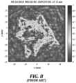
- FIG. 8is a graph of pressure amplitude for a sample target shown in FIG. 3 in accordance with conventional technology
- FIG. 9is a schematic diagram of a method for designing a customizable lens in accordance with an embodiment of the present technology.
- FIG. 10is a schematic diagram of determining holographic features of the lens in accordance with an embodiment of the present technology
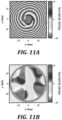
- FIG. 11 Ais a phase solution at aperture plane a graph of a target phase boundary condition in accordance with an embodiment of the present technology
- FIG. 11 Billustrates a phase solution on a transducer surface in accordance with an embodiment of the present technology
- FIG. 12is an isometric view of a curved holographic lens in accordance with an embodiment of the present technology
- FIG. 12 Ais a cross sectional view of a curved holographic lens in accordance with an embodiment of the present technology
- FIG. 13is a cross-sectional view of a curved holographic lens in accordance with an embodiment of the present technology.
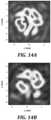
- FIGS. 14 A and 14 Bare graphs of simulated and measured pressure amplitude, respectively, at a target image plane of ultrasound in accordance with an embodiment of the present technology.
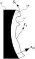
- FIG. 1is a side plan view of an ultrasound system 10 in accordance with conventional technology.
- the ultrasound system 10is a test system that includes a housing 30 that is filled with a medium 32 (typically water) that facilitates transmission of the ultrasound within the system 10 .
- the ultrasound system 10includes a test target 22 representing, for example, a hypothetical calcification or tumor in a body.
- the target 22is held by a target holder 24 .
- a transducer 12generates vibrations at ultrasound frequencies (e.g., from about 20 kHz to about 10 MHz).
- the transducer 12can be a piezoelectric element that expands and shrinks with changing electrical polarity applied to the transducer. Such a change in electrical polarity can be applied by an alternating current (AC) at a target ultrasound frequency.
- An interface 14attaches a lens to the transducer 14 .
- the interface 14is typically a permanent epoxy or other suitable strong adhesive.
- the lens 16focuses the ultrasound generated by the transducer 12 through an acoustic window 18 onto a target 22 .
- acoustic wavesobey Snell's law.
- ultrasoundcan be shaped by the lens 16 in the path of a propagating acoustic wave.
- Acoustic lensesbend the propagating wave in proportion to the ratio of indices of refraction of the lens and of a target medium, such as biological tissue.
- the index of refractionis a material property, depending on the speed of sound in the material.
- a coupling 17(e.g., gel, oil, etc.) provides acoustic coupling for the ultrasound propagating toward the target 22 .
- the ultrasound system 10includes an absorber 26 that prevents ultrasound from escaping into the environment.
- the operation of the transducer 12can be controlled by a controller 40 .
- FIG. 2is a side plan view of an ultrasound system 10 in accordance with conventional technology.
- the illustrated conventional system 10includes a holographic lens 16 .
- the illustrated holographic lens 16is relatively thick in the middle of the transducer 12 , therefore increasing the acoustic losses and degrading targeting precision of the ultrasound system 10 .
- a person of ordinary skillwould know that one of the challenges in developing ultrasound instruments for moving and breaking urinary tract stones is generating the appropriate acoustic pressure and beam shape to effectively apply force to or fragment the stone. For example, if a beam is too narrow, it may not fragment a stone because it does not impart enough energy on the entire stone. On the other hand, if a beam is too wide, ultrasound energy is wasted on collateral tissue. Therefore, ultrasound focusing is often necessary to achieve sufficient pressure on the stone.
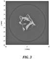
- FIG. 3is a view of a sample target object.
- the horizontal and vertical axesrepresent the target size in millimeters.
- Illustrated sample target imageis 32 mm away from the source of the ultrasound.
- the illustrated target imageis binary, the bright areas representing the maximum target pressure and dark areas representing zero target pressure. However, in different embodiments non-binary distributions of target pressure amplitude or phase may be used.
- the circle that is around the imageshows the outline of the transducer aperture (which is in the 0 mm plane).
- the combination of transducer and lensattempts to re-create the illustrated pressure field at 32 mm distance from the source of the ultrasound. A method of designing such customizable lens is described with reference to FIG. 5 below.
- FIG. 4is a schematic diagram of a method for designing a customizable lens in accordance with an embodiment of the present technology.
- the lensstimulates additive and destructive interference in a propagating wave front to generate a desired pressure and/or phase pattern at a target focal surface.
- the iterative angular spectrum approachdevelops precise phase mappings for the lenses, which in turn provide a physical design for the lens geometry.
- typical approaches to lens designsuch as the Fresnel approximation, fail to produce the desired pressure pattern with sufficient precision when the feature size in desired pressure pattern approaches the wavelength of the propagating wave front.
- the customizable lensmay be designed using the iterative angular spectrum approach (IASA).
- IASAiterative angular spectrum approach
- an algorithmimplements IASA numerically by iteratively comparing simulated conditions at the target focal surface against the target conditions at the focal surface.
- an algorithmimplements IASA numerically by iteratively comparing simulated conditions at the focal surface against the target conditions at the focal surface; and the complex pressure distribution at the source to the results from the previous iterative step.
- the algorithmintroduces lens geometry, propagating wave front, and target focal surface in a given medium.
- the target focal surfacemay be defined by its pressure pattern (p), made up of an amplitude map (A) and a phase map ( ⁇ ).
- the target focal surfaceis located some known distance from the lens.
- the IASA methoduses fast Fourier transform (FFT) and inverse fast Fourier transform (IFFT) methods to converge to an optimum error criterion, calculated as an error between the target focal surface and conditions at the focal surface.
- FFTfast Fourier transform
- IFFTinverse fast Fourier transform
- Equation 3The output of the FFT equation, P(kx,ky), gives an angular spectrum, where ki is the wavenumber in i space.
- Equation 3The IFFT equation, excluding the evanescent wave components, is shown in Equation 3:
- p ⁇ ( x , y , z )1 4 ⁇ ⁇ 2 ⁇ ⁇ ⁇ k x 2 + k y 2 ⁇ k 2 P ⁇ ( k x ⁇ k y ) ⁇ e j ⁇ ( k x ⁇ x + k y ⁇ y + k 2 - k x 2 - k y 2 ⁇ z ) ⁇ dk x ⁇ dk y ( 3 )
- Equation 4calculates the effect of movement through a given medium on the angular spectrum:
- the propagating wave frontthen propagates through the lens and the given medium to produce an angular spectrum for a propagated wave front at the focal surface (the conditions at the focal surface).
- IFFTprovides a wave equation in spatial coordinates for comparison to the desired conditions at the target focal surface.
- the error criterionindicates whether the lens design at the current iteration produces the target focal surface. In initial iterations, the error between the conditions at the focal surface and the target focal surface may be significant, due to near field effects that impact the propagating wave front.
- the IASAincorporates a back-propagation of the propagated wave front from the focal surface to the lens, shown as a clockwise lower arrow in FIG. 5 , and modulates the propagating wave front, and its angular spectrum, for iterative propagation forward to the focal surface.
- the algorithmretains the latest iteration of the phase information at the focal surface to calculate convergence.
- the methoduses the multiple checks in the convergence criterion to meet our desired goals.
- the algorithmiteratively compares the convergence of the simulated conditions to the target image specified at each target location.
- the algorithmcompares the complex pressure distribution at the source to that of the previous step as well to speed up and improve the convergence calculation criterion.
- the comparisons in the previous two checksare specified to be within a specific error tolerance below which convergence to the optimal hologram solution is achieved.
- a maximum number of iterationsis determined for each run, such that when it is exceeded the method terminates and saves the optimal hologram solution.
- the error tolerance and maximum number of iterationsis determined based on the complexity of the hologram, such as, the number of target locations for phase and or amplitude at different frequencies.
- a spatial thickness parameterdescribes the lens geometry by taking into account the transmission coefficient (a) of the system, including acoustic impedances (Z) of the lens material (h), the given medium (m), and a transducer (t), a source of acoustic waves:
- a T ( x , y )4 ⁇ Z t ⁇ Z h 2 ⁇ Z m z h 2 ( Z t + Z m ) 2 ⁇ cos ⁇ ( k h ⁇ T ⁇ ( x , y ) ) 2 + ( Z h 2 + Z t ⁇ Z m ) 2 ⁇ sin ⁇ ( k h ⁇ T ⁇ ( x , y ) ) 2 ( 5 )
- the thickness of the lens (T)can be calculated from the angular spectrum of the converged solution by creating a phase map for the surface of the lens.
- the lenscreates constructive and destructive interference in the near-field by introducing phase offsets ( ⁇ ) in the propagating wave front as it passes through the holographic lens.
- the IASA algorithmis capable of designing a lens that produces multiple target focal surfaces at as many distances from the lens in a given medium. To accomplish this, the IASA algorithm separately incorporates the backpropagation from the wave equations of each of the target focal surfaces when modulating the propagating wave equation.
- the IASA methodcan be used with different transducer geometries. For instance, for a focused transducer, the exact pressure field can be simulated and verified through holographic scanning in a plane. Next, the pressure field at the transducer aperture (obtained by back-projection) is used as the initial boundary condition over which we can impose the required phase to obtain the desired beam shape.
- the IASA-based design methodmaximizes the power of the beam while producing an arbitrary pressure distribution in the plane of interest.
- the methodcan be extended to constrain the amplitude distribution in several different planes of propagation. Analogously, the method can be extended to produce different beam patterns using ultrasonic transducers at different frequencies. The method can also be used to constrain the phase distribution in one or more planes, or both amplitude and phase distributions simultaneously.
- the desired target fieldmay be binary or continuously varying in amplitude and/or phase over the focal plane of interest.
- FIG. 5is a graph of thickness of a holographic lens in accordance with an embodiment of the present technology.
- the holographic features of the illustrated lensmay be obtained by the method described in conjunction with FIG. 4 above.
- the overall thickness of the lenschanges with the height T of the particular holographic features.
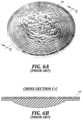
- FIG. 6 Ais an isometric view of a holographic lens in accordance with conventional technology.
- FIG. 6 Bis a cross-sectional view of the lens of FIG. 6 A .
- a flat holographic lensmay mate with a transducer having a flat outer surface.
- the back surface of the holographic lens 160when mated to a transducer having a concave surface, the back surface of the holographic lens 160 must be shaped against the curved surface of transducer by adding material to the back side of the holographic lens.
- An example of such additional material that makes the holographic lens thickeris shown in the cross-sectional view of FIG. 6 B .
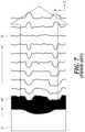
- FIG. 7is a schematic view of pressure waves produced by the lens in accordance with conventional technology.
- the holographic lens 160When mated with a transducer that operates at the design frequency of the ultrasound, the holographic lens 160 generates illustrated ultrasound waves that are focused on an image plane (focal plane) 20 .
- the additional lens thicknessincreases energy dissipation and reduces the targeting precision of the lens.
- FIG. 8is a graph of pressure amplitude for a sample target shown in FIG. 3 .
- the pressure amplitude fieldattempts to emulate the target image shown in FIG. 3 at a prescribed distance from the source (i.e., at a prescribed distance from the transducer).
- obtained pressure fieldmay lack spatial resolution and the pressure amplitudes may be off the target values.
- these shortcomings of the ultrasound pressure field at the target planemay be attributed to the additional thickness of the holographic lens, as explained above.
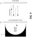
- FIG. 9is a schematic diagram of a method for designing a customizable lens 230 in accordance with an embodiment of the present technology.
- the method of designingmay be understood as a two-step process.
- an IASA algorithmas discussed with, for example, equations (1)-(7) may be used to design a flat holographic lens 230 based on the target pressure, phase, amplitude or velocity distribution of the ultrasound at the image plane 20 .
- flat holographic lensmay be referred to as an intermediate customizable holographic lens characterized by the intermediate pressure/velocity plane that is a flat, two-dimensional surface.
- a Rayleigh integral methodis used to determine the required holographic features of the curved holographic lens 230 .
- the resulting curved holographic lens (non-planar holographic lens) 230is characterized by the curvature of its principal plane in addition to the size and distribution of the holographic features, which in general differ from the holographic features of the corresponding flat holographic lens.
- the term principal plane of the holographic lensrefers to the plane that approximately follows a middle of the thickness of the lens.
- the principal plane of the holographic lens 230conforms to the curvature of the front surface (also referred to as the outer surface) of the transducer 12 .
- the Raileigh integralmay be determined based on the boundary conditions of a focused source and complex pressure at aperture plane plus half wavelength (1 ⁇ 2 ⁇ ) of the ultrasound being used.
- the Rayleigh integral to aperture planemay be expressed as:
- the ultrasonic transducer 12is illustrated as a single element transducer.
- a frequency of the ultrasonic transduceris within a range from 100 kHz to 20 MHz.
- a focal number of the customizable holographic lensis greater than 0.6.
- a ratio of an aperture of the customizable holographic lens and a wavelength of the ultrasoundgreater than 20.
- the holographic featuresare determined for the curved holographic lens.
- the holographic features of the curved holographic lensare different from those of the flat holographic lens.
- the holographic features of the curved lenscan be determined by simply bending a flat holographic lens into a mating position with a surface of the transducer. A person of ordinary skill would understand that such approach would result in erroneous summation/subtraction of the phases and amplitudes at the target focal plane. Determination of the holographic features of the curved holographic lens 230 is described in conjunction with FIGS. 10 - 11 B below.
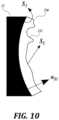
- FIG. 10is a schematic diagram of determining holographic features of the lens in accordance with an embodiment of the present technology.
- a focused phase solution at the aperture plane( FIG. 11 A ) is backpropagated to the phase solution on curved surface of the transducer 12 ( FIG. 11 B ) as:
- the small-scale features (holographic features) 232 on the surface of the lensdetermine the phase offsets of the emitted ultrasound.
- these phase offsetsconstructively/destructively combine into a target pressure, velocity, amplitude and/or phase field.
- the lens 230may also be a multi-element lens that comprises multiple segments.
- the holographic lens 230may be designed based on the target pressure amplitude/phase distributions, for example, as shown in FIG. 3 . It is possible to obtain different distributions of different parameters (e.g., pressure, velocity, amplitude and phase) at different target distances from the source of ultrasound. As explained above, the size and distribution of the holographic features 232 of the curved holographic lens 230 is determined using the method outlined by the equations (1)-(11).
- a time-varying signalalters the beam pattern of a single-lensed transducer.
- a curved holographic lens 230may generate multiple patterns at different frequencies simultaneously, or may generate a single pressure pattern for a finite temporal period.
- the frequency of a sinusoidal ultrasound signalmay be varied over time to change the pattern, either continuously as a frequency chirp, or discretely in intervals.
- a short signal pulsemay be generated by the transducer to produce a temporary holographic image for a therapy such as shock wave lithotripsy, burst wave lithotripsy, or histotripsy.
- the customizable lensmay be designed to produce a target distribution of ultrasound phases that, for example, pushes the target in a desired direction.
- the inventive technologyis used for diagnostic imaging, image guidance, or microbubble manipulation.
- FIG. 12is an isometric view of a curved holographic lens 230 in accordance with an embodiment of the present technology.
- the holographic lens 230is illustrated as facing the object to be treated, i.e., the holographic features 232 face the object to be treated.
- the customizable lens 230is made by machining or by additive manufacturing processes, for example, by 3D printing. In other embodiments, the customizable lens may be made by machining or injection molding.
- the customizable lens 230may be manufactured from glass, graphite, metal, epoxy, composite with suitable acoustic properties or plastic that has suitable transmission coefficients for the ultrasound frequency.
- the customizable lens 230may have a curvature to achieve focusing or defocusing simultaneously with image formation (e.g., formation of the target pressure field or phase distribution).
- the lens resolutionis generally determined by the method of manufacture, but in some applications the lens resolution can be smaller than a wavelength.
- Plane D-Dindicates a cross-sectional plane of the holographic lens 230 .
- FIG. 12 Ais a cross sectional view D-D of the curved holographic lens of FIG. 12 .
- the holographic lens 230is designed such that the back side of the lens follows the curvature R of the transducer 12 .
- an interface 14(not shown) is disposed between the transducer and holographic lens.
- the holographic lens 230has a generally uniform thickness To, save for the differing heights T of the individual holographic features 232 . As a result, the targeting accuracy and pressure amplitude/phase distribution are improved in comparison to the holographic lenses having non-uniform thickness, for example, the holographic lens illustrated in FIG. 6 B .
- FIG. 13is a cross-sectional view of a curved holographic lens in accordance with an embodiment of the present technology.
- the transducer 12may be characterized by a wavy surface to which the curved holographic lens 230 mates.
- the transducer's surfaceis characterized by different radii R 1 and R 2 , but in other embodiments, radii R 1 and R 2 may be same.
- the transducer's surfacemay be characterized by more than two radii, that is, by more than two different curvatures.
- a curvature of the front surface of the ultrasonic transduceris a spherical, parabolic or elliptical curvature.
- a curvature of the front surface of the ultrasonic transduceris a non-constant curvature disposed along multiple directions.
- FIGS. 14 A and 14 Bare graphs of simulated and measured pressure amplitude, respectively, achieved by a curved holographic lens at a target image plane of ultrasound in accordance with an embodiment of the present technology.
- the horizontal and vertical axesindicate the size of the image plane in mm Pressures are normalized for comparisons.
- the measured field of FIG. 14 Bis obtained by holography field propagation, i.e., a holography scan is used to propagate the pressure field in 3D.
- An excellent agreementis achieved between the simulated pressure amplitude ( FIG. 14 A ) and measured pressure amplitude ( FIG. 14 B ).
- Deviationwas quantified using relative change in Frobenius norm.
- a difference between the simulated and measured fieldscan be expressed (in percentage) as:
- ⁇⁇ P ⁇ ( x , y ) sim . , P ⁇ ( x , y ) sim . >- ⁇ P ⁇ ( x , y ) meas . , P ⁇ ( x , y ) meas . > ⁇ P ⁇ ( x , y ) sim . , P ⁇ ( x , y ) sim . > ⁇ 100 ( 12 )
- ⁇corresponds to 4.8%. This is considered a very good result, which far exceeds the performance of a flat holographic lens under the same conditions.
- computer- or controller-executable instructionsmay take the form of computer- or controller-executable instructions, including routines executed by a programmable computer or controller.
- routines executed by a programmable computer or controllerThose skilled in the relevant art will appreciate that the technology can be practiced on computer/controller systems other than those shown and described above.
- the technologycan be embodied in a special-purpose computer, controller or data processor that is specifically programmed, configured or constructed to perform one or more of the computer-executable instructions described above.
- the terms “computer” and “controller” as generally used hereinrefer to any data processor and can include Internet appliances and hand-held devices (including palm-top computers, wearable computers, cellular or mobile phones, multi-processor systems, processor-based or programmable consumer electronics, network computers, mini computers and the like).
Landscapes
- Physics & Mathematics (AREA)
- Health & Medical Sciences (AREA)
- Engineering & Computer Science (AREA)
- General Physics & Mathematics (AREA)
- Optics & Photonics (AREA)
- Biomedical Technology (AREA)
- Ophthalmology & Optometry (AREA)
- Mechanical Engineering (AREA)
- Manufacturing & Machinery (AREA)
- Nuclear Medicine, Radiotherapy & Molecular Imaging (AREA)
- Radiology & Medical Imaging (AREA)
- Life Sciences & Earth Sciences (AREA)
- Animal Behavior & Ethology (AREA)
- General Health & Medical Sciences (AREA)
- Public Health (AREA)
- Veterinary Medicine (AREA)
- Ultra Sonic Daignosis Equipment (AREA)
Abstract
Description
p(x,y,z)={circumflex over (p)}(x,y,z)ejΔΦ(x,y,z) (1)
where {circumflex over (p)}(x, y, z) and ΔΦ(x, y, z) are the amplitude and phase functions, respectively.
ΔΦ(x,y)=(km−kh)ΔT(x,y) (6)
where
T(x,y)=T0−ΔT(x,y). (7)
assuming that the radius of curvature (R) of the front surface of the transducer is much higher than the ultrasound wavelength (R>>λ), which is a reasonable assumption for most practical ultrasonic transducers. The
where nsiis Sisurface normal. The resulting thickness (T) of the
where k=2π/λi, and λiis wavelength in material i.
SL−S1=(T+To)·nS1 (11)
where T is the height of the holographic feature, and To is a constant thickness that adds no phase change.
Claims (8)
SL−S1=(T+To)·ns1
T=Φ/ko−klens
Priority Applications (1)
| Application Number | Priority Date | Filing Date | Title |
|---|---|---|---|
| US17/881,026US12285636B2 (en) | 2021-08-05 | 2022-08-04 | Non-planar holographic beam shaping lenses for acoustics |
Applications Claiming Priority (2)
| Application Number | Priority Date | Filing Date | Title |
|---|---|---|---|
| US202163230003P | 2021-08-05 | 2021-08-05 | |
| US17/881,026US12285636B2 (en) | 2021-08-05 | 2022-08-04 | Non-planar holographic beam shaping lenses for acoustics |
Publications (2)
| Publication Number | Publication Date |
|---|---|
| US20230038081A1 US20230038081A1 (en) | 2023-02-09 |
| US12285636B2true US12285636B2 (en) | 2025-04-29 |
Family
ID=85152207
Family Applications (1)
| Application Number | Title | Priority Date | Filing Date |
|---|---|---|---|
| US17/881,026Active2042-10-13US12285636B2 (en) | 2021-08-05 | 2022-08-04 | Non-planar holographic beam shaping lenses for acoustics |
Country Status (1)
| Country | Link |
|---|---|
| US (1) | US12285636B2 (en) |
Citations (64)
| Publication number | Priority date | Publication date | Assignee | Title |
|---|---|---|---|---|
| US4475921A (en) | 1982-03-24 | 1984-10-09 | The United States Of America As Represented By The Administrator Of The National Aeronautics And Space Administration | Acoustic agglomeration methods and apparatus |
| EP0134346A1 (en)* | 1983-08-25 | 1985-03-20 | Analogic Corporation | Ultrasonic transducers |
| US5902489A (en) | 1995-11-08 | 1999-05-11 | Hitachi, Ltd. | Particle handling method by acoustic radiation force and apparatus therefore |
| WO2006055470A1 (en) | 2004-11-15 | 2006-05-26 | Garlick George F | System, method and apparatus for direct imaging in ultrasonic holography |
| US20080194965A1 (en) | 2007-02-08 | 2008-08-14 | Sliwa John W | Device and method for high intensity focused ultrasound ablation with acoustic lens |
| US7837623B2 (en) | 2002-08-28 | 2010-11-23 | Super Sonic Imagine | Non-invasive method of obtaining a pre-determined acoustic wave field in an essentially uniform medium which is concealed by a bone barrier, imaging method and device for carrying out said methods |
| CN101955595A (en) | 2010-08-11 | 2011-01-26 | 东南大学 | Method for guiding fixed-point cell growth by preparing chemical micro-patterns on surfaces of various materials |
| US20120029393A1 (en) | 2010-07-30 | 2012-02-02 | General Electric Company | Compact ultrasound transducer assembly and methods of making and using the same |
| KR101261298B1 (en) | 2012-01-31 | 2013-05-06 | 원테크놀로지 주식회사 | Multi-focal ultrasound device for epilation |
| US8509928B2 (en) | 2004-05-27 | 2013-08-13 | Bracco Imaging S.P.A. | Method and apparatus for producing stationary intense wave fields of arbitrary shape |
| CA2864665A1 (en) | 2012-02-14 | 2013-08-22 | Board Of Regents, The University Of Texas System | Tissue engineering device and construction of vascularized dermis |
| US20130289593A1 (en) | 2012-04-30 | 2013-10-31 | Timothy L. Hall | Ultrasound Transducer Manufacturing Using Rapid-Prototyping Method |
| US20130301383A1 (en) | 2012-05-14 | 2013-11-14 | Oleg A. Sapozhnikov | Portable acoustic holography systems for therapeutic ultrasound sources and associated devices and methods |
| US20140058292A1 (en) | 2012-08-22 | 2014-02-27 | Medtronic, Inc. | Ultrasound diagnostic and therapy management system and associated method |
| JP2014198197A (en) | 2013-03-29 | 2014-10-23 | セイコーエプソン株式会社 | Acoustic matching body, ultrasonic probe, and ultrasonic imaging device |
| US20160114193A1 (en) | 2014-10-23 | 2016-04-28 | Oleg Prus | Multilayer ultrasound transducers for high-power transmission |
| US20160185056A1 (en) | 2014-12-31 | 2016-06-30 | General Electric Company | System and method for manufacturing an ultrasound probe lens |
| US20160317842A1 (en) | 2006-12-21 | 2016-11-03 | St. Jude Medical, Atrial Fibrillation Division, Inc. | High intensity focused ultrasound transducer with acoustic lens |
| KR20170005526A (en) | 2015-06-23 | 2017-01-16 | 서강대학교산학협력단 | An ultrasound transducer assembly for beam-forming and manufacturing method thereof |
| US20170094265A1 (en) | 2015-09-30 | 2017-03-30 | Brian Mullins | Bidirectional holographic lens |
| CN106659463A (en) | 2014-05-14 | 2017-05-10 | 皇家飞利浦有限公司 | Acoustical lens and ultrasound transducer probe |
| WO2017097417A1 (en) | 2015-12-11 | 2017-06-15 | Max-Planck-Gesellschaft Zur Förderung Der Förderung Der Wissenschaften E. V. | Apparatus and method for creating a holographic ultrasound field in an object |
| US20170226473A1 (en) | 2014-10-27 | 2017-08-10 | The Board Of Trustees Of The Leland Stanford Junior University | Scaffold-free 3D Cell Assembly based on patterned Hydrodynamic Drag Force |
| US20170245874A1 (en) | 2014-10-17 | 2017-08-31 | University Of Washington | Broadly focused ultrasonic propulsion probes, systems, and methods |
| US20170296216A1 (en) | 2012-11-06 | 2017-10-19 | Med-Sonics Corporation | Systems and methods for controlling delivery of ultrasonic energy to a bodily tissue |
| US20170311804A1 (en) | 2015-01-15 | 2017-11-02 | Rodney Herring | Diffuse acoustic confocal imager |
| US9901753B2 (en) | 2009-08-26 | 2018-02-27 | The Regents Of The University Of Michigan | Ultrasound lithotripsy and histotripsy for using controlled bubble cloud cavitation in fractionating urinary stones |
| US20180070967A1 (en) | 2016-09-09 | 2018-03-15 | M. Fazni Aziz | Air bubble removal lithotripsy assembly and method |
| US20180110497A1 (en) | 2016-10-25 | 2018-04-26 | General Electric Company | Customized handle for ultrasound probe |
| US20180192990A1 (en) | 2015-07-01 | 2018-07-12 | Centre National De La Recherche Scientifique - Cnrs | Insonification Method for Obtaining a Predetermined Field of Ultrasonic Waves and Production Method for Making an Ultrasonic Lens for These Purposes |
| US10251657B1 (en) | 2013-05-02 | 2019-04-09 | University Of Washington Through Its Center For Commercialization | Noninvasive fragmentation of urinary tract stones with focused ultrasound |
| CN110314715A (en) | 2019-07-17 | 2019-10-11 | 西安交通大学 | Micro-fluidic chip is enriched with based on focusing surface acoustic wave and the particle of microlayer model technology |
| WO2019236409A1 (en) | 2018-06-04 | 2019-12-12 | Fujifilm Sonosite, Inc. | Ultrasound transducer with curved transducer stack |
| US20200078608A1 (en) | 2013-03-28 | 2020-03-12 | University Of Washington Through Its Center For Commercialization | Focused Ultrasound Apparatus and Methods of Use |
| CN111254076A (en) | 2020-01-19 | 2020-06-09 | 武汉大学 | A hexagonal surface wave acoustic tweezers chip for cell arrangement and assembly |
| CN111326135A (en) | 2020-04-03 | 2020-06-23 | 青岛大学 | Broadband achromatic acoustic focusing lens |
| US20200384463A1 (en) | 2017-08-04 | 2020-12-10 | Nokia Technologies Oy | Apparatus and method for positioning particles inside a channel |
| US20210008394A1 (en) | 2013-08-22 | 2021-01-14 | The Regents Of The University Of Michigan | Histotripsy using very short ultrasound pulses |
| WO2021035679A1 (en) | 2019-08-30 | 2021-03-04 | 江南大学 | Tissue engineered nerve graft and preparation method therefor |
| US20210101178A1 (en) | 2019-10-07 | 2021-04-08 | University Of Southern California | Electrical Tuning of Focal Size with Single-Element Planar Focused Ultrasonic Transducer |
| CN213098574U (en) | 2020-05-31 | 2021-05-04 | 山西省人民医院 | Autologous chondrocyte composite bracket |
| CN112951196A (en) | 2014-09-05 | 2021-06-11 | 华盛顿大学 | Method for generating ultrasound intensity traps to confine or move objects using focused ultrasound waves |
| CN112946087A (en) | 2021-01-28 | 2021-06-11 | 四川工程职业技术学院 | Fine sound beam ultrasonic probe and design method |
| US20210187330A1 (en) | 2018-08-16 | 2021-06-24 | University Of Washington | Apparatus and method for ultrasound beam shaping |
| CN113018514A (en) | 2021-04-29 | 2021-06-25 | 承德石油高等专科学校 | Heterogeneous bone tissue engineering scaffold, extrusion assembly and preparation method thereof |
| CN113061279A (en) | 2021-03-17 | 2021-07-02 | 宁波大学 | Preparation method of PTMC micro-graph bionic functional membrane |
| CN213722633U (en) | 2020-05-12 | 2021-07-20 | 北京大学第三医院(北京大学第三临床医学院) | HIFU equipment suitable for experiment is aroused to animal tumour treatment supersound |
| CN113215101A (en) | 2021-05-31 | 2021-08-06 | 清华大学 | Method for constructing fiber bundle/tissue structure with heterogeneous functional fibers and blood vessel channel |
| US20210260578A1 (en) | 2018-10-19 | 2021-08-26 | North Carolina State University | Ultrasound-based patterning of particles and cells within fluid matrices |
| CN113604463A (en) | 2021-07-30 | 2021-11-05 | 武汉大学 | Cell assembly method for Faraday wave multi-wavelength synthesis and application |
| CN113643683A (en) | 2021-07-01 | 2021-11-12 | 大连理工大学 | A three-dimensional multifunctional acoustic lens based on gradient index control and its realization method |
| US20210362145A1 (en) | 2020-05-22 | 2021-11-25 | University Of Southern California | Contactless, damage-free, high-precision cell extraction and transfer through acoustic droplet ejection |
| CR20210549A (en) | 2019-04-03 | 2021-11-30 | Peaches S L | Composition for tissue regeneration, method of production and uses thereof |
| CN113826229A (en) | 2019-04-24 | 2021-12-21 | 加利福尼亚大学董事会 | Deep subwavelength acoustic manipulation of arbitrary shapes for microparticle and cell patterning |
| US20210396712A1 (en) | 2018-10-22 | 2021-12-23 | Consejo Superior De Investigaciones Cientificas (Csic) | Method for Producing a Lens and Ultrasound Device Comprising the Lens |
| CN113941030A (en) | 2021-10-27 | 2022-01-18 | 西安交通大学 | Ultrasound-assisted 3D printed vascular tissue engineering scaffold and preparation method thereof |
| JP2022017543A (en) | 2013-07-03 | 2022-01-25 | ヒストソニックス,インコーポレーテッド | Histotripsy excitation sequence optimized for bubble cloud formation using shock scattering |
| WO2022032203A1 (en) | 2020-08-07 | 2022-02-10 | The Trustees Of The Stevens Institute Of Technology | Conductive scaffolds for guided neural network formation |
| WO2022052179A1 (en) | 2020-09-09 | 2022-03-17 | 深圳先进技术研究院 | Ultrasonic nerve regulating device |
| US20220082690A1 (en) | 2020-09-11 | 2022-03-17 | Toyota Motor Engineering & Manufacturing North America, Inc. | Acoustic metamaterial and systems for edge detection |
| US20220096873A1 (en) | 2020-09-29 | 2022-03-31 | Cancer Rx, LLC | Cancer Imaging Methods And Cancer Treatment Methods Using Thermotherapy And Drug Delivery |
| EP3985096A1 (en) | 2019-06-13 | 2022-04-20 | Savelife Biotechnology Co., Limited | Method and device for controlling movement of micro-particles in solution using ultra-high frequency sound wave |
| WO2022083432A1 (en) | 2020-10-19 | 2022-04-28 | 浙江大学 | Method and system for ultrasonic non-invasive transcranial imaging employing broadband acoustic metamaterial |
| US20220328032A1 (en)* | 2019-09-06 | 2022-10-13 | Triangle Biotechnology, Inc. | Targeted Multifocal Lens for Biological Sample Processing and Related Methods |
- 2022
- 2022-08-04USUS17/881,026patent/US12285636B2/enactiveActive
Patent Citations (65)
| Publication number | Priority date | Publication date | Assignee | Title |
|---|---|---|---|---|
| US4475921A (en) | 1982-03-24 | 1984-10-09 | The United States Of America As Represented By The Administrator Of The National Aeronautics And Space Administration | Acoustic agglomeration methods and apparatus |
| EP0134346A1 (en)* | 1983-08-25 | 1985-03-20 | Analogic Corporation | Ultrasonic transducers |
| US5902489A (en) | 1995-11-08 | 1999-05-11 | Hitachi, Ltd. | Particle handling method by acoustic radiation force and apparatus therefore |
| US7837623B2 (en) | 2002-08-28 | 2010-11-23 | Super Sonic Imagine | Non-invasive method of obtaining a pre-determined acoustic wave field in an essentially uniform medium which is concealed by a bone barrier, imaging method and device for carrying out said methods |
| US8509928B2 (en) | 2004-05-27 | 2013-08-13 | Bracco Imaging S.P.A. | Method and apparatus for producing stationary intense wave fields of arbitrary shape |
| WO2006055470A1 (en) | 2004-11-15 | 2006-05-26 | Garlick George F | System, method and apparatus for direct imaging in ultrasonic holography |
| US20160317842A1 (en) | 2006-12-21 | 2016-11-03 | St. Jude Medical, Atrial Fibrillation Division, Inc. | High intensity focused ultrasound transducer with acoustic lens |
| US20080194965A1 (en) | 2007-02-08 | 2008-08-14 | Sliwa John W | Device and method for high intensity focused ultrasound ablation with acoustic lens |
| US9901753B2 (en) | 2009-08-26 | 2018-02-27 | The Regents Of The University Of Michigan | Ultrasound lithotripsy and histotripsy for using controlled bubble cloud cavitation in fractionating urinary stones |
| US20120029393A1 (en) | 2010-07-30 | 2012-02-02 | General Electric Company | Compact ultrasound transducer assembly and methods of making and using the same |
| CN101955595A (en) | 2010-08-11 | 2011-01-26 | 东南大学 | Method for guiding fixed-point cell growth by preparing chemical micro-patterns on surfaces of various materials |
| KR101261298B1 (en) | 2012-01-31 | 2013-05-06 | 원테크놀로지 주식회사 | Multi-focal ultrasound device for epilation |
| CA2864665A1 (en) | 2012-02-14 | 2013-08-22 | Board Of Regents, The University Of Texas System | Tissue engineering device and construction of vascularized dermis |
| US20130289593A1 (en) | 2012-04-30 | 2013-10-31 | Timothy L. Hall | Ultrasound Transducer Manufacturing Using Rapid-Prototyping Method |
| US20130301383A1 (en) | 2012-05-14 | 2013-11-14 | Oleg A. Sapozhnikov | Portable acoustic holography systems for therapeutic ultrasound sources and associated devices and methods |
| US20140058292A1 (en) | 2012-08-22 | 2014-02-27 | Medtronic, Inc. | Ultrasound diagnostic and therapy management system and associated method |
| US20170296216A1 (en) | 2012-11-06 | 2017-10-19 | Med-Sonics Corporation | Systems and methods for controlling delivery of ultrasonic energy to a bodily tissue |
| US20200078608A1 (en) | 2013-03-28 | 2020-03-12 | University Of Washington Through Its Center For Commercialization | Focused Ultrasound Apparatus and Methods of Use |
| JP2014198197A (en) | 2013-03-29 | 2014-10-23 | セイコーエプソン株式会社 | Acoustic matching body, ultrasonic probe, and ultrasonic imaging device |
| US10251657B1 (en) | 2013-05-02 | 2019-04-09 | University Of Washington Through Its Center For Commercialization | Noninvasive fragmentation of urinary tract stones with focused ultrasound |
| JP2022017543A (en) | 2013-07-03 | 2022-01-25 | ヒストソニックス,インコーポレーテッド | Histotripsy excitation sequence optimized for bubble cloud formation using shock scattering |
| US20210008394A1 (en) | 2013-08-22 | 2021-01-14 | The Regents Of The University Of Michigan | Histotripsy using very short ultrasound pulses |
| CN106659463A (en) | 2014-05-14 | 2017-05-10 | 皇家飞利浦有限公司 | Acoustical lens and ultrasound transducer probe |
| CN112951196A (en) | 2014-09-05 | 2021-06-11 | 华盛顿大学 | Method for generating ultrasound intensity traps to confine or move objects using focused ultrasound waves |
| US20170245874A1 (en) | 2014-10-17 | 2017-08-31 | University Of Washington | Broadly focused ultrasonic propulsion probes, systems, and methods |
| US20160114193A1 (en) | 2014-10-23 | 2016-04-28 | Oleg Prus | Multilayer ultrasound transducers for high-power transmission |
| US20170226473A1 (en) | 2014-10-27 | 2017-08-10 | The Board Of Trustees Of The Leland Stanford Junior University | Scaffold-free 3D Cell Assembly based on patterned Hydrodynamic Drag Force |
| US20160185056A1 (en) | 2014-12-31 | 2016-06-30 | General Electric Company | System and method for manufacturing an ultrasound probe lens |
| US20170311804A1 (en) | 2015-01-15 | 2017-11-02 | Rodney Herring | Diffuse acoustic confocal imager |
| KR20170005526A (en) | 2015-06-23 | 2017-01-16 | 서강대학교산학협력단 | An ultrasound transducer assembly for beam-forming and manufacturing method thereof |
| US20180192990A1 (en) | 2015-07-01 | 2018-07-12 | Centre National De La Recherche Scientifique - Cnrs | Insonification Method for Obtaining a Predetermined Field of Ultrasonic Waves and Production Method for Making an Ultrasonic Lens for These Purposes |
| US20170094265A1 (en) | 2015-09-30 | 2017-03-30 | Brian Mullins | Bidirectional holographic lens |
| US20180341221A1 (en)* | 2015-12-11 | 2018-11-29 | Max-Planck-Gesellschaft Zur Foerderung Der Wissenschaften E.V | Apparatus and method for creating a holographic ultrasound field in an object |
| WO2017097417A1 (en) | 2015-12-11 | 2017-06-15 | Max-Planck-Gesellschaft Zur Förderung Der Förderung Der Wissenschaften E. V. | Apparatus and method for creating a holographic ultrasound field in an object |
| US20180070967A1 (en) | 2016-09-09 | 2018-03-15 | M. Fazni Aziz | Air bubble removal lithotripsy assembly and method |
| US20180110497A1 (en) | 2016-10-25 | 2018-04-26 | General Electric Company | Customized handle for ultrasound probe |
| US20200384463A1 (en) | 2017-08-04 | 2020-12-10 | Nokia Technologies Oy | Apparatus and method for positioning particles inside a channel |
| WO2019236409A1 (en) | 2018-06-04 | 2019-12-12 | Fujifilm Sonosite, Inc. | Ultrasound transducer with curved transducer stack |
| US20210187330A1 (en) | 2018-08-16 | 2021-06-24 | University Of Washington | Apparatus and method for ultrasound beam shaping |
| US20210260578A1 (en) | 2018-10-19 | 2021-08-26 | North Carolina State University | Ultrasound-based patterning of particles and cells within fluid matrices |
| US20210396712A1 (en) | 2018-10-22 | 2021-12-23 | Consejo Superior De Investigaciones Cientificas (Csic) | Method for Producing a Lens and Ultrasound Device Comprising the Lens |
| CR20210549A (en) | 2019-04-03 | 2021-11-30 | Peaches S L | Composition for tissue regeneration, method of production and uses thereof |
| CN113826229A (en) | 2019-04-24 | 2021-12-21 | 加利福尼亚大学董事会 | Deep subwavelength acoustic manipulation of arbitrary shapes for microparticle and cell patterning |
| EP3985096A1 (en) | 2019-06-13 | 2022-04-20 | Savelife Biotechnology Co., Limited | Method and device for controlling movement of micro-particles in solution using ultra-high frequency sound wave |
| CN110314715A (en) | 2019-07-17 | 2019-10-11 | 西安交通大学 | Micro-fluidic chip is enriched with based on focusing surface acoustic wave and the particle of microlayer model technology |
| WO2021035679A1 (en) | 2019-08-30 | 2021-03-04 | 江南大学 | Tissue engineered nerve graft and preparation method therefor |
| US20220328032A1 (en)* | 2019-09-06 | 2022-10-13 | Triangle Biotechnology, Inc. | Targeted Multifocal Lens for Biological Sample Processing and Related Methods |
| US20210101178A1 (en) | 2019-10-07 | 2021-04-08 | University Of Southern California | Electrical Tuning of Focal Size with Single-Element Planar Focused Ultrasonic Transducer |
| CN111254076A (en) | 2020-01-19 | 2020-06-09 | 武汉大学 | A hexagonal surface wave acoustic tweezers chip for cell arrangement and assembly |
| CN111326135A (en) | 2020-04-03 | 2020-06-23 | 青岛大学 | Broadband achromatic acoustic focusing lens |
| CN213722633U (en) | 2020-05-12 | 2021-07-20 | 北京大学第三医院(北京大学第三临床医学院) | HIFU equipment suitable for experiment is aroused to animal tumour treatment supersound |
| US20210362145A1 (en) | 2020-05-22 | 2021-11-25 | University Of Southern California | Contactless, damage-free, high-precision cell extraction and transfer through acoustic droplet ejection |
| CN213098574U (en) | 2020-05-31 | 2021-05-04 | 山西省人民医院 | Autologous chondrocyte composite bracket |
| WO2022032203A1 (en) | 2020-08-07 | 2022-02-10 | The Trustees Of The Stevens Institute Of Technology | Conductive scaffolds for guided neural network formation |
| WO2022052179A1 (en) | 2020-09-09 | 2022-03-17 | 深圳先进技术研究院 | Ultrasonic nerve regulating device |
| US20220082690A1 (en) | 2020-09-11 | 2022-03-17 | Toyota Motor Engineering & Manufacturing North America, Inc. | Acoustic metamaterial and systems for edge detection |
| US20220096873A1 (en) | 2020-09-29 | 2022-03-31 | Cancer Rx, LLC | Cancer Imaging Methods And Cancer Treatment Methods Using Thermotherapy And Drug Delivery |
| WO2022083432A1 (en) | 2020-10-19 | 2022-04-28 | 浙江大学 | Method and system for ultrasonic non-invasive transcranial imaging employing broadband acoustic metamaterial |
| CN112946087A (en) | 2021-01-28 | 2021-06-11 | 四川工程职业技术学院 | Fine sound beam ultrasonic probe and design method |
| CN113061279A (en) | 2021-03-17 | 2021-07-02 | 宁波大学 | Preparation method of PTMC micro-graph bionic functional membrane |
| CN113018514A (en) | 2021-04-29 | 2021-06-25 | 承德石油高等专科学校 | Heterogeneous bone tissue engineering scaffold, extrusion assembly and preparation method thereof |
| CN113215101A (en) | 2021-05-31 | 2021-08-06 | 清华大学 | Method for constructing fiber bundle/tissue structure with heterogeneous functional fibers and blood vessel channel |
| CN113643683A (en) | 2021-07-01 | 2021-11-12 | 大连理工大学 | A three-dimensional multifunctional acoustic lens based on gradient index control and its realization method |
| CN113604463A (en) | 2021-07-30 | 2021-11-05 | 武汉大学 | Cell assembly method for Faraday wave multi-wavelength synthesis and application |
| CN113941030A (en) | 2021-10-27 | 2022-01-18 | 西安交通大学 | Ultrasound-assisted 3D printed vascular tissue engineering scaffold and preparation method thereof |
Non-Patent Citations (136)
| Title |
|---|
| Ali, C., et al., "Tunable Control and Functional Switch of Transmitted Acoustic Waves by an Arch-Shaped Metasurface," Chinese Journal of Theoretical and Applied Mechanics, 2021, 53(3): 789-801, 2021. |
| Al-Jumaily, A.M. and A. Meshkinzar, "On the Development of Focused Ultrasound Liquid Atomizers," Advances in Acoustics and Vibration, vol. 2017, pp. 1-10, 2017. |
| Armstrong, J. P. K. and M. M. Stevens. "Using Remote Fields for Complex Tissue Engineering," Trends in Biotechnology, Mar. 2020, vol. 38, No. 3, pp. 254-263 https://doi.org/10.1016/j.tibtech.2019.07.005. |
| Armstrong, J.P. K. et al., "Engineering Anisotropic Muscle Tissue using Acoustic Cell Patterning," Adv. Mater. 2018, 30, 1802649, pp. 1-7. |
| Bailey, M.R., et al., "Progress in Lithotripsy Research," Acoustics Today 2(2):18-29, 2006. |
| Bakhtiari-Nejad, M., "Multi-focal transmission acoustic phase holograms in contactless ultrasonic power transfer systems," Sensors and Actuators A: Physical, vol. 340, 2022, 113551. |
| Baudoin M. et a., "Spatially selective manipulation of cells with single-beam acoustical tweezers," Nature Communications; 202011:4244, pp. 1-10 https://doi.org/10.1038/s41467-020-18000-y. |
| Bigelow, T.A., "Experimental Evaluation of Nonlinear Indices for Ultrasound Transducer Characterizations" master's thesis, Colorado State University, 1998, pp. 99-103, Appendix B: The KLM Model. |
| Blitz, B.F., et al., "Applicability of Iceland Spar as a Stone Model Standard for Lithotripsy Devices," Journal of Endourology 9(6):449-452, 1995. |
| Bohris, C., "Quality of Coupling in ESWL Significantly Affects the Disintegration Capacity—How to Achieve Good Coupling With Ultra-Sound Gel," in ed. C. Koehrmann et al., 1st ed., "Therapy Energy Applications in Urology II: Standards Recent Developments," Chap. 2.4, pp. 61-64, 2010. |
| Chan, W. et al., "Laser-generated focused ultrasound for arbitrary waveforms," Applied Physics Letters 109 (17):174102, 2016. |
| Chansoria, P. and R. Shirwaiker, "3D bioprinting of anisotropic engineered tissue constructs with ultrasonically induced cell patterning," Elsevier: Additive Manufacturing 32 (2020) 101042, pp. 1-12. |
| Chansoria, P. and R. Shirwaiker, "Characterizing the Process Physics of Ultrasound-Assisted Bioprinting," Scientific Reports 2019 9: 13889, p. 1-17 https://doi.org/10.1038/s41598-019-50449-w. |
| Chansoria, P. et al., Ultrasound-assisted biofabrication and bioprinting of preferentially aligned three-dimensional cellular constructs, Biofabrication 11 (2019) 035015, pp. 1-18. |
| Chaussy, C., et al., "Extracorporeally Induced Destruction of Kidney Stones by Shock Waves," The Lancet, vol. 316, No. 8207, pp. 1265-1268, 1980. |
| Chen, L., et al., "High Intensity Focused Ultrasound Ablation for Patients with Inoperable Liver Cancer," Hepato-Gastroenterology 62(137):140-143, 2015. |
| Cheng, K. W. et al., "Fast three-dimensional micropatterning of PC12 cells in rapidly crosslinked hydrogel scaffolds using ultrasonic standing waves," 2020 Biofabrication 12 015013. |
| Chu, B.T.C., "Design of a defocused transducer for targeted cancer drug delivery by ultrasound-mediated hyperthermia, PHD thesis, University of Oxford," 2018, 215 pages. |
| Cleveland, R., and J. McAteer, "The Physics of Shock Wave Lithotripsy," Smith's Textbook of Endourology, published by B. C. Decker Inc., Hamilton, Ontario, Canada, vol. 1, Chap. 38, pp. 317-331, 2007. |
| Crum, L.A., "Cavitation Microjets as a Contributory Mechanism for Renal Calculi Disintegration in ESWL," The Journal of Urology 140(6):1587-1590, 1988. |
| Crum, L.A., and J. B. Fowlkes, "Acoustic cavitation generated by microsecond pulses of ultrasound," Nature, vol. 319, No. 6048, pp. 52-54, 1986. |
| Dalecki, D. and D. C. Hocking, "Ultrasound Technologies for Biomaterials Fabrication and Imaging," Annals of Biomedical Engineering, vol. 43, No. 3, Mar. 2015 (2014) pp. 747-761; DOI: 10.1007/s10439-014-1158-6. |
| Dardikman-Yoffe, G. et al. "High-resolution 4-D acquisition of freely swimming human sperm cells without staining," Sci. Adv. 2020; 6: eaay7619 Apr. 10, 2020. |
| Delius, M., et al., "A mechanism of gallstone destruction by extracorporeal shock waves.," Naturwissenschaften 75(4):200-201, 1988. |
| Dennis Li et al., "Design of an acoustic metamaterial lens using genetic algorithms," Oct. 1, 2012, The Journal of the Acoustical Society of America, 132, 4, pp. 2823-2833 (Year: 2012). |
| Ding, X. et al., "Tunable patterning of microparticles and cells using standing surface acoustic waves," Lab Chip, 2012, 12, 2491-2497. |
| Duryea, A.P., et al., "In Vitro Comminution of Model Renal Calculi Using Histotripsy," IEEE Transactions on Ultrasonics Ferroelectrics and Frequency Control 58(5):971-980, 2011. |
| Eisenmenger, W. et al., "The first clinical results of ‘wide-focus and low-pressure’ ESWL," Ultrasound Medical Biology 28(6):769-774, 2002. |
| Eisenmenger, W., "The mechanisms of stone fragmentation in ESWL.," Ultrasound Medical Biology 27(5):683-693, 2001. |
| Esch, E., et al., "A simple method for fabricating artificial kidney stones of different physical properties," Urological Research 38(4):315-319, 2010. |
| Falconnet, D. et al., "Surface engineering approaches to micropattern surfaces for cell-based assays," Elsevier: Biomaterials 27 (2006) 3044-3063. |
| Ferri, M., et al., "Enhanced Numerical Method for the Design of 3-D-Printed Holographic Acoustic Lenses for Aberration Correction of Single-Element Transcranial Focused Ultrasound," Ultrasound in Medicine and Biology 45(3):867-884, 2019. |
| Ferri, M., et al., "On the Evaluation of the Suitability of the Materials Used to 3D Print Holographic Acoustic Lenses to Correct Transcranial Focused Ultrasound Aberrations," Polymers 2019, 11(9), 1521, 25 pages. |
| Gao, H., et al., "Acoustic focusing by symmetrical self-bending beams with phase modulations," Applied Physics Letters, vol. 108, No. 7, 2016, 5 pages. |
| Gesellchen, F. et al., "Cell patterning with a heptagon acoustic tweezer—application in neurite guidance," Lab Chip, 2014, 14, 2266. |
| Gjorevski, N. et al., "Designer matrices for intestinal stem cell and organoid culture," Nature vol. 539, Nov. 2016, 560-576; doi: 10.1038/nature20168. |
| Gu, Y. et al., "Acoustofluidic Holography for Micro- to Nanoscale Particle Manipulation," ACS Nano 2020, 14, 14635-14645. |
| Hadimioglu, B., et al., "High-Efficiency Fresnel Acoustic Lenses," IEEE Ultrasonics Symposium, pp. 579-582, 1993. |
| Hampson, M., "Ultrasonic Holograms: Who Knew Acoustics Could Go 30? Imaging and other medical applications waiting in the wings," News Sensors, Feb. 3, 2021. |
| Harper, J.D., et al., "Focused Ultrasound to Expel Calculi from the Kidney: Safety and Efficacy of a Clinical Prototype Device," The Journal of Urology 190:1090-1095, 2013. |
| He, J., et al., "Multitarget Transcranial Ultrasound Therapy in Small Animals Based on Phase-Only Acoustic Holographic Lens," in IEEE Transactions on Ultrasonics, Ferroelectrics, and Frequency Control 69(2):662-671, 2022. |
| Hitchock, T. and L. Niklason, "Lymphatic Tissue Engineering Progress and Prospects," Ann NY Acad Sci. 2008; 1131: 44-49. doi: 10.1196/annals.1413.004. |
| Hiwang, E.Y., et al., "Variables controlling contrast generation in a urinary bladder model," The Journal of the Acoustical Society of America 103(6):3706-3716, 1998. |
| Hsiao, Y.-H., et al., "Clinical Application of High-Intensity Focused Ultrasound in Cancer Therapy," Journal of Cancer 7(3):225-231, 2016. |
| Hunter, C., et al., "Evaluation of in vitro burst wave lithotripsy exposure conditions," Scientific Program of 35th World Congress of Endourology Program Book and Abstracts, BRPS4: Bench to Bedside: The Science of Stones II—A37—Journal of Endourology, vol. 31, No. S2, paper BRPRS4-20, 2017. |
| Ikeda T., et al., "Cloud cavitation control for lithotripsy using high intensity focused ultrasound," Ultrasound in Medicine Biology 32(9):383-1397, 2006. |
| Imashiro, C.; Shimizu, T. "Fundamental Technologies and Recent Advances of Cell-Sheet-Based Tissue Engineering," Int. J. Mol. Sci. 2021, 22,425. https://doi.org/ 10.3390/ijms22010425. |
| International Search Report and Written Opinion, mailed Nov. 5, 2019, issued in corresponding International Application No. PCT/US2019/046501, filed Aug. 14, 2019, 9 pages. |
| J. Xia et al., "Broadband Tunable Acoustic Asymmetric Focusing Lens from Dual-Layer Metasurfaces," Jul. 17, 2018, Physical Review Applied , 10, pp. 014016-1 to 014016-12 (Year: 2018). |
| Jaklenec, Ph.D., A et al., Progress in the Tissue Engineering and Stem Cell Industry "Are we there yet?" Tissue Engineering: Part B, vol. 18, No. 3, 2012, 155-167; DOI: 10.1089/ten.teb.2011.0553. |
| Jeno, A., et al., "Relation of Spontaneous Passage of Ureteral Calculi to Size," Urology 10(6):544-546, 1977. |
| Jeon, H. et al., "Directing cell migration and organization via nanocrater-patterned cell repellent interfaces," Nat Mater. Sep. 2015; 14(9): 918-923. doi:10.1038/nmat4342. |
| Jeong, J.S., et al., "Extended Necrosis by Using Dual-Curved Therapeutic Transducer for Noninvasive HIFU Surgery," 2011 IEEE International Ultrasonics Symposium, Orlando, Florida, 2011, pp. 2321-2324. |
| Jiménez-Gambín, S., et al., "Generating Bessel beams with broad depth-of-field by using phase-only acoustic holograms," Scientific Reports 9:20104, 2019, 13 pages. |
| Jiménez-Gambín, S., et al., "Holograms to Focus Arbitrary Ultrasonic Fields through the Skull," Physical Review Applied vol. 12, Issue 1, 2019, 14 pages. |
| Joenathan, C. et al., "Lateral shear interferometer using multiplexed holographic lenses and spatial Fourier transform: varying spectrum position and phase fluctuations," Optical Engineering 52(8), 084103 (Aug. 2013). |
| Joenathan, C. et al., "Novel and simple lateral shear interferometer with holographic lens and spatial Fourier transform," Optical Engineering 51(7), 075601 (Jul. 2012). |
| Karzova, "Shock formation and nonlinear saturation effects in the ultrasound field of a diagnostic curvilinear probe", Acoustical Society of America, 2017 (Year: 2017).* |
| Kim, G., et al., "Poroelastic microlattices for underwater wave focusing," Extreme Mechanics Letters vol. 49, 2021, 6 pages. |
| Kim, H. N., "Patterning Methods for Polymers in Cell and Tissue Engineering," Annals of Biomedical Engineering, vol. 40, No. 6, Jun. 2012 (2012) pp. 1339-111326135 5. |
| Kim, J., et al., "Acoustic holograms for directing arbitrary cavitation patterns," Applied Physics Letters vol. 118, No. 5, 2021, 2021, 7 pages. |
| Kim, J., et al., "Holographic acoustic admittance surface for acoustic beam steering," Applied Physics Letters, vol. 115, No. 19. 2019, 6 pages. |
| Kim, Y., et al., "Rapid Prototyping Fabrication of Focused Ultrasound Transducers," IEEE Transactions on Ultrasonics Ferroelectrics, and Frequency Control 61(9):1559-1574, 2014. |
| Koo, K. et al., "Acoustic Cell Patterning in Hydrogel for Three-Dimensional Cell Network Formation," Micromachines 2021, 12, 3. https://dx.doi.org/10.3390/ mi12010003. |
| Koo, K-i et al., "Acoustic Cell Patterning in Hydrogel for Three-Dimensional Cell Network Formation," Micromachines 2021, 12, 3. https://dx.doi.org/10.3390/ mi12010003. |
| Krimholtz, R., et al., "New equivalent circuits for elementary piezoelectric transducers," Electronics Letters 6 (13):398-399, 1970. |
| Lee, S., et al., "Preclinical study to improve microbubble-mediated drug delivery in cancer using an ultrasonic probe with an interchangeable acoustic lens," Scientific Reports 11:12654, 2021, 10 pages. |
| Lévesque, D., et al., "Performance of Ultrasonic Imaging With Frequency Domain SAFT (F-SAFT)," Industrial Materials Institute, National Research Council Canada, Boucherville, Quebec, Canada, Sep. 2004, 8 pages. |
| Li, X.-S., "Modulation of acoustic self-accelerating beams with tunable curved metasurfaces," Applied Physics Letters, vol. 118, No. 2, 2021, 6 pages. |
| Li, Z., et al., "Acoustic Hole-Hologram for Ultrasonic Focusing With High Sensitivity," in IEEE Sensors Journal 21(7):8935-8942, 2021. |
| Litwin, M.S., and C.S. Saigal, "Urologic Diseases in America 2012," Washington, DC US Gov. Print. Office; NIH Publ. No. 12-7865, Tables: 11-2-11-42, 2012. |
| Liu, Y., and P. Zhong, "BegoStone—a new stone phantom for shock wave lithotripsy research (L)," The Journal of Acoustical Society of America 112(4):1265-1268, 2002. |
| M. Bakhtiari-Nejad, "Passive metamaterial-based acoustic holograms in ultrasound energy transfer systems," Mar. 15, 2018, Proc. SPIE 10595, Active and Passive Smart Structures and Integrated Systems XII (Year: 2018). |
| Ma, Z. et al., "Acoustic Holographic Cell Patterning in a Biocompatible Hydrogel," Adv. Mater. 2020, 32, 1904181, pp. 1-6. |
| Maréchal, P., et al., "Effect of Acoustical Properties of a Lens on the Pulse-Echo Response of a Single Element Transducer," 2004 IEEE International Ultrasonics Symposium Ferroelectrics, and Frequency Control Joint 50th Anniversary Conference, Montreal, Quebec, Canada, vol. 3, pp. 1651-1654. |
| Marzo, A., et al., "Holographic acoustic elements for manipulation of levitated objects," Nature Communications, vol. 6, No. 1, 9661, 2015, 7 pages. |
| Maslakowski, M.S., et al., "The Characterization and Assembly of an Efficient, Cost Effective Focused Ultrasound Transducer," 2020 IEEE 14th Dallas Circuits and Systems Conference (DCAS), Dallas, Texas, 2020, 6 pages. |
| Maxwell, A. D., et al., "Fragmentation of Urinary Calculi In Vitro by Burst Wave Lithotripsy.," The Journal of Urology 193(1): 338-44, 2015. |
| May, P.C., et al., "Detection and Evaluation of Renal Injury in Burst Wave Lithotripsy Using Ultrasound and Magnetic Resonance Imaging," Journal of Endourology 31(8):786-792, 2017. |
| Mayo Clinic, "Kidney stones diagnosis and treatment" [internet], [cited Mar. 18, 2018], 9 pages. |
| McDonald, B., "Surf2stl," MATLAB Central File Exchange, 2021, https://www.mathworks.com/matlabcentral/fileexchange/4512-surf2stl (Retrieved Feb. 14, 2021), 8 pages. |
| McDonald, B., "surf2stl—File Exchange—MATLAB Central." [Online]. Available: https://www.mathworks.com/matlabcentral/fileexchange/4512-surf2stl, [Accessed: Jul. 22, 2018], 1 page. |
| Melde, K., et al., "Holograms for acoustics," Nature, vol. 537, No. 7621, pp. 518-522, 2016. |
| Mellin, S., and G. Nordin, "Limits of scalar diffraction theory and an iterative angular spectrum algorithm for finite aperture diffractive optical element design," Optics Express 8(13):705-722, 2001. |
| Murugan, Ph.D., R. and S. Ramakrishna, Ph.D., "Design Strategies of Tissue Engineering Scaffolds with Controlled Fiber Orientation," Tissue Engineering vol. 13: No. 8, 2007, Mary Ann Liebert, Inc., DOI: 10.1089/ Dten.2006.0078. |
| National Kidney Foundation Inc. , "Kidney Stone Treatment: Shock Wave Lithotripsy" [internet], National Kidney Foundation Inc. [cited Mar. 18, 2018 ], 6 pages. |
| National Kidney Foundation Inc. , "Kidney Stones" [internet], National Kidney Foundation Inc. [cited Mar. 18, 2018], 6 pages. |
| Nikolić, V., and B. Kaltenbacher, "Sensitivity Analysis for Shape Optimization of a Focusing Acoustic Lens in Lithotripsy," Applied Mathematics & Optimization 76(2): 261-301, 2017. |
| Oberlin, D.T., et al., "Contemporary Surgical Trends in the Management of Upper Tract Calculi," The Journal of Urology, 193(3):880-884, 2015. |
| Oleg A. Sapozhnikov, "Acoustic Holography as a metrological tool for characterizing medical ultrasound sources and fields", 2015 ( Year: 2015).* |
| Olson, J. L. et al., "Tissue Engineering: Current Strategies and Future Directions," Chonnam Med J 2011 ;47: 1-13; DOI: 10.4068/cmj.2011.47.1.1. |
| Physics World, "Holographic lenses focus ultrasound in the brain," Apr. 18, 2019. |
| Pishchalnikov, Y.A., and J.A. McAteer, "Cavitation-induced streaming in shock wave lithotripsy," Proceedings of Meetings on Acoustics, vol. 19, 075032, pp. 1-9; The Journal of Acoustical Society of America 133(5):3315-3315, 2013. |
| Pishchalnikov, Y.A., and J.A. McAteer, "Gas content of the medium surrounding a stone has a significant effect on the efficiency of stone breakage in shock wave lithotripsy.," The Journal of Acoustical Society of America vol. 127, No. 3, 1761, 2010. |
| Pishchalnikov, Y.A., et al. "Bubble proliferation in shock wave lithotripsy," The Journal of Acoustical Society of America 121(5):3081, 2007. |
| Pishchalnikov, Y.A., et al., "Cavitation selectively reduces the negative-pressure phase of lithotripter shock pulses," Acoustics Research Letters Online 6(4):280-286, 2005. |
| Pishchalnikov, Y.A., et al., "Why Stones Break Better at Slow Shockwave Rates Than at Fast Rates: In Vitro Study With a Research Electrohydraulic Lithotripter," Journal of Endourology 20(8):537-41, 2006. |
| Rajagopalan, P. et al., "Direct Comparison of the Spread Area, Contractility, and Migration of balb/c 3T3 Fibroblasts Adhered to Fibronectin- and RGD-Modified Substrata," Biophysical Journal vol. 87 Oct. 2004 2818-2827. |
| Randad, A., "Design, Fabrication and Characterization of Ultrasound Transducers for Fragmenting Large Renal Calculi," master's thesis, University of Washington, Seattle, Washington, Nov. 2018, < University of Washington Research Works Archive, https://digital.lib.washington.edu/researchworks/handle/1773/43102> (retrieved on Sep. 26, 2019, 104 pages. |
| Randad, A., et al., "Design, fabrication, and characterization of broad beam transducers for fragmenting large renal calculi with burst wave lithotripsy," The Journal of Acoustical Society of America 148(1):44-50, 2020. |
| Randad, A.P., "Design, Fabrication and Characterization of Ultrasound Transducers for Fragmenting Large Renal Calculi," [online], master's thesis, University of Washington, 2018 [retrieved Sep. 26, 2019] Retrieved from <University of Washington ResearchWorks Archive, <https://digital.lib.washington.edu/researchworks/handle/1773/43102>; figure 3/1, pp. 32, 51, and 78. |
| Randad, A.P., et al., "Design of a Transducer for Fragmenting Large Kidney Stones Using Burst Wave Lithotripsy," Proceedings of Meetings on Acoustics 35(1):1-11, 2018. |
| Rassweiler, J.J., et al., "Shock Wave Technology and Application: An Update," European Urology 59(5):784-796, 2011. |
| Ren, X et al., "Particle Trapping in Arbitrary Trajectories Using First-Order Bessel-Like Acoustic Beams," Physical Review Applied 15, 054041 (2021). |
| Rosnitskiy, P.B., et al., "Design of HIFU Transducers for Generating Specified Nonlinear Ultrasound Fields," in IEEE Transactions on Ultrasonics, Ferroelectrics, and Frequency Control 64(2):374-390, 2017. |
| Sallam, A., et al., "Theoretical and experimental investigations on metallic acoustic lenses," Proc. SPIE vol. 11588, Active and Passive Smart Structures and Integrated Systems XV, 1158807, Mar. 2021. |
| Samoudi, M.A. et al., "Computational modeling of a single-element transcranial focused ultrasound transducer for subthalamic nucleus stimulation," Journal of Neural Engineering, vol. 16, No. 2, 026015, 2019, 13 pages. |
| Sapozhnikov, O.A., "A mechanistic analysis of stone fracture in lithotripsy.," The Journal of Acoustical Society of America 121(2):1190-202, 2007. |
| Sapozhnikov, O.A., et al., "Effect of overpressure and pulse repetition frequency on cavitation in shock wave lithotripsy," The Journal of Acoustical Society of America 112(3):1183-1195, 2002. |
| Scales, C.D., et al., "Prevalence of kidney stones in the United States," Urologic Diseases in America Project, European Urology 62(1):160-5, 2012. |
| Shanjani, PhD., Y. et al., "Acoustic Patterning of Growth Factor for Three-Dimensional Tissue Engineering," Tissue Engineering: Part A, vol. 26, Nos. 11 and 12, 2020, 602-612; DOI: 10.1089/ten.tea.2019.0271. |
| Shi, J. et al., "Acoustic tweezers: patterning cells and microparticles using standing surface acoustic waves (SSAW)," Lab Chip, 2009, 9, 2890-2895. |
| Shipman, M. "Ultrasound Aligns Living Cells inBioprinted Tissues," Apr. 10, 2019; 4-min. read. |
| Simon, J.C., et al., "Some Work on the Diagnosis and Management of Kidney Stones with Ultrasound," Acoustics Today 13(4):52-59, 2017. |
| Sonic Concepts, Inc., Therapy Transducers, <https://sonicconcepts.com/therapy-transducers/>, 2021. |
| Sorensen, M.D., et al., "Focused ultrasonic propulsion of kidney stones: review and update of preclinical technology.," Journal of Endourology 27(10):1183-1186, 2013. |
| Souquet, J., et al., "Design of Low-Loss Wide-Band Ultrasonic Transducers for Noninvasive Medical Application," IEEE Transactions on Sonics Ultrasonics 26(2):75-80, 1979. |
| Spirou, G.M., et al., "Optical and acoustic properties at 1064 nm of polyvinyl chloride-plastisol for use as a tissue phantom in biomedical optoacoustics," Physics in Medicine and Biology 50(14):N141-N153, 2005. |
| Srinivas, V., and R.L. Harne, "Acoustic wave focusing by doubly curved origami-inspired arrays," Mechanical Engineering, Journal of Intelligent Material Systems and Structures 31(8)1041-1052, 2020. |
| Starritt, H.C., et al., "An experimental investigation of streaming in pulsed diagnostic ultrasound beams," Ultrasound in Medical and biology 15(4):363-373, 1989. |
| Stevens, M. M. et al., "Direct patterning of mammalian cells onto porous tissue engineering substrates using agarose stamps," Elsevier: Biomaterials 26 (2005) 7636-7641. |
| Suomi, V., et al., "Full Modeling of High-Intensity Focused Ultrasound and Thermal Heating in the Kidney Using Realistic Patient Models," IEEE Transactions on Biomedical Engineering 65(5):969-979, 2018. |
| Suomi. V., et al., "Full Modeling of High-Intensity Focused Ultrasound and Thermal Heating in the Kidney Using Realistic Patient Models," IEEE Transactions on Biomedical Engineering, 65(5):969-979, May 2018. |
| Thomas, G.P.L, et al., "Parametric Shape Optimization of Lens-Focused Piezoelectric Ultrasound Transducers," IEEE Transactions on Ultrasonics, Ferroelectrics, and Frequency Control 65(5):844-850, 2018. |
| Tian, Z. et al., "Generating multifunctional acoustic tweezers in Petri dishes for contactless, precise manipulation of bioparticles," Tian et al., Sci. Adv. 2020; 6 : eabb0494 Sep. 9, 2020. |
| Tiselius, H.-G., and A. Andersson, "Stone Burden in an Average Swedish Population of Stone Formers Requiring Active Stone Removal: How Can the Stone Size Be Estimated in the Clinical Routine?" European Urology 43:275-281. 2003. |
| Upsdell, S.M., et al., "Diuretic-induced urinary flow rates at varying clearances and their relevance to the performance and interpretation of diuresis renography.," British Journal of Urology 61(1):14-18, 1988. |
| Wang, M., et al., "Design and fabrication of diffractive microlens and analysis of optical characteristics," Proceedings of the SPIE, vol. 7657, id. 765717 (2010). |
| Wang, X. et al., "A method for solvent-free fabrication of porous polymer using solid-state foaming and ultrasound for tissue engineering applications," Elseier: Biomaterials 27 (2006) 1924-1929. |
| Worcester, E.M. and F.L. Coe, "Nephrolithiasis," Primary Care: Clinics in Office Practice 35(2):369-391, 2008. |
| Yang, S. et al., "Harmonic acoustics for dynamic and selective particle manipulation," Nature Materials, vol. 21, May 2022, 540-546. |
| Yoshida, S. and M. Yamamoto, "Design and Evaluation of Diffractive Optical Elements: Optimization by Using Iterative Angular Spectrum Approach and Evaluation Based on Vector Diffraction Theory," in Baldini, F., et al. (eds.), Optical Sensors 2009. ⋅ Proceedings of SPIE (The International Society for Optical Engineering), 7356:73561Z-1-73561Z-8, May 2009. |
| Young, J. L. et al., Nanoscale and mechanical properties of the physiological cell-ECM microenvironment, Elsevier: Experimental Cell Research 343 (2016) 3-6. |
| Zhong, P., et al., "Recent Developments in SWL Physics Research," Journal of Endourology 13(9):611-617, 1999. |
| Zhou, Q., et al., "High efficiency acoustic Fresnel lens," Journal of Physics D: Applied Physics, vol. 53, No. 6, 065302, 2019, 7 pages. |
| Zwaschka, T.A., et al., "Combined Burst Wave Lithotripsy and Ultrasonic Propulsion for Improved Urinary Stone Fragmentation," Journal of Endourology 32(4):344-349, 2018. |
Also Published As
| Publication number | Publication date |
|---|---|
| US20230038081A1 (en) | 2023-02-09 |
Similar Documents
| Publication | Publication Date | Title |
|---|---|---|
| US20210187330A1 (en) | Apparatus and method for ultrasound beam shaping | |
| Jiménez-Gambín et al. | Holograms to focus arbitrary ultrasonic fields through the skull | |
| Jiménez-Gambín et al. | Generating Bessel beams with broad depth-of-field by using phase-only acoustic holograms | |
| US6618206B2 (en) | System and method for acoustic imaging at two focal lengths with a single lens | |
| US12127887B2 (en) | Method for obtaining elastic properties of a soft solid, which uses acoustic vortices | |
| US20240043825A1 (en) | Method to create patterns in tissue growth for tissue engineering | |
| Ghanem et al. | Field characterization and compensation of vibrational nonuniformity for a 256-element focused ultrasound phased array | |
| CN106267592A (en) | A kind of stigmatic concave transducer designs method with super structure surface | |
| Jing et al. | Modeling the propagation of nonlinear three-dimensional acoustic beams in inhomogeneous media | |
| US12285636B2 (en) | Non-planar holographic beam shaping lenses for acoustics | |
| US12366558B2 (en) | Ultrasonic transmission device and wave control method | |
| Lin et al. | Computational study on the propagation of strongly focused nonlinear ultrasound in tissue with rib-like structures | |
| Lalonde et al. | Variable frequency field conjugate lenses for ultrasound hyperthermia | |
| Rosnitskiy et al. | xDDx: A numerical toolbox for ultrasound transducer characterization and design with acoustic holography | |
| Adams et al. | Excitation and acquisition of cranial guided waves using a concave array transducer | |
| Franco et al. | Subwavelength twin ultrasound focused (STUF) beam generated by shear-to-longitudinal mode conversion in a triangular prism | |
| Lu | Remote Super-Resolution Mapping of Wave Fields | |
| Dong et al. | Ultra-broadband transcranial ultrasound by acoustic phase-only hologram with a tungsten metalens | |
| Sallam | Multi-functional Holographic Acoustic Lenses for Modulating Low-to High-Intensity Focused Ultrasound | |
| Aoxuan et al. | Design and fabrication of novel sensor for high pressure measurement of acoustic wave | |
| Yoon et al. | Sound field calculations for an ultrasonic linear phased array with a spherical liquid lens | |
| Zhou | Simulation of the sub-wavelength focusing capability of cylindrical concave phased array | |
| CN120010040B (en) | Regulation and control method and device for laser ultrasonic system | |
| Jiménez-Gambın et al. | Holograms in the brain: focusing arbitrary ultrasonic fields through the skull using holographic phase plates | |
| Kamakura et al. | Focusing properties of bicylindrical acoustic lenses |
Legal Events
| Date | Code | Title | Description |
|---|---|---|---|
| FEPP | Fee payment procedure | Free format text:ENTITY STATUS SET TO UNDISCOUNTED (ORIGINAL EVENT CODE: BIG.); ENTITY STATUS OF PATENT OWNER: SMALL ENTITY | |
| FEPP | Fee payment procedure | Free format text:ENTITY STATUS SET TO SMALL (ORIGINAL EVENT CODE: SMAL); ENTITY STATUS OF PATENT OWNER: SMALL ENTITY | |
| AS | Assignment | Owner name:UNIVERSITY OF WASHINGTON, WASHINGTON Free format text:ASSIGNMENT OF ASSIGNORS INTEREST;ASSIGNORS:BAILEY, MICHAEL R.;GHANEM, MOHAMED ABDALLA;MAXWELL, ADAM D.;SIGNING DATES FROM 20220819 TO 20220826;REEL/FRAME:061214/0814 | |
| STPP | Information on status: patent application and granting procedure in general | Free format text:DOCKETED NEW CASE - READY FOR EXAMINATION | |
| STPP | Information on status: patent application and granting procedure in general | Free format text:NON FINAL ACTION MAILED | |
| STPP | Information on status: patent application and granting procedure in general | Free format text:RESPONSE TO NON-FINAL OFFICE ACTION ENTERED AND FORWARDED TO EXAMINER | |
| STPP | Information on status: patent application and granting procedure in general | Free format text:FINAL REJECTION MAILED | |
| STPP | Information on status: patent application and granting procedure in general | Free format text:DOCKETED NEW CASE - READY FOR EXAMINATION | |
| STCF | Information on status: patent grant | Free format text:PATENTED CASE |