US12285573B2 - Catheter housing - Google Patents
Catheter housingDownload PDFInfo
- Publication number
- US12285573B2 US12285573B2US18/538,836US202318538836AUS12285573B2US 12285573 B2US12285573 B2US 12285573B2US 202318538836 AUS202318538836 AUS 202318538836AUS 12285573 B2US12285573 B2US 12285573B2
- Authority
- US
- United States
- Prior art keywords
- catheter
- main body
- hub
- membrane
- patient
- Prior art date
- Legal status (The legal status is an assumption and is not a legal conclusion. Google has not performed a legal analysis and makes no representation as to the accuracy of the status listed.)
- Active
Links
Images


Classifications
- A—HUMAN NECESSITIES
- A61—MEDICAL OR VETERINARY SCIENCE; HYGIENE
- A61M—DEVICES FOR INTRODUCING MEDIA INTO, OR ONTO, THE BODY; DEVICES FOR TRANSDUCING BODY MEDIA OR FOR TAKING MEDIA FROM THE BODY; DEVICES FOR PRODUCING OR ENDING SLEEP OR STUPOR
- A61M25/00—Catheters; Hollow probes
- A61M25/01—Introducing, guiding, advancing, emplacing or holding catheters
- A61M25/02—Holding devices, e.g. on the body
- A—HUMAN NECESSITIES
- A61—MEDICAL OR VETERINARY SCIENCE; HYGIENE
- A61B—DIAGNOSIS; SURGERY; IDENTIFICATION
- A61B5/00—Measuring for diagnostic purposes; Identification of persons
- A61B5/01—Measuring temperature of body parts ; Diagnostic temperature sensing, e.g. for malignant or inflamed tissue
- A—HUMAN NECESSITIES
- A61—MEDICAL OR VETERINARY SCIENCE; HYGIENE
- A61B—DIAGNOSIS; SURGERY; IDENTIFICATION
- A61B5/00—Measuring for diagnostic purposes; Identification of persons
- A61B5/02—Detecting, measuring or recording for evaluating the cardiovascular system, e.g. pulse, heart rate, blood pressure or blood flow
- A61B5/021—Measuring pressure in heart or blood vessels
- A—HUMAN NECESSITIES
- A61—MEDICAL OR VETERINARY SCIENCE; HYGIENE
- A61B—DIAGNOSIS; SURGERY; IDENTIFICATION
- A61B5/00—Measuring for diagnostic purposes; Identification of persons
- A61B5/02—Detecting, measuring or recording for evaluating the cardiovascular system, e.g. pulse, heart rate, blood pressure or blood flow
- A61B5/024—Measuring pulse rate or heart rate
- A61B5/02438—Measuring pulse rate or heart rate with portable devices, e.g. worn by the patient
- A—HUMAN NECESSITIES
- A61—MEDICAL OR VETERINARY SCIENCE; HYGIENE
- A61B—DIAGNOSIS; SURGERY; IDENTIFICATION
- A61B5/00—Measuring for diagnostic purposes; Identification of persons
- A61B5/145—Measuring characteristics of blood in vivo, e.g. gas concentration or pH-value ; Measuring characteristics of body fluids or tissues, e.g. interstitial fluid or cerebral tissue
- A61B5/1455—Measuring characteristics of blood in vivo, e.g. gas concentration or pH-value ; Measuring characteristics of body fluids or tissues, e.g. interstitial fluid or cerebral tissue using optical sensors, e.g. spectral photometrical oximeters
- A61B5/14551—Measuring characteristics of blood in vivo, e.g. gas concentration or pH-value ; Measuring characteristics of body fluids or tissues, e.g. interstitial fluid or cerebral tissue using optical sensors, e.g. spectral photometrical oximeters for measuring blood gases
- A61B5/14552—Details of sensors specially adapted therefor
- A—HUMAN NECESSITIES
- A61—MEDICAL OR VETERINARY SCIENCE; HYGIENE
- A61M—DEVICES FOR INTRODUCING MEDIA INTO, OR ONTO, THE BODY; DEVICES FOR TRANSDUCING BODY MEDIA OR FOR TAKING MEDIA FROM THE BODY; DEVICES FOR PRODUCING OR ENDING SLEEP OR STUPOR
- A61M25/00—Catheters; Hollow probes
- A61M25/0097—Catheters; Hollow probes characterised by the hub
- A—HUMAN NECESSITIES
- A61—MEDICAL OR VETERINARY SCIENCE; HYGIENE
- A61B—DIAGNOSIS; SURGERY; IDENTIFICATION
- A61B2560/00—Constructional details of operational features of apparatus; Accessories for medical measuring apparatus
- A61B2560/04—Constructional details of apparatus
- A61B2560/0475—Special features of memory means, e.g. removable memory cards
- A—HUMAN NECESSITIES
- A61—MEDICAL OR VETERINARY SCIENCE; HYGIENE
- A61B—DIAGNOSIS; SURGERY; IDENTIFICATION
- A61B5/00—Measuring for diagnostic purposes; Identification of persons
- A61B5/0002—Remote monitoring of patients using telemetry, e.g. transmission of vital signals via a communication network
- A61B5/0015—Remote monitoring of patients using telemetry, e.g. transmission of vital signals via a communication network characterised by features of the telemetry system
- A61B5/002—Monitoring the patient using a local or closed circuit, e.g. in a room or building
- A—HUMAN NECESSITIES
- A61—MEDICAL OR VETERINARY SCIENCE; HYGIENE
- A61B—DIAGNOSIS; SURGERY; IDENTIFICATION
- A61B5/00—Measuring for diagnostic purposes; Identification of persons
- A61B5/02—Detecting, measuring or recording for evaluating the cardiovascular system, e.g. pulse, heart rate, blood pressure or blood flow
- A61B5/02042—Determining blood loss or bleeding, e.g. during a surgical procedure
- A—HUMAN NECESSITIES
- A61—MEDICAL OR VETERINARY SCIENCE; HYGIENE
- A61B—DIAGNOSIS; SURGERY; IDENTIFICATION
- A61B5/00—Measuring for diagnostic purposes; Identification of persons
- A61B5/44—Detecting, measuring or recording for evaluating the integumentary system, e.g. skin, hair or nails
- A61B5/441—Skin evaluation, e.g. for skin disorder diagnosis
- A61B5/443—Evaluating skin constituents, e.g. elastin, melanin, water
- A—HUMAN NECESSITIES
- A61—MEDICAL OR VETERINARY SCIENCE; HYGIENE
- A61B—DIAGNOSIS; SURGERY; IDENTIFICATION
- A61B5/00—Measuring for diagnostic purposes; Identification of persons
- A61B5/68—Arrangements of detecting, measuring or recording means, e.g. sensors, in relation to patient
- A61B5/6801—Arrangements of detecting, measuring or recording means, e.g. sensors, in relation to patient specially adapted to be attached to or worn on the body surface
- A61B5/6802—Sensor mounted on worn items
- A—HUMAN NECESSITIES
- A61—MEDICAL OR VETERINARY SCIENCE; HYGIENE
- A61B—DIAGNOSIS; SURGERY; IDENTIFICATION
- A61B5/00—Measuring for diagnostic purposes; Identification of persons
- A61B5/68—Arrangements of detecting, measuring or recording means, e.g. sensors, in relation to patient
- A61B5/6801—Arrangements of detecting, measuring or recording means, e.g. sensors, in relation to patient specially adapted to be attached to or worn on the body surface
- A61B5/6813—Specially adapted to be attached to a specific body part
- A61B5/6824—Arm or wrist
- A—HUMAN NECESSITIES
- A61—MEDICAL OR VETERINARY SCIENCE; HYGIENE
- A61B—DIAGNOSIS; SURGERY; IDENTIFICATION
- A61B5/00—Measuring for diagnostic purposes; Identification of persons
- A61B5/68—Arrangements of detecting, measuring or recording means, e.g. sensors, in relation to patient
- A61B5/6801—Arrangements of detecting, measuring or recording means, e.g. sensors, in relation to patient specially adapted to be attached to or worn on the body surface
- A61B5/683—Means for maintaining contact with the body
- A61B5/6831—Straps, bands or harnesses
- A—HUMAN NECESSITIES
- A61—MEDICAL OR VETERINARY SCIENCE; HYGIENE
- A61M—DEVICES FOR INTRODUCING MEDIA INTO, OR ONTO, THE BODY; DEVICES FOR TRANSDUCING BODY MEDIA OR FOR TAKING MEDIA FROM THE BODY; DEVICES FOR PRODUCING OR ENDING SLEEP OR STUPOR
- A61M25/00—Catheters; Hollow probes
- A61M2025/0019—Cleaning catheters or the like, e.g. for reuse of the device, for avoiding replacement
- A—HUMAN NECESSITIES
- A61—MEDICAL OR VETERINARY SCIENCE; HYGIENE
- A61M—DEVICES FOR INTRODUCING MEDIA INTO, OR ONTO, THE BODY; DEVICES FOR TRANSDUCING BODY MEDIA OR FOR TAKING MEDIA FROM THE BODY; DEVICES FOR PRODUCING OR ENDING SLEEP OR STUPOR
- A61M25/00—Catheters; Hollow probes
- A61M25/0043—Catheters; Hollow probes characterised by structural features
- A61M2025/0056—Catheters; Hollow probes characterised by structural features provided with an antibacterial agent, e.g. by coating, residing in the polymer matrix or releasing an agent out of a reservoir
- A—HUMAN NECESSITIES
- A61—MEDICAL OR VETERINARY SCIENCE; HYGIENE
- A61M—DEVICES FOR INTRODUCING MEDIA INTO, OR ONTO, THE BODY; DEVICES FOR TRANSDUCING BODY MEDIA OR FOR TAKING MEDIA FROM THE BODY; DEVICES FOR PRODUCING OR ENDING SLEEP OR STUPOR
- A61M25/00—Catheters; Hollow probes
- A61M25/01—Introducing, guiding, advancing, emplacing or holding catheters
- A61M25/02—Holding devices, e.g. on the body
- A61M2025/0206—Holding devices, e.g. on the body where the catheter is secured by using devices worn by the patient, e.g. belts or harnesses
- A—HUMAN NECESSITIES
- A61—MEDICAL OR VETERINARY SCIENCE; HYGIENE
- A61M—DEVICES FOR INTRODUCING MEDIA INTO, OR ONTO, THE BODY; DEVICES FOR TRANSDUCING BODY MEDIA OR FOR TAKING MEDIA FROM THE BODY; DEVICES FOR PRODUCING OR ENDING SLEEP OR STUPOR
- A61M25/00—Catheters; Hollow probes
- A61M25/01—Introducing, guiding, advancing, emplacing or holding catheters
- A61M25/02—Holding devices, e.g. on the body
- A61M2025/0246—Holding devices, e.g. on the body fixed on the skin having a cover for covering the holding means
- A—HUMAN NECESSITIES
- A61—MEDICAL OR VETERINARY SCIENCE; HYGIENE
- A61M—DEVICES FOR INTRODUCING MEDIA INTO, OR ONTO, THE BODY; DEVICES FOR TRANSDUCING BODY MEDIA OR FOR TAKING MEDIA FROM THE BODY; DEVICES FOR PRODUCING OR ENDING SLEEP OR STUPOR
- A61M25/00—Catheters; Hollow probes
- A61M25/01—Introducing, guiding, advancing, emplacing or holding catheters
- A61M25/02—Holding devices, e.g. on the body
- A61M2025/028—Holding devices, e.g. on the body having a mainly rigid support structure
- A—HUMAN NECESSITIES
- A61—MEDICAL OR VETERINARY SCIENCE; HYGIENE
- A61M—DEVICES FOR INTRODUCING MEDIA INTO, OR ONTO, THE BODY; DEVICES FOR TRANSDUCING BODY MEDIA OR FOR TAKING MEDIA FROM THE BODY; DEVICES FOR PRODUCING OR ENDING SLEEP OR STUPOR
- A61M2202/00—Special media to be introduced, removed or treated
- A61M2202/04—Liquids
- A61M2202/0468—Liquids non-physiological
- A61M2202/048—Anaesthetics
- A—HUMAN NECESSITIES
- A61—MEDICAL OR VETERINARY SCIENCE; HYGIENE
- A61M—DEVICES FOR INTRODUCING MEDIA INTO, OR ONTO, THE BODY; DEVICES FOR TRANSDUCING BODY MEDIA OR FOR TAKING MEDIA FROM THE BODY; DEVICES FOR PRODUCING OR ENDING SLEEP OR STUPOR
- A61M2205/00—General characteristics of the apparatus
- A61M2205/15—Detection of leaks
- A—HUMAN NECESSITIES
- A61—MEDICAL OR VETERINARY SCIENCE; HYGIENE
- A61M—DEVICES FOR INTRODUCING MEDIA INTO, OR ONTO, THE BODY; DEVICES FOR TRANSDUCING BODY MEDIA OR FOR TAKING MEDIA FROM THE BODY; DEVICES FOR PRODUCING OR ENDING SLEEP OR STUPOR
- A61M2205/00—General characteristics of the apparatus
- A61M2205/18—General characteristics of the apparatus with alarm
- A—HUMAN NECESSITIES
- A61—MEDICAL OR VETERINARY SCIENCE; HYGIENE
- A61M—DEVICES FOR INTRODUCING MEDIA INTO, OR ONTO, THE BODY; DEVICES FOR TRANSDUCING BODY MEDIA OR FOR TAKING MEDIA FROM THE BODY; DEVICES FOR PRODUCING OR ENDING SLEEP OR STUPOR
- A61M2205/00—General characteristics of the apparatus
- A61M2205/33—Controlling, regulating or measuring
- A61M2205/3306—Optical measuring means
Definitions
- the present disclosurerelates to catheter stabilization or securement devices.
- IV catheterPeripheral intravenous catheter
- a catheter needleis inserted into a vein of a patient.
- traditional methods of cleaning the catheter insertion sitefor example, a quick swabbing of the insertion region by an alcohol swab or other antiseptic solution
- Germs and bacteriacommonly inhabit layers of the skin underneath the surface layer.
- microorganismscan inhabit the first 5 layers of the skin's stratum corneum, and up to 20% of the remaining microorganisms exist in biofilms in the underlying epidermal and dermal layers and sebaceous glands.
- Traditional techniques of applying an adhesive film dressingtherefore will cover and incubate such germs at or near the insertion site. Such contamination can lead to various infections and complications, such as blood stream infection and/or phlebitis, among others.
- traditional adhesive catheter securement techniquesinhibit normal skin respiration and/or ventilation processes and also raise the humidity and/or temperature levels underneath the adhesive materials. This in turn can also promote microorganism growth.
- Another disadvantage of traditional catheter securement devices and techniquesis that firmly fixing the catheter device to a patient's skin results in the catheter cannula tip being improperly angled within the vein and/or vein wall or lumen such that the cannula tip can erode or otherwise cause damage to the vein and/or vein wall or lumen and/or surrounding regions. Such erosion or other damage can be exacerbated when the patient moves or the catheter cannula tip is otherwise altered in its angle or position.
- a care providertypically applies a series of tapes in order to stabilize the catheter in an attempt to prevent catheter movement.
- IV catheters applied in this mannerhave a very high failure rate.
- the present disclosurerelates to an IV catheter or arterial catheter housing system which provides stabilization, disinfection, local anesthetic and/or digital monitoring vital signs.
- the housing systemcan reduce catheter failure and can extend catheter dwell time beyond the current standard dwell period. Stabilizing a catheter is of critical importance. For example, phlebitis is commonly caused by movement of the catheter relative to the vessel wall. In other examples, catheters can become dislodged from patients due to patient movement or can be pushed further into a patient's arm or other body part, potentially dislodging it from a vein or other tissue and disrupting fluid flow. Moreover, catheters that move in and out of the skin can cause an increased risk of bacterial infection.
- tapes used to stabilize cathetersare considered the common standard of care, tapes introduce a number of drawbacks that are solved by the present disclosure. It is difficult to maintain a proper angle of a catheter needle with tape. Tape adhesives can also cause irritation to patient skin, particularly when worn for an extended period of time. Compounding this problem, tapes obscure the insertion site and can prevent assessment of IV catheter complications. Tapes can also prevent proper ventilation of areas near and/or surrounding the insertion site, which, among other things, can decrease patient comfort. Moreover, it has been found that tapes on or near the insertion site can introduce and/or incubate bacteria, leading to infections and catheter failure.
- the catheter housing devicescan include various disinfection or sterilization methods and components.
- the catheter housingwhen fully assembled, can be supplied with sterilizing inert gas which can suffocate microbes or other contaminants in and around the catheter and needle insertion site, including a hub portion of a catheter and a fluid tube.
- Various components of the catheter housingcan be structured to form a hermetic seal which can advantageously inhibit or prevent microbes or other contaminants from entering portions of the catheter housing.
- the catheter housing devicecan include a gas line or port which can be used to provide sterilizing gases.
- other gasescan be provided in the manner described above, such as local anesthetics.
- soothing, anesthetic, or similar vapor drugscan be provided to the catheter housing device in a gaseous form to aid healing or reconstruction in and around the insertion site.
- the catheter housing devices described hereincan also include various sensors, including bio-sensors that can measure, gather, and transmit patient medical condition data.
- the bio-sensorscan include a micro-processor.
- the bio-sensorscan include an illuminated LCD monitor for detecting, measuring, storing and/or displaying patient vital functions, including venous and arterial blood pressure, heart beats, blood oxygen levels, general and topical temperature, and local tissue humidity, and/or venous blood current speed, among others.
- the measurements and/or calculations performed and/or taken by these sensorscan be stored on a flash storage memory positioned on the catheter housing system.
- the sensor measurementscan be wirelessly transmitted to a patient monitoring system for display to a care provider or user.
- the catheter housing devices and methods described hereincan avoid using adhesives to secure a catheter or portion thereof or connected to a catheter to a patient's skin.
- the catheter housing devices and methods described hereincan also avoid applying pressure directly to the needle. This can dramatically reduce the potential for contamination in and/or around the insertion site.
- the catheteris not covered with tape, the insertion area remains readily visible to a care provider. This visibility allows the care provider to easily, quickly and repeatedly assess the insertion site for signs of inflammation, failure or infection.
- the stabilization systemalso mechanically isolates the catheter from patient movement and holds the catheter at a proper or natural insertion angle.
- the catheter housing devices and methods described hereincan also provide a securement system that is highly skin breathable, allowing for patient comfort and reduced skin irritation.
- the catheter housing devicecan stabilize a catheter on a patient without using adhesives or applying direct pressure to a catheter insertion site.
- the catheter housing device(also referred to as “catheter housing” herein) can include a hub, a catheter lock, a cover, and a band.
- the hubcomprises a main body configured to at least partially surround a catheter insertion site, and the main body can include at least one port or opening which allows catheter tubing outside of the main body to connect to a catheter inside the main body.
- the catheter lockcan comprise a body configured to engage with the main body of the hub and a securement recess, wherein the securement recess can be configured to receive at least a portion of the catheter, and wherein the securement recess can be configured to stabilize the catheter.
- the covercan be configured to engage with and fit on a top of the hub.
- the bandcan be configured to secure the stabilizing device to the patient.
- the securement recess of the catheter housing devicecan comprise a hook.
- the securement recesscan also be an opening sized and shaped to fit at least a portion of the catheter in a friction fit.
- the securement recesscan be configured to rotate relative to the body of the catheter lock.
- the hub of the catheter housing devicecan comprise an inner groove extending along an inner surface of the main body, and wherein the lock body further comprises a rib configured to engage the inner groove of the hub.
- the catheter lock of the catheter housing devicecan comprise a raised sealing structure, wherein the raised sealing structure extends along one side of an interior region of the lock body and is spaced apart from a base of the lock body, and wherein the raised sealing structure is configured to create a compartment surrounding the insertion site.
- the band of the catheter housing devicecan be configured to secure the stabilizing device to the patient without chemical adhesives.
- the band of the catheter housing devicecan comprise a plurality of contacting structures configured to space the band from direct contact with the patient's skin.
- the plurality of contact structurescan comprise one or more of a suction cup or a corrugated strip.
- the bandcan comprise at least one sensor for measuring a physiological parameter of the patient.
- the bandcan comprise a plurality of arms configured to wrap around an appendage or other body portion of the patient and secure the hub to the patient.
- the bandcan comprise an opening configured to fit around a perimeter of the main body of the hub.
- the cover of the catheter housing devicecomprises a window configured to facilitate viewing of an interior of the device.
- the hub of the catheter housing devicecan comprise a flange configured to surround the main body and lay flat against skin of the patient surrounding the insertion site.
- the hubcan be made of flexible silicon.
- the catheter lock of the catheter housing devicecan be made of a rigid material.
- a method for stabilizing a catheter without using adhesives and without applying direct pressure to a patient insertion sitecan include: placing a stabilizing device on a patient around a catheter insertion site, the stabilizing device including a hub including a main body and an outer membrane connected to a bottom portion of the main body and configured to lay flat against skin of a patient; connecting a lock body to the hub and the catheter such that the lock body holds at least a portion of the catheter body in a notch configured to receive a portion of the catheter, wherein the lock body is configured to reduce movement of the catheter with respect to the patient; placing a band with an aperture sized and shaped to receive the hub over the hub such that the hub is received within the aperture; and securing the band to the patient without adhesives.
- a catheter housing devicewhich houses a catheter inserted into a patient at an insertion site can comprise a hub component, a catheter lock component, a cover, and at least one fastening strap.
- the hub componentcan be configured to at least partially surround the catheter insertion site on the patient and secure to the patient.
- the catheter lock componentcan be configured retain the catheter within the hub component.
- the covercan be configured to at least partially enclose the catheter lock component and secure to at least a portion of the hub component.
- the at least one fastening strapcan be configured to wrap around at least a portion of the patient's body and secure to at least a portion of the hub component.
- the at least one fastening strap of the catheter housing devicecan comprise a first partial-length fastening strap and a second partial-length fastening strap, wherein the first partial-length fastening strap being can be configured to secure to at least a portion of the hub component and at least a portion of the second partial-length fastening strap, the second partial-length fastening strap configured to secure to at least a portion of the hub component and at least a portion of the first partial-length fastening strap.
- the at least one fastening strapcan comprise at least one corrugated protrusion along a portion of the at least one fastening strap that contacts the patient's skin.
- the catheter housing devicecan comprise at least one sensor located on a member selected from the group consisting of the hub component, the catheter lock component, the cover, and the at least one fastening strap.
- the at least one sensorcan be selected from the group consisting of a temperature sensor, a blood pressure sensor, a blood oxygen saturation sensor, a sensor for liquid and blood leakage, and a skin humidity sensor.
- the cover of the catheter housing devicecan comprise a slot configured to allow at least a portion of the catheter to pass through the cover.
- the covercan comprise at least one tube holder configured to secure at least one catheter tube and/or gas tube.
- the covercan comprise a material selected from the group consisting of plastic, rubber, and silicone.
- the covercan be substantially waterproof and shockproof.
- the covercan comprise a transparent material.
- the covercan comprise a shape selected from the group consisting of trapezoidal, rectangular, square, oval, and circular.
- the covercan comprise at least one port configured to permit gas to flow into an interior of the cover.
- the covercan comprise at least one interior notch located along an interior portion of the cover and the catheter lock component can comprise at least one slot configured to secure to the at least one interior notch of the cover when the cover is placed over a portion of the catheter lock component and secured to the catheter lock component.
- the catheter housing devicecan include at least one port which comprises an opening and at least one port rim, wherein the opening extends outwardly from the cove and the at least one port rim extends radially outward from the opening.
- the at least one port rimcan be configured to secure to a portion of a gas tube in a configuration selected from the group consisting of a snap-fit, a press fit, and a friction fit.
- the catheter housing devicecan include a catheter lock component which comprises a top portion and a bottom portion, wherein the bottom portion comprises a recess configured to secure the catheter.
- the recess of the bottom portioncan comprise at least one groove configured to secure at least a portion of the catheter.
- the recess of the bottom portioncan comprise a front groove, a back groove, and a middle groove positioned between the front groove and the back groove, wherein the front groove can be configured to secure a first portion of the catheter, the back groove can be configured to secure a second portion of the catheter, and the middle groove can be configured to secure a third portion of the catheter.
- the middle groovecan be angled such that the third portion of the catheter is inclined at an angle when secured by the middle groove.
- the catheter housing devicecan include a catheter lock component which comprises a top portion and a bottom portion, wherein the bottom portion comprises a first jaw and a second jaw and a cavity in between the first jaw and second jaw, wherein the cavity can be configured to secure at least a portion of the catheter.
- the first jaw and the second jawcan comprise corresponding grooves configured to secure at least a portion of the catheter at an inclined angle.
- the cover of the catheter housing devicecan comprise at least one protrusion located along an interior portion of the cover, and the hub component can comprise at least one peripheral groove configured to secure to the at least one protrusion when the cover is placed over a portion of the hub component and secured to the hub component.
- the covercan be configured to form a hermetic seal when the cover is secured to the hub component.
- the catheter lock component of the catheter housing devicecan comprise at least one pin located on a bottom portion of the catheter lock component, wherein the catheter lock component can be configured to secure to the hub component when the at least one pin secures to an at least one recess located on a portion of the hub component.
- the catheter lock componentcan comprise a lip on a bottom portion of the catheter lock component, wherein the lip can be configured to accommodate a portion of the hub component when the catheter lock component is placed atop a portion of the hub component.
- the catheter lock componentcan comprise at least one light configured to illuminate a region proximate to the catheter housing device.
- the hub component of the catheter housing devicecan comprise a main body, a membrane, and an opening in the membrane, wherein the membrane can be configured to secure to the main body and contact at least a portion of the patient's skin, and the opening in the membrane can be positioned around the insertion site.
- the membranecan comprise at least one arm configured to extend outwardly from a body of the membrane, wherein the at least one arm can be further configured to secure to the at least one fastening strap.
- the membranecan comprise a top surface and a bottom surface, wherein at least a portion of the top surface can comprise an attachment structure configured to secure to the at least one fastening strap.
- the attachment structurecan be selected from the group consisting of hook and loop fasteners, buckles, and fungi-like attachment.
- the main body of the hub componentcan comprise at least one inlet configured to receive a portion of the catheter.
- the main bodycan comprise at least one joint configured to be flexibly opened and closed to permit a portion of the catheter to more easily pass through the at least one inlet.
- the main body and/or the membranecan comprise a transparent material.
- the main body and/or the membranecan comprise at least one indicator proximate to the insertion site.
- the main body and/or the membranecan comprise a material selected from the group consisting of plastic, rubber, and silicone.
- the membranecan be configured to form a hermetic seal around the insertion site on the patient's skin.
- the membranecan comprise at least one sensor selected from the group consisting of a temperature sensor, a blood pressure sensor, a blood oxygen saturation sensor, a sensor for liquid and blood leakage, and a skin humidity sensor.
- the membranecan comprise a top layer, a base layer, and a middle layer in between the top layer and the base layer, wherein the top layer can be coupled to the middle layer, the middle layer can be coupled to the base layer, the base layer located adjacent to the patient's skin.
- the membranecan include a gas line and the base layer can comprise at least one perforated loop tube coupled to the gas line. Gas can be permitted to flow from the gas line through the at least one perforated loop tube to at least a portion of the patient's skin.
- the base layer of the membranecan comprise a corrugate structure and/or at least one suction cup configured to at least partially secure to the patient's skin.
- the middle layer of the membranecan be thicker than the top layer and/or the base layer, and the middle layer can comprise a stronger material than the top layer and/or the base layer.
- a method for stabilizing a catheter to a patientcan include: placing a hub component on the patient wherein the hub component surrounds a catheter insertion site; connecting a catheter lock component to at least a portion of the catheter and the hub component; and securing at least one fastening strap to the hub component and to the patient without using adhesives.
- the methodcan comprise securing a cover to the hub component to enclose the catheter insertion site.
- the methodcan comprise connecting a gas line to an at least one port that can be located on the cover and permitting gas to flow into an interior of the cover.
- the covercan comprise at least one interior notch located along an interior portion of the cover and the catheter lock component can comprise at least one slot, wherein the method can include securing the cover to the catheter lock component by securing the at least one interior notch to the at least one slot.
- the covercan comprise at least one protrusion located along an interior portion of the cover and the hub component can comprise at least one peripheral groove, wherein the cover is secured to the hub component according to the method by securing the at least one protrusion to the at least one peripheral groove.
- the securing of the cover to the hub component according to the methodcan form a hermetic seal.
- the catheter lock componentcan comprise at least one pin located on a bottom portion of the catheter lock component and the hub component can comprise at least one recess, wherein the catheter lock component is secured to the hub component according to the method by securing the at least one pin to the at least one recess.
- the catheter lock componentcan comprise a top portion and a bottom portion, the bottom portion including a recess, wherein the catheter lock component can be connected to at least a portion of the catheter according to the method by securing at least a portion of the catheter to the recess.
- the hub componentcan comprise an inlet, wherein, when the catheter lock component secures at least a portion of the catheter and secures to the hub component according to the method, at least a portion of the catheter is positioned through the inlet.
- the at least one fastening strapcan comprise at least one corrugated protrusion along a portion of the at least one fastening strap that contacts the patient's skin when the catheter is stabilized to the patient according to the method.
- the at least one fastening strapcan comprise a first partial-length fastening strap and a second partial-length fastening strap, wherein the method can further comprise securing the first partial-length fastening strap to the hub component and at least a portion of the second partial-length fastening strap and securing the second partial-length fastening strap to the hub component and at least a portion of the first partial-length fastening strap.
- the methodcan comprise measuring a physiological parameter of the patient from an at least one sensor located on a member selected from the group consisting of the hub component, the catheter lock component, and the at least one fastening strap.
- the hub componentcan comprise a main body and a membrane positioned around the catheter insertion site, the membrane positioned to contact the patient's skin, wherein the catheter lock component can be connected to the main body of the hub component and the at least one fastening strap can be secured to the membrane according to the method.
- the membrane of the hub componentcan comprise at least one perforated loop tube and a gas line connected to the at least one perforated loop tube, wherein the method can further comprise permitting gas to flow through the gas line and the at least one perforated loop tube to at least partially contact the patient's skin.
- a catheter housing devicewhich houses a catheter inserted into a patient at an insertion site can comprise a housing and a catheter lock component.
- the housingcan be configured to surround and enclose the insertion site, wherein the housing does not touch skin of the patient at the insertion site, and the housing can include an opening that allows catheter tubing to be inserted into the housing.
- the catheter lock componentcan be configured to secure at least a portion of the catheter.
- the catheter housing devicecan comprise at least one fastening strap configured to wrap around at least a portion of the patient's body and secure to at least a portion of the housing.
- the catheter housing devicecan comprise at least one arm extending outwardly from the housing, and the at least one fastening strap can be configured to secure to the at least one arm of the housing.
- the at least one armcan include Velcro and the at least one fastening strap can include Velcro, wherein, when the at least one fastening strap is configured to secure to the at least one arm of the housing, the Velcro of the at least one arm attaches to the Velcro of the at least one fastening strap.
- the at least one fastening strapcan comprise a first partial-length fastening strap and a second partial-length fastening strap, and the first partial-length fastening strap can be configured to secure to at least a portion of the housing and at least a portion of the second partial-length fastening strap, and the second partial-length fastening strap can be configured to secure to at least a portion of the housing and at least a portion of the first partial-length fastening strap.
- the at least one fastening strapcan comprise at least one corrugated protrusion along a portion of the at least one fastening strap that contacts the patient's skin when the at least one fastening strap is wrapped around at least a portion of the patient's body.
- the catheter housing devicecan comprise at least one sensor located on a member selected from the group consisting of the housing and the catheter lock component.
- the at least one sensorcan be selected from the group consisting of a temperature sensor, a blood pressure sensor, a blood oxygen saturation sensor, a sensor for liquid and blood leakage, and a skin humidity sensor.
- the housing of the catheter housing devicecan comprise a slot which can be configured to allow at least a portion of the catheter to pass from the catheter lock component outwardly through the housing.
- the housingcan comprise at least one tube holder which can be configured to secure at least one catheter tube, and the catheter tube can be configured to connect with the catheter.
- the catheter housing devicecan comprise a material selected from the group consisting of plastic, rubber, and silicone.
- the catheter housing devicecan be substantially waterproof and shockproof.
- the catheter housing devicecan comprise a transparent material.
- the housingcan comprise a shape selected from the group consisting of trapezoidal, rectangular, square, oval, and circular.
- the housingcan comprise at least one port configured to permit gas to flow through the housing and to the insertion site.
- the at least one portcan comprise an opening and at least one port rim, and the opening can extend outwardly from the housing, and the at least one port rim can extend radially outward from the opening.
- the at least one port rimcan be configured to secure to a portion of a gas tube in a configuration selected from the group consisting of a snap-fit, a press fit, and a friction fit.
- the catheter lock componentcan include a top portion and a bottom portion, wherein the bottom portion can comprise a recess configured to secure the catheter.
- the recess of the bottom portioncan comprise at least one groove configured to secure at least a portion of the catheter.
- the recess of the bottom portioncan include a first groove and a second groove, wherein the second groove can be larger than the first groove, and the first groove can be configured to secure a first portion of the catheter, and the second groove can be configured to secure a second portion of the catheter.
- the second groovecan be angled such that, when the second portion of the catheter is secured by the second groove, the catheter is inclined at an angle.
- the second groovecan be angled such that, when the second portion of the catheter is secured by the second groove, the catheter is inclined at an angle between 1 and 25 degrees.
- the catheter housing devicecan form a hermetic seal around the insertion site.
- the catheter housing devicecan comprise at least one light located on the member selected from the group consisting of the housing and the catheter lock component.
- the housingcan comprise at least one indicator located on a portion of the housing proximate to the opening in the housing.
- the catheter housing devicecan comprise a membrane coupled to the housing that extends around the housing and around the insertion site and at least partially contacts the patient's skin.
- the membranecan comprise at least one perforated loop tube and a gas line connected to the at least one perforated loop tube that can be configured to permit gas to flow through the gas line and the at least one perforated loop tube to at least partially contact the patient's skin.
- the membranecan comprise a corrugated structure.
- the membranecan comprise at least one suction cup configured to secure to the patient's skin.
- the membranecan include a bottom surface and a top surface, wherein at least a portion of the top surface can comprise a first attachment structure configured to secure to a second attachment structure on an at least one fastening strap.
- the first and second attachment structurescan be selected from the group consisting of hook and loop fasteners, buckles, and fungi-like attachment.
- the membranecan comprise a top layer, a base layer, and a middle layer in between the top layer and the base layer, wherein the top layer can be coupled to the middle layer, the middle layer can be coupled to the base layer, and the base layer can be located adjacent to the patient's skin.
- the membranecan comprise a gas line, wherein the base layer can include at least one perforated loop tube coupled to the gas line.
- the base layercan comprise a corrugated structure.
- the base layercan comprise at least one suction cup that can be configured to at least partially secure to the patient's skin.
- the middle layercan be thicker than the top layer and/or the base layer, and the middle layer can comprise a stronger material than the top layer and/or the base layer.
- a method of stabilizing a catheter to a patient at an insertion sitecan comprise: placing a catheter housing device on the patient wherein the catheter housing device surrounds and encloses the catheter insertion site, the catheter housing device including an opening positioned around the insertion site and a catheter stabilizing component, wherein the opening is configured to allow catheter tubing to be inserted into the catheter stabilizing component; connecting the catheter stabilizing component to at least a portion of the catheter; and securing the catheter housing device to the patient without using adhesives.
- the securing of the catheter housing device to the patientcan comprise securing at least one fastening strap to the patient and attaching the at least one fastening strap to the catheter housing device.
- the catheter housing device of the methodcan comprise at least one arm, wherein securing the catheter housing device to the patient can comprise securing the at least one arm to the patient and attaching the at least one arm to the catheter housing device.
- the catheter housing device of the methodcan comprise at least one port, wherein the method further can comprise attaching at least one gas line to the at least one port and permitting gas to flow to the insertion site.
- the gas permitted to flow to the insertion sitecan be sterilizing gas and/or anesthetic gas.
- the catheter housing device of the methodcan include a top surface and a bottom surface, wherein the bottom surface comprises at least one recess, wherein connecting the catheter stabilizing component to at least a portion of the catheter comprises securing the catheter to the at least one recess.
- the at least one recess of the bottom surfacecan comprise at least two grooves configured to secure different portions of the catheter.
- the at least one recess of the bottom surfacecan comprise a first groove and a second groove larger than the first groove, the first groove can be configured to secure a first portion of the catheter, and the second groove can be configured to secure a second portion of the catheter.
- the second groovecan be angled such that, when the second portion of the catheter is secured by the second groove, the catheter is inclined at an angle between 1 and 25 degrees.
- a universal catheter stabilization device which stabilizes a range of different catheter typescan comprise at least one recess extending along a direction from a front portion to a back portion of the catheter stabilization device, wherein the at least one recess can include at least a first groove sized and shaped to secure a first type of catheter and a second groove sized and shaped to secure a second type of catheter, wherein the first type of catheter and the second type of catheter are different types of catheters having different physical dimensions.
- the first groove and the second groovecan occupy substantially the same space.
- the first groove and the second groovecan be formed in a single recess.
- the first groove and the second groovecan be formed in a different recess.
- the universal catheter stabilization devicecomprise one recess.
- the first groovecan be positioned near the front portion of the catheter lock, and the second groove can be positioned near the back portion of the catheter lock, and a third groove can be positioned between the first groove and the second groove.
- the third groovecan be longer than the first groove and/or the second groove.
- the third groovecan be longer than the first groove and/or the second groove, and the third groove can comprise at least two sub-grooves, wherein the at least two sub-grooves are angled differently.
- the first groovecan be configured to secure a first portion of the catheter and the third groove can be configured to secure a second portion of the catheter, wherein the second portion of the catheter is larger than the first portion.
- the first groove of the recesscan be inclined, wherein, when at least a portion of the catheter is secured to the first groove of the recess, the catheter can be in an inclined position.
- the cathetercan be inclined at an angle between 1 and 25 degrees.
- the first groove and/or the second groovecan have an upper portion and a lower portion, and the upper portion can have a wider surface than the lower portion.
- the first groove and/or the second groovecan have an upper portion and a lower portion, and the lower portion can have a wider surface than the upper portion.
- the first groovecan have a deeper recess than the second groove.
- the second groovecan have a deeper recess than the first groove.
- a method of securing a portion of a catheter to a catheter stabilizing devicecan comprise: providing a catheter; providing a catheter stabilizing device including at least one recess extending along a direction from a front portion to a back portion of the catheter stabilizing device, the at least one recess including at least one groove sized and shaped to secure the catheter; and securing the catheter with the at least one groove of the at least one recess.
- the at least one groovecan comprise a first groove sized and shaped to secure a first type of catheter and a second groove sized and shaped to secure a second type of catheter, wherein the first type of catheter and the second type of catheter are different types of catheters having different physical dimensions.
- the at least one groovecan be angled such that, when the catheter is secured by the at least one groove, the catheter is inclined at an angle between 1 and 25 degrees.
- the at least one groovecan comprise a front groove positioned near the front portion of the catheter lock and a back groove positioned near the back portion of the catheter lock, wherein the securing of the catheter by the recess can include securing a first portion of the catheter with the front groove and securing a second portion of the catheter with the back groove.
- the at least one groovecan comprise a front groove positioned near the front portion of the catheter lock, a back groove positioned near the back portion of the catheter lock, and a middle groove positioned between the front groove and the back groove, wherein the securing of the catheter by the recess can comprise securing a first portion of the catheter with the front groove and securing a second portion of the catheter with the middle groove, wherein the second portion of the catheter is larger than the first portion of the catheter.
- the at least one groovecan comprise a front groove positioned near the front portion of the catheter lock, a back groove positioned near the back portion of the catheter lock, and a middle groove positioned between the front groove and the back groove, wherein the securing of the catheter by the recess can comprise securing a first portion of the catheter with the back groove and securing a second portion of the catheter with the middle groove, wherein the second portion of the catheter is larger than the first portion of the catheter.
- the at least one recesscan comprise a front groove positioned near the front portion of the catheter lock, a back groove positioned near the back portion of the catheter lock, and a middle groove positioned between the front groove and the back groove, wherein the securing of the catheter by the recess can comprise securing a first portion of the catheter with the front groove and securing a second portion of the catheter with the back groove and securing a third portion of the catheter with the middle groove.
- a catheter housing devicewhich houses a catheter inserted into a patient at an insertion site and seals the insertion site from contamination can comprise: a housing including an opening that allows catheter tubing to be inserted into the housing, the housing configured to surround and enclose the insertion site and form a hermetic seal when the housing is secured to the patient; a catheter lock component configured to secure at least a portion of the catheter; and at least one port coupled to the housing and configured to permit gas to flow to the insertion site.
- the at least one portcan be configured to permit sterilizing gas to the insertion site.
- the at least one portcan be configured to permit ethylene oxide gas to flow to the insertion site.
- the at least one portcan be configured to permit hydrogen peroxide gas plasma to flow to the insertion site.
- the at least one portcan be configured to permit anesthetic gas to flow to the insertion site.
- the at least one portcan be configured to permit both anesthetic and sterilizing gas to flow to the insertion site.
- the at least one portcan comprise a first port and a second port, wherein the first port can be configured to permit anesthetic gas to flow to the insertion site, and the second port can be configured to permit sterilizing gas to flow to the insertion site.
- a method of securing a catheter to a patient near an insertion site and sealing the insertion site from contaminationcan comprise: placing a catheter housing device around the insertion site on the patient, the catheter housing device including a housing, a catheter lock component, and at least one port coupled to the housing; securing the catheter with the catheter lock component of the catheter housing device; and securing the catheter housing device to the patient to form a hermetic seal around the insertion site.
- the catheter housing device of the methodcan include at least one arm comprising a first attachment structure, and the housing can include a second attachment structure, wherein the securing the catheter housing device to the patient can comprise wrapping the at least one arm of the catheter housing device around a portion of the patient's body and securing the first attachment structure of the at least one arm to the second attachment structure of the housing.
- the first attachment structure and the second attachment structurecan be selected from the group consisting of hook and loop fasteners, buckles, and fungi-like attachment.
- the methodcan comprise attaching a gas line to the at least one port and permitting gas to flow from the gas line through the at least one port and to the insertion site.
- the gas permitted to flow from the gas line through the port and to the insertion sitecan be sterilizing gas, ethylene oxide gas, hydrogen peroxide gas, anesthetic gas, or a combination of these or other gases.
- the at least one portcan include a first port and a second port, wherein the method can comprise attaching a first gas line to the first port and permitting gas to flow from the gas line through the first port and to the insertion site, and attaching a second gas line to the second port and permitting gas to flow from the second gas line through the second port and to the insertion site.
- Anesthetic gascan be provided to the first gas line and sterilizing gas can be provided to the second gas line.
- a catheter housing device which houses a catheter inserted into a patient at an insertion sitecan comprise: a housing configured to surround the catheter insertion site on the patient and secure to the patient, wherein the housing can be configured to stabilize the catheter and reduce the likelihood of catheter movement; and at least one sensor configured to measure at least one physiological parameter of the patient.
- the housingcan comprise a transparent material.
- the at least one sensorcan be configured to measure at least one physiological parameter selected from the group consisting of blood pressure, heartbeat, blood oxygen level, temperature, and humidity.
- the at least one physiological parameter measured from the at least one sensorcan be wirelessly transmitted to a patient monitoring system.
- the catheter housing devicecan include a flash storage memory unit, wherein the at least one physiological parameter measured from the at least one sensor can be stored on the flash storage memory unit.
- the at least one sensorcan be selected from the group consisting of a temperature sensor, a blood pressure sensor, a blood oxygen saturation sensor, a liquid leakage sensor, and a skin humidity sensor.
- the catheter housing devicecan comprise at least one light.
- the at least one lightcan be LED or UV.
- the housingcan comprise a hub component configured to at least partially contact the patient's skin when the housing is secured to the patient, and a catheter lock component configured to retain the catheter within the hub component.
- the housingcan comprise a cover configured to enclose the insertion site and secure to at least a portion of the hub component.
- the catheter housing devicecan comprise at least one light located on a member selected from the group consisting of the hub component, the catheter lock component, and the cover.
- the at least one sensorcan be located on a member selected from the group consisting of the hub component, the catheter lock component, and the cover.
- the hub componentcan comprise a main body secured to the catheter lock component, a membrane coupled to the main body, and an opening in the membrane positioned around the insertion site, wherein, when the housing is secured to the patient, the membrane at least partially contacts the patient's skin.
- the catheter housing devicecan comprise at least one light located on a member selected from the group consisting of the main body, the membrane, and the catheter lock component.
- the at least one sensor of the catheter housing devicecan be located on a member selected from the group consisting of the main body, the membrane, and the catheter lock component.
- a method of securing a catheter to a patient near an insertion site and measuring a physiological parameter of the patientcan comprise: placing a catheter housing device around the insertion site on the patient, the catheter housing device configured to surround and stabilize a catheter in order to reduce the likelihood of catheter movement, the catheter housing device including at least one sensor; attaching the catheter housing device to the patient; securing the catheter with the catheter housing device; and measuring at least one physiological parameter of the patient with the at least one sensor.
- the measuring of the at least one physiological parametercan comprise measuring a physiological parameter selected from the group consisting of blood pressure, heartbeat, blood oxygen level, temperature, and humidity.
- the methodcan comprise wirelessly transmitting the measured at least one physiological parameter to a patient monitoring system.
- the methodcan comprise storing the measured at least one physiological parameter on a flash storage memory unit located on the catheter housing device.
- the methodcan comprise storing the measured at least one physiological parameter on a flash storage memory unit located on the catheter housing device, and wirelessly transmitting the measured at least one physiological parameter to a patient monitoring system.
- the methodcan comprise illuminating a region proximate to the catheter housing device and/or the insertion site with at least one light source.
- the at least one light sourcecan be LED or UV.
- the catheter housing device of the methodcan include a hub component and a catheter lock component, wherein the attaching the catheter housing device to the patient can comprise securing the hub component to the patient, and wherein the securing the catheter with the catheter housing device can include securing the catheter by the catheter lock component.
- the catheter housing device of the methodcan include a cover, and the method can include enclosing the insertion site by securing the cover to the hub component and/or the catheter lock component.
- the methodcan include illuminating a region proximate to the catheter housing device with at least one light source.
- the at least one light sourcecan be located on a member selected from the group consisting of the hub component, the catheter lock component, and the cover.
- FIG. 1 Aillustrates a perspective view of an assembly of a catheter housing device.
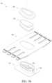
- FIG. 1 Billustrates an exploded view of a catheter housing device.
- FIG. 2 Aillustrates a perspective view of a hub of a catheter housing device.
- FIG. 2 Billustrates a rear view of a hub of a catheter housing device.
- FIG. 2 Cillustrates a top perspective view of a hub of a catheter housing device.
- FIG. 3 Aillustrates a perspective view of a lock body of an alternative design of a catheter housing device.
- FIG. 3 Billustrates a bottom perspective view of a lock body of a catheter housing device.
- FIG. 3 Cillustrates a top perspective view of a lock body of a catheter housing device.
- FIG. 3 Dillustrates another top perspective view of a lock body of a catheter housing device.
- FIG. 4illustrates a bottom perspective view of an alternative design of a catheter housing device where the band assembly comprises suction cups.
- FIG. 5illustrates a perspective view of a cover of a catheter housing device.
- FIG. 6illustrates a top perspective view of a band base membrane of a catheter housing device.
- FIG. 7illustrates a bottom perspective view of a back hand band of a catheter housing device.
- FIG. 8illustrates a perspective view of a band of a catheter housing device comprising a plurality of sensors.
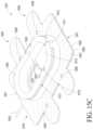
- FIG. 9illustrates a perspective view of a band of a catheter housing device.
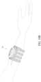
- FIG. 10 Aillustrates a perspective view of a catheter housing device in an assembled form.
- FIG. 10 Billustrates a perspective view of a catheter housing device in an assembled form on a human arm.
- FIG. 11illustrates a method of providing and removing a catheter housing device.
- FIG. 12 Aillustrates a perspective view of an alternative design of a catheter housing device.
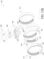
- FIG. 12 Billustrates an exploded perspective view of an alternative design of a catheter housing device.
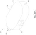
- FIG. 12 Dillustrates a top perspective view of an alternative design of a catheter housing device in an assembled form.
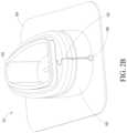
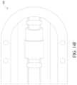
- FIG. 13 Aillustrates a perspective view of a cover of an alternative design of a catheter housing device.
- FIG. 13 Billustrates another perspective view of a cover of an alternative design of a catheter housing device.
- FIG. 13 Cillustrates a top perspective view of a cover of an alternative design of a catheter housing device.
- FIG. 13 Dillustrates a cross-section perspective view of a cover of an alternative design of a catheter housing device.
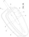
- FIG. 14 Aillustrates a perspective view of a catheter lock component of an alternative design of a catheter housing device.
- FIG. 14 Billustrates a top perspective view of a catheter lock component of an alternative design of a catheter housing device.
- FIG. 14 Cillustrates a perspective view of a catheter lock component of an alternative design of a catheter housing device.
- FIG. 14 Dillustrates a cross-section perspective view of a catheter lock component of an alternative design of a catheter housing device.
- FIG. 14 Eillustrates a perspective view of an underside of a catheter lock component of an alternative design of a catheter housing device.
- FIG. 14 Fillustrates a top perspective view of an underside of a catheter lock component of an alternative design of a catheter housing device.
- FIG. 14 Gillustrates a perspective view of an underside of a catheter lock component of an alternative design of a catheter housing device wherein a catheter is secured to the catheter lock component.
- FIG. 14 Hillustrates a perspective view of an underside of a catheter lock component of an alternative design of a catheter housing device wherein a catheter is secured to the catheter lock component.
- FIG. 14 Iillustrates a perspective view of an underside of a catheter lock component of an alternative design of a catheter housing device wherein a catheter is secured to the catheter lock component.
- FIG. 14 Jillustrates a perspective view of a catheter lock component of an alternative design of a catheter housing device wherein a catheter is secured to the catheter lock component and in an angled position.
- FIG. 14 Killustrates a perspective view of a catheter lock component of an alternative design of a catheter housing device wherein a catheter is secured to the catheter lock component and in an angled position.
- FIG. 14 Lillustrates a perspective view of a catheter lock component of an alternative design of a catheter housing device wherein a catheter is secured to the catheter lock component and in an angled position.
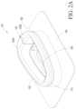
- FIG. 15 Aillustrates a perspective view of a hub component of an alternative design of a catheter housing device.
- FIG. 15 Billustrates a top perspective view of a hub component of an alternative design of a catheter housing device.
- FIG. 15 Cillustrates a perspective view of a hub component of an alternative design of a catheter housing device.
- FIG. 15 Dillustrates a cross-section perspective view of a hub component of an alternative design of a catheter housing device.
- FIG. 15 Eillustrates a perspective view of a top portion of a membrane of a hub component of an alternative design of a catheter housing device.
- FIG. 15 Fillustrates a perspective view of a bottom portion of a membrane of a hub component of an alternative design of a catheter housing device where the membrane comprises perforated loop tubes.
- FIG. 15 Gillustrates a cross-section perspective view of a bottom portion of a membrane of a hub component of an alternative design of a catheter housing device where the membrane comprises perforated loop tubes.
- FIG. 15 Hillustrates a perspective view of a top portion of a membrane of a hub component of an alternative design of a catheter housing device.
- FIG. 15 Iillustrates a perspective view of a bottom portion of a membrane of a hub component of an alternative design of a catheter housing device where the membrane comprises a corrugated structure.
- FIG. 15 Jillustrates a perspective view of a bottom portion of a membrane of a hub component of an alternative design of a catheter housing device where the membrane comprises suction cups.
- FIG. 15 Killustrates a perspective view of a main body of a hub component of an alternative design of a catheter housing device.
- FIG. 15 Lillustrates a perspective view of a main body of a hub component of an alternative design of a catheter housing device.
- FIG. 15 Millustrates a top perspective view of a main body of a hub component of an alternative design of a catheter housing device.
- FIG. 15 Nillustrates a recessed portion of a membrane of a hub component of an alternative design of a catheter housing device.
- an assembled catheter housing device 100can include a catheter holding structure 107 and a band 160 .
- the catheter holding structure 107forms a catheter lock that is configured to engage and/or secure a catheter to the patient at a location near, but not directly at, the catheter insertion site.
- the catheter housing device 100can be positioned at and/near any location where an IV can be inserted into a patient.
- FIG. 1 Billustrates an exploded view of the catheter housing device 100 .
- Catheter capsule structure 107 of catheter housing device 100can include a hub 101 , a lock body 120 and a cover 140 .
- the band 160can slide and/or fit around at least a portion of the hub 101 .
- the catheter lock 120can be inserted into an opening in the hub 101 to lock a catheter in place.
- the cover 140can be coupled to the hub 101 and/or the catheter lock 120 to secure and/or seal the stabilizing device.
- the catheter capsule structure 107can be sealed and supplied with inert gas that is free from oxygen to inhibit microbe development.
- the closed interior compartment of the main body 102 above the insertion sitecan be supplied with sterilized inert gas and/or a soothing anesthetic vapor drug.
- the inert gascan suffocate microbes or other contaminants around the needle insertion site.
- the inert gascan be pumped from a special small metallic ampule attached to the band 160 .
- a needle insertion portcan be provided on the cover in order to allow a needle to penetrate through the port and supply the gas.
- the portcan have a self-sealing valve to prevent gas from escaping once the needle is removed.
- the interior compartment formed by the main body 102 and cover 140can advantageously allow for the insertion site to be sterilized before and/or after a catheter is inserted and/or removed.
- the hub 101can include a main body 102 and a flange or membrane 104 .
- a membranecan comprise a thin, flat, flexible, planar and/or elongate portion of the device.
- the main body 102 of the hub 101can be generally egg-shaped. However, the main body 102 can be approximately trapezoidal, rectangular, square, oval and/or circular in shape, among other shapes that can encapsulate the insertion site.
- the main body 102can comprise plastic, rubber, and/or silicone, among other materials. Additionally, the main body can comprise a combination of materials.
- the hub 101can be manufactured of a soft, pliable material, such as medical grade silicone, that is soft on skin and generally conforms to the shape of the placement site. Alternatively, harder silicone, or rubber can be used.
- the main body 102can include a tubing port and/or tubing port separation 103 .
- the tubing port separation 103can separate by flexing the main body 102 to allow a path to a tubing port.
- the tubing port and tubing port separation 103allows catheter tubing to pass through the main body's 102 side walls and into the catheter insertion area.
- the port and/or port separation 103can seal around the tubing once inserted.
- the main body 102can be formed so as to not extend continuously around a perimeter of hub 101 . Instead, in some alternative designs, a first side 102 A and a second side 102 B of the main body 102 can be spaced apart, pulled apart, pushed apart, and/or otherwise separated.
- the first side 102 A and the second side 102 Bcan be biased towards one another.
- the portion of the first side 102 A and the second side 102 B adjacent the tubing port separation 103can tend to be pushed together, pulled together, and/or otherwise forced together after being separated.
- the two sides 102 A, 102 B of the main body 102 of the hub 101can be pulled apart to allow passage of some portion of the catheter there between, after which the two sides 102 A, 102 B are pushed together to seal the main body 102 about the catheter tubing.
- the main body 102can be divided in half between the first side 102 A and the second side 102 B.
- the main body 102can be formed without a tubing port separation 103 , in which tubing is simply threaded through a tubing port.
- the main body 102can include a top wall 109 .
- the top wall 109can be convex.
- the top wall 109can be smooth and/or rounded.
- the top wall 109 of the main body 102can advantageously allow the cover 140 to engage with the main body 102 .
- the top wall 109 of the main body 102can allow the cover 140 to slide over and securely fit around the main body 102 .
- the top wall 109 of the main body 102can be flat and/or concave.
- the main body 102can include an outer groove 110 .
- the outer groove 110can extend circumferentially about all or a portion of the main body 102 .
- the outer groove 110is positioned approximately at a center (for example, one-half the height) of the main body 102 .
- the outer groove 110can be positioned above or below the center of the height of the main body 102 .
- the outer groove 110can be spaced from the top wall 109 and the base of the main body 102 .
- the outer groove 110can be advantageously shaped to receive a corresponding tongue 146 of the cover 140 (see FIG. 5 ) and/or a corresponding inner rib of the cover 140 .
- the outer groove 110can allow the cover 140 to engage with the main body 102 .
- the outer groove 110can allow the cover 140 to engage the main body 102 by a snap-fit, press fit, and/or other configurations for securely connecting the cover 140 to the main body 102 .
- the hub 101can include a membrane 104 .
- the membrane 104is generally rectangular in shape. However, in some alternative designs, the membrane 104 is egg-shaped, trapezoidal, square, oval, and/or circular in shape, among other shapes.
- the main body 102can be integrally formed with the membrane 104 .
- the main body 102can be molded or co-molded with the membrane 104 .
- the main body 102can also be pressed onto, adhered to, and/or otherwise attached to a top surface of the membrane 104 .
- the membrane 104can extend outwardly from a base of the main body 102 .
- the membrane 104can be coupled with an outer edge of the base of the main body 102 .
- a bottom surface of the base of the main body 102can be coupled with the membrane 104 .
- at least a portion of the membrane 104can extend inwardly towards an inner region of the main body 102 (see, for example, FIG. 4 ).
- the membrane 104forms a thin layer to surround at least a portion of a perimeter of the main body 102 .
- the membrane 104can surround all or a portion of a perimeter of an inner edge and/or an outer edge of the base of the main body 102 .
- the membrane 104can form an outer membrane that extends outwardly from and surrounds a perimeter of the base of the main body 102 .
- the hub 101can include an inner membrane 104 A that is formed integrally with and/or is separate from the membrane 104 .
- the inner membrane 104 A(for example, a skirt, an overhang, a flange, a sealing structure, a ridge, or other structure) can be formed at the bottom of the opening in the hub 101 at the base of an inner region of the main body 102 .
- the inner membrane 104 Acan be formed between outer portions of the membrane and the base of the inner region of the main body 102 .
- the inner membrane 104 Acan extend toward the patient.
- the inner membrane 104 Acan at least partially surround the insertion site. Such configurations can advantageously reduce and/or eliminate ingress of pathogens to the insertion site.
- the inner membrane 104 Acan include a thin silicone membrane.
- the inner membrane 104 Acan overlap and/or surround the needle and/or the insertion site. This can advantageously help to ensure that the hub 101 is secured and/or sealed to the patient's skin.
- the inner membrane 104 Acan overlap at least a portion of the insertion site and/or needle to provide a hermetic sealing isolation state between the hub 101 and the patient's skin. Accordingly, the inner membrane 104 A can help to inhibit or prevent air and/or gases from an outside environment from entering the insertion site.
- Such configurations of an inwardly extending membrane 104 Acan also inhibit or prevent lower edges of needle lock from contacting the skin underneath the needle lock, as described in more detail below. This can help to inhibit or prevent skin abrasions, ulcers, and/or irritation caused by contact between the needle lock and the patient's skin.
- the membrane 104 and/or main body 102can include a tube port 108 .
- the tube port 108forms a hole or slot in the main body 102 .
- the portcan be positioned near a lower portion of the main body 102 .
- the port 108can be positioned above, for example, directly above, the membrane 104 to allow the catheter tube to pass through.
- Such configurationscan be configured to receive, snap onto, and/or engage at least a portion of the catheter. Such configurations can secure the catheter in place away from the insertion site.
- the main body 102 and the membrane 104can comprise the same material.
- the main body 102 and the membrane 104can include different materials.
- the membrane 104can comprise silicone, plastic, and/or rubber, among other materials.
- the membrane 104can also incorporate various sensors to measure physiological parameters or condition of the patient.
- the sensorscan include a temperature sensor to measure a temperature of the measurement site of a patient.
- the sensorscan also include a pulse rate sensor, a blood oximeter sensor, phlebomanometer or artery blood manometer sensor, puncture site hygrometer, blood glucose sensor or any other noninvasive physiological vital signs sensors.
- FIG. 3 Aillustrates an alternative design for a catheter lock 120 .
- the catheter lock 120can include a lock body 122 .
- the lock body 122can comprise rigid plastic material, such as a hard plastic, and/or hard rubber, among other hard materials.
- the lock body 122can be made of a clear or substantially transparent material to allow visibility of the insertion site, for example, through the lock body 122 . Transparency can also allow an incorporated LED or UV light to spread light over the insertion site.
- the lock body 122 or portions of the lock bodycan also be opaque or partially opaque.
- the lock body 122can include a tongue and/or a groove 124 .
- the lock body 122includes a tongue 124 to engage a corresponding locking groove 125 ( FIG. 1 B ) positioned along at least a portion of an inner perimeter of an inner wall of the hub 101 .
- Thiscan allow the lock body 122 to securely engage with the main body 102 .
- the lock body 122can engage with the hub 101 through a snap-fit configuration, press fit configuration, and/or other securement structures or methods. Such configurations can advantageously allow the lock body 122 to securely engage with the main body 102 , yet quickly be removed from and/or be attached to the main body 102 when the catheter is removed, replaced, inserted, and/or accessed.
- the lock body 122can enclose the catheter and secure the catheter in place. For example, once inserted through the opening in the main body 102 and the lock body 122 is securely engaged with the main body 102 , the lock body 122 can be fixed in a proper position. The engagement between the lock body 122 and the main body 102 can advantageously inhibit and/or prevent movement of the lock body 122 relative to the main body 102 . The lock body 122 can inhibit or prevent the catheter from moving once the lock body 122 is secured with the main body 102 .
- the catheter lock 120can be configured to secure a hub 123 of the catheter (or other portion of a catheter) in the proper orientation relative to the patient's skin.
- the securement of the hub 123 of the catheter or other portion of the catheter by the catheter lock 120can be a physical locking, holding, stabilizing without locking, retaining, stabilizing to prevent movement, stabilizing to minimize or reduce the likelihood of movement, or another type of securement.
- the lock body 122can have a recess sized and shaped to hold a portion of the catheter hub in a friction fit configuration, a snap-fit configuration, a press fit configuration, and/or another securement configuration method or structure.
- the securement recess of the catheter lock 120can comprise a hook. The catheter lock 120 can stabilize the catheter relative to the insertion site while still allowing the catheter to move slightly in order to accommodate patient movement as described further below.
- the lock body 122can fit within the interior region of the main body 102 to form a hermetic sealing structure around the catheter.
- the lock body 122e.g., in combination with the cover 140
- the catheter hub 123can include a ring 129 or flange.
- the ring 129can help to seal and/or lock the catheter in place within the hub lock body 122 .
- the ring 129can surround the catheter and engage an outer wall of the lock body 122 to securely seal the catheter in place.
- the ring/flange 129can be configured to engage with a groove 133 of the bridge structure 127 .
- the lock body 122creates an interior compartment above the sealed insertion site once the lock body 122 is positioned within the opening of the main body 102 and/or securely engaged to the main body 102 .
- the lock body 122can include a raised support bridge or structure 127 to enclose at least a portion of the catheter or catheter hub.
- the raised support structure 127extends from an inner side wall of the lock body 122 to an opposite inner side wall of the lock body 122 .
- the raised support structurecan be positioned near the insertion site along one end of the lock body 122 .
- the raised support structure 127can include an aperture 133 to engage the catheter and/or catheter hub 123 .
- the support structure 127can include a cavity 145 sized and shaped to receive all or a portion of the catheter hub 123 . This allows the catheter to pass through the aperture. Some configurations can allow a seal to be formed around the catheter opening and enclose the insertion site.
- the raised support structure (bridge) 127can include a swinging mechanism.
- the swinging mechanismcan allow the structure 127 to rotate and/or tilt.
- the swinging mechanismcan comprise a hinge (e.g., mechanical and/or living hinge) between the raised support structure 127 and the walls of the lock body 122 .
- the swinging mechanismcan allow the structure 127 to tilt upwardly and/or downwardly (e.g., about an axis perpendicular to the catheter hub 123 .
- the swinging mechanismcan allow the structure 127 to tilt according to the inclination of the needle and/or catheter.
- the swinging mechanismcan allow the structure 127 to tilt as the patient moves, to accommodate movement of the needle and/or catheter.
- the tilt of the structure 127can be limited in its rotation to prevent the catheter from swinging too far relative to the body.
- the structure 127can also be configured to keep the catheter fixed in its natural position to the patient's skin after insertion. This provides for an optimal catheter holding angle. This can help to limit or prevent irritation caused by contacting of needle's cannula tip with vein lumen sides.
- the holding anglecan be between 1 and 45 degrees.
- the inclination anglecan also be between 1 and 10 degrees, between 10 and 20 degrees, or between 20 and 30 degrees.
- the holding anglecan be more than 45 degrees as well, depending on the implementation of the stabilization device.
- the holding anglecan also be at a very small angle, such as between 0 and 1 degrees. Such configurations can help to limit forces provided to the insertion point.
- the raised support structure 127can be made of hard plastic, such as anti-erosion hard plastic, among other hard materials.
- Some catheter hubscan include a catheter opening 123 A.
- the raised sealing structure 127can include an aperture 127 A.
- the aperture 127 Acan allow the catheter opening 123 A to pass through the raised support structure 127 .
- the aperture 127 Acan be cylindrical, circular, square, or rectangular, among other shapes or combination of shapes.
- the catheter opening 123 Acan provide an access point through which a care provider or other person can administer fluids (for example, medicinal, nutritive, and/or hydrating fluids) to the patient instead of or in addition to the fluids provided though the attached catheter 126 .
- the catheter lock 120includes at least one light source 131 .
- the catheter lock 120can include one, two, three, four, five, six, seven, eight, or nine or more light sources 131 .
- the catheter lock 120can include at least two light sources 131 .
- the light sourcescan include LEDs.
- the light sourcescan allow the catheter to be inspected during the day and/or night.
- the light sourcescan also indicate that lock structure 122 is properly fit into the main body 102 .
- the light sourcescan also indicate that the catheter is not properly positioned and/or secured to the patient.
- the lightscan change colors, flash at certain speeds, and/or change brightness to indicate an issue with the catheter lock 120 or catheter.
- the light sourcecan include a UV light source to help with disinfecting the catheter and/or hub and/or insertion site.
- One or more of the light sourcescan also be used to illuminate various structures.
- a first lightcan illuminate an area surrounding and/or proximate to the catheter.
- the one or more light sourcescan illuminate a region within 3 feet from the catheter housing device 100 .
- the one or more light sourcescan illuminate a region within 1 feet from the catheter housing device 100 .
- the one or more light sourcescan illuminate a region within 5 feet from the catheter housing device 100 .
- the raised sealing structure 127can distribute light within the hub 101 .
- One lightcan be used to illuminate the lock structure while a second light can provide an alarm and/or indicator to indicate that a complication is occurring (for example, the catheter or catheter lock is not properly positioned).
- the light sourcescan also provide a patient with an indication of wellness and/or that the patient is in a well-state. For example, when the light sources are not emitting light, this can indicate that a patient is in a well state of being.
- FIG. 5illustrates an embodiment of the cover 140 .
- the cover 140can include a cover body 142 , a cover window 144 , and a cover tongue 146 . As shown in at least FIGS. 1 A- 1 B , the cover 140 is configured to enclose the main body 102 and catheter lock 120 within the interior of the hub 101 .
- the cover body 142can couple with a top surface of the main body 102 of the hub 101 .
- the cover tongue 146can be positioned inwardly offset from an outer edge of the cover body 142 .
- the cover tongue 146can slide over or into an interior or exterior region of the main body 102 of the hub 101 .
- the cover tongue 146can snap into an interior or exterior region of the main body 102 .
- the cover tongue 146can contact an outer side wall of the main body 102 .
- the cover tongue 146 , or some other portion of the cover 140engages the outer groove 110 of the main body 102 .
- the cover tongue 146can contact an inner side wall of the lock body 122 to engage the cover 140 with the hub 101 .
- the cover tongue 146can slide into and/or snaps into a space formed between an outer wall of the lock body 122 of the catheter lock 120 and an outer wall of the main body 102 .
- the cover tongue 146can engage the main body 102 to secure the cover 140 in place and to enclose the external components of the hub 101 .
- a sealcan be formed such that the cover 140 does not allow external air and/or contaminants from entering the enclosed internal volume of the hub 101 .
- the cover 140can engage the lock body 122 and/or the main body 102 to form a closed and/or isolated atmosphere, which encloses the insertion site.
- the insertion sitecan advantageously be sterilized.
- the cover 140can advantageously help to inhibit or prevent microbe contaminate and help to lower contamination vulnerability.
- the cover 140can also be configured to prevent the separation 103 from separating while in use.
- the cover 140can include a cover window 144 .
- the cover window 144can be formed along a top surface of the cover body 142 .
- the cover window 144can be recessed along the top surface of the cover body 142 such that it extends inwardly towards an interior region of the main body 102 when assembled.
- the cover window 144can be substantially clear to allow a doctor and/or a patient to inspect the insertion site and/or catheter.
- such configurationscan advantageously allow a doctor and/or a patient to view the insertion site and/or the catheter position without the need to disassemble the stabilizing device 100 .
- the cover window 144can allow the stabilizing device 100 to remain sealed.
- FIG. 6illustrates an embodiment of the band 160 .
- the band 160can include an opening 162 to receive the hub 101 .
- the band 160can fit over the hub 101 such that the main body 102 extends through the opening 162 of the band 160 and the membrane 104 of the hub 101 is captured below the band 160 .
- the opening 162can stretch such that the band 160 tightly fits around an outer wall of the main body 102 of the hub 101 .
- the band 160 and main body 102can be formed together as a single structure.
- the band 160includes an upper surface 161 A and a lower surface 161 B.
- the upper surface 161 Ais configured to face away from the patient's skin in use (see, e.g., FIG. 6 ) and the lower surface 161 B is configured to face towards the patient's skin in use (see, e.g., FIG. 7 ).
- At least a portion of the upper surface 161 Acan include connection structures 172 .
- the upper surfaceis entirely covered with connection structures 172 .
- the band 160can include one or more attachment arms 170 .
- the band 160can include one, two, three, four, five, six, seven, eight, nine, ten, eleven or more attachment arms 170 .
- the attachment arms 170can wrap around a patient's body part including an arm, wrist, leg, hand, and/or neck, among other body parts.
- the attachment armscan include one or more connection structures 172 such as hook and loop fasteners, clips, hooks, or other known attachment systems.
- One or more strips (not shown) of a corresponding fastenercan be used to attach the one or more arms 170 on one side of band 160 to one or more arms 170 on the other side of the band 170 in order to hold the band 160 in place on a patient.
- one, two, three, four, five, six, seven, eight, nine, ten, eleven or more strips of a corresponding fastenercan be used to attach the one or more arms 170 on one side of band 160 to one or more arms 170 on the other side of the band 170 in order to hold the band 160 in place on a patient.
- the band 160can include eight arms. For example, one-half of the arms 170 can be positioned on one side of the opening 162 and one-half of the arms 170 can be positioned on the opposite side of the opening 162 .
- the band 160can include at least one, two, three, four, five, six, seven, eight, nine, and/or ten or more arms positioned on opposite sides of the opening 162 .
- the arms 170 positioned on opposite sides of the opening 162can be positioned in an alternating or misaligned configuration.
- one side of the opening 162can include an even number of arms 170 and the other side can include an odd number of arms 170 .
- Such configurationscan distribute the band about the entire body part of the patient to increase the strength of the securement of the band 160 to the patient.
- at least one arm 170can be configured to wrap around a patient's body part and attach to a corresponding arm, while other arms are left open without a connection. By alternating which arms 170 are used to hold the band 160 onto the patient's tissue, the patient's skin can be provided relief by decreasing pressure and contact between connection structures and the patient's skin.
- the band 160can include a single attachment arm 170 .
- the band 160can be a single arm that is configured to wrap around a patient's body part.
- connection structures 172can include a plurality of hook and loop structures, buckles, fungi-like attachment, and/or other attachment structures or methods.
- the connection structures 172can facilitate connection of other complimentary bands, straps, and/or other components to the band 160 .
- the upper surface 161 Acan include soft hooks to provide a wide surface area for fixing various peripheral tools to the band 160 , such as a catheter tube, an LCD monitor of a micro-processor, and/or a metallic ampule of the soothing and sterilizing gas.
- connection structures 172can facilitate attachment of a first set of arms 170 positioned on one side of the band 160 to a second set of arms 170 positioned on another side of the band 160 .
- the first and second set of arms 170can be configured to wrap around a patient's arm such that the connection structures 172 of the first set of arms 170 attaches to the connection structures 172 of the second set of arms 170 to secure the catheter housing 100 to the patient.
- FIG. 7illustrates an embodiment of the lower surface 161 B.
- the lower surface 161 Bis generally configured to face towards the patient's body in use and/or contact the patient's skin.
- the lower surface 161 B of the band 160can engage the patient to secure the catheter housing 100 to the patient and/or surround the insertion site.
- the band 160can include a plurality of contact structures 166 .
- the contact structures 166can include a plurality of corrugated strips (see FIG. 7 ), suction cups (see FIG. 4 ), silicone or hybrid silicone-silk deep velvet structure, and/or other contacting mechanisms.
- the contact structures 166can include rows of corrugated strips, suction cups (as shown in FIG.
- the contact structures 166can be positioned in alternating rows.
- the contact structures 166can include alternating rows of corrugated strips and suction cups.
- the bandcan include alternating arms of various contacting mechanisms, as described below.
- the contact structures 166can be configured to space the band from the patient to allow the patient's skin to breath, yet secure the catheter housing 100 to the patient.
- the contact structures 166can allow the band 160 to maintain engagement with the patient's skin without the use of adhesives (including, for example, chemical adhesives, tapes, or other adhesives).
- the contact structures 166can advantageously reduce abrasion of the patient's skin.
- the contact structures 166promote regular air/blood flow and ventilation along the patient's skin beneath the band 160 .
- the lower surface 161 B of the band 160can include a plurality of suction cups.
- the suction cupscan be designed to be of a thin narrow circumference creating finely intricate suction cups which can be configured to stabilize a connection between the band 160 and the patient's skin.
- the band 160can be manually pressed onto the patient's skin to secure the contacting structures 166 of the band 160 to the patient.
- the contact structuressuch as the suction cups and/or corrugated strips, can engage with the patient's skin such that the band 160 does not necessarily wrap entirely around the patient's arm.
- the band 160can wrap around only a portion of the patient's arm.
- the contact structures 166can provide sufficient engagement or suction force to securely engage the catheter housing device 100 to the patient with and/or without the use of additional connection structures, such as connection structures 172 .
- the lower surface 161 Bcomprises a soft flesh-like material to increase comfort and wearability by highly reducing irritation to the patient.
- Such materials and/or configurationscan include miniature pillows.
- the materialscan include silicone or other appropriate FDA approved materials.
- the connecting structure 166can comprise a soft material, such as silicone.
- the lower surface 161 Bcan be made from soft flesh-like, high strength silicone material (for example, FDA compliant) to increase the air circulation between underneath band surface and the patient's skin.
- the contacting structures 166can advantageously help to minimize the surface area of the band 160 that contacts the patient's skin to reduce irritation. This can allow the catheter housing 100 to be secured to the patient for longer periods of time without having to be removed unnecessarily. Similarly, such configurations can reduce the risk of complications that can arise from applying the band 160 to the patient's skin.
- FIG. 8illustrates an alternative design of a band 160 A.
- the band 160 Ais similar to or identical to the band 160 as discussed above in many respects.
- the band 160 Acan include any one, or any combination of features of the band 160 .
- the band 160 Acan be located on any portion of a patient's body.
- the band 160 Acan be positioned at and/or near any location where an IV can be inserted into a patient, including but not limited to, a thigh, foot, calf, wrist, leg, hand, and/or neck, among other body parts.
- the band 160 Acan include at least three arms 170 A.
- the band 160 Acan include one, two, four, five, six, seven, or eight or more arms 170 A.
- the band 160 Acan include an opening 162 A for receiving the hub 101 .
- the opening 162 A of the band 160 Ais generally rectangular, however the opening can include other shapes, such as trapezoidal, square, oval, and/or circular in shape, among other shapes.
- the band 160 Acan be used in conjunction with and/or instead of the band 160 .
- the band 160 Acan form a complimentary band that is configured to receive a supplemental hub.
- the band 160 Acan alternatively be mounted, for example, on the back of a patient's hand. Such configurations can be advantageous in situations, for example, in which the patient's arm is not accessible or cannot be easily reached.
- the band 160 Acan include a plurality of sensors 190 A, as described in more detail below.
- FIG. 9illustrates another embodiment of the band 160 B.
- the band 160 Bis similar to or identical to the band 160 , 160 A as discussed above in many respects.
- the band 160 Bcan include any one, or any combination of features of the band 160 , 160 A.
- the band 160 Bforms a multi-purpose attachment strap that can be coupled to the catheter housing 100 .
- the band 160 Bcan include a plurality of contacting structures 166 B (e.g., hook and loop fasteners, buckles, or other structures).
- the band 160 Bcan be located on any portion of a patient's body.
- the band 160 Bcan be positioned at and/or near any location where an IV can be inserted into a patient, including but not limited to, an arm, thigh, foot, calf, wrist, leg, hand, and/or neck, among other body parts.
- FIGS. 10 A- 10 Billustrate another example of a stabilizing device 200 .
- the catheter housing 200(also referred to as “catheter housing device 200 ” herein) is similar to or identical to the catheter housing 100 discussed above in many respects.
- the catheter housing 200can include a hub 201 , a catheter lock 220 , a cover 240 , and a band 260 , which can be respectively similar to the hub 101 , the catheter lock 120 , the cover 140 , and the band 160 .
- the catheter housing 200can include any one, or any combination of features of the catheter housing 100 .
- the catheter housingcan wrap around a patient's arm, for example.
- the catheter housing 200can include one or more sensors 290 .
- the catheter housing 200can have one, two, three, four, five, six, seven, eight, nine, ten, eleven, or twelve or more sensors.
- the one or more sensors sensor 290can be mounted to and/or otherwise coupled to the hub 201 , the catheter lock 220 , the cover 240 , connecting straps 160 B, and/or the band 260 .
- the sensor 290can include a temperature sensor (for example, a topical temperature sensor), an artery pressure sensor, a blood oxygen saturation sensor, a sensor for liquid and blood leakage, and/or a skin humidity sensor.
- the catheter housing 200can include any one or combination of sensors 190 described herein.
- the band 260can include at least one sensor 290 A.
- the sensor 290 Acan include one or more bio-sensors.
- the band 260can include one, two, three, four, five, six, seven, eight, nine, or ten or more bio-sensors.
- the bio-sensorscan include a micro-processor.
- the bio-sensorscan include an LCD monitor for detecting, measuring, storing and/or displaying patient vital functions, including venous and arterial blood pressure, heart beats, blood oxygen levels, general and topical temperature, and local tissue humidity, and/or venous blood current speed, among others.
- the measurements and/or calculations performed and/or taken by the at least one sensor 290 , 290 Acan be stored on a flash storage memory positioned on one or more of the band 260 , the hub 201 , the catheter lock 220 , or the cover 240 .
- the sensor measurementscan be wirelessly transmitted to a patient monitoring system for analysis, management, organization, and/or display to a care provider or user.
- the sensor measurementscan be transmitted to a personal communications device, such as a tablet or smart device, or a software application or website.
- FIG. 11illustrates an example method of implementing the catheter housing 100 and/or 200 .
- a care provider or other personidentifies the appropriate insertion site (step 300 ), whether it is on an arm, wrist, hand, leg, or other site on a body.
- the needle and catheterare inserted into the patient to establish a line (for example, an IV and/or other fluid supply or withdrawal line).
- catheter tubingcan be inserted or coupled to the hub 101 at block 302 .
- the step described in block 301can come before or after the step described in block 302 .
- the hub 101is centered over the insertion site.
- the hub 101 and/or the catheter housing 100can be positioned at and/or near any location where an IV can be inserted into a patient.
- the hub 101can be positioned to surround the insertion site and at least a portion of the catheter.
- the hub 101can be advantageously positioned such that a seal is formed around the insertion site and/or catheter.
- the hub 101can be provided to the patient before and/or after a catheter is coupled to the needle at the insertion site. For example, if a catheter is already in place, the catheter can be fed through the tubing port and/or tubing port separation 103 of the hub 101 and can be configured to slide over the catheter and form a seal.
- the hub 101can be provided to the patient and at least partially secured in place before the needle and catheter are inserted. In such configurations, the tubing can then slide through the tubing port and/or tubing port separation 103 in the hub 101 .
- the catheter tubeis connected to the catheter.
- the band 160is laid over the hub 101 and secured to the patient.
- the catheter lock 120is coupled with the main body 102 and/or with the catheter hub 101 to lock the catheter in place as described herein. It should be understood that block 310 and block 308 can be switched. In other words, the catheter lock 120 can be coupled with the main body 102 and/or with the catheter hub 101 to lock the catheter in place as described herein (block 310 ) prior to the overlaying and securement of the band 160 to the patient (block 308 ). Additionally, block 306 can occur before or after block 310 and/or 308 .
- the cover 140is releasably installed over the hub 101 to seal the hub 101 from the outside environment and protect it from contamination.
- the cover 140can be installed before the band 160 is laid over the hub 101 and secured in place.
- Block 312can occur before or after block 306 , block 308 , and/or block 310 .
- the bandWhen it is time to remove the catheter, the band can be released and removed from the patient. The entire remaining catheter stabilizing device can then be removed, removing the catheter and tubing as well. This allows for quick and efficient removal of the catheter without causing undo discomfort to the patient. Moreover, it should be understood that the entire catheter housing 100 , including the band 160 , can also be removed in one step. Further, a care provider can also disassemble and remove the catheter housing 100 while the catheter remains in place or before or after the catheter is removed from the patient.
- the catheter housing described hereindoes not use adhesives and avoids applying pressure directly to the needle and/or the insertion site. Because the stabilization system does not use adhesives and does not apply any tape or other layers in the immediate needle insertion area, potential contamination is dramatically reduced. Moreover, because the catheter is not covered with tape, the insertion area can remain readily visible to a care provider. This visibility allows the care provider to easily, quickly, and repeatedly assess the insertion site for signs of inflammation, failure or infection.
- the disclosed catheter housingalso mechanically isolates the catheter from patient movement and holds the catheter at the proper insertion angle.
- the disclosed catheter housingalso provides a securement system that is highly breathable, allowing for patient comfort and reduced skin irritation.
- FIG. 12 Aillustrates a perspective view of a fully assembled alternative design for a catheter housing device (also referred to as a “catheter housing” herein) 1201 that can be placed over any portion of a human's body, such as an arm or leg.
- a catheter housing devicealso referred to as a “catheter housing” herein
- FIG. 12 Billustrates an exploded view of the catheter housing 1201 of FIG. 12 A .
- the catheter housing 1201can have a cover 1203 , a catheter lock component 1205 , a hub component 1207 , a full-length fastening strap 1211 , and a partial-length fastening strap 1215 .
- the catheter housingcan be configured to secure a catheter device which can include a fluid tube connector 1209 or a portion thereof.
- the catheter housing 1201can be configured such that a catheter device 1209 is secured to the catheter lock component 1205 .
- the catheter lock component 1205can be secured to the cover 1203 or the hub component 1207 , or both the cover 1203 and the hub component 1207 .
- the cover 1203can be secured to the hub component 1207 or the catheter lock component 1205 , or both the hub component 1207 and the catheter lock component 1205 . As illustrated in FIGS. 12 A and 12 B , when the catheter housing 1201 is assembled, the cover 1203 can substantially surround or enclose the catheter lock component 1205 and/or a portion of the hub component 1207 .
- the hub component 1207can have an opening 1525 that allows the catheter device 1209 to be inserted in a patient while secured to at least a portion of the catheter housing 1201 , for example, the catheter device 1209 can be secured to the catheter lock component 1205 .
- the hub component 1207can secure to one or more fastening straps, such as one or more full-length fastening straps 1211 or one or more partial-length fastening straps 1215 , or both one or more full-length fastening straps 1211 and one or more partial-length fastening straps 1215 .
- the hub component 1207can be integrally formed with the one or more full-length fastening straps 1211 and/or the one or more partial-length fastening straps 1215 .
- the catheter housing 1201can have a hub component 1207 that includes one or more bands which can be used to wrap around or otherwise secure to a patient in a manner similar to the manner described below regarding the one or more full-length fastening straps 1211 and/or the one or more partial-length fastening straps 1215 .
- FIG. 12 Cillustrates a perspective view of a fully assembled catheter housing 1201 while secured to a human arm.
- the catheter housing 1201can also be attached to other locations on a human body, such as appendages like a thigh, foot, calf, wrist, leg, hand, and/or neck, among other body parts.
- the catheter housing 1201can be attached to various body parts and surround catheter insertion sites located in different regions on a human body, such as near the wrist or elbow-joint area, among other areas.
- the catheter housing 1201can be positioned and/or secured at and/or near any location where an IV can be inserted into a patient.
- FIG. 12 Dillustrates a top perspective view of the catheter housing 1201 of FIG. 12 A .
- the catheter housing 1201 described hereincan be integrally formed or unitary in structure.
- the catheter housing 1201 described hereincan have a cover 1203 , a catheter lock component 1205 , a hub component 1207 , and one or more fastening straps which comprises a single unit or structure.
- portions of the catheter housing 1201 described hereincan comprise a unitary structure.
- the catheter lock component 1205 and the hub component 1207can comprise a unitary structure.
- the cover 1203 , the catheter lock component 1205 and the hub component 1207can comprise a unitary structure, for example, they can comprise a housing that secures to a patient and surrounds an insertion site.
- the catheter housing 1201can have one or more full-length fastening straps 1211 and/or one or more partial-length fastening straps 1215 .
- the catheter housing 1201can have one, two, three, four, five, sex, seven, eight, nine, or ten or more full-length fastening straps 1211 and/or one or more partial-length fastening straps 1215 .
- the catheter housing 1201can have both one or more full-length fastening straps 1211 and one or more partial length fastening straps 1215 .
- These fastening strapscan be made from a variety of material or combination of materials.
- the fastening strapscan comprise silicone, plastic, rubber, and/or fabric.
- the fastening strapscan comprise appropriate FDA approved materials.
- the fastening strapscan comprise medical grade soft silicone material.
- the fastening strapscan be substantially waterproof, durable, and/or washable.
- the one or more fastening strapscan contain information regarding a patient, such as name, birthdate, and other information.
- the full-length fastening straps 1211 and partial-length fastening straps 1215can include a ventilation portion 1217 .
- the ventilation portion 1217can exist on the underside of the fastening straps, which can be the side that contacts the skin of a patient.
- the ventilation portion 1217can include one or more corrugated protrusions that can facilitate ventilation underneath and around the fastening straps.
- the ventilation portion 1217can include one, two, three, four, five, six, seven, eight, nine, ten, eleven or more corrugated protrusions.
- the ventilation portion 1217can have corrugated protrusions that extend along a perimeter of the fastening straps.
- the ventilation portion 1217can have corrugated protrusions that extend in a direction perpendicular to the perimeter of the fastening strap.
- the corrugated protrusionscan extend partially in both a parallel and perpendicular direction to the perimeter of the fastening straps.
- the corrugated protrusions of the ventilation portion 1217can be continuous or intermittent (i.e., noncontinuous), and can be located in different locations along the underside of the fastening straps.
- the ventilation portion 1217can be located at one end of the fastening strap, or can be located along a middle portion of the fastening strap.
- the ventilation portion 1217can also include any of the structures described with respect to FIGS. 1 - 11 above, including, for example, suction cups.
- the full-length fastening straps 1211 and/or partial-length fastening straps 1215can include one or more underside securement portions 1219 and one or more exterior securement portions 1221 .
- the full-length fastening straps 1211 and/or partial-length fastening straps 1215can include one, two, three, four, five, six, seven, eight, nine, ten, eleven or more underside securement portions 1219 and one or more exterior securement portions 1221 .
- the underside securement portion 1219can be continuous or noncontinuous and can extend along the underside of the fastening straps (i.e., the portion of the fastening strap that contacts the skin of a patient when the fastening straps are secured to a patient).
- the underside securement portion 1219can be located in different locations along the underside of the fastening straps.
- the underside securement portion 1219can be located at one end of the fastening strap, or can be located along a middle portion of the fastening strap.
- the exterior securement portion 1221can be continuous or noncontinuous and can extend along the exterior of the fastening straps.
- the exterior securement portion 1221can be located in different locations along the exterior of the fastening straps.
- the exterior securement portion 1221can be located at one end of the fastening strap, or can be located along a middle portion of the fastening strap.
- the underside securement portion 1219 and exterior securement portion 1221can comprise various securement means.
- the underside securement portion 1219 and/or exterior securement portion 1221can comprise hook and loop fasteners, clips, buckles, fungi-like attachment, or other known attachment systems, or a combination of these attachment systems.
- the underside securement portion 1219 and/or exterior securement portion 1221can comprise Velcro.
- the underside securement portion 1219 and exterior securement portion 1221can comprise an adhesive attachment system.
- the underside securement portion 1219 and exterior securement portion 1221can be configured to attach and detach from one another.
- the underside securement portion 1219can attach underneath the exterior securement portion 1221 .
- the underside securement portion 1219can attach overtop of the exterior securement portion 1221 .
- the underside securement portion 1219 and exterior securement portion 1221can secure to one another in another fashion, such as side-by-side.
- the one or more full length fastening straps 1211 and the one or more partial length fastening straps 1215can be configured to at least partially secure to the hub component 1207 and/or the catheter housing 1201 .
- the full-length fastening straps 1211can secure to a front portion of the hub component 1207 , or a back portion of the hub component 1207 , or both a front and back portion of the hub component 1207 .
- the full-length fastening straps 1211can secure to at least a portion of the hub component 1207 and also be secured to itself. For example, as illustrated in FIGS.
- an underside securement portion 1219 of the full-length fastening strap 1211can secure to at least a portion of the hub component 1207 and an underside securement portion 1219 can also secure to an exterior securement portion 1221 of the full-length fastening strap 1211 .
- one or more partial-length fastening straps 1215can secure to at least a portion of the hub component 1207 .
- an underside securement portion 1219 of a partial-length fastening strap 1215can secure to at least a portion of the hub component 1207 , and another underside securement portion 1219 of the same partial length fastening strap can secure to an exterior securement portion 1221 of a different partial-length fastening strap 1215 .
- the catheter housing 1201can include one or more fastening straps.
- the catheter housing 1201can include two full-length fastening straps 1211 and four partial length fastening straps 1215 .
- one or more of the fastening strapscan be detached for a given time.
- one or more full-length fastening straps 1211can be detached so as to relieve pressure imposed from the attached catheter housing 1201 .
- one or more of the partial-length fastening straps 1215can be detached so as to relieve pressure imposed from the attached catheter housing 1201 .
- the catheter housing 1201can be configured to alternate the securement of the fastening straps while maintaining securement of the device to a patient.
- the one or more fastening straps disclosed hereincan be used as a tourniquet to help a caregiver locate a patient's vein without needing any other equipment such as tools, devices, bands, or other devices.
- a caregivercan attach, adhere, secure, and/or write patient information on the one or more fastening straps disclosed herein.
- the caregivercan also place or write the insertion date and time on the one or more fastening straps.
- FIGS. 13 A and 13 Billustrate perspective views of a cover 1203 of the catheter housing 1201 of FIG. 12 A .
- the cover 1203can be configured to secure to the catheter lock 1205 or the hub component 1207 , or both the catheter lock component 1205 and the hub component 1207 .
- the cover 1203can be configured to secure to a full-length fastening strap 1211 and/or a partial-length fastening strap 1215 .
- the cover 1203can be made of transparent material. Alternatively, the cover can be made of nontransparent material. Additionally, the cover 1203 can be comprise both transparent and nontransparent material. For example, the portions of the cover can be made of transparent material where it is advantageous to be able to see through the cover in order to observe the other components of the catheter housing 1201 .
- the cover 1203can be made of substantially shockproof and/or durable material. This is advantageous because the catheter housing 1201 and the cover 1203 can be subjected to impact during installation or use.
- the cover 1203can also be made of substantially waterproof material. This is advantageous because the catheter housing 1201 and the cover 1203 can be subjected to water or other liquids when the device is in use.
- the cover 1203can comprise plastic, rubber, and/or silicone, among other materials, or a combination of such materials.
- the cover 1203can comprise of a soft, pliable material, such as medical grade silicone.
- the cover 1203can comprise harder silicone, or rubber can be used.
- the cover 1203can be configured to form a closed environment over a site where an intravenous catheter is inserted into a patient. Such a closed environment can aid in keeping the site free from contamination. As discussed above, the cover 1203 can be made of at least partially transparent material so as to allow a caregiver or other person to examine the catheter insertion site and/or other portions of the catheter housing 1201 (e.g., the hub component 1207 and/or the catheter lock component 1205 ) while the cover 1203 is secured to the hub component and/or the catheter lock component 1205 .
- the cover 1203can comprise a cover body 1301 and a catheter tube slot 1303 .
- the cover body 1301can have a rounded shape.
- the cover body 1301can have a non-round shape, for example, a rectangular shape.
- the cover body 1301can be approximately trapezoidal, rectangular, square, oval and/or circular in shape, among other shapes.
- the cover 1203can comprise a single, continuous piece.
- the cover 1203can comprise more than one piece.
- the catheter tube slot 1303can permit a catheter tube, an intravenous line, or other device to pass through the cover body 1301 .
- the catheter tube slot 1303can permit a catheter tube, an intravenous line, or other device to pass through the cover body 1301 when the cover is secured to the hub component 1207 and/or the catheter lock component 1205 .
- the cover 1203can have one or more ports 1307 which can be used to insert sterilizing and/or anesthetic gas into the catheter housing 1201 .
- the cover 1203can have one, two, three, four, five, six, seven, eight, nine, ten, eleven or more ports 1307 .
- the one or more ports 1307can be located on a side of the cover 1203 .
- the one or more ports 1307can be located on a top portion of the cover 1203 .
- the one or more ports 1307can be used to provide sterilization gases, such as ethylene oxide gas, hydrogen peroxide gas plasma, or other sterilizing or anesthetic gases.
- the cover 1203can include a port 1307 for providing sterilizing gases, and a separate port for providing anesthetic gases.
- the cover 1203can include a catheter tube holder 1305 .
- the catheter tube holder 1305can be located on a side of the cover body 1301 .
- the catheter tube holder 1305can be located on a top portion of the cover body 1301 .
- the catheter tube holder 1305can be configured to secure one or more catheter tubes, or other tubes or devices.
- the cover 1203can include a gas tube holder 1309 , which can be located on a side and/or a top portion of the cover body 1301 .
- the gas tube holder 1309can be configured to secure one or more gas tubes, or other tubes or devices.
- the protrusion 1315can be configured to secure to at least a portion of the catheter lock component 1205 and/or the hub component 1207 .
- such securementcan occur when the cover 1203 is placed over the catheter lock component 1205 and the hub component 1207 , so as to encompass both the catheter lock component 1205 and the hub component 1207 , and secure to the hub component 1207 , whereby the protrusion 1315 can secure to a peripheral groove 1517 of the hub component 1207 (see FIG. 15 C ).
- the protrusion 1315can secure to the peripheral groove 1517 by a snap-fit, press fit, and/or other configuration for securely connecting the cover 1203 to the hub component 1207 .
- the protrusion 1315can be replaced with one or more interior grooves (not shown in figures).
- the protrusion 1315can be replaced with one, two, three, four, or five, six, seven, or eight or more grooves.
- the protrusion 1315can be replaced with one groove.
- Such interior groovescan secure to at least a portion of the catheter lock component 1205 and/or the hub component 1207 .
- such interior groovescan secure to a protrusion appearing on the hub component 1207 .
- Such securementcan occur by a snap-fit, press fit, and/or other configuration.
- the cover 1203can secure to the catheter lock component 1205 and/or the hub component 1207 by insertion of a protrusion located on the cover 1203 , or by accepting a protrusion located on the catheter lock component 1205 and/or the hub component 1207 .
- the cover 1203can include one or more ports 1307 .
- the one or more ports 1307can be substantially cylindrical, rectangular, or another shape.
- the one or more ports 1307can include a gas opening 1311 which permits sterilizing gas, anesthetic gas, or other gases, to flow into the catheter housing 1201 .
- the one or more ports 1307can include a port rim 1313 that extends at least partially around an exterior portion of the one or more ports 1307 .
- the port rim 1313can extend radially outward from the one or more ports 1307 .
- the port rim 1313can be located at an end of the one or more ports 1307 (as shown in FIG.
- the one or more ports 1307can extend outwardly from the cover body 1301 .
- the port rim 1313can be configured to secure to gas tubes or other devices that provide gas to the catheter housing 1201 .
- the port rim 1313can contain one or more threads by which a gas tube or other device can screw into.
- the port rim 1313can comprise a snap mechanism that can secure to a gas tube or other device, whereby a portion of such tube or other device can be configured to snap into or around the snap mechanism of the port rim 1313 .
- Other alternative methods of securing a gas tube or other device to the port rim 1313 of the one or more ports 1307exist.
- the one or more ports 1307can also include one or more valves, such as a control valve and/or a multi-valve.
- the cover 1203can include one or more interior notches 1317 .
- the cover 1203can include one, two, three, four, five, six, seven, eight, nine, ten, eleven or more notches 1317 .
- the one or more interior notches 1317can be located along the interior sides of the cover 1203 .
- the one or more interior notches 1317can be located on the interior top wall of the cover 1203 .
- the one or more interior notches 1317can be located along the interior sides of the cover 1203 and can be configured to align with one or more slots 1403 located on the catheter lock component 1205 (see FIGS. 13 D and 14 C ).
- the one or more interior notches 1317can align with the one or more slots 1403 so that the catheter lock component 1205 and the cover 1203 are secured to one another.
- the one or more interior notches 1317can be cylindrical, rectangular, or another shape, and can extend outward from an interior side of the cover 1203 .
- the one or more interior notches 1317can extend along the interior side of the cover 1203 .
- the one or more interior notches 1317can be configured to secure to the one or more slots 1403 located on the catheter lock component 1205 by a snap-fit, press fit, and/or other configuration.
- the catheter lock component 1205can include one, two, three, four, five, six, seven, eight, nine, ten, eleven or more slots 1403 .
- a sealis formed such that the cover 1203 does not allow external air and/or contaminants from entering the enclosed internal volume of the catheter housing 1201 .
- the cover 1203can engage the catheter lock component 1205 and/or the hub component 1207 to form a closed and/or isolated atmosphere, which encloses the insertion site.
- the insertion sitecan advantageously be sterilized by inert gas as described above.
- the cover 1203can advantageously help to inhibit or prevent microbe contaminate and help to lower contamination vulnerability.
- the cover 1203can also be configured to prevent the joint 1510 from separating while the catheter housing 1201 is in use.
- FIGS. 14 A through 14 Lillustrate various perspectives of the catheter lock component 1205 .
- the catheter lock component 1205can include a catheter lock body 1401 , a left jaw 1421 , a right jaw 1413 , one or more slots 1403 , one or more pins 1405 , a catheter inlet 1407 , a catheter outlet 1408 , and a back face 1410 .
- the catheter lock component 1205can comprise rigid plastic material, such as a hard plastic, and/or hard rubber, among other hard materials.
- the catheter lock component 1205can be made of substantially shockproof and durable material. This is advantageous because the catheter housing 1201 and/or the catheter lock component 1205 can be subjected to impact during installation or use of the device.
- the catheter lock component 1205can also be made of substantially waterproof material. This is advantageous because the catheter housing 1201 and/or the catheter lock component 1205 can be subjected to water or other liquids when the device is in use.
- the catheter lock component 1205can comprise a clear or transparent material to allow light to spread over the insertion site, for example, through the catheter lock component 1205 .
- the catheter lock component 1205 or portions of the catheter lock component 1205can also be opaque or partially opaque.
- the one or more slots 1403can be located along an exterior portion of the catheter body 1401 .
- the one or more slots 1403can be located on one or more sides of the catheter lock component 1205 .
- the one or more slots 1403can comprise a cylindrical, rectangular, or other shape, so as to engage the one or more interior notches 1317 of the cover 1203 .
- the catheter lock component 1205can include two slots 1403 on each side of the catheter lock body 1401 to accommodate and secure to two interior notches 1317 on each side of the cover 1203 .
- FIG. 14 Cillustrates the catheter lock component 1205 in an upright position.
- the catheter lock body 1401can have a top portion, a bottom portion, side portions, and a front portion.
- the catheter lock body 1401can also have a back face 1410 .
- the side portionscan extend along the perimeter of the catheter lock body 1401 .
- the back face 1410 of the catheter lock body 1401can be substantially flat (see FIG. 14 A ).
- the front portion, which is opposite the back face 1410can be curved (see FIG. 14 C ).
- the one or more pins 1405can extend downward from a top portion of the catheter lock body 1401 .
- the one or more pins 1405can be located along the perimeter of the catheter lock body 1401 .
- the one or more pins 1405can be located along a side of the catheter lock body 1401 (see FIG. 14 C ).
- the catheter lock body 1401can include one, two, three, four, five, six, seven, eight, nine, ten, eleven or more pins 1405 .
- the one or more pins 1405can be cylindrical, rectangular, or another shape. Additionally, the one or more pins 1405 can have a rounded end. Alternatively, the one or more pins 1405 can have a substantially flat end.
- the one or more pins 1405can have a sharp or pointed end.
- the catheter lock component 1205includes two catheter pins on two opposite sides of the catheter lock component 1205 (see FIG. 14 E ).
- the one or more pins 1405can be configured to align with one or more recesses 1515 in the hub component 1207 (see FIG. 15 C ).
- the catheter lock component 1205 of FIG. 14 Ccan be secured to the hub component 1207 when the one or more pins 1405 are inserted into the one or more recesses 1515 of the hub component 1207 .
- the one or more pins 1405can be configured to secure to the one or more recesses 1515 by a snap-fit configuration, press fit configuration, friction fit configuration, and/or other securement structures or methods.
- the one or more pins 1405can include one or more ridges (not shown) that can interact with one or more corresponding grooves inside an interior portion of the one or more recesses 1515 so that the one or more pins 1405 are in a locked position when the one or more pins 1405 are secured to the one or more recesses 1515 .
- the one or more pins 1405can be disengaged, or unlocked from the one or more recesses 1515 when the one or more pins 1405 are subjected to pulling force, so that the one or more ridges of the one or more pins 1405 passes over the corresponding one or more grooves of the one or more recesses 1515 .
- Other connectionsare possible to secure the one or more pins 1405 of the catheter lock component 1205 to the one or more recesses 1515 of the hub component, and one skilled in the art will be able to recognize them.
- the catheter lock component 1205can include a catheter inlet 1407 .
- the catheter inlet 1407can permit a catheter or portion thereof to pass into and through the catheter lock component 1205 .
- the catheter inlet 1407can align with a hub inlet 1511 when the catheter lock component 1205 is secured to the hub component 1207 , thus permitting a catheter or other tube to pass through the hub inlet 1511 and into and through the catheter inlet 1407 .
- the catheter lock component 1205can include one or more catheter lights 1411 .
- the catheter lock component 1205can include one, two, three, four, five, six, seven, eight, nine, ten, eleven or more catheter lights 1411 .
- the one or more lights 1411can be located on a portion of the catheter lock body 1401 .
- one or more lights 1411can be located on a top portion or bottom portion of the catheter lock body 1401 .
- the one or more lights 1411can be located on a side portion of the catheter lock body 1401 .
- the one or more lights 1411can be located on both a side portion and a top portion of the catheter lock body 1401 , or both a side portion and a bottom portion of the catheter lock body 1401 , or both a top portion and a bottom portion of the catheter lock body 1401 .
- one or more lights 1411can be located on a back face 1410 of the catheter lock body 1401 .
- the one or more lights 1411can be LED.
- the one or more lights 1411can allow the catheter, the catheter housing 1201 , or areas in and around the insertion site to be inspected during the day and/or night.
- the one or more lights 1411can illuminate a region surrounding or proximate to the catheter housing 1201 .
- the one or more lights 1411can illuminate a region within 3 feet from the catheter housing 1201 .
- the one or more lights 1411can illuminate a region within 1 feet from the catheter housing 1201 .
- the one or more lights 1411can illuminate a region within 5 feet from the catheter housing 1201 .
- the one or more lights 1411can also indicate that catheter lock component 1205 is properly fit into the hub component 1207 and/or the cover 1203 .
- the one or more lights 1411can also indicate that the catheter is not properly positioned and/or secured to the patient.
- the lightscan change colors, flash at certain speeds, and/or change brightness to indicate an issue with the catheter lock component 1205 or the catheter.
- the catheter lock component 1205can include one or more cavities 1412 (see FIG. 14 A ).
- the catheter lock component 1205can include one, two, three, four, five, six, seven, eight, nine, ten, eleven or more cavities 1412 .
- the one or more cavities 1412can extend from a back face 1410 of the catheter lock component 1205 into a portion of the catheter lock component 1205 .
- the one or more cavities 1412can decrease the total weight of the catheter lock component 1205 .
- FIG. 14 Dillustrates an interior cross-section of the catheter lock component 1205 of FIG. 14 C .
- the catheter lock component 1205can include one or more recesses that can secure a portion of a catheter, including catheters of different sizes and shapes.
- the catheter lock component 1205can be configured to secure a catheter or portion thereof in the proper orientation relative to the patient's skin.
- the securement of catheter or portion thereof by or with the catheter lock component 1205can be a physical locking, holding, stabilizing without locking, retaining, stabilizing to prevent or reduce the likelihood of movement, stabilizing to minimize movement, or another type of securement.
- the catheter lock component 1205can include one, two, three, four, five, six, or seven or more recesses.
- the one or more recessescan be located on the bottom surface, a top surface, and/or a side surface of the catheter lock component 1205 .
- the one or more recesses of the catheter lock component 1205can be configured to secure a catheter or portion thereof in the proper orientation relative to the patient's skin.
- the securement of catheter or portion thereof by or with the one or more recesses of the catheter lock component 1205can be a physical locking, holding, stabilizing without locking, retaining, stabilizing to prevent or reduce the likelihood of movement, stabilizing to minimize movement, or another type of securement.
- the one or more recesses of the catheter lock component 1205can include one or more interior grooves for securing a catheter or portion thereof.
- the one or more recesses of the catheter lock component 1205can include one, two, three, four, five, six, seven, eight, or nine or more interior grooves for securing a catheter or portion thereof.
- the one or more interior groovescan be sized and shaped differently to secure different types of catheters having different physical dimensions.
- the one or more interior groovescan secure the catheter or a portion thereof by or with a physical locking, holding, stabilizing without locking, retaining, stabilizing to prevent or reduce the likelihood of movement, stabilizing to minimize movement, or another type of securement.
- the one or more interior groovescan occupy substantially the same space.
- the one or more interior groovescan be located in the same portion of the one or more recesses but be sized and shaped differently (see FIG. 14 E ).
- the one or more interior groovescan at least partially overlap as well. As illustrated in FIG.
- a catheter with different rim or body portions or other portionscan be secured by or with the one or more recesses of the catheter lock component 1205 when at least a portion of the catheter secures to the one or more recesses.
- at least a portion of the cathetercan be secured by or with one or more interior grooves located in the one or more recesses.
- the one or more interior groovescan themselves include one or more sub-grooves.
- the one or more interior groovescan include one, two, three, four, or five or more sub-grooves. These sub-grooves can be angled differently than each other.
- the one or more interior groovescan include a first sub-groove that has a surface that is angled in a first direction and a second sub-groove that has a surface that is angled in a second direction, different than the first direction.
- the one or more interior groovescan have a wider surface on an upper portion of the one or more interior grooves than on a lower portion of the one or more interior grooves. This can advantageously enable a catheter needle rim to be secured at a final resting angle or inclination angle that approximates the angle at which a needle is inserted into a vein of a patient. As discussed previously this is beneficial because it reduces the chance of injury and/or other complications that can result when the catheter needle and/or catheter moves or is secured at an angle that damages the vein wall or nearby area. Additionally, the one or more interior grooves can have a deeper or shallower recess in at least some portions of the one or more interior grooves. In one alternative design, the one or more recesses can have one interior groove that is deeper recessed (i.e., has a deeper groove) than a different interior groove.
- the one or more recesses of the catheter lock component 1205can include a first groove sized and shaped to secure a first type of catheter and a second groove sized and shaped to secure a second type of catheter.
- the first type of catheter and the second type of cathetercan be different types of catheters having different physical dimensions.
- the first groove and the second groovecan occupy substantially the same space.
- both the first and second groovecan be located in the same portion of the one or more recesses but be sized and shaped differently to secure different types of catheters having different physical dimensions.
- the first and second groovecan be formed in a single recess, or, alternatively, in different recesses. Additionally, the first groove and the second groove can at least partially overlap.
- the catheter lock component 1205can include a back groove 1409 .
- the back groove 1409can be located near an end of the catheter lock body 1205 .
- the back groove 1409can be located near the catheter inlet 1407 (see FIG. 14 C ).
- the back groove 1409can be recessed from an interior surface of the right jaw 1413 and/or the left jaw 1421 (see FIG. 14 E ).
- the back groove 1409can permit a rim or portion of a catheter to insert therewithin.
- the back groove 1409 of the catheter lock component 1205can secure a rim or portion of a catheter.
- the back groove 1409can have a wider surface on an upper portion of the back groove 1409 than on a lower portion of the back groove 1409 .
- the final resting angle or inclination anglecan be between 1 and 45 degrees.
- the inclination anglecan also be between 1 and 10 degrees, between 10 and 20 degrees, or between 20 and 30 degrees.
- the inclination anglecan be more than 45 degrees as well, depending on the implementation of the stabilization device.
- the inclination anglecan also be at a very small angle, such as between 0 and 1 degrees. Such configurations can help to limit forces provided to the insertion point.
- the back groove 1409can have a deeper or shallower recess in at least some portions of the back groove 1409 .
- the catheter lock component 1205can include a front groove 1419 .
- the front groove 1419can be located near an end of the catheter lock body 1205 .
- the front groove 1419can be located near the catheter outlet 1408 (see FIGS. 14 E and 14 A ).
- the front groove 1419can be recessed from an interior surface of the right jaw 1413 and/or the left jaw 1421 (see FIG. 14 E ).
- the front groove 1419can permit a rim or portion of a catheter to insert therewithin.
- the front groove 1419 of the catheter lock component 1205can secure a portion of a rim or portion of a catheter.
- the front groove 1419can have a wider surface on an upper portion of the front groove 1419 than on a lower portion of the front groove 1419 .
- the inclination anglecan be more than 45 degrees as well, depending on the implementation of the stabilization device.
- the inclination anglecan also be at a very small angle, such as between 0 and 1 degrees. Such configurations can help to limit forces provided to the insertion point.
- the front groove 1419can have a deeper or shallower recesses in at least some portions of the front groove 1419 . Additionally, the front groove 1419 can be deeper recessed (i.e., have a deeper groove) than the back groove 1409 , and vice versa.
- the catheter lock component 1205can include a middle groove 1417 .
- the middle groove 1417can extend along an interior portion of the catheter lock component 1205 .
- the middle groove 1417can extend from a location proximate to the back groove 1409 to a location proximate to the front groove 1419 (see FIG. 14 E ).
- the middle groove 1417can be longer (i.e., can extend further) than the front groove 1419 and/or the back groove 1409 .
- the middle groove 1417can be shorter than the front groove 1419 and/or the back groove 1409 .
- the middle groove 1417can be substantially the same length as the front groove 1419 and/or the back groove 1409 .
- the middle groove 1417can be recessed from an interior of the right jaw 1413 and/or an interior of the left jaw 1421 .
- the middle groove 1417can itself comprise more than one groove. These more than one grooves on the middle groove 1417 can be angled differently, or in other words, can have planes that are angled differently with respect to one another (see FIG. 14 E ).
- the middle groove 1417can include one, two, three, four, five, six, seven, eight, nine, ten or eleven or more grooves.
- the middle groove 1417can have one or more grooves angled or recessed differently.
- the middle groove 1417can be adapted to secure a larger portion of a catheter, and/or a component attached to the catheter, such as a catheter tube connector.
- the middle groove 1417can be configured to secure a catheter needle rim at a final resting angle or inclination angle that approximates the angle at which a needle is inserted into a vein of a patient. As discussed previously, this is beneficial because it reduces the chance of injury and/or other complications that can result when the catheter needle and/or catheter moves or is secured at an angle that damages the vein wall or nearby area.
- the inclination anglecan be more than 45 degrees as well, depending on the implementation of the stabilization device.
- the inclination anglecan also be at a very small angle, such as between 0 and 1 degrees. Such configurations can help to limit forces provided to the insertion point.
- the one or more interior grooves described abovecan be spaced apart or proximate to one another. For example, there can be one or more gaps between the one or more grooves. The one or more gaps can range in length.
- the one or more interior grooves, which can be included in the catheter lock component 1205can provide securement for a variety of types, sizes, and configurations of catheter tubes and devices.
- the catheter lock component 1205can include a back groove 1409 , a front groove 1419 , and a middle groove 1417 that together can secure any type of catheter or portion thereof.
- a cathetercan be inserted into and/or secured by, the back groove 1419 , the front groove 1409 , and/or the middle groove 1417 , or a combination of the grooves.
- FIGS. 14 G, 14 H, and 14 Iillustrate how a variety of types of catheters can be inserted into and/or secured by the back groove 1419 , the front groove 1409 , the middle groove 1417 , or a combination thereof.
- the one or more interior grooves of the catheter lock component 1205can comprise a universal fit.
- catheters secured by such groovescan be secured at an angle that accommodates a natural inclined position of an intravenous catheter when it is inserted into a patient or when it is in its final resting position after it is inserted into a patient or at a position in between the insertion position and the final resting position.
- current techniques for securing a catheter to a patientcan result in dislodgment, inappropriate angle of the catheter needle, or twisting or other movement while the needle is inserted into a patient.
- the catheter lock component described in the current disclosurewhich can accommodate any type of catheter design, and can secure the catheter and needle in a position that provides for a normal, or optimal, catheter angle. This can help to limit or prevent irritation and/or cannula tip erosion caused by contacting of needle's cannula tip with vein lumen sides. Such configurations can help to limit forces provided to the insertion point.
- FIGS. 14 J, 14 K, and 14 Lillustrate various perspective views of a catheter device secured to the catheter lock component 1205 and inclined at a natural angle.
- the disclosed catheter lock component 1205 of the catheter stabilizing device 1201can eliminate a caretaker's need to reapply the catheter securement and reinsert the catheter needle, which can in turn eliminate pain induced to the patient and infection or sickness that can result from reapplication of the catheter device (e.g., phlebitis or other complications).
- the catheter lock componentcan include a lip 1423 .
- the lip 1423can be substantially flat. Alternatively, the lip 1423 can be sized and shaped to accommodate a portion of the hub component 1207 .
- the lip 1423can be sized and shaped to accommodate a top surface 1503 of the main body 1501 (see FIGS. 14 E and 15 C ).
- the lip 1423can be concave so as to accommodate the top surface 1503 which can be convex.
- the lip 1423can be convex so as to accommodate the top surface 1503 which can be concave.
- the catheter lock component 1205can be placed upon the hub component 1207 such that the lip 1423 of the catheter lock component 1205 can rest upon the top surface 1503 of the hub component 1207 . Additionally, the catheter lock component 1205 can be placed upon the hub component 1207 such that the lip 1423 of the catheter lock component 1205 can rest upon the top surface 1503 of the hub component 1207 when the one or more pins 1405 secure to the one or more recesses 1515 in the hub component 1207 .
- the engagement between the catheter lock component 1205 and the hub component 1207can advantageously inhibit and/or prevent movement of the lock component 1205 relative to the hub component 1207 .
- the catheter lock component 1205can inhibit or prevent the catheter from moving once the catheter lock component 1205 is secured with the hub component 1207 .
- the engagement between the catheter lock component 1205 and the hub component 1207can advantageously form a hermetic seal around the catheter.
- the catheter lock component 1205e.g., in combination with the cover 1203
- the back face 1410 of the catheter lock component 1205can include one or more lights.
- the one or more lightscan help illuminate interior portions of the catheter housing 1201 in and around the insertion site.
- the one or more lightscan allow the catheter to be inspected during the day and/or night.
- the back face 1410 of the catheter lock component 1205can include one or more sensors (not shown).
- the back face 1410can include one, two, three, four, five, six, or seven or more sensors.
- the back face 1410can incorporate various sensors to measure physiological parameters or condition of the patient.
- the sensorscan include a temperature sensor to measure a temperature of the measurement site of a patient.
- the sensorscan also include a pulse rate sensor, a blood oximeter sensor, phlebomanometer or artery blood manometer sensor, puncture site hygrometer, blood glucose sensor or any other noninvasive physiological vital signs sensors.
- the back face 1410 of the catheter lock component 1205can include can include one or more bio-sensors (not shown).
- the back face 1410can include one, two, three, four, five, six, or seven or more bio-sensors.
- the bio-sensorscan include a micro-processor.
- the bio-sensorscan include an LCD monitor for detecting, measuring, storing and/or displaying patient vital functions, including venous and arterial blood pressure, heartbeat, blood oxygen level (blood oxygen saturation), general and topical temperature, and local tissue or skin humidity, and/or venous blood current speed, among others.
- the measurements and/or calculations performed and/or taken by the one or more bio-sensorscan be stored on a flash storage memory positioned on one or more of the cover 1203 , catheter lock component 1205 , the hub component 1207 , or the one or more the full-length fastening straps 1211 or one or more partial-length fastening straps 1215 .
- the sensor measurementscan be wirelessly transmitted to a patient monitoring system for display to a care provider or user.
- the sensor measurementscan be transmitted via a direct or wired transmission.
- FIGS. 15 A through 15 Cillustrate different views of the hub component 1207 .
- the hub component 1207can include a main body 1501 , a membrane 1504 , and a gas line 1523 .
- the catheter lock component 1205 and the hub component 1207can be integrally formed or comprise a unitary structure.
- a caregivercan attach, adhere, secure, and/or write patient information on the hub component 1207 or a portion thereof.
- patient informationcan include the insertion date and/or time, the patient's identification, and other information.
- the main body 1501can comprise plastic, rubber, and/or silicone, among other materials.
- the main body 1501can comprise a transparent material.
- the main body 1501can be made of a nontransparent material.
- the main body 1501can be comprise both transparent and nontransparent material.
- portions of the main body 1501can be made of transparent material where it is advantageous to be able to see through a portion of the main body 1501 in order to observe other components of the catheter housing 1201 .
- the main body 1501can be made of substantially shockproof and/or durable material. This is advantageous because the catheter housing 1201 and/or the main body 1501 can be subjected to impact during implementation of the device onto, for example, patients in a hospital.
- the main body 1501can comprise substantially waterproof material.
- the main body 1501can include a top surface 1503 .
- the top surface 1503can be concave or convex. Additionally, the top surface 1503 can be substantially flat. In one alternative design, the top surface 1503 can be smooth and/or rounded.
- the hub component 1207can contain an opening 1525 in the membrane 1504 .
- This opening 1525can be positioned over a site where a catheter needle is to be inserted into a patient.
- the opening 1525can be sized and shaped to fit within the main body 1501 (see FIG. 15 C ).
- the opening 1525can be generally egg-shaped, trapezoidal, rectangular, square, oval, and/or circular in shape, among other shapes.
- the opening 1525can be a combination of these described shapes.
- the opening 1525can have a rounded end and a substantially straight end.
- the opening 1525can be bell-shaped, or can contain a rounded end and a substantially straight end with a round recess in the substantially straight end (see, e.g., FIG. 15 E ) so as to accommodate a cylindrical catheter or needle to advantageously to lay.
- the membrane 1504can extend around the opening 1525 in a region defined within the main body 1501 and surrounding an insertion site. Such configurations can confine the insertion site to within the boundaries of the main body 1501 and can thus advantageously reduce and/or elimination ingress of pathogens to the insertion site.
- the membrane 1504can include a thin silicone membrane.
- the membrane 1504can overlap and/or surround the needle and/or the insertion site. This can advantageously help to ensure that the hub component 1207 is secured and/or sealed to a patient's skin.
- the membrane 1504can overlap at least a portion of the insertion site and/or needle to provide a hermetic sealing isolation state between the hub component 1207 and the patient's skin.
- the membrane 1504can help to inhibit or prevent air and/or gases from an outside environment from entering the insertion site. Such configurations can also inhibit or prevent lower edges of a catheter device or portion thereof from contacting skin underneath. This can help to inhibit or prevent skin abrasions, ulcers, and/or irritation caused by contact between the catheter device or portion thereof and the patient's skin.
- the hub component 1207can include one or more markers or indicators 1527 located on a portion of the main body 1501 and/or the membrane 1504 , near the opening 1525 .
- the hub component 1207can include one, two, three, four, five, six, or seven or more markers or indicators 1527 .
- the hub component 1207has four markers 1527 , two of which are disposed proximate to a first side of the opening 1525 and two of which are disposed proximate to a second side of the opening 1525 .
- the one or more markers 1527can help a caregiver position and align the hub component 1207 over an insertion site where the catheter and/or needle has been already inserted.
- the one or more markers 1527can help provide an indication as to where a needle should be inserted into a patient. This can greatly aid caretakers in determining where the optimal insertion location should be so as to comport with the position of a catheter device when it is engaged and secured by the catheter lock component 1205 .
- the one or more markers 1527can be located on a portion of the main body 1501 and/or the membrane 1504 proximate to the opening 1525 (see FIG. 15 C ). In one alternative design, the one or more markers 1527 can be located on a portion of the membrane 1504 near a side of the main body 1501 (see FIG. 15 C ).
- the one or more markers 1527can comprise a line, dot, or other indicator.
- the membrane 1504 of the hub component 1207can include an inner membrane portion 1513 .
- the inner membrane portion 1513can be proximate to the opening 1525 and can be contained within the boundaries of the main body 1501 .
- the inner membrane portion 1513can provide a platform for the catheter or portion thereof to rest or lay on when the catheter and/or needle is inserted into the patient.
- the catheter lock component 1205can be placed over the catheter or portion thereof that rests on the inner membrane portion 1513 and can secure the catheter or portion thereof to prevent movement of the catheter or portion thereof.
- the main body 1501can comprise a rounded shape.
- the main body 1501can be generally egg-shaped.
- the main body 1501can be approximately trapezoidal, rectangular, square, oval, and/or circular in shape, among other shapes.
- the main body 1501can include one or more recesses 1515 .
- the main body 1501can include one, two, three, four, five, six, or seven or more recesses 1515 .
- the one or more recesses 1515can accommodate the one or more pins 1405 on the catheter lock component 1205 (see FIGS. 14 C and 14 E ).
- the main body 1501can include one or more peripheral grooves 1517 .
- the main body main body 1501can include one, two, three, four, five, six, or seven or more peripheral grooves 1517 .
- the one or more peripheral grooves 1517can be configured to accommodate a protrusion 1315 on the cover 1203 .
- the one or more peripheral grooves 1517 of the main body 1501can be continuous around the perimeter of the main body 1501 .
- the one or more peripheral grooves 1517can be noncontinuous.
- the one or more peripheral grooves 1517can extend along a portion of the perimeter of the main body 1501 , but not extend continuously around the entire perimeter of the main body 1501 .
- the one or more peripheral grooves 1517can extend along a perimeter of the main body 1501 proximate to the hub inlet 1511 , but terminate at a location before reaching the hub inlet 1511 .
- the main body 1501includes more than one peripheral groove 1517 that extend along the perimeter of the main body 1501 , which secure to one or more protrusions 1315 on the cover 1203 .
- the one or more protrusions 1315can secure to the one or more peripheral grooves 1517 by a snap-fit, press fit, and/or other configuration for securely connecting the cover 1203 to the hub component 1207 .
- the main body 1501can include one or more joints 1510 that can be pulled apart or pushed together, to allow for a needle, fluid tube, or catheter device or portion thereof to more easily pass through the hub inlet 1511 .
- the main body 1501can include one, two, three, four, five, six, or seven or more joints 1510 .
- the main body 1501includes one joint 1510 .
- the joint 1510can be proximate to the hub inlet 1511 .
- the joint 1510can provide a mechanism whereby a needle, fluid tube, or catheter device or portion thereof can be accommodated by the main body 1501 so as to be able to pass into and through the main body 1501 with relative ease and in a short timeframe.
- the joint 1510can be configured to hermetically close the main body 1501 , and can form a seal in the main body 1501 and the hub component 1207 .
- the joint 1510can permit the main body 1501 to be spaced apart, pulled apart, pushed apart, and/or otherwise partially separated.
- the joint 1510can extend down an entire side portion of the hub main body 1501 so that the joint 1510 separates an entire cross-section of the side portion of the hub main body 1501 .
- the joint 1510can separate at least in part by flexing the main body 1501 .
- the membrane 1504 of the hub component 1207can be sized and shaped to accommodate a patient's arm, leg, appendage, or other portion of a patient's body.
- the membrane 1504can be rectangular in shape.
- the membrane 1504can be egg-shaped, trapezoidal, square, oval, and/or circular in shape, among other shapes. Additionally, the membrane 1504 can comprise a combination of these described shapes.
- the membrane 1504can have a front side 1519 and a back side 1521 , wherein the front side 1519 is wider than the back side 1521 .
- the membrane 1504can have a front side 1519 that is substantially equal in width to, or of less width than, the back side 1521 .
- the membrane 1504can be integrally formed with the main body 1501 .
- the membrane 1504can be molded with the main body 1501 .
- the main body 1501can be pressed onto, adhered to, and/or otherwise attached to a portion of the membrane 1504 , which can include a top layer 1507 of membrane 1504 .
- the membrane 1504can include a recessed portion to accommodate the main body 1501 .
- the membrane 1504can contain a recessed portion that surrounds the opening 1525 and allows a portion of the main body 1501 to sit within or be accommodated by the recessed portion of the membrane 1504 .
- the membrane 1504can contain a recessed portion to accommodate other portions of the catheter housing 1201 , such as the cover 1203 or a portion of the cover 1203 .
- the membrane 1504can include one or more different materials. Additionally, the membrane 1504 can include substantially the same material.
- the main body 1501 and the membrane 1504can include the same material. Alternatively, the main body 1501 and the membrane 1504 can include different materials.
- the membrane 1504can comprise silicone, plastic, and/or rubber, among other materials.
- the membrane 1504can comprise, at least in part, FDA approved materials.
- the membrane 1504can extend outwardly from a base of the main body 1501 (see FIG. 15 C ).
- the membrane 1504can be coupled with an outer edge of the base of the main body 1501 .
- a bottom surface of the base of the main body 1501can be coupled with the membrane 1504 .
- at least a portion of the membrane 1504can extend inwardly towards an inner region of the main body 1501 (see, e.g., FIGS. 15 B and 15 C ).
- the membrane 1504can surround at least a portion of a perimeter of the main body 1501 .
- the membrane 1504can surround all or a portion of a perimeter of an inner edge and/or an outer edge of the base of the main body 1501 .
- the membrane 1504can have one or more layers.
- the membrane 1504can have one, two, three, four, five, six, or seven or more layers.
- the membranecan have a top layer 1507 , a middle layer 1529 , and a bottom layer 1508 .
- At least a portion of the top layer 1507can include a plurality of hook and loop structures, buckles, fungi-like attachment, and/or other attachment structures or methods.
- at least a portion of the top layer 1507can include Velcro.
- the top layer 1507can facilitate connection of the one or more full-length fastening straps 1211 and/or partial-length fastening straps 1215 .
- the full-length fastening straps 1211 and/or partial length fastening straps 1215can wrap around a patient's arm, leg, other or body part and secure to at least a portion of the top layer 1507 such that the hub component 1207 is secured to the patient.
- the top layer 1507can be a varied thickness.
- the bottom layercan be between 0 and 10 mm in thickness.
- the top layer 1507can be between 10 and 20 mm in thickness.
- the top layer 1507can be other thicknesses as well.
- the membrane 1504can include one or more arms 1505 , which can extend outwardly from a portion of the membrane 1504 .
- the membrane 1504can have one, two, three, four, five, six, seven, or eight or more arms 1505 .
- the one or more arms 1505can be sized and shaped to accommodate and secure to one or more of the partial-length fastening straps 1215 .
- the one or more full-length fastening straps 1211can be configured to secure to the one or more arms 1505 .
- Including one or more arms 1505 to the membrane 1504provides a practical method by which the one or more partial-length fastening straps 1215 can be secured to the membrane 1504 without requiring the membrane 1504 to extend far beyond the exterior perimeter of the main body 1501 .
- the amount of material used in the membrane 1504can be optimized and/or minimized.
- the middle layer 1529 of the membrane 1504can be in between the top layer 1507 and the bottom layer 1508 .
- the middle layer 1529can be integrally formed with, or molded to, the top layer 1507 and/or the bottom layer 1508 .
- the middle layer 1529can be pressed onto, adhered to, and/or otherwise attached to the top layer 1507 and/or the bottom layer 1508 .
- the middle layer 1529can be thicker than the top layer 1507 and/or the bottom layer 1508 .
- the middle layer 1529can include a stronger and/or stiffer material than the top layer 1507 and/or the bottom layer 1508 .
- the middle layer 1529can serve to structurally reinforce the membrane 1504 .
- the middle layer 1529can comprise silicone, plastic, and/or rubber, among other materials. Additionally, the middle layer 1529 can comprise a combination of materials. In one alternative design, the middle layer 1529 is approximately 1 mm thick or less, for example, 0.5 mm in thickness In some alternative designs, the middle layer 1529 is between 1 mm and 10 mm in thickness. In some alternative designs, the middle layer 1529 is between 10 mm and 20 mm in thickness.
- the bottom layer 1508 of the membrane 1504can at least partially contact the skin of a patient when the hub component 1207 and/or the catheter housing 1201 is attached to the patient.
- the bottom layer 1508can include different structures, shapes, and functions.
- the bottom layer 1508can comprise silicone, plastic, and/or rubber, among other materials. Additionally, the bottom layer 1508 can comprise a combination of materials.
- the bottom layer 1508can be a varied thickness. For example, the bottom layer can be between 0 and 10 mm in thickness. Alternatively, the bottom layer 1508 can be between 10 and 20 mm in thickness.
- the bottom layer 1508can be other thicknesses as well.
- the bottom layer 1508can include one or more perforated loop tubes.
- the bottom layer 1508can include one, two, three, four, five, six, seven, eight, nine, or ten or more perforated loop tubes.
- the perforated loop tubes of the bottom layer 1508can be substantially cylindrical, circular, square, or rectangular, among other shapes.
- the perforate loop tubescan also comprise a combination of these shapes.
- the perforated loop tubescan be sized, shaped, and spaced apart to accommodate ventilation or for other reasons.
- the perforated loop tubescan provide spacing to allow air to flow between the perforated loop tubes and a patient's skin.
- the perforated loop tubescan be arranged adjacent to one another so that they at least partially surround the opening 1525 in the membrane 1504 (see FIG. 15 F ).
- the perforated loop tubescan be continuous or noncontinuous. Alternatively, the perforated loop tubes can be noncontinuous—i.e., can terminate at two ends (see FIG. 15 F ).
- the one or more perforated loop tubes of the bottom layer 1508can alternatively be connected to the gas line 1523 of the hub component 1207 .
- the gas line 1523can be used to insert inert gas that is free from oxygen to inhibit microbe development.
- This inert gascan contain sterilizing and/or soothing properties.
- This inert gascan be supplied from an ampoule attached to the gas line 1523 .
- the gas line 1523can be connected to the one or more perforated loop tubes such that, when gas flows from the ampoule through the gas line 1523 , the gas travels through the perforated loop tubes.
- the perforated loop tubescan contain holes that allow the gas flowing from the gas line 1523 to exit through the holes and contact the patient's skin.
- the gascan be provided through the gas line 1523 and to the holes so that a gas cushion is formed when the gas flows through the holes and contacts the patient's skin.
- the gascan further be configured to be applied, or flow, continuously or on an intermittent basis.
- the supply of gas in this mannercan substantially increase patient comfort in an around the insertion site and location where the hub component 1207 and/or membrane 1504 is attached.
- the application of such gascan have a soothing effect, or can prevent numbing or itching from prolonged attachment times.
- the application of such gascan also prevent contamination of the site.
- the bottom layer 1508can comprise a corrugated structure.
- the corrugated structurecan be substantially cylindrical, circular, square, or rectangular, among other shapes.
- the corrugated structurecan also comprise a combination of these shapes.
- the corrugated structurecan be sized, shaped, and spaced apart to accommodate ventilation or for other reasons.
- the corrugated structurecan provide gaps to allow air to flow between the corrugated structure and contact the patient's skin.
- the corrugated structurecan be one continuous piece, or alternatively, can comprise more than one piece.
- the bottom layer 1508can include one or more suction cups.
- the bottom layer 1508can have one or more, two or more, three or more, four or more, five or more, six or more, seven or more, eight or more, nine or more, ten or more, or eleven or more.
- the bottom layer 1508can have between twenty and fifty suction cups.
- the bottom layer 1508can have between 50 and a hundred suctions cups.
- the one or more suction cupscan be positioned in one or more rows.
- the suction cupscan be configured to stabilize a connection between the hub component 1207 and the patient's skin.
- the hub component 1207 and/or the membrane 1504can be manually pressed onto the patient's skin to secure the hub component 1207 to the patient.
- the suction cupscan engage with the patient's skin such that the hub component 1207 can be at least partially secured to the patient without requiring the fastening straps to be connected to the hub component 1207 and/or wrapped around a portion of the patient's body.
- the one or more suction cupscan be substantially cylindrical, circular, square, or rectangular, among other shapes.
- the suction cupscan also comprise a combination of these shapes.
- the suction cupscan be sized, shaped, and spaced apart to accommodate ventilation or for other reasons.
- the suction cupscan be spaced to provide gaps to allow air to flow between the suction cups and the patient's skin.
- At least a portion of the membrane 1504can be used for fixing various peripheral tools, such as a catheter tube, an LCD monitor of a micro-processor, and/or a metallic ampule of the soothing and sterilizing gas.
- peripheral toolscan be fixed or secured to at least a portion of the membrane 1504 through hook and loop structures, buckles, fungi-like attachment, and/or other attachment structures or methods.
- the hub component 1207can include one or more sensors 1509 .
- the one or more sensors 1509can be located on various components of the catheter housing 1201 .
- the one or more sensors 1509can be located and/or mounted to the cover 1203 , the catheter lock component 1205 , the one or more full-length fastening straps 1211 , and/or the one or more partial-length fastening straps 1215 .
- the number of sensors 1509 located on and/or mounted to the various components described abovecan be one, two, three, four, five, six, seven, eight, nine, ten, eleven, twelve, or thirteen or more.
- the one or more sensors 1509can be used to measure various physiological parameters or condition of a patient.
- the one or more sensors 1509can include a temperature sensor (for example, a topical temperature sensor), a blood pressure sensor, a blood oxygen saturation sensor, a sensor for liquid and blood leakage, and/or a skin humidity sensor.
- the sensors 1509can be located in various locations on the membrane 1504 .
- the sensors 1509can be located near the front side 1519 and/or the back side 1521 of the membrane 1504 .
- the sensors 1509can be located in regions proximate to the arms 1505 of the membrane 1504 (see FIG. 15 C ).
- the one or more sensorscan include one or more bio-sensors.
- the bio-sensorscan include a micro-processor.
- the bio-sensorscan include an LCD monitor for detecting, measuring, storing and/or displaying patient vital functions, including venous and arterial blood pressure, heart beats, blood oxygen levels, general and topical temperature, and local tissue humidity, and/or venous blood current speed, among others.
- the measurements and/or calculations performed and/or taken by the one or more sensors 1509can be stored on a flash storage memory positioned on one or more of the cover 1203 , the catheter lock component 1205 , the hub component 1207 , the full-length fastening strap 1211 , the partial-length fastening strap 1215 , and/or the membrane 1504 .
- any of the sensor measurements discussed hereincan be wirelessly transmitted to a patient monitoring system for analysis, management, organization, and/or display to a care provider or user.
- the sensor measurementscan be transmitted to a personal communications device, such as a tablet or smart device, or a software application or website.
- the catheter stabilizing device 1201 described hereincan be assembled and/or secured to a patient during a catheter insertion procedure in a number of different ways.
- the catheter or portion thereofcan be placed within a portion of the catheter housing device 1201 , such as the hub component 1207 .
- the hub component 1207can be centered over the insertion site.
- the indicators or markers 1527 of the hub component 1207can help with the positioning of the hub component 1207 on the patient around the insertion site.
- a fluid tubecan be inserted through a portion of the hub component, for example, the hub inlet 1511 of the main body 1501 of the hub component 1207 and connected to a portion of the catheter (such as a body of the catheter).
- a portion of the hub component 1207can be secured to the patient with one or more fastening straps.
- a full-length fastening strap 1211can secure to a portion of the patient's body and also secure to a front side 1519 of the membrane 1504 of the hub component 1207 .
- another full-length fastening strap 1211can secure to a portion of the patient's body and also secure to a back side 1521 of the membrane 1504 of the hub component 1207 .
- one or more partial length fastening straps 1221can secure to a portion of the patient's body and also to a portion of the hub component 1207 , such as an arm 1505 of the hub component 1207 .
- the catheter or portion thereofcan be secured with the catheter lock component 1205 .
- the catheter lock component 1205can secure a catheter or a portion thereof by or with a physical locking, holding, stabilizing without locking, retaining, stabilizing to prevent movement, stabilizing to minimize or reduce the likelihood of movement, or another type of securement.
- the catheter lock component 1205can also be secured to at least a portion of the hub component 1207 , for example, a main body 1501 of the hub component 1207 .
- a cover 1203can be placed over the catheter lock component 1205 and/or a portion of the hub component 1207 to seal the insertion site from the outside environment and protect it from contamination.
- the cover 1203can secure to the catheter lock component 1205 and/or a portion of the hub component 1207 .
- the methodfurther includes connecting a gas tube to an at least one port of the catheter housing device 1201 and permitting sterilizing and/or anesthetic gas to flow to the insertion site.
- the method of assembling and/or securing a catheter stabilizing device 1201 to a patient during a catheter insertion procedurecan begin by first identifying an insertion site, and then securing at least a portion of the catheter housing device 1201 , such as the hub component 1207 , to the patient around the insertion site.
- the opening 1525 of the hub component 1207can be positioned so that the insertion site is at least partially aligned with indicators 1527 on the hub component 1207 and the insertion site is located within the opening 1525 of the hub component 1207 .
- the securing of at least a portion of the catheter housing device 1201 , such as the hub component 1207 , to the patient around the insertion sitecan include use of one or more fastening straps, for example, in the manner described in the method previously described.
- a fluid tubecan be inserted through a portion of the catheter housing device 1201 , such as the hub component 1207 and for example, the hub inlet 1511 of the main body 1501 of the hub component 1207 , and connected to a portion of the catheter (such as a body or rim of the catheter).
- the catheter housing device 1201 or a portion thereofsuch as the hub component 1207 has been secured to the patient and the catheter is resting on a portion of the hub component 1207 , such as the inner membrane portion 1513 of the membrane 1504 of the hub component 1207 , the catheter or portion thereof can be secured with the catheter lock component 1205 .
- the catheter lock component 1205can secure a catheter or a portion thereof by or with a physical locking, holding, stabilizing without locking, retaining, stabilizing to prevent movement, stabilizing to minimize or reduce the likelihood of movement, or another type of securement.
- the catheter lock component 1205can also secure to at least a portion of the hub component 1207 , for example, a main body 1501 of the hub component 1207 .
- a cover 1203can be placed over the catheter lock component 1205 and/or a portion of the hub component 1207 to seal the insertion site from the outside environment and protect it from contamination.
- the cover 1203can secure to the catheter lock component 1205 and/or a portion of the hub component 1207 .
- the methodfurther includes connecting a gas tube to an at least one port of the catheter housing device 1201 and permitting sterilizing and/or anesthetic gas to flow to the insertion site.
- the catheter housing 1201 and/or the various components discussed hereincan comprise a single unit or structure.
- the method of securing the catheter housing device 1201 to a patient during a catheter insertion procedurecan comprise placing a single unit catheter housing device 1201 over an insertion site after the caregiver has identified the insertion site and inserted the needle and/or catheter into a patient. Once the single unit catheter housing device 1201 is secured to the patient over the insertion site and the catheter or portion thereof is secured by the catheter housing device 1201 , the catheter housing device 1201 can seal the insertion site.
Landscapes
- Health & Medical Sciences (AREA)
- Life Sciences & Earth Sciences (AREA)
- Physics & Mathematics (AREA)
- Veterinary Medicine (AREA)
- Public Health (AREA)
- Engineering & Computer Science (AREA)
- Biomedical Technology (AREA)
- Heart & Thoracic Surgery (AREA)
- Biophysics (AREA)
- Animal Behavior & Ethology (AREA)
- General Health & Medical Sciences (AREA)
- Pathology (AREA)
- Cardiology (AREA)
- Surgery (AREA)
- Molecular Biology (AREA)
- Medical Informatics (AREA)
- Physiology (AREA)
- Anesthesiology (AREA)
- Hematology (AREA)
- Pulmonology (AREA)
- Vascular Medicine (AREA)
- Spectroscopy & Molecular Physics (AREA)
- Optics & Photonics (AREA)
- Media Introduction/Drainage Providing Device (AREA)
- Infusion, Injection, And Reservoir Apparatuses (AREA)
- Measuring And Recording Apparatus For Diagnosis (AREA)
Abstract
Description
Claims (20)
Priority Applications (1)
| Application Number | Priority Date | Filing Date | Title |
|---|---|---|---|
| US18/538,836US12285573B2 (en) | 2016-12-27 | 2023-12-13 | Catheter housing |
Applications Claiming Priority (5)
| Application Number | Priority Date | Filing Date | Title |
|---|---|---|---|
| US201662439302P | 2016-12-27 | 2016-12-27 | |
| US15/853,469US10173035B2 (en) | 2016-12-27 | 2017-12-22 | Catheter housing |
| US16/204,689US10960184B2 (en) | 2016-12-27 | 2018-11-29 | Catheter housing |
| US17/178,779US11896783B2 (en) | 2016-12-27 | 2021-02-18 | Catheter housing |
| US18/538,836US12285573B2 (en) | 2016-12-27 | 2023-12-13 | Catheter housing |
Related Parent Applications (1)
| Application Number | Title | Priority Date | Filing Date |
|---|---|---|---|
| US17/178,779ContinuationUS11896783B2 (en) | 2016-12-27 | 2021-02-18 | Catheter housing |
Publications (2)
| Publication Number | Publication Date |
|---|---|
| US20240181219A1 US20240181219A1 (en) | 2024-06-06 |
| US12285573B2true US12285573B2 (en) | 2025-04-29 |
Family
ID=62625441
Family Applications (4)
| Application Number | Title | Priority Date | Filing Date |
|---|---|---|---|
| US15/853,469ActiveUS10173035B2 (en) | 2016-12-27 | 2017-12-22 | Catheter housing |
| US16/204,689Active2038-04-28US10960184B2 (en) | 2016-12-27 | 2018-11-29 | Catheter housing |
| US17/178,779Active2038-01-05US11896783B2 (en) | 2016-12-27 | 2021-02-18 | Catheter housing |
| US18/538,836ActiveUS12285573B2 (en) | 2016-12-27 | 2023-12-13 | Catheter housing |
Family Applications Before (3)
| Application Number | Title | Priority Date | Filing Date |
|---|---|---|---|
| US15/853,469ActiveUS10173035B2 (en) | 2016-12-27 | 2017-12-22 | Catheter housing |
| US16/204,689Active2038-04-28US10960184B2 (en) | 2016-12-27 | 2018-11-29 | Catheter housing |
| US17/178,779Active2038-01-05US11896783B2 (en) | 2016-12-27 | 2021-02-18 | Catheter housing |
Country Status (5)
| Country | Link |
|---|---|
| US (4) | US10173035B2 (en) |
| EP (1) | EP3562539B1 (en) |
| JP (2) | JP7132633B2 (en) |
| CA (1) | CA3047165A1 (en) |
| WO (1) | WO2018125845A1 (en) |
Families Citing this family (20)
| Publication number | Priority date | Publication date | Assignee | Title |
|---|---|---|---|---|
| EP3261572B1 (en)* | 2016-05-20 | 2018-08-01 | Brainlab AG | Tracking reference fixation support |
| US10173035B2 (en) | 2016-12-27 | 2019-01-08 | Vasonics, Llc | Catheter housing |
| EP3630230A4 (en) | 2017-05-21 | 2020-12-30 | Oncodisc, Inc. | Low profile implantable medication infusion port with electronic localization, physiologic monitoring, and data transfer |
| US11134957B2 (en)* | 2017-09-01 | 2021-10-05 | Stat Band, LLC | Transradial sheath support and hemostasis device and method |
| GB201800774D0 (en)* | 2018-01-17 | 2018-02-28 | Mariyaselvam Maryanne Zonia Ajanthini | Temperature detection device for ventilator circuit |
| US11628276B2 (en) | 2018-06-25 | 2023-04-18 | Vasonics, Inc. | Catheter securement, stabilization, and antimicrobial device |
| CA3120522A1 (en) | 2018-11-20 | 2020-05-28 | Oncodisc, Inc. | Wireless charging, localization, and data communication for implantable vascular access devices |
| US11096582B2 (en) | 2018-11-20 | 2021-08-24 | Veris Health Inc. | Vascular access devices, systems, and methods for monitoring patient health |
| US11839742B2 (en)* | 2019-01-18 | 2023-12-12 | Becton, Dickinson And Company | Intravenous device with integrated sensors |
| CN111481804B (en)* | 2019-01-25 | 2022-01-11 | 华中科技大学同济医学院附属协和医院 | Special PICC of children puts a tub protection device |
| USD907768S1 (en)* | 2019-06-21 | 2021-01-12 | Novonate, Inc. | Catheter securing device |
| AU2020385399A1 (en)* | 2019-11-18 | 2022-04-14 | Veris Health Inc. | Vascular access devices, systems, and methods for monitoring patient health |
| US11786138B2 (en)* | 2020-06-08 | 2023-10-17 | Omid Ahmadvand | System for arterial blood gas testing |
| US20210386939A1 (en)* | 2020-06-12 | 2021-12-16 | Becton, Dickinson And Company | Catheter placement device and related methods |
| WO2022093215A1 (en)* | 2020-10-28 | 2022-05-05 | Np Medical Inc. | Iv catheter stabilization and interrogation device and method |
| EP4267229A4 (en)* | 2020-12-23 | 2024-11-20 | Vasonics, Inc. | CATHETER HOUSING |
| US20240149021A1 (en)* | 2022-11-04 | 2024-05-09 | Becton, Dickinson And Company | Intravenous Catheter Securement Sleeve |
| US20240216649A1 (en)* | 2023-01-03 | 2024-07-04 | Becton, Dickinson And Company | Management of Catheters and Accessories During Intravascular Catheter Maintenance |
| KR20250083725A (en)* | 2023-12-01 | 2025-06-10 | 주식회사 온힐 | Safety IV connection kit and how to use it |
| CN119633199B (en)* | 2025-01-22 | 2025-08-01 | 中国人民解放军总医院第五医学中心 | Anti-leakage infusion device special for infusing chemotherapeutic medicine |
Citations (424)
| Publication number | Priority date | Publication date | Assignee | Title |
|---|---|---|---|---|
| US3194235A (en) | 1963-09-09 | 1965-07-13 | Edith A Cooke | Shielding device for intravenous feeding apparatus |
| US3900026A (en) | 1973-11-19 | 1975-08-19 | William H Wagner | Device for holding and protecting intravenous injection needles |
| US3901226A (en) | 1974-03-29 | 1975-08-26 | Anthony Scardenzan | Protective guard for a hypodermic needle |
| US4224937A (en) | 1979-01-19 | 1980-09-30 | Whitman Medical Corporation | Stabilizing fitting for an intravenous catheter |
| GB2046095A (en) | 1979-01-11 | 1980-11-12 | Outcastle Ltd | Cannula fixing device |
| US4250880A (en) | 1979-06-08 | 1981-02-17 | Whitman Medical Corporation | Stabilizing fitting for an intravenous catheter |
| US4397647A (en) | 1979-01-19 | 1983-08-09 | Whitman Medical Corporation | Catheter stabilization fitting having a snap-over cover |
| US4517971A (en) | 1982-11-22 | 1985-05-21 | Sorbonne Robert L | Guard for venipuncture site and catheter retainer |
| US4585443A (en) | 1983-10-21 | 1986-04-29 | Hemedix International, Inc. | Catheter locating device |
| US4633863A (en) | 1985-09-27 | 1987-01-06 | Filips Chester P | Arterial anchor bandage |
| US4666434A (en) | 1983-10-21 | 1987-05-19 | Kaufman Jerry M | Catheter locating device |
| US4669458A (en) | 1980-03-10 | 1987-06-02 | Conmed Inc. | I.V. holder |
| US4679553A (en) | 1983-11-23 | 1987-07-14 | Proulx Raymond E | Venipuncture site protector |
| US4698057A (en) | 1986-06-09 | 1987-10-06 | Joishy Suresh K | Built in assembly for stabilizing and securing intravascular needle or catheter like device |
| US4898587A (en) | 1988-11-15 | 1990-02-06 | Mera Csaba L | Intravenous line stabilizing device |
| US5074847A (en) | 1989-05-01 | 1991-12-24 | Century Plastics, Inc. | Needle shield with transparency maintaining coating |
| US5112313A (en) | 1989-08-11 | 1992-05-12 | Sallee Patricia L | IV cover/protector |
| US5304145A (en) | 1993-03-08 | 1994-04-19 | Blair Jacqueline E | Gastronomy tube holder |
| US5354283A (en) | 1994-01-07 | 1994-10-11 | Little Rapids Corporation | Trocar retention apparatus |
| WO1998047556A1 (en) | 1997-04-18 | 1998-10-29 | Hubert Decker | Catheter application strap |
| US6231548B1 (en) | 1999-08-26 | 2001-05-15 | Alfred Ernest Bassett | Securing device for intravenous cannula or catheter |
| US6257240B1 (en) | 2000-06-05 | 2001-07-10 | Tapeless Technologies, Inc. | Combination protective medical guard with self-contained support |
| WO2001068180A1 (en) | 2000-03-10 | 2001-09-20 | Venetec International, Inc. | Device for securing a catheter or the like |
| US6361523B1 (en) | 1998-03-27 | 2002-03-26 | Venetec International, Inc. | Anchoring system for a medical article |
| US6375639B1 (en) | 1998-10-09 | 2002-04-23 | Renee F. Duplessie | Intravenous stabilizing device |
| US20020092529A1 (en) | 2000-06-30 | 2002-07-18 | Betty Rozier | Site guard for intravenous sites and other sensitive areas |
| WO2002102419A2 (en) | 2001-06-15 | 2002-12-27 | Uv-Solutions, Llc. | Method and apparatus for sterilizing or disinfecting a region through a bandage |
| US6500154B1 (en) | 2000-01-11 | 2002-12-31 | Canox International Ltd. | Intravascular access device positioning system |
| US6572240B2 (en) | 1996-07-26 | 2003-06-03 | Gary L. Reinert, Sr. | Stainless steel airport light cannister apparatus and method |
| US6579267B2 (en) | 2001-01-05 | 2003-06-17 | Applied Diabetes Research, Inc. | Pivoting joint infusion assembly |
| US20030216686A1 (en) | 2002-03-08 | 2003-11-20 | Applied Diabetes Research, Inc. | Low profile, pivotal connection infusion assembly |
| WO2004016309A2 (en) | 2002-08-15 | 2004-02-26 | Venetec International, Inc. | Catheter securement device |
| WO2004052427A1 (en) | 2002-12-09 | 2004-06-24 | Colin Dunlop | Veterinary intravenous administration apparatus |
| US20040158209A1 (en) | 2003-02-06 | 2004-08-12 | Medical Device Group, Inc. | Flexible IV site protector and method of using same |
| US20040204685A1 (en) | 2003-02-06 | 2004-10-14 | Medical Device Group, Inc. | Flexible IV site protector and method of using same |
| US6827707B2 (en) | 2003-02-06 | 2004-12-07 | Medical Device Group, Inc. | Venipuncture site protector and method of using same |
| WO2005009524A1 (en) | 2003-07-08 | 2005-02-03 | Georg-August-Universität Göttingen | Catheter securing device |
| WO2005014087A1 (en) | 2002-06-18 | 2005-02-17 | Milestone Scientific Inc. | Safety iv catheter infusion device |
| US20050043686A1 (en) | 2002-05-14 | 2005-02-24 | Tollini Dennis R. | Winged catheter securing tape |
| US20050076921A1 (en) | 2000-06-30 | 2005-04-14 | Rozier Betty M | Site guard for intravenous sites and other sensitive areas |
| US6890321B2 (en) | 2000-03-13 | 2005-05-10 | Ronald B. Luther | Hard tip over-the-needle intravenous catheter |
| WO2005069954A2 (en) | 2004-01-20 | 2005-08-04 | Schwab Lester M | Iv compatible limb stabilization apparatus |
| US20050197647A1 (en) | 2004-03-02 | 2005-09-08 | Dolliver Phillip B. | Surgical wound drain tube with flow control safeguards |
| US20050215953A1 (en) | 2004-03-27 | 2005-09-29 | Rossen Joel S | Intravenous catheter and I.V. medical line securement dressing and stabilizer for human and veterinary medicine |
| US20050234405A1 (en) | 2004-04-16 | 2005-10-20 | Dikeman W C | Site securement device for securing intravascular tubing |
| WO2005102438A2 (en) | 2004-04-19 | 2005-11-03 | Pamela Howard | Self-anchoring catheter and method for using same |
| US20050256459A1 (en) | 2004-04-19 | 2005-11-17 | Eben Howard And Pamela A. Howard | Device and method for securing a catheter to a patient |
| US20050273986A1 (en) | 2004-06-09 | 2005-12-15 | Tammy Honchel | Disposable, adjustable device for securing intravenous tubing to a bedrail |
| US20060015068A1 (en) | 2002-04-04 | 2006-01-19 | Shai Amisar | Intravenous catheter assembly |
| WO2006019725A2 (en) | 2004-07-14 | 2006-02-23 | Medical Components, Inc. | Catheter hub clip |
| US7022111B2 (en) | 1998-10-09 | 2006-04-04 | Duplessie Renee F | Intravenous stabilizing device |
| US7083597B2 (en) | 2001-01-05 | 2006-08-01 | Applied Diabetes Research, Inc. | Pivoting joint infusion system with seal |
| US7087038B2 (en) | 2002-05-18 | 2006-08-08 | Nak-Ho Lee | Locking system for catheter |
| US20060200195A1 (en) | 2005-02-25 | 2006-09-07 | Chang-Ming Yang | Aspiration and delivery safety system |
| JP2006520628A (en) | 2003-03-19 | 2006-09-14 | フランシス ナバーロ | Device for securing a catheter to a patient's body |
| WO2006097755A1 (en) | 2005-03-17 | 2006-09-21 | Unomedical Limited | A device for fixating a catheter to a skin |
| US7112191B2 (en) | 2004-06-15 | 2006-09-26 | Neha Daga | Needle safety device for an intravenous catheter apparatus and method of use |
| US20060217669A1 (en) | 2002-09-04 | 2006-09-28 | Ruark Botha | Device for securing a blood vessel cannula to a body |
| US7135010B2 (en) | 2003-09-30 | 2006-11-14 | Damage Control Surgical Technologies, Inc. | Method and apparatus for rapid deployment chest drainage |
| WO2007027545A2 (en) | 2005-08-31 | 2007-03-08 | I-Flow Corporation | Anti-microbial catheter |
| US20070060874A1 (en) | 2005-09-12 | 2007-03-15 | Nesbitt Matthew T | Apparatus and methods for controlling and automating fluid infusion activities |
| US20070083163A1 (en) | 2005-08-26 | 2007-04-12 | Candace Rydell | Iv cuff |
| WO2007044878A2 (en) | 2005-10-11 | 2007-04-19 | Covidien Ag | Iv catheter with in-line valve and methods related thereto |
| US20070106222A1 (en) | 2005-10-24 | 2007-05-10 | Bennett Tionne A | Intravenous catheter protective cover |
| US20070142785A1 (en) | 2003-11-28 | 2007-06-21 | Health Equipment Denmark Aps | Medical securing device |
| WO2007082093A2 (en) | 2006-01-12 | 2007-07-19 | Medical Device Group, Inc. | Universal catheter securement device |
| US7247150B2 (en) | 1997-05-29 | 2007-07-24 | Venetec International, Inc. | Medical line anchoring system |
| USD547862S1 (en) | 2006-02-06 | 2007-07-31 | Nexus Medical, Llc | Adhesive patient-contact strip for intravenous catheter anchoring devices |
| WO2007100776A2 (en) | 2006-02-28 | 2007-09-07 | Becton, Dickinson And Company | Antimicrobial compositions and methods for locking catheters |
| US7270649B2 (en) | 2004-07-14 | 2007-09-18 | P. Rowan Smith, Jr. | Intravenous catheter device |
| US20070250011A1 (en) | 2006-03-31 | 2007-10-25 | David Lee | Winged venous catheter |
| US20070260187A1 (en) | 2006-05-04 | 2007-11-08 | Hawkins Charles R | Adjustable sealing catheter anchor |
| US20070259026A1 (en) | 2006-04-20 | 2007-11-08 | Robert Ang | Vasodialating dressing for use with intravenous catheters |
| US7294751B2 (en) | 2005-08-23 | 2007-11-13 | Tri-State Hospital Supply Corporation | Window dressing |
| US20070270758A1 (en) | 2006-05-22 | 2007-11-22 | Gert Hanner | IV catheter assembly with an ergonomic needle grip |
| WO2007142746A1 (en) | 2006-06-08 | 2007-12-13 | Rishi Baid | Safety device to cover the needle tip of intravenous catheter apparatus |
| US20070299405A1 (en) | 2006-05-19 | 2007-12-27 | Heiner Kaufmann | Structure and Method for Securing an Infusion Device |
| US20080071224A1 (en) | 2006-09-14 | 2008-03-20 | Forsyth Barbara B | Catheter/IV cover |
| USD567941S1 (en) | 2005-12-21 | 2008-04-29 | Nexus Medical, Llc | Intravenous site securement device for catheters |
| WO2008058286A2 (en) | 2006-11-09 | 2008-05-15 | Medical Device Group, Inc. | Universal catheter securement device |
| US7377915B2 (en) | 2004-04-01 | 2008-05-27 | C. R. Bard, Inc. | Catheter connector system |
| US20080200880A1 (en) | 2007-02-15 | 2008-08-21 | Kurt Kyvik | Catheter anchor |
| WO2008137587A1 (en) | 2007-05-03 | 2008-11-13 | I-Flow Corporation | Apparatus for securing a catheter within an anatomy |
| US7458964B2 (en) | 2006-11-01 | 2008-12-02 | Medical Technologies Of Georgia, Inc. | Catheter movement control device |
| WO2008151047A1 (en) | 2007-06-01 | 2008-12-11 | Medical Device Group, Inc. | Universal catheter securement device |
| US20080306454A1 (en) | 2007-06-06 | 2008-12-11 | Sikora Christopher F | Apparatus And Method For Sterilization Of An Intravenous Catheter |
| WO2008157710A1 (en) | 2007-06-19 | 2008-12-24 | Medical Components, Inc. | Catheter-to-device locking system |
| WO2008157703A1 (en) | 2007-06-19 | 2008-12-24 | Medical Components, Inc. | Catheter-to device locking system |
| EP2008624A1 (en) | 2007-06-26 | 2008-12-31 | MBH International A/S | An adhesive laminate, a male external urinary catheter comprising the adhesive laminate, and a method of applying the adhesive laminate |
| WO2009027778A1 (en) | 2007-08-27 | 2009-03-05 | Estelle Enterprises Limited | Catheter clip |
| US20090149814A1 (en) | 2007-12-07 | 2009-06-11 | Michelle Bailey | Catheter stress reliever and stabilizer |
| US20090240121A1 (en) | 2008-03-21 | 2009-09-24 | Nova Biomedical Corporation | Intravascular sensor and insertion set combination |
| US7594911B2 (en) | 2004-03-18 | 2009-09-29 | C. R. Bard, Inc. | Connector system for a proximally trimmable catheter |
| US7594910B2 (en) | 2004-03-18 | 2009-09-29 | C. R. Bard, Inc. | Catheter connector |
| US20090257910A1 (en) | 2008-04-10 | 2009-10-15 | Segal Jeremy P | Intravenous catheter connection point disinfection |
| USD604411S1 (en) | 2008-11-07 | 2009-11-17 | Gomez Roy C | Intravenous catheter body |
| US7618400B2 (en) | 2005-01-14 | 2009-11-17 | Nephrokit Sarl | Dressing for securing and protecting a needle |
| US20090299294A1 (en) | 2006-03-28 | 2009-12-03 | East & North Hertfordshire Nhs Trust | Support devices for catheters |
| US7635355B2 (en) | 2002-05-01 | 2009-12-22 | Venetec International, Inc. | Medical line securement device |
| WO2010039752A1 (en) | 2008-09-30 | 2010-04-08 | Tyco Healthcare Group Lp | Transparent catheter securement system |
| WO2010039751A1 (en) | 2008-09-30 | 2010-04-08 | Tyco Healthcare Group Lp | Transparent catheter securement system |
| US7696182B2 (en) | 2004-11-02 | 2010-04-13 | Nd Partners, Llc | Antimicrobial locking solutions comprising taurinamide derivatives and biologically acceptable salts and acids, with the addition of small concentrations of heparin |
| US7695458B2 (en) | 2005-10-11 | 2010-04-13 | Tyco Healthcare Group Lp | IV catheter with in-line valve and methods related thereto |
| US7699810B2 (en) | 2001-01-25 | 2010-04-20 | L.R.R. & D Ltd. | Means for retaining transcutaneous catheters and needles in place |
| US20100100049A1 (en) | 2008-10-22 | 2010-04-22 | Godfrey Mark W | Securement device for vascular access system |
| US20100113871A1 (en) | 2006-09-13 | 2010-05-06 | Aylvin Jorge Angelo Athanasius Dias | Antimicrobial coating |
| WO2010057080A1 (en) | 2008-11-17 | 2010-05-20 | Dsm Ip Assets B.V. | Surface modification of polymers via surface active and reactive end groups |
| US7723561B2 (en) | 2005-09-09 | 2010-05-25 | Centurion Medical Products Corporation | PIV dressing assembly |
| WO2010061143A1 (en) | 2008-11-28 | 2010-06-03 | Safe Tee Fixe | Device enabling the attachment of at least one tube, such as a catheter tube or a drainage tube, to the body of patient |
| US7731708B2 (en) | 2007-03-02 | 2010-06-08 | Tyco Healthcare Group Lp | Catheter system with attachable catheter hub |
| US7736337B2 (en) | 2006-02-16 | 2010-06-15 | Smiths Medical, Asd, Inc. | Sealing catheter hub attachment |
| USD618792S1 (en) | 1993-03-19 | 2010-06-29 | Venetec International, Inc. | Catheter retainer |
| US7753889B2 (en) | 2007-06-15 | 2010-07-13 | Interrad Medical, Inc. | Anchor instrumentation and methods |
| WO2010088192A1 (en) | 2009-01-27 | 2010-08-05 | Telelflex Medical Incorporated | Bacteriostatic catheter lock containing glycerol |
| EP2075029B1 (en) | 2007-12-20 | 2010-09-29 | Tyco Healthcare Group LP | Locking cap assembly with spring-loaded collar |
| US7806873B2 (en) | 2006-07-13 | 2010-10-05 | Venetec International, Inc. | Intravenous securement device with adhesively interconnected anchoring component and permeable adhesive strip |
| US20100256487A1 (en) | 2009-04-06 | 2010-10-07 | Angiodynamics, Inc. | Micro central line vascular access catheter and method of use |
| US7812212B2 (en) | 2005-08-23 | 2010-10-12 | Centurion Medical Products Corporation | Window dressing |
| FR2945451A1 (en) | 2009-05-14 | 2010-11-19 | Jacques Strouk | Catheter safe maintenance device for patient, has small plate including sub face whose portion in contact with skin of patient is covered with auto-adhesive film during utilization of device |
| WO2010144674A2 (en) | 2009-06-11 | 2010-12-16 | Becton, Dickinson And Company | A catheter locking solution having antimicrobial and anticoagulation properties |
| US7875019B2 (en) | 2005-06-20 | 2011-01-25 | C. R. Bard, Inc. | Connection system for multi-lumen catheter |
| EP2277581A1 (en) | 2009-07-20 | 2011-01-26 | Ostergaard, Hans Jorgen Lund | A device for fastening and protecting a catheter unit |
| US20110021997A1 (en) | 2009-07-21 | 2011-01-27 | Kurt Kyvik | Catheter securement device |
| US7879013B2 (en) | 2005-12-21 | 2011-02-01 | Venetec International, Inc. | Intravenous catheter anchoring device |
| US7887515B2 (en) | 1993-03-19 | 2011-02-15 | Venetec International, Inc. | Catheter anchoring system |
| WO2011019985A2 (en) | 2009-08-14 | 2011-02-17 | The Regents Of The University Of Michigan | Integrated vascular delivery system |
| US20110040258A1 (en) | 2009-07-29 | 2011-02-17 | Robison Carroll V | Flexible and adjustable wrap for protecting and stabilizing intravenous catheter |
| US20110054409A1 (en) | 2009-08-26 | 2011-03-03 | C.R. Bard, Inc. | Medical line strap securement system |
| US20110060070A1 (en) | 2008-02-18 | 2011-03-10 | Dias Aylvin J A A | Coating composition comprising an antimicrobial cross-linker |
| US7918829B2 (en) | 2008-12-05 | 2011-04-05 | Daniels Jr Richard Dean | Catheter clip for securing a catheter hub to a patient |
| US20110098654A1 (en) | 2009-10-27 | 2011-04-28 | Russell Shipman | Anchoring And Protective Intravenous Shield |
| WO2011058171A1 (en) | 2009-11-16 | 2011-05-19 | Dsm Ip Assets B.V. | Hydrophilic copolymer |
| US20110123475A1 (en) | 2008-02-18 | 2011-05-26 | Dias Aylvin J A A | Coating composition comprising an antimicrobial copolymer |
| US20110124772A1 (en) | 2008-05-29 | 2011-05-26 | Dsm Ip Assets B.V. | Antimicrobial polymers and their uses |
| US7967788B2 (en) | 2007-05-25 | 2011-06-28 | Iq Medical Devices, Llc | Catheter with variable attachment means |
| US20110160644A1 (en) | 2007-08-17 | 2011-06-30 | Searete Llc, A Limited Liability Corporation Of The State Of Delaware | Systems, devices, and methods including catheters configured to release ultraviolet energy absorbing agents |
| US20110160681A1 (en) | 2008-12-04 | 2011-06-30 | Searete Llc, A Limited Liability Corporation Of The State Of Delaware | Systems, devices, and methods including catheters having light removable coatings based on a sensed condition |
| US7972310B2 (en) | 2004-02-26 | 2011-07-05 | Maddoc Medical Products, Inc. | Securement device for indwelling catheters or introducers |
| US7981087B2 (en) | 2005-09-20 | 2011-07-19 | Centurion Medical Products Corporation | Winged securement device |
| US20110178467A1 (en) | 2000-06-01 | 2011-07-21 | Venetec International, Inc. | Anchoring system for luer lock connector |
| US20110178466A1 (en) | 2007-01-26 | 2011-07-21 | Ingenium Medical Solutions Limited | Medical attachment device |
| US20110208102A1 (en) | 2008-09-30 | 2011-08-25 | Nephrokit | Medical device for a puncture site or infusion site |
| US20110213025A1 (en) | 2009-08-10 | 2011-09-01 | Proviflo, Llc | Catheter Lock Solutions Utilizing Tocopherol and Mid-Chain Fatty Acids |
| WO2011109356A2 (en) | 2010-03-03 | 2011-09-09 | Edwards Lifesciences Corporation | Anti-coagulant infusion fluid source |
| US8016813B2 (en) | 2006-03-09 | 2011-09-13 | Interrad Medical, Inc. | Anchor device and method |
| US8029479B2 (en) | 2008-06-19 | 2011-10-04 | Guthrie Gertrude T | Bandage with catheter port pocket |
| US8029476B2 (en) | 2008-11-19 | 2011-10-04 | Interrad Medical, Inc. | Anchoring a medical instrument |
| US8038653B2 (en) | 2008-07-16 | 2011-10-18 | Interrad Medical, Inc. | Anchor systems and methods |
| TR201101486A2 (en) | 2011-02-16 | 2011-10-21 | Kiliç Taşkin | Cannula (intravenous catheter) fixation kit. |
| US8052648B2 (en) | 2005-12-21 | 2011-11-08 | Venetec International, Inc. | Intravenous catheter anchoring device |
| US8057443B2 (en) | 2005-02-23 | 2011-11-15 | Medical Device Innovations Ltd. | Apparatus for providing a fluid passageway into an individual and method of use thereof |
| WO2011146781A1 (en) | 2010-05-19 | 2011-11-24 | Tangent Medical Technologies Llc | Catheter stabilization device |
| US20120010572A1 (en) | 2005-10-24 | 2012-01-12 | Tionne Bennett | Intravenous Catheter Protective Cover |
| WO2012018891A2 (en) | 2010-08-03 | 2012-02-09 | Drexel University | Materials for disinfection produced by non-thermal plasma |
| US8123681B2 (en) | 2007-10-19 | 2012-02-28 | Rodney D. Schaeffer | Medical appliance stabilization device and method for using same |
| US8147459B2 (en) | 2007-10-10 | 2012-04-03 | Interrad Medical, Inc. | Anchor instrumentation and methods |
| WO2012048133A2 (en) | 2010-10-06 | 2012-04-12 | A&R Possibilities, Llc | Catheter anchoring system, apparatus and method |
| US8157770B2 (en) | 2008-06-04 | 2012-04-17 | Elwell David G | Stabilization of a catheter or cannula |
| US8167851B2 (en) | 2006-10-23 | 2012-05-01 | Sun Medical-Scientific (Shanghai) Co., Ltd. | Safety transfusion catheter |
| US8197447B2 (en) | 2005-04-19 | 2012-06-12 | Venetec International, Inc. | Flexible IV site protector |
| US8211064B2 (en) | 2008-01-11 | 2012-07-03 | Centurion Medical Products Corporation | Catheter securement device |
| US20120191044A1 (en) | 2011-01-22 | 2012-07-26 | Hideo Koike | Catheter Attachment and Method |
| US20120197206A1 (en) | 2011-01-31 | 2012-08-02 | Glenn Bradley J | Adhesive dressing with resealable cover |
| US20120197204A1 (en) | 2011-01-31 | 2012-08-02 | Helm Jr Robert E | Snap-seal sterile intravascular catheter-dressing system |
| US8241253B2 (en) | 2007-07-20 | 2012-08-14 | C.R. Bard, Inc. | Securement system for a medical article |
| US20120209206A1 (en) | 2011-02-10 | 2012-08-16 | Medical Components, Inc. | Catheter-securable cuff |
| US20120209090A1 (en) | 2011-02-14 | 2012-08-16 | Searete Llc, A Limited Liability Corporation Of The Sate Of Delaware | Systems, devices, and methods including implantable devices with anti-microbial properties |
| US20120232489A1 (en) | 2009-10-29 | 2012-09-13 | Helm Jr Robert E | Sealed sterile catheter dressings |
| US8298212B2 (en) | 2003-10-02 | 2012-10-30 | Fresenius Kabi Deutschland Gmbh | Port system with opposing clamping jaws |
| WO2012154754A1 (en) | 2011-05-09 | 2012-11-15 | The University Of Utah Research Foundation | Clamp for a catheter and methods for use thereof |
| US8313469B2 (en) | 2007-09-27 | 2012-11-20 | Tyco Healthcare Group Lp | I.V. catheter assembly and needle safety device |
| US8313461B2 (en) | 1998-04-21 | 2012-11-20 | Zoll Circulation, Inc. | Method for a central venous line catheter having a temperature control system |
| WO2012162251A1 (en) | 2011-05-20 | 2012-11-29 | Becton, Dickinson And Company | Catheter securement via integrated securement strips |
| US8328764B2 (en) | 2009-02-06 | 2012-12-11 | Interrad Medical, Inc. | System for anchoring medical devices |
| WO2012176071A2 (en) | 2011-05-13 | 2012-12-27 | Bactriblue, Ltd. | Methods and apparatus for reducing count of infectious agents in intravenous access systems |
| US8343108B2 (en) | 2010-09-29 | 2013-01-01 | Interrad Medical, Inc. | Systems and methods for anchoring medical devices |
| US8343115B2 (en) | 2001-01-05 | 2013-01-01 | Applied Diabetes Research, Inc. | Low profile pivoting joint infusion assembly |
| US8353876B2 (en) | 2008-01-30 | 2013-01-15 | Becton, Dickinson And Company | Occlusion resistant catheters |
| US20130018319A1 (en) | 2011-07-13 | 2013-01-17 | Tyco Healthcare Group Lp | Catheter fixing device |
| WO2013015836A2 (en) | 2011-07-27 | 2013-01-31 | Norkunas Matthew W | Improved iv catheter for preventing backflow |
| US8366652B2 (en) | 2007-08-17 | 2013-02-05 | The Invention Science Fund I, Llc | Systems, devices, and methods including infection-fighting and monitoring shunts |
| US8394067B2 (en) | 2009-05-21 | 2013-03-12 | C.R. Bard, Inc. | Medical device securement system |
| WO2013058828A1 (en) | 2011-10-21 | 2013-04-25 | Roo Healthcare Solutions, Llc | Antimicrobial catheter cover |
| US20130110048A1 (en) | 2011-11-01 | 2013-05-02 | Mtm Innovative Solutions, Llc | Patient site protective cover |
| WO2006085331A9 (en) | 2005-02-14 | 2013-05-02 | Flexicath Ltd. | Method and apparatus for inserting a catheter device |
| US8460229B2 (en) | 2007-08-17 | 2013-06-11 | The Invention Science Fund I, Llc | Systems, devices, and methods including catheters having components that are actively controllable between transmissive and reflective states |
| WO2013082884A1 (en) | 2011-12-07 | 2013-06-13 | Tang erhu | Cut, catheter infusion wound protecting device wound, |
| WO2013086098A1 (en) | 2011-12-07 | 2013-06-13 | Becton, Dickinson And Company | Adhesive backed iv catheter with auto release liner |
| WO2013086099A1 (en) | 2011-12-07 | 2013-06-13 | Becton, Dickinson And Company | Foldable iv catheter securement dressing for protecting against inadvertent contamination |
| US8465458B2 (en) | 2005-05-18 | 2013-06-18 | Venetec International, Inc. | Insertion site protection device |
| US20130158506A1 (en) | 2011-05-19 | 2013-06-20 | Tangent Medical Technologies Llc | Catheter and needle system and method of inserting a catheter |
| US8486004B1 (en) | 2009-07-02 | 2013-07-16 | Centurion Medical Products Corporation | Dressing having integral antimicrobial |
| US8486026B2 (en) | 2009-11-25 | 2013-07-16 | John Koan Koberstein | Intravenous catheter anchor system and method |
| US8540680B2 (en) | 2007-07-17 | 2013-09-24 | C.R. Bard, Inc. | Medical line securement device with locating guides |
| US8556859B2 (en) | 2011-12-21 | 2013-10-15 | Securcath LLC | Securement device for medical fixtures |
| US8579863B2 (en) | 2006-03-09 | 2013-11-12 | B. Braun Hospicare Limited | Catheter patch |
| US20130303986A1 (en) | 2012-05-14 | 2013-11-14 | Richard V. Penalosa, JR. | Vascular Access Catheter Anchor and Access Valve |
| US8585655B2 (en) | 2005-05-23 | 2013-11-19 | Venetec International, Inc. | Securement device for I.V. t-connector |
| US8591471B1 (en) | 2010-01-25 | 2013-11-26 | Benjamin Marble | Secure self adhering IV catheter assembly |
| US8603037B1 (en) | 2011-04-11 | 2013-12-10 | Dartmouth-Hitchcock Clinic | Intravascular needle and catheter assembly and grip for the same |
| US8628511B2 (en) | 2008-06-27 | 2014-01-14 | Interrad Medical, Inc. | System for anchoring medical devices |
| WO2014015254A1 (en) | 2012-07-19 | 2014-01-23 | Sotera Wireless, Inc. | Apparatus to secure and adjust flexible conduit |
| US8636699B2 (en) | 2011-03-02 | 2014-01-28 | Dale Medical Products, Inc. | Percutaneous catheter anchoring device |
| US8641677B2 (en) | 2010-01-21 | 2014-02-04 | James T. Rawls | Low-profile intravenous catheter device |
| US20140039401A1 (en) | 2012-07-31 | 2014-02-06 | Marshall Kerr | Securement device |
| US8647292B2 (en) | 2007-08-17 | 2014-02-11 | The Invention Science Fund I, Llc | Systems, devices, and methods including catheters having components that are actively controllable between two or more wettability states |
| US20140046265A1 (en) | 2009-11-18 | 2014-02-13 | Dennis M. Kay | Tube Holder and Method of Securing Catheters to a Patient |
| US20140066882A1 (en) | 2012-08-31 | 2014-03-06 | 3M Innovative Properties Company | Medical article securement systems comprising indicia and methods of using same |
| US8702640B2 (en) | 2007-08-17 | 2014-04-22 | The Invention Science Fund I, Llc | System, devices, and methods including catheters configured to monitor and inhibit biofilm formation |
| US8706211B2 (en) | 2007-08-17 | 2014-04-22 | The Invention Science Fund I, Llc | Systems, devices, and methods including catheters having self-cleaning surfaces |
| US8715250B2 (en) | 2011-09-26 | 2014-05-06 | Covidien Lp | Safety catheter and needle assembly |
| US8721606B2 (en) | 2010-03-11 | 2014-05-13 | Kci Licensing, Inc. | Dressings, systems, and methods for treating a tissue site |
| US8734718B2 (en) | 2007-08-17 | 2014-05-27 | The Invention Science Fund I, Llc | Systems, devices, and methods including catheters having an actively controllable therapeutic agent delivery component |
| US8734401B2 (en) | 2006-10-31 | 2014-05-27 | Carefusion 303, Inc. | Catheter securement device |
| US8740852B2 (en) | 2009-08-25 | 2014-06-03 | C. R. Bard, Inc. | Medical article securement device |
| US20140155831A1 (en) | 2011-07-14 | 2014-06-05 | Ruben Caballero Lopez | Peripheral venous catheter having protection against blood spray |
| US8747387B2 (en) | 2005-10-11 | 2014-06-10 | Covidien Lp | IV catheter with in-line valve and methods related thereto |
| KR20140069877A (en) | 2012-11-30 | 2014-06-10 | 김도형 | a injection needie and injection supple hose fixed |
| WO2014120741A1 (en) | 2013-01-30 | 2014-08-07 | Vascular Pathways, Inc. | Systems and methods for venipuncture and catheter placement |
| US8827959B2 (en) | 2007-03-20 | 2014-09-09 | Venetec International, Inc. | Securement device for catheters |
| US8834426B2 (en) | 2009-10-27 | 2014-09-16 | Russell Shipman | Catheter and tubing restraining device and protective cover |
| WO2014149668A1 (en) | 2013-03-15 | 2014-09-25 | Venetec International, Inc. | Securement device having an integral strap and dressing |
| WO2014162381A1 (en) | 2013-04-01 | 2014-10-09 | テルモ株式会社 | Indwelling catheter and catheter assembly |
| WO2014169741A1 (en) | 2013-04-16 | 2014-10-23 | He Guang | Catheter securing strap |
| WO2014169740A1 (en) | 2013-04-16 | 2014-10-23 | He Guang | Catheter fixing device |
| US8915891B2 (en) | 2012-09-13 | 2014-12-23 | Becton, Dickinson And Company | Integrated catheter securement and luer access device |
| WO2014210565A2 (en) | 2013-06-28 | 2014-12-31 | Le Duc Hong | Catheter anchoring device and method |
| US20150005712A1 (en) | 2011-06-09 | 2015-01-01 | Tidi Securement Products, Llc | Slotted Catheter Securement Device |
| US8926563B2 (en) | 2011-04-27 | 2015-01-06 | Covidien Lp | Safety IV catheter assemblies |
| US8926565B2 (en) | 2011-10-20 | 2015-01-06 | Loris Barbara Cusworth | Intravenous catheter securement device |
| US8932263B2 (en) | 2012-02-17 | 2015-01-13 | Interrad Medical, Inc. | Anchoring an intravenous cannula |
| US8936576B2 (en) | 2011-09-15 | 2015-01-20 | Interrad Medical, Inc. | System for anchoring medical devices |
| WO2015006892A1 (en) | 2013-07-13 | 2015-01-22 | Zhang Jianming | Flow stop switch for in vitro infusion catheter |
| WO2015020882A1 (en) | 2013-08-05 | 2015-02-12 | 3M Innovative Properties Company | Catheter securement device |
| WO2015017961A1 (en) | 2013-08-03 | 2015-02-12 | Zhang Jianming | Medical infusion joint having cut-off valve |
| WO2015023358A1 (en) | 2013-08-14 | 2015-02-19 | Teleflex Medical Incorporated | Catheter insertion device |
| WO2015023922A1 (en) | 2013-08-16 | 2015-02-19 | Np Medical Inc. | Catheter connection and stabilization device and methods of using same |
| US8968253B2 (en) | 2013-03-12 | 2015-03-03 | Centurion Medical Products Corporation | Catheter securement device |
| US20150073347A1 (en) | 2013-09-10 | 2015-03-12 | Terrell Friedrich | Two-Piece Catheter Securement System and Method For Using Same |
| US9011897B2 (en) | 2005-02-08 | 2015-04-21 | Ash Access Technology, Inc. | Catheter lock solution comprising citrate and a paraben |
| US9044539B2 (en) | 2013-03-14 | 2015-06-02 | Trenclasp, LLC | IV line clasp |
| USD731641S1 (en) | 2012-08-30 | 2015-06-09 | Terumo Kabushiki Kaisha | Intravenous catheter |
| USD732160S1 (en) | 2012-08-30 | 2015-06-16 | Terumo Kabushiki Kaisha | Intravenous catheter |
| US9061122B2 (en) | 2005-08-22 | 2015-06-23 | C. R. Bard, Inc. | Catheter securement device |
| US9084848B2 (en) | 2006-05-15 | 2015-07-21 | Roche Diagnostics International Ag | Infusion set with a massage-hub |
| US9089335B2 (en) | 2010-03-29 | 2015-07-28 | Terumo Kabushiki Kaisha | Introducer sheath assembly and method |
| US20150224285A1 (en) | 2012-09-07 | 2015-08-13 | C.R.Bard, Inc. | Medical Article Securement Systems |
| US20150224286A1 (en) | 2014-02-07 | 2015-08-13 | B. Braun Melsungen Ag | Catheter devices with securing mechanisms and related methods |
| WO2015123684A1 (en) | 2014-02-17 | 2015-08-20 | The Johns Hopkins University | Securement device with attachable members for use with a catheter |
| US20150258309A1 (en) | 2014-03-13 | 2015-09-17 | Tidi Securement Products, Llc | Offset Catheter Securement Device |
| US9155301B2 (en) | 2005-03-21 | 2015-10-13 | Cytacoat Ab | Antimicrobial agent comprising a cysteine component covalently bound to a substrate in particular by binding through an S-S bridge via a spacer molecule |
| US9155866B2 (en) | 2012-09-13 | 2015-10-13 | Becton, Dickinson And Company | Luer securement device |
| WO2015166157A1 (en) | 2014-04-30 | 2015-11-05 | Nephrokit | Device for protecting a catheter |
| US9180275B2 (en) | 2011-01-31 | 2015-11-10 | Robert E. Helm | Catheter-dressing systems with integrated flushing mechanisms |
| US9186455B2 (en) | 2006-02-14 | 2015-11-17 | B. Braun Medical Inc. | Port access device |
| US20150343177A1 (en) | 2010-08-02 | 2015-12-03 | Schwindt Jeffrey R | Intravenous Therapy |
| US20160008582A1 (en) | 2014-07-08 | 2016-01-14 | Becton, Dickinson And Company | Peripheral intravenous catheter with winged grip |
| WO2016006751A1 (en) | 2014-07-09 | 2016-01-14 | 최형찬 | Fixing apparatus for catheter |
| US20160015931A1 (en) | 2012-02-17 | 2016-01-21 | Dana Wm Ryan | Integrated cleaning and disinfection device, system and method |
| US9259564B2 (en) | 2009-01-22 | 2016-02-16 | Avent, Inc. | Enteral feeding assembly with lock assembly |
| US9314596B2 (en) | 2012-10-11 | 2016-04-19 | Interrad Medical, Inc. | Systems and methods for anchoring medical devices |
| WO2016063287A1 (en) | 2014-10-22 | 2016-04-28 | Neeraj Gupta | Intravenous (iv) catheter with needle stick safety mechanism |
| WO2016077234A1 (en) | 2014-11-10 | 2016-05-19 | LUKASAVAGE, Jeanne P. | Safety iv catheter with v-clip interlock and needle tip capture |
| US9352119B2 (en) | 2012-05-15 | 2016-05-31 | Becton, Dickinson And Company | Blood control IV catheter with antimicrobial properties |
| WO2016083806A1 (en) | 2014-11-25 | 2016-06-02 | Braidlock Limited | Methods and apparatus for securing a line |
| US20160151607A1 (en) | 2013-08-14 | 2016-06-02 | Tidi Securement Products, Llc | Double Notched Catheter Securement Device |
| WO2016089894A1 (en) | 2014-12-01 | 2016-06-09 | PAVmed Inc. | Self-anchoring catheters and methods of use |
| US20160158499A1 (en) | 2009-10-29 | 2016-06-09 | Robert E. Helm | Two-Part Multi-Function Vascular Catheter And Integrated Circumferentially Sealing Securement Dressing |
| US20160166807A1 (en) | 2013-07-04 | 2016-06-16 | Loren Medical Device Usa Ltd | Cannula-needle for intravenous catheter, method for the manufacture thereof and infusion device including the cannula-needle |
| US9381321B2 (en) | 2013-05-03 | 2016-07-05 | Interrad Medical, Inc. | Systems and methods for anchoring medical devices |
| US9387306B2 (en) | 2013-05-07 | 2016-07-12 | Andrew Eric Andreae | Universal catheter securement device |
| WO2016122305A2 (en) | 2015-01-30 | 2016-08-04 | Equipos Medicos Vizcarra, S.A. | Securing device for central venous catheters |
| US20160220805A1 (en) | 2015-01-30 | 2016-08-04 | Smiths Medical Asd, Inc. | Intravenous catheter assembly design |
| WO2016123278A1 (en) | 2015-01-29 | 2016-08-04 | Redsmith, Inc. | Rapid insertion integrated catheter and method of using an integrated catheter |
| US20160256665A1 (en) | 2013-10-18 | 2016-09-08 | Lightside Md, Llc | Support devices and methods of making and using them |
| WO2016141291A1 (en) | 2015-03-04 | 2016-09-09 | Viaderm, Llc | Vacuum assisted skin penetrating appliance with external interface |
| WO2016152378A1 (en) | 2015-03-25 | 2016-09-29 | テルモ株式会社 | Catheter assembly |
| WO2016152415A1 (en) | 2015-03-25 | 2016-09-29 | テルモ株式会社 | Catheter assembly |
| US9486613B2 (en) | 2010-10-28 | 2016-11-08 | Centurion Medical Products Corporation | Catheter securement device with slit between first and second pull tabs |
| WO2016178222A1 (en) | 2015-05-07 | 2016-11-10 | Malka Michel | Catheter with a safety faucet-valve |
| US9492640B2 (en) | 2013-11-09 | 2016-11-15 | SimplicityMD Solutions, LLC | Catheter securement device and methods |
| US20160354580A1 (en) | 2015-06-02 | 2016-12-08 | B. Braun Melsungen Ag | Catheter devices with pliable catheter hubs and related methods |
| US20160361517A1 (en) | 2014-03-04 | 2016-12-15 | Terumo Kabushiki Kaisha | Catheter |
| US9526869B2 (en) | 2013-04-23 | 2016-12-27 | Anthony V Beran | Catheter securement device |
| US9550043B2 (en) | 2012-12-13 | 2017-01-24 | Interrad Medical, Inc. | Systems and methods for anchoring medical devices |
| US9555230B2 (en) | 2013-05-03 | 2017-01-31 | Fresenius Kabi Deutschland Gmbh | Port for a catheter |
| US9566417B1 (en) | 2009-07-02 | 2017-02-14 | Centurion Medical Products Corporation | Integrated antimicrobial dressing |
| US9579487B2 (en) | 2013-04-29 | 2017-02-28 | Patricia Lee Ambrose | Waterproof chest catheter protector sheath |
| US20170073548A1 (en) | 2012-04-23 | 2017-03-16 | 3M Innovative Properties Company | Conforming securement articles and methods of use |
| WO2017042825A2 (en) | 2015-09-08 | 2017-03-16 | Neeraj Gupta | Intravenous catheter with a secured mechanism to avoid reverse flow of the blood |
| US9604031B2 (en) | 2012-08-31 | 2017-03-28 | 3M Innovative Properties Company | Medical article securement systems and methods of using same |
| WO2017051801A1 (en) | 2015-09-24 | 2017-03-30 | テルモ株式会社 | Catheter assembly |
| US9629983B2 (en) | 2013-03-08 | 2017-04-25 | Ethicon, Inc. | All in one antimicrobial dressing for catheter coverage |
| DE102016003189B3 (en) | 2016-03-15 | 2017-04-27 | Kai Stefan Kisielinski | Venous catheter for puncturing peripheral veins with integrated micromechanical and antimicrobial protection function in the injection device for rapid deployment in ambulance and emergency medicine |
| WO2017074674A1 (en) | 2015-10-28 | 2017-05-04 | Becton, Dickinson And Company | Catheter adapter with distal inner diameter curvature providing kink resistance |
| WO2017074685A2 (en) | 2015-10-28 | 2017-05-04 | Becton, Dickinson And Company | Soft push tabs for catheter adapter |
| WO2017075320A1 (en) | 2015-10-31 | 2017-05-04 | Dermalink Technologies, Inc. | Skin adhesives, antimicrobial compositions, articles, and methods for the use thereof |
| WO2017074684A1 (en) | 2015-10-28 | 2017-05-04 | Becton, Dickinson And Company | Integrated catheter with independent fluid paths |
| US20170120000A1 (en) | 2015-10-30 | 2017-05-04 | Oscor Inc. | Central venous catheter with removable side ports |
| WO2017074676A1 (en) | 2015-10-28 | 2017-05-04 | Becton, Dickinson And Company | Ergonomic iv systems and methods |
| US9652595B1 (en) | 2015-02-17 | 2017-05-16 | Diabetes Relief Llc | Kit that improves impaired hepatic glucose processing in subjects |
| US20170143941A1 (en) | 2015-11-24 | 2017-05-25 | Augustine Biomedical And Design, Llc | Catheter anchoring device |
| WO2017105202A1 (en) | 2015-12-17 | 2017-06-22 | Gallegos Rendon Karina | Venoclysis device with two safety valves for intravenous catheters |
| US9717885B1 (en) | 2014-07-28 | 2017-08-01 | Luis Alberto Narciso Martinez | Catheter stabilization device |
| US9731097B2 (en) | 2009-10-06 | 2017-08-15 | Venetec International, Inc. | Stabilizing device having a locking collet |
| WO2017139114A1 (en) | 2016-02-08 | 2017-08-17 | EM Device Lab, Inc. | Drainage catheter system including a hub |
| WO2017139224A1 (en) | 2016-02-12 | 2017-08-17 | Medical Components, Inc. | Catheter locking solution and catheter locking therapy |
| US20170246029A1 (en) | 2014-10-06 | 2017-08-31 | Medivance Incorporated | Pad, method and system for providing thermotherapy at intravascular catheter administration site |
| JP2017164257A (en) | 2016-03-16 | 2017-09-21 | テルモ株式会社 | Catheter retainer |
| US20170273628A1 (en) | 2016-03-24 | 2017-09-28 | C. R. Bard, Inc. | Catheter Assembly Including Transitioning Lumens |
| US9782536B2 (en) | 2009-01-12 | 2017-10-10 | Becton, Dickinson And Company | Infusion set and/or patch pump having at least one of an in-dwelling rigid catheter with flexible features and/or a flexible catheter attachment |
| WO2017174851A1 (en) | 2016-04-07 | 2017-10-12 | Fundación Para La Investigación Del Hospital Universitario Y Politécnico La Fe De La Comunidad Valenciana | Mechanism for securing and protecting catheters or invasive medical devices |
| US9789227B1 (en) | 2015-03-06 | 2017-10-17 | Adel Sayed El-Hennawy | Lock solution for venous catheters using sodium bicarbonate |
| US9789287B2 (en) | 2014-07-18 | 2017-10-17 | Kenneth EHRLICH | Head mounted IV holder assembly and method of use |
| WO2017197367A1 (en) | 2016-05-13 | 2017-11-16 | C. R. Bard, Inc. | Catheter securement device including a guiding nose |
| US9867966B2 (en) | 2012-05-16 | 2018-01-16 | Terumo Kabushiki Kaisha | Catheter assembly |
| USD810287S1 (en) | 2016-07-01 | 2018-02-13 | B. Braun Medical, Inc. | Accessory for venous catheter |
| US9895514B2 (en) | 2014-01-27 | 2018-02-20 | Maddoc Medical Products, Inc. | Medical device securement system and method |
| US20180071493A1 (en) | 2015-02-23 | 2018-03-15 | Joseph Michael Konstantarakis | Suture-based catheter securement device and method |
| US9925358B2 (en) | 2015-04-07 | 2018-03-27 | Tamer Elsamahy | Catheter stabilization device and method of use |
| WO2018075499A1 (en) | 2016-10-17 | 2018-04-26 | Medical Components, Inc. | Needle cannula-catheter bonding method and apparatus |
| WO2018106654A1 (en) | 2016-12-05 | 2018-06-14 | Medline Industries, Inc. | Securement device and assembly |
| US20180161546A1 (en) | 2016-12-12 | 2018-06-14 | National Guard Health Affairs | Intravenous catheter stopper |
| US20180177982A1 (en) | 2016-12-27 | 2018-06-28 | Vasonics, Llc | Catheter housing |
| USD824515S1 (en) | 2017-06-30 | 2018-07-31 | Kt Kyvik, Llc | Winged IV, arterial and midline catheter securement device |
| US20180256855A1 (en) | 2014-12-04 | 2018-09-13 | Terumo Kabushiki Kaisha | Catheter assembly and method for manufacturing same |
| US10086168B2 (en) | 2016-08-19 | 2018-10-02 | Sarah L. Olson | External catheter stabilizer |
| WO2018191361A1 (en) | 2017-04-13 | 2018-10-18 | Teleflex Medical Incorporated | Catheter insertion device |
| WO2018217781A1 (en) | 2017-05-25 | 2018-11-29 | Timothy Joseph Erskine | Catheter hub with injection port and valve |
| US20180339135A1 (en) | 2017-05-28 | 2018-11-29 | Menachem Nathan | Cannula securing device |
| USD835262S1 (en) | 2016-10-05 | 2018-12-04 | Becton, Dickinson And Company | Intravenous catheter assembly |
| US10173036B2 (en) | 2012-02-07 | 2019-01-08 | Marie-Andrea I. Wilborn | Apparatus operable to protect and maintain positioning of an IV catheter |
| WO2019010119A1 (en) | 2017-07-03 | 2019-01-10 | George Hsu | Device with open cutout design for securement and position verification of medical catheters |
| US20190015636A1 (en) | 2016-03-23 | 2019-01-17 | John Robinson | Medical Component Securement Device |
| US10195400B2 (en) | 2015-02-23 | 2019-02-05 | Michael J. Vaillancourt | Dresssing |
| US20190054270A1 (en) | 2017-08-15 | 2019-02-21 | Becton, Dickinson And Company | Anti-occlusion catheter |
| US10244935B2 (en) | 2015-03-30 | 2019-04-02 | Acclarent, Inc. | Handle with features to secure a catheter assembly to an endoscope |
| US10252023B2 (en) | 2013-01-11 | 2019-04-09 | C. R. Bard, Inc. | Curved catheter and methods for making same |
| USD846114S1 (en) | 2017-06-30 | 2019-04-16 | Kt Kyvik, Llc | Lobed IV, arterial and midline catheter securement device |
| US20190111235A1 (en) | 2016-04-27 | 2019-04-18 | Avasys, Llc | Catheter hub with removable extensions |
| EP3492134A1 (en) | 2017-11-30 | 2019-06-05 | Tidi Products, LLC | Catheter securement device with at least one vertical slit |
| US20190184140A1 (en) | 2016-08-18 | 2019-06-20 | David DeIulio | Apparatus for use with catheters |
| WO2019119935A1 (en) | 2017-12-21 | 2019-06-27 | 浙江海创医疗器械有限公司 | Catheter securing device |
| US10335518B2 (en) | 2013-09-26 | 2019-07-02 | Krzysztof Appelt | Catheter locking formulation and method to prepare same |
| US10335322B2 (en) | 2013-08-26 | 2019-07-02 | Lightside Md, Llc | Adhesive support devices and methods of making and using them |
| US10350388B2 (en) | 2014-09-05 | 2019-07-16 | Tidi Securement Products, Llc | Peripheral intravenous and arterial catheter securement device |
| US10357635B2 (en) | 2013-03-12 | 2019-07-23 | Teleflex Medical Incorporated | Catheter insertion device |
| US20190247623A1 (en) | 2016-06-28 | 2019-08-15 | H2L Medical Technologies, LLC. | Integrated sealing and securing device for vascular catheters and methods for use of same |
| US10387613B2 (en) | 2015-08-03 | 2019-08-20 | Drägerwerk AG & Co. KGaA | Displaying status of medical lines |
| US10398878B2 (en) | 2010-06-30 | 2019-09-03 | Bernard Engelhardt | Medical tubing and catheter control |
| US10406321B1 (en) | 2013-01-07 | 2019-09-10 | Johnathan Ivan Macy | Method and apparatus for insertion of a catheter with a proximal connector while monitoring blood pressure |
| US10433790B2 (en) | 2015-09-25 | 2019-10-08 | C. R. Bard, Inc. | Catheter assembly including monitoring capabilities |
| US10441750B2 (en) | 2015-02-23 | 2019-10-15 | Michael J. Vaillancourt | Dressing |
| US10456559B2 (en) | 2012-02-07 | 2019-10-29 | Marie-Andrea I. Wilborn | Cannulated tube protector, apparatus operable to facilitate the flow of fluids through a cannulated site and apparatus operable to protect and maintain positioning of a catheter |
| US10478593B2 (en) | 2014-02-17 | 2019-11-19 | The Johns Hopkins University | Catheter hub with removable extensions |
| US20190351183A1 (en) | 2017-03-23 | 2019-11-21 | Terumo Kabushiki Kaisha | Catheter assembly |
| US20190366050A1 (en) | 2017-01-23 | 2019-12-05 | 3M Innovative Properties Company | Catheter securement systems, kits and methods of using same |
| FR3081714A1 (en) | 2018-06-01 | 2019-12-06 | Martial Monteux | TRANSPARENT ADHESIVE FILM FOR CATHETER MOUNTING |
| US10537714B2 (en) | 2009-11-11 | 2020-01-21 | Venetec International, Inc. | Stabilizing device for an extension set |
| US20200030592A1 (en) | 2016-02-22 | 2020-01-30 | Stephen T. Cheche | Apparatus For Administering Liquids To A Human Intravenously Via An Implanted Port |
| US20200046946A1 (en) | 2017-02-24 | 2020-02-13 | Becton, Dickinson And Company | Catheter assembly |
| US10576250B2 (en) | 2016-12-13 | 2020-03-03 | Becton, Dickinson And Company | Securement dressing for vascular access device with skin adhesive application window |
| US10576251B2 (en) | 2014-03-13 | 2020-03-03 | TDI Products, LLC | Offset catheter securement device with removable retention member |
| US10596350B2 (en) | 2016-12-07 | 2020-03-24 | Kt Kyuik, Llc | Catheter securement device with dual retention straps |
| US20200171273A1 (en) | 2005-08-31 | 2020-06-04 | C. R. Bard, Inc. | Anchoring System For a Catheter |
| US10675440B2 (en) | 2016-02-18 | 2020-06-09 | Smiths Medical Asd, Inc. | Closed system catheter |
| US10682507B2 (en) | 2009-10-29 | 2020-06-16 | One Iv Solutions, Llc | Catheter extension with integrated circumferentially sealing securement dressing |
| US10682499B2 (en) | 2015-01-02 | 2020-06-16 | Becton, Dickinson And Company | Safety intravenous catheter with friction-based retention and disabling feature |
| US10688280B2 (en) | 2010-05-14 | 2020-06-23 | C. R. Bard, Inc. | Catheter placement device including guidewire and catheter control elements |
| US10729888B2 (en) | 2013-04-23 | 2020-08-04 | Anthony V Beran | Securement device for IV catheters |
| US20200246592A1 (en) | 2019-02-01 | 2020-08-06 | Becton, Dickinson And Company | Stabilization Device, System, and Methods Thereof for Integrated Catheters |
| US10751512B2 (en) | 2013-10-17 | 2020-08-25 | Poly Medicure Limited | Intravenous (IV) catheter apparatus |
| US20200368493A1 (en) | 2017-11-25 | 2020-11-26 | Ash Access Technology, Inc. | Catheter lock solution comprising sodium citrate and benzyl alcohol |
| US20200368498A1 (en) | 2016-06-27 | 2020-11-26 | Michael J. Vaillancourt | Dressing |
| US20210008347A1 (en) | 2013-04-05 | 2021-01-14 | Arrow International Llc | Catheter assembly with segmented stabilization system |
| US10905847B2 (en) | 2017-04-07 | 2021-02-02 | Becton, Dickinson And Company | Integrated vascular access device and anchor pad |
| US20210038868A1 (en) | 2017-03-09 | 2021-02-11 | Becton, Dickinson And Company | Intravenous catheter assembly with cannula safety mechanism |
| US20210060213A1 (en) | 2013-04-18 | 2021-03-04 | Board Of Regents, The University Of Texas System | Antimicrobial catheters |
| US10946176B2 (en) | 2017-04-06 | 2021-03-16 | Becton, Dickinson And Company | Intravenous catheter assembly with safety clip |
| US10980980B2 (en) | 2015-09-24 | 2021-04-20 | Terumo Kabushiki Kaisha | Catheter assembly |
| US10987486B2 (en) | 2017-04-07 | 2021-04-27 | Becton, Dickinson And Company | Catheter securement device with window |
| US20210154459A1 (en) | 2009-11-17 | 2021-05-27 | Bard Peripheral Vascular, Inc. | Overmolded Access Port Including Anchoring and Identification Features |
| US20210154438A1 (en) | 2014-01-29 | 2021-05-27 | Terumo Kabushiki Kaisha | Catheter assembly |
| US11033717B2 (en) | 2017-08-10 | 2021-06-15 | Tension Square, Llc | Catheter anchor system and method thereof |
| US11090406B1 (en) | 2015-09-25 | 2021-08-17 | Elkem Silicones France Sas | Item that adheres to the skin |
| US11103681B2 (en) | 2014-10-16 | 2021-08-31 | B. Braun Melsungen Ag | Caps for needles and catheters |
| US20210283375A1 (en) | 2010-07-30 | 2021-09-16 | C. R. Bard, Inc. | Securement Device |
| US11123523B2 (en) | 2015-10-28 | 2021-09-21 | Becton, Dickinson And Company | Intravenous catheter device with integrated extension tube |
| US11167112B2 (en) | 2014-05-23 | 2021-11-09 | Kare Devices, Llc | Catheter safety product |
| US20210361914A1 (en) | 2015-05-15 | 2021-11-25 | Terumo Kabushiki Kaisha | Catheter assembly |
| US20210361927A1 (en) | 2016-04-11 | 2021-11-25 | Abiomed, Inc. | Magnetic fixation apparatus for percutaneous catheter |
| US11191928B2 (en) | 2013-02-27 | 2021-12-07 | SonoStik LLC | Ultrasound assisted catheter placement system |
| US20210379337A1 (en) | 2019-03-28 | 2021-12-09 | Terumo Kabushiki Kaisha | Catheter assembly |
| US11197980B2 (en) | 2019-11-27 | 2021-12-14 | Skydance Vascular, Inc. | Retractable needle catheter delivery apparatus |
| US20210393875A1 (en) | 2016-07-27 | 2021-12-23 | Becton, Dickinson And Company | Infusion device with stabilizer member |
| US11207501B2 (en) | 2017-05-30 | 2021-12-28 | Velano Vascular, Inc. | Stabilization devices for vascular access and methods of using the same |
| US20210402154A1 (en) | 2016-08-01 | 2021-12-30 | Poly Medicure Limited | Intravenous catheter apparatus with safety function and pressure controlled valve element |
| US11224720B2 (en) | 2015-09-09 | 2022-01-18 | B. Braun Melsungen Ag | Infusion systems, connectors for use with catheter devices, and related methods |
| US11224724B2 (en) | 2013-03-12 | 2022-01-18 | Teleflex Medical Incorporated | Catheter insertion device |
| US20220040456A1 (en) | 2014-01-29 | 2022-02-10 | Terumo Kabushiki Kaisha | Catheter assembly |
| US11247025B2 (en) | 2012-12-21 | 2022-02-15 | 3M Innovative Properties Company | Medical dressing comprising a flap |
| US20220072277A1 (en) | 2011-05-09 | 2022-03-10 | SimplicityMD Solutions, LLC | Catheter securement device and related methods |
| US11273291B2 (en) | 2016-08-04 | 2022-03-15 | Terumo Kabushiki Kaisha | Catheter assembly |
| US11291800B2 (en) | 2017-03-17 | 2022-04-05 | Terumo Kabushiki Kaisha | Catheter body and hub securing apparatus |
| US11291801B2 (en) | 2020-01-31 | 2022-04-05 | Np Medical Inc. | Patient access site securement system |
| US11298508B2 (en) | 2017-03-27 | 2022-04-12 | Terumo Kabushiki Kaisha | Catheter assembly |
| US20220126026A1 (en) | 2017-12-20 | 2022-04-28 | Terumo Kabushiki Kaisha | Catheter assembly |
| US11318287B2 (en) | 2015-06-10 | 2022-05-03 | B. Braun Melsungen Ag | Catheter hub with flexible extended fluid connector and related methods |
| US20220161005A1 (en) | 2017-05-04 | 2022-05-26 | Becton, Dickinson And Company | Intravenous catheter systems and methods |
| US11351352B1 (en) | 2017-04-28 | 2022-06-07 | Dak Scientific, Inc. | Tamper resistant catheter device |
| US11383074B2 (en) | 2017-04-03 | 2022-07-12 | Becton, Dickinson And Company | Systems and methods to prevent catheter occlusion |
| US11389621B2 (en) | 2017-08-10 | 2022-07-19 | Tension Square, Llc | Catheter anchor system and method thereof |
| US20220226614A1 (en) | 2017-03-16 | 2022-07-21 | Terumo Kabushiki Kaisha | Catheter assembly |
| US11413432B2 (en) | 2015-10-28 | 2022-08-16 | Beeton, Dickinson and Company | Compliant catheter adapter having self-slitting needle |
| US11426558B2 (en) | 2016-03-28 | 2022-08-30 | Beeton, Dickinson and Company | Ergonomic IV systems and methods |
| US11426556B2 (en) | 2017-01-27 | 2022-08-30 | University Of Limerick | Catheter securement device |
| US11458281B2 (en) | 2012-01-05 | 2022-10-04 | Becton, Dickinson And Company | Split and side-ported catheter devices |
| US11524145B2 (en) | 2017-03-24 | 2022-12-13 | Poly Medicure Limited | Fluid administration medical apparatus and intravenous catheter assembly |
| US11612717B2 (en) | 2016-10-05 | 2023-03-28 | Becton, Dickinson And Company | Catheter with an asymmetric tip |
| US11617864B2 (en) | 2015-10-28 | 2023-04-04 | Becton, Dickinson And Company | Compliant catheter adapter and compression cap |
| US11628276B2 (en) | 2018-06-25 | 2023-04-18 | Vasonics, Inc. | Catheter securement, stabilization, and antimicrobial device |
| US11633573B2 (en) | 2008-09-19 | 2023-04-25 | C. R. Bard, Inc. | Medical device securement system |
| US20230145227A1 (en) | 2016-03-28 | 2023-05-11 | Becton, Dickinson And Company | Cannula capture mechanism |
| US20230287642A1 (en) | 2018-06-20 | 2023-09-14 | Vasonics, Inc. | Catheter securement, stabilization, and anti-microbial device |
Family Cites Families (1)
| Publication number | Priority date | Publication date | Assignee | Title |
|---|---|---|---|---|
| JP2003062039A (en)* | 2001-08-29 | 2003-03-04 | Fukoku Co Ltd | Medicine container |
- 2017
- 2017-12-22USUS15/853,469patent/US10173035B2/enactiveActive
- 2017-12-22WOPCT/US2017/068343patent/WO2018125845A1/ennot_activeCeased
- 2017-12-22EPEP17888827.7Apatent/EP3562539B1/enactiveActive
- 2017-12-22CACA3047165Apatent/CA3047165A1/enactivePending
- 2017-12-22JPJP2019555738Apatent/JP7132633B2/enactiveActive
- 2018
- 2018-11-29USUS16/204,689patent/US10960184B2/enactiveActive
- 2021
- 2021-02-18USUS17/178,779patent/US11896783B2/enactiveActive
- 2022
- 2022-06-14JPJP2022095745Apatent/JP2022132279A/enactivePending
- 2023
- 2023-12-13USUS18/538,836patent/US12285573B2/enactiveActive
Patent Citations (611)
| Publication number | Priority date | Publication date | Assignee | Title |
|---|---|---|---|---|
| US3194235A (en) | 1963-09-09 | 1965-07-13 | Edith A Cooke | Shielding device for intravenous feeding apparatus |
| US3900026A (en) | 1973-11-19 | 1975-08-19 | William H Wagner | Device for holding and protecting intravenous injection needles |
| US3901226A (en) | 1974-03-29 | 1975-08-26 | Anthony Scardenzan | Protective guard for a hypodermic needle |
| GB2046095A (en) | 1979-01-11 | 1980-11-12 | Outcastle Ltd | Cannula fixing device |
| US4224937A (en) | 1979-01-19 | 1980-09-30 | Whitman Medical Corporation | Stabilizing fitting for an intravenous catheter |
| US4397647A (en) | 1979-01-19 | 1983-08-09 | Whitman Medical Corporation | Catheter stabilization fitting having a snap-over cover |
| US4250880A (en) | 1979-06-08 | 1981-02-17 | Whitman Medical Corporation | Stabilizing fitting for an intravenous catheter |
| US4669458A (en) | 1980-03-10 | 1987-06-02 | Conmed Inc. | I.V. holder |
| US4517971A (en) | 1982-11-22 | 1985-05-21 | Sorbonne Robert L | Guard for venipuncture site and catheter retainer |
| US4585443A (en) | 1983-10-21 | 1986-04-29 | Hemedix International, Inc. | Catheter locating device |
| US4666434A (en) | 1983-10-21 | 1987-05-19 | Kaufman Jerry M | Catheter locating device |
| US4679553A (en) | 1983-11-23 | 1987-07-14 | Proulx Raymond E | Venipuncture site protector |
| US4633863A (en) | 1985-09-27 | 1987-01-06 | Filips Chester P | Arterial anchor bandage |
| US4698057A (en) | 1986-06-09 | 1987-10-06 | Joishy Suresh K | Built in assembly for stabilizing and securing intravascular needle or catheter like device |
| US4898587A (en) | 1988-11-15 | 1990-02-06 | Mera Csaba L | Intravenous line stabilizing device |
| US5074847A (en) | 1989-05-01 | 1991-12-24 | Century Plastics, Inc. | Needle shield with transparency maintaining coating |
| US5112313A (en) | 1989-08-11 | 1992-05-12 | Sallee Patricia L | IV cover/protector |
| US5304145A (en) | 1993-03-08 | 1994-04-19 | Blair Jacqueline E | Gastronomy tube holder |
| US7887515B2 (en) | 1993-03-19 | 2011-02-15 | Venetec International, Inc. | Catheter anchoring system |
| USD622841S1 (en) | 1993-03-19 | 2010-08-31 | Venetec International, Inc. | Catheter retainer |
| US7967792B2 (en) | 1993-03-19 | 2011-06-28 | Venetec International, Inc. | Catheter anchoring system |
| USD618792S1 (en) | 1993-03-19 | 2010-06-29 | Venetec International, Inc. | Catheter retainer |
| US5354283A (en) | 1994-01-07 | 1994-10-11 | Little Rapids Corporation | Trocar retention apparatus |
| US6572240B2 (en) | 1996-07-26 | 2003-06-03 | Gary L. Reinert, Sr. | Stainless steel airport light cannister apparatus and method |
| WO1998047556A1 (en) | 1997-04-18 | 1998-10-29 | Hubert Decker | Catheter application strap |
| US7247150B2 (en) | 1997-05-29 | 2007-07-24 | Venetec International, Inc. | Medical line anchoring system |
| US6361523B1 (en) | 1998-03-27 | 2002-03-26 | Venetec International, Inc. | Anchoring system for a medical article |
| US8313461B2 (en) | 1998-04-21 | 2012-11-20 | Zoll Circulation, Inc. | Method for a central venous line catheter having a temperature control system |
| US9259349B2 (en) | 1998-04-21 | 2016-02-16 | Zoll Circulation, Inc. | Method for a central venous line catheter having a temperature control system |
| US8870819B2 (en) | 1998-04-21 | 2014-10-28 | Zoll Circulation, Inc. | Method for a central venous line catheter having a temperature control system |
| US7022111B2 (en) | 1998-10-09 | 2006-04-04 | Duplessie Renee F | Intravenous stabilizing device |
| US6375639B1 (en) | 1998-10-09 | 2002-04-23 | Renee F. Duplessie | Intravenous stabilizing device |
| US6231548B1 (en) | 1999-08-26 | 2001-05-15 | Alfred Ernest Bassett | Securing device for intravenous cannula or catheter |
| US6500154B1 (en) | 2000-01-11 | 2002-12-31 | Canox International Ltd. | Intravascular access device positioning system |
| WO2001068180A1 (en) | 2000-03-10 | 2001-09-20 | Venetec International, Inc. | Device for securing a catheter or the like |
| US8366678B2 (en) | 2000-03-10 | 2013-02-05 | Venetec International, Inc. | Medical anchoring system |
| US6572588B1 (en) | 2000-03-10 | 2003-06-03 | Venetec International, Inc. | Medical anchoring system |
| US6890321B2 (en) | 2000-03-13 | 2005-05-10 | Ronald B. Luther | Hard tip over-the-needle intravenous catheter |
| US20110178467A1 (en) | 2000-06-01 | 2011-07-21 | Venetec International, Inc. | Anchoring system for luer lock connector |
| US6257240B1 (en) | 2000-06-05 | 2001-07-10 | Tapeless Technologies, Inc. | Combination protective medical guard with self-contained support |
| US8006699B2 (en) | 2000-06-30 | 2011-08-30 | Rozier Betty M | Site guard for intravenous sites and other sensitive areas |
| US20020092529A1 (en) | 2000-06-30 | 2002-07-18 | Betty Rozier | Site guard for intravenous sites and other sensitive areas |
| US20050076921A1 (en) | 2000-06-30 | 2005-04-14 | Rozier Betty M | Site guard for intravenous sites and other sensitive areas |
| US6579267B2 (en) | 2001-01-05 | 2003-06-17 | Applied Diabetes Research, Inc. | Pivoting joint infusion assembly |
| US7083597B2 (en) | 2001-01-05 | 2006-08-01 | Applied Diabetes Research, Inc. | Pivoting joint infusion system with seal |
| US7569034B2 (en) | 2001-01-05 | 2009-08-04 | Lynch George R | Low profile pivoting joint infusion assembly |
| US8343115B2 (en) | 2001-01-05 | 2013-01-01 | Applied Diabetes Research, Inc. | Low profile pivoting joint infusion assembly |
| US7699810B2 (en) | 2001-01-25 | 2010-04-20 | L.R.R. & D Ltd. | Means for retaining transcutaneous catheters and needles in place |
| US6730113B2 (en) | 2001-06-15 | 2004-05-04 | Uv-Solutions Llc | Method and apparatus for sterilizing or disinfecting a region through a bandage |
| JP2005508664A (en) | 2001-06-15 | 2005-04-07 | ユーブイ−ソルーションズ・エルエルシー | Method and apparatus for sterilizing or disinfecting an area through a bandage |
| WO2002102419A2 (en) | 2001-06-15 | 2002-12-27 | Uv-Solutions, Llc. | Method and apparatus for sterilizing or disinfecting a region through a bandage |
| US20030018373A1 (en) | 2001-06-15 | 2003-01-23 | Uv-Solutions, Llc | Method and apparatus for sterilizing or disinfecting a region on a patient |
| US20040034398A1 (en) | 2001-06-15 | 2004-02-19 | Uv-Solutions, Llc | Method and apparatus for sterilizing or disinfecting a region through a bandage |
| US7766867B2 (en) | 2001-06-29 | 2010-08-03 | Applied Diabetes Research, Inc. | Low profile, pivotal connection infusion assembly |
| US7214207B2 (en) | 2002-03-08 | 2007-05-08 | Applied Diabetes Research, Inc. | Low profile, pivotal connection infusion assembly |
| US20030216686A1 (en) | 2002-03-08 | 2003-11-20 | Applied Diabetes Research, Inc. | Low profile, pivotal connection infusion assembly |
| US20060015068A1 (en) | 2002-04-04 | 2006-01-19 | Shai Amisar | Intravenous catheter assembly |
| US8394065B2 (en) | 2002-05-01 | 2013-03-12 | Venetec International, Inc. | Medical line securement device |
| US7635355B2 (en) | 2002-05-01 | 2009-12-22 | Venetec International, Inc. | Medical line securement device |
| US20050043686A1 (en) | 2002-05-14 | 2005-02-24 | Tollini Dennis R. | Winged catheter securing tape |
| US8128602B2 (en) | 2002-05-14 | 2012-03-06 | Tollini Dennis R | Winged catheter securing tape |
| US7087038B2 (en) | 2002-05-18 | 2006-08-08 | Nak-Ho Lee | Locking system for catheter |
| WO2005014087A1 (en) | 2002-06-18 | 2005-02-17 | Milestone Scientific Inc. | Safety iv catheter infusion device |
| US9561348B2 (en) | 2002-08-15 | 2017-02-07 | Venetec International, Inc. | Catheter securement device |
| WO2004016309A2 (en) | 2002-08-15 | 2004-02-26 | Venetec International, Inc. | Catheter securement device |
| US7014627B2 (en) | 2002-08-15 | 2006-03-21 | Venetec International, Inc. | Catheter securement device |
| US7799001B2 (en) | 2002-08-15 | 2010-09-21 | Venetec International, Inc. | Catheter securement device |
| US20060217669A1 (en) | 2002-09-04 | 2006-09-28 | Ruark Botha | Device for securing a blood vessel cannula to a body |
| WO2004052427A1 (en) | 2002-12-09 | 2004-06-24 | Colin Dunlop | Veterinary intravenous administration apparatus |
| US20040204685A1 (en) | 2003-02-06 | 2004-10-14 | Medical Device Group, Inc. | Flexible IV site protector and method of using same |
| US20040158209A1 (en) | 2003-02-06 | 2004-08-12 | Medical Device Group, Inc. | Flexible IV site protector and method of using same |
| US6827707B2 (en) | 2003-02-06 | 2004-12-07 | Medical Device Group, Inc. | Venipuncture site protector and method of using same |
| US7635354B2 (en) | 2003-03-19 | 2009-12-22 | Francis Navarro | Device for fixing a catheter to the body of a patient |
| US20070043326A1 (en)* | 2003-03-19 | 2007-02-22 | Francis Navarro | Device for fixing a catheter to the body of a patient |
| JP2006520628A (en) | 2003-03-19 | 2006-09-14 | フランシス ナバーロ | Device for securing a catheter to a patient's body |
| WO2005009524A1 (en) | 2003-07-08 | 2005-02-03 | Georg-August-Universität Göttingen | Catheter securing device |
| US7135010B2 (en) | 2003-09-30 | 2006-11-14 | Damage Control Surgical Technologies, Inc. | Method and apparatus for rapid deployment chest drainage |
| US8298212B2 (en) | 2003-10-02 | 2012-10-30 | Fresenius Kabi Deutschland Gmbh | Port system with opposing clamping jaws |
| US20070142785A1 (en) | 2003-11-28 | 2007-06-21 | Health Equipment Denmark Aps | Medical securing device |
| US20070156070A1 (en) | 2004-01-20 | 2007-07-05 | Schwab Lester M | IV Compatible limb stabilization apparatus |
| WO2005069954A2 (en) | 2004-01-20 | 2005-08-04 | Schwab Lester M | Iv compatible limb stabilization apparatus |
| US7972310B2 (en) | 2004-02-26 | 2011-07-05 | Maddoc Medical Products, Inc. | Securement device for indwelling catheters or introducers |
| US20050197647A1 (en) | 2004-03-02 | 2005-09-08 | Dolliver Phillip B. | Surgical wound drain tube with flow control safeguards |
| US7594911B2 (en) | 2004-03-18 | 2009-09-29 | C. R. Bard, Inc. | Connector system for a proximally trimmable catheter |
| US7594910B2 (en) | 2004-03-18 | 2009-09-29 | C. R. Bard, Inc. | Catheter connector |
| US20050215953A1 (en) | 2004-03-27 | 2005-09-29 | Rossen Joel S | Intravenous catheter and I.V. medical line securement dressing and stabilizer for human and veterinary medicine |
| US7377915B2 (en) | 2004-04-01 | 2008-05-27 | C. R. Bard, Inc. | Catheter connector system |
| US20050234405A1 (en) | 2004-04-16 | 2005-10-20 | Dikeman W C | Site securement device for securing intravascular tubing |
| WO2005102438A2 (en) | 2004-04-19 | 2005-11-03 | Pamela Howard | Self-anchoring catheter and method for using same |
| US20050256459A1 (en) | 2004-04-19 | 2005-11-17 | Eben Howard And Pamela A. Howard | Device and method for securing a catheter to a patient |
| US20050256458A1 (en) | 2004-04-19 | 2005-11-17 | Eben Howard And Pamela A. Howard | Self-anchoring catheter and method for using same |
| US20050273987A1 (en) | 2004-06-09 | 2005-12-15 | Tammy Honchel | Intravenous tubing securing device for protecting tubing |
| US20050273986A1 (en) | 2004-06-09 | 2005-12-15 | Tammy Honchel | Disposable, adjustable device for securing intravenous tubing to a bedrail |
| US7112191B2 (en) | 2004-06-15 | 2006-09-26 | Neha Daga | Needle safety device for an intravenous catheter apparatus and method of use |
| WO2006019725A2 (en) | 2004-07-14 | 2006-02-23 | Medical Components, Inc. | Catheter hub clip |
| US7270649B2 (en) | 2004-07-14 | 2007-09-18 | P. Rowan Smith, Jr. | Intravenous catheter device |
| US20200330651A1 (en) | 2004-11-02 | 2020-10-22 | Nd Partners, Llc | Antimicrobial locking solutions comprising taurinamide derivatives and biologically acceptable salts and acids, with the addition of small concentrations of heparin |
| US7696182B2 (en) | 2004-11-02 | 2010-04-13 | Nd Partners, Llc | Antimicrobial locking solutions comprising taurinamide derivatives and biologically acceptable salts and acids, with the addition of small concentrations of heparin |
| US20210236698A1 (en) | 2004-11-02 | 2021-08-05 | Nd Partners, Llc | Antimicrobial locking solutions comprising taurinamide derivatives and biologically acceptable salts and acids, with the addition of small concentrations of heparin |
| US7618400B2 (en) | 2005-01-14 | 2009-11-17 | Nephrokit Sarl | Dressing for securing and protecting a needle |
| US9011897B2 (en) | 2005-02-08 | 2015-04-21 | Ash Access Technology, Inc. | Catheter lock solution comprising citrate and a paraben |
| WO2006085331A9 (en) | 2005-02-14 | 2013-05-02 | Flexicath Ltd. | Method and apparatus for inserting a catheter device |
| US8057443B2 (en) | 2005-02-23 | 2011-11-15 | Medical Device Innovations Ltd. | Apparatus for providing a fluid passageway into an individual and method of use thereof |
| US20060200195A1 (en) | 2005-02-25 | 2006-09-07 | Chang-Ming Yang | Aspiration and delivery safety system |
| WO2006097755A8 (en) | 2005-03-17 | 2006-11-23 | Unomedical Ltd | A device for fixating a catheter to a skin |
| WO2006097755A1 (en) | 2005-03-17 | 2006-09-21 | Unomedical Limited | A device for fixating a catheter to a skin |
| US9155301B2 (en) | 2005-03-21 | 2015-10-13 | Cytacoat Ab | Antimicrobial agent comprising a cysteine component covalently bound to a substrate in particular by binding through an S-S bridge via a spacer molecule |
| US8197447B2 (en) | 2005-04-19 | 2012-06-12 | Venetec International, Inc. | Flexible IV site protector |
| US8465458B2 (en) | 2005-05-18 | 2013-06-18 | Venetec International, Inc. | Insertion site protection device |
| US8585655B2 (en) | 2005-05-23 | 2013-11-19 | Venetec International, Inc. | Securement device for I.V. t-connector |
| US7875019B2 (en) | 2005-06-20 | 2011-01-25 | C. R. Bard, Inc. | Connection system for multi-lumen catheter |
| US9061122B2 (en) | 2005-08-22 | 2015-06-23 | C. R. Bard, Inc. | Catheter securement device |
| US7674948B2 (en) | 2005-08-23 | 2010-03-09 | Centurion Medical Products Corporation | Window dressing |
| US7294751B2 (en) | 2005-08-23 | 2007-11-13 | Tri-State Hospital Supply Corporation | Window dressing |
| US7812212B2 (en) | 2005-08-23 | 2010-10-12 | Centurion Medical Products Corporation | Window dressing |
| US20070083163A1 (en) | 2005-08-26 | 2007-04-12 | Candace Rydell | Iv cuff |
| WO2007027545A2 (en) | 2005-08-31 | 2007-03-08 | I-Flow Corporation | Anti-microbial catheter |
| US20200171273A1 (en) | 2005-08-31 | 2020-06-04 | C. R. Bard, Inc. | Anchoring System For a Catheter |
| US7723561B2 (en) | 2005-09-09 | 2010-05-25 | Centurion Medical Products Corporation | PIV dressing assembly |
| US20070060874A1 (en) | 2005-09-12 | 2007-03-15 | Nesbitt Matthew T | Apparatus and methods for controlling and automating fluid infusion activities |
| US7981087B2 (en) | 2005-09-20 | 2011-07-19 | Centurion Medical Products Corporation | Winged securement device |
| US8747387B2 (en) | 2005-10-11 | 2014-06-10 | Covidien Lp | IV catheter with in-line valve and methods related thereto |
| US7695458B2 (en) | 2005-10-11 | 2010-04-13 | Tyco Healthcare Group Lp | IV catheter with in-line valve and methods related thereto |
| WO2007044878A2 (en) | 2005-10-11 | 2007-04-19 | Covidien Ag | Iv catheter with in-line valve and methods related thereto |
| US8286657B2 (en) | 2005-10-11 | 2012-10-16 | Tyco Healthcare Group Lp | IV catheter with in-line valve and methods related thereto |
| US20070106222A1 (en) | 2005-10-24 | 2007-05-10 | Bennett Tionne A | Intravenous catheter protective cover |
| US20120010572A1 (en) | 2005-10-24 | 2012-01-12 | Tionne Bennett | Intravenous Catheter Protective Cover |
| US9526868B2 (en) | 2005-10-24 | 2016-12-27 | Tionne Allen Bennett | Intravenous catheter protective cover |
| USD568466S1 (en) | 2005-12-21 | 2008-05-06 | Nexus Medical, Llc | Intravenous site securement device for catheters |
| US8052648B2 (en) | 2005-12-21 | 2011-11-08 | Venetec International, Inc. | Intravenous catheter anchoring device |
| US8915885B2 (en) | 2005-12-21 | 2014-12-23 | Venetec International, Inc. | Intravenous catheter anchoring device |
| US7879013B2 (en) | 2005-12-21 | 2011-02-01 | Venetec International, Inc. | Intravenous catheter anchoring device |
| US20120059328A1 (en) | 2005-12-21 | 2012-03-08 | Venetec International, Inc. | Intravenous catheter anchoring device |
| US9616200B2 (en) | 2005-12-21 | 2017-04-11 | Venetc International, Inc. | Intravenous catheter anchoring device |
| USD567941S1 (en) | 2005-12-21 | 2008-04-29 | Nexus Medical, Llc | Intravenous site securement device for catheters |
| USD569506S1 (en) | 2005-12-21 | 2008-05-20 | Nexus Medical, Llc | Intravenous site securement device for catheters |
| US8016792B2 (en) | 2006-01-12 | 2011-09-13 | Venetec International, Inc. | Universal catheter securement device |
| WO2007082093A3 (en) | 2006-01-12 | 2007-11-22 | Medical Device Group Inc | Universal catheter securement device |
| US8016793B2 (en) | 2006-01-12 | 2011-09-13 | Venetec International, Inc. | Universal catheter securement device |
| US9526871B2 (en) | 2006-01-12 | 2016-12-27 | Venetec International, Inc. | Universal catheter securement device |
| WO2007082093A2 (en) | 2006-01-12 | 2007-07-19 | Medical Device Group, Inc. | Universal catheter securement device |
| US9138560B2 (en) | 2006-01-12 | 2015-09-22 | Venetec International, Inc. | Universal catheter securement device |
| USD547862S1 (en) | 2006-02-06 | 2007-07-31 | Nexus Medical, Llc | Adhesive patient-contact strip for intravenous catheter anchoring devices |
| US9186455B2 (en) | 2006-02-14 | 2015-11-17 | B. Braun Medical Inc. | Port access device |
| US7736337B2 (en) | 2006-02-16 | 2010-06-15 | Smiths Medical, Asd, Inc. | Sealing catheter hub attachment |
| WO2007100776A2 (en) | 2006-02-28 | 2007-09-07 | Becton, Dickinson And Company | Antimicrobial compositions and methods for locking catheters |
| US10117971B2 (en) | 2006-02-28 | 2018-11-06 | Becton, Dickinson And Company | Antimicrobial compositions and methods for locking catheters |
| US9872941B2 (en) | 2006-02-28 | 2018-01-23 | Becton, Dickinson And Company | Antimicrobial compositions and methods for locking catheters |
| US9649411B2 (en) | 2006-02-28 | 2017-05-16 | Becton, Dickinson And Company | Antimicrobial compositions and methods for locking catheters |
| US8016813B2 (en) | 2006-03-09 | 2011-09-13 | Interrad Medical, Inc. | Anchor device and method |
| US20210370026A1 (en) | 2006-03-09 | 2021-12-02 | Interrad Medical, Inc. | Anchor Device and Method |
| US9381323B2 (en) | 2006-03-09 | 2016-07-05 | Interrad Medical, Inc. | Anchor device and method |
| US8771232B2 (en) | 2006-03-09 | 2014-07-08 | Interrad Medical, Inc. | Anchor device and method |
| US11058853B2 (en) | 2006-03-09 | 2021-07-13 | Interrad Medical, Inc. | Anchor device and method |
| US10293140B2 (en) | 2006-03-09 | 2019-05-21 | Interrad Medical, Inc. | Anchor device and method |
| US8016794B2 (en) | 2006-03-09 | 2011-09-13 | Interrad Medical, Inc. | Anchor device and method |
| US8579863B2 (en) | 2006-03-09 | 2013-11-12 | B. Braun Hospicare Limited | Catheter patch |
| US20090299294A1 (en) | 2006-03-28 | 2009-12-03 | East & North Hertfordshire Nhs Trust | Support devices for catheters |
| US20070250011A1 (en) | 2006-03-31 | 2007-10-25 | David Lee | Winged venous catheter |
| US20070259026A1 (en) | 2006-04-20 | 2007-11-08 | Robert Ang | Vasodialating dressing for use with intravenous catheters |
| US20070260187A1 (en) | 2006-05-04 | 2007-11-08 | Hawkins Charles R | Adjustable sealing catheter anchor |
| US9084848B2 (en) | 2006-05-15 | 2015-07-21 | Roche Diagnostics International Ag | Infusion set with a massage-hub |
| US20070299405A1 (en) | 2006-05-19 | 2007-12-27 | Heiner Kaufmann | Structure and Method for Securing an Infusion Device |
| US20070270758A1 (en) | 2006-05-22 | 2007-11-22 | Gert Hanner | IV catheter assembly with an ergonomic needle grip |
| WO2007142746A1 (en) | 2006-06-08 | 2007-12-13 | Rishi Baid | Safety device to cover the needle tip of intravenous catheter apparatus |
| US8235945B2 (en) | 2006-06-08 | 2012-08-07 | Rishi Baid | Safety device to cover the needle tip of intravenous catheter apparatus |
| US20120220947A1 (en) | 2006-07-13 | 2012-08-30 | Venetec International, Inc. | Intravenous securement device with adhesively interconnected anchoring component and permeable adhesive strip |
| US7806873B2 (en) | 2006-07-13 | 2010-10-05 | Venetec International, Inc. | Intravenous securement device with adhesively interconnected anchoring component and permeable adhesive strip |
| US20100113871A1 (en) | 2006-09-13 | 2010-05-06 | Aylvin Jorge Angelo Athanasius Dias | Antimicrobial coating |
| US20080071224A1 (en) | 2006-09-14 | 2008-03-20 | Forsyth Barbara B | Catheter/IV cover |
| US8167851B2 (en) | 2006-10-23 | 2012-05-01 | Sun Medical-Scientific (Shanghai) Co., Ltd. | Safety transfusion catheter |
| US9358368B2 (en) | 2006-10-31 | 2016-06-07 | Carefusion 303, Inc. | Catheter securement device |
| US8734401B2 (en) | 2006-10-31 | 2014-05-27 | Carefusion 303, Inc. | Catheter securement device |
| US7458964B2 (en) | 2006-11-01 | 2008-12-02 | Medical Technologies Of Georgia, Inc. | Catheter movement control device |
| WO2008058286A2 (en) | 2006-11-09 | 2008-05-15 | Medical Device Group, Inc. | Universal catheter securement device |
| US20110178466A1 (en) | 2007-01-26 | 2011-07-21 | Ingenium Medical Solutions Limited | Medical attachment device |
| US20080200880A1 (en) | 2007-02-15 | 2008-08-21 | Kurt Kyvik | Catheter anchor |
| US8529544B2 (en) | 2007-03-02 | 2013-09-10 | Covidien Lp | Catheter system with attachable catheter hub |
| US7731708B2 (en) | 2007-03-02 | 2010-06-08 | Tyco Healthcare Group Lp | Catheter system with attachable catheter hub |
| US8827959B2 (en) | 2007-03-20 | 2014-09-09 | Venetec International, Inc. | Securement device for catheters |
| WO2008137587A1 (en) | 2007-05-03 | 2008-11-13 | I-Flow Corporation | Apparatus for securing a catheter within an anatomy |
| US9662474B2 (en) | 2007-05-25 | 2017-05-30 | Iq Medical Devices, Llc | Catheter with variable attachment means |
| US7967788B2 (en) | 2007-05-25 | 2011-06-28 | Iq Medical Devices, Llc | Catheter with variable attachment means |
| US9056186B2 (en) | 2007-06-01 | 2015-06-16 | Venetec International, Inc. | Universal catheter securement device |
| WO2008151047A1 (en) | 2007-06-01 | 2008-12-11 | Medical Device Group, Inc. | Universal catheter securement device |
| US20080306454A1 (en) | 2007-06-06 | 2008-12-11 | Sikora Christopher F | Apparatus And Method For Sterilization Of An Intravenous Catheter |
| US8142401B2 (en) | 2007-06-15 | 2012-03-27 | Interrad Medical, Inc. | Anchor instrumentation and methods |
| US11452846B2 (en) | 2007-06-15 | 2022-09-27 | Interrad Medical, Inc. | Anchor instrumentation and methods |
| US7753889B2 (en) | 2007-06-15 | 2010-07-13 | Interrad Medical, Inc. | Anchor instrumentation and methods |
| US8920380B2 (en) | 2007-06-15 | 2014-12-30 | Interrad Medical, Inc. | Anchor instrumentation and methods |
| US10046142B2 (en) | 2007-06-15 | 2018-08-14 | Interrad Medical, Inc. | Anchor instrumentation and methods |
| WO2008157710A1 (en) | 2007-06-19 | 2008-12-24 | Medical Components, Inc. | Catheter-to-device locking system |
| WO2008157703A1 (en) | 2007-06-19 | 2008-12-24 | Medical Components, Inc. | Catheter-to device locking system |
| US8696647B2 (en) | 2007-06-19 | 2014-04-15 | Medical Components, Inc. | Catheter-to-device locking system |
| US20080319398A1 (en) | 2007-06-19 | 2008-12-25 | Medical Components, Inc. | Catheter-to-Device Locking System |
| EP2008624A1 (en) | 2007-06-26 | 2008-12-31 | MBH International A/S | An adhesive laminate, a male external urinary catheter comprising the adhesive laminate, and a method of applying the adhesive laminate |
| US8540680B2 (en) | 2007-07-17 | 2013-09-24 | C.R. Bard, Inc. | Medical line securement device with locating guides |
| US8241253B2 (en) | 2007-07-20 | 2012-08-14 | C.R. Bard, Inc. | Securement system for a medical article |
| US8706211B2 (en) | 2007-08-17 | 2014-04-22 | The Invention Science Fund I, Llc | Systems, devices, and methods including catheters having self-cleaning surfaces |
| US8647292B2 (en) | 2007-08-17 | 2014-02-11 | The Invention Science Fund I, Llc | Systems, devices, and methods including catheters having components that are actively controllable between two or more wettability states |
| US8734718B2 (en) | 2007-08-17 | 2014-05-27 | The Invention Science Fund I, Llc | Systems, devices, and methods including catheters having an actively controllable therapeutic agent delivery component |
| US8460229B2 (en) | 2007-08-17 | 2013-06-11 | The Invention Science Fund I, Llc | Systems, devices, and methods including catheters having components that are actively controllable between transmissive and reflective states |
| US20110160644A1 (en) | 2007-08-17 | 2011-06-30 | Searete Llc, A Limited Liability Corporation Of The State Of Delaware | Systems, devices, and methods including catheters configured to release ultraviolet energy absorbing agents |
| US8366652B2 (en) | 2007-08-17 | 2013-02-05 | The Invention Science Fund I, Llc | Systems, devices, and methods including infection-fighting and monitoring shunts |
| US8702640B2 (en) | 2007-08-17 | 2014-04-22 | The Invention Science Fund I, Llc | System, devices, and methods including catheters configured to monitor and inhibit biofilm formation |
| WO2009027778A1 (en) | 2007-08-27 | 2009-03-05 | Estelle Enterprises Limited | Catheter clip |
| US8313469B2 (en) | 2007-09-27 | 2012-11-20 | Tyco Healthcare Group Lp | I.V. catheter assembly and needle safety device |
| US10814105B2 (en) | 2007-10-10 | 2020-10-27 | Interrad Medical, Inc. | Anchor instrumentation and methods |
| US10058682B2 (en) | 2007-10-10 | 2018-08-28 | Interrad Medical, Inc. | Anchor instrumentation and methods |
| US9545503B2 (en) | 2007-10-10 | 2017-01-17 | Interrad Medical, Inc. | Anchor instrumentation and methods |
| US8585654B2 (en) | 2007-10-10 | 2013-11-19 | Interrad Medical, Inc. | Anchor instrumentation and methods |
| US8147459B2 (en) | 2007-10-10 | 2012-04-03 | Interrad Medical, Inc. | Anchor instrumentation and methods |
| US20210038866A1 (en) | 2007-10-10 | 2021-02-11 | Interrad Medical, Inc. | Anchor instrumentation and methods |
| US8123681B2 (en) | 2007-10-19 | 2012-02-28 | Rodney D. Schaeffer | Medical appliance stabilization device and method for using same |
| US20090149814A1 (en) | 2007-12-07 | 2009-06-11 | Michelle Bailey | Catheter stress reliever and stabilizer |
| EP2075029B1 (en) | 2007-12-20 | 2010-09-29 | Tyco Healthcare Group LP | Locking cap assembly with spring-loaded collar |
| US8211064B2 (en) | 2008-01-11 | 2012-07-03 | Centurion Medical Products Corporation | Catheter securement device |
| US8353876B2 (en) | 2008-01-30 | 2013-01-15 | Becton, Dickinson And Company | Occlusion resistant catheters |
| US20110060070A1 (en) | 2008-02-18 | 2011-03-10 | Dias Aylvin J A A | Coating composition comprising an antimicrobial cross-linker |
| US20110123475A1 (en) | 2008-02-18 | 2011-05-26 | Dias Aylvin J A A | Coating composition comprising an antimicrobial copolymer |
| US20090240121A1 (en) | 2008-03-21 | 2009-09-24 | Nova Biomedical Corporation | Intravascular sensor and insertion set combination |
| US20090257910A1 (en) | 2008-04-10 | 2009-10-15 | Segal Jeremy P | Intravenous catheter connection point disinfection |
| US20110124772A1 (en) | 2008-05-29 | 2011-05-26 | Dsm Ip Assets B.V. | Antimicrobial polymers and their uses |
| US8157770B2 (en) | 2008-06-04 | 2012-04-17 | Elwell David G | Stabilization of a catheter or cannula |
| US8029479B2 (en) | 2008-06-19 | 2011-10-04 | Guthrie Gertrude T | Bandage with catheter port pocket |
| US11224723B2 (en) | 2008-06-27 | 2022-01-18 | Interrad Medical, Inc. | System for anchoring medical devices |
| US10471236B2 (en) | 2008-06-27 | 2019-11-12 | Interrad Medical, Inc. | System for anchoring medical devices |
| US9283355B2 (en) | 2008-06-27 | 2016-03-15 | Interrad Medical, Inc. | System for anchoring medical devices |
| US9919134B2 (en) | 2008-06-27 | 2018-03-20 | Interrad Medical, Inc. | System for anchoring medical devices |
| US8628511B2 (en) | 2008-06-27 | 2014-01-14 | Interrad Medical, Inc. | System for anchoring medical devices |
| US9937327B2 (en) | 2008-07-16 | 2018-04-10 | Interrad Medical, Inc. | Anchor systems and methods |
| US8579864B2 (en) | 2008-07-16 | 2013-11-12 | Interrad Medical, Inc. | Anchor systems and methods |
| US20220023597A1 (en) | 2008-07-16 | 2022-01-27 | Interrad Medical, Inc. | Subcutaneous Anchor Device for Securing a Catheter |
| US8038653B2 (en) | 2008-07-16 | 2011-10-18 | Interrad Medical, Inc. | Anchor systems and methods |
| US9056187B2 (en) | 2008-07-16 | 2015-06-16 | Interrad Medical, Inc. | Anchor systems and methods |
| US8444603B2 (en) | 2008-07-16 | 2013-05-21 | Interrad Medical, Inc. | Anchor systems and methods |
| US11147951B2 (en) | 2008-07-16 | 2021-10-19 | Interrad Medical, Inc. | Subcutaneous anchor device for securing a catheter |
| US10335576B2 (en) | 2008-07-16 | 2019-07-02 | Interrad Medical, Inc. | Anchor systems and methods |
| US11633573B2 (en) | 2008-09-19 | 2023-04-25 | C. R. Bard, Inc. | Medical device securement system |
| WO2010039752A1 (en) | 2008-09-30 | 2010-04-08 | Tyco Healthcare Group Lp | Transparent catheter securement system |
| US8795237B2 (en) | 2008-09-30 | 2014-08-05 | Covidien Lp | Transparent catheter securement system |
| US20110208102A1 (en) | 2008-09-30 | 2011-08-25 | Nephrokit | Medical device for a puncture site or infusion site |
| US8881899B2 (en) | 2008-09-30 | 2014-11-11 | Covidien Lp | Transparent catheter securement system |
| WO2010039751A1 (en) | 2008-09-30 | 2010-04-08 | Tyco Healthcare Group Lp | Transparent catheter securement system |
| US20100100049A1 (en) | 2008-10-22 | 2010-04-22 | Godfrey Mark W | Securement device for vascular access system |
| WO2010048401A2 (en) | 2008-10-22 | 2010-04-29 | Sta-Med, Llc | Securement device for vascular access system |
| USD604411S1 (en) | 2008-11-07 | 2009-11-17 | Gomez Roy C | Intravenous catheter body |
| WO2010057080A1 (en) | 2008-11-17 | 2010-05-20 | Dsm Ip Assets B.V. | Surface modification of polymers via surface active and reactive end groups |
| US20210353908A1 (en) | 2008-11-19 | 2021-11-18 | Interrad Medical, Inc. | Anchoring a Medical Instrument |
| US8137323B2 (en) | 2008-11-19 | 2012-03-20 | Interrad Medical, Inc. | Anchoring a medical instrument |
| US8394066B2 (en) | 2008-11-19 | 2013-03-12 | Interrad Medical, Inc. | Anchoring a medical instrument |
| US11045630B2 (en) | 2008-11-19 | 2021-06-29 | Interrad Medical, Inc. | Anchoring a medical instrument |
| US10315009B2 (en) | 2008-11-19 | 2019-06-11 | Interrad Medical, Inc. | Anchoring a medical instrument |
| US8029476B2 (en) | 2008-11-19 | 2011-10-04 | Interrad Medical, Inc. | Anchoring a medical instrument |
| US9205230B2 (en) | 2008-11-19 | 2015-12-08 | Interrad Medical, Inc. | Anchoring a medical instrument |
| WO2010061143A1 (en) | 2008-11-28 | 2010-06-03 | Safe Tee Fixe | Device enabling the attachment of at least one tube, such as a catheter tube or a drainage tube, to the body of patient |
| US20110160681A1 (en) | 2008-12-04 | 2011-06-30 | Searete Llc, A Limited Liability Corporation Of The State Of Delaware | Systems, devices, and methods including catheters having light removable coatings based on a sensed condition |
| US7918829B2 (en) | 2008-12-05 | 2011-04-05 | Daniels Jr Richard Dean | Catheter clip for securing a catheter hub to a patient |
| US20210236721A1 (en) | 2009-01-12 | 2021-08-05 | Becton, Dickinson And Company | Infusion set and/or patch pump having at least one of an in-dwelling rigid catheter with flexible features and/or a flexible catheter attachment |
| US9782536B2 (en) | 2009-01-12 | 2017-10-10 | Becton, Dickinson And Company | Infusion set and/or patch pump having at least one of an in-dwelling rigid catheter with flexible features and/or a flexible catheter attachment |
| US9259564B2 (en) | 2009-01-22 | 2016-02-16 | Avent, Inc. | Enteral feeding assembly with lock assembly |
| WO2010088192A1 (en) | 2009-01-27 | 2010-08-05 | Telelflex Medical Incorporated | Bacteriostatic catheter lock containing glycerol |
| US10384037B2 (en) | 2009-02-06 | 2019-08-20 | Interrad Medical, Inc. | System for anchoring medical devices |
| US11045629B2 (en) | 2009-02-06 | 2021-06-29 | Interrad Medical, Inc. | System for anchoring medical devices |
| US8986257B2 (en) | 2009-02-06 | 2015-03-24 | Interrad Medical, Inc. | System for anchoring medical devices |
| US9656045B2 (en) | 2009-02-06 | 2017-05-23 | Interrad Medical, Inc. | System for anchoring medical devices |
| US8328764B2 (en) | 2009-02-06 | 2012-12-11 | Interrad Medical, Inc. | System for anchoring medical devices |
| US8974434B2 (en) | 2009-02-06 | 2015-03-10 | Interrad Medical, Inc. | System for anchoring medical devices |
| US20100256487A1 (en) | 2009-04-06 | 2010-10-07 | Angiodynamics, Inc. | Micro central line vascular access catheter and method of use |
| FR2945451A1 (en) | 2009-05-14 | 2010-11-19 | Jacques Strouk | Catheter safe maintenance device for patient, has small plate including sub face whose portion in contact with skin of patient is covered with auto-adhesive film during utilization of device |
| US8394067B2 (en) | 2009-05-21 | 2013-03-12 | C.R. Bard, Inc. | Medical device securement system |
| US9744273B2 (en) | 2009-06-11 | 2017-08-29 | Becton, Dickson And Company | Catheter locking solution having antimicrobial and anticoagulation properties |
| US10350334B2 (en) | 2009-06-11 | 2019-07-16 | Becton, Dickinson And Company | Catheter locking solution having antimicrobial and anticoagulation properties |
| US9248093B2 (en) | 2009-06-11 | 2016-02-02 | Becton, Dickinson And Company | Catheter locking solution having antimicrobial and anticoagulation properties |
| WO2010144674A2 (en) | 2009-06-11 | 2010-12-16 | Becton, Dickinson And Company | A catheter locking solution having antimicrobial and anticoagulation properties |
| US8486004B1 (en) | 2009-07-02 | 2013-07-16 | Centurion Medical Products Corporation | Dressing having integral antimicrobial |
| US9566417B1 (en) | 2009-07-02 | 2017-02-14 | Centurion Medical Products Corporation | Integrated antimicrobial dressing |
| EP2277581A1 (en) | 2009-07-20 | 2011-01-26 | Ostergaard, Hans Jorgen Lund | A device for fastening and protecting a catheter unit |
| US20110021997A1 (en) | 2009-07-21 | 2011-01-27 | Kurt Kyvik | Catheter securement device |
| US20110040258A1 (en) | 2009-07-29 | 2011-02-17 | Robison Carroll V | Flexible and adjustable wrap for protecting and stabilizing intravenous catheter |
| US20110213025A1 (en) | 2009-08-10 | 2011-09-01 | Proviflo, Llc | Catheter Lock Solutions Utilizing Tocopherol and Mid-Chain Fatty Acids |
| US8668674B2 (en) | 2009-08-14 | 2014-03-11 | The Regents Of The University Of Michigan | Integrated vascular delivery system |
| WO2011019985A2 (en) | 2009-08-14 | 2011-02-17 | The Regents Of The University Of Michigan | Integrated vascular delivery system |
| JP2013501595A (en) | 2009-08-14 | 2013-01-17 | ザ リージェンツ オブ ザ ユニバーシティ オブ ミシガン | Integrated vascular transfer system |
| US8740852B2 (en) | 2009-08-25 | 2014-06-03 | C. R. Bard, Inc. | Medical article securement device |
| US20110054409A1 (en) | 2009-08-26 | 2011-03-03 | C.R. Bard, Inc. | Medical line strap securement system |
| US9731097B2 (en) | 2009-10-06 | 2017-08-15 | Venetec International, Inc. | Stabilizing device having a locking collet |
| US20110098654A1 (en) | 2009-10-27 | 2011-04-28 | Russell Shipman | Anchoring And Protective Intravenous Shield |
| US8834426B2 (en) | 2009-10-27 | 2014-09-16 | Russell Shipman | Catheter and tubing restraining device and protective cover |
| US20160158499A1 (en) | 2009-10-29 | 2016-06-09 | Robert E. Helm | Two-Part Multi-Function Vascular Catheter And Integrated Circumferentially Sealing Securement Dressing |
| US20120232489A1 (en) | 2009-10-29 | 2012-09-13 | Helm Jr Robert E | Sealed sterile catheter dressings |
| US10682507B2 (en) | 2009-10-29 | 2020-06-16 | One Iv Solutions, Llc | Catheter extension with integrated circumferentially sealing securement dressing |
| US9808601B2 (en) | 2009-10-29 | 2017-11-07 | Robert E. HELM, JR. | Sealed sterile catheter dressings |
| US10537714B2 (en) | 2009-11-11 | 2020-01-21 | Venetec International, Inc. | Stabilizing device for an extension set |
| WO2011058171A1 (en) | 2009-11-16 | 2011-05-19 | Dsm Ip Assets B.V. | Hydrophilic copolymer |
| US20210154459A1 (en) | 2009-11-17 | 2021-05-27 | Bard Peripheral Vascular, Inc. | Overmolded Access Port Including Anchoring and Identification Features |
| US20140046265A1 (en) | 2009-11-18 | 2014-02-13 | Dennis M. Kay | Tube Holder and Method of Securing Catheters to a Patient |
| US8486026B2 (en) | 2009-11-25 | 2013-07-16 | John Koan Koberstein | Intravenous catheter anchor system and method |
| US9861791B2 (en) | 2010-01-21 | 2018-01-09 | James T. Rawls | Low-profile intravenous catheter device |
| US8641677B2 (en) | 2010-01-21 | 2014-02-04 | James T. Rawls | Low-profile intravenous catheter device |
| US8591471B1 (en) | 2010-01-25 | 2013-11-26 | Benjamin Marble | Secure self adhering IV catheter assembly |
| US20130197325A1 (en) | 2010-03-03 | 2013-08-01 | Edwards Lifesciences Corporation | Anti-coagulant infusion fluid source |
| WO2011109356A2 (en) | 2010-03-03 | 2011-09-09 | Edwards Lifesciences Corporation | Anti-coagulant infusion fluid source |
| US8721606B2 (en) | 2010-03-11 | 2014-05-13 | Kci Licensing, Inc. | Dressings, systems, and methods for treating a tissue site |
| US9089335B2 (en) | 2010-03-29 | 2015-07-28 | Terumo Kabushiki Kaisha | Introducer sheath assembly and method |
| US10722685B2 (en) | 2010-05-14 | 2020-07-28 | C. R. Bard, Inc. | Catheter placement device including guidewire and catheter control elements |
| US10688280B2 (en) | 2010-05-14 | 2020-06-23 | C. R. Bard, Inc. | Catheter placement device including guidewire and catheter control elements |
| WO2011146781A1 (en) | 2010-05-19 | 2011-11-24 | Tangent Medical Technologies Llc | Catheter stabilization device |
| US20120016312A1 (en) | 2010-05-19 | 2012-01-19 | Brown Henry J H | Catheter stabilization device |
| US10398878B2 (en) | 2010-06-30 | 2019-09-03 | Bernard Engelhardt | Medical tubing and catheter control |
| US20210283375A1 (en) | 2010-07-30 | 2021-09-16 | C. R. Bard, Inc. | Securement Device |
| US20150343177A1 (en) | 2010-08-02 | 2015-12-03 | Schwindt Jeffrey R | Intravenous Therapy |
| WO2012018891A2 (en) | 2010-08-03 | 2012-02-09 | Drexel University | Materials for disinfection produced by non-thermal plasma |
| US20170202218A1 (en) | 2010-08-03 | 2017-07-20 | Drexel University | Materials for Disinfection Produced by Non-Thermal Plasma |
| US8956329B2 (en) | 2010-09-29 | 2015-02-17 | Interrad Medical, Inc. | Systems and methods for anchoring medical devices |
| US8343108B2 (en) | 2010-09-29 | 2013-01-01 | Interrad Medical, Inc. | Systems and methods for anchoring medical devices |
| US9381322B2 (en) | 2010-09-29 | 2016-07-05 | Interrad Medical, Inc. | Systems and methods for anchoring medical devices |
| WO2012048133A2 (en) | 2010-10-06 | 2012-04-12 | A&R Possibilities, Llc | Catheter anchoring system, apparatus and method |
| US9486613B2 (en) | 2010-10-28 | 2016-11-08 | Centurion Medical Products Corporation | Catheter securement device with slit between first and second pull tabs |
| JP2012152552A (en) | 2011-01-22 | 2012-08-16 | Hideo Koike | Catheter mounting device |
| US20120191044A1 (en) | 2011-01-22 | 2012-07-26 | Hideo Koike | Catheter Attachment and Method |
| US9180275B2 (en) | 2011-01-31 | 2015-11-10 | Robert E. Helm | Catheter-dressing systems with integrated flushing mechanisms |
| US20120197206A1 (en) | 2011-01-31 | 2012-08-02 | Glenn Bradley J | Adhesive dressing with resealable cover |
| US20120197204A1 (en) | 2011-01-31 | 2012-08-02 | Helm Jr Robert E | Snap-seal sterile intravascular catheter-dressing system |
| US8715242B2 (en) | 2011-01-31 | 2014-05-06 | Robert E. HELM, JR. | Snap-seal sterile intravascular catheter-dressing system |
| WO2012106088A2 (en) | 2011-01-31 | 2012-08-09 | Helm Robert E Jr | Snap-seal sterile intravascular catheter-dressing system |
| US20120209206A1 (en) | 2011-02-10 | 2012-08-16 | Medical Components, Inc. | Catheter-securable cuff |
| US20120209090A1 (en) | 2011-02-14 | 2012-08-16 | Searete Llc, A Limited Liability Corporation Of The Sate Of Delaware | Systems, devices, and methods including implantable devices with anti-microbial properties |
| TR201101486A2 (en) | 2011-02-16 | 2011-10-21 | Kiliç Taşkin | Cannula (intravenous catheter) fixation kit. |
| US8636699B2 (en) | 2011-03-02 | 2014-01-28 | Dale Medical Products, Inc. | Percutaneous catheter anchoring device |
| US8603037B1 (en) | 2011-04-11 | 2013-12-10 | Dartmouth-Hitchcock Clinic | Intravascular needle and catheter assembly and grip for the same |
| US8926563B2 (en) | 2011-04-27 | 2015-01-06 | Covidien Lp | Safety IV catheter assemblies |
| WO2012154754A1 (en) | 2011-05-09 | 2012-11-15 | The University Of Utah Research Foundation | Clamp for a catheter and methods for use thereof |
| US20220072277A1 (en) | 2011-05-09 | 2022-03-10 | SimplicityMD Solutions, LLC | Catheter securement device and related methods |
| WO2012176071A2 (en) | 2011-05-13 | 2012-12-27 | Bactriblue, Ltd. | Methods and apparatus for reducing count of infectious agents in intravenous access systems |
| US20130158506A1 (en) | 2011-05-19 | 2013-06-20 | Tangent Medical Technologies Llc | Catheter and needle system and method of inserting a catheter |
| US9155867B2 (en) | 2011-05-20 | 2015-10-13 | Becton, Dickinson And Company | Catheter securement via integrated securement strips |
| WO2012162251A1 (en) | 2011-05-20 | 2012-11-29 | Becton, Dickinson And Company | Catheter securement via integrated securement strips |
| US20150005712A1 (en) | 2011-06-09 | 2015-01-01 | Tidi Securement Products, Llc | Slotted Catheter Securement Device |
| US20130018319A1 (en) | 2011-07-13 | 2013-01-17 | Tyco Healthcare Group Lp | Catheter fixing device |
| US20140155831A1 (en) | 2011-07-14 | 2014-06-05 | Ruben Caballero Lopez | Peripheral venous catheter having protection against blood spray |
| WO2013015836A2 (en) | 2011-07-27 | 2013-01-31 | Norkunas Matthew W | Improved iv catheter for preventing backflow |
| US20140200549A1 (en) | 2011-07-27 | 2014-07-17 | Matthew W. Norkunas | Iv catheter for preventing backflow |
| US10709874B2 (en) | 2011-09-15 | 2020-07-14 | Interrad Medical, Inc. | System for anchoring medical devices |
| US8936576B2 (en) | 2011-09-15 | 2015-01-20 | Interrad Medical, Inc. | System for anchoring medical devices |
| US9849269B2 (en) | 2011-09-15 | 2017-12-26 | Interrad Medical, Inc. | System for anchoring medical devices |
| US8715250B2 (en) | 2011-09-26 | 2014-05-06 | Covidien Lp | Safety catheter and needle assembly |
| US8926565B2 (en) | 2011-10-20 | 2015-01-06 | Loris Barbara Cusworth | Intravenous catheter securement device |
| WO2013058828A1 (en) | 2011-10-21 | 2013-04-25 | Roo Healthcare Solutions, Llc | Antimicrobial catheter cover |
| US20130110048A1 (en) | 2011-11-01 | 2013-05-02 | Mtm Innovative Solutions, Llc | Patient site protective cover |
| US8747360B2 (en) | 2011-12-07 | 2014-06-10 | Becton, Dickinston And Company | Adhesive backed IV catheter with auto release liner |
| WO2013082884A1 (en) | 2011-12-07 | 2013-06-13 | Tang erhu | Cut, catheter infusion wound protecting device wound, |
| WO2013086099A1 (en) | 2011-12-07 | 2013-06-13 | Becton, Dickinson And Company | Foldable iv catheter securement dressing for protecting against inadvertent contamination |
| US9827396B2 (en) | 2011-12-07 | 2017-11-28 | Becton, Dickinson And Company | Foldable IV catheter securement dressing for protecting against inadvertent contamination |
| WO2013086098A1 (en) | 2011-12-07 | 2013-06-13 | Becton, Dickinson And Company | Adhesive backed iv catheter with auto release liner |
| US10898687B2 (en) | 2011-12-07 | 2021-01-26 | Becton, Dickinson And Company | Foldable IV catheter securement dressing for protecting against inadvertent contamination |
| US8556859B2 (en) | 2011-12-21 | 2013-10-15 | Securcath LLC | Securement device for medical fixtures |
| US11458281B2 (en) | 2012-01-05 | 2022-10-04 | Becton, Dickinson And Company | Split and side-ported catheter devices |
| US10456559B2 (en) | 2012-02-07 | 2019-10-29 | Marie-Andrea I. Wilborn | Cannulated tube protector, apparatus operable to facilitate the flow of fluids through a cannulated site and apparatus operable to protect and maintain positioning of a catheter |
| US10173036B2 (en) | 2012-02-07 | 2019-01-08 | Marie-Andrea I. Wilborn | Apparatus operable to protect and maintain positioning of an IV catheter |
| US20160015931A1 (en) | 2012-02-17 | 2016-01-21 | Dana Wm Ryan | Integrated cleaning and disinfection device, system and method |
| US20200114123A1 (en) | 2012-02-17 | 2020-04-16 | Interrad Medical, Inc. | Anchoring an intravenous cannula |
| US10449575B2 (en) | 2012-02-17 | 2019-10-22 | Rymed Technologies, Llc | Integrated cleaning and disinfection device, system and method |
| US9782567B2 (en) | 2012-02-17 | 2017-10-10 | Interrad Medical, Inc. | Anchoring an intravenous cannula |
| US8932263B2 (en) | 2012-02-17 | 2015-01-13 | Interrad Medical, Inc. | Anchoring an intravenous cannula |
| US10532188B2 (en) | 2012-02-17 | 2020-01-14 | Interrad Medical, Inc. | Anchoring an intravenous cannula |
| US20170073548A1 (en) | 2012-04-23 | 2017-03-16 | 3M Innovative Properties Company | Conforming securement articles and methods of use |
| US20130303986A1 (en) | 2012-05-14 | 2013-11-14 | Richard V. Penalosa, JR. | Vascular Access Catheter Anchor and Access Valve |
| US9352119B2 (en) | 2012-05-15 | 2016-05-31 | Becton, Dickinson And Company | Blood control IV catheter with antimicrobial properties |
| US9867966B2 (en) | 2012-05-16 | 2018-01-16 | Terumo Kabushiki Kaisha | Catheter assembly |
| WO2014015254A1 (en) | 2012-07-19 | 2014-01-23 | Sotera Wireless, Inc. | Apparatus to secure and adjust flexible conduit |
| US9592365B2 (en) | 2012-07-19 | 2017-03-14 | Sotera Wireless, Inc. | Apparatus to secure and adjust flexible conduit |
| US20140039401A1 (en) | 2012-07-31 | 2014-02-06 | Marshall Kerr | Securement device |
| WO2014022597A1 (en) | 2012-07-31 | 2014-02-06 | Marshall Kerr | Securement device |
| USD731641S1 (en) | 2012-08-30 | 2015-06-09 | Terumo Kabushiki Kaisha | Intravenous catheter |
| USD732160S1 (en) | 2012-08-30 | 2015-06-16 | Terumo Kabushiki Kaisha | Intravenous catheter |
| US20140066882A1 (en) | 2012-08-31 | 2014-03-06 | 3M Innovative Properties Company | Medical article securement systems comprising indicia and methods of using same |
| WO2014036348A1 (en) | 2012-08-31 | 2014-03-06 | 3M Innovative Properties Company | Medical article securement systems comprising indicia and methods of using same |
| US9604031B2 (en) | 2012-08-31 | 2017-03-28 | 3M Innovative Properties Company | Medical article securement systems and methods of using same |
| US20150224285A1 (en) | 2012-09-07 | 2015-08-13 | C.R.Bard, Inc. | Medical Article Securement Systems |
| US20200338311A1 (en) | 2012-09-07 | 2020-10-29 | C. R. Bard, Inc. | Medical Article Securement Systems |
| US10549070B2 (en) | 2012-09-07 | 2020-02-04 | C. R. Bard, Inc. | Medical article securement systems |
| US20160206855A1 (en) | 2012-09-07 | 2016-07-21 | C. R. Bard, Inc. | Medical Article Securement Systems |
| US8915891B2 (en) | 2012-09-13 | 2014-12-23 | Becton, Dickinson And Company | Integrated catheter securement and luer access device |
| US9155866B2 (en) | 2012-09-13 | 2015-10-13 | Becton, Dickinson And Company | Luer securement device |
| US11577051B2 (en) | 2012-10-11 | 2023-02-14 | Interrad Medical, Inc. | Systems and methods for anchoring medical devices |
| US10874835B2 (en) | 2012-10-11 | 2020-12-29 | Interrad Medical, Inc. | Systems and methods for anchoring medical devices |
| US10342954B2 (en) | 2012-10-11 | 2019-07-09 | Interrad Medical, Inc. | Systems and methods for anchoring medical devices |
| US9907934B2 (en) | 2012-10-11 | 2018-03-06 | Interrad Medical, Inc. | Systems and methods for anchoring medical devices |
| US9314596B2 (en) | 2012-10-11 | 2016-04-19 | Interrad Medical, Inc. | Systems and methods for anchoring medical devices |
| KR20140069877A (en) | 2012-11-30 | 2014-06-10 | 김도형 | a injection needie and injection supple hose fixed |
| KR101448359B1 (en) | 2012-11-30 | 2014-10-07 | 김도형 | a injection needie and injection supple hose fixed |
| US9550043B2 (en) | 2012-12-13 | 2017-01-24 | Interrad Medical, Inc. | Systems and methods for anchoring medical devices |
| US10279148B2 (en) | 2012-12-13 | 2019-05-07 | Interrad Medical, Inc. | Systems and methods for anchoring medical devices |
| US9789288B2 (en) | 2012-12-13 | 2017-10-17 | Interrad Medical, Inc. | Systems and methods for anchoring medical devices |
| US11247025B2 (en) | 2012-12-21 | 2022-02-15 | 3M Innovative Properties Company | Medical dressing comprising a flap |
| US10406321B1 (en) | 2013-01-07 | 2019-09-10 | Johnathan Ivan Macy | Method and apparatus for insertion of a catheter with a proximal connector while monitoring blood pressure |
| US10252023B2 (en) | 2013-01-11 | 2019-04-09 | C. R. Bard, Inc. | Curved catheter and methods for making same |
| WO2014120741A1 (en) | 2013-01-30 | 2014-08-07 | Vascular Pathways, Inc. | Systems and methods for venipuncture and catheter placement |
| US20190240459A1 (en) | 2013-01-30 | 2019-08-08 | Vascular Pathways, Inc. | Systems And Methods For Venipuncture And Catheter Placement |
| US10265507B2 (en) | 2013-01-30 | 2019-04-23 | Vascular Pathways, Inc. | Systems and methods for venipuncture and catheter placement |
| US9522254B2 (en) | 2013-01-30 | 2016-12-20 | Vascular Pathways, Inc. | Systems and methods for venipuncture and catheter placement |
| US11191928B2 (en) | 2013-02-27 | 2021-12-07 | SonoStik LLC | Ultrasound assisted catheter placement system |
| US9629983B2 (en) | 2013-03-08 | 2017-04-25 | Ethicon, Inc. | All in one antimicrobial dressing for catheter coverage |
| US20220134058A1 (en) | 2013-03-12 | 2022-05-05 | Teleflex Medical Incorporated | Catheter insertion device |
| US11224724B2 (en) | 2013-03-12 | 2022-01-18 | Teleflex Medical Incorporated | Catheter insertion device |
| US10357635B2 (en) | 2013-03-12 | 2019-07-23 | Teleflex Medical Incorporated | Catheter insertion device |
| US8968253B2 (en) | 2013-03-12 | 2015-03-03 | Centurion Medical Products Corporation | Catheter securement device |
| US9044539B2 (en) | 2013-03-14 | 2015-06-02 | Trenclasp, LLC | IV line clasp |
| JP2016510676A (en) | 2013-03-15 | 2016-04-11 | ヴェネテック・インターナショナル,インコーポレーテッド | Fixing device with integrated strap and dressing |
| WO2014149668A1 (en) | 2013-03-15 | 2014-09-25 | Venetec International, Inc. | Securement device having an integral strap and dressing |
| US20230018539A1 (en) | 2013-03-15 | 2023-01-19 | C. R. Bard, Inc. | Securement Device Having an Integral Strap and Dressing |
| WO2014162381A1 (en) | 2013-04-01 | 2014-10-09 | テルモ株式会社 | Indwelling catheter and catheter assembly |
| US20210008347A1 (en) | 2013-04-05 | 2021-01-14 | Arrow International Llc | Catheter assembly with segmented stabilization system |
| WO2014169741A1 (en) | 2013-04-16 | 2014-10-23 | He Guang | Catheter securing strap |
| WO2014169740A1 (en) | 2013-04-16 | 2014-10-23 | He Guang | Catheter fixing device |
| US20210060213A1 (en) | 2013-04-18 | 2021-03-04 | Board Of Regents, The University Of Texas System | Antimicrobial catheters |
| US10729888B2 (en) | 2013-04-23 | 2020-08-04 | Anthony V Beran | Securement device for IV catheters |
| US9526869B2 (en) | 2013-04-23 | 2016-12-27 | Anthony V Beran | Catheter securement device |
| US9579487B2 (en) | 2013-04-29 | 2017-02-28 | Patricia Lee Ambrose | Waterproof chest catheter protector sheath |
| US9381321B2 (en) | 2013-05-03 | 2016-07-05 | Interrad Medical, Inc. | Systems and methods for anchoring medical devices |
| US9555230B2 (en) | 2013-05-03 | 2017-01-31 | Fresenius Kabi Deutschland Gmbh | Port for a catheter |
| US9387306B2 (en) | 2013-05-07 | 2016-07-12 | Andrew Eric Andreae | Universal catheter securement device |
| US9993620B2 (en) | 2013-06-28 | 2018-06-12 | Safesharp Technologies Corporation | Catheter anchoring device and method |
| WO2014210565A2 (en) | 2013-06-28 | 2014-12-31 | Le Duc Hong | Catheter anchoring device and method |
| US20210228840A1 (en) | 2013-06-28 | 2021-07-29 | Safesharp Technologies Corporation | Catheter anchoring device and method |
| US20160166807A1 (en) | 2013-07-04 | 2016-06-16 | Loren Medical Device Usa Ltd | Cannula-needle for intravenous catheter, method for the manufacture thereof and infusion device including the cannula-needle |
| WO2015006892A1 (en) | 2013-07-13 | 2015-01-22 | Zhang Jianming | Flow stop switch for in vitro infusion catheter |
| WO2015017961A1 (en) | 2013-08-03 | 2015-02-12 | Zhang Jianming | Medical infusion joint having cut-off valve |
| WO2015020882A1 (en) | 2013-08-05 | 2015-02-12 | 3M Innovative Properties Company | Catheter securement device |
| WO2015023358A1 (en) | 2013-08-14 | 2015-02-19 | Teleflex Medical Incorporated | Catheter insertion device |
| US20160151607A1 (en) | 2013-08-14 | 2016-06-02 | Tidi Securement Products, Llc | Double Notched Catheter Securement Device |
| WO2017015047A1 (en) | 2013-08-16 | 2017-01-26 | Np Medical Inc. | Catheter connection and stabilization device and methods of using same |
| US10987041B2 (en) | 2013-08-16 | 2021-04-27 | Np Medical Inc. | Catheter connection and stabilization device and methods of using same |
| WO2015023922A1 (en) | 2013-08-16 | 2015-02-19 | Np Medical Inc. | Catheter connection and stabilization device and methods of using same |
| US10335322B2 (en) | 2013-08-26 | 2019-07-02 | Lightside Md, Llc | Adhesive support devices and methods of making and using them |
| US11141319B2 (en) | 2013-08-26 | 2021-10-12 | Lightside Md, Llc | Adhesive support devices |
| US9981111B2 (en) | 2013-09-10 | 2018-05-29 | Novum Vascular, Llc | Two-piece catheter securement system and method for using same |
| US20150073347A1 (en) | 2013-09-10 | 2015-03-12 | Terrell Friedrich | Two-Piece Catheter Securement System and Method For Using Same |
| US11167113B2 (en) | 2013-09-10 | 2021-11-09 | Novum Vascular, Llc | Two-piece catheter securement system and method for using same |
| US20160317786A1 (en) | 2013-09-10 | 2016-11-03 | Terrell Friedrich | Two-Piece Catheter Securement System and Method for Using Same |
| US10335518B2 (en) | 2013-09-26 | 2019-07-02 | Krzysztof Appelt | Catheter locking formulation and method to prepare same |
| US10751512B2 (en) | 2013-10-17 | 2020-08-25 | Poly Medicure Limited | Intravenous (IV) catheter apparatus |
| US10786652B2 (en) | 2013-10-18 | 2020-09-29 | Lightside Md, Llc | Support devices and methods of making and using them |
| US20160256665A1 (en) | 2013-10-18 | 2016-09-08 | Lightside Md, Llc | Support devices and methods of making and using them |
| US9492640B2 (en) | 2013-11-09 | 2016-11-15 | SimplicityMD Solutions, LLC | Catheter securement device and methods |
| US9895514B2 (en) | 2014-01-27 | 2018-02-20 | Maddoc Medical Products, Inc. | Medical device securement system and method |
| US10232145B2 (en) | 2014-01-27 | 2019-03-19 | Maddoc Medical Products, Inc. | Medical device securement system and method |
| US10463837B2 (en) | 2014-01-27 | 2019-11-05 | Maddoc Medical Products, Inc. | Medical device securement system and method |
| US20210154438A1 (en) | 2014-01-29 | 2021-05-27 | Terumo Kabushiki Kaisha | Catheter assembly |
| US20220040456A1 (en) | 2014-01-29 | 2022-02-10 | Terumo Kabushiki Kaisha | Catheter assembly |
| US20150224286A1 (en) | 2014-02-07 | 2015-08-13 | B. Braun Melsungen Ag | Catheter devices with securing mechanisms and related methods |
| US10478593B2 (en) | 2014-02-17 | 2019-11-19 | The Johns Hopkins University | Catheter hub with removable extensions |
| US10632289B2 (en) | 2014-02-17 | 2020-04-28 | The Johns Hopkins University | Securement device with attachable members for use with a catheter |
| WO2015123684A1 (en) | 2014-02-17 | 2015-08-20 | The Johns Hopkins University | Securement device with attachable members for use with a catheter |
| US20160361517A1 (en) | 2014-03-04 | 2016-12-15 | Terumo Kabushiki Kaisha | Catheter |
| US10576251B2 (en) | 2014-03-13 | 2020-03-03 | TDI Products, LLC | Offset catheter securement device with removable retention member |
| US9814863B2 (en) | 2014-03-13 | 2017-11-14 | Tidi Securement Products, Llc | Offset catheter securement device |
| US20150258309A1 (en) | 2014-03-13 | 2015-09-17 | Tidi Securement Products, Llc | Offset Catheter Securement Device |
| WO2015166157A1 (en) | 2014-04-30 | 2015-11-05 | Nephrokit | Device for protecting a catheter |
| US11167112B2 (en) | 2014-05-23 | 2021-11-09 | Kare Devices, Llc | Catheter safety product |
| US20160008582A1 (en) | 2014-07-08 | 2016-01-14 | Becton, Dickinson And Company | Peripheral intravenous catheter with winged grip |
| US20190381283A1 (en) | 2014-07-08 | 2019-12-19 | Becton, Dickinson And Company | Peripheral intravenous catheter with winged grip |
| WO2016006751A1 (en) | 2014-07-09 | 2016-01-14 | 최형찬 | Fixing apparatus for catheter |
| US9789287B2 (en) | 2014-07-18 | 2017-10-17 | Kenneth EHRLICH | Head mounted IV holder assembly and method of use |
| US10238839B2 (en) | 2014-07-18 | 2019-03-26 | Kenneth EHRLICH | Pulmonary artery head catheter holder |
| US9717885B1 (en) | 2014-07-28 | 2017-08-01 | Luis Alberto Narciso Martinez | Catheter stabilization device |
| US10350388B2 (en) | 2014-09-05 | 2019-07-16 | Tidi Securement Products, Llc | Peripheral intravenous and arterial catheter securement device |
| US20170246029A1 (en) | 2014-10-06 | 2017-08-31 | Medivance Incorporated | Pad, method and system for providing thermotherapy at intravascular catheter administration site |
| US11103681B2 (en) | 2014-10-16 | 2021-08-31 | B. Braun Melsungen Ag | Caps for needles and catheters |
| WO2016063287A1 (en) | 2014-10-22 | 2016-04-28 | Neeraj Gupta | Intravenous (iv) catheter with needle stick safety mechanism |
| WO2016077234A1 (en) | 2014-11-10 | 2016-05-19 | LUKASAVAGE, Jeanne P. | Safety iv catheter with v-clip interlock and needle tip capture |
| WO2016083806A1 (en) | 2014-11-25 | 2016-06-02 | Braidlock Limited | Methods and apparatus for securing a line |
| US10252034B2 (en) | 2014-12-01 | 2019-04-09 | PAVmed Inc. | Self-anchoring catheters and methods of use |
| US20190151618A1 (en) | 2014-12-01 | 2019-05-23 | PAVmed Inc. | Self-Anchoring Catheters and Methods of Use |
| WO2016089894A1 (en) | 2014-12-01 | 2016-06-09 | PAVmed Inc. | Self-anchoring catheters and methods of use |
| US20190151620A1 (en) | 2014-12-01 | 2019-05-23 | PAVmed Inc. | Self-Anchoring Catheters and Methods of Use |
| US11511081B2 (en) | 2014-12-01 | 2022-11-29 | PAVmed Inc. | Self-anchoring catheters and methods of use |
| US20180256855A1 (en) | 2014-12-04 | 2018-09-13 | Terumo Kabushiki Kaisha | Catheter assembly and method for manufacturing same |
| US10682499B2 (en) | 2015-01-02 | 2020-06-16 | Becton, Dickinson And Company | Safety intravenous catheter with friction-based retention and disabling feature |
| WO2016123278A1 (en) | 2015-01-29 | 2016-08-04 | Redsmith, Inc. | Rapid insertion integrated catheter and method of using an integrated catheter |
| US20160220805A1 (en) | 2015-01-30 | 2016-08-04 | Smiths Medical Asd, Inc. | Intravenous catheter assembly design |
| WO2016122305A2 (en) | 2015-01-30 | 2016-08-04 | Equipos Medicos Vizcarra, S.A. | Securing device for central venous catheters |
| US9652595B1 (en) | 2015-02-17 | 2017-05-16 | Diabetes Relief Llc | Kit that improves impaired hepatic glucose processing in subjects |
| US10195400B2 (en) | 2015-02-23 | 2019-02-05 | Michael J. Vaillancourt | Dresssing |
| US20180071493A1 (en) | 2015-02-23 | 2018-03-15 | Joseph Michael Konstantarakis | Suture-based catheter securement device and method |
| US10441750B2 (en) | 2015-02-23 | 2019-10-15 | Michael J. Vaillancourt | Dressing |
| WO2016141291A1 (en) | 2015-03-04 | 2016-09-09 | Viaderm, Llc | Vacuum assisted skin penetrating appliance with external interface |
| US9789227B1 (en) | 2015-03-06 | 2017-10-17 | Adel Sayed El-Hennawy | Lock solution for venous catheters using sodium bicarbonate |
| WO2016152378A1 (en) | 2015-03-25 | 2016-09-29 | テルモ株式会社 | Catheter assembly |
| WO2016152415A1 (en) | 2015-03-25 | 2016-09-29 | テルモ株式会社 | Catheter assembly |
| US10244935B2 (en) | 2015-03-30 | 2019-04-02 | Acclarent, Inc. | Handle with features to secure a catheter assembly to an endoscope |
| US9925358B2 (en) | 2015-04-07 | 2018-03-27 | Tamer Elsamahy | Catheter stabilization device and method of use |
| WO2016178222A1 (en) | 2015-05-07 | 2016-11-10 | Malka Michel | Catheter with a safety faucet-valve |
| US20210361914A1 (en) | 2015-05-15 | 2021-11-25 | Terumo Kabushiki Kaisha | Catheter assembly |
| US20160354580A1 (en) | 2015-06-02 | 2016-12-08 | B. Braun Melsungen Ag | Catheter devices with pliable catheter hubs and related methods |
| US11318287B2 (en) | 2015-06-10 | 2022-05-03 | B. Braun Melsungen Ag | Catheter hub with flexible extended fluid connector and related methods |
| US10387613B2 (en) | 2015-08-03 | 2019-08-20 | Drägerwerk AG & Co. KGaA | Displaying status of medical lines |
| WO2017042825A2 (en) | 2015-09-08 | 2017-03-16 | Neeraj Gupta | Intravenous catheter with a secured mechanism to avoid reverse flow of the blood |
| US11224720B2 (en) | 2015-09-09 | 2022-01-18 | B. Braun Melsungen Ag | Infusion systems, connectors for use with catheter devices, and related methods |
| US10980980B2 (en) | 2015-09-24 | 2021-04-20 | Terumo Kabushiki Kaisha | Catheter assembly |
| WO2017051801A1 (en) | 2015-09-24 | 2017-03-30 | テルモ株式会社 | Catheter assembly |
| US11129573B2 (en) | 2015-09-25 | 2021-09-28 | C. R. Bard, Inc. | Catheter assembly including monitoring capabilities |
| US11090406B1 (en) | 2015-09-25 | 2021-08-17 | Elkem Silicones France Sas | Item that adheres to the skin |
| US10433790B2 (en) | 2015-09-25 | 2019-10-08 | C. R. Bard, Inc. | Catheter assembly including monitoring capabilities |
| US11413432B2 (en) | 2015-10-28 | 2022-08-16 | Beeton, Dickinson and Company | Compliant catheter adapter having self-slitting needle |
| US11571551B2 (en) | 2015-10-28 | 2023-02-07 | Becton, Dickinson And Company | Ergonomic IV systems and methods |
| WO2017074674A1 (en) | 2015-10-28 | 2017-05-04 | Becton, Dickinson And Company | Catheter adapter with distal inner diameter curvature providing kink resistance |
| WO2017074685A2 (en) | 2015-10-28 | 2017-05-04 | Becton, Dickinson And Company | Soft push tabs for catheter adapter |
| US20200038634A1 (en) | 2015-10-28 | 2020-02-06 | Becton, Dickinson And Company | Soft push tabs for catheter adapter |
| US11617864B2 (en) | 2015-10-28 | 2023-04-04 | Becton, Dickinson And Company | Compliant catheter adapter and compression cap |
| US20200155808A1 (en) | 2015-10-28 | 2020-05-21 | Becton, Dickinson And Company | Integrated catheter with independent fluid paths |
| WO2017074684A1 (en) | 2015-10-28 | 2017-05-04 | Becton, Dickinson And Company | Integrated catheter with independent fluid paths |
| US10549072B2 (en) | 2015-10-28 | 2020-02-04 | Becton, Dickinson And Company | Integrated catheter with independent fluid paths |
| US11123523B2 (en) | 2015-10-28 | 2021-09-21 | Becton, Dickinson And Company | Intravenous catheter device with integrated extension tube |
| US10814106B2 (en) | 2015-10-28 | 2020-10-27 | Becton, Dickinson And Company | Soft push tabs for catheter adapter |
| US10525237B2 (en) | 2015-10-28 | 2020-01-07 | Becton, Dickinson And Company | Ergonomic IV systems and methods |
| WO2017074676A1 (en) | 2015-10-28 | 2017-05-04 | Becton, Dickinson And Company | Ergonomic iv systems and methods |
| US20170120000A1 (en) | 2015-10-30 | 2017-05-04 | Oscor Inc. | Central venous catheter with removable side ports |
| WO2017075320A1 (en) | 2015-10-31 | 2017-05-04 | Dermalink Technologies, Inc. | Skin adhesives, antimicrobial compositions, articles, and methods for the use thereof |
| US11077286B2 (en) | 2015-11-24 | 2021-08-03 | Augustine Biomedical And Design Llc | Catheter anchoring device |
| US20170143941A1 (en) | 2015-11-24 | 2017-05-25 | Augustine Biomedical And Design, Llc | Catheter anchoring device |
| WO2017105202A1 (en) | 2015-12-17 | 2017-06-22 | Gallegos Rendon Karina | Venoclysis device with two safety valves for intravenous catheters |
| WO2017139114A1 (en) | 2016-02-08 | 2017-08-17 | EM Device Lab, Inc. | Drainage catheter system including a hub |
| US10814110B2 (en) | 2016-02-08 | 2020-10-27 | EM Device Lab, Inc. | Drainage catheter system including a hub |
| WO2017139224A1 (en) | 2016-02-12 | 2017-08-17 | Medical Components, Inc. | Catheter locking solution and catheter locking therapy |
| US10940240B2 (en) | 2016-02-12 | 2021-03-09 | Medical Components, Inc. | Catheter locking solution and catheter locking therapy |
| US20210170075A1 (en) | 2016-02-12 | 2021-06-10 | Medical Components, Inc. | Catheter Locking Solution and Catheter Locking Therapy |
| US10675440B2 (en) | 2016-02-18 | 2020-06-09 | Smiths Medical Asd, Inc. | Closed system catheter |
| US20200030592A1 (en) | 2016-02-22 | 2020-01-30 | Stephen T. Cheche | Apparatus For Administering Liquids To A Human Intravenously Via An Implanted Port |
| DE102016003189B3 (en) | 2016-03-15 | 2017-04-27 | Kai Stefan Kisielinski | Venous catheter for puncturing peripheral veins with integrated micromechanical and antimicrobial protection function in the injection device for rapid deployment in ambulance and emergency medicine |
| JP2017164257A (en) | 2016-03-16 | 2017-09-21 | テルモ株式会社 | Catheter retainer |
| US20190015636A1 (en) | 2016-03-23 | 2019-01-17 | John Robinson | Medical Component Securement Device |
| US20170273628A1 (en) | 2016-03-24 | 2017-09-28 | C. R. Bard, Inc. | Catheter Assembly Including Transitioning Lumens |
| WO2017165831A1 (en) | 2016-03-24 | 2017-09-28 | C.R. Bard, Inc. | Catheter assembly including transitioning lumens |
| US20230145227A1 (en) | 2016-03-28 | 2023-05-11 | Becton, Dickinson And Company | Cannula capture mechanism |
| US20220362521A1 (en) | 2016-03-28 | 2022-11-17 | Becton, Dickinson And Company | Ergonomic iv systems and methods |
| US11426558B2 (en) | 2016-03-28 | 2022-08-30 | Beeton, Dickinson and Company | Ergonomic IV systems and methods |
| WO2017174851A1 (en) | 2016-04-07 | 2017-10-12 | Fundación Para La Investigación Del Hospital Universitario Y Politécnico La Fe De La Comunidad Valenciana | Mechanism for securing and protecting catheters or invasive medical devices |
| US20210361927A1 (en) | 2016-04-11 | 2021-11-25 | Abiomed, Inc. | Magnetic fixation apparatus for percutaneous catheter |
| US20190111235A1 (en) | 2016-04-27 | 2019-04-18 | Avasys, Llc | Catheter hub with removable extensions |
| WO2017197367A1 (en) | 2016-05-13 | 2017-11-16 | C. R. Bard, Inc. | Catheter securement device including a guiding nose |
| US20200368498A1 (en) | 2016-06-27 | 2020-11-26 | Michael J. Vaillancourt | Dressing |
| US20190247623A1 (en) | 2016-06-28 | 2019-08-15 | H2L Medical Technologies, LLC. | Integrated sealing and securing device for vascular catheters and methods for use of same |
| USD810287S1 (en) | 2016-07-01 | 2018-02-13 | B. Braun Medical, Inc. | Accessory for venous catheter |
| US20210393875A1 (en) | 2016-07-27 | 2021-12-23 | Becton, Dickinson And Company | Infusion device with stabilizer member |
| US20210402154A1 (en) | 2016-08-01 | 2021-12-30 | Poly Medicure Limited | Intravenous catheter apparatus with safety function and pressure controlled valve element |
| US11273291B2 (en) | 2016-08-04 | 2022-03-15 | Terumo Kabushiki Kaisha | Catheter assembly |
| US20190184140A1 (en) | 2016-08-18 | 2019-06-20 | David DeIulio | Apparatus for use with catheters |
| US10086168B2 (en) | 2016-08-19 | 2018-10-02 | Sarah L. Olson | External catheter stabilizer |
| US10639453B2 (en) | 2016-08-19 | 2020-05-05 | Sarah L. Olson | External catheter stabilizer |
| US11612717B2 (en) | 2016-10-05 | 2023-03-28 | Becton, Dickinson And Company | Catheter with an asymmetric tip |
| USD893707S1 (en) | 2016-10-05 | 2020-08-18 | Becton, Dickinson And Company | Intravenous catheter assembly |
| USD835262S1 (en) | 2016-10-05 | 2018-12-04 | Becton, Dickinson And Company | Intravenous catheter assembly |
| US10773054B2 (en) | 2016-10-17 | 2020-09-15 | Medical Components, Inc. | Needle cannula-catheter bonding method and apparatus |
| US20200406003A1 (en) | 2016-10-17 | 2020-12-31 | Medical Components, Inc. | Needle Cannula-Catheter Bonding Method and Apparatus |
| WO2018075499A1 (en) | 2016-10-17 | 2018-04-26 | Medical Components, Inc. | Needle cannula-catheter bonding method and apparatus |
| WO2018106654A1 (en) | 2016-12-05 | 2018-06-14 | Medline Industries, Inc. | Securement device and assembly |
| US10799679B2 (en) | 2016-12-05 | 2020-10-13 | Medline Industries, Inc. | Securement device and assembly |
| US10596350B2 (en) | 2016-12-07 | 2020-03-24 | Kt Kyuik, Llc | Catheter securement device with dual retention straps |
| US20180161546A1 (en) | 2016-12-12 | 2018-06-14 | National Guard Health Affairs | Intravenous catheter stopper |
| US10576250B2 (en) | 2016-12-13 | 2020-03-03 | Becton, Dickinson And Company | Securement dressing for vascular access device with skin adhesive application window |
| US11395905B2 (en) | 2016-12-13 | 2022-07-26 | Becton, Dickinson And Company | Securement dressing for vascular access device with skin adhesive application window |
| US10960184B2 (en)* | 2016-12-27 | 2021-03-30 | Vasonics, Llc | Catheter housing |
| US10173035B2 (en) | 2016-12-27 | 2019-01-08 | Vasonics, Llc | Catheter housing |
| US20210260342A1 (en) | 2016-12-27 | 2021-08-26 | Vasonics, Llc | Catheter housing |
| US20180177982A1 (en) | 2016-12-27 | 2018-06-28 | Vasonics, Llc | Catheter housing |
| WO2018125845A1 (en) | 2016-12-27 | 2018-07-05 | Vasonics, Llc | Catheter housing |
| US11896783B2 (en)* | 2016-12-27 | 2024-02-13 | Vasonics, Inc. | Catheter housing |
| US20190366050A1 (en) | 2017-01-23 | 2019-12-05 | 3M Innovative Properties Company | Catheter securement systems, kits and methods of using same |
| US11426556B2 (en) | 2017-01-27 | 2022-08-30 | University Of Limerick | Catheter securement device |
| US20200046946A1 (en) | 2017-02-24 | 2020-02-13 | Becton, Dickinson And Company | Catheter assembly |
| US20210038868A1 (en) | 2017-03-09 | 2021-02-11 | Becton, Dickinson And Company | Intravenous catheter assembly with cannula safety mechanism |
| US20220226614A1 (en) | 2017-03-16 | 2022-07-21 | Terumo Kabushiki Kaisha | Catheter assembly |
| US11291800B2 (en) | 2017-03-17 | 2022-04-05 | Terumo Kabushiki Kaisha | Catheter body and hub securing apparatus |
| US20190351183A1 (en) | 2017-03-23 | 2019-11-21 | Terumo Kabushiki Kaisha | Catheter assembly |
| US11524145B2 (en) | 2017-03-24 | 2022-12-13 | Poly Medicure Limited | Fluid administration medical apparatus and intravenous catheter assembly |
| US11298508B2 (en) | 2017-03-27 | 2022-04-12 | Terumo Kabushiki Kaisha | Catheter assembly |
| US11383074B2 (en) | 2017-04-03 | 2022-07-12 | Becton, Dickinson And Company | Systems and methods to prevent catheter occlusion |
| US10946176B2 (en) | 2017-04-06 | 2021-03-16 | Becton, Dickinson And Company | Intravenous catheter assembly with safety clip |
| US20210213240A1 (en) | 2017-04-07 | 2021-07-15 | Becton, Dickinson And Company | Catheter securement device with window |
| US10905847B2 (en) | 2017-04-07 | 2021-02-02 | Becton, Dickinson And Company | Integrated vascular access device and anchor pad |
| US20210106786A1 (en) | 2017-04-07 | 2021-04-15 | Becton, Dickinson And Company | Integrated vascular access device and anchor pad |
| US10987486B2 (en) | 2017-04-07 | 2021-04-27 | Becton, Dickinson And Company | Catheter securement device with window |
| US10737063B2 (en) | 2017-04-13 | 2020-08-11 | Teleflex Medical Incorporated | Catheter insertion device |
| WO2018191361A1 (en) | 2017-04-13 | 2018-10-18 | Teleflex Medical Incorporated | Catheter insertion device |
| US20200360665A1 (en) | 2017-04-13 | 2020-11-19 | Teleflex Medical Incorporated | Catheter insertion device |
| US11351352B1 (en) | 2017-04-28 | 2022-06-07 | Dak Scientific, Inc. | Tamper resistant catheter device |
| US20220161005A1 (en) | 2017-05-04 | 2022-05-26 | Becton, Dickinson And Company | Intravenous catheter systems and methods |
| WO2018217781A1 (en) | 2017-05-25 | 2018-11-29 | Timothy Joseph Erskine | Catheter hub with injection port and valve |
| US20180339135A1 (en) | 2017-05-28 | 2018-11-29 | Menachem Nathan | Cannula securing device |
| US20220072278A1 (en) | 2017-05-30 | 2022-03-10 | Velano Vascular, Inc. | Stabilization Devices for Vascular Access and Methods of Using the Same |
| US11207501B2 (en) | 2017-05-30 | 2021-12-28 | Velano Vascular, Inc. | Stabilization devices for vascular access and methods of using the same |
| USD846114S1 (en) | 2017-06-30 | 2019-04-16 | Kt Kyvik, Llc | Lobed IV, arterial and midline catheter securement device |
| USD824515S1 (en) | 2017-06-30 | 2018-07-31 | Kt Kyvik, Llc | Winged IV, arterial and midline catheter securement device |
| WO2019010119A1 (en) | 2017-07-03 | 2019-01-10 | George Hsu | Device with open cutout design for securement and position verification of medical catheters |
| US11033717B2 (en) | 2017-08-10 | 2021-06-15 | Tension Square, Llc | Catheter anchor system and method thereof |
| US11389621B2 (en) | 2017-08-10 | 2022-07-19 | Tension Square, Llc | Catheter anchor system and method thereof |
| US20190054270A1 (en) | 2017-08-15 | 2019-02-21 | Becton, Dickinson And Company | Anti-occlusion catheter |
| US20200368493A1 (en) | 2017-11-25 | 2020-11-26 | Ash Access Technology, Inc. | Catheter lock solution comprising sodium citrate and benzyl alcohol |
| EP3492134A1 (en) | 2017-11-30 | 2019-06-05 | Tidi Products, LLC | Catheter securement device with at least one vertical slit |
| US20220126026A1 (en) | 2017-12-20 | 2022-04-28 | Terumo Kabushiki Kaisha | Catheter assembly |
| WO2019119935A1 (en) | 2017-12-21 | 2019-06-27 | 浙江海创医疗器械有限公司 | Catheter securing device |
| FR3081714A1 (en) | 2018-06-01 | 2019-12-06 | Martial Monteux | TRANSPARENT ADHESIVE FILM FOR CATHETER MOUNTING |
| US20230287642A1 (en) | 2018-06-20 | 2023-09-14 | Vasonics, Inc. | Catheter securement, stabilization, and anti-microbial device |
| US11628276B2 (en) | 2018-06-25 | 2023-04-18 | Vasonics, Inc. | Catheter securement, stabilization, and antimicrobial device |
| WO2020160318A1 (en) | 2019-02-01 | 2020-08-06 | Becton, Dickinson And Company | Stabilization device, system, and methods thereof for integrated catheters |
| US20200246592A1 (en) | 2019-02-01 | 2020-08-06 | Becton, Dickinson And Company | Stabilization Device, System, and Methods Thereof for Integrated Catheters |
| US20210379337A1 (en) | 2019-03-28 | 2021-12-09 | Terumo Kabushiki Kaisha | Catheter assembly |
| US11197980B2 (en) | 2019-11-27 | 2021-12-14 | Skydance Vascular, Inc. | Retractable needle catheter delivery apparatus |
| US11291801B2 (en) | 2020-01-31 | 2022-04-05 | Np Medical Inc. | Patient access site securement system |
Non-Patent Citations (22)
| Title |
|---|
| 2019 Top 10 Patient Safety Concerns: Executive Brief, ECRI Institute, 2019, 19 pages. |
| Alekseyev, Sonya, et al. "Prolonging the life of a patient's IV: an integrative review of intravenous securement devices." Medsurg nursing 21.5 (2012). |
| Bastian, Dallas, "Better dressings needed to curb PIVC failures," Nursing Review, Jul. 27, 2018, 3 pages. |
| Catheter Housing, U.S. Appl. No. 15/853,469, U.S. Pat. No. 10,173,035. |
| Catheter Housing, U.S. Appl. No. 16/204,689, U.S. Pat. No. 10,960,184. |
| Catheter Housing, U.S. Appl. No. 17/178,779, U.S. Pat. No. 11,896,783. |
| Catheter Housing, U.S. Appl. No. 18/258,292. |
| Catheter Securement, Stabilization, and Anti-Mirobial Device, U.S. Appl. No. 16/447,684, U.S. Pat. No. 11,628,276. |
| Catheter Securement, Stabilization, and Anti-Mirobial Device, U.S. Appl. No. 18/179,786, 2023/0287642. |
| European Search Report received in Application No. 17888827.7, dated Aug. 13, 2020. |
| Grau, Delphine, et al. "Complications with peripherally inserted central catheters (PICCs) used in hospitalized patients and outpatients: a prospective cohort study." Antimicrobial Resistance & Infection Control 6.1 (2017): 1-8. |
| Hedayatinejad, Maryam, et al. "Survey of complications of peripheral venous catheterization at an Intensive Care Unit of (ICU) of Susa city." Jentashapir J Health Res [Internet] (2016). |
| Helm, Robert E., et al. "Accepted but unacceptable: peripheral IV catheter failure." Journal of Infusion Nursing 38.3 (2015): 189-203. |
| Marsh, Nicole, et al. "Observational study of peripheral intravenous catheter outcomes in adult hospitalized patients: a multivariable analysis of peripheral intravenous catheter failure." Journal of Hospital Medicine 13.2 (2017): E1-E7. |
| Piper, Russell, et al. "The mechanistic causes of peripheral intravenous catheter failure based on a parametric computational study." Scientific Reports 8.1 (2018): 1-12. |
| Rickard, Claire M., et al. "Securing All intraVenous devices Effectively in hospitalised patients—the SAVE trial: study protocol for a multicentre randomised controlled trial." BMJ open 5.9 (2015): e008689. |
| Schneider Jr, Laura Valbousquet, et al. "Evaluation of PICC complications in orthopedic inpatients with bone infection for long-term intravenous antibiotics therapy." The journal of vascular access 16.4 (2015): 299-308. |
| Search Report and Written Opinion in International Application No. PCT/US2017/068343 dated Apr. 13, 2018 in 16 pages. |
| Search Report and Written Opinion in International Application No. PCT/US2019/038208 dated Oct. 18, 2019, in 26 pages. |
| Search Report and Written Opinion received in International Application No. PCT/US2021/064998. |
| Takahashi, Toshiaki, et al. "Preventing peripheral intravenous catheter failure by reducing mechanical irritation." Scientific reports 10.1 (2020): 1-13. |
| Zhang, Li, et al. "Infection risks associated with peripheral vascular catheters." Journal of infection prevention 17.5 (2016): 207-213. |
Also Published As
| Publication number | Publication date |
|---|---|
| EP3562539A1 (en) | 2019-11-06 |
| EP3562539B1 (en) | 2024-08-21 |
| US20210260342A1 (en) | 2021-08-26 |
| EP3562539A4 (en) | 2020-09-16 |
| CA3047165A1 (en) | 2018-07-05 |
| JP2020503992A (en) | 2020-02-06 |
| JP2022132279A (en) | 2022-09-08 |
| US10960184B2 (en) | 2021-03-30 |
| US20240181219A1 (en) | 2024-06-06 |
| US20190091447A1 (en) | 2019-03-28 |
| WO2018125845A1 (en) | 2018-07-05 |
| US10173035B2 (en) | 2019-01-08 |
| JP7132633B2 (en) | 2022-09-07 |
| US11896783B2 (en) | 2024-02-13 |
| US20180177982A1 (en) | 2018-06-28 |
Similar Documents
| Publication | Publication Date | Title |
|---|---|---|
| US12285573B2 (en) | Catheter housing | |
| US11628276B2 (en) | Catheter securement, stabilization, and antimicrobial device | |
| US12076507B2 (en) | Integrated sealing and securing device for vascular catheters and methods for use of same | |
| US20080033371A1 (en) | Cover for catheter assembly | |
| AU2016259243B2 (en) | Systems and methods for protecting umbilical stumps | |
| JP7373511B2 (en) | Systems and methods for protecting catheters | |
| US20240261544A1 (en) | Catheter housing | |
| US20230287642A1 (en) | Catheter securement, stabilization, and anti-microbial device | |
| US20220313956A1 (en) | Catheter interface protection device manipulation tools | |
| CN118286572A (en) | Intravenous catheter fixing device |
Legal Events
| Date | Code | Title | Description |
|---|---|---|---|
| FEPP | Fee payment procedure | Free format text:ENTITY STATUS SET TO UNDISCOUNTED (ORIGINAL EVENT CODE: BIG.); ENTITY STATUS OF PATENT OWNER: SMALL ENTITY | |
| FEPP | Fee payment procedure | Free format text:ENTITY STATUS SET TO SMALL (ORIGINAL EVENT CODE: SMAL); ENTITY STATUS OF PATENT OWNER: SMALL ENTITY | |
| STPP | Information on status: patent application and granting procedure in general | Free format text:DOCKETED NEW CASE - READY FOR EXAMINATION | |
| STPP | Information on status: patent application and granting procedure in general | Free format text:NON FINAL ACTION MAILED | |
| STPP | Information on status: patent application and granting procedure in general | Free format text:RESPONSE TO NON-FINAL OFFICE ACTION ENTERED AND FORWARDED TO EXAMINER | |
| STPP | Information on status: patent application and granting procedure in general | Free format text:NOTICE OF ALLOWANCE MAILED -- APPLICATION RECEIVED IN OFFICE OF PUBLICATIONS | |
| ZAAB | Notice of allowance mailed | Free format text:ORIGINAL CODE: MN/=. | |
| AS | Assignment | Owner name:VASONICS, INC., CALIFORNIA Free format text:CHANGE OF NAME;ASSIGNOR:VASONICS, LLC;REEL/FRAME:069827/0954 Effective date:20210413 Owner name:VASONICS, LLC, CALIFORNIA Free format text:ASSIGNMENT OF ASSIGNORS INTEREST;ASSIGNORS:ALBANY, RAMY;ALBANY, AMID;SIGNING DATES FROM 20171222 TO 20171223;REEL/FRAME:069760/0562 | |
| STPP | Information on status: patent application and granting procedure in general | Free format text:AWAITING TC RESP., ISSUE FEE NOT PAID | |
| STPP | Information on status: patent application and granting procedure in general | Free format text:NOTICE OF ALLOWANCE MAILED -- APPLICATION RECEIVED IN OFFICE OF PUBLICATIONS | |
| STCF | Information on status: patent grant | Free format text:PATENTED CASE |