US12285379B2 - Systems, methods, and devices for percussive massage therapy - Google Patents
Systems, methods, and devices for percussive massage therapyDownload PDFInfo
- Publication number
- US12285379B2 US12285379B2US18/397,229US202318397229AUS12285379B2US 12285379 B2US12285379 B2US 12285379B2US 202318397229 AUS202318397229 AUS 202318397229AUS 12285379 B2US12285379 B2US 12285379B2
- Authority
- US
- United States
- Prior art keywords
- massage
- attachment
- axis
- heater
- massage head
- Prior art date
- Legal status (The legal status is an assumption and is not a legal conclusion. Google has not performed a legal analysis and makes no representation as to the accuracy of the status listed.)
- Active
Links
Images


Classifications
- A—HUMAN NECESSITIES
- A61—MEDICAL OR VETERINARY SCIENCE; HYGIENE
- A61H—PHYSICAL THERAPY APPARATUS, e.g. DEVICES FOR LOCATING OR STIMULATING REFLEX POINTS IN THE BODY; ARTIFICIAL RESPIRATION; MASSAGE; BATHING DEVICES FOR SPECIAL THERAPEUTIC OR HYGIENIC PURPOSES OR SPECIFIC PARTS OF THE BODY
- A61H23/00—Percussion or vibration massage, e.g. using supersonic vibration; Suction-vibration massage; Massage with moving diaphragms
- A61H23/006—Percussion or tapping massage
- A—HUMAN NECESSITIES
- A61—MEDICAL OR VETERINARY SCIENCE; HYGIENE
- A61H—PHYSICAL THERAPY APPARATUS, e.g. DEVICES FOR LOCATING OR STIMULATING REFLEX POINTS IN THE BODY; ARTIFICIAL RESPIRATION; MASSAGE; BATHING DEVICES FOR SPECIAL THERAPEUTIC OR HYGIENIC PURPOSES OR SPECIFIC PARTS OF THE BODY
- A61H23/00—Percussion or vibration massage, e.g. using supersonic vibration; Suction-vibration massage; Massage with moving diaphragms
- A61H23/02—Percussion or vibration massage, e.g. using supersonic vibration; Suction-vibration massage; Massage with moving diaphragms with electric or magnetic drive
- A61H23/0254—Percussion or vibration massage, e.g. using supersonic vibration; Suction-vibration massage; Massage with moving diaphragms with electric or magnetic drive with rotary motor
- A61H23/0263—Percussion or vibration massage, e.g. using supersonic vibration; Suction-vibration massage; Massage with moving diaphragms with electric or magnetic drive with rotary motor using rotating unbalanced masses
- A—HUMAN NECESSITIES
- A61—MEDICAL OR VETERINARY SCIENCE; HYGIENE
- A61H—PHYSICAL THERAPY APPARATUS, e.g. DEVICES FOR LOCATING OR STIMULATING REFLEX POINTS IN THE BODY; ARTIFICIAL RESPIRATION; MASSAGE; BATHING DEVICES FOR SPECIAL THERAPEUTIC OR HYGIENIC PURPOSES OR SPECIFIC PARTS OF THE BODY
- A61H23/00—Percussion or vibration massage, e.g. using supersonic vibration; Suction-vibration massage; Massage with moving diaphragms
- A61H23/02—Percussion or vibration massage, e.g. using supersonic vibration; Suction-vibration massage; Massage with moving diaphragms with electric or magnetic drive
- A61H2023/0209—Percussion or vibration massage, e.g. using supersonic vibration; Suction-vibration massage; Massage with moving diaphragms with electric or magnetic drive powered with frequencies not related to mains frequency
- A—HUMAN NECESSITIES
- A61—MEDICAL OR VETERINARY SCIENCE; HYGIENE
- A61H—PHYSICAL THERAPY APPARATUS, e.g. DEVICES FOR LOCATING OR STIMULATING REFLEX POINTS IN THE BODY; ARTIFICIAL RESPIRATION; MASSAGE; BATHING DEVICES FOR SPECIAL THERAPEUTIC OR HYGIENIC PURPOSES OR SPECIFIC PARTS OF THE BODY
- A61H2201/00—Characteristics of apparatus not provided for in the preceding codes
- A61H2201/01—Constructive details
- A61H2201/0107—Constructive details modular
- A—HUMAN NECESSITIES
- A61—MEDICAL OR VETERINARY SCIENCE; HYGIENE
- A61H—PHYSICAL THERAPY APPARATUS, e.g. DEVICES FOR LOCATING OR STIMULATING REFLEX POINTS IN THE BODY; ARTIFICIAL RESPIRATION; MASSAGE; BATHING DEVICES FOR SPECIAL THERAPEUTIC OR HYGIENIC PURPOSES OR SPECIFIC PARTS OF THE BODY
- A61H2201/00—Characteristics of apparatus not provided for in the preceding codes
- A61H2201/01—Constructive details
- A61H2201/0119—Support for the device
- A61H2201/0153—Support for the device hand-held
- A—HUMAN NECESSITIES
- A61—MEDICAL OR VETERINARY SCIENCE; HYGIENE
- A61H—PHYSICAL THERAPY APPARATUS, e.g. DEVICES FOR LOCATING OR STIMULATING REFLEX POINTS IN THE BODY; ARTIFICIAL RESPIRATION; MASSAGE; BATHING DEVICES FOR SPECIAL THERAPEUTIC OR HYGIENIC PURPOSES OR SPECIFIC PARTS OF THE BODY
- A61H2201/00—Characteristics of apparatus not provided for in the preceding codes
- A61H2201/02—Characteristics of apparatus not provided for in the preceding codes heated or cooled
- A61H2201/0207—Characteristics of apparatus not provided for in the preceding codes heated or cooled heated
- A—HUMAN NECESSITIES
- A61—MEDICAL OR VETERINARY SCIENCE; HYGIENE
- A61H—PHYSICAL THERAPY APPARATUS, e.g. DEVICES FOR LOCATING OR STIMULATING REFLEX POINTS IN THE BODY; ARTIFICIAL RESPIRATION; MASSAGE; BATHING DEVICES FOR SPECIAL THERAPEUTIC OR HYGIENIC PURPOSES OR SPECIFIC PARTS OF THE BODY
- A61H2201/00—Characteristics of apparatus not provided for in the preceding codes
- A61H2201/10—Characteristics of apparatus not provided for in the preceding codes with further special therapeutic means, e.g. electrotherapy, magneto therapy or radiation therapy, chromo therapy, infrared or ultraviolet therapy
- A—HUMAN NECESSITIES
- A61—MEDICAL OR VETERINARY SCIENCE; HYGIENE
- A61H—PHYSICAL THERAPY APPARATUS, e.g. DEVICES FOR LOCATING OR STIMULATING REFLEX POINTS IN THE BODY; ARTIFICIAL RESPIRATION; MASSAGE; BATHING DEVICES FOR SPECIAL THERAPEUTIC OR HYGIENIC PURPOSES OR SPECIFIC PARTS OF THE BODY
- A61H2201/00—Characteristics of apparatus not provided for in the preceding codes
- A61H2201/14—Special force transmission means, i.e. between the driving means and the interface with the user
- A61H2201/1481—Special movement conversion means
- A61H2201/149—Special movement conversion means rotation-linear or vice versa
- A—HUMAN NECESSITIES
- A61—MEDICAL OR VETERINARY SCIENCE; HYGIENE
- A61H—PHYSICAL THERAPY APPARATUS, e.g. DEVICES FOR LOCATING OR STIMULATING REFLEX POINTS IN THE BODY; ARTIFICIAL RESPIRATION; MASSAGE; BATHING DEVICES FOR SPECIAL THERAPEUTIC OR HYGIENIC PURPOSES OR SPECIFIC PARTS OF THE BODY
- A61H2201/00—Characteristics of apparatus not provided for in the preceding codes
- A61H2201/16—Physical interface with patient
- A61H2201/1657—Movement of interface, i.e. force application means
- A61H2201/1664—Movement of interface, i.e. force application means linear
- A—HUMAN NECESSITIES
- A61—MEDICAL OR VETERINARY SCIENCE; HYGIENE
- A61H—PHYSICAL THERAPY APPARATUS, e.g. DEVICES FOR LOCATING OR STIMULATING REFLEX POINTS IN THE BODY; ARTIFICIAL RESPIRATION; MASSAGE; BATHING DEVICES FOR SPECIAL THERAPEUTIC OR HYGIENIC PURPOSES OR SPECIFIC PARTS OF THE BODY
- A61H2201/00—Characteristics of apparatus not provided for in the preceding codes
- A61H2201/16—Physical interface with patient
- A61H2201/1683—Surface of interface
- A61H2201/1685—Surface of interface interchangeable
- A—HUMAN NECESSITIES
- A61—MEDICAL OR VETERINARY SCIENCE; HYGIENE
- A61H—PHYSICAL THERAPY APPARATUS, e.g. DEVICES FOR LOCATING OR STIMULATING REFLEX POINTS IN THE BODY; ARTIFICIAL RESPIRATION; MASSAGE; BATHING DEVICES FOR SPECIAL THERAPEUTIC OR HYGIENIC PURPOSES OR SPECIFIC PARTS OF THE BODY
- A61H2201/00—Characteristics of apparatus not provided for in the preceding codes
- A61H2201/50—Control means thereof
- A61H2201/5023—Interfaces to the user
- A61H2201/5025—Activation means
- A61H2201/5028—Contact activation, i.e. activated at contact with a surface of the user to be treated
- A—HUMAN NECESSITIES
- A61—MEDICAL OR VETERINARY SCIENCE; HYGIENE
- A61H—PHYSICAL THERAPY APPARATUS, e.g. DEVICES FOR LOCATING OR STIMULATING REFLEX POINTS IN THE BODY; ARTIFICIAL RESPIRATION; MASSAGE; BATHING DEVICES FOR SPECIAL THERAPEUTIC OR HYGIENIC PURPOSES OR SPECIFIC PARTS OF THE BODY
- A61H2201/00—Characteristics of apparatus not provided for in the preceding codes
- A61H2201/50—Control means thereof
- A61H2201/5023—Interfaces to the user
- A61H2201/5043—Displays
- A—HUMAN NECESSITIES
- A61—MEDICAL OR VETERINARY SCIENCE; HYGIENE
- A61H—PHYSICAL THERAPY APPARATUS, e.g. DEVICES FOR LOCATING OR STIMULATING REFLEX POINTS IN THE BODY; ARTIFICIAL RESPIRATION; MASSAGE; BATHING DEVICES FOR SPECIAL THERAPEUTIC OR HYGIENIC PURPOSES OR SPECIFIC PARTS OF THE BODY
- A61H2201/00—Characteristics of apparatus not provided for in the preceding codes
- A61H2201/50—Control means thereof
- A61H2201/5058—Sensors or detectors
- A61H2201/5082—Temperature sensors
- A—HUMAN NECESSITIES
- A61—MEDICAL OR VETERINARY SCIENCE; HYGIENE
- A61H—PHYSICAL THERAPY APPARATUS, e.g. DEVICES FOR LOCATING OR STIMULATING REFLEX POINTS IN THE BODY; ARTIFICIAL RESPIRATION; MASSAGE; BATHING DEVICES FOR SPECIAL THERAPEUTIC OR HYGIENIC PURPOSES OR SPECIFIC PARTS OF THE BODY
- A61H2201/00—Characteristics of apparatus not provided for in the preceding codes
- A61H2201/50—Control means thereof
- A61H2201/5058—Sensors or detectors
- A61H2201/5092—Optical sensor
- A—HUMAN NECESSITIES
- A61—MEDICAL OR VETERINARY SCIENCE; HYGIENE
- A61H—PHYSICAL THERAPY APPARATUS, e.g. DEVICES FOR LOCATING OR STIMULATING REFLEX POINTS IN THE BODY; ARTIFICIAL RESPIRATION; MASSAGE; BATHING DEVICES FOR SPECIAL THERAPEUTIC OR HYGIENIC PURPOSES OR SPECIFIC PARTS OF THE BODY
- A61H2201/00—Characteristics of apparatus not provided for in the preceding codes
- A61H2201/50—Control means thereof
- A61H2201/5097—Control means thereof wireless
- A—HUMAN NECESSITIES
- A61—MEDICAL OR VETERINARY SCIENCE; HYGIENE
- A61H—PHYSICAL THERAPY APPARATUS, e.g. DEVICES FOR LOCATING OR STIMULATING REFLEX POINTS IN THE BODY; ARTIFICIAL RESPIRATION; MASSAGE; BATHING DEVICES FOR SPECIAL THERAPEUTIC OR HYGIENIC PURPOSES OR SPECIFIC PARTS OF THE BODY
- A61H2230/00—Measuring physical parameters of the user
- A61H2230/04—Heartbeat characteristics, e.g. E.G.C., blood pressure modulation
- A61H2230/06—Heartbeat rate
- A61H2230/065—Heartbeat rate used as a control parameter for the apparatus
Definitions
- Percussive massage deviceshave become popular with athletes, fitness enthusiasts, and many other users for their ability to provide a range of benefits, such as relief of muscle tension and soreness.
- Several other types of therapycan also be useful for treating the same conditions, or other conditions experienced by various groups of people. For those reasons among others, many users rely on multiple devices to provide different types of therapy. Some such users can have difficulty achieving the synergistic potential of multiple types of therapy when using different devices for each treatment.
- a percussive massage devicehaving a shaft that comprises a mount for electronic massage attachments.
- the mountincludes electrical contacts for connecting electronics within the massage attachments to a power source and controller of the percussive massage device.
- the percussive massage devicecan therefore be configured for use with electronic massage attachments that provide different types of therapy in addition to percussive massage.
- a massage headcomprising a base and a heater and heat spreader resiliently biased relative to the base by a cushion that makes the massage head flexible enough for percussive massage while also being configured to provide effective heat therapy.
- a massage headcomprising a panel for contacting treated tissue, a heat pump configured to cool the panel, and a heat sink configured to rapidly dissipate heat from the heat pump to ambient air.
- an infrared modulethat can be included in a percussive massage device.
- the infrared modulecan be configured to provide infrared therapy.
- a percussive massage devicecomprising a biometric sensor and haptic motors.
- the percussive massage devicecan be configured to use the biometric sensor and haptic motors to establish feedback loops for therapeutic protocols.
- Such therapeutic protocolscan include, for example, guided breathing exercises. Further such therapeutic protocols can be configured to induce changes in a user's heart rate.
- a therapeutic systemmay comprise a device.
- the devicemay comprise an electrical power source and a mount.
- the therapeutic systemmay also comprise an attachment configured to removably couple to the mount.
- the therapeutic systemmay also comprise a first electrical connector comprising a socket that defines an interior.
- the therapeutic systemmay also comprise a second electrical connector comprising a plurality of prongs arranged around a central axis.
- the attachmentmay comprise either the first electrical connector or the second electrical connector and the mount may comprise the other of the first electrical connector or the second electrical connector.
- the devicemay be a percussive massage device.
- the devicemay further comprise a motor and a shaft configured to reciprocate linearly in response to activation of the motor, wherein the shaft comprises the mount.
- the attachmentmay comprise a massage head.
- the second electrical connectormay comprise a base.
- the plurality of prongsmay extend substantially parallel to the central axis from the base to a free end, wherein the free end is the furthest point on the plurality of prongs from the base.
- the prongs among the plurality of prongsmay each be resiliently biased toward a resting shape that tapers toward the central axis at the free end such that the plurality of prongs has a greatest collective diameter perpendicular to the central axis at an axial location between the free end and the base.
- the socketmay be configured with a contact depth at which the plurality of prongs contacts the interior of the socket when the attachment is coupled to the mount, and a contact span is a greatest distance across the interior of the socket at the contact depth.
- the greatest collective diameter of the plurality of prongs in a resting shapemay be greater than the contact span of the socket.
- the socketmay define an opening through which the plurality of prongs are configured to be received when the attachment is coupled to the mount.
- the contact spanmay be at least as great as a diameter of the opening.
- the socketmay be circular in axial cross-section at the contact depth.
- the prongsmay be configured to deflect radially inward toward the central axis as the attachment is coupled to the mount.
- the first electrical connectormay comprise a trench that surrounds the socket.
- the trenchmay be bounded by an outer wall.
- the first electrical connectormay also comprise a conductive band comprised by the outer wall.
- the second electrical connectormay comprise a conductive fin located radially outward of the plurality of prongs. The conductive fin may be configured to extend into the trench and contact the conductive band when the attachment is coupled to the mount.
- the trenchmay comprise a first trench
- the inner wallmay comprise a first inner wall
- the outer wallmay comprise a first outer wall
- the conductive bandmay comprise a first conductive band
- the conductive finmay comprise a first conductive fin.
- the socketmay comprise a second trench surrounded by the first trench, the second trench being bounded by a second outer wall.
- the socketmay also comprise a second conductive band comprised by the second outer wall.
- the plurality of prongsmay comprise a second conductive fin located radially inward of the first conductive fin, wherein the second conductive fin is configured to extend into the second trench and contact the second conductive band when the attachment is coupled to the mount.
- the percussive therapy systemmay further comprise a first mechanical connector and a second mechanical connector.
- the mountmay comprise either the first mechanical connector or the second mechanical connector and the attachment may comprise the other of the first mechanical connector or the second mechanical connector.
- the first mechanical connectormay comprise radially extending posts, wherein radial is defined relative to the position of the central axis of the second electrical connector with respect to the first mechanical connector when the attachment is coupled to the mount.
- the second mechanical connectormay comprise channels configured to guide the posts as the attachment is coupled to the mount such that the second mechanical connector is configured to engage the first mechanical connector when the attachment is coupled to the mount to releasably secure the attachment to the device.
- the channels of the second mechanical connectormay each comprise an opening configured to receive a respective one of the posts of the first mechanical connector as the attachment is coupled to the mount.
- the channels of the second mechanical connectormay each also comprise a seat defining a terminal position reached by the respective one of the posts when the attachment is coupled to the mount.
- the channels of the second mechanical connectormay each also comprise a non-linear portion extending from the opening to the seat.
- each channelmay further comprise a circumferential leg that ends at the seat of the same channel.
- the circumferential legmay extend circumferentially about the position of the central axis of the second electrical connector relative to the second mechanical connector when the attachment is coupled to the mount.
- each channelmay be configured and sized to create an interference fit between the respective one of the posts and an axial face of the seat when the attachment is coupled to the mount.
- the socketmay be configured with a contact depth sat which the plurality of prongs contacts the interior of the socket when the attachment is coupled to the mount, and a contact span is a greatest distance across the interior of the socket at the contact depth.
- the plurality of prongsmay be resiliently biased have a collective external diameter at least as great as the contact span when the posts reach the seats.
- a therapeutic systemmay comprise a device.
- the devicemay comprise an electrical power source.
- the devicemay also comprise a mount.
- the therapeutic systemmay also comprise an attachment.
- the therapeutic systemmay also comprise a first electrical connector comprising an annular socket.
- the therapeutic systemmay also comprise a second electrical connector comprising an annular projection centered on a central axis.
- the attachmentmay comprise either the first electrical connector or the second electrical connector and the mount may comprise the other of the first electrical connector or the second electrical connector.
- the one of the first electrical connector or the second electrical connector comprised by the mountmay be electrically connected to the power source.
- the annular socketmay define an interior and the annular projection is biased outward relative to the central axis such that the annular projection is configured to press radially outward on the interior of the socket when the attachment is in the locked position.
- the annular projectionmay be defined collectively by a plurality of prongs.
- each prong among the plurality of prongsmay have a fin shape.
- the second electrical connectormay comprise a base.
- the annular projectionmay extend substantially parallel to the central axis from the base to a free end.
- the free endmay be the furthest point on annular projection from the base.
- the annular projectionmay be resiliently biased toward a resting shape that tapers toward the central axis at the free end such that the annular projection has a greatest diameter relative to the central axis at an axial location between the free end and the base.
- a massage head for a percussive therapy devicemay comprise a base configured to connect a massage attachment to a reciprocating shaft of a percussive massage device.
- the massage headmay also comprise an end portion comprising a heater.
- the massage headmay also comprise a medial portion located between the base and the end portion. The medial portion may be configured to resiliently bias the end portion away from the base.
- the end portionmay further comprise a panel between the heater and the flexible cover.
- the panelmay have a thermal conductivity of from about 90 to about 5000 watts per meter-kelvin.
- the end portionmay define a distal surface.
- An area of a distal side of the panelmay be at least 90% of an area of the distal surface.
- the massage headmay comprise a temperature sensor located in the distal portion and configured to measure a temperature of the heater.
- the massage headmay also comprise a wire extending from the temperature sensor to the base.
- the massage headmay comprise a controller located in the base.
- the wiremay be connected to the controller.
- the end portionmay comprise a rigid frame that retains the heater.
- the end portionmay also comprise a compressible pad positioned proximally of the heater and between the heater and a portion of the rigid frame.
- a percussive massage systemmay comprise the massage head of any of the foregoing embodiments and a percussive massage device comprising a reciprocating shaft and a motor.
- the reciprocating shaftmay be configured to reciprocate linearly along a reciprocation axis in response to activation of the motor.
- the medial portionmay be configured to resiliently bias the end portion away from the base along a proximal-distal axis that is parallel to the reciprocation axis.
- the basemay be configured to releasably connect the massage head to the reciprocating shaft.
- a massage attachment for a percussive therapy devicemay comprise a base configured to connect the massage attachment to a reciprocating shaft of a percussive therapy device.
- the massage attachmentmay also comprise a heater.
- the massage attachmentmay also comprise a heat spreader positioned distally of the base and thermally coupled to the heater.
- the massage attachmentmay also comprise a cushion positioned between the base and the heat spreader and configured to resiliently bias the heat spreader away from the base.
- the attachmentmay, comprise a flexible cover within which the cushion is disposed.
- the heat spreadermay be disposed within the flexible cover.
- the heat spreadermay be a panel disposed within the flexible cover distally of the heater, the panel having a thermal conductivity of from about 90 to about 5000 watts per meter-kelvin.
- the attachmentmay comprise a controller mounted to the base and electrically connected to the heater through the cushion.
- the attachmentmay comprise a rigid frame within which the heater is disposed, the rigid frame being positioned distally of the cushion.
- the attachmentmay comprise a compressible pad located proximally of the heater and between the heater and a portion of the rigid frame.
- the cushionmay comprise a foam block.
- a temperature therapy modulecomprise a heat pump that comprises a first side and a second side.
- the modulemay also comprise a fan.
- the modulemay also comprise a housing that encloses the heat pump and the fan.
- the modulemay also comprise a panel thermally coupled to the first side of the heat pump, the panel defining a distal end of the housing.
- the modulemay also comprise a heat sink thermally coupled to the second side of the heat pump, wherein a portion of the heat sink defines a medial portion of housing that is proximal of the distal end of the housing.
- the heat pumpmay be configured to transfer thermal energy from the first side to the second side.
- a proximal-distal axismay be defined relative to the housing.
- the heat sinkmay comprise a platform to which the heat pump is thermally coupled and a plurality of fins extending proximally from the platform.
- Each fin of the plurality of finsmay comprise a radially outer edge, and the radially outer edges may define a portion of an exterior of the medial portion of the housing.
- the modulemay comprise a base configured to connect the module to a therapeutic device, wherein the base defines a proximal portion of the housing.
- the modulemay further comprise lateral vents defined by spaces between adjacent fins of the plurality of fins.
- the modulemay also comprise proximal vents extending through the base.
- the fanmay be configured to draw air through the proximal vents and expel air through the lateral vents.
- the heat sinkmay define a cavity surrounded by the fins and the fan may comprise an impeller disposed in the cavity.
- the fanmay comprise a motor disposed in the housing.
- the housingmay comprise a distal portion that comprises the panel.
- the distal portion of the housing and the medial portion of the housingmay form a dome.
- the housingmay comprise a distal portion that comprises the panel and an insulator disposed between the panel and the heat sink.
- a percussive therapy systemmay comprise a percussive massage device comprising a motor, a reciprocation shaft configured to reciprocate along a reciprocation axis when the motor is active, and a controller.
- the percussive therapy systemmay also comprise a therapeutic attachment configured to be selectively attachable to a distal end of the reciprocation shaft.
- the controllermay be configured to prevent activation of the motor when the therapeutic attachment is operatively connected to the distal end of the reciprocation shaft.
- the therapeutic attachmentmay comprise electronic components and the percussive massage device may be configured to supply electrical power to the electronic components when the therapeutic attachment is operatively connected to the distal end of the reciprocation shaft.
- the therapeutic attachmentmay comprise electronic components.
- the controllermay have a data communication connection with the electronic components when the therapeutic attachment is operatively connected to the distal end of the reciprocation shaft.
- the therapeutic attachmentmay comprise a cold therapy module.
- the percussive therapymay comprise a heat therapy module configured to be selectively attachable to the distal end of the reciprocation shaft.
- the controllermay be configured to permit activation of the motor when the heat therapy module is operatively connected to the distal end of the reciprocation shaft.
- a percussive therapy systemmay comprise a percussive massage device comprising a motor and a reciprocation shaft configured to reciprocate along a reciprocation axis when the motor is active.
- the percussive therapy systemmay also comprise an attachment. The attachment may be configured to generate vibration independently of the reciprocation of the reciprocation shaft.
- the motormay comprise a first motor and the attachment comprises a second motor and a weight coupled to the second motor, wherein the weight is configured to rotate eccentrically about a vibration axis when the second motor is active.
- the vibration axismay be parallel to the reciprocation axis.
- the percussive massage devicemay comprise a controller configured to prevent activation of the motor when the attachment is operatively connected to the reciprocation shaft.
- the percussive massage devicemay comprise a controller configured to disable reciprocation of the shaft when the attachment is operatively connected to the reciprocation shaft.
- the attachmentmay comprise a rigid housing and a flexible cover disposed over the rigid housing.
- the rigid housingmay comprise a distal end and a depression defined in the distal end and the cover comprises an internal boss fitted into the depression.
- a percussive massage devicemay comprise a housing, the housing comprising a window.
- the percussive massage devicemay also comprise a motor contained in the housing.
- the percussive massage devicemay also comprise a reciprocation shaft coupled to the motor and configured to reciprocate when the motor is active.
- the percussive massage devicemay also comprise an infrared radiation emitter contained in the housing. The infrared emitter may be configured to direct infrared radiation through the window and outside the housing.
- the therapeutic devicemay further comprise a fan and a heat sink to which the infrared emitter is mounted.
- the fan, heat sink, and windowmay cooperate to define an air flow path that extends across at least a portion of a surface of the window and through the fan.
- a first openingmay be defined through the heat sink.
- the fanmay be configured to mobilize air along the air flow path.
- a first portion of the air flow pathmay extend from the window to the fan through the first opening.
- the infrared radiation emittermay comprise an LED array comprising infrared LEDs and a board to which the infrared LEDs are mounted.
- the boardmay comprise a second opening aligned with the first opening defined through the heat sink such that the first portion of the air flow path extends through the board.
- a second openingmay be defined through the heat sink.
- a second portion of the air flow pathmay be defined through the second opening, and the fan and heat sink are respectively configured such that the second portion of the flow path is upstream of the first portion of the air flow path.
- the heat sinkmay comprise a tray to which the infrared emitter is mounted and walls extending from the tray toward the housing such that the heat sink and window define an enclosed space within which the infrared radiation emitter is disposed.
- the first openingmay be defined through the tray and the second opening is defined through one of the walls.
- the heat sinkmay comprise a first integrally formed piece that comprises the wall through which the second opening is defined and a frame that contacts the window.
- the heat sinkmay also comprise a second integrally formed piece that comprises the tray. The second integrally formed piece may be fastened to the first integrally formed piece.
- a percussive massage devicemay comprise a housing comprising an extension that comprises an edge defined on a distal facing side of the extension and extending along an edge axis.
- the percussive massage devicemay also comprise a motor contained in the housing.
- the percussive massage devicemay also comprise a reciprocation shaft coupled to the motor and configured to reciprocate along a proximal-distal axis when the motor is active.
- the reciprocation shaftmay comprise a distal end configured for connection to a massage attachment.
- the percussive massage devicemay also comprise an infrared radiation emitter contained in the extension and configured to direct infrared radiation parallel to an infrared axis that intersects the proximal-distal axis and the edge of the extension, the infrared radiation emitter comprising an infrared array extending on an emitter plane that is normal to the infrared axis and intersects the edge axis.
- the infrared arraymay comprise a plurality of infrared LEDs arrayed on the emitter plane.
- the housingmay comprise a window and the infrared axis passes through the window.
- the extension of the housingmay be a handle portion.
- the infrared axismay intersect the edge with a non-zero angle of incidence.
- the edgemay be a first edge.
- the extensionmay comprise a second edge defined on a proximal facing side of the extension. The first and second edges may converge with increasing distance from the reciprocation shaft.
- the extensionmay extend along an extension axis that intersects the infrared axis and the proximal-distal axis.
- a percussive massage devicemay comprise a housing comprising an extension that comprises an edge defined on a distal facing side of the extension and extending along an edge axis.
- the percussive massage devicemay also comprise a motor contained within the housing.
- the percussive massage devicemay also comprise a reciprocation shaft coupled to the motor and configured to reciprocate along a proximal-distal axis when the motor is active.
- the percussive massage devicemay also comprise an infrared radiation emitter configured to direct infrared radiation parallel to an infrared axis.
- a distal end of the reciprocation shaftmay be configured for connection to a massage attachment.
- the proximal-distal axis, edge axis, and infrared axismay intersect one another to define a triangle.
- An interior angle of the triangle at an intersection of the edge axis and infrared axismay be greater than ninety degrees.
- the housingmay comprise a handle portion in which the infrared emitter is disposed.
- the proximal-distal axismay intersect the infrared axis distally of a distal end of the reciprocation shaft.
- the infrared arraymay be configured to emit infrared radiation at a power density of from about 25 to about 80 milliwatts per square centimeter in an area centered on the infrared axis at a distance of from about 8 to about 10 centimeters from the infrared array.
- the areamay be centered on the infrared axis and have a 10 centimeter diameter.
- a percussive massage devicemay comprise a housing, wherein the housing defines a handle portion and a corner where the handle portion meets another portion of the housing.
- the percussive massage devicemay also comprise a motor contained within the housing.
- the percussive massage devicemay also comprise a reciprocation shaft coupled to the motor and configured to reciprocate when the motor is active.
- the percussive massage devicemay also comprise a heart rate sensor located at the corner.
- the handle portionmay define a first straight edge.
- the housingmay define a second straight edge.
- the cornermay be a transition between the first straight edge and the second straight edge.
- the transitionmay be a curvature on a first plane.
- the housingmay have a concave profile on the first plane and a convex profile on a second plane.
- the second planemay be perpendicular to the first plane.
- the heart rate sensormay define a local recess in the housing behind the concave and convex profiles.
- the heart rate sensormay define a local recess in the housing at an intersection between the first plane and the second plane.
- the motormay comprise a reciprocation motor
- the handle portionmay comprise a first handle portion
- the other portion of the housingmay comprise a second handle portion
- the percussive massage devicemay further comprise a first vibration motor disposed in the first handle portion and a second vibration motor disposed in the second handle portion.
- the motormay comprise a reciprocation motor and the percussive massage device further comprises a vibration motor.
- the devicemay be configured to activate the vibration motor according to a protocol that comprises a first stage having a duration between 0.4 and 30 seconds, wherein the vibration motor begins the first stage at a first operating frequency and ends the first stage at a second operating frequency, the first operating frequency being greater than zero and less than the second operating frequency, and the vibration motor operates between the first operating frequency and the second operating frequency for an entire time between a beginning and an ending of the first stage.
- the protocolay also comprise a second stage having a duration between 0.4 and 30 seconds, wherein the vibration motor begins the second stage at a third operating frequency and ends the second stage at a fourth operating frequency, the fourth operating frequency being greater than zero and less than the third operating frequency, and the vibration motor operates between the third operating frequency and the fourth operating frequency for an entire time between a beginning and an ending the second stage.
- the third operating frequencymay be less than the second operating frequency.
- the protocolmay comprise a repeating cycle that comprises the first stage a first gap following the first stage, wherein the vibration motor is deactivated during the first gap, the second stage, wherein the second stage follows the first gap, and a second gap following the second stage, wherein the vibration motor is deactivated during the second gap.
- a repeating cyclethat comprises the first stage a first gap following the first stage, wherein the vibration motor is deactivated during the first gap, the second stage, wherein the second stage follows the first gap, and a second gap following the second stage, wherein the vibration motor is deactivated during the second gap.
- a percussive massage devicemay comprise a housing, a reciprocation motor contained within the housing, and a reciprocation shaft coupled to the motor and configured to reciprocate when the motor is active, wherein the housing defines a first handle portion and a second handle portion, wherein the first handle portion extends transverse to the first handle portion.
- the percussive massage devicemay also comprise a heart rate sensor located on the housing.
- the percussive massage devicemay also comprise a first vibration motor located in the first handle portion and a second vibration motor located in the second handle portion.
- the first vibration motormay be positioned against a wall of the first handle portion that faces away from the second handle portion and the second vibration motor may be positioned against a wall of the second handle portion that faces toward the first handle portion.
- the second handle portionmay be wider than the first handle portion.
- the percussive massage devicemay be configured to vary an operating parameter of the first or second vibration motors in response to a heart rate measured by the heart rate sensor.
- the operating parametermay be a pulse frequency
- the percussive massage devicemay be configured to vary the pulse frequency to be offset from the heart rate measured by the heart rate sensor by a predetermined magnitude.
- the percussive massage devicemay be configured to vary the pulse frequency to be offset from the heart rate measured by the heart rate sensor by a predetermined proportion.
- a percussive massage devicemay comprise a housing, a reciprocation motor contained within the housing, and a reciprocation shaft coupled to the motor and configured to reciprocate when the motor is active, wherein the housing defines a first handle portion and a second handle portion, wherein the first handle portion extends transverse to the first handle portion.
- the percussive massage devicemay also comprise a heart rate sensor located on the housing.
- the percussive massage devicemay be configured to sense skin on the heart rate sensor.
- the percussive massage devicemay also be configured to detect a tap on the heart rate sensor from an absence of skin on the heart rate sensor followed by a presence of skin on the heart rate sensor.
- the percussive massage devicemay also be configured to execute a function upon detecting a predetermined sequence of at least two taps on the heart rate sensor.
- the functionmay be to display a heart rate detected with the heart rate sensor.
- the predetermined sequence of tapsmay be a predetermined quantity of taps within a predetermined amount of time.
- FIG. 1 Ais a side elevation view of a therapeutic system according to some aspects of the present disclosure.
- FIG. 1 Bis a side elevation view of the therapeutic system of FIG. 1 A in a partially disassembled state.
- FIG. 1 Cis a side elevation view of a portion of a percussive massage device of the therapeutic system of FIG. 1 A .
- FIG. 1 Dis an oblique perspective view of the portion of the percussive massage device of FIG. 1 C .
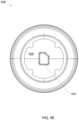
- FIG. 1 Eis an end plan view of a mount of the percussive massage device of FIG. 1 C .
- FIG. 1 Fis a side elevation view of a mechanical connector of the mount of FIG. 1 E .
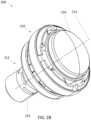
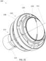
- FIG. 1 Gis an oblique perspective view of an electrical connector of the mount of FIG. 1 E .
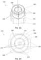
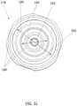
- FIG. 1 His an end plan view of the electrical connector of FIG. 1 G .
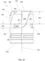
- FIG. 1 Iis a side elevation view of the electrical connector of FIG. 1 G .
- FIG. 1 Jis a side elevation view of a massage attachment of the therapeutic system of FIG. 1 A .
- FIG. 1 Kis an oblique perspective view of a connector of the attachment of FIG. 1 J .
- FIG. 1 Lis an end plan view of an electrical connector of the connector of FIG. 1 K .
- FIG. 2 Ais an oblique perspective view of a massage head according to further aspects of the present disclosure.
- FIG. 2 Bis an oblique perspective view of the massage head of FIG. 2 A in a partially disassembled state.
- FIG. 2 Cis an oblique perspective view of the massage head of FIG. 2 A in a further disassembled state.
- FIG. 2 Dis an oblique perspective view of the massage head of FIG. 2 A in a still further disassembled state.
- FIG. 2 Eis a side elevation view of the massage head of FIG. 2 A in the partially disassembled state of FIG. 2 B .
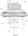
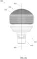
- FIG. 3 Ais a side elevation view of a massage head according to further aspects of the present disclosure.
- FIG. 3 Bis an oblique perspective view of the massage head of FIG. 3 A .
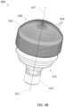
- FIG. 3 Cis an oblique perspective view of the massage head of FIG. 3 A in a partially disassembled state.
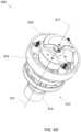
- FIG. 3 Dis an oblique perspective view of the massage head of FIG. 3 A in a further disassembled state.
- FIG. 3 Eis a side elevation view of the massage head of FIG. 3 A in a still further disassembled state.
- FIG. 3 Fis a side elevation view of a heat sink of the massage head of FIG. 3 A .
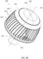
- FIG. 3 Gis an oblique perspective view of the heat sink of FIG. 3 F .
- FIG. 3 His a second oblique perspective view of the heat sink of FIG. 3 F .
- FIG. 3 Iis a bottom plan view of the heat sink of FIG. 3 F .
- FIG. 4 Ais a side elevation view of a massage head according to further aspects of the present disclosure.
- FIG. 4 Bis an oblique perspective view of the massage head of FIG. 4 A .
- FIG. 4 Cis an oblique perspective view of the massage head of FIG. 4 A in a partially disassembled state.
- FIG. 4 Dis an oblique perspective view of the massage head of FIG. 4 A in a further disassembled state
- FIG. 4 Eis a bottom plan view of a cover of the massage head of FIG. 4 A .
- FIG. 4 Fis an oblique perspective view of another configuration of a massage head of the type shown in FIG. 4 A .
- FIG. 5 Ais a side plan view of a therapeutic system according to further aspects of the present disclosure.
- FIG. 5 Bis a side plan view of the therapeutic system of FIG. 5 A in a partially disassembled state.
- FIG. 5 Cis a side elevation view of an infrared module of the therapeutic device of FIG. 5 A .
- FIG. 5 Dis front elevation view of the infrared module of FIG. 5 C in a partially disassembled state.
- FIG. 5 Eis an oblique perspective view of the infrared module of FIG. 5 C in the partially disassembled state of FIG. 5 D .
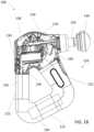
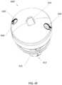
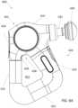
- FIG. 6 Ais a side elevation view of a therapeutic system according to further aspects of the present disclosure.
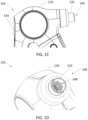
- FIG. 6 Bis a close view of a portion of the therapeutic system of FIG. 6 A .
- FIG. 6 Cis an oblique perspective view of the portion of FIG. 6 B .
- FIG. 6 Dis a side elevation view of the therapeutic system of FIG. 6 A in a partially disassembled state.
- FIG. 6 Eis a graphical representation of a therapeutic protocol executable by the therapeutic system of FIG. 6 A .
- FIG. 6 Fis a chart showing steps of a heart rate control protocol in accordance with a method of performing a therapy routine with a percussive massage device, according to an embodiment of the present disclosure.
- FIG. 6 Gis a chart showing steps of a second rate heart control protocol in accordance with a method of performing a therapy routine with a percussive massage device, according to an embodiment of the present disclosure.
- FIG. 6 His a chart showing steps of a third heart rate control protocol in accordance with a method of performing a therapy routine with a percussive massage device, according to an embodiment of the present disclosure
- Embodimentsmay be implemented in hardware (e.g., circuits), firmware, software, or any combination thereof. Embodiments may also be implemented as instructions stored on a machine-readable medium, which may be read and executed by one or more processors.
- a machine-readable mediummay include any mechanism for storing or transmitting information in a form readable by a machine (e.g., a computing device).
- a machine-readable mediummay include read only memory (ROM); random access memory (RAM); magnetic disk storage media; optical storage media; flash memory devices; electrical, optical, acoustical or other forms of propagated signals (e.g., carrier waves, infrared signals, digital signals, etc.), and others.
- firmware, software, routines, instructionsmay be described herein as performing certain actions. However, it should be appreciated that such descriptions are merely for convenience and that such actions in fact result from computing devices, processors, controllers, or other devices executing the firmware, software, routines, instructions, etc. Further, any of the implementation variations may be carried out by a general purpose computer, as described below.
- modulemay include one, or more than one, component within an actual device, and each component that forms a part of the described module may function either cooperatively or independently of any other component forming a part of the module.
- multiple modules described hereinmay represent a single component within an actual device.
- components within a modulemay be in a single device or distributed among multiple devices in a wired or wireless manner.
- FIG. 1 Aillustrates a therapeutic system 100 comprising a percussive massage device 101 and a massage attachment 130 .
- Therapeutic system 100is similar in some respects to the systems disclosed in U.S. patent application Ser. No. 18/176,399, filed Feb. 28, 2023, hereinafter “the '399 application,” the entirety of which is hereby incorporated by reference. Accordingly, in some examples, therapeutic system 100 can be alike to any of the embodiments disclosed in the '399 application in any details that do not conflict with the features of therapeutic system 100 as described or illustrated herein.
- Massage attachment 130is mounted to a distal end of a shaft 132 comprised by percussive massage device 101 .
- Percussive massage device 101comprises a head portion 110 , from which shaft 132 extends.
- Percussive massage device 101further comprises a handle 120 that also extends from head portion 110 .
- Handle 120 of the illustrated examplecomprises three handle portions 122 in a co-planar, triangular arrangement, though in other examples other types of handles may be used.
- handle 120can have any shape enabling a user to grasp device 101 and use device 101 to apply percussive massage with massage attachment 130 .
- device 101comprises a motor 138 .
- Shaft 132is configured to reciprocate linearly along a reciprocation axis 111 when a motor 138 of massage device 101 is active.
- device 101may be used for percussive massage by applying massage attachment 130 to tissue while shaft 132 reciprocates.
- Massage device 101comprises a push rod 139 connecting motor 138 to shaft 132 and a cable 144 that conveys electrical power to shaft 132 and establishes electronic communication between shaft 132 and controller 136 .
- Push rod 139 and cable 144 of the illustrated exampleare alike to the push rod 1722 and cable assembly 1726, 1728 of the '399 application.
- any other structurescan be used to connect shaft 132 mechanically to motor 138 , provide power to shaft 132 , and establish electronic communication between shaft 132 and controller 136 .
- the concepts of the present disclosureare illustrated and described in connection with a percussive massage device 101 , they can also be applied to devices without percussive functionality wherein shaft 132 is not motorized.
- Percussive massage device 101further comprises a control panel 134 comprising a switch configured to activate the motor 138 that drives shaft 132 .
- Control panel 134 of the illustrated exampleis positioned on a proximally facing side of head portion 110 .
- Device 101further comprises a controller 136 in electronic communication with control panel 134 such that controller 136 can receive and act on user's manual inputs to control panel 134 .
- Device 101further comprises an electrical power source 140 , such as, for example, an onboard battery, and a power line 142 connecting source 140 to controller 136 .
- Controller 136can be configured to govern distribution of electrical power from source 140 to various components of device 101 .
- control panel 134can be positioned anywhere accessible by a user.
- percussive massage device 101can be operable by remote control, such as, for example, through a smart device in wireless communication with controller 136 , and can lack a control panel 134 .
- shaft 132comprises a mount 146 located at the distal end of shaft 132 .
- Mount 146 of the illustrated examplecomprises an opening at the distal end of shaft 132 that massage attachment 130 can be plugged into to removably couple massage attachment 130 to mount 146 .
- Mount 146comprises a shaft connector 148 disposed within the opening.
- Shaft connector 148in turn comprises a shaft mechanical connector 150 and a shaft electrical connector 152 .
- Shaft mechanical connector 150comprises a barrel 154
- shaft electrical connector 152is disposed within barrel 154 .
- shaft mechanical connector 150comprises a barrel 154 .
- Barrel 154extends along a mount connection axis 112 that is aligned with an attachment connection axis 114 , defined relative to massage attachment 130 as described below with regard to FIGS. 1 J and 1 K , when massage attachment 130 is attached to shaft 132 at mount 146 .
- Mount connection axis 112 of the illustrated exampleis coaxial with reciprocation axis 111 such that attachment connection axis 114 also becomes coaxial with reciprocation axis 111 when massage attachment 130 is connected to shaft 132 at mount 146 .
- mount connection axis 112can be parallel to reciprocation axis 111 without being coaxial with reciprocation axis 111 .
- mount connection axis 112can be transverse to reciprocation axis 111 .
- Barrel 154comprises channels 156 that extend proximally from a distal end 157 of barrel 154 toward a proximal end 159 of barrel 154 .
- Each channel 156comprises an opening 158 defining a distal end of the channel 156 .
- Each channelfurther comprises a circumferential leg 160 .
- Each circumferential leg 160extends circumferentially on a portion of barrel 154 about mount connection axis 112 .
- Each circumferential leg 160 of the illustrated exampleis spaced proximally from the opening 158 of the same channel 156 .
- circumferential legs 160can be at a same axial location as openings 158 or circumferential legs 160 can be omitted.
- Each circumferential leg 160terminates at a seat 162 .
- Each seat 162defines a circumferential end of the circumferential leg 160 and further comprises a distal axial face 165 and a proximal axial face 167 .
- Axial faces 165 , 167 of each seat 162define axial limits of the seat 162 relative to mount connection axis 112 .
- Axial faces 165 , 167 of each seat 162are spaced apart by a first height 163 defined as an axial distance, relative to mount connection axis 112 , between distal axial face 165 and proximal axial face 167 .
- Distal axial face 165 of each seat 162is spaced from opening 158 of the same channel 156 by a second height 164 defined as an axial distance, relative to mount connection axis 112 , between distal axial face 165 and opening 158 .
- shaft mechanical connector 150comprises channels 156 configured to guide posts 180 , discussed further below, as attachment 130 is coupled to mount 146 such that shaft mechanical connector 150 is configured to engage attachment mechanical connector 172 when attachment 130 is coupled to mount 146 to releasably secure attachment 130 to device 101 .
- Each channel 156comprises an opening 158 configured to receive a respective one of the posts 180 of attachment mechanical connector 174 as attachment 130 is coupled to mount 146 .
- Each channel 156further comprises a seat 162 defining a terminal position reached by the respective one of the posts 180 when attachment 130 is coupled to mount 146 .
- Each channel 156further comprises a non-linear portion extending from opening 158 to seat 162 .
- the non-linear portion of the illustrated exampleis shaped similarly to the letter “J” as shown in FIG. 1 F , though channels 156 of other examples can have other non-linear shapes.
- the inclusion of a non-linear portion between each opening 158 and seat 162enables a user to lock attachment mechanical connector 174 to shaft mechanical connector 150 by guiding posts 180 to seat 162 . Because of the non-linear portion of channel 156 between seat 162 and opening 158 , posts 180 are inhibited from simply backing out of channels 156 during use, which reduces a likelihood of unintended disconnection of attachment 130 from mount 146 .
- each channel 156further comprises a circumferential leg 160 that ends at seat 162 of the same channel.
- Each circumferential leg 160extends circumferentially about the position of the central axis of shaft electrical connector 152 relative to shaft mechanical connector 150 when attachment 130 is coupled to mount 146 .
- the central axis of shaft electrical connector 152is mount connection axis 112 , but as explained further below the features of mechanical connectors 150 , 174 and electrical connectors 152 , 178 are reversible between mount 146 and attachment connector 172 .
- circumferential legs 160can extend circumferentially about the central axis of those features when attachment 130 is coupled to mount 146 because mount connection axis 112 and attachment connection axis 114 become coaxial when attachment 130 is coupled to mount 146 .
- the positioning of legs 160 to extend circumferentially about the respective central axes of both electrical connectors 152 , 178 as shown in the illustrated exampleguides connection of attachment 130 to mount 146 in a motion wherein electrical connectors 152 , 178 rotate relative to one another but remain coaxial.
- Barrel 154can comprise one or more sloped shoulders 155 extending both radially and proximally away from distal end 157 of barrel 154 and encircling mount connection axis 112 .
- Shoulders 155can assist a user with aligning attachment mechanical connector 174 relative to shaft 132 as attachment 130 while the user couples attachment 130 to mount 146 .
- attachment 130can be configured to bear on shoulders 155 such that some or all load between attachment 130 and shaft 132 is applied to shoulders 155 .
- shoulders 155can partially deflect the load between attachment 130 and shaft 132 such that the barrel 154 and attachment 130 receive the load as combined axial and radial load relative to mount connection axis 112 , rather than purely axial load.
- Shoulders 155can thereby contribute to longevity of barrel 154 and attachment 130 and reduce noise produced at the interface of mount 146 and massage attachment 130 when therapeutic system 100 is in use.
- shoulders 155are optional, and can be omitted in other examples.
- shaft electrical connector 152comprises electrically conductive prongs 166 , 168 .
- Prongs 166 , 168can be constructed of any suitably electrically conductive material, such as, for example, metals and metal alloys such as copper or brass.
- Prongs 166 , 168are in electrical communication with cable 144 through shaft 132 .
- Prongs 166 , 168thus provide electrical contacts of shaft 132 for establishing electrical power and electronic data connection between shaft 132 and massage attachment 130 .
- Shaft electrical connector 152can further comprise a base 161 from which prongs 166 , 168 extend.
- One of the prongs 166 , 168 comprised by shaft electrical connector 152is a center prong 166 centered on mount connection axis 112 .
- Center prong 166is in the form of a post extending along mount connection axis 112 .
- Further prongs 168are arranged about mount connection axis 112 and center prong 166 .
- Each prong 168is in the form of an arcuate fin.
- the arcuate fin shape of each prong 168comprises a portion of a circle centered on mount connection axis 112 .
- Prongs 168 of the illustrated exampleare arranged in concentric circles about mount connection axis 112 .
- shaft electrical connector 152 of the illustrated examplecomprises two concentric circles or rings of fin-shaped prongs 168 , with each circle being centered on mount connection axis 112 .
- each ring of fin-shaped prongs 168collectively defines an annular projection centered on mount connection axis 112 .
- the electrical contacts of the illustrated example of shaft electrical connector 152thus comprise a post and two concentric annular projections centered on mount connection axis 112 . Because of the inherent resilient bias of fin-shaped prongs 168 to the resting shape shown in FIGS.
- shaft electrical connector 152can comprise more or fewer circles of fin-shaped prongs 168 , such as three concentric circles of fin-shaped prongs 168 or only one circle of fin-shaped prongs 168 .
- shaft electrical connector 152can lack a post-shaped central prong 166 and can instead comprise a further circle of fin-shaped prongs 168 .
- each circle of fin-shaped prongs 168 in the illustrated examplecomprises four such fin-shaped prongs 168
- other examplescan comprise more or fewer fin-shaped prongs 168 in each circle.
- shaft electrical connector 152comprises multiple circles of fin-shaped prongs 168
- shaft electrical connector 152can comprise different amounts of fin-shaped prongs 168 in different circles.
- shaft electrical connector 152comprises a base 161 .
- the plurality of fin-shaped prongs 168extends substantially parallel to mount connection axis 112 to a free end 183 .
- extending substantially parallel to mount connection axis 112 from base 161 to free end 183means that an axial distance between base 161 and free end 183 exceeds a radial distance between free end 183 and the portion of the prong 168 to which free end 183 belongs that is nearest base 161 .
- Free end 183is a furthest point on the plurality of prongs 168 from base 161 .
- Prongs 168collectively have a first diameter 171 centered on and perpendicular to mount connection axis 112 at a first axial location near base 161 .
- Prongs 168collectively have a second collective diameter 173 centered on and perpendicular to mount connection axis 112 at a second axial location further from base 161 than the first axial location where prongs 168 collectively have first diameter 171 .
- Prongs 168collectively have a third diameter 177 centered on and perpendicular to mount connection axis 112 at free end 183 . As shown, free end 183 is further from base 161 along mount connection axis 112 than the first axial location where prongs 168 collectively have first diameter 171 and the second axial location where prongs 168 collectively have second diameter 173 .
- Prongs 168are resiliently flexible. In particular, because prongs 168 are separated by axially extending gaps 179 spaced angularly about mount connection axis 112 , prongs 168 can flex radially inward toward mount connection axis 112 such that free end can have a smaller collective diameter than third diameter 177 .
- FIG. 1 Ishows the outer circle of prongs 168 at a resting shape to which the outer circle of prongs 168 are biased by their own resilience to return in the absence of external forces on prongs 168 . In the illustrated resting shape, third diameter 177 is less than second diameter 173 . Further, second diameter 173 is a greatest diameter collectively defined by the outer circle of prongs 168 visible in FIG.
- prongs 168 of the plurality of prongs 168are each resiliently biased toward a resting shape that tapers toward mount connection axis 112 at free end 183 such that the plurality of prongs 168 has a greatest collective diameter perpendicular to mount connection axis 112 at an axial location between free end 183 and base 161 .
- This tapered shapefacilitates pressing prongs 168 into a socket having an internal diameter between second diameter 173 and third diameter 177 .
- first diameter 171is less than second diameter 173
- the resting shapehas a portion with a collective diameter perpendicular to mount connection axis less than the greatest collective diameter at an axial location proximal of the portion between base 161 and the portion of the resting shape that has the greatest collective diameter.
- This profileplaces the widest portion of the circle of prongs 168 away from the axial location wherein prongs 168 are connected to base, facilitating contact between prongs 168 and an interior of a receiving socket at an intended depth.
- shaft electrical connector 152 of the illustrated examplecomprises two concentric circles or rings of fin-shaped prongs 168 .
- the characteristics described above with regard to the multiple diameters of the external profile of the outer ring of prongs 168 shown in FIG. 1 Ican also be true for the inner ring of prongs 168 .
- each additional ring of prongs 168can have a similar external profile with different diameters at different axial locations to facilitate pressing each ring into a respective socket and establishing reliable contact at an intended depth therein.
- massage attachment 130comprises a massage end 170 and an attachment connector 172 .
- massage end 170comprises features that create a therapeutic effect when massage end 170 is applied to tissue.
- Attachment connector 172extends from massage end 170 along attachment connection axis 114 in a direction along which massage attachment 130 connects to mount 146 .
- attachment connection axis 114becomes coaxial with mount connection axis 112 .
- attachment connector 172comprises an attachment mechanical connector 174 and an attachment electrical connector 178 .
- Attachment mechanical connector 174 of the illustrated examplecomprises a tube 175 having friction elements 176 positioned to engage mount 146 when massage attachment 130 is coupled to mount 146 .
- Friction elements 176can be radial protrusions or bands of a material, such as, for example, rubber, or another polymer material with similar properties. Friction element 176 are optional, but can contribute to a secure connection of attachment 130 to mount 146 while reducing vibration of attachment 130 relative to shaft 132 during use. Friction elements 176 can therefore contribute to longevity of shaft 132 and attachment 130 and enable therapeutic system 100 to operate quietly.
- Attachment mechanical connector 174further comprises posts 180 .
- Posts 180protrude radially from tube 175 of attachment mechanical connector 174 .
- Posts 180are positioned to be insertable into channels 156 to connect attachment mechanical connector 174 to shaft mechanical connector 150 when mount connection axis 112 and attachment connection axis 114 are coaxial.
- a process for coupling massage attachment 130 to mount 146 of shaft 132can comprise aligning attachment connection axis 114 with mount connection axis 112 while attachment 130 is positioned distally of shaft 132 and massage end 170 faces distally, then translating massage attachment 130 proximally so that posts 180 of attachment mechanical connector 174 enter openings 158 of channels 156 of shaft mechanical connector 150 .
- the process for coupling massage attachment 130 to mount 146can further comprise, after posts 180 enter openings 158 , advancing and turning attachment along mount connection axis 112 and attachment connection axis 114 so that posts 180 follow channels 156 until posts 180 reach seats 162 .
- Posts 180are shown in FIG. 1 K to extend radially relative to attachment connection axis 114 .
- Posts 180also extend radially relative to mount connection axis 112 when attachment 130 is coupled to mount 146 because mount connection axis 112 and attachment connection axis 114 become coaxial when attachment 130 is coupled to mount.
- Posts 180thus also extend radially relative to respective central axes, defined by mount connection axis 112 , and attachment connection axis 114 , of both electrical connectors 152 , 178 when attachment 130 is coupled to mount 146 .
- Posts 180can have an axial height relative to attachment connection axis 114 equal to first height 163 , introduced above with regard to FIG. 1 F . Posts 180 can therefore have a tight fit within seat 162 between distal axial face 165 and proximal axial face 167 . In further examples, posts 180 can have an axial height slightly larger than first height 163 , such as by up to 1% of first height 163 , up to 2% of first height 163 , or up to 5% of first height 163 , to create an interference fit between posts 180 and seats 162 . The fit between post 180 and distal axial face 165 in particular depends on a length and shape of channels 156 .
- Each channel 156can thus be sized and configured to create an interference fit between a respective one of the posts 180 and an axial face of seat 162 when attachment 130 is coupled to mount 146 .
- the above described tight fit or interference fit between posts 180 and seats 162can reduce or prevent both axial and rotational movement of attachment 130 relative to shaft 132 .
- Longevity of attachment 130 and shaft 132can be improved and noise at the interface of attachment 130 and mount 146 can be reduced by reducing axial movement of attachment 130 relative to shaft 132 .
- Unintended loosening or decoupling of attachment 130 from mount 146can be avoided by preventing rotational movement of attachment 130 relative to shaft 132 .
- Attachment mechanical connector 174further comprises one or more shoulders 181 that protrude from a side of tube 175 as posts 180 and encircling attachment connection axis 114 .
- Shoulders 181can extend both radially away from the side of tube 175 and distally, as shown in the illustrated example. In other examples, shoulders 181 can extend purely radially away from the side of tube 175 .
- Shoulders 181are spaced distally from posts 180 by an amount relative to second height 164 , introduced above with regard to FIG. 1 F , such that shoulders 181 bear upon barrel 154 when posts 180 are received in seats 162 .
- shoulders 181are sloped and positioned to engage shoulders 155 of barrel 154 when posts 180 are received in seats 162 .
- shoulders 181can be positioned to additionally or alternatively bear upon distal end 157 of barrel 154 when posts 180 are received in seats 162 .
- Shoulders 181can be spaced distally from posts 180 by an amount relative to second height 164 that creates a tight or interference fit of a portion of barrel 154 between posts 180 and shoulders 181 when posts 180 are received in seats 162 .
- shoulders 181can be positioned relative to posts 180 such that posts 180 bear upon distal axial faces 165 with a tight or interference fit and shoulders 181 bear upon shoulders 155 or distal end 157 with the tight or interference fit when posts 180 are received in seats 162 .
- the tight or interference fit between posts 180 , shoulders 181 , and barrel 154can prevent or reduce movement of attachment 130 relative to shaft 132 when attachment 130 is coupled to mount, thereby improving longevity of attachment 130 and shaft 132 , reducing noise at an interface between mount 146 and attachment 130 , and reducing a likelihood of unintentional decoupling of attachment 130 and mount 146 .
- shoulders 181are sloped to extend distally as well as radially, as in the illustrated example, shoulders 181 can deflect some or all load between shaft 132 and attachment 130 such that the shaft mechanical connector 150 and attachment mechanical connector 174 receive the load as combined axial and radial load, relative to attachment connection axis 114 , instead of purely axial load. Such deflection of load can further improve longevity of shaft 132 and attachment and reduce noise at the interface between mount 146 and attachment 130 .
- attachment mechanical connector 174is configured relative to first axial height 163 and second axial height 164 of barrel 154 to create tight or interference axial fits for posts 180 within seats 162 and for portions of barrel 154 received between posts 180 and shoulders 181 . These axial fits cooperate to advance part longevity, reduce noise, and avoid unintended decoupling of attachment 130 from mount 146 .
- posts 180can be shorter along attachment connection axis 114 than first height 163 while shoulders 181 remain spaced relative to posts 180 so as to create a tight or fiction fit on a portion of barrel 154 between posts 180 and shoulders 181 when attachment 130 is coupled to mount 146 .
- shoulders 181can be omitted or spaced distally from posts 180 by more than second height 164 while posts 180 are sized to have an interference fit within seat 162 between distal axial face 165 and proximal axial face 167 .
- barrel 154comprises four channels 156 equally angularly spaced about mount connection axis 112 .
- attachment mechanical connector 174comprises four posts 180 equally angularly spaced about mount connection axis 112 .
- Channels 156are therefore symmetrically distributed about mount connection axis 112 while an equal number of posts 180 are symmetrically distributed about attachment connection axis 114 .
- posts 180can all be simultaneously received in channels 156 when mount connection axis 112 and attachment connection axis 114 are made coaxial.
- each post 180is located at a same position within a respective channel 156 as each other post 180 is located within another channel 156 .
- shaft mechanical connector 150is a male connector while attachment mechanical connector 174 is a female connector.
- barrel 154is configured to be received in tube 175
- channels 156are defined on a radial exterior of barrel 154
- posts 180protrude radially inward from tube 175 to engage channels 156 .
- shaft mechanical connector 150can be a female mechanical connector while attachment mechanical connector 174 is a male mechanical connector.
- shaft mechanical connector 150can comprise a tube with channels 156 defined on a radial interior of the tube
- attachment mechanical connector 174can comprise a barrel configured to be received in the tube of shaft mechanical connector 150
- attachment mechanical connector 174can further comprise posts 180 protruding radially outward from the barrel to engage channels 156 .
- attachment electrical connector 178comprises a central socket 182 aligned on attachment connection axis 114 .
- Central socket 182is configured to receive central prong 166 when attachment 130 is coupled to mount 146 .
- Central socket 182comprises an electrical contact to establish an electrical connection between central prong 166 and components within attachment 130 when central prong 166 is received in central socket 182 .
- Central socket 182is surrounded by additional annular sockets 184 in the form of trenches defined between walls 186 .
- Walls 186 of the illustrated exampleare in the form of concentric rings centered on attachment connection axis 114 .
- the trenches that define annular sockets 184are configured to receive fin-shaped prongs 168 when attachment 130 is coupled to mount 146 .
- Each wall 186comprises a conductive band on its radially inner side that acts as an electrical contact to establish an electrical connection between prongs 168 and components within attachment 130 when prongs 168 are received in the trenches that define annular sockets 184 .
- the conductive band on the radially inner side of each wall 186extends to a contact depth where prongs 168 will contact wall 186 when attachment 130 is coupled to mount 146 .
- the contact depth of each annular socket 184is the depth at which the portion of the corresponding ring of prongs 168 defining the greatest diameter perpendicular to mount connection axis 112 , such as second diameter 173 , will contact wall 186 when attachment 130 is coupled to mount 146 .
- Each annular socket 184has a contact span 185 defined as a diameter of the annular socket 184 perpendicular to attachment connection axis 114 at the contact depth of the annular socket 184 .
- Annular sockets 184 of the illustrated examplehave constant diameters perpendicular to attachment connection axis 114 for their entire depth, meaning each contact span 185 is also a diameter of an opening of the same annular socket 184 .
- annular sockets 184according to other examples can have different diameters perpendicular to attachment connection axis 114 at different depths or angles relative to attachment connection axis 114 .
- each wall 186 that defines the radial exterior of an annular socket 184defines an interior of that socket 184 and comprises a conductive band that acts as an electrical contact for the socket 184 .
- the conductive bandcan be the wall 186 itself.
- each annular socket 184is configured with a contact depth at which the corresponding plurality of prongs 168 contacts the interior of the interior of the socket 184 when attachment 130 is coupled to mount 146 .
- contact span 185is a greatest distance across the interior of the socket 184 at the contact depth.
- Each circle of prongs 168 making up a plurality of prongs 168 to be received in an annular socket 184can, when in a resting shape such as that shown in FIG. 1 I , have a greatest collective diameter, such as second diameter 173 , that is greater than contact span 185 of that annular socket 184 to ensure that prongs 168 press into contact with the conductive band of the corresponding wall 186 when posts 180 reach seats 162 .
- each annular socket 184defines an opening through which a plurality of prongs 168 are configured to be received when attachment 130 is coupled to mount 146 , and the contact span 185 of each annular socket is at least as great as a diameter of the opening.
- the prongs 168are configured to deflect radially inward toward mount connection axis 112 as attachment 130 is being coupled to mount 146 . Placing the electrical contacts of sockets 182 , 184 in the walls that define sockets 182 , 184 rather than, or in addition to, the axial ends of sockets 182 , 184 facilitates consistent electrical contact between prongs 166 and sockets 182 , 184 despite relative axial movement between electrical connectors 152 , 178 that may occur during axial reciprocation of shaft 132 and attachment 130 .
- attachment electrical connector 178comprises an inner annular socket 184 and another trench that surrounds the inner annular socket 184 , providing an outer annular socket 184 .
- Both annular sockets 184are bounded by a respective outer wall 186 comprising a respective conductive band.
- attachment electrical connector 178comprises a first trench defining an outer annular socket 184 bounded by a first, outermost wall 186 and a second trench surrounded by the first trench and defining an inner annular socket 184 bounded by a second wall 186 surrounded by the first wall 186 .
- Shaft electrical connector 152comprises a first, outermost ring of prongs 168 and a second, inner ring of prongs 168 surrounded by the first ring of prongs 168 .
- Each ring of prongs 168comprises at least one conductive fin configured to be received in a respective one of the annular sockets 184 and to travel angularly therein.
- the outer ring of prongs 168comprises at least a first conductive fin configured to extend into the first annular socket 184 and contact the conductive band of the first wall 186 when attachment 130 is coupled to mount 146 .
- the inner ring of prongs 168comprises at least a conductive fin that is located radially inward of the first conductive fin and configured to extend into the second annular socket 184 and contact the conductive band of the second wall 186 when attachment 130 is coupled to mount 146 .
- This fin-and-trench arrangementallows multiple independent electrical connections to be made at different distances from the respective central axes, defined as mount connection axis 112 and attachment connection axis 114 , of electrical connectors 152 , 178 while permitting electrical connectors 152 , 178 to rotate freely relative to one another as mechanical connectors 150 , 174 are engaged or disengaged.
- Shaft electrical connector 152 and attachment electrical connector 178can be respectively configured to provide either or both of an electrical power connection, whereby power can be supplied from device 101 to attachment 130 , and an electronic data connection, whereby data and control signals can be communicated between device 101 and attachment 130 .
- Shaft electrical connector 152 and attachment electrical connector 178can therefore allow therapeutic system 100 to have electronic attachments 130 for providing controllable therapeutic effects in addition to percussion.
- device 101can be configured to supply electrical power to the electronic components when attachment 130 is operatively connected to the distal end of shaft 132 at mount 146 .
- controller 136can have a data connection with the electronic components when attachment 130 is operatively connected to the distal end of shaft 132 at mount 146 .
- controller 136can be configured to send instructions to attachment 130 through the electronic data connection provided by shaft electrical connector 152 and attachment electrical connector 178 . In some such examples, controller 136 can further be configured to enable user control of electronic functions of attachment 130 by manual inputs to a user interface of control panel 134 . In some examples, controller 136 can be configured to identify a type of attachment 130 connected to mount 146 from information communicated through the electronic data connection provided by shaft electrical connector 152 and attachment electrical connector 178 . In some such examples, controller 136 can be configured to disable motor 138 when controller 136 determines that a certain type of attachment 130 is connected to mount 146 . In further examples, attachment 130 can have an integrated battery or other power source, and shaft electrical connector 152 and attachment electrical connector 178 can be respectively configured to establish an electronic data connection between device 101 and attachment 130 without otherwise conveying power from device 101 to attachment 130 .
- shaft connector 148can have mechanical connecting features like those described above with regard to attachment mechanical connector 174 instead of the features of shaft mechanical connector 150 while attachment connector 172 has complementary mechanical connecting features like those described above with regard to shaft mechanical connector 150 instead of the features of attachment mechanical connector 174 .
- the mechanical connectors 150 , 174can be reversed between shaft connector 148 and attachment connector 172 without affecting electrical connectors 152 , 178 .
- shaft connector 148can have electrical connecting features like those described above with regard to attachment electrical connector 178 instead of the features of shaft electrical connector 152 while attachment connector 172 has complementary electrical connecting features like those described above with regard to shaft electrical connector 152 instead of the features of attachment electrical connector 178 .
- the electrical connectors 152 , 178can be reversed between shaft connector 148 and attachment connector 172 without affecting mechanical connectors 150 , 174 .
- shaft connector 148can have the features described above with regard to both attachment mechanical connector 174 and attachment electrical connector 178 instead of shaft mechanical connector 150 and shaft electrical connector 152 while attachment connector 172 has the complementary features described above with regard to both shaft mechanical connector 150 and shaft electrical connector 152 instead of attachment mechanical connector 174 and attachment electrical connector 178 .
- shaft mechanical connector 150 and shaft electrical connector 152can be arranged relative to attachment connection axis 114 the way they are arranged relative to mount connection axis 112 in the illustrated example, while the features of attachment mechanical connector 174 and attachment electrical connector 178 can be arranged relative to mount connection axis 112 the way they are arranged relative to attachment connection axis 114 in the illustrated example.
- therapeutic system 100comprises a first mechanical connector 172 , a first electrical connector 178 , a second mechanical connector 150 , and a second electrical connector 152 .
- shaft connector 148comprises either first mechanical connector 172 or second mechanical connector 150 while attachment connector 172 comprises the other of first mechanical connector 172 or second mechanical connector 150 .
- shaft connector 148also comprises either first electrical connector 178 or second electrical connector 152 while attachment connector 172 also comprises the other of first electrical connector 178 or second electrical connector 178 .
- therapeutic system 100 of the illustrated examplecomprises a device 101 , an attachment 130 , a first electrical connector 178 , and a second electrical connector 152 .
- Device 101comprises an electrical power source 140 and a mount 146 .
- Attachment 130is configured to removably couple to mount 146 .
- First electrical connector 178comprises at least one socket 184 that defines an interior
- second electrical connector 152comprises a plurality of prongs 168 arranged around a central axis, such as mount connection axis 112 .
- Attachment 130comprises either first electrical connector 178 or second electrical connector 152 and mount 146 comprises the other of first electrical connector 178 or second electrical connector 152 .
- first electrical connector 178 or second electrical connector 152 comprised by mount 146is electrically connected to power source 140 .
- Prongs 168 among the plurality of prongs 168are biased outward relative to the central axis, which can be mount connection axis 112 , and are configured such that when attachment 130 is coupled to mount 146 , the plurality of prongs 168 extend into socket 184 and press radially outward on the interior of socket 184 .
- Device 101is a percussive massage device comprising a motor 138 and a shaft 132 configured to reciprocate linearly in response to activation of motor 138 , and shaft 132 comprises mount 146 .
- Attachment 130comprises a massage head.
- FIGS. 2 A- 2 Eillustrate a massage head 200 .
- a massage attachmentis an article comprising a massage head that can be removably coupled to a massage device to form a therapeutic system.
- massage head 200according to various examples can be either removably couplable to a mount of a massage device or permanently connected to a massage device.
- massage head 200can be massage attachment 130 described above.
- Massage head 200is a heating massage head.
- Massage head 200comprises a massage end 210 and a base 212 extending from massage end 210 .
- Base 212comprises a connector 215 configured to connect massage head 200 to a massage device.
- connector 215 of some examplescan be attachment connector 172 described above with regard to massage attachment 130 .
- a percussive massage systemcan comprise massage head 200 and a percussive massage device comprising a reciprocating shaft and a motor, wherein the reciprocating shaft is configured to reciprocate linearly along a reciprocation axis in response to activation of the motor.
- the massage head 200can further comprise a medial portion 230 and an end portion 232 , described further below with regard to FIG.
- medial portion 230is configured to resiliently bias the end portion 232 away from base 212 along a proximal-distal axis 211 that is parallel to reciprocation axis 111 .
- Base 212can optionally be configured to releasably connect massage head 200 to shaft 132 .
- Massage head 200 of the illustrated exampleboth provides heat to treated tissue and compresses along a proximal-distal axis 211 , making massage head 200 suitable for simultaneous application of heat therapy and percussive massage.
- massage head 200can comprise relatively rigid or inflexible elements responsible for providing an advantageous distribution of heat across a distal surface of massage head 200 .
- Those rigid elementscan be located near the distal surface of massage head 200
- massage head 200can further comprise a resiliently compressible element between base 212 and the rigid elements.
- the compressible elementcan resiliently bias the rigid elements away from base 212 , allowing the rigid elements to provide effective heat therapy while softening the impact of the distal end of massage head 200 upon treated tissue to a magnitude suitable for percussive massage.
- massage head 200comprises a cover 214 .
- Cover 214is constructed of a flexible material suitable for applying percussive massage to a skin of a user, such as, for example, foam, plastic, rubber, or other similarly flexible and biocompatible materials.
- FIG. 2 Bshows massage head 200 without cover 214 .
- massage head 200comprises a panel 216 within massage end 210 under cover 214 .
- Panel 216can be disposed within cover 214 distally of a heater 218 , described further below.
- Panel 216is made of thermally conductive material, such as, for example, metal, carbon, or any other material both durable and conductive enough to act as a heat spreader for a head of a percussive massage device.
- Panel 216can have a thermal conductivity of, for example, from about 90 to about 5000 watts per meter-kelvin.
- the lower boundcan be about 150, about 300, about 500, or about 1000 watts per meter-kelvin while the upper bound remains 5000 watts per meter-kelvin. “About,” in this instance, encompasses values within 10% of the stated number, and the stated number itself is explicitly contemplated.
- Panel 216is positioned against, or at least adjacent to, an interior side of cover 214 . In the illustrated example, panel 216 is located between a heater 218 , described further below, and cover 214 . Panel 216 can extend across a majority of an intended contact surface of massage head 200 .
- an end portion 232described further below with regard to FIG. 2 E , of massage head 200 , can define a distal surface intended for contact with treated tissue, and a distal side of panel 216 can have an area that is from 90% to 100% of a total area of the distal surface of end portion 232 .
- FIG. 2 Cshows massage head 200 without either cover 214 or panel 216 .
- Heater 218can be, for example, a resistive heater, a carbon fiber heater, or any other type of heater controllable to heat to therapeutic temperatures within the interior of massage head 200 .
- massage head 200further comprises a heater 218 within massage end 210 .
- Heater 218is positioned against panel 216 such that, when active, heater 218 heats panel 216 .
- heater 218can be thermally coupled to panel 216 , meaning heater 218 can be in direct contact with panel 216 or heater 218 can be placed in thermal communication with panel 216 by a bridging portion of thermally conductive material, such as thermal paste, carbon fiber, or metal.
- panel 216is constructed of thermally conductive material, panel 216 can act as a heat spreader by rising to a relatively uniform elevated temperature across its surface when heated by heater 218 . This elevated temperature is then communicated from panel 216 to cover 214 , resulting in even heating of a portion of cover 214 that extends a distal side of heater 218 and forms a distal side of massage end 210 . Thus, activation of heater 218 results in even heating across a distal side of massage end 210 . When the distal side of massage end 210 is heated in this manner, massage head 200 can be applied to tissue to provide heat therapy.
- massage head 200When massage head 200 is further connected to a percussive massage device with an active motor causing massage head 200 to reciprocate linearly along reciprocation axis, relative to which the proximal and distal directions are defined, massage head 200 can be used to provide simultaneous heat therapy and percussive massage.
- Some varieties of heat therapyare associated with benefits including improving blood flow to a treated area and causing muscle relaxation, which can augment the effects of percussive massage.
- FIG. 2 Dshows massage head 200 without cover 214 , panel 216 , or heater 218 .
- wires 226extend from a controller 234 toward the location where heater 218 is shown in FIG. 2 C .
- Wires 226extend from controller 234 to heater 218 and establish communication therebetween.
- Heater 218receives electrical power and control signals from controller 234 through wires 226 .
- Massage head 200 of the illustrated examplefurther comprises temperature sensors 224 located within massage end 210 and configured to measure temperature of heater 218 .
- Temperature sensors 224are also connected to controller 234 by wires 226 .
- Temperature sensors 224receive power from controller 234 and communicate temperature measurements to controller 234 .
- massage head 200can alternatively or additionally comprise wires extending from heater 218 , temperature sensors 224 , or both, to a connection with the massage device, such that heater 218 , temperature sensors 224 , or both, can receive power directly from the massage device, be in electronic communication with a controller of the massage device, or both.
- massage head 200can lack controller 234 .
- massage head 200can receive power and control signals from a therapeutic device to which massage head 200 is connected through connector 215 .
- massage head 200comprises controller 234 , some or all of the power and control signals received through connector 215 can reach controller 234 , which can relay power and signals to other elements of massage head 200 .
- massage end 210 of the illustrated example of massage head 200comprises a frame 220 that retains heater 218 and temperature sensors 224 .
- massage head 200also comprises a pad 222 retained by frame 220 .
- Pad 222is located between heater 218 and at least a portion of frame 220 .
- Framecan be made of a more rigid material than pad 222 .
- Pad 222can therefore protect heater 218 from impacting or rattling against frame 220 when massage head 300 is used for percussive massage.
- Frame 220 of the illustrated exampleis positioned distally of cushion 228 , described further below.
- FIG. 2 Ecomprises a rigid frame 220 that retains heater 218 and a pad 222 positioned proximally of heater 218 , between heater 218 and a portion of rigid frame 220 .
- Frame 220 and pad 222are both optional and can be located elsewhere or omitted in other examples of massage head 200 .
- Massage head 200further comprises a cushion 228 .
- Cushion 228supports frame 220 , heater 218 , temperature sensors 226 , and panel 216 relative to base 212 .
- Cushion 228can be disposed within cover 214 .
- Cushion 228is made of a compressible material, such as foam.
- cushion 228can be replaced by a metal coil spring or another similarly resilient material or structure.
- cushion 228can be positioned between base 212 and panel 216 and configured to resiliently bias panel 216 away from base 212 .
- cushion 228can be an assembly of multiple components.
- cushion 228can be an assembly of a foam block and an axially compressible frame constructed of a different material than the foam block.
- cushion 228can be an assembly of a polyurethane foam block and an axially compressible frame of polycarbonate.
- cushion 228can be a foam block. Because cushion 228 is compressible and relatively inflexible elements located within massage end 210 of massage head 200 , such as panel 216 and heater 218 , are located on an opposite side of cushion 228 from base 212 , massage head 200 can compress, allowing panel 216 and heater 218 to move nearer to base 212 along reciprocation axis 211 .
- massage head 200comprises a distal portion 232 and a medial portion 230 located between distal portion 232 and base 212 .
- Distal portion 232comprises panel 216 , heater 218 , and frame 220 .
- Medial portion 230comprises at least a portion of cushion 228 .
- Medial portion 230also comprises a portion of wires 226 extending between distal portion 232 and base 212 . Because cushion 228 is compressible and wires 226 are flexible, medial portion 230 can compress axially relative to reciprocation axis 211 . Thus, when massage head 200 is used for percussive massage such that the distal side of massage head 200 impacts the treated site, massage head 200 can compress axially.
- medial portion 230comprising compressible or flexible components allows use of relatively rigid elements in distal portion 232 without making massage head 200 inflexible overall.
- a relatively inflexible panel 216 or heater 218can be used in distal portion 232 to achieve desired heat transfer effects between massage head 200 and the treated tissue while preserving mechanical yield in massage head 200 such that massage head 200 provides an appropriate amount of force to the treated tissue.
- Cover 214which is omitted from FIG. 2 E , extends into distal portion 232 and medial portion 230 in the illustrated example, though in other examples cover 214 can be limited to distal portion 232 . Because cover 214 is also flexible, the presence of cover 214 in medial portion 230 does not interfere with axial compression of medial portion 230 .
- controller 234can be located in distal portion 232 of massage head 200 , and an additional wire or additional wires can extend from controller 234 through medial portion 230 into base 212 .
- the wire or wires extending from controller 234 to base 212are also flexible such that medial portion 230 is compressible as described above.
- FIGS. 3 A- 3 Iillustrate a massage head 300 according to another example.
- Massage head 300is a temperature therapy module, such as a cold therapy module.
- Massage head 300 of the illustrated examplecomprises a tissue contacting element in the form of panel 316 and a heat pump 324 for bringing panel 316 toward an intended temperature.
- Massage head 300 of the illustrated examplefurther comprises a housing 310 and is configured to distribute a thermal load from heat pump 324 across housing 310 .
- Massage head 300is further configured to use a fan to force air across housing 310 , thereby using housing 310 both as a structural element and as a heat sink for dissipating the thermal load of heat pump 324 to ambient air.
- FIGS. 3 A and 3 Bshow massage head 300 in an assembled state.
- Massage head 300can be a cooling or heating massage head.
- massage head 300can be a cooling or heating attachment.
- Massage head 300comprises housing 310 .
- a proximal-distal axis 311is defined relative to housing 310 .
- a base 312defines a proximal portion of housing 310 and extends proximally along proximal-distal axis 311 .
- Housing 310can be centered on proximal-distal axis 311 as shown in the illustrated example or off-center relative to proximal-distal axis 311 in other examples.
- Base 312comprises a connector 315 configured to connect massage head 300 to a massage device. Accordingly, connector 315 of some examples can be attachment connector 172 described above with regard to massage attachment 130 .
- Massage head 300can therefore be a therapeutic attachment in a percussive therapy system, such as therapeutic system 100 described above, comprising a percussive massage device that in turn comprises a motor, a reciprocation shaft configured to reciprocate along a reciprocation axis when the motor is active, and a controller, wherein massage head 300 is configured to be selectively attachable to a distal end of the reciprocation shaft.
- the controllercan optionally be configured to prevent activation of the motor when the therapeutic attachment is operatively connected to the distal end of reciprocation shaft.
- massage head 300can be configured to provide a type of temperature therapy that does not benefit from simultaneous application of percussive massage, so the controller of the percussive massage device 101 can be configured to detect when massage head 300 is connected to mount 146 and to deactivate the motor when connection of massage head 300 to mount 146 is detected.
- the therapeutic systemcan further comprise a distinct heat therapy module, such as heating massage head 200 described above, that is also configured to be selectively attachable to the distal end of the reciprocation shaft.
- the controllercan be configured to permit activation of the motor when the heat therapy module is connected to the distal end of the reciprocation shaft.
- Housing 310in turn comprises a medial portion 320 and a distal portion 321 .
- Distal portion 321comprises a panel 316 configured to act as a thermal spreader to apply a temperature effect to treated tissue.
- Distal portion 321further comprises an insulator 322 .
- Insulator 322is disposed between panel 316 and heat sink 323 .
- Insulator 322is constructed of a less thermally conductive material than panel 316 and heat sink 323 .
- Insulator 322can be constructed of, for example, metal, such as any metal having a lower thermal conductivity than the panel 316 , carbon or carbon fiber, polymer, plastic, such as polycarbonate/acrylonitrile butadiene styrene (PC-ABS), ceramic, or any other substance having lower thermal conductivity than panel 316 .
- insulator 322can contain a cavity, which can contain, for example, air or a vacuum, to provide additional thermal insulation between panel 316 and heat sink 323 .
- distal portion 321 and medial portion 320together form a dome.
- housing 310can have other shapes in other examples.
- a portion of panel 316defines distal end 318 of housing 310 and massage head 300 .
- Housing 310comprises a heat sink 323 enabling massage head 300 to bring panel 316 to a target temperature more efficiently.
- a portion of heat sink 323defines medial portion 320 of housing 310 , which is proximal of distal end 318 .
- Heat sink 323comprises fins 314 . Fins 314 extend proximally from a platform 326 of heat sink 323 , described below with regard to FIG. 3 D .
- Each fin 314comprises a radially outer edge, and the radially outer edges define a portion of an exterior of medial portion 320 of housing 310 .
- Massage head 300is configured to distribute a thermal load across fins 314 to be dissipated to ambient air.
- Medial portion 320 of housing 310also comprises the fins 314 .
- Panel 316is separated from fins 314 by insulator 322 that reduces unintended heat transfer directly between panel 316 and fins 314 , thereby enabling a larger temperature differential between panel 316 and fins 3
- an outlet portion 325 of housing 310 defined between two points along proximal-distal axis 311consists only of portions of fins 314 .
- distal portion 321 of housing 310is supported relative to base 312 by fins 314 .
- fins 314can be the only portion of housing 310 that extends from distal portion 321 , which comprises panel 316 , to base 312 .
- proximal-distal axis 311is coaxial with a fan axis 317 , described further below.
- Outlet portion 325is therefore also a portion of housing 310 defined between two points along fan axis 317 .
- outlet portion 325can be a portion of housing 310 defined between points along proximal-distal axis 311 without being defined between two points along fan axis 317 or outlet portion 325 can be a portion of housing defined between two points along fan axis 317 without being defined between two points along proximal-distal axis 311 .
- housing 310can lack any such outlet portion 325 consisting only of portions of fins 314 .
- housing 310according to some other examples can comprise additional structures connecting distal portion 321 to base 312 .
- housing 310 of the illustrated exampleachieves a large heat dissipation capacity at a relatively low weight.
- FIG. 3 Cillustrates massage head 300 without panel 316 .
- massage head 300comprises a heat pump 324 .
- Heat pump 324can be, for example, a Peltier module. Heat pump 324 can further be a Peltier module configured to pump heat from a distal side to a proximal side. Further, heat pump 324 can comprise a first side and a second side, and can be configured to transfer thermal energy from the first side to the second side. Thus, heat pump 324 can be configured to pump heat proximally from panel 316 to heat sink 323 . In further examples, heat pump 324 can be any other type of heat pump configured to cool panel 316 and convey the thermal energy drawn from panel 316 to heat sink 323 .
- Heat pump 324can be positioned within massage head 300 such that a distal side of heat pump 324 is in contact with a proximal side of panel 316 .
- a distal side of heat pump 324can be thermally coupled to the proximal side of panel 316 .
- thermally coupledas used herein can refer to direct contact or being placed in thermal communication by a thermally conductive medium. The position of insulator 322 around heat pump 324 and between panel 316 and heat sink 323 in the illustrated example limits heat transfer between panel 316 and heat sink 323 except through heat pump 324 .
- insulator 322limits conduction of thermal energy back from heat sink 323 to panel 316 . Insulator 322 can therefore enable larger temperature differentials between panel 316 and heat sink 323 and contribute to efficient operation of massage head 300 .
- FIG. 3 Dillustrates massage head 300 without panel 316 or insulator 322 .
- heat sink 323comprises a platform 326 .
- Heat sink 323can be positioned such that a proximal side of heat pump 324 is in contact with platform 326 .
- a proximal side of heat pump 324can be thermally coupled to the distal side of platform 326 .
- Platform 326is configured to conduct heat to fins 314 .
- thermal energy pumped from the distal side of heat pump 324 to the proximal side of heat pump 324is conducted through platform 326 to fins 314 .
- heat pump 324can therefore be used to pump thermal energy from panel 316 to fins 314 through platform 326 .
- platform 326is integrally formed with fins 314 , and platform and fins 314 are both formed of a thermally conductive material. Thermally conductive materials for this purpose include, for example, metal, carbon fiber, and similarly conductive materials.
- platform 326can be separately formed from fins 314 , but thermally coupled to fins 314 .
- FIG. 3 Eillustrates base 312 and an impeller 334 of massage head 300 .
- Massage head 300further comprises a motor 341 configured to drive impeller 334 to rotate about a fan axis 317 . Impeller 334 and motor 341 thus cooperate to form a fan within massage head 300 .
- massage head 300comprises a fan.
- the fancomprises a motor 341 disposed in housing 310 .
- the fanfurther comprises an impeller 334 disposed in a cavity 330 , described further below with regard to FIGS. 3 H and 3 I .
- Impeller 334 of the illustrated exampleis a centrifugal impeller 334 , making the fan within massage head 300 a centrifugal fan configured to draw air in axially and expel air radially relative to fan axis 317 .
- massage head 300can comprise fans of other types.
- fan axis 317 of the illustrated exampleis coaxial with proximal-distal axis 311
- fan axis 317 of other examplescan be transverse to proximal-distal axis.
- An air flow path 332enters massage head 300 through base 312 and exits massage head 300 through heat sink 323 as will be described further below.
- Base 312comprises proximal vents 336 through which air flow path 332 enters massage head 300 .
- Base 312further comprises one or more inlet ducts 338 extending from proximal vents 336 into a cavity 330 , which is defined by heat sink 323 and discussed further below with regard to FIGS. 3 F- 3 I .
- Impeller 334is disposed within cavity 330 , so inlet duct 338 provides a portion of flow path 332 between proximal vents 336 and impeller 334 .
- air flow path 332extends axially from proximal vents 336 to impeller 334 through inlet duct 338 .
- One portion of air flow path 332is shown extending through one proximal vent 336 and leaving impeller 334 in one direction for clarity, but massage head 300 of the illustrated example is configured to draw air in through all proximal vents 336 and drive air from impeller 334 in all radial directions.
- Motor 341 of the illustrated exampleis located in base 312 .
- Massage head 300 of the illustrated examplefurther comprises a controller 340 .
- Controller 340is also located in base 312 .
- Controller 340can be configured to govern motor 341 , such as by activating motor 341 , deactivating motor 341 , and changing a speed of motor 341 .
- Controller 340can further be configured to govern heat pump 324 , such as by activating heat pump 324 , deactivating heat pump 324 , changing a magnitude of a temperature differential created by heat pump 324 , and, in some further examples, changing a direction of a temperature differential created by heat pump 324 .
- Massage head 300can further comprise temperature sensors configured to measure a temperature of either side of heat pump 324 , panel 316 , or both. Controller 340 can receive measurements from the temperature sensors and be used to establish a feedback loop with heat pump 324 to achieve an intended temperature of panel. Though controller 340 and motor 341 of the illustrated example are both positioned in base 312 , controller 340 , motor 341 , or both controller 340 and motor 341 can be located elsewhere in massage head 300 in other examples. In further examples, massage head 300 can lack a controller 340 . In some examples, massage head 300 can receive power and control signals from a therapeutic device to which massage head 300 is connected through connector 315 . In further examples wherein massage head 300 comprises controller 340 , some or all of the power and control signals received through connector 315 can reach controller 340 , which can relay power and signals to other elements of massage head 300 .
- FIGS. 3 F- 3 Iillustrate heat sink 323 is isolation.
- fins 314surround a cavity 330 .
- a perimeter of cavity 330is defined by radially internal ends of fins 314 collectively.
- heat sink 323defines cavity surrounded by fins 314 .
- Impeller 334described above and illustrated in FIG. 3 E , is disposed within cavity 330 when massage head 300 is fully assembled.
- cavity 330is centered on proximal-distal axis 311 and fan axis 317 while fins 314 are arranged radially about cavity 330 relative to proximal-distal axis 311 and fan axis 317 .
- cavity 330can be located elsewhere within massage head 300 , such as at an off-axis location.
- proximal-distal axis 311 and fan axis 317are coaxial, so the terms “axial,” “radial,” “circumferential,” and the like, refer to directions relative to both proximal-distal axis 311 and fan axis 317 unless specified otherwise.
- proximal-distal axis 311 and fan axis 317are not coaxial.
- features of massage head 300 described herein with respect to axial, radial, and circumferential directionsmay be so related to axial, radial, and circumferential directions defined relative to either proximal-distal axis 311 or fan axis 317 unless specified otherwise.
- fins 314redirect air driven radially away from impeller 334 to impart a circumferential component as the air exits housing 310 through lateral vents 328 , as shown by the portions of flow paths 332 illustrated in FIG. 3 I .
- This redirectionis created as exiting air is impinged upon portions of fins 314 transverse to the exiting air's flow direction.
- the impingementincreases heat transfer between fins 314 and the impinged air, thereby increasing convection from fins 314 to the air driven out of massage head 300 .
- heat pump 324is configured to cool panel 316 and drive thermal load to heat sink 323
- the illustrated arrangement of fins 314 to redirect air as the air exits housing 310can increase convective cooling of heat sink 323 and thereby improve the efficiency of heat pump 324 in cooling panel 316 .
- massage head 300 of the illustrated examplecomprises lateral vents 328 defined by spaces between adjacent fins 314 and proximal vents 336 extending through base 312 .
- Proximal vents 336are discontinuous from lateral vents 328 .
- Proximal vents 336can be angularly aligned with lateral vents 328 about proximal-distal axis 311 , though in other examples, proximal vents 336 can differ in quantity, spacing, and angular location from lateral vents 328 .
- Each fin 314 of the illustrated examplealso curves from extending in a direction with a relatively small circumferential component relative to impeller axis 317 at a radially inner end to a relatively large circumferential component relative to impeller axis 317 at a radially outer end.
- Lateral vents 328are therefore also curved.
- air in each lateral vent 328is continually redirected to have greater circumferential velocity relative to radial velocity as it exits housing 310 .
- aircontinually impinges upon fins 314 as it exits housing 310 , further contributing to efficient convection from heat sink 323 to the exiting air.
- fins 314therefore enables efficient convective heat transfer between heat sink 323 and air driven by impeller 334 , contributing to efficient operation of heat pump 324 .
- the convective heat transfercan be convective cooling of heat sink 323 .
- fins 314can be straight rather than curved.
- fins 314can be straight and can extend relative to fan axis 317 in directions with both radial and circumferential components or in purely radial directions.
- FIGS. 4 A- 4 Fshow a massage head 400 according to another example.
- Massage head 400can be a vibrating massage head.
- Massage head 400comprises a massage end 410 .
- a base 412extends from massage end 410 proximally along a proximal-distal axis 411 .
- Base 412is configured to connect massage head 400 to a massage device. Accordingly, base 412 of some examples can be attachment connector 172 described above with regard to massage attachment 130 .
- massage head 400can be an attachment comprised by a percussive therapy system, such as system 100 described above, that also comprises a percussive massage device, such as device 101 .
- the percussive massage device of the percussive therapy system comprising massage head 400can further comprise a motor and a reciprocation shaft configured to reciprocate along a reciprocation axis when the motor is active.
- Massage head 400can be configured to generate vibration independently of the reciprocation of the reciprocation shaft.
- the percussive massage devicecan further comprise a controller, and the controller can optionally be configured to prevent activation of the motor when the massage head 400 is operatively connected to the distal end of reciprocation shaft.
- massage head 400can be configured to provide a type of vibration therapy that is more effective with prolonged contact between massage head 400 and the treated tissue, so the controller of the percussive massage device 101 can be configured to detect when massage head 400 is connected to mount 146 and to deactivate the motor when connection of massage head 400 to mount 146 is detected.
- the therapeutic systemcan further comprise other therapeutic modules or massage heads, such as heating massage head 200 or cooling massage head 300 described above, or both, that are also configured to be selectively attachable to the distal end of the reciprocation shaft.
- the controllercan be configured to permit activation of the motor when certain other massage heads, such as heating massage head 200 , are connected to the distal end of the reciprocation shaft. Accordingly, heating massage head 200 , cooling massage heat 300 , and vibrating massage head 400 can each be provided as replaceable attachments in a kit that further comprises percussive massage device 101 .
- massage end 410comprises a cover 416 .
- An exterior surface of cover 416can be provided with a texture to enhance a therapeutic effect of the vibration of massage head 400 upon tissue.
- the textureis provided by ridges 419 arranged on the exterior of cover 416 . Ridges 419 can engage a surface of the treated tissue, such as skin, and thereby increase an effective coefficient of friction between the surface of the treated tissue and massage head 400 .
- the texture of cover 416can increase an extent to which the surface of the treated tissue moves with massage head 400 as massage head 400 vibrates.
- massage head 400By causing the surface of the treated tissue to move, massage head 400 according to some examples can provide therapeutic effects to the treated tissue, such as relieving tension or promoting blood flow. Ridges 419 of the illustrated example are arranged in concentric rings about vibration axis 417 , which can contribute to effective engagement of the surface of the tissue being treated as the vibration of massage head 400 causes massage head 400 to move in any direction transverse to vibration axis 417 .
- the texture of the exterior of cover 416can be provided by any other features, such as ribs in arrangements other than concentric rings about vibration axis 417 , bumps, nodules, or any other feature capable of enhancing a therapeutic effect of massage head 400 as massage head 400 vibrates upon tissue.
- massage headfurther comprises a case 418 under cover 416 .
- cover 416can be disposed over case 418 .
- Cover 416can be made of a more flexible material than case 418 .
- cover 416can be made of foam, flexible plastic, rubber, or fabric.
- Case 418can be made of, for example, metal or rigid plastic.
- cover 416can be a flexible cover for case 418
- case 418can be a rigid housing for the elements enclosed within case 418 and described below with regard to FIG. 4 D . By acting as a rigid housing, case 418 can prevent external interference with the moving elements enclosed therein.
- massage head 400further comprises a motor 422 and a weight 420 coupled to motor 422 .
- Motor 422 and weight 420are enclosed within case 418 .
- Motor 422is configured to cause weight 420 to rotate eccentrically about vibration axis 417 to cause massage head 400 to vibrate.
- the motor of the percussive massage devicecan be a first motor of the system and motor 422 can be a second motor of the system.
- vibration axis 417can optionally be parallel to the reciprocation axis of the percussive therapy system.
- vibration axis 417can optionally be coaxial with the reciprocation axis of the percussive therapy system.
- Motor 422 of the illustrated exampleis located in massage end 410 , though in other examples motor 422 can be located elsewhere within massage head 400 , such as in base 412 .
- Case 418provides a housing for motor 422 to prevent external interference with movement of motor 422 and weight 420 when motor 422 is active.
- Vibration axis 417is coaxial with proximal-distal axis 411 in the illustrated example, but in other examples, vibration axis 417 can be spaced from proximal-distal axis 411 , transverse to proximal-distal axis 411 , or both.
- case 418comprises first orienting features on an exterior surface of case 418
- cover 416comprises complementary second orienting features facing an interior of cover 416 .
- the first orienting featuresare provided by a depression 424 in the exterior surface of case 418
- the second orienting featuresare provided by an inward facing boss 426 of the same shape as the depression. Because the respective orienting features 424 , 426 of case 418 and cover 416 are complementary in shape, they can be used to guide cover 416 to an intended placement on case 418 wherein the orienting features 424 , 426 become nested.
- the orienting features 424 , 426inhibit movement of cover 416 relative to case 418 and can therefore cause cover 416 to vibrate along with case 418 even when external resistance is applied, such as by a surface of tissue being treated.
- Depression 424 and boss 426are asymmetric, so they can only fit together in one orientation.
- the orienting features 424 , 426can be asymmetric, as in the illustrated example, and thereby define only one orientation of cover 416 upon case 418 wherein the orienting features 424 , 426 nest together.
- the cover 416 and case 418can comprise different orienting features.
- the cover 416can have a concave orienting feature such as a depression while the case 418 can have a convex orienting feature such as a boss.
- the orienting featurescan be symmetrical and allow cover 416 to fit on case 418 in multiple orientations.
- FIG. 4 Fshows a case 418 ′ of a massage head 400 ′ according to another example.
- Case 418 ′comprises third orienting features in the form of guide holes 430 .
- a covercan be provided with fourth orienting features in the form of interior guide posts complementary to guide holes 430 for use with case 418 ′.
- guide holes 430 and the guide postsare used in conjunction with a depression 424 and a complementary boss on the cover, meaning the massage head 400 ′ comprises first, second, third, and fourth orienting features.
- guide holes 430 and corresponding guide postscan be used without the depression 424 and corresponding boss.
- FIG. 5 Aillustrates a therapeutic system 500 comprising a percussive massage device 501 and a massage head 530 .
- Therapeutic system 500can, in some examples, be the same as therapeutic system 100 described above. Accordingly, percussive massage device 501 and massage head 530 can be the same as percussive massage device 101 and massage attachment 130 , respectively, described above.
- the features described herein with regard to therapeutic system 500can also be true of some implementations of the therapeutic system 100 of FIGS. 1 A- 1 L .
- the features described above with regard to therapeutic system 100can also be true of some implementations therapeutic system 500 of FIGS. 5 A- 5 E .
- therapeutic systems 100 , 500need not be the same, and features described with regard to either system 100 , 500 can be implemented independently of one another.
- Massage head 530is mounted to a distal end of a shaft 532 comprised by percussive massage device 501 .
- Percussive massage device 501comprises a head portion 510 , from which shaft 532 extends.
- Percussive massage device 501further comprises a handle 520 that also extends from head portion 510 .
- Handle 520 of the illustrated examplecomprises three handle portions 522 in a co-planar, triangular arrangement, though in other examples other types of handles may be used.
- handle 520can have any shape enabling a user to grasp device 501 and use device 501 to apply percussive massage with massage attachment 530 .
- Shaft 532is configured to reciprocate linearly along a reciprocation axis 511 when a motor of massage device 501 is active.
- device 501may be used for percussive massage by applying massage head 530 to tissue while shaft 532 reciprocates.
- Percussive massage device 501further comprises a control panel 534 comprising a switch configured to activate the motor that drives shaft 532 .
- Control panel 534 of the illustrated exampleis positioned on a proximally facing side of head portion 510 , though in further examples, control panel 534 can be positioned anywhere accessible by a user.
- control panel 534may comprise one or more buttons and a user interface that allows the user to power on/off the percussive massage device 501 and operate the therapeutic massage attachments, along with the various functions of the percussive massage device 501 .
- percussive massage device 501can be operable by remote control, such as, for example, through a smart device, and can lack a control panel 534 .
- Control panel 534can be used to control the infrared therapy functions described below.
- device 501comprises an infrared module 546 , shown in FIG. 5 B .
- Infrared module 546is configured to emit infrared radiation from device 501 in a generally distal direction.
- Infrared module 546directs infrared radiation out of device 501 through a window 536 .
- Window 536 of the illustrated exampleis a panel of material permeable by infrared radiation, such as, for example, glass, clear plastic, or another similarly permeable material.
- window 536can be one or more openings defined through a housing of device 501 .
- infrared module 546is configured to direct emitted infrared radiation to intersect reciprocation axis 511 at a location slightly distal of a distal-most position reachable by massage head 530 in massage head's 530 reciprocation pattern. Infrared module 546 is thus configured to direct infrared radiation to reach a portion of treated tissue immediately adjacent a point on the treated tissue contacted by massage head 530 when massage head 530 is used for percussive massage. Portions of the treated tissue can therefore be affected by both the percussive massage and the infrared radiation, enabling simultaneous application of percussive massage and infrared therapy. Infrared module 546 can therefore augment percussive massage with complementary effects associated with infrared therapy, such as reduced inflammation, reduced pain, and improved blood flow.
- infrared module 546 of the illustrated exampleis configured to direct infrared radiation along an infrared axis 542 .
- Infrared axis 542refers to an axis parallel to which more infrared radiation is directed than in any other direction.
- Infrared axis 542can intersect reciprocation axis 511 .
- infrared axis 542intersects reciprocation axis 511 at a location distal of a distal-most location reached by massage head 530 in a reciprocation pattern of massage head 530 .
- infrared axis 542can intersect reciprocation axis 511 at another location, such as at a location along reciprocation axis 511 through which massage head 530 passes during a reciprocation pattern of massage head 530 .
- Extension Device 501also comprises an extension 525 that extends along an extension axis 527 .
- Extension axis 527is an axis that comes nearest to extending through the center of area of every cross-section along the length of extension 525 .
- extension 525may not define an extension axis 527 .
- extension axis 527intersects reciprocation axis 511 .
- Extension 525 of the illustrated exampleis a handle portion 522 , though in other examples extension 525 can be a portion of device 501 outside of handle 520 .
- Infrared module 546 and window 536are both located in extension 525 .
- infrared axis 542intersects extension axis 527 in addition to reciprocation axis 511 .
- infrared axis 542 , extension axis 527 , and reciprocation axis 511define a triangle.
- extension axis 527may not intersect either or both of infrared axis 542 and reciprocation axis 511 .
- window 536 of the illustrated exampleis located on a distal straight edge 538 of extension 525 .
- Edge 538defines an edge axis 540 that extends along edge 538 and intersects both infrared axis 542 and reciprocation axis 511 .
- reciprocation axis 511 , edge axis 540 , and infrared axis 542also define a triangle.
- the triangle defined by reciprocation axis 511 , edge axis 540 , and infrared axis 542includes a first internal angle 544 at the intersection of edge axis 540 and infrared axis 542 .
- Internal angle 544 of the illustrated exampleis an obtuse angle.
- First internal angle 544being an obtuse angle enables a placement of window 536 and infrared module 546 at a location relatively near to reciprocation axis 511 and an intersection between reciprocation axis 511 and infrared axis 542 at a relatively distal location while a second internal angle 547 defined between reciprocation axis 511 and edge axis 540 remains relatively small.
- first internal angle 544can contribute to infrared radiation from infrared module 546 reaching treated tissue near a point contacted by massage head 530 with elevated intensity and density in proportion to the amount of radiation emitted while extension 525 has an ergonomically desirable shape.
- infrared axis 542intersects edge 538 with a non-zero angle of incidence.
- Extension 525 of the illustrated examplefurther comprises a proximal straight edge 529 .
- edge axis 540is a first edge axis while proximal straight edge 529 extends along a second edge axis 541 .
- Distal edge 528 and proximal edge 529converge toward one another with increasing distance from reciprocation axis 511 such that first edge axis 540 and second edge axis 541 intersect on an opposite side of extension 525 from reciprocation axis 511 .
- Extension 525thus tapers to become narrower at an end further from window 536 .
- Extension 525 of the illustrated exampleis therefore convenient to grasp without the user's hand covering window 536 .
- distal edge 538 and proximal edge 539may not converge with increasing distance from reciprocation axis 511 .
- extension 525can lack either or both of a straight distal edge 538 and a straight proximal edge 539 .
- distalrefers to a direction along reciprocation axis 511 toward massage head 530
- proximalis an opposite direction along reciprocation axis 511 .
- control panel 534faces generally proximally.
- Reciprocation axis 511can therefore also be a proximal-distal axis.
- infrared module 546comprises a board 550 supporting one or more infrared radiation emitters.
- Board 550 of the illustrated examplesupports the infrared radiation emitters in a planar arrangement defining an emitter plane 548 , wherein infrared axis 542 is normal to emitter plane 548 .
- Board 550 of the illustrated exampleis further arranged to define emitter plane 548 such that edge axis 540 intersects emitter plane 548 between window 536 and reciprocation axis 511 .
- board 550can support the one or more infrared emitters in other than a planar arrangement.
- infrared modulefurther comprises a heat sink 554 .
- Heat sink 554can be constructed partially or entirely of thermally conductive materials, such as, for example, metal.
- board 550is mounted to heat sink 554 , though in other examples, heat sink 554 can comprise board 550 .
- heat sink 554 of the illustrated examplecomprises a tray 558 , and board 550 is positioned to be in contact with tray 558 .
- board 550can be thermally coupled to tray 558 .
- heat sink 554can lack a tray and be otherwise in contact with or thermally coupled to board 550 .
- Device 501further comprises a fan 552 configured to cool infrared module 546 .
- fan 552is configured to draw air along an air flow path 556 that passes window 536 and heat sink 554 .
- Fan 552can therefore convectively cool window 536 and heat sink 554 .
- heat sink 554 and board 550are respectively configured such that thermal load from board 550 is conducted to heat sink 554 , fan 552 also cools board 550 and infrared emitters 560 mounted to board 550 by cooling heat sink 554 .
- Fan 552 of the illustrated exampleis positioned against tray 558 , though in further examples fan 552 can be located anywhere else in device 501 and otherwise configured to cause air to move across any one or any combination of window 536 , board 550 , and heat sink 554 .
- LEDs 560are mounted to board 550 .
- device 501 of the illustrated examplecomprises a fan 552 and a heat sink 554 , wherein an infrared radiation emitter in the form of an array of infrared LEDs 560 mounted to board 550 is mounted to heat sink 554 .
- the infrared emitteris further contained in the housing of device 501 .
- the infrared radiation emitter of the illustrated examplecomprises a plurality of LEDs arrayed on an emitter plane 548 that is normal to infrared axis 542 and intersects edge axis 540 .
- Infrared LEDs 560 of the illustrated exampleare one source of infrared radiation suitable for the infrared radiation emitter of device 501 , though other sources of infrared radiation can be used in other examples.
- the infrared radiation emittercan be configured to emit radiation at a power density of, for example, from about 25 to about 80 milliwatts per square centimeter in an area centered on infrared axis 542 at a distance of from about 8 centimeters to about 10 centimeters from the array of infrared LEDs 560 . Further the infrared radiation emitter can emit radiation at that power density and distance for an entirety of an area centered on infrared axis 542 having a diameter of about 10 centimeters. “About,” in this instance, encompasses values within 10% of the stated number, and the stated number itself is explicitly contemplated.
- Heat sink 554comprises sidewalls 566 and an end wall 564 that, together with tray 558 and window 536 , define an enclosed space 570 within which the infrared radiation emitters 560 are disposed. Heat sink 554 further comprises wall openings 568 and tray openings 562 that allow air to flow into or out of enclosed space 570 . Wall openings 568 of the illustrated example are defined through sidewalls 566 , though in other examples, wall openings 568 can additionally or alternatively be defined through end wall 564 . In the illustrated example, heat sink 554 further comprises a frame 555 that contacts window 536 , and sidewalls 566 are integrally formed with frame 555 .
- Tray openings 562are defined through tray 558 at a location not covered by board 550 such that air can pass board 550 as the air exits enclosed space 570 through tray 558 .
- board 550can comprise additional openings aligned with tray openings 562 .
- Fan 552is configured to draw air through infrared module 546 along an air flow path 556 .
- Air flow path 556 of the illustrated exampleenters enclosed space 570 through wall openings 568 and exits enclosed space 570 through tray 558 .
- fan 552 , window 536 , and heat sink 554cooperate to define an air flow path 556 .
- fan 552is configured to mobilize air along the air flow path 556 that extends across at least a portion of window 536 and through fan 552 .
- Fan 552 and heat sink 554are respectively configured such that a downstream portion of flow path 556 that extends from window 536 to fan 552 extends through tray openings 562 and board 550 , and an upstream portion of flow path 556 is defined through wall openings 568 .
- Fan 552 , window 536 , and heat sink 554are further respectively configured such that a portion of the air flow path flows across a portion of a surface of window 536 between entering space 570 through wall openings 568 and leaving space 570 through tray openings 562 .
- Fan 552thus causes air to travel past sidewalls 566 , end wall 564 , and tray 558 , and thereby convectively cools heat sink 554 .
- board 550is coupled to heat sink 554 , so fan 552 cools board 550 and infrared emitters 560 by cooling heat sink 554 .
- Air flow path 556 of the illustrated examplealso passes infrared emitters 560 and board 550 , so fan 552 also convectively cools infrared emitters 560 and board 550 directly in the illustrated example.
- Air flow path 556 of the illustrated examplealso travels across window 536 , meaning fan 552 also convectively cools window 536 in the illustrated example.
- air flow path 556 of the illustrated exampletravels across window 536 before passing infrared emitters 560 , board 550 , or tray 558 , meaning the travelling air is relatively cool when it passes window 536 .
- Air flow path 556 established by fan 552is therefore relatively efficient in cooling window 536 .
- Cooling window 536efficiently can improve a user experience by reducing an amount of heat a user may perceive upon touching an exterior of window 536 when infrared emitters 560 are active.
- Air flow path 556 of the illustrated examplecan therefore prevent user discomfort upon touching window 536 while also cooling board 550 enough to enable use of a relatively powerful infrared emitter.
- FIG. 6 Aillustrates a therapeutic system 600 comprising a percussive massage device 601 and a massage head 630 .
- Therapeutic system 600can, in some examples, be the same as therapeutic systems 100 , 500 described above. Accordingly, percussive massage device 601 and massage head 630 can be the same as percussive massage devices 101 , 501 and massage attachment 130 or massage head 530 , respectively, described above.
- the features described herein with regard to therapeutic system 600can also be true of some implementations of the therapeutic system 100 of FIGS. 1 A- 1 L or therapeutic system 500 of FIGS. 5 A- 5 E .
- the features described above with regard to therapeutic systems 100 , 500can also be true of some implementations therapeutic system 600 of FIGS. 6 A- 6 E .
- therapeutic systems 100 , 500 , 600need not be the same, and features described with regard to any of the systems 100 , 500 , 600 can be implemented independently of one another.
- Massage head 630is mounted to a distal end of a shaft 632 comprised by percussive massage device 601 .
- Percussive massage device 601comprises a head portion 610 from which shaft 632 extends.
- Percussive massage device 601further comprises a housing and a motor 637 , shown in FIG. 6 D , contained within the housing.
- Percussive massage device 601further comprises a handle 620 that also extends from head portion 610 .
- Handle 620 of the illustrated examplecomprises three handle portions 622 in a co-planar, triangular arrangement, though in other examples other types of handles may be used.
- handle 620can have any shape enabling a user to grasp device 601 and use device 601 to apply percussive massage with massage attachment 630 .
- Shaft 632is configured to reciprocate linearly along a reciprocation axis when motor 637 of massage device 601 is active.
- device 601may be used for percussive massage by applying massage head 630 to tissue while shaft 632 reciprocates.
- Percussive massage device 601further comprises a control panel 634 comprising a switch configured to activate the motor that drives shaft 632 .
- Control panel 634 of the illustrated exampleis positioned on a proximally facing side of head portion 610 , though in further examples, control panel 634 can be positioned anywhere accessible by a user.
- percussive massage device 601can be operable by remote control, such as, for example, through a smart device, and can lack a control panel 634 .
- Control panel 634 or the remote control devicecan be used to select protocols and display information, such as measured heart rate, such as the protocols and information discussed below.
- Device 601comprises a heart rate sensor 636 .
- heart rate sensor 636is a photoplethysmography (“PPG”) sensor.
- PPGphotoplethysmography
- heart rate sensor 636 of the illustrated examplecomprises a local recess 644 that acts as an aperture for sensor 636 , at which heart rate sensor 636 is recessed behind adjoining portions of the housing of device 601 .
- heart rate sensor 636can be another type of heart rate sensor, such as, for example, an electrocardiography sensor, which may lack recess 644 .
- a PPG sensorcan be used to gain additional biometric and health information about a user, which can be used to enhance the breathing protocols and biometric feedback loops discussed below.
- corner 638is defined where two handle portions 622 meet each other and head 610 of massage device 601 . Still further according to the illustrated example, corner 638 is defined where a first edge 640 defined by a first portion of the housing of device 601 meets a second edge 642 defined by as second portion of the housing to form a concave profile on at least one plane. In the illustrated example, the portions of the housing that define edges 640 , 642 are two different handle portions 622 and the at least one plane includes the plane on which FIG. 6 B is illustrated. Further according to the illustrated example, first edge 640 and second edge 642 are a first straight edge and a second straight edge, making corner 638 a transition between the first straight edge and the second straight edge.
- the transitionis a curvature on a plane parallel to the plane on which FIGS. 6 A and 6 B are illustrated. In the illustrated example, the transition is also a curvature on a plane on which a concave profile 646 is defined. Still further according to the illustrated example, corner 638 is defined where two handle portions 622 meet and faces a handle space 621 surrounded on at least one plane by handle 620 . Though heart rate sensor 636 of the illustrated example is located at corner 638 , heart rate sensor 636 in other examples can be located elsewhere on device 601 .
- heart rate sensor 636 of the illustrated exampleis located at a corner 638 of the housing of device 601 that defines a concave profile 646 on a first plane and a convex profile 648 on a second plane normal to the first plane. Further, heart rate sensor 636 is located at an intersection between concave profile 646 and convex profile 648 .
- the recess 644 defined by heart rate sensor 636is a local recess in the housing behind the concave profile 646 and the convex profile 648 .
- the recess 644 defined by heart rate sensor 636is a local recess in the housing located at an intersection between the first plane, on which the concave profile 646 is defined, and the second plane, on which convex profile 648 is defined.
- the placement of heart rate sensor 636 at the intersection between concave profile 646 and convex profile 648facilitates grasping device 601 such that the user's hand will contact heart rate sensor 636 because concave profile 646 can rest on a user's fingers when the user's fingers are wrapped around convex profile 648 .
- grasping device 601 by wrapping fingers around convex profile 648allows a weight of the device to be transferred to the fingers by concave profile 646 .
- heart rate sensor 636at a corner 638 adjacent head 610 makes heart rate sensor 636 positioned like a trigger with respect to handle 620 and shaft 632 .
- Heart rate sensor 636can therefore be adapted to act as a convenient additional receiver for manual control inputs as described further below.
- a usermay tap their index finger or pointer finger on heart rate sensor 636 while holding the device 601 .
- percussive massage device 601can be configured to sense skin on heart rate sensor 636 and detect a tap on heart rate sensor 636 from an absence of skin on heart rate sensor 636 followed by a presence of skin on heart rate sensor.
- Device 601can further be configured to execute a function upon detecting a predetermined sequence of at least two taps on heart rate sensor 636 .
- Each predetermined sequence of tapscan have predefined parameters comprising a total number of taps and a timing of taps with respect to one another.
- the predetermined sequence of tapscan be a predetermined quantity of taps within a predetermined amount of time.
- a function executed by device 601 upon detecting a predetermined sequence of taps on heart rate sensor 636can be to display a heart rate detected with heart rate sensor 636 .
- device 601can be configured to display a heart rate detected with heart rate sensor 636 upon detecting two taps upon heart rate sensor 636 within a predetermined amount of time.
- the predetermined amount of timecan be, for example, three seconds, two seconds, or one second.
- the plane on which concave profile 646 is definedis a plane on which central axes of all three handle portions 522 extend. Further according to the illustrated example, the plane on which concave profile 646 is defined is a plane parallel to the planes of FIGS. 6 A and 6 B .
- heart rate sensor 636can be located elsewhere on device 601 in other examples.
- Heart rate sensor 636can be used as a touch sensor. For example, measurements from heart rate sensor 636 can be used to determine whether skin is in contact with heart rate sensor 636 . In further examples, heart rate sensor 636 can be used as a touch sensor by configuring a controller of device 601 to determine that skin touches heart rate sensor 636 when heart rate sensor 636 detects a heartbeat and to determine that skin does not touch heart rate sensor 636 when heart rate sensor 636 does not detect a heartbeat.
- heart rate sensor 636can further be used as a receiver for manual control inputs.
- a controller of device 601can be configured to detect predefined sequences of touch inputs to heart rate sensor 636 and execute functions associated with those sequences upon detection. The sequences may be selected to be easily performed by a user but uncommon in normal handling of device 601 during use of other functions of device 601 , such as percussive massage.
- the predefined sequence or sequences of touch inputs to heart rate sensor 636 that device 601 may be configured to detectcan comprise multiple taps in quick succession.
- device 601comprises one or more vibration motors 650 for providing haptic feedback to a user grasping device 601 .
- device 601comprises two vibration motors 650 in each of the two handle portions 622 that extend from head 610 .
- device 601comprises a reciprocation motor 637 in addition to a first vibration motor 650 disposed in a first handle portion 622 and a second vibration motor 650 disposed in a second handle portion 622 .
- Placement of vibration motors 650 in each of two handle portions 622facilitates strong haptic feedback to two hands of a user when the user grasps both handle portion 622 that comprise vibration motors 650 .
- device 601can comprise any number of vibration motors 650 , and the vibration motors 650 can be located anywhere in device 601 .
- at least one vibration motorcan be placed to provide an intended intensity of haptic feedback to a hand that grasps device 601 in at least one expected position wherein the hand contacts heart rate sensor 636 .
- heart rate sensor 636can be used in cooperation with vibration motors 650 to provide haptic feedback that responds to a user's heart rate.
- At least one vibration motor 650is positioned in a handle portion 622 against a wall of that handle portion 622 facing away from another handle portion 622 having a vibration motor 650 therein. Further, at least one vibration motor 650 is positioned against a wall of another, wider handle portion 622 facing toward another handle portion 622 having a vibration motor 650 therein. In particular, vibration motors 650 are positioned against proximal facing walls of the handle portions 622 that contain vibration motors 650 . In other examples, vibration motors 650 can be positioned other than where shown in FIG. 6 D .
- FIG. 6 Eshows a frequency over time graph of a guided breathing protocol 652 that can be implemented with vibration motors 650 .
- FIG. 6 Edepicts protocol 652 with respect to a frequency axis 654 and a time axis 656 .
- Protocol 652comprises, in sequence, a first stage 658 , a first gap 660 , a second stage 662 , and a second gap 664 .
- Vibration motors 650begin first stage 658 operating at a first frequency 671 .
- Vibration motors 650gradually accelerate through first stage 658 until reaching a second frequency 672 , which is greater than first frequency 671 , at the end of first stage 658 .
- vibration motors 650cease to operate for a duration of first gap 660 .
- motors 650begin second stage 662 operating at a third frequency 673 .
- Vibration motors 650gradually decelerate through second stage 662 until reaching a fourth frequency 674 , which is less than third frequency 673 , at the end of second stage 662 .
- protocol 652can begin again at first stage 658 .
- vibration motors 650cease to operate for a duration of second gap 664 .
- both third frequency 673 and fourth frequency 674are less than first frequency 671 and second frequency 672 .
- the proportions of frequencies 671 , 672 , 673 , 674 relative to one anothercan vary in other examples.
- the relative durations of stages 658 , 662 and gaps 660 , 664can vary.
- either or both of gaps 660 , 664can be eliminated.
- the frequency at which vibration motors 650 operate during protocol 652can be used as a prompt for a user's breathing.
- a usercan interpret increasing frequency, such as during first stage 658 , as a prompt to inhale.
- a usercan further interpret decreasing frequency, such as during second stage 662 , as a prompt to exhale.
- a usercan further interpret deactivation of motors such as during gaps 660 , 664 , or operation at a constant frequency, as a prompt to hold the user's breath.
- Variations upon protocol 652can be generated and provided to device 601 to prepare users for differing occasions and mental states.
- protocol 652can be used to calm a user, lower a user's heart rate, prepare a user for meditation, or prepare a user for sleep.
- faster variations on protocol 652can be used to bring a user to a state of alertness, raise a user's heart rate, or prepare a user for athletic activity.
- Variations on protocol 652can further be adapted dynamically in response to measurements from heart rate sensor 636 to bring a user to an intended heart rate or cause the user's heart rate to change at an intended rate.
- stages 658 , 662 and gaps 660 , 664can vary across implementations. Stages 658 , 662 can have a duration longer than the time required for a vibration motor 650 to transition between being deactivated and operating at a haptically perceptible frequency, but shorter than an amount of time required for a typical user to fully inhale or exhale. Stages 658 , 662 can therefore be, for example, between 0.4 and 30 seconds long. In further examples, stages 658 , 662 can be between 1 second and 20 seconds long, between 2 seconds and 15 seconds long, or between 3 seconds and 10 seconds long. A duration of first stage 658 can vary independently of a duration of second stage 662 .
- Durations of gaps 660 , 664can similarly vary independently of one another and of durations of stages 658 , 662 . In protocols 652 according to other examples, more stages wherein vibration motors 650 are active can occur, and more or fewer gaps wherein vibration motors 650 are inactive can occur.
- protocol 652can comprise a first stage 658 having a duration between 0.4 and 30 seconds and a second stage 662 having a duration between 0.4 and 30 seconds.
- at least one vibration motor 650begins first stage 658 at a first operating frequency 671 that is greater than zero and less than a second operating frequency 672 , ends first stage 658 at the second operating frequency 672 , and operates between first operating frequency 671 and second operating frequency 672 for an entire time between a beginning and an ending of first stage 658 .
- Protocol 652at least one vibration motor 650 begins second stage 662 at a third operating frequency 673 , ends second stage 662 at a fourth operating frequency 674 that is greater than zero and less than third operating frequency 673 , and operates between third operating frequency 673 and fourth operating frequency 674 for an entire time between a beginning and an ending of second stage 662 .
- Protocol 652further comprises a repeating cycle that, in turn, comprises first stage 658 , a first gap 660 following first stage 658 , wherein the vibration motors 650 are deactivated during first gap 660 , second stage 662 following first gap 660 , and a second gap 664 following second stage 662 , wherein the vibration motors 650 are deactivated during second gap 664 .
- Another iteration of the cycle beginning with first stage 658can follow second gap 664 .
- protocol 652is described above with regard to changing frequency over time, the same or similar protocols 652 can be implemented through vibration motors 650 with respect to varying other haptic parameters over time, such as such as haptic intensity.
- device 601can be configured to run a routine that varies an operating parameter of vibration motors 650 in response to a heart rate measured by heart rate sensor 636 .
- the operating parametercan be a pulse frequency.
- a pulse of vibration motors 650can be an increase in operating frequency followed by a decrease in operating frequency, such as an activation followed by a deactivation.
- a pulse frequency for vibration motors 650can be a frequency at which vibration motors 650 are made to pulse.
- device 601according to some examples can be configured to run a routine that varies a frequency at which vibration motors 650 are made to pulse in response to a heart rate measured by heart rate sensor 636 .
- Device 601can, for example, run the routine by causing the pulse frequency of vibration motors 650 be a function of heart rate measured by heart rate sensor 636 , such as a geometric function or a function wherein the pulse frequency is a sum of a heart rate measured by heart rate sensor 636 and a constant.
- the constantcan be positive or negative.
- device 601can be configured to vary the pulse frequency of vibration motors 650 to be offset from a heart rate measured by heart rate sensor 636 by a predetermined proportion or a predetermined magnitude.
- device 601can be configured to use heart rate sensor 636 and vibration motors 650 to create a haptic feedback loop wherein a user's heart rate is measured through heart rate sensor 636 then guided toward a goal rate by providing pulsing haptic feedback with vibration motors 650 in a manner similar to what is described in U.S. patent application Ser. No. 17/933,419, filed Sep. 19, 2022, the entirety of which is hereby incorporated herein by reference.
- device 601can lower a user's heart rate by continuously or periodically measuring the heart rate with heart rate sensor 636 , then pulsing vibration motors 650 at a slightly lower frequency than the most recent measured heart rate.
- device 601can raise a user's heart rate by continuously or periodically measuring the heart rate with heart rate sensor 636 , then pulsing vibration motors 650 at a slightly higher frequency than the most recent measured heart rate.
- a user's heart ratecan be held steady by pulsing vibration motors 650 at a constant rate within a typical range for human heart rates.
- the usermay select a heart control function of percussive massage device 601 for a predetermined treatment period, such as, for example, fifteen minutes.
- the treatment periodmay be, for example, between ten and twenty minutes, between five and twenty-five minutes, or between one and thirty minutes, or any other suitable length of time.
- Each treatment periodmay be divided up into a plurality of smaller dynamic periods where the pulse rate may be updated based on the heart rate of the user.
- percussive massage device 601For a heart rate adjustment protocol conducted with percussive massage device 601 , a user's heart rate may be found with heart rate sensor 636 . For a first dynamic period, percussive massage device 601 may detect the heart rate of the user, such as by use of sensor 636 . Percussive massage device 601 may then operate vibration motors 650 at a first pulse rate equal to a first percentage of the heart rate of the user.
- the first pulse rate, or any other pulse rates mentioned herein with regard to heart rate control or adjustment processes,can optionally be either individual pulses of equal magnitude and timing or alternating primary and secondary pulses timed to mimic a sinus rhythm of a human heart.
- percussive massage device 601may operate at the upper treatment limit.
- the first percentageis 100%, though other percentages are possible in other examples.
- percussive massage device 601may detect the heart rate of the user. Percussive massage device 601 may then operate at second pulse rate equal to a second percentage of the heart rate of the user. If the second pulse rate is determined to be greater than the upper treatment limit, percussive massage device 601 may operate the at the upper treatment limit. The second percentage is less than the first percentage. For example, the second percentage may be 97%.
- Percussive massage device 601continues to lower the user's pulse rate by implementing lowering percentages for following dynamic periods until the treatment period is over, a desired heart rate of the user is achieved, or the pulse rate is equal to the lower treatment limit, meaning a lower limit on the pulse rate device 601 is configured to achieve with vibration motors 650 . If the desired heart rate of the user is achieved before the end of the treatment period, percussive massage device 601 may maintain a pulse rate of the vibration motors 650 equal to the desired heart rate.
- percussive massage device 601may use pulses to provide haptic feedback with vibration motors 650 in the first minute of the treatment to mimic a heart rate of about 60 beats per minute, if about 60 beats per minute is the upper treatment limit. If in the second minute of the treatment, the user's heart rate has dropped to 60 beats per minutes, percussive massage device 601 may provide haptic feedback with vibration motors 650 to mimic a heart rate of 58 beats per minute (97% of user's heart rate).
- percussive massage device 601may use pulses to provide haptic feedback in the first minute of the treatment to mimic a heart rate of about 54 beats per minute (100% of user heart rate). If in the second minute of the treatment, the user's heart rate has dropped to 49 beats per minutes, percussive massage device 601 may use pulses of vibration motors 650 to provide haptic feedback to mimic a heart rate of 48 beats per minute (97% of user's heart rate). The heart rate the haptic feedback is provided to mimic can decrease further as time goes on according to an example shown in FIGS. 6 F and 6 G .
- percussive massage device 601may be configured to increase the heart rate. For example, the user may have a lowered heart rate due to sleeping, resting, or otherwise being in a relaxed state and desire to increase their heart rate to become focused or energized.
- sensor 636may detect the heart rate of the user with heart rate sensor 636 .
- Percussive massage device 601may then operate vibration motors 650 at a first pulse rate equal to a first percentage of the heart rate of the user. If the first pulse rate is determined to be lower than the lower treatment limit, percussive massage device 601 may operate the at the lower treatment limit. In the example of FIG. 6 H , the first percentage is 100%.
- sensor 636may detect the heart rate of the user.
- Percussive massage device 601may then operate vibration motors 650 at a second pulse rate equal to a second percentage of the heart rate of the user.
- the second percentageis greater than the first percentage.
- the second percentagemay be about 103%.
- Percussive massage device 601may continue to increase the pulse rate by using increasing the percentages for following dynamic periods.
- percussive massage device 601may use pulses of vibration motors 650 to provide haptic feedback in the first minute of the treatment to mimic a heart rate of 40 beats per minute. If in the second minute of the treatment, the user's heart rate has increased to 44 beats per minutes, percussive massage device 601 may use pulses to provide haptic feedback to mimic a heart rate of 45 beats per minute (103% of user's heart rate).
- percussive massage device 601may include five heart rate adjustment programs such as, for example, focus, energize, relax, inspire, and sleep. For each of said programs, percussive massage device 601 may use pulses of vibration motors 650 to provide haptic feedback within a range of heart rates set as a goal within the program.
- a method for providing heart rate information about a user, and/or providing biofeedback to the usermay include defining a plurality of heart rate zones as ranges of beats per minute of the user.
- the zonesmay be defined by parameters other than heart rate ranges.
- the methodmay include determining upper and lower limits for heart rate zones, and/or associating a color with each of said heart rate zones.
- the methodmay include receiving heart rate information from sensor 636 or another device, and/or providing biofeedback to the user of percussive massage device 601 by activating vibration motors 650 to pulse in a way that corresponds to each of the intended zones and user consciousness states.
- the methodmay also include initiating a display or other visual indicia on the percussive massage device 601 , such as at control panel 634 , or a separate device (e.g., a phone) in response to receiving the heart rate information from the user and/or providing biofeedback to the user.
- a color of the display or other visual indiciacorresponds with the color associated with one of said heart rate zones.
- a usermay employ a mobile application on a mobile device to select routines or protocols for utilizing the percussive massage device 601 with any of the therapeutic massage attachments (e.g., cooling, heating, or vibration attachments).
- the mobile applicationmay be paired with the percussive massage device 601 (e.g., via Bluetooth), and the user may also select personalized routines or protocols through the mobile application for guided breathing and haptic feedback provided through the vibration motors 650 .
- a user interface of the control panel 634may provide prompts to the user for holding the device and instructions to the user for inhaling and exhaling along with a predetermined pulse rate or vibration pattern of the vibration motors 650 .
- a mobile application paired with the percussive massage device 601may provide a visual and/or audio output that is customized to match the pulse rate or vibration pattern of the vibration motors 650 .
- the visual outputmay include a visualization or visual imagery that is displayed via a user interface of the mobile device paired with the percussive massage device 601 .
- the audio outputmay include one or more musical tracks that are composed to energize, focus, relax, or inspire the user, and may be similar in some respects to the audio protocols described in U.S. patent application Ser. No. 17/933,423, filed Sep. 19, 2022, the entirety of which is hereby incorporated herein by reference.
- the mobile applicationmay provide the user with measured heart rate readings (e.g., via heart rate sensor 636 ) to show the user the effects and benefits of using the personalized routines or protocols for the percussive massage device 601 .
Landscapes
- Health & Medical Sciences (AREA)
- Epidemiology (AREA)
- Pain & Pain Management (AREA)
- Physical Education & Sports Medicine (AREA)
- Rehabilitation Therapy (AREA)
- Life Sciences & Earth Sciences (AREA)
- Animal Behavior & Ethology (AREA)
- General Health & Medical Sciences (AREA)
- Public Health (AREA)
- Veterinary Medicine (AREA)
- Percussion Or Vibration Massage (AREA)
Abstract
Description
Claims (17)
Priority Applications (1)
| Application Number | Priority Date | Filing Date | Title |
|---|---|---|---|
| US18/397,229US12285379B2 (en) | 2023-09-21 | 2023-12-27 | Systems, methods, and devices for percussive massage therapy |
Applications Claiming Priority (3)
| Application Number | Priority Date | Filing Date | Title |
|---|---|---|---|
| PCT/CN2023/120408WO2025059992A1 (en) | 2023-09-21 | 2023-09-21 | Systems, methods, and devices for percussive massage therapy |
| US18/534,304US12161599B1 (en) | 2023-09-21 | 2023-12-08 | Systems, methods, and devices for percussive massage therapy |
| US18/397,229US12285379B2 (en) | 2023-09-21 | 2023-12-27 | Systems, methods, and devices for percussive massage therapy |
Related Parent Applications (1)
| Application Number | Title | Priority Date | Filing Date |
|---|---|---|---|
| US18/534,304ContinuationUS12161599B1 (en) | 2023-09-21 | 2023-12-08 | Systems, methods, and devices for percussive massage therapy |
Publications (2)
| Publication Number | Publication Date |
|---|---|
| US20250099323A1 US20250099323A1 (en) | 2025-03-27 |
| US12285379B2true US12285379B2 (en) | 2025-04-29 |
Family
ID=88505494
Family Applications (4)
| Application Number | Title | Priority Date | Filing Date |
|---|---|---|---|
| US18/534,304ActiveUS12161599B1 (en) | 2023-09-21 | 2023-12-08 | Systems, methods, and devices for percussive massage therapy |
| US18/397,229ActiveUS12285379B2 (en) | 2023-09-21 | 2023-12-27 | Systems, methods, and devices for percussive massage therapy |
| US18/397,310ActiveUS12290486B2 (en) | 2023-09-21 | 2023-12-27 | Systems, methods, and devices for percussive massage therapy |
| US18/397,276PendingUS20250099324A1 (en) | 2023-09-21 | 2023-12-27 | Systems, methods, and devices for percussive massage therapy |
Family Applications Before (1)
| Application Number | Title | Priority Date | Filing Date |
|---|---|---|---|
| US18/534,304ActiveUS12161599B1 (en) | 2023-09-21 | 2023-12-08 | Systems, methods, and devices for percussive massage therapy |
Family Applications After (2)
| Application Number | Title | Priority Date | Filing Date |
|---|---|---|---|
| US18/397,310ActiveUS12290486B2 (en) | 2023-09-21 | 2023-12-27 | Systems, methods, and devices for percussive massage therapy |
| US18/397,276PendingUS20250099324A1 (en) | 2023-09-21 | 2023-12-27 | Systems, methods, and devices for percussive massage therapy |
Country Status (2)
| Country | Link |
|---|---|
| US (4) | US12161599B1 (en) |
| WO (1) | WO2025059992A1 (en) |
Citations (646)
| Publication number | Priority date | Publication date | Assignee | Title |
|---|---|---|---|---|
| US657765A (en) | 1900-01-24 | 1900-09-11 | George James Gibbs | Belt driving mechanism. |
| US675772A (en) | 1899-04-28 | 1901-06-04 | Benjamin G Mullins | Water-motor. |
| US1545027A (en) | 1922-10-09 | 1925-07-07 | William H Sweetland | Chiropractic adjustment machine |
| US1594636A (en) | 1924-04-18 | 1926-08-03 | Fitzgerald Mfg Co | Liquid-reservoir applicator for massage vibrators |
| US1657765A (en) | 1925-12-30 | 1928-01-31 | Ernest H Pasque | Massage apparatus |
| US1784301A (en) | 1927-12-09 | 1930-12-09 | Lev A Mekler | Massaging device |
| US2179594A (en) | 1938-06-09 | 1939-11-14 | Albert E Johnson | Well tool |
| US2391671A (en) | 1944-05-17 | 1945-12-25 | William M Berg | Self-releasing die holder |
| US2475861A (en) | 1945-08-30 | 1949-07-12 | Rigid Ltd | Chuck |
| US2931632A (en) | 1955-09-15 | 1960-04-05 | Dynamics Corp America | Beater release means for electric mixers |
| US2987334A (en) | 1959-06-22 | 1961-06-06 | Apex Machine & Tool Company | Tool holders |
| US3053559A (en) | 1959-11-16 | 1962-09-11 | Aerpat Ag | Connector |
| US3077837A (en) | 1959-01-28 | 1963-02-19 | Armstrong Patents Co Ltd | Hydraulic pumps |
| US3172675A (en) | 1963-02-19 | 1965-03-09 | Victor E Gonzalez | Ball socket attachment for impact tool |
| US3452226A (en) | 1965-04-30 | 1969-06-24 | Bosch Gmbh Robert | Portable power tool of compact construction |
| US3545301A (en) | 1969-06-02 | 1970-12-08 | Cincinnati Milacron Inc | Stepping motor damper |
| US3626934A (en) | 1970-04-06 | 1971-12-14 | Ernest R Andis | Massaging device |
| US3699952A (en) | 1971-02-03 | 1972-10-24 | Sunbeam Corp | Skin treating appliance |
| US3705579A (en) | 1970-03-10 | 1972-12-12 | Jean Louis Morini | Massage device |
| US3942251A (en) | 1971-09-17 | 1976-03-09 | Rockwell International Corporation | Saber saw |
| US3968789A (en) | 1973-10-31 | 1976-07-13 | Giancarlo Simoncini | Apparatus for massaging the skin |
| JPS5230553A (en) | 1975-09-04 | 1977-03-08 | Mabuchi Motor Co Ltd | Device for beauty culture |
| US4031763A (en) | 1975-09-15 | 1977-06-28 | The Singer Company | Adjustable stroke length, reciprocating tools |
| US4046142A (en) | 1976-04-09 | 1977-09-06 | Dorothy Whitney | Beauty paddle |
| US4088128A (en) | 1975-09-04 | 1978-05-09 | Mabuchi Motor Co., Ltd. | Beauty treatment device |
| JPS5428491A (en) | 1977-08-08 | 1979-03-03 | Yoshinori Nishida | Double head vibration massager |
| US4150668A (en) | 1976-06-08 | 1979-04-24 | Johnston Lyman C | Massage device |
| US4158246A (en) | 1977-09-07 | 1979-06-19 | Disston, Inc. | Portable cordless scrubber |
| US4173217A (en) | 1976-07-08 | 1979-11-06 | Johnston Lyman C | Massage apparatus |
| US4203431A (en) | 1977-05-06 | 1980-05-20 | Matsushita Electric Works, Ltd. | Facial treatment device |
| GB2066081A (en) | 1979-12-29 | 1981-07-08 | Mabuchi Motor Co | Patting device for beauty treatment |
| USD265985S (en) | 1979-10-17 | 1982-08-31 | Black & Decker, Inc. | Rechargeable battery pack |
| US4506159A (en) | 1983-08-10 | 1985-03-19 | Dosimeter Corporation Of America | Dosimeter charging apparatus |
| JPS60135123A (en) | 1983-12-22 | 1985-07-18 | Mitsubishi Electric Corp | Electric discharge machining equipment |
| US4533796A (en) | 1984-01-30 | 1985-08-06 | Engelmore Anthony R | Rotatable electrical connector for telephone cord |
| US4549535A (en) | 1982-12-06 | 1985-10-29 | Wing Thomas W | Linear motor massage apparatus |
| US4565189A (en) | 1981-10-08 | 1986-01-21 | Bio Mabuchi Co. Ltd. | Beauty treatment device |
| US4566442A (en) | 1982-04-28 | 1986-01-28 | Bio Mobuchi Co. Ltd. | Massager |
| US4596406A (en) | 1985-09-13 | 1986-06-24 | Vleet Robert D Van | Quick change ball hitch apparatus |
| CN86101310A (en) | 1985-02-14 | 1986-09-03 | 马克斯·J·鲁德尔恩 | vibration therapy device |
| USD287814S (en) | 1983-08-20 | 1987-01-20 | Ryobi Ltd. | Electric drill |
| US4691693A (en) | 1986-09-02 | 1987-09-08 | Magnetic Massage Company | Massage device |
| US4692958A (en) | 1986-01-08 | 1987-09-15 | U.S. Chemical & Plastics, Inc. | Buffing pad assembly |
| USD292368S (en) | 1983-12-07 | 1987-10-20 | Toshio Mikiya | Multi-needle type chisel |
| US4730605A (en) | 1985-12-31 | 1988-03-15 | Wellness Innovations Corp. | Percussing body massager having amplitude adjustment means |
| DE3633888A1 (en) | 1986-10-04 | 1988-04-07 | Licentia Gmbh | Jigsaw with a stroke movement of the plunger produced by a Scotch-yoke mechanism |
| USD300132S (en) | 1986-04-11 | 1989-03-07 | General Electric Company | Battery for a portable radio |
| US4815224A (en) | 1986-05-16 | 1989-03-28 | Sears, Roebuck & Company | Electric iron |
| US4841955A (en) | 1987-05-21 | 1989-06-27 | Kinetic Technology, Inc. | Chiropractic adjustor |
| USD303373S (en) | 1988-05-13 | 1989-09-12 | Gates Energy Products, Inc. | Battery |
| JPH0219157A (en) | 1988-07-06 | 1990-01-23 | Sanden Eng Kk | Effective spot hitter |
| USD310005S (en) | 1986-10-21 | 1990-08-21 | Robert Krups Stiftung & Co. Kg. | Portable electric stirrer |
| USD314320S (en) | 1987-08-06 | 1991-02-05 | Eldorado Cartridge Corporation | Nail gun |
| US4989613A (en) | 1989-09-29 | 1991-02-05 | Finkenberg John G | Diagnosis by intrasound |
| US4991298A (en) | 1988-09-13 | 1991-02-12 | David K. Caruso | Extendible tree trimming apparatus |
| US5014681A (en) | 1989-05-05 | 1991-05-14 | Mego Afek Industrial Measuring Instruments | Method and apparatus for applying intermittent compression to a body part |
| JPH03218763A (en) | 1988-12-12 | 1991-09-26 | Shinatsushin Kurinitsuku:Kk | Massage device |
| USD320379S (en) | 1989-08-07 | 1991-10-01 | General Electric Company | Battery for a portable radio |
| USD321338S (en) | 1989-06-02 | 1991-11-05 | Ryobi Ltd. | Storage battery for electric tools |
| US5085207A (en) | 1991-01-28 | 1992-02-04 | Fiore Russell D | Device for deep massage and method of using |
| JPH048128B2 (en) | 1985-12-27 | 1992-02-14 | Kobe Steel Ltd | |
| JPH0447440A (en) | 1990-06-13 | 1992-02-17 | Mitsubishi Electric Corp | Converting system for word |
| US5088474A (en) | 1988-12-28 | 1992-02-18 | Bio Pit Co., Ltd. | Massager |
| US5092317A (en) | 1989-06-29 | 1992-03-03 | Avigdor Zelikovski | Method for accelerating the alleviation of fatigue resulting from muscular exertion in a body limb |
| US5103809A (en) | 1990-12-05 | 1992-04-14 | Deluca Pierre | Massaging device |
| JPH0447440U (en) | 1990-08-28 | 1992-04-22 | ||
| US5123139A (en) | 1991-01-16 | 1992-06-23 | Meguiar's, Inc. | Buffing pad assembly |
| USD329166S (en) | 1989-12-12 | 1992-09-08 | Whirlpool Corporation | Housing for a hand-held mixer |
| USD329291S (en) | 1990-06-04 | 1992-09-08 | Hwe, Inc. | Hand-held massager |
| USD329292S (en) | 1990-06-04 | 1992-09-08 | Hwe, Inc. | Hand-held massager |
| USD331467S (en) | 1989-04-21 | 1992-12-01 | Hwe, Inc. | Hand-held massager |
| USD334012S (en) | 1991-12-04 | 1993-03-16 | Regitar Power Tools Co., Ltd. | Battery pack |
| US5201149A (en) | 1990-06-27 | 1993-04-13 | Gerd Eisenblaetter Gmbh | Lamellar end grinding tool |
| US5207697A (en) | 1991-06-27 | 1993-05-04 | Stryker Corporation | Battery powered surgical handpiece |
| US5212887A (en) | 1992-03-18 | 1993-05-25 | S-B Power Tool Company | Counterbalanced orbital drive mechanism for saws and the like |
| GB2262236A (en) | 1991-12-09 | 1993-06-16 | Franz Haas | Skin treatment appliance |
| USD338802S (en) | 1991-04-18 | 1993-08-31 | Robert Krups GmbH. & Co. KG | Portable mixing implement |
| USD345077S (en) | 1991-04-18 | 1994-03-15 | Robert Krups Gmbh & Co., Kg | Hand mixer |
| USD345727S (en) | 1991-08-09 | 1994-04-05 | Skil and S-B Power Tool Company | Rechargeable battery pack for electric power tools |
| USD345888S (en) | 1992-08-04 | 1994-04-12 | Rival Manufacturing Company | Hand mixer |
| EP0436719B1 (en) | 1988-11-17 | 1994-05-18 | Nihonkenkozoshinkenkyukai Co. Ltd. | Electric massager |
| USD349029S (en) | 1992-11-21 | 1994-07-26 | Hitachi Koki Company Limited | Portable elecrtric hammer drill |
| JPH0751393A (en) | 1993-08-12 | 1995-02-28 | Hitachi Metals Ltd | Electric massage machine |
| US5417644A (en) | 1993-12-02 | 1995-05-23 | Lee; Ming L. | Reciprocating massage apparatus |
| USD363352S (en) | 1992-07-23 | 1995-10-17 | Fairform Mfg. Co., Ltd. | Massager |
| USD367712S (en) | 1995-05-22 | 1996-03-05 | General Physiotherapy | Cordless hand held massager |
| US5501657A (en) | 1995-01-30 | 1996-03-26 | Feero; Andrew A. | Method of alleviating carpal tunnel syndrome |
| USD374934S (en) | 1994-01-06 | 1996-10-22 | Kolvin Industries Limited | Massager |
| US5569168A (en) | 1994-01-14 | 1996-10-29 | Wahl Clipper Corporation | Kneader massager having dwell feature |
| US5573500A (en) | 1994-03-24 | 1996-11-12 | Biopit Co., Ltd. | Sole massage device |
| US5656018A (en) | 1996-09-04 | 1997-08-12 | Tseng; James | Handy vibrating massager |
| US5656017A (en) | 1995-06-09 | 1997-08-12 | Activator Methods, Inc. | Apparatus for determining the dynamic biomechanical characteristics of a musculoskeletal structure and for treatment of musculoskeletal disorders |
| USD383435S (en) | 1995-12-19 | 1997-09-09 | S-B Power Tool Company | Battery pack |
| USD383366S (en) | 1995-12-26 | 1997-09-09 | Philip Heck | Chamfer cutting tool |
| USD384639S (en) | 1995-09-12 | 1997-10-07 | Makita Corporation | Battery pack |
| USD387728S (en) | 1996-05-09 | 1997-12-16 | Makita Corporation | Battery pack |
| USD388175S (en) | 1994-01-06 | 1997-12-23 | Kolvin Industries Limited | Massager |
| USD397991S (en) | 1996-09-04 | 1998-09-08 | Makita Corporation | Battery pack |
| USD400161S (en) | 1997-07-31 | 1998-10-27 | Motorola, Inc. | Battery housing |
| USD400758S (en) | 1997-07-17 | 1998-11-10 | Black & Decker Inc. | Hand mixer |
| US5860669A (en) | 1994-11-30 | 1999-01-19 | Wass; Lloyd G. | Ball-exchange trailer hitch system |
| USD408543S (en) | 1998-03-16 | 1999-04-20 | Back Michael J | Massager |
| US5910197A (en) | 1997-07-30 | 1999-06-08 | Hand Tool Design Corporation | Wrench with supplementary driving lugs formed on its square cross-sectioned drive tang and interchangeable sockets therefor |
| US5925002A (en) | 1995-09-22 | 1999-07-20 | Hwe, Inc. | Hand-held vibratory massager |
| USD412485S (en) | 1998-02-10 | 1999-08-03 | Makita Corporation | Battery pack |
| US5935089A (en) | 1996-12-06 | 1999-08-10 | Daito Electric Machine Industry Company Limited | Tapping-type massaging mechanism and massage device containing the same |
| US5951501A (en) | 1996-12-20 | 1999-09-14 | Point Financial Associates | Pulsating muscle massaging device |
| USD417648S (en) | 1997-07-01 | 1999-12-14 | Porter-Cable Corporation | Power tool rechargeable battery |
| US6003052A (en) | 1996-12-04 | 1999-12-14 | Nec Corporation | Portable information instrument having a display cover protecting a display screen |
| US6006631A (en) | 1998-05-20 | 1999-12-28 | Miner; Montie H. | Through-hole quick release adapters |
| USD425014S (en) | 1999-05-12 | 2000-05-16 | Intermec Ip Corporation | Battery pack |
| DE19905199A1 (en) | 1998-12-29 | 2000-07-06 | Maxstar Ind Co | Hand-held electronic massaging device has cooling fan with weight on one side to generate vibration, and thermoelectric component coupled via contact plate |
| JP2000189525A (en) | 1998-12-25 | 2000-07-11 | Marutaka Co Ltd | Potential treating device |
| USD430774S (en) | 1999-01-06 | 2000-09-12 | Hp Intellectual Corp. | Hand mixer |
| USD430938S (en) | 1999-12-28 | 2000-09-12 | Lee jae a | Magnetic point massager |
| USD432077S (en) | 1999-07-28 | 2000-10-17 | Black & Decker Inc. | Battery pack |
| USD433300S (en) | 1999-08-13 | 2000-11-07 | Black & Decker Inc. | Circular saw |
| US6146383A (en) | 1998-02-02 | 2000-11-14 | Sulzer Orthopadie Ag | Pivotal securing system at a bone screw |
| US6165145A (en) | 1999-02-04 | 2000-12-26 | Wellness Innovations Corp. | Body massager |
| WO2001000269A1 (en) | 1999-06-30 | 2001-01-04 | Thermage, Inc. | Fluid delivery apparatus |
| WO2001019316A2 (en) | 1999-09-15 | 2001-03-22 | Niagara Manufacturing Limited | A vibratory therapy apparatus |
| USD439984S1 (en) | 1999-11-05 | 2001-04-03 | Anh N. Thach | Vibrator head |
| USD440136S1 (en) | 2000-06-05 | 2001-04-10 | John E. Buck | Fastener driving tool |
| US6228042B1 (en) | 1998-09-24 | 2001-05-08 | Thomas E. Dungan | Chiropractic adjusting tool |
| US6228120B1 (en) | 1998-01-09 | 2001-05-08 | Alain Leonard | Surgical equipment for implanting a total shoulder prosthesis, and total shoulder prosthesis constituting same |
| US6227959B1 (en) | 1997-06-16 | 2001-05-08 | Donald W. Beaudry | Sanding sponge |
| JP3077837U (en) | 2000-11-21 | 2001-06-08 | 利幸 古沼 | Electric shock treatment machine |
| US6245031B1 (en) | 1997-12-29 | 2001-06-12 | Roger C. Pearson | Massage system |
| RU2170567C1 (en) | 1999-12-02 | 2001-07-20 | Педдер Валерий Викторович | Device for applying pulsating vibromassage treatment |
| US20010016697A1 (en) | 1998-04-09 | 2001-08-23 | Michael Gorsen | Methods and apparatus for stimulating gingiva |
| US6290660B1 (en) | 1999-11-12 | 2001-09-18 | Charlene Epps | Automated chest percussor apparatus |
| USD448852S1 (en) | 2000-08-16 | 2001-10-02 | U.S. Philips Corporation | Facial cleansing apparatus |
| US20010027280A1 (en) | 1998-12-31 | 2001-10-04 | Homedics, Inc. | Percussive massager |
| US20020057203A1 (en) | 1997-11-07 | 2002-05-16 | Borders Richard L. | Communication and data entry device |
| US6401289B1 (en) | 2001-08-24 | 2002-06-11 | Linda S. Herbert | Skin cleaning device |
| US6406445B1 (en) | 2000-11-20 | 2002-06-18 | Mego Afek Industrial Measuring Instruments | Articulated pneumomassage sleeve |
| US20020082532A1 (en) | 2000-12-26 | 2002-06-27 | Tucek Kevin B. | Chiropractic adjustor apparatus having housing configured for enhanced heat dissipation and symmetrical force-transmitting shaft support |
| US6432072B1 (en) | 2000-01-21 | 2002-08-13 | Brookstone Company, Inc. | Hand held percussive massager with adjustable nodes |
| US20020115947A1 (en) | 1997-11-18 | 2002-08-22 | General Physiotherapy | Portable massager |
| US20020119767A1 (en) | 2000-12-29 | 2002-08-29 | Fieldhouse Douglas M. | Toll free calling account recharge system and method |
| JP2002282322A (en) | 2001-03-23 | 2002-10-02 | Daito Denki Kogyo Kk | Hand-held massage equipment |
| US6479752B1 (en) | 1998-04-07 | 2002-11-12 | Baker Hughes Incorporated | Coil springs for cable support |
| US20020177795A1 (en) | 2001-05-25 | 2002-11-28 | Frye Bruce A. | Pneumatic spinal and extremity manipulator |
| US20020183668A1 (en) | 2001-06-05 | 2002-12-05 | Chien-Ming Huang | Massager |
| US20020182563A1 (en) | 1999-05-03 | 2002-12-05 | Dmitri Boutoussov | Optical source method |
| US20020188233A1 (en) | 2001-06-08 | 2002-12-12 | Denyes Judson L. | Stimulation device |
| US20030009116A1 (en) | 2001-07-03 | 2003-01-09 | Luettgen Harold A. | Vibrating personal massager |
| US20030028134A1 (en) | 1999-12-30 | 2003-02-06 | Mordechai Lev | Percussive massager with variable node spacing |
| JP2003077837A (en) | 2001-08-31 | 2003-03-14 | Toshiba Corp | Semiconductor manufacturing system |
| US6539328B1 (en) | 1999-04-30 | 2003-03-25 | Sigma Instruments, Inc. | Device and process for measurement and treatment of spinal mobility |
| US6558338B1 (en) | 2000-11-20 | 2003-05-06 | Mego Afek Industrial Measuring Instruments | System for and method of applying pressure to human body |
| USD474445S1 (en) | 2000-12-27 | 2003-05-13 | Hiatchi Koki Co., Ltd. | Storage battery |
| KR200313149Y1 (en) | 2003-01-28 | 2003-05-16 | 주식회사 게딩웰 | Finger-pressure apparatus |
| US20030094356A1 (en) | 2001-11-20 | 2003-05-22 | Michael Waldron | Switch mechanism for a power tool |
| US6568089B1 (en) | 1999-06-04 | 2003-05-27 | Porter-Cable/Delta | Reciprocating saw having compact configuration and independent stability |
| USD475595S1 (en) | 2002-06-04 | 2003-06-10 | S-B Power Tool Corporation | Circular saw with top handle |
| USD475679S1 (en) | 2001-10-18 | 2003-06-10 | Black & Decker Inc. | Battery pack |
| USD476746S1 (en) | 2002-09-05 | 2003-07-01 | Brookstone Company, Inc. | Hand-held massager |
| US6599260B2 (en) | 2000-12-27 | 2003-07-29 | Kevin B. Tucek | Chiropractic percussor apparatus having compact percussion-applying head assembly centrally attached to reciprocatory push rod |
| US6599250B2 (en) | 2000-03-17 | 2003-07-29 | Medtronic, Inc. | Heart failure monitor quicklook summary for patient management systems |
| CN1432452A (en) | 2002-01-14 | 2003-07-30 | 伊利诺斯器械工程公司 | Fastener driver in modular structure |
| US20030144615A1 (en) | 2002-01-28 | 2003-07-31 | Chun-Kuang Lin | Rotating and vibrating massage shower nozzle |
| USD478385S1 (en) | 2002-11-04 | 2003-08-12 | Wahl Clipper Corporation | Massager |
| JP2003275265A (en) | 2002-03-22 | 2003-09-30 | Family Kk | Massaging machine |
| US20030195443A1 (en) | 2002-04-12 | 2003-10-16 | Miller Edward W. | Percussive therapeutic device |
| USD481279S1 (en) | 2003-02-21 | 2003-10-28 | Black & Decker Inc. | Fastener tool |
| US6663657B1 (en) | 2002-11-27 | 2003-12-16 | Edward W. Miller | Percussive therapeutic device |
| US6682496B1 (en) | 1999-12-28 | 2004-01-27 | Jake W. Pivaroff | Deep muscle stimulator device |
| KR200345192Y1 (en) | 2003-12-12 | 2004-03-16 | 김구봉 | Body massager which is able to control the number of massaging part |
| US6715781B1 (en) | 2002-10-31 | 2004-04-06 | Jerry R. Smith | Interchangeable ball hitch assembly |
| US6723050B2 (en) | 2001-12-19 | 2004-04-20 | Koninklijke Philips Electronics N.V. | Volume rendered three dimensional ultrasonic images with polar coordinates |
| US6723060B2 (en) | 2002-02-07 | 2004-04-20 | Edward W. Miller | Vibrator |
| EP1430863A1 (en) | 2001-09-21 | 2004-06-23 | Ya-Man Ltd | Ultrasonic beauty treatment probe |
| US20040176710A1 (en) | 2002-09-30 | 2004-09-09 | Kennedy/Matsumoto Design Llc | Massage device |
| US6823762B2 (en) | 2001-12-14 | 2004-11-30 | Bobby Hu | Wrench extension with a socket-coupling system |
| US6846295B1 (en) | 2000-11-20 | 2005-01-25 | Mego Afek Industrial Measuring Instruments | Compression sleeve |
| US20050075591A1 (en) | 2002-01-19 | 2005-04-07 | Klaus Hafemann | Massage attachment for a motor-driven foot care apparatus |
| USD504111S1 (en) | 2004-01-16 | 2005-04-19 | Hitachi Koki Co., Ltd. | Battery pack for portable power tool |
| US20050109137A1 (en) | 2003-11-20 | 2005-05-26 | Markus Hartmann | Movement conversion device for a hand-held power tool |
| US20050113870A1 (en) | 2003-11-21 | 2005-05-26 | Miller Edward W. | Impact head assembly for percussive therapeutic device |
| US20050126018A1 (en) | 2003-12-11 | 2005-06-16 | Guenter Haas | Drive for a motor-driven hand-held tool |
| US20050131461A1 (en) | 2000-12-26 | 2005-06-16 | Tucek Kevin B. | Chiropractic adjustor apparatus with rotation hub |
| JP2005204777A (en) | 2004-01-21 | 2005-08-04 | Omron Healthcare Co Ltd | Massage device |
| US20050203445A1 (en) | 2004-03-10 | 2005-09-15 | Chin-Yi Tsai | Multi-functional massager |
| USD510317S1 (en) | 2002-09-12 | 2005-10-04 | Positec Power Tools (Suzhou) Co., Ltd. | Battery pack for power tools |
| US20050235988A1 (en) | 2004-04-22 | 2005-10-27 | Hansen Craig N | Body pulsating method and apparatus |
| US20050252011A1 (en) | 2004-05-14 | 2005-11-17 | Michael Neumeier | Guide adapter with claw contour |
| CN1720120A (en) | 2002-10-25 | 2006-01-11 | 电气联合股份有限公司 | Handle joined of two sections for a hand held engine powered tool |
| US20060025710A1 (en) | 2004-07-09 | 2006-02-02 | Manfred Schulz | Instrument for applying vibrations to the human body |
| US6994575B1 (en) | 2004-12-22 | 2006-02-07 | Motorola, Inc. | Desktop charger with adjustable connector module |
| JP2006034941A (en) | 2004-06-25 | 2006-02-09 | Twinbird Corp | Brush apparatus, brushing method therefor, massage apparatus, and massage method therefor |
| US20060047315A1 (en) | 2004-08-26 | 2006-03-02 | Colloca Christopher J | Electromechanical adjusting instrument |
| US20060074455A1 (en) | 2002-09-23 | 2006-04-06 | Hans Strandberg | Implantable medical device |
| US7041072B2 (en) | 2002-02-21 | 2006-05-09 | Matrix Surgical Consulting Corporation | Massager and method of using same |
| US20060116614A1 (en) | 2004-06-15 | 2006-06-01 | Babacu International | Hand held massage device with removable handle |
| US20060118841A1 (en) | 2004-12-03 | 2006-06-08 | Texas Instruments Incorporated | Ferroelectric capacitor with parallel resistance for ferroelectric memory |
| US20060123941A1 (en) | 2001-12-13 | 2006-06-15 | Brian Wadge | Mechanism for use in a power tool and a power tool including such a mechanism |
| CN2788807Y (en) | 2005-03-29 | 2006-06-21 | 于开礼 | Massager |
| US20060178603A1 (en) | 2004-10-21 | 2006-08-10 | Popescu Horatiu M | Lumbar adjustable support integrated with massage system |
| JP2006212228A (en) | 2005-02-04 | 2006-08-17 | Family Co Ltd | Massage machine |
| US20060192527A1 (en) | 2003-09-29 | 2006-08-31 | Sven Kageler | Battery-driven screwdriver |
| US20060211961A1 (en) | 2005-03-18 | 2006-09-21 | Meyer Elizabeth H | Massager with shock absorption, multiple contact surfaces and visual therapy effects |
| USD530270S1 (en) | 2005-05-12 | 2006-10-17 | Hitachi Koki Co., Ltd. | Battery pack |
| US7128721B2 (en) | 2004-04-30 | 2006-10-31 | Homedics, Inc. | Portable body massager |
| USD531733S1 (en) | 2004-06-03 | 2006-11-07 | Brookstone Purchasing, Inc. | Massager |
| EP1728494A1 (en) | 2005-06-03 | 2006-12-06 | L'oreal | Set for massage and / or distribution |
| US20060272664A1 (en) | 2002-09-13 | 2006-12-07 | O'dwyer Barry | Abrasive head attachment for nail polish removal tool |
| KR200435552Y1 (en) | 2006-09-21 | 2007-01-30 | 정일구 | Thermal Ultrasonic |
| US20070055186A1 (en) | 2005-09-07 | 2007-03-08 | Kuang Yu Metal Working Co., Ltd. | Massage device having multiple massage modes |
| US7223250B2 (en) | 2003-10-23 | 2007-05-29 | Brattesani Steven J | Integrated remote control and massage device |
| USD544102S1 (en) | 2006-06-22 | 2007-06-05 | Pivaroff Jake W | Deep muscle stimulator |
| US20070129220A1 (en) | 2005-12-06 | 2007-06-07 | Ilir Bardha | Jump rope with physiological monitor |
| USD544436S1 (en) | 2006-01-06 | 2007-06-12 | Hitachi Koki, Co., Ltd. | Battery pack |
| US20070150004A1 (en) | 2004-08-26 | 2007-06-28 | Colloca Christopher J | Electromechanical Adjusting Instrument |
| US20070144310A1 (en) | 2005-11-04 | 2007-06-28 | Credo Technology Corporation | Articulating drill with integrated circuit board and method of operation |
| USD547264S1 (en) | 2006-03-14 | 2007-07-24 | Makita Corporation | Battery |
| US20070173886A1 (en) | 2004-02-04 | 2007-07-26 | Flowmedic Limited | Method and system for external counterpulsation |
| US20070179414A1 (en) | 2006-02-01 | 2007-08-02 | Jimmyjane, Inc. | Wireless remote control massager |
| KR100752432B1 (en) | 2006-01-03 | 2007-08-24 | 최동환 | Complex Function Skin Massager |
| USD553252S1 (en) | 2004-10-15 | 2007-10-16 | Masatoshi Masuda | Combined cosmetic device and vibrator |
| USD553562S1 (en) | 2006-01-06 | 2007-10-23 | Hitachi Koki Co., Ltd. | Battery pack |
| US20070270727A1 (en) | 2005-12-21 | 2007-11-22 | David Khorassani Zadeh | Apparatus, systems, and methods for continuous pressure technique therapy |
| US20070282228A1 (en) | 2004-02-05 | 2007-12-06 | Omer Einav | Methods and Apparatus for Rehabilitation and Training |
| US20070299464A1 (en) | 2006-06-15 | 2007-12-27 | Microvention, Inc. | Embolization device constructed from expansile polymer |
| US20080077061A1 (en) | 2006-09-21 | 2008-03-27 | Hans Dehli | Kneading and rolling robotic massage device |
| US20080097260A1 (en) | 2004-10-14 | 2008-04-24 | Matsushita Electric Works, Ltd. | Massage Machine |
| US20080103419A1 (en) | 2006-10-25 | 2008-05-01 | Adamson Christopher D | Liposculpting Device |
| US7384405B2 (en) | 2004-09-10 | 2008-06-10 | Rhoades Dean L | Oxygenating cosmetic instrument having various numbers of heads |
| US20080146980A1 (en) | 2004-06-09 | 2008-06-19 | Benny Rousso | Portable Self-Contained Device for Enhancing Circulation |
| US20080167588A1 (en) | 2007-01-10 | 2008-07-10 | Samuel Chen | Shoulder massage chair |
| US20080169715A1 (en) | 2007-01-17 | 2008-07-17 | Brookstone Purchasing, Inc. | Vibration apparatus and motor assembly therefore |
| US20080177207A1 (en) | 2007-01-23 | 2008-07-24 | Li-Chiao Liao | Multi-function scraping massager |
| US20080185888A1 (en) | 2007-02-07 | 2008-08-07 | Ozio Llc | Multimedia chair and method |
| USD575224S1 (en) | 2007-04-21 | 2008-08-19 | Hitachi Koki Co., Ltd. | Battery pack |
| US20080200849A1 (en) | 2007-02-05 | 2008-08-21 | Geoffrey Hollington | Body Massager with Learning Capability |
| EP1964537A1 (en) | 2007-02-28 | 2008-09-03 | Twinbird Corporation | Massaging device |
| US20080243041A1 (en) | 2007-03-27 | 2008-10-02 | Patricia Brenner | Butt and thigh massager |
| US7431706B2 (en) | 2005-06-22 | 2008-10-07 | Louis John G | Generally triangular-shaped massage tool with three different contact elements |
| USD579868S1 (en) | 2008-03-28 | 2008-11-04 | Eastway Fair Company Ltd. | Battery |
| USD580353S1 (en) | 2008-03-28 | 2008-11-11 | Eastway Fair Company Ltd. | Battery |
| JP2008289616A (en) | 2007-05-23 | 2008-12-04 | Twinbird Corp | Massaging device |
| US20080306417A1 (en) | 2006-02-01 | 2008-12-11 | Imboden Ethan F | Rechargeable personal massager |
| US20080312568A1 (en) | 2007-06-14 | 2008-12-18 | Ko-Po Chen | Angular adjusting mechanism for use in massage device of massage machine |
| US20080314610A1 (en) | 2005-12-29 | 2008-12-25 | Gerhard Meixner | Hand-Held Power Tool, in Particular a Rotary Hammer and/or Chisel Hammer |
| US7470081B2 (en) | 2004-05-10 | 2008-12-30 | Daikyonishikawa Corporation | Joint structure between members |
| US20090005812A1 (en) | 2005-06-23 | 2009-01-01 | Activator Methods International, Ltd. | Portable chiropractic adjustor |
| WO2009014727A1 (en) | 2007-07-24 | 2009-01-29 | Activator Methods International, Limited | Portable chiropractic adjustor |
| US7497639B2 (en) | 2002-11-18 | 2009-03-03 | Saint-Gobain Glass France | Insert in the form of a threaded bushing, which is designed to equip and fix plates, for example, glass plates, and plates thus equipped |
| USD587977S1 (en) | 2007-02-20 | 2009-03-10 | Gmca Pty Ltd | Base for a router power tool |
| US20090112134A1 (en) | 2005-01-24 | 2009-04-30 | Kineticure Limited | Devices and method for applying vibrations to joints |
| CN201239336Y (en) | 2007-10-31 | 2009-05-20 | 珠海温原堂医疗科技有限公司 | Separate type mild-moxibustioner |
| USD593204S1 (en) | 2008-06-26 | 2009-05-26 | Eleme Medical Inc. | Handpiece for massage or therapy |
| US7549966B2 (en) | 2002-09-09 | 2009-06-23 | Family Co., Ltd. | Massaging apparatus and forearm massager |
| EP2080500A1 (en) | 2008-01-16 | 2009-07-22 | Twinbird Corporation | Massaging device |
| US20090188119A1 (en) | 2007-02-13 | 2009-07-30 | Credo Technology Corporation | Linkage drive mechanism for a reciprocating tool |
| USD597482S1 (en) | 2007-10-30 | 2009-08-04 | Makita Corporation | Battery |
| WO2009102279A1 (en) | 2008-02-13 | 2009-08-20 | Ternary Technologies Pte Ltd | Theft-deterrent system and method |
| CN201333160Y (en) | 2008-12-16 | 2009-10-28 | 巫东和 | Structure of combined rotary massage head |
| US20090270777A1 (en) | 2008-04-16 | 2009-10-29 | Weightec Electronic Technology Co., Ltd. | Massage device with a shaft transmission mechanism |
| USD604235S1 (en) | 2008-09-19 | 2009-11-17 | The Coleman Company, Inc. | Power cartridge insert |
| KR20090119424A (en) | 2008-05-16 | 2009-11-19 | 전성희 | Thermal massager |
| USD605586S1 (en) | 2008-05-28 | 2009-12-08 | Chervon Limited | Power pack |
| USD606192S1 (en) | 2008-06-04 | 2009-12-15 | Karl Storz Gmbh & Co. Kg | Handle for medical instrument |
| US20090309313A1 (en) | 2006-04-11 | 2009-12-17 | Jens Knorr | Sealing Body for a Cable Sleeve |
| US20090326540A1 (en) | 2008-06-30 | 2009-12-31 | Medtronic Xomed, Inc. | Chuck for Reciprocating Surgical Instrument |
| US20100100119A1 (en) | 2008-10-17 | 2010-04-22 | Herndon Terry O | Mechanical vein lifter |
| EP2181786A1 (en) | 2008-10-30 | 2010-05-05 | BLACK & DECKER INC. | Handle and Attachments for Right Angle Drill |
| US20100137907A1 (en) | 2008-12-03 | 2010-06-03 | Stephen Tsai | Power Operated Chiropractic Adjuster |
| US20100137752A1 (en) | 2007-05-31 | 2010-06-03 | Gerold Heine | Medical Apparatus For Treatment Of The Human Or Animal Body By Mechanical Pressure Waves Or Shock Waves |
| US7731672B2 (en) | 2004-05-11 | 2010-06-08 | Chichun Wu | Massage device |
| US20100145242A1 (en) | 2008-12-05 | 2010-06-10 | Ming-Wei Tsai | Handheld massage device |
| US7740249B1 (en) | 2006-05-01 | 2010-06-22 | Bradshaw Medical, Inc. | Holder for replaceable tools |
| US20100160841A1 (en) | 2008-12-24 | 2010-06-24 | Dong-Her Wu | Massaging Device That Is Assembled and Disassembled Easily and Quickly |
| US20100162579A1 (en) | 2008-03-07 | 2010-07-01 | Michael Naughton | Reciprocating power tool having a counterbalance device |
| CN201524220U (en) | 2009-06-17 | 2010-07-14 | 山东康泰实业有限公司 | Forearm massage device of massage armchair |
| US20100176919A1 (en) | 2009-01-13 | 2010-07-15 | Peter Christian Myers | One-time access for electronic locking devices |
| US20100204694A1 (en) | 2007-06-15 | 2010-08-12 | Primaeva Medical, Inc. | Devices and methods for percutaneous energy delivery |
| US20100210194A1 (en) | 2009-02-17 | 2010-08-19 | Walter Thomaschewski | Grinding Or Polishing Tool For An Oscillating Drive |
| USD622660S1 (en) | 2009-06-19 | 2010-08-31 | Hitachi Koki Co., Ltd. | Battery pack |
| US20100249637A1 (en) | 2008-05-08 | 2010-09-30 | Lotus Magnus, Llc | Systems, devices, and methods for treating restless leg syndrome and periodic limb movement disorder |
| KR20100110413A (en) | 2009-04-03 | 2010-10-13 | (주)기술과디자인 | Portable solenoid massage apparatus |
| US20100274162A1 (en) | 2009-04-22 | 2010-10-28 | Dale Marlyn Marie Evans | Thermal Massager |
| US20100286569A1 (en) | 2007-12-28 | 2010-11-11 | Panasonic Electric Works Co., Ltd. | Massage apparatus |
| CN101888050A (en) | 2009-05-15 | 2010-11-17 | 宏达国际电子股份有限公司 | Holder for Handheld Electronic Devices |
| US20100298863A1 (en) | 2006-03-17 | 2010-11-25 | Hindinger John R | Method, system and device for electronic acupuncture and pressure, moisture and voltage control therefor |
| US7857729B2 (en) | 2008-06-17 | 2010-12-28 | Fairfield University | Automated striking and blocking trainer with quantitative feedback |
| CN201711952U (en) | 2009-02-24 | 2011-01-19 | 布莱克和戴克公司 | Ergonomical handle for power tool |
| JP2011502369A (en) | 2007-08-31 | 2011-01-20 | カーディアック ペースメイカーズ, インコーポレイテッド | Medical information transmission method, medical information transmission system and patient portable communication device through life critical network |
| USD631315S1 (en) | 2009-11-09 | 2011-01-25 | Makita Corporation | Portable electric drill |
| US7877880B2 (en) | 2007-08-31 | 2011-02-01 | The Gillette Company | Hand held personal care appliance |
| CN201743890U (en) | 2010-07-13 | 2011-02-16 | 深圳市轻松科技股份有限公司 | Hand-held kneading massager |
| US20110037431A1 (en) | 2009-08-14 | 2011-02-17 | Tait Electronics Limited | Battery charger for a portable radio |
| US20110055720A1 (en) | 2009-09-03 | 2011-03-03 | David Potter | Comprehensive user control system for therapeutic wellness devices |
| US7927294B2 (en) | 2006-02-28 | 2011-04-19 | Twinbird Corporation | Massaging device |
| US7927259B1 (en) | 2008-08-26 | 2011-04-19 | Rix Paul B | Body impact trainer system |
| US20110098615A1 (en) | 2007-10-15 | 2011-04-28 | Alterg, Inc. | Systems, methods and apparatus for differential air pressure devices |
| US20110098537A1 (en) | 2009-10-28 | 2011-04-28 | Warsaw Orthopedic, Inc. | Tissue massage retractor |
| US20110118637A1 (en) | 2009-11-19 | 2011-05-19 | Fka Distributing Co. D/B/A Homedics, Inc. | Percussive massager |
| US7946977B2 (en) | 2004-09-07 | 2011-05-24 | My Little Secret, Llc | Phallic devices with audio features and related methods |
| CN201847899U (en) | 2010-09-28 | 2011-06-01 | 硕勇股份有限公司 | handheld massager |
| EP2328255A1 (en) | 2009-11-27 | 2011-06-01 | GIRA Giersiepen GmbH & Co. KG | Charging device with pivoting device stand |
| US7963717B2 (en) | 2007-10-25 | 2011-06-21 | Tooling Technology, Llc | Quick change locking coupler with condition sensor |
| US7996996B2 (en) | 2003-08-01 | 2011-08-16 | Makita Corporation | Reciprocating power tool |
| US20110201979A1 (en) | 2010-02-12 | 2011-08-18 | Advanced Circulatory Systems, Inc. | Guided active compression decompression cardiopulmonary resuscitation systems and methods |
| CN301664182S (en) | 2011-03-25 | 2011-09-07 | 徐静壮 | Connecting shaft (1) |
| US20110224580A1 (en) | 2010-03-11 | 2011-09-15 | Ortho-Neuro Technologies, Inc. | Therapeutic manipulation device |
| USD649657S1 (en) | 2011-03-29 | 2011-11-29 | Brookstone Purchasing, Inc. | Hand-held massager with a plurality of attachable node assemblies |
| WO2011159317A1 (en) | 2010-06-18 | 2011-12-22 | Willow Vibe Llc | Method and apparatus for localized vibratory, tactile, and other stimulus for pain abatement associated with injections for minor surgical procedures and cosmetic laser treatments |
| US20110314677A1 (en) | 2009-02-13 | 2011-12-29 | Eveready Battery Company Inc. | Body care device |
| KR20120004574A (en) | 2010-07-07 | 2012-01-13 | 오일묵 | Automatic Bath Equipment for Bath Assistant |
| AT510048A1 (en) | 2010-06-24 | 2012-01-15 | Hoepperger Margaretha | MASSAGER |
| US20120059294A1 (en) | 2009-02-12 | 2012-03-08 | Schubert Shai Y | Devices and methods for manipulating circulation in the circulatory system of a patient |
| TWI359657B (en) | 2008-11-14 | 2012-03-11 | ||
| CN202161539U (en) | 2011-06-28 | 2012-03-14 | 黄卫卿 | Hand-held massager |
| US20120065556A1 (en) | 2010-09-15 | 2012-03-15 | Smith Walton F | Device and method for stimulating the meibomian glands of the eyelid |
| US20120078071A1 (en) | 2010-09-29 | 2012-03-29 | Dexcom, Inc. | Advanced continuous analyte monitoring system |
| KR101123926B1 (en) | 2011-08-24 | 2012-04-13 | 주식회사 에이티시스템 | Vibration massage apparatus for muscle |
| USD658759S1 (en) | 2009-05-18 | 2012-05-01 | Karl Storz Gmbh & Co. Kg | Handgrip for medical device |
| USD659644S1 (en) | 2011-04-20 | 2012-05-15 | Arlington Industries, Inc. | Cable connector |
| US20120124758A1 (en) | 2010-11-19 | 2012-05-24 | Markus Sabisch | Powered brush |
| US20120161706A1 (en) | 2010-12-28 | 2012-06-28 | Hon Hai Precision Industry Co., Ltd. | Dock charger with slidable connector |
| KR101162978B1 (en) | 2012-02-09 | 2012-07-09 | 주식회사 에이티시스템 | Vibration massage apparatus for muscle |
| US20120197357A1 (en) | 2011-02-01 | 2012-08-02 | Solta Medical, Inc. | Handheld apparatus for use by a non-physician consumer to fractionally resurface the skin of the consumer |
| US20120207147A1 (en) | 2010-12-31 | 2012-08-16 | Macdonald Derek | Communication System and Method |
| USD666303S1 (en) | 2010-03-05 | 2012-08-28 | Jane Jian Ding | Massage apparatus |
| CN102666029A (en) | 2009-12-25 | 2012-09-12 | 株式会社牧田 | Striking tool |
| US20120238922A1 (en) | 2011-03-17 | 2012-09-20 | Gs Elektromedizinische Geraete G. Stemple Gmbh | Apparatus for Reanimation of a Patient |
| US20120253245A1 (en) | 2010-12-16 | 2012-10-04 | Stanbridge Stanley R | Therapeutic device and method for scar tissue therapy having intermediate and opposed heads |
| US8313450B2 (en) | 2004-07-21 | 2012-11-20 | Mego Afek Ac Ltd. | Inflatable compression sleeve |
| US8342187B2 (en) | 2008-03-06 | 2013-01-01 | Conopco, Inc. | Vibrating device |
| CN202637439U (en) | 2012-03-19 | 2013-01-02 | 刘兴 | Massage cone |
| US20130014968A1 (en) | 2010-03-10 | 2013-01-17 | Kehoe Sean T | Motor mount for a power tool |
| JP5129032B2 (en) | 2008-06-06 | 2013-01-23 | 英明 渡辺 | Body massager |
| US20130030506A1 (en) | 2011-07-28 | 2013-01-31 | Conopco, Inc., D/B/A Unilever | Handholdable laser device featuring pulsing of a continuous wave laser |
| US20130046212A1 (en) | 2010-07-01 | 2013-02-21 | Thomas Nichols | Handheld facial massage and light therapy device |
| US20130052871A1 (en) | 2011-02-24 | 2013-02-28 | Andrew Eklind | Method and apparatus of a charging cell phone case |
| US20130085421A1 (en) | 2011-09-30 | 2013-04-04 | Ronald J. Gillespie | Method of applying heat using handheld device |
| US8435194B2 (en) | 2009-07-12 | 2013-05-07 | Alma Lasers Ltd | Device for RF heating and mechanical massage of biological tissue |
| US20130116503A1 (en) | 2011-11-04 | 2013-05-09 | Ohmea Medical Technologies, Inc. | Systems and methods for therapeutic treatments of various conditions of a female person |
| USD682195S1 (en) | 2012-04-26 | 2013-05-14 | Robert Bosch Gmbh | Battery pack |
| US20130133210A1 (en) | 2011-11-30 | 2013-05-30 | Robert Bosch Gmbh | Articulating Jig Saw |
| US20130138023A1 (en) | 2010-03-22 | 2013-05-30 | Atlantotec | Device for massaging or treating the muscles of the back and neck |
| JP2013119018A (en) | 2011-12-09 | 2013-06-17 | Akoozu:Kk | Facial beauty device |
| US8479616B2 (en) | 2010-02-26 | 2013-07-09 | Meng Rui Co., Ltd. | Magnetic driving device |
| WO2013114084A1 (en) | 2012-01-30 | 2013-08-08 | Barham Andrew Gareth | Use of exercise equipment |
| US20130218058A1 (en) | 2010-10-29 | 2013-08-22 | Bosco System Lab S.P.A. | Apparatus for transmitting localised vibrations, in particular to muscles of a user |
| US8517895B2 (en) | 2009-08-05 | 2013-08-27 | Pinchas Shalev | Vibratory exercise device |
| US20130237751A1 (en) | 2012-03-07 | 2013-09-12 | Taylor Lawrence Alexander | Linear Motor and Handheld Unit |
| US20130241470A1 (en) | 2012-03-13 | 2013-09-19 | Samsung Electronics Co., Ltd. | Universal dock for portable phone |
| US20130261516A1 (en) | 2012-03-30 | 2013-10-03 | Joseph J. Cilea | Hand Held Percussion Device |
| WO2013145346A1 (en) | 2012-03-30 | 2013-10-03 | 大東電機工業株式会社 | Chair-type massage machine |
| US20130261517A1 (en) | 2012-04-02 | 2013-10-03 | Maverick Sports Medicine, Inc. | Deep tissue massage roller |
| US20130271067A1 (en) | 2012-04-17 | 2013-10-17 | Hon Hai Precision Industry Co., Ltd. | Portable charger |
| US20130281897A1 (en) | 2003-09-04 | 2013-10-24 | Ahof Biophysical Systems Inc. | Non-invasive reperfusion system by deformation of remote, superficial arteries at a frequency much greater than the pulse rate |
| US20130304642A1 (en) | 2012-04-04 | 2013-11-14 | Blackhawk Network, Inc. | System and Method for Using Intelligent Codes to Add a Stored-Value Card to an Electronic Wallet |
| US8622943B2 (en) | 2009-10-13 | 2014-01-07 | Mego Afek Ac Ltd. | Compression bag |
| US20140024982A1 (en) | 2011-02-08 | 2014-01-23 | Alasca Pty Ltd Atf The John Cully Family Trust | Device and method for the treatment of adhesive capsulitis |
| US20140031866A1 (en) | 2012-07-19 | 2014-01-30 | Activator Methods International, Ltd. | Chiropractic adjustor system and method |
| US8646348B2 (en) | 2010-10-25 | 2014-02-11 | Moteck Electric Corp. | Electric push rod and release mechanism combination structure |
| CN103648320A (en) | 2011-03-28 | 2014-03-19 | 怡得乐纳斯科尔有限公司 | fastener |
| US20140097793A1 (en) | 2012-10-09 | 2014-04-10 | David Wurtz | Adjustable docking station with a swappable charging component and a method for its use |
| US8695461B2 (en) | 2010-12-22 | 2014-04-15 | Black & Decker Inc. | Cleanable magnetic nut driver |
| US20140101872A1 (en) | 2011-07-25 | 2014-04-17 | Braun Gmbh | Oral Cleaning Tool For An Oral Hygiene Device |
| USD703337S1 (en) | 2012-02-28 | 2014-04-22 | Activator Methods International, Ltd | Medical device |
| USD703480S1 (en) | 2013-03-01 | 2014-04-29 | Whirlpool Corporation | Hand mixer |
| JP2014511240A (en) | 2011-03-02 | 2014-05-15 | マードック チルドレンズ リサーチ インスティテュート | Transcutaneous stimulation method and system |
| CN203598194U (en) | 2012-07-17 | 2014-05-21 | 罗炜皓 | Improved structure of massager |
| USD706433S1 (en) | 2012-02-28 | 2014-06-03 | Activator Methods International, Ltd | Medical device |
| US20140163443A1 (en) | 2012-04-27 | 2014-06-12 | Young Living Essential Oils | Massaging Topical Oils Applicator |
| KR101406275B1 (en) | 2012-06-29 | 2014-06-12 | 유니스파테크주식회사 | Decompression skin management device |
| US20140180331A1 (en) | 2011-08-09 | 2014-06-26 | Thomas W. Turner | Neuromuscular therapy device and method |
| USD708742S1 (en) | 2012-06-12 | 2014-07-08 | Karl Storz Gmbh & Co. Kg | Handle for medical device |
| US8770882B2 (en) | 2008-06-04 | 2014-07-08 | Zf Friedrichshafen Ag | Ball joint |
| US20140194900A1 (en) | 2013-01-07 | 2014-07-10 | Filip Sedic | Skin Cleanser |
| US20140190023A1 (en) | 2011-08-31 | 2014-07-10 | Infusion Brands International, Inc. | Dual Reciprocating Apparatus and Saw Blades for Use Therewith |
| US20140200495A1 (en) | 2006-08-15 | 2014-07-17 | Innovative Standards, Inc. | Massaging system and method |
| US20140202493A1 (en) | 2012-12-19 | 2014-07-24 | Newton Medical, Llc | Apparatus with elliptical movement for microdermabrasion and topical delivery of treatments |
| US20140207032A1 (en) | 2013-01-18 | 2014-07-24 | Fnu Dematio | Pulsation System and Method |
| US20140209594A1 (en) | 2008-06-16 | 2014-07-31 | Robert Besner | Far Infrared Heat Emitting Therapeutic Device |
| WO2014118596A1 (en) | 2013-02-01 | 2014-08-07 | Telefield Limited | Facial care apparatus and attachments |
| US20140221887A1 (en) | 2013-02-07 | 2014-08-07 | Dong-Her Wu | Positioning structure of plastic disk of massaging device |
| US20140288473A1 (en) | 2011-11-16 | 2014-09-25 | MTG Co., ltd | Beauty instrument |
| US20140305747A1 (en) | 2013-04-10 | 2014-10-16 | Sensormatic Electronics, LLC | Access Control System for Override Elevator Control and Method Therefor |
| US8864143B2 (en) | 2010-11-23 | 2014-10-21 | Ying-Mo Lin | Small outer diameter quick release extension rod |
| US20140310900A1 (en) | 2013-03-05 | 2014-10-23 | Beam Technologies, Llc | Toothbrush and System with Sensors and User Identification |
| US20140316313A1 (en) | 2011-12-02 | 2014-10-23 | Avex, Llc | Spring-driven foot compression system |
| US8870796B2 (en) | 2003-09-04 | 2014-10-28 | Ahof Biophysical Systems Inc. | Vibration method for clearing acute arterial thrombotic occlusions in the emergency treatment of heart attack and stroke |
| TW201440753A (en) | 2014-06-17 | 2014-11-01 | fu-mao Gao | Differential frequency type impact massager |
| US20150005682A1 (en) | 2013-07-01 | 2015-01-01 | Good Fortune 5, Llc | Massaging device |
| USD722016S1 (en) | 2013-07-12 | 2015-02-03 | Chervon (Hk) Limited | Battery pack |
| US8945104B2 (en) | 2008-08-22 | 2015-02-03 | Envy Medical, Inc. | Microdermabrasion system with combination skin therapies |
| US8951216B2 (en) | 2008-06-30 | 2015-02-10 | Amorepacific Corporation | Skin massager |
| US20150042254A1 (en) | 2013-08-07 | 2015-02-12 | Makita Corporation | Motor- driven appliance |
| US20150045702A1 (en) | 2013-08-08 | 2015-02-12 | Mei-Chi-Na Hsinyen Co., Ltd. | Cosmetic device disposed with magnetic attraction structure and replaceable cosmetic assembly |
| CN104352341A (en) | 2014-12-03 | 2015-02-18 | 蔡加信 | Massaging movement of massager |
| WO2015038005A2 (en) | 2013-09-11 | 2015-03-19 | Nevroflex AS | A stimulation and treatment device |
| US20150082562A1 (en) | 2012-05-15 | 2015-03-26 | Tsubakimoto Kogyo Co. Ltd. | Cleaning device coupling instrument and cleaning device |
| US20150098184A1 (en) | 2013-10-09 | 2015-04-09 | Mophie, Inc. | Dock station with movable support |
| USD726495S1 (en) | 2014-02-06 | 2015-04-14 | Breville Pty Limited | Hand mixer |
| US9017273B2 (en) | 2008-02-29 | 2015-04-28 | Sensory Neurostimulation, Inc. | Devices and methods for treating restless leg syndrome |
| US20150119771A1 (en) | 2013-10-28 | 2015-04-30 | PSOAS Massage Therapy Offices, P.C. | Device and method for trigger point massage therapy |
| US20150133833A1 (en) | 2013-11-11 | 2015-05-14 | Christopher Michael Bradley | Vibrator |
| US20150145297A1 (en) | 2012-05-10 | 2015-05-28 | Nam-Jin Lee | Combined car seat cover and infant seat |
| US20150148592A1 (en) | 2013-11-22 | 2015-05-28 | Maurice S. Kanbar Revocable Trust | Personal massager |
| JP2015104422A (en) | 2013-11-28 | 2015-06-08 | 株式会社 Mtg | Massage machine |
| US20150157528A1 (en) | 2013-12-11 | 2015-06-11 | Luraco Technologies, Inc. | Massage apparatus and massage chair with health monitoring devices |
| US20150176674A1 (en) | 2012-07-09 | 2015-06-25 | Trench Limited | Damping bearing |
| USD734863S1 (en) | 2012-05-25 | 2015-07-21 | Pro Massage, Inc. | Hand-held massager |
| USD735348S1 (en) | 2014-10-02 | 2015-07-28 | Daniel Hennessey | Hand-held massager |
| US20150216719A1 (en) | 2014-01-31 | 2015-08-06 | Zeltiq Aesthetics, Inc | Treatment systems and methods for treating cellulite and for providing other treatments |
| US20150217142A1 (en) | 2008-03-04 | 2015-08-06 | Photosonix Medical, Inc. | Method and device for treatment with combination ultrasound-phototherapy transducer |
| US9107486B2 (en) | 2013-04-12 | 2015-08-18 | L'oreal | Exfoliating brush head for a personal care appliance |
| DE102015102112A1 (en) | 2014-02-14 | 2015-08-20 | Roland Liebscher-Bracht | Body treatment device |
| US20150257964A1 (en) | 2014-03-13 | 2015-09-17 | Panasonic Intellectual Property Management Co., Ltd. | Massage apparatus and massage method |
| US9138257B2 (en) | 2013-05-06 | 2015-09-22 | Spa De Soleil, Inc. | Rotating handheld motorized hand-piece including combination interchangeable microdermabrasion brush head, interchangeable heads having a latex sponge, and hook and loop fasteners to removably retain cleaning pads |
| USD740222S1 (en) | 2014-04-11 | 2015-10-06 | SZ DJI Technology Co., Ltd. | Chargeable battery |
| US20150305969A1 (en) | 2012-11-22 | 2015-10-29 | Seb S.A. | Massaging Appliance Equipped with Interchangeable and Distinguishable Massaging Heads |
| US20150320352A1 (en) | 2009-04-13 | 2015-11-12 | Enhanced Surface Dynamics, Inc. | System and method for preventing decubitus ulcers |
| US20150328081A1 (en) | 2014-05-14 | 2015-11-19 | Nuelle, Inc. | Devices and Methods for Promoting Female Sexual Wellness and Satisfaction |
| US20150375315A1 (en) | 2013-02-01 | 2015-12-31 | Makita Corporation | Cutting tool |
| US20160000642A1 (en) | 2012-03-14 | 2016-01-07 | Ralph Zipper | Sexual stimulation device using light therapy, vibration and physiological feedback |
| US20160017905A1 (en) | 2014-02-21 | 2016-01-21 | Magnet-Schultz Of America, Inc. | Solenoid Coupling with Electrical Pulse Release |
| US20160030279A1 (en) | 2013-10-28 | 2016-02-04 | Dimensional Industries, Inc. | Configurable personal massaging device |
| US20160045661A1 (en) | 2014-08-13 | 2016-02-18 | Ivenix, Inc. | Medical device management and theft inhibitor techniques |
| US9272837B2 (en) | 2006-05-25 | 2016-03-01 | Ball Burnishing Machine Tools Ltd. | Pad dispensing rubbing tool |
| CN205163583U (en) | 2015-11-19 | 2016-04-20 | 合肥和正医疗科技有限公司 | Trolley type massager |
| US20160112841A1 (en) | 1999-07-29 | 2016-04-21 | Bryan Holland | Locator system |
| US20160113841A1 (en) | 2014-10-27 | 2016-04-28 | Health E Vibrations, Llc | Vibrating massage roller with amplitude adjustment |
| US20160113840A1 (en) | 2013-06-04 | 2016-04-28 | Sigma Instruments Holdings, Llc | Diagnostic and therapeutic treatment device, and related systems and methods of utilizing such a device |
| US20160127129A1 (en) | 2013-06-03 | 2016-05-05 | Osim International Ltd | System and method for providing massage related services |
| US20160129186A1 (en) | 2014-11-10 | 2016-05-12 | White Bear Medical LLC | Dynamically controlled treatment protocols for autonomous treatment systems |
| USD756180S1 (en) | 2014-04-10 | 2016-05-17 | Chao-Ming Chen | Hand tool adapter |
| US20160136040A1 (en) | 2014-11-14 | 2016-05-19 | Muchun LI | Multi-functional massage mechanical core for simulating impacts and vibrations of water jets and corresponding massage products |
| US20160136037A1 (en) | 2014-11-19 | 2016-05-19 | Danzhi Cai | Pressing contact module and massage device using the same |
| US20160151238A1 (en) | 2011-09-15 | 2016-06-02 | Sigma Instruments Holdings, Llc | System and Method for Treating Skin and Underlying Tissues for Improved Health, Function and/or Appearance |
| CN205286890U (en) | 2015-09-26 | 2016-06-08 | 上品一家武汉有限公司 | Intelligence massager based on thing networking is monitored by cell -phone app |
| USD759237S1 (en) | 2014-09-27 | 2016-06-14 | Koninklijke Philips N.V. | Tool for implanting tongue stabilization |
| USD759238S1 (en) | 2014-09-27 | 2016-06-14 | Koninklijke Philips N.V. | Tool for removing tongue stabilization |
| US9364385B2 (en) | 2013-05-13 | 2016-06-14 | Tsung-Hsun Yang | Massage apparatus |
| US20160166464A1 (en) | 2014-12-10 | 2016-06-16 | Nextern Inc. | Responsive whole patient care compression therapy and treatment system |
| US20160166833A1 (en) | 2013-11-15 | 2016-06-16 | Uk Do-I Co., Ltd. | Seating apparatus for diagnosis and treatment of diagnosing and curing urinary incontinence, erectile dysfunction and defecation disorders |
| US20160170996A1 (en) | 2014-08-21 | 2016-06-16 | Affectomatics Ltd. | Crowd-based scores for experiences from measurements of affective response |
| US20160192814A1 (en) | 2013-08-07 | 2016-07-07 | Glovics Co., Ltd. | Auto-cleansing apparatus |
| USD763442S1 (en) | 2013-11-15 | 2016-08-09 | Ethicon Endo-Surgery, Llc | Handpiece for surgical instrument |
| CN205459750U (en) | 2016-03-07 | 2016-08-17 | 吴正福 | Rechargeablely trade first massager fast |
| CN205494357U (en) | 2016-03-21 | 2016-08-24 | 杨开波 | Beat massager |
| US20160243359A1 (en) | 2013-01-15 | 2016-08-25 | Itrace Biomedical Inc. | Personalized Pain Management Treatments |
| US20160269486A1 (en) | 2015-03-13 | 2016-09-15 | Qualcomm Incorporated | Internet of everything device relay discovery and selection |
| US20160263732A1 (en) | 2015-03-13 | 2016-09-15 | Black & Decker Inc. | Magnetic socket adapters and socket drivers |
| CN205598186U (en) | 2016-01-22 | 2016-09-28 | 李安 | Friction head, first mechanism of massage and cervical vertebra massager |
| US20160311091A1 (en) | 2015-04-25 | 2016-10-27 | Compass Corp. (The president is Chen, Su-Chiu) | Tool coupler |
| US20160310353A1 (en) | 2013-12-24 | 2016-10-27 | Maxine L. Barasch | Massager communication device, system, and method |
| DE202015005257U1 (en) | 2015-07-27 | 2016-10-28 | Storz Medical Ag | Device for treating the human or animal body with mechanical shocks |
| CN106074129A (en) | 2016-07-07 | 2016-11-09 | 济南鲁智电子科技有限公司 | Multifunctional massaging mechanism and massage machine |
| US20160324717A1 (en) | 2015-05-06 | 2016-11-10 | Brett W. Burton | Self-Administering Massage Device |
| US20160331308A1 (en) | 2010-11-02 | 2016-11-17 | Yuchen Zhou | Customized skin care and method to provide same |
| US20160338901A1 (en) | 2015-05-19 | 2016-11-24 | Marcos Isaac Cohen | Massaging Board Assembly |
| US20160346163A1 (en) | 2015-06-01 | 2016-12-01 | Lovely, Inc. | Wearable, activity-tracking sex toy, and a method for its use |
| CN106236528A (en) | 2016-01-03 | 2016-12-21 | 郑纯建 | A kind of kneading and the Multifunctional massage hammer beaten |
| US20160367425A1 (en) | 2015-06-20 | 2016-12-22 | Theragun, LLC | Apparatus, system, and method for a reciprocating treatment device |
| USD776612S1 (en) | 2014-07-01 | 2017-01-17 | SZ DJI Technology Co., Ltd. | Chargeable battery |
| USD778439S1 (en) | 2015-04-21 | 2017-02-07 | Conroy Medical Ab | Medical instrument |
| US20170042754A1 (en) | 2015-08-14 | 2017-02-16 | Pamela Fowers | Apparatus and method for self-regulating therapeutic pressure massage |
| US20170049278A1 (en) | 2014-05-06 | 2017-02-23 | Koninklijke Philips N.V. | Bodycare device |
| US20170069191A1 (en) | 2015-09-04 | 2017-03-09 | Polar Electro Oy | Enhancing exercise safety |
| US9597256B1 (en) | 2016-06-29 | 2017-03-21 | Delores Ann Paul | Integral one piece gum soother |
| CN206081000U (en) | 2016-07-18 | 2017-04-12 | 林力良 | Beautification massaging instrument |
| US20170119623A1 (en) | 2014-05-29 | 2017-05-04 | Resuscitation International, Llc | Electromechanical chest compression system and method |
| US20170128320A1 (en) | 2015-11-10 | 2017-05-11 | Hsin Hao Health Materials Co., Ltd. | Massage chair |
| US20170156975A1 (en) | 2015-12-04 | 2017-06-08 | Brookstone Purchasing, Inc. | Massage apparatus with integrated rotating and reciprocating massage mechanisms |
| US20170156974A1 (en) | 2015-12-08 | 2017-06-08 | Healthy Muscles Llc | Device for delivery of resonant frequencies to treated muscles |
| US9677901B2 (en) | 2015-03-10 | 2017-06-13 | Toyota Motor Engineering & Manufacturing North America, Inc. | System and method for providing navigation instructions at optimal times |
| CN106859949A (en) | 2017-03-24 | 2017-06-20 | 倪劼 | A kind of beating masseur |
| US20170189227A1 (en) | 2015-12-30 | 2017-07-06 | L'oreal | Iontophoresis massager |
| US20170216136A1 (en) | 2014-10-17 | 2017-08-03 | Beurer Gmbh | Tissue Treatment Stick |
| US20170233063A1 (en) | 2014-11-04 | 2017-08-17 | SZ DJI Technology Co., Ltd. | Lock mechanism, propeller having a lock mechanism, and aerial vehicle |
| US9744600B2 (en) | 2014-10-24 | 2017-08-29 | Fu Ding Electronical Technology (Jiashan) Co., Ltd. | Electrically-adjustable tool holder |
| US20170246074A1 (en) | 2016-02-26 | 2017-08-31 | Shanghai Rongtai Health Technology Corporation Limited | Massage device |
| KR20170108550A (en) | 2016-03-18 | 2017-09-27 | 이용식 | Smart Mobile Vibration omitted |
| US20170304145A1 (en)* | 2016-04-21 | 2017-10-26 | TT Therapeutics, LLC | Handheld massage device |
| US20170304144A1 (en) | 2016-04-26 | 2017-10-26 | James William Tucker | Myofascial release tool |
| US20170308046A1 (en) | 2016-04-21 | 2017-10-26 | Beijing Xiaomi Mobile Software Co., Ltd. | Method and device for controlling target massage equipment |
| US20170312161A1 (en) | 2016-04-27 | 2017-11-02 | Eric Johnson | Adaptive compression therapy systems and methods |
| US20170319866A1 (en) | 2016-07-16 | 2017-11-09 | Guangdong Travelmall Health Technology Co., Ltd. | Multi-functional airbag |
| CN107374898A (en) | 2017-07-25 | 2017-11-24 | 苏州君之宏电器科技有限公司 | Massage chair movement |
| US20170360641A1 (en) | 2016-06-20 | 2017-12-21 | Family Inada Co., Ltd. | Massage unit and massage machine having massage unit |
| US20180008512A1 (en) | 2016-07-11 | 2018-01-11 | Touch + Glow, Inc. | Therapeutic wand system, kit, and method |
| WO2018012105A1 (en) | 2016-07-13 | 2018-01-18 | L'oreal | Tapping device |
| US20180021591A1 (en) | 2016-07-21 | 2018-01-25 | Savvy Chic Management INC, DBA The Sculpting Shoppe | Method and system for reducing fat cells in a human body |
| US20180033437A1 (en) | 2016-07-28 | 2018-02-01 | Family Inada Co., Ltd. | Massage machine |
| US20180036198A1 (en) | 2015-03-12 | 2018-02-08 | Brose Fahrzeugteile Gmbh & Co. Kommanditgesellschaft, Coburg | Massage device for a vehicle seat |
| US20180039478A1 (en) | 2016-08-02 | 2018-02-08 | Google Inc. | Voice interaction services |
| US20180050440A1 (en) | 2016-08-18 | 2018-02-22 | Jei Mou Industrial Co., Ltd. | Magnetic Tool Connector |
| US20180056029A1 (en) | 2016-08-30 | 2018-03-01 | Dentsu Inc. | Meditation support device and meditation support system |
| US20180078449A1 (en) | 2016-09-22 | 2018-03-22 | Perfect Fit Brand, Inc. | Driveshaft Personal Massager and Method of Massage |
| CN207286298U (en) | 2017-02-28 | 2018-05-01 | 深圳市倍轻松科技股份有限公司 | Massage head and massager |
| USD817732S1 (en) | 2017-05-09 | 2018-05-15 | Snap-On Incorporated | Socket adaptor |
| USD817869S1 (en) | 2016-09-26 | 2018-05-15 | Mobiletron Electronics Co., Ltd. | Battery pack |
| US20180133101A1 (en) | 2016-11-15 | 2018-05-17 | Family Inada Co., Ltd. | Massage system including massage machine |
| US20180140502A1 (en) | 2015-05-19 | 2018-05-24 | Sparq Laboratories, Llc | Male and female sexual aid with wireless capabilities |
| US20180141188A1 (en) | 2016-11-23 | 2018-05-24 | Hangzhou Li Er Yi Industrial Co., Ltd. | Friction ratchet wrench |
| US20180140100A1 (en) | 2016-11-22 | 2018-05-24 | Brittany Cribbs | Portable Memory Foam Seat Cushion |
| USD819221S1 (en) | 2017-03-03 | 2018-05-29 | Shenzhen Peninsula Medical Co., Ltd. | Skin treatment apparatus |
| US9981366B2 (en) | 2016-02-22 | 2018-05-29 | Malco Products, Inc. | Cleanable reversible socket and driver |
| US20180154141A1 (en) | 2014-06-02 | 2018-06-07 | Gowoonsesang Cosmetics Co., Ltd. | Skin treatment device |
| US20180185234A1 (en) | 2015-07-03 | 2018-07-05 | Daito Electric Machine Industry Company Limited | Chair massager and massaging mechanism |
| USD823478S1 (en) | 2016-08-18 | 2018-07-17 | Homelec Korea Co., Ltd | Portable massager |
| US20180200141A1 (en) | 2015-06-20 | 2018-07-19 | Theragun, LLC | Massage device and method of use |
| US10034813B1 (en) | 2013-03-15 | 2018-07-31 | Alan H. Silver | System and method for a deep tissue massager |
| USD826418S1 (en) | 2015-10-09 | 2018-08-21 | Mr & Mrs Toy Ltd | Body massager |
| US20180236572A1 (en) | 2017-02-23 | 2018-08-23 | Makita Corporation | Reciprocating saw |
| US20180243158A1 (en) | 2015-09-16 | 2018-08-30 | Indiana University Research And Technology Corporation | Quantification of force during soft tissue massage for research and clinical use |
| CN207855923U (en) | 2017-08-18 | 2018-09-14 | 苏州伟泰克工具制造有限公司 | Massage angle regulating mechanism for reciprocating motor massager |
| CN108543126A (en) | 2018-05-15 | 2018-09-18 | 黄广文 | Moxa ultrasonic massager |
| US20180263845A1 (en) | 2017-03-14 | 2018-09-20 | Theragun, LLC | Apparatus, system, and method for a reciprocating treatment device |
| US20180288160A1 (en) | 2017-03-31 | 2018-10-04 | L'oreal | Cosmetic device system with a communication and power interface for a cosmetic device |
| US20180279843A1 (en) | 2017-03-31 | 2018-10-04 | L'oreal | Communication and power interface for a cosmetic device |
| EP3388003A1 (en) | 2017-04-12 | 2018-10-17 | Storz Medical Ag | Pressure wave device |
| US20180315504A1 (en) | 2017-04-27 | 2018-11-01 | Family Inada Co., Ltd. | Massage apparatus and massage system |
| US20180315499A1 (en) | 2017-04-28 | 2018-11-01 | Better Therapeutics Llc | System, methods, and apparatuses for managing data for artificial intelligence software and mobile applications in digital health therapeutics |
| CN109009978A (en) | 2018-09-17 | 2018-12-18 | 郑州飞龙医疗设备有限公司 | A kind of apparatus for diagnosis and therapy of soft tissue of joint pain |
| USD837395S1 (en) | 2017-01-20 | 2019-01-01 | Shenzhen Valuelink E-Commerce Co., Ltd. | Percussion action massager |
| US20190000709A1 (en) | 2016-10-20 | 2019-01-03 | Daito Electric Machine Industry Company Limited | Massage machine |
| USD838378S1 (en) | 2017-09-21 | 2019-01-15 | Ruyi Cao | Vibrating prostate massager |
| CN208405314U (en) | 2017-09-21 | 2019-01-22 | 广州龙之杰科技有限公司 | A kind of device for muscle and deep stimulation therapy |
| CN109259995A (en) | 2017-11-21 | 2019-01-25 | 厦门蒙发利电子有限公司 | A kind of massager core and massager with folder shoulder massage functions |
| CN208448086U (en) | 2017-09-27 | 2019-02-01 | 厦门蒙发利电子有限公司 | A kind of massager core of achievable folder shoulder massaging action |
| US20190038229A1 (en) | 2017-08-02 | 2019-02-07 | Faurecia Automotive Seating, Llc | Seat cover |
| USD840547S1 (en) | 2017-02-06 | 2019-02-12 | Fourth State Medicine Ltd | Skin treatment device |
| US20190066833A1 (en) | 2017-08-23 | 2019-02-28 | Arctos Medical Technologies | System and method for monitoring physical therapy |
| USD842489S1 (en) | 2017-05-22 | 2019-03-05 | Body Iron LLC | Massage tool |
| USD842491S1 (en) | 2018-03-05 | 2019-03-05 | Wahl Clipper Corporation | Massager housing lid |
| USD843656S1 (en) | 2016-09-06 | 2019-03-19 | Shenzhen Cosbeauty Technology Co., Ltd. | Hair removal device |
| CN109528473A (en) | 2018-12-07 | 2019-03-29 | 苏州凯云体育科技有限公司 | A kind of reciprocating hand-held impact therapeutic equipment structure |
| USD844896S1 (en) | 2017-01-10 | 2019-04-02 | Home Skinovations Ltd. | Hair removal device |
| US20190110945A1 (en) | 2017-10-17 | 2019-04-18 | Fuji Medical Instruments Mfg. Co., Ltd. | Massage Machine |
| USD847362S1 (en) | 2017-09-12 | 2019-04-30 | LIT Electronic Technology Co., Ltd | Massager |
| US10276844B2 (en) | 2010-10-08 | 2019-04-30 | Milwaukee Electric Tool Corporation | Battery retention system for a power tool |
| USD847364S1 (en) | 2018-09-18 | 2019-04-30 | Pado, Inc. | Massage appliance |
| USD847990S1 (en) | 2016-08-16 | 2019-05-07 | Ethicon Llc | Surgical instrument |
| US10314762B1 (en) | 2018-11-12 | 2019-06-11 | Hyper Ice, Inc. | Battery-powered percussive massage device with pressure sensor |
| US20190175434A1 (en) | 2017-12-13 | 2019-06-13 | Suzhou Kaiyun Sports Tech Ltd. | Reciprocating-hit treatment instrument |
| CN109907965A (en) | 2019-04-09 | 2019-06-21 | 惠州市盈毅电机有限公司 | A kind of deep myofascial impact massage instrument and massage control method |
| US10335345B2 (en) | 2013-08-08 | 2019-07-02 | Evosonic Co., Ltd. | Vibration device using sound pressure, and human body stimulation apparatus comprising same |
| US20190216677A1 (en) | 2016-06-29 | 2019-07-18 | Lori Ann Paul | Gum soother |
| CN209154392U (en) | 2018-04-16 | 2019-07-26 | 安吉新芯科技有限公司 | A kind of shared massage armchair |
| US20190232478A1 (en) | 2018-01-26 | 2019-08-01 | Milwaukee Electric Tool Corporation | Percussion tool |
| USD855822S1 (en) | 2018-02-22 | 2019-08-06 | Hyper Ice, Inc. | Percussive massage device |
| US20190254922A1 (en) | 2018-02-22 | 2019-08-22 | Hyper Ice, Inc. | Battery-powered percussive massage device |
| US20190262607A1 (en) | 2010-07-01 | 2019-08-29 | Thomas Nichols | Handheld facial massage and light therapy device |
| USD858432S1 (en) | 2016-03-17 | 2019-09-03 | Tti (Macao Commercial Offshore) Limited | Battery pack |
| WO2019186225A1 (en) | 2018-09-19 | 2019-10-03 | Golden Gm Holdings Sdn. Bhd. | Method and system for customized operation of a therapeutic device |
| USD862382S1 (en) | 2016-03-17 | 2019-10-08 | Tti (Macao Commercial Offshore) Limited | Battery pack |
| US20190307983A1 (en) | 2016-12-23 | 2019-10-10 | Enso Co. | Standalone handheld wellness device |
| US20190314239A1 (en) | 2018-04-16 | 2019-10-17 | Zhonghua Ci | Health Multifunctional Chair and Control Method therefor |
| US20190337140A1 (en) | 2018-05-02 | 2019-11-07 | Christian Shanklin | Spin wrench |
| USD867279S1 (en) | 2016-03-17 | 2019-11-19 | Tti (Macao Commercial Offshore) Limited | Battery pack |
| US20190350793A1 (en) | 2017-07-11 | 2019-11-21 | Theragun, LLC | Attachment system for a plurality of treatment members |
| US20190371136A1 (en) | 2018-06-01 | 2019-12-05 | MD FACS Elizabeth Whitaker | Fingertip medical vibratory device |
| US20190381271A1 (en) | 2019-08-09 | 2019-12-19 | Lg Electronics Inc. | Massage chair and operating method thereof |
| US20200000237A1 (en) | 2018-06-29 | 2020-01-02 | Dong-Her Wu | Foldable massage chair |
| US20200016027A1 (en) | 2019-06-28 | 2020-01-16 | Lg Electronics Inc. | Apparatus for providing massage and method for controlling apparatus for providing massage |
| US20200035237A1 (en) | 2019-07-09 | 2020-01-30 | Lg Electronics Inc. | Communication robot and method for operating the same |
| US10557490B2 (en) | 2017-07-11 | 2020-02-11 | Theragun, Inc. | Treatment element attachment system |
| USD877351S1 (en) | 2017-10-02 | 2020-03-03 | Theragun, Inc. | Therapeutic device |
| US20200069510A1 (en) | 2017-03-14 | 2020-03-05 | Theragun, Inc. | Percussive massage device and method of use |
| US20200085675A1 (en) | 2018-09-18 | 2020-03-19 | Pado, Inc. | Versatile and Ergonomic Percussion Massage Appliance |
| US20200090175A1 (en) | 2018-09-13 | 2020-03-19 | Milwaukee Electric Tool Corporation | Anti-theft systems and devices for battery-powered power tools |
| USD880419S1 (en) | 2019-02-11 | 2020-04-07 | Theragun, Inc. | Charging stand |
| USD880716S1 (en) | 2018-12-26 | 2020-04-07 | Theragun, LLC | Percussive massage device |
| USD880714S1 (en) | 2018-12-26 | 2020-04-07 | Theragun, LLC | Percussive massage device |
| USD880715S1 (en) | 2018-12-26 | 2020-04-07 | Theragun, LLC | Percussive massage device |
| USD884205S1 (en) | 2018-12-26 | 2020-05-12 | Kunxian Zhuang | Hand-held muscle fascia massage impact device |
| KR20200051098A (en) | 2018-11-02 | 2020-05-13 | 시너지미모스 주식회사 | Device for skin care |
| US20200179210A1 (en) | 2017-06-09 | 2020-06-11 | Universidad Autónoma de Bucaramanga | Assisted rehabilitation system |
| US20200179215A1 (en) | 2018-12-10 | 2020-06-11 | Arizona Board Of Regents On Behalf Of Northern Arizona University | Proportional joint-moment control for powered exoskeletons and prostheses |
| WO2020139715A1 (en) | 2018-12-26 | 2020-07-02 | Theragun, Inc. | Percussive massage device and method of use |
| US20200214927A1 (en) | 2019-01-08 | 2020-07-09 | Glenn Clowney | Device configured to induce vasodilation of a superficial vein |
| US20200230012A1 (en) | 2017-09-18 | 2020-07-23 | Activator Methods International, Ltd. | Chiropractic Adjusting Instrument System and Method |
| US20200241683A1 (en) | 2019-01-24 | 2020-07-30 | Luraco, Inc. | Massage chairs with touchscreen-based control system |
| USD893738S1 (en) | 2018-12-26 | 2020-08-18 | Kunxian Zhuang | Hand-held deep muscle fascia massage gun |
| US20200261307A1 (en) | 2018-12-26 | 2020-08-20 | Theragun, Inc. | Percussive therapy device |
| US20200261306A1 (en) | 2017-04-21 | 2020-08-20 | TT Therapeutics, LLC | Handheld massage device |
| US20200268594A1 (en)* | 2019-02-26 | 2020-08-27 | TT Therapeutics, LLC | Massaging head for a massage device |
| CN106618998B (en) | 2016-12-30 | 2020-08-28 | 漳州蒙发利实业有限公司 | Massage machine |
| US10758027B2 (en) | 2018-03-29 | 2020-09-01 | L'oréal | Flexible tilting applicator attachment |
| CN111616938A (en) | 2020-06-10 | 2020-09-04 | 宁波光星健康科技有限公司 | A massage chair movement with percussion massage function |
| US20200294423A1 (en) | 2017-11-21 | 2020-09-17 | Ossimtech Inc. | Impactor mechanism for virtual reality surgery simulation system and telesurgery |
| US20200352821A1 (en) | 2019-05-07 | 2020-11-12 | Theragun, Inc. | Portable percussive massage device |
| US20200357046A1 (en) | 2019-05-08 | 2020-11-12 | Tristan William McGann | Portable hand held battery powered percussive massager rental system |
| US20200360723A1 (en) | 2019-05-14 | 2020-11-19 | Verily Life Sciences Llc | Gland treatment devices and methods for treating dry eye disease |
| CN111973419A (en) | 2019-05-24 | 2020-11-24 | 上海荣泰健康科技股份有限公司 | Three-dimensional massager and massage chair |
| US20200390644A1 (en) | 2019-06-11 | 2020-12-17 | Addaday, Inc. | Programmable therapeutic device, method, and system |
| US20200397651A1 (en) | 2018-03-05 | 2020-12-24 | Coway Co., Ltd. | Massage ball assembly with separate tilting frame and massage chair with massage ball assembly applied |
| US20200405570A1 (en) | 2019-06-28 | 2020-12-31 | Fuji Medical Instruments Mfg. Co., Ltd. | Chair-Type Massage Machine |
| US20210000683A1 (en) | 2020-09-23 | 2021-01-07 | Guomei Cheng | Percussive massage gun |
| US20210022955A1 (en) | 2018-12-26 | 2021-01-28 | Theragun, Inc. | Intelligence engine system and method |
| US20210022951A1 (en) | 2019-01-18 | 2021-01-28 | Dongguan Xiqin Electrical Appliance Co., Ltd. | Handheld muscle massager |
| US20210059898A1 (en) | 2018-12-26 | 2021-03-04 | Theragun, Inc. | Percussive therapy device |
| US10940081B2 (en) | 2019-05-07 | 2021-03-09 | Theragun, Inc. | Percussive massage device with force meter |
| WO2021050861A1 (en) | 2019-09-11 | 2021-03-18 | Theragun, Inc. | Percussive therapy device |
| US20210085555A1 (en) | 2018-06-09 | 2021-03-25 | Sensus Holistic Technologies, Llc | Devices, systems and methods for self-administered therapy |
| US10959911B2 (en) | 2018-12-26 | 2021-03-30 | Theragun, Inc. | Percussive therapy device with active control |
| US10959674B2 (en) | 2017-10-23 | 2021-03-30 | Datafeel Inc. | Communication devices, methods, and systems |
| US20210093023A1 (en) | 2018-03-28 | 2021-04-01 | Emeline Kuhner-Stout | Energizing garment |
| US10993874B1 (en) | 2020-11-05 | 2021-05-04 | Hyper Ice, Inc. | Motor and piston assembly for percussive massage device |
| US20210128402A1 (en)* | 2019-11-06 | 2021-05-06 | Jkh Usa, Llc | Physical Therapy Device with Percussion, Cooling, and Heating |
| US20210137777A1 (en) | 2017-06-15 | 2021-05-13 | Morari, Llc | Apparatus and method of treating premature ejaculation |
| USD919560S1 (en) | 2017-10-06 | 2021-05-18 | Hitachi Koki Co., Ltd. | Storage battery |
| CN113143721A (en) | 2021-03-29 | 2021-07-23 | 厦门奥佳华智能健康设备有限公司 | Leg massage device, massage device and massage chair |
| US20210244610A1 (en)* | 2018-12-26 | 2021-08-12 | Theragun, Inc. | Percussive therapy device with orientation, position, and force sensing and accessory therefor |
| US20210244611A1 (en) | 2018-12-26 | 2021-08-12 | Theragun, Inc. | Percussive therapy device with electrically connected attachment |
| US11090221B1 (en) | 2020-07-21 | 2021-08-17 | Uccellini LLC | Massager |
| WO2021168450A1 (en) | 2020-02-22 | 2021-08-26 | Pado, Inc. | Y-shaped percussion massager with side-mounted motor |
| US20210307995A1 (en) | 2020-04-02 | 2021-10-07 | Xiamen Emoka Health Science & Technology Co., Ltd. | Kneading massage machine core |
| CN113509369A (en) | 2021-04-14 | 2021-10-19 | 尹钢 | Profiling manipulator |
| CN113509366A (en) | 2021-03-29 | 2021-10-19 | 厦门奥佳华智能健康设备有限公司 | Massage chair |
| US20210330539A1 (en) | 2014-08-06 | 2021-10-28 | Polar Fusion Llc | Massage device and system |
| US11160721B2 (en) | 2015-06-20 | 2021-11-02 | Theragun, Inc. | Percussive therapy device with variable amplitude |
| WO2021222571A1 (en) | 2020-04-29 | 2021-11-04 | Theragun, Inc. | Percussive therapy device with orientation, position, and force sensing and accessory therefor |
| US20220000781A9 (en) | 2018-08-14 | 2022-01-06 | Abnoba Gmbh | Method of encapsulating active ingredients in liposomes |
| US20220000706A1 (en) | 2018-09-28 | 2022-01-06 | Margita Grbic | Portable massage device with kneading massage and percussion massage function |
| US20220007810A1 (en) | 2018-11-29 | 2022-01-13 | Bic Violex S.A. | Bladeless exfoliation head, handheld skincare device and shaving kit |
| US20220023141A1 (en) | 2020-07-23 | 2022-01-27 | Hyper Ice, Inc. | System and Methods for Controlling a Smart Exercise Recovery Device and Mitigation of Damage from Vibrations |
| US20220040030A1 (en)* | 2020-08-07 | 2022-02-10 | Zhejiang E-cozy Electronic Technology Co., Ltd. | Massage Head for Massage Gun and Massage Gun Containing the Same |
| US20220054350A1 (en) | 2020-08-20 | 2022-02-24 | Theragun, Inc. | Vibrating therapeutic garment |
| US20220054347A1 (en) | 2018-09-18 | 2022-02-24 | Osim International Pte. Ltd. | System and method for controlling a massage apparatus |
| US20220087433A1 (en) | 2019-11-28 | 2022-03-24 | Dakang Holding Co., Ltd. | Light-emitting seat |
| WO2022011251A9 (en) | 2018-11-12 | 2022-05-12 | Hyper Ice, Inc. | System, application and process for exercise recovery |
| US20220233397A1 (en) | 2019-09-17 | 2022-07-28 | Shenzhen Fittop Health Technology Co., Ltd. | Fascial gun having function of intelligently adjusting striking |
| US20220241135A1 (en) | 2019-07-16 | 2022-08-04 | Henglin Home Furnishings Co., Ltd. | Massage armchair, and massage mechanism and massage method thereof |
| US20220257460A1 (en) | 2018-12-26 | 2022-08-18 | Therabody, Inc. | Percussive therapy device with interchangeable modules |
| US20220287909A1 (en) | 2019-05-07 | 2022-09-15 | Therabody, Inc. | Vibrating garment assembly including linear motors |
| US11452667B2 (en) | 2013-06-03 | 2022-09-27 | Osim International Ltd. | Method of driving a massage chair |
| US20220323290A1 (en) | 2018-09-24 | 2022-10-13 | Brian Sloan | Voice-based control of sexual stimulation devices |
| US11478606B1 (en) | 2020-01-08 | 2022-10-25 | New Heights Energy, LLC | Wearable devices and methods for providing therapy to a user and/or for measuring physiological parameters of the user |
| US11478400B1 (en) | 2019-07-12 | 2022-10-25 | Hyper Ice, Inc. | Percussive massage device with selectable stroke length |
| US20220362097A1 (en)* | 2021-05-17 | 2022-11-17 | MerchSource, LLC | Percussion Massager Having a Temperature-Controlled Massage Node |
| US20230080370A1 (en) | 2021-09-08 | 2023-03-16 | Hyper Ice, Inc. | Therapy device with smart applicator |
| US20230145400A1 (en) | 2020-06-29 | 2023-05-11 | Therabody, Inc. | Vibration therapy system and device |
| US20230277410A1 (en) | 2022-02-28 | 2023-09-07 | Therabody, Inc. | System for electrical connection of massage attachment to percussive therapy device |
| WO2023172676A2 (en) | 2022-03-10 | 2023-09-14 | New Heights Energy, LLC | Wearable devices, systems, and methods for providing therapy to a user and/or for measuring physiological parameters of the user |
| US20230301868A1 (en) | 2022-03-04 | 2023-09-28 | Sundance Spas, Inc. | Light therapy for spa |
| US20230329965A1 (en)* | 2022-04-05 | 2023-10-19 | PlayMakar Inc. | Selectable, Configurable and Interchangeable Massage Tool Head System For Percussion Massage Devices |
| US11819625B1 (en) | 2022-04-27 | 2023-11-21 | Therabody, Inc. | Facial wearable device and methods for providing external stimuli using the same |
| US20230398324A1 (en) | 2022-06-14 | 2023-12-14 | Therabody, Inc. | System and method for altering user mind-body states through external stimuli |
Family Cites Families (3)
| Publication number | Priority date | Publication date | Assignee | Title |
|---|---|---|---|---|
| WO2008011520A2 (en)* | 2006-07-19 | 2008-01-24 | My Little Secret, Llc | Device with base for accommodating vibrating and related stimulating attachments |
| CN201239338Y (en) | 2008-08-16 | 2009-05-20 | 肖春芳 | Device for transmitting powdery medicament during operation |
| KR102537377B1 (en) | 2016-03-10 | 2023-05-26 | 삼성디스플레이 주식회사 | Apparatus for manufacturing display device and manufacturing method thereof |
- 2023
- 2023-09-21WOPCT/CN2023/120408patent/WO2025059992A1/enactivePending
- 2023-12-08USUS18/534,304patent/US12161599B1/enactiveActive
- 2023-12-27USUS18/397,229patent/US12285379B2/enactiveActive
- 2023-12-27USUS18/397,310patent/US12290486B2/enactiveActive
- 2023-12-27USUS18/397,276patent/US20250099324A1/enactivePending
Patent Citations (698)
| Publication number | Priority date | Publication date | Assignee | Title |
|---|---|---|---|---|
| CN303250924S (en) | 2015-06-17 | |||
| CN303250929S (en) | 2015-06-17 | |||
| US675772A (en) | 1899-04-28 | 1901-06-04 | Benjamin G Mullins | Water-motor. |
| US657765A (en) | 1900-01-24 | 1900-09-11 | George James Gibbs | Belt driving mechanism. |
| US1545027A (en) | 1922-10-09 | 1925-07-07 | William H Sweetland | Chiropractic adjustment machine |
| US1594636A (en) | 1924-04-18 | 1926-08-03 | Fitzgerald Mfg Co | Liquid-reservoir applicator for massage vibrators |
| US1657765A (en) | 1925-12-30 | 1928-01-31 | Ernest H Pasque | Massage apparatus |
| US1784301A (en) | 1927-12-09 | 1930-12-09 | Lev A Mekler | Massaging device |
| US2179594A (en) | 1938-06-09 | 1939-11-14 | Albert E Johnson | Well tool |
| US2391671A (en) | 1944-05-17 | 1945-12-25 | William M Berg | Self-releasing die holder |
| US2475861A (en) | 1945-08-30 | 1949-07-12 | Rigid Ltd | Chuck |
| US2931632A (en) | 1955-09-15 | 1960-04-05 | Dynamics Corp America | Beater release means for electric mixers |
| US3077837A (en) | 1959-01-28 | 1963-02-19 | Armstrong Patents Co Ltd | Hydraulic pumps |
| US2987334A (en) | 1959-06-22 | 1961-06-06 | Apex Machine & Tool Company | Tool holders |
| US3053559A (en) | 1959-11-16 | 1962-09-11 | Aerpat Ag | Connector |
| US3172675A (en) | 1963-02-19 | 1965-03-09 | Victor E Gonzalez | Ball socket attachment for impact tool |
| US3452226A (en) | 1965-04-30 | 1969-06-24 | Bosch Gmbh Robert | Portable power tool of compact construction |
| US3545301A (en) | 1969-06-02 | 1970-12-08 | Cincinnati Milacron Inc | Stepping motor damper |
| US3705579A (en) | 1970-03-10 | 1972-12-12 | Jean Louis Morini | Massage device |
| US3626934A (en) | 1970-04-06 | 1971-12-14 | Ernest R Andis | Massaging device |
| US3699952A (en) | 1971-02-03 | 1972-10-24 | Sunbeam Corp | Skin treating appliance |
| US3942251A (en) | 1971-09-17 | 1976-03-09 | Rockwell International Corporation | Saber saw |
| US3968789A (en) | 1973-10-31 | 1976-07-13 | Giancarlo Simoncini | Apparatus for massaging the skin |
| JPS5230553A (en) | 1975-09-04 | 1977-03-08 | Mabuchi Motor Co Ltd | Device for beauty culture |
| US4088128A (en) | 1975-09-04 | 1978-05-09 | Mabuchi Motor Co., Ltd. | Beauty treatment device |
| US4031763A (en) | 1975-09-15 | 1977-06-28 | The Singer Company | Adjustable stroke length, reciprocating tools |
| US4046142A (en) | 1976-04-09 | 1977-09-06 | Dorothy Whitney | Beauty paddle |
| US4150668A (en) | 1976-06-08 | 1979-04-24 | Johnston Lyman C | Massage device |
| US4173217A (en) | 1976-07-08 | 1979-11-06 | Johnston Lyman C | Massage apparatus |
| US4203431A (en) | 1977-05-06 | 1980-05-20 | Matsushita Electric Works, Ltd. | Facial treatment device |
| JPS5428491A (en) | 1977-08-08 | 1979-03-03 | Yoshinori Nishida | Double head vibration massager |
| US4158246A (en) | 1977-09-07 | 1979-06-19 | Disston, Inc. | Portable cordless scrubber |
| USD265985S (en) | 1979-10-17 | 1982-08-31 | Black & Decker, Inc. | Rechargeable battery pack |
| GB2066081A (en) | 1979-12-29 | 1981-07-08 | Mabuchi Motor Co | Patting device for beauty treatment |
| US4513737A (en) | 1979-12-29 | 1985-04-30 | Kenichi Mabuchi | Beauty treatment device |
| US4565189A (en) | 1981-10-08 | 1986-01-21 | Bio Mabuchi Co. Ltd. | Beauty treatment device |
| US4566442A (en) | 1982-04-28 | 1986-01-28 | Bio Mobuchi Co. Ltd. | Massager |
| US4549535A (en) | 1982-12-06 | 1985-10-29 | Wing Thomas W | Linear motor massage apparatus |
| US4506159A (en) | 1983-08-10 | 1985-03-19 | Dosimeter Corporation Of America | Dosimeter charging apparatus |
| USD287814S (en) | 1983-08-20 | 1987-01-20 | Ryobi Ltd. | Electric drill |
| USD292368S (en) | 1983-12-07 | 1987-10-20 | Toshio Mikiya | Multi-needle type chisel |
| JPS60135123A (en) | 1983-12-22 | 1985-07-18 | Mitsubishi Electric Corp | Electric discharge machining equipment |
| US4533796A (en) | 1984-01-30 | 1985-08-06 | Engelmore Anthony R | Rotatable electrical connector for telephone cord |
| CN86101310A (en) | 1985-02-14 | 1986-09-03 | 马克斯·J·鲁德尔恩 | vibration therapy device |
| US4596406A (en) | 1985-09-13 | 1986-06-24 | Vleet Robert D Van | Quick change ball hitch apparatus |
| JPH048128B2 (en) | 1985-12-27 | 1992-02-14 | Kobe Steel Ltd | |
| US4730605A (en) | 1985-12-31 | 1988-03-15 | Wellness Innovations Corp. | Percussing body massager having amplitude adjustment means |
| US4692958A (en) | 1986-01-08 | 1987-09-15 | U.S. Chemical & Plastics, Inc. | Buffing pad assembly |
| USD300132S (en) | 1986-04-11 | 1989-03-07 | General Electric Company | Battery for a portable radio |
| US4815224A (en) | 1986-05-16 | 1989-03-28 | Sears, Roebuck & Company | Electric iron |
| US4691693A (en) | 1986-09-02 | 1987-09-08 | Magnetic Massage Company | Massage device |
| DE3633888A1 (en) | 1986-10-04 | 1988-04-07 | Licentia Gmbh | Jigsaw with a stroke movement of the plunger produced by a Scotch-yoke mechanism |
| USD310005S (en) | 1986-10-21 | 1990-08-21 | Robert Krups Stiftung & Co. Kg. | Portable electric stirrer |
| US4841955A (en) | 1987-05-21 | 1989-06-27 | Kinetic Technology, Inc. | Chiropractic adjustor |
| USD314320S (en) | 1987-08-06 | 1991-02-05 | Eldorado Cartridge Corporation | Nail gun |
| USD303373S (en) | 1988-05-13 | 1989-09-12 | Gates Energy Products, Inc. | Battery |
| JPH0219157A (en) | 1988-07-06 | 1990-01-23 | Sanden Eng Kk | Effective spot hitter |
| US4991298A (en) | 1988-09-13 | 1991-02-12 | David K. Caruso | Extendible tree trimming apparatus |
| EP0436719B1 (en) | 1988-11-17 | 1994-05-18 | Nihonkenkozoshinkenkyukai Co. Ltd. | Electric massager |
| JPH03218763A (en) | 1988-12-12 | 1991-09-26 | Shinatsushin Kurinitsuku:Kk | Massage device |
| US5088474A (en) | 1988-12-28 | 1992-02-18 | Bio Pit Co., Ltd. | Massager |
| USD331467S (en) | 1989-04-21 | 1992-12-01 | Hwe, Inc. | Hand-held massager |
| US5014681A (en) | 1989-05-05 | 1991-05-14 | Mego Afek Industrial Measuring Instruments | Method and apparatus for applying intermittent compression to a body part |
| USD321338S (en) | 1989-06-02 | 1991-11-05 | Ryobi Ltd. | Storage battery for electric tools |
| US5092317A (en) | 1989-06-29 | 1992-03-03 | Avigdor Zelikovski | Method for accelerating the alleviation of fatigue resulting from muscular exertion in a body limb |
| USD320379S (en) | 1989-08-07 | 1991-10-01 | General Electric Company | Battery for a portable radio |
| US4989613A (en) | 1989-09-29 | 1991-02-05 | Finkenberg John G | Diagnosis by intrasound |
| USD329166S (en) | 1989-12-12 | 1992-09-08 | Whirlpool Corporation | Housing for a hand-held mixer |
| USD329292S (en) | 1990-06-04 | 1992-09-08 | Hwe, Inc. | Hand-held massager |
| USD329291S (en) | 1990-06-04 | 1992-09-08 | Hwe, Inc. | Hand-held massager |
| JPH0447440A (en) | 1990-06-13 | 1992-02-17 | Mitsubishi Electric Corp | Converting system for word |
| US5201149A (en) | 1990-06-27 | 1993-04-13 | Gerd Eisenblaetter Gmbh | Lamellar end grinding tool |
| JPH0447440U (en) | 1990-08-28 | 1992-04-22 | ||
| US5103809A (en) | 1990-12-05 | 1992-04-14 | Deluca Pierre | Massaging device |
| US5123139A (en) | 1991-01-16 | 1992-06-23 | Meguiar's, Inc. | Buffing pad assembly |
| US5085207A (en) | 1991-01-28 | 1992-02-04 | Fiore Russell D | Device for deep massage and method of using |
| USD338802S (en) | 1991-04-18 | 1993-08-31 | Robert Krups GmbH. & Co. KG | Portable mixing implement |
| USD345077S (en) | 1991-04-18 | 1994-03-15 | Robert Krups Gmbh & Co., Kg | Hand mixer |
| US5207697A (en) | 1991-06-27 | 1993-05-04 | Stryker Corporation | Battery powered surgical handpiece |
| USD345727S (en) | 1991-08-09 | 1994-04-05 | Skil and S-B Power Tool Company | Rechargeable battery pack for electric power tools |
| USD334012S (en) | 1991-12-04 | 1993-03-16 | Regitar Power Tools Co., Ltd. | Battery pack |
| GB2262236A (en) | 1991-12-09 | 1993-06-16 | Franz Haas | Skin treatment appliance |
| US5212887A (en) | 1992-03-18 | 1993-05-25 | S-B Power Tool Company | Counterbalanced orbital drive mechanism for saws and the like |
| USD363352S (en) | 1992-07-23 | 1995-10-17 | Fairform Mfg. Co., Ltd. | Massager |
| USD345888S (en) | 1992-08-04 | 1994-04-12 | Rival Manufacturing Company | Hand mixer |
| USD349029S (en) | 1992-11-21 | 1994-07-26 | Hitachi Koki Company Limited | Portable elecrtric hammer drill |
| JPH0751393A (en) | 1993-08-12 | 1995-02-28 | Hitachi Metals Ltd | Electric massage machine |
| US5417644A (en) | 1993-12-02 | 1995-05-23 | Lee; Ming L. | Reciprocating massage apparatus |
| USD374934S (en) | 1994-01-06 | 1996-10-22 | Kolvin Industries Limited | Massager |
| USD388175S (en) | 1994-01-06 | 1997-12-23 | Kolvin Industries Limited | Massager |
| US5569168A (en) | 1994-01-14 | 1996-10-29 | Wahl Clipper Corporation | Kneader massager having dwell feature |
| US5573500A (en) | 1994-03-24 | 1996-11-12 | Biopit Co., Ltd. | Sole massage device |
| US5860669A (en) | 1994-11-30 | 1999-01-19 | Wass; Lloyd G. | Ball-exchange trailer hitch system |
| US5501657A (en) | 1995-01-30 | 1996-03-26 | Feero; Andrew A. | Method of alleviating carpal tunnel syndrome |
| USD367712S (en) | 1995-05-22 | 1996-03-05 | General Physiotherapy | Cordless hand held massager |
| US5656017A (en) | 1995-06-09 | 1997-08-12 | Activator Methods, Inc. | Apparatus for determining the dynamic biomechanical characteristics of a musculoskeletal structure and for treatment of musculoskeletal disorders |
| USD384639S (en) | 1995-09-12 | 1997-10-07 | Makita Corporation | Battery pack |
| US5925002A (en) | 1995-09-22 | 1999-07-20 | Hwe, Inc. | Hand-held vibratory massager |
| USD383435S (en) | 1995-12-19 | 1997-09-09 | S-B Power Tool Company | Battery pack |
| USD383366S (en) | 1995-12-26 | 1997-09-09 | Philip Heck | Chamfer cutting tool |
| USD387728S (en) | 1996-05-09 | 1997-12-16 | Makita Corporation | Battery pack |
| USD397991S (en) | 1996-09-04 | 1998-09-08 | Makita Corporation | Battery pack |
| US5656018A (en) | 1996-09-04 | 1997-08-12 | Tseng; James | Handy vibrating massager |
| US6003052A (en) | 1996-12-04 | 1999-12-14 | Nec Corporation | Portable information instrument having a display cover protecting a display screen |
| US5935089A (en) | 1996-12-06 | 1999-08-10 | Daito Electric Machine Industry Company Limited | Tapping-type massaging mechanism and massage device containing the same |
| US5951501A (en) | 1996-12-20 | 1999-09-14 | Point Financial Associates | Pulsating muscle massaging device |
| US6227959B1 (en) | 1997-06-16 | 2001-05-08 | Donald W. Beaudry | Sanding sponge |
| USD417648S (en) | 1997-07-01 | 1999-12-14 | Porter-Cable Corporation | Power tool rechargeable battery |
| USD400758S (en) | 1997-07-17 | 1998-11-10 | Black & Decker Inc. | Hand mixer |
| US5910197A (en) | 1997-07-30 | 1999-06-08 | Hand Tool Design Corporation | Wrench with supplementary driving lugs formed on its square cross-sectioned drive tang and interchangeable sockets therefor |
| USD400161S (en) | 1997-07-31 | 1998-10-27 | Motorola, Inc. | Battery housing |
| US20020057203A1 (en) | 1997-11-07 | 2002-05-16 | Borders Richard L. | Communication and data entry device |
| US20020115947A1 (en) | 1997-11-18 | 2002-08-22 | General Physiotherapy | Portable massager |
| US6245031B1 (en) | 1997-12-29 | 2001-06-12 | Roger C. Pearson | Massage system |
| US6228120B1 (en) | 1998-01-09 | 2001-05-08 | Alain Leonard | Surgical equipment for implanting a total shoulder prosthesis, and total shoulder prosthesis constituting same |
| US6146383A (en) | 1998-02-02 | 2000-11-14 | Sulzer Orthopadie Ag | Pivotal securing system at a bone screw |
| USD412485S (en) | 1998-02-10 | 1999-08-03 | Makita Corporation | Battery pack |
| USD408543S (en) | 1998-03-16 | 1999-04-20 | Back Michael J | Massager |
| US6479752B1 (en) | 1998-04-07 | 2002-11-12 | Baker Hughes Incorporated | Coil springs for cable support |
| US20010016697A1 (en) | 1998-04-09 | 2001-08-23 | Michael Gorsen | Methods and apparatus for stimulating gingiva |
| US6006631A (en) | 1998-05-20 | 1999-12-28 | Miner; Montie H. | Through-hole quick release adapters |
| US6228042B1 (en) | 1998-09-24 | 2001-05-08 | Thomas E. Dungan | Chiropractic adjusting tool |
| JP2000189525A (en) | 1998-12-25 | 2000-07-11 | Marutaka Co Ltd | Potential treating device |
| DE19905199A1 (en) | 1998-12-29 | 2000-07-06 | Maxstar Ind Co | Hand-held electronic massaging device has cooling fan with weight on one side to generate vibration, and thermoelectric component coupled via contact plate |
| US20010027280A1 (en) | 1998-12-31 | 2001-10-04 | Homedics, Inc. | Percussive massager |
| USD430774S (en) | 1999-01-06 | 2000-09-12 | Hp Intellectual Corp. | Hand mixer |
| US6165145A (en) | 1999-02-04 | 2000-12-26 | Wellness Innovations Corp. | Body massager |
| US6539328B1 (en) | 1999-04-30 | 2003-03-25 | Sigma Instruments, Inc. | Device and process for measurement and treatment of spinal mobility |
| US20020182563A1 (en) | 1999-05-03 | 2002-12-05 | Dmitri Boutoussov | Optical source method |
| USD425014S (en) | 1999-05-12 | 2000-05-16 | Intermec Ip Corporation | Battery pack |
| US6568089B1 (en) | 1999-06-04 | 2003-05-27 | Porter-Cable/Delta | Reciprocating saw having compact configuration and independent stability |
| WO2001000269A1 (en) | 1999-06-30 | 2001-01-04 | Thermage, Inc. | Fluid delivery apparatus |
| USD432077S (en) | 1999-07-28 | 2000-10-17 | Black & Decker Inc. | Battery pack |
| US20160112841A1 (en) | 1999-07-29 | 2016-04-21 | Bryan Holland | Locator system |
| USD433300S (en) | 1999-08-13 | 2000-11-07 | Black & Decker Inc. | Circular saw |
| WO2001019316A2 (en) | 1999-09-15 | 2001-03-22 | Niagara Manufacturing Limited | A vibratory therapy apparatus |
| USD439984S1 (en) | 1999-11-05 | 2001-04-03 | Anh N. Thach | Vibrator head |
| US6290660B1 (en) | 1999-11-12 | 2001-09-18 | Charlene Epps | Automated chest percussor apparatus |
| RU2170567C1 (en) | 1999-12-02 | 2001-07-20 | Педдер Валерий Викторович | Device for applying pulsating vibromassage treatment |
| USD430938S (en) | 1999-12-28 | 2000-09-12 | Lee jae a | Magnetic point massager |
| US6682496B1 (en) | 1999-12-28 | 2004-01-27 | Jake W. Pivaroff | Deep muscle stimulator device |
| US20030028134A1 (en) | 1999-12-30 | 2003-02-06 | Mordechai Lev | Percussive massager with variable node spacing |
| US6432072B1 (en) | 2000-01-21 | 2002-08-13 | Brookstone Company, Inc. | Hand held percussive massager with adjustable nodes |
| US6599250B2 (en) | 2000-03-17 | 2003-07-29 | Medtronic, Inc. | Heart failure monitor quicklook summary for patient management systems |
| USD440136S1 (en) | 2000-06-05 | 2001-04-10 | John E. Buck | Fastener driving tool |
| USD448852S1 (en) | 2000-08-16 | 2001-10-02 | U.S. Philips Corporation | Facial cleansing apparatus |
| US6846295B1 (en) | 2000-11-20 | 2005-01-25 | Mego Afek Industrial Measuring Instruments | Compression sleeve |
| US6558338B1 (en) | 2000-11-20 | 2003-05-06 | Mego Afek Industrial Measuring Instruments | System for and method of applying pressure to human body |
| US6406445B1 (en) | 2000-11-20 | 2002-06-18 | Mego Afek Industrial Measuring Instruments | Articulated pneumomassage sleeve |
| JP3077837U (en) | 2000-11-21 | 2001-06-08 | 利幸 古沼 | Electric shock treatment machine |
| US7169169B2 (en) | 2000-12-26 | 2007-01-30 | Kevin B Tucek | Chiropractic adjustor apparatus with rotation hub |
| US20050131461A1 (en) | 2000-12-26 | 2005-06-16 | Tucek Kevin B. | Chiropractic adjustor apparatus with rotation hub |
| US20030014079A1 (en) | 2000-12-26 | 2003-01-16 | Tucek Kevin B. | Chiropractic adjustor apparatus |
| US20020082532A1 (en) | 2000-12-26 | 2002-06-27 | Tucek Kevin B. | Chiropractic adjustor apparatus having housing configured for enhanced heat dissipation and symmetrical force-transmitting shaft support |
| US6537236B2 (en) | 2000-12-26 | 2003-03-25 | Kevin B. Tucek | Chiropractic adjustor apparatus having housing configured for enhanced heat dissipation and symmetrical force-transmitting shaft support |
| US6599260B2 (en) | 2000-12-27 | 2003-07-29 | Kevin B. Tucek | Chiropractic percussor apparatus having compact percussion-applying head assembly centrally attached to reciprocatory push rod |
| USD474445S1 (en) | 2000-12-27 | 2003-05-13 | Hiatchi Koki Co., Ltd. | Storage battery |
| US20020119767A1 (en) | 2000-12-29 | 2002-08-29 | Fieldhouse Douglas M. | Toll free calling account recharge system and method |
| JP2002282322A (en) | 2001-03-23 | 2002-10-02 | Daito Denki Kogyo Kk | Hand-held massage equipment |
| US20020177795A1 (en) | 2001-05-25 | 2002-11-28 | Frye Bruce A. | Pneumatic spinal and extremity manipulator |
| US20020183668A1 (en) | 2001-06-05 | 2002-12-05 | Chien-Ming Huang | Massager |
| US20020188233A1 (en) | 2001-06-08 | 2002-12-12 | Denyes Judson L. | Stimulation device |
| US20030009116A1 (en) | 2001-07-03 | 2003-01-09 | Luettgen Harold A. | Vibrating personal massager |
| US6758826B2 (en) | 2001-07-03 | 2004-07-06 | Water Pik, Inc. | Vibrating personal massager |
| US6401289B1 (en) | 2001-08-24 | 2002-06-11 | Linda S. Herbert | Skin cleaning device |
| JP2003077837A (en) | 2001-08-31 | 2003-03-14 | Toshiba Corp | Semiconductor manufacturing system |
| EP1430863A1 (en) | 2001-09-21 | 2004-06-23 | Ya-Man Ltd | Ultrasonic beauty treatment probe |
| USD475679S1 (en) | 2001-10-18 | 2003-06-10 | Black & Decker Inc. | Battery pack |
| US20030094356A1 (en) | 2001-11-20 | 2003-05-22 | Michael Waldron | Switch mechanism for a power tool |
| US20060123941A1 (en) | 2001-12-13 | 2006-06-15 | Brian Wadge | Mechanism for use in a power tool and a power tool including such a mechanism |
| US6823762B2 (en) | 2001-12-14 | 2004-11-30 | Bobby Hu | Wrench extension with a socket-coupling system |
| US6723050B2 (en) | 2001-12-19 | 2004-04-20 | Koninklijke Philips Electronics N.V. | Volume rendered three dimensional ultrasonic images with polar coordinates |
| CN1432452A (en) | 2002-01-14 | 2003-07-30 | 伊利诺斯器械工程公司 | Fastener driver in modular structure |
| US20050075591A1 (en) | 2002-01-19 | 2005-04-07 | Klaus Hafemann | Massage attachment for a motor-driven foot care apparatus |
| US20030144615A1 (en) | 2002-01-28 | 2003-07-31 | Chun-Kuang Lin | Rotating and vibrating massage shower nozzle |
| US6723060B2 (en) | 2002-02-07 | 2004-04-20 | Edward W. Miller | Vibrator |
| US7041072B2 (en) | 2002-02-21 | 2006-05-09 | Matrix Surgical Consulting Corporation | Massager and method of using same |
| JP2003275265A (en) | 2002-03-22 | 2003-09-30 | Family Kk | Massaging machine |
| US6805700B2 (en) | 2002-04-12 | 2004-10-19 | Edward W. Miller | Percussive therapeutic device |
| US20030195443A1 (en) | 2002-04-12 | 2003-10-16 | Miller Edward W. | Percussive therapeutic device |
| USD475595S1 (en) | 2002-06-04 | 2003-06-10 | S-B Power Tool Corporation | Circular saw with top handle |
| USD476746S1 (en) | 2002-09-05 | 2003-07-01 | Brookstone Company, Inc. | Hand-held massager |
| US7549966B2 (en) | 2002-09-09 | 2009-06-23 | Family Co., Ltd. | Massaging apparatus and forearm massager |
| USD510317S1 (en) | 2002-09-12 | 2005-10-04 | Positec Power Tools (Suzhou) Co., Ltd. | Battery pack for power tools |
| US20060272664A1 (en) | 2002-09-13 | 2006-12-07 | O'dwyer Barry | Abrasive head attachment for nail polish removal tool |
| US20060074455A1 (en) | 2002-09-23 | 2006-04-06 | Hans Strandberg | Implantable medical device |
| US20040176710A1 (en) | 2002-09-30 | 2004-09-09 | Kennedy/Matsumoto Design Llc | Massage device |
| CN1720120A (en) | 2002-10-25 | 2006-01-11 | 电气联合股份有限公司 | Handle joined of two sections for a hand held engine powered tool |
| US6715781B1 (en) | 2002-10-31 | 2004-04-06 | Jerry R. Smith | Interchangeable ball hitch assembly |
| USD478385S1 (en) | 2002-11-04 | 2003-08-12 | Wahl Clipper Corporation | Massager |
| US7497639B2 (en) | 2002-11-18 | 2009-03-03 | Saint-Gobain Glass France | Insert in the form of a threaded bushing, which is designed to equip and fix plates, for example, glass plates, and plates thus equipped |
| US6663657B1 (en) | 2002-11-27 | 2003-12-16 | Edward W. Miller | Percussive therapeutic device |
| KR200313149Y1 (en) | 2003-01-28 | 2003-05-16 | 주식회사 게딩웰 | Finger-pressure apparatus |
| USD481279S1 (en) | 2003-02-21 | 2003-10-28 | Black & Decker Inc. | Fastener tool |
| US7996996B2 (en) | 2003-08-01 | 2011-08-16 | Makita Corporation | Reciprocating power tool |
| US8870796B2 (en) | 2003-09-04 | 2014-10-28 | Ahof Biophysical Systems Inc. | Vibration method for clearing acute arterial thrombotic occlusions in the emergency treatment of heart attack and stroke |
| US20130281897A1 (en) | 2003-09-04 | 2013-10-24 | Ahof Biophysical Systems Inc. | Non-invasive reperfusion system by deformation of remote, superficial arteries at a frequency much greater than the pulse rate |
| US20060192527A1 (en) | 2003-09-29 | 2006-08-31 | Sven Kageler | Battery-driven screwdriver |
| US7223250B2 (en) | 2003-10-23 | 2007-05-29 | Brattesani Steven J | Integrated remote control and massage device |
| US20050109137A1 (en) | 2003-11-20 | 2005-05-26 | Markus Hartmann | Movement conversion device for a hand-held power tool |
| US20050113870A1 (en) | 2003-11-21 | 2005-05-26 | Miller Edward W. | Impact head assembly for percussive therapeutic device |
| US7503923B2 (en) | 2003-11-21 | 2009-03-17 | Miller Edward W | Impact head assembly for percussive therapeutic device |
| US20050126018A1 (en) | 2003-12-11 | 2005-06-16 | Guenter Haas | Drive for a motor-driven hand-held tool |
| KR200345192Y1 (en) | 2003-12-12 | 2004-03-16 | 김구봉 | Body massager which is able to control the number of massaging part |
| USD504111S1 (en) | 2004-01-16 | 2005-04-19 | Hitachi Koki Co., Ltd. | Battery pack for portable power tool |
| JP2005204777A (en) | 2004-01-21 | 2005-08-04 | Omron Healthcare Co Ltd | Massage device |
| US20070173886A1 (en) | 2004-02-04 | 2007-07-26 | Flowmedic Limited | Method and system for external counterpulsation |
| US20070282228A1 (en) | 2004-02-05 | 2007-12-06 | Omer Einav | Methods and Apparatus for Rehabilitation and Training |
| US20190021929A1 (en) | 2004-02-05 | 2019-01-24 | Motorika Limited | Methods and apparatus for rehabilitation and training |
| US20050203445A1 (en) | 2004-03-10 | 2005-09-15 | Chin-Yi Tsai | Multi-functional massager |
| US20050235988A1 (en) | 2004-04-22 | 2005-10-27 | Hansen Craig N | Body pulsating method and apparatus |
| US7128721B2 (en) | 2004-04-30 | 2006-10-31 | Homedics, Inc. | Portable body massager |
| US7470081B2 (en) | 2004-05-10 | 2008-12-30 | Daikyonishikawa Corporation | Joint structure between members |
| US7731672B2 (en) | 2004-05-11 | 2010-06-08 | Chichun Wu | Massage device |
| US20050252011A1 (en) | 2004-05-14 | 2005-11-17 | Michael Neumeier | Guide adapter with claw contour |
| USD531733S1 (en) | 2004-06-03 | 2006-11-07 | Brookstone Purchasing, Inc. | Massager |
| US20080146980A1 (en) | 2004-06-09 | 2008-06-19 | Benny Rousso | Portable Self-Contained Device for Enhancing Circulation |
| US20060116614A1 (en) | 2004-06-15 | 2006-06-01 | Babacu International | Hand held massage device with removable handle |
| JP2006034941A (en) | 2004-06-25 | 2006-02-09 | Twinbird Corp | Brush apparatus, brushing method therefor, massage apparatus, and massage method therefor |
| US20060025710A1 (en) | 2004-07-09 | 2006-02-02 | Manfred Schulz | Instrument for applying vibrations to the human body |
| US8313450B2 (en) | 2004-07-21 | 2012-11-20 | Mego Afek Ac Ltd. | Inflatable compression sleeve |
| US20070150004A1 (en) | 2004-08-26 | 2007-06-28 | Colloca Christopher J | Electromechanical Adjusting Instrument |
| US20060047315A1 (en) | 2004-08-26 | 2006-03-02 | Colloca Christopher J | Electromechanical adjusting instrument |
| JP2008510588A (en) | 2004-08-26 | 2008-04-10 | コロッカ,クリストファー,ジェイ | Improved electromechanical adjustment device |
| US7946977B2 (en) | 2004-09-07 | 2011-05-24 | My Little Secret, Llc | Phallic devices with audio features and related methods |
| US7384405B2 (en) | 2004-09-10 | 2008-06-10 | Rhoades Dean L | Oxygenating cosmetic instrument having various numbers of heads |
| US20080097260A1 (en) | 2004-10-14 | 2008-04-24 | Matsushita Electric Works, Ltd. | Massage Machine |
| USD553252S1 (en) | 2004-10-15 | 2007-10-16 | Masatoshi Masuda | Combined cosmetic device and vibrator |
| US20060178603A1 (en) | 2004-10-21 | 2006-08-10 | Popescu Horatiu M | Lumbar adjustable support integrated with massage system |
| US20060118841A1 (en) | 2004-12-03 | 2006-06-08 | Texas Instruments Incorporated | Ferroelectric capacitor with parallel resistance for ferroelectric memory |
| US6994575B1 (en) | 2004-12-22 | 2006-02-07 | Motorola, Inc. | Desktop charger with adjustable connector module |
| US20090112134A1 (en) | 2005-01-24 | 2009-04-30 | Kineticure Limited | Devices and method for applying vibrations to joints |
| JP2006212228A (en) | 2005-02-04 | 2006-08-17 | Family Co Ltd | Massage machine |
| US20060211961A1 (en) | 2005-03-18 | 2006-09-21 | Meyer Elizabeth H | Massager with shock absorption, multiple contact surfaces and visual therapy effects |
| CN2788807Y (en) | 2005-03-29 | 2006-06-21 | 于开礼 | Massager |
| USD530270S1 (en) | 2005-05-12 | 2006-10-17 | Hitachi Koki Co., Ltd. | Battery pack |
| EP1728494B1 (en) | 2005-06-03 | 2013-01-23 | L'Oréal | Set for massage and / or distribution |
| EP1728494A1 (en) | 2005-06-03 | 2006-12-06 | L'oreal | Set for massage and / or distribution |
| US7431706B2 (en) | 2005-06-22 | 2008-10-07 | Louis John G | Generally triangular-shaped massage tool with three different contact elements |
| US20090005812A1 (en) | 2005-06-23 | 2009-01-01 | Activator Methods International, Ltd. | Portable chiropractic adjustor |
| US20070055186A1 (en) | 2005-09-07 | 2007-03-08 | Kuang Yu Metal Working Co., Ltd. | Massage device having multiple massage modes |
| US20070144310A1 (en) | 2005-11-04 | 2007-06-28 | Credo Technology Corporation | Articulating drill with integrated circuit board and method of operation |
| US20070129220A1 (en) | 2005-12-06 | 2007-06-07 | Ilir Bardha | Jump rope with physiological monitor |
| US20070270727A1 (en) | 2005-12-21 | 2007-11-22 | David Khorassani Zadeh | Apparatus, systems, and methods for continuous pressure technique therapy |
| US20080314610A1 (en) | 2005-12-29 | 2008-12-25 | Gerhard Meixner | Hand-Held Power Tool, in Particular a Rotary Hammer and/or Chisel Hammer |
| KR100752432B1 (en) | 2006-01-03 | 2007-08-24 | 최동환 | Complex Function Skin Massager |
| USD544436S1 (en) | 2006-01-06 | 2007-06-12 | Hitachi Koki, Co., Ltd. | Battery pack |
| USD553562S1 (en) | 2006-01-06 | 2007-10-23 | Hitachi Koki Co., Ltd. | Battery pack |
| US20080306417A1 (en) | 2006-02-01 | 2008-12-11 | Imboden Ethan F | Rechargeable personal massager |
| US20150359704A1 (en) | 2006-02-01 | 2015-12-17 | LELO Inc. | Rechargeable Personal Massager |
| US20070179414A1 (en) | 2006-02-01 | 2007-08-02 | Jimmyjane, Inc. | Wireless remote control massager |
| US9132058B2 (en) | 2006-02-01 | 2015-09-15 | LELO Inc. | Rechargeable personal massager |
| US7927294B2 (en) | 2006-02-28 | 2011-04-19 | Twinbird Corporation | Massaging device |
| USD547264S1 (en) | 2006-03-14 | 2007-07-24 | Makita Corporation | Battery |
| US20100298863A1 (en) | 2006-03-17 | 2010-11-25 | Hindinger John R | Method, system and device for electronic acupuncture and pressure, moisture and voltage control therefor |
| US20090309313A1 (en) | 2006-04-11 | 2009-12-17 | Jens Knorr | Sealing Body for a Cable Sleeve |
| US7740249B1 (en) | 2006-05-01 | 2010-06-22 | Bradshaw Medical, Inc. | Holder for replaceable tools |
| US9272837B2 (en) | 2006-05-25 | 2016-03-01 | Ball Burnishing Machine Tools Ltd. | Pad dispensing rubbing tool |
| US20070299464A1 (en) | 2006-06-15 | 2007-12-27 | Microvention, Inc. | Embolization device constructed from expansile polymer |
| USD544102S1 (en) | 2006-06-22 | 2007-06-05 | Pivaroff Jake W | Deep muscle stimulator |
| US20140200495A1 (en) | 2006-08-15 | 2014-07-17 | Innovative Standards, Inc. | Massaging system and method |
| US20080077061A1 (en) | 2006-09-21 | 2008-03-27 | Hans Dehli | Kneading and rolling robotic massage device |
| KR200435552Y1 (en) | 2006-09-21 | 2007-01-30 | 정일구 | Thermal Ultrasonic |
| US20080103419A1 (en) | 2006-10-25 | 2008-05-01 | Adamson Christopher D | Liposculpting Device |
| US20080167588A1 (en) | 2007-01-10 | 2008-07-10 | Samuel Chen | Shoulder massage chair |
| US20080169715A1 (en) | 2007-01-17 | 2008-07-17 | Brookstone Purchasing, Inc. | Vibration apparatus and motor assembly therefore |
| US20080177207A1 (en) | 2007-01-23 | 2008-07-24 | Li-Chiao Liao | Multi-function scraping massager |
| US20080200849A1 (en) | 2007-02-05 | 2008-08-21 | Geoffrey Hollington | Body Massager with Learning Capability |
| US20080185888A1 (en) | 2007-02-07 | 2008-08-07 | Ozio Llc | Multimedia chair and method |
| US20090188119A1 (en) | 2007-02-13 | 2009-07-30 | Credo Technology Corporation | Linkage drive mechanism for a reciprocating tool |
| USD587977S1 (en) | 2007-02-20 | 2009-03-10 | Gmca Pty Ltd | Base for a router power tool |
| EP1964537A1 (en) | 2007-02-28 | 2008-09-03 | Twinbird Corporation | Massaging device |
| US20080243041A1 (en) | 2007-03-27 | 2008-10-02 | Patricia Brenner | Butt and thigh massager |
| USD575224S1 (en) | 2007-04-21 | 2008-08-19 | Hitachi Koki Co., Ltd. | Battery pack |
| JP2008289616A (en) | 2007-05-23 | 2008-12-04 | Twinbird Corp | Massaging device |
| US20100137752A1 (en) | 2007-05-31 | 2010-06-03 | Gerold Heine | Medical Apparatus For Treatment Of The Human Or Animal Body By Mechanical Pressure Waves Or Shock Waves |
| US20080312568A1 (en) | 2007-06-14 | 2008-12-18 | Ko-Po Chen | Angular adjusting mechanism for use in massage device of massage machine |
| US20100204694A1 (en) | 2007-06-15 | 2010-08-12 | Primaeva Medical, Inc. | Devices and methods for percutaneous energy delivery |
| WO2009014727A1 (en) | 2007-07-24 | 2009-01-29 | Activator Methods International, Limited | Portable chiropractic adjustor |
| JP2010534110A (en) | 2007-07-24 | 2010-11-04 | アクティヴェイター メソッズ インターナショナル リミテッド | Portable acupressure corrector |
| US7877880B2 (en) | 2007-08-31 | 2011-02-01 | The Gillette Company | Hand held personal care appliance |
| JP2011502369A (en) | 2007-08-31 | 2011-01-20 | カーディアック ペースメイカーズ, インコーポレイテッド | Medical information transmission method, medical information transmission system and patient portable communication device through life critical network |
| US20110098615A1 (en) | 2007-10-15 | 2011-04-28 | Alterg, Inc. | Systems, methods and apparatus for differential air pressure devices |
| US7963717B2 (en) | 2007-10-25 | 2011-06-21 | Tooling Technology, Llc | Quick change locking coupler with condition sensor |
| USD597482S1 (en) | 2007-10-30 | 2009-08-04 | Makita Corporation | Battery |
| CN201239336Y (en) | 2007-10-31 | 2009-05-20 | 珠海温原堂医疗科技有限公司 | Separate type mild-moxibustioner |
| US20100286569A1 (en) | 2007-12-28 | 2010-11-11 | Panasonic Electric Works Co., Ltd. | Massage apparatus |
| EP2080500A1 (en) | 2008-01-16 | 2009-07-22 | Twinbird Corporation | Massaging device |
| WO2009102279A1 (en) | 2008-02-13 | 2009-08-20 | Ternary Technologies Pte Ltd | Theft-deterrent system and method |
| US9017273B2 (en) | 2008-02-29 | 2015-04-28 | Sensory Neurostimulation, Inc. | Devices and methods for treating restless leg syndrome |
| US20150217142A1 (en) | 2008-03-04 | 2015-08-06 | Photosonix Medical, Inc. | Method and device for treatment with combination ultrasound-phototherapy transducer |
| US8342187B2 (en) | 2008-03-06 | 2013-01-01 | Conopco, Inc. | Vibrating device |
| US20100162579A1 (en) | 2008-03-07 | 2010-07-01 | Michael Naughton | Reciprocating power tool having a counterbalance device |
| USD579868S1 (en) | 2008-03-28 | 2008-11-04 | Eastway Fair Company Ltd. | Battery |
| USD580353S1 (en) | 2008-03-28 | 2008-11-11 | Eastway Fair Company Ltd. | Battery |
| US20090270777A1 (en) | 2008-04-16 | 2009-10-29 | Weightec Electronic Technology Co., Ltd. | Massage device with a shaft transmission mechanism |
| US20100249637A1 (en) | 2008-05-08 | 2010-09-30 | Lotus Magnus, Llc | Systems, devices, and methods for treating restless leg syndrome and periodic limb movement disorder |
| KR20090119424A (en) | 2008-05-16 | 2009-11-19 | 전성희 | Thermal massager |
| USD605586S1 (en) | 2008-05-28 | 2009-12-08 | Chervon Limited | Power pack |
| USD606192S1 (en) | 2008-06-04 | 2009-12-15 | Karl Storz Gmbh & Co. Kg | Handle for medical instrument |
| US8770882B2 (en) | 2008-06-04 | 2014-07-08 | Zf Friedrichshafen Ag | Ball joint |
| JP5129032B2 (en) | 2008-06-06 | 2013-01-23 | 英明 渡辺 | Body massager |
| US20140209594A1 (en) | 2008-06-16 | 2014-07-31 | Robert Besner | Far Infrared Heat Emitting Therapeutic Device |
| US7857729B2 (en) | 2008-06-17 | 2010-12-28 | Fairfield University | Automated striking and blocking trainer with quantitative feedback |
| USD593204S1 (en) | 2008-06-26 | 2009-05-26 | Eleme Medical Inc. | Handpiece for massage or therapy |
| US20090326540A1 (en) | 2008-06-30 | 2009-12-31 | Medtronic Xomed, Inc. | Chuck for Reciprocating Surgical Instrument |
| US8951216B2 (en) | 2008-06-30 | 2015-02-10 | Amorepacific Corporation | Skin massager |
| US8945104B2 (en) | 2008-08-22 | 2015-02-03 | Envy Medical, Inc. | Microdermabrasion system with combination skin therapies |
| US7927259B1 (en) | 2008-08-26 | 2011-04-19 | Rix Paul B | Body impact trainer system |
| USD604235S1 (en) | 2008-09-19 | 2009-11-17 | The Coleman Company, Inc. | Power cartridge insert |
| US20100100119A1 (en) | 2008-10-17 | 2010-04-22 | Herndon Terry O | Mechanical vein lifter |
| EP2181786A1 (en) | 2008-10-30 | 2010-05-05 | BLACK & DECKER INC. | Handle and Attachments for Right Angle Drill |
| TWI359657B (en) | 2008-11-14 | 2012-03-11 | ||
| US20100137907A1 (en) | 2008-12-03 | 2010-06-03 | Stephen Tsai | Power Operated Chiropractic Adjuster |
| US20100145242A1 (en) | 2008-12-05 | 2010-06-10 | Ming-Wei Tsai | Handheld massage device |
| US8777881B2 (en) | 2008-12-05 | 2014-07-15 | Ming-Wei Tsai | Handheld massage device |
| CN201333160Y (en) | 2008-12-16 | 2009-10-28 | 巫东和 | Structure of combined rotary massage head |
| US20100160841A1 (en) | 2008-12-24 | 2010-06-24 | Dong-Her Wu | Massaging Device That Is Assembled and Disassembled Easily and Quickly |
| US20100176919A1 (en) | 2009-01-13 | 2010-07-15 | Peter Christian Myers | One-time access for electronic locking devices |
| US20120059294A1 (en) | 2009-02-12 | 2012-03-08 | Schubert Shai Y | Devices and methods for manipulating circulation in the circulatory system of a patient |
| US20110314677A1 (en) | 2009-02-13 | 2011-12-29 | Eveready Battery Company Inc. | Body care device |
| US20100210194A1 (en) | 2009-02-17 | 2010-08-19 | Walter Thomaschewski | Grinding Or Polishing Tool For An Oscillating Drive |
| CN201711952U (en) | 2009-02-24 | 2011-01-19 | 布莱克和戴克公司 | Ergonomical handle for power tool |
| KR20100110413A (en) | 2009-04-03 | 2010-10-13 | (주)기술과디자인 | Portable solenoid massage apparatus |
| US20150320352A1 (en) | 2009-04-13 | 2015-11-12 | Enhanced Surface Dynamics, Inc. | System and method for preventing decubitus ulcers |
| US20100274162A1 (en) | 2009-04-22 | 2010-10-28 | Dale Marlyn Marie Evans | Thermal Massager |
| CN101888050A (en) | 2009-05-15 | 2010-11-17 | 宏达国际电子股份有限公司 | Holder for Handheld Electronic Devices |
| USD658759S1 (en) | 2009-05-18 | 2012-05-01 | Karl Storz Gmbh & Co. Kg | Handgrip for medical device |
| CN201524220U (en) | 2009-06-17 | 2010-07-14 | 山东康泰实业有限公司 | Forearm massage device of massage armchair |
| USD622660S1 (en) | 2009-06-19 | 2010-08-31 | Hitachi Koki Co., Ltd. | Battery pack |
| US8435194B2 (en) | 2009-07-12 | 2013-05-07 | Alma Lasers Ltd | Device for RF heating and mechanical massage of biological tissue |
| US8517895B2 (en) | 2009-08-05 | 2013-08-27 | Pinchas Shalev | Vibratory exercise device |
| US20110037431A1 (en) | 2009-08-14 | 2011-02-17 | Tait Electronics Limited | Battery charger for a portable radio |
| US20110055720A1 (en) | 2009-09-03 | 2011-03-03 | David Potter | Comprehensive user control system for therapeutic wellness devices |
| US8622943B2 (en) | 2009-10-13 | 2014-01-07 | Mego Afek Ac Ltd. | Compression bag |
| US20110098537A1 (en) | 2009-10-28 | 2011-04-28 | Warsaw Orthopedic, Inc. | Tissue massage retractor |
| USD631315S1 (en) | 2009-11-09 | 2011-01-25 | Makita Corporation | Portable electric drill |
| US20120232445A1 (en) | 2009-11-19 | 2012-09-13 | Fka Distributing Co. D/B/A Homedics, Inc. | Body massager |
| US20110118637A1 (en) | 2009-11-19 | 2011-05-19 | Fka Distributing Co. D/B/A Homedics, Inc. | Percussive massager |
| EP2328255A1 (en) | 2009-11-27 | 2011-06-01 | GIRA Giersiepen GmbH & Co. KG | Charging device with pivoting device stand |
| CN102666029A (en) | 2009-12-25 | 2012-09-12 | 株式会社牧田 | Striking tool |
| US20110201979A1 (en) | 2010-02-12 | 2011-08-18 | Advanced Circulatory Systems, Inc. | Guided active compression decompression cardiopulmonary resuscitation systems and methods |
| US8479616B2 (en) | 2010-02-26 | 2013-07-09 | Meng Rui Co., Ltd. | Magnetic driving device |
| USD666303S1 (en) | 2010-03-05 | 2012-08-28 | Jane Jian Ding | Massage apparatus |
| US20130014968A1 (en) | 2010-03-10 | 2013-01-17 | Kehoe Sean T | Motor mount for a power tool |
| US20110224580A1 (en) | 2010-03-11 | 2011-09-15 | Ortho-Neuro Technologies, Inc. | Therapeutic manipulation device |
| US20130138023A1 (en) | 2010-03-22 | 2013-05-30 | Atlantotec | Device for massaging or treating the muscles of the back and neck |
| WO2011159317A1 (en) | 2010-06-18 | 2011-12-22 | Willow Vibe Llc | Method and apparatus for localized vibratory, tactile, and other stimulus for pain abatement associated with injections for minor surgical procedures and cosmetic laser treatments |
| AT510048A1 (en) | 2010-06-24 | 2012-01-15 | Hoepperger Margaretha | MASSAGER |
| US20190262607A1 (en) | 2010-07-01 | 2019-08-29 | Thomas Nichols | Handheld facial massage and light therapy device |
| US10252051B2 (en) | 2010-07-01 | 2019-04-09 | Thomas Nichols | Handheld facial massage and light therapy device |
| US20130046212A1 (en) | 2010-07-01 | 2013-02-21 | Thomas Nichols | Handheld facial massage and light therapy device |
| KR20120004574A (en) | 2010-07-07 | 2012-01-13 | 오일묵 | Automatic Bath Equipment for Bath Assistant |
| CN201743890U (en) | 2010-07-13 | 2011-02-16 | 深圳市轻松科技股份有限公司 | Hand-held kneading massager |
| US20120065556A1 (en) | 2010-09-15 | 2012-03-15 | Smith Walton F | Device and method for stimulating the meibomian glands of the eyelid |
| CN201847899U (en) | 2010-09-28 | 2011-06-01 | 硕勇股份有限公司 | handheld massager |
| US20120078071A1 (en) | 2010-09-29 | 2012-03-29 | Dexcom, Inc. | Advanced continuous analyte monitoring system |
| US10276844B2 (en) | 2010-10-08 | 2019-04-30 | Milwaukee Electric Tool Corporation | Battery retention system for a power tool |
| US8646348B2 (en) | 2010-10-25 | 2014-02-11 | Moteck Electric Corp. | Electric push rod and release mechanism combination structure |
| US20130218058A1 (en) | 2010-10-29 | 2013-08-22 | Bosco System Lab S.P.A. | Apparatus for transmitting localised vibrations, in particular to muscles of a user |
| US20160331308A1 (en) | 2010-11-02 | 2016-11-17 | Yuchen Zhou | Customized skin care and method to provide same |
| US20120124758A1 (en) | 2010-11-19 | 2012-05-24 | Markus Sabisch | Powered brush |
| US8864143B2 (en) | 2010-11-23 | 2014-10-21 | Ying-Mo Lin | Small outer diameter quick release extension rod |
| US20120253245A1 (en) | 2010-12-16 | 2012-10-04 | Stanbridge Stanley R | Therapeutic device and method for scar tissue therapy having intermediate and opposed heads |
| US8695461B2 (en) | 2010-12-22 | 2014-04-15 | Black & Decker Inc. | Cleanable magnetic nut driver |
| US20120161706A1 (en) | 2010-12-28 | 2012-06-28 | Hon Hai Precision Industry Co., Ltd. | Dock charger with slidable connector |
| US20120207147A1 (en) | 2010-12-31 | 2012-08-16 | Macdonald Derek | Communication System and Method |
| US20120197357A1 (en) | 2011-02-01 | 2012-08-02 | Solta Medical, Inc. | Handheld apparatus for use by a non-physician consumer to fractionally resurface the skin of the consumer |
| US20140024982A1 (en) | 2011-02-08 | 2014-01-23 | Alasca Pty Ltd Atf The John Cully Family Trust | Device and method for the treatment of adhesive capsulitis |
| US20130052871A1 (en) | 2011-02-24 | 2013-02-28 | Andrew Eklind | Method and apparatus of a charging cell phone case |
| JP2014511240A (en) | 2011-03-02 | 2014-05-15 | マードック チルドレンズ リサーチ インスティテュート | Transcutaneous stimulation method and system |
| US20120238922A1 (en) | 2011-03-17 | 2012-09-20 | Gs Elektromedizinische Geraete G. Stemple Gmbh | Apparatus for Reanimation of a Patient |
| CN301664182S (en) | 2011-03-25 | 2011-09-07 | 徐静壮 | Connecting shaft (1) |
| CN103648320A (en) | 2011-03-28 | 2014-03-19 | 怡得乐纳斯科尔有限公司 | fastener |
| USD649657S1 (en) | 2011-03-29 | 2011-11-29 | Brookstone Purchasing, Inc. | Hand-held massager with a plurality of attachable node assemblies |
| USD659644S1 (en) | 2011-04-20 | 2012-05-15 | Arlington Industries, Inc. | Cable connector |
| CN202161539U (en) | 2011-06-28 | 2012-03-14 | 黄卫卿 | Hand-held massager |
| US20140101872A1 (en) | 2011-07-25 | 2014-04-17 | Braun Gmbh | Oral Cleaning Tool For An Oral Hygiene Device |
| US20130030506A1 (en) | 2011-07-28 | 2013-01-31 | Conopco, Inc., D/B/A Unilever | Handholdable laser device featuring pulsing of a continuous wave laser |
| US20140180331A1 (en) | 2011-08-09 | 2014-06-26 | Thomas W. Turner | Neuromuscular therapy device and method |
| KR101123926B1 (en) | 2011-08-24 | 2012-04-13 | 주식회사 에이티시스템 | Vibration massage apparatus for muscle |
| US20140190023A1 (en) | 2011-08-31 | 2014-07-10 | Infusion Brands International, Inc. | Dual Reciprocating Apparatus and Saw Blades for Use Therewith |
| US20160151238A1 (en) | 2011-09-15 | 2016-06-02 | Sigma Instruments Holdings, Llc | System and Method for Treating Skin and Underlying Tissues for Improved Health, Function and/or Appearance |
| US20130085421A1 (en) | 2011-09-30 | 2013-04-04 | Ronald J. Gillespie | Method of applying heat using handheld device |
| US20130116503A1 (en) | 2011-11-04 | 2013-05-09 | Ohmea Medical Technologies, Inc. | Systems and methods for therapeutic treatments of various conditions of a female person |
| US20140288473A1 (en) | 2011-11-16 | 2014-09-25 | MTG Co., ltd | Beauty instrument |
| US20130133210A1 (en) | 2011-11-30 | 2013-05-30 | Robert Bosch Gmbh | Articulating Jig Saw |
| US20140316313A1 (en) | 2011-12-02 | 2014-10-23 | Avex, Llc | Spring-driven foot compression system |
| JP2013119018A (en) | 2011-12-09 | 2013-06-17 | Akoozu:Kk | Facial beauty device |
| WO2013114084A1 (en) | 2012-01-30 | 2013-08-08 | Barham Andrew Gareth | Use of exercise equipment |
| KR101162978B1 (en) | 2012-02-09 | 2012-07-09 | 주식회사 에이티시스템 | Vibration massage apparatus for muscle |
| USD706433S1 (en) | 2012-02-28 | 2014-06-03 | Activator Methods International, Ltd | Medical device |
| USD703337S1 (en) | 2012-02-28 | 2014-04-22 | Activator Methods International, Ltd | Medical device |
| US20130237751A1 (en) | 2012-03-07 | 2013-09-12 | Taylor Lawrence Alexander | Linear Motor and Handheld Unit |
| US20130241470A1 (en) | 2012-03-13 | 2013-09-19 | Samsung Electronics Co., Ltd. | Universal dock for portable phone |
| US20160000642A1 (en) | 2012-03-14 | 2016-01-07 | Ralph Zipper | Sexual stimulation device using light therapy, vibration and physiological feedback |
| CN202637439U (en) | 2012-03-19 | 2013-01-02 | 刘兴 | Massage cone |
| WO2013145346A1 (en) | 2012-03-30 | 2013-10-03 | 大東電機工業株式会社 | Chair-type massage machine |
| US20130261516A1 (en) | 2012-03-30 | 2013-10-03 | Joseph J. Cilea | Hand Held Percussion Device |
| US20130261517A1 (en) | 2012-04-02 | 2013-10-03 | Maverick Sports Medicine, Inc. | Deep tissue massage roller |
| US20130304642A1 (en) | 2012-04-04 | 2013-11-14 | Blackhawk Network, Inc. | System and Method for Using Intelligent Codes to Add a Stored-Value Card to an Electronic Wallet |
| US20130271067A1 (en) | 2012-04-17 | 2013-10-17 | Hon Hai Precision Industry Co., Ltd. | Portable charger |
| USD682195S1 (en) | 2012-04-26 | 2013-05-14 | Robert Bosch Gmbh | Battery pack |
| US20140163443A1 (en) | 2012-04-27 | 2014-06-12 | Young Living Essential Oils | Massaging Topical Oils Applicator |
| US20150145297A1 (en) | 2012-05-10 | 2015-05-28 | Nam-Jin Lee | Combined car seat cover and infant seat |
| US20150082562A1 (en) | 2012-05-15 | 2015-03-26 | Tsubakimoto Kogyo Co. Ltd. | Cleaning device coupling instrument and cleaning device |
| USD734863S1 (en) | 2012-05-25 | 2015-07-21 | Pro Massage, Inc. | Hand-held massager |
| USD708742S1 (en) | 2012-06-12 | 2014-07-08 | Karl Storz Gmbh & Co. Kg | Handle for medical device |
| KR101406275B1 (en) | 2012-06-29 | 2014-06-12 | 유니스파테크주식회사 | Decompression skin management device |
| US20150176674A1 (en) | 2012-07-09 | 2015-06-25 | Trench Limited | Damping bearing |
| CN203598194U (en) | 2012-07-17 | 2014-05-21 | 罗炜皓 | Improved structure of massager |
| US20140031866A1 (en) | 2012-07-19 | 2014-01-30 | Activator Methods International, Ltd. | Chiropractic adjustor system and method |
| US20140097793A1 (en) | 2012-10-09 | 2014-04-10 | David Wurtz | Adjustable docking station with a swappable charging component and a method for its use |
| US20150305969A1 (en) | 2012-11-22 | 2015-10-29 | Seb S.A. | Massaging Appliance Equipped with Interchangeable and Distinguishable Massaging Heads |
| US9872813B2 (en) | 2012-11-22 | 2018-01-23 | Seb S.A. | Massaging appliance equipped with interchangeable and distinguishable massaging heads |
| US20140202493A1 (en) | 2012-12-19 | 2014-07-24 | Newton Medical, Llc | Apparatus with elliptical movement for microdermabrasion and topical delivery of treatments |
| US20140194900A1 (en) | 2013-01-07 | 2014-07-10 | Filip Sedic | Skin Cleanser |
| US20160243359A1 (en) | 2013-01-15 | 2016-08-25 | Itrace Biomedical Inc. | Personalized Pain Management Treatments |
| US20140207032A1 (en) | 2013-01-18 | 2014-07-24 | Fnu Dematio | Pulsation System and Method |
| WO2014118596A1 (en) | 2013-02-01 | 2014-08-07 | Telefield Limited | Facial care apparatus and attachments |
| US20150375315A1 (en) | 2013-02-01 | 2015-12-31 | Makita Corporation | Cutting tool |
| US20140221887A1 (en) | 2013-02-07 | 2014-08-07 | Dong-Her Wu | Positioning structure of plastic disk of massaging device |
| USD703480S1 (en) | 2013-03-01 | 2014-04-29 | Whirlpool Corporation | Hand mixer |
| US20140310900A1 (en) | 2013-03-05 | 2014-10-23 | Beam Technologies, Llc | Toothbrush and System with Sensors and User Identification |
| US10034813B1 (en) | 2013-03-15 | 2018-07-31 | Alan H. Silver | System and method for a deep tissue massager |
| US20140305747A1 (en) | 2013-04-10 | 2014-10-16 | Sensormatic Electronics, LLC | Access Control System for Override Elevator Control and Method Therefor |
| US9107486B2 (en) | 2013-04-12 | 2015-08-18 | L'oreal | Exfoliating brush head for a personal care appliance |
| US9138257B2 (en) | 2013-05-06 | 2015-09-22 | Spa De Soleil, Inc. | Rotating handheld motorized hand-piece including combination interchangeable microdermabrasion brush head, interchangeable heads having a latex sponge, and hook and loop fasteners to removably retain cleaning pads |
| US9364385B2 (en) | 2013-05-13 | 2016-06-14 | Tsung-Hsun Yang | Massage apparatus |
| US20160127129A1 (en) | 2013-06-03 | 2016-05-05 | Osim International Ltd | System and method for providing massage related services |
| US11452667B2 (en) | 2013-06-03 | 2022-09-27 | Osim International Ltd. | Method of driving a massage chair |
| US20160113840A1 (en) | 2013-06-04 | 2016-04-28 | Sigma Instruments Holdings, Llc | Diagnostic and therapeutic treatment device, and related systems and methods of utilizing such a device |
| US9889066B2 (en) | 2013-07-01 | 2018-02-13 | Good Fortune 5, Llc | Massaging device having a heat sink |
| US20180296433A1 (en) | 2013-07-01 | 2018-10-18 | Hyper Ice, Inc. | Massaging device |
| US20150005682A1 (en) | 2013-07-01 | 2015-01-01 | Good Fortune 5, Llc | Massaging device |
| USD722016S1 (en) | 2013-07-12 | 2015-02-03 | Chervon (Hk) Limited | Battery pack |
| US20160192814A1 (en) | 2013-08-07 | 2016-07-07 | Glovics Co., Ltd. | Auto-cleansing apparatus |
| JP2015035844A (en) | 2013-08-07 | 2015-02-19 | 株式会社マキタ | Electric machinery / equipment |
| US20150042254A1 (en) | 2013-08-07 | 2015-02-12 | Makita Corporation | Motor- driven appliance |
| US20150045702A1 (en) | 2013-08-08 | 2015-02-12 | Mei-Chi-Na Hsinyen Co., Ltd. | Cosmetic device disposed with magnetic attraction structure and replaceable cosmetic assembly |
| US10335345B2 (en) | 2013-08-08 | 2019-07-02 | Evosonic Co., Ltd. | Vibration device using sound pressure, and human body stimulation apparatus comprising same |
| WO2015038005A2 (en) | 2013-09-11 | 2015-03-19 | Nevroflex AS | A stimulation and treatment device |
| US20160206502A1 (en) | 2013-09-11 | 2016-07-21 | Nevroflex AS | Stimulation and treatment device |
| US20150098184A1 (en) | 2013-10-09 | 2015-04-09 | Mophie, Inc. | Dock station with movable support |
| US20160030279A1 (en) | 2013-10-28 | 2016-02-04 | Dimensional Industries, Inc. | Configurable personal massaging device |
| US20150119771A1 (en) | 2013-10-28 | 2015-04-30 | PSOAS Massage Therapy Offices, P.C. | Device and method for trigger point massage therapy |
| US20150133833A1 (en) | 2013-11-11 | 2015-05-14 | Christopher Michael Bradley | Vibrator |
| USD763442S1 (en) | 2013-11-15 | 2016-08-09 | Ethicon Endo-Surgery, Llc | Handpiece for surgical instrument |
| US20160166833A1 (en) | 2013-11-15 | 2016-06-16 | Uk Do-I Co., Ltd. | Seating apparatus for diagnosis and treatment of diagnosing and curing urinary incontinence, erectile dysfunction and defecation disorders |
| US20150148592A1 (en) | 2013-11-22 | 2015-05-28 | Maurice S. Kanbar Revocable Trust | Personal massager |
| JP2015104422A (en) | 2013-11-28 | 2015-06-08 | 株式会社 Mtg | Massage machine |
| US20150157528A1 (en) | 2013-12-11 | 2015-06-11 | Luraco Technologies, Inc. | Massage apparatus and massage chair with health monitoring devices |
| US20160310353A1 (en) | 2013-12-24 | 2016-10-27 | Maxine L. Barasch | Massager communication device, system, and method |
| US20150216719A1 (en) | 2014-01-31 | 2015-08-06 | Zeltiq Aesthetics, Inc | Treatment systems and methods for treating cellulite and for providing other treatments |
| USD726495S1 (en) | 2014-02-06 | 2015-04-14 | Breville Pty Limited | Hand mixer |
| DE102015102112A1 (en) | 2014-02-14 | 2015-08-20 | Roland Liebscher-Bracht | Body treatment device |
| US9416805B2 (en) | 2014-02-21 | 2016-08-16 | Magnet-Schultz Of America, Inc. | Solenoid coupling with electrical pulse release |
| US20160017905A1 (en) | 2014-02-21 | 2016-01-21 | Magnet-Schultz Of America, Inc. | Solenoid Coupling with Electrical Pulse Release |
| US20150257964A1 (en) | 2014-03-13 | 2015-09-17 | Panasonic Intellectual Property Management Co., Ltd. | Massage apparatus and massage method |
| USD756180S1 (en) | 2014-04-10 | 2016-05-17 | Chao-Ming Chen | Hand tool adapter |
| USD740222S1 (en) | 2014-04-11 | 2015-10-06 | SZ DJI Technology Co., Ltd. | Chargeable battery |
| US20170049278A1 (en) | 2014-05-06 | 2017-02-23 | Koninklijke Philips N.V. | Bodycare device |
| US20150328081A1 (en) | 2014-05-14 | 2015-11-19 | Nuelle, Inc. | Devices and Methods for Promoting Female Sexual Wellness and Satisfaction |
| US20170119623A1 (en) | 2014-05-29 | 2017-05-04 | Resuscitation International, Llc | Electromechanical chest compression system and method |
| US20180154141A1 (en) | 2014-06-02 | 2018-06-07 | Gowoonsesang Cosmetics Co., Ltd. | Skin treatment device |
| TW201440753A (en) | 2014-06-17 | 2014-11-01 | fu-mao Gao | Differential frequency type impact massager |
| USD776612S1 (en) | 2014-07-01 | 2017-01-17 | SZ DJI Technology Co., Ltd. | Chargeable battery |
| US20210330539A1 (en) | 2014-08-06 | 2021-10-28 | Polar Fusion Llc | Massage device and system |
| US20160045661A1 (en) | 2014-08-13 | 2016-02-18 | Ivenix, Inc. | Medical device management and theft inhibitor techniques |
| US20160170996A1 (en) | 2014-08-21 | 2016-06-16 | Affectomatics Ltd. | Crowd-based scores for experiences from measurements of affective response |
| USD759237S1 (en) | 2014-09-27 | 2016-06-14 | Koninklijke Philips N.V. | Tool for implanting tongue stabilization |
| USD759238S1 (en) | 2014-09-27 | 2016-06-14 | Koninklijke Philips N.V. | Tool for removing tongue stabilization |
| USD735348S1 (en) | 2014-10-02 | 2015-07-28 | Daniel Hennessey | Hand-held massager |
| US20170216136A1 (en) | 2014-10-17 | 2017-08-03 | Beurer Gmbh | Tissue Treatment Stick |
| US9744600B2 (en) | 2014-10-24 | 2017-08-29 | Fu Ding Electronical Technology (Jiashan) Co., Ltd. | Electrically-adjustable tool holder |
| US20160113841A1 (en) | 2014-10-27 | 2016-04-28 | Health E Vibrations, Llc | Vibrating massage roller with amplitude adjustment |
| US20170233063A1 (en) | 2014-11-04 | 2017-08-17 | SZ DJI Technology Co., Ltd. | Lock mechanism, propeller having a lock mechanism, and aerial vehicle |
| US20160129186A1 (en) | 2014-11-10 | 2016-05-12 | White Bear Medical LLC | Dynamically controlled treatment protocols for autonomous treatment systems |
| US20160136040A1 (en) | 2014-11-14 | 2016-05-19 | Muchun LI | Multi-functional massage mechanical core for simulating impacts and vibrations of water jets and corresponding massage products |
| US20160136037A1 (en) | 2014-11-19 | 2016-05-19 | Danzhi Cai | Pressing contact module and massage device using the same |
| CN104352341B (en) | 2014-12-03 | 2016-07-13 | 蔡加信 | A kind of massager core of masseur |
| CN104352341A (en) | 2014-12-03 | 2015-02-18 | 蔡加信 | Massaging movement of massager |
| US20160166464A1 (en) | 2014-12-10 | 2016-06-16 | Nextern Inc. | Responsive whole patient care compression therapy and treatment system |
| US9677901B2 (en) | 2015-03-10 | 2017-06-13 | Toyota Motor Engineering & Manufacturing North America, Inc. | System and method for providing navigation instructions at optimal times |
| US20180036198A1 (en) | 2015-03-12 | 2018-02-08 | Brose Fahrzeugteile Gmbh & Co. Kommanditgesellschaft, Coburg | Massage device for a vehicle seat |
| US20160263732A1 (en) | 2015-03-13 | 2016-09-15 | Black & Decker Inc. | Magnetic socket adapters and socket drivers |
| US20160269486A1 (en) | 2015-03-13 | 2016-09-15 | Qualcomm Incorporated | Internet of everything device relay discovery and selection |
| USD778439S1 (en) | 2015-04-21 | 2017-02-07 | Conroy Medical Ab | Medical instrument |
| US20160311091A1 (en) | 2015-04-25 | 2016-10-27 | Compass Corp. (The president is Chen, Su-Chiu) | Tool coupler |
| US20160324717A1 (en) | 2015-05-06 | 2016-11-10 | Brett W. Burton | Self-Administering Massage Device |
| US20180140502A1 (en) | 2015-05-19 | 2018-05-24 | Sparq Laboratories, Llc | Male and female sexual aid with wireless capabilities |
| US20160338901A1 (en) | 2015-05-19 | 2016-11-24 | Marcos Isaac Cohen | Massaging Board Assembly |
| US20160346163A1 (en) | 2015-06-01 | 2016-12-01 | Lovely, Inc. | Wearable, activity-tracking sex toy, and a method for its use |
| US20170027798A1 (en) | 2015-06-20 | 2017-02-02 | Theragun, LLC | Apparatus, system, and method for a reciprocating treatment device |
| US20160367425A1 (en) | 2015-06-20 | 2016-12-22 | Theragun, LLC | Apparatus, system, and method for a reciprocating treatment device |
| KR20180031683A (en) | 2015-06-20 | 2018-03-28 | 테라건 엘엘씨 | Apparatus, system, and method for reciprocating treatment device |
| JP2018518347A (en) | 2015-06-20 | 2018-07-12 | セラガン,リミティド ライアビリティ カンパニー | Apparatus, system and method for a reciprocating treatment instrument |
| US10357425B2 (en) | 2015-06-20 | 2019-07-23 | Theragun, LLC | Massage device and method of use |
| US20180200141A1 (en) | 2015-06-20 | 2018-07-19 | Theragun, LLC | Massage device and method of use |
| US11160721B2 (en) | 2015-06-20 | 2021-11-02 | Theragun, Inc. | Percussive therapy device with variable amplitude |
| US20190209424A1 (en) | 2015-06-20 | 2019-07-11 | Theragun, LLC | Massage device and method of use |
| US20180185234A1 (en) | 2015-07-03 | 2018-07-05 | Daito Electric Machine Industry Company Limited | Chair massager and massaging mechanism |
| DE202015005257U1 (en) | 2015-07-27 | 2016-10-28 | Storz Medical Ag | Device for treating the human or animal body with mechanical shocks |
| US20170042754A1 (en) | 2015-08-14 | 2017-02-16 | Pamela Fowers | Apparatus and method for self-regulating therapeutic pressure massage |
| US20170069191A1 (en) | 2015-09-04 | 2017-03-09 | Polar Electro Oy | Enhancing exercise safety |
| US20180243158A1 (en) | 2015-09-16 | 2018-08-30 | Indiana University Research And Technology Corporation | Quantification of force during soft tissue massage for research and clinical use |
| CN205286890U (en) | 2015-09-26 | 2016-06-08 | 上品一家武汉有限公司 | Intelligence massager based on thing networking is monitored by cell -phone app |
| USD826418S1 (en) | 2015-10-09 | 2018-08-21 | Mr & Mrs Toy Ltd | Body massager |
| US20170128320A1 (en) | 2015-11-10 | 2017-05-11 | Hsin Hao Health Materials Co., Ltd. | Massage chair |
| CN205163583U (en) | 2015-11-19 | 2016-04-20 | 合肥和正医疗科技有限公司 | Trolley type massager |
| US20170156975A1 (en) | 2015-12-04 | 2017-06-08 | Brookstone Purchasing, Inc. | Massage apparatus with integrated rotating and reciprocating massage mechanisms |
| US10201470B2 (en) | 2015-12-08 | 2019-02-12 | Healthy Muscles Llc | Device for delivery of resonant frequencies to treated muscles |
| US20170156974A1 (en) | 2015-12-08 | 2017-06-08 | Healthy Muscles Llc | Device for delivery of resonant frequencies to treated muscles |
| US20170189227A1 (en) | 2015-12-30 | 2017-07-06 | L'oreal | Iontophoresis massager |
| CN106236528A (en) | 2016-01-03 | 2016-12-21 | 郑纯建 | A kind of kneading and the Multifunctional massage hammer beaten |
| CN205598186U (en) | 2016-01-22 | 2016-09-28 | 李安 | Friction head, first mechanism of massage and cervical vertebra massager |
| US9981366B2 (en) | 2016-02-22 | 2018-05-29 | Malco Products, Inc. | Cleanable reversible socket and driver |
| US20170246074A1 (en) | 2016-02-26 | 2017-08-31 | Shanghai Rongtai Health Technology Corporation Limited | Massage device |
| CN205459750U (en) | 2016-03-07 | 2016-08-17 | 吴正福 | Rechargeablely trade first massager fast |
| USD867279S1 (en) | 2016-03-17 | 2019-11-19 | Tti (Macao Commercial Offshore) Limited | Battery pack |
| USD858432S1 (en) | 2016-03-17 | 2019-09-03 | Tti (Macao Commercial Offshore) Limited | Battery pack |
| USD862382S1 (en) | 2016-03-17 | 2019-10-08 | Tti (Macao Commercial Offshore) Limited | Battery pack |
| KR20170108550A (en) | 2016-03-18 | 2017-09-27 | 이용식 | Smart Mobile Vibration omitted |
| CN205494357U (en) | 2016-03-21 | 2016-08-24 | 杨开波 | Beat massager |
| US20170308046A1 (en) | 2016-04-21 | 2017-10-26 | Beijing Xiaomi Mobile Software Co., Ltd. | Method and device for controlling target massage equipment |
| US20170304145A1 (en)* | 2016-04-21 | 2017-10-26 | TT Therapeutics, LLC | Handheld massage device |
| US20170304144A1 (en) | 2016-04-26 | 2017-10-26 | James William Tucker | Myofascial release tool |
| US20170312161A1 (en) | 2016-04-27 | 2017-11-02 | Eric Johnson | Adaptive compression therapy systems and methods |
| US20170360641A1 (en) | 2016-06-20 | 2017-12-21 | Family Inada Co., Ltd. | Massage unit and massage machine having massage unit |
| US20190216677A1 (en) | 2016-06-29 | 2019-07-18 | Lori Ann Paul | Gum soother |
| US9597256B1 (en) | 2016-06-29 | 2017-03-21 | Delores Ann Paul | Integral one piece gum soother |
| CN106074129A (en) | 2016-07-07 | 2016-11-09 | 济南鲁智电子科技有限公司 | Multifunctional massaging mechanism and massage machine |
| US20180008512A1 (en) | 2016-07-11 | 2018-01-11 | Touch + Glow, Inc. | Therapeutic wand system, kit, and method |
| US20200009010A1 (en) | 2016-07-13 | 2020-01-09 | L'oreal | Tapping device |
| WO2018012105A1 (en) | 2016-07-13 | 2018-01-18 | L'oreal | Tapping device |
| US20170319866A1 (en) | 2016-07-16 | 2017-11-09 | Guangdong Travelmall Health Technology Co., Ltd. | Multi-functional airbag |
| CN206081000U (en) | 2016-07-18 | 2017-04-12 | 林力良 | Beautification massaging instrument |
| US20180021591A1 (en) | 2016-07-21 | 2018-01-25 | Savvy Chic Management INC, DBA The Sculpting Shoppe | Method and system for reducing fat cells in a human body |
| US20180033437A1 (en) | 2016-07-28 | 2018-02-01 | Family Inada Co., Ltd. | Massage machine |
| US20180039478A1 (en) | 2016-08-02 | 2018-02-08 | Google Inc. | Voice interaction services |
| USD847990S1 (en) | 2016-08-16 | 2019-05-07 | Ethicon Llc | Surgical instrument |
| US20180050440A1 (en) | 2016-08-18 | 2018-02-22 | Jei Mou Industrial Co., Ltd. | Magnetic Tool Connector |
| USD823478S1 (en) | 2016-08-18 | 2018-07-17 | Homelec Korea Co., Ltd | Portable massager |
| US20180056029A1 (en) | 2016-08-30 | 2018-03-01 | Dentsu Inc. | Meditation support device and meditation support system |
| USD843656S1 (en) | 2016-09-06 | 2019-03-19 | Shenzhen Cosbeauty Technology Co., Ltd. | Hair removal device |
| US20180078449A1 (en) | 2016-09-22 | 2018-03-22 | Perfect Fit Brand, Inc. | Driveshaft Personal Massager and Method of Massage |
| USD817869S1 (en) | 2016-09-26 | 2018-05-15 | Mobiletron Electronics Co., Ltd. | Battery pack |
| US20190000709A1 (en) | 2016-10-20 | 2019-01-03 | Daito Electric Machine Industry Company Limited | Massage machine |
| US20180133101A1 (en) | 2016-11-15 | 2018-05-17 | Family Inada Co., Ltd. | Massage system including massage machine |
| US20180140100A1 (en) | 2016-11-22 | 2018-05-24 | Brittany Cribbs | Portable Memory Foam Seat Cushion |
| US20180141188A1 (en) | 2016-11-23 | 2018-05-24 | Hangzhou Li Er Yi Industrial Co., Ltd. | Friction ratchet wrench |
| US20190307983A1 (en) | 2016-12-23 | 2019-10-10 | Enso Co. | Standalone handheld wellness device |
| CN106618998B (en) | 2016-12-30 | 2020-08-28 | 漳州蒙发利实业有限公司 | Massage machine |
| USD844896S1 (en) | 2017-01-10 | 2019-04-02 | Home Skinovations Ltd. | Hair removal device |
| USD837395S1 (en) | 2017-01-20 | 2019-01-01 | Shenzhen Valuelink E-Commerce Co., Ltd. | Percussion action massager |
| USD840547S1 (en) | 2017-02-06 | 2019-02-12 | Fourth State Medicine Ltd | Skin treatment device |
| US20180236572A1 (en) | 2017-02-23 | 2018-08-23 | Makita Corporation | Reciprocating saw |
| CN207286298U (en) | 2017-02-28 | 2018-05-01 | 深圳市倍轻松科技股份有限公司 | Massage head and massager |
| USD819221S1 (en) | 2017-03-03 | 2018-05-29 | Shenzhen Peninsula Medical Co., Ltd. | Skin treatment apparatus |
| US20200069510A1 (en) | 2017-03-14 | 2020-03-05 | Theragun, Inc. | Percussive massage device and method of use |
| US10702448B2 (en) | 2017-03-14 | 2020-07-07 | Theragun, Inc. | Percussive massage device and method of use |
| US20180263845A1 (en) | 2017-03-14 | 2018-09-20 | Theragun, LLC | Apparatus, system, and method for a reciprocating treatment device |
| US10918565B2 (en) | 2017-03-14 | 2021-02-16 | Theragun, Inc. | Percussive massage device and method of use |
| CN106859949A (en) | 2017-03-24 | 2017-06-20 | 倪劼 | A kind of beating masseur |
| US20180288160A1 (en) | 2017-03-31 | 2018-10-04 | L'oreal | Cosmetic device system with a communication and power interface for a cosmetic device |
| US20180279843A1 (en) | 2017-03-31 | 2018-10-04 | L'oreal | Communication and power interface for a cosmetic device |
| US20200113777A1 (en) | 2017-04-12 | 2020-04-16 | Storz Medical Ag | Shock wave apparatus |
| EP3388003A1 (en) | 2017-04-12 | 2018-10-17 | Storz Medical Ag | Pressure wave device |
| US20200261306A1 (en) | 2017-04-21 | 2020-08-20 | TT Therapeutics, LLC | Handheld massage device |
| US20180315504A1 (en) | 2017-04-27 | 2018-11-01 | Family Inada Co., Ltd. | Massage apparatus and massage system |
| US20180315499A1 (en) | 2017-04-28 | 2018-11-01 | Better Therapeutics Llc | System, methods, and apparatuses for managing data for artificial intelligence software and mobile applications in digital health therapeutics |
| USD817732S1 (en) | 2017-05-09 | 2018-05-15 | Snap-On Incorporated | Socket adaptor |
| USD842489S1 (en) | 2017-05-22 | 2019-03-05 | Body Iron LLC | Massage tool |
| US20200179210A1 (en) | 2017-06-09 | 2020-06-11 | Universidad Autónoma de Bucaramanga | Assisted rehabilitation system |
| US20210137777A1 (en) | 2017-06-15 | 2021-05-13 | Morari, Llc | Apparatus and method of treating premature ejaculation |
| US20190350793A1 (en) | 2017-07-11 | 2019-11-21 | Theragun, LLC | Attachment system for a plurality of treatment members |
| US10557490B2 (en) | 2017-07-11 | 2020-02-11 | Theragun, Inc. | Treatment element attachment system |
| CN110868983A (en) | 2017-07-11 | 2020-03-06 | 泰乐甘股份有限公司 | Processing element attachment system |
| CN107374898A (en) | 2017-07-25 | 2017-11-24 | 苏州君之宏电器科技有限公司 | Massage chair movement |
| US20190038229A1 (en) | 2017-08-02 | 2019-02-07 | Faurecia Automotive Seating, Llc | Seat cover |
| CN207855923U (en) | 2017-08-18 | 2018-09-14 | 苏州伟泰克工具制造有限公司 | Massage angle regulating mechanism for reciprocating motor massager |
| US20190066833A1 (en) | 2017-08-23 | 2019-02-28 | Arctos Medical Technologies | System and method for monitoring physical therapy |
| USD847362S1 (en) | 2017-09-12 | 2019-04-30 | LIT Electronic Technology Co., Ltd | Massager |
| US20200230012A1 (en) | 2017-09-18 | 2020-07-23 | Activator Methods International, Ltd. | Chiropractic Adjusting Instrument System and Method |
| USD838378S1 (en) | 2017-09-21 | 2019-01-15 | Ruyi Cao | Vibrating prostate massager |
| CN208405314U (en) | 2017-09-21 | 2019-01-22 | 广州龙之杰科技有限公司 | A kind of device for muscle and deep stimulation therapy |
| CN208448086U (en) | 2017-09-27 | 2019-02-01 | 厦门蒙发利电子有限公司 | A kind of massager core of achievable folder shoulder massaging action |
| USD877351S1 (en) | 2017-10-02 | 2020-03-03 | Theragun, Inc. | Therapeutic device |
| USD919560S1 (en) | 2017-10-06 | 2021-05-18 | Hitachi Koki Co., Ltd. | Storage battery |
| US20190110945A1 (en) | 2017-10-17 | 2019-04-18 | Fuji Medical Instruments Mfg. Co., Ltd. | Massage Machine |
| US10959674B2 (en) | 2017-10-23 | 2021-03-30 | Datafeel Inc. | Communication devices, methods, and systems |
| CN109259995A (en) | 2017-11-21 | 2019-01-25 | 厦门蒙发利电子有限公司 | A kind of massager core and massager with folder shoulder massage functions |
| US20200294423A1 (en) | 2017-11-21 | 2020-09-17 | Ossimtech Inc. | Impactor mechanism for virtual reality surgery simulation system and telesurgery |
| US20190175434A1 (en) | 2017-12-13 | 2019-06-13 | Suzhou Kaiyun Sports Tech Ltd. | Reciprocating-hit treatment instrument |
| US20190232478A1 (en) | 2018-01-26 | 2019-08-01 | Milwaukee Electric Tool Corporation | Percussion tool |
| USD855822S1 (en) | 2018-02-22 | 2019-08-06 | Hyper Ice, Inc. | Percussive massage device |
| US20190254922A1 (en) | 2018-02-22 | 2019-08-22 | Hyper Ice, Inc. | Battery-powered percussive massage device |
| US20190254921A1 (en) | 2018-02-22 | 2019-08-22 | Hyper Ice, Inc. | Battery-powered percussive massage device |
| USD842491S1 (en) | 2018-03-05 | 2019-03-05 | Wahl Clipper Corporation | Massager housing lid |
| US20200397651A1 (en) | 2018-03-05 | 2020-12-24 | Coway Co., Ltd. | Massage ball assembly with separate tilting frame and massage chair with massage ball assembly applied |
| US20210093023A1 (en) | 2018-03-28 | 2021-04-01 | Emeline Kuhner-Stout | Energizing garment |
| US10758027B2 (en) | 2018-03-29 | 2020-09-01 | L'oréal | Flexible tilting applicator attachment |
| CN209154392U (en) | 2018-04-16 | 2019-07-26 | 安吉新芯科技有限公司 | A kind of shared massage armchair |
| US20190314239A1 (en) | 2018-04-16 | 2019-10-17 | Zhonghua Ci | Health Multifunctional Chair and Control Method therefor |
| US20190337140A1 (en) | 2018-05-02 | 2019-11-07 | Christian Shanklin | Spin wrench |
| CN108543126A (en) | 2018-05-15 | 2018-09-18 | 黄广文 | Moxa ultrasonic massager |
| US20190371136A1 (en) | 2018-06-01 | 2019-12-05 | MD FACS Elizabeth Whitaker | Fingertip medical vibratory device |
| US20210085555A1 (en) | 2018-06-09 | 2021-03-25 | Sensus Holistic Technologies, Llc | Devices, systems and methods for self-administered therapy |
| US20200000237A1 (en) | 2018-06-29 | 2020-01-02 | Dong-Her Wu | Foldable massage chair |
| US20220000781A9 (en) | 2018-08-14 | 2022-01-06 | Abnoba Gmbh | Method of encapsulating active ingredients in liposomes |
| US20200090175A1 (en) | 2018-09-13 | 2020-03-19 | Milwaukee Electric Tool Corporation | Anti-theft systems and devices for battery-powered power tools |
| CN109009978A (en) | 2018-09-17 | 2018-12-18 | 郑州飞龙医疗设备有限公司 | A kind of apparatus for diagnosis and therapy of soft tissue of joint pain |
| US10959908B2 (en) | 2018-09-18 | 2021-03-30 | Pado, Inc. | Versatile and ergonomic percussion massage appliance |
| USD866790S1 (en) | 2018-09-18 | 2019-11-12 | Pado, Inc. | Massage appliance |
| US20200085675A1 (en) | 2018-09-18 | 2020-03-19 | Pado, Inc. | Versatile and Ergonomic Percussion Massage Appliance |
| US20220054347A1 (en) | 2018-09-18 | 2022-02-24 | Osim International Pte. Ltd. | System and method for controlling a massage apparatus |
| USD847364S1 (en) | 2018-09-18 | 2019-04-30 | Pado, Inc. | Massage appliance |
| WO2019186225A1 (en) | 2018-09-19 | 2019-10-03 | Golden Gm Holdings Sdn. Bhd. | Method and system for customized operation of a therapeutic device |
| US20220323290A1 (en) | 2018-09-24 | 2022-10-13 | Brian Sloan | Voice-based control of sexual stimulation devices |
| US20220000706A1 (en) | 2018-09-28 | 2022-01-06 | Margita Grbic | Portable massage device with kneading massage and percussion massage function |
| KR20200051098A (en) | 2018-11-02 | 2020-05-13 | 시너지미모스 주식회사 | Device for skin care |
| US10314762B1 (en) | 2018-11-12 | 2019-06-11 | Hyper Ice, Inc. | Battery-powered percussive massage device with pressure sensor |
| AU2019204770B1 (en) | 2018-11-12 | 2019-10-24 | Hyperice Ip Subco, Llc | Battery-powered percussive massage device with pressure sensor |
| WO2022011251A9 (en) | 2018-11-12 | 2022-05-12 | Hyper Ice, Inc. | System, application and process for exercise recovery |
| US20220007810A1 (en) | 2018-11-29 | 2022-01-13 | Bic Violex S.A. | Bladeless exfoliation head, handheld skincare device and shaving kit |
| CN109528473A (en) | 2018-12-07 | 2019-03-29 | 苏州凯云体育科技有限公司 | A kind of reciprocating hand-held impact therapeutic equipment structure |
| US20200179215A1 (en) | 2018-12-10 | 2020-06-11 | Arizona Board Of Regents On Behalf Of Northern Arizona University | Proportional joint-moment control for powered exoskeletons and prostheses |
| US10959911B2 (en) | 2018-12-26 | 2021-03-30 | Theragun, Inc. | Percussive therapy device with active control |
| USD880716S1 (en) | 2018-12-26 | 2020-04-07 | Theragun, LLC | Percussive massage device |
| US11432994B2 (en) | 2018-12-26 | 2022-09-06 | Therabody, Inc. | Intelligence engine system and method |
| US10857064B2 (en) | 2018-12-26 | 2020-12-08 | Theragun, Inc. | Percussive therapy device |
| US20220257460A1 (en) | 2018-12-26 | 2022-08-18 | Therabody, Inc. | Percussive therapy device with interchangeable modules |
| WO2020139715A1 (en) | 2018-12-26 | 2020-07-02 | Theragun, Inc. | Percussive massage device and method of use |
| US11357697B2 (en) | 2018-12-26 | 2022-06-14 | Therabody, Inc. | Percussive therapy device |
| US11452670B2 (en) | 2018-12-26 | 2022-09-27 | Therabody, Inc. | Percussive therapy device with orientation, position, and force sensing and accessory therefor |
| US20210022955A1 (en) | 2018-12-26 | 2021-01-28 | Theragun, Inc. | Intelligence engine system and method |
| USD880714S1 (en) | 2018-12-26 | 2020-04-07 | Theragun, LLC | Percussive massage device |
| US11564860B2 (en) | 2018-12-26 | 2023-01-31 | Therabody, Inc. | Percussive therapy device with electrically connected attachment |
| US20210059898A1 (en) | 2018-12-26 | 2021-03-04 | Theragun, Inc. | Percussive therapy device |
| US20200261307A1 (en) | 2018-12-26 | 2020-08-20 | Theragun, Inc. | Percussive therapy device |
| US20210244611A1 (en) | 2018-12-26 | 2021-08-12 | Theragun, Inc. | Percussive therapy device with electrically connected attachment |
| JP2021510606A (en) | 2018-12-26 | 2021-04-30 | セラガン,インコーポレイテッド | Impact massage device and how to use it |
| USD893738S1 (en) | 2018-12-26 | 2020-08-18 | Kunxian Zhuang | Hand-held deep muscle fascia massage gun |
| USD884205S1 (en) | 2018-12-26 | 2020-05-12 | Kunxian Zhuang | Hand-held muscle fascia massage impact device |
| US20210244610A1 (en)* | 2018-12-26 | 2021-08-12 | Theragun, Inc. | Percussive therapy device with orientation, position, and force sensing and accessory therefor |
| USD880715S1 (en) | 2018-12-26 | 2020-04-07 | Theragun, LLC | Percussive massage device |
| US20200214927A1 (en) | 2019-01-08 | 2020-07-09 | Glenn Clowney | Device configured to induce vasodilation of a superficial vein |
| US20210022951A1 (en) | 2019-01-18 | 2021-01-28 | Dongguan Xiqin Electrical Appliance Co., Ltd. | Handheld muscle massager |
| US20200241683A1 (en) | 2019-01-24 | 2020-07-30 | Luraco, Inc. | Massage chairs with touchscreen-based control system |
| USD880419S1 (en) | 2019-02-11 | 2020-04-07 | Theragun, Inc. | Charging stand |
| US20200268594A1 (en)* | 2019-02-26 | 2020-08-27 | TT Therapeutics, LLC | Massaging head for a massage device |
| CN109907965A (en) | 2019-04-09 | 2019-06-21 | 惠州市盈毅电机有限公司 | A kind of deep myofascial impact massage instrument and massage control method |
| US10940081B2 (en) | 2019-05-07 | 2021-03-09 | Theragun, Inc. | Percussive massage device with force meter |
| US20220287909A1 (en) | 2019-05-07 | 2022-09-15 | Therabody, Inc. | Vibrating garment assembly including linear motors |
| US11160723B2 (en) | 2019-05-07 | 2021-11-02 | Theragun, Inc. | Portable percussive massage device |
| US10945915B2 (en) | 2019-05-07 | 2021-03-16 | Theragun, Inc. | Portable percussive massage device |
| US20200352821A1 (en) | 2019-05-07 | 2020-11-12 | Theragun, Inc. | Portable percussive massage device |
| US20200357046A1 (en) | 2019-05-08 | 2020-11-12 | Tristan William McGann | Portable hand held battery powered percussive massager rental system |
| US20200360723A1 (en) | 2019-05-14 | 2020-11-19 | Verily Life Sciences Llc | Gland treatment devices and methods for treating dry eye disease |
| CN111973419A (en) | 2019-05-24 | 2020-11-24 | 上海荣泰健康科技股份有限公司 | Three-dimensional massager and massage chair |
| US20200390644A1 (en) | 2019-06-11 | 2020-12-17 | Addaday, Inc. | Programmable therapeutic device, method, and system |
| US20200016027A1 (en) | 2019-06-28 | 2020-01-16 | Lg Electronics Inc. | Apparatus for providing massage and method for controlling apparatus for providing massage |
| US20200405570A1 (en) | 2019-06-28 | 2020-12-31 | Fuji Medical Instruments Mfg. Co., Ltd. | Chair-Type Massage Machine |
| US20200035237A1 (en) | 2019-07-09 | 2020-01-30 | Lg Electronics Inc. | Communication robot and method for operating the same |
| US11488592B2 (en) | 2019-07-09 | 2022-11-01 | Lg Electronics Inc. | Communication robot and method for operating the same |
| US11478400B1 (en) | 2019-07-12 | 2022-10-25 | Hyper Ice, Inc. | Percussive massage device with selectable stroke length |
| US20220241135A1 (en) | 2019-07-16 | 2022-08-04 | Henglin Home Furnishings Co., Ltd. | Massage armchair, and massage mechanism and massage method thereof |
| US20190381271A1 (en) | 2019-08-09 | 2019-12-19 | Lg Electronics Inc. | Massage chair and operating method thereof |
| WO2021050861A1 (en) | 2019-09-11 | 2021-03-18 | Theragun, Inc. | Percussive therapy device |
| US20220233397A1 (en) | 2019-09-17 | 2022-07-28 | Shenzhen Fittop Health Technology Co., Ltd. | Fascial gun having function of intelligently adjusting striking |
| US20230090085A1 (en) | 2019-11-06 | 2023-03-23 | Threesixty Sourcing Limited | Cooling and Heating Massager |
| US20210128402A1 (en)* | 2019-11-06 | 2021-05-06 | Jkh Usa, Llc | Physical Therapy Device with Percussion, Cooling, and Heating |
| US20220087433A1 (en) | 2019-11-28 | 2022-03-24 | Dakang Holding Co., Ltd. | Light-emitting seat |
| US11478606B1 (en) | 2020-01-08 | 2022-10-25 | New Heights Energy, LLC | Wearable devices and methods for providing therapy to a user and/or for measuring physiological parameters of the user |
| US20230001131A1 (en) | 2020-01-08 | 2023-01-05 | New Heights Energy, LLC | Wearable Devices and Methods for Providing Therapy to a User and/or for Measuring Physiological Parameters of the User |
| WO2021168450A1 (en) | 2020-02-22 | 2021-08-26 | Pado, Inc. | Y-shaped percussion massager with side-mounted motor |
| US20210307995A1 (en) | 2020-04-02 | 2021-10-07 | Xiamen Emoka Health Science & Technology Co., Ltd. | Kneading massage machine core |
| WO2021222571A1 (en) | 2020-04-29 | 2021-11-04 | Theragun, Inc. | Percussive therapy device with orientation, position, and force sensing and accessory therefor |
| CN111616938A (en) | 2020-06-10 | 2020-09-04 | 宁波光星健康科技有限公司 | A massage chair movement with percussion massage function |
| US20230145400A1 (en) | 2020-06-29 | 2023-05-11 | Therabody, Inc. | Vibration therapy system and device |
| US11090221B1 (en) | 2020-07-21 | 2021-08-17 | Uccellini LLC | Massager |
| US20220023141A1 (en) | 2020-07-23 | 2022-01-27 | Hyper Ice, Inc. | System and Methods for Controlling a Smart Exercise Recovery Device and Mitigation of Damage from Vibrations |
| US20220040030A1 (en)* | 2020-08-07 | 2022-02-10 | Zhejiang E-cozy Electronic Technology Co., Ltd. | Massage Head for Massage Gun and Massage Gun Containing the Same |
| US20220054350A1 (en) | 2020-08-20 | 2022-02-24 | Theragun, Inc. | Vibrating therapeutic garment |
| US20210000683A1 (en) | 2020-09-23 | 2021-01-07 | Guomei Cheng | Percussive massage gun |
| US10993874B1 (en) | 2020-11-05 | 2021-05-04 | Hyper Ice, Inc. | Motor and piston assembly for percussive massage device |
| CN113143721A (en) | 2021-03-29 | 2021-07-23 | 厦门奥佳华智能健康设备有限公司 | Leg massage device, massage device and massage chair |
| CN113509366A (en) | 2021-03-29 | 2021-10-19 | 厦门奥佳华智能健康设备有限公司 | Massage chair |
| CN113509369A (en) | 2021-04-14 | 2021-10-19 | 尹钢 | Profiling manipulator |
| US20220362097A1 (en)* | 2021-05-17 | 2022-11-17 | MerchSource, LLC | Percussion Massager Having a Temperature-Controlled Massage Node |
| US20230080370A1 (en) | 2021-09-08 | 2023-03-16 | Hyper Ice, Inc. | Therapy device with smart applicator |
| US20230277410A1 (en) | 2022-02-28 | 2023-09-07 | Therabody, Inc. | System for electrical connection of massage attachment to percussive therapy device |
| US20230301868A1 (en) | 2022-03-04 | 2023-09-28 | Sundance Spas, Inc. | Light therapy for spa |
| WO2023172676A2 (en) | 2022-03-10 | 2023-09-14 | New Heights Energy, LLC | Wearable devices, systems, and methods for providing therapy to a user and/or for measuring physiological parameters of the user |
| US20240050689A1 (en) | 2022-03-10 | 2024-02-15 | New Heights Energy, LLC | Device For Providing Multiple Types Of Therapy To A User |
| US20230329965A1 (en)* | 2022-04-05 | 2023-10-19 | PlayMakar Inc. | Selectable, Configurable and Interchangeable Massage Tool Head System For Percussion Massage Devices |
| US11819625B1 (en) | 2022-04-27 | 2023-11-21 | Therabody, Inc. | Facial wearable device and methods for providing external stimuli using the same |
| US20230398324A1 (en) | 2022-06-14 | 2023-12-14 | Therabody, Inc. | System and method for altering user mind-body states through external stimuli |
Non-Patent Citations (79)
| Title |
|---|
| Amazon: "OIVO Xbox One Controller Charger Dual Charging Station Updated Strap, Remote Charger Dock-2 Rechargeable Battery Packs Included," OIVO, Sep. 6, 2018, Especially annotated figures, Retrieved from Entire Document, 11 Pages. |
| Amazon: "PowerA Joy Con & Pro Controller Charging Dock Nintendo Switch," PowerA, Oct. 31, 2017, Especially annotated figures, Retrieved from Entire Document, 10 Pages. |
| Amazon: "Theragun G3PRO Percussive Therapy Device, White, Handheld Deep Muscle, Treatment Massager & Muscle Stimulator for Pain Relief, Recovery, Enhance Performance & Energize The Body," Feb. 13, 2019, Shown on pp. 1, 2 Pages, Retrieved from URL: https://www.amazon.com/dp/B07MJ2MCT3/ref=nav_timeline_asin?_encoding=UTF8&psc=1. |
| Anthony Katz, "The RAPTOR: Helps Patients and Saves Your Most Valuable Tool . . . Your Hands," DC Aligned:MeyerDC, Dec. 9, 2015, available at: http://news.meyerdc.com/community/vendor-spotlight/the-raptor-helps-patients-saves-your-most-valuable-tool-your-hands/ (last visited Feb. 15, 2023); 5 pages. |
| Bardwell D., "Wahl's Massage Products—Meant for Life's Big Pains," DougBardwell.com, Apr. 6, 2016, 7 Pages, [Retrieved on Jun. 3, 2021] Retrieved from URL: https://dougbardwell.com/db/2016/04/06/wahls-massage-products-meant-for-lifes-big-pains/. |
| Bob & Brad YouTube channel, "Massage Gun Heads: Heal Muscles Faster by Using Correct Head", YouTube (Year: 2020).* |
| Collins D., "External Rotor Motor Basics: Design and Applications," Jun. 6, 2018, 03 Pages. |
| Collins D., "FAQ: What are Hall Effect Sensors and What Is Theirs Role in Dc Motors?," Jan. 11, 2017, 03 Pages. |
| Defendant's Initial Invalidity Contentions, Therabody, Inc. v. Tzumi Electronics LLC et al., Case No. SDNY-1-21-cv-07803 (PGG)(RWL), dated Aug. 17, 2022; 16 pages. |
| Description of Therabody GI Device, available at: https://www.therabody.com/us/en-us/faq/thearagun-devices/faq-devices-1.html?fdid=faq&csortb1=sortOrder&csortd1=1 (last visited Feb. 15, 2023). |
| Digi-Key's North American Editors: "How to Power and Control Brushless DC Motors," Dec. 7, 2016, 09 Pages. |
| Examination Report For Australian Patent Application No. 2016284030, dated May 7, 2018, 3 Pages. |
| Extended European Search Report for European Application No. 16815104.1, mailed Jan. 23, 2019, 08 Pages. |
| Extended European Search Report for European Application No. 18832213.5, mailed Jul. 21, 2021, 11 Pages. |
| Extended European Search Report for European Application No. 18832923.9, mailed Apr. 23, 2021, 7 Pages. |
| Extended European Search Report for European Application No. 20720323.3, mailed Sep. 9, 2021, 10 Pages. |
| Extended European Search Report for European Application No. 20802710.2, mailed May 10, 2022, 9 Pages. |
| Extended European Search Report for European Application No. 20802804.3, mailed Apr. 28, 2022, 8 Pages. |
| Extended European Search Report for European Application No. 21178300.6, mailed Oct. 19, 2021, 9 Pages. |
| Extended European Search Report for European Application No. 21178311.3, mailed Sep. 23, 2021, 5 Pages. |
| Holly Riddle, "Theragun vs. Hyperice vs, Hydragun: Massage Gun Showdown [Buyer's Guide]," ChatterSource: Health & Wellness, Mar. 9, 2021, available at: https://www.chattersource.com/article/massage-gun/ (last visited Feb. 17, 2023); 14 pages. |
| International Preliminary Report on Patentability for International Application No. PCT/US2016/038326, mailed Jan. 4, 2018, 8 Pages. |
| International Preliminary Report on Patentability for International Application No. PCT/US2018/022426, mailed Sep. 26, 2019, 9 Pages. |
| International Preliminary Report on Patentability for International Application No. PCT/US2018/039599, mailed Jan. 23, 2020, 8 Pages. |
| International Preliminary Report on Patentability for International Application No. PCT/US2018/040795, mailed Jan. 23, 2020, 7 Pages. |
| International Preliminary Report on Patentability for International Application No. PCT/US2019/067624, mailed Jul. 8, 2021, 11 Pages. |
| International Preliminary Report on Patentability for International Application No. PCT/US2020/017645, mailed Aug. 26, 2021, 11 Pages. |
| International Preliminary Report on Patentability for International Application No. PCT/US2020/031339, mailed Nov. 18, 2021,11 Pages. |
| International Preliminary Report on Patentability for International Application No. PCT/US2020/031936, mailed Nov. 18, 2021, 14 Pages. |
| International Preliminary Report on Patentability for International Application No. PCT/US2020/050385, mailed Mar. 24, 2022, 12 Pages. |
| International Preliminary Report on Patentability for International Application No. PCT/US2020/050399, mailed Jan. 13, 2022, 6 Pages. |
| International Preliminary Report on Patentability for International Application No. PCT/US2020/054773, mailed Apr. 21, 2022, 8 Pages. |
| International Preliminary Report on Patentability for International Application No. PCT/US2020/054842, mailed Apr. 21, 2022, 7 Pages. |
| International Preliminary Report on Patentability for International Application No. PCT/US2020/063426, mailed Jun. 16, 2022, 06 Pages. |
| International Preliminary Report on Patentability for International Application No. PCT/US2021/022500, mailed Oct. 6, 2022, 6 Pages. |
| International Preliminary Report on Patentability for International Application No. PCT/US2021/029900, mailed Nov. 10, 2022, 9 Pages. |
| International Preliminary Report on Patentability for International Application No. PCT/US2021/029903, mailed Nov. 10, 2022, 7 Pages. |
| International Search Report and Written Opinion for International Application No. PCT/US2016/038326, mailed Sep. 1, 2016, 9 Pages. |
| International Search Report and Written Opinion for International Application No. PCT/US2018/022426, mailed May 31, 2018, 10 Pages. |
| International Search Report and Written Opinion for International Application No. PCT/US2018/039599, mailed Sep. 24, 2018, 9 Pages. |
| International Search Report and Written Opinion for International Application No. PCT/US2018/040795, mailed Sep. 24, 2018, 8 Pages. |
| International Search Report and Written Opinion for International Application No. PCT/US2019/067624, mailed Feb. 3, 2020, 13 Pages. |
| International Search Report and Written Opinion for International Application No. PCT/US2020/017645, mailed May 20, 2020, 13 Pages. |
| International Search Report and Written Opinion for International Application No. PCT/US2020/031339, mailed Jun. 10, 2020, 12 Pages. |
| International Search Report and Written Opinion for International Application No. PCT/US2020/031347, mailed Aug. 3, 2020, 9 Pages. |
| International Search Report and Written Opinion for International Application No. PCT/US2020/031936, mailed Sep. 11, 2020, 17 Pages. |
| International Search Report and Written Opinion for International Application No. PCT/US2020/050385, mailed Dec. 3, 2020, 13 Pages. |
| International Search Report and Written Opinion for International Application No. PCT/US2020/050399, mailed Feb. 4, 2021, 11 Pages. |
| International Search Report and Written Opinion for International Application No. PCT/US2020/054773, mailed Jan. 12, 2021, 9 Pages. |
| International Search Report and Written Opinion for International Application No. PCT/US2020/054842, mailed Jan. 11, 2021, 8 Pages. |
| International Search Report and Written Opinion for International Application No. PCT/US2020/063426, mailed Feb. 26, 2021, 09 Pages. |
| International Search Report and Written Opinion for International Application No. PCT/US2021/022500, mailed Apr. 20, 2021, 7 Pages. |
| International Search Report and Written Opinion for International Application No. PCT/US2021/029900, mailed Oct. 6, 2021, 12 Pages. |
| International Search Report and Written Opinion for International Application No. PCT/US2021/029903, mailed Jul. 28, 2021, 8 Pages. |
| International Search Report and Written Opinion for International Application No. PCT/US2022/028309, mailed Sep. 8, 2022, 10 Pages. |
| International Search Report and Written Opinion for International Application No. PCT/US2022/076238, mailed Jan. 23, 2023, 12 Pages. |
| International Search Report and Written Opinion of the International Searching Authority directed to International Patent Application No. PCT/CN2023/120408, mailed Apr. 16, 2024; 22 pages. |
| Japanese Office Action mailed Jan. 10, 2023, in Japanese Patent Application No. 2022165143, filed Oct. 14, 2022, 6 pages. |
| Japanese Office Action mailed Jun. 14, 2022, in Japanese Patent Application No. 2020555400, filed Dec. 19, 2019, 7 pages. |
| Machine translation from Espacenet of written description and claims for CN106074129A, 9 pages (2016). |
| Machine translation from Espacenet of written description and claims for CN111616938A, 5 pages (2020). |
| Machine translation from Espacenet of written description and claims for CN111973419A, 7 pages (2020). |
| Machine Translation of Written Description and Claims for WO2013145346A1 (Year: 2013). |
| Massage Expert: "Nursal Deep Percussion Massager Review—6 Interchangeable Nodes," Jan. 4, 2021, 6 Pages, [Retrieved on Jun. 3, 2021] Retrieved from URL: https://www.massagexpert.net/nursal-deep-percussion-massager-review/. |
| McFarland M., "Segway Was Supposed to Change the World, Two Decades Later, It Just Might," CNN Wire Service, Oct. 30, 2018, 7 Pages. |
| Notice of First Examination Opinion directed to Chinese Patent Application No. 202180041926.3, mailed Jul. 7, 2023, 16 pages. |
| Notice of Reasons for Rejection for Japanese Patent Application No. 2018-517683, dated Oct. 2, 2018, 10 Pages. |
| Office Action for Canadian Application No. 2,990,178, dated Oct. 15, 2018, 4 Pages. |
| Partial Supplementary European Search Report for European Application No. 18832213.5, mailed Apr. 20, 2021, 12 Pages. |
| Rachel [no family name indicated], "Jigsaw Massager," Instructables, Apr. 18, 2010, 6 Pages, Retrieved from URL: https://web.archive.org/web/20100418041422/ http://www.instructables.com/id/Jigsaw-Massager/. |
| Rockwell: "Trans4mer Operating Manual for Multi-purpose saw," Model RK2516/RK2516K, 2011, 32 Pages. |
| Supplementary European Search Report for European Application No. 19904459.5, mailed Apr. 15, 2021, 04 Pages. |
| TESTBERICHTE.DE: "Naipo Handheld Percussion Massager with Heating (MGPC 5000)," amazon.de, 7 Pages, [Retrieved on Jun. 3, 2021] Retrieved from URL: https://www.testberichte.de/p/naipo-tests/handheld-percussion-massager-with-heating-mgpc-5000-testbericht.html, See also a YouTube Review of this Device dated May 21, 2018 at https://www.youtube.com/watch?v=bi_QCJA3D9k. |
| Tim Fraticelli—PTPProgress YouTube channel, "How to Choose the Right Massage Gun Attachment", YouTube (Year: 2021).* |
| Visual Description of Hyper Ice, Inc. Raptor Device, "Osteopatia Haidy Ortale—Raptor Massage," available at: https://www.youtube.com/watch?v=plyW8FBowVs (last visited Feb. 15, 2023); 1 page. |
| Visual Description of Hyper Ice, Inc. Raptor Device, "RAPTOR Solutions 1.3 Prone," available at: https://www.youtube.com/watch?v=6i1tRqdwPU8&t=156s (last visited Feb. 15, 2023); 1 page. |
| WORX Trans4mer "Safety and Operating Manual Original Instructions" for 12V Li-Ion Multipurpose saw, WX540, NX540.3, WX540.9, 16 pages (2013). |
| Written Opinion for International Application No. PCT/US2023/063004 mailed Jul. 28, 2023, 14 pages. |
| Youtube: "Unboxing: Joy-Con & Pro Controller Charging Dock for Nintendo Switch," Crusherbad64, Especially demonstration 8:30-8:55, (This reference is Being Used to Show Greater Details of Product not Clearly Disclosed in ‘PowerA’), Feb. 26, 2018, Retrieved from entire document, 1 Page. |
Also Published As
| Publication number | Publication date |
|---|---|
| US20250099323A1 (en) | 2025-03-27 |
| US12290486B2 (en) | 2025-05-06 |
| US20250099325A1 (en) | 2025-03-27 |
| US12161599B1 (en) | 2024-12-10 |
| US20250099324A1 (en) | 2025-03-27 |
| WO2025059992A1 (en) | 2025-03-27 |
Similar Documents
| Publication | Publication Date | Title |
|---|---|---|
| US20210212888A1 (en) | Apparatus and method for sexual stimulation | |
| JP5728502B2 (en) | Body controlling device | |
| JP6208758B2 (en) | Household beauty treatment equipment | |
| EP3043763B1 (en) | A stimulation and treatment device | |
| US10413473B2 (en) | Sexual stimulation device using light therapy, vibration and physiological feedback | |
| AU2017341098B2 (en) | Improved stimulation apparatus | |
| US12329711B2 (en) | Percussive therapy device with interchangeable modules | |
| US20210059898A1 (en) | Percussive therapy device | |
| KR101649522B1 (en) | Multifunction Beauty Equipment | |
| WO2021050861A1 (en) | Percussive therapy device | |
| US12350191B2 (en) | Cold treatment apparatus | |
| US20230172799A1 (en) | System and method for performing tissue treatment using powered treatment devices | |
| CN109394503A (en) | Multifunctional beauty instrument and use method thereof | |
| US12285379B2 (en) | Systems, methods, and devices for percussive massage therapy | |
| WO2022236162A1 (en) | Percussive therapy device with interchangeable modules | |
| CN209770842U (en) | Multifunctional beauty instrument with beauty accessories | |
| JP2017529899A (en) | Heart-shaped exercise device | |
| CN114515241B (en) | Massage instrument with heating function and control method | |
| KR200245818Y1 (en) | laser appliance for medical freatment | |
| JP7591637B2 (en) | Suction-type composite handpiece and beauty device including same | |
| CN205108309U (en) | A domestic medical treatment vibration heating massage stick for therapeutic massage |
Legal Events
| Date | Code | Title | Description |
|---|---|---|---|
| FEPP | Fee payment procedure | Free format text:ENTITY STATUS SET TO UNDISCOUNTED (ORIGINAL EVENT CODE: BIG.); ENTITY STATUS OF PATENT OWNER: SMALL ENTITY | |
| FEPP | Fee payment procedure | Free format text:ENTITY STATUS SET TO SMALL (ORIGINAL EVENT CODE: SMAL); ENTITY STATUS OF PATENT OWNER: SMALL ENTITY | |
| AS | Assignment | Owner name:JPMORGAN CHASE BANK, N.A., AS ADMINISTRATIVE AGENT, ILLINOIS Free format text:SECURITY INTEREST;ASSIGNORS:THERABODY, INC. (FORMERLY KNOWN AS THERAGUN, INC.);FLEXIR RECOVERY, LLC;REEL/FRAME:066374/0980 Effective date:20240126 | |
| AS | Assignment | Owner name:JPMORGAN CHASE BANK, N.A., AS ADMINISTRATIVE AGENT, ILLINOIS Free format text:SECURITY INTEREST;ASSIGNORS:THERABODY, INC. (FORMERLY KNOWN AS THERAGUN, INC.);FLEXIR RECOVERY, LLC;REEL/FRAME:066435/0708 Effective date:20240126 | |
| AS | Assignment | Owner name:FLEXIR RECOVERY, LLC, DELAWARE Free format text:TERMINATION AND RELEASE OF SECOND LIEN SECURITY INTEREST IN PATENT RIGHTS;ASSIGNOR:JPMORGAN CHASE BANK, N.A., AS ADMINISTRATIVE AGENT;REEL/FRAME:067802/0492 Effective date:20240531 Owner name:THERABODY, INC. (FORMERLY KNOWN AS THERAGUN, INC.), CALIFORNIA Free format text:TERMINATION AND RELEASE OF SECOND LIEN SECURITY INTEREST IN PATENT RIGHTS;ASSIGNOR:JPMORGAN CHASE BANK, N.A., AS ADMINISTRATIVE AGENT;REEL/FRAME:067802/0492 Effective date:20240531 | |
| AS | Assignment | Owner name:THERABODY, INC., CALIFORNIA Free format text:ASSIGNMENT OF ASSIGNORS INTEREST;ASSIGNORS:ZHOU, ZENGER;SANCHEZ SOLANA, JAIME;MERINO, EDUARDO;AND OTHERS;SIGNING DATES FROM 20231220 TO 20231222;REEL/FRAME:070024/0676 | |
| STCF | Information on status: patent grant | Free format text:PATENTED CASE |