US12285206B2 - Application of irreversible electroporation (IRE) ablation using catheter with electrode array - Google Patents
Application of irreversible electroporation (IRE) ablation using catheter with electrode arrayDownload PDFInfo
- Publication number
- US12285206B2 US12285206B2US16/889,565US202016889565AUS12285206B2US 12285206 B2US12285206 B2US 12285206B2US 202016889565 AUS202016889565 AUS 202016889565AUS 12285206 B2US12285206 B2US 12285206B2
- Authority
- US
- United States
- Prior art keywords
- array
- electrodes
- ire
- cavity
- selected local
- Prior art date
- Legal status (The legal status is an assumption and is not a legal conclusion. Google has not performed a legal analysis and makes no representation as to the accuracy of the status listed.)
- Active, expires
Links
Images


Classifications
- A—HUMAN NECESSITIES
- A61—MEDICAL OR VETERINARY SCIENCE; HYGIENE
- A61B—DIAGNOSIS; SURGERY; IDENTIFICATION
- A61B18/00—Surgical instruments, devices or methods for transferring non-mechanical forms of energy to or from the body
- A61B18/04—Surgical instruments, devices or methods for transferring non-mechanical forms of energy to or from the body by heating
- A61B18/12—Surgical instruments, devices or methods for transferring non-mechanical forms of energy to or from the body by heating by passing a current through the tissue to be heated, e.g. high-frequency current
- A61B18/14—Probes or electrodes therefor
- A61B18/1492—Probes or electrodes therefor having a flexible, catheter-like structure, e.g. for heart ablation
- A—HUMAN NECESSITIES
- A61—MEDICAL OR VETERINARY SCIENCE; HYGIENE
- A61B—DIAGNOSIS; SURGERY; IDENTIFICATION
- A61B18/00—Surgical instruments, devices or methods for transferring non-mechanical forms of energy to or from the body
- A—HUMAN NECESSITIES
- A61—MEDICAL OR VETERINARY SCIENCE; HYGIENE
- A61B—DIAGNOSIS; SURGERY; IDENTIFICATION
- A61B18/00—Surgical instruments, devices or methods for transferring non-mechanical forms of energy to or from the body
- A61B18/04—Surgical instruments, devices or methods for transferring non-mechanical forms of energy to or from the body by heating
- A61B18/12—Surgical instruments, devices or methods for transferring non-mechanical forms of energy to or from the body by heating by passing a current through the tissue to be heated, e.g. high-frequency current
- A61B18/1206—Generators therefor
- A—HUMAN NECESSITIES
- A61—MEDICAL OR VETERINARY SCIENCE; HYGIENE
- A61B—DIAGNOSIS; SURGERY; IDENTIFICATION
- A61B18/00—Surgical instruments, devices or methods for transferring non-mechanical forms of energy to or from the body
- A61B2018/00005—Cooling or heating of the probe or tissue immediately surrounding the probe
- A61B2018/00011—Cooling or heating of the probe or tissue immediately surrounding the probe with fluids
- A61B2018/00023—Cooling or heating of the probe or tissue immediately surrounding the probe with fluids closed, i.e. without wound contact by the fluid
- A—HUMAN NECESSITIES
- A61—MEDICAL OR VETERINARY SCIENCE; HYGIENE
- A61B—DIAGNOSIS; SURGERY; IDENTIFICATION
- A61B18/00—Surgical instruments, devices or methods for transferring non-mechanical forms of energy to or from the body
- A61B2018/00005—Cooling or heating of the probe or tissue immediately surrounding the probe
- A61B2018/00011—Cooling or heating of the probe or tissue immediately surrounding the probe with fluids
- A61B2018/00029—Cooling or heating of the probe or tissue immediately surrounding the probe with fluids open
- A—HUMAN NECESSITIES
- A61—MEDICAL OR VETERINARY SCIENCE; HYGIENE
- A61B—DIAGNOSIS; SURGERY; IDENTIFICATION
- A61B18/00—Surgical instruments, devices or methods for transferring non-mechanical forms of energy to or from the body
- A61B2018/00053—Mechanical features of the instrument of device
- A61B2018/0016—Energy applicators arranged in a two- or three dimensional array
- A—HUMAN NECESSITIES
- A61—MEDICAL OR VETERINARY SCIENCE; HYGIENE
- A61B—DIAGNOSIS; SURGERY; IDENTIFICATION
- A61B18/00—Surgical instruments, devices or methods for transferring non-mechanical forms of energy to or from the body
- A61B2018/00053—Mechanical features of the instrument of device
- A61B2018/00214—Expandable means emitting energy, e.g. by elements carried thereon
- A61B2018/00267—Expandable means emitting energy, e.g. by elements carried thereon having a basket shaped structure
- A—HUMAN NECESSITIES
- A61—MEDICAL OR VETERINARY SCIENCE; HYGIENE
- A61B—DIAGNOSIS; SURGERY; IDENTIFICATION
- A61B18/00—Surgical instruments, devices or methods for transferring non-mechanical forms of energy to or from the body
- A61B2018/00315—Surgical instruments, devices or methods for transferring non-mechanical forms of energy to or from the body for treatment of particular body parts
- A61B2018/00345—Vascular system
- A61B2018/00351—Heart
- A—HUMAN NECESSITIES
- A61—MEDICAL OR VETERINARY SCIENCE; HYGIENE
- A61B—DIAGNOSIS; SURGERY; IDENTIFICATION
- A61B18/00—Surgical instruments, devices or methods for transferring non-mechanical forms of energy to or from the body
- A61B2018/00571—Surgical instruments, devices or methods for transferring non-mechanical forms of energy to or from the body for achieving a particular surgical effect
- A61B2018/00577—Ablation
- A—HUMAN NECESSITIES
- A61—MEDICAL OR VETERINARY SCIENCE; HYGIENE
- A61B—DIAGNOSIS; SURGERY; IDENTIFICATION
- A61B18/00—Surgical instruments, devices or methods for transferring non-mechanical forms of energy to or from the body
- A61B2018/00571—Surgical instruments, devices or methods for transferring non-mechanical forms of energy to or from the body for achieving a particular surgical effect
- A61B2018/00613—Irreversible electroporation
- A—HUMAN NECESSITIES
- A61—MEDICAL OR VETERINARY SCIENCE; HYGIENE
- A61B—DIAGNOSIS; SURGERY; IDENTIFICATION
- A61B18/00—Surgical instruments, devices or methods for transferring non-mechanical forms of energy to or from the body
- A61B2018/00636—Sensing and controlling the application of energy
- A61B2018/00642—Sensing and controlling the application of energy with feedback, i.e. closed loop control
- A61B2018/00654—Sensing and controlling the application of energy with feedback, i.e. closed loop control with individual control of each of a plurality of energy emitting elements
- A—HUMAN NECESSITIES
- A61—MEDICAL OR VETERINARY SCIENCE; HYGIENE
- A61B—DIAGNOSIS; SURGERY; IDENTIFICATION
- A61B18/00—Surgical instruments, devices or methods for transferring non-mechanical forms of energy to or from the body
- A61B2018/00636—Sensing and controlling the application of energy
- A61B2018/00696—Controlled or regulated parameters
- A61B2018/00702—Power or energy
- A—HUMAN NECESSITIES
- A61—MEDICAL OR VETERINARY SCIENCE; HYGIENE
- A61B—DIAGNOSIS; SURGERY; IDENTIFICATION
- A61B18/00—Surgical instruments, devices or methods for transferring non-mechanical forms of energy to or from the body
- A61B2018/00636—Sensing and controlling the application of energy
- A61B2018/00773—Sensed parameters
- A61B2018/00839—Bioelectrical parameters, e.g. ECG, EEG
- A—HUMAN NECESSITIES
- A61—MEDICAL OR VETERINARY SCIENCE; HYGIENE
- A61B—DIAGNOSIS; SURGERY; IDENTIFICATION
- A61B18/00—Surgical instruments, devices or methods for transferring non-mechanical forms of energy to or from the body
- A61B2018/00636—Sensing and controlling the application of energy
- A61B2018/00773—Sensed parameters
- A61B2018/00875—Resistance or impedance
- A—HUMAN NECESSITIES
- A61—MEDICAL OR VETERINARY SCIENCE; HYGIENE
- A61B—DIAGNOSIS; SURGERY; IDENTIFICATION
- A61B18/00—Surgical instruments, devices or methods for transferring non-mechanical forms of energy to or from the body
- A61B2018/00636—Sensing and controlling the application of energy
- A61B2018/00904—Automatic detection of target tissue
- A—HUMAN NECESSITIES
- A61—MEDICAL OR VETERINARY SCIENCE; HYGIENE
- A61B—DIAGNOSIS; SURGERY; IDENTIFICATION
- A61B18/00—Surgical instruments, devices or methods for transferring non-mechanical forms of energy to or from the body
- A61B2018/00982—Surgical instruments, devices or methods for transferring non-mechanical forms of energy to or from the body combined with or comprising means for visual or photographic inspections inside the body, e.g. endoscopes
- A—HUMAN NECESSITIES
- A61—MEDICAL OR VETERINARY SCIENCE; HYGIENE
- A61B—DIAGNOSIS; SURGERY; IDENTIFICATION
- A61B18/00—Surgical instruments, devices or methods for transferring non-mechanical forms of energy to or from the body
- A61B18/04—Surgical instruments, devices or methods for transferring non-mechanical forms of energy to or from the body by heating
- A61B18/12—Surgical instruments, devices or methods for transferring non-mechanical forms of energy to or from the body by heating by passing a current through the tissue to be heated, e.g. high-frequency current
- A61B18/1206—Generators therefor
- A61B2018/1246—Generators therefor characterised by the output polarity
- A61B2018/126—Generators therefor characterised by the output polarity bipolar
- A—HUMAN NECESSITIES
- A61—MEDICAL OR VETERINARY SCIENCE; HYGIENE
- A61B—DIAGNOSIS; SURGERY; IDENTIFICATION
- A61B18/00—Surgical instruments, devices or methods for transferring non-mechanical forms of energy to or from the body
- A61B18/04—Surgical instruments, devices or methods for transferring non-mechanical forms of energy to or from the body by heating
- A61B18/12—Surgical instruments, devices or methods for transferring non-mechanical forms of energy to or from the body by heating by passing a current through the tissue to be heated, e.g. high-frequency current
- A61B18/14—Probes or electrodes therefor
- A61B2018/1467—Probes or electrodes therefor using more than two electrodes on a single probe
- A—HUMAN NECESSITIES
- A61—MEDICAL OR VETERINARY SCIENCE; HYGIENE
- A61B—DIAGNOSIS; SURGERY; IDENTIFICATION
- A61B90/00—Instruments, implements or accessories specially adapted for surgery or diagnosis and not covered by any of the groups A61B1/00 - A61B50/00, e.g. for luxation treatment or for protecting wound edges
- A61B90/06—Measuring instruments not otherwise provided for
- A61B2090/064—Measuring instruments not otherwise provided for for measuring force, pressure or mechanical tension
- A61B2090/065—Measuring instruments not otherwise provided for for measuring force, pressure or mechanical tension for measuring contact or contact pressure
- A—HUMAN NECESSITIES
- A61—MEDICAL OR VETERINARY SCIENCE; HYGIENE
- A61B—DIAGNOSIS; SURGERY; IDENTIFICATION
- A61B2218/00—Details of surgical instruments, devices or methods for transferring non-mechanical forms of energy to or from the body
- A61B2218/001—Details of surgical instruments, devices or methods for transferring non-mechanical forms of energy to or from the body having means for irrigation and/or aspiration of substances to and/or from the surgical site
- A61B2218/002—Irrigation
Definitions
- the present inventionrelates generally to medical probes, and particularly to multi-electrode catheters.
- U.S. Pat. No. 9,867,978describes an array of electrodes on a flexible scaffolding, with the ability to collapse into an axial configuration suitable for deploying through a narrow cylindrical channel.
- the electrode arrayscan be placed into the ventricular system of the brain, constituting a minimally invasive platform for precise spatial and temporal localization of electrical activity within the brain, and precise electrical stimulation of brain tissue, to diagnose and restore function in conditions caused by abnormal electrical activity in the brain.
- U.S. Patent Application Publication No. 2005/0065509describes an apparatus for ablating pleurae with electrical energy, which includes an array of electrodes disposed within a lumen of a cannula and deployable from a distal end of the cannula.
- the electrodesmay extend in a direction substantially perpendicular to a longitudinal axis of the cannula when deployed from the cannula, thereby defining a plane.
- the cannulamay be inserted into a thoracic cavity until the distal end is adjacent the pleura.
- the electrodesare advanced from the cannula such that distal portions of the electrodes extend away from one another and lie within a plane.
- the distal portionsare placed in contact with the pleura, and electrical energy is delivered from the electrodes to ablate the pleura.
- An embodiment of the present inventionthat is described hereinafter provides a method including inserting an array of multiple electrodes, fitted at a distal end of a catheter, into a cavity in an organ of a patient.
- the arrayis brought into contact with an inner surface of the cavity.
- An inputis received from a user, the input specifying one or more tissue segments to be ablated on the inner surface.
- one or more pairs of the electrodes in the arrayare selected that, when driven with irreversible electroporation (IRE) signals, would ablate the specified tissue segments.
- IREirreversible electroporation
- receiving the inputincludes visualizing to the user a position of the array relative to the cavity, and receiving the input in response to the visualized position.
- receiving the inputincludes indicating to the user a partial subset of the electrodes in the array that are in contact with the inner surface of the cavity, and receiving the input in response to the subset.
- receiving the inputincludes indicating to the user one or more regions on the inner surface of the cavity that are in contact with the array, and receiving the input in response to the one or more regions.
- bringing the array into contact with the inner surface of the cavityincludes measuring impedances using the multiple electrodes.
- bringing the array into contact with the inner surface of the cavityincludes measuring a shape of the array. In yet another embodiment, bringing the array into contact with the inner surface of the cavity includes measuring contact force between the array and the surface.
- the arrayis a flat array.
- a systemincluding a processor and an IRE generator.
- the processoris connected to an array of multiple electrodes that is fitted at a distal end of a catheter, inserted into a cavity in an organ of a patient and brought into contact with an inner surface of the cavity, with the processor configured to: (a) receive, from a user, input that specifies one or more tissue segments to be ablated on the inner surface of the cavity, and (b) select one or more pairs of the electrodes in the array that, when driven with irreversible electroporation (IRE) signals, would ablate the specified tissue segments.
- the IRE generatoris configured to ablate the specified tissue segments by applying the IRE signals to the pairs of the electrodes.
- FIG. 1is a schematic, pictorial illustration of a catheter-based irreversible electroporation (IRE) ablation system comprising a flat array of multiple electrodes, in accordance with an exemplary embodiment of the present invention
- FIG. 2is a side view of the flat array of multiple electrodes, of the catheter of FIG. 1 , in accordance with an exemplary embodiment of the present invention
- FIG. 4is a flow chart that schematically illustrates a method of irreversible electroporation (IRE) using the flat array of multiple electrodes of FIG. 2 , in accordance with an exemplary embodiment of the present invention.
- IREirreversible electroporation
- Irreversible electroporationalso called Pulsed Field Ablation (PFA) may be used as an invasive therapeutic modality to kill tissue cells of surface tissue of a cavity of an organ of a patient by subjecting them to high-voltage pulses.
- IRE pulseshave a potential use to kill myocardium tissue cells (e.g., of a cardiac chamber) in order to treat cardiac arrhythmia.
- bipolar electric pulsese.g., using a pair of electrodes of a catheter in contact with tissue
- Cellular destructionoccurs when the transmembrane potential exceeds a threshold, leading to cell death and thus the development of a tissue lesion.
- IREIn order for IRE to be used effectively to ablate selected tissue, it is important to be able to bring the electrodes providing the IRE pulses in contact with selected tissue. While this is possible with substantially any catheter, such as a focal or a basket catheter, if large areas of tissue are to be ablated these catheter types need to be moved so that the electrodes are correctly positioned. Moreover, the electrodes need to maintain contact with the surface tissue during cardiac wall movement, which, in particular, may increase complexity and the time required to complete the ablation.
- Using multiple electrodes that are simultaneously positioned in close proximity to one another, and in contact with the surface tissue,can increase the effectiveness of the IRE ablation by strengthening an applied electric field, and, optionally, by locally controlling a direction of the electric field to achieve better selectivity in favor of irreversibly electroporating cardiac cells only.
- Exemplary embodiments of the present inventionthat are described hereinafter use an array catheter, such as a flat array catheter, with a large number of electrodes, for applying the IRE pulses to an inner surface of a cavity in an organ of a patient, to which the flat array is inserted.
- an array cathetersuch as a flat array catheter
- electrodesfor applying the IRE pulses to an inner surface of a cavity in an organ of a patient, to which the flat array is inserted.
- a physicianinserts the array, fitted at a distal end of a catheter, into the cavity, and brings the array into contact with the inner surface of the cavity.
- the physicianspecifies one or more tissue segments to be ablated on the inner surface.
- a processorselects one or more pairs of the electrodes in the array that, when driven with IRE signals, would ablate the specified tissue segments.
- An IRE pulse generatorthat the processor controls, ablates the specified segments by applying the IRE signals to the pairs of the electrodes.
- the arrayis flat, while in other exemplary embodiments the array is curved, such as an array of a basket catheter.
- the arrayis typically two-dimensional but may be one-dimensional.
- the input from the physicianis based on a visualization to the physician of a position of the array relative to the cavity.
- the userreceives as an input a partial subset of the electrodes in the array that are in contact with the inner surface of the cavity.
- the userreceives as an input indication of one or more regions on the inner surface of the cavity that are in contact with the array.
- the physicianreceives an indication regarding which electrodes of the catheter's electrode array are in contact with tissue, e.g., using a method to determine if a catheter electrode is in physical contact with tissue by measuring a frequency-response of the electrode for example, as described in U.S. Patent Application Publication No. 2019/0365463 assigned to Biosense Webster, and then selecting at least these electrodes of the array, as described below.
- a physicianmay simultaneously ablate separate tissue regions deemed in contact with electrodes of the array, for example, by selecting a subset of the electrodes per each region.
- the electrodesare formed as short cylinders on tubes, with insulated leads for the electrodes within the tubes, and the tubes deployed in a “fly-swatter” format such as with the PicassoTM catheter, made by Biosense-Webster, California.
- the electrodesare able to transfer the high IRE voltages without themselves being destroyed. Irrigation fluid can also be conveyed through the tubes to cool electrode edges in order to avoid voltage breakdowns.
- the electrodesare formed over an expandable flexible distal-end assembly which comprises two flexible substrates upon which is printed an array of electrodes, together with conductors to the electrodes.
- the substratesare cemented on either side of a flat flexible Nitinol backing sheet, within which irrigation channels are formed. The irrigation is performed by flowing a coolant into blood in the vicinity of the electrodes via holes in the substrates connected to the channels.
- a cooling fluidmay circulate in a closed loop in channels having thermal contact with blood.
- Expandable flexible distal-end assemblies with the two cooling optionsare described in U.S. patent application Ser. No. 16/852,165, filed Apr. 17, 2020, and titled, “Flexible Distal-End Assembly with Double-Sided Electrode Array and Irrigation,” whose disclosure is incorporated herein by reference.
- the catheteris navigated to a desired section of tissue using an electrical tracking system and/or a magnetic tracking system.
- the physician using the catheterutilizes a provided protocol to select which electrodes are to be used for the IRE ablation, as well as the parameters of the IRE pulses.
- the disclosed methodcan yield an efficient and consistent ablation over a wide area and in complicated tissue anatomy.
- an arraye.g., a flat array
- FIG. 1is a schematic, pictorial illustration of a catheter-based irreversible electroporation (IRE) ablation system 20 comprising a flat electrode-array catheter 21 , in accordance with an exemplary embodiment of the present invention.
- System 20is used to determine the position of a flat array 50 of multiple electrodes 55 ( FIG. 2 ), by way of example, the aforementioned PicassoTM catheter, seen in an inset 25 fitted at a distal end of a shaft 22 , to IRE ablate target cardiac tissue of a heart 26 of a patient 28 .
- IREirreversible electroporation
- Physician 30navigates flat array 50 to the target tissue location in heart 26 by manipulating shaft 22 using a manipulator 32 near the proximal end of the catheter and/or deflection from a sheath 23 .
- Flat array 50is inserted through sheath 23 in a folded configuration, and only after sheath 23 is retracted does flat array 50 regain its intended functional shape.
- sheath 23also serves to minimize vascular trauma along the way to target location.
- flat array 50is used for diagnostic or therapeutic treatment, such as spatially mapping the heart and mapping respective electrical potentials in the heart prior to performing an ablation of heart tissue.
- flat array 50comprises multiple electrodes (seen in FIG. 2 ) disposed over a large area assembly of electrodes, and have multiple uses (i.e., navigation, sensing, and ablation).
- the electrodesare connected by wires running through shaft 22 to an IRE pulse generator 37 comprising a processor-controlled switching circuitry 38 (e.g., an array of relays) in a console 24 .
- a system processoror the physician, may select which electrodes to connect to pulse-generator 37 to apply IRE pulses.
- Console 24comprises a processor 41 , typically a general-purpose computer, with suitable front end and interface circuits 44 for receiving signals from patch electrodes 49 .
- Signals from electrodes 49may be electrocardiograms (ECG) and/or position signals used in an Advanced Catheter Location (ACL) catheter-position tracking method described below.
- Processor 41is connected to patch electrodes 49 , which are attached to the skin of the chest of patient 26 , by wires running through a cable 39 .
- processor 41accurately determines position coordinates of the electrodes of flat electrode-array 50 inside heart 26 .
- Processor 41determines the position coordinates based on, among other inputs, measured impedances between the electrodes (on the catheter) and ACL patch electrodes 49 (i.e., using the ACL method described below).
- Console 24drives a display 27 which shows the distal end of catheter position inside the heart.
- Processor 41upon calculating an estimated location of at least a portion of the electrodes of flat array 50 within the patient's heart, may then associate any given signal received from the electrodes, such as an electrophysiological signal, with the location at which the signal was acquired.
- any given signal received from the electrodessuch as an electrophysiological signal
- the ACL method of electrode position sensing using system 20is implemented in various medical applications, for example in the CARTOTM system, produced by Biosense Webster Inc. (Irvine, California) and is described in detail in U.S. Pat. Nos. 7,756,576, 7,869,865, and 7,848,787, whose disclosures are all incorporated herein by reference.
- Console 24further comprises a magnetic-sensing sub-system.
- Patient 28is placed in a magnetic field generated by a pad containing magnetic field generator coils 42 , which are driven by unit 43 .
- the magnetic fields generated by coils 42generate position signals in a magnetic sensor 51 , seen in inset 25 fitted just proximally to flat array 50 .
- the signalsare further provided as corresponding electrical inputs to processor 41 , which uses them to calculate, for example, a roll angle of flat array 50 to correct the ACL-derived electrode positions and/or orientation of the flat array inside the cavity.
- Processor 41is typically programmed in software to carry out the functions described herein.
- the softwaremay be downloaded to the computer in electronic form, over a network, for example, or it may, alternatively or additionally, be provided and/or stored on non-transitory tangible media, such as magnetic, optical, or electronic memory.
- processor 41runs dedicated algorithms that enable processor 41 to perform the steps shown in FIG. 4 .
- FIG. 1shows only elements related to the disclosed techniques, for the sake of simplicity and clarity.
- System 20typically comprises additional modules and elements that are not directly related to the disclosed techniques, and thus are intentionally omitted from FIG. 1 and from the corresponding description.
- Another position tracking techniquethat can be used for tracking the locations of the electrodes on flat array 50 inside heart 26 , similar to the ACL described above, is described in U.S. patent application Ser. No. 15/966,514, filed Apr. 30, 2018, titled “Improved Active Voltage Location (AVL) Resolution,” which is assigned to the assignee of the present patent application, which document is incorporated by reference herein.
- ACLActive Voltage Location
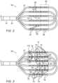
- FIG. 2is a side view of flat array 50 of multiple electrodes 55 , of catheter 21 of FIG. 1 , in accordance with exemplary embodiments of the present invention.
- the shown electrode-array assemblyi.e., flat array of electrodes
- the shown electrode-array assemblyis that of the aforementioned PicassoTM catheter, though, as noted above, other flat electrode-array assemblies may be used.
- flat array 50comprises an array of cylindrical electrodes 55 fitted over tubes 57 .
- the arrayis characterized by inter-electrode distances 70 and 72 , which, for a given voltage of a bipolar electrical pulse that falls between any two electrodes 55 , determines a strength of the electric field applied to tissue between them.
- electrode pairscan be selected according to a direction of the electric field that is deemed best suitable, e.g., for killing myocardium cells with higher selectively.
- FIG. 2describes schematically a region 62 that includes a subset of electrodes 55 , which are selected for applying IRE ablation using processor 41 that commands switching circuitry 38 .
- cooling fluidis conveyed through tubes 57 to electrode edges to avoid voltage breakdowns.
- the cooling fluidmay circulate in a closed loop, or, optionally, the tubes may include irrigation holes 59 to flow (i.e., irrigate) cooling fluid (e.g., saline solution) into blood in the vicinity of the edges of the electrodes.
- irrigation holes 59to flow (i.e., irrigate) cooling fluid (e.g., saline solution) into blood in the vicinity of the edges of the electrodes.
- FIG. 3is a side view of flat array 50 of multiple electrodes 55 of FIG. 2 highlighting subsets of electrodes 75 and 175 selected for irreversible electroporation (IRE) ablation of separate tissue regions 74 and 174 , respectively, in accordance with an exemplary embodiment of the present invention.
- IREirreversible electroporation
- processor 41determines that the subsets of electrodes 75 and 175 of the electrode-array are in contact with tissue areas 74 and 174 , for example, using one of the electrical, mechanical, or other available methods for determining physical contact of an electrode of a catheter with tissue. As seen, selected electrodes 75 and 175 are shaded in black, in contrast to electrodes 76 which are deemed to be not in contact with tissue. Processor 41 therefore selects electrodes 75 and 175 , and subsequently commands switching assembly 38 to connect electrodes 75 and electrodes 175 to IRE pulse-generator 37 to apply bipolar IRE pulses between pairs of electrodes 75 and separately apply bipolar IRE pulses between pairs of electrodes 175 . Nevertheless, if the two regions are close, the processor may unite electrodes 75 and 175 to determine a best electrode connection configuration for the IRE ablation.
- Processor 41is used to select an IRE ablation protocol comprising the bipolar IRE pulses.
- An example of IRE ablation settings that may be used with electrode 75 and 175 of catheter 21is given by Table I:
- FIG. 3shows that physician 30 selected to apply the pulses such that different tissue regions 78 , 80 , 82 , 84 , and 86 in contact with electrodes 75 receive IRE pulses with the electric field oriented along directions 88 , 90 , 92 , 94 , and 96 , respectively.
- Such a selectionmay, for example, suit known myocardium fiber cell alignment to selectively kill them.
- a possible means to enable a user to select electric field directionsis a graphical user interface that inputs selected electric field directions to a processor to accordingly select pairs of electrodes 75 between which to apply pulses.
- other methodsmay be used, such as selecting one of a number of preset possible directions.
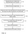
- FIG. 4is a flow chart that schematically illustrates a method of applying irreversible electroporation (IRE) using flat array 50 of multiple electrodes 55 of FIG. 2 , in accordance with an exemplary embodiment of the present invention.
- the algorithmcarries out a process that begins when physician 30 navigates flat array 50 to a target tissue location in an organ of a patient, such as at an ostium in the heart, for example, using, for example, electrodes 55 as ACL-sensing electrodes, at a flat array navigation step 102 .
- physician 30positions flat array 50 at ostium, at a flat array positioning step 104 .
- processor 41determines which of electrodes 55 are in contact with tissue and physician 30 selects at least part of these electrodes to apply IRE pulses, at an electrode physical contact determination and selection step 106 .
- processor 41receives user inputs, such as of step 106 and/or in the form of one or more prespecified directions (e.g., relative to a longitudinal axis of the distal end) along which the electric field should be applied to tissue.
- the prespecified directionsmay differ from one tissue region to another, as described above.
- processor 41determines the pairs of the selected electrodes to apply IRE pulses between.
- processor 41controls switching assembly 38 to connect the pairs of electrodes to IRE pulse-generator 37 according to the determined configuration, at pair electrodes connecting step 110 .
- Processor 41then receives (e.g., uploads from memory) an ablation protocol comprising the IRE ablation parameters (e.g., number and peak voltage of pulses), at an IRE parameter selection step 112 .
- an ablation protocolcomprising the IRE ablation parameters (e.g., number and peak voltage of pulses)
- the physicianmay modify some of the parameters.
- the protocolmay have been loaded earlier in the procedure and is ready at this stage.
- processor 41commands IRE pulse-generator 37 to apply the directional IRE pulses to tissue via the selected pairs of electrodes 55 , at an IRE treatment step 114 .
- FIG. 4is an example flow that is depicted purely for the sake of clarity. Additional steps may be included, such as applying irrigation. In alternative embodiments, any other suitable method flow can be used.
- processor 41may control switching assembly to apply IRE pulses at multiple (typically two) different orientations to the same region of tissue.
- processor 41may control switching assembly 38 to apply the IRE pulses at two orthogonal directions.
- the exemplary embodiments described hereinmainly address cardiac applications, the methods and systems described herein can also be used in other medical applications, such as in neurology, otolaryngology, and renal denervation.
Landscapes
- Health & Medical Sciences (AREA)
- Surgery (AREA)
- Life Sciences & Earth Sciences (AREA)
- Engineering & Computer Science (AREA)
- Biomedical Technology (AREA)
- Public Health (AREA)
- Nuclear Medicine, Radiotherapy & Molecular Imaging (AREA)
- Veterinary Medicine (AREA)
- Otolaryngology (AREA)
- Heart & Thoracic Surgery (AREA)
- Medical Informatics (AREA)
- Molecular Biology (AREA)
- Animal Behavior & Ethology (AREA)
- General Health & Medical Sciences (AREA)
- Physics & Mathematics (AREA)
- Plasma & Fusion (AREA)
- Cardiology (AREA)
- Surgical Instruments (AREA)
- Measurement And Recording Of Electrical Phenomena And Electrical Characteristics Of The Living Body (AREA)
Abstract
Description
| TABLE I | |||
| Parameter | Range | ||
| Preset IRE peak voltage | 500-2000 | V | |
| Pulse width | 0.5-10 | microsecond | |
| Repetition rate | 1-400 | Hz |
| Number of pulses | 10-200 | ||
| Directon of electrical field | User selected | ||
Claims (13)
Priority Applications (7)
| Application Number | Priority Date | Filing Date | Title |
|---|---|---|---|
| US16/889,565US12285206B2 (en) | 2020-06-01 | 2020-06-01 | Application of irreversible electroporation (IRE) ablation using catheter with electrode array |
| IL281799AIL281799A (en) | 2020-06-01 | 2021-03-24 | Application of ablation by irreversible electroporation using a catheter with an array of electrodes |
| RU2021108254ARU2762988C1 (en) | 2020-06-01 | 2021-03-29 | Use of ablation by irreversible electroporation (iep) using a catheter with a matrix of electrodes |
| JP2021056876AJP2021186657A (en) | 2020-06-01 | 2021-03-30 | Application of irreversible electroporation (ire) ablation using catheter with electrode array |
| EP21165827.3AEP3919014A1 (en) | 2020-06-01 | 2021-03-30 | Catheter with electrode array for irreversible electroporation |
| CN202110340338.1ACN113749755A (en) | 2020-06-01 | 2021-03-30 | Applying irreversible electroporation (IRE) ablation using a catheter with an electrode array |
| KR1020210041738AKR20210149591A (en) | 2020-06-01 | 2021-03-31 | Application of irreversible electroporation (ire) ablation using catheter with electrode array |
Applications Claiming Priority (1)
| Application Number | Priority Date | Filing Date | Title |
|---|---|---|---|
| US16/889,565US12285206B2 (en) | 2020-06-01 | 2020-06-01 | Application of irreversible electroporation (IRE) ablation using catheter with electrode array |
Publications (2)
| Publication Number | Publication Date |
|---|---|
| US20210369338A1 US20210369338A1 (en) | 2021-12-02 |
| US12285206B2true US12285206B2 (en) | 2025-04-29 |
Family
ID=75302269
Family Applications (1)
| Application Number | Title | Priority Date | Filing Date |
|---|---|---|---|
| US16/889,565Active2040-11-17US12285206B2 (en) | 2020-06-01 | 2020-06-01 | Application of irreversible electroporation (IRE) ablation using catheter with electrode array |
Country Status (7)
| Country | Link |
|---|---|
| US (1) | US12285206B2 (en) |
| EP (1) | EP3919014A1 (en) |
| JP (1) | JP2021186657A (en) |
| KR (1) | KR20210149591A (en) |
| CN (1) | CN113749755A (en) |
| IL (1) | IL281799A (en) |
| RU (1) | RU2762988C1 (en) |
Families Citing this family (9)
| Publication number | Priority date | Publication date | Assignee | Title |
|---|---|---|---|---|
| US12076071B2 (en) | 2020-08-14 | 2024-09-03 | Kardium Inc. | Systems and methods for treating tissue with pulsed field ablation |
| WO2022038546A1 (en) | 2020-08-18 | 2022-02-24 | St. Jude Medical, Cardiology Division, Inc. | High-density electrode catheters with magnetic position tracking |
| EP4338695A1 (en) | 2022-09-11 | 2024-03-20 | Biosense Webster (Israel) Ltd. | System for combined ablation modalities |
| IL319700A (en) | 2022-10-05 | 2025-05-01 | Btl Medical Dev A S | Pulsed field ablation device and method |
| CN115721409A (en)* | 2022-11-15 | 2023-03-03 | 上海玄宇医疗器械有限公司 | Ablation catheter and control device and control method thereof |
| CN116269733B (en)* | 2023-03-20 | 2024-05-03 | 成都飞云科技有限公司 | Pulse ablation catheter, device and pulse ablation method |
| KR102729199B1 (en) | 2023-11-01 | 2024-11-13 | (주)더스탠다드 | Pulse generation system providing cardiac synchronized multi-pulsing and pulse generation mehtod thereof |
| US20250213295A1 (en)* | 2023-12-29 | 2025-07-03 | Boston Scientific Scimed, Inc. | Electroporation ablation from tissue-contacting electrodes |
| WO2025153870A1 (en)* | 2024-01-16 | 2025-07-24 | Medtronic, Inc. | Waveform delivery based on tissue fiber orientation |
Citations (74)
| Publication number | Priority date | Publication date | Assignee | Title |
|---|---|---|---|---|
| US5391199A (en) | 1993-07-20 | 1995-02-21 | Biosense, Inc. | Apparatus and method for treating cardiac arrhythmias |
| WO1996005768A1 (en) | 1994-08-19 | 1996-02-29 | Biosense, Inc. | Medical diagnosis, treatment and imaging systems |
| US5704908A (en) | 1996-10-10 | 1998-01-06 | Genetronics, Inc. | Electroporation and iontophoresis catheter with porous balloon |
| US5759158A (en)* | 1995-07-28 | 1998-06-02 | E.P. Technologies, Inc. | Systems and methods for conducting electrophysiological testing using high-voltage energy pulses to stun heart tissue |
| WO1999037358A1 (en) | 1998-01-27 | 1999-07-29 | Genetronics, Inc. | Electroporation apparatus with connective electrode template |
| US6014581A (en)* | 1998-03-26 | 2000-01-11 | Ep Technologies, Inc. | Interface for performing a diagnostic or therapeutic procedure on heart tissue with an electrode structure |
| US6239724B1 (en) | 1997-12-30 | 2001-05-29 | Remon Medical Technologies, Ltd. | System and method for telemetrically providing intrabody spatial position |
| US6332089B1 (en) | 1996-02-15 | 2001-12-18 | Biosense, Inc. | Medical procedures and apparatus using intrabody probes |
| US20020065455A1 (en) | 1995-01-24 | 2002-05-30 | Shlomo Ben-Haim | Medical diagnosis, treatment and imaging systems |
| US20020077627A1 (en)* | 2000-07-25 | 2002-06-20 | Johnson Theodore C. | Method for detecting and treating tumors using localized impedance measurement |
| US6484118B1 (en) | 2000-07-20 | 2002-11-19 | Biosense, Inc. | Electromagnetic position single axis system |
| US20030120150A1 (en) | 2001-12-21 | 2003-06-26 | Assaf Govari | Wireless position sensor |
| US20030130711A1 (en)* | 2001-09-28 | 2003-07-10 | Pearson Robert M. | Impedance controlled tissue ablation apparatus and method |
| US6618612B1 (en) | 1996-02-15 | 2003-09-09 | Biosense, Inc. | Independently positionable transducers for location system |
| US20040068178A1 (en) | 2002-09-17 | 2004-04-08 | Assaf Govari | High-gradient recursive locating system |
| US20050065509A1 (en) | 2003-09-22 | 2005-03-24 | Scimed Life Systems, Inc. | Flat electrode arrays for generating flat lesions |
| US20060293713A1 (en)* | 2005-06-24 | 2006-12-28 | Boris Rubinsky | Methods and systems for treating BPH using electroporation |
| US7326204B2 (en)* | 2004-01-16 | 2008-02-05 | St. Jude Medical, Atrial Fibrillation Division, Inc. | Brush electrode and method for ablation |
| US20080097559A1 (en)* | 2006-10-19 | 2008-04-24 | Eggers Philip E | Method and apparatus for carrying out the controlled heating of dermis and vascular tissue |
| US20080255642A1 (en)* | 2006-06-28 | 2008-10-16 | Ardian, Inc. | Methods and systems for thermally-induced renal neuromodulation |
| US20090062788A1 (en)* | 2007-08-31 | 2009-03-05 | Long Gary L | Electrical ablation surgical instruments |
| US20100087813A1 (en)* | 2007-02-15 | 2010-04-08 | Ethicon Endo-Surgery, Inc. | Electroporation ablation apparatus, system, and method |
| US7756576B2 (en) | 2005-08-26 | 2010-07-13 | Biosense Webster, Inc. | Position sensing and detection of skin impedance |
| US20100204560A1 (en)* | 2008-11-11 | 2010-08-12 | Amr Salahieh | Low profile electrode assembly |
| US7848787B2 (en) | 2005-07-08 | 2010-12-07 | Biosense Webster, Inc. | Relative impedance measurement |
| US7869865B2 (en) | 2005-01-07 | 2011-01-11 | Biosense Webster, Inc. | Current-based position sensing |
| US20110160514A1 (en)* | 2009-12-31 | 2011-06-30 | Ethicon Endo-Surgery, Inc. | Electrical ablation devices |
| US8048067B2 (en) | 2003-12-24 | 2011-11-01 | The Regents Of The University Of California | Tissue ablation with irreversible electroporation |
| US20110301587A1 (en)* | 2010-04-06 | 2011-12-08 | Innovative Pulmonary Solutions, Inc. | System and method for pulmonary treatment |
| US20120059255A1 (en)* | 2010-09-02 | 2012-03-08 | Saurav Paul | Catheter systems |
| US20120071870A1 (en)* | 2008-11-11 | 2012-03-22 | Amr Salahieh | Low Profile Electrode Assembly |
| US8221411B2 (en) | 2008-07-28 | 2012-07-17 | Medtronic, Inc. | Systems and methods for cardiac tissue electroporation ablation |
| US20120310230A1 (en)* | 2011-06-01 | 2012-12-06 | Angiodynamics, Inc. | Coaxial dual function probe and method of use |
| US20130090646A1 (en)* | 2011-09-28 | 2013-04-11 | Angiodynamics, Inc. | Multiple Treatment Zone Ablation Probe |
| US20130184702A1 (en)* | 2011-07-15 | 2013-07-18 | II Robert E. Neal | Device and Method for Electroporation Based Treatment of Stenosis of a Tubular Body Part |
| US20130218157A1 (en) | 2012-02-08 | 2013-08-22 | Angiodynamics, Inc. | System and method for increasing a target zone for electrical ablation |
| US20140012247A1 (en) | 2012-07-03 | 2014-01-09 | Ethicon Endo-Surgery, Inc. | Endoscopic cap electrode and method for using the same |
| US8880195B2 (en)* | 2007-09-14 | 2014-11-04 | Lazure Technologies, Llc | Transurethral systems and methods for ablation treatment of prostate tissue |
| US20160051324A1 (en) | 2011-07-29 | 2016-02-25 | Medtronic Ablation Frontiers Llc | Intracardiac tools and methods for delivery of electroporation therapies |
| US20160113709A1 (en)* | 2013-06-05 | 2016-04-28 | Tel Hashomer Medical Research Infrastructure And Services Ltd | Myocardial ablation by irreversible electroporation |
| US20160113707A1 (en)* | 2014-10-24 | 2016-04-28 | Northwestern University | Electroporation apparatus and method of using same for ablation of an arbitrary volume |
| US20160331446A1 (en)* | 2012-07-04 | 2016-11-17 | Cibiem, Inc. | Methods, devices and systems for carotid body ablation via a transradial or transbrachial approach |
| US20170043154A1 (en) | 2014-05-02 | 2017-02-16 | Koninklijke Philips N.V. | A device for inactivating bacteria |
| US20170120048A1 (en) | 2015-11-04 | 2017-05-04 | Boston Scientific Scimed, Inc. | Medical device and related methods |
| US20170189106A1 (en)* | 2015-12-30 | 2017-07-06 | Schuler Scientific Solutions, Llc | Tissue mapping and treatment |
| US20170348049A1 (en)* | 2016-06-07 | 2017-12-07 | Metavention, Inc. | Therapeutic tissue modulation devices and methods |
| US9867978B1 (en) | 2016-09-16 | 2018-01-16 | Precision Neurotechnologies Llc | Conformal electrode arrays for electrophysiologic recording and neural stimulation within the cerebral ventricles |
| US20180071014A1 (en)* | 2015-04-10 | 2018-03-15 | Angiodynamics, Inc. | System and Methods for Irreversible Electroporation with Thermally Controlled Electrodes |
| US20180116751A1 (en)* | 2015-05-12 | 2018-05-03 | Navix International Limited | Contact quality assessment by dielectric property analysis |
| US9987081B1 (en)* | 2017-04-27 | 2018-06-05 | Iowa Approach, Inc. | Systems, devices, and methods for signal generation |
| US20180228528A1 (en)* | 2017-02-14 | 2018-08-16 | Medtronic, Inc. | Method of confirming safe delivery pathway to patient prior to energy delivery |
| US20180296277A1 (en)* | 2015-05-12 | 2018-10-18 | Navix International Limited | Fiducial marking for image-electromagnetic field registration |
| WO2018191149A1 (en) | 2017-04-10 | 2018-10-18 | St. Jude Medical, Cardiology Division, Inc. | Electroporation system and method of energizing a catheter |
| US20180310987A1 (en)* | 2017-04-27 | 2018-11-01 | Biosense Webster (Israel) Ltd. | Systems and processes for map-guided automatic cardiac ablation |
| US20180311497A1 (en)* | 2017-04-28 | 2018-11-01 | Iowa Approach, Inc. | Systems, devices, and methods for delivery of pulsed electric field ablative energy to esophageal tissue |
| US20190030328A1 (en)* | 2017-07-28 | 2019-01-31 | Medtronic, Inc. | Expandable elements for delivery of electric fields |
| US10271893B2 (en) | 2014-12-15 | 2019-04-30 | Medtronic Ablation Frontiers Llc | Timed energy delivery |
| US20190201040A1 (en)* | 2017-12-28 | 2019-07-04 | Ethicon Llc | Controlling activation of an ultrasonic surgical instrument according to the presence of tissue |
| US10342598B2 (en) | 2012-08-15 | 2019-07-09 | Ethicon Llc | Electrosurgical system for delivering a biphasic waveform |
| US20190223949A1 (en)* | 2018-01-24 | 2019-07-25 | Medtronic Ardian Luxembourg S.A.R.L. | Multielectrode catheter |
| US20190328274A1 (en) | 2018-04-30 | 2019-10-31 | Biosense Webster (Israel) Ltd. | Active voltage location (avl) resolution |
| US20190350649A1 (en) | 2018-05-21 | 2019-11-21 | St. Jude Medical, Cardiology Division, Inc. | Radio-frequency ablation and direct current electroporation catheters |
| RU2018118953A (en) | 2015-10-26 | 2019-11-28 | Ньювэйв Медикал, Инк. | ENERGY SUPPLY SYSTEMS AND THEIR APPLICATION |
| US20190365463A1 (en) | 2018-05-29 | 2019-12-05 | Biosense Webster (Israel) Ltd. | Touch detection based on frequency response of tissue |
| US10531914B2 (en) | 2015-08-06 | 2020-01-14 | Medtronic, Inc. | Cardiac pulsed field ablation |
| US20200015876A1 (en)* | 2016-10-11 | 2020-01-16 | Acutus Medical, Inc. | Ablation system with force control |
| US20200022653A1 (en)* | 2018-07-20 | 2020-01-23 | Kardium Inc. | Systems and methods for facilitating improved transducer-to-tissue contact |
| US10842572B1 (en)* | 2019-11-25 | 2020-11-24 | Farapulse, Inc. | Methods, systems, and apparatuses for tracking ablation devices and generating lesion lines |
| US20200397505A1 (en)* | 2019-06-19 | 2020-12-24 | Farapulse, Inc. | Systems, devices, and methods for focal ablation |
| US20210113265A1 (en)* | 2019-10-21 | 2021-04-22 | DyaMX, Inc. | Devices, systems, and methods for pulsed electric field treatment of the duodenum |
| US20210169394A1 (en)* | 2018-05-08 | 2021-06-10 | Acutus Medical, Inc. | Cardiac information processing system |
| US20210322093A1 (en) | 2020-04-17 | 2021-10-21 | Biosense Webster (Israel) Ltd. | Flexible Distal-End Assembly with Double-Sided Electrode Array and Irrigation |
| US20220008123A1 (en)* | 2020-07-13 | 2022-01-13 | Biosense Webster (Israel) Ltd. | Sequential activation of electrode-pairs during irreversible electroporation (ire) |
| US20220071681A1 (en)* | 2020-03-26 | 2022-03-10 | Adagio Medical, Inc. | Multi-modality Ablation Catheter Having A Shape Memory Stylet |
Family Cites Families (1)
| Publication number | Priority date | Publication date | Assignee | Title |
|---|---|---|---|---|
| CA2881462C (en)* | 2012-08-09 | 2020-07-14 | University Of Iowa Research Foundation | Catheters, catheter systems, and methods for puncturing through a tissue structure |
- 2020
- 2020-06-01USUS16/889,565patent/US12285206B2/enactiveActive
- 2021
- 2021-03-24ILIL281799Apatent/IL281799A/enunknown
- 2021-03-29RURU2021108254Apatent/RU2762988C1/enactive
- 2021-03-30EPEP21165827.3Apatent/EP3919014A1/enactivePending
- 2021-03-30CNCN202110340338.1Apatent/CN113749755A/enactivePending
- 2021-03-30JPJP2021056876Apatent/JP2021186657A/enactivePending
- 2021-03-31KRKR1020210041738Apatent/KR20210149591A/ennot_activeWithdrawn
Patent Citations (82)
| Publication number | Priority date | Publication date | Assignee | Title |
|---|---|---|---|---|
| US5391199A (en) | 1993-07-20 | 1995-02-21 | Biosense, Inc. | Apparatus and method for treating cardiac arrhythmias |
| WO1996005768A1 (en) | 1994-08-19 | 1996-02-29 | Biosense, Inc. | Medical diagnosis, treatment and imaging systems |
| US20020065455A1 (en) | 1995-01-24 | 2002-05-30 | Shlomo Ben-Haim | Medical diagnosis, treatment and imaging systems |
| US6690963B2 (en) | 1995-01-24 | 2004-02-10 | Biosense, Inc. | System for determining the location and orientation of an invasive medical instrument |
| US5759158A (en)* | 1995-07-28 | 1998-06-02 | E.P. Technologies, Inc. | Systems and methods for conducting electrophysiological testing using high-voltage energy pulses to stun heart tissue |
| US6618612B1 (en) | 1996-02-15 | 2003-09-09 | Biosense, Inc. | Independently positionable transducers for location system |
| US6332089B1 (en) | 1996-02-15 | 2001-12-18 | Biosense, Inc. | Medical procedures and apparatus using intrabody probes |
| US5704908A (en) | 1996-10-10 | 1998-01-06 | Genetronics, Inc. | Electroporation and iontophoresis catheter with porous balloon |
| US6239724B1 (en) | 1997-12-30 | 2001-05-29 | Remon Medical Technologies, Ltd. | System and method for telemetrically providing intrabody spatial position |
| WO1999037358A1 (en) | 1998-01-27 | 1999-07-29 | Genetronics, Inc. | Electroporation apparatus with connective electrode template |
| US6014581A (en)* | 1998-03-26 | 2000-01-11 | Ep Technologies, Inc. | Interface for performing a diagnostic or therapeutic procedure on heart tissue with an electrode structure |
| US6484118B1 (en) | 2000-07-20 | 2002-11-19 | Biosense, Inc. | Electromagnetic position single axis system |
| US20020077627A1 (en)* | 2000-07-25 | 2002-06-20 | Johnson Theodore C. | Method for detecting and treating tumors using localized impedance measurement |
| US20030130711A1 (en)* | 2001-09-28 | 2003-07-10 | Pearson Robert M. | Impedance controlled tissue ablation apparatus and method |
| US20030120150A1 (en) | 2001-12-21 | 2003-06-26 | Assaf Govari | Wireless position sensor |
| US20040068178A1 (en) | 2002-09-17 | 2004-04-08 | Assaf Govari | High-gradient recursive locating system |
| US20050065509A1 (en) | 2003-09-22 | 2005-03-24 | Scimed Life Systems, Inc. | Flat electrode arrays for generating flat lesions |
| US8048067B2 (en) | 2003-12-24 | 2011-11-01 | The Regents Of The University Of California | Tissue ablation with irreversible electroporation |
| US7326204B2 (en)* | 2004-01-16 | 2008-02-05 | St. Jude Medical, Atrial Fibrillation Division, Inc. | Brush electrode and method for ablation |
| US7869865B2 (en) | 2005-01-07 | 2011-01-11 | Biosense Webster, Inc. | Current-based position sensing |
| US20060293713A1 (en)* | 2005-06-24 | 2006-12-28 | Boris Rubinsky | Methods and systems for treating BPH using electroporation |
| US7848787B2 (en) | 2005-07-08 | 2010-12-07 | Biosense Webster, Inc. | Relative impedance measurement |
| US7756576B2 (en) | 2005-08-26 | 2010-07-13 | Biosense Webster, Inc. | Position sensing and detection of skin impedance |
| US20080255642A1 (en)* | 2006-06-28 | 2008-10-16 | Ardian, Inc. | Methods and systems for thermally-induced renal neuromodulation |
| US20080097559A1 (en)* | 2006-10-19 | 2008-04-24 | Eggers Philip E | Method and apparatus for carrying out the controlled heating of dermis and vascular tissue |
| US20100087813A1 (en)* | 2007-02-15 | 2010-04-08 | Ethicon Endo-Surgery, Inc. | Electroporation ablation apparatus, system, and method |
| US20090062788A1 (en)* | 2007-08-31 | 2009-03-05 | Long Gary L | Electrical ablation surgical instruments |
| US8880195B2 (en)* | 2007-09-14 | 2014-11-04 | Lazure Technologies, Llc | Transurethral systems and methods for ablation treatment of prostate tissue |
| US8221411B2 (en) | 2008-07-28 | 2012-07-17 | Medtronic, Inc. | Systems and methods for cardiac tissue electroporation ablation |
| US20120071870A1 (en)* | 2008-11-11 | 2012-03-22 | Amr Salahieh | Low Profile Electrode Assembly |
| US20100204560A1 (en)* | 2008-11-11 | 2010-08-12 | Amr Salahieh | Low profile electrode assembly |
| US20170119465A1 (en) | 2009-12-31 | 2017-05-04 | Ethicon Endo-Surgery, Inc. | Electrical ablation devices comprising an injector catheter electrode |
| US20110160514A1 (en)* | 2009-12-31 | 2011-06-30 | Ethicon Endo-Surgery, Inc. | Electrical ablation devices |
| US20110301587A1 (en)* | 2010-04-06 | 2011-12-08 | Innovative Pulmonary Solutions, Inc. | System and method for pulmonary treatment |
| US20120059255A1 (en)* | 2010-09-02 | 2012-03-08 | Saurav Paul | Catheter systems |
| US20120310230A1 (en)* | 2011-06-01 | 2012-12-06 | Angiodynamics, Inc. | Coaxial dual function probe and method of use |
| US20130184702A1 (en)* | 2011-07-15 | 2013-07-18 | II Robert E. Neal | Device and Method for Electroporation Based Treatment of Stenosis of a Tubular Body Part |
| US20160051324A1 (en) | 2011-07-29 | 2016-02-25 | Medtronic Ablation Frontiers Llc | Intracardiac tools and methods for delivery of electroporation therapies |
| US20130090646A1 (en)* | 2011-09-28 | 2013-04-11 | Angiodynamics, Inc. | Multiple Treatment Zone Ablation Probe |
| US20130218157A1 (en) | 2012-02-08 | 2013-08-22 | Angiodynamics, Inc. | System and method for increasing a target zone for electrical ablation |
| US20140012247A1 (en) | 2012-07-03 | 2014-01-09 | Ethicon Endo-Surgery, Inc. | Endoscopic cap electrode and method for using the same |
| US20160331446A1 (en)* | 2012-07-04 | 2016-11-17 | Cibiem, Inc. | Methods, devices and systems for carotid body ablation via a transradial or transbrachial approach |
| US10342598B2 (en) | 2012-08-15 | 2019-07-09 | Ethicon Llc | Electrosurgical system for delivering a biphasic waveform |
| US20160113709A1 (en)* | 2013-06-05 | 2016-04-28 | Tel Hashomer Medical Research Infrastructure And Services Ltd | Myocardial ablation by irreversible electroporation |
| US20170043154A1 (en) | 2014-05-02 | 2017-02-16 | Koninklijke Philips N.V. | A device for inactivating bacteria |
| RU2016147150A (en) | 2014-05-02 | 2018-06-05 | Конинклейке Филипс Н.В. | DEVICE FOR INACTIVATION OF BACTERIA |
| US20160113707A1 (en)* | 2014-10-24 | 2016-04-28 | Northwestern University | Electroporation apparatus and method of using same for ablation of an arbitrary volume |
| US10271893B2 (en) | 2014-12-15 | 2019-04-30 | Medtronic Ablation Frontiers Llc | Timed energy delivery |
| US20180071014A1 (en)* | 2015-04-10 | 2018-03-15 | Angiodynamics, Inc. | System and Methods for Irreversible Electroporation with Thermally Controlled Electrodes |
| US20180116751A1 (en)* | 2015-05-12 | 2018-05-03 | Navix International Limited | Contact quality assessment by dielectric property analysis |
| US20180296277A1 (en)* | 2015-05-12 | 2018-10-18 | Navix International Limited | Fiducial marking for image-electromagnetic field registration |
| US10531914B2 (en) | 2015-08-06 | 2020-01-14 | Medtronic, Inc. | Cardiac pulsed field ablation |
| RU2018118953A (en) | 2015-10-26 | 2019-11-28 | Ньювэйв Медикал, Инк. | ENERGY SUPPLY SYSTEMS AND THEIR APPLICATION |
| US20230320784A1 (en) | 2015-10-26 | 2023-10-12 | Neuwave Medical, Inc. | Energy delivery systems and uses thereof |
| JP2018537136A (en) | 2015-11-04 | 2018-12-20 | ボストン サイエンティフィック サイムド,インコーポレイテッドBoston Scientific Scimed,Inc. | Medical device and associated method |
| US10675462B2 (en) | 2015-11-04 | 2020-06-09 | Boston Scientific Scimed, Inc. | Medical device and related methods |
| US20170120048A1 (en) | 2015-11-04 | 2017-05-04 | Boston Scientific Scimed, Inc. | Medical device and related methods |
| US20170189106A1 (en)* | 2015-12-30 | 2017-07-06 | Schuler Scientific Solutions, Llc | Tissue mapping and treatment |
| US20170348049A1 (en)* | 2016-06-07 | 2017-12-07 | Metavention, Inc. | Therapeutic tissue modulation devices and methods |
| US9867978B1 (en) | 2016-09-16 | 2018-01-16 | Precision Neurotechnologies Llc | Conformal electrode arrays for electrophysiologic recording and neural stimulation within the cerebral ventricles |
| US20200015876A1 (en)* | 2016-10-11 | 2020-01-16 | Acutus Medical, Inc. | Ablation system with force control |
| US20180228528A1 (en)* | 2017-02-14 | 2018-08-16 | Medtronic, Inc. | Method of confirming safe delivery pathway to patient prior to energy delivery |
| WO2018191149A1 (en) | 2017-04-10 | 2018-10-18 | St. Jude Medical, Cardiology Division, Inc. | Electroporation system and method of energizing a catheter |
| US20210137587A1 (en)* | 2017-04-10 | 2021-05-13 | St. Jude Medical, Cardiology Division, Inc. | Electroporation system and method of energizing a catheter |
| JP2018187373A (en) | 2017-04-27 | 2018-11-29 | バイオセンス・ウエブスター・(イスラエル)・リミテッドBiosense Webster (Israel), Ltd. | Systems and processes for map-guided automatic cardiac ablation |
| US20180310987A1 (en)* | 2017-04-27 | 2018-11-01 | Biosense Webster (Israel) Ltd. | Systems and processes for map-guided automatic cardiac ablation |
| US9987081B1 (en)* | 2017-04-27 | 2018-06-05 | Iowa Approach, Inc. | Systems, devices, and methods for signal generation |
| US20180311497A1 (en)* | 2017-04-28 | 2018-11-01 | Iowa Approach, Inc. | Systems, devices, and methods for delivery of pulsed electric field ablative energy to esophageal tissue |
| US20190030328A1 (en)* | 2017-07-28 | 2019-01-31 | Medtronic, Inc. | Expandable elements for delivery of electric fields |
| US20190201040A1 (en)* | 2017-12-28 | 2019-07-04 | Ethicon Llc | Controlling activation of an ultrasonic surgical instrument according to the presence of tissue |
| US20190223949A1 (en)* | 2018-01-24 | 2019-07-25 | Medtronic Ardian Luxembourg S.A.R.L. | Multielectrode catheter |
| US20190328274A1 (en) | 2018-04-30 | 2019-10-31 | Biosense Webster (Israel) Ltd. | Active voltage location (avl) resolution |
| US20210169394A1 (en)* | 2018-05-08 | 2021-06-10 | Acutus Medical, Inc. | Cardiac information processing system |
| US20190350649A1 (en) | 2018-05-21 | 2019-11-21 | St. Jude Medical, Cardiology Division, Inc. | Radio-frequency ablation and direct current electroporation catheters |
| US20190365463A1 (en) | 2018-05-29 | 2019-12-05 | Biosense Webster (Israel) Ltd. | Touch detection based on frequency response of tissue |
| US20200022653A1 (en)* | 2018-07-20 | 2020-01-23 | Kardium Inc. | Systems and methods for facilitating improved transducer-to-tissue contact |
| US20200397505A1 (en)* | 2019-06-19 | 2020-12-24 | Farapulse, Inc. | Systems, devices, and methods for focal ablation |
| US20210113265A1 (en)* | 2019-10-21 | 2021-04-22 | DyaMX, Inc. | Devices, systems, and methods for pulsed electric field treatment of the duodenum |
| US10842572B1 (en)* | 2019-11-25 | 2020-11-24 | Farapulse, Inc. | Methods, systems, and apparatuses for tracking ablation devices and generating lesion lines |
| US20220071681A1 (en)* | 2020-03-26 | 2022-03-10 | Adagio Medical, Inc. | Multi-modality Ablation Catheter Having A Shape Memory Stylet |
| US20210322093A1 (en) | 2020-04-17 | 2021-10-21 | Biosense Webster (Israel) Ltd. | Flexible Distal-End Assembly with Double-Sided Electrode Array and Irrigation |
| US20220008123A1 (en)* | 2020-07-13 | 2022-01-13 | Biosense Webster (Israel) Ltd. | Sequential activation of electrode-pairs during irreversible electroporation (ire) |
Non-Patent Citations (1)
| Title |
|---|
| Search Report from corresponding Japanese Patent Application No. 2021-056876 dated Sep. 27, 2024. |
Also Published As
| Publication number | Publication date |
|---|---|
| JP2021186657A (en) | 2021-12-13 |
| KR20210149591A (en) | 2021-12-09 |
| IL281799A (en) | 2021-12-01 |
| RU2762988C1 (en) | 2021-12-24 |
| US20210369338A1 (en) | 2021-12-02 |
| EP3919014A1 (en) | 2021-12-08 |
| CN113749755A (en) | 2021-12-07 |
Similar Documents
| Publication | Publication Date | Title |
|---|---|---|
| US12285206B2 (en) | Application of irreversible electroporation (IRE) ablation using catheter with electrode array | |
| US11931182B2 (en) | Catheter with plurality of sensing electrodes used as ablation electrode | |
| EP3831442A1 (en) | Using reversible electroporation on cardiac tissue | |
| EP3888550B1 (en) | Detection and mapping of phrenic nerve by pacing | |
| KR20220014803A (en) | Automatically performing irreversible electroporation ablation during heart refractory period | |
| EP3960107B1 (en) | Proximal electrode cooling | |
| EP4166106B1 (en) | High frequency unipolar electroporation ablation | |
| EP3973904B1 (en) | Electrode shorting | |
| EP4193947B1 (en) | Basket catheter with electrically-connected spines forming a distributed electrode | |
| US20240197393A1 (en) | Catheter shape detection for map and ablate catheters | |
| EP4137079A1 (en) | Phrenic nerve warning | |
| US20210378734A1 (en) | Smooth-edge and equidistantly spaced electrodes on an expandable frame of a catheter for irreversible-electroporation (ire) | |
| EP4197473B1 (en) | Basket catheter with cushioning porous sheath cover | |
| KR20220014275A (en) | Controlling irreversible electroporation ablation using a focal catheter having contact-force and temperature sensors | |
| CN113893025A (en) | Bipolar tissue ablation according to predetermined periodic time slot sets | |
| IL292745A (en) | Improving efficiency in the ablation procedure using ire by applying a pressure signal in the target tissue | |
| JP2023543846A (en) | Pretreatment waveform for irreversible electroporation | |
| US20230310072A1 (en) | Directed pulsed electric field ablation | |
| WO2023192863A1 (en) | Directed pulsed electric field ablation | |
| EP4578413A1 (en) | Medical probe for navigating small diameter blood vessels | |
| EP4527333A1 (en) | Medical device with an irrigation manifold | |
| EP4393433A1 (en) | Basket catheters with compatible irrigation and staggered electrodes | |
| CN120168087A (en) | Mapping and ablation catheters | |
| CN120302936A (en) | Annotation for electroporation ablation |
Legal Events
| Date | Code | Title | Description |
|---|---|---|---|
| FEPP | Fee payment procedure | Free format text:ENTITY STATUS SET TO UNDISCOUNTED (ORIGINAL EVENT CODE: BIG.); ENTITY STATUS OF PATENT OWNER: LARGE ENTITY | |
| AS | Assignment | Owner name:BIOSENSE WEBSTER (ISRAEL) LTD., ISRAEL Free format text:ASSIGNMENT OF ASSIGNORS INTEREST;ASSIGNORS:GOVARI, ASSAF;ALTMANN, ANDRES CLAUDIO;BEECKLER, CHRISTOPHER THOMAS;SIGNING DATES FROM 20200602 TO 20200603;REEL/FRAME:055672/0670 | |
| STPP | Information on status: patent application and granting procedure in general | Free format text:DOCKETED NEW CASE - READY FOR EXAMINATION | |
| STPP | Information on status: patent application and granting procedure in general | Free format text:NON FINAL ACTION MAILED | |
| STPP | Information on status: patent application and granting procedure in general | Free format text:RESPONSE TO NON-FINAL OFFICE ACTION ENTERED AND FORWARDED TO EXAMINER | |
| STPP | Information on status: patent application and granting procedure in general | Free format text:FINAL REJECTION MAILED | |
| STPP | Information on status: patent application and granting procedure in general | Free format text:ADVISORY ACTION MAILED | |
| STPP | Information on status: patent application and granting procedure in general | Free format text:ADVISORY ACTION MAILED | |
| STPP | Information on status: patent application and granting procedure in general | Free format text:DOCKETED NEW CASE - READY FOR EXAMINATION | |
| STPP | Information on status: patent application and granting procedure in general | Free format text:RESPONSE TO NON-FINAL OFFICE ACTION ENTERED AND FORWARDED TO EXAMINER | |
| STPP | Information on status: patent application and granting procedure in general | Free format text:FINAL REJECTION MAILED | |
| STPP | Information on status: patent application and granting procedure in general | Free format text:ADVISORY ACTION MAILED | |
| STPP | Information on status: patent application and granting procedure in general | Free format text:DOCKETED NEW CASE - READY FOR EXAMINATION | |
| STPP | Information on status: patent application and granting procedure in general | Free format text:NON FINAL ACTION MAILED | |
| STPP | Information on status: patent application and granting procedure in general | Free format text:RESPONSE TO NON-FINAL OFFICE ACTION ENTERED AND FORWARDED TO EXAMINER | |
| STPP | Information on status: patent application and granting procedure in general | Free format text:FINAL REJECTION MAILED | |
| STPP | Information on status: patent application and granting procedure in general | Free format text:NOTICE OF ALLOWANCE MAILED -- APPLICATION RECEIVED IN OFFICE OF PUBLICATIONS | |
| STCF | Information on status: patent grant | Free format text:PATENTED CASE |