US12285200B2 - Length adjustable modular screw system - Google Patents
Length adjustable modular screw systemDownload PDFInfo
- Publication number
- US12285200B2 US12285200B2US18/133,005US202318133005AUS12285200B2US 12285200 B2US12285200 B2US 12285200B2US 202318133005 AUS202318133005 AUS 202318133005AUS 12285200 B2US12285200 B2US 12285200B2
- Authority
- US
- United States
- Prior art keywords
- collet
- component
- expander
- length adjustable
- adjustable modular
- Prior art date
- Legal status (The legal status is an assumption and is not a legal conclusion. Google has not performed a legal analysis and makes no representation as to the accuracy of the status listed.)
- Active
Links
Images


Classifications
- A—HUMAN NECESSITIES
- A61—MEDICAL OR VETERINARY SCIENCE; HYGIENE
- A61B—DIAGNOSIS; SURGERY; IDENTIFICATION
- A61B17/00—Surgical instruments, devices or methods
- A61B17/56—Surgical instruments or methods for treatment of bones or joints; Devices specially adapted therefor
- A61B17/58—Surgical instruments or methods for treatment of bones or joints; Devices specially adapted therefor for osteosynthesis, e.g. bone plates, screws or setting implements
- A61B17/68—Internal fixation devices, including fasteners and spinal fixators, even if a part thereof projects from the skin
- A61B17/84—Fasteners therefor or fasteners being internal fixation devices
- A61B17/86—Pins or screws or threaded wires; nuts therefor
- A61B17/8685—Pins or screws or threaded wires; nuts therefor comprising multiple separate parts
- A—HUMAN NECESSITIES
- A61—MEDICAL OR VETERINARY SCIENCE; HYGIENE
- A61B—DIAGNOSIS; SURGERY; IDENTIFICATION
- A61B17/00—Surgical instruments, devices or methods
- A61B17/56—Surgical instruments or methods for treatment of bones or joints; Devices specially adapted therefor
- A61B17/58—Surgical instruments or methods for treatment of bones or joints; Devices specially adapted therefor for osteosynthesis, e.g. bone plates, screws or setting implements
- A61B17/68—Internal fixation devices, including fasteners and spinal fixators, even if a part thereof projects from the skin
- A61B17/70—Spinal positioners or stabilisers, e.g. stabilisers comprising fluid filler in an implant
- A61B17/7001—Screws or hooks combined with longitudinal elements which do not contact vertebrae
- A61B17/7002—Longitudinal elements, e.g. rods
- A—HUMAN NECESSITIES
- A61—MEDICAL OR VETERINARY SCIENCE; HYGIENE
- A61B—DIAGNOSIS; SURGERY; IDENTIFICATION
- A61B17/00—Surgical instruments, devices or methods
- A61B17/56—Surgical instruments or methods for treatment of bones or joints; Devices specially adapted therefor
- A61B17/58—Surgical instruments or methods for treatment of bones or joints; Devices specially adapted therefor for osteosynthesis, e.g. bone plates, screws or setting implements
- A61B17/68—Internal fixation devices, including fasteners and spinal fixators, even if a part thereof projects from the skin
- A61B17/70—Spinal positioners or stabilisers, e.g. stabilisers comprising fluid filler in an implant
- A61B17/7001—Screws or hooks combined with longitudinal elements which do not contact vertebrae
- A61B17/7032—Screws or hooks with U-shaped head or back through which longitudinal rods pass
- A—HUMAN NECESSITIES
- A61—MEDICAL OR VETERINARY SCIENCE; HYGIENE
- A61B—DIAGNOSIS; SURGERY; IDENTIFICATION
- A61B17/00—Surgical instruments, devices or methods
- A61B17/56—Surgical instruments or methods for treatment of bones or joints; Devices specially adapted therefor
- A61B17/58—Surgical instruments or methods for treatment of bones or joints; Devices specially adapted therefor for osteosynthesis, e.g. bone plates, screws or setting implements
- A61B17/68—Internal fixation devices, including fasteners and spinal fixators, even if a part thereof projects from the skin
- A61B17/70—Spinal positioners or stabilisers, e.g. stabilisers comprising fluid filler in an implant
- A61B17/7001—Screws or hooks combined with longitudinal elements which do not contact vertebrae
- A61B17/7035—Screws or hooks, wherein a rod-clamping part and a bone-anchoring part can pivot relative to each other
- A61B17/7037—Screws or hooks, wherein a rod-clamping part and a bone-anchoring part can pivot relative to each other wherein pivoting is blocked when the rod is clamped
- A—HUMAN NECESSITIES
- A61—MEDICAL OR VETERINARY SCIENCE; HYGIENE
- A61B—DIAGNOSIS; SURGERY; IDENTIFICATION
- A61B17/00—Surgical instruments, devices or methods
- A61B17/56—Surgical instruments or methods for treatment of bones or joints; Devices specially adapted therefor
- A61B17/58—Surgical instruments or methods for treatment of bones or joints; Devices specially adapted therefor for osteosynthesis, e.g. bone plates, screws or setting implements
- A61B17/68—Internal fixation devices, including fasteners and spinal fixators, even if a part thereof projects from the skin
- A61B17/70—Spinal positioners or stabilisers, e.g. stabilisers comprising fluid filler in an implant
- A61B17/7074—Tools specially adapted for spinal fixation operations other than for bone removal or filler handling
- A61B17/7076—Tools specially adapted for spinal fixation operations other than for bone removal or filler handling for driving, positioning or assembling spinal clamps or bone anchors specially adapted for spinal fixation
- A61B17/7082—Tools specially adapted for spinal fixation operations other than for bone removal or filler handling for driving, positioning or assembling spinal clamps or bone anchors specially adapted for spinal fixation for driving, i.e. rotating, screws or screw parts specially adapted for spinal fixation, e.g. for driving polyaxial or tulip-headed screws
- A—HUMAN NECESSITIES
- A61—MEDICAL OR VETERINARY SCIENCE; HYGIENE
- A61B—DIAGNOSIS; SURGERY; IDENTIFICATION
- A61B17/00—Surgical instruments, devices or methods
- A61B17/56—Surgical instruments or methods for treatment of bones or joints; Devices specially adapted therefor
- A61B17/58—Surgical instruments or methods for treatment of bones or joints; Devices specially adapted therefor for osteosynthesis, e.g. bone plates, screws or setting implements
- A61B17/68—Internal fixation devices, including fasteners and spinal fixators, even if a part thereof projects from the skin
- A61B17/84—Fasteners therefor or fasteners being internal fixation devices
- A61B17/86—Pins or screws or threaded wires; nuts therefor
- A61B17/8625—Shanks, i.e. parts contacting bone tissue
- A61B17/863—Shanks, i.e. parts contacting bone tissue with thread interrupted or changing its form along shank, other than constant taper
- A—HUMAN NECESSITIES
- A61—MEDICAL OR VETERINARY SCIENCE; HYGIENE
- A61B—DIAGNOSIS; SURGERY; IDENTIFICATION
- A61B17/00—Surgical instruments, devices or methods
- A61B17/56—Surgical instruments or methods for treatment of bones or joints; Devices specially adapted therefor
- A61B17/58—Surgical instruments or methods for treatment of bones or joints; Devices specially adapted therefor for osteosynthesis, e.g. bone plates, screws or setting implements
- A61B17/68—Internal fixation devices, including fasteners and spinal fixators, even if a part thereof projects from the skin
- A61B17/84—Fasteners therefor or fasteners being internal fixation devices
- A61B17/86—Pins or screws or threaded wires; nuts therefor
- A61B17/8695—Washers
- A—HUMAN NECESSITIES
- A61—MEDICAL OR VETERINARY SCIENCE; HYGIENE
- A61B—DIAGNOSIS; SURGERY; IDENTIFICATION
- A61B17/00—Surgical instruments, devices or methods
- A61B17/56—Surgical instruments or methods for treatment of bones or joints; Devices specially adapted therefor
- A61B2017/564—Methods for bone or joint treatment
- A—HUMAN NECESSITIES
- A61—MEDICAL OR VETERINARY SCIENCE; HYGIENE
- A61B—DIAGNOSIS; SURGERY; IDENTIFICATION
- A61B17/00—Surgical instruments, devices or methods
- A61B17/56—Surgical instruments or methods for treatment of bones or joints; Devices specially adapted therefor
- A61B17/58—Surgical instruments or methods for treatment of bones or joints; Devices specially adapted therefor for osteosynthesis, e.g. bone plates, screws or setting implements
- A61B17/68—Internal fixation devices, including fasteners and spinal fixators, even if a part thereof projects from the skin
- A61B17/84—Fasteners therefor or fasteners being internal fixation devices
- A61B17/86—Pins or screws or threaded wires; nuts therefor
- A61B2017/8655—Pins or screws or threaded wires; nuts therefor with special features for locking in the bone
Definitions
- the present inventionrelates to modular and adjustable assemblies for achieving alignment and fixation of two or more bones or bone segments.
- the inventionrelates to modular and adjustable assemblies for achieving fixation of bones in the spine.
- the human skeletonis formed of bones, each bone performing a structural role, either individually or collectively with other bones.
- the spinewhich surrounds and protects the spinal cord and associated nerves, provides structure to the body, and enables fluid movement in many planes. Constructed of essentially twenty-four stacked vertebrae, the spine includes seven cervical vertebrae, twelve thoracic vertebrae and five lumbar vertebrae. A healthy spine is flexible in multiple directions to enable a broad range of physical movement. Intervertebral disks are disposed between adjacent vertebrae and provide cushioning and dampening to protect the spinal column and nerves in response to the various translational and rotational forces associated with body motion. Maintenance of the structural integrity and approximate axial alignment of the vertebrae is one key to good health.
- a clinical subject's spinemay be damaged or otherwise compromised in one of many ways.
- Abnormalities of or damage to the spineinclude but are not limited to scoliosis (abnormal lateral curvature), kyphosis, excessive lordosis, spondylolisthesis, displaced, degenerative or ruptured discs, fractures to one or more vertebral bodies and tumors.
- a stabilization systemcan be used without fusion treatment of the spine, or in conjunction with fusion treatment of the spine wherein one or more spacing devices is used to replace all or a portion of a vertebral disc.
- discal implantsare used together with natural bone components obtained from the clinical subject or a donor source, artificial bone, other biologic components to promote bone growth and fusion between the adjacent vertebral bodies.
- One or more such replacementsmay be accomplished in a spinal fixation surgery.
- the fixation systemwith or without fusion components, operates to create a substantially rigid construct of bone and mechanical hardware that replaces damaged or diseased vertebrae and connects them to relatively healthier adjacent vertebrae.
- spinal fixation systemsinvolve some mode of stabilization using one or more rigid or substantially rigid surgical stabilization elements, such as a rod or a plate, and means for fastening and securing the stabilization element to bone.
- Fastening meanscan include one or more bone anchors, such as screws or bolts, assembled with connectors that enable engagement with one or more stabilization elements.
- the connectorsmay include hooks, clamps, cross connectors and other structures that engage with one or more of stabilization elements and anchors.
- a stabilization elementin the form of a thin plate, typically formed of metal, to adjacent vertebral bodies and secure the plate using anchors, such as screws.
- anchorssuch as screws.
- the fixation surgeryis performed from the posterior aspect of the clinical subject, it is conventional practice to affix bone anchors into the vertebral bodies, typically in the pedicle. Multiple levels of adjacent vertebrae may be fixed in this manner. Interconnection of the secured anchors to the stabilization element creates a rigid fixation between the adjacent vertebral bodies.
- the mode of surgical accessmay be open, that is, involving a relatively extensive resection of the soft tissue to plainly expose the vertebrae to be fixated.
- the mode of surgical accessmay be minimal, wherein less invasive surgical techniques are used to minimize tissue resection.
- adjacent vertebraeare typically not perfectly aligned. Indeed, along any particular portion of a spine, a series of adjacent vertebrae can deviate laterally a great deal from the central axis of the spine. Further, as a result of natural spinal curvature and any vertebral defects, corresponding portions, such as pedicles, of adjacent vertebra are not in the same plane. In the context of implanting spinal fixation systems, these variations can be accommodated to some extent by introducing bends or curves in the substantially rigid stabilization element(s) used for fixation.
- anchorsare adapted to achieve a range of variability in positioning based on pivotal rotation of the anchor such that the axis of the secured anchor relative to the stabilization element can be varied.
- Theseare referred to as poly-axial and uni-axial anchors. They are useful in particular for facilitating attachment of a stabilization element to two or more vertebrae that are not aligned along the spinal axis.
- systemsthat are adapted with features that facilitate engagement of non-axially aligned vertebrae.
- a fixation systemthat includes one or more anchors that are capable of mono-, uni-, and poly-axial positioning and allow substantial vertical travel between the distal attachment point in the bone and the proximal position of a stabilization element, and are capable of locking to avoid further vertical travel after the system implantation is completed.
- Such an anchorwould enable simplified attachment of adjacent anchors to a stabilization element by reducing the extent of height variability of adjacent anchors, thereby avoiding many of the challenges faced in the surgical setting.
- the present inventiondescribes various exemplary systems and methods of installation of one or more anchors and stabilization elements that are adapted for height adjustability during spinal fixation surgery.
- the disclosureis directed in various embodiments, both described and contemplated, to assemblies, subassemblies and modular components and their methods of use and installation for achieving adjustable fixation and/or reduction of bones and bone fragments.
- the length adjustable modular anchor systemincludes a length adjustable modular screw that includes a neck assembly and a shank.
- the disclosureprovides a length adjustable modular screw that includes a neck assembly that has proximal and distal ends and includes an expander component and a collet component that are slidably engagable by insertion of the expander component in a through channel of the collet component along a common axis.
- the length adjustable modular screwalso includes a shank suitable for insertion and retention within a bone, the shank including a threaded portion between its proximal and distal ends and a socket adapted to coaxially receive at least a portion of the distal end of the neck assembly.
- the length adjustable modular screwhas a length that is selected by splaying at least a portion of the distal end of the engaged expander and neck components of the neck assembly within the socket of the shank.
- the length adjustable modular screwis one of monoaxial, uniaxial, and poly-axial.
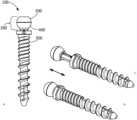
- FIG. 1shows a front plan view (a.) and alternate perspective views (b. and c.) of a length adjustable modular anchor system according to the disclosure
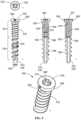
- FIG. 2shows exploded (a.) and assembled (b.) perspective views of the neck assembly of the length adjustable modular anchor system shown in FIG. 1 ;
- FIG. 3shows a front plan view (a.), an exploded perspective view (b.) and a close up perspective (c.) view of the length adjustable modular anchor system shown in FIG. 1 ;
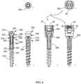
- FIG. 4shows on the left alternate top perspective (a.), side plan (b.), and partial close up side plan (c.) views of an expander component of the neck assembly shown in FIG. 2 , and on the right alternate top perspective (d.), bottom perspective (e.), and side cross sectional (f.) views of a collet component of the neck assembly shown in FIG. 2 ;
- FIG. 5shows an alternate side plan (b.), top, (a.) perspective (e.), and alternate side cross sectional (c. and d.) views of a shank component of the length adjustable modular anchor system 10 shown in FIG. 1 ;
- FIG. 6shows on the top a top plan view (a.), and on the bottom side plan (b.) and cross sectional (c.) views of the length adjustable modular anchor system 10 shown in FIG. 1 , and a top plan view (f.), side plan (d.) and cross sectional (e.) views of an alternate embodiment of a length adjustable modular anchor system 10 that includes a retaining housing 20 , a compression washer 30 and a locking element 40 according to the disclosure; and
- FIG. 7shows each, individually in alternate views, the retaining housing 20 (a.), a compression washer 30 (top perspective, b., and bottom perspective, c.), locking element 40 (d.), and protuberance 570 (e.).
- proximalrefers to the portion of the object that is closest to the operator of the object (or some other stated reference point), and the term “distal” refers to the portion of the object that is farthest from the operator of the object (or some other stated reference point).
- a “clinical subject”refers to a human or other animal who is the subject of treatment with a bone fixation or reduction device in accordance with the disclosure.
- cephaladindicates a direction toward the head of the clinical subject
- the term “caudad”indicates a direction toward the feet of the clinical subject.
- posteriorindicates a direction toward the back of the clinical subject
- anteriorindicates a direction toward the front of the clinical subject
- lateralindicates a direction toward a side of the clinical subject.
- the term “height” as used specifically hereinpertains to references to the spine of a clinical subject and refers to the relative position of one or both of vertebrae and anchors along adjacent portions of the spine.
- the terms “vertical” and “vertical adjustment”relate to the relative height variations and adjustments thereof with respect to one or both of vertebrae and anchors along adjacent portions or the length of the spine in the context of a clinical subject in a prone position wherein a length adjustment to an anchor would be in a vertical dimension from anterior to posterior.
- anchortypically refers to the screw component of an anchor assembly or subassembly
- anchor assemblyrefers to the screw component together with attachment features, such as a retaining housing (a conventional tulip head) or other type of attachment device, and one or more of compression washers and set screws, and optionally additional fixation components.
- Subassembliesalso refer to the modular components of the screw, such as, for example, the shank and head portions and subassemblies of these. More generically, anchor components, subassemblies and assemblies can be adapted to include features suitable for use with any bones in a clinical subject, wherein the modular and adjustable features are as described and claimed herein.
- FIG. 1 - FIG. 6an embodiment of a modular and length adjustable modular anchor system 10 for securing a bone stabilization element, such as a spinal stabilization rod, to a bone is depicted in FIG. 1 - FIG. 6 .
- the length adjustable modular anchor system 10includes a length adjustable modular screw 100 which can be varied in length.
- the length adjustable modular screw 100is assembled to provide a construct that resembles a convention screw that includes a head 310 portion including at a proximal end 410 a hemispherical screw head and a separate threaded shank 500 portion including at a distal end a threaded shank 500 .
- the length adjustable modular screw 100 componentsare adapted for interconnection along a common elongate axis and capable of vertical displacement to achieve fixed or variable length when implanted in a bone.
- FIG. 6provides an example of such a system that includes an embodiment of a length adjustable modular screw 100 according to the disclosure.
- the compressive force employed to lock a rod to a conventional screwalso serves to lock the length adjustable modular screw 100 embodiments according to this disclosure, thereby fixing the vertical position selected by the surgeon.
- the length adjustable modular anchor system 10for engagement with a bone.
- the length adjustable modular anchor system 10includes a length adjustable modular screw 100 that includes a neck assembly 200 and a shank 500 .
- the neck assembly 200includes an expander component 300 and a collet component 400 .
- a portion of the expander component 300is insertable within a through channel 430 in the collet component 400 along a common axis, as shown in FIG. 2 .
- the collet component 400 through channel 430originates within the seat 440 and extends through the distal end 420 of the collet 450 .
- the expander component pin 330When engaged, the head 310 of the expander component 300 contacts the seat of the collet component 400 and the pin 330 is passed through the through channel 430 .
- the expander component pin 330includes an extension 334 that extends beyond the distal end 420 of the collet 450 .
- the expander component pin 330may lack such an extension 334 and thus, the pin 330 may not extend beyond the distal end 420 of the collet 450 .
- the expander component 300 and the collet component 400are engagable in each of open, mated and compressed configurations.
- the expander component 300 and the collet component 400are engaged without the head 310 contacting the seat 440 and the pin 330 of the expander component 300 is coaxially engaged with and only partially inserted in the through channel 430 of the collet component 400 and the expander and collet components 300 , 400 are freely movable along the common axis.
- the head 310is contacting the seat 440 and the head 310 of the expander component 300 and the seat 440 of the collet component 400 are mated but not compressed, and the pin 330 of the expander component 300 is fully inserted in the through channel 430 of the collet component 400 .
- the collet 450is not splayed.
- the compressed configurationthe expander component 300 and the collet component 400 are mated and the head 310 and the seat 440 are contacted and in compression, and the collet 450 is splayed such that it has an overall greater diameter 590 than in its non-splayed configuration.
- Each of the expander and collet components 300 , 400include cooperating features that are compressible together to splay the collet 450 .
- the expander component 300includes a head 310 at a proximal end and a pin 330 that extends from the head 310 at a distal end.
- the collet component 400includes at a proximal end 410 a seat 440 that is matable with the head 310 of the expander component 300 , and at a distal end 420 a collet 450 that extends from the seat 440 .
- each of the head 310 of the expander component 300 and the seat 440 of the collet component 400are generally hemispherical in shape and mated 220 to form a generally spherical head 310 , the mated 220 pin 330 and collet 450 features forming a generally rod-shaped extension from the sphere.
- the head 310 and seat 440 featuresmay be other than hemispherical.
- the expander component 300has a head 310 that is generally hemispherical and includes a flat at its apex that includes a drive recess 360 for engaging a driver. Any suitable shaped drive recess 360 may be employed for engagement with any of a variety of drivers.
- the head 310 of the expander component 300includes a foot 320 having a generally square cross sectional shape
- the seat 440 of the collet component 400includes a complementary seat recess 441 having a generally square cross sectional shape for receiving the foot 320 of the extender component 300 .
- the collet 450includes at least one through slot 452 oriented parallel to the common axis and along at least a portion of the collet 450 through the distal end 420 . And in some embodiments the collet 450 includes a plurality of through slots 452 arranged circumferentially around the collet 450 and extending along at least a portion of the length of the collet 450 and through the distal end 420 . As shown in the drawings, for example FIG. 4 , the collet 450 includes four through slots 452 .
- the collet 450has a generally square cross sectional shape 490 , and each of the through slots 452 are arranged, respectively, on a side of the collet 450 to form four legs.
- the collet 450has chamfered corners 482 and generally planar sides on its outer surface.
- the collet 450includes on its outer surface at its distal end 420 an array of interference enhancers 454 .
- the interference enhancers 454include a knurled texture.
- the featuremay include other textural elements, or may include one or more furrows, divots or ridges.
- the interference enhancers 454may enhance the contact with the wall 550 of the socket 540 within the shank 500 when the collet 450 is splayed. And the interference enhancers 454 may also enhance the flexibility of the shank 500 for splaying. It will be appreciated that in some embodiments the collet 450 lacks such interference enhancers 454 . And as shown in the depicted embodiment, the collet 450 includes at its distal end 420 on each leg 456 and within the through channel 430 a compression element 460 that is generally block shaped with a proximally oriented taper or angle.
- collets 450may be selected to facilitate locking and compression and/or frictional engagement between a collet 450 and engaged anchor components.
- variations in the thickness of walls 550 of one or more componentscan be employed to achieve compressive engagement.
- collet 450 featuresmay include tapers along the length of engaging components. It will be understood that the features described herein are intended to be non-limiting and other features of collets 450 known in the art may be used to achieve the inventive modular and adjustable anchors in accordance with the invention.
- At least one of the expander component 300 and the collet component 400includes a locking feature that is engagable when the head 310 of the expander component 300 and the seat 440 of the collet component 400 are mated 220 .
- the locking featureincludes a circumferential flange 340 on the pin 330 of the expander component 300 that interferes with the distal end 420 of the collet 450 when the expander and collet components 300 , 400 are in the mated 220 arrangement to limit displacement of the expander component 300 .
- the circumferential flange 340is located at a position that is between the proximal and distal ends 410 , 420 and includes a generally planar surface 345 on a proximal edge which abuts a taper 347 that is angled toward the common axis from proximal to distal to form a generally conical taper shape.
- the pin 330has a diameter at its proximal end 410 that is greater than the diameter at its distal end 420 .
- the pin 330 of the expander component 300also includes a detent region 350 , which is shown in FIG. 2 .
- the detent region 350has a diameter that is approximately the same as the diameter of the pin 330 at the distal end 420 .
- the detent region 350is abutted at its proximal end by a taper 332 that is angled toward the common axis from proximal to distal to form a generally conical shape and abuts at its distal end the generally planar surface 345 of the circumferential flange 340 .
- the collet component 400includes at least one compression element 460 within the collet 450 through channel 430 for contacting the taper 332 of the pin 330 .
- the at least one compression element 460 of the collet 450is engagable within the detent region 350 of the pin 330 of the expander component 300 when the expander and collet components 300 , 400 are mated 220 .
- the compression element 460extends into the collet 450 through channel 430 , and has a shape that is one of angled, radiused and squared.
- the compression element 460may be formed continuously and interrupted only by the through slots 452 , and may be dome shaped, may have planer circumferential flange 340 shape, may include one or more conical or beveled edges, and may be wedge shaped. And there may be more than one compression element 460 arranged along the length of the through channel 430 .
- the pin 330has a cross sectional shape 370 that is generally cylindrical and the through channel 430 of the collet component 400 has an inner wall 431 with an inner wall cross sectional shape 432 that is cylindrical. It will be appreciated that in other embodiments, each of the pin 330 cross sectional shape 370 and the inner wall cross sectional shape 432 may be other than cylindrical.
- the threaded portion 510 of the shank 500may be continuous from the proximal to the distal ends 520 , 530 , or there may be a gap at either end that lacks threading, or a gap along the length that lacks threading.
- the shank 500includes at least a major and a minor diameter 592 , 594 , the minor diameter 594 defined by the outer surface of the shank 500 wall 550 excluding the threads, and the major diameter 592 defined by the threads. In some embodiments, one or both of the major and minor diameters 592 , 594 may be straight or may be tapered.
- the shaped recess 470has a generally elliptical shape and is elongate from the proximal 410 and towards the distal end 420 of the collet component 400 .
- the shaped recess 470includes proximal and distal stops 472 , 474 . It will be appreciated that other shapes for the shaped recess 470 may be employed, and the shaped recess 470 may have a longer or shorter length along the collet 450 .
- the stepsinclude in some embodiments selecting each of two or more bone anchors, at least one of which bone anchors is a length adjustable modular anchor system 10 that includes a neck assembly 200 and a shank 500 , as described herein above, and at least one spinal rod defining a longitudinal axis, and two or more retaining housings 20 for engaging and securing a bone anchor and a surgical rod, and two or more locking elements 40 for securing a rod to a bone anchor, and optionally, one or more compression washers 30 for engagement between a rod and a bone anchor.
- the stepsinclude, either before or after seating the neck assembly 200 in a retaining housing 20 , assembling a length adjustable modular screw 100 system.
- the stepsinclude releasing the drive compression on the drive recess 360 of the neck assembly 200 to thereby relieve the collet 450 from being splayed and thereby allowing translation of the neck assembly 200 within the shank 500 .
- the vertical height (length) of the length adjustable modular anchor system 10may be adjusted by sliding the neck assembly 200 along the common axis within the socket 540 of the shank 500 .
- the methodincludes tightening the fixation element within the retaining housing 20 to compress the rod against the neck assembly 200 and to drive the expander component 300 and the collet component 400 into compressed engagement to splay the collet 450 within the socket 540 of the shank 500 .
- the length adjustable modular anchor system 10is fully assembled prior to engagement of the threaded portion 510 of the shank 500 with bone. In yet other embodiments, the length adjustable modular anchor system 10 is provided pre-assembled. And in yet other embodiments, at least the neck assembly 200 of the length adjustable modular anchor system 10 is provided pre-assembled with a retaining housing 20 .
- the length adjustable modular screw 100can be adjusted within a displacement range between zero mm to 20 mm, and more particularly 0 mm to 10 mm, including fractional increments therein, including 0.1, 0.2, 0.3, 0.4, 0.5, 1.0, 1.5, 2.0, and 2.5 up to and through 20.0 mm.
- a displacement rangebetween zero mm to 20 mm, and more particularly 0 mm to 10 mm, including fractional increments therein, including 0.1, 0.2, 0.3, 0.4, 0.5, 1.0, 1.5, 2.0, and 2.5 up to and through 20.0 mm.
- fractional increments thereinincluding 0.1, 0.2, 0.3, 0.4, 0.5, 1.0, 1.5, 2.0, and 2.5 up to and through 20.0 mm.
- other increments and ranges of travelare possible, and implementation thereof is well within the skill in the art.
- length adjustable modular screwmay be provided that are of varying lengths and therefore allow for an expanded range of length adaptability.
- length adjustable modular screw componentsare of fixed length or offered in ranges of lengths, such possible embodiments are particularly advantageous in that they provide options in some embodiments for providing preassembled bottom and top loading anchor assemblies, as well as anchor assemblies and subassemblies that may be assembled partially by the manufacturer or partially or completely by the surgeon, providing a range of options for achieving maximal flexibility in the surgical setting.
- the components of the length adjustable modular screw 100 assembly that achieve locking of the length adjustable modular screw 100 to a rodcan also actuate the collet 450 locking mechanism for fixing the neck assembly 200 of the length adjustable modular anchor system 10 to the shank 500 and optionally fixing the vertical position of the length adjustable modular screw 100 relative to the vertebra and the fixation system elements.
- the means of achieving lockingmay be other than compression by the rod, and in yet other embodiments the locking means may be the same but the specific elements, such as the locking element 40 , rod and compression washer 30 , may be varied.
- fixation systemsthat include in the depicted embodiments anchors in the form of vertebral pedicle screws, and stabilization elements in the form of one or more surgical rods.
- the spineis but one example of a bone or bone system that may be the object of surgical correction, and thus, pedicle screws and rods are mere examples of the bone anchor, and vertebral stabilization system components contemplated herein.
- anchorsmay be screws for engagement with a tether or other tensioning means, or with one or more plates or rods or combinations of these.
- anchors and systems described hereinmay be suitable for other bones and bone systems in the body.
- the mechanisms for adjustment of anchor lengthcan be adapted for use with other anchor and fixation and stabilization elements used in orthopedic applications in the spine or in other parts of the body.
- spinal rodsmay be made adjustable according to the features disclosed herein to enable tuned adjustment of rod length at the time of implantation or subsequently as spinal healing and or adjustment takes place, such as for adjustment of rod length in connection with scoliosis treatment.
- adjustable anchorsmay be employed in the reduction or fixation of other bones, such as bones of the hand, or of the foot or in other locations where adjustment of the length of an anchor or other fixation element is desirable.
- One such examplewould be incorporation of adjustability features disclosed herein in dual threaded headless screws or screws, rods or pins with other head and threading configurations that are used for interconnecting and reducing fractured bone fragments or adjacent bones.
- Such anchors adapted according to the instant disclosurewould enable tuned adjustment of implant length to accommodate anatomical variations in a clinical subject and achieve optimized anchor placement.
- the inventionis directed in various aspects to a system including assemblies and subassemblies, components including anchors and anchor components adapted for attachment to a bony structure of a clinical subject.
- a systemincluding assemblies and subassemblies, components including anchors and anchor components adapted for attachment to a bony structure of a clinical subject.
- one, two or more such anchors in the form of screwsare affixed to bones, for example, vertebral structures such as the pedicle, and each anchor is connected to a stabilizer such as a surgical rod that is inserted between the anchors.
- the anchorsare novel in many respects owing to their modular nature and thus the options to provide the anchors in modular, sub-assembled and assembled forms provide a broad array of choices for the surgeon in devising the optimal surgical fixation plan.
- installation of the inventive components of the exemplary bone anchor system for spinal fixation described aboveincludes: selecting two or more bone anchor assemblies or subassemblies, including assemblies and subassemblies selected from pre-assembled and top and bottom loading forms, wherein at least one anchor assembly includes an length adjustable modular screw; selecting a stabilization element; using a suitable driver to drive each of two or more anchors or anchor subassemblies into fixed engagement with corresponding vertebrae, wherein at least one anchor or anchor subassembly includes or is adapted to engage with modular components that allow length adjustability, including translation along the vertical axis of the anchor, so as to enable selection of the anchor length by the surgeon; engaging a proximal portion of the modular adjustable anchor, such modular portion selected from a pre-assembled or modular screw head and engagement seat, to provide a means to introduce the stabilization element into engagement with the anchor; optionally incrementally adjusting the length of the anchor so as to achieve engagement of the stabilization element in the anchor; sliding the stabilization element into place within
- the length adjustable modular screw described hereinmay be employed with components of a conventional spinal stabilization system, and may be used on a single vertebra, or traversing two or more vertebra, and may be used in conjunction with fusion or non-fusion treatment of the spine.
- the anchorsmay be employed in isolation or in systems that include two or more anchors, connectors and stabilization elements, and the anchors may be deployed other than along the spinal axis.
- two or more anchorsmay be used to secure one or more stabilization elements that extend either laterally or from an anterior to posterior aspect to traverse a vertebral body, or that wrap around one or more vertebral bodies, or combinations of these.
- assemblies and subassemblies, components, including anchors and anchor componentsmay be used in bones of the body other than the spine, and as such may be used individually, as a plurality, or in combination with other devices, and combinations of these.
Landscapes
- Health & Medical Sciences (AREA)
- Orthopedic Medicine & Surgery (AREA)
- Life Sciences & Earth Sciences (AREA)
- Surgery (AREA)
- Neurology (AREA)
- Heart & Thoracic Surgery (AREA)
- Engineering & Computer Science (AREA)
- Biomedical Technology (AREA)
- Nuclear Medicine, Radiotherapy & Molecular Imaging (AREA)
- Medical Informatics (AREA)
- Molecular Biology (AREA)
- Animal Behavior & Ethology (AREA)
- General Health & Medical Sciences (AREA)
- Public Health (AREA)
- Veterinary Medicine (AREA)
- Surgical Instruments (AREA)
Abstract
Description
| TABLE |
| of Reference Numerals |
| length adjustable modular | through slot 452 | ||
| anchor system 10 | interference enhancer 454 | ||
| retaining housing 20 | (e.g., groove/furrow/rib) | ||
| compression washer 30 (e.g., cap) | leg 456 | ||
| locking element 40 (e.g., set screw) | compression element 460 | ||
| rod (not shown) | complementary taper 462 | ||
| length adjustable modular screw 100 | shaped recess 470 | ||
| neck assembly 200 | recess proximal stop 472 | ||
| mated 220 | recess distal stop 474 | ||
| expander component 300 | outer surface 480 | ||
| head 310 (hemispherical) | chamfered corners 482 | ||
| foot 320 | collet cross sectional shape | ||
| foot cross sectional shape 322 | 490 (e.g., square) | ||
| pin 330 | shank 500 | ||
| taper 332 | threaded portion 510 | ||
| extension 334 | proximal end 520 | ||
| circumferential flange 340 | proximal aperture 522 | ||
| flange generally planar surface 345 | proximal thread zone 524 | ||
| flange taper 347 | distal end 530 | ||
| detent region 350 | distal tip 532 | ||
| drive recess 360 (hex) | distal thread zone 534 | ||
| pin 330 | socket 540 | ||
| cross sectional shape | socket cross sectional shape | ||
| 370 (e.g., sq/cyl) | 542 (e.g., sq/cyl) | ||
| collet component 400 | chamfered sidewall 544 | ||
| proximal end 410 | wall 550 | ||
| distal end 420 | wall aperture 560, 560′ | ||
| through channel 430 | protuberance 570, 570′ | ||
| inner wall 431 | floor 580 | ||
| inner wall cross sectional shape 432 | floor taper 582 | ||
| (cylindrical) | diameter 590 (e.g., straight, | ||
| seat 440 (hemispherical) | tapered, step down) | ||
| seat recess 441 | major diameter 592 | ||
| seat recess cross sectional | minor diameter 594 | ||
| shape 442 (e.g., | cannula 596 | ||
| sq/cyl)collet 450 | flange 598 | ||
Claims (14)
Priority Applications (2)
| Application Number | Priority Date | Filing Date | Title |
|---|---|---|---|
| US18/133,005US12285200B2 (en) | 2016-08-24 | 2023-04-11 | Length adjustable modular screw system |
| US19/092,849US20250221750A1 (en) | 2016-08-24 | 2025-03-27 | Length adjustable modular screw system |
Applications Claiming Priority (5)
| Application Number | Priority Date | Filing Date | Title |
|---|---|---|---|
| US201662379111P | 2016-08-24 | 2016-08-24 | |
| PCT/US2017/048480WO2018039485A1 (en) | 2016-08-24 | 2017-08-24 | Adjustable bone fixation systems |
| US16/018,942US10758285B2 (en) | 2016-08-24 | 2018-06-26 | Length adjustable modular screw system |
| US16/818,924US11633220B2 (en) | 2016-08-24 | 2020-03-13 | Length adjustable modular screw system |
| US18/133,005US12285200B2 (en) | 2016-08-24 | 2023-04-11 | Length adjustable modular screw system |
Related Parent Applications (1)
| Application Number | Title | Priority Date | Filing Date |
|---|---|---|---|
| US16/818,924DivisionUS11633220B2 (en) | 2016-08-24 | 2020-03-13 | Length adjustable modular screw system |
Related Child Applications (1)
| Application Number | Title | Priority Date | Filing Date |
|---|---|---|---|
| US19/092,849ContinuationUS20250221750A1 (en) | 2016-08-24 | 2025-03-27 | Length adjustable modular screw system |
Publications (2)
| Publication Number | Publication Date |
|---|---|
| US20230355286A1 US20230355286A1 (en) | 2023-11-09 |
| US12285200B2true US12285200B2 (en) | 2025-04-29 |
Family
ID=61246348
Family Applications (5)
| Application Number | Title | Priority Date | Filing Date |
|---|---|---|---|
| US16/018,942ActiveUS10758285B2 (en) | 2016-08-24 | 2018-06-26 | Length adjustable modular screw system |
| US16/283,384ActiveUS11129657B2 (en) | 2016-08-24 | 2019-02-22 | Adjustable bone fixation systems |
| US16/818,924Active2038-11-09US11633220B2 (en) | 2016-08-24 | 2020-03-13 | Length adjustable modular screw system |
| US18/133,005ActiveUS12285200B2 (en) | 2016-08-24 | 2023-04-11 | Length adjustable modular screw system |
| US19/092,849PendingUS20250221750A1 (en) | 2016-08-24 | 2025-03-27 | Length adjustable modular screw system |
Family Applications Before (3)
| Application Number | Title | Priority Date | Filing Date |
|---|---|---|---|
| US16/018,942ActiveUS10758285B2 (en) | 2016-08-24 | 2018-06-26 | Length adjustable modular screw system |
| US16/283,384ActiveUS11129657B2 (en) | 2016-08-24 | 2019-02-22 | Adjustable bone fixation systems |
| US16/818,924Active2038-11-09US11633220B2 (en) | 2016-08-24 | 2020-03-13 | Length adjustable modular screw system |
Family Applications After (1)
| Application Number | Title | Priority Date | Filing Date |
|---|---|---|---|
| US19/092,849PendingUS20250221750A1 (en) | 2016-08-24 | 2025-03-27 | Length adjustable modular screw system |
Country Status (6)
| Country | Link |
|---|---|
| US (5) | US10758285B2 (en) |
| EP (1) | EP3503827A4 (en) |
| CN (1) | CN112312851A (en) |
| AU (1) | AU2019291788A1 (en) |
| BR (1) | BR112020026334A2 (en) |
| WO (1) | WO2018039485A1 (en) |
Families Citing this family (23)
| Publication number | Priority date | Publication date | Assignee | Title |
|---|---|---|---|---|
| US11147688B2 (en) | 2013-10-15 | 2021-10-19 | Si-Bone Inc. | Implant placement |
| WO2018039485A1 (en) | 2016-08-24 | 2018-03-01 | Integrity Implants, Inc. | Adjustable bone fixation systems |
| WO2020005971A1 (en)* | 2018-06-26 | 2020-01-02 | Integrity Implants, Inc. | Length adjustable modular screw system |
| US11298156B2 (en)* | 2017-03-30 | 2022-04-12 | K2M, Inc. | Modular screw |
| US11648037B2 (en)* | 2017-05-03 | 2023-05-16 | Advance Research System, Llc | Extension-ready spinal support system with vascular-safe pedicle screw |
| US10653455B2 (en)* | 2017-09-12 | 2020-05-19 | Warsaw Orthopedic, Inc. | Spinal implant system and methods of use |
| US11116519B2 (en) | 2017-09-26 | 2021-09-14 | Si-Bone Inc. | Systems and methods for decorticating the sacroiliac joint |
| ES3011907T3 (en) | 2018-03-28 | 2025-04-08 | Si Bone Inc | Threaded implants for use across bone segments |
| EP4613244A2 (en) | 2019-02-14 | 2025-09-10 | SI-Bone Inc. | Implants for spinal fixation and or fusion |
| US11369419B2 (en) | 2019-02-14 | 2022-06-28 | Si-Bone Inc. | Implants for spinal fixation and or fusion |
| JP7646654B2 (en) | 2019-11-21 | 2025-03-17 | エスアイ-ボーン・インコーポレイテッド | Rod coupling assembly for bone stabilization construct - Patent application |
| AU2020392121B2 (en) | 2019-11-27 | 2025-05-22 | Si-Bone, Inc. | Bone stabilizing implants and methods of placement across SI joints |
| EP4072452A4 (en) | 2019-12-09 | 2023-12-20 | SI-Bone, Inc. | Sacro-iliac joint stabilizing implants and methods of implantation |
| WO2021154257A1 (en)* | 2020-01-30 | 2021-08-05 | Next Orthosurgical, Inc. | Polyaxial pedicle screw system |
| WO2021177018A1 (en)* | 2020-03-02 | 2021-09-10 | 大阪螺子販売株式会社 | Mounting member with ic tag |
| EP4259015A4 (en) | 2020-12-09 | 2024-09-11 | SI-Bone, Inc. | SACROILIAC JOINT STABILIZATION IMPLANTS AND METHODS OF IMPLANTATION |
| US11291477B1 (en) | 2021-05-04 | 2022-04-05 | Warsaw Orthopedic, Inc. | Dorsal adjusting implant and methods of use |
| US11432848B1 (en) | 2021-05-12 | 2022-09-06 | Warsaw Orthopedic, Inc. | Top loading quick lock construct |
| US11712270B2 (en) | 2021-05-17 | 2023-08-01 | Warsaw Orthopedic, Inc. | Quick lock clamp constructs and associated methods |
| CN113303897A (en)* | 2021-05-20 | 2021-08-27 | 首都医科大学附属北京朝阳医院 | Assembled cortical bone screw |
| CN113693699B (en)* | 2021-09-16 | 2024-11-15 | 郝定均 | A claw-shaped pedicle screw for osteoporosis |
| US11957391B2 (en) | 2021-11-01 | 2024-04-16 | Warsaw Orthopedic, Inc. | Bone screw having an overmold of a shank |
| WO2025038769A1 (en) | 2023-08-15 | 2025-02-20 | Si-Bone Inc. | Pelvic stabilization implants, methods of use and manufacture |
Citations (61)
| Publication number | Priority date | Publication date | Assignee | Title |
|---|---|---|---|---|
| US5209753A (en) | 1989-11-03 | 1993-05-11 | Lutz Biedermann | Bone screw |
| US6086589A (en) | 1999-02-02 | 2000-07-11 | Spineology, Inc. | Method and device for fixing spondylolisthesis posteriorly |
| EP0841876B1 (en) | 1994-03-03 | 2002-07-31 | Societe De Fabrication De Materiel Orthopedique Sofamor | Connector used in spinal osteosynthesis equipment for lumbar, sacral or iliosacral fixation |
| RU2189200C2 (en) | 1996-01-19 | 2002-09-20 | Астра Актиеболаг | Fastening unit and prosthesis having the unit |
| US6626911B1 (en) | 1998-11-11 | 2003-09-30 | Nobel Biocare Ab | Threaded implant, and arrangement and method for such an implant |
| US20040147929A1 (en) | 2002-12-20 | 2004-07-29 | Biedermann Motech Gmbh | Tubular element for an implant for use in spine or bone surgery and implant having such an element |
| US6778861B1 (en) | 1999-06-23 | 2004-08-17 | Geot Gesellschaft Fur Elektro-Osteo-Therapie G.M.B.H. | Bone screw comprising a device for electrostimulation |
| US20050055026A1 (en) | 2002-10-02 | 2005-03-10 | Biedermann Motech Gmbh | Bone anchoring element |
| WO2005044117A2 (en) | 2003-11-07 | 2005-05-19 | Biedermann Motech Gmbh | Spring element for a bone stabilizing device, and method for the production of said spring element |
| US20050273101A1 (en) | 2004-05-28 | 2005-12-08 | Aesculap Ag & Co. Kg | Bone screw and osteosynthesis device |
| US20060241593A1 (en) | 2005-04-08 | 2006-10-26 | Sdgi Holdings, Inc. | Multi-piece vertebral attachment device |
| US7186255B2 (en) | 2004-08-12 | 2007-03-06 | Atlas Spine, Inc. | Polyaxial screw |
| US20070233062A1 (en) | 2006-04-04 | 2007-10-04 | Amedica Corporation | Pedicle screw system with offset stabilizer rod |
| US20070270855A1 (en) | 2006-04-06 | 2007-11-22 | Lotus Medical, Llc | Active compression to facilitate healing of bones |
| US7306603B2 (en) | 2002-08-21 | 2007-12-11 | Innovative Spinal Technologies | Device and method for percutaneous placement of lumbar pedicle screws and connecting rods |
| US20080147129A1 (en) | 2006-11-17 | 2008-06-19 | Lutz Biedermann | Bone anchoring device |
| US20080161863A1 (en) | 2006-12-28 | 2008-07-03 | Depuy Spine, Inc. | Spinal anchoring screw |
| US20080312701A1 (en) | 2007-06-15 | 2008-12-18 | Robert Reid, Inc. | System and Method for Polyaxially Adjustable Bone Anchorage |
| US7468064B2 (en) | 2003-08-21 | 2008-12-23 | Warsaw Orthopedic, Inc. | Systems and methods for positioning implants relative to bone anchors in surgical approaches to the spine |
| US20090036929A1 (en) | 2005-07-22 | 2009-02-05 | Joey Camia Reglos | Offset connector for a spinal stabilization rod |
| US20090062868A1 (en) | 2005-04-04 | 2009-03-05 | Zimmer Gmbh | Pedicle screw |
| US20090157123A1 (en) | 2007-12-17 | 2009-06-18 | Andreas Appenzeller | Dynamic bone fixation element and method of using the same |
| US7588593B2 (en) | 2006-04-18 | 2009-09-15 | International Spinal Innovations, Llc | Pedicle screw with vertical adjustment |
| US20100114108A1 (en) | 2008-11-05 | 2010-05-06 | K2M, Inc. | Multiplanar taper lock screw and lock indicator gauge |
| US20100249846A1 (en) | 2009-03-25 | 2010-09-30 | Simonson Peter M | Variable height, multi-axial bone screw assembly |
| US7875065B2 (en) | 2004-11-23 | 2011-01-25 | Jackson Roger P | Polyaxial bone screw with multi-part shank retainer and pressure insert |
| US7892257B2 (en) | 2004-02-27 | 2011-02-22 | Custom Spine, Inc. | Spring loaded, load sharing polyaxial pedicle screw assembly and method |
| US7967850B2 (en) | 2003-06-18 | 2011-06-28 | Jackson Roger P | Polyaxial bone anchor with helical capture connection, insert and dual locking assembly |
| US7988694B2 (en) | 2005-09-29 | 2011-08-02 | K2M, Inc. | Spinal fixation system having locking and unlocking devices for use with a multi-planar, taper lock screw |
| US20110230915A1 (en) | 2002-03-19 | 2011-09-22 | Anderson D Greg | Device and Method for Expanding the Spinal Canal With Spinal Column Stabilization and Spinal Deformity Correction |
| US8052720B2 (en) | 2006-11-09 | 2011-11-08 | Zimmer Spine, Inc. | Minimally invasive pedicle screw access system and associated method |
| US20110307013A1 (en) | 2010-06-10 | 2011-12-15 | Spartek Medical, Inc. | Adaptive spinal rod and methods for stabilization of the spine |
| US20110319946A1 (en) | 2009-03-12 | 2011-12-29 | Levy Mark M | Bone implantation and stabilization assembly including deployment device |
| US8092494B2 (en) | 2004-01-13 | 2012-01-10 | Life Spine, Inc. | Pedicle screw constructs for spine fixation systems |
| US20120016423A1 (en) | 2008-10-01 | 2012-01-19 | Sherwin Hua | System and method for wire-guided pedicle screw stabilization of spinal vertebrae |
| US20120041490A1 (en) | 2009-11-18 | 2012-02-16 | Synthes Usa, Llc | Variable offset spine fixation system and method |
| US8162991B2 (en) | 2006-07-27 | 2012-04-24 | K2M, Inc. | Multi-planar, taper lock screw |
| US20120203288A1 (en) | 2009-10-05 | 2012-08-09 | Robert Lange | Spinal fixation system and screwdriver tool for use with the same |
| US20120215264A1 (en) | 2011-02-23 | 2012-08-23 | Choon Sung Lee | Extensible pedicle screw coupling device |
| US20120271353A1 (en) | 2010-08-16 | 2012-10-25 | Mark Barry | System and method for aligning vertebrae in the amelioration of aberrant spinal column deviation conditions in patients requiring the accomodation of spinal column growth or elongation |
| US20120316609A1 (en) | 2011-06-13 | 2012-12-13 | Warsaw Orthopedic, Inc. | Surgical instrument for securing a spinal rod |
| US8377101B2 (en) | 2008-11-05 | 2013-02-19 | K2M, Inc. | Multi-planar taper lock screw with increased rod friction |
| US20130144342A1 (en) | 2010-06-28 | 2013-06-06 | K2M, Inc. | Spine stabilization system |
| US20130172937A1 (en) | 2011-12-19 | 2013-07-04 | Amendia, Inc. | Extended tab bone screw system |
| US8623061B2 (en) | 2009-11-23 | 2014-01-07 | Rolix Holdings, Llc | CAM lock pedicle screw |
| US20140094860A1 (en) | 2012-10-02 | 2014-04-03 | Alphatec Spine, Inc. | Expandable screw and methods of use |
| US8790374B2 (en) | 2004-04-08 | 2014-07-29 | Globus Medical, Inc. | Polyaxial screw |
| US20140277187A1 (en) | 2013-03-13 | 2014-09-18 | Blackstone Medical, Inc. | Pedicle screw with reverse spiral cut and methods thereof |
| US20140288605A1 (en) | 2013-03-15 | 2014-09-25 | Ali H. MESIWALA | Implants for spinal fixation or fusion |
| US8852239B2 (en) | 2013-02-15 | 2014-10-07 | Roger P Jackson | Sagittal angle screw with integral shank and receiver |
| US20140336709A1 (en) | 2013-03-13 | 2014-11-13 | Baxano Surgical, Inc. | Multi-threaded pedicle screw system |
| US20140358182A1 (en) | 2011-10-05 | 2014-12-04 | Aesculap Ag | Readjustable polyaxial pedicle screw |
| US20150100093A1 (en) | 2011-10-26 | 2015-04-09 | Globus Medical Inc. | Connection assembly |
| WO2016054951A1 (en) | 2014-10-09 | 2016-04-14 | 中国人民解放军第四军医大学 | Telescopic double-threaded pull-out resistant pedicle screw assembly for medical use |
| US20160270826A1 (en) | 2015-03-20 | 2016-09-22 | Trinity Orthopedics, Llc | Bone anchoring assemblies and methods of use |
| US20170112555A1 (en) | 2015-10-23 | 2017-04-27 | K2M, Inc. | Semi-constrained bone screw and insertion instrument |
| US10117679B2 (en) | 2015-03-02 | 2018-11-06 | Globus Medical, Inc. | Adjustable height pedicle screw |
| US20190125410A1 (en) | 2016-04-26 | 2019-05-02 | K2M, Inc. | Expandable surgical fixation assemblies and method of use |
| US20190133660A1 (en) | 2016-05-13 | 2019-05-09 | Aesculap Ag | Pedicle screw with large-diameter bone thread |
| US20190159820A1 (en) | 2016-08-24 | 2019-05-30 | Wyatt Drake Geist | Length adjustable modular screw system |
| US20200030006A1 (en) | 2017-03-30 | 2020-01-30 | K2M, Inc. | Modular Screw |
Family Cites Families (11)
| Publication number | Priority date | Publication date | Assignee | Title |
|---|---|---|---|---|
| NL1017932C2 (en) | 2001-04-24 | 2002-10-29 | Paul De Windt | Fixing device for fixing swirl parts. |
| US20050182401A1 (en)* | 2003-05-02 | 2005-08-18 | Timm Jens P. | Systems and methods for spine stabilization including a dynamic junction |
| CN2910138Y (en)* | 2006-05-18 | 2007-06-13 | 雷伟 | Universal expanding screw for pedicle of vertebral arch |
| CN102123674A (en)* | 2008-08-15 | 2011-07-13 | 活动脊柱技术有限公司 | Dynamic pedicle screw |
| US9987057B2 (en)* | 2009-02-13 | 2018-06-05 | Globus Medical, Inc. | Orthopedic anchor assembly |
| WO2012134437A1 (en)* | 2011-03-28 | 2012-10-04 | Synthes Usa, Llc | Interlock driving instrument |
| CN103596511B (en)* | 2011-05-17 | 2017-07-28 | 新特斯有限责任公司 | Telescoping Screws for Femoral Neck Fractures |
| US20130035721A1 (en)* | 2011-08-04 | 2013-02-07 | John Eric Brunelle | Surgical anchor |
| EP2845553B1 (en)* | 2013-09-05 | 2016-05-11 | Biedermann Technologies GmbH & Co. KG | Bone anchor |
| AU2015207673B2 (en)* | 2014-01-17 | 2020-02-06 | The Sydney Children's Hospitals Network (Randwick And Westmead) | Intramedullary device |
| US10653455B2 (en)* | 2017-09-12 | 2020-05-19 | Warsaw Orthopedic, Inc. | Spinal implant system and methods of use |
- 2017
- 2017-08-24WOPCT/US2017/048480patent/WO2018039485A1/ennot_activeCeased
- 2017-08-24EPEP17844441.0Apatent/EP3503827A4/ennot_activeWithdrawn
- 2018
- 2018-06-26USUS16/018,942patent/US10758285B2/enactiveActive
- 2019
- 2019-02-22USUS16/283,384patent/US11129657B2/enactiveActive
- 2019-06-25BRBR112020026334-6Apatent/BR112020026334A2/ennot_activeApplication Discontinuation
- 2019-06-25AUAU2019291788Apatent/AU2019291788A1/ennot_activeAbandoned
- 2019-06-25CNCN201980041687.4Apatent/CN112312851A/enactivePending
- 2020
- 2020-03-13USUS16/818,924patent/US11633220B2/enactiveActive
- 2023
- 2023-04-11USUS18/133,005patent/US12285200B2/enactiveActive
- 2025
- 2025-03-27USUS19/092,849patent/US20250221750A1/enactivePending
Patent Citations (66)
| Publication number | Priority date | Publication date | Assignee | Title |
|---|---|---|---|---|
| US5209753A (en) | 1989-11-03 | 1993-05-11 | Lutz Biedermann | Bone screw |
| EP0841876B1 (en) | 1994-03-03 | 2002-07-31 | Societe De Fabrication De Materiel Orthopedique Sofamor | Connector used in spinal osteosynthesis equipment for lumbar, sacral or iliosacral fixation |
| RU2189200C2 (en) | 1996-01-19 | 2002-09-20 | Астра Актиеболаг | Fastening unit and prosthesis having the unit |
| US6626911B1 (en) | 1998-11-11 | 2003-09-30 | Nobel Biocare Ab | Threaded implant, and arrangement and method for such an implant |
| US6086589A (en) | 1999-02-02 | 2000-07-11 | Spineology, Inc. | Method and device for fixing spondylolisthesis posteriorly |
| US6778861B1 (en) | 1999-06-23 | 2004-08-17 | Geot Gesellschaft Fur Elektro-Osteo-Therapie G.M.B.H. | Bone screw comprising a device for electrostimulation |
| US20110230915A1 (en) | 2002-03-19 | 2011-09-22 | Anderson D Greg | Device and Method for Expanding the Spinal Canal With Spinal Column Stabilization and Spinal Deformity Correction |
| US8382802B2 (en) | 2002-08-21 | 2013-02-26 | Theken Spine, Llc | Systems, methods and devices for placement of bone anchors and connectors |
| EP1545355B1 (en) | 2002-08-21 | 2008-12-10 | Boehm, Frank H. | Device for percutaneous placement of lumbar pedicle screws and connecting rods |
| US8202304B2 (en) | 2002-08-21 | 2012-06-19 | Theken Spine, Llc | Methods and systems for performing spinal surgery |
| US7306603B2 (en) | 2002-08-21 | 2007-12-11 | Innovative Spinal Technologies | Device and method for percutaneous placement of lumbar pedicle screws and connecting rods |
| US20050055026A1 (en) | 2002-10-02 | 2005-03-10 | Biedermann Motech Gmbh | Bone anchoring element |
| US20040147929A1 (en) | 2002-12-20 | 2004-07-29 | Biedermann Motech Gmbh | Tubular element for an implant for use in spine or bone surgery and implant having such an element |
| US7967850B2 (en) | 2003-06-18 | 2011-06-28 | Jackson Roger P | Polyaxial bone anchor with helical capture connection, insert and dual locking assembly |
| US7468064B2 (en) | 2003-08-21 | 2008-12-23 | Warsaw Orthopedic, Inc. | Systems and methods for positioning implants relative to bone anchors in surgical approaches to the spine |
| WO2005044117A2 (en) | 2003-11-07 | 2005-05-19 | Biedermann Motech Gmbh | Spring element for a bone stabilizing device, and method for the production of said spring element |
| US8092494B2 (en) | 2004-01-13 | 2012-01-10 | Life Spine, Inc. | Pedicle screw constructs for spine fixation systems |
| US7892257B2 (en) | 2004-02-27 | 2011-02-22 | Custom Spine, Inc. | Spring loaded, load sharing polyaxial pedicle screw assembly and method |
| US8790374B2 (en) | 2004-04-08 | 2014-07-29 | Globus Medical, Inc. | Polyaxial screw |
| US20050273101A1 (en) | 2004-05-28 | 2005-12-08 | Aesculap Ag & Co. Kg | Bone screw and osteosynthesis device |
| US7186255B2 (en) | 2004-08-12 | 2007-03-06 | Atlas Spine, Inc. | Polyaxial screw |
| US7875065B2 (en) | 2004-11-23 | 2011-01-25 | Jackson Roger P | Polyaxial bone screw with multi-part shank retainer and pressure insert |
| US20090062868A1 (en) | 2005-04-04 | 2009-03-05 | Zimmer Gmbh | Pedicle screw |
| US20060241593A1 (en) | 2005-04-08 | 2006-10-26 | Sdgi Holdings, Inc. | Multi-piece vertebral attachment device |
| US20090036929A1 (en) | 2005-07-22 | 2009-02-05 | Joey Camia Reglos | Offset connector for a spinal stabilization rod |
| US8361122B2 (en) | 2005-09-29 | 2013-01-29 | K2M, Inc. | Spinal fixation system having locking and unlocking devices for use with a multi-planar, taper lock screw |
| US7988694B2 (en) | 2005-09-29 | 2011-08-02 | K2M, Inc. | Spinal fixation system having locking and unlocking devices for use with a multi-planar, taper lock screw |
| US20070233062A1 (en) | 2006-04-04 | 2007-10-04 | Amedica Corporation | Pedicle screw system with offset stabilizer rod |
| US20070270855A1 (en) | 2006-04-06 | 2007-11-22 | Lotus Medical, Llc | Active compression to facilitate healing of bones |
| US7588593B2 (en) | 2006-04-18 | 2009-09-15 | International Spinal Innovations, Llc | Pedicle screw with vertical adjustment |
| US8162991B2 (en) | 2006-07-27 | 2012-04-24 | K2M, Inc. | Multi-planar, taper lock screw |
| US8052720B2 (en) | 2006-11-09 | 2011-11-08 | Zimmer Spine, Inc. | Minimally invasive pedicle screw access system and associated method |
| US20080147129A1 (en) | 2006-11-17 | 2008-06-19 | Lutz Biedermann | Bone anchoring device |
| US20080161863A1 (en) | 2006-12-28 | 2008-07-03 | Depuy Spine, Inc. | Spinal anchoring screw |
| US20080312701A1 (en) | 2007-06-15 | 2008-12-18 | Robert Reid, Inc. | System and Method for Polyaxially Adjustable Bone Anchorage |
| WO2009079329A2 (en) | 2007-12-17 | 2009-06-25 | Synthes (U.S.A.) | Dynamic bone fixation element and method of using the same |
| US20090157123A1 (en) | 2007-12-17 | 2009-06-18 | Andreas Appenzeller | Dynamic bone fixation element and method of using the same |
| US20120016423A1 (en) | 2008-10-01 | 2012-01-19 | Sherwin Hua | System and method for wire-guided pedicle screw stabilization of spinal vertebrae |
| US20100114108A1 (en) | 2008-11-05 | 2010-05-06 | K2M, Inc. | Multiplanar taper lock screw and lock indicator gauge |
| US8377101B2 (en) | 2008-11-05 | 2013-02-19 | K2M, Inc. | Multi-planar taper lock screw with increased rod friction |
| US20110319946A1 (en) | 2009-03-12 | 2011-12-29 | Levy Mark M | Bone implantation and stabilization assembly including deployment device |
| US20100249846A1 (en) | 2009-03-25 | 2010-09-30 | Simonson Peter M | Variable height, multi-axial bone screw assembly |
| US20120203288A1 (en) | 2009-10-05 | 2012-08-09 | Robert Lange | Spinal fixation system and screwdriver tool for use with the same |
| US20120041490A1 (en) | 2009-11-18 | 2012-02-16 | Synthes Usa, Llc | Variable offset spine fixation system and method |
| US8623061B2 (en) | 2009-11-23 | 2014-01-07 | Rolix Holdings, Llc | CAM lock pedicle screw |
| US20110307013A1 (en) | 2010-06-10 | 2011-12-15 | Spartek Medical, Inc. | Adaptive spinal rod and methods for stabilization of the spine |
| US20130144342A1 (en) | 2010-06-28 | 2013-06-06 | K2M, Inc. | Spine stabilization system |
| US20120271353A1 (en) | 2010-08-16 | 2012-10-25 | Mark Barry | System and method for aligning vertebrae in the amelioration of aberrant spinal column deviation conditions in patients requiring the accomodation of spinal column growth or elongation |
| US20120215264A1 (en) | 2011-02-23 | 2012-08-23 | Choon Sung Lee | Extensible pedicle screw coupling device |
| US20120316609A1 (en) | 2011-06-13 | 2012-12-13 | Warsaw Orthopedic, Inc. | Surgical instrument for securing a spinal rod |
| US20140358182A1 (en) | 2011-10-05 | 2014-12-04 | Aesculap Ag | Readjustable polyaxial pedicle screw |
| US20150100093A1 (en) | 2011-10-26 | 2015-04-09 | Globus Medical Inc. | Connection assembly |
| US20130172937A1 (en) | 2011-12-19 | 2013-07-04 | Amendia, Inc. | Extended tab bone screw system |
| US20140094860A1 (en) | 2012-10-02 | 2014-04-03 | Alphatec Spine, Inc. | Expandable screw and methods of use |
| US8852239B2 (en) | 2013-02-15 | 2014-10-07 | Roger P Jackson | Sagittal angle screw with integral shank and receiver |
| US20140277187A1 (en) | 2013-03-13 | 2014-09-18 | Blackstone Medical, Inc. | Pedicle screw with reverse spiral cut and methods thereof |
| US20140336709A1 (en) | 2013-03-13 | 2014-11-13 | Baxano Surgical, Inc. | Multi-threaded pedicle screw system |
| US20140288605A1 (en) | 2013-03-15 | 2014-09-25 | Ali H. MESIWALA | Implants for spinal fixation or fusion |
| WO2016054951A1 (en) | 2014-10-09 | 2016-04-14 | 中国人民解放军第四军医大学 | Telescopic double-threaded pull-out resistant pedicle screw assembly for medical use |
| US10117679B2 (en) | 2015-03-02 | 2018-11-06 | Globus Medical, Inc. | Adjustable height pedicle screw |
| US20160270826A1 (en) | 2015-03-20 | 2016-09-22 | Trinity Orthopedics, Llc | Bone anchoring assemblies and methods of use |
| US20170112555A1 (en) | 2015-10-23 | 2017-04-27 | K2M, Inc. | Semi-constrained bone screw and insertion instrument |
| US20190125410A1 (en) | 2016-04-26 | 2019-05-02 | K2M, Inc. | Expandable surgical fixation assemblies and method of use |
| US20190133660A1 (en) | 2016-05-13 | 2019-05-09 | Aesculap Ag | Pedicle screw with large-diameter bone thread |
| US20190159820A1 (en) | 2016-08-24 | 2019-05-30 | Wyatt Drake Geist | Length adjustable modular screw system |
| US20200030006A1 (en) | 2017-03-30 | 2020-01-30 | K2M, Inc. | Modular Screw |
Non-Patent Citations (4)
| Title |
|---|
| International Search Report and Written Opinion from corresponding International Application PCT/US2017/048480 Nov. 7, 2017. |
| International Search Report and Written Opinion from corresponding International Application PCT/US2019/039026 dated Sep. 19, 2019. |
| Partial Supplementary European Search Report issued for Application No. / Patent No. 17844441.0—132 / 3503827 PCT/US2017/048480 dated Mar. 30, 2020. |
| Rasoulinejad, Parham, "Design and Development of a Novel Expanding Pedicle Screw for Use in the Osteoporotic Lumbar Spine" (2013) Electronic Thesis and Dissertation Repository. Paper 1614. |
Also Published As
| Publication number | Publication date |
|---|---|
| AU2019291788A1 (en) | 2021-01-07 |
| BR112020026334A2 (en) | 2021-03-30 |
| EP3503827A1 (en) | 2019-07-03 |
| US11129657B2 (en) | 2021-09-28 |
| CN112312851A (en) | 2021-02-02 |
| US11633220B2 (en) | 2023-04-25 |
| US20190159820A1 (en) | 2019-05-30 |
| US20200146725A1 (en) | 2020-05-14 |
| US20250221750A1 (en) | 2025-07-10 |
| US10758285B2 (en) | 2020-09-01 |
| US20230355286A1 (en) | 2023-11-09 |
| US20200229854A1 (en) | 2020-07-23 |
| WO2018039485A1 (en) | 2018-03-01 |
| EP3503827A4 (en) | 2020-08-05 |
Similar Documents
| Publication | Publication Date | Title |
|---|---|---|
| US12285200B2 (en) | Length adjustable modular screw system | |
| US9198696B1 (en) | Cross-connector and related methods | |
| US8137384B2 (en) | Modular pedicle screw system | |
| US8016832B2 (en) | Installation systems for spinal stabilization system and related methods | |
| US5997539A (en) | Polyaxial pedicle screw having a compression locking rod gripping mechanism | |
| US6451021B1 (en) | Polyaxial pedicle screw having a rotating locking element | |
| US20100174325A1 (en) | Poly-axial pedicle screw assembly | |
| US20050277928A1 (en) | Spinal implant fixation assembly | |
| US20110230917A1 (en) | Adjustable multi-axial spinal coupling assemblies | |
| US9615868B2 (en) | Bone fastener and methods of use | |
| US20070100341A1 (en) | Systems and methods for stabilization of bone structures | |
| CA2680065A1 (en) | Multi-level minimally invasive spinal stabilization system | |
| AU7933301A (en) | Pedicle screw assembly | |
| US11103283B2 (en) | Integral double rod spinal construct | |
| US10561453B2 (en) | Bone fastener and methods of use | |
| EP3781056A1 (en) | Length adjustable modular screw system | |
| US20200022734A1 (en) | Apparatus, system, and method for spinal vertebrae stabilization |
Legal Events
| Date | Code | Title | Description |
|---|---|---|---|
| FEPP | Fee payment procedure | Free format text:ENTITY STATUS SET TO UNDISCOUNTED (ORIGINAL EVENT CODE: BIG.); ENTITY STATUS OF PATENT OWNER: SMALL ENTITY | |
| FEPP | Fee payment procedure | Free format text:ENTITY STATUS SET TO SMALL (ORIGINAL EVENT CODE: SMAL); ENTITY STATUS OF PATENT OWNER: SMALL ENTITY | |
| STPP | Information on status: patent application and granting procedure in general | Free format text:DOCKETED NEW CASE - READY FOR EXAMINATION | |
| AS | Assignment | Owner name:SYMBIOTIC CAPITAL AGENCY LLC, AS ADMINISTRATIVE AGENT, CALIFORNIA Free format text:PATENT SECURITY AGREEMENT;ASSIGNOR:INTEGRITY IMPLANTS INC.;REEL/FRAME:066090/0832 Effective date:20231221 | |
| STPP | Information on status: patent application and granting procedure in general | Free format text:NON FINAL ACTION MAILED | |
| STPP | Information on status: patent application and granting procedure in general | Free format text:RESPONSE TO NON-FINAL OFFICE ACTION ENTERED AND FORWARDED TO EXAMINER | |
| STPP | Information on status: patent application and granting procedure in general | Free format text:NOTICE OF ALLOWANCE MAILED -- APPLICATION RECEIVED IN OFFICE OF PUBLICATIONS | |
| ZAAB | Notice of allowance mailed | Free format text:ORIGINAL CODE: MN/=. | |
| AS | Assignment | Owner name:KAPSTONE MEDICAL, LLC, NORTH CAROLINA Free format text:ASSIGNMENT OF ASSIGNORS INTEREST;ASSIGNORS:SOUZA, JOHN, JR.;LEWIS, RYAN;VON AMSBERG, MARC;SIGNING DATES FROM 20190418 TO 20190520;REEL/FRAME:069357/0874 Owner name:GEIST, WYATT DRAKE, FLORIDA Free format text:ASSIGNMENT OF ASSIGNORS INTEREST;ASSIGNOR:SOUZA, JOHN, JR.;REEL/FRAME:069357/0809 Effective date:20190418 Owner name:INTEGRITY IMPLANTS INC., FLORIDA Free format text:ASSIGNMENT OF ASSIGNORS INTEREST;ASSIGNORS:KAPSTONE MEDICAL, LLC;GEIST, WYATT D.;FOLSOM METAL PRODUCTS, INC., DBA FRONTIER DEVICES, INC.;SIGNING DATES FROM 20190417 TO 20190424;REEL/FRAME:069259/0459 Owner name:FOLSOM METAL PRODUCTS, INC., DBA FRONTIER DEVICES, INC., ALABAMA Free format text:ASSIGNMENT OF ASSIGNORS INTEREST;ASSIGNOR:FOLSOM, AUBREY C.;REEL/FRAME:069259/0374 Effective date:20190417 | |
| STPP | Information on status: patent application and granting procedure in general | Free format text:PUBLICATIONS -- ISSUE FEE PAYMENT VERIFIED | |
| STCF | Information on status: patent grant | Free format text:PATENTED CASE | |
| AS | Assignment | Owner name:INTEGRITY IMPLANTS INC., FLORIDA Free format text:PARTIAL RELEASE OF SECURITY INTEREST IN PATENT;ASSIGNOR:SYMBIOTIC CAPITAL AGENCY LLC, AS ADMINISTRATIVE AGENT;REEL/FRAME:069999/0978 Effective date:20250123 | |
| STPP | Information on status: patent application and granting procedure in general | Free format text:PUBLICATIONS -- ISSUE FEE PAYMENT VERIFIED | |
| AS | Assignment | Owner name:FOLSOM METAL PRODUCTS, INC., DBA FRONTIER DEVICES, INC., ALABAMA Free format text:ASSIGNMENT OF ASSIGNORS INTEREST;ASSIGNOR:INTEGRITY IMPLANTS INC. D/B/A ACCELUS;REEL/FRAME:070047/0510 Effective date:20250129 Owner name:KAPSTONE MEDICAL, LLC, NORTH CAROLINA Free format text:ASSIGNMENT OF ASSIGNORS INTEREST;ASSIGNOR:INTEGRITY IMPLANTS INC. D/B/A ACCELUS;REEL/FRAME:070047/0510 Effective date:20250129 Owner name:GEIST, WYATT, FLORIDA Free format text:ASSIGNMENT OF ASSIGNORS INTEREST;ASSIGNOR:INTEGRITY IMPLANTS INC. D/B/A ACCELUS;REEL/FRAME:070047/0510 Effective date:20250129 | |
| STCF | Information on status: patent grant | Free format text:PATENTED CASE | |
| FEPP | Fee payment procedure | Free format text:PETITION RELATED TO MAINTENANCE FEES GRANTED (ORIGINAL EVENT CODE: PTGR); ENTITY STATUS OF PATENT OWNER: SMALL ENTITY |