US12283806B2 - Brackets for mounting antenna cables - Google Patents
Brackets for mounting antenna cablesDownload PDFInfo
- Publication number
- US12283806B2 US12283806B2US18/414,571US202418414571AUS12283806B2US 12283806 B2US12283806 B2US 12283806B2US 202418414571 AUS202418414571 AUS 202418414571AUS 12283806 B2US12283806 B2US 12283806B2
- Authority
- US
- United States
- Prior art keywords
- cable
- mounting
- apertures
- mounting bracket
- clamp
- Prior art date
- Legal status (The legal status is an assumption and is not a legal conclusion. Google has not performed a legal analysis and makes no representation as to the accuracy of the status listed.)
- Active
Links
Images


Classifications
- H—ELECTRICITY
- H01—ELECTRIC ELEMENTS
- H01Q—ANTENNAS, i.e. RADIO AERIALS
- H01Q1/00—Details of, or arrangements associated with, antennas
- H01Q1/12—Supports; Mounting means
- H01Q1/1242—Rigid masts specially adapted for supporting an aerial
- H—ELECTRICITY
- H01—ELECTRIC ELEMENTS
- H01B—CABLES; CONDUCTORS; INSULATORS; SELECTION OF MATERIALS FOR THEIR CONDUCTIVE, INSULATING OR DIELECTRIC PROPERTIES
- H01B17/00—Insulators or insulating bodies characterised by their form
- H01B17/14—Supporting insulators
- H—ELECTRICITY
- H02—GENERATION; CONVERSION OR DISTRIBUTION OF ELECTRIC POWER
- H02G—INSTALLATION OF ELECTRIC CABLES OR LINES, OR OF COMBINED OPTICAL AND ELECTRIC CABLES OR LINES
- H02G7/00—Overhead installations of electric lines or cables
- H02G7/20—Spatial arrangements or dispositions of lines or cables on poles, posts or towers
Definitions
- the present inventionrelates generally to mounts for antennas, radios and cables, and more particularly to mounts for antennas, radios and cables on an antenna tower or monopole.
- New towerswill need to be designed to support greater numbers of antenna and radio units, while existing towers are retrofitted to support more units, and effort is made to fully utilize space available on the towers.
- Antennastypically mount to a round pipe; an exemplary mount with round vertical pipes for antenna mounting is shown in U.S. Pat. No. 9,812,762 to Skrepcinski, the disclosure of which is hereby incorporated herein in its entirety).
- the cables attaching the radio to the antennatypically protrude from the bottom of the antenna for some unsupported length. It is typically desirable to secure these cables to maintain a sense of organization and to prevent swaying in the wind.
- a system of cable support bracketsis commonly used to hold these cables in place.
- Those cable support systemsusually also mount to the same pipe to which the antenna is mounted, and include two half-clamps that are joined with bolts that extend on either side of the pipe.
- the front plane of one of the half-clampsis parallel to the face of the antenna. Additional brackets are then bolted onto the front half-clamp. Additional support may be needed behind the antenna when the radio is not mounted in close proximity to the antenna and from the radio to an overvoltage protection unit, which is typically mounted in a central position on the mount to feed up to 6 radios.
- Areas near cellular antennascan be (relatively) high radio frequency (RF) energy environments.
- Conductive items in these areascan generate undesirable passive intermodulation (PIM).
- PIMpassive intermodulation
- Typical examples of potential PIM-generating conditionsinclude the combination of steel-on-steel contact (between two or more components), plus low contact pressure and/or relative movement between the steel components at the joint. As such, it may be desirable to provide solutions for hanging cables with reduced (or eliminated) likelihood of PIM generation.
- inventions of the inventionare directed to a cable mounting bracket.
- the cable mounting bracketincludes a pair of clamping members configured to be secured to a mounting structure. Each clamping member has at least one flanged end.
- the cable mounting bracketfurther includes a pair of rods in which each rod extends through a mounting aperture of each clamping member.
- the cable mounting bracketfurther includes a main panel secured to the at least one flanged end of each clamping member.
- the main panelincludes a plurality of apertures with at least one of the plurality of apertures being configured to receive and secure a cable hanger to the main panel.
- the main panelis planar and elongated in a dimension orthogonal to an axis of the mounting structure.
- inventions of the inventionare directed to a cable mounting bracket.
- the cable mounting bracketincludes a clamp configured to engage a mounting structure, and a generally planar cable hanger mounting member directly coupled to the clamp.
- the cable hanger mounting memberincludes a plurality of apertures with at least one of the plurality of apertures being configured to receive and secure a cable hanger therein. When the clamp is engaged with the mounting structure, the cable hanger mounting member is spaced apart a distance from the mounting structure.
- inventions of the inventionare directed to a cable mounting bracket.
- the cable mounting bracketincludes a clamp configured to engage a mounting structure.
- the clampincludes a pair of clamping members being secured to the mounting structure via a pair of rods and a securing component that engages each rod.
- the cable mounting bracketfurther includes a first cable hanger mounting member coupled to a first end of the first clamp member and including a first plurality of apertures and a second cable hanger mounting member coupled to a first end of the second clamp member and including a second plurality of apertures. At least one of each of the first and second pluralities of apertures are configured to receive and secure a cable hanger therein, and when the clamp is engaged with the mounting structure, the first and second cable hanger mounting members are each spaced apart a respective distance from the mounting structure.
- FIG. 1is a perspective view of a cable support bracket according to embodiments of the invention.
- FIGS. 2 A and 2 Bare top and bottom perspective view of an exemplary polymeric cable hanger that may be employed with the cable support bracket of FIG. 1 .
- FIG. 3is a perspective view of the cable support bracket of FIG. 1 and an attached expansion bracket according to embodiments of the invention.
- FIG. 4is a perspective view of a cable support bracket according to alternative embodiments of the invention.
- FIG. 5is a perspective view of the cable support bracket and expansion bracket of FIG. 3 with extender rails attached to the cable support bracket,
- FIG. 6is an enlarged partial perspective view of the cable support bracket and one extender rail of FIG. 5 .
- FIG. 7is a side view of the of the cable support bracket and extender rail of FIG. 6 .
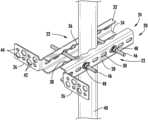
- FIG. 1a cable support bracket according to embodiments of the invention is illustrated in FIG. 1 and designated broadly at 20 .
- the bracket 20includes two mirror image L-shaped members 22 . Only one of the L-shaped members 22 will be described below, with the understanding that the description applies equally to the other of the L-shaped members 22 .
- Each of the L-shaped members 22has a clamp portion 24 and a flange 26 that extends substantially perpendicularly to the clamp portion 24 .
- the clamp portion 24has a main panel 28 with a plurality of mounting slots 30 .
- Upper and lower jaws 32 , 34extend perpendicularly from the upper and lower edges of the main panel 28 .
- the upper and lower jaws 32 , 34have scalloped edges 36 , 38 .
- Each flange 26includes a plurality (in this instance four) of mounting holes 42 .
- the mounting holes 42are typically nominally 3 ⁇ 4 inch in diameter.
- the mounting holes 42are arranged in staggered fashion in two rows.
- each flange 26also includes smaller holes 44 , also staggered in two rows, that are typically nominally 7/16 inch in diameter to receive 3 ⁇ 8 inch hangers/hardware.
- the bracket 20can be mounted to the mounting pole 40 via two threaded rods 46 , each of which is inserted into and through a respective slot 30 in the L-shaped members 22 , wherein one threaded rod 46 is located on each side of the pole 40 .
- the threaded rods 46are secured with nuts 48 .
- the scalloped edges 36 , 38have indentations that define mounting locations for the pole 40 .
- an antenna(not shown) is mounted on the pole 40 above the bracket 20 .
- the bracket 20can provide mounting locations for hangers that secure cables in place, and particularly cables routed from the underside of an antenna.
- Such cable hangersmay be polymeric cable hangers that are sized for mounting in the mounting holes 42 and, once mounted, capture cables.
- An exemplary cable hanger of this sortis shown in FIGS. 2 A and 2 B at 70 and is described in U.S. Patent Publication No. 2018/0045336 to Vaccaro, the disclosure of which is hereby incorporated herein.
- the use of polymeric hangerseliminates the generation of PIM from metal-to-metal contact that could result from the use of metal hangers.
- the bracket 20can provide certain performance advantages.
- the scalloped edges 36 , 38 of the upper and lower jaws 32 , 34can enable the bracket 20 to be mounted such that the distances of the flanges 26 from the pole 40 can be varied.
- the bracket 20can be mounted so that the flanges 26 and cable hangers mounted thereto are positioned conveniently relative to an antenna also mounted to the pole 40 .
- the bracket 20may be mounted so that the flanges 26 and cable hangers mounted therein are positioned generally directly below connectors located on the bottom portion of the antenna.
- the shape of the scalloped edges 36 , 38 and the positions and lengths of the slots 30can enable the jaws 32 , 34 to clamp on poles of different sizes.
- the bracket 20may be suitable for poles having diameters as small as 23 ⁇ 8 inches or smaller to as large as 31 ⁇ 2 inches or larger.
- bracket 20can be mounted to the pole 40 with only the threaded rods 46 and still provide mounting locations for cable hangers below an antenna.
- This simple arrangementcan maintain the number of points of metal-to-metal contact at a low number, and these points can be tightly secured. Both keeping the number of points of contact low and ensuring secure contact can reduce or minimize PIM that can be generated at loose metal-to-metal joints.
- the bracket 20may take other forms.
- the flanges 26may extend from the main panel 30 at an oblique angle, such as a 30 or 45 degree angle.
- the flange 26may include more or fewer mounting holes of either size, the mounting holes may be arranged in more or fewer rows, and/or the holes may not be staggered.
- the bracket 20is shown as being formed of a metallic material, such as steel, but may be formed of other materials, such as composites (e.g., reinforced polymers and/or ceramics).
- the bracket 20may be secured to the pole in other ways.
- a securing component other than a nutmay be employed on the rods (e.g., a cotter pin or spring nut).
- the rodsmay not be threaded as described above.
- scalloped edges 36 , 38 of the upper and lower jaws 32 , 34are shown as having gradually curved roots and crests, but as used herein the term “scalloped edges” is intended to include other edges that have roots and crests, including herringbone, sawtooth, wavy, sinuous and the like.
- the crestsare separated by about 1 ⁇ 2 and 1 inch, and the roots are between about 1 ⁇ 4 and 1 ⁇ 2 inch deeper than the crests.
- the L-shaped members 22may be oriented such that the flange 26 of one L-shaped member 22 is located on one side of the pole 40 (e.g., under the radio) and the flange of the other L-shaped member 22 is located on the opposite side of the pole 40 (e.g., under the antenna).
- one of the L-shaped brackets 22may be inverted from its orientation in FIG. 1 . This configuration can provide mounting locations under both the radio and the antenna.
- the bracket 20can be used in conjunction with an expansion bracket 50 to provide a larger number of mounting locations for cable hangers.
- the expansion bracket 50is generally C-shaped, with a main panel 52 , end panels 54 that extend perpendicularly from the ends of the main panel 52 , and attachment flanges 56 that extend perpendicularly to the end panels 54 .
- the main panel 52includes a plurality of staggered mounting holes 58 arranged in two rows, with smaller offset holes 60 .
- the mounting holes 58 , 60are typically nominally 3 ⁇ 4 inch and 7/16 inch in diameter.
- the attachment flanges 56include slots 62 .
- the expansion bracket 50can be mounted onto the bracket 20 with bolts 64 inserted through the slots 62 in the attachment flanges 56 and aligned holes 44 in the flanges 26 of the bracket 20 , where they are secured with nuts (not shown).
- the attachment flanges 56are vertically offset from each other; i.e., on one side the attachment flange 56 extends from the upper edge of the adjacent end panel 54 , and on the other side the attachment flange 56 extends from the lower edge of the adjacent end panel 54 .
- This offsetpositions each of the attachment flanges 56 in alignment with a respective hole 44 in the flange 26 to which the attachment flange 56 is mounted.
- This arrangementalso enables the expansion bracket 50 to be oriented for mounting irrespective of the “upside-down” or “right-side-up” orientation of the expansion bracket 50 .
- the expansion bracket 50 mounted to the bracket 20 in this mannersignificantly increases the number of mounting locations for cable hangers.
- the advantages discussed above for the bracket 20are equally applicable here.
- the expansion bracket 50can be secured to the bracket 20 with only two additional mounting points, both of which can be tightly secured, which can reduce or minimize the generation of PIM.
- the main panel 52can be mounted at a desired set-off distance from a mounting pole due to the presence of the scalloped edges 36 , 38 of the upper and lower jaws 32 , 34 , which, as discussed above, can enable cable hangers to be mounted near connectors of an antenna mounted on the mounting pole.
- the expansion bracket 50may be employed independently for wall or rooftop deployments.
- the expansion bracket 50could take other forms.
- the main panel 52may be longer or shorter, with more or fewer holes 58 , 60 .
- the end panels 54may be longer or shorter.
- the expansion bracket 50may comprise simply a main panel with mounting holes that is attached to one or both of the flanges 26 of the mounting bracket 20 .
- Other configurationsmay also be employed.
- each extender rail 200is generally C-shaped in profile, with a main panel 202 and lips 204 , although in some embodiments the extender rail may lack lips 204 (i.e., the extender rail may be flat and/or planar).
- each main panel 202includes a plurality of mounting slots 206 .
- each main panel 202includes a pattern of staggered mounting holes 208 arranged in two rows, with smaller offset holes 210 filling in the “gaps” between the mounting holes 208 in much the same manner as the holes 58 , 60 discussed above.
- each extender rail 200can be attached to the cable support bracket 20 by positioning the extender rail 200 to overlie a free end of the L-shaped member 22 , then inserting the threaded rod 46 through the mounting slot 206 at the same time the threaded rod 46 is inserted through the mounting slots 30 of the cable support bracket 20 .
- the nut 48can then secure both the cable support bracket 20 and the extender rail 200 to the pole 40 .
- the extender rails 200can be further secured to the cable support bracket 20 with additional bolts and nuts 212 , 214 inserted through the mounting slots 206 if desired.
- the extender rails 200may be mounted with both threaded rods 46 and no other bolts and nuts.
- the holes 208 , 210provide mounting locations for cable hangers such as those shown in FIGS. 2 A and 2 B , and can provide such locations with similar benefits as discussed above in connection with the expansion bracket 50 .
- the plurality of mounting slots 206provides the technician with multiple options for locating the extender rails 200 on the bracket 20 .
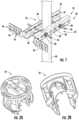
- the bracket 100comprises two identical clamps 102 .
- Each clamp 102includes a V-shaped clamping portion 104 , a securing panel 106 that extends from one end of the clamping portion 104 , and a generally C-shaped cable mounting portion 108 that is mounted to the opposite end of the clamping portion 104 .
- the cable mounting portion 108includes serially merging near, intermediate and end panels 110 , 112 , 114 that are disposed at right angles to each other.
- the near panel 110is substantially parallel with the securing panel 106 (and may in some embodiments be coplanar with the securing panel 106 ).
- the end panel 114is substantially parallel with the near panel 110 .
- Each of the near, intermediate and end panels 110 , 112 , 114includes a respective cable mounting hole 116 , 118 , 120 , which are typically nominally 3 ⁇ 4 inch in diameter.
- the securing panel 106includes a mounting hole 122 .
- the near panel 110includes a mounting hole 124 between the cable mounting hole 116 and the clamping portion 104 .
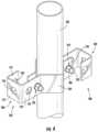
- the clamps 102can be secured to a mounting pole 130 by positioning the clamps 102 on opposite sides of the pole 130 , with the pole 130 captured within the clamping portion 104 of each clamp 102 and with the cable mounting portions 108 of the clamps 102 extending in opposite directions.
- This arrangementaligns the mounting holes 122 of each clamp 102 with the mounting holes 124 of the other clamp 102 .
- Bolts 132can then be inserted through the mounting holes 122 , 124 and secured with a nut 134 .
- the bracket 100can provide mounting locations for a cable hanger such as that shown in FIGS. 2 A and 2 B , and can do so with tightly secured mounting points to reduce PIM.
- bracket 20Any or all of the bracket 20 , expansion bracket 50 , extender rails 200 , and bracket 100 may be formed of a metallic material, such as steel or aluminum, or of a composite material.
Landscapes
- Support Of Aerials (AREA)
- Installation Of Indoor Wiring (AREA)
- Engineering & Computer Science (AREA)
- General Engineering & Computer Science (AREA)
- Mechanical Engineering (AREA)
- Architecture (AREA)
- Civil Engineering (AREA)
- Structural Engineering (AREA)
- Clamps And Clips (AREA)
Abstract
Description
Claims (19)
Priority Applications (2)
| Application Number | Priority Date | Filing Date | Title |
|---|---|---|---|
| US18/414,571US12283806B2 (en) | 2018-10-12 | 2024-01-17 | Brackets for mounting antenna cables |
| US19/086,343US20250219379A1 (en) | 2018-10-12 | 2025-03-21 | Brackets for mounting antenna cables |
Applications Claiming Priority (5)
| Application Number | Priority Date | Filing Date | Title |
|---|---|---|---|
| US201862744771P | 2018-10-12 | 2018-10-12 | |
| US16/375,544US11159006B2 (en) | 2018-10-12 | 2019-04-04 | Brackets for mounting antenna cables |
| US17/498,857US11621548B2 (en) | 2018-10-12 | 2021-10-12 | Brackets for mounting antenna cables |
| US18/191,349US11916366B2 (en) | 2018-10-12 | 2023-03-28 | Brackets for mounting antenna cables |
| US18/414,571US12283806B2 (en) | 2018-10-12 | 2024-01-17 | Brackets for mounting antenna cables |
Related Parent Applications (1)
| Application Number | Title | Priority Date | Filing Date |
|---|---|---|---|
| US18/191,349ContinuationUS11916366B2 (en) | 2018-10-12 | 2023-03-28 | Brackets for mounting antenna cables |
Related Child Applications (1)
| Application Number | Title | Priority Date | Filing Date |
|---|---|---|---|
| US19/086,343ContinuationUS20250219379A1 (en) | 2018-10-12 | 2025-03-21 | Brackets for mounting antenna cables |
Publications (2)
| Publication Number | Publication Date |
|---|---|
| US20240186783A1 US20240186783A1 (en) | 2024-06-06 |
| US12283806B2true US12283806B2 (en) | 2025-04-22 |
Family
ID=70160491
Family Applications (5)
| Application Number | Title | Priority Date | Filing Date |
|---|---|---|---|
| US16/375,544Active2040-05-11US11159006B2 (en) | 2018-10-12 | 2019-04-04 | Brackets for mounting antenna cables |
| US17/498,857Active2039-04-05US11621548B2 (en) | 2018-10-12 | 2021-10-12 | Brackets for mounting antenna cables |
| US18/191,349ActiveUS11916366B2 (en) | 2018-10-12 | 2023-03-28 | Brackets for mounting antenna cables |
| US18/414,571ActiveUS12283806B2 (en) | 2018-10-12 | 2024-01-17 | Brackets for mounting antenna cables |
| US19/086,343PendingUS20250219379A1 (en) | 2018-10-12 | 2025-03-21 | Brackets for mounting antenna cables |
Family Applications Before (3)
| Application Number | Title | Priority Date | Filing Date |
|---|---|---|---|
| US16/375,544Active2040-05-11US11159006B2 (en) | 2018-10-12 | 2019-04-04 | Brackets for mounting antenna cables |
| US17/498,857Active2039-04-05US11621548B2 (en) | 2018-10-12 | 2021-10-12 | Brackets for mounting antenna cables |
| US18/191,349ActiveUS11916366B2 (en) | 2018-10-12 | 2023-03-28 | Brackets for mounting antenna cables |
Family Applications After (1)
| Application Number | Title | Priority Date | Filing Date |
|---|---|---|---|
| US19/086,343PendingUS20250219379A1 (en) | 2018-10-12 | 2025-03-21 | Brackets for mounting antenna cables |
Country Status (4)
| Country | Link |
|---|---|
| US (5) | US11159006B2 (en) |
| CA (1) | CA3115918A1 (en) |
| MX (1) | MX2021004175A (en) |
| WO (1) | WO2020076572A1 (en) |
Families Citing this family (17)
| Publication number | Priority date | Publication date | Assignee | Title |
|---|---|---|---|---|
| WO2019118119A1 (en)* | 2017-12-12 | 2019-06-20 | Commscope Technologies Llc | Small cell antenna and cable mounting guides for same |
| EP3794697A4 (en)* | 2018-05-18 | 2022-03-02 | CommScope Technologies LLC | ADAPTER FOR MOUNTING CABLES AND CABLE HOLDERS AND FASTENING ELEMENTS FOR MOUNTING IT |
| US11159006B2 (en)* | 2018-10-12 | 2021-10-26 | Commscope Technologies Llc | Brackets for mounting antenna cables |
| USD969596S1 (en)* | 2019-01-23 | 2022-11-15 | Mafi Ab | Fastening device, without anvil |
| EP3904702B1 (en)* | 2020-04-29 | 2022-06-08 | Menz Industriedienstleistungs-GmbH | Clamping holder |
| CN213299554U (en)* | 2020-09-11 | 2021-05-28 | 维谛公司 | Installing support of compatible multiple mounting means |
| US11817615B2 (en)* | 2020-12-10 | 2023-11-14 | Commscope Technologies Llc | Universal remote radio unit mounting assemblies |
| US11592141B2 (en)* | 2021-04-02 | 2023-02-28 | Havis, Inc. | Mounting apparatus for an electronic device |
| US11996604B2 (en)* | 2021-05-10 | 2024-05-28 | Dish Wireless L.L.C. | Mounting brackets and systems |
| US20230231366A1 (en)* | 2022-01-14 | 2023-07-20 | Wanho Manufacturing, Llc. | Cable support system |
| US11877380B2 (en)* | 2022-01-14 | 2024-01-16 | Wanho Manufacturing, Llc. | Cable management system |
| CN116937125A (en)* | 2022-04-07 | 2023-10-24 | 康普技术有限责任公司 | Clamp assembly for base station antenna |
| EP4312307A1 (en)* | 2022-07-26 | 2024-01-31 | Nokia Shanghai Bell Co., Ltd. | Apparatus for attaching a gimbal to a structure and method of manufacturing such apparatus |
| WO2024026234A1 (en)* | 2022-07-27 | 2024-02-01 | Commscope Technologies Llc | Assemblies for mounting antenna cables |
| US20240266811A1 (en)* | 2023-02-08 | 2024-08-08 | LineVision, Inc. | Mounting system for power transmission line towers |
| USD1039949S1 (en)* | 2023-02-10 | 2024-08-27 | DBJ Innovations, LLC | Cable mounting bracket |
| WO2025174521A1 (en) | 2024-02-15 | 2025-08-21 | Outdoor Wireless Networks LLC | Assemblies for mounting antenna cables |
Citations (15)
| Publication number | Priority date | Publication date | Assignee | Title |
|---|---|---|---|---|
| US3652780A (en) | 1970-10-30 | 1972-03-28 | Dare Products Inc | Reversibly mountable insulator |
| US4025824A (en) | 1976-02-12 | 1977-05-24 | Cheatham Harry P | Transformer support rack |
| US4728749A (en) | 1984-09-03 | 1988-03-01 | R.F.D. Consultants Pty. Ltd. | Utility pole assembly |
| KR200177564Y1 (en) | 1999-06-24 | 2000-04-15 | 이영우 | H-beam clamp assembly |
| KR20060008585A (en) | 2004-07-21 | 2006-01-27 | 주식회사 케이티프리텔 | Rotatable device to fix Yagi antenna to the support |
| US7692100B2 (en) | 2008-07-21 | 2010-04-06 | Hendrix Wire & Cable | Spacers for cable conductors |
| US7772500B2 (en) | 2007-02-14 | 2010-08-10 | Marmon Utility Llc | Overhead and underground pole mount cable restraint insulator |
| JP2012105107A (en) | 2010-11-11 | 2012-05-31 | Nec Engineering Ltd | Antenna device and antenna bracket |
| KR20160119402A (en) | 2015-04-03 | 2016-10-13 | 삼성전자주식회사 | Apparatus and method for assembling communications equipment |
| CN206487932U (en) | 2016-12-26 | 2017-09-12 | 中车广东轨道交通车辆有限公司 | A kind of new EMUs pipeline deck |
| US9812762B2 (en) | 2015-04-28 | 2017-11-07 | Commscope Technologies Llc | Antenna mount |
| US9837185B2 (en) | 2013-07-03 | 2017-12-05 | Commscope Technologies Llc | Mounting systems for power, communication and fiber optic cables |
| US20180045336A1 (en) | 2016-08-15 | 2018-02-15 | Commscope Technologies Llc | Hanger for mounting cables |
| US10873180B2 (en) | 2017-04-18 | 2020-12-22 | Burndy, LLC | Fastener assembly |
| US11159006B2 (en) | 2018-10-12 | 2021-10-26 | Commscope Technologies Llc | Brackets for mounting antenna cables |
- 2019
- 2019-04-04USUS16/375,544patent/US11159006B2/enactiveActive
- 2019-10-02WOPCT/US2019/054208patent/WO2020076572A1/ennot_activeCeased
- 2019-10-02MXMX2021004175Apatent/MX2021004175A/enunknown
- 2019-10-02CACA3115918Apatent/CA3115918A1/enactivePending
- 2021
- 2021-10-12USUS17/498,857patent/US11621548B2/enactiveActive
- 2023
- 2023-03-28USUS18/191,349patent/US11916366B2/enactiveActive
- 2024
- 2024-01-17USUS18/414,571patent/US12283806B2/enactiveActive
- 2025
- 2025-03-21USUS19/086,343patent/US20250219379A1/enactivePending
Patent Citations (18)
| Publication number | Priority date | Publication date | Assignee | Title |
|---|---|---|---|---|
| US3652780A (en) | 1970-10-30 | 1972-03-28 | Dare Products Inc | Reversibly mountable insulator |
| US4025824A (en) | 1976-02-12 | 1977-05-24 | Cheatham Harry P | Transformer support rack |
| US4728749A (en) | 1984-09-03 | 1988-03-01 | R.F.D. Consultants Pty. Ltd. | Utility pole assembly |
| KR200177564Y1 (en) | 1999-06-24 | 2000-04-15 | 이영우 | H-beam clamp assembly |
| KR20060008585A (en) | 2004-07-21 | 2006-01-27 | 주식회사 케이티프리텔 | Rotatable device to fix Yagi antenna to the support |
| US7772500B2 (en) | 2007-02-14 | 2010-08-10 | Marmon Utility Llc | Overhead and underground pole mount cable restraint insulator |
| US7692100B2 (en) | 2008-07-21 | 2010-04-06 | Hendrix Wire & Cable | Spacers for cable conductors |
| JP2012105107A (en) | 2010-11-11 | 2012-05-31 | Nec Engineering Ltd | Antenna device and antenna bracket |
| US9837185B2 (en) | 2013-07-03 | 2017-12-05 | Commscope Technologies Llc | Mounting systems for power, communication and fiber optic cables |
| KR20160119402A (en) | 2015-04-03 | 2016-10-13 | 삼성전자주식회사 | Apparatus and method for assembling communications equipment |
| US9812762B2 (en) | 2015-04-28 | 2017-11-07 | Commscope Technologies Llc | Antenna mount |
| US20180045336A1 (en) | 2016-08-15 | 2018-02-15 | Commscope Technologies Llc | Hanger for mounting cables |
| US10253906B2 (en) | 2016-08-15 | 2019-04-09 | Commscope Technologies Llc | Hanger for mounting cables |
| CN206487932U (en) | 2016-12-26 | 2017-09-12 | 中车广东轨道交通车辆有限公司 | A kind of new EMUs pipeline deck |
| US10873180B2 (en) | 2017-04-18 | 2020-12-22 | Burndy, LLC | Fastener assembly |
| US11159006B2 (en) | 2018-10-12 | 2021-10-26 | Commscope Technologies Llc | Brackets for mounting antenna cables |
| US11621548B2 (en) | 2018-10-12 | 2023-04-04 | Commscope Technologies Llc | Brackets for mounting antenna cables |
| US11916366B2 (en)* | 2018-10-12 | 2024-02-27 | Commscope Technologies Llc | Brackets for mounting antenna cables |
Non-Patent Citations (2)
| Title |
|---|
| International Preliminary Report on Patentability corresponding to PCT/US2019/054208; mailed Apr. 22, 2021. |
| International Search Report and Written Opinion corresponding to PCT/US2019/054208; mailed Jan. 17, 2020. |
Also Published As
| Publication number | Publication date |
|---|---|
| US20250219379A1 (en) | 2025-07-03 |
| WO2020076572A1 (en) | 2020-04-16 |
| US20200119537A1 (en) | 2020-04-16 |
| MX2021004175A (en) | 2021-06-08 |
| US11916366B2 (en) | 2024-02-27 |
| US11621548B2 (en) | 2023-04-04 |
| US20220029402A1 (en) | 2022-01-27 |
| US20240186783A1 (en) | 2024-06-06 |
| US20230238790A1 (en) | 2023-07-27 |
| CA3115918A1 (en) | 2020-04-16 |
| US11159006B2 (en) | 2021-10-26 |
Similar Documents
| Publication | Publication Date | Title |
|---|---|---|
| US12283806B2 (en) | Brackets for mounting antenna cables | |
| US12347923B2 (en) | Universal RRU mounting assembly | |
| US11979107B2 (en) | Solar module mounting system | |
| US10724655B2 (en) | Low-PIM cable support brackets | |
| US6768474B2 (en) | Antenna mounting assembly and method | |
| US10851916B2 (en) | Adapter for mounting cable hangers | |
| US11493150B2 (en) | Isolator for mounting cable hangers | |
| US11815207B2 (en) | Adapter for mounting cables and cable hangers and clamp members for mounting same | |
| US11817615B2 (en) | Universal remote radio unit mounting assemblies | |
| US20140250820A1 (en) | Truss system with integral channels | |
| US12107317B2 (en) | Universal small cell antenna mounts and antenna mount assemblies | |
| US9742350B2 (en) | Solar panel grounding lug assemblies and systems | |
| US11152682B2 (en) | Low-PIM universal antenna equipment mount | |
| WO2021050316A1 (en) | Isolator for mounting cable hangers | |
| US20240039264A1 (en) | Assemblies for mounting antenna cables | |
| US20250267810A1 (en) | Assemblies for mounting antenna cables | |
| US20170133976A1 (en) | System for Mounting Solar Panels |
Legal Events
| Date | Code | Title | Description |
|---|---|---|---|
| FEPP | Fee payment procedure | Free format text:ENTITY STATUS SET TO UNDISCOUNTED (ORIGINAL EVENT CODE: BIG.); ENTITY STATUS OF PATENT OWNER: LARGE ENTITY | |
| STPP | Information on status: patent application and granting procedure in general | Free format text:DOCKETED NEW CASE - READY FOR EXAMINATION | |
| AS | Assignment | Owner name:OUTDOOR WIRELESS NETWORKS LLC, NORTH CAROLINA Free format text:ASSIGNMENT OF ASSIGNORS INTEREST;ASSIGNOR:COMMSCOPE TECHNOLOGIES LLC;REEL/FRAME:068107/0089 Effective date:20240701 | |
| STPP | Information on status: patent application and granting procedure in general | Free format text:NON FINAL ACTION MAILED | |
| AS | Assignment | Owner name:JPMORGAN CHASE BANK, N.A., AS COLLATERAL AGENT, NEW YORK Free format text:PATENT SECURITY AGREEMENT (TERM);ASSIGNOR:OUTDOOR WIRELESS NETWORKS LLC;REEL/FRAME:068770/0632 Effective date:20240813 Owner name:JPMORGAN CHASE BANK, N.A., AS COLLATERAL AGENT, NEW YORK Free format text:PATENT SECURITY AGREEMENT (ABL);ASSIGNOR:OUTDOOR WIRELESS NETWORKS LLC;REEL/FRAME:068770/0460 Effective date:20240813 | |
| STPP | Information on status: patent application and granting procedure in general | Free format text:RESPONSE TO NON-FINAL OFFICE ACTION ENTERED AND FORWARDED TO EXAMINER | |
| AS | Assignment | Owner name:APOLLO ADMINISTRATIVE AGENCY LLC, NEW YORK Free format text:SECURITY INTEREST;ASSIGNORS:ARRIS ENTERPRISES LLC;COMMSCOPE TECHNOLOGIES LLC;COMMSCOPE INC., OF NORTH CAROLINA;AND OTHERS;REEL/FRAME:069889/0114 Effective date:20241217 | |
| AS | Assignment | Owner name:OUTDOOR WIRELESS NETWORKS LLC, NORTH CAROLINA Free format text:RELEASE OF SECURITY INTEREST AT REEL/FRAME 068770/0632;ASSIGNOR:JPMORGAN CHASE BANK, N.A., AS COLLATERAL AGENT;REEL/FRAME:069743/0264 Effective date:20241217 | |
| AS | Assignment | Owner name:OUTDOOR WIRELESS NETWORKS LLC, NORTH CAROLINA Free format text:RELEASE (REEL 068770 / FRAME 0460);ASSIGNOR:JPMORGAN CHASE BANK, N.A.;REEL/FRAME:070149/0432 Effective date:20250131 | |
| STPP | Information on status: patent application and granting procedure in general | Free format text:NOTICE OF ALLOWANCE MAILED -- APPLICATION RECEIVED IN OFFICE OF PUBLICATIONS | |
| STCF | Information on status: patent grant | Free format text:PATENTED CASE |