US12281762B2 - Work light - Google Patents
Work lightDownload PDFInfo
- Publication number
- US12281762B2 US12281762B2US18/504,251US202318504251AUS12281762B2US 12281762 B2US12281762 B2US 12281762B2US 202318504251 AUS202318504251 AUS 202318504251AUS 12281762 B2US12281762 B2US 12281762B2
- Authority
- US
- United States
- Prior art keywords
- light
- battery
- work
- work light
- light source
- Prior art date
- Legal status (The legal status is an assumption and is not a legal conclusion. Google has not performed a legal analysis and makes no representation as to the accuracy of the status listed.)
- Active
Links
Images


Classifications
- F—MECHANICAL ENGINEERING; LIGHTING; HEATING; WEAPONS; BLASTING
- F21—LIGHTING
- F21L—LIGHTING DEVICES OR SYSTEMS THEREOF, BEING PORTABLE OR SPECIALLY ADAPTED FOR TRANSPORTATION
- F21L4/00—Electric lighting devices with self-contained electric batteries or cells
- F21L4/02—Electric lighting devices with self-contained electric batteries or cells characterised by the provision of two or more light sources
- F21L4/022—Pocket lamps
- F21L4/027—Pocket lamps the light sources being a LED
- F—MECHANICAL ENGINEERING; LIGHTING; HEATING; WEAPONS; BLASTING
- F21—LIGHTING
- F21L—LIGHTING DEVICES OR SYSTEMS THEREOF, BEING PORTABLE OR SPECIALLY ADAPTED FOR TRANSPORTATION
- F21L4/00—Electric lighting devices with self-contained electric batteries or cells
- F21L4/04—Electric lighting devices with self-contained electric batteries or cells characterised by the provision of a light source housing portion adjustably fixed to the remainder of the device
- F—MECHANICAL ENGINEERING; LIGHTING; HEATING; WEAPONS; BLASTING
- F21—LIGHTING
- F21L—LIGHTING DEVICES OR SYSTEMS THEREOF, BEING PORTABLE OR SPECIALLY ADAPTED FOR TRANSPORTATION
- F21L4/00—Electric lighting devices with self-contained electric batteries or cells
- F21L4/08—Electric lighting devices with self-contained electric batteries or cells characterised by means for in situ recharging of the batteries or cells
- F—MECHANICAL ENGINEERING; LIGHTING; HEATING; WEAPONS; BLASTING
- F21—LIGHTING
- F21V—FUNCTIONAL FEATURES OR DETAILS OF LIGHTING DEVICES OR SYSTEMS THEREOF; STRUCTURAL COMBINATIONS OF LIGHTING DEVICES WITH OTHER ARTICLES, NOT OTHERWISE PROVIDED FOR
- F21V21/00—Supporting, suspending, or attaching arrangements for lighting devices; Hand grips
- F21V21/08—Devices for easy attachment to any desired place, e.g. clip, clamp, magnet
- F21V21/096—Magnetic devices
- F21V21/0965—Magnetic devices for portable lighting devices
- F—MECHANICAL ENGINEERING; LIGHTING; HEATING; WEAPONS; BLASTING
- F21—LIGHTING
- F21V—FUNCTIONAL FEATURES OR DETAILS OF LIGHTING DEVICES OR SYSTEMS THEREOF; STRUCTURAL COMBINATIONS OF LIGHTING DEVICES WITH OTHER ARTICLES, NOT OTHERWISE PROVIDED FOR
- F21V21/00—Supporting, suspending, or attaching arrangements for lighting devices; Hand grips
- F21V21/14—Adjustable mountings
- F21V21/30—Pivoted housings or frames
- F—MECHANICAL ENGINEERING; LIGHTING; HEATING; WEAPONS; BLASTING
- F21—LIGHTING
- F21V—FUNCTIONAL FEATURES OR DETAILS OF LIGHTING DEVICES OR SYSTEMS THEREOF; STRUCTURAL COMBINATIONS OF LIGHTING DEVICES WITH OTHER ARTICLES, NOT OTHERWISE PROVIDED FOR
- F21V21/00—Supporting, suspending, or attaching arrangements for lighting devices; Hand grips
- F21V21/40—Hand grips
- F21V21/406—Hand grips for portable lighting devices
- F—MECHANICAL ENGINEERING; LIGHTING; HEATING; WEAPONS; BLASTING
- F21—LIGHTING
- F21V—FUNCTIONAL FEATURES OR DETAILS OF LIGHTING DEVICES OR SYSTEMS THEREOF; STRUCTURAL COMBINATIONS OF LIGHTING DEVICES WITH OTHER ARTICLES, NOT OTHERWISE PROVIDED FOR
- F21V23/00—Arrangement of electric circuit elements in or on lighting devices
- F21V23/003—Arrangement of electric circuit elements in or on lighting devices the elements being electronics drivers or controllers for operating the light source, e.g. for a LED array
- F—MECHANICAL ENGINEERING; LIGHTING; HEATING; WEAPONS; BLASTING
- F21—LIGHTING
- F21Y—INDEXING SCHEME ASSOCIATED WITH SUBCLASSES F21K, F21L, F21S and F21V, RELATING TO THE FORM OR THE KIND OF THE LIGHT SOURCES OR OF THE COLOUR OF THE LIGHT EMITTED
- F21Y2115/00—Light-generating elements of semiconductor light sources
- F21Y2115/10—Light-emitting diodes [LED]
Definitions
- Work lightscan be used to illuminate work areas that are otherwise difficult to light. Examples of these areas include work sites, ceiling spaces, basement areas, and the like.
- a work lightincluding a body defining a first end, a second end opposite the first end, a length extending between the first end and the second end, and a pivot axis extending parallel to the length.
- the first endincludes a power button.
- the work lightfurther includes a light source head pivotally coupled to the body to pivot about the pivot axis and configured to be operated by the power button.
- the light source headincludes a planar light panel having a plurality of light emitting diodes aligned in a direction parallel to the pivot axis.
- the work lightfurther includes a battery receptacle disposed on the body and configured to receive at least a portion of a battery. The battery couples to the battery receptacle by sliding into the battery receptacle along the direction parallel to the pivot axis.
- FIG. 1is a front perspective view of a work light according to an embodiment of the disclosure.
- FIG. 2is a rear perspective view of the work light of FIG. 1 .
- FIG. 3is a side elevation view of the work light of FIG. 1 .
- FIG. 4is a top plan view of the work light of FIG. 1 .
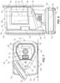
- FIG. 5is a cross-sectional side elevation view of the work light of FIG. 1 coupled to a structure.
- FIG. 6is an exploded view of the work light of FIG. 1 .
- FIG. 7is a top elevation view of the work light of FIG. 1 laid on its side.
- FIG. 8is a side elevation view of the work light of FIG. 1 coupled to a structure.
- FIG. 9is a circuit diagram of the work light of FIG. 1 .
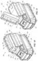
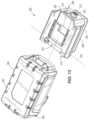
- FIG. 10is a top perspective view of a work light according to an embodiment of the disclosure.
- FIG. 11is a top perspective view of the work light of FIG. 10 with a light source head pivoted away from the body.
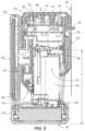
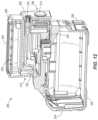
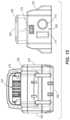
- FIG. 12is a perspective cross-sectional view of the work light of FIG. 10 .
- FIG. 13is a bottom perspective view of the work light of FIG. 10 with the battery removed from the body.
- FIG. 14is a top plan view of the work light of FIG. 10 with the battery removed from the body.
- FIG. 15is a rear elevation view of the work light of FIG. 10 with the battery removed from the body.
- FIG. 16is a side elevation view of the work light of FIG. 10 .
- FIG. 1illustrates a work light 100 according to an embodiment of the present disclosure.
- the illustrated work light 100is battery-powered.
- the work light 100is sized and shaped for one-handed operation and transport.
- the work light 100includes a body 102 and a light source head 104 coupled to the body 102 .
- a battery 106is also removably coupled to the body 102 .
- the body 102includes a first end 108 and a second end 110 opposite the first end 108 .
- the first end 108includes one or more controls, such as a power button 112 and a wake button 114 , disposed thereon.
- the illustrated embodimentfurther includes one or more indicators, such as one or more battery power gauge lights 116 , disposed on the first end 108 of the body 102 .
- the body 102further includes a charging port 118 disposed on the first end 108 of the body 102 .
- the charging port 118is a USB port.
- the charging port 118is selectively covered with a charging port cover 120 pivotably connected to the body 102 .
- the charging port cover 120pivots and raises relative to the first end 108 of the body 102 , while remaining connected to the body 102 , to selectively uncover the charging port 118 .
- other suitable coversmay be used.
- the charging portmay 118 may be utilized to charge a device, such as a user's cell phone.
- the charging port 118may be used as a power input port to charge the battery 106 without the need for removing the battery 106 . Additionally or alternatively, the charging port 118 may be used as a power input port to bypass the battery 106 and power the work light 100 with an outside power source, such as mains power.
- the wake button 114 discussed abovemay be engaged by a user in order to activate the charging port 118 for energy output to charge and/or power an external device.
- controls, indicators, and the charging port 118may instead be disposed on other portions of the work light 100 or may be omitted entirely.
- the body 102 of the work light 100further includes a battery receptacle 122 defined in the second end 110 .
- the battery receptacle 122receives at least a portion of the battery 106 to power the work light 100 (discussed in more detail below).
- the body 102 of the work light 100also includes two opposing sides 124 , 126 extending between the first end 108 and the second end 110 of the body 102 .
- Each side 124 , 126includes a grip section 128 , 130 disposed thereon.
- each of the first grip section 128 and the second grip section 130includes at least part of an indentation defined in the body 102 .
- a continuous indentation 132is defined in the body 102 such that the indentation 132 extends about a majority of a perimeter of the body 102 .
- the perimeteris defined by the outer surfaces of the body 102 located between the first end 108 and the second end 110 .
- each of the first grip section 128 and the second grip section 130is disposed in the indentation 132 .
- the first and second grip sections 128 , 130may be only the respective portions of the indentation 132 itself, or the grip sections 128 , 130 may further include a textured surface or additional material disposed in the indentation 132 to further facilitate a secure grip of the work light 100 .
- the body 102further includes a mount surface 134 .
- the mount surface 134is disposed between the two opposing sides 124 , 126 , opposite from the light source head 104 .
- the mount surface 134allows a user to mount the work light 100 to one or more structures.
- the body 102includes a pair of ferromagnetic members 136 coupled thereto and disposed adjacent the mount surface 134 . In some embodiments, such as the illustrated embodiment, at least a portion of each of the pair of ferromagnetic members 136 is exposed on the mount surface 134 . In other embodiments, however, the ferromagnetic members 136 may be completely disposed within and concealed by the body 102 .
- each of the ferromagnetic members 136includes a length that extends in a direction that is parallel with the length L1 of the body 102 (shown in FIG. 3 ). Also in the illustrated embodiment, both of the ferromagnetic members 136 are disposed in the continuous indentation 132 . In this embodiment, the ferromagnetic members 136 extend outward beyond the surface of the indentation 132 so as to directly engage a surface of a structure. Of course, other embodiments may include ferromagnetic member 136 that may not directly engage a surface of a structure so as to avoid scratching the surface. Such embodiments may include the ferromagnetic members 136 being flush with the surface of the indentation 132 or recessed relative to the surface of the indentation 132 .
- a recess 140is defined in the mount surface 134 .
- the recess 140is located between the ferromagnetic members 136 . Stated another way, the recess 140 is located in the space 138 . In the illustrated embodiment, the recess 140 is also located in the continuous indentation 132 .
- the recess 140may be any appropriate shape and size, but is illustrated as a keyhole slot.
- the light source head 104is pivotably connected to the body 102 .
- the light source head 104is coupled to the body 102 opposite the mount surface 134 of the body 102 .
- the light source head 104is coupled to the body 102 by a hinge 142 .
- the light source head 104is coupled to the body 102 by a single hinge 142 located between the first end 108 and the second end 110 of the body 102 , although other embodiments may include different or additional pivotable connections between the light source head 104 and the body 102 .
- the light source head 104is pivotable relative to the body 102 about a pivot axis 144 .
- the pivot axis 144extends in a direction that is parallel to the length L1 of the body 102 .
- the light source head 104includes a planar light panel 146 ( FIG. 1 ) surrounded by a head frame 148 to mitigate damage to the light panel 146 from dropping the work light 100 .
- the illustrated embodimentincludes the planar light panel 146 recessed relative to the head frame 148 .
- the light panel 146 , and the light source head 104 itself,may be any size, but the illustrated embodiment includes a light panel 146 that extends along a majority of the length L1 of the body 102 of the work light 100 .
- the light panel 146includes a plurality of light-emitting diodes (LEDs) 149 , but other embodiments may include additional or alternative light sources. As shown in FIG. 6 , the LEDs 149 are arranged in two parallel columns. In other embodiments, the LEDs 149 may be arranged in other configurations.
- LEDslight-emitting diodes
- the light panel 146may be operable in different modes, such as a HIGH mode and a LOW mode. In some embodiments, the light panel 146 may produce light having a brightness of 700 Lumens or more in the HIGH mode and a brightness of 300 Lumens or less on in the LOW mode.
- the work light 100is operable to switch modes by actuating the power button 112 . More specifically, the light panel 146 may produce light having a brightness of 750 lumens while in the HIGH mode and a brightness of 250 Lumens while in the LOW mode. In other embodiments, the light panel 146 may be operable in different modes and/or may be switchable between the modes by a dedicated actuator.
- the light panel 146is selectively powered by the battery 106 .
- the illustrated battery 106is a power tool battery having a voltage of, for example, 12 volts.
- the battery 106also has a Li-ion chemistry. In other embodiments, the battery 106 may have other voltages and chemistries.
- the illustrated battery 106also has a capacity of 4.0 Amp-hours (Ah). With such a battery, the light panel 146 may be powered for at least five hours while in HIGH mode and for at least ten hours while in LOW mode. In some embodiments, the light panel 146 may be powered for five to eight hours while in HIGH mode and may be powered for ten to sixteen hours while in LOW mode. In further embodiments, the light panel 146 may be powered for longer in either mode, depending on the capacity of the battery 106 .
- the light source head 104may pivot relative to the body 102 along an angle of rotation 150 .
- the angle of rotation 150is up to and including 120 degrees. In other embodiments, the angle of rotation 150 is up to and including 180 degrees. In the illustrated embodiment, these angles of rotation 150 are possible due to the shape of the body 102 .
- the body 102 of the illustrated embodimentis narrower adjacent the light source head 104 than it is adjacent the mount surface 134 . This configuration of the body 102 allows for a sufficiently wide mount surface 134 while providing clearance for the rotation of the light source head 104 .
- the illustrated embodimentincludes a body 102 having horizontal cross-sectional shape that is generally an isosceles triangle with rounded corners. This shape can be seen in FIG. 4 .
- the battery 106includes a connection portion 152 that is removably received within the battery receptacle 122 of the body 102 .
- the battery 106further includes an external portion 154 that is disposed outside of the body 102 even when the battery 106 is properly coupled to the body 102 .
- the connection portion 152 of the battery 106is slidably received in the battery receptacle 122 of the body 102 in a direction parallel to the length L1 of the body 102 in the illustrated embodiment.
- the length direction of the battery receptacle 122is parallel with the length L1 of the body 102 and parallel with the pivot axis 144 ( FIG. 3 ) of the light source head 104 .
- the length of the battery receptacle 122 and the corresponding length of the connection portion 152 of the battery 106are each longer than one third of the length L1 of the body 102 . In some embodiments, the length of the battery receptacle 122 and the corresponding length of the connection portion 152 of the battery 106 are each longer than one half of the length L1 of the body 102 .
- the battery 106further includes at least one support surface, such as a first support surface 156 .
- This first support surface 156allows the work light 100 to be oriented and maintained in a vertical standing position on a work surface, such as a horizontal work surface 158 (e.g., a table, a workbench, the ground, etc.).
- the first support surface 156is disposed on the external portion 154 of the battery 106 and is perpendicular to the mount surface 134 of the body 102 . While the work light 100 is in the vertical standing position, a user may adjust the light source head 104 relative to the body 102 to alter the direction of the light emitted from the light source head 104 to the left or right relative to the horizontal work surface 158 .
- the first support surface 156 of the battery 106is perpendicular to the pivot axis 144 of the light source head 104 . In some embodiments, the first support surface 156 of the battery 106 is perpendicular to the planar light panel 146 .
- the battery 106may also include at least one additional support surface, such as a second support surface 160 .
- the second support surface 160is illustrated as being perpendicular to the first support surface 156 .
- This second support surface 160allows the work light 100 to be oriented and maintained in a horizontal laying position on a work surface, such as the horizontal work surface 158 . While the work light 100 is in the horizontal laying position, a user may adjust the light source head 104 relative to the body 102 to alter the direction of the light emitted from the light source head 104 up or down relative to the horizontal work surface 158 .
- the second support surface 160 of the battery 106is parallel to the pivot axis 144 of the light source head 104 .
- the second support surface 160is perpendicular to the planar light panel 146 .
- the work light 100is shown mounted to a work surface, such as a vertical work surface 162 (e.g., a wall, strut, cabinet, etc.).
- a vertical work surface 162e.g., a wall, strut, cabinet, etc.
- the ferromagnetic members 136may not work at all or may be insufficient to mount the work light 100 to the vertical work surface 162 .
- a usermay instead hang the work light 100 by a projection disposed on the vertical work surface 162 , such as the nail 164 shown in FIG. 5 .
- the head of the nail 164is removably received in the recess 140 defined in the mount surface 134 of the body 102 .
- the recess 140slidably traps the head of the nail 164 such that a user must raise the work light 100 relative to the nail 164 in a direction along the vertical work surface 162 in order to remove the work light 100 from the nail 164 .
- the illustrated embodiment of the work light 100further includes at least one permanent magnet 166 .
- the permanent magnet 166is illustrated as being housed within the body 102 of the work light 100 and as being in contact with both of the ferromagnetic members 136 .
- each of the ferromagnetic members 136is magnetized by the permanent magnet 166 .
- the ferromagnetic member 136may be made of steel, iron, or the like. In other embodiments, however, each of the ferromagnetic members 136 may itself be a permanent magnet. In such embodiments, the additional permanent magnet 166 shown in FIG. 6 may be omitted.
- one or more electromagnetsmay be included instead of or in addition to one or more permanent magnets.
- the work light 100may also be mounted to a vertical work surface 162 without the need for a nail 164 or other projection when the vertical work surface 162 is sufficiently magnetic (such as a structure made at least in part of steel, iron, or the like).
- a usermay elect to affix a magnet to a non-magnetic vertical work surface 162 with, for instance, adhesive.
- the ferromagnetic members 136may magnetically engage the magnet that has been affixed to the vertical work surface 162 to support the work light 100 from the vertical work surface 162 even if the vertical work surface 162 is itself not sufficiently magnetic (such as a vertical work surface 162 made of wood).
- the illustrated embodiment of the work light 100may be sized and shaped for single-handed operation and transport. Further, the work light 100 may be sized and shaped to fit in, for instance, a user's pocket.
- some embodiments of the work light 100include the body 102 having a width W1 of less than ten centimeters. The width dimension of the body 102 of the work light 100 is perpendicular to the pivot axis 144 of the light source head 104 in the illustrated embodiment. In some embodiments, the width W1 of the body 102 is less than seven centimeters.
- the length L1 of the body 102(measured in a direction that is parallel with the pivot axis 144 of the light source head 104 in the illustrated embodiment) is less than fifteen centimeters. In some embodiments, the length L1 of the body 102 is less than ten centimeters. In some embodiments, the distance D between the mount surface 134 of the body and the illuminating face of the planar light panel 146 is less than twelve centimeters. In some embodiments, the distance D between the mount surface 134 and the illuminating face of the planar light panel 146 is less than ten centimeters.
- some embodimentsinclude the light source head 104 having a width W2 that is slightly less than the width W1 of the body 102 . Some embodiments also include the battery 106 having a width W3 that is slightly greater than the width W1 of the body 102 . In some embodiments, the width W3 of the battery 106 is between about 1.5 inches and about 3.5 inches (between about 3.8 centimeters and about 8.9 centimeters). In other embodiments, the width W3 of the battery 106 is between about 2.0 inches and about 3.0 inches (between about 5.1 centimeters and about 7.6 centimeters). In some embodiments, the width W2 of the light source head 104 is at least 50% of the width W3 of the battery 106 . In other embodiments, the width W2 of the light source head 104 is between about 70% and about 90% of the width W3 of the battery 106 .
- the body 102has a length L1
- the light source head 104has a length L2 that is longer than the length L1 of the body 102 .
- the length L2 of the light source head 104is between about 1.1 times and about 2 times the length L3 of the battery 106 .
- the length L2 of the light source head 104is between about 1.1 times and about 1.5 times the length L3 of the battery 106 .
- the length L1 of the body 102is between about 1.05 times and about 1.5 times the length L3 of the battery 106 .
- the length L3 of the battery 106may be between about 3 inches and about 6 inches (between about 7.6 centimeters and about 15.2 centimeters). In some embodiments, the length L3 of the battery 106 may be about 4.5 inches (about 11.4 centimeters).
- the work light 100has a total length L4.
- the length L2 of the light source head 104is between about 50% and about 90% of the total length L4 of the work light 100 . In other embodiments, the length L2 of the light source head 104 is between about 75% and about 85% of the total length L4 of the work light 100 .
- the battery 106is a typical power tool battery that may also be used with, for instance, an electric drill. Of course, other batteries not suitable for power tools may also be used in other embodiments.
- the total length L4 of the work light 100including the battery 106 , may be less than fifteen centimeters.
- the work light 100may also be relatively light and easy to carry by hand. In some embodiments, the work light 100 (including the battery 106 ) may have a mass that is less than 500 grams. In some embodiments, the work light 100 (including the battery 106 ) may have a mass that is less than 400 grams. In some embodiments, the work light 100 (including the battery 106 ) may have a mass that is less than 350 grams.
- some embodimentsmay include a hook or other hanging structure such that the work light 100 may be hung over the top of a structure, such as a horizontally oriented frame member or the like.
- FIG. 9illustrates an exemplary circuit diagram 168 for use with the work light 100 .
- the circuit diagram 168illustrates the layout of various electrical components of the work light 100 , including the battery 106 , a power switch 170 associated with the power button 112 , a wake switch 172 associated with the wake button 114 , lights 174 associated with the remaining battery power gauge light 116 , a port power output (and/or input) 176 associated with the charging port 118 , the LEDs 149 , and the like.
- the illustrated circuit diagram 168is only one example of the configuration of the electrical components of the work light 100 , and other configurations are also contemplated herein.
- FIG. 10illustrates an alternative embodiment of a work light 200 .
- Some components of the work light 200 of FIG. 10are similar to components of the work light 100 of FIG. 1 . As such, many of the similar components will be the same number, but increased by a value of one hundred. Some of the similar components may not be discussed further below for the sake of brevity.
- the work light 200 of FIG. 10includes a body 202 , a light source head 204 , and a removable battery 206 .
- the body 202includes a first end 208 and a second end 220 opposite the first end 208 .
- the first end 208includes one or more controls, such as a power button 212 and a wake button 214 disposed thereon.
- at least one of the body 202 and the battery 206includes one or more indicators, such as one or more battery power gauge lights 216 .
- the body 202further includes a charging port 218 disposed on the first end 208 of the body 202 .
- the body 202 of the work light 200further includes a battery receptacle 222 defined therein.
- the battery receptacle 222is disposed on a side of the body 202 that is opposite the light source head 204 .
- the battery 206couples to the body 202 on a side of the body 202 that is opposite the light source head 204 .
- the battery receptacle 222receives at least a portion of the battery 206 to power the work light 200 .
- the battery receptacle 222is open on two sides of the body 202 such that the battery 206 is slidably received in the battery receptacle 222 .
- the battery receptacle 222is oriented such that the battery 206 is slidably received in the battery receptacle 222 in a direction that is parallel with the length L5 of the body 202 (shown in FIG. 14 ).
- at least one of the battery 206 and the body 202includes one or more movable latching elements configured to secure the battery 206 to the body 202 when the battery 206 is fully inserted in the battery receptacle 222 .
- the light source head 204is pivotably connected to the body 202 .
- the light source head 204is coupled to the body 202 by a single hinge 242 .
- the hinge 242is disposed adjacent the second end 210 of the body 202 .
- the light source head 204is pivotable relative to the body 202 about a pivot axis 244 .
- the pivot axis 244extends in a direction that is perpendicular to the length L5 of the body 202 .
- the light source head 204includes a planar light panel 246 surrounded by a head frame 248 .
- the light panel 246includes a plurality of LEDs 249 .
- the light panel 246is selectively powered by the battery 206 .
- the illustrated battery 206is a power tool battery having a voltage of, for example, 18 volts.
- the battery 206includes a connection portion 252 that is removably received within the battery receptacle 222 of the body 202 .
- the battery 206further includes an external portion 254 that is disposed outside of the body 202 even when the battery 206 is properly coupled to the body 202 .
- the battery 206further includes at least one support surface, such as a first support surface 256 .
- the first support surface 256is disposed on the external portion 254 of the battery 206 .
- a usermay adjust the light source head 204 relative to the body 202 to alter the direction of the light emitted from the light source head 204 at an angle relative to the first support surface 256 (angled relative to the floor and movable up and down relative to the floor, for instance).
- the battery 206may also include at least one additional support surface, such as a second support surface 260 .
- the second support surface 260is illustrated as being perpendicular to the first support surface 256 .
- This second support surface 260allows the work light 200 to be oriented and maintained in a horizontal laying position on a work surface, such as the floor. While the work light 200 is in the horizontal laying position, a user may adjust the light source head 204 relative to the body 202 to alter the direction of the light emitted from the light source head 204 left or right relative to the work surface.
- the body 202includes a recess 278 defined therein.
- the recess 278is defined in the body 202 on a side of the body 202 that is opposite the battery receptacle 222 .
- the light source head 204is at least partially received within the recess 278 when the light source head 204 is positioned as shown in FIG. 10 .
- the length L5 of the body 202is less than the length L6 of the battery 206 .
- the length L5 of the body 202may be between about 40% and about 90% of the length L6 of the battery 206 .
- the length L5 of the body 202may be between about 50% and about 85% of the length L6 of the battery 206 .
- the height H1 of the body 202 and the light source head 204is less than a height H2 of the battery 206 .
- the height H1 of the body 202 and the light source head 204may be between about 40% and about 90% of the height H2 of the battery 206 .
- the height H1 of the body 202 and the light source head 204may be between about 60% and about 90% of the height H2 of the battery 206 .
- the length L6 of the battery 206is between about 3 inches and about 6 inches (between about 7.6 centimeters and about 15.2 centimeters), or between about 4 inches and about 5 inches (between about 10.2 centimeters and about 12.7 centimeters) in other embodiments.
- the width W4 of the battery 206is between about 2 inches and about 4 inches (between about 5.1 centimeters and about 10.2 centimeters), or between about 2.5 inches and about 3.5 inches (between about 6.4 centimeters and about 8.9 centimeters) in other embodiments.
- the height H2 of the battery 206is between about 1 inch and about 6 inches (between about 2.5 centimeters and about 15.2 centimeters), or between about 2 inches and about 4 inches (between about 5.1 centimeters and about 10.2 centimeters) in other embodiments.
- the body 202 of the work light 200when the body 202 of the work light 200 is coupled to the battery 206 , the body 202 , light source head 204 , and battery 206 define a total height H3 and a total length L7 of the work light 200 .
- the total height H3is approximately double the height H1 of the body 202 and light source head 204 .
- the total length L7is between about 5% and about 25% greater than the length L6 of the battery 206 .
- the total length L7may be equal to the length L6 of the battery 206 .
- the length L6 of the battery 206may be between about 85% and about 95% of the total length L7.
Landscapes
- Engineering & Computer Science (AREA)
- General Engineering & Computer Science (AREA)
- Microelectronics & Electronic Packaging (AREA)
- Non-Portable Lighting Devices Or Systems Thereof (AREA)
Abstract
Description
Claims (20)
Priority Applications (2)
| Application Number | Priority Date | Filing Date | Title |
|---|---|---|---|
| US18/504,251US12281762B2 (en) | 2019-11-22 | 2023-11-08 | Work light |
| US19/183,146US20250243978A1 (en) | 2019-11-22 | 2025-04-18 | Work light |
Applications Claiming Priority (7)
| Application Number | Priority Date | Filing Date | Title |
|---|---|---|---|
| US201962939425P | 2019-11-22 | 2019-11-22 | |
| US201962939465P | 2019-11-22 | 2019-11-22 | |
| CN202021172042.0UCN212617986U (en) | 2019-11-22 | 2020-06-22 | working lamp |
| CN202021172042.0 | 2020-06-22 | ||
| US17/094,117US11448372B2 (en) | 2019-11-22 | 2020-11-10 | Work light |
| US17/900,957US11879603B2 (en) | 2019-11-22 | 2022-09-01 | Work light |
| US18/504,251US12281762B2 (en) | 2019-11-22 | 2023-11-08 | Work light |
Related Parent Applications (1)
| Application Number | Title | Priority Date | Filing Date |
|---|---|---|---|
| US17/900,957ContinuationUS11879603B2 (en) | 2019-11-22 | 2022-09-01 | Work light |
Related Child Applications (1)
| Application Number | Title | Priority Date | Filing Date |
|---|---|---|---|
| US19/183,146ContinuationUS20250243978A1 (en) | 2019-11-22 | 2025-04-18 | Work light |
Publications (2)
| Publication Number | Publication Date |
|---|---|
| US20240077180A1 US20240077180A1 (en) | 2024-03-07 |
| US12281762B2true US12281762B2 (en) | 2025-04-22 |
Family
ID=74756345
Family Applications (4)
| Application Number | Title | Priority Date | Filing Date |
|---|---|---|---|
| US17/094,117ActiveUS11448372B2 (en) | 2019-11-22 | 2020-11-10 | Work light |
| US17/900,957ActiveUS11879603B2 (en) | 2019-11-22 | 2022-09-01 | Work light |
| US18/504,251ActiveUS12281762B2 (en) | 2019-11-22 | 2023-11-08 | Work light |
| US19/183,146PendingUS20250243978A1 (en) | 2019-11-22 | 2025-04-18 | Work light |
Family Applications Before (2)
| Application Number | Title | Priority Date | Filing Date |
|---|---|---|---|
| US17/094,117ActiveUS11448372B2 (en) | 2019-11-22 | 2020-11-10 | Work light |
| US17/900,957ActiveUS11879603B2 (en) | 2019-11-22 | 2022-09-01 | Work light |
Family Applications After (1)
| Application Number | Title | Priority Date | Filing Date |
|---|---|---|---|
| US19/183,146PendingUS20250243978A1 (en) | 2019-11-22 | 2025-04-18 | Work light |
Country Status (4)
| Country | Link |
|---|---|
| US (4) | US11448372B2 (en) |
| EP (1) | EP4062096A4 (en) |
| CN (2) | CN212617986U (en) |
| WO (1) | WO2021101752A1 (en) |
Families Citing this family (14)
| Publication number | Priority date | Publication date | Assignee | Title |
|---|---|---|---|---|
| USD956332S1 (en)* | 2019-09-10 | 2022-06-28 | Arnold & Richter Cine Technik Gmbh & Co. Betriebs Kg | Headlight |
| USD1032902S1 (en)* | 2020-06-22 | 2024-06-25 | Milwaukee Electric Tool Corporation | Work light |
| USD1039191S1 (en)* | 2020-06-22 | 2024-08-13 | Energizer Brands, Llc | Lighting device |
| USD984003S1 (en)* | 2020-09-24 | 2023-04-18 | Yuyao Tailian Lighting Electric Co., Ltd. | Work lamp |
| JP1715846S (en)* | 2021-10-06 | 2022-05-25 | Lantern body | |
| US12385630B2 (en) | 2022-05-24 | 2025-08-12 | Black & Decker Inc. | Portable flashlight |
| US12196380B2 (en) | 2022-05-24 | 2025-01-14 | Black & Decker Inc. | Portable illumination apparatus |
| USD1024392S1 (en)* | 2022-07-06 | 2024-04-23 | Zhanchi Lu | LED and laser light housing |
| USD1021182S1 (en)* | 2022-09-16 | 2024-04-02 | Zongtao Li | Stage light |
| USD1028315S1 (en)* | 2022-11-23 | 2024-05-21 | Kunman Yu | Laser lamp |
| DE102023203037A1 (en) | 2023-03-31 | 2024-10-02 | Robert Bosch Gesellschaft mit beschränkter Haftung | Work light device, work light and method for operating a work light device |
| DE102023203035A1 (en) | 2023-03-31 | 2024-10-02 | Robert Bosch Gesellschaft mit beschränkter Haftung | Work light device, work light and method for operating a work light device |
| DE102023203036A1 (en) | 2023-03-31 | 2024-10-02 | Robert Bosch Gesellschaft mit beschränkter Haftung | Work light device, work light and method for operating a work light device |
| US20240344673A1 (en)* | 2023-04-12 | 2024-10-17 | Milwaukee Electric Tool Corporation | Cordless work light |
Citations (152)
| Publication number | Priority date | Publication date | Assignee | Title |
|---|---|---|---|---|
| USD404838S (en) | 1996-09-05 | 1999-01-26 | NBB Nordisk Bilbelysning AB | Work light |
| US5871272A (en) | 1997-01-28 | 1999-02-16 | Streamlight, Incorporated | Flashlight with rotatable lamp head |
| CN1230040A (en) | 1998-03-19 | 1999-09-29 | 惠特克公司 | Electrical connector for leaded electronic component |
| US5988828A (en) | 1997-07-18 | 1999-11-23 | Milwaukee Electric Tool Corporation | Portable light incorporating a multi-position hook |
| US6095661A (en) | 1998-03-19 | 2000-08-01 | Ppt Vision, Inc. | Method and apparatus for an L.E.D. flashlight |
| US6179431B1 (en) | 1998-12-24 | 2001-01-30 | Tseng-Lu Chien | Flashlight with electro-luminescent element |
| US20030076051A1 (en) | 2001-09-07 | 2003-04-24 | Bowman Scott A. | Light-emitting diode module for retrofit to flashlights using incandescent bulbs |
| US6573659B2 (en) | 2000-03-31 | 2003-06-03 | Carmanah Technologies, Inc. | Solar-powered light assembly with automatic light control |
| US20030234778A1 (en) | 2002-06-22 | 2003-12-25 | Samsung Electronics Co., Ltd. | Apparatus for and method of reducing energy consumption |
| USD515228S1 (en) | 2004-03-30 | 2006-02-14 | Golight, Inc. | Searchlight |
| US20060043911A1 (en) | 2004-08-31 | 2006-03-02 | Jianwen Shao | Method and circuit for driving a low voltage light emitting diode |
| US20060072306A1 (en) | 2004-10-05 | 2006-04-06 | Woodyard Joe E | Spotlight system and method |
| US20060109662A1 (en) | 2001-04-11 | 2006-05-25 | Reiff Paul J | Intrinsically safe light |
| US20060198132A1 (en) | 2005-03-07 | 2006-09-07 | Phil Trigiani | Portable work light |
| US20070014103A1 (en) | 2005-07-18 | 2007-01-18 | Mobiletron Electronics Co., Ltd. | Flashlight |
| US7186002B2 (en) | 2003-12-09 | 2007-03-06 | Surefire Llc | Flashlight with selectable output level switching |
| US7196477B2 (en) | 2003-12-23 | 2007-03-27 | Simon Nicholas Richmond | Solar powered light assembly to produce light of varying colors |
| USD541962S1 (en) | 2006-05-15 | 2007-05-01 | Bayco Products, Ltd. | Hand-held fluorescent LED combination lamp with flood and spot lighting |
| USD544620S1 (en) | 2006-02-03 | 2007-06-12 | Lg Innotek Co., Ltd | Light-emitting diode (LED) |
| USD550387S1 (en) | 2006-01-30 | 2007-09-04 | Rab Lighting, Inc. | Flex light fixture with trunnion mount |
| USD554781S1 (en) | 2006-04-27 | 2007-11-06 | Gold Coral International Limited | Flashlight |
| US7338189B2 (en) | 2004-08-10 | 2008-03-04 | Alert Safety Lite Products Co., Inc. | LED utility light with removable magnet |
| US7344270B2 (en) | 2003-12-09 | 2008-03-18 | Surefire, Llc | Flashlight with incrementing brightness selector switch |
| CN101146388A (en) | 2007-12-03 | 2008-03-19 | 孙民兴 | LED lamp discharge control system of independent DC power supply |
| US20080112160A1 (en) | 2006-11-13 | 2008-05-15 | Robinson William J | Battery Charging Work Light |
| USD573286S1 (en) | 2006-09-19 | 2008-07-15 | Hella Fahrzeugteile Austria Gmbh | Lamp with support bracket |
| US20080225518A1 (en) | 2006-08-01 | 2008-09-18 | John Devaney | Portable lighting device |
| US20080258642A1 (en) | 2007-04-20 | 2008-10-23 | Bharat Patel | Lamp base with electrical device recharging receptacle and method |
| US20080304254A1 (en) | 2007-06-08 | 2008-12-11 | Icc Innovative Concepts, Corp. | Self-powered flashlight/lantern |
| US20090085502A1 (en) | 2007-09-28 | 2009-04-02 | Ryan Geris | Method and Apparatus for Maximizing the Sustainable Flash of a Handheld Portable Electronic Device |
| US7517107B2 (en) | 2004-08-03 | 2009-04-14 | Fiskars Brands, Inc. | Blood tracking system |
| US20090134191A1 (en) | 2007-11-28 | 2009-05-28 | Michael Phillips | Power tool with hook |
| CN101485076A (en) | 2006-07-04 | 2009-07-15 | Nxp股份有限公司 | Method for controlling a deceleration process of a DC motor and controller |
| US7591572B1 (en) | 2007-04-11 | 2009-09-22 | Levine Jonathan E | Compact lighting device |
| CN201360368Y (en) | 2009-02-23 | 2009-12-09 | 杭州海康蓝博电器有限公司 | Solar energy LED drive |
| WO2010027460A2 (en) | 2008-09-02 | 2010-03-11 | Eveready Battery Company, Inc. | Battery powered lighting appliance having substantially constant light output |
| US20100084997A1 (en) | 2008-10-02 | 2010-04-08 | Joseph Anthony Oberzeir | Multi-mode utility lighting device |
| US7740371B1 (en) | 1998-03-19 | 2010-06-22 | Charles A. Lemaire | Method and apparatus for pulsed L.E.D. illumination for a camera |
| US20100277899A1 (en) | 2009-05-04 | 2010-11-04 | Jason Peak | Utility light with articulating mounting legs adapted with suction cup fasteners |
| US7850330B2 (en) | 2008-08-20 | 2010-12-14 | Eveready Battery Co., Inc. | Lighting device configured to operate with different batteries |
| US7888883B2 (en) | 2008-01-25 | 2011-02-15 | Eveready Battery Company, Inc. | Lighting device having cross-fade and method thereof |
| US7942553B2 (en) | 2008-01-25 | 2011-05-17 | Eveready Battery Company, Inc. | Lighting device and optics package therefor |
| USD646822S1 (en) | 2011-01-19 | 2011-10-11 | Actuant Corporation | Spotlight |
| US8104915B1 (en) | 2009-05-18 | 2012-01-31 | Osterhout Design Group | LED flashlight with battery life indicator |
| US20120033415A1 (en) | 2010-02-09 | 2012-02-09 | Sharrah Raymond L | Portable light having a rotatable head |
| US20120033412A1 (en) | 2010-08-03 | 2012-02-09 | Ibt Holdings, Llc | Portable work light clamp |
| US8115492B2 (en) | 2008-01-25 | 2012-02-14 | Eveready Battery Company, Inc. | Fuel gauging system and method thereof |
| US8120268B2 (en) | 2008-01-25 | 2012-02-21 | Eveready Battery Company, Inc. | Lighting device and method of control based on chemistry composition of power source |
| US8134300B2 (en) | 2008-08-08 | 2012-03-13 | Mag Instrument, Inc. | Portable lighting devices |
| US20120140467A1 (en)* | 2010-12-06 | 2012-06-07 | Foxsemicon Integrated Technology, Inc. | Led lamp |
| US8197085B2 (en) | 2007-06-20 | 2012-06-12 | Eveready Battery Company, Inc. | Portable lighting device having user selectable light control |
| US20120182723A1 (en) | 2011-01-13 | 2012-07-19 | Sharrah Raymond L | Portable light with light source module and light source module |
| US20120182748A1 (en) | 2011-01-19 | 2012-07-19 | Mccaslin Christopher | Portable light assembly |
| US20120182727A1 (en) | 2011-01-13 | 2012-07-19 | Sharrah Raymond L | Portable light with hanger, clip and led module |
| USD666346S1 (en) | 2012-01-04 | 2012-08-28 | Golight, Inc. | Searchlight |
| US20120236551A1 (en) | 2011-03-17 | 2012-09-20 | Sharrah Raymond L | Light having a compartment accommodating batteries of different types, sizes and/or shapes |
| US20120286940A1 (en) | 2011-05-13 | 2012-11-15 | Carmen Jr Lawrence R | Control device having a night light |
| CN202551454U (en) | 2012-04-23 | 2012-11-21 | 圣邦微电子(北京)股份有限公司 | LED (light-emitting diode) driver with automatic current regulation function |
| JP2013033644A (en) | 2011-08-02 | 2013-02-14 | Panasonic Corp | Led drive device and lighting device using the same |
| CN102970787A (en) | 2011-08-29 | 2013-03-13 | 三洋电机株式会社 | Control method and illuminating device for illuminating power |
| US8414142B2 (en) | 2010-05-21 | 2013-04-09 | Walter R. Tucker Enterprises, Ltd. | Portable light |
| US20130100653A1 (en)* | 2011-10-21 | 2013-04-25 | Thomas Edward Renk, JR. | Flashlight |
| US20130128565A1 (en)* | 2013-01-15 | 2013-05-23 | Foxfury, Llc | Light Fixture Reconfigurable Between Area Lighting and Spot Lighting Configurations |
| US20130170189A1 (en) | 2010-07-09 | 2013-07-04 | Tom Staeubli | Hand-lamp device |
| US20130258649A1 (en) | 2012-03-28 | 2013-10-03 | Milwaukee Electric Tool Corporation | Portable light, such as a stick light |
| USD695434S1 (en)* | 2012-05-29 | 2013-12-10 | Ningbo Taiweite Electric Appliance Co., Ltd | Multi-functional LED light |
| US20130328402A1 (en) | 2011-02-22 | 2013-12-12 | Cybercoin Inc. | Led illumination device for fluorescent light fixture |
| US20130335996A1 (en)* | 2012-06-18 | 2013-12-19 | Shanghai Raylin International Trade Co., Ltd. | Illumination device having two light sources with rotational and planar movement capabilities |
| US20140085876A1 (en) | 2012-04-03 | 2014-03-27 | Marc Howard Fields | Handheld work light including adjustable light focusing or scattering mechanism |
| USD703851S1 (en) | 2012-07-13 | 2014-04-29 | Golight Inc. | Searchlight |
| US20140126192A1 (en) | 2012-11-08 | 2014-05-08 | Blackbeam Llc | Worklight with integrated clamp handle |
| US20140126226A1 (en) | 2012-11-07 | 2014-05-08 | Mao-Shen Wang | Portable searchlight having a replaceable sealing lamp cover for weather resistance |
| USD708376S1 (en) | 2012-09-28 | 2014-07-01 | Milwaukee Electric Tool Corporation | Stick light |
| US8810191B2 (en) | 2007-05-08 | 2014-08-19 | David Maldonado | Solar sign illumination system |
| USD713076S1 (en) | 2011-07-01 | 2014-09-09 | Osram Ag | Electric torch |
| US8853951B2 (en) | 2011-11-21 | 2014-10-07 | Janlincia Llc | Method of adjusting brightness by desired run time |
| US20140301066A1 (en)* | 2013-04-09 | 2014-10-09 | Mathew Inskeep | Multi-axis tilting light stand with removable light |
| US8866392B2 (en) | 2011-08-31 | 2014-10-21 | Chia-Teh Chen | Two-level LED security light with motion sensor |
| CN203942676U (en) | 2014-05-12 | 2014-11-12 | 游世中 | A kind of multi-functional formula LED desk lamp that do not have a power failure |
| DE102014204971A1 (en) | 2013-05-14 | 2014-11-20 | Robert Bosch Gmbh | work light |
| CN104235741A (en) | 2013-06-24 | 2014-12-24 | 华荣科技股份有限公司 | Signal lamp and control method thereof |
| EP2827684A1 (en) | 2012-03-12 | 2015-01-21 | Panasonic Corporation | Lighting apparatus, and lighting adjustment method |
| USD721841S1 (en) | 2012-09-04 | 2015-01-27 | Koninklijke Philips N.V. | Portable lamp |
| US20150131276A1 (en) | 2012-05-18 | 2015-05-14 | Jack Sealey Limited | Lighting device |
| USD731687S1 (en) | 2012-03-21 | 2015-06-09 | Coleman Cable, Llc | Flashlight |
| USD734887S1 (en) | 2013-08-27 | 2015-07-21 | Golight, Inc. | Searchlight |
| US9101022B2 (en) | 2008-01-25 | 2015-08-04 | Eveready Battery Company, Inc. | Lighting device having boost circuitry |
| US20150247628A1 (en) | 2014-03-14 | 2015-09-03 | Black & Decker Inc. | Portable Lighting Apparatus |
| USD739063S1 (en) | 2014-02-21 | 2015-09-15 | Shin Chin Industrial Co., Ltd. | Hand-held lighting lamp |
| US20150267902A1 (en) | 2014-03-19 | 2015-09-24 | Yuyao Jinfeng Electric Appliance Co., Ltd. | Portable lighting device |
| US20150276182A1 (en) | 2014-03-25 | 2015-10-01 | Hitachi Koki Co., Ltd. | Illuminating device |
| EP2927557A1 (en) | 2014-03-31 | 2015-10-07 | Hitachi Koki Co., Ltd. | Electrical apparatus |
| US9179520B2 (en) | 2010-09-30 | 2015-11-03 | Ams Ag | Method for current limitation of a load current and circuit having current limitation of a load current for a flash means |
| USD742568S1 (en) | 2014-03-25 | 2015-11-03 | Energizer Brands Llc | Lighting device |
| USD745990S1 (en) | 2014-05-13 | 2015-12-22 | Golight, Inc. | Searchlight |
| US9252613B2 (en) | 2009-01-21 | 2016-02-02 | Jason J. Kugel | Managing load power consumption based on stored energy rate |
| US20160061429A1 (en) | 2014-09-03 | 2016-03-03 | Amstore Corporation | Display lighting system |
| US20160128151A1 (en) | 2014-11-05 | 2016-05-05 | Urban Solar Corporation | Low Current LED Lighting System |
| USD757318S1 (en) | 2014-03-19 | 2016-05-24 | BryteWerks, LLC | Light |
| KR20160002590U (en) | 2015-01-15 | 2016-07-26 | 신영측기(주) | Floodlight fixing device |
| USD764087S1 (en) | 2013-07-23 | 2016-08-16 | Goal Zero Llc | Solar powered lighting device |
| USD766477S1 (en) | 2015-03-26 | 2016-09-13 | Energizer Brands, Llc | Lighting device |
| US20160265754A1 (en) | 2015-03-11 | 2016-09-15 | Shanghai Easy-Use Tools Enterprise Co., Ltd. | Work Lamp With Magnetic Tray and Tools |
| US20160356439A1 (en) | 2015-06-04 | 2016-12-08 | Mathew Inskeep | Expanding multi-faced work light flashlight |
| US20170130912A1 (en) | 2015-11-09 | 2017-05-11 | Chervon (Hk) Limited | Lighting device |
| EP3168523A1 (en) | 2015-11-13 | 2017-05-17 | Milwaukee Electric Tool Corporation | Utility mount light |
| US9739467B1 (en) | 2013-12-06 | 2017-08-22 | Cooper Technologies Company | Portable light device with headlight and front floodlight panel |
| US20170284646A1 (en) | 2016-04-05 | 2017-10-05 | Streamlight, Inc. | Portable light having a forward facing light and a rearward facing light |
| US20170292659A1 (en) | 2016-04-07 | 2017-10-12 | Bayco Products, Inc. | Dual-Light Flashlight with Pivoting Beam Housing |
| USD805666S1 (en) | 2015-10-09 | 2017-12-19 | Surefire, Llc | Lighting device |
| USD806923S1 (en) | 2016-04-12 | 2018-01-02 | Gentos Co., Ltd. | Work light |
| US20180034313A1 (en) | 2015-02-25 | 2018-02-01 | Tridonic Gmbh & Co Kg | Emergency power supply unit and method for operating an emergency lighting means |
| USD810335S1 (en) | 2014-09-17 | 2018-02-13 | Navajo Manufacturing Company, Inc. | Flashlight |
| CN107864531A (en) | 2017-10-31 | 2018-03-30 | 马瑞利汽车零部件(芜湖)有限公司 | The four-way electronic control system of vehicle light illumination control |
| USD819245S1 (en) | 2015-09-21 | 2018-05-29 | Penguin Lites, LLC | Nightlight with joint |
| US20180156427A1 (en) | 2016-12-02 | 2018-06-07 | Les Produits Sunforce Inc. | Exterior lamp mounting adaptor |
| USD821007S1 (en) | 2016-11-10 | 2018-06-19 | Huo-Chuan Chen | Head light worn on forehead |
| US20180224077A1 (en) | 2017-02-09 | 2018-08-09 | Aixia Bian | Methods and apparatus for a multi-functional folding straight light |
| US20180266637A1 (en) | 2015-08-24 | 2018-09-20 | Cleantek Industries Inc. | Direct current hybrid lighting and energy management systems and methods |
| US10091854B1 (en) | 2017-07-25 | 2018-10-02 | Energizer Brands, Llc | Portable light control apparatus |
| USD831248S1 (en) | 2016-07-20 | 2018-10-16 | Festool Gmbh | Hand lamp |
| US20190093867A1 (en)* | 2017-09-22 | 2019-03-28 | Ningbo Futai Electric Limited | Portable Lamp and Manufacturing Method Thereof |
| USD852399S1 (en) | 2017-09-28 | 2019-06-25 | Osram Gmbh | Lighting device for vehicles |
| USD852400S1 (en) | 2017-09-28 | 2019-06-25 | Jyun-Teng Wang | Searchlight |
| EP3508785A1 (en) | 2016-08-30 | 2019-07-10 | Panasonic Intellectual Property Management Co., Ltd. | Lighting apparatus |
| USD854207S1 (en) | 2017-07-14 | 2019-07-16 | Tiger Auto Accessories Co., Ltd | Pocket LED light |
| USD855228S1 (en) | 2013-12-09 | 2019-07-30 | Wilmar Corporation | Light tool |
| USD857958S1 (en) | 2017-10-11 | 2019-08-27 | Amphipod, Inc. | Light with clip |
| USD858833S1 (en) | 2015-03-27 | 2019-09-03 | Wilmar Corporation | Light |
| USD858830S1 (en) | 2016-10-06 | 2019-09-03 | Promier Products, Inc. | LED cube light |
| USD858837S1 (en) | 2018-05-08 | 2019-09-03 | Shawshank Ledz Inc. | LED light with clamp |
| USD858831S1 (en) | 2016-06-08 | 2019-09-03 | Milwaukee Electric Tool Corporation | Light |
| USD859718S1 (en) | 2018-06-05 | 2019-09-10 | Clarolux, Inc. | Lighting fixture |
| USD861209S1 (en) | 2015-01-23 | 2019-09-24 | Wilmar Corporation | Light |
| USD863615S1 (en) | 2017-02-17 | 2019-10-15 | Herrmans Oy Ab | LED light |
| USD863616S1 (en) | 2017-02-17 | 2019-10-15 | Herrmans Oy Ab | LED light |
| USD863613S1 (en) | 2017-02-17 | 2019-10-15 | Herrmans Oy Ab | LED light |
| US20190331326A1 (en) | 2018-04-27 | 2019-10-31 | Milwaukee Electric Tool Corporation | Portable lighting device |
| USD866818S1 (en) | 2017-02-17 | 2019-11-12 | Herrmans Oy Ab | LED light |
| USD867629S1 (en) | 2017-02-17 | 2019-11-19 | Herrmans Oy Ab | LED light |
| USD884957S1 (en) | 2018-07-11 | 2020-05-19 | Lightforce Australia Pty Ltd. | Luminaire |
| US20200300446A1 (en) | 2019-03-18 | 2020-09-24 | Black & Decker Inc. | Battery powered light |
| US20200340634A1 (en) | 2019-04-29 | 2020-10-29 | Black & Decker Inc. | Shed light |
| USD907272S1 (en) | 2019-02-08 | 2021-01-05 | Makita Corporation | Floodlight |
| US11098858B2 (en) | 2018-04-26 | 2021-08-24 | Milwaukee Electric Tool Corporation | Portable light having a pivotable light head |
| USD957023S1 (en) | 2020-01-17 | 2022-07-05 | Phoenix Products Llc | Light fixture |
| USD982208S1 (en) | 2021-11-15 | 2023-03-28 | Lihua Ouyang | Outdoor LED projector light |
| USD986462S1 (en) | 2021-07-27 | 2023-05-16 | Qiaoqiao Zhang | Solar landscape light |
| USD1005541S1 (en) | 2019-07-23 | 2023-11-21 | Streamlight, Inc. | Mountable light |
| USD1007021S1 (en) | 2022-11-02 | 2023-12-05 | Unilite LTD | Hand lamp |
| USD1007016S1 (en) | 2021-09-30 | 2023-12-05 | Ruipan He | Vehicle search lamp |
| USD1011580S1 (en) | 2020-08-04 | 2024-01-16 | Sanfeng Gou | LED light |
- 2020
- 2020-06-22CNCN202021172042.0Upatent/CN212617986U/enactiveActive
- 2020-06-22CNCN202120247195.5Upatent/CN214580790U/enactiveActive
- 2020-11-10WOPCT/US2020/059814patent/WO2021101752A1/ennot_activeCeased
- 2020-11-10EPEP20888766.1Apatent/EP4062096A4/enactivePending
- 2020-11-10USUS17/094,117patent/US11448372B2/enactiveActive
- 2022
- 2022-09-01USUS17/900,957patent/US11879603B2/enactiveActive
- 2023
- 2023-11-08USUS18/504,251patent/US12281762B2/enactiveActive
- 2025
- 2025-04-18USUS19/183,146patent/US20250243978A1/enactivePending
Patent Citations (181)
| Publication number | Priority date | Publication date | Assignee | Title |
|---|---|---|---|---|
| USD404838S (en) | 1996-09-05 | 1999-01-26 | NBB Nordisk Bilbelysning AB | Work light |
| US5871272A (en) | 1997-01-28 | 1999-02-16 | Streamlight, Incorporated | Flashlight with rotatable lamp head |
| US5988828A (en) | 1997-07-18 | 1999-11-23 | Milwaukee Electric Tool Corporation | Portable light incorporating a multi-position hook |
| US7393119B2 (en) | 1998-03-19 | 2008-07-01 | Charles A. Lemaire | Method and apparatus for constant light output pulsed L.E.D. illumination |
| US6808287B2 (en) | 1998-03-19 | 2004-10-26 | Ppt Vision, Inc. | Method and apparatus for a pulsed L.E.D. illumination source |
| US6095661A (en) | 1998-03-19 | 2000-08-01 | Ppt Vision, Inc. | Method and apparatus for an L.E.D. flashlight |
| US6231370B1 (en) | 1998-03-19 | 2001-05-15 | The Whitaker Corporation | Electrical connector for leaded electronic component |
| US6305818B1 (en) | 1998-03-19 | 2001-10-23 | Ppt Vision, Inc. | Method and apparatus for L.E.D. illumination |
| CN1230040A (en) | 1998-03-19 | 1999-09-29 | 惠特克公司 | Electrical connector for leaded electronic component |
| US8362712B1 (en) | 1998-03-19 | 2013-01-29 | Led Tech Development, Llc | Apparatus and method for L.E.D. illumination |
| US9119266B1 (en) | 1998-03-19 | 2015-08-25 | Led Tech Development, Llc | Pulsed L.E.D. illumination apparatus and method |
| US8159146B1 (en) | 1998-03-19 | 2012-04-17 | Lemaire Illumination Technologies, Llc | Apparatus and method for pulsed L.E.D. illumination |
| US7186000B2 (en) | 1998-03-19 | 2007-03-06 | Lebens Gary A | Method and apparatus for a variable intensity pulsed L.E.D. light |
| US6488390B1 (en) | 1998-03-19 | 2002-12-03 | Ppt Vision, Inc. | Color-adjusted camera light and method |
| US8643305B2 (en) | 1998-03-19 | 2014-02-04 | Lemaire Illumination Technologies, Llc | Apparatus for L.E.D. illumination |
| US7740371B1 (en) | 1998-03-19 | 2010-06-22 | Charles A. Lemaire | Method and apparatus for pulsed L.E.D. illumination for a camera |
| US8829808B1 (en) | 1998-03-19 | 2014-09-09 | Led Tech Development, Llc | Apparatus and method for pulsed L.E.D. illumination |
| US6179431B1 (en) | 1998-12-24 | 2001-01-30 | Tseng-Lu Chien | Flashlight with electro-luminescent element |
| US6573659B2 (en) | 2000-03-31 | 2003-06-03 | Carmanah Technologies, Inc. | Solar-powered light assembly with automatic light control |
| US20060109662A1 (en) | 2001-04-11 | 2006-05-25 | Reiff Paul J | Intrinsically safe light |
| US20030076051A1 (en) | 2001-09-07 | 2003-04-24 | Bowman Scott A. | Light-emitting diode module for retrofit to flashlights using incandescent bulbs |
| US20030234778A1 (en) | 2002-06-22 | 2003-12-25 | Samsung Electronics Co., Ltd. | Apparatus for and method of reducing energy consumption |
| US7186002B2 (en) | 2003-12-09 | 2007-03-06 | Surefire Llc | Flashlight with selectable output level switching |
| US7344270B2 (en) | 2003-12-09 | 2008-03-18 | Surefire, Llc | Flashlight with incrementing brightness selector switch |
| US7429827B2 (en) | 2003-12-23 | 2008-09-30 | Simon Nicholas Richmond | Solar powered light assembly to produce light of varying colours |
| US7196477B2 (en) | 2003-12-23 | 2007-03-27 | Simon Nicholas Richmond | Solar powered light assembly to produce light of varying colors |
| US8362700B2 (en) | 2003-12-23 | 2013-01-29 | Richmond Simon N | Solar powered light assembly to produce light of varying colors |
| USD515228S1 (en) | 2004-03-30 | 2006-02-14 | Golight, Inc. | Searchlight |
| US7517107B2 (en) | 2004-08-03 | 2009-04-14 | Fiskars Brands, Inc. | Blood tracking system |
| US7338189B2 (en) | 2004-08-10 | 2008-03-04 | Alert Safety Lite Products Co., Inc. | LED utility light with removable magnet |
| US20060043911A1 (en) | 2004-08-31 | 2006-03-02 | Jianwen Shao | Method and circuit for driving a low voltage light emitting diode |
| US20060072306A1 (en) | 2004-10-05 | 2006-04-06 | Woodyard Joe E | Spotlight system and method |
| US20060198132A1 (en) | 2005-03-07 | 2006-09-07 | Phil Trigiani | Portable work light |
| US20070014103A1 (en) | 2005-07-18 | 2007-01-18 | Mobiletron Electronics Co., Ltd. | Flashlight |
| USD550387S1 (en) | 2006-01-30 | 2007-09-04 | Rab Lighting, Inc. | Flex light fixture with trunnion mount |
| USD544620S1 (en) | 2006-02-03 | 2007-06-12 | Lg Innotek Co., Ltd | Light-emitting diode (LED) |
| USD554781S1 (en) | 2006-04-27 | 2007-11-06 | Gold Coral International Limited | Flashlight |
| USD541962S1 (en) | 2006-05-15 | 2007-05-01 | Bayco Products, Ltd. | Hand-held fluorescent LED combination lamp with flood and spot lighting |
| CN101485076A (en) | 2006-07-04 | 2009-07-15 | Nxp股份有限公司 | Method for controlling a deceleration process of a DC motor and controller |
| US20080225518A1 (en) | 2006-08-01 | 2008-09-18 | John Devaney | Portable lighting device |
| USD573286S1 (en) | 2006-09-19 | 2008-07-15 | Hella Fahrzeugteile Austria Gmbh | Lamp with support bracket |
| USD573285S1 (en) | 2006-09-19 | 2008-07-15 | Hella Fahrzeugteile Austria Gmbh | Lamp with support bracket |
| US20080112160A1 (en) | 2006-11-13 | 2008-05-15 | Robinson William J | Battery Charging Work Light |
| US7591572B1 (en) | 2007-04-11 | 2009-09-22 | Levine Jonathan E | Compact lighting device |
| US20080258642A1 (en) | 2007-04-20 | 2008-10-23 | Bharat Patel | Lamp base with electrical device recharging receptacle and method |
| US8810191B2 (en) | 2007-05-08 | 2014-08-19 | David Maldonado | Solar sign illumination system |
| US20080304254A1 (en) | 2007-06-08 | 2008-12-11 | Icc Innovative Concepts, Corp. | Self-powered flashlight/lantern |
| US8197085B2 (en) | 2007-06-20 | 2012-06-12 | Eveready Battery Company, Inc. | Portable lighting device having user selectable light control |
| US20090085502A1 (en) | 2007-09-28 | 2009-04-02 | Ryan Geris | Method and Apparatus for Maximizing the Sustainable Flash of a Handheld Portable Electronic Device |
| US20090134191A1 (en) | 2007-11-28 | 2009-05-28 | Michael Phillips | Power tool with hook |
| CN101146388A (en) | 2007-12-03 | 2008-03-19 | 孙民兴 | LED lamp discharge control system of independent DC power supply |
| US7888883B2 (en) | 2008-01-25 | 2011-02-15 | Eveready Battery Company, Inc. | Lighting device having cross-fade and method thereof |
| US7942553B2 (en) | 2008-01-25 | 2011-05-17 | Eveready Battery Company, Inc. | Lighting device and optics package therefor |
| US8324836B2 (en) | 2008-01-25 | 2012-12-04 | Eveready Battery Company, Inc. | Lighting device having cross-fade and method thereof |
| US8063607B2 (en) | 2008-01-25 | 2011-11-22 | Eveready Battery Company, Inc. | Energy storage system and method of sequentially charging a first and second battery cell based on voltage potential |
| US9101022B2 (en) | 2008-01-25 | 2015-08-04 | Eveready Battery Company, Inc. | Lighting device having boost circuitry |
| US8717034B2 (en) | 2008-01-25 | 2014-05-06 | Eveready Battery Company, Inc. | Fuel gauging system and method thereof |
| US8115492B2 (en) | 2008-01-25 | 2012-02-14 | Eveready Battery Company, Inc. | Fuel gauging system and method thereof |
| US8120268B2 (en) | 2008-01-25 | 2012-02-21 | Eveready Battery Company, Inc. | Lighting device and method of control based on chemistry composition of power source |
| US9549454B2 (en) | 2008-08-08 | 2017-01-17 | Mag Instrument, Inc | Portable lighting devices |
| US8134300B2 (en) | 2008-08-08 | 2012-03-13 | Mag Instrument, Inc. | Portable lighting devices |
| US8975822B2 (en) | 2008-08-08 | 2015-03-10 | Mag Instrument, Inc. | Portable lighting devices |
| US9447951B2 (en) | 2008-08-08 | 2016-09-20 | Mag Instrument, Inc. | Portable lighting devices |
| US20180027627A1 (en) | 2008-08-08 | 2018-01-25 | Mag Instrument, Inc. | Portable Lighting Devices |
| US9801256B2 (en) | 2008-08-08 | 2017-10-24 | Mag Intstrument, Inc. | Portable lighting devices |
| US7959317B2 (en) | 2008-08-20 | 2011-06-14 | Eveready Battery Company, Inc. | Lighting device configured to operate with different batteries |
| US7850330B2 (en) | 2008-08-20 | 2010-12-14 | Eveready Battery Co., Inc. | Lighting device configured to operate with different batteries |
| WO2010027460A2 (en) | 2008-09-02 | 2010-03-11 | Eveready Battery Company, Inc. | Battery powered lighting appliance having substantially constant light output |
| US20100084997A1 (en) | 2008-10-02 | 2010-04-08 | Joseph Anthony Oberzeir | Multi-mode utility lighting device |
| US9252613B2 (en) | 2009-01-21 | 2016-02-02 | Jason J. Kugel | Managing load power consumption based on stored energy rate |
| CN201360368Y (en) | 2009-02-23 | 2009-12-09 | 杭州海康蓝博电器有限公司 | Solar energy LED drive |
| US20100277899A1 (en) | 2009-05-04 | 2010-11-04 | Jason Peak | Utility light with articulating mounting legs adapted with suction cup fasteners |
| US8104915B1 (en) | 2009-05-18 | 2012-01-31 | Osterhout Design Group | LED flashlight with battery life indicator |
| US20120033415A1 (en) | 2010-02-09 | 2012-02-09 | Sharrah Raymond L | Portable light having a rotatable head |
| US8414142B2 (en) | 2010-05-21 | 2013-04-09 | Walter R. Tucker Enterprises, Ltd. | Portable light |
| US8628210B2 (en) | 2010-05-21 | 2014-01-14 | Walter R. Tucker Enterprises, Ltd. | Portable light |
| US20130170189A1 (en) | 2010-07-09 | 2013-07-04 | Tom Staeubli | Hand-lamp device |
| US20120033412A1 (en) | 2010-08-03 | 2012-02-09 | Ibt Holdings, Llc | Portable work light clamp |
| US9179520B2 (en) | 2010-09-30 | 2015-11-03 | Ams Ag | Method for current limitation of a load current and circuit having current limitation of a load current for a flash means |
| US20120140467A1 (en)* | 2010-12-06 | 2012-06-07 | Foxsemicon Integrated Technology, Inc. | Led lamp |
| US20120182727A1 (en) | 2011-01-13 | 2012-07-19 | Sharrah Raymond L | Portable light with hanger, clip and led module |
| US20120182723A1 (en) | 2011-01-13 | 2012-07-19 | Sharrah Raymond L | Portable light with light source module and light source module |
| USD646822S1 (en) | 2011-01-19 | 2011-10-11 | Actuant Corporation | Spotlight |
| US20120182748A1 (en) | 2011-01-19 | 2012-07-19 | Mccaslin Christopher | Portable light assembly |
| US20130328402A1 (en) | 2011-02-22 | 2013-12-12 | Cybercoin Inc. | Led illumination device for fluorescent light fixture |
| US8779683B2 (en) | 2011-03-17 | 2014-07-15 | Streamlight, Inc. | Light having a circuit accommodating batteries of different types and/or sizes |
| US20120236551A1 (en) | 2011-03-17 | 2012-09-20 | Sharrah Raymond L | Light having a compartment accommodating batteries of different types, sizes and/or shapes |
| US8727561B2 (en) | 2011-03-17 | 2014-05-20 | Streamlight, Inc. | Light and/or device having a compartment accommodating batteries of different types, sizes and/or shapes |
| US20120286940A1 (en) | 2011-05-13 | 2012-11-15 | Carmen Jr Lawrence R | Control device having a night light |
| USD713076S1 (en) | 2011-07-01 | 2014-09-09 | Osram Ag | Electric torch |
| JP2013033644A (en) | 2011-08-02 | 2013-02-14 | Panasonic Corp | Led drive device and lighting device using the same |
| CN102970787A (en) | 2011-08-29 | 2013-03-13 | 三洋电机株式会社 | Control method and illuminating device for illuminating power |
| US8866392B2 (en) | 2011-08-31 | 2014-10-21 | Chia-Teh Chen | Two-level LED security light with motion sensor |
| US20130100653A1 (en)* | 2011-10-21 | 2013-04-25 | Thomas Edward Renk, JR. | Flashlight |
| US8853951B2 (en) | 2011-11-21 | 2014-10-07 | Janlincia Llc | Method of adjusting brightness by desired run time |
| USD666346S1 (en) | 2012-01-04 | 2012-08-28 | Golight, Inc. | Searchlight |
| EP2827684A1 (en) | 2012-03-12 | 2015-01-21 | Panasonic Corporation | Lighting apparatus, and lighting adjustment method |
| USD731687S1 (en) | 2012-03-21 | 2015-06-09 | Coleman Cable, Llc | Flashlight |
| US20130258649A1 (en) | 2012-03-28 | 2013-10-03 | Milwaukee Electric Tool Corporation | Portable light, such as a stick light |
| US20140085876A1 (en) | 2012-04-03 | 2014-03-27 | Marc Howard Fields | Handheld work light including adjustable light focusing or scattering mechanism |
| CN202551454U (en) | 2012-04-23 | 2012-11-21 | 圣邦微电子(北京)股份有限公司 | LED (light-emitting diode) driver with automatic current regulation function |
| US20150131276A1 (en) | 2012-05-18 | 2015-05-14 | Jack Sealey Limited | Lighting device |
| USD695434S1 (en)* | 2012-05-29 | 2013-12-10 | Ningbo Taiweite Electric Appliance Co., Ltd | Multi-functional LED light |
| US20130335996A1 (en)* | 2012-06-18 | 2013-12-19 | Shanghai Raylin International Trade Co., Ltd. | Illumination device having two light sources with rotational and planar movement capabilities |
| USD703851S1 (en) | 2012-07-13 | 2014-04-29 | Golight Inc. | Searchlight |
| USD721841S1 (en) | 2012-09-04 | 2015-01-27 | Koninklijke Philips N.V. | Portable lamp |
| USD708376S1 (en) | 2012-09-28 | 2014-07-01 | Milwaukee Electric Tool Corporation | Stick light |
| US20140126226A1 (en) | 2012-11-07 | 2014-05-08 | Mao-Shen Wang | Portable searchlight having a replaceable sealing lamp cover for weather resistance |
| US20140126192A1 (en) | 2012-11-08 | 2014-05-08 | Blackbeam Llc | Worklight with integrated clamp handle |
| US20130128565A1 (en)* | 2013-01-15 | 2013-05-23 | Foxfury, Llc | Light Fixture Reconfigurable Between Area Lighting and Spot Lighting Configurations |
| US20140301066A1 (en)* | 2013-04-09 | 2014-10-09 | Mathew Inskeep | Multi-axis tilting light stand with removable light |
| DE102014204971A1 (en) | 2013-05-14 | 2014-11-20 | Robert Bosch Gmbh | work light |
| CN104235741A (en) | 2013-06-24 | 2014-12-24 | 华荣科技股份有限公司 | Signal lamp and control method thereof |
| USD764087S1 (en) | 2013-07-23 | 2016-08-16 | Goal Zero Llc | Solar powered lighting device |
| USD734887S1 (en) | 2013-08-27 | 2015-07-21 | Golight, Inc. | Searchlight |
| US9739467B1 (en) | 2013-12-06 | 2017-08-22 | Cooper Technologies Company | Portable light device with headlight and front floodlight panel |
| USD855228S1 (en) | 2013-12-09 | 2019-07-30 | Wilmar Corporation | Light tool |
| USD739063S1 (en) | 2014-02-21 | 2015-09-15 | Shin Chin Industrial Co., Ltd. | Hand-held lighting lamp |
| US20150247628A1 (en) | 2014-03-14 | 2015-09-03 | Black & Decker Inc. | Portable Lighting Apparatus |
| US20150267902A1 (en) | 2014-03-19 | 2015-09-24 | Yuyao Jinfeng Electric Appliance Co., Ltd. | Portable lighting device |
| USD757318S1 (en) | 2014-03-19 | 2016-05-24 | BryteWerks, LLC | Light |
| USD742568S1 (en) | 2014-03-25 | 2015-11-03 | Energizer Brands Llc | Lighting device |
| US20150276182A1 (en) | 2014-03-25 | 2015-10-01 | Hitachi Koki Co., Ltd. | Illuminating device |
| EP2927557A1 (en) | 2014-03-31 | 2015-10-07 | Hitachi Koki Co., Ltd. | Electrical apparatus |
| CN203942676U (en) | 2014-05-12 | 2014-11-12 | 游世中 | A kind of multi-functional formula LED desk lamp that do not have a power failure |
| USD745990S1 (en) | 2014-05-13 | 2015-12-22 | Golight, Inc. | Searchlight |
| US20160061429A1 (en) | 2014-09-03 | 2016-03-03 | Amstore Corporation | Display lighting system |
| USD810335S1 (en) | 2014-09-17 | 2018-02-13 | Navajo Manufacturing Company, Inc. | Flashlight |
| US20160128151A1 (en) | 2014-11-05 | 2016-05-05 | Urban Solar Corporation | Low Current LED Lighting System |
| KR20160002590U (en) | 2015-01-15 | 2016-07-26 | 신영측기(주) | Floodlight fixing device |
| USD861209S1 (en) | 2015-01-23 | 2019-09-24 | Wilmar Corporation | Light |
| US20180034313A1 (en) | 2015-02-25 | 2018-02-01 | Tridonic Gmbh & Co Kg | Emergency power supply unit and method for operating an emergency lighting means |
| US20160265754A1 (en) | 2015-03-11 | 2016-09-15 | Shanghai Easy-Use Tools Enterprise Co., Ltd. | Work Lamp With Magnetic Tray and Tools |
| USD766477S1 (en) | 2015-03-26 | 2016-09-13 | Energizer Brands, Llc | Lighting device |
| USD858833S1 (en) | 2015-03-27 | 2019-09-03 | Wilmar Corporation | Light |
| US10001252B2 (en) | 2015-06-04 | 2018-06-19 | Mathew Inskeep | Expanding multi-faced work light flashlight |
| US20160356439A1 (en) | 2015-06-04 | 2016-12-08 | Mathew Inskeep | Expanding multi-faced work light flashlight |
| US20180266637A1 (en) | 2015-08-24 | 2018-09-20 | Cleantek Industries Inc. | Direct current hybrid lighting and energy management systems and methods |
| USD819245S1 (en) | 2015-09-21 | 2018-05-29 | Penguin Lites, LLC | Nightlight with joint |
| USD805666S1 (en) | 2015-10-09 | 2017-12-19 | Surefire, Llc | Lighting device |
| US20170130912A1 (en) | 2015-11-09 | 2017-05-11 | Chervon (Hk) Limited | Lighting device |
| EP3168523A1 (en) | 2015-11-13 | 2017-05-17 | Milwaukee Electric Tool Corporation | Utility mount light |
| US20170284646A1 (en) | 2016-04-05 | 2017-10-05 | Streamlight, Inc. | Portable light having a forward facing light and a rearward facing light |
| US20170292659A1 (en) | 2016-04-07 | 2017-10-12 | Bayco Products, Inc. | Dual-Light Flashlight with Pivoting Beam Housing |
| USD806923S1 (en) | 2016-04-12 | 2018-01-02 | Gentos Co., Ltd. | Work light |
| USD858831S1 (en) | 2016-06-08 | 2019-09-03 | Milwaukee Electric Tool Corporation | Light |
| USD831248S1 (en) | 2016-07-20 | 2018-10-16 | Festool Gmbh | Hand lamp |
| US20190234587A1 (en)* | 2016-08-30 | 2019-08-01 | Panasonic Intellectual Property Management Co., Ltd. | Lighting apparatus |
| EP3508785A1 (en) | 2016-08-30 | 2019-07-10 | Panasonic Intellectual Property Management Co., Ltd. | Lighting apparatus |
| USD858830S1 (en) | 2016-10-06 | 2019-09-03 | Promier Products, Inc. | LED cube light |
| USD821007S1 (en) | 2016-11-10 | 2018-06-19 | Huo-Chuan Chen | Head light worn on forehead |
| US20180156427A1 (en) | 2016-12-02 | 2018-06-07 | Les Produits Sunforce Inc. | Exterior lamp mounting adaptor |
| US20180224077A1 (en) | 2017-02-09 | 2018-08-09 | Aixia Bian | Methods and apparatus for a multi-functional folding straight light |
| USD867629S1 (en) | 2017-02-17 | 2019-11-19 | Herrmans Oy Ab | LED light |
| USD863615S1 (en) | 2017-02-17 | 2019-10-15 | Herrmans Oy Ab | LED light |
| USD863616S1 (en) | 2017-02-17 | 2019-10-15 | Herrmans Oy Ab | LED light |
| USD863613S1 (en) | 2017-02-17 | 2019-10-15 | Herrmans Oy Ab | LED light |
| USD866818S1 (en) | 2017-02-17 | 2019-11-12 | Herrmans Oy Ab | LED light |
| USD854207S1 (en) | 2017-07-14 | 2019-07-16 | Tiger Auto Accessories Co., Ltd | Pocket LED light |
| US10091854B1 (en) | 2017-07-25 | 2018-10-02 | Energizer Brands, Llc | Portable light control apparatus |
| US20190093867A1 (en)* | 2017-09-22 | 2019-03-28 | Ningbo Futai Electric Limited | Portable Lamp and Manufacturing Method Thereof |
| USD852400S1 (en) | 2017-09-28 | 2019-06-25 | Jyun-Teng Wang | Searchlight |
| USD852399S1 (en) | 2017-09-28 | 2019-06-25 | Osram Gmbh | Lighting device for vehicles |
| USD857958S1 (en) | 2017-10-11 | 2019-08-27 | Amphipod, Inc. | Light with clip |
| CN107864531A (en) | 2017-10-31 | 2018-03-30 | 马瑞利汽车零部件(芜湖)有限公司 | The four-way electronic control system of vehicle light illumination control |
| US11098858B2 (en) | 2018-04-26 | 2021-08-24 | Milwaukee Electric Tool Corporation | Portable light having a pivotable light head |
| US20190331326A1 (en) | 2018-04-27 | 2019-10-31 | Milwaukee Electric Tool Corporation | Portable lighting device |
| US11035556B2 (en) | 2018-04-27 | 2021-06-15 | Milwaukee Electric Tool Corporation | Portable lighting device |
| USD858837S1 (en) | 2018-05-08 | 2019-09-03 | Shawshank Ledz Inc. | LED light with clamp |
| USD859718S1 (en) | 2018-06-05 | 2019-09-10 | Clarolux, Inc. | Lighting fixture |
| USD884957S1 (en) | 2018-07-11 | 2020-05-19 | Lightforce Australia Pty Ltd. | Luminaire |
| USD907272S1 (en) | 2019-02-08 | 2021-01-05 | Makita Corporation | Floodlight |
| US20200300446A1 (en) | 2019-03-18 | 2020-09-24 | Black & Decker Inc. | Battery powered light |
| US20200340634A1 (en) | 2019-04-29 | 2020-10-29 | Black & Decker Inc. | Shed light |
| USD1005541S1 (en) | 2019-07-23 | 2023-11-21 | Streamlight, Inc. | Mountable light |
| USD957023S1 (en) | 2020-01-17 | 2022-07-05 | Phoenix Products Llc | Light fixture |
| USD1011580S1 (en) | 2020-08-04 | 2024-01-16 | Sanfeng Gou | LED light |
| USD986462S1 (en) | 2021-07-27 | 2023-05-16 | Qiaoqiao Zhang | Solar landscape light |
| USD1007016S1 (en) | 2021-09-30 | 2023-12-05 | Ruipan He | Vehicle search lamp |
| USD982208S1 (en) | 2021-11-15 | 2023-03-28 | Lihua Ouyang | Outdoor LED projector light |
| USD1007021S1 (en) | 2022-11-02 | 2023-12-05 | Unilite LTD | Hand lamp |
Non-Patent Citations (2)
| Title |
|---|
| International Search Report and Written Opinion for Application No. PCT/US2020/059814 dated Mar. 5, 2021 (11 pages). |
| Partial Supplementary European Search Report for Application No. 20888766.1 dated Nov. 8, 2023 (15 pages). |
Also Published As
| Publication number | Publication date |
|---|---|
| US20240077180A1 (en) | 2024-03-07 |
| US11448372B2 (en) | 2022-09-20 |
| EP4062096A1 (en) | 2022-09-28 |
| US20210156528A1 (en) | 2021-05-27 |
| CN212617986U (en) | 2021-02-26 |
| US20250243978A1 (en) | 2025-07-31 |
| US20220412516A1 (en) | 2022-12-29 |
| CN214580790U (en) | 2021-11-02 |
| EP4062096A4 (en) | 2024-02-28 |
| WO2021101752A1 (en) | 2021-05-27 |
| US11879603B2 (en) | 2024-01-23 |
Similar Documents
| Publication | Publication Date | Title |
|---|---|---|
| US12281762B2 (en) | Work light | |
| US6034505A (en) | Rechargeable charging cradle and night light | |
| US9205774B2 (en) | Mountable light assembly | |
| CN210004181U (en) | Portable lamp | |
| US6364580B1 (en) | Accessory tray for a hand-held power tool | |
| US9797592B2 (en) | Illuminated housing for portable electronic devices | |
| JP7214339B2 (en) | Portable charging and feeding device | |
| US10897149B2 (en) | Storage tote with electrical outlets | |
| USD486787S1 (en) | Charger base for rechargeable battery operated devices | |
| US20040050735A1 (en) | Magnetic tool holder | |
| US11493177B2 (en) | Task-area light | |
| US9073192B2 (en) | Pocket driver tool | |
| AU2013342098A1 (en) | Worklight with integrated clamp handle | |
| US9388953B2 (en) | Solar powered flashlight | |
| US20120281421A1 (en) | Portable illumination device | |
| US5803586A (en) | Illuminated tool caddy | |
| US11346530B2 (en) | Portable lighting device with mounting features | |
| CN210424565U (en) | Lamp device | |
| US20250207743A1 (en) | Work light | |
| USD472005S1 (en) | Portable rechargeable battery pack with spotlight | |
| JPH0713989Y2 (en) | Work table top device | |
| CN211260407U (en) | Multipurpose night lamp | |
| CN215603900U (en) | Table with socket | |
| CN220582347U (en) | Folding multidirectional control lamp | |
| CN217825671U (en) | Outdoor power supply |
Legal Events
| Date | Code | Title | Description |
|---|---|---|---|
| FEPP | Fee payment procedure | Free format text:ENTITY STATUS SET TO UNDISCOUNTED (ORIGINAL EVENT CODE: BIG.); ENTITY STATUS OF PATENT OWNER: LARGE ENTITY | |
| STPP | Information on status: patent application and granting procedure in general | Free format text:DOCKETED NEW CASE - READY FOR EXAMINATION | |
| STPP | Information on status: patent application and granting procedure in general | Free format text:NON FINAL ACTION MAILED | |
| STPP | Information on status: patent application and granting procedure in general | Free format text:RESPONSE TO NON-FINAL OFFICE ACTION ENTERED AND FORWARDED TO EXAMINER | |
| STPP | Information on status: patent application and granting procedure in general | Free format text:FINAL REJECTION MAILED | |
| AS | Assignment | Owner name:MILWAUKEE ELECTRIC TOOL CORPORATION, WISCONSIN Free format text:ASSIGNMENT OF ASSIGNORS INTEREST;ASSIGNOR:TECHPOWER ENGINEERING (DONGGUAN) COMPANY LIMITED;REEL/FRAME:069008/0529 Effective date:20200324 Owner name:MILWAUKEE ELECTRIC TOOL CORPORATION, WISCONSIN Free format text:ASSIGNMENT OF ASSIGNORS INTEREST;ASSIGNORS:WENZEL, DUANE W.;CORNELL, BRIAN;AMUNDSON, ALAN;AND OTHERS;SIGNING DATES FROM 20210216 TO 20210422;REEL/FRAME:069007/0676 Owner name:TECHPOWER ENGINEERING (DONGGUAN) COMPANY LIMITED, CHINA Free format text:ASSIGNMENT OF ASSIGNORS INTEREST;ASSIGNORS:MA, JUN;SU, JING;REEL/FRAME:069008/0326 Effective date:20210222 | |
| STPP | Information on status: patent application and granting procedure in general | Free format text:RESPONSE AFTER FINAL ACTION FORWARDED TO EXAMINER | |
| STPP | Information on status: patent application and granting procedure in general | Free format text:NOTICE OF ALLOWANCE MAILED -- APPLICATION RECEIVED IN OFFICE OF PUBLICATIONS | |
| STPP | Information on status: patent application and granting procedure in general | Free format text:AWAITING TC RESP, ISSUE FEE PAYMENT VERIFIED | |
| STCF | Information on status: patent grant | Free format text:PATENTED CASE |