US12279227B2 - Device location finding - Google Patents
Device location findingDownload PDFInfo
- Publication number
- US12279227B2 US12279227B2US17/543,421US202117543421AUS12279227B2US 12279227 B2US12279227 B2US 12279227B2US 202117543421 AUS202117543421 AUS 202117543421AUS 12279227 B2US12279227 B2US 12279227B2
- Authority
- US
- United States
- Prior art keywords
- wireless
- ranging
- wireless device
- target wireless
- electronic device
- Prior art date
- Legal status (The legal status is an assumption and is not a legal conclusion. Google has not performed a legal analysis and makes no representation as to the accuracy of the status listed.)
- Active
Links
Images


Classifications
- H—ELECTRICITY
- H04—ELECTRIC COMMUNICATION TECHNIQUE
- H04W—WIRELESS COMMUNICATION NETWORKS
- H04W64/00—Locating users or terminals or network equipment for network management purposes, e.g. mobility management
- H04W64/006—Locating users or terminals or network equipment for network management purposes, e.g. mobility management with additional information processing, e.g. for direction or speed determination
- H—ELECTRICITY
- H04—ELECTRIC COMMUNICATION TECHNIQUE
- H04W—WIRELESS COMMUNICATION NETWORKS
- H04W64/00—Locating users or terminals or network equipment for network management purposes, e.g. mobility management
- H04W64/003—Locating users or terminals or network equipment for network management purposes, e.g. mobility management locating network equipment
- G—PHYSICS
- G01—MEASURING; TESTING
- G01C—MEASURING DISTANCES, LEVELS OR BEARINGS; SURVEYING; NAVIGATION; GYROSCOPIC INSTRUMENTS; PHOTOGRAMMETRY OR VIDEOGRAMMETRY
- G01C21/00—Navigation; Navigational instruments not provided for in groups G01C1/00 - G01C19/00
- G01C21/10—Navigation; Navigational instruments not provided for in groups G01C1/00 - G01C19/00 by using measurements of speed or acceleration
- G01C21/12—Navigation; Navigational instruments not provided for in groups G01C1/00 - G01C19/00 by using measurements of speed or acceleration executed aboard the object being navigated; Dead reckoning
- G01C21/16—Navigation; Navigational instruments not provided for in groups G01C1/00 - G01C19/00 by using measurements of speed or acceleration executed aboard the object being navigated; Dead reckoning by integrating acceleration or speed, i.e. inertial navigation
- G01C21/165—Navigation; Navigational instruments not provided for in groups G01C1/00 - G01C19/00 by using measurements of speed or acceleration executed aboard the object being navigated; Dead reckoning by integrating acceleration or speed, i.e. inertial navigation combined with non-inertial navigation instruments
- G01C21/1652—Navigation; Navigational instruments not provided for in groups G01C1/00 - G01C19/00 by using measurements of speed or acceleration executed aboard the object being navigated; Dead reckoning by integrating acceleration or speed, i.e. inertial navigation combined with non-inertial navigation instruments with ranging devices, e.g. LIDAR or RADAR
- G—PHYSICS
- G01—MEASURING; TESTING
- G01S—RADIO DIRECTION-FINDING; RADIO NAVIGATION; DETERMINING DISTANCE OR VELOCITY BY USE OF RADIO WAVES; LOCATING OR PRESENCE-DETECTING BY USE OF THE REFLECTION OR RERADIATION OF RADIO WAVES; ANALOGOUS ARRANGEMENTS USING OTHER WAVES
- G01S1/00—Beacons or beacon systems transmitting signals having a characteristic or characteristics capable of being detected by non-directional receivers and defining directions, positions, or position lines fixed relatively to the beacon transmitters; Receivers co-operating therewith
- G01S1/02—Beacons or beacon systems transmitting signals having a characteristic or characteristics capable of being detected by non-directional receivers and defining directions, positions, or position lines fixed relatively to the beacon transmitters; Receivers co-operating therewith using radio waves
- G01S1/68—Marker, boundary, call-sign, or like beacons transmitting signals not carrying directional information
- G—PHYSICS
- G01—MEASURING; TESTING
- G01S—RADIO DIRECTION-FINDING; RADIO NAVIGATION; DETERMINING DISTANCE OR VELOCITY BY USE OF RADIO WAVES; LOCATING OR PRESENCE-DETECTING BY USE OF THE REFLECTION OR RERADIATION OF RADIO WAVES; ANALOGOUS ARRANGEMENTS USING OTHER WAVES
- G01S13/00—Systems using the reflection or reradiation of radio waves, e.g. radar systems; Analogous systems using reflection or reradiation of waves whose nature or wavelength is irrelevant or unspecified
- G01S13/74—Systems using reradiation of radio waves, e.g. secondary radar systems; Analogous systems
- G01S13/76—Systems using reradiation of radio waves, e.g. secondary radar systems; Analogous systems wherein pulse-type signals are transmitted
- G01S13/765—Systems using reradiation of radio waves, e.g. secondary radar systems; Analogous systems wherein pulse-type signals are transmitted with exchange of information between interrogator and responder
- G—PHYSICS
- G01—MEASURING; TESTING
- G01S—RADIO DIRECTION-FINDING; RADIO NAVIGATION; DETERMINING DISTANCE OR VELOCITY BY USE OF RADIO WAVES; LOCATING OR PRESENCE-DETECTING BY USE OF THE REFLECTION OR RERADIATION OF RADIO WAVES; ANALOGOUS ARRANGEMENTS USING OTHER WAVES
- G01S13/00—Systems using the reflection or reradiation of radio waves, e.g. radar systems; Analogous systems using reflection or reradiation of waves whose nature or wavelength is irrelevant or unspecified
- G01S13/86—Combinations of radar systems with non-radar systems, e.g. sonar, direction finder
- G01S13/867—Combination of radar systems with cameras
- G—PHYSICS
- G01—MEASURING; TESTING
- G01S—RADIO DIRECTION-FINDING; RADIO NAVIGATION; DETERMINING DISTANCE OR VELOCITY BY USE OF RADIO WAVES; LOCATING OR PRESENCE-DETECTING BY USE OF THE REFLECTION OR RERADIATION OF RADIO WAVES; ANALOGOUS ARRANGEMENTS USING OTHER WAVES
- G01S5/00—Position-fixing by co-ordinating two or more direction or position line determinations; Position-fixing by co-ordinating two or more distance determinations
- G01S5/02—Position-fixing by co-ordinating two or more direction or position line determinations; Position-fixing by co-ordinating two or more distance determinations using radio waves
- G01S5/0257—Hybrid positioning
- G01S5/0263—Hybrid positioning by combining or switching between positions derived from two or more separate positioning systems
- G—PHYSICS
- G01—MEASURING; TESTING
- G01S—RADIO DIRECTION-FINDING; RADIO NAVIGATION; DETERMINING DISTANCE OR VELOCITY BY USE OF RADIO WAVES; LOCATING OR PRESENCE-DETECTING BY USE OF THE REFLECTION OR RERADIATION OF RADIO WAVES; ANALOGOUS ARRANGEMENTS USING OTHER WAVES
- G01S5/00—Position-fixing by co-ordinating two or more direction or position line determinations; Position-fixing by co-ordinating two or more distance determinations
- G01S5/02—Position-fixing by co-ordinating two or more direction or position line determinations; Position-fixing by co-ordinating two or more distance determinations using radio waves
- G01S5/0294—Trajectory determination or predictive filtering, e.g. target tracking or Kalman filtering
- G—PHYSICS
- G06—COMPUTING OR CALCULATING; COUNTING
- G06F—ELECTRIC DIGITAL DATA PROCESSING
- G06F21/00—Security arrangements for protecting computers, components thereof, programs or data against unauthorised activity
- G06F21/70—Protecting specific internal or peripheral components, in which the protection of a component leads to protection of the entire computer
- G06F21/88—Detecting or preventing theft or loss
- H—ELECTRICITY
- H04—ELECTRIC COMMUNICATION TECHNIQUE
- H04L—TRANSMISSION OF DIGITAL INFORMATION, e.g. TELEGRAPHIC COMMUNICATION
- H04L67/00—Network arrangements or protocols for supporting network services or applications
- H04L67/01—Protocols
- H04L67/04—Protocols specially adapted for terminals or networks with limited capabilities; specially adapted for terminal portability
- H—ELECTRICITY
- H04—ELECTRIC COMMUNICATION TECHNIQUE
- H04L—TRANSMISSION OF DIGITAL INFORMATION, e.g. TELEGRAPHIC COMMUNICATION
- H04L67/00—Network arrangements or protocols for supporting network services or applications
- H04L67/01—Protocols
- H04L67/10—Protocols in which an application is distributed across nodes in the network
- H—ELECTRICITY
- H04—ELECTRIC COMMUNICATION TECHNIQUE
- H04L—TRANSMISSION OF DIGITAL INFORMATION, e.g. TELEGRAPHIC COMMUNICATION
- H04L67/00—Network arrangements or protocols for supporting network services or applications
- H04L67/01—Protocols
- H04L67/12—Protocols specially adapted for proprietary or special-purpose networking environments, e.g. medical networks, sensor networks, networks in vehicles or remote metering networks
- H—ELECTRICITY
- H04—ELECTRIC COMMUNICATION TECHNIQUE
- H04L—TRANSMISSION OF DIGITAL INFORMATION, e.g. TELEGRAPHIC COMMUNICATION
- H04L67/00—Network arrangements or protocols for supporting network services or applications
- H04L67/50—Network services
- H04L67/52—Network services specially adapted for the location of the user terminal
- H—ELECTRICITY
- H04—ELECTRIC COMMUNICATION TECHNIQUE
- H04L—TRANSMISSION OF DIGITAL INFORMATION, e.g. TELEGRAPHIC COMMUNICATION
- H04L67/00—Network arrangements or protocols for supporting network services or applications
- H04L67/50—Network services
- H04L67/535—Tracking the activity of the user
- H—ELECTRICITY
- H04—ELECTRIC COMMUNICATION TECHNIQUE
- H04W—WIRELESS COMMUNICATION NETWORKS
- H04W4/00—Services specially adapted for wireless communication networks; Facilities therefor
- H04W4/02—Services making use of location information
- H04W4/023—Services making use of location information using mutual or relative location information between multiple location based services [LBS] targets or of distance thresholds
- H—ELECTRICITY
- H04—ELECTRIC COMMUNICATION TECHNIQUE
- H04W—WIRELESS COMMUNICATION NETWORKS
- H04W4/00—Services specially adapted for wireless communication networks; Facilities therefor
- H04W4/02—Services making use of location information
- H04W4/025—Services making use of location information using location based information parameters
- H04W4/026—Services making use of location information using location based information parameters using orientation information, e.g. compass
- H—ELECTRICITY
- H04—ELECTRIC COMMUNICATION TECHNIQUE
- H04W—WIRELESS COMMUNICATION NETWORKS
- H04W4/00—Services specially adapted for wireless communication networks; Facilities therefor
- H04W4/02—Services making use of location information
- H04W4/025—Services making use of location information using location based information parameters
- H04W4/027—Services making use of location information using location based information parameters using movement velocity, acceleration information
- H—ELECTRICITY
- H04—ELECTRIC COMMUNICATION TECHNIQUE
- H04W—WIRELESS COMMUNICATION NETWORKS
- H04W4/00—Services specially adapted for wireless communication networks; Facilities therefor
- H04W4/02—Services making use of location information
- H04W4/029—Location-based management or tracking services
- G—PHYSICS
- G01—MEASURING; TESTING
- G01S—RADIO DIRECTION-FINDING; RADIO NAVIGATION; DETERMINING DISTANCE OR VELOCITY BY USE OF RADIO WAVES; LOCATING OR PRESENCE-DETECTING BY USE OF THE REFLECTION OR RERADIATION OF RADIO WAVES; ANALOGOUS ARRANGEMENTS USING OTHER WAVES
- G01S13/00—Systems using the reflection or reradiation of radio waves, e.g. radar systems; Analogous systems using reflection or reradiation of waves whose nature or wavelength is irrelevant or unspecified
- G01S13/02—Systems using reflection of radio waves, e.g. primary radar systems; Analogous systems
- G01S13/06—Systems determining position data of a target
- G01S13/42—Simultaneous measurement of distance and other co-ordinates
- G—PHYSICS
- G01—MEASURING; TESTING
- G01S—RADIO DIRECTION-FINDING; RADIO NAVIGATION; DETERMINING DISTANCE OR VELOCITY BY USE OF RADIO WAVES; LOCATING OR PRESENCE-DETECTING BY USE OF THE REFLECTION OR RERADIATION OF RADIO WAVES; ANALOGOUS ARRANGEMENTS USING OTHER WAVES
- G01S2205/00—Position-fixing by co-ordinating two or more direction or position line determinations; Position-fixing by co-ordinating two or more distance determinations
- G01S2205/01—Position-fixing by co-ordinating two or more direction or position line determinations; Position-fixing by co-ordinating two or more distance determinations specially adapted for specific applications
- G—PHYSICS
- G06—COMPUTING OR CALCULATING; COUNTING
- G06F—ELECTRIC DIGITAL DATA PROCESSING
- G06F2221/00—Indexing scheme relating to security arrangements for protecting computers, components thereof, programs or data against unauthorised activity
- G06F2221/21—Indexing scheme relating to G06F21/00 and subgroups addressing additional information or applications relating to security arrangements for protecting computers, components thereof, programs or data against unauthorised activity
- G06F2221/2111—Location-sensitive, e.g. geographical location, GPS
Definitions
- Embodiments described hereinrelate to locating devices using device locator services.
- Previous device locator servicesdo not provide meaningful assistance in locating a device when a connection between the devices has not been established.
- usersmay often travel on the same path repeatedly attempting to locate a device with prior approaches and need more information to help guide them to a missing device. As such, there is a need to provide improved locator services.
- Embodimentsinclude an electronic device, a non-transitory machine-readable medium, and a method.
- an electronic deviceincludes a communications radio, an inertial sensor, a camera sensor, a display device, memory to store instructions, and one or more processors to execute the instructions.
- Embodimentsmay have instructions that cause the one or more processors to receive one or more inertial displacement measurement values using the inertial sensor and received camera sensor data, determine a trajectory based on the one or more inertial displacement measurement values, receive a beacon signal from a target wireless device and determine at least one signal strength value from the beacon signal, estimate at least one proximity value to the target wireless device based on the at least one signal strength value corresponding to at least one position along the trajectory, and present an indicator of the at least one proximity value to the target wireless device along the trajectory in a user interface.
- the one or more processorsexecute the instructions, where the instructions further cause the one or more processors to determine a category from a plurality of categories for signal strength values, and present the indicator of the proximity value in accordance with the determined category.
- the one or more processorsexecute the instructions, where the instructions further cause the one or more processors to present the indicator of the proximity value on a two-dimensional heat map along the trajectory within the user interface.
- the one or more processorsexecute the instructions, where the instructions further cause the one or more processors to present the indicator of the proximity value on a hexagonal grid.
- a wireless controllerincluding a ranging sensor; the one or more processors to execute the instructions, the instructions further cause the one or more processors to selectively present within the user interface at least one of a ranging view, a signal strength proximity view, or a ranging and signal strength proximity view, where presenting the ranging view includes determining a range and a direction to the target wireless device via the ranging sensor of the wireless controller during a bi-directional ranging operation, determining a target position estimate for the target wireless device relative to the electronic device based on the range and direction to the target wireless device, and presenting the ranging view includes displaying at least one of the target position estimate for the target wireless device and an indicator for the direction to the target wireless device.
- the selecting to present the ranging viewis performed in response to establishing a wireless radio connection with the target wireless device.
- the one or more processors to execute the instructionsthe instructions further cause the one or more processors to request, the target wireless device, increase a beaconing rate.
- the one or more wireless ranging operationsinclude a ranging operation performed via an ultra-wideband radio.
- presenting the signal strength proximity view and the ranging viewincludes presenting at least one indicator of the proximity value to the target wireless device and the indicator for the direction to the target wireless device along the trajectory in the user interface.
- FIGS. 1 A and 1 Billustrate a device locator user interface, according to embodiments described herein.
- FIG. 1 Cis a block diagram of a network operating environment 100 for mobile devices, according to an embodiment.
- FIG. 2illustrates a system to locate wireless accessories, according to an embodiment.
- FIG. 3illustrates a system for pairing and locating a wireless accessory, according to embodiments described herein.
- FIG. 4is a flow diagrams illustrating methods for use with the device locator systems described herein.
- FIG. 5is a sequence diagram illustrating methods to present a device locator user interface for use with the device locator systems described herein.
- FIG. 6illustrates a system to enable ranging and pose estimates to generate a target position estimate of a target device, according to an embodiment.
- FIG. 7illustrates a system in which proximity enhancements can be enabled for a device locator application.
- FIG. 8is a flowchart illustrating a method for a device locator user interface in an embodiment.
- FIG. 9illustrates a method to enable proximity enhanced user interfaces for a device locator application.
- FIG. 10illustrates a method to determine a location for a wireless accessory via a device locator server.
- FIG. 11illustrates an additional method to determine a location for a wireless accessory via a device locator server.
- FIG. 12is a flow diagram illustrating a method of broadcasting a signal beacon at a wireless accessory, according to an embodiment.
- FIG. 13 - 14illustrate operations of a method that can be performed by a finder device, according to embodiments described herein.
- FIG. 15illustrates the gathering of signal and ranging data by a finder device, according to an embodiment.
- FIGS. 16 - 21illustrate device locator user interfaces, according to one or more embodiments.
- FIG. 22is a block diagram illustrating an exemplary API architecture, which may be used in some embodiments.
- FIG. 23is a block diagram of a device architecture for a mobile or embedded device, according to an embodiment.
- FIG. 24is a block diagram of a computing system, according to an embodiment.
- Embodiments described hereingenerally provide techniques for presenting information on a mobile device to guide or to assist a user actively engaged in locating a target device.
- the mobile devicemay use various data sources and/or signals to present information to assist in locating the target device, including signals received from the target device itself.
- the accessibility of the types of signals received from the target devicemay vary as the mobile device is being moved around within a location environment of the target device.
- Various user interface viewsmay be presented within the user interface of the mobile device to represent the information when data sources/signals are accessible to the mobile device.
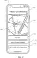
- FIGS. 1 A and 1 Billustrate a device locator user interface 204 on mobile device 2100 , according to embodiments described herein.
- a “proximity view” 2104 as shown in FIG. 1 Amay present proximity information using visualization techniques to present the proximity information in relation to a target wireless accessory device.
- the proximity view 2104has visual indicators, such as user interface elements, positioned along a trajectory 2118 presented within the user interface 204 to represent a path the user has taken in their search.
- the visual indicatorsmay be user interface elements displayed with a gradient, a color, a color gradient, a size, a shape, and/or any other visualization technique to represent signal strength values and a corresponding defined proximity category (e.g., far, near, close, etc.) to the target device.
- the proximity view 2104 for finding “Tommy's AirPods”has indicators 2102 , 2106 , 2110 , 2112 , and 2114 at various positions along the trajectory 2118 within the user interface 204 .
- Each indicator in proximity view 2104may be a user interface element that represents proximity to the target wireless accessory device by size and color gradient within the user interface 204 .
- indicator 2106is closest to the target wireless accessory device along the trajectory 2118 that the user has taken to find the target wireless accessory device as represented by a darker color and/or a larger size as compared to the other indicators (e.g., 2102 , 2110 , 2112 , and 2114 ).
- Embodimentsmay use visual inertial odometry (VIO) measurements to determine the trajectory 2118 that a user has taken in their search within the user interface 204 .
- VIOprovides the ability to track movement of a mobile device in an arbitrary initial coordinate system.
- VIO techniquesinclude the analysis of a sequence of images collected with the mobile device to estimate camera motion over the sequence of images.
- the mobile devicemay move to be within a threshold range of the target device allowing for a ranging process using communication between the mobile device and the target device to determine a distance from and direction to the target device.
- a “ranging view” 2120 of the user interface 204may provide a distance measurement 2116 in addition to the direction 2108 to the target device that may be selectively displayed.
- the proximity view 2104 for finding the target devicemay be used when ranging data for a ranging view 2120 is not available due to a target device not being within a threshold range of the mobile device, a target device transmitter not being in a field of view of a receiver at the mobile device, and/or a mobile device does not have a nearly unobstructed view to the target device, in some embodiments.
- the target devicemay be in the field of view of the mobile device when the receiver at the mobile device has a view of the target device transmitter.
- ranging using an ultra-wide band (UWB) radio technologymay provide relatively precise location or distance data to a target device, but are a relatively short-range radio frequency (RF) technology wireless communication as compared to Bluetooth technology.
- RFradio frequency
- Proximity information in the form of signal strength informationmay be relatively less precise in comparison to UWB but may cover a wider area offering a longer range and can be obtained from advertisements before the wireless radio connection is established.
- Bi-directional communicationmay not be established with a connection between the mobile device and target device, but advertisements received at the mobile device may provide signal strength information to aid in directing the user to the target device prior to establishing a connection, in some embodiments.
- the combination of techniquesmay assist the user in locating the target wireless accessory device.
- a computing devicethat includes a touch-sensitive display is described. It should be understood, however, that the computing device may include one or more other physical user-interface devices.
- the various applications that may be executed on the devicemay use at least one common physical user-interface device, such as the touch-sensitive surface.
- One or more functions of the touch-sensitive surface as well as corresponding information displayed on the devicemay be adjusted and/or varied from one application to the next and/or within a respective application.
- a common physical architecture(such as the touch-sensitive surface) of the device may support the variety of applications with user interfaces that are intuitive and transparent.
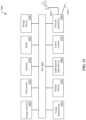
- FIG. 1 Cis a block diagram of a network operating environment 100 for mobile devices, according to an embodiment.
- the network operating environment 100includes multiple mobile devices, such as accessory device 101 as well as mobile device 102 .
- Accessory device 101may be paired to mobile device 102 .
- mobile device 101may be a pair of accessory devices that may be paired as a device group.
- the device group with accessory devices 101may be stored in a mobile device with a wired connection, such as a case to hold the accessory devices 101 .
- the casemay also be an accessory device that may be paired with mobile device 102 in some embodiments.
- accessory device 101may be collectively devices such as Apple AirPods® or EarPods®.
- accessory device 101may not be able to communicate over a wide area network.
- the mobile devices 101 and 102can each be any electronic device capable of communicating with a wireless network and a wireless accessory device.
- Some example mobile devicesinclude but are not limited to a smartphone, a tablet computer, a notebook computer, a wearable computer (e.g., smartwatch or other wearable computing accessory), a mobile media player, a personal digital assistant, AirPods®, EarPods®, locator tags, headphones, head mounted display, health equipment, and other similar devices.
- Each of mobile devices 101 and mobile device 102optionally can include a user interface, such as user interface 104 of mobile device 102 .
- mobile device 101may not have a user interface.
- Mobile devices 101 and 102may be a third-party device that utilizes an application programming interface to access device locator services.
- the third-party devicemay be provided by a different device manufacturer or be part of a different ecosystem (e.g., operating system) from mobile device 101 and 102 .
- Mobile devices 101 and 102can communicate over one or more wired and/or wireless networks 110 to perform data communication.
- a wireless network 112e.g., cellular network, Wi-Fi network
- a wide area network 114such as the Internet
- an access device 118such as a mobile hotspot wireless access device, can provide communication access to the wide area network 114 .
- the gateway 116 and access device 118can then communicate with the wide area network 114 over a combination of wired and/or wireless networks.
- both voice and data communicationscan be established over the wireless network 112 and/or the access device 118 .
- mobile device 102can place and receive phone calls (e.g., using VoIP protocols), send and receive e-mail messages (e.g., using POP3 protocol), and retrieve electronic documents and/or streams, such as web pages, photographs, and videos, over the wireless network 112 , gateway 116 , and wide area network 114 (e.g., using TCP/IP or UDP protocols).
- mobile device 102can place and receive phone calls, send and receive e-mail messages, and retrieve electronic documents over the access device 118 and the wide area network 114 .
- mobile device 101 and/or mobile device 102can be physically connected to the access device 118 using one or more cables, for example, where the access device 118 is a personal computer. In this configuration, mobile device 101 or mobile device 102 can be referred to as a “tethered” device.
- mobile device 101can communicate with mobile device 102 via a wireless peer-to-peer connection 120 .
- the wireless peer-to-peer connection 120can be used to synchronize data between the devices.
- Mobile device 101 or mobile device 102can communicate with one or more services, such as a telephony service 130 , a messaging service 140 , a media service 150 , a storage service 160 , and a device locator service 170 over the one or more wired and/or wireless networks 110 .
- the telephony service 130can enable telephonic communication between mobile devices or between a mobile device and a wired telephonic device.
- the telephony service 130can route voice over IP (VoIP) calls over the wide area network 114 or can access a cellular voice network (e.g., wireless network 112 ).
- the messaging service 140can, for example, provide e-mail and/or other messaging services.
- the media service 150can, for example, provide access to media files, such as song files, audio books, movie files, video clips, and other media data.
- the storage service 160can provide network storage capabilities to mobile device 101 and mobile device 102 to store documents and media files.
- the device locator service 170can enable a user to locate a lost or misplaced device that was, at least at some point, connected to the one or more wired and/or wireless networks 110 .
- Other servicescan also be provided, including a software update service to update operating system software or client software on the mobile devices.
- the messaging service 140 , media service 150 , storage service 160 , and device locator service 170can each be associated with a cloud service provider, where the various services are facilitated via a cloud services account associated with the mobile devices 101 and 102 .
- accessory device 101 and mobile device 102 , and/or device groupmay be registered with a certificate authority 106 .
- the certificate authority 106is an entity that issues digital certificates, and the service may be implemented using a set of servers managed by a device manufacturer, service provider, or a registration service.
- the certificate provided by the certificate authority 106may attest to the validity of received verifiable information about the device, such as a particular manufacturer for the device, a serial number, an identifier for a device group or other identifier, an indicator that device is part of a device group, and/or any other verifiable information.
- a device manufacturermay establish the device group by grouping serial numbers of accessory devices in the device group.
- the certificatecan be encrypted by the device 101 and 102 prior to being sent to a third party and may be decrypted at an attestation service (e.g., certificate authority or another attestation service) when the third-party requests verification of information provided by accessory device 101 , mobile device 102 , and/or devices within device group.
- a secure tokenmay be provided in requests to pair by an accessory device 101 . Additional examples of paired devices using location services may be found in U.S.
- Mobile device 101 and 102may have applications, services, and functionality locally accessible on the devices including location services 180 .
- mobile devices 101 and/or 102may have a device locator application (e.g., a “Find my” application) 190 to utilize device locator services 170 and location services 180 .
- Locally accessible datamay be stored on known locations 182 and safe or trusted locations 184 .
- machine learning algorithms 186may be used to identify known locations 182 , and/or trusted locations 184 .
- cluster analysisis provided as an example of machine learning algorithms that may be used, those with skill in the art will recognize that other algorithms may be used to identify potential known or trusted locations.
- cluster data analysismay be used to identify and classify and provide semantic labels for locations, such as locations frequented by a user.
- Safe or trusted locations 184may be designated explicitly or confirmed as such by a user of the device 102 A-B after data analysis.
- the known locations 182 or the trusted locations 184may be classified offline and provided by device locator service 170 or a third-party (e.g., a database with map information).
- On-device heuristics and/or machine learning modelsmay be used to infer relationships between a user and locations based on analysis of the locally stored data on frequented locations including frequently visited locations by the user, known locations, and/or any other locations.
- a frequently visited locationsuch as a home, a vehicle, a workplace, any location frequented by a user with mobile device (e.g., accessory devices, 101 and mobile device 102 ) and/or any other location designated as a trusted location 184 by the user.
- Known locations 182may be business locations, public spaces, parks, museums, and/or any other location that may be frequented by a user.
- Boundary information for the respective stored locationsmay be stored along with classification type for the location and any semantic label assigned to the location.
- Stored informationmay include a defined set of boundaries or a radius distance around a point location to allow for creation of a geofence for the location.
- the geofenceis a virtual perimeter for a real-world geographic area.
- Global positioning systemGPS may be used to create a virtual fence around a location and track the physical location of the mobile device 101 and 102 within the geofence boundary as well as entry and exit of the bounded area.
- Machine learning algorithms 186may include on-device heuristics, machine learning algorithms, or a combination thereof to analyze and assign a label regarding movement or travel of a device to be designated as being “in transit” state or “settled” state in a particular location for a time period. Analysis may be performed using a variety of signals from data sources available to the mobile device 102 , including, but not limited to, the following: sensor data, positioning data, calendar data, transit card usage data, application data, historical data on patterns/routines of travel, and/or any other data accessible to the mobile device 102 .
- a mobile device 102may be classified with a “settled” semantic label after remaining within the geographic boundaries that define a location (e.g., the trusted location 184 ) for a defined time period.
- positioning data for the mobile device 102may remain within the boundaries of a geofence for a particular location for a duration of time (e.g., 5 minutes).
- Sensor datasuch as accelerometer data, may indicate that the mobile device 102 is at rest to support an inference of being settled.
- Application datamay support the inference that the mobile device 102 is settled, such as the mobile device being located at a calendar appointment location.
- Application data indicating a type of application in usemay also provide an inference of the device being settled, such as using a media application.
- Historical data for the user on routines or patterns in travelmay be used to determine whether the mobile device 102 is settled, such as a bedtime routine at a home or hotel location.
- Mobile device 102may be classified as with an “in transit” label based on prior behavior, patterns, or routines for the user and analyzed on mobile device 102 . For example, the user may have routine of going to work around the same time every day and an “in transit” state may be assigned if the data on the device supports that the pattern is being repeated.
- a speed at which the mobile device is moving or entering and exiting known geographic areasmay allow for the inferring that the mobile device 102 is in transit.
- the mobile device 102may be given the status of “in transit.” Similarly, if transit applications/cards are used/in use, then the mobile device 102 may be designated as “in transit”.
- FIG. 2illustrates a system 200 to locate wireless accessory 201 , according to an embodiment.
- the wireless accessories 201are another embodiment of accessory devices 101 (and optionally a case) that may be paired as part of a device group.
- accessory device 201are separate accessory devices that are not part of a device group and are each paired separately to mobile device 102 .
- Each accessory device 201includes one or more wireless transceivers and can communicate, either directly or indirectly (e.g., through another device or computer) with a companion device (e.g., mobile device 102 ) over a wireless network or peer-to-peer communication link.
- Accessory devices 201may provide the beacon signal for the case and any accessories in the case.
- Accessory device 201is separated from the case and independently and separately able to be found by providing the beacon signal.
- wireless accessory devices 201include but are not limited to wireless earbuds, EarPods, AirPods, input devices, a charging device, a case for accessories, headphones, headsets, fitness equipment, health equipment, display devices, external hard drives, other wearable devices (e.g., smartwatches, fitness bands, optical head-mounted displays) adapters, speakers, and/or other devices. Paired groups of accessories may be the same type of device (e.g., speakers, AirPods, fitness weights, etc.) or different types of devices (e.g., smartphone and credit card reader, etc.).
- the wireless accessory 201can also include other wireless devices such as input devices including, but not limited to credit card reading devices, stylus devices, mouse, keyboard, game controllers or remote controls.
- the wireless accessory 201in one embodiment, also includes smartphones, tablet computers, laptop computers, smart speaker devices, televisions, or television set top boxes that at least temporarily are unable to access a wide area network, such as the Internet (e.g., wide area network 114 as in FIG. 1 ).
- the wireless accessory 201can also be any other wireless device, including beacons or locator tags that can be attached to other devices to enable the tracking or locating of those devices.
- the wireless accessory 201can be from a device group of accessory devices that are paired with the mobile device 102 using a wireless technology standard, such as but not limited to Bluetooth.
- the wireless accessory 201can also communicate with the mobile device 102 over wireless technologies including the implementation of any wireless standards and protocols, such as Wi-Fi direct, Zigbee, or AirPlay.
- the companion device to which the wireless accessories 201 are pairedis generally referred to as a mobile device 102
- companion devicesare not limited to mobile devices.
- Companion devicesin some embodiments, can also include laptop or desktop devices and can additionally include some wearable accessories, such as but not limited to a smart watch device or a wearable display.
- the wireless accessory 201can periodically transmit a wireless beacon signal.
- the wireless accessory 201can transmit the beacon signal using one of a variety of wireless technologies described herein (e.g., Bluetooth, Wi-Fi, etc.) and in one embodiment can also beacon using an ultra-wide band (UWB) radio technology.
- the beacon signalcan be transmitted using a single wireless technology, one of multiple selectable wireless technologies, or multiple simultaneous wireless technologies.
- the beacon signalcan transmit a beacon identifier that includes information to specifically identify the individual wireless accessory 201 , and/or a device group.
- the beacon identifieris a public encryption key associated with the device.
- the beacon signalcan also convey information about the wireless accessory 201 , such device status information and/or verifiable information.
- Device status information in the beacon signalmay include, but is not limited to the following: a beacon type, a device classification, a battery level, any pre-defined device status, a device state, a lost status, an alarm status, a separated from owner status, a near-owner status, a proximate to one or more accessory devices in a device group status, a wired or wireless connection status, a physically connected to one or more accessory devices in a device group status, a pairing status indicating whether accessory device is paired or not paired, a pending pairing status, a battery life state, a charging status, and/or any other status information.
- the lost or “separated from owner” statuscan indicate that the wireless accessory 201 has determined itself to be lost or has been placed into a lost state by the owner of the device.
- the alarm statuscan indicate that the wireless accessory 201 was placed in a state that the device should trigger an alarm if moved from a current location.
- the near-owner statuscan indicate that the wireless accessory 201 has detected the nearby presence of the mobile device 102 associated with the owner of the accessory.
- verifiable informationmay include any information that may be needed to establish trust or authority that a pairing process and/or finding process may proceed with the device presenting the verifiable information.
- verifiable informationmay include information established by a device manufacturer, such as a serial number or set of serial numbers in a device group.
- the verifiable informationmay include status or state information for the device.
- the verifiable informationmay include, but is not limited to, the following: a device type, a member of device group, a serial number, a device group, serial numbers of other devices within a device group, state or status information, a software version, and/or any other verifiable information.
- Verifiable informationmay be sent to the certificate authority 106 or other attestations service to verify received information presented by the device to another device.
- Verifiable informationmay be encrypted and/or sent with a token to allow for further verification of the device.
- the beacon signalcan be detected by a finder device 202 , which is locally proximate to the wireless accessory 201 in order to use crowdsourcing to locate a lost wireless accessory 201 .
- the finder device 202can be a similar device as the mobile device 102 and can receive and transmitting data over a wide area network 114 and receiving and transmitting using similar wireless technologies as the wireless accessory 201 (e.g., Bluetooth, etc.). Particularly, the finder device 202 can receive data using the wireless protocol over which the beacon signal is transmitted.
- the finder device 202can determine a location using one or more location and/or positioning services including, but not limited to a satellite positioning service 206 or a terrestrial positioning system using RF signals received from wireless base stations 205 such as Wi-Fi access points or cell tower transmitters of a cellular telephone network.
- the finder device 202periodically stores its location as determined based on the one or more location and/or positioning services. The stored location can be associated with a timestamp for which the location was determined.
- the finder device 202receives a beacon signal from the wireless accessory 201 , the finder device 202 can transmit a location for the finder device 202 over the wide area network 114 to a device locator server 203 .
- the timestamp for a determined location for the finder device 202can be correlated with a timestamp for which a beacon signal was received to associate a geographic location with a received beacon signal.
- the finder device 202can encrypt the determined location data and transmit the encrypted location data to the device locator server 203 over the wide area network 114 .
- additional datacan either be encrypted and transmitted along with the location data or transmitted unencrypted to the device locator server 203 .
- a received signal strength indicator (RSSI) for the beacon signalcan be transmitted along with the location data. The RSSI data can then be used to determine the distance of the wireless accessory 201 from the finder device 202 and assist in triangulation on the owner device.
- RSSIreceived signal strength indicator
- the servercan use RSSI information to reduce noise by discarding very weak signals if other, stronger signals are present.
- UWB ranging datacan also be provided, where such data is available.
- the finder device 202can behave differently upon receiving a beacon signal from a wireless accessory 201 depending upon a device status conveyed by the wireless accessory 201 .
- the finder device 202can place encrypted location data into a queue and transmit the location data to the device locator server 203 during a periodic transmission window.
- the finder device 202can transmit the location data to the device locator server 203 immediately.
- the finder device 202may not transmit the location data to the device locator server 203 if the beacon signal of the wireless accessory 201 indicates that the accessory is near the owner of the accessory.
- the finder device 202may delay transmission of encrypted location data.
- the owner of the wireless accessory 201wishes to locate the wireless accessory, the owner can access a device locator user interface 204 on the mobile device 102 .
- the device locator user interface 204can be associated with a device locator application that is used to locate electronic devices and accessories that are registered with an online account of the user, such as a cloud services account or another type of online account.
- the device ownerusing the device locator UI 204 , can query the device locator server 203 for location data that may have been transmitted to the device locator server by a finder device 202 of the wireless accessory 201 .
- the mobile device 102can transmit the public encryption key associated with the wireless accessory 201 to the device locator server 203 .
- the device locator server 203can then return any stored location data that corresponds with the public encryption key.
- the location data returned to the mobile device 102can be encrypted data that is encrypted by the finder device 202 using the public encryption key.
- the mobile device 102can use an associated private key to decrypt the encrypted location data.
- the decrypted location datacan then be processed by the mobile device 102 to determine a most probable location for the wireless accessory 201 .
- the most probable location for the wireless accessory 201can be determined by triangulation from multiple received locations and using other data, such as a beacon signal RSSI associated with each location and timestamp or UWB ranging data included within the location data.
- FIG. 3illustrates a system 300 for pairing and locating a wireless accessory, according to embodiments described herein.
- a mobile device 102 of a user of the wireless accessory 201e.g., example of device 101
- a public key exchange310
- the mobile device 102 and the wireless accessory 201exchange public keys of public key pairs generated by the device and the accessory 201 .
- the public key exchange ( 310 )is a one-way transfer, in which the mobile device 102 transmits a public key of a public/private key pair to the wireless accessory 201 .
- the public key exchange ( 310 )may be a Diffie-Hellman key exchange in which the device and the accessory establish a shared secret between two parties.
- the public key exchange ( 310 )additionally uses elliptic curve cryptography to establish the shared secret.
- Elliptic-curve Diffie-Hellman (ECDH)can be used to enable the establishment of a public key pair and one or more shared secrets.
- the one or more shared secretsinclude an anti-tracking secret, which can the wireless accessory 201 to periodically derive additional public keys.
- the wireless accessory 201can periodically broadcast a beacon signal 301 that includes device status information and a beacon identifier.
- the beacon identifieris a public key derived from a shared secret that is established during the public key exchange ( 310 ). Additionally, the wireless accessory 201 can periodically perform a public key derivation ( 315 ) to generate a new public key and begin broadcasting the new public key as the beacon identifier.
- the public keyis a K-byte key, with a new K-byte key generated every M minutes.
- the value K and Mcan vary between embodiments. In one embodiment, a K value of 28 bytes is used. In one embodiment, a K value of 27 bytes is used.
- the value Kcan be determined at least in part based on the beacon length associated with the wireless protocol used to transmit the beacon signal 301 .
- the beacon signalcan transmit a variant of beacon advertisement packet associated with a low-energy radio protocol, such as Bluetooth Low Energy.
- the value Min one embodiment, is 15 minutes, such that a new K-byte key is generated every 15 minutes.
- the public keycan be derived deterministically based on a timestamp and an anti-tracking secret generated during the public key exchange 310 .
- the public key derivation ( 315 ) processenables the wireless accessory 201 to use different keys over time, preventing the long-term association with a specific key with a specific device.
- the keycan be derived based on an anti-tracking secret known only to the mobile device 102 and the wireless accessory 201 , allowing the mobile device 102 , and only the mobile device, to determine which public key will be broadcast by the wireless accessory 201 at any given timestamp.
- the anti-tracking secretcan be generated along with an ECDH public key and transferred to the wireless accessory 201 .
- the anti-tracking secretcan then be used to enable the wireless accessory 201 to generate a sequence of public keys P i .
- the sequence of public keys P i⁇ i ⁇ P, which defines a group operation between a scalar or exponent value ⁇ i and group elements, such as, for example, Elliptic Curve points P.
- the scalar or exponent value ⁇KDF(AT, i), where KDF is a key derivation function, AT is the anti-tracking secret, and i is a counter or timestamp.
- backtracking resistancecan be enabled to protect the anti-tracking secret in the event the wireless accessory 201 is compromised.
- time), with ⁇ 0AT and H being a cryptographic hash function.
- the wireless accessory 201then stores ⁇ i for a given time period i. If the wireless accessory 201 is compromised, only ⁇ i for current and future values of i is exposed, without exposing the anti-tracking secret AT.
- backtracking resistanceis performed by periodically writing ⁇ i to non-volatile memory of the wireless accessory 201 .
- the wireless accessory 201can transmit the beacon signal 301 every two seconds, although other beacon rates can be used, and the beacon rate can vary under certain circumstances. For example, the wireless accessory 201 can decrease a beacon rate when in a near-owner state. Beacon rate can also vary based on accelerometer triggered events. For example, the wireless accessory 201 can increase the beacon rate when in an alarm state, which can be triggered by the accelerometer on the wireless accessory 201 .
- the wireless accessory 201can enter the near-owner state if, after transmitting the beacon signal 301 , the wireless accessory 201 receives a reply from the mobile device 102 associated with the user of the accessory, which indicates that the mobile device 102 is within range of the wireless accessory. Additionally, while the wireless accessory is in the near-owner state, the amount of data transmitted by the beacon signal 301 may be reduced. In one embodiment, the rate at which new public keys are generated can also be reduced while the wireless accessory is in the near-owner state.
- the wireless accessory 201can enter an alarm state upon receiving a message from the mobile device 102 that indicates that the wireless accessory 201 should enter the alarm state.
- the wireless accessorycan initially enter an armed state in which the wireless accessory 201 can reduce or cease the transmission of locator beacon signals, although other types of wireless signaling can persist.
- the wireless accessory 201can remain in the armed state until the state is deactivated by the mobile device 102 or alarm is triggered.
- the alarmcan be triggered, in one embodiment, upon detection of movement, for example, via an accelerometer within the wireless accessory 201 .
- the alarmcan also be triggered, in one embodiment, upon detection that the wireless accessory has moved out of range of the mobile device and is no longer in the near-owner state.
- the rate at which the beacon signal 301can be increased, to increase the speed by which the wireless accessory 201 can be located.
- the beacon signal 301 transmitted by the wireless accessory 201can be detected by a set of finder devices 303 (finder devices may be finder device 202 ) and/or the mobile device 102 , which are other electronic devices that can receive the beacon signal transmitted by the wireless accessory and are transmit location and other data associated with the beacon signal 301 to the device locator server 203 via the wide area network 114 .
- the set of finder devices 303include variants of the mobile device 102 or can be other types of electronic devices.
- the set of finder devices 303can perform operations ( 320 ) to correlate the beacon signal 301 received from the wireless accessory 201 with a device location associated with the finder device 303 . As described with respect to FIG.
- the device locationcan be determined via a satellite positioning service or a terrestrial positioning system that uses RF signals received from wireless base stations (e.g., Wi-Fi access points or cell tower transmitters).
- the set of finder devices 303can also include stationary devices such as smart speaker devices, televisions, or television set top boxes that can receive the beacon signal 301 .
- the set of finder devices 303can encrypt the location data with the beacon identifier (e.g., public key) received within the beacon signal 301 and send the location data ( 325 ) to the device locator server 203 .
- the data sent by the set of finder devices 303is send anonymously and no identifying information for the finder devices is stored with the data sent by the finder devices.
- the device locator server 203can store encrypted location data in a data store 304 , which in one embodiment can be a distributed database having multiple nodes. Hashes of the beacon identifier/public key of an accessory can be sent along with encrypted location data.
- the encrypted location datacan be stored to a database node based on a hash of the beacon identifier.
- the encrypted location datacan be indexed by the device locator server 203 using the hash of the beacon identifier. Sending the hash of the beacon identifier instead of the full beacon identifier prevents the storage of the full beacon identifier to the server.
- Other informationcan also be sent and stored with the location data, either in an encrypted or unencrypted state. The other information can include timestamps for when the beacon signal 301 was received, RSSI information for the received beacon, and/or ranging information determined, for example, via UWB ranging.
- the device locator UI 204can be associated with a locator application 190 or feature of the mobile device 102 .
- the device locator UI 204may also have a web-based interface that can be accessed from the mobile device 102 or another type of electronic device, such as a laptop or desktop device.
- the mobile device 102upon loading the device locator UI 204 , can send a request ( 330 ) for location data to the device locator server 203 .
- the request 330can include a set of public keys or public key hashes, which can serve as beacon identifiers for the beacon data.
- the mobile device 102can generate the set of public keys based on the secret information held by the mobile device 102 and the wireless accessory 201 and the timestamps over which the mobile device 102 wishes to receive location data.
- the set of public keysis the sequence of public keys P i that are generated based on the anti-tracking secret.
- the sequence of public keys P icorresponds to a matching sequence of private keys d i .
- the mobile device 102can generate the sequence of public keys, as well as the corresponding sequence of public keys d i , where i is a counter or timestamp.
- the mobile device 102can generate and send the previous 24 hours of public keys (or hashes of the 24 hours of public keys) within the request 330 . If no data is found for 24 hours of public keys, the mobile device 102 can send generate keys for an earlier period, back to a pre-determined location data retention limit.
- the encrypted location datais stored and indexed based on a hash of the public key instead of the public key to prevent the provider of the location service data from storing data that can be used to tie the encrypted location data to a specific device, and thus a specific user or user account.
- the finder devicecan send the hash of the public key that is broadcast within the beacon signal 301 associated with an observation location.
- the owner of the devicecan query the device locator server 203 using a hash of the public key that is determined for a query period.
- a location queryis to be performed via the web-based interface from an electronic device, such as a laptop or desktop device
- keys to enable the decryption of the location datamay be required to be sent to the electronic device.
- decryption keys for the location datamay be sent to the server that provides the web-based interface to enable the server to decrypt location data, at least while the location data is being viewed through the web-based interface.
- a noticemay be presented to inform the user that location decryption keys are being temporarily shared with the web-based interface server to enable location data to be decrypted and presented.
- the sharing of the location decryption keyscan be performed via an automatic and temporarily delegation of location query rights with a proxy account associated with the web-based interface.
- the wireless accessory 201can be placed in a light lost mode.
- a set of future public keyscan be generated for the wireless accessory and transmitted to the device locator server 203 .
- the device locator server 203can then notify the mobile device 102 if any location data is received that correspond with a key in the set of future public keys.
- a finder device that sends a location for a wireless accessory that is in the light lost modecan be directed by the device locator server 203 to relay a message to the wireless accessory 201 that notifies the wireless accessory that it is in the light lost mode.
- a similar mechanismcan be used to relay a message to the wireless accessory 201 that places the accessory in an explicit lost mode.
- the explicit lost modecan be enabled by the user via the device locator UI 204 .
- the wireless accessory 201cannot be paired with another device unless unlocked by the owner. Additional examples of paired devices using location services may be found in U.S. patent application Ser. No. 16/543,227 filed Aug. 16, 2019 entitled “A System and Method for Locating Wireless Accessories,” which is incorporated by reference herein in its entirety.
- FIG. 4is a flow diagrams illustrating methods for use with the device locator systems described herein.
- FIG. 4illustrates a method 400 to pair a mobile device with a wireless accessory. Aspects of method 400 are also illustrated in FIG. 2 and FIG. 3 , as described above. For example, the description of the operations below refers to the mobile device 102 , wireless accessory 201 and device locator server 203 .
- method 400includes an operation ( 402 ) that performs an initial pairing with a wireless accessory.
- the initial pairingcan be a Bluetooth pairing or another type of pairing using other wireless radio technologies.
- the mobile device and the wireless accessorycan exchange identifiers, passkeys, or other credentials that enables a wireless data exchange to be performed between a mobile or another electronic device and the wireless accessory.
- the initial paring with the wireless accessorycan include the exchange of credentials associated with the wireless protocol for which the pairing is performed, allowing all data exchanged wirelessly to have at least a first layer of encryption.
- the mobile devicecan then generate a public/private key pair and one or more additional shared secrets ( 404 ).
- the devicecan then send the public key and one or more additional shared secrets to the wireless accessory ( 406 ).
- a variety of key generation techniquescan be used.
- a variant of ECDHis used to generate a public key pair for encryption.
- the one or more additional shared secretscan include an anti-tracking secret that enables the wireless accessory to derive a new public key based on an existing public key.
- the mobile devicecan store public/private key pair to keystore ( 408 ).
- the keystoreis a cloud-based keystore that can be synchronized with other devices associated with the same cloud services account, or family of cloud services accounts, to which the mobile device and wireless accessory are associated.
- the cloud-based keystoreallows the wireless accessory to be located by other synchronized devices.
- the mobile devicecan then register the wireless accessory with a device management server ( 410 ). Registering the wireless accessory with the device management server can form an association between the wireless accessory and the cloud services account to which the mobile device is associated.
- the mobile devicemay register the wireless accessory and the device group 104 .
- Information stored in a device group profile for the device groupmay also be synchronized between devices tied to a cloud services account (e.g., a user account).
- the device management servercan be associated with other cloud-based servers that are used to facilitate cloud-based services accessible to the mobile device, such as the device locator server 203 of FIG. 2 and FIG. 3 .
- FIG. 5is a sequence diagram 500 illustrating methods to present a device locator user interface for use with the device locator systems described herein.
- Mobile device 102may launch the device locator application 204 ( 506 ).
- Mobile device 102may receive a beacon signal from accessory device 201 including advertisements ( 508 ).
- the advertisementsmay be sent prior to launching the application ( 506 ) and/or subsequent to launch of the device locator application 204 .
- BLE advertisementsmay be sent prior to establishing a wireless radio connection to the mobile device 102 .
- the BLE advertisementsmay be received every two seconds.
- Signal strength measurementsmay be determined from the beacon signal and the process may begin for finding at least one accessory device 201 ( 510 ) paired to mobile device 102 ( 510 ) with a proximity view for the user interface 204 .
- the proximity view for the device locator application 204 user interfacemay be presented with a visual indicator representing the proximity of a target accessory device 201 .
- the visual indicatormay correspond to the signal strength measurements ( 512 ) from the received advertisements at the mobile device 102 .
- a wireless radio connectionmay be formed between the target accessory device 201 and the mobile device 102 ( 514 ) allowing for the mobile device 102 to request that the target accessory device 201 play a sound, in some embodiments.
- a wireless radio connectionmay be formed between the target accessory device 201 and the mobile device 102 and the mobile device may request to a ranging process be performed.
- the ranging processmay be performed to determine a distance from and direction to the target wireless accessory device 201 .
- a ranging view for the device locator application 204 user interfacemay be presented ( 516 ).
- the ranging viewmay provide a direction and a calculated distance to the wireless target to aid in finding the accessory device 201 ( 518 ).
- the ranging viewmay be presented selectively with the proximity view and/or independently within the user interface 204 .
- the device locator application 204 user interfacemay be presented querying the user as to whether the accessory device 201 was found ( 520 ).
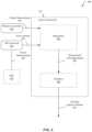
- FIG. 6illustrates a system 600 to enable ranging and pose estimates to generate a target position estimate of a target device, according to an embodiment.
- the system 600includes a wireless controller 630 , an IMU 612 , and a set of frameworks that execute on an application processor of a mobile device 102 as described herein.
- the set of frameworkscan include an augmented reality (AR) framework 610 and the sensor fusion framework 611 .
- the wireless controller 630can send range measurements 601 interpolator logic 604 within the sensor framework 611 .
- the AR framework 610can receive sensor measurements 603 from the IMU 612 and generate pose estimates 602 for the mobile device 102 .
- the pose estimates 602can be sent to the interpolator logic 604 within the sensor framework 611 .
- ARaugmented reality
- the interpolator logic 604can process the range measurements 601 and pose estimates 602 to generate a measurement with an aligned pose 605 .
- the interpolator logic 604can generate the measurement with an aligned pose 605 by interpolating and aligning range measurements 601 and pose estimates 602 based on the times in which the measurements and estimates were determined.
- the measurement with an aligned pose 605can be provided to estimator logic 606 .
- the estimator logic 606can then generate a three-dimensional target position estimate 607 for use by the mobile device. This target position estimate can be used by the mobile device 102 to generate views of a location environment.
- the interpolator logic 604 and estimator logic 606can include various algorithmic techniques to overcome anomalous data and sensor interference to enhance the precision of the three-dimensional target position estimate 607 .
- the system 600can fuse inertial data gathered from the IMU 612 with images captured via one or more cameras to perform visual inertial odometry (VIO).
- VIO techniquesinclude the analysis of a sequence of images to estimate camera motion over the sequence of images. Using image-based camera motion estimation and inertial measurements captured over the same period of time, motion of the mobile device through a coordinate system can be estimated, providing software of the system 600 the ability to estimate both the position of the mobile device 102 (or any finder device) and the target device to be located within a three-dimensional coordinate space.
- the target location estimatecan take the form of a nonlinear least-squares problem that can be solved using a non-linear-least-squares (NLLS) batch filter.
- NLLSnon-linear-least-squares
- the specific pose estimate usedmay be based on or relative to the position of the wireless ranging radio antenna on the mobile device. Alternatively, a Kalman Filter or spatial occupancy grid-based approach may be applied.
- the relative target position of the wireless devicecan be updated using AR data even in the absence of updated range measurements between the wireless device 102 and the accessory device 201 .
- the frequency of wireless ranging operationsmay be throttled to reduce power consumption by the target device 201 and mobile device 102 .
- FIG. 7illustrates a system 700 in which proximity enhancements can be enabled for a device locator application 204 .
- One embodimentprovides a system 700 to enhance the functionality of a device locator application 204 when in a location environment 708 that is proximate to an item or target device 201 to be located.
- the location environment 708can include a mobile device 102 (e.g., smartphone, wearable, tablet, etc.).
- the mobile device 102can communicate wirelessly with a wireless device 101 that includes a radio 719 .
- the mobile device 102can also include a variant of the radio 719 in the wireless device 102 .
- the wireless device 201may also be a mobile device or can be a wireless accessory 201 as described herein.
- the devicescan communicate wirelessly via wireless communication signals 705 by detecting one another by scanning wireless channels, transmitting and receiving beacons or beacon frames on wireless channels, establishing connections (for example, by transmitting connect requests), and/or transmitting and receiving packets or frames (which may include the request and/or additional information, such as data, as payloads).
- the wireless communication signals 705can be carrier signals that conform to wireless communication technologies such as, but not limited to Wi-Fi or Bluetooth.
- the mobile device 102 and the wireless device 201perform wireless ranging operations using wireless ranging signals 706 .
- the wireless ranging signalscan be, for example, ultra-wideband signals that can be used to determine a distance and/or angle between the wireless device 201 and the mobile device 102 using techniques described herein.
- data provided by the wireless ranging signals 706can be correlated with other metrics, such as an RSSI of the wireless communication signals 705 .
- a communications processor of the mobile device 102 and the wireless device 201can fuse multiple types of ranging to provide a unified distance and/or angle estimate based on multiple types of radio data.
- the mobile device 102can provide a device locator UI 204 that presents a map and/or a view of the location environment 708 .
- the map and/or viewcan present a virtual representation of the wireless device 201 .
- the virtual representationcan streamline the process of locating the wireless device 201 by user of the mobile device 102 . For example, using a direction indicator that points to a detected location of the wireless device 201 can simplify the process of finding the approximate location of the wireless device 201 .
- the direction indicatorcan be paired with a map of the location environment 708 , where the map can include the virtual representation of the wireless device 201 .
- a proximity view and/or a ranging view of the location environment 708can be presented, which can allow the user to identify the wireless device 201 when the wireless is hidden from view.
- the wireless device 201may be concealed by an item.
- the itemmay be, for example, a jacket or another article of clothing and the wireless device 201 may be a smartphone or tablet device that is in a pocket of the item.
- the item and the wireless device 201may each be within a container, such as a backpack, storage chest, item of luggage, or another item that make reduce the efficiency of audio-based location techniques that rely on the wireless device 201 to play a sound that can be heard by a user.
- the wireless device 201may be a beacon peripheral or locator tag that is attached to the item.
- the usercan use the device locator UI 204 on the mobile device 102 to find the wireless device 201 , enabling the user to locate the item to which the wireless device 201 is attached.
- the proximity enhancements described hereincan be used to augment the device locator UI 204 , allowing the user to quickly determine the location of the item, via the wireless device 201 , in scenarios where the item may be concealed by a container or another physical item.
- the mobile device 102can establish a secure wireless communication connection (e.g., a Bluetooth connection) with the wireless device 201 (e.g., via wireless communication signals 705 ) and command the wireless device 201 to begin a wireless ranging process, for example, using the wireless ranging signals 706 , which can be UWB signals.
- the wireless ranging signals 706enable the mobile device 102 to receive measurements of range and angles to the wireless device 201 .
- the mobile device 102may request that the target wireless device 201 increase the rate of sending advertisements (e.g., from every 2s to every 30 ms) to aid in finding the wireless device 201 .
- signal strength measurementsmay be determined from received advertisements and may aid in directing a user to the wireless device 201 .
- wireless rangingcan be performed using any standard or proprietary ranging technique, or any combination of standard and/or proprietary ranging techniques.
- a wireless ranging operationcan be performed to determine a distance between devices (e.g., between an initiator and a responder), a direction between devices, or both.
- a Time of Flight/Time of Arrival (ToF/ToA)can be determined for one or more messages between the devices, which can be used to establish a measure of distance.
- the one or more messagescan have any format and can be transmitted using any wireless protocol.
- ToF/ToAcan be determined using a bi-directional exchange of two or more messages.
- one or more messages used to perform rangingcan be secured, e.g., by encrypting or otherwise protecting at least a portion of the content.
- the direction of the source of one or more wireless signalscan be determined using a technique such as Angle of Arrival (AoA).
- AoA estimationcan be performed using multiple receive elements (e.g., elements of an antenna array) to measure the different times (TDOA) and/or different phases (PDOA) of arrival of a signal.
- directionalitycan be determined by measuring Doppler shifts to establish a frequency difference of arrival (FDOA).
- Wireless ranging techniquescan be applied individually or in combination to perform a single ranging operation. Further, wireless ranging techniques can be applied individually or in combination to perform on-going ranging operations, such as continuous or intermittent ranging, and a history of measurements can be captured and used in performing operations based on range and/or direction.
- the incoming measurementscan be processed to reduce measurement noise and stabilize the estimated location of the lost item.
- the mobile device 102can use a sensor fusion technique that relies upon multiple streams of measurements to arrive at a best estimate of device location.
- incoming range and/or angle measurementscan be fused with position and orientation measurements of the mobile device 102 .
- the position and orientation measurementscan be gathered using visual-inertial odometry (VIO), which determines the device location and orientation using an IMU and computer vision using camera data.
- VIOvisual-inertial odometry
- the VIO dataenables software on the mobile device 102 to be aware of the movement and orientation of the device.
- Combining the VIO data with the range and/or angle measurements determined via the wireless ranging signals 706enables estimation of the most likely position of the wireless device and allows the user to be pointed towards the wireless device 201 . Additionally, combining the VIO data with the signal strength measurements via the wireless communication signals 705 may aid in directing the user to the wireless device 201 with the proximity view and/or in combination with the ranging view. VIO data may be particularly useful in scenarios where one or more of the range or angle measurements may be inaccurate due to multipath signal propagation effects.
- the algorithm for determining the position of a lost itemcan be accessed via the device locator UI 204 .
- the usercan select the item from a list of registered devices and select a “find” button that is presented via the device locator UI 204 .
- multiple user interfacesmay be presented. Some interfaces resemble a two-dimensional compass like view with a two-dimensional arrow guiding the user to the target item or device to be found.
- the proximity view and/or combination of proximity and ranging view of the device locator UI 204may provide an arrow guiding the user in addition to presenting the trajectory that the user has taken in their search with proximity indicators presented along the path taken.
- FIG. 8is a flowchart 800 illustrating a method for a device locator user interface 204 in an embodiment.
- One or more inertial displacement measurement valuesmay be determined with using received inertial sensor data and received camera sensor data ( 802 ).
- the one or more inertial displacement measurementsare determined from an origin within an arbitrary 2D or 3D coordinate system using VIO.
- the origine.g., ([0,0,0] x,y, and z axis)
- the target wireless devicemay be the wireless accessory device 201 and/or wireless accessory device 101 as shown in FIGS. 1 - 3 .
- a trajectorymay be determined based on the one or more inertial displacement measurement values ( 804 ) collected.
- the displacement measurement values from the origin collected as the user moves within the location environment and the displacement measurementsmay be used to plot the trajectory in the user interface 204 to represent the path taken by the user within a location environment.
- the trajectorymay be presented within the user interface to alert the user of the path the user has already taken, so the user may use the information to attempt other routes or maintain a route to locate the device.
- a beacon signalmay be received from the target wireless device 201 ( 806 ).
- the mobile device 102may receive beacon signals from the target wireless device 201 with one or more advertisements prior to establishing a wireless radio connection and/or while the target wireless device 201 has established the wireless radio connection to the mobile device 102 .
- Bi-directional communicationmay not be established between the mobile device 102 and target wireless device 201 , but the received advertisements by the mobile device 102 may be used to determine proximity to the target wireless device 201 .
- a signal strength valuemay be determined from the received beacon signal ( 806 ).
- the signal strength valuemay be an average of signal strength measurement values determined from advertisements in the beacon signal received while the user is positioned in an area on the trajectory.
- the average of signal strength values taken over the areamay reduce the effects of fading. Fading occurs when beacon signals received at the wireless radio receiver on mobile device 102 contemporaneously cause a dip in signal strength values.
- Alternative embodimentsmay use an average of signal strength values taken over time.
- a proximity value to the target wireless device 201may be estimated based on the signal strength values corresponding to a position along the trajectory ( 808 ) within the area where signal strength values have been received.
- An indicator of the proximity value to the target wireless devicemay be displayed along the trajectory ( 810 ).
- a defined category for the signal strength valuemay be determined for each set of one or more signal strength values that are averaged for an area along the trajectory and the indicator of the proximity value may be presented in accordance with the defined category. For example, a range of values may be defined for each of a set of buckets to designate close, near, and far categories and/or any other categories that provide information to the user for the proximity to the wireless accessory device 201 .
- the visual indicatormay be any type of user interface element, including, but not limited to, the following: a marker, a particular color or gradient, a shape, or any other visual indication may be displayed on the user interface.
- a ranging view, a signal strength proximity view, and/or a combination of the ranging and signal strength proximity viewmay selectively be presented within a user interface ( 812 ).
- the ranging viewmay only be shown when the wireless radio connection has been established.
- Performance and accuracy of the distance, bearing, and range calculationscan be enhanced using various algorithmic approaches.
- the devicemay encounter multipath signal propagation effects when ranging to the target.
- Multipath propagationis a phenomenon that results in radio signals reaching a receiving antenna by two or more paths. Multipath propagation can occur if the line of sight to the target is obscured by obstacles in the environment, the antenna pattern severely attenuates the line of sight signal, or the users themselves block the signal.
- the mobile devicetraces a trajectory through space towards the target, the measured range to the target can evolve over time, along with the distance traveled over the trajectory. During this evolution, anomalies and interference may arise.
- the measured range determined from the sensor datamay appear to jump more than the distance traveled through space.
- a sudden increase in the measured range that differs from the distance travelled over a period of timemay be used to determine when the multipath conditions have changed.
- the change in rangeis positive and larger than the distance traveled, the bias on the measurement due to multi path may have increased.
- the change in rangeis negative and larger in magnitude than the distance traveled, a multi path component likely existed before and has reduced in effect.
- the uncertainty of previous measurementscan be increased to account for the potential multi interference.
- previous measurements that have been deemed as multipath measurementsmay be removed from the measurement history by setting the weights associated with those measurements to zero.
- the measurements received after the detected increasecan similarly be de-weighted or those measurements can be rejected.
- range measurementscan be de-weighted due to the passage of time. As range measurements are gathered over the device's trajectory, the solution for the target's position becomes overdetermined. Range measurements can be de-weighted as the measurements age and/or as VIO errors accumulate. In the case of a moving target, analysis of range measurements as a function of time may be particularly important, as a time series of range measurements can be used to determine an angle measurement to the device without relying on angle measurements associated with any one ranging operation. Thus, the weights associated with older measurements may be decayed based on a time function.
- range measurementscan be de-weighted due to the measured and/or estimated distance to target. As measurements indicate further ranges, the possibility of multipath interference increases, and the measurements become less useful. As a solution is formed, the estimated distance to each position where a measurement was formed can be calculated. Based on that distance, the measurement can be reweighed. Additionally, the measurement itself is a range, and can be used to infer a measurement uncertainty.
- angle of arrival measurementscan be used to further refine the target position when a range-only solution indicates the target is in the device's field of view.
- a position solution for the devicecan be formed using ranging measurements only (e.g., without angle measurements). Given the position solution, probabilities can be calculated that each of the angle measurements was made from the mobile device when the target was in the device's field of view. If the probability meets a threshold, the angle measurement can be used to form a new position solution. Use of the angle measurement can resolve ambiguities that may be present in the range solution, especially along the z axis, due to the device trajectory mostly being in a single plane (e.g., xy plane).
- the measurement errors of individual contributing measurementscan be calculated. In an over determined solution, the measurement errors will be non-zero and give some indication of the quality of the position fix. If large errors are seen, the confidence in the position fix can be decreased. A threshold on the confidence can be used to determine if the position should be shown to the user. If all measurements are seen to disagree by small amounts, the errors can be used to increase the uncertainty of the position.
- FIG. 9illustrates a method 900 to enable proximity enhanced user interfaces for a device locator application.
- Method 900includes operations by which range measurements determined by a wireless controller can be fused with pose estimates determined based on sensor data from an IMU to generate pose aligned measurements and three-dimensional or two-dimensional target position estimates.
- the three-dimensional target position estimatescan be used to enable an AR view of a location environment that includes a target device or item to be located.
- Range measurements determined by a wireless controller and estimates determined based on sensor data from an IMUmay also be used to determine two-dimensional target position estimates.
- Method 900can be performed by a mobile device (e.g., mobile device 102 ) as described herein to locate a target wireless accessory device (e.g., wireless device 101 ) or a target wireless accessory device (e.g., wireless accessory device 201 ) described herein, or an item associated with a wireless accessory device 201 , such as an item that is tagged with a beacon or locator tag.
- a target wireless accessory devicee.g., wireless device 101
- a target wireless accessory devicee.g., wireless accessory device 201
- an item associated with a wireless accessory device 201such as an item that is tagged with a beacon or locator tag.
- method 900includes operations to optionally receive, at a mobile device 102 , a geographic location of a target wireless accessory device ( 901 ).
- the geographic location for the target wireless accessory device 201can be a location determined by a mobile device 102 that can access a user account of the mobile device 102 , or a location received from a device locator server 203 .
- the mobile device 102can then present an indicator for the target wireless accessory device 201 on an interface of a device locator application 204 that is executed by the mobile device 102 ( 902 ).
- the indicatorcan be a map indicator that shows a location of the target wireless accessory device on a map of the nearby environment. For example, a map with a map indicator may be presented as shown in FIGS. 17 - 20 . A distance and range measurement to the target wireless accessory device 201 can be presented on the map, along with the map indicator that shows the location of the target wireless accessory device. The user of the mobile device 102 can then move towards the location of the target wireless accessory device 201 .
- the wireless accessory device 201can determine a range and/or direction to the target wireless accessory device 201 using one or more wireless ranging operations ( 903 ).
- the one or more ranging operationscan include continuous or periodic ultra-wideband ranging operations.
- the ultra-wideband ranging operationscan be performed in conjunction with other range determination techniques, such as RSSI-based distance determinations.
- the ultra-wideband ranging operationsare secure ranging operations in which the ranging packets exchanged are encrypted.
- both range and direction determinationscan be made based on the one or more ranging operations.
- range-only determinationscan be made and the direction may be determined based on analysis of multiple range measurements. Where both range and angle measurements may be determined based on instantaneous wireless ranging signal analysis, a history of range measurements can be used to increase the accuracy of the determined angle measurements.
- the mobile device 102can then determine a pose of the mobile device 102 via sensor data received from an inertial measurement unit within the mobile device 102 ( 904 ).
- the inertial measurement unit datacan be processed by the system to determine the pose of the mobile device 102 .
- the pose datacan be used to further enhance the direction determinations made for the target wireless accessory device 201 based on wireless ranging sensors.
- the mobile device 102can then determine a position estimate of the target wireless accessory device 201 based on the range, direction, and pose ( 905 ). In one embodiment the specific range, direction, and pose determined for the target wireless accessory device 201 and the mobile device 102 is determined based on a fusion of sensor data from the wireless ranging system and the system of the mobile device 102 .
- the position estimatemay be a position relative to the mobile device 102 or an absolute position within a 3D and/or 2D coordinate space.
- the mobile device 102can then generate and display a device locator UI 204 that includes the position estimate of the wireless accessory device 201 ( 906 ).
- the device locator UIcan be a ranging view, for example, as shown in FIG.
- the proximity viewalso shown in FIG. 21 , provides a trajectory in 2D coordinate space with visual indicators for the proximity to the target wireless accessory device 201 as determined by signal strength measurements.
- FIG. 10illustrates a method 1000 to determine a location for a wireless accessory via a device locator server.
- FIG. 11illustrates an additional method 1100 to determine a location for a wireless accessory via a device locator server.
- method 1000includes an operation in which an electronic device launches a device locator UI ( 1001 ).
- the electronic devicewhich can be a mobile device as described herein, or another electronic device associated with the same cloud services account as the mobile electronic device, can perform an operation to generate a set of public keys that were included within a beacon signal broadcast by a wireless accessory during a first period ( 1002 ).
- the first periodcan be, for example, a previous 24 hours.
- the electronic deviceis aware of the frequency in which the wireless accessory is to generate new public keys and, using a shared secret generated with the wireless accessory, can generate a set of public keys that correspond with the keys that were generated by the wireless accessory over the first period.
- the electronic devicecan then send the set of public keys within a request for the device locator server to send location data that corresponds with the set of public keys ( 1003 ).
- location data sent by the server in response to the requestwill be encrypted using the public key transmitted as the beacon identifier of the wireless accessory.
- the electronic devicecan decrypt the encrypted location data received by the server using the private key generated during the initial pairing with the wireless accessory ( 1004 ).
- the electronic devicecan then process the location data to determine the highest probability location for the wireless accessory ( 1005 ).
- the location datamay include data for accessory devices 201 in the device group.
- Processing the location datacan include a variety of different operations.
- the location dataincludes latitude and longitude information along with a timestamp for which the location was determined. The electronic device can triangulate based on the timestamps and remove noise or outlier locations.
- the location dataspecifies the location of the finder device that detected the beacon.
- the location datacan additionally include UWB ranging information and/or RSSI information for the beacon detected by the finder device. The electronic device can analyze the UWB ranging information and/or RSSI information in context with the device locations to develop a more accurate location for the wireless accessory. Data that can be transmitted by a finder device and used for location processing is shown in FIG. 12 and described below.
- method 11includes operations that can be performed if the device locator server does not have location data to provide to the electronic device in response to a request.
- the electronic devicee.g., mobile device 102
- the electronic devicecan generate a first set of public keys that were included within a beacon signal broadcast by wireless accessory during a first period ( 1101 ).
- the first periodcan be, for example, 24 hours, although other initial search periods can be used.
- the electronic devicecan perform a subsequent operation to request the device locator server to send location data that corresponds with first set of public keys ( 1102 ). If the data is returned by the server ( 1103 , “yes”), the electronic device can decrypt the location data received from the server using the private key that corresponds with the set of public keys (block 1109 ).
- the electronic devicecan generate a second set of public keys that were included within a beacon signal broadcast by the wireless accessory during a second period ( 1104 ).
- the second periodcan be the 24, 48, or another number of hours before the first period.
- the electronic devicecan then request for the device locator server to send data that corresponds with the second set of public keys ( 1105 ). If, in response to the request, data is returned by the server ( 1106 , “yes”), method 1100 can proceed to block 1109 , in which the electronic device decrypts the received data.
- method 1100includes for the electronic device can widen the search time by requesting successively older time periods until the max period is reached ( 1107 ).
- FIG. 12is a flow diagram illustrating a method 1200 of broadcasting a signal beacon at a wireless accessory, according to an embodiment. Aspects of method 1200 are also illustrated in FIG. 2 and FIG. 3 .
- Method 1200includes for the wireless accessory to derive a public key (block 1202 ).
- the public keycan be derived based on a shared secret and a timestamp determined based on a clock or time keeping device of the wireless accessory.
- a determinationis made as to whether the wireless accessory is part of a device group ( 1204 ). If the wireless accessory is part of a device group, the status information and/or verifiable information for other accessory devices 201 in the device group is provided in the beacon signal ( 1206 ).
- the wireless accessorymay indicate status information and/or verifiable information, such as whether any other wireless accessory in the device group is proximate, connected (physically or wirelessly), and/or any other information on the other wireless accessories in the device group 105 .
- a set of bits included in the beacon signalmay represent each accessory in the device group and setting a Boolean value (e.g., true ( 1 ) or false ( 0 )) may indicate whether the respective accessory is proximate and/or connected to the accessory device sending the beacon signal.
- a Boolean valuee.g., true ( 1 ) or false ( 0 )
- the wireless accessorycan then transmit a beacon signal at a first frequency, where the beacon signal includes the public key ( 1208 ).
- the first frequencycan vary, and in one embodiment is one beacon every two seconds.
- the wireless accessorycan listen for a response from the owner device ( 1210 ). If the wireless signal receives a response from the owner device ( 1210 , “yes”), the wireless accessory can enter a near-owner state ( 1212 ) and begin to transmit the beacon signal at a second, lower frequency ( 1216 ). If the wireless accessory does not receive a response from the owner device ( 1210 , “no”), the wireless accessory can continue beaconing at the first frequency ( 1214 ).
- Method 1200additionally includes for the wireless device, while beaconing, to rotate the public key every M minutes, where the value of M can vary across embodiments and/or based on the device state.
- the wireless accessorycan determine whether the accessory has entered a new key period ( 1218 ). While the wireless accessory has not entered a new key period ( 1218 , “no”), the accessory can continue beaconing using the current public key ( 1222 ). When the wireless accessory detects that it has entered a new key period ( 1218 , “yes”) the accessory can derive a new public key using the current timestamp ( 1220 ). In one embodiment the new public key can be derived using an existing public key, a timestamp, and an anti-tracking secret.
- FIG. 13 - 14illustrate operations of a method 1300 that can be performed by a finder device, according to embodiments described herein. Aspects of method 1300 are also illustrated in FIG. 2 and FIG. 3 .
- method 1300includes for the finder device to perform a periodic beacon scan using a wireless baseband processor while an application processor of the finder device is in a low power mode ( 1301 ). While the beacon scan can also be performed when the application processor is active, beacon scans can be performed by the wireless processor and a wireless radio receiver as a low power operation while the finder device is idle, inactive, or otherwise in a low power state.
- the finder devicecan store a timestamp and a beacon identifier to a beacon scan buffer for any beacon data received by the finder device ( 1302 ).
- the beacon identifierin one embodiment, is a public key that is generated by the wireless device based on a timestamp and a shared secret generated with the mobile device of the owner.
- Method 1300additionally includes for the finder device to perform periodic Wi-Fi scans using the wireless processor while application processor is in a low power mode ( 1303 ). While the Wi-Fi scans can also be performed when the application processor is active, Wi-Fi scans can be performed by the wireless processor and a wireless radio receiver as a low power operation while the finder device is idle, inactive, or otherwise in a low power state. The finder device can then store Wi-Fi service set identifiers (SSIDs) and scan timestamps to a Wi-Fi scan buffer on the finder device ( 1304 ).
- SSIDsWi-Fi service set identifiers
- the Wi-Fi scan bufferis a rolling buffer that stores the most recently detected SSIDs, while overwriting older detected SSIDs.
- the beacon scan buffercan be a fixed-size buffer having space for a pre-determined number of entries.
- the finder devicecan wake the application processor when the beacon scan buffer becomes full ( 1305 ) and correlate those beacon scan with the most recently detected SSIDs in the Wi-Fi scan buffer. If the beacon indicates a beacon signal was received from a device group ( 1306 ), then a set of device locations that correspond with received beacons based on Wi-Fi scan buffer data may be performed for beacon signals from the device group ( 1310 ).
- a beacon signalis received from a first accessory device from a device group 105 and includes information on a set of proximate devices that are either physically or wirelessly connected to the first accessory device
- the last known location for the first accessory devicemay be attributed/stored to the first accessory device and each of the proximate devices in the device group 105 .
- that correlationcan enable the finder device to determine a set of device locations that correspond with received beacons based on Wi-Fi scan buffer data ( 1308 ).
- Method 1300continues in FIG. 14 and includes for the finder device to correlate device locations from the Wi-Fi scan buffer data with other location data if other location data is available ( 1407 ), to generate refined device locations. If refined device locations are generated, the finder device can optionally combine the beacon data with refined device locations ( 1408 ). The finder device can also add signal strength (RSSI) and/or ranging data to the location data ( 1409 ). The signal strength and ranging data (e.g., UWB ranging data) can be gathered when the beacon signal is received by the finder device. The finder device can then encrypt the location data with one or more public keys received within the beacon data ( 1410 ).
- RSSIsignal strength
- UWB ranging datacan be gathered when the beacon signal is received by the finder device.
- the finder devicecan then encrypt the location data with one or more public keys received within the beacon data ( 1410 ).
- the signal and ranging datamay be encrypted along with the location data or can be send unencrypted along with the encrypted location data.
- the finder devicecan enqueue encrypted location data for transmission to the device locator server ( 1411 ).
- the device locator servercan be one of multiple cloud services servers to which communication is generally performed in a batched and throttled manner. A batch of encrypted data can be gathered and placed in the transmission queue until a transmit interval arrives, during which the finder device can transmit data to the cloud services servers ( 1412 ).
- FIG. 15illustrates the gathering of signal and ranging data by a finder device, according to an embodiment.
- the finder device 202can gather signal strength information (e.g., RSSI 1504 A- 1504 N) for a beacon signal 301 received from the wireless accessory 201 across multiple locations 1502 A- 1502 N.
- the finder device 202can also represent multiple finder devices, such as the set of finder devices 303 in FIG. 3 , where each finder device detects the beacon signal at a different location.
- Each finder device 202can send different locations and signal strengths and the location and signal strength data received from the multiple finder devices will be aggregated by the device locator server.
- UWB ranging 1506can be performed if the finder device and the wireless device are within range of UWB transmissions.
- UWB ranging and signal strength datacan be transmitted along with location data for the finder devices to the device locator server.
- the owner devicecan retrieve the RSSI and/or UWB information from the device locator server along with location data, which in one embodiment is provided the form of latitude and longitude information, along with timestamps for which the locations were determined. The owner device can then use the location data, timestamps, and signal information to triangulate a most probable location for the wireless accessory 201 .
- FIG. 16 - 21illustrate a device locator UI 204 , according to an embodiment.
- FIG. 16shows a first graphical user interface of the device locator UI 204 , according to an embodiment, which shows a notification for various wireless accessories of a user.
- the device locator UI 204can cause the presentation of separation notifications 1602 on the home screen 1601 of the electronic device 1600 .
- FIG. 17shows a second graphical user interface of the device locator UI 204 , according to an embodiment, which enables an accessory device left behind to be viewed on a map, add trusted location, or request cease notifications for items.
- FIG. 18shows a third graphical user interface of the device locator UI 204 , according to an embodiment, which enables accessory devices 201 including devices in a device group to be found in a map.
- FIG. 19shows a fourth graphical user interface of the device locator UI 204 , according to an embodiment, which enables a wireless accessory to be set to a lost mode or notify when found.
- the device locator UI 204can be displayed on an electronic device, which can be a mobile device 102 , or any other type of electronic device described herein.
- FIG. 20shows a fifth graphical user interface of the device locator UI 204 , according to an embodiment, which enables a wireless accessory to add trusted locations.
- FIG. 21shows a sixth graphical user interface of the device locator UI 204 , according to an embodiment, which enables a proximity view using signal strength measurements.
- the device locator UI 204can present a unified graphical interface on electronic device 1700 through which multiple different types of devices and accessories can be located, including wireless devices with network or cellular access and wireless accessories without native network access.
- the device locator UI 204can include a map 1704 with a marker 1705 that shows the current or last known location of a wireless accessory device 201 .
- the marker 1705can be an icon, image, graphic or any other user interface element that identifies the accessory and conveys a location for the accessory.
- a selectable element 1707 in the device locator UI 204can present an option to request not to be notified about particular items.
- a selectable element 1706 in the device locator UI 204can present a description or name of the wireless device or accessory and can show an estimated distance between the wireless device or accessory and the current location of the electronic device 1800 as shown in FIG. 18 .
- the device locator UI 204can present a user interface that enables a wireless accessory view the item 1803 and 1805 as well as the distance from electronic device 1800 .
- the third user interfacecan be displayed, in one embodiment, in response to the selection of the selectable element 1706 shown in FIG. 17 .
- the third user interfacecan present a user interface element 1802 that represents and/or describes the wireless accessory in question, as well as the map 1801 and marker 1802 that show the current or last known location of the wireless accessory.
- the device locator UI 204can present a fourth graphical user interface that enables a wireless accessory to be set to a lost mode.
- the map 1901will not display a marker that indicates a location for the accessory.
- the device locator UI 204can present the user interface element 1904 that represents and/or describes the wireless accessory in question and a set of selectable user interface elements.
- One selectable user interface element 1906can present the option to notify the user when the accessory is found. When notify when found is enabled, in one embodiment the wireless accessory can be placed into a light lost mode.
- the electronic device associated with the device locator UI 204can generate a set of public keys that the wireless accessory will broadcast with the beacon signal during a future time period (e.g., next 24 hours, next 48 hours, etc.). If a signal is detected by a finder device using one of the future keys, the device locator server can notify one or more electronic devices associated with the user.
- a future time periode.g., next 24 hours, next 48 hours, etc.
- Another selectable user interface element 1907can place the wireless accessory into an explicit lost mode.
- the wireless accessoryWhen explicitly placed into lost mode, the wireless accessory will be unable to be paired with other devices until the accessory is unlocked by the user or owner that places the device into lost mode.
- the requesting usercan be required to enter authenticating information to ensure that the requesting user is authorized to request that lost mode be initiated on the lost accessory.
- the authenticating informationcan include a username or password associated with an account of a user, such as a cloud services account to which the user, electronic device, and wireless accessory are associated.
- the authenticating informationcan also include biometric information, such as a fingerprint or facial recognition data.
- a message and contact information provided by the requesting usercan be displayed on the user device to alert a person who finds the lost wireless accessory on how to contact the requesting user.
- the message and contact informationcan be displayed when another user attempts to pair another electronic device with the lost accessory.
- the device locator UI 204can present a fifth graphical user interface in electronic device 2000 that enables a designation of a known location 2006 shown on map with 2004 to become a trusted location with selection of selectable element 2003 .
- the fifth user interfacecan be displayed, in one embodiment, in response to the selection of the selectable element 1703 shown in FIG. 17 .
- the device locator UI 204can present the user interface element 2005 that represents and/or describes the wireless accessory in question.
- the device locator UI 204can present a sixth graphical user interface in electronic device 2100 with a proximity view using signal strength measurements.
- the proximity view 2124 for finding “Tommy's AirPods”has indicators 2122 , 2126 , 2130 , 2132 , 2134 , and 2128 at various positions along the trajectory 2138 within the user interface 204 .
- Each indicatormay be user interface element that represent proximity to target wireless accessory device 201 by size, color, shape, color gradient, shading, pattern, and/or any other technique for a visual indicator within a user interface.
- the indicatorsmay be displayed along the trajectory 2138 as the user moves through the location environment.
- indicator 2106is closest to the target wireless accessory device 201 along the trajectory 2138 that the user has taken to find the target wireless accessory device 201 as represented by a darker color and/or a larger size as compared to the other indicators.
- user interface 204 proximity viewmay present ranging information using ranging measurements and present an arrow 2128 indicating the direction of the target wireless accessory device 201 and the distance 2136 to the target wireless accessory device 201 .
- the ranging informationmay be presented within a separate user interface without the proximity indicators 2122 , 2126 , 2130 , 2132 , and 2134 as shown in FIG. 1 B .
- the trajectorymay be shown in a grid, such as a hexagonal grid, with visual indicators consisting of areas of the grid designated with colors, gradients, shading, and/or any other marking along the trajectory plotted on the grid to represent the proximity values for signal strength observed in the respective areas.
- FIG. 22is a block diagram illustrating an exemplary API architecture, which may be used in some embodiments of the invention.
- the API architecture 2200includes the API-implementing component 2210 (e.g., an operating system, a library, a device driver, an API, an application program, software or other module) that implements the API 2220 .
- the API 2220specifies one or more functions, methods, classes, objects, protocols, data structures, formats and/or other features of the API-implementing component that may be used by the API-calling component 2230 .
- the API 2220can specify at least one calling convention that specifies how a function in the API-implementing component receives parameters from the API-calling component and how the function returns a result to the API-calling component.
- the API-calling component 2230(e.g., an operating system, a library, a device driver, an API, an application program, software or other module), makes API calls through the API 2220 to access and use the features of the API-implementing component 2210 that are specified by the API 2220 .
- the API-implementing component 2210may return a value through the API 2220 to the API-calling component 2230 in response to an API call.
- the API-implementing component 2210may include additional functions, methods, classes, data structures, and/or other features that are not specified through the API 2220 and are not available to the API-calling component 2230 .
- the API-calling component 2230may be on the same system as the API-implementing component 2210 or may be located remotely and accesses the API-implementing component 2210 using the API 2220 over a network. While FIG. 22 illustrates a single API-calling component 2230 interacting with the API 2220 , it should be understood that other API-calling components, which may be written in different languages (or the same language) than the API-calling component 2230 , may use the API 2220 .
- the API-implementing component 2210 , the API 2220 , and the API-calling component 2230may be stored in a machine-readable medium, which includes any mechanism for storing information in a form readable by a machine (e.g., a computer or other data processing system).
- a machine-readable mediumincludes magnetic disks, optical disks, random-access memory; read only memory, flash memory devices, etc.
- FIG. 23is a block diagram of a device architecture 2000 for a mobile or embedded device, according to an embodiment.
- the device architecture 2300includes a memory interface 2302 , a processing system 2304 including one or more data processors, image processors and/or graphics processing units, and a peripherals interface 2306 .
- the various componentscan be coupled by one or more communication buses or signal lines.
- the various componentscan be separate logical components or devices or can be integrated in one or more integrated circuits, such as in a system on a chip integrated circuit.
- the memory interface 2302can be coupled to memory 2350 , which can include high-speed random-access memory such as static random-access memory (SRAM) or dynamic random-access memory (DRAM) and/or non-volatile memory, such as but not limited to flash memory (e.g., NAND flash, NOR flash, etc.).
- SRAMstatic random-access memory
- DRAMdynamic random-access memory
- non-volatile memorysuch as but not limited to flash memory (e.g., NAND flash, NOR flash, etc.).
- Sensors, devices, and subsystemscan be coupled to the peripherals interface 2306 to facilitate multiple functionalities.
- a motion sensor 2310a light sensor 2312 , and a proximity sensor 2314 can be coupled to the peripherals interface 2306 to facilitate the mobile device functionality.
- One or more biometric sensor(s) 2315may also be present, such as a fingerprint scanner for fingerprint recognition or an image sensor for facial recognition.
- Other sensors 2316can also be connected to the peripherals interface 2306 , such as a positioning system (e.g., GPS receiver), a temperature sensor, or other sensing device, to facilitate related functionalities.
- a camera subsystem 2320 and an optical sensor 2322e.g., a charged coupled device (CCD) or a complementary metal-oxide semiconductor (CMOS) optical sensor, can be utilized to facilitate camera functions, such as recording photographs and video clips.
- CCDcharged coupled device
- CMOScomplementary metal-oxide semiconductor
- wireless communication subsystems 2324can include radio frequency receivers and transmitters and/or optical (e.g., infrared) receivers and transmitters.
- the specific design and implementation of the wireless communication subsystems 2324can depend on the communication network(s) over which a mobile device is intended to operate.
- a mobile device including the illustrated device architecture 2300can include wireless communication subsystems 2324 designed to operate over a GSM network, a CDMA network, an LTE network, a Wi-Fi network, a Bluetooth network, or any other wireless network.
- the wireless communication subsystems 2324can provide a communications mechanism over which a media playback application can retrieve resources from a remote media server or scheduled events from a remote calendar or event server.
- An audio subsystem 2326can be coupled to a speaker 2328 and a microphone 2330 to facilitate voice-enabled functions, such as voice recognition, voice replication, digital recording, and telephony functions.
- voice-enabled functionssuch as voice recognition, voice replication, digital recording, and telephony functions.
- the audio subsystem 2326can be a high-quality audio system including support for virtual surround sound.
- the I/O subsystem 2340can include a touch screen controller 2342 and/or other input controller(s) 2345 .
- the touch screen controller 2342can be coupled to a touch sensitive display system 2346 (e.g., touch-screen).
- the touch sensitive display system 2346 and touch screen controller 2342can, for example, detect contact and movement and/or pressure using any of a plurality of touch and pressure sensing technologies, including but not limited to capacitive, resistive, infrared, and surface acoustic wave technologies, as well as other proximity sensor arrays or other elements for determining one or more points of contact with a touch sensitive display system 2346 .
- Display output for the touch sensitive display system 2346can be generated by a display controller 2343 .
- the display controller 2343can provide frame data to the touch sensitive display system 2346 at a variable frame rate.
- a sensor controller 2344is included to monitor, control, and/or processes data received from one or more of the motion sensor 2310 , light sensor 2312 , proximity sensor 2314 , or other sensors 2316 .
- the sensor controller 2344can include logic to interpret sensor data to determine the occurrence of one of more motion events or activities by analysis of the sensor data from the sensors.
- the I/O subsystem 2340includes other input controller(s) 2345 that can be coupled to other input/control devices 2348 , such as one or more buttons, rocker switches, thumb-wheel, infrared port, USB port, and/or a pointer device such as a stylus, or control devices such as an up/down button for volume control of the speaker 2328 and/or the microphone 2330 .
- other input/control devices 2348such as one or more buttons, rocker switches, thumb-wheel, infrared port, USB port, and/or a pointer device such as a stylus, or control devices such as an up/down button for volume control of the speaker 2328 and/or the microphone 2330 .
- the memory 2350 coupled to the memory interface 2302can store instructions for an operating system 2352 , including portable operating system interface (POSIX) compliant and non-compliant operating system or an embedded operating system.
- the operating system 2352may include instructions for handling basic system services and for performing hardware dependent tasks.
- the operating system 2352can be a kernel.
- the memory 2350can also store communication instructions 2354 to facilitate communicating with one or more additional devices, one or more computers and/or one or more servers, for example, to retrieve web resources from remote web servers.
- the memory 2350can also include user interface instructions 2356 , including graphical user interface instructions to facilitate graphic user interface processing.
- the memory 2350can store sensor processing instructions 2358 to facilitate sensor-related processing and functions; telephony instructions 2360 to facilitate telephone-related processes and functions; messaging instructions 2362 to facilitate electronic-messaging related processes and functions; web browser instructions 2364 to facilitate web browsing-related processes and functions; media processing instructions 2366 to facilitate media processing-related processes and functions; location services instructions including GPS and/or navigation instructions 2368 and Wi-Fi based location instructions to facilitate location based functionality; camera instructions 2370 to facilitate camera-related processes and functions; and/or other software instructions 2372 to facilitate other processes and functions, e.g., security processes and functions, and processes and functions related to the systems.
- sensor processing instructions 2358to facilitate sensor-related processing and functions
- telephony instructions 2360to facilitate telephone-related processes and functions
- messaging instructions 2362to facilitate electronic-messaging related processes and functions
- web browser instructions 2364to facilitate web browsing-related processes and functions
- media processing instructions 2366to facilitate media processing-related processes and functions
- location services instructionsincluding GPS and/or navigation instructions 2368 and Wi
- the memory 2350may also store other software instructions such as web video instructions to facilitate web video-related processes and functions; and/or web shopping instructions to facilitate web shopping-related processes and functions.
- the media processing instructions 2366are divided into audio processing instructions and video processing instructions to facilitate audio processing-related processes and functions and video processing-related processes and functions, respectively.
- a mobile equipment identifiersuch as an International Mobile Equipment Identity (IMEI) 2374 or a similar hardware identifier can also be stored in memory 2350 .
- IMEIInternational Mobile Equipment Identity
- Each of the above identified instructions and applicationscan correspond to a set of instructions for performing one or more functions described above. These instructions need not be implemented as separate software programs, procedures, or modules.
- the memory 2350can include additional instructions or fewer instructions.
- various functionsmay be implemented in hardware and/or in software, including in one or more signal processing and/or application specific integrated circuits.
- FIG. 24is a block diagram of a computing system 2400 , according to an embodiment.
- the illustrated computing system 2400is intended to represent a range of computing systems (either wired or wireless) including, for example, desktop computer systems, laptop computer systems, tablet computer systems, cellular telephones, personal digital assistants (PDAs) including cellular-enabled PDAs, set top boxes, entertainment systems or other consumer electronic devices, smart appliance devices, or one or more implementations of a smart media playback device.
- Alternative computing systemsmay include more, fewer and/or different components.
- the computing system 2400can be used to provide the computing device and/or a server device to which the computing device may connect.
- the computing system 2400includes bus 2435 or other communication device to communicate information, and processor(s) 2410 coupled to bus 2435 that may process information. While the computing system 2400 is illustrated with a single processor, the computing system 2400 may include multiple processors and/or co-processors.
- the computing system 2400further may include memory 2420 in the form of random access memory (RAM) or other dynamic storage device coupled to the bus 2435 .
- the memory 2420may store information and instructions that may be executed by processor(s) 2410 .
- the memory 2420may also be main memory that is used to store temporary variables or other intermediate information during execution of instructions by the processor(s) 2410 .
- the computing system 2400may also include read only memory (ROM) 2430 and/or another data storage device 2440 coupled to the bus 2435 that may store information and instructions for the processor(s) 2410 .
- ROMread only memory
- the data storage device 2440can be or include a variety of storage devices, such as a flash memory device, a magnetic disk, or an optical disc and may be coupled to computing system 2400 via the bus 2435 or via a remote peripheral interface.
- the computing system 2400may also be coupled, via the bus 2435 , to a display device 2450 to display information to a user.
- the computing system 2400can also include an alphanumeric input device 2460 , including alphanumeric and other keys, which may be coupled to bus 2435 to communicate information and command selections to processor(s) 2410 .
- Another type of user input deviceincludes a cursor control 2470 device, such as a touchpad, a mouse, a trackball, or cursor direction keys to communicate direction information and command selections to processor(s) 2410 and to control cursor movement on the display device 2450 .
- the computing system 2400may also receive user input from a remote device that is communicatively coupled via one or more network interface(s) 2480 .
- the computing system 2400further may include one or more network interface(s) 2480 to provide access to a network, such as a local area network.
- the network interface(s) 2480may include, for example, a wireless network interface having antenna 2485 , which may represent one or more antenna(e).
- the computing system 2400can include multiple wireless network interfaces such as a combination of Wi-Fi, Bluetooth®, near field communication (NFC), and/or cellular telephony interfaces.
- the network interface(s) 2480may also include, for example, a wired network interface to communicate with remote devices via network cable 2487 , which may be, for example, an Ethernet cable, a coaxial cable, a fiber optic cable, a serial cable, or a parallel cable.
- the network interface(s) 2480may provide access to a local area network, for example, by conforming to IEEE 802.11 wireless standards and/or the wireless network interface may provide access to a personal area network, for example, by conforming to Bluetooth standards. Other wireless network interfaces and/or protocols can also be supported.
- network interface(s) 2480may provide wireless communications using, for example, Time Division, Multiple Access (TDMA) protocols, Global System for Mobile Communications (GSM) protocols, Code Division, Multiple Access (CDMA) protocols, Long Term Evolution (LTE) protocols, and/or any other type of wireless communications protocol.
- TDMATime Division, Multiple Access
- GSMGlobal System for Mobile Communications
- CDMACode Division, Multiple Access
- LTELong Term Evolution
- the computing system 2400can further include one or more energy sources 2405 and one or more energy measurement systems 2445 .
- Energy sources 2405can include an AC/DC adapter coupled to an external power source, one or more batteries, one or more charge storage devices, a USB charger, or other energy source.
- Energy measurement systemsinclude at least one voltage or amperage measuring device that can measure energy consumed by the computing system 2400 during a predetermined period of time. Additionally, one or more energy measurement systems can be included that measure, e.g., energy consumed by a display device, cooling subsystem, Wi-Fi subsystem, or other frequently used or high-energy consumption subsystem.
Landscapes
- Engineering & Computer Science (AREA)
- Computer Networks & Wireless Communication (AREA)
- Radar, Positioning & Navigation (AREA)
- Remote Sensing (AREA)
- Signal Processing (AREA)
- General Physics & Mathematics (AREA)
- Physics & Mathematics (AREA)
- Computer Hardware Design (AREA)
- Theoretical Computer Science (AREA)
- General Engineering & Computer Science (AREA)
- Computer Security & Cryptography (AREA)
- Software Systems (AREA)
- Automation & Control Theory (AREA)
- Health & Medical Sciences (AREA)
- Computing Systems (AREA)
- General Health & Medical Sciences (AREA)
- Medical Informatics (AREA)
- Mobile Radio Communication Systems (AREA)
- Position Fixing By Use Of Radio Waves (AREA)
Abstract
Description
The specific pose estimate used may be based on or relative to the position of the wireless ranging radio antenna on the mobile device. Alternatively, a Kalman Filter or spatial occupancy grid-based approach may be applied.
Claims (20)
Priority Applications (9)
| Application Number | Priority Date | Filing Date | Title |
|---|---|---|---|
| US17/543,421US12279227B2 (en) | 2021-06-04 | 2021-12-06 | Device location finding |
| CN202210606447.8ACN115442884A (en) | 2021-06-04 | 2022-05-31 | Finding the location of the device |
| KR1020237041423AKR102691009B1 (en) | 2021-06-04 | 2022-06-01 | Device location detection |
| KR1020247025462AKR20240122570A (en) | 2021-06-04 | 2022-06-01 | Device location finding |
| JP2023574729AJP7646881B2 (en) | 2021-06-04 | 2022-06-01 | Device Location Detection |
| PCT/US2022/031819WO2022256438A1 (en) | 2021-06-04 | 2022-06-01 | Device location finding |
| EP22177121.5AEP4099727A1 (en) | 2021-06-04 | 2022-06-03 | Device location finding |
| US18/792,406US20240397477A1 (en) | 2021-06-04 | 2024-08-01 | Device Location Finding |
| JP2025034775AJP2025118587A (en) | 2021-06-04 | 2025-03-05 | Device Location Detection |
Applications Claiming Priority (2)
| Application Number | Priority Date | Filing Date | Title |
|---|---|---|---|
| US202163197228P | 2021-06-04 | 2021-06-04 | |
| US17/543,421US12279227B2 (en) | 2021-06-04 | 2021-12-06 | Device location finding |
Related Child Applications (1)
| Application Number | Title | Priority Date | Filing Date |
|---|---|---|---|
| US18/792,406ContinuationUS20240397477A1 (en) | 2021-06-04 | 2024-08-01 | Device Location Finding |
Publications (2)
| Publication Number | Publication Date |
|---|---|
| US20220394660A1 US20220394660A1 (en) | 2022-12-08 |
| US12279227B2true US12279227B2 (en) | 2025-04-15 |
Family
ID=82016198
Family Applications (2)
| Application Number | Title | Priority Date | Filing Date |
|---|---|---|---|
| US17/543,421ActiveUS12279227B2 (en) | 2021-06-04 | 2021-12-06 | Device location finding |
| US18/792,406PendingUS20240397477A1 (en) | 2021-06-04 | 2024-08-01 | Device Location Finding |
Family Applications After (1)
| Application Number | Title | Priority Date | Filing Date |
|---|---|---|---|
| US18/792,406PendingUS20240397477A1 (en) | 2021-06-04 | 2024-08-01 | Device Location Finding |
Country Status (6)
| Country | Link |
|---|---|
| US (2) | US12279227B2 (en) |
| EP (1) | EP4099727A1 (en) |
| JP (2) | JP7646881B2 (en) |
| KR (2) | KR102691009B1 (en) |
| CN (1) | CN115442884A (en) |
| WO (1) | WO2022256438A1 (en) |
Families Citing this family (24)
| Publication number | Priority date | Publication date | Assignee | Title |
|---|---|---|---|---|
| US9779596B2 (en) | 2012-10-24 | 2017-10-03 | Apple Inc. | Devices and methods for locating accessories of an electronic device |
| US11641563B2 (en) | 2018-09-28 | 2023-05-02 | Apple Inc. | System and method for locating wireless accessories |
| US11863671B1 (en) | 2019-04-17 | 2024-01-02 | Apple Inc. | Accessory assisted account recovery |
| WO2020214708A1 (en) | 2019-04-17 | 2020-10-22 | Prestacom Services Llc | Finding a target device using augmented reality |
| EP4418694A1 (en) | 2019-04-17 | 2024-08-21 | Apple Inc. | Separation notifications for wireless accessories |
| US11889302B2 (en) | 2020-08-28 | 2024-01-30 | Apple Inc. | Maintenance of wireless devices |
| US12073705B2 (en) | 2021-05-07 | 2024-08-27 | Apple Inc. | Separation alerts for notification while traveling |
| US12143895B2 (en) | 2021-06-04 | 2024-11-12 | Apple Inc. | Pairing groups of accessories |
| US12279227B2 (en) | 2021-06-04 | 2025-04-15 | Apple Inc. | Device location finding |
| US12152902B2 (en) | 2021-09-13 | 2024-11-26 | Motorola Mobility Llc | Environment mapping based on UWB tags |
| US12004046B2 (en) | 2021-09-13 | 2024-06-04 | Motorola Mobility Llc | Object tracking based on UWB tags |
| US12069120B2 (en) | 2021-11-29 | 2024-08-20 | Motorola Mobility Llc | Digital media playback based on UWB radios |
| US11990012B2 (en) | 2021-11-29 | 2024-05-21 | Motorola Mobility Llc | Object contextual control based on UWB radios |
| US12200572B2 (en) | 2021-12-30 | 2025-01-14 | Motorola Mobility Llc | Environment dead zone determination based on UWB ranging |
| US12063059B2 (en)* | 2022-01-20 | 2024-08-13 | Motorola Mobility Llc | UWB accessory for a wireless device |
| US20240129690A1 (en)* | 2022-09-22 | 2024-04-18 | Apple Inc. | Distributed Device Location Finding |
| US20240192357A1 (en)* | 2022-12-13 | 2024-06-13 | Qualcomm Incorporated | Visual sensing for positioning |
| WO2024173279A1 (en)* | 2023-02-13 | 2024-08-22 | Apple Inc. | Find my using delegated location |
| EP4425213A1 (en)* | 2023-03-02 | 2024-09-04 | Nxp B.V. | Communication devices and operating methods |
| US11852713B1 (en) | 2023-03-23 | 2023-12-26 | Link Labs, Inc. | Real-time location system using dual wireless communications protocols in a time difference of arrival framework for ranging between nodes |
| US12078713B1 (en) | 2023-03-23 | 2024-09-03 | Link Labs, Inc. | Real-time location system using sequenced wireless communications protocols for scheduling timings of node synchronization and time difference of arrival ranging between nodes |
| US11877233B1 (en)* | 2023-03-23 | 2024-01-16 | Link Labs, Inc. | Real-time location system for selectively coordinating operative wireless communications protocols when ranging between supporting nodes |
| WO2024233565A1 (en)* | 2023-05-09 | 2024-11-14 | Apple Inc. | Server-mediated management of accessory device sharing |
| WO2025136857A1 (en)* | 2023-12-21 | 2025-06-26 | Apple Inc. | Arrow and arc generation for display |
Citations (257)
| Publication number | Priority date | Publication date | Assignee | Title |
|---|---|---|---|---|
| US4918425A (en) | 1988-07-25 | 1990-04-17 | Daniel E. Ely | Monitoring and locating system for an object attached to a transponder monitored by a base station having an associated ID code |
| US5910776A (en) | 1994-10-24 | 1999-06-08 | Id Technologies, Inc. | Method and apparatus for identifying locating or monitoring equipment or other objects |
| JPH11262065A (en) | 1998-03-11 | 1999-09-24 | Sony Corp | Wrist watch for monitoring portable device |
| US6292660B1 (en) | 1998-09-29 | 2001-09-18 | Ericsson Inc. | Adaptive site scanning based on fade base estimation |
| US6345098B1 (en) | 1998-07-02 | 2002-02-05 | International Business Machines Corporation | Method, system and apparatus for improved reliability in generating secret cryptographic variables |
| US6369706B1 (en) | 1999-05-10 | 2002-04-09 | Gateway, Inc. | System and method for protecting a digital information appliance from environmental influences |
| US20020144215A1 (en) | 2001-03-09 | 2002-10-03 | Hoskote Yatin V. | System and method for automatically mapping state elements for equivalence verification |
| EP1296155A1 (en) | 2001-09-25 | 2003-03-26 | Symbol Technologies, Inc. | Three dimensional object locator system using a sound beacon, and corresponding method |
| US20030065918A1 (en) | 2001-04-06 | 2003-04-03 | Willey William Daniel | Device authentication in a PKI |
| US20030092437A1 (en) | 2001-11-13 | 2003-05-15 | Nowlin Dan H. | Method for switching the use of a shared set of wireless I/O devices between multiple computers |
| US20030182584A1 (en) | 2002-03-22 | 2003-09-25 | John Banes | Systems and methods for setting and resetting a password |
| US6754349B1 (en) | 1999-06-11 | 2004-06-22 | Fujitsu Services Limited | Cryptographic key, or other secret material, recovery |
| US20040162027A1 (en) | 2003-02-17 | 2004-08-19 | Samsung Electronics Co., Ltd. | Bluetooth wireless communication apparatus and method of notifying users of devices connectable to ad-hoc networks to establish effective connections based on a user's selection |
| US20040249817A1 (en) | 1999-06-28 | 2004-12-09 | Zix Corporation, A Texas Corporation | Secure transmission system |
| US20050021767A1 (en) | 2001-08-13 | 2005-01-27 | Hong Cai | Keeping persistency while switching between modalities |
| US20050154896A1 (en) | 2003-09-22 | 2005-07-14 | Mathias Widman | Data communication security arrangement and method |
| US20050190098A1 (en) | 2004-03-01 | 2005-09-01 | Raj Bridgelall | Object location system and method using RFID |
| US20050285739A1 (en) | 2004-06-25 | 2005-12-29 | Velhal Ravindra V | Proximity management system and method using radio-frequency identification tags |
| US6993350B2 (en) | 2001-05-31 | 2006-01-31 | Nec Corporation | Navigation system using mobile terminal |
| US20060039337A1 (en) | 2004-08-18 | 2006-02-23 | Nec Infrontia Corporation | Wireless LAN system, wireless LAN access point, wireless LAN terminal and activation control method for use therewith |
| US7039427B2 (en) | 2001-05-29 | 2006-05-02 | Nec Corporation | Private information supplying system for mobile stations, method for displaying private information and method for roughly positioning users |
| US20060111835A1 (en) | 2004-11-23 | 2006-05-25 | Texas Instruments Incorporated | Location system for locating a parked vehicle, a method for providing a location of a parked vehicle and a personal wireless device incorporating the system or method |
| US7059182B1 (en) | 2004-03-03 | 2006-06-13 | Gary Dean Ragner | Active impact protection system |
| US7224987B1 (en) | 2002-06-27 | 2007-05-29 | Microsoft Corporation | System and method for controlling access to location information |
| JP2007150904A (en) | 2005-11-29 | 2007-06-14 | Sony Ericsson Mobilecommunications Japan Inc | Mobile communication terminal, emergency notification system, and emergency notification program |
| US20070139199A1 (en) | 2005-11-29 | 2007-06-21 | Pango Networks, Inc. | Method and apparatus for an active radio frequency identification tag |
| US7274761B2 (en) | 2000-06-27 | 2007-09-25 | Nokia Corporation | Device synchronisation over a network |
| US20070249374A1 (en) | 2006-04-21 | 2007-10-25 | Lucent Technologies Inc. | Method for controlling delivery of short messages in wireless network |
| US20070283151A1 (en) | 2004-04-21 | 2007-12-06 | Toshihisa Nakano | Content Providing System, Information Processing Device And Memory Card |
| US20070283395A1 (en) | 2006-06-01 | 2007-12-06 | Sony Ericsson Mobile Communications Ab | Communication terminal with sender-specific alert signals |
| US20080004798A1 (en) | 2000-12-26 | 2008-01-03 | Troxler Electronic Laboratories, Inc. | Methods, systems, and computer program products for locating and tracking objects |
| US7342497B2 (en) | 2004-08-26 | 2008-03-11 | Avante International Technology, Inc | Object monitoring, locating, and tracking system employing RFID devices |
| US7376393B2 (en) | 2001-12-12 | 2008-05-20 | Fujitsu Ten Limited | Communication control method in wireless data communication network |
| US20080120196A1 (en) | 2005-04-07 | 2008-05-22 | Iofy Corporation | System and Method for Offering a Title for Sale Over the Internet |
| US20080119953A1 (en) | 2005-04-07 | 2008-05-22 | Iofy Corporation | Device and System for Utilizing an Information Unit to Present Content and Metadata on a Device |
| US7388491B2 (en) | 2005-07-20 | 2008-06-17 | Rockwell Automation Technologies, Inc. | Mobile RFID reader with integrated location awareness for material tracking and management |
| EP2020784A1 (en) | 2007-07-30 | 2009-02-04 | Qualcomm Incorporated | Method of pairing devices |
| US20090058670A1 (en) | 2007-08-30 | 2009-03-05 | Embarq Holdings Company, Llc | System and method for a wireless device locator |
| US7519377B2 (en) | 2000-10-10 | 2009-04-14 | Nec Corporation | Calling system from accessory to portable device |
| US20090150674A1 (en) | 2007-12-05 | 2009-06-11 | Uniloc Corporation | System and Method for Device Bound Public Key Infrastructure |
| US7558529B2 (en) | 2005-01-24 | 2009-07-07 | Broadcom Corporation | Earpiece/microphone (headset) servicing multiple incoming audio streams |
| US20090315767A1 (en) | 2007-04-05 | 2009-12-24 | Scalisi Joseph F | Apparatus and method for generating position fix of a tracking device in accordance with a subscriber service usage profile to conserve tracking device power |
| US20090323972A1 (en)* | 2008-06-27 | 2009-12-31 | University Of Washington | Privacy-preserving location tracking for devices |
| US20090325599A1 (en) | 2006-07-03 | 2009-12-31 | Nokia Corporation | Method and devices for facilitating the location of a mobile electronic device |
| CN101682508A (en) | 2007-06-11 | 2010-03-24 | Nxp股份有限公司 | Method of generating a public key for an electronic device and electronic device |
| US20100079249A1 (en) | 2008-09-26 | 2010-04-01 | Chi Mei Communication Systems, Inc. | Communication device and method for acquiring information of radio frequency identification tags |
| US20100159833A1 (en) | 2008-12-19 | 2010-06-24 | At&T Mobility Ii Llc | Headset Locator Device |
| US20100184378A1 (en) | 2006-03-24 | 2010-07-22 | Sony Ericsson Mobile Communications Ab | Methods, systems, and devices for detecting and indicating loss of proximity between mobile devices |
| US20100245054A1 (en) | 2007-11-21 | 2010-09-30 | Nam Yun Kim | Near Field Radio Frequency Communication System |
| WO2010126846A1 (en) | 2009-04-26 | 2010-11-04 | Qualcomm Incorporated | Apparatus and methods for locating, tracking and/or recovering a wireless communication device |
| US20100289620A1 (en) | 2009-05-14 | 2010-11-18 | International Buisness Machines Corporation | Connectionless location identification within a server system |
| GB2472192A (en) | 2009-07-27 | 2011-02-02 | Ceri Phillip Stagg | A system for identifying lost pets |
| US20110124326A1 (en) | 2009-11-21 | 2011-05-26 | Susan Leeds Kudo | Locator for finding lost or misplaced objects |
| CN102325324A (en) | 2011-09-13 | 2012-01-18 | 中兴通讯股份有限公司 | Wireless device and mobile terminal positioning method and system |
| US20120054493A1 (en) | 2010-08-30 | 2012-03-01 | Apple Inc. | Secure wireless link between two devices using probes |
| US20120083209A1 (en) | 2010-09-30 | 2012-04-05 | Apple Inc. | Wireless accessory device pairing determination for multiple host devices |
| US20120100868A1 (en) | 2010-10-20 | 2012-04-26 | Samsung Electronics Co., Ltd. | Method and apparatus for searching for bluetooth device in portable terminal |
| US8213389B2 (en) | 2008-04-15 | 2012-07-03 | Apple Inc. | Location determination using formula |
| US8224355B2 (en) | 2007-11-06 | 2012-07-17 | Location Based Technologies Inc. | System and method for improved communication bandwidth utilization when monitoring location information |
| US20120275361A1 (en) | 2011-04-28 | 2012-11-01 | Cubic Corporation | Accelerated rejoining in low power wireless networking for logistics and transportation applications |
| US20120310391A1 (en) | 2011-06-01 | 2012-12-06 | Apple Inc. | Controlling operation of a media device based upon whether a presentation device is currently being worn by a user |
| US20120328061A1 (en) | 2011-06-27 | 2012-12-27 | Nokia Corporation | Method, apparatus, and computer program product for using discovered clock in a first communications protocol to synchronize networking activity in a second communications protocol |
| US8351937B2 (en) | 2007-12-18 | 2013-01-08 | Lg Electronics Inc. | Mobile terminal and method for displaying wireless devices thereof |
| US20130023238A1 (en) | 2005-12-19 | 2013-01-24 | Kyocera Corporation | Picture caller id systems, methods and appartus |
| US20130034004A1 (en) | 2011-08-02 | 2013-02-07 | Qualcomm Atheros, Inc. | Reference tbtt estimation algorithm for smart power saving on wlan client |
| WO2013036488A2 (en) | 2011-09-09 | 2013-03-14 | Microsoft Corporation | Shared item account selection |
| US20130104035A1 (en) | 2011-10-25 | 2013-04-25 | Robert Wagner | Gps tracking system and method employing public portal publishing location data |
| US20130111555A1 (en) | 2011-10-27 | 2013-05-02 | Stmicroelectronics Asia Pacific Pte Ltd. | System and method for security using a sibling smart card |
| WO2013086056A2 (en) | 2011-12-06 | 2013-06-13 | Qualcomm Incorporated | Wireless docking |
| US20130171986A1 (en) | 2010-09-17 | 2013-07-04 | Fujitsu Limited | Wireless communication system, relay station, user equipment, and wireless communication method |
| US8499337B1 (en) | 2004-10-06 | 2013-07-30 | Mcafee, Inc. | Systems and methods for delegation and notification of administration of internet access |
| US8538401B2 (en) | 2010-12-21 | 2013-09-17 | Lg Electronics Inc. | Mobile terminal and controlling method thereof |
| US20130275873A1 (en) | 2012-04-13 | 2013-10-17 | Qualcomm Incorporated | Systems and methods for displaying a user interface |
| US20130271902A1 (en) | 2011-08-22 | 2013-10-17 | Catalyst Lifestyle Limited | Waterproof case |
| US20130290522A1 (en) | 2012-04-11 | 2013-10-31 | Edward F. Behm, Jr. | Engine, System and Method of Locating a Mobile Device and Reporting on Other Devices Proximately Located Thereto |
| US20130290191A1 (en) | 2012-04-24 | 2013-10-31 | Oberthur Technologies | Method of transferring access rights to a service from one device to another |
| WO2013163334A2 (en) | 2012-04-24 | 2013-10-31 | Qualcomm Incorporated | Airplane mode for wireless transmitter device and system using short-range wireless broadcasts |
| US8583915B1 (en) | 2007-05-31 | 2013-11-12 | Bby Solutions, Inc. | Security and authentication systems and methods for personalized portable devices and associated systems |
| US20130343542A1 (en) | 2012-06-26 | 2013-12-26 | Certicom Corp. | Methods and devices for establishing trust on first use for close proximity communications |
| WO2014005004A1 (en) | 2012-06-29 | 2014-01-03 | Techlok, Llc | Proximity aware security system for portable electronics with multi-factor user authentication and secure device identity verification |
| WO2014042507A1 (en) | 2012-09-13 | 2014-03-20 | Balda Solutions Malaysia Sdn Bhd | A wireless pairing and/or tracking system for locating lost items |
| KR20140044916A (en) | 2011-08-11 | 2014-04-15 | 인텔 코포레이션 | Systems, methods, and apparatus for a short beacon in low rate wi-fi communications |
| US20140111307A1 (en) | 2012-10-24 | 2014-04-24 | Apple Inc. | Devices and methods for locating accessories of an electronic device |
| US20140222685A1 (en) | 2013-02-01 | 2014-08-07 | Swirl Networks, Inc | Systems and methods for encrypting location broadcasts |
| US20140379584A1 (en) | 2013-06-25 | 2014-12-25 | FraudFree Finance, LLC | Anti-fraud financial transaction method |
| US20150019124A1 (en) | 2007-08-06 | 2015-01-15 | Amrit Bandyopadhyay | System and method for locating, tracking, and/or monitoring the status of personnel and/or assets both indoors and outdoors |
| US8971924B2 (en) | 2011-05-23 | 2015-03-03 | Apple Inc. | Identifying and locating users on a mobile network |
| US20150072618A1 (en) | 2013-09-06 | 2015-03-12 | John Hastings Granbery | Systems and methods for enabling additional devices to check in to bluetooth low energy (ble) beacons |
| US9009794B2 (en) | 2011-12-30 | 2015-04-14 | Rovi Guides, Inc. | Systems and methods for temporary assignment and exchange of digital access rights |
| US20150189596A1 (en) | 2012-12-14 | 2015-07-02 | Intel Corporation | Techniques and apparatus to manage power in wireless device |
| US9077521B2 (en) | 2010-02-24 | 2015-07-07 | Ims Health Inc. | Method and system for secure communication |
| US9104896B2 (en) | 2012-06-04 | 2015-08-11 | Apple Inc. | System and method for remotely initiating lost mode on a computing device |
| CN104833945A (en) | 2015-03-27 | 2015-08-12 | 南京旭品信息科技有限公司 | System and method for realizing lost article wireless label positioning based on mobile terminal |
| US20150277852A1 (en) | 2014-03-31 | 2015-10-01 | Ebay Inc. | Dynamic jukebox |
| US20150289207A1 (en) | 2014-04-07 | 2015-10-08 | Aruba Networks, Inc. | Method and system for tracking devices |
| US20150334569A1 (en) | 2014-05-15 | 2015-11-19 | Cisco Technology, Inc. | Rogue Wireless Beacon Device Detection |
| US20150350140A1 (en) | 2014-05-31 | 2015-12-03 | Apple Inc. | Live Location Sharing |
| US20150350820A1 (en) | 2014-06-02 | 2015-12-03 | Samsung Electronics Co., Ltd. | Beacon additional service of electronic device and electronic device for same background arts |
| US20150356030A1 (en) | 2014-06-05 | 2015-12-10 | Microsoft Corporation | Hub-to-hub peripheral discovery |
| US20150382140A1 (en) | 2014-06-27 | 2015-12-31 | Samsung Electronics Co., Ltd. | Peripheral apparatus, server apparatus and method for determining location of portable apparatus |
| US20160006577A1 (en) | 2009-10-08 | 2016-01-07 | Bringrr Systems, Llc | Method and device to set household parameters based on the movement of items |
| US20160017402A1 (en) | 2011-08-30 | 2016-01-21 | Geoffrey N. Roth | Method and apparatus utilizing enzyme substrates producing slow diffusing fluorescent product appearances and chromogens, and use in combination with fast diffusing product appearances |
| US20160037439A1 (en) | 2014-08-01 | 2016-02-04 | Apple Inc. | Method and apparatus for automatically detecting and connecting to wi-fi networks |
| US20160057625A1 (en) | 2013-10-18 | 2016-02-25 | Verizon Patent And Licensing Inc. | Managing hidden security features in user equipment |
| US20160057572A1 (en) | 2014-08-20 | 2016-02-25 | Microsoft Corporation | Geo-fencing notifications subscriptions |
| US9277386B1 (en) | 2014-08-05 | 2016-03-01 | Alberto Masiero | Object location tracking system and method |
| US9277353B2 (en) | 2013-04-02 | 2016-03-01 | Xerox Corporation | Methods and systems for locating peripheral devices |
| WO2016032610A1 (en) | 2014-08-29 | 2016-03-03 | Intel Corporation | Pairing computing devices according to a multi-level security protocol |
| US20160069991A1 (en) | 2014-09-05 | 2016-03-10 | Qualcomm Incorporated | Apparatus and method for beacon processing |
| WO2016036453A1 (en) | 2014-09-02 | 2016-03-10 | Qualcomm Incorporated | Proximity application discovery and provisioning |
| US20160080591A1 (en) | 2014-09-11 | 2016-03-17 | Brother Kogyo Kabushiki Kaisha | Communication Apparatus |
| US20160088143A1 (en) | 2014-09-24 | 2016-03-24 | Intel Corporation | Method, system and apparatus for graceful disconnection from a wireless docking station |
| US20160087959A1 (en) | 2014-09-18 | 2016-03-24 | Samsung Electronics Co., Ltd. | Electronic device and method for processing data in electronic device |
| US20160094947A1 (en) | 2014-09-25 | 2016-03-31 | Alibaba Group Holding Limited | Bluetooth-Based Positioning Method and Apparatus |
| US9316717B2 (en) | 2010-11-24 | 2016-04-19 | Samsung Electronics Co., Ltd. | Position determination of devices using stereo audio |
| US9323916B1 (en) | 2013-02-14 | 2016-04-26 | Google Inc. | Secure authorization for accessing content on a shareable device |
| US20160140335A1 (en) | 2014-11-14 | 2016-05-19 | Mcafee, Inc. | Account recovery protocol |
| US9357348B2 (en) | 2013-01-29 | 2016-05-31 | Tile, Inc. | Systems and methods for locating a tracking device |
| US20160164973A1 (en) | 2014-12-04 | 2016-06-09 | Apple Inc. | Master device for using connection attribute of electronic accessories connections to facilitate locating an accessory |
| US20160174023A1 (en) | 2014-03-27 | 2016-06-16 | Google Technology Holdings LLC | Selective user notification for link termination events in wireless personal area network |
| US20160180392A1 (en) | 2014-12-18 | 2016-06-23 | Google Inc. | Methods, systems, and media for presenting advertisements relevant to nearby users on a public display device |
| US20160189507A1 (en) | 2012-06-27 | 2016-06-30 | Treefrog Developments, Inc. | Electronic luggage tag and system |
| US20160205556A1 (en) | 2009-12-14 | 2016-07-14 | Apple Inc. | Proactive security for mobile devices |
| US20160212538A1 (en) | 2015-01-19 | 2016-07-21 | Scott Francis Fullam | Spatial audio with remote speakers |
| US20160234213A1 (en) | 2013-09-23 | 2016-08-11 | Samsung Electronics Co., Ltd. | Apparatus and method by which user device in home network system transmits home-device-related information |
| US9420423B1 (en) | 2005-04-12 | 2016-08-16 | Ehud Mendelson | RF beacon deployment and method of use |
| US20160242192A1 (en) | 2015-02-17 | 2016-08-18 | Sr Technologies, Inc. | Estimation of wireless signal strength at a distance from distributed survey |
| US9426749B2 (en) | 2014-05-05 | 2016-08-23 | Intel IP Corporation | Method and apparatus for Bluetooth-based Wi-Fi synchronization |
| US9432802B2 (en) | 2012-06-27 | 2016-08-30 | Ricoh Company, Ltd. | Communication device and communication system |
| US9439056B2 (en) | 2012-04-09 | 2016-09-06 | Intel Corporation | Secure sharing of device voice and data services with fee based policies |
| US9456298B2 (en) | 2008-08-04 | 2016-09-27 | Apple Inc. | Device-to-device location awareness |
| US9462109B1 (en) | 2015-12-07 | 2016-10-04 | Motorola Mobility Llc | Methods, systems, and devices for transferring control of wireless communication devices |
| US20160302137A1 (en) | 2015-04-10 | 2016-10-13 | Qualcomm Incorporated | Method and apparatus for securing structured proximity service codes for restricted discovery |
| US20160330095A1 (en) | 2015-05-08 | 2016-11-10 | Canon Kabushiki Kaisha | Communication apparatus, communication system, communication method, and storage medium |
| US20160344712A1 (en) | 2014-05-14 | 2016-11-24 | Huawei Technologies., Ltd. | Terminal Pairing Method and Pairing Terminal |
| US20160352518A1 (en) | 2015-05-31 | 2016-12-01 | Apple Inc. | Backup System with Multiple Recovery Keys |
| US9516620B1 (en) | 2015-12-28 | 2016-12-06 | Motorola Solutions, Inc. | Method and apparatus for binding of a user-based public identity to a shared device in an internet protocol multimedia subsystem (IMS)-based communication system |
| US20160357385A1 (en) | 2015-06-04 | 2016-12-08 | Cisco Technology, Inc. | Indicators for relative positions of connected devices |
| US20160360350A1 (en) | 2015-06-05 | 2016-12-08 | Apple Inc. | Wireless audio output devices |
| US9520045B2 (en) | 2014-09-02 | 2016-12-13 | Apple Inc. | Establishment and detection of breakage of wireless leash between devices |
| US20160371507A1 (en) | 2015-06-22 | 2016-12-22 | Qualcomm Incorporated | Managing Unwanted Tracking on a Device |
| US20170006417A1 (en) | 2015-06-30 | 2017-01-05 | Qualcomm Incorporated | Ground-based location systems and methods |
| US9544075B2 (en) | 2012-02-22 | 2017-01-10 | Qualcomm Incorporated | Platform for wireless identity transmitter and system using short range wireless broadcast |
| US9557185B2 (en) | 2014-11-12 | 2017-01-31 | Homeaway, Inc. | Systems and methods to modify direction of travel as a function of action items |
| KR20170013833A (en) | 2015-07-28 | 2017-02-07 | 주식회사 케이티 | System and metohd for providing service |
| CN106412816A (en) | 2016-12-19 | 2017-02-15 | 东软集团股份有限公司 | Positioning method, apparatus and server |
| US20170078408A1 (en) | 2015-09-11 | 2017-03-16 | Blackberry Limited | Pre-association discovery of services |
| US20170126818A1 (en) | 2015-10-28 | 2017-05-04 | Sk Planet Co., Ltd. | Method and apparatus for providing beacon service |
| US20170127340A1 (en) | 2014-05-30 | 2017-05-04 | Apple Inc. | Operating-mode transitions based on advertising information |
| US20170134898A1 (en)* | 2015-11-11 | 2017-05-11 | Tile, Inc. | Location History Access for Lost Tracking Device |
| CN106792501A (en) | 2016-11-17 | 2017-05-31 | 广东工业大学 | A kind of LBS customer locations and privacy of identities guard method |
| US20170171181A1 (en) | 2015-12-14 | 2017-06-15 | Afero, Inc. | Apparatus and method for internet of things (iot) authentication for a mass storage device |
| WO2017107077A1 (en) | 2015-12-22 | 2017-06-29 | Motorola Solutions, Inc. | Method, device, and system for device pairing for improved safety and security of first responders entering incident scene area |
| US9706032B2 (en) | 2013-06-06 | 2017-07-11 | Apple Inc. | Device locator disable authentication |
| US20170228935A1 (en) | 2016-02-04 | 2017-08-10 | Apple Inc. | Augmented reality based on wireless ranging |
| US9762316B2 (en) | 2014-09-03 | 2017-09-12 | Adobe Systems Incorporated | Lightweight pairing and connection transfer protocol via gesture-driven shared secrets |
| US9769601B2 (en) | 2012-04-18 | 2017-09-19 | Google Inc. | Using peer devices to locate a mobile device |
| US20170272415A1 (en) | 2016-03-15 | 2017-09-21 | Intel Corporation | System, Apparatus And Method For Key Provisioning Delegation |
| US9781106B1 (en) | 2013-11-20 | 2017-10-03 | Knowles Electronics, Llc | Method for modeling user possession of mobile device for user authentication framework |
| US9801059B2 (en) | 2015-07-09 | 2017-10-24 | Google Inc. | Security for wireless broadcasts |
| CN107328424A (en) | 2017-07-12 | 2017-11-07 | 三星电子(中国)研发中心 | Air navigation aid and device |
| US9820093B2 (en) | 2013-12-20 | 2017-11-14 | Apple Inc. | Programmable beacon payloads |
| US20170330031A1 (en) | 2013-12-04 | 2017-11-16 | Microsoft Technology Licensing, Llc | Fusing device and image motion for user identification, tracking and device association |
| US9848075B1 (en) | 2015-05-14 | 2017-12-19 | Invoy Technologies, Llc | Communication system for pairing user devices with medical devices |
| WO2018001518A1 (en) | 2016-07-01 | 2018-01-04 | Sony Mobile Communications Inc. | Determining a position of the terminal device in a wireless communication system |
| US20180013815A1 (en) | 2011-01-08 | 2018-01-11 | Steven K. Gold | Remote control authority and authentication |
| US20180035374A1 (en) | 2015-02-09 | 2018-02-01 | Gthrive, Inc | Lockstep networking |
| US9922531B1 (en) | 2016-12-21 | 2018-03-20 | Tile, Inc. | Safe zones in tracking device environments |
| JP2018056773A (en) | 2016-09-28 | 2018-04-05 | 株式会社プロモート | System and program for radio connection |
| US20180176748A1 (en) | 2016-12-21 | 2018-06-21 | Samsung Electronics Co., Ltd. | Method for providing content corresponding to accessory and electronic device thereof |
| US20180184286A1 (en) | 2016-12-22 | 2018-06-28 | Tile, Inc. | Unauthorized tracking device detection and prevention |
| US20180183591A1 (en) | 2015-09-03 | 2018-06-28 | Philips Lighting Holding B.V. | Network node |
| WO2018118026A1 (en) | 2016-12-20 | 2018-06-28 | Apple Inc. | Cloud-based emergency location service |
| US20180183596A1 (en) | 2016-12-28 | 2018-06-28 | Google Inc. | Peer discovery, connection, and data transfer |
| CN108223229A (en) | 2017-12-27 | 2018-06-29 | 沪东重机有限公司 | A kind of start-control device of high-powered medium-speed diesel engines |
| US20180199138A1 (en) | 2017-01-09 | 2018-07-12 | Apple Inc. | Locating wireless devices |
| US10022066B2 (en) | 2013-08-26 | 2018-07-17 | Toshiba Medical Systems Corporation | Coil pad, vibrator, and magnetic resonance imaging apparatus |
| US10022086B1 (en) | 2013-04-19 | 2018-07-17 | Dp Technologies, Inc. | Extended band system |
| WO2018135919A1 (en) | 2017-01-20 | 2018-07-26 | Samsung Electronics Co., Ltd. | Apparatus and method for providing and managing security information in communication system |
| KR20180086118A (en) | 2017-01-20 | 2018-07-30 | 삼성전자주식회사 | Apparatus and method for providing and managing security informaiton in communicnation system |
| US20180219872A1 (en) | 2015-08-07 | 2018-08-02 | Denso Corporation | Communication system, management node, normal node, counter synchronization method, and storage medium |
| US10042595B2 (en) | 2016-09-06 | 2018-08-07 | Apple Inc. | Devices, methods, and graphical user interfaces for wireless pairing with peripheral devices and displaying status information concerning the peripheral devices |
| US20180227284A1 (en) | 2015-08-07 | 2018-08-09 | Denso Corporation | Communication apparatus, communication method, and communication program product |
| WO2018156555A1 (en) | 2017-02-21 | 2018-08-30 | Scorpion Security Products, Inc. | Mobil device management system and method |
| WO2018160863A1 (en) | 2017-03-01 | 2018-09-07 | Apple Inc. | System access using a mobile device |
| CN108520552A (en) | 2018-03-26 | 2018-09-11 | 广东欧珀移动通信有限公司 | Image processing method, image processing device, storage medium and electronic equipment |
| US20180262907A1 (en) | 2017-03-10 | 2018-09-13 | International Business Machines Corporation | Location based authentication verification for internet of things |
| US20180288208A1 (en) | 2017-03-31 | 2018-10-04 | Samsung Electronics Co., Ltd. | Method for providing contents corresponding to accessory devices and electronic device thereof |
| US20180317266A1 (en) | 2017-04-27 | 2018-11-01 | Afero, Inc. | Secure two-way beacon in an internet of things (iot) system |
| US20180348718A1 (en) | 2017-06-04 | 2018-12-06 | Apple Inc. | Presence triggered notifications and actions |
| JP2018191522A (en) | 2017-05-12 | 2018-12-06 | 株式会社クボタ | Work vehicle |
| US20190028281A1 (en) | 2017-07-19 | 2019-01-24 | Spyrus, Inc. | Remote attestation of a security module's assurance level |
| US20190028445A1 (en) | 2016-01-08 | 2019-01-24 | Apple Inc. | Secure wireless communication between controllers and accessories |
| US20190037469A1 (en) | 2017-07-28 | 2019-01-31 | LGS Innovations LLC | Methods and apparatuses for beacon assisted low power localization |
| US20190034920A1 (en) | 2017-12-29 | 2019-01-31 | Intel Corporation | Contextual Authentication of an Electronic Wallet |
| US20190058966A1 (en) | 2017-08-16 | 2019-02-21 | Tile, Inc. | Tracking Device Operation In Risk-Classified Zone |
| US20190069243A1 (en) | 2016-01-23 | 2019-02-28 | Blustream Corporation | Intelligent Power Management for Monitoring A Movable Object |
| CN109596118A (en) | 2018-11-22 | 2019-04-09 | 亮风台(上海)信息科技有限公司 | It is a kind of for obtaining the method and apparatus of the spatial positional information of target object |
| US20190116173A1 (en) | 2017-10-12 | 2019-04-18 | Dell Products L.P. | Context and device state driven authorization for devices |
| US20190124469A1 (en) | 2017-10-20 | 2019-04-25 | Koninklijke Philips N.V. | Wireless location recognition for wearable device |
| US20190191301A1 (en) | 2016-08-31 | 2019-06-20 | Huawei Technologies Co., Ltd. | Association Establishment Method in Wireless Local Area Network, Terminal, and Access Point |
| US20190213528A1 (en) | 2018-01-10 | 2019-07-11 | Microsoft Technology Licensing, Llc | Digital assistant task management |
| US10366692B1 (en) | 2017-05-15 | 2019-07-30 | Amazon Technologies, Inc. | Accessory for a voice-controlled device |
| US20190246253A1 (en) | 2016-02-19 | 2019-08-08 | Samsung Electronics Co., Ltd. | Location detection apparatus and method in communication system supporting device-to-device scheme |
| US20190289059A1 (en) | 2018-03-19 | 2019-09-19 | Citrix Systems, Inc. | Cloud authenticated offline file sharing |
| US10448211B1 (en) | 2018-11-07 | 2019-10-15 | Adero, Inc. | Organizing groups of physical objects using wireless tags |
| WO2019232420A2 (en) | 2018-06-01 | 2019-12-05 | Culvert-Iot Corporation | An intelligent tracking system and methods and systems therefor |
| US10506517B2 (en) | 2014-12-05 | 2019-12-10 | Huawei Technologies Co., Ltd. | Apparatus and method for enabling broadcast of a wireless signal when switching operation mode |
| KR20190141998A (en) | 2018-06-15 | 2019-12-26 | 폴스타헬스케어(주) | System and method of calculating patient position information using beacon arrangement pattern |
| US20200034835A1 (en) | 2015-06-08 | 2020-01-30 | Ebay Korea Co., Ltd. | Payment system for user non-repudiation using user terminal and method thereof |
| US20200107164A1 (en) | 2018-09-28 | 2020-04-02 | Apple Inc. | System and method for locating wireless accessories |
| US20200145244A1 (en) | 2018-11-07 | 2020-05-07 | International Business Machines Corporation | Optimal device selection for streaming content |
| US10667313B2 (en) | 2017-11-14 | 2020-05-26 | Knowmadics, Inc. | Wireless communication system and method for monitoring the pairing status between two devices |
| US20200177595A1 (en) | 2018-11-29 | 2020-06-04 | International Business Machines Corporation | Deriving confidence scores based on device sharing |
| US20200187001A1 (en) | 2018-12-11 | 2020-06-11 | Leviton Manufacturing Co., Inc. | Simplified wi-fi and/or cloud enrollment for wi-fi devices |
| US10701203B2 (en) | 2016-01-04 | 2020-06-30 | Telefonaktiebolaget Lm Ericsson (Publ) | Methods of operating a user device in a user device group and related user devices and control servers |
| CN111436040A (en) | 2019-10-29 | 2020-07-21 | 珠海市杰理科技股份有限公司 | Triangulation, method for retrieving bluetooth device, bluetooth device and positioning system |
| WO2020214711A1 (en) | 2019-04-17 | 2020-10-22 | Prestacom Services Llc | Separation notifications for wireless accessories |
| WO2020214701A1 (en) | 2019-04-17 | 2020-10-22 | Prestacom Services Llc | Sharing keys for a wireless accessory |
| WO2020214709A1 (en) | 2019-04-17 | 2020-10-22 | Prestacom Services Llc | Location data harvesting and pruning for wireless accessory devices |
| WO2020214708A1 (en) | 2019-04-17 | 2020-10-22 | Prestacom Services Llc | Finding a target device using augmented reality |
| US20200344549A1 (en) | 2019-04-23 | 2020-10-29 | Left Right Studios Inc. | Synchronized multiuser audio |
| US10841736B1 (en) | 2019-12-18 | 2020-11-17 | Tile, Inc. | Notifications in a tracking device environment |
| US10855483B1 (en) | 2019-03-21 | 2020-12-01 | Amazon Technologies, Inc. | Device-state quality analysis |
| US10862684B2 (en) | 2014-11-17 | 2020-12-08 | Samsung Electronics Co., Ltd. | Method and apparatus for providing service on basis of identifier of user equipment |
| CN112068512A (en) | 2020-08-13 | 2020-12-11 | 北京小米移动软件有限公司 | Device control method, device control device, and storage medium |
| US20210044957A1 (en) | 2016-01-15 | 2021-02-11 | Koninklijke Kpn N.V. | System and Methods for Registering Wireless Devices and Transmitting Information |
| JP2021025798A (en) | 2019-07-31 | 2021-02-22 | 哲也 芦塚 | Search device, transmitter, and communication system |
| US10956975B1 (en) | 2018-09-24 | 2021-03-23 | Wells Fargo Bank, N.A. | Purchase assistance based on device movement |
| US10970989B1 (en) | 2019-09-27 | 2021-04-06 | Tereo Corporation, Inc. | Proximity alert device and method |
| US10992755B1 (en) | 2019-09-17 | 2021-04-27 | Bao Tran | Smart vehicle |
| US20210136846A1 (en) | 2019-11-01 | 2021-05-06 | Microsoft Technology Licensing, Llc | Proximity-based pairing and operation of user-specific companion devices |
| US20210204115A1 (en) | 2019-12-30 | 2021-07-01 | Motorola Mobility Llc | Shareable Device Use Based on User Identifiable Information |
| US20210203747A1 (en) | 2019-12-30 | 2021-07-01 | Motorola Mobility Llc | End a Shareable Device Interactive Session Based on User Intent |
| US11088830B2 (en) | 2017-12-29 | 2021-08-10 | Vechain Global Technology Sarl | IoT devices, block chain platforms and IoT systems for recording transportation data of objects and methods of using the same |
| US20210250355A1 (en) | 2018-06-11 | 2021-08-12 | Apple Inc. | Friend Key Sharing |
| US20210256833A1 (en) | 2018-09-18 | 2021-08-19 | Pb Inc. (Dba Pebblebee) | Xcb tracking devices, methods and systems |
| US11107088B2 (en) | 2016-05-27 | 2021-08-31 | Chronicled, Inc. | Open registry for internet of things |
| US20210334851A1 (en) | 2008-09-08 | 2021-10-28 | Proxicom Wireless Llc | Efficient and secure communication using wireless service identifiers |
| US11202168B2 (en) | 2013-01-29 | 2021-12-14 | Tile, Inc. | Systems and methods for locating a tracking device |
| US20210400045A1 (en) | 2020-06-18 | 2021-12-23 | T-Mobile Usa, Inc. | Borrower privacy enhancement for shared-line solutions |
| US20220021684A1 (en) | 2020-07-20 | 2022-01-20 | Alarm.Com Incorporated | Guest access to control devices |
| US20220052847A1 (en) | 2020-08-12 | 2022-02-17 | Apple Inc. | Secure storage and retrieval of sensitive information |
| CN114071357A (en) | 2021-12-02 | 2022-02-18 | 四川虹美智能科技有限公司 | Intelligent household equipment control method and system based on UWB technology |
| US11265716B2 (en) | 2019-09-19 | 2022-03-01 | Tile, Inc. | End-to-end encryption with distributed key management in a tracking device environment |
| WO2022046527A1 (en) | 2020-08-28 | 2022-03-03 | Apple Inc. | Near owner maintenance |
| US11288562B2 (en) | 2017-11-10 | 2022-03-29 | Landcar Management, Ltd. | System and method for location tracking |
| US11356799B2 (en) | 2005-04-04 | 2022-06-07 | X One, Inc. | Fleet location sharing application in association with services provision |
| US20220224300A1 (en) | 2017-12-04 | 2022-07-14 | Lutron Technology Company Llc | Audio device with dynamically responsive volume |
| US20220256633A1 (en) | 2021-02-09 | 2022-08-11 | Realtek Semiconductor Corp. | Bluetooth communication system and related computer program product capable of reducing complexity of pairing bluetooth host device with bluetooth device set for user |
| US20220327196A1 (en) | 2021-03-30 | 2022-10-13 | Security Enhancement Systems, Llc | Wireless shared omnibus access control method and system |
| US20220369022A1 (en) | 2020-12-02 | 2022-11-17 | Amazon Technologies, Inc. | Sharing audio from a source device |
| US20220394660A1 (en) | 2021-06-04 | 2022-12-08 | Apple Inc. | Device Location Finding |
| US11595784B2 (en) | 2016-06-20 | 2023-02-28 | Telefonaktiebolaget Lm Ericsson (Publ) | Monitoring objects capable of wireless communications |
| US11622237B2 (en) | 2005-12-23 | 2023-04-04 | Perdiemco Llc | Method that logs locations of a mobile computing device in a log file |
| US11716603B2 (en) | 2019-10-28 | 2023-08-01 | Samsung Electronics Co., Ltd. | Method for transmitting data based on multiple communication schemes and electronic device supporting same |
| US11863671B1 (en) | 2019-04-17 | 2024-01-02 | Apple Inc. | Accessory assisted account recovery |
Family Cites Families (9)
| Publication number | Priority date | Publication date | Assignee | Title |
|---|---|---|---|---|
| US6414629B1 (en)* | 2001-04-19 | 2002-07-02 | Tektrack, Llc | Tracking device |
| KR100866487B1 (en)* | 2007-01-03 | 2008-11-03 | 삼성전자주식회사 | User track tracking device and method |
| KR101161097B1 (en)* | 2010-12-30 | 2012-06-29 | 연세대학교 산학협력단 | Method, apparatus and system for tracking lost device |
| US20120176525A1 (en)* | 2011-01-12 | 2012-07-12 | Qualcomm Incorporated | Non-map-based mobile interface |
| CN104320751B (en)* | 2014-10-14 | 2017-08-15 | 浙江大学 | A kind of object finding method based on bluetooth signal intensity |
| JP2018124258A (en) | 2017-01-31 | 2018-08-09 | 株式会社オープンストリーム | Position estimation device, position estimation system, position estimation method, and position estimation program |
| US10123297B1 (en)* | 2017-08-10 | 2018-11-06 | Lokatur, Inc. | System, method and devices for performing wireless tracking |
| CN108766012A (en)* | 2018-04-11 | 2018-11-06 | 上海东软载波微电子有限公司 | route guidance system |
| CN108683799A (en)* | 2018-04-23 | 2018-10-19 | Oppo广东移动通信有限公司 | wearable device searching method and related device |
- 2021
- 2021-12-06USUS17/543,421patent/US12279227B2/enactiveActive
- 2022
- 2022-05-31CNCN202210606447.8Apatent/CN115442884A/enactivePending
- 2022-06-01KRKR1020237041423Apatent/KR102691009B1/enactiveActive
- 2022-06-01WOPCT/US2022/031819patent/WO2022256438A1/ennot_activeCeased
- 2022-06-01KRKR1020247025462Apatent/KR20240122570A/enactivePending
- 2022-06-01JPJP2023574729Apatent/JP7646881B2/enactiveActive
- 2022-06-03EPEP22177121.5Apatent/EP4099727A1/enactivePending
- 2024
- 2024-08-01USUS18/792,406patent/US20240397477A1/enactivePending
- 2025
- 2025-03-05JPJP2025034775Apatent/JP2025118587A/enactivePending
Patent Citations (294)
| Publication number | Priority date | Publication date | Assignee | Title |
|---|---|---|---|---|
| US4918425A (en) | 1988-07-25 | 1990-04-17 | Daniel E. Ely | Monitoring and locating system for an object attached to a transponder monitored by a base station having an associated ID code |
| US5910776A (en) | 1994-10-24 | 1999-06-08 | Id Technologies, Inc. | Method and apparatus for identifying locating or monitoring equipment or other objects |
| JPH11262065A (en) | 1998-03-11 | 1999-09-24 | Sony Corp | Wrist watch for monitoring portable device |
| US6345098B1 (en) | 1998-07-02 | 2002-02-05 | International Business Machines Corporation | Method, system and apparatus for improved reliability in generating secret cryptographic variables |
| US6292660B1 (en) | 1998-09-29 | 2001-09-18 | Ericsson Inc. | Adaptive site scanning based on fade base estimation |
| US6369706B1 (en) | 1999-05-10 | 2002-04-09 | Gateway, Inc. | System and method for protecting a digital information appliance from environmental influences |
| US6754349B1 (en) | 1999-06-11 | 2004-06-22 | Fujitsu Services Limited | Cryptographic key, or other secret material, recovery |
| US20040249817A1 (en) | 1999-06-28 | 2004-12-09 | Zix Corporation, A Texas Corporation | Secure transmission system |
| US7274761B2 (en) | 2000-06-27 | 2007-09-25 | Nokia Corporation | Device synchronisation over a network |
| US7519377B2 (en) | 2000-10-10 | 2009-04-14 | Nec Corporation | Calling system from accessory to portable device |
| US20080004798A1 (en) | 2000-12-26 | 2008-01-03 | Troxler Electronic Laboratories, Inc. | Methods, systems, and computer program products for locating and tracking objects |
| US20020144215A1 (en) | 2001-03-09 | 2002-10-03 | Hoskote Yatin V. | System and method for automatically mapping state elements for equivalence verification |
| US20030065918A1 (en) | 2001-04-06 | 2003-04-03 | Willey William Daniel | Device authentication in a PKI |
| US7039427B2 (en) | 2001-05-29 | 2006-05-02 | Nec Corporation | Private information supplying system for mobile stations, method for displaying private information and method for roughly positioning users |
| US6993350B2 (en) | 2001-05-31 | 2006-01-31 | Nec Corporation | Navigation system using mobile terminal |
| US20050021767A1 (en) | 2001-08-13 | 2005-01-27 | Hong Cai | Keeping persistency while switching between modalities |
| EP1296155A1 (en) | 2001-09-25 | 2003-03-26 | Symbol Technologies, Inc. | Three dimensional object locator system using a sound beacon, and corresponding method |
| US20030092437A1 (en) | 2001-11-13 | 2003-05-15 | Nowlin Dan H. | Method for switching the use of a shared set of wireless I/O devices between multiple computers |
| US7376393B2 (en) | 2001-12-12 | 2008-05-20 | Fujitsu Ten Limited | Communication control method in wireless data communication network |
| US20030182584A1 (en) | 2002-03-22 | 2003-09-25 | John Banes | Systems and methods for setting and resetting a password |
| US7224987B1 (en) | 2002-06-27 | 2007-05-29 | Microsoft Corporation | System and method for controlling access to location information |
| US20040162027A1 (en) | 2003-02-17 | 2004-08-19 | Samsung Electronics Co., Ltd. | Bluetooth wireless communication apparatus and method of notifying users of devices connectable to ad-hoc networks to establish effective connections based on a user's selection |
| US20050154896A1 (en) | 2003-09-22 | 2005-07-14 | Mathias Widman | Data communication security arrangement and method |
| US20050190098A1 (en) | 2004-03-01 | 2005-09-01 | Raj Bridgelall | Object location system and method using RFID |
| US7059182B1 (en) | 2004-03-03 | 2006-06-13 | Gary Dean Ragner | Active impact protection system |
| US20070283151A1 (en) | 2004-04-21 | 2007-12-06 | Toshihisa Nakano | Content Providing System, Information Processing Device And Memory Card |
| US20050285739A1 (en) | 2004-06-25 | 2005-12-29 | Velhal Ravindra V | Proximity management system and method using radio-frequency identification tags |
| US7657248B2 (en) | 2004-08-18 | 2010-02-02 | Nec Infrontia Corporation | Wireless LAN system, wireless LAN access point, wireless LAN terminal and activation control method for use therewith |
| US20060039337A1 (en) | 2004-08-18 | 2006-02-23 | Nec Infrontia Corporation | Wireless LAN system, wireless LAN access point, wireless LAN terminal and activation control method for use therewith |
| US7342497B2 (en) | 2004-08-26 | 2008-03-11 | Avante International Technology, Inc | Object monitoring, locating, and tracking system employing RFID devices |
| US8499337B1 (en) | 2004-10-06 | 2013-07-30 | Mcafee, Inc. | Systems and methods for delegation and notification of administration of internet access |
| US20060111835A1 (en) | 2004-11-23 | 2006-05-25 | Texas Instruments Incorporated | Location system for locating a parked vehicle, a method for providing a location of a parked vehicle and a personal wireless device incorporating the system or method |
| US7558529B2 (en) | 2005-01-24 | 2009-07-07 | Broadcom Corporation | Earpiece/microphone (headset) servicing multiple incoming audio streams |
| US11356799B2 (en) | 2005-04-04 | 2022-06-07 | X One, Inc. | Fleet location sharing application in association with services provision |
| US20080119953A1 (en) | 2005-04-07 | 2008-05-22 | Iofy Corporation | Device and System for Utilizing an Information Unit to Present Content and Metadata on a Device |
| US20080120196A1 (en) | 2005-04-07 | 2008-05-22 | Iofy Corporation | System and Method for Offering a Title for Sale Over the Internet |
| US9420423B1 (en) | 2005-04-12 | 2016-08-16 | Ehud Mendelson | RF beacon deployment and method of use |
| US9961507B1 (en) | 2005-04-12 | 2018-05-01 | Ehud Mendelson | Beacon deployment enabling location based services (LBS) in an urban or city environment |
| US7388491B2 (en) | 2005-07-20 | 2008-06-17 | Rockwell Automation Technologies, Inc. | Mobile RFID reader with integrated location awareness for material tracking and management |
| JP2007150904A (en) | 2005-11-29 | 2007-06-14 | Sony Ericsson Mobilecommunications Japan Inc | Mobile communication terminal, emergency notification system, and emergency notification program |
| US20070139199A1 (en) | 2005-11-29 | 2007-06-21 | Pango Networks, Inc. | Method and apparatus for an active radio frequency identification tag |
| US20130023238A1 (en) | 2005-12-19 | 2013-01-24 | Kyocera Corporation | Picture caller id systems, methods and appartus |
| US11622237B2 (en) | 2005-12-23 | 2023-04-04 | Perdiemco Llc | Method that logs locations of a mobile computing device in a log file |
| US20100184378A1 (en) | 2006-03-24 | 2010-07-22 | Sony Ericsson Mobile Communications Ab | Methods, systems, and devices for detecting and indicating loss of proximity between mobile devices |
| US20070249374A1 (en) | 2006-04-21 | 2007-10-25 | Lucent Technologies Inc. | Method for controlling delivery of short messages in wireless network |
| US20070283395A1 (en) | 2006-06-01 | 2007-12-06 | Sony Ericsson Mobile Communications Ab | Communication terminal with sender-specific alert signals |
| US20090325599A1 (en) | 2006-07-03 | 2009-12-31 | Nokia Corporation | Method and devices for facilitating the location of a mobile electronic device |
| US20090315767A1 (en) | 2007-04-05 | 2009-12-24 | Scalisi Joseph F | Apparatus and method for generating position fix of a tracking device in accordance with a subscriber service usage profile to conserve tracking device power |
| US8583915B1 (en) | 2007-05-31 | 2013-11-12 | Bby Solutions, Inc. | Security and authentication systems and methods for personalized portable devices and associated systems |
| CN101682508A (en) | 2007-06-11 | 2010-03-24 | Nxp股份有限公司 | Method of generating a public key for an electronic device and electronic device |
| EP2020784A1 (en) | 2007-07-30 | 2009-02-04 | Qualcomm Incorporated | Method of pairing devices |
| US20150019124A1 (en) | 2007-08-06 | 2015-01-15 | Amrit Bandyopadhyay | System and method for locating, tracking, and/or monitoring the status of personnel and/or assets both indoors and outdoors |
| US20090058670A1 (en) | 2007-08-30 | 2009-03-05 | Embarq Holdings Company, Llc | System and method for a wireless device locator |
| US8457617B2 (en) | 2007-08-30 | 2013-06-04 | Centurylink Intellectual Property Llc | System and method for a wireless device locator |
| US8224355B2 (en) | 2007-11-06 | 2012-07-17 | Location Based Technologies Inc. | System and method for improved communication bandwidth utilization when monitoring location information |
| US20100245054A1 (en) | 2007-11-21 | 2010-09-30 | Nam Yun Kim | Near Field Radio Frequency Communication System |
| US20090150674A1 (en) | 2007-12-05 | 2009-06-11 | Uniloc Corporation | System and Method for Device Bound Public Key Infrastructure |
| US8351937B2 (en) | 2007-12-18 | 2013-01-08 | Lg Electronics Inc. | Mobile terminal and method for displaying wireless devices thereof |
| US8213389B2 (en) | 2008-04-15 | 2012-07-03 | Apple Inc. | Location determination using formula |
| US20090323972A1 (en)* | 2008-06-27 | 2009-12-31 | University Of Washington | Privacy-preserving location tracking for devices |
| US9456298B2 (en) | 2008-08-04 | 2016-09-27 | Apple Inc. | Device-to-device location awareness |
| US20210334851A1 (en) | 2008-09-08 | 2021-10-28 | Proxicom Wireless Llc | Efficient and secure communication using wireless service identifiers |
| US20100079249A1 (en) | 2008-09-26 | 2010-04-01 | Chi Mei Communication Systems, Inc. | Communication device and method for acquiring information of radio frequency identification tags |
| US20100159833A1 (en) | 2008-12-19 | 2010-06-24 | At&T Mobility Ii Llc | Headset Locator Device |
| WO2010126846A1 (en) | 2009-04-26 | 2010-11-04 | Qualcomm Incorporated | Apparatus and methods for locating, tracking and/or recovering a wireless communication device |
| US20100289620A1 (en) | 2009-05-14 | 2010-11-18 | International Buisness Machines Corporation | Connectionless location identification within a server system |
| GB2472192A (en) | 2009-07-27 | 2011-02-02 | Ceri Phillip Stagg | A system for identifying lost pets |
| US20160006577A1 (en) | 2009-10-08 | 2016-01-07 | Bringrr Systems, Llc | Method and device to set household parameters based on the movement of items |
| US20110124326A1 (en) | 2009-11-21 | 2011-05-26 | Susan Leeds Kudo | Locator for finding lost or misplaced objects |
| US20160205556A1 (en) | 2009-12-14 | 2016-07-14 | Apple Inc. | Proactive security for mobile devices |
| US9077521B2 (en) | 2010-02-24 | 2015-07-07 | Ims Health Inc. | Method and system for secure communication |
| US8873758B2 (en) | 2010-08-30 | 2014-10-28 | Apple Inc. | Secure wireless link between two devices using probes |
| US20120054493A1 (en) | 2010-08-30 | 2012-03-01 | Apple Inc. | Secure wireless link between two devices using probes |
| WO2012030733A1 (en) | 2010-08-30 | 2012-03-08 | Apple Inc. | Secure wireless link between two devices using probes |
| US20130171986A1 (en) | 2010-09-17 | 2013-07-04 | Fujitsu Limited | Wireless communication system, relay station, user equipment, and wireless communication method |
| US20120083209A1 (en) | 2010-09-30 | 2012-04-05 | Apple Inc. | Wireless accessory device pairing determination for multiple host devices |
| US20120100868A1 (en) | 2010-10-20 | 2012-04-26 | Samsung Electronics Co., Ltd. | Method and apparatus for searching for bluetooth device in portable terminal |
| US9316717B2 (en) | 2010-11-24 | 2016-04-19 | Samsung Electronics Co., Ltd. | Position determination of devices using stereo audio |
| US8538401B2 (en) | 2010-12-21 | 2013-09-17 | Lg Electronics Inc. | Mobile terminal and controlling method thereof |
| US20180013815A1 (en) | 2011-01-08 | 2018-01-11 | Steven K. Gold | Remote control authority and authentication |
| US20120275361A1 (en) | 2011-04-28 | 2012-11-01 | Cubic Corporation | Accelerated rejoining in low power wireless networking for logistics and transportation applications |
| US8971924B2 (en) | 2011-05-23 | 2015-03-03 | Apple Inc. | Identifying and locating users on a mobile network |
| US20120310391A1 (en) | 2011-06-01 | 2012-12-06 | Apple Inc. | Controlling operation of a media device based upon whether a presentation device is currently being worn by a user |
| US20120328061A1 (en) | 2011-06-27 | 2012-12-27 | Nokia Corporation | Method, apparatus, and computer program product for using discovered clock in a first communications protocol to synchronize networking activity in a second communications protocol |
| US20130034004A1 (en) | 2011-08-02 | 2013-02-07 | Qualcomm Atheros, Inc. | Reference tbtt estimation algorithm for smart power saving on wlan client |
| KR20140044916A (en) | 2011-08-11 | 2014-04-15 | 인텔 코포레이션 | Systems, methods, and apparatus for a short beacon in low rate wi-fi communications |
| US20160248564A1 (en) | 2011-08-11 | 2016-08-25 | Emily H. Qi | Systems, methods, and apparatus for a short beacon in low rate wi-fi communications |
| US20130271902A1 (en) | 2011-08-22 | 2013-10-17 | Catalyst Lifestyle Limited | Waterproof case |
| US20160017402A1 (en) | 2011-08-30 | 2016-01-21 | Geoffrey N. Roth | Method and apparatus utilizing enzyme substrates producing slow diffusing fluorescent product appearances and chromogens, and use in combination with fast diffusing product appearances |
| WO2013036488A2 (en) | 2011-09-09 | 2013-03-14 | Microsoft Corporation | Shared item account selection |
| CN102325324A (en) | 2011-09-13 | 2012-01-18 | 中兴通讯股份有限公司 | Wireless device and mobile terminal positioning method and system |
| US20130104035A1 (en) | 2011-10-25 | 2013-04-25 | Robert Wagner | Gps tracking system and method employing public portal publishing location data |
| US20130111555A1 (en) | 2011-10-27 | 2013-05-02 | Stmicroelectronics Asia Pacific Pte Ltd. | System and method for security using a sibling smart card |
| JP2015507395A (en) | 2011-12-06 | 2015-03-05 | クゥアルコム・インコーポレイテッドQualcomm Incorporated | Wireless docking |
| WO2013086056A2 (en) | 2011-12-06 | 2013-06-13 | Qualcomm Incorporated | Wireless docking |
| US9009794B2 (en) | 2011-12-30 | 2015-04-14 | Rovi Guides, Inc. | Systems and methods for temporary assignment and exchange of digital access rights |
| US9544075B2 (en) | 2012-02-22 | 2017-01-10 | Qualcomm Incorporated | Platform for wireless identity transmitter and system using short range wireless broadcast |
| US9439056B2 (en) | 2012-04-09 | 2016-09-06 | Intel Corporation | Secure sharing of device voice and data services with fee based policies |
| US20130290522A1 (en) | 2012-04-11 | 2013-10-31 | Edward F. Behm, Jr. | Engine, System and Method of Locating a Mobile Device and Reporting on Other Devices Proximately Located Thereto |
| US20130275873A1 (en) | 2012-04-13 | 2013-10-17 | Qualcomm Incorporated | Systems and methods for displaying a user interface |
| US9769601B2 (en) | 2012-04-18 | 2017-09-19 | Google Inc. | Using peer devices to locate a mobile device |
| US20130290191A1 (en) | 2012-04-24 | 2013-10-31 | Oberthur Technologies | Method of transferring access rights to a service from one device to another |
| WO2013163334A2 (en) | 2012-04-24 | 2013-10-31 | Qualcomm Incorporated | Airplane mode for wireless transmitter device and system using short-range wireless broadcasts |
| US9104896B2 (en) | 2012-06-04 | 2015-08-11 | Apple Inc. | System and method for remotely initiating lost mode on a computing device |
| US20130343542A1 (en) | 2012-06-26 | 2013-12-26 | Certicom Corp. | Methods and devices for establishing trust on first use for close proximity communications |
| US9443366B2 (en) | 2012-06-27 | 2016-09-13 | Treefrog Developments, Inc. | Tracking and control of personal effects |
| US9432802B2 (en) | 2012-06-27 | 2016-08-30 | Ricoh Company, Ltd. | Communication device and communication system |
| US20160189507A1 (en) | 2012-06-27 | 2016-06-30 | Treefrog Developments, Inc. | Electronic luggage tag and system |
| WO2014005004A1 (en) | 2012-06-29 | 2014-01-03 | Techlok, Llc | Proximity aware security system for portable electronics with multi-factor user authentication and secure device identity verification |
| WO2014042507A1 (en) | 2012-09-13 | 2014-03-20 | Balda Solutions Malaysia Sdn Bhd | A wireless pairing and/or tracking system for locating lost items |
| US11282351B2 (en) | 2012-10-24 | 2022-03-22 | Apple Inc. | Devices and methods for locating accessories of an electronic device |
| US9779596B2 (en) | 2012-10-24 | 2017-10-03 | Apple Inc. | Devices and methods for locating accessories of an electronic device |
| US20140111307A1 (en) | 2012-10-24 | 2014-04-24 | Apple Inc. | Devices and methods for locating accessories of an electronic device |
| US10410485B2 (en) | 2012-10-24 | 2019-09-10 | Apple Inc. | Devices and methods for locating accessories of an electronic device |
| US20200074822A1 (en) | 2012-10-24 | 2020-03-05 | Apple Inc. | Devices and methods for locating accessories of an electronic device |
| US20180025595A1 (en) | 2012-10-24 | 2018-01-25 | Apple Inc. | Devices and methods for locating accessories of an electronic device |
| US20220165139A1 (en) | 2012-10-24 | 2022-05-26 | Apple Inc. | Devices and methods for locating accessories of an electronic device |
| US20150189596A1 (en) | 2012-12-14 | 2015-07-02 | Intel Corporation | Techniques and apparatus to manage power in wireless device |
| US11202168B2 (en) | 2013-01-29 | 2021-12-14 | Tile, Inc. | Systems and methods for locating a tracking device |
| US9357348B2 (en) | 2013-01-29 | 2016-05-31 | Tile, Inc. | Systems and methods for locating a tracking device |
| US20140222685A1 (en) | 2013-02-01 | 2014-08-07 | Swirl Networks, Inc | Systems and methods for encrypting location broadcasts |
| US20200242662A1 (en) | 2013-02-01 | 2020-07-30 | Bby Solutions, Inc | System for the secure distributed firmware and configuration update of un-networked physical devices |
| US9323916B1 (en) | 2013-02-14 | 2016-04-26 | Google Inc. | Secure authorization for accessing content on a shareable device |
| US9277353B2 (en) | 2013-04-02 | 2016-03-01 | Xerox Corporation | Methods and systems for locating peripheral devices |
| US10022086B1 (en) | 2013-04-19 | 2018-07-17 | Dp Technologies, Inc. | Extended band system |
| US9706032B2 (en) | 2013-06-06 | 2017-07-11 | Apple Inc. | Device locator disable authentication |
| US20140379584A1 (en) | 2013-06-25 | 2014-12-25 | FraudFree Finance, LLC | Anti-fraud financial transaction method |
| US10022066B2 (en) | 2013-08-26 | 2018-07-17 | Toshiba Medical Systems Corporation | Coil pad, vibrator, and magnetic resonance imaging apparatus |
| US20150072618A1 (en) | 2013-09-06 | 2015-03-12 | John Hastings Granbery | Systems and methods for enabling additional devices to check in to bluetooth low energy (ble) beacons |
| US20160234213A1 (en) | 2013-09-23 | 2016-08-11 | Samsung Electronics Co., Ltd. | Apparatus and method by which user device in home network system transmits home-device-related information |
| US20160057625A1 (en) | 2013-10-18 | 2016-02-25 | Verizon Patent And Licensing Inc. | Managing hidden security features in user equipment |
| US9781106B1 (en) | 2013-11-20 | 2017-10-03 | Knowles Electronics, Llc | Method for modeling user possession of mobile device for user authentication framework |
| US20170330031A1 (en) | 2013-12-04 | 2017-11-16 | Microsoft Technology Licensing, Llc | Fusing device and image motion for user identification, tracking and device association |
| US9820093B2 (en) | 2013-12-20 | 2017-11-14 | Apple Inc. | Programmable beacon payloads |
| US20160174023A1 (en) | 2014-03-27 | 2016-06-16 | Google Technology Holdings LLC | Selective user notification for link termination events in wireless personal area network |
| US20150277852A1 (en) | 2014-03-31 | 2015-10-01 | Ebay Inc. | Dynamic jukebox |
| US20150289207A1 (en) | 2014-04-07 | 2015-10-08 | Aruba Networks, Inc. | Method and system for tracking devices |
| US9426749B2 (en) | 2014-05-05 | 2016-08-23 | Intel IP Corporation | Method and apparatus for Bluetooth-based Wi-Fi synchronization |
| US20160344712A1 (en) | 2014-05-14 | 2016-11-24 | Huawei Technologies., Ltd. | Terminal Pairing Method and Pairing Terminal |
| US20150334569A1 (en) | 2014-05-15 | 2015-11-19 | Cisco Technology, Inc. | Rogue Wireless Beacon Device Detection |
| US20170127340A1 (en) | 2014-05-30 | 2017-05-04 | Apple Inc. | Operating-mode transitions based on advertising information |
| US20150350140A1 (en) | 2014-05-31 | 2015-12-03 | Apple Inc. | Live Location Sharing |
| US20150350820A1 (en) | 2014-06-02 | 2015-12-03 | Samsung Electronics Co., Ltd. | Beacon additional service of electronic device and electronic device for same background arts |
| US20150356030A1 (en) | 2014-06-05 | 2015-12-10 | Microsoft Corporation | Hub-to-hub peripheral discovery |
| US20150382140A1 (en) | 2014-06-27 | 2015-12-31 | Samsung Electronics Co., Ltd. | Peripheral apparatus, server apparatus and method for determining location of portable apparatus |
| US20160037439A1 (en) | 2014-08-01 | 2016-02-04 | Apple Inc. | Method and apparatus for automatically detecting and connecting to wi-fi networks |
| US9277386B1 (en) | 2014-08-05 | 2016-03-01 | Alberto Masiero | Object location tracking system and method |
| US20160057572A1 (en) | 2014-08-20 | 2016-02-25 | Microsoft Corporation | Geo-fencing notifications subscriptions |
| WO2016032610A1 (en) | 2014-08-29 | 2016-03-03 | Intel Corporation | Pairing computing devices according to a multi-level security protocol |
| WO2016036453A1 (en) | 2014-09-02 | 2016-03-10 | Qualcomm Incorporated | Proximity application discovery and provisioning |
| US10600310B2 (en) | 2014-09-02 | 2020-03-24 | Apple Inc. | Establishment and detection of breakage of wireless leash between devices |
| US9520045B2 (en) | 2014-09-02 | 2016-12-13 | Apple Inc. | Establishment and detection of breakage of wireless leash between devices |
| US9762316B2 (en) | 2014-09-03 | 2017-09-12 | Adobe Systems Incorporated | Lightweight pairing and connection transfer protocol via gesture-driven shared secrets |
| US20160069991A1 (en) | 2014-09-05 | 2016-03-10 | Qualcomm Incorporated | Apparatus and method for beacon processing |
| US20160080591A1 (en) | 2014-09-11 | 2016-03-17 | Brother Kogyo Kabushiki Kaisha | Communication Apparatus |
| US20160087959A1 (en) | 2014-09-18 | 2016-03-24 | Samsung Electronics Co., Ltd. | Electronic device and method for processing data in electronic device |
| US20160088143A1 (en) | 2014-09-24 | 2016-03-24 | Intel Corporation | Method, system and apparatus for graceful disconnection from a wireless docking station |
| US20160094947A1 (en) | 2014-09-25 | 2016-03-31 | Alibaba Group Holding Limited | Bluetooth-Based Positioning Method and Apparatus |
| US9557185B2 (en) | 2014-11-12 | 2017-01-31 | Homeaway, Inc. | Systems and methods to modify direction of travel as a function of action items |
| US20160140335A1 (en) | 2014-11-14 | 2016-05-19 | Mcafee, Inc. | Account recovery protocol |
| US10862684B2 (en) | 2014-11-17 | 2020-12-08 | Samsung Electronics Co., Ltd. | Method and apparatus for providing service on basis of identifier of user equipment |
| US10015836B2 (en) | 2014-12-04 | 2018-07-03 | Apple Inc. | Master device for using connection attribute of electronic accessories connections to facilitate locating an accessory |
| US20160164973A1 (en) | 2014-12-04 | 2016-06-09 | Apple Inc. | Master device for using connection attribute of electronic accessories connections to facilitate locating an accessory |
| US9860932B2 (en) | 2014-12-04 | 2018-01-02 | Apple Inc. | Master device for using connection attribute of electronic accessories connections to facilitate locating an accessory |
| US9641622B2 (en) | 2014-12-04 | 2017-05-02 | Apple Inc. | Master device for using connection attribute of electronic accessories connections to facilitate locating an accessory |
| US9565255B2 (en) | 2014-12-04 | 2017-02-07 | Apple Inc. | Electronic accessory for detecting and communicating a connection attribute corresponding to another electronic accessory |
| US10506517B2 (en) | 2014-12-05 | 2019-12-10 | Huawei Technologies Co., Ltd. | Apparatus and method for enabling broadcast of a wireless signal when switching operation mode |
| US20160180392A1 (en) | 2014-12-18 | 2016-06-23 | Google Inc. | Methods, systems, and media for presenting advertisements relevant to nearby users on a public display device |
| US20160212538A1 (en) | 2015-01-19 | 2016-07-21 | Scott Francis Fullam | Spatial audio with remote speakers |
| US20180035374A1 (en) | 2015-02-09 | 2018-02-01 | Gthrive, Inc | Lockstep networking |
| US20160242192A1 (en) | 2015-02-17 | 2016-08-18 | Sr Technologies, Inc. | Estimation of wireless signal strength at a distance from distributed survey |
| CN104833945A (en) | 2015-03-27 | 2015-08-12 | 南京旭品信息科技有限公司 | System and method for realizing lost article wireless label positioning based on mobile terminal |
| US20160302137A1 (en) | 2015-04-10 | 2016-10-13 | Qualcomm Incorporated | Method and apparatus for securing structured proximity service codes for restricted discovery |
| US20160330095A1 (en) | 2015-05-08 | 2016-11-10 | Canon Kabushiki Kaisha | Communication apparatus, communication system, communication method, and storage medium |
| US10110642B2 (en) | 2015-05-08 | 2018-10-23 | Canon Kabushiki Kaisha | Communication apparatus, communication system, communication method, and storage medium |
| US9848075B1 (en) | 2015-05-14 | 2017-12-19 | Invoy Technologies, Llc | Communication system for pairing user devices with medical devices |
| US20160352518A1 (en) | 2015-05-31 | 2016-12-01 | Apple Inc. | Backup System with Multiple Recovery Keys |
| US20160357385A1 (en) | 2015-06-04 | 2016-12-08 | Cisco Technology, Inc. | Indicators for relative positions of connected devices |
| US20160360350A1 (en) | 2015-06-05 | 2016-12-08 | Apple Inc. | Wireless audio output devices |
| US20200034835A1 (en) | 2015-06-08 | 2020-01-30 | Ebay Korea Co., Ltd. | Payment system for user non-repudiation using user terminal and method thereof |
| US20160371507A1 (en) | 2015-06-22 | 2016-12-22 | Qualcomm Incorporated | Managing Unwanted Tracking on a Device |
| US20170006417A1 (en) | 2015-06-30 | 2017-01-05 | Qualcomm Incorporated | Ground-based location systems and methods |
| US9801059B2 (en) | 2015-07-09 | 2017-10-24 | Google Inc. | Security for wireless broadcasts |
| KR20170013833A (en) | 2015-07-28 | 2017-02-07 | 주식회사 케이티 | System and metohd for providing service |
| US20180219872A1 (en) | 2015-08-07 | 2018-08-02 | Denso Corporation | Communication system, management node, normal node, counter synchronization method, and storage medium |
| US20180227284A1 (en) | 2015-08-07 | 2018-08-09 | Denso Corporation | Communication apparatus, communication method, and communication program product |
| US20180183591A1 (en) | 2015-09-03 | 2018-06-28 | Philips Lighting Holding B.V. | Network node |
| US20170078408A1 (en) | 2015-09-11 | 2017-03-16 | Blackberry Limited | Pre-association discovery of services |
| US20170126818A1 (en) | 2015-10-28 | 2017-05-04 | Sk Planet Co., Ltd. | Method and apparatus for providing beacon service |
| US20170134898A1 (en)* | 2015-11-11 | 2017-05-11 | Tile, Inc. | Location History Access for Lost Tracking Device |
| US9462109B1 (en) | 2015-12-07 | 2016-10-04 | Motorola Mobility Llc | Methods, systems, and devices for transferring control of wireless communication devices |
| US20170171181A1 (en) | 2015-12-14 | 2017-06-15 | Afero, Inc. | Apparatus and method for internet of things (iot) authentication for a mass storage device |
| US20180288599A1 (en) | 2015-12-22 | 2018-10-04 | Motorola Solutions, Inc | Method, device, and system for device pairing for improved safety and security of first responders entering an incident scene area |
| WO2017107077A1 (en) | 2015-12-22 | 2017-06-29 | Motorola Solutions, Inc. | Method, device, and system for device pairing for improved safety and security of first responders entering incident scene area |
| US9516620B1 (en) | 2015-12-28 | 2016-12-06 | Motorola Solutions, Inc. | Method and apparatus for binding of a user-based public identity to a shared device in an internet protocol multimedia subsystem (IMS)-based communication system |
| US10701203B2 (en) | 2016-01-04 | 2020-06-30 | Telefonaktiebolaget Lm Ericsson (Publ) | Methods of operating a user device in a user device group and related user devices and control servers |
| US20190028445A1 (en) | 2016-01-08 | 2019-01-24 | Apple Inc. | Secure wireless communication between controllers and accessories |
| US20210044957A1 (en) | 2016-01-15 | 2021-02-11 | Koninklijke Kpn N.V. | System and Methods for Registering Wireless Devices and Transmitting Information |
| US11310652B2 (en) | 2016-01-15 | 2022-04-19 | Koninklijke Kpn N.V. | System and methods for registering wireless devices and transmitting information |
| US20190069243A1 (en) | 2016-01-23 | 2019-02-28 | Blustream Corporation | Intelligent Power Management for Monitoring A Movable Object |
| US10368378B2 (en) | 2016-02-04 | 2019-07-30 | Apple Inc. | Controlling electronic devices based on wireless ranging |
| US20170228935A1 (en) | 2016-02-04 | 2017-08-10 | Apple Inc. | Augmented reality based on wireless ranging |
| US20190246253A1 (en) | 2016-02-19 | 2019-08-08 | Samsung Electronics Co., Ltd. | Location detection apparatus and method in communication system supporting device-to-device scheme |
| US20170272415A1 (en) | 2016-03-15 | 2017-09-21 | Intel Corporation | System, Apparatus And Method For Key Provisioning Delegation |
| US11107088B2 (en) | 2016-05-27 | 2021-08-31 | Chronicled, Inc. | Open registry for internet of things |
| US11595784B2 (en) | 2016-06-20 | 2023-02-28 | Telefonaktiebolaget Lm Ericsson (Publ) | Monitoring objects capable of wireless communications |
| WO2018001518A1 (en) | 2016-07-01 | 2018-01-04 | Sony Mobile Communications Inc. | Determining a position of the terminal device in a wireless communication system |
| US20190191301A1 (en) | 2016-08-31 | 2019-06-20 | Huawei Technologies Co., Ltd. | Association Establishment Method in Wireless Local Area Network, Terminal, and Access Point |
| US10042595B2 (en) | 2016-09-06 | 2018-08-07 | Apple Inc. | Devices, methods, and graphical user interfaces for wireless pairing with peripheral devices and displaying status information concerning the peripheral devices |
| JP2018056773A (en) | 2016-09-28 | 2018-04-05 | 株式会社プロモート | System and program for radio connection |
| CN106792501A (en) | 2016-11-17 | 2017-05-31 | 广东工业大学 | A kind of LBS customer locations and privacy of identities guard method |
| CN106412816A (en) | 2016-12-19 | 2017-02-15 | 东软集团股份有限公司 | Positioning method, apparatus and server |
| WO2018118026A1 (en) | 2016-12-20 | 2018-06-28 | Apple Inc. | Cloud-based emergency location service |
| US20180176748A1 (en) | 2016-12-21 | 2018-06-21 | Samsung Electronics Co., Ltd. | Method for providing content corresponding to accessory and electronic device thereof |
| US9922531B1 (en) | 2016-12-21 | 2018-03-20 | Tile, Inc. | Safe zones in tracking device environments |
| US20200226908A1 (en) | 2016-12-21 | 2020-07-16 | Tile, Inc. | Safe Zones in Tracking Device Environments |
| US20180184286A1 (en) | 2016-12-22 | 2018-06-28 | Tile, Inc. | Unauthorized tracking device detection and prevention |
| US20180343561A1 (en) | 2016-12-22 | 2018-11-29 | Tile, Inc. | Unauthorized tracking device detection and prevention |
| US20180183596A1 (en) | 2016-12-28 | 2018-06-28 | Google Inc. | Peer discovery, connection, and data transfer |
| US11051105B2 (en) | 2017-01-09 | 2021-06-29 | Apple Inc. | Locating wireless devices |
| US10771898B2 (en) | 2017-01-09 | 2020-09-08 | Apple Inc. | Locating wireless devices |
| US20180199138A1 (en) | 2017-01-09 | 2018-07-12 | Apple Inc. | Locating wireless devices |
| KR20180086118A (en) | 2017-01-20 | 2018-07-30 | 삼성전자주식회사 | Apparatus and method for providing and managing security informaiton in communicnation system |
| WO2018135919A1 (en) | 2017-01-20 | 2018-07-26 | Samsung Electronics Co., Ltd. | Apparatus and method for providing and managing security information in communication system |
| WO2018156555A1 (en) | 2017-02-21 | 2018-08-30 | Scorpion Security Products, Inc. | Mobil device management system and method |
| US20220078029A1 (en) | 2017-03-01 | 2022-03-10 | Apple Inc. | System Access Using a Mobile Device |
| WO2018160863A1 (en) | 2017-03-01 | 2018-09-07 | Apple Inc. | System access using a mobile device |
| US20180262907A1 (en) | 2017-03-10 | 2018-09-13 | International Business Machines Corporation | Location based authentication verification for internet of things |
| US20180288208A1 (en) | 2017-03-31 | 2018-10-04 | Samsung Electronics Co., Ltd. | Method for providing contents corresponding to accessory devices and electronic device thereof |
| US20180317266A1 (en) | 2017-04-27 | 2018-11-01 | Afero, Inc. | Secure two-way beacon in an internet of things (iot) system |
| JP2018191522A (en) | 2017-05-12 | 2018-12-06 | 株式会社クボタ | Work vehicle |
| US10366692B1 (en) | 2017-05-15 | 2019-07-30 | Amazon Technologies, Inc. | Accessory for a voice-controlled device |
| US20180348718A1 (en) | 2017-06-04 | 2018-12-06 | Apple Inc. | Presence triggered notifications and actions |
| CN107328424A (en) | 2017-07-12 | 2017-11-07 | 三星电子(中国)研发中心 | Air navigation aid and device |
| US20190028281A1 (en) | 2017-07-19 | 2019-01-24 | Spyrus, Inc. | Remote attestation of a security module's assurance level |
| US20190037469A1 (en) | 2017-07-28 | 2019-01-31 | LGS Innovations LLC | Methods and apparatuses for beacon assisted low power localization |
| US20190058966A1 (en) | 2017-08-16 | 2019-02-21 | Tile, Inc. | Tracking Device Operation In Risk-Classified Zone |
| US20190116173A1 (en) | 2017-10-12 | 2019-04-18 | Dell Products L.P. | Context and device state driven authorization for devices |
| US20190124469A1 (en) | 2017-10-20 | 2019-04-25 | Koninklijke Philips N.V. | Wireless location recognition for wearable device |
| US11288562B2 (en) | 2017-11-10 | 2022-03-29 | Landcar Management, Ltd. | System and method for location tracking |
| US10667313B2 (en) | 2017-11-14 | 2020-05-26 | Knowmadics, Inc. | Wireless communication system and method for monitoring the pairing status between two devices |
| US20220224300A1 (en) | 2017-12-04 | 2022-07-14 | Lutron Technology Company Llc | Audio device with dynamically responsive volume |
| CN108223229A (en) | 2017-12-27 | 2018-06-29 | 沪东重机有限公司 | A kind of start-control device of high-powered medium-speed diesel engines |
| US20190034920A1 (en) | 2017-12-29 | 2019-01-31 | Intel Corporation | Contextual Authentication of an Electronic Wallet |
| US11088830B2 (en) | 2017-12-29 | 2021-08-10 | Vechain Global Technology Sarl | IoT devices, block chain platforms and IoT systems for recording transportation data of objects and methods of using the same |
| US20190213528A1 (en) | 2018-01-10 | 2019-07-11 | Microsoft Technology Licensing, Llc | Digital assistant task management |
| US20190289059A1 (en) | 2018-03-19 | 2019-09-19 | Citrix Systems, Inc. | Cloud authenticated offline file sharing |
| CN108520552A (en) | 2018-03-26 | 2018-09-11 | 广东欧珀移动通信有限公司 | Image processing method, image processing device, storage medium and electronic equipment |
| WO2019232420A2 (en) | 2018-06-01 | 2019-12-05 | Culvert-Iot Corporation | An intelligent tracking system and methods and systems therefor |
| US20210250355A1 (en) | 2018-06-11 | 2021-08-12 | Apple Inc. | Friend Key Sharing |
| KR20190141998A (en) | 2018-06-15 | 2019-12-26 | 폴스타헬스케어(주) | System and method of calculating patient position information using beacon arrangement pattern |
| US20210256833A1 (en) | 2018-09-18 | 2021-08-19 | Pb Inc. (Dba Pebblebee) | Xcb tracking devices, methods and systems |
| US10956975B1 (en) | 2018-09-24 | 2021-03-23 | Wells Fargo Bank, N.A. | Purchase assistance based on device movement |
| US20220394431A1 (en) | 2018-09-28 | 2022-12-08 | Apple Inc. | System and method for locating wireless accessories |
| US11606669B2 (en) | 2018-09-28 | 2023-03-14 | Apple Inc. | System and method for locating wireless accessories |
| US20200107164A1 (en) | 2018-09-28 | 2020-04-02 | Apple Inc. | System and method for locating wireless accessories |
| US11641563B2 (en) | 2018-09-28 | 2023-05-02 | Apple Inc. | System and method for locating wireless accessories |
| US20220386076A1 (en) | 2018-09-28 | 2022-12-01 | Apple Inc. | System and method for locating wireless accessories |
| US20200145244A1 (en) | 2018-11-07 | 2020-05-07 | International Business Machines Corporation | Optimal device selection for streaming content |
| US10448211B1 (en) | 2018-11-07 | 2019-10-15 | Adero, Inc. | Organizing groups of physical objects using wireless tags |
| CN109596118A (en) | 2018-11-22 | 2019-04-09 | 亮风台(上海)信息科技有限公司 | It is a kind of for obtaining the method and apparatus of the spatial positional information of target object |
| US20200177595A1 (en) | 2018-11-29 | 2020-06-04 | International Business Machines Corporation | Deriving confidence scores based on device sharing |
| US20200187001A1 (en) | 2018-12-11 | 2020-06-11 | Leviton Manufacturing Co., Inc. | Simplified wi-fi and/or cloud enrollment for wi-fi devices |
| US10855483B1 (en) | 2019-03-21 | 2020-12-01 | Amazon Technologies, Inc. | Device-state quality analysis |
| WO2020214708A1 (en) | 2019-04-17 | 2020-10-22 | Prestacom Services Llc | Finding a target device using augmented reality |
| WO2020214709A1 (en) | 2019-04-17 | 2020-10-22 | Prestacom Services Llc | Location data harvesting and pruning for wireless accessory devices |
| WO2020214711A1 (en) | 2019-04-17 | 2020-10-22 | Prestacom Services Llc | Separation notifications for wireless accessories |
| US20220200789A1 (en) | 2019-04-17 | 2022-06-23 | Apple Inc. | Sharing keys for a wireless accessory |
| US11863671B1 (en) | 2019-04-17 | 2024-01-02 | Apple Inc. | Accessory assisted account recovery |
| WO2020214701A1 (en) | 2019-04-17 | 2020-10-22 | Prestacom Services Llc | Sharing keys for a wireless accessory |
| US20200344549A1 (en) | 2019-04-23 | 2020-10-29 | Left Right Studios Inc. | Synchronized multiuser audio |
| JP2021025798A (en) | 2019-07-31 | 2021-02-22 | 哲也 芦塚 | Search device, transmitter, and communication system |
| US10992755B1 (en) | 2019-09-17 | 2021-04-27 | Bao Tran | Smart vehicle |
| US11265716B2 (en) | 2019-09-19 | 2022-03-01 | Tile, Inc. | End-to-end encryption with distributed key management in a tracking device environment |
| US10970989B1 (en) | 2019-09-27 | 2021-04-06 | Tereo Corporation, Inc. | Proximity alert device and method |
| US11716603B2 (en) | 2019-10-28 | 2023-08-01 | Samsung Electronics Co., Ltd. | Method for transmitting data based on multiple communication schemes and electronic device supporting same |
| CN111436040A (en) | 2019-10-29 | 2020-07-21 | 珠海市杰理科技股份有限公司 | Triangulation, method for retrieving bluetooth device, bluetooth device and positioning system |
| US20210136846A1 (en) | 2019-11-01 | 2021-05-06 | Microsoft Technology Licensing, Llc | Proximity-based pairing and operation of user-specific companion devices |
| US10841736B1 (en) | 2019-12-18 | 2020-11-17 | Tile, Inc. | Notifications in a tracking device environment |
| US20210204115A1 (en) | 2019-12-30 | 2021-07-01 | Motorola Mobility Llc | Shareable Device Use Based on User Identifiable Information |
| US20210203747A1 (en) | 2019-12-30 | 2021-07-01 | Motorola Mobility Llc | End a Shareable Device Interactive Session Based on User Intent |
| US20210400045A1 (en) | 2020-06-18 | 2021-12-23 | T-Mobile Usa, Inc. | Borrower privacy enhancement for shared-line solutions |
| US20220021684A1 (en) | 2020-07-20 | 2022-01-20 | Alarm.Com Incorporated | Guest access to control devices |
| US20220052847A1 (en) | 2020-08-12 | 2022-02-17 | Apple Inc. | Secure storage and retrieval of sensitive information |
| CN112068512A (en) | 2020-08-13 | 2020-12-11 | 北京小米移动软件有限公司 | Device control method, device control device, and storage medium |
| WO2022046527A1 (en) | 2020-08-28 | 2022-03-03 | Apple Inc. | Near owner maintenance |
| US20220070667A1 (en) | 2020-08-28 | 2022-03-03 | Apple Inc. | Near owner maintenance |
| US11889302B2 (en) | 2020-08-28 | 2024-01-30 | Apple Inc. | Maintenance of wireless devices |
| US20220369022A1 (en) | 2020-12-02 | 2022-11-17 | Amazon Technologies, Inc. | Sharing audio from a source device |
| US20220256633A1 (en) | 2021-02-09 | 2022-08-11 | Realtek Semiconductor Corp. | Bluetooth communication system and related computer program product capable of reducing complexity of pairing bluetooth host device with bluetooth device set for user |
| US20220327196A1 (en) | 2021-03-30 | 2022-10-13 | Security Enhancement Systems, Llc | Wireless shared omnibus access control method and system |
| WO2022256438A1 (en) | 2021-06-04 | 2022-12-08 | Apple Inc. | Device location finding |
| US20220394660A1 (en) | 2021-06-04 | 2022-12-08 | Apple Inc. | Device Location Finding |
| CN114071357A (en) | 2021-12-02 | 2022-02-18 | 四川虹美智能科技有限公司 | Intelligent household equipment control method and system based on UWB technology |
Non-Patent Citations (16)
Also Published As
| Publication number | Publication date |
|---|---|
| WO2022256438A1 (en) | 2022-12-08 |
| EP4099727A1 (en) | 2022-12-07 |
| US20220394660A1 (en) | 2022-12-08 |
| CN115442884A (en) | 2022-12-06 |
| JP2024521935A (en) | 2024-06-04 |
| JP7646881B2 (en) | 2025-03-17 |
| KR20240122570A (en) | 2024-08-12 |
| JP2025118587A (en) | 2025-08-13 |
| KR102691009B1 (en) | 2024-08-05 |
| KR20230173205A (en) | 2023-12-26 |
| US20240397477A1 (en) | 2024-11-28 |
Similar Documents
| Publication | Publication Date | Title |
|---|---|---|
| US12279227B2 (en) | Device location finding | |
| US12262278B2 (en) | Proximity enhanced location query | |
| EP4068828B1 (en) | Broadcast of a beacon signal including a public key periodically derived from a shared secret and a timestamp | |
| US12143895B2 (en) | Pairing groups of accessories | |
| US20240380575A1 (en) | Server-Mediated Management of Accessory Device Sharing | |
| US20240371252A1 (en) | Separation Alerts for Notification While Traveling | |
| US20230328635A1 (en) | Non-Waking Maintenance of Near Owner State | |
| US20240276177A1 (en) | Find My using Delegated Location | |
| US20240129690A1 (en) | Distributed Device Location Finding | |
| US20230379994A1 (en) | Pairing Groups of Accessories | |
| WO2023200693A1 (en) | Non-waking maintenance of near owner state | |
| WO2024173279A1 (en) | Find my using delegated location |
Legal Events
| Date | Code | Title | Description |
|---|---|---|---|
| AS | Assignment | Owner name:APPLE INC., CALIFORNIA Free format text:ASSIGNMENT OF ASSIGNORS INTEREST;ASSIGNORS:WERNER, BENJAMIN A.;LEDVINA, BRENT M.;ERTAN, TUNC;SIGNING DATES FROM 20211203 TO 20211204;REEL/FRAME:058312/0057 | |
| FEPP | Fee payment procedure | Free format text:ENTITY STATUS SET TO UNDISCOUNTED (ORIGINAL EVENT CODE: BIG.); ENTITY STATUS OF PATENT OWNER: LARGE ENTITY | |
| STPP | Information on status: patent application and granting procedure in general | Free format text:DOCKETED NEW CASE - READY FOR EXAMINATION | |
| STPP | Information on status: patent application and granting procedure in general | Free format text:NON FINAL ACTION MAILED | |
| STPP | Information on status: patent application and granting procedure in general | Free format text:RESPONSE TO NON-FINAL OFFICE ACTION ENTERED AND FORWARDED TO EXAMINER | |
| STPP | Information on status: patent application and granting procedure in general | Free format text:NOTICE OF ALLOWANCE MAILED -- APPLICATION RECEIVED IN OFFICE OF PUBLICATIONS | |
| STPP | Information on status: patent application and granting procedure in general | Free format text:DOCKETED NEW CASE - READY FOR EXAMINATION | |
| STPP | Information on status: patent application and granting procedure in general | Free format text:NOTICE OF ALLOWANCE MAILED -- APPLICATION RECEIVED IN OFFICE OF PUBLICATIONS | |
| STPP | Information on status: patent application and granting procedure in general | Free format text:NOTICE OF ALLOWANCE MAILED -- APPLICATION RECEIVED IN OFFICE OF PUBLICATIONS | |
| STPP | Information on status: patent application and granting procedure in general | Free format text:DOCKETED NEW CASE - READY FOR EXAMINATION | |
| STPP | Information on status: patent application and granting procedure in general | Free format text:NOTICE OF ALLOWANCE MAILED -- APPLICATION RECEIVED IN OFFICE OF PUBLICATIONS | |
| STPP | Information on status: patent application and granting procedure in general | Free format text:AWAITING TC RESP., ISSUE FEE NOT PAID | |
| STPP | Information on status: patent application and granting procedure in general | Free format text:PUBLICATIONS -- ISSUE FEE PAYMENT VERIFIED | |
| STCF | Information on status: patent grant | Free format text:PATENTED CASE |