US12278508B2 - Single inductor multiple output charger for multiple battery applications - Google Patents
Single inductor multiple output charger for multiple battery applicationsDownload PDFInfo
- Publication number
- US12278508B2 US12278508B2US16/901,673US202016901673AUS12278508B2US 12278508 B2US12278508 B2US 12278508B2US 202016901673 AUS202016901673 AUS 202016901673AUS 12278508 B2US12278508 B2US 12278508B2
- Authority
- US
- United States
- Prior art keywords
- transistor
- battery
- charging
- electrically connected
- voltage
- Prior art date
- Legal status (The legal status is an assumption and is not a legal conclusion. Google has not performed a legal analysis and makes no representation as to the accuracy of the status listed.)
- Active, expires
Links
Images


Classifications
- H—ELECTRICITY
- H02—GENERATION; CONVERSION OR DISTRIBUTION OF ELECTRIC POWER
- H02J—CIRCUIT ARRANGEMENTS OR SYSTEMS FOR SUPPLYING OR DISTRIBUTING ELECTRIC POWER; SYSTEMS FOR STORING ELECTRIC ENERGY
- H02J7/00—Circuit arrangements for charging or depolarising batteries or for supplying loads from batteries
- H02J7/0013—Circuit arrangements for charging or depolarising batteries or for supplying loads from batteries acting upon several batteries simultaneously or sequentially
- H02J7/0014—Circuits for equalisation of charge between batteries
- H02J7/0019—Circuits for equalisation of charge between batteries using switched or multiplexed charge circuits
- H—ELECTRICITY
- H02—GENERATION; CONVERSION OR DISTRIBUTION OF ELECTRIC POWER
- H02J—CIRCUIT ARRANGEMENTS OR SYSTEMS FOR SUPPLYING OR DISTRIBUTING ELECTRIC POWER; SYSTEMS FOR STORING ELECTRIC ENERGY
- H02J7/00—Circuit arrangements for charging or depolarising batteries or for supplying loads from batteries
- H02J7/00047—Circuit arrangements for charging or depolarising batteries or for supplying loads from batteries with provisions for charging different types of batteries
- H—ELECTRICITY
- H02—GENERATION; CONVERSION OR DISTRIBUTION OF ELECTRIC POWER
- H02J—CIRCUIT ARRANGEMENTS OR SYSTEMS FOR SUPPLYING OR DISTRIBUTING ELECTRIC POWER; SYSTEMS FOR STORING ELECTRIC ENERGY
- H02J7/00—Circuit arrangements for charging or depolarising batteries or for supplying loads from batteries
- H02J7/0013—Circuit arrangements for charging or depolarising batteries or for supplying loads from batteries acting upon several batteries simultaneously or sequentially
- H—ELECTRICITY
- H02—GENERATION; CONVERSION OR DISTRIBUTION OF ELECTRIC POWER
- H02J—CIRCUIT ARRANGEMENTS OR SYSTEMS FOR SUPPLYING OR DISTRIBUTING ELECTRIC POWER; SYSTEMS FOR STORING ELECTRIC ENERGY
- H02J7/00—Circuit arrangements for charging or depolarising batteries or for supplying loads from batteries
- H02J7/0042—Circuit arrangements for charging or depolarising batteries or for supplying loads from batteries characterised by the mechanical construction
- H02J7/0045—Circuit arrangements for charging or depolarising batteries or for supplying loads from batteries characterised by the mechanical construction concerning the insertion or the connection of the batteries
- H—ELECTRICITY
- H02—GENERATION; CONVERSION OR DISTRIBUTION OF ELECTRIC POWER
- H02J—CIRCUIT ARRANGEMENTS OR SYSTEMS FOR SUPPLYING OR DISTRIBUTING ELECTRIC POWER; SYSTEMS FOR STORING ELECTRIC ENERGY
- H02J7/00—Circuit arrangements for charging or depolarising batteries or for supplying loads from batteries
- H02J7/0047—Circuit arrangements for charging or depolarising batteries or for supplying loads from batteries with monitoring or indicating devices or circuits
- H02J7/0048—Detection of remaining charge capacity or state of charge [SOC]
- H—ELECTRICITY
- H02—GENERATION; CONVERSION OR DISTRIBUTION OF ELECTRIC POWER
- H02J—CIRCUIT ARRANGEMENTS OR SYSTEMS FOR SUPPLYING OR DISTRIBUTING ELECTRIC POWER; SYSTEMS FOR STORING ELECTRIC ENERGY
- H02J7/00—Circuit arrangements for charging or depolarising batteries or for supplying loads from batteries
- H02J7/007—Regulation of charging or discharging current or voltage
- H02J7/00712—Regulation of charging or discharging current or voltage the cycle being controlled or terminated in response to electric parameters
- H02J7/007182—Regulation of charging or discharging current or voltage the cycle being controlled or terminated in response to electric parameters in response to battery voltage
- H—ELECTRICITY
- H02—GENERATION; CONVERSION OR DISTRIBUTION OF ELECTRIC POWER
- H02J—CIRCUIT ARRANGEMENTS OR SYSTEMS FOR SUPPLYING OR DISTRIBUTING ELECTRIC POWER; SYSTEMS FOR STORING ELECTRIC ENERGY
- H02J2207/00—Indexing scheme relating to details of circuit arrangements for charging or depolarising batteries or for supplying loads from batteries
- H02J2207/20—Charging or discharging characterised by the power electronics converter
- H—ELECTRICITY
- H02—GENERATION; CONVERSION OR DISTRIBUTION OF ELECTRIC POWER
- H02J—CIRCUIT ARRANGEMENTS OR SYSTEMS FOR SUPPLYING OR DISTRIBUTING ELECTRIC POWER; SYSTEMS FOR STORING ELECTRIC ENERGY
- H02J3/00—Circuit arrangements for AC mains or AC distribution networks
- H02J3/38—Arrangements for parallely feeding a single network by two or more generators, converters or transformers
Definitions
- An exemplary SIMO architectureprovides various advantage or advantages in at least the technical field.
- a SIMO architecture according to one or more embodimentsreduces size while maintaining desired operation by allowing a single inductor to connect to multiple power outputs, thereby reducing the number of power inductors and associated electrical components required to realize the desired operation.
- advantages of the SIMO architectureinclude reducing significant cost associated with each power inductors, and reducing package and/or system size by reducing the number of external discrete components required to realize desired operation.
- External discrete componentsinclude but are not limited to any logical or electrical device connected, operatively coupled, or operatively coupleable to a power delivery controller. Reduction in system complexity from use of the SIMO architecture according to various embodiments may also reduce cost through a reduction in design and manufacturing associated with device having fewer electronic components.
- One or more embodimentsinclude obtaining a first operating characteristic associated with a first battery, and obtaining a second operating characteristic associated with a second battery.
- the operating the charging device in the first charging modeincludes determining whether the first operating characteristic satisfies a first condition, operating the charging device in a first conditional charging mode in accordance with a determination that the first operating characteristic satisfies the first condition, and operating the charging device in a second conditional charging mode in accordance with a determination that the first operating characteristic does not satisfy the first condition.
- One or more embodimentsinclude operating the charging device in the second charging mode by determining whether the second operating characteristic satisfies a second condition, operating the charging device in a third conditional charging mode in accordance with a determination that the second operating characteristic satisfies the second condition, and operating the charging device in a fourth conditional charging mode in accordance with a determination that the second operating characteristic does not satisfy the second condition.
- FIG. 4 Billustrates an example operation of the battery charger in FIG. 3 in a second charging mode of a second battery.
- Embodiments described as being implemented in softwareshould not be limited thereto, but can include embodiments implemented in hardware, or combinations of software and hardware, and vice-versa, as will be apparent to those skilled in the art, unless otherwise specified herein.
- an embodiment showing a singular componentshould not be considered limiting; rather, the present disclosure is intended to encompass other embodiments including a plurality of the same component, and vice-versa, unless explicitly stated otherwise herein.
- the present embodimentsencompass present and future known equivalents to the known components referred to herein by way of illustration.
- the present embodimentsrelate to a battery charger that can support multiple battery applications with a single Universal Serial Bus (USB) type-C port.
- the batteriescan have different voltage capacities.
- the battery charging current for the batteries, and the current limits for each battery,can be controlled separately.
- the architectureis modular such that the architecture can be extended to support multiple battery applications by adding additional charging modules and/or extended to support multiple USB Type-C port applications by adding additional charging modules.
- the power supplied by the chargerscan be summed.
- Exemplary control scheme implementations according to the present embodimentsare flexible to support varying numbers of batteries and ports, including but not limited to USB Type-C ports.
- System 100includes subsystems 108 and 109 .
- One or both of these subsystemscan include a CPU running a conventional operating system such as Windows or Apple OS, and can be an x86 processor from Intel, AMD or other manufacturers, as well as other processors made by Freescale, Qualcomm, DSPs, GPUs, etc. It should be apparent that system 100 can include many other components not shown such as solid state and other disk drives, memories, peripherals, displays, user interface components, etc.
- subsystem 109 in system 100can be configured to implement a touch screen 106 configured for user input, while subsystem 108 in system 100 can implement a computing device that is operative in response to user inputs from subsystem 109 and generates a display on screen 105 .
- the screens and subsystemscan be detachable and operate independently.
- screen 105 in system 100can detach from screen 106 . While detached, each screen, because of the screen's independent subsystem, can operate under its own battery power.
- system 100 in which the present embodiments can find particularly useful applicationhas operational power needs that can exceed the power limits of technologies such as USB-A, for example over 60 watts.
- technologiessuch as USB-A, for example over 60 watts.
- the present embodimentsare not limited to applications in such systems.
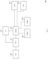
- FIG. 2is a block diagram illustrating aspects of a system for charging two batteries from a single adapter or port according to the present embodiments.
- FIG. 2illustrates exemplary system 200 including exemplary charger 202 .
- system 200includes one or more chargers.
- EC 212manages power configurations of system 200 (e.g. determining whether a power adapter is connected or not connected to port 108 and communicating the determination to the EC 212 from the TCPC 210 ), receiving battery status from one or more of batteries 204 - 1 and 204 - 2 (e.g. via a separate or incorporated fuel gauge circuit), and for communicating battery charging and other operational control information to charger 202 (e.g. via at least one SMbus interface).
- the EC 212can communicate with the TCPC 210 and the charger 202 , including controllers housed respectively within the TCPC 210 and the charger 202 via known protocols such as I2C or SMBus, or other protocols which are known or may become known.
- the EC 212can receive information from the TCPC 210 operatively connected to the port 208 via controllers inside TCPC 210 or elsewhere regarding devices attached to the port 208 . In some embodiments, the EC 212 can subsequently send control signals to the controllers for controlling the operations of the voltage regulator module 206 and battery charger module 202 in accordance with the information. In some embodiments, the EC 212 can communicate with one or more charger controllers housed within the charger 202 to control the overall operation of system 200 such that power can be delivered to a subsystem (e.g. system nodes 214 - 1 and 214 - 2 via an output voltage) and/or charge a battery (e.g. batteries 204 - 1 and 204 - 2 ).
- a subsysteme.g. system nodes 214 - 1 and 214 - 2 via an output voltage
- a batterye.g. batteries 204 - 1 and 204 - 2
- the charger 202can be implemented in a 32 Ld 4 ⁇ 4 mm 2 QFN package.
- the charger 202is Pb-frce (RoHS compliant).
- the chargercan be ISL95522 from Renesas Electronics America.
- SIMO buck-boost or other SIMO topologiesmay also be used for different applications.
- charger 202when a USB OTG device (e.g. a cell phone, etc.) is connected to port 208 , charger 202 can be configured to manage the supply of power from one or more of battery 204 - 1 and 204 - 2 to port 208 .
- the charger 202can operate in reverse to provide power in a reverse buck mode, a reverse boost mode, a reverse buck-boost mode, or other methods known in the art to output a regulated voltage to port 208 from one or more of battery 204 - 1 and 204 - 2 .
- a regulated output voltage supplied to the OTG devicecan be the full OTG functionality range (e.g. providing OTG voltages from 5V to 20V).
- the battery 204 - 1 and the battery 204 - 2may be charged alternately. Further details of the charger 202 according to the present embodiments will be provided below.
- the system 200is included within a notebook computer (e.g. Ultrabook), and batteries 204 - 1 and 204 - 2 include at least one rechargeable 1S/2S/3S/4S (e.g. 1 cell, 2 cell, 3 cell, or 4 cell stack) Lithium-ion (Li-ion) battery.
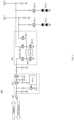
- FIG. 3is a schematic diagram illustrating an example battery charger for two or more systems and their corresponding battery stacks according to the present embodiments.
- FIG. 3illustrates exemplary system 300 including exemplary power delivery and/or port detection (“PD”) controller 301 and exemplary charger 302 .
- charger 302provides an output voltage to system node 305 - 1 , system node 305 - 2 , battery 304 - 1 , and battery 304 - 2 .
- the charger 302provides system power to system node 305 - 1 and system node 305 - 2 , and charging power to battery 304 - 1 and battery 304 - 2 .
- the charger 302includes a battery charger controller 302 -A, as discussed above, and other components (e.g. an inductor and switching transistors or power MOSFETs).
- charger 302includes switching transistors 302 -B, 302 -C, 302 -D, 302 - 1 and 302 - 2 .
- one or more of the switching transistorsare power transistors. While a battery charger controller is described, the disclosure is not limited to battery charger controllers and can include buck-boost converters, boost converters, buck converters, integrated circuits with identical functionality and the like.
- an alternating charging cyclemay not be strictly isolating, in which power provided to a first load from the charger at least partially occurs during or otherwise overlaps with providing power to a second load.
- a conditional charging or isolating modecan depend on relative voltages between battery 424 - 1 and 424 - 2 , 434 - 1 and 434 - 2 , 444 - 1 and 444 - 2 , or 454 - 1 and 454 - 2 .
- a battery charger in accordance with exemplary embodimentsmay implement an alternating charging cycle with a buck, boost, or buck-boost transistor configuration.
- a relationship between output voltage and supply voltagemay influence the form of the transistor configuration.
- the charging cyclemay correspond to one or more PWM cycles, or portions thereof, in a PWM modulation scheme. In other embodiments, the charging cycle(s) and the PWM cycles may be completely independent of each other.
- FIGS. 4 A-Fillustrate exemplary operation of system 300 as system 400 , 410 , 420 , 430 , 440 , and 450 , respectively.
- Each of these exemplary systemsincludes PD controller 401 , a charger 402 connected to an output of the PD controller 401 , and a port 406 connected to an input of the PD controller 301 .
- the exemplary PD controller 401 of exemplary system 400includes a PD-IC 401 -A, a pair of back-to-back FETs 401 -B, and a single FET 401 -C.
- EC 212may directly or indirectly control operation of battery charger controller 402 -A.
- a transistor activation stateincludes providing a nonzero voltage to a transistor gate terminal.
- a transistor deactivation stateincludes providing a ground voltage to a transistor gate terminal.
- a transistor deactivation stateincludes providing a floating or high impedance voltage to a transistor gate terminal.
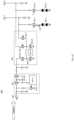
- FIG. 4 Billustrates an example operation of the battery charger in FIG. 3 in a second charging mode of a second battery.
- Exemplary system 410illustrates the exemplary charger 402 operating in a second charging mode delivering power to battery 414 - 2 and electrically isolating battery 414 - 1 .
- switching transistor 412 - 1is deactivated with a predetermined negative or ground gate voltage
- switching transistor 412 - 2is activated with a predetermined positive gate voltage
- battery control transistor 413 - 1is deactivated with a predetermined negative or ground gate voltage
- battery control transistor 413 - 2is activated with a predetermined positive gate voltage.
- exemplary charging current 417flows to battery 414 - 2 from charger 402 through switching transistor 412 - 2 and battery control transistor 413 - 2 , and battery 414 - 1 is electrically isolated from charger 402 by switching transistor 412 - 1 and battery control transistor 413 - 1 .
- FIGS. 4 C-Fillustrate exemplary operation of the battery charger in FIG. 3 in various conditional charging modes.
- a conditional charging modeis conditioned at least upon a relative voltage level of a first battery with respect to a second battery.
- switching transistor 422 - 1is activated with a predetermined positive gate voltage
- switching transistor 422 - 2is activated with a predetermined positive gate voltage
- battery control transistor 423 - 1is activated with a predetermined positive gate voltage
- battery control transistor 423 - 2is deactivated with a predetermined negative or ground gate voltage.
- exemplary charging current 427flows to battery 424 - 1 from charger 402 through switching transistor 422 - 1 and battery control transistor 423 - 1
- battery 424 - 2is electrically isolated from charger 402 by battery control transistor 423 - 2 .
- power received at the port 406 from a power adapteris delivered to both the system node 425 - 1 and the system node 425 - 2 .
- switching transistor 442 - 1is deactivated with a predetermined negative or ground gate voltage
- switching transistor 442 - 2is activated with a predetermined positive gate voltage
- battery control transistor 443 - 1can be activated or deactivated depending on voltage level at system node 445 - 1
- battery control transistor 443 - 2is activated with a predetermined positive gate voltage.
- exemplary charging current 447flows to battery 444 - 2 from charger 402 through switching transistor 442 - 2 and battery control transistor 443 - 2 , and battery 444 - 1 is electrically isolated from charger 402 by switching transistor 442 - 1 .
- FIG. 4 Fillustrates an example operation of the battery charger in FIG. 3 in a fourth conditional charging mode of a second battery where the voltage level of battery 454 - 1 is less than the voltage level of battery 454 - 2 .
- Exemplary system 450illustrates the exemplary charger 402 operating in a fourth conditional charging mode delivering power to battery 454 - 2 and electrically isolating battery 454 - 1 .
- switching transistor 452 - 1is activated with a predetermined positive gate voltage
- switching transistor 452 - 2is activated with a predetermined positive gate voltage
- switching transistor 453 - 1is deactivated with a predetermined negative or ground gate voltage
- battery control transistor 453 - 2is activated with a predetermined positive gate voltage.
- exemplary charging current 457flows to battery 454 - 2 from charger 402 through switching transistor 452 - 2 and battery control transistor 453 - 2 , and battery 454 - 1 is electrically isolated from charger 402 by battery control transistor 453 - 1 .
- FIG. 5is a block diagram illustrating an example adaptation of the charger in FIG. 3 for a Dual Type-C Ports application.
- FIG. 5illustrates exemplary system 500 including exemplary first subsystem having a first port detection (“PD”) controller 501 (having a pair of back-to-back transistors 501 -B) and first charger 502 (including inductor L 1 ) in accordance with the exemplary embodiments of FIG. 3 , and exemplary second subsystem having a second port detection (“PD”) controller 504 (having a pair of back-to-back transistors 504 -B) and second charger 505 (including inductor L 2 ) having structure corresponding to those of the first port detection (“PD”) controller 501 and the first charger 502 , respectively.
- PDport detection
- PDsecond port detection
- two adaptersmay be connected respectively to ports 503 and 506 . These adapters may supply charging power for batteries 508 - 1 and 508 - 2 , and supply system node 509 - 1 and 509 - 2 via the chargers 502 and 505 .
- two OTG devicesmay be connected respectively to ports 503 and 506 , where a full range of OTG voltage (e.g. from 5V to 20V) can be supported via the chargers 502 and 505 .
- an adaptorcan be connected to one port 503 or 506
- an OTG devicecan be connected to another port 503 or 506 .
- the devices connected to the portscan be detected, for example, by TCPC functionality in PD-ICs 501 -A and 504 -A in PD controller modules 501 and 504 , respectively.
- FIG. 7illustrates an example method 700 of operation of the battery charger in FIG. 3 in a plurality of conditional charging modes.
- exemplary system in operation in accordance with method 700may include, but is not limited to, the system 300 and one or more of the operating states 4 C- 4 F associated therewith.
- the exemplary systemobtains one or more charging instructions.
- the exemplary systemmay receive one or more instructions to charge at least one battery present in the exemplary system.
- Charging instructionsmay comprise one or more of logic levels, electrical input, magnetic input, digitized electrical signals, or the like.
- the method 700then proceeds to step 712 .
- the exemplary systementers a first conditional charging mode.
- the exemplary first conditional charging mode of step 732at least four transistors in the exemplary system enter or remain in particular states.
- a first charger switching transistor coupled to a first system nodeis or remains activated;
- a first battery control transistor coupled to the first system nodeis or remains activated;
- a second charger switching transistor coupled to a second system nodeis or remains activated;
- a second battery control transistor coupled to the second system nodeis or remains deactivated.
- the first and second charger switching transistorsmay respectively each comprise, in various embodiments, a boost-high transistor in a buck-boost voltage regulator.
- currentmay flow to the first battery while current is isolated from the second battery.
- the exemplary systemdetermines whether the first voltage across the first battery is greater than or equal to the second voltage across the second battery.
- the method 700may determine, at step 740 , whether the voltage of the first battery is greater than or equal to the voltage of the second battery. It is to be understood that the exemplary system may conduct a determination at step 740 with any threshold or combination of thresholds, or with any criterion or criteria in accordance with the present embodiments, and that the exemplary system is thus not limited to the determination of step 740 . If the first voltage is greater than or equal to the second voltage, then the method 700 proceeds to step 742 . Alternatively, if the first voltage is not greater than or equal to the second voltage, then the method 700 proceeds to step 744 .
- any two components so associatedcan also be viewed as being “operably connected,” or “operably coupled,” to each other to achieve the desired functionality, and any two components capable of being so associated can also be viewed as being “operably couplable,” to each other to achieve the desired functionality.
- operably couplableinclude but are not limited to physically mateable and/or physically interacting components and/or wirelessly interactable and/or wirelessly interacting components and/or logically interacting and/or logically interactable components
Landscapes
- Engineering & Computer Science (AREA)
- Power Engineering (AREA)
- Charge And Discharge Circuits For Batteries Or The Like (AREA)
- Secondary Cells (AREA)
Abstract
Description
Claims (19)
Priority Applications (3)
| Application Number | Priority Date | Filing Date | Title |
|---|---|---|---|
| US16/901,673US12278508B2 (en) | 2019-06-17 | 2020-06-15 | Single inductor multiple output charger for multiple battery applications |
| CN202010547413.7ACN112104012A (en) | 2019-06-17 | 2020-06-16 | Single inductor multiple output charger for multiple battery applications |
| TW109120358ATWI891639B (en) | 2019-06-17 | 2020-06-17 | Charging device and charging method |
Applications Claiming Priority (2)
| Application Number | Priority Date | Filing Date | Title |
|---|---|---|---|
| US201962862422P | 2019-06-17 | 2019-06-17 | |
| US16/901,673US12278508B2 (en) | 2019-06-17 | 2020-06-15 | Single inductor multiple output charger for multiple battery applications |
Publications (2)
| Publication Number | Publication Date |
|---|---|
| US20200395774A1 US20200395774A1 (en) | 2020-12-17 |
| US12278508B2true US12278508B2 (en) | 2025-04-15 |
Family
ID=73744818
Family Applications (1)
| Application Number | Title | Priority Date | Filing Date |
|---|---|---|---|
| US16/901,673Active2040-08-07US12278508B2 (en) | 2019-06-17 | 2020-06-15 | Single inductor multiple output charger for multiple battery applications |
Country Status (2)
| Country | Link |
|---|---|
| US (1) | US12278508B2 (en) |
| CN (1) | CN112104012A (en) |
Citations (160)
| Publication number | Priority date | Publication date | Assignee | Title |
|---|---|---|---|---|
| US4020243A (en)* | 1974-03-22 | 1977-04-26 | Oldford William G | Electrical measuring system for testing electrical components |
| US4034762A (en)* | 1975-08-04 | 1977-07-12 | Electro Medical Systems, Inc. | Vas cautery apparatus |
| US4066996A (en)* | 1976-02-20 | 1978-01-03 | Warner Electric Brake & Clutch Company | Breakaway protection for electrically controlled trailer brakes |
| US4224383A (en)* | 1978-12-26 | 1980-09-23 | Power-Lite Industries, Inc. | Rechargeable battery pack |
| US4238722A (en)* | 1978-07-20 | 1980-12-09 | Ford Jimmie R | Battery safety jumper cables |
| US4345304A (en)* | 1980-03-03 | 1982-08-17 | Streamlight, Inc. | Rechargeable lamp assembly, mounting unit, and circuit therefor |
| US4463283A (en)* | 1980-03-03 | 1984-07-31 | Streamlight, Inc. | Rechargeable lamp assembly, mounting unit, and circuit therefor |
| US4930997A (en)* | 1987-08-19 | 1990-06-05 | Bennett Alan N | Portable medical suction device |
| US4943770A (en)* | 1987-04-21 | 1990-07-24 | Mccormick Laboratories, Inc. | Device for accurately detecting the position of a ferromagnetic material inside biological tissue |
| US5057762A (en)* | 1990-07-30 | 1991-10-15 | Motorola, Inc. | System for determining battery charge states and charging sequence for a battery charger |
| US5117173A (en)* | 1991-02-22 | 1992-05-26 | Motorola, Inc. | Integrated battery cycle counter |
| US5166596A (en)* | 1991-08-29 | 1992-11-24 | Motorola, Inc. | Battery charger having variable-magnitude charging current source |
| US5200644A (en)* | 1988-05-31 | 1993-04-06 | Kabushiki Kaisha Toshiba | Air conditioning system having battery for increasing efficiency |
| US5545933A (en)* | 1993-09-28 | 1996-08-13 | Okamura Laboratory Inc. | Electric power storage apparatus |
| US5640078A (en)* | 1994-01-26 | 1997-06-17 | Physio-Control Corporation | Method and apparatus for automatically switching and charging multiple batteries |
| US5666006A (en)* | 1994-05-12 | 1997-09-09 | Apple Computer, Inc. | Circuit offering sequential discharge and simultaneous charge for a multiple battery system and method for charging multiple batteries |
| US5717309A (en)* | 1995-10-30 | 1998-02-10 | Samsung Electronics Co. | Dual battery charging device |
| US5955867A (en)* | 1997-07-29 | 1999-09-21 | Dell Usa L.P. | Dual battery pack charging in a computer system |
| US5982050A (en)* | 1996-03-14 | 1999-11-09 | Fuji Jukogyo Kabushiki Kaisha | Power supply unit for automotive vehicle |
| US6081101A (en)* | 1998-09-04 | 2000-06-27 | Yang; Tai-Her | Temperature switch controlled charging circuit |
| US6226190B1 (en)* | 1998-02-27 | 2001-05-01 | Power Integrations, Inc. | Off-line converter with digital control |
| US6229349B1 (en)* | 1995-04-19 | 2001-05-08 | Gec Alsthom Acec Transport S.A. | AC input cell for data acquisition circuits |
| US20020079865A1 (en)* | 1998-04-15 | 2002-06-27 | Tyco Electronics Corporation | Devices and methods for protection of rechargeable elements |
| US20020089307A1 (en)* | 2001-01-10 | 2002-07-11 | Tai-Her Yang | Electric appliance equipped with redundant battery enabled by mains power supply |
| US20030137304A1 (en)* | 2002-01-22 | 2003-07-24 | Danylyk Donald Bohdan | E-water machine |
| US20030223227A1 (en)* | 2002-05-29 | 2003-12-04 | Team Products International, Inc. | Smart pad switches |
| US20040046673A1 (en)* | 2002-09-05 | 2004-03-11 | S-B Power Tool Corporation | Battery charge indicating circuit |
| US20040124716A1 (en)* | 2002-07-25 | 2004-07-01 | Keiji Shirato | Battery-power-operated circuit |
| US20050001593A1 (en)* | 2003-05-30 | 2005-01-06 | Atsushi Kawasumi | Method of charging and discharging a plurality of batteries |
| US6864669B1 (en)* | 2002-05-02 | 2005-03-08 | O2Micro International Limited | Power supply block with simplified switch configuration |
| US20050052154A1 (en)* | 2002-09-11 | 2005-03-10 | Kavounas Gregory T. | Reconfigurable defibrillator battery module and method |
| US20060232667A1 (en)* | 2005-04-14 | 2006-10-19 | Pentax Corporation | Voltage control circuit for endoscope |
| US20070188126A1 (en)* | 2005-11-18 | 2007-08-16 | Patrick Dickson | Method and apparatus for utilizing used batteries to surface charge an automobile battery |
| US20070216355A1 (en)* | 2006-03-20 | 2007-09-20 | Lg Electronics Inc. | Apparatus and method for managing power of battery packs in a portable device |
| US20070253225A1 (en)* | 2006-04-26 | 2007-11-01 | Stefan Baurle | Method and apparatus for transformerless safety isolation in a power supply |
| US20080036419A1 (en)* | 2004-01-14 | 2008-02-14 | Vanner, Inc. | Battery isolator |
| US20080219032A1 (en)* | 2007-03-09 | 2008-09-11 | Stancu Constantin C | Method and system for operating a power converter |
| US20090115374A1 (en)* | 2006-02-15 | 2009-05-07 | Ricoh Company, Ltd. | Charging Circuit For Secondary Battery, Power Supply Switching Method In Charging Circuit For Secondary Battery, And Power Supply Unit |
| US20100001682A1 (en)* | 2005-11-18 | 2010-01-07 | Automotive Energy Systems Llc | Method and apparatus for utilizing recycled batteries to surface charge an automobile battery |
| US20100123428A1 (en)* | 2008-11-19 | 2010-05-20 | Kuen-Der Wu | Battery-Charging Device for a Stand-Alone Generator System having a MPPT Function and Method Thereof |
| US20100149840A1 (en)* | 2008-12-15 | 2010-06-17 | Canon Kabushiki Kaisha | Power supply apparatus and image forming apparatus |
| US20100194344A1 (en)* | 2009-02-05 | 2010-08-05 | Infineon Technologies Ag | Combining Two or More DC to DC Converters to Limit External Coils |
| US20100219794A1 (en)* | 2007-10-23 | 2010-09-02 | Toyota Jidosha Kabushiki Kaisha | Electrically-powered vehicle |
| US20100261043A1 (en)* | 2009-04-10 | 2010-10-14 | The Regents Of The University Of Michigan | Dynamically Reconfigurable Framework For A Large-Scale Battery System |
| US20100264893A1 (en)* | 2009-04-16 | 2010-10-21 | Delta Electronics, Inc. | Power supply apparatus and power supply system with multiple power supply apparatuses |
| US7854203B2 (en)* | 2001-03-27 | 2010-12-21 | General Electric Company | Electrical energy capture system with circuitry for blocking flow of undesirable electrical currents therein |
| US20110025125A1 (en)* | 2009-07-31 | 2011-02-03 | Ladislaus Joseph Brabec | Bi-directional battery voltage converter |
| US20110140649A1 (en)* | 2009-12-15 | 2011-06-16 | Looney Choi | Energy storage system |
| US20110144861A1 (en)* | 2009-12-14 | 2011-06-16 | Control Solutions LLC | Electronic circuit for charging and heating a battery |
| US20110156479A1 (en)* | 2009-03-17 | 2011-06-30 | Min Carroll | Solar powered DC load system |
| US20120068537A1 (en)* | 2010-09-20 | 2012-03-22 | Andrew Stephen Hintz | Energy management system |
| US20120091930A1 (en)* | 2009-06-30 | 2012-04-19 | Kenji Takahashi | Power supply system, electric vehicle provided with same, and control method of power supply system |
| US20120112693A1 (en)* | 2010-11-05 | 2012-05-10 | Ruediger Soeren Kusch | Apparatus and method for charging an electric vehicle |
| US20120126820A1 (en)* | 2008-09-17 | 2012-05-24 | Stl Energy Technology (S) Pte Ltd | Battery pack burn-in test system and method |
| US20120133310A1 (en)* | 2009-07-02 | 2012-05-31 | Chong Uk Lee | Reconfigurable battery |
| US20120256568A1 (en)* | 2009-07-02 | 2012-10-11 | Chong Uk Lee | Multi-port reconfigurable battery |
| US20120286733A1 (en)* | 2011-05-12 | 2012-11-15 | Lite-On Clean Energy Technology Corp. | Battery system and battery equalizer |
| US20130062946A1 (en)* | 2011-09-14 | 2013-03-14 | Electronvault, Inc. | Hierarchical balancing system |
| US20130076301A1 (en)* | 2011-09-28 | 2013-03-28 | Integrated Device Technology, Inc. | Apparatus and method for a switching power converter |
| US20130082661A1 (en)* | 2011-10-03 | 2013-04-04 | R. W. Beckett Corporation | Mobile Power Systems for High Power Applications |
| US20130090797A1 (en)* | 2010-06-23 | 2013-04-11 | Toyota Jidosha Kabushiki Kaisha | Vehicular control device and method |
| US20130154372A1 (en)* | 2011-12-14 | 2013-06-20 | Macroblock, Inc. | Power-factor-corrected resonant converter and parallel power-factor-corrected resonant converter |
| US20130187612A1 (en)* | 2011-03-18 | 2013-07-25 | Asahi Kasei Microdevices Corporation | Balance charging circuit for series-connected storage cells and balance charging method for series-connected storage cells |
| US20140084862A1 (en)* | 2011-05-25 | 2014-03-27 | Hitachi, Ltd. | Charging System |
| US20140087215A1 (en)* | 2012-09-24 | 2014-03-27 | Samsung Sdi Co., Ltd. | Temperature controlling system and method of battery |
| US20140145504A1 (en)* | 2012-11-28 | 2014-05-29 | Renesas Electronics Corporation | Semiconductor integrated circuit and operation method of the same |
| US20140266011A1 (en)* | 2013-03-15 | 2014-09-18 | Qualcomm Incorporated | Multiphase charger |
| US20140285158A1 (en)* | 2011-12-13 | 2014-09-25 | Shindengen Electric Manufacturing Co., Ltd | Regulator, battery charging apparatus and battery charging method |
| US20140368041A1 (en)* | 2013-06-17 | 2014-12-18 | Mcmaster Universtiy | Reconfigurable hybrid energy storage system for electrified vehicles |
| US20150009657A1 (en)* | 2013-07-05 | 2015-01-08 | Thierno Souleymane Bah | Light Apparatus |
| US20150054753A1 (en)* | 2013-08-23 | 2015-02-26 | Ethicon Endo-Surgery, Inc. | Interactive displays |
| US20150137754A1 (en)* | 2012-06-27 | 2015-05-21 | Byd Company Limited | Charging system, vehicle comprising the same and method for controlling charging vehicle with the same |
| US20150263390A1 (en)* | 2012-10-11 | 2015-09-17 | Renault S.A.S. | Structure for modulating the voltage of a battery and the active equilibration thereof |
| US20150329007A1 (en)* | 2014-05-14 | 2015-11-19 | Toyota Jidosha Kabushiki Kaisha | Power supply control device |
| US20150333550A1 (en)* | 2012-12-20 | 2015-11-19 | Hitachi, Ltd. | Electricity Storage System |
| US20160065070A1 (en)* | 2014-08-27 | 2016-03-03 | Renesas Electronics Corporation | Semiconductor device |
| US20160087472A1 (en)* | 2014-09-22 | 2016-03-24 | Qualcomm Incorporated | Multiple power chargers for mobile terminals |
| US20160099582A1 (en)* | 2014-10-02 | 2016-04-07 | Stmicroelectronics S.R.L. | Single inductor dc-dc converter with regulated output and energy harvesting system |
| US20160118825A1 (en)* | 2014-10-28 | 2016-04-28 | Renesas Electronics America Inc. | High voltage generation method at battery system |
| US20160202743A1 (en)* | 2015-01-12 | 2016-07-14 | Dong-Sheng Li | Hub Having Complex Power Converters |
| US20160246316A1 (en)* | 2015-02-24 | 2016-08-25 | Intersil Americas LLC | System and method for determining adapter current limit |
| US20160254689A1 (en)* | 2015-02-27 | 2016-09-01 | Kwang Chan LEE | Dc-dc converter, charger integrated circuit and electronic device having the same and battery charging method thereof |
| US20160285283A1 (en)* | 2013-11-21 | 2016-09-29 | Renault S.A.S | Balancing of a battery having two branches, with bridging of differential numbers of storage elements |
| US20160352101A1 (en)* | 2015-05-29 | 2016-12-01 | Samsung Electronics Co., Ltd. | Electronic device and method for controlling dynamic power |
| US20160380455A1 (en)* | 2015-06-24 | 2016-12-29 | Apple Inc. | Systems and methods for bidirectional two-port battery charging with boost functionality |
| US20170077729A1 (en)* | 2015-09-11 | 2017-03-16 | Renesas Electronics America Inc. | Transformer less battery charger system |
| US20170110893A1 (en)* | 2015-08-31 | 2017-04-20 | Silergy Semiconductor Technology (Hangzhou) Ltd | Battery balance circuit and battery apparatus thereof |
| US20170279275A1 (en)* | 2014-12-18 | 2017-09-28 | Fujikura Ltd. | Power storage system and power storage method |
| US20170279284A1 (en)* | 2016-03-22 | 2017-09-28 | Intersil Americas LLC | Multiple chargers configuration in one system |
| US20170282745A1 (en)* | 2016-03-30 | 2017-10-05 | Honda Motor Co.,Ltd. | Power supply apparatus, transport device including power supply apparatus, estimating method of estimating correlation information between charge rate and open-end voltage of electric storage section, and computer readable medium for estimating correlation information |
| US20170338672A1 (en)* | 2014-10-27 | 2017-11-23 | Robert Bosch Gmbh | Method and circuit arrangement for actively balancing cells of an electric energy store |
| US20170366023A1 (en)* | 2015-02-17 | 2017-12-21 | Mitsubishi Electric Corporation | Power conversion system |
| US20180062415A1 (en)* | 2016-08-24 | 2018-03-01 | Tianjin Synergy Groups Co., Ltd. | Mobile power supply |
| US20180086330A1 (en)* | 2016-09-27 | 2018-03-29 | Honda Motor Co., Ltd. | Power system and method for operating power sytem |
| US9973017B2 (en)* | 2014-09-19 | 2018-05-15 | Samsung Electronics Co., Ltd. | Charger circuit including a plurality of charging paths |
| US20180219397A1 (en)* | 2017-01-31 | 2018-08-02 | Toyota Jidosha Kabushiki Kaisha | Electric power supply system |
| US20180269697A1 (en)* | 2016-10-12 | 2018-09-20 | Guangdong Oppo Mobile Telecommunications Corp., Ltd. | Chargeable device and charging method |
| US20180331564A1 (en)* | 2017-05-12 | 2018-11-15 | Qualcomm Incorporated | Master-slave charging circuit with slave charger input current sensing and adaptive battery current limiting |
| US20180334118A1 (en)* | 2017-05-18 | 2018-11-22 | Yazaki Corporation | Power distribution system |
| US20180354374A1 (en)* | 2017-06-13 | 2018-12-13 | Hyundai Motor Company | System and method of controlling charge of vehicle battery |
| US20190063891A1 (en)* | 2008-06-29 | 2019-02-28 | Omnitek Partners Llc | Inertially Operated Piezoelectric Energy Harvesting Electronic Circuitry |
| US10243376B2 (en)* | 2016-06-15 | 2019-03-26 | Schneider Electric It Corporation | Stack DC power supply battery charger |
| US10250059B2 (en)* | 2016-09-19 | 2019-04-02 | Microsoft Technology Licensing, Llc | Charging circuit for battery-powered device |
| US20190100321A1 (en)* | 2017-09-30 | 2019-04-04 | Beihang University | Power supply and distribution device for solar-powered aircraft |
| US20190103805A1 (en)* | 2016-06-08 | 2019-04-04 | Nanjing Chervon Industry Co., Ltd. | Power station |
| US20190207392A1 (en)* | 2017-12-29 | 2019-07-04 | Chengdu Monolithic Power Systems Co., Ltd. | Battery charging circuit with improved system stability and control method thereof |
| US20190214831A1 (en)* | 2018-01-10 | 2019-07-11 | Microsoft Technology Licensing, Llc | Distributed battery architecture |
| US20190214837A1 (en)* | 2018-01-10 | 2019-07-11 | Microsoft Technology Licensing, Llc | Parallel charging and discharging of batteries with disparate characteristics |
| US10363828B1 (en)* | 2018-06-12 | 2019-07-30 | Nio Usa, Inc. | Systems and methods for regulating charging of electric vehicles |
| US10404095B2 (en)* | 2014-06-25 | 2019-09-03 | Fdk Corporation | Uninterruptible power supply unit |
| US10446880B2 (en)* | 2015-07-23 | 2019-10-15 | Lg Chem., Ltd. | Battery stack balancing apparatus |
| US20190356134A1 (en)* | 2017-01-26 | 2019-11-21 | Sony Interactive Entertainment Inc. | Electrical device |
| US20200006952A1 (en)* | 2016-09-28 | 2020-01-02 | Samsung Electronics Co., Ltd. | Electronic device for controlling power |
| US20200014219A1 (en)* | 2018-07-09 | 2020-01-09 | GM Global Technology Operations LLC | Battery module with active cell balancing using energy storage element and two tiers of switches |
| US20200062140A1 (en)* | 2017-05-03 | 2020-02-27 | Huawei Technologies Co., Ltd. | Distributed Battery, Battery Control Method, and Electric Vehicle |
| US20200067335A1 (en)* | 2018-08-21 | 2020-02-27 | Renesas Electronics America Inc. | System and method for providing reverse boost mode in battery charger application |
| US20200099229A1 (en)* | 2018-09-21 | 2020-03-26 | Samsung Electronics Co., Ltd. | Load switch circuit and method of controlling battery power using the same |
| US20200144829A1 (en)* | 2018-11-07 | 2020-05-07 | Samsung Electronics Co., Ltd. | Charger integrated circuit for charging battery device and electronic device including the charger integrated circuit |
| US20200177008A1 (en)* | 2018-12-04 | 2020-06-04 | Alex Tiedtke | Mobile power system with bidirectional ac-dc converter and related platforms and methods |
| US20200244170A1 (en)* | 2019-01-30 | 2020-07-30 | Renesas Electronics America Inc. | Power delivery architecture for multiport systems |
| US10770912B2 (en)* | 2016-03-25 | 2020-09-08 | Anpec Electronics Corporation | Charging device and control method thereof |
| US20200295588A1 (en)* | 2018-08-21 | 2020-09-17 | Renesas Electronics America Inc. | Buck boost charger configuration with reverse boost mode |
| US20200358295A1 (en)* | 2019-05-09 | 2020-11-12 | Renesas Electronics America Inc. | Buck-boost battery charger for dual battery application |
| US10847991B2 (en)* | 2016-11-15 | 2020-11-24 | Huawei Technologies Co., Ltd. | Multiple bidirectional converters for charging and discharging of energy storage units |
| US20200403426A1 (en)* | 2019-06-24 | 2020-12-24 | Renesas Electronics America Inc. | Adapter power add-up feature for multiport systems |
| US20210057929A1 (en)* | 2019-08-20 | 2021-02-25 | Renesas Electronics America Inc. | Device and method for independent charge control of a multiple port battery charger |
| US10936032B2 (en)* | 2018-12-11 | 2021-03-02 | Dell Products L.P. | Information handling system dual charger power balancing and fast role swapping |
| US20210066930A1 (en)* | 2019-08-27 | 2021-03-04 | Globe (Jiangsu) Co., Ltd | Power System |
| US20210066956A1 (en)* | 2019-08-27 | 2021-03-04 | Yazaki Corporation | Vehicle power supply system |
| US20210175734A1 (en)* | 2019-12-06 | 2021-06-10 | Renesas Electronics America Inc. | Device and method for generating magnitude and rate offsets at a phase comparator |
| US20210203179A1 (en)* | 2019-12-26 | 2021-07-01 | Dialog Semiconductor (Uk) Limited | Power Management Circuit |
| US20210242693A1 (en)* | 2020-02-03 | 2021-08-05 | Wisk Aero Llc | Redundant power distribution circuits including dc/dc converters |
| US20210265842A1 (en)* | 2020-02-25 | 2021-08-26 | Renesas Electronics America Inc. | Bidirectional battery charging system including capacitor divider circuit |
| US20210305816A1 (en)* | 2018-09-06 | 2021-09-30 | Panasonic Intellectual Property Management Co., Ltd. | Equalization circuit and power storage system |
| US20210302015A1 (en)* | 2020-03-24 | 2021-09-30 | Samir Moufawad Moufawad | Lasting And Representative Dim Light Apparatus |
| US20210313813A1 (en)* | 2018-09-06 | 2021-10-07 | Panasonic Intellectual Property Management Co., Ltd. | Energy transfer circuit and power storage system |
| US20210320504A1 (en)* | 2020-04-13 | 2021-10-14 | Samsung Electronics Co., Ltd. | Electronic device for controlling charging of multiple batteries connected in parallel and method for operating same |
| US20210328514A1 (en)* | 2018-09-07 | 2021-10-21 | Magna International Inc. | Dual dc-dc converter |
| US11245332B1 (en)* | 2019-02-08 | 2022-02-08 | Renesas Electronics America Inc. | Reference voltage control in a switch mode power supply |
| US11243551B1 (en)* | 2020-09-24 | 2022-02-08 | Renesas Electronics America Inc. | Method and system of dynamic voltage compensation for electrical power delivery |
| US20220052534A1 (en)* | 2020-08-11 | 2022-02-17 | Renesas Electronics America Inc. | Inductive charger apparatus with multiple charging paths and method for charging therewith |
| US20220102999A1 (en)* | 2020-09-28 | 2022-03-31 | Monolithic Power Systems, Inc. | Battery charge current management system and related integrated circuit |
| US20220097549A1 (en)* | 2020-09-28 | 2022-03-31 | Yazaki Corporation | Electric power supply system |
| US20220102769A1 (en)* | 2020-09-30 | 2022-03-31 | GM Global Technology Operations LLC | Architecture for battery self heating |
| US20220115879A1 (en)* | 2020-10-08 | 2022-04-14 | Element Energy, Inc. | Safe battery energy management systems, battery management system nodes, and methods |
| US20220131398A1 (en)* | 2019-07-15 | 2022-04-28 | Eaton Intelligent Power Limited | Power distribution and circuit protection for a mobile application having a high efficiency inverter |
| US20220140621A1 (en)* | 2020-10-30 | 2022-05-05 | Samsung Electronics Co., Ltd. | Charging integrated circuit for charging battery device and electronic device including the same |
| US20220149644A1 (en)* | 2020-11-11 | 2022-05-12 | Halo Microelectronics International | Battery Charger System and Control Method |
| US11368027B2 (en)* | 2018-05-31 | 2022-06-21 | Samsung Electronics Co., Ltd. | Electronic device including control circuits controlling switches connected to charging circuit |
| US20220200322A1 (en)* | 2020-12-22 | 2022-06-23 | Renesas Electronics America Inc. | Device and method for reducing current overshoot in a power regulator |
| US20220209546A1 (en)* | 2020-12-10 | 2022-06-30 | B2U Storage Solutions Inc. | Energy storage system and method employing second-life electric vehicle batteries |
| US20220216703A1 (en)* | 2019-05-24 | 2022-07-07 | Panasonic Intellectual Property Management Co., Ltd. | Energy transfer circuit and power storage system |
| US11387659B2 (en)* | 2018-06-26 | 2022-07-12 | Texas Instruments Incorporated | Switching mode charger with pass through mode |
| US20220231518A1 (en)* | 2021-01-19 | 2022-07-21 | Qualcomm Incorporated | Multi-output switched-mode power supply for multi-cell-in-series battery charging |
| US20220274498A1 (en)* | 2019-07-31 | 2022-09-01 | Byd Company Limited | Discharging vehicle and vehicle charging system |
| US20220285964A1 (en)* | 2021-03-05 | 2022-09-08 | Honda Motor Co., Ltd. | Power supply circuit |
| US11509146B1 (en)* | 2022-04-19 | 2022-11-22 | Nuvolta Technologies (Hefei) Co., Ltd. | Dual-battery charging apparatus and control method |
| US20230142751A1 (en)* | 2021-11-09 | 2023-05-11 | Samsung Electronics Co., Ltd. | Charger integrated circuit for charging series battery device and electronic device including same |
| US20240136846A1 (en)* | 2021-02-26 | 2024-04-25 | Foundation For Research And Business, Seoul National University Of Science And Technology | Three-phase and single-phase two-way charger |
| US20240239219A1 (en)* | 2021-12-24 | 2024-07-18 | Byd Company Limited | Vehicle, and energy conversion device and discharging method therefor |
Family Cites Families (1)
| Publication number | Priority date | Publication date | Assignee | Title |
|---|---|---|---|---|
| CN102570529A (en)* | 2010-12-30 | 2012-07-11 | 金宝电子工业股份有限公司 | Power management circuit, power management module and power management method thereof |
- 2020
- 2020-06-15USUS16/901,673patent/US12278508B2/enactiveActive
- 2020-06-16CNCN202010547413.7Apatent/CN112104012A/enactivePending
Patent Citations (240)
| Publication number | Priority date | Publication date | Assignee | Title |
|---|---|---|---|---|
| US4020243A (en)* | 1974-03-22 | 1977-04-26 | Oldford William G | Electrical measuring system for testing electrical components |
| US4034762A (en)* | 1975-08-04 | 1977-07-12 | Electro Medical Systems, Inc. | Vas cautery apparatus |
| US4066996A (en)* | 1976-02-20 | 1978-01-03 | Warner Electric Brake & Clutch Company | Breakaway protection for electrically controlled trailer brakes |
| US4238722A (en)* | 1978-07-20 | 1980-12-09 | Ford Jimmie R | Battery safety jumper cables |
| US4224383A (en)* | 1978-12-26 | 1980-09-23 | Power-Lite Industries, Inc. | Rechargeable battery pack |
| US4345304A (en)* | 1980-03-03 | 1982-08-17 | Streamlight, Inc. | Rechargeable lamp assembly, mounting unit, and circuit therefor |
| US4463283A (en)* | 1980-03-03 | 1984-07-31 | Streamlight, Inc. | Rechargeable lamp assembly, mounting unit, and circuit therefor |
| US4943770A (en)* | 1987-04-21 | 1990-07-24 | Mccormick Laboratories, Inc. | Device for accurately detecting the position of a ferromagnetic material inside biological tissue |
| US4930997A (en)* | 1987-08-19 | 1990-06-05 | Bennett Alan N | Portable medical suction device |
| US5200644A (en)* | 1988-05-31 | 1993-04-06 | Kabushiki Kaisha Toshiba | Air conditioning system having battery for increasing efficiency |
| US5057762A (en)* | 1990-07-30 | 1991-10-15 | Motorola, Inc. | System for determining battery charge states and charging sequence for a battery charger |
| US5117173A (en)* | 1991-02-22 | 1992-05-26 | Motorola, Inc. | Integrated battery cycle counter |
| US5166596A (en)* | 1991-08-29 | 1992-11-24 | Motorola, Inc. | Battery charger having variable-magnitude charging current source |
| US5545933A (en)* | 1993-09-28 | 1996-08-13 | Okamura Laboratory Inc. | Electric power storage apparatus |
| US5640078A (en)* | 1994-01-26 | 1997-06-17 | Physio-Control Corporation | Method and apparatus for automatically switching and charging multiple batteries |
| US5666006A (en)* | 1994-05-12 | 1997-09-09 | Apple Computer, Inc. | Circuit offering sequential discharge and simultaneous charge for a multiple battery system and method for charging multiple batteries |
| US6229349B1 (en)* | 1995-04-19 | 2001-05-08 | Gec Alsthom Acec Transport S.A. | AC input cell for data acquisition circuits |
| US5717309A (en)* | 1995-10-30 | 1998-02-10 | Samsung Electronics Co. | Dual battery charging device |
| US5982050A (en)* | 1996-03-14 | 1999-11-09 | Fuji Jukogyo Kabushiki Kaisha | Power supply unit for automotive vehicle |
| US5955867A (en)* | 1997-07-29 | 1999-09-21 | Dell Usa L.P. | Dual battery pack charging in a computer system |
| US6226190B1 (en)* | 1998-02-27 | 2001-05-01 | Power Integrations, Inc. | Off-line converter with digital control |
| US20020079865A1 (en)* | 1998-04-15 | 2002-06-27 | Tyco Electronics Corporation | Devices and methods for protection of rechargeable elements |
| US6081101A (en)* | 1998-09-04 | 2000-06-27 | Yang; Tai-Her | Temperature switch controlled charging circuit |
| US20020089307A1 (en)* | 2001-01-10 | 2002-07-11 | Tai-Her Yang | Electric appliance equipped with redundant battery enabled by mains power supply |
| US7854203B2 (en)* | 2001-03-27 | 2010-12-21 | General Electric Company | Electrical energy capture system with circuitry for blocking flow of undesirable electrical currents therein |
| US20030137304A1 (en)* | 2002-01-22 | 2003-07-24 | Danylyk Donald Bohdan | E-water machine |
| US6864669B1 (en)* | 2002-05-02 | 2005-03-08 | O2Micro International Limited | Power supply block with simplified switch configuration |
| US20030223227A1 (en)* | 2002-05-29 | 2003-12-04 | Team Products International, Inc. | Smart pad switches |
| US20040124716A1 (en)* | 2002-07-25 | 2004-07-01 | Keiji Shirato | Battery-power-operated circuit |
| US20040046673A1 (en)* | 2002-09-05 | 2004-03-11 | S-B Power Tool Corporation | Battery charge indicating circuit |
| US6873133B1 (en)* | 2002-09-11 | 2005-03-29 | Medtronic Physio-Control Manufacturing Corporation | Defibrillator with a reconfigurable battery module |
| US20050052154A1 (en)* | 2002-09-11 | 2005-03-10 | Kavounas Gregory T. | Reconfigurable defibrillator battery module and method |
| US20050001593A1 (en)* | 2003-05-30 | 2005-01-06 | Atsushi Kawasumi | Method of charging and discharging a plurality of batteries |
| US20080036419A1 (en)* | 2004-01-14 | 2008-02-14 | Vanner, Inc. | Battery isolator |
| US7525320B2 (en)* | 2005-04-14 | 2009-04-28 | Hoya Corporation | Voltage control circuit for endoscope |
| US20060232667A1 (en)* | 2005-04-14 | 2006-10-19 | Pentax Corporation | Voltage control circuit for endoscope |
| US20100001682A1 (en)* | 2005-11-18 | 2010-01-07 | Automotive Energy Systems Llc | Method and apparatus for utilizing recycled batteries to surface charge an automobile battery |
| US20070188126A1 (en)* | 2005-11-18 | 2007-08-16 | Patrick Dickson | Method and apparatus for utilizing used batteries to surface charge an automobile battery |
| US20090115374A1 (en)* | 2006-02-15 | 2009-05-07 | Ricoh Company, Ltd. | Charging Circuit For Secondary Battery, Power Supply Switching Method In Charging Circuit For Secondary Battery, And Power Supply Unit |
| US20070216355A1 (en)* | 2006-03-20 | 2007-09-20 | Lg Electronics Inc. | Apparatus and method for managing power of battery packs in a portable device |
| US7839121B2 (en)* | 2006-03-20 | 2010-11-23 | Lg Electronics Inc. | Apparatus and method for managing power of battery packs in a portable device |
| US20070253225A1 (en)* | 2006-04-26 | 2007-11-01 | Stefan Baurle | Method and apparatus for transformerless safety isolation in a power supply |
| US20080219032A1 (en)* | 2007-03-09 | 2008-09-11 | Stancu Constantin C | Method and system for operating a power converter |
| US8222866B2 (en)* | 2007-10-23 | 2012-07-17 | Toyota Jidosha Kabushiki Kaisha | Electrically-powered vehicle |
| US20100219794A1 (en)* | 2007-10-23 | 2010-09-02 | Toyota Jidosha Kabushiki Kaisha | Electrically-powered vehicle |
| US11248893B2 (en)* | 2008-06-29 | 2022-02-15 | Omnitek Partners Llc | Inertially operated piezoelectric energy harvesting electronic circuitry |
| US20190063891A1 (en)* | 2008-06-29 | 2019-02-28 | Omnitek Partners Llc | Inertially Operated Piezoelectric Energy Harvesting Electronic Circuitry |
| US20120126820A1 (en)* | 2008-09-17 | 2012-05-24 | Stl Energy Technology (S) Pte Ltd | Battery pack burn-in test system and method |
| US8072187B2 (en)* | 2008-11-19 | 2011-12-06 | Ablerex Electronics Co., Ltd. | Battery-charging device for a stand-alone generator system having a MPPT function and method thereof |
| US20100123428A1 (en)* | 2008-11-19 | 2010-05-20 | Kuen-Der Wu | Battery-Charging Device for a Stand-Alone Generator System having a MPPT Function and Method Thereof |
| US20130307917A1 (en)* | 2008-12-15 | 2013-11-21 | Canon Kabushiki Kaisha | Power supply apparatus and image forming apparatus |
| US20100149840A1 (en)* | 2008-12-15 | 2010-06-17 | Canon Kabushiki Kaisha | Power supply apparatus and image forming apparatus |
| US20100194344A1 (en)* | 2009-02-05 | 2010-08-05 | Infineon Technologies Ag | Combining Two or More DC to DC Converters to Limit External Coils |
| US8159181B2 (en)* | 2009-02-05 | 2012-04-17 | Infineon Technologies Ag | Combining two or more DC to DC converters to limit external coils |
| US20110156479A1 (en)* | 2009-03-17 | 2011-06-30 | Min Carroll | Solar powered DC load system |
| US20100261043A1 (en)* | 2009-04-10 | 2010-10-14 | The Regents Of The University Of Michigan | Dynamically Reconfigurable Framework For A Large-Scale Battery System |
| US8427106B2 (en)* | 2009-04-10 | 2013-04-23 | The Regents Of The University Of Michigan | Dynamically reconfigurable framework for a large-scale battery system |
| US20120319493A1 (en)* | 2009-04-10 | 2012-12-20 | The Regents Of The University Of Michigan | Dynamically reconfigurable framework for a large-scale battery system |
| US8330419B2 (en)* | 2009-04-10 | 2012-12-11 | The Regents Of The University Of Michigan | Dynamically reconfigurable framework for a large-scale battery system |
| US20100264893A1 (en)* | 2009-04-16 | 2010-10-21 | Delta Electronics, Inc. | Power supply apparatus and power supply system with multiple power supply apparatuses |
| US20120091930A1 (en)* | 2009-06-30 | 2012-04-19 | Kenji Takahashi | Power supply system, electric vehicle provided with same, and control method of power supply system |
| US20120133310A1 (en)* | 2009-07-02 | 2012-05-31 | Chong Uk Lee | Reconfigurable battery |
| US8816613B2 (en)* | 2009-07-02 | 2014-08-26 | Chong Uk Lee | Reconfigurable battery |
| US20120256568A1 (en)* | 2009-07-02 | 2012-10-11 | Chong Uk Lee | Multi-port reconfigurable battery |
| US9102241B2 (en)* | 2009-07-31 | 2015-08-11 | Thermo King Corporation | Bi-directional battery voltage converter |
| US20130334878A1 (en)* | 2009-07-31 | 2013-12-19 | Thermo King Corporation | Bi-directional battery voltage converter |
| US20110025126A1 (en)* | 2009-07-31 | 2011-02-03 | Ladislaus Joseph Brabec | Bi-directional battery voltage converter |
| US8541905B2 (en)* | 2009-07-31 | 2013-09-24 | Thermo King Corporation | Bi-directional battery voltage converter |
| US20110025124A1 (en)* | 2009-07-31 | 2011-02-03 | Ladislaus Joseph Brabec | Bi-directional battery voltage converter |
| US9199543B2 (en)* | 2009-07-31 | 2015-12-01 | Thermo King Corporation | Bi-directional battery voltage converter |
| US20130221897A1 (en)* | 2009-07-31 | 2013-08-29 | Thermo King Corporation | Bi-directional battery voltage converter |
| US20110025125A1 (en)* | 2009-07-31 | 2011-02-03 | Ladislaus Joseph Brabec | Bi-directional battery voltage converter |
| US8441228B2 (en)* | 2009-07-31 | 2013-05-14 | Thermo King Corporation | Bi-directional battery voltage converter |
| US9694697B2 (en)* | 2009-07-31 | 2017-07-04 | Thermo King Corporation | Bi-directional battery voltage converter |
| US8452490B2 (en)* | 2009-12-14 | 2013-05-28 | Control Solutions LLC | Electronic circuit for charging and heating a battery |
| US20110144861A1 (en)* | 2009-12-14 | 2011-06-16 | Control Solutions LLC | Electronic circuit for charging and heating a battery |
| US20110140649A1 (en)* | 2009-12-15 | 2011-06-16 | Looney Choi | Energy storage system |
| US20130090797A1 (en)* | 2010-06-23 | 2013-04-11 | Toyota Jidosha Kabushiki Kaisha | Vehicular control device and method |
| US9511679B2 (en)* | 2010-06-23 | 2016-12-06 | Toyota Jidosha Kabushiki Kaisha | Vehicular control device and method |
| US20150192973A1 (en)* | 2010-09-20 | 2015-07-09 | Indy Power Systems Llc | Energy management system |
| US20120068537A1 (en)* | 2010-09-20 | 2012-03-22 | Andrew Stephen Hintz | Energy management system |
| US9223372B2 (en)* | 2010-09-20 | 2015-12-29 | Indy Power Systems Llc | Energy management system |
| US8981710B2 (en)* | 2010-09-20 | 2015-03-17 | Indy Power Systems Llc | Energy management system |
| US20120112693A1 (en)* | 2010-11-05 | 2012-05-10 | Ruediger Soeren Kusch | Apparatus and method for charging an electric vehicle |
| US9385553B2 (en)* | 2011-03-18 | 2016-07-05 | Asahi Kasei Microdevices Corporation | Balance charging circuit for series-connected storage cells and balance charging method for series-connected storage cells |
| US20130187612A1 (en)* | 2011-03-18 | 2013-07-25 | Asahi Kasei Microdevices Corporation | Balance charging circuit for series-connected storage cells and balance charging method for series-connected storage cells |
| US20120286733A1 (en)* | 2011-05-12 | 2012-11-15 | Lite-On Clean Energy Technology Corp. | Battery system and battery equalizer |
| US20140084862A1 (en)* | 2011-05-25 | 2014-03-27 | Hitachi, Ltd. | Charging System |
| US9231424B2 (en)* | 2011-05-25 | 2016-01-05 | Hitachi, Ltd. | Charging system |
| US20130062946A1 (en)* | 2011-09-14 | 2013-03-14 | Electronvault, Inc. | Hierarchical balancing system |
| US20130076301A1 (en)* | 2011-09-28 | 2013-03-28 | Integrated Device Technology, Inc. | Apparatus and method for a switching power converter |
| US8847553B2 (en)* | 2011-10-03 | 2014-09-30 | R.W. Beckett Corporation | Mobile power systems for high power applications |
| US20130082661A1 (en)* | 2011-10-03 | 2013-04-04 | R. W. Beckett Corporation | Mobile Power Systems for High Power Applications |
| US20140285158A1 (en)* | 2011-12-13 | 2014-09-25 | Shindengen Electric Manufacturing Co., Ltd | Regulator, battery charging apparatus and battery charging method |
| US9263941B2 (en)* | 2011-12-14 | 2016-02-16 | Macroblock, Inc. | Power factor-corrected resonant converter and parallel power factor-corrected resonant converter |
| US20130154372A1 (en)* | 2011-12-14 | 2013-06-20 | Macroblock, Inc. | Power-factor-corrected resonant converter and parallel power-factor-corrected resonant converter |
| US20150137754A1 (en)* | 2012-06-27 | 2015-05-21 | Byd Company Limited | Charging system, vehicle comprising the same and method for controlling charging vehicle with the same |
| US9209500B2 (en)* | 2012-09-24 | 2015-12-08 | Samsung Sdi Co., Ltd. | Temperature controlling system and method of battery |
| US20140087215A1 (en)* | 2012-09-24 | 2014-03-27 | Samsung Sdi Co., Ltd. | Temperature controlling system and method of battery |
| US20150263390A1 (en)* | 2012-10-11 | 2015-09-17 | Renault S.A.S. | Structure for modulating the voltage of a battery and the active equilibration thereof |
| US10193192B2 (en)* | 2012-10-11 | 2019-01-29 | Renault S.A.S. | Structure for modulating the voltage of a battery and the active equilibration thereof |
| US9343950B2 (en)* | 2012-11-28 | 2016-05-17 | Renesas Electronics Corporation | Semiconductor integrated circuit and operation method of the same |
| US20140145504A1 (en)* | 2012-11-28 | 2014-05-29 | Renesas Electronics Corporation | Semiconductor integrated circuit and operation method of the same |
| US20150333550A1 (en)* | 2012-12-20 | 2015-11-19 | Hitachi, Ltd. | Electricity Storage System |
| US20140266011A1 (en)* | 2013-03-15 | 2014-09-18 | Qualcomm Incorporated | Multiphase charger |
| US9219369B2 (en)* | 2013-03-15 | 2015-12-22 | Qualcomm Incorporated | Multiphase charger |
| US20140368041A1 (en)* | 2013-06-17 | 2014-12-18 | Mcmaster Universtiy | Reconfigurable hybrid energy storage system for electrified vehicles |
| US10293702B2 (en)* | 2013-06-17 | 2019-05-21 | Mcmaster University | Reconfigurable hybrid energy storage system for electrified vehicles |
| US20150009657A1 (en)* | 2013-07-05 | 2015-01-08 | Thierno Souleymane Bah | Light Apparatus |
| US20150054753A1 (en)* | 2013-08-23 | 2015-02-26 | Ethicon Endo-Surgery, Inc. | Interactive displays |
| US20160285283A1 (en)* | 2013-11-21 | 2016-09-29 | Renault S.A.S | Balancing of a battery having two branches, with bridging of differential numbers of storage elements |
| US10498145B2 (en)* | 2013-11-21 | 2019-12-03 | Renault S.A.S. | Balancing of a battery having two branches, with bridging of differential numbers of storage elements |
| US20150329007A1 (en)* | 2014-05-14 | 2015-11-19 | Toyota Jidosha Kabushiki Kaisha | Power supply control device |
| US10404095B2 (en)* | 2014-06-25 | 2019-09-03 | Fdk Corporation | Uninterruptible power supply unit |
| US9739429B2 (en)* | 2014-07-04 | 2017-08-22 | Thierno Souleymane Bah | Light apparatus |
| US10305468B2 (en)* | 2014-08-27 | 2019-05-28 | Renesas Electronics Corporation | Semiconductor device |
| US10033372B2 (en)* | 2014-08-27 | 2018-07-24 | Renesas Electronics Corporation | Semiconductor device |
| US20160065070A1 (en)* | 2014-08-27 | 2016-03-03 | Renesas Electronics Corporation | Semiconductor device |
| US20180323779A1 (en)* | 2014-08-27 | 2018-11-08 | Renesas Electronics Corporation | Semiconductor device |
| US9973017B2 (en)* | 2014-09-19 | 2018-05-15 | Samsung Electronics Co., Ltd. | Charger circuit including a plurality of charging paths |
| US20160087472A1 (en)* | 2014-09-22 | 2016-03-24 | Qualcomm Incorporated | Multiple power chargers for mobile terminals |
| US9680323B2 (en)* | 2014-10-02 | 2017-06-13 | Stmicroelectronics S.R.L. | Single inductor DC-DC converter with regulated output and energy harvesting system |
| US20160099582A1 (en)* | 2014-10-02 | 2016-04-07 | Stmicroelectronics S.R.L. | Single inductor dc-dc converter with regulated output and energy harvesting system |
| US10211648B2 (en)* | 2014-10-27 | 2019-02-19 | Robert Bosch Gmbh | Method and circuit arrangement for actively balancing cells of an electric energy store |
| US20170338672A1 (en)* | 2014-10-27 | 2017-11-23 | Robert Bosch Gmbh | Method and circuit arrangement for actively balancing cells of an electric energy store |
| US9711984B2 (en)* | 2014-10-28 | 2017-07-18 | Renesas Electronics America Inc. | High voltage generation method at battery system |
| US20160118825A1 (en)* | 2014-10-28 | 2016-04-28 | Renesas Electronics America Inc. | High voltage generation method at battery system |
| US20170279275A1 (en)* | 2014-12-18 | 2017-09-28 | Fujikura Ltd. | Power storage system and power storage method |
| US20160202743A1 (en)* | 2015-01-12 | 2016-07-14 | Dong-Sheng Li | Hub Having Complex Power Converters |
| US20170366023A1 (en)* | 2015-02-17 | 2017-12-21 | Mitsubishi Electric Corporation | Power conversion system |
| US10164448B2 (en)* | 2015-02-17 | 2018-12-25 | Mitsubishi Electric Corporation | Power conversion system |
| US20160246316A1 (en)* | 2015-02-24 | 2016-08-25 | Intersil Americas LLC | System and method for determining adapter current limit |
| US9715244B2 (en)* | 2015-02-24 | 2017-07-25 | Intersil Americas LLC | System and method for determining adapter current limit |
| US10270339B2 (en)* | 2015-02-27 | 2019-04-23 | Samsung Electronics Co., Ltd. | DC-DC converter, charger integrated circuit and electronic device having the same and battery charging method thereof |
| US20160254689A1 (en)* | 2015-02-27 | 2016-09-01 | Kwang Chan LEE | Dc-dc converter, charger integrated circuit and electronic device having the same and battery charging method thereof |
| US20160352101A1 (en)* | 2015-05-29 | 2016-12-01 | Samsung Electronics Co., Ltd. | Electronic device and method for controlling dynamic power |
| US20160380455A1 (en)* | 2015-06-24 | 2016-12-29 | Apple Inc. | Systems and methods for bidirectional two-port battery charging with boost functionality |
| US10446880B2 (en)* | 2015-07-23 | 2019-10-15 | Lg Chem., Ltd. | Battery stack balancing apparatus |
| US10348100B2 (en)* | 2015-08-31 | 2019-07-09 | Silergy Semiconductor Technology (Hangzhou) Ltd | Battery balance circuit and battery apparatus thereof |
| US20170110893A1 (en)* | 2015-08-31 | 2017-04-20 | Silergy Semiconductor Technology (Hangzhou) Ltd | Battery balance circuit and battery apparatus thereof |
| US10658855B2 (en)* | 2015-09-11 | 2020-05-19 | Renesas Electronics America Inc. | Transformer less battery charger system |
| US20170077729A1 (en)* | 2015-09-11 | 2017-03-16 | Renesas Electronics America Inc. | Transformer less battery charger system |
| US20180083467A1 (en)* | 2015-09-11 | 2018-03-22 | Renesas Electronics America Inc. | Transformer less battery charger system |
| US9843206B2 (en)* | 2015-09-11 | 2017-12-12 | Renesas Electronics America Inc. | Transformer less battery charger system |
| US20170279284A1 (en)* | 2016-03-22 | 2017-09-28 | Intersil Americas LLC | Multiple chargers configuration in one system |
| US11088549B2 (en)* | 2016-03-22 | 2021-08-10 | Intersil Americas LLC | Multiple chargers configuration in one system |
| US10770912B2 (en)* | 2016-03-25 | 2020-09-08 | Anpec Electronics Corporation | Charging device and control method thereof |
| US20170282745A1 (en)* | 2016-03-30 | 2017-10-05 | Honda Motor Co.,Ltd. | Power supply apparatus, transport device including power supply apparatus, estimating method of estimating correlation information between charge rate and open-end voltage of electric storage section, and computer readable medium for estimating correlation information |
| US10500970B2 (en)* | 2016-03-30 | 2019-12-10 | Honda Motor Co., Ltd. | Power supply apparatus, transport device including power supply apparatus, estimating method of estimating correlation information between charge rate and open-end voltage of electric storage section, and computer readable medium for estimating correlation information |
| US20190103805A1 (en)* | 2016-06-08 | 2019-04-04 | Nanjing Chervon Industry Co., Ltd. | Power station |
| US10243376B2 (en)* | 2016-06-15 | 2019-03-26 | Schneider Electric It Corporation | Stack DC power supply battery charger |
| US10116153B2 (en)* | 2016-08-24 | 2018-10-30 | Tianjin Synergy Groups Co., Ltd. | Mobile power supply capable of charging itself and electronic device |
| US20180062415A1 (en)* | 2016-08-24 | 2018-03-01 | Tianjin Synergy Groups Co., Ltd. | Mobile power supply |
| US10250059B2 (en)* | 2016-09-19 | 2019-04-02 | Microsoft Technology Licensing, Llc | Charging circuit for battery-powered device |
| US20180086330A1 (en)* | 2016-09-27 | 2018-03-29 | Honda Motor Co., Ltd. | Power system and method for operating power sytem |
| US10486683B2 (en)* | 2016-09-27 | 2019-11-26 | Honda Motor Co., Ltd. | Power system and method for operating power system |
| US20200006952A1 (en)* | 2016-09-28 | 2020-01-02 | Samsung Electronics Co., Ltd. | Electronic device for controlling power |
| US11190038B2 (en)* | 2016-09-28 | 2021-11-30 | Samsung Electronics Co., Ltd | Electronic device for controlling power |
| US20180269697A1 (en)* | 2016-10-12 | 2018-09-20 | Guangdong Oppo Mobile Telecommunications Corp., Ltd. | Chargeable device and charging method |
| US10847991B2 (en)* | 2016-11-15 | 2020-11-24 | Huawei Technologies Co., Ltd. | Multiple bidirectional converters for charging and discharging of energy storage units |
| US20190356134A1 (en)* | 2017-01-26 | 2019-11-21 | Sony Interactive Entertainment Inc. | Electrical device |
| US11342760B2 (en)* | 2017-01-26 | 2022-05-24 | Sony Interactive Entertainment Inc. | Electrical device for parallel connected batteries |
| US20180219397A1 (en)* | 2017-01-31 | 2018-08-02 | Toyota Jidosha Kabushiki Kaisha | Electric power supply system |
| US10523026B2 (en)* | 2017-01-31 | 2019-12-31 | Toyota Jidosha Kabushiki Kaisha | Electric power supply system |
| US20200062140A1 (en)* | 2017-05-03 | 2020-02-27 | Huawei Technologies Co., Ltd. | Distributed Battery, Battery Control Method, and Electric Vehicle |
| US11322936B2 (en)* | 2017-05-03 | 2022-05-03 | Huawei Technologies Co., Ltd. | Distributed battery, battery control method, and electric vehicle |
| US20180331564A1 (en)* | 2017-05-12 | 2018-11-15 | Qualcomm Incorporated | Master-slave charging circuit with slave charger input current sensing and adaptive battery current limiting |
| US10518725B2 (en)* | 2017-05-18 | 2019-12-31 | Yazaki Corporation | Power distribution system |
| US20180334118A1 (en)* | 2017-05-18 | 2018-11-22 | Yazaki Corporation | Power distribution system |
| US20180354374A1 (en)* | 2017-06-13 | 2018-12-13 | Hyundai Motor Company | System and method of controlling charge of vehicle battery |
| US10377250B2 (en)* | 2017-06-13 | 2019-08-13 | Hyundai Motor Company | System and method of controlling charge of vehicle battery |
| US20190100321A1 (en)* | 2017-09-30 | 2019-04-04 | Beihang University | Power supply and distribution device for solar-powered aircraft |
| US11014680B2 (en)* | 2017-09-30 | 2021-05-25 | Beihang University | Power supply and distribution device for solar-powered aircraft |
| US20190207392A1 (en)* | 2017-12-29 | 2019-07-04 | Chengdu Monolithic Power Systems Co., Ltd. | Battery charging circuit with improved system stability and control method thereof |
| US20190214837A1 (en)* | 2018-01-10 | 2019-07-11 | Microsoft Technology Licensing, Llc | Parallel charging and discharging of batteries with disparate characteristics |
| US20190214831A1 (en)* | 2018-01-10 | 2019-07-11 | Microsoft Technology Licensing, Llc | Distributed battery architecture |
| US11368027B2 (en)* | 2018-05-31 | 2022-06-21 | Samsung Electronics Co., Ltd. | Electronic device including control circuits controlling switches connected to charging circuit |
| US10363828B1 (en)* | 2018-06-12 | 2019-07-30 | Nio Usa, Inc. | Systems and methods for regulating charging of electric vehicles |
| US11387659B2 (en)* | 2018-06-26 | 2022-07-12 | Texas Instruments Incorporated | Switching mode charger with pass through mode |
| US20200014219A1 (en)* | 2018-07-09 | 2020-01-09 | GM Global Technology Operations LLC | Battery module with active cell balancing using energy storage element and two tiers of switches |
| US20200067335A1 (en)* | 2018-08-21 | 2020-02-27 | Renesas Electronics America Inc. | System and method for providing reverse boost mode in battery charger application |
| US20200295588A1 (en)* | 2018-08-21 | 2020-09-17 | Renesas Electronics America Inc. | Buck boost charger configuration with reverse boost mode |
| US11418048B2 (en)* | 2018-08-21 | 2022-08-16 | Renesas Electronics America Inc. | System and method for providing reverse boost mode in battery charger application |
| US11387667B2 (en)* | 2018-08-21 | 2022-07-12 | Renesas Electronics America Inc. | Combo buck boost battery charger architecture with reverse boost mode |
| US11437828B2 (en)* | 2018-09-06 | 2022-09-06 | Panasonic Intellectual Property Management Co., Ltd. | Equalization circuit and power storage system |
| US20210313813A1 (en)* | 2018-09-06 | 2021-10-07 | Panasonic Intellectual Property Management Co., Ltd. | Energy transfer circuit and power storage system |
| US20210305816A1 (en)* | 2018-09-06 | 2021-09-30 | Panasonic Intellectual Property Management Co., Ltd. | Equalization circuit and power storage system |
| US20210328514A1 (en)* | 2018-09-07 | 2021-10-21 | Magna International Inc. | Dual dc-dc converter |
| US11114881B2 (en)* | 2018-09-21 | 2021-09-07 | Samsung Electronics Co., Ltd. | Load switch circuit and method of controlling battery power using the same |
| US20200099229A1 (en)* | 2018-09-21 | 2020-03-26 | Samsung Electronics Co., Ltd. | Load switch circuit and method of controlling battery power using the same |
| US20200144829A1 (en)* | 2018-11-07 | 2020-05-07 | Samsung Electronics Co., Ltd. | Charger integrated circuit for charging battery device and electronic device including the charger integrated circuit |
| US20200177008A1 (en)* | 2018-12-04 | 2020-06-04 | Alex Tiedtke | Mobile power system with bidirectional ac-dc converter and related platforms and methods |
| US11228190B2 (en)* | 2018-12-04 | 2022-01-18 | Cohelios, Llc | Mobile power system with bidirectional AC-DC converter and related platforms and methods |
| US20200171971A1 (en)* | 2018-12-04 | 2020-06-04 | Mobile Escapes, Llc | Mobile power system with multiple converters and related platforms and methods |
| US11251637B2 (en)* | 2018-12-04 | 2022-02-15 | Mobile Escapes, Llc | Mobile power system with multiple converters and related platforms and methods |
| US20200177007A1 (en)* | 2018-12-04 | 2020-06-04 | Mobile Escapes, Llc | Mobile power system with multiple dc-ac converters and related platforms and methods |
| US11070073B2 (en)* | 2018-12-04 | 2021-07-20 | Mobile Escapes, Llc | Mobile power system with multiple DC-AC converters and related platforms and methods |
| US20220109317A1 (en)* | 2018-12-04 | 2022-04-07 | Cohelios, Llc | Mobile power system with bidirectional ac-dc converter and related platforms and methods |
| US10936032B2 (en)* | 2018-12-11 | 2021-03-02 | Dell Products L.P. | Information handling system dual charger power balancing and fast role swapping |
| US20200244170A1 (en)* | 2019-01-30 | 2020-07-30 | Renesas Electronics America Inc. | Power delivery architecture for multiport systems |
| US11251707B2 (en)* | 2019-01-30 | 2022-02-15 | Renesas Electronics America Inc. | Power delivery architecture for multiport systems |
| US11418118B1 (en)* | 2019-02-08 | 2022-08-16 | Renesas Electronics America Inc. | Regulation loop control for voltage regulation in a switch mode power supply |
| US11245332B1 (en)* | 2019-02-08 | 2022-02-08 | Renesas Electronics America Inc. | Reference voltage control in a switch mode power supply |
| US20200358295A1 (en)* | 2019-05-09 | 2020-11-12 | Renesas Electronics America Inc. | Buck-boost battery charger for dual battery application |
| US11239677B2 (en)* | 2019-05-09 | 2022-02-01 | Renesas Electronics America Inc. | Buck-boost battery charger for dual battery application |
| US20220216703A1 (en)* | 2019-05-24 | 2022-07-07 | Panasonic Intellectual Property Management Co., Ltd. | Energy transfer circuit and power storage system |
| US20200403426A1 (en)* | 2019-06-24 | 2020-12-24 | Renesas Electronics America Inc. | Adapter power add-up feature for multiport systems |
| US11251639B2 (en)* | 2019-06-24 | 2022-02-15 | Renesas Electronics America Inc. | Adapter power add-up feature for multiport systems |
| US20220131398A1 (en)* | 2019-07-15 | 2022-04-28 | Eaton Intelligent Power Limited | Power distribution and circuit protection for a mobile application having a high efficiency inverter |
| US20220274498A1 (en)* | 2019-07-31 | 2022-09-01 | Byd Company Limited | Discharging vehicle and vehicle charging system |
| US20210057929A1 (en)* | 2019-08-20 | 2021-02-25 | Renesas Electronics America Inc. | Device and method for independent charge control of a multiple port battery charger |
| US11133702B2 (en)* | 2019-08-27 | 2021-09-28 | Yazaki Corporation | Vehicle power supply system |
| US20210066930A1 (en)* | 2019-08-27 | 2021-03-04 | Globe (Jiangsu) Co., Ltd | Power System |
| US20210066956A1 (en)* | 2019-08-27 | 2021-03-04 | Yazaki Corporation | Vehicle power supply system |
| US20210175734A1 (en)* | 2019-12-06 | 2021-06-10 | Renesas Electronics America Inc. | Device and method for generating magnitude and rate offsets at a phase comparator |
| US20220416558A1 (en)* | 2019-12-26 | 2022-12-29 | Dialog Semiconductor (Uk) Limited | Power Management Circuit |
| US11456611B2 (en)* | 2019-12-26 | 2022-09-27 | Dialog Semiconductor (Uk) Limited | Power management circuit |
| US20210203179A1 (en)* | 2019-12-26 | 2021-07-01 | Dialog Semiconductor (Uk) Limited | Power Management Circuit |
| US20210242693A1 (en)* | 2020-02-03 | 2021-08-05 | Wisk Aero Llc | Redundant power distribution circuits including dc/dc converters |
| US20210265842A1 (en)* | 2020-02-25 | 2021-08-26 | Renesas Electronics America Inc. | Bidirectional battery charging system including capacitor divider circuit |
| US20210302015A1 (en)* | 2020-03-24 | 2021-09-30 | Samir Moufawad Moufawad | Lasting And Representative Dim Light Apparatus |
| US20210320504A1 (en)* | 2020-04-13 | 2021-10-14 | Samsung Electronics Co., Ltd. | Electronic device for controlling charging of multiple batteries connected in parallel and method for operating same |
| US20220052534A1 (en)* | 2020-08-11 | 2022-02-17 | Renesas Electronics America Inc. | Inductive charger apparatus with multiple charging paths and method for charging therewith |
| US11243551B1 (en)* | 2020-09-24 | 2022-02-08 | Renesas Electronics America Inc. | Method and system of dynamic voltage compensation for electrical power delivery |
| US20220097549A1 (en)* | 2020-09-28 | 2022-03-31 | Yazaki Corporation | Electric power supply system |
| US20220102999A1 (en)* | 2020-09-28 | 2022-03-31 | Monolithic Power Systems, Inc. | Battery charge current management system and related integrated circuit |
| US20220102769A1 (en)* | 2020-09-30 | 2022-03-31 | GM Global Technology Operations LLC | Architecture for battery self heating |
| US20220115879A1 (en)* | 2020-10-08 | 2022-04-14 | Element Energy, Inc. | Safe battery energy management systems, battery management system nodes, and methods |
| US20220140621A1 (en)* | 2020-10-30 | 2022-05-05 | Samsung Electronics Co., Ltd. | Charging integrated circuit for charging battery device and electronic device including the same |
| US20220149644A1 (en)* | 2020-11-11 | 2022-05-12 | Halo Microelectronics International | Battery Charger System and Control Method |
| US11476691B2 (en)* | 2020-11-11 | 2022-10-18 | Halo Microelectronics International | Battery charger system and control method |
| US20220209546A1 (en)* | 2020-12-10 | 2022-06-30 | B2U Storage Solutions Inc. | Energy storage system and method employing second-life electric vehicle batteries |
| US20220200322A1 (en)* | 2020-12-22 | 2022-06-23 | Renesas Electronics America Inc. | Device and method for reducing current overshoot in a power regulator |
| US20220231518A1 (en)* | 2021-01-19 | 2022-07-21 | Qualcomm Incorporated | Multi-output switched-mode power supply for multi-cell-in-series battery charging |
| US20240136846A1 (en)* | 2021-02-26 | 2024-04-25 | Foundation For Research And Business, Seoul National University Of Science And Technology | Three-phase and single-phase two-way charger |
| US20240235245A9 (en)* | 2021-02-26 | 2024-07-11 | Foundation For Research And Business, Seoul National University Of Science And Technology | Three-phase and single-phase two-way charger |
| US20220285964A1 (en)* | 2021-03-05 | 2022-09-08 | Honda Motor Co., Ltd. | Power supply circuit |
| US20230142751A1 (en)* | 2021-11-09 | 2023-05-11 | Samsung Electronics Co., Ltd. | Charger integrated circuit for charging series battery device and electronic device including same |
| US20240239219A1 (en)* | 2021-12-24 | 2024-07-18 | Byd Company Limited | Vehicle, and energy conversion device and discharging method therefor |
| US11509146B1 (en)* | 2022-04-19 | 2022-11-22 | Nuvolta Technologies (Hefei) Co., Ltd. | Dual-battery charging apparatus and control method |
Also Published As
| Publication number | Publication date |
|---|---|
| US20200395774A1 (en) | 2020-12-17 |
| TW202105878A (en) | 2021-02-01 |
| CN112104012A (en) | 2020-12-18 |
Similar Documents
| Publication | Publication Date | Title |
|---|---|---|
| US11239677B2 (en) | Buck-boost battery charger for dual battery application | |
| US11677260B2 (en) | Managing power in a portable device comprising multiple batteries | |
| US20180076647A1 (en) | Hybrid power buck-boost charger | |
| US20230268763A1 (en) | Managing power in a portable device comprising multiple batteries | |
| US7956578B2 (en) | Power supply having a reduced number of switching elements | |
| US9136724B2 (en) | Method for limiting battery discharging current in battery charger and discharger circuit | |
| US11251707B2 (en) | Power delivery architecture for multiport systems | |
| US10574073B2 (en) | Electronic device and method for controlling power supply | |
| EP3537586A1 (en) | Single inductor battery charger for portable electronic devices | |
| US20060075266A1 (en) | Selector circuit for power management in multiple battery systems | |
| US11251639B2 (en) | Adapter power add-up feature for multiport systems | |
| TWI827653B (en) | System and method for providing reverse boost mode in battery charger application | |
| US20200295588A1 (en) | Buck boost charger configuration with reverse boost mode | |
| US11784499B2 (en) | Multi-port battery charge and discharge system | |
| US20200117257A1 (en) | Method and device for power control | |
| US20180109134A1 (en) | Power monitoring for output voltage support | |
| US12136836B2 (en) | Multi-port charging device with multiple chargers | |
| TW201011513A (en) | Multi-output voltage battery module and electronic device using the same | |
| US12278508B2 (en) | Single inductor multiple output charger for multiple battery applications | |
| TWI891639B (en) | Charging device and charging method | |
| US20240356437A1 (en) | Power supply circuit for independent control and monitoring of multi-battery charging and/or generating multiple voltage domains | |
| US20250260242A1 (en) | Power supply circuit for balancing and isolating batteries | |
| US20240291284A1 (en) | Power supply circuit for independent control and monitoring of multi-battery charging | |
| US20240170995A1 (en) | Bi-directional power flow control using a single battery charger | |
| WO2025174492A1 (en) | Power supply circuit for balancing and isolating batteries |
Legal Events
| Date | Code | Title | Description |
|---|---|---|---|
| FEPP | Fee payment procedure | Free format text:ENTITY STATUS SET TO UNDISCOUNTED (ORIGINAL EVENT CODE: BIG.); ENTITY STATUS OF PATENT OWNER: LARGE ENTITY | |
| STPP | Information on status: patent application and granting procedure in general | Free format text:APPLICATION DISPATCHED FROM PREEXAM, NOT YET DOCKETED | |
| AS | Assignment | Owner name:RENESAS ELECTRONICS AMERICA INC., CALIFORNIA Free format text:ASSIGNMENT OF ASSIGNORS INTEREST;ASSIGNORS:CHEN, YEN-MO;LIM, SUNGKEUN;SUN, QIAN;REEL/FRAME:054290/0833 Effective date:20201023 | |
| STPP | Information on status: patent application and granting procedure in general | Free format text:DOCKETED NEW CASE - READY FOR EXAMINATION | |
| STPP | Information on status: patent application and granting procedure in general | Free format text:NON FINAL ACTION MAILED | |
| STPP | Information on status: patent application and granting procedure in general | Free format text:RESPONSE TO NON-FINAL OFFICE ACTION ENTERED AND FORWARDED TO EXAMINER | |
| STPP | Information on status: patent application and granting procedure in general | Free format text:FINAL REJECTION MAILED | |
| STPP | Information on status: patent application and granting procedure in general | Free format text:RESPONSE AFTER FINAL ACTION FORWARDED TO EXAMINER | |
| STPP | Information on status: patent application and granting procedure in general | Free format text:ADVISORY ACTION MAILED | |
| STPP | Information on status: patent application and granting procedure in general | Free format text:DOCKETED NEW CASE - READY FOR EXAMINATION | |
| STPP | Information on status: patent application and granting procedure in general | Free format text:NON FINAL ACTION MAILED | |
| STPP | Information on status: patent application and granting procedure in general | Free format text:RESPONSE TO NON-FINAL OFFICE ACTION ENTERED AND FORWARDED TO EXAMINER | |
| STPP | Information on status: patent application and granting procedure in general | Free format text:NOTICE OF ALLOWANCE MAILED -- APPLICATION RECEIVED IN OFFICE OF PUBLICATIONS | |
| STPP | Information on status: patent application and granting procedure in general | Free format text:PUBLICATIONS -- ISSUE FEE PAYMENT VERIFIED | |
| STCF | Information on status: patent grant | Free format text:PATENTED CASE |