US12278116B2 - Chip cooler with high pressure bearing capacity - Google Patents
Chip cooler with high pressure bearing capacityDownload PDFInfo
- Publication number
- US12278116B2 US12278116B2US17/755,626US202117755626AUS12278116B2US 12278116 B2US12278116 B2US 12278116B2US 202117755626 AUS202117755626 AUS 202117755626AUS 12278116 B2US12278116 B2US 12278116B2
- Authority
- US
- United States
- Prior art keywords
- conducting plate
- heat
- chip
- liquid inlet
- notches
- Prior art date
- Legal status (The legal status is an assumption and is not a legal conclusion. Google has not performed a legal analysis and makes no representation as to the accuracy of the status listed.)
- Active, expires
Links
Images


Classifications
- G—PHYSICS
- G12—INSTRUMENT DETAILS
- G12B—CONSTRUCTIONAL DETAILS OF INSTRUMENTS, OR COMPARABLE DETAILS OF OTHER APPARATUS, NOT OTHERWISE PROVIDED FOR
- G12B15/00—Cooling
- H—ELECTRICITY
- H01—ELECTRIC ELEMENTS
- H01L—SEMICONDUCTOR DEVICES NOT COVERED BY CLASS H10
- H01L21/00—Processes or apparatus adapted for the manufacture or treatment of semiconductor or solid state devices or of parts thereof
- H01L21/02—Manufacture or treatment of semiconductor devices or of parts thereof
- H01L21/04—Manufacture or treatment of semiconductor devices or of parts thereof the devices having potential barriers, e.g. a PN junction, depletion layer or carrier concentration layer
- H01L21/48—Manufacture or treatment of parts, e.g. containers, prior to assembly of the devices, using processes not provided for in a single one of the groups H01L21/18 - H01L21/326 or H10D48/04 - H10D48/07
- H01L21/4814—Conductive parts
- H01L21/4871—Bases, plates or heatsinks
- H—ELECTRICITY
- H01—ELECTRIC ELEMENTS
- H01L—SEMICONDUCTOR DEVICES NOT COVERED BY CLASS H10
- H01L23/00—Details of semiconductor or other solid state devices
- H01L23/34—Arrangements for cooling, heating, ventilating or temperature compensation ; Temperature sensing arrangements
- H01L23/46—Arrangements for cooling, heating, ventilating or temperature compensation ; Temperature sensing arrangements involving the transfer of heat by flowing fluids
- H01L23/473—Arrangements for cooling, heating, ventilating or temperature compensation ; Temperature sensing arrangements involving the transfer of heat by flowing fluids by flowing liquids
Definitions
- the refrigerant channelis defined by the alignment of the grooves in the two heat-conducting plates, the hydraulic pressure of the liquid inlet and outlet of the refrigerant channel in abutting joint with a refrigerant pipe is maximum, and in the process of long-term use, the pressure-bearing fatigue of a plate surface of the lower heat-conducting plate corresponding to the liquid inlet and outlet is easily caused, thus resulting in deformation.
- the deformation of the heat-conducting platewill lead to the deformation or even damage of the chip connected with the heat-conducting plate. Therefore, room is left for improvement.
- the utility modelprovides a chip cooler with high pressure bearing capacity.
- Reinforced connecting piecesare disposed in liquid inlet and outlet channels, and the reinforced connecting pieces connect opposite upper and lower wall surfaces, so that the pressure bearing capacity of the liquid inlet and outlet channels is enhanced, the possibility of plate surface deformation at the liquid inlet and outlet channels is reduced, and the stable operation of a chip is effectively guaranteed.
- the cooler bodyat least includes an upper heat-conducting plate and a lower heat-conducting plate, and a lower surface of the lower heat-conducting plate is flatly attached to the chip;
- the lower surface of the upper heat-conducting plateis aligned with the upper surface of the lower heat-conducting plate in a sealing way, the communicating channels of the upper heat-conducting plate are matched with the plate surface of the lower heat-conducting plate to form the refrigerant channel, and the two upper notches of the upper heat-conducting plate are matched with the plate surface of the lower heat-conducting plate to form the two liquid inlet and outlet channels.
- lower flanging folded upward and matched with the end faces of the upper notches in a sealing wayis disposed at an edge of the plate body of the lower heat-conducting plate at least corresponding to the upper notches of the upper heat-conducting plate, and mounting ports communicated with the upper notches are disposed at the lower flanging.
- sealing lips matched with the lower flangingare formed by correspondingly extending edges of the upper notches of the upper heat-conducting plate outward.
- FIG. 3is a perspective view of a chip cooler relating to embodiment II.
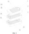
- FIG. 5is an exploded perspective view of a chip cooler relating to embodiment III.
- 200denotes reinforced connecting pieces; and 300 denotes liquid inlet and outlet adapter tubes.
- the utility modelrelates to a chip cooler with high pressure bearing capacity.
- the chip cooleris used for heat dissipation of a chip by connecting with a refrigerant pipeline in series and directly attaching to the surface of the chip, and for instance, the chip cooler is applied to a chip of a variable-frequency air conditioner for heat dissipation.
- the refrigerant cooling deviceincludes a cooler body 100 , and two liquid inlet and outlet adapter tubes 300 connected with the cooler body 100 .
- the cooler body 100has a refrigerant channel formed corresponding to the internal construction of the cooler body and configured to guide the flow of a refrigerant, and two liquid inlet and outlet channels formed corresponding to the construction at an edge of the cooler body, connected to the refrigerant channel and configured to transversely communicate the inside and outside of the cooler body 100 .
- the two liquid inlet and outlet channelsmay be provided either on the same side of the cooler body 100 or on different sides thereof.
- the two liquid inlet and outlet adapter tubes 300are respectively communicated with the two liquid inlet and outlet channels.
- the refrigerant channel in the cooler body 100can receive the refrigerant and guide the refrigerant to flow in the refrigerant channel in the cooler body 100 , so that the heat of the chip can be quickly absorbed, and the chip is then cooled. Accordingly, the chip is enabled to be always within a lower temperature range, and would not be burnt due to overheating.
- a reinforced connecting piece 200is disposed in one of the two liquid inlet and outlet channels of the cooler body 100 , a flow gap exists between the reinforced connecting piece 200 and the liquid inlet and outlet channel, and the reinforced connecting piece 200 at least connects the opposite upper and lower wall surfaces of the liquid inlet and outlet channel.
- a reinforced connecting piece 200is disposed in each of the two liquid inlet and outlet channels of the cooler body 100 , and the reinforced connecting piece 200 is preferably a line-shaped structure, a cross-shaped structure, or a -shaped structure.
- Embodiment IAs shown in FIG. 1 and FIG. 2 , the cooler body 100 is formed by the alignment of an upper heat-conducting plate 2 and a lower heat-conducting plate 1 .
- the lower surface of the lower heat-conducting plate 1is a flat end face and is attached to the surface of a chip.
- the whole plate body of the lower heat-conducting plate 1is positioned in the chip.
- Communicating channels 21 formed by the lower surface sinking to the upper surface through extrusion formingare disposed in the interior of the plate body of the upper heat-conducting plate 2 .
- the upper notches 22are configured to transversely communicate the inside and outside of the plate body of the upper heat-conducting plate 2 .
- Lower flanging 11 folded upward and matched with end faces of the edges of the upper notches 22 in a sealing wayare disposed at an edge of the lower heat-conducting plate 1 at least corresponding to the two upper notches 22 of the upper heat-conducting plate 2 .
- Mounting ports 111are disposed at the lower flanging 11 .
- the liquid inlet and outlet adapter tubes 300are inserted into the mounting ports 111 of the lower flanging 11 .
- Reinforced connecting pieces 200are connected with the bottom walls of the upper notches 22 and the upper surface of the lower heat-conducting plate 1 .
- sealing lipsare formed by correspondingly extending the edges of the upper notches 22 of the upper heat-conducting plate 2 outward. The sealing lips are matched with the lower flanging 11 , so that the contact area is effectively enlarged, and the sealing effect of the edges of the upper notches 22 and the lower flanging 11 is improved.
- a reinforced bulge 13 formed by the lower surface sinking to the upper surfaceis disposed at a position of the lower heat-conducting plate 1 corresponding to the communicating channels 21 on the upper heat-conducting plate 2 , thus enhancing the plate surface pressure bearing effect of the lower heat-conducting plate 1 at the refrigerant channel.
- Embodiment IIIAs shown in FIG. 5 , compared with embodiment I and embodiment II, the chip cooler provided by embodiment III is provided with refrigerant expansion cavities expanded above the upper heat-conducting plate 2 , so that the flow resistance and hydraulic pressure inside the chip cooler can be effectively reduced, and the stable operation of the chip cooler is further guaranteed.
- at least one fitting plate 3is stacked on the upper heat-conducting plate 2 .
- the refrigerant expansion cavities communicated with the refrigerant channel in embodiment I or embodiment IIare formed between the fitting plates 3 and the upper heat-conducting plate 2 which are adjacent to each other or between the adjacent fitting plates 3 in a way of seal fit.
- the reinforced connecting piecesare disposed in the liquid inlet and outlet channels, and the reinforced connecting pieces connect the opposite upper and lower wall surfaces of the liquid inlet and outlet channels, so that the pressure bearing capacity of the liquid inlet and outlet channels is effectively enhanced, the formation of a convex hull or deformation at the position of the lower heat-conducting plate corresponding the liquid inlet and outlet channels can be effectively avoided, the possibility of damage to the chip due to the deformation of the lower heat-conducting plate is reduced, and the use stability of the chip is further effectively guaranteed.
Landscapes
- Engineering & Computer Science (AREA)
- Physics & Mathematics (AREA)
- Condensed Matter Physics & Semiconductors (AREA)
- General Physics & Mathematics (AREA)
- Computer Hardware Design (AREA)
- Microelectronics & Electronic Packaging (AREA)
- Power Engineering (AREA)
- Manufacturing & Machinery (AREA)
- Thermal Sciences (AREA)
- Cooling Or The Like Of Semiconductors Or Solid State Devices (AREA)
- Cooling Or The Like Of Electrical Apparatus (AREA)
Abstract
Description

Claims (6)
Applications Claiming Priority (3)
| Application Number | Priority Date | Filing Date | Title |
|---|---|---|---|
| CN202021345114.7 | 2020-07-09 | ||
| CN202021345114.7UCN212084987U (en) | 2020-07-09 | 2020-07-09 | Chip cooler with high bearing capacity |
| PCT/CN2021/098331WO2022007563A1 (en) | 2020-07-09 | 2021-06-04 | Chip cooler having strong pressure-bearing capability |
Publications (2)
| Publication Number | Publication Date |
|---|---|
| US20220392776A1 US20220392776A1 (en) | 2022-12-08 |
| US12278116B2true US12278116B2 (en) | 2025-04-15 |
Family
ID=73557561
Family Applications (1)
| Application Number | Title | Priority Date | Filing Date |
|---|---|---|---|
| US17/755,626Active2042-07-25US12278116B2 (en) | 2020-07-09 | 2021-06-04 | Chip cooler with high pressure bearing capacity |
Country Status (5)
| Country | Link |
|---|---|
| US (1) | US12278116B2 (en) |
| JP (1) | JP7162161B2 (en) |
| CN (1) | CN212084987U (en) |
| DE (1) | DE112021000072T5 (en) |
| WO (1) | WO2022007563A1 (en) |
Families Citing this family (5)
| Publication number | Priority date | Publication date | Assignee | Title |
|---|---|---|---|---|
| CN212084987U (en) | 2020-07-09 | 2020-12-04 | 宁波市哈雷换热设备有限公司 | Chip cooler with high bearing capacity |
| CN112902712A (en)* | 2021-03-29 | 2021-06-04 | 浙江峰煌热交换器有限公司 | Chip cooling heat exchanger |
| CN115672079A (en)* | 2021-07-26 | 2023-02-03 | 青岛威巴克生物技术有限公司 | Mixing liquid and gas mixing device and mixing method thereof |
| CN114628343A (en)* | 2022-01-26 | 2022-06-14 | 深圳佰维存储科技股份有限公司 | Apparatus and system for heat dissipation of high power chip packages |
| CN120497230B (en)* | 2025-07-14 | 2025-09-16 | 宁波市哈雷换热设备有限公司 | High-performance chip cooler |
Citations (35)
| Publication number | Priority date | Publication date | Assignee | Title |
|---|---|---|---|---|
| US5016090A (en)* | 1990-03-21 | 1991-05-14 | International Business Machines Corporation | Cross-hatch flow distribution and applications thereof |
| US20080237847A1 (en)* | 2007-03-30 | 2008-10-02 | Nichicon Corporation | Power semiconductor module, and power semiconductor device having the module mounted therein |
| US20090008061A1 (en)* | 2003-12-18 | 2009-01-08 | Denso Corporation | Easily assembled cooler |
| US20100320753A1 (en)* | 2008-02-19 | 2010-12-23 | Showa Denko K.K. | Method of manufacturing a pipe coupling component, method of manufacutring a casing structural member, and pipe coupling sturcture for a hollow part |
| US20110056661A1 (en)* | 2009-09-01 | 2011-03-10 | Life Technologies Corporation | Thermal Block Assemblies and Instruments Providing Low Thermal Non-Uniformity for Rapid Thermal Cycling |
| US20110073292A1 (en)* | 2009-09-30 | 2011-03-31 | Madhav Datta | Fabrication of high surface area, high aspect ratio mini-channels and their application in liquid cooling systems |
| US20110094722A1 (en)* | 2009-10-26 | 2011-04-28 | Kabushiki Kaisha Toyota Jidoshokki | Liquid-cooled-type cooling device |
| US20110188204A1 (en)* | 2010-01-29 | 2011-08-04 | Hitachi, Ltd. | Semiconductor Power Module, Inverter/Converter Including the same, and Method of Manufacturing a Cooling Jacket for Semiconductor Power Module |
| CN201936873U (en) | 2010-11-17 | 2011-08-17 | 珠海格力电器股份有限公司 | Electric element radiator for heat pump and heat pump system using radiator |
| US20110308059A1 (en)* | 2009-02-23 | 2011-12-22 | Nippon Light Metal Company, Ltd. | Manufacturing method of liquid-cooled jacket |
| US8102652B2 (en)* | 2006-03-13 | 2012-01-24 | Kabushiki Kaisha Toyota Jidoshokki | Base for power module |
| US20120103575A1 (en)* | 2010-11-03 | 2012-05-03 | Hon Hai Precision Industry Co., Ltd. | Cooling device |
| US20130128643A1 (en)* | 2010-06-21 | 2013-05-23 | Hitachi Automotive Systems, Ltd. | Power Converter Device |
| US20130153186A1 (en)* | 2010-08-23 | 2013-06-20 | Naoya Gotou | Cooling Device |
| US20130264702A1 (en)* | 2012-04-06 | 2013-10-10 | Kabushiki Kaisha Toyota Jidoshokki | Semiconductor unit |
| US20140239486A1 (en)* | 2011-10-12 | 2014-08-28 | Fuji Electric Co., Ltd. | Cooling device for semiconductor module, and semiconductor module |
| US9000582B2 (en)* | 2011-02-28 | 2015-04-07 | Hitachi Automotive Systems, Ltd. | Power semiconductor module and power conversion device |
| USD757236S1 (en)* | 2013-12-06 | 2016-05-24 | Kyoshin Kogyo Co., Ltd. | Heat exchanger holder |
| US20160273842A1 (en)* | 2015-03-16 | 2016-09-22 | Dana Canada Corporation | Heat exchangers with plates having surface patterns for enhancing flatness and methods for manufacturing same |
| US20170187300A1 (en)* | 2014-08-07 | 2017-06-29 | Hitachi Automotive Systems, Ltd. | Power Module |
| US9704779B2 (en)* | 2014-05-20 | 2017-07-11 | Fuji Electric Co., Ltd. | Semiconductor module cooler and method for manufacturing same |
| US20170235350A1 (en)* | 2016-02-15 | 2017-08-17 | Cooler Master Technology Inc. | Cooling apparatus |
| CN107611103A (en) | 2017-07-24 | 2018-01-19 | 广东美的暖通设备有限公司 | The heat abstractor and transducer air conditioning of transducer air conditioning drive module chip |
| US9960100B2 (en)* | 2014-03-20 | 2018-05-01 | Fuji Electric Co., Ltd | Cooler and semiconductor module using same |
| CN208671747U (en) | 2018-08-14 | 2019-03-29 | 宁波市哈雷换热设备有限公司 | A kind of heat-exchangers of the plate type with bracing means |
| US20190221499A1 (en)* | 2018-01-12 | 2019-07-18 | Je-Young Chang | Heat management system |
| CN110520980A (en) | 2017-03-22 | 2019-11-29 | 福利家麦克罗斯株式会社 | Cooling construction body, cooling system, heat generating device and structure |
| CN210868300U (en) | 2019-09-25 | 2020-06-26 | 北京比特大陆科技有限公司 | PCB heat dissipation assembly and server with same |
| CN111769083A (en) | 2020-03-06 | 2020-10-13 | 宁波市哈雷换热设备有限公司 | A refrigerant chip cooler |
| US20200365419A1 (en)* | 2019-05-15 | 2020-11-19 | Fuji Electric Co., Ltd. | Semiconductor module, method for manufacturing semiconductor module, and level different jig |
| CN212084987U (en) | 2020-07-09 | 2020-12-04 | 宁波市哈雷换热设备有限公司 | Chip cooler with high bearing capacity |
| US20220153085A1 (en)* | 2019-03-01 | 2022-05-19 | Valeo Systemes Thermiques | Temperature control device, in particular cooling device for a motor vehicle |
| US20220262701A1 (en)* | 2021-02-18 | 2022-08-18 | Global Unichip Corporation | Heat dissipation structure, semiconductor packaging device, and manufacturing method of the semiconductor packaging device |
| US20220404100A1 (en)* | 2021-06-18 | 2022-12-22 | Dana Canada Corporation | Two-pass heat exchanger with calibrated bypass |
| US20230025258A1 (en)* | 2016-02-15 | 2023-01-26 | Cooler Master Co., Ltd. | Cooling apparatus |
Family Cites Families (4)
| Publication number | Priority date | Publication date | Assignee | Title |
|---|---|---|---|---|
| JPS6215843A (en)* | 1985-07-12 | 1987-01-24 | Fujitsu Ltd | Liquid pipe for low temperature refrigerant |
| JP3953741B2 (en)* | 2001-03-02 | 2007-08-08 | 株式会社エムエーファブテック | Boiling cooler and manufacturing method thereof |
| EP2947412A4 (en)* | 2013-01-18 | 2017-05-24 | Taisei Plas Co., Ltd. | Heat exchanger and method for manufacturing same |
| JP6708113B2 (en)* | 2016-12-19 | 2020-06-10 | 株式会社デンソー | Stacked cooler |
- 2020
- 2020-07-09CNCN202021345114.7Upatent/CN212084987U/enactiveActive
- 2021
- 2021-06-04DEDE112021000072.1Tpatent/DE112021000072T5/enactivePending
- 2021-06-04JPJP2022518378Apatent/JP7162161B2/enactiveActive
- 2021-06-04USUS17/755,626patent/US12278116B2/enactiveActive
- 2021-06-04WOPCT/CN2021/098331patent/WO2022007563A1/ennot_activeCeased
Patent Citations (37)
| Publication number | Priority date | Publication date | Assignee | Title |
|---|---|---|---|---|
| US5016090A (en)* | 1990-03-21 | 1991-05-14 | International Business Machines Corporation | Cross-hatch flow distribution and applications thereof |
| US20090008061A1 (en)* | 2003-12-18 | 2009-01-08 | Denso Corporation | Easily assembled cooler |
| US8102652B2 (en)* | 2006-03-13 | 2012-01-24 | Kabushiki Kaisha Toyota Jidoshokki | Base for power module |
| US20080237847A1 (en)* | 2007-03-30 | 2008-10-02 | Nichicon Corporation | Power semiconductor module, and power semiconductor device having the module mounted therein |
| US20100320753A1 (en)* | 2008-02-19 | 2010-12-23 | Showa Denko K.K. | Method of manufacturing a pipe coupling component, method of manufacutring a casing structural member, and pipe coupling sturcture for a hollow part |
| US20110308059A1 (en)* | 2009-02-23 | 2011-12-22 | Nippon Light Metal Company, Ltd. | Manufacturing method of liquid-cooled jacket |
| US20110056661A1 (en)* | 2009-09-01 | 2011-03-10 | Life Technologies Corporation | Thermal Block Assemblies and Instruments Providing Low Thermal Non-Uniformity for Rapid Thermal Cycling |
| US20110073292A1 (en)* | 2009-09-30 | 2011-03-31 | Madhav Datta | Fabrication of high surface area, high aspect ratio mini-channels and their application in liquid cooling systems |
| US20110094722A1 (en)* | 2009-10-26 | 2011-04-28 | Kabushiki Kaisha Toyota Jidoshokki | Liquid-cooled-type cooling device |
| US20110188204A1 (en)* | 2010-01-29 | 2011-08-04 | Hitachi, Ltd. | Semiconductor Power Module, Inverter/Converter Including the same, and Method of Manufacturing a Cooling Jacket for Semiconductor Power Module |
| US20130128643A1 (en)* | 2010-06-21 | 2013-05-23 | Hitachi Automotive Systems, Ltd. | Power Converter Device |
| US20130153186A1 (en)* | 2010-08-23 | 2013-06-20 | Naoya Gotou | Cooling Device |
| US20120103575A1 (en)* | 2010-11-03 | 2012-05-03 | Hon Hai Precision Industry Co., Ltd. | Cooling device |
| CN201936873U (en) | 2010-11-17 | 2011-08-17 | 珠海格力电器股份有限公司 | Electric element radiator for heat pump and heat pump system using radiator |
| US9000582B2 (en)* | 2011-02-28 | 2015-04-07 | Hitachi Automotive Systems, Ltd. | Power semiconductor module and power conversion device |
| US20140239486A1 (en)* | 2011-10-12 | 2014-08-28 | Fuji Electric Co., Ltd. | Cooling device for semiconductor module, and semiconductor module |
| US20130264702A1 (en)* | 2012-04-06 | 2013-10-10 | Kabushiki Kaisha Toyota Jidoshokki | Semiconductor unit |
| USD757236S1 (en)* | 2013-12-06 | 2016-05-24 | Kyoshin Kogyo Co., Ltd. | Heat exchanger holder |
| US9960100B2 (en)* | 2014-03-20 | 2018-05-01 | Fuji Electric Co., Ltd | Cooler and semiconductor module using same |
| US9704779B2 (en)* | 2014-05-20 | 2017-07-11 | Fuji Electric Co., Ltd. | Semiconductor module cooler and method for manufacturing same |
| US20170187300A1 (en)* | 2014-08-07 | 2017-06-29 | Hitachi Automotive Systems, Ltd. | Power Module |
| US20160273842A1 (en)* | 2015-03-16 | 2016-09-22 | Dana Canada Corporation | Heat exchangers with plates having surface patterns for enhancing flatness and methods for manufacturing same |
| US20170235350A1 (en)* | 2016-02-15 | 2017-08-17 | Cooler Master Technology Inc. | Cooling apparatus |
| US20230025258A1 (en)* | 2016-02-15 | 2023-01-26 | Cooler Master Co., Ltd. | Cooling apparatus |
| CN110520980A (en) | 2017-03-22 | 2019-11-29 | 福利家麦克罗斯株式会社 | Cooling construction body, cooling system, heat generating device and structure |
| CN107611103A (en) | 2017-07-24 | 2018-01-19 | 广东美的暖通设备有限公司 | The heat abstractor and transducer air conditioning of transducer air conditioning drive module chip |
| US20190221499A1 (en)* | 2018-01-12 | 2019-07-18 | Je-Young Chang | Heat management system |
| CN208671747U (en) | 2018-08-14 | 2019-03-29 | 宁波市哈雷换热设备有限公司 | A kind of heat-exchangers of the plate type with bracing means |
| US20220153085A1 (en)* | 2019-03-01 | 2022-05-19 | Valeo Systemes Thermiques | Temperature control device, in particular cooling device for a motor vehicle |
| US20200365419A1 (en)* | 2019-05-15 | 2020-11-19 | Fuji Electric Co., Ltd. | Semiconductor module, method for manufacturing semiconductor module, and level different jig |
| CN210868300U (en) | 2019-09-25 | 2020-06-26 | 北京比特大陆科技有限公司 | PCB heat dissipation assembly and server with same |
| CN111769083A (en) | 2020-03-06 | 2020-10-13 | 宁波市哈雷换热设备有限公司 | A refrigerant chip cooler |
| CN212084986U (en) | 2020-03-06 | 2020-12-04 | 宁波市哈雷换热设备有限公司 | Refrigerant type chip cooler |
| US20220392776A1 (en)* | 2020-07-09 | 2022-12-08 | Ningbo Halley Heat Exchange Equipment Co., Ltd | Chip Cooler with High Pressure Bearing Capacity |
| CN212084987U (en) | 2020-07-09 | 2020-12-04 | 宁波市哈雷换热设备有限公司 | Chip cooler with high bearing capacity |
| US20220262701A1 (en)* | 2021-02-18 | 2022-08-18 | Global Unichip Corporation | Heat dissipation structure, semiconductor packaging device, and manufacturing method of the semiconductor packaging device |
| US20220404100A1 (en)* | 2021-06-18 | 2022-12-22 | Dana Canada Corporation | Two-pass heat exchanger with calibrated bypass |
Also Published As
| Publication number | Publication date |
|---|---|
| CN212084987U (en) | 2020-12-04 |
| JP2022539482A (en) | 2022-09-09 |
| JP7162161B2 (en) | 2022-10-27 |
| WO2022007563A1 (en) | 2022-01-13 |
| US20220392776A1 (en) | 2022-12-08 |
| DE112021000072T5 (en) | 2022-04-14 |
Similar Documents
| Publication | Publication Date | Title |
|---|---|---|
| US12278116B2 (en) | Chip cooler with high pressure bearing capacity | |
| CN106918165B (en) | Heat exchanger | |
| US20180080693A1 (en) | Heat exchange device | |
| WO2017097133A1 (en) | Heat exchanger | |
| CN107687787B (en) | Heat exchange device | |
| US12292241B2 (en) | Throttling heat exchange assembly | |
| CN111490311A (en) | Integrated heat exchange plate and vehicle battery thermal management system | |
| WO2022007562A1 (en) | Refrigerant-type chip cooler | |
| CN218827444U (en) | Cold plate heat exchangers, battery packs, thermal management systems and vehicles | |
| CN111678364A (en) | A microchannel heat exchanger | |
| WO2020187005A1 (en) | Battery pack and cooling system thereof | |
| CN212253773U (en) | Micro-channel heat exchanger | |
| EP3495761A1 (en) | Heat exchange device | |
| CN113758341A (en) | Energy storage component, cold filling and storage system, cold storage and supply system and cold chain transport case | |
| CN212084984U (en) | Chip cooler | |
| CN214382024U (en) | Parallel flow cold plate | |
| WO2024045907A1 (en) | Cooling structural body | |
| CN113970267B (en) | Heat exchange assembly and vehicle thermal management system | |
| CN209960833U (en) | Fluid cooling device | |
| CN203249430U (en) | Laminated evaporator | |
| CN220021255U (en) | Inlet and outlet assembly, heat exchange plate module, battery pack and vehicle | |
| CN214279959U (en) | Chip cooler with good bearing performance | |
| CN209623449U (en) | Heat exchanger core, plate heat exchanger and air conditioning unit | |
| CN113970259B (en) | Throttling heat exchange assembly | |
| CN212362958U (en) | Micro-channel connecting piece and heat exchanger with same |
Legal Events
| Date | Code | Title | Description |
|---|---|---|---|
| FEPP | Fee payment procedure | Free format text:ENTITY STATUS SET TO UNDISCOUNTED (ORIGINAL EVENT CODE: BIG.); ENTITY STATUS OF PATENT OWNER: SMALL ENTITY | |
| AS | Assignment | Owner name:NINGBO HALLEY HEAT EXCHANGE EQUIPMENT CO., LTD, CHINA Free format text:ASSIGNMENT OF ASSIGNORS INTEREST;ASSIGNORS:DAI, DINGJUN;ZHUO, HONGQIANG;SUN, XUGUANG;AND OTHERS;REEL/FRAME:059807/0561 Effective date:20220307 | |
| FEPP | Fee payment procedure | Free format text:ENTITY STATUS SET TO SMALL (ORIGINAL EVENT CODE: SMAL); ENTITY STATUS OF PATENT OWNER: SMALL ENTITY | |
| STPP | Information on status: patent application and granting procedure in general | Free format text:DOCKETED NEW CASE - READY FOR EXAMINATION | |
| STPP | Information on status: patent application and granting procedure in general | Free format text:NON FINAL ACTION MAILED | |
| STPP | Information on status: patent application and granting procedure in general | Free format text:RESPONSE TO NON-FINAL OFFICE ACTION ENTERED AND FORWARDED TO EXAMINER | |
| STPP | Information on status: patent application and granting procedure in general | Free format text:NOTICE OF ALLOWANCE MAILED -- APPLICATION RECEIVED IN OFFICE OF PUBLICATIONS | |
| STCF | Information on status: patent grant | Free format text:PATENTED CASE |