US12275227B2 - Composite materials and structures - Google Patents
Composite materials and structuresDownload PDFInfo
- Publication number
- US12275227B2 US12275227B2US17/304,902US202117304902AUS12275227B2US 12275227 B2US12275227 B2US 12275227B2US 202117304902 AUS202117304902 AUS 202117304902AUS 12275227 B2US12275227 B2US 12275227B2
- Authority
- US
- United States
- Prior art keywords
- helicoidal
- plies
- tows
- fibers
- skin
- Prior art date
- Legal status (The legal status is an assumption and is not a legal conclusion. Google has not performed a legal analysis and makes no representation as to the accuracy of the status listed.)
- Active, expires
Links
Images


Classifications
- B—PERFORMING OPERATIONS; TRANSPORTING
- B32—LAYERED PRODUCTS
- B32B—LAYERED PRODUCTS, i.e. PRODUCTS BUILT-UP OF STRATA OF FLAT OR NON-FLAT, e.g. CELLULAR OR HONEYCOMB, FORM
- B32B7/00—Layered products characterised by the relation between layers; Layered products characterised by the relative orientation of features between layers, or by the relative values of a measurable parameter between layers, i.e. products comprising layers having different physical, chemical or physicochemical properties; Layered products characterised by the interconnection of layers
- B32B7/03—Layered products characterised by the relation between layers; Layered products characterised by the relative orientation of features between layers, or by the relative values of a measurable parameter between layers, i.e. products comprising layers having different physical, chemical or physicochemical properties; Layered products characterised by the interconnection of layers with respect to the orientation of features
- B—PERFORMING OPERATIONS; TRANSPORTING
- B29—WORKING OF PLASTICS; WORKING OF SUBSTANCES IN A PLASTIC STATE IN GENERAL
- B29C—SHAPING OR JOINING OF PLASTICS; SHAPING OF MATERIAL IN A PLASTIC STATE, NOT OTHERWISE PROVIDED FOR; AFTER-TREATMENT OF THE SHAPED PRODUCTS, e.g. REPAIRING
- B29C70/00—Shaping composites, i.e. plastics material comprising reinforcements, fillers or preformed parts, e.g. inserts
- B29C70/04—Shaping composites, i.e. plastics material comprising reinforcements, fillers or preformed parts, e.g. inserts comprising reinforcements only, e.g. self-reinforcing plastics
- B29C70/06—Fibrous reinforcements only
- B29C70/10—Fibrous reinforcements only characterised by the structure of fibrous reinforcements, e.g. hollow fibres
- B29C70/16—Fibrous reinforcements only characterised by the structure of fibrous reinforcements, e.g. hollow fibres using fibres of substantial or continuous length
- B29C70/20—Fibrous reinforcements only characterised by the structure of fibrous reinforcements, e.g. hollow fibres using fibres of substantial or continuous length oriented in a single direction, e.g. roofing or other parallel fibres
- B29C70/202—Fibrous reinforcements only characterised by the structure of fibrous reinforcements, e.g. hollow fibres using fibres of substantial or continuous length oriented in a single direction, e.g. roofing or other parallel fibres arranged in parallel planes or structures of fibres crossing at substantial angles, e.g. cross-moulding compound [XMC]
- B—PERFORMING OPERATIONS; TRANSPORTING
- B32—LAYERED PRODUCTS
- B32B—LAYERED PRODUCTS, i.e. PRODUCTS BUILT-UP OF STRATA OF FLAT OR NON-FLAT, e.g. CELLULAR OR HONEYCOMB, FORM
- B32B15/00—Layered products comprising a layer of metal
- B32B15/14—Layered products comprising a layer of metal next to a fibrous or filamentary layer
- B—PERFORMING OPERATIONS; TRANSPORTING
- B32—LAYERED PRODUCTS
- B32B—LAYERED PRODUCTS, i.e. PRODUCTS BUILT-UP OF STRATA OF FLAT OR NON-FLAT, e.g. CELLULAR OR HONEYCOMB, FORM
- B32B27/00—Layered products comprising a layer of synthetic resin
- B32B27/12—Layered products comprising a layer of synthetic resin next to a fibrous or filamentary layer
- B—PERFORMING OPERATIONS; TRANSPORTING
- B32—LAYERED PRODUCTS
- B32B—LAYERED PRODUCTS, i.e. PRODUCTS BUILT-UP OF STRATA OF FLAT OR NON-FLAT, e.g. CELLULAR OR HONEYCOMB, FORM
- B32B27/00—Layered products comprising a layer of synthetic resin
- B32B27/30—Layered products comprising a layer of synthetic resin comprising vinyl (co)polymers; comprising acrylic (co)polymers
- B32B27/304—Layered products comprising a layer of synthetic resin comprising vinyl (co)polymers; comprising acrylic (co)polymers comprising vinyl halide (co)polymers, e.g. PVC, PVDC, PVF, PVDF
- B—PERFORMING OPERATIONS; TRANSPORTING
- B32—LAYERED PRODUCTS
- B32B—LAYERED PRODUCTS, i.e. PRODUCTS BUILT-UP OF STRATA OF FLAT OR NON-FLAT, e.g. CELLULAR OR HONEYCOMB, FORM
- B32B3/00—Layered products comprising a layer with external or internal discontinuities or unevennesses, or a layer of non-planar shape; Layered products comprising a layer having particular features of form
- B32B3/10—Layered products comprising a layer with external or internal discontinuities or unevennesses, or a layer of non-planar shape; Layered products comprising a layer having particular features of form characterised by a discontinuous layer, i.e. formed of separate pieces of material
- B32B3/12—Layered products comprising a layer with external or internal discontinuities or unevennesses, or a layer of non-planar shape; Layered products comprising a layer having particular features of form characterised by a discontinuous layer, i.e. formed of separate pieces of material characterised by a layer of regularly- arranged cells, e.g. a honeycomb structure
- B—PERFORMING OPERATIONS; TRANSPORTING
- B32—LAYERED PRODUCTS
- B32B—LAYERED PRODUCTS, i.e. PRODUCTS BUILT-UP OF STRATA OF FLAT OR NON-FLAT, e.g. CELLULAR OR HONEYCOMB, FORM
- B32B5/00—Layered products characterised by the non- homogeneity or physical structure, i.e. comprising a fibrous, filamentary, particulate or foam layer; Layered products characterised by having a layer differing constitutionally or physically in different parts
- B32B5/02—Layered products characterised by the non- homogeneity or physical structure, i.e. comprising a fibrous, filamentary, particulate or foam layer; Layered products characterised by having a layer differing constitutionally or physically in different parts characterised by structural features of a fibrous or filamentary layer
- B32B5/024—Woven fabric
- B—PERFORMING OPERATIONS; TRANSPORTING
- B32—LAYERED PRODUCTS
- B32B—LAYERED PRODUCTS, i.e. PRODUCTS BUILT-UP OF STRATA OF FLAT OR NON-FLAT, e.g. CELLULAR OR HONEYCOMB, FORM
- B32B5/00—Layered products characterised by the non- homogeneity or physical structure, i.e. comprising a fibrous, filamentary, particulate or foam layer; Layered products characterised by having a layer differing constitutionally or physically in different parts
- B32B5/02—Layered products characterised by the non- homogeneity or physical structure, i.e. comprising a fibrous, filamentary, particulate or foam layer; Layered products characterised by having a layer differing constitutionally or physically in different parts characterised by structural features of a fibrous or filamentary layer
- B32B5/026—Knitted fabric
- B—PERFORMING OPERATIONS; TRANSPORTING
- B32—LAYERED PRODUCTS
- B32B—LAYERED PRODUCTS, i.e. PRODUCTS BUILT-UP OF STRATA OF FLAT OR NON-FLAT, e.g. CELLULAR OR HONEYCOMB, FORM
- B32B5/00—Layered products characterised by the non- homogeneity or physical structure, i.e. comprising a fibrous, filamentary, particulate or foam layer; Layered products characterised by having a layer differing constitutionally or physically in different parts
- B32B5/02—Layered products characterised by the non- homogeneity or physical structure, i.e. comprising a fibrous, filamentary, particulate or foam layer; Layered products characterised by having a layer differing constitutionally or physically in different parts characterised by structural features of a fibrous or filamentary layer
- B32B5/028—Net structure, e.g. spaced apart filaments bonded at the crossing points
- B—PERFORMING OPERATIONS; TRANSPORTING
- B32—LAYERED PRODUCTS
- B32B—LAYERED PRODUCTS, i.e. PRODUCTS BUILT-UP OF STRATA OF FLAT OR NON-FLAT, e.g. CELLULAR OR HONEYCOMB, FORM
- B32B5/00—Layered products characterised by the non- homogeneity or physical structure, i.e. comprising a fibrous, filamentary, particulate or foam layer; Layered products characterised by having a layer differing constitutionally or physically in different parts
- B32B5/02—Layered products characterised by the non- homogeneity or physical structure, i.e. comprising a fibrous, filamentary, particulate or foam layer; Layered products characterised by having a layer differing constitutionally or physically in different parts characterised by structural features of a fibrous or filamentary layer
- B32B5/06—Layered products characterised by the non- homogeneity or physical structure, i.e. comprising a fibrous, filamentary, particulate or foam layer; Layered products characterised by having a layer differing constitutionally or physically in different parts characterised by structural features of a fibrous or filamentary layer characterised by a fibrous or filamentary layer mechanically connected, e.g. by needling to another layer, e.g. of fibres, of paper
- B—PERFORMING OPERATIONS; TRANSPORTING
- B32—LAYERED PRODUCTS
- B32B—LAYERED PRODUCTS, i.e. PRODUCTS BUILT-UP OF STRATA OF FLAT OR NON-FLAT, e.g. CELLULAR OR HONEYCOMB, FORM
- B32B5/00—Layered products characterised by the non- homogeneity or physical structure, i.e. comprising a fibrous, filamentary, particulate or foam layer; Layered products characterised by having a layer differing constitutionally or physically in different parts
- B32B5/02—Layered products characterised by the non- homogeneity or physical structure, i.e. comprising a fibrous, filamentary, particulate or foam layer; Layered products characterised by having a layer differing constitutionally or physically in different parts characterised by structural features of a fibrous or filamentary layer
- B32B5/08—Layered products characterised by the non- homogeneity or physical structure, i.e. comprising a fibrous, filamentary, particulate or foam layer; Layered products characterised by having a layer differing constitutionally or physically in different parts characterised by structural features of a fibrous or filamentary layer the fibres or filaments of a layer being of different substances, e.g. conjugate fibres, mixture of different fibres
- B—PERFORMING OPERATIONS; TRANSPORTING
- B32—LAYERED PRODUCTS
- B32B—LAYERED PRODUCTS, i.e. PRODUCTS BUILT-UP OF STRATA OF FLAT OR NON-FLAT, e.g. CELLULAR OR HONEYCOMB, FORM
- B32B5/00—Layered products characterised by the non- homogeneity or physical structure, i.e. comprising a fibrous, filamentary, particulate or foam layer; Layered products characterised by having a layer differing constitutionally or physically in different parts
- B32B5/02—Layered products characterised by the non- homogeneity or physical structure, i.e. comprising a fibrous, filamentary, particulate or foam layer; Layered products characterised by having a layer differing constitutionally or physically in different parts characterised by structural features of a fibrous or filamentary layer
- B32B5/12—Layered products characterised by the non- homogeneity or physical structure, i.e. comprising a fibrous, filamentary, particulate or foam layer; Layered products characterised by having a layer differing constitutionally or physically in different parts characterised by structural features of a fibrous or filamentary layer characterised by the relative arrangement of fibres or filaments of different layers, e.g. the fibres or filaments being parallel or perpendicular to each other
- B—PERFORMING OPERATIONS; TRANSPORTING
- B32—LAYERED PRODUCTS
- B32B—LAYERED PRODUCTS, i.e. PRODUCTS BUILT-UP OF STRATA OF FLAT OR NON-FLAT, e.g. CELLULAR OR HONEYCOMB, FORM
- B32B5/00—Layered products characterised by the non- homogeneity or physical structure, i.e. comprising a fibrous, filamentary, particulate or foam layer; Layered products characterised by having a layer differing constitutionally or physically in different parts
- B32B5/18—Layered products characterised by the non- homogeneity or physical structure, i.e. comprising a fibrous, filamentary, particulate or foam layer; Layered products characterised by having a layer differing constitutionally or physically in different parts characterised by features of a layer of foamed material
- B—PERFORMING OPERATIONS; TRANSPORTING
- B32—LAYERED PRODUCTS
- B32B—LAYERED PRODUCTS, i.e. PRODUCTS BUILT-UP OF STRATA OF FLAT OR NON-FLAT, e.g. CELLULAR OR HONEYCOMB, FORM
- B32B5/00—Layered products characterised by the non- homogeneity or physical structure, i.e. comprising a fibrous, filamentary, particulate or foam layer; Layered products characterised by having a layer differing constitutionally or physically in different parts
- B32B5/22—Layered products characterised by the non- homogeneity or physical structure, i.e. comprising a fibrous, filamentary, particulate or foam layer; Layered products characterised by having a layer differing constitutionally or physically in different parts characterised by the presence of two or more layers which are next to each other and are fibrous, filamentary, formed of particles or foamed
- B32B5/24—Layered products characterised by the non- homogeneity or physical structure, i.e. comprising a fibrous, filamentary, particulate or foam layer; Layered products characterised by having a layer differing constitutionally or physically in different parts characterised by the presence of two or more layers which are next to each other and are fibrous, filamentary, formed of particles or foamed one layer being a fibrous or filamentary layer
- B32B5/245—Layered products characterised by the non- homogeneity or physical structure, i.e. comprising a fibrous, filamentary, particulate or foam layer; Layered products characterised by having a layer differing constitutionally or physically in different parts characterised by the presence of two or more layers which are next to each other and are fibrous, filamentary, formed of particles or foamed one layer being a fibrous or filamentary layer another layer next to it being a foam layer
- B—PERFORMING OPERATIONS; TRANSPORTING
- B32—LAYERED PRODUCTS
- B32B—LAYERED PRODUCTS, i.e. PRODUCTS BUILT-UP OF STRATA OF FLAT OR NON-FLAT, e.g. CELLULAR OR HONEYCOMB, FORM
- B32B5/00—Layered products characterised by the non- homogeneity or physical structure, i.e. comprising a fibrous, filamentary, particulate or foam layer; Layered products characterised by having a layer differing constitutionally or physically in different parts
- B32B5/22—Layered products characterised by the non- homogeneity or physical structure, i.e. comprising a fibrous, filamentary, particulate or foam layer; Layered products characterised by having a layer differing constitutionally or physically in different parts characterised by the presence of two or more layers which are next to each other and are fibrous, filamentary, formed of particles or foamed
- B32B5/24—Layered products characterised by the non- homogeneity or physical structure, i.e. comprising a fibrous, filamentary, particulate or foam layer; Layered products characterised by having a layer differing constitutionally or physically in different parts characterised by the presence of two or more layers which are next to each other and are fibrous, filamentary, formed of particles or foamed one layer being a fibrous or filamentary layer
- B32B5/26—Layered products characterised by the non- homogeneity or physical structure, i.e. comprising a fibrous, filamentary, particulate or foam layer; Layered products characterised by having a layer differing constitutionally or physically in different parts characterised by the presence of two or more layers which are next to each other and are fibrous, filamentary, formed of particles or foamed one layer being a fibrous or filamentary layer another layer next to it also being fibrous or filamentary
- B32B5/262—Layered products characterised by the non- homogeneity or physical structure, i.e. comprising a fibrous, filamentary, particulate or foam layer; Layered products characterised by having a layer differing constitutionally or physically in different parts characterised by the presence of two or more layers which are next to each other and are fibrous, filamentary, formed of particles or foamed one layer being a fibrous or filamentary layer another layer next to it also being fibrous or filamentary characterised by one fibrous or filamentary layer being a woven fabric layer
- B32B5/263—Layered products characterised by the non- homogeneity or physical structure, i.e. comprising a fibrous, filamentary, particulate or foam layer; Layered products characterised by having a layer differing constitutionally or physically in different parts characterised by the presence of two or more layers which are next to each other and are fibrous, filamentary, formed of particles or foamed one layer being a fibrous or filamentary layer another layer next to it also being fibrous or filamentary characterised by one fibrous or filamentary layer being a woven fabric layer next to one or more woven fabric layers
- B—PERFORMING OPERATIONS; TRANSPORTING
- B32—LAYERED PRODUCTS
- B32B—LAYERED PRODUCTS, i.e. PRODUCTS BUILT-UP OF STRATA OF FLAT OR NON-FLAT, e.g. CELLULAR OR HONEYCOMB, FORM
- B32B7/00—Layered products characterised by the relation between layers; Layered products characterised by the relative orientation of features between layers, or by the relative values of a measurable parameter between layers, i.e. products comprising layers having different physical, chemical or physicochemical properties; Layered products characterised by the interconnection of layers
- B32B7/04—Interconnection of layers
- B32B7/08—Interconnection of layers by mechanical means
- B32B7/09—Interconnection of layers by mechanical means by stitching, needling or sewing
- B—PERFORMING OPERATIONS; TRANSPORTING
- B32—LAYERED PRODUCTS
- B32B—LAYERED PRODUCTS, i.e. PRODUCTS BUILT-UP OF STRATA OF FLAT OR NON-FLAT, e.g. CELLULAR OR HONEYCOMB, FORM
- B32B7/00—Layered products characterised by the relation between layers; Layered products characterised by the relative orientation of features between layers, or by the relative values of a measurable parameter between layers, i.e. products comprising layers having different physical, chemical or physicochemical properties; Layered products characterised by the interconnection of layers
- B32B7/04—Interconnection of layers
- B32B7/12—Interconnection of layers using interposed adhesives or interposed materials with bonding properties
- B—PERFORMING OPERATIONS; TRANSPORTING
- B32—LAYERED PRODUCTS
- B32B—LAYERED PRODUCTS, i.e. PRODUCTS BUILT-UP OF STRATA OF FLAT OR NON-FLAT, e.g. CELLULAR OR HONEYCOMB, FORM
- B32B2250/00—Layers arrangement
- B32B2250/40—Symmetrical or sandwich layers, e.g. ABA, ABCBA, ABCCBA
- B—PERFORMING OPERATIONS; TRANSPORTING
- B32—LAYERED PRODUCTS
- B32B—LAYERED PRODUCTS, i.e. PRODUCTS BUILT-UP OF STRATA OF FLAT OR NON-FLAT, e.g. CELLULAR OR HONEYCOMB, FORM
- B32B2260/00—Layered product comprising an impregnated, embedded, or bonded layer wherein the layer comprises an impregnation, embedding, or binder material
- B32B2260/02—Composition of the impregnated, bonded or embedded layer
- B32B2260/021—Fibrous or filamentary layer
- B32B2260/023—Two or more layers
- B—PERFORMING OPERATIONS; TRANSPORTING
- B32—LAYERED PRODUCTS
- B32B—LAYERED PRODUCTS, i.e. PRODUCTS BUILT-UP OF STRATA OF FLAT OR NON-FLAT, e.g. CELLULAR OR HONEYCOMB, FORM
- B32B2260/00—Layered product comprising an impregnated, embedded, or bonded layer wherein the layer comprises an impregnation, embedding, or binder material
- B32B2260/04—Impregnation, embedding, or binder material
- B32B2260/046—Synthetic resin
- B—PERFORMING OPERATIONS; TRANSPORTING
- B32—LAYERED PRODUCTS
- B32B—LAYERED PRODUCTS, i.e. PRODUCTS BUILT-UP OF STRATA OF FLAT OR NON-FLAT, e.g. CELLULAR OR HONEYCOMB, FORM
- B32B2262/00—Composition or structural features of fibres which form a fibrous or filamentary layer or are present as additives
- B32B2262/02—Synthetic macromolecular fibres
- B32B2262/0253—Polyolefin fibres
- B—PERFORMING OPERATIONS; TRANSPORTING
- B32—LAYERED PRODUCTS
- B32B—LAYERED PRODUCTS, i.e. PRODUCTS BUILT-UP OF STRATA OF FLAT OR NON-FLAT, e.g. CELLULAR OR HONEYCOMB, FORM
- B32B2262/00—Composition or structural features of fibres which form a fibrous or filamentary layer or are present as additives
- B32B2262/02—Synthetic macromolecular fibres
- B32B2262/0261—Polyamide fibres
- B32B2262/0269—Aromatic polyamide fibres
- B—PERFORMING OPERATIONS; TRANSPORTING
- B32—LAYERED PRODUCTS
- B32B—LAYERED PRODUCTS, i.e. PRODUCTS BUILT-UP OF STRATA OF FLAT OR NON-FLAT, e.g. CELLULAR OR HONEYCOMB, FORM
- B32B2262/00—Composition or structural features of fibres which form a fibrous or filamentary layer or are present as additives
- B32B2262/06—Vegetal fibres
- B32B2262/062—Cellulose fibres, e.g. cotton
- B32B2262/065—Lignocellulosic fibres, e.g. jute, sisal, hemp, flax, bamboo
- B—PERFORMING OPERATIONS; TRANSPORTING
- B32—LAYERED PRODUCTS
- B32B—LAYERED PRODUCTS, i.e. PRODUCTS BUILT-UP OF STRATA OF FLAT OR NON-FLAT, e.g. CELLULAR OR HONEYCOMB, FORM
- B32B2262/00—Composition or structural features of fibres which form a fibrous or filamentary layer or are present as additives
- B32B2262/10—Inorganic fibres
- B32B2262/101—Glass fibres
- B—PERFORMING OPERATIONS; TRANSPORTING
- B32—LAYERED PRODUCTS
- B32B—LAYERED PRODUCTS, i.e. PRODUCTS BUILT-UP OF STRATA OF FLAT OR NON-FLAT, e.g. CELLULAR OR HONEYCOMB, FORM
- B32B2262/00—Composition or structural features of fibres which form a fibrous or filamentary layer or are present as additives
- B32B2262/10—Inorganic fibres
- B32B2262/103—Metal fibres
- B—PERFORMING OPERATIONS; TRANSPORTING
- B32—LAYERED PRODUCTS
- B32B—LAYERED PRODUCTS, i.e. PRODUCTS BUILT-UP OF STRATA OF FLAT OR NON-FLAT, e.g. CELLULAR OR HONEYCOMB, FORM
- B32B2262/00—Composition or structural features of fibres which form a fibrous or filamentary layer or are present as additives
- B32B2262/10—Inorganic fibres
- B32B2262/105—Ceramic fibres
- B—PERFORMING OPERATIONS; TRANSPORTING
- B32—LAYERED PRODUCTS
- B32B—LAYERED PRODUCTS, i.e. PRODUCTS BUILT-UP OF STRATA OF FLAT OR NON-FLAT, e.g. CELLULAR OR HONEYCOMB, FORM
- B32B2262/00—Composition or structural features of fibres which form a fibrous or filamentary layer or are present as additives
- B32B2262/10—Inorganic fibres
- B32B2262/106—Carbon fibres, e.g. graphite fibres
- B—PERFORMING OPERATIONS; TRANSPORTING
- B32—LAYERED PRODUCTS
- B32B—LAYERED PRODUCTS, i.e. PRODUCTS BUILT-UP OF STRATA OF FLAT OR NON-FLAT, e.g. CELLULAR OR HONEYCOMB, FORM
- B32B2262/00—Composition or structural features of fibres which form a fibrous or filamentary layer or are present as additives
- B32B2262/14—Mixture of at least two fibres made of different materials
- B—PERFORMING OPERATIONS; TRANSPORTING
- B32—LAYERED PRODUCTS
- B32B—LAYERED PRODUCTS, i.e. PRODUCTS BUILT-UP OF STRATA OF FLAT OR NON-FLAT, e.g. CELLULAR OR HONEYCOMB, FORM
- B32B2264/00—Composition or properties of particles which form a particulate layer or are present as additives
- B32B2264/10—Inorganic particles
- B32B2264/102—Oxide or hydroxide
- B—PERFORMING OPERATIONS; TRANSPORTING
- B32—LAYERED PRODUCTS
- B32B—LAYERED PRODUCTS, i.e. PRODUCTS BUILT-UP OF STRATA OF FLAT OR NON-FLAT, e.g. CELLULAR OR HONEYCOMB, FORM
- B32B2264/00—Composition or properties of particles which form a particulate layer or are present as additives
- B32B2264/10—Inorganic particles
- B32B2264/107—Ceramic
- B32B2264/108—Carbon, e.g. graphite particles
- B—PERFORMING OPERATIONS; TRANSPORTING
- B32—LAYERED PRODUCTS
- B32B—LAYERED PRODUCTS, i.e. PRODUCTS BUILT-UP OF STRATA OF FLAT OR NON-FLAT, e.g. CELLULAR OR HONEYCOMB, FORM
- B32B2266/00—Composition of foam
- B32B2266/02—Organic
- B32B2266/0214—Materials belonging to B32B27/00
- B32B2266/0221—Vinyl resin
- B32B2266/0235—Vinyl halide, e.g. PVC, PVDC, PVF, PVDF
- B—PERFORMING OPERATIONS; TRANSPORTING
- B32—LAYERED PRODUCTS
- B32B—LAYERED PRODUCTS, i.e. PRODUCTS BUILT-UP OF STRATA OF FLAT OR NON-FLAT, e.g. CELLULAR OR HONEYCOMB, FORM
- B32B2307/00—Properties of the layers or laminate
- B32B2307/30—Properties of the layers or laminate having particular thermal properties
- B32B2307/304—Insulating
- B—PERFORMING OPERATIONS; TRANSPORTING
- B32—LAYERED PRODUCTS
- B32B—LAYERED PRODUCTS, i.e. PRODUCTS BUILT-UP OF STRATA OF FLAT OR NON-FLAT, e.g. CELLULAR OR HONEYCOMB, FORM
- B32B2307/00—Properties of the layers or laminate
- B32B2307/50—Properties of the layers or laminate having particular mechanical properties
- B32B2307/558—Impact strength, toughness
- B—PERFORMING OPERATIONS; TRANSPORTING
- B32—LAYERED PRODUCTS
- B32B—LAYERED PRODUCTS, i.e. PRODUCTS BUILT-UP OF STRATA OF FLAT OR NON-FLAT, e.g. CELLULAR OR HONEYCOMB, FORM
- B32B2307/00—Properties of the layers or laminate
- B32B2307/50—Properties of the layers or laminate having particular mechanical properties
- B32B2307/56—Damping, energy absorption
- B—PERFORMING OPERATIONS; TRANSPORTING
- B32—LAYERED PRODUCTS
- B32B—LAYERED PRODUCTS, i.e. PRODUCTS BUILT-UP OF STRATA OF FLAT OR NON-FLAT, e.g. CELLULAR OR HONEYCOMB, FORM
- B32B2307/00—Properties of the layers or laminate
- B32B2307/70—Other properties
- B32B2307/718—Weight, e.g. weight per square meter
- B—PERFORMING OPERATIONS; TRANSPORTING
- B32—LAYERED PRODUCTS
- B32B—LAYERED PRODUCTS, i.e. PRODUCTS BUILT-UP OF STRATA OF FLAT OR NON-FLAT, e.g. CELLULAR OR HONEYCOMB, FORM
- B32B2597/00—Tubular articles, e.g. hoses, pipes
- B—PERFORMING OPERATIONS; TRANSPORTING
- B32—LAYERED PRODUCTS
- B32B—LAYERED PRODUCTS, i.e. PRODUCTS BUILT-UP OF STRATA OF FLAT OR NON-FLAT, e.g. CELLULAR OR HONEYCOMB, FORM
- B32B2603/00—Vanes, blades, propellers, rotors with blades
- B—PERFORMING OPERATIONS; TRANSPORTING
- B32—LAYERED PRODUCTS
- B32B—LAYERED PRODUCTS, i.e. PRODUCTS BUILT-UP OF STRATA OF FLAT OR NON-FLAT, e.g. CELLULAR OR HONEYCOMB, FORM
- B32B2605/00—Vehicles
- B—PERFORMING OPERATIONS; TRANSPORTING
- B32—LAYERED PRODUCTS
- B32B—LAYERED PRODUCTS, i.e. PRODUCTS BUILT-UP OF STRATA OF FLAT OR NON-FLAT, e.g. CELLULAR OR HONEYCOMB, FORM
- B32B2605/00—Vehicles
- B32B2605/12—Ships
- B—PERFORMING OPERATIONS; TRANSPORTING
- B32—LAYERED PRODUCTS
- B32B—LAYERED PRODUCTS, i.e. PRODUCTS BUILT-UP OF STRATA OF FLAT OR NON-FLAT, e.g. CELLULAR OR HONEYCOMB, FORM
- B32B2605/00—Vehicles
- B32B2605/16—Submarines
- B—PERFORMING OPERATIONS; TRANSPORTING
- B32—LAYERED PRODUCTS
- B32B—LAYERED PRODUCTS, i.e. PRODUCTS BUILT-UP OF STRATA OF FLAT OR NON-FLAT, e.g. CELLULAR OR HONEYCOMB, FORM
- B32B2605/00—Vehicles
- B32B2605/18—Aircraft
Definitions
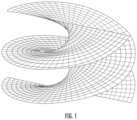
- the present disclosurerelates to shock and impact resistant structures. Particularly, the present disclosure is directed to embodiments of materials having a helicoidal architecture.
- the spiral formed from the assembly of these pitched fiberscan be tuned to a specific wavelength to dampen propagating shock waves initiated by ballistics, strike forces or foreign material impacts; can have matrix additives to toughen and arrest propagation of catastrophic fractures; and can be made to exploit the difference in elastic moduli between the fibers and matrix resin to further arrest fractures generated from blunt or sharp impacts.
- TPUDthin ply uni-directional
- TPWthin-ply woven fabrics
- QUDWquasi-uni-directional woven fabrics
- hybrid fiber reinforced helicoidal materialsarranged, for example, as stacks of polymer based composite material.
- apparatusesthat include the envisioned structures: consumer products, protective armor, sporting equipment, crash protection devices, wind turbine blades, cryogenic tanks, automotive/aerospace components, construction materials, and other composite products.
- FIG. 1is an illustration of an example of a helicoidal geometry.
- FIGS. 2 A- 2 Billustrate examples of a matrix resin molecular structure.
- FIG. 3illustrates a stack of fiber layers arranged into a helicoidal pattern according to embodiments of the invention.
- FIGS. 4 A- 4 Billustrate discontinuous and continuous material forms.
- FIGS. 5 A- 5 Hillustrate uni-directional and other material forms.
- FIG. 6illustrates fiber crimping arising from interlacing.
- FIG. 7 Aillustrates a helicoidal preform made of straight fiber placement on a 3D curved shape according to embodiments of the invention.
- FIG. 7 Billustrates a helicoidal preform made of curved fiber placement on a 2D shape according to embodiments of the invention.
- FIG. 8is an illustration of an MX fabric machine.
- FIG. 9is an illustration of a fiber metal laminate.
- FIGS. 10 A- 10 Bare illustrations of composite sandwich structures.
- FIG. 11depicts an illustration of a helicoidal laminate stack.
- FIG. 12depicts laminate intra and interlaminar zones.
- FIG. 13depicts examples of individual fiber interlaminar contact lengths according to embodiments of the invention.
- FIGS. 14 A- 14 Cdepict typical composite impact damage.
- FIGS. 15 A- 15 Cdepict typical composites where nanomaterials bridge gaps and cracks between fibers.
- FIG. 16depicts a stairstep shaped clocking spiral assembly according to embodiments of the invention.
- FIG. 17depicts an illustration of fiber placement steering.
- FIGS. 18 A-Care schematic views of a structure that includes both impact resistance and load carrying strength according to embodiments of the invention.
- FIG. 19shows a spread tow woven fabric and a light-tow woven fabric.
- FIGS. 20 A-Cshow initial crack formation in woven fabric composites according to embodiments of the invention.
- FIGS. 21 A-Cshow QUDW fabric according to embodiments of the invention.
- FIGS. 22 A-Bshow QUDW fabrics with different included angles between plies according to embodiments of the invention.
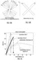
- FIG. 23 Ashows the ply orientations of a helicoidal layup according to embodiments of the invention.
- FIG. 23 Bshows the ply orientations of a conventional thin-ply biaxial layup.
- FIG. 24shows force vs. displacement for various plies and arrangements according to embodiments of the invention.
- helicoidalrefers to a stacking arrangement of plies of fibers wherein the fibers of at least one ply define an orientation direction relative to an orientation direction of the fibers of an adjacent ply and that provide an included angle greater than 0° and less than about 30°.
- the stacking arrangementmay include adjacent plies that define included angles outside of this range, and the stacking arrangement may comprise less than a full rotation of 360°, or may comprise more than one full rotation.
- the fiber orientation direction of one or more pliesmay be straight or curved.
- novel enhancements set forth hereininclude helicoidal materials including: (a) nanomaterials, (b) variable pitch and partial spirals, (c) TPUD lay-ups, (d) hybrid materials, (e) curved fibers within a ply, (f) automated fiber or tape or patch placement for 2D or 3D preforms, (g) non-crimped fabrics, (h) 3D woven fabrics, (i) 3D printed materials, and (j) filament wound materials, (l) TPW layups, (m) QUDW layups.
- helicoidal materialscan be laid up by hand, direct placed with automated machines, and/or pre-assembled in stacks using weaving/braiding/stitching equipment (e.g., non-crimp fabric machines).
- Additive (e.g., 3D printing) manufacturing techniquescan be used to vary and mix material types. For example, polymeric and metallic fibers can be used together that are printed using additive manufacturing techniques in building the helicoidal stack.
- Impact behavior of composite structuresis a complex dynamic phenomenon that can involve elastic deformation, matrix resin cracking, fiber breakage and eventually intra-ply and/or inter-ply delamination.
- Component failurecan occur at free edges, areas of concentrated bearing load or at the point of maximum stress induced by a foreign object impact.
- Impact damageis often worse on the side opposite the strike and can go visually unnoticed, requiring extensive non-destructive inspection (e.g., hand-held ultrasonics). Therefore, impact resistance and damage tolerance are often design limiting criteria. Impact damage can reduce, or limit in-plane load carrying capability and require a product to be removed from usage for repair or if the damage is extensive scrapped and replaced.
- Resin materialsThe molecular structure of matrix resin in a composite consists of a backbone structure (polymer chain) with numerous and varying types of cross-links (i.e., network structures), See FIGS. 2 A-B .
- Traditional thermosetscompositions that go through a phase change curing reaction to reach final form typically possess rigid, highly cross-linked, glassy polymeric structures. This molecular arrangement can make a composite susceptible to matrix cracking and/or delamination when impacted.
- thermoplastic resinone that melts instead of cures and typically has a higher molecular weight and lower degree of cross-linking and/or is more amorphous than crystalline
- toughening of the thermoset resin via network alteratione.g., lowering monomer functionality, increasing the backbone molecular weight, or incorporation of flexible subgroups
- elastomer tougheningby introducing discrete rubber or thermoplastic particles
- interlayer tougheningincorpororation of a thin thermoplastic veil, typically 0.001 in) between thermoset plies.
- Resin tougheningis well known and utilized in the industry.
- Embodiments of the inventionmay also use vitrimers, which are reprocessable thermoset resins, in addition to or in replacement of nonreprocessable thermoset or thermoplastic resins.
- microspheres and microporesinto a helicoidal laminate, such as in the fiber structure illustrated in FIG. 3 , is used in composite materials.
- nanovoidse.g., formed by a laser or other mechanism
- voids or regions of weaknesscan be provided with a directional component so as to cause catastrophic failure to occur in a preferred location and/or along a preferred direction.
- Voidscan have any desired average dimension (an average transverse dimension) between, for example, 0.1 nanometers and 500 microns, or any increment therebetween of 0.1 nanometers, or any subrange within that range having an extent between 10 nanometers and 50 microns, such as a subrange of 10 nanometers, 25 nanometers, 50 nanometers, 80 nanometers, 100 nanometers, 150 nanometers, 250 nanometers, 500 nanometers, and so on.
- average transverse dimensionbetween, for example, 0.1 nanometers and 500 microns, or any increment therebetween of 0.1 nanometers, or any subrange within that range having an extent between 10 nanometers and 50 microns, such as a subrange of 10 nanometers, 25 nanometers, 50 nanometers, 80 nanometers, 100 nanometers, 150 nanometers, 250 nanometers, 500 nanometers, and so on.
- NanomaterialsIncorporation of nanoparticles [e.g., carbon nanotubes (CNTs) and graphene] or elongated nanofibers, such as in the form fibers having an average diameter less than 100 nm, into a matrix resin which can also be combined with fiber reinforcements can improve mechanical properties and impact resistance over conventional composite laminates of identical thickness. This improvement can sometimes be attributed to whiskering (i.e., nanoscale whiskers interacting with the fibers to improve transverse and intralaminar shear properties).
- CNTscarbon nanotubes
- grapheneelongated nanofibers, such as in the form fibers having an average diameter less than 100 nm
- Fibersprovide a composite with strength and stiffness. Fibers can be continuous or discontinuous, depending on the application and manufacturing process. Fibers can also be tailored (arranged in preferential orientations to suit the given application). Most prevalent in the industry, plies are clocked every 45 degrees using 0, +45, ⁇ 45, and 90-degree orientations. The type and amount of fiber reinforcement in a composite can be varied for cost, manufacturing and performance reasons. Certain fiber types (i.e., carbon and graphite) are high in specific strength (properties like tensile and compression divided by density), but are inherently brittle while others, like fiberglass, have better impact strength but lower specific strength due to higher density.
- Aramid (an aromatic polyamide) fibershave excellent toughness and outstanding ballistic and impact resistance, but have reduced performance with temperature fluctuation, are susceptible to ultraviolet light, and tend to absorb moisture.
- a wide variety of known fiber typescan be used to make helicoidal structures, such as carbon, fiberglass, aramid, basalt, ultra-high molecular weight polyethylene (UHMWPE), ultra-high molecular weight polypropylene (UHMWPP) (e.g., Innegra®), self-reinforced polymeric fibers (e.g. Pure®, Tegris®, Curv®), natural fibers such as flax or hemp, metallic fibers, quartz fibers, ceramic fibers and recycled fibers of any of these types.
- UHMWPEultra-high molecular weight polyethylene
- UHMWPPultra-high molecular weight polypropylene
- self-reinforced polymeric fiberse.g. Pure®, Tegris®, Curv®
- natural fiberssuch as flax or hemp, metallic fiber
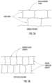
- Material formsLike resin and fiber selection, material form is generally driven by application, cost and manufacturing process. Broadly speaking, material form can include discontinuous or continuous fibers with random or oriented directionality as illustrated in FIGS. 4 A and 4 B .
- FIG. 5 Aillustrates uni-directional manufacturing
- FIG. 5 Billustrates a woven structure
- FIG. 5 Cpresents an example of non-crimped multi-axial fabric
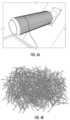
- FIG. 5 Dpresents a net-shaped preform
- FIG. 5 Epresents a schematic of a 3D woven fabric
- FIG. 5 Fpresents an example of filament winding
- FIG. 5 Gpresents an example of fiber patch placement
- FIG. 5 Hpresents an example of braiding.
- UD tapesin general provide better in-plane structural properties than woven fabrics due to the absence of fiber crimp (fibers being taken in and out of plain during interlacing), see FIG. 6 .
- fiber crimpfibers being taken in and out of plain during interlacing
- FIG. 6It will be appreciated that the figures are not necessarily to scale. Weaving can create z-direction fibers and interlocked non-planar fiber bundles that spread point loads and slow or arrest matrix cracking and laminate delamination. But weaving requires large complex machinery, hence the cost can be high and size limited. Further, in-plane properties are typically reduced due to fiber crimping when compared to UD composites. Transverse stitching has been used with UD composites to create z-direction load carrying capability and as a crack arrestor.
- the current disclosureextends the helicoidal application/design to include specific materials (most prevalently TPUD tape, TPW and QUDW), as well as glass, carbon, aramid fibers, and the like, as well as novel fiber angle clocking combinations to help to overcome drawbacks and limitations of current impact resistant composite designs, as well as skins in sandwich applications where helicoid layups have never been explored due to the lack of design space to reproduce full helicoidal stacks.
- Several prevalent methods for placing continuous composites material using dry or pre-impregnated fibersinclude: (a) hand lay-up, (b) automated material placement (AMP which includes continuous fiber placement but also fiber patch placement), and (c) weaving/braiding/ply stitching machines (e.g., multi-axial non-crimp fabric machines where fiber bundles are kept together with a knitting yarn) (d) Filament winding and Pull winding, (e) 3D weaving, (f) 3D printing, (g) heat press consolidation of organosheets.
- AMPusing either type of fiber (slit tape), has the ability to add and drop material on the fly, clock to any pre-programmed angle, and can therefore be used to place near net-shape stacks.
- AMPis an exemplary low-cost method for placing them.
- Near net shaped 2-dimensional (2D) and 3-dimensional (3D) pre-forms(a mostly dry fiber lay-up that can later be infused with resin) can be made of UD tape or multi-directional tape (in which the plies are held together using a powder binder, inter-ply non-woven veil, and/or stitching).
- Pre-impregnated tapetypically 11 ⁇ 2 in to 24 in wide
- slit tapetypically 1 ⁇ 8 in to 11 ⁇ 2 in wide
- “towpreg”can also be laid down directly to shape on contoured tooling using AMP equipment (e.g., contoured tape laminating machine (CTLM), automated fiber placement (AFP) or robotic fiber placement (RFP) and subsequently cured in an oven or autoclave).
- CTLMcontoured tape laminating machine
- AFPautomated fiber placement
- RFProbotic fiber placement
- 2D or 3D preform structurescan be made of dry fiber or UD Tape or multi-directional tape, forming several plies held together by means of a powder binder, inter-ply non-woven thermoplastic veil, needle or pneumatic air punching, A “towpreg”, or any kind of pre-impregnated fiber, UD Tape, multi-directional tape or a slit tape of thermoplastic matrix & fiber can be deposited with a robotic fiber placement head to produce a helicoidal near net shape 2D or 3D preform that can already be impregnated as set forth in FIGS.
- FIG. 7 Aillustrates a helicoidal preform made of straight fiber placement on a 3D curved shape
- FIG. 7 Billustrates a helicoidal preform made of curved fiber placement on a 2D shape.
- Continuous Tow Shearing (CTS)can be used to create in-plane curvilinear fiber orientations.
- NCFNon-Crimp Fabric
- Pliesare usually stitched together but can be linked together by means of a powder binder or an interply non-woven thermoplastic veil that is slightly melted.
- HMXHelicoidal Multiaxial
- a roll of 5 helicoid plies forming a Helicoidal Multiaxial (HMX) fabric[0°, 22.5°, 45°, 67.5°, 90° ] can be produced.
- This rollcan then be folded around its 0° axis dividing its width by 2 or simply combined with another same roll flipped over to form a 10-plies HMX: [ ⁇ 90°, ⁇ 67.5°, ⁇ 45°, ⁇ 22.5°, 0°, 0°, 22.5°, 45°, 67.5°, 90°].
- a first helicoidal MX fabric(e.g., [56°, 79°, ⁇ 79°, ⁇ 56°]) can be taken off a large continuous roll and rotated 90° (e.g., [ ⁇ 34°, ⁇ 11°, 11°, 34°]) and placed on top of one another to create a 8-plies HMX fabric (e.g., 22° HMX with 8 plies [56°, 79°, ⁇ 79°, ⁇ 56°, ⁇ 34°, ⁇ 11°, 11°, 34°]).
- two HMX stackscan be joined using stitching or powder binder or heat laminated thermoplastic non-woven veil or any other suitable known technics such as air punch or needle punch.
- Hybrid constructionComposite components have been made that incorporate non-polymer and/or sandwich materials that can improve properties like bearing, stiffness and impact resistance. Examples of hybrid designs are provided below:
- Metalstypically have limited elastic capability to dissipate energy and therefore fail catastrophically when loaded beyond their ultimate capability. Alternatively, metals can deform plastically to dissipate impact energy.
- Metal foils, meshes and fiberse.g., aluminum, titanium and steel
- SMAShape Memory Alloys
- Typical fiber metal laminate (FML) forms in use in industryinclude: ARALL (aramid/aluminum), GLARE (fiberglass/aluminum), CARALL (carbon/aluminum), and TiGr (titanium/graphite).
- Additional metal/composite hybrid drawbacksinclude: (a) metals may have non-compatible coefficients of thermal expansion (CTE's) when incorporated into polymer-based composites, (b) metal foils, meshes and fibers are difficult to place to complex contours, and (c) metals are denser than the composite material they are displacing.
- CTE'scoefficients of thermal expansion
- Sandwich structuresPlacing a material including, for example a polymer layer on a honeycomb core or foam material between composite laminate face sheets, as shown in FIGS. 10 A and 10 B , creates a synergistic structural configuration in which the face sheets provide bending stiffness and the sandwich material provide shear rigidity and buckling resistance.
- sandwich panelscan exhibit improved strength-to-weight ratios, sound deadening, fatigue capability, thermal insulation, and impact/damage resistance.
- Sandwich panel impact performancecan be superior to laminates since some of the energy associated with a strike may dissipate as elastic deformation instead of matrix and/or fiber damage and/or the core may cushion inertial loads while the face sheet performs the energy absorption.
- Laminate face sheet configuration, core type/structural properties and boundary conditionscontrol the impact behavior.
- the face sheetsare relatively thin and the core is bonded to the face sheets with an adhesive.
- Structural and failure mechanisms that make sandwich inappropriate for some applicationsinclude the following: a) because of limited bond area and strength the face sheets may prematurely separate from the core during impact, b) since the face sheets are thin relative to an equivalent laminate design fiber breakage, fiber matrix de-bonding and laminate delamination can initiate at lower impact levels, c) the core can crush or experience shear deformation and d) replacing laminate plies with sandwich material can degrade in-plane structural properties like compression, tension, strength and stiffness.
- Thin plyComposite laminates made from TPUD stacks have been shown to exhibit better mechanical properties and improved resistance to micro-cracking, delamination, and impact when compared to same thickness parts made using thicker plies.
- aerospace UD carbon/epoxy (C/E) pre-pregsare grade 190 (0.0073 in/ply) or grade 145 (0.0056 in/ply).
- TPUDis typically grade 75 (0.003 in/ply) or thinner. The grade specifies the nominal areal weight of carbon fiber in UD pre-preg measured in g/m 2 .
- TPUD laminatesallow for reduced minimum gauge and/or lighter weight equivalent performance structures.
- Fiber orientationcontrols load carrying capability. Therefore, it is best to run the bulk of the fibers in the direction of primary loading. Balance/symmetry rules along with rules for minimum orientation to protect from unexpected loads (e.g., no less than 10% of the fibers in any one direction) limit stacking freedom and often dictate a lay-up thicker than that needed expressively to take a given load case. These constraints are particularly challenging when tapering (dropping plies) in part areas of reduced loading.
- TPUD pliesas a whole or in combination with normal thickness plies open lighter/thinner stacking options.
- TPUDcan be harder and more costly to pre-preg slit and re-roll and can suffer from more defects and be harder and/or more costly to lay down to a part shape using automated fiber placement equipment than traditional thicknesses pre-preg tape and therefore has seen limited usage in aerospace applications to date.
- TPUD tapetakes more time to lay down to part shape than traditional thickness pre-preg tape due to the higher number of plies being placed.
- composite structurescan be subjected to low and/or high velocity impacts from planned strikes, collisions, hail, rain, birds, tool drop, ballistics, random debris, shock waves, lightning strike or aero fluttering.
- a fiber reinforced elastic composite ply stacking approachin which the individual layers are rotated along the longitudinal or x-direction axis at a predefined angle relative to the adjacent layers so as to create a z-direction helicoidal fiber-oriented stack is depicted in FIG. 11 .
- the left-hand imageuses a single line to represent each ply layer (lamina), this view highlights the generated z direction helicoidal spiral.
- the right-hand imageuses fiber bundles (tows typically consisting of 3000 to 50,000 fibers or more) to more realistically show the construction layers of a helicoidal lay-up.
- the subsequent blow upsshow how the helicoidal laminate stack is formed of individual laminae layers that are formed of evenly dispersed spread fiber tow and resin.
- Helicoidal clockingcan be chosen to create a specific spiraling pitch or circular polarization z orientation fibers that are in close enough proximity as to exhibit significant intralaminar-like direct load sharing between laminate fibers.
- These left and right-handed chirality (a non-superimposable structure distinguishable from its mirror image) spiralsare novel when compared to industry standard 0°, ⁇ 45°, 90° composite laminates (note: in some cases 22.5°, 30°, and 60° angles are used but in these cases large clocking angles and symmetry/balance rules are still typical).
- the ability of the fibers to load share directly between laminae pliesis a significant contributor to a helicoidal laminate's ability to absorb and dissipate impact forces more efficiently than conventional composite lay-ups and minimize the effects of impact fatigue.
- the spiral formed from the assembly of these pitched fiberscan be tuned to a specific wavelength to dampen propagating shock waves initiated by ballistics, strike forces or foreign material impacts; can be filled with a matrix that contains microspheres or toughening particles to further prevent or arrest propagation of catastrophic fractures and can be made to exploit the difference in elastic moduli between the fibers and resin to further arrest fractures generated from blunt or sharp impacts.
- the dynamic performance of a composite structure under load when subject to impact or shockwaveis complex and difficult to predict even when using dynamic state-of-the art fine-grid finite element analysis (FEA).
- FEAfinite element analysis
- the extent of plastic deformation, matrix cracking, fiber breakage and ultimately delamination due to foreign object impact (planned or unplanned)can only be ascertained with any degree of certainty through controlled structural test and post-failure evaluation.
- the current disclosuredetails additional design and manufacturing options that extend the scope and capabilities of helicoidal stacks to a broader range of industrial applications (e.g., wind turbine blades, cryogenic tanks, hydrogen pressure vessels, aerospace primary structures, sporting goods, automotive components, consumer products, defense/space vehicles, soft or hard armor, construction materials, and other composite products).
- Certain disclosed enhancementsinclude helicoidal materials containing: (a) nanomaterials, (b) variable pitch and partial spirals, (c) TPUD plies, (d) hybrid materials, (e) curved fiber within a ply, (f) automated fiber or tape or patch placement for 2D or 3D preforms, (g) non-crimped fabrics, (h) 3D woven fabrics, (i) 3D printed materials, and (j) filament wound parts, (l) TPW layups, (m) QUDW layups.
- Dry and/or pre-preg helicoidal lay-upscan be placed ply-by-ply by hand, direct placed on contoured tools with automated fiber placement machines, and/or pre-knitted in stacks using weaving/braiding/UD plies and woven fabric stitching equipment (e.g., non-crimp fabric machines).
- Nanomaterialsare property enhancing particles having dimensions in the 1 and 1000 nanometers (10 ⁇ 9 meter) range. Examples include carbon nanofibers (CNFs), carbon nanotubes (CNTs), single-wall nanotubes (SWNTs), multi-wall nanotubes (MWNTs), graphite platelets/graphene, organic spherical particles; copolymers, inorganic clays; silica, silicon carbide, alumina, metal oxides, and other known or yet to be evolved nano materials. Incorporation of nanomaterials into a resin in combination with fiber reinforcements has been shown to improve mechanical properties and impact resistance over conventional composite laminates of identical thickness. In some implementations, nanofibers (fibers having a diameter less than 100 nm) can be incorporated into the material.
- FIGS. 14 A-Cshow different types of impact damage (i.e., deformation, intralaminar resin cracking, interlaminar resin cracking, fiber breakage and delamination) arising from different impact levels (i.e., low, medium, and high).
- impact improvementcan be attributed to whiskering (i.e., nanoscale bridging between fibers that improves transverse and intralaminar shear properties).
- FIGS. 15 A-Cshow how nanoscale bridging (also known as stitching) is particularly effective between fibers of the same or similar orientation (i.e., same orientation intralaminar fibers or close orientation interlaminar fibers like the 5-degree helicoidal example shown in FIG. 13 ).
- nanomaterialscan reduce or even eliminate resin cracks arising from low and medium level impacts. Since helicoidal lay-ups' plies are clocked at shallow angles (e.g. 5 to 30 degrees), the direct contact length between individual interlaminar fibers is up to 10 times greater than with standard 0°, ⁇ 45°, 90° lay-ups. This longer contact length makes nanocomposite additives more effective on helicoidal lay-ups than industry standard lay-ups that are separated by angles of 45 or 90 degrees.
- Helicoidal lay-ups with nano additivescan exhibit not only reduced/eliminated intralaminar vertical/horizontal resin cracking but also reduced/eliminated horizontal interlaminar resin cracking and even delamination (total ply separation) arrest, as shown in the FIG. 14 B under medium impact.
- Nanomaterialscan be added uniformly into the resin during pre-pregging, attached directly to the fibers or added as an interlaminar layer between ply stacks.
- Variable pitch and partial helicoidal structuresThe pitch of a helicoidal lay-up depends on the per ply laminae thickness and the angle the plies are clocked/stacked at.
- the resultant spiralcan be tuned to a specific wavelength or strength in anticipation of expected impact type/level and/or required strength.
- conventional lay-ups(those using 0°, ⁇ 45°, 90° plies) require ply stacks to be balanced and symmetric.
- Certain prior art acknowledges that a helicoidal lay-upcan be left hand, right hand or both direction spiraled. As originally envisioned, a helicoidal stack contains consistent angular offset throughout the entire lay-up.
- An example of a balanced and symmetric 18 degree offset helicoidal lay-upis (0°, 18°, 36°, 54°, 72°, 90°, ⁇ 72°, ⁇ 54°, ⁇ 36°, ⁇ 18°, 0°, ⁇ 18°, ⁇ 36°, ⁇ 54°, ⁇ 72° 90°, 72°, 54°, 36°, 18°, 0°). Because of shallow clocking angles (e.g. 30 degrees or less) helicoidal lay-ups have less propensity to warp than industry standard 0°, ⁇ 45°, 90° lay-ups, even when not balanced and/or symmetric. This ability to make non-standard helicoidal lay-ups allows for unique thinner laminate options that can be further tuned for specific applications.
- the current disclosuredescribes the additional helicoidal clocking options:
- TPUD helicoidal materialsIndustry typical UD carbon/epoxy (C/E) pre-preg grades include; 190 (0.0073 in/ply) and 145 (0.0056 in/ply). Thin ply pre-preg is typically grade 60 (0.0023 in/ply) or thinner.
- FIG. 16depicts how helicoidal ply thickness and clocking creates stair step spirals of various height and width. For example, a grade 145 UD helicoidal lay-up would have ⁇ 15 to 20 carbon fibers stacked on top of each other per ply for a vertical step of 0.0056 in.
- This 1:1 tightly clocked spiral with short interlaminar resin shear zone and substantial fiber to fiber direct contactis at the heart of helicoidal lay-ups' impact resistant, crack arresting and interlaminar load sharing between capabilities.
- a grade 190 (0.0073 in/ply) helicoidal lay-up with the same 5° clockingwould have a roughly 2:1 stairstep.
- a typical grade 145 industry standard lay-up with 45° clockingwould have a 0.056 in vertical resin step and therein a relatively long 1:10 spiral.
- This long resin shear zonewhen compared to a helicoidal lay-up, limits interlaminar direct fiber load sharing and, in some instances, can account for reduced impact resistance.
- 90° clockingcreates an interlaminar step of infinity (i.e., an undisturbed interlaminar resin zone).
- TPUD lay-upshave been shown to have improved strength and impact capability when compared to similar thickness traditional lay-ups.
- a TPUD grade 60 (0.0023 in/ply) helicoidal lay-up with 5° clockingwould create an exemplary 1 ⁇ 2:1 stairstep.
- Such a pre-preg clocking arrangementhas been shown to have up to a 50% impact improvement versus traditional (thickness and clocking) lay-ups.
- thin ply lay-upshave been shown to have up to a 30% strength improvement when compared to traditional lay-up of similar total thickness and orientation.
- the adjacent pliesare still divergent enough as to help arrest intralaminar vertical resin cracks.
- composite componentscan be tailored by adding and dropping plies, therein increasing strength and impact resistance in areas of higher loading while maintaining minimal thickness and weight in other areas.
- partsare padded up around openings in the structure such as fastener locations and conduit pass-throughs and in bond zones to locally stiffen a component and/or improve bearing and/or structural strength like aerospace structural assembly with rivets, or a bicycle rim around spoke attachment points.
- partsare thickened in areas of expected high impact, like the leading edge of a wing or wind turbine blade, golf club, striking area of bats and clubs, protective helmets, etc.
- partscan be made to flex in one area and be stiff in other areas such as is the case with fishing poles, golf clubs, pole vault poles, sailing masts, skis & snowboards, running shoes etc.
- the pad-up regions of a componentcan consist of any of the helicoidal variants discussed in this disclosure. This pad-up can be incorporated with a base traditional lay-up or a base helicoidal lay-up of the same or different construction. As detailed in the eight previously listed exemplary cases, TPUD helicoidal laminates allow for reduced minimum gauge and/or lighter weight better or equivalent performing structures.
- Hybrid material helicoidal structuresHelicoidal laminates including nanomaterials, variable pitch and partial spirals, and TPUD can be combined with hybrid materials (e.g., woven composites, non-polymers, metals, foams, sandwich materials, and/or other materials known or to be evolved in the industry) to improve properties like overall weight, fabrication cost, bearing, stiffness and impact resistance. These combinations can be done globally (e.g., nanomaterial combined throughout a matrix resin) or judiciously (e.g., a layer of titanium foil replacing four plies of traditional thickness pre-preg in a thin-thick helicoidal spiral) so as to dial in specific strength and impact characteristics while minimizing cost, weight and/or thickness. Specific exemplary examples of hybrid helicoidal structures are listed below:
- Embodiments of the invention hereinprovide a composite skin sandwich structure with impact resistance wherein at least one of the skins comprises a plurality of plies of reinforcing fibers arranged in a helicoidal relationship, which are not necessarily balanced and/or symmetric.
- the thickness or weight of a skincan relate to the ultimate intended application for the sandwich structure.
- a skinhas a total fabric fiber areal weight of lower than about 1,600 gsm. This weight of fabric may be used for surfboards, for example.
- the skinhas a total fabric fiber areal weight of lower than about 5,000 gsm. This weight of fabric may be used for wind turbine blades made from E-glass fibers, for example.
- the skinhas a thickness of less than about 4 mm.
- the weight of the skinmay be lower than about 3,000 gsm according to embodiments.
- the skin of the composite sandwich structuremay have a partially directional (or quasi-isotropic) strength profile and with improved impact resistance.
- the helicoidal arrangement of the skinhas superior in-plane compression resistance.
- the off-axis pliesi.e. plies which fiber direction is not aligned along the loading direction
- the off-axis pliesusually are the first one to fail with the formation of matrix cracks.
- These matrix cracksoften begin in a direction parallel to the off-axis plies such that they are aligned within and/or adjacent to the tows of an off-axis ply. From there, the matrix cracks propagate into interface damage between plies, which causes delamination, and can lead to early catastrophic failure. This is particularly evident in conventional skins with off-axis plies oriented along medium to large orientations, e.g. ⁇ 30°, ⁇ 45° and ⁇ 60° and 90° orientations.
- a helicoidal fiber arrangementprovides a better load redistribution along the off-axis plies, making it more difficult for a crack to form and propagate. This is due to one or both of at least two reasons.
- a helicoidal fiber arrangementtypically has fewer off-axis plies and/or off-axis plies positioned at smaller angles relative to the reference direction (0°) as compared to conventional skins and thus providing fewer sites for matrix cracks to initiate.
- the propagation of interlaminar cracks at the interface between two pliesis determined at least in part by the interlaminar shear stress, which in turn is driven at least in part by the difference in directional elasticity from one ply to the next.
- a larger change in elasticity from one ply to the next along a common reference directionis more likely to lead to interlaminar matrix cracks.
- the smooth transition in fiber orientation between adjacent plies in helicoid structuresreduces the difference in elasticity from one ply to the next (relative to conventional skins), which in turn reduces the interlaminar stresses at the interface between plies and delays crack propagation and delamination under an increasing compressive load.
- delaminationscan lead to local decrease in the stiffness of the skin which can result in early buckling of the skins.
- the formation of delaminationswould be delayed, leading to better compression strength.
- the in-plane compression resistance of a helicoidal skinis especially advantageous in sandwich structures because the bending or flexural resistance (as determined by the industry-known three-point bending test) of composite structures is often limited by the skin of the sandwich that is subjected to the compressive load (as opposed to an opposite skin that is subjected to the tensile load).
- the sandwich structurecan have a three-layer construction with two helicoidal skins and a core material therebetween.
- embodiments of the inventionalso include three-layer constructions where only one of the skins is a helicoidal skin, and an opposing skin can comprise, for example, a conventional composite material.
- a constructionis well adapted to design environments where the sandwich structure will be subjected to bending forces in only one direction, and/or where only one surface of the sandwich structure will be expected to receive impact forces.
- the coremay comprise more than one layer of material and/or be formed of more than one type of core material. Additional layers of composite material may also be included to provide stiffening or other structural properties.
- Curved fibers within a plycan be created using traditional or robotic fiber placement equipment.
- relatively narrow strips of slit tape or towe.g. 1 ⁇ 4 in
- a wider bande.g., 4 in
- the placement headcan alter heat, placement pressure and angular shear laydown forces in a manner so that the band can be steered in an arc (e.g., 200 mm radius), s-shape or any desired contour instead of the traditional straight line orientation used when placing most composites, see FIG. 17 .
- This curvaturecan add more degrees of freedom to a helicoidal stack and can be used with any of the alternative designs discussed within this disclosure. In-plane curving within a 2D or 3D shape combined with helicoidal ply stacking can further enhance wavelength tuning and impact capabilities.
- Thin-ply woven (TPW) fabricsare an emerging class of high-performance fiber reinforced materials to provide high strength and abrasion resistance.
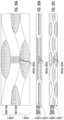
- TPW fabricsare typically found in two forms: 1) spread tow fabrics, where a tow is spread into a thin and flat uni-directional tape (with fiber areal weight similar to the ones of TPUD) and then the various tapes are woven to form a fabric; and 2) fabrics made using light tows, as shown in FIG. 19 .
- Light towsare defined herein as tows having 1 k-12 k filaments per tow in the case of carbon filaments and having a weight of less than about 300 tex for glass.
- Light tow TPW fiberscan also comprise natural fibers ( ⁇ 320 tex), aramid fibers ( ⁇ 300 tex), UHMWPE fibers ( ⁇ 300 tex), polypropylene fibers (( ⁇ 200 tex), and other typical fibers commonly used in composites and mixtures thereof.
- TPW fabricsare laid-up helicoidally and offer superior impact performance compared to conventional thick tows.
- Helicoidal lay-ups of woven fabrics as used hereinrefers to helicoidal lay-ups wherein the included angle between two corresponding tow directions of abutting fabric layers are offset by a helicoidal angle.
- the warp tows of two overlaid woven fabricscan be offset by 5° [so as to define a 0°/5°/ . . . arrangement], and thus the weft tows would be offset by 90° accordingly [in 90°/95°/ . . . directions].
- the superior impact performance of helicoidal TPW layups as disclosed hereinlies in the ability of sub-critical matrix splits (as caused by an impact) to more progressively grow and nest within the laminate in a spiral cracking pattern.
- the failure mechanismtypically starts with a split in the matrix, which has a lower tensile strength (in isolation) than the fiber material. This split may start at a portion of the matrix between the tows, or it may start through the tow (and parallel to its fiber orientation direction) as shown in FIGS. 20 A-C .
- FIG. 20 Ashows two layers of conventional woven fabrics with intersecting warp tows and weft tows, FIG.
- FIG. 20 Bshows two layers of spread tow TPW fabrics
- FIG. 20 Cshows two layers of light-tow TPW fabrics.
- the splitwill need to cross the fibers of the next tow in the direction of the split.
- this next towis generally orthogonal to the split tow, and thus the split will need to break the fibers of the next tow (in their tensile direction) as shown for layers 1 and 2 for FIGS. 20 A-C .
- the translaminar fracture toughness in fiber reinforced compositesincreases with the ply thickness. However, contrary to what might be expected, the translaminar fracture toughness does not increase linearly with increased ply thickness. As an example, doubling the ply thickness or tow count requires more than double the energy required for the crack to propagate. This is related to the activation of additional energy dissipation mechanisms such as splitting, delamination, kink bands (compression) and fiber pull-outs (tension) that contribute to the energy dissipation process.
- TPW fabrics with lower tow count and/or spread tow layersgreatly reduces the amount of energy required to break the weft thin-tow/spread tow (on a relative basis) hence allowing the failure mechanisms of helicoidal structures to activate without instability.
- a composite structure having TPW fabric layers stacked in a helicoidal arrangementcan exhibit a spiral cracking pattern and thus superior impact resistance as compared to conventional thick ply woven fabric composites that might fail in an unstable fashion.
- Example uses for TPW fabric compositesinclude sporting goods, automotive/motorsports components (including wings, splitters, diffusers, body panels) and marine components (including hulls, masts, decks).
- Other example usesinclude consumer goods, such as suitcases and luggage.
- Suitcases and luggage made from polypropylene fibers according to embodiments of the inventionprovide impact protection and toughness at a reasonable cost.
- Quasi-Uni-Directional Woven (QUDW) fabricscan be provided in standard, thick, and thin woven fabrics and arranged helicoidally to provide enhanced impact performance.
- QUDW fabricsare highly unbalanced fabrics where more than >80% of the fibers are aligned along the warp direction and the complementary percentage ( ⁇ 20%) is aligned along the weft direction with the function of providing stability and drapability to the fabric as shown in FIGS. 21 A-C .
- the fibers of the weftcan be different from the fibers of the warp to maximize the difference in elastic properties with the warp fibers (i.e. load carrying fibers).
- the fibers along the warp directioncould be made with glass fiber to provide the bulk of the stiffness and strength to the ply using a relatively low-price fiber type.
- the fibers of the weft tows( ⁇ 20%) could be made of carbon fiber, which is more expensive but better performing than glass, to provide a stiffening effect to the direction orthogonal to the warp.
- the unbalancing of the fabrics and relative spacing between the dispersed weft yarnsis advantageous to achieve enhanced impact performance when the QUDW fabrics are arranged helicoidally to achieve the failure mechanisms of helicoid layups according to embodiments of the invention.
- a matrix split that forms along the warpcan propagate in the neighboring ply-fabric without being halted by a weft yarn crossing over the warp yarn.
- fibersare not required to break to allow for the helicoidal crack to form and grow to take advantage of the helicoidal layup failure mechanisms.
- embodiments of the inventioninclude larger included angles for QUDW fabrics.
- the regions where the weft yarns of two adjacent plies overlapcause a higher resistance to the propagation of helicoidal cracks because the energy required for a crack to propagate helicoidally will require it to break the fibers of the weft yarns. This might lead to unstable catastrophic failure.
- FIG. 22 Ashows two QUDW plies with 95% warp fibers and 5% weft fibers
- FIG. 22 Bshows two QUDW plies with 75% warp fibers and 25% weft fibers.
- QUDW fabricscan be made of carbon fibers and other fiber types typically used in composites.
- the warp and/or weft yarnscan be formed from glass fibers.
- Example uses for QUDW fabric compositesinclude sporting goods, automotive/motorsports components (including body panels, chassis components, battery casings, skid plates), wind turbine blades, pipes and marine components (including hulls, masts, decks).
- the present disclosuredetails a range of novel helicoidal design and manufacturing enhancements that are beyond the prior art.
- This disclosureteaches modifications to spiraling pitch and construction material/alternatives in specific including: (a) nanomaterials, (b) variable pitch and partial spirals, (c) TPUD, (d) hybrid materials, (e) curved fibers within a ply, (f) automated fiber or tape placement for 2D or 3D preforms, (g) non-crimped fabrics, (h) 3D woven fabrics, (i) 3D printed materials, and (j) filament wound parts, (l) TPW, and (m) QUDW.
- Example 1Helicoidal structures containing nanomaterials including but not limited to CNFs, CNTs, SWNTs, MWNTs, graphite platelets/graphene, organic spherical particles, copolymers, inorganic clays, silica, silicon carbide, alumina, metal oxides, and other known or yet to be evolved nano materials. Incorporation of nanomaterials into a resin in combination with fiber reinforcements has been shown to improve mechanical properties and impact resistance over conventional composite laminates of identical thickness. If desired, it is possible to incorporate nanofibers (fibers having a diameter less than 100 nm) into the material.
- nanofibersfibers having a diameter less than 100 nm
- Nanomaterial whiskering between fiberscan improve transverse and intralaminar shear properties and reduce or even eliminate resin cracks arising from low and medium level impacts.
- Helicoidal lay-ups with shallow clocking angles that increase direct contact length between interlaminar fiberscan improve whiskering effects. This lengthening of the contact length, resultant from tight helicoidal clocking, makes nanocomposite additives more effective when incorporated into helicoidal lay-ups than when used in industry standard lay-ups.
- Helicoidal lay-ups with nano-additivescan exhibit not only reduced/eliminated intralaminar vertical/horizontal resin cracking but also reduced/eliminated horizontal interlaminar resin cracks and forestalled onset of delamination.
- Example 2TPUD helicoidal structures create tightly clocked spirals with short interlaminar resin shear zones and substantial fiber to fiber direct contact. Such lay-ups are impact resistant, crack arresting (both from impact and low temperatures) and have improved interlaminar load sharing capabilities. TPUD helicoidal laminates allow for reduced minimum gauge and/or lighter weight better or equivalent performing structures. Balance/symmetry rules along with rules for minimum orientation to protect for unexpected loading (e.g., no less than 10% of the fibers in any one direction) that limit stacking freedom and often dictate lay-ups thicker than needed expressively to take a given load case can be used more sparingly with TPUD helicoidal structures or in some cases ignored. Specific variants of this example include the following:
- Hybrid material helicoidal structurescan be created using any of the previously mentioned nanomaterials, variable pitch and partial spirals, and TPUD plies in combination with hybrid materials (e.g., non-polymer, metals, foams and/or sandwich materials) to improve strength, bearing, stiffness and impact resistance. These combinations can be done globally or just in selected regions to dial in specific strength and impact characteristics while minimizing cost, weight and/or thickness. Specific variants of this example include the following:
- Example 4Automated material placement equipment for deposition of continuous fiber, tape or fiber patches can be used to create any of the previously mentioned helicoidal designs with the added enhancement of curving the fibers within a given ply. This curvature can add more degrees of freedom to a 2D or 3D shape helicoidal stack and can be used to further enhance wavelength tuning and impact capabilities.
- Example 5Helicoidal Multiaxial (HMX) non-crimp fabric [0°, 22.5°, 45°, 67.5°, 90° ] can be produced. This roll can then be folded around its 0° axis dividing its width by 2 or simply combined with another same roll flipped over to form a 10-plies HMX: [ ⁇ 90°, ⁇ 67.5°, ⁇ 45°, ⁇ 22.5°, 0°, 0°, 22.5°, 45°, 67.5°, 90°].
- a first helicoidal MX fabric(e.g., [56°, 79°, ⁇ 79°, ⁇ 56°]) can be taken off a large continuous roll and rotated 90° (e.g., [ ⁇ 34°, ⁇ 11°, 11°, 34°]) and placed on top of one another to create a 8-plies HMX fabric (e.g., 22° HMX with 8 plies [56°, 79°, ⁇ 79°, ⁇ 56°, ⁇ 34°, ⁇ 11°, 11°, 34°]).
- two HMX stackscan be joined using stitching or powder binder or heat laminated thermoplastic non-woven veil or any other suitable known technics such as air punch or needle punch.
- Filament Windingcan be used to create structures based on a helicoidal architecture for various kinds of axisymmetric parts such as pipes, tapered tubes, as well as tanks and pressure vessels (typically in form of a sphere or a cylinder which may have domes on one or both ends).
- these filament winded partsneed to be highly resistant to external impact and are crash and drop tested (such as a hydrogen pressure vessel in the form of a fuel tank in a vehicle) so as to withstand major crashes and avoid exploding.
- Such structurescan be made using full or partial helicoidal laminates to enhance impact strength and to also have more diffused crack propagation to avoid gas leakage and extend operational life cycle.
- Filament winding techniquescan be used to interlace helicoidally formed unidirectional fiber band or tapes, for example, by winding from one end to the other end over a mandrel.
- Such an interlaced helicoidal pattern(as illustrated, for example, in FIG. 5 H ) can complete the mandrel coverage with a bi-angle +X + / ⁇ X° double layer. This angle can be measured from the mandrel rotational axis which accounts for the 0° angular reference.
- this filament winding techniqueit is therefore possible to create successive interlaced helicoidal double layers with a small shallow clocking angle therebetween (e.g. 5° to 10°) around the 0° or the 90° orientations. Around the 45° direction, fibers will cross nearly orthogonally.
- a structure having a helicoidal architecturecan be manufactured with filament winding by winding a layer of fibers all having same angle, or variable angles within the layer/ply. This can be accomplished by programming a robotic filament winding machine accordingly to wind the desired pattern or by adjusting the setup of the roving dispenser.
- This techniquepermits winding several full surface plies of fibers with a small variation of clocking angle between plies to obtain the benefit of a helicoid architecture.
- winding successive circumferential plies at relative angles close to 90°in increments of 4°, such as 88°, 84°, 80°, 76°, 72°
- Such a helicoidal architecturecan also be used as an internal layer to enhance the safety factor in regard to gas leakage through cracks within a partially damaged laminate structure.
- Pull-winding processescan combine pultrusion of a profile with a 0° main direction of fiber reinforcement with wound fibers or tapes to bring further resistance to a transverse load.
- These wound pliescan also be adjacent with a small variation of their angle to from a structure having a helicoidal architecture and deliver higher transverse impact resistance properties.
- Braids and Skewed FabricsBraids produced using 2D or 3D techniques offer an interesting property of diameter variation associated with fiber angle variation. As fibers can slip within a tubular braid, this allows to expand or reduce the diameter of such braid. This property can be advantageous to create a structure having a helicoidal architecture with several layers effectively sleeved over one another so as to progressively expand the diameter of the structure and to slightly vary the fiber angle between and/or along layers to create a very small clocking angle variation between two adjacent braided layers, Such braided fiber reinforcing structures can also be provided in the form of a flat braided tape obtained from a tubular braid cut along a longitudinal direction and then laid open flat.
- the fiber angular orientationalso varies with the width of the tape.
- Such braided tapecan also be used to stack different layers of the same tape with slightly different fiber angle to create a structure having a helicoidal architecture.
- This propertycan also be found in woven fabrics which are skewed to modify the initial 90° angle between warp and weft which can be tuned to create a series of warp/weft angles with small angular variations from one fabric layer to the next one (such as a 5° clocking angle to align layers at 90°, 85°, 80°, 75° degrees, etc.) thus creating a structure having a helicoidal architecture.
- Example 8Additive Manufacturing. Many of the aforementioned techniques use existing sets of fabrics, pre-pregs, and the like. In this example, an alternative method for forming helicoidal architectures is provided. There are multiple routes to additive manufacturing, including stereolithography (SLA) that uses lasers to cure layer by layer photopolymer resins, fused deposition modeling (FDM) that uses 3D printers to deposit thermoplastic materials, multijet modeling (MJM) that can build materials via a printer head depositing materials in 3 dimensions, and selective laser sintering (SLS), which uses a high powered laser to fuse small polymer, metallic, or ceramic/glass particles together.
- SLAstereolithography
- FDMfused deposition modeling
- MJMmultijet modeling
- SLSselective laser sintering
- multiple printer jetscan be used to print, simultaneously, two or more materials that can both have the helicoidal structure, but be offset by a specific angle (e.g., a double helicoid), or have one material act as the in-plane helicoid and another material be printed out of plane, acting as a z-pinned structure.
- materialsdo not have to be printed in a solid fibrous form.
- a “core-shell” print headcan be used to print core-shell materials, where the shell is the desired final material and the core is used as a sacrificial template.
- a hydrophobic polymersuch as polypropylene (PP) can be co-printed with polyvinyl alcohol (PVA) as the core.
- PVApolyvinyl alcohol
- the structurecan be placed in an aqueous bath that will subsequently remove the PVA, yielding hollow PP fibers/tubes.
- the materialsdo not have to be printed as polymers, but as ceramic-based precursors (e.g., SiC, B 4 C, etc.).
- a ceramic precursore.g., polycarbosilane, a precursor to SiC
- the ceramic precursorUpon annealing at a low temperature (e.g., 200° C.), the ceramic precursor will solidify (not yet transform to SiC).
- the PVAcan be safely removed without collapsing the tubes and then the resulting structures can be annealed to completely transform the ceramic precursor to a given material (e.g., SiC).
- the resulting fiberscan be micro or nano-tubes, which can act as transport channels for fluids (air, water, self-healing resin, thermal cooling material, etc.).
- the stiffness or hardness (or any other material property that depends on material composition, particle size, etc.) of the material being depositedcan be graded by continuously changing the material in the print reservoir.
- the rotational angle of the helicoidcan further be tuned to form a graded helicoidal composite material, which may also provide additional mechanical benefit.
- existing templated structurescan be placed on the print stage as a scaffold or sacrificial structure that will yield an architecture that goes beyond just a helicoidal architecture.
- a 2D or even 3D array of pins, tubes or other structurescan be placed on the build plate of a SLA printer.
- the helicoidal architecturecan be printed around this scaffold and subsequently the scaffold can be removed, yielding a multi-structure with helicoidal architecture that maintains impact resistance, but offers additional benefits (for example, mechanical benefits such as z-pinning and thermal: cooling).
- the 3D printing technologycan be used to print curved structures with ease.
- a simple CAD modelcan be constructed to enable an FDM printer (for example) to place fibers in a helicoidal array, but in a curved macrostructural part.
- Example 9TPW and QUDW fabrics helicoidal structures brings together the benefits of the superior impact resistance of helicoidal architectures with the class of woven fabrics for improved drapability, reduced layup time, improved abrasion and visuals. Such lay-ups are impact resistant, crack arresting (both from impact and low temperatures) and have improved interlaminar load sharing capabilities. TPW and QUDW helicoidal laminates allow for structural weight reduction, by improving the impact performances of conventional woven laminates while reducing manufacturing costs of helicoidal structures. The presence of weft and warp fibers eliminates the problem of using balanced/unbalanced layups delivering helicoid solutions with a much wider design space. Specific variants of this example include the following:
- Example 10Conventional lightweight sandwich structures comprise a core, usually PVC, EPS, Honeycomb, Aramid fiber Honeycomb, shear thickening foam cores (D30®), metamaterial cores (MetaCORETM, MetaCORE-LDTM, MetaTHERMTM) and similar to provide stiffness, acoustic impedance, reduced weight and other structural and mechanical properties.
- Lightweight fiber-reinforced composite skins with a total fiberareal weight of 5000 gsm and lower and/or with a skin thickness of 4 mm and lower are used to provide strength and stiffness to the sandwich structure in lightweight sandwich applications.
- TPUDTPUD
- QUDWTPW
- NCFTPW
- UDUD
- a sandwich applicationincludes 200 gsm skins for application to a 5 mm thick PVC core.
- a skinis formed using 10 layers of 20 gsm carbon filament TPUD arranged with the parallel fibers of each ply defining orientation directions as [ ⁇ 15/ ⁇ 25/ ⁇ 35/ ⁇ 45/ ⁇ 60/60/45/35/25/15] to create a helicoidal relationship.
- FIG. 23 Bshows a conventional TPUD biaxial with a [+45/ ⁇ 45] 5 relationship.
- FIG. 24shows the results of a three-point bending flexural test pursuant to ASTM D7249.
- the helicoid TPUD layupshowed increased flexural strength of 88% and 54% when tested along the longitudinal (0°) and transverse (90°) direction, respectively (note that with conventional biaxial, the 0° and 90° properties are expected to be equivalent).
- the helicoid TPUD layup according to this exampleshowed increased flexural strength of 118% and 77%, tested along the longitudinal and transverse direction, respectively.
- the resultant innovative sandwich with directional helicoid skinsthus offers superior compressive strength of the skins in both the longitudinal and orthogonal loading direction.
- the helicoidal arrangementachieves higher stiffness and strength also along the orthogonal direction which, in the helicoidal is characterized by a lower percentage of fiber components aligned to the load than the reference [+45/ ⁇ 45].
- a helicoidal composite ply clocking/stacking design and methodologyin which composite plies are stacked in a tight spiral to specific pitches in order to create a z-direction fiber arrangement that will dampen and absorb shockwave propagation, dissipate strain energy, minimize the effects of impact fatigue, and minimize and/or arrest damage associated with impacts.
- the helicoidal system in aspect 1that is laid up by hand, direct placed with automated machines, and/or pre-knitted in stacks using weaving/braiding/stitching equipment (e.g., non-crimp fabric machines).
- pre-knitted stacke.g. 4, 6, 10, or more specifically clocked helicoidal plies chosen for strength and impact resistance
- the stackcan be dry and later liquid molded or made from pre-preg.
- This stackcan be the entire part or a specific area of the component chosen for helicoidal enhancement using any of the variants disclosed in this disclosure.
- helicoidal system in aspect 1where matrix resin alteration (e.g., lowering monomer functionality, increasing the backbone molecular weight, or incorporation of flexible subgroups) and/or additives (e.g., microspheres, discrete rubber, thermoplastic particle or veils) are used to toughen the laminate and further arrest propagation of catastrophic fractures.
- matrix resin alteratione.g., lowering monomer functionality, increasing the backbone molecular weight, or incorporation of flexible subgroups
- additivese.g., microspheres, discrete rubber, thermoplastic particle or veils
- the helicoidal system in aspect 1, where the pad-up regions of a componentcan include any of the helicoidal variants discussed in this disclosure with a base traditional lay-up or a base helicoidal lay-up of the same or different construction.
- a helicoidal system in aspects 1 through 7, with nanomaterialse.g., CNFs, CNTs, SWNTs, MWNTs, graphite platelets/graphene, organic spherical particles, copolymers, inorganic clays, silica, silicon carbide, alumina, metal oxides, and other known or yet to be evolved nano materials
- nanomaterialse.g., CNFs, CNTs, SWNTs, MWNTs, graphite platelets/graphene, organic spherical particles, copolymers, inorganic clays, silica, silicon carbide, alumina, metal oxides, and other known or yet to be evolved nano materials
- the resultant helicoidal/nanomaterial hybridhas nanoscale whiskers/connections that bridge and allow for sharing between the fibers, improve overall laminate mechanical properties, improve impact resistance and have crack arresting characteristics.
- a helicoidal system in aspect 11with variable clocking angles (i.e., 5°, 10°, 15°) in a single laminate that are tuned over variable wavelengths, arrest/dissipate impact forces at a particular zone/depth and can be optimized for a preferred combination of impact capability and overall laminate strength.
- Such lay-upscan take advantage of helicoidal clocking benefits without having to increase thickness to adhere to balance and symmetry rules of thumb.
- Components made with shallow helicoidal clocking angleshave less propensity to warp than traditional 0°, ⁇ 45°, 90° lay-ups. Further, any tendency to warp can often be overcome by part shape or local stiffening effects.
- TPUD pliestypically 0.0023 in/ply or thinner
- the resultant tightly clocked helicoidal spiralshave relatively short interlaminar resin shear zones hence substantial fiber to fiber direct contact/load sharing (i.e., tight aspect ratios) which make them impact resistant and crack arresting capable.
- TPUD lay-upshave been shown to have improved strength when compared to similar thickness traditional lay-ups.
- the helicoidal system in aspect 16that not only has superior resin crack arrest capability from impact events but also exhibits the capability to minimize intra and inter laminar cracking due to extreme environments (e.g., ⁇ 200 to 415° F. temperatures) such as would be experienced during space and cryogenic tank applications.
- the helicoidal system in aspect 16with continuously clocked spirals that exhibit strength as good or better than highly oriented traditional stacks (extra plies in the primary load carrying direction) while having improved impact characteristics.
- the combination of thinner plies and slightly clocked off-angle fiberscombine to make efficient interlaminar load sharing that results in superior in-plane strength capabilities.
- the helicoidal system in aspect 16while having less total thickness than a comparable traditional laminate stack, may have similar or better strength and impact capability. Therein, it is possible to make thinner and lighter TPUD helicoidal laminates than is possible when adhering to industry standard balance, symmetry, and minimum direction orientation rules.
- the helicoidal system in aspect 16of a thinner or minimum gauge (a thickness that will take critical load case such as hail or bird strike) while still possessing desired properties and adhering to traditional lay-up symmetry, balance and minimum orientation rules.
- the helicoidal system in aspect 16that can combine TPUD and thick plies to create uniquely tuned, strength and impact capability components.
- thin helicoidal pliescan be used for a portion of the lay-up to tune the lay-up and increase impact capability, while thick plies can be used to reduce lay-up time and create overall in-plane strength.
- a helicoidal TPUD non-symmetric/non-balanced stackcan have a minimal gauge and low weight.
- the system in aspect 16with combined TPUD and thick ply helicoidal stacks and variable clocking to create uniquely tuned and strength/impact laminates that are superior to traditional lay-ups.
- the thin and thick pliescan be used to minimize lay-up cost and optimize strength/spiral tuning variables to a certain degree while the variable clocking pitch can be used to optimize properties.
- the helicoidal system in aspect 16, where the pad-up regions of a componentcan include any of the TPUD variants described in 17 through 24 with a base traditional lay-up or a base helicoidal lay-up of the same or different construction.
- the helicoidal systems in aspects 1 through 25combined with hybrid materials (e.g., non-polymer, metals, foams and/or sandwich materials) to improve strength, bearing, stiffness and/or impact resistance.
- hybrid materialse.g., non-polymer, metals, foams and/or sandwich materials
- Such combinationscan be done globally (e.g., nanomaterial combined throughout a matrix resin) or selectively (e.g., a layer of titanium foil) as dictated to meet specific strength, erosion, and impact characteristics while minimizing cost, weight and/or thickness.
- hybrid materiale.g., metals and sandwich
- the helicoidal system in aspect 26with fabric composite plies selectively placed in the stack or on the inner and outer surfaces to create unique clocking arrangements specifically chosen to absorb and dissipate impact forces. Also, when used on the outer plies, to minimize fiber breakout during drilling or trimming. Fabric plies can also contain metal foils, fibers or meshes to help dissipate lightning strikes, transmit current, shield electrical components or change thermal conductivity.
- the helicoidal system in aspect 26with metal foil on the inner and outer surfaces to improve strength, erosion, bearing and impact capability.
- the metal foilcan yield, and the helicoidal plies can absorb/dampen energy during impact.
- a method of making a helicoidal structure from a non-crimp fabric using a multiaxial fabric machineis a method of making a helicoidal structure from a non-crimp fabric using a multiaxial fabric machine.
- HMXMultiaxial Helicoid Non-Crimp Fabric
Landscapes
- Engineering & Computer Science (AREA)
- Textile Engineering (AREA)
- Mechanical Engineering (AREA)
- Chemical & Material Sciences (AREA)
- Composite Materials (AREA)
- Laminated Bodies (AREA)
- Reinforced Plastic Materials (AREA)
Abstract
Description
- 1. Lay-ups with variable clocking angles in a single laminate such as 5, 10, 15 and 30 degrees. One example would be (0°, 5°, 15°, 30, 45°, 75°, −75°, −45°, 30 −15°, −5°, 0°). This type of lay-up is good for tuning over variable wavelengths, arresting/dissipating impact forces at a zone/depth in the lay-up and/or balancing between impact capability and overall laminate strength.
- 2. Lay-ups with tight clocking on the (a) exterior, (b) middle, or (c) middle and exterior of the lay-up and broader clocking on the remainder of the lay-up. (0°, 5°, 10°, 15°, 45°, 75°, −75°, −45°, −15°, −10°, −5°, 0°), is an example of a lay-up with tight clocking on the middle and exterior surfaces of the laminate. This type of lay-up is good for dissipating impact loads within a certain thickness of the laminate while still allowing the freedom to tailor the orientation of other plies for strength in the load bearing direction.
- 3. Non-symmetric and/or non-balanced lay-ups that are only left or right hand spiraled such as: (0°, 30°, 60°, 90°, −60°, −30°, 0°) and (0°, −30°, −60°, 90°, 60°, 30°, 0°). These lay-ups allow one to take advantage of helicoidal clocking, hence impact capability, without having to make a thick balanced/symmetric lay-up. Because tighter helicoidal clocking angles are used (not the traditional 0°, ±45°, 90°), such lay-ups have less propensity to warp. Further, the tendency to warp can often be overcome by part shape or local stiffening.
- 4. Lay-ups that are only partially spiraled and do not clock through a full 360 degree, such as: (0°, 5°, 10°, 15°, 90°, 90°, 15°, 10°, 5°, 0°) or (−35°, −25°, −15°, −5°, 5°, 15°, 25°, 35°). Such lay-ups can isolate the impact benefit of the helicoidal arrangement in certain laminate zones while optimizing load carrying fibers in other zones. This clocking can be directional as to anticipate the nature and direction of impacts in service.
- 1. TPUD helicoidal stacks exhibit improved strength, impact and interlaminar microcrack arresting versus standard ply thickness traditional clocking lay-ups. These capabilities can be attributed to tighter aspect ratio spiraling and therein improved interlaminar load sharing.
- 2. TPUD helicoidal stacks of continuously clocked spirals have strength as good or better than highly oriented traditional stacks (extra plies in the primary load carrying direction) while having improved impact characteristics. This is attributable to the fact that although the helicoidal lay-up may have fewer total fibers in the primary load direction, the thinner plies and slightly clocked off-angle fibers promote efficient interlaminar load sharing. Additionally, since identical angle fibers are not being stacked directly on top of each other in the helicoidal stack, there is less of a propensity for vertical resin microcracks to propagate between laminae during high loading and/or impact events and/or in cold weather environments. Microcrack arrestment will not only help maintain load carrying capability, but it will also reduce permeation of liquids and/or gases in containment vessels.
- 3. TPUD helicoidal stacks of less total thickness may have similar or better impact strength than thicker traditional laminates. Therein, it is possible to make thinner and lighter laminates when using TPUD helicoidal stacks than when using industry non-helicoidal standard balanced, symmetric, and minimum direction orientation laminates.
- 4. Thinner minimum gauge TPUD helicoidal stacks can possess desired properties while adhering to tradition lay-up symmetry, balance and minimum orientation rules. For example, an aircraft skin may require 8-plies of grade 190 UD tape or 0.058 in total thickness for hail strike when using standard 0°, ±45°, 90° lay-ups rules, (0°, +45°, −45°, 90°, 90°, −45°, +45°, 0°). But for the same application a TPUD helicoidal lay-up (one using plies of 0.0023 in or less) might meet impact requirements and lay-up rules using a 16-ply 0.037 in laminate.
- 5. Helicoidal stacks can combine TPUD and thick plies to create uniquely tuned and strength/impact laminates that are superior to traditional lay-ups. One drawback of TPUD is that it may require more time to lay-up a laminate when compared to a thick ply material part because more layers are needed. This drawback can partially be obviated by using a combination of thin and thick plies. In the exemplary case suggested by this disclosure, thin helicoidal plies can be used for a portion of the lay-up to tune the lay-up and increase overall impact capability, while thick plies can be used to reduce lay-up time and create overall strength. In one preferred example, helicoidal plies could be used near the outer surface of the laminate to improve impact strength and thick plies on the remainder or middle of the lay-up as the primary load carrying mechanism. For example, in the example of a wind turbine blade, it is possible to have a thick inner layer that uses unidirectional fibers, and this can be wrapped, or encapsulated, within a layer of helicoidal material. By way of a further example, helicoidal material can be used on an inner layer of a pressure vessel to prevent cracks from propagating to an outer layer of the pressure vessel. If desired, a helicoidal material can be used for an intermediate or outer layer of a pressure vessel in addition to or instead of an inner layer of the pressure vessel.
- An example of this can be seen in
FIGS.18A-C , which show schematic views of a ply arrangement for a fiber-reinforcedcomposite structure 10 according to embodiments of the invention.FIG.18B represents a cross section of the structure shown in perspective inFIGS.18A and18C . Thecomposite structure 10 has a first plurality ofplies 11 of reinforcing fibers defining a first region of the fiber reinforced composite structure, the plies comprising parallel fibers, and wherein the plies are arranged to provide load-carrying strength for the reinforced composite structure. In the example shown, thefirst plurality 11 includes five plies. The two plies at the bottom are arranged at +80°/−80°, and the three plies above those are both arranged at 0°. In this example, the 0° plies are arranged along the axis of an axisymmetric part, such as a tubular structure, and provide strength in the direction of primary loading. The +80°/−80° plies serve to reinforce the 0° plies and resist buckling of the axisymmetric part, such as might be advantageous in long, thin tubular structures. - A second plurality of plies of reinforcing
fibers 12 define a second region of the fiber reinforced composite structure and are arranged in a helicoidal relationship, and wherein an included angle between the orientation directions of at least two adjacent plies is more than 0° and less than about 30° to provide impact resistance for the reinforced composite structure. In the illustrated example, the plies (starting from the top and working down) are arranged at 70°, 65°, 60°, 55°, 50°, 45°, 40°, 30°, 20°, and 10°. As described elsewhere herein, this helicoidal relationship provides impact resistance to the underlying structure. - A third plurality of plies of reinforcing fibers may be positioned opposite the second plurality of plies of reinforcing fibers so as to provide impact resistance to both sides of the first plurality positioned in the middle of the second and third plies. Although shown with TPUD plies for the second plurality of helicoidal plies and thick plies for the other plies, which provides advantages in terms of impact resistance, primary load carrying ability and reduced lay-up time, the thickness of the plies could be the same for each of the plies.
- An example of this can be seen in
- 6. TPUD helicoidal stacks can be made with variable clocking to create uniquely tuned laminates that still possess strength and impact properties that are superior to traditional lay-ups. For example, instead of using a standard clocking of 45 and 90 degrees, as is typical in industry, or using a consistent 5-degree clocking, as can be done on a basic helicoidal lay-up, one could create a helicoidal lay-up where the clocking shifts a few degrees with each subsequent lamina. The resultant laminate could therein possess a predetermined pitch and tuning that uniquely meets the demands of the products environment (as an example thermal, impact, and strength requirements) while minimizing part weight.
- 7. Helicoidal arrangements created using tight clocking and thin plies have been shown to have less of a propensity to warp than traditional lay-ups using standard clocking and standard ply thicknesses. Further, what warpage does remain in a TPUD non-symmetric/non-balanced stack can often be overcome by part shape or local stiffening effects. Therein, left hand only and right hand only TPUD helicoidal lay-ups allow for helicoidal TPUD lay-ups to contain exemplary strength and impact properties while having a minimal gauge and the lowest possible weight.
- 8. Combined TPUD and thick ply helicoidal stacks can be made with variable clocking to create uniquely tuned and strength/impact capable laminates that are superior to traditional lay-ups. Therein, thin and thick plies can be used to minimize lay-up cost and optimize strength/spiral tuning capabilities while variable clocking pitch can be used to maximize properties to a further degree or of a different nature. For example, the thin and thick ply selection can be driven primarily from a lay-up cost standpoint while the variable clocking can be chosen to arrest vertical intralaminar resin microcracking. Other combinations of cost to strength, cost to impact resistance, and cost to weight tuning to improve cost-performance can be envisioned.
- 1. A helicoidal structure with woven fabric composites plies distributed in the stack or on the inner and outer surfaces can be created with unique clocking arrangements chosen to improve impact capability. Woven plies can be useful on the inner and outer surface to minimize fiber breakout when drilling or trimming and can improve erosion and impact capability. Within the lay-up, fabric can be used to create unique clocking/spiraling and tuning combinations that help absorb and dissipate impact forces and minimize the effects of impact fatigue. Fabric plies can also contain metal foils, fibers or meshes to help dissipate lightning strikes, transmit current, shield electrical components or change thermal conductivity.
- 2. A helicoidal structure with metal foil on the inner and outer surfaces can be created to improve erosion and impact capability. Therein, the metal foil can obviate bearing failure, reduce or delay erosion, and/or yield under impact while allowing the helicoidal structure to remain intact for further impact resistance and load carrying.
- 3. Placing a layer of dampening foam or sandwich material in the center of a helicoidal stack can be done to increase shear rigidity, cushion inertial loads, dissipate strike energy, and/or improve buckling resistance. Such construction can improve component strength-to-weight ratios, sound deadening, fatigue capability, thermal insulation, and impact/damage resistance.
- 4. Using helicoidal TPUD skins in a sandwich construction replacing traditional skin structures made of Biaxial (e.g., [+x°/−x°]), Tri-axial (e.g., [0°, +x°, −x°]) or Quadriaxial (i.e., [0°, ±45°, 90°]), or Woven Fabric allows for the improvement of through-thickness impact strength of the skin and to delay skin buckling under in-plane compression. This results from smaller interply angles and a larger number of plies which leads to weight savings. In such a structure the helicoidal stacking delivers higher through-thickness impact strength and complements and counterbalances weaknesses typical of thin ply laminates in out-of-plane strength. Thus, helicoidal stacking of thin plies permits improvement of in-plane properties of thin plies for increased weight reduction.
- 5. Nanomaterials can be incorporated into a matrix resin to improve the bond between helicoidal plies themselves and hybrid materials (e.g., metals and sandwich) and therein improve interlaminar strength and properties relying on such (e.g., strength shear, bending tensile, compression and impact).
- 1. Helicoidal stacks wherein all layers are TPUD plies.
- 2. TPUD helicoidal stacks of continuously clocked spirals.
- 3. TPUD helicoidal stacks adhering to industry standard balance, symmetric, and minimum direction orientation rules that are thinner than traditional lay-ups but have similar or better strength and impact.
- 4. Thinner minimum gauge TPUD helicoidal stacks that possess desired properties while adhering to tradition lay-up symmetry, balance and minimum orientation rules.
- 5. Helicoidal stacks that combine TPUD and thick plies to create uniquely tuned and strength/impact laminates that are superior to traditional lay-ups. For example, thin helicoidal plies can be used for a portion of the lay-up to tune the lay-up and increase overall impact capability, while thick plies can be used to reduce lay-up time and create overall strength.
- 6. TPUD helicoidal stacks with variable clocking to create uniquely tuned laminates that still possess strength and impact properties that are superior to traditional lay-ups.
- 7. Helicoidal stacks with tight clocking and thin plies that have less of a propensity to warp than traditional lay-ups using standard clocking and standard ply thicknesses. This allows for helicoidal TPUD lay-ups to contain exemplary strength and impact properties while having a minimal gauge and lowest possible weight.
- 8. Combined TPUD and thick ply helicoidal stacks with variable clocking to create uniquely tuned and strength/impact laminates that are superior to traditional lay-ups. For example, the thin and thick ply selection can be driven primarily from a lay-up cost standpoint while the variable clocking can be chosen to arrest vertical intralaminar resin microcracking.
- 9. Pad-up regions of a component can include any of the helicoidal variants discussed in this disclosure. This pad-up can be incorporated with a base traditional lay-up or a base helicoidal lay-up of the same or different construction.
- 1. Helicoidal variants with woven fabric composite plies distributed in the stack or on the inner and outer surfaces to create unique clocking arrangements chosen to absorb and dissipate impact forces, minimize fiber breakout when drilling or trimming, and improve erosion capability. Fabric plies can also contain metal foils, fibers or meshes to help dissipate lightning strikes, transmit current, shield electrical components or change thermal conductivity.
- 2. Helicoidal variants with metal foil on the inner and outer surfaces to improve erosion and impact capability.
- 3. Helicoidal variants with dampening foam or sandwich material in the center of the lay-up to increase shear rigidity, cushion inertial loads, dissipate strike energy, and/or improve buckling resistance. Additionally, to improve component strength-to-weight ratios, sound dampening, fatigue capability, thermal insulation, and impact/damage resistance.
- 4. Helicoidal materials can be made using thin ply uni-directional (TPUD) materials assembled in a sandwich construction replacing the traditional skin structure made of Non-Crimp Fabrics or Woven Fabrics. This structure permits a corresponding improvement of impact strength and also can help delay skin buckling under in-plane compression. In such a structure the helicoidal TPUD stacking can be expected to deliver relatively higher through-thickness impact strength and complement and counterbalance the weakness of thin ply laminates in out of plane strength. Thus, in this example, helicoidal stacking of TPUD permits enhancement of in-plane properties of thin plies that can in turn permit weight reduction of parts.
- 5. Helicoidal variants that use nanomaterials in the resin to improve the bond between helicoidal plies themselves and hybrid materials (e.g., metals and sandwich) and therein improve interlaminar strength and properties relying on such (e.g., strength shear, bending tensile, compression and impact).
- 1. Helicoidal stacks wherein all layers are TPW plies.
- 2. Helicoidal stacks wherein all layers are QUDW plies.
- 3. TPW helicoidal stacks of continuously clocked spirals.
- 4. QUDW helicoidal stacks of continuously clocked spirals.
- 5. TPW and/or QUDW Helicoidal stacks that combine TPUD, thick plies and thick woven plies to create uniquely tuned and strength/impact laminates that are superior to traditional lay-ups. For example, TPW helicoidal plies, according to embodiments of the invention, are used for the top portion of the lay-up to locally improve abrasion resistance, visuals and impact resistance, while TPUD or thick UD plies can be used to provide tailored stiffness and in-plane strength.
- 6. TPW and/or QUDW helicoidal stacks with variable clocking to create uniquely tuned laminates that still possess strength and impact properties that are superior to traditional lay-ups.
- 7. Combined TPW and/or QUDW with thick woven, TPUD and thick UD ply helicoidal stacks with variable clocking to create uniquely tuned and strength/impact laminates that are superior to traditional lay-ups.
- 1. Helicoidal skins wherein all layers are TPW plies, or QUDW plies or TPUD, or NCF, or UD plies.
- 2. TPW or QUDW or TPUD or NCF or UD helicoidal skins of continuously clocked spirals.
- 3. TPW or QUDW or TPUD or NCF or UD helicoidal stacks of partially clocked spirals with either continuous or variable pitch angles.
- 4. TPW or QUDW or TPUD or NCF or UD Helicoidal skins that combine TPUD, NCF, thick plies and thick woven plies to create uniquely tuned and strength/impact skins that are superior to traditional skins. For example, one layer of TPW can be used as top skins to improve visual appeal and anti-abrasion resistance while TPUD helicoidal plies can be used for the rest of the skin to provide tailored impact resistance, stiffness, and in-plane strength.
- 5. Sandwich applications with only the top (impact-facing) helicoidal skin. This is to offer an impact resistant mechanism where the overall stiffness is offered by geometrical features of the structures, such as in applications with a double curvature or complex shapes. Such architecture confers higher stress redistribution during impact, further improving impact performances.
- 6. Sandwich applications with both a top (impact facing) and bottom helicoidal skins.
- 7. Sandwich applications where either the top or bottom skins are helicoidal or partial helicoidal lay-up.
- 8. Sandwich applications where the top skins and the bottom skins are symmetrical.
- 9. Sandwich applications where the top and bottom helicoidal skins are not symmetrical
- 10. Sandwich applications where the top skin is helicoidal and the bottom skin is non-helicoidal and where the top and bottom skins can have similar or different weights. For instance, a thicker top helicoidal skin to provide compression strength and impact resistance, while a bottom non-helicoid skin to provide flexural tensile strength and stiffness.
- 17.1 A helicoidal system in
aspects 1 through 7, that uses TPW and/or QUDW plies arranged in a helicoid spiral. The specific construction of such woven fabrics, characterized by either low translaminar fracture toughness of the weft yarns (TPW) and large spacing between weft yarns (QUDW) can be tailored to allow for the highly dissipative failure mechanisms of helicoidal structure to activate and lead to enhanced impact performances. The use of woven fabrics allows to improve drapability of helicoid stack to complex shapes and reduce layup costs.
- 17.1 A helicoidal system in
Claims (29)
Priority Applications (5)
| Application Number | Priority Date | Filing Date | Title |
|---|---|---|---|
| EP21907356.6AEP4263207A4 (en) | 2020-12-17 | 2021-06-28 | COMPOSITE MATERIALS AND STRUCTURES |
| PCT/US2021/039399WO2022132228A1 (en) | 2020-12-17 | 2021-06-28 | Composite materials and structures |
| KR1020237024079AKR20230131473A (en) | 2020-12-17 | 2021-06-28 | Composites and Structures |
| US17/304,902US12275227B2 (en) | 2020-02-11 | 2021-06-28 | Composite materials and structures |
| JP2023537108AJP2023554637A (en) | 2020-12-17 | 2021-06-28 | Composite materials and structures |
Applications Claiming Priority (4)
| Application Number | Priority Date | Filing Date | Title |
|---|---|---|---|
| US202062972830P | 2020-02-11 | 2020-02-11 | |
| US202063033835P | 2020-06-03 | 2020-06-03 | |
| US17/247,603US11376812B2 (en) | 2020-02-11 | 2020-12-17 | Shock and impact resistant structures |
| US17/304,902US12275227B2 (en) | 2020-02-11 | 2021-06-28 | Composite materials and structures |
Related Parent Applications (1)
| Application Number | Title | Priority Date | Filing Date |
|---|---|---|---|
| US17/247,603Continuation-In-PartUS11376812B2 (en) | 2020-02-11 | 2020-12-17 | Shock and impact resistant structures |
Publications (2)
| Publication Number | Publication Date |
|---|---|
| US20210339499A1 US20210339499A1 (en) | 2021-11-04 |
| US12275227B2true US12275227B2 (en) | 2025-04-15 |
Family
ID=78292404
Family Applications (1)
| Application Number | Title | Priority Date | Filing Date |
|---|---|---|---|
| US17/304,902Active2043-08-06US12275227B2 (en) | 2020-02-11 | 2021-06-28 | Composite materials and structures |
Country Status (1)
| Country | Link |
|---|---|
| US (1) | US12275227B2 (en) |
Families Citing this family (11)
| Publication number | Priority date | Publication date | Assignee | Title |
|---|---|---|---|---|
| BR102018006222A2 (en)* | 2018-03-27 | 2019-10-15 | Blue Ocean Engenharia Ltda | MINING SCREEN, MINING SYSTEM AND CONTROL METHOD OF A MINING SCREEN |
| US11852297B2 (en) | 2021-06-01 | 2023-12-26 | Helicoid Industries Inc. | Containers and methods for protecting pressure vessels |
| EP4183580A1 (en)* | 2021-11-22 | 2023-05-24 | Autoneum Management AG | Ground impact plate for a battery electric vehicle |
| US12427748B2 (en)* | 2021-12-06 | 2025-09-30 | Rohr, Inc | Composites and methods of forming composites having tailored hardness profile |
| CN114300859A (en)* | 2021-12-17 | 2022-04-08 | 贵州航天南海科技有限责任公司 | Forming structure of multidirectional load beam made of carbon fiber composite material |
| CN114919249B (en)* | 2022-04-29 | 2024-04-16 | 杭州电子科技大学 | Bumper beam adopting front chelating improved structure of mantis of sparrow tail and preparation method of bumper beam |
| WO2024006078A1 (en) | 2022-06-27 | 2024-01-04 | Helicoid Industries Inc. | High impact-resistant, reinforced fiber for leading edge protection of aerodynamic structures |
| CN117507516A (en)* | 2022-07-29 | 2024-02-06 | 荣耀终端有限公司 | Glass fiber board, rear cover, electronic equipment and preparation method of glass fiber board |
| GB202301908D0 (en)* | 2023-02-10 | 2023-03-29 | Rolls Royce Plc | A containment structure |
| CN116512708A (en)* | 2023-04-14 | 2023-08-01 | 华中科技大学 | Bionic functional composite sandwich antiknock structure and preparation method and application thereof |
| CN118581364A (en)* | 2024-05-14 | 2024-09-03 | 哈尔滨工业大学 | SiCw directional arrangement Brigan structure preform and aluminum-based composite material based thereon and preparation method and application thereof |
Citations (127)
| Publication number | Priority date | Publication date | Assignee | Title |
|---|---|---|---|---|
| US5437450A (en) | 1993-08-31 | 1995-08-01 | Somar Corporation | Golf club shaft and process of preparing same |
| EP0967071A1 (en) | 1998-06-23 | 1999-12-29 | Dardo Bonaparte Lujan | Multilaminar structure for conforming flexible components highly resistant to impacts and dynamic strain |
| US6641893B1 (en) | 1997-03-14 | 2003-11-04 | Massachusetts Institute Of Technology | Functionally-graded materials and the engineering of tribological resistance at surfaces |
| JP2004160927A (en) | 2002-11-15 | 2004-06-10 | Toray Ind Inc | Preform substrate, preform, fiber-reinforced plastic molding and molding method |
| WO2006037083A2 (en) | 2004-09-24 | 2006-04-06 | Itochu Corporation | Thin ply laminates |
| WO2007083641A1 (en) | 2006-01-17 | 2007-07-26 | Unitika Fibers Ltd. | Fabric with highly expanded layer and process for production thereof |
| JP2007191658A (en) | 2006-01-23 | 2007-08-02 | Kawasaki Heavy Ind Ltd | Prepreg and resin composite materials |
| US20070181238A1 (en) | 2006-02-06 | 2007-08-09 | Ternon Gerard L R | Weft inserted warp knit fabric for tire cap ply |
| US20070238379A1 (en) | 2006-03-30 | 2007-10-11 | Honeywell International Inc. | Molded ballistic panel with enhanced structural performance |
| WO2007136755A2 (en) | 2006-05-19 | 2007-11-29 | Massachusetts Institute Of Technology | Continuous process for the production of nanostructures including nanotubes |
| WO2008018421A1 (en) | 2006-08-07 | 2008-02-14 | Toray Industries, Inc. | Prepreg and carbon fiber-reinforced composite material |
| US20080145647A1 (en) | 2006-12-13 | 2008-06-19 | Rahul Ganguli | Metal impregnated composites and methods of making |
| WO2008098990A1 (en) | 2007-02-15 | 2008-08-21 | Grein Tec Gmbh | Composite material |
| WO2008098771A1 (en) | 2007-02-16 | 2008-08-21 | Dsm Ip Assets B.V. | Ballistic-resistant moulded article and process for obtaining such article |
| WO2008141687A2 (en) | 2007-05-21 | 2008-11-27 | Carl Freudenberg Kg | Multi-layer composite for use in an air filter |
| WO2009058500A1 (en) | 2007-11-01 | 2009-05-07 | Lockheed Martin Corporation | Highly tailored stiffening for advanced composites |
| US20090140098A1 (en) | 2007-11-29 | 2009-06-04 | Hauke Lengsfeld | Component with carbon nanotubes |
| CN101524903A (en) | 2009-04-09 | 2009-09-09 | 哈尔滨工业大学 | Carbon fiber metal laminate |
| EP2110056A1 (en) | 2008-04-18 | 2009-10-21 | Bernhard Scheuring | Compound assembly |
| WO2009127852A1 (en) | 2008-04-16 | 2009-10-22 | Airbus Uk Limited | Composite laminate with self-healing layer |
| CN101633254A (en) | 2008-07-23 | 2010-01-27 | 辽宁丰城工业技术有限公司 | Multilayer composite plate for building templates and brick pallets and preparation process thereof |
| US20100099513A1 (en) | 2003-05-21 | 2010-04-22 | Taylor Made Golf Company, Inc. | Golf club head having a composite face insert |
| WO2010058196A1 (en) | 2008-11-19 | 2010-05-27 | Bae Systems Plc | Fibre reinforced composite |
| WO2010065330A1 (en) | 2008-11-25 | 2010-06-10 | The Boeing Company | Reinforced foam-filled composite stringer |
| US20100282404A1 (en) | 2008-02-18 | 2010-11-11 | Hexcel Composites Limited | Composite Tape For Use In Tape Laying Machines |
| US20100304145A1 (en) | 2007-11-10 | 2010-12-02 | Kyushu Institute Of Technology | Carbon fiber reinforced prepreg of gas barrier properties, carbon fiber reinforced plastic and methods of producing the same |
| WO2010144010A1 (en) | 2009-06-11 | 2010-12-16 | Saab Ab | A structural longitudinal composite joint for aircraft structure |
| US7874937B2 (en) | 2007-12-19 | 2011-01-25 | Taylor Made Golf Company, Inc. | Composite articles and methods for making the same |
| WO2011090396A1 (en) | 2010-01-24 | 2011-07-28 | Instytut Chemii Fizycznej Polskiej Akademii Nauk | System and method for automated generation and handling of liquid mixtures |
| CN102145553A (en) | 2010-11-15 | 2011-08-10 | 长春博超汽车零部件股份有限公司 | Environmental-friendly recyclable basalt fiber and jute fiber composite plate for automotive interiors and production method thereof |
| US8012291B2 (en) | 2006-12-11 | 2011-09-06 | The Boeing Company | Backing film removal system and method for fiber placement machine |
| WO2011107733A2 (en) | 2010-03-02 | 2011-09-09 | Gkn Aerospace Services Limited | Seamless acoustic liner |
| WO2011121340A1 (en) | 2010-03-30 | 2011-10-06 | Airbus Operations Limited | Composite structural member |
| WO2011128667A1 (en) | 2010-04-15 | 2011-10-20 | Airbus Operations Limited | Composite structure |
| CN102336034A (en) | 2010-07-21 | 2012-02-01 | 三芳化学工业股份有限公司 | Laminated material and method for producing same |
| WO2012024023A1 (en) | 2010-08-17 | 2012-02-23 | The Boeing Company | Composite structures having composite-to-metal joints and method for making the same |
| WO2012060971A1 (en) | 2010-11-01 | 2012-05-10 | Cytec Technology Corp. | Targeted deposition of particles on substrates used in the manufacture of composite articles |
| US8187402B2 (en) | 2006-03-04 | 2012-05-29 | Karl Mayer Malimo Textilmaschinenfabrik Gmbh | Method for producing a multidirectional fabric web |
| US8192853B2 (en) | 2007-09-14 | 2012-06-05 | Greg Hilmas Hilmas | Method for toughening via the production of spiral architectures through powder loaded polymeric extrusion and toughened materials formed thereby |
| WO2012091897A1 (en) | 2010-12-31 | 2012-07-05 | Cytec Technology Corp. | Method of fabricating a composite structure with a conductive surface |
| WO2012096696A1 (en) | 2011-01-12 | 2012-07-19 | Stanford University | Composite laminated structures and methods for manufacturing and using the same |
| WO2012126897A1 (en) | 2011-03-18 | 2012-09-27 | Quadrant Epp Ag | Thermoplastically deformable composite material |
| WO2013004671A1 (en) | 2011-07-01 | 2013-01-10 | Daher Aerospace | Method for locally strengthening a composite panel with fibrous reinforcement and panel obtained using such a method |
| US8460777B2 (en) | 2008-10-07 | 2013-06-11 | Alliant Techsystems Inc. | Multifunctional radiation-hardened laminate |
| WO2013135515A1 (en) | 2012-03-15 | 2013-09-19 | Sgl Carbon Se | Thermally conductive composite element based on expanded graphite |
| WO2013162989A1 (en) | 2012-04-28 | 2013-10-31 | General Electric Company | Composite article and methods therefor |
| WO2013173035A1 (en) | 2012-05-17 | 2013-11-21 | Honeywell International Inc. | Hybrid fiber unidirectional tape and composite laminates |
| WO2014001652A1 (en) | 2012-06-28 | 2014-01-03 | Franck GAUCEL | Blocks for ventilated walls |
| WO2014009314A1 (en) | 2012-07-12 | 2014-01-16 | Compagnie Chomarat | Reinforcing textile complex for composite parts, and composite parts integrating said complex |
| WO2014011293A2 (en) | 2012-04-19 | 2014-01-16 | Cytec Technology Corp. | Composite materials |
| US20140033411A1 (en) | 2012-08-06 | 2014-02-06 | The Regents Of The University Of California | Shock and impact resistant materials |
| WO2014026448A1 (en) | 2012-08-14 | 2014-02-20 | 深圳市海斯比船艇科技股份有限公司 | Abrasion-resistant and impact-resistant composite material ship hull and manufacturing method therefor and super hybrid composite material and manufacturing method therefor |
| US20140099484A1 (en) | 2012-10-04 | 2014-04-10 | General Electric Company | Ceramic matrix composite, method of making a ceramic matrix composite, and a pre-preg composite ply |
| WO2014071306A1 (en) | 2012-11-05 | 2014-05-08 | Gordon Holdings, Inc. | High strength, light weight composite structure, method of manufacture and use thereof |
| US8728263B2 (en) | 2007-09-04 | 2014-05-20 | The Boeing Company | Composite fabric with rigid member structure |
| CN103818606A (en) | 2013-12-26 | 2014-05-28 | 余姚中国塑料城塑料研究院有限公司 | Manufacturing method for light plastic packing boxes |
| WO2014085802A1 (en) | 2012-11-30 | 2014-06-05 | The Broad Institute, Inc. | High-throughput dynamic reagent delivery system |
| WO2014088962A1 (en) | 2012-12-03 | 2014-06-12 | The Boeing Company | Split resistant composite laminate |
| WO2014099149A1 (en) | 2012-12-19 | 2014-06-26 | Cytec Industries Inc. | Particle toughening for improving fracture toughness |
| WO2014151658A1 (en) | 2013-03-15 | 2014-09-25 | The Regents Of The University Of California | High-speed on demand microfluidic droplet generation and manipulation |
| US20140335300A1 (en) | 2013-01-02 | 2014-11-13 | The Board Of Trustees Of The Leland Stanford Junior University | Tri-angle herringbone tape for composite panels |
| WO2014197039A2 (en) | 2013-03-15 | 2014-12-11 | Honeywell International Inc. | Trauma reduction without ballistic performance reduction |
| US20150030805A1 (en) | 2013-07-29 | 2015-01-29 | Compagnie Chomarat | Composite bi-angle and thin-ply laminate tapes and methods for manufacturing and using the same |
| WO2015047480A2 (en) | 2013-08-20 | 2015-04-02 | United Technologies Corporation | Composite flange with three-dimensional weave architecture |
| WO2015044099A1 (en) | 2013-09-27 | 2015-04-02 | Bayer Materialscience Ag | Multilayer structural component, method for the production thereof and use thereof |
| WO2015073537A1 (en) | 2013-11-13 | 2015-05-21 | Gordon Holdings, Inc. | Composite structure with reinforced thermoplastic adhesive laminate and method of manufacture |
| WO2015088594A1 (en) | 2013-12-14 | 2015-06-18 | The Boeing Company | Coupled fibers in composite articles |
| WO2015091794A1 (en) | 2013-12-20 | 2015-06-25 | Hexcel Composites Limited | Composite structure |
| WO2015095396A1 (en) | 2013-12-17 | 2015-06-25 | C&D Zodiac, Inc. | Polyimide aerogel insulated panel assembly |
| DE202015004314U1 (en) | 2015-06-11 | 2015-08-03 | Rüdiger Turtenwald | Moisture barrier or wall barrier |
| US9114588B2 (en) | 2012-05-22 | 2015-08-25 | Airbus Helicopters Deutschland GmbH | Skin-stiffener transition assembly, method of manufacture and application of said skin-stiffener transition assembly |
| CN104943185A (en) | 2015-06-17 | 2015-09-30 | 天台县富华塑胶有限公司 | High-strength high-sound-insulation thermoplasticity sound insulation plate and production technology thereof |
| CN104985902A (en) | 2015-07-02 | 2015-10-21 | 河北搏强塑料制品有限公司 | Polypropylene micro-foaming on-line thermal lamination film sheet and manufacturing method thereof |
| WO2015167630A1 (en) | 2014-05-01 | 2015-11-05 | The Boeing Company | Structural bonded patch with tapered adhesive design |
| US20150314553A1 (en) | 2013-01-11 | 2015-11-05 | Aircelle | Reinforced structural component made of composite material |
| CN204845063U (en) | 2015-08-07 | 2015-12-09 | 湖南星通汽车制造有限公司 | Car as a house integrated into one piece shell structure |
| WO2015188963A1 (en) | 2014-06-11 | 2015-12-17 | Thyssenkrupp Ag | Torsion-loaded rod-shaped component with different fibre reinforcements for tensile and compressive loading |
| CN105235295A (en) | 2015-11-03 | 2016-01-13 | 无锡同春新能源科技有限公司 | Composite material buoyancy tank glued by wood-plastic foaming board, PIN core material and foaming board |
| US20160009368A1 (en) | 2013-02-28 | 2016-01-14 | The Boeing Company | Composite laminated plate having reduced crossply angle |
| WO2016020414A1 (en) | 2014-08-06 | 2016-02-11 | Etablissements J. Soufflet | A method for fusing or contacting reactor and reagent droplets in a microfluidic or millifluidic device |
| WO2016048885A1 (en) | 2014-09-22 | 2016-03-31 | Cytec Industries Inc. | Composite materials with high z-direction electrical conductivity |
| US20160101592A1 (en) | 2013-06-18 | 2016-04-14 | E I Du Pont De Nemours And Company | Hybrid glass fibers carbon fibers thermoplastic composites |
| CN105667057A (en) | 2016-03-31 | 2016-06-15 | 马鞍山联洪合成材料有限公司 | A foam-type reinforced film production device and its production process |
| WO2016154089A1 (en) | 2015-03-26 | 2016-09-29 | Research Frontiers Incorporated | Laminated glazings with improved moisture protection |
| WO2016193758A1 (en) | 2015-06-03 | 2016-12-08 | Sphere Fluidics Limited | Systems and methods |
| CN205854774U (en) | 2016-08-04 | 2017-01-04 | 廊坊市晓名纸业有限公司 | A kind of waterproof reinforced carton |
| US20170028652A1 (en) | 2015-07-29 | 2017-02-02 | Airbus Operations S.L. | Monolithic primary structural part for aircraft and processes for manufacturing it |
| WO2017027598A1 (en) | 2015-08-11 | 2017-02-16 | Sabic Global Technologies B.V. | Multiple ply layered composite having low areal weight |
| WO2017048975A1 (en) | 2015-09-17 | 2017-03-23 | The Regents Of The University Of California | Droplet-trapping devices for bioassays and diagnostics |
| US9643734B2 (en) | 2013-03-18 | 2017-05-09 | The Boeing Company | Electromagnetic energy surface protection |
| CN106739237A (en) | 2016-12-15 | 2017-05-31 | 中国航空工业集团公司基础技术研究院 | A kind of multiple-protection composite and preparation method thereof |
| CN106739192A (en) | 2016-11-22 | 2017-05-31 | 北京空间机电研究所 | A kind of full carbon fiber composite material reflector substrate and preparation method thereof |
| WO2017095810A1 (en) | 2015-11-30 | 2017-06-08 | Cytec Industries Inc. | Surfacing materials for composite structures |
| CN106832672A (en) | 2017-02-21 | 2017-06-13 | 武汉普优瑞科技有限公司 | PVC foam core materials and its production technology |
| WO2017103669A1 (en) | 2015-12-16 | 2017-06-22 | Toray Industries, Inc. | Prepreg, laminate body, fiber reinforced composite material, and manufacturing method for fiber reinforced composite material |
| WO2017117083A1 (en) | 2015-12-28 | 2017-07-06 | Federal-Mogul Corporation | Piston including a composite layer applied to metal substrate |
| WO2017117383A1 (en) | 2015-12-30 | 2017-07-06 | Cytec Industries Inc. | Multifunctional surfacing material with burn-through resistance |
| CN107187131A (en) | 2017-06-13 | 2017-09-22 | 北京航空航天大学 | A kind of aluminium base superhybrid composite laminate and preparation method thereof |
| CN107187124A (en) | 2017-06-13 | 2017-09-22 | 北京航空航天大学 | A kind of magnesium-based superhybrid composite laminate and preparation method thereof |
| WO2017180387A1 (en) | 2016-04-15 | 2017-10-19 | Honeywell International Inc. | Blister free composite materials molding |
| WO2017207611A1 (en) | 2016-06-03 | 2017-12-07 | Covestro Deutschland Ag | Multi-layer composite material containing special copolycarbonates as a matrix material |
| CN107891631A (en) | 2017-11-23 | 2018-04-10 | 航天材料及工艺研究所 | A kind of composite pilotaxitic texture and its laying method |
| CN107946511A (en) | 2017-11-16 | 2018-04-20 | 北京航空航天大学 | A kind of variable cross-section composite material battery case and preparation process |
| WO2018093520A2 (en) | 2016-10-18 | 2018-05-24 | Sabic Global Technologies B.V. | Selective perforation, construction, and sequencing of plies for composite laminates and hybrids |
| US20180148154A1 (en) | 2016-11-29 | 2018-05-31 | Airbus Operations, S.L. | Aircraft composite panel assembly and manufacturing method thereof |
| US20180162101A1 (en) | 2016-12-14 | 2018-06-14 | The Boeing Company | Material systems and methods of manufacturing material systems |
| WO2018132360A1 (en) | 2017-01-15 | 2018-07-19 | Honeywell International Inc. | Improved peel strength between dissimilar fabrics |
| WO2018187186A1 (en) | 2017-04-04 | 2018-10-11 | The Board Of Trustees Of The Leland Stanford Junior University | Double-double composite sub-laminate structures and methods for manufacturing and using the same |
| US10099445B2 (en) | 2015-05-14 | 2018-10-16 | The Boeing Company | Systems and methods for forming composite materials |
| WO2019031589A1 (en) | 2017-08-09 | 2019-02-14 | 積水化学工業株式会社 | Multilayer sheet, coating fibers, coating fiber bundle, and fire-reinforced plastic |
| US10247523B2 (en) | 2015-12-11 | 2019-04-02 | Fortified Composites Llc | Composite laminates incorporating vertically aligned carbon nanotubes for ballistic and low velocity impact protection |
| WO2019133463A1 (en) | 2017-12-26 | 2019-07-04 | Cytec Industries Inc. | Fire retardant veil for use in composite materials |
| US20190225764A1 (en) | 2016-10-04 | 2019-07-25 | Mitsubishi Chemical Corporation | Prepreg, prepreg laminate, and fiber-reinforced composite material |
| CN110145984A (en) | 2019-06-10 | 2019-08-20 | 吉林市圣赢碳纤维制品科技有限公司 | A composite material anti-vibration explosion-proof cylinder |
| US20190263532A1 (en) | 2018-02-26 | 2019-08-29 | The Boeing Company | Kinetic Energy Absorption Method and Kinetic Energy Absorptive, Reinforced, Composite Article |
| WO2019203893A2 (en) | 2017-11-08 | 2019-10-24 | Cytec Industries Inc. | Composites with interlaminar toughening particles and method of making the same |
| US10472472B2 (en) | 2014-09-23 | 2019-11-12 | The Boeing Company | Placement of modifier material in resin-rich pockets to mitigate microcracking in a composite structure |
| CN209700003U (en) | 2018-11-26 | 2019-11-29 | 安徽信耀玻璃有限公司 | Three layers of inorganic composite plate |
| JP2019218050A (en) | 2018-06-20 | 2019-12-26 | コロングロテック インコーポレイテッド | Truck, deck gate for truck, and method for manufacturing the same |
| US10576335B2 (en) | 2017-07-20 | 2020-03-03 | Taylor Made Golf Company, Inc. | Golf club including composite material with color coated fibers and methods of making the same |
| US10604226B2 (en) | 2017-04-14 | 2020-03-31 | Textron Innovations Inc. | Shielded structure for aircraft |
| US10603873B2 (en) | 2016-08-29 | 2020-03-31 | Northrop Grumman Innovation Systems, Inc. | Hybrid metal composite structures, rocket cases, and related methods |
| US10632353B2 (en) | 2015-03-20 | 2020-04-28 | North Thin Ply Technology Sarl | Method for forming a fiber-reinforced composite structure |
| WO2020109342A1 (en) | 2018-11-26 | 2020-06-04 | Euro-Composites S.A. | Sandwich-composite component for aircraft interiors |
| JP2020131528A (en) | 2019-02-18 | 2020-08-31 | Ntn株式会社 | Frp cylindrical body and power transmission shaft |
| US10786977B2 (en) | 2014-06-04 | 2020-09-29 | Bright Lite Structures Llc | Composite sandwich having a high bending stiffness |
| WO2020214871A1 (en) | 2019-04-17 | 2020-10-22 | Cytec Industries Inc. | Light-weight sandwich structure with flame-retardant property and method of making the same |
- 2021
- 2021-06-28USUS17/304,902patent/US12275227B2/enactiveActive
Patent Citations (140)
| Publication number | Priority date | Publication date | Assignee | Title |
|---|---|---|---|---|
| US5437450A (en) | 1993-08-31 | 1995-08-01 | Somar Corporation | Golf club shaft and process of preparing same |
| US6641893B1 (en) | 1997-03-14 | 2003-11-04 | Massachusetts Institute Of Technology | Functionally-graded materials and the engineering of tribological resistance at surfaces |
| EP0967071A1 (en) | 1998-06-23 | 1999-12-29 | Dardo Bonaparte Lujan | Multilaminar structure for conforming flexible components highly resistant to impacts and dynamic strain |
| JP2000033662A (en) | 1998-06-23 | 2000-02-02 | Bonaparte Lujan Daldo | Multilayered structure suitable for flexible material having high resistance to impact and dynamic strain |
| JP2004160927A (en) | 2002-11-15 | 2004-06-10 | Toray Ind Inc | Preform substrate, preform, fiber-reinforced plastic molding and molding method |
| US20100099513A1 (en) | 2003-05-21 | 2010-04-22 | Taylor Made Golf Company, Inc. | Golf club head having a composite face insert |
| WO2006037083A2 (en) | 2004-09-24 | 2006-04-06 | Itochu Corporation | Thin ply laminates |
| JP2008514458A (en) | 2004-09-24 | 2008-05-08 | 伊藤忠商事株式会社 | Thin ply laminate |
| WO2007083641A1 (en) | 2006-01-17 | 2007-07-26 | Unitika Fibers Ltd. | Fabric with highly expanded layer and process for production thereof |
| JP2007191658A (en) | 2006-01-23 | 2007-08-02 | Kawasaki Heavy Ind Ltd | Prepreg and resin composite materials |
| US20070181238A1 (en) | 2006-02-06 | 2007-08-09 | Ternon Gerard L R | Weft inserted warp knit fabric for tire cap ply |
| US8187402B2 (en) | 2006-03-04 | 2012-05-29 | Karl Mayer Malimo Textilmaschinenfabrik Gmbh | Method for producing a multidirectional fabric web |
| JP2009532231A (en) | 2006-03-30 | 2009-09-10 | ハネウェル・インターナショナル・インコーポレーテッド | Molded bullet panel with enhanced structural properties |
| US20070238379A1 (en) | 2006-03-30 | 2007-10-11 | Honeywell International Inc. | Molded ballistic panel with enhanced structural performance |
| WO2007136755A2 (en) | 2006-05-19 | 2007-11-29 | Massachusetts Institute Of Technology | Continuous process for the production of nanostructures including nanotubes |
| WO2008018421A1 (en) | 2006-08-07 | 2008-02-14 | Toray Industries, Inc. | Prepreg and carbon fiber-reinforced composite material |
| US9822228B2 (en) | 2006-08-07 | 2017-11-21 | Toray Industries, Inc. | Prepreg and carbon fiber reinforced composite materials |
| US8012291B2 (en) | 2006-12-11 | 2011-09-06 | The Boeing Company | Backing film removal system and method for fiber placement machine |
| US20080145647A1 (en) | 2006-12-13 | 2008-06-19 | Rahul Ganguli | Metal impregnated composites and methods of making |
| WO2008098990A1 (en) | 2007-02-15 | 2008-08-21 | Grein Tec Gmbh | Composite material |
| WO2008098771A1 (en) | 2007-02-16 | 2008-08-21 | Dsm Ip Assets B.V. | Ballistic-resistant moulded article and process for obtaining such article |
| WO2008141687A2 (en) | 2007-05-21 | 2008-11-27 | Carl Freudenberg Kg | Multi-layer composite for use in an air filter |
| US8728263B2 (en) | 2007-09-04 | 2014-05-20 | The Boeing Company | Composite fabric with rigid member structure |
| US8192853B2 (en) | 2007-09-14 | 2012-06-05 | Greg Hilmas Hilmas | Method for toughening via the production of spiral architectures through powder loaded polymeric extrusion and toughened materials formed thereby |
| WO2009058500A1 (en) | 2007-11-01 | 2009-05-07 | Lockheed Martin Corporation | Highly tailored stiffening for advanced composites |
| US20100304145A1 (en) | 2007-11-10 | 2010-12-02 | Kyushu Institute Of Technology | Carbon fiber reinforced prepreg of gas barrier properties, carbon fiber reinforced plastic and methods of producing the same |
| US20090140098A1 (en) | 2007-11-29 | 2009-06-04 | Hauke Lengsfeld | Component with carbon nanotubes |
| US7874937B2 (en) | 2007-12-19 | 2011-01-25 | Taylor Made Golf Company, Inc. | Composite articles and methods for making the same |
| US20100282404A1 (en) | 2008-02-18 | 2010-11-11 | Hexcel Composites Limited | Composite Tape For Use In Tape Laying Machines |
| WO2009127852A1 (en) | 2008-04-16 | 2009-10-22 | Airbus Uk Limited | Composite laminate with self-healing layer |
| EP2110056A1 (en) | 2008-04-18 | 2009-10-21 | Bernhard Scheuring | Compound assembly |
| CN101633254A (en) | 2008-07-23 | 2010-01-27 | 辽宁丰城工业技术有限公司 | Multilayer composite plate for building templates and brick pallets and preparation process thereof |
| US8460777B2 (en) | 2008-10-07 | 2013-06-11 | Alliant Techsystems Inc. | Multifunctional radiation-hardened laminate |
| WO2010058196A1 (en) | 2008-11-19 | 2010-05-27 | Bae Systems Plc | Fibre reinforced composite |
| WO2010065330A1 (en) | 2008-11-25 | 2010-06-10 | The Boeing Company | Reinforced foam-filled composite stringer |
| CN101524903A (en) | 2009-04-09 | 2009-09-09 | 哈尔滨工业大学 | Carbon fiber metal laminate |
| WO2010144010A1 (en) | 2009-06-11 | 2010-12-16 | Saab Ab | A structural longitudinal composite joint for aircraft structure |
| WO2011090396A1 (en) | 2010-01-24 | 2011-07-28 | Instytut Chemii Fizycznej Polskiej Akademii Nauk | System and method for automated generation and handling of liquid mixtures |
| WO2011107733A2 (en) | 2010-03-02 | 2011-09-09 | Gkn Aerospace Services Limited | Seamless acoustic liner |
| WO2011121340A1 (en) | 2010-03-30 | 2011-10-06 | Airbus Operations Limited | Composite structural member |
| WO2011128667A1 (en) | 2010-04-15 | 2011-10-20 | Airbus Operations Limited | Composite structure |
| CN102336034A (en) | 2010-07-21 | 2012-02-01 | 三芳化学工业股份有限公司 | Laminated material and method for producing same |
| WO2012024023A1 (en) | 2010-08-17 | 2012-02-23 | The Boeing Company | Composite structures having composite-to-metal joints and method for making the same |
| WO2012060971A1 (en) | 2010-11-01 | 2012-05-10 | Cytec Technology Corp. | Targeted deposition of particles on substrates used in the manufacture of composite articles |
| CN102145553A (en) | 2010-11-15 | 2011-08-10 | 长春博超汽车零部件股份有限公司 | Environmental-friendly recyclable basalt fiber and jute fiber composite plate for automotive interiors and production method thereof |
| WO2012091897A1 (en) | 2010-12-31 | 2012-07-05 | Cytec Technology Corp. | Method of fabricating a composite structure with a conductive surface |
| WO2012096696A1 (en) | 2011-01-12 | 2012-07-19 | Stanford University | Composite laminated structures and methods for manufacturing and using the same |
| US10589474B2 (en) | 2011-01-12 | 2020-03-17 | Compagnie Chomarat | Methods for manufacturing sublaminate modules and forming composite laminated structures from the same |
| US9296174B2 (en) | 2011-01-12 | 2016-03-29 | Compagnie Chomarat | Composite laminated structures and methods for manufacturing and using the same |
| WO2012126897A1 (en) | 2011-03-18 | 2012-09-27 | Quadrant Epp Ag | Thermoplastically deformable composite material |
| WO2013004671A1 (en) | 2011-07-01 | 2013-01-10 | Daher Aerospace | Method for locally strengthening a composite panel with fibrous reinforcement and panel obtained using such a method |
| WO2013135515A1 (en) | 2012-03-15 | 2013-09-19 | Sgl Carbon Se | Thermally conductive composite element based on expanded graphite |
| WO2014011293A2 (en) | 2012-04-19 | 2014-01-16 | Cytec Technology Corp. | Composite materials |
| WO2013162989A1 (en) | 2012-04-28 | 2013-10-31 | General Electric Company | Composite article and methods therefor |
| WO2013173035A1 (en) | 2012-05-17 | 2013-11-21 | Honeywell International Inc. | Hybrid fiber unidirectional tape and composite laminates |
| US9114588B2 (en) | 2012-05-22 | 2015-08-25 | Airbus Helicopters Deutschland GmbH | Skin-stiffener transition assembly, method of manufacture and application of said skin-stiffener transition assembly |
| WO2014001652A1 (en) | 2012-06-28 | 2014-01-03 | Franck GAUCEL | Blocks for ventilated walls |
| WO2014009314A1 (en) | 2012-07-12 | 2014-01-16 | Compagnie Chomarat | Reinforcing textile complex for composite parts, and composite parts integrating said complex |
| US20140033411A1 (en) | 2012-08-06 | 2014-02-06 | The Regents Of The University Of California | Shock and impact resistant materials |
| US9452587B2 (en) | 2012-08-06 | 2016-09-27 | The Regents Of The University Of California | Shock and impact resistant materials |
| WO2014026448A1 (en) | 2012-08-14 | 2014-02-20 | 深圳市海斯比船艇科技股份有限公司 | Abrasion-resistant and impact-resistant composite material ship hull and manufacturing method therefor and super hybrid composite material and manufacturing method therefor |
| US20140099484A1 (en) | 2012-10-04 | 2014-04-10 | General Electric Company | Ceramic matrix composite, method of making a ceramic matrix composite, and a pre-preg composite ply |
| WO2014071306A1 (en) | 2012-11-05 | 2014-05-08 | Gordon Holdings, Inc. | High strength, light weight composite structure, method of manufacture and use thereof |
| WO2014085802A1 (en) | 2012-11-30 | 2014-06-05 | The Broad Institute, Inc. | High-throughput dynamic reagent delivery system |
| WO2014088962A1 (en) | 2012-12-03 | 2014-06-12 | The Boeing Company | Split resistant composite laminate |
| WO2014099149A1 (en) | 2012-12-19 | 2014-06-26 | Cytec Industries Inc. | Particle toughening for improving fracture toughness |
| US20140335300A1 (en) | 2013-01-02 | 2014-11-13 | The Board Of Trustees Of The Leland Stanford Junior University | Tri-angle herringbone tape for composite panels |
| US9199429B2 (en) | 2013-01-02 | 2015-12-01 | The Board Of Trustees Of The Leland Stanford Junior University | Tri-angle herringbone tape for composite panels |
| US20150314553A1 (en) | 2013-01-11 | 2015-11-05 | Aircelle | Reinforced structural component made of composite material |
| US20160009368A1 (en) | 2013-02-28 | 2016-01-14 | The Boeing Company | Composite laminated plate having reduced crossply angle |
| US8986810B2 (en) | 2013-03-15 | 2015-03-24 | Honeywell International Inc | Trauma reduction without ballistic performance reduction |
| WO2014197039A2 (en) | 2013-03-15 | 2014-12-11 | Honeywell International Inc. | Trauma reduction without ballistic performance reduction |
| WO2014151658A1 (en) | 2013-03-15 | 2014-09-25 | The Regents Of The University Of California | High-speed on demand microfluidic droplet generation and manipulation |
| US9643734B2 (en) | 2013-03-18 | 2017-05-09 | The Boeing Company | Electromagnetic energy surface protection |
| US20160101592A1 (en) | 2013-06-18 | 2016-04-14 | E I Du Pont De Nemours And Company | Hybrid glass fibers carbon fibers thermoplastic composites |
| WO2015017006A1 (en) | 2013-07-29 | 2015-02-05 | Compagnie Chomarat | Composite bi-angle and thin-ply laminate tapes and methods for manufacturing and using the same |
| US20150030805A1 (en) | 2013-07-29 | 2015-01-29 | Compagnie Chomarat | Composite bi-angle and thin-ply laminate tapes and methods for manufacturing and using the same |
| WO2015047480A2 (en) | 2013-08-20 | 2015-04-02 | United Technologies Corporation | Composite flange with three-dimensional weave architecture |
| US20160031182A1 (en) | 2013-08-20 | 2016-02-04 | United Technologies Corporation | Composite flange with three-dimensional weave architecture |
| WO2015044099A1 (en) | 2013-09-27 | 2015-04-02 | Bayer Materialscience Ag | Multilayer structural component, method for the production thereof and use thereof |
| WO2015073537A1 (en) | 2013-11-13 | 2015-05-21 | Gordon Holdings, Inc. | Composite structure with reinforced thermoplastic adhesive laminate and method of manufacture |
| WO2015088594A1 (en) | 2013-12-14 | 2015-06-18 | The Boeing Company | Coupled fibers in composite articles |
| WO2015095396A1 (en) | 2013-12-17 | 2015-06-25 | C&D Zodiac, Inc. | Polyimide aerogel insulated panel assembly |
| WO2015091794A1 (en) | 2013-12-20 | 2015-06-25 | Hexcel Composites Limited | Composite structure |
| CN103818606A (en) | 2013-12-26 | 2014-05-28 | 余姚中国塑料城塑料研究院有限公司 | Manufacturing method for light plastic packing boxes |
| WO2015167630A1 (en) | 2014-05-01 | 2015-11-05 | The Boeing Company | Structural bonded patch with tapered adhesive design |
| US10786977B2 (en) | 2014-06-04 | 2020-09-29 | Bright Lite Structures Llc | Composite sandwich having a high bending stiffness |
| WO2015188963A1 (en) | 2014-06-11 | 2015-12-17 | Thyssenkrupp Ag | Torsion-loaded rod-shaped component with different fibre reinforcements for tensile and compressive loading |
| WO2016020414A1 (en) | 2014-08-06 | 2016-02-11 | Etablissements J. Soufflet | A method for fusing or contacting reactor and reagent droplets in a microfluidic or millifluidic device |
| WO2016048885A1 (en) | 2014-09-22 | 2016-03-31 | Cytec Industries Inc. | Composite materials with high z-direction electrical conductivity |
| US10472472B2 (en) | 2014-09-23 | 2019-11-12 | The Boeing Company | Placement of modifier material in resin-rich pockets to mitigate microcracking in a composite structure |
| US10632353B2 (en) | 2015-03-20 | 2020-04-28 | North Thin Ply Technology Sarl | Method for forming a fiber-reinforced composite structure |
| WO2016154089A1 (en) | 2015-03-26 | 2016-09-29 | Research Frontiers Incorporated | Laminated glazings with improved moisture protection |
| US10099445B2 (en) | 2015-05-14 | 2018-10-16 | The Boeing Company | Systems and methods for forming composite materials |
| WO2016193758A1 (en) | 2015-06-03 | 2016-12-08 | Sphere Fluidics Limited | Systems and methods |
| DE202015004314U1 (en) | 2015-06-11 | 2015-08-03 | Rüdiger Turtenwald | Moisture barrier or wall barrier |
| CN104943185A (en) | 2015-06-17 | 2015-09-30 | 天台县富华塑胶有限公司 | High-strength high-sound-insulation thermoplasticity sound insulation plate and production technology thereof |
| CN104985902A (en) | 2015-07-02 | 2015-10-21 | 河北搏强塑料制品有限公司 | Polypropylene micro-foaming on-line thermal lamination film sheet and manufacturing method thereof |
| US20170028652A1 (en) | 2015-07-29 | 2017-02-02 | Airbus Operations S.L. | Monolithic primary structural part for aircraft and processes for manufacturing it |
| CN204845063U (en) | 2015-08-07 | 2015-12-09 | 湖南星通汽车制造有限公司 | Car as a house integrated into one piece shell structure |
| WO2017027598A1 (en) | 2015-08-11 | 2017-02-16 | Sabic Global Technologies B.V. | Multiple ply layered composite having low areal weight |
| WO2017048975A1 (en) | 2015-09-17 | 2017-03-23 | The Regents Of The University Of California | Droplet-trapping devices for bioassays and diagnostics |
| CN105235295A (en) | 2015-11-03 | 2016-01-13 | 无锡同春新能源科技有限公司 | Composite material buoyancy tank glued by wood-plastic foaming board, PIN core material and foaming board |
| WO2017095810A1 (en) | 2015-11-30 | 2017-06-08 | Cytec Industries Inc. | Surfacing materials for composite structures |
| US10247523B2 (en) | 2015-12-11 | 2019-04-02 | Fortified Composites Llc | Composite laminates incorporating vertically aligned carbon nanotubes for ballistic and low velocity impact protection |
| WO2017103669A1 (en) | 2015-12-16 | 2017-06-22 | Toray Industries, Inc. | Prepreg, laminate body, fiber reinforced composite material, and manufacturing method for fiber reinforced composite material |
| WO2017117083A1 (en) | 2015-12-28 | 2017-07-06 | Federal-Mogul Corporation | Piston including a composite layer applied to metal substrate |
| WO2017117383A1 (en) | 2015-12-30 | 2017-07-06 | Cytec Industries Inc. | Multifunctional surfacing material with burn-through resistance |
| CN105667057A (en) | 2016-03-31 | 2016-06-15 | 马鞍山联洪合成材料有限公司 | A foam-type reinforced film production device and its production process |
| WO2017180387A1 (en) | 2016-04-15 | 2017-10-19 | Honeywell International Inc. | Blister free composite materials molding |
| WO2017207611A1 (en) | 2016-06-03 | 2017-12-07 | Covestro Deutschland Ag | Multi-layer composite material containing special copolycarbonates as a matrix material |
| CN205854774U (en) | 2016-08-04 | 2017-01-04 | 廊坊市晓名纸业有限公司 | A kind of waterproof reinforced carton |
| US10603873B2 (en) | 2016-08-29 | 2020-03-31 | Northrop Grumman Innovation Systems, Inc. | Hybrid metal composite structures, rocket cases, and related methods |
| US20190225764A1 (en) | 2016-10-04 | 2019-07-25 | Mitsubishi Chemical Corporation | Prepreg, prepreg laminate, and fiber-reinforced composite material |
| WO2018093520A2 (en) | 2016-10-18 | 2018-05-24 | Sabic Global Technologies B.V. | Selective perforation, construction, and sequencing of plies for composite laminates and hybrids |
| CN106739192A (en) | 2016-11-22 | 2017-05-31 | 北京空间机电研究所 | A kind of full carbon fiber composite material reflector substrate and preparation method thereof |
| US20180148154A1 (en) | 2016-11-29 | 2018-05-31 | Airbus Operations, S.L. | Aircraft composite panel assembly and manufacturing method thereof |
| US20180162101A1 (en) | 2016-12-14 | 2018-06-14 | The Boeing Company | Material systems and methods of manufacturing material systems |
| CN106739237A (en) | 2016-12-15 | 2017-05-31 | 中国航空工业集团公司基础技术研究院 | A kind of multiple-protection composite and preparation method thereof |
| WO2018132360A1 (en) | 2017-01-15 | 2018-07-19 | Honeywell International Inc. | Improved peel strength between dissimilar fabrics |
| CN106832672A (en) | 2017-02-21 | 2017-06-13 | 武汉普优瑞科技有限公司 | PVC foam core materials and its production technology |
| WO2018187186A1 (en) | 2017-04-04 | 2018-10-11 | The Board Of Trustees Of The Leland Stanford Junior University | Double-double composite sub-laminate structures and methods for manufacturing and using the same |
| US10604226B2 (en) | 2017-04-14 | 2020-03-31 | Textron Innovations Inc. | Shielded structure for aircraft |
| CN107187131A (en) | 2017-06-13 | 2017-09-22 | 北京航空航天大学 | A kind of aluminium base superhybrid composite laminate and preparation method thereof |
| CN107187124A (en) | 2017-06-13 | 2017-09-22 | 北京航空航天大学 | A kind of magnesium-based superhybrid composite laminate and preparation method thereof |
| US10576335B2 (en) | 2017-07-20 | 2020-03-03 | Taylor Made Golf Company, Inc. | Golf club including composite material with color coated fibers and methods of making the same |
| WO2019031589A1 (en) | 2017-08-09 | 2019-02-14 | 積水化学工業株式会社 | Multilayer sheet, coating fibers, coating fiber bundle, and fire-reinforced plastic |
| WO2019203893A2 (en) | 2017-11-08 | 2019-10-24 | Cytec Industries Inc. | Composites with interlaminar toughening particles and method of making the same |
| CN107946511A (en) | 2017-11-16 | 2018-04-20 | 北京航空航天大学 | A kind of variable cross-section composite material battery case and preparation process |
| CN107891631A (en) | 2017-11-23 | 2018-04-10 | 航天材料及工艺研究所 | A kind of composite pilotaxitic texture and its laying method |
| WO2019133463A1 (en) | 2017-12-26 | 2019-07-04 | Cytec Industries Inc. | Fire retardant veil for use in composite materials |
| US20190263532A1 (en) | 2018-02-26 | 2019-08-29 | The Boeing Company | Kinetic Energy Absorption Method and Kinetic Energy Absorptive, Reinforced, Composite Article |
| US20190389516A1 (en) | 2018-06-20 | 2019-12-26 | Kolon Glotech, Inc. | Truck, deck gate for truck and method for manufacturing thereof |
| JP2019218050A (en) | 2018-06-20 | 2019-12-26 | コロングロテック インコーポレイテッド | Truck, deck gate for truck, and method for manufacturing the same |
| WO2020109342A1 (en) | 2018-11-26 | 2020-06-04 | Euro-Composites S.A. | Sandwich-composite component for aircraft interiors |
| CN209700003U (en) | 2018-11-26 | 2019-11-29 | 安徽信耀玻璃有限公司 | Three layers of inorganic composite plate |
| US20210323651A1 (en) | 2018-11-26 | 2021-10-21 | Euro-Composites S.A. | Sandwich-Composite Component for Aircraft Interiors |
| JP2020131528A (en) | 2019-02-18 | 2020-08-31 | Ntn株式会社 | Frp cylindrical body and power transmission shaft |
| WO2020214871A1 (en) | 2019-04-17 | 2020-10-22 | Cytec Industries Inc. | Light-weight sandwich structure with flame-retardant property and method of making the same |
| CN110145984A (en) | 2019-06-10 | 2019-08-20 | 吉林市圣赢碳纤维制品科技有限公司 | A composite material anti-vibration explosion-proof cylinder |
Non-Patent Citations (97)
| Title |
|---|
| Abir, M.R., et al., "On the improved ballistic performance of bio-inspired composites", Composites Part A, Applied Science and Manufacturing, Apr. 25, 2019, pp. 59-70, vol. 123, Elsevier Ltd., UK. |
| Abrate, S., "Impact on Laminated Composite Materials," Applied Mechanics Reviews, Apr. 1991, p. 155-190, vol. 44, No. 4, ASBE, US. |
| Al-Sawalmih, Ali, et al., "Microtexture and chitin/calcite orientation relationship in the mineralized exoskeleton of the american lobster," Advanced Functional Materials, 2008, pp. 3307-3314, vol. 18, No. 20, Whiley-VCH, Germany. |
| Amacher, R., et al., "Thin Ply Composites: Experimental Characterization and Modeling", Proceedings of 19th International Conference on Composite Materials, Jul. 28 to Aug. 2, 2013, 13 pages, Canada. |
| Apichattrabrut, T., et al., "Helicoidal composites," Mechanics of Advanced Materials and Structures, Aug. 20, 2006, pp. 61-76, vol. 13, No. 1, Taylor & Francis Group, UK. |
| ASTM International, "Astm D7136/D7136M-15 Standard Test Method for Measuring the Damage Resistance of a Fiber-Reinforced Polymer Matrix Composite to a Drop-Weight Impact Event," Mar. 2015, 16 pages, ASTM International, US. |
| Basalt Today, "A bio-metric disruptive technology boosting composites parts toughness and impact strength performances", Feb. 26, 2020, [article, online], retrieved from <URL: https://basalt.today/2020/02/41839/> on Jan. 27, 2022, 6 pages. |
| Bouligand, Y, et al., "Twisted fibrous arrangements in biological materials and cholesteric mesophases," Tissue and Cell, Jan. 1972, pp. 189-217, vol. 4, No. 2, Elsevier, B.V., Netherlands. |
| Bullegas, Gianmaria, et al., "Towards quasi isotropic laminates with engineered fracture behaviour for industrial applications," Composites Science and Technology, Jul. 4, 2018, pp. 290-306, vol. 165, Elsevier Ltd., UK. |
| Campbell Jr, Flake C., "Manufacturing Technology for Aerospace Structural Materials," Jan. 2006, 600 pages, Elsevier (www.EngineeringEBooksPdf.com), US. |
| Campbell, F. C., "Manufacturing Processes for Advanced Composites," Elsevier Science Ltd, (2004): pp. 1-448, (ISBN: 1856174158). |
| Carlota V., "9T Labs raises $4.3 million to advance carbon fiber 3D printing", Feb. 1, 2020, [article, online], [retrieved on Feb. 5, 2021], retrieved from the Internet <URL:https://www.3dnatives.com/en/9t-labs-raises-4-3-million-010220205/>, (8 pages). |
| Chen, B., et al., "Spiry-layup model of Rutelidae cuticle," Computational Materials Science, Feb. 2004, pp. 517-522, vol. 30, Elsevier, B.V., Netherlands. |
| Chen, Liang, et al., "Mechanics-based analysis of selected features of the exoskeletal microstructure of Popillia japonica," Journal of Materials Research, Nov. 2009, pp. 3253-3267, vol. 24, No. 11, Mechanical Engineering Faculty Publications, US. |
| Chen, Po-Yu, et al., "Structure and mechanical properties of crab exoskeletons," Acta Biomaterialia, Jan. 2008, pp. 587-596, vol. 4, No. 3, Elsevier Ltd., UK. |
| Cheng, Liang, et al., "Image analyses of two crustacean exoskeletons and implications of the exoskeletal microstructure on the mechanical behavior," Journal of Materials Research, Nov. 2008, pp. 2854-2872, vol. 23, No. 11, Mechanical Engineering Faculty Publications, US. |
| Cheng, Liang, et al., "Mechanical behavior of bio-inspired laminated composites," Composites: Part A: Applied Science and Manufacturing, Feb. 2011, pp. 211-220, vol. 42, No. 2, Elsevier Ltd., UK. |
| Chotikapanich, Danu, "Surfboard: The history and future of surfboard design", JEC Composites Magazine (Sports and Leisure Feature), Jan.-Feb. 2018, pp. 44-45, No. 118, Centre de documentation du verre textile et des plastiques renforces, France. |
| Cugnoni, Joel, et al., "Thin ply technology advantages: An overview of the TPT-TECA project", May 2013, [slides, online], [retrieved on Feb. 4, 2021] retrieved from the Internet <http://www.thinplytechnology.com/mesimages/fichiers/TPTTECA-characterization-program-May 2013.pdf > (25 pages). |
| d30.com, "D30 Impact Protection | Nothing protects better than D30", [retrieved Feb. 5, 2021] retrieved from the Internet, <URL:https://www.d3o.com/>, (6 pages). |
| European Patent Office, Extended European Search Report received for Application No. 21792480.2, dated Mar. 15, 2024, 9 pages, Germany. |
| European Patent Office, Partial Supplementary European Search Report received for Application No. 21907356.6, dated Nov. 25, 2024, 12 pages, Germany. |
| Feilden, Ezra, et al., "3D Printing Bioinspired Ceramic Composites," Scientific Reports, Oct. 23, 2017, 9 pages, vol. 7, id. 13759, Nature Research, UK. |
| Fischer, F.D., et al., "Crack driving force in twisted plywood structures," Acta Biomater, Apr. 8, 2017, pp. 349-359, vol. 55, Elsevier Ltd., UK. |
| Foreman, Andrew, et al., "An integrated system for improved damage resistance and lighting strike protection in composite structures", 16th International Conference on Composite Materials, Jul. 8-13, 2007, [conference paper, online], [retrieved Feb. 5, 2021], retrieved from the Internet <URL:https://www.semanticscholar.org/paper/AN-INTEGRATED-SYSTEM-FOR-IMPROVED-DAMAGE-RESISTANCE-Foreman-Nensi/e43ac413377e40ala8b070cc160811cbee25d229#citing-papers>, (7 pages). |
| Gao, Yang, et al., "Spiral interface: A reinforcing mechanism for laminated composite materials learned from nature", Journal of the Mechanics and Physics of Solids, Sep. 6, 2017, pp. 252-263, vol. 109, Elsevier Ltd., UK. |
| Ginzburg, D., et al., "Damage tolerance of bio-inspired helicoidal composites under low velocity impact," Composite Structures, Feb. 2017, vol. 161, pp. 187-203, Elsevier Ltd., UK. |
| Gnoli, Daniel, et al., "Homogenization and Equivalent Beam Model for Fiber-Reinforced Tubular Profiles," Materials, Apr. 28, 2020, vol. 13, No. 2069, MDPI, Switzerland. |
| Green, P. A, et al. "Contests with deadly weapons: Telson sparring in mantis shrimp (Stomatopoda)," Sep. 1, 2015, 4 pages, Biology Letters, vol. 11, No. 9, The Royal Society Publishing, England. |
| Greenfeld, Israel, et al., "Nested helicoids in biological microstructures," Nature Communications, Jan. 13, 2020, pp. 1-12, vol. 11, No. 1, Springer Nature Ltd. UK. |
| Grunenfelder, L. K., et al., "Bio-inspired impact-resistant composites," Acta Biomaterialia, Mar. 27, 2014, pp. 3997-4008, vol. 10, No. 9., Elsevier Ltd., UK. |
| Grunenfelder, Lessa Kay, et al., "Crustacean-Derived Biomimetic Components and Nanostructured Composites", Small (Nano Micro), Aug. 27, 2014, pp. 3207-3232, vol. 10, No. 16, Wiley-VCH Verlag GmbH & Co. KGaA, Germany. |
| Guarín-Zapata, N., et al., "Bandgap tuning in bioinspired helicoidal composites", Journal of the Mechanics and Physics of Solids, Jul. 6, 2019, pp. 344-357, vol. 131, Elsevier Ltd., UK. |
| Guarín-Zapata, N., et al., "Shear wave filtering in naturally-occurring Bouligand structures", Acta Biomaterialia, May 14, 2015, pp. 11-20, vol. 23, Elsevier Ltd., UK. |
| Han, Qigang, et al., "Experimental investigation on impact and bending properties of a novel dactyl-inspired sandwich honeycomb with carbon fiber", Construction and Building Materials, Aug. 30, 2020, vol. 253, No. 119161, 7 pages, Elsevier Ltd, UK. |
| Han, Qigang, et al., "Mechanical properties of a novel dactyl-inspired green-composite sandwich structures with basalt fiber," Journal of Sandwich Structures and Materials, May 2019, 11 pages, SAGE Publishing, US. |
| Han, Qigang, et al., "Study on impact resistance behaviors of a novel composite laminate with basalt fiber for helical-sinusoidal bionic structure of dactyl club of mantis shrimp," Composites Part B: Engineering, Jun. 15, 2020, 11 pages, vol. 191, id. 107976, Elsevier Ltd., UK. |
| Haufler Composites, "Glass Fibre Fabrics", 4 pages, retrieved from the Internet at <URL:https://www.haufler.com/en/14/Glass-filament-fabrics.html>, on Sep. 22, 2021. |
| Hazzard, M. K. et al., "Effect of fibre orientation on the low velocity impact response of thin Dyneema® composite laminates," International Journal of Impact Engineering, Feb. 2017, pp. 35-45, vol. 100, Elsevier Ltd., UK. |
| Hundley, J.M., et al., "Multi-Scale Modeling of Metal-Composite Interfaces in Titanium-Graphite Fiber Metal Laminates Part I: Molecular Scale", Open Journal of Composite Materials, Oct. 25, 2011, pp. 19-37, vol. 1, No. 1, Scientific Research Publishing, China. |
| International Preliminary Examining Authority, Preliminary Report on Patentability, Chapter II (including Applicant's Jan. 7, 2022 reply to the Oct. 13, 2021 Written Opinion), dated Apr. 19, 2022, 23 pages, United States Patent and Trademark Office, U.S.A. |
| International Preliminary Examining Authority, Preliminary Report on Patentability, Chapter II (including Applicant's Jan. 7, 2022 reply to the Oct. 13, 2021 Written Opinion), received for International Application No. PCT/US2021/014848, dated Apr. 19, 2022, 23 pages, United States Patent and Trademark Office, U.S.A. (Document previously provided on May 10, 2022, correcting entry by adding the International Application No.). |
| International Searching Authority, International Search Report and Written Opinion received for International Application No. PCT/US2021/014848, dated Oct. 13, 2021, 10 pages, United States Patent & Trademark Office, U.S. |
| International Searching Authority, International Search Report and Written Opinion received for International Application No. PCT/US2021/039399, mailed Mar. 18, 2022, 13 pages, United States Patent and Trademark Office, US. |
| International Searching Authority, Invitation to Pay Additional Fees received for International Application No. PCT/US2021/039399, dated Jan. 13, 2022, 2 pages, United States Patent & Trademark Office, U.S. |
| Japan Patent Office, Decision of Refusal received for Application No. 2023-537108, dated Nov. 28, 2024, 6 pages, Japan. |
| Japan Patent Office, Notice of Reasons for Refusal received for Application No. 2022-549233, mailed Apr. 27, 2023, 6 pages, Japan. |
| Japan Patent Office, Office Action, including Search Report, received for Application No. 2023-537108, mailed May 27, 2024, 36 pages, Japan. |
| JEC Group, "Printing continuous carbon fibre in true 3D", Oct. 14, 2020, [article, online], [retrieved Feb. 5, 2021], retrieved from the Internet <URL:http://www.jeccomposites.com/knowledge/international-composites-news/printing-continuous-carbon-fibre-true-3d>, (10 pages). |
| Jiang, H., et al., "Low-velocity impact resistance behaviors of bio-inspired helicoidal composite laminates with non-linear rotation angle based layups," Composite Structures, Apr. 2019, pp. 463-475, vol. 214, Elsevier Ltd., UK. |
| Joubert Des Ouches, Pascal, "Windfoil Board: An Innovative carbon non-crimp fabric (NCF) for sports applications", JEC Composites Magazine (Sports and Leisure Feature), Jan.-Feb. 2018, pp. 40-41, No. 118, Centre de documentation du verre textile et des plastiques renforces, France. |
| Karthikeyan, K., et al., "Optimal fibre architecture of soft-matrix ballistic laminates," International Journal of Impact Engineering, Feb. 2016, pp. 227-237, vol. 88, Elsevier Ltd., UK. |
| Li, Nanya, "Rapid Microwave Additive Manufacturing of Continuous Carbon Fiber Reinforced Bionic Plastics", Proceedings of JEC Group's Fibre & Nano-Reinforced Materials Fill Gaps in Additive Manufacturing, Jun. 17, 2020, 15 pages, Paris. |
| Lim, Samuel, W.Y., et al., "Comparison of Tensile and Impact Absorption properties of Bio-Inspired Helicoidal stacked with Cross-Ply Stacked Carbon Fiber Laminate", IOP Conf. Series: Materials Science and Engineering, Jan. 2020, vol. 744, No. 012018, IOP Publishing, UK. |
| Liu, J. L., et al., "Bio-Inspired Laminates of Different Material Systems," Journal of Applied Mechanics, Mar. 2020, pp. 031007-1 to 031007-7, vol. 87, Transactions of ASME, US. |
| Liu, J. L., et al., "Effects of inter-ply angles on the failure mechanisms in bioinspired helicoidal laminates," Composites Science and Technology, Jul. 9, 2018, pp. 282-289, vol. 165, Elsevier Ltd., UK. |
| Liu, J. L., et al., "Failure mechanisms in bioinspired helicoidal laminates," Composites Science and Technology, Feb. 3, 2018, pp. 99-106, vol. 157, Elsevier Ltd., UK. |
| Liu, J. L., et al., "Healable bio-inspired helicoidal laminates," Composites Part A: Applied Science and Manufacturing, Jun. 20, 2020, vol. 137, id. 106024, Elsevier Ltd., UK. |
| Liu, J. L., et al., "Improving laminates through non-uniform inter-ply angles," Composites: Part A: Applied Science and Manufacturing, Sep. 14, 2019, 9 pages, vol. 127, id. 105625, Elsevier Ltd., UK. |
| Liu, J. L., et al., "The Response of Bio-inspired Helicoidal Laminates to Small Projectile Impact," International Journal of Impact Engineering, Aug. 2020, 16 pages, vol. 142, id. 103608, Elsevier Ltd., UK. |
| Mencattelli, Lorenzo, et al., "Herringbone-Bouligand CFRP structures: A new tailorable damage-tolerant solution for damage containment and reduced delaminations," Composites Science and Technology, Feb. 3, 2020, vol. 190, id. 108047, Elsevier Ltd., UK. |
| Mencattelli, Lorenzo, et al., "Realising bio-inspired impact damage-tolerant thin-ply CFRP Bouligand structures via promoting diffused sub-critical helicoidal damage," Composites Science and Technology, Jun. 2019, 13 pages, vol. 182, Elsevier Ltd., UK. |
| Mencattelli, Lorenzo, et al., "Ultra-thin-ply CFRP Bouligand bio-inspired structures with enhanced load-bearing capacity, delayed catastrophic failure and high energy dissipation capability," Composites: Part A: Applied Science and Manufacturing, Feb. 2020, 15 pages, vol. 129, id. 105655, Elsevier Ltd., UK. |
| Milliron, Garrett, "Lightweight Impact-Resistant Composite Materials: Lessons from Mantis Shrimp," (Dissertation), University of California Riverside, Sep. 2012, retrieved from the Internet on Feb. 5, 2021, at <URL: https://escholarship.org/content/qt5zc2x10s/qt5zc2x10s.pdf>, (143 pages). |
| Miracle, D.B., "ASM Handbook vol. 21: Composites," ASM International, (2001): pp. 1-1201(portions missing), (ISBN: 0-87170-703-9). |
| Mo, Chengyang, et al., "Spatial programming of defect distributions to enhance material failure characteristics," Extreme Mechanics Letters, Jan. 2020, vol. 34, id. 100598, Elsevier Ltd., UK. |
| N12 NanoStitch™, NanoStitch Interlaminar Reinforcement, Mar. 3, 2015, YouTube, accessed on Feb. 5, 2021, <URL:https://www.youtube.com/watch?v=og67m9v0mkM&feature=emb__ogo>, (5 pages). |
| Patek, S. N., et al., "Extreme impact and cavitation forces of a biological hammer: strike forces of the peacock mantis shrimp Odontodactylus scyllarus," Journal of Experimental Biology, Nov. 2005, pp. 3655-3664, vol. 208, No. 19, The Company of Biologists, UK. |
| Pinto, F., et al., "Bioinspired twisted composites based on Bouligand structures," Proceedings of SPIE, Bioinspiration, Biomimetics, and Bioreplication 2016, Mar. 21-22, 2016, pp. 97970E-1 to 97970E-13, vol. 9797, Las Vegas, US. |
| Raabe, D., et al., "Microstructure and crystallographic texture of the chitin-protein network in the biological composite material of the exoskeleton of the lobster Homarus americanus," Materials Science and Engineering A, Apr. 15, 2006, pp. 143-153, vol. 421, No. 1-2, Elsevier, B.V., Netherlands. |
| Raabe, D., et al., "The crustacean exoskeleton as an example of a structurally and mechanically graded biological nanocomposite material," Acta Materialia, Jul. 14, 2005, pp. 4281-4292, vol. 53, No. 15, Elsevier Ltd., UK. |
| Raphel, George, et al., "Bioinspired designs for shock absorption, based upon nacre and Bouligand structures," SN Applied Sciences, Aug. 12, 2019, vol. 1, id. 1022, Springer Nature, UK. |
| Ribbans, B., et al., "A bioinspired study on the interlaminar shear resistance of helicoidal fiber structures," Journal of the Mechanical Behavior of Biomedical Materials, Mar. 2016, vol. 56, pp. 57-67, Elsevier Ltd., UK. |
| Shang, J. S., et al., "Crustacean-inspired helicoidal laminates," Composites Science and Technology, Apr. 7, 2016, pp. 222-232, vol. 128, Elsevier Ltd., UK. |
| Sloan, Jeff (editor), "Vitrimers: The reprocessable thermoset", Sep. 28, 2020, [article, online], [retrieved Feb. 4, 2021], retrieved from the Internet <URL:https://www.compositesworld.com/articles/vitrimers-the-reprocessable-thermoset> (5 pages). |
| Suksangpanya, N. et al., "Twisting cracks in Bouligand structures," Journal of the Mechanical Behavior of Biomedical Materials, Jun. 10, 2017, pp. 38-57, vol. 76, Elsevier Ltd., UK. |
| Suksangpanya, Nobphadon, et al., "Crack twisting and toughening strategies in Bouligand architectures," International Journal of Solids and Structures, Jun. 6, 2018, vol. 150, pp. 83-106, Elsevier Ltd., UK. |
| Tan, Ting, et al., "A bioinspired study on the compressive resistance of helicoidal fibre structures," Proceedings of the Royal Society A: Mathematical, Physical and Engineering Sciences, Oct. 11, 2017, 15 pages, vol. 473, No. 2206, The Royal Society Publishing, England. |
| Textreme, "+/−45 Woven Fabrics.", 6 pages, retrieved from the Internet at <URL:https://www.textreme.com/what-we-do/spread-tow-products/45-woven-fabrics/>, on Sep. 22, 2021. |
| Torres, J.P., et al., "Manufacture of Green-Composite Sandwich Structures with Basalt Fiber and Bioepoxy Resin", Advances in Materials Science and Engineering, Jun. 2013, 9 pages, vol. 2013, id. 214506, Hindawi Publishing Corporation, UK. |
| Trimech Blog, "3D Printing Composite Materials: Micro Automated Fiber Placement", Feb. 4, 2020, [blog, online], [retrieved Feb. 5, 2021], retrieved from the Internet <URL:https://blog.trimech.com/3d-printing-composite-materials-micro-automated-fiber-placement#:˜:text=3D%20Printing%20Composite%20Materials%3A%20Micro%20Automated%20Fiber%20Placement,-By%20TriMech%20on&text=Automated%20Fiber%20Placement%20(AFP)%20is,also%20contains%20non%2Dmetallic%20fibers> (7 pages). |
| United States Patent and Trademark Office, Non-Final Office Action received for U.S. Appl. No. 17/247,603, dated Nov. 10, 2021, 32 pages, U.S. |
| United States Patent and Trademark Office, Notice of Allowance received for U.S. Appl. No. 17/247,603, dated Feb. 17, 2022, 9 pages, US. |
| Vargas-Gonzalez, Lionel R., et al., "Examining the Relationship Between Ballistic and Structural Properties of Lightweight Thermoplastic Unidirectional Composite Laminates", Army Research Laboratory, Aug. 2011, 18 pages, ARL-RP-0329, US. |
| Vargas-Gonzalez, Lionel R., et al., "Hybridized composite architecture for mitigation of non-penetrating ballistic trauma", International Journal of Impact Engineering, Aug. 28, 2015, pp. 295-306, vol. 86, Elsevier Ltd., UK. |
| Vargas-Gonzalez, Lionel R., et al., "Impact and Ballistic Response of Hybridized Thermoplastic Laminates", Army Research Laboratory, Feb. 2011, 26 pages, ARL-MR-0769, US. |
| Weaver, James C., et al., "The stomatopod dactyl club: A formidable damage-tolerant biological hammer," Jun. 8, 2012, Science, vol. 336, pp. 1275-1280, American Association for the Advancement of Science, US. |
| Yang, Ruiguo, et al., "AFM Identification of Beetle Exocuticle: Bouligand Structure and Nanofiber Anisotropic Elastic Properties," Advanced Functional Materials, Feb. 10, 2017, pp. 1603993-1 to 1603993-8, vol. 27, Whiley-VCH, Germany. |
| Yaraghi, N. A., et al., "A Sinusoidally Architected Helicoidal Biocomposite," Advanced Materials, May 30, 2016, pp. 6835-6844, vol. 28, No. 32, Whiley-VCH, Germany. |
| Yaraghi, N. A., et al., "The Stomatopod Telson: Convergent Evolution in the Development of a Biological Shield," Advanced Functional Materials, Jun. 2019, pp. 1902238-1 to 1902238-13, vol. 29, No. 34, Whiley-VCH, Germany. |
| Yin, Sha, et al., "Toughening Mechanism of Coelacanth-Fish-Inspired Double-Helicoidal Composites", Composites Science and Technology, Jan. 8, 2021, 8 pages, vol. 205, No. 108650, Elsevier Ltd., UK. |
| Zaheri, Alireza, et al., "Revealing the Mechanics of Helicoidal Composites through Additive Manufacturing and Beetle Developmental Stage Analysis", Advanced Functional Materials, Aug. 15, 2018, 11 pages, vol. 28, No. 33, id. 1803073, Wiley-VCH Verlag GmbH & Co. KGaA, Germany. |
| Zhang, Timothy G., et al., "Ballistic Impact Response of Ultra-High-Molecular-Weight Polyethylene (UHMWPE)", Composite Structures, Jul. 18, 2015, pp. 191-201, Elsevier BV, Netherlands. |
| Zhang, Timothy G., et al., "Effects of Curvature and Architecture on Ballistic Performance of UHMWPE Helmets", Proceeding of the ASME 2019 International Mechanical Engineering Congress and Exposition, Nov. 11-24, 2019, 9 pages, Salt Lake City, Utah, US. |
| Zhang, Y., et al., "Uncovering three-dimensional gradients in fibrillar orientation in an impact-resistant biological armour," Scientific Reports, May 2016, pp. 26249-1 to 26249-13, vol. 6, Nature Research, UK. |
| Zorzetto, Laura, et al., "Wood-Inspired 3D-Printed Helical Composites with Tunable and Enhanced Mechanical Performance," Advanced Functional Materials, Jan. 4, 2019, pp. 1805888 1-9, vol. 29, No. 1, Whiley-VCH, Germany. |
| Zympeloudis, Evangelos, et al., "CMTS (Continuous Multi-Tow Shearing) for High-Volume Production of Complex Composite Parts", Jun. 10, 2016, [slides, online], [retrieved Feb. 5, 2021], retrieved from Internet <http://www.bristol.ac.uk/media-library/sites/composites/documents/cdt/conference/2016/evangelos-zympeloudis.pdf>, (10 pages). |
Also Published As
| Publication number | Publication date |
|---|---|
| US20210339499A1 (en) | 2021-11-04 |
Similar Documents
| Publication | Publication Date | Title |
|---|---|---|
| US12275227B2 (en) | Composite materials and structures | |
| US11376812B2 (en) | Shock and impact resistant structures | |
| WO2022132228A1 (en) | Composite materials and structures | |
| US10099434B2 (en) | Composite airfoil structures | |
| JP5970606B2 (en) | Composite article and method therefor | |
| JP7393852B2 (en) | Placement of modified materials within resin-rich pockets to reduce microcrack formation in composite structures | |
| KR101861936B1 (en) | Method for producing a composite molded part and composite molded part | |
| WO2015153475A1 (en) | Systems and methods of producing a structural and non-structural homogeneous and hybrid composite panels, prepregs, hand layup panels with "basalt" fiber, various composite materials, and additives | |
| Hasanzadeh et al. | Advanced fibrous composites for aircraft application | |
| US9834649B1 (en) | Shaped fiber composites | |
| JP2007263098A (en) | Windmill blade | |
| TWI588353B (en) | Manufacturing method of composite structural component, composite structural component and wind power generation device | |
| JPH11311101A (en) | Fiber reinforced plastic blade structure | |
| US11952103B2 (en) | High impact-resistant, reinforced fiber for leading edge protection of aerodynamic structures | |
| Kinnan et al. | Shaped fiber composites | |
| CN116714286A (en) | Connecting method of composite material skin and truss | |
| Venkataraman et al. | Review on hybrid yarns, textile structures and techniques | |
| TR2024000977U5 (en) | CARBON FIBER COMPOSITE SYSTEM SUPPORTED WITH STEEL NETWORK OBTAINED BY VACUUM INFUSION METHOD | |
| Venkataraman et al. | Review on Hybrid Yarn, Structure and Techniques | |
| Gongshuo et al. | A New Path Planning Strategy Driven by Geometric Features and Tensile Properties for 3d Printing of Continuous Fiber Reinforced Thermoplastic Composites |
Legal Events
| Date | Code | Title | Description |
|---|---|---|---|
| AS | Assignment | Owner name:HELICOID INDUSTRIES, INC., CALIFORNIA Free format text:ASSIGNMENT OF ASSIGNORS INTEREST;ASSIGNORS:MENCATTELLI, LORENZO;WASILENKOFF, CHAD;JOUBERT DES OUCHES, PASCAL;REEL/FRAME:056689/0894 Effective date:20210625 | |
| FEPP | Fee payment procedure | Free format text:ENTITY STATUS SET TO UNDISCOUNTED (ORIGINAL EVENT CODE: BIG.); ENTITY STATUS OF PATENT OWNER: SMALL ENTITY | |
| FEPP | Fee payment procedure | Free format text:ENTITY STATUS SET TO SMALL (ORIGINAL EVENT CODE: SMAL); ENTITY STATUS OF PATENT OWNER: SMALL ENTITY | |
| STPP | Information on status: patent application and granting procedure in general | Free format text:DOCKETED NEW CASE - READY FOR EXAMINATION | |
| STPP | Information on status: patent application and granting procedure in general | Free format text:NON FINAL ACTION MAILED | |
| STPP | Information on status: patent application and granting procedure in general | Free format text:RESPONSE TO NON-FINAL OFFICE ACTION ENTERED AND FORWARDED TO EXAMINER | |
| STPP | Information on status: patent application and granting procedure in general | Free format text:NOTICE OF ALLOWANCE MAILED -- APPLICATION RECEIVED IN OFFICE OF PUBLICATIONS | |
| STPP | Information on status: patent application and granting procedure in general | Free format text:AWAITING TC RESP., ISSUE FEE NOT PAID | |
| STPP | Information on status: patent application and granting procedure in general | Free format text:NOTICE OF ALLOWANCE MAILED -- APPLICATION RECEIVED IN OFFICE OF PUBLICATIONS | |
| STPP | Information on status: patent application and granting procedure in general | Free format text:PUBLICATIONS -- ISSUE FEE PAYMENT VERIFIED | |
| STCF | Information on status: patent grant | Free format text:PATENTED CASE |