US12274525B2 - Systems and methods for tracking anatomical motion - Google Patents
Systems and methods for tracking anatomical motionDownload PDFInfo
- Publication number
- US12274525B2 US12274525B2US17/464,300US202117464300AUS12274525B2US 12274525 B2US12274525 B2US 12274525B2US 202117464300 AUS202117464300 AUS 202117464300AUS 12274525 B2US12274525 B2US 12274525B2
- Authority
- US
- United States
- Prior art keywords
- robotic arm
- anatomical element
- processor
- anatomical
- force
- Prior art date
- Legal status (The legal status is an assumption and is not a legal conclusion. Google has not performed a legal analysis and makes no representation as to the accuracy of the status listed.)
- Active, expires
Links
Images


Classifications
- A—HUMAN NECESSITIES
- A61—MEDICAL OR VETERINARY SCIENCE; HYGIENE
- A61B—DIAGNOSIS; SURGERY; IDENTIFICATION
- A61B34/00—Computer-aided surgery; Manipulators or robots specially adapted for use in surgery
- A61B34/70—Manipulators specially adapted for use in surgery
- A61B34/77—Manipulators with motion or force scaling
- A—HUMAN NECESSITIES
- A61—MEDICAL OR VETERINARY SCIENCE; HYGIENE
- A61B—DIAGNOSIS; SURGERY; IDENTIFICATION
- A61B34/00—Computer-aided surgery; Manipulators or robots specially adapted for use in surgery
- A61B34/10—Computer-aided planning, simulation or modelling of surgical operations
- A—HUMAN NECESSITIES
- A61—MEDICAL OR VETERINARY SCIENCE; HYGIENE
- A61B—DIAGNOSIS; SURGERY; IDENTIFICATION
- A61B34/00—Computer-aided surgery; Manipulators or robots specially adapted for use in surgery
- A61B34/20—Surgical navigation systems; Devices for tracking or guiding surgical instruments, e.g. for frameless stereotaxis
- A—HUMAN NECESSITIES
- A61—MEDICAL OR VETERINARY SCIENCE; HYGIENE
- A61B—DIAGNOSIS; SURGERY; IDENTIFICATION
- A61B34/00—Computer-aided surgery; Manipulators or robots specially adapted for use in surgery
- A61B34/30—Surgical robots
- A—HUMAN NECESSITIES
- A61—MEDICAL OR VETERINARY SCIENCE; HYGIENE
- A61B—DIAGNOSIS; SURGERY; IDENTIFICATION
- A61B17/00—Surgical instruments, devices or methods
- A61B2017/00017—Electrical control of surgical instruments
- A61B2017/00115—Electrical control of surgical instruments with audible or visual output
- A61B2017/00119—Electrical control of surgical instruments with audible or visual output alarm; indicating an abnormal situation
- A—HUMAN NECESSITIES
- A61—MEDICAL OR VETERINARY SCIENCE; HYGIENE
- A61B—DIAGNOSIS; SURGERY; IDENTIFICATION
- A61B17/00—Surgical instruments, devices or methods
- A61B2017/00681—Aspects not otherwise provided for
- A61B2017/00694—Aspects not otherwise provided for with means correcting for movement of or for synchronisation with the body
- A—HUMAN NECESSITIES
- A61—MEDICAL OR VETERINARY SCIENCE; HYGIENE
- A61B—DIAGNOSIS; SURGERY; IDENTIFICATION
- A61B34/00—Computer-aided surgery; Manipulators or robots specially adapted for use in surgery
- A61B34/10—Computer-aided planning, simulation or modelling of surgical operations
- A61B2034/101—Computer-aided simulation of surgical operations
- A61B2034/105—Modelling of the patient, e.g. for ligaments or bones
- A—HUMAN NECESSITIES
- A61—MEDICAL OR VETERINARY SCIENCE; HYGIENE
- A61B—DIAGNOSIS; SURGERY; IDENTIFICATION
- A61B34/00—Computer-aided surgery; Manipulators or robots specially adapted for use in surgery
- A61B34/10—Computer-aided planning, simulation or modelling of surgical operations
- A61B2034/107—Visualisation of planned trajectories or target regions
- A—HUMAN NECESSITIES
- A61—MEDICAL OR VETERINARY SCIENCE; HYGIENE
- A61B—DIAGNOSIS; SURGERY; IDENTIFICATION
- A61B34/00—Computer-aided surgery; Manipulators or robots specially adapted for use in surgery
- A61B34/20—Surgical navigation systems; Devices for tracking or guiding surgical instruments, e.g. for frameless stereotaxis
- A61B2034/2046—Tracking techniques
- A61B2034/2048—Tracking techniques using an accelerometer or inertia sensor
- A—HUMAN NECESSITIES
- A61—MEDICAL OR VETERINARY SCIENCE; HYGIENE
- A61B—DIAGNOSIS; SURGERY; IDENTIFICATION
- A61B34/00—Computer-aided surgery; Manipulators or robots specially adapted for use in surgery
- A61B34/20—Surgical navigation systems; Devices for tracking or guiding surgical instruments, e.g. for frameless stereotaxis
- A61B2034/2046—Tracking techniques
- A61B2034/2055—Optical tracking systems
- A—HUMAN NECESSITIES
- A61—MEDICAL OR VETERINARY SCIENCE; HYGIENE
- A61B—DIAGNOSIS; SURGERY; IDENTIFICATION
- A61B34/00—Computer-aided surgery; Manipulators or robots specially adapted for use in surgery
- A61B34/20—Surgical navigation systems; Devices for tracking or guiding surgical instruments, e.g. for frameless stereotaxis
- A61B2034/2046—Tracking techniques
- A61B2034/2059—Mechanical position encoders
- A—HUMAN NECESSITIES
- A61—MEDICAL OR VETERINARY SCIENCE; HYGIENE
- A61B—DIAGNOSIS; SURGERY; IDENTIFICATION
- A61B34/00—Computer-aided surgery; Manipulators or robots specially adapted for use in surgery
- A61B34/20—Surgical navigation systems; Devices for tracking or guiding surgical instruments, e.g. for frameless stereotaxis
- A61B2034/2072—Reference field transducer attached to an instrument or patient
- A—HUMAN NECESSITIES
- A61—MEDICAL OR VETERINARY SCIENCE; HYGIENE
- A61B—DIAGNOSIS; SURGERY; IDENTIFICATION
- A61B90/00—Instruments, implements or accessories specially adapted for surgery or diagnosis and not covered by any of the groups A61B1/00 - A61B50/00, e.g. for luxation treatment or for protecting wound edges
- A61B90/06—Measuring instruments not otherwise provided for
- A61B2090/064—Measuring instruments not otherwise provided for for measuring force, pressure or mechanical tension
- A61B2090/066—Measuring instruments not otherwise provided for for measuring force, pressure or mechanical tension for measuring torque
Definitions
- the present technologyis related generally to monitoring anatomical motion, and more particularly, to detecting and tracking anatomical motion via one or more internal sensor of a robotic arm.
- Surgical procedures using robotic systemsrely on a navigation system to track positions of various components and elements of the surgical procedures, such as tools, robotic arms, and patient anatomy. These positions may be identified and tracked by reference markers tracked by the navigation system. Components or elements that are unable to receive a reference marker may not be tracked by the navigation system and may not be tracked or may be tracked by other means.
- Example aspects of the present disclosureinclude:
- a method of tracking anatomical motioncomprises detecting, based on information received from at least one internal sensor of a first robotic arm, an initial contact between the first robotic arm and an anatomical element of a patient; determining, based on the information, a position of the anatomical element; comparing the determined position of the anatomical element to an expected position of the anatomical element; and when the determined position is offset from the expected position, updating a tool trajectory of a second robotic arm based on the comparison.
- the at least one internal sensorcomprises a force sensor and a torque sensor.
- the at least one internal sensorcomprises an encoder
- the methodfurther comprising: receiving second information from at least one second internal sensor of the second robotic arm, the second information corresponding to at least one of an applied force or an applied torque exerted by the second robotic arm on the anatomical element; and causing the first robotic arm to exert at least one of a responsive force or a responsive torque on the anatomical element to counteract the applied force or the applied torque.
- a method of controlling a robotic armcomprises registering a first robotic arm and a second robotic arm to a patient space corresponding to a patient; receiving a surgical plan comprising information about an anatomical element of the patient and a surgical task to be completed on the anatomical element by the second robotic arm; causing the first robotic arm to grip the anatomical element with a mechanical gripper; and detecting, based on sensor data received from at least one internal sensor of the first robotic arm and without use of data from any external sensor, at least one force or torque exerted on the anatomical element by the second robotic arm.
- any of the aspects hereinfurther comprising: comparing the detected at least one force or torque to a corresponding predicted at least one force or torque described in the surgical plan; and generating an alert when the detected at least one force or torque differs from the predicted at least one force or torque by more than a predetermined amount.
- any of the aspects hereinfurther comprising: detecting an initial contact between the first robotic arm and the anatomical element, based on information from the at least one internal sensor; calculating a position of the anatomical element based on a position of the first robotic arm at a time of the detected initial contact; and comparing the calculated position of the anatomical element to a predicted position of the anatomical element from the surgical plan.
- anatomical elementis a vertebra.
- a system for accounting for anatomical movement during a surgical procedurecomprises a working robotic arm; a detecting robotic arm comprising at least one internal sensor configured to detect at least one of a force or a torque exerted on the working robotic arm; at least one processor; and at least one memory storing instructions for execution by the at least one processor that, when executed, cause the at least one processor to: receive a surgical plan comprising information about an anatomical element of a patient and a surgical task to be completed on the anatomical element by the working robotic arm; correlate a position of the detecting robotic arm to a position of the anatomical element; detect, based solely on sensor data received from at least one internal sensor, a movement of the detecting robotic arm resulting from a movement of the anatomical element during execution of the surgical task; and control movement of the detecting robotic arm during execution of the surgical task based on the detected movement.
- the at least one internal sensorcomprises an encoder configured to sense at least one of an applied force or an applied torque.
- the surgical plancomprises information about a predicted force or torque to be exerted on the anatomical element by the working robotic arm during execution of the surgical task
- the at least one memorystores additional instructions for execution by the at least one processor that, when executed, cause the at least one processor to: detect, based solely on information received from the at least one internal sensor, a force or a torque exerted on the anatomical element by the working robotic arm; and compare the detected force or torque to the predicted force or torque.
- each of the expressions “at least one of A, B and C”, “at least one of A, B, or C”, “one or more of A, B, and C”, “one or more of A, B, or C” and “A, B, and/or C”means A alone, B alone, C alone, A and B together, A and C together, B and C together, or A, B and C together.
- each one of A, B, and C in the above expressionsrefers to an element, such as X, Y, and Z, or class of elements, such as X 1 -X n , Y 1 -Y m , and Z 1 -Z o
- the phraseis intended to refer to a single element selected from X, Y, and Z, a combination of elements selected from the same class (e.g., X 1 and X 2 ) as well as a combination of elements selected from two or more classes (e.g., Y 1 and Z o ).
- FIG. 1is a block diagram of a system according to at least one embodiment of the present disclosure
- FIG. 2is a diagram of a system according to at least one embodiment of the present disclosure
- FIG. 3is a flowchart of a method according to at least one embodiment of the present disclosure.
- FIG. 4is a flowchart of a method according to at least one embodiment of the present disclosure.
- Computer-readable mediamay include non-transitory computer-readable media, which corresponds to a tangible medium such as data storage media (e.g., RAM, ROM, EEPROM, flash memory, or any other medium that can be used to store desired program code in the form of instructions or data structures and that can be accessed by a computer).
- data storage mediae.g., RAM, ROM, EEPROM, flash memory, or any other medium that can be used to store desired program code in the form of instructions or data structures and that can be accessed by a computer.
- processorssuch as one or more digital signal processors (DSPs), general purpose microprocessors (e.g., Intel Core i3, i5, i7, or i9 processors; Intel Celeron processors; Intel Xeon processors; Intel Pentium processors; AMD Ryzen processors; AMD Athlon processors; AMD Phenom processors; Apple A10 or 10X Fusion processors; Apple A11, A12, A12X, A12Z, or A13 Bionic processors; or any other general purpose microprocessors), application specific integrated circuits (ASICs), field programmable logic arrays (FPGAs), or other equivalent integrated or discrete logic circuitry.
- DSPsdigital signal processors
- general purpose microprocessorse.g., Intel Core i3, i5, i7, or i9 processors
- Intel Celeron processorsIntel Xeon processors
- Intel Pentium processorsIntel Pentium processors
- AMD Ryzen processorsAMD Athlon processors
- the use of two robotic armscan help detect this type of behavior, generate an alert, and/or mitigate it.
- one armis used to rigidly hold the anatomical element, such as a vertebra for example, in position, whether directly by a gripper or by gripping a custom hardware rigidly anchored to the anatomical element, while the other robotic arm executes the procedure.
- the first arm holding the anatomical elementmay also have an integrated sensing mechanism that enables the sensing of forces and torques channeled to it through the rigidly gripped anatomical element. This allows for continuous monitoring and alerting when undesired forces/torques are detected on the anatomical element.
- the second armcan predict a relative motion vector and compensate for it until forces/torque values are acceptable. This collaboration of the two robotic arms results in minimizing the relative motion, which results in executing the plan with high accuracy.
- Embodiments of the present disclosurecomprise determining a position of an anatomical element based on a first robotic arm contacting, being secured to, or otherwise being correlated to the anatomical element.
- a movement of or a position of the first robotic arm(and thus, the anatomical element) may be determined or detected based on sensor data received from an internal sensor of the first robotic arm.
- a force or torque exerted on the anatomical element by a second robotic armmay be detected based on the internal sensor of the first robotic arm.
- Such force or torquemay correlate to movement of the anatomical element.
- several responsesmay occur based on such determined movement. For example, a tool trajectory of the second robotic arm may be adjusted, the first robotic arm may apply a reactive or compensative force, and/or the first robotic arm may move the anatomical element back to its initial position.
- methods and systems for tracking anatomical movementmay beneficially utilize a robotic system operating in a single coordinate system with multiple arms, using integrated sensors with high accuracy.
- integrated sensorsmay provide accurate information or sensor data concerning the anatomical element, based on forces or torques measured in the robotic arm.
- the methods and systemsmay also provide a robotic system that increases accuracy of surgical procedures or otherwise alerts a surgeon or operator of movement of the anatomical element, thereby reducing and preventing unnecessary damage to patient anatomy.
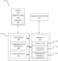
- FIG. 1a block diagram of a system 100 according to at least one embodiment of the present disclosure is shown.
- the system 100may be used to execute a comparison algorithm 122 and/or a compensation parameter algorithm 124 and/or to carry out other aspects of one or more of the methods disclosed herein.
- the system 100comprises a computing device 102 , a navigation system 112 , a robot 114 having a robotic arm 116 , and/or a sensor 118 .
- Systems according to other embodiments of the present disclosuremay comprise more or fewer components than the system 100 .
- the system 100may not include the navigation system 112 .
- the computing device 102comprises a processor 104 , a memory 106 , a communication interface 108 , and a user interface 110 .
- Computing devices according to other embodiments of the present disclosuremay comprise more or fewer components than the computing device 102 .
- the processor 104 of the computing device 102may be any processor described herein or any similar processor.
- the processor 104may be configured to execute instructions stored in the memory 106 , which instructions may cause the processor 104 to carry out one or more computing steps utilizing or based on data received from the navigation system 112 , the robot 114 , and/or the sensor 118 .
- the memory 106may be or comprise RAM, DRAM, SDRAM, other solid-state memory, any memory described herein, or any other tangible, non-transitory memory for storing computer-readable data and/or instructions.
- the memory 106may store information or data useful for completing, for example, any step of the methods 300 and/or 400 described herein.
- the memory 106may store, for example, one or more surgical plans 120 , one or more comparison algorithms 122 , and/or one or more compensation parameter algorithms 124 .
- Such algorithmsmay, in some embodiments, be organized into one or more applications, modules, packages, layers, or engines.
- the algorithmsmay cause the processor 104 to manipulate data stored in the memory 106 and/or received from the navigation system 112 , the robot 114 , and/or the sensor 118 .
- the computing device 102may also comprise a communication interface 108 .
- the communication interface 108may be used for receiving information from an external source (such as the navigation system 112 , the robot 114 , and/or the sensor 118 ), and/or for transmitting instructions, images, or other information to an external system or device (e.g., another computing device 102 , the navigation system 112 , the robot 114 , and/or the sensor 118 ).
- the communication interface 108may comprise one or more wired interfaces (e.g., a USB port, an ethernet port, a Firewire port) and/or one or more wireless interfaces (configured, for example, to transmit information via one or more wireless communication protocols such as 802.11a/b/g/n, Bluetooth, NFC, ZigBee, and so forth).
- the communication interface 108may be useful for enabling the device 102 to communicate with one or more other processors 104 or computing devices 102 , whether to reduce the time needed to accomplish a computing-intensive task or for any other reason.
- the computing device 102may also comprise one or more user interfaces 110 .
- the user interface 110may be or comprise a keyboard, mouse, trackball, monitor, television, touchscreen, headset, and/or any other device for receiving information from a user and/or for providing information to a user.
- the user interface 110may receive information and/or commands from a user via voice activation.
- the user interface 110may incorporate augmented reality or virtual reality.
- the user interface 110may be used, for example, to receive a user selection or other user input regarding detecting an initial contact between a first robotic arm and an anatomical element of a patient; to receive a user selection or other user input regarding determining a position of the anatomical element; to receive a user selection or other user input regarding comparing the determined position to an expected position; to receive a user selection or other user input regarding updating a tool trajectory of a second robotic arm when the determined position is offset from the expected position; to receive a user selection or other user input regarding registering a first robotic arm and a second robotic arm to a patient space; to receive a user selection or other user input regarding receiving a surgical plan such as the surgical plan 120 ; to receive a user selection or other user input regarding correlating a position of a detecting robotic arm to a position of the anatomical element; to receive a user selection or other user input regarding causing the first robotic arm to grip an anatomical element; to receive a user selection or other user input regarding controlling movement of the detecting robotic arm during
- the user interface 110may be useful to allow a surgeon or other user to modify the plan 120 , or other information displayed, though it will be appreciated that each of the preceding inputs may be generated automatically by the system 100 (e.g., by the processor 104 or another component of the system 100 ) or received by the system 100 from a source external to the system 100 .
- user inputsuch as that described above may be optional or not needed for operation of the systems, devices, and methods described herein.
- the computing device 102may utilize a user interface 110 that is housed separately from one or more remaining components of the computing device 102 .
- the user interface 110may be located proximate one or more other components of the computing device 102 , while in other embodiments, the user interface 110 may be located remote from one or more other components of the computer device 102 .
- the navigation system 112may provide navigation for a surgeon and/or a surgical robot during an operation.
- the navigation system 112may be any now-known or future-developed navigation system, including, for example, the Medtronic StealthStationTM S8 surgical navigation system.
- the navigation system 112may include a camera or other sensor(s) for tracking one or more reference markers, navigated trackers, or other objects within the operating room or other room where a surgery takes place.
- the navigation system 112may be used to track a position of the robot 114 (or, more particularly, of a navigated reference marker attached, directly or indirectly, in fixed relation to the robot 114 ).
- the navigation system 112may include a display for displaying one or more images from an external source (e.g., the computing device 102 or other source) or a video stream from the camera or other sensor of the navigation system 112 .
- the navigation system 112may be used to track movement of the robot 114 and may provide feedback regarding or confirmation of a position of the robot 114 or of the robotic arm 116 .
- the navigation system 112may track the robot 114 and/or the robotic arm 116 by detecting a navigated tracking marker affixed thereto.
- the navigation system 112may indicate, for example—audibly and/or visually via a display—that the robot 114 or the robotic arm 116 needs to be moved, automatically or manually, to a suggested robot pose.
- the navigation system 112can monitor or track the robot 114 or the robotic arm 116 as the robot 114 or the robotic arm 116 is moved toward the suggested robot pose.
- the navigation system 112can further indicate to or alert a user when the robot 114 or the robotic arm 116 has reached the suggested robot pose.
- a usermay view a display of the navigation system 112 while moving the robot 114 or the robotic arm 116 to the suggested robot pose, so as to ensure that the user moves the robot 114 or the robotic arm 116 to the correct pose.
- the system 100can operate without the use of navigation system 112 .
- the robot 114may be any surgical robot or surgical robotic system.
- the robot 114may be or comprise, for example, the Mazor XTM Stealth Edition robotic guidance system.
- the robot 114may comprise one or more robotic arms 116 .
- the robotic arm 116may comprise a plurality of robotic arms, though the robot 114 may comprise one robotic arm, two robotic arms, or more than two robotic arms.
- the robotic arm 116may be used to selectively hold any tool or instrument and/or to be secured to an anatomical element of a patient.
- the robotic arm 116has at least five degrees of freedom.
- the robotic arm 116has at least six degrees of freedom.
- the robotic arm 116has fewer than five or greater than six degrees of freedom.
- the robotic arm 116(and/or a base of the robot 114 , shown in FIG. 2 ) may also have three dimensions of orientation.
- the combination of multiple degrees of freedom and multiple dimensions of orientationallows for the robotic arm 116 to move to any pose.
- the robotic arm 116is not limited to a fixed area and can move in any direction.
- the robot 114can move during a surgical procedure to position the robotic arm 116 (and thus, a tool or instrument) within reach of a desired or predetermined pose.
- Reference markersmay be placed on the robot 114 , the robotic arm 116 , and/or any other object in the surgical space.
- the reference markersmay be tracked by the navigation system 112 , and the results of the tracking may be used by the robot 114 and/or by an operator of the system 100 or any component thereof.
- the navigation system 112can be used to track any other components of the system 100 .
- the robot 114comprises one or more sensors 118 operable to measure or monitor a characteristic of the robot 114 or the robotic arm 116 .
- the characteristicmay include, but is not limited to, a force or torque experienced by the robotic arm 116 and/or the robot 114 , and/or a position of the robot 114 and/or the robotic arm 116 .
- Each sensor 118may be any kind of sensor 118 for measuring the characteristic herein.
- the sensor 118may include one or more or any combination of components that are electrical, mechanical, electro-mechanical, magnetic, electromagnetic, or the like.
- the sensor 118may include, but is not limited to, one or more of a torque sensor, a force sensor, a linear encoder, a rotary encoder, a capacitor, and/or an accelerometer.
- the senor 118may include a memory for storing sensor data. In still other examples, the sensor 118 may output signals (e.g., sensor data) to one or more sources (e.g., the computing device 102 , the navigation system 112 , and/or the robot 114 ).
- signalse.g., sensor data
- sourcese.g., the computing device 102 , the navigation system 112 , and/or the robot 114 .
- the sensor 118may be integrated internally into the robotic arm 116 or otherwise positioned inside of the robotic arm. In some embodiments, the sensor 118 is positioned inside a joint (shown in FIG. 2 ) of the robotic arm 116 .
- the sensor 118may include a plurality of sensors and each sensor may be positioned at the same location or a different location as any other sensor. For example, a sensor 118 may be positioned in one or more joints of the robotic arm 116 . It will be appreciated that in some embodiments the sensor(s) 118 can be positioned at or on any component of the system 100 or environment (e.g., on any portion of the navigation system 112 , the robot 114 , the robotic arm 116 , and/or any other component at the surgical site).
- the sensor 118may be operable to sense and/or monitor a force exerted on an anatomical element by the robotic arm 116 and/or to sense movement of the robotic arm 116 and/or the anatomical element (via the robotic arm 116 ). Data regarding the measured or monitored characteristic may be directly useful (e.g., a measured force may be compared to an expected force) and/or indirectly useful (e.g., a sudden increase in force may indicate that the anatomical element has moved).
- the sensor 118may send the data to the computing device 102 when the sensor 118 detects a change in the characteristic. Further, in some embodiments, the sensor 118 may send data to the computing device 102 to display on the user interface 110 or otherwise notify the surgeon or operator of the change in the characteristic.
- the senor 118may alert the surgeon or operator of the change in the characteristic by an alert such as, but not limited to, a sound or a light display.
- the sensor 118may advantageously provide a safety function by monitoring and alerting the surgeon or operator of the force meeting or exceeding a predetermined threshold, thereby alerting the surgeon or operator of potential issues with the robot 114 and/or the robotic arm 116 .
- the sensor 118may trigger the computing device 102 to determine a position of an anatomical element based on the sensor data, compare the determined position with an expected position of the anatomical element, and update a tool trajectory of the robotic arm 116 based on the comparison when the determined position is offset from the expected position.
- the sensor 118may also trigger the computing device 102 to calculate a compensation parameter based on the comparison and update the tool trajectory of the robotic arm 116 by applying the compensation parameter to the tool trajectory.
- the sensor 118may further trigger the computing device 102 to cause the robotic arm 116 to exert at least one of a responsive force or a responsive torque on the anatomical element to counteract an applied force or applied torque on the anatomical element sensed by the sensor 118 .
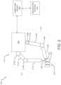
- FIG. 2a block diagram of another system 200 according to at least one embodiment of the present disclosure is shown.
- the system 200includes a computing device 202 (which may be the same as or similar to the computing device 102 described above), a navigation system 212 (which may be the same as or similar to the navigation system 112 described above), and a robot 214 (which may be the same as or similar to the robot 214 described above).
- Systems according to other embodiments of the present disclosuremay comprise more or fewer components than the system 200 .
- the system 200may not include the navigation system 212 .
- the robot 214includes a first or detecting robotic arm 216 (which may comprise one or more members 216 A connected by one or more joints 216 B) and a second or a working robotic arm 217 (which may comprise one or more members 217 A connected by one or more joints 217 B), each extending from a base 204 .
- the robot 214may include one robotic arm or two or more robotic arms.
- the base 204may be stationary or movable.
- One or more tools or instrumentsmay be disposed on an end of each of the first or detecting robotic arm 216 and the second or working robotic arm 217 , though the tools or instruments may be disposed on any portion of the first or detecting robotic arm 216 and/or the second or working robotic arm 217 .
- the first or detecting robotic arm 216 and/or the second or working robotic arm 217is operable to execute one or more planned movements and/or procedures autonomously and/or based on input from a surgeon or operator.
- the first or detecting robotic arm 216is secured to an anatomical element 226 .
- the anatomical element 226is a vertebra of a spinal region 224 .
- the first or detecting robotic arm 216may be secured to the anatomical element 226 in any form.
- the first or detecting robotic arm 216is secured to the anatomical element 226 via a gripper 222 .
- the first or detecting robotic arm 216may be attached to the anatomical element 226 with one or more screws, clamped to the anatomical element 226 , or otherwise secured to the anatomical element 226 , whether using one or more mechanical fasteners, a chemical adhesive, or otherwise.
- the second or working robotic arm 217may have a tool or instrument 228 disposed at an end of the second or working robotic arm 217 .
- the tool 228may be used by the second or working robotic arm 217 to perform a procedure on the anatomical element 226 , whether based on instructions from a surgeon and/or pursuant to a surgical plan. While the second or working robotic arm 217 uses the tool 228 to perform the procedure, movement of the anatomical element 226 may be monitored and undesired movement may be detected from an integrated sensor 218 of the first or detecting robotic arm 216 .
- the sensor 218(which may be the same as or similar to the sensor 118 described above, and of which more than one may be included in the robotic arm 216 and/or 217 ) may be integrated into a joint 216 B of the first or detecting robotic arm 216 . Though the sensor 218 is shown integrated into the joint 216 B nearest the base 204 , the sensor 218 may be integrated into any joint 216 B, 217 B, any member 216 A, 217 A, or any portion of the first or detecting robotic arm 216 , the second or working robotic arm 217 , and/or the robot 214 . Furthermore, more than one sensor 218 may be integrated into the first or detecting robotic arm 216 , the second or working robotic arm 217 , and/or the robot 214 .
- the sensor 218may be one or more of a torque sensor, a force sensor, or an encoder integrated into the joint 216 B.
- the sensor 218is configured to sense at least one of an applied force or an applied torque exerted on the first or detecting robotic arm 216 .
- the sensor 218may detect a force or torque exerted by the second or working robotic arm 217 on the anatomical element 226 to which the first or working robotic arm 216 is secured.
- such sensor datamay be used to determine movement of the anatomical element 226 .
- sensor data from the sensor 218 of the first or detecting robotic arm 216may be provided to, for example, the processor 104 for processing. Because the first or detecting robotic arm 216 does not perform the procedure, the first or detecting robotic arm 216 may be positioned and/or oriented in an optimized pose for obtaining sensor data. Further, in some instances, the first or detecting robotic arm 216 may be stationary and/or may not be receiving or exerting any forces, thereby enabling the first or detecting robotic arm 216 to obtain sensor data without obstructions.
- a proceduree.g., a surgical procedure such as, for example, drilling
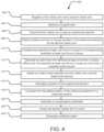
- a method 300 for tracking anatomical motionmay be executed in whole or in part, for example, on a computing device such as the computing device 102 or 202 or similar device, and may utilize one or more other components of the system 100 or 200 or similar components.
- One or more aspects of the method 300may be performed by or with a robot such as the robot 114 or 214 , a surgeon, or a combination of a surgeon and a robot.
- the method 300comprises receiving a surgical plan such as the surgical plan 120 (step 302 ).
- the surgical planmay be received via a user interface (e.g., the user interface 110 ) and/or a communication interface (e.g., the communication interface 108 ) of a computing device such as the computing device 102 or 202 , and may be stored in a memory such as the memory 106 of the computing device.
- the surgical planmay include information about an anatomical element, such as the anatomical element 226 , of the patient and/or about a surgical task to be completed on the anatomical element.
- the anatomical elementmay be a vertebra in some embodiments.
- the informationmay include information about a position and/or orientation of the anatomical element.
- the informationmay also include information about a first robotic arm, such as the robotic arm 116 or the first robotic arm 216 , and/or a second robotic arm, such as the robotic arm 116 or the second robotic arm 217 , that may perform the surgical task.
- the surgical planmay also include information about one or more planned movements of the second robotic arm. In some embodiments, the surgical plan includes a planned trajectory or path of the second robotic arm.
- the informationmay also include an expected position of the anatomical element (e.g., a position and/or orientation of the anatomical element).
- the informationmay further include a predicted force or torque that may be experienced by the anatomical element from the second robotic arm.
- the method 300comprises detecting an initial contact between the first robotic arm and the anatomical element of a patient (step 304 ).
- the detectingmay be based on information received from at least one internal sensor such as the sensor 118 or 218 of the first robotic arm.
- the informationmay be received by the computing device, and more particularly, by a processor such as the processor 104 of the computing device.
- the informationmay be or comprise raw sensor data received directly from the internal sensor, or the information may be or comprise processed sensor data.
- the informationmay be received via the user interface and/or via the communication interface of the computing device, and may be stored in the memory.
- the informationmay be indirectly received via any other component of the system or a node of a network to which the system is connected.
- the sensor data or informationmay include force data, torque data, or positional data of the first robotic arm and/or the second robotic arm. Such information, as described below, may be useful for determining a position and/or movement of the anatomical element.
- the method 300also comprises determining a position of the anatomical element (step 306 ).
- the determiningmay be based on the information received from at least one internal sensor such as the sensor 118 or 218 of the first robotic arm.
- Such information or other sensor datamay be used to determine a position of the first robotic arm (e.g., as detected at the moment of initial contact between the first robotic arm and the anatomical element).
- the determined position of the first robotic armmay then be used to determine a position of the anatomical element (e.g., based on one or more of a known position of the first robotic arm, known dimensions of the first robotic arm, and/or known dimensions of the anatomical element).
- informationobtained from one or more sensors 118 or 218 ) about a force and/or torque experienced by the first robotic arm at the moment of initial contact with the anatomical element may be used (together with information about, for example, a velocity of the robotic arm at the moment of the initial contact and a time of the initial contact) to calculate a position of the anatomical element.
- the method 300also comprises comparing the determined position of the anatomical element to an expected position of the anatomical element (step 308 ).
- the comparingmay be executed by a comparison algorithm such as the comparison algorithm 122 .
- the expected positionas previously described, may be predetermined and/or based on a surgical plan such as the surgical plan 120 .
- the expected positionmay be based on preoperative imaging of the anatomical element and/or of an anatomical region comprising the anatomical element.
- the expected positionmay be a position utilized for preoperative planning (including, for example, navigation and/or robotic guidance), such that a determination that the anatomical element is no longer in the expected position may necessitate updating the preoperative planning (including, for example, the navigation and/or robotic guidance).
- the first robotic armmay be caused to move toward and contact the anatomical element at different times throughout a surgical procedure.
- the moment of initial contact between the first robotic arm and the anatomical elementmay be detected, as described above in connection with the step 304 , and the position of the anatomical element at that time may be determined, as described above with respect to the step 306 .
- the expected position of the anatomical elementmay be, for example, the position of the anatomical element as determined during the immediately previous iteration of the steps 304 and 306 .
- any digital models, surgical plans, and/or other information that is based upon or otherwise reflects an expected position of the anatomical elementmay be updated to reflect a then-current actual position of the anatomical element.
- an amount or degree of movement of the anatomical elementmay be determined by comparing the determined position of the anatomical element to the expected position of the anatomical element.
- the method 300further comprises updating a tool trajectory of a second robotic arm, such as the robotic arm 116 or the second robotic arm 217 , based on the comparison and/or the compensation parameter when the determined position is offset from the expected position (step 310 ).
- Such offsetmay indicate that the anatomical element has moved from the expected position, and thus, that a predetermined tool trajectory for execution of a surgical procedure may be inaccurate.
- the tool trajectorymay be a trajectory of a tool, such as the tool 228 , held by the second robotic arm. As such, the tool trajectory may be updated to accommodate such offset.
- the compensation parametermay be applied to the tool trajectory.
- the method 300also comprises registering the first robotic arm and the second robotic arm to a patient space corresponding to the patient space (step 312 ). Such registration correlates a pose of the first robotic arm and of the second robotic arm to a patient in a common coordinate system.
- the registrationmay utilize one or more images, including, for example, a virtual model of patient anatomy and/or an image of one or both of the first robotic arm and the second robotic arm.
- data generated by one or more sensors other than an optical sensormay be used instead of images.
- the method 300may register the first robotic arm and the second robotic arm to a navigation coordinate system used by a navigation system such as the navigation system 112 or 212 .
- the method 300may also comprise calculating a compensation parameter based on the comparing step (step 314 ).
- the compensation parametermay be a constant, an algorithm, or any other transformation function that may be applied to a position, path, trajectory, and/or other value generated based on the expected position of the anatomical element to yield a new position, path, trajectory, and/or other value that reflects or is otherwise based on the determined position of the anatomical element.
- the compensation parametermay be calculated via a compensation parameter algorithm such as the compensation parameter algorithm 124 .
- the compensation parametermaybe based on, for example, a difference between the determined position and the expected position of the anatomical element, or in other words, on the results of the comparison of the determined position to the expected position.
- the compensation parametermay further be based on, for example, a position of the first robotic arm and/or the second robotic arm, a force and/or torque sensed by the sensor of the first anatomical arm, a force and/or torque exerted by the second robotic arm sensed by the sensor of the second robotic arm, and/or the like.
- the method 300also comprises securing the first robotic arm to the anatomical element (step 316 ).
- the first robotic armmay be secured to the anatomical element via a mechanical gripper such as the gripper 222 .
- the first robotic armmay be attached to the anatomical element with one or more screws, clamped to the anatomical element, or otherwise secured to the anatomical element, whether using one or more mechanical fasteners, a chemical adhesive, or otherwise.
- the method 300also comprises detecting movement of the first robotic arm based on data received from the sensor while the first robotic arm is secured to the anatomical element (step 318 ), and determining a movement of the anatomical element based on the detected movement of the first robotic arm (step 320 ).
- Using dimensional information about the first robotic arme.g., a length of one or more segments, dimensions of an end effector or other gripper that secures the first robotic arm to the anatomical element, etc.
- information from one or more sensors internal to the first robotic armincluding, for example, information about a position of any one portion of the robotic arm relative to a position of any other portion of the robotic arm
- a pose of the first robotic arm—and thus of any end effector secured to the first robotic arm—may be determined.
- a pose of the anatomical elementmay be readily determined based on a known pose of the first robotic arm.
- any force or torque exerted on the anatomical element that causes movement of the anatomical elementwill necessarily cause movement of at least a portion of the first robotic arm.
- any uncommanded movemente.g., movement not caused by the first robotic arm's motor(s) or other actuator(s)
- the pose of the first robotic arm(as determined based on information from the one or more internal sensors of the first robotic arm) during and after such movement may be used to determine a pose of the anatomical element during and after such movement.
- the connection between the first robotic arm and the anatomical elementenables the pose of the anatomical element to be monitored using only the sensors internal to the first robotic arm, and no other sensors.
- the method 300also comprises updating a virtual model of an anatomical portion of the patient—for instance, a virtual model from a surgical plan such as the surgical plan 120 or a virtual model generated pre- or intraoperatively—based on the determined movement of the anatomical element (step 322 ).
- a virtual model of an anatomical portion of the patientfor instance, a virtual model from a surgical plan such as the surgical plan 120 or a virtual model generated pre- or intraoperatively—based on the determined movement of the anatomical element (step 322 ).
- the first robotic arm and/or the second robotic armmay be correlated or otherwise registered to the virtual model, and updating the virtual model may update the registration.
- the method 300also comprises activating the first robotic arm to prevent movement of the anatomical element from the determined position (step 324 ).
- the first robotic armis used to hold the anatomical element in a desired position and to prevent movement of the anatomical element.
- the first robotic armmay be sufficiently rigid in any given pose to prevent movement of the anatomical element without having to apply a counteractive force and/or torque via the first robotic arm's internal motors or other actuators.
- the predicted torques and/or forces from a surgical planmay be used to apply counteractive force(s) and/or torque(s) at one or more time intervals while using the first robotic arm, so that the anatomical element does not move.
- the method 300also comprises causing the second robotic arm to move based on the determined movement of the anatomical element (step 326 ).
- movement of the second robotic armmay be commanded and/or adjusted based on movement of the anatomical element, as detected using the first robotic arm.
- the first robotic armmay be utilized to detect movement of the anatomical element, but not to reduce or prevent any such movement.
- monitoring of a pose of the anatomical element using the first robotic armenables a trajectory and/or other guidance for controlling the second robotic arm to be adjusted as needed based on the pose of the anatomical element.
- the one or more sensors of the first robotic armprovide information about the movement of the first robotic arm (and therefore of the anatomical element) to a computing device such as the computing device 102 , and the computing device adjusts a trajectory or other guidance of the second robotic arm based on the movement.
- a computing devicesuch as the computing device 102
- the computing deviceadjusts a trajectory or other guidance of the second robotic arm based on the movement.
- the computing device or other controller of the second robotic armcan adjust the trajectory of the second robotic arm by one centimeter in the given direction, thus maintaining a desired relative position or path of the second robotic arm with respect to the anatomical element.
- the first robotic armis secured to the anatomical element both to prevent movement of the anatomical element to an extent possible (as described above in connection with the step 324 ) and to detect movement of the anatomical element when preventative measures are insufficient to prevent movement of the anatomical element so as to enable appropriate adjustment of the movement of the second robotic arm (as described above in connection with the step 326 ).
- the first robotic armmay be sufficiently rigid to prevent at least some movement of the anatomical element, and/or may utilize one or more of its motors or other actuators to apply counteractive force(s) and/or torque(s) to the anatomical element at one or more time intervals (based on, for example, one or more predicted force(s) and/or torque(s) as set forth in a surgical plan) to prevent at least some such movement.
- the first robotic arm(including the one or more internal sensors thereof) may detect such movement and provide information about the movement to the computing device.
- the computing devicemay then adjust a trajectory of the second robotic arm based on the movement to maintain a desired position or path of the second robotic arm relative to the anatomical element.
- the method 300also comprises activating the first robotic arm to move the anatomical element to the expected position (step 328 ).
- a trajectory or path of the second robotic armmay not be able to be updated to account for movement of the anatomical element, and/or the anatomical element may have moved out of a desired position and/or orientation.
- the first robotic armmay be activated to move the anatomical element into, or back into, an expected, desired, or otherwise predetermined position.
- movement of the second robotic arm and/or progress in the surgical proceduremay be paused while the first robotic arm moves the anatomical element into the predetermined position.
- the method 300also comprises receiving second information from at least one second internal sensor, such as the sensor 118 or 218 , of the second robotic arm (step 330 ).
- the second informationmay correspond to at least one of an applied force or an applied torque exerted by the second robotic arm on the anatomical element.
- a toole.g., a drill, tap, screwdriver, and/or other tool held by the second robotic arm may apply a force and/or a torque on the anatomical element during operation thereof.
- the second robotic armmay be configured to press the force against and/or into the anatomical element to increase an effectiveness thereof.
- one or more internal sensors of the second robotic armmay detect the force and/or torque applied thereby on the anatomical element, and may provide information corresponding to the detected force and/or torque to a computing device and/or other controller of the first and/or second robotic arm.
- the method 300may comprise receiving information about an activation of the second robotic arm (which may include, for example, information about activation of a surgical tool held by the second robotic arm).
- the computing device or other controller of the first robotic armmay utilize the received information to calculate a predicted force and/or torque that will be experienced by the anatomical element as a result of the activation.
- the first robotic armmay detected a force and/or torque exerted by the second robotic arm (including, for example, a surgical tool held by the second robotic arm) on the anatomical element, as a result of the force and/or torque being communicated to the first robotic arm via the anatomical element.
- the method 300also comprises causing the first robotic arm to exert at least one of a responsive force or a responsive torque on the anatomical element to counteract the applied force or the applied torque experienced by the anatomical element (step 332 ).
- the computing device or other controller of the first robotic armmay calculate, based on the detected or calculated applied force and/or torque, an activation of the one or more internal motors or other actuators of the first robotic arm that is required to counteract the applied force and/or torque.
- the computing device or other controller of the first robotic armmay utilize a feedback loop to activate one or more actuators of the first robotic arm in increasing increments for as long as a detected or calculated applied force on the anatomical element is rising, to maintain a given level of activation of the first robotic arm for as long as the detected or calculated applied force is constant, and to decrement the activation of the one or more actuators of the first robotic arm once the detected or calculated applied force begins to decrease.
- the computing device or controller of the first robotic armdoes not explicitly calculate a required degree of activation of the first robotic arm, but instead continually adjusts a degree of activation of the first robotic arm in response to the detected or calculated applied force and/or torque.
- a method 400 for controlling a robotic armmay be executed in whole or in part, for example, on a computing device such as the computing device 102 or 202 or a similar device, and may utilize one or more other components of the system 100 or 200 or similar components.
- One or more aspects of the method 400may be performed by or with a robot such as the robot 114 or 214 , a surgeon, or a combination of a surgeon and/or the robot.
- the method 400comprises registering a first robotic arm to a patient space corresponding to a patient (step 402 ).
- the first robotic armmay be the robotic arm 116 or the first robotic arm 216
- the second robotic armmay be the robotic arm 116 or the second robotic arm 217 .
- the step 402may be the same as or similar to the step 312 of the method 300 described above, or vice versa.
- the registeringmay correlate a pose of the first robotic arm and of the second robotic arm to a patient in a common coordinate system.
- the registrationmay utilize one or more images, including, for example, a virtual model of patient anatomy and/or an image of one or both of the first robotic arm and the second robotic arm.
- data generated by one or more sensors other than an optical sensormay be used instead of images.
- the method 400may register the first robotic arm and the second robotic arm to a navigation coordinate system used by a navigation system such as the navigation system 112 or 212 , instead of or in addition to registering the first and second robotic arms to a patient space.
- a coordinate system corresponding to the first robotic armmay be registered to a coordinate system corresponding to the second robotic arm or vice versa, so that both robotic arms are registered to and controllable with respect to a single coordinate space.
- the method 400also comprises receiving a surgical plan (step 404 ).
- the surgical planmay be the surgical plan 120 .
- the step 404may be the same as or similar to the step 302 of the method 300 described above, or vice versa.
- the surgical planmay be received via a user interface (e.g., the user interface 110 ) and/or a communication interface (e.g., the communication interface 108 ) of a computing device such as the computing device 102 or 202 , and may be stored in a memory such as the memory 106 of the computing device.
- the surgical planincludes information about an anatomical element, such as the anatomical element 226 , of the patient and/or a surgical task to be completed on the anatomical element.
- the anatomical elementmay be a vertebra in some embodiments.
- the surgical planmay include information about a position and/or orientation of the anatomical element.
- the surgical planmay also include information about a second robotic arm, such as the robotic arm 116 or the second robotic arm 217 , that may perform the surgical task.
- the surgical planmay also include information about one or more planned movements of the second robotic arm.
- the surgical planincludes a planned trajectory or path of the second robotic arm.
- the surgical planmay also include an expected position of the anatomical element (e.g., a position and/or orientation of the anatomical element).
- the surgical planmay further include a predicted force or torque that will be or at least is expected to be exerted on the anatomical element by the second robotic arm (including by a surgical tool held by the second robotic arm), and/or a predicted movement of the anatomical element as a result of interaction between the second robotic arm and the anatomical element.
- the method 400also comprises causing the first robotic arm to grip the anatomical element with a mechanical gripper (step 406 ).
- the mechanical grippermay be the gripper 222 .
- the step 406may be the same as or similar to the step 316 of the method 300 described above, or vice versa.
- the first robotic armmay grip the anatomical element at a position provided by the surgical plan.
- the first robotic armmay be attached to the anatomical element using one or more screws, clamped to the anatomical element, or otherwise secured to the anatomical element, whether using one or more mechanical fasteners, a chemical adhesive, or otherwise.
- the gripping or attachmentensures that the anatomical element cannot move relative to the gripper or other end effector and further acts to translate the anatomical element's movement to a movement of the first robotic arm. In other words, movement of the anatomical element moves the first robotic arm via the gripper or other end effector. Further, because the first robotic arm has a known position relative to the anatomical element, a pose of the anatomical element can be determined based on a pose of the first robotic arm.
- the method 400further comprises detecting at least one force or torque exerted on the anatomical element by the second robotic arm (step 408 ).
- the detectingmay be based on sensor data relating to the at least one force or torque received from at least one internal sensor such as the sensor 118 or 218 of the first robotic arm. In particular, the detecting may be accomplished without the use of any sensor external to the first robotic arm. Because the first robotic arm is secured to the anatomical element, forces sensed by the first robotic arm correlate to forces exerted on the anatomical element by the second robotic arm. The amount of correlation may depend, for example, on the makeup of the anatomical element.
- the amount of correlationmay be high, because a force exerted on one point of the anatomical element will largely be translated to another point of the anatomical element.
- the anatomical elementcomprises soft tissue (or tissue that is not as hard as a bone)
- the amount of correlationmay be low, because the anatomical element may absorb some of the force by deforming or otherwise.
- Detecting the at least one force or torquemay include receiving sensor data correlating to the at least one force or torque from the at least one internal sensor.
- the sensor datamay be received by a computing device such as the computing device 102 or 202 , or by another controller of the first and/or second robotic arm.
- the sensor datamay be received via the user interface and/or via the communication interface of the computing device, and may be stored in the memory.
- the sensor datamay be indirectly received via any other component of the system or a node of a network to which the system is connected.
- the sensor datamay include force data, torque data, and/or positional data (e.g., data corresponding to a relative position of one or more segments of the robotic arm with respect to one or more other segments of the robotic arm) of the first robotic arm and/or the second robotic arm.
- positional datae.g., data corresponding to a relative position of one or more segments of the robotic arm with respect to one or more other segments of the robotic arm
- the method 400also comprises comparing the detected force or torque to a corresponding predicted force or torque described in the surgical plan (step 410 ).
- the comparingmay be executed by a comparison algorithm such as the comparison algorithm 122 .
- the predicted force or torquemay be based on, for example, information about a hardness of the anatomical element, information about a surgical task to be carried out on the anatomical element, information about a tool that will be used to carry out the surgical task (including, for example, information about a force and/or torque produced by the tool), information about an amount of force or torque that the anatomical element can receive without causing the anatomical element to move out of position, and/or other information.
- the predicted force or torquemay be based on information about a torque produced by the drill that will be used to drill the hole and information about the down-force that will be applied by the second robotic arm during the drilling process.
- the amount of force and/or torque expected to be appliedmay be selected and/or adjusted based on information about an amount of force or torque that the anatomical element can receive without causing the anatomical element to move out of position, although in other embodiments (e.g., where the first robotic arm will be used to hold the anatomical element in position), this consideration may not be relevant.
- movement of the anatomical elementcan be predicted and/or determined simply based on a mismatch between the detected force or torque and the predicted force or torque.
- the method 400also include generating an alert when the detected force or torque differs from the predicted force or torque by more than a predetermined amount (step 412 ).
- Such alertmay be audible, visual, haptic, or any combination thereof, and may be displayed or otherwise generated or emitted from, for example, a user interface such as the user interface 110 , the computing device, and/or the robot.
- the method 400also comprises detecting an initial contact between the first robotic arm and the anatomical element based on information from the at least one sensor (step 414 ), and calculating a position of the anatomical element at a time of the detected initial contact (step 416 ).
- the steps 414 and 416may be the same as or similar to the steps 304 and 306 of the method 300 described above, or vice versa.
- the position of the anatomical elementmay be determined, for example, based on the information or sensor data from one or more internal sensors of the first robotic arm.
- Such information or sensor datamay comprise, for example, position information of the first robotic arm (e.g., as detected at the time of the initial contact), force and/or torque data regarding a force and/or torque experienced by the first robotic arm during the initial contact, and/or other information useful for determining a position of the first robotic arm and, based on that determined position, a position of the anatomical element. Because the first robotic arm contacts the anatomical element, the positional data of the first robotic arm may correlate to the position of the anatomical element. With respect to method 400 , where the first robotic arm is subsequently secured to the anatomical element, the position of the anatomical element, once determined, may be correlated to a position of the first robotic arm.
- a position of the first robotic armmay be determined from the at least one sensor, and a relative position of the anatomical element and the first robotic arm may be determined using, for example, information about the dimensions of the first robotic arm, dimensions of the anatomical element, and/or information from the navigation system.
- the method 400also comprises comparing the calculated position of the anatomical element to a predicted position of the anatomical element from the surgical plan (step 418 ).
- the step 418is the same as or similar to the step 308 of the method 300 described above, or vice versa.
- the comparingmay be executed by a comparison algorithm such as the comparison algorithm 122 .
- the expected positionas previously described, may be predetermined and/or based on the surgical plan. The expected position may be based on preoperative imaging of the anatomical element and/or of an anatomical region comprising the anatomical element.
- the expected positionmay be a position utilized for preoperative planning (including, for example, navigation and/or robotic guidance), such that a determination that the anatomical element is no longer in the expected position may necessitate updating the preoperative planning (including, for example, the navigation and/or robotic guidance).
- the method 400also comprises generating a compensation parameter based on the comparison step (step 420 ).
- the step 420may be the same as or similar to the step 314 of the method 300 described above, or vice versa.
- the compensation parametermay be a constant, an algorithm, or any other transformation function that may be applied to a position, path, trajectory, and/or other value generated based on the expected position of the anatomical element to yield a new position, path, trajectory, and/or other value that reflects the determined position of the anatomical element.
- the compensation parametermay be calculated via a compensation parameter algorithm such as the compensation parameter algorithm 124 .
- the compensation parametermay be based on, for example, a difference between the determined position and the expected position of the anatomical element, or in other words, on the results of the comparison of the determined position to the expected position.
- the compensation parametermay further be based on, for example, a position of the first robotic arm and/or the second robotic arm, a force sensed by the sensor of the first anatomical arm, a force exerted by the second robotic arm sensed by the sensor of the second robotic arm, and/or the like.
- the method 400also comprises causing the second robotic arm to move at least in part based on the compensation parameter (step 422 ).
- the compensation parametermay shift a trajectory of the second robotic arm to accommodate a determined position of the anatomical element. For example, if the anatomical element shifts one centimeter in a direction, then the trajectory of the second robotic arm may be shifted one centimeter the same direction.
- the compensation parametermay be utilized to calculate a responsive force or responsive torque applied by the first robotic arm, a needed movement of the anatomical element by the first robotic arm, and/or a required activation of the first robotic arm to prevent movement of the anatomical element.
- the method 400also comprises generating a stiffness matrix (step 424 ).
- the stiffness matrixis generated once the first robotic arm is secured to the anatomical element, by causing the first robotic arm to move in each of six degrees of freedom.
- the movementsmay be small motions.
- Information about the force applied by the first robotic arm (and/or any component thereof) to cause the movement, as well as information about the amplitude of the movement,may be used to generate stiffness data for the anatomical element in each degree of freedom, thus resulting in a stiffness matrix.
- Predicted motion of the anatomical elementmay be determined based on the stiffness matrix and known forces and/or moments generated by the second robotic arm. The predicted motion may be compared to a motion of the anatomical element detected using the first robotic arm.
- the differencemay indicate that an undesired motion of the anatomical element occurred.
- the second robotic armdrills (e.g., using a surgical drill held by the second robotic arm) into an anatomical element, (e.g., a bone) held by the first robotic arm then the expected or predicted applied force is along the drilling direction and the expected or predicted torque is around the drill's longitudinal axis.
- a predicted motion of the bonecan be calculated.
- a different motionis detected by the first robotic arm (e.g., when the predicted motion does not match the detected motion), that difference may reflect a skiving.
- detecting the forces and torques using the first robotic arm(as opposed to detecting the motion of the anatomical element) and comparing the detected forces and torques to the expected or predicted forces and torques also provides the necessary information of possible skiving.
- the samecan be achieved in another embodiment involving minimally invasive surgical procedures where the first robotic arm does not directly hold the anatomical element, but instead holds a device connecting rigidly to the anatomical element.
- the devicemay be K-wire or a dynamic reference frame.
- Methods and systems for tracking anatomical motion and/or controlling a robotic armbeneficially provide notification of or compensation for undesired movement of an anatomical element during a surgical procedure.
- Such notificationmay allow for a surgeon or operator to pause the procedure, thus preventing further damage to patient anatomy.
- Such compensationprovides for self-correcting tool movement, and thus may also prevent unnecessary damage to patient anatomy.
- the use of internal, integrated sensorsbeneficially provide for accurate sensing of anatomical movement within a single coordinate space.
- the present disclosureencompasses methods with fewer than all of the steps identified in FIGS. 3 and 4 (and the corresponding description of the methods 300 and 400 ), as well as methods that include additional steps beyond those identified in FIGS. 3 and 4 (and the corresponding description of the method 300 and 400 ).
- One or more steps of the methods described hereinmay be performed in an order other than the order in which they are described herein.
Landscapes
- Health & Medical Sciences (AREA)
- Surgery (AREA)
- Engineering & Computer Science (AREA)
- Life Sciences & Earth Sciences (AREA)
- Biomedical Technology (AREA)
- Robotics (AREA)
- Nuclear Medicine, Radiotherapy & Molecular Imaging (AREA)
- Heart & Thoracic Surgery (AREA)
- Medical Informatics (AREA)
- Molecular Biology (AREA)
- Animal Behavior & Ethology (AREA)
- General Health & Medical Sciences (AREA)
- Public Health (AREA)
- Veterinary Medicine (AREA)
- Manipulator (AREA)
Abstract
Description
Claims (20)
Priority Applications (4)
| Application Number | Priority Date | Filing Date | Title |
|---|---|---|---|
| US17/464,300US12274525B2 (en) | 2020-09-29 | 2021-09-01 | Systems and methods for tracking anatomical motion |
| PCT/IB2021/058420WO2022069985A1 (en) | 2020-09-29 | 2021-09-15 | Systems and methods for tracking anatomical motion |
| CN202180066127.1ACN116261432A (en) | 2020-09-29 | 2021-09-15 | Systems and methods for tracking anatomical motion |
| EP21786262.2AEP4221618B1 (en) | 2020-09-29 | 2021-09-15 | Systems for tracking anatomical motion |
Applications Claiming Priority (2)
| Application Number | Priority Date | Filing Date | Title |
|---|---|---|---|
| US202063085018P | 2020-09-29 | 2020-09-29 | |
| US17/464,300US12274525B2 (en) | 2020-09-29 | 2021-09-01 | Systems and methods for tracking anatomical motion |
Publications (2)
| Publication Number | Publication Date |
|---|---|
| US20220096188A1 US20220096188A1 (en) | 2022-03-31 |
| US12274525B2true US12274525B2 (en) | 2025-04-15 |
Family
ID=80822156
Family Applications (1)
| Application Number | Title | Priority Date | Filing Date |
|---|---|---|---|
| US17/464,300Active2043-11-02US12274525B2 (en) | 2020-09-29 | 2021-09-01 | Systems and methods for tracking anatomical motion |
Country Status (4)
| Country | Link |
|---|---|
| US (1) | US12274525B2 (en) |
| EP (1) | EP4221618B1 (en) |
| CN (1) | CN116261432A (en) |
| WO (1) | WO2022069985A1 (en) |
Families Citing this family (4)
| Publication number | Priority date | Publication date | Assignee | Title |
|---|---|---|---|---|
| US11571205B2 (en)* | 2018-07-16 | 2023-02-07 | Cilag Gmbh International | Surgical visualization feedback system |
| CA3116287A1 (en) | 2018-10-15 | 2020-04-23 | Mazor Robotics Ltd. | Versatile multi-arm robotic surgical system |
| US20230346492A1 (en)* | 2022-05-02 | 2023-11-02 | Mazor Robotics Ltd. | Robotic surgical system with floating patient mount |
| US20240024028A1 (en)* | 2022-07-21 | 2024-01-25 | Mazor Robotics Ltd. | Systems and methods for verifying a pose of a target |
Citations (134)
| Publication number | Priority date | Publication date | Assignee | Title |
|---|---|---|---|---|
| JPS527490U (en) | 1975-07-03 | 1977-01-19 | ||
| GB2156983A (en) | 1983-08-26 | 1985-10-16 | Mintowt Czyz Witek | Method and apparatus for assessing the structure and mechanical integrity of osseous systems |
| US5329933A (en) | 1991-09-24 | 1994-07-19 | Henry Graf | Device for measuring the angle of movement of two vertebrae |
| WO1995001757A1 (en) | 1993-07-07 | 1995-01-19 | Cornelius Borst | Robotic system for close inspection and remote treatment of moving parts |
| WO1996029930A1 (en) | 1995-03-31 | 1996-10-03 | Washington University | Method and apparatus for determining bone density |
| WO2000035366A1 (en) | 1998-12-14 | 2000-06-22 | Integrated Surgical Systems, Inc. | Bone motion tracking system |
| US6152890A (en) | 1997-10-30 | 2000-11-28 | Hauptverband Der Gewerblichen Berufsgenossenschaften E.V. | Method and device for the recording, presentation and automatic classification of biomechanical load variables measured on a freely moving test person during a work shift |
| US6200024B1 (en) | 1998-11-27 | 2001-03-13 | Picker International, Inc. | Virtual C-arm robotic positioning system for use in radiographic imaging equipment |
| DE10042599A1 (en) | 2000-08-30 | 2002-03-14 | Mueller Bbm Gmbh | Method and appliance for recording and evaluating movements of spinal columns by mechanical excitation of spine |
| US6435715B1 (en) | 1998-11-30 | 2002-08-20 | Siemens Aktiengesellschaft | Radiography device |
| US6582121B2 (en) | 2001-11-15 | 2003-06-24 | Ge Medical Systems Global Technology | X-ray positioner with side-mounted, independently articulated arms |
| US6644852B2 (en) | 2001-11-15 | 2003-11-11 | Ge Medical Systems Global Technology | Automatically reconfigurable x-ray positioner |
| US20040122427A1 (en) | 2002-10-10 | 2004-06-24 | Holmes David C. | Apparatus and method for restoring biomechanical function to a motion segment unit of the spine |
| US20050096502A1 (en) | 2003-10-29 | 2005-05-05 | Khalili Theodore M. | Robotic surgical device |
| US20060241414A1 (en) | 1998-11-20 | 2006-10-26 | Intuitive Surgical Inc. | Repositioning and reorientation of master/slave relationship in minimally invasive telesuregery |
| US20060258938A1 (en) | 2005-05-16 | 2006-11-16 | Intuitive Surgical Inc. | Methods and system for performing 3-D tool tracking by fusion of sensor and/or camera derived data during minimally invasive robotic surgery |
| WO2007025218A2 (en) | 2005-08-25 | 2007-03-01 | Virginia Commonwealth University | Portable pulmonary injury diagnostic devices and methods |
| US7198630B2 (en)* | 2002-12-17 | 2007-04-03 | Kenneth I. Lipow | Method and apparatus for controlling a surgical robot to mimic, harmonize and enhance the natural neurophysiological behavior of a surgeon |
| WO2007038510A1 (en) | 2005-09-26 | 2007-04-05 | The Regents Of The University Of California | Articulating instrumentation for dynamic spinal stabilization |
| US20070106307A1 (en) | 2005-09-30 | 2007-05-10 | Restoration Robotics, Inc. | Methods for implanting follicular units using an automated system |
| US20070232958A1 (en) | 2006-02-17 | 2007-10-04 | Sdgi Holdings, Inc. | Sensor and method for spinal monitoring |
| US7567834B2 (en)* | 2004-05-03 | 2009-07-28 | Medtronic Navigation, Inc. | Method and apparatus for implantation between two vertebral bodies |
| US7708741B1 (en)* | 2001-08-28 | 2010-05-04 | Marctec, Llc | Method of preparing bones for knee replacement surgery |
| WO2010068005A2 (en) | 2008-12-12 | 2010-06-17 | Rebo | Surgical robot |
| US7899226B2 (en) | 2007-04-03 | 2011-03-01 | General Electric Company | System and method of navigating an object in an imaged subject |
| EP2289452A2 (en) | 2005-06-06 | 2011-03-02 | Intuitive Surgical Operations, Inc. | Laparoscopic ultrasound robotic surgical system |
| US7907166B2 (en) | 2005-12-30 | 2011-03-15 | Intuitive Surgical Operations, Inc. | Stereo telestration for robotic surgery |
| US20110069818A1 (en) | 2008-03-31 | 2011-03-24 | Kuka Roboter Gmbh | X-Ray Apparatus And Medical Workstation |
| US20110087238A1 (en) | 1996-02-20 | 2011-04-14 | Intuitive Surgical Operations, Inc. | Method and apparatus for performing minimally invasive cardiac procedures |
| US20110172720A1 (en) | 2010-01-13 | 2011-07-14 | Kyphon Sarl | Articulating interspinous process clamp |
| US20110172566A1 (en) | 2008-05-23 | 2011-07-14 | Greg Kawchuk | Biological skeletal system monitoring |
| WO2011149845A2 (en) | 2010-05-25 | 2011-12-01 | Pharmaco-Kinesis Corporation | A method and apparatus for an implantable inertial-based sensing system for real-time, in vivo detection of spinal pseudarthrosis and adjacent segment motion |
| US8073528B2 (en) | 2007-09-30 | 2011-12-06 | Intuitive Surgical Operations, Inc. | Tool tracking systems, methods and computer products for image guided surgery |
| US8108072B2 (en) | 2007-09-30 | 2012-01-31 | Intuitive Surgical Operations, Inc. | Methods and systems for robotic instrument tool tracking with adaptive fusion of kinematics information and image information |
| US20120029694A1 (en) | 2010-08-02 | 2012-02-02 | Kuka Laboratories Gmbh | Medical Work Station |
| US20120041562A1 (en) | 2009-10-19 | 2012-02-16 | Pharmaco-Kinesis Corporation | Remotely Activated Piezoelectric Pump for Delivery of Biological Agents to the Intervertebral Disc and Spine |
| US8147503B2 (en) | 2007-09-30 | 2012-04-03 | Intuitive Surgical Operations Inc. | Methods of locating and tracking robotic instruments in robotic surgical systems |
| EP2467074A2 (en) | 2009-11-13 | 2012-06-27 | Intuitive Surgical Operations, Inc. | Curved cannula, robotic manipulator and surgical instrument having a passively flexible shaft |
| WO2012168534A1 (en) | 2011-06-09 | 2012-12-13 | Tays Sydänkeskus Oy | Device and method for measuring vibration transmittance of sternum |
| US20130012831A1 (en) | 2007-09-06 | 2013-01-10 | Schmitz Gregory P | Method, system and apparatus for neural localization |
| US8392022B2 (en) | 2007-11-19 | 2013-03-05 | Kuka Laboratories Gmbh | Device comprising a robot, medical work station, and method for registering an object |
| US20130096574A1 (en) | 2011-10-18 | 2013-04-18 | Hyosig Kang | System and method for robotic surgery |
| JP5207490B2 (en) | 2001-02-23 | 2013-06-12 | マルシオ マルク アブリュー | Noninvasive measuring instrument |
| DE102012004506A1 (en) | 2012-03-05 | 2013-09-05 | Epionics Medical Gmbh | Measuring- and evaluation system for evaluating mobility and performance of subject, has determined sensors which generate amount of data which is assigned to certain sensor and is transferred to processing unit |
| US20130268007A1 (en) | 2012-04-05 | 2013-10-10 | Warsaw Orthopedic, Inc. | Spinal implant measuring system and method |
| US8568317B1 (en) | 2005-09-27 | 2013-10-29 | Nuvasive, Inc. | System and methods for nerve monitoring |
| US8611495B2 (en) | 2010-05-10 | 2013-12-17 | Siemens Aktiengesellschaft | Biplane X-ray imaging system |
| US8721566B2 (en) | 2010-11-12 | 2014-05-13 | Robert A. Connor | Spinal motion measurement device |
| EP2739231A1 (en) | 2011-08-04 | 2014-06-11 | Olympus Corporation | Operation support device and control method thereof |
| US20140163736A1 (en) | 2012-12-10 | 2014-06-12 | Intuitive Surgical Operations, Inc. | Collision avoidance during controlled movement of image capturing device and manipulatable device movable arms |
| US20140179997A1 (en) | 2012-12-20 | 2014-06-26 | avateramedical GmBH | System with Decoupled Multiple Cameras for Use in Minimal-Invasive Surgery |
| WO2014106262A1 (en) | 2012-12-31 | 2014-07-03 | Mako Surgical Corp. | System for image-based robotic surgery |
| US8781630B2 (en) | 2008-10-14 | 2014-07-15 | University Of Florida Research Foundation, Inc. | Imaging platform to provide integrated navigation capabilities for surgical guidance |
| EP2757948A1 (en) | 2011-09-23 | 2014-07-30 | Orthosensor | System and method for vertebral load and location sensing |
| US20140253684A1 (en) | 2010-09-10 | 2014-09-11 | The Johns Hopkins University | Visualization of registered subsurface anatomy |
| US20140309659A1 (en) | 2013-04-10 | 2014-10-16 | Samsung Electronics Co., Ltd. | Surgical robot and control method thereof |
| US8870889B2 (en) | 2010-06-29 | 2014-10-28 | George Frey | Patient matching surgical guide and method for using the same |
| US9050728B2 (en) | 2009-08-03 | 2015-06-09 | Fanuc Ltd | Apparatus and method for measuring tool center point position of robot |
| EP2879608A2 (en) | 2012-08-03 | 2015-06-10 | Stryker Corporation | Systems and methods for robotic surgery |
| US20150297177A1 (en) | 2014-04-17 | 2015-10-22 | The Johns Hopkins University | Robot assisted ultrasound system |
| US9259276B2 (en) | 2005-06-30 | 2016-02-16 | Intuitive Surgical Operations, Inc. | Indicator for tool state and communication in multiarm telesurgery |
| US9259278B2 (en) | 2011-12-30 | 2016-02-16 | Mako Surgical Corp. | System for image-based robotic surgery |
| US20160081754A1 (en) | 2013-10-04 | 2016-03-24 | KB Medical SA | Apparatus, systems, and methods for precise guidance of surgical tools |
| US9307894B2 (en) | 2012-12-20 | 2016-04-12 | avateramedical GmBH | Endoscope comprising a system with multiple cameras for use in minimal-invasive surgery |
| US20160184032A1 (en) | 2014-09-30 | 2016-06-30 | Auris Surgical Robotics, Inc. | Configurable robotic surgical system with virtual rail and flexible endoscope |
| US9402689B2 (en) | 2005-12-20 | 2016-08-02 | Intuitive Surgical Operations, Inc. | Control system for reducing internally generated frictional and inertial resistance to manual positioning of a surgical manipulator |
| EP3060157A1 (en) | 2013-10-24 | 2016-08-31 | Auris Surgical Robotics, Inc. | System for robotic-assisted endolumenal surgery and related methods |
| WO2017002143A1 (en) | 2015-06-29 | 2017-01-05 | 川崎重工業株式会社 | Surgical robot |
| DE102015217059A1 (en) | 2015-09-07 | 2017-03-09 | Siemens Healthcare Gmbh | X-ray equipment |
| US9592096B2 (en) | 2011-11-30 | 2017-03-14 | Medtech S.A. | Robotic-assisted device for positioning a surgical instrument relative to the body of a patient |
| CA2958013A1 (en) | 2017-02-15 | 2017-04-14 | Synaptive Medical (Barbados) Inc. | Patient reference device |
| US9649072B2 (en) | 2011-05-17 | 2017-05-16 | Mtt Ehf | Device for measuring spinal mobility |
| US9662174B2 (en) | 2010-08-02 | 2017-05-30 | The Johns Hopkins University | Micro-force guided cooperative control for surgical manipulation of delicate tissue |
| US9687301B2 (en) | 2012-08-07 | 2017-06-27 | Samsung Elecronics Co., Ltd. | Surgical robot system and control method thereof |
| US9767608B2 (en) | 2013-03-13 | 2017-09-19 | Samsung Electronics Co., Ltd. | Augmented reality image display system and surgical robot system comprising the same |
| US20170273614A1 (en) | 2014-08-21 | 2017-09-28 | Halifax Biomedical Inc. | Systems and methods for measuring and assessing spine instability |
| US9789313B2 (en) | 2011-02-23 | 2017-10-17 | John D. LIPANI | System and methods for diagnosis and treatment of discogenic lower back pain |
| US9888966B2 (en) | 2013-03-14 | 2018-02-13 | Board Of Regents Of The University Of Nebraska | Methods, systems, and devices relating to force control surgical systems |
| US9895813B2 (en) | 2008-03-31 | 2018-02-20 | Intuitive Surgical Operations, Inc. | Force and torque sensing in a surgical robot setup arm |
| US20180064497A1 (en) | 2012-06-21 | 2018-03-08 | Globus Medical, Inc. | Surgical robotic automation with tracking markers |
| RO132416A0 (en) | 2017-10-25 | 2018-03-30 | Universitatea "Transilvania" Din Braşov | Portable system for diagnosis and therapy of spine disorders, based on inertial sensors |
| US9969090B2 (en) | 2015-10-05 | 2018-05-15 | Fanuc Corporation | Robot system equipped with camera for capturing image of target mark |
| CN108186120A (en) | 2017-12-27 | 2018-06-22 | 微创(上海)医疗机器人有限公司 | Surgical Robot Terminal |
| US10076385B2 (en) | 2013-12-08 | 2018-09-18 | Mazor Robotics Ltd. | Method and apparatus for alerting a user to sensed lateral forces upon a guide-sleeve in a robot surgical system |
| US20180263530A1 (en) | 2017-02-08 | 2018-09-20 | Hwisu Jung | Chest measuring device, scoliosis correction system, system for remotely diagnosing spine, and wearable measuring device |
| US20180307314A1 (en) | 2012-06-14 | 2018-10-25 | Medibotics Llc | Circumferential Array of Electromyographic (EMG) Sensors |
| WO2018203903A1 (en) | 2017-05-04 | 2018-11-08 | Filippo Adamo | Intervertebral disc prosthesis for cervical spines |
| US20180333061A1 (en) | 2017-05-18 | 2018-11-22 | DePuy Synthes Products, Inc. | Neural monitoring devices and methods |
| US10149729B2 (en) | 2013-03-15 | 2018-12-11 | Intuitive Surgical Operations, Inc. | Inter-operative switching of tools in a robotic surgical system |
| US20180368931A1 (en) | 2016-01-26 | 2018-12-27 | Sony Corporation | Grip force sensation feedback device and stylus-type force sensation feedback device |
| CN109171745A (en) | 2018-08-29 | 2019-01-11 | 成都和煦医疗科技有限公司 | The integrated rehabilitation of cervical spondylosis system of detection and physical therapy based on cloud platform |
| WO2019036006A1 (en) | 2017-08-16 | 2019-02-21 | Covidien Lp | Synthesizing spatially-aware transitions between multiple camera viewpoints during minimally invasive surgery |
| US20190069957A1 (en) | 2017-09-06 | 2019-03-07 | Verily Life Sciences Llc | Surgical recognition system |
| US10271832B2 (en) | 2014-04-08 | 2019-04-30 | DePuy Synthes Products, Inc. | Methods and devices for spinal correction |
| US10299880B2 (en) | 2017-04-24 | 2019-05-28 | Truevision Systems, Inc. | Stereoscopic visualization camera and platform |
| EP3492047A1 (en) | 2017-11-30 | 2019-06-05 | Clariance | Intervertebral fusion remote monitoring device |
| EP3492046A1 (en) | 2017-11-30 | 2019-06-05 | Clariance | Method for monitoring an intervertebral disc prosthesis |
| US20190206565A1 (en) | 2017-12-28 | 2019-07-04 | Ethicon Llc | Method for operating surgical instrument systems |
| US10368054B2 (en) | 2014-03-28 | 2019-07-30 | Intuitive Surgical Operations, Inc. | Quantitative three-dimensional imaging of surgical scenes |
| US10383765B2 (en) | 2012-04-24 | 2019-08-20 | Auris Health, Inc. | Apparatus and method for a global coordinate system for use in robotic surgery |
| US10390895B2 (en) | 2016-08-16 | 2019-08-27 | Ethicon Llc | Control of advancement rate and application force based on measured forces |
| JP2019524230A (en) | 2016-07-07 | 2019-09-05 | ザ・リージェンツ・オブ・ザ・ユニバーシティ・オブ・カリフォルニアThe Regents of the University of California | Implants using ultrasound to stimulate tissue |
| KR20190114052A (en) | 2009-03-09 | 2019-10-08 | 인튜어티브 서지컬 오퍼레이션즈 인코포레이티드 | Adaptable integrated energy control system for electrosurgical tools in robotic surgical systems |
| US20190307519A1 (en) | 2016-12-07 | 2019-10-10 | Koninklijke Philips N.V. | Automatic motion control of a dependent surgical robotic arm |
| EP3551983A1 (en) | 2016-12-07 | 2019-10-16 | Orthosoft Inc. | Torque sensor sawblade anti-skiving system |
| US10456076B2 (en) | 2014-12-05 | 2019-10-29 | Boe Technology Group Co., Ltd. | Method for measuring movement of cervical vertebra, device thereof and wearable apparatus |
| US10456211B2 (en) | 2015-11-04 | 2019-10-29 | Medicrea International | Methods and apparatus for spinal reconstructive surgery and measuring spinal length and intervertebral spacing, tension and rotation |
| WO2019206340A1 (en) | 2018-04-27 | 2019-10-31 | 微创(上海)医疗机器人有限公司 | Surgical robot system |
| US20190357884A1 (en) | 2008-03-31 | 2019-11-28 | Intuitive Surgical Operations, Inc. | Surgical system with tools for laser marking and laser cutting |
| US20190374299A1 (en) | 2015-02-19 | 2019-12-12 | Covidien Lp | Repositioning method of input device for robotic surgical system |
| US10512413B2 (en) | 2014-08-26 | 2019-12-24 | Avent, Inc. | Method and system for identification of source of chronic pain and treatment |
| US20200015923A1 (en) | 2018-07-16 | 2020-01-16 | Ethicon Llc | Surgical visualization platform |
| US10561384B2 (en) | 2015-08-17 | 2020-02-18 | Kawasaki Jukogyo Kabushiki Kaisha | X-ray imaging system |
| EP3609422A1 (en) | 2017-04-14 | 2020-02-19 | Medical Microinstruments S.P.A. | Robotic microsurgical assembly |
| US20200054215A1 (en) | 2005-03-29 | 2020-02-20 | Martin W. Roche | Method for detecting body parameters |
| US20200060775A1 (en) | 2002-03-20 | 2020-02-27 | P Tech, Llc | Robotic surgery |
| US20200069377A1 (en) | 2018-09-05 | 2020-03-05 | Nuvasive, Inc. | Systems and methods for spinal surgical procedures |
| WO2020072255A1 (en) | 2018-10-01 | 2020-04-09 | Smith & Nephew, Inc. | Data transmission systems and methods for operative setting |
| US20200113637A1 (en) | 2018-10-11 | 2020-04-16 | Medicaroid Corporation | Robotically-assisted surgical device, robotically-assisted surgery method, and system |
| WO2020079596A1 (en) | 2018-10-15 | 2020-04-23 | Mazor Robotics Ltd. | Versatile multi-arm robotic surgical system |
| US10668625B2 (en) | 2014-03-28 | 2020-06-02 | Sony Corporation | Robot arm apparatus, robot arm apparatus control method, and program |
| US10675098B2 (en) | 2008-12-31 | 2020-06-09 | Intuitive Surgical Operations, Inc. | Configuration marker design and detection for instrument tracking |
| US10675107B2 (en) | 2017-11-15 | 2020-06-09 | Intuitive Surgical Operations, Inc. | Surgical instrument end effector with integral FBG |
| US20200179065A1 (en) | 2012-06-21 | 2020-06-11 | Globus Medical, Inc. | Methods for performing medical procedures using a surgical robot |
| WO2020118244A1 (en) | 2018-12-07 | 2020-06-11 | Activ Surgical, Inc. | Mechanical coupling to join two collaborative robots together for means of calibration |
| US20200205900A1 (en) | 2018-12-31 | 2020-07-02 | Motion Insights, Inc. | Dynamic 3d motion capture for surgical implant orientation |
| US20200261160A1 (en) | 2017-09-05 | 2020-08-20 | Covidien Lp | Robotic surgical systems and methods and computer-readable media for controlling them |
| WO2020201353A1 (en) | 2019-04-02 | 2020-10-08 | Medicrea International | Systems, methods, and devices for developing patient-specific spinal implants, treatments, operations, and/or procedures |
| US20210298590A1 (en)* | 2020-03-30 | 2021-09-30 | Auris Health, Inc. | Target anatomical feature localization |
| US20210402603A1 (en) | 2020-06-30 | 2021-12-30 | Auris Health, Inc. | Robotic medical system with collision proximity indicators |
| US11298195B2 (en)* | 2019-12-31 | 2022-04-12 | Auris Health, Inc. | Anatomical feature identification and targeting |
| US20220160445A1 (en) | 2019-03-20 | 2022-05-26 | Covidien Lp | Robotic surgical collision detection systems |
| US20220241032A1 (en) | 2021-02-01 | 2022-08-04 | Mazor Robotics Ltd. | Multi-arm robotic systems and methods for identifying a target |
| US20220395342A1 (en) | 2021-06-10 | 2022-12-15 | Mazor Robotics Ltd. | Multi-arm robotic systems and methods for monitoring a target or performing a surgical procedure |
- 2021
- 2021-09-01USUS17/464,300patent/US12274525B2/enactiveActive
- 2021-09-15EPEP21786262.2Apatent/EP4221618B1/enactiveActive
- 2021-09-15CNCN202180066127.1Apatent/CN116261432A/enactivePending
- 2021-09-15WOPCT/IB2021/058420patent/WO2022069985A1/ennot_activeCeased
Patent Citations (143)
| Publication number | Priority date | Publication date | Assignee | Title |
|---|---|---|---|---|
| JPS527490U (en) | 1975-07-03 | 1977-01-19 | ||
| GB2156983A (en) | 1983-08-26 | 1985-10-16 | Mintowt Czyz Witek | Method and apparatus for assessing the structure and mechanical integrity of osseous systems |
| US5329933A (en) | 1991-09-24 | 1994-07-19 | Henry Graf | Device for measuring the angle of movement of two vertebrae |
| WO1995001757A1 (en) | 1993-07-07 | 1995-01-19 | Cornelius Borst | Robotic system for close inspection and remote treatment of moving parts |
| WO1996029930A1 (en) | 1995-03-31 | 1996-10-03 | Washington University | Method and apparatus for determining bone density |
| US20110087238A1 (en) | 1996-02-20 | 2011-04-14 | Intuitive Surgical Operations, Inc. | Method and apparatus for performing minimally invasive cardiac procedures |
| US6152890A (en) | 1997-10-30 | 2000-11-28 | Hauptverband Der Gewerblichen Berufsgenossenschaften E.V. | Method and device for the recording, presentation and automatic classification of biomechanical load variables measured on a freely moving test person during a work shift |
| US20060241414A1 (en) | 1998-11-20 | 2006-10-26 | Intuitive Surgical Inc. | Repositioning and reorientation of master/slave relationship in minimally invasive telesuregery |
| US6200024B1 (en) | 1998-11-27 | 2001-03-13 | Picker International, Inc. | Virtual C-arm robotic positioning system for use in radiographic imaging equipment |
| US6435715B1 (en) | 1998-11-30 | 2002-08-20 | Siemens Aktiengesellschaft | Radiography device |
| WO2000035366A1 (en) | 1998-12-14 | 2000-06-22 | Integrated Surgical Systems, Inc. | Bone motion tracking system |
| DE10042599A1 (en) | 2000-08-30 | 2002-03-14 | Mueller Bbm Gmbh | Method and appliance for recording and evaluating movements of spinal columns by mechanical excitation of spine |
| JP5207490B2 (en) | 2001-02-23 | 2013-06-12 | マルシオ マルク アブリュー | Noninvasive measuring instrument |
| US7708741B1 (en)* | 2001-08-28 | 2010-05-04 | Marctec, Llc | Method of preparing bones for knee replacement surgery |
| US6582121B2 (en) | 2001-11-15 | 2003-06-24 | Ge Medical Systems Global Technology | X-ray positioner with side-mounted, independently articulated arms |
| US6644852B2 (en) | 2001-11-15 | 2003-11-11 | Ge Medical Systems Global Technology | Automatically reconfigurable x-ray positioner |
| US20200060775A1 (en) | 2002-03-20 | 2020-02-27 | P Tech, Llc | Robotic surgery |
| US20040122427A1 (en) | 2002-10-10 | 2004-06-24 | Holmes David C. | Apparatus and method for restoring biomechanical function to a motion segment unit of the spine |
| US7198630B2 (en)* | 2002-12-17 | 2007-04-03 | Kenneth I. Lipow | Method and apparatus for controlling a surgical robot to mimic, harmonize and enhance the natural neurophysiological behavior of a surgeon |
| US20050096502A1 (en) | 2003-10-29 | 2005-05-05 | Khalili Theodore M. | Robotic surgical device |
| US7567834B2 (en)* | 2004-05-03 | 2009-07-28 | Medtronic Navigation, Inc. | Method and apparatus for implantation between two vertebral bodies |
| US20200054215A1 (en) | 2005-03-29 | 2020-02-20 | Martin W. Roche | Method for detecting body parameters |
| US20060258938A1 (en) | 2005-05-16 | 2006-11-16 | Intuitive Surgical Inc. | Methods and system for performing 3-D tool tracking by fusion of sensor and/or camera derived data during minimally invasive robotic surgery |
| EP2289452A2 (en) | 2005-06-06 | 2011-03-02 | Intuitive Surgical Operations, Inc. | Laparoscopic ultrasound robotic surgical system |
| US9259276B2 (en) | 2005-06-30 | 2016-02-16 | Intuitive Surgical Operations, Inc. | Indicator for tool state and communication in multiarm telesurgery |
| WO2007025218A2 (en) | 2005-08-25 | 2007-03-01 | Virginia Commonwealth University | Portable pulmonary injury diagnostic devices and methods |
| WO2007038510A1 (en) | 2005-09-26 | 2007-04-05 | The Regents Of The University Of California | Articulating instrumentation for dynamic spinal stabilization |
| US8568317B1 (en) | 2005-09-27 | 2013-10-29 | Nuvasive, Inc. | System and methods for nerve monitoring |
| US20070106307A1 (en) | 2005-09-30 | 2007-05-10 | Restoration Robotics, Inc. | Methods for implanting follicular units using an automated system |
| US9402689B2 (en) | 2005-12-20 | 2016-08-02 | Intuitive Surgical Operations, Inc. | Control system for reducing internally generated frictional and inertial resistance to manual positioning of a surgical manipulator |
| US7907166B2 (en) | 2005-12-30 | 2011-03-15 | Intuitive Surgical Operations, Inc. | Stereo telestration for robotic surgery |
| US20070232958A1 (en) | 2006-02-17 | 2007-10-04 | Sdgi Holdings, Inc. | Sensor and method for spinal monitoring |
| US7899226B2 (en) | 2007-04-03 | 2011-03-01 | General Electric Company | System and method of navigating an object in an imaged subject |
| US20130012831A1 (en) | 2007-09-06 | 2013-01-10 | Schmitz Gregory P | Method, system and apparatus for neural localization |
| US8147503B2 (en) | 2007-09-30 | 2012-04-03 | Intuitive Surgical Operations Inc. | Methods of locating and tracking robotic instruments in robotic surgical systems |
| US8108072B2 (en) | 2007-09-30 | 2012-01-31 | Intuitive Surgical Operations, Inc. | Methods and systems for robotic instrument tool tracking with adaptive fusion of kinematics information and image information |
| US8073528B2 (en) | 2007-09-30 | 2011-12-06 | Intuitive Surgical Operations, Inc. | Tool tracking systems, methods and computer products for image guided surgery |
| US8392022B2 (en) | 2007-11-19 | 2013-03-05 | Kuka Laboratories Gmbh | Device comprising a robot, medical work station, and method for registering an object |
| US20110069818A1 (en) | 2008-03-31 | 2011-03-24 | Kuka Roboter Gmbh | X-Ray Apparatus And Medical Workstation |
| US9895813B2 (en) | 2008-03-31 | 2018-02-20 | Intuitive Surgical Operations, Inc. | Force and torque sensing in a surgical robot setup arm |
| US20190357884A1 (en) | 2008-03-31 | 2019-11-28 | Intuitive Surgical Operations, Inc. | Surgical system with tools for laser marking and laser cutting |
| US20110172566A1 (en) | 2008-05-23 | 2011-07-14 | Greg Kawchuk | Biological skeletal system monitoring |
| US8781630B2 (en) | 2008-10-14 | 2014-07-15 | University Of Florida Research Foundation, Inc. | Imaging platform to provide integrated navigation capabilities for surgical guidance |
| WO2010068005A2 (en) | 2008-12-12 | 2010-06-17 | Rebo | Surgical robot |
| US10675098B2 (en) | 2008-12-31 | 2020-06-09 | Intuitive Surgical Operations, Inc. | Configuration marker design and detection for instrument tracking |
| KR20190114052A (en) | 2009-03-09 | 2019-10-08 | 인튜어티브 서지컬 오퍼레이션즈 인코포레이티드 | Adaptable integrated energy control system for electrosurgical tools in robotic surgical systems |
| US9050728B2 (en) | 2009-08-03 | 2015-06-09 | Fanuc Ltd | Apparatus and method for measuring tool center point position of robot |
| US20120041562A1 (en) | 2009-10-19 | 2012-02-16 | Pharmaco-Kinesis Corporation | Remotely Activated Piezoelectric Pump for Delivery of Biological Agents to the Intervertebral Disc and Spine |
| EP2467074A2 (en) | 2009-11-13 | 2012-06-27 | Intuitive Surgical Operations, Inc. | Curved cannula, robotic manipulator and surgical instrument having a passively flexible shaft |
| US20110172720A1 (en) | 2010-01-13 | 2011-07-14 | Kyphon Sarl | Articulating interspinous process clamp |
| US8611495B2 (en) | 2010-05-10 | 2013-12-17 | Siemens Aktiengesellschaft | Biplane X-ray imaging system |
| WO2011149845A2 (en) | 2010-05-25 | 2011-12-01 | Pharmaco-Kinesis Corporation | A method and apparatus for an implantable inertial-based sensing system for real-time, in vivo detection of spinal pseudarthrosis and adjacent segment motion |
| US8870889B2 (en) | 2010-06-29 | 2014-10-28 | George Frey | Patient matching surgical guide and method for using the same |
| US9662174B2 (en) | 2010-08-02 | 2017-05-30 | The Johns Hopkins University | Micro-force guided cooperative control for surgical manipulation of delicate tissue |
| US20120029694A1 (en) | 2010-08-02 | 2012-02-02 | Kuka Laboratories Gmbh | Medical Work Station |
| US20140253684A1 (en) | 2010-09-10 | 2014-09-11 | The Johns Hopkins University | Visualization of registered subsurface anatomy |
| US8721566B2 (en) | 2010-11-12 | 2014-05-13 | Robert A. Connor | Spinal motion measurement device |
| US9789313B2 (en) | 2011-02-23 | 2017-10-17 | John D. LIPANI | System and methods for diagnosis and treatment of discogenic lower back pain |
| US9649072B2 (en) | 2011-05-17 | 2017-05-16 | Mtt Ehf | Device for measuring spinal mobility |
| WO2012168534A1 (en) | 2011-06-09 | 2012-12-13 | Tays Sydänkeskus Oy | Device and method for measuring vibration transmittance of sternum |
| EP2739231A1 (en) | 2011-08-04 | 2014-06-11 | Olympus Corporation | Operation support device and control method thereof |
| EP2757948A1 (en) | 2011-09-23 | 2014-07-30 | Orthosensor | System and method for vertebral load and location sensing |
| US20130096574A1 (en) | 2011-10-18 | 2013-04-18 | Hyosig Kang | System and method for robotic surgery |
| US9592096B2 (en) | 2011-11-30 | 2017-03-14 | Medtech S.A. | Robotic-assisted device for positioning a surgical instrument relative to the body of a patient |
| US20190125460A1 (en) | 2011-11-30 | 2019-05-02 | Medtech S.A. | Robotic-assisted device for positioning a surgical instrument relative to the body of a patient |
| US9259278B2 (en) | 2011-12-30 | 2016-02-16 | Mako Surgical Corp. | System for image-based robotic surgery |
| DE102012004506A1 (en) | 2012-03-05 | 2013-09-05 | Epionics Medical Gmbh | Measuring- and evaluation system for evaluating mobility and performance of subject, has determined sensors which generate amount of data which is assigned to certain sensor and is transferred to processing unit |
| US20130268007A1 (en) | 2012-04-05 | 2013-10-10 | Warsaw Orthopedic, Inc. | Spinal implant measuring system and method |
| US10383765B2 (en) | 2012-04-24 | 2019-08-20 | Auris Health, Inc. | Apparatus and method for a global coordinate system for use in robotic surgery |
| US20180307314A1 (en) | 2012-06-14 | 2018-10-25 | Medibotics Llc | Circumferential Array of Electromyographic (EMG) Sensors |
| US20200179065A1 (en) | 2012-06-21 | 2020-06-11 | Globus Medical, Inc. | Methods for performing medical procedures using a surgical robot |
| US20180064497A1 (en) | 2012-06-21 | 2018-03-08 | Globus Medical, Inc. | Surgical robotic automation with tracking markers |
| EP2879608A2 (en) | 2012-08-03 | 2015-06-10 | Stryker Corporation | Systems and methods for robotic surgery |
| US9687301B2 (en) | 2012-08-07 | 2017-06-27 | Samsung Elecronics Co., Ltd. | Surgical robot system and control method thereof |
| US9259282B2 (en) | 2012-12-10 | 2016-02-16 | Intuitive Surgical Operations, Inc. | Collision avoidance during controlled movement of image capturing device and manipulatable device movable arms |
| US20140163736A1 (en) | 2012-12-10 | 2014-06-12 | Intuitive Surgical Operations, Inc. | Collision avoidance during controlled movement of image capturing device and manipulatable device movable arms |
| US9307894B2 (en) | 2012-12-20 | 2016-04-12 | avateramedical GmBH | Endoscope comprising a system with multiple cameras for use in minimal-invasive surgery |
| US20140179997A1 (en) | 2012-12-20 | 2014-06-26 | avateramedical GmBH | System with Decoupled Multiple Cameras for Use in Minimal-Invasive Surgery |
| US20140188132A1 (en) | 2012-12-31 | 2014-07-03 | Mako Surgical Corp. | System for image-based robotic surgery |
| WO2014106262A1 (en) | 2012-12-31 | 2014-07-03 | Mako Surgical Corp. | System for image-based robotic surgery |
| US9767608B2 (en) | 2013-03-13 | 2017-09-19 | Samsung Electronics Co., Ltd. | Augmented reality image display system and surgical robot system comprising the same |
| US9888966B2 (en) | 2013-03-14 | 2018-02-13 | Board Of Regents Of The University Of Nebraska | Methods, systems, and devices relating to force control surgical systems |
| US10149729B2 (en) | 2013-03-15 | 2018-12-11 | Intuitive Surgical Operations, Inc. | Inter-operative switching of tools in a robotic surgical system |
| US20200360099A1 (en) | 2013-03-15 | 2020-11-19 | Intuitive Surgical Operations, Inc. | Inter-operative switching of tools in a robotic surgical system |
| US20140309659A1 (en) | 2013-04-10 | 2014-10-16 | Samsung Electronics Co., Ltd. | Surgical robot and control method thereof |
| US20160081754A1 (en) | 2013-10-04 | 2016-03-24 | KB Medical SA | Apparatus, systems, and methods for precise guidance of surgical tools |
| EP3060157A1 (en) | 2013-10-24 | 2016-08-31 | Auris Surgical Robotics, Inc. | System for robotic-assisted endolumenal surgery and related methods |
| US10076385B2 (en) | 2013-12-08 | 2018-09-18 | Mazor Robotics Ltd. | Method and apparatus for alerting a user to sensed lateral forces upon a guide-sleeve in a robot surgical system |
| US10368054B2 (en) | 2014-03-28 | 2019-07-30 | Intuitive Surgical Operations, Inc. | Quantitative three-dimensional imaging of surgical scenes |
| US10668625B2 (en) | 2014-03-28 | 2020-06-02 | Sony Corporation | Robot arm apparatus, robot arm apparatus control method, and program |
| US10271832B2 (en) | 2014-04-08 | 2019-04-30 | DePuy Synthes Products, Inc. | Methods and devices for spinal correction |
| US20150297177A1 (en) | 2014-04-17 | 2015-10-22 | The Johns Hopkins University | Robot assisted ultrasound system |
| US20170273614A1 (en) | 2014-08-21 | 2017-09-28 | Halifax Biomedical Inc. | Systems and methods for measuring and assessing spine instability |
| US10512413B2 (en) | 2014-08-26 | 2019-12-24 | Avent, Inc. | Method and system for identification of source of chronic pain and treatment |
| US20160184032A1 (en) | 2014-09-30 | 2016-06-30 | Auris Surgical Robotics, Inc. | Configurable robotic surgical system with virtual rail and flexible endoscope |
| US10456076B2 (en) | 2014-12-05 | 2019-10-29 | Boe Technology Group Co., Ltd. | Method for measuring movement of cervical vertebra, device thereof and wearable apparatus |
| US20190374299A1 (en) | 2015-02-19 | 2019-12-12 | Covidien Lp | Repositioning method of input device for robotic surgical system |
| WO2017002143A1 (en) | 2015-06-29 | 2017-01-05 | 川崎重工業株式会社 | Surgical robot |
| US20180193101A1 (en) | 2015-06-29 | 2018-07-12 | Kawasaki Jukogyo Kabushiki Kaisha | Surgical robot |
| US10561384B2 (en) | 2015-08-17 | 2020-02-18 | Kawasaki Jukogyo Kabushiki Kaisha | X-ray imaging system |
| DE102015217059A1 (en) | 2015-09-07 | 2017-03-09 | Siemens Healthcare Gmbh | X-ray equipment |
| US9969090B2 (en) | 2015-10-05 | 2018-05-15 | Fanuc Corporation | Robot system equipped with camera for capturing image of target mark |
| US10456211B2 (en) | 2015-11-04 | 2019-10-29 | Medicrea International | Methods and apparatus for spinal reconstructive surgery and measuring spinal length and intervertebral spacing, tension and rotation |
| US20180368931A1 (en) | 2016-01-26 | 2018-12-27 | Sony Corporation | Grip force sensation feedback device and stylus-type force sensation feedback device |
| JP2019524230A (en) | 2016-07-07 | 2019-09-05 | ザ・リージェンツ・オブ・ザ・ユニバーシティ・オブ・カリフォルニアThe Regents of the University of California | Implants using ultrasound to stimulate tissue |
| US10390895B2 (en) | 2016-08-16 | 2019-08-27 | Ethicon Llc | Control of advancement rate and application force based on measured forces |
| US20190307519A1 (en) | 2016-12-07 | 2019-10-10 | Koninklijke Philips N.V. | Automatic motion control of a dependent surgical robotic arm |
| EP3551983A1 (en) | 2016-12-07 | 2019-10-16 | Orthosoft Inc. | Torque sensor sawblade anti-skiving system |
| US20180263530A1 (en) | 2017-02-08 | 2018-09-20 | Hwisu Jung | Chest measuring device, scoliosis correction system, system for remotely diagnosing spine, and wearable measuring device |
| CA2958013A1 (en) | 2017-02-15 | 2017-04-14 | Synaptive Medical (Barbados) Inc. | Patient reference device |
| EP3609422A1 (en) | 2017-04-14 | 2020-02-19 | Medical Microinstruments S.P.A. | Robotic microsurgical assembly |
| US10299880B2 (en) | 2017-04-24 | 2019-05-28 | Truevision Systems, Inc. | Stereoscopic visualization camera and platform |
| WO2018203903A1 (en) | 2017-05-04 | 2018-11-08 | Filippo Adamo | Intervertebral disc prosthesis for cervical spines |
| US20180333061A1 (en) | 2017-05-18 | 2018-11-22 | DePuy Synthes Products, Inc. | Neural monitoring devices and methods |
| WO2019036006A1 (en) | 2017-08-16 | 2019-02-21 | Covidien Lp | Synthesizing spatially-aware transitions between multiple camera viewpoints during minimally invasive surgery |
| US20210029307A1 (en) | 2017-08-16 | 2021-01-28 | Covidien Lp | Synthesizing spatially-aware transitions between multiple camera viewpoints during minimally invasive surgery |
| US20200169673A1 (en) | 2017-08-16 | 2020-05-28 | Covidien Lp | Synthesizing spatially-aware transitions between multiple camera viewpoints during minimally invasive surgery |
| US20200261160A1 (en) | 2017-09-05 | 2020-08-20 | Covidien Lp | Robotic surgical systems and methods and computer-readable media for controlling them |
| US20190069957A1 (en) | 2017-09-06 | 2019-03-07 | Verily Life Sciences Llc | Surgical recognition system |
| RO132416A0 (en) | 2017-10-25 | 2018-03-30 | Universitatea "Transilvania" Din Braşov | Portable system for diagnosis and therapy of spine disorders, based on inertial sensors |
| US10675107B2 (en) | 2017-11-15 | 2020-06-09 | Intuitive Surgical Operations, Inc. | Surgical instrument end effector with integral FBG |
| EP3492046A1 (en) | 2017-11-30 | 2019-06-05 | Clariance | Method for monitoring an intervertebral disc prosthesis |
| EP3492047A1 (en) | 2017-11-30 | 2019-06-05 | Clariance | Intervertebral fusion remote monitoring device |
| CN108186120A (en) | 2017-12-27 | 2018-06-22 | 微创(上海)医疗机器人有限公司 | Surgical Robot Terminal |
| US20190206565A1 (en) | 2017-12-28 | 2019-07-04 | Ethicon Llc | Method for operating surgical instrument systems |
| WO2019206340A1 (en) | 2018-04-27 | 2019-10-31 | 微创(上海)医疗机器人有限公司 | Surgical robot system |
| US20200015806A1 (en) | 2018-07-16 | 2020-01-16 | Ethicon Llc | Robotically-assisted surgical suturing systems |
| US20200015923A1 (en) | 2018-07-16 | 2020-01-16 | Ethicon Llc | Surgical visualization platform |
| CN109171745A (en) | 2018-08-29 | 2019-01-11 | 成都和煦医疗科技有限公司 | The integrated rehabilitation of cervical spondylosis system of detection and physical therapy based on cloud platform |
| US20200069377A1 (en) | 2018-09-05 | 2020-03-05 | Nuvasive, Inc. | Systems and methods for spinal surgical procedures |
| WO2020072255A1 (en) | 2018-10-01 | 2020-04-09 | Smith & Nephew, Inc. | Data transmission systems and methods for operative setting |
| US20200113637A1 (en) | 2018-10-11 | 2020-04-16 | Medicaroid Corporation | Robotically-assisted surgical device, robotically-assisted surgery method, and system |
| WO2020079596A1 (en) | 2018-10-15 | 2020-04-23 | Mazor Robotics Ltd. | Versatile multi-arm robotic surgical system |
| US20210338348A1 (en) | 2018-10-15 | 2021-11-04 | Mazor Robotics Ltd. | Versatile multi-arm robotic surgical system |
| WO2020118244A1 (en) | 2018-12-07 | 2020-06-11 | Activ Surgical, Inc. | Mechanical coupling to join two collaborative robots together for means of calibration |
| US20200205900A1 (en) | 2018-12-31 | 2020-07-02 | Motion Insights, Inc. | Dynamic 3d motion capture for surgical implant orientation |
| US20220160445A1 (en) | 2019-03-20 | 2022-05-26 | Covidien Lp | Robotic surgical collision detection systems |
| WO2020201353A1 (en) | 2019-04-02 | 2020-10-08 | Medicrea International | Systems, methods, and devices for developing patient-specific spinal implants, treatments, operations, and/or procedures |
| US11298195B2 (en)* | 2019-12-31 | 2022-04-12 | Auris Health, Inc. | Anatomical feature identification and targeting |
| US20210298590A1 (en)* | 2020-03-30 | 2021-09-30 | Auris Health, Inc. | Target anatomical feature localization |
| US20210402603A1 (en) | 2020-06-30 | 2021-12-30 | Auris Health, Inc. | Robotic medical system with collision proximity indicators |
| US20220241032A1 (en) | 2021-02-01 | 2022-08-04 | Mazor Robotics Ltd. | Multi-arm robotic systems and methods for identifying a target |
| US20220395342A1 (en) | 2021-06-10 | 2022-12-15 | Mazor Robotics Ltd. | Multi-arm robotic systems and methods for monitoring a target or performing a surgical procedure |
Non-Patent Citations (47)
| Title |
|---|
| "Robot-Assisted Laparoscopic Procedures," EBESCO Information Services, Updated May 2014, 6 pages [retrieved online from: www.wkhs.com/cancer/cancer-treatment-services/surgery/robotic-surgery/robot-assisted-laparoscopic-procedures]. |
| "Robotic Assisted Systems," Intuitive Surgical, Jul. 2019, 5 pages. |
| Abdelaal et al. "A multi-camera, multi-view system for training and skill assessment for robot- assisted surgery," International Journal of Computer Assisted Radiology and Surgery, May 2020, vol. 15, pp. 1369-1377. |
| Aranda-Valera et al. "Measuring Spinal Mobility Using an Inertial Measurement Unit System: A Validation Study in Axial Spondyloarthritis," Diagnostics, 2020, vol. 10, No. 6, Article 426, 13 pages. |
| Boctor et al. "A Dual-Armed Robotic System for Intraoperative Ultrasound Guided Hepatic Ablative Therapy: A Prospective Study," IEEE, Proceedings of the 2004 IEEE International Conference on Robotics & Automation, New Orleans, LA, Apr. 2004, pp. 2517-2522. |
| Cao et al. "A Novel Robotic Suturing System for Flexible Endoscopic Surgery," IEEE, 2019 International Conference on Robotics and Automation (ICRA), May 20-24, 2019, Montreal, Canada, 7 pages. |
| Dai et al. "Vibration-Based Milling Condition Monitoring in Robot-Assisted Spine Surgery," IEEE/AMSE Transactions on Mechatronics, Dec. 2015, vol. 20, No. 6, pp. 3028-3039. |
| Extended Search Report for European Patent Application No. 19872498.1, dated Jun. 9, 2022, 9 pages. |
| Haratian et al., Toward Flexibility in Sensor Placement for Motion Capture Systems: A Signal Processing Approach, 2013, IEEE, p. 701-709 (Year: 2013).* |
| He et al. "A Multi-Function Force Sensing Instrument for Variable Admittance Robot Control in Retinal Microsurgery," 2014 IEEE International Conference on Robotics and Automation (ICRA), 2014, pp. 1411-1418. |
| Hennersperger et al., Towards MRI-Based Autonomous Robotic US Acquisitions: A First Feasibility Study, 2016, IEEE, p. 538-548 (Year: 2016).* |
| International Preliminary Report on Patentability for International (PCT) Patent Application No. PCT/IB2021/058420, dated Apr. 13, 2023 10 pages. |
| International Search Report and Written Opinion for International (PCT) Patent Application No. PCT/IB2021/058420, dated Nov. 29, 2021 16 pages. |
| International Search Report and Written Opinion for International (PCT) Patent Application No. PCT/IL2022/050126, dated Jul. 18, 2022, 18 pages. |
| International Search Report and Written Opinion for International (PCT) Patent Application No. PCT/IL2022/050141, dated Jun. 8, 2022, 16 pages. |
| International Search Report and Written Opinion for International (PCT) Patent Application No. PCT/IL2022/050603, dated Nov. 28, 2022, 21 pages. |
| International Search Report and Written Opinion prepared by the Israel Patent Office on Dec. 31, 2019, for International Application No. PCT/IB2019/058795. |
| Invitation to Pay Additional Fees for International (PCT) Patent Application No. PCT/IL2022/050126, dated May 27, 2022, 11 pages. |
| Invitation to Pay Additional Fees for International (PCT) Patent Application No. PCT/IL2022/050603, dated Oct. 6, 2022, 13 pages. |
| Joskowicz "Computer-aided surgery meets predictive, preventive, and personalized medicine," EPMA Journal, 2017, vol. 8, 4 pages. |
| Khandalavala "Emerging surgical robotic technology: a progression toward microbots," Annals of Laparoscopic and Endoscopic Surgery, Jan. 2020, vol. 5, Article 3, 18 pages. |
| Kim et al. "Robot-Assisted Cardiac Surgery Using the Da Vinci Surgical System: A Single Center Experience," Korean Journal of Thoracic and Cardiovascular Surgery, 2015, vol. 48, pp. 99-104. |
| Kong et al. "Da Vinci Tool Torque Mapping over 50,000 Grasps and its Implications on Grip Force Estimation Accuracy," 2018 International Symposium on Medical Robotics (ISMR), 2018, 6 pages. |
| Kumar et al. "Emerging role of robotics in urology," Journal of Minimal Access Surgery, Oct. 2005, vol. 1, No. 4, pp. 202-210. |
| Leroy "Analysis of the spine through a multibody model and IMU technology," Ecole polytechnique de Louvain, Université catholique de Louvain, 2019, 90 pages [retrieved online Oct. 29, 2020 from: hdl.handle.net/2078.1/thesis:19491]. |
| Li et al. "Design of a Multi-Arm Surgical Robotic System for Dexterous Manipulation," Journal of Mechanisms and Robotics, Dec. 2016, vol. 8, article 061017, 10 pages. |
| Matthews "How better data, 5G, and surgical robots will improve healthcare," The Robot Report, Sep. 29, 2019, 12 pages [retrieved online from: www.therobotreport.com/better-data-advancing-healthcare-robotics]. |
| Official Action for U.S. Appl. No. 17/285,374, dated Aug. 30, 2023 14 pages. |
| Official Action for U.S. Appl. No. 17/285,374, dated Feb. 6, 2024 16 pages. |
| Official Action for U.S. Appl. No. 17/285,374, dated May 8, 2024 15 pages. |
| Official Action for U.S. Appl. No. 17/344,658, dated Aug. 4, 2023 6 pages Restriction Requirement. |
| Official Action for U.S. Appl. No. 17/344,658, dated Jul. 15, 2024 10 pages. |
| Official Action for U.S. Appl. No. 17/344,658, dated Mar. 21, 2024 12 pages. |
| Official Action for U.S. Appl. No. 17/344,658, dated Oct. 25, 2023 9 pages. |
| Official Action for U.S. Appl. No. 17/575,404, dated Jun. 21, 2024 13 pages. |
| Official Action for U.S. Appl. No. 17/583,788, dated Aug. 19, 2024 6 pages Restriction Requirement. |
| Official Action with English Translation for Japan Patent Application No. 2021-514567, dated May 11, 2023, 12 pages. |
| Official Action with English Translation for Japan Patent Application No. 2021-514567, dated Sep. 26, 2023, 12 pages. |
| Official Action with Machine Translation for China Patent Application No. 201980067844.9, dated Mar. 1, 2024, 27 pages. |
| Seibold "An Advanced Force Feedback Tool Design for Minimally Invasive Robotic Surgery," Technische Universität München, May 15, 2012, Doctoral Engineers dissertation, 218 pages. |
| Staub "Micro Endoscope based Fine Manipulation in Robotic Surgery," Technische Universitat Munchen Lehrstuhl Robotic und Echtzeitsysteme, Dissertation, Apr. 2013, 146 pages. |
| Stolka et al., Improving Navigation Precision of Milling Operations in Surgical Robotics, 2007, IEEE, p. 2351-2357 (Year: 2007).* |
| Tian et al. "A Robot-Assisted Surgical System Using a Force-Image Control Method for Pedicle Screw Insertion," PLOS One, Jan. 2014, vol. 9, No. 1, article e86346, 9 pages. |
| Valeo "Scarless Surgery: The benefits and drawbacks of robotic thryroidectomy," ENTtoday, Apr. 1, 2010, 4 pages [retrieved online from: www.enttoday.org/article/scarless-surgery-the-benefits-and-drawbacks-of-robotic-thryroidectomy/]. |
| Vandini et al., Unified Tracking and Shape Estimation for Concentric Tube Robots, 2017, IEEE, p. 901-915 (Year: 2017).* |
| Vivek et al. "Study of Neuroarm and Force Sensing Grippers in Robo-Assisted Neurosurgery," International Journal of Current Engineering and Technology, Mar. 2016, Special Issue 4, pp. 444-447. |
| Voinea et al. "Measurement and Geometric Modelling of Human Spine Posture for Medical Rehabilitation Purposes Using a Wearable Monitoring System Based on Inertial Sensors," Sensors, 2017, vol. 17, No. 1, Article 3, 19 pages. |
Also Published As
| Publication number | Publication date |
|---|---|
| WO2022069985A1 (en) | 2022-04-07 |
| EP4221618A1 (en) | 2023-08-09 |
| EP4221618B1 (en) | 2025-05-07 |
| US20220096188A1 (en) | 2022-03-31 |
| CN116261432A (en) | 2023-06-13 |
Similar Documents
| Publication | Publication Date | Title |
|---|---|---|
| US12274525B2 (en) | Systems and methods for tracking anatomical motion | |
| JP6880090B2 (en) | Systems and methods that control robotic systems for manipulating the patient's anatomy during surgical procedures | |
| US10888385B2 (en) | Calibration device and calibration method for surgical instrument | |
| US12042171B2 (en) | Systems and methods for surgical port positioning | |
| US20220241032A1 (en) | Multi-arm robotic systems and methods for identifying a target | |
| CN105592818A (en) | System and method for interaction with an object | |
| EP4225250A1 (en) | Systems and methods for determining and maintaining a center of rotation | |
| US20250090262A1 (en) | Systems, devices, and methods for monitoring a rod reduction process | |
| US20240382216A1 (en) | Systems and methods for monitoring a surgical tool | |
| CA2974996C (en) | Navigation by bending forces | |
| CN117320658A (en) | Multi-arm surgical robot platform | |
| Tobergte et al. | Towards accurate motion compensation in surgical robotics | |
| US20210361360A1 (en) | Stabilization system for navigation camera in computer-assisted surgery | |
| US20250186144A1 (en) | Device and method for tracking movement of robot in robot-assisted surgery | |
| US20240374329A1 (en) | Robotic system with force monitoring for computer-assisted surgery system | |
| WO2025150039A1 (en) | Rigidity-based robotic arm position selection and compensation | |
| CN119630359A (en) | System and method for verifying the pose of an object | |
| EP4333756A1 (en) | Devices, methods, and systems for robot-assisted surgery | |
| WO2020002078A1 (en) | Optimal imaging point of view based on intervention instrument loading |
Legal Events
| Date | Code | Title | Description |
|---|---|---|---|
| AS | Assignment | Owner name:MAZOR ROBOTICS LTD., ISRAEL Free format text:ASSIGNMENT OF ASSIGNORS INTEREST;ASSIGNORS:ELLMAN, AVIV;SHOHAM, MOSHE;REEL/FRAME:057359/0849 Effective date:20210824 | |
| FEPP | Fee payment procedure | Free format text:ENTITY STATUS SET TO UNDISCOUNTED (ORIGINAL EVENT CODE: BIG.); ENTITY STATUS OF PATENT OWNER: LARGE ENTITY | |
| STPP | Information on status: patent application and granting procedure in general | Free format text:DOCKETED NEW CASE - READY FOR EXAMINATION | |
| STPP | Information on status: patent application and granting procedure in general | Free format text:NON FINAL ACTION MAILED | |
| STPP | Information on status: patent application and granting procedure in general | Free format text:NOTICE OF ALLOWANCE MAILED -- APPLICATION RECEIVED IN OFFICE OF PUBLICATIONS | |
| STPP | Information on status: patent application and granting procedure in general | Free format text:AWAITING TC RESP., ISSUE FEE NOT PAID | |
| STPP | Information on status: patent application and granting procedure in general | Free format text:NOTICE OF ALLOWANCE MAILED -- APPLICATION RECEIVED IN OFFICE OF PUBLICATIONS | |
| STPP | Information on status: patent application and granting procedure in general | Free format text:AWAITING TC RESP, ISSUE FEE PAYMENT VERIFIED | |
| STPP | Information on status: patent application and granting procedure in general | Free format text:PUBLICATIONS -- ISSUE FEE PAYMENT VERIFIED | |
| STCF | Information on status: patent grant | Free format text:PATENTED CASE |