US12274460B2 - Lesion crossing shock wave catheter - Google Patents
Lesion crossing shock wave catheterDownload PDFInfo
- Publication number
- US12274460B2 US12274460B2US17/021,905US202017021905AUS12274460B2US 12274460 B2US12274460 B2US 12274460B2US 202017021905 AUS202017021905 AUS 202017021905AUS 12274460 B2US12274460 B2US 12274460B2
- Authority
- US
- United States
- Prior art keywords
- catheter
- wire
- sheath
- electrode pair
- conductive
- Prior art date
- Legal status (The legal status is an assumption and is not a legal conclusion. Google has not performed a legal analysis and makes no representation as to the accuracy of the status listed.)
- Active, expires
Links
Images


Classifications
- A—HUMAN NECESSITIES
- A61—MEDICAL OR VETERINARY SCIENCE; HYGIENE
- A61B—DIAGNOSIS; SURGERY; IDENTIFICATION
- A61B17/00—Surgical instruments, devices or methods
- A61B17/22—Implements for squeezing-off ulcers or the like on inner organs of the body; Implements for scraping-out cavities of body organs, e.g. bones; for invasive removal or destruction of calculus using mechanical vibrations; for removing obstructions in blood vessels, not otherwise provided for
- A61B17/22004—Implements for squeezing-off ulcers or the like on inner organs of the body; Implements for scraping-out cavities of body organs, e.g. bones; for invasive removal or destruction of calculus using mechanical vibrations; for removing obstructions in blood vessels, not otherwise provided for using mechanical vibrations, e.g. ultrasonic shock waves
- A61B17/22012—Implements for squeezing-off ulcers or the like on inner organs of the body; Implements for scraping-out cavities of body organs, e.g. bones; for invasive removal or destruction of calculus using mechanical vibrations; for removing obstructions in blood vessels, not otherwise provided for using mechanical vibrations, e.g. ultrasonic shock waves in direct contact with, or very close to, the obstruction or concrement
- A61B17/2202—Implements for squeezing-off ulcers or the like on inner organs of the body; Implements for scraping-out cavities of body organs, e.g. bones; for invasive removal or destruction of calculus using mechanical vibrations; for removing obstructions in blood vessels, not otherwise provided for using mechanical vibrations, e.g. ultrasonic shock waves in direct contact with, or very close to, the obstruction or concrement the ultrasound transducer being inside patient's body at the distal end of the catheter
- A—HUMAN NECESSITIES
- A61—MEDICAL OR VETERINARY SCIENCE; HYGIENE
- A61B—DIAGNOSIS; SURGERY; IDENTIFICATION
- A61B17/00—Surgical instruments, devices or methods
- A61B17/22—Implements for squeezing-off ulcers or the like on inner organs of the body; Implements for scraping-out cavities of body organs, e.g. bones; for invasive removal or destruction of calculus using mechanical vibrations; for removing obstructions in blood vessels, not otherwise provided for
- A61B17/22004—Implements for squeezing-off ulcers or the like on inner organs of the body; Implements for scraping-out cavities of body organs, e.g. bones; for invasive removal or destruction of calculus using mechanical vibrations; for removing obstructions in blood vessels, not otherwise provided for using mechanical vibrations, e.g. ultrasonic shock waves
- A61B17/22012—Implements for squeezing-off ulcers or the like on inner organs of the body; Implements for scraping-out cavities of body organs, e.g. bones; for invasive removal or destruction of calculus using mechanical vibrations; for removing obstructions in blood vessels, not otherwise provided for using mechanical vibrations, e.g. ultrasonic shock waves in direct contact with, or very close to, the obstruction or concrement
- A61B17/22022—Implements for squeezing-off ulcers or the like on inner organs of the body; Implements for scraping-out cavities of body organs, e.g. bones; for invasive removal or destruction of calculus using mechanical vibrations; for removing obstructions in blood vessels, not otherwise provided for using mechanical vibrations, e.g. ultrasonic shock waves in direct contact with, or very close to, the obstruction or concrement using electric discharge
- A—HUMAN NECESSITIES
- A61—MEDICAL OR VETERINARY SCIENCE; HYGIENE
- A61B—DIAGNOSIS; SURGERY; IDENTIFICATION
- A61B17/00—Surgical instruments, devices or methods
- A61B17/22—Implements for squeezing-off ulcers or the like on inner organs of the body; Implements for scraping-out cavities of body organs, e.g. bones; for invasive removal or destruction of calculus using mechanical vibrations; for removing obstructions in blood vessels, not otherwise provided for
- A61B2017/22001—Angioplasty, e.g. PCTA
- A—HUMAN NECESSITIES
- A61—MEDICAL OR VETERINARY SCIENCE; HYGIENE
- A61B—DIAGNOSIS; SURGERY; IDENTIFICATION
- A61B17/00—Surgical instruments, devices or methods
- A61B17/22—Implements for squeezing-off ulcers or the like on inner organs of the body; Implements for scraping-out cavities of body organs, e.g. bones; for invasive removal or destruction of calculus using mechanical vibrations; for removing obstructions in blood vessels, not otherwise provided for
- A61B17/22004—Implements for squeezing-off ulcers or the like on inner organs of the body; Implements for scraping-out cavities of body organs, e.g. bones; for invasive removal or destruction of calculus using mechanical vibrations; for removing obstructions in blood vessels, not otherwise provided for using mechanical vibrations, e.g. ultrasonic shock waves
- A61B17/22012—Implements for squeezing-off ulcers or the like on inner organs of the body; Implements for scraping-out cavities of body organs, e.g. bones; for invasive removal or destruction of calculus using mechanical vibrations; for removing obstructions in blood vessels, not otherwise provided for using mechanical vibrations, e.g. ultrasonic shock waves in direct contact with, or very close to, the obstruction or concrement
- A61B17/2202—Implements for squeezing-off ulcers or the like on inner organs of the body; Implements for scraping-out cavities of body organs, e.g. bones; for invasive removal or destruction of calculus using mechanical vibrations; for removing obstructions in blood vessels, not otherwise provided for using mechanical vibrations, e.g. ultrasonic shock waves in direct contact with, or very close to, the obstruction or concrement the ultrasound transducer being inside patient's body at the distal end of the catheter
- A61B2017/22021—Implements for squeezing-off ulcers or the like on inner organs of the body; Implements for scraping-out cavities of body organs, e.g. bones; for invasive removal or destruction of calculus using mechanical vibrations; for removing obstructions in blood vessels, not otherwise provided for using mechanical vibrations, e.g. ultrasonic shock waves in direct contact with, or very close to, the obstruction or concrement the ultrasound transducer being inside patient's body at the distal end of the catheter electric leads passing through the catheter
- A—HUMAN NECESSITIES
- A61—MEDICAL OR VETERINARY SCIENCE; HYGIENE
- A61B—DIAGNOSIS; SURGERY; IDENTIFICATION
- A61B17/00—Surgical instruments, devices or methods
- A61B17/22—Implements for squeezing-off ulcers or the like on inner organs of the body; Implements for scraping-out cavities of body organs, e.g. bones; for invasive removal or destruction of calculus using mechanical vibrations; for removing obstructions in blood vessels, not otherwise provided for
- A61B17/22004—Implements for squeezing-off ulcers or the like on inner organs of the body; Implements for scraping-out cavities of body organs, e.g. bones; for invasive removal or destruction of calculus using mechanical vibrations; for removing obstructions in blood vessels, not otherwise provided for using mechanical vibrations, e.g. ultrasonic shock waves
- A61B17/22012—Implements for squeezing-off ulcers or the like on inner organs of the body; Implements for scraping-out cavities of body organs, e.g. bones; for invasive removal or destruction of calculus using mechanical vibrations; for removing obstructions in blood vessels, not otherwise provided for using mechanical vibrations, e.g. ultrasonic shock waves in direct contact with, or very close to, the obstruction or concrement
- A61B2017/22025—Implements for squeezing-off ulcers or the like on inner organs of the body; Implements for scraping-out cavities of body organs, e.g. bones; for invasive removal or destruction of calculus using mechanical vibrations; for removing obstructions in blood vessels, not otherwise provided for using mechanical vibrations, e.g. ultrasonic shock waves in direct contact with, or very close to, the obstruction or concrement applying a shock wave
- A—HUMAN NECESSITIES
- A61—MEDICAL OR VETERINARY SCIENCE; HYGIENE
- A61B—DIAGNOSIS; SURGERY; IDENTIFICATION
- A61B17/00—Surgical instruments, devices or methods
- A61B17/22—Implements for squeezing-off ulcers or the like on inner organs of the body; Implements for scraping-out cavities of body organs, e.g. bones; for invasive removal or destruction of calculus using mechanical vibrations; for removing obstructions in blood vessels, not otherwise provided for
- A61B2017/22038—Implements for squeezing-off ulcers or the like on inner organs of the body; Implements for scraping-out cavities of body organs, e.g. bones; for invasive removal or destruction of calculus using mechanical vibrations; for removing obstructions in blood vessels, not otherwise provided for with a guide wire
- A61B2017/22042—Details of the tip of the guide wire
- A61B2017/22044—Details of the tip of the guide wire with a pointed tip
- A—HUMAN NECESSITIES
- A61—MEDICAL OR VETERINARY SCIENCE; HYGIENE
- A61B—DIAGNOSIS; SURGERY; IDENTIFICATION
- A61B17/00—Surgical instruments, devices or methods
- A61B17/22—Implements for squeezing-off ulcers or the like on inner organs of the body; Implements for scraping-out cavities of body organs, e.g. bones; for invasive removal or destruction of calculus using mechanical vibrations; for removing obstructions in blood vessels, not otherwise provided for
- A61B2017/22038—Implements for squeezing-off ulcers or the like on inner organs of the body; Implements for scraping-out cavities of body organs, e.g. bones; for invasive removal or destruction of calculus using mechanical vibrations; for removing obstructions in blood vessels, not otherwise provided for with a guide wire
- A61B2017/22045—Implements for squeezing-off ulcers or the like on inner organs of the body; Implements for scraping-out cavities of body organs, e.g. bones; for invasive removal or destruction of calculus using mechanical vibrations; for removing obstructions in blood vessels, not otherwise provided for with a guide wire fixed to the catheter; guiding tip
- A—HUMAN NECESSITIES
- A61—MEDICAL OR VETERINARY SCIENCE; HYGIENE
- A61B—DIAGNOSIS; SURGERY; IDENTIFICATION
- A61B17/00—Surgical instruments, devices or methods
- A61B17/22—Implements for squeezing-off ulcers or the like on inner organs of the body; Implements for scraping-out cavities of body organs, e.g. bones; for invasive removal or destruction of calculus using mechanical vibrations; for removing obstructions in blood vessels, not otherwise provided for
- A61B2017/22051—Implements for squeezing-off ulcers or the like on inner organs of the body; Implements for scraping-out cavities of body organs, e.g. bones; for invasive removal or destruction of calculus using mechanical vibrations; for removing obstructions in blood vessels, not otherwise provided for with an inflatable part, e.g. balloon, for positioning, blocking, or immobilisation
- A61B2017/22062—Implements for squeezing-off ulcers or the like on inner organs of the body; Implements for scraping-out cavities of body organs, e.g. bones; for invasive removal or destruction of calculus using mechanical vibrations; for removing obstructions in blood vessels, not otherwise provided for with an inflatable part, e.g. balloon, for positioning, blocking, or immobilisation to be filled with liquid
- A—HUMAN NECESSITIES
- A61—MEDICAL OR VETERINARY SCIENCE; HYGIENE
- A61B—DIAGNOSIS; SURGERY; IDENTIFICATION
- A61B17/00—Surgical instruments, devices or methods
- A61B17/22—Implements for squeezing-off ulcers or the like on inner organs of the body; Implements for scraping-out cavities of body organs, e.g. bones; for invasive removal or destruction of calculus using mechanical vibrations; for removing obstructions in blood vessels, not otherwise provided for
- A61B2017/22051—Implements for squeezing-off ulcers or the like on inner organs of the body; Implements for scraping-out cavities of body organs, e.g. bones; for invasive removal or destruction of calculus using mechanical vibrations; for removing obstructions in blood vessels, not otherwise provided for with an inflatable part, e.g. balloon, for positioning, blocking, or immobilisation
- A61B2017/22065—Functions of balloons
- A61B2017/22067—Blocking; Occlusion
- A—HUMAN NECESSITIES
- A61—MEDICAL OR VETERINARY SCIENCE; HYGIENE
- A61B—DIAGNOSIS; SURGERY; IDENTIFICATION
- A61B17/00—Surgical instruments, devices or methods
- A61B17/22—Implements for squeezing-off ulcers or the like on inner organs of the body; Implements for scraping-out cavities of body organs, e.g. bones; for invasive removal or destruction of calculus using mechanical vibrations; for removing obstructions in blood vessels, not otherwise provided for
- A61B2017/22051—Implements for squeezing-off ulcers or the like on inner organs of the body; Implements for scraping-out cavities of body organs, e.g. bones; for invasive removal or destruction of calculus using mechanical vibrations; for removing obstructions in blood vessels, not otherwise provided for with an inflatable part, e.g. balloon, for positioning, blocking, or immobilisation
- A61B2017/22065—Functions of balloons
- A61B2017/22071—Steering
- A—HUMAN NECESSITIES
- A61—MEDICAL OR VETERINARY SCIENCE; HYGIENE
- A61B—DIAGNOSIS; SURGERY; IDENTIFICATION
- A61B17/00—Surgical instruments, devices or methods
- A61B17/22—Implements for squeezing-off ulcers or the like on inner organs of the body; Implements for scraping-out cavities of body organs, e.g. bones; for invasive removal or destruction of calculus using mechanical vibrations; for removing obstructions in blood vessels, not otherwise provided for
- A61B2017/22094—Implements for squeezing-off ulcers or the like on inner organs of the body; Implements for scraping-out cavities of body organs, e.g. bones; for invasive removal or destruction of calculus using mechanical vibrations; for removing obstructions in blood vessels, not otherwise provided for for crossing total occlusions, i.e. piercing
Definitions
- the present disclosurerelates generally to catheter devices that can be used to cross a calcified lesion.
- the catheterincludes a distal shock wave generator configured with a very low profile to permit advancement through narrow vascular structures.
- angioplasty balloonsto dilate a lesion (e.g., a calcified lesion) and restore normal blood flow in an artery.
- a catheter carrying a balloonis advanced into the vasculature along a guidewire until the balloon is aligned with calcified plaques.
- the balloonis then pressurized to reduce or break the calcified plaques and push them back into the vessel wall.
- the ballooncan have smooth walls or be provided with structures that physically score the lesions in the vessel.
- Other catheters, known as atherectomy deviceshave rotating members for drilling out the lesion.
- cathetershave been developed that include one or more electrode pairs positioned inside an angioplasty balloon.
- the catheteris advanced over a guidewire in a patient's vasculature until it is proximal to a lesion.
- the balloonis inflated with conductive fluid to contact the lesion and then shock wave generators are fired to produce shock waves that direct acoustic waves into the lesion.
- shock wave devicesare particularly effective for treating calcified lesions because the acoustic waves can crack the lesions without harming the surrounding vasculature. Once the lesions are cracked, the balloon can be expanded further in the vessel to create an improved blood flow lumen.
- the shock wave generatorsare typically electrode pairs excited by the application of high voltage pulses. Efforts have been made to reduce the size of the electrode pairs to allow access to tighter and harder-to-cross calcified lesions. Examples of such low profile designs can be found in U.S. Pat. Nos. 8,747,416 and 10,555,744, and U.S. Publication No. 2019/0150960, all of which are incorporated herein by reference.
- the guidewirenecessarily has a soft tip which cannot be easily pushed through a blockage.
- the guidewire designis unipolar, with one electrode at the tip of the guidewire and the second electrode defined by a pad affixed to the patient's body. This means that the patient is part of the electrical circuit.
- the guidewire designdoes not have a balloon at the tip.
- a balloonis advantageous in that it can shield the tissue from direct contact with the plasma that is generated during shock wave creation.
- a balloonalso ensures that the conductive fluid surrounds the electrodes during shock wave generation.
- a catheter for treating occlusions in blood vesselsthat has at least one electrode pair inside of a flexible angioplasty balloon at the distal end of the catheter.
- the electrodesare coplanar reducing the diameter of the device.
- a low profile balloonis used that does need to be folded before insertion into the cardiovascular system.
- Such a ballooncan be expanded a relatively small amount sufficient to immerse the electrodes in a conductive fluid before generating shock waves at the electrodes to treat an occlusion.
- the ballooncan be made of material having elastomeric properties such that it returns to its original low profile configuration when it is deflated following treatment.
- An exemplary catheter for treating occlusions in blood vesselscomprises a tubular guidewire sheath defining a first lumen for receiving a guidewire and a second lumen for carrying a first wire; a shock wave generator located near a distal end of the catheter, said shock wave generator including at least one electrode pair, with electrodes of each pair being spaced apart to define at least one gap; a first wire extending within the second lumen, with a proximal end of the first wire being connectable to a pulsed voltage source and with a distal end of the first wire being connected to the at least one electrode pair; a reinforced sheath wrapped circumferentially around the guidewire sheath, wherein a proximal end of the reinforced sheath is connectable to the pulsed voltage source and a distal end of the reinforced wire sheath is connected to the at least one electrode pair, such that when high voltage pulses are applied across the reinforced wire sheath and the first wire, current flows
- a second exemplary catheter for treating occlusions in blood vesselscomprises a tubular guidewire sheath defining a plurality of lumens, the plurality of lumens comprising a first lumen for carrying a guidewire; a shock wave generator located near a distal end of the catheter, said shock wave generator including at least one distal electrode pair, with electrodes of each pair being spaced apart to define at least one gap; a first wire and a second wire, wherein proximal ends of the first wire and the second wire are connectable to a pulsed voltage source, and wherein distal ends of the first wire and the second wire are connected to the at least one distal electrode pair such that when high voltage pulses are applied across the first wire and the second wire, current flows across the at least one gap creating shock waves for treating an occlusion; and a flexible cap sealably attached to the distal end of the catheter and surrounding the at least one electrode pair, said flexible cap being inflatable with conductive fluid such that the cap expands to provide a space between an inner wall of the cap and
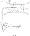
- FIG. 1 Ais an illustration of a shock wave angioplasty catheter being used to treat an occlusion in a blood vessel, according to one embodiment of the subject invention.
- FIG. 1 Bis an illustration of the distal end of a catheter having a low-profile no-fold balloon in a deflated state in accordance with some embodiments of the subject invention.
- FIG. 1 Cis an illustration of the distal end of the catheter of FIG. 1 B showing the low-profile no-fold balloon in an inflated state.
- FIG. 1 Dis an illustration of the catheter of the subject invention being used to treat a coronary total occlusion (CTO).
- CTOcoronary total occlusion
- FIG. 1 Eis an illustration of the catheter of the subject invention being used in a blood vessel highly narrowed by a partial occlusion.
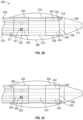
- FIG. 2 Ais an exploded perspective view of a distal section of a catheter according to one embodiment of the subject invention.
- FIG. 2 Bis a side view illustration of the distal end of the catheter of FIG. 2 A , including a first electrode pair and a no-fold balloon over the electrode pair.
- FIG. 2 Cis an illustration of the embodiment of FIG. 2 B rotated by 180 degrees to show a second electrode pair.
- FIG. 2 Dis an exploded perspective view of an the catheter of FIG. 2 A showing a fluid inlet and fluid outlet.
- FIG. 2 Eis a cross-sectional view of the embodiment of FIGS. 2 B- 2 C , taken at a more proximal region of the catheter.
- FIG. 2 Fis a cross-sectional perspective view of the catheter of FIG. 2 E .
- FIG. 2 Gis a longitudinal cutaway view of the catheter of FIG. 2 A showing an electrical current flow through the catheter.
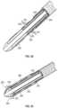
- FIG. 3 Ais a perspective view of a distal section of a catheter according to another embodiment of the subject invention.
- FIG. 3 Bis a side view illustration of the distal end of the catheter of FIG. 3 A including a first distal electrode pair and a first proximal electrode pair and a no-fold balloon over the electrode pairs.
- FIG. 3 Cis an illustration of the embodiment of FIG. 3 B rotated by 180 degrees to show a second distal electrode pair and a second proximal electrode pair.
- FIG. 3 Dis a longitudinal cross section of a distal section of the catheter of FIG. 3 A showing a fluid path for a conductive fluid
- FIG. 3 Eis a cross-sectional view of the embodiment of FIGS. 3 B- 3 C , taken at a more proximal region of the catheter.
- FIG. 3 Fis a cross-sectional perspective view of the catheter of FIG. 3 E .
- FIG. 3 Gprovides a cross-sectional view of the catheter of FIG. 3 A being used to generate shock waves at a proximal emitter.
- FIG. 3 Hprovides a perpendicular cross-sectional view of the catheter of FIG. 3 G being used to generate shock waves at a distal emitter.
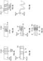
- FIG. 4 Aillustrates a top view of a ring electrode configuration according to some embodiments of the subject invention
- FIG. 4 Billustrates a magnified side view of the embodiment of FIG. 4 A .
- FIG. 5 Aillustrates a top view of a tongue-and-groove electrode configuration according to some embodiments of the subject invention.
- FIG. 5 Billustrates a side views of the embodiment of FIG. 5 A .
- FIG. 5 Cillustrates an exploded view of an alternative tongue-and-groove electrode configuration arranged to produce two electrode pairs, according to some embodiments of the subject invention.
- FIG. 6 Aillustrates a helical electrode configuration according to some embodiments of the subject invention.
- FIG. 6 Billustrates the helical electrode configuration of FIG. 6 A showing just the helically coiled wires.
- the assignee hereinhas developed a number of low-profile shock wave electrodes that may be suitable for use in angioplasty and/or valvuloplasty procedures.
- a low-profile electrode assemblyin which an outer electrode is formed by a conductive sheath, and an inner electrode is formed by removing a portion of an insulated wire (e.g., cutting a hole in the insulating layer near the end of the wire) to expose an electrically conductive portion of the insulated wire.
- the inner electrodeis placed a controlled distance apart from the side edge of the conductive sheath to allow for a reproducible arc for a given current and voltage.
- Pat. No. 10,555,744also incorporated herein by reference, the assignee discloses a tongue-and-groove electrode assembly in which electrode pairs are formed from a groove-shaped cut-out in a conductive sheath and a coplanar tongue-shaped protrusion extending into the groove-shaped cut-out.
- lithotripsyIVL
- the present inventionis similar to existing IVL systems in that it can comprise an array of lithotripsy emitters (e.g., electrode pairs) on a catheter that is entered into a patient's vasculature to deliver shock waves to an occlusion.
- lithotripsy emitterse.g., electrode pairs
- the present inventionadditionally includes a low-profile angioplasty balloon attached to the distal end of the catheter that can be positioned in a patient's vasculature without folding.
- the surface area of the balloonis small enough that the balloon does not need to be folded while advancing the catheter through a blood vessel.
- the low profile of the no-fold balloonadvantageously allows the catheter to advance into even tighter regions of vasculature, such as those that are partially or totally occluded.
- the catheters described hereininclude additional low-profile elements, such as coplanar electrodes, which further reduce the diameter of the distal end of the catheter.
- the cathetersmay provide an electrical connection to the electrodes by way of a reinforced wire sheath wrapped circumferentially around the catheter shaft.
- the reinforced wire sheathprovides improved kink resistence, torqueability, and pushability to the catheter for more easily maneuvering the device within a patient's vasculature.
- Including at least one electrical connection integrated into the reinforced wire sheathalso improves the low-profile aspects of the device by reducing the number of wires or other conductors that must be carried elsewhere in the catheter.
- FIG. 1 Aillustrates an exemplary catheter 10 for treating occlusions in blood vessels according to an embodiment of the subject invention.
- the catheter 10is advanced into an occlusion in a patient's vasculature, such as the stenotic lesion depicted in FIG. 1 A , over a guidewire 20 carried in a guidewire sheath.
- a distal end 14 of the catheter 10includes a shock wave generator 16 that produces shock waves at a plurality of emitters (e.g., electrode pairs) to break up calcified lesions.
- the plurality of emittersinclude electrode pairs having first and second electrode separated by a gap, at which shock waves are formed when a current flows across the gap between the electrodes of the pair (i.e., when a voltage is applied across the first and second electrodes).
- the electrodes pairsare arranged in a low-profile configuration that reduces the diameter of the distal end 14 of the catheter 10 and permits the treatment of tight, hard-to-cross lesions.
- the shock wave generator 16includes one or more coplanar electrode pairs, or includes one or more electrodes at least partially recessed into the catheter 10 .
- a flexible cap 18(e.g., a low-profile flexible angioplasty balloon) is sealably attached to the distal end 14 of the catheter 10 , forming an annular channel around the shaft 12 of the catheter.
- the flexible cap 18surrounds the shock wave generator 16 , such that the shock waves are produced in a closed system defined by the walls of the cap.
- the cap 18is filled with a conductive fluid, such as saline.
- the conductive fluidallows the acoustic shock waves to propagate from the electrode pairs of the shock wave generator 16 through the walls of the cap 18 and then into the target lesion.
- the conductive fluidmay also contain an x-ray contrast to permit fluoroscopic viewing of the catheter 10 during use.
- the capis rigid and not flexible.
- FIGS. 1 B- 1 Cprovide more detailed views of the distal end 14 of the catheter 10 of FIG. 1 A , including an exemplary no-fold angioplasty balloon forming the flexible cap 18 over the shock wave generator 16 .
- the balloon 18has a small enough diameter and surface area that it does not need to be folded like a conventional angioplasty balloon when advanced through a patient's vasculature.
- the extremely low profile of the balloon 18allows the distal end 14 of the catheter to access tightly occluded regions of vasculature.
- the diameter of the catheter's distal end 14 in the region of the balloon 18is one millimeter or less.
- the balloon 18is preferably formed of a material having elastomeric properties such that the balloon can be inflated during treatment of an occlusion, and then returns to a low profile state when deflated after treatment.
- the flexible cap 18is an extruded polymer tube having semi-compliant material properties such that the polymer tube can be inflated and deflated similarly to an angioplasty balloon.
- flexible cap and balloonare used interchangeably to describe the flexible annular structure that surrounds the electrode pairs and is inflated with conductive fluid during treatment.
- FIG. 1 Bshows an exemplary flexible balloon 18 in a deflated state, for instance, during entry, advancing, and positioning of the balloon in a blood vessel.
- the surface area of the balloonis small enough that the balloon is not folded when the catheter 10 is advanced through a blood vessel.
- the surface area of the deflated balloonis small enough that the balloon is not folded inside of the guide catheter or outer jacket.
- the diameter of the balloonis smaller than the diameter of the guide catheter or outer jacket.
- FIG. 1 Cshows the same balloon 18 in an inflated state.
- the balloon 18is formed of a material having elastomeric properties such that the balloon can accept inflation pressures of between approximately one atmosphere and approximately six atmospheres.
- the balloon 18is configured to expand only slightly when inflated with conductive fluid during treatment. For example, the maximum inflated diameter of the balloon 18 may be no more than 10%-15% greater than the original diameter of the balloon (i.e., the diameter of the balloon in a deflated state).
- the maximum diameter of the balloon in an inflated statecan be determined by the material durometer of the balloon 18 , its wall thickness, and/or the inflation pressure inside the balloon.
- the balloon 18expands to provide a space between the inner surface of the balloon and the electrode pairs 16 .
- the outer diameter of the guidewire sheathis approximately 0.028 inches and the inner diameter of the inflated balloon 18 is approximately 0.039 inches, providing a space of about 0.011 inches between the guidewire sheath and the inner surface of the balloon. The space ensures that the electrode pairs 16 are immersed in conductive fluid during shock wave generation and that the inner surface of the balloon 18 is sufficiently far from the electrode pairs that the balloon material is not damaged by the shock waves.
- the diameter of the inflated balloon 18is one millimeter or less.
- the outer surface of the balloon 18includes a hydrophilic coating to facilitate contact between the balloon and the target lesion.
- the balloon 18can be deflated to its original low profile deflated configuration.
- the balloon 18returns to a deflated state after being inflated, the balloon should return to its original low profile configuration (i.e., a configuration having a small surface area and diameter) such that that the balloon is not folded when removing the catheter 10 from the patient's vasculature.
- an exemplary catheter 10also includes a proximal end or handle 22 that remains outside of a patient's vasculature during treatment.
- the proximal end 22includes an entry port for receiving the guidewire 20 .
- the proximal end 22also includes a fluid port 26 for receiving a conductive fluid for inflating and deflating the flexible cap 18 during treatment.
- An electrical connection port 24is also located on the proximal end 22 to provide an electrical connection between the distal shock wave generator 16 and an external pulsed high voltage source 28 , such as the intravascular lithotripsy (IVL) generator shown in FIG. 1 A .
- IVLintravascular lithotripsy
- the catheter 10also includes a flexible shaft 12 that extends from the proximal handle 22 to the distal end 14 of the catheter.
- the shaft 12provides various internal conduits connecting elements of the distal end 14 with the handle 22 of the catheter (see, e.g., FIGS. 2 E- 2 F and FIG. 3 E- 3 F for cross-sections of a region of an example shaft).
- the shaft 12includes a guidewire sheath that includes a lumen for receiving the guidewire 20 .
- the guidewire sheathalso defines a number of further lumens extending longitudinally through the shaft 12 . For instance, one or more wire lumens can be included for carrying conductive wires that electrically connect the pulsed voltage source 28 with electrodes of the distal shock wave generator 16 .
- one or more fluid lumensare provided in the guidewire sheath for carrying conductive fluid from the fluid port 26 into the cap 18 .
- the flexible shaft 12includes a reinforced wire sheath wrapped circumferentially around the guidewire sheath. The reinforced wire sheath provides mechanical support to the flexible shaft 12 to facilitate torqueing, pushing, and maneuvering of the catheter 10 through a patient's blood vessel.
- the reinforced wire sheathis also configured for carrying a current, such that the reinforced wire sheath can be used to connect one or more of the distal electrode pairs of the shock wave generator 16 with the pulsed voltage source 28 (i.e., in lieu of one or more of the conductive wires).
- a tubular outer jacketcovers the guidewire sheath and the reinforced wire sheath to provide a barrier between active elements of the catheter 10 and the in situ environment.
- the catheter 10can be used to treat occlusions in vasculature, for example, stenotic lesions, calcified portions of an artery, or some other occlusion in a blood vessel.
- a physicianadvances the guidewire 20 from an entry site on a patient (e.g., an artery in the groin area of the leg) to the target region of a vessel (e.g., a region having an occlusion that needs to be broken up).
- the catheter 10is then advanced over the guidewire 20 to the target region of the vessel.
- the flexible cap 18 sealed to the distal end 14is a no-fold balloon having a low profile when deflated, such that the balloon does not need to be folded while the device is advanced through the vasculature.
- a guide catheter or outer jacketmay be used to aid the entry and maneuvering of the catheter 10 within the vasculature.
- the outer jacketprovides tubular linear support to the catheter shaft 12 and retains the deflated state of the flexible cap 18 during pushing, crossing, and placement of the catheter 10 .
- the in situ location of the distal end 14 of the catheter 10may be determined by x-ray imaging and/or fluoroscopy.
- the distal end 14 of the catheter 10is advanced as far as possible inside the tight lesion.
- the flexible cap 18is then inflated by a conductive fluid (e.g., saline and/or saline mixed with an image contrast agent) introduced via the fluid port 26 , allowing conductive fluid to expand the cap so that the outer surface of the cap contacts the target lesion.
- a conductive fluide.g., saline and/or saline mixed with an image contrast agent
- IVL pressurewhich is between approximately one atmosphere and approximately six atmospheres.
- the diameter of the flexible cap in an inflated statemay be about 10-15% greater than the diameter of the flexible cap in a deflated state. However, in some examples the diameter of the cap in an inflated state is even less than 10% greater than the diameter of the cap in a deflated state.
- a voltage pulseis then applied by the pulsed high voltage source 28 across one or more electrode pairs (i.e., emitters of the shockwave generator 16 ).
- Each pulseinitially ionizes the conducive fluid in the flexible cap 18 to create small gas bubbles around the shock wave generator 16 that insulate the electrodes.
- Fluidcan be continuously flowed through the cap 18 during treatment at a constant rate to clear the bubbles and debris from the electrodes.
- the fluid flow ratemay be controlled throughout treatment, but is generally in the range of approximately 1 ml/min to approximately 3 ml/min.
- a plasma arcforms across the electrode pairs, creating a low impedance path where current flows freely.
- the heat from the plasma archeats the conductive fluid creating a rapidly expanding vapor bubble.
- the expansion of the vapor bubblecreates a shock wave that is conducted through the fluid, through walls of the flexible cap 18 , and into an occlusion where the energy breaks up the hardened lesion.
- the voltage pulse applied by the voltage pulse generator 28is typically in the range of approximately 2000 volts to approximately 3000 volts and preferably between 2300 and 3000 volts.
- the pulse width of the applied voltage pulsesranges between 2 microseconds and 6 microseconds.
- the repetition rate or frequency of the applied voltage pulsesmay be between approximately 1 Hz and approximately 10 Hz.
- the preferred voltage and repetition ratemay vary depending on, e.g., the size of the lesion, the extent of calcification, the size of the blood vessel, the attributes of the patient, or the stage of treatment. For instance, a physician may start with low energy shock waves and increase the energy as needed during the procedure.
- the magnitude of the shock wavescan be controlled by controlling the voltage, current, duration, and repetition rate of the pulsed voltage from the pulsed voltage source 28 . More information about the physics of shock wave generation and their control can be found in U.S. Pat. Nos. 8,956,371; 8,728,091; 9,522,012; and 10,226,265, each of which is incorporated by reference.
- one or more cycles of shock wavescan be applied to create a more compliant vessel.
- the flexible cap 18can be deflated and the distal end 14 of the catheter 10 can be advanced further into the occlusion.
- the flexible cap 18is then re-inflated and another cycle of shock waves can be applied. Further advancement of the cap 18 can be attempted after the completion of successive cycles.
- the placement and spacing of the electrode pairscan be controlled to provide a more effective shock wave treatment.
- the electrode pairs of the shockwave generator 16may be spaced circumferentially around the distal end 14 of the catheter 10 in consistent increments, e.g., 180 degrees apart or 90 degrees apart, to generate shock waves more evenly around the catheter.
- the shock wave generator 16includes electrode pairs positioned in various groupings spaced longitudinally along the catheter 10 within the flexible cap 18 .
- the shock wave generator 16may include at least one distal electrode pair and at least one proximal electrode pair.
- the pulsed voltage source 28can be controlled to selectively generate high voltage pulses at either the proximal or distal electrode pairs, e.g., by applying voltage pulses across differing set of wires or other conductors leading to the respective pairs.
- a first stage of treatmenti.e., during initial treatment of the tight or totally-occluding lesion
- only the distal electrode pairsare activated to generate shock waves.
- the capis again inflated and more proximal electrode pairs are activated to generate more proximal shock waves.
- the progress of the proceduremay be monitored by x-ray and/or fluoroscopy. Shock wave cycles can be repeated until the occlusion has been cleared, or until a channel is formed in the lesion having a diameter sufficient to receive a second treatment device having a larger profile. For example, the enlarged channel can receive a different catheter having a more conventional angioplasty balloon or differently oriented shock wave sources. Catheters of this type are described in U.S. Pat. No. 8,747,416 and U.S. Publication No. 2019/0150960, cited above.
- FIG. 1 Ddepicts the catheter 10 being used to treat a total occlusion in a blood vessel, for instance, a coronary total occlusion (CTO).
- CTOcoronary total occlusion
- the guidewireis advanced at least partially into the stenotic lesion.
- the catheteris then advanced through the patient's vasculature over the guidewire and at least partially into the lesion.
- the flexible capis then inflated with a conductive fluid until the cap gently contacts the lesion.
- Voltage pulsesare then supplied by a pulsed voltage source to electrode pairs at the tip of the catheter to generate shock waves that break up or loosen the lesion.
- the guidewire and the cathetercan then be advanced further into the lesion and the shock wave treatment can be repeated until the total occlusion is cleared or until the diameter of the vessel permits the placement of a larger more conventional angioplasty device.
- FIG. 1 Eillustrates the use of the inventive catheter 10 in a small vessel that is partially blocked by a stenotic lesion.
- the guidewirecan be advanced much further into the lesion and, in some cases, all the way through the lesion.
- the catheteris advanced through the lesion in incremental stages.
- the flexible capis inflated and shock waves are generated to break up the occlusion and increase the diameter of the blood vessel.
- a larger-diameter cathetermay be advanced through the vessel to complete the treatment.
- FIGS. 2 A- 2 G and 3 A- 3 Hprovide more detailed views of the distal ends of catheters that can be included in a shock wave angioplasty device, such as any of the catheters of FIGS. 1 A- 1 E and described herein.
- FIG. 2 Aillustrates an exploded perspective view of a distal section of an exemplary catheter including two low-profile electrode pairs formed from a conductive sheath (the “emitter band”, e.g., a ring electrode) wrapped circumferentially around a guidewire sheath (the “multilumen inner member”).
- the emitter bande.g., a ring electrode
- the electrode pairsare electrically connected to an external pulsed voltage source by way of a conductive wire (for example, the polyimide-insulated copper wire) and a conductive reinforced wire sheath (the “flat wire braid”) wrapped circumferentially around the guidewire sheath.
- a cape.g., a low-profile angioplasty balloon or a tubular polymer
- the catheteralso includes an outer jacket having a diameter greater than the diameter of the distal section of the catheter. The outer jacket aids the entry and positioning of the catheter by providing circumferential protection and mechanical support to the device.
- FIG. 2 Bdepicts a first side view of the distal end 200 of the exemplary catheter showing a first electrode pair in a dot-circle configuration.
- FIG. 2 Cprovides a second view of the distal end 200 of the catheter of FIG. 2 B rotated by 180 degrees to show a second electrode pair opposite the first electrode pair, the second electrode pair having a tongue-and-groove configuration.
- the distal end 200 of the catheterincludes a guidewire sheath 210 , a shockwave generator including a first electrode pair and a second electrode pair, and a flexible cap 280 surrounding the electrode pairs.
- the flexible cap 280is wrapped circumferentially around the guidewire sheath 210 and sealed to the distal end 200 of the catheter using, e.g., an adhesive seal or a thermal bond to form a closed annular channel around a portion of the guidewire sheath 210 .
- the flexible cap 280is a no-fold angioplasty balloon (i.e. a low-profile angioplasty balloon) that can be positioned in a patient's vasculature without folding.
- the surface area of the balloonis small enough that the balloon is not folded when the catheter is advanced into a blood vessel.
- the flexible cap 280is an extruded tubular structure formed of a semi-compliant polymer material (i.e., an extruded polymer tube).
- the semi-compliant polymer materialallows the flexible cap 280 to inflate slightly responsive to fluid pressure inside the flexible cap, and then return to its original size when under no pressure.
- the flexible cap 280is inflatable with a conductive fluid, for example, saline, such that the cap expands to provide a space between the inner wall of the cap and the electrode pairs (see, e.g., FIG. 1 C ).
- the flexible cap 280expands a relatively small amount such that the cap retains a low profile (e.g., has a diameter less than 1 millimeter) when it is in an inflated state.
- the maximum inflated diameter of the flexible cap 280may be no more than 10%-15% greater than the original diameter of the cap, such that the diameter of the flexible cap in an inflated state is 10-15% greater than the diameter of the cap in a deflated state.
- the flexible cap 280when inflated, should provide a space sufficient to allow the conductive fluid to surround and immerse the electrode pairs to avoid damage to the cap during shock wave generation.
- the conductive fluidallows the acoustic shock waves from the electrode pairs to propagate through the walls of the cap 280 and into a lesion in contact with the outer surface of the cap.
- the conductive fluidalso contains an x-ray contrast agent to permit fluoroscopic viewing of the catheter during IVL treatment.
- the conductive fluidis admitted into the cap 280 via a fluid inlet 217 in the guidewire sheath 210 , and removed from the cap via a fluid outlet 219 in the guidewire sheath.
- the fluid inlet 217 and fluid outlet 219provide channels extending from the surface of the guidewire sheath 210 to a respective fluid inlet lumen 216 and fluid outlet lumen 218 in the guidewire sheath (and, more proximally, allow the cap to access fluid supplied by the fluid port shown in FIG. 1 A ). While treating an occlusion, fluid can be continually flushed through the flexible cap 280 via the inlet 217 and the outlet 219 to clear bubbles and debris produced when high voltage pulses across the electrodes create shock waves in the cap 280 .
- the fluid inlet 217 and fluid outlet 219are positioned to maximize fluid flow across the electrode pairs, such that fluid flowed through the cap 280 via the inlet and outlet flows across at least one of the electrode pairs.
- the fluid inlet 217 and the fluid outlet 219can be positioned diagonally across the conductive sheath 220 , such that one or more of the electrode pairs are positioned between the fluid inlet and the fluid outlet.
- FIG. 2 Dprovides an exploded perspective view of an IVL catheter embodiment, having a fluid inlet and fluid outlet positioned to flow fluid across an electrode pair.
- the guidewire sheath 210provides various internal conduits connecting elements of the distal end 200 with the proximal end of the catheter (not pictured), including a guidewire lumen 211 for receiving a guidewire; a wire lumen 212 for carrying an insulated wire 242 , and one or more fluid lumens 216 , 218 for carrying a fluid, e.g., the conductive fluid, from a proximal end of the catheter to the cap 280 .
- the internal structure of the guidewire sheath 210is shown more clearly in FIGS. 2 E- 2 F .
- FIG. 2 Eprovides a cross-section of a more proximal section of the shaft of the catheter of FIGS. 2 B- 2 C .
- FIG. 2 Fprovides a perspective view of the cross-section of FIG. 2 E inside of an outer jacket of the catheter 200 .
- the catheterincludes a central, tubular guidewire sheath 210 defining a plurality of lumens.
- the pluralityincludes a first lumen (i.e., the guidewire lumen 211 ) for receiving a guidewire and a second lumen (i.e., the wire lumen 212 ) for carrying a conductive wire 242 .
- the guidewire lumen 211may extend through the center of the guidewire sheath 210 , or may be slightly offset from the center as shown in FIG. 2 E .
- the guidewire lumen 211is shaped to loosely receive a guidewire having a diameter between approximately 0.014 inches and approximately 0.035 inches.
- the wire lumen 212is shaped to carry at least one wire 242 for flowing current from the pulsed voltage source (such as the pulsed voltage source of FIG. 1 A ) to the electrode pairs at the distal end 200 of the catheter.
- the wireis a polyimide insulated copper wire having a diameter between approximately 0.003 inches and approximately 0.007 inches.
- the wiresmay be flattened to reduce the profile of the catheter, with the flattened wires having a cross-section that is approximately 0.003 inches thick and approximately 0.010 inches wide.
- the plurality of lumensalso includes a fluid inlet lumen 216 for flowing fluid into the cap 280 and a fluid outlet lumen 218 for flowing fluid out of the cap 280 . While the lumens are pictured in FIG.
- lumens in the guidewire sheath 210may have any desired shape.
- the wire 242could have a flattened shape and the second lumen 212 could have a flattened or oblong shape to accommodate the flattened wire.
- the fluid inlet lumen 216 or the fluid outlet lumen 218could be arranged around the circumference of the guidewire sheath (e.g., in an annular space between the sheath and the reinforced wire sheath 230 ).
- the location, size, and shape of any of the lumenscan be modified to reduce the profile of the catheter or to provide some other benefit.
- the various lumensmay be combined (e.g. by providing two or more insulated wires in the same lumen) or eliminated without departing from the scope of the present invention.
- a tubular reinforced wire sheath 230formed from at least one conductive reinforced wire material (e.g., a wire that is braided, coiled or both), for example, reinforced copper or stainless steel.
- the reinforced wire sheath 230can be used to carry current from a pulsed voltage source at the proximal end of the catheter to the distal end 200 of the catheter to provide current to one or more electrode pairs.
- a proximal end of the reinforced wire sheath 230is connectable to a pulsed voltage source, while the distal end of the reinforced wire sheath is connected to one or more of the electrode pairs.
- the reinforced wire sheath 230is connected to an electrode pair via a conductive piece of metal shaped to form an electrode (e.g., the conductive emitter portion 234 depicted in FIG. 2 C ).
- the reinforced wire sheath 230may also provide favorable mechanical properties to the shaft of the catheter. For instance, the material composition of the reinforced wire sheath 230 could provide increased torqueability, pushability, or enhanced rigidity to the catheter shaft to facilitate maneuvering the catheter through a patient's vasculature.
- the reinforced sheath 230includes one or more braided or coiled metals (e.g., metal wires) encapsulated at least partially in a polymer.
- Polymer encapsulationinsulates the conductive metal elements of the sheath 230 and/or to provides improved mechanical properties.
- the reinforced metal of the sheath 230may be flattened to reduce the profile of the sheath 230 and allow the catheter to more easily fit into tightly occluded vessels.
- the distal end 200 of the catheteralso includes a soft tip 290 that tapers toward the distal tip of the catheter.
- the soft tip 290can be formed from a polymer or any other suitable biocompatible material.
- the tip 290is formed at least partially from a radiopaque material such as platinum, iridium, or stainless steel to permit fluoroscopic viewing of the catheter during use.
- the soft tipalso includes a guidewire lumen such that, during operation, the catheter is advanced through a patient's vasculature along a guidewire with the soft tip leading. Providing a soft tip 290 may prevent physical damage to blood vessel walls while facilitating contact with and entry into tight lesions in the vasculature.
- the distal end 200also includes the shock wave generator of the catheter, which includes a first electrode pair, shown in FIG. 2 B and a second electrode pair shown in FIG. 2 C .
- the electrode pairshave low-profile configurations (e.g., are coplanar or at least partially recessed into the guidewire sheath 210 ) to reduce the diameter of the distal end 200 .
- the first electrode pair and the second electrode pairare located approximately 180 degrees apart circumferentially around the guidewire sheath 210 .
- the electrodes of each pairare spaced apart to define gaps where current can flow to produce shock waves in the conductive fluid inside the flexible cap 280 .
- An electrode paircan be formed by a side edge of a conductive sheath (e.g., a ring electrode) and a conductive portion of a wire, as described in assignee's prior filing U.S. Pub. No. 2019/0150960.
- the conductive portion of the wirecan be formed by removing a portion of the insulating layer of an insulated wire near the distal end of the wire to expose an electrically conductive portion of the wire.
- the location, size, and shape of the removed portionmay vary to control the location, direction, and/or magnitude of the shock wave.
- an electrodemay be formed by cutting the end of an insulated wire to expose an electrically conductive cross-section.
- flat wiresrather than round wires are used to further reduce the crossing profile of the electrode assembly.
- the first electrode pairincludes a first electrode formed from an insulation removed portion 243 of a wire extending through a lumen 212 of the guidewire sheath 210 , for instance, conductive wire 242 .
- the first electrode pairalso includes a second electrode formed from a cut out 222 in a conductive sheath 220 wrapped circumferentially around the guidewire sheath.
- the cut out 222 in the conductive sheath 220is defined by an approximately circular hole in the conductive sheath.
- the location, size, and shape of the cut out 222can be varied to control the location, direction, and/or magnitude of the shock wave.
- the conductive sheath 220is at least partially recessed into the guidewire sheath 210 to reduce the profile of the electrode assembly and the diameter of distal end 200 of the catheter.
- the insulation removed portion 243 of the wire 242 and the cut out 222 of the conductive sheath 220are spaced apart to define a gap between the first electrode and the second electrode of the first electrode pair.
- the spacing of the gapcan be controlled to generate reproducible electrical arcs in the conductive fluid between the electrodes.
- the spacing of the electrodesmay be modified to produce shock waves having a desired magnitude for a given voltage and current output from a pulsed voltage source.
- the guidewire sheath 210includes an aperture extending between the outer surface of the guidewire sheath and the wire lumen 212 .
- the apertureis positioned over the insulation removed portion 243 of the wire 242 and under the cut out 222 such that current flows through the aperture when high voltage pulses are applied across the reinforced wire sheath 230 and the wire 242 .
- the size of the aperturemay correspond to the size of the insulation removed portion 243 of the wire 242 , the size of the cut out 222 in the conductive sheath 220 , or some other desired size or shape.
- FIG. 2 Cprovides a cross section of the distal end 200 of the catheter of FIG. 2 B rotated by 180 degrees to show a second electrode pair of the shock wave generator.
- the second electrode pairincludes a first electrode formed from an edge 224 of the conductive sheath 220 , and a second electrode formed from a conductive emitter portion 234 coplanar with the conductive sheath 220 .
- the first and second electrode of the second electrode pairare formed in a tongue-and-groove configuration.
- the edge 224 of the conductive sheath 220is defined by a longitudinal cut in the side of the conductive sheath and forms the “groove”.
- the “tongue”is formed from the conductive emitter portion 234 , which extends into the groove such that the tongue and groove define a U-shaped gap between the emitter portion 234 and the edge 224 of the conductive sheath 220 .
- the shape of the gapcan be controlled to generate reproducible electrical arcs in the conductive fluid between the electrodes of the pair and to produce shock waves having a desired magnitude.
- the conductive sheath 220 and the emitter portion 234are coplanar to reduce the profile of the electrode pair and the diameter of the distal end 200 of the catheter.
- the conductive emitter portion 234additionally includes PET heat shrink tubing. More information about tongue-and-groove electrode configurations is included in applicant's U.S. Pat. No. 10,555,744, incorporated herein by reference.
- the emitter portion 234is coupled to the distal end of the reinforced wire sheath 230 , which electrically connects the second electrode pair with a pulsed voltage source (not pictured).
- the emitter portion 234could be coupled to, e.g., a further wire extending along the catheter, which electrically connects the second electrode pair with the pulsed voltage source.
- the first electrode pairis electrically connected to the pulsed voltage source via the wire 242 extending within the lumen 212 of the guidewire sheath 210 .
- the proximal end of the wire 242is connectable to the pulsed voltage source, while the distal end of the wire 242 is connected to (i.e., forms a part of or is otherwise electrically connected with) the first electrode pair.
- FIG. 2 Gshows show an exemplary current flow through a catheter having one tongue-and-groove electrode pair and one dot-circle electrode pair connected to a voltage source by way of a polyimide-insulated copper wire and a reinforced wire sheath formed of flat copper clad stainless steel wire.
- a physicianmay simultaneously connect the wire 242 to a positive lead of the voltage pulse generator, and connect the reinforced wire sheath 230 (or a wire electrically connected to a proximal end of the sheath) to a negative lead or the ground.
- currentwill flow from the voltage source, down the wire 242 , across the first gap between the insulation removed portion 243 of the wire and the cut out 222 in the conductive sheath 220 , creating a plasma arc that generates a shock wave at the first electrode pair.
- the currentthen flows across the conductive sheath 220 and across the second gap between the edge 224 of the conductive sheath 220 and the conductive emitter portion 234 , creating another plasma arc that generates a shock wave at the second electrode pair.
- the currentthen flows from the conductive emitter portion 234 to the reinforced wire sheath 230 , and down the reinforced wire sheath to reach the negative lead or ground.
- the physicianmay connect the reinforced wire sheath 230 (or a wire electrically connected to the reinforced wire sheath) to a positive lead of the pulse generator and connect the wire 242 to the negative lead or ground, such that the current travels the opposite path across the first and second electrode pairs.
- FIGS. 3 A- 3 Hprovide detailed views of the distal end of an alternative catheter that can be included in a shock wave angioplasty device, such as any of the catheters of FIGS. 1 A- 1 E and described herein.
- the distal end 300 shock wave generator of catheter of FIGS. 3 A- 3 Hincludes at least one distal emitter (e.g., one or more distal electrode pairs) and at least one proximal emitter (e.g., one or more proximal electrode pairs).
- FIG. 3 Aprovides a perspective view of an exemplary catheter including a distal emitter and a proximal emitter. As illustrated in FIG.
- the distal emitter and the proximal emitterare formed from a respective proximal conductive sheath (e.g., a proximal electrode ring) and distal conductive sheath (e.g., a distal electrode ring) wrapped circumferentially around a guidewire sheath.
- the distal emitterincludes one or more distal electrode pairs, while the proximal emitter includes one or more proximal electrode pairs.
- the electrode pairshave a low profile-configuration and are electrically connected to an external pulsed voltage source by way of a number of conductive wires extending through lumens of the guidewire sheath.
- FIG. 3 Bdepicts a first side of the distal end 300 of an exemplary catheter showing a first distal electrode pair and a first proximal electrode pair.
- FIG. 3 Cprovides a second view of the distal end 300 of the catheter of FIG. 3 B rotated 180 degrees to show a second distal electrode pair and a second proximal electrode pair.
- the distal end 300 of the catheterincludes a guidewire sheath 310 , a shockwave generator including two distal electrode pairs and two proximal electrode pairs, and a flexible cap 380 surrounding the electrode pairs.
- the flexible cap 380is wrapped circumferentially around the guidewire sheath 310 and sealed to the distal end 300 of the catheter using, e.g., an adhesive seal or a thermal seal to form a closed annular channel around the guidewire sheath 310 .
- the flexible cap 380is a no-fold angioplasty balloon (i.e. a low-profile angioplasty balloon) that can be positioned in a patient's vasculature without folding.
- the surface area of the balloonis small enough that the balloon is not folded when the catheter is advanced into a blood vessel.
- the flexible cap 380is an extruded tubular structure formed of a semi-compliant polymer material (i.e., an extruded polymer tube).
- the semi-compliant polymer materialallows the flexible cap 380 to inflate slightly responsive to fluid pressure inside the flexible cap, and then return to its original size when under no pressure.
- the flexible cap 380is inflatable with a conductive fluid, for example, saline, such that the cap expands to provide a space between the inner wall of the cap and the proximal and distal electrode pairs (see, e.g., FIG. 1 C ).
- a conductive fluidfor example, saline
- the flexible cap 380expands a relatively small amount such that the inflated cap retains a low profile (e.g., has a diameter less than 1 millimeter).
- the maximum inflated diameter of the flexible cap 380may be no more than 10%-15% greater than the original (i.e., deflated) diameter of the cap.
- the flexible cap 380when inflated, should provide a space sufficient to allow the conductive fluid to surround and immerse the electrode pairs to avoid damage to the cap during shock wave generation.
- the conductive fluidallows the acoustic shock waves from the proximal and distal electrode pairs to propagate through the walls of the flexible cap 380 and into a lesion in contact with the outer surface of the cap.
- the conductive fluidalso contains an x-ray contrast agent to permit fluoroscopic viewing of the catheter during IVL treatment.
- the conductive fluidis admitted into the cap 380 via a fluid inlet 317 in the guidewire sheath 310 , and removed from the cap via a fluid outlet 319 in the guidewire sheath.
- the fluid inlet 317 and fluid outlet 319provide channels extending from the surface of the guidewire sheath 310 to a respective fluid inlet lumen 316 and fluid outlet lumen 318 in the guidewire sheath (and, more proximally, allow the flexible cap to access fluid supplied by the fluid port shown in FIG. 1 A ). While treating an occlusion, fluid can be continually flushed through the cap 380 via the inlet 317 and the outlet 319 to clear bubbles and debris produced when high voltage pulses across the electrodes create shock waves in the cap.
- the fluid inlet 317 and fluid outlet 3219are positioned to maximize fluid flow across the electrode pairs, such that fluid flowed through the cap 380 via the inlet and outlet flows across at least one of the electrode pairs.
- the fluid inlet 317 and the fluid outlet 319can be positioned diagonally across one or more of the conductive sheaths 330 , 336 , such that one or more of the electrode pairs are positioned between the fluid inlet and the fluid outlet.
- FIG. 3 Dprovides a cross-sectional view of a distal section of an exemplary catheter depicting the flow of fluid through internal lumens and the flexible cap of the catheter via a fluid inlet and a fluid outlet in the guidewire sheath.
- the guidewire sheath 310provides various internal conduits connecting elements of the distal end with the proximal end of the catheter, including a guidewire lumen, lumens for carrying conductive wires, and one or more fluid lumens.
- the internal structure of the guidewire sheath 310is shown more clearly in FIG. 3 E , which provides a cross-section of a more proximal section of the shaft of the catheter.
- FIG. 3 Fprovides a perspective view of the cross-section of FIG. 3 E inside of the flexible cap 380 the catheter 300 .
- the catheterincludes a central, tubular guidewire sheath 310 defining a plurality of lumens.
- the plurality of lumensincludes a guidewire lumen 311 for receiving a guidewire.
- the guidewire lumen 311may extend through the center of the guidewire sheath 310 , as shown in FIGS. 3 E- 3 F , or may be slightly offset from the center.
- the guidewire lumen 311is shaped to loosely receive a guidewire having a diameter between approximately 0.014 inches and approximately 0.035 inches.
- the guidewire sheath 310also includes four wire lumens for carrying respective conductive wires 342 , 344 , 346 , 348 for flowing current from a pulsed voltage source (such as the pulsed voltage source of FIG. 1 A ) to the proximal and distal electrode pairs.
- the wires 342 , 344 , 346 , 348are polyimide insulated copper wires having a diameter between approximately 0.003 inches and approximately 0.007 inches.
- the wires 342 , 344 , 346 , 348may be flattened to reduce the profile of the catheter, with the flattened wires having a cross-section that is approximately 0.003 inches thick and approximately 0.010 inches wide.
- the plurality of lumensalso includes a fluid inlet lumen 316 for flowing fluid into the cap 380 and a fluid outlet lumen 318 for flowing fluid out of the cap 380 . While the lumens are pictured in FIGS. 3 E- 3 F as having approximately circular cross-sections, lumens in the guidewire sheath 310 may have any desired shape. For instance, one or more of the wires 342 , 344 , 346 , 348 could have a flattened shape and the associated lumen could have a flattened or oblong shape to accommodate the flattened wire.
- the fluid inlet lumen 316 or the fluid outlet lumen 318could be arranged around the circumference of the guidewire sheath 310 (e.g., in an annular space between the sheath and the reinforced wire sheath 330 ).
- the location, size, and shape of any of the lumenscan be modified to reduce the profile of the catheter or to provide some other benefit.
- the various lumensmay be combined (e.g. by providing two or more insulated wires in the same lumen) or eliminated without departing from the scope of the present invention.
- the guidewire sheath 310includes spacing features 312 that protrude from an outer surface of the guidewire sheath.
- the spacing features 312are configured to maintain the inner surface of the cap 380 a controlled distance away from the outer surface of the guidewire sheath 310 , e.g., in order to prevent damage to the cap caused by the shock waves produced at the electrode pairs.
- the spacing features 312surround one or more of the conductive sheaths 320 , 326 , or extend between the respective proximal conductive sheath 320 and the distal conductive sheath 326
- the distal end 300 of the catheteralso includes a soft tip 390 that tapers toward the distal tip of the catheter.
- the soft tip 390can be formed from a polymer or any other suitable biocompatible material.
- the tip 390is formed at least partially from a radiopaque material such as platinum, iridium, or stainless steel to permit fluoroscopic viewing of the catheter during use.
- the soft tipalso includes a guidewire lumen such that, during operation, the catheter is advanced through a patient's vasculature along a guidewire with the soft tip leading. Providing a soft tip 390 may prevent physical damage to blood vessel walls while facilitating contact with and entry into tight lesions in the vasculature.
- the distal end 300also includes the shock wave generator of the catheter, which includes a first distal electrode pair and a first proximal electrode pair, shown in FIG. 3 B and a second distal electrode pair and a second proximal electrode shown in FIG. 3 C .
- the first and second distal electrodesare formed from respective conductive portions 343 , 355 of a first wire 342 and a second wire 344 and a distal conductive sheath 326 (e.g., a distal ring electrode), while the first and second proximal electrode pairs are dot-circle electrode pairs formed from insulation removed portions of a third wire 346 and fourth wire 348 and a proximal conductive sheath 320 .
- the electrode pairshave low-profile configurations to reduce the diameter of the distal end 300 .
- the proximal conductive sheath 320 and/or the distal conductive sheath 326may be at least partially recessed into the guidewire sheath 310 to reduce the diameter of the distal end 300 of the catheter.
- an electrode paircan be formed by a side edge of a conductive sheath and a portion of a wire.
- the portion of wirecan be formed by removing a portion of the insulating layer of a wire near the distal end of the wire to expose an electrically conductive portion of the wire.
- the location, size, and shape of the removed portionmay vary to control the location, direction, and/or magnitude of the shock wave.
- an electrodemay be formed by cutting the end of an insulated wire to expose an electrically conductive cross-section.
- flat wiresrather than round wires are used to further reduce the crossing profile of the electrode assembly.
- the first distal electrode pairincludes a first electrode formed from a conductive portion 343 of a first wire 342 extending through a lumen of the guidewire sheath 310 .
- the first distal electrode pairalso includes a second electrode formed from a side edge 328 of a distal conductive sheath 326 wrapped circumferentially around the guidewire sheath 310 .
- the second distal electrode pairincludes a first electrode formed from the side edge 328 of the distal conductive sheath 326 .
- the second distal electrode pairalso includes a second electrode formed from a conductive portion 345 of a second wire 344 extending through a lumen of the guidewire sheath 310 .
- the first distal electrode pair and the second distal electrode pairare located approximately 180 degrees apart circumferentially around the distal conductive sheath 326 .
- the conductive portion 343 of the first wire 342is spaced apart from the side edge 328 of the distal conductive sheath 326 to define a first gap between the electrodes of the first distal pair.
- the conductive portion 345 of the second wire 344is spaced apart from the side edge 328 of the distal conductive sheath 326 to define a second gap between the electrodes of the second distal pair.
- the spacing of the gapscan be controlled to generate reproducible electrical arcs in the conductive fluid between the electrodes of the respective pairs and to produce shock waves having a desired magnitude for a given voltage and current output from the pulsed voltage source.
- the guidewire sheath 310includes distal apertures extending between the outer surface of the guidewire sheath 310 and the lumens containing the first wire 342 and the second wire 344 .
- the aperturesare positioned between the conductive portions 343 , 345 of the wires 342 , 344 and the side edge 328 of the distal conductive sheath 326 such that current flows through the respective apertures when high voltage pulses are applied across the first wire 342 and the second wire 344 .
- the first proximal electrode pairincludes a first electrode formed from an insulation removed portion 347 of a third wire 346 extending through a lumen of the guidewire sheath 310 .
- the first proximal electrode pairalso includes a second electrode formed from a first cut out 322 in the proximal conductive sheath 320 .
- the second proximal electrode pairincludes a first electrode formed from an insulation removed portion 349 of a fourth wire 348 extending through a lumen of the guidewire sheath 310 .
- the second proximal electrode pairalso includes a second electrode formed from a second cut out 324 in the proximal conductive sheath 320 .
- the first proximal electrode pair and the second proximal electrode pairare located approximately 180 degrees apart circumferentially around the proximal conductive sheath 320 .
- the insulation removed portion 347 of the third wire 346is spaced apart from the first cut out 322 of the proximal conductive sheath 320 to define a first gap between the electrodes of the first proximal pair.
- the insulation removed portion 349 of the fourth wire 348is spaced apart from the second cut out 324 of the proximal conductive sheath 320 to define a second gap between the electrodes of the second proximal pair.
- the spacing of the gapscan be controlled to generate reproducible electrical arcs in the conductive fluid between the electrodes of the respective pairs and to produce shock waves having a desired magnitude for a given voltage and current output from the pulsed voltage source.
- the guidewire sheath 310includes proximal apertures extending between the outer surface of the guidewire sheath 310 and the lumens containing the third wire 346 and the fourth wire 348 .
- the aperturesare positioned between the insulation removed portions 347 , 349 of the wires 346 , 348 and the cut outs 322 , 324 in the proximal conductive sheath 320 such that current flows through the respective apertures when high voltage pulses are applied across the third wire 346 and the fourth wire 348 .
- the distal ends of the first wire 342 and the second wire 344are connected to (i.e., form a part of or are electrically connected with) the distal electrode pairs and the proximal ends of the first wire 342 and the second wire 344 (not shown) are connectable to a pulsed voltage source, such that when high voltage pulses are applied across the first wire 342 and the second wire 344 , current flows across the first gap and the second gap creating shock waves for treating occlusions near the distal electrodes.
- the distal ends of the third wire 346 and the fourth wire 348are connected to the proximal electrode pairs and the proximal ends of the third wire 346 and the fourth wire 348 are connectable to the pulsed voltage source, such that when high voltage pulses are applied across the third wire 346 and the fourth wire 348 , current flows across the first gap and the second gap creating shock waves for treating occlusions near the proximal electrodes.
- FIG. 3 Gillustrates the selective firing of the proximal emitters by applying a current to the proximal emitter wires.
- FIG. 3 Hillustrates the selective firing of the distal emitters by applying a current to the distal emitter wires.
- the separate wiring of the proximal and distal electrode pairsadvantageously allows for generation of either distal or proximal shock waves by applying high voltage pulses across only the wires corresponding to the proximal or distal electrodes.
- the pulsed voltage sourcecan be controllable to apply high voltage pulses across either the first wire 342 and the second wire 344 to create shock waves at the distal electrode pairs or the third wire 346 and the fourth wire 348 to create shock waves at the proximal electrode pairs.
- FIGS. 2 A- 2 G and FIG. 3 A- 3 Hmay be rearranged, recombined, and modified without departing from the present invention.
- FIGS. 2 A- 2 Gprovide a catheter including a reinforced wire sheath
- the reinforced wire sheathmay be replaced by one or more conductive wires, as seen in the catheter of FIGS. 3 A- 3 H .
- one or more of the wires in FIGS. 3 A- 3 Hcould be replaced by a reinforced wire sheath.
- 3 A- 3 He.g., the spacing features, a further proximal conductive sheath, additional electrode pairs and/or independently controlled distal and proximal electrode pairs, may be combined with the catheter of FIGS. 2 A- 2 G without departing from the subject invention.
- FIGS. 2 A- 2 G and 3 A- 3 Hillustrate two examples of shock wave generators
- the subject inventionis intended to include catheters having a variety of electrode configurations.
- a shock wave generator of an exemplary cathetercould include two tongue-and-groove electrode pairs (see FIGS. 2 B and 5 A- 5 C ), two dot and circle electrode pairs (see FIG. 2 C and the proximal electrode pairs of FIGS. 3 B- 3 C ), or two electrode pairs formed from distal conductive portions of wires and a conductive sheath (see, e.g., the distal electrode pairs of FIGS. 3 B- 3 C ), or any other desired configuration.
- the placement and spacing of the electrode pairscan modified without departing from the subject invention.
- the electrode pairsmay be spaced circumferentially around the catheter in consistent increments, e.g., 180 degrees apart, 90 degrees apart, or 60 degrees apart to generate shock waves more evenly around the catheter.
- the shock wave generatorincludes electrode pairs positioned in various groupings spaced longitudinally along the catheter.
- the shock wave generatorcould include a plurality of electrode pairs defined by a plurality of conductive sheaths spaced longitudinally along the catheter.
- FIGS. 4 A- 4 B, 5 A- 5 C, and 6 A- 6 Bdepict several exemplary shock wave electrode assemblies that could be included in a shock wave angioplasty device, such as any of the catheters illustrated in FIGS. 1 A- 1 C, 2 A- 2 G, and 3 A- 3 H and described herein.
- FIGS. 4 A and 4 Billustrate one exemplary variation of an electrode pair.
- This embodimentincludes a pair of spaced apart ring electrodes provided as a first conductive sheath 52 b and a second conductive sheath 58 c wrapped circumferentially around the shaft of a catheter.
- One or more of the sheaths 58 c, 52 bmay be recessed into the shaft to reduce the diameter of shock wave generator and to permit entry of the catheter into tighter lesions.
- an electrode pairis formed from respective side edges of the first conductive sheath 52 b and the second conductive sheath 58 c. The spacing between the side edges of the two conductive sheaths defines a spark gap 64 between the electrodes.
- FIG. 4 Billustrates a different view of the electrodes of FIG. 4 A , with the gap 64 shown larger for clarity.
- a first wire “A” 36is connected to the first conductive sheath 52 b and the second wire “B” is connected to ring electrode 58 c.
- a plasma arcis created across the spark gap 64 between the ring electrodes.
- the plasma arccreates a shock wave for treating an occlusion.
- FIGS. 5 A, 5 B, and 5 Cillustrate exemplary tongue-and-groove electrode pair configurations formed a conductive sheaths (e.g., ring electrodes) and conductive emitter portions extending into the conductive sheaths.
- a first electrode of the pairis formed from an edge of the conductive sheath that is defined by a groove cut into a side of the conductive sheath.
- the second electrode of the pairis formed from a conductive tongue-shaped emitter portion extending into the groove.
- the conductive emitter portion “tongue”may be formed from a conductive portion of a wire (for instance, an insulation removed portion or a conductive end of wire) or some other conductive metal portion shaped to fit within the groove.
- the tongue and groovedefine a U-shaped spark gap between the electrodes of the pair.
- a first wire 36is connected to the conductive emitter portion “tongue” 52 and a second wire 38 is connected to the ring electrode conductive sheath 58 .
- a plasma arcis created across the spark gap 64 between the tongue 52 and groove 60 .
- the plasma arccreates a shock wave for treating the stenosis.
- FIG. 5 Cillustrates a related exemplary tongue-and-groove electrode embodiment providing two electrode pairs formed from a single conductive sheath 58 a (e.g., a single ring electrode) wrapped circumferentially around the guidewire sheath.
- a first groove 60 a and a second groove 60 bare cut into edges the same conductive sheath 58 a.
- the first and second groovemay be located 180 degrees circumferentially apart around the conductive sheath.
- Corresponding conductive tongue-shaped emitter portionsextend into the first groove and second groove to create first and second electrode pairs.
- a first electrode pairis formed from the edge of the conductive sheath defined by the first groove 60 a and the first tongue-shaped emitter portion 68 extending into the first groove.
- the second electrode pairis formed from the edge of the conductive sheath defined by the second groove 60 b and the second tongue-shaped emitter portion 52 extending into the second groove.
- Each electrode pairdefines a U-shaped gap between the respective tongues and grooves of the first and second electrode pairs.
- a first wire 38is connected to the first emitter portion “tongue” 68 and a second wire 36 is connected to the second emitter portion “tongue” 52 .
- FIGS. 6 A and 6 Billustrate another variation of an electrode pair of the subject invention.
- the first wire 36 and the second wires 38are helically wrapped around the shaft of a catheter.
- One or more electrode pairsare created by selectively removing insulation from the wires to define electrodes.
- a first electrode paircomprises a first insulation removed portion of the first wire 36 and a first insulation removed portion of the second wire 38 .
- Electrodes pairscan be created by removing additional portions of insulation from the wires (i.e., such that a second electrode pair comprises a second insulation removed portion of the first wire and a second insulation removed portion of the second wire, etc.)
- the helically wrapped first wire 36 and second wire 38are spaced sufficiently close to allow spark formation between the insulation removed portions of the two wires.
- the spaces between the insulation removed portionsdefine spark gaps between respective electrode pairs. Examples of helically wound wires to create electrode pairs and more information can be found in U.S. Pat. No. 9,993,292 and U.S. Publication No. 2018/0098779, incorporated herein by reference.
- the electrodesare arranged in the same plane (i.e., coplanar), thereby minimizing the diameter of the distal end of the catheter.
- coplanar electrode designsare described in U.S. 2017/0135709, incorporated herein by reference.
Landscapes
- Health & Medical Sciences (AREA)
- Surgery (AREA)
- Engineering & Computer Science (AREA)
- Life Sciences & Earth Sciences (AREA)
- Biomedical Technology (AREA)
- Molecular Biology (AREA)
- Vascular Medicine (AREA)
- Orthopedic Medicine & Surgery (AREA)
- Mechanical Engineering (AREA)
- Heart & Thoracic Surgery (AREA)
- Medical Informatics (AREA)
- Nuclear Medicine, Radiotherapy & Molecular Imaging (AREA)
- Animal Behavior & Ethology (AREA)
- General Health & Medical Sciences (AREA)
- Public Health (AREA)
- Veterinary Medicine (AREA)
- Media Introduction/Drainage Providing Device (AREA)
- Surgical Instruments (AREA)
Abstract
Description
Claims (12)
Priority Applications (2)
| Application Number | Priority Date | Filing Date | Title |
|---|---|---|---|
| US17/021,905US12274460B2 (en) | 2019-09-24 | 2020-09-15 | Lesion crossing shock wave catheter |
| US18/632,713US20240268842A1 (en) | 2019-09-24 | 2024-04-11 | Lesion crossing shock wave catheter |
Applications Claiming Priority (2)
| Application Number | Priority Date | Filing Date | Title |
|---|---|---|---|
| US201962904847P | 2019-09-24 | 2019-09-24 | |
| US17/021,905US12274460B2 (en) | 2019-09-24 | 2020-09-15 | Lesion crossing shock wave catheter |
Related Child Applications (1)
| Application Number | Title | Priority Date | Filing Date |
|---|---|---|---|
| US18/632,713DivisionUS20240268842A1 (en) | 2019-09-24 | 2024-04-11 | Lesion crossing shock wave catheter |
Publications (2)
| Publication Number | Publication Date |
|---|---|
| US20210085347A1 US20210085347A1 (en) | 2021-03-25 |
| US12274460B2true US12274460B2 (en) | 2025-04-15 |
Family
ID=72744844
Family Applications (2)
| Application Number | Title | Priority Date | Filing Date |
|---|---|---|---|
| US17/021,905Active2040-11-19US12274460B2 (en) | 2019-09-24 | 2020-09-15 | Lesion crossing shock wave catheter |
| US18/632,713PendingUS20240268842A1 (en) | 2019-09-24 | 2024-04-11 | Lesion crossing shock wave catheter |
Family Applications After (1)
| Application Number | Title | Priority Date | Filing Date |
|---|---|---|---|
| US18/632,713PendingUS20240268842A1 (en) | 2019-09-24 | 2024-04-11 | Lesion crossing shock wave catheter |
Country Status (7)
| Country | Link |
|---|---|
| US (2) | US12274460B2 (en) |
| EP (2) | EP4034005B1 (en) |
| JP (2) | JP7637671B2 (en) |
| CN (2) | CN120549571A (en) |
| AU (1) | AU2020354360A1 (en) |
| ES (1) | ES3009524T3 (en) |
| WO (1) | WO2021061451A1 (en) |
Families Citing this family (57)
| Publication number | Priority date | Publication date | Assignee | Title |
|---|---|---|---|---|
| US10966737B2 (en) | 2017-06-19 | 2021-04-06 | Shockwave Medical, Inc. | Device and method for generating forward directed shock waves |
| US11819229B2 (en) | 2019-06-19 | 2023-11-21 | Boston Scientific Scimed, Inc. | Balloon surface photoacoustic pressure wave generation to disrupt vascular lesions |
| US12402946B2 (en) | 2019-06-19 | 2025-09-02 | Boston Scientific Scimed, Inc. | Breakdown of laser pulse energy for breakup of vascular calcium |
| US11717139B2 (en) | 2019-06-19 | 2023-08-08 | Bolt Medical, Inc. | Plasma creation via nonaqueous optical breakdown of laser pulse energy for breakup of vascular calcium |
| US11660427B2 (en) | 2019-06-24 | 2023-05-30 | Boston Scientific Scimed, Inc. | Superheating system for inertial impulse generation to disrupt vascular lesions |
| US12280223B2 (en) | 2019-06-26 | 2025-04-22 | Boston Scientific Scimed, Inc. | Focusing element for plasma system to disrupt vascular lesions |
| WO2021061451A1 (en)* | 2019-09-24 | 2021-04-01 | Shockwave Medical, Inc. | Lesion crossing shock wave catheter |
| US11583339B2 (en) | 2019-10-31 | 2023-02-21 | Bolt Medical, Inc. | Asymmetrical balloon for intravascular lithotripsy device and method |
| US12102384B2 (en) | 2019-11-13 | 2024-10-01 | Bolt Medical, Inc. | Dynamic intravascular lithotripsy device with movable energy guide |
| US12274497B2 (en) | 2019-12-18 | 2025-04-15 | Bolt Medical, Inc. | Multiplexer for laser-driven intravascular lithotripsy device |
| US11672599B2 (en) | 2020-03-09 | 2023-06-13 | Bolt Medical, Inc. | Acoustic performance monitoring system and method within intravascular lithotripsy device |
| US20210290286A1 (en) | 2020-03-18 | 2021-09-23 | Bolt Medical, Inc. | Optical analyzer assembly and method for intravascular lithotripsy device |
| US11707323B2 (en) | 2020-04-03 | 2023-07-25 | Bolt Medical, Inc. | Electrical analyzer assembly for intravascular lithotripsy device |
| US12295654B2 (en) | 2020-06-03 | 2025-05-13 | Boston Scientific Scimed, Inc. | System and method for maintaining balloon integrity within intravascular lithotripsy device with plasma generator |
| US12207870B2 (en) | 2020-06-15 | 2025-01-28 | Boston Scientific Scimed, Inc. | Spectroscopic tissue identification for balloon intravascular lithotripsy guidance |
| US12232755B2 (en) | 2020-12-11 | 2025-02-25 | Shockwave Medical, Inc. | Lesion crossing shock wave catheter |
| US12016610B2 (en) | 2020-12-11 | 2024-06-25 | Bolt Medical, Inc. | Catheter system for valvuloplasty procedure |
| MX2023006886A (en)* | 2020-12-11 | 2023-07-18 | Shockwave Medical Inc | Lesion crossing shock wave catheter. |
| US11672585B2 (en) | 2021-01-12 | 2023-06-13 | Bolt Medical, Inc. | Balloon assembly for valvuloplasty catheter system |
| EP4277548B1 (en) | 2021-01-12 | 2025-06-04 | Bolt Medical, Inc. | Balloon assembly for valvuloplasty catheter system |
| US11911056B2 (en) | 2021-02-26 | 2024-02-27 | Fastwave Medical Inc. | Intravascular lithotripsy |
| US11484327B2 (en) | 2021-02-26 | 2022-11-01 | Fastwave Medical Inc. | Intravascular lithotripsy |
| US11944331B2 (en) | 2021-02-26 | 2024-04-02 | Fastwave Medical Inc. | Intravascular lithotripsy |
| US11648057B2 (en) | 2021-05-10 | 2023-05-16 | Bolt Medical, Inc. | Optical analyzer assembly with safety shutdown system for intravascular lithotripsy device |
| US11806075B2 (en) | 2021-06-07 | 2023-11-07 | Bolt Medical, Inc. | Active alignment system and method for laser optical coupling |
| US12089861B2 (en) | 2021-08-05 | 2024-09-17 | Nextern Innovation, Llc | Intravascular lithotripsy system and device |
| US11801066B2 (en) | 2021-08-05 | 2023-10-31 | Nextern Innovation, Llc | Systems, devices and methods for selection of arc location within a lithoplasty balloon spark gap |
| US11877761B2 (en) | 2021-08-05 | 2024-01-23 | Nextern Innovation, Llc | Systems, devices and methods for monitoring voltage and current and controlling voltage of voltage pulse generators |
| US11957369B2 (en) | 2021-08-05 | 2024-04-16 | Nextern Innovation, Llc | Intravascular lithotripsy systems and methods |
| US11896248B2 (en) | 2021-08-05 | 2024-02-13 | Nextern Innovation, Llc | Systems, devices and methods for generating subsonic pressure waves in intravascular lithotripsy |
| CN113598878B (en)* | 2021-08-13 | 2025-02-25 | 苏州中荟医疗科技有限公司 | A catheter and shock wave generating system |
| US12023098B2 (en)* | 2021-10-05 | 2024-07-02 | Shockwave Medical, Inc. | Lesion crossing shock wave catheter |
| CN113877044A (en)* | 2021-11-03 | 2022-01-04 | 上海微创旋律医疗科技有限公司 | Medical device |
| CN116322534A (en)* | 2021-11-18 | 2023-06-23 | 科塞尔医疗科技(苏州)有限公司 | Balloon catheter |
| US20230165598A1 (en)* | 2021-11-30 | 2023-06-01 | Shockwave Medical, Inc. | Electrode design for directional lithotripsy catheters |
| CN114305652A (en)* | 2021-12-09 | 2022-04-12 | 深圳先进技术研究院 | A microporous electrode for the treatment of vascular calcification and fragmentation |
| US11839391B2 (en) | 2021-12-14 | 2023-12-12 | Bolt Medical, Inc. | Optical emitter housing assembly for intravascular lithotripsy device |
| WO2023146878A1 (en)* | 2022-01-27 | 2023-08-03 | Bolt Medical, Inc. | Energy source for preconditioning an energy guide in a catheter system |
| US12193738B2 (en) | 2022-06-01 | 2025-01-14 | Fastwave Medical Inc. | Intravascular lithotripsy |
| AU2023280407A1 (en) | 2022-06-01 | 2024-11-07 | Fastwave Medical Inc. | Intravascular lithotripsy |
| CN115245373B (en)* | 2022-09-26 | 2023-06-23 | 上海百心安生物技术股份有限公司 | Pulse saccule dilating catheter capable of being crushed uniformly |
| WO2024081361A1 (en)* | 2022-10-14 | 2024-04-18 | Cardiovascular Systems, Inc. | Intravascular lithotripsy devices and systems with forward facing electrodes and flex circuit arrangements |
| CN115737061A (en)* | 2022-11-14 | 2023-03-07 | 杭州诺纳生物医疗科技有限公司 | Shock wave device |
| CN120282755A (en)* | 2022-12-05 | 2025-07-08 | 美敦力瓦斯科尔勒公司 | Catheter for treating calcified plaque |
| CN116138840A (en)* | 2023-01-19 | 2023-05-23 | 上海科亚方舟医疗科技有限公司 | Electrode assembly, balloon catheter and balloon seismic wave apparatus |
| WO2024206827A2 (en)* | 2023-03-30 | 2024-10-03 | Cardiovascular Systems, Inc. | Intravascular lithotripsy devices and systems with current fault detection |
| US12290268B2 (en) | 2023-03-31 | 2025-05-06 | Shockwave Medical, Inc. | Shockwave catheters for treating rhinosinusitis |
| US12035932B1 (en)* | 2023-04-21 | 2024-07-16 | Shockwave Medical, Inc. | Intravascular lithotripsy catheter with slotted emitter bands |
| US12220141B2 (en) | 2023-06-29 | 2025-02-11 | Shockwave Medical, Inc. | Catheter system with independently controllable bubble and arc generation |
| CN116793869B (en)* | 2023-08-29 | 2023-10-20 | 苏州心岭迈德医疗科技有限公司 | Impact strength detection device of shock wave balloon catheter |
| US20250160862A1 (en)* | 2023-11-16 | 2025-05-22 | Shockwave Medical, Inc. | Low-profile shock wave catheters |
| US12426904B2 (en)* | 2023-11-17 | 2025-09-30 | Shockwave Medical, Inc. | Intravascular lithotripsy catheter with oscillating impactor |
| WO2025106089A1 (en)* | 2023-11-17 | 2025-05-22 | Shockwave Medical, Inc. | Intravascular lithotripsy catheter with oscillating impactor |
| WO2025171173A1 (en) | 2024-02-08 | 2025-08-14 | IV-X Medical, LLC | Intravascular lithotripsy system |
| US12433620B2 (en)* | 2024-02-23 | 2025-10-07 | Shockwave Medical, Inc. | Locus emitter shock wave catheter devices with increased longevity and higher sonic output |
| CN117942131B (en)* | 2024-03-27 | 2024-05-31 | 苏州中荟医疗科技有限公司 | Impact waveguide tube and system |
| US12178458B1 (en) | 2024-05-16 | 2024-12-31 | Shockwave Medical, Inc. | Guidewireless shock wave catheters |
Citations (264)
| Publication number | Priority date | Publication date | Assignee | Title |
|---|---|---|---|---|
| US2916647A (en) | 1959-03-18 | 1959-12-08 | Roscoe H George | Spark gap impulse generator |
| US3412288A (en) | 1965-01-25 | 1968-11-19 | Gen Motors Corp | Arc suppression circuit for inductive loads |
| US3413976A (en) | 1963-07-29 | 1968-12-03 | G Elektrotekhnichesky Zd Vef | Arrangement for removal of concretions from urinary tract |
| US3524101A (en) | 1963-10-28 | 1970-08-11 | Comp Generale Electricite | Triggering device for spark-gap |
| US3583766A (en) | 1969-05-22 | 1971-06-08 | Louis R Padberg Jr | Apparatus for facilitating the extraction of minerals from the ocean floor |
| US3785382A (en) | 1971-05-14 | 1974-01-15 | Wolf Gmbh Richard | Device for destroying stones in the bladder, in the ureter, in the kidneys and the like |
| US3902499A (en) | 1974-01-02 | 1975-09-02 | Hoffman Saul | Stone disintegrator |
| US3942531A (en) | 1973-10-12 | 1976-03-09 | Dornier System Gmbh | Apparatus for breaking-up, without contact, concrements present in the body of a living being |
| US4027674A (en) | 1975-06-06 | 1977-06-07 | Tessler Arthur N | Method and device for removing concretions within human ducts |
| US4030505A (en) | 1975-11-28 | 1977-06-21 | Calculus Instruments Ltd. | Method and device for disintegrating stones in human ducts |
| DE3038445A1 (en) | 1980-10-11 | 1982-05-27 | Dornier Gmbh, 7990 Friedrichshafen | Pressure wave generator for diagnosis and therapy - has spark gap in inflatable balloon at end of catheter |
| US4445509A (en) | 1982-02-04 | 1984-05-01 | Auth David C | Method and apparatus for removal of enclosed abnormal deposits |
| JPS60191353U (en) | 1984-05-25 | 1985-12-18 | 日立工機株式会社 | Ink ribbon feeding control device |
| JPS61135648A (en) | 1984-12-05 | 1986-06-23 | オリンパス光学工業株式会社 | Discharge stone crushing probe |
| US4662126A (en) | 1986-05-23 | 1987-05-05 | Fike Corporation | Vibration resistant explosion control vent |
| US4662375A (en) | 1985-04-04 | 1987-05-05 | Dornier System Gmbh | Alleviating pain during extracoporal lithotripsy |
| US4671254A (en) | 1985-03-01 | 1987-06-09 | Memorial Hospital For Cancer And Allied Diseases | Non-surgical method for suppression of tumor growth |
| JPS6299210U (en) | 1985-12-12 | 1987-06-24 | ||
| US4685458A (en) | 1984-03-01 | 1987-08-11 | Vaser, Inc. | Angioplasty catheter and method for use thereof |
| JPS62275446A (en) | 1986-05-21 | 1987-11-30 | オリンパス光学工業株式会社 | Discharge stone crushing apparatus |
| US4741405A (en) | 1987-01-06 | 1988-05-03 | Tetra Corporation | Focused shock spark discharge drill using multiple electrodes |
| US4809682A (en) | 1985-12-12 | 1989-03-07 | Dornier Medizintechnik Gmbh | Underwater electrodes for contactless lithotripsy |
| US4813934A (en) | 1987-08-07 | 1989-03-21 | Target Therapeutics | Valved catheter device and method |
| US4878495A (en) | 1987-05-15 | 1989-11-07 | Joseph Grayzel | Valvuloplasty device with satellite expansion means |
| WO1989011307A1 (en) | 1988-05-26 | 1989-11-30 | The Regents Of The University Of California | Perfusion balloon catheter |
| US4890603A (en) | 1987-11-09 | 1990-01-02 | Filler William S | Extracorporeal shock wave lithotripsy employing non-focused, spherical-sector shock waves |
| US4900303A (en) | 1978-03-10 | 1990-02-13 | Lemelson Jerome H | Dispensing catheter and method |
| US4990134A (en) | 1986-01-06 | 1991-02-05 | Heart Technology, Inc. | Transluminal microdissection device |
| US4994032A (en) | 1987-12-01 | 1991-02-19 | Terumo Kabushiki Kaisha | Balloon catheter |
| JPH0363059A (en) | 1989-04-26 | 1991-03-19 | Advanced Cardiovascular Syst Inc | Blood flow measurement using self-irrigation catheter for blood vessel formation and its device |
| US5009232A (en) | 1988-08-17 | 1991-04-23 | Siemens Aktiengesellschaft | Extracorporeal lithotripsy apparatus using high intensity shock waves for calculus disintegration and low intensity shock waves for imaging |
| EP0442199A2 (en) | 1990-02-12 | 1991-08-21 | BS & B SAFETY SYSTEMS, INC. | Low pressure non-fragmenting rupture disks |
| US5057106A (en) | 1986-02-27 | 1991-10-15 | Kasevich Associates, Inc. | Microwave balloon angioplasty |
| US5057103A (en) | 1990-05-01 | 1991-10-15 | Davis Emsley A | Compressive intramedullary nail |
| US5061240A (en) | 1990-04-02 | 1991-10-29 | George Cherian | Balloon tip catheter for venous valve ablation |
| US5078717A (en) | 1989-04-13 | 1992-01-07 | Everest Medical Corporation | Ablation catheter with selectively deployable electrodes |
| WO1992003975A1 (en) | 1990-09-04 | 1992-03-19 | Cannon Robert L Iii | Catheter and apparatus for the treatment, inter alia, of pulmonary embolisms |
| US5102402A (en) | 1991-01-04 | 1992-04-07 | Medtronic, Inc. | Releasable coatings on balloon catheters |
| US5103804A (en) | 1990-07-03 | 1992-04-14 | Boston Scientific Corporation | Expandable tip hemostatic probes and the like |
| US5116227A (en) | 1991-03-01 | 1992-05-26 | Endo Technic Corporation | Process for cleaning and enlarging passages |
| US5152767A (en) | 1990-11-23 | 1992-10-06 | Northgate Technologies, Inc. | Invasive lithotripter with focused shockwave |
| US5152768A (en) | 1991-02-26 | 1992-10-06 | Bhatta Krishna M | Electrohydraulic lithotripsy |
| US5154722A (en) | 1988-05-05 | 1992-10-13 | Circon Corporation | Electrohydraulic probe having a controlled discharge path |
| US5176675A (en) | 1985-04-24 | 1993-01-05 | The General Hospital Corporation | Use of lasers to break down objects for removal from within the body |
| US5195508A (en) | 1990-05-18 | 1993-03-23 | Dornier Medizintechnik Gmbh | Spark gap unit for lithotripsy |
| US5231976A (en) | 1989-03-21 | 1993-08-03 | Hans Wiksell | Apparatus for triggering shock waves |
| US5246447A (en) | 1989-02-22 | 1993-09-21 | Physical Sciences, Inc. | Impact lithotripsy |
| US5245988A (en) | 1989-11-15 | 1993-09-21 | Dormer Gmbh | Preparing a circuit for the production of shockwaves |
| US5254121A (en) | 1992-05-22 | 1993-10-19 | Meditron Devices, Inc. | Method and device for removing concretions within human ducts |
| EP0571306A1 (en) | 1992-05-22 | 1993-11-24 | LASER MEDICAL TECHNOLOGY, Inc. | Apparatus and method for removal of deposits from the walls of body passages |
| US5281231A (en) | 1989-02-22 | 1994-01-25 | Physical Sciences, Inc. | Impact lithotrypsy |
| US5295958A (en) | 1991-04-04 | 1994-03-22 | Shturman Cardiology Systems, Inc. | Method and apparatus for in vivo heart valve decalcification |
| US5304134A (en) | 1992-01-17 | 1994-04-19 | Danforth Biomedical, Inc. | Lubricious yet bondable catheter channel sleeve for over-the-wire catheters |
| JPH06125915A (en) | 1992-10-21 | 1994-05-10 | Inter Noba Kk | Catheter type medical instrument |
| US5321715A (en) | 1993-05-04 | 1994-06-14 | Coherent, Inc. | Laser pulse format for penetrating an absorbing fluid |
| US5324255A (en) | 1991-01-11 | 1994-06-28 | Baxter International Inc. | Angioplasty and ablative devices having onboard ultrasound components and devices and methods for utilizing ultrasound to treat or prevent vasopasm |
| US5336234A (en) | 1992-04-17 | 1994-08-09 | Interventional Technologies, Inc. | Method and apparatus for dilatation of a stenotic vessel |
| US5362309A (en) | 1992-09-14 | 1994-11-08 | Coraje, Inc. | Apparatus and method for enhanced intravascular phonophoresis including dissolution of intravascular blockage and concomitant inhibition of restenosis |
| EP0623360A1 (en) | 1993-02-05 | 1994-11-09 | The Joe W. And Dorothy Dorsett Brown Foundation | Ultrasonic angioplasty balloon catheter |
| US5364393A (en) | 1990-07-02 | 1994-11-15 | Heart Technology, Inc. | Tissue dissipative recanalization catheter |
| US5368591A (en) | 1988-10-28 | 1994-11-29 | Prutech Research And Development Partnership Ii | Heated balloon catheters |
| CA2104414A1 (en) | 1993-08-19 | 1995-02-20 | Krishna M. Bhatta | Electrohydraulic lithotripsy |
| US5395335A (en) | 1991-05-24 | 1995-03-07 | Jang; G. David | Universal mode vascular catheter system |
| EP0647435A1 (en) | 1993-10-12 | 1995-04-12 | Arrow International Investment Corporation | Electrode-carrying catheter and method of making same |
| US5425735A (en) | 1989-02-22 | 1995-06-20 | Psi Medical Products, Inc. | Shielded tip catheter for lithotripsy |
| US5431173A (en) | 1991-05-29 | 1995-07-11 | Origin Medsystems, Inc. | Method and apparatus for body structure manipulation and dissection |
| US5454809A (en) | 1989-01-06 | 1995-10-03 | Angioplasty Systems, Inc. | Electrosurgical catheter and method for resolving atherosclerotic plaque by radio frequency sparking |
| US5472406A (en) | 1991-10-03 | 1995-12-05 | The General Hospital Corporation | Apparatus and method for vasodilation |
| WO1996024297A1 (en) | 1995-02-09 | 1996-08-15 | C.R. Bard, Inc. | Angioplasty catheter used to expand and/or open up blood vessels |
| US5582578A (en) | 1995-08-01 | 1996-12-10 | Duke University | Method for the comminution of concretions |
| US5584843A (en) | 1994-12-20 | 1996-12-17 | Boston Scientific Corporation | Shaped wire multi-burr rotational ablation device |
| US5603731A (en) | 1994-11-21 | 1997-02-18 | Whitney; Douglass G. | Method and apparatus for thwarting thrombosis |
| US5709676A (en) | 1990-02-14 | 1998-01-20 | Alt; Eckhard | Synergistic treatment of stenosed blood vessels using shock waves and dissolving medication |
| JPH1099444A (en) | 1996-09-27 | 1998-04-21 | Advanced Cardeovascular Syst Inc | Vibratory stent to open calcified lesion part |
| JPH10314177A (en) | 1997-04-26 | 1998-12-02 | Convergenza Ag | Device with treating catheter |
| US5846218A (en) | 1996-09-05 | 1998-12-08 | Pharmasonics, Inc. | Balloon catheters having ultrasonically driven interface surfaces and methods for their use |
| CN1204242A (en) | 1995-10-13 | 1999-01-06 | 血管转换公司 | Methods and devices for bypassing and/or other transvascular procedures for arterial blockages |
| WO1999000060A1 (en) | 1997-06-26 | 1999-01-07 | Advanced Coronary Intervention | Electrosurgical catheter for resolving obstructions by radio frequency ablation |
| WO1999002096A1 (en) | 1997-07-08 | 1999-01-21 | The Regents Of The University Of California | Circumferential ablation device assembly and method |
| US5891089A (en) | 1994-05-17 | 1999-04-06 | Hadasit Medical Research Services & Development | System and method for coronary angioplasty |
| US5893840A (en) | 1991-01-04 | 1999-04-13 | Medtronic, Inc. | Releasable microcapsules on balloon catheters |
| US5931805A (en) | 1997-06-02 | 1999-08-03 | Pharmasonics, Inc. | Catheters comprising bending transducers and methods for their use |
| US6024718A (en) | 1996-09-04 | 2000-02-15 | The Regents Of The University Of California | Intraluminal directed ultrasound delivery device |
| US6056722A (en) | 1997-09-18 | 2000-05-02 | Iowa-India Investments Company Limited Of Douglas | Delivery mechanism for balloons, drugs, stents and other physical/mechanical agents and methods of use |
| US6080119A (en) | 1997-05-02 | 2000-06-27 | Hmt Holding Ag | Process and device for generating shock waves for medical uses |
| US6090104A (en) | 1995-06-07 | 2000-07-18 | Cordis Webster, Inc. | Catheter with a spirally wound flat ribbon electrode |
| US6113560A (en) | 1994-09-21 | 2000-09-05 | Hmt High Medical Techologies | Method and device for generating shock waves for medical therapy, particularly for electro-hydraulic lithotripsy |
| WO2000056237A2 (en) | 1999-03-19 | 2000-09-28 | Atrionix, Inc. | Atrial annulus ablation device |
| US6132444A (en) | 1997-08-14 | 2000-10-17 | Shturman Cardiology Systems, Inc. | Eccentric drive shaft for atherectomy device and method for manufacture |
| US6146358A (en) | 1989-03-14 | 2000-11-14 | Cordis Corporation | Method and apparatus for delivery of therapeutic agent |
| US6186963B1 (en) | 1997-05-02 | 2001-02-13 | Hmt Holding Ag | Device for generating acoustic shock waves, especially for medical applications |
| US6210408B1 (en) | 1999-02-24 | 2001-04-03 | Scimed Life Systems, Inc. | Guide wire system for RF recanalization of vascular blockages |
| US6215734B1 (en) | 1996-08-05 | 2001-04-10 | Tetra Corporation | Electrohydraulic pressure wave projectors |
| US6217531B1 (en) | 1997-10-24 | 2001-04-17 | Its Medical Technologies & Services Gmbh | Adjustable electrode and related method |
| US6267747B1 (en) | 1998-05-11 | 2001-07-31 | Cardeon Corporation | Aortic catheter with porous aortic root balloon and methods for inducing cardioplegic arrest |
| US6277138B1 (en) | 1999-08-17 | 2001-08-21 | Scion Cardio-Vascular, Inc. | Filter for embolic material mounted on expandable frame |
| US20010044596A1 (en) | 2000-05-10 | 2001-11-22 | Ali Jaafar | Apparatus and method for treatment of vascular restenosis by electroporation |
| US6352535B1 (en) | 1997-09-25 | 2002-03-05 | Nanoptics, Inc. | Method and a device for electro microsurgery in a physiological liquid environment |
| US6364894B1 (en) | 2000-06-12 | 2002-04-02 | Cordis Corporation | Method of making an angioplasty balloon catheter |
| US6367203B1 (en) | 2000-09-11 | 2002-04-09 | Oklahoma Safety Equipment Co., Inc. | Rupture panel |
| US6371971B1 (en) | 1999-11-15 | 2002-04-16 | Scimed Life Systems, Inc. | Guidewire filter and methods of use |
| US20020045890A1 (en) | 1996-04-24 | 2002-04-18 | The Regents Of The University O F California | Opto-acoustic thrombolysis |
| US6398792B1 (en) | 1999-06-21 | 2002-06-04 | O'connor Lawrence | Angioplasty catheter with transducer using balloon for focusing of ultrasonic energy and method for use |
| US6406486B1 (en) | 1991-10-03 | 2002-06-18 | The General Hospital Corporation | Apparatus and method for vasodilation |
| US20020077643A1 (en) | 1999-10-05 | 2002-06-20 | Robert Rabiner | Method of removing occlusions using ultrasonic medical device operating in a transverse mode |
| US20020082553A1 (en) | 2000-12-22 | 2002-06-27 | Advanced Cardiovascular Systems, Inc. | Balloon designs for angioplasty |
| US6440124B1 (en) | 1998-07-22 | 2002-08-27 | Endovasix, Inc. | Flexible flow apparatus and method for the disruption of occlusions |
| US6494890B1 (en) | 1997-08-14 | 2002-12-17 | Shturman Cardiology Systems, Inc. | Eccentric rotational atherectomy device |
| US20030004434A1 (en) | 2001-06-29 | 2003-01-02 | Francesco Greco | Catheter system having disposable balloon |
| US6514203B2 (en) | 2001-02-12 | 2003-02-04 | Sonata Technologies Ltd. | Method for ultrasonic coronary thrombolysis |
| US6524251B2 (en) | 1999-10-05 | 2003-02-25 | Omnisonics Medical Technologies, Inc. | Ultrasonic device for tissue ablation and sheath for use therewith |
| US20030060813A1 (en) | 2001-09-22 | 2003-03-27 | Loeb Marvin P. | Devices and methods for safely shrinking tissues surrounding a duct, hollow organ or body cavity |
| US6589253B1 (en) | 1999-12-30 | 2003-07-08 | Advanced Cardiovascular Systems, Inc. | Ultrasonic angioplasty transmission wire |
| US6607003B1 (en) | 2001-04-23 | 2003-08-19 | Oklahoma Safety Equipment Co, | Gasket-lined rupture panel |
| US20030176873A1 (en) | 2002-03-12 | 2003-09-18 | Lithotech Medical Ltd. | Method for intracorporeal lithotripsy fragmentation and apparatus for its implementation |
| US6638246B1 (en) | 2000-11-28 | 2003-10-28 | Scimed Life Systems, Inc. | Medical device for delivery of a biologically active material to a lumen |
| US20030229370A1 (en) | 2002-06-11 | 2003-12-11 | Miller Paul James | Catheter balloon with ultrasonic microscalpel blades |
| US6666834B2 (en) | 2001-01-11 | 2003-12-23 | Hmt High Medical Technologies Ag | Method and apparatus for generating shock waves |
| US20040006333A1 (en) | 1994-09-09 | 2004-01-08 | Cardiofocus, Inc. | Coaxial catheter instruments for ablation with radiant energy |
| US20040010249A1 (en) | 2000-08-01 | 2004-01-15 | Csaba Truckai | Voltage threshold ablation apparatus |
| JP2004081374A (en) | 2002-08-26 | 2004-03-18 | Dairin Kk | Instrument for removing sediment in tubular organ |
| US6736784B1 (en) | 1999-06-24 | 2004-05-18 | Ferton Holding S.A. | Medical instrument for treating biological tissue and method for transmitting pressure waves |
| US20040097963A1 (en) | 2002-11-19 | 2004-05-20 | Seddon J. Michael | Method and apparatus for disintegrating urinary tract stones |
| US20040097996A1 (en) | 1999-10-05 | 2004-05-20 | Omnisonics Medical Technologies, Inc. | Apparatus and method of removing occlusions using an ultrasonic medical device operating in a transverse mode |
| US6740081B2 (en) | 2002-01-25 | 2004-05-25 | Applied Medical Resources Corporation | Electrosurgery with improved control apparatus and method |
| US6755821B1 (en) | 1998-12-08 | 2004-06-29 | Cardiocavitational Systems, Inc. | System and method for stimulation and/or enhancement of myocardial angiogenesis |
| US20040162508A1 (en) | 2003-02-19 | 2004-08-19 | Walter Uebelacker | Shock wave therapy method and device |
| US20040249401A1 (en) | 1999-10-05 | 2004-12-09 | Omnisonics Medical Technologies, Inc. | Apparatus and method for an ultrasonic medical device with a non-compliant balloon |
| US20040254570A1 (en) | 2003-06-13 | 2004-12-16 | Andreas Hadjicostis | Endoscopic medical treatment involving acoustic ablation |
| JP2004357792A (en) | 2003-06-02 | 2004-12-24 | Keio Gijuku | Apparatus for preventing and treating vascular restenosis by sound pressure wave induced by high intensity pulsed light irradiation |
| US20050021013A1 (en) | 1997-10-21 | 2005-01-27 | Endo Vasix, Inc. | Photoacoustic removal of occlusions from blood vessels |
| US20050015953A1 (en) | 2003-07-21 | 2005-01-27 | Yaron Keidar | Method for making a spiral array ultrasound transducer |
| US20050059965A1 (en) | 2003-09-15 | 2005-03-17 | Scimed Life Systems, Inc. | Catheter balloons |
| US20050075662A1 (en) | 2003-07-18 | 2005-04-07 | Wesley Pedersen | Valvuloplasty catheter |
| JP2005095410A (en) | 2003-09-25 | 2005-04-14 | Keisei Ika Kogyo Kk | Catheter for thrombus removal |
| US20050090888A1 (en) | 2003-10-28 | 2005-04-28 | Hines Richard A. | Pleated stent assembly |
| US20050113722A1 (en) | 2003-03-14 | 2005-05-26 | Sws Shock Wave Systems Ag | Apparatus and process for optimized electro-hydraulic pressure pulse generation |
| US20050113822A1 (en) | 2002-07-23 | 2005-05-26 | Fuimaono Kristine B. | Ablation catheter having stabilizing array |
| US20050171527A1 (en) | 2003-12-31 | 2005-08-04 | Sumita Bhola | Circumferential ablation device assembly with an expandable member |
| US6939320B2 (en) | 1998-05-18 | 2005-09-06 | Boston Scientific Scimed., Inc. | Localized delivery of drug agents |
| US20050228372A1 (en) | 2000-08-01 | 2005-10-13 | Sciogen, Inc. | Voltage threshold ablation apparatus |
| US20050240146A1 (en) | 2004-04-27 | 2005-10-27 | Nash John E | Thrombectomy and soft debris removal device |
| WO2005099594A1 (en) | 2004-04-08 | 2005-10-27 | Boston Scientific Limited | Cutting balloon catheter and method for blade mounting |
| US20050245866A1 (en) | 1996-05-20 | 2005-11-03 | Medtronic Vascular, Inc. | Exchange method for emboli containment |
| WO2005102199A1 (en) | 2004-04-19 | 2005-11-03 | Prorhythm, Inc. | Ablation devices with sensor structures |
| US20050251131A1 (en) | 1997-05-09 | 2005-11-10 | Lesh Michael D | Circumferential ablation device assembly |
| EP1596746A2 (en) | 2003-02-20 | 2005-11-23 | ProRhythm, Inc. | Cardiac ablation devices |
| US20060004286A1 (en) | 2004-04-21 | 2006-01-05 | Acclarent, Inc. | Methods and devices for performing procedures within the ear, nose, throat and paranasal sinuses |
| WO2006006169A2 (en) | 2004-07-14 | 2006-01-19 | By-Pass, Inc. | Material delivery system |
| US6989009B2 (en) | 2002-04-19 | 2006-01-24 | Scimed Life Systems, Inc. | Cryo balloon |
| US20060069424A1 (en) | 2004-09-27 | 2006-03-30 | Xtent, Inc. | Self-constrained segmented stents and methods for their deployment |
| US20060074484A1 (en) | 2004-10-02 | 2006-04-06 | Huber Christoph H | Methods and devices for repair or replacement of heart valves or adjacent tissue without the need for full cardiopulmonary support |
| US7066904B2 (en) | 1990-12-28 | 2006-06-27 | Boston Scientific Scimed, Inc. | Triggered release hydrogel drug delivery system |
| US20060184076A1 (en) | 2004-12-01 | 2006-08-17 | Gill Robert P | Ultrasonic device and method for treating stones within the body |
| US20060221528A1 (en) | 2005-04-05 | 2006-10-05 | Texas Instruments Incorporated | Systems and methods for providing over-current protection in a switching power supply |
| WO2006127158A2 (en) | 2005-05-23 | 2006-11-30 | Qi Yu | An intravascular ultrasound catheter device and method for ablating atheroma |
| DE202006014285U1 (en) | 2006-09-13 | 2006-12-28 | Walz Elektronik Gmbh | Probe for generating an electro-hydraulic pressure wave for shattering concrete bodies has coil electrode wound around rod electrode at the end of a sheath |
| US20070016112A1 (en) | 2005-06-09 | 2007-01-18 | Reiner Schultheiss | Shock Wave Treatment Device and Method of Use |
| US20070088380A1 (en) | 2005-10-14 | 2007-04-19 | Endocross Ltd. | Balloon catheter system for treating vascular occlusions |
| US20070156129A1 (en) | 2006-01-03 | 2007-07-05 | Alcon, Inc. | System For Dissociation and Removal of Proteinaceous Tissue |
| WO2007088546A2 (en) | 2006-02-02 | 2007-08-09 | Releaf Medical Ltd. | Shock-wave generating device, such as for the treatment of calcific aortic stenosis |
| CN101043914A (en) | 2004-07-14 | 2007-09-26 | 旁路公司 | Material delivery system |
| US20070239082A1 (en) | 2006-01-27 | 2007-10-11 | General Patent, Llc | Shock Wave Treatment Device |
| US20070239253A1 (en) | 2006-04-06 | 2007-10-11 | Jagger Karl A | Oscillation assisted drug elution apparatus and method |
| US20070244423A1 (en) | 2002-05-29 | 2007-10-18 | Jona Zumeris | Acoustic add-on device for biofilm prevention in urinary catheter |
| US20070250052A1 (en) | 2006-04-24 | 2007-10-25 | Sherwood Services Ag | Arc based adaptive control system for an electrosurgical unit |
| US20070255270A1 (en) | 2006-04-27 | 2007-11-01 | Medtronic Vascular, Inc. | Intraluminal guidance system using bioelectric impedance |
| US20070282301A1 (en) | 2004-02-26 | 2007-12-06 | Segalescu Victor A | Dilatation Balloon Catheter Including External Means For Endoluminal Therapy And For Drug Activation |
| US7309324B2 (en) | 2004-10-15 | 2007-12-18 | Futuremed Interventional, Inc. | Non-compliant medical balloon having an integral woven fabric layer |
| WO2007149905A2 (en) | 2006-06-20 | 2007-12-27 | Aortx, Inc. | Prosthetic valve implant site preparation techniques |
| US20070299481A1 (en) | 2006-06-21 | 2007-12-27 | Intrapace, Inc. | Endoscopic device delivery system |
| US20080097251A1 (en) | 2006-06-15 | 2008-04-24 | Eilaz Babaev | Method and apparatus for treating vascular obstructions |
| US7389148B1 (en) | 2004-05-05 | 2008-06-17 | Pacesetter, Inc. | Electrode design for defibrillation and/or sensing capabilities |
| US20080188913A1 (en) | 2006-10-18 | 2008-08-07 | Minnow Medical, Inc. | Inducing desirable temperature effects on body tissue |
| US20080294037A1 (en) | 2007-05-23 | 2008-11-27 | Jacob Richter | Apparatus and Method for Guided Chronic Total Occlusion Penetration |
| US20090041833A1 (en) | 2005-04-18 | 2009-02-12 | Bracco Research S.A. | Composition comprising gas-filled microcapsules for ultrasound mediated delivery |
| US7505812B1 (en) | 1993-05-10 | 2009-03-17 | Arthrocare Corporation | Electrosurgical system for treating restenosis of body lumens |
| US20090234282A1 (en)* | 2008-03-17 | 2009-09-17 | Medtronic Vascular, Inc. | Outer Catheter Shaft to Balloon Joint |
| US20090230822A1 (en) | 2008-03-13 | 2009-09-17 | Leonid Kushculey | Patterned ultrasonic transducers |
| US20090247945A1 (en) | 2006-10-13 | 2009-10-01 | Endocross | Balloons and balloon catheter systems for treating vascular occlusions |
| WO2009121017A1 (en) | 2008-03-27 | 2009-10-01 | The Regents Of The University Of California | Balloon catheter for reducing restenosis via irreversible electroporation |
| WO2009126544A1 (en) | 2008-04-08 | 2009-10-15 | Arizona Board Of Regents, A Body Corporate Of The State Of Arizona Acting For And On Behalf Of Arizona State University | Assemblies and methods for reducing warp and bow of a flexible substrate during semiconductor processing |
| WO2009136268A2 (en) | 2008-05-07 | 2009-11-12 | Northgate Technologies Inc. | Radially-firing electrohydraulic lithotripsy probe |
| US20090299447A1 (en) | 2005-07-01 | 2009-12-03 | Marc Jensen | Deployable epicardial electrode and sensor array |
| WO2009152352A2 (en) | 2008-06-13 | 2009-12-17 | Aspen Medtech, Inc. | Shockwave balloon catheter system |
| US20100016862A1 (en) | 2008-07-16 | 2010-01-21 | Daniel Hawkins | Method of providing embolic protection and shockwave angioplasty therapy to a vessel |
| US20100022950A1 (en) | 2008-07-23 | 2010-01-28 | Boston Scientific Scimed, Inc. | Catheter having electrically conductive pathways |
| WO2010014515A2 (en) | 2008-07-27 | 2010-02-04 | Klein, David | Fracturing calcifications in heart valves |
| US20100094209A1 (en) | 2008-10-10 | 2010-04-15 | Intervalve, Inc. | Valvuloplasty Catheter And Methods |
| US20100114065A1 (en) | 2008-11-04 | 2010-05-06 | Daniel Hawkins | Drug delivery shockwave balloon catheter system |
| US20100114020A1 (en) | 2008-11-05 | 2010-05-06 | Daniel Hawkins | Shockwave valvuloplasty catheter system |
| US20100121322A1 (en) | 2002-09-24 | 2010-05-13 | Endoscopic Technologies, Inc. (Estech) | Electrophysiology electrode having multiple power connections and electrophysiology devices including the same |
| US20100125244A1 (en)* | 2008-11-14 | 2010-05-20 | Medtronic Vascular, Inc. | Balloon catheter for crossing a chronic total occlusion |
| US20100179424A1 (en) | 2009-01-09 | 2010-07-15 | Reinhard Warnking | Methods and apparatus for treatment of mitral valve insufficiency |
| US20100274189A1 (en) | 2009-04-22 | 2010-10-28 | Pressure Products Medical Supplies Inc. | Balloon catheter and method of manufacture of the same |
| US20100286709A1 (en) | 2007-12-12 | 2010-11-11 | Lithotech Medical Ltd. | Device and method for fragmenting and removing concretions from body ducts and cavities |
| EP2253884A1 (en) | 2008-03-14 | 2010-11-24 | Yantai Longyuan Power Technology Co. Ltd. | A method of reducing nitrogen oxides of a pulverized coal boiler using inner combustion type burners |
| US7853332B2 (en) | 2005-04-29 | 2010-12-14 | Medtronic, Inc. | Lead electrode for use in an MRI-safe implantable medical device |
| US7850685B2 (en) | 2005-06-20 | 2010-12-14 | Medtronic Ablation Frontiers Llc | Ablation catheter |
| WO2011006017A1 (en) | 2009-07-08 | 2011-01-13 | Sanuwave, Inc. | Usage of extracorporeal and intracorporeal pressure shock waves in medicine |
| US7873404B1 (en) | 2008-05-29 | 2011-01-18 | Seth Caplan | Method for performing angioplasty and angiography with a single catheter |
| CN102057422A (en) | 2008-04-14 | 2011-05-11 | 阿夫纳·斯佩科特 | Automatic adjustable voltage for pressure stabilization of shock wave medical therapy equipment |
| WO2011094111A2 (en) | 2010-01-29 | 2011-08-04 | Ethicon Endo-Surgery, Inc. | Surgical instrument comprising an electrode |
| US20110208185A1 (en) | 2010-02-24 | 2011-08-25 | Valery Diamant | Method and system for assisting a wire guide to cross occluded ducts |
| US20110257523A1 (en) | 2010-04-14 | 2011-10-20 | Roger Hastings | Focused ultrasonic renal denervation |
| WO2011143468A2 (en) | 2010-05-12 | 2011-11-17 | Shifamed, Llc | Low profile electrode assembly |
| CN102355856A (en) | 2009-01-19 | 2012-02-15 | 美敦力 | System and method for monitoring bioimpedance and respiration |
| WO2012025833A2 (en) | 2010-08-27 | 2012-03-01 | Socpra- Sciences Et Génie, S.E.C. | Mechanical wave generator and method thereof |
| US20120095461A1 (en) | 2010-04-09 | 2012-04-19 | Minnow Medical, Inc. | Power generating and control apparatus for the treatment of tissue |
| US20120116289A1 (en) | 2010-11-09 | 2012-05-10 | Daniel Hawkins | Shockwave valvuloplasty device with guidewire and debris basket |
| US8177801B2 (en) | 2008-04-18 | 2012-05-15 | Cardiovascular Systems, Inc. | Method and apparatus for increasing rotational amplitude of abrasive element on high-speed rotational atherectomy device |
| US20120143177A1 (en) | 2010-12-07 | 2012-06-07 | Boaz Avitall | Catheter Systems for Cardiac Arrhythmia Ablation |
| US20120157991A1 (en) | 2010-12-17 | 2012-06-21 | Christian Steven C | Irrigant distribution system for flexible electrodes |
| US20120203255A1 (en) | 2011-02-04 | 2012-08-09 | Daniel Hawkins | High pressure balloon shockwave catheter and method |
| US20120221013A1 (en) | 2008-06-13 | 2012-08-30 | Daniel Hawkins | Non-cavitation shockwave balloon catheter system |
| US20120253358A1 (en) | 2009-12-05 | 2012-10-04 | Erez Golan | Fracturing calcifications in heart valves |
| US20120271339A1 (en)* | 2011-04-21 | 2012-10-25 | Medtronic Vascular, Inc. | Balloon Catheter With Integrated Optical Sensor For Determining Balloon Diameter |
| CN102765785A (en) | 2012-07-16 | 2012-11-07 | 广州埔玛电气有限公司 | Device and method for sterilizing and disinfecting wastewater by pulsed liquid-phase discharge plasma |
| US20120289889A1 (en) | 2011-05-11 | 2012-11-15 | Ekos Corporation | Ultrasound system |
| US8353923B2 (en) | 2005-05-26 | 2013-01-15 | Cardiovascular Systems, Inc. | Rotational device with eccentric abrasive element and method of use |
| US20130030431A1 (en) | 2008-06-13 | 2013-01-31 | Adams John M | Shock wave balloon catheter system with off center shock wave generator |
| US20130041355A1 (en) | 2011-08-11 | 2013-02-14 | Tammo Heeren | Reducing Damage From A Dielectric Breakdown in Surgical Applications |
| WO2013059735A1 (en) | 2011-10-19 | 2013-04-25 | Mercator Medsystems, Inc. | Localized modulation of tissues and cells to enhance therapeutic effects including renal denervation |
| US20130116714A1 (en) | 2011-11-08 | 2013-05-09 | John M. Adams | Shock wave valvuloplasty device with moveable shock wave generator |
| US20130123694A1 (en) | 2010-09-17 | 2013-05-16 | Angiometrix Corporation | Diagnostic kit and method for measuring balloon dimension in vivo |
| US20130150874A1 (en) | 2011-12-12 | 2013-06-13 | Kassab Kughn Endovascular Devices Llc | Catheter system with balloon-mounted plaque-modifying elements |
| US20130253622A1 (en) | 2010-12-01 | 2013-09-26 | Michael D. Hooven | Method and apparatus for remodeling/profiling a tissue lumen, particularly in the urethral lumen in the prostate gland |
| WO2013169807A1 (en) | 2012-05-07 | 2013-11-14 | Djt, Llc. | Non-cavitation shockwave balloon catheter system |
| US20140005576A1 (en) | 2012-06-27 | 2014-01-02 | Shockwave Medical, Inc. | Shock wave balloon catheter with multiple shock wave sources |
| US20140039513A1 (en)* | 2012-08-06 | 2014-02-06 | Shockwave Medical, Inc. | Low profile electrodes for an angioplasty shock wave catheter |
| WO2014025620A1 (en) | 2012-08-06 | 2014-02-13 | Shockwave Medical, Inc. | Shockwave catheter |
| US20140046229A1 (en) | 2012-08-10 | 2014-02-13 | Shockwave Medical, Inc. | Shockwave nerve therapy system and method |
| US20140052145A1 (en) | 2012-08-17 | 2014-02-20 | Shockwave Medical, Inc. | Shock wave catheter system with arc preconditioning |
| US20140074113A1 (en) | 2012-09-13 | 2014-03-13 | Shockwave Medical, Inc. | Shockwave catheter system with energy control |
| CN203564304U (en) | 2013-07-08 | 2014-04-30 | 刘京山 | Shock-wave guide tube of in-vivo electro-hydraulic lithotripsy electrode |
| US20140288570A1 (en) | 2012-09-13 | 2014-09-25 | Shockwave Medical, Inc. | Shockwave catheter system with energy control |
| US20140350401A1 (en) | 2012-06-30 | 2014-11-27 | Yegor D. Sinelnikov | Carotid body ablation via directed energy |
| WO2015017499A1 (en) | 2013-07-31 | 2015-02-05 | Shockwave Medical, Inc. | Device for generating shockwaves |
| US20150320432A1 (en) | 2014-05-08 | 2015-11-12 | Shockwave Medical, Inc. | Shock wave guide wire |
| US9198825B2 (en) | 2012-06-22 | 2015-12-01 | Sanuwave, Inc. | Increase electrode life in devices used for extracorporeal shockwave therapy (ESWT) |
| CN105188848A (en) | 2013-03-14 | 2015-12-23 | 瑞蔻医药有限公司 | Ultrasound-based neuromodulation system |
| WO2016077627A1 (en) | 2014-11-14 | 2016-05-19 | Shockwave Medical, Inc. | Shock wave valvuloplasty device and methods |
| US20160174995A1 (en)* | 2014-12-22 | 2016-06-23 | Cognition Medical Corp | Post-conditioning suction catheter apparatus and methods |
| WO2016109739A1 (en) | 2014-12-30 | 2016-07-07 | The Spectranetics Corporation | Electrically-induced pressure wave emitting catheter sheath |
| US20170135709A1 (en) | 2015-11-18 | 2017-05-18 | Shockwave Medical, Inc. | Shock wave electrodes |
| US20170151415A1 (en)* | 2014-09-04 | 2017-06-01 | Terumo Kabushiki Kaisha | Catheter |
| CN107072666A (en) | 2014-09-10 | 2017-08-18 | 血管解决方案公司 | Perfusion catheters and related methods |
| US20180098779A1 (en) | 2016-10-06 | 2018-04-12 | Shockwave Medical, Inc. | Aortic leaflet repair using shock wave applicators |
| WO2018075924A1 (en) | 2016-10-20 | 2018-04-26 | Retrovascular, Inc. | Method and device for enhanced composition delivery |
| US10118015B2 (en) | 2010-06-16 | 2018-11-06 | St. Jude Medical, Atrial Fibrillation Division, Inc. | Catheter having flexible tip with multiple flexible segments |
| US10154799B2 (en) | 2016-08-12 | 2018-12-18 | Elucent Medical, Inc. | Surgical device guidance and monitoring devices, systems, and methods |
| US20180360482A1 (en) | 2017-06-19 | 2018-12-20 | Shockwave Medical, Inc. | Device and method for generating forward directed shock waves |
| EP3434209A1 (en) | 2017-07-26 | 2019-01-30 | Boston Scientific Scimed, Inc. | Shockwave generating device |
| US10226265B2 (en) | 2016-04-25 | 2019-03-12 | Shockwave Medical, Inc. | Shock wave device with polarity switching |
| EP3473195A1 (en) | 2017-10-19 | 2019-04-24 | Medtronic Vascular Inc. | Catheter for generating pulse waves within vasculature |
| US20190150960A1 (en) | 2017-11-17 | 2019-05-23 | Shockwave Medical, Inc. | Low profile electrodes for a shock wave catheter |
| US20190365400A1 (en) | 2008-06-13 | 2019-12-05 | Shockwave Medical, Inc. | Two-stage method for treating calcified lesions within the wall of a blood vessel |
| CN111067591A (en) | 2019-06-14 | 2020-04-28 | 谱创医疗科技(上海)有限公司 | Shock wave generation system for traversing a lesion site |
| US20210085383A1 (en) | 2019-09-24 | 2021-03-25 | Shockwave Medical, Inc. | Low profile electrodes for a shock wave catheter |
| JP2022501112A (en) | 2018-09-20 | 2022-01-06 | ファラパルス,インコーポレイテッド | Systems, devices, and methods for the delivery of pulsed field ablation energy to endocardial tissue |
| US20220183708A1 (en) | 2020-12-11 | 2022-06-16 | Shockwave Medical, Inc. | Lesion crossing shock wave catheter |
| JP2022544651A (en) | 2019-08-06 | 2022-10-20 | 沛嘉医療科技(蘇州)有限公司 | Devices and methods for treating heart valve or vascular calcification |
| US11534187B2 (en) | 2004-09-20 | 2022-12-27 | P Tech, Llc | Acoustic therapy device |
| US20240268842A1 (en) | 2019-09-24 | 2024-08-15 | Shockwave Medical, Inc. | Lesion crossing shock wave catheter |
Family Cites Families (2)
| Publication number | Priority date | Publication date | Assignee | Title |
|---|---|---|---|---|
| US20160184022A1 (en)* | 2013-03-13 | 2016-06-30 | The Spectranetics Corporation | Laser-induced pressure wave emitting catheter sheath |
| WO2018022641A1 (en)* | 2016-07-25 | 2018-02-01 | The Spectranetics Corporation | Liquid laser-induced pressure wave emitting catheter sheath |
- 2020
- 2020-09-15WOPCT/US2020/050899patent/WO2021061451A1/ennot_activeCeased
- 2020-09-15AUAU2020354360Apatent/AU2020354360A1/enactivePending
- 2020-09-15EPEP20786114.7Apatent/EP4034005B1/enactiveActive
- 2020-09-15EPEP24199502.6Apatent/EP4454575A3/enactivePending
- 2020-09-15CNCN202510656816.8Apatent/CN120549571A/enactivePending
- 2020-09-15JPJP2022518253Apatent/JP7637671B2/enactiveActive
- 2020-09-15USUS17/021,905patent/US12274460B2/enactiveActive
- 2020-09-15CNCN202080081317.6Apatent/CN114760940B/enactiveActive
- 2020-09-15ESES20786114Tpatent/ES3009524T3/enactiveActive
- 2024
- 2024-04-11USUS18/632,713patent/US20240268842A1/enactivePending
- 2024-07-01JPJP2024106084Apatent/JP2024114954A/enactivePending
Patent Citations (406)
| Publication number | Priority date | Publication date | Assignee | Title |
|---|---|---|---|---|
| US2916647A (en) | 1959-03-18 | 1959-12-08 | Roscoe H George | Spark gap impulse generator |
| US3413976A (en) | 1963-07-29 | 1968-12-03 | G Elektrotekhnichesky Zd Vef | Arrangement for removal of concretions from urinary tract |
| US3524101A (en) | 1963-10-28 | 1970-08-11 | Comp Generale Electricite | Triggering device for spark-gap |
| US3412288A (en) | 1965-01-25 | 1968-11-19 | Gen Motors Corp | Arc suppression circuit for inductive loads |
| US3583766A (en) | 1969-05-22 | 1971-06-08 | Louis R Padberg Jr | Apparatus for facilitating the extraction of minerals from the ocean floor |
| US3785382A (en) | 1971-05-14 | 1974-01-15 | Wolf Gmbh Richard | Device for destroying stones in the bladder, in the ureter, in the kidneys and the like |
| US3942531A (en) | 1973-10-12 | 1976-03-09 | Dornier System Gmbh | Apparatus for breaking-up, without contact, concrements present in the body of a living being |
| US3902499A (en) | 1974-01-02 | 1975-09-02 | Hoffman Saul | Stone disintegrator |
| US4027674A (en) | 1975-06-06 | 1977-06-07 | Tessler Arthur N | Method and device for removing concretions within human ducts |
| US4030505A (en) | 1975-11-28 | 1977-06-21 | Calculus Instruments Ltd. | Method and device for disintegrating stones in human ducts |
| US4900303A (en) | 1978-03-10 | 1990-02-13 | Lemelson Jerome H | Dispensing catheter and method |
| DE3038445A1 (en) | 1980-10-11 | 1982-05-27 | Dornier Gmbh, 7990 Friedrichshafen | Pressure wave generator for diagnosis and therapy - has spark gap in inflatable balloon at end of catheter |
| US4445509A (en) | 1982-02-04 | 1984-05-01 | Auth David C | Method and apparatus for removal of enclosed abnormal deposits |
| US4685458A (en) | 1984-03-01 | 1987-08-11 | Vaser, Inc. | Angioplasty catheter and method for use thereof |
| JPS60191353U (en) | 1984-05-25 | 1985-12-18 | 日立工機株式会社 | Ink ribbon feeding control device |
| JPS61135648A (en) | 1984-12-05 | 1986-06-23 | オリンパス光学工業株式会社 | Discharge stone crushing probe |
| US4671254A (en) | 1985-03-01 | 1987-06-09 | Memorial Hospital For Cancer And Allied Diseases | Non-surgical method for suppression of tumor growth |
| US4662375A (en) | 1985-04-04 | 1987-05-05 | Dornier System Gmbh | Alleviating pain during extracoporal lithotripsy |
| US5176675A (en) | 1985-04-24 | 1993-01-05 | The General Hospital Corporation | Use of lasers to break down objects for removal from within the body |
| JPS6299210U (en) | 1985-12-12 | 1987-06-24 | ||
| US4809682A (en) | 1985-12-12 | 1989-03-07 | Dornier Medizintechnik Gmbh | Underwater electrodes for contactless lithotripsy |
| US4990134B1 (en) | 1986-01-06 | 1996-11-05 | Heart Techn Inc | Transluminal microdissection device |
| US4990134A (en) | 1986-01-06 | 1991-02-05 | Heart Technology, Inc. | Transluminal microdissection device |
| US5057106A (en) | 1986-02-27 | 1991-10-15 | Kasevich Associates, Inc. | Microwave balloon angioplasty |
| JPS62275446A (en) | 1986-05-21 | 1987-11-30 | オリンパス光学工業株式会社 | Discharge stone crushing apparatus |
| US4662126A (en) | 1986-05-23 | 1987-05-05 | Fike Corporation | Vibration resistant explosion control vent |
| US4741405A (en) | 1987-01-06 | 1988-05-03 | Tetra Corporation | Focused shock spark discharge drill using multiple electrodes |
| US4878495A (en) | 1987-05-15 | 1989-11-07 | Joseph Grayzel | Valvuloplasty device with satellite expansion means |
| US4813934A (en) | 1987-08-07 | 1989-03-21 | Target Therapeutics | Valved catheter device and method |
| US4813934B1 (en) | 1987-08-07 | 1992-05-12 | Target Therapeutics Inc | |
| US4890603A (en) | 1987-11-09 | 1990-01-02 | Filler William S | Extracorporeal shock wave lithotripsy employing non-focused, spherical-sector shock waves |
| US4994032A (en) | 1987-12-01 | 1991-02-19 | Terumo Kabushiki Kaisha | Balloon catheter |
| US5154722A (en) | 1988-05-05 | 1992-10-13 | Circon Corporation | Electrohydraulic probe having a controlled discharge path |
| WO1989011307A1 (en) | 1988-05-26 | 1989-11-30 | The Regents Of The University Of California | Perfusion balloon catheter |
| US5009232A (en) | 1988-08-17 | 1991-04-23 | Siemens Aktiengesellschaft | Extracorporeal lithotripsy apparatus using high intensity shock waves for calculus disintegration and low intensity shock waves for imaging |
| US5368591A (en) | 1988-10-28 | 1994-11-29 | Prutech Research And Development Partnership Ii | Heated balloon catheters |
| US5454809A (en) | 1989-01-06 | 1995-10-03 | Angioplasty Systems, Inc. | Electrosurgical catheter and method for resolving atherosclerotic plaque by radio frequency sparking |
| US5425735A (en) | 1989-02-22 | 1995-06-20 | Psi Medical Products, Inc. | Shielded tip catheter for lithotripsy |
| US5246447A (en) | 1989-02-22 | 1993-09-21 | Physical Sciences, Inc. | Impact lithotripsy |
| US5281231A (en) | 1989-02-22 | 1994-01-25 | Physical Sciences, Inc. | Impact lithotrypsy |
| US6146358A (en) | 1989-03-14 | 2000-11-14 | Cordis Corporation | Method and apparatus for delivery of therapeutic agent |
| US5231976A (en) | 1989-03-21 | 1993-08-03 | Hans Wiksell | Apparatus for triggering shock waves |
| US5078717A (en) | 1989-04-13 | 1992-01-07 | Everest Medical Corporation | Ablation catheter with selectively deployable electrodes |
| JPH0363059A (en) | 1989-04-26 | 1991-03-19 | Advanced Cardiovascular Syst Inc | Blood flow measurement using self-irrigation catheter for blood vessel formation and its device |
| US5046503A (en) | 1989-04-26 | 1991-09-10 | Advanced Cardiovascular Systems, Inc. | Angioplasty autoperfusion catheter flow measurement method and apparatus |
| US5245988A (en) | 1989-11-15 | 1993-09-21 | Dormer Gmbh | Preparing a circuit for the production of shockwaves |
| EP0442199A2 (en) | 1990-02-12 | 1991-08-21 | BS & B SAFETY SYSTEMS, INC. | Low pressure non-fragmenting rupture disks |
| US5709676A (en) | 1990-02-14 | 1998-01-20 | Alt; Eckhard | Synergistic treatment of stenosed blood vessels using shock waves and dissolving medication |
| US5061240A (en) | 1990-04-02 | 1991-10-29 | George Cherian | Balloon tip catheter for venous valve ablation |
| US5057103A (en) | 1990-05-01 | 1991-10-15 | Davis Emsley A | Compressive intramedullary nail |
| US5195508A (en) | 1990-05-18 | 1993-03-23 | Dornier Medizintechnik Gmbh | Spark gap unit for lithotripsy |
| US5364393A (en) | 1990-07-02 | 1994-11-15 | Heart Technology, Inc. | Tissue dissipative recanalization catheter |
| US5103804A (en) | 1990-07-03 | 1992-04-14 | Boston Scientific Corporation | Expandable tip hemostatic probes and the like |
| WO1992003975A1 (en) | 1990-09-04 | 1992-03-19 | Cannon Robert L Iii | Catheter and apparatus for the treatment, inter alia, of pulmonary embolisms |
| US5152767A (en) | 1990-11-23 | 1992-10-06 | Northgate Technologies, Inc. | Invasive lithotripter with focused shockwave |
| US7066904B2 (en) | 1990-12-28 | 2006-06-27 | Boston Scientific Scimed, Inc. | Triggered release hydrogel drug delivery system |
| US5102402A (en) | 1991-01-04 | 1992-04-07 | Medtronic, Inc. | Releasable coatings on balloon catheters |
| US5893840A (en) | 1991-01-04 | 1999-04-13 | Medtronic, Inc. | Releasable microcapsules on balloon catheters |
| US5324255A (en) | 1991-01-11 | 1994-06-28 | Baxter International Inc. | Angioplasty and ablative devices having onboard ultrasound components and devices and methods for utilizing ultrasound to treat or prevent vasopasm |
| US5152768A (en) | 1991-02-26 | 1992-10-06 | Bhatta Krishna M | Electrohydraulic lithotripsy |
| US5116227A (en) | 1991-03-01 | 1992-05-26 | Endo Technic Corporation | Process for cleaning and enlarging passages |
| US5295958A (en) | 1991-04-04 | 1994-03-22 | Shturman Cardiology Systems, Inc. | Method and apparatus for in vivo heart valve decalcification |
| US5395335A (en) | 1991-05-24 | 1995-03-07 | Jang; G. David | Universal mode vascular catheter system |
| US5431173A (en) | 1991-05-29 | 1995-07-11 | Origin Medsystems, Inc. | Method and apparatus for body structure manipulation and dissection |
| US5472406A (en) | 1991-10-03 | 1995-12-05 | The General Hospital Corporation | Apparatus and method for vasodilation |
| US5662590A (en) | 1991-10-03 | 1997-09-02 | The General Hospital Corporation | Apparatus and method for vasodilation |
| US6033371A (en) | 1991-10-03 | 2000-03-07 | The General Hospital Corporation | Apparatus and method for vasodilation |
| US6406486B1 (en) | 1991-10-03 | 2002-06-18 | The General Hospital Corporation | Apparatus and method for vasodilation |
| US5304134A (en) | 1992-01-17 | 1994-04-19 | Danforth Biomedical, Inc. | Lubricious yet bondable catheter channel sleeve for over-the-wire catheters |
| US5336234A (en) | 1992-04-17 | 1994-08-09 | Interventional Technologies, Inc. | Method and apparatus for dilatation of a stenotic vessel |
| US5254121A (en) | 1992-05-22 | 1993-10-19 | Meditron Devices, Inc. | Method and device for removing concretions within human ducts |
| EP0571306A1 (en) | 1992-05-22 | 1993-11-24 | LASER MEDICAL TECHNOLOGY, Inc. | Apparatus and method for removal of deposits from the walls of body passages |
| JPH0889511A (en) | 1992-05-22 | 1996-04-09 | Laser Medical Technol Inc | Method and device to remove deposit from lumen |
| US5362309A (en) | 1992-09-14 | 1994-11-08 | Coraje, Inc. | Apparatus and method for enhanced intravascular phonophoresis including dissolution of intravascular blockage and concomitant inhibition of restenosis |
| JPH06125915A (en) | 1992-10-21 | 1994-05-10 | Inter Noba Kk | Catheter type medical instrument |
| JPH0747135A (en) | 1993-02-05 | 1995-02-21 | Joe W & Dorothy Dorsett Brown Found:The | Ultrasonic angioplasty balloon catheter |
| EP0623360A1 (en) | 1993-02-05 | 1994-11-09 | The Joe W. And Dorothy Dorsett Brown Foundation | Ultrasonic angioplasty balloon catheter |
| US5609606A (en) | 1993-02-05 | 1997-03-11 | Joe W. & Dorothy Dorsett Brown Foundation | Ultrasonic angioplasty balloon catheter |
| US5321715A (en) | 1993-05-04 | 1994-06-14 | Coherent, Inc. | Laser pulse format for penetrating an absorbing fluid |
| US7505812B1 (en) | 1993-05-10 | 2009-03-17 | Arthrocare Corporation | Electrosurgical system for treating restenosis of body lumens |
| CA2104414A1 (en) | 1993-08-19 | 1995-02-20 | Krishna M. Bhatta | Electrohydraulic lithotripsy |
| US5417208A (en) | 1993-10-12 | 1995-05-23 | Arrow International Investment Corp. | Electrode-carrying catheter and method of making same |
| EP0647435A1 (en) | 1993-10-12 | 1995-04-12 | Arrow International Investment Corporation | Electrode-carrying catheter and method of making same |
| US5891089A (en) | 1994-05-17 | 1999-04-06 | Hadasit Medical Research Services & Development | System and method for coronary angioplasty |
| US20040006333A1 (en) | 1994-09-09 | 2004-01-08 | Cardiofocus, Inc. | Coaxial catheter instruments for ablation with radiant energy |
| US6113560A (en) | 1994-09-21 | 2000-09-05 | Hmt High Medical Techologies | Method and device for generating shock waves for medical therapy, particularly for electro-hydraulic lithotripsy |
| US5603731A (en) | 1994-11-21 | 1997-02-18 | Whitney; Douglass G. | Method and apparatus for thwarting thrombosis |
| US5584843A (en) | 1994-12-20 | 1996-12-17 | Boston Scientific Corporation | Shaped wire multi-burr rotational ablation device |
| US6007530A (en) | 1995-02-09 | 1999-12-28 | C.R. Bard, Inc. | Angioplasty catheter for expanding and/or opening up blood vessels |
| JPH10513379A (en) | 1995-02-09 | 1998-12-22 | シー.アール.バード インコーポレイテッド | Angioplasty catheter for dilating and / or opening blood vessels |
| WO1996024297A1 (en) | 1995-02-09 | 1996-08-15 | C.R. Bard, Inc. | Angioplasty catheter used to expand and/or open up blood vessels |
| US6090104A (en) | 1995-06-07 | 2000-07-18 | Cordis Webster, Inc. | Catheter with a spirally wound flat ribbon electrode |
| US5582578A (en) | 1995-08-01 | 1996-12-10 | Duke University | Method for the comminution of concretions |
| CN1204242A (en) | 1995-10-13 | 1999-01-06 | 血管转换公司 | Methods and devices for bypassing and/or other transvascular procedures for arterial blockages |
| US20020045890A1 (en) | 1996-04-24 | 2002-04-18 | The Regents Of The University O F California | Opto-acoustic thrombolysis |
| US20050245866A1 (en) | 1996-05-20 | 2005-11-03 | Medtronic Vascular, Inc. | Exchange method for emboli containment |
| US6215734B1 (en) | 1996-08-05 | 2001-04-10 | Tetra Corporation | Electrohydraulic pressure wave projectors |
| US6024718A (en) | 1996-09-04 | 2000-02-15 | The Regents Of The University Of California | Intraluminal directed ultrasound delivery device |
| US20020177889A1 (en) | 1996-09-05 | 2002-11-28 | Pharmasonics, Inc. | Ballon catheters having ultraonically driven interface surfaces and methods for their use |
| US6287272B1 (en) | 1996-09-05 | 2001-09-11 | Pharmasonics, Inc. | Balloon catheters having ultrasonically driven interface surfaces and methods for their use |
| US5846218A (en) | 1996-09-05 | 1998-12-08 | Pharmasonics, Inc. | Balloon catheters having ultrasonically driven interface surfaces and methods for their use |
| US6083232A (en) | 1996-09-27 | 2000-07-04 | Advanced Cardivascular Systems, Inc. | Vibrating stent for opening calcified lesions |
| JPH1099444A (en) | 1996-09-27 | 1998-04-21 | Advanced Cardeovascular Syst Inc | Vibratory stent to open calcified lesion part |
| US6689089B1 (en) | 1997-04-26 | 2004-02-10 | Convergenza Ag | Therapeutic catheter having sensor for monitoring distal environment |
| JPH10314177A (en) | 1997-04-26 | 1998-12-02 | Convergenza Ag | Device with treating catheter |
| US20070129667A1 (en) | 1997-04-26 | 2007-06-07 | Convergenza Ag | Device with a therapeutic catheter |
| US6186963B1 (en) | 1997-05-02 | 2001-02-13 | Hmt Holding Ag | Device for generating acoustic shock waves, especially for medical applications |
| US6080119A (en) | 1997-05-02 | 2000-06-27 | Hmt Holding Ag | Process and device for generating shock waves for medical uses |
| US20050251131A1 (en) | 1997-05-09 | 2005-11-10 | Lesh Michael D | Circumferential ablation device assembly |
| US5931805A (en) | 1997-06-02 | 1999-08-03 | Pharmasonics, Inc. | Catheters comprising bending transducers and methods for their use |
| WO1999000060A1 (en) | 1997-06-26 | 1999-01-07 | Advanced Coronary Intervention | Electrosurgical catheter for resolving obstructions by radio frequency ablation |
| CN1269708A (en) | 1997-07-08 | 2000-10-11 | 加利福尼亚大学董事会 | Circumferential ablation device assembly and method |
| WO1999002096A1 (en) | 1997-07-08 | 1999-01-21 | The Regents Of The University Of California | Circumferential ablation device assembly and method |
| US6132444A (en) | 1997-08-14 | 2000-10-17 | Shturman Cardiology Systems, Inc. | Eccentric drive shaft for atherectomy device and method for manufacture |
| US6494890B1 (en) | 1997-08-14 | 2002-12-17 | Shturman Cardiology Systems, Inc. | Eccentric rotational atherectomy device |
| US6056722A (en) | 1997-09-18 | 2000-05-02 | Iowa-India Investments Company Limited Of Douglas | Delivery mechanism for balloons, drugs, stents and other physical/mechanical agents and methods of use |
| US6352535B1 (en) | 1997-09-25 | 2002-03-05 | Nanoptics, Inc. | Method and a device for electro microsurgery in a physiological liquid environment |
| US20050021013A1 (en) | 1997-10-21 | 2005-01-27 | Endo Vasix, Inc. | Photoacoustic removal of occlusions from blood vessels |
| US6217531B1 (en) | 1997-10-24 | 2001-04-17 | Its Medical Technologies & Services Gmbh | Adjustable electrode and related method |
| US6267747B1 (en) | 1998-05-11 | 2001-07-31 | Cardeon Corporation | Aortic catheter with porous aortic root balloon and methods for inducing cardioplegic arrest |
| US6939320B2 (en) | 1998-05-18 | 2005-09-06 | Boston Scientific Scimed., Inc. | Localized delivery of drug agents |
| US6440124B1 (en) | 1998-07-22 | 2002-08-27 | Endovasix, Inc. | Flexible flow apparatus and method for the disruption of occlusions |
| US6755821B1 (en) | 1998-12-08 | 2004-06-29 | Cardiocavitational Systems, Inc. | System and method for stimulation and/or enhancement of myocardial angiogenesis |
| US6210408B1 (en) | 1999-02-24 | 2001-04-03 | Scimed Life Systems, Inc. | Guide wire system for RF recanalization of vascular blockages |
| JP2002538932A (en) | 1999-03-19 | 2002-11-19 | アトリオニクス・インコーポレーテツド | Perimeter linear reformer assembly for providing a modifying perimeter linear band along an inflatable member and method of use and manufacture thereof |
| US7241295B2 (en) | 1999-03-19 | 2007-07-10 | Astrionix | Circumferential ablation device assembly and methods of use and manufacture providing an ablative circumferential band along an expandable member |
| WO2000056237A2 (en) | 1999-03-19 | 2000-09-28 | Atrionix, Inc. | Atrial annulus ablation device |
| US6398792B1 (en) | 1999-06-21 | 2002-06-04 | O'connor Lawrence | Angioplasty catheter with transducer using balloon for focusing of ultrasonic energy and method for use |
| US6736784B1 (en) | 1999-06-24 | 2004-05-18 | Ferton Holding S.A. | Medical instrument for treating biological tissue and method for transmitting pressure waves |
| US6277138B1 (en) | 1999-08-17 | 2001-08-21 | Scion Cardio-Vascular, Inc. | Filter for embolic material mounted on expandable frame |
| US6652547B2 (en) | 1999-10-05 | 2003-11-25 | Omnisonics Medical Technologies, Inc. | Apparatus and method of removing occlusions using ultrasonic medical device operating in a transverse mode |
| US20040249401A1 (en) | 1999-10-05 | 2004-12-09 | Omnisonics Medical Technologies, Inc. | Apparatus and method for an ultrasonic medical device with a non-compliant balloon |
| US6524251B2 (en) | 1999-10-05 | 2003-02-25 | Omnisonics Medical Technologies, Inc. | Ultrasonic device for tissue ablation and sheath for use therewith |
| US20020077643A1 (en) | 1999-10-05 | 2002-06-20 | Robert Rabiner | Method of removing occlusions using ultrasonic medical device operating in a transverse mode |
| US20040097996A1 (en) | 1999-10-05 | 2004-05-20 | Omnisonics Medical Technologies, Inc. | Apparatus and method of removing occlusions using an ultrasonic medical device operating in a transverse mode |
| US6371971B1 (en) | 1999-11-15 | 2002-04-16 | Scimed Life Systems, Inc. | Guidewire filter and methods of use |
| US6589253B1 (en) | 1999-12-30 | 2003-07-08 | Advanced Cardiovascular Systems, Inc. | Ultrasonic angioplasty transmission wire |
| US20010044596A1 (en) | 2000-05-10 | 2001-11-22 | Ali Jaafar | Apparatus and method for treatment of vascular restenosis by electroporation |
| US6364894B1 (en) | 2000-06-12 | 2002-04-02 | Cordis Corporation | Method of making an angioplasty balloon catheter |
| US20040010249A1 (en) | 2000-08-01 | 2004-01-15 | Csaba Truckai | Voltage threshold ablation apparatus |
| JP2005501597A (en) | 2000-08-01 | 2005-01-20 | トラッカイ,サバ | Voltage threshold excision method and apparatus |
| US20100305565A1 (en) | 2000-08-01 | 2010-12-02 | Arqos Surgical, Inc. | Voltage threshold ablation apparatus |
| US20050228372A1 (en) | 2000-08-01 | 2005-10-13 | Sciogen, Inc. | Voltage threshold ablation apparatus |
| US6367203B1 (en) | 2000-09-11 | 2002-04-09 | Oklahoma Safety Equipment Co., Inc. | Rupture panel |
| US6638246B1 (en) | 2000-11-28 | 2003-10-28 | Scimed Life Systems, Inc. | Medical device for delivery of a biologically active material to a lumen |
| US7569032B2 (en) | 2000-11-28 | 2009-08-04 | Boston Scientific Scimed, Inc. | Medical device for delivery of a biologically active material to a lumen |
| US20040044308A1 (en) | 2000-11-28 | 2004-03-04 | Scimed Life Systems, Inc. | Medical device for delivery of a biologically active material to a lumen |
| US20020082553A1 (en) | 2000-12-22 | 2002-06-27 | Advanced Cardiovascular Systems, Inc. | Balloon designs for angioplasty |
| US6666834B2 (en) | 2001-01-11 | 2003-12-23 | Hmt High Medical Technologies Ag | Method and apparatus for generating shock waves |
| US6514203B2 (en) | 2001-02-12 | 2003-02-04 | Sonata Technologies Ltd. | Method for ultrasonic coronary thrombolysis |
| US6607003B1 (en) | 2001-04-23 | 2003-08-19 | Oklahoma Safety Equipment Co, | Gasket-lined rupture panel |
| US20030004434A1 (en) | 2001-06-29 | 2003-01-02 | Francesco Greco | Catheter system having disposable balloon |
| US20030060813A1 (en) | 2001-09-22 | 2003-03-27 | Loeb Marvin P. | Devices and methods for safely shrinking tissues surrounding a duct, hollow organ or body cavity |
| US6740081B2 (en) | 2002-01-25 | 2004-05-25 | Applied Medical Resources Corporation | Electrosurgery with improved control apparatus and method |
| JP2005515825A (en) | 2002-01-25 | 2005-06-02 | アプライド メディカル リソーシーズ コーポレイション | Electrosurgical instrument using improved control device and method of handling the same |
| US7087061B2 (en) | 2002-03-12 | 2006-08-08 | Lithotech Medical Ltd | Method for intracorporeal lithotripsy fragmentation and apparatus for its implementation |
| US20030176873A1 (en) | 2002-03-12 | 2003-09-18 | Lithotech Medical Ltd. | Method for intracorporeal lithotripsy fragmentation and apparatus for its implementation |
| US6989009B2 (en) | 2002-04-19 | 2006-01-24 | Scimed Life Systems, Inc. | Cryo balloon |
| US20070244423A1 (en) | 2002-05-29 | 2007-10-18 | Jona Zumeris | Acoustic add-on device for biofilm prevention in urinary catheter |
| US20030229370A1 (en) | 2002-06-11 | 2003-12-11 | Miller Paul James | Catheter balloon with ultrasonic microscalpel blades |
| US20050113822A1 (en) | 2002-07-23 | 2005-05-26 | Fuimaono Kristine B. | Ablation catheter having stabilizing array |
| JP2004081374A (en) | 2002-08-26 | 2004-03-18 | Dairin Kk | Instrument for removing sediment in tubular organ |
| US20100121322A1 (en) | 2002-09-24 | 2010-05-13 | Endoscopic Technologies, Inc. (Estech) | Electrophysiology electrode having multiple power connections and electrophysiology devices including the same |
| US20040097963A1 (en) | 2002-11-19 | 2004-05-20 | Seddon J. Michael | Method and apparatus for disintegrating urinary tract stones |
| JP2006516465A (en) | 2003-02-03 | 2006-07-06 | カーディオフォーカス・インコーポレイテッド | Coaxial catheter device for ablation with radiant energy |
| WO2004069072A2 (en) | 2003-02-03 | 2004-08-19 | Cardiofocus, Inc. | Coaxial catheter instruments for ablation with radiant energy |
| US20040162508A1 (en) | 2003-02-19 | 2004-08-19 | Walter Uebelacker | Shock wave therapy method and device |
| EP1596746A2 (en) | 2003-02-20 | 2005-11-23 | ProRhythm, Inc. | Cardiac ablation devices |
| US20050113722A1 (en) | 2003-03-14 | 2005-05-26 | Sws Shock Wave Systems Ag | Apparatus and process for optimized electro-hydraulic pressure pulse generation |
| JP2004357792A (en) | 2003-06-02 | 2004-12-24 | Keio Gijuku | Apparatus for preventing and treating vascular restenosis by sound pressure wave induced by high intensity pulsed light irradiation |
| US20040254570A1 (en) | 2003-06-13 | 2004-12-16 | Andreas Hadjicostis | Endoscopic medical treatment involving acoustic ablation |
| US20050075662A1 (en) | 2003-07-18 | 2005-04-07 | Wesley Pedersen | Valvuloplasty catheter |
| US20050015953A1 (en) | 2003-07-21 | 2005-01-27 | Yaron Keidar | Method for making a spiral array ultrasound transducer |
| US20050059965A1 (en) | 2003-09-15 | 2005-03-17 | Scimed Life Systems, Inc. | Catheter balloons |
| JP2005095410A (en) | 2003-09-25 | 2005-04-14 | Keisei Ika Kogyo Kk | Catheter for thrombus removal |
| US20050090888A1 (en) | 2003-10-28 | 2005-04-28 | Hines Richard A. | Pleated stent assembly |
| US20050171527A1 (en) | 2003-12-31 | 2005-08-04 | Sumita Bhola | Circumferential ablation device assembly with an expandable member |
| US20070282301A1 (en) | 2004-02-26 | 2007-12-06 | Segalescu Victor A | Dilatation Balloon Catheter Including External Means For Endoluminal Therapy And For Drug Activation |
| JP2007532182A (en) | 2004-04-08 | 2007-11-15 | ボストン サイエンティフィック リミテッド | Cutting balloon catheter and blade mounting method |
| WO2005099594A1 (en) | 2004-04-08 | 2005-10-27 | Boston Scientific Limited | Cutting balloon catheter and method for blade mounting |
| WO2005102199A1 (en) | 2004-04-19 | 2005-11-03 | Prorhythm, Inc. | Ablation devices with sensor structures |
| CN1942145A (en) | 2004-04-19 | 2007-04-04 | 普罗里森姆股份有限公司 | Ablation devices with sensor structures |
| US20060004286A1 (en) | 2004-04-21 | 2006-01-05 | Acclarent, Inc. | Methods and devices for performing procedures within the ear, nose, throat and paranasal sinuses |
| US20050240146A1 (en) | 2004-04-27 | 2005-10-27 | Nash John E | Thrombectomy and soft debris removal device |
| US7389148B1 (en) | 2004-05-05 | 2008-06-17 | Pacesetter, Inc. | Electrode design for defibrillation and/or sensing capabilities |
| JP2008506447A (en) | 2004-07-14 | 2008-03-06 | バイ−パス, インコーポレイテッド | Material delivery system |
| CN101043914A (en) | 2004-07-14 | 2007-09-26 | 旁路公司 | Material delivery system |
| WO2006006169A2 (en) | 2004-07-14 | 2006-01-19 | By-Pass, Inc. | Material delivery system |
| US20060190022A1 (en) | 2004-07-14 | 2006-08-24 | By-Pass, Inc. | Material delivery system |
| US11534187B2 (en) | 2004-09-20 | 2022-12-27 | P Tech, Llc | Acoustic therapy device |
| US20060069424A1 (en) | 2004-09-27 | 2006-03-30 | Xtent, Inc. | Self-constrained segmented stents and methods for their deployment |
| US20060074484A1 (en) | 2004-10-02 | 2006-04-06 | Huber Christoph H | Methods and devices for repair or replacement of heart valves or adjacent tissue without the need for full cardiopulmonary support |
| US7309324B2 (en) | 2004-10-15 | 2007-12-18 | Futuremed Interventional, Inc. | Non-compliant medical balloon having an integral woven fabric layer |
| US20060184076A1 (en) | 2004-12-01 | 2006-08-17 | Gill Robert P | Ultrasonic device and method for treating stones within the body |
| US20060221528A1 (en) | 2005-04-05 | 2006-10-05 | Texas Instruments Incorporated | Systems and methods for providing over-current protection in a switching power supply |
| US20090041833A1 (en) | 2005-04-18 | 2009-02-12 | Bracco Research S.A. | Composition comprising gas-filled microcapsules for ultrasound mediated delivery |
| US7853332B2 (en) | 2005-04-29 | 2010-12-14 | Medtronic, Inc. | Lead electrode for use in an MRI-safe implantable medical device |
| WO2006127158A2 (en) | 2005-05-23 | 2006-11-30 | Qi Yu | An intravascular ultrasound catheter device and method for ablating atheroma |
| US8353923B2 (en) | 2005-05-26 | 2013-01-15 | Cardiovascular Systems, Inc. | Rotational device with eccentric abrasive element and method of use |
| US20070016112A1 (en) | 2005-06-09 | 2007-01-18 | Reiner Schultheiss | Shock Wave Treatment Device and Method of Use |
| US8162859B2 (en) | 2005-06-09 | 2012-04-24 | General Patent , LLC | Shock wave treatment device and method of use |
| US7850685B2 (en) | 2005-06-20 | 2010-12-14 | Medtronic Ablation Frontiers Llc | Ablation catheter |
| US20090299447A1 (en) | 2005-07-01 | 2009-12-03 | Marc Jensen | Deployable epicardial electrode and sensor array |
| US20090254114A1 (en) | 2005-10-14 | 2009-10-08 | Eran Hirszowicz | Balloon catheter system for treating vascular occlusions |
| US20070088380A1 (en) | 2005-10-14 | 2007-04-19 | Endocross Ltd. | Balloon catheter system for treating vascular occlusions |
| US20070156129A1 (en) | 2006-01-03 | 2007-07-05 | Alcon, Inc. | System For Dissociation and Removal of Proteinaceous Tissue |
| US20070239082A1 (en) | 2006-01-27 | 2007-10-11 | General Patent, Llc | Shock Wave Treatment Device |
| WO2007088546A2 (en) | 2006-02-02 | 2007-08-09 | Releaf Medical Ltd. | Shock-wave generating device, such as for the treatment of calcific aortic stenosis |
| US20090227992A1 (en) | 2006-02-02 | 2009-09-10 | Releaf Medical Ltd | Shock-Wave Generating Device, Such as for the Treatment of Calcific Aortic Stenosis |
| US20070239253A1 (en) | 2006-04-06 | 2007-10-11 | Jagger Karl A | Oscillation assisted drug elution apparatus and method |
| JP2007289707A (en) | 2006-04-24 | 2007-11-08 | Sherwood Services Ag | Arc-based adaptive control system for electrosurgical units |
| US20070250052A1 (en) | 2006-04-24 | 2007-10-25 | Sherwood Services Ag | Arc based adaptive control system for an electrosurgical unit |
| US20070255270A1 (en) | 2006-04-27 | 2007-11-01 | Medtronic Vascular, Inc. | Intraluminal guidance system using bioelectric impedance |
| US20080097251A1 (en) | 2006-06-15 | 2008-04-24 | Eilaz Babaev | Method and apparatus for treating vascular obstructions |
| WO2007149905A2 (en) | 2006-06-20 | 2007-12-27 | Aortx, Inc. | Prosthetic valve implant site preparation techniques |
| US20070299481A1 (en) | 2006-06-21 | 2007-12-27 | Intrapace, Inc. | Endoscopic device delivery system |
| DE202006014285U1 (en) | 2006-09-13 | 2006-12-28 | Walz Elektronik Gmbh | Probe for generating an electro-hydraulic pressure wave for shattering concrete bodies has coil electrode wound around rod electrode at the end of a sheath |
| US20090247945A1 (en) | 2006-10-13 | 2009-10-01 | Endocross | Balloons and balloon catheter systems for treating vascular occlusions |
| US20080188913A1 (en) | 2006-10-18 | 2008-08-07 | Minnow Medical, Inc. | Inducing desirable temperature effects on body tissue |
| US20080294037A1 (en) | 2007-05-23 | 2008-11-27 | Jacob Richter | Apparatus and Method for Guided Chronic Total Occlusion Penetration |
| US20100286709A1 (en) | 2007-12-12 | 2010-11-11 | Lithotech Medical Ltd. | Device and method for fragmenting and removing concretions from body ducts and cavities |
| US20090230822A1 (en) | 2008-03-13 | 2009-09-17 | Leonid Kushculey | Patterned ultrasonic transducers |
| EP2253884A1 (en) | 2008-03-14 | 2010-11-24 | Yantai Longyuan Power Technology Co. Ltd. | A method of reducing nitrogen oxides of a pulverized coal boiler using inner combustion type burners |
| JP2011513694A (en) | 2008-03-14 | 2011-04-28 | 煙台竜源電力技術股▲ふん▼有限公司 | Method for reducing nitrogen oxides in pulverized coal boilers using an internal combustion burner |
| US20090234282A1 (en)* | 2008-03-17 | 2009-09-17 | Medtronic Vascular, Inc. | Outer Catheter Shaft to Balloon Joint |
| WO2009121017A1 (en) | 2008-03-27 | 2009-10-01 | The Regents Of The University Of California | Balloon catheter for reducing restenosis via irreversible electroporation |
| WO2009126544A1 (en) | 2008-04-08 | 2009-10-15 | Arizona Board Of Regents, A Body Corporate Of The State Of Arizona Acting For And On Behalf Of Arizona State University | Assemblies and methods for reducing warp and bow of a flexible substrate during semiconductor processing |
| JP2011520248A (en) | 2008-04-08 | 2011-07-14 | アリゾナ ボード オブ リージェンツ ア ボディー コーポレート アクティング オン ビハーフ オブ アリゾナ ステイト ユニバーシティ | Assembly and method for reducing warp and bow of a flexible substrate during semiconductor processing |
| CN102057422A (en) | 2008-04-14 | 2011-05-11 | 阿夫纳·斯佩科特 | Automatic adjustable voltage for pressure stabilization of shock wave medical therapy equipment |
| US8177801B2 (en) | 2008-04-18 | 2012-05-15 | Cardiovascular Systems, Inc. | Method and apparatus for increasing rotational amplitude of abrasive element on high-speed rotational atherectomy device |
| US20100036294A1 (en) | 2008-05-07 | 2010-02-11 | Robert Mantell | Radially-Firing Electrohydraulic Lithotripsy Probe |
| US20120071889A1 (en) | 2008-05-07 | 2012-03-22 | Northgate Technologies Inc. | Radially-firing electrohydraulic lithotripsy probe |
| WO2009136268A2 (en) | 2008-05-07 | 2009-11-12 | Northgate Technologies Inc. | Radially-firing electrohydraulic lithotripsy probe |
| US7873404B1 (en) | 2008-05-29 | 2011-01-18 | Seth Caplan | Method for performing angioplasty and angiography with a single catheter |
| US20130030431A1 (en) | 2008-06-13 | 2013-01-31 | Adams John M | Shock wave balloon catheter system with off center shock wave generator |
| US20120221013A1 (en) | 2008-06-13 | 2012-08-30 | Daniel Hawkins | Non-cavitation shockwave balloon catheter system |
| US20090312768A1 (en) | 2008-06-13 | 2009-12-17 | Aspen Medtech, Inc. | Shockwave balloon catheter system |
| WO2009152352A2 (en) | 2008-06-13 | 2009-12-17 | Aspen Medtech, Inc. | Shockwave balloon catheter system |
| US10959743B2 (en) | 2008-06-13 | 2021-03-30 | Shockwave Medical, Inc. | Shockwave balloon catheter system |
| US20190365400A1 (en) | 2008-06-13 | 2019-12-05 | Shockwave Medical, Inc. | Two-stage method for treating calcified lesions within the wall of a blood vessel |
| US10039561B2 (en) | 2008-06-13 | 2018-08-07 | Shockwave Medical, Inc. | Shockwave balloon catheter system |
| US10702293B2 (en) | 2008-06-13 | 2020-07-07 | Shockwave Medical, Inc. | Two-stage method for treating calcified lesions within the wall of a blood vessel |
| US20130030447A1 (en) | 2008-06-13 | 2013-01-31 | Adams John M | Shockwave balloon catheter system |
| US20150238208A1 (en) | 2008-06-13 | 2015-08-27 | Shockwave Medical, Inc. | Shockwave balloon catheter system |
| US11771449B2 (en) | 2008-06-13 | 2023-10-03 | Shockwave Medical, Inc. | Shockwave balloon catheter system |
| JP2014208305A (en) | 2008-06-13 | 2014-11-06 | ディージェイティー、 エルエルシー | Shockwave balloon catheter device |
| US20110166570A1 (en) | 2008-06-13 | 2011-07-07 | Daniel Hawkins | Shockwave balloon catheter system |
| US9072534B2 (en) | 2008-06-13 | 2015-07-07 | Shockwave Medical, Inc. | Non-cavitation shockwave balloon catheter system |
| US8956374B2 (en) | 2008-06-13 | 2015-02-17 | Shockwave Medical, Inc. | Shockwave balloon catheter system |
| US8956371B2 (en) | 2008-06-13 | 2015-02-17 | Shockwave Medical, Inc. | Shockwave balloon catheter system |
| JP2011524203A (en) | 2008-06-13 | 2011-09-01 | ダニエル ホーキンス、 | Shock wave balloon catheter device |
| US9011462B2 (en) | 2008-06-13 | 2015-04-21 | Shockwave Medical, Inc. | Shockwave balloon catheter system |
| US20100016862A1 (en) | 2008-07-16 | 2010-01-21 | Daniel Hawkins | Method of providing embolic protection and shockwave angioplasty therapy to a vessel |
| US20100022950A1 (en) | 2008-07-23 | 2010-01-28 | Boston Scientific Scimed, Inc. | Catheter having electrically conductive pathways |
| WO2010014515A2 (en) | 2008-07-27 | 2010-02-04 | Klein, David | Fracturing calcifications in heart valves |
| WO2010014515A3 (en) | 2008-07-27 | 2010-08-12 | Klein, David | Fracturing calcifications in heart valves |
| US20110118634A1 (en) | 2008-07-27 | 2011-05-19 | Erez Golan | Fracturing calcifications in heart valves |
| JP2011528963A (en) | 2008-07-27 | 2011-12-01 | ゴラン、エレズ | Fracture of calcified part in heart valve |
| US7951111B2 (en) | 2008-10-10 | 2011-05-31 | Intervalve, Inc. | Valvuloplasty catheter and methods |
| US20100094209A1 (en) | 2008-10-10 | 2010-04-15 | Intervalve, Inc. | Valvuloplasty Catheter And Methods |
| JP2012505050A (en) | 2008-10-10 | 2012-03-01 | インターバルブ, インコーポレイテッド | Valvuloplasty catheter and method |
| US20100114065A1 (en) | 2008-11-04 | 2010-05-06 | Daniel Hawkins | Drug delivery shockwave balloon catheter system |
| US9044619B2 (en) | 2008-11-05 | 2015-06-02 | Shockwave Medical, Inc. | Shockwave valvuloplasty catheter system |
| EP2362798B1 (en) | 2008-11-05 | 2014-04-09 | Djt, Llc. | Shockwave valvuloplasty catheter system |
| US20100114020A1 (en) | 2008-11-05 | 2010-05-06 | Daniel Hawkins | Shockwave valvuloplasty catheter system |
| US11000299B2 (en) | 2008-11-05 | 2021-05-11 | Shockwave Medical, Inc. | Shockwave valvuloplasty catheter system |
| US20150238209A1 (en) | 2008-11-05 | 2015-08-27 | Shockwave Medical, Inc. | Shockwave valvuloplasty catheter system |
| AU2009313507B2 (en) | 2008-11-05 | 2014-11-27 | Djt, Llc | Shockwave valvuloplasty catheter system |
| US20210338258A1 (en) | 2008-11-05 | 2021-11-04 | Shockwave Medical, Inc. | Shockwave valvuloplasty catheter system |
| US20190069916A1 (en) | 2008-11-05 | 2019-03-07 | Shockwave Medical, Inc. | Shockwave valvuloplasty catheter system |
| US9044618B2 (en) | 2008-11-05 | 2015-06-02 | Shockwave Medical, Inc. | Shockwave valvuloplasty catheter system |
| JP2012508042A (en) | 2008-11-05 | 2012-04-05 | ダニエル ホーキンス、 | Shock wave valve forming catheter system |
| US9421025B2 (en) | 2008-11-05 | 2016-08-23 | Shockwave Medical, Inc. | Shockwave valvuloplasty catheter system |
| WO2010054048A2 (en) | 2008-11-05 | 2010-05-14 | Daniel Hawkins | Shockwave valvuloplasty catheter system |
| US10149690B2 (en) | 2008-11-05 | 2018-12-11 | Shockwave Medical, Inc. | Shockwave valvuloplasty catheter system |
| US20110295227A1 (en) | 2008-11-05 | 2011-12-01 | Daniel Hawkins | Shockwave valvuloplasty catheter system |
| US20160324534A1 (en) | 2008-11-05 | 2016-11-10 | Shockwave Medical, Inc. | Shockwave valvuloplasty catheter system |
| JP6029828B2 (en) | 2008-11-05 | 2016-11-24 | ショックウェーブ メディカル, インコーポレイテッド | Shock wave valve forming catheter system |
| JP6081510B2 (en) | 2008-11-05 | 2017-02-15 | ショックウェーブ メディカル, インコーポレイテッド | Shock wave valve forming catheter system |
| CN102271748A (en) | 2008-11-05 | 2011-12-07 | 丹尼尔·霍金斯 | Shockwave Valvuloplasty Catheter System |
| WO2010054048A3 (en) | 2008-11-05 | 2010-09-02 | Daniel Hawkins | Shockwave valvuloplasty catheter system |
| US20100125244A1 (en)* | 2008-11-14 | 2010-05-20 | Medtronic Vascular, Inc. | Balloon catheter for crossing a chronic total occlusion |
| US20100179424A1 (en) | 2009-01-09 | 2010-07-15 | Reinhard Warnking | Methods and apparatus for treatment of mitral valve insufficiency |
| CN102355856A (en) | 2009-01-19 | 2012-02-15 | 美敦力 | System and method for monitoring bioimpedance and respiration |
| US20100274189A1 (en) | 2009-04-22 | 2010-10-28 | Pressure Products Medical Supplies Inc. | Balloon catheter and method of manufacture of the same |
| US20110034832A1 (en) | 2009-07-08 | 2011-02-10 | Iulian Cioanta | Usage of Extracorporeal and Intracorporeal Pressure Shock Waves in Medicine |
| US8556813B2 (en) | 2009-07-08 | 2013-10-15 | Sanuwave, Inc. | Extracorporeal pressure shock wave device |
| WO2011006017A1 (en) | 2009-07-08 | 2011-01-13 | Sanuwave, Inc. | Usage of extracorporeal and intracorporeal pressure shock waves in medicine |
| US20120253358A1 (en) | 2009-12-05 | 2012-10-04 | Erez Golan | Fracturing calcifications in heart valves |
| WO2011094111A2 (en) | 2010-01-29 | 2011-08-04 | Ethicon Endo-Surgery, Inc. | Surgical instrument comprising an electrode |
| US20110208185A1 (en) | 2010-02-24 | 2011-08-25 | Valery Diamant | Method and system for assisting a wire guide to cross occluded ducts |
| US20120095461A1 (en) | 2010-04-09 | 2012-04-19 | Minnow Medical, Inc. | Power generating and control apparatus for the treatment of tissue |
| CN103068330A (en) | 2010-04-09 | 2013-04-24 | Vessix血管股份有限公司 | Power generation and control devices for treating tissue |
| US20110257523A1 (en) | 2010-04-14 | 2011-10-20 | Roger Hastings | Focused ultrasonic renal denervation |
| WO2011143468A2 (en) | 2010-05-12 | 2011-11-17 | Shifamed, Llc | Low profile electrode assembly |
| US10118015B2 (en) | 2010-06-16 | 2018-11-06 | St. Jude Medical, Atrial Fibrillation Division, Inc. | Catheter having flexible tip with multiple flexible segments |
| WO2012025833A2 (en) | 2010-08-27 | 2012-03-01 | Socpra- Sciences Et Génie, S.E.C. | Mechanical wave generator and method thereof |
| US20130123694A1 (en) | 2010-09-17 | 2013-05-16 | Angiometrix Corporation | Diagnostic kit and method for measuring balloon dimension in vivo |
| US20120116289A1 (en) | 2010-11-09 | 2012-05-10 | Daniel Hawkins | Shockwave valvuloplasty device with guidewire and debris basket |
| US20130253622A1 (en) | 2010-12-01 | 2013-09-26 | Michael D. Hooven | Method and apparatus for remodeling/profiling a tissue lumen, particularly in the urethral lumen in the prostate gland |
| US20120143177A1 (en) | 2010-12-07 | 2012-06-07 | Boaz Avitall | Catheter Systems for Cardiac Arrhythmia Ablation |
| US20120157991A1 (en) | 2010-12-17 | 2012-06-21 | Christian Steven C | Irrigant distribution system for flexible electrodes |
| US20120203255A1 (en) | 2011-02-04 | 2012-08-09 | Daniel Hawkins | High pressure balloon shockwave catheter and method |
| US20120271339A1 (en)* | 2011-04-21 | 2012-10-25 | Medtronic Vascular, Inc. | Balloon Catheter With Integrated Optical Sensor For Determining Balloon Diameter |
| US20120289889A1 (en) | 2011-05-11 | 2012-11-15 | Ekos Corporation | Ultrasound system |
| US20130041355A1 (en) | 2011-08-11 | 2013-02-14 | Tammo Heeren | Reducing Damage From A Dielectric Breakdown in Surgical Applications |
| WO2013059735A1 (en) | 2011-10-19 | 2013-04-25 | Mercator Medsystems, Inc. | Localized modulation of tissues and cells to enhance therapeutic effects including renal denervation |
| US20160151081A1 (en) | 2011-11-08 | 2016-06-02 | Shockwave Medical, Inc. | Shock wave valvuloplasty device with moveable shock wave generator |
| US20140214061A1 (en) | 2011-11-08 | 2014-07-31 | Shockwave Medical, Inc. | Shock wave valvuloplasty device with moveable shock wave generator |
| US20130116714A1 (en) | 2011-11-08 | 2013-05-09 | John M. Adams | Shock wave valvuloplasty device with moveable shock wave generator |
| US8574247B2 (en) | 2011-11-08 | 2013-11-05 | Shockwave Medical, Inc. | Shock wave valvuloplasty device with moveable shock wave generator |
| US20130150874A1 (en) | 2011-12-12 | 2013-06-13 | Kassab Kughn Endovascular Devices Llc | Catheter system with balloon-mounted plaque-modifying elements |
| WO2013169807A1 (en) | 2012-05-07 | 2013-11-14 | Djt, Llc. | Non-cavitation shockwave balloon catheter system |
| US9198825B2 (en) | 2012-06-22 | 2015-12-01 | Sanuwave, Inc. | Increase electrode life in devices used for extracorporeal shockwave therapy (ESWT) |
| AU2013284490B2 (en) | 2012-06-27 | 2018-05-17 | Shockwave Medical, Inc. | Shock wave balloon catheter with multiple shock wave sources |
| US20140005576A1 (en) | 2012-06-27 | 2014-01-02 | Shockwave Medical, Inc. | Shock wave balloon catheter with multiple shock wave sources |
| US9011463B2 (en) | 2012-06-27 | 2015-04-21 | Shockwave Medical, Inc. | Shock wave balloon catheter with multiple shock wave sources |
| US9642673B2 (en) | 2012-06-27 | 2017-05-09 | Shockwave Medical, Inc. | Shock wave balloon catheter with multiple shock wave sources |
| US20230310073A1 (en) | 2012-06-27 | 2023-10-05 | Shockwave Medical, Inc. | Shock wave balloon catheter with multiple shock wave sources |
| US20140243820A1 (en) | 2012-06-27 | 2014-08-28 | Shockwave Medical, Inc. | Shock wave balloon catheter with multiple shock wave sources |
| US10682178B2 (en) | 2012-06-27 | 2020-06-16 | Shockwave Medical, Inc. | Shock wave balloon catheter with multiple shock wave sources |
| US20200383724A1 (en) | 2012-06-27 | 2020-12-10 | Shockwave Medical, Inc. | Shock wave balloon catheter with multiple shock wave sources |
| US9993292B2 (en) | 2012-06-27 | 2018-06-12 | Shockwave Medical, Inc. | Shock wave balloon catheter with multiple shock wave sources |
| US11696799B2 (en) | 2012-06-27 | 2023-07-11 | Shockwave Medical, Inc. | Shock wave balloon catheter with multiple shock wave sources |
| US20140350401A1 (en) | 2012-06-30 | 2014-11-27 | Yegor D. Sinelnikov | Carotid body ablation via directed energy |
| CN102765785A (en) | 2012-07-16 | 2012-11-07 | 广州埔玛电气有限公司 | Device and method for sterilizing and disinfecting wastewater by pulsed liquid-phase discharge plasma |
| US11076874B2 (en) | 2012-08-06 | 2021-08-03 | Shockwave Medical, Inc. | Low profile electrodes for an angioplasty shock wave catheter |
| US9433428B2 (en) | 2012-08-06 | 2016-09-06 | Shockwave Medical, Inc. | Low profile electrodes for an angioplasty shock wave catheter |
| US20140039513A1 (en)* | 2012-08-06 | 2014-02-06 | Shockwave Medical, Inc. | Low profile electrodes for an angioplasty shock wave catheter |
| JP2015528327A (en) | 2012-08-06 | 2015-09-28 | ショックウェーブ メディカル, インコーポレイテッド | Thin electrodes for shock wave catheters for angioplasty |
| US8888788B2 (en) | 2012-08-06 | 2014-11-18 | Shockwave Medical, Inc. | Low profile electrodes for an angioplasty shock wave catheter |
| WO2014025397A1 (en) | 2012-08-06 | 2014-02-13 | Shockwave Medical, Inc. | Low profile electrodes for an angioplasty shock wave catheter |
| WO2014025620A1 (en) | 2012-08-06 | 2014-02-13 | Shockwave Medical, Inc. | Shockwave catheter |
| US10206698B2 (en) | 2012-08-06 | 2019-02-19 | Shockwave Medical, Inc. | Low profile electrodes for an angioplasty shock wave catheter |
| US20140052147A1 (en) | 2012-08-06 | 2014-02-20 | Shockwave Medical, Inc. | Low profile electrodes for an angioplasty shock wave catheter |
| US20220015785A1 (en) | 2012-08-06 | 2022-01-20 | Shockwave Medical, Inc. | Low profile electrodes for an angioplasty shock wave catheter |
| CN104736073A (en) | 2012-08-06 | 2015-06-24 | 冲击波医疗公司 | Shockwave catheter |
| CN104582621A (en) | 2012-08-06 | 2015-04-29 | 冲击波医疗公司 | Low profile electrode for an angioplasty shock waveguide |
| US20160331389A1 (en) | 2012-08-06 | 2016-11-17 | Shockwave Medical, Inc. | Low profile electrodes for an angioplasty shock wave catheter |
| US20150073430A1 (en) | 2012-08-06 | 2015-03-12 | Shockwave Medical, Inc. | Low profile electrodes for an angioplasty shock wave catheter |
| US8747416B2 (en) | 2012-08-06 | 2014-06-10 | Shockwave Medical, Inc. | Low profile electrodes for an angioplasty shock wave catheter |
| US20140046229A1 (en) | 2012-08-10 | 2014-02-13 | Shockwave Medical, Inc. | Shockwave nerve therapy system and method |
| US20140052145A1 (en) | 2012-08-17 | 2014-02-20 | Shockwave Medical, Inc. | Shock wave catheter system with arc preconditioning |
| JP2015525657A (en) | 2012-08-17 | 2015-09-07 | ショックウェーブ メディカル, インコーポレイテッド | Shock wave catheter system with arc preconditioning |
| US9138249B2 (en) | 2012-08-17 | 2015-09-22 | Shockwave Medical, Inc. | Shock wave catheter system with arc preconditioning |
| US20140243847A1 (en) | 2012-09-13 | 2014-08-28 | Shockwave Medical, Inc. | Shockwave catheter system with energy control |
| US20230043475A1 (en) | 2012-09-13 | 2023-02-09 | Shockwave Medical, Inc. | Shock wave catheter system with energy control |
| US20160183957A1 (en) | 2012-09-13 | 2016-06-30 | Shockwave Medical, Inc. | Shockwave catheter system with energy control |
| US20230329731A1 (en) | 2012-09-13 | 2023-10-19 | Shockwave Medical, Inc. | Shockwave catheter system with energy control |
| US9005216B2 (en) | 2012-09-13 | 2015-04-14 | Shockwave Medical, Inc. | Shockwave catheter system with energy control |
| US8728091B2 (en) | 2012-09-13 | 2014-05-20 | Shockwave Medical, Inc. | Shockwave catheter system with energy control |
| US9333000B2 (en) | 2012-09-13 | 2016-05-10 | Shockwave Medical, Inc. | Shockwave catheter system with energy control |
| US20140288570A1 (en) | 2012-09-13 | 2014-09-25 | Shockwave Medical, Inc. | Shockwave catheter system with energy control |
| US20140074111A1 (en) | 2012-09-13 | 2014-03-13 | Shockwave Medical, Inc. | Shockwave catheter system with energy control |
| US20140074113A1 (en) | 2012-09-13 | 2014-03-13 | Shockwave Medical, Inc. | Shockwave catheter system with energy control |
| US10517620B2 (en) | 2012-09-13 | 2019-12-31 | Shockwave Medical, Inc. | Shock wave catheter system with energy control |
| US10517621B1 (en) | 2012-09-13 | 2019-12-31 | Shockwave Medical, Inc. | Method of managing energy delivered by a shockwave through dwell time compensation |
| US10159505B2 (en) | 2012-09-13 | 2018-12-25 | Shockwave Medical, Inc. | Shockwave catheter system with energy control |
| US11596424B2 (en) | 2012-09-13 | 2023-03-07 | Shockwave Medical, Inc. | Shockwave catheter system with energy control |
| US9522012B2 (en) | 2012-09-13 | 2016-12-20 | Shockwave Medical, Inc. | Shockwave catheter system with energy control |
| US11432834B2 (en) | 2012-09-13 | 2022-09-06 | Shockwave Medical, Inc. | Shock wave catheter system with energy control |
| US10973538B2 (en) | 2012-09-13 | 2021-04-13 | Shockwave Medical, Inc. | Shockwave catheter system with energy control |
| CN105188848A (en) | 2013-03-14 | 2015-12-23 | 瑞蔻医药有限公司 | Ultrasound-based neuromodulation system |
| CN203564304U (en) | 2013-07-08 | 2014-04-30 | 刘京山 | Shock-wave guide tube of in-vivo electro-hydraulic lithotripsy electrode |
| WO2015017499A1 (en) | 2013-07-31 | 2015-02-05 | Shockwave Medical, Inc. | Device for generating shockwaves |
| US20170311965A1 (en) | 2014-05-08 | 2017-11-02 | Shockwave Medical, Inc. | Shock wave guide wire |
| US9730715B2 (en) | 2014-05-08 | 2017-08-15 | Shockwave Medical, Inc. | Shock wave guide wire |
| US20150320432A1 (en) | 2014-05-08 | 2015-11-12 | Shockwave Medical, Inc. | Shock wave guide wire |
| US20170151415A1 (en)* | 2014-09-04 | 2017-06-01 | Terumo Kabushiki Kaisha | Catheter |
| CN107072666A (en) | 2014-09-10 | 2017-08-18 | 血管解决方案公司 | Perfusion catheters and related methods |
| WO2016077627A1 (en) | 2014-11-14 | 2016-05-19 | Shockwave Medical, Inc. | Shock wave valvuloplasty device and methods |
| US20160135828A1 (en) | 2014-11-14 | 2016-05-19 | Shockwave Medical, Inc. | Shock wave valvuloplasty device and methods |
| US20160174995A1 (en)* | 2014-12-22 | 2016-06-23 | Cognition Medical Corp | Post-conditioning suction catheter apparatus and methods |
| US20160262784A1 (en) | 2014-12-30 | 2016-09-15 | The Spectranetics Corporation | Electrically-induced pressure wave emitting catheter sheath |
| WO2016109739A1 (en) | 2014-12-30 | 2016-07-07 | The Spectranetics Corporation | Electrically-induced pressure wave emitting catheter sheath |
| US10555744B2 (en) | 2015-11-18 | 2020-02-11 | Shockware Medical, Inc. | Shock wave electrodes |
| US20200085458A1 (en) | 2015-11-18 | 2020-03-19 | Shockwave Medical, Inc. | Shock wave electrodes |
| US11337713B2 (en) | 2015-11-18 | 2022-05-24 | Shockwave Medical, Inc. | Shock wave electrodes |
| US20220240958A1 (en) | 2015-11-18 | 2022-08-04 | Shockwave Medical, Inc. | Shock wave electrodes |
| US20170135709A1 (en) | 2015-11-18 | 2017-05-18 | Shockwave Medical, Inc. | Shock wave electrodes |
| US10226265B2 (en) | 2016-04-25 | 2019-03-12 | Shockwave Medical, Inc. | Shock wave device with polarity switching |
| US10154799B2 (en) | 2016-08-12 | 2018-12-18 | Elucent Medical, Inc. | Surgical device guidance and monitoring devices, systems, and methods |
| US20180098779A1 (en) | 2016-10-06 | 2018-04-12 | Shockwave Medical, Inc. | Aortic leaflet repair using shock wave applicators |
| WO2018075924A1 (en) | 2016-10-20 | 2018-04-26 | Retrovascular, Inc. | Method and device for enhanced composition delivery |
| US10966737B2 (en) | 2017-06-19 | 2021-04-06 | Shockwave Medical, Inc. | Device and method for generating forward directed shock waves |
| JP2020524032A (en) | 2017-06-19 | 2020-08-13 | ショックウェーブ メディカル, インコーポレイテッド | Device and method for generating forward-directed shock waves |
| US11950793B2 (en) | 2017-06-19 | 2024-04-09 | Shockwave Medical, Inc. | Device and method for generating forward directed shock waves |
| US20210177445A1 (en) | 2017-06-19 | 2021-06-17 | Shockwave Medical, Inc. | Device and method for generating forward directed shock waves |
| US20240188975A1 (en) | 2017-06-19 | 2024-06-13 | Shockwave Medical, Inc. | Device and method for generating forward directed shock waves |
| US20180360482A1 (en) | 2017-06-19 | 2018-12-20 | Shockwave Medical, Inc. | Device and method for generating forward directed shock waves |
| US11602363B2 (en) | 2017-06-19 | 2023-03-14 | Shockwave Medical, Inc. | Device and method for generating forward directed shock waves |
| EP3434209A1 (en) | 2017-07-26 | 2019-01-30 | Boston Scientific Scimed, Inc. | Shockwave generating device |
| EP3473195A1 (en) | 2017-10-19 | 2019-04-24 | Medtronic Vascular Inc. | Catheter for generating pulse waves within vasculature |
| CN109674508A (en) | 2017-10-19 | 2019-04-26 | 美敦力瓦斯科尔勒公司 | For generating the conduit of impulse wave in vascular |
| US10709462B2 (en) | 2017-11-17 | 2020-07-14 | Shockwave Medical, Inc. | Low profile electrodes for a shock wave catheter |
| US20190150960A1 (en) | 2017-11-17 | 2019-05-23 | Shockwave Medical, Inc. | Low profile electrodes for a shock wave catheter |
| US11622780B2 (en) | 2017-11-17 | 2023-04-11 | Shockwave Medical, Inc. | Low profile electrodes for a shock wave catheter |
| WO2019099218A1 (en) | 2017-11-17 | 2019-05-23 | Shockwave Medical, Inc. | Low profile electrodes for a shock wave catheter |
| US20230293197A1 (en) | 2017-11-17 | 2023-09-21 | Shockwave Medical, Inc. | Low profile electrodes for a shock wave catheter |
| US20200297366A1 (en) | 2017-11-17 | 2020-09-24 | Shockwave Medical, Inc. | Low profile electrodes for a shock wave catheter |
| JP2022501112A (en) | 2018-09-20 | 2022-01-06 | ファラパルス,インコーポレイテッド | Systems, devices, and methods for the delivery of pulsed field ablation energy to endocardial tissue |
| CN111067591A (en) | 2019-06-14 | 2020-04-28 | 谱创医疗科技(上海)有限公司 | Shock wave generation system for traversing a lesion site |
| JP2022544651A (en) | 2019-08-06 | 2022-10-20 | 沛嘉医療科技(蘇州)有限公司 | Devices and methods for treating heart valve or vascular calcification |
| US20210085383A1 (en) | 2019-09-24 | 2021-03-25 | Shockwave Medical, Inc. | Low profile electrodes for a shock wave catheter |
| US20240268842A1 (en) | 2019-09-24 | 2024-08-15 | Shockwave Medical, Inc. | Lesion crossing shock wave catheter |
| US20220183708A1 (en) | 2020-12-11 | 2022-06-16 | Shockwave Medical, Inc. | Lesion crossing shock wave catheter |
Non-Patent Citations (417)
| Title |
|---|
| 21 C.F.R. 870.5100 Title 21, vol. 8 Apr. 1, 2018 pp. 1-2. |
| Abraham et al. (1992). "Effect of Humidity and on the dc Breakdown and Rod-Plane Temperature of Rod-Rod Gaps," IEEE Transactions on Electrical Insulation, 27(2):207-213. |
| Advisory Action Received for U. S. Appl. No. 13/049,199, mailed on Jun. 7, 2012, 3 pages. |
| Advisory Action received for U. S. Appl. No. 13/615,107, mailed on Nov. 6, 2015, 3 pages. |
| Advisory Action Received for U.S. Appl. No. 12/482,995, mailed on Jun. 2, 2014, 3 pages. |
| Advisory Action Received for U.S. Appl. No. 12/482,995, mailed on Sep. 29, 2011, 2 pages. |
| Advisory Action Received for U.S. Appl. No. 12/581,295, mailed on Jul. 3, 2014, 3 pages. |
| Advisory Action received for U.S. Appl. No. 13/267,383, mailed on Jan. 6, 2014, 4 pages. |
| After Orbital Atherectomy Video (post treatment) Video 2019. |
| Allen et al. (1993). "Dielectric Breakdown in Nonuniform Field Air Gaps: Ranges of Applicability to dc Voltage Measurement," IEEE Transactions on Electrical Insulation, 28(2):183-191. |
| Allibone et al. (1972). "Influence of Humidity on the Breakdown of Sphere and Rod Gaps Under Impulse Voltages of Short and Long Wavefronts," Proceedings of the Institution of Electrical Engineers, 119(9):1417-1422. |
| Amendment After Final Action received for U.S. Appl. No. 12/482,995, filed May 16, 2014, 8 pages. |
| Amendment in Response to Non-Final Office Action received for U.S. Appl. No. 12/482,995, filed Jan. 9, 2014 Jan. 9, 2014, 9 pages. |
| Amighi et al., (2005). "Impact of the Rapid-Exchange Versus Over-the-Wire Technique on Procedural Complications of Renal Artery Angioplasty," J Endovasc Ther., 12:233-239. |
| Anvari et al. (1973). "Study of a 40 KV Multistage Spark Gap Operated in Air at Atmospheric Pressure," Exhibit 1044, Declaration of Juanita DeLoach, Ph.D., 3 pages. |
| Armstrong, Ehrin, "Responses to Question 6 by Patent Owner's Declarants Ehrin Armstrong," Jan. 29, 2020, 5 pages. |
| Armstrong, Ehrin, "Responses to Questions 1-5 by Patent Owner's Declarants Ehrin Armstrong," Jan. 24, 2020, 4 pages. |
| Athanasoulis, (1980). "Percutaneous Transluminal Angioplasty: General Principles," American journal of Roentgenology, 135:893-900. |
| Bank of America Merrill Lynch, "A Simple Solution to a Difficult (and Large) Problem—Initiating Coverage of SWAV," Shockwave Medical Inc., Apr. 1, 2019, pp. 1-22. |
| Becker et al., (1988). "Radiofrequency Balloon Angioplasty," Rationale and Proof of Principle Investigative Radiology, 23(11):810-817. |
| Before Orbital Aterectomy Video (pre-treatment) Video 2019. |
| Belmouss (2015). "Effect of Electrode Geometry on High Energy Spark Discharges in Air," Purdue University Open Access Theses, 216 pages. |
| Ben-Dor et al., "Handbook of Shock Waves", Shockwave Medical, Inc. Patent Owner Exhibit 2223, vol. 2, 2001, 824 pages. |
| Bittl et al., (1993). "Coronary Artery Perforation during Excimer Laser Coronary Angioplasty," Journal of the American College of Cardiology, 21(5):1158-1165. |
| Bittl et al., (1993). "Publication Information—Coronary Artery Perforation during Excimer Laser Coronary Angioplasty," Journal of the American College of Cardiology, 21(5): 1-6. |
| Brace et al. (2009). "Pulmonary Thermal Ablation: Comparison of Radiofrequency and Microwave Devices by Using Gross Pathologic and CT Findings in a Swine Model," Radiology, 251(3):705-711. |
| Brinton et al., (2016). "Publication Information—TCT-777 Safety and Performance of the Shockwave Medical Lithoplasty® System in Treating Calcified Peripheral Vascular Lesions: 6-Month Results from the Two-Phase DISRUPT PAD Study," Journal of the American College of Cardiology, 68(18):1-5. |
| Brinton et al., (2016). "TCT-777 Safety and Performance of the Shockwave Medical Lithoplasty® System in Treating Calcified Peripheral Vascular Lesions: 6-Month Results from the Two-Phase DISRUPT PAD Study," Journal of the American College of Cardiology, 68(18):B314. |
| Brodmann et al., (2018). "Primary outcomes and mechanism of action of intravascular lithotripsy in calcified femoropopliteal lesions: Results of the Disrupt PAD II," Catheter Cardiovasc Interv., 93(2):335-342. |
| Calcium in the Peripheral and Coronary Arteries: The Pathologist View, Deposition Exhibit from Deposition of Dr. Finn, Mar. 6, 2020, 27 pages. |
| Canfield et al., (2018). "40 Years of Percutaneous Coronary Intervention: History and Future Directions," Journal of Personalized Medicine, 8(33):1-9. |
| Cardiology Today's Intervention, "Shockwave Attracts Additional Investment from Abiomed, has IPO," Available Online at <https://www.healio.com/cardiac-vascular-intervention/peripheral/news/online/%7Bf96c1e20-b4a9-4167-bdb8-254e86a8182a%7D/shockwave-attracts-additional-investment-from-abiomed-has-ipo>, Mar. 12, 2019, pp. 1-2. |
| Chart of Mantell Detailed Mapping of Provisional to '371 Claims Case No. IPR2019-00405 2020, 12 pages. |
| Cleveland et al. (2000). "Design and Characterization of a Research Electrohydraulic Lithotripter Patterned after the Dornier HM3," Review of Scientific Instruments, 71(6):2514-2525. |
| Cleveland et al. (2000). "Publication Information—Design and Characterization of a Research Electrohydraulic Lithotripter Patterned after the Dornier HM3," Review of Scientific Instruments, 71, No. 6, 4 pages. |
| Cleveland et al., (2012). "The Physics of Shock Wave Lithotripsy", Extracorporeal Shock Wave Lithotripsy, Part IV, Chapter 38, pp. 317-332. |
| Concise Description of Relevance Accompanying Third Party Preissuance Submission Under 37 CFR 1.290 for U.S. Appl. No. 15/817,073, filed Aug. 5, 2019, 31 pages. |
| Concise Description of Relevance Accompanying Third Party Preissuance Submission Under 37 CFR 1.290 for U.S. Appl. No. 16/028,225, filed Aug. 2, 2019, 4 pages. |
| Concise Description of Relevance Accompanying Third Party Preissuance Submission Under 37 CFR 1.290 U.S. Appl. No. 16/240,556, filed Sep. 20, 2019, 14 pages. |
| Connors et al., (2003). "Renal Nerves Mediate Changes in Contralateral Renal Blood Flow after Extracorporeal Shockwave Lithotripsy", Nephron Physiology, vol. 95, pp. 67-75. |
| Corrected Notice of Allowance received for U.S. Appl. No. 16/544,516, mailed on May 26, 2020, 5 pages. |
| Das et al., (2014). "Technique Optimization of Orbital Atherectomy in Calcified Peripheral Lesions of the Lower Extremities," Catheterization and Cardiov Interv, 83:115-122. |
| DEAGON (2019). "Technology—Shockwave Medical IPO Soars On First Day Of Trading," Investor's Business Daily, Available Online at <https://www.investors.com/news/technology/shockwave-medical-ipo-soars-trading/>, pp. 1-15. |
| Decision Instituting Inter Partes Review for U.S. Pat. No. 8,956,371, by the Patent Trial and Appeal Board dated Jul. 9, 2019, 28 pages. |
| Decision Instituting Inter Partes Review of U.S. Pat. No. 9,642,673, by the Patent Trial and Appeal Board dated Jul. 22, 2019, 22 pages. |
| Decision of Appeals Notice received for Japanese Patent Application No. 2011-534914, mailed on Oct. 17, 2016, 2 pages of Official Copy only. |
| Decision to Grant received for European Patent Application No. 09763640.1, mailed on Feb. 22, 2018, 2 pages. |
| Decision to Grant received for European Patent Application No. 09825393.3, mailed on Mar. 13, 2014, 2 pages. |
| Decision to Grant received for European Patent Application No. 13756766.5, mailed on May 27, 2016, 2 pages. |
| Decision to Grant received for European Patent Application No. 13827971.6, mailed on Jan. 31, 2019, 2 pages. |
| Decision to Grant received for Japanese Patent Application No. 2011-513694, mailed on Oct. 7, 2014, 3 pages of official copy only. |
| Declaration and CV of Aloke V. Finn Case IPR2019-00405 Feb. 20, 2020, 45 pages. |
| Declaration and CV of Jeffrey Chambers Case IPR2019-00405 Dec. 19, 2020, 32 pages. |
| Declaration of Dr. Morten Olgaard Jensen dated Dec. 6, 2018, pp. 1-137. |
| Declaration of Juanita DeLoach Exhibit 1236, Case IPR2019-00408 Feb. 18, 2020, 4 pages. |
| Declaration of Natalie J. Grace dated Apr. 10, 2019, pp. 1-3. |
| Declaration of Natalie J. Grace, Apr. 22, 2019, pp. 1-5. |
| Declaration of William Patrick Stephens, Apr. 22, 2019, pp. 1-6. |
| Deposition Exhibit from Deposition of Dr. Jensen, Balloon Attributes that Impact Deliverability, Mar. 4, 2020, 1 page. |
| Deposition Exhibit from Deposition of Dr. Jensen, Diagram from Wikipedia Page for Balloon Catheters, Mar. 4, 2020, 1 page. |
| Deposition Exhibit from Deposition of Dr. Jensen, Figures 1 and 2 of JP Patent No. 62-275446 (color added), Mar. 4, 2020, 1 page. |
| Deposition Exhibit from Deposition of Dr. Jensen, Handwritten Diagram, Mar. 4, 2020, 1 page. |
| Deposition Exhibit of Ronald David Berger Case No. IPR2019-00405 Jan. 27, 2020, 42 pages. |
| Deposition Transcript (compressed) of Dr. Aloke Finn, Case No. IPR2019-00405, Mar. 6, 2020, 31 pages. |
| Deposition Transcript (compressed) of Dr. Daniel van der Weide, Case No. IPR2019-00409, U.S. Pat. No. 8,728,091 B2, Jan. 10, 2020., 111 pages. |
| Deposition Transcript (compressed) of Dr. Jeffrey Chambers, Case No. IPR2019-00405, Mar. 2, 2020., 81 pages. |
| Deposition Transcript (compressed) of Dr. Morten Olgaard Jensen, Case No. IPR2019-00405, U.S. Pat. No. 8,956,371, Mar. 4, 2020, 73 pages. |
| Deposition Transcript (compressed) of Dr. Morten Olgaard Jensen, Case No. IPR2019-00408, U.S. Pat. No. 9,642,673, Feb. 26, 2020., 80 pages. |
| Deposition Transcript (compressed) of Ronald David Berger Case No. IPR2019-00405 Jan. 27, 2020, 103 pages. |
| Dewhirst et al., (2003). "Basic Principles of Thermal Dosimetry and Thermal Thresholds for Tissue Damage from Hyperthermia International," Journal of Hyperthermia, 19(3):267-294. |
| Dewhirst et al., (2003). "Publication Information—Basic Principles of Thermal Dosimetry and Thermal Thresholds for Tissue Damage from Hyperthermia," International Journal of Hyperthermia, 19(3):1-3. |
| Diamondback 360® Peripheral Orbital Atherectomy System, Cardiovascular Systems, Inc., Patent Owner Exhibit 2231, 2019, 58 pages. |
| Dictionary.com Definition of ‘Angioplasty’ Available Online at <https://www.dictionary.com/browse/angioplasty> pp. 1-5. |
| Dodd, (1842). "Two Cases of Calculus in the Bladder, in Which Lithotripsy Was Performed," Provincial Medical & Surgical Journal, 3(71):368-370. |
| Dodge Jr., et al., (1992). "Lumen Diameter of Normal Human Coronary Arteries," Influence of Age, Sex, Anatomic Variation, and Left Ventricular Hypertrophy or Dilation Circulation, 86(1):232-246. |
| Drilling Research on the Electrical Detonation and Subsequent Cavitation in a Liquid Technique (Spark Drilling), Drilling Research Division—5718, Sandia Laboratories, Status Report Jul. 1-Dec. 31, 1975, 53 pages. |
| E-mail from Cook Alciati to Mark Nelson confirming Dr. Chamber's total compensation amount from Cardiovascular Systems, Inc, CSI v. Shockwave—Dr. Chambers Testimony, Mar. 20, 2020, 1 page. |
| Extended European Search Report (includes Supplementary European Search Report and Search Opinion) received for European Patent Application No. 09763640.1, mailed on Oct. 10, 2013, 5 pages. |
| Extended European Search Report and Search Opinion received for European Patent Application No. 09825393.3, mailed on Feb. 28, 2013, 6 pages. |
| Extended European Search Report received for European Patent Application No. 13827971.6, mailed on Apr. 12, 2016, 8 pages. |
| Extended European Search Report received for European Patent Application No. 21191690.3, mailed on Jan. 17, 2022, 3 pages. |
| Farb et al., (2002). "Morphological Predictors of Restenosis After Coronary Stenting in Humans," Circulation, pp. 2974-2980. |
| FDA Clears Lithoplasty Balloon That Shatters Calcified Lesions With Ultrasound, Diagnostic and Interventional Cardiology, Available Online at <https://www.dicardiology.com/product/fda-clearslithoplasty-balloon-shatters-calcified-lesions-ultrasound>, Sep. 16, 2016, pp. 1-5. |
| Fernandes et al., (2007). "Enhanced infarct border zone function and altered mechanical activation predict inducibility of monomorphic ventricular tachycardia in patients with ischemic cardiomyopathy," Radiology, 245(3):712-719. |
| File History for U.S. Pat. No. 9,642,673, May 9, 2017, pp. 1-1789. |
| File History of U.S. Pat. No. 8,956,371, pp. 1-1561. |
| Final Office Action received for U.S. Appl. No. 12/482,995, mailed on Feb. 20, 2014, 11 pages. |
| Final Office Action received for U.S. Appl. No. 12/482,995, mailed on Jul. 22, 2011, 14 pages. |
| Final Office Action received for U.S. Appl. No. 12/501,619, mailed on Feb. 21, 2012, 12 pages. |
| Final Office Action received for U.S. Appl. No. 12/581,295, mailed on Jun. 5, 2014, 14 pages. |
| Final Office Action received for U.S. Appl. No. 12/611,997, mailed on Dec. 11, 2012, 9 pages. |
| Final Office Action received for U.S. Appl. No. 12/611,997, mailed on Nov. 10, 2011, 15 pages. |
| Final Office Action received for U.S. Appl. No. 12/611,997, mailed on Oct. 24, 2013 10 pages. |
| Final Office Action received for U.S. Appl. No. 13/049,199 mailed on Aug. 11, 2014, 8 pages. |
| Final Office Action received for U.S. Appl. No. 13/049,199, mailed on Apr. 4, 2012, 10 pages. |
| Final Office Action received for U.S. Appl. No. 13/207,381, mailed on Nov. 2, 2012, 7 pages. |
| Final Office Action received for U.S. Appl. No. 13/207,381, mailed on Nov. 7, 2013 7 pages. |
| Final Office Action Received for U.S. Appl. No. 13/267,383, mailed on May 28, 2015, 12 pages. |
| Final Office Action received for U.S. Appl. No. 13/267,383, mailed on Oct. 25, 2013 8 pages. |
| Final Office Action received for U.S. Appl. No. 13/534,658, mailed on Aug. 23, 2016, 11 pages. |
| Final Office Action received for U.S. Appl. No. 13/615,107 mailed on Sep. 1, 2015, 9 pages. |
| Final Office Action received for U.S. Appl. No. 13/646,570, mailed on Dec. 23, 2014, 10 pages. |
| Final Office Action received for U.S. Appl. No. 14/229,735, mailed on Aug. 27, 2015, 7 pages. |
| Final Office Action received for U.S. Appl. No. 14/271,342 mailed on Feb. 27, 2015, 7 pages. |
| Final Office Action received for U.S. Appl. No. 14/273,063, mailed on Dec. 28, 2016, 11 pages. |
| Final Office Action received for U.S. Appl. No. 14/660,539, mailed on Aug. 3, 2017, 11 pages. |
| Final Office Action received for U.S. Appl. No. 15/213,105, mailed on May 4, 2018, 8 pages. |
| Final Office Action received for U.S. Appl. No. 15/346,132, mailed on Jun. 5, 2019, 12 pages. |
| Final Office Action received for U.S. Appl. No. 15/979,182, mailed on Oct. 21, 2019, 6 pages. |
| Final Office Action received for U.S. Appl. No. 16/183,438, mailed on Aug. 11, 2020, 12 pages. |
| Final Written Decision Ariosa Diagnostics Inc. vs. Illumina Inc. dated Jan. 7, 2016, pp. 1-18. |
| Final Written Decision for U.S. Pat. No. 8,956,371, by the Patent Trial and Appeal Board dated Jul. 8, 2020, 89 pages. |
| Fung (1993). "Biomechanics—Mechanical Properties of Living Tissues," Second Edition, Springer, 14 pages. |
| Gambihler et al., (1994). "Permeabilization of the Plasma Membrane of LI210 Mouse Leukemia Cells Using Lithotripter Shock Waves," The Journal of Membrane Biology, 141:267-275. |
| Goryachev et al., (1997). "Mechanism of Electrode Erosion in Pulsed Discharges in Water with a Pulse Energy of ˜1 J," Tech. Phys. Lett. vol. 23(5):386-387. |
| Gottlieb (2018). "U.S. Department of Health and Human Services, Food and Drug Administration Report to Congress by Scott Gottlieb," Exhibit 1217, 10 pages. |
| Grassi et al., (2012). "Novel Antihypertensive Therapies: Renal Sympathetic Nerve Ablation and Carotid Baroreceptor Stimulation," Curr Hypertens Rep, 14:567-572. |
| Grocela et al., (1997). "Intracorporeal Lithotripsy," Instrumentation and Development Urologic Clinics of North America, 24(1):13-23. |
| Hawkins et al. U.S. Appl. No. 61/061,170, filed on Jun. 13, 2008, titled "Shockwave Balloon Catheter System". pp. 1-50. |
| Hill (2019). "Deposition Transcript (compressed) of Jonathan M. Hill, M.d.," Exhibit 1211, Case No. IPR2019-00408, U.S. Pat. No. 9,642,673, 63 pages. |
| Hodges et al., (1994). "Publication Information—Ultrasound Determination of Total Arterial Wall Thickness," Journal of Vascular Surgery, 19(4):1-13. |
| Hodges et al., (1994). "Ultrasound Determination of Total Arterial Wall Thickness," Journal of Vascular Surgery, 19(4):745-753. |
| Huang et al., (1998). "Cost Effectiveness of Electrohydraulic Lithotripsy v Candela Pulsed-Dye Laser in Management of the Distal Ureteral Stone," Journal of Endourology, 12(3):237-240. |
| Intention to Grant received for European Patent Application No. 09763640.1, mailed on Oct. 11, 2017, 8 pages. |
| Intention to Grant received for European Patent Application No. 13756766.5, mailed on Jan. 8, 2016, 5 pages. |
| Intention to Grant received for European Patent Application No. 13827971.6, mailed on Sep. 28, 2018, 8 pages. |
| International Preliminary Report on Patentability received for PCT Patent Application No. PCT/US2009/047070, mailed on Dec. 23, 2010, 7 pages. |
| International Preliminary Report on Patentability received for PCT Patent Application No. PCT/US2009/063354, mailed on May 19, 2011, 6 pages. |
| International Preliminary Report on Patentability received for PCT Patent Application No. PCT/US2011/047070, mailed on Feb. 21, 2013, 7 pages. |
| International Preliminary Report on Patentability received for PCT Patent Application No. PCT/US2012/023172, mailed on Aug. 15, 2013, 6 pages. |
| International Preliminary Report on Patentability received for PCT Patent Application No. PCT/US2012/063925, mailed on May 22, 2014, 12 pages. |
| International Preliminary Report on Patentability received for PCT Patent Application No. PCT/US2013/031805, mailed on Feb. 19, 2015, 11 pages. |
| International Preliminary Report on Patentability received for PCT Patent Application No. PCT/US2013/039987 issued on Nov. 20, 2014, 11 pages. |
| International Preliminary Report on Patentability received for PCT Patent Application No. PCT/US2013/048277 mailed on Jan. 8, 2015, 9 pages. |
| International Preliminary Report on Patentability received for PCT Patent Application No. PCT/US2013/054104 mailed on Feb. 19, 2015, 8 pages. |
| International Preliminary Report on Patentability received for PCT Patent Application No. PCT/US2013/055431, mailed on Feb. 26, 2015, 7 pages. |
| International Preliminary Report on Patentability received for PCT Patent Application No. PCT/US2013/059533 mailed on Mar. 26, 2015, 10 pages. |
| International Preliminary Report on Patentability received for PCT Patent Application No. PCT/US2015/029088, mailed on Nov. 17, 2016, 8 pages. |
| International Preliminary Report on Patentability received for PCT Patent Application No. PCT/US2016/060817, mailed on May 31, 2018, 9 pages. |
| International Preliminary Report on Patentability received for PCT Patent Application No. PCT/US2018/059083, mailed on May 28, 2020, 7 pages. |
| International Search Report and Written Opinion Received for PCT Application No. PCT/US2018/034855, mailed on Aug. 23, 2018, 13 pages. |
| International Search Report and Written Opinion Received for PCT Application No. PCT/US2018/059083, mailed on Jan. 22, 2019, 10 pages. |
| International Search Report and Written Opinion received for PCT Patent Application No. PCT/US2013/031805 mailed on May 20, 2013, 13 pages. |
| International Search Report and Written Opinion received for PCT Patent Application No. PCT/US2013/039987, mailed on Sep. 23, 2013, 15 pages. |
| International Search Report and Written Opinion received for PCT Patent Application No. PCT/US2013/048277, mailed on Oct. 2, 2013, 14 pages. |
| International Search Report and Written Opinion received for PCT Patent Application No. PCT/US2013/055431, mailed on Nov. 12, 2013, 9 pages. |
| International Search Report and Written Opinion received for PCT Patent Application No. PCT/US2013/059533, mailed on Nov. 7, 2013, 14 pages. |
| International Search Report and Written Opinion received for PCT Patent Application No. PCT/US2015/029088 mailed on Jul. 16, 2015, 13 pages. |
| International Search Report and Written Opinion received for PCT Patent Application No. PCT/US2015/060453, mailed on Jan. 21, 2016, 15 pages. |
| International Search Report and Written Opinion received for PCT Patent Application No. PCT/US2016/060817, mailed on Feb. 20, 2017, 13 pages. |
| International Search Report and Written Opinion received for PCT Patent Application No. PCT/US2020/046134, mailed on Oct. 26, 2020, 18 pages. |
| International Search Report and Written Opinion received for PCT Patent Application No. PCT/US2020/050899 mailed on Feb. 2, 2021, 23 pages. |
| International Search Report received for PCT Patent Application No. PCT/US2009/047070, mailed on Jan. 19, 2010, 4 pages. |
| International Search Report received for PCT Patent Application No. PCT/US2009/063354, mailed on Jun. 11, 2010, 3 pages. |
| International Search Report received for PCT Patent Application No. PCT/US2012/023172, mailed on Sep. 28, 2012, 3 pages. |
| International Search Report received for PCT Patent Application No. PCT/US2021/062666 mailed on Mar. 25, 2022, 9 pages. |
| International Written Opinion received for PCT Patent Application No. PCT/US2009/047070, mailed on Jan. 19, 2010, 5 pages. |
| International Written Opinion received for PCT Patent Application No. PCT/US2009/063354, mailed on Jun. 11, 2010, 4 pages. |
| International Written Opinion received for PCT Patent Application No. PCT/US2011/047070, mailed on May 1, 2012, 5 pages. |
| International Written Opinion received for PCT Patent Application No. PCT/US2012/023172, mailed on Sep. 28, 2012, 4 pages. |
| Invitation to Pay Additional Fees for PCT Patent Application No. PCT/US2020/050899, mailed on Nov. 5, 2020, 16 pages. |
| Jacob (1993). "Applications and Design with Analog Integrated Circuits," Second Edition, Prentice-Hall International Editions, pp. 1-8. |
| Jahnke et al. (2008). "Retrospective Study of Rapid-Exchange Monorail Versus Over-the-Wire Technique for Femoropopliteal Angioplasty," Cardiovascular and Interventional Radiology, vol. 31, pp. 854-859. |
| Johnson et al. (1992). "Electric Circuit Analysis—Second Edition," Prentice-Hall International Editions, pp. 1-17. |
| Johnston et al., (2004). "Publication Information—Non-Newtonian Blood Flow in Human Right Coronary Arteries: Steady State Simulations," Journal of Biomechanics, 37(5):1-2. |
| Johnston et al., (2006). "Non-Newtonian Blood Flow in Human Right Coronary Arteries: Transient Simulations," Journal of Biomechanics, 39(6):1-35. |
| Kaplan et al., (1993). "Healing after Arterial Dilatation with Radiofrequency Thermal and Nonthermal Balloon Angioplasty Systems," Journal of Investigative Surgery, 6:33-52. |
| Kini et al., (2015). "Optical Coherence Tomography Assessment of the Mechanistic Effects of Rotational and Orbital Atherectomy in Severely Calcified Coronary Lesions," Catheterization and Cardiovascular Interventions, 86:1024-1032. |
| Knuttinen et al., (2014). "Unintended Thermal Injuries from Radiofrequency Ablation: Organ Protection with An Angioplasty Balloon Catheter in an Animal Model," Journal of Clinical Imaging Science, 4(1):1-6. |
| Laeseke et al. (2006). "Multiple-Electrode RF Ablation Creates Confluent Areas of Necrosis: Results in in vivo Porcine Liver," Radiology, 241(1):116-124. |
| Lauer et al., (1997). "Shock wave permeabilization as a new gene transfer method," Gene Therapy, 4:710-715. |
| Lee et al., (2017). "Orbital atherectomy for treating de novo, severely calcified coronary lesions: 3-year results of the pivotal ORBIT II trial," Cardiovascular Revascularization Medicine, 18:261-264. |
| Lee et al., (2018). "Acute Procedural Outcomes of Orbital Atherectomy for the Treatment of Profunda Femoris Artery Disease: Subanalysis of the CONFIRM Registries," J Invasive Cardio, 330(5):177-181. |
| Lipowski, et al. U.S. Appl. No. 61/051,262 pp. 1-36. |
| Liu et al., (2015). "Current Understanding of Coronary Artery Calcification," Journal of Geriatric Cardiology, 12:668-675. |
| Llewellyn-Jones (1963). "The Mechanism of Electrode Erosion in Electrical Discharges," Platinum Metals Rev. vol. 7(2):58-65. |
| Loske (2007). "Shock Wave Physics for Urologists," Universidad Nacional Autónoma de México, pp. 1-188. |
| Med Device Online Angioplasty Balloons Advanced Polymers Inc., Available Online at <https://www.meddeviceonline.com/doc/angioplasty-balloons-0001>, 1 page. |
| MedlinePlus Angioplasty U.S. National Library of Medicine, Available Online at <https://medlineplus.gov/angioplasty.html>, pp. 1-4. |
| Millman et al. (1987). "Microelectronics—Second Edition," McGraw-Hill International Editions, pp. 1-15. |
| Mills et al., (2019). "Cracking the Code on Calcium; Initiate with BUY, $39 Target Canaccord Genuity—Capital Markets," US Equity Research Apr. 1, 2019, pp. 1-63. |
| Mitomo (2018). "Intravascular lithotripsy: A Novel Technology for Treating Calcified Coronary Stenoses," Cardiovascular News, Online Available at <https://cardiovascularnews.com/intravascular-lithotripsy-anovel-technology-for-treating-calcified-coronary-stenoses>, pp. 1-4. |
| Mooney et al., (1990). "Monorail Piccolino Catheter: A New Rapid Exchange/Ultralow Profile Coronary Angioplasty System," Catheterization and Cardiovascular Diagnosis, 20:114-119. |
| Mori et al., "Coronary Artery Calcification and its Progression—What Does it Really Mean", American College of Cardiology Foundation, vol. 11, No. 1, 2018, 16 pages. |
| Myler et al., (1987). "Recurrence After Coronary Aangioplasty," Catheterization and Cardiovascular Diagnosis, 13:77-86. |
| Nichols et al., (2005). "McDonald's Blood Flow in Arteries: Theoretical," Experimental and Clinical Principles 5th Edition, pp. 1-9. |
| Nisonson et al., (1986). "Ambulatory Extracorporeal Shockwave Lithotripsy," Urology, 28(5):381-384. |
| Non Final Office Action received for U.S. Appl. No. 12/482,995, mailed on Aug. 13, 2014, 10 pages. |
| Non Final Office Action received for U.S. Appl. No. 12/482,995, mailed on Feb. 11, 2011, 27 pages. |
| Non Final Office Action received for U.S. Appl. No. 12/482,995, mailed on Jul. 12, 2013, 11 pages. |
| Non Final Office Action received for U.S. Appl. No. 12/501,619, mailed on Nov. 3, 2011, 10 pages. |
| Non Final Office Action received for U.S. Appl. No. 12/611,997, mailed on Apr. 8, 2013, 9 pages. |
| Non Final Office Action received for U.S. Appl. No. 12/611,997, mailed on Aug. 24, 2012, 11 pages. |
| Non Final Office Action received for U.S. Appl. No. 12/611,997, mailed on Jun. 21, 2011, 13 pages. |
| Non Final Office Action received for U.S. Appl. No. 12/611,997, mailed on Nov. 26, 2014, 8 pages. |
| Non Final Office Action received for U.S. Appl. No. 13/049,199, mailed on Dec. 12, 2011, 10 pages. |
| Non Final Office Action received for U.S. Appl. No. 13/207,381, mailed on Feb. 22, 2013, 7 pages. |
| Non Final Office Action received for U.S. Appl. No. 13/207,381, mailed on Jun. 12, 2012, 6 pages. |
| Non Final Office Action received for U.S. Appl. No. 13/207,381, mailed on Nov. 25, 2014, 5 pages. |
| Non Final Office Action received for U.S. Appl. No. 13/465,264, mailed on Oct. 29, 2014, 13 pages. |
| Non Final Office Action received for U.S. Appl. No. 13/534,658, mailed on Mar. 11, 2016, 12 pages. |
| Non Final Office Action received for U.S. Appl. No. 13/646,570, mailed on Oct. 29, 2014, 10 pages. |
| Non Final Office Action received for U.S. Appl. No. 14/079,463, mailed on Mar. 4, 2014, 9 pages. |
| Non Final Office Action received for U.S. Appl. No. 14/218,858, mailed on Mar. 30, 2016, 13 pages. |
| Non Final Office Action received for U.S. Appl. No. 14/515,130, mailed on Jan. 14, 2016, 16 pages. |
| Non-Final Office Action received for U.S. Appl. No. 12/501,619, mailed on Jan. 28, 2014, 10 pages. |
| Non-Final Office Action received for U.S. Appl. No. 12/581,295, mailed on Jan. 15, 2015, 14 pages. |
| Non-Final Office Action received for U.S. Appl. No. 12/581,295, mailed on Mar. 10, 2014, 11 pages. |
| Non-Final Office Action received for U.S. Appl. No. 12/611,997, mailed on Feb. 13, 2014, 9 pages. |
| Non-Final Office Action received for U.S. Appl. No. 13/049,199, mailed on Feb. 4, 2014, 8 pages. |
| Non-Final Office Action received for U.S. Appl. No. 13/207,381, mailed on Feb. 25, 2014, 8 pages. |
| Non-Final Office Action received for U.S. Appl. No. 13/267,383, mailed on Feb. 25, 2015, 9 pages. |
| Non-Final Office Action received for U.S. Appl. No. 13/465,264, mailed on Dec. 23, 2014, 13 pages. |
| Non-Final Office Action received for U.S. Appl. No. 13/615,107, mailed on Apr. 24, 2015, 9 pages. |
| Non-Final Office Action received for U.S. Appl. No. 13/646,583, mailed on Oct. 31, 2014, 8 pages. |
| Non-Final Office Action received for U.S. Appl. No. 13/962,315, mailed on Aug. 26, 2015, 20 pages. |
| Non-Final Office Action received for U.S. Appl. No. 14/061,554, mailed on Mar. 12, 2014, 14 pages. |
| Non-Final Office Action received for U.S. Appl. No. 14/271,276, mailed on Aug. 4, 2014, 7 pages. |
| Non-Final Office Action received for U.S. Appl. No. 14/271,342, mailed on Sep. 2, 2014, 6 pages. |
| Non-Final Office Action received for U.S. Appl. No. 14/273,063, mailed on Jun. 3, 2016, 9 pages. |
| Non-Final Office Action received for U.S. Appl. No. 14/660,539, mailed on Mar. 6, 2017, 14 pages. |
| Non-Final Office Action received for U.S. Appl. No. 14/660,539, mailed on Nov. 24, 2017, 10 pages. |
| Non-Final Office Action received for U.S. Appl. No. 14/693,155, mailed on Jan. 15, 2016, 6 pages. |
| Non-Final Office Action received for U.S. Appl. No. 15/213,105, mailed on Nov. 28, 2017, 7 pages. |
| Non-Final Office Action received for U.S. Appl. No. 15/346,132, mailed on Dec. 20, 2018, 14 pages. |
| Non-Final Office Action received for U.S. Appl. No. 15/474,885, mailed on Oct. 5, 2017, 9 pages. |
| Non-Final Office Action received for U.S. Appl. No. 15/817,073, mailed on Nov. 12, 2019, 18 pages. |
| Non-Final Office Action received for U.S. Appl. No. 15/979,182, mailed on Aug. 9, 2019, 6 pages. |
| Non-Final Office Action received for U.S. Appl. No. 16/183,438, mailed on Mar. 31, 2020, 11 pages. |
| Non-Final Office Action received for U.S. Appl. No. 17/021,905, mailed on Apr. 8, 2022, 11 pages. |
| Notice of Acceptance Received for Australian Patent Application No. 2009257368, mailed on Aug. 28, 2014, 2 pages. |
| Notice of Acceptance Received for Australian Patent Application No. 2009313507, mailed on Nov. 17, 2014, 2 pages. |
| Notice of Acceptance received for Australian Patent Application No. 2013284490, mailed on May 8, 2018, 3 pages. |
| Notice of Acceptance received for Australian Patent Application No. 2013300176, mailed on Aug. 7, 2017, 3 pages. |
| Notice of Acceptance received for Australian Patent Application No. 2018204691, mailed on Jun. 18, 2019, 3 pages. |
| Notice of Allowance and Examiner Interview Summary Record received for U.S. Appl. No. 17/537,325 mailed on Nov. 22, 2024, 11 pages. |
| Notice of Allowance and Examiner Interview Summary Record received for U.S. Appl. No. 18/582,579 mailed on Oct. 25, 2024, 13 pages. |
| Notice of Allowance received for Canadian Patent Application No. 2,727,429, mailed on May 26, 2015, 1 page. |
| Notice of Allowance received for Canadian Patent Application No. 2,779,600, mailed on Jul. 7, 2017, 1 page. |
| Notice of Allowance received for Canadian Patent Application No. 2,881,208, mailed on Oct. 24, 2019, 1 page. |
| Notice of Allowance received for Chinese Patent Application No. 201380033808.3, mailed on Dec. 29, 2016, 4 pages (Official Copy Only). |
| Notice of Allowance received for Chinese Patent Application No. 201380041656.1, mailed on Mar. 3, 2017, 4 pages (Official Copy Only). |
| Notice of Allowance received for Japanese Patent Application No. 2015-036444, mailed on Jan. 13, 2017, 3 pages (Official Copy Only). |
| Notice of Allowance received for Japanese Patent Application No. 2015-520522, mailed on Feb. 23, 2017, 3 pages (Official Copy Only). |
| Notice of Allowance received for Japanese Patent Application No. 2015-526523, mailed on Dec. 4, 2017, 3 pages (Official Copy Only) (See Communication under 37 CFR § 1.98(a) (3)). |
| Notice of Allowance received for Japanese Patent Application No. 2016-143049, mailed on Nov. 13, 2017, 3 pages (Official copy only). |
| Notice of Allowance received for Japanese Patent Application No. 2017-212658, mailed on May 13, 2019, 3 pages (Official Copy Only). |
| Notice of Allowance received for U.S. Appl. No. 12/482,995, mailed on Dec. 24, 2014, 6 pages. |
| Notice of Allowance received for U.S. Appl. No. 12/581,295, mailed on Jul. 10, 2015, 15 pages. |
| Notice of Allowance received for U.S. Appl. No. 12/581,295, mailed on Jul. 29, 2015, 7 pages. |
| Notice of Allowance received for U.S. Appl. No. 12/611,997, mailed on Apr. 15, 2015, 7 pages. |
| Notice of Allowance received for U.S. Appl. No. 13/049,199, mailed on Dec. 15, 2014, 7 pages. |
| Notice of Allowance received for U.S. Appl. No. 13/049,199, mailed on Jan. 13, 2015, 4 pages. |
| Notice of Allowance received for U.S. Appl. No. 13/207,381, mailed on Apr. 14, 2015, 7 pages. |
| Notice of Allowance received for U.S. Appl. No. 13/465,264, mailed on May 8, 2015, 7 pages. |
| Notice of Allowance received for U.S. Appl. No. 13/534,658, mailed on Jan. 18, 2017, 4 pages. |
| Notice of Allowance received for U.S. Appl. No. 13/534,658, mailed on Jan. 5, 2017, 6 pages. |
| Notice of Allowance received for U.S. Appl. No. 13/615,107, mailed on Dec. 31, 2015, 10 pages. |
| Notice of Allowance received for U.S. Appl. No. 13/646,570, mailed on Mar. 11, 2015, 7 pages. |
| Notice of Allowance received for U.S. Appl. No. 13/777,807, mailed on May 19, 2015, 13 pages. |
| Notice of Allowance received for U.S. Appl. No. 13/831,543, mailed on Oct. 8, 2014, 14 pages. |
| Notice of Allowance received for U.S. Appl. No. 13/957,276, mailed on Aug. 28, 2015, 9 pages. |
| Notice of Allowance received for U.S. Appl. No. 14/061,554, mailed on Apr. 25, 2014, 8 pages. |
| Notice of Allowance received for U.S. Appl. No. 14/079,463, mailed on Apr. 1, 2014, 5 pages. |
| Notice of Allowance received for U.S. Appl. No. 14/218,858, mailed on Aug. 26, 2016, 8 pages. |
| Notice of Allowance received for U.S. Appl. No. 14/271,276, mailed on Feb. 25, 2015, 8 pages. |
| Notice of Allowance received for U.S. Appl. No. 14/271,342, mailed on Mar. 13, 2015, 5 pages. |
| Notice of Allowance received for U.S. Appl. No. 14/273,063, mailed on Apr. 12, 2017. 7 pages. |
| Notice of Allowance received for U.S. Appl. No. 14/515,130, mailed on May 2, 2016, 8 pages. |
| Notice of Allowance received for U.S. Appl. No. 14/515,130, mailed on May 25, 2016, 3 pages. |
| Notice of Allowance received for U.S. Appl. No. 14/660,539, mailed on Apr. 6, 2018, 7 pages. |
| Notice of Allowance received for U.S. Appl. No. 14/693,155, mailed on Apr. 26, 2016, 9 pages. |
| Notice of Allowance received for U.S. Appl. No. 15/213,105, mailed on Aug. 10, 2018, 8 pages. |
| Notice of Allowance received for U.S. Appl. No. 15/220,999, mailed on Oct. 10, 2018, 10 pages. |
| Notice of Allowance received for U.S. Appl. No. 15/346,132, mailed on Aug. 21, 2019, 8 pages. |
| Notice of Allowance received for U.S. Appl. No. 15/346,132, mailed on Dec. 17, 2019, 7 pages. |
| Notice of Allowance received for U.S. Appl. No. 15/474,885, mailed on Feb. 14, 2018, 5 pages. |
| Notice of Allowance received for U.S. Appl. No. 15/817,073, mailed on Mar. 13, 2020, 8 pages. |
| Notice of Allowance received for U.S. Appl. No. 16/544,516, mailed on May 5, 2020, 7 pages. |
| Notice of Allowance received for U.S. Appl. No. 17/185,276, mailed on Jan. 4, 2023, 8 pages. |
| Notice of Allowance received for U.S. Appl. No. 17/185,276, mailed on Oct. 26, 2022, 10 pages. |
| Office Action received for Australian Patent Application No. 2009257368, issued on Apr. 28, 2014, 4 pages. |
| Office Action received for Australian Patent Application No. 2009257368, issued on Jul. 31, 2013, 4 pages. |
| Office Action received for Australian Patent Application No. 2009313507, mailed on Nov. 13, 2013, 3 pages. |
| Office Action received for Australian Patent Application No. 2013284490, mailed on Jun. 5, 2017, 4 pages. |
| Office Action received for Australian Patent Application No. 2013284490, mailed on May 3, 2018, 5 pages. |
| Office Action received for Australian Patent Application No. 2013300176, mailed on Nov. 10, 2016, 2 pages. |
| Office Action received for Australian Patent Application No. 2018204691, mailed on Jul. 12, 2018, 2 pages. |
| Office Action received for Canadian Patent Application No. 2,727,429, mailed on Apr. 14, 2015, 4 pages. |
| Office Action received for Canadian Patent Application No. 2,779,600, mailed on Jan. 4, 2016, 6 pages. |
| Office Action received for Canadian Patent Application No. 2,779,600, mailed on Oct. 19, 2016, 3 pages. |
| Office Action received for Canadian Patent Application No. 2,877, 160, mailed on Feb. 7, 2019, 4 pages. |
| Office Action received for Canadian Patent Application No. 2,881,208, mailed on Feb. 12, 2019, 4 pages. |
| Office Action received for Chinese Patent Application No. 200980153687.X, mailed on Dec. 26, 2012, 11 pages of Official copy only. |
| Office Action received for Chinese Patent Application No. 200980153687.X, mailed on Jul. 11, 2013, 11 pages (Official copy only). |
| Office Action received for Chinese Patent Application No. 201380033808.3, mailed on Jul. 5, 2016. 9 pages (3 pages of English translation and 6 pages of Official copy). |
| Office Action received for Chinese Patent Application No. 201380041656.1, mailed on Jul. 5, 2016. 9 pages (4 pages of English translation and 5 pages of Official copy). |
| Office Action received for Chinese Patent Application No. 201380042887.4, mailed on Aug. 8, 2016, 9 pages (4 pages of English translation and 5 pages of Official copy). |
| Office Action received for Chinese Patent Application No. 201880040835.6, mailed on Oct. 14, 2022, 8 pages. English translation. |
| Office Action received for Chinese Patent Application No. 202080081317.6 mailed on Jul. 16, 2024, 14 pages. English translation. |
| Office Action received for European Patent Application No. 09763640.1, mailed on Dec. 2, 2016, 4 pages. |
| Office Action received for European Patent Application No. 13735174.8, mailed on Oct. 15, 2018, 5 pages. |
| Office Action received for European Patent Application No. 21844444.6 mailed on Sep. 5, 2024, 5 pages. |
| Office Action received for Japanese Patent Application No. 2011-513694, mailed on Aug. 27, 2013, 6 pages (3 pages of English Translation and 3 pages of Official copy). |
| Office Action Received for Japanese Patent Application No. 2011-513694, mailed on Jun. 10, 2014, 4 pages total (2 pages of Official Copy and 2 pages of English Translation) . |
| Office Action Received for Japanese Patent Application No. 2011-534914, mailed on Jan. 13, 2015, 9 pages (7 pages of English Translation and 2 pages of Official Copy. |
| Office Action Received for Japanese Patent Application No. 2011-534914, mailed on Jul. 15, 2014, 3 pages (1 page of English Translation and 2 pages of Official Copy). |
| Office Action received for Japanese Patent Application No. 2011-534914, mailed on May 10, 2016, 10 pages ( 4 pages of Official Copy and 6 pages of English Translation). |
| Office Action received for Japanese Patent Application No. 2011-534914, mailed on Oct. 1, 2013, 5 pages (2 pages of English Translation and 3 pages of Official copy). |
| Office Action received for Japanese Patent Application No. 2014-158517, mailed on Feb. 15, 2017, 8 pages (5 pages of English Translation and 3 pages of Official Copy Only). |
| Office Action Received for Japanese Patent Application No. 2014-158517, mailed on Jun. 22, 2017. 14 pages of official Copy only. |
| Office Action Received for Japanese Patent Application No. 2014-158517, mailed on May 19, 2015, 5 pages (2 pages of English Translation and 3 pages of Official Copy). |
| Office Action received for Japanese Patent Application No. 2015-036444, mailed on Feb. 23, 2016, 3 pages of English translation only. |
| Office Action received for Japanese Patent Application No. 2015-036444, mailed on Sep. 14, 2016, 5 pages (3 Pages of English Translation and 2 Pages of Official Copy). |
| Office Action received for Japanese Patent Application No. 2015-526523, mailed on Jan. 25, 2017, 8 pages (5 pages of English Translation and 3 pages of Official Copy Only). |
| Office Action received for Japanese Patent Application No. 2016-094326, mailed on Dec. 2, 2016, 4 pages (2 pages of English Translation and 2 pages Official Copy Only). |
| Office Action received for Japanese Patent Application No. 2016-094326, mailed on Jul. 6, 2017, 2 pages (Official Copy Only). |
| Office Action received for Japanese Patent Application No. 2016-143049, mailed on Apr. 24, 2017. 5 pages ( 2 pages of English Translation and 3 pages of Official copy). |
| Office Action received for Japanese Patent Application No. 2016-143049, mailed on Jul. 28, 2017, 7 pages (4 pages of English Translation and 3 pages of Official copy). |
| Office Action received for Japanese Patent Application No. 2017-212658, mailed on Dec. 20, 2018, 10 pages (6 pages of English Translation and 4 pages of Official Copy). |
| Office Action received for Japanese Patent Application No. 2017-212658, mailed on Sep. 12, 2018, 8 pages (5 pages of English Translation and 3 pages of Official Copy). |
| Office Action received for Japanese Patent Application No. 2017-212659, mailed on Jul. 5, 2018, 2 pages (Official Copy Only). |
| Office Action received for Japanese Patent Application No. 2017-212659, mailed on Mar. 4, 2019, 2 pages (Official Copy Only). |
| Office Action received for Japanese Patent Application No. 2019-569918, mailed on Feb. 14, 2022, 6 pages. English translation. |
| Office Action received for Japanese Patent Application No. 2022-518253 mailed on Oct. 10, 2024, 6 pages. English translation. |
| Operator's Manual Intravascular Lithotripsy (IVL) Generator and Connector Cable LBL 61876 Rev. E Mar. 2018, pp. 1-16. |
| Oral Argument Cardiovascular Systems Inc. vs. Shockwave Medical Inc. in Inter Partes Review No. IPR2019-00405, dated May 8, 2019, 35 pages. |
| Otsuka et al., "Has Our Understanding of Calcification in Human Coronary Atherosclerosis Progressed", Coronary Calcification, Apr. 2014, pp. 724-738. |
| Patent Owner Preliminary Response for U.S. Pat. No. 8,956,371, by the Patent Trial and Appeal Board dated Apr. 10, 2019, 79 pages. |
| Patent Owner Preliminary Response for U.S. Pat. No. 9,642,673, by the Patent Trial and Appeal Board dated Apr. 24, 2019, 56 pages. |
| Patent Owner Sur-Reply for U.S. Pat. No. 8,956,371, by the Patent Trial and Appeal Board dated May 24, 2019, 8 pages. |
| Patent Owner's Response Case No. IPR2019-00409 Nov. 3, 2019, 65 pages. |
| Patent Owner's Response Nov. 7, 2019, 70 pages. |
| Patent Owner's Sur-Reply for U.S. Pat. No. 8,956,371, by the Patent Trial and Appeal Board dated Mar. 20, 2020, Mar. 20, 2020, 53 pages. |
| Patent Owner's Updated Exhibit List for U.S. Pat. No. 8,956,371, by the Patent Trial and Appeal Board dated Mar. 20, 2020, 18 pages. |
| Patent Owner's Updated Exhibit List for U.S. Pat. No. 8,956,371, by the Patent Trial and Appeal Board dated May 24, 2019, 7 pages. |
| Patterson et al., (1985). "The Etiology and Treatment of delayed Bleeding following Percutaneous Lithotripsy," The Journal of Urology, 133:447-451. |
| Peripheral Diamondback 360 Peripheral OAS, Micro Crown, Patents, Cardiovascular Systems, INC., 2017, 6 pages. |
| Peripheral Intravascular Lithotripsy (IVL) Catheter Instructions for Use (IFU) LBL 61959, Rev. B Instructions for Use Jun. 2018, pp. 1-7. |
| Peripheral Intravascular Lithotripsy (IVL) Catheter—Instructions for Use (IFU) LBL 61932, Rev A Instructions for Use US Jan. 2018, pp. 1-5. |
| Peripheral IVL Case Setup and Execution Shockwave Medical Inc., Available Online at <http://shockwavemedical.com/wp-content/uploads/2018/12/PAD-IVL-Case-Set-Up.pdf>, pp. 1-11. |
| Petition for Inter Partes Review for U.S. Pat. No. 8,956,371, issued on Feb. 17, 2015, 75 pages. |
| Petition for Inter Partes Review of U.S. Pat. No. 9,642,673, issued on May 9, 2017, 77 pages. |
| Petitioner Power of Attorney for U.S. Pat. No. 8,956,371, dated Dec. 6, 2018, pp. 1-2. |
| Petitioner Power of Attorney for U.S. Pat. No. 9,642,673, dated Dec. 6, 2018, pp. 1-2. |
| Petitioner's Reply Brief Case IPR2019-00405 Feb. 21, 2020, 65 pages. |
| Petitioner's Reply Brief, Dated Feb. 18, 2020, 32 pages. |
| Petitioner's Reply to Patent Owner's Preliminary Response for U.S. Pat. No. 8,956,371, by the Patent Trial and Appeal Board dated May 15, 2019, 7 pages. |
| Press Release: Shockwave Medical Reports Fourth Quarter and Full Year 2019 Financial Results and Provides Full Year 2020 Financial Outlook, Mar. 4, 2020, 7 pages. |
| Press Release: St. Francis Participates in Landmark Study Using Sonic Pressure Waves to Treat Heart Blockages, Catholic Health, Jan. 17, 2019, 5 pages. |
| Publicly Available Professional & Educational Background Summary for Actus Medical, Nov. 2, 2020, 9 pages. |
| Publicly Available Professional & Educational Background Summary for Alex Asconeguy, Nov. 2, 2020, 4 pages. |
| Publicly Available Professional & Educational Background Summary for Chris Kunis, 2012, 3 pages. |
| Publicly available Professional & Educational Background Summary for Clifton Alferness Exhibit 1229 2013, 3 pages. |
| Publicly available Professional & Educational Background Summary for Daniel Hawkins Exhibit 1226, 2018, 2 pages. |
| Publicly Available Professional & Educational Background Summary for Doug Hakala, 2016, 5 pages. |
| Publicly available Professional & Educational Background Summary for Guy Levy Exhibit 1253 2019, 2 pages. |
| Publicly Available Professional & Educational Background Summary for J. Christopher Flaherty, Nov. 2, 2020, 2 pages. |
| Publicly available Professional & Educational Background Summary for John Adams Exhibit 1221, 2009, 2 pages. |
| Publicly available Professional & Educational Background Summary for Krishna Bhatta Exhibit 1251 2005, 2 pages. |
| Publicly available Professional & Educational Background Summary for Marat Izrailevich Lerner 2020, 3 pages. |
| Publicly available Professional & Educational Background Summary for Marat Lerner 2008-2020, 4 pages. |
| Publicly Available Professional & Educational Background Summary for Michael D. Lesh, 2017, 4 pages. |
| Publicly available Professional & Educational Background Summary for Naoki Uchiyama 2020, 2 pages. |
| Publicly available Professional & Educational Background Summary for Ralph de la Torre Exhibit 1252 2010, 2 pages. |
| Publicly Available Professional & Educational Background Summary for Randy Werneth, Nov. 2, 2020, 3 pages. |
| Publicly available Professional & Educational Background Summary for Robert Mantell Exhibit 1256 2000, 2 pages. |
| Publicly available Professional & Educational Background Summary for Stepan Khachin 2008-2020, 3 pages. |
| Publicly Available Professional & Educational Background Summary for Tom Goff, 2017, 3 pages. |
| Publicly available Professional & Educational Background Summary for Valery Diamant Exhibit 1257 2017, 2 pages. |
| Redline of Shockwave Provisional to Utility, pp. 1-6. |
| Requirement for Restriction/Election received for U.S. Appl. No. 17/021,905 mailed on Nov. 8, 2021, 5 pages. |
| Requirement for Restriction/Election received for U.S. Appl. No. 18/582,579 mailed on Sep. 5, 2024, 6 pages. |
| Response to Final Office Action received for U.S. Appl. No. 12/482,995, filed Sep. 19, 2011 Sep. 19, 2011, 20 pages. |
| Ricks (2019). "Long Island Doctors Using Sound Waves to Loosen Calcium Deposits from Arteries, Restore Blood Flow," News/Health, Available Online at <https://www.newsday.com/news/health/calcium-treatment-st-francis-hospital-1.27314331>, pp. 1-4. |
| Rocha-Singh et al. (2014). "Peripheral Arterial Calcification: Prevalence, Mechanism, Detection, and Clinical Implications," Catheterization and Cardiovascular Interventions, vol. 86, pp. E212-E220. |
| Rosenschein et al., (1992). "Shock-Wave Thrombus Ablation, a New Method for Noninvasive Mechanical Thrombolysis," The American Journal of Cardiology, 70:1358-1361. |
| Salunke et al., (2001). "Compressive Stress-Relaxation of Human Atherosclerotic Plaque," J Biomed Mater, 55:236-241. |
| Sasaki et al., (2015). New Insight into Scar-related Ventricular Tachycardia Circuits in Ischemic Cardiomyopathy: Fat Deposition after Myocardial Infarction on Computed Tomography, Heart Rhythm, 12(7):1508-1518. |
| Schenkman, Noah Ureter Anatomy WebMD LLC, Emedicine.medscape.com, Jul. 10, 2013, 8 pages. |
| Second Declaration of Natalie J. Grace dated May 24, 2019, pp. 1-2. |
| Shlofmitz et al., (2019). "Orbital Atherectomy: A Comprehensive Review," Interv Cardiol Clin, 8(2):161-171. |
| Shockwavemedical.com, "Intravascular Lithotripsy (IVL)," Available Online at <https://shockwavemedical.com/technology/intravascular-lithotripsy-ivl/?country=Egypt>, 2019, pp. 1-4. |
| Simpson et al., (1982). "A New Catheter System for Coronary Angioplasty," The American Journal of Cardiology, 49:1216-1222. |
| Smith et al., (1992). "Microwave Thermal Balloon Angioplasty in the Normal Rabbit," American Heart Journal, 123(6):1516-1521. |
| Sokol (2011). "Clinical Anatomy of the Uterus, Fallopian Tubes, and Ovaries," Glob. Libr. Women's Med., pp. 1-12. |
| Soukas, Peter, "Deposition Transcript (compressed) of Peter Soukas," Cases: IPR2019-00405, IPR2019-00408, IPR2019-00409, Dec. 30, 2019, 81 pages. |
| Stephens, William, "Deposition Transcript (compressed) of William Patrick Stephens," Case No. IPR2019-00408, Jan. 22, 2020, 55 pages. |
| Supplemental Declaration of Dr. Morten Olgaard Jensen Case IPR2019-00405 Feb. 21, 2020, 136 pages. |
| Sweers et al. (2012). "Lightning Strikes: Protection, Inspection, and Repair," Aero Magazine, Quarter 4, pp. 19-28. |
| Tanaka et al., (2001). "A New Radiofrequency Thermal Balloon Catheter for Pulmonary Vein Isolation," Journal of the American College of Cardiology, 38(7):2079-2086. |
| Thiem et al., (2018). "The 12-Month Results of the EffPac Trial," Journal of Vascular Surgery, 68(55):e122-e123. |
| Third Party Preissuance Submission for U.S. Appl. No. 15/817,073, filed Aug. 5, 2019, 3 pages. |
| Third Party Preissuance Submission for U.S. Appl. No. 15/989,016, filed Mar. 8, 2019, 3 pages. |
| Third Party Preissuance Submission for U.S. Appl. No. 16/240,556, filed Sep. 20, 2019, 3 pages. |
| Third-Party Submission Under 37 CFR 1.290 Concise Description of Relevance for U.S. Appl. No. 15/817,073, filed Aug. 5, 2019, 3 pages. |
| Third-Party Submission Under 37 CFR 1.290 Concise Description of Relevance for U.S. Appl. No. 16/028,225, filed Aug. 2, 2019, 4 pages. |
| Third-Party Submission Under 37 CFR 1.290 Concise Description of Relevance for U.S. Appl. No. 16/240,556, filed Sep. 20, 2019, 14 pages. |
| TOMLINSON (1991). "Electrical Networks and Filters: Theory and Design," Prentice Hall, pp. 1-9. |
| Top Cardiovascular Innovation Award Cardiovascular Research Technologies (CRT) 2015, 1 page. |
| U.S. Unpublished U.S. Appl. No. 16/993,114, filed on Sep. 13, 2020, titled "Low Profile Electrodes for a Shock Wave Catheter," (Copy not submitted herewith pursuant to the waiver of 37 C.F.R. § 1.98(a)(2)(iii)). |
| Viljoen (2008). "Flashover Performance of a Rod-Rod Gap Containing a Floating Rod Under Switching Impulses with Critical and Near Critical Times to Crest," A Dissertation Submitted to the Faculty of Engineering and the Built Environment, University of the Witwatersrand, 128 pages. |
| Vorreuther et al. (1992). "Impact of Voltage and Capacity on the Electrical and Acoustic Output of Intracorporeal Electrohydraulic Lithotripsy," Urological Research, 20(5):355-359. |
| Vorreuther et al. (1992). "Publication Information—Impact of Voltage and Capacity on the Electrical and Acoustic Output of Intracorporeal Electrohydraulic Lithotripsy," Urological Research, 20, No. 5, Available Online at <https://rd.springer.com/article/10.1007/BF00922748>): pp. 1-3. |
| Wagner et al. (1961). "Mechanism of Breakdown of Laboratory Gaps," Transactions of the American Institute of Electrical Engineers. Part III: Power Apparatus and Systems, 80(3):604-618. |
| Wakerly (1990). "Digital Design: Principles and Practices," Prentice Hall Inc., pp. 1-19. |
| WebMD.com Definition of ‘Angioplasty’ Available Online at <https://www.webmd.com/heart-disease/heart-failure/qa/what-is-the-definition-of-angioplasty> Oct. 29, 2017, pp. 1-2. |
| Weide, Daniel, "Deposition Transcript (compressed) of Daniel Van Der Weide, Ph.d.," Exhibit 1203, Case No. IPR2019-00408, U.S. Pat. No. 9,642,673 B2, Jan. 13, 2020, 94 pages. |
| Weide, Daniel, "Exhibit 1116 to Deposition of Daniel Van Der Weide," Jan. 13, 2020, 1 page. |
| Weide, Daniel, "Exhibit to 1117 Deposition of Daniel Van Der Weide, Ph.d.," Jan. 13, 2020, 1 page. |
| Weide, Daniel, "Exhibit to 1118 Deposition of Daniel Van Der Weide, Ph.d.," Jan. 13, 2020, 1 page. |
| Wells Fargo Securities LLC, "SWAV: Initiating With A Market Perform Rating," Shockwave Medical Inc., Apr. 1, 2019, pp. 1-34. |
| Whitaker (2001). "Modelling of Three-Dimensional Field Around Lightning Rods," University of Tasmania, pp. 1-64. |
| Whitaker (2001). "Publication Information—Modelling of Three-Dimensional Field Around Lightning Rods," University of Tasmania, 1 page. |
| Yamamoto et al., (2018). "Effect of orbital atherectomy in calcified coronary artery lesions as assessed by optical coherence tomography," Catheter Cardiovasc Interv, 93(7):1211-1218. |
| Zhong et al., (1997). "Publication Information—Transient Oscillation of Cavitation Bubbles Near Stone Surface During Electrohydraulic Lithotripsy," Journal of Endourology, 11, 1 page. |
| Zhong et al., (1997). "Transient Oscillation of Cavitation Bubbles Near Stone Surface During Electrohydraulic Lithotripsy," Journal of Endourology, 11:55-61. |
Also Published As
| Publication number | Publication date |
|---|---|
| JP2024114954A (en) | 2024-08-23 |
| EP4454575A3 (en) | 2025-01-15 |
| ES3009524T3 (en) | 2025-03-27 |
| CN114760940A (en) | 2022-07-15 |
| CN114760940B (en) | 2025-05-27 |
| WO2021061451A1 (en) | 2021-04-01 |
| AU2020354360A1 (en) | 2022-04-07 |
| EP4034005C0 (en) | 2024-12-18 |
| EP4034005A1 (en) | 2022-08-03 |
| CN120549571A (en) | 2025-08-29 |
| JP2022548977A (en) | 2022-11-22 |
| US20210085347A1 (en) | 2021-03-25 |
| EP4454575A2 (en) | 2024-10-30 |
| EP4034005B1 (en) | 2024-12-18 |
| JP7637671B2 (en) | 2025-02-28 |
| US20240268842A1 (en) | 2024-08-15 |
Similar Documents
| Publication | Publication Date | Title |
|---|---|---|
| US12274460B2 (en) | Lesion crossing shock wave catheter | |
| US12232755B2 (en) | Lesion crossing shock wave catheter | |
| US12426938B2 (en) | Low profile electrodes for a shock wave catheter | |
| US11950793B2 (en) | Device and method for generating forward directed shock waves | |
| JP2021503344A (en) | Thin electrodes for shock wave catheters | |
| US12023098B2 (en) | Lesion crossing shock wave catheter | |
| US20250186074A1 (en) | Lesion crossing shock wave catheter | |
| US20240260982A1 (en) | Intravascular lithotripsy catheter with movable emitters | |
| US20240350154A1 (en) | Intravascular lithotripsy catheter with slotted emitter bands | |
| CN116867445A (en) | Focus penetrating impact wave guide tube |
Legal Events
| Date | Code | Title | Description |
|---|---|---|---|
| FEPP | Fee payment procedure | Free format text:ENTITY STATUS SET TO UNDISCOUNTED (ORIGINAL EVENT CODE: BIG.); ENTITY STATUS OF PATENT OWNER: LARGE ENTITY | |
| FEPP | Fee payment procedure | Free format text:ENTITY STATUS SET TO SMALL (ORIGINAL EVENT CODE: SMAL); ENTITY STATUS OF PATENT OWNER: LARGE ENTITY | |
| STPP | Information on status: patent application and granting procedure in general | Free format text:DOCKETED NEW CASE - READY FOR EXAMINATION | |
| AS | Assignment | Owner name:SHOCKWAVE MEDICAL, INC., CALIFORNIA Free format text:ASSIGNMENT OF ASSIGNORS INTEREST;ASSIGNORS:PHAN, HUY;LONG, CHI;REEL/FRAME:057091/0952 Effective date:20191024 | |
| AS | Assignment | Owner name:SHOCKWAVE MEDICAL, INC., CALIFORNIA Free format text:ASSIGNMENT OF ASSIGNORS INTEREST;ASSIGNORS:PHAN, HUY;NGUYEN, HOA;LONG, CHI;AND OTHERS;SIGNING DATES FROM 20210809 TO 20210816;REEL/FRAME:057319/0368 | |
| STPP | Information on status: patent application and granting procedure in general | Free format text:NON FINAL ACTION MAILED | |
| FEPP | Fee payment procedure | Free format text:ENTITY STATUS SET TO UNDISCOUNTED (ORIGINAL EVENT CODE: BIG.); ENTITY STATUS OF PATENT OWNER: LARGE ENTITY | |
| STPP | Information on status: patent application and granting procedure in general | Free format text:RESPONSE TO NON-FINAL OFFICE ACTION ENTERED AND FORWARDED TO EXAMINER | |
| STPP | Information on status: patent application and granting procedure in general | Free format text:NON FINAL ACTION MAILED | |
| STPP | Information on status: patent application and granting procedure in general | Free format text:RESPONSE TO NON-FINAL OFFICE ACTION ENTERED AND FORWARDED TO EXAMINER | |
| STPP | Information on status: patent application and granting procedure in general | Free format text:FINAL REJECTION MAILED | |
| AS | Assignment | Owner name:WELLS FARGO BANK, NATIONAL ASSOCIATION, NORTH CAROLINA Free format text:SECURITY AGREEMENT;ASSIGNOR:SHOCKWAVE MEDICAL, INC.;REEL/FRAME:061728/0132 Effective date:20221019 | |
| STPP | Information on status: patent application and granting procedure in general | Free format text:RESPONSE AFTER FINAL ACTION FORWARDED TO EXAMINER | |
| STPP | Information on status: patent application and granting procedure in general | Free format text:ADVISORY ACTION MAILED | |
| STPP | Information on status: patent application and granting procedure in general | Free format text:NON FINAL ACTION MAILED | |
| STCV | Information on status: appeal procedure | Free format text:NOTICE OF APPEAL FILED | |
| STCV | Information on status: appeal procedure | Free format text:APPEAL BRIEF (OR SUPPLEMENTAL BRIEF) ENTERED AND FORWARDED TO EXAMINER | |
| STCV | Information on status: appeal procedure | Free format text:EXAMINER'S ANSWER TO APPEAL BRIEF MAILED | |
| AS | Assignment | Owner name:SHOCKWAVE MEDICAL, INC., CALIFORNIA Free format text:TERMINATION OF PATENT SECURITY AGREEMENT;ASSIGNOR:WELLS FARGO BANK, NATIONAL ASSOCIATION, AS ADMINISTRATIVE AGENT;REEL/FRAME:067605/0799 Effective date:20240531 | |
| STCV | Information on status: appeal procedure | Free format text:ON APPEAL -- AWAITING DECISION BY THE BOARD OF APPEALS | |
| FEPP | Fee payment procedure | Free format text:PETITION RELATED TO MAINTENANCE FEES GRANTED (ORIGINAL EVENT CODE: PTGR); ENTITY STATUS OF PATENT OWNER: LARGE ENTITY | |
| STCV | Information on status: appeal procedure | Free format text:BOARD OF APPEALS DECISION RENDERED | |
| STPP | Information on status: patent application and granting procedure in general | Free format text:NOTICE OF ALLOWANCE MAILED -- APPLICATION RECEIVED IN OFFICE OF PUBLICATIONS | |
| STPP | Information on status: patent application and granting procedure in general | Free format text:PUBLICATIONS -- ISSUE FEE PAYMENT RECEIVED | |
| STCF | Information on status: patent grant | Free format text:PATENTED CASE |