US12274256B2 - Rodent trap and method of using it - Google Patents
Rodent trap and method of using itDownload PDFInfo
- Publication number
- US12274256B2 US12274256B2US18/049,847US202218049847AUS12274256B2US 12274256 B2US12274256 B2US 12274256B2US 202218049847 AUS202218049847 AUS 202218049847AUS 12274256 B2US12274256 B2US 12274256B2
- Authority
- US
- United States
- Prior art keywords
- infrared sensor
- discharge
- rodent trap
- control circuit
- circuit board
- Prior art date
- Legal status (The legal status is an assumption and is not a legal conclusion. Google has not performed a legal analysis and makes no representation as to the accuracy of the status listed.)
- Active, expires
Links
Images


Classifications
- A—HUMAN NECESSITIES
- A01—AGRICULTURE; FORESTRY; ANIMAL HUSBANDRY; HUNTING; TRAPPING; FISHING
- A01M—CATCHING, TRAPPING OR SCARING OF ANIMALS; APPARATUS FOR THE DESTRUCTION OF NOXIOUS ANIMALS OR NOXIOUS PLANTS
- A01M23/00—Traps for animals
- A01M23/38—Electric traps
Definitions
- the present inventionrelates to a rodent trap for trapping rodents and a method of using the rodent trap.
- Devices and methods as described hereinrelate to rodent traps and methods of using rodent traps. These devices, methods, and techniques allow rodent traps to operate under different environments, including an environment with high humidity, such as outdoors.
- a rodent trapincluding a cage including a top portion and a bottom portion, wherein the top portion and the bottom portion forms a chamber; an entrance adjacent to one end of the cage, the entrance located on a side wall of the bottom portion; discharge plates positioned within the chamber, the discharge plates coupled to a power supply; a passive infrared sensor located adjacent to the entrance, the passive infrared sensor configured to detect a motion within the chamber; an infrared sensor including an infrared emitter and an infrared receiver, the infrared sensor located adjacent to another end of the cage; a control circuit board coupled to the discharge plates, the control circuit board configured to set the rodent trap in a standby mode, the control circuit board configured to exit the standby mode and activate the infrared sensor upon receiving a motion signal from the passive infrared sensor, and the control circuit board further configured to supply a high voltage to the discharge plates upon receiving an interruption signal from the infrared sensor.
- the rodent trapis in standby mode, the passive infrared sensor is active and the infrared sensor is off.
- the bottom portioncomprises a fence extending from the side wall toward an interior of the chamber, the fence configured to direct a rodent to enter the interior of the chamber.
- the bottom portionincludes a support placed between the discharge plates and a bottom surface of the bottom portion, the support configured to elevate the discharge plates away from the bottom surface.
- the supportincludes a series of ribs.
- the discharge platesinclude a first discharge plate having one end adjacent to the entrance and a second end adjacent to the bait region opposite the entrance, and wherein the discharge plates include a second discharge plate placed between the two ends of the first discharge plate.
- the rodent trapfurther comprises mounting legs extended downward from the top portion and away from the entrance, the mounting legs configured to host the infrared emitter and the infrared receiver.
- the rodent trapfurther comprises a module coupled to the control circuit board, the module configured to detect an electric resistance change between the discharge plates.
- the rodent trapfurther comprises a waterproof cap configured to cover the top portion
- the rodent trapcomprises a bottom portion having a fence extending from the side wall toward an interior of the rodent trap, the fence configured to direct a rodent to enter the interior of the rodent trap.
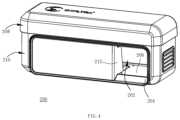
- FIG. 1is a perspective side view of an example rodent trap, according to an embodiment of the present invention.
- FIG. 2is an exploded perspective side view of the rodent trap of FIG. 1 , according to an embodiment of the present invention.
- FIG. 3is another exploded perspective view of the rodent trap of FIG. 1 , according to an embodiment of the present invention.
- FIG. 5is another perspective side view of the rodent trap of FIG. 4 , according to an embodiment of the present invention.
- FIG. 6is an exploded perspective view of the rodent trap of FIG. 4 , according to an embodiment of the present invention.
- FIG. 7is a perspective top view of a bottom portion of the rodent trap of FIG. 4 , according to an embodiment of the present invention.
- FIG. 8is a perspective bottom view of a top portion of the rodent trap of FIG. 4 , according to an embodiment of the present invention.
- FIG. 10is a sectional view of FIG. 5 along A-A, according to an embodiment of the present invention.
- the upper shell 11may include an indicator light 5 , a power switch 6 and a battery holder 1121 .
- the upper shell 11may include mounting legs 113 that are extended towards discharge plates 2 on the lower shell 12 .
- the mounting legs 113may be located on the sides of the cage 1 in pairs.
- the first infrared sensor 3 and the second infrared sensor 4may be located on the mounting legs 113 .
- the entrance 10may be located at the front end of the cage 1 , or on a sidewall near the rear end of the cage 1 , as shown in FIG. 4 .
- FIG. 2is an exploded perspective view of the rodent trap 100 , according to an embodiment of the present invention.
- the rodent trap 100comprises a control circuit board that may be placed inside a chamber formed by a mounting substrate 111 and a cover 112 that is covered on the mounting substrate 111 .
- the control circuit boardmay include a controller and a peripheral circuit electrically connected to the controller.
- the control circuit boardmay be provided with a plug capable of being electrically connected to an external power supply, or to a battery that may be mounted in the chamber to supply power to the control circuit board.
- the battery holder 1121may be located in the chamber.
- the battery holder 1121is electrically connected to the control circuit board, and one or more batteries can be connected to the control circuit board after the batteries are mounted in the battery holder 1121 . As an example, four batteries may be used for supplying power. Meanwhile, the battery holder 1121 may have a battery cover that can be detached.
- the indicator light 5may be embedded on the shell cover 112 , and the indicator light 5 may be electrically connected to the control circuit board, so that the operating state of the rodent trap 100 is indicated in response to the control circuit board. Additionally, the power switch 6 may be electrically connected to the control circuit board to control the turn-on or turn-off of the power.
- the entrance 10from which the rodent comes into the cage, may be formed in the rear end of the cage 1 .
- the first infrared sensor 3includes a first infrared emitter and a first infrared receiver which may be oppositely arranged on two sides in the cage 1 and electrically connected to the control circuit board.
- An infrared light beam emitted by the first infrared emitteris located above one of the discharge plates 2 .
- the infrared light beamcan be prevented from reaching the first infrared receiver by the rodent.
- the cage 1may have a bait region 101 for placing the bait.
- the bait region 101may include an opening 103 and a baffle 102 where the baffle 102 may be hinged to a wall of the cage 1 .
- the baffle 102may be covered on a placement port in order to prevent the rodent from escaping from the placement port. There may be one or more openings on the baffle 102 that can help spread the smell of the bait.
- the discharge plates 2may comprise a first discharge plate, a second discharge closer than the first discharge plate to the entrance, and a third discharge plate placed between the first discharge plate and the second discharge plate.
- the first discharge plate and the second discharge plateare short-circuited to each other, and the third discharge plate is not connected to the first discharge plate and the second discharge plate on the inner surface of the cage.
- Two discharge plates 2may be selectively disposed according to the length of the cage 1 , and these discharge plates 2 disposed on a soleplate inside the cage 1 and spaced apart from each other. Each discharge plate 2 being electrically connected to the control circuit board that is configured to establish a voltage between the discharge plates 2 .
- two discharge plates 2are provided.
- One of the discharge platesmay be a rectangular metal plate while the other discharge plate may have two metal plate bodies connected by an elongated metal strip. That is, the two metal plate bodies are short-circuited to each other.
- the elongated metal stripmay be part of one whole piece of metal plate, or a separate piece from the two metal plate bodies but connected with them by a conductive material.
- the rectangular metal platemay be placed between the two metal plate bodies.
- the elongated metal stripmay surround the rectangular metal plate but not be electrically connected to the rectangular metal plate.
- the first infrared emitter, the first infrared receiver, the second infrared emitter and the second infrared receiverare located respectively on the mounting legs 113 that are extended downward from the mounting substrate 111 .
- the first infrared emitter, the first infrared receiver, the second infrared emitter and the second infrared receivermay be arranged at lower ends of the mounting legs 113 .
- the first infrared emitter and the first infrared receivermay be oppositely arranged on a horizontal line, and the second infrared emitter and the second infrared receiver may be oppositely arranged on another horizontal line.
- the first infrared receivercan receive an infrared light beam signal emitted by the first infrared emitter when there is no obstacle between the first infrared emitter and the first infrared receiver.
- the second infrared receivercan receive an infrared light beam signal emitted by the second infrared emitter when there is no obstacle between them.
- the first infrared emitter and the first infrared receivermay be arranged on two sides in the cage 1 in such a way that the first infrared emitter and the first infrared receiver are close to the discharge plates but not in contact with the discharge plates 2 .
- a distance between the mounting legs 113 and the discharge plates 2is kept to prevent false alarms triggered by rodents that are not targeted by the present invention such as insects.
- the length of the mounting legs 113 near the entrance 10may be the same or shorter than the mounting legs 113 near the opening 103 .
- the first infrared sensor 3may be placed close to the bait region 101 .
- the first infrared sensor 3may be located near the bait region 101 and the second infrared sensor 4 may be closer to the entrance 10 than the first infrared sensor 3 .
- the first infrared sensor 3 and the second infrared sensor 4may supply signals to the control circuit separately. For example, when the rodent trap 100 is in activated and the first infrared sensor and the second infrared sensor are operating, a rodent or a person's arm comes into the cage 1 near the entrance 10 . The infrared light beam emitted by the second infrared sensor may be blocked by the rodent the person's arm. A voltage greater than 5000 V will be supplied to the discharge plates 2 only when the light beam emitted by the first infrared sensor is blocked, and simultaneously the second infrared receiver is receiving light beam signal from the second infrared sensor.
- the present inventionprovides a method of using the rodent trap 100 , the method comprises the following steps.
- the cage 1When the cage 1 is in an initial state in which no rodent comes into the cage 1 , the cage 1 is in a low-power-consumption standby state. Both the first infrared sensor 3 and the second infrared sensor 4 are not operating.
- Resistance signals on the adjacent pair of discharge plates 2are monitored.
- the electric resistance between the adjacent pair of discharge plates 2may change.
- the control circuit on the control circuit boardis woken up from the low-power-consumption standby state.
- the thresholdis of 1M ohms level, which is in the range of skin resistance of a rodent. It is determined that a rodent or an object comes into the cage when the change of resistance is detected.
- the first infrared sensor 3 and the second infrared sensor 4are activated to operate. That is, both the first infrared emitter and the second infrared emitter emit infrared light beams.
- the first infrared receiver and the second infrared receiverkeep receiving the infrared light beam from the first infrared emitter and the second infrared emitter correspondingly if there is no obstacle between the infrared emitters and the infrared receivers.
- the control circuit boardreceives signals from the first infrared sensor 3 and the second infrared sensor 4 indicating the light beams are in transmission or not.
- control circuit boardacquires a signal indicating that both the infrared light beam from the first infrared sensor 3 and the light beam from the second infrared sensor 4 are blocked or only the light beam from the second infrared sensor 4 is blocked, no high-voltage power (greater than 5000V) is supplied to the discharge plates 2 .
- the control circuit boardremains receiving signals from the first infrared sensor and the second infrared sensor. For instance, in a case that a rodent bigger than a mouse, for example a rabbit or cat, comes into the cage 1 or a person's arm comes into the cage 1 , the infrared light beam from the first infrared sensor 3 and the second infrared sensor 4 may be blocked.
- the control circuit boardreceives a signal indicating that only the infrared light beam from the first infrared sensor 3 is blocked, and simultaneously the second infrared receiver is able to receive an infrared light beam emitted from the second infrared emitter.
- the control circuit boardsupplies high-voltage power to the discharge plates 2 .
- the rodentis trapped in the cage 1 because of the high-voltage power.
- the high-voltage power supplied to the discharge plates 2may be in a range of 5000 V to 10000 V.
- the discharge time of supplying high-voltage power to the discharge plates 2may be adjusted under different circumstances. The discharge time may be 30 s to 120 s depending upon the operating voltage of the discharge plates 2 .
- FIG. 4is a perspective side view of a rodent trap 200 , according to an embodiment of the present invention.
- the rodent trap 200shares some common parts and designs with the rodent trap 100 while includes additional features that allow the rodent trap work in various outdoor environments. Detecting a resistance change between adjacent discharge plates may not be as sensitive under humid environment.
- the rodent trap 200includes a passive infrared sensor to run in the low-power-consumption standby mode, which is a supplemental mechanism to the resistance detection to activate a infrared sensor and then supply a high power voltage to discharge plates. The following description will focus on the differences and additional features of the rodent trap 200 .
- the rodent trapincludes a chamber 202 that is formed by a top portion 250 and a bottom portion 210 .
- the top portion 250(not shown) is covered by a waterproof cap 208
- FIG. 5is another perspective side view of rodent trap 200 with the top portion 250 visible.
- the waterproof cap 208can prevent water from entering the top portion 250 and the chamber 202 .
- the waterproof cap 208can be see through so that a user can see the flashing of indicator lights 266 and 267 (see FIG. 9 ).
- the rodent trap 200has an entrance 204 located on a side wall and near an end of the bottom portion 210 .
- the entrance 204can be located on either side of the bottom portion 210 .
- Discharge plates 206are placed within the chamber 202 .
- the discharged platesare connected to a power supply.
- the power supplycan be external batteries, a power bank, or a portable charger.
- the bottom portion 210may have a fence 212 extending from the side wall toward an interior of the chamber 202 .
- the fence 212may guide the rodent to enter the interior of the chamber 202 so that its motion can be detected.
- FIG. 6is an exploded perspective view of the rodent trap 200 , according to an embodiment of the present invention.
- the top portion 250may have mounting legs 258 extending downward.
- the mounting legscan be configured to host an infrared emitter and an infrared transmitter, respectively.
- the top portion 250may have a passive infrared sensor 256 .
- Other motion sensorsuch as an optical sensor, a camera, or a microwave motion detector can substitute the passive infrared sensor.
- the motion sensormay be covered by a Fresnel lens that does not allow visible light to pass through to avoid the interference of the visible light to the motion detector.
- the top portion 250may have a protruding block 260 to engage with the fence 212 .
- the protruding block 260may have a groove 270 in length and thickness that mates with the fence 212 .
- the top portion 250 and the bottom portion 210can be fixed when the fence 212 mates with the groove 270 .
- the discharge plates 260may include a first discharge plate near the entrance 204 , a second discharge plate adjacent to the bait region, and a third discharge plate between the first discharge plate and the second discharge plate.
- the first discharge plate and the second discharge plateare connected and short-circuited to each other.
- the discharge plates 206may include a first discharge plate having one end adjacent to the entrance and a second end adjacent to the bait region opposite the entrance.
- the discharge platesmay include a second discharge plate placed at a cutout between the two ends of the first discharge plate (see FIG. 6 ).
- FIG. 7is a perspective top view of the bottom portion 210 of the rodent trap 200 , according to an embodiment of the present invention.
- a bait region 216is located at another end of the chamber opposite the entrance.
- a vent outlet 218 next to the bait region 216can help send out the scent of a bait place inside the bait region 216 .
- the bottom portion 210may include a support 214 placed between the discharge plates 206 and a bottom surface of the bottom portion 210 .
- the support 214is configured to elevate the discharge plates 206 away from the bottom surface.
- the support 214can be a series of ribs that bear the discharge plates 206 placed on top. The elevated design can lower the chance of the discharge plates 206 in contact with the water entering the bottom portion 210 .
- FIG. 8is a perspective bottom view of the top portion 250 of the rodent trap 200 , according to an embodiment of the present invention.
- FIG. 9is an exploded perspective view of the top portion 250 of the rodent trap 200 , according to an embodiment of the present invention.
- the top portion 250may include a first top cover 252 and a second top cover 254 .
- a control circuit boardmay be placed inside the top portion 250 and covered by the first top cover 252 .
- the top portion 250may include two indicator lights 266 and 267 , and a power switch 264 .
- the control circuit boardmay be powered by batteries placed within the top portion 250 and covered by the second top cover 254 .
- the control circuit boardmay be connected to an external charger via USB port 262 .
- a cable plugged in the USB port 262can be placed under the second top cover 254 and through slot 268 .
- FIG. 10is a sectional view of FIG. 5 along A-A, according to an embodiment of the present invention.
- the passive infrared sensor 256when the rodent enters the chamber 202 , the passive infrared sensor 256 detects a motion and sends a motion signal to the control circuit board.
- the passive infrared sensor 256should be always on when the rodent trap 200 is in a low-power-consumption standby mode.
- the passive infrared sensor 256is close to the fence 212 and entrance 204 so that the passive infrared sensor 256 can detect the presence of the rodent immediately after the rodent entering the chamber 202 .
- the control circuit boardthen may release the high voltage to the discharge plates 206 right after the motion is detected.
- control circuit boardmay exit the standby mode, and activate the infrared sensor and wait for the rodent to get closer to the bait region.
- the rodentis ensured inside the chamber 202 .
- the control circuit boardsupplies high voltage to the discharge plates 206 .
- the rodent trap 200may include a wake-up module configured to detect an electric resistance change between the discharge plates 206 .
- the control circuit boardmay activate the infrared sensor upon the electric resistance between adjacent pair of discharge plates below a threshold.
- the thresholdmay be of 1M ohms level that is in the range of skin resistance of a rodent.
- S2a green light is on for one second, detect if the infrared beam transmission is blocked. If the infrared beam transmission is blocked, go to S4; otherwise, go to S5.
- S6a rodent enters chamber 202 , the passive infrared sensor detects a motion, or both the passive infrared sensor and the wake-up module detect the presence of the rodent.
- the control circuit boardreceives a signal indicating the presence of the rodent, exits the standby mode and activate the infrared sensor.
- S7check the infrared beam transmission. If the infrared beam transmission is interrupted, go to S8; otherwise, go to S9.
- S9check if there is an overtime.
- An overcomemeans the control circuit board cannot detect interruption signal starting from exiting standby mode until a pre-determined time. If an overtime is detected, go to S5; otherwise, go to S6.
Landscapes
- Life Sciences & Earth Sciences (AREA)
- Pest Control & Pesticides (AREA)
- Engineering & Computer Science (AREA)
- Insects & Arthropods (AREA)
- Wood Science & Technology (AREA)
- Zoology (AREA)
- Environmental Sciences (AREA)
- Catching Or Destruction (AREA)
Abstract
Description
Claims (20)
Priority Applications (1)
| Application Number | Priority Date | Filing Date | Title |
|---|---|---|---|
| US18/049,847US12274256B2 (en) | 2019-09-12 | 2022-10-26 | Rodent trap and method of using it |
Applications Claiming Priority (7)
| Application Number | Priority Date | Filing Date | Title |
|---|---|---|---|
| CN201910867252.7ACN110463683B (en) | 2019-09-12 | 2019-09-12 | Mousetrap and method of using the mousetrap |
| CN201910867252.7 | 2019-09-12 | ||
| US16/801,076US11464222B2 (en) | 2019-09-12 | 2020-02-25 | Rodent trap and method of using it |
| US17/495,647US20220039371A1 (en) | 2019-09-12 | 2021-10-06 | Rodent trap and method of using it |
| CN202122616809.5 | 2021-10-26 | ||
| CN202122616809.5UCN216164742U (en) | 2021-10-26 | 2021-10-26 | Rodent trapping and killing device |
| US18/049,847US12274256B2 (en) | 2019-09-12 | 2022-10-26 | Rodent trap and method of using it |
Related Parent Applications (1)
| Application Number | Title | Priority Date | Filing Date |
|---|---|---|---|
| US17/495,647Continuation-In-PartUS20220039371A1 (en) | 2019-09-12 | 2021-10-06 | Rodent trap and method of using it |
Publications (2)
| Publication Number | Publication Date |
|---|---|
| US20230066844A1 US20230066844A1 (en) | 2023-03-02 |
| US12274256B2true US12274256B2 (en) | 2025-04-15 |
Family
ID=85288058
Family Applications (1)
| Application Number | Title | Priority Date | Filing Date |
|---|---|---|---|
| US18/049,847Active2040-09-17US12274256B2 (en) | 2019-09-12 | 2022-10-26 | Rodent trap and method of using it |
Country Status (1)
| Country | Link |
|---|---|
| US (1) | US12274256B2 (en) |
Families Citing this family (8)
| Publication number | Priority date | Publication date | Assignee | Title |
|---|---|---|---|---|
| GB2578312B (en)* | 2018-10-22 | 2022-02-23 | Brandenburg Uk Ltd | Rodent trap and rodent management |
| JP7329058B2 (en)* | 2019-03-25 | 2023-08-17 | スイスインノ ソリューションズ アーゲー | Animal trap for killing animals, method of preventing unwanted electrical shock from animal traps, and use of shielding in electric animal traps |
| GB201913055D0 (en)* | 2019-09-10 | 2019-10-23 | Stv Int Ltd | Pest VCapture apparatus and method |
| KR20230114271A (en)* | 2020-11-20 | 2023-08-01 | 캐치 데이터 아이피 홀딩스 엘티디. | Methods and devices for controlling animal pests |
| US20240415108A1 (en)* | 2023-04-18 | 2024-12-19 | Catch Data Ip Holdings Ltd. | Method and apparatus for controlling pest animals |
| CN117158400A (en)* | 2023-10-09 | 2023-12-05 | 新疆农业科学院植物保护研究所 | An intelligent rat trapping device with double protection |
| USD1080796S1 (en)* | 2024-07-12 | 2025-06-24 | Zhenxiang Zhao | Mousetrap |
| US12376580B1 (en)* | 2024-08-19 | 2025-08-05 | Shenzhen Visson Technology Co., Ltd. | Mouse trap |
Citations (84)
| Publication number | Priority date | Publication date | Assignee | Title |
|---|---|---|---|---|
| US3815278A (en)* | 1971-08-05 | 1974-06-11 | A Beaton | Automatic electro-mechanical rodent trap |
| US4612724A (en)* | 1984-07-08 | 1986-09-23 | Alboainin Ali H A | Rodent control apparatus |
| US5560146A (en)* | 1994-05-23 | 1996-10-01 | Garro; Daniel F. | Automatic trap for catching cockroaches |
| US5815982A (en)* | 1996-11-14 | 1998-10-06 | Garretson; John E. | Automatic insect trap using infrared beam of radiation |
| US5918409A (en)* | 1998-06-15 | 1999-07-06 | Carnwath; James R. | Self clearing tunnel rat trap |
| US5953853A (en)* | 1997-03-31 | 1999-09-21 | Kim; Bok M. | Mouse and rat trap |
| US6016623A (en)* | 1998-10-08 | 2000-01-25 | Celestine; Wallace | Rodent trap |
| US6202340B1 (en)* | 1999-08-18 | 2001-03-20 | Joniel Nieves | Electronically actuated animal trap |
| US6445301B1 (en)* | 2000-09-12 | 2002-09-03 | Liphatech, Inc. | Electronic pest monitoring system and method |
| US20030131522A1 (en)* | 2002-01-14 | 2003-07-17 | Swift David W. | Electronic animal trap |
| US6735899B1 (en)* | 2002-12-17 | 2004-05-18 | Woodstream Corporation | Animal trap |
| US6807767B1 (en)* | 2003-10-22 | 2004-10-26 | James Frederick Schade | Small animal trap with infrared trigger |
| US6865843B1 (en)* | 2003-10-23 | 2005-03-15 | Charles Jordan, Sr. | Portable electrical mouse trap |
| US20050097808A1 (en)* | 2003-09-12 | 2005-05-12 | Vorhies James F. | Humane tubular trap, remote trap monitoring system and method and programs for monitoring multiple traps |
| US20050235553A1 (en)* | 2004-04-27 | 2005-10-27 | Rail Kenneth D | Rodent elimination system |
| US20060032110A1 (en)* | 2004-08-16 | 2006-02-16 | Keng-Ming Yang | Trapping device |
| US20060123693A1 (en)* | 2002-10-02 | 2006-06-15 | Frank Muller | Electrocution animal trap with a sender |
| US20060150470A1 (en)* | 2003-06-16 | 2006-07-13 | Per Ronnau | Pest control system |
| US20060265941A1 (en)* | 2003-10-14 | 2006-11-30 | John Newton | Pest detection apparatus |
| US7219466B2 (en)* | 2003-09-03 | 2007-05-22 | Woodstream Corporation | CPU-controlled, rearming electronic animal trap with three-killing-plate configuration |
| WO2007123755A2 (en)* | 2006-04-04 | 2007-11-01 | Agrizap, Inc. | Pest electrocution device with infrared detector |
| US20080236023A1 (en)* | 2007-03-28 | 2008-10-02 | Ecolab Inc. | Automated pest-trapping device |
| US20090172995A1 (en)* | 2008-01-03 | 2009-07-09 | Wetzel Troy A | Rearming electronic animal trap with infrared sensor and multiple-killing-plate configuration |
| US20090205244A1 (en)* | 2008-02-20 | 2009-08-20 | Pomerantz Joseph L | Humane animal trap |
| US20090313880A1 (en)* | 2008-06-18 | 2009-12-24 | Alan Weir Bucher | Electrocuting mouse trap with automatic chamber-clearing mechanism |
| US7690147B2 (en)* | 2007-07-09 | 2010-04-06 | Woodstream Corporation | Rearming electronic animal trap with baffle, mechanical switch and multiple-killing-plate configuration |
| US20100146839A1 (en)* | 2008-06-18 | 2010-06-17 | Cruz Robert T | Electrocuting mouse trap with automatic chamber-clearing mechanism and access control mechanism |
| US20110109460A1 (en)* | 2009-11-11 | 2011-05-12 | Nisus Corporation | Animal Control System |
| US20110138676A1 (en)* | 2009-12-10 | 2011-06-16 | Frank Moustirats | Humane animal trap |
| US8099900B2 (en)* | 2009-03-18 | 2012-01-24 | Adrian Rivera | Method for pest electrocution with disposable container |
| CN102524235A (en)* | 2012-02-23 | 2012-07-04 | 成都理工大学 | Mousing/deratization electric fence device |
| US20120285075A1 (en)* | 2011-03-02 | 2012-11-15 | Woodstream Corporation | Mousetrap with disposable, hermetically sealing cartridge and internal high-voltage killing mechanism |
| US8365995B2 (en)* | 2008-04-03 | 2013-02-05 | National Taiwan University | Multi-checkpoint type clustered fruit fly counting device |
| CN102939952A (en)* | 2012-11-20 | 2013-02-27 | 无锡商业职业技术学院 | Electrically-controlled mouse trap |
| CN103081890A (en)* | 2013-01-18 | 2013-05-08 | 宁波市鄞州宏远电子有限公司 | Mousetrap and mouse catching method thereof |
| US20130174469A1 (en)* | 2012-01-10 | 2013-07-11 | Richard Kittelson | Motion Activated Non-Lethal Animal Trap |
| US20140018051A1 (en)* | 2011-04-05 | 2014-01-16 | Abraham Frojmovics | Method and system for monitoring and communicating the status of traps for vermin or pests |
| US20140013649A1 (en)* | 2009-03-18 | 2014-01-16 | Adrian Rivera | Nestable Disposable Container for Pest Electrocution |
| US20140055270A1 (en)* | 2012-08-27 | 2014-02-27 | Perry Le Pews Wildlife Management LLC | Methods and Systems for Humane Capture, Maintenance, and Release of Wildlife |
| US20140283435A1 (en)* | 2011-11-01 | 2014-09-25 | Attax Dedetização Desratização S/C Ltda. Me | Method and system for controlling and eliminating pests |
| CN104222062A (en)* | 2014-09-12 | 2014-12-24 | 李欲晓 | Mousetrap |
| US20150150236A1 (en)* | 2012-05-29 | 2015-06-04 | Animal Deterrent System Ltd. | Multiple-use vermin trap apparatus, method and system |
| CN204466718U (en)* | 2015-02-06 | 2015-07-15 | 侯贤飞 | A kind of safe and reliable high pressure Mouse killing trap |
| CN105028381A (en)* | 2015-07-09 | 2015-11-11 | 冯晓明 | Invisible continuous mousetrap |
| US20150351378A1 (en)* | 2014-06-06 | 2015-12-10 | James Frankland ZERO | Self emptying rat trap for dumpsters and residential waste carts |
| US20160277688A1 (en)* | 2015-03-18 | 2016-09-22 | The Samuel Roberts Noble Foundation, Inc. | Low-light trail camera |
| US20160302402A1 (en)* | 2013-12-02 | 2016-10-20 | Wisecon A/S | Trap |
| US20170035040A1 (en)* | 2015-08-03 | 2017-02-09 | Michael T. Hobbs | Drift fence camera trap |
| US20170035041A1 (en)* | 2013-12-18 | 2017-02-09 | Rentokil Initial Plc | Bait station for pest control |
| US20170215407A1 (en)* | 2016-02-03 | 2017-08-03 | Jackson Innovations, LLC | Pest trap monitor |
| US20170231215A1 (en)* | 2016-02-14 | 2017-08-17 | Patrick Barton | Method and Apparatus for Automated Animal Trapping |
| CN107047525A (en)* | 2017-01-09 | 2017-08-18 | 湖北科技学院 | A kind of low cost it is non-maintaining can continuous mouse catching mousetrap |
| CN207167550U (en)* | 2017-09-22 | 2018-04-03 | 宋家峰 | A kind of infrared induction electronic mousetrap |
| US20180139949A1 (en)* | 2017-10-24 | 2018-05-24 | Yu-Chen Liu | Electric mousetrap with intelligent detection and safety protection functions |
| US20180199565A1 (en)* | 2015-07-21 | 2018-07-19 | Smart Wave Technologies Corp. | Pest Control Monitoring System |
| US20180249699A1 (en)* | 2017-03-02 | 2018-09-06 | Woodstream Corporation | Self-arming electronic rodent trap and system and method for use thereof |
| US20180325093A1 (en)* | 2017-05-10 | 2018-11-15 | Vm Products, Inc. | Pest-management assemblies and/or components for pest management assemblies |
| CN208318079U (en)* | 2018-04-19 | 2019-01-04 | 林廷昕 | Double-door intelligent mousetrap |
| US20190029246A1 (en)* | 2017-06-29 | 2019-01-31 | Woodstream Corporation | Electronic rat trap with internal barrier structure |
| CN208798587U (en)* | 2018-08-12 | 2019-04-30 | 贵州省剑河民族中学 | A kind of binary channels infrared ray mousetrap |
| JP2019076024A (en)* | 2017-10-25 | 2019-05-23 | 三重県 | Automatic trapping device of large harmful animal |
| CN109938002A (en)* | 2017-12-20 | 2019-06-28 | 宋丽芸 | A kind of rat clamper |
| CN110463683A (en)* | 2019-09-12 | 2019-11-19 | 宁波立格科技有限公司 | A kind of application method of mousetrap and mousetrap |
| US20190364876A1 (en)* | 2018-02-12 | 2019-12-05 | Woodstream Corporation | Electronic rodent traps with remote monitoring capability |
| US20200253187A1 (en)* | 2019-02-08 | 2020-08-13 | Jace Files | Pest trap with disposable container and wireless monitoring |
| CN212660934U (en)* | 2020-07-09 | 2021-03-09 | 韩吉平 | Double-emitting type double-infrared mouse trapping device |
| WO2021070153A1 (en)* | 2019-10-11 | 2021-04-15 | Brandenburg Connect Limited | Animal detection |
| CN112970724A (en)* | 2021-02-05 | 2021-06-18 | 山东大学 | Automatic pest killing device, system and method |
| CN213639426U (en)* | 2020-11-09 | 2021-07-09 | 湖南省创卫生物防治有限责任公司 | Mouse trapping box |
| CN113375769A (en)* | 2021-06-30 | 2021-09-10 | 于德波 | Intelligent rodent control system |
| CN215012967U (en)* | 2021-06-30 | 2021-12-07 | 烟台卫达环境科技有限公司 | Intelligent bait storehouse of accuse is prevented to rodent |
| CN215123666U (en)* | 2021-07-22 | 2021-12-14 | 刘国辉 | Multifunctional automatic electric mouse cage |
| US20220039369A1 (en)* | 2020-08-05 | 2022-02-10 | The United States Of America, As Represented By The Secretary Of Agriculture | Electromechanical pest animal suppression trap |
| US20220071193A1 (en)* | 2019-02-18 | 2022-03-10 | Bayer Aktiengesellschaft | An animal capture system |
| CN114451395A (en)* | 2021-06-30 | 2022-05-10 | 烟台卫达环境科技有限公司 | Mouse prevention and control method |
| US20220225605A1 (en)* | 2017-11-20 | 2022-07-21 | Dennis LaRoque | Smart micro-mouse rat trap |
| US20220232817A1 (en)* | 2021-01-28 | 2022-07-28 | Adolfo Gabriel Fuligni | Electromechanical trap for small animals |
| US20220338460A1 (en)* | 2020-10-13 | 2022-10-27 | Hongqin Liu | Mousetrap |
| US20230064810A1 (en)* | 2021-08-27 | 2023-03-02 | Shenzhen Palaza Technology Co., Ltd. | Electric rat killer |
| US20230130763A1 (en)* | 2021-10-21 | 2023-04-27 | Maximiliano Lucas Schlichter | Mouse trap |
| US20230189780A1 (en)* | 2020-05-13 | 2023-06-22 | Syngenta Crop Protection Ag | A pest monitoring device |
| US20230309546A1 (en)* | 2020-11-20 | 2023-10-05 | Catch Data Ltd. | Method and apparatus for controlling pest animals |
| US12010985B2 (en)* | 2018-10-22 | 2024-06-18 | Caucus Limited | Rodent trap and rodent management |
| US20240415108A1 (en)* | 2023-04-18 | 2024-12-19 | Catch Data Ip Holdings Ltd. | Method and apparatus for controlling pest animals |
- 2022
- 2022-10-26USUS18/049,847patent/US12274256B2/enactiveActive
Patent Citations (95)
| Publication number | Priority date | Publication date | Assignee | Title |
|---|---|---|---|---|
| US3815278A (en)* | 1971-08-05 | 1974-06-11 | A Beaton | Automatic electro-mechanical rodent trap |
| US4612724A (en)* | 1984-07-08 | 1986-09-23 | Alboainin Ali H A | Rodent control apparatus |
| US5560146A (en)* | 1994-05-23 | 1996-10-01 | Garro; Daniel F. | Automatic trap for catching cockroaches |
| US5815982A (en)* | 1996-11-14 | 1998-10-06 | Garretson; John E. | Automatic insect trap using infrared beam of radiation |
| US5953853A (en)* | 1997-03-31 | 1999-09-21 | Kim; Bok M. | Mouse and rat trap |
| US5918409A (en)* | 1998-06-15 | 1999-07-06 | Carnwath; James R. | Self clearing tunnel rat trap |
| US6016623A (en)* | 1998-10-08 | 2000-01-25 | Celestine; Wallace | Rodent trap |
| US6202340B1 (en)* | 1999-08-18 | 2001-03-20 | Joniel Nieves | Electronically actuated animal trap |
| US6445301B1 (en)* | 2000-09-12 | 2002-09-03 | Liphatech, Inc. | Electronic pest monitoring system and method |
| US20030131522A1 (en)* | 2002-01-14 | 2003-07-17 | Swift David W. | Electronic animal trap |
| US20060123693A1 (en)* | 2002-10-02 | 2006-06-15 | Frank Muller | Electrocution animal trap with a sender |
| US6735899B1 (en)* | 2002-12-17 | 2004-05-18 | Woodstream Corporation | Animal trap |
| US20060150470A1 (en)* | 2003-06-16 | 2006-07-13 | Per Ronnau | Pest control system |
| US7219466B2 (en)* | 2003-09-03 | 2007-05-22 | Woodstream Corporation | CPU-controlled, rearming electronic animal trap with three-killing-plate configuration |
| US20050097808A1 (en)* | 2003-09-12 | 2005-05-12 | Vorhies James F. | Humane tubular trap, remote trap monitoring system and method and programs for monitoring multiple traps |
| US20060265941A1 (en)* | 2003-10-14 | 2006-11-30 | John Newton | Pest detection apparatus |
| US6807767B1 (en)* | 2003-10-22 | 2004-10-26 | James Frederick Schade | Small animal trap with infrared trigger |
| US6865843B1 (en)* | 2003-10-23 | 2005-03-15 | Charles Jordan, Sr. | Portable electrical mouse trap |
| US20050235553A1 (en)* | 2004-04-27 | 2005-10-27 | Rail Kenneth D | Rodent elimination system |
| US20060032110A1 (en)* | 2004-08-16 | 2006-02-16 | Keng-Ming Yang | Trapping device |
| WO2007123755A2 (en)* | 2006-04-04 | 2007-11-01 | Agrizap, Inc. | Pest electrocution device with infrared detector |
| US20090102600A1 (en)* | 2006-04-04 | 2009-04-23 | Noe Robert G | Pest Electrocution Device with Infrared Detector |
| US10143193B2 (en)* | 2006-04-04 | 2018-12-04 | Robert G. Noe | Pest electrocution device with infrared detector |
| US20080236023A1 (en)* | 2007-03-28 | 2008-10-02 | Ecolab Inc. | Automated pest-trapping device |
| US7690147B2 (en)* | 2007-07-09 | 2010-04-06 | Woodstream Corporation | Rearming electronic animal trap with baffle, mechanical switch and multiple-killing-plate configuration |
| US20090172995A1 (en)* | 2008-01-03 | 2009-07-09 | Wetzel Troy A | Rearming electronic animal trap with infrared sensor and multiple-killing-plate configuration |
| US7757430B2 (en)* | 2008-01-03 | 2010-07-20 | Woodstream Corporation | Rearming electronic animal trap with infrared sensor and multiple-killing-plate configuration |
| US8024888B2 (en)* | 2008-01-03 | 2011-09-27 | Woodstream Corporation | Rearming electronic animal trap with infrared sensor and multiple-killing-plate configuration |
| US20090205244A1 (en)* | 2008-02-20 | 2009-08-20 | Pomerantz Joseph L | Humane animal trap |
| US8365995B2 (en)* | 2008-04-03 | 2013-02-05 | National Taiwan University | Multi-checkpoint type clustered fruit fly counting device |
| US20100146839A1 (en)* | 2008-06-18 | 2010-06-17 | Cruz Robert T | Electrocuting mouse trap with automatic chamber-clearing mechanism and access control mechanism |
| US20090313880A1 (en)* | 2008-06-18 | 2009-12-24 | Alan Weir Bucher | Electrocuting mouse trap with automatic chamber-clearing mechanism |
| US8099900B2 (en)* | 2009-03-18 | 2012-01-24 | Adrian Rivera | Method for pest electrocution with disposable container |
| US20140013649A1 (en)* | 2009-03-18 | 2014-01-16 | Adrian Rivera | Nestable Disposable Container for Pest Electrocution |
| US20110109460A1 (en)* | 2009-11-11 | 2011-05-12 | Nisus Corporation | Animal Control System |
| US20110138676A1 (en)* | 2009-12-10 | 2011-06-16 | Frank Moustirats | Humane animal trap |
| US20120285075A1 (en)* | 2011-03-02 | 2012-11-15 | Woodstream Corporation | Mousetrap with disposable, hermetically sealing cartridge and internal high-voltage killing mechanism |
| US20140018051A1 (en)* | 2011-04-05 | 2014-01-16 | Abraham Frojmovics | Method and system for monitoring and communicating the status of traps for vermin or pests |
| US20140283435A1 (en)* | 2011-11-01 | 2014-09-25 | Attax Dedetização Desratização S/C Ltda. Me | Method and system for controlling and eliminating pests |
| US20130174469A1 (en)* | 2012-01-10 | 2013-07-11 | Richard Kittelson | Motion Activated Non-Lethal Animal Trap |
| CN102524235A (en)* | 2012-02-23 | 2012-07-04 | 成都理工大学 | Mousing/deratization electric fence device |
| US20150150236A1 (en)* | 2012-05-29 | 2015-06-04 | Animal Deterrent System Ltd. | Multiple-use vermin trap apparatus, method and system |
| US20140055270A1 (en)* | 2012-08-27 | 2014-02-27 | Perry Le Pews Wildlife Management LLC | Methods and Systems for Humane Capture, Maintenance, and Release of Wildlife |
| CN102939952A (en)* | 2012-11-20 | 2013-02-27 | 无锡商业职业技术学院 | Electrically-controlled mouse trap |
| CN103081890A (en)* | 2013-01-18 | 2013-05-08 | 宁波市鄞州宏远电子有限公司 | Mousetrap and mouse catching method thereof |
| US20160302402A1 (en)* | 2013-12-02 | 2016-10-20 | Wisecon A/S | Trap |
| US20170035041A1 (en)* | 2013-12-18 | 2017-02-09 | Rentokil Initial Plc | Bait station for pest control |
| US20150351378A1 (en)* | 2014-06-06 | 2015-12-10 | James Frankland ZERO | Self emptying rat trap for dumpsters and residential waste carts |
| CN104222062A (en)* | 2014-09-12 | 2014-12-24 | 李欲晓 | Mousetrap |
| CN204466718U (en)* | 2015-02-06 | 2015-07-15 | 侯贤飞 | A kind of safe and reliable high pressure Mouse killing trap |
| US20160277688A1 (en)* | 2015-03-18 | 2016-09-22 | The Samuel Roberts Noble Foundation, Inc. | Low-light trail camera |
| CN105028381A (en)* | 2015-07-09 | 2015-11-11 | 冯晓明 | Invisible continuous mousetrap |
| US20180199565A1 (en)* | 2015-07-21 | 2018-07-19 | Smart Wave Technologies Corp. | Pest Control Monitoring System |
| US20170035040A1 (en)* | 2015-08-03 | 2017-02-09 | Michael T. Hobbs | Drift fence camera trap |
| US11083188B2 (en)* | 2016-02-03 | 2021-08-10 | Kness Mfg. Co., Inc. | Pest trap monitor |
| US20170215407A1 (en)* | 2016-02-03 | 2017-08-03 | Jackson Innovations, LLC | Pest trap monitor |
| US20170231215A1 (en)* | 2016-02-14 | 2017-08-17 | Patrick Barton | Method and Apparatus for Automated Animal Trapping |
| CN107047525A (en)* | 2017-01-09 | 2017-08-18 | 湖北科技学院 | A kind of low cost it is non-maintaining can continuous mouse catching mousetrap |
| US20180249699A1 (en)* | 2017-03-02 | 2018-09-06 | Woodstream Corporation | Self-arming electronic rodent trap and system and method for use thereof |
| WO2018160831A1 (en)* | 2017-03-02 | 2018-09-07 | Woodstream Corporation | Self-arming electronic rodent trap and system and method for use thereof |
| US11564385B2 (en)* | 2017-03-02 | 2023-01-31 | Woodstream Corporation | Self-arming electronic rodent trap and system and method for use thereof |
| US20180325093A1 (en)* | 2017-05-10 | 2018-11-15 | Vm Products, Inc. | Pest-management assemblies and/or components for pest management assemblies |
| US20190029246A1 (en)* | 2017-06-29 | 2019-01-31 | Woodstream Corporation | Electronic rat trap with internal barrier structure |
| CN207167550U (en)* | 2017-09-22 | 2018-04-03 | 宋家峰 | A kind of infrared induction electronic mousetrap |
| US20180139949A1 (en)* | 2017-10-24 | 2018-05-24 | Yu-Chen Liu | Electric mousetrap with intelligent detection and safety protection functions |
| JP2019076024A (en)* | 2017-10-25 | 2019-05-23 | 三重県 | Automatic trapping device of large harmful animal |
| JP6973715B2 (en)* | 2017-10-25 | 2021-12-01 | 三重県 | Automatic capture device for large pests |
| US20220225605A1 (en)* | 2017-11-20 | 2022-07-21 | Dennis LaRoque | Smart micro-mouse rat trap |
| CN109938002A (en)* | 2017-12-20 | 2019-06-28 | 宋丽芸 | A kind of rat clamper |
| US20190364876A1 (en)* | 2018-02-12 | 2019-12-05 | Woodstream Corporation | Electronic rodent traps with remote monitoring capability |
| CN208318079U (en)* | 2018-04-19 | 2019-01-04 | 林廷昕 | Double-door intelligent mousetrap |
| CN208798587U (en)* | 2018-08-12 | 2019-04-30 | 贵州省剑河民族中学 | A kind of binary channels infrared ray mousetrap |
| US12010985B2 (en)* | 2018-10-22 | 2024-06-18 | Caucus Limited | Rodent trap and rodent management |
| US20200253187A1 (en)* | 2019-02-08 | 2020-08-13 | Jace Files | Pest trap with disposable container and wireless monitoring |
| US20220071193A1 (en)* | 2019-02-18 | 2022-03-10 | Bayer Aktiengesellschaft | An animal capture system |
| US11464222B2 (en)* | 2019-09-12 | 2022-10-11 | Owltra Tech Co. Ltd. | Rodent trap and method of using it |
| US20200187486A1 (en)* | 2019-09-12 | 2020-06-18 | Owltra Tech Co., Ltd. | Rodent Trap and Method of Using It |
| CN110463683A (en)* | 2019-09-12 | 2019-11-19 | 宁波立格科技有限公司 | A kind of application method of mousetrap and mousetrap |
| WO2021070153A1 (en)* | 2019-10-11 | 2021-04-15 | Brandenburg Connect Limited | Animal detection |
| US20230189780A1 (en)* | 2020-05-13 | 2023-06-22 | Syngenta Crop Protection Ag | A pest monitoring device |
| CN212660934U (en)* | 2020-07-09 | 2021-03-09 | 韩吉平 | Double-emitting type double-infrared mouse trapping device |
| US20220039369A1 (en)* | 2020-08-05 | 2022-02-10 | The United States Of America, As Represented By The Secretary Of Agriculture | Electromechanical pest animal suppression trap |
| US20220338460A1 (en)* | 2020-10-13 | 2022-10-27 | Hongqin Liu | Mousetrap |
| CN213639426U (en)* | 2020-11-09 | 2021-07-09 | 湖南省创卫生物防治有限责任公司 | Mouse trapping box |
| US20230309546A1 (en)* | 2020-11-20 | 2023-10-05 | Catch Data Ltd. | Method and apparatus for controlling pest animals |
| US12089583B2 (en)* | 2020-11-20 | 2024-09-17 | Catch Data Ip Holdings Ltd. | Method and apparatus for controlling pest animals |
| US20220232817A1 (en)* | 2021-01-28 | 2022-07-28 | Adolfo Gabriel Fuligni | Electromechanical trap for small animals |
| CN112970724A (en)* | 2021-02-05 | 2021-06-18 | 山东大学 | Automatic pest killing device, system and method |
| CN114451395A (en)* | 2021-06-30 | 2022-05-10 | 烟台卫达环境科技有限公司 | Mouse prevention and control method |
| CN215012967U (en)* | 2021-06-30 | 2021-12-07 | 烟台卫达环境科技有限公司 | Intelligent bait storehouse of accuse is prevented to rodent |
| CN113375769A (en)* | 2021-06-30 | 2021-09-10 | 于德波 | Intelligent rodent control system |
| CN215123666U (en)* | 2021-07-22 | 2021-12-14 | 刘国辉 | Multifunctional automatic electric mouse cage |
| US20230064810A1 (en)* | 2021-08-27 | 2023-03-02 | Shenzhen Palaza Technology Co., Ltd. | Electric rat killer |
| US20230130763A1 (en)* | 2021-10-21 | 2023-04-27 | Maximiliano Lucas Schlichter | Mouse trap |
| US20240415108A1 (en)* | 2023-04-18 | 2024-12-19 | Catch Data Ip Holdings Ltd. | Method and apparatus for controlling pest animals |
Also Published As
| Publication number | Publication date |
|---|---|
| US20230066844A1 (en) | 2023-03-02 |
Similar Documents
| Publication | Publication Date | Title |
|---|---|---|
| US12274256B2 (en) | Rodent trap and method of using it | |
| US20220039371A1 (en) | Rodent trap and method of using it | |
| RU2322807C2 (en) | Central processing unit controlled, re-armed high-voltage output circuit for electronic animal trap | |
| US8024888B2 (en) | Rearming electronic animal trap with infrared sensor and multiple-killing-plate configuration | |
| US10143193B2 (en) | Pest electrocution device with infrared detector | |
| EP2014160B1 (en) | Rearming electronic animal trap with baffle, mechanical switch and multiple-killing-plate configuration | |
| US12171211B2 (en) | Adaptive active infrared sensor hardware and software in the detection of pests with pest detection station | |
| KR20080109307A (en) | Pest capture device | |
| CN211185601U (en) | Mouse trap | |
| CN112189656A (en) | Intelligent mouse blocking board for internet of things | |
| HK40063793A (en) | Adaptive active infrared sensor hardware and software in the detection of pests with pest detection station | |
| KR20080109306A (en) | Pest detection device | |
| AU4447299A (en) | Alarm | |
| HK1126351B (en) | Rearming electronic animal trap |
Legal Events
| Date | Code | Title | Description |
|---|---|---|---|
| FEPP | Fee payment procedure | Free format text:ENTITY STATUS SET TO UNDISCOUNTED (ORIGINAL EVENT CODE: BIG.); ENTITY STATUS OF PATENT OWNER: SMALL ENTITY | |
| FEPP | Fee payment procedure | Free format text:ENTITY STATUS SET TO SMALL (ORIGINAL EVENT CODE: SMAL); ENTITY STATUS OF PATENT OWNER: SMALL ENTITY | |
| STPP | Information on status: patent application and granting procedure in general | Free format text:DOCKETED NEW CASE - READY FOR EXAMINATION | |
| STPP | Information on status: patent application and granting procedure in general | Free format text:NON FINAL ACTION MAILED | |
| STPP | Information on status: patent application and granting procedure in general | Free format text:RESPONSE TO NON-FINAL OFFICE ACTION ENTERED AND FORWARDED TO EXAMINER | |
| STPP | Information on status: patent application and granting procedure in general | Free format text:NOTICE OF ALLOWANCE MAILED -- APPLICATION RECEIVED IN OFFICE OF PUBLICATIONS | |
| AS | Assignment | Owner name:OWLTRA TECH CO., LTD., COLORADO Free format text:ASSIGNMENT OF ASSIGNORS INTEREST;ASSIGNOR:CHEN, HONGGUANG;REEL/FRAME:070509/0226 Effective date:20200304 | |
| STCF | Information on status: patent grant | Free format text:PATENTED CASE | |
| AS | Assignment | Owner name:OWLTRA TECH CO., LTD., COLORADO Free format text:ASSIGNMENT OF ASSIGNORS INTEREST;ASSIGNOR:CHEN, HONGGUANG;REEL/FRAME:070809/0426 Effective date:20250410 | |
| CC | Certificate of correction |