US12268472B2 - Anatomical surface assessment methods, devices and systems - Google Patents
Anatomical surface assessment methods, devices and systemsDownload PDFInfo
- Publication number
- US12268472B2 US12268472B2US17/398,883US202117398883AUS12268472B2US 12268472 B2US12268472 B2US 12268472B2US 202117398883 AUS202117398883 AUS 202117398883AUS 12268472 B2US12268472 B2US 12268472B2
- Authority
- US
- United States
- Prior art keywords
- camera
- patient
- image
- skin surface
- guide
- Prior art date
- Legal status (The legal status is an assumption and is not a legal conclusion. Google has not performed a legal analysis and makes no representation as to the accuracy of the status listed.)
- Active
Links
Images


Classifications
- A—HUMAN NECESSITIES
- A61—MEDICAL OR VETERINARY SCIENCE; HYGIENE
- A61B—DIAGNOSIS; SURGERY; IDENTIFICATION
- A61B5/00—Measuring for diagnostic purposes; Identification of persons
- A61B5/0059—Measuring for diagnostic purposes; Identification of persons using light, e.g. diagnosis by transillumination, diascopy, fluorescence
- A61B5/0077—Devices for viewing the surface of the body, e.g. camera, magnifying lens
- A—HUMAN NECESSITIES
- A61—MEDICAL OR VETERINARY SCIENCE; HYGIENE
- A61B—DIAGNOSIS; SURGERY; IDENTIFICATION
- A61B5/00—Measuring for diagnostic purposes; Identification of persons
- A61B5/0002—Remote monitoring of patients using telemetry, e.g. transmission of vital signals via a communication network
- A61B5/0015—Remote monitoring of patients using telemetry, e.g. transmission of vital signals via a communication network characterised by features of the telemetry system
- A61B5/002—Monitoring the patient using a local or closed circuit, e.g. in a room or building
- A—HUMAN NECESSITIES
- A61—MEDICAL OR VETERINARY SCIENCE; HYGIENE
- A61B—DIAGNOSIS; SURGERY; IDENTIFICATION
- A61B5/00—Measuring for diagnostic purposes; Identification of persons
- A61B5/44—Detecting, measuring or recording for evaluating the integumentary system, e.g. skin, hair or nails
- A61B5/441—Skin evaluation, e.g. for skin disorder diagnosis
- A61B5/445—Evaluating skin irritation or skin trauma, e.g. rash, eczema, wound, bed sore
- A—HUMAN NECESSITIES
- A61—MEDICAL OR VETERINARY SCIENCE; HYGIENE
- A61B—DIAGNOSIS; SURGERY; IDENTIFICATION
- A61B5/00—Measuring for diagnostic purposes; Identification of persons
- A61B5/68—Arrangements of detecting, measuring or recording means, e.g. sensors, in relation to patient
- A61B5/6801—Arrangements of detecting, measuring or recording means, e.g. sensors, in relation to patient specially adapted to be attached to or worn on the body surface
- A61B5/6844—Monitoring or controlling distance between sensor and tissue
- A—HUMAN NECESSITIES
- A61—MEDICAL OR VETERINARY SCIENCE; HYGIENE
- A61B—DIAGNOSIS; SURGERY; IDENTIFICATION
- A61B5/00—Measuring for diagnostic purposes; Identification of persons
- A61B5/68—Arrangements of detecting, measuring or recording means, e.g. sensors, in relation to patient
- A61B5/6887—Arrangements of detecting, measuring or recording means, e.g. sensors, in relation to patient mounted on external non-worn devices, e.g. non-medical devices
- A61B5/6898—Portable consumer electronic devices, e.g. music players, telephones, tablet computers
- G—PHYSICS
- G01—MEASURING; TESTING
- G01S—RADIO DIRECTION-FINDING; RADIO NAVIGATION; DETERMINING DISTANCE OR VELOCITY BY USE OF RADIO WAVES; LOCATING OR PRESENCE-DETECTING BY USE OF THE REFLECTION OR RERADIATION OF RADIO WAVES; ANALOGOUS ARRANGEMENTS USING OTHER WAVES
- G01S17/00—Systems using the reflection or reradiation of electromagnetic waves other than radio waves, e.g. lidar systems
- G01S17/86—Combinations of lidar systems with systems other than lidar, radar or sonar, e.g. with direction finders
- G—PHYSICS
- G01—MEASURING; TESTING
- G01S—RADIO DIRECTION-FINDING; RADIO NAVIGATION; DETERMINING DISTANCE OR VELOCITY BY USE OF RADIO WAVES; LOCATING OR PRESENCE-DETECTING BY USE OF THE REFLECTION OR RERADIATION OF RADIO WAVES; ANALOGOUS ARRANGEMENTS USING OTHER WAVES
- G01S17/00—Systems using the reflection or reradiation of electromagnetic waves other than radio waves, e.g. lidar systems
- G01S17/88—Lidar systems specially adapted for specific applications
- G—PHYSICS
- G06—COMPUTING OR CALCULATING; COUNTING
- G06T—IMAGE DATA PROCESSING OR GENERATION, IN GENERAL
- G06T7/00—Image analysis
- G06T7/0002—Inspection of images, e.g. flaw detection
- G06T7/0012—Biomedical image inspection
- G06T7/0014—Biomedical image inspection using an image reference approach
- G06T7/0016—Biomedical image inspection using an image reference approach involving temporal comparison
- G—PHYSICS
- G06—COMPUTING OR CALCULATING; COUNTING
- G06T—IMAGE DATA PROCESSING OR GENERATION, IN GENERAL
- G06T7/00—Image analysis
- G06T7/60—Analysis of geometric attributes
- G06T7/62—Analysis of geometric attributes of area, perimeter, diameter or volume
- G—PHYSICS
- G06—COMPUTING OR CALCULATING; COUNTING
- G06T—IMAGE DATA PROCESSING OR GENERATION, IN GENERAL
- G06T7/00—Image analysis
- G06T7/80—Analysis of captured images to determine intrinsic or extrinsic camera parameters, i.e. camera calibration
- H—ELECTRICITY
- H04—ELECTRIC COMMUNICATION TECHNIQUE
- H04N—PICTORIAL COMMUNICATION, e.g. TELEVISION
- H04N17/00—Diagnosis, testing or measuring for television systems or their details
- H04N17/002—Diagnosis, testing or measuring for television systems or their details for television cameras
- H—ELECTRICITY
- H04—ELECTRIC COMMUNICATION TECHNIQUE
- H04N—PICTORIAL COMMUNICATION, e.g. TELEVISION
- H04N23/00—Cameras or camera modules comprising electronic image sensors; Control thereof
- H04N23/60—Control of cameras or camera modules
- H04N23/63—Control of cameras or camera modules by using electronic viewfinders
- H—ELECTRICITY
- H04—ELECTRIC COMMUNICATION TECHNIQUE
- H04N—PICTORIAL COMMUNICATION, e.g. TELEVISION
- H04N23/00—Cameras or camera modules comprising electronic image sensors; Control thereof
- H04N23/60—Control of cameras or camera modules
- H04N23/64—Computer-aided capture of images, e.g. transfer from script file into camera, check of taken image quality, advice or proposal for image composition or decision on when to take image
- H—ELECTRICITY
- H04—ELECTRIC COMMUNICATION TECHNIQUE
- H04N—PICTORIAL COMMUNICATION, e.g. TELEVISION
- H04N5/00—Details of television systems
- H04N5/222—Studio circuitry; Studio devices; Studio equipment
- H04N5/2224—Studio circuitry; Studio devices; Studio equipment related to virtual studio applications
- H04N5/2226—Determination of depth image, e.g. for foreground/background separation
- H—ELECTRICITY
- H04—ELECTRIC COMMUNICATION TECHNIQUE
- H04N—PICTORIAL COMMUNICATION, e.g. TELEVISION
- H04N5/00—Details of television systems
- H04N5/222—Studio circuitry; Studio devices; Studio equipment
- H04N5/262—Studio circuits, e.g. for mixing, switching-over, change of character of image, other special effects ; Cameras specially adapted for the electronic generation of special effects
- H04N5/265—Mixing
- H—ELECTRICITY
- H04—ELECTRIC COMMUNICATION TECHNIQUE
- H04Q—SELECTING
- H04Q9/00—Arrangements in telecontrol or telemetry systems for selectively calling a substation from a main station, in which substation desired apparatus is selected for applying a control signal thereto or for obtaining measured values therefrom
- A—HUMAN NECESSITIES
- A61—MEDICAL OR VETERINARY SCIENCE; HYGIENE
- A61B—DIAGNOSIS; SURGERY; IDENTIFICATION
- A61B2560/00—Constructional details of operational features of apparatus; Accessories for medical measuring apparatus
- A61B2560/02—Operational features
- A61B2560/0204—Operational features of power management
- A61B2560/0214—Operational features of power management of power generation or supply
- A—HUMAN NECESSITIES
- A61—MEDICAL OR VETERINARY SCIENCE; HYGIENE
- A61B—DIAGNOSIS; SURGERY; IDENTIFICATION
- A61B2560/00—Constructional details of operational features of apparatus; Accessories for medical measuring apparatus
- A61B2560/02—Operational features
- A61B2560/0223—Operational features of calibration, e.g. protocols for calibrating sensors
- A—HUMAN NECESSITIES
- A61—MEDICAL OR VETERINARY SCIENCE; HYGIENE
- A61B—DIAGNOSIS; SURGERY; IDENTIFICATION
- A61B2562/00—Details of sensors; Constructional details of sensor housings or probes; Accessories for sensors
- A61B2562/02—Details of sensors specially adapted for in-vivo measurements
- A61B2562/0233—Special features of optical sensors or probes classified in A61B5/00
- A—HUMAN NECESSITIES
- A61—MEDICAL OR VETERINARY SCIENCE; HYGIENE
- A61B—DIAGNOSIS; SURGERY; IDENTIFICATION
- A61B2562/00—Details of sensors; Constructional details of sensor housings or probes; Accessories for sensors
- A61B2562/02—Details of sensors specially adapted for in-vivo measurements
- A61B2562/0257—Proximity sensors
- A—HUMAN NECESSITIES
- A61—MEDICAL OR VETERINARY SCIENCE; HYGIENE
- A61B—DIAGNOSIS; SURGERY; IDENTIFICATION
- A61B2576/00—Medical imaging apparatus involving image processing or analysis
- A61B2576/02—Medical imaging apparatus involving image processing or analysis specially adapted for a particular organ or body part
- A—HUMAN NECESSITIES
- A61—MEDICAL OR VETERINARY SCIENCE; HYGIENE
- A61B—DIAGNOSIS; SURGERY; IDENTIFICATION
- A61B5/00—Measuring for diagnostic purposes; Identification of persons
- A61B5/44—Detecting, measuring or recording for evaluating the integumentary system, e.g. skin, hair or nails
- A61B5/441—Skin evaluation, e.g. for skin disorder diagnosis
- A61B5/444—Evaluating skin marks, e.g. mole, nevi, tumour, scar
- G—PHYSICS
- G06—COMPUTING OR CALCULATING; COUNTING
- G06T—IMAGE DATA PROCESSING OR GENERATION, IN GENERAL
- G06T2207/00—Indexing scheme for image analysis or image enhancement
- G06T2207/10—Image acquisition modality
- G06T2207/10028—Range image; Depth image; 3D point clouds
- G—PHYSICS
- G06—COMPUTING OR CALCULATING; COUNTING
- G06T—IMAGE DATA PROCESSING OR GENERATION, IN GENERAL
- G06T2207/00—Indexing scheme for image analysis or image enhancement
- G06T2207/30—Subject of image; Context of image processing
- G06T2207/30004—Biomedical image processing
- G—PHYSICS
- G06—COMPUTING OR CALCULATING; COUNTING
- G06T—IMAGE DATA PROCESSING OR GENERATION, IN GENERAL
- G06T2207/00—Indexing scheme for image analysis or image enhancement
- G06T2207/30—Subject of image; Context of image processing
- G06T2207/30004—Biomedical image processing
- G06T2207/30088—Skin; Dermal
- G—PHYSICS
- G16—INFORMATION AND COMMUNICATION TECHNOLOGY [ICT] SPECIALLY ADAPTED FOR SPECIFIC APPLICATION FIELDS
- G16H—HEALTHCARE INFORMATICS, i.e. INFORMATION AND COMMUNICATION TECHNOLOGY [ICT] SPECIALLY ADAPTED FOR THE HANDLING OR PROCESSING OF MEDICAL OR HEALTHCARE DATA
- G16H30/00—ICT specially adapted for the handling or processing of medical images
- G16H30/40—ICT specially adapted for the handling or processing of medical images for processing medical images, e.g. editing
- H—ELECTRICITY
- H04—ELECTRIC COMMUNICATION TECHNIQUE
- H04Q—SELECTING
- H04Q2209/00—Arrangements in telecontrol or telemetry systems
- H04Q2209/40—Arrangements in telecontrol or telemetry systems using a wireless architecture
- H04Q2209/43—Arrangements in telecontrol or telemetry systems using a wireless architecture using wireless personal area networks [WPAN], e.g. 802.15, 802.15.1, 802.15.4, Bluetooth or ZigBee
Definitions
- the present technologyis generally related to devices, systems and methods for assessing anatomical surface features.
- a method of assessing a feature on a patient's skin surfaceincluding: receiving a first image of the patient's skin surface captured at a first time; and determining one or more dimensions of the feature at the first time, from the first image, in arbitrary units.
- a second image of the patient's skin surfacemay be received, having been captured at a second time; the method including identifying one or more anatomical features of the patient that are present in both the first and second images, determining a relative scale factor between the first and second images based on the identified anatomical features; and determining one or more dimensions of the feature at the second time, from the second image and the relative scale factor, in the arbitrary units.
- the first timemay precede the second time, or the second time may precede the first time.
- the determined dimensionsmay be displayed to a user and/or stored in memory.
- the first timemay precede the second time, or the second time may precede the first time.
- the determined dimensionsmay be displayed to a user and/or stored in memory.
- retrieving focal data from the cameramay include: driving the camera through a range of focal distances; capturing a plurality of calibration images at different focal distances within the range; determining a focal metric for each calibration image; fitting a curve through the focal metrics; and determining a focal distance value for a point of peak focal quality.
- the methodmay include determining a temperature and applying a correction based on the determined temperature to the focal data.
- a trend of the one or more dimensions overtimemay be determined and displayed to a user.
- the trendmay be comparted to a predicted trend and a notification may be issued to a user if said trend departs from the predicted trend.
- a first processormay perform the determining of the one or more dimensions of the feature.
- the first processormay be in one of: the capture device; a personal computing device; an d a server computer.
- the auxiliary cameramay have a different spectral response than the first camera.
- a method of assessing a feature on a patient's skin surfaceincluding: using a capture device including a camera, capturing at least a first image of the patient's skin surface from a first position of the capture device and a second image of the patient's skin surface from a second position of the capture device; determining at least a distance between the first position and the second position; based on a common image region present in the first and second images and the determined distance, determining a range to the patient's skin surface; and from the range determining a scale associated with the image.
- FIG. 1is a diagram showing some of the components typically incorporated in at least some of the computer systems and other devices on which the facility executes.
- FIG. 3 Bshows a scaled version of the image of FIG. 3 A ;
- FIG. 3 Dshows a graph of the trend in ulcer area over time
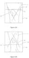
- FIG. 4 Ashows a device display with a real-time camera feed and overlaid guide
- FIG. 4 Bis a further view of the display of FIG. 4 A ;
- FIG. 5 Bis a further view of the display of FIG. 5 A ;
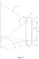
- FIG. 7shows a device including a main camera and an auxiliary camera
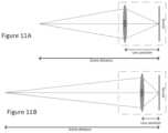
- FIGS. 11 A and 11 Bdepict lens movement with focal distance
- FIG. 13shows a device display with real-time camera feed and overlaid guide, at a desired range
- FIG. 13 Bshows the display of FIG. 13 , at a farther range
- the facilityfor automatically assessing an anatomical surface feature (“the facility”), such as a wound, and for managing information related to assessed anatomical surface features across a range of patients and institutions.
- the facilitymay be straightforwardly applied to anatomical surface features of other types, such as ulcers, sores, lesions, tumors, bruises, burns, moles, psoriasis, keloids, skin cancers, erythema, cellulitis, and the like.
- usersmay use the facility, including doctors, nurses, technologists, or any other caregiver of the patient, or the patient.
- FIG. 1is a block diagram showing a sample environment having multiple components in which the facility executes.
- the environment 100may include one or more capture devices 102 , 102 a , 102 b , one or more personal computing devices 104 , one or more server computers 106 , and one or more persistent storage devices 108 .
- the capture device 102 , 102 a , 102 b and the personal computing device 104communicate (wirelessly or through a wired connection) with the server computer 106 through a network 140 such as, for example, a Local Area Network (LAN), a Wide Area Network (WAN), and/or the Internet.
- LANLocal Area Network
- WANWide Area Network
- the capture device 102 , 102 a , 102 bmay or may not communicate directly with the personal computing device 104 .
- the capture device 102 , 102 a , 102 bmay communicate wirelessly with a first base station or access point 142 using a wireless mobile telephone standard, such as the Global System for Mobile Communication (GSM), or another wireless standard, such as IEEE 802.11, and the first base station or access point 142 communicates with the server computer 106 via the network 140 .
- GSMGlobal System for Mobile Communication
- the computing device 104may communicate wirelessly with a second base station or access point 144 using a wireless mobile telephone standard, such as the Global System for Mobile Communication (GSM), or another wireless standard, such as IEEE 802.11, and the second base station or access point 144 communicates with the server computer 106 via the network 140 .
- GSMGlobal System for Mobile Communication
- IEEE 802.11another wireless standard, such as IEEE 802.11
- confidential patient data generated by the capture device 102 , 102 a , 102 bis only temporarily stored locally, or not at all, and instead is permanently stored at the storage device 108 associated with the server computer 106 .
- the facilitycan be practiced on any of the computing devices disclosed herein (e.g., one or more personal computing devices 104 , one or more server computers 106 , etc.), and may include an interface module that generates graphical user interfaces (GUIs) to allow users to access the facility (as described in greater detail below with reference to FIGS. 2 - 16 .
- GUIsgraphical user interfaces
- the desktop computing devices 122are typically associated with a particular property, e.g, a medical treatment center 124 (e.g., a hospital, a doctor's office, a clinic, etc.).
- the portable computing devices 120 and desktop computing devices 124communicate with each other and the server computer 106 through networks including, for example, the Internet.
- the portable computing devices 120 and desktop computing devices 122may communicate with each other through other wireless protocols, such as near field or Bluetooth.
- the depth sensor 112may comprise three laser elements (labeled 112 a - 112 c ) spaced apart around a circumference of the capture device 102 .
- the laser elements 112 a - 112 chave a fixed positional relationship with respect to one another, and also with respect to the image sensor 110 .
- the laser elements 112 a - 112 ccan be configured to create a structured light pattern (e.g., a laser point(s), a laser fan(s), etc.)
- the laser elementsdo not need to be symmetrically arranged.
- the depth sensor 112can include other suitable devices for range imaging, such as an ultrasonic sensor, a stereo camera, a plenoptic camera, a time-of-flight camera, an ISM band miniature radar, etc.
- the capture device 102 , 102 a , 102 bmay be permanently cordless (i.e., no input port), and in other embodiments, the capture device 102 , 102 a , 102 b may be configured to detachably receive an electronic connector, such as a power cord or a USB cord, or a permanently attached retracting cord may be provided.
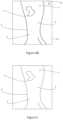
- FIG. 2shows an anatomical surface feature 1 , such as a wound or ulcer, on the leg 2 of a patient.
- a usere.g. a healthcare professional or caregiver
- Scalingcan be achieved by identifying points in the common image region of the first and second images, such as the outline of the patient's leg, bone structures and any anatomical fiducials 3 , such as moles, freckles, birthmarks, skin wrinkles, creases, lines, tattoos, scars or the like. Once two or more such anatomical fiducials have been identified, a distance or distances between the anatomical fiducials can be measured in both images and a relative scale factor determined. In some embodiments, it may be advantageous to utilize three or more anatomical fiducials. This allows correction for variance in the angle of the captured device relative to the skin surface.
- FIG. 3 Bshows the image of FIG. 3 A , scaled or registered to the scale of FIG. 3 .
- Scaling of image datafacilitates visual comparison between the images.
- dimensionsmay be determined directly from each image and subsequently scaled, i.e. the dimensional data may be scaled rather than the image data.
- FIG. 3 Dshows a displayed graph of wound dimension (in this case area, measured in arbitrary or normalized units) against time.
- a curve or line 8may be fitted to the gathered data points. The curve or line 8 may be extrapolated (as indicated by the dashed line) beyond the last data point to give an expected healing profile. If measured ulcer dimensions depart from the expected healing profile, an alert may be issued.
- the devicemay automatically capture data when an acceptable alignment is detected.
- the usermay issue a data capture instruction (for example by pressing a button, touch screen etc., or by any other suitable user input).
- the absolute scaleis again not necessarily known.
- the image datais obtained at approximately the same scale in each case because the user is guided to position the device to deliver images with approximately the same scale. If further accuracy is required, scaling or registration can be performed as discussed above.
- Estimated calibration datamay include an expected dimension (such as an expected limb width, length or circumference etc).
- Estimated calibration datamay be in the form of a manually entered user estimate of a dimension.
- the devicemay allow a user to select points on an image and enter an estimate of a distance between them.
- estimated calibration datamay be automatically generated.
- the estimated calibration datamay be a function of any suitable data in the patient's health record. For example, an estimated limb width, length or circumference may be generated based on the patient's gender, weight, height or any other suitable information.
- Manually obtained calibration informationmay include measurements between anatomical fiducials made by a healthcare provider or other user. For example, the distances between anatomical fiducials may be measured using a ruler or tape measure, and manually input into the device or otherwise into the patient's electronic record. A dimension of a limb, e.g. a circumference, width or length of a limb, may be measured in a similar manner.
- calibration datamay be captured using a device capable of capturing absolute dimensional data, such as a 3D camera (e.g. stereoscopic camera, depth camera, a camera capable of measuring range such as a time-of-flight based device), or a structured light device.
- a device capable of capturing absolute dimensional datasuch as a 3D camera (e.g. stereoscopic camera, depth camera, a camera capable of measuring range such as a time-of-flight based device), or a structured light device.
- Suitable devices for gathering calibration datamay be simple devices or may be auxiliary modules for attachment to a Smartphone, tablet or the like.
- calibration datamay b e obtained using the Applicant's Silhouette device, or any of the suitable devices described in U.S. Pat. Nos. 8,755,053 and 9,179,844, the entire contents of which are incorporated by reference herein.
- calibration datacan be gathered using a more complex device once, or for only a subset of data captures, with a simpler more ubiquitous device being used for other data captures.
- Other datacan be gathered by less skilled users, possibly at remote locations, such as patient's homes, using more ubiquitous devices such as Smartphones, digital cameras, tablets etc.
- the calibration dataneed not be the first data gathered as calibration can be performed retrospectively.
- each data setcontains sufficient information for absolute dimensions of the surface feature to be determined without reference to additional calibration data.
- Thismay be achieved by manually entering user measurements with every data capture, using user-supplied known fiducials with every data capture, or by use of a device capable of capturing absolute dimensional data at every data capture, such as a 3D camera (e.g. stereoscopic camera, depth camera, a camera capable of measuring range such as a time-of-flight based device), or a structured light device.
- Suitable devices for gathering calibration datamay be self-contained devices or may be auxiliary modules for attachment to a Smartphone, tablet or other capture device.
- calibration datamay be obtained using the Applicant's Silhouette device, or any of the suitable devices described in U.S. Pat. Nos. 8,755,053 and 9,179,844, the entire contents of which are incorporated by reference herein.
- User-supplied fiducialsmay also contain machine readable indicia, such as bar codes, QR codes, RFID elements or any other suitable indicia.
- machine readable indiciamay encode any desired data, including patient identification information, date information, wound information, and/or user information (e.g. healthcare provider identification).
- Machine readable indiciamay be read from image data captured by the capture device, for example by identifying and reading a QR code in the image.
- the image datamay be the image data captured for analysis of the anatomical surface feature. Alternatively, further image data may be captured.
- the machine readable indiciamay be read over any suitable wired or wireless link (e.g. Bluetooth or reading by an RFID reader).
- Machine readable indiciamay allow other captured data or medical samples to be correctly associated with the patient or anatomical surface feature data. Machine readable indicia may also be used to ensure that supplies (e.g. the fiducials) are not being reused for different patients.
- Imagesmay either be captured at a consistent scale, or may be scaled for consistent display, assessment and/or measurements.
- scale or calibration informationmay be generated by one of the following methods, with every data capture or as a calibration to be applied to other data captures.
- FIGS. 7 - 14show different embodiments of capture devices for use with the facility disclosed herein.
- a device with an inbuilt first camera having a first focal length, with a first field of view, and an inbuilt second camera having a second focal length, with a second field of viewmay be used.
- FIG. 7shows a capture device 20 including a first camera 21 and a second camera 22 .
- the devicemay also include a display 23 , such as a touchscreen.
- the first camera 21may be a wide angle or standard lens camera, while the second camera 22 may be a standard or telephoto lens camera.
- Image datamay be captured of the skin surface, including the surface feature of interest, using the two cameras 21 , 22 .
- the capture device 20may be arranged to capture data from both cameras simultaneously, or substantially simultaneously, in response to a single instruction from the user to capture data or in response to an automatic capture decision.
- the field of view of the first camera 21is indicated by dashed lines 24
- the field of view of the second camera 22is indicated by dashed lines 25
- the two fields of view 24 , 25define a common image region 26 on the skin surface.
- the range or scale associated with the imagecan be determined by analysing points present in both images captured by the cameras 21 , 22 , within the common image region 26 . This may be done using a triangulation process between a common object point and the corresponding image points from each camera, with knowledge of the lens focal lengths and image sensor characteristics such as pixel pitch or spacing etc. For autofocus cameras, the triangulation may also take into account the focal distance (to allow for lens movement).
- measurementsmay be made in relation to any point within either field of view 24 , 25 , including points outside the common image region 26 .
- FIG. 8shows another embodiment of a capture device 30 .
- the capture device 30includes a first camera 31 and a second camera 32 .
- the capture device 30may also include a display 33 , such as a touchscreen.
- the first camera 31may be a color (RGB) camera, while the second camera 22 may be a monochrome camera.
- the two camerasare of the same focal length and field of view 34 , 35 .
- Image datamay be captured of the skin surface, including the surface feature of interest, using the two cameras 31 , 32 .
- the device 30may be arranged to capture data from both cameras simultaneously, or substantially simultaneously, in response to a single instruction from the user to capture data.
- the two fields of view 34 , 35define a common image region 36 on the skin surface.
- the range or scale associated with the imagecan be determined by analysing points present in both images captured by the cameras 31 , 32 , within the common image region 36 . This may be done using a triangulation process between a common object point and the corresponding image points on the two camera sensors, with knowledge of the lens focal lengths and image sensor characteristics such as pixel pitch or spacing etc. For autofocus cameras, the triangulation may also take into account the focal distance (to allow for lens movement).
- the camera-scene distanceis determined from focal information obtained from the camera lens.
- This embodimentrelies on the use of a camera with an autofocus lens for which focal distance or lens position information is accessible.
- the lens focal distance or lens positionis an output of the camera hardware/software, typically accessible via the device vendor's API. Some cameras output focal distance directly. Others output a lens position.
- FIGS. 11 A and 11 Billustrate the adjustment of the lens position based on focal distance.
- a different number of guide linesmay be used. For example, four lines could be used, forming a square or rectangle, or five lines could be used forming a pentagon. However, in some embodiments the polygon will diminish in size as the optimum range is approached, with all lines crossing at a single point at the optimum range.
- Suitable auxiliary devicesinclude structured light devices (projecting one or more spots, stripes, fan beams etc produced by appropriate laser devices or a pattern generator), guide devices (e.g. projecting a laser or other light pattern to guide the user to position the device at a desired range and/or positon and/or orientation with respect to the skin surface) cameras, stereoscopic cameras, and image splitters (described further below).
- Further auxiliary devicesinclude sonar, ultrasound, infrared, ISM band miniature radar, or time-of-flight range finder modules (described in further detail below with reference to FIGS. 15 A and 15 B ).
- An auxiliary devicemay include one or more further sensors (e.g. light sensors, reflectance sensors, temperature sensors), light sources, distance sensors, further cameras, or code readers (e.g. RFID readers, barcode scanners etc) etc.
- An auxiliary devicemay be battery powered, or may be powered from an external power source. Where the auxiliary device requires power from an external source, this may be provided by a wired connection to the device's headphone jack. Further, control signals can be sent over a wired connection between the device's headphone jack and the auxiliary device, using the device's standard interface for transmitting audio signals through that jack. In other embodiments a wired connection may be made to any other suitable jack or connector on the capture device (e.g. Lightning connector).
- the other light path 73is an opposite path, extending through the second window 70 and being redirected by reflectors 67 , 65 before entering the camera 63 .
- Thisallows a baseline to be established between two optical paths. Each optical path will have its own field of view, and as the two fields of view overlap, the image data captured through this splitter allows a range to an object surface to be determined.
- the projected guidemay simply bean image of the skin surface captured previously.
- a usermay align the device with the desired position and/or range by moving it to bring the projected guide into alignment with the patient's anatomy. Correct alignment of the device may be determined by the user, simply by observing the alignment of the guide and the patient's anatomy.
- the devicemay detect the alignment of anatomy (as viewed through the camera) an d guide and when an acceptable level of alignment is reached provide feedback in the form of an audio, visual or audiovisual notification. For example, when acceptable alignment is achieved the device may beep. Alternatively, a visual indicator may be displayed when acceptable alignment is achieved.
- the devicemay automatically capture data when an acceptable alignment is detected.
- the usermay issue a data capture instruction (for example by pressing a button, touch screen etc, or by any other suitable user input).
- the projected guidemay include image portions or markings corresponding to the anatomical fiducials 3 .
- Anatomical fiducialsmay be selected by a user in the previous image for subsequent use in the guide image.
- the absolute scaleis again not necessarily known.
- the image datais obtained at approximately the same scale in each case because the user is guided to position the device to deliver images with approximately the same scale. If further accuracy is required, scaling or registration can be performed as discussed above.
- the devicemay be positioned at a desired range from the surface using a physical guide or frame that sets a distance between the surface and device.
- a physical guidemay include a device support, and a spacing arrangement with one or more distal elements configured to contact the skin. In many embodiments skin contact is undesirable. However, in some settings the use of such a physical guide may be acceptable.
- this range informationmay be used in at least the following ways.
- the user devicemay be connected over any suitable wired or wireless connection to another local device and/or over a network to a server.
- the servermay be a facility server (e.g. a hospital server) or may be a remote server used by a number of different facilities.
- the capture and storage of datais controlled such that data is not stored, or is stored only transiently, on the device itself.
- Datais immediately communicated to secure storage over the wired/wireless link and/or over the network.
- a usermay view data retrieved from that secure storage on the device display.
- the Applicant's methods at the device levelmay be implemented using a web application.
- the devicemay operate as a thin client.
- any of the assessment techniques described hereinallow surface feature dimensions to be tracked over time, whether in arbitrary units or in absolute dimensions. These trends allow medical professionals to monitor surface feature development or healing. Where a measurement departs from the predicted trend (e.g. an average trend for similar wounds, or some other defined trend based on one or more of: wound size and/or other characteristics, tissue type, patient characteristics etc), an alert may be issued to a user, either through the device itself or by any suitable messaging system to a healthcare provider.
- the predicted trende.g. an average trend for similar wounds, or some other defined trend based on one or more of: wound size and/or other characteristics, tissue type, patient characteristics etc
- Statistical trends of conditions, treatments and outcomescan be monitored. This data can be used to suggest a particular treatment, based on a set of symptoms exhibited by a particular patient. Data can provide predictions for wound healing. Where actual healing differs from the prediction by more than a threshold, the system may issue an alert. Similarly, where the actual healing is in accordance with the predicted trend, a positive notification (e.g. “Wound healing well”, or a green light or another positive indicator) may be issued or displayed.
- a positive notificatione.g. “Wound healing well”, or a green light or another positive indicator
- the surface feature and surrounding skinall lie in a plane. For many applications, this is expected to be sufficiently accurate. It may also be assumed that the device's optical axis or optical axes is/are perpendicular to that plane. Alternatively, in some embodiments no such assumption is made, and appropriate corrections may or may not be made.
- an auxiliary device or moduleincluding additional hardware may be used.
- the alignment of the widget to the onboard camera within the capture devicemay be important. If the exact alignment of the auxiliary device to the host optical system cannot be guaranteed by design, it may be estimated or calibrated.
- the auxiliary devicemay communicate with the capture device using any appropriate wired, physical or wireless link.
- the position of the points in commonis given by the auxiliary range-finder subsystem and the cameras' intrinsic parameters.
- the extrinsic parameters of the two camerascan be determined by determining the alignment of the two camera frames.
- intrinsic parametersrefer to the known internal geometry of the camera, eg: lens focal length, lens focal distance, sensor pitch, geometric distortion, etc.
- degrees per pixelor the solid angle subtended by a pixel
- the rangeis unknown, the size of an area on an image object corresponding to a pixel on the sensor is not known.
- Extrinsic parametersrefer to the geometrical relationship between two components, for example the angle and offset of the laser plane relative to the camera's optical axis.
- the extrinsic parameters of the components within the auxiliary devicecan be determined to the required degree of accuracy either by design or by a calibration step in the factory prior to being supplied to the user of the smart device.
- an auxiliary devicemay include three line generating lasers surrounding a low-resolution camera connected to a low-power processor and battery subsystem.
- the auxiliary devicemay project a light pattern similar to that disclosed in the Applicant's U.S. Pat. No. 9,179,844.
- Communications with the capture devicemay be provided by Bluetooth, or other wireless, or wired communication link.
- an auxiliary device or widgetcan include a range finding device configured for attachment to a Smartphone, tablet, or other portable device that includes a camera.
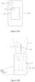
- FIGS. 15 A and 15 Billustrate an embodiment of such an auxiliary range finding device configured in accordance with embodiments of the present technology.
- FIG. 15 Ashows an auxiliary range finding device 80 (“auxiliary device 80 ”) physically attached to a capture device 102 (e.g., a Smartphone or tablet) having an image sensor 110 (e.g., a camera).
- FIG. 15 Bshows the capture device 102 and auxiliary device 80 positioned relative to a leg 2 of a patient including a wound 1 .
- the auxiliary device 80can be attached to the capture device 102 using any suitable manner, including for example a partial sleeve that allows the auxiliary device 80 to mount to the capture device 102 .
- the auxiliary device 80may be integrated into a case of the capture device 102 .
- the auxiliary device 80can be attached to a “back side” of the capture device 102 that includes the image sensor 110 .
- the capture device 102can have a “front side” opposite the back side that includes a display 11 for viewing, e.g., images captured by the image sensor 110 of the capture device 102 .
- the auxiliary device 80may be a very simple device for providing range information.
- the range information obtained by the auxiliary device 80can be used to scale images.
- the range informationmay be used to determine relative scale factors between images which can be useful to normalize images to a consistent scale. It may also be used simply to provide absolute dimensions from each image.
- the range informationmay be used as a seed or an input to any suitable registration process, for registering images to each other.
- the range informationmay be used merely to determine scale, and a full model of a skin surface as provided by more complex range-finding cameras and devices may not be required.
- the signals 84 emitted by the auxiliary device 80may be incident upon only a portion of the skin surface of the leg 2 and/or the wound 1 of the patient, and may be incident upon more or less of the skin surface and the wound 1 depending on the distance between the auxiliary device 102 and the patient.
- the range measurementmay vary depending on the method used to determine range.
- a first time-of-flight measurementcould correspond to the nearest patch of skin outside the wound 1 (for a concave wound), while an averaged value could produce a slightly greater range as the signals 84 are incident upon a portion of the wound 1 and a portion of the skin surface outside the wound 1 .
- Parameters of clinical significance in wound monitoringinclude the length, width, perimeter, and area of the boundary.
- an auxiliary range finding devicecan project a tightly confined beam of visible light.
- the useris instructed to manipulate the resultant spot so that it lies just outside the boundary of the wound.
- the subsequently derived scale factoris optimal for making accurate and consistent boundary measurements.
- the spotcan be turned off during image capture using the capture device 102 .
- the spotcan be turned on during at least one image capture and used for retrospective quality assurance of consistency of image captures made at different times and by different operators.
- the auxiliary device 80can be used to provide scaling or registration of the images so that, for example, the images can be processed to provide absolute dimensional information. That is, the auxiliary device 80 can provide calibration data in the form of range information so that images captured by the capture device 102 can be processed to provide absolute dimensional information or real scale information. This may be done, for example, in response to a health expert's determination that the surface feature requires further analysis.
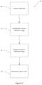
- datamay be captured in the following sequence, described with reference to FIG. 16 .
- capture sequencesmay be used, and the capture sequence may be adapted to the type of capture device and/or auxiliary device used.
- one or more image framesmay be captured.
- a high resolution imagemay be captured with the guide switched off.
- a low resolution imagemay be captured with lasers on (possibly multiple frames to allow the laser beams to be uniquely identified in the captured images).
- All datamay be transferred from the auxiliary device to the capture device at block 156 , for example via Bluetooth or some other wireless or wired communications link.
- the auxiliary device cameramay not be a visible light camera.
- the auxiliary device cameramay be a thermal camera.
- Such a devicewould require the scene to contain an object with common features apparent in both the thermal camera and optical camera images.
- Such a scenecould be something like a user's hand with outstretched fingers placed on a desk. The outline of the warm hand on the desk could be detected by the thermal camera, and also in the capture device visible light camera.
- FIG. 17shows another embodiment, executing within the facility, in which blocks 150 to 154 are as described above with reference to FIG. 16 .
- one or more image framesmay be captured.
- a high resolution imagemay be captured
- a low resolution imagemay be captured, both with lasers on (possibly multiple frames from each camera to allow the laser beams to be uniquely identified in the captured images).
- These imagesshould be captured simultaneously or in sequence over a short time period. The image from both cameras will show the same position s of the lasers on the surface.
- the Applicant's methodsmay take advantage of existing device capabilities without the need for separate hardware attachments. In some embodiments the Applicant's methods may avoid any physical contact with the wound. In some embodiments the Applicant's methods may provide a mechanism for determining the scale of an image without requiring a reference object to be placed near the wound. In some embodiments the Applicant's methods may enable the determination of both area and depth or volume of a wound or dimensions of other anatomical surface features.
- any of the guiding arrangements described abovemay be adapted to guide a user to position the device at a suitable range and/or position and/or orientation for capturing a macro image.
- the capture devicemay be arranged to guide the user to two or more desired ranges for capture of different images.
- a method of assessing a feature on a patient's skin surfaceincluding:
- a method of assessing a feature on a patient's skin surfaceincluding:
- a method of assessing a feature on a patient's skin surfaceincluding:
- a method of assessing a feature on a patient's skin surfaceincluding:
- a method as claimed in example 25, wherein the retrieving focal data from the cameraincludes:
Landscapes
- Engineering & Computer Science (AREA)
- Health & Medical Sciences (AREA)
- Life Sciences & Earth Sciences (AREA)
- Physics & Mathematics (AREA)
- General Health & Medical Sciences (AREA)
- Medical Informatics (AREA)
- Biomedical Technology (AREA)
- Multimedia (AREA)
- Animal Behavior & Ethology (AREA)
- Pathology (AREA)
- Heart & Thoracic Surgery (AREA)
- Biophysics (AREA)
- Molecular Biology (AREA)
- Surgery (AREA)
- Public Health (AREA)
- Veterinary Medicine (AREA)
- General Physics & Mathematics (AREA)
- Signal Processing (AREA)
- Computer Vision & Pattern Recognition (AREA)
- Computer Networks & Wireless Communication (AREA)
- Remote Sensing (AREA)
- Radar, Positioning & Navigation (AREA)
- Theoretical Computer Science (AREA)
- Electromagnetism (AREA)
- Dermatology (AREA)
- Nuclear Medicine, Radiotherapy & Molecular Imaging (AREA)
- Radiology & Medical Imaging (AREA)
- Quality & Reliability (AREA)
- Geometry (AREA)
- Measuring And Recording Apparatus For Diagnosis (AREA)
- Measurement Of The Respiration, Hearing Ability, Form, And Blood Characteristics Of Living Organisms (AREA)
Abstract
Description
- i. receiving a first image of the patient's skin surface captured at a first time;
- ii. determining one or more dimensions of the feature at the first time, from the first image, in arbitrary units;
- iii. receiving a second image of the patient's skin surface captured at a second time;
- iv. identifying one or more anatomical features of the patient that are present in both the first and second images;
- v. determining a relative scale factor between the first and second images based on the identified anatomical features; and
- vi. determining one or more dimensions of the feature at the second time, from the second image and the relative scale factor, in the arbitrary units.
- capturing the first image using a first capture device;
- by a first processor, determining the one or more dimensions of the feature at the first time;
- wherein the first processor is in one of: the first capture device; a personal computing device; and a server computer.
- capturing the second image using the first capture device or a second capture device;
- by the first processor or a second processor determining one or more dimensions of the feature at the second time;
- wherein the second processor is in one of: the second capture device; a personal computing device; and a server computer.
- i. receiving a first image of the patient's skin surface captured at a first time and calibration data associated with the first image;
- ii. receiving a second image of the patient's skin surface captured at a second time;
- iii. identifying one or more anatomical features of the patient that are present in both the first and second images;
- iv. determining a relative scale factor between the first and second images based on the identified anatomical features; and
- v. determining one or more dimensions of the feature at the second time, from the second image and the relative scale factor.
- a. data including an image, captured by a device capable of determining a scale associated with the image;
- b. manually obtained measurement data;
- c. data including an image, the image including a known-size fiducial.
- capturing the first image using a first capture device;
- by a first processor, determining one or more dimensions of the feature at the first time;
- wherein the first processor is in one of: the first capture device; a personal computing device; and a server computer.
- capturing the second image using the first capture device or a second capture device;
- by the first processor or a second processor determining the one or more dimensions of the feature at the second time;
- wherein the second processor is in one of: the second capture device; a personal computing device; and a server computer.
- i. displaying a guide image overlaid on a real-time camera view on a display of a capture device, the capture device including a camera, whereby a user may align the camera relative to the feature by moving the capture device to align the real-time camera view with the overlaid guide image; and
- ii. capturing an image of the patient's skin surface using the camera.
- a. a previously captured image of the patient's skin surface;
- b. one or more portions of a previously captured image of the patient's skin surface;
- c. one or more guide masks or markings based on a previously captured image of the patient's skin surface;
- d. one or more guide masks or markings selected from a library of available guide masks or markings; and
- e. one or more guide patterns that vary with range.
- i. at a first time, capturing a first image of the patient's skin surface;
- ii. at a second time, projecting a guide image onto the patient's skin surface using a projector, the projector being coupled to or incorporated in a capture device including a camera, the guide image including one or more of:
- a. all of the first image, or one or more portions of the first image; and
- b. one or more markings based on the first image;
- whereby a user may align the camera to a position and field of view corresponding to the first image by moving the capture device to align the projected guide with the anatomy of the patient; and
- iii. capturing an image of the patient's skin surface using the camera.
- i. using a capture device including an autofocus camera, capturing an image of the patient's skin surface;
- ii. retrieving focal data from the camera;
- iii. determining a scale associated with the captured image based on the retrieved focal data;
- iv. determining one or more dimensions of the feature based on the image and the determined scale.
- a) driving the camera through a range of focal distances;
- b) capturing a plurality of calibration images at different focal distances within the range;
- c) determining a focal metric for each calibration image;
- d) fitting a curve through the focal metrics; and
- e) determining a focal distance value for a point of peak focal quality.
- a. at a different time, using the same or a different capture device including an autofocus camera, capturing a further image of the patient's skin surface;
- b. retrieving further focal data from the camera;
- c. determining a further scale associated with the captured further image based on the retrieved further focal data;
- d. determining one or more dimensions of the feature at the different time, based on the further image and the determined further scale; and
- e. determining a trend of the one or more dimensions overtime and displaying said trend to a user.
- by a first processor, determining the one or more dimensions of the feature;
- wherein the processor is in one of: the capture device; a personal computing device; and a server computer.
- i. capturing an image of the patient's skin surface using a capture device including a first camera and an auxiliary camera;
- ii. based on a common image region covered by both the first camera and the auxiliary camera and a known baseline between an optical axis of the first camera optical axis and an optical axis of the second camera, determining a range to the patient's skin surface; and
- iii. from the range determining a scale associated with the image.
- i. using a capture device including a camera, capturing at least a first image of the patient's skin surface from a first position of the capture device and a second image of the patient's skin surface from a second position of the capture device;
- ii. determining at least a distance between the first position and the second position;
- iii. based on a common image region present in the first and second images and the determined distance, determining a range to the patient's skin surface; and
- iv. from the range determining a scale associated with the image.
Claims (30)
Priority Applications (2)
| Application Number | Priority Date | Filing Date | Title |
|---|---|---|---|
| US17/398,883US12268472B2 (en) | 2016-11-17 | 2021-08-10 | Anatomical surface assessment methods, devices and systems |
| US19/071,443US20250194931A1 (en) | 2016-11-17 | 2025-03-05 | Anatomical surface assessment methods, devices and systems |
Applications Claiming Priority (3)
| Application Number | Priority Date | Filing Date | Title |
|---|---|---|---|
| US201662423709P | 2016-11-17 | 2016-11-17 | |
| US15/816,862US11116407B2 (en) | 2016-11-17 | 2017-11-17 | Anatomical surface assessment methods, devices and systems |
| US17/398,883US12268472B2 (en) | 2016-11-17 | 2021-08-10 | Anatomical surface assessment methods, devices and systems |
Related Parent Applications (1)
| Application Number | Title | Priority Date | Filing Date |
|---|---|---|---|
| US15/816,862ContinuationUS11116407B2 (en) | 2016-11-17 | 2017-11-17 | Anatomical surface assessment methods, devices and systems |
Related Child Applications (1)
| Application Number | Title | Priority Date | Filing Date |
|---|---|---|---|
| US19/071,443ContinuationUS20250194931A1 (en) | 2016-11-17 | 2025-03-05 | Anatomical surface assessment methods, devices and systems |
Publications (2)
| Publication Number | Publication Date |
|---|---|
| US20210386295A1 US20210386295A1 (en) | 2021-12-16 |
| US12268472B2true US12268472B2 (en) | 2025-04-08 |
Family
ID=62106275
Family Applications (3)
| Application Number | Title | Priority Date | Filing Date |
|---|---|---|---|
| US15/816,862ActiveUS11116407B2 (en) | 2016-11-17 | 2017-11-17 | Anatomical surface assessment methods, devices and systems |
| US17/398,883ActiveUS12268472B2 (en) | 2016-11-17 | 2021-08-10 | Anatomical surface assessment methods, devices and systems |
| US19/071,443PendingUS20250194931A1 (en) | 2016-11-17 | 2025-03-05 | Anatomical surface assessment methods, devices and systems |
Family Applications Before (1)
| Application Number | Title | Priority Date | Filing Date |
|---|---|---|---|
| US15/816,862ActiveUS11116407B2 (en) | 2016-11-17 | 2017-11-17 | Anatomical surface assessment methods, devices and systems |
Family Applications After (1)
| Application Number | Title | Priority Date | Filing Date |
|---|---|---|---|
| US19/071,443PendingUS20250194931A1 (en) | 2016-11-17 | 2025-03-05 | Anatomical surface assessment methods, devices and systems |
Country Status (1)
| Country | Link |
|---|---|
| US (3) | US11116407B2 (en) |
Families Citing this family (35)
| Publication number | Priority date | Publication date | Assignee | Title |
|---|---|---|---|---|
| KR20080064155A (en) | 2005-10-14 | 2008-07-08 | 어플라이드 리써치 어쏘시에이츠 뉴질랜드 리미티드 | Method and apparatus for monitoring surface features |
| US9179844B2 (en) | 2011-11-28 | 2015-11-10 | Aranz Healthcare Limited | Handheld skin measuring or monitoring device |
| US10013527B2 (en) | 2016-05-02 | 2018-07-03 | Aranz Healthcare Limited | Automatically assessing an anatomical surface feature and securely managing information related to the same |
| US11116407B2 (en) | 2016-11-17 | 2021-09-14 | Aranz Healthcare Limited | Anatomical surface assessment methods, devices and systems |
| WO2018185560A2 (en) | 2017-04-04 | 2018-10-11 | Aranz Healthcare Limited | Anatomical surface assessment methods, devices and systems |
| US11893729B2 (en)* | 2017-11-22 | 2024-02-06 | GE Precision Healthcare LLC | Multi-modal computer-aided diagnosis systems and methods for prostate cancer |
| GB2573011B (en)* | 2018-04-20 | 2021-03-03 | Metlase Ltd | Device for illuminating and monitoring an insertion site of an orthopaedic pin or wire |
| KR102655676B1 (en)* | 2018-10-10 | 2024-04-05 | 삼성전자주식회사 | Apparatus and method for estimating blood pressure, and apparatus for supporting blood pressure estimation |
| KR102236826B1 (en)* | 2018-11-30 | 2021-04-06 | 아주대학교산학협력단 | The Method and System for Evaluating the Quality of Medical Image dataset for Machine Learning |
| US20240096468A1 (en)* | 2019-05-06 | 2024-03-21 | Keystone Pharmacy, Llc | Electronic system for wound image analysis and communication |
| WO2020234653A1 (en) | 2019-05-20 | 2020-11-26 | Aranz Healthcare Limited | Automated or partially automated anatomical surface assessment methods, devices and systems |
| US11310451B1 (en) | 2019-09-05 | 2022-04-19 | Waymo Llc | Smart sensor with region of interest capabilities |
| KR102323328B1 (en)* | 2019-09-17 | 2021-11-09 | 주식회사 날마다자라는아이 | System for measuring growth state of child using smart scale |
| US20210093227A1 (en)* | 2019-09-26 | 2021-04-01 | Canon Kabushiki Kaisha | Image processing system and control method thereof |
| US11252366B2 (en)* | 2019-11-19 | 2022-02-15 | Waymo Llc | Sensor read out mode for high resolution and low light imaging in-sync with LIDAR timing |
| US20210185295A1 (en)* | 2019-12-17 | 2021-06-17 | Koninklijke Philips N.V. | Device and method for assisting in 3d scanning a subject |
| EP3838117A1 (en)* | 2019-12-20 | 2021-06-23 | Koninklijke Philips N.V. | Illumination compensation in imaging |
| US20210228148A1 (en)* | 2020-01-28 | 2021-07-29 | Zebra Technologies Corporation | System and Method for Lesion Monitoring |
| US11428550B2 (en) | 2020-03-03 | 2022-08-30 | Waymo Llc | Sensor region of interest selection based on multisensor data |
| US11529094B2 (en) | 2020-03-06 | 2022-12-20 | Diabetis | System, method, and apparatus for temperature asymmetry measurement of body parts |
| US11950883B2 (en) | 2020-03-06 | 2024-04-09 | Uab Diabetis | System, method, and apparatus for temperature asymmetry measurement of body parts |
| US10993625B1 (en)* | 2020-03-06 | 2021-05-04 | Uab Diabetis | System, method, and apparatus for temperature asymmetry measurement of body parts |
| EP3944832B1 (en)* | 2020-07-30 | 2025-03-12 | Ellicut UG (haftungsbeschränkt) | System and method for creating cutting lines |
| US12376786B2 (en)* | 2020-10-09 | 2025-08-05 | Arizona Board Of Regents On Behalf Of The University Of Arizona | Smartphone-based multispectral dermascope |
| US11763491B2 (en)* | 2020-10-21 | 2023-09-19 | Faro Technologies, Inc. | Compensation of three-dimensional measuring instrument having an autofocus camera |
| US11756283B2 (en) | 2020-12-16 | 2023-09-12 | Waymo Llc | Smart sensor implementations of region of interest operating modes |
| US11430562B2 (en)* | 2021-01-04 | 2022-08-30 | Healthy.Io Ltd. | Selective reaction to failure to complete medical action |
| EP4285334A1 (en)* | 2021-01-29 | 2023-12-06 | TEC Competence UG (Haftungsbeschränkt) & Co. KG | Method for evaluating 3d data representing a 3d shape, auxiliary device obtained using such 3d data, and method for obtaining such 3d data |
| TWI783636B (en)* | 2021-08-18 | 2022-11-11 | 緯創資通股份有限公司 | Portable electronic device and method of measuring size of wound |
| TWI788065B (en)* | 2021-10-22 | 2022-12-21 | 長庚醫療財團法人林口長庚紀念醫院 | Bone cutting and repairing-aided sysyem, method and computer program product thereof |
| US20240161440A1 (en)* | 2022-11-16 | 2024-05-16 | Shanghai United Imaging Intelligence Co., Ltd. | Systems and methods for image alignment and augmentation |
| CN116158753A (en)* | 2023-03-03 | 2023-05-26 | 大连奥瑞科技有限公司 | Wound measurement system and method |
| WO2024263797A1 (en)* | 2023-06-22 | 2024-12-26 | Wound Pros Technology, Inc. | Methods and systems for improving wound healing |
| CN117442190B (en)* | 2023-12-21 | 2024-04-02 | 山东第一医科大学附属省立医院(山东省立医院) | An automatic wound measurement method and system based on target detection |
| USD1093617S1 (en)* | 2024-08-24 | 2025-09-16 | Canfield Scientific, Incorporated | Facial imaging apparatus |
Citations (468)
| Publication number | Priority date | Publication date | Assignee | Title |
|---|---|---|---|---|
| US3259612A (en) | 1960-02-04 | 1966-07-05 | Montedison Spa | Polymers having a highly regular structure, obtained from esters containing an innerdouble bond and process for preparing the same |
| US3335716A (en) | 1965-01-18 | 1967-08-15 | Gen Electric | Diagnostic thermography method and means |
| DE2642841A1 (en) | 1976-09-23 | 1978-03-30 | Siemens Ag | Quantitative topographical evaluation of electron microscope images - uses reference structure of know geometry and dimensions placed upon sample |
| US4090501A (en) | 1976-06-24 | 1978-05-23 | Horace Chaitin | Skin lesion analyzer |
| JPS5467404U (en) | 1977-10-21 | 1979-05-14 | ||
| US4170987A (en) | 1977-11-28 | 1979-10-16 | California Institute Of Technology | Medical diagnosis system and method with multispectral imaging |
| US4236082A (en) | 1979-01-29 | 1980-11-25 | Palmguard, Inc. | Method and apparatus for recording image details of the palm of a hand |
| EP0119660A1 (en) | 1983-03-17 | 1984-09-26 | Nicolaas Roelof Snijder | System of examining skeleton parts of a living body, more particularly the vertebral column of the human body |
| DE3420588A1 (en) | 1983-06-03 | 1984-12-06 | Agip S.p.A., Rom/Roma | STEREOPHOTOGRAMMETRIC MEASURING METHOD |
| US4505583A (en) | 1981-04-10 | 1985-03-19 | Masaaki Konomi | Spectroscopic analyzer system for examining intravital tissue |
| US4515165A (en) | 1980-02-04 | 1985-05-07 | Energy Conversion Devices, Inc. | Apparatus and method for detecting tumors |
| US4535782A (en) | 1984-03-07 | 1985-08-20 | American Cyanamid Company | Method for determining wound volume |
| US4556057A (en) | 1982-08-31 | 1985-12-03 | Hamamatsu Tv Co., Ltd. | Cancer diagnosis device utilizing laser beam pulses |
| FR2570206A1 (en) | 1984-09-07 | 1986-03-14 | Shiseido Co Ltd | Apparatus for detecting and classifying the characteristics of skin surface shapes |
| US4724480A (en) | 1985-05-02 | 1988-02-09 | Robotic Vision Systems, Inc. | Method for optical alignment of one object with respect to another |
| US4736739A (en) | 1985-05-28 | 1988-04-12 | Dowd & Dowd, P.C. | Photographic specimen mat |
| US4768513A (en) | 1986-04-21 | 1988-09-06 | Agency Of Industrial Science And Technology | Method and device for measuring and processing light |
| US4773097A (en) | 1984-05-31 | 1988-09-20 | Omron Tateisi Electronics Co. | Image analyzing apparatus |
| US4821117A (en) | 1986-11-12 | 1989-04-11 | Kabushiki Kaisha Toshiba | Endoscopic system for producing fluorescent and visible images |
| US4839807A (en) | 1987-08-03 | 1989-06-13 | University Of Chicago | Method and system for automated classification of distinction between normal lungs and abnormal lungs with interstitial disease in digital chest radiographs |
| US4851984A (en) | 1987-08-03 | 1989-07-25 | University Of Chicago | Method and system for localization of inter-rib spaces and automated lung texture analysis in digital chest radiographs |
| US4894547A (en) | 1987-09-28 | 1990-01-16 | Yale University | Optical method and apparatus for detecting and measuring aging, photoaging, dermal disease and pigmentation in skin |
| EP0355221A1 (en) | 1987-08-03 | 1990-02-28 | Vexcel Corporation | Method and apparatus of photogrammetric mensuration with a reseau grid |
| US4930516A (en) | 1985-11-13 | 1990-06-05 | Alfano Robert R | Method for detecting cancerous tissue using visible native luminescence |
| US4957114A (en) | 1985-04-01 | 1990-09-18 | Kun Zeng | Diagnostic apparatus for intrinsic fluorescence of malignant tumor |
| US4979815A (en) | 1989-02-17 | 1990-12-25 | Tsikos Constantine J | Laser range imaging system based on projective geometry |
| US4996994A (en) | 1985-12-23 | 1991-03-05 | Eyemetrics Systems-Ag | Apparatus for photogrammetrically measuring the human head |
| USD315901S (en) | 1989-01-30 | 1991-04-02 | Metrologic Instruments, Inc. | Portable laser scanner |
| US5003977A (en) | 1988-03-31 | 1991-04-02 | Agency Of Industrial Science And Technology | Device for analyzing fluorescent light signals |
| US5016173A (en) | 1989-04-13 | 1991-05-14 | Vanguard Imaging Ltd. | Apparatus and method for monitoring visually accessible surfaces of the body |
| US5036853A (en) | 1988-08-26 | 1991-08-06 | Polartechnics Ltd. | Physiological probe |
| DE4120074A1 (en) | 1990-06-26 | 1992-01-02 | Technomed Int Sa | Monitoring position of patient's body - involves transmitting image of mark in body to control screen |
| US5080100A (en) | 1988-10-04 | 1992-01-14 | Cgr Mev | System and method for measuring and/or checking the position of a patient in a radio-therapy machine |
| US5157461A (en) | 1990-06-14 | 1992-10-20 | Smiths Industries Aerospace & Defense Systems Inc. | Interface configuration for rate sensor apparatus |
| US5174297A (en) | 1989-11-22 | 1992-12-29 | S.L.T. Japan Co., Ltd. | Diagnostic apparatus for living tissues and medical treatment apparatus with diagnostic apparatus |
| EP0552526A1 (en) | 1990-06-18 | 1993-07-28 | Richard A Mosby | Surgical device for volumetric localization, biopsy and surgical procedures |
| US5241468A (en) | 1989-04-13 | 1993-08-31 | Vanguard Imaging Ltd. | Apparatus and method for spectral enhancement of body-surface images to improve sensitivity of detecting subtle color features |
| US5270168A (en) | 1990-02-21 | 1993-12-14 | Board Of Regents, The University Of Texas System | Method for diagnosing non-healing ulcers |
| US5319550A (en) | 1988-03-24 | 1994-06-07 | Olganix Corporation | High resolution digital image registration |
| US5363854A (en) | 1990-08-24 | 1994-11-15 | U.S. Philips Corporation | Method of detecting anomalies of the skin, more particularly melanomae, and apparatus for carrying out the method |
| US5369496A (en) | 1989-11-13 | 1994-11-29 | Research Foundation Of City College Of New York | Noninvasive method and apparatus for characterizing biological materials |
| US5396331A (en) | 1993-08-10 | 1995-03-07 | Sanyo Machine Works, Ltd. | Method for executing three-dimensional measurement utilizing correctively computing the absolute positions of CCD cameras when image data vary |
| US5408996A (en) | 1993-03-25 | 1995-04-25 | Salb; Jesse | System and method for localization of malignant tissue |
| EP0650694A1 (en) | 1993-11-01 | 1995-05-03 | Polartechnics Ltd | Method and apparatus for diseased tissue type recognition |
| US5421337A (en) | 1989-04-14 | 1995-06-06 | Massachusetts Institute Of Technology | Spectral diagnosis of diseased tissue |
| US5515449A (en) | 1989-01-26 | 1996-05-07 | Olympus Optical Co., Ltd. | Endoscope image processing apparatus |
| US5519208A (en) | 1994-09-29 | 1996-05-21 | Esparza; Joel | Infrared aided method and apparatus for venous examination |
| US5528703A (en) | 1992-02-18 | 1996-06-18 | Neopath, Inc. | Method for identifying objects using data processing techniques |
| US5532824A (en) | 1994-01-25 | 1996-07-02 | Mts Systems Corporation | Optical motion sensor |
| US5531520A (en) | 1994-09-01 | 1996-07-02 | Massachusetts Institute Of Technology | System and method of registration of three-dimensional data sets including anatomical body data |
| US5561526A (en) | 1994-05-26 | 1996-10-01 | Lockheed Missiles & Space Company, Inc. | Three-dimensional measurement device and system |
| US5588428A (en) | 1993-04-28 | 1996-12-31 | The University Of Akron | Method and apparatus for non-invasive volume and texture analysis |
| US5590660A (en) | 1994-03-28 | 1997-01-07 | Xillix Technologies Corp. | Apparatus and method for imaging diseased tissue using integrated autofluorescence |
| US5603318A (en) | 1992-04-21 | 1997-02-18 | University Of Utah Research Foundation | Apparatus and method for photogrammetric surgical localization |
| US5627907A (en) | 1994-12-01 | 1997-05-06 | University Of Pittsburgh | Computerized detection of masses and microcalcifications in digital mammograms |
| US5644141A (en) | 1995-10-12 | 1997-07-01 | The United States Of America As Represented By The Administrator Of The National Aeronautics And Space Administration | Apparatus and method for high-speed characterization of surfaces |
| US5648915A (en) | 1995-11-20 | 1997-07-15 | Triangle Research & Development Corporation | Soft tissue damage assessment system |
| NZ293713A (en) | 1994-09-28 | 1997-09-22 | William Richard Fright | Laser surface scanning system: shape of surface recorded by determining relative positions of laser, camera, and laser spot on surface with respect to fixed reference point |
| US5673300A (en) | 1996-06-11 | 1997-09-30 | Wisconsin Alumni Research Foundation | Method of registering a radiation treatment plan to a patient |
| US5689575A (en) | 1993-11-22 | 1997-11-18 | Hitachi, Ltd. | Method and apparatus for processing images of facial expressions |
| US5699798A (en) | 1990-08-10 | 1997-12-23 | University Of Washington | Method for optically imaging solid tumor tissue |
| US5701902A (en) | 1994-09-14 | 1997-12-30 | Cedars-Sinai Medical Center | Spectroscopic burn injury evaluation apparatus and method |
| US5717791A (en) | 1994-11-10 | 1998-02-10 | Agfa-Gevaert | Image contrast enhancing method |
| USD393068S (en) | 1994-01-31 | 1998-03-31 | Kabushiki Kaisha Toshiba | Radio frequency coil for magnetic resonance imaging apparatus |
| US5740268A (en) | 1994-04-29 | 1998-04-14 | Arch Development Corporation | Computer-aided method for image feature analysis and diagnosis in mammography |
| US5749830A (en) | 1993-12-03 | 1998-05-12 | Olympus Optical Co., Ltd. | Fluorescent endoscope apparatus |
| US5784162A (en) | 1993-08-18 | 1998-07-21 | Applied Spectral Imaging Ltd. | Spectral bio-imaging methods for biological research, medical diagnostics and therapy |
| US5791346A (en) | 1996-08-22 | 1998-08-11 | Western Research Company, Inc. | Colposcope device and method for measuring areas of cervical lesions |
| US5799100A (en) | 1996-06-03 | 1998-08-25 | University Of South Florida | Computer-assisted method and apparatus for analysis of x-ray images using wavelet transforms |
| US5810014A (en) | 1997-03-25 | 1998-09-22 | Davis; Dennis W. | Method and system for detection of physiological conditions |
| US5910972A (en) | 1996-09-25 | 1999-06-08 | Fuji Photo Film Co., Ltd. | Bone image processing method and apparatus |
| US5946645A (en) | 1997-04-09 | 1999-08-31 | National Research Council Of Canada | Three dimensional imaging method and device |
| US5957837A (en) | 1996-10-17 | 1999-09-28 | Faro Technologies, Inc. | Method and apparatus for wound management |
| US5967797A (en) | 1997-09-24 | 1999-10-19 | Teledyne Industries, Inc. | High density multi-pin connector with solder points |
| US5967979A (en) | 1995-11-14 | 1999-10-19 | Verg, Inc. | Method and apparatus for photogrammetric assessment of biological tissue |
| US5974165A (en) | 1993-11-30 | 1999-10-26 | Arch Development Corporation | Automated method and system for the alignment and correlation of images from two different modalities |
| WO2000003210A1 (en) | 1998-07-10 | 2000-01-20 | Sugen, Inc. | Device for estimating volume |
| US6032070A (en) | 1995-06-07 | 2000-02-29 | University Of Arkansas | Method and apparatus for detecting electro-magnetic reflection from biological tissue |
| WO2000030337A2 (en) | 1998-11-19 | 2000-05-25 | Oracis Medical Corporation | Three-dimensional handheld digital camera for medical applications |
| US6081739A (en) | 1998-05-21 | 2000-06-27 | Lemchen; Marc S. | Scanning device or methodology to produce an image incorporating correlated superficial, three dimensional surface and x-ray images and measurements of an object |
| US6081612A (en) | 1997-02-28 | 2000-06-27 | Electro Optical Sciences Inc. | Systems and methods for the multispectral imaging and characterization of skin tissue |
| US6091995A (en) | 1996-11-08 | 2000-07-18 | Surx, Inc. | Devices, methods, and systems for shrinking tissues |
| US6101408A (en) | 1996-08-22 | 2000-08-08 | Western Research Company, Inc. | Probe and method to obtain accurate area measurements from cervical lesions |
| US6208749B1 (en) | 1997-02-28 | 2001-03-27 | Electro-Optical Sciences, Inc. | Systems and methods for the multispectral imaging and characterization of skin tissue |
| US6215893B1 (en) | 1998-05-24 | 2001-04-10 | Romedix Ltd. | Apparatus and method for measurement and temporal comparison of skin surface images |
| US6265151B1 (en) | 1998-03-27 | 2001-07-24 | Seroptix, Inc. | Apparatus and method for infectious disease detection |
| US6266453B1 (en) | 1999-07-26 | 2001-07-24 | Computerized Medical Systems, Inc. | Automated image fusion/alignment system and method |
| US6272278B1 (en) | 1997-12-05 | 2001-08-07 | Nippon Telegraph And Telephone Corporation | Video data storage and playback scheme with automatic playback continuation after overtaking |
| US6278793B1 (en) | 1995-11-02 | 2001-08-21 | University Of Pittsburgh | Image quality based adaptive optimization of computer aided detection schemes |
| US6307957B1 (en) | 1997-02-28 | 2001-10-23 | Electro-Optical Sciences Inc | Multispectral imaging and characterization of biological tissue |
| US6324417B1 (en) | 1996-11-19 | 2001-11-27 | Optiscan Limited | Method for measurement of skin histology |
| USD453350S1 (en) | 2001-03-05 | 2002-02-05 | Silent Witness Enterprises, Ltd. | Enclosure for a video sensor |
| US6359513B1 (en) | 2001-01-31 | 2002-03-19 | U.S. Philips Corporation | CMOS power amplifier with reduced harmonics and improved efficiency |
| US6359612B1 (en) | 1998-09-30 | 2002-03-19 | Siemens Aktiengesellschaft | Imaging system for displaying image information that has been acquired by means of a medical diagnostic imaging device |
| USD455166S1 (en) | 2000-03-14 | 2002-04-02 | Silent Witness Enterprises, Ltd. | Infrared illuminator housing |
| US6381026B1 (en) | 1999-03-15 | 2002-04-30 | Lifecell Corp. | Method of measuring the contour of a biological surface |
| US6381488B1 (en) | 1999-06-15 | 2002-04-30 | Sandia Corporation | Method and apparatus to measure the depth of skin burns |
| US20020054297A1 (en) | 2000-11-06 | 2002-05-09 | Chun-Hsing Lee | Three dimensional scanning system |
| US6392744B1 (en) | 2000-12-11 | 2002-05-21 | Analog Technologies, Corp. | Range measurement system |
| US6396270B1 (en) | 1992-05-15 | 2002-05-28 | University Of Washington | Quantitation and standardization of magnetic resonance measurements |
| EP1210906A1 (en) | 2000-11-28 | 2002-06-05 | Pulsion Medical Systems AG | Apparatus for determining tissue perfusion and the associated intraoperative method of use |
| US6421463B1 (en) | 1998-04-01 | 2002-07-16 | Massachusetts Institute Of Technology | Trainable system to search for objects in images |
| US6427022B1 (en) | 1998-11-10 | 2002-07-30 | Western Research Company, Inc. | Image comparator system and method for detecting changes in skin lesions |
| WO2002065069A2 (en) | 2000-11-07 | 2002-08-22 | Hypermed, Inc. | Hyperspectral imaging calibration device |
| EP1248237A2 (en) | 2001-03-14 | 2002-10-09 | Johnson & Johnson Consumer Companies, Inc. | Method for measuring volumetric changes in portions of a human body |
| US20020149585A1 (en) | 1996-04-24 | 2002-10-17 | Kacyra Ben K. | Integrated system for quickly and accurately imaging and modeling three-dimensional objects |
| WO2002093450A1 (en) | 2001-05-16 | 2002-11-21 | Cellavision Ab | Information processing for distinguishing an object |
| US6491632B1 (en) | 2001-06-26 | 2002-12-10 | Geoffrey L. Taylor | Method and apparatus for photogrammetric orientation of ultrasound images |
| US20020197600A1 (en) | 2001-05-15 | 2002-12-26 | Maione Theodore E. | Method for determining the presence of infection in an individual |
| US20030004405A1 (en) | 1999-10-14 | 2003-01-02 | Cti Pet Systems, Inc. | Combined PET and X-Ray CT tomograph |
| US20030006770A1 (en) | 1992-05-15 | 2003-01-09 | Board Of Regents Of The University Of Washington | Quantitation and standardization of magnetic resonance measurements |
| US20030031383A1 (en) | 2000-09-13 | 2003-02-13 | Gooch Richard Michael | Method for establishing the position of a temprary on an object relative to know features of the object |
| US20030036751A1 (en) | 2001-05-30 | 2003-02-20 | Anderson R. Rox | Apparatus and method for laser treatment with spectroscopic feedback |
| EP1303267A1 (en) | 2000-07-17 | 2003-04-23 | Medac Gesellschaft für klinische Spezialpräparate mbH | Dermal for amino laevulinic acid |
| US20030085908A1 (en) | 1997-05-15 | 2003-05-08 | Luby James H. | Method and apparatus for an automated reference indicator system for photographic and video images |
| US6567682B1 (en) | 1999-11-16 | 2003-05-20 | Carecord Technologies, Inc. | Apparatus and method for lesion feature identification and characterization |
| US6594516B1 (en) | 2000-07-18 | 2003-07-15 | Koninklijke Philips Electronics, N.V. | External patient contouring |
| US6594388B1 (en) | 2000-05-25 | 2003-07-15 | Eastman Kodak Company | Color image reproduction of scenes with preferential color mapping and scene-dependent tone scaling |
| US6603552B1 (en) | 1999-12-22 | 2003-08-05 | Xillix Technologies Corp. | Portable system for detecting skin abnormalities based on characteristic autofluorescence |
| US6611617B1 (en) | 1995-07-26 | 2003-08-26 | Stephen James Crampton | Scanning apparatus and method |
| US6611833B1 (en) | 1999-06-23 | 2003-08-26 | Tissueinformatics, Inc. | Methods for profiling and classifying tissue using a database that includes indices representative of a tissue population |
| US20030164841A1 (en) | 2002-03-01 | 2003-09-04 | Edward Greenberg | System and method for passive three-dimensional data acquisition |
| US20030164875A1 (en) | 2002-03-01 | 2003-09-04 | Myers Kenneth J. | System and method for passive three-dimensional data acquisition |
| EP1351036A1 (en) | 2002-04-04 | 2003-10-08 | Uwe Braasch | Photogrammetric method of determining geometric information from images |
| US6648820B1 (en) | 1999-10-27 | 2003-11-18 | Home-Medicine (Usa), Inc. | Medical condition sensing system |
| US20030229514A2 (en) | 1992-11-17 | 2003-12-11 | Stephen Brown | Multi-user remote health monitoring system with biometrics support |
| US6671349B1 (en) | 2000-11-13 | 2003-12-30 | Olganix Corporation | Tomosynthesis system and registration method |
| US6678001B1 (en) | 1999-11-01 | 2004-01-13 | Elbex Video Ltd. | Ball shaped camera housing with simplified positioning |
| US20040013292A1 (en) | 2002-05-17 | 2004-01-22 | Pfizer, Inc. | Apparatus and method for statistical image analysis |
| US20040014165A1 (en) | 2000-06-19 | 2004-01-22 | Joseph Keidar | System and automated and remote histological analysis and new drug assessment |
| US6690964B2 (en) | 2000-07-12 | 2004-02-10 | Siemens Aktiengesellschaft | Method and device for visualization of positions and orientation of intracorporeally guided instruments during a surgical intervention |
| US20040059199A1 (en) | 2002-09-04 | 2004-03-25 | Thomas Pamela Sue | Wound assessment and monitoring apparatus and method |
| US6715675B1 (en) | 2000-11-16 | 2004-04-06 | Eldat Communication Ltd. | Electronic shelf label systems and methods |
| US20040080497A1 (en) | 1992-11-09 | 2004-04-29 | Toshiharu Enmei | Portable communicator |
| US6754370B1 (en) | 2000-08-14 | 2004-06-22 | The Board Of Trustees Of The Leland Stanford Junior University | Real-time structured light range scanning of moving scenes |
| US20040136579A1 (en) | 2002-11-19 | 2004-07-15 | Alexander Gutenev | Method for monitoring wounds |
| US20040146290A1 (en) | 2001-11-08 | 2004-07-29 | Nikiforos Kollias | Method of taking images of the skin using blue light and the use thereof |
| US6770186B2 (en) | 2001-11-13 | 2004-08-03 | Eldat Communication Ltd. | Rechargeable hydrogen-fueled motor vehicle |
| US6798571B2 (en) | 2001-01-11 | 2004-09-28 | Interscope Technologies, Inc. | System for microscopic digital montage imaging using a pulse light illumination system |
| US20040201694A1 (en) | 2001-02-07 | 2004-10-14 | Vladimir Gartstein | Noninvasive methods and apparatus for monitoring at least one hair characteristic |
| EP1467706A2 (en) | 2002-01-23 | 2004-10-20 | Photonamic GmbH & Co. KG | Dermal application system for aminolevulinic acid-derivatives |
| US6809803B1 (en) | 1998-12-24 | 2004-10-26 | Airbus Uk Limited | Surface topology inspection |
| WO2004092874A2 (en) | 2003-04-07 | 2004-10-28 | E.I. Dupont De Nemours And Company | Method and apparatus for quantifying visual showthrough of printed images on the reverse of planar objects |
| WO2004095372A1 (en) | 2003-04-22 | 2004-11-04 | Provincia Italiana Della Congregazione Dei Figli Dell'immacolata Concezione - Instituto Dermopatico Dell'immacolata | Automatic detection of skin lesions |
| US6816847B1 (en) | 1999-09-23 | 2004-11-09 | Microsoft Corporation | computerized aesthetic judgment of images |
| US6816606B2 (en) | 2001-02-21 | 2004-11-09 | Interscope Technologies, Inc. | Method for maintaining high-quality focus during high-throughput, microscopic digital montage imaging |
| US20040225222A1 (en) | 2003-05-08 | 2004-11-11 | Haishan Zeng | Real-time contemporaneous multimodal imaging and spectroscopy uses thereof |
| US20040264749A1 (en) | 2001-05-18 | 2004-12-30 | Skladnev Victor Nickolaevick | Boundary finding in dermatological examination |
| US20050012817A1 (en) | 2003-07-15 | 2005-01-20 | International Business Machines Corporation | Selective surveillance system with active sensor management policies |
| US20050027567A1 (en) | 2003-07-29 | 2005-02-03 | Taha Amer Jamil | System and method for health care data collection and management |
| US20050033142A1 (en) | 2003-05-09 | 2005-02-10 | University Of Rochester Medical Center | Method of indexing biological imaging data using a three-dimensional body representation |
| US6862410B2 (en) | 2001-02-09 | 2005-03-01 | Olympus Corporation | Stereoadapter, pattern projection adapter, and adapter for light-emitting member |
| US6862542B2 (en) | 2002-01-17 | 2005-03-01 | Charlotte-Mecklenburg Hospital | Erythema measuring device |
| US6873716B1 (en) | 1995-11-14 | 2005-03-29 | ARETé ASSOCIATES | Confocal-reflection streak lidar apparatus with strip-shaped photocathode, for applications at a wide range of scales |
| US6879394B2 (en) | 2000-11-20 | 2005-04-12 | Institut Curie | Multi-photon imaging installation |
| WO2005033620A2 (en) | 2003-09-12 | 2005-04-14 | Biopticon Corporation | Methods and systems for measuring the size and volume of features on live tissue |
| US20050094262A1 (en) | 2003-11-05 | 2005-05-05 | Visx, Incorporated | Microscope magnification sensor |
| US20050111757A1 (en) | 2003-11-26 | 2005-05-26 | Brackett Charles C. | Auto-image alignment system and method based on identified anomalies |
| US6907193B2 (en) | 2001-11-08 | 2005-06-14 | Johnson & Johnson Consumer Companies, Inc. | Method of taking polarized images of the skin and the use thereof |
| US6915073B2 (en) | 2001-10-12 | 2005-07-05 | Pentax Corporation | Stereo camera and automatic convergence adjusting device |
| US20050154276A1 (en) | 2002-03-28 | 2005-07-14 | Alessandro Barducci | Apparatus and process for reading radiation reflected from human skin |
| US6922523B2 (en) | 2001-11-08 | 2005-07-26 | Johnson & Johnson Consumer Companies, Inc. | Method of promoting skin care products |
| US20050190988A1 (en) | 2004-03-01 | 2005-09-01 | Mass Institute Of Technology (Mit) | Passive positioning sensors |
| US6941323B1 (en) | 1999-08-09 | 2005-09-06 | Almen Laboratories, Inc. | System and method for image comparison and retrieval by enhancing, defining, and parameterizing objects in images |
| EP1584405A2 (en) | 2004-03-31 | 2005-10-12 | Kabushiki Kaisha Kobe Seiko Sho (Kobe Steel, Ltd.) | Die Plate |
| US20050237384A1 (en) | 2003-08-14 | 2005-10-27 | Helge Jess | Optical viewing system and method for operating the same |
| US6961517B2 (en) | 2001-11-08 | 2005-11-01 | Johnson & Johnson Consumer Companies, Inc. | Method of promoting skin care products |
| US6968094B1 (en) | 2000-03-27 | 2005-11-22 | Eastman Kodak Company | Method of estimating and correcting camera rotation with vanishing point location |
| US20050259281A1 (en) | 2004-05-06 | 2005-11-24 | Océ-Technologies B.V. | Method, apparatus and computer program for transforming digital colour images |
| US20050265585A1 (en) | 2004-06-01 | 2005-12-01 | Lumidigm, Inc. | Multispectral liveness determination |
| US20050265586A1 (en) | 2004-06-01 | 2005-12-01 | Lumidigm, Inc. | Multispectral biometric imaging |
| US20050271258A1 (en) | 2004-06-01 | 2005-12-08 | Lumidigm, Inc. | Multispectral imaging biometrics |
| US20050273011A1 (en) | 2003-10-16 | 2005-12-08 | David Hattery | Multispectral imaging for quantitative contrast of functional and structural features of layers inside optically dense media such as tissue |
| US20050273267A1 (en) | 2001-12-03 | 2005-12-08 | Maione Theodore E | Method for identifying markers |
| US20060008178A1 (en) | 2004-07-08 | 2006-01-12 | Seeger Adam A | Simulation of scanning beam images by combination of primitive features extracted from a surface model |
| US20060012802A1 (en) | 1996-02-12 | 2006-01-19 | Lyle Shirley | Apparatus and methods for surface contour measurement |
| US6993169B2 (en) | 2001-01-11 | 2006-01-31 | Trestle Corporation | System and method for finding regions of interest for microscopic digital montage imaging |
| US20060036156A1 (en) | 2004-07-19 | 2006-02-16 | Martin Lachaine | Weighted surface-to-surface mapping |
| US20060036135A1 (en) | 2004-08-10 | 2006-02-16 | Kern Kenneth A | Skin cancer identification template |
| US7006223B2 (en) | 2003-03-07 | 2006-02-28 | 3Gen, Llc. | Dermoscopy epiluminescence device employing cross and parallel polarization |
| US20060044546A1 (en) | 2002-11-11 | 2006-03-02 | Qinetiq Limited | Ranging apparatus |
| US20060055943A1 (en) | 2002-11-14 | 2006-03-16 | Technodream21 Inc. | Three-dimensional shape measuring method and its device |
| US20060058665A1 (en) | 2004-08-19 | 2006-03-16 | Biosound, Inc. | Noninvasive method of ultrasound wound evaluation |
| US7015906B2 (en) | 2001-02-21 | 2006-03-21 | Leica Microsystems Cms Gmbh | Method and arrangement for imaging and measuring microscopic three-dimensional structures |
| US20060073132A1 (en) | 2004-10-06 | 2006-04-06 | Congote Luis F | Agents for wound healing |
| US20060072122A1 (en) | 2004-09-30 | 2006-04-06 | Qingying Hu | Method and apparatus for measuring shape of an object |
| US20060089553A1 (en) | 2002-07-19 | 2006-04-27 | Astron Clinica Limited | Method and apparatus for investigating histology of epithelial tissue |
| US20060098876A1 (en) | 2002-03-11 | 2006-05-11 | Buscema Paolo M | Method for encoding image pixels a method for processing images and a method for processing images aimed at qualitative recognition of the object reproduced by one or more image pixels |
| US7054674B2 (en) | 1996-11-19 | 2006-05-30 | Astron Clinica Limited | Method of and apparatus for investigating tissue histology |
| US7064311B2 (en) | 2001-04-02 | 2006-06-20 | Atlab, Inc. | Optical image detector and method for controlling illumination of the same |
| US20060135953A1 (en) | 2004-12-22 | 2006-06-22 | Wlodzimierz Kania | Tissue ablation system including guidewire with sensing element |
| US7068836B1 (en) | 2000-04-28 | 2006-06-27 | Orametrix, Inc. | System and method for mapping a surface |
| US7068828B2 (en) | 2001-11-29 | 2006-06-27 | Gaiagene Inc. | Biochip image analysis system and method thereof |
| US7074509B2 (en) | 2001-11-13 | 2006-07-11 | Eldat Communication Ltd. | Hydrogen generators for fuel cells |
| US20060152586A1 (en) | 2002-07-26 | 2006-07-13 | Olympus Corporation | Image processing system |
| US20060159341A1 (en) | 2003-06-13 | 2006-07-20 | Vladimir Pekar | 3D image segmentation |
| WO2006078902A2 (en) | 2005-01-19 | 2006-07-27 | Dermaspect, Llc | Devices and methods for identifying and monitoring changes of a suspect area on a patient |
| US7103205B2 (en) | 2000-11-24 | 2006-09-05 | U-Systems, Inc. | Breast cancer screening with ultrasound image overlays |
| US7106685B2 (en) | 2002-10-29 | 2006-09-12 | Salvatore J. Calaio | Turntable with vertically adjustable platter |
| US20060204072A1 (en) | 2001-01-11 | 2006-09-14 | Wetzel Arthur W | System for creating microscopic digital montage images |
| US20060222263A1 (en) | 2005-04-04 | 2006-10-05 | Carlson Eric A | Linear measurement machine-readable medium, method and system |
| US7127094B1 (en) | 2003-01-02 | 2006-10-24 | Electro Optical Sciences Inc | Method of controlling data gathered at remote locations |
| US7127280B2 (en) | 2000-06-23 | 2006-10-24 | L'oreal | Apparatus and process for examining a surface |
| US7130465B2 (en) | 2002-08-29 | 2006-10-31 | Fraunhofer-Gesellschaft Zur Foerderung Der Angewandten Forschung E.V | Method for extracting texture features from a multichannel image |
| US7128894B1 (en) | 2002-06-27 | 2006-10-31 | The United States Of America As Represented By The United States Department Of Energy | Contrast enhancing solution for use in confocal microscopy |
| US20060251408A1 (en) | 2004-01-23 | 2006-11-09 | Olympus Corporation | Image processing system and camera |
| US7136191B2 (en) | 2002-06-24 | 2006-11-14 | Eastman Kodak Company | Method for inspecting prints |
| US20060269125A1 (en) | 2003-09-24 | 2006-11-30 | Ossi Kalevo | Method and system in a digital image processing chain for adjusting a colour balance, corresponding equipment, and software means for implementing the method |
| USD533555S1 (en) | 2004-06-04 | 2006-12-12 | Nobel Biocare Services Ag | Scanner |
| US20060293613A1 (en) | 2005-06-27 | 2006-12-28 | Concept Development Group | Method and Apparatus for Automated Monitoring and Tracking of the Trajectory of Patients' Center of Gravity Movements |
| US7162063B1 (en) | 2003-07-29 | 2007-01-09 | Western Research Company, Inc. | Digital skin lesion imaging system and method |
| US7181363B2 (en) | 2003-04-16 | 2007-02-20 | Massachusetts Institute Of Technology | Three dimensional tangible interface for interacting with spatial-temporal data using a laser scanner |
| WO2007029038A1 (en) | 2005-09-05 | 2007-03-15 | Sld Limited | Laser imaging apparatus and method |
| US7194114B2 (en) | 2002-10-07 | 2007-03-20 | Carnegie Mellon University | Object finder for two-dimensional images, and system for determining a set of sub-classifiers composing an object finder |
| US20070065009A1 (en) | 2005-08-26 | 2007-03-22 | Shenzhen Mindray Bio-Medical Electronics Co., Ltd. | Ultrasound image enhancement and speckle mitigation method |
| WO2007043899A1 (en) | 2005-10-14 | 2007-04-19 | Applied Research Associates Nz Limited | A method of monitoring a surface feature and apparatus therefor |
| US20070097381A1 (en) | 2005-10-31 | 2007-05-03 | Tobiason Joseph D | Hand-size structured-light three-dimensional metrology imaging system and method |
| WO2007059780A1 (en) | 2005-11-28 | 2007-05-31 | 3Shape A/S | Coded structured light |
| US7227621B2 (en) | 2004-08-30 | 2007-06-05 | Postech Foundation | System for visualizing flow and measuring velocity field using X-ray particle image velocimetry |
| US20070129602A1 (en) | 2005-11-22 | 2007-06-07 | Given Imaging Ltd. | Device, method and system for activating an in-vivo imaging device |
| US20070125390A1 (en) | 2005-12-07 | 2007-06-07 | Isabelle Afriat | Method of evaluating the effects of exogenous and endogenous factors on the skin |
| US7233693B2 (en) | 2003-04-29 | 2007-06-19 | Inforward, Inc. | Methods and systems for computer analysis of skin image |
| USD547347S1 (en) | 2006-01-06 | 2007-07-24 | Samsung Electronics Co., Ltd. | Monitoring camera |
| US20070229850A1 (en) | 2006-04-04 | 2007-10-04 | Boxternal Logics, Llc | System and method for three-dimensional image capture |
| USD554682S1 (en) | 2005-09-30 | 2007-11-06 | Logitech Europe S.A. | Webcam with a user-configurable shell |
| US7295226B1 (en) | 1999-11-15 | 2007-11-13 | Given Imaging Ltd. | Method for activating an image collecting process |
| US7298881B2 (en) | 2004-02-13 | 2007-11-20 | University Of Chicago | Method, system, and computer software product for feature-based correlation of lesions from multiple images |
| US20070276195A1 (en) | 2006-05-12 | 2007-11-29 | Kci Licensing, Inc. | Systems and methods for wound area management |
| US20070276309A1 (en) | 2006-05-12 | 2007-11-29 | Kci Licensing, Inc. | Systems and methods for wound area management |
| US20070273894A1 (en) | 2006-05-23 | 2007-11-29 | Johnson James T | Method and apparatus for remote spatial calibration and imaging |
| US20080006282A1 (en) | 2006-05-04 | 2008-01-10 | Predrag Sukovic | Medical imaging exchange network |
| US20080021329A1 (en) | 2006-06-29 | 2008-01-24 | Fred Wood | Scanned laser vein contrast enhancer |
| USD561804S1 (en) | 2004-09-08 | 2008-02-12 | Matsushita Electric Industrial Co., Ltd. | Surveillance television camera |
| US20080045807A1 (en) | 2006-06-09 | 2008-02-21 | Psota Eric T | System and methods for evaluating and monitoring wounds |
| WO2008033010A1 (en) | 2006-09-13 | 2008-03-20 | Alb. Van Gool R & D | Device and method for positioning recording means for recording images relative to an object |
| US7347365B2 (en) | 2003-04-04 | 2008-03-25 | Lumidigm, Inc. | Combined total-internal-reflectance and tissue imaging systems and methods |
| WO2008039539A2 (en) | 2006-09-27 | 2008-04-03 | Georgia Tech Research Corporation | Systems and methods for the measurement of surfaces |
| US20080088704A1 (en) | 2006-10-13 | 2008-04-17 | Martin Edmund Wendelken | Method of making digital planimetry measurements on digital photographs |
| US20080098322A1 (en) | 2006-06-01 | 2008-04-24 | Simquest Llc | Method and apparatus for collecting and analyzing surface wound data |
| WO2008048424A2 (en) | 2006-10-13 | 2008-04-24 | Leica Geosystems Ag | Image-mapped point cloud with ability to accurately represent point coordinates |
| WO2008057056A1 (en) | 2006-11-07 | 2008-05-15 | Alpina, Tovarna Obutve, D.D., Ziri | Three-dimensional scanning of feet |
| US20080126478A1 (en) | 2004-12-16 | 2008-05-29 | Renovo Limited | Information Collection System |
| WO2008071414A1 (en) | 2006-12-15 | 2008-06-19 | Fraunhofer-Gesellschaft zur Förderung der angewandten Forschung e.V. | Apparatus and method for increasing the measurement accuracy of digital 3d geometry measuring systems |
| US20080165357A1 (en) | 2006-11-07 | 2008-07-10 | Howard Stern | Method and system for providing a high definition triangulation system |
| WO2008080385A1 (en) | 2006-12-28 | 2008-07-10 | Chronos Vision Gmbh | Method and device for sensing the three-dimensional surface of an object, in particular of a vehicle tire |
| US7400754B2 (en) | 2003-04-08 | 2008-07-15 | The Regents Of The University Of California | Method and apparatus for characterization of chromophore content and distribution in skin using cross-polarized diffuse reflectance imaging |
| EP1946567A2 (en) | 2005-10-04 | 2008-07-23 | Eugene J. Alexander | Device for generating three dimensional surface models of moving objects |
| US7426319B2 (en) | 2003-12-26 | 2008-09-16 | Canon Kabushiki Kaisha | Image processing apparatus, image processing method, image processing system, program, and storage medium |
| US20080232679A1 (en) | 2005-08-17 | 2008-09-25 | Hahn Daniel V | Apparatus and Method for 3-Dimensional Scanning of an Object |
| US20080246759A1 (en) | 2005-02-23 | 2008-10-09 | Craig Summers | Automatic Scene Modeling for the 3D Camera and 3D Video |
| US7440597B2 (en) | 2003-04-04 | 2008-10-21 | Rowe Robert K | Liveness sensor |
| US20080275315A1 (en) | 2004-01-09 | 2008-11-06 | Hiroshi Oka | Pigmentary Deposition Portion Remote Diagnosis System |
| US20080285056A1 (en) | 2007-05-17 | 2008-11-20 | Ilya Blayvas | Compact 3D scanner with fixed pattern projector and dual band image sensor |
| US7460250B2 (en) | 2003-10-24 | 2008-12-02 | 3Dm Devices Inc. | Laser triangulation system |
| US20080298649A1 (en) | 2004-06-01 | 2008-12-04 | Lumidigm, Inc. | Hygienic biometric sensors |
| US7474415B2 (en) | 2006-09-13 | 2009-01-06 | Chung Shan Institute Of Science And Technology, Armaments Bureau, M.N.D. | Measurement method of three-dimensional profiles and reconstruction system thereof using subpixel localization with color gratings and picture-in-picture switching on single display |
| US7487063B2 (en) | 2003-06-13 | 2009-02-03 | UNIVERSITé LAVAL | Three-dimensional modeling from arbitrary three-dimensional curves |
| US7489799B2 (en) | 2004-11-30 | 2009-02-10 | General Electric Company | Method and apparatus for image reconstruction using data decomposition for all or portions of the processing flow |
| US7495208B2 (en) | 2006-06-01 | 2009-02-24 | Czarnek And Orkin Laboratories, Inc. | Portable optical wound scanner |
| US7496399B2 (en) | 2004-01-20 | 2009-02-24 | Siemens Aktiengesellschaft | Method and device for examining the skin |
| US7509861B2 (en) | 2003-10-08 | 2009-03-31 | Actis Active Sensors S.R.L. | Method and device for local spectral analysis of an ultrasonic signal |
| WO2009046218A2 (en) | 2007-10-05 | 2009-04-09 | Artec Group, Inc. | Combined object capturing system and display device and associated method |
| US20090116712A1 (en) | 2007-11-02 | 2009-05-07 | Osama Al-Moosawi | Apparatus and method for wound diagnosis |
| US20090118720A1 (en) | 2001-12-12 | 2009-05-07 | Reliant Technologies, Inc. | Dermatological Apparatus and Method |
| US7538869B2 (en) | 2004-06-30 | 2009-05-26 | Chemimage Corporation | Multipoint method for identifying hazardous agents |
| US7545963B2 (en) | 2003-04-04 | 2009-06-09 | Lumidigm, Inc. | Texture-biometrics sensor |
| USD597205S1 (en) | 2004-12-22 | 2009-07-28 | Zutron Medical, L.L.C. | Handle for endoscope stiffening device |
| US7580590B2 (en) | 2005-10-03 | 2009-08-25 | Chroma Ate Inc. | Optical image system surface resolution calibration method |
| US7581191B2 (en) | 1999-11-15 | 2009-08-25 | Xenogen Corporation | Graphical user interface for 3-D in-vivo imaging |
| US7587618B2 (en) | 2001-04-12 | 2009-09-08 | Lenovo (Singapore) Pte. Ltd. | Computer system and unit, and power supply control method therefor |
| US20090225333A1 (en) | 2008-03-05 | 2009-09-10 | Clark Alexander Bendall | System aspects for a probe system that utilizes structured-light |
| US20090234313A1 (en) | 2005-05-20 | 2009-09-17 | Peter Mullejeans | Device for Recording and Transferring a Contour |
| US7595878B2 (en) | 2000-10-13 | 2009-09-29 | Chemimage Corporation | Spectroscopic methods for component particle analysis |
| GB2458927A (en) | 2008-04-02 | 2009-10-07 | Eykona Technologies Ltd | 3D imaging system |
| US7603031B1 (en) | 2004-12-15 | 2009-10-13 | Canfield Scientific, Incorporated | Programmable, multi-spectral, image-capture environment |
| USD603441S1 (en) | 2007-12-25 | 2009-11-03 | Panasonic Corporation | Surveillance camera |
| US7613335B2 (en) | 2003-02-12 | 2009-11-03 | The University Of Iowa Research Foundation | Methods and devices useful for analyzing color medical images |
| US20100004564A1 (en) | 2006-07-25 | 2010-01-07 | Johan Jendle | Wound measuring device |
| US20100020164A1 (en) | 2005-11-04 | 2010-01-28 | Ronald Perrault | Surface Analysis Method and System |
| US7668350B2 (en) | 2003-04-04 | 2010-02-23 | Lumidigm, Inc. | Comparative texture analysis of tissue for biometric spoof detection |
| US20100113940A1 (en)* | 2008-01-10 | 2010-05-06 | The Ohio State University Research Foundation | Wound goggles |
| WO2010048960A1 (en) | 2008-10-28 | 2010-05-06 | 3Shape A/S | Scanner with feedback control |
| US20100121201A1 (en)* | 2008-10-13 | 2010-05-13 | George Yiorgos Papaioannou | Non-invasive wound prevention, detection, and analysis |
| US7724379B2 (en) | 2005-05-12 | 2010-05-25 | Technodream21, Inc. | 3-Dimensional shape measuring method and device thereof |
| US7729747B2 (en) | 1997-04-03 | 2010-06-01 | Stranc Miroslaw F | Method of assessing tissue viability using near-infrared spectroscopy |
| US7738032B2 (en) | 2001-11-08 | 2010-06-15 | Johnson & Johnson Consumer Companies, Inc. | Apparatus for and method of taking and viewing images of the skin |
| US20100149551A1 (en) | 2008-12-16 | 2010-06-17 | Faro Technologies, Inc. | Structured Light Imaging System and Method |
| US7751594B2 (en) | 2003-04-04 | 2010-07-06 | Lumidigm, Inc. | White-light spectral biometric sensors |
| US7765487B2 (en) | 1999-11-15 | 2010-07-27 | Xenogen Corporation | Graphical user interface for in-vivo imaging |
| US20100278312A1 (en) | 2009-04-30 | 2010-11-04 | Kent State University | Core measurements stand for use with a portable xrf analyzer |
| US7881777B2 (en) | 1999-09-24 | 2011-02-01 | National Research Council Of Canada | Method and apparatus for performing intra-operative angiography |
| US20110032349A1 (en)* | 2008-04-11 | 2011-02-10 | Catfosc. Health Made To Measure, S.L. | Device for monitoring surface alterations over time and method associated therewith |
| US7894645B2 (en) | 2000-08-10 | 2011-02-22 | Ohio State University | High-resolution digital image processing in the analysis of pathological materials |
| US7912320B1 (en) | 2007-01-16 | 2011-03-22 | Paul Minor | Method and apparatus for photographic measurement |
| US7912534B2 (en) | 2002-04-02 | 2011-03-22 | Yeda Research And Development Co. Ltd. | Characterization of moving objects in a stationary background |
| US7916834B2 (en) | 2007-02-12 | 2011-03-29 | Thermo Niton Analyzers Llc | Small spot X-ray fluorescence (XRF) analyzer |
| US7931149B2 (en) | 2009-05-27 | 2011-04-26 | Given Imaging Ltd. | System for storing and activating an in vivo imaging capsule |
| US20110125028A1 (en) | 2009-07-22 | 2011-05-26 | Fred Wood | Vein scanner |
| US20110163163A1 (en) | 2004-06-01 | 2011-07-07 | Lumidigm, Inc. | Multispectral barcode imaging |
| US20110190637A1 (en) | 2008-08-18 | 2011-08-04 | Naviswiss Ag | Medical measuring system, method for surgical intervention as well as use of a medical measuring system |
| US8000776B2 (en) | 2002-12-12 | 2011-08-16 | Olympus Corporation | Imaging apparatus |
| US8019801B1 (en) | 2004-06-23 | 2011-09-13 | Mayo Foundation For Medical Education And Research | Techniques to rate the validity of multiple methods to process multi-dimensional data |
| US8026942B2 (en) | 2004-10-29 | 2011-09-27 | Johnson & Johnson Consumer Companies, Inc. | Skin imaging system with probe |
| US8078262B2 (en) | 2001-04-16 | 2011-12-13 | The Johns Hopkins University | Method for imaging and spectroscopy of tumors and determination of the efficacy of anti-tumor drug therapies |
| US20110304705A1 (en) | 2009-02-25 | 2011-12-15 | Roman Kantor | Method and apparatus for imaging tissue topography |
| US8105233B2 (en) | 2007-10-24 | 2012-01-31 | Tarek Ahmed Nabil Abou El Kheir | Endoscopic system and method for therapeutic applications and obtaining 3-dimensional human vision simulated imaging with real dynamic convergence |
| USD653687S1 (en) | 2010-04-02 | 2012-02-07 | Powertech Electronics | Case for security camera |
| US20120035469A1 (en) | 2006-09-27 | 2012-02-09 | Whelan Thomas J | Systems and methods for the measurement of surfaces |
| US8123704B2 (en) | 2008-02-07 | 2012-02-28 | Richards Thomas J | Calibration and measurement system |
| US20120059266A1 (en) | 2009-03-09 | 2012-03-08 | Mologic Ltd. | Imaging method |
| US20120078088A1 (en) | 2010-09-28 | 2012-03-29 | Point of Contact, LLC. | Medical image projection and tracking system |
| US20120078113A1 (en) | 2010-09-28 | 2012-03-29 | Point of Contact, LLC | Convergent parameter instrument |
| US8150500B2 (en) | 2006-01-10 | 2012-04-03 | Accuvein Inc. | Micro vein enhancer |
| US8161826B1 (en) | 2009-03-05 | 2012-04-24 | Stryker Corporation | Elastically stretchable fabric force sensor arrays and methods of making |
| USD662122S1 (en) | 2011-04-07 | 2012-06-19 | ARANZ Medical Limited | Combined handheld laser and camera unit |
| US8213695B2 (en) | 2007-03-07 | 2012-07-03 | University Of Houston | Device and software for screening the skin |
| US8218873B2 (en) | 2000-11-06 | 2012-07-10 | Nant Holdings Ip, Llc | Object information derived from object images |
| US8218862B2 (en) | 2008-02-01 | 2012-07-10 | Canfield Scientific, Incorporated | Automatic mask design and registration and feature detection for computer-aided skin analysis |
| US8224079B2 (en) | 2000-11-06 | 2012-07-17 | Nant Holdings Ip, Llc | Image capture and identification system and process |
| US8224077B2 (en) | 2000-11-06 | 2012-07-17 | Nant Holdings Ip, Llc | Data capture and identification system and process |
| USD664655S1 (en) | 2010-10-07 | 2012-07-31 | Eykona Technologies Ltd. | Template |
| US8238623B2 (en) | 2005-10-04 | 2012-08-07 | Lvmh Recherche | Method and apparatus for characterizing the imperfections of skin and method of assessing the anti-aging effect of a cosmetic product |
| US20120226152A1 (en)* | 2011-03-03 | 2012-09-06 | Porikli Fatih M | Tumor Tracking System and Method for Radiotherapy |
| US20120253200A1 (en) | 2009-11-19 | 2012-10-04 | The Johns Hopkins University | Low-cost image-guided navigation and intervention systems using cooperative sets of local sensors |
| US20120265236A1 (en) | 2011-04-14 | 2012-10-18 | Biotronik Ag | Catheter device |
| WO2012146720A1 (en) | 2011-04-29 | 2012-11-01 | Peira Bvba | Stereo-vision system |
| US20120275668A1 (en) | 2011-04-29 | 2012-11-01 | National Applied Research Laboratories | Handheld facial skin analyzing device |
| US8306334B2 (en) | 2004-09-23 | 2012-11-06 | Mitsubishi Denki Kabushiki Kaisha | Methods of representing and analysing images |
| US20130051651A1 (en) | 2010-05-07 | 2013-02-28 | Purdue Research Foundation | Quantitative image analysis for wound healing assay |
| US20130137991A1 (en)* | 2011-11-28 | 2013-05-30 | William Richard Fright | Handheld skin measuring or monitoring device |
| US20130162796A1 (en)* | 2010-10-14 | 2013-06-27 | The Arizona Board Of Regents On Behalf Of The University Of Arizona | Methods and apparatus for imaging, detecting, and monitoring surficial and subdermal inflammation |
| US8480641B2 (en) | 2008-06-13 | 2013-07-09 | Premco Medical Systems, Inc. | Negative pressure wound treatment apparatus and method |
| US8498460B2 (en) | 2010-02-22 | 2013-07-30 | Canfield Scientific, Incorporated | Reflectance imaging and analysis for evaluating tissue pigmentation |
| US8533879B1 (en) | 2008-03-15 | 2013-09-17 | Stryker Corporation | Adaptive cushion method and apparatus for minimizing force concentrations on a human body |
| US8588476B1 (en) | 2012-06-04 | 2013-11-19 | Clicrweight, LLC | Systems for determining animal metrics and related devices and methods |
| US8588527B2 (en) | 2000-11-06 | 2013-11-19 | Nant Holdings Ip, Llc | Object information derived from object images |
| US20130335545A1 (en) | 2010-12-19 | 2013-12-19 | Matthew Ross Darling | System for integrated wound analysis |
| USD697210S1 (en) | 2012-02-28 | 2014-01-07 | X-Ray Optical Systems, Inc. | Handheld x-ray analyzer |
| US8638986B2 (en) | 2011-04-20 | 2014-01-28 | Qualcomm Incorporated | Online reference patch generation and pose estimation for augmented reality |
| US20140048687A1 (en) | 2012-08-14 | 2014-02-20 | Symbol Technologies, Inc. | Handheld imaging apparatus for, and method of, imaging targets using a high performance, compact scan engine |
| US20140063220A1 (en)* | 2012-08-29 | 2014-03-06 | Ossur Hf | Method and Device for Ordering a Custom Orthopedic Device |
| US20140088402A1 (en) | 2012-09-25 | 2014-03-27 | Innovative Therapies, Inc. | Wound measurement on smart phones |
| US8768052B2 (en) | 2011-09-05 | 2014-07-01 | Fuji Xerox Co., Ltd. | Image processing apparatus, image processing method, and non-transitory computer readable medium |
| EP2750673A1 (en) | 2011-08-31 | 2014-07-09 | LTS LOHMANN Therapie-Systeme AG | Transdermal therapeutic system for 5-aminolevulinic acid hydrochloride |
| US8787630B2 (en) | 2004-08-11 | 2014-07-22 | Lumidigm, Inc. | Multispectral barcode imaging |
| US8795169B2 (en) | 1999-04-16 | 2014-08-05 | Cardiocom, Llc | Apparatus and method for monitoring and communicating wellness parameters of ambulatory patients |
| US8814841B2 (en) | 2007-12-06 | 2014-08-26 | Smith & Nephew Plc | Apparatus and method for wound volume measurement |
| US8849380B2 (en) | 2007-11-26 | 2014-09-30 | Canfield Scientific Inc. | Multi-spectral tissue imaging |
| USD714940S1 (en) | 2014-01-06 | 2014-10-07 | Nanofocusray Co., Ltd. | Medical X-ray imaging apparatus |
| US8888286B2 (en) | 2009-04-01 | 2014-11-18 | Tearscience, Inc. | Full-eye illumination ocular surface imaging of an ocular tear film for determining tear film thickness and/or providing ocular topography |
| US20140354830A1 (en) | 2013-06-03 | 2014-12-04 | Littleton Precision, LLC | System and method for adding scale to photographic images |
| US8904876B2 (en) | 2012-09-29 | 2014-12-09 | Stryker Corporation | Flexible piezocapacitive and piezoresistive force and pressure sensors |
| USD720864S1 (en) | 2013-03-21 | 2015-01-06 | Scanadu Incorporated | Diagnostic test paddle |
| USD724216S1 (en) | 2013-11-18 | 2015-03-10 | American Science And Engineering, Inc. | Handheld backscatter imager |
| US20150077517A1 (en) | 2013-09-17 | 2015-03-19 | Occipital, Inc. | Apparatus for real-time 3d capture |
| US20150089994A1 (en) | 2008-02-07 | 2015-04-02 | Thomas J. Richards | Photo scaling guide configured to scale wounds or objects |
| US8997588B2 (en) | 2012-09-29 | 2015-04-07 | Stryker Corporation | Force detecting mat with multiple sensor types |
| US20150142462A1 (en) | 2013-11-19 | 2015-05-21 | General Electric Company | System and method for efficient transmission of patient data |
| US9041810B2 (en) | 2003-12-12 | 2015-05-26 | Careview Communications, Inc. | System and method for predicting patient falls |
| US20150150457A1 (en) | 2013-12-03 | 2015-06-04 | Children's National Medical Center | Method and system for wound assessment and management |
| EP2883037A2 (en) | 2012-08-08 | 2015-06-17 | Scanadu Incorporated | Method and apparatus for performing and quantifying color changes induced by specific concentrations of biological analytes in an automatically calibrated environment |
| US20150164327A1 (en) | 2012-07-13 | 2015-06-18 | University Of Massachusetts | Multimodal imaging for the detection of tissue structure and composition |
| US20150205992A1 (en) | 2014-01-21 | 2015-07-23 | Lumidigm, Inc. | Multispectral imaging biometrics |
| US20150214993A1 (en) | 2012-09-01 | 2015-07-30 | Mophie, Inc. | Wireless communication accessory for a mobile device |
| US20150250416A1 (en) | 2012-10-05 | 2015-09-10 | Vasamed, Inc. | Apparatus and method to assess wound healing |
| US20150270734A1 (en) | 2014-03-20 | 2015-09-24 | Otter Products, Llc | Powered case for portable electronic device |
| US20150265236A1 (en) | 2012-11-09 | 2015-09-24 | Baylor University | Method and system of measuring anatomical features in subcutaneous images to assess risk of injury |
| USD740945S1 (en) | 2014-10-31 | 2015-10-13 | Aranz Healthcare Limited | Handheld scanner |
| US9167800B2 (en) | 2012-06-04 | 2015-10-27 | Clicrweight, LLC | Systems for determining animal metrics and related devices and methods |
| US9186053B2 (en) | 2012-05-03 | 2015-11-17 | Covidien Lp | Methods of using light to repair hernia defects |
| US9196067B1 (en) | 2013-03-05 | 2015-11-24 | Amazon Technologies, Inc. | Application specific tracking of projection surfaces |
| US9224205B2 (en) | 2012-06-14 | 2015-12-29 | Qualcomm Incorporated | Accelerated geometric shape detection and accurate pose tracking |
| US9268197B1 (en) | 2015-01-21 | 2016-02-23 | Canfield Scientific, Incorporated | External shutter and flash for rolling shutter camera |
| US9285323B2 (en) | 2012-08-08 | 2016-03-15 | Scanadu Incorporated | Quantifying color changes of chemical test pads induced concentrations of biological analytes under different lighting conditions |
| US20160100790A1 (en)* | 2014-10-08 | 2016-04-14 | Revealix, Inc. | Automated systems and methods for skin assessment and early detection of a latent pathogenic bio-signal anomaly |
| US9330453B2 (en) | 2011-03-24 | 2016-05-03 | Red. Soft It-Service Gmbh | Apparatus and method for determining a skin inflammation value |
| WO2016069463A2 (en) | 2014-10-29 | 2016-05-06 | Tissue Analystics, Inc. | A system and method for the analysis and transmission of data, images and video relating to mammalian skin damage conditions |
| US20160157725A1 (en) | 2014-12-08 | 2016-06-09 | Luis Daniel Munoz | Device, system and methods for assessing tissue structures, pathology, and healing |
| US20160178512A1 (en) | 2014-12-18 | 2016-06-23 | Microsoft Technology Licensing, Llc | Range camera |
| US9395234B2 (en) | 2012-12-05 | 2016-07-19 | Cardiocom, Llc | Stabilizing base for scale |
| US9399676B2 (en) | 2013-05-06 | 2016-07-26 | Scholar Rock, Inc. | Compositions and methods for growth factor modulation |
| US20160261133A1 (en) | 2014-12-24 | 2016-09-08 | Coremate Technical Co., Ltd. | Cell phone protector having wireless charging and discharging function |
| US20160259992A1 (en) | 2015-03-06 | 2016-09-08 | Ricoh Company, Ltd. | Image acquisition and management |
| US20160275681A1 (en) | 2015-03-18 | 2016-09-22 | Canfield Scientific, Incorporated | Methods and apparatus for identifying skin features of interest |
| US9451928B2 (en) | 2006-09-13 | 2016-09-27 | Elekta Ltd. | Incorporating internal anatomy in clinical radiotherapy setups |
| US20160284084A1 (en) | 2015-03-23 | 2016-09-29 | Ohio State Innovation Foundation | System and method for segmentation and automated measurement of chronic wound images |
| US20160338594A1 (en) | 2011-04-04 | 2016-11-24 | James G. Spahn | Grayscale Thermographic Imaging |
| WO2016199134A1 (en) | 2015-06-10 | 2016-12-15 | Tyto Care Ltd. | Apparatus and method for inspecting skin lesions |
| US9525867B2 (en) | 2011-09-06 | 2016-12-20 | Canfield Scientific, Incorporated | Systems, devices, and methods for analyzing skin images |
| US9528941B2 (en) | 2012-08-08 | 2016-12-27 | Scanadu Incorporated | Method and apparatus for determining analyte concentration by quantifying and interpreting color information captured in a continuous or periodic manner |
| EP3114462A1 (en) | 2014-03-05 | 2017-01-11 | Scanadu Incorporated | Analyte concentration by quantifying and interpreting color |
| US20170076446A1 (en) | 2013-10-30 | 2017-03-16 | Worcester Polytechnic Institute | System and method for assessing wound |
| EP3143378A1 (en) | 2014-05-12 | 2017-03-22 | Ownhealth Ltd. | Method and system for automated visual analysis of a dipstick using standard user equipment |
| US20170085764A1 (en)* | 2015-09-22 | 2017-03-23 | Lg Electronics Inc. | Mobile terminal and method for controlling the same |
| US20170079530A1 (en) | 2014-10-29 | 2017-03-23 | Spectral Md, Inc. | Reflective mode multi-spectral time-resolved optical imaging methods and apparatuses for tissue classification |
| US20170084024A1 (en) | 2015-09-23 | 2017-03-23 | Novadaq Technologies Inc. | Methods and systems for assessing healing of tissue |
| US20170086940A1 (en) | 2014-06-25 | 2017-03-30 | Panasonic Intellectual Property Management Co. Ltd. | Projection system |
| USD783838S1 (en) | 2014-05-20 | 2017-04-11 | Scanadu Incorporated | Portable wireless vital signs scanner |
| EP3160327A1 (en) | 2014-06-30 | 2017-05-03 | Canfield Scientific, Incorporated | Acne imaging methods and apparatus |
| US20170127196A1 (en) | 2015-10-29 | 2017-05-04 | PogoTec, Inc. | Hearing aid adapted for wireless power reception |
| WO2017077276A1 (en) | 2015-11-03 | 2017-05-11 | Fuel 3D Technologies Limited | Systems and methods for forming models of three dimensional objects |
| WO2017077277A1 (en) | 2015-11-03 | 2017-05-11 | Fuel 3D Technologies Limited | System and methods for imaging three-dimensional objects |
| WO2017077279A1 (en) | 2015-11-03 | 2017-05-11 | Fuel 3D Technologies Limited | Systems and methods for generating and using three-dimensional images |
| WO2017089826A1 (en) | 2015-11-27 | 2017-06-01 | Fuel 3D Technologies Limited | Systems and methods for forming three-dimensional models of objects |
| US9684815B2 (en) | 2014-09-18 | 2017-06-20 | Sciometrics Llc | Mobility empowered biometric appliance a tool for real-time verification of identity through fingerprints |
| US9690904B1 (en) | 2013-09-09 | 2017-06-27 | Scanadu Incorporated | Signal-embedded signatures |
| US9697415B2 (en) | 2013-04-26 | 2017-07-04 | Fujitsu Limited | Recording medium, image processing method, and information terminal |
| US9730629B2 (en) | 2011-08-01 | 2017-08-15 | Board Of Regents, The University Of Texas System | Vaginal biomechanics analyzer |
| US20170236273A1 (en)* | 2016-02-17 | 2017-08-17 | Samsung Electronics Co., Ltd. | Remote image transmission system, display apparatus, and guide displaying method thereof |
| US20170245792A1 (en) | 2014-10-20 | 2017-08-31 | Flare Diagnostics, Llc | Skin Test Reading Device and Associated Systems and Methods |
| US20170258340A1 (en) | 2016-03-10 | 2017-09-14 | Scanadu Incorporated | Cuff-less multi-sensor system for statistical inference of blood pressure with progressive learning/tuning |
| US20170262985A1 (en) | 2016-03-14 | 2017-09-14 | Sensors Unlimited, Inc. | Systems and methods for image-based quantification for allergen skin reaction |
| US20170303844A1 (en)* | 2016-04-20 | 2017-10-26 | Welch Allyn, Inc. | Skin Feature Imaging System |
| US20170303790A1 (en)* | 2016-04-25 | 2017-10-26 | Samsung Electronics Co., Ltd. | Mobile hyperspectral camera system and human skin monitoring using a mobile hyperspectral camera system |
| US9808206B1 (en) | 2013-09-09 | 2017-11-07 | Scanadu, Inc. | Data acquisition quality and data fusion for personal portable wireless vital signs scanner |
| US9818193B2 (en) | 2012-01-30 | 2017-11-14 | Scanadu, Inc. | Spatial resolution enhancement in hyperspectral imaging |
| US9824271B2 (en) | 2014-06-25 | 2017-11-21 | Kodak Alaris Inc. | Adaptable eye artifact identification and correction system |
| EP3251332A1 (en) | 2015-01-27 | 2017-12-06 | Healthy.IO Ltd | Measuring and monitoring skin feature colors, form and size |
| US20170367580A1 (en) | 2014-10-29 | 2017-12-28 | Spectral Md, Inc. | Reflective mode multi-spectral time-resolved optical imaging methods and apparatuses for tissue classification |
| US9863811B2 (en) | 2014-08-15 | 2018-01-09 | Scanadu Incorporated | Precision luxmeter methods for digital cameras to quantify colors in uncontrolled lighting environments |
| EP3286695A1 (en) | 2015-04-24 | 2018-02-28 | Canfield Scientific, Incorporated | Dermatological feature tracking over multiple images |
| US20180132726A1 (en) | 2016-11-17 | 2018-05-17 | Aranz Healthcare Limited | Anatomical surface assessment methods, devices and systems |
| US20180143073A1 (en) | 2015-02-05 | 2018-05-24 | Verifood, Ltd. | Spectrometry system applications |
| WO2018109453A1 (en) | 2016-12-16 | 2018-06-21 | Fuel 3D Technologies Limited | Systems and methods for obtaining data characterizing a three-dimensional object |
| WO2018109479A1 (en) | 2016-12-14 | 2018-06-21 | Fuel 3D Technologies Limited | Method of obtaining data characterizing 3d-imaging equipment |
| US10013527B2 (en) | 2016-05-02 | 2018-07-03 | Aranz Healthcare Limited | Automatically assessing an anatomical surface feature and securely managing information related to the same |
| US20180184972A1 (en) | 2016-09-22 | 2018-07-05 | Verifood, Ltd. | Spectrometry system applications |
| EP3364859A1 (en) | 2015-10-20 | 2018-08-29 | Healthymize Ltd | System and method for monitoring and determining a medical condition of a user |
| GB2559978A (en) | 2017-02-22 | 2018-08-29 | Fuel 3D Tech Limited | Systems and methods for obtaining eyewear information |
| GB2559977A (en) | 2017-02-22 | 2018-08-29 | Fuel 3D Tech Limited | Systems and methods for obtaining information about the face and eyes of a subject |
| US10068329B2 (en) | 2014-05-12 | 2018-09-04 | Healthy.Io Ltd | Method and system for automated visual analysis of a dipstick using standard user equipment |
| USD827827S1 (en) | 2016-06-02 | 2018-09-04 | Canfield Scientific, Incorporated | Facial imaging booth |
| WO2018185560A2 (en) | 2017-04-04 | 2018-10-11 | Aranz Healthcare Limited | Anatomical surface assessment methods, devices and systems |
| USD831197S1 (en) | 2017-04-11 | 2018-10-16 | Scanadu Incorporated | Biological fluid collection device |
| USD837388S1 (en) | 2016-02-08 | 2019-01-01 | Moleculight, Inc. | Handheld device |
| US20190133513A1 (en) | 2017-11-07 | 2019-05-09 | Canfield Scientific, Incorporated | Enhancing pigmentation in dermoscopy images |
| US10426402B2 (en) | 2013-12-20 | 2019-10-01 | Apple Inc. | Skin proximity and tilt effect sensor |
| US20190298183A1 (en) | 2014-05-05 | 2019-10-03 | Scanadu Incorporated | Portable device with multiple integrated sensors for vital signs scanning |
| US20190298252A1 (en) | 2018-04-03 | 2019-10-03 | Canfield Scientific, Incorporated | Imaging-based methods and apparatuses for assessing skin pigmentation |
| US20190307400A1 (en) | 2013-09-09 | 2019-10-10 | Scanadu Incorporated | Systems for personal portable wireless vital signs scanner |
| US20190307337A1 (en) | 2014-03-06 | 2019-10-10 | Scanadu Incorporated | Methods and apparatus for self-calibrating non-invasive cuffless blood pressure measurements |
| US20190336003A1 (en) | 2018-05-02 | 2019-11-07 | Canfield Scientific, Incorporated | Skin reflectance and oiliness measurement |
| US20190350535A1 (en) | 2013-09-09 | 2019-11-21 | Wenyi Zhao | Systems, methods, and apparatus for personal and group vital signs curves |
| WO2019239147A1 (en) | 2018-06-14 | 2019-12-19 | Fuel 3D Technologies Limited | Systems and methods for segmentation and measurement of a skin abnormality |
| EP3589187A1 (en) | 2017-03-01 | 2020-01-08 | Canfield Scientific, Incorporated | Three dimensional image capture |
| WO2020014779A1 (en) | 2018-07-16 | 2020-01-23 | Swift Medical Inc. | Apparatus for visualization of tissue |
| EP3602501A1 (en) | 2017-03-21 | 2020-02-05 | Canfield Scientific, Incorporated | Methods and apparatuses for age appearance simulation |
| USD877931S1 (en) | 2018-05-09 | 2020-03-10 | Moleculight, Inc. | Dispenser for a darkening drape |
| US10617305B2 (en) | 2013-02-28 | 2020-04-14 | Canfield Scientific, Incorporated | Dermatoscope devices |
| US20200126227A1 (en) | 2014-05-12 | 2020-04-23 | Healthy.Io Ltd. | Systems and methods for urianlysis using a personal communications device |
| US20200126226A1 (en) | 2014-05-12 | 2020-04-23 | Healthy.Io Ltd. | Utilizing personal communications devices for medical testing |
| EP3655924A1 (en) | 2017-07-26 | 2020-05-27 | Canfield Scientific, Incorporated | Method and apparatus to generate and track standardized anatomical regions automatically |
| US20200196962A1 (en) | 2018-12-23 | 2020-06-25 | Scanadu Incorporated | Systems, methods, and apparatus for personal and group vital signs curves |
| US20200211697A1 (en) | 2019-01-02 | 2020-07-02 | Healthy.Io Ltd. | Home testing data automatically changes insurance status |
| US20200225166A1 (en) | 2012-08-08 | 2020-07-16 | Scanadu Incorporated | Method, apparatus and system for detecting and determining compromised reagent pads by quantifying color changes induced by exposure to a hostile environment |
| US20200234444A1 (en) | 2019-01-18 | 2020-07-23 | Tissue Analytics, Inc. | Systems and methods for the analysis of skin conditions |
| US20200286600A1 (en) | 2016-01-22 | 2020-09-10 | Scanadu Incorporated | Systems, methods, and apparatus for personal medical record keeping |
| US20200288982A1 (en) | 2012-12-31 | 2020-09-17 | Omni Medsci, Inc. | System for non-invasive measurement using cameras and time of flight detection |
| US10835204B2 (en) | 2014-01-02 | 2020-11-17 | Metritrack, Inc. | System and method for tracking completeness of co-registered medical image data |
| US20200364862A1 (en) | 2018-02-02 | 2020-11-19 | Moleculight Inc. | Wound imaging and analysis |
| USD903863S1 (en) | 2019-01-15 | 2020-12-01 | Moleculight Inc. | Adapter for supporting a darkening drape |
| US20200383631A1 (en) | 2019-06-09 | 2020-12-10 | Canfield Scientific, Incorporated | Hair analysis methods and apparatuses |
| US10880488B2 (en)* | 2016-08-02 | 2020-12-29 | Parto Inc. | Rapid real-time large depth of field, whole body, multi-spectral optical imaging for skin surveillance and photography |
| US20210004995A1 (en) | 2014-03-31 | 2021-01-07 | Healthy .Io Ltd. | Methods and apparatus for enhancing color vision and quantifying color interpretation |
| US10940328B2 (en)* | 2016-05-12 | 2021-03-09 | Boe Technology Group Co., Ltd. | Irradiation device and method for using the same |
| US11138707B2 (en)* | 2016-09-06 | 2021-10-05 | Samsung Electronics Co., Ltd | Electronic device and method for processing multiple images |
| US11315245B2 (en)* | 2016-06-28 | 2022-04-26 | Kci Licensing, Inc. | Semi-automated system for real-time wound image segmentation and photogrammetry on a mobile platform |
| US20220215538A1 (en) | 2019-05-20 | 2022-07-07 | Aranz Healthcare Limited | Automated or partially automated anatomical surface assessment methods, devices and systems |
Family Cites Families (1)
| Publication number | Priority date | Publication date | Assignee | Title |
|---|---|---|---|---|
| US7106885B2 (en) | 2000-09-08 | 2006-09-12 | Carecord Technologies, Inc. | Method and apparatus for subject physical position and security determination |
- 2017
- 2017-11-17USUS15/816,862patent/US11116407B2/enactiveActive
- 2021
- 2021-08-10USUS17/398,883patent/US12268472B2/enactiveActive
- 2025
- 2025-03-05USUS19/071,443patent/US20250194931A1/enactivePending
Patent Citations (684)
| Publication number | Priority date | Publication date | Assignee | Title |
|---|---|---|---|---|
| US3259612A (en) | 1960-02-04 | 1966-07-05 | Montedison Spa | Polymers having a highly regular structure, obtained from esters containing an innerdouble bond and process for preparing the same |
| US3335716A (en) | 1965-01-18 | 1967-08-15 | Gen Electric | Diagnostic thermography method and means |
| US4090501A (en) | 1976-06-24 | 1978-05-23 | Horace Chaitin | Skin lesion analyzer |
| DE2642841A1 (en) | 1976-09-23 | 1978-03-30 | Siemens Ag | Quantitative topographical evaluation of electron microscope images - uses reference structure of know geometry and dimensions placed upon sample |
| JPS5467404U (en) | 1977-10-21 | 1979-05-14 | ||
| US4170987A (en) | 1977-11-28 | 1979-10-16 | California Institute Of Technology | Medical diagnosis system and method with multispectral imaging |
| US4236082A (en) | 1979-01-29 | 1980-11-25 | Palmguard, Inc. | Method and apparatus for recording image details of the palm of a hand |
| US4515165A (en) | 1980-02-04 | 1985-05-07 | Energy Conversion Devices, Inc. | Apparatus and method for detecting tumors |
| US4505583A (en) | 1981-04-10 | 1985-03-19 | Masaaki Konomi | Spectroscopic analyzer system for examining intravital tissue |
| US4556057A (en) | 1982-08-31 | 1985-12-03 | Hamamatsu Tv Co., Ltd. | Cancer diagnosis device utilizing laser beam pulses |
| EP0119660A1 (en) | 1983-03-17 | 1984-09-26 | Nicolaas Roelof Snijder | System of examining skeleton parts of a living body, more particularly the vertebral column of the human body |
| DE3420588A1 (en) | 1983-06-03 | 1984-12-06 | Agip S.p.A., Rom/Roma | STEREOPHOTOGRAMMETRIC MEASURING METHOD |
| US4535782A (en) | 1984-03-07 | 1985-08-20 | American Cyanamid Company | Method for determining wound volume |
| US4773097A (en) | 1984-05-31 | 1988-09-20 | Omron Tateisi Electronics Co. | Image analyzing apparatus |
| FR2570206A1 (en) | 1984-09-07 | 1986-03-14 | Shiseido Co Ltd | Apparatus for detecting and classifying the characteristics of skin surface shapes |
| US4957114A (en) | 1985-04-01 | 1990-09-18 | Kun Zeng | Diagnostic apparatus for intrinsic fluorescence of malignant tumor |
| US4724480A (en) | 1985-05-02 | 1988-02-09 | Robotic Vision Systems, Inc. | Method for optical alignment of one object with respect to another |
| US4736739A (en) | 1985-05-28 | 1988-04-12 | Dowd & Dowd, P.C. | Photographic specimen mat |
| US4930516B1 (en) | 1985-11-13 | 1998-08-04 | Laser Diagnostic Instr Inc | Method for detecting cancerous tissue using visible native luminescence |
| US4930516A (en) | 1985-11-13 | 1990-06-05 | Alfano Robert R | Method for detecting cancerous tissue using visible native luminescence |
| US4996994A (en) | 1985-12-23 | 1991-03-05 | Eyemetrics Systems-Ag | Apparatus for photogrammetrically measuring the human head |
| US4768513A (en) | 1986-04-21 | 1988-09-06 | Agency Of Industrial Science And Technology | Method and device for measuring and processing light |
| US4821117A (en) | 1986-11-12 | 1989-04-11 | Kabushiki Kaisha Toshiba | Endoscopic system for producing fluorescent and visible images |
| EP0355221A1 (en) | 1987-08-03 | 1990-02-28 | Vexcel Corporation | Method and apparatus of photogrammetric mensuration with a reseau grid |
| US4839807A (en) | 1987-08-03 | 1989-06-13 | University Of Chicago | Method and system for automated classification of distinction between normal lungs and abnormal lungs with interstitial disease in digital chest radiographs |
| US4851984A (en) | 1987-08-03 | 1989-07-25 | University Of Chicago | Method and system for localization of inter-rib spaces and automated lung texture analysis in digital chest radiographs |
| US4894547A (en) | 1987-09-28 | 1990-01-16 | Yale University | Optical method and apparatus for detecting and measuring aging, photoaging, dermal disease and pigmentation in skin |
| US5319550A (en) | 1988-03-24 | 1994-06-07 | Olganix Corporation | High resolution digital image registration |
| US5003977A (en) | 1988-03-31 | 1991-04-02 | Agency Of Industrial Science And Technology | Device for analyzing fluorescent light signals |
| US5036853A (en) | 1988-08-26 | 1991-08-06 | Polartechnics Ltd. | Physiological probe |
| US5080100A (en) | 1988-10-04 | 1992-01-14 | Cgr Mev | System and method for measuring and/or checking the position of a patient in a radio-therapy machine |
| US5515449A (en) | 1989-01-26 | 1996-05-07 | Olympus Optical Co., Ltd. | Endoscope image processing apparatus |
| USD315901S (en) | 1989-01-30 | 1991-04-02 | Metrologic Instruments, Inc. | Portable laser scanner |
| US4979815A (en) | 1989-02-17 | 1990-12-25 | Tsikos Constantine J | Laser range imaging system based on projective geometry |
| US5016173A (en) | 1989-04-13 | 1991-05-14 | Vanguard Imaging Ltd. | Apparatus and method for monitoring visually accessible surfaces of the body |
| US5241468A (en) | 1989-04-13 | 1993-08-31 | Vanguard Imaging Ltd. | Apparatus and method for spectral enhancement of body-surface images to improve sensitivity of detecting subtle color features |
| US5836872A (en) | 1989-04-13 | 1998-11-17 | Vanguard Imaging, Ltd. | Digital optical visualization, enhancement, quantification, and classification of surface and subsurface features of body surfaces |
| US5421337A (en) | 1989-04-14 | 1995-06-06 | Massachusetts Institute Of Technology | Spectral diagnosis of diseased tissue |
| US5369496A (en) | 1989-11-13 | 1994-11-29 | Research Foundation Of City College Of New York | Noninvasive method and apparatus for characterizing biological materials |
| US5174297A (en) | 1989-11-22 | 1992-12-29 | S.L.T. Japan Co., Ltd. | Diagnostic apparatus for living tissues and medical treatment apparatus with diagnostic apparatus |
| US5270168A (en) | 1990-02-21 | 1993-12-14 | Board Of Regents, The University Of Texas System | Method for diagnosing non-healing ulcers |
| US5157461A (en) | 1990-06-14 | 1992-10-20 | Smiths Industries Aerospace & Defense Systems Inc. | Interface configuration for rate sensor apparatus |
| EP0552526A1 (en) | 1990-06-18 | 1993-07-28 | Richard A Mosby | Surgical device for volumetric localization, biopsy and surgical procedures |
| DE4120074A1 (en) | 1990-06-26 | 1992-01-02 | Technomed Int Sa | Monitoring position of patient's body - involves transmitting image of mark in body to control screen |
| US5699798A (en) | 1990-08-10 | 1997-12-23 | University Of Washington | Method for optically imaging solid tumor tissue |
| US5363854A (en) | 1990-08-24 | 1994-11-15 | U.S. Philips Corporation | Method of detecting anomalies of the skin, more particularly melanomae, and apparatus for carrying out the method |
| US5528703A (en) | 1992-02-18 | 1996-06-18 | Neopath, Inc. | Method for identifying objects using data processing techniques |
| US5603318A (en) | 1992-04-21 | 1997-02-18 | University Of Utah Research Foundation | Apparatus and method for photogrammetric surgical localization |
| US20030006770A1 (en) | 1992-05-15 | 2003-01-09 | Board Of Regents Of The University Of Washington | Quantitation and standardization of magnetic resonance measurements |
| US6396270B1 (en) | 1992-05-15 | 2002-05-28 | University Of Washington | Quantitation and standardization of magnetic resonance measurements |
| US20040080497A1 (en) | 1992-11-09 | 2004-04-29 | Toshiharu Enmei | Portable communicator |
| US20030229514A2 (en) | 1992-11-17 | 2003-12-11 | Stephen Brown | Multi-user remote health monitoring system with biometrics support |
| US5408996A (en) | 1993-03-25 | 1995-04-25 | Salb; Jesse | System and method for localization of malignant tissue |
| US5588428A (en) | 1993-04-28 | 1996-12-31 | The University Of Akron | Method and apparatus for non-invasive volume and texture analysis |
| US5396331A (en) | 1993-08-10 | 1995-03-07 | Sanyo Machine Works, Ltd. | Method for executing three-dimensional measurement utilizing correctively computing the absolute positions of CCD cameras when image data vary |
| US5784162A (en) | 1993-08-18 | 1998-07-21 | Applied Spectral Imaging Ltd. | Spectral bio-imaging methods for biological research, medical diagnostics and therapy |
| EP0650694A1 (en) | 1993-11-01 | 1995-05-03 | Polartechnics Ltd | Method and apparatus for diseased tissue type recognition |
| US5689575A (en) | 1993-11-22 | 1997-11-18 | Hitachi, Ltd. | Method and apparatus for processing images of facial expressions |
| US5974165A (en) | 1993-11-30 | 1999-10-26 | Arch Development Corporation | Automated method and system for the alignment and correlation of images from two different modalities |
| US5749830A (en) | 1993-12-03 | 1998-05-12 | Olympus Optical Co., Ltd. | Fluorescent endoscope apparatus |
| US5532824A (en) | 1994-01-25 | 1996-07-02 | Mts Systems Corporation | Optical motion sensor |
| USD393068S (en) | 1994-01-31 | 1998-03-31 | Kabushiki Kaisha Toshiba | Radio frequency coil for magnetic resonance imaging apparatus |
| US5590660A (en) | 1994-03-28 | 1997-01-07 | Xillix Technologies Corp. | Apparatus and method for imaging diseased tissue using integrated autofluorescence |
| US5740268A (en) | 1994-04-29 | 1998-04-14 | Arch Development Corporation | Computer-aided method for image feature analysis and diagnosis in mammography |
| US5561526A (en) | 1994-05-26 | 1996-10-01 | Lockheed Missiles & Space Company, Inc. | Three-dimensional measurement device and system |
| US5531520A (en) | 1994-09-01 | 1996-07-02 | Massachusetts Institute Of Technology | System and method of registration of three-dimensional data sets including anatomical body data |
| US5701902A (en) | 1994-09-14 | 1997-12-30 | Cedars-Sinai Medical Center | Spectroscopic burn injury evaluation apparatus and method |
| NZ293713A (en) | 1994-09-28 | 1997-09-22 | William Richard Fright | Laser surface scanning system: shape of surface recorded by determining relative positions of laser, camera, and laser spot on surface with respect to fixed reference point |
| US5969822A (en) | 1994-09-28 | 1999-10-19 | Applied Research Associates Nz Ltd. | Arbitrary-geometry laser surface scanner |
| US5519208A (en) | 1994-09-29 | 1996-05-21 | Esparza; Joel | Infrared aided method and apparatus for venous examination |
| US5717791A (en) | 1994-11-10 | 1998-02-10 | Agfa-Gevaert | Image contrast enhancing method |
| US5627907A (en) | 1994-12-01 | 1997-05-06 | University Of Pittsburgh | Computerized detection of masses and microcalcifications in digital mammograms |
| US6032070A (en) | 1995-06-07 | 2000-02-29 | University Of Arkansas | Method and apparatus for detecting electro-magnetic reflection from biological tissue |
| US20030231793A1 (en) | 1995-07-26 | 2003-12-18 | Crampton Stephen James | Scanning apparatus and method |
| US6611617B1 (en) | 1995-07-26 | 2003-08-26 | Stephen James Crampton | Scanning apparatus and method |
| US5644141A (en) | 1995-10-12 | 1997-07-01 | The United States Of America As Represented By The Administrator Of The National Aeronautics And Space Administration | Apparatus and method for high-speed characterization of surfaces |
| US6278793B1 (en) | 1995-11-02 | 2001-08-21 | University Of Pittsburgh | Image quality based adaptive optimization of computer aided detection schemes |
| US5967979A (en) | 1995-11-14 | 1999-10-19 | Verg, Inc. | Method and apparatus for photogrammetric assessment of biological tissue |
| US6873716B1 (en) | 1995-11-14 | 2005-03-29 | ARETé ASSOCIATES | Confocal-reflection streak lidar apparatus with strip-shaped photocathode, for applications at a wide range of scales |
| US5648915A (en) | 1995-11-20 | 1997-07-15 | Triangle Research & Development Corporation | Soft tissue damage assessment system |
| US20060012802A1 (en) | 1996-02-12 | 2006-01-19 | Lyle Shirley | Apparatus and methods for surface contour measurement |
| US20020149585A1 (en) | 1996-04-24 | 2002-10-17 | Kacyra Ben K. | Integrated system for quickly and accurately imaging and modeling three-dimensional objects |
| US5799100A (en) | 1996-06-03 | 1998-08-25 | University Of South Florida | Computer-assisted method and apparatus for analysis of x-ray images using wavelet transforms |
| US5673300A (en) | 1996-06-11 | 1997-09-30 | Wisconsin Alumni Research Foundation | Method of registering a radiation treatment plan to a patient |
| US5791346A (en) | 1996-08-22 | 1998-08-11 | Western Research Company, Inc. | Colposcope device and method for measuring areas of cervical lesions |
| US6101408A (en) | 1996-08-22 | 2000-08-08 | Western Research Company, Inc. | Probe and method to obtain accurate area measurements from cervical lesions |
| US5910972A (en) | 1996-09-25 | 1999-06-08 | Fuji Photo Film Co., Ltd. | Bone image processing method and apparatus |
| US6413212B1 (en) | 1996-10-17 | 2002-07-02 | Faro Technologies, Inc. | Method and apparatus for wound management |
| US5957837A (en) | 1996-10-17 | 1999-09-28 | Faro Technologies, Inc. | Method and apparatus for wound management |
| US6091995A (en) | 1996-11-08 | 2000-07-18 | Surx, Inc. | Devices, methods, and systems for shrinking tissues |
| US7054674B2 (en) | 1996-11-19 | 2006-05-30 | Astron Clinica Limited | Method of and apparatus for investigating tissue histology |
| US6324417B1 (en) | 1996-11-19 | 2001-11-27 | Optiscan Limited | Method for measurement of skin histology |
| US7647085B2 (en) | 1996-11-19 | 2010-01-12 | Astron Clinica Limted | Method of and apparatus for investigating tissue histology |
| US6307957B1 (en) | 1997-02-28 | 2001-10-23 | Electro-Optical Sciences Inc | Multispectral imaging and characterization of biological tissue |
| US6208749B1 (en) | 1997-02-28 | 2001-03-27 | Electro-Optical Sciences, Inc. | Systems and methods for the multispectral imaging and characterization of skin tissue |
| US6081612A (en) | 1997-02-28 | 2000-06-27 | Electro Optical Sciences Inc. | Systems and methods for the multispectral imaging and characterization of skin tissue |
| US5921937A (en) | 1997-03-25 | 1999-07-13 | Davis; Dennis W. | Method and system for extraction and detection of physiological features |
| US5810014A (en) | 1997-03-25 | 1998-09-22 | Davis; Dennis W. | Method and system for detection of physiological conditions |
| US7729747B2 (en) | 1997-04-03 | 2010-06-01 | Stranc Miroslaw F | Method of assessing tissue viability using near-infrared spectroscopy |
| US5946645A (en) | 1997-04-09 | 1999-08-31 | National Research Council Of Canada | Three dimensional imaging method and device |
| US20030085908A1 (en) | 1997-05-15 | 2003-05-08 | Luby James H. | Method and apparatus for an automated reference indicator system for photographic and video images |
| US6873340B2 (en) | 1997-05-15 | 2005-03-29 | Visimatix, Inc. | Method and apparatus for an automated reference indicator system for photographic and video images |
| US5967797A (en) | 1997-09-24 | 1999-10-19 | Teledyne Industries, Inc. | High density multi-pin connector with solder points |
| US6272278B1 (en) | 1997-12-05 | 2001-08-07 | Nippon Telegraph And Telephone Corporation | Video data storage and playback scheme with automatic playback continuation after overtaking |
| US6265151B1 (en) | 1998-03-27 | 2001-07-24 | Seroptix, Inc. | Apparatus and method for infectious disease detection |
| US6421463B1 (en) | 1998-04-01 | 2002-07-16 | Massachusetts Institute Of Technology | Trainable system to search for objects in images |
| US6081739A (en) | 1998-05-21 | 2000-06-27 | Lemchen; Marc S. | Scanning device or methodology to produce an image incorporating correlated superficial, three dimensional surface and x-ray images and measurements of an object |
| US6215893B1 (en) | 1998-05-24 | 2001-04-10 | Romedix Ltd. | Apparatus and method for measurement and temporal comparison of skin surface images |
| WO2000003210A1 (en) | 1998-07-10 | 2000-01-20 | Sugen, Inc. | Device for estimating volume |
| US6359612B1 (en) | 1998-09-30 | 2002-03-19 | Siemens Aktiengesellschaft | Imaging system for displaying image information that has been acquired by means of a medical diagnostic imaging device |
| US6427022B1 (en) | 1998-11-10 | 2002-07-30 | Western Research Company, Inc. | Image comparator system and method for detecting changes in skin lesions |
| WO2000030337A2 (en) | 1998-11-19 | 2000-05-25 | Oracis Medical Corporation | Three-dimensional handheld digital camera for medical applications |
| US6809803B1 (en) | 1998-12-24 | 2004-10-26 | Airbus Uk Limited | Surface topology inspection |
| US6381026B1 (en) | 1999-03-15 | 2002-04-30 | Lifecell Corp. | Method of measuring the contour of a biological surface |
| US8795169B2 (en) | 1999-04-16 | 2014-08-05 | Cardiocom, Llc | Apparatus and method for monitoring and communicating wellness parameters of ambulatory patients |
| US6381488B1 (en) | 1999-06-15 | 2002-04-30 | Sandia Corporation | Method and apparatus to measure the depth of skin burns |
| US6611833B1 (en) | 1999-06-23 | 2003-08-26 | Tissueinformatics, Inc. | Methods for profiling and classifying tissue using a database that includes indices representative of a tissue population |
| US20040117343A1 (en) | 1999-06-23 | 2004-06-17 | Johnson Peter C. | Methods for profiling and classifying tissue using a database that includes indices representative of a tissue population |
| US6266453B1 (en) | 1999-07-26 | 2001-07-24 | Computerized Medical Systems, Inc. | Automated image fusion/alignment system and method |
| US6941323B1 (en) | 1999-08-09 | 2005-09-06 | Almen Laboratories, Inc. | System and method for image comparison and retrieval by enhancing, defining, and parameterizing objects in images |
| US6816847B1 (en) | 1999-09-23 | 2004-11-09 | Microsoft Corporation | computerized aesthetic judgment of images |
| US8892190B2 (en) | 1999-09-24 | 2014-11-18 | National Research Council Of Canada | Method and apparatus for performing intra-operative angiography |
| US7881777B2 (en) | 1999-09-24 | 2011-02-01 | National Research Council Of Canada | Method and apparatus for performing intra-operative angiography |
| US20030004405A1 (en) | 1999-10-14 | 2003-01-02 | Cti Pet Systems, Inc. | Combined PET and X-Ray CT tomograph |
| US6648820B1 (en) | 1999-10-27 | 2003-11-18 | Home-Medicine (Usa), Inc. | Medical condition sensing system |
| US6678001B1 (en) | 1999-11-01 | 2004-01-13 | Elbex Video Ltd. | Ball shaped camera housing with simplified positioning |
| US7295226B1 (en) | 1999-11-15 | 2007-11-13 | Given Imaging Ltd. | Method for activating an image collecting process |
| US8734342B2 (en) | 1999-11-15 | 2014-05-27 | Xenogen Corporation | Graphical user interface for in-vivo imaging |
| US7765487B2 (en) | 1999-11-15 | 2010-07-27 | Xenogen Corporation | Graphical user interface for in-vivo imaging |
| US7581191B2 (en) | 1999-11-15 | 2009-08-25 | Xenogen Corporation | Graphical user interface for 3-D in-vivo imaging |
| US6567682B1 (en) | 1999-11-16 | 2003-05-20 | Carecord Technologies, Inc. | Apparatus and method for lesion feature identification and characterization |
| US6603552B1 (en) | 1999-12-22 | 2003-08-05 | Xillix Technologies Corp. | Portable system for detecting skin abnormalities based on characteristic autofluorescence |
| USD455166S1 (en) | 2000-03-14 | 2002-04-02 | Silent Witness Enterprises, Ltd. | Infrared illuminator housing |
| US6968094B1 (en) | 2000-03-27 | 2005-11-22 | Eastman Kodak Company | Method of estimating and correcting camera rotation with vanishing point location |
| US7068836B1 (en) | 2000-04-28 | 2006-06-27 | Orametrix, Inc. | System and method for mapping a surface |
| US6594388B1 (en) | 2000-05-25 | 2003-07-15 | Eastman Kodak Company | Color image reproduction of scenes with preferential color mapping and scene-dependent tone scaling |
| US20040014165A1 (en) | 2000-06-19 | 2004-01-22 | Joseph Keidar | System and automated and remote histological analysis and new drug assessment |
| US7127280B2 (en) | 2000-06-23 | 2006-10-24 | L'oreal | Apparatus and process for examining a surface |
| WO2002001143A2 (en) | 2000-06-27 | 2002-01-03 | Electro-Optical Sciences, Inc. | Multispectral imaging and characterization of internal biological tissue |
| US6690964B2 (en) | 2000-07-12 | 2004-02-10 | Siemens Aktiengesellschaft | Method and device for visualization of positions and orientation of intracorporeally guided instruments during a surgical intervention |
| US7951395B2 (en) | 2000-07-17 | 2011-05-31 | Photonamic Gmbh & Co. Kg | Dermal application system for aminolaevulinic acid |
| EP1303267A1 (en) | 2000-07-17 | 2003-04-23 | Medac Gesellschaft für klinische Spezialpräparate mbH | Dermal for amino laevulinic acid |
| US6594516B1 (en) | 2000-07-18 | 2003-07-15 | Koninklijke Philips Electronics, N.V. | External patient contouring |
| US7894645B2 (en) | 2000-08-10 | 2011-02-22 | Ohio State University | High-resolution digital image processing in the analysis of pathological materials |
| US6754370B1 (en) | 2000-08-14 | 2004-06-22 | The Board Of Trustees Of The Leland Stanford Junior University | Real-time structured light range scanning of moving scenes |
| US20030031383A1 (en) | 2000-09-13 | 2003-02-13 | Gooch Richard Michael | Method for establishing the position of a temprary on an object relative to know features of the object |
| US7595878B2 (en) | 2000-10-13 | 2009-09-29 | Chemimage Corporation | Spectroscopic methods for component particle analysis |
| US9330326B2 (en) | 2000-11-06 | 2016-05-03 | Nant Holdings Ip, Llc | Image capture and identification system and process |
| US9014513B2 (en) | 2000-11-06 | 2015-04-21 | Nant Holdings Ip, Llc | Image capture and identification system and process |
| US8326031B2 (en) | 2000-11-06 | 2012-12-04 | Nant Holdings Ip, Llc | Image capture and identification system and process |
| US8335351B2 (en) | 2000-11-06 | 2012-12-18 | Nant Holdings Ip, Llc | Image capture and identification system and process |
| US8224077B2 (en) | 2000-11-06 | 2012-07-17 | Nant Holdings Ip, Llc | Data capture and identification system and process |
| US8873891B2 (en) | 2000-11-06 | 2014-10-28 | Nant Holdings Ip, Llc | Image capture and identification system and process |
| US8867839B2 (en) | 2000-11-06 | 2014-10-21 | Nant Holdings Ip, Llc | Image capture and identification system and process |
| US20020054297A1 (en) | 2000-11-06 | 2002-05-09 | Chun-Hsing Lee | Three dimensional scanning system |
| US9135355B2 (en) | 2000-11-06 | 2015-09-15 | Nant Holdings Ip, Llc | Image capture and identification system and process |
| US8861859B2 (en) | 2000-11-06 | 2014-10-14 | Nant Holdings Ip, Llc | Image capture and identification system and process |
| US8437544B2 (en) | 2000-11-06 | 2013-05-07 | Nant Holdings Ip, Llc | Image capture and identification system and process |
| US8923563B2 (en) | 2000-11-06 | 2014-12-30 | Nant Holdings Ip, Llc | Image capture and identification system and process |
| US8855423B2 (en) | 2000-11-06 | 2014-10-07 | Nant Holdings Ip, Llc | Image capture and identification system and process |
| US8842941B2 (en) | 2000-11-06 | 2014-09-23 | Nant Holdings Ip, Llc | Image capture and identification system and process |
| US9116920B2 (en) | 2000-11-06 | 2015-08-25 | Nant Holdings Ip, Llc | Image capture and identification system and process |
| US8457395B2 (en) | 2000-11-06 | 2013-06-04 | Nant Holdings Ip, Llc | Image capture and identification system and process |
| US8463030B2 (en) | 2000-11-06 | 2013-06-11 | Nant Holdings Ip, Llc | Image capture and identification system and process |
| US9148562B2 (en) | 2000-11-06 | 2015-09-29 | Nant Holdings Ip, Llc | Image capture and identification system and process |
| US8467602B2 (en) | 2000-11-06 | 2013-06-18 | Nant Holdings Ip, Llc | Image capture and identification system and process |
| US8837868B2 (en) | 2000-11-06 | 2014-09-16 | Nant Holdings Ip, Llc | Image capture and identification system and process |
| US8824738B2 (en) | 2000-11-06 | 2014-09-02 | Nant Holdings Ip, Llc | Data capture and identification system and process |
| US9154695B2 (en) | 2000-11-06 | 2015-10-06 | Nant Holdings Ip, Llc | Image capture and identification system and process |
| US8798368B2 (en) | 2000-11-06 | 2014-08-05 | Nant Holdings Ip, Llc | Image capture and identification system and process |
| US9154694B2 (en) | 2000-11-06 | 2015-10-06 | Nant Holdings Ip, Llc | Image capture and identification system and process |
| US9342748B2 (en) | 2000-11-06 | 2016-05-17 | Nant Holdings Ip. Llc | Image capture and identification system and process |
| US9330328B2 (en) | 2000-11-06 | 2016-05-03 | Nant Holdings Ip, Llc | Image capture and identification system and process |
| US8463031B2 (en) | 2000-11-06 | 2013-06-11 | Nant Holdings Ip, Llc | Image capture and identification system and process |
| US8938096B2 (en) | 2000-11-06 | 2015-01-20 | Nant Holdings Ip, Llc | Image capture and identification system and process |
| US8885983B2 (en) | 2000-11-06 | 2014-11-11 | Nant Holdings Ip, Llc | Image capture and identification system and process |
| US8774463B2 (en) | 2000-11-06 | 2014-07-08 | Nant Holdings Ip, Llc | Image capture and identification system and process |
| US8948459B2 (en) | 2000-11-06 | 2015-02-03 | Nant Holdings Ip, Llc | Image capture and identification system and process |
| US8224078B2 (en) | 2000-11-06 | 2012-07-17 | Nant Holdings Ip, Llc | Image capture and identification system and process |
| US9110925B2 (en) | 2000-11-06 | 2015-08-18 | Nant Holdings Ip, Llc | Image capture and identification system and process |
| US8948460B2 (en) | 2000-11-06 | 2015-02-03 | Nant Holdings Ip, Llc | Image capture and identification system and process |
| US9330327B2 (en) | 2000-11-06 | 2016-05-03 | Nant Holdings Ip, Llc | Image capture and identification system and process |
| US8718410B2 (en) | 2000-11-06 | 2014-05-06 | Nant Holdings Ip, Llc | Image capture and identification system and process |
| US8712193B2 (en) | 2000-11-06 | 2014-04-29 | Nant Holdings Ip, Llc | Image capture and identification system and process |
| US9141714B2 (en) | 2000-11-06 | 2015-09-22 | Nant Holdings Ip, Llc | Image capture and identification system and process |
| US9324004B2 (en) | 2000-11-06 | 2016-04-26 | Nant Holdings Ip, Llc | Image capture and identification system and process |
| US9014514B2 (en) | 2000-11-06 | 2015-04-21 | Nant Holdings Ip, Llc | Image capture and identification system and process |
| US9014515B2 (en) | 2000-11-06 | 2015-04-21 | Nant Holdings Ip, Llc | Image capture and identification system and process |
| US9317769B2 (en) | 2000-11-06 | 2016-04-19 | Nant Holdings Ip, Llc | Image capture and identification system and process |
| US9244943B2 (en) | 2000-11-06 | 2016-01-26 | Nant Holdings Ip, Llc | Image capture and identification system and process |
| US9020305B2 (en) | 2000-11-06 | 2015-04-28 | Nant Holdings Ip, Llc | Image capture and identification system and process |
| US9025813B2 (en) | 2000-11-06 | 2015-05-05 | Nant Holdings Ip, Llc | Image capture and identification system and process |
| US9025814B2 (en) | 2000-11-06 | 2015-05-05 | Nant Holdings Ip, Llc | Image capture and identification system and process |
| US9031278B2 (en) | 2000-11-06 | 2015-05-12 | Nant Holdings Ip, Llc | Image capture and identification system and process |
| US8478037B2 (en) | 2000-11-06 | 2013-07-02 | Nant Holdings Ip, Llc | Image capture and identification system and process |
| US8588527B2 (en) | 2000-11-06 | 2013-11-19 | Nant Holdings Ip, Llc | Object information derived from object images |
| US9036947B2 (en) | 2000-11-06 | 2015-05-19 | Nant Holdings Ip, Llc | Image capture and identification system and process |
| US8467600B2 (en) | 2000-11-06 | 2013-06-18 | Nant Holdings Ip, Llc | Image capture and identification system and process |
| US8582817B2 (en) | 2000-11-06 | 2013-11-12 | Nant Holdings Ip, Llc | Data capture and identification system and process |
| US8548245B2 (en) | 2000-11-06 | 2013-10-01 | Nant Holdings Ip, Llc | Image capture and identification system and process |
| US8548278B2 (en) | 2000-11-06 | 2013-10-01 | Nant Holdings Ip, Llc | Image capture and identification system and process |
| US9311552B2 (en) | 2000-11-06 | 2016-04-12 | Nant Holdings IP, LLC. | Image capture and identification system and process |
| US8478036B2 (en) | 2000-11-06 | 2013-07-02 | Nant Holdings Ip, Llc | Image capture and identification system and process |
| US9311554B2 (en) | 2000-11-06 | 2016-04-12 | Nant Holdings Ip, Llc | Image capture and identification system and process |
| US9311553B2 (en) | 2000-11-06 | 2016-04-12 | Nant Holdings IP, LLC. | Image capture and identification system and process |
| US9288271B2 (en) | 2000-11-06 | 2016-03-15 | Nant Holdings Ip, Llc | Data capture and identification system and process |
| US8520942B2 (en) | 2000-11-06 | 2013-08-27 | Nant Holdings Ip, Llc | Image capture and identification system and process |
| US9262440B2 (en) | 2000-11-06 | 2016-02-16 | Nant Holdings Ip, Llc | Image capture and identification system and process |
| US8218873B2 (en) | 2000-11-06 | 2012-07-10 | Nant Holdings Ip, Llc | Object information derived from object images |
| US8218874B2 (en) | 2000-11-06 | 2012-07-10 | Nant Holdings Ip, Llc | Object information derived from object images |
| US8488880B2 (en) | 2000-11-06 | 2013-07-16 | Nant Holdings Ip, Llc | Image capture and identification system and process |
| US8224079B2 (en) | 2000-11-06 | 2012-07-17 | Nant Holdings Ip, Llc | Image capture and identification system and process |
| US9036948B2 (en) | 2000-11-06 | 2015-05-19 | Nant Holdings Ip, Llc | Image capture and identification system and process |
| US8494264B2 (en) | 2000-11-06 | 2013-07-23 | Nant Holdings Ip, Llc | Data capture and identification system and process |
| US9235600B2 (en) | 2000-11-06 | 2016-01-12 | Nant Holdings Ip, Llc | Image capture and identification system and process |
| WO2002065069A2 (en) | 2000-11-07 | 2002-08-22 | Hypermed, Inc. | Hyperspectral imaging calibration device |
| US7013172B2 (en) | 2000-11-07 | 2006-03-14 | Hypermed, Inc. | Hyperspectral imaging calibration device |
| US6810279B2 (en) | 2000-11-07 | 2004-10-26 | Hypermed, Inc. | Hyperspectral imaging calibration device |
| US6671349B1 (en) | 2000-11-13 | 2003-12-30 | Olganix Corporation | Tomosynthesis system and registration method |
| US20060151601A1 (en) | 2000-11-16 | 2006-07-13 | Eldat Communication Ltd. | Electronic shelf label systems and methods |
| US7040536B2 (en) | 2000-11-16 | 2006-05-09 | Eldat Communication Ltd. | Electronic shelf label systems and methods |
| US6715675B1 (en) | 2000-11-16 | 2004-04-06 | Eldat Communication Ltd. | Electronic shelf label systems and methods |
| US6879394B2 (en) | 2000-11-20 | 2005-04-12 | Institut Curie | Multi-photon imaging installation |
| US7103205B2 (en) | 2000-11-24 | 2006-09-05 | U-Systems, Inc. | Breast cancer screening with ultrasound image overlays |
| EP1210906A1 (en) | 2000-11-28 | 2002-06-05 | Pulsion Medical Systems AG | Apparatus for determining tissue perfusion and the associated intraoperative method of use |
| US6631286B2 (en) | 2000-11-28 | 2003-10-07 | Pulsion Medical Systems Ag | Device for the determination of tissue perfusion and operative use thereof |
| US6392744B1 (en) | 2000-12-11 | 2002-05-21 | Analog Technologies, Corp. | Range measurement system |
| US7869641B2 (en) | 2001-01-11 | 2011-01-11 | Carl Zeiss Microimaging Gmbh | System and method for finding regions of interest for microscopic digital montage imaging |
| US6798571B2 (en) | 2001-01-11 | 2004-09-28 | Interscope Technologies, Inc. | System for microscopic digital montage imaging using a pulse light illumination system |
| US6993169B2 (en) | 2001-01-11 | 2006-01-31 | Trestle Corporation | System and method for finding regions of interest for microscopic digital montage imaging |
| US7876948B2 (en) | 2001-01-11 | 2011-01-25 | Carl Zeiss Microimaging Gmbh | System for creating microscopic digital montage images |
| US7155049B2 (en) | 2001-01-11 | 2006-12-26 | Trestle Acquisition Corp. | System for creating microscopic digital montage images |
| US20060204072A1 (en) | 2001-01-11 | 2006-09-14 | Wetzel Arthur W | System for creating microscopic digital montage images |
| US7212660B2 (en) | 2001-01-11 | 2007-05-01 | Clarient, Inc. | System and method for finding regions of interest for microscopic digital montage imaging |
| US7421102B2 (en) | 2001-01-11 | 2008-09-02 | Carl Zeiss Microimaging Ais, Inc. | System and method for finding regions of interest for microscopic digital montage imaging |
| US6359513B1 (en) | 2001-01-31 | 2002-03-19 | U.S. Philips Corporation | CMOS power amplifier with reduced harmonics and improved efficiency |
| US20040201694A1 (en) | 2001-02-07 | 2004-10-14 | Vladimir Gartstein | Noninvasive methods and apparatus for monitoring at least one hair characteristic |
| US6862410B2 (en) | 2001-02-09 | 2005-03-01 | Olympus Corporation | Stereoadapter, pattern projection adapter, and adapter for light-emitting member |
| US7015906B2 (en) | 2001-02-21 | 2006-03-21 | Leica Microsystems Cms Gmbh | Method and arrangement for imaging and measuring microscopic three-dimensional structures |
| US6816606B2 (en) | 2001-02-21 | 2004-11-09 | Interscope Technologies, Inc. | Method for maintaining high-quality focus during high-throughput, microscopic digital montage imaging |
| USD453350S1 (en) | 2001-03-05 | 2002-02-05 | Silent Witness Enterprises, Ltd. | Enclosure for a video sensor |
| EP1248237A2 (en) | 2001-03-14 | 2002-10-09 | Johnson & Johnson Consumer Companies, Inc. | Method for measuring volumetric changes in portions of a human body |
| US7064311B2 (en) | 2001-04-02 | 2006-06-20 | Atlab, Inc. | Optical image detector and method for controlling illumination of the same |
| US7587618B2 (en) | 2001-04-12 | 2009-09-08 | Lenovo (Singapore) Pte. Ltd. | Computer system and unit, and power supply control method therefor |
| US8078262B2 (en) | 2001-04-16 | 2011-12-13 | The Johns Hopkins University | Method for imaging and spectroscopy of tumors and determination of the efficacy of anti-tumor drug therapies |
| US20020197600A1 (en) | 2001-05-15 | 2002-12-26 | Maione Theodore E. | Method for determining the presence of infection in an individual |
| WO2002093450A1 (en) | 2001-05-16 | 2002-11-21 | Cellavision Ab | Information processing for distinguishing an object |
| US20040264749A1 (en) | 2001-05-18 | 2004-12-30 | Skladnev Victor Nickolaevick | Boundary finding in dermatological examination |
| US20030036751A1 (en) | 2001-05-30 | 2003-02-20 | Anderson R. Rox | Apparatus and method for laser treatment with spectroscopic feedback |
| US6491632B1 (en) | 2001-06-26 | 2002-12-10 | Geoffrey L. Taylor | Method and apparatus for photogrammetric orientation of ultrasound images |
| US6915073B2 (en) | 2001-10-12 | 2005-07-05 | Pentax Corporation | Stereo camera and automatic convergence adjusting device |
| US7376346B2 (en) | 2001-11-08 | 2008-05-20 | J&J Consumer Companies, Inc. | Method of promoting skin care products |
| US7738032B2 (en) | 2001-11-08 | 2010-06-15 | Johnson & Johnson Consumer Companies, Inc. | Apparatus for and method of taking and viewing images of the skin |
| US20060268148A1 (en) | 2001-11-08 | 2006-11-30 | Nikiforos Kollias | Method of taking images of the skin using blue light and the use thereof |
| US6907193B2 (en) | 2001-11-08 | 2005-06-14 | Johnson & Johnson Consumer Companies, Inc. | Method of taking polarized images of the skin and the use thereof |
| US6961517B2 (en) | 2001-11-08 | 2005-11-01 | Johnson & Johnson Consumer Companies, Inc. | Method of promoting skin care products |
| US20040146290A1 (en) | 2001-11-08 | 2004-07-29 | Nikiforos Kollias | Method of taking images of the skin using blue light and the use thereof |
| US6922523B2 (en) | 2001-11-08 | 2005-07-26 | Johnson & Johnson Consumer Companies, Inc. | Method of promoting skin care products |
| US6770186B2 (en) | 2001-11-13 | 2004-08-03 | Eldat Communication Ltd. | Rechargeable hydrogen-fueled motor vehicle |
| US7074509B2 (en) | 2001-11-13 | 2006-07-11 | Eldat Communication Ltd. | Hydrogen generators for fuel cells |
| US8071242B2 (en) | 2001-11-13 | 2011-12-06 | Eldat Communication Ltd. | Hydrogen generators for fuel cells |
| US7068828B2 (en) | 2001-11-29 | 2006-06-27 | Gaiagene Inc. | Biochip image analysis system and method thereof |
| US20050273267A1 (en) | 2001-12-03 | 2005-12-08 | Maione Theodore E | Method for identifying markers |
| US20090118720A1 (en) | 2001-12-12 | 2009-05-07 | Reliant Technologies, Inc. | Dermatological Apparatus and Method |
| US6862542B2 (en) | 2002-01-17 | 2005-03-01 | Charlotte-Mecklenburg Hospital | Erythema measuring device |
| US8465762B2 (en) | 2002-01-23 | 2013-06-18 | Photonamic Gmbh & Co. Kg | Dermal application system for aminolevulinic acid-derivatives |
| EP1467706A2 (en) | 2002-01-23 | 2004-10-20 | Photonamic GmbH & Co. KG | Dermal application system for aminolevulinic acid-derivatives |
| US20030164841A1 (en) | 2002-03-01 | 2003-09-04 | Edward Greenberg | System and method for passive three-dimensional data acquisition |
| US20030164875A1 (en) | 2002-03-01 | 2003-09-04 | Myers Kenneth J. | System and method for passive three-dimensional data acquisition |
| US20060098876A1 (en) | 2002-03-11 | 2006-05-11 | Buscema Paolo M | Method for encoding image pixels a method for processing images and a method for processing images aimed at qualitative recognition of the object reproduced by one or more image pixels |
| US20050154276A1 (en) | 2002-03-28 | 2005-07-14 | Alessandro Barducci | Apparatus and process for reading radiation reflected from human skin |
| US7912534B2 (en) | 2002-04-02 | 2011-03-22 | Yeda Research And Development Co. Ltd. | Characterization of moving objects in a stationary background |
| EP1351036A1 (en) | 2002-04-04 | 2003-10-08 | Uwe Braasch | Photogrammetric method of determining geometric information from images |
| US20040013292A1 (en) | 2002-05-17 | 2004-01-22 | Pfizer, Inc. | Apparatus and method for statistical image analysis |
| US7136191B2 (en) | 2002-06-24 | 2006-11-14 | Eastman Kodak Company | Method for inspecting prints |
| US7128894B1 (en) | 2002-06-27 | 2006-10-31 | The United States Of America As Represented By The United States Department Of Energy | Contrast enhancing solution for use in confocal microscopy |
| US20060089553A1 (en) | 2002-07-19 | 2006-04-27 | Astron Clinica Limited | Method and apparatus for investigating histology of epithelial tissue |
| US20060152586A1 (en) | 2002-07-26 | 2006-07-13 | Olympus Corporation | Image processing system |
| US7130465B2 (en) | 2002-08-29 | 2006-10-31 | Fraunhofer-Gesellschaft Zur Foerderung Der Angewandten Forschung E.V | Method for extracting texture features from a multichannel image |
| US20040059199A1 (en) | 2002-09-04 | 2004-03-25 | Thomas Pamela Sue | Wound assessment and monitoring apparatus and method |
| US7194114B2 (en) | 2002-10-07 | 2007-03-20 | Carnegie Mellon University | Object finder for two-dimensional images, and system for determining a set of sub-classifiers composing an object finder |
| US7106685B2 (en) | 2002-10-29 | 2006-09-12 | Salvatore J. Calaio | Turntable with vertically adjustable platter |
| US20060044546A1 (en) | 2002-11-11 | 2006-03-02 | Qinetiq Limited | Ranging apparatus |
| US20060055943A1 (en) | 2002-11-14 | 2006-03-16 | Technodream21 Inc. | Three-dimensional shape measuring method and its device |
| US20040136579A1 (en) | 2002-11-19 | 2004-07-15 | Alexander Gutenev | Method for monitoring wounds |
| US7248724B2 (en) | 2002-11-19 | 2007-07-24 | Polartechnics Limited | Method for monitoring wounds |
| US8000776B2 (en) | 2002-12-12 | 2011-08-16 | Olympus Corporation | Imaging apparatus |
| US7127094B1 (en) | 2003-01-02 | 2006-10-24 | Electro Optical Sciences Inc | Method of controlling data gathered at remote locations |
| US20100156921A1 (en) | 2003-02-12 | 2010-06-24 | Mclennan Geoffrey | Methods and devices useful for analyzing color medical images |
| US7613335B2 (en) | 2003-02-12 | 2009-11-03 | The University Of Iowa Research Foundation | Methods and devices useful for analyzing color medical images |
| US7006223B2 (en) | 2003-03-07 | 2006-02-28 | 3Gen, Llc. | Dermoscopy epiluminescence device employing cross and parallel polarization |
| US7027153B2 (en) | 2003-03-07 | 2006-04-11 | 3 Gen, Llc. | Dermoscopy epiluminescence device employing multiple color illumination sources |
| US7167244B2 (en) | 2003-03-07 | 2007-01-23 | 3Gen, Llc. | Dermoscopy epiluminescence device employing multiple color illumination sources |
| US7167243B2 (en) | 2003-03-07 | 2007-01-23 | 3Gen, Llc. | Dermoscopy epiluminescence device employing cross and parallel polarization |
| US7668350B2 (en) | 2003-04-04 | 2010-02-23 | Lumidigm, Inc. | Comparative texture analysis of tissue for biometric spoof detection |
| US7819311B2 (en) | 2003-04-04 | 2010-10-26 | Lumidigm, Inc. | Multispectral biometric sensor |
| US7545963B2 (en) | 2003-04-04 | 2009-06-09 | Lumidigm, Inc. | Texture-biometrics sensor |
| US7735729B2 (en) | 2003-04-04 | 2010-06-15 | Lumidigm, Inc. | Biometric sensor |
| US8184873B2 (en) | 2003-04-04 | 2012-05-22 | Lumidigm, Inc. | White-light spectral biometric sensors |
| US7440597B2 (en) | 2003-04-04 | 2008-10-21 | Rowe Robert K | Liveness sensor |
| US7751594B2 (en) | 2003-04-04 | 2010-07-06 | Lumidigm, Inc. | White-light spectral biometric sensors |
| US7347365B2 (en) | 2003-04-04 | 2008-03-25 | Lumidigm, Inc. | Combined total-internal-reflectance and tissue imaging systems and methods |
| US7620211B2 (en) | 2003-04-07 | 2009-11-17 | E.I. Du Pont De Nemours And Company | Method and apparatus for quantifying visual showthrough of printed images on the reverse of planar objects |
| EP1611543A2 (en) | 2003-04-07 | 2006-01-04 | E.I. Dupont De Nemours And Company | Method and apparatus for quantifying visual showthrough of printed images on the reverse of planar objects |
| WO2004092874A2 (en) | 2003-04-07 | 2004-10-28 | E.I. Dupont De Nemours And Company | Method and apparatus for quantifying visual showthrough of printed images on the reverse of planar objects |
| US7400754B2 (en) | 2003-04-08 | 2008-07-15 | The Regents Of The University Of California | Method and apparatus for characterization of chromophore content and distribution in skin using cross-polarized diffuse reflectance imaging |
| US7181363B2 (en) | 2003-04-16 | 2007-02-20 | Massachusetts Institute Of Technology | Three dimensional tangible interface for interacting with spatial-temporal data using a laser scanner |
| WO2004095372A1 (en) | 2003-04-22 | 2004-11-04 | Provincia Italiana Della Congregazione Dei Figli Dell'immacolata Concezione - Instituto Dermopatico Dell'immacolata | Automatic detection of skin lesions |
| US7233693B2 (en) | 2003-04-29 | 2007-06-19 | Inforward, Inc. | Methods and systems for computer analysis of skin image |
| US20040225222A1 (en) | 2003-05-08 | 2004-11-11 | Haishan Zeng | Real-time contemporaneous multimodal imaging and spectroscopy uses thereof |
| US20050033142A1 (en) | 2003-05-09 | 2005-02-10 | University Of Rochester Medical Center | Method of indexing biological imaging data using a three-dimensional body representation |
| US20060159341A1 (en) | 2003-06-13 | 2006-07-20 | Vladimir Pekar | 3D image segmentation |
| US7487063B2 (en) | 2003-06-13 | 2009-02-03 | UNIVERSITé LAVAL | Three-dimensional modeling from arbitrary three-dimensional curves |
| US20050012817A1 (en) | 2003-07-15 | 2005-01-20 | International Business Machines Corporation | Selective surveillance system with active sensor management policies |
| US7162063B1 (en) | 2003-07-29 | 2007-01-09 | Western Research Company, Inc. | Digital skin lesion imaging system and method |
| US20050027567A1 (en) | 2003-07-29 | 2005-02-03 | Taha Amer Jamil | System and method for health care data collection and management |
| US20050237384A1 (en) | 2003-08-14 | 2005-10-27 | Helge Jess | Optical viewing system and method for operating the same |
| WO2005033620A2 (en) | 2003-09-12 | 2005-04-14 | Biopticon Corporation | Methods and systems for measuring the size and volume of features on live tissue |
| US7450783B2 (en) | 2003-09-12 | 2008-11-11 | Biopticon Corporation | Methods and systems for measuring the size and volume of features on live tissues |
| US20050084176A1 (en) | 2003-09-12 | 2005-04-21 | Talapov Andrei L. | Methods and systems for measuring the size and volume of features on live tissues |
| US20060269125A1 (en) | 2003-09-24 | 2006-11-30 | Ossi Kalevo | Method and system in a digital image processing chain for adjusting a colour balance, corresponding equipment, and software means for implementing the method |
| US7509861B2 (en) | 2003-10-08 | 2009-03-31 | Actis Active Sensors S.R.L. | Method and device for local spectral analysis of an ultrasonic signal |
| US20050273011A1 (en) | 2003-10-16 | 2005-12-08 | David Hattery | Multispectral imaging for quantitative contrast of functional and structural features of layers inside optically dense media such as tissue |
| US7460250B2 (en) | 2003-10-24 | 2008-12-02 | 3Dm Devices Inc. | Laser triangulation system |
| US20050094262A1 (en) | 2003-11-05 | 2005-05-05 | Visx, Incorporated | Microscope magnification sensor |
| US20050111757A1 (en) | 2003-11-26 | 2005-05-26 | Brackett Charles C. | Auto-image alignment system and method based on identified anomalies |
| US9041810B2 (en) | 2003-12-12 | 2015-05-26 | Careview Communications, Inc. | System and method for predicting patient falls |
| US9311540B2 (en) | 2003-12-12 | 2016-04-12 | Careview Communications, Inc. | System and method for predicting patient falls |
| US7426319B2 (en) | 2003-12-26 | 2008-09-16 | Canon Kabushiki Kaisha | Image processing apparatus, image processing method, image processing system, program, and storage medium |
| US20080275315A1 (en) | 2004-01-09 | 2008-11-06 | Hiroshi Oka | Pigmentary Deposition Portion Remote Diagnosis System |
| US7496399B2 (en) | 2004-01-20 | 2009-02-24 | Siemens Aktiengesellschaft | Method and device for examining the skin |
| US20060251408A1 (en) | 2004-01-23 | 2006-11-09 | Olympus Corporation | Image processing system and camera |
| US7298881B2 (en) | 2004-02-13 | 2007-11-20 | University Of Chicago | Method, system, and computer software product for feature-based correlation of lesions from multiple images |
| US20050190988A1 (en) | 2004-03-01 | 2005-09-01 | Mass Institute Of Technology (Mit) | Passive positioning sensors |
| EP1584405A2 (en) | 2004-03-31 | 2005-10-12 | Kabushiki Kaisha Kobe Seiko Sho (Kobe Steel, Ltd.) | Die Plate |
| US20050259281A1 (en) | 2004-05-06 | 2005-11-24 | Océ-Technologies B.V. | Method, apparatus and computer program for transforming digital colour images |
| US20050271258A1 (en) | 2004-06-01 | 2005-12-08 | Lumidigm, Inc. | Multispectral imaging biometrics |
| US8165357B2 (en) | 2004-06-01 | 2012-04-24 | Lumidigm, Inc. | Two camera biometric imaging |
| US20080298649A1 (en) | 2004-06-01 | 2008-12-04 | Lumidigm, Inc. | Hygienic biometric sensors |
| US20050265586A1 (en) | 2004-06-01 | 2005-12-01 | Lumidigm, Inc. | Multispectral biometric imaging |
| US8229185B2 (en) | 2004-06-01 | 2012-07-24 | Lumidigm, Inc. | Hygienic biometric sensors |
| US8913800B2 (en) | 2004-06-01 | 2014-12-16 | Lumidigm, Inc. | Optical biometrics imaging with films |
| US20110163163A1 (en) | 2004-06-01 | 2011-07-07 | Lumidigm, Inc. | Multispectral barcode imaging |
| US20050265585A1 (en) | 2004-06-01 | 2005-12-01 | Lumidigm, Inc. | Multispectral liveness determination |
| USD533555S1 (en) | 2004-06-04 | 2006-12-12 | Nobel Biocare Services Ag | Scanner |
| US8019801B1 (en) | 2004-06-23 | 2011-09-13 | Mayo Foundation For Medical Education And Research | Techniques to rate the validity of multiple methods to process multi-dimensional data |
| US7538869B2 (en) | 2004-06-30 | 2009-05-26 | Chemimage Corporation | Multipoint method for identifying hazardous agents |
| US8094294B2 (en) | 2004-06-30 | 2012-01-10 | Chemimage Corporation | Multipoint method for identifying hazardous agents |
| US20060008178A1 (en) | 2004-07-08 | 2006-01-12 | Seeger Adam A | Simulation of scanning beam images by combination of primitive features extracted from a surface model |
| US20060036156A1 (en) | 2004-07-19 | 2006-02-16 | Martin Lachaine | Weighted surface-to-surface mapping |
| US20060036135A1 (en) | 2004-08-10 | 2006-02-16 | Kern Kenneth A | Skin cancer identification template |
| US8787630B2 (en) | 2004-08-11 | 2014-07-22 | Lumidigm, Inc. | Multispectral barcode imaging |
| US20060058665A1 (en) | 2004-08-19 | 2006-03-16 | Biosound, Inc. | Noninvasive method of ultrasound wound evaluation |
| US7227621B2 (en) | 2004-08-30 | 2007-06-05 | Postech Foundation | System for visualizing flow and measuring velocity field using X-ray particle image velocimetry |
| USD561804S1 (en) | 2004-09-08 | 2008-02-12 | Matsushita Electric Industrial Co., Ltd. | Surveillance television camera |
| US8306334B2 (en) | 2004-09-23 | 2012-11-06 | Mitsubishi Denki Kabushiki Kaisha | Methods of representing and analysing images |
| US20060072122A1 (en) | 2004-09-30 | 2006-04-06 | Qingying Hu | Method and apparatus for measuring shape of an object |
| US20060073132A1 (en) | 2004-10-06 | 2006-04-06 | Congote Luis F | Agents for wound healing |
| US8026942B2 (en) | 2004-10-29 | 2011-09-27 | Johnson & Johnson Consumer Companies, Inc. | Skin imaging system with probe |
| US7684589B2 (en) | 2004-11-30 | 2010-03-23 | General Electric Company | Method and apparatus for image reconstruction using data decomposition for all or portions of the processing flow |
| US7489799B2 (en) | 2004-11-30 | 2009-02-10 | General Electric Company | Method and apparatus for image reconstruction using data decomposition for all or portions of the processing flow |
| US7603031B1 (en) | 2004-12-15 | 2009-10-13 | Canfield Scientific, Incorporated | Programmable, multi-spectral, image-capture environment |
| US20080126478A1 (en) | 2004-12-16 | 2008-05-29 | Renovo Limited | Information Collection System |
| USD597205S1 (en) | 2004-12-22 | 2009-07-28 | Zutron Medical, L.L.C. | Handle for endoscope stiffening device |
| US20060135953A1 (en) | 2004-12-22 | 2006-06-22 | Wlodzimierz Kania | Tissue ablation system including guidewire with sensing element |
| US20080312643A1 (en) | 2004-12-22 | 2008-12-18 | Cryocath Technologies Inc. | Tissue ablation system including guidewire with sensing element |
| US20080312642A1 (en) | 2004-12-22 | 2008-12-18 | Cryocath Technologies Inc. | Tissue ablation system including guidewire with sensing element |
| US20190273890A1 (en) | 2005-01-19 | 2019-09-05 | Dermaspect Llc | Devices and methods for identifying and monitoring changes of a suspect area of a patient |
| WO2006078902A2 (en) | 2005-01-19 | 2006-07-27 | Dermaspect, Llc | Devices and methods for identifying and monitoring changes of a suspect area on a patient |
| US20060210132A1 (en) | 2005-01-19 | 2006-09-21 | Dermaspect, Llc | Devices and methods for identifying and monitoring changes of a suspect area on a patient |
| US20100111387A1 (en) | 2005-01-19 | 2010-05-06 | Dermaspect, Llc | Devices and methods for identifying and monitoring changes of a suspect area of a patient |
| US20080246759A1 (en) | 2005-02-23 | 2008-10-09 | Craig Summers | Automatic Scene Modeling for the 3D Camera and 3D Video |
| US20060222263A1 (en) | 2005-04-04 | 2006-10-05 | Carlson Eric A | Linear measurement machine-readable medium, method and system |
| US7724379B2 (en) | 2005-05-12 | 2010-05-25 | Technodream21, Inc. | 3-Dimensional shape measuring method and device thereof |
| US20090234313A1 (en) | 2005-05-20 | 2009-09-17 | Peter Mullejeans | Device for Recording and Transferring a Contour |
| US20060293613A1 (en) | 2005-06-27 | 2006-12-28 | Concept Development Group | Method and Apparatus for Automated Monitoring and Tracking of the Trajectory of Patients' Center of Gravity Movements |
| US20080232679A1 (en) | 2005-08-17 | 2008-09-25 | Hahn Daniel V | Apparatus and Method for 3-Dimensional Scanning of an Object |
| US20070065009A1 (en) | 2005-08-26 | 2007-03-22 | Shenzhen Mindray Bio-Medical Electronics Co., Ltd. | Ultrasound image enhancement and speckle mitigation method |
| WO2007029038A1 (en) | 2005-09-05 | 2007-03-15 | Sld Limited | Laser imaging apparatus and method |
| USD554682S1 (en) | 2005-09-30 | 2007-11-06 | Logitech Europe S.A. | Webcam with a user-configurable shell |
| US7580590B2 (en) | 2005-10-03 | 2009-08-25 | Chroma Ate Inc. | Optical image system surface resolution calibration method |
| US8238623B2 (en) | 2005-10-04 | 2012-08-07 | Lvmh Recherche | Method and apparatus for characterizing the imperfections of skin and method of assessing the anti-aging effect of a cosmetic product |
| EP1946567A2 (en) | 2005-10-04 | 2008-07-23 | Eugene J. Alexander | Device for generating three dimensional surface models of moving objects |
| US20180214071A1 (en) | 2005-10-14 | 2018-08-02 | Aranz Healthcare Limited | Method of monitoring a surface feature and apparatus therefor |
| US20170079577A1 (en) | 2005-10-14 | 2017-03-23 | Aranz Healthcare Limited | Method of monitoring a surface feature and apparatus therefor |
| WO2007043899A1 (en) | 2005-10-14 | 2007-04-19 | Applied Research Associates Nz Limited | A method of monitoring a surface feature and apparatus therefor |
| US9377295B2 (en) | 2005-10-14 | 2016-06-28 | Aranz Healthcare Limited | Method of monitoring a surface feature and apparatus therefor |
| US20160262659A1 (en) | 2005-10-14 | 2016-09-15 | William Richard Fright | Method of monitoring a surface feature and apparatus therefor |
| US20210219907A1 (en) | 2005-10-14 | 2021-07-22 | Aranz Healthcare Limited | Method of monitoring a surface feature and apparatus therefor |
| US9955910B2 (en) | 2005-10-14 | 2018-05-01 | Aranz Healthcare Limited | Method of monitoring a surface feature and apparatus therefor |
| US8755053B2 (en) | 2005-10-14 | 2014-06-17 | Applied Research Associates Nz Limited | Method of monitoring a surface feature and apparatus therefor |
| US20070097381A1 (en) | 2005-10-31 | 2007-05-03 | Tobiason Joseph D | Hand-size structured-light three-dimensional metrology imaging system and method |
| US20100020164A1 (en) | 2005-11-04 | 2010-01-28 | Ronald Perrault | Surface Analysis Method and System |
| US20070129602A1 (en) | 2005-11-22 | 2007-06-07 | Given Imaging Ltd. | Device, method and system for activating an in-vivo imaging device |
| US20090221874A1 (en) | 2005-11-28 | 2009-09-03 | 3Shape A/S | Coded structure light |
| WO2007059780A1 (en) | 2005-11-28 | 2007-05-31 | 3Shape A/S | Coded structured light |
| US20070125390A1 (en) | 2005-12-07 | 2007-06-07 | Isabelle Afriat | Method of evaluating the effects of exogenous and endogenous factors on the skin |
| USD547347S1 (en) | 2006-01-06 | 2007-07-24 | Samsung Electronics Co., Ltd. | Monitoring camera |
| US8150500B2 (en) | 2006-01-10 | 2012-04-03 | Accuvein Inc. | Micro vein enhancer |
| US20070229850A1 (en) | 2006-04-04 | 2007-10-04 | Boxternal Logics, Llc | System and method for three-dimensional image capture |
| US20080006282A1 (en) | 2006-05-04 | 2008-01-10 | Predrag Sukovic | Medical imaging exchange network |
| US20070276195A1 (en) | 2006-05-12 | 2007-11-29 | Kci Licensing, Inc. | Systems and methods for wound area management |
| US20070276309A1 (en) | 2006-05-12 | 2007-11-29 | Kci Licensing, Inc. | Systems and methods for wound area management |
| US20070273894A1 (en) | 2006-05-23 | 2007-11-29 | Johnson James T | Method and apparatus for remote spatial calibration and imaging |
| US20080098322A1 (en) | 2006-06-01 | 2008-04-24 | Simquest Llc | Method and apparatus for collecting and analyzing surface wound data |
| US7495208B2 (en) | 2006-06-01 | 2009-02-24 | Czarnek And Orkin Laboratories, Inc. | Portable optical wound scanner |
| US20080045807A1 (en) | 2006-06-09 | 2008-02-21 | Psota Eric T | System and methods for evaluating and monitoring wounds |
| US20080021329A1 (en) | 2006-06-29 | 2008-01-24 | Fred Wood | Scanned laser vein contrast enhancer |
| US20100004564A1 (en) | 2006-07-25 | 2010-01-07 | Johan Jendle | Wound measuring device |
| US9451928B2 (en) | 2006-09-13 | 2016-09-27 | Elekta Ltd. | Incorporating internal anatomy in clinical radiotherapy setups |
| WO2008033010A1 (en) | 2006-09-13 | 2008-03-20 | Alb. Van Gool R & D | Device and method for positioning recording means for recording images relative to an object |
| US7474415B2 (en) | 2006-09-13 | 2009-01-06 | Chung Shan Institute Of Science And Technology, Armaments Bureau, M.N.D. | Measurement method of three-dimensional profiles and reconstruction system thereof using subpixel localization with color gratings and picture-in-picture switching on single display |
| WO2008039539A2 (en) | 2006-09-27 | 2008-04-03 | Georgia Tech Research Corporation | Systems and methods for the measurement of surfaces |
| US20100091104A1 (en) | 2006-09-27 | 2010-04-15 | Georgia Tech Research Corporation | Systems and methods for the measurement of surfaces |
| US20120035469A1 (en) | 2006-09-27 | 2012-02-09 | Whelan Thomas J | Systems and methods for the measurement of surfaces |
| WO2008048424A2 (en) | 2006-10-13 | 2008-04-24 | Leica Geosystems Ag | Image-mapped point cloud with ability to accurately represent point coordinates |
| US20080088704A1 (en) | 2006-10-13 | 2008-04-17 | Martin Edmund Wendelken | Method of making digital planimetry measurements on digital photographs |
| US20080165357A1 (en) | 2006-11-07 | 2008-07-10 | Howard Stern | Method and system for providing a high definition triangulation system |
| WO2008057056A1 (en) | 2006-11-07 | 2008-05-15 | Alpina, Tovarna Obutve, D.D., Ziri | Three-dimensional scanning of feet |
| WO2008071414A1 (en) | 2006-12-15 | 2008-06-19 | Fraunhofer-Gesellschaft zur Förderung der angewandten Forschung e.V. | Apparatus and method for increasing the measurement accuracy of digital 3d geometry measuring systems |
| WO2008080385A1 (en) | 2006-12-28 | 2008-07-10 | Chronos Vision Gmbh | Method and device for sensing the three-dimensional surface of an object, in particular of a vehicle tire |
| US7912320B1 (en) | 2007-01-16 | 2011-03-22 | Paul Minor | Method and apparatus for photographic measurement |
| US7916834B2 (en) | 2007-02-12 | 2011-03-29 | Thermo Niton Analyzers Llc | Small spot X-ray fluorescence (XRF) analyzer |
| US8213695B2 (en) | 2007-03-07 | 2012-07-03 | University Of Houston | Device and software for screening the skin |
| US20080285056A1 (en) | 2007-05-17 | 2008-11-20 | Ilya Blayvas | Compact 3D scanner with fixed pattern projector and dual band image sensor |
| WO2009046218A2 (en) | 2007-10-05 | 2009-04-09 | Artec Group, Inc. | Combined object capturing system and display device and associated method |
| US8105233B2 (en) | 2007-10-24 | 2012-01-31 | Tarek Ahmed Nabil Abou El Kheir | Endoscopic system and method for therapeutic applications and obtaining 3-dimensional human vision simulated imaging with real dynamic convergence |
| US20100191126A1 (en) | 2007-11-02 | 2010-07-29 | Woundmatrix, Inc. | Apparatus and method for wound diagnosis |
| US20090116712A1 (en) | 2007-11-02 | 2009-05-07 | Osama Al-Moosawi | Apparatus and method for wound diagnosis |
| US8849380B2 (en) | 2007-11-26 | 2014-09-30 | Canfield Scientific Inc. | Multi-spectral tissue imaging |
| US10130260B2 (en) | 2007-11-26 | 2018-11-20 | Canfield Scientific, Incorporated | Multi-spectral tissue imaging |
| US8814841B2 (en) | 2007-12-06 | 2014-08-26 | Smith & Nephew Plc | Apparatus and method for wound volume measurement |
| USD603441S1 (en) | 2007-12-25 | 2009-11-03 | Panasonic Corporation | Surveillance camera |
| US20100113940A1 (en)* | 2008-01-10 | 2010-05-06 | The Ohio State University Research Foundation | Wound goggles |
| US8218862B2 (en) | 2008-02-01 | 2012-07-10 | Canfield Scientific, Incorporated | Automatic mask design and registration and feature detection for computer-aided skin analysis |
| US8123704B2 (en) | 2008-02-07 | 2012-02-28 | Richards Thomas J | Calibration and measurement system |
| US20150089994A1 (en) | 2008-02-07 | 2015-04-02 | Thomas J. Richards | Photo scaling guide configured to scale wounds or objects |
| US8939918B2 (en) | 2008-02-07 | 2015-01-27 | Thomas J. Richards | Calibration and measurement system |
| US20090225333A1 (en) | 2008-03-05 | 2009-09-10 | Clark Alexander Bendall | System aspects for a probe system that utilizes structured-light |
| US8800386B2 (en) | 2008-03-15 | 2014-08-12 | Stryker Corporation | Force sensing sheet |
| US8875331B2 (en) | 2008-03-15 | 2014-11-04 | Stryker Corporation | Adaptive cushion method and apparatus for minimizing force concentrations on a human body |
| US8533879B1 (en) | 2008-03-15 | 2013-09-17 | Stryker Corporation | Adaptive cushion method and apparatus for minimizing force concentrations on a human body |
| JP2011516849A (en) | 2008-04-02 | 2011-05-26 | エイコナ・テクノロジーズ・リミテッド | 3D imaging system |
| ES2384086T3 (en) | 2008-04-02 | 2012-06-29 | Eykona Technologies Ltd | 3D image capture system |
| GB2458927A (en) | 2008-04-02 | 2009-10-07 | Eykona Technologies Ltd | 3D imaging system |
| WO2009122200A1 (en) | 2008-04-02 | 2009-10-08 | Eykona Technologies Ltd | 3d imaging system |
| US20110102550A1 (en) | 2008-04-02 | 2011-05-05 | Eykona Technologies Ltd. | 3d imaging system |
| EP2272047A1 (en) | 2008-04-02 | 2011-01-12 | Eykona Technologies Ltd | 3d imaging system |
| US8773508B2 (en) | 2008-04-02 | 2014-07-08 | Fuel 3D Technologies Limited | 3D imaging system |
| NZ588740A (en) | 2008-04-02 | 2012-07-27 | Eykona Technologies Ltd | 3d imaging system |
| JP5467404B2 (en) | 2008-04-02 | 2014-04-09 | エイコナ・リミテッド | 3D imaging system |
| US20110032349A1 (en)* | 2008-04-11 | 2011-02-10 | Catfosc. Health Made To Measure, S.L. | Device for monitoring surface alterations over time and method associated therewith |
| US8480641B2 (en) | 2008-06-13 | 2013-07-09 | Premco Medical Systems, Inc. | Negative pressure wound treatment apparatus and method |
| US20110190637A1 (en) | 2008-08-18 | 2011-08-04 | Naviswiss Ag | Medical measuring system, method for surgical intervention as well as use of a medical measuring system |
| US20100121201A1 (en)* | 2008-10-13 | 2010-05-13 | George Yiorgos Papaioannou | Non-invasive wound prevention, detection, and analysis |
| WO2010048960A1 (en) | 2008-10-28 | 2010-05-06 | 3Shape A/S | Scanner with feedback control |
| US20100149551A1 (en) | 2008-12-16 | 2010-06-17 | Faro Technologies, Inc. | Structured Light Imaging System and Method |
| US20110304705A1 (en) | 2009-02-25 | 2011-12-15 | Roman Kantor | Method and apparatus for imaging tissue topography |
| US8161826B1 (en) | 2009-03-05 | 2012-04-24 | Stryker Corporation | Elastically stretchable fabric force sensor arrays and methods of making |
| US8661915B2 (en) | 2009-03-05 | 2014-03-04 | Stryker Corporation | Elastically stretchable fabric force sensor arrays and methods of making |
| US20120059266A1 (en) | 2009-03-09 | 2012-03-08 | Mologic Ltd. | Imaging method |
| US8888286B2 (en) | 2009-04-01 | 2014-11-18 | Tearscience, Inc. | Full-eye illumination ocular surface imaging of an ocular tear film for determining tear film thickness and/or providing ocular topography |
| US20100278312A1 (en) | 2009-04-30 | 2010-11-04 | Kent State University | Core measurements stand for use with a portable xrf analyzer |
| US7931149B2 (en) | 2009-05-27 | 2011-04-26 | Given Imaging Ltd. | System for storing and activating an in vivo imaging capsule |
| US20110125028A1 (en) | 2009-07-22 | 2011-05-26 | Fred Wood | Vein scanner |
| US20120253200A1 (en) | 2009-11-19 | 2012-10-04 | The Johns Hopkins University | Low-cost image-guided navigation and intervention systems using cooperative sets of local sensors |
| US8498460B2 (en) | 2010-02-22 | 2013-07-30 | Canfield Scientific, Incorporated | Reflectance imaging and analysis for evaluating tissue pigmentation |
| USRE47921E1 (en) | 2010-02-22 | 2020-03-31 | Canfield Scientific, Incorporated | Reflectance imaging and analysis for evaluating tissue pigmentation |
| USD653687S1 (en) | 2010-04-02 | 2012-02-07 | Powertech Electronics | Case for security camera |
| US20130051651A1 (en) | 2010-05-07 | 2013-02-28 | Purdue Research Foundation | Quantitative image analysis for wound healing assay |
| US20120078088A1 (en) | 2010-09-28 | 2012-03-29 | Point of Contact, LLC. | Medical image projection and tracking system |
| US20120078113A1 (en) | 2010-09-28 | 2012-03-29 | Point of Contact, LLC | Convergent parameter instrument |
| USD664655S1 (en) | 2010-10-07 | 2012-07-31 | Eykona Technologies Ltd. | Template |
| US20130162796A1 (en)* | 2010-10-14 | 2013-06-27 | The Arizona Board Of Regents On Behalf Of The University Of Arizona | Methods and apparatus for imaging, detecting, and monitoring surficial and subdermal inflammation |
| US20130335545A1 (en) | 2010-12-19 | 2013-12-19 | Matthew Ross Darling | System for integrated wound analysis |
| US20120226152A1 (en)* | 2011-03-03 | 2012-09-06 | Porikli Fatih M | Tumor Tracking System and Method for Radiotherapy |
| US9330453B2 (en) | 2011-03-24 | 2016-05-03 | Red. Soft It-Service Gmbh | Apparatus and method for determining a skin inflammation value |
| US20160338594A1 (en) | 2011-04-04 | 2016-11-24 | James G. Spahn | Grayscale Thermographic Imaging |
| USD662122S1 (en) | 2011-04-07 | 2012-06-19 | ARANZ Medical Limited | Combined handheld laser and camera unit |
| US20120265236A1 (en) | 2011-04-14 | 2012-10-18 | Biotronik Ag | Catheter device |
| US8638986B2 (en) | 2011-04-20 | 2014-01-28 | Qualcomm Incorporated | Online reference patch generation and pose estimation for augmented reality |
| WO2012146720A1 (en) | 2011-04-29 | 2012-11-01 | Peira Bvba | Stereo-vision system |
| US20120275668A1 (en) | 2011-04-29 | 2012-11-01 | National Applied Research Laboratories | Handheld facial skin analyzing device |
| US9730629B2 (en) | 2011-08-01 | 2017-08-15 | Board Of Regents, The University Of Texas System | Vaginal biomechanics analyzer |
| US20190240166A1 (en) | 2011-08-31 | 2019-08-08 | Lts Lohmann Therapie-Systeme Ag | Transdermal Therapeutic System for 5-Aminolevulinic Acid Hydrochloride |
| EP2750673A1 (en) | 2011-08-31 | 2014-07-09 | LTS LOHMANN Therapie-Systeme AG | Transdermal therapeutic system for 5-aminolevulinic acid hydrochloride |
| US10307382B2 (en) | 2011-08-31 | 2019-06-04 | Photonamic Gmbh & Co. Kg | Transdermal therapeutic system for 5-aminolevulinic acid hydrochloride |
| US8768052B2 (en) | 2011-09-05 | 2014-07-01 | Fuji Xerox Co., Ltd. | Image processing apparatus, image processing method, and non-transitory computer readable medium |
| US9525867B2 (en) | 2011-09-06 | 2016-12-20 | Canfield Scientific, Incorporated | Systems, devices, and methods for analyzing skin images |
| US9179844B2 (en) | 2011-11-28 | 2015-11-10 | Aranz Healthcare Limited | Handheld skin measuring or monitoring device |
| US9861285B2 (en) | 2011-11-28 | 2018-01-09 | Aranz Healthcare Limited | Handheld skin measuring or monitoring device |
| US20210068664A1 (en) | 2011-11-28 | 2021-03-11 | Aranz Healthcare Limited | Handheld skin measuring or monitoring device |
| US10874302B2 (en) | 2011-11-28 | 2020-12-29 | Aranz Healthcare Limited | Handheld skin measuring or monitoring device |
| US20130137991A1 (en)* | 2011-11-28 | 2013-05-30 | William Richard Fright | Handheld skin measuring or monitoring device |
| US9818193B2 (en) | 2012-01-30 | 2017-11-14 | Scanadu, Inc. | Spatial resolution enhancement in hyperspectral imaging |
| USD697210S1 (en) | 2012-02-28 | 2014-01-07 | X-Ray Optical Systems, Inc. | Handheld x-ray analyzer |
| US9186053B2 (en) | 2012-05-03 | 2015-11-17 | Covidien Lp | Methods of using light to repair hernia defects |
| US8588476B1 (en) | 2012-06-04 | 2013-11-19 | Clicrweight, LLC | Systems for determining animal metrics and related devices and methods |
| US8787621B2 (en) | 2012-06-04 | 2014-07-22 | Clicrweight, LLC | Methods and systems for determining and displaying animal metrics |
| US9167800B2 (en) | 2012-06-04 | 2015-10-27 | Clicrweight, LLC | Systems for determining animal metrics and related devices and methods |
| US9224205B2 (en) | 2012-06-14 | 2015-12-29 | Qualcomm Incorporated | Accelerated geometric shape detection and accurate pose tracking |
| US20150164327A1 (en) | 2012-07-13 | 2015-06-18 | University Of Massachusetts | Multimodal imaging for the detection of tissue structure and composition |
| US9528941B2 (en) | 2012-08-08 | 2016-12-27 | Scanadu Incorporated | Method and apparatus for determining analyte concentration by quantifying and interpreting color information captured in a continuous or periodic manner |
| EP2883037A2 (en) | 2012-08-08 | 2015-06-17 | Scanadu Incorporated | Method and apparatus for performing and quantifying color changes induced by specific concentrations of biological analytes in an automatically calibrated environment |
| US10267743B2 (en) | 2012-08-08 | 2019-04-23 | Scanadu Incorporated | Quantifying color changes of chemical test pads induced by specific concentrations of biological analytes under different lighting conditions |
| US9285323B2 (en) | 2012-08-08 | 2016-03-15 | Scanadu Incorporated | Quantifying color changes of chemical test pads induced concentrations of biological analytes under different lighting conditions |
| US9607380B2 (en) | 2012-08-08 | 2017-03-28 | Scanadu Incorporated | Methods and apparatus for quantifying color changes induced by specific concentrations of biological analytes |
| US20200225166A1 (en) | 2012-08-08 | 2020-07-16 | Scanadu Incorporated | Method, apparatus and system for detecting and determining compromised reagent pads by quantifying color changes induced by exposure to a hostile environment |
| US9311520B2 (en) | 2012-08-08 | 2016-04-12 | Scanadu Incorporated | Method and apparatus for performing and quantifying color changes induced by specific concentrations of biological analytes in an automatically calibrated environment |
| US20190310203A1 (en) | 2012-08-08 | 2019-10-10 | Scanadu Incorporated | Quantifying color changes of chemical test pads induced by specific concentrations of biological analytes under different lighting conditions |
| US20140048687A1 (en) | 2012-08-14 | 2014-02-20 | Symbol Technologies, Inc. | Handheld imaging apparatus for, and method of, imaging targets using a high performance, compact scan engine |
| US20140063220A1 (en)* | 2012-08-29 | 2014-03-06 | Ossur Hf | Method and Device for Ordering a Custom Orthopedic Device |
| US20150214993A1 (en) | 2012-09-01 | 2015-07-30 | Mophie, Inc. | Wireless communication accessory for a mobile device |
| US20140088402A1 (en) | 2012-09-25 | 2014-03-27 | Innovative Therapies, Inc. | Wound measurement on smart phones |
| US8904876B2 (en) | 2012-09-29 | 2014-12-09 | Stryker Corporation | Flexible piezocapacitive and piezoresistive force and pressure sensors |
| US8997588B2 (en) | 2012-09-29 | 2015-04-07 | Stryker Corporation | Force detecting mat with multiple sensor types |
| US20150250416A1 (en) | 2012-10-05 | 2015-09-10 | Vasamed, Inc. | Apparatus and method to assess wound healing |
| US20150265236A1 (en) | 2012-11-09 | 2015-09-24 | Baylor University | Method and system of measuring anatomical features in subcutaneous images to assess risk of injury |
| US9395234B2 (en) | 2012-12-05 | 2016-07-19 | Cardiocom, Llc | Stabilizing base for scale |
| US20200288982A1 (en) | 2012-12-31 | 2020-09-17 | Omni Medsci, Inc. | System for non-invasive measurement using cameras and time of flight detection |
| US10617305B2 (en) | 2013-02-28 | 2020-04-14 | Canfield Scientific, Incorporated | Dermatoscope devices |
| US9196067B1 (en) | 2013-03-05 | 2015-11-24 | Amazon Technologies, Inc. | Application specific tracking of projection surfaces |
| USD720864S1 (en) | 2013-03-21 | 2015-01-06 | Scanadu Incorporated | Diagnostic test paddle |
| USD758608S1 (en) | 2013-03-21 | 2016-06-07 | Scanadu Incorporated | Diagnostic test paddle |
| USD735879S1 (en) | 2013-03-21 | 2015-08-04 | Scanadu Incorporated | Diagnostic test paddle |
| US9697415B2 (en) | 2013-04-26 | 2017-07-04 | Fujitsu Limited | Recording medium, image processing method, and information terminal |
| US9399676B2 (en) | 2013-05-06 | 2016-07-26 | Scholar Rock, Inc. | Compositions and methods for growth factor modulation |
| US20140354830A1 (en) | 2013-06-03 | 2014-12-04 | Littleton Precision, LLC | System and method for adding scale to photographic images |
| US10143425B1 (en) | 2013-09-09 | 2018-12-04 | Scanadu Incorporated | Methods of data acquisition quality and data fusion for personal portable wireless vital signs scanner |
| US9808206B1 (en) | 2013-09-09 | 2017-11-07 | Scanadu, Inc. | Data acquisition quality and data fusion for personal portable wireless vital signs scanner |
| US20190307400A1 (en) | 2013-09-09 | 2019-10-10 | Scanadu Incorporated | Systems for personal portable wireless vital signs scanner |
| US20210000387A1 (en) | 2013-09-09 | 2021-01-07 | Healthy.Io Ltd. | Methods for signal-embedded signatures |
| US9690904B1 (en) | 2013-09-09 | 2017-06-27 | Scanadu Incorporated | Signal-embedded signatures |
| US20200359971A1 (en) | 2013-09-09 | 2020-11-19 | Scanadu Incorporated | Data acquisition quality and data fusion for personal portable wireless vital signs scanner |
| US20190350535A1 (en) | 2013-09-09 | 2019-11-21 | Wenyi Zhao | Systems, methods, and apparatus for personal and group vital signs curves |
| US20150077517A1 (en) | 2013-09-17 | 2015-03-19 | Occipital, Inc. | Apparatus for real-time 3d capture |
| US9438775B2 (en) | 2013-09-17 | 2016-09-06 | Occipital, Inc. | Apparatus for real-time 3D capture |
| US20170076446A1 (en) | 2013-10-30 | 2017-03-16 | Worcester Polytechnic Institute | System and method for assessing wound |
| USD724216S1 (en) | 2013-11-18 | 2015-03-10 | American Science And Engineering, Inc. | Handheld backscatter imager |
| US20150142462A1 (en) | 2013-11-19 | 2015-05-21 | General Electric Company | System and method for efficient transmission of patient data |
| US20150150457A1 (en) | 2013-12-03 | 2015-06-04 | Children's National Medical Center | Method and system for wound assessment and management |
| US20160206205A1 (en) | 2013-12-03 | 2016-07-21 | Children's National Medical Center | Method and system for wound assessment and management |
| US10426402B2 (en) | 2013-12-20 | 2019-10-01 | Apple Inc. | Skin proximity and tilt effect sensor |
| US10835204B2 (en) | 2014-01-02 | 2020-11-17 | Metritrack, Inc. | System and method for tracking completeness of co-registered medical image data |
| USD714940S1 (en) | 2014-01-06 | 2014-10-07 | Nanofocusray Co., Ltd. | Medical X-ray imaging apparatus |
| US20150205992A1 (en) | 2014-01-21 | 2015-07-23 | Lumidigm, Inc. | Multispectral imaging biometrics |
| EP3114462A1 (en) | 2014-03-05 | 2017-01-11 | Scanadu Incorporated | Analyte concentration by quantifying and interpreting color |
| US20190307337A1 (en) | 2014-03-06 | 2019-10-10 | Scanadu Incorporated | Methods and apparatus for self-calibrating non-invasive cuffless blood pressure measurements |
| US20150270734A1 (en) | 2014-03-20 | 2015-09-24 | Otter Products, Llc | Powered case for portable electronic device |
| US20210004995A1 (en) | 2014-03-31 | 2021-01-07 | Healthy .Io Ltd. | Methods and apparatus for enhancing color vision and quantifying color interpretation |
| US20190298183A1 (en) | 2014-05-05 | 2019-10-03 | Scanadu Incorporated | Portable device with multiple integrated sensors for vital signs scanning |
| US9972077B2 (en) | 2014-05-12 | 2018-05-15 | Healthy.Io Ltd. | Method and system for automated visual analysis of a dipstick using standard user equipment |
| US20200126226A1 (en) | 2014-05-12 | 2020-04-23 | Healthy.Io Ltd. | Utilizing personal communications devices for medical testing |
| US10559081B2 (en) | 2014-05-12 | 2020-02-11 | Healthy.Io Ltd | Method and system for automated visual analysis of a dipstick using standard user equipment |
| US10068329B2 (en) | 2014-05-12 | 2018-09-04 | Healthy.Io Ltd | Method and system for automated visual analysis of a dipstick using standard user equipment |
| EP3143378A1 (en) | 2014-05-12 | 2017-03-22 | Ownhealth Ltd. | Method and system for automated visual analysis of a dipstick using standard user equipment |
| US20200126227A1 (en) | 2014-05-12 | 2020-04-23 | Healthy.Io Ltd. | Systems and methods for urianlysis using a personal communications device |
| USD783838S1 (en) | 2014-05-20 | 2017-04-11 | Scanadu Incorporated | Portable wireless vital signs scanner |
| US20170086940A1 (en) | 2014-06-25 | 2017-03-30 | Panasonic Intellectual Property Management Co. Ltd. | Projection system |
| US9824271B2 (en) | 2014-06-25 | 2017-11-21 | Kodak Alaris Inc. | Adaptable eye artifact identification and correction system |
| EP3160327A1 (en) | 2014-06-30 | 2017-05-03 | Canfield Scientific, Incorporated | Acne imaging methods and apparatus |
| US10368795B2 (en) | 2014-06-30 | 2019-08-06 | Canfield Scientific, Incorporated | Acne imaging methods and apparatus |
| US9863811B2 (en) | 2014-08-15 | 2018-01-09 | Scanadu Incorporated | Precision luxmeter methods for digital cameras to quantify colors in uncontrolled lighting environments |
| US20180252585A1 (en) | 2014-08-15 | 2018-09-06 | Scanadu Incorporated | Precision luxmeter methods for digital cameras to quantify colors in uncontrolled lighting environments |
| US9684815B2 (en) | 2014-09-18 | 2017-06-20 | Sciometrics Llc | Mobility empowered biometric appliance a tool for real-time verification of identity through fingerprints |
| US10117617B2 (en)* | 2014-10-08 | 2018-11-06 | Revealix, Inc. | Automated systems and methods for skin assessment and early detection of a latent pathogenic bio-signal anomaly |
| US20160100790A1 (en)* | 2014-10-08 | 2016-04-14 | Revealix, Inc. | Automated systems and methods for skin assessment and early detection of a latent pathogenic bio-signal anomaly |
| US20170245792A1 (en) | 2014-10-20 | 2017-08-31 | Flare Diagnostics, Llc | Skin Test Reading Device and Associated Systems and Methods |
| US20170367580A1 (en) | 2014-10-29 | 2017-12-28 | Spectral Md, Inc. | Reflective mode multi-spectral time-resolved optical imaging methods and apparatuses for tissue classification |
| US20170079530A1 (en) | 2014-10-29 | 2017-03-23 | Spectral Md, Inc. | Reflective mode multi-spectral time-resolved optical imaging methods and apparatuses for tissue classification |
| WO2016069463A2 (en) | 2014-10-29 | 2016-05-06 | Tissue Analystics, Inc. | A system and method for the analysis and transmission of data, images and video relating to mammalian skin damage conditions |
| US20180279943A1 (en) | 2014-10-29 | 2018-10-04 | Tissue Analytics, Inc. | System and method for the analysis and transmission of data, images and video relating to mammalian skin damage conditions |
| USD740945S1 (en) | 2014-10-31 | 2015-10-13 | Aranz Healthcare Limited | Handheld scanner |
| US20160157725A1 (en) | 2014-12-08 | 2016-06-09 | Luis Daniel Munoz | Device, system and methods for assessing tissue structures, pathology, and healing |
| US20160178512A1 (en) | 2014-12-18 | 2016-06-23 | Microsoft Technology Licensing, Llc | Range camera |
| US9958383B2 (en) | 2014-12-18 | 2018-05-01 | Microsoft Technology Licensing, Llc. | Range camera |
| US20160261133A1 (en) | 2014-12-24 | 2016-09-08 | Coremate Technical Co., Ltd. | Cell phone protector having wireless charging and discharging function |
| US9268197B1 (en) | 2015-01-21 | 2016-02-23 | Canfield Scientific, Incorporated | External shutter and flash for rolling shutter camera |
| EP3251332A1 (en) | 2015-01-27 | 2017-12-06 | Healthy.IO Ltd | Measuring and monitoring skin feature colors, form and size |
| US10362984B2 (en) | 2015-01-27 | 2019-07-30 | Healthy.Io Ltd | Measuring and monitoring skin feature colors, form and size |
| US20190290187A1 (en) | 2015-01-27 | 2019-09-26 | Healthy.Io Ltd. | Measuring and Monitoring Skin Feature Colors, Form and Size |
| US20180143073A1 (en) | 2015-02-05 | 2018-05-24 | Verifood, Ltd. | Spectrometry system applications |
| US20160259992A1 (en) | 2015-03-06 | 2016-09-08 | Ricoh Company, Ltd. | Image acquisition and management |
| US20160275681A1 (en) | 2015-03-18 | 2016-09-22 | Canfield Scientific, Incorporated | Methods and apparatus for identifying skin features of interest |
| EP3270770A1 (en) | 2015-03-18 | 2018-01-24 | Canfield Scientific, Incorporated | Methods and apparatus for identifying skin features of interest |
| US20160284084A1 (en) | 2015-03-23 | 2016-09-29 | Ohio State Innovation Foundation | System and method for segmentation and automated measurement of chronic wound images |
| US9996923B2 (en) | 2015-04-24 | 2018-06-12 | Canfield Scientific, Incorporated | Methods and apparatuses for dermatological feature tracking over multiple images |
| EP3286695A1 (en) | 2015-04-24 | 2018-02-28 | Canfield Scientific, Incorporated | Dermatological feature tracking over multiple images |
| WO2016199134A1 (en) | 2015-06-10 | 2016-12-15 | Tyto Care Ltd. | Apparatus and method for inspecting skin lesions |
| US20170085764A1 (en)* | 2015-09-22 | 2017-03-23 | Lg Electronics Inc. | Mobile terminal and method for controlling the same |
| US20170084024A1 (en) | 2015-09-23 | 2017-03-23 | Novadaq Technologies Inc. | Methods and systems for assessing healing of tissue |
| US20180303413A1 (en) | 2015-10-20 | 2018-10-25 | Healthymize Ltd | System and method for monitoring and determining a medical condition of a user |
| EP3364859A1 (en) | 2015-10-20 | 2018-08-29 | Healthymize Ltd | System and method for monitoring and determining a medical condition of a user |
| EP3365057A1 (en) | 2015-10-20 | 2018-08-29 | Healthymize Ltd | System and method for monitoring and determining a medical condition of a user |
| US20180296092A1 (en) | 2015-10-20 | 2018-10-18 | Healthymize Ltd | System and method for monitoring and determining a medical condition of a user |
| US20170127196A1 (en) | 2015-10-29 | 2017-05-04 | PogoTec, Inc. | Hearing aid adapted for wireless power reception |
| US20180322647A1 (en) | 2015-11-03 | 2018-11-08 | Fuel 3D Technologies Limited | Systems and Methods For Forming Models of Three-Dimensional Objects |
| EP3371780A1 (en) | 2015-11-03 | 2018-09-12 | Fuel 3D Technologies Limited | System and methods for imaging three-dimensional objects |
| EP3371779A1 (en) | 2015-11-03 | 2018-09-12 | Fuel 3D Technologies Limited | Systems and methods for forming models of three dimensional objects |
| WO2017077276A1 (en) | 2015-11-03 | 2017-05-11 | Fuel 3D Technologies Limited | Systems and methods for forming models of three dimensional objects |
| US20180336720A1 (en) | 2015-11-03 | 2018-11-22 | Fuel 3D Technologies Limited | Systems and Methods For Generating and Using Three-Dimensional Images |
| WO2017077277A1 (en) | 2015-11-03 | 2017-05-11 | Fuel 3D Technologies Limited | System and methods for imaging three-dimensional objects |
| WO2017077279A1 (en) | 2015-11-03 | 2017-05-11 | Fuel 3D Technologies Limited | Systems and methods for generating and using three-dimensional images |
| GB2544263A (en) | 2015-11-03 | 2017-05-17 | Fuel 3D Tech Ltd | Systems and methods for imaging three-dimensional objects |
| GB2544460A (en) | 2015-11-03 | 2017-05-24 | Fuel 3D Tech Ltd | Systems and methods for generating and using three-dimensional images |
| GB2544725A (en) | 2015-11-03 | 2017-05-31 | Fuel 3D Tech Ltd | Systems and methods for forming models of a three-dimensional objects |
| EP3371781A1 (en) | 2015-11-03 | 2018-09-12 | Fuel 3D Technologies Limited | Systems and methods for generating and using three-dimensional images |
| EP3381015A1 (en) | 2015-11-27 | 2018-10-03 | Fuel 3D Technologies Limited | Systems and methods for forming three-dimensional models of objects |
| WO2017089826A1 (en) | 2015-11-27 | 2017-06-01 | Fuel 3D Technologies Limited | Systems and methods for forming three-dimensional models of objects |
| GB2545394A (en) | 2015-11-27 | 2017-06-21 | Fuel 3D Tech Ltd | Systems and methods for forming three-dimensional models of objects |
| US20200286600A1 (en) | 2016-01-22 | 2020-09-10 | Scanadu Incorporated | Systems, methods, and apparatus for personal medical record keeping |
| USD899604S1 (en) | 2016-02-08 | 2020-10-20 | Moleculight, Inc. | Handheld device |
| USD898921S1 (en) | 2016-02-08 | 2020-10-13 | Moleculight, Inc. | Handheld device |
| USD837388S1 (en) | 2016-02-08 | 2019-01-01 | Moleculight, Inc. | Handheld device |
| US20170236273A1 (en)* | 2016-02-17 | 2017-08-17 | Samsung Electronics Co., Ltd. | Remote image transmission system, display apparatus, and guide displaying method thereof |
| US10607340B2 (en)* | 2016-02-17 | 2020-03-31 | Samsung Electronics Co., Ltd. | Remote image transmission system, display apparatus, and guide displaying method thereof |
| US20170258340A1 (en) | 2016-03-10 | 2017-09-14 | Scanadu Incorporated | Cuff-less multi-sensor system for statistical inference of blood pressure with progressive learning/tuning |
| US20170262985A1 (en) | 2016-03-14 | 2017-09-14 | Sensors Unlimited, Inc. | Systems and methods for image-based quantification for allergen skin reaction |
| US20170303844A1 (en)* | 2016-04-20 | 2017-10-26 | Welch Allyn, Inc. | Skin Feature Imaging System |
| US10674953B2 (en)* | 2016-04-20 | 2020-06-09 | Welch Allyn, Inc. | Skin feature imaging system |
| US11134848B2 (en)* | 2016-04-25 | 2021-10-05 | Samsung Electronics Co., Ltd. | Mobile hyperspectral camera system and human skin monitoring using a mobile hyperspectral camera system |
| US20170303790A1 (en)* | 2016-04-25 | 2017-10-26 | Samsung Electronics Co., Ltd. | Mobile hyperspectral camera system and human skin monitoring using a mobile hyperspectral camera system |
| US11250945B2 (en) | 2016-05-02 | 2022-02-15 | Aranz Healthcare Limited | Automatically assessing an anatomical surface feature and securely managing information related to the same |
| US10013527B2 (en) | 2016-05-02 | 2018-07-03 | Aranz Healthcare Limited | Automatically assessing an anatomical surface feature and securely managing information related to the same |
| US10777317B2 (en) | 2016-05-02 | 2020-09-15 | Aranz Healthcare Limited | Automatically assessing an anatomical surface feature and securely managing information related to the same |
| US20220270746A1 (en) | 2016-05-02 | 2022-08-25 | Aranz Healthcare Limited | Automatically assessing an anatomical surface feature and securely managing information related to the same |
| US11923073B2 (en) | 2016-05-02 | 2024-03-05 | Aranz Healthcare Limited | Automatically assessing an anatomical surface feature and securely managing information related to the same |
| US10940328B2 (en)* | 2016-05-12 | 2021-03-09 | Boe Technology Group Co., Ltd. | Irradiation device and method for using the same |
| USD827827S1 (en) | 2016-06-02 | 2018-09-04 | Canfield Scientific, Incorporated | Facial imaging booth |
| US11315245B2 (en)* | 2016-06-28 | 2022-04-26 | Kci Licensing, Inc. | Semi-automated system for real-time wound image segmentation and photogrammetry on a mobile platform |
| US10880488B2 (en)* | 2016-08-02 | 2020-12-29 | Parto Inc. | Rapid real-time large depth of field, whole body, multi-spectral optical imaging for skin surveillance and photography |
| US11138707B2 (en)* | 2016-09-06 | 2021-10-05 | Samsung Electronics Co., Ltd | Electronic device and method for processing multiple images |
| US20180184972A1 (en) | 2016-09-22 | 2018-07-05 | Verifood, Ltd. | Spectrometry system applications |
| US11116407B2 (en) | 2016-11-17 | 2021-09-14 | Aranz Healthcare Limited | Anatomical surface assessment methods, devices and systems |
| US20180132726A1 (en) | 2016-11-17 | 2018-05-17 | Aranz Healthcare Limited | Anatomical surface assessment methods, devices and systems |
| US20210386295A1 (en) | 2016-11-17 | 2021-12-16 | Aranz Healthcare Limited | Anatomical surface assessment methods, devices and systems |
| WO2018109479A1 (en) | 2016-12-14 | 2018-06-21 | Fuel 3D Technologies Limited | Method of obtaining data characterizing 3d-imaging equipment |
| GB2557633A (en) | 2016-12-14 | 2018-06-27 | Fuel 3D Tech Limited | Method of obtaining data characterizing 3D-imaging equipment |
| US20200014910A1 (en) | 2016-12-16 | 2020-01-09 | Fuel 3D Technologies Limited | Systems and Methods for Obtaining Data Characterizing a Three-Dimensional Object |
| EP3555856A1 (en) | 2016-12-16 | 2019-10-23 | Fuel 3D Technologies Limited | Systems and methods for obtaining data characterizing a three-dimensional object |
| CN110326029A (en) | 2016-12-16 | 2019-10-11 | 富欧3D技术有限公司 | The system and method for obtaining the data of characterization three dimensional object |
| GB2557928A (en) | 2016-12-16 | 2018-07-04 | Fuel 3D Tech Limited | Systems and methods for obtaining data characterizing a three-dimensional object |
| WO2018109453A1 (en) | 2016-12-16 | 2018-06-21 | Fuel 3D Technologies Limited | Systems and methods for obtaining data characterizing a three-dimensional object |
| EP3586195A1 (en) | 2017-02-22 | 2020-01-01 | Fuel 3D Technologies Limited | Systems and methods for obtaining eyewear information |
| WO2018154271A1 (en) | 2017-02-22 | 2018-08-30 | Fuel 3D Technologies Limited | Systems and methods for obtaining eyewear information |
| WO2018154272A1 (en) | 2017-02-22 | 2018-08-30 | Fuel 3D Technologies Limited | Systems and methods for obtaining information about the face and eyes of a subject |
| GB2559977A (en) | 2017-02-22 | 2018-08-29 | Fuel 3D Tech Limited | Systems and methods for obtaining information about the face and eyes of a subject |
| GB2559978A (en) | 2017-02-22 | 2018-08-29 | Fuel 3D Tech Limited | Systems and methods for obtaining eyewear information |
| US10775647B2 (en) | 2017-02-22 | 2020-09-15 | Fuel 3D Technologies Limited | Systems and methods for obtaining eyewear information |
| US20190369418A1 (en) | 2017-02-22 | 2019-12-05 | Fuel 3D Technologies Limited | Systems and methods for obtaining eyewear information |
| US10652520B2 (en) | 2017-03-01 | 2020-05-12 | Canfield Scientific, Incorporated | Three dimensional image capture |
| EP3589187A1 (en) | 2017-03-01 | 2020-01-08 | Canfield Scientific, Incorporated | Three dimensional image capture |
| EP3602501A1 (en) | 2017-03-21 | 2020-02-05 | Canfield Scientific, Incorporated | Methods and apparatuses for age appearance simulation |
| US10614623B2 (en) | 2017-03-21 | 2020-04-07 | Canfield Scientific, Incorporated | Methods and apparatuses for age appearance simulation |
| WO2018185560A2 (en) | 2017-04-04 | 2018-10-11 | Aranz Healthcare Limited | Anatomical surface assessment methods, devices and systems |
| US20200121245A1 (en) | 2017-04-04 | 2020-04-23 | Aranz Healthcare Limited | Anatomical surface assessment methods, devices and systems |
| EP4183328A1 (en) | 2017-04-04 | 2023-05-24 | Aranz Healthcare Limited | Anatomical surface assessment methods, devices and systems |
| USD831197S1 (en) | 2017-04-11 | 2018-10-16 | Scanadu Incorporated | Biological fluid collection device |
| US10692214B2 (en) | 2017-07-26 | 2020-06-23 | Canfield Scientific, Incorporated | Method and apparatus to generate and track standardized anatomical regions automatically |
| EP3655924A1 (en) | 2017-07-26 | 2020-05-27 | Canfield Scientific, Incorporated | Method and apparatus to generate and track standardized anatomical regions automatically |
| EP3707670A1 (en) | 2017-11-07 | 2020-09-16 | Canfield Scientific, Incorporated | Enhancing pigmentation in dermoscopy images |
| US20190133513A1 (en) | 2017-11-07 | 2019-05-09 | Canfield Scientific, Incorporated | Enhancing pigmentation in dermoscopy images |
| US20200364862A1 (en) | 2018-02-02 | 2020-11-19 | Moleculight Inc. | Wound imaging and analysis |
| US20190298252A1 (en) | 2018-04-03 | 2019-10-03 | Canfield Scientific, Incorporated | Imaging-based methods and apparatuses for assessing skin pigmentation |
| US10702160B2 (en) | 2018-05-02 | 2020-07-07 | Canfield Scientific, Incorporated | Skin assessment using image fusion |
| US20190336003A1 (en) | 2018-05-02 | 2019-11-07 | Canfield Scientific, Incorporated | Skin reflectance and oiliness measurement |
| US20200297213A1 (en) | 2018-05-02 | 2020-09-24 | Canfield Scientific, Incorporated | Skin assessment using image fusion |
| USD877931S1 (en) | 2018-05-09 | 2020-03-10 | Moleculight, Inc. | Dispenser for a darkening drape |
| WO2019239147A1 (en) | 2018-06-14 | 2019-12-19 | Fuel 3D Technologies Limited | Systems and methods for segmentation and measurement of a skin abnormality |
| WO2019239106A1 (en) | 2018-06-14 | 2019-12-19 | Fuel 3D Technologies Limited | Deformity edge detection |
| WO2020014779A1 (en) | 2018-07-16 | 2020-01-23 | Swift Medical Inc. | Apparatus for visualization of tissue |
| US20200196962A1 (en) | 2018-12-23 | 2020-06-25 | Scanadu Incorporated | Systems, methods, and apparatus for personal and group vital signs curves |
| US20200211228A1 (en) | 2019-01-02 | 2020-07-02 | Healthy.Io Ltd. | Uniquely coded color boards for analyzing images |
| US20200211697A1 (en) | 2019-01-02 | 2020-07-02 | Healthy.Io Ltd. | Home testing data automatically changes insurance status |
| US20200211193A1 (en) | 2019-01-02 | 2020-07-02 | Healthy.Io Ltd. | Tracking wound healing progress using remote image analysis |
| US20200211682A1 (en) | 2019-01-02 | 2020-07-02 | Healthy.Io Ltd. | Integrating results of image-based analysis with electronic medical records |
| US20200211693A1 (en) | 2019-01-02 | 2020-07-02 | Healthy.Io Ltd. | Updating an electronic medical record based on patient generated image data |
| US20200209214A1 (en) | 2019-01-02 | 2020-07-02 | Healthy.Io Ltd. | Urinalysis testing kit with encoded data |
| WO2020141346A2 (en) | 2019-01-02 | 2020-07-09 | Healthy.Io Ltd. | Using image analysis for evaluating medical conditions |
| USD903863S1 (en) | 2019-01-15 | 2020-12-01 | Moleculight Inc. | Adapter for supporting a darkening drape |
| US20200234444A1 (en) | 2019-01-18 | 2020-07-23 | Tissue Analytics, Inc. | Systems and methods for the analysis of skin conditions |
| US20220215538A1 (en) | 2019-05-20 | 2022-07-07 | Aranz Healthcare Limited | Automated or partially automated anatomical surface assessment methods, devices and systems |
| WO2020251938A1 (en) | 2019-06-09 | 2020-12-17 | Canfield Scientific, Incorporated | Hair analysis methods and apparatuses |
| US20200383631A1 (en) | 2019-06-09 | 2020-12-10 | Canfield Scientific, Incorporated | Hair analysis methods and apparatuses |
Non-Patent Citations (170)
| Title |
|---|
| Afromowitz, et al., "Multispectral Imaging of Burn Wounds: A New Clinical Instrument for Evaluating Burn Depth", IEEE Transactions on Biomedical Engineering, vol. 35, No. 10, pp. 842-850; Oct. 1988. |
| Ahn et al., "Advances in Wound Photography and Assessment Methods," Advances in Skin & Wound Care, Feb. 2008, pp. 85-93. |
| Ahroni, JH et al., "Reliability of computerized wound surface area determinations" Wounds: A Compendium of Clinical Research and Practice, No. 4, (1992) 133-137. |
| Anderson, R., et al. "The Optics of Human Skin", The Journal of Investigative Dermatology, vol. 77, No. 1, pp. 13-19; Jul. 1981. |
| Armstrong, DG et al. "Diabetic foot ulcers: prevention, diagnosis and classification" Am Fam Physician Mar. 15, 1998; 57 (6) : 1325-32, 1337-8. |
| Bale, S, Harding K, Leaper D. An Introduction to Wounds. Emap Healthcare Ltd 2000. |
| Beaumont, E et al "RN Technology Scorecard: Wound Care Science at the Crossroads" American Journal of Nursing Dec. 1998 98(12):16-18, 20-21. |
| Bergstrom, N, Bennett MA, Carlson CE. Treatment of Pressure Ulcers: Clinical Practice Guideline No. 15. Rockville, MD: U.S. Department of Health and Human Services. Public Health Service, Agency for Health Care Policy and Research 1994: 95-0652: [O]. |
| Berriss 1997: Automatic Quantitative Analysis of Healing Skin Wounds using Colour Digital Image Processing: William Paul Berriss, Stephen John Sangwine [E]. |
| Binder, et al., "Application of an artificial neural network in epiluminescence microscopy pattern analysis of pigmented skin lesions: a pilot study", British Journal of Dermatology 130; pp. 460-465; 1994. |
| Bland, JM et al "Measurement error and correlation coefficients" BMJ Jul. 6, 1996; 313 (7048) :41-2. |
| Bland, JM et al "Measurement error" BMJ Jun. 29, 1996; 312 (7047) : 1654. |
| Bohannon Richard; Barbara A Pfaller Documentation of Wound Surface Area from Tracings of Wound Perimeters [E]. |
| Bolton, L., "Re Measuring Wound Length, Width, and Area: Which Technique?" Letters, Advances in Skin & Wound Care, pp. 450-452, vol. 21, No. 10. |
| Bostock, et al., Toward a neural network based system for skin cancer diagnosis; IEEE Conference on Artificial neural Networks, ISBN: 0-85296-573-7, pp. 215-219, May 1993. |
| BPG2005: Assessment and Management of Foot Ulcers for People with Diabetes: Nursing Best Practice Guidelines, Toronto, Ontario [E], Mar. 2013. |
| Briers, J.D., "Laser speckle contrast imaging for measuring blood flow," Optica Applicata, 2007, pp. 139-152, vol. XXXVII, No. 1-2. |
| Briggs Corporation: Managed care making photo documentation a wound care standard. Wound care solutions product catalog 1997. |
| Brown, G "Reporting outcomes for Stage IV pressure ulcer healing: a proposal" Adv Skin Wound Care (2000)13:277-83. |
| Callieri 2003: Callieri M, Cignoni P, Pingi P, Scopigno R. Derma: Monitoring the evolution of skin lesions with a 3D system, VMV 2003. 8th International Fall Workshop, Vision, Modeling, and Visualization 2003, Nov. 19-21, 2003, Munich, Germany [E]. |
| Campana: XML-based synchronization of mobile medical devices [E], 2002, 2 Pages. |
| Cardinal et al., "Early healing rates and wound area measurements are reliable predictors of later complete wound closure," Wound Rep. Reg., 2008, pp. 19-22, vol. 16. |
| Cardinal et al., "Wound shape geometry measurements correlate to eventual wound healing," Wound Rep. Reg., 2009, pp. 173-178, vol. 17. |
| Cascinelli, N., et al. "Results obtained by using a computerized image analysis system designed as an aid to diagnosis of cutaneous melanoma", Melanoma Research, vol. 2, pp. 163-170, 1992. |
| Cleator et al., "Mobile wound care: Transforming care through technology," Rehab & Community Care Medicine, Winter 2008, pp. 14-15. |
| Collins, C et al "The Role of Ultrasound in Lower Extremity Wound Management" International Journal of Lower Extremity Wounds (2002) 1: 229-235. |
| Daubechies, I., "The Wavelet Transform, Time-Frequency Localization and Signal Analysis", IEEE Trans Inform Theory, vol. 36, No. 5, pp. 961-1005; Sep. 1990. |
| De Vet, H C., et al., "When to use agreement versus reliability measures", J Clin Epidemiol 59 (10), (Oct. 2006), 1033-9. |
| De Vet, HC et al "Current challenges in clinimetrics" J Clin Epidemiol Dec. 2003; 56 (12) :1137-41. |
| Debray, M., Couturier P, Greuillet F, Hohn C, Banerjee S, Gavazzi G, Franco A. "A preliminary study of the feasibility of wound telecare for the elderly." Journal of Telemedicine & Telecare 2001: 7(6): 353-8. [A]. |
| Dowsett, C. et al., "Triangle of Wound Assessment—made easy", Wounds Asia (www.woundasia.com), May 2015. |
| Duckworth et al., "A Clinically Affordable Non-Contact Wound Measurement Device," 2007, pp. 1-3. |
| Duff, et al. (2003), Loftus Hills A, Morrell C 2000 Clinical. Guidelines for the management of venous leg ulcers: Implementation Guide. Royal College of Nursing; 2000: 001 (213): 1-48. [E]. |
| Ercal, F., "Detection of Skin Tumor Boundaries in Color Images", IEEE Transactions of Medical Imaging, vol. 12, No. 3, pp. 624-627, Sep. 1993. |
| Ercal, F., et al. "Neural Network Diagnosis of Malignant Melanoma From Color Images", IEEE Transactions of Biomedical Engineering, vol. 41, No. 9, pp. 837-845, Sep. 1994. |
| Extended European Search Report for European Application No. EP22204772.2 filed Apr. 3, 2018, mailed Apr. 13, 2023, 6 pages. |
| Ferrell, B "Pressure ulcers. Assessment of healing" Clin Geriatr Med (1997)13:575-87. |
| Fette, A.M., "A clinimetric analysis of wound measurement tools," World Wide Wounds, 2006, [retrieved on Jul. 26, 2006]. Retrieved from the Internet: <URL: http://www.worldwidewounds.com/2006/January/Fette/Clinimetric-Ana . . . >, 6 pages. |
| Final Office Action mailed Oct. 6, 2022 for U.S. Appl. No. 16/500,785, 34 pages. |
| Fitzpatrick et al., "Evaluating patient-based outcome measures for use in clinical trials," Health Technology Assessment, 1998, vol. 2, No. 14, 86 pages. |
| Flahr et al., "Clinimetrics and Wound Science," Wound Care Canada, 2005, pp. 18-19, 48, vol. 3, No. 2. |
| Flanagan, M. "Improving accuracy of wound measurement in clinical practice" Ostomy Wound Manage Oct. 2003, 49(10):28-40. |
| Flanagan, M., "Wound measurement: can it help us to monitor progression to healing?" JWound Care May 2003, 12(5):189-94. |
| Gethin et al., "Wound Measurement: the contribution to practice," EWMA Journal, 2007, pp. 26-28, vol. 7, No. 1. |
| Gilman, T "Wound outcomes: the utility of surface measures" Int J Low Extrem Wounds Sep. 2004; 3 (3) :125-32. |
| Goldman, RJ "The patientcom, 1 year later" Adv Skin Wound Care Nov.-Dec. 2002; 15 (6) :254, 256. |
| Goldman, RJ et al "More than one way to measure a wound: An overview of tools and techniques" Adv Skin Wound Care (2002) 15:236-45. |
| Golston, et al. "Automatic Detection of Irregular Borders in Melanoma and Other Skin Tumors", Computerized Medical Imaging and Graphics, vol. 16, No. 3, pp. 199-203, 1992. |
| Graaf, R., et al. "Optical properties of human dermis in vitro and in vivo", Applied Optics, vol. 32, No. 4, pp. 435-447, Feb. 1, 1993. |
| Greene, A., "Computer image analysis in the diagnosis of melanoma", Journal of the American Academy of Dermatology; vol. 31, No. 6, pp. 958-964, 1994. |
| Griffin, JW et al "A comparison of photographic and transparency-based methods for measuring wound surface area" Phys Ther Feb. 1993; 73 (2) :117-22. |
| Haghpanah et al., "Reliability of Electronic Versus Manual Wound Measurement Techniques," Arch Phys Med Rehabil, Oct. 2006, pp. 1396-1402, vol. 87. |
| Hansen 1997: Wound Status Evaluation Using Color Image Processing Gary: L. Hansen, Ephraim M. Sparrow, Jaydeep Y. Kokate, Keith J. Leland, and Paul A. Iaizzo [E]. |
| Hayes 2003: Hayes S, Dodds, S. Digital photography in wound care. Nursing Times 2003:9(42):48-9. [A]. |
| Herbin, et al, Color Quantitation Through Image Processing in Dermatology; IEEE Transaction on Medical Imaging, vol. 9, Issue 3, pp. 262-269, Sep. 1990. |
| Hibbs, P "The economics of pressure ulcer prevention" Decubitus Aug. 1988; 1 (3) :32-8. |
| Houghton 2000: Houghton PE, Kincaid CB, Campbell KE, Woodbury MG, Keast DH. Photographic assessment of the appearance of chronic pressure and leg ulcers. Ostomy Wound management 2000: 46(4): 20-6, 28-30. [A]. |
| HSA Global, "Mobile Wound Care", Marketing material (2009). |
| Huang, C., et al. "Border irregularity: atypical moles versus melanoma", Eur J Dermatol, vol. 6, pp. 270-273, Jun. 1996. |
| Iakovou, D. et al., "Integrated sensors for robotic laser welding," Proceedings of the Third International WLT-Conference on Lasers in Manufacturing, Jun. 2005, pp. 1-6. |
| International Search Report and Written Opinion for International Application No. PCT/US2004/028445 filed Sep. 1, 2004. |
| International Search Report and Written Opinion mailed Jan. 23, 2019, International Application No. PCT/IB2018/000447, 20 pages. |
| International Search Report and Written Opinion mailed Jul. 2, 2019, International Application No. PCT/IB2018/001572, 17 pages. |
| International Search Report and Written Opinion mailed Mar. 1, 2007, International Application No. PCT/NZ2006/000262, 12 pages. |
| Johnson, JD (1995) Using ulcer surface area and volume to document wound size, J Am Podiatr Med Assoc 85(2), (Feb. 1995), 91-5. |
| Jones, et al, An Instrument to Measure the Dimension of Skin Wounds; IEEE Transaction on Biomedical Engineering, ISSN: 0018-9294; vol. 42, Issue 5, pp. 464-470, May 1995. |
| Jones, TD "Improving the Precision of Leg Ulcer Area Measurement with Active Contour Models", PhD Thesis (1999) http://www.comp.glam.ac.uklpages/staff/tjones/ThesisOL/Title. Htm. |
| Jones, TD et al "An active contour model for measuring the area of leg ulcers" IEEE Trans Med Imaging Dec. 2000, 19(12):1202-10. |
| Kecelj-Leskovec et al., "Measurement of venous leg ulcers with a laser-based three-dimensional method: Comparison to computer planimetry with photography," Wound Rep Reg, 2007, pp. 767-771, vol. 15. |
| Kenet, R., et al. "Clinical Diagnosis of Pigmented Lesions Using Digital Epiluminescence Microscopy", Arch Dermatol, vol. 129, pp. 157-174; Feb. 1993. |
| Khashram et al., "Effect ofTNP on the microbiology of venous leg ulcers: a pilot study," J Wound Care, Apr. 2009, pp. 164-167, vol. 18, No. 4. |
| Kloth, LC et al "A Randomized Controlled Clinical Trial to Evaluate the Effects of Noncontact Normothermic Wound Therapy on Chronic Full-thickness Pressure Ulcers" Advances in Skin & Wound Care Nov./Dec. 2002, 15(6):270-276. |
| Korber et al., "Three-dimensional documentation of wound healing: First results of a new objective method for measurement," JDDG, Oct. 2006, (Band 4), pp. 848-854. |
| Koren, et al, Interactive Wavelet Processing and Techniques Applied to Digital Mammography; IEEE Conference Proceedings, ISBN: 0-7803-3192-3; vol. 3, pp. 1415-1418, May 1996. |
| Kovesi, P., "Image Features From Phase Congruency", University of Western Australia, pp. 1-30; Technical Report 9/4, Revised Jun. 1995. |
| Krouskop, TA et al "A noncontact wound measurement system" J Rehabil Res Dev May-Jun. 2002, 39(3):337-45. |
| Kumar et al., "Wound Image Analysis Classifier For Efficient Tracking Of Wound Healing Status," Signal & Image Processing: An International Journal (SIPIJ), vol. 5, No. 2, Apr. 2014, pp. 15-27. |
| Kundin 1989: Kudin JI. A new way to size up a wound. American Journal of Nursing 1989: (2):206-7. |
| Lakovou, D. et al., "Integrated sensors for robotic laser welding," Proceedings of the Third International WLT-Conference on Lasres in Manufacturing, Jun. 2005, pp. 1-6. |
| Langemo et al., "Measuring Wound Length, Width, and Area: Which Technique?", Advances in Skin & Wound Care, Jan. 2008, pp. 42-45, vol. 21, No. I. |
| Langemo, DK et al "Comparison of 2 Wound Volume Measurement Methods" Advances in Skin & Wound Care Jul./Aug. 2001, vol. 14(4), 190-196. |
| Langemo, DK et al "Two-dimensional wound measurement: comparison of 4 techniques" Advances in Wound Care Nov.-Dec. 1998, 11(7):337-43. |
| Laughton, C et al "A comparison of four methods of obtaining a negative impression of the foot" J Am Podiatr Med Assoc May 2002; 92 (5) :261-8. |
| Lee, et al, A Multi-stage Segmentation Method for Images of Skin Lesions; IEEE Conference Proceedings on Communication, Computers, and Signal Processing, ISBN 0-7803-2553-2, pp. 602-605, May 1995. |
| Levoy, et al. "The Digital Michelangelo Project: 3D Scanning Of Large Statues," ACM, 2000. |
| Lewis 1997: Lewis P, McCann R, Hidalgo P, Gorman M. Use of store and forward technology for vascular nursing teleconsultation service. Journal of Vascular Nursing 1997. 15(4): 116-23. [A]. |
| Lewis, JS, Achilefu S, Garbow JR, Laforest R, Welch MJ., Small animal imaging. current technology and perspectives for oncological imaging, Radiation Sciences, Washington University School of Medicine, Saint Louis, MO, USA, Eur J Cancer. Nov. 2002;38(16):2173-88. |
| Li, D. 2004, Database design and implementation for wound measurement system. Biophotonics, 2004: 42-43. [E]. |
| Liu et al., "Wound measurement by curvature maps: a feasibility study," Physiol. Meas., 2006, pp. I 107-1123, vol. 27. |
| Lorimer, K "Continuity through best practice: design and implementation of a nurse-led community leg-ulcer service" Can J Nurs Res Jun. 2004, 36(2):105-12. |
| Lowery et al., "Technical Overview of a Web-based Telemedicine System for Wound Assessment," Advances in Skin & Wound Care, Jul./Aug. 2002, pp. 165-169, vol. 15, No. 4. |
| Lowson, S., "The safe practitioner: Getting the record straight: the need for accurate documentation," J Wound Care, Dec. 2004, vol. 13, No. 10, [retrieved on Dec. 17, 2004). Retrieved from the Internet: <URL: http://www.journalofwoundcare.com/nav?page=jowc.article&resource=I455125>, 2 pages. |
| Lucas, C., "Pressure ulcer surface area measurement using instant full-scale photography and transparency tracings," Advances in Skin & Wound Care, Jan./Feb. 2002, [retrieved on Jul. 28, 2006]. Retrieved from the Internet: <URL: http://www.findarticles.com/p/articles/mi _qa3977/is_200201 /ai_n904 . . . >, 7 pages. |
| Lunt, M.J., "Review of duplex and colour Doppler imaging of lower-limb arteries and veins," World Wide Wounds, 2000, [retrieved on Apr. 17, 2005]. Retrieved from the Internet: <URL: http://www.worldwidewounds.com/2000/sept/Michael-Lunt/Dopple . . . >, 6 pages. |
| Maglogiannis et al., "A system for the acquisition of reproducible digital skin lesions images," Technol and Health Care, 2003, pp. 425-441, vol. 11. |
| Malian et al., "MEDPHOS: A New Photogrammetric System for Medical Measurement," 2004, Commission V, WG V/3, 6 pages. |
| Mallat, S., et al. "Characterization of signals from multiscale edges", IEEE Trans Patt and Mech Int'l; 14:710-732; 1992. |
| Marchesini, R., et al. "In vivo Spectrophotometric Evaluation of Neoplastic and Non-Neoplastic Skin Pigmented Lesions. III. CCD Camera-Based Reflectance Imaging", Photochemistry and Photobiology, vol. 62, No. 1, pp. 151-154; 1995. |
| Marjanovic et al., "Measurement of the volume of a leg ulcer using a laser scanner," Physiol. Meas., 1998, pp. 535-543, vol. 19. |
| Mashburn et al., "Enabling user-guided segmentation and tracking of surface-labeled cells in time-lapse image sets of living tissues," Cytometry A., NIH Public Access, May 1, 2013, pp. 1-17. |
| Mastronjcola et al., "Burn Depth Assessment Using a Tri-stimulus Colorimeter," Wounds—ISSN: I044-7946, Sep. 2005, pp. 255-258, vol. 17, No. 9. |
| McCardle, J., "Visitrak: wound measurement as an aid to making treatment decisions," The Diabetic Foot, Winter 2005, [retrieved on Mar. 30, 2008). Retrieved from the Internet: <URL: http://findarticles.com/p/articles/mi_ mOMDQ/is_4_8/ai_n16043804/print>, 4 pages. |
| Menzies, S., "The Morphologic Criteria of the Pseudopod in Surface Microscopy", Arch Dermatol, vol. 131, pp. 436-440, Apr. 1995. |
| Molnar et al., "Use of Standardized, Quantitative Digital Photography in a Multicenter Web-based Study," 2009, ePlasty, pp. 19-26, vol. 9. |
| Nachbar, et al., "The ABCD rule of dermatology", Journal of the American Academy of Dermatology, vol. 3, No. 4, pp. 551-559, Apr. 1994. |
| National Pressure Ulcer Advisory Panel, "FAQ: Photography for pressure ulcer documentation," 1 1P56, 4 pages. |
| National Pressure Ulcer Advisory Panel, Position Statement, 1998, [retrieved on Jan. 6, 2005]. Retrieved from the Internet: <URL: http://www.npuap.org/>, 2 pages (Pressure Ulcer Healing Chart attached, 2 pages). |
| Non-Final Office Action mailed Mar. 29, 2023 for U.S. Appl. No. 17/100,615, 10 pages. |
| Non-Final Office Action mailed Nov. 24, 2021, U.S. Appl. No. 16/500,785, 34 pages. |
| Non-Final Office Action mailed Sep. 10, 2024 for U.S. Appl. No. 18/470,147, 57 pages. |
| Notice of Allowance mailed Aug. 15, 2023 for U.S. Appl. No. 17/100,615, 10 pages. |
| Notice of Allowance mailed Feb. 24, 2021, U.S. Appl. No. 15/816,862, 18 pages. |
| Notice of Allowance mailed Feb. 29, 2024 for U.S. Appl. No. 17/612,176, 55 pages. |
| Notice of Allowance mailed Oct. 20, 2023 for U.S. Appl. No. 17/567,270, 48 pages. |
| Notice of Allowance mailed Oct. 25, 2023 for U.S. Appl. No. 16/500,785, 10 pages. |
| Oduncu et al., "Analysis of Skin Wound Images Using Digital Color Image Processing: A Preliminary Communication," Lower Extremity Wounds, 2004, pp. 151-156, vol. 3, No. 3. |
| Pages, Jordi, et al., "Plane-to-plane positioning from image-based visual serving and structured light," Proceedings of 2004 IEEE/RSJ International Conference on Intelligent Robots and Systems, Sep. 28-Oct. 2, 2004, pp. 1004-1009. |
| Patete et al., "A non-invasive, three-dimensional, diagnostic laser imaging system for accurate wound analysis," Physiol. Meas., 1996, pp. 71-79, vol. 17. |
| Payne, C., "Cost benefit comparison of plaster casts and optical scans of the foot for the manufacture of foot orthoses," AJPM, 2007, pp. 29-31, vol. 41, No. 2. |
| Pehamberger, H., et al. "In vivo epiluminescence microscopy of pigmented skin lesions. I. Pattern analysis of pigmented skin lesions", Journal of American Academy of Dermatology, vol. 17, No. 4, pp. 571-583, Oct. 1987. |
| Plassman, et al. "Problems of Assessing Wound Size," Would healing Research Unit, University of Wales College of Medicine, Cardiff CF4 4XN, Wales, UK (1993) (Unpublished). |
| Plassmann et al., "MAVIS: a non-invasive instrument to measure area and volume of wounds," Medical Engineering & Physics, 1998, pp. 332-338, vol. 20. |
| Plassmann, P., "Recording Wounds—Documenting Woundcare," Medical Computing Group, 1998, pp. 1-31. |
| Plaza et al., "Minimizing Manual Image Segmentation Turn-Around Time for Neuronal Reconstruction by Embracing Uncertainty," PLOS ONE, vol. 7, Issue 9, Sep. 2012, pp. 1-14. |
| Rogers et al., "Measuring Wounds: Which Stick to Use?", Podiatry Management, Aug. 2008, pp. 85-90. |
| Romanelli et al., "Technological Advances in Wound Bed Measurements," Wounds, 2002, pp. 58-66, vol. 14, No. 2, [retrieved on Apr. 8, 2005]. Retrieved from the Internet: <URL: http://www.medscape.com/viewarticle/430900_print>, 8 pages. |
| Russell, L., "The importance of wound documentation & classification," British J Nursing, 1999, pp. 1342-1354, vol. 8, No. 20. |
| Salcido, R., "Pressure Ulcers and Wound Care," Physical Medicine and Rehabilitation, eMedicine, 2006, [retrieved on]. Retrieved from the Internet: <URL: http://www.emedicine.com/pmr/topic 179.htm>, 25 pages. |
| Salcido, R., "The Future of Wound Measurement," Advances in Skin & Wound Care, Mar./Apr. 2003, pp. 54, 56, vol. 13, No. 2. |
| Salmhofer, et al., "Wound teleconsultation in patients with chronic leg ulcers," 2005. |
| Sani-Kick et al., "Recording and Transmission of Digital Wound Images with the Help of a Mobile Device," 2002, 2 pages. |
| Santamaria et al., "The effectiveness of digital imaging and remote expert wound consultation on healing rates in chronic lower leg ulcers in the Kimberley region of Western Australia," Primary Intention, May 2004, pp. 62-70, vol. 12, No. 2. |
| Schindewolf, et al. "Comparison of classification rates for conventional and dermatoscopic images of malignant and benign melanocytic lesions using computerized colour image analysis", Eur J Dermatol, vol. 3, No. 4, pp. 299-303, May 1993. |
| Schindewolf, T., et al. "Classification of Melanocylic Lesions with Color and Texture Analysis Using Digital Image Processing", The International Academy of Cytology, Analytical and Quantitative Cytology and Histology, vol. 15, No. 1, pp. 1-11, Feb. 1993. |
| Schindewolf, T., et al. "Evaluation of different image acquisition techniques for a computer vision system in the diagnosis of malignant melanoma"; Journal of the American Academy of Dermatology, vol. 31, No. 1, pp. 33-41, Jul. 1994. |
| Schultz et al., "Wound bed preparation: a systematic approach to wound management," Wound Repair and Regeneration, Mar./Apr. 2003, p. SI-S28, vol. 1 1, No. 2, Supplement. |
| Shaw et al., "An Evaluation of Three Wound Measurement Techniques in Diabetic Foot Wounds," Diabetes Care, 2007, [retrieved on Mar. 30, 2008]. Retrieved from the Internet: <URL: http://care.diabetesjournals.org/cgi/content/full/30/ I 0/2641?ck=nck>, 5 pages. |
| Sheehan et al., "Percent Change in Wound Area of Diabetic Foot Ulcers Over a 4-Week Period Is a Robust Predictor of Complete Healing in a 12-Week Prospective Trial," Diabetes Care, Jun. 2003, pp. 1879-1882, vol. 26, No. 6. |
| Sheng, Chao, Brian W. Pogue, Hamid Dehghani, Julia A. O'Hara, P. J. Hoopes, Numerical light dosimetry in murine tissue: analysis of tumor curvature and angle of incidence effects upon fluence in the tissue, Proc. SPIE, vol. 4952, 39 (2003), DOI:10.1117/12.474081, Online Publication Date: Jul. 28, 2003. |
| Smith & Nephew, "Guidelines for the Management of Leg Ulcers in Ireland" www.smith-nephew.com. |
| Smith & Nephew, "Leg ulcer guidelines: a pocket guide for practice," National Guideline Clearinghouse, U.S. Dept of Health & Human Services, 2002, [retrieved on Jan. 10, 2012]. Retrieved from the Internet: <URL: http://guidelines.gov/content.aspx?id=9830&search=Pressure+Ulcer>, 17 pages. |
| Smith & Nephew, "Visitrak Wound Measurement Device," Wound Management, [retrieved on Apr. 7, 2005]. Retrieved from the Internet: <URL: http://wound.smith-nephew.com/us/node.asp?NodeId=3_I20>, 7 pages. |
| Smith et al., "Three-Dimensional Laser Imaging System for Measuring Wound Geometry," Lasers in Surgery and Medicine, 1998, pp. 87-93, vol. 23. |
| Sober, et al., "Computerized Digital Image Analysis: An Aid for Melanoma Diagnosis", The Journal of Dermatology, vol. 21, pp. 885-890, 1994. |
| Solomon et al., "The use of video image analysis for the measurement of venous ulcers," British J Dermatology, 1995, pp. 565-570, vol. I 33. |
| Steiner, A., "In vivo epiluminescence microscopy of pigmented skin lesions. II. Diagnosis of small pigmented skin lesions and early detection of malignant melanoma", Journal of the American Academy of Dermatology, vol. 17, No. 4, pp. 584-591; Oct. 1987. |
| Stoecker, et al. "Automatic Detection of Asymmetry in Skin Tumors" Computerized Medical Imaging and Graphics, vol. 16, No. 3, pp. 191-197, 1992. |
| Takiwaki, et al., "A rudimentary system for automatic discrimination among basic skin lesions on the basis of color analysis of video images", Journal of the American Academy of Dermatology, vol. 32, No. 4, pp. 600-604, Apr. 1995. |
| Tellez, R., "Managed Care Making Photo Documentation a Wound Care Standard," Wound Care, 1997, [retrieved on Aug. 29, 2005]. Retrieved from the Internet: <URL: http://woundcare.org/newsvol2n4/arl.htm>, 2 pages. |
| Thali, M.J., et al. "Optical 3D surface digitizing in forensic medicine: 3D documentation of skin and bone injuries." Forensic Science International. 2003. |
| Thawer et al., "A Comparison of Computer-Assisted and Manual Wound Size Measurement," Ostomy Wound Management, Oct. 2002, pp. 46-53, vol. 48, No. IO. |
| Treuillet et al., "Three-Dimensional Assessment of Skin Wounds Using a Standard Digital Camera," IEEE Transactions on Medical Imaging, May 2009, pp. 752-762, vol. 28, No. 5. |
| Umbaugh et al., "Automatic Color Segmentation Algorithms with Application to Skin Tumor Feature Identification", IEEE Engineering in Medicine and Biology, pp. 75-82, Sep. 1993. |
| Umbaugh, et al., "An Automatic Color Segmentation Algorithm with Application to Identification of Skin Tumor Borders", Computerized Medical Imaging and Graphics, vol. 16, No. 3, pp. 227-235, May-Jun. 1992. |
| Umbaugh, et al., "Automatic Color Segmentation of Images with Application to Detection of Variegated Coloring in Skin Tumors", IEEE Engineering in Medicine and Biology Magazine, Dec. 1989, pp. 43-52. |
| Van Zuijlen et al., "Reliability and Accuracy of Practical Techniques for Surface Area Measurements of Wounds and Scars," Lower Extremity Wounds, 2004, pp. 7-11, vol. 3, No. I. |
| Vermolen et al., "A simplified model for growth factor induced healing of circular wounds," 2005, pp. 1-15. |
| Voigt, H., et al. "Topodermatographic Image Analysis for Melanoma Screening and the Quantitative Assessment of Tumor Dimension Parameters of the Skin", Cancer, vol. 75, No. 4, Feb. 15, 1995. |
| Walker, N, Vandal A, Holden K, Rogers A, Birchall N, Norton R, Triggs C, MacMahon S. Does capture-recapture analysis provide more reliable estimates of the incidence and prevalence of leg ulcers in the community? Aust NZJ Public Health 2002; 26(5):451-5. |
| Walker, N. Rogers A, Birchall N, Norton R, MacMahon S. Leg ulcers in New Zealand: age at onset, recurrence and provision of care in an urban population. NZ Med J; 2002: 115(1156):286-9. |
| Walker, N., Rodgers A, Birchall N, Norton R, MacMahon S. The occurrence of leg ulcers in Auckland: results of a population-based study. NZ Med J; 2002: 115 (1151): 159-162. |
| Wallenstein et al., "Statistical analysis of wound-healing rates for pressure ulcers," Amer J Surgery, Jul. 2004 (Supplement), pp. 73S-78S, vol. 188. |
| Wang et al., "A comparison of digital planimetry and transparency tracing based methods for measuring diabetic cutaneous ulcer surface area," Zhongguo Xiu Fu Chong Jian Wal Ke Za Zhi, May 2008, pp. 563-566, vol. 22, No. 5, [retrieved on Sep. 15, 2009]. Retrieved from the Internet: <URL: http://www.ncbi.nlm.nih.gov/pubmed/ I 8630436?ordinalpos= I &itool=E . . . >, I page. |
| Wendelken et al., "Key Insights On Mapping Wounds With Ultrasound," Podiatry Today, Jul. 2008, [retrieved on Jul. 14, 2008]. Retrieved from the Internet: <URL: http://www.podiatrytoday.com/article/5831>, 5 pages. |
| Wilbright, W.A., The Use of Telemedicine in the Management of Diabetes-Related Foot Ulceration: A Pilot Study, Advances in Skin & Wound Care, Jun. 2004, [retrieved on Jul. 28, 2006]. Retrieved from the Internet: <URL: http://www.findarticles.com/p/articles/mi_qa3977/is_200406/ai_n942 . . . >, 6 pages. |
| Wild et al., "Wound healing analysis and measurement by means of colour segmentation," ETRS Poster Presentation V28, Sep. 15, 2005, V28-I 7, 1 page. |
| Williams, C., "The Verge Videometer wound measurement package," British J Nursing, Feb./Mar. 2000, pp. 237-239, vol. 9, No. 4. |
| Woodbury et al., Pressure ulcer assessment instruments: a critical appraisal, Ostomy Wound Management, May 1999, pp. 48-50, 53-55, vol. 45, No. 5, [retrieved on Dec. 8, 2005]. Retrieved from the Internet: <URL: http://gateway.ut.ovid.com.ezproxy.otago.ac.nzigw2/ovidweb.cgi>, 2 pages. |
| Zhao, et al, The Classification of the Depth of Burn Injury Using Hybrid Neural Network; IEEE Conference on Engineering in Medicine and Biology Society, ISBN 0-7803-2475-7; vol. 1, pp. 815-816, Sep. 1995. |
| Zimmet, "Venous Leg Ulcers: Evaluation and Management," American College of Phlebology, 1998. |
Also Published As
| Publication number | Publication date |
|---|---|
| US20250194931A1 (en) | 2025-06-19 |
| US11116407B2 (en) | 2021-09-14 |
| US20210386295A1 (en) | 2021-12-16 |
| US20180132726A1 (en) | 2018-05-17 |
Similar Documents
| Publication | Publication Date | Title |
|---|---|---|
| US12268472B2 (en) | Anatomical surface assessment methods, devices and systems | |
| US12279883B2 (en) | Anatomical surface assessment methods, devices and systems | |
| US11850025B2 (en) | Handheld skin measuring or monitoring device | |
| US11160491B2 (en) | Devices, systems, and methods for monitoring wounds | |
| US10827970B2 (en) | Method of monitoring a surface feature and apparatus therefor | |
| US20190273890A1 (en) | Devices and methods for identifying and monitoring changes of a suspect area of a patient | |
| US20210225492A1 (en) | Automatically assessing an anatomical surface feature and securely managing information related to the same | |
| WO2009058996A1 (en) | Method and apparatus for skin documentation and analysis | |
| US20250134383A1 (en) | Unmanned mobile robot and software for clinical examination and treatment | |
| US20240398517A1 (en) | Image processing apparatus and image processing method using same | |
| KR20230052246A (en) | Image processing apparatus and image processing method using thereof |
Legal Events
| Date | Code | Title | Description |
|---|---|---|---|
| AS | Assignment | Owner name:ARANZ HEALTHCARE LIMITED, NEW ZEALAND Free format text:ASSIGNMENT OF ASSIGNORS INTEREST;ASSIGNORS:DICKIE, OLIVER JOHN;BARCLAY, PHILIP JOHN;ROBINSON, BRENT STEPHEN;AND OTHERS;SIGNING DATES FROM 20171205 TO 20171214;REEL/FRAME:057139/0583 | |
| FEPP | Fee payment procedure | Free format text:ENTITY STATUS SET TO UNDISCOUNTED (ORIGINAL EVENT CODE: BIG.); ENTITY STATUS OF PATENT OWNER: SMALL ENTITY | |
| FEPP | Fee payment procedure | Free format text:ENTITY STATUS SET TO SMALL (ORIGINAL EVENT CODE: SMAL); ENTITY STATUS OF PATENT OWNER: SMALL ENTITY | |
| STPP | Information on status: patent application and granting procedure in general | Free format text:DOCKETED NEW CASE - READY FOR EXAMINATION | |
| STPP | Information on status: patent application and granting procedure in general | Free format text:NON FINAL ACTION MAILED | |
| STPP | Information on status: patent application and granting procedure in general | Free format text:RESPONSE TO NON-FINAL OFFICE ACTION ENTERED AND FORWARDED TO EXAMINER | |
| STPP | Information on status: patent application and granting procedure in general | Free format text:FINAL REJECTION MAILED | |
| STPP | Information on status: patent application and granting procedure in general | Free format text:DOCKETED NEW CASE - READY FOR EXAMINATION | |
| STPP | Information on status: patent application and granting procedure in general | Free format text:NON FINAL ACTION MAILED | |
| STPP | Information on status: patent application and granting procedure in general | Free format text:RESPONSE TO NON-FINAL OFFICE ACTION ENTERED AND FORWARDED TO EXAMINER | |
| STPP | Information on status: patent application and granting procedure in general | Free format text:NOTICE OF ALLOWANCE MAILED -- APPLICATION RECEIVED IN OFFICE OF PUBLICATIONS | |
| ZAAB | Notice of allowance mailed | Free format text:ORIGINAL CODE: MN/=. | |
| STPP | Information on status: patent application and granting procedure in general | Free format text:AWAITING TC RESP., ISSUE FEE NOT PAID | |
| STPP | Information on status: patent application and granting procedure in general | Free format text:NOTICE OF ALLOWANCE MAILED -- APPLICATION RECEIVED IN OFFICE OF PUBLICATIONS | |
| STPP | Information on status: patent application and granting procedure in general | Free format text:PUBLICATIONS -- ISSUE FEE PAYMENT VERIFIED | |
| STCF | Information on status: patent grant | Free format text:PATENTED CASE |