US12268459B2 - Physical medical element affixation systems, methods, and materials - Google Patents
Physical medical element affixation systems, methods, and materialsDownload PDFInfo
- Publication number
- US12268459B2 US12268459B2US17/101,710US202017101710AUS12268459B2US 12268459 B2US12268459 B2US 12268459B2US 202017101710 AUS202017101710 AUS 202017101710AUS 12268459 B2US12268459 B2US 12268459B2
- Authority
- US
- United States
- Prior art keywords
- affixation
- medical element
- physical medical
- surgical instrument
- target location
- Prior art date
- Legal status (The legal status is an assumption and is not a legal conclusion. Google has not performed a legal analysis and makes no representation as to the accuracy of the status listed.)
- Active, expires
Links
Images


Classifications
- A—HUMAN NECESSITIES
- A61—MEDICAL OR VETERINARY SCIENCE; HYGIENE
- A61B—DIAGNOSIS; SURGERY; IDENTIFICATION
- A61B34/00—Computer-aided surgery; Manipulators or robots specially adapted for use in surgery
- A61B34/30—Surgical robots
- A61B34/35—Surgical robots for telesurgery
- A—HUMAN NECESSITIES
- A61—MEDICAL OR VETERINARY SCIENCE; HYGIENE
- A61B—DIAGNOSIS; SURGERY; IDENTIFICATION
- A61B90/00—Instruments, implements or accessories specially adapted for surgery or diagnosis and not covered by any of the groups A61B1/00 - A61B50/00, e.g. for luxation treatment or for protecting wound edges
- A61B90/06—Measuring instruments not otherwise provided for
- A—HUMAN NECESSITIES
- A61—MEDICAL OR VETERINARY SCIENCE; HYGIENE
- A61B—DIAGNOSIS; SURGERY; IDENTIFICATION
- A61B34/00—Computer-aided surgery; Manipulators or robots specially adapted for use in surgery
- A61B34/20—Surgical navigation systems; Devices for tracking or guiding surgical instruments, e.g. for frameless stereotaxis
- A—HUMAN NECESSITIES
- A61—MEDICAL OR VETERINARY SCIENCE; HYGIENE
- A61B—DIAGNOSIS; SURGERY; IDENTIFICATION
- A61B34/00—Computer-aided surgery; Manipulators or robots specially adapted for use in surgery
- A61B34/30—Surgical robots
- A61B34/37—Leader-follower robots
- A—HUMAN NECESSITIES
- A61—MEDICAL OR VETERINARY SCIENCE; HYGIENE
- A61B—DIAGNOSIS; SURGERY; IDENTIFICATION
- A61B34/00—Computer-aided surgery; Manipulators or robots specially adapted for use in surgery
- A61B34/70—Manipulators specially adapted for use in surgery
- A61B34/76—Manipulators having means for providing feel, e.g. force or tactile feedback
- A—HUMAN NECESSITIES
- A61—MEDICAL OR VETERINARY SCIENCE; HYGIENE
- A61B—DIAGNOSIS; SURGERY; IDENTIFICATION
- A61B34/00—Computer-aided surgery; Manipulators or robots specially adapted for use in surgery
- A61B34/70—Manipulators specially adapted for use in surgery
- A61B34/77—Manipulators with motion or force scaling
- A—HUMAN NECESSITIES
- A61—MEDICAL OR VETERINARY SCIENCE; HYGIENE
- A61B—DIAGNOSIS; SURGERY; IDENTIFICATION
- A61B17/00—Surgical instruments, devices or methods
- A61B2017/00017—Electrical control of surgical instruments
- A61B2017/00115—Electrical control of surgical instruments with audible or visual output
- A61B2017/00119—Electrical control of surgical instruments with audible or visual output alarm; indicating an abnormal situation
- A61B2017/00123—Electrical control of surgical instruments with audible or visual output alarm; indicating an abnormal situation and automatic shutdown
- A—HUMAN NECESSITIES
- A61—MEDICAL OR VETERINARY SCIENCE; HYGIENE
- A61B—DIAGNOSIS; SURGERY; IDENTIFICATION
- A61B34/00—Computer-aided surgery; Manipulators or robots specially adapted for use in surgery
- A61B34/20—Surgical navigation systems; Devices for tracking or guiding surgical instruments, e.g. for frameless stereotaxis
- A61B2034/2046—Tracking techniques
- A61B2034/2065—Tracking using image or pattern recognition
- A—HUMAN NECESSITIES
- A61—MEDICAL OR VETERINARY SCIENCE; HYGIENE
- A61B—DIAGNOSIS; SURGERY; IDENTIFICATION
- A61B34/00—Computer-aided surgery; Manipulators or robots specially adapted for use in surgery
- A61B34/20—Surgical navigation systems; Devices for tracking or guiding surgical instruments, e.g. for frameless stereotaxis
- A61B2034/2068—Surgical navigation systems; Devices for tracking or guiding surgical instruments, e.g. for frameless stereotaxis using pointers, e.g. pointers having reference marks for determining coordinates of body points
- A—HUMAN NECESSITIES
- A61—MEDICAL OR VETERINARY SCIENCE; HYGIENE
- A61B—DIAGNOSIS; SURGERY; IDENTIFICATION
- A61B90/00—Instruments, implements or accessories specially adapted for surgery or diagnosis and not covered by any of the groups A61B1/00 - A61B50/00, e.g. for luxation treatment or for protecting wound edges
- A61B90/06—Measuring instruments not otherwise provided for
- A61B2090/064—Measuring instruments not otherwise provided for for measuring force, pressure or mechanical tension
- A—HUMAN NECESSITIES
- A61—MEDICAL OR VETERINARY SCIENCE; HYGIENE
- A61B—DIAGNOSIS; SURGERY; IDENTIFICATION
- A61B90/00—Instruments, implements or accessories specially adapted for surgery or diagnosis and not covered by any of the groups A61B1/00 - A61B50/00, e.g. for luxation treatment or for protecting wound edges
- A61B90/39—Markers, e.g. radio-opaque or breast lesions markers
- A61B2090/3937—Visible markers
- A—HUMAN NECESSITIES
- A61—MEDICAL OR VETERINARY SCIENCE; HYGIENE
- A61B—DIAGNOSIS; SURGERY; IDENTIFICATION
- A61B90/00—Instruments, implements or accessories specially adapted for surgery or diagnosis and not covered by any of the groups A61B1/00 - A61B50/00, e.g. for luxation treatment or for protecting wound edges
- A61B90/90—Identification means for patients or instruments, e.g. tags
- A61B90/94—Identification means for patients or instruments, e.g. tags coded with symbols, e.g. text
Definitions
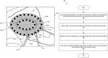
- An exemplary materialincludes a top surface; a plurality of concentric lines printed on the top surface of the material and that define a plurality of concentric regions, the concentric lines configured to guide a user in cutting a patch out of the material for placement over an anatomical surface in an internal space of a patent; and a plurality of fiducial markers printed on the top surface within each of the concentric regions, the fiducial markers configured to be recognized within an image utilizing a machine vision heuristic while the patch is placed over the anatomical surface and guide an affixing of the patch to the anatomical surface by an affixation device coupled to a manipulator arm of a computer-implemented surgical system.
- An exemplary materialmay include a top surface and a plurality of concentric lines printed on the top surface of the material and that define a plurality of concentric regions.
- the concentric linesmay be configured to guide a user in cutting a patch out of the material for placement over an anatomical surface in an internal space of a patent.
- the materialmay further include a plurality of fiducial markers printed on the top surface within each of the concentric regions.
- the fiducial markersmay be configured to be recognized within an image utilizing a machine vision heuristic while the patch is placed over the anatomical surface and guide an affixation of the patch to the anatomical surface by an affixation device coupled to a manipulator arm of a computer-implemented surgical system.
- the materialmay further include a bottom surface configured to adhere to the anatomical surface in the internal space of the patient.
- Suture target data 204may be in any suitable format.
- suture target data 204may include two or three-dimensional pixel coordinates representative of pixels that depict the suture target locations. Additionally or alternatively, suture target data 204 may include two or three-dimensional coordinates representative of physical locations in the internal space.
- suturing device 310may be referred to as a certain type of surgical instrument coupled to and controlled by the computer-assisted surgical system.
- suturing device 310is not controlled by a computer-assisted surgical system.
- suturing device 310may be manually held and/or otherwise controlled by a user and system 100 may provide an indication of the target suture locations to the user for suturing physical medical element 304 to the anatomical surface.
- system 100may also direct surgical instruments 312 - 1 and 312 - 2 (“surgical instruments 312 ”), which may include (among other suitable instruments) any suitable grasping tool configured to hold and guide physical medical element 304 into place.
- surgical instruments 312may also be coupled to manipulator arms of the computer-assisted surgical system.
- surgical instruments 312may be controlled by user input commands provided by a surgeon or other user.
- configuration 400shows system 100 providing preventative measure 406 based on image data 202 , kinematic data 402 , and/or force sensing data 404 .
- system 100may determine a potential collision between a suturing device (e.g., suturing device 310 ) and surgical instrument 312 - 1 based on image data 202 and/or kinematic data 402 .
- Potential collisionsmay be detected in any suitable manner such as by analyzing image data 202 and/or kinematic data 402 to determine positions and/or velocities of suturing device 310 and surgical instrument 312 - 1 .
- System 100may further determine whether the positions are within a threshold amount of each other and/or the velocities may result in such positions. Based on the detection of the potential collision, system 100 may perform one or more of preventative measure 406 .
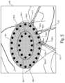
- FIG. 5shows an exemplary image 502 of the internal space shown in image 302 , with physical medical element 304 , suturing device 310 , and surgical instruments 312 .
- system 100has coordinated the movements of suturing device 310 and surgical instruments 312 to the next set of fiducial markers 306 .
- surgical instrument 312 - 1has been repositioned from fiducial marker 306 - 1 to a next fiducial marker to one side (e.g., a right side of fiducial marker 306 - 1 ), fiducial marker 306 - 2 .
- image 502shows system 100 repositioning suturing device 310 and surgical instruments 312 to next fiducial markers to the right of initial fiducial markers in image 302 , it should be evident that movements of suturing device 310 and surgical instruments 312 may be to a left of the initial fiducial markers or any other suitable direction. Additionally, while image 502 repositions each of suturing device 310 and surgical instruments 312 one fiducial marker over, any suitable number of fiducial markers may be used. Further, while images 302 and 502 show surgical instruments 312 each two fiducial markers away from suturing device 310 , any suitable number of fiducial markers may be used. Additionally or alternatively, rather than or in conjunction with the fiducial markers, a specified distance from suturing device 310 may be used to guide movements of surgical instruments 312 .
- surgical instruments 312may provide force sensing data 404 to system 100 based on an amount of force generated on surgical instruments 312 by an anatomical surface.
- an amount of force needed to hold physical medical element 304 against the anatomical surfacemay depend on a position, orientation, and/or contour of the anatomical surface and/or a relation of the anatomical surface to poses of surgical instruments 312 and suturing device 310 .
- force sensing data 404may be used to ensure that an appropriate amount of force is applied by surgical instruments 312 to keep physical medical element 304 in place while not damaging the anatomical surface.
- System 100may determine the appropriate amount of force and include such determinations in arm movement data 408 .
- the physical medical elementmay include concentric regions 604 of fiducial markers 306 that may be used by a medical element management system (e.g., system 100 ), for instance, to automatically suture the physical medical element to the anatomical surface as described herein.
- a medical element management systeme.g., system 100
- the medical element management systemidentifies a region, within the image, that depicts a fiducial marker on the physical medical element. Operation 704 may be performed in any of the ways described herein.
- the medical element management systemdetermines, based on the identified region, an affixation target location on the physical medical element. Operation 706 may be performed in any of the ways described herein.
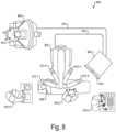
- FIG. 9illustrates an exemplary computing device 900 that may be specifically configured to perform one or more of the processes described herein. Any of the systems, computing devices, and/or other components described herein may be implemented by computing device 900 .
Landscapes
- Health & Medical Sciences (AREA)
- Surgery (AREA)
- Engineering & Computer Science (AREA)
- Life Sciences & Earth Sciences (AREA)
- Medical Informatics (AREA)
- Robotics (AREA)
- Biomedical Technology (AREA)
- Heart & Thoracic Surgery (AREA)
- Nuclear Medicine, Radiotherapy & Molecular Imaging (AREA)
- Molecular Biology (AREA)
- Animal Behavior & Ethology (AREA)
- General Health & Medical Sciences (AREA)
- Public Health (AREA)
- Veterinary Medicine (AREA)
- Oral & Maxillofacial Surgery (AREA)
- Pathology (AREA)
- Manipulator (AREA)
Abstract
Description
Claims (20)
Priority Applications (2)
| Application Number | Priority Date | Filing Date | Title |
|---|---|---|---|
| US17/101,710US12268459B2 (en) | 2019-11-26 | 2020-11-23 | Physical medical element affixation systems, methods, and materials |
| US19/074,957US20250205001A1 (en) | 2019-11-26 | 2025-03-10 | Physical medical element affixation systems, methods, and materials |
Applications Claiming Priority (2)
| Application Number | Priority Date | Filing Date | Title |
|---|---|---|---|
| US201962940351P | 2019-11-26 | 2019-11-26 | |
| US17/101,710US12268459B2 (en) | 2019-11-26 | 2020-11-23 | Physical medical element affixation systems, methods, and materials |
Related Child Applications (1)
| Application Number | Title | Priority Date | Filing Date |
|---|---|---|---|
| US19/074,957ContinuationUS20250205001A1 (en) | 2019-11-26 | 2025-03-10 | Physical medical element affixation systems, methods, and materials |
Publications (2)
| Publication Number | Publication Date |
|---|---|
| US20210153959A1 US20210153959A1 (en) | 2021-05-27 |
| US12268459B2true US12268459B2 (en) | 2025-04-08 |
Family
ID=75974616
Family Applications (2)
| Application Number | Title | Priority Date | Filing Date |
|---|---|---|---|
| US17/101,710Active2042-04-26US12268459B2 (en) | 2019-11-26 | 2020-11-23 | Physical medical element affixation systems, methods, and materials |
| US19/074,957PendingUS20250205001A1 (en) | 2019-11-26 | 2025-03-10 | Physical medical element affixation systems, methods, and materials |
Family Applications After (1)
| Application Number | Title | Priority Date | Filing Date |
|---|---|---|---|
| US19/074,957PendingUS20250205001A1 (en) | 2019-11-26 | 2025-03-10 | Physical medical element affixation systems, methods, and materials |
Country Status (1)
| Country | Link |
|---|---|
| US (2) | US12268459B2 (en) |
Families Citing this family (2)
| Publication number | Priority date | Publication date | Assignee | Title |
|---|---|---|---|---|
| CN114376733B (en)* | 2015-06-09 | 2025-01-10 | 直观外科手术操作公司 | Configuring surgical systems using surgical procedure atlases |
| WO2025027463A1 (en)* | 2023-08-01 | 2025-02-06 | Covidien Lp | System and method for processing combined data streams of surgical robots |
Citations (66)
| Publication number | Priority date | Publication date | Assignee | Title |
|---|---|---|---|---|
| US5603318A (en)* | 1992-04-21 | 1997-02-18 | University Of Utah Research Foundation | Apparatus and method for photogrammetric surgical localization |
| US20010010004A1 (en)* | 1998-06-22 | 2001-07-26 | Doris Traxel | Fiducial matching using fiducial implants |
| US20020107518A1 (en)* | 2001-02-06 | 2002-08-08 | Timo Neubauer | Device for attaching an element to a body |
| US20020133236A1 (en)* | 2001-03-19 | 2002-09-19 | Ethicon, Inc. | Pocketed hernia repair |
| US20030083648A1 (en)* | 1996-02-20 | 2003-05-01 | Yulun Wang | Method and apparatus for performing minimally invasive surgical procedures |
| US20030158477A1 (en)* | 2001-11-09 | 2003-08-21 | Dorin Panescu | Systems and methods for guiding catheters using registered images |
| US20040106916A1 (en)* | 2002-03-06 | 2004-06-03 | Z-Kat, Inc. | Guidance system and method for surgical procedures with improved feedback |
| US20040152972A1 (en)* | 2003-01-30 | 2004-08-05 | Mark Hunter | Method and apparatus for post-operative tuning of a spinal implant |
| US20050113846A1 (en)* | 2001-02-27 | 2005-05-26 | Carson Christopher P. | Surgical navigation systems and processes for unicompartmental knee arthroplasty |
| US20050228270A1 (en)* | 2004-04-02 | 2005-10-13 | Lloyd Charles F | Method and system for geometric distortion free tracking of 3-dimensional objects from 2-dimensional measurements |
| US20050267529A1 (en)* | 2004-05-13 | 2005-12-01 | Heber Crockett | Devices, systems and methods for tissue repair |
| US20060098851A1 (en)* | 2002-06-17 | 2006-05-11 | Moshe Shoham | Robot for use with orthopaedic inserts |
| US20070088340A1 (en)* | 1998-02-24 | 2007-04-19 | Hansen Medical, Inc. | Surgical instruments |
| US20070142825A1 (en)* | 2005-12-20 | 2007-06-21 | Giuseppe Prisco | Method for handling an operator command exceeding a medical device state limitation in a medical robotic system |
| US20070238982A1 (en)* | 2006-03-29 | 2007-10-11 | Caylor Edward J Iii | System and method for monitoring kinematic motion of a patient |
| US20070235768A1 (en)* | 2006-04-10 | 2007-10-11 | Kazushi Nakazawa | Semiconductor device |
| US20070270660A1 (en)* | 2006-03-29 | 2007-11-22 | Caylor Edward J Iii | System and method for determining a location of an orthopaedic medical device |
| US20080125630A1 (en)* | 2006-09-11 | 2008-05-29 | Caylor Edward J | System and method for determining a location of an orthopaedic medical device |
| US20080262523A1 (en)* | 2006-04-19 | 2008-10-23 | Joshua Makower | Devices and methods for treatment of obesity |
| US20080262390A1 (en)* | 2007-04-19 | 2008-10-23 | Searete Llc, A Limited Liability Corporation Of The State Of Delaware | Fiducials for placement of tissue closures |
| US20090088897A1 (en)* | 2007-09-30 | 2009-04-02 | Intuitive Surgical, Inc. | Methods and systems for robotic instrument tool tracking |
| US20100161129A1 (en)* | 2008-12-23 | 2010-06-24 | Intuitive Surgical, Inc. | System and method for adjusting an image capturing device attribute using an unused degree-of-freedom of a master control device |
| US20100168763A1 (en)* | 2008-12-31 | 2010-07-01 | Intuitive Surgical, Inc. | Configuration marker design and detection for instrument tracking |
| US20100168562A1 (en)* | 2008-12-31 | 2010-07-01 | Intuitive Surgical, Inc. | Fiducial marker design and detection for locating surgical instrument in images |
| US7758345B1 (en)* | 2006-04-01 | 2010-07-20 | Medical Modeling Inc. | Systems and methods for design and manufacture of a modified bone model including an accurate soft tissue model |
| US7844320B2 (en)* | 1996-06-28 | 2010-11-30 | Ramin Shahidi | Method and apparatus for volumetric image navigation |
| US20110019884A1 (en)* | 2008-01-09 | 2011-01-27 | Stryker Leibinger Gmbh & Co. Kg | Stereotactic Computer Assisted Surgery Based On Three-Dimensional Visualization |
| US7892247B2 (en)* | 2001-10-03 | 2011-02-22 | Bioconnect Systems, Inc. | Devices and methods for interconnecting vessels |
| US20110160570A1 (en)* | 2009-12-31 | 2011-06-30 | Itay Kariv | Prolapse detection and tool dislodgement detection |
| US20110288568A1 (en)* | 2008-12-19 | 2011-11-24 | Capuzziello Thomas J | Implantable prosthesis |
| US20120071890A1 (en)* | 2010-09-21 | 2012-03-22 | The Johns Hopkins University | Method and appartus for cochlear implant surgery |
| US20120130159A1 (en)* | 2010-11-24 | 2012-05-24 | Omid Abri | Holding system for medical instruments |
| US20130190726A1 (en)* | 2010-04-30 | 2013-07-25 | Children's Medical Center Corporation | Motion compensating catheter device |
| US20130253550A1 (en)* | 2010-01-05 | 2013-09-26 | G. I. Windows, Inc. | Self-assembling magnetic anastomosis device having an exoskeleton |
| US20140018824A1 (en)* | 1998-12-08 | 2014-01-16 | Intuitive Surgical Operations, Inc. | In Vivo Accessories for Minimally Invasive Surgery |
| US20140178832A1 (en)* | 2012-12-21 | 2014-06-26 | Anatomage Inc. | System and method for providing compact navigation-based surgical guide in dental implant surgery |
| US20140229007A1 (en)* | 2011-10-18 | 2014-08-14 | Olympus Corporation | Operation input device and method of initializing operation input device |
| US20140343416A1 (en)* | 2013-05-16 | 2014-11-20 | Intuitive Surgical Operations, Inc. | Systems and methods for robotic medical system integration with external imaging |
| US20150100066A1 (en)* | 2013-10-04 | 2015-04-09 | KB Medical SA | Apparatus, systems, and methods for precise guidance of surgical tools |
| US20150150457A1 (en)* | 2013-12-03 | 2015-06-04 | Children's National Medical Center | Method and system for wound assessment and management |
| US9220570B2 (en)* | 2012-06-29 | 2015-12-29 | Children's National Medical Center | Automated surgical and interventional procedures |
| US9402691B2 (en)* | 2014-09-16 | 2016-08-02 | X-Nav Technologies, LLC | System for determining and tracking movement during a medical procedure |
| US20160324523A1 (en)* | 2015-05-08 | 2016-11-10 | GI Windows, Inc. | Systems, devices, and methods for forming anastomoses |
| US20170079722A1 (en)* | 2014-03-17 | 2017-03-23 | Intuitive Surgical Operations, Inc. | Methods and devices for table pose tracking using fudicial markers |
| US20170181825A1 (en)* | 2014-06-25 | 2017-06-29 | Canary Medical Inc. | Devices, systems and methods for using and monitoring implants |
| US20170210012A1 (en)* | 2006-06-29 | 2017-07-27 | Intuitive Surgical Operations, Inc. | Tool position and identification indicator displayed in a boundary area of a computer display screen |
| US20170219339A1 (en)* | 2014-07-31 | 2017-08-03 | Hewlett-Packard Development Company, L.P. | Measuring and correcting optical misalignment |
| US20170265866A1 (en)* | 2016-03-16 | 2017-09-21 | GI Windows, Inc. | Targeting systems for providing accurate placement of magnetic anastomosis devices |
| US9795446B2 (en)* | 2005-06-06 | 2017-10-24 | Intuitive Surgical Operations, Inc. | Systems and methods for interactive user interfaces for robotic minimally invasive surgical systems |
| US20170323062A1 (en)* | 2014-11-18 | 2017-11-09 | Koninklijke Philips N.V. | User guidance system and method, use of an augmented reality device |
| US20180014888A1 (en)* | 2015-03-05 | 2018-01-18 | Think Surgical, Inc. | Methods for locating and tracking a tool axis |
| US20180070860A1 (en)* | 2016-09-12 | 2018-03-15 | Medos International Sarl | Systems and methods for anatomical alignment |
| US20180098766A1 (en)* | 2011-02-15 | 2018-04-12 | Intuitive Surgical Operations, Inc. | Methods and systems for controlling staple firing |
| US20180116731A1 (en)* | 2016-10-27 | 2018-05-03 | Inneroptic Technology, Inc. | Medical instrument navigation |
| US20190008624A1 (en)* | 2012-03-22 | 2019-01-10 | Sofradim Production | Guide for selecting and positioning a prosthesis |
| US20190021796A1 (en)* | 2017-07-20 | 2019-01-24 | Howmedica Osteonics Corp. | System and method for robotically assisting a surgical procedure |
| US20190059696A1 (en)* | 2016-03-09 | 2019-02-28 | Sony Corporation | Image processing device, endoscopic surgery system, and image processing method |
| US20200038108A1 (en)* | 2018-08-02 | 2020-02-06 | Point Robotics Medtech Inc. | Sugery assistive system and method for obtaining surface information thereof |
| US20200100881A1 (en)* | 2018-09-27 | 2020-04-02 | X-Nav Technologies, LLC | Method for dynamically guiding a dental oral and maxillofacial prosthesis |
| US20200129240A1 (en)* | 2017-06-30 | 2020-04-30 | Mirus Llc | Systems and methods for intraoperative planning and placement of implants |
| US20200229893A1 (en)* | 2019-01-23 | 2020-07-23 | Eloupes, Inc. | Aligning Pre-Operative Scan Images To Real-Time Operative Images For A Mediated-Reality View Of A Surgical Site |
| US20210022693A1 (en)* | 2018-02-14 | 2021-01-28 | Rowan University | Methods for detecting positional movement of orthopedic implants |
| US20210196399A1 (en)* | 2019-12-31 | 2021-07-01 | Auris Health, Inc. | Alignment techniques for percutaneous access |
| US20210366012A1 (en)* | 2016-02-29 | 2021-11-25 | Canary Medical Inc. | Computer-based marketplace for information |
| US20220361958A1 (en)* | 2021-05-17 | 2022-11-17 | Kim Herbert Manwaring | Registration and alignment of implantable sonic windows |
| US20230270504A1 (en)* | 2020-08-06 | 2023-08-31 | Neocis Inc. | System and method for prosthetic placement, surgical guide placement, and orthognathic surgery reassembly |
- 2020
- 2020-11-23USUS17/101,710patent/US12268459B2/enactiveActive
- 2025
- 2025-03-10USUS19/074,957patent/US20250205001A1/enactivePending
Patent Citations (68)
| Publication number | Priority date | Publication date | Assignee | Title |
|---|---|---|---|---|
| US5603318A (en)* | 1992-04-21 | 1997-02-18 | University Of Utah Research Foundation | Apparatus and method for photogrammetric surgical localization |
| US20030083648A1 (en)* | 1996-02-20 | 2003-05-01 | Yulun Wang | Method and apparatus for performing minimally invasive surgical procedures |
| US7844320B2 (en)* | 1996-06-28 | 2010-11-30 | Ramin Shahidi | Method and apparatus for volumetric image navigation |
| US20070088340A1 (en)* | 1998-02-24 | 2007-04-19 | Hansen Medical, Inc. | Surgical instruments |
| US20010010004A1 (en)* | 1998-06-22 | 2001-07-26 | Doris Traxel | Fiducial matching using fiducial implants |
| US20140018824A1 (en)* | 1998-12-08 | 2014-01-16 | Intuitive Surgical Operations, Inc. | In Vivo Accessories for Minimally Invasive Surgery |
| US20020107518A1 (en)* | 2001-02-06 | 2002-08-08 | Timo Neubauer | Device for attaching an element to a body |
| US20050113846A1 (en)* | 2001-02-27 | 2005-05-26 | Carson Christopher P. | Surgical navigation systems and processes for unicompartmental knee arthroplasty |
| US20020133236A1 (en)* | 2001-03-19 | 2002-09-19 | Ethicon, Inc. | Pocketed hernia repair |
| US7892247B2 (en)* | 2001-10-03 | 2011-02-22 | Bioconnect Systems, Inc. | Devices and methods for interconnecting vessels |
| US20030158477A1 (en)* | 2001-11-09 | 2003-08-21 | Dorin Panescu | Systems and methods for guiding catheters using registered images |
| US20040106916A1 (en)* | 2002-03-06 | 2004-06-03 | Z-Kat, Inc. | Guidance system and method for surgical procedures with improved feedback |
| US20060098851A1 (en)* | 2002-06-17 | 2006-05-11 | Moshe Shoham | Robot for use with orthopaedic inserts |
| US20040152972A1 (en)* | 2003-01-30 | 2004-08-05 | Mark Hunter | Method and apparatus for post-operative tuning of a spinal implant |
| US20050228270A1 (en)* | 2004-04-02 | 2005-10-13 | Lloyd Charles F | Method and system for geometric distortion free tracking of 3-dimensional objects from 2-dimensional measurements |
| US20050267529A1 (en)* | 2004-05-13 | 2005-12-01 | Heber Crockett | Devices, systems and methods for tissue repair |
| US9795446B2 (en)* | 2005-06-06 | 2017-10-24 | Intuitive Surgical Operations, Inc. | Systems and methods for interactive user interfaces for robotic minimally invasive surgical systems |
| US20070142825A1 (en)* | 2005-12-20 | 2007-06-21 | Giuseppe Prisco | Method for handling an operator command exceeding a medical device state limitation in a medical robotic system |
| US20070270660A1 (en)* | 2006-03-29 | 2007-11-22 | Caylor Edward J Iii | System and method for determining a location of an orthopaedic medical device |
| US20070238982A1 (en)* | 2006-03-29 | 2007-10-11 | Caylor Edward J Iii | System and method for monitoring kinematic motion of a patient |
| US7758345B1 (en)* | 2006-04-01 | 2010-07-20 | Medical Modeling Inc. | Systems and methods for design and manufacture of a modified bone model including an accurate soft tissue model |
| US20070235768A1 (en)* | 2006-04-10 | 2007-10-11 | Kazushi Nakazawa | Semiconductor device |
| US20080262523A1 (en)* | 2006-04-19 | 2008-10-23 | Joshua Makower | Devices and methods for treatment of obesity |
| US20170210012A1 (en)* | 2006-06-29 | 2017-07-27 | Intuitive Surgical Operations, Inc. | Tool position and identification indicator displayed in a boundary area of a computer display screen |
| US20200331147A1 (en)* | 2006-06-29 | 2020-10-22 | Intuitive Surgical Operations, Inc. | Tool position and identification indicator displayed in a boundary area of a computer display screen |
| US20080125630A1 (en)* | 2006-09-11 | 2008-05-29 | Caylor Edward J | System and method for determining a location of an orthopaedic medical device |
| US20080262390A1 (en)* | 2007-04-19 | 2008-10-23 | Searete Llc, A Limited Liability Corporation Of The State Of Delaware | Fiducials for placement of tissue closures |
| US20090088897A1 (en)* | 2007-09-30 | 2009-04-02 | Intuitive Surgical, Inc. | Methods and systems for robotic instrument tool tracking |
| US20110019884A1 (en)* | 2008-01-09 | 2011-01-27 | Stryker Leibinger Gmbh & Co. Kg | Stereotactic Computer Assisted Surgery Based On Three-Dimensional Visualization |
| US20110288568A1 (en)* | 2008-12-19 | 2011-11-24 | Capuzziello Thomas J | Implantable prosthesis |
| US20100161129A1 (en)* | 2008-12-23 | 2010-06-24 | Intuitive Surgical, Inc. | System and method for adjusting an image capturing device attribute using an unused degree-of-freedom of a master control device |
| US20100168763A1 (en)* | 2008-12-31 | 2010-07-01 | Intuitive Surgical, Inc. | Configuration marker design and detection for instrument tracking |
| US20100168562A1 (en)* | 2008-12-31 | 2010-07-01 | Intuitive Surgical, Inc. | Fiducial marker design and detection for locating surgical instrument in images |
| US20110160570A1 (en)* | 2009-12-31 | 2011-06-30 | Itay Kariv | Prolapse detection and tool dislodgement detection |
| US20130253550A1 (en)* | 2010-01-05 | 2013-09-26 | G. I. Windows, Inc. | Self-assembling magnetic anastomosis device having an exoskeleton |
| US20130190726A1 (en)* | 2010-04-30 | 2013-07-25 | Children's Medical Center Corporation | Motion compensating catheter device |
| US20120071890A1 (en)* | 2010-09-21 | 2012-03-22 | The Johns Hopkins University | Method and appartus for cochlear implant surgery |
| US20120130159A1 (en)* | 2010-11-24 | 2012-05-24 | Omid Abri | Holding system for medical instruments |
| US11589863B2 (en)* | 2011-02-15 | 2023-02-28 | Intuitive Surgical Operations, Inc. | Methods and systems for controlling staple firing |
| US20180098766A1 (en)* | 2011-02-15 | 2018-04-12 | Intuitive Surgical Operations, Inc. | Methods and systems for controlling staple firing |
| US20140229007A1 (en)* | 2011-10-18 | 2014-08-14 | Olympus Corporation | Operation input device and method of initializing operation input device |
| US20190008624A1 (en)* | 2012-03-22 | 2019-01-10 | Sofradim Production | Guide for selecting and positioning a prosthesis |
| US9220570B2 (en)* | 2012-06-29 | 2015-12-29 | Children's National Medical Center | Automated surgical and interventional procedures |
| US20140178832A1 (en)* | 2012-12-21 | 2014-06-26 | Anatomage Inc. | System and method for providing compact navigation-based surgical guide in dental implant surgery |
| US20140343416A1 (en)* | 2013-05-16 | 2014-11-20 | Intuitive Surgical Operations, Inc. | Systems and methods for robotic medical system integration with external imaging |
| US20150100066A1 (en)* | 2013-10-04 | 2015-04-09 | KB Medical SA | Apparatus, systems, and methods for precise guidance of surgical tools |
| US20150150457A1 (en)* | 2013-12-03 | 2015-06-04 | Children's National Medical Center | Method and system for wound assessment and management |
| US20170079722A1 (en)* | 2014-03-17 | 2017-03-23 | Intuitive Surgical Operations, Inc. | Methods and devices for table pose tracking using fudicial markers |
| US20170181825A1 (en)* | 2014-06-25 | 2017-06-29 | Canary Medical Inc. | Devices, systems and methods for using and monitoring implants |
| US20170219339A1 (en)* | 2014-07-31 | 2017-08-03 | Hewlett-Packard Development Company, L.P. | Measuring and correcting optical misalignment |
| US9402691B2 (en)* | 2014-09-16 | 2016-08-02 | X-Nav Technologies, LLC | System for determining and tracking movement during a medical procedure |
| US20170323062A1 (en)* | 2014-11-18 | 2017-11-09 | Koninklijke Philips N.V. | User guidance system and method, use of an augmented reality device |
| US20180014888A1 (en)* | 2015-03-05 | 2018-01-18 | Think Surgical, Inc. | Methods for locating and tracking a tool axis |
| US20160324523A1 (en)* | 2015-05-08 | 2016-11-10 | GI Windows, Inc. | Systems, devices, and methods for forming anastomoses |
| US20210366012A1 (en)* | 2016-02-29 | 2021-11-25 | Canary Medical Inc. | Computer-based marketplace for information |
| US20190059696A1 (en)* | 2016-03-09 | 2019-02-28 | Sony Corporation | Image processing device, endoscopic surgery system, and image processing method |
| US20170265866A1 (en)* | 2016-03-16 | 2017-09-21 | GI Windows, Inc. | Targeting systems for providing accurate placement of magnetic anastomosis devices |
| US20180070860A1 (en)* | 2016-09-12 | 2018-03-15 | Medos International Sarl | Systems and methods for anatomical alignment |
| US20180116731A1 (en)* | 2016-10-27 | 2018-05-03 | Inneroptic Technology, Inc. | Medical instrument navigation |
| US20200129240A1 (en)* | 2017-06-30 | 2020-04-30 | Mirus Llc | Systems and methods for intraoperative planning and placement of implants |
| US20190021796A1 (en)* | 2017-07-20 | 2019-01-24 | Howmedica Osteonics Corp. | System and method for robotically assisting a surgical procedure |
| US20210022693A1 (en)* | 2018-02-14 | 2021-01-28 | Rowan University | Methods for detecting positional movement of orthopedic implants |
| US20200038108A1 (en)* | 2018-08-02 | 2020-02-06 | Point Robotics Medtech Inc. | Sugery assistive system and method for obtaining surface information thereof |
| US20200100881A1 (en)* | 2018-09-27 | 2020-04-02 | X-Nav Technologies, LLC | Method for dynamically guiding a dental oral and maxillofacial prosthesis |
| US20200229893A1 (en)* | 2019-01-23 | 2020-07-23 | Eloupes, Inc. | Aligning Pre-Operative Scan Images To Real-Time Operative Images For A Mediated-Reality View Of A Surgical Site |
| US20210196399A1 (en)* | 2019-12-31 | 2021-07-01 | Auris Health, Inc. | Alignment techniques for percutaneous access |
| US20230270504A1 (en)* | 2020-08-06 | 2023-08-31 | Neocis Inc. | System and method for prosthetic placement, surgical guide placement, and orthognathic surgery reassembly |
| US20220361958A1 (en)* | 2021-05-17 | 2022-11-17 | Kim Herbert Manwaring | Registration and alignment of implantable sonic windows |
Non-Patent Citations (1)
| Title |
|---|
| Vertut, Jean and Phillipe Coiffet, Robot Technology: Teleoperation and Robotics Evolution and Development, English translation, Prentice-Hall, Inc., Inglewood Cliffs, NJ, USA 1986, vol. 3A, 332 pages. |
Also Published As
| Publication number | Publication date |
|---|---|
| US20250205001A1 (en) | 2025-06-26 |
| US20210153959A1 (en) | 2021-05-27 |
Similar Documents
| Publication | Publication Date | Title |
|---|---|---|
| US20250090241A1 (en) | Systems and methods for tracking a position of a robotically-manipulated surgical instrument | |
| EP3737322B1 (en) | Guidance for placement of surgical ports | |
| US20250205001A1 (en) | Physical medical element affixation systems, methods, and materials | |
| US12165317B2 (en) | Composite medical imaging systems and methods | |
| US11896441B2 (en) | Systems and methods for measuring a distance using a stereoscopic endoscope | |
| US12322089B2 (en) | Physical medical element sizing systems and methods | |
| EP4090254A1 (en) | Systems and methods for autonomous suturing | |
| JP2011502673A (en) | Robot, medical workstation and method for projecting an image on the surface of an object | |
| JP2007007041A (en) | Surgery support | |
| WO2021126788A1 (en) | Systems for facilitating guided teleoperation of a non-robotic device in a surgical space | |
| US20250114146A1 (en) | Physical medical element placement systems and methods | |
| JP2024541293A (en) | An interactive augmented reality system for laparoscopic and video-assisted surgery | |
| CN114830638A (en) | System and method for telestration with spatial memory | |
| US20170258375A1 (en) | Method, system and apparatus for image capture and registration in image-guided surgery | |
| JP4785127B2 (en) | Endoscopic visual field expansion system, endoscopic visual field expansion device, and endoscope visual field expansion program | |
| US12285153B2 (en) | Anatomical scene visualization systems and methods | |
| WO2025010362A1 (en) | Determination of a curvilinear distance within a subject | |
| WO2025019594A1 (en) | Systems and methods for implementing a zoom feature associated with an imaging device in an imaging space |
Legal Events
| Date | Code | Title | Description |
|---|---|---|---|
| AS | Assignment | Owner name:INTUITIVE SURGICAL OPERATIONS, INC., CALIFORNIA Free format text:ASSIGNMENT OF ASSIGNORS INTEREST;ASSIGNOR:SHAW, RYAN W.;REEL/FRAME:054447/0141 Effective date:20200413 | |
| FEPP | Fee payment procedure | Free format text:ENTITY STATUS SET TO UNDISCOUNTED (ORIGINAL EVENT CODE: BIG.); ENTITY STATUS OF PATENT OWNER: LARGE ENTITY | |
| AS | Assignment | Owner name:INTUITIVE SURGICAL OPERATIONS, INC., CALIFORNIA Free format text:ASSIGNMENT OF ASSIGNORS INTEREST;ASSIGNOR:SHAW, RYAN W.;REEL/FRAME:054552/0713 Effective date:20201202 | |
| STPP | Information on status: patent application and granting procedure in general | Free format text:APPLICATION DISPATCHED FROM PREEXAM, NOT YET DOCKETED | |
| STPP | Information on status: patent application and granting procedure in general | Free format text:DOCKETED NEW CASE - READY FOR EXAMINATION | |
| STPP | Information on status: patent application and granting procedure in general | Free format text:RESPONSE TO NON-FINAL OFFICE ACTION ENTERED AND FORWARDED TO EXAMINER | |
| STPP | Information on status: patent application and granting procedure in general | Free format text:FINAL REJECTION MAILED | |
| STPP | Information on status: patent application and granting procedure in general | Free format text:RESPONSE AFTER FINAL ACTION FORWARDED TO EXAMINER | |
| STPP | Information on status: patent application and granting procedure in general | Free format text:ADVISORY ACTION MAILED | |
| STPP | Information on status: patent application and granting procedure in general | Free format text:DOCKETED NEW CASE - READY FOR EXAMINATION | |
| STPP | Information on status: patent application and granting procedure in general | Free format text:NON FINAL ACTION MAILED | |
| STPP | Information on status: patent application and granting procedure in general | Free format text:RESPONSE TO NON-FINAL OFFICE ACTION ENTERED AND FORWARDED TO EXAMINER | |
| STPP | Information on status: patent application and granting procedure in general | Free format text:FINAL REJECTION MAILED | |
| STPP | Information on status: patent application and granting procedure in general | Free format text:RESPONSE AFTER FINAL ACTION FORWARDED TO EXAMINER | |
| STPP | Information on status: patent application and granting procedure in general | Free format text:NOTICE OF ALLOWANCE MAILED -- APPLICATION RECEIVED IN OFFICE OF PUBLICATIONS | |
| STPP | Information on status: patent application and granting procedure in general | Free format text:PUBLICATIONS -- ISSUE FEE PAYMENT VERIFIED | |
| STCF | Information on status: patent grant | Free format text:PATENTED CASE |