US12268433B2 - Devices for therapeutic nasal neuromodulation and associated methods and systems - Google Patents
Devices for therapeutic nasal neuromodulation and associated methods and systemsDownload PDFInfo
- Publication number
- US12268433B2 US12268433B2US18/678,536US202418678536AUS12268433B2US 12268433 B2US12268433 B2US 12268433B2US 202418678536 AUS202418678536 AUS 202418678536AUS 12268433 B2US12268433 B2US 12268433B2
- Authority
- US
- United States
- Prior art keywords
- electrodes
- energy
- treatment
- tissue
- shaft
- Prior art date
- Legal status (The legal status is an assumption and is not a legal conclusion. Google has not performed a legal analysis and makes no representation as to the accuracy of the status listed.)
- Active
Links
Images


Classifications
- A—HUMAN NECESSITIES
- A61—MEDICAL OR VETERINARY SCIENCE; HYGIENE
- A61B—DIAGNOSIS; SURGERY; IDENTIFICATION
- A61B18/00—Surgical instruments, devices or methods for transferring non-mechanical forms of energy to or from the body
- A61B18/04—Surgical instruments, devices or methods for transferring non-mechanical forms of energy to or from the body by heating
- A61B18/12—Surgical instruments, devices or methods for transferring non-mechanical forms of energy to or from the body by heating by passing a current through the tissue to be heated, e.g. high-frequency current
- A61B18/1206—Generators therefor
- A—HUMAN NECESSITIES
- A61—MEDICAL OR VETERINARY SCIENCE; HYGIENE
- A61B—DIAGNOSIS; SURGERY; IDENTIFICATION
- A61B18/00—Surgical instruments, devices or methods for transferring non-mechanical forms of energy to or from the body
- A61B18/04—Surgical instruments, devices or methods for transferring non-mechanical forms of energy to or from the body by heating
- A61B18/12—Surgical instruments, devices or methods for transferring non-mechanical forms of energy to or from the body by heating by passing a current through the tissue to be heated, e.g. high-frequency current
- A61B18/14—Probes or electrodes therefor
- A61B18/1485—Probes or electrodes therefor having a short rigid shaft for accessing the inner body through natural openings
- A—HUMAN NECESSITIES
- A61—MEDICAL OR VETERINARY SCIENCE; HYGIENE
- A61B—DIAGNOSIS; SURGERY; IDENTIFICATION
- A61B18/00—Surgical instruments, devices or methods for transferring non-mechanical forms of energy to or from the body
- A61B18/04—Surgical instruments, devices or methods for transferring non-mechanical forms of energy to or from the body by heating
- A61B18/12—Surgical instruments, devices or methods for transferring non-mechanical forms of energy to or from the body by heating by passing a current through the tissue to be heated, e.g. high-frequency current
- A61B18/14—Probes or electrodes therefor
- A61B18/1492—Probes or electrodes therefor having a flexible, catheter-like structure, e.g. for heart ablation
- A—HUMAN NECESSITIES
- A61—MEDICAL OR VETERINARY SCIENCE; HYGIENE
- A61B—DIAGNOSIS; SURGERY; IDENTIFICATION
- A61B34/00—Computer-aided surgery; Manipulators or robots specially adapted for use in surgery
- A61B34/25—User interfaces for surgical systems
- A—HUMAN NECESSITIES
- A61—MEDICAL OR VETERINARY SCIENCE; HYGIENE
- A61B—DIAGNOSIS; SURGERY; IDENTIFICATION
- A61B18/00—Surgical instruments, devices or methods for transferring non-mechanical forms of energy to or from the body
- A61B18/02—Surgical instruments, devices or methods for transferring non-mechanical forms of energy to or from the body by cooling, e.g. cryogenic techniques
- A—HUMAN NECESSITIES
- A61—MEDICAL OR VETERINARY SCIENCE; HYGIENE
- A61B—DIAGNOSIS; SURGERY; IDENTIFICATION
- A61B18/00—Surgical instruments, devices or methods for transferring non-mechanical forms of energy to or from the body
- A61B18/18—Surgical instruments, devices or methods for transferring non-mechanical forms of energy to or from the body by applying electromagnetic radiation, e.g. microwaves
- A61B18/20—Surgical instruments, devices or methods for transferring non-mechanical forms of energy to or from the body by applying electromagnetic radiation, e.g. microwaves using laser
- A—HUMAN NECESSITIES
- A61—MEDICAL OR VETERINARY SCIENCE; HYGIENE
- A61B—DIAGNOSIS; SURGERY; IDENTIFICATION
- A61B17/00—Surgical instruments, devices or methods
- A61B2017/00017—Electrical control of surgical instruments
- A61B2017/00199—Electrical control of surgical instruments with a console, e.g. a control panel with a display
- A—HUMAN NECESSITIES
- A61—MEDICAL OR VETERINARY SCIENCE; HYGIENE
- A61B—DIAGNOSIS; SURGERY; IDENTIFICATION
- A61B17/00—Surgical instruments, devices or methods
- A61B17/00234—Surgical instruments, devices or methods for minimally invasive surgery
- A61B2017/00292—Surgical instruments, devices or methods for minimally invasive surgery mounted on or guided by flexible, e.g. catheter-like, means
- A—HUMAN NECESSITIES
- A61—MEDICAL OR VETERINARY SCIENCE; HYGIENE
- A61B—DIAGNOSIS; SURGERY; IDENTIFICATION
- A61B17/00—Surgical instruments, devices or methods
- A61B2017/00831—Material properties
- A61B2017/00862—Material properties elastic or resilient
- A—HUMAN NECESSITIES
- A61—MEDICAL OR VETERINARY SCIENCE; HYGIENE
- A61B—DIAGNOSIS; SURGERY; IDENTIFICATION
- A61B17/00—Surgical instruments, devices or methods
- A61B2017/00831—Material properties
- A61B2017/00867—Material properties shape memory effect
- A—HUMAN NECESSITIES
- A61—MEDICAL OR VETERINARY SCIENCE; HYGIENE
- A61B—DIAGNOSIS; SURGERY; IDENTIFICATION
- A61B18/00—Surgical instruments, devices or methods for transferring non-mechanical forms of energy to or from the body
- A61B2018/00053—Mechanical features of the instrument of device
- A61B2018/0016—Energy applicators arranged in a two- or three dimensional array
- A—HUMAN NECESSITIES
- A61—MEDICAL OR VETERINARY SCIENCE; HYGIENE
- A61B—DIAGNOSIS; SURGERY; IDENTIFICATION
- A61B18/00—Surgical instruments, devices or methods for transferring non-mechanical forms of energy to or from the body
- A61B2018/00053—Mechanical features of the instrument of device
- A61B2018/00214—Expandable means emitting energy, e.g. by elements carried thereon
- A61B2018/0022—Balloons
- A—HUMAN NECESSITIES
- A61—MEDICAL OR VETERINARY SCIENCE; HYGIENE
- A61B—DIAGNOSIS; SURGERY; IDENTIFICATION
- A61B18/00—Surgical instruments, devices or methods for transferring non-mechanical forms of energy to or from the body
- A61B2018/00053—Mechanical features of the instrument of device
- A61B2018/00273—Anchoring means for temporary attachment of a device to tissue
- A—HUMAN NECESSITIES
- A61—MEDICAL OR VETERINARY SCIENCE; HYGIENE
- A61B—DIAGNOSIS; SURGERY; IDENTIFICATION
- A61B18/00—Surgical instruments, devices or methods for transferring non-mechanical forms of energy to or from the body
- A61B2018/00315—Surgical instruments, devices or methods for transferring non-mechanical forms of energy to or from the body for treatment of particular body parts
- A61B2018/00321—Head or parts thereof
- A61B2018/00327—Ear, nose or throat
- A—HUMAN NECESSITIES
- A61—MEDICAL OR VETERINARY SCIENCE; HYGIENE
- A61B—DIAGNOSIS; SURGERY; IDENTIFICATION
- A61B18/00—Surgical instruments, devices or methods for transferring non-mechanical forms of energy to or from the body
- A61B2018/00315—Surgical instruments, devices or methods for transferring non-mechanical forms of energy to or from the body for treatment of particular body parts
- A61B2018/00434—Neural system
- A—HUMAN NECESSITIES
- A61—MEDICAL OR VETERINARY SCIENCE; HYGIENE
- A61B—DIAGNOSIS; SURGERY; IDENTIFICATION
- A61B18/00—Surgical instruments, devices or methods for transferring non-mechanical forms of energy to or from the body
- A61B2018/00571—Surgical instruments, devices or methods for transferring non-mechanical forms of energy to or from the body for achieving a particular surgical effect
- A61B2018/00577—Ablation
- A—HUMAN NECESSITIES
- A61—MEDICAL OR VETERINARY SCIENCE; HYGIENE
- A61B—DIAGNOSIS; SURGERY; IDENTIFICATION
- A61B18/00—Surgical instruments, devices or methods for transferring non-mechanical forms of energy to or from the body
- A61B2018/00636—Sensing and controlling the application of energy
- A61B2018/00642—Sensing and controlling the application of energy with feedback, i.e. closed loop control
- A61B2018/00648—Sensing and controlling the application of energy with feedback, i.e. closed loop control using more than one sensed parameter
- A—HUMAN NECESSITIES
- A61—MEDICAL OR VETERINARY SCIENCE; HYGIENE
- A61B—DIAGNOSIS; SURGERY; IDENTIFICATION
- A61B18/00—Surgical instruments, devices or methods for transferring non-mechanical forms of energy to or from the body
- A61B2018/00636—Sensing and controlling the application of energy
- A61B2018/00666—Sensing and controlling the application of energy using a threshold value
- A61B2018/00672—Sensing and controlling the application of energy using a threshold value lower
- A—HUMAN NECESSITIES
- A61—MEDICAL OR VETERINARY SCIENCE; HYGIENE
- A61B—DIAGNOSIS; SURGERY; IDENTIFICATION
- A61B18/00—Surgical instruments, devices or methods for transferring non-mechanical forms of energy to or from the body
- A61B2018/00636—Sensing and controlling the application of energy
- A61B2018/00696—Controlled or regulated parameters
- A61B2018/00702—Power or energy
- A—HUMAN NECESSITIES
- A61—MEDICAL OR VETERINARY SCIENCE; HYGIENE
- A61B—DIAGNOSIS; SURGERY; IDENTIFICATION
- A61B18/00—Surgical instruments, devices or methods for transferring non-mechanical forms of energy to or from the body
- A61B2018/00636—Sensing and controlling the application of energy
- A61B2018/00773—Sensed parameters
- A61B2018/00791—Temperature
- A61B2018/00815—Temperature measured by a thermistor
- A—HUMAN NECESSITIES
- A61—MEDICAL OR VETERINARY SCIENCE; HYGIENE
- A61B—DIAGNOSIS; SURGERY; IDENTIFICATION
- A61B18/00—Surgical instruments, devices or methods for transferring non-mechanical forms of energy to or from the body
- A61B2018/00636—Sensing and controlling the application of energy
- A61B2018/00773—Sensed parameters
- A61B2018/00791—Temperature
- A61B2018/00821—Temperature measured by a thermocouple
- A—HUMAN NECESSITIES
- A61—MEDICAL OR VETERINARY SCIENCE; HYGIENE
- A61B—DIAGNOSIS; SURGERY; IDENTIFICATION
- A61B18/00—Surgical instruments, devices or methods for transferring non-mechanical forms of energy to or from the body
- A61B2018/00636—Sensing and controlling the application of energy
- A61B2018/00773—Sensed parameters
- A61B2018/00875—Resistance or impedance
- A—HUMAN NECESSITIES
- A61—MEDICAL OR VETERINARY SCIENCE; HYGIENE
- A61B—DIAGNOSIS; SURGERY; IDENTIFICATION
- A61B18/00—Surgical instruments, devices or methods for transferring non-mechanical forms of energy to or from the body
- A61B18/04—Surgical instruments, devices or methods for transferring non-mechanical forms of energy to or from the body by heating
- A61B18/12—Surgical instruments, devices or methods for transferring non-mechanical forms of energy to or from the body by heating by passing a current through the tissue to be heated, e.g. high-frequency current
- A61B18/1206—Generators therefor
- A61B2018/1246—Generators therefor characterised by the output polarity
- A61B2018/1253—Generators therefor characterised by the output polarity monopolar
- A—HUMAN NECESSITIES
- A61—MEDICAL OR VETERINARY SCIENCE; HYGIENE
- A61B—DIAGNOSIS; SURGERY; IDENTIFICATION
- A61B18/00—Surgical instruments, devices or methods for transferring non-mechanical forms of energy to or from the body
- A61B18/04—Surgical instruments, devices or methods for transferring non-mechanical forms of energy to or from the body by heating
- A61B18/12—Surgical instruments, devices or methods for transferring non-mechanical forms of energy to or from the body by heating by passing a current through the tissue to be heated, e.g. high-frequency current
- A61B18/1206—Generators therefor
- A61B2018/1246—Generators therefor characterised by the output polarity
- A61B2018/126—Generators therefor characterised by the output polarity bipolar
- A—HUMAN NECESSITIES
- A61—MEDICAL OR VETERINARY SCIENCE; HYGIENE
- A61B—DIAGNOSIS; SURGERY; IDENTIFICATION
- A61B18/00—Surgical instruments, devices or methods for transferring non-mechanical forms of energy to or from the body
- A61B18/04—Surgical instruments, devices or methods for transferring non-mechanical forms of energy to or from the body by heating
- A61B18/12—Surgical instruments, devices or methods for transferring non-mechanical forms of energy to or from the body by heating by passing a current through the tissue to be heated, e.g. high-frequency current
- A61B18/14—Probes or electrodes therefor
- A61B2018/1467—Probes or electrodes therefor using more than two electrodes on a single probe
- A—HUMAN NECESSITIES
- A61—MEDICAL OR VETERINARY SCIENCE; HYGIENE
- A61B—DIAGNOSIS; SURGERY; IDENTIFICATION
- A61B18/00—Surgical instruments, devices or methods for transferring non-mechanical forms of energy to or from the body
- A61B18/18—Surgical instruments, devices or methods for transferring non-mechanical forms of energy to or from the body by applying electromagnetic radiation, e.g. microwaves
- A61B2018/1807—Surgical instruments, devices or methods for transferring non-mechanical forms of energy to or from the body by applying electromagnetic radiation, e.g. microwaves using light other than laser radiation
- A—HUMAN NECESSITIES
- A61—MEDICAL OR VETERINARY SCIENCE; HYGIENE
- A61B—DIAGNOSIS; SURGERY; IDENTIFICATION
- A61B18/00—Surgical instruments, devices or methods for transferring non-mechanical forms of energy to or from the body
- A61B18/18—Surgical instruments, devices or methods for transferring non-mechanical forms of energy to or from the body by applying electromagnetic radiation, e.g. microwaves
- A61B18/1815—Surgical instruments, devices or methods for transferring non-mechanical forms of energy to or from the body by applying electromagnetic radiation, e.g. microwaves using microwaves
- A61B2018/1823—Generators therefor
- A—HUMAN NECESSITIES
- A61—MEDICAL OR VETERINARY SCIENCE; HYGIENE
- A61B—DIAGNOSIS; SURGERY; IDENTIFICATION
- A61B90/00—Instruments, implements or accessories specially adapted for surgery or diagnosis and not covered by any of the groups A61B1/00 - A61B50/00, e.g. for luxation treatment or for protecting wound edges
- A61B90/36—Image-producing devices or illumination devices not otherwise provided for
- A61B90/37—Surgical systems with images on a monitor during operation
- A61B2090/373—Surgical systems with images on a monitor during operation using light, e.g. by using optical scanners
- A61B2090/3735—Optical coherence tomography [OCT]
- A—HUMAN NECESSITIES
- A61—MEDICAL OR VETERINARY SCIENCE; HYGIENE
- A61B—DIAGNOSIS; SURGERY; IDENTIFICATION
- A61B90/00—Instruments, implements or accessories specially adapted for surgery or diagnosis and not covered by any of the groups A61B1/00 - A61B50/00, e.g. for luxation treatment or for protecting wound edges
- A61B90/36—Image-producing devices or illumination devices not otherwise provided for
- A61B90/37—Surgical systems with images on a monitor during operation
- A61B2090/376—Surgical systems with images on a monitor during operation using X-rays, e.g. fluoroscopy
- A61B2090/3762—Surgical systems with images on a monitor during operation using X-rays, e.g. fluoroscopy using computed tomography systems [CT]
- A—HUMAN NECESSITIES
- A61—MEDICAL OR VETERINARY SCIENCE; HYGIENE
- A61B—DIAGNOSIS; SURGERY; IDENTIFICATION
- A61B90/00—Instruments, implements or accessories specially adapted for surgery or diagnosis and not covered by any of the groups A61B1/00 - A61B50/00, e.g. for luxation treatment or for protecting wound edges
- A61B90/36—Image-producing devices or illumination devices not otherwise provided for
- A61B90/37—Surgical systems with images on a monitor during operation
- A61B2090/378—Surgical systems with images on a monitor during operation using ultrasound
Definitions
- the present technologyrelates generally to devices, systems, and methods for therapeutically modulating nerves in or associated with a nasal region of a patient.
- various embodiments of the present technologyare related to therapeutic neuromodulation systems and methods for the treating rhinitis and other indications.
- Rhinosinusitisis characterized as an inflammation of the mucous membrane of the nose and refers to a group of conditions, including allergic rhinitis, non-allergic rhinitis, chronic rhinitis, chronic sinusitis, and medical resistant rhinitis.
- Symptoms of rhinosinusitisinclude nasal blockage, obstruction, congestion, nasal discharge (e.g., rhinorrhea and/or posterior nasal drip), facial pain, facial pressure, and/or reduction or loss of smell.
- Allergic rhinitiscan include further symptoms, such as sneezing, watery rhinorrhea, nasal itching, and itchy or watery eyes.
- Severe rhinitiscan lead to exacerbation of coexisting asthma, sleep disturbances, and impairment of daily activities.
- rhinosinusitiscan fall within four subtypes: acute rhinosinusitis, recurrent rhinosinusitis, chronic rhinosinusitis with nasal polyposis (i.e., soft, non-cancerous growths on the lining of the nasal passages or sinuses), and chronic rhinosinusitis without nasal polyposis.
- Acute rhinosinusitisrefers to symptoms lasting for less than twelve weeks, whereas chronic rhinosinusitis (with and without nasal polyposis) refers to symptoms lasting longer than twelve weeks.
- Recurrent rhinosinusitisrefers to four or more episodes of acute rhinosinusitis within a twelve-month period, with resolution of symptoms between each episode.
- Non-allergic rhinosinusitiscan be caused by environmental irritants (e.g., exhaust fumes, cleaning solutions, latex, perfume, dust, etc.), medications (e.g., NSAIDs, oral contraceptives, blood pressure medications including ACE inhibitors, antidepressants, etc.), foods (e.g., alcoholic beverages, spicy foods, etc.), hormonal changes (e.g., pregnancy and menstruation), and/or nasal septum deviation.
- environmental irritantse.g., exhaust fumes, cleaning solutions, latex, perfume, dust, etc.
- medicationse.g., NSAIDs, oral contraceptives, blood pressure medications including ACE inhibitors, antidepressants, etc.
- foodse.g., alcoholic beverages, spicy foods, etc.
- hormonal changese.g., pregnancy and menstruation
- the treatment of rhinosinusitiscan include a general avoidance of rhinitis triggers, nasal irrigation with a saline solution, and/or drug therapies.
- Pharmaceutical agents prescribed for rhinosinusitisinclude, for example, oral H1 antihistamines, topical nasal H1 antihistamines, topical intranasal corticosteroids, systemic glucocorticoids, injectable corticosteroids, anti-leukotrienes, nasal or oral decongestants, topical anticholinergic, chromoglycate, and/or anti-immunoglobulin E therapies.
- the site of neurectomyincludes preganglionic secretomotor fibers to the lacrimal gland, and therefore the neurectomy often resulted in the loss of reflex tearing, i.e., lacrimation, which in severe cases can cause vision loss. Due to such irreversible complications, this technique was soon abandoned.
- the position of the vidian neurectomy relative to the target end organmay result in re-innervation via the autonomic plexus and otic ganglion projections traveling with the accessory meningeal artery.
- FIG. 1 Bis an enlarged side view of the nerves of the lateral nasal wall of FIG. 1 A .
- FIG. 2is a partially schematic view of a therapeutic neuromodulation system for therapeutically modulating nerves in a nasal region in accordance with an embodiment of the present technology.
- FIGS. 3 A- 3 Eare partial cut-away side views illustrating various approaches for delivering a distal portion of a therapeutic neuromodulation device to a target site within a nasal region in accordance with embodiments of the present technology.
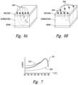
- FIG. 7is a graph illustrating threshold levels of electrical conductivity of nasal tissue with respect to temperature.
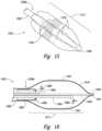
- FIGS. 8 and 9are isometric views of a distal portion of a therapeutic neuromodulation device configured in accordance with an embodiment of the present technology.
- FIG. 12is a side view of a distal portion of a therapeutic neuromodulation device configured in accordance with a further embodiment of the present technology.
- FIG. 13is a side view of a distal portion of a therapeutic neuromodulation device configured in accordance with a still further embodiment of the present technology.
- FIG. 14is an isometric side view of a distal portion of a therapeutic neuromodulation device configured in accordance with an additional embodiment of the present technology.
- FIG. 15is an isometric side view of a distal portion of a therapeutic neuromodulation device configured in accordance with an additional embodiment of the present technology.
- FIG. 16is a cross-sectional side view of a distal portion of a therapeutic neuromodulation device configured in accordance with an additional embodiment of the present technology.
- FIG. 17is a cross-sectional side view of a distal portion of a therapeutic neuromodulation device configured in accordance with an additional embodiment of the present technology.
- FIG. 18is a cross-sectional side view of a distal portion of a therapeutic neuromodulation device configured in accordance with an additional embodiment of the present technology.
- FIG. 20is a partial cut-away side view illustrating target sites proximate to ostia of nasal sinuses for a therapeutic neuromodulation device configured in accordance with embodiments of the present technology.
- the present technologyis generally directed to devices for therapeutic nasal neuromodulation and associated systems and methods.
- the disclosed devicesare configured to provide an accurate and localized non-invasive application of energy to disrupt the parasympathetic motor sensory function in the nasal region.
- Specific details of several embodiments of the present technologyare described herein with reference to FIGS. 1 A- 20 .
- FIGS. 1 A- 20Specific details of several embodiments of the present technology are described herein with reference to FIGS. 1 A- 20 .
- FIGS. 1 A- 20Specific details of several embodiments of the present technology are described herein with reference to FIGS. 1 A- 20 .
- FIGS. 1 A- 20Specific details of several embodiments of the present technology are described herein with reference to FIGS. 1 A- 20 .
- FIGS. 1 A- 20Specific details of several embodiments of the present technology are described herein with reference to FIGS. 1 A- 20 .
- FIGS. 1 A- 20Specific details of several embodiments of the present technology are described herein with reference to FIGS. 1
- embodiments of the present technologycan have different configurations, components, and/or procedures than those shown or described herein.
- a person of ordinary skill in the artwill understand that embodiments of the present technology can have configurations, components, and/or procedures in addition to those shown or described herein and that these and other embodiments can be without several of the configurations, components, and/or procedures shown or described herein without deviating from the present technology.
- distal and proximalwithin this description, unless otherwise specified, the terms can reference relative positions of portions of a therapeutic neuromodulation device and/or an associated delivery device with reference to an operator and/or a location within the nasal cavity.
- proximalcan refer to a position closer to the operator of the device or access point at the entrance point of a patient's nostril
- distalcan refer to a position that is more distant from the operator of the device or further from the access point at the entrance of the patient's nostril.
- posterior, anterior, inferior and superiorare used in accordance with standard medical terminology.
- therapeutic modulationof nerves and “therapeutic neuromodulation” refer to the partial or complete incapacitation or other effective disruption of neural activity, including partial or complete ablation of nerves.
- Therapeutic neuromodulationfor example, can include partially or completely inhibiting, reducing, and/or blocking neural communication along neural fibers.
- FIG. 1 Ais a cut-away side view illustrating the anatomy of a lateral nasal wall
- FIG. 1 Bis an enlarged side view of the nerves of the lateral nasal wall of FIG. 1 A
- the sphenopalatine foramen(“SPF”; FIG. 1 A ) is an opening or conduit defined by the palatine bone and the sphenoid bone through which the sphenopalatine vessels and the posterior superior nasal nerves travel into the nasal cavity. More specifically, the orbital and sphenoidal processes of the perpendicular plate of the palatine bone define the sphenopalatine notch, which is converted into the SPF by the articulation with the surface of the body of the sphenoid bone.
- the location of the SPFis highly variable within the posterior region of the lateral nasal cavity, which makes it difficult to visually locate the SPF.
- the SPFis located in the middle meatus (“MM”; FIG. 1 A ); however, anatomical variations also result in the SPF being located in the superior meatus (“SM”; FIG. 1 A ) or at the transition of the superior and middle meatuses.
- the inferior border of the SPFhas been measured at about 19 mm above the horizontal plate of the palatine bone (i.e., the nasal sill), which is about 13 mm above the horizontal lamina of the inferior turbinate (“IT”; FIG.
- the anatomical variations of the SPFare expected to correspond to alterations of the autonomic and vascular pathways traversing into the nasal cavity.
- the posterior nasal nervesalso referred to as lateral posterior superior nasal nerves
- PPGpterygopalatine ganglion
- the sphenopalatine ganglionFIG. 1 A
- the sphenopalatine arterybranches into two main portions: the posterior lateral nasal branch and the posterior septal branch.
- the main branch of the posterior lateral nasal arterytravels inferiorly into the inferior turbinate IT (e.g., between about 1.0 mm and 1.5 mm from the posterior tip of the inferior turbinate IT), while another branch enters the middle turbinate MT and branches anteriorly and posteriorly.
- inferior turbinate ITe.g., between about 1.0 mm and 1.5 mm from the posterior tip of the inferior turbinate IT
- the accessory foramenaare typically smaller than the SPF and positioned inferior to the SPF.
- the variability in location, size, and quantity associated with the accessory foramen and the associated branching arteries and nerves that travel through the accessory foramengives rise to a great deal of uncertainty regarding the positions of the vasculature and nerves of the sphenopalatine region.
- the natural anatomy extending from the SPFoften includes deep inferior and/or superior grooves that carry neural and arterial pathways, which make it difficult to locate arterial and neural branches.
- the groovescan extend more than 5 mm long, more than 2 mm wide, and more than 1 mm deep, thereby creating a path significant enough to carry both arteries and nerves.
- the variations caused by the grooves and the accessory foramen in the sphenopalatine regionmake locating and accessing the arteries and nerves (positioned posterior to the arteries) extremely difficult for surgeons.
- FIG. 1Recent microanatomic dissection of the pterygopalatine fossa (PPF) have further evidenced the highly variable anatomy of the region surrounding the SPF, showing that a multiplicity of efferent rami that project from the pterygopalatine ganglion (“PPG”; FIG. 1 ) to innervate the orbit and nasal mucosa via numerous groups of small nerve fascicles, rather than an individual postganglionic autonomic nerves (e.g., the posterior nasal nerve). Studies have shown that at least 87% of humans have microforamina and micro rami in the palatine bone.
- PPGpterygopalatine ganglion
- FIG. 1 Cis a front view of a left palatine bone illustrating geometry of microforamina and micro rami in a left palatine bone.
- the solid regionsrepresent nerves traversing directly through the palatine bone, and the open circles represent nerves that were associated with distinct microforamina.
- FIG. 1 Cillustrates that a medial portion of the palatine bone can include at least 25 accessory posterolateral nerves.
- the respiratory portion of the nasal cavity mucosais composed of a type of ciliated pseudostratified columnar epithelium with a basement membrane.
- Nasal secretionse.g., mucus
- goblet cellse.g., goblet cells
- submucosal glandse.g., submucosal glands
- transudate from plasmae.g., fet cells
- Nasal seromucous glands and blood vesselsare highly regulated by parasympathetic innervation deriving from the vidian and other nerves.
- Parasympathetic (cholinergic) stimulation through acetylcholine and vasoactive intestinal peptidegenerally results in mucus production.
- the parasympathetic innervation of the mucosais primarily responsible submucosal gland activation/hyper activation, venous engorgement (e.g., congestion), and increased blood flow to the blood vessels lining the nose. Accordingly, severing or modulating the parasympathetic pathways that innervate the mucosa are expected to reduce or eliminate the hyper activation of the submucosal glands and engorgement of vessels that cause symptoms associated with rhinosinusitis and other indications.
- postganglionic parasympathetic fibers that innervate the nasal mucosawere thought to travel exclusively through the SPF as a sphenopalatine neurovascular bundle.
- the posterior nasal nervesare branches of the maxillary nerve that innervate the nasal cavity via a number of smaller medial and lateral branches extending through the mucosa of the superior and middle turbinates ST, MT (i.e., nasal conchae) and to the nasal septum.
- the nasopalatine nerveis generally the largest of the medial posterior superior nasal nerves. It passes antero-inferiorly in a groove on the vomer to the floor of the nasal cavity.
- the posterior superior nasal nervespass through the pterygopalatine ganglion PPG without synapsing and onto the maxillary nerve via its ganglionic branches.
- the sinonasal parasympathetic pathwayactually comprises individual rami project from the pterygopalatine ganglion (PPG) to innervate the nasal mucosa via multiple small nerve fascicles (i.e., accessory posterolateral nerves), not a single branch extending through the SPF.
- PPGpterygopalatine ganglion
- These ramiare transmitted through multiple fissures, accessory foramina, and microforamina throughout the palatine bone and may demonstrate anastomotic loops with both the SPF and other accessory nerves.
- embodiments of the present technologyare configured to therapeutically modulate nerves at precise and focused treatment sites corresponding to the sites of rami extending through fissures, accessory foramina, and microforamina throughout the palatine bone (e.g., target region T shown in FIG. 1 B ).
- the targeted nervesare postganglionic parasympathetic nerves that go on to innervate the nasal mucosa.
- This selective neural treatmentis also expected to decrease the rate of postoperative nasal crusting and dryness because it allows a clinician to titrate the degree of anterior denervation through judicious sparing of the rami orbitonasalis.
- embodiments of the present technologyare also expected to maintain at least some sympathetic tone by preserving a portion of the sympathetic contributions from the deep petrosal nerve and internal maxillary periarteriolar plexi, leading to improved outcomes with respect to nasal obstruction.
- embodiments of the present technologyare configured to target a multitude of parasympathetic neural entry locations (e.g., accessory foramen, fissures, and microforamina) to the nasal region to provide for a complete resection of all anastomotic loops, thereby reducing the rate of long-term re-innervation.
- parasympathetic neural entry locationse.g., accessory foramen, fissures, and microforamina
- FIG. 2is a partially schematic view of a therapeutic neuromodulation system 200 (“system 200 ”) for therapeutically modulating nerves in a nasal region in accordance with an embodiment of the present technology.
- the system 200includes a therapeutic neuromodulation catheter or device 202 , a console 204 , and a cable 206 extending therebetween.
- the therapeutic neuromodulation device 202includes a shaft 208 having a proximal portion 208 a , a distal portion 208 b , a handle 210 at a proximal portion 208 a of the shaft 208 , and a therapeutic assembly or element 212 at the distal portion 208 b of the shaft 208 .
- the shaft 208is configured to locate the distal portion 208 b intraluminally at a treatment or target site within a nasal region proximate to postganglionic parasympathetic nerves that innervate the nasal mucosa.
- the target sitemay be a region, volume, or area in which the target nerves are located and may differ in size and shape depending upon the anatomy of the patient.
- the target sitemay be a 3 cm area inferior to the SPF.
- the target sitemay be larger, smaller, and/or located elsewhere in the nasal cavity to target the desired neural fibers.
- the therapeutic assembly 212can include at least one energy delivery element 214 configured to therapeutically modulate the postganglionic parasympathetic nerves.
- the therapeutic assembly 212can therapeutically modulate the postganglionic parasympathetic nerves branching from the pterygopalatine ganglion and innervating the nasal region and nasal mucosa, such as parasympathetic nerves (e.g., the posterior nasal nerves) traversing the SPF, accessory foramen, and microforamina of a palatine bone.
- parasympathetic nervese.g., the posterior nasal nerves traversing the SPF, accessory foramen, and microforamina of a palatine bone.
- the therapeutic assembly 212includes at least one energy delivery element 214 configured to provide therapeutic neuromodulation to the target site.
- the energy delivery element 214can include one or more electrodes configured to apply electromagnetic neuromodulation energy (e.g., RF energy) to target sites.
- the energy delivery element 214can be configured to provide therapeutic neuromodulation using various other modalities, such as cryotherapeutic cooling, ultrasound energy (e.g., high intensity focused ultrasound (“HIFU”) energy), microwave energy (e.g., via a microwave antenna), direct heating, high and/or low power laser energy, mechanical vibration, and/or optical power.
- HIFUhigh intensity focused ultrasound
- the therapeutic assembly 212can be configured to deliver chemicals or drugs to the target site to chemically ablate or embolize the target nerves.
- the therapeutic assembly 212can include a needle applicator extending through an access portion of the shaft 208 and/or a separate introducer, and the needle applicator can be configured to inject a chemical into the target site to therapeutically modulate the target nerves, such as botox, alcohol, guanethidine, ethanol, phenol, a neurotoxin, or another suitable agent selected to alter, damage, or disrupt nerves.
- the therapeutic assembly 212can include one or more sensors (not shown), such as one or more temperature sensors (e.g., thermocouples, thermistors, etc.), impedance sensors, and/or other sensors.
- the sensor(s) and/or the energy delivery element 214can be connected to one or more wires (not shown; e.g., copper wires) extending through the shaft 208 to transmit signals to and from the sensor(s) and/or convey energy to the energy delivery element 214 .
- the therapeutic neuromodulation device 202can be operatively coupled to the console 204 via a wired connection (e.g., via the cable 206 ) and/or a wireless connection.
- the console 204can be configured to control, monitor, supply, and/or otherwise support operation of the therapeutic neuromodulation device 202 .
- the console 204can further be configured to generate a selected form and/or magnitude of energy for delivery to tissue or nerves at the target site via the therapeutic assembly 212 , and therefore the console 204 may have different configurations depending on the treatment modality of the therapeutic neuromodulation device 202 .
- the therapeutic neuromodulation device 202can be configured for delivery via a guide catheter or introducer sheath (not shown) with or without using a guide wire.
- the introducer sheathcan first be inserted intraluminally to the target site in the nasal region, and the distal portion 208 b of the shaft 208 can then be inserted through the introducer sheath.
- the therapeutic assembly 212can be deployed through a distal end opening of the introducer sheath or a side port of the introducer sheath.
- Image guidancemay be used to aid the clinician's positioning and manipulation of the distal portion 208 b of the shaft 208 and the therapeutic assembly 212 .
- an endoscope(not shown) can be positioned to visualize the target site, the positioning of the therapeutic assembly 212 at the target site, and/or the therapeutic assembly 212 during therapeutic neuromodulation.
- the distal portion 208 b of the shaft 208is delivered via a working channel extending through an endoscope, and therefore the endoscope can provide direct in-line visualization of the target site and the therapeutic assembly 212 .
- an endoscopeis incorporated with the therapeutic assembly 212 and/or the distal portion 208 b of the shaft 208 to provide in-line visualization of the assembly 212 and/or the surrounding nasal anatomy.
- image guidancecan be provided with various other guidance modalities, such as image filtering in the infrared (IR) spectrum to visualize the vasculature and/or other anatomical structures, computed tomography (CT), fluoroscopy, ultrasound, optical coherence tomography (OCT), and/or combinations thereof.
- image guidance componentsmay be integrated with the therapeutic neuromodulation device 202 to provide image guidance during positioning of the therapeutic assembly 212 .
- the therapeutic modulationmay be applied via the energy delivery element 214 and/or other features of the therapeutic assembly 212 to precise, localized regions of tissue to induce one or more desired therapeutic neuromodulating effects to disrupt parasympathetic motor sensory function.
- the therapeutic assembly 212can selectively target postganglionic parasympathetic fibers that innervate the nasal mucosa at a target or treatment site proximate to or at their entrance into the nasal region.
- the therapeutic assembly 212can be positioned to apply therapeutic neuromodulation at least proximate to the SPF ( FIG. 1 A ) to therapeutically modulate nerves entering the nasal region via the SPF.
- the therapeutic assembly 212can also be positioned to inferior to the SPF to apply therapeutic neuromodulation energy across accessory foramen and microforamina (e.g., in the palatine bone) through which smaller medial and lateral branches of the posterior superior lateral nasal nerve enter the nasal region.
- the purposeful application of the energy at the target sitemay achieve therapeutic neuromodulation along all or at least a portion of posterior nasal neural fibers entering the nasal region.
- the therapeutic neuromodulating effectsare generally a function of, at least in part, power, time, and contact between the energy delivery elements and the adjacent tissue.
- therapeutic neuromodulation of autonomic neural fibersare produced by applying RF energy at a power of about 2-20 W (e.g., 5 W, 7 W, 10 W, etc.) for a time period of about 1-20 sections (e.g., 5-10 seconds, 8-10 seconds, 10-12 seconds, etc.).
- the therapeutic neuromodulating effectsmay include partial or complete denervation via thermal ablation and/or non-ablative thermal alteration or damage (e.g., via sustained heating and/or resistive heating). Desired thermal heating effects may include raising the temperature of target neural fibers above a desired threshold to achieve non-ablative thermal alteration, or above a higher temperature to achieve ablative thermal alteration.
- the target temperaturemay be above body temperature (e.g., approximately 37° C.) but less than about 90° C. (e.g., 70-75° C.) for non-ablative thermal alteration, or the target temperature may be about 100° C. or higher (e.g., 110° C., 120° C., etc.) for the ablative thermal alteration.
- Desired non-thermal neuromodulation effectsmay include altering the electrical signals transmitted in a nerve.
- a cryotherapeutic applicatormay be used to cool tissue at a target site to provide therapeutically-effective direct cell injury (e.g., necrosis), vascular injury (e.g., starving the cell from nutrients by damaging supplying blood vessels), and sublethal hypothermia with subsequent apoptosis.
- Exposure to cryotherapeutic coolingcan cause acute cell death (e.g., immediately after exposure) and/or delayed cell death (e.g., during tissue thawing and subsequent hyperperfusion).
- Embodiments of the present technologycan include cooling a structure positioned at or near tissue such that the tissue is effectively cooled to a depth where the targeted postganglionic parasympathetic nerves reside.
- the cooling structureis cooled to the extent that it causes therapeutically effective, cryogenic posterior nasal nerve modulation.
- the system 200can determine the locations of the nerves, accessory foramen, and/or microforamina before therapy such that the therapeutic neuromodulation can be applied to precise regions including parasympathetic neural fibers.
- the system 200may identify a target site that has a length and/or width of about 3 mm inferior to the SPF, and the therapeutic assembly 212 can apply therapeutic neuromodulation to the identified target site via one or more applications of therapeutic neuromodulation.
- the target sitemay be smaller or larger (e.g., a 3 cm-long target region) based on the detected locations of neural fibers and foramena.
- This neural and anatomical mappingallows the system 200 to accurately detect and therapeutically modulate the postganglionic parasympathetic neural fibers that innervate the mucosa at the numerous neural entrance points into the nasal cavity. Further, because there are not any clear anatomical markers denoting the location of the SPF, accessory foramen, and microforamina, the neural mapping allows the operator to identify and therapeutically modulate nerves that would otherwise be unidentifiable without intricate dissection of the mucosa. In addition, anatomical mapping can also allow the operator to identify certain structures that the operator may wish to avoid during therapeutic neural modulation (e.g., certain arteries).
- Sufficiently modulating at least a portion of the parasympathetic nervesis expected to slow or potentially block conduction of autonomic neural signals to the nasal mucosa to produce a prolonged or permanent reduction in nasal parasympathetic activity. This is expected to reduce or eliminate activation or hyperactivation of the submucosal glands and venous engorgement and, thereby, reduce or eliminate the symptoms of rhinosinusitis.
- the system 200applies therapeutic neuromodulation to the multitude of branches of the posterior nasal nerves rather than a single large branch of the posterior nasal nerve branch entering the nasal cavity at the SPF, the system 200 provides a more complete disruption of the parasympathetic neural pathway that affects the nasal mucosa and results in rhinosinusitis. Accordingly, the system 200 is expected to have enhanced therapeutic effects for the treatment of rhinosinusitis and reduced re-innervation of the treated mucosa.
- the system 200can be configured to therapeutically modulate nerves and/or other structures to treat different indications.
- the system 200can be used to locate and/or therapeutically modulate nerves that innervate the para-nasal sinuses to treat chronic sinusitis.
- the system 200 and the devices disclosed hereincan be configured therapeutically modulate the vasculature within the nasal anatomy to treat other indications, such as epistaxis (i.e., excessive bleeding from the nose).
- the system 200 and the therapeutic neuromodulation devices described hereincan be used to apply therapeutically effective energy to arteries (e.g., the sphenopalatine artery and its branches) as they enter the nasal cavity (e.g., via the SPF, accessory foramen, etc.) to partially or completely coagulate or ligate the arteries.
- the system 200can be configured to partially or completely coagulate or ligate veins and/or other vessels.
- the system 200would be modified to deliver energy at significantly higher power (e.g., about 100 W) and/or longer times (e.g., 1 minute or longer) than would be required for therapeutic neuromodulation.
- the system 100could apply the anatomical mapping techniques disclosed herein to locate or detect the targeted vasculature and surrounding anatomy before, during, and/or after treatment.
- FIGS. 3 A- 3 Eare partial cut-away side views illustrating various approaches for delivering a distal portion of the therapeutic neuromodulation device 202 of FIG. 2 to a target site within a nasal region in accordance with embodiments of the present technology.
- the distal portion 208 b of the shaft 208extends into the nasal passage NP, through the inferior meatus IM between the inferior turbinate IT and the nasal sill NS, and around the posterior portion of the inferior turbinate IT where the therapeutic assembly 212 is deployed at a treatment site.
- FIG. 3 Ain various embodiments the distal portion 208 b of the shaft 208 extends into the nasal passage NP, through the inferior meatus IM between the inferior turbinate IT and the nasal sill NS, and around the posterior portion of the inferior turbinate IT where the therapeutic assembly 212 is deployed at a treatment site.
- the treatment sitecan be located proximate to the access point or points of postganglionic parasympathetic nerves (e.g., branches of the posterior nasal nerve and/or other parasympathetic neural fibers that innervate the nasal mucosa) into the nasal cavity.
- the target sitecan be elsewhere within the nasal cavity depending on the location of the target nerves.
- An endoscope 330 and/or other visualization deviceis delivered proximate to the target site by extending through the nasal passage NP and through the middle meatus MM between the inferior and middle turbinates IT and MT. From the visualization location within the middle meatus MM, the endoscope 330 can be used to visualize the treatment site, surrounding regions of the nasal anatomy, and the therapeutic assembly 212 .
- the positioning member 332can be positioned distal to the therapeutic assembly 212 and expanded in a region distal to the therapeutic assembly 212 and the treatment site.
- the positioning member 332is positioned on an introducer sheath (not shown) through which the shaft 208 and/or other devices (e.g., a fluid line for delivery of saline or local anesthetics, an endoscope, a sensor, etc.) can pass.
- the positioning member 332can be positioned proximal to the target site (e.g., similar to the position shown in FIG. 3 A ) or distal to the treatment site.
- FIG. 3 Billustrates a differ embodiment in which the distal portion 208 b of the shaft 208 extends into the nasal passage NP, through the middle meatus MM between the inferior turbinate IT and the middle turbinate, and in posterior direction where the therapeutic assembly 212 is deployed at a treatment site.
- the endoscope 330 and/or other visualization deviceis delivered alongside the shaft 208 through the same intraluminal pathway as the therapeutic assembly 212 .
- the pathway through the middle meatus MMmay provide for generally straight access to the target site depending on the specific region of interest and anatomical variations of the patient. Accordingly, an approach through the middle meatus MM may require less steering and/or articulation of the shaft 208 and the endoscope 330 .
- the endoscopecan provide in-line or side-by-side visualization of the therapeutic assembly 212 .
- FIG. 3 Cillustrates another intraluminal pathway in which the distal portion 208 b of the shaft 208 and the endoscope 330 travel next to each other such that the endoscope 330 can provide in-line or side-by-side visualization of the distal portion 208 b of the shaft 208 , the therapeutic assembly 212 , and/or the nasal anatomy.
- the intraluminal pathwayextends through the inferior meatus IM to a posterior treatment site.
- the distal portion 208 b of the shaft 208extends to the treatment site via the middle meatus MM, and the endoscope 330 extends through the inferior meatus IM to a position proximate to the target site.
- the endoscope 330may have an articulating, steerable, or curved distal end that directs the endoscope 330 superiorly to visualize the nasal anatomy and the therapeutic assembly 332 at the target site.
- the distal end portion of the endoscope 330can be configured to bend at least 30° to visualize the treatment site.
- the distal portion 208 b of the shaft 208can be delivered to the treatment site via the mouth.
- therapeutic neuromodulationcan be applied at a treatment site posterior to the nasal cavity (e.g., posterior to the SPF).
- the endoscope 330(not shown) can extend into the nasal passage NP, through the middle meatus MM or the inferior meatus IM to a position proximate to the treatment site. Alternatively, the endoscope 330 (not shown) can travel along the same pathway as the shaft 208 .
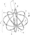
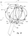
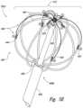
- FIG. 4is an isometric view of a distal portion of a therapeutic neuromodulation device 402 configured in accordance with an embodiment of the present technology.
- the therapeutic neuromodulation device 402can be used in conjunction with the system 200 described above with respect to FIGS. 2 - 3 E .
- the therapeutic neuromodulation device 402can include a shaft 408 having a proximal portion (not shown) and a distal portion 408 b , and a therapeutic assembly 412 at the distal portion 408 b of the shaft 408 .
- the therapeutic assembly 412is transformable between a low-profile delivery state to facilitate intraluminal delivery of the therapeutic assembly 412 to a treatment site within the nasal region and an expanded state (shown in FIG. 4 ).
- the therapeutic assembly 412includes a plurality of struts 440 that are spaced apart from each other to form a frame or basket 442 when the therapeutic assembly 412 is in the expanded state.
- the struts 440can carry one or more energy delivery elements, such as a plurality of electrodes 444 .
- the struts 440can position at least two of the electrodes 444 against tissue at a target site within the nasal region (e.g., proximate to the palatine bone inferior to the SPF).
- the electrodes 444can apply bipolar or multi-polar radiofrequency (RF) energy to the target site to therapeutically modulate postganglionic parasympathetic nerves that innervate the nasal mucosa proximate to the target site.
- the electrodes 444can be configured to apply pulsed RF energy with a desired duty cycle (e.g., 1 second on/0.5 seconds off) to regulate the temperature increase in the target tissue.
- the basket 442includes eight branches 446 spaced radially apart from each other to form at least a generally spherical structure, and each of the branches 446 includes two struts 440 positioned adjacent to each other. In other embodiments, however, the basket 442 can include fewer than eight branches 446 (e.g., two, three, four, five, six, or seven branches) or more than eight branches 446 . In further embodiments, each branch 446 of the basket 442 can include a single strut 440 , more than two struts 440 , and/or the number of struts 440 per branch can vary.
- the branches 446 and struts 440can form baskets or frames having other suitable shapes for placing the electrodes 444 in contact with tissue at the target site.
- the struts 440can form an ovoid shape, a hemispherical shape, a cylindrical structure, a pyramid structure, and/or other suitable shapes.
- the therapeutic assembly 412can further include an internal or interior support member 448 that extends distally from the distal portion 408 b of the shaft 408 .
- a distal end portion 450 of the support member 448can support the distal end portions of the struts 440 to form the desired basket shape.
- the struts 440can extend distally from the distal portion 408 b of the shaft 408 and the distal end portions of the struts 440 can attach to the distal end portion 450 of the support member 448 .
- the support member 448can include an internal channel (not shown) through which electrical connectors (e.g., wires) coupled to the electrodes 444 and/or other electrical features of the therapeutic element 412 can run.
- the internal support member 448can also carry an electrode (not shown) at the distal end portion 450 and/or along the length of the support member 448 .
- the basket 442can transform from the low-profile delivery state to the expanded state ( FIG. 4 ) by manipulating a handle (e.g., the handle 210 of FIG. 2 ) and/or other feature at the proximal portion of the shaft 408 and operably coupled to the basket 442 .
- a handlee.g., the handle 210 of FIG. 2
- an operatorcan push the support member 448 distally to bring the struts 440 inward toward the support member 448 .
- An introducer or guide sheath(not shown) can be positioned over the low-profile therapeutic assembly 412 to facilitate intraluminal delivery or removal of the therapeutic assembly 412 from or to the target site.
- the therapeutic assembly 412is transformed between the delivery state and the expanded state using other suitable means.
- the individual struts 440can be made from a resilient material, such as a shape-memory material (e.g., Nitinol) that allows the struts 440 to self-expand into the desired shape of the basket 442 when in the expanded state.
- a shape-memory materiale.g., Nitinol
- the struts 440can be made from other suitable materials and/or the therapeutic assembly 412 can be mechanically expanded via a balloon or by proximal movement of the support member 448 .
- the basket 442 and the associated struts 440can have sufficient rigidity to support the electrodes 444 and position or press the electrodes 444 against tissue at the target site.
- the expanded basket 442can press against surrounding anatomical structures proximate to the target site (e.g., the turbinates, the palatine bone, etc.) and the individual struts 440 can at least partially conform to the shape of the adjacent anatomical structures to anchor the therapeutic element 412 at the treatment site during energy delivery.
- the expansion and conformability of the struts 440can facilitate placing the electrodes 444 in contact with the surrounding tissue at the target site.
- At least one electrode 444is disposed on individual struts 440 .
- two electrodes 444are positioned along the length of each strut 440 .
- the number of electrodes 444 on individual struts 440be only one, more than two, zero, and/or the number of electrodes 444 on the different struts 440 can vary.
- the electrodes 444can be made from platinum, iridium, gold, silver, stainless steel, platinum-iridium, cobalt chromium, iridium oxide, polyethylenedioxythiophene (“PEDOT”), titanium, titanium nitride, carbon, carbon nanotubes, platinum grey, Drawn Filled Tubing (“DFT”) with a silver core made by Fort Wayne Metals of Fort Wayne, Indiana, and/or other suitable materials for delivery RF energy to target tissue.
- PEDOTpolyethylenedioxythiophene
- DFTDrawn Filled Tubing
- each electrode 444can be operated independently of the other electrodes 444 .
- each electrodecan be individually activated and the polarity and amplitude of each electrode can be selected by an operator or a control algorithm (e.g., executed by the controller 218 of FIG. 2 ).
- a control algorithme.g., executed by the controller 218 of FIG. 2 .
- Various embodiments of such independently controlled electrodes 444are described in further detail below with reference to FIGS. 5 A- 5 G .
- the selective independent control of the electrodes 444allows the therapeutic assembly 412 to deliver RF energy to highly customized regions.
- a select portion of the electrodes 444can be activated to target neural fibers in a specific region while the other electrodes 444 remain inactive.
- electrodes 444may be activated across the portion of the basket 442 that is adjacent to tissue at the target site, and the electrodes 444 that are not proximate to the target tissue can remain inactive to avoid applying energy to non-target tissue.
- Such configurationsfacilitate selective therapeutic modulation of nerves on the lateral nasal wall within one nostril without applying energy to structures in other portions of the nasal cavity.
- the electrodes 444can be electrically coupled to an RF generator (e.g., the generator 216 of FIG. 2 ) via wires (not shown) that extend from the electrodes 444 , through the shaft 408 , and to the RF generator.
- an RF generatore.g., the generator 216 of FIG. 2
- wiresnot shown
- each electrode 444couples to a corresponding wire that extends through the shaft 408 .
- multiple electrodes 444can be controlled together and, therefore, multiple electrodes 444 can be electrically coupled to the same wire extending through the shaft 408 .
- the RF generator and/or components operably coupled (e.g., a control module) theretocan include custom algorithms to control the activation of the electrodes 444 .
- the RF generatorcan deliver RF power at about 200-300 W to the electrodes 444 , and do so while activating the electrodes 444 in a predetermined pattern selected based on the position of the therapeutic element 412 relative to the treatment site and/or the identified locations of the target nerves.
- the RF generatordelivers power at lower levels (e.g., less than 15 W, 15-50 W, 50-150 W, etc.) and/or higher power levels.
- the therapeutic assembly 412can further include one or more temperature sensors 452 disposed on the struts 440 and/or other portions of the therapeutic assembly 412 and configured to detect the temperature adjacent to the temperature sensor 452 .
- the temperature sensors 452can be electrically coupled to a console (e.g., the console 204 of FIG. 2 ) via wires (not shown) that extend through the shaft 408 .
- the temperature sensors 452can be positioned proximate to the electrodes 444 to detect the temperature at the interface between tissue at the target site and the electrodes 444 .
- the temperature sensors 452can penetrate the tissue at the target site (e.g., a penetrating thermocouple) to detect the temperature at a depth within the tissue.
- the temperature measurementscan provide the operator or the system with feedback regarding the effect of the therapeutic neuromodulation on the tissue.
- the operatormay wish to prevent or reduce damage to the tissue at the treatment site (e.g., the nasal mucosa), and therefore the temperature sensors 452 can be used to determine if the tissue temperature reaches a predetermined threshold for irreversible tissue damage. Once the threshold is reached, the application of therapeutic neuromodulation energy can be terminated to allow the tissue to remain intact.
- the energy deliverycan automatically terminate based on an evaluation/feedback algorithm (e.g., the evaluation/feedback algorithm 220 of FIG. 2 ) stored on a console (e.g., the console 204 of FIG. 2 ) operably coupled to the temperature sensors 452 .
- an evaluation/feedback algorithme.g., the evaluation/feedback algorithm 220 of FIG. 2
- a consolee.g., the console 204 of FIG. 2
- FIGS. 5 A- 5 Gare isometric views of examples of electrode configurations of therapeutic neuromodulation devices (identified individually as first through fourth therapeutic neuromodulation devices 502 a - 502 d , respectively; referred to collectively as therapeutic neuromodulation devices 502 ) for therapeutic neuromodulation in accordance with embodiments of the present technology.
- the therapeutic neuromodulation devices 502 of FIGS. 5 A- 5 Gcan include features generally similar to the features of the therapeutic neuromodulation device 402 of FIG. 4 .
- the therapeutic neuromodulation devices 502include a plurality of struts 440 that form a basket 442 when in an expanded state, and a plurality of electrodes 444 disposed on one or more of the struts 440 .
- the first through third therapeutic neuromodulation device 502 a - c shown in FIGS. 5 A- 5 Einclude a single strut 440 corresponding to each branch 446 of the basket 442
- the fourth therapeutic neuromodulation device 502 d shown in FIGS. 5 F and 5 Gincludes two adjacent struts 440 in each branch 446 of the basket 442 .
- the branches 446 of the therapeutic neuromodulation devices 502may have different quantities of struts 440 , and apply RF energy in the same manner as described below with reference to FIGS. 5 A- 5 G . As shown in FIGS.
- the electrodes 444can be independently controlled and activated via instructions from a controller (e.g., the controller 218 of FIG. 2 ) or a generator (e.g., the generator 216 of FIG. 2 ) to apply RF energy across selected regions or segments of the therapeutic assembly 412 .
- a controllere.g., the controller 218 of FIG. 2
- a generatore.g., the generator 216 of FIG. 2
- two electrodes 444 of the therapeutic assembly 412are activated in the first therapeutic neuromodulation device 502 a . More specifically, a first electrode 444 a on a first strut 440 a is activated at a positive polarity, and a second electrode 444 b on a second strut 440 b spaced radially apart from the first strut 440 a is activated at a negative polarity. The remainder of the electrodes 444 remain inactive. Accordingly, as indicated by the arrows, current can flow from the first electrode 444 a to the second electrode 444 b through the target tissue across a circumferential or peripheral segment of the therapeutic assembly 412 .
- This configurationmay be used to therapeutically modulate nerves positioned proximate to the peripheral segment.
- different or additional electrodes 444can be activated to have a selected polarity to apply therapeutic neuromodulation across selected regions of the therapeutic assembly 412 in a predetermined manner.
- the first therapeutic neuromodulation device 502 ais configured to have three selectively active electrodes 444 .
- a first electrode 444 a on a first strut 440 ais activated at a positive polarity
- second and third electrodes 444 b and 444 c on corresponding second and third struts 440 b and 440 care activated at a negative polarity.
- the remainder of the electrodes 444remain inactive.
- currentcan flow through the tissue from the first electrode 444 a to the second and third electrodes 444 b and 444 c across a segment of the therapeutic assembly 412 , and therefore therapeutically modulate nerves positioned proximate to the peripheral segment.
- the second and third activated electrodes 444 b and 444 care positioned on struts 440 b , 440 c that are radially spaced apart from but adjacent to the first strut 440 a carrying the first active electrode 444 a .
- a first electrode on a first strut 440 ais selectively activated at a positive polarity, and a plurality of electrodes 444 (identified individually as second through fifth electrodes 444 b - 444 e , respectively) within the first hemispherical region 501 a are selectively activated at a negative polarity such that RF energy is applied across the first hemispherical region 501 a .
- This electrode activation configurationmay be used to apply RF energy across one side of the basket 442 to therapeutically modulate nerves on the lateral nasal wall in one nostril.
- a different set of electrodes 444can be activated across a hemispherical region of the therapeutic assembly 412 based on the orientation of the basket 442 with respect to the lateral nasal wall.
- the basket 442has a generally symmetrical shape (e.g., circular, oval, etc.) and because the electrodes 444 can be selectively activated, the orientation of the basket 442 with respect to the target site on the lateral nasal wall does not matter. Instead, the operator can deploy the therapeutic assembly 412 at the target site irrespective of orientation, and selectively activate the electrodes 444 in a desired arrangement to apply RF energy across the target site.
- the second therapeutic neuromodulation device 502 bis configured to selectively control the polarity of a plurality of the electrodes 444 across at least a portion of the therapeutic assembly 412 to apply RF energy in a sesquipolar fashion (i.e., the sequential or transient bipolar pairing of electrodes).
- a first electrode 444 ais biased at a positive polarity and second through seventh electrodes 444 b - 444 g are controlled to have negative polarities.
- the second through seventh electrodes 444 b - 444 gare spaced substantially equal distances apart from the first electrode 444 a such that the electrodes 444 are dimensionally predisposed to multiplex in sequence.
- the first through seventh electrodes 444 a - 444 gare concurrently activated.
- the first electrode 444 awill pair with the individual negative electrodes 444 in a sequential manner based on the path of least resistance.
- This path of least resistanceis dictated by the natural anatomy of the treatment site in contact with the electrodes 444 .
- the first electrode 444 amay initially pair with the second electrode 444 b .
- a second pairinge.g., with the third electrode 444 c
- the first electrode 444 awill continue to sequentially pair with the remaining activated negative electrodes in a similar manner until a threshold is reached and the electrodes 444 are in a state of equilibrium in which there is homogenized current flow between all of the electrode pairs.
- the therapeutic assembly 412increases the size of the ablation zone (i.e., the region in which therapeutic neuromodulation energy is applied).
- this sequential pairing of the electrodes 444may occur in a circular direction (e.g., in a counter clockwise or clockwise direction) based on the impedance changes between the electrodes 444 .
- the sequential pairing of electrodes 444may occur in a different pattern based on the anatomical surroundings and/or the positioning of the electrodes 444 .
- the activated electrodes 444are positioned in a quadrant of the therapeutic element 412 with equal radial distances between the individual electrode pairs.
- the activated electrodes 444can be positioned across larger or smaller regions of the therapeutic element 412 to apply energy across larger or smaller treatment regions.
- the sesquipolar application of RF energyallows the therapeutic assembly 412 to intelligently apply RF energy across a target site to therapeutically modulate nerves proximate to the treatment site.
- the naturally occurring impedance changes between the electrode pairscause the therapeutic assembly 412 to radially increase the zone of energy application with each pairing.
- the electrodes 444can be configured to sequentially pair with each other in a manner such that the zone of energy application increases in a transverse and/or longitudinal manner based on the naturally occurring impedance changes between the electrodes 444 .
- a controllere.g., the controller 218 of FIG. 2
- instructionse.g., software
- portions of the struts 440themselves can define the electrodes 444 .
- the struts 440are made from an electrically conductive material and coated with an insulative material (e.g., poly-xylene polymers, including Paralyene C). Portions of the struts 440 can remain uncoated to define electrodes 444 .
- the locations of the uncoated portions of the struts 440i.e., the electrodes 444
- the uncoated portionscan be spaced equally apart from a central electrode 444 to allow for sesquipolar RF application.
- the conductive struts 440serve as the electrical connectors and, therefore, the therapeutic assembly 412 does not require as many wires as if the electrodes 444 were separate elements positioned on the struts 440 .
- the third therapeutic neuromodulation device 502 cincludes a return electrode 503 at the distal end portion 450 of the support member 448 and selective polarity control of the individual electrodes 444 on the struts 440 to provide radial multiplexing of the electrodes 444 .
- the return electrode 503has a negative polarity, and the other electrodes 444 have a positive polarity.
- all of the electrodes 444are activated, but in other embodiments the electrodes 444 can be selectively activated based on a desired energy application zone. As indicated by the arrows, this configuration applies RF energy across a distal hemispherical region of the basket 442 .
- the return electrode 503can be positioned elsewhere on the therapeutic assembly 412 , and the electrodes 444 , 503 can be used to apply RF energy across different regions of the basket 442 .
- the return electrode 503can be activated in conjunction with two or more of the electrodes 444 on the struts to apply RF energy in a sesquipolar manner.
- the fourth therapeutic neuromodulation device 502 dincludes branches 446 having two adjacent struts 440 , and the electrodes 444 on the adjacent struts are spaced apart from each other in a longitudinal direction and selectively activated to apply energy in a radial direction across discrete zones.
- a first electrode 444 a on a first strut 440 a of a first branch 446 amay be selectively activated to have a first polarity
- a second electrode 444 b on the adjacent second strut 440 b of the first branch 446 amay be selectively activated to have a second polarity opposite the first polarity.
- the first and second electrodes 444 a and 444 bcan then apply bipolar RF energy in a radial direction within a specific region of the therapeutic assembly 412 .
- the individual struts 440can include multiple electrodes 444 disposed thereon, and the adjacent strut 440 in the same branch 446 can have a corresponding quantity of electrodes 444 to allow for bipolar coupling of each of the electrode pairs along discrete regions of the branch 446 .
- the electrodes of one strut 440can all have the same polarity (e.g., coupled to a first wire; not shown), and the electrodes 444 of the adjacent strut 440 in the same branch 446 can all have the opposite polarity (e.g., coupled to a second wire; not shown).
- the electrodes 444 on an individual strut 440can be independently controlled to have a desired polarity.
- the electrode pairing configurations shown in FIG. 5 Fcan be used to detect impedance across selected regions of the therapeutic assembly 412 defined by the bipolar electrode pairs. The impedance measurements can then be used to identify the presence of neural fibers in the selected regions. If nerves are detected in one or more specific regions associated with an electrode pair, the same electrode pair can be used to apply RF energy to that region and therapeutically modulate the nerves in that region.
- the fourth therapeutic neuromodulation device 502 dis configured to selectively control the polarity of a plurality of the electrodes 444 across at least a portion of the therapeutic assembly 412 to apply RF energy in a multi-polar manner in a circular or spiral pattern.
- electrodes 444 of one branch 446can be activated to have negative polarities and electrodes 444 of another branch 446 can be activated to have positive polarities.
- the arrangement of the electrodes 444 and the variable distances between the electrodes 444can differ such that the energy application zone has a different shape or pattern.
- the positive and negative electrodes 444are spaced apart from each other at variable distances. Impedance changes resulting from the surrounding anatomical structures causes the electrodes to pair with each other in a sequential manner and, thereby, continuously increase the zone or region in which energy is applied in a radial direction and in a generally spiral manner.
- Electrodes at the distal and proximal regions of the basket 442apply energy to shallower depths in the target tissue than the electrode pairs positioned on the medial region of the basket 442 . Accordingly, the electrodes pairs positioned closer together can therapeutically modulate nerves at shallower depths than the electrode pairs spaced further apart from each other. As shown in the illustrated embodiment, some of the electrodes 444 and/or entire branches 446 of the basket 442 can remain inactive to achieve the desired depth of energy application and/or neuromodulation pattern.
- Various embodiments of the present technologycan include features that measure bio-electric, dielectric, and/or other properties of heterogeneous tissue at target sites within the nasal region to determine the presence, location, and/or activity of neural fibers and, optionally, map the locations of the detected nerves.
- the features discussed belowcan be incorporated into any of the systems and/or devices disclosed herein to provide an accurate depiction of nerves at the target site.
- Neural detectioncan occur (a) before the application of a therapeutic neuromodulation energy to determine the presence or location of nerves at the target site and/or record baseline levels of neural activity; (b) during therapeutic neuromodulation to determine the effect of the energy application on the neural fibers at the treatment site; and/or (c) after therapeutic neuromodulation to confirm the efficacy of the treatment on the targeted nerves.
- such neural detection and mappingcan provide an accurate representation of the neural anatomy to adequately treat the parasympathetic nerves, not just the one or two main branches of the posterior nasal nerves traversing the SPF.
- the systems disclosed hereincan use bioelectric measurements, such as impedance, resistance, voltage, current density, and/or other parameters (e.g., temperature) to determine the anatomy, in particular the neural anatomy, at the target site.
- bioelectric measurementssuch as impedance, resistance, voltage, current density, and/or other parameters (e.g., temperature) to determine the anatomy, in particular the neural anatomy, at the target site.
- the location of the neural anatomycan then be used to determine where the treatment site(s) should be with respect to various anatomical structures for therapeutically effective neuromodulation of the targeted parasympathetic nasal nerves.
- the informationcan be used to determine the treatment site(s) with respect to the location of the turbinates or meatuses.
- the bioelectric propertiescan be detected via electrodes (e.g., the electrodes 444 of the therapeutic neuromodulation devices 402 - 502 d of FIGS. 4 - 5 G ).
- the electrode pairings on a devicee.g., the therapeutic assemblies 412 described with respect to FIGS. 4 - 5 G
- FIGS. 6 A and 6 Bare partially schematic diagrams illustrating configurations of electrodes 644 for nerve detection configured in accordance with embodiments of the present technology. As shown in FIG. 6 A , the further the electrodes 644 are apart from each other, the deeper into the tissue the current flows.
- electrodes 644can be selectively activated based on the depth at which the desired measurements should be taken. As shown in FIG. 6 B , the spacing between the electrodes 644 along a plane (e.g., the surface of the tissue, can affect the region in which the measurements are taken. Thus, electrodes 644 can be selectively activated to obtain information (e.g., impedance) at a desired depth and across a desired region.
- the bioelectric propertiescan be detected using optical coherent tomography (OCT), ultrasound, and/or other suitable detection modalities.
- the measurement of bioelectric propertiescan provide information associated not only with neural fiber locations, but also the identification of gross anatomy (e.g., turbinates, meatuses, bone, etc.), which can be used to facilitate system delivery and identification of the target nerves with respect to the gross anatomy.
- gross target identificationcan be determined by evaluating of the incident electromagnetic field on soft and hard tissues within the nasal region, which is in turn dependent upon the local geometry and the dielectric properties of those features.
- measurements for neuro-mappingcan be obtained by applying a constant current to electrodes and measuring the voltage differences between adjacent pairs of electrodes to produce a spectral profile or map the tissues at the target site.
- Impedance datacan be obtained while applying high, medium, and/or low frequencies to the target tissue. At high frequencies, the current passes directly through cell membranes, and the resultant measurements are indicative of the tissue and liquids both inside and outside the cells. At low frequencies, cell membranes impede current flow to provide different defining characteristics of the tissue. Accordingly, bioimpedance can be used to measure targeted shapes or electrical properties of tissue and/or other structures of the nasal cavity.
- complex neural mappingcan be performed using frequency difference reconstruction, which requires measurement data (e.g., impedance) at two different frequencies.
- the spatial orientation, direction, and activity of the detected nerve bundlescan be used to further identify and characterize the nerves.
- the measured bioelectric propertiescan distinguish between terminating axons (i.e., entering a detection region, but not exiting), branching axons (i.e., entering the detection region and increasing in number upon exiting the detecting region), travelling axons (i.e., entering and exiting the detection region within no change in geometry or numerical value), and/or other properties of nerves.
- axon orientations relative to the electrode arraycan be identified to indicate whether the neural fibers extend parallel (X direction), perpendicular (Y direction), depth penetrating (Z direction), and/or any relative position or angulation to these parameters. This information can then be used to selectively treat specific neural fibers. For example, selected electrode configurations can be applied to treat a specific region and/or the therapeutic assembly can be moved or manipulated to treat the nerves from a different orientation or location.
- FIG. 7is a graph illustrating threshold levels of electrical conductivity of nasal tissue with respect to temperature.
- a first curve 701depicts the electrical conductivity ( ⁇ ) of tissue in response to temperature and indicates that a temperature of about 70° C. corresponds to a first threshold of the irreversible change in impedance of the tissue.
- a second curve 703shows that the electrical conductivity of the tissue permanently increases significantly (i.e., impedance decreases) after the tissue has been exposed to temperatures of 70° C., as it may during therapeutic neuromodulation.
- the therapeutic neuromodulationwas stopped when the tissue temperature was detected to be about 70° C., it is expected that there would be a permanent measurable change in the conductivity of the tissue without reaching a phase in which the tissue is structurally changed or damaged (e.g., due to vaporization, desiccation, etc.). However, if the tissue is exposed to temperatures above a second thermal threshold of about 90° C., the tissue undergoes a high degree of tissue desiccation, and thus a significant decrease in electrical conductivity (i.e., and a higher level of in the electrical impedance). A third curve 705 illustrates this lower electrical conductivity of the tissue after exposure to temperatures above 90° C.
- systems disclosed hereincan be configured to stop neuromodulation when the temperature reaches about 70° C. (e.g., 70-80° C.) to avoid structural changes or damage to the mucosa, but still providing what is expected to be therapeutically effective neuromodulation.
- 70° C.e.g., 70-80° C.
- Neural detection and mappingcan provide a pre-procedural assessment of the neural anatomy, a mid-procedure assessment and feedback on temporal changes in tissue during neuromodulation, and/or a post procedural assessment of the neural activity as a confirmation of effectiveness.
- the bioelectric measurements taken pre-, mid-, and post-procedurallycan be taken multiple times during each stage of the procedure to assess and confirm findings.
- Pre-procedural assessmentcan be used to evaluate the bioelectric properties of the native/host tissue to determine a baseline for subsequent actions and as a reference guide against source biological signatures to identify anatomical targets of interest (e.g., nerves, microforamina, etc.).
- This informationcan be determined by placing a multi-electrode array in a known spatial configuration to detect and then map electro-anatomical characteristics (e.g., variations in the impedance of different tissue types).
- the resultant anatomical mappingcan comprise a composition of multiple (high density) activation sequence in multiple planes, relying on the variations in impedance to identify different tissue types and structures.
- the impedance measurementscan be used to confirm that the electrodes maintain good contact with tissue at the target site.
- the datacan be used to determine whether the mid- or post-procedural recorded spectra has a shape consistent with the expected tissue types.
- Post-procedurallythe information can be used to determine whether the targeted nerves were therapeutically treated.
- the action potentials of neural fiberscan be detected via electrodes and or other contacts to dynamically map the locations and/or activity of nerves in the target region.
- the recorded action potentialscan be used to numerically measure, map, and/or produce images of fast neuronal depolarization to generate an accurate picture of neural activity.
- the depolarization of the neuronal membranecan cause drops in voltage of about 110 uV, has about 2 ms, and have an impedance/resistance from 1000 ⁇ cm to 25 ⁇ cm.
- the metabolic recovery processes associated with action potential activityi.e., to restore ionic gradients to normal
- the detection of the bioelectric properties associated with these featureshas the advantage that the changes are much larger (e.g., approximately a thousand times larger) and, therefore, easier to measure.
- a nontherapeutic stimulatione.g., RF energy
- RF energycan be applied to the tissue at the detection region via two or more electrodes of an electrode array to enhance the recording of action potentials.
- the stimulating energy applicationcan temporarily activate the neural fibers and the resultant action potential can be recorded.
- two or more electrodes of a therapeutic assemblycan deliver a stimulating pulse of energy, and two or more other electrodes can be configured to detect the resultant action potential.
- the stimulating energy pulsesare expected to enhance the action potential signal, making it easier to record.
- FIGS. 8 and 9are isometric views of a distal portion of a therapeutic neuromodulation device 802 (“device 802 ”) configured in accordance with an embodiment of the present technology.
- the device 802can include various features generally similar to the features of the therapeutic neuromodulation devices 402 and 502 a - d described above with reference to FIGS. 4 - 5 G .
- the device 802includes a therapeutic assembly 812 at a distal portion 408 b of a shaft 408 .
- the therapeutic assembly 812includes a plurality of struts 440 that form branches 446 and define an expandable frame or basket 442 , and one or more electrodes 444 disposed on one or more of the struts 440 . As shown in FIGS.
- the device 902can further include an expandable member 856 (e.g., a balloon) carried by the support member 448 and expandable within the basket 442 .
- the expandable member 856can include a plurality of electrodes 858 disposed on the outer surface of the expandable member 856 .
- the electrodes 858can be used for detection of bioelectric features (e.g., impedance) to allow for mapping of the neural anatomy at the target site before, during, and/or after therapeutic neuromodulation via the other electrodes 444 .
- the electrodes 858can be configured to apply energy for therapeutic neuromodulation.
- the electrodes 858can be positioned on the expandable member 856 in a substantially symmetrical manner and a uniform distribution. This provides an expansive array with which impedance and/or other properties can be detected across the tissue and, therefore, may provide a more detailed mapping of the tissue and nerves at the treatment site. In other embodiments, the electrodes 858 can be clustered toward the medial portion of the expandable member 856 and/or around different portions of the expandable member 856 .
- the electrodes 858can be selectively activated at a specific polarity, and therefore the electrode array can be configured in a variety of static configurations and a dynamically change sequences (e.g., sesquipolar application of current) that may be advantageous for mapping functions.
- the expandable member 856can be inflated or otherwise expanded ( FIG. 9 ) to place at least a portion of the electrodes 858 into contact with tissue at the target site.
- the electrodes 858can measure various bioelectric properties of the tissue (e.g., impedance, action potentials, etc.) to detect, locate, and/or map the nerves at the treatment site.
- the electrodes 444 on the struts 440 and/or a portion of the electrodes 858 on the expandable member 856can apply a stimulating pulse of RF energy, and the electrodes 858 can detect the resultant neural response.
- the expandable member 856can be deflated or collapsed ( FIG.
- the detected propertiese.g., impedances
- the detected propertiestaken before, during, and/or after neuromodulation can be compared to each other to determine whether the neuromodulation was therapeutically effective. If not, the electrodes 444 can again apply therapeutic neuromodulation energy to the same treatment site, or the configuration of the active electrodes 444 can be changed to apply therapeutic neuromodulation energy in a different pattern or sequence, and/or the therapeutic assembly 812 can be moved to a different treatment site.
- FIG. 10 Ais an isometric view of a distal portion of a therapeutic neuromodulation device 1002 (“device 1002 ”) configured in accordance with another embodiment of the present technology
- FIG. 10 Bis an isometric view illustrating the therapeutic neuromodulation device 1002 of FIG. 10 A at a treatment site.
- the device 1002can include various features generally similar to the features of the therapeutic neuromodulation devices 402 , 502 a - d , and 802 described above with reference to FIGS. 4 - 5 G, 8 and 9 .
- the device 1002includes a shaft 1008 and a therapeutic assembly 1012 at a distal portion 1008 b of the shaft 1008 .
- the therapeutic assembly 1012includes a plurality of struts 1040 that form branches 1046 and define an expandable frame or basket 1042 , and one or more electrodes 1044 disposed on one or more of the struts 1040 .
- the device 1002can further include a secondary or return electrode 1060 disposed along the distal portion of the shaft 1008 .
- the return electrode 1060is a ring electrode having a ring-like shape, but in other embodiments the return electrode 1060 may have other shapes or configurations.
- the return electrode 1060may be biased at a negative polarity, and at least a portion of the electrodes 1044 on the struts 1040 and/or on other portions of the therapeutic assembly 1012 may be biased at a positive polarity.
- bipolar RF energycan flow across a region spanning from the therapeutic assembly 1012 to the return electrode 1060 on this distal portion 1008 b of the shaft 1008 .
- the RF energycan be applied in a sesquipolar manner (i.e., imbalanced bipolar energy).
- the therapeutic assembly 1012can be positioned inferior to the SPF and superior to the inferior turbinate IT and at least a portion of the microforamina MF and nerves N traversing the palatine bone.
- the return electrode 1060can be positioned inferior to the inferior turbinate IT and at least a portion of the microforamina MF and nerves N traversing the palatine bone.
- RF energycan then be applied across a wide region spanning from the therapeutic assembly 1012 to the return electrode 1060 .
- the device 1002can apply energy across the top and bottom portions of the inferior turbinate, where a high density of microforamina reside.
- FIGS. 11 A- 11 Dare isometric views illustrating distal portions of therapeutic neuromodulation devices 1102 (referred to individually as a first device 1102 a and a second device 1102 b ) configured in accordance with further embodiments of the present technology.
- the first device 1102 acan include various features generally similar to the features of the therapeutic neuromodulation devices 402 , 502 a - d , 802 and 1002 described above with reference to FIGS. 4 - 5 G and 8 - 10 B .
- the first device 1102 aincludes a shaft 1108 and a therapeutic assembly 1112 at a distal portion 1108 b of the shaft 1108 .
- the therapeutic assembly 1112includes a flexible membrane 1162 that carries a plurality of electrodes 1144 and/or other energy delivery elements arranged in an array across the flexible membrane 1162 .
- the flexible membrane 1162can be configured to transform from a low-profile delivery state ( FIG. 11 A ), to an expanded state ( FIG. 11 B ) via self-expansion or mechanical expansion means, and back to the low-profile delivery or retrieval state ( FIG. 11 C ) for removal of the device from the nasal cavity.
- the flexible membraneIn the expanded state shown in FIG. 11 B , the flexible membrane can conform to the irregular anatomy of the nasal space (e.g., turbinates, sinus, and/or other para-nasal) to enhance the contact area between the flexible membrane 1162 (and the electrodes 1144 disposed thereon) with the non-planar anatomy.
- the flexible membrane 1162can be made from a flexible and dynamic material to support the electrodes 1144 .
- the flexible membrane 1162can comprise polymer filaments and/or other materials that add support and structure to the flexible membrane 1162 .
- the flexible membrane 1162can have pre-set geometry to retain a predetermined shape.
- the flexible membrane 1162 and/or the electrode array on the flexible membrane 1162can retain spherical curvature (e.g., as shown in FIG. 11 A ).
- the shaft 1108can be movable relative to the flexible membrane 1162 to allow for deployment and recapture of the flexible membrane 1162 .
- the flexible membrane 1162may be curled or otherwise folded into a circular shape when in the delivery state ( FIG. 11 A ).
- components of the shaft 1108can be rotated and/or moved axially relative to the flexible membrane 1162 to unwind or otherwise expand the flexible membrane 1162 such that the flexible membrane 1162 at least partially opens and conforms to the structures of the surrounding anatomy to place the electrodes 1144 into contact with tissue at the target site.
- the shaft 1108can again be moved axially or rotational manner to close wind or otherwise fold the flexible membrane 1162 .
- the electrodes 1144may be interconnected through a plurality of connectors 1164 , such as nano-ribbons, nano-wires, direct inking, multidirectional printing/deposition, and/or other suitable electrical connectors.
- the interconnections 1164 between the electrodes 1144can include periodic undulating conduits or lines having a “U”, “S”, or elliptical shapes. These undulating connectors 1164 may form a multidimensional spring within the flexible membrane 1162 and/or impose a predetermined shape on the flexible membrane 1162 that facilitates apposition of the flexible membrane 1162 to the tissue at the target site to improve energy conductivity/transference.
- the electrodes 1144may be surface mounted on the flexible membrane 1162 or embedded within a multi-layered composite structure of the flexible membrane 1162 .
- the electrodes 1144may be relatively small in size, having diameters ranging from 50-2,000 microns.
- the electrodes 1144may be configured to deliver energy in a mono-polar, bipolar, or multipolar manner.
- multipolar electrodescan be used in a bipolar arrangement and in a quad-polar arrangement to facilitate a linear and an angulated (diagonal) energy connectivity between the electrodes 1144 .
- the electrodes 1144can be connected to a connection pad (not shown) housed within the shaft 1108 and/or features connected to proximal portions of the shaft 1108 , such as a handle or console.
- the electrodes 1144can be connected to the connection pad through a conductive connector cable (e.g., a metallic cable, a polymeric cable, and/or combinations thereof).
- the flexible membrane 1162may also house a feedback system (not shown) to control the delivery of the RF energy and maintain predefined treatment parameters.
- the electronic circuits of the flexible membrane 1162may include thermal sensors that provide temperature feedback to control energy dissipation and depth penetration of the RF energy.
- the features of electronic circuits of the flexible membrane 1162may also measure resistance and temperature at the treatment site to determine the effects of the therapeutic energy application. This information may be used to regulate energy application and avoid collateral damage to host tissue.
- energy delivery via the electrodes 1144may be automatically terminated if the detected temperature and/or resistance reaches a predetermined threshold maximum (e.g., a threshold temperature associated with tissue damage).
- Energy delivery via the electrodes 1144may be automatically or manually adjusted if the detected temperature and/or resistance is below a predetermined threshold range indicative of parameters associated with therapeutically effective modulation of the parasympathetic nasal nerves.
- the feedback systemcan be incorporated to components communicatively coupled with the electrodes 1144 and any additional sensors on the flexible membrane 1162 .
- the feedback systemcan be stored on the console 204 of FIG. 2 and executed by the controller 218 ( FIG. 2 ).
- the second device 1102 bcan include various features generally similar to the features of the first device 1102 a described above with reference to FIGS. 11 A- 11 C .
- the device 1102 b of FIG. 11 Dincludes the flexible membrane 1162 that carries a plurality of electrodes 1144 and associated electrical connectors 1164 disposed on or embedded in the flexible membrane 1162 .
- the device 1102 bfurther includes an expandable frame 1166 carrying the flexible membrane 1162 .
- the frame 1166may have a U-shape and can be made from a shape memory material (e.g., Nitinol). In other embodiments, the frame may have different shapes and/or be made from different materials suitable for supporting the flexible membrane 1162 .
- the frame 1166facilitates the deployment of the flexible membrane 1162 against the anatomy of the nasal cavity, and provides support for the flexible membrane 1162 and the associated array of electrodes 1144 .
- the U-shaped frame 1166can enhance the ability of the flexible membrane 1162 to contact the non-planar anatomy at the target site.
- the frame 1166may act as a cantilever spring to establish a positive directional apposition of the membrane 1162 to the target surface tissue to improve energy conductivity/transference from the electrodes 1144 to the target tissue.
- FIG. 12is a side view of a distal portion of a therapeutic neuromodulation device 1202 (“device 1202 ”) configured in accordance with a further embodiment of the present technology.
- the device 1202includes include various features generally similar to the features of the therapeutic neuromodulation devices 402 , 502 a - d , 802 , 1002 and 1102 described above with reference to FIGS. 4 - 5 G and 8 - 11 .
- the device 1202includes a shaft 1208 and a therapeutic assembly 1212 including a plurality of energy delivery elements, such as electrodes 1244 , at a distal portion 1208 b of the shaft 1208 .
- the therapeutic assembly 1212includes four electrodes 1244 are arranged along a spiral/helical section 1268 at the distal portion 1208 b of the shaft 1208 .
- the therapeutic assembly 1212may include one, two, three, or more than four electrodes 1244 , and/or may include different energy delivery elements.
- the therapeutic assembly 1212can also include a temperature sensor 1252 (e.g., a thermocouple) and/or other type of sensor to detect various properties at the treatment site before, during, and/or after applying therapeutic neuromodulation energy, and provide feedback that may be used to control the operation of the therapeutic assembly 1212 .
- a temperature sensor 1252e.g., a thermocouple
- Such sensorscan be incorporated in any of the other embodiments of therapeutic assemblies disclosed herein.
- the spiral/helical section 1168 of the shaft 1208is positioned in a low-profile delivery state in which the section 1268 is substantially straitened or flattened within an introducer sheath and/or via mechanical components associated with the shaft 1208 .
- the operatorcan transform the spiral/helical section 1268 to an expanded state (shown in FIG. 12 ) to place one or more of the electrodes 1244 in contact with the target tissue.
- One or more of the electrodes 1244can then be selectively activated to apply RF energy (e.g., monopolar and/or bipolar RF energy) to tissue at a target site in the nasal region to therapeutically modulate nerves proximate to the treatment site.
- RF energye.g., monopolar and/or bipolar RF energy
- the distal section of the shaft 1208can have other suitable shapes, sizes, and/or configurations that facilitate placing the electrodes 1244 in contact with tissue at the target site.
- the distal portion 1208 b of the shaft 1208can have a semi-circular, curved, bent, or straight shape and/or the therapeutic assembly 1212 can include multiple support members configured to carry one or more of the electrodes 1244 .
- FIG. 13is a side view of a distal portion of a therapeutic neuromodulation device 1302 (“device 1302 ”) configured in accordance with a still further embodiment of the present technology.
- the device 1302includes include various features generally similar to the features of the therapeutic neuromodulation devices 402 , 502 a - d , 802 , 1002 , 1102 and 1202 described above with reference to FIGS. 4 - 5 G and 8 - 12 .
- the device 1302includes a shaft 1308 and a therapeutic assembly 1312 including a plurality of energy delivery elements, such as an array of electrodes 1344 , at a distal portion 1308 b of the shaft 1308 .
- a therapeutic assembly 1312including a plurality of energy delivery elements, such as an array of electrodes 1344 , at a distal portion 1308 b of the shaft 1308 .
- the therapeutic assembly 1312includes a balloon 1370 that carries the electrodes 1344 .
- a support member 1372can extend through the length of the balloon 1370 to support the balloon 1370 and, optionally, include a channel through which a guidewire (not shown) can extend to facilitate delivery of the therapeutic assembly 1312 to the target site. In other embodiments, the support member 1372 may be omitted.
- the electrodes 1344can be made from conductive ink that is printed, sprayed, and/or otherwise disposed on the surface of the balloon 1370 . Such conductive ink electrodes facilitates the use of complex electrode configurations.
- thermocouples(not shown) can also be incorporated onto the surface of the balloon 1370 using conductive ink and/or other suitable methods.
- the electrodes 1344can be made from foil and adhered to the surface of the balloon 1370 .
- the electrodes 1344can be made from other suitable materials that may be disposed on the surface of the balloon 1370 and/or embedded within the material of the balloon 1370 .
- the balloon 1370can be made from various different materials and have various different shapes. As shown in FIG. 13 , for example, the balloon 1370 can have an ovoid shape when in the expanded state, which is expected to improve the conformance to anatomical variations at the target site within the nasal cavity. In other embodiments, the balloon 1370 can have a circular shape, a spherical shape, an irregular shape, and/or other suitable shape for expansion within the nasal anatomy.
- the balloon 1370can be made from a compliant material (e.g., a urethane material) that allows the balloon 1370 to conform to anatomical variances when expanded within the nasal region.
- the balloonmay be made from a non-compliant material (e.g., polyethylene terephthalate, nylon, etc.) that allows the balloon 1370 to have a defined shape when expanded and facilitates the attachment of electrodes 1344 to the balloon surface.
- the balloon 1370may be dip-coated and form a bulbous tip at the distal end of the shaft 1308 .
- the balloon 1370may be inflated with a fluid via an opening or port 1374 in the support member 1372 and/or an opening in the shaft 1308 in fluid communication with the interior of the balloon 1370 .
- the support member 1372 and/or the shaft 1308can include a channel extending along the length of the shaft 1308 and connected to a fluid supply at the proximal portion of the shaft 1308 such that fluid can be delivered to the balloon 1370 .
- the balloon 1370can inflate against the nasal anatomy at the target site to places the electrodes 1344 in contact with tissue at the target site.
- the electrodes 1344deliver RF energy to tissue to therapeutically modulate nerves at the treatment site.
- the array of electrodes 1344can be arranged on the balloon 1370 and/or selectively activated to apply transverse bipolar RF energy across a radial regions of the balloon 1370 (i.e., extending around circumferential portions of the balloon 1370 ).
- the array of electrodes 1344can be arranged on the balloon 1370 and/or selectively activated to apply longitudinal bipolar RF energy across longitudinal regions of the balloon 1370 (i.e., extending between proximal and distal portions of the balloon 1370 ).
- the therapeutic assembly 1312may include features that facilitate with positioning of the balloon 1370 within the nasal anatomy and proper placement of the electrodes 1344 at the treatment site.
- an endoscope 1371may be positioned on the surface of the balloon 1370 to provide direct, in-line visualization of the balloon 1370 and the target site during placement at the target site.
- the therapeutic assembly 1312can also include graduated markings 1373 along the support member 1372 and/or the surface of the balloon 1370 to depict spatial orientation and/or depth positioning of the therapeutic assembly 1312 .
- the balloon 1370can be configured to allow for a slow perfusion of fluid through the balloon wall to cool the electrodes 1344 while energy is applied to the target tissue.
- a “weeping” balloon 1370can include laser-driller holes and/or other small openings or pores along at least a portion of the balloon 1370 to allow for the slow perfusion of a fluid (e.g., saline solution) through the balloon wall.
- a fluide.g., saline solution
- the saline solutionis expected to improve the electrical conductivity between the electrodes 1344 and the target tissue and may enhance the effect of the RF energy on the nerves at the target site.
- a cooled fluidcan be circulated through the balloon 1470 during activation of the electrodes 1444 to cool the electrodes 1444 and the surrounding tissue during energy delivery.
- FIG. 14is a side view of a distal portion of a therapeutic neuromodulation device 1402 (“device 1402 ”) configured in accordance with an additional embodiment of the present technology.
- the device 1402includes include various features generally similar to the features of the therapeutic neuromodulation device 1302 described above with reference to FIG. 13 .
- the device 1402includes a shaft 1408 and a therapeutic assembly 1412 at a distal portion 1408 b of the shaft 1408 .
- the therapeutic assembly 1412includes a balloon 1470 , a support member 1472 supporting the balloon 1470 , and a plurality of energy delivery elements, such as an array of electrodes 1444 disposed on the balloon 1470 .
- FIG. 14is a side view of a distal portion of a therapeutic neuromodulation device 1402 (“device 1402 ”) configured in accordance with an additional embodiment of the present technology.
- the device 1402includes include various features generally similar to the features of the therapeutic neuromodulation device 1302 described above with reference to FIG. 13 .
- the electrodes 1444are part of a flex circuit 1476 adhered to the surface of the balloon 1470 .
- the flex circuit 1476facilitates the creation of complex electrode arrays that can create highly customizable neuromodulation patterns.
- the flex circuit 1476can include a conductive return electrode along the surface of the balloon 1470 and a plurality of electrodes on a proximal or distal portion of the balloon 1470 (e.g., a conical end portion of the balloon 1470 ).
- the flex circuit 1476can incorporate thermocouples and/or thermistors into the circuitry on the surface of the balloon 1470 to detect temperature at the treatment site before, during, and/or after energy application.
- FIG. 15is an isometric side view of a distal portion of a therapeutic neuromodulation device 1502 (“device 1502 ”) configured in accordance with an additional embodiment of the present technology.
- the device 1502includes include various features generally similar to the features of the therapeutic neuromodulation devices 1302 and 1402 described above with reference to FIGS. 13 and 14 .
- the device 1502includes a shaft 1508 and a therapeutic assembly 1512 at a distal portion 1508 b of the shaft 1508 .
- the therapeutic assembly 1512includes a plurality of balloons 1578 positioned around an inner support member 1580 , and a plurality of energy delivery elements, such as electrodes 1544 disposed on one or more of the balloons 1578 .
- the balloons 1578are independently inflatable.
- the device 1502can include less than four balloons 1578 or more than four balloons 1578 arranged around the inner support member 1580 .
- the balloons 1578can have different sizes and/or shapes, and can be positioned along various portions of the inner support member 1580 .
- the balloons 1578reconfigured as struts that are attached at end portions to the inner support member 1580 and extend outwardly away from the inner support member 1580 when inflated (e.g., in a similar manner as the struts 440 of the therapeutic neuromodulation device 402 of FIG. 4 ).
- the electrodes 1544can be configured to apply bipolar RF energy across the electrodes 1544 on different balloons 1578 and/or between electrodes 1544 on the same balloon 1578 .
- the electrodes 1544apply energy in a sesquipolar manner.
- the inner support member 1580can include a return electrode (not shown), and the electrodes 1544 on two or more of the balloons 1578 may be activated for sesquipolar RF energy delivery.
- FIG. 16is a cross-sectional side view of a distal portion of a therapeutic neuromodulation device 1602 (“device 1602 ”) configured in accordance with an additional embodiment of the present technology.
- the device 1602includes various features generally similar to the features of the therapeutic neuromodulation devices described above.
- the device 1602includes a shaft 1608 and a therapeutic assembly 1612 at a distal portion 1608 b of the shaft 1608 .
- the therapeutic assembly 1612is configured to apply cryotherapeutic cooling to therapeutically modulate nerves at the target site. As shown in FIG.
- the cryotherapeutic assembly 1612can include an expansion chamber 1682 (e.g., a balloon, inflatable body, etc.) in fluid communication with one or more supply tubes or lumens 1684 via corresponding orifices 1686 in the supply lumens 1684 .
- the supply lumens 1682can extend along at least a portion of the shaft 1608 and be configured to transport a refrigerant in an at least a partially liquid state to the distal portion 1608 b of the shaft 1608 .
- An exhaust tube or lumen 1689(e.g., defined by a portion of the shaft 1608 ) can be placed in fluid communication with the interior of the expansion chamber 1682 via an outlet 1688 such that the exhaust lumen 1689 can return the refrigerant to the proximal portion of the shaft 1608 .
- a vacuum(not shown) at the proximal portion of the shaft 1608 may be used to exhaust the refrigerant from the expansion chamber 1682 via the exhaust lumen 1689 .
- the refrigerantmay be transported to the proximal portion of the shaft 1608 using other suitable mechanisms known to those having skill in the art.
- the orifices 1686 of the supply lumens 1684can restrict refrigerant flow to provide a high pressure differential between the supply lumen 1684 and the expansion chamber 1682 , thereby facilitating the expansion of the refrigerant to the gas phase within the expansion chamber 1682 .
- the pressure drop as the liquid refrigerant passes through the orifices 1682causes the refrigerant to expand to a gas and reduces the temperature to a therapeutically effective temperature that can modulate neural fibers proximate a treatment site within the nasal cavity.
- the expansion chamber 1682includes heat transfer portions 1691 that contact and cool tissue at the target site at a rate sufficient to cause cryotherapeutic neuromodulation of postganglionic parasympathetic neural fibers that innervate the nasal mucosa.
- the therapeutic assembly 1602can operate at temperatures of ⁇ 40° C., ⁇ 60° C., ⁇ 80° C., or lower. In other embodiments, the therapeutic assembly 1602 can operated at higher cryotherapeutic temperatures (e.g., 5° C. and ⁇ 15° C., ⁇ 20° C., etc.).
- the refrigerant used for cryogenic cooling in the device 1602can be a compressed or condensed gas that is stored in at least a substantially liquid phase, such as nitrous oxide (N 2 O), carbon dioxide (CO 2 ), hydrofluorocarbon (e.g., FREON made available by E. I. du Pont de Nemours and Company of Wilmington, DE), and/or other suitable fluids that can be stored at a sufficiently high pressure to be in at least a substantially liquid phase at about ambient temperature.
- nitrous oxideN 2 O
- CO 2carbon dioxide
- hydrofluorocarbone.g., FREON made available by E. I. du Pont de Nemours and Company of Wilmington, DE
- R-410Aa zeotropic, but near-azeotropic mixture of difluoromethane (CH 2 F 2 ; also known as HFC-32 or R-32) and pentafluoroethane (CHF 2 CF 3 ; also known as HFC-125 or R-125), can be in at least a substantially liquid phase at about ambient temperature when contained at a pressure of about 1.45 MPa (210 psi). Under proper conditions, these refrigerants can reach cryotherapeutic temperatures at or near their respective normal boiling points (e.g., approximately ⁇ 88° C. for nitrous oxide) to effectuate therapeutic neuromodulation.
- CH 2 F 2also known as HFC-32 or R-32
- pentafluoroethaneCHF 2 CF 3
- these refrigerantscan reach cryotherapeutic temperatures at or near their respective normal boiling points (e.g., approximately ⁇ 88° C. for nitrous oxide) to effectuate therapeutic neuromodulation.
- the therapeutic assembly 1612can include a cryotherapeutic applicator rather than the expansion chamber 1682 of FIG. 16 .
- a cryotherapeutic applicatorcan be used for very targeted treatment of the nerves.
- the device 1602can also include a support member 1690 extending through the expansion chamber 1682 and configured to carry the distal portion of the expansion chamber 1682 .
- the support member 1690can also include a channel extending along its length and an opening 1692 at the distal end portion of the support member 1690 to facilitate delivery of the therapeutic assembly 1612 to the treatment site via a guidewire GW.
- FIG. 17is a cross-sectional side view of a distal portion of a therapeutic neuromodulation device 1702 (“device 1702 ”) configured in accordance with an additional embodiment of the present technology.
- the device 1702includes various features generally similar to the features of the therapeutic neuromodulation devices described above.
- the device 1702includes a shaft 1708 and a therapeutic assembly 1712 at a distal portion 1708 b of the shaft 1708 .
- the therapeutic assembly 1712is configured to apply direct conductive heating to thermally therapeutically modulate nerves at the target site. As shown in FIG.
- the therapeutic assembly 1712can include a balloon 1770 in fluid communication with a supply tube or lumen 1794 (e.g., defined by a portion of the shaft 1708 ) via an outlet at a distal portion of the supply lumen 1794 .
- the supply lumen 1794can extend along at least a portion of the shaft 1708 and be insulated to transport a heated fluid (e.g., heated saline) to the balloon 1770 at the distal portion 1708 b of the shaft 1708 .
- An exhaust or return tube or lumen 1796(e.g., defined by a portion of the shaft 1708 ) can be placed in fluid communication with the interior of the balloon 1770 via an outlet such that the return lumen 1796 can exhaust the fluid to the proximal portion of the shaft 1708 (e.g., using a vacuum at the proximal portion of the shaft 1708 ).
- the supply lumen 1794can supply a heated fluid to the balloon 1770 , and the exhaust lumen 1796 can be used to exhaust the fluid from the balloon 1770 such that the heated fluid circulates through the balloon 1770 (e.g., as indicated by the arrows).
- the heated fluidcan be heated to a therapeutically effective temperature that causes time-dependent thermal damage (e.g., determined using the Arrhenius equation) to the target tissue at a treatment site within the nasal cavity and modulates neural fibers within or proximate to the heated target tissue.
- the wall of the balloon 1770 and/or portions thereofcan contact and heat tissue at the target site at a rate and time sufficient to cause thermal damage to the target tissue to provide therapeutic neuromodulation of postganglionic parasympathetic neural fibers that innervate the nasal mucosa.
- the device 1702can also include a support member 1790 extending through the balloon 1770 and configured to carry the distal portion of the balloon 1770 .
- the support member 1790can also include a channel extending along its length and an opening 1792 at the distal end portion of the support member 1790 that can be used to facilitate delivery of the therapeutic assembly 1712 to the treatment site via a guidewire GW.
- FIG. 18is a cross-sectional side view of a distal portion of a therapeutic neuromodulation device 1802 (“device 1802 ”) configured in accordance with an additional embodiment of the present technology.
- the device 1802includes various features generally similar to the features of the therapeutic neuromodulation devices described above.
- the device 1802includes a shaft 1808 and a therapeutic assembly 1812 at a distal portion 1808 b of the shaft 1808 .
- the therapeutic assembly 1812can include an inflatable balloon 1870 and a support member 1890 extending through the balloon 1870 .
- the support member 1890may also include a channel with an opening 1892 that allows for guidewire delivery of the therapeutic assembly 1812 to the treatment site.
- the balloon 1870can be heated via capacitive coupling to reach therapeutically effective temperatures that causes thermal damage to the target tissue at a treatment site within the nasal cavity and modulate neural fibers within or proximate to the heated target tissue.
- the balloon 1870can be inflated with an isotonic solution, and the balloon 1870 can be ionically agitated at a high frequency to allow capacitive energy to discharge across the membrane of the balloon 1870 to the target tissue.
- FIG. 19is a side view of a distal portion of a therapeutic neuromodulation device 1902 (“device 1902 ”) configured in accordance with an additional embodiment of the present technology.
- the device 1902includes various features generally similar to the features of the therapeutic neuromodulation devices described above.
- the device 1902includes a shaft 1908 and a therapeutic assembly 1912 at a distal portion 1908 b of the shaft 1908 .
- the therapeutic assembly 1912is configured to apply plasma or laser ablation to therapeutically modulate nerves at the target site.
- the therapeutic assembly 1912can include an ablation element 1999 (e.g., an electrode) on a distal end portion of the shaft 1908 .
- an ablation element 1999e.g., an electrode
- Parasympathetic nervesinnervate the mucosa of the sinuses and stimulate the production of mucus in the sinuses.
- Hyperactivity of the parasympathetic nerves innervating the sinusescan cause hyper production of mucus and the soft tissue engorgement.
- the inflammation of the soft tissue proximate to the sinusescan cause can obstruct the conduit between a sinus and the nasal cavity and block the ostium to the sinus.
- the hyperactive mucosa and/or the blockage of the ostiumcan cause the pooling of mucosal secretions within the sinus occurs due to the lack of drainage from the sinus. This can lead to infection and, eventually, a chronic sinusitis state.
- the therapeutic neuromodulation devicescan be delivered intraluminally via the nasal passage and through the superior, middle, and/or inferior meatuses to access the ostium or ostia of the desired sinus.
- neural mapping techniques similar to those described above with respect to FIGS. 6 A- 9can be used to locate or detect the parasympathetic nerves that innervate the ostia before, during, and/or after treatment.
- the application of therapeutic neuromodulation at the target sites proximate to the sinus ostiacan disrupt the parasympathetic signals to the sinus tissues, leading to the opening of the ostia and the ability to drain fluid.
Landscapes
- Health & Medical Sciences (AREA)
- Engineering & Computer Science (AREA)
- Surgery (AREA)
- Life Sciences & Earth Sciences (AREA)
- Veterinary Medicine (AREA)
- Molecular Biology (AREA)
- Nuclear Medicine, Radiotherapy & Molecular Imaging (AREA)
- Public Health (AREA)
- Biomedical Technology (AREA)
- Heart & Thoracic Surgery (AREA)
- Medical Informatics (AREA)
- General Health & Medical Sciences (AREA)
- Animal Behavior & Ethology (AREA)
- Otolaryngology (AREA)
- Plasma & Fusion (AREA)
- Physics & Mathematics (AREA)
- Human Computer Interaction (AREA)
- Robotics (AREA)
- Cardiology (AREA)
- Surgical Instruments (AREA)
Abstract
Description
Claims (23)
Priority Applications (4)
| Application Number | Priority Date | Filing Date | Title |
|---|---|---|---|
| US18/678,536US12268433B2 (en) | 2015-05-12 | 2024-05-30 | Devices for therapeutic nasal neuromodulation and associated methods and systems |
| US19/172,339US20250281230A1 (en) | 2015-05-12 | 2025-04-07 | Devices for therapeutic nasal neuromodulation and associated methods and systems |
| US19/246,304US20250312089A1 (en) | 2015-05-12 | 2025-06-23 | Devices for therapeutic nasal neuromodulation and associated methods and systems |
| US19/246,316US20250312090A1 (en) | 2015-05-12 | 2025-06-23 | Devices for therapeutic nasal neuromodulation and associated methods and systems |
Applications Claiming Priority (4)
| Application Number | Priority Date | Filing Date | Title |
|---|---|---|---|
| US201562160289P | 2015-05-12 | 2015-05-12 | |
| US15/153,217US11026746B2 (en) | 2015-05-12 | 2016-05-12 | Devices for therapeutic nasal neuromodulation and associated methods and systems |
| US16/703,263US20210169566A1 (en) | 2019-12-04 | 2019-12-04 | Devices for therapeutic nasal neuromodulation and associated methods and systems |
| US18/678,536US12268433B2 (en) | 2015-05-12 | 2024-05-30 | Devices for therapeutic nasal neuromodulation and associated methods and systems |
Related Parent Applications (1)
| Application Number | Title | Priority Date | Filing Date |
|---|---|---|---|
| US16/703,263ContinuationUS20210169566A1 (en) | 2015-05-12 | 2019-12-04 | Devices for therapeutic nasal neuromodulation and associated methods and systems |
Related Child Applications (1)
| Application Number | Title | Priority Date | Filing Date |
|---|---|---|---|
| US19/172,339ContinuationUS20250281230A1 (en) | 2015-05-12 | 2025-04-07 | Devices for therapeutic nasal neuromodulation and associated methods and systems |
Publications (2)
| Publication Number | Publication Date |
|---|---|
| US20240307110A1 US20240307110A1 (en) | 2024-09-19 |
| US12268433B2true US12268433B2 (en) | 2025-04-08 |
Family
ID=92715594
Family Applications (4)
| Application Number | Title | Priority Date | Filing Date |
|---|---|---|---|
| US18/678,536ActiveUS12268433B2 (en) | 2015-05-12 | 2024-05-30 | Devices for therapeutic nasal neuromodulation and associated methods and systems |
| US19/172,339PendingUS20250281230A1 (en) | 2015-05-12 | 2025-04-07 | Devices for therapeutic nasal neuromodulation and associated methods and systems |
| US19/246,304PendingUS20250312089A1 (en) | 2015-05-12 | 2025-06-23 | Devices for therapeutic nasal neuromodulation and associated methods and systems |
| US19/246,316PendingUS20250312090A1 (en) | 2015-05-12 | 2025-06-23 | Devices for therapeutic nasal neuromodulation and associated methods and systems |
Family Applications After (3)
| Application Number | Title | Priority Date | Filing Date |
|---|---|---|---|
| US19/172,339PendingUS20250281230A1 (en) | 2015-05-12 | 2025-04-07 | Devices for therapeutic nasal neuromodulation and associated methods and systems |
| US19/246,304PendingUS20250312089A1 (en) | 2015-05-12 | 2025-06-23 | Devices for therapeutic nasal neuromodulation and associated methods and systems |
| US19/246,316PendingUS20250312090A1 (en) | 2015-05-12 | 2025-06-23 | Devices for therapeutic nasal neuromodulation and associated methods and systems |
Country Status (1)
| Country | Link |
|---|---|
| US (4) | US12268433B2 (en) |
Citations (218)
| Publication number | Priority date | Publication date | Assignee | Title |
|---|---|---|---|---|
| US874178A (en) | 1907-03-01 | 1907-12-17 | George K Woodworth | Cautery. |
| US3117571A (en) | 1957-02-28 | 1964-01-14 | Univ Illinois | Production of reversible changes in living tissue by ultrasound |
| US3538919A (en) | 1967-04-07 | 1970-11-10 | Gregory System Inc | Depilation by means of laser energy |
| US3941121A (en) | 1974-12-20 | 1976-03-02 | The University Of Cincinnati | Focusing fiber-optic needle endoscope |
| US3987795A (en) | 1974-08-28 | 1976-10-26 | Valleylab, Inc. | Electrosurgical devices having sesquipolar electrode structures incorporated therein |
| US4271848A (en) | 1979-01-11 | 1981-06-09 | Bio Systems Design, Corp. | Apparatus for electromagnetic radiation of living tissue and the like |
| US4411266A (en) | 1980-09-24 | 1983-10-25 | Cosman Eric R | Thermocouple radio frequency lesion electrode |
| US4898169A (en) | 1987-05-08 | 1990-02-06 | Boston Scientific Corporation | Medical instrument for therapy of hemorrhoidal lesions |
| US5184625A (en) | 1992-04-16 | 1993-02-09 | Cordis Corporation | Biopsy forceps device having improved handle |
| WO1994010921A1 (en) | 1992-11-13 | 1994-05-26 | Ep Technologies, Inc. | Systems for identifying catheters and monitoring their use |
| US5395383A (en) | 1991-10-18 | 1995-03-07 | Ethicon, Inc. | Adhesion barrier applicator |
| US5456662A (en) | 1993-02-02 | 1995-10-10 | Edwards; Stuart D. | Method for reducing snoring by RF ablation of the uvula |
| US5562720A (en) | 1992-05-01 | 1996-10-08 | Vesta Medical, Inc. | Bipolar/monopolar endometrial ablation device and method |
| US5575788A (en) | 1994-06-24 | 1996-11-19 | Stuart D. Edwards | Thin layer ablation apparatus |
| US5588429A (en) | 1991-07-09 | 1996-12-31 | Rensselaer Polytechnic Institute | Process for producing optimal current patterns for electrical impedance tomography |
| US5697536A (en) | 1992-01-07 | 1997-12-16 | Arthrocare Corporation | System and method for electrosurgical cutting and ablation |
| US5697882A (en) | 1992-01-07 | 1997-12-16 | Arthrocare Corporation | System and method for electrosurgical cutting and ablation |
| US5746224A (en) | 1994-06-24 | 1998-05-05 | Somnus Medical Technologies, Inc. | Method for ablating turbinates |
| US5766605A (en) | 1994-04-15 | 1998-06-16 | Mount Sinai School Of Medicine Of The City University Of New York | Treatment of autonomic nerve dysfunction with botulinum toxin |
| US5823197A (en) | 1994-06-24 | 1998-10-20 | Somnus Medical Technologies, Inc. | Method for internal ablation of turbinates |
| US5827277A (en) | 1994-06-24 | 1998-10-27 | Somnus Medical Technologies, Inc. | Minimally invasive apparatus for internal ablation of turbinates |
| US5836947A (en) | 1994-10-07 | 1998-11-17 | Ep Technologies, Inc. | Flexible structures having movable splines for supporting electrode elements |
| US5843026A (en) | 1992-08-12 | 1998-12-01 | Vidamed, Inc. | BPH ablation method and apparatus |
| US6033397A (en) | 1996-03-05 | 2000-03-07 | Vnus Medical Technologies, Inc. | Method and apparatus for treating esophageal varices |
| US6045532A (en) | 1998-02-20 | 2000-04-04 | Arthrocare Corporation | Systems and methods for electrosurgical treatment of tissue in the brain and spinal cord |
| US6053172A (en) | 1995-06-07 | 2000-04-25 | Arthrocare Corporation | Systems and methods for electrosurgical sinus surgery |
| US6063079A (en) | 1995-06-07 | 2000-05-16 | Arthrocare Corporation | Methods for electrosurgical treatment of turbinates |
| US6106518A (en) | 1998-04-09 | 2000-08-22 | Cryocath Technologies, Inc. | Variable geometry tip for a cryosurgical ablation device |
| US6139527A (en) | 1996-03-05 | 2000-10-31 | Vnus Medical Technologies, Inc. | Method and apparatus for treating hemorrhoids |
| US6142991A (en) | 1998-03-31 | 2000-11-07 | Galil Medical, Ltd. | High resolution cryosurgical method and apparatus |
| WO2001017450A1 (en) | 1999-09-08 | 2001-03-15 | Curon Medical, Inc. | Graphical user interface for monitoring and controlling use of medical devices |
| JP2001120565A (en) | 1999-10-22 | 2001-05-08 | Olympus Optical Co Ltd | High frequency treatment ingredient |
| US6273886B1 (en) | 1998-02-19 | 2001-08-14 | Curon Medical, Inc. | Integrated tissue heating and cooling apparatus |
| JP2001526077A (en) | 1997-12-23 | 2001-12-18 | ソムナス メディカル テクノロジーズ インコーポレイテッド | Device for reducing tissue volume through the use of energy |
| US6332880B1 (en) | 1996-12-19 | 2001-12-25 | Ep Technologies, Inc. | Loop structures for supporting multiple electrode elements |
| US6352533B1 (en) | 1999-05-03 | 2002-03-05 | Alan G. Ellman | Electrosurgical handpiece for treating tissue |
| US20020068930A1 (en) | 1995-11-22 | 2002-06-06 | Arthrocare Corporation | Systems and methods for electrosurgical tendon vascularization |
| US20020072742A1 (en) | 2000-07-06 | 2002-06-13 | Schaefer Dean A. | Tumor ablation needle with independently activated and independently traversing tines |
| US20020115994A1 (en)* | 1999-10-02 | 2002-08-22 | Paul Teirstein | Catheter system for repairing a mitral valve annulus |
| US20020133152A1 (en)* | 2001-03-13 | 2002-09-19 | Bruno Strul | Method and system for heating tissue with a bipolar instrument |
| US20020177765A1 (en) | 2001-05-24 | 2002-11-28 | Bowe Wade A. | Ablation and high-resolution mapping catheter system for pulmonary vein foci elimination |
| US20030016085A1 (en) | 2000-03-06 | 2003-01-23 | Daisuke Yamazaki | Preamplifier |
| US6517534B1 (en) | 1998-02-11 | 2003-02-11 | Cosman Company, Inc. | Peri-urethral ablation |
| US6520185B1 (en) | 1999-03-17 | 2003-02-18 | Ntero Surgical, Inc. | Systems and methods for reducing post-surgical complications |
| US6529756B1 (en) | 1999-11-22 | 2003-03-04 | Scimed Life Systems, Inc. | Apparatus for mapping and coagulating soft tissue in or around body orifices |
| US6594518B1 (en) | 1993-02-26 | 2003-07-15 | David A. Benaron | Device and method for classification of tissue |
| US6595988B2 (en) | 2000-06-23 | 2003-07-22 | Cryocath Technologies Inc. | Cryotreatment device and method |
| US6626899B2 (en) | 1999-06-25 | 2003-09-30 | Nidus Medical, Llc | Apparatus and methods for treating tissue |
| US20030212394A1 (en) | 2001-05-10 | 2003-11-13 | Rob Pearson | Tissue ablation apparatus and method |
| US6652548B2 (en) | 2000-03-31 | 2003-11-25 | Bacchus Vascular Inc. | Expansible shearing catheters for thrombus removal |
| US6669689B2 (en) | 1997-02-27 | 2003-12-30 | Cryocath Technologies Inc. | Cryosurgical catheter |
| US6685648B2 (en) | 1996-10-11 | 2004-02-03 | Transvascular, Inc. | Systems and methods for delivering drugs to selected locations within the body |
| US6746474B2 (en) | 2002-05-31 | 2004-06-08 | Vahid Saadat | Apparatus and methods for cooling a region within the body |
| US20050010206A1 (en)* | 2000-05-12 | 2005-01-13 | Cardima, Inc. | System and method for multi-channel RF energy delivery with coagulum reduction |
| US20050015125A1 (en)* | 2003-03-14 | 2005-01-20 | Mioduski Paul C. | Hyperthermia treatment systems and methods |
| US20050080409A1 (en) | 2003-10-10 | 2005-04-14 | Scimed Life Systems, Inc. | Multi-zone bipolar ablation probe assembly |
| US20050107853A1 (en)* | 2003-10-15 | 2005-05-19 | Yosef Krespi | Control of rhinosinusitis-related, and other microorganisms in the sino-nasal tract |
| US20050171582A1 (en) | 2004-01-30 | 2005-08-04 | Solarant Medical, Inc. | Electrically heated/phase change probe temperature control |
| US20050171583A1 (en) | 2004-01-30 | 2005-08-04 | Solarant Medical, Inc. | Heating method for tissue contraction |
| US20050171574A1 (en) | 2003-12-24 | 2005-08-04 | The Regents Of The University Of California | Electroporation to interrupt blood flow |
| US20050187546A1 (en) | 2001-09-19 | 2005-08-25 | Curon Medical, Inc. | Systems and methods for treating tissue regions of the body |
| US20050240147A1 (en) | 2004-04-21 | 2005-10-27 | Exploramed Ii, Inc. | Devices, systems and methods for diagnosing and treating sinusitus and other disorders of the ears, nose and/or throat |
| US20050283148A1 (en) | 2004-06-17 | 2005-12-22 | Janssen William M | Ablation apparatus and system to limit nerve conduction |
| US20050288730A1 (en) | 2002-04-08 | 2005-12-29 | Mark Deem | Methods and apparatus for renal neuromodulation |
| US20060036237A1 (en) | 2002-12-03 | 2006-02-16 | Arthrocare Corporation | Devices and methods for selective orientation of electrosurgical devices |
| US20060055942A1 (en) | 2003-02-27 | 2006-03-16 | Beat Krattiger | Method and optical system for measuring the topography of a test object |
| US20060100620A1 (en) | 2002-08-21 | 2006-05-11 | Daniel Steven A | Thermal hemostasis and/or coagulation of tissue |
| US20060106375A1 (en) | 2004-11-15 | 2006-05-18 | Werneth Randell L | Ablation system with feedback |
| US20060116599A1 (en) | 2004-11-13 | 2006-06-01 | The Boeing Company | Electrical impedance tomography using a virtual short measurement technique |
| US20060149226A1 (en) | 2005-01-06 | 2006-07-06 | Scimed Life Systems, Inc. | Co-access bipolar ablation probe |
| US20060247683A1 (en) | 2005-04-21 | 2006-11-02 | Asthmatx, Inc. | Control systems for delivering energy |
| US20070006975A1 (en) | 2005-07-11 | 2007-01-11 | Corghi S.P.A. | Method and device for dismounting self-supporting tyres |
| WO2007008954A2 (en) | 2005-07-11 | 2007-01-18 | Ablation Frontiers | Low power tissue ablation system |
| US20070032786A1 (en) | 2002-05-16 | 2007-02-08 | Francischelli David E | Device and method for ablation of cardiac tissue |
| US20070031341A1 (en) | 2005-08-08 | 2007-02-08 | Dimauro Thomas M | Methods of delivering therapeutics to the brain |
| US7195629B2 (en) | 2000-09-15 | 2007-03-27 | Boston Scientific Scimed, Inc. | Methods and systems for focused bipolar tissue ablation |
| US20070083194A1 (en) | 2005-06-20 | 2007-04-12 | Kunis Christopher G | Ablation catheter |
| US20070093803A1 (en) | 2005-10-21 | 2007-04-26 | Dalbec Tim R | Energy delivery devices and methods |
| US20070129760A1 (en) | 2002-04-08 | 2007-06-07 | Ardian, Inc. | Methods and apparatus for intravasculary-induced neuromodulation or denervation |
| US20070173760A1 (en) | 2005-09-27 | 2007-07-26 | Fedenia Adam S | Medical suction and irrigation device handpiece |
| US20070219600A1 (en) | 2006-03-17 | 2007-09-20 | Michael Gertner | Devices and methods for targeted nasal phototherapy |
| US20070233191A1 (en) | 2006-02-07 | 2007-10-04 | Parmer Jonathan B | Vaginal remodeling device and methods |
| US7285119B2 (en) | 1999-04-05 | 2007-10-23 | Medtronic, Inc. | Ablation catheter assembly and method for isolating a pulmonary vein |
| US20070265608A1 (en) | 2006-01-23 | 2007-11-15 | Hernandez Lyndon V | Method of energy ablation for the treatment of gastrointestinal diseases |
| US20070287994A1 (en) | 2006-06-12 | 2007-12-13 | Pankaj Amrit Patel | Endoscopically Introducible Expandable Bipolar Probe |
| US20070299433A1 (en) | 2006-06-27 | 2007-12-27 | C2 Therapeutics | Barrett's Esophagus Cryogenic Ablation System |
| US20080021369A1 (en) | 2005-07-22 | 2008-01-24 | The Foundry Inc. | Methods and systems for toxin delivery to the nasal cavity |
| US20080255642A1 (en)* | 2006-06-28 | 2008-10-16 | Ardian, Inc. | Methods and systems for thermally-induced renal neuromodulation |
| US20080287908A1 (en) | 2004-04-21 | 2008-11-20 | Acclarent, Inc. | Ethmoidotomy System and Implantable Spacer Devices Having Therapeutic Substance Delivery Capability for Treatment of Paranasal Sinusitis |
| US7524318B2 (en) | 2004-10-28 | 2009-04-28 | Boston Scientific Scimed, Inc. | Ablation probe with flared electrodes |
| US20090198216A1 (en) | 2004-04-21 | 2009-08-06 | Acclarent, Inc. | Frontal sinus spacer |
| US7608275B2 (en) | 2005-07-22 | 2009-10-27 | The Foundry, Llc | Systems and methods for delivery of a therapeutic agent |
| US20090306644A1 (en) | 2008-05-09 | 2009-12-10 | Innovative Pulmonary Solutions, Inc. | Systems, assemblies, and methods for treating a bronchial tree |
| WO2009154456A1 (en) | 2008-06-18 | 2009-12-23 | Kerphos B.V. | A flexible electronic system for producing a stimulation signal to the human body. |
| US20090318914A1 (en) | 2008-06-18 | 2009-12-24 | Utley David S | System and method for ablational treatment of uterine cervical neoplasia |
| US20100049187A1 (en) | 2008-08-21 | 2010-02-25 | Carlton John D | Electrosurgical Instrument Including a Sensor |
| US20100057048A1 (en) | 2008-09-04 | 2010-03-04 | Stephen Eldredge | Apparatus, System, and Method for Treating Atypical Headaches |
| US20100168737A1 (en) | 2008-12-30 | 2010-07-01 | Debby Esther Grunewald | Catheter with multiple electrode assemblies for use at or near tubular regions of the heart |
| WO2010077980A1 (en) | 2008-12-16 | 2010-07-08 | Aardvark Medical, Inc. | Methods and systems for delivery of fluids, aerosols and acoustic energy to tissue surfaces, cavities and obstructed passages such as intranasal ostia |
| US7758571B2 (en) | 2001-11-02 | 2010-07-20 | Nidus Medical, Llc | Methods and apparatus for cryo-therapy |
| US7771409B2 (en) | 2004-04-21 | 2010-08-10 | Acclarent, Inc. | Devices, systems and methods useable for treating sinusitis |
| US20100204560A1 (en) | 2008-11-11 | 2010-08-12 | Amr Salahieh | Low profile electrode assembly |
| US20100305715A1 (en) | 2009-05-18 | 2010-12-02 | Pneumrx, Inc. | Cross-Sectional Modification During Deployment of an Elongate Lung Volume Reduction Device |
| US20110004207A1 (en) | 2004-10-15 | 2011-01-06 | Baxano, Inc. | Flexible Neural Localization Devices and Methods |
| US20110152855A1 (en) | 2009-10-27 | 2011-06-23 | Mayse Martin L | Delivery devices with coolable energy emitting assemblies |
| US20110238057A1 (en) | 2010-02-16 | 2011-09-29 | Angiodynamics, Inc. | Dual Bracketed Energy Delivery Probe and Method of Use |
| US20110264086A1 (en) | 2010-04-14 | 2011-10-27 | Frank Ingle | Renal artery denervation apparatus employing helical shaping arrangement |
| US20120078377A1 (en) | 2010-09-24 | 2012-03-29 | Entrigue Surgical, Inc. | Systems, devices and methods for providing therapy to an anatomical structure using high frequency pressure waves and/or cryogenic temperatures |
| US20120191003A1 (en) | 2004-10-15 | 2012-07-26 | Robert Garabedian | Flexible neural localization devices and methods |
| US8231613B2 (en) | 1999-07-14 | 2012-07-31 | Cardiofocus, Inc. | Deflectable sheath catheters |
| US20120245576A1 (en)* | 2011-03-23 | 2012-09-27 | Halt Medical Inc. | Merged image user interface and navigational tool for remote control of surgical devices |
| US20120259326A1 (en) | 2011-04-08 | 2012-10-11 | Vivant Medical, Inc. | Flexible microwave catheters for natural or artificial lumens |
| US20120323232A1 (en) | 2011-06-14 | 2012-12-20 | Aerin Medical, Inc. | Methods and devices to treat nasal airways |
| US20120323214A1 (en) | 2012-05-16 | 2012-12-20 | Totada R Shantha | Alzheimer's disease treatment with multiple therapeutic agents delivered to the olfactory region through a special delivery catheter and iontophoresis |
| US20130018367A1 (en) | 2011-07-11 | 2013-01-17 | C2 Therapeutics | Focal Ablation Assembly |
| US8372068B2 (en) | 2008-10-21 | 2013-02-12 | Hermes Innovations, LLC | Tissue ablation systems |
| US8382746B2 (en) | 2008-11-21 | 2013-02-26 | C2 Therapeutics, Inc. | Cryogenic ablation system and method |
| US20130123778A1 (en) | 2011-11-15 | 2013-05-16 | Boston Scientific Scimed, Inc. | Device and methods for renal nerve modulation monitoring |
| US8460181B2 (en) | 2008-01-17 | 2013-06-11 | Nidus Medical, Llc | Epicardial access and treatment systems |
| US8463359B2 (en) | 2007-04-25 | 2013-06-11 | Nidus Medical, Llc | Shape-sensing expandable member |
| US20130158475A1 (en) | 2008-08-01 | 2013-06-20 | Tian Xia | Devices for Delivering a Medicament and Connector for Same |
| US20130165916A1 (en) | 2011-12-23 | 2013-06-27 | Vessix Vascular, Inc. | Methods and apparatuses for remodeling tissue of or adjacent to a body passage |
| US20130172877A1 (en) | 2011-12-28 | 2013-07-04 | Boston Scientific Scimed, Inc. | Balloon expandable multi-electrode rf ablation catheter |
| US20130178910A1 (en) | 2011-12-09 | 2013-07-11 | Metavention, Inc. | Methods for thermally-induced hepatic neuromodulation |
| US8512324B2 (en) | 2005-04-29 | 2013-08-20 | Medtronic Cryocath Lp | Wide area ablation of myocardial tissue |
| US20130253387A1 (en) | 2012-03-08 | 2013-09-26 | Sonitec, LLC | Vibratory energy systems and methods for occluded body cavities |
| US20130253389A1 (en) | 2012-03-20 | 2013-09-26 | Chordate Medical Ag | Electroactive vibration method |
| US20130282084A1 (en) | 2004-09-10 | 2013-10-24 | Vessix Vascular, Inc. | Apparatus and Method for Treatment of In-Stent Restenosis |
| US20130289552A1 (en) | 2005-03-25 | 2013-10-31 | Boston Scientific Scimed, Inc. | Ablation probe having a plurality of arrays of electrodes |
| US20140005706A1 (en) | 2012-06-30 | 2014-01-02 | Mark Gelfand | Carotid Body Ablation Via Directed Energy |
| US20140018792A1 (en) | 2012-07-13 | 2014-01-16 | Magnetecs Inc. | Method and apparatus for magnetically guided catheter for renal denervation employing mosfet sensor array |
| US20140025069A1 (en) | 2012-07-17 | 2014-01-23 | Boston Scientific Scimed, Inc. | Renal nerve modulation catheter design |
| US20140074091A1 (en) | 2012-09-07 | 2014-03-13 | Covidien Lp | Instruments, systems, and methods for sealing tissue structures |
| US20140100557A1 (en) | 2012-10-05 | 2014-04-10 | Medtronic Advanced Energy Llc | Electrosurgical device for cutting and removing tissue |
| US8747401B2 (en) | 2011-01-20 | 2014-06-10 | Arthrocare Corporation | Systems and methods for turbinate reduction |
| US20140180196A1 (en) | 2006-10-18 | 2014-06-26 | Vessix Vascular, Inc. | Tuned rf energy and electrical tissue characterization for selective treatment of target tissues |
| US20140200581A1 (en) | 2013-01-17 | 2014-07-17 | Arthrocare Corporation | Systems and methods for turbinate reduction |
| US20140243793A1 (en) | 2011-07-13 | 2014-08-28 | The Foundry, Llc | Delivery devices for nasopharyngeal mucosa targets |
| US20140276752A1 (en) | 2013-03-15 | 2014-09-18 | Boston Scientific Scimed, Inc. | Nerve ablation devices and related methods of use |
| US20140303665A1 (en) | 2008-11-12 | 2014-10-09 | Lawrence J. Gerrans | Fluid Source with Physiological Feedback |
| US20150006606A1 (en) | 2013-06-29 | 2015-01-01 | Google Inc. | Asynchronous message passing for large graph clustering |
| US20150018818A1 (en) | 2013-07-11 | 2015-01-15 | Boston Scientific Scimed, Inc. | Devices and methods for nerve modulation |
| WO2015013252A1 (en) | 2013-07-22 | 2015-01-29 | Wedge Therapeutics, Llc | Treatment of alzheimer's disease |
| US20150031946A1 (en) | 2013-07-24 | 2015-01-29 | Nidus Medical, Llc | Direct vision cryosurgical probe and methods of use |
| US20150066006A1 (en) | 2013-08-30 | 2015-03-05 | Medtronic Ardian Luxembourg S.A.R.L. | Neuromodulation systems having nerve monitoring assemblies and associated devices, systems, and methods |
| JP2015507964A (en) | 2012-02-10 | 2015-03-16 | ドラー テクノロジーズ, エル.エル.シー. | System and apparatus for facilitating intranasal treatment of a patient |
| US8986301B2 (en) | 2012-06-13 | 2015-03-24 | Aerin Medical Inc. | Methods and devices to treat nasal airways |
| US8996137B2 (en) | 2013-04-19 | 2015-03-31 | Oculeve, Inc. | Nasal stimulation devices and methods |
| WO2015048806A2 (en) | 2013-09-30 | 2015-04-02 | Nidus Medical, Llc | Apparatus and methods for treating rhinitis |
| US20150112321A1 (en) | 2013-10-23 | 2015-04-23 | Medtronic Ardian Luxembourg S.A.R.L. | Current Control Methods and Systems |
| US20150119881A1 (en) | 2013-10-25 | 2015-04-30 | Covidien Lp | Unfurling electrode devices with the protection element |
| US20150150624A1 (en) | 2012-03-09 | 2015-06-04 | Jeffrey Petersohn | Device For Therapeutic Delivery of Radio Frequency Energy |
| US20150182282A1 (en) | 2011-09-17 | 2015-07-02 | M.O.E. Medical Devices Llc | Electrode Geometries and Method for Applying Electric Field Treatment to Parts of the Body |
| US20150202003A1 (en) | 2011-06-14 | 2015-07-23 | Aerin Medical, Inc. | Post nasal drip treatment |
| US9101384B2 (en) | 2004-04-21 | 2015-08-11 | Acclarent, Inc. | Devices, systems and methods for diagnosing and treating sinusitis and other disorders of the ears, Nose and/or throat |
| US20150257754A1 (en) | 2014-02-21 | 2015-09-17 | Medeon Biodesign, Inc. | Systems and methods for suture delivery |
| US20150257825A1 (en) | 2014-03-13 | 2015-09-17 | Medtronic Ardian Luxembourg S.A.R.L. | Low Profile Catheter Assemblies and Associated Systems and Methods |
| US20150257824A1 (en) | 2014-03-11 | 2015-09-17 | Medtronic Ardian Luxembourg S.A.R.L. | Catheters With Independent Radial-Expansion Members and Associated Devices, Systems, and Methods |
| US20150265812A1 (en) | 2014-03-21 | 2015-09-24 | Medtronic Cryocath Lp | Balloon design to reduce distal length |
| EP2929852A1 (en) | 2010-04-06 | 2015-10-14 | Holaira, Inc. | System for pulmonary treatment |
| US20150289750A1 (en) | 2014-04-11 | 2015-10-15 | Jeremy Stigall | Imaging and treatment device |
| US20150297282A1 (en) | 2012-03-04 | 2015-10-22 | Medtronic Ardian Luxembourg Sarl | Generator assemblies for neuromodulation therapy and associated systems and methods |
| US20150313669A1 (en) | 2014-05-04 | 2015-11-05 | Diros Technology Inc. | Radiofrequency Probes with Retractable Multi-Tined Electrodes |
| US9179973B2 (en) | 2013-03-15 | 2015-11-10 | St. Jude Medical, Cardiology Division, Inc. | Feedback systems and methods for renal denervation utilizing balloon catheter |
| US20150351836A1 (en) | 2013-01-31 | 2015-12-10 | Renal Dynamics Ltd. | Unipolar and/or bipolar ablation catheter |
| US9233245B2 (en) | 2004-02-20 | 2016-01-12 | Brainsgate Ltd. | SPG stimulation |
| US20160008053A1 (en) | 2014-07-11 | 2016-01-14 | Boston Scientific Scimed, Inc. | Ablation medical devices |
| US20160045277A1 (en) | 2014-07-25 | 2016-02-18 | Nidus Medical, Llc | Apparatus and method for treating rhinitis |
| US20160120598A1 (en) | 2014-10-31 | 2016-05-05 | Medtronic, Inc. | Ablation therapy to disrupt coordinated bladder contractions |
| US9333023B2 (en) | 2010-10-22 | 2016-05-10 | Medtronic Cryocath Lp | Balloon catheter with deformable fluid delivery conduit |
| US20160128767A1 (en) | 2013-06-05 | 2016-05-12 | Metavention, Inc. | Modulation of targeted nerve fibers |
| WO2016134264A1 (en) | 2015-02-20 | 2016-08-25 | Boston Scientific Scimed Inc. | Tissue contact sensing using a medical device |
| US20160250474A1 (en) | 2015-02-11 | 2016-09-01 | Interventional Autonomics Corporation | Intravascular Electrode System and Method |
| WO2016183337A2 (en) | 2015-05-12 | 2016-11-17 | National University Of Ireland Galway | Devices for therapeutic nasal neuromodulation and associated methods and systems |
| US9498278B2 (en) | 2010-09-08 | 2016-11-22 | Covidien Lp | Asymmetrical electrodes for bipolar vessel sealing |
| US20170071494A1 (en) | 2015-09-14 | 2017-03-16 | Biosense Webster (Israel) Ltd. | Dual multiray electrode catheter |
| US20170095252A1 (en) | 2005-07-26 | 2017-04-06 | Ethicon Endo-Surgery, Llc | Electrically Self-Powered Surgical Instrument with Manual Release |
| US9649156B2 (en) | 2010-12-15 | 2017-05-16 | Boston Scientific Scimed, Inc. | Bipolar off-wall electrode device for renal nerve ablation |
| US9655667B2 (en) | 2008-03-13 | 2017-05-23 | Boston Scientific Scimed, Inc. | Cryo-ablation refrigerant distribution catheter |
| US20170151014A1 (en) | 2014-03-20 | 2017-06-01 | Atricath S.P.A. | Ablation catheter and ablation apparatus |
| US20170215950A1 (en) | 2014-05-07 | 2017-08-03 | Pythagoras Medical Ltd. | Controlled tissue ablation techniques |
| US20170215952A1 (en) | 2012-12-21 | 2017-08-03 | Volcano Corporation | Device, System, and Method for Imaging and Tissue Characterization of Ablated Tissue |
| US20170231651A1 (en) | 2013-09-13 | 2017-08-17 | Aerin Medical, Inc. | Hyaline cartilage shaping |
| US20170231474A1 (en) | 2016-02-11 | 2017-08-17 | Arrinex, Inc. | Method and device for image guided post-nasal nerve ablation |
| US20170252089A1 (en) | 2016-03-04 | 2017-09-07 | Aerin Medical, Inc. | Eustachian tube modification |
| US20170266422A1 (en) | 2005-07-22 | 2017-09-21 | The Foundry, Llc | Methods and systems for toxin delivery to the nasal cavity |
| US20170312021A1 (en) | 2016-04-28 | 2017-11-02 | Medtronic Ardian Luxembourg S.A.R.L. | Neuromodulation and associated systems and methods for the treatment of cancer |
| US20180042471A1 (en) | 2013-12-17 | 2018-02-15 | Biovision Technologies, Llc | Method of performing a sphenopalatine ganglion block procedure |
| US20180049802A1 (en) | 2016-08-22 | 2018-02-22 | Beijing Institute For Cancer Research | Controlled multi-needle point expanding radiofrequency ablation electrode needle |
| US20180063678A1 (en) | 2015-05-06 | 2018-03-01 | Huawei Technologies Co., Ltd. | Positioning Method, Positioning Server, and Positioning System |
| US20180103994A1 (en) | 2016-10-17 | 2018-04-19 | Arrinex, Inc. | Integrated nasal nerve detector ablation-apparatus, nasal nerve locator, and methods of use |
| US20180125560A1 (en) | 2016-06-15 | 2018-05-10 | Arrinex, Inc. | Devices and methods for treating a lateral surface of a nasal cavity |
| WO2018087601A1 (en) | 2016-11-11 | 2018-05-17 | National University Of Ireland, Galway | Devices, systems, and methods for specializing, monitoring, and/or evaluating therapeutic nasal neuromodulation |
| US20180161577A1 (en) | 2016-03-09 | 2018-06-14 | CARDIONOMIC, Inc. | Methods of reducing duty cycle during neurostimulation treatment |
| US20180177546A1 (en) | 2016-12-22 | 2018-06-28 | Aerin Medical, Inc. | Soft palate treatment |
| US20180317997A1 (en) | 2017-05-05 | 2018-11-08 | Aerin Medical, Inc. | Treatment of spinal tissue |
| US20180344378A1 (en) | 2011-06-14 | 2018-12-06 | Aerin Medical, Inc. | Methods and devices to treat nasal airways |
| US20180344411A1 (en) | 2017-04-28 | 2018-12-06 | Arrinex, Inc. | Systems and methods for locating blood vessels in the treatment of rhinitis |
| US10201687B2 (en) | 2013-02-08 | 2019-02-12 | Arrinex, Inc. | Surgical device with integrated visualization and cauterization |
| US20190069949A1 (en) | 2014-12-03 | 2019-03-07 | Metavention, Inc. | Systems and methods for modulatng nerves or other tissue |
| US20190076185A1 (en) | 2017-09-08 | 2019-03-14 | Aerin Medical, Inc. | Reconfigurable design for multiple airway treatments |
| US10252048B2 (en) | 2016-02-19 | 2019-04-09 | Oculeve, Inc. | Nasal stimulation for rhinitis, nasal congestion, and ocular allergies |
| US20190223944A1 (en) | 2018-01-24 | 2019-07-25 | Medtronic Ardian Luxembourg S.A.R.L. | Controlled irrigation for neuromodulation systems and associated methods |
| US20190282289A1 (en) | 2011-06-14 | 2019-09-19 | Aerin Medical, Inc. | Methods and devices to treat nasal airways |
| US20190314620A1 (en) | 2004-04-21 | 2019-10-17 | Acclarent, Inc. | Apparatus and methods for dilating and modifying ostia of paranasal sinuses and other intranasal or paranasal structures |
| US10456185B2 (en) | 2011-06-14 | 2019-10-29 | Aerin Medical, Inc. | Methods and devices to treat nasal airways |
| US20200078134A1 (en) | 2018-09-06 | 2020-03-12 | Gyrus ACMI, Inc.d/b/a Olympus Surgical Technologies America | System and method for preventing reuse of medical device |
| US10588682B2 (en) | 2011-04-25 | 2020-03-17 | Medtronic Ardian Luxembourg S.A.R.L. | Apparatus and methods related to constrained deployment of cryogenic balloons for limited cryogenic ablation of vessel walls |
| US20200129223A1 (en) | 2018-10-31 | 2020-04-30 | Aerin Medical, Inc. | Electrosurgical device console |
| US10687883B2 (en) | 2015-03-10 | 2020-06-23 | PAVmed Inc. | Continuous flow balloon catheter systems and methods of use |
| US10695557B1 (en) | 2018-12-11 | 2020-06-30 | Neurent Medical Limited | Systems and methods for therapeutic nasal neuromodulation |
| US20200289185A1 (en) | 2019-03-15 | 2020-09-17 | Boston Scientific Scimed, Inc. | Waveform generator and control for selective cell ablation |
| WO2021205230A1 (en) | 2020-04-09 | 2021-10-14 | Neurent Medical Limited | Systems and methods for therapeutic nasal treatment |
| WO2021205231A1 (en) | 2020-04-09 | 2021-10-14 | Neurent Medical Limited | Systems and methods for identifying and characterizing tissue and providing targeted treatment thereof |
| US20210315627A1 (en) | 2018-08-01 | 2021-10-14 | Adagio Medical, Inc. | Ablation catheter having an expandable treatment portion |
| WO2021260435A1 (en) | 2020-06-26 | 2021-12-30 | Neurent Medical Limited | Systems and methods for targeted tissue treatment |
| US11241271B2 (en) | 2011-06-14 | 2022-02-08 | Aerin Medical Inc. | Methods of treating nasal airways |
| US11304746B2 (en) | 2011-06-14 | 2022-04-19 | Aerin Medical Inc. | Method of treating airway tissue to reduce mucus secretion |
- 2024
- 2024-05-30USUS18/678,536patent/US12268433B2/enactiveActive
- 2025
- 2025-04-07USUS19/172,339patent/US20250281230A1/enactivePending
- 2025-06-23USUS19/246,304patent/US20250312089A1/enactivePending
- 2025-06-23USUS19/246,316patent/US20250312090A1/enactivePending
Patent Citations (317)
| Publication number | Priority date | Publication date | Assignee | Title |
|---|---|---|---|---|
| US874178A (en) | 1907-03-01 | 1907-12-17 | George K Woodworth | Cautery. |
| US3117571A (en) | 1957-02-28 | 1964-01-14 | Univ Illinois | Production of reversible changes in living tissue by ultrasound |
| US3538919A (en) | 1967-04-07 | 1970-11-10 | Gregory System Inc | Depilation by means of laser energy |
| US3987795A (en) | 1974-08-28 | 1976-10-26 | Valleylab, Inc. | Electrosurgical devices having sesquipolar electrode structures incorporated therein |
| US3941121A (en) | 1974-12-20 | 1976-03-02 | The University Of Cincinnati | Focusing fiber-optic needle endoscope |
| US4271848A (en) | 1979-01-11 | 1981-06-09 | Bio Systems Design, Corp. | Apparatus for electromagnetic radiation of living tissue and the like |
| US4411266A (en) | 1980-09-24 | 1983-10-25 | Cosman Eric R | Thermocouple radio frequency lesion electrode |
| US4898169A (en) | 1987-05-08 | 1990-02-06 | Boston Scientific Corporation | Medical instrument for therapy of hemorrhoidal lesions |
| US5588429A (en) | 1991-07-09 | 1996-12-31 | Rensselaer Polytechnic Institute | Process for producing optimal current patterns for electrical impedance tomography |
| US5395383A (en) | 1991-10-18 | 1995-03-07 | Ethicon, Inc. | Adhesion barrier applicator |
| US5697882A (en) | 1992-01-07 | 1997-12-16 | Arthrocare Corporation | System and method for electrosurgical cutting and ablation |
| US5697536A (en) | 1992-01-07 | 1997-12-16 | Arthrocare Corporation | System and method for electrosurgical cutting and ablation |
| US5184625A (en) | 1992-04-16 | 1993-02-09 | Cordis Corporation | Biopsy forceps device having improved handle |
| US5562720A (en) | 1992-05-01 | 1996-10-08 | Vesta Medical, Inc. | Bipolar/monopolar endometrial ablation device and method |
| US5843026A (en) | 1992-08-12 | 1998-12-01 | Vidamed, Inc. | BPH ablation method and apparatus |
| WO1994010921A1 (en) | 1992-11-13 | 1994-05-26 | Ep Technologies, Inc. | Systems for identifying catheters and monitoring their use |
| US5456662A (en) | 1993-02-02 | 1995-10-10 | Edwards; Stuart D. | Method for reducing snoring by RF ablation of the uvula |
| US6594518B1 (en) | 1993-02-26 | 2003-07-15 | David A. Benaron | Device and method for classification of tissue |
| US5766605A (en) | 1994-04-15 | 1998-06-16 | Mount Sinai School Of Medicine Of The City University Of New York | Treatment of autonomic nerve dysfunction with botulinum toxin |
| US5575788A (en) | 1994-06-24 | 1996-11-19 | Stuart D. Edwards | Thin layer ablation apparatus |
| US5746224A (en) | 1994-06-24 | 1998-05-05 | Somnus Medical Technologies, Inc. | Method for ablating turbinates |
| US5800429A (en) | 1994-06-24 | 1998-09-01 | Somnus Medical Technologies, Inc. | Noninvasive apparatus for ablating turbinates |
| US5823197A (en) | 1994-06-24 | 1998-10-20 | Somnus Medical Technologies, Inc. | Method for internal ablation of turbinates |
| US5827277A (en) | 1994-06-24 | 1998-10-27 | Somnus Medical Technologies, Inc. | Minimally invasive apparatus for internal ablation of turbinates |
| US6517535B2 (en) | 1994-06-24 | 2003-02-11 | Gyrus Ent L.L.C. | Apparatus for ablating turbinates |
| US5836947A (en) | 1994-10-07 | 1998-11-17 | Ep Technologies, Inc. | Flexible structures having movable splines for supporting electrode elements |
| US6063079A (en) | 1995-06-07 | 2000-05-16 | Arthrocare Corporation | Methods for electrosurgical treatment of turbinates |
| US6053172A (en) | 1995-06-07 | 2000-04-25 | Arthrocare Corporation | Systems and methods for electrosurgical sinus surgery |
| US20020068930A1 (en) | 1995-11-22 | 2002-06-06 | Arthrocare Corporation | Systems and methods for electrosurgical tendon vascularization |
| US6139527A (en) | 1996-03-05 | 2000-10-31 | Vnus Medical Technologies, Inc. | Method and apparatus for treating hemorrhoids |
| US6033397A (en) | 1996-03-05 | 2000-03-07 | Vnus Medical Technologies, Inc. | Method and apparatus for treating esophageal varices |
| US6685648B2 (en) | 1996-10-11 | 2004-02-03 | Transvascular, Inc. | Systems and methods for delivering drugs to selected locations within the body |
| US6332880B1 (en) | 1996-12-19 | 2001-12-25 | Ep Technologies, Inc. | Loop structures for supporting multiple electrode elements |
| US6669689B2 (en) | 1997-02-27 | 2003-12-30 | Cryocath Technologies Inc. | Cryosurgical catheter |
| JP2001526077A (en) | 1997-12-23 | 2001-12-18 | ソムナス メディカル テクノロジーズ インコーポレイテッド | Device for reducing tissue volume through the use of energy |
| US6517534B1 (en) | 1998-02-11 | 2003-02-11 | Cosman Company, Inc. | Peri-urethral ablation |
| US6273886B1 (en) | 1998-02-19 | 2001-08-14 | Curon Medical, Inc. | Integrated tissue heating and cooling apparatus |
| US6045532A (en) | 1998-02-20 | 2000-04-04 | Arthrocare Corporation | Systems and methods for electrosurgical treatment of tissue in the brain and spinal cord |
| US6142991A (en) | 1998-03-31 | 2000-11-07 | Galil Medical, Ltd. | High resolution cryosurgical method and apparatus |
| US6106518A (en) | 1998-04-09 | 2000-08-22 | Cryocath Technologies, Inc. | Variable geometry tip for a cryosurgical ablation device |
| US6520185B1 (en) | 1999-03-17 | 2003-02-18 | Ntero Surgical, Inc. | Systems and methods for reducing post-surgical complications |
| US7285119B2 (en) | 1999-04-05 | 2007-10-23 | Medtronic, Inc. | Ablation catheter assembly and method for isolating a pulmonary vein |
| US6352533B1 (en) | 1999-05-03 | 2002-03-05 | Alan G. Ellman | Electrosurgical handpiece for treating tissue |
| US6626899B2 (en) | 1999-06-25 | 2003-09-30 | Nidus Medical, Llc | Apparatus and methods for treating tissue |
| US8231613B2 (en) | 1999-07-14 | 2012-07-31 | Cardiofocus, Inc. | Deflectable sheath catheters |
| WO2001017450A1 (en) | 1999-09-08 | 2001-03-15 | Curon Medical, Inc. | Graphical user interface for monitoring and controlling use of medical devices |
| US20020115994A1 (en)* | 1999-10-02 | 2002-08-22 | Paul Teirstein | Catheter system for repairing a mitral valve annulus |
| JP2001120565A (en) | 1999-10-22 | 2001-05-08 | Olympus Optical Co Ltd | High frequency treatment ingredient |
| US6529756B1 (en) | 1999-11-22 | 2003-03-04 | Scimed Life Systems, Inc. | Apparatus for mapping and coagulating soft tissue in or around body orifices |
| US20050171536A1 (en) | 1999-11-22 | 2005-08-04 | Phan Huy D. | Apparatus for mapping and coagulating soft tissue in or around body orifices |
| US20030016085A1 (en) | 2000-03-06 | 2003-01-23 | Daisuke Yamazaki | Preamplifier |
| US6652548B2 (en) | 2000-03-31 | 2003-11-25 | Bacchus Vascular Inc. | Expansible shearing catheters for thrombus removal |
| US20050010206A1 (en)* | 2000-05-12 | 2005-01-13 | Cardima, Inc. | System and method for multi-channel RF energy delivery with coagulum reduction |
| US6595988B2 (en) | 2000-06-23 | 2003-07-22 | Cryocath Technologies Inc. | Cryotreatment device and method |
| US20020072742A1 (en) | 2000-07-06 | 2002-06-13 | Schaefer Dean A. | Tumor ablation needle with independently activated and independently traversing tines |
| US7195629B2 (en) | 2000-09-15 | 2007-03-27 | Boston Scientific Scimed, Inc. | Methods and systems for focused bipolar tissue ablation |
| US20020133152A1 (en)* | 2001-03-13 | 2002-09-19 | Bruno Strul | Method and system for heating tissue with a bipolar instrument |
| US20030212394A1 (en) | 2001-05-10 | 2003-11-13 | Rob Pearson | Tissue ablation apparatus and method |
| US20020177765A1 (en) | 2001-05-24 | 2002-11-28 | Bowe Wade A. | Ablation and high-resolution mapping catheter system for pulmonary vein foci elimination |
| US20050187546A1 (en) | 2001-09-19 | 2005-08-25 | Curon Medical, Inc. | Systems and methods for treating tissue regions of the body |
| US7758571B2 (en) | 2001-11-02 | 2010-07-20 | Nidus Medical, Llc | Methods and apparatus for cryo-therapy |
| US20070129760A1 (en) | 2002-04-08 | 2007-06-07 | Ardian, Inc. | Methods and apparatus for intravasculary-induced neuromodulation or denervation |
| US20050288730A1 (en) | 2002-04-08 | 2005-12-29 | Mark Deem | Methods and apparatus for renal neuromodulation |
| US20070032786A1 (en) | 2002-05-16 | 2007-02-08 | Francischelli David E | Device and method for ablation of cardiac tissue |
| US7232458B2 (en) | 2002-05-31 | 2007-06-19 | Nidus Medical, Llc | Apparatus and methods for cooling a region within the body |
| US7500985B2 (en) | 2002-05-31 | 2009-03-10 | Nidus Medical, Llc | Apparatus and methods for cooling a region within the body |
| US6746474B2 (en) | 2002-05-31 | 2004-06-08 | Vahid Saadat | Apparatus and methods for cooling a region within the body |
| US20060100620A1 (en) | 2002-08-21 | 2006-05-11 | Daniel Steven A | Thermal hemostasis and/or coagulation of tissue |
| US20060036237A1 (en) | 2002-12-03 | 2006-02-16 | Arthrocare Corporation | Devices and methods for selective orientation of electrosurgical devices |
| US20060055942A1 (en) | 2003-02-27 | 2006-03-16 | Beat Krattiger | Method and optical system for measuring the topography of a test object |
| US20050015125A1 (en)* | 2003-03-14 | 2005-01-20 | Mioduski Paul C. | Hyperthermia treatment systems and methods |
| US20050080409A1 (en) | 2003-10-10 | 2005-04-14 | Scimed Life Systems, Inc. | Multi-zone bipolar ablation probe assembly |
| US20050107853A1 (en)* | 2003-10-15 | 2005-05-19 | Yosef Krespi | Control of rhinosinusitis-related, and other microorganisms in the sino-nasal tract |
| US20050171574A1 (en) | 2003-12-24 | 2005-08-04 | The Regents Of The University Of California | Electroporation to interrupt blood flow |
| US20050171583A1 (en) | 2004-01-30 | 2005-08-04 | Solarant Medical, Inc. | Heating method for tissue contraction |
| US20050171582A1 (en) | 2004-01-30 | 2005-08-04 | Solarant Medical, Inc. | Electrically heated/phase change probe temperature control |
| US9233245B2 (en) | 2004-02-20 | 2016-01-12 | Brainsgate Ltd. | SPG stimulation |
| US7771409B2 (en) | 2004-04-21 | 2010-08-10 | Acclarent, Inc. | Devices, systems and methods useable for treating sinusitis |
| US9101384B2 (en) | 2004-04-21 | 2015-08-11 | Acclarent, Inc. | Devices, systems and methods for diagnosing and treating sinusitis and other disorders of the ears, Nose and/or throat |
| US7803150B2 (en) | 2004-04-21 | 2010-09-28 | Acclarent, Inc. | Devices, systems and methods useable for treating sinusitis |
| US7654997B2 (en) | 2004-04-21 | 2010-02-02 | Acclarent, Inc. | Devices, systems and methods for diagnosing and treating sinusitus and other disorders of the ears, nose and/or throat |
| US20190314620A1 (en) | 2004-04-21 | 2019-10-17 | Acclarent, Inc. | Apparatus and methods for dilating and modifying ostia of paranasal sinuses and other intranasal or paranasal structures |
| US9370649B2 (en) | 2004-04-21 | 2016-06-21 | Acclarent, Inc. | Devices, systems and methods useable for treating sinusitis |
| US20090198216A1 (en) | 2004-04-21 | 2009-08-06 | Acclarent, Inc. | Frontal sinus spacer |
| US20080287908A1 (en) | 2004-04-21 | 2008-11-20 | Acclarent, Inc. | Ethmoidotomy System and Implantable Spacer Devices Having Therapeutic Substance Delivery Capability for Treatment of Paranasal Sinusitis |
| US20050240147A1 (en) | 2004-04-21 | 2005-10-27 | Exploramed Ii, Inc. | Devices, systems and methods for diagnosing and treating sinusitus and other disorders of the ears, nose and/or throat |
| US20080154250A1 (en) | 2004-04-21 | 2008-06-26 | Acclarent, Inc. | Devices, Systems and Methods For Diagnosing and Treating Sinusitis and Other Disorders of the Ears, Nose and/or Throat |
| US9055965B2 (en) | 2004-04-21 | 2015-06-16 | Acclarent, Inc. | Devices, systems and methods useable for treating sinusitis |
| JP2007537784A (en) | 2004-04-21 | 2007-12-27 | アクラレント インコーポレイテッド | Apparatus, system and method for diagnosing and treating sinusitis and various diseases of the ear, nose and / or throat |
| US20050283148A1 (en) | 2004-06-17 | 2005-12-22 | Janssen William M | Ablation apparatus and system to limit nerve conduction |
| US8939970B2 (en) | 2004-09-10 | 2015-01-27 | Vessix Vascular, Inc. | Tuned RF energy and electrical tissue characterization for selective treatment of target tissues |
| US8920414B2 (en) | 2004-09-10 | 2014-12-30 | Vessix Vascular, Inc. | Tuned RF energy and electrical tissue characterization for selective treatment of target tissues |
| US20130282084A1 (en) | 2004-09-10 | 2013-10-24 | Vessix Vascular, Inc. | Apparatus and Method for Treatment of In-Stent Restenosis |
| JP2012143573A (en) | 2004-10-05 | 2012-08-02 | Medtronic Ardian Luxembourg Sarl | Apparatus for renal neuromodulation |
| US20110004207A1 (en) | 2004-10-15 | 2011-01-06 | Baxano, Inc. | Flexible Neural Localization Devices and Methods |
| US20120191003A1 (en) | 2004-10-15 | 2012-07-26 | Robert Garabedian | Flexible neural localization devices and methods |
| US7524318B2 (en) | 2004-10-28 | 2009-04-28 | Boston Scientific Scimed, Inc. | Ablation probe with flared electrodes |
| US20060116599A1 (en) | 2004-11-13 | 2006-06-01 | The Boeing Company | Electrical impedance tomography using a virtual short measurement technique |
| US20060106375A1 (en) | 2004-11-15 | 2006-05-18 | Werneth Randell L | Ablation system with feedback |
| US20060149226A1 (en) | 2005-01-06 | 2006-07-06 | Scimed Life Systems, Inc. | Co-access bipolar ablation probe |
| US20130289552A1 (en) | 2005-03-25 | 2013-10-31 | Boston Scientific Scimed, Inc. | Ablation probe having a plurality of arrays of electrodes |
| US20060247683A1 (en) | 2005-04-21 | 2006-11-02 | Asthmatx, Inc. | Control systems for delivering energy |
| US8512324B2 (en) | 2005-04-29 | 2013-08-20 | Medtronic Cryocath Lp | Wide area ablation of myocardial tissue |
| US20070083194A1 (en) | 2005-06-20 | 2007-04-12 | Kunis Christopher G | Ablation catheter |
| US20070006975A1 (en) | 2005-07-11 | 2007-01-11 | Corghi S.P.A. | Method and device for dismounting self-supporting tyres |
| WO2007008954A2 (en) | 2005-07-11 | 2007-01-18 | Ablation Frontiers | Low power tissue ablation system |
| US20070083195A1 (en) | 2005-07-11 | 2007-04-12 | Werneth Randell L | Low power tissue ablation system |
| US8636684B2 (en) | 2005-07-22 | 2014-01-28 | The Foundry Llc | Methods and systems for toxin delivery to the nasal cavity |
| US20170266422A1 (en) | 2005-07-22 | 2017-09-21 | The Foundry, Llc | Methods and systems for toxin delivery to the nasal cavity |
| US10894011B2 (en) | 2005-07-22 | 2021-01-19 | The Foundry, Llc | Systems and methods for delivery of a therapeutic agent |
| US20140114233A1 (en) | 2005-07-22 | 2014-04-24 | The Foundry, Llc | Methods and systems for toxin delivery to the nasal cavity |
| US8961391B2 (en) | 2005-07-22 | 2015-02-24 | The Foundry, Llc | Systems and methods for delivery of a therapeutic agent |
| US20080021369A1 (en) | 2005-07-22 | 2008-01-24 | The Foundry Inc. | Methods and systems for toxin delivery to the nasal cavity |
| US7608275B2 (en) | 2005-07-22 | 2009-10-27 | The Foundry, Llc | Systems and methods for delivery of a therapeutic agent |
| US10729897B2 (en) | 2005-07-22 | 2020-08-04 | The Foundry, Llc | Systems and methods for delivery of a therapeutic agent |
| US7655243B2 (en) | 2005-07-22 | 2010-02-02 | The Foundry, Llc | Methods and systems for toxin delivery to the nasal cavity |
| US10610675B2 (en) | 2005-07-22 | 2020-04-07 | The Foundry, Llc | Systems and methods for delivery of a therapeutic agent |
| US8338164B2 (en) | 2005-07-22 | 2012-12-25 | The Foundry, Llc | Systems and methods for delivery of a therapeutic agent |
| US10052465B2 (en) | 2005-07-22 | 2018-08-21 | The Foundry, Llc | Methods and systems for toxin delivery to the nasal cavity |
| US8105817B2 (en) | 2005-07-22 | 2012-01-31 | The Foundry Llc | Methods and systems for toxin delivery to the nasal cavity |
| US8133497B2 (en) | 2005-07-22 | 2012-03-13 | The Foundry, Llc | Systems and methods for delivery of a therapeutic agent |
| US10022529B2 (en) | 2005-07-22 | 2018-07-17 | The Foundry, Llc | Systems and methods for delivery of a therapeutic agent |
| US9498283B2 (en) | 2005-07-22 | 2016-11-22 | The Foundry, Llc | Systems and methods for delivery of a therapeutic agent |
| US11679077B2 (en) | 2005-07-22 | 2023-06-20 | The Foundry, Llc | Systems and methods for delivery of a therapeutic agent |
| US9700707B2 (en) | 2005-07-22 | 2017-07-11 | The Foundry, Llc | Methods and systems for toxin delivery to the nasal cavity |
| US20170095252A1 (en) | 2005-07-26 | 2017-04-06 | Ethicon Endo-Surgery, Llc | Electrically Self-Powered Surgical Instrument with Manual Release |
| US20070031341A1 (en) | 2005-08-08 | 2007-02-08 | Dimauro Thomas M | Methods of delivering therapeutics to the brain |
| US20070173760A1 (en) | 2005-09-27 | 2007-07-26 | Fedenia Adam S | Medical suction and irrigation device handpiece |
| US20070093803A1 (en) | 2005-10-21 | 2007-04-26 | Dalbec Tim R | Energy delivery devices and methods |
| US20070265608A1 (en) | 2006-01-23 | 2007-11-15 | Hernandez Lyndon V | Method of energy ablation for the treatment of gastrointestinal diseases |
| US20070233191A1 (en) | 2006-02-07 | 2007-10-04 | Parmer Jonathan B | Vaginal remodeling device and methods |
| US20070219600A1 (en) | 2006-03-17 | 2007-09-20 | Michael Gertner | Devices and methods for targeted nasal phototherapy |
| JP2009538641A (en) | 2006-05-19 | 2009-11-12 | ザ ファウンドリー, エルエルシー | Devices, methods and systems for nasal toxin delivery |
| US20070287994A1 (en) | 2006-06-12 | 2007-12-13 | Pankaj Amrit Patel | Endoscopically Introducible Expandable Bipolar Probe |
| US20070299433A1 (en) | 2006-06-27 | 2007-12-27 | C2 Therapeutics | Barrett's Esophagus Cryogenic Ablation System |
| US20080255642A1 (en)* | 2006-06-28 | 2008-10-16 | Ardian, Inc. | Methods and systems for thermally-induced renal neuromodulation |
| US20140180196A1 (en) | 2006-10-18 | 2014-06-26 | Vessix Vascular, Inc. | Tuned rf energy and electrical tissue characterization for selective treatment of target tissues |
| US8463359B2 (en) | 2007-04-25 | 2013-06-11 | Nidus Medical, Llc | Shape-sensing expandable member |
| US8460181B2 (en) | 2008-01-17 | 2013-06-11 | Nidus Medical, Llc | Epicardial access and treatment systems |
| US9655667B2 (en) | 2008-03-13 | 2017-05-23 | Boston Scientific Scimed, Inc. | Cryo-ablation refrigerant distribution catheter |
| US20090306644A1 (en) | 2008-05-09 | 2009-12-10 | Innovative Pulmonary Solutions, Inc. | Systems, assemblies, and methods for treating a bronchial tree |
| US20090318914A1 (en) | 2008-06-18 | 2009-12-24 | Utley David S | System and method for ablational treatment of uterine cervical neoplasia |
| WO2009154456A1 (en) | 2008-06-18 | 2009-12-23 | Kerphos B.V. | A flexible electronic system for producing a stimulation signal to the human body. |
| US20130158475A1 (en) | 2008-08-01 | 2013-06-20 | Tian Xia | Devices for Delivering a Medicament and Connector for Same |
| US20100049187A1 (en) | 2008-08-21 | 2010-02-25 | Carlton John D | Electrosurgical Instrument Including a Sensor |
| US20100057048A1 (en) | 2008-09-04 | 2010-03-04 | Stephen Eldredge | Apparatus, System, and Method for Treating Atypical Headaches |
| US8372068B2 (en) | 2008-10-21 | 2013-02-12 | Hermes Innovations, LLC | Tissue ablation systems |
| US20100204560A1 (en) | 2008-11-11 | 2010-08-12 | Amr Salahieh | Low profile electrode assembly |
| US20140303665A1 (en) | 2008-11-12 | 2014-10-09 | Lawrence J. Gerrans | Fluid Source with Physiological Feedback |
| US8382746B2 (en) | 2008-11-21 | 2013-02-26 | C2 Therapeutics, Inc. | Cryogenic ablation system and method |
| WO2010077980A1 (en) | 2008-12-16 | 2010-07-08 | Aardvark Medical, Inc. | Methods and systems for delivery of fluids, aerosols and acoustic energy to tissue surfaces, cavities and obstructed passages such as intranasal ostia |
| US20100168737A1 (en) | 2008-12-30 | 2010-07-01 | Debby Esther Grunewald | Catheter with multiple electrode assemblies for use at or near tubular regions of the heart |
| US20100305715A1 (en) | 2009-05-18 | 2010-12-02 | Pneumrx, Inc. | Cross-Sectional Modification During Deployment of an Elongate Lung Volume Reduction Device |
| US20110152855A1 (en) | 2009-10-27 | 2011-06-23 | Mayse Martin L | Delivery devices with coolable energy emitting assemblies |
| US20110238057A1 (en) | 2010-02-16 | 2011-09-29 | Angiodynamics, Inc. | Dual Bracketed Energy Delivery Probe and Method of Use |
| EP2929852A1 (en) | 2010-04-06 | 2015-10-14 | Holaira, Inc. | System for pulmonary treatment |
| US20110264086A1 (en) | 2010-04-14 | 2011-10-27 | Frank Ingle | Renal artery denervation apparatus employing helical shaping arrangement |
| US9498278B2 (en) | 2010-09-08 | 2016-11-22 | Covidien Lp | Asymmetrical electrodes for bipolar vessel sealing |
| US20120078377A1 (en) | 2010-09-24 | 2012-03-29 | Entrigue Surgical, Inc. | Systems, devices and methods for providing therapy to an anatomical structure using high frequency pressure waves and/or cryogenic temperatures |
| US9333023B2 (en) | 2010-10-22 | 2016-05-10 | Medtronic Cryocath Lp | Balloon catheter with deformable fluid delivery conduit |
| US9649156B2 (en) | 2010-12-15 | 2017-05-16 | Boston Scientific Scimed, Inc. | Bipolar off-wall electrode device for renal nerve ablation |
| US8747401B2 (en) | 2011-01-20 | 2014-06-10 | Arthrocare Corporation | Systems and methods for turbinate reduction |
| US20120245576A1 (en)* | 2011-03-23 | 2012-09-27 | Halt Medical Inc. | Merged image user interface and navigational tool for remote control of surgical devices |
| US20120259326A1 (en) | 2011-04-08 | 2012-10-11 | Vivant Medical, Inc. | Flexible microwave catheters for natural or artificial lumens |
| US10363094B2 (en) | 2011-04-08 | 2019-07-30 | Covidien Lp | Flexible microwave catheters for natural or artificial lumens |
| US10588682B2 (en) | 2011-04-25 | 2020-03-17 | Medtronic Ardian Luxembourg S.A.R.L. | Apparatus and methods related to constrained deployment of cryogenic balloons for limited cryogenic ablation of vessel walls |
| US9526571B2 (en) | 2011-06-14 | 2016-12-27 | Aerin Medical, Inc. | Methods and devices to treat nasal airways |
| US20160015450A1 (en) | 2011-06-14 | 2016-01-21 | Aerin Medical, Inc. | Devices to treat nasal airways |
| US9788886B2 (en) | 2011-06-14 | 2017-10-17 | Aerin Medical Inc. | Methods and devices to treat nasal airways |
| US9801752B2 (en) | 2011-06-14 | 2017-10-31 | Aerin Medical, Inc. | Post nasal drip treatment |
| US20170252100A1 (en) | 2011-06-14 | 2017-09-07 | Aerin Medical Inc. | Methods of treating nasal airways |
| US9237924B2 (en) | 2011-06-14 | 2016-01-19 | Aerin Medical, Inc. | Methods and devices to treat nasal airways |
| US20170245924A1 (en) | 2011-06-14 | 2017-08-31 | Aerin Medical Inc. | Treating upper airway nerve tissue |
| US9888957B2 (en) | 2011-06-14 | 2018-02-13 | Aerin Medical Inc. | Pressure sensitive tissue treatment device |
| US9913682B2 (en) | 2011-06-14 | 2018-03-13 | Aerin Medical, Inc. | Methods and devices to treat nasal airways |
| US9943361B2 (en) | 2011-06-14 | 2018-04-17 | Aerin Medical Inc. | Treating upper airway nerve tissue |
| US10485603B2 (en) | 2011-06-14 | 2019-11-26 | Aerin Medical, Inc. | Methods and devices to treat nasal airways |
| US20180177542A1 (en) | 2011-06-14 | 2018-06-28 | Aerin Medical, Inc. | Methods and devices to treat nasal airways |
| US9072597B2 (en) | 2011-06-14 | 2015-07-07 | Aerin Medical Inc. | Methods and devices to treat nasal airways |
| US20150202003A1 (en) | 2011-06-14 | 2015-07-23 | Aerin Medical, Inc. | Post nasal drip treatment |
| US20170209199A1 (en) | 2011-06-14 | 2017-07-27 | Aerin Medical, Inc. | Methods and devices to treat nasal airways |
| US10456186B1 (en) | 2011-06-14 | 2019-10-29 | Aerin Medical, Inc. | Methods and devices to treat nasal airways |
| US10456185B2 (en) | 2011-06-14 | 2019-10-29 | Aerin Medical, Inc. | Methods and devices to treat nasal airways |
| US11241271B2 (en) | 2011-06-14 | 2022-02-08 | Aerin Medical Inc. | Methods of treating nasal airways |
| US20190282289A1 (en) | 2011-06-14 | 2019-09-19 | Aerin Medical, Inc. | Methods and devices to treat nasal airways |
| US20180185085A1 (en) | 2011-06-14 | 2018-07-05 | Aerin Medical, Inc. | Pressure sensitive tissue treatment device |
| US10398489B2 (en) | 2011-06-14 | 2019-09-03 | Aerin Medical, Inc. | Methods of treating nasal airways with radiofrequency energy |
| US9687296B2 (en) | 2011-06-14 | 2017-06-27 | Aerin Medical Inc. | Devices to treat nasal airways |
| US10376300B2 (en) | 2011-06-14 | 2019-08-13 | Aerin Medical, Inc. | Methods and devices to treat nasal airways |
| US9179964B2 (en) | 2011-06-14 | 2015-11-10 | Aerin Medical, Inc. | Methods and devices to treat nasal airways |
| US11766286B2 (en) | 2011-06-14 | 2023-09-26 | Aerin Medical Inc. | Methods and devices to treat nasal airways |
| US9179967B2 (en) | 2011-06-14 | 2015-11-10 | Aerin Medical, Inc. | Devices to treat nasal airways |
| US20120323232A1 (en) | 2011-06-14 | 2012-12-20 | Aerin Medical, Inc. | Methods and devices to treat nasal airways |
| US20170095288A1 (en) | 2011-06-14 | 2017-04-06 | Aerin Medical, Inc. | Methods and devices to treat nasal airways |
| US20190231409A1 (en) | 2011-06-14 | 2019-08-01 | Aerin Medical, Inc. | Methods and devices to treat nasal airways |
| US10028780B2 (en) | 2011-06-14 | 2018-07-24 | Aerin Medical, Inc. | Methods and devices to treat nasal airways |
| US20180228533A1 (en) | 2011-06-14 | 2018-08-16 | Aerin Medical Inc. | Treating upper airway nerve tissue |
| US8936594B2 (en) | 2011-06-14 | 2015-01-20 | Aerin Medical Inc. | Methods and devices to treat nasal airways |
| US10335221B2 (en) | 2011-06-14 | 2019-07-02 | Aerin Medical, Inc. | Methods and devices to treat nasal airways |
| US9415194B2 (en) | 2011-06-14 | 2016-08-16 | Aerin Medical Inc. | Post nasal drip treatment |
| US11033318B2 (en) | 2011-06-14 | 2021-06-15 | Aerin Medical, Inc. | Methods and devices to treat nasal airways |
| US20190175242A1 (en) | 2011-06-14 | 2019-06-13 | Aerin Medical, Inc. | Methods and devices to treat nasal airways |
| US11304746B2 (en) | 2011-06-14 | 2022-04-19 | Aerin Medical Inc. | Method of treating airway tissue to reduce mucus secretion |
| US10265115B2 (en) | 2011-06-14 | 2019-04-23 | Aerin Medical, Inc. | Methods and devices to treat nasal airways |
| US20120323227A1 (en) | 2011-06-14 | 2012-12-20 | Aerin Medical, Inc. | Methods and devices to treat nasal airways |
| US9433463B2 (en) | 2011-06-14 | 2016-09-06 | Aerin Medical, Inc. | Devices to treat nasal airways |
| US20180344378A1 (en) | 2011-06-14 | 2018-12-06 | Aerin Medical, Inc. | Methods and devices to treat nasal airways |
| US9452010B2 (en) | 2011-06-14 | 2016-09-27 | Aerin Medical, Inc. | Methods and devices to treat airways |
| US20160287315A1 (en) | 2011-06-14 | 2016-10-06 | Aerin Medical Inc. | Pressure sensitive tissue treatment device |
| US9486278B2 (en) | 2011-06-14 | 2016-11-08 | Aerin Medical Inc. | Methods and devices to treat nasal airways |
| US20130018367A1 (en) | 2011-07-11 | 2013-01-17 | C2 Therapeutics | Focal Ablation Assembly |
| US20140243793A1 (en) | 2011-07-13 | 2014-08-28 | The Foundry, Llc | Delivery devices for nasopharyngeal mucosa targets |
| US20150182282A1 (en) | 2011-09-17 | 2015-07-02 | M.O.E. Medical Devices Llc | Electrode Geometries and Method for Applying Electric Field Treatment to Parts of the Body |
| US20130123778A1 (en) | 2011-11-15 | 2013-05-16 | Boston Scientific Scimed, Inc. | Device and methods for renal nerve modulation monitoring |
| US20130178910A1 (en) | 2011-12-09 | 2013-07-11 | Metavention, Inc. | Methods for thermally-induced hepatic neuromodulation |
| US20130165916A1 (en) | 2011-12-23 | 2013-06-27 | Vessix Vascular, Inc. | Methods and apparatuses for remodeling tissue of or adjacent to a body passage |
| US20130172877A1 (en) | 2011-12-28 | 2013-07-04 | Boston Scientific Scimed, Inc. | Balloon expandable multi-electrode rf ablation catheter |
| JP2015507964A (en) | 2012-02-10 | 2015-03-16 | ドラー テクノロジーズ, エル.エル.シー. | System and apparatus for facilitating intranasal treatment of a patient |
| US20150297282A1 (en) | 2012-03-04 | 2015-10-22 | Medtronic Ardian Luxembourg Sarl | Generator assemblies for neuromodulation therapy and associated systems and methods |
| US20130253387A1 (en) | 2012-03-08 | 2013-09-26 | Sonitec, LLC | Vibratory energy systems and methods for occluded body cavities |
| US20150150624A1 (en) | 2012-03-09 | 2015-06-04 | Jeffrey Petersohn | Device For Therapeutic Delivery of Radio Frequency Energy |
| US20130253389A1 (en) | 2012-03-20 | 2013-09-26 | Chordate Medical Ag | Electroactive vibration method |
| US20120323214A1 (en) | 2012-05-16 | 2012-12-20 | Totada R Shantha | Alzheimer's disease treatment with multiple therapeutic agents delivered to the olfactory region through a special delivery catheter and iontophoresis |
| US8986301B2 (en) | 2012-06-13 | 2015-03-24 | Aerin Medical Inc. | Methods and devices to treat nasal airways |
| US20140005706A1 (en) | 2012-06-30 | 2014-01-02 | Mark Gelfand | Carotid Body Ablation Via Directed Energy |
| US20140018792A1 (en) | 2012-07-13 | 2014-01-16 | Magnetecs Inc. | Method and apparatus for magnetically guided catheter for renal denervation employing mosfet sensor array |
| US20140025069A1 (en) | 2012-07-17 | 2014-01-23 | Boston Scientific Scimed, Inc. | Renal nerve modulation catheter design |
| US20140074091A1 (en) | 2012-09-07 | 2014-03-13 | Covidien Lp | Instruments, systems, and methods for sealing tissue structures |
| US20140100557A1 (en) | 2012-10-05 | 2014-04-10 | Medtronic Advanced Energy Llc | Electrosurgical device for cutting and removing tissue |
| US20170215952A1 (en) | 2012-12-21 | 2017-08-03 | Volcano Corporation | Device, System, and Method for Imaging and Tissue Characterization of Ablated Tissue |
| US20140200581A1 (en) | 2013-01-17 | 2014-07-17 | Arthrocare Corporation | Systems and methods for turbinate reduction |
| US20150351836A1 (en) | 2013-01-31 | 2015-12-10 | Renal Dynamics Ltd. | Unipolar and/or bipolar ablation catheter |
| US10201687B2 (en) | 2013-02-08 | 2019-02-12 | Arrinex, Inc. | Surgical device with integrated visualization and cauterization |
| US9179973B2 (en) | 2013-03-15 | 2015-11-10 | St. Jude Medical, Cardiology Division, Inc. | Feedback systems and methods for renal denervation utilizing balloon catheter |
| US20140276752A1 (en) | 2013-03-15 | 2014-09-18 | Boston Scientific Scimed, Inc. | Nerve ablation devices and related methods of use |
| US10238861B2 (en) | 2013-04-19 | 2019-03-26 | Oculeve, Inc. | Nasal stimulation devices and methods for treating dry eye |
| US10155108B2 (en) | 2013-04-19 | 2018-12-18 | Oculeve, Inc. | Nasal stimulation devices and methods |
| US9737702B2 (en) | 2013-04-19 | 2017-08-22 | Oculeve, Inc. | Nasal stimulation devices and methods |
| US9440065B2 (en) | 2013-04-19 | 2016-09-13 | Oculeve, Inc. | Nasal stimulation devices and methods |
| US8996137B2 (en) | 2013-04-19 | 2015-03-31 | Oculeve, Inc. | Nasal stimulation devices and methods |
| US20160128767A1 (en) | 2013-06-05 | 2016-05-12 | Metavention, Inc. | Modulation of targeted nerve fibers |
| US20150006606A1 (en) | 2013-06-29 | 2015-01-01 | Google Inc. | Asynchronous message passing for large graph clustering |
| US20150018818A1 (en) | 2013-07-11 | 2015-01-15 | Boston Scientific Scimed, Inc. | Devices and methods for nerve modulation |
| WO2015013252A1 (en) | 2013-07-22 | 2015-01-29 | Wedge Therapeutics, Llc | Treatment of alzheimer's disease |
| US20180153375A1 (en) | 2013-07-24 | 2018-06-07 | Arrinex, Inc. | Direct Vision Cryosurgical Probe and Methods of Use |
| US20150031946A1 (en) | 2013-07-24 | 2015-01-29 | Nidus Medical, Llc | Direct vision cryosurgical probe and methods of use |
| US20150066006A1 (en) | 2013-08-30 | 2015-03-05 | Medtronic Ardian Luxembourg S.A.R.L. | Neuromodulation systems having nerve monitoring assemblies and associated devices, systems, and methods |
| US20170231651A1 (en) | 2013-09-13 | 2017-08-17 | Aerin Medical, Inc. | Hyaline cartilage shaping |
| WO2015048806A2 (en) | 2013-09-30 | 2015-04-02 | Nidus Medical, Llc | Apparatus and methods for treating rhinitis |
| US10448985B2 (en) | 2013-09-30 | 2019-10-22 | Arrinex, Inc. | Apparatus and methods for treating rhinitis |
| US20180317993A1 (en) | 2013-09-30 | 2018-11-08 | Arrinex, Inc. | Apparatus and methods for treating rhinitis |
| US20160354136A1 (en) | 2013-09-30 | 2016-12-08 | Nidus Medical, Llc | Apparatus and Methods for Treating Rhinitis |
| US20150164571A1 (en) | 2013-09-30 | 2015-06-18 | Nidus Medical, Llc | Apparatus and methods for treating rhinitis |
| US10028781B2 (en) | 2013-09-30 | 2018-07-24 | Arrinex, Inc. | Apparatus and methods for treating rhinitis |
| US20190083157A1 (en) | 2013-09-30 | 2019-03-21 | Arrinex, Inc. | Apparatus and methods for treating rhinitis |
| US9763723B2 (en) | 2013-09-30 | 2017-09-19 | Arrinex, Inc. | Apparatus and methods for treating rhinitis |
| US10307200B2 (en) | 2013-09-30 | 2019-06-04 | Arrinex, Inc. | Apparatus and methods for treating rhinitis |
| US9687288B2 (en) | 2013-09-30 | 2017-06-27 | Arrinex, Inc. | Apparatus and methods for treating rhinitis |
| US20150112321A1 (en) | 2013-10-23 | 2015-04-23 | Medtronic Ardian Luxembourg S.A.R.L. | Current Control Methods and Systems |
| US20150119881A1 (en) | 2013-10-25 | 2015-04-30 | Covidien Lp | Unfurling electrode devices with the protection element |
| US20180042471A1 (en) | 2013-12-17 | 2018-02-15 | Biovision Technologies, Llc | Method of performing a sphenopalatine ganglion block procedure |
| US20150257754A1 (en) | 2014-02-21 | 2015-09-17 | Medeon Biodesign, Inc. | Systems and methods for suture delivery |
| US20150257824A1 (en) | 2014-03-11 | 2015-09-17 | Medtronic Ardian Luxembourg S.A.R.L. | Catheters With Independent Radial-Expansion Members and Associated Devices, Systems, and Methods |
| US20150257825A1 (en) | 2014-03-13 | 2015-09-17 | Medtronic Ardian Luxembourg S.A.R.L. | Low Profile Catheter Assemblies and Associated Systems and Methods |
| US20170151014A1 (en) | 2014-03-20 | 2017-06-01 | Atricath S.P.A. | Ablation catheter and ablation apparatus |
| US20150265812A1 (en) | 2014-03-21 | 2015-09-24 | Medtronic Cryocath Lp | Balloon design to reduce distal length |
| US20150289750A1 (en) | 2014-04-11 | 2015-10-15 | Jeremy Stigall | Imaging and treatment device |
| US20150313669A1 (en) | 2014-05-04 | 2015-11-05 | Diros Technology Inc. | Radiofrequency Probes with Retractable Multi-Tined Electrodes |
| US20170215950A1 (en) | 2014-05-07 | 2017-08-03 | Pythagoras Medical Ltd. | Controlled tissue ablation techniques |
| US20160008053A1 (en) | 2014-07-11 | 2016-01-14 | Boston Scientific Scimed, Inc. | Ablation medical devices |
| US10159538B2 (en) | 2014-07-25 | 2018-12-25 | Arrinex, Inc. | Apparatus and method for treating rhinitis |
| US20160045277A1 (en) | 2014-07-25 | 2016-02-18 | Nidus Medical, Llc | Apparatus and method for treating rhinitis |
| US20180078327A1 (en) | 2014-07-25 | 2018-03-22 | Arrinex, Inc. | Apparatus and method for treating rhinitis |
| US9763743B2 (en) | 2014-07-25 | 2017-09-19 | Arrinex, Inc. | Apparatus and method for treating rhinitis |
| US20160120598A1 (en) | 2014-10-31 | 2016-05-05 | Medtronic, Inc. | Ablation therapy to disrupt coordinated bladder contractions |
| US20190069949A1 (en) | 2014-12-03 | 2019-03-07 | Metavention, Inc. | Systems and methods for modulatng nerves or other tissue |
| US20160250474A1 (en) | 2015-02-11 | 2016-09-01 | Interventional Autonomics Corporation | Intravascular Electrode System and Method |
| WO2016134264A1 (en) | 2015-02-20 | 2016-08-25 | Boston Scientific Scimed Inc. | Tissue contact sensing using a medical device |
| US10687883B2 (en) | 2015-03-10 | 2020-06-23 | PAVmed Inc. | Continuous flow balloon catheter systems and methods of use |
| US20180063678A1 (en) | 2015-05-06 | 2018-03-01 | Huawei Technologies Co., Ltd. | Positioning Method, Positioning Server, and Positioning System |
| US20190239955A1 (en) | 2015-05-12 | 2019-08-08 | National University Of Ireland, Galway | Devices for Therapeutic Nasal Neuromodulation and Associated Methods and Systems |
| US20190239956A1 (en) | 2015-05-12 | 2019-08-08 | National University Of Ireland, Galway | Devices for Therapeutic Nasal Neuromodulation and Associated Methods and Systems |
| WO2016183337A2 (en) | 2015-05-12 | 2016-11-17 | National University Of Ireland Galway | Devices for therapeutic nasal neuromodulation and associated methods and systems |
| US20190231429A1 (en) | 2015-05-12 | 2019-08-01 | National University Of Ireland, Galway | Devices for Therapeutic Nasal Neuromodulation and Associated Methods and Systems |
| US20190239957A1 (en) | 2015-05-12 | 2019-08-08 | National University Of Ireland, Galway | Devices for Therapeutic Nasal Neuromodulation and Associated Methods and Systems |
| US20190239954A1 (en) | 2015-05-12 | 2019-08-08 | National University Of Ireland, Galway | Devices for Therapeutic Nasal Neuromodulation and Associated Methods and Systems |
| JP2018515314A (en) | 2015-05-12 | 2018-06-14 | ナショナル ユニバーシティ オブ アイルランド ゴールウェイ | Devices for therapeutic nasal nerve modulation and related methods and systems |
| US20200107882A1 (en) | 2015-05-12 | 2020-04-09 | National University Of Ireland, Galway | Devices for therapeutic nasal neuromodulation and associated methods and systems |
| US20190239953A1 (en) | 2015-05-12 | 2019-08-08 | National University Of Ireland, Galway | Devices for Therapeutic Nasal Neuromodulation and Associated Methods and Systems |
| US20160331459A1 (en) | 2015-05-12 | 2016-11-17 | National University Of Ireland, Galway | Devices for therapeutic nasal neuromodulation and associated methods and systems |
| US20170071494A1 (en) | 2015-09-14 | 2017-03-16 | Biosense Webster (Israel) Ltd. | Dual multiray electrode catheter |
| US20170231474A1 (en) | 2016-02-11 | 2017-08-17 | Arrinex, Inc. | Method and device for image guided post-nasal nerve ablation |
| US10252048B2 (en) | 2016-02-19 | 2019-04-09 | Oculeve, Inc. | Nasal stimulation for rhinitis, nasal congestion, and ocular allergies |
| US20170252089A1 (en) | 2016-03-04 | 2017-09-07 | Aerin Medical, Inc. | Eustachian tube modification |
| US20180161577A1 (en) | 2016-03-09 | 2018-06-14 | CARDIONOMIC, Inc. | Methods of reducing duty cycle during neurostimulation treatment |
| US20180168503A1 (en) | 2016-03-09 | 2018-06-21 | CARDIONOMIC, Inc. | Methods of facilitating positioning of electrodes |
| US20180169414A1 (en) | 2016-03-09 | 2018-06-21 | CARDIONOMIC, Inc. | Methods of monitoring effects of neurostimulation |
| US20170312021A1 (en) | 2016-04-28 | 2017-11-02 | Medtronic Ardian Luxembourg S.A.R.L. | Neuromodulation and associated systems and methods for the treatment of cancer |
| US20180125560A1 (en) | 2016-06-15 | 2018-05-10 | Arrinex, Inc. | Devices and methods for treating a lateral surface of a nasal cavity |
| US20180049802A1 (en) | 2016-08-22 | 2018-02-22 | Beijing Institute For Cancer Research | Controlled multi-needle point expanding radiofrequency ablation electrode needle |
| US20180103994A1 (en) | 2016-10-17 | 2018-04-19 | Arrinex, Inc. | Integrated nasal nerve detector ablation-apparatus, nasal nerve locator, and methods of use |
| WO2018087601A1 (en) | 2016-11-11 | 2018-05-17 | National University Of Ireland, Galway | Devices, systems, and methods for specializing, monitoring, and/or evaluating therapeutic nasal neuromodulation |
| US20180133460A1 (en) | 2016-11-11 | 2018-05-17 | National University Of Ireland, Galway | Devices, systems, and methods for specializing, monitoring, and/or evaluating therapeutic nasal neuromodulation |
| US20200086112A1 (en) | 2016-11-11 | 2020-03-19 | National University Of Ireland, Galway | Devices, systems, and methods for specializing, monitoring, and/or evaluating therapeutic nasal neuromodulation |
| US20180177546A1 (en) | 2016-12-22 | 2018-06-28 | Aerin Medical, Inc. | Soft palate treatment |
| US20180344411A1 (en) | 2017-04-28 | 2018-12-06 | Arrinex, Inc. | Systems and methods for locating blood vessels in the treatment of rhinitis |
| US20180317997A1 (en) | 2017-05-05 | 2018-11-08 | Aerin Medical, Inc. | Treatment of spinal tissue |
| US20190076185A1 (en) | 2017-09-08 | 2019-03-14 | Aerin Medical, Inc. | Reconfigurable design for multiple airway treatments |
| US20190223944A1 (en) | 2018-01-24 | 2019-07-25 | Medtronic Ardian Luxembourg S.A.R.L. | Controlled irrigation for neuromodulation systems and associated methods |
| US20210315627A1 (en) | 2018-08-01 | 2021-10-14 | Adagio Medical, Inc. | Ablation catheter having an expandable treatment portion |
| US20200078134A1 (en) | 2018-09-06 | 2020-03-12 | Gyrus ACMI, Inc.d/b/a Olympus Surgical Technologies America | System and method for preventing reuse of medical device |
| US20200129223A1 (en) | 2018-10-31 | 2020-04-30 | Aerin Medical, Inc. | Electrosurgical device console |
| US10695557B1 (en) | 2018-12-11 | 2020-06-30 | Neurent Medical Limited | Systems and methods for therapeutic nasal neuromodulation |
| US20200289185A1 (en) | 2019-03-15 | 2020-09-17 | Boston Scientific Scimed, Inc. | Waveform generator and control for selective cell ablation |
| WO2021205230A1 (en) | 2020-04-09 | 2021-10-14 | Neurent Medical Limited | Systems and methods for therapeutic nasal treatment |
| WO2021205231A1 (en) | 2020-04-09 | 2021-10-14 | Neurent Medical Limited | Systems and methods for identifying and characterizing tissue and providing targeted treatment thereof |
| WO2021260435A1 (en) | 2020-06-26 | 2021-12-30 | Neurent Medical Limited | Systems and methods for targeted tissue treatment |
Non-Patent Citations (39)
| Title |
|---|
| Aerin Medical FDA 510(k) Summary—510(k) No. K150637, dated Oct. 23, 2015 (8 pages). |
| Aerin Medical FDA 510(k) Summary—510(k) No. K161994, dated Aug. 19, 2016 (6 pages). |
| Aerin Medical FDA 510(k) Summary—510(k) No. K162810, dated Dec. 9, 2016 (7 pages). |
| Aerin Medical FDA 510(k) Summary—510(k) No. K172529, dated Nov. 2, 2017 (7 pages). |
| Aerin Medical FDA 510(k) Summary—510(k) No. K192471, dated Sep. 9, 2019 (7 pages). |
| Aerin Medical FDA 510(k) Summary—510(k) No. K200300, dated Mar. 13, 2020 (6 pages). |
| Annotated Perfler Fig 11 (2022). |
| Anonymous: Flexible electronics—Wikipedia, 8 Aug. 202, pp. 1-9. |
| Arora, 1980, Cryodestruction of Vidian Nerve Branches, Indian Journal of Otolaryngology, 32(3):80-82. |
| Chen, 2005, Radiofrequency treatment of nasal posterior-under nerve ethmoidal nerve and infraturbinal for perennial allergic rhinitis under nasal endoscope, China Journal of Endoscopy, 11(3):239-243. |
| Fang, 2005, Nasal endoscopy combined with multiple radiofrequency for perennial allergic rhinitis, J. First Mil. Medic Univ., 25(7):876-877. |
| Horesh, 2006, Some novel approaches in modelling and image reconstruction for multi-frequency Electrical Impedance Tomography of the human brain, Thesis (Ph.D.)—University of London, University College London (United Kingdom), 2006.; Publication No. AAT U592053. |
| Ikeda, 2008, Effect of resection of the posterior nasal nerve on functional and morphological changes in the inferior turbinate mucosa, Acta Oto-Laryngologica, 128, pp. 1337-1341. |
| International Search Report and Written Opinion for International Application No. PCT/US2016/032132, filed May 12, 2016, Applicant: National University of Ireland, Galway, Date of Mailing: Nov. 14, 2016, 26 pages. |
| International Search Report and Written Opinion issued in International Application No. PCT/IB2017/001541, date of mailing: Apr. 3, 2018, 15 pages. |
| International Search Report and Written Opinion issued in International Application No. PCT/IB2019/001298, date of mailing May 12, 2020, 15 pages. |
| International Search Report and Written Opinion issued in International Application No. PCT/IB2020/000544, date of mailing Jan. 11, 2021, 15 pages. |
| International Search Report and Written Opinion issued in International Application No. PCT/IB2021/000234, date of mailing: Aug. 6, 2021, 14 pages. |
| International Search Report and Written Opinion issued in International Application No. PCT/IB2021/000243, date of mailing: Aug. 25, 2021, 15 pages. |
| International Search Report and Written Opinion issued in International Application No. PCT/IB2021/000597, date of mailing: Jan. 22, 2022, 18 pages. |
| International Search Report and Written Opinion issued in International Application No. PCT/IB2021/000667, date of mailing: Feb. 2, 2022, 17 pages. |
| International Search Report and Written Opinion issued in International Application No. PCT/IB2021/000699, date mailing: Feb. 4, 2022, 28 pages. |
| International Search Report and Written Opinion issued in International Application No. PCT/IB2021/000700, date of mailing: Apr. 4, 2022, 20 pages. |
| International Search Report and Written Opinion issued in International Patent Application No. PCT/IB2020/000544, date of mailing Jan. 11, 2021, 15 pages. |
| Kanaya, 2009, Endoscopic posterior nasal neurectomy: an alternative to Vidian neurectomy, Clinical and Experimental Allergy Reviews, pp. 24-27. |
| Kikawada, 2007, Endoscopic posterior nasal neurectomy: An alternative to vidian neurectomy, Operative Techniques in Otolaryngology, 18(4), 5 pages. |
| Kobayashi, 2012, Resection of peripheral branches of the posterior nasal nerve compared to conventional posterior neuectomy in severe allergic rhinitis, Auris Nasus Larynx, 39 (2012):593-596. |
| Kong, 2005, Low-temperature plasma ablation of inferior turbinate for the treatment of perennial allergic rhinitis, 19:5 J Clin Otorhinolaryngol (China), 19:5:214. |
| Lane, 2004, Nasal anatomy and physiology, Facial Plast Surg Clin North Am., 12(4):387-395. |
| Lee, 2003, Sampling and Reconstruction, In: Structure and Interpretation of Singals and Systems, Reading, MA: Addison-Wesley, ISBN: 0-201-74551-8, Pearson Education, Inc., pp. 373-392. |
| Liang, 1999, Radiofrequency treatment of ethmoidal nerve with allergic rhinitis under nasal endoscopy, J. Clin Otorhinolaryngol, 13(8):341-342. |
| Lin, 2003, Radiofrequency for the treatment of allergic rhinits refactory to medical therapy, The Laryngoscope, 113, pp. 673-678. |
| Lin, 2010, Long-term results of radiofrequency turbinoplasty for allergic rhinits refactor to medical therapy, Arch Otolaryngol Head Neck Surg, 136(9) 4 pages. |
| Min, 2015, Impedance Detection, In: Li, D. (eds) Encyclopedia of Microfluidics and Nanofluidics, Springer, New York, NY, https://doi.org/10.1007/978-1-4614-5491-5_1783, pp. 1333-1472. |
| Neubauer, 2022, Endothelial cells and coagulation, Cell Tissue Res, 387:391-398. |
| Ozenbeger, 1970, Cryosurgery in chronic rhinitis, The Laryngoscope, vol. 8, issue 5, pp. 723-734. |
| Ozenberger, 1973, Cryosurgery for the treatment of chronic rhinitis, The Laryngoscope, vol. 83, issue 4, pp. 508-516. |
| Paterno, 2009, Frequency-dpmain reconstruction of singals in electrical bioimpedance spectroscopy, Med Biol Eng Comput, 47(10):1093-1102. |
| Yang, 2014, Electrical Impedance Tomography: Algorithms and Application, University of Bath, 143 pages. |
Also Published As
| Publication number | Publication date |
|---|---|
| US20240307110A1 (en) | 2024-09-19 |
| US20250281230A1 (en) | 2025-09-11 |
| US20250312090A1 (en) | 2025-10-09 |
| US20250312089A1 (en) | 2025-10-09 |
Similar Documents
| Publication | Publication Date | Title |
|---|---|---|
| US11690672B2 (en) | Devices for therapeutic nasal neuromodulation and associated methods and systems | |
| US10806921B2 (en) | Devices, systems, and methods for specializing, monitoring, and/or evaluating therapeutic nasal neuromodulation | |
| CN113710181B (en) | Systems and methods for therapeutic nasal nerve modulation | |
| US20210169566A1 (en) | Devices for therapeutic nasal neuromodulation and associated methods and systems | |
| US12268433B2 (en) | Devices for therapeutic nasal neuromodulation and associated methods and systems |
Legal Events
| Date | Code | Title | Description |
|---|---|---|---|
| FEPP | Fee payment procedure | Free format text:ENTITY STATUS SET TO UNDISCOUNTED (ORIGINAL EVENT CODE: BIG.); ENTITY STATUS OF PATENT OWNER: SMALL ENTITY | |
| AS | Assignment | Owner name:NATIONAL UNIVERSITY OF IRELAND, GALWAY, IRELAND Free format text:ASSIGNMENT OF ASSIGNORS INTEREST;ASSIGNORS:TOWNLEY, DAVID;SHIELDS, BRIAN;QI ZHAN, MICHELE;AND OTHERS;SIGNING DATES FROM 20160512 TO 20160713;REEL/FRAME:067599/0917 Owner name:NATIONAL UNIVERSITY OF IRELAND, GALWAY, IRELAND Free format text:ASSIGNMENT OF ASSIGNORS INTEREST;ASSIGNOR:KEOGH, IVAN;REEL/FRAME:067599/0912 Effective date:20160511 | |
| FEPP | Fee payment procedure | Free format text:ENTITY STATUS SET TO SMALL (ORIGINAL EVENT CODE: SMAL); ENTITY STATUS OF PATENT OWNER: SMALL ENTITY | |
| STPP | Information on status: patent application and granting procedure in general | Free format text:NON FINAL ACTION MAILED | |
| STPP | Information on status: patent application and granting procedure in general | Free format text:FINAL REJECTION MAILED | |
| STPP | Information on status: patent application and granting procedure in general | Free format text:SPECIAL NEW | |
| STPP | Information on status: patent application and granting procedure in general | Free format text:NOTICE OF ALLOWANCE MAILED -- APPLICATION RECEIVED IN OFFICE OF PUBLICATIONS | |
| STPP | Information on status: patent application and granting procedure in general | Free format text:PUBLICATIONS -- ISSUE FEE PAYMENT VERIFIED | |
| STCF | Information on status: patent grant | Free format text:PATENTED CASE | |
| AS | Assignment | Owner name:UNIVERSITY OF GALWAY, IRELAND Free format text:CHANGE OF NAME;ASSIGNOR:NATIONAL UNIVERSITY OF IRELAND, GALWAY;REEL/FRAME:072211/0962 Effective date:20240223 Owner name:NEURENT MEDICAL LIMITED, IRELAND Free format text:ASSIGNMENT OF ASSIGNORS INTEREST;ASSIGNOR:UNIVERSITY OF GALWAY;REEL/FRAME:072212/0186 Effective date:20250910 |