US12265264B2 - Fiber optic adapters convertible between different polarity types - Google Patents
Fiber optic adapters convertible between different polarity typesDownload PDFInfo
- Publication number
- US12265264B2 US12265264B2US17/630,412US202017630412AUS12265264B2US 12265264 B2US12265264 B2US 12265264B2US 202017630412 AUS202017630412 AUS 202017630412AUS 12265264 B2US12265264 B2US 12265264B2
- Authority
- US
- United States
- Prior art keywords
- fiber optic
- connector
- adapter
- end cap
- shutters
- Prior art date
- Legal status (The legal status is an assumption and is not a legal conclusion. Google has not performed a legal analysis and makes no representation as to the accuracy of the status listed.)
- Active, expires
Links
Images


Classifications
- G—PHYSICS
- G02—OPTICS
- G02B—OPTICAL ELEMENTS, SYSTEMS OR APPARATUS
- G02B6/00—Light guides; Structural details of arrangements comprising light guides and other optical elements, e.g. couplings
- G02B6/24—Coupling light guides
- G02B6/36—Mechanical coupling means
- G02B6/38—Mechanical coupling means having fibre to fibre mating means
- G02B6/3807—Dismountable connectors, i.e. comprising plugs
- G02B6/381—Dismountable connectors, i.e. comprising plugs of the ferrule type, e.g. fibre ends embedded in ferrules, connecting a pair of fibres
- G02B6/3825—Dismountable connectors, i.e. comprising plugs of the ferrule type, e.g. fibre ends embedded in ferrules, connecting a pair of fibres with an intermediate part, e.g. adapter, receptacle, linking two plugs
- G—PHYSICS
- G02—OPTICS
- G02B—OPTICAL ELEMENTS, SYSTEMS OR APPARATUS
- G02B6/00—Light guides; Structural details of arrangements comprising light guides and other optical elements, e.g. couplings
- G02B6/24—Coupling light guides
- G02B6/36—Mechanical coupling means
- G02B6/38—Mechanical coupling means having fibre to fibre mating means
- G02B6/3807—Dismountable connectors, i.e. comprising plugs
- G02B6/381—Dismountable connectors, i.e. comprising plugs of the ferrule type, e.g. fibre ends embedded in ferrules, connecting a pair of fibres
- G02B6/3826—Dismountable connectors, i.e. comprising plugs of the ferrule type, e.g. fibre ends embedded in ferrules, connecting a pair of fibres characterised by form or shape
- G02B6/3831—Dismountable connectors, i.e. comprising plugs of the ferrule type, e.g. fibre ends embedded in ferrules, connecting a pair of fibres characterised by form or shape comprising a keying element on the plug or adapter, e.g. to forbid wrong connection
- G—PHYSICS
- G02—OPTICS
- G02B—OPTICAL ELEMENTS, SYSTEMS OR APPARATUS
- G02B6/00—Light guides; Structural details of arrangements comprising light guides and other optical elements, e.g. couplings
- G02B6/24—Coupling light guides
- G02B6/36—Mechanical coupling means
- G02B6/38—Mechanical coupling means having fibre to fibre mating means
- G02B6/3807—Dismountable connectors, i.e. comprising plugs
- G02B6/3833—Details of mounting fibres in ferrules; Assembly methods; Manufacture
- G02B6/3847—Details of mounting fibres in ferrules; Assembly methods; Manufacture with means preventing fibre end damage, e.g. recessed fibre surfaces
- G02B6/3849—Details of mounting fibres in ferrules; Assembly methods; Manufacture with means preventing fibre end damage, e.g. recessed fibre surfaces using mechanical protective elements, e.g. caps, hoods, sealing membranes
- G—PHYSICS
- G02—OPTICS
- G02B—OPTICAL ELEMENTS, SYSTEMS OR APPARATUS
- G02B6/00—Light guides; Structural details of arrangements comprising light guides and other optical elements, e.g. couplings
- G02B6/24—Coupling light guides
- G02B6/36—Mechanical coupling means
- G02B6/38—Mechanical coupling means having fibre to fibre mating means
- G02B6/3807—Dismountable connectors, i.e. comprising plugs
- G02B6/3833—Details of mounting fibres in ferrules; Assembly methods; Manufacture
- G02B6/3851—Ferrules having keying or coding means
- G—PHYSICS
- G02—OPTICS
- G02B—OPTICAL ELEMENTS, SYSTEMS OR APPARATUS
- G02B6/00—Light guides; Structural details of arrangements comprising light guides and other optical elements, e.g. couplings
- G02B6/24—Coupling light guides
- G02B6/36—Mechanical coupling means
- G02B6/38—Mechanical coupling means having fibre to fibre mating means
- G02B6/3807—Dismountable connectors, i.e. comprising plugs
- G02B6/3873—Connectors using guide surfaces for aligning ferrule ends, e.g. tubes, sleeves, V-grooves, rods, pins, balls
- G02B6/3885—Multicore or multichannel optical connectors, i.e. one single ferrule containing more than one fibre, e.g. ribbon type
- G—PHYSICS
- G02—OPTICS
- G02B—OPTICAL ELEMENTS, SYSTEMS OR APPARATUS
- G02B6/00—Light guides; Structural details of arrangements comprising light guides and other optical elements, e.g. couplings
- G02B6/24—Coupling light guides
- G02B6/36—Mechanical coupling means
- G02B6/38—Mechanical coupling means having fibre to fibre mating means
- G02B6/3807—Dismountable connectors, i.e. comprising plugs
- G02B6/3895—Dismountable connectors, i.e. comprising plugs identification of connection, e.g. right plug to the right socket or full engagement of the mating parts
Definitions
- polarityIn a fiber optic system, polarity relates to maintaining a direction of signal travel throughout the length a given optical fiber path (e.g., fiber link, optical transmission path).
- a given optical fiber pathe.g., fiber link, optical transmission path.
- Example polarity methods established by the telecommunications industry for MPO connectivityinclude Method A, Method B and Method C.
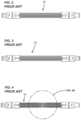
- FIG. 1depicts a typical MPO connector 20 including an MPO ferrule 22 mounted at the end of an MPO connector body 24 .
- a release sleeve 26 for releasing the MPO connector 20 from an MPO adapteris mounted on the MPO connector body 24 .
- the MPO connector body 24includes a key 28 .
- the MPO ferrule 22defines a row of twelve fiber openings 30 in which optical fibers are secured.
- the fiber openings 30have been assigned fiber positions by the telecommunications industry. For example, when the MPO connector 20 is viewed with the key 28 up as shown at FIG. 1 , the fiber openings 30 define fiber positions 1-12 numbered consecutively from left to right.
- FIGS. 2 - 4respectively show a Type-A cord 32 used primarily for Method A applications, a Type-B cord 33 used primarily for Method B applications and a Type-C cord 34 used primarily for Method C applications.
- the cords 32 - 34each have MPO connectors at each end and twelve optical fibers routed through the cords and terminated at the MPO connectors.
- the optical fibersare not laterally transposed such that the ends of each optical fiber are secured at the same position at each of the MPO connectors. As depicted at FIG.
- the optical fibersare laterally transposed such that the ends of each optical fiber are secured at opposite lateral positions at each of the MPO connectors.
- the MPO connectorsare both key up, and the optical fibers are routed straight between the MPO connectors.
- the optical fibersrespectively are connected between fiber positions: 1 and 12; 2 and 11; 3 and 10; 4 and 9; 5 and 8; 6 and 7; 7 and 6; 8 and 5; 9 and 4; 10 and 3; 11 and 2; and 12 and 1.
- the Type-C cordshown at FIGS.
- 4 and 4 Ahas pair-wise flipping/transposition of the optical fibers so the optical fibers are respectively coupled between fiber positions: 1 and 2; 2 and 1; 3 and 4; 4 and 3; 5 and 6; 6 and 5; 7 and 8; 8 and 7; 9 and 10; 10 and 9; 11 and 12; and 12 and 11.
- MPO fiber optic adaptersare used to couple two MPO connectors together.
- the MPO fiber optic adaptersinclude latches for retaining the MPO connectors within ports of the MPO adapters.
- the release sleeves 26 of the MPO connectorsare pulled-back relative to the MPO connector bodies 24 to release the MPO connectors from the ports.
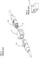
- MPO adapterscan have a Type-B configuration (see FIG. 5 showing MPO connectors 20 a , 20 b aligned with a Type B adapter 38 as also shown at FIG. 6 ) for Method B applications and a Type-A configuration (see FIG. 7 showing MPO connectors 20 a , 20 b aligned with a Type A adapter 36 as also shown at FIG. 8 ) for Method B applications.
- the Type A adapter 36has a key-up to key-down configuration for orienting the MPO connectors 20 a , 20 b so that the fiber positions of the MPO connectors 20 a , 20 b are not laterally transposed.
- the Type B adapter 38has a key-up to key-up configuration for orienting the MPO connectors 20 a , 20 b so that the fiber positions of the MPO connectors 20 a , 20 b are laterally transposed.
- MPO connectorscan either be female or male.
- a male MPO connectorhas alignment pins 39 that protrude from the MPO ferrule (e.g., see MPO connector 20 b ) while a female MPO connector has openings in the MPO ferrule for receiving the pins 39 of the male MPO connector to provide alignment between the male and female MPO connectors when the MPO connectors are coupled together.
- MPO connectorscan include MPO ferrules with end faces that are perpendicular relative to the axes of the optical fibers supported by the ferrules. As used herein, this type of end face is referred to as a perpendicular end face and is typically used with multi-mode optical fibers. This type of end face can also be referred to as a flat end face. MPO connectors can also include MPO ferrules with end faces that are obliquely angled relative to the axes of the optical fibers supported by the ferrules. As used herein, this type of end face is referred to as an obliquely angled end face and is typically used with single mode optical fibers. This type of end face can also be referred to as an angled end face.
- obliquely angled end facesare angled about 8 degrees relative to perpendicular with respect to the axes of the optical fibers supported by the ferrule.
- Obliquely angled end facescan be oriented to face toward the MPO connector key (typically called an “angled-up” configuration) or can be oriented to face away from the MPO connector key (typically called an “angled-down” configuration).
- aspects of the present disclosurerelate to fiber optic adapters that are convertible between different configurations corresponding to different polarity schemes.
- the fiber optic adapterscan be converted between Type A fiber optic adapters and Type B fiber optic adapters.
- the internal shutter configurationsare compatible with fiber optic adapters that can be converted between configurations corresponding to different polarity schemes.
- FIG. 1schematically depicts a prior art MPO ferrule
- FIG. 2depicts a prior art Type A patch cord assembly
- FIG. 3depicts a prior art Type B patch cord assembly
- FIG. 4depicts a prior art Type C patch cord assembly
- FIG. 4 Ais an enlarged view of a portion of FIG. 4 showing pair-wise fiber crossovers
- FIG. 5depicts a prior art Type B adapter with corresponding MPO fiber optic connectors aligned therewith;
- FIG. 6is a schematic view of the prior art Type B adapter of FIG. 5 ;
- FIG. 7depicts a prior art Type A fiber optic adapter with corresponding MPO fiber optic connectors aligned therewith;
- FIG. 8is a schematic view of the prior art Type A fiber optic adapter of FIG. 7 ;
- FIG. 9is a perspective view depicting a fiber optic adapter in accordance with the principles of the present disclosure that can be converted between different configurations corresponding to different polarity schemes, a tool for switching the fiber optic adapter between the different configurations is also depicted;
- FIG. 10is an end view showing the back end of the fiber optic adapter of FIG. 9 ;
- FIG. 11is an end view showing the front end of the fiber optic adapter of FIG. 9 with an upper keyway in a blocked configuration and a lower keyway in an open configuration;
- FIG. 12is an end view showing the front end of the fiber optic adapter of FIG. 9 with the upper keyway open and the lower keyway blocked;
- FIG. 13is an end view of the front end of the fiber optic adapter of FIG. 9 with upper and lower keyway blockers of the fiber optic adapter laterally exploded from an adapter body of the fiber optic adapter;
- FIG. 14is a perspective view of one of the keyway blockers of FIG. 13 ;
- FIG. 15is another perspective view of the keyway blocker of FIG. 14 ;
- FIG. 16is a schematic illustration showing how the tool of FIG. 9 is used to move the lower key blocker from the non-blocking position to the blocking position;
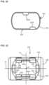
- FIG. 17is a perspective view of another fiber optic adapter in accordance with the principles of the present disclosure, the fiber optic adapter includes dials that can be rotated to change the configuration of the fiber optic adapter to be compatible with different polarity schemes;
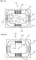
- FIG. 18is an end view of the fiber optic adapter of FIG. 17 showing the rear end of the fiber optic adapter
- FIG. 19is an end view of the fiber optic adapter of FIG. 17 showing the front end of the fiber optic connector in a configuration in which an upper keyway of the fiber optic adapter is blocked and a lower keyway of the fiber optic adapter is open;
- FIG. 20is another end view of the front end of the fiber optic adapter of FIG. 17 showing the fiber optic adapter in a configuration in which the lower keyway is blocked and the upper keyway is open;
- FIG. 21is a perspective, exploded view of another fiber optic adapter in accordance with the principles of the present disclosure, the fiber optic adapter includes a belt that can be rotated to different positions to convert the fiber optic adapter between different configurations compatible with different polarity schemes;
- FIG. 22is an end view showing the belt of the fiber optic adapter of FIG. 21 in isolation from the remainder of the fiber optic adapter;
- FIG. 23is an end view of a front end of a fiber optic adapter body of the fiber optic adapter of FIG. 21 with the belt not mounted on the adapter body;
- FIG. 24is an end view depicting the front end of the adapter body of FIG. 23 with the belt mounted thereon and with a blocking portion of the belt blocking an upper keyway of the adapter body;
- FIG. 25is another end view showing the front end of the adapter body of FIG. 23 with the belt mounted on the adapter body and with a blocking portion of the belt blocking a lower keyway of the adapter body;
- FIG. 26is an end view showing a rear end of the fiber optic adapter of FIG. 21 ;
- FIG. 27depicts the fiber optic adapter of FIG. 21 with an end cap including internal shutters mounted over the front end of the adapter body of the fiber optic adapter;
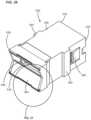
- FIG. 28is a perspective view showing an adapter body of another fiber optic adapter in accordance with the principles of the present disclosure, the adapter body includes separate adapter body portions that can be coupled together in different configurations corresponding to different polarity schemes;
- FIG. 29is an end view showing a front end of the fiber optic adapter body of FIG. 28 ;
- FIG. 30is an end view showing a rear end of the adapter body of FIG. 28 ;
- FIG. 31shows the fiber optic adapter body of FIG. 28 with the separate portions of the adapter body disconnected from one another;
- FIG. 32is a perspective, front view showing an end cap with internal shutters that can be mounted over the front end of the adapter body of FIG. 28 ;
- FIG. 33is a rear, perspective view of the end cap of FIG. 32 ;
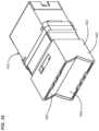
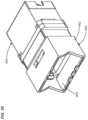
- FIG. 34depicts the adapter body of FIG. 28 with the end cap of FIG. 32 mounted over the front end of the adapter body, internal shutters of the end cap are shown in a closed configuration;
- FIG. 35depicts the fiber optic adapter body and end cap combination of FIG. 34 with the internal shutters of the end cap in an open configuration
- FIG. 36is a perspective view of another fiber optic adapter in accordance with the principles of the present disclosure, the fiber optic adapter includes internal shutters;
- FIG. 37is an enlarged view of a portion of the fiber optic adapter of FIG. 36 ;
- FIG. 38is a side view of a portion of the fiber optic adapter of FIG. 36 ;
- FIG. 39is a perspective view of another fiber optic adapter in accordance with the principles of the present disclosure, the fiber optic adapter includes internal shutters;
- FIG. 40is a perspective cross-sectional view of the fiber optic adapter of FIG. 39 , the internal shutters are shown in a closed configuration;
- FIG. 41is a perspective cross-sectional view of the fiber optic adapter of FIG. 39 , the internal shutter as shown in an open configuration;
- FIG. 42is a perspective view of another fiber optic adapter in accordance with the principles of the present disclosure with an end cap including internal shutters mounted over the front end of the adapter body of the fiber optic adapter.
- FIGS. 9 - 16depict a fiber optic adapter 120 in accordance with the principles of the present disclosure.
- the fiber optic adapter 120is preferably configured for coupling together two fiber optic connectors.
- the fiber optic connectorscan be multi-fiber fiber optic connectors such as MPO fiber optic connectors.
- the fiber optic adapter 120includes first and second slide blockers 122 a , 122 b that can be moved to convert the fiber optic adapter 120 between different configurations corresponding to different polarity schemes.
- FIG. 11shows the fiber optic adapter 120 configured as a Type A fiber optic adapter
- FIG. 12shows the fiber optic adapter 120 configured as a Type B fiber optic adapter.
- a tool 124can be used to move the first and second slide blockers 122 a , 122 b to convert the fiber optic adapter 120 between the different configurations.
- the fiber optic adapter 120includes an adapter body 126 including first and second opposite ends 128 , 130 .
- the first end 128defines a first connector port 132 (see FIGS. 11 and 12 ) while the second end 130 defines a second connector port 134 (see FIG. 10 ).
- the first and second connector ports 132 , 134are aligned along a central axis C (see FIG. 9 ) that extends between the first and second ends 128 , 130 of the adapter body 126 and through the first and second connector ports 132 , 134 .
- the first and second connector ports 132 , 134each define an oblong profile shape having perpendicular major and minor axes A 1 , A 2 (see FIGS.
- the oblong profile shape of each of the first and second connector ports 132 , 134has first and second major sides 136 , 138 intersected by the minor axis A 2 and first and second minor sides 140 , 142 intersected by the major axis A 1 .
- the first connector port 132includes first and second keyways 144 a , 144 b aligned along the minor axis A 2 of the first connector port 132 .
- the first and second keyways 144 a , 144 bare located respectively at the first and second major sides 136 , 138 of the first connector port 132 .
- the second connector port 134defines a single keyway 146 (see FIG.
- the single keyway 146is located at the first major side 136 of the second connector port 134 and is coaxially aligned with the first keyway 144 a of the first connector port 132 .
- the fiber optic adapter 120also includes connector retention latches 148 integrated with the adapter body 126 at the first and second connector ports 132 , 134 .
- the connector latches 148 of each of the first and second connector ports 132 , 134are located respectively at the first and second minor sides 140 , 142 of the respective first or second connector port 132 , 134 .
- the connector retention latches 148 of each of the first and second connector ports 132 , 134are aligned along the major axis A 1 of their respective first or second connector port 132 , 134 .
- the first and second slide blockers 122 a , 122 bare respectively slideably mounted to the adapter body 126 adjacent the first and second major sides 136 , 138 of the first connector port 132 .
- the first and second slide blockers 122 a , 122 bare each slideably movable relative to the adapter body 126 between first and second positions.
- the first and second slide blockers 122 a , 122 bare each slideably moveable relative to the adapter body 126 in an orientation that extends along the major axis A 1 of the first connector port 132 .
- the first slide blocker 122 aat least partially obstructs the first keyway 144 a such that the first keyway is in a key non-receiving configuration.
- the first slide blocker 122 ais in the second position (see FIG. 12 )
- the first keyway 144 ais in a key receiving configuration.
- the second slide blocker 122 bis in the first position (see FIG. 12 )
- the second slide blocker 122 bat least partially obstructs the second keyway 144 b such that the second keyway 144 b is in a key non-receiving configuration.
- the second slide blocker 122 bis in the second position (see FIG.
- the second keyway 144 bis in a key receiving configuration. It will be appreciated that by selectively opening or blocking the keyways 144 a , 144 b with the first and second slide blockers 122 a , 122 b , the fiber optic adapter 120 can be converted between a Type A configuration as shown at FIG. 11 and a Type B configuration as shown at FIG. 12 .
- first slide blocker 122 amoves toward the first minor side 140 of the first connector port 132 when moving from the first position (e.g., the blocking position) to the second position (e.g., the non-blocking position) and moves toward the second minor side 142 when moving from the second position to the first position.
- the second slide blocker 122 bmoves toward the second minor side 142 when moving from the first position (e.g., the blocking position) to the second position (e.g., the non-blocking position) and moves toward the first minor side 140 when moving from the second position to the first position.
- the first and second slide blockers 122 a , 122 beach include first and second blocker cam surfaces 150 , 152 that face generally in opposite directions with respect to each other.
- the first and second slide blockers 122 a , 122 bare positioned such that the first blocker cam surface 150 of the first slide blocker 122 a and the second blocker cam surface 152 of the second slide blocker 122 b face in a direction toward the second minor side 142 of the first connector port.
- the second blocker cam surface 152 of the first slide blocker 122 a and the first blocker cam surface 150 of the second slide blocker 122 bface toward the first minor side 140 of the first connector port 132 .
- the first blocker cam surface 150 of the first slide blocker 122 a and the second blocker cam surface 152 of the second slide blocker 122 bangle toward the second minor side 142 of the first connector port 132 as they extend axially into the connector port 132 .
- the second blocker cam surface 152 of the first slide blocker 122 a and the first blocker cam surface 150 of the second slide blocker 122 bangle toward the first minor side 140 of the first connector port 132 as the cam surfaces extend axially into the connector port 132 .
- the first blocker cam surfaces 150are offset a first distance d 1 from a central reference plane RP and includes the minor axis A 2 and the central axis C.
- the second blocker cam surfaces 152are offset a second distance d 2 from the central reference plane RP.
- the first and second distances d 1 , d 2are not equal.
- the first distance d 1is smaller than the second distance d 2 .
- first and second slide blockers 122 a , 122 bare configured to move in opposite directions with respect to one another when moving from the first position to the second position. Similarly, the first and second slide blockers 122 a , 122 b are configured to move in opposite directions relative to one another when moving from the second position to the first position.
- the tool 124is configured to: a) move the first slide blocker 122 a from the first position to the second position and simultaneously move the second slide blocker 122 b from the second position to the first position; and b) move the first slide blocker 122 a from the second position to the first position and simultaneously move the second slide blocker 122 b from the first position to the second position.
- the tool 124includes first and second prongs 154 , 156 with are preferably spaced apart from one another and parallel to one another.
- the first prong 154includes a first tool cam surface 158 and the second prong 156 includes a second tool cam surface 160 .
- the first prong 154 and the first tool cam surface 158are offset the first distance D 1 from a central reference plane 162 of the tool and the second prong 156 and the second tool cam surface 160 are offset the second distance D 2 from the central reference plane 162 of the tool 124 .
- the first and second prongs 154 , 156 of the toolare configured to be inserted into the adapter body 126 of the fiber optic adapter 120 in a direction that extends along the central axis C to move the first and second slide blockers 122 a , 122 b between the first and second positions.
- the tool 124is inserted into the fiber optic adapter 120 while at a first rotational position, during insertion, the first tool cam surface 158 engages the first blocker cam surface 150 of the first slide blocker 122 a and the second tool cam surface 160 simultaneously engages the second blocker cam surface 152 of the second slide blocker 122 b to cause simultaneous movement of the slide blockers 122 a , 122 b .
- the first and second prongs 154 , 156 of the tool 124are inserted into the fiber optic adapter 120 while the tool 124 is in a second rotational position that is rotated 180 degrees from the first rotational position.
- the second tool cam surface 160engages the second blocker cam surface 152 of the first slide blocker 122 a and the first tool cam surface 158 engages the first blocker cam surface 150 of the second slide blocker 122 b to cause simultaneous movement of the first and second slide blockers 122 a , 122 b in opposite directions.
- the adapter body 126defines first and second prong-receiving slots 164 , 166 adjacent the first and second major sides 136 , 138 of the first connector port 132 .
- the first and second prong-receiving slots 164 , 166 as well as the first and second keyways 144 a , 144 bare configured for receiving the first and second prongs 154 , 156 of the tool 124 .
- the first prong 154is inserted into the first keyway 144 a and the second prong 156 is simultaneously inserted into the second prong-receiving slot 166 to move the first slide blocker 122 a from the first position to the second position and simultaneously move the second slide blocker 122 b from the second position to the first position.
- the first prong 154is inserted into the second keyway 144 b and the second prong 156 is simultaneously inserted into the first prong-receiving slot 164 to move the first slide blocker from the second position to the first position and simultaneously move the second slide blocker 122 b from the first position to the second position.
- the central reference plane 162 of the tool 124aligns with the central reference plane RP of the adapter body 126 when the first and second prongs 154 , 156 are inserted into the adapter body 126 .
- FIG. 16shows how axial movement of the tool 124 along axis C causes sliding movement of the first and second slide blockers 122 a , 122 b in an orientation perpendicular to the axis C.
- contact between the second tool cam surface 160 of the second prong 156 and the second blocker cam surface 152 of the second slide blocker 122 b as the tool 124 is inserted axially along the direction 168 into the fiber optic adapter 120provides a cam action that forces the second slide blocker 122 b in a direction 170 perpendicular relative to the direction 168 .
- the interaction between the cam surfaces 158 , 160 of the tool 124 and the other blocker cam surfaces 150 , 152operate in a similar manner to cause movement of the slide blockers 122 a , 122 b.
- FIGS. 17 - 20depict another fiber optic adapter 220 in accordance with the principles of the present disclosure.
- the fiber optic adapter 220is configured for coupling together two fiber optic connectors.
- the fiber optic adapter 220is configured for coupling together two multi-fiber fiber optic connectors such as MPO connectors.
- the fiber optic adapter 220includes first and second dials 222 a , 222 b that can be rotated to different positions to convert the fiber optic adapter 220 between different configurations corresponding to different polarity schemes.
- FIG. 19shows the fiber optic adapter 220 in a Type A configuration
- FIG. 20shows the fiber optic adapter 220 in a Type B configuration.
- Each of the dials 222 a , 222 bdefines a keyway 224 .
- Each of the first and second dials 222 a , 222 bis rotatable between first and second rotational positions.
- the keyway 224is in a key receiving configuration when the dial 222 a , 222 b is in the first rotational position.
- the keyway 224is in a key non-receiving configuration when the dial 222 a , 222 b is in the second rotational position.
- the fiber optic adapter 220includes an adapter body 226 including first and second ends 228 , 230 .
- the first end 228defines a first connector port 232 (see FIGS. 17 , 19 and 20 ) and the second end 230 defines a second connector port 234 (see FIG. 18 ).
- the first and second connector ports 232 , 234are aligned along a central axis C that extends between the first and second ends 228 , 230 of the adapter body 226 and through the first and second connector ports 232 , 234 .
- the first and second connector ports 232 , 234each define an oblong profile shape having perpendicular major and minor axes A 1 , A 2 .
- each of the first and second connector ports 232 , 234includes opposite first and second major sides 236 , 238 intersected by the minor axis A 2 and first and second minor sides 240 , 242 intersected by the major axis A 1 .
- the first connector port 232includes first and second keyways 244 a , 244 b defined at least in part by the keyways 224 of the first and second dials 222 a , 222 b .
- the first and second dials 222 a , 222 bare aligned along the minor axis A 2 of a first connector port 232 and are located respectively at the first and second major sides 236 , 238 of the first connector port 232 .
- the second connector port 234defines a single keyway 246 aligned along the minor axis A 2 of the second connector port 234 .
- the single keyway 246is located at the first major side 242 of the second connector port 234 and is preferably coaxially aligned with the first keyway 244 a of the first connector port 232 .
- the adapter body 226includes connector retention latches 248 integrated with the adapter body 226 at the first and second connector ports 232 , 234 .
- the connector retention latches 248 of each of the first and second connector ports 232 , 234are located respectively at the first and second minor sides 240 , 242 of their respective first or second connector port 232 , 234 and are aligned along the major axis A 1 of their respective first or second connector port 232 , 234 .
- the first and second dials 222 a , 222 bare rotatably mounted to the adapter body 226 and are positioned adjacent the first connector port 232 .
- the keyways 224 defined by the dials 222 a , 222 bpreferably extend through the dials 222 a , 222 b along diameters of the dials 222 a , 222 b .
- the dials 222 a , 222 bare rotatable relative to the adapter body 226 between first and second rotational positions.
- the keyways 244 a , 224 bare in the key receiving configuration when their corresponding dial is in the first rotational position and are in a key non-receiving configuration when their corresponding dials are in the second rotational position.
- the first dial 220 ais shown in a key non-receiving configuration while the second dial 222 b is shown in the key receiving configuration.
- the fiber optic adapter 220corresponds to a Type A adapter configuration.
- the first dial 222 ahas been rotated to the key receiving configuration while the second dial 222 b has been rotated to the key non-receiving configuration.
- the fiber optic adapter 220is configured as a Type B fiber optic adapter.
- the first and second rotational positions between which the dials 222 a , 222 b are movableare offset from one another by an angle in a range of about 80-100 degrees, or about 90 degrees.
- the dials 222 a , 222 brotate about dial axes that are perpendicular relative to the central axis C.
- the dials 222 a , 222 bcan be independently or separately rotated between the first and second rotational positions.
- the first and second dials 222 a , 222 bcan be mechanically coupled or linked such that the dials 222 a , 222 b rotate in unison with one another.
- coupling between the dials 222 a , 222 bcan be configured such that rotation of one of the dials causes rotation of the other dials in unison with one another.
- a gear arrangement 250can be used to mechanically couple the dials 222 a , 222 b together such that torque is transferred between the dials 222 a , 222 b through the gear arrangement 250 .
- FIGS. 21 - 27depict another fiber optic adapter 320 in accordance with the principles of the present disclosure.
- the fiber optic adapter 320is adapted for coupling together two fiber optic connectors.
- the fiber optic adapter 320is adapted for coupling together two multi-fiber fiber optic connectors such as MPO connectors.
- the fiber optic adapter 320includes a belt 322 having both first and second keyway blocking portions 322 a , 322 b .
- the belt 322is rotatable between a first position in which the fiber optic adapter 320 is configured as a Type A adapter (see FIG. 24 ), and a second position in which the fiber optic adapter 320 is configured as a Type B adapter (see FIG. 25 ).
- the fiber optic adapter 320includes an adapter body 326 having a first end 328 and an opposite second end 330 .
- the first end 328defines a first connector port 332 (see FIGS. 21 , 23 , and 24 ) and the second end 330 defines a second connector port 334 (see FIG. 26 ).
- the first and second connector ports 332 , 334are aligned along a central axis C that extends between the first and second ends 328 , 330 of the adapter body 326 and through the first and second connector ports 332 , 334 .
- the first and second connector ports 332 , 334each define an oblong profile shape having perpendicular major and minor axes A 1 , A 2 .
- each of the first and second connector ports 332 , 334have opposite first and second major sides 336 , 338 intersected by the minor axis A 2 and first and second minor sides 340 , 342 intersected by the major axis A 1 .
- the first connector port 332includes first and second keyways 344 a , 344 b aligned along the minor axis A 2 of the first connector port 332 .
- the first and second keyways 344 a , 334 bare located respectively at the first and second major sides 336 , 338 of the first connector port 332 .
- the second connector port 334as shown at FIG. 26 , defines a single keyway 346 .
- the single keyway 346is aligned along the minor axis A 2 of the second connector port 334 and is located at the first major side 336 of the second connector port 334 .
- the fiber optic adapter 320further includes connector retention latches 348 integrated with the adapter body 326 at the first and second connector ports 332 , 334 .
- Connector retention latches 348 of each of the first and second connector ports 332 , 334are located respectively at the first and second minor sides 340 , 342 of each of the respective first and second connector ports 332 , 334 .
- the connector retention latches 348are also aligned along the major axes A 1 of each of the connector ports 332 , 334 .
- the belt 322is mounted at the first end 328 of the adapter body 326 .
- the belt 322is rotatable relative to the adapter body 326 about the central axis C.
- the belt 322is rotatably moveable relative to the adapter body 326 about the central axis C between first and second positions.
- the blocking portion 322 aWhen the belt 322 is in the first position as shown at FIG. 24 , the blocking portion 322 a at least partially obstructs the first keyway 344 a such that the first keyway is in a key non-receiving configuration.
- the blocking portion 322 bis offset from the second keyway 344 b such that the second keyway 344 b is open and in a key receiving configuration.
- the blocking portion 322 ais offset from the first keyway 344 a such that the first keyway 344 a is unobstructed and in a key receiving configuration.
- the blocking portion 322 bat least partially obstructs the second keyway 344 b such that the second keyway 344 b is in a key non-receiving configuration.
- the fiber optic adapter 320is configured as a Type A adapter, and when the belt 322 is in the second rotational position, the fiber optic adapter 320 is configured in a Type B configuration.
- the belt 322moves along an oblong path.
- the belt 322includes a main belt body 350 that is a continuous body and that surrounds the central axis C.
- the blocking portions 322 a , 322 bare formed by blocking tabs that project inwardly from the main belt body 350 .
- the belt 322can further include a manipulation tab 352 that projects outwardly from the main belt body 350 for allowing the belt to be manually rotated between the first and second positions. As shown at FIGS.
- the fiber optic adapter 320can further include an end cap 353 having an end cap body 354 that mounts over the first end 328 of the adapter body 326 at a location in which the end cap body 354 is positioned over the belt 322 .
- the end capcan be secured to the adapter body 326 by a mechanical connection such as an interference fit, a snap-fit, a slide latch, fasteners or other techniques.
- the adapter body 326includes flexible latches 356 that snap within receivers 358 defined by the end cap body 354 to secure the end cap body 354 and the adapter body 326 together.
- the end capalso includes internal shutters 359 pivotally connected to the end cap body 354 .
- the internal shutters 359are configured to pivot relative to the ends cap body 354 between a closed position and an open position (see FIGS. 21 and 27 ) in which the shutters 359 are pivoted inside the end cap body 354 . It will be appreciated that when a fiber optic connector is inserted into the first connector port 332 , contact between the fiber optic connector and the shutters 359 forces the shutters to pivot into the interior of the end cap body 354 from the closed position to the open position to allow the fiber optic connector to be inserted into the first connector port 332 .
- the end cap body 354includes a side slot 360 that receives the manipulation tab 352 of the belt 322 and allows the manipulation tab 352 to be accessed from outside the fiber optic adapter 320 even when the end cap 353 is mounted over the first end 328 of the adapter body 326 .
- the manipulation tab 352By moving the manipulation tab 352 up or down within the side slot 360 , the belt 322 can be moved between the first and second positions to change the keying configuration of the fiber optic adapter 320 to be compatible with different polarity schemes.
- the internal shutters 359are coupled to the end cap body 354 by a pivotal, snap-fit connection.
- the internal shutters 359are spring biased toward the closed position, and are configured to pivot from the closed position to the open position via contact with a fiber optic connector as the fiber optic connector is inserted into the first port 332 .
- the spring biasing of the shutters 359can be provided by leaf springs mounted within the end cap body 354 .
- the internal shutters 359are configured to pivot relative to the end cap body 354 and the adapter body 326 between a closed position in which the shutters 359 block the first connector port 332 and an open position in which the internal shutters 359 are pivoted inside the end cap body 354 or the adapter body 326 to allow a fiber optic connector to be received within the first connector port 332 .
- the internal shutters 359are outwardly offset from free ends of the connector retention latches 348 of the first connector port 332 at least when the internal shutters 359 are in the closed position.
- the internal shutters 359are obliquely angled relative to the central axis C when in the closed position.
- the end cap 353can include one or more of the key blocking features described herein (e.g., slide blockers, dials, belt with blocking portions, etc.) so as to form the Type A adapter configuration or Type B adapter configuration as required or desired.
- the key blocking features described hereine.g., slide blockers, dials, belt with blocking portions, etc.
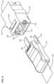
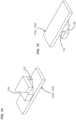
- FIGS. 28 - 35depict another fiber optic adapter 420 in accordance with the principles of the present disclosure.
- the fiber optic adapter 420is adapted for coupling together two fiber optic connectors.
- the fiber optic connectorsare multi-fiber fiber optic connectors such as MPO connectors.
- the fiber optic adapter 420includes first and second adapter body portions 422 a , 422 b that can be connected together in different configurations to make the fiber optic adapter 420 compatible with different polarity schemes.
- the fiber optic adapter 420includes an adapter body 426 including first and second ends 428 , 430 .
- the first end 428defines a first connector port 432 and the second end defines a second connector port 434 .
- the first and second connector portsare aligned along a central axis C that extends between the first and second ends 428 , 430 of the adapter body 426 and through the first and second connector ports 432 , 434 .
- the first and second connector ports 432 , 434each define an oblong profile shape having perpendicular major and minor axes A 1 , A 2 .
- the oblong profile shape of each of the first and second connector ports 432 , 434has opposite first and second major sides 436 , 438 intersected by the minor axis A 2 and first and second minor sides 440 , 442 intersected by the major axis A 1 .
- the first connector port 432includes a single first keyway 444 aligned along the minor axis A 2 of the first connector port 432 at one of the first and second major sides 436 , 438 of the first connector port 432 .
- the second connector port 434includes a single second keyway 446 aligned along the minor axis A 2 of the second connector port 434 at one of the first and second major sides 436 , 438 of the second connector port 434 .
- the fiber optic adapter 420also includes connector retention latches 448 integrated with the adapter body 426 at the first and second connector ports 432 , 434 .
- the connector retention latches 448 of each of the first and second connector ports 432 , 434are located respectively at the first and second minor sides 440 , 442 of their respective first or second connector ports 432 , 434 and are aligned along the major axis A 1 of their respective first or second connector ports 432 , 434 .
- the adapter body 426includes the first adapter body portion 422 a which defines the first connector port 432 and includes the connector latches 448 corresponding to the first connector port 432 .
- the adapter body 426also includes the second adapter body portion 422 b which defines the second connector port 434 and includes the connector latches 448 corresponding to the second connector port 434 .
- the first adapter body portion 422 aincludes the single first keyway 444 and the second adapter body portion 422 b includes the single second keyway 446 .
- the first and second adapter body portions 422 a , 422 bare connectable at a mechanical interface 450 that allows the adapter body 426 to be configured in a Type A configuration and also allows the adapter body to be configured in a Type B configuration.
- the first and second adapter body portions 422 a , 422 bare coupled together at a relative orientation in which the single first and second keyways 444 , 446 are positioned at opposite sides of their respective ports (e.g., one of the keyways is up and the other of the keyways is down).
- the adapter body 426is configured in the Type B configuration, the first and second adapter body portions 422 a , 422 b are coupled together in a configuration in which the single first and second keyways 444 , 446 are positioned at the same sides of their respective connector ports 432 , 434 (e.g., the keyways 444 , 446 are either both up or both down).
- the mechanical interface 450is a tongue and groove configuration.
- other types of configurationssuch as snap-fit configurations, interference fit configurations and other securement techniques could also be used.
- first and second adapter body portions 422 a , 422 beach form half-portions of the adapter body 426 .
- an end cap 460 having an end cap body 462 and internal shutters 464can be mounted over the first end 428 of the adapter body 426 .
- the end cap 460can be secured to the first end 428 of the adapter body 426 by a snap-fit connection between the end cap body 462 and the first end 428 .
- the first end 428can include latches, tabs, bumps or other structures that snap within a corresponding receptacle such as a slot defined by the end cap body 462 to secure the end cap 460 to the first end 428 of the adapter body 426 .
- the internal shutters 464are secured to the end cap body 462 by a pivotal, snap-fit connection are configured to pivot about pivot axes 463 .
- the pivot axes 463preferably extend parallel to the major axis A 1 .
- the internal shutters 464can be movable between open and closed positions. Springs such as leaf springs 465 can be configured for biasing the internal shutters 464 toward the closed position. In the closed position, the internal shutters 464 can be oriented at an oblique angle relative to the central axis C. In certain examples, the shutters define a V-shaped profile when in the closed position when viewed from the side of the end cap 460 .
- the shutters 464when the internal shutters 464 are closed, the shutters angle toward the first connector port 432 from the hinge axes 463 and meet at a central line 468 that bisects the connector port 432 .
- the internal shutters 464are configured to pivot from the closed position (see FIGS. 32 and 34 ) to the open position (See FIG. 35 ) via contact with a fiber optic connector as the fiber optic connector is inserted into the first connector port 432 .
- the internal shutters 464are outwardly offset from free ends of the connector retention latches 448 at least when the internal shutters 464 are in a closed position. When the internal shutters 464 are in the closed position, the internal shutters 464 assist in preventing contaminants from entering the first connector port 432 and also provide light blocking ability.
- the end cap 460can include one or more of the key blocking features described herein (e.g., slide blockers, dials, belt with blocking portions, etc.) so as to form the Type A adapter configuration or Type B adapter configuration as required or desired.
- key blocking features described hereine.g., slide blockers, dials, belt with blocking portions, etc.
- FIGS. 36 - 38show another fiber optic adapter 520 in accordance with the principles of the present disclosure.
- the fiber optic adapter 520includes an adapter body 526 having first and second opposite ends 528 , 530 .
- the first end 528defines a first connector port 532 and the second end 530 defines a second connector port 534 .
- Internal shutters 564 of the type previously describedare pivotally connected directly to the adapter body 526 adjacent the first connector port 532 via a pivotal snap-fit connection.
- the shutters 564can move between open and closed positions in the same manner as described with respect to the other shutters previously described herein.
- the adapter body 526also includes unitarily formed side latches 580 and side flanges 582 that cooperate for allowing the fiber optic adapter 520 to be snapped within an opening of a panel. For example, when the fiber optic adapter 520 is snapped within an opening in a panel, the panel is captured between free ends of the side latches 580 and the side flanges 582 . The side latches 580 flex inwardly as the fiber optic adapter 520 is inserted through the opening in the panel, and then snap outwardly to a retaining position once the side latches 580 move through the opening.
- FIGS. 39 - 41show another fiber optic adapter 620 in accordance with the principles of the present disclosure.
- the fiber optic adapter 620includes an adapter body 626 having first and second opposite ends 628 , 630 .
- the first end 628defines a first connector port 632 and the second end 630 defines a second connector port 634 .
- Internal shutters 664are secured to the adapter body 626 by a pivotal, snap-fit connection and are configured to pivot about axes that extend parallel to the major axis.
- the internal shutters 664are movable between an open configuration (shown in FIG. 41 ) and a closed configuration (shown in FIG. 40 ), and are illustrated as transparent so that the components underneath are shown.
- a spring 665biases each internal shutter 664 toward the closed configuration.
- the spring 665has a base 666 and one or more resilient arms 668 .
- the base 666is mounted on an interior surface of the major side, and in some examples, a portion of the base 666 extends at least partially along each minor side.
- the resilient arms 668are biased into a curved configuration with a concave surface facing outwards from the first end 628 and a convex surface facing inwards towards the second end 630 .
- a free end of the resilient arm 668is configured to engage an inner surface of the internal shutter 664 and slide along the surface. This configuration urges the internal shutters 664 into the closed configuration when a fiber optic connector is not present.
- the fiber optic connectorWhen a fiber optic connector is inserted into the first connector port 632 , the fiber optic connector contacts the internal shutter 664 and overcomes the force of the spring 665 , allowing the shutters 664 to pivot and open.
- the resilient arms 668when the internal shutters 664 are in the closed configuration, the resilient arms 668 are oriented substantially parallel to the internal shutter 664 and against the interior surface of the major side.
- the interior surface of the major sidecan have one or more tracks so that the resilient arms 668 can lay flat within the adapter body 626 in the closed configuration.
- the internal shutters 664are offset from free ends of connector retention latches 648 .
- FIG. 42depicts another fiber optic adapter 720 in accordance with the principles of the present disclosure.
- the fiber optic adapter 720is adapted for coupling together two fiber optic connectors. Components of the adapter 720 are similar to those described above, and thus, are not necessarily described further.
- the fiber optic adapter 720further includes an end cap 760 having an end cap body 762 that mounts over the end of the adapter body.
- the end cap 760can be secured to the adapter by a mechanical connection such as an interference fit, a snap-fit, a slide latch, fasteners, or other techniques.
- the end cap 760includes internal shutters 764 pivotally connected to the end cap body 762 and configured to move between an open configuration and a closed configuration.
- the shutters 764are illustrated as transparent so that the components underneath are shown. As illustrated in FIG. 42 , the shutters 764 are in an open configuration. In certain examples, the shutters 764 are biased towards the closed configuration by a spring 765 .
- the spring 765may have a similar configuration to the spring 665 described above in reference to FIG. 39 - 41 , or may have any other configuration as required or desired.
- the end cap 760can include one or more of the key blocking features described herein (e.g., slide blockers, dials, belt with blocking portions, etc.) so as to form the Type A adapter configuration or Type B adapter configuration as required or desired.
- a keyway of a connector portis in a key receiving configuration when the keyway is configured to receive a key of a fiber optic connector when the fiber optic connector is inserted in into the connector port while the fiber optic connector is in a rotational orientation in which the key is aligned within the keyway.
- the fiber optic connectoris allowed to be inserted in the connector port while the fiber optic connector is in the rotational positon in which the key is aligned with the keyway.
- a keyway of a connector portis in a key non-receiving configuration when the keyway is configured to prevent receipt of a key of a fiber optic connector into the keyway when the fiber optic connector is attempted to be inserted in into the connector port while the fiber optic connector is in a rotational orientation in which the key is aligned within the keyway. In this way, when the keyway is in the key non-receiving configuration, the fiber optic connector is prevented from being inserted in the connector port while the fiber optic connector is in the rotational position in which the key is aligned with the keyway.
Landscapes
- Physics & Mathematics (AREA)
- General Physics & Mathematics (AREA)
- Optics & Photonics (AREA)
- Mechanical Coupling Of Light Guides (AREA)
Abstract
Description
Claims (7)
Priority Applications (1)
| Application Number | Priority Date | Filing Date | Title |
|---|---|---|---|
| US17/630,412US12265264B2 (en) | 2019-07-26 | 2020-07-23 | Fiber optic adapters convertible between different polarity types |
Applications Claiming Priority (3)
| Application Number | Priority Date | Filing Date | Title |
|---|---|---|---|
| US201962879232P | 2019-07-26 | 2019-07-26 | |
| PCT/US2020/043312WO2021021575A1 (en) | 2019-07-26 | 2020-07-23 | Fiber optic adapters convertible between different polarity types |
| US17/630,412US12265264B2 (en) | 2019-07-26 | 2020-07-23 | Fiber optic adapters convertible between different polarity types |
Related Parent Applications (1)
| Application Number | Title | Priority Date | Filing Date |
|---|---|---|---|
| PCT/US2020/043312A-371-Of-InternationalWO2021021575A1 (en) | 2019-07-26 | 2020-07-23 | Fiber optic adapters convertible between different polarity types |
Related Child Applications (1)
| Application Number | Title | Priority Date | Filing Date |
|---|---|---|---|
| US19/069,012ContinuationUS20250321383A1 (en) | 2025-03-03 | Fiber optic adapters convertible between different polarity types |
Publications (2)
| Publication Number | Publication Date |
|---|---|
| US20220283381A1 US20220283381A1 (en) | 2022-09-08 |
| US12265264B2true US12265264B2 (en) | 2025-04-01 |
Family
ID=74228271
Family Applications (1)
| Application Number | Title | Priority Date | Filing Date |
|---|---|---|---|
| US17/630,412Active2041-10-17US12265264B2 (en) | 2019-07-26 | 2020-07-23 | Fiber optic adapters convertible between different polarity types |
Country Status (3)
| Country | Link |
|---|---|
| US (1) | US12265264B2 (en) |
| EP (1) | EP4004619A4 (en) |
| WO (1) | WO2021021575A1 (en) |
Cited By (1)
| Publication number | Priority date | Publication date | Assignee | Title |
|---|---|---|---|---|
| US20240369778A1 (en)* | 2023-05-06 | 2024-11-07 | Huizhou Fibercan Industrial Co.,Ltd | Multi-gang adapter for high-density assembly |
Families Citing this family (2)
| Publication number | Priority date | Publication date | Assignee | Title |
|---|---|---|---|---|
| WO2022197638A1 (en)* | 2021-03-16 | 2022-09-22 | US Conec, Ltd | Adapter shutter assembly with shutter retention cap |
| CN221261311U (en)* | 2023-11-17 | 2024-07-02 | 浙江欧亚华通讯设备有限公司 | An LC dust-proof adapter |
Citations (97)
| Publication number | Priority date | Publication date | Assignee | Title |
|---|---|---|---|---|
| US4712861A (en) | 1985-02-07 | 1987-12-15 | Northern Telecom Limited | Two-channel hermaphroditic fiber connector |
| US4775327A (en) | 1987-02-17 | 1988-10-04 | Amphenol Corporation | Connector with automatic protection cap |
| US4779950A (en) | 1984-04-03 | 1988-10-25 | Thomas & Betts Corporation | Connection apparatus for optical fibers |
| US5348487A (en) | 1992-05-20 | 1994-09-20 | Diamond Sa | Plug connector for optical fibers |
| US5363460A (en) | 1992-11-26 | 1994-11-08 | Diamond Sa | Sleeve portion for an optical fibre plug connector |
| US5372515A (en) | 1993-06-10 | 1994-12-13 | Martin Marietta Corporation | Mechanical ESD protector |
| US5506922A (en) | 1994-08-01 | 1996-04-09 | Molex Incorporated | Fiber optic component assembly with a movable protective shield |
| US5570445A (en) | 1994-06-22 | 1996-10-29 | Xintec Corporation | Reusable optical fiber connector adapter with plurality of optical barriers for all fiber delivery laser sources |
| KR970062736A (en) | 1996-02-01 | 1997-09-12 | 루이스 에이. 헥트 | Fiber Optic Connector Receptacle with Protective Shutter |
| US5687268A (en)* | 1995-11-27 | 1997-11-11 | Lucent Technologies Inc. | Pivotable optical shutter for blocking emission from a lightguide adapter #5 |
| US5708745A (en) | 1994-10-20 | 1998-01-13 | Fujitsu Limited | Device for preventing laser beam leakage |
| US5716224A (en) | 1994-11-10 | 1998-02-10 | Yazaki Corporation | Connector with shutter mechanism |
| US5887098A (en)* | 1997-02-27 | 1999-03-23 | Molex Incorporated | Fiber optic adapter with protective shield |
| US5909526A (en) | 1998-04-08 | 1999-06-01 | Molex Incorporated | Fiber optic connector assembly |
| US5956444A (en) | 1997-02-13 | 1999-09-21 | Amphenol Corporation | Radiation absorbing shield for fiber optic systems |
| US6004043A (en) | 1997-12-19 | 1999-12-21 | The Whitaker Corporation | Shuttered connector receptacle |
| US6041155A (en) | 1997-12-10 | 2000-03-21 | Lucent Technologies Inc. | Universal dust cover |
| US6076973A (en) | 1997-05-20 | 2000-06-20 | Adc Telecommunications, Inc. | Fiber connector and adapter |
| US6081647A (en) | 1998-01-05 | 2000-06-27 | Molex Incorporated | Fiber optic connector receptacle |
| US6079881A (en) | 1998-04-08 | 2000-06-27 | Molex Incorporated | Fiber optic connector receptacle assembly |
| US6108482A (en) | 1998-01-14 | 2000-08-22 | Molex Incorporated | Fiber optic connector receptacle |
| US6206577B1 (en)* | 1998-02-05 | 2001-03-27 | Alcoa Fujikura Limited | Fiber optic adapter shutter door assembly |
| US6240229B1 (en) | 1998-12-21 | 2001-05-29 | Molex Incorporated | Connector assembly |
| US6247849B1 (en) | 1997-09-13 | 2001-06-19 | Alliance Fiber Optics Products, Inc. | Protection cap for fiber coupler |
| EP1139128A2 (en) | 2000-03-24 | 2001-10-04 | Tyco Electronics Corporation | Shielded optical connector |
| US6332781B1 (en) | 2000-04-06 | 2001-12-25 | Yazaki Corporation | Connector structure having dust/water droplet damage prevention capability |
| US6371657B1 (en) | 1999-12-07 | 2002-04-16 | Molex Incorporated | Alignment system for mating connectors |
| US6425694B1 (en) | 2000-09-18 | 2002-07-30 | Molex Incorporated | Fiber optic receptacle with protective shutter |
| US6461054B1 (en) | 1999-10-25 | 2002-10-08 | The Furukawa Electric Co., Ltd. | Adapter having a light-shielding shutter and optical module receptacle having a light-shielding shutter |
| US6471412B1 (en) | 2000-02-04 | 2002-10-29 | Molex Incorporated | Fiber optic connector receptacle |
| US20030081913A1 (en) | 2001-10-31 | 2003-05-01 | Ziqiang Zhu | Optical connector with slidable shielding door |
| US6572274B1 (en) | 2001-11-29 | 2003-06-03 | Lynx Photonic Networks Inc. | Safety shutter module for fiber-optics connector |
| US6595696B1 (en)* | 2001-03-14 | 2003-07-22 | Amphenol Corporation | Internal shutter for optical adapters |
| US20030147597A1 (en)* | 2002-02-07 | 2003-08-07 | Jaime Duran | Cantilevered shutter for optical adapter |
| US20030180005A1 (en)* | 2002-03-21 | 2003-09-25 | Lucent Technologies Inc. | Optical fiber shutter adapter |
| US6652155B2 (en) | 2001-06-21 | 2003-11-25 | Fitel Usa Corp. | Optical connector plug |
| US6688781B2 (en) | 2002-03-11 | 2004-02-10 | Fitel Usa Corp. | Optical connector adapter having switching capability |
| US20040062486A1 (en)* | 2002-10-01 | 2004-04-01 | Fujikura Ltd. | Optical connector with shutter |
| US20040081419A1 (en) | 2002-10-24 | 2004-04-29 | Jun Takeda | Optical fiber splicing instrument with shutter |
| US20040141693A1 (en) | 2003-01-16 | 2004-07-22 | Szilagyi B. Daniel | Fiber optic connector assembly |
| JP2005017598A (en) | 2003-06-25 | 2005-01-20 | Suncall Corp | Optical connector |
| US20050286833A1 (en)* | 2001-08-23 | 2005-12-29 | Anne Kramer | Universal adapter |
| JP2006106635A (en)* | 2004-10-08 | 2006-04-20 | Matsushita Electric Works Ltd | Optical plug socket |
| US7093983B2 (en) | 2003-12-05 | 2006-08-22 | Seikoh Giken Co., Ltd. | Optical connector plug and optical connector |
| US20060204200A1 (en)* | 2005-03-10 | 2006-09-14 | Yazaki Corporation | Dust shutter for an optical adapter |
| US7261472B2 (en) | 2005-01-12 | 2007-08-28 | Illum Technologies, Inc. | Ultra-small, form factor single fiber optical interconnect system, with push-push type insertion/withdrawal mechanism and shuttered modular connector and shuttered adapter and method for using same |
| US20070230874A1 (en) | 2006-03-20 | 2007-10-04 | Lin Samuel I En | Fiber adapter and shutter member thereof |
| US20080267566A1 (en) | 2006-03-20 | 2008-10-30 | Senko Advanced Components, Inc. | Fiber adapter and shutter member thereof |
| US20080317414A1 (en)* | 2007-06-20 | 2008-12-25 | Suncall Corporation | Shutter Assembly |
| US20090003772A1 (en) | 2007-05-06 | 2009-01-01 | Yu Lu | Mechanical interface converter for making non-ruggedized fiber optic connectors compatible with a ruggedized fiber optic adapter |
| US20090028507A1 (en) | 2007-07-27 | 2009-01-29 | Ashley Wesley Jones | Fiber optic adapter with integrated shutter |
| US7561775B2 (en) | 2006-08-22 | 2009-07-14 | Senko Advanced Components, Inc. | Fiber optic protective shutter |
| US7661887B2 (en)* | 2007-06-20 | 2010-02-16 | Suncall Corporation | Shutter assembly |
| US7785018B2 (en) | 2008-08-29 | 2010-08-31 | Corning Cable Systems Llc | Fiber optic adapters with integrated shutter |
| US7837395B2 (en) | 2009-01-21 | 2010-11-23 | Protai Photonic Co., Ltd. | Optical fiber adapter with shutter member |
| US7841777B2 (en) | 2008-01-17 | 2010-11-30 | U.S. Conec, Ltd. | Adapter with dust shutter |
| US8348517B2 (en) | 2009-08-13 | 2013-01-08 | Commscope, Inc. Of North Carolina | Shutter for a fiber optic component and a fiber optic component including the shutter |
| JP2013007841A (en) | 2011-06-23 | 2013-01-10 | Canare Electric Co Ltd | Connector with shutter and connector device |
| CN103018844A (en) | 2011-09-23 | 2013-04-03 | 泰科电子(上海)有限公司 | Optical fiber connector plug |
| CN103018843A (en) | 2011-09-23 | 2013-04-03 | 泰科电子(上海)有限公司 | Optical fiber connector plug |
| US8491198B2 (en) | 2011-03-30 | 2013-07-23 | Protai Photonic Co., Ltd. | Optical fiber adapter with shutter member |
| US20130272671A1 (en)* | 2012-04-13 | 2013-10-17 | Ashley W. Jones | Adapter for fiber optic connectors |
| US8632258B2 (en) | 2010-08-03 | 2014-01-21 | Seikoh Giken Co., Ltd. | Optical connector adapter with shutter |
| US8690459B2 (en) | 2011-10-27 | 2014-04-08 | Ezontek Technologies Co., Ltd. | Protection cap for optical fiber adapter |
| US8708574B2 (en) | 2010-01-04 | 2014-04-29 | Tyco Electronics (Shanghai) Co., Ltd. | Safeguard device for an interface of a fibre adapter |
| US8770856B2 (en) | 2011-09-21 | 2014-07-08 | Protai Photonic Co., Ltd. | Shutter member for optical fiber adapter and optical fiber adapter with the same |
| US8807845B2 (en) | 2011-09-21 | 2014-08-19 | Protai Photonic Co., Ltd. | Shutter member for optical fiber adapter and optical fiber adapter with the same |
| US8821031B2 (en)* | 2011-06-14 | 2014-09-02 | Ezontek Technologies Co., Ltd. | Optical fiber adapter with shutter member |
| CN104903766A (en) | 2012-10-10 | 2015-09-09 | 富波有限公司 | fiber optic adapter |
| US9151908B2 (en) | 2013-08-19 | 2015-10-06 | Honda Tsushin Kogyo Co., Ltd. | LC type plug with a shutter having a spring stored in both a front housing and a locking housing |
| US9244228B2 (en) | 2012-05-16 | 2016-01-26 | Hon Hai Precision Industry Co., Ltd. | Female optical connector |
| US9279940B2 (en) | 2013-11-08 | 2016-03-08 | Protai Photonic Co., Ltd. | Optical fiber adapter with shutter member |
| US9366827B2 (en) | 2014-09-02 | 2016-06-14 | Seikoh Giken Co., Ltd. | Optical connector assembly and optical connector adapter with shutter |
| US9453963B2 (en)* | 2013-09-17 | 2016-09-27 | Sanwa Denki Kogyo Co., Ltd. | Dust proofing shutter built-in adapter of LC type optical connector |
| US9494746B2 (en) | 2011-11-10 | 2016-11-15 | Panduit Corp. | Shuttered LC adapter |
| US9618715B1 (en) | 2015-10-02 | 2017-04-11 | Protai Photonic Co., Ltd. | Optical fiber adapter with shutter member |
| US9671568B2 (en)* | 2013-08-22 | 2017-06-06 | Honda Tsushin Kogyo Co., Ltd. | Optical connector plug with shutter |
| US20170285268A1 (en) | 2011-05-04 | 2017-10-05 | The Siemon Company | Fiber optic connector with polarity change |
| US9933586B1 (en)* | 2017-02-23 | 2018-04-03 | Muh-Chyng Yang | Optical fiber adapter with shutter members |
| US20180149813A1 (en)* | 2016-11-29 | 2018-05-31 | Protai Photonic Co., Ltd. | Optical fiber adapter with shutter members |
| US10001605B2 (en)* | 2012-02-07 | 2018-06-19 | Commscope Technologies Llc | Optical fiber connector and optical fiber connection system |
| KR20180069121A (en) | 2010-10-22 | 2018-06-22 | 팬듀트 코포레이션 | Optical communication connector |
| US10067296B2 (en) | 2015-03-30 | 2018-09-04 | Fujikura Ltd. | Optical connector component |
| EP3376271A1 (en) | 2015-12-17 | 2018-09-19 | Huawei Technologies Co., Ltd. | Optical fibre adapter |
| US20180329153A1 (en) | 2015-11-13 | 2018-11-15 | CommScope Connectivity Belgium BVBA | Adapter shutter with integrated connector lock |
| CN108919430A (en) | 2018-09-21 | 2018-11-30 | 新确精密科技(深圳)有限公司 | A kind of fiber adapter |
| CN108957643A (en) | 2018-09-21 | 2018-12-07 | 新确精密科技(深圳)有限公司 | A kind of fiber adapter structure |
| WO2019060293A1 (en) | 2017-09-20 | 2019-03-28 | Molex, Llc | Light blocking shutter for optical fiber adapter |
| US20190137695A1 (en) | 2016-03-16 | 2019-05-09 | Nexans | Reversible polarity mpo fiber optic connector with a removable key |
| WO2019143786A2 (en) | 2018-01-17 | 2019-07-25 | US Conec, Ltd | Dual interlocking shutter system for a fiber optic connector and adapter |
| US10416392B2 (en) | 2018-01-09 | 2019-09-17 | Advanced-Connectek Inc. | Optical adapter |
| US10502904B2 (en)* | 2018-04-27 | 2019-12-10 | Muh-Chen Yang | Optical fiber adapter |
| US10502903B1 (en)* | 2018-09-13 | 2019-12-10 | Leviton Manufacturing Co., Inc. | Fiber optic adapter with an internal shutter assembly and integrated alignment sleeve holder |
| US20200174199A1 (en)* | 2018-12-02 | 2020-06-04 | Senko Advanced Components, Inc | Fiber optic adatper with dust shutter assembly for receiving a fiber optic connector |
| US20220221653A1 (en)* | 2021-01-14 | 2022-07-14 | Google Llc | Optical Fiber Adapter with Shutter Assembly |
| US20240142714A1 (en)* | 2022-10-28 | 2024-05-02 | Senko Advanced Components, Inc. | Fiber optic connection assembly and fiber optic installation methods |
| US20240219670A1 (en)* | 2022-12-30 | 2024-07-04 | Google Llc | High Density Breakout Panels With Front Access |
Family Cites Families (1)
| Publication number | Priority date | Publication date | Assignee | Title |
|---|---|---|---|---|
| US6634796B2 (en)* | 1999-06-30 | 2003-10-21 | Corning Cable Systems Llc | Polarity reversal for fiber optic connections |
- 2020
- 2020-07-23EPEP20847728.1Apatent/EP4004619A4/enactivePending
- 2020-07-23WOPCT/US2020/043312patent/WO2021021575A1/ennot_activeCeased
- 2020-07-23USUS17/630,412patent/US12265264B2/enactiveActive
Patent Citations (112)
| Publication number | Priority date | Publication date | Assignee | Title |
|---|---|---|---|---|
| US4779950A (en) | 1984-04-03 | 1988-10-25 | Thomas & Betts Corporation | Connection apparatus for optical fibers |
| US4712861A (en) | 1985-02-07 | 1987-12-15 | Northern Telecom Limited | Two-channel hermaphroditic fiber connector |
| US4775327A (en) | 1987-02-17 | 1988-10-04 | Amphenol Corporation | Connector with automatic protection cap |
| US5348487A (en) | 1992-05-20 | 1994-09-20 | Diamond Sa | Plug connector for optical fibers |
| US5363460A (en) | 1992-11-26 | 1994-11-08 | Diamond Sa | Sleeve portion for an optical fibre plug connector |
| US5372515A (en) | 1993-06-10 | 1994-12-13 | Martin Marietta Corporation | Mechanical ESD protector |
| US5570445A (en) | 1994-06-22 | 1996-10-29 | Xintec Corporation | Reusable optical fiber connector adapter with plurality of optical barriers for all fiber delivery laser sources |
| US5506922A (en) | 1994-08-01 | 1996-04-09 | Molex Incorporated | Fiber optic component assembly with a movable protective shield |
| US5708745A (en) | 1994-10-20 | 1998-01-13 | Fujitsu Limited | Device for preventing laser beam leakage |
| US5716224A (en) | 1994-11-10 | 1998-02-10 | Yazaki Corporation | Connector with shutter mechanism |
| US5687268A (en)* | 1995-11-27 | 1997-11-11 | Lucent Technologies Inc. | Pivotable optical shutter for blocking emission from a lightguide adapter #5 |
| KR970062736A (en) | 1996-02-01 | 1997-09-12 | 루이스 에이. 헥트 | Fiber Optic Connector Receptacle with Protective Shutter |
| US5956444A (en) | 1997-02-13 | 1999-09-21 | Amphenol Corporation | Radiation absorbing shield for fiber optic systems |
| US5887098A (en)* | 1997-02-27 | 1999-03-23 | Molex Incorporated | Fiber optic adapter with protective shield |
| US6076973A (en) | 1997-05-20 | 2000-06-20 | Adc Telecommunications, Inc. | Fiber connector and adapter |
| US6247849B1 (en) | 1997-09-13 | 2001-06-19 | Alliance Fiber Optics Products, Inc. | Protection cap for fiber coupler |
| US6041155A (en) | 1997-12-10 | 2000-03-21 | Lucent Technologies Inc. | Universal dust cover |
| US6004043A (en) | 1997-12-19 | 1999-12-21 | The Whitaker Corporation | Shuttered connector receptacle |
| US6081647A (en) | 1998-01-05 | 2000-06-27 | Molex Incorporated | Fiber optic connector receptacle |
| US6108482A (en) | 1998-01-14 | 2000-08-22 | Molex Incorporated | Fiber optic connector receptacle |
| US6206577B1 (en)* | 1998-02-05 | 2001-03-27 | Alcoa Fujikura Limited | Fiber optic adapter shutter door assembly |
| US5909526A (en) | 1998-04-08 | 1999-06-01 | Molex Incorporated | Fiber optic connector assembly |
| US6079881A (en) | 1998-04-08 | 2000-06-27 | Molex Incorporated | Fiber optic connector receptacle assembly |
| US6240229B1 (en) | 1998-12-21 | 2001-05-29 | Molex Incorporated | Connector assembly |
| US6461054B1 (en) | 1999-10-25 | 2002-10-08 | The Furukawa Electric Co., Ltd. | Adapter having a light-shielding shutter and optical module receptacle having a light-shielding shutter |
| US6371657B1 (en) | 1999-12-07 | 2002-04-16 | Molex Incorporated | Alignment system for mating connectors |
| US6471412B1 (en) | 2000-02-04 | 2002-10-29 | Molex Incorporated | Fiber optic connector receptacle |
| EP1139128A2 (en) | 2000-03-24 | 2001-10-04 | Tyco Electronics Corporation | Shielded optical connector |
| US6685362B2 (en) | 2000-03-24 | 2004-02-03 | Tyco Electronics Corporation | Shielded adapter assembly |
| US6332781B1 (en) | 2000-04-06 | 2001-12-25 | Yazaki Corporation | Connector structure having dust/water droplet damage prevention capability |
| US6425694B1 (en) | 2000-09-18 | 2002-07-30 | Molex Incorporated | Fiber optic receptacle with protective shutter |
| US6595696B1 (en)* | 2001-03-14 | 2003-07-22 | Amphenol Corporation | Internal shutter for optical adapters |
| US6652155B2 (en) | 2001-06-21 | 2003-11-25 | Fitel Usa Corp. | Optical connector plug |
| US20050286833A1 (en)* | 2001-08-23 | 2005-12-29 | Anne Kramer | Universal adapter |
| US7182524B2 (en)* | 2001-08-23 | 2007-02-27 | Adc Gmbh | Universal adapter |
| US7703987B2 (en) | 2001-08-23 | 2010-04-27 | Adc Gmbh | Universal adapter |
| US20030081913A1 (en) | 2001-10-31 | 2003-05-01 | Ziqiang Zhu | Optical connector with slidable shielding door |
| US6572274B1 (en) | 2001-11-29 | 2003-06-03 | Lynx Photonic Networks Inc. | Safety shutter module for fiber-optics connector |
| US6688780B2 (en)* | 2002-02-07 | 2004-02-10 | Amphenol Corporation | Cantilevered shutter for optical adapter |
| US20030147597A1 (en)* | 2002-02-07 | 2003-08-07 | Jaime Duran | Cantilevered shutter for optical adapter |
| US6688781B2 (en) | 2002-03-11 | 2004-02-10 | Fitel Usa Corp. | Optical connector adapter having switching capability |
| US6715930B2 (en)* | 2002-03-21 | 2004-04-06 | Lucent Technologies Inc. | Optical fiber shutter adapter with protective door |
| US20030180005A1 (en)* | 2002-03-21 | 2003-09-25 | Lucent Technologies Inc. | Optical fiber shutter adapter |
| US20040062486A1 (en)* | 2002-10-01 | 2004-04-01 | Fujikura Ltd. | Optical connector with shutter |
| US6866424B2 (en)* | 2002-10-01 | 2005-03-15 | Fujikura Ltd. | Optical connector with shutter |
| US20040081419A1 (en) | 2002-10-24 | 2004-04-29 | Jun Takeda | Optical fiber splicing instrument with shutter |
| US20040141693A1 (en) | 2003-01-16 | 2004-07-22 | Szilagyi B. Daniel | Fiber optic connector assembly |
| JP2005017598A (en) | 2003-06-25 | 2005-01-20 | Suncall Corp | Optical connector |
| US7093983B2 (en) | 2003-12-05 | 2006-08-22 | Seikoh Giken Co., Ltd. | Optical connector plug and optical connector |
| JP2006106635A (en)* | 2004-10-08 | 2006-04-20 | Matsushita Electric Works Ltd | Optical plug socket |
| US7261472B2 (en) | 2005-01-12 | 2007-08-28 | Illum Technologies, Inc. | Ultra-small, form factor single fiber optical interconnect system, with push-push type insertion/withdrawal mechanism and shuttered modular connector and shuttered adapter and method for using same |
| US20060204200A1 (en)* | 2005-03-10 | 2006-09-14 | Yazaki Corporation | Dust shutter for an optical adapter |
| US7340146B2 (en)* | 2005-03-10 | 2008-03-04 | Yazaki Corporation | Dust shutter for an optical adapter |
| US7676133B2 (en) | 2005-03-10 | 2010-03-09 | Yazaki Corporation | Dust shutter for an optical adapter |
| US20070230874A1 (en) | 2006-03-20 | 2007-10-04 | Lin Samuel I En | Fiber adapter and shutter member thereof |
| US20080267566A1 (en) | 2006-03-20 | 2008-10-30 | Senko Advanced Components, Inc. | Fiber adapter and shutter member thereof |
| US7561775B2 (en) | 2006-08-22 | 2009-07-14 | Senko Advanced Components, Inc. | Fiber optic protective shutter |
| US20090003772A1 (en) | 2007-05-06 | 2009-01-01 | Yu Lu | Mechanical interface converter for making non-ruggedized fiber optic connectors compatible with a ruggedized fiber optic adapter |
| US7648286B2 (en)* | 2007-06-20 | 2010-01-19 | Suncall Corporation | Shutter assembly |
| US7661887B2 (en)* | 2007-06-20 | 2010-02-16 | Suncall Corporation | Shutter assembly |
| US20080317414A1 (en)* | 2007-06-20 | 2008-12-25 | Suncall Corporation | Shutter Assembly |
| US20090028507A1 (en) | 2007-07-27 | 2009-01-29 | Ashley Wesley Jones | Fiber optic adapter with integrated shutter |
| US7841777B2 (en) | 2008-01-17 | 2010-11-30 | U.S. Conec, Ltd. | Adapter with dust shutter |
| US7785018B2 (en) | 2008-08-29 | 2010-08-31 | Corning Cable Systems Llc | Fiber optic adapters with integrated shutter |
| US7837395B2 (en) | 2009-01-21 | 2010-11-23 | Protai Photonic Co., Ltd. | Optical fiber adapter with shutter member |
| US8348517B2 (en) | 2009-08-13 | 2013-01-08 | Commscope, Inc. Of North Carolina | Shutter for a fiber optic component and a fiber optic component including the shutter |
| US8708574B2 (en) | 2010-01-04 | 2014-04-29 | Tyco Electronics (Shanghai) Co., Ltd. | Safeguard device for an interface of a fibre adapter |
| US8632258B2 (en) | 2010-08-03 | 2014-01-21 | Seikoh Giken Co., Ltd. | Optical connector adapter with shutter |
| KR20180069121A (en) | 2010-10-22 | 2018-06-22 | 팬듀트 코포레이션 | Optical communication connector |
| US8491198B2 (en) | 2011-03-30 | 2013-07-23 | Protai Photonic Co., Ltd. | Optical fiber adapter with shutter member |
| US20170285268A1 (en) | 2011-05-04 | 2017-10-05 | The Siemon Company | Fiber optic connector with polarity change |
| US8821031B2 (en)* | 2011-06-14 | 2014-09-02 | Ezontek Technologies Co., Ltd. | Optical fiber adapter with shutter member |
| JP2013007841A (en) | 2011-06-23 | 2013-01-10 | Canare Electric Co Ltd | Connector with shutter and connector device |
| US8770856B2 (en) | 2011-09-21 | 2014-07-08 | Protai Photonic Co., Ltd. | Shutter member for optical fiber adapter and optical fiber adapter with the same |
| US8807845B2 (en) | 2011-09-21 | 2014-08-19 | Protai Photonic Co., Ltd. | Shutter member for optical fiber adapter and optical fiber adapter with the same |
| CN103018843A (en) | 2011-09-23 | 2013-04-03 | 泰科电子(上海)有限公司 | Optical fiber connector plug |
| CN103018844A (en) | 2011-09-23 | 2013-04-03 | 泰科电子(上海)有限公司 | Optical fiber connector plug |
| US8690459B2 (en) | 2011-10-27 | 2014-04-08 | Ezontek Technologies Co., Ltd. | Protection cap for optical fiber adapter |
| US9494746B2 (en) | 2011-11-10 | 2016-11-15 | Panduit Corp. | Shuttered LC adapter |
| US10012799B2 (en) | 2011-11-10 | 2018-07-03 | Panduit Corp. | Shuttered LC adapter |
| US10001605B2 (en)* | 2012-02-07 | 2018-06-19 | Commscope Technologies Llc | Optical fiber connector and optical fiber connection system |
| US8676022B2 (en) | 2012-04-13 | 2014-03-18 | Corning Cable Systems Llc | Adapter for fiber optic connectors |
| US20130272671A1 (en)* | 2012-04-13 | 2013-10-17 | Ashley W. Jones | Adapter for fiber optic connectors |
| US9244228B2 (en) | 2012-05-16 | 2016-01-26 | Hon Hai Precision Industry Co., Ltd. | Female optical connector |
| CN104903766A (en) | 2012-10-10 | 2015-09-09 | 富波有限公司 | fiber optic adapter |
| US9151908B2 (en) | 2013-08-19 | 2015-10-06 | Honda Tsushin Kogyo Co., Ltd. | LC type plug with a shutter having a spring stored in both a front housing and a locking housing |
| US9671568B2 (en)* | 2013-08-22 | 2017-06-06 | Honda Tsushin Kogyo Co., Ltd. | Optical connector plug with shutter |
| US9453963B2 (en)* | 2013-09-17 | 2016-09-27 | Sanwa Denki Kogyo Co., Ltd. | Dust proofing shutter built-in adapter of LC type optical connector |
| US9279940B2 (en) | 2013-11-08 | 2016-03-08 | Protai Photonic Co., Ltd. | Optical fiber adapter with shutter member |
| US9366827B2 (en) | 2014-09-02 | 2016-06-14 | Seikoh Giken Co., Ltd. | Optical connector assembly and optical connector adapter with shutter |
| US10067296B2 (en) | 2015-03-30 | 2018-09-04 | Fujikura Ltd. | Optical connector component |
| US9618715B1 (en) | 2015-10-02 | 2017-04-11 | Protai Photonic Co., Ltd. | Optical fiber adapter with shutter member |
| US20180329153A1 (en) | 2015-11-13 | 2018-11-15 | CommScope Connectivity Belgium BVBA | Adapter shutter with integrated connector lock |
| US10451812B2 (en) | 2015-11-13 | 2019-10-22 | CommScope Connectivity Belgium BVBA | Adapter shutter with integrated connector lock |
| EP3376271A1 (en) | 2015-12-17 | 2018-09-19 | Huawei Technologies Co., Ltd. | Optical fibre adapter |
| US20190137695A1 (en) | 2016-03-16 | 2019-05-09 | Nexans | Reversible polarity mpo fiber optic connector with a removable key |
| US20180149813A1 (en)* | 2016-11-29 | 2018-05-31 | Protai Photonic Co., Ltd. | Optical fiber adapter with shutter members |
| US10101539B2 (en) | 2016-11-29 | 2018-10-16 | Protai Photonic Co., Ltd. | Optical fiber adapter with shutter members |
| US9933586B1 (en)* | 2017-02-23 | 2018-04-03 | Muh-Chyng Yang | Optical fiber adapter with shutter members |
| US11609384B2 (en)* | 2017-09-20 | 2023-03-21 | Molex, Llc | Light blocking shutter for optical fiber adapter |
| WO2019060293A1 (en) | 2017-09-20 | 2019-03-28 | Molex, Llc | Light blocking shutter for optical fiber adapter |
| US10416392B2 (en) | 2018-01-09 | 2019-09-17 | Advanced-Connectek Inc. | Optical adapter |
| WO2019143786A2 (en) | 2018-01-17 | 2019-07-25 | US Conec, Ltd | Dual interlocking shutter system for a fiber optic connector and adapter |
| US10502904B2 (en)* | 2018-04-27 | 2019-12-10 | Muh-Chen Yang | Optical fiber adapter |
| US10502903B1 (en)* | 2018-09-13 | 2019-12-10 | Leviton Manufacturing Co., Inc. | Fiber optic adapter with an internal shutter assembly and integrated alignment sleeve holder |
| CN108957643A (en) | 2018-09-21 | 2018-12-07 | 新确精密科技(深圳)有限公司 | A kind of fiber adapter structure |
| US20210349268A1 (en) | 2018-09-21 | 2021-11-11 | Suncall Technologies (Sz) Co., Ltd | Optical fiber adapter |
| CN108919430A (en) | 2018-09-21 | 2018-11-30 | 新确精密科技(深圳)有限公司 | A kind of fiber adapter |
| US20200174199A1 (en)* | 2018-12-02 | 2020-06-04 | Senko Advanced Components, Inc | Fiber optic adatper with dust shutter assembly for receiving a fiber optic connector |
| US20220221653A1 (en)* | 2021-01-14 | 2022-07-14 | Google Llc | Optical Fiber Adapter with Shutter Assembly |
| US20240142714A1 (en)* | 2022-10-28 | 2024-05-02 | Senko Advanced Components, Inc. | Fiber optic connection assembly and fiber optic installation methods |
| US20240219670A1 (en)* | 2022-12-30 | 2024-07-04 | Google Llc | High Density Breakout Panels With Front Access |
Non-Patent Citations (3)
| Title |
|---|
| Extended European Search Report for Application No. 20847728.1 mailed Jul. 7, 2023. |
| International Search Report and Written Opinion of the International Searching Authority for International Patent Application No. PCT/US2020/043312 mailed Nov. 9, 2020, 11 pages. |
| PCT International Preliminary Report on Patentability in International Application PCT/US2020/043312, mailed Feb. 10, 2022, 9 pages. |
Cited By (1)
| Publication number | Priority date | Publication date | Assignee | Title |
|---|---|---|---|---|
| US20240369778A1 (en)* | 2023-05-06 | 2024-11-07 | Huizhou Fibercan Industrial Co.,Ltd | Multi-gang adapter for high-density assembly |
Also Published As
| Publication number | Publication date |
|---|---|
| WO2021021575A1 (en) | 2021-02-04 |
| EP4004619A1 (en) | 2022-06-01 |
| US20220283381A1 (en) | 2022-09-08 |
| EP4004619A4 (en) | 2023-08-09 |
Similar Documents
| Publication | Publication Date | Title |
|---|---|---|
| US12265264B2 (en) | Fiber optic adapters convertible between different polarity types | |
| US11585989B2 (en) | Small form factor fiber optic connector with multi-purpose boot | |
| US11822132B2 (en) | Optical communications connectors | |
| US12124099B2 (en) | Low cost hardened fiber optic connection system | |
| US10451812B2 (en) | Adapter shutter with integrated connector lock | |
| US11237342B2 (en) | Adjustable polarity fiber optic connector assembly with shortened rotatable boot assembly | |
| JP3505237B2 (en) | Plug holding device and duplex type optical connector using the same | |
| EP3850410B1 (en) | A fiber optic adapter with an internal shutter assembly and integrated alignment sleeve holder | |
| US7284912B2 (en) | Multi fiber optical interconnect system, with push—push type insertion/withdrawal mechanism, MT-type connector and shuttered adapter and method for using same | |
| AU2007342442B2 (en) | Multi-fiber fiber optic receptacle and plug assembly | |
| US11099330B2 (en) | Ultra-small form factor optical connectors with polarity change and method of use | |
| US11411377B2 (en) | Connection interface | |
| US20110013876A1 (en) | Fiber Optic Dust Cap and Connector for Terminating Multi-Fiber Optical Cables | |
| US11624875B2 (en) | Fiber optic connector with dust shutter and orienting guide | |
| US6283640B1 (en) | Tunable optical fiber buildout | |
| CN116348795A (en) | Male plug optical connector configured to mate with different connectors | |
| US20020025121A1 (en) | Universal modular optical fiber buildout | |
| US20210255404A1 (en) | Rotary clip for duplex polarity change | |
| US12001064B2 (en) | Small form factor fiber optic connector with multi-purpose boot | |
| US20250321383A1 (en) | Fiber optic adapters convertible between different polarity types | |
| WO2021016431A1 (en) | Ultra-small form factor receptacle for receiving a fiber optic connector opposing a ferrule assembly | |
| US20250264668A1 (en) | Adapters and optical assemblies for mating dissimilar optical connectors | |
| US20240077682A1 (en) | Automatic shutter assembly for multi-fiber connection systems | |
| US20250138250A1 (en) | Extender ports having rotatable end caps and optical assemblies incorporating the same | |
| WO2006076061A2 (en) | Multi fiber optical interconnect system, with push-push type insertion/withdrawal mechanism, mt-type connector and shuttered adapter and method for using same |
Legal Events
| Date | Code | Title | Description |
|---|---|---|---|
| AS | Assignment | Owner name:COMMSCOPE TECHNOLOGIES LLC, NORTH CAROLINA Free format text:ASSIGNMENT OF ASSIGNORS INTEREST;ASSIGNORS:GIBBS, GARY FEDERICO;RUIZ, GUILIBALDO;BILLMAN, BRADLEY SCOTT;AND OTHERS;SIGNING DATES FROM 20210506 TO 20210607;REEL/FRAME:058781/0148 | |
| FEPP | Fee payment procedure | Free format text:ENTITY STATUS SET TO UNDISCOUNTED (ORIGINAL EVENT CODE: BIG.); ENTITY STATUS OF PATENT OWNER: LARGE ENTITY | |
| STPP | Information on status: patent application and granting procedure in general | Free format text:DOCKETED NEW CASE - READY FOR EXAMINATION | |
| STPP | Information on status: patent application and granting procedure in general | Free format text:NON FINAL ACTION MAILED | |
| AS | Assignment | Owner name:JPMORGAN CHASE BANK, N.A., AS COLLATERAL AGENT, NEW YORK Free format text:PATENT SECURITY AGREEMENT (ABL);ASSIGNORS:ARRIS ENTERPRISES LLC;COMMSCOPE TECHNOLOGIES LLC;COMMSCOPE, INC. OF NORTH CAROLINA;REEL/FRAME:067252/0657 Effective date:20240425 Owner name:JPMORGAN CHASE BANK, N.A., AS COLLATERAL AGENT, NEW YORK Free format text:PATENT SECURITY AGREEMENT (TERM);ASSIGNORS:ARRIS ENTERPRISES LLC;COMMSCOPE TECHNOLOGIES LLC;COMMSCOPE, INC. OF NORTH CAROLINA;REEL/FRAME:067259/0697 Effective date:20240425 | |
| STPP | Information on status: patent application and granting procedure in general | Free format text:RESPONSE TO NON-FINAL OFFICE ACTION ENTERED AND FORWARDED TO EXAMINER | |
| STPP | Information on status: patent application and granting procedure in general | Free format text:NON FINAL ACTION MAILED | |
| STPP | Information on status: patent application and granting procedure in general | Free format text:RESPONSE TO NON-FINAL OFFICE ACTION ENTERED AND FORWARDED TO EXAMINER | |
| STPP | Information on status: patent application and granting procedure in general | Free format text:NOTICE OF ALLOWANCE MAILED -- APPLICATION RECEIVED IN OFFICE OF PUBLICATIONS | |
| STPP | Information on status: patent application and granting procedure in general | Free format text:AWAITING TC RESP., ISSUE FEE NOT PAID | |
| STPP | Information on status: patent application and granting procedure in general | Free format text:NOTICE OF ALLOWANCE MAILED -- APPLICATION RECEIVED IN OFFICE OF PUBLICATIONS | |
| AS | Assignment | Owner name:APOLLO ADMINISTRATIVE AGENCY LLC, NEW YORK Free format text:SECURITY INTEREST;ASSIGNORS:ARRIS ENTERPRISES LLC;COMMSCOPE TECHNOLOGIES LLC;COMMSCOPE INC., OF NORTH CAROLINA;AND OTHERS;REEL/FRAME:069889/0114 Effective date:20241217 | |
| AS | Assignment | Owner name:COMMSCOPE TECHNOLOGIES LLC, NORTH CAROLINA Free format text:RELEASE OF SECURITY INTEREST AT REEL/FRAME 067259/0697;ASSIGNOR:JPMORGAN CHASE BANK, N.A., AS COLLATERAL AGENT;REEL/FRAME:069790/0575 Effective date:20241217 Owner name:COMMSCOPE, INC. OF NORTH CAROLINA, NORTH CAROLINA Free format text:RELEASE OF SECURITY INTEREST AT REEL/FRAME 067259/0697;ASSIGNOR:JPMORGAN CHASE BANK, N.A., AS COLLATERAL AGENT;REEL/FRAME:069790/0575 Effective date:20241217 Owner name:ARRIS ENTERPRISES LLC (F/K/A ARRIS ENTERPRISES, INC.), NORTH CAROLINA Free format text:RELEASE OF SECURITY INTEREST AT REEL/FRAME 067259/0697;ASSIGNOR:JPMORGAN CHASE BANK, N.A., AS COLLATERAL AGENT;REEL/FRAME:069790/0575 Effective date:20241217 | |
| STPP | Information on status: patent application and granting procedure in general | Free format text:PUBLICATIONS -- ISSUE FEE PAYMENT VERIFIED | |
| STCF | Information on status: patent grant | Free format text:PATENTED CASE |