US12265181B2 - Scanner, and coaxial, and non-coaxial lidar systems with same - Google Patents
Scanner, and coaxial, and non-coaxial lidar systems with sameDownload PDFInfo
- Publication number
- US12265181B2 US12265181B2US18/018,032US202118018032AUS12265181B2US 12265181 B2US12265181 B2US 12265181B2US 202118018032 AUS202118018032 AUS 202118018032AUS 12265181 B2US12265181 B2US 12265181B2
- Authority
- US
- United States
- Prior art keywords
- optical signal
- optical
- local
- splitter
- grating
- Prior art date
- Legal status (The legal status is an assumption and is not a legal conclusion. Google has not performed a legal analysis and makes no representation as to the accuracy of the status listed.)
- Active
Links
Images
Classifications
- G—PHYSICS
- G01—MEASURING; TESTING
- G01S—RADIO DIRECTION-FINDING; RADIO NAVIGATION; DETERMINING DISTANCE OR VELOCITY BY USE OF RADIO WAVES; LOCATING OR PRESENCE-DETECTING BY USE OF THE REFLECTION OR RERADIATION OF RADIO WAVES; ANALOGOUS ARRANGEMENTS USING OTHER WAVES
- G01S17/00—Systems using the reflection or reradiation of electromagnetic waves other than radio waves, e.g. lidar systems
- G01S17/02—Systems using the reflection of electromagnetic waves other than radio waves
- G01S17/06—Systems determining position data of a target
- G01S17/08—Systems determining position data of a target for measuring distance only
- G—PHYSICS
- G01—MEASURING; TESTING
- G01S—RADIO DIRECTION-FINDING; RADIO NAVIGATION; DETERMINING DISTANCE OR VELOCITY BY USE OF RADIO WAVES; LOCATING OR PRESENCE-DETECTING BY USE OF THE REFLECTION OR RERADIATION OF RADIO WAVES; ANALOGOUS ARRANGEMENTS USING OTHER WAVES
- G01S17/00—Systems using the reflection or reradiation of electromagnetic waves other than radio waves, e.g. lidar systems
- G01S17/88—Lidar systems specially adapted for specific applications
- G01S17/89—Lidar systems specially adapted for specific applications for mapping or imaging
- G—PHYSICS
- G01—MEASURING; TESTING
- G01S—RADIO DIRECTION-FINDING; RADIO NAVIGATION; DETERMINING DISTANCE OR VELOCITY BY USE OF RADIO WAVES; LOCATING OR PRESENCE-DETECTING BY USE OF THE REFLECTION OR RERADIATION OF RADIO WAVES; ANALOGOUS ARRANGEMENTS USING OTHER WAVES
- G01S7/00—Details of systems according to groups G01S13/00, G01S15/00, G01S17/00
- G01S7/48—Details of systems according to groups G01S13/00, G01S15/00, G01S17/00 of systems according to group G01S17/00
- G01S7/4808—Evaluating distance, position or velocity data
- G—PHYSICS
- G01—MEASURING; TESTING
- G01S—RADIO DIRECTION-FINDING; RADIO NAVIGATION; DETERMINING DISTANCE OR VELOCITY BY USE OF RADIO WAVES; LOCATING OR PRESENCE-DETECTING BY USE OF THE REFLECTION OR RERADIATION OF RADIO WAVES; ANALOGOUS ARRANGEMENTS USING OTHER WAVES
- G01S7/00—Details of systems according to groups G01S13/00, G01S15/00, G01S17/00
- G01S7/48—Details of systems according to groups G01S13/00, G01S15/00, G01S17/00 of systems according to group G01S17/00
- G01S7/481—Constructional features, e.g. arrangements of optical elements
- G01S7/4811—Constructional features, e.g. arrangements of optical elements common to transmitter and receiver
- G01S7/4812—Constructional features, e.g. arrangements of optical elements common to transmitter and receiver transmitted and received beams following a coaxial path
- G—PHYSICS
- G01—MEASURING; TESTING
- G01S—RADIO DIRECTION-FINDING; RADIO NAVIGATION; DETERMINING DISTANCE OR VELOCITY BY USE OF RADIO WAVES; LOCATING OR PRESENCE-DETECTING BY USE OF THE REFLECTION OR RERADIATION OF RADIO WAVES; ANALOGOUS ARRANGEMENTS USING OTHER WAVES
- G01S7/00—Details of systems according to groups G01S13/00, G01S15/00, G01S17/00
- G01S7/48—Details of systems according to groups G01S13/00, G01S15/00, G01S17/00 of systems according to group G01S17/00
- G01S7/481—Constructional features, e.g. arrangements of optical elements
- G01S7/4817—Constructional features, e.g. arrangements of optical elements relating to scanning
- Y—GENERAL TAGGING OF NEW TECHNOLOGICAL DEVELOPMENTS; GENERAL TAGGING OF CROSS-SECTIONAL TECHNOLOGIES SPANNING OVER SEVERAL SECTIONS OF THE IPC; TECHNICAL SUBJECTS COVERED BY FORMER USPC CROSS-REFERENCE ART COLLECTIONS [XRACs] AND DIGESTS
- Y02—TECHNOLOGIES OR APPLICATIONS FOR MITIGATION OR ADAPTATION AGAINST CLIMATE CHANGE
- Y02A—TECHNOLOGIES FOR ADAPTATION TO CLIMATE CHANGE
- Y02A90/00—Technologies having an indirect contribution to adaptation to climate change
- Y02A90/10—Information and communication technologies [ICT] supporting adaptation to climate change, e.g. for weather forecasting or climate simulation
Definitions
- the present disclosurerelates to the field of lidars, in particular, to a scanner, a coaxial lidar system with the scanner, and a non-coaxial lidar system with the scanner.
- a lidaris a sensor that uses a laser to detect objects and measure distances. It includes a radiating device that emits light beams onto a target, and a receiving device that measures delay and intensity of reflected light beams to calculate the distance between the target and the sensor.
- the present disclosurehas the following beneficial effects: two-dimensional scanning is performed by the scanner, combined with distance information in the third dimension calculated by the system, thereby achieving three-dimensional imaging and improving the detection accuracy; through joint participation of an optical amplifier and grating antenna groups, noise removal is realized, reducing external interference on detection results and increasing the detection distance.
- the systemis integrated on a chip, has a small size and is easy to install, which is convenient for cost reduction and mass production.
Landscapes
- Engineering & Computer Science (AREA)
- Physics & Mathematics (AREA)
- Computer Networks & Wireless Communication (AREA)
- General Physics & Mathematics (AREA)
- Radar, Positioning & Navigation (AREA)
- Remote Sensing (AREA)
- Electromagnetism (AREA)
- Optical Radar Systems And Details Thereof (AREA)
Abstract
Description
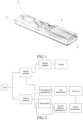
- a laser, for emitting light and outputting an optical signal, a first splitter in the plurality of splitters divides the optical signal into a first optical signal and a local optical signal;
- an optical circulator, for enabling bidirectional communication of optical signals;
- an optical amplifier, for amplifying the first optical signal output from the first splitter to obtain an amplified first optical signal, and outputting the amplified first optical signal to a scanner;
- the scanner, for outputting the amplified first optical signal to free space and receiving optical signals in free space to obtain a second optical signal;
- an optical attenuator, for receiving and attenuating the local optical signal output from the first splitter to obtain an attenuated local optical signal, thereby avoiding damage to a detection pipeline; and
- the detection pipeline, for comparing the attenuated local optical signal and the second optical signal to calculate a detection distance; the detection pipeline includes a set of balanced photodetectors, a set of spectrometers, a processor, and an optical fiber.
- a laser, for emitting light and outputting an optical signal, a first splitter in the plurality of splitters divides the optical signal into a third optical signal and a local optical signal;
- an optical amplifier, for receiving and amplifying the third optical signal output from the first splitter to obtain an amplified third optical signal, and transmitting the amplified third optical signal to a first scanner in the two scanners;
- two scanners, including a first scanner, for outputting the amplified third optical signal to free space; and
- a second scanner, for receiving optical signals in free space to obtain a fourth optical signal;
- an optical attenuator, for receiving and attenuating the local optical signal output from the first splitter to obtain an attenuated local optical signal, thereby avoiding damage to a detection pipeline; and
- the detection pipeline, for comparing the attenuated local optical signal and the fourth optical signal to calculate a detection distance; the detection pipeline includes a set of balanced photodetectors, a set of spectrometers, a processor, and an optical fiber
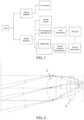
to correct any aberration of the edge field of view.
- a laser, for emitting light and outputting an optical signal, wherein a first splitter divides the optical signal into a first optical signal and a local optical signal, the first optical signal is transmitted to an optical circulator, and the local optical signal is transmitted to an optical attenuator;
- the optical circulator, for enabling bidirectional communication of optical signals; in the embodiment, the optical circulator has three interfaces, for example, a first interface, a second interface, and a third interface; the first interface is connected to an optical amplifier, the second interface is connected to a splitter, and the third interface is connected to a detection pipeline, with a scanner system being connected to the other port of the optical amplifier, to facilitate subsequent calculation of scanning distances;
- the optical amplifier, for receiving and amplifying the first optical signal output from the optical circulator to obtain an amplified first optical signal, and outputting the amplified first optical signal to a scanner;
- the scanner, for outputting the amplified first optical signal output from the optical amplifier to free space and receiving optical signals in free space to obtain a second optical signal;
- the optical attenuator, for receiving and attenuating the local optical signal output from the first splitter to obtain an attenuated local optical signal, thereby avoiding damage to a detection pipeline; and
- the detection pipeline, for comparing the attenuated local optical signal and the second optical signal to calculate a detection distance; the detection pipeline includes a set of balanced photodetectors, a set of spectrometers, a processor, and an optical fiber.
- a laser, for emitting light and outputting an optical signal, wherein a first splitter divides the optical signal output from the laser into a third optical signal and a local optical signal, transmits the third optical signal to an optical amplifier, and transmits the local optical signal to an optical attenuator;
- the optical amplifier, for receiving and amplifying the third optical signal to obtain an amplified third optical signal and transmitting the amplified third optical signal to a first scanner; noise removal and power enhancement are performed through the optical amplifier and the plurality of grating antenna groups in the first scanner to improve detection distance and reduce external interference.
- the first scanner, for outputting the amplified third optical signal to free space;
- a second scanner, for receiving optical signals in free space to obtain a fourth optical signal;
- an optical attenuator, for receiving and attenuating the local optical signal to obtain an attenuated local optical signal, thereby avoiding damage to a detection pipeline;
- the detection pipeline, for comparing the attenuated local optical signal and the fourth optical signal to calculate a detection distance; the detection pipeline includes a set of balanced photodetectors, a set of spectrometers, a processor, and an optical fiber.
Claims (14)
Applications Claiming Priority (3)
| Application Number | Priority Date | Filing Date | Title |
|---|---|---|---|
| CN202010744507.3ACN111856481B (en) | 2020-07-29 | 2020-07-29 | Scanner and coaxial and non-coaxial radar system applying same |
| CN202010744507.3 | 2020-07-29 | ||
| PCT/CN2021/116482WO2022022747A1 (en) | 2020-07-29 | 2021-09-03 | Scanner and coaxial and non-coaxial radar systems using same |
Publications (2)
| Publication Number | Publication Date |
|---|---|
| US20230273300A1 US20230273300A1 (en) | 2023-08-31 |
| US12265181B2true US12265181B2 (en) | 2025-04-01 |
Family
ID=72945949
Family Applications (1)
| Application Number | Title | Priority Date | Filing Date |
|---|---|---|---|
| US18/018,032ActiveUS12265181B2 (en) | 2020-07-29 | 2021-09-03 | Scanner, and coaxial, and non-coaxial lidar systems with same |
Country Status (3)
| Country | Link |
|---|---|
| US (1) | US12265181B2 (en) |
| CN (1) | CN111856481B (en) |
| WO (1) | WO2022022747A1 (en) |
Families Citing this family (6)
| Publication number | Priority date | Publication date | Assignee | Title |
|---|---|---|---|---|
| CN111856481B (en) | 2020-07-29 | 2021-07-06 | 杭州视光半导体科技有限公司 | Scanner and coaxial and non-coaxial radar system applying same |
| CN112630884B (en)* | 2020-12-22 | 2023-09-08 | 联合微电子中心有限责任公司 | Waveguide grating antenna array for optical phased array and preparation method thereof |
| CN115327555A (en) | 2021-05-10 | 2022-11-11 | 信泰光学(深圳)有限公司 | Optical device |
| TWI792305B (en)* | 2021-05-10 | 2023-02-11 | 大陸商信泰光學(深圳)有限公司 | Optical device with coaxial optical path |
| CN113671464B (en)* | 2021-10-22 | 2022-02-18 | 杭州视光半导体科技有限公司 | Scanning coaxial area array transceiver for on-chip coherence detection |
| CN117092619B (en)* | 2023-10-18 | 2024-01-12 | 吉林大学 | A coherent laser radar transceiver chip and preparation method |
Citations (24)
| Publication number | Priority date | Publication date | Assignee | Title |
|---|---|---|---|---|
| JP2003333633A (en) | 2002-05-09 | 2003-11-21 | Toshiba Corp | Optical switch device and control method thereof |
| CN103954602A (en)* | 2014-03-10 | 2014-07-30 | 北京理工大学 | Laser double-shaft differential confocal Brillouin-Raman spectrum measurement method and device |
| CN105162515A (en)* | 2015-06-23 | 2015-12-16 | 西安空间无线电技术研究所 | Balance phase-locked loop system and method with separated phase lock and data |
| WO2017113094A1 (en) | 2015-12-29 | 2017-07-06 | 浙江大学 | Radar system based on array waveguide grating router |
| CN107102322A (en) | 2017-05-02 | 2017-08-29 | 哈尔滨工业大学 | Microwave laser radar integral system |
| US20180267250A1 (en)* | 2017-03-20 | 2018-09-20 | Analog Photonics LLC | Large scale steerable coherent optical switched arrays |
| CN208013431U (en) | 2018-03-01 | 2018-10-26 | 深圳市镭神智能系统有限公司 | A kind of laser radar |
| US20190033522A1 (en)* | 2016-01-22 | 2019-01-31 | National University Corporation Yokohama National University | Optical deflection device and lidar apparatus |
| CN109298404A (en) | 2018-10-22 | 2019-02-01 | 上海交通大学 | Lens-Based Integrated 2D Beam Steering Device |
| US20190094651A1 (en)* | 2017-09-15 | 2019-03-28 | Analog Photonics LLC | Tunable optical structures |
| US20190243000A1 (en)* | 2018-02-02 | 2019-08-08 | Samsung Electronics Co., Ltd. | System including beam steering device |
| CN110118960A (en) | 2019-05-29 | 2019-08-13 | 深圳市镭神智能系统有限公司 | Laser radar |
| CN110168430A (en) | 2016-11-16 | 2019-08-23 | 博莱佳私人有限公司 | Light beam direction finder |
| CN110244281A (en) | 2019-07-19 | 2019-09-17 | 北京一径科技有限公司 | A kind of laser radar system |
| US20190317199A1 (en) | 2018-04-17 | 2019-10-17 | Santec Corporation | Lidar sensing arrangements |
| CN110857977A (en) | 2018-08-23 | 2020-03-03 | 北京万集科技股份有限公司 | Optical antenna, phased array laser radar and two-dimensional scanning method of optical antenna |
| US20200110161A1 (en)* | 2018-10-05 | 2020-04-09 | GM Global Technology Operations LLC | Lidar spectrum analyzer |
| US20200256958A1 (en)* | 2019-02-07 | 2020-08-13 | Pointcloud Inc. | Ranging using a shared path optical coupler |
| CN111856481A (en) | 2020-07-29 | 2020-10-30 | 杭州视光半导体科技有限公司 | Scanner and coaxial and non-coaxial radar system applying same |
| US20210055391A1 (en)* | 2019-08-20 | 2021-02-25 | Luminar Technologies, Inc. | Coherent pulsed lidar system with spectral signatures |
| US20210181320A1 (en)* | 2019-12-12 | 2021-06-17 | Aeva, Inc. | Performing speckle reduction using polarization |
| US20210278542A1 (en)* | 2018-12-26 | 2021-09-09 | Panasonic Intellectual Property Management Co., Ltd. | Line beam scanning optical system and laser radar |
| US20210293934A1 (en)* | 2020-03-17 | 2021-09-23 | Litexel Inc. | Switched optical phased array based beam steering lidar |
| US20220158418A1 (en)* | 2019-03-14 | 2022-05-19 | Takumi Satoh | Light source device, detection device, and electronic apparatus |
Family Cites Families (10)
| Publication number | Priority date | Publication date | Assignee | Title |
|---|---|---|---|---|
| JP3553385B2 (en)* | 1998-08-31 | 2004-08-11 | 三菱電機株式会社 | Optical switching device |
| JP2013130609A (en)* | 2011-12-20 | 2013-07-04 | Ngk Insulators Ltd | Electromagnetic wave radiation element and method of manufacturing the same |
| EP3180652A4 (en)* | 2014-08-14 | 2018-04-04 | Mtt Innovation Incorporated | Multiple-laser light source |
| CN105607304B (en)* | 2016-02-15 | 2021-02-19 | 欧阳征标 | Transverse output magnetic control alternative optical path switch based on photonic crystal T-shaped waveguide |
| CA3015684A1 (en)* | 2016-04-22 | 2017-10-26 | Wavefront Technology, Inc. | Optical switch devices |
| CN106501812B (en)* | 2016-12-01 | 2024-04-30 | 上海思岚科技有限公司 | Laser scanning range unit |
| CN108375774A (en)* | 2018-02-28 | 2018-08-07 | 中国科学技术大学 | A kind of single photon image detecting laser radar of no-raster |
| CN109581329B (en)* | 2018-12-29 | 2024-01-23 | 国科光芯(海宁)科技股份有限公司 | Phased array integrated optical chip and optical phased array transmitting device |
| CN109991582B (en)* | 2019-03-13 | 2023-11-03 | 上海交通大学 | Silicon-based hybrid integrated lidar chip system |
| CN111257896B (en)* | 2020-05-06 | 2020-08-11 | 中国电子科技集团公司信息科学研究院 | Gated array lidar receiving optical system and lidar |
- 2020
- 2020-07-29CNCN202010744507.3Apatent/CN111856481B/enactiveActive
- 2021
- 2021-09-03USUS18/018,032patent/US12265181B2/enactiveActive
- 2021-09-03WOPCT/CN2021/116482patent/WO2022022747A1/ennot_activeCeased
Patent Citations (24)
| Publication number | Priority date | Publication date | Assignee | Title |
|---|---|---|---|---|
| JP2003333633A (en) | 2002-05-09 | 2003-11-21 | Toshiba Corp | Optical switch device and control method thereof |
| CN103954602A (en)* | 2014-03-10 | 2014-07-30 | 北京理工大学 | Laser double-shaft differential confocal Brillouin-Raman spectrum measurement method and device |
| CN105162515A (en)* | 2015-06-23 | 2015-12-16 | 西安空间无线电技术研究所 | Balance phase-locked loop system and method with separated phase lock and data |
| WO2017113094A1 (en) | 2015-12-29 | 2017-07-06 | 浙江大学 | Radar system based on array waveguide grating router |
| US20190033522A1 (en)* | 2016-01-22 | 2019-01-31 | National University Corporation Yokohama National University | Optical deflection device and lidar apparatus |
| CN110168430A (en) | 2016-11-16 | 2019-08-23 | 博莱佳私人有限公司 | Light beam direction finder |
| US20180267250A1 (en)* | 2017-03-20 | 2018-09-20 | Analog Photonics LLC | Large scale steerable coherent optical switched arrays |
| CN107102322A (en) | 2017-05-02 | 2017-08-29 | 哈尔滨工业大学 | Microwave laser radar integral system |
| US20190094651A1 (en)* | 2017-09-15 | 2019-03-28 | Analog Photonics LLC | Tunable optical structures |
| US20190243000A1 (en)* | 2018-02-02 | 2019-08-08 | Samsung Electronics Co., Ltd. | System including beam steering device |
| CN208013431U (en) | 2018-03-01 | 2018-10-26 | 深圳市镭神智能系统有限公司 | A kind of laser radar |
| US20190317199A1 (en) | 2018-04-17 | 2019-10-17 | Santec Corporation | Lidar sensing arrangements |
| CN110857977A (en) | 2018-08-23 | 2020-03-03 | 北京万集科技股份有限公司 | Optical antenna, phased array laser radar and two-dimensional scanning method of optical antenna |
| US20200110161A1 (en)* | 2018-10-05 | 2020-04-09 | GM Global Technology Operations LLC | Lidar spectrum analyzer |
| CN109298404A (en) | 2018-10-22 | 2019-02-01 | 上海交通大学 | Lens-Based Integrated 2D Beam Steering Device |
| US20210278542A1 (en)* | 2018-12-26 | 2021-09-09 | Panasonic Intellectual Property Management Co., Ltd. | Line beam scanning optical system and laser radar |
| US20200256958A1 (en)* | 2019-02-07 | 2020-08-13 | Pointcloud Inc. | Ranging using a shared path optical coupler |
| US20220158418A1 (en)* | 2019-03-14 | 2022-05-19 | Takumi Satoh | Light source device, detection device, and electronic apparatus |
| CN110118960A (en) | 2019-05-29 | 2019-08-13 | 深圳市镭神智能系统有限公司 | Laser radar |
| CN110244281A (en) | 2019-07-19 | 2019-09-17 | 北京一径科技有限公司 | A kind of laser radar system |
| US20210055391A1 (en)* | 2019-08-20 | 2021-02-25 | Luminar Technologies, Inc. | Coherent pulsed lidar system with spectral signatures |
| US20210181320A1 (en)* | 2019-12-12 | 2021-06-17 | Aeva, Inc. | Performing speckle reduction using polarization |
| US20210293934A1 (en)* | 2020-03-17 | 2021-09-23 | Litexel Inc. | Switched optical phased array based beam steering lidar |
| CN111856481A (en) | 2020-07-29 | 2020-10-30 | 杭州视光半导体科技有限公司 | Scanner and coaxial and non-coaxial radar system applying same |
Also Published As
| Publication number | Publication date |
|---|---|
| CN111856481A (en) | 2020-10-30 |
| CN111856481B (en) | 2021-07-06 |
| US20230273300A1 (en) | 2023-08-31 |
| WO2022022747A1 (en) | 2022-02-03 |
Similar Documents
| Publication | Publication Date | Title |
|---|---|---|
| US12265181B2 (en) | Scanner, and coaxial, and non-coaxial lidar systems with same | |
| CN115639543B (en) | Frequency modulation continuous wave laser radar and automatic driving equipment | |
| US12025741B2 (en) | Three-dimensional scanning LiDAR based on one-dimensional optical phased arrays | |
| CN111722237B (en) | LIDAR detection setup based on lens and integrated beam transceiver | |
| US12025739B1 (en) | Frequency modulated continuous wave LiDAR and autonomous driving device | |
| US10788574B2 (en) | LIDAR device and LIDAR system including the same | |
| CN114002703B (en) | A three-dimensional imaging all-solid-state laser radar device | |
| WO2020135802A1 (en) | Laser measurement module and laser radar | |
| CN111257896B (en) | Gated array lidar receiving optical system and lidar | |
| CN109444850B (en) | Phased Array LiDAR | |
| CN116243278B (en) | Optical chip module, laser radar and mobile equipment | |
| CN112068147B (en) | Integrated chip and electronic device for target detection | |
| CN112284302B (en) | Device and method for measuring laser transceiver coaxiality of active optoelectronic system by scanning method | |
| CN111948665A (en) | Solid-state lidar system and solid-state lidar | |
| CN108988951A (en) | Fiber optical transceiver and coaxial R-T unit | |
| CN109444851B (en) | Laser emission mechanism and phased array laser radar | |
| US20230366986A1 (en) | LiDAR array with vertically-coupled transceivers | |
| WO2022188687A1 (en) | Detection apparatus, detector, laser radar, and terminal device | |
| CN117008090A (en) | Laser radar and detection method | |
| CN113960619A (en) | On-chip integrated distance measuring chip | |
| CN111751819A (en) | sensor device | |
| CN223123233U (en) | A high-density multi-channel transceiver integrated device and laser radar | |
| CN117008089A (en) | Optical transceiver based on planar waveguide chip and laser radar | |
| CN118068350B (en) | A long-distance infrared imaging and ranging device and its application | |
| CN109556833B (en) | Phase difference measuring device and measuring method of waveguide array |
Legal Events
| Date | Code | Title | Description |
|---|---|---|---|
| FEPP | Fee payment procedure | Free format text:ENTITY STATUS SET TO UNDISCOUNTED (ORIGINAL EVENT CODE: BIG.); ENTITY STATUS OF PATENT OWNER: SMALL ENTITY | |
| FEPP | Fee payment procedure | Free format text:ENTITY STATUS SET TO SMALL (ORIGINAL EVENT CODE: SMAL); ENTITY STATUS OF PATENT OWNER: SMALL ENTITY | |
| STPP | Information on status: patent application and granting procedure in general | Free format text:NON FINAL ACTION MAILED | |
| STPP | Information on status: patent application and granting procedure in general | Free format text:RESPONSE TO NON-FINAL OFFICE ACTION ENTERED AND FORWARDED TO EXAMINER | |
| STPP | Information on status: patent application and granting procedure in general | Free format text:FINAL REJECTION MAILED | |
| STPP | Information on status: patent application and granting procedure in general | Free format text:RESPONSE AFTER FINAL ACTION FORWARDED TO EXAMINER | |
| STPP | Information on status: patent application and granting procedure in general | Free format text:ADVISORY ACTION MAILED | |
| STPP | Information on status: patent application and granting procedure in general | Free format text:DOCKETED NEW CASE - READY FOR EXAMINATION | |
| STPP | Information on status: patent application and granting procedure in general | Free format text:NOTICE OF ALLOWANCE MAILED -- APPLICATION RECEIVED IN OFFICE OF PUBLICATIONS | |
| STPP | Information on status: patent application and granting procedure in general | Free format text:NOTICE OF ALLOWANCE MAILED -- APPLICATION RECEIVED IN OFFICE OF PUBLICATIONS | |
| STPP | Information on status: patent application and granting procedure in general | Free format text:AWAITING TC RESP., ISSUE FEE NOT PAID | |
| STPP | Information on status: patent application and granting procedure in general | Free format text:NOTICE OF ALLOWANCE MAILED -- APPLICATION RECEIVED IN OFFICE OF PUBLICATIONS | |
| STPP | Information on status: patent application and granting procedure in general | Free format text:PUBLICATIONS -- ISSUE FEE PAYMENT VERIFIED | |
| STCF | Information on status: patent grant | Free format text:PATENTED CASE |