US12262971B2 - One-operator surgical system and methods of use - Google Patents
One-operator surgical system and methods of useDownload PDFInfo
- Publication number
- US12262971B2 US12262971B2US16/008,976US201816008976AUS12262971B2US 12262971 B2US12262971 B2US 12262971B2US 201816008976 AUS201816008976 AUS 201816008976AUS 12262971 B2US12262971 B2US 12262971B2
- Authority
- US
- United States
- Prior art keywords
- intracavity
- grasper
- operator
- devices
- support arm
- Prior art date
- Legal status (The legal status is an assumption and is not a legal conclusion. Google has not performed a legal analysis and makes no representation as to the accuracy of the status listed.)
- Active, expires
Links
Images


Classifications
- A—HUMAN NECESSITIES
- A61—MEDICAL OR VETERINARY SCIENCE; HYGIENE
- A61B—DIAGNOSIS; SURGERY; IDENTIFICATION
- A61B34/00—Computer-aided surgery; Manipulators or robots specially adapted for use in surgery
- A61B34/70—Manipulators specially adapted for use in surgery
- A61B34/73—Manipulators for magnetic surgery
- A—HUMAN NECESSITIES
- A61—MEDICAL OR VETERINARY SCIENCE; HYGIENE
- A61B—DIAGNOSIS; SURGERY; IDENTIFICATION
- A61B1/00—Instruments for performing medical examinations of the interior of cavities or tubes of the body by visual or photographical inspection, e.g. endoscopes; Illuminating arrangements therefor
- A61B1/00002—Operational features of endoscopes
- A61B1/00039—Operational features of endoscopes provided with input arrangements for the user
- A61B1/00042—Operational features of endoscopes provided with input arrangements for the user for mechanical operation
- A—HUMAN NECESSITIES
- A61—MEDICAL OR VETERINARY SCIENCE; HYGIENE
- A61B—DIAGNOSIS; SURGERY; IDENTIFICATION
- A61B1/00—Instruments for performing medical examinations of the interior of cavities or tubes of the body by visual or photographical inspection, e.g. endoscopes; Illuminating arrangements therefor
- A61B1/00002—Operational features of endoscopes
- A61B1/00043—Operational features of endoscopes provided with output arrangements
- A61B1/00045—Display arrangement
- A—HUMAN NECESSITIES
- A61—MEDICAL OR VETERINARY SCIENCE; HYGIENE
- A61B—DIAGNOSIS; SURGERY; IDENTIFICATION
- A61B1/00—Instruments for performing medical examinations of the interior of cavities or tubes of the body by visual or photographical inspection, e.g. endoscopes; Illuminating arrangements therefor
- A61B1/00147—Holding or positioning arrangements
- A61B1/00158—Holding or positioning arrangements using magnetic field
- A—HUMAN NECESSITIES
- A61—MEDICAL OR VETERINARY SCIENCE; HYGIENE
- A61B—DIAGNOSIS; SURGERY; IDENTIFICATION
- A61B1/00—Instruments for performing medical examinations of the interior of cavities or tubes of the body by visual or photographical inspection, e.g. endoscopes; Illuminating arrangements therefor
- A61B1/04—Instruments for performing medical examinations of the interior of cavities or tubes of the body by visual or photographical inspection, e.g. endoscopes; Illuminating arrangements therefor combined with photographic or television appliances
- A61B1/041—Capsule endoscopes for imaging
- A—HUMAN NECESSITIES
- A61—MEDICAL OR VETERINARY SCIENCE; HYGIENE
- A61B—DIAGNOSIS; SURGERY; IDENTIFICATION
- A61B1/00—Instruments for performing medical examinations of the interior of cavities or tubes of the body by visual or photographical inspection, e.g. endoscopes; Illuminating arrangements therefor
- A61B1/12—Instruments for performing medical examinations of the interior of cavities or tubes of the body by visual or photographical inspection, e.g. endoscopes; Illuminating arrangements therefor with cooling or rinsing arrangements
- A61B1/126—Instruments for performing medical examinations of the interior of cavities or tubes of the body by visual or photographical inspection, e.g. endoscopes; Illuminating arrangements therefor with cooling or rinsing arrangements provided with means for cleaning in-use
- A—HUMAN NECESSITIES
- A61—MEDICAL OR VETERINARY SCIENCE; HYGIENE
- A61B—DIAGNOSIS; SURGERY; IDENTIFICATION
- A61B17/00—Surgical instruments, devices or methods
- A61B17/02—Surgical instruments, devices or methods for holding wounds open, e.g. retractors; Tractors
- A61B17/0218—Surgical instruments, devices or methods for holding wounds open, e.g. retractors; Tractors for minimally invasive surgery
- A—HUMAN NECESSITIES
- A61—MEDICAL OR VETERINARY SCIENCE; HYGIENE
- A61B—DIAGNOSIS; SURGERY; IDENTIFICATION
- A61B17/00—Surgical instruments, devices or methods
- A61B17/28—Surgical forceps
- A61B17/29—Forceps for use in minimally invasive surgery
- A—HUMAN NECESSITIES
- A61—MEDICAL OR VETERINARY SCIENCE; HYGIENE
- A61B—DIAGNOSIS; SURGERY; IDENTIFICATION
- A61B34/00—Computer-aided surgery; Manipulators or robots specially adapted for use in surgery
- A61B34/25—User interfaces for surgical systems
- A—HUMAN NECESSITIES
- A61—MEDICAL OR VETERINARY SCIENCE; HYGIENE
- A61B—DIAGNOSIS; SURGERY; IDENTIFICATION
- A61B34/00—Computer-aided surgery; Manipulators or robots specially adapted for use in surgery
- A61B34/70—Manipulators specially adapted for use in surgery
- A61B34/76—Manipulators having means for providing feel, e.g. force or tactile feedback
- A—HUMAN NECESSITIES
- A61—MEDICAL OR VETERINARY SCIENCE; HYGIENE
- A61B—DIAGNOSIS; SURGERY; IDENTIFICATION
- A61B90/00—Instruments, implements or accessories specially adapted for surgery or diagnosis and not covered by any of the groups A61B1/00 - A61B50/00, e.g. for luxation treatment or for protecting wound edges
- A61B90/36—Image-producing devices or illumination devices not otherwise provided for
- A61B90/361—Image-producing devices, e.g. surgical cameras
- A—HUMAN NECESSITIES
- A61—MEDICAL OR VETERINARY SCIENCE; HYGIENE
- A61B—DIAGNOSIS; SURGERY; IDENTIFICATION
- A61B90/00—Instruments, implements or accessories specially adapted for surgery or diagnosis and not covered by any of the groups A61B1/00 - A61B50/00, e.g. for luxation treatment or for protecting wound edges
- A61B90/50—Supports for surgical instruments, e.g. articulated arms
- A—HUMAN NECESSITIES
- A61—MEDICAL OR VETERINARY SCIENCE; HYGIENE
- A61B—DIAGNOSIS; SURGERY; IDENTIFICATION
- A61B1/00—Instruments for performing medical examinations of the interior of cavities or tubes of the body by visual or photographical inspection, e.g. endoscopes; Illuminating arrangements therefor
- A61B1/00064—Constructional details of the endoscope body
- A61B1/00071—Insertion part of the endoscope body
- A61B1/0008—Insertion part of the endoscope body characterised by distal tip features
- A61B1/00087—Tools
- A—HUMAN NECESSITIES
- A61—MEDICAL OR VETERINARY SCIENCE; HYGIENE
- A61B—DIAGNOSIS; SURGERY; IDENTIFICATION
- A61B17/00—Surgical instruments, devices or methods
- A61B2017/00017—Electrical control of surgical instruments
- A61B2017/00022—Sensing or detecting at the treatment site
- A61B2017/00057—Light
- A—HUMAN NECESSITIES
- A61—MEDICAL OR VETERINARY SCIENCE; HYGIENE
- A61B—DIAGNOSIS; SURGERY; IDENTIFICATION
- A61B17/00—Surgical instruments, devices or methods
- A61B2017/00017—Electrical control of surgical instruments
- A61B2017/00022—Sensing or detecting at the treatment site
- A61B2017/00075—Motion
- A—HUMAN NECESSITIES
- A61—MEDICAL OR VETERINARY SCIENCE; HYGIENE
- A61B—DIAGNOSIS; SURGERY; IDENTIFICATION
- A61B17/00—Surgical instruments, devices or methods
- A61B2017/00017—Electrical control of surgical instruments
- A61B2017/00022—Sensing or detecting at the treatment site
- A61B2017/00084—Temperature
- A—HUMAN NECESSITIES
- A61—MEDICAL OR VETERINARY SCIENCE; HYGIENE
- A61B—DIAGNOSIS; SURGERY; IDENTIFICATION
- A61B17/00—Surgical instruments, devices or methods
- A61B2017/00017—Electrical control of surgical instruments
- A61B2017/00115—Electrical control of surgical instruments with audible or visual output
- A61B2017/00119—Electrical control of surgical instruments with audible or visual output alarm; indicating an abnormal situation
- A—HUMAN NECESSITIES
- A61—MEDICAL OR VETERINARY SCIENCE; HYGIENE
- A61B—DIAGNOSIS; SURGERY; IDENTIFICATION
- A61B17/00—Surgical instruments, devices or methods
- A61B2017/00017—Electrical control of surgical instruments
- A61B2017/00199—Electrical control of surgical instruments with a console, e.g. a control panel with a display
- A—HUMAN NECESSITIES
- A61—MEDICAL OR VETERINARY SCIENCE; HYGIENE
- A61B—DIAGNOSIS; SURGERY; IDENTIFICATION
- A61B17/00—Surgical instruments, devices or methods
- A61B2017/00017—Electrical control of surgical instruments
- A61B2017/00203—Electrical control of surgical instruments with speech control or speech recognition
- A—HUMAN NECESSITIES
- A61—MEDICAL OR VETERINARY SCIENCE; HYGIENE
- A61B—DIAGNOSIS; SURGERY; IDENTIFICATION
- A61B17/00—Surgical instruments, devices or methods
- A61B2017/00017—Electrical control of surgical instruments
- A61B2017/00207—Electrical control of surgical instruments with hand gesture control or hand gesture recognition
- A—HUMAN NECESSITIES
- A61—MEDICAL OR VETERINARY SCIENCE; HYGIENE
- A61B—DIAGNOSIS; SURGERY; IDENTIFICATION
- A61B17/00—Surgical instruments, devices or methods
- A61B17/00234—Surgical instruments, devices or methods for minimally invasive surgery
- A61B2017/00238—Type of minimally invasive operation
- A61B2017/00283—Type of minimally invasive operation with a device releasably connected to an inner wall of the abdomen during surgery, e.g. an illumination source
- A—HUMAN NECESSITIES
- A61—MEDICAL OR VETERINARY SCIENCE; HYGIENE
- A61B—DIAGNOSIS; SURGERY; IDENTIFICATION
- A61B17/00—Surgical instruments, devices or methods
- A61B2017/0046—Surgical instruments, devices or methods with a releasable handle; with handle and operating part separable
- A61B2017/00473—Distal part, e.g. tip or head
- A—HUMAN NECESSITIES
- A61—MEDICAL OR VETERINARY SCIENCE; HYGIENE
- A61B—DIAGNOSIS; SURGERY; IDENTIFICATION
- A61B17/00—Surgical instruments, devices or methods
- A61B2017/00477—Coupling
- A—HUMAN NECESSITIES
- A61—MEDICAL OR VETERINARY SCIENCE; HYGIENE
- A61B—DIAGNOSIS; SURGERY; IDENTIFICATION
- A61B17/00—Surgical instruments, devices or methods
- A61B2017/00831—Material properties
- A61B2017/00876—Material properties magnetic
- A—HUMAN NECESSITIES
- A61—MEDICAL OR VETERINARY SCIENCE; HYGIENE
- A61B—DIAGNOSIS; SURGERY; IDENTIFICATION
- A61B17/00—Surgical instruments, devices or methods
- A61B17/28—Surgical forceps
- A61B17/29—Forceps for use in minimally invasive surgery
- A61B2017/2926—Details of heads or jaws
- A61B2017/2927—Details of heads or jaws the angular position of the head being adjustable with respect to the shaft
- A61B2017/2929—Details of heads or jaws the angular position of the head being adjustable with respect to the shaft with a head rotatable about the longitudinal axis of the shaft
- A—HUMAN NECESSITIES
- A61—MEDICAL OR VETERINARY SCIENCE; HYGIENE
- A61B—DIAGNOSIS; SURGERY; IDENTIFICATION
- A61B17/00—Surgical instruments, devices or methods
- A61B17/28—Surgical forceps
- A61B17/29—Forceps for use in minimally invasive surgery
- A61B2017/2947—Pivots
- A—HUMAN NECESSITIES
- A61—MEDICAL OR VETERINARY SCIENCE; HYGIENE
- A61B—DIAGNOSIS; SURGERY; IDENTIFICATION
- A61B34/00—Computer-aided surgery; Manipulators or robots specially adapted for use in surgery
- A61B34/20—Surgical navigation systems; Devices for tracking or guiding surgical instruments, e.g. for frameless stereotaxis
- A61B2034/2046—Tracking techniques
- A61B2034/2048—Tracking techniques using an accelerometer or inertia sensor
- A—HUMAN NECESSITIES
- A61—MEDICAL OR VETERINARY SCIENCE; HYGIENE
- A61B—DIAGNOSIS; SURGERY; IDENTIFICATION
- A61B90/00—Instruments, implements or accessories specially adapted for surgery or diagnosis and not covered by any of the groups A61B1/00 - A61B50/00, e.g. for luxation treatment or for protecting wound edges
- A61B90/50—Supports for surgical instruments, e.g. articulated arms
- A61B2090/508—Supports for surgical instruments, e.g. articulated arms with releasable brake mechanisms
- A—HUMAN NECESSITIES
- A61—MEDICAL OR VETERINARY SCIENCE; HYGIENE
- A61B—DIAGNOSIS; SURGERY; IDENTIFICATION
- A61B2562/00—Details of sensors; Constructional details of sensor housings or probes; Accessories for sensors
- A61B2562/02—Details of sensors specially adapted for in-vivo measurements
- A61B2562/0223—Magnetic field sensors
- A—HUMAN NECESSITIES
- A61—MEDICAL OR VETERINARY SCIENCE; HYGIENE
- A61B—DIAGNOSIS; SURGERY; IDENTIFICATION
- A61B2562/00—Details of sensors; Constructional details of sensor housings or probes; Accessories for sensors
- A61B2562/02—Details of sensors specially adapted for in-vivo measurements
- A61B2562/0257—Proximity sensors
- A—HUMAN NECESSITIES
- A61—MEDICAL OR VETERINARY SCIENCE; HYGIENE
- A61B—DIAGNOSIS; SURGERY; IDENTIFICATION
- A61B34/00—Computer-aided surgery; Manipulators or robots specially adapted for use in surgery
- A61B34/30—Surgical robots
- A—HUMAN NECESSITIES
- A61—MEDICAL OR VETERINARY SCIENCE; HYGIENE
- A61B—DIAGNOSIS; SURGERY; IDENTIFICATION
- A61B90/00—Instruments, implements or accessories specially adapted for surgery or diagnosis and not covered by any of the groups A61B1/00 - A61B50/00, e.g. for luxation treatment or for protecting wound edges
- A61B90/30—Devices for illuminating a surgical field, the devices having an interrelation with other surgical devices or with a surgical procedure
Definitions
- the present inventionis directed toward systems, devices, and methods for providing remote manipulation or visualization of tissue using a surgical system that may be operated by a single operator.
- Minimally invasive proceduressuch as endoscopic, laparoscopic, and thoracoscopic procedures may be associated with lower pain, quicker post-surgical recovery, shortened hospitalization, and reduced complications when compared to open surgical procedures.
- minimally invasive proceduresit may be desirable to reposition or otherwise manipulate tissue, however the introduction of additional devices to engage tissue may crowd the access sites provided by incisions, which may require the formation of larger or additional access sites.
- Minimally invasive robotic surgery using videois currently performed by two skilled surgeons (e.g., operators).
- a primary surgeonperforms the surgical tasks (e.g. dissection, clipping, cutting, stapling, etc.) and a secondary surgeon assists in these functions.
- the primary surgeonis located at a console outside of a sterile field while the secondary surgeon is located within the sterile field in order to assist by, for example, changing the instruments coupled to a robotic surgical system.
- the secondary surgeonmay assist the primary surgeon by holding an instrument in each hand such as an optical sensor (e.g., camera) and a retractor. Accordingly, it may be desirable to provide a surgical system having one or more devices to manipulate tissue controlled by a single operator without an assistant operator.
- the systems for manipulating tissuemay comprise one or more intracavity devices each configured to be advanced through an access site into a body cavity or lumen of a patient.
- One or more external magnetic positioning devicesmay be configured to magnetically couple to a respective intracavity device through tissue (e.g., through a body cavity wall).
- a controllermay comprise a processor and memory.
- a displaymay be coupled to the controller. The controller may be configured to generate a graphical user interface on the display and control movement of the one or more intracavity devices within the body cavity or lumen.
- the controllermay be configured to control the external magnetic positioning devices to magnetically hold the respective intracavity device in the body cavity or lumen.
- the controlleris configured to move each external magnetic positioning device coupled to the intracavity device in response to the graphical user interface receiving operator input to control the intracavity device.
- One or more of the intracavity devicesmay be configured to generate an image of a portion of the body cavity or lumen, and the graphical user interface may be configured to generate an intracavity device control button using the image.
- the imagemay be a real-time image.
- the graphical user interfacemay be configured to simultaneously control two or more of the intracavity devices.
- the controllermay be configured to control a movement of each of the intracavity devices within the body cavity or lumen by moving the support arm and applying the magnetic force to the intracavity device, and may be configured to actuate at least one of the intracavity devices.
- the systemmay include one or more additional features.
- the input devicemay comprise a touch surface configured to receive the control signal from the operator.
- An output devicemay be configured to display a graphical user interface.
- the output devicemay further comprise an audio device and a haptic device.
- at least one of the external magnetic positioning devicescomprises one or more of a proximity sensor, force sensor, and magnetic field sensor.
- one or more intracavity devicesmay comprise a visualization device and a tissue manipulation device.
- the systemmay further comprise a delivery device configured to releasably engage the intracavity device and actuate the intracavity device.
- Also described here are methods of performing minimally invasive surgerycomprising advancing one or more intracavity devices through an access site into a body cavity or lumen of a patient and magnetically coupling each of the intracavity devices to a respective positioning device.
- Each of the positioning devicesmay be located externally of the patient.
- Each of the intracavity devicesmay move within the body cavity or lumen using the respective positioning devices.
- Each of the intracavity devicesmay be controlled using a graphical user interface.
- the magnetic couplingmay comprise generating a magnetic field using the positioning device.
- moving each of the intracavity devices within the body cavity or lumenmay further comprise moving the positioning device or modifying the magnetic field generated by the positioning device.
- controlling each of the intracavity devicesmay comprise actuating at least one of the intracavity devices using the graphical user interface.
- the intracavity devicemay be held in contact with a patient cavity wall within a predetermined force threshold.
- the methodsmay further comprise advancing a second intracavity device into the body cavity through the access site.
- the second intracavity devicemay be magnetically coupled to a second positioning device, wherein the second positioning device is located externally of the patient, and the method may further comprise controlling the first intracavity device and the second intracavity device using a graphical user interface.
- the first and second intracavity devicesmay be controlled using the graphical user interface through input from a single operator, wherein the single operator is not assisted by a second operator.
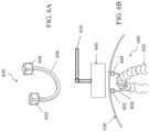
- FIGS. 5 A and 5 Bdepict perspective and side views, respectively, of an illustrative variation of a grasper.
- FIG. 5 Cdepicts a cross-sectional side view of the grasper shown in FIGS. 5 A and 5 B .
- FIG. 7depicts a perspective view of an illustrative variation of a user interface of a surgical system.
- FIG. 1A block diagram of an exemplary surgical system 100 is depicted in FIG. 1 .
- the system 100may comprise a controller 110 coupled to one or more support arms 120 , external magnets 122 , sensors 124 , intracavity devices 130 , and delivery devices 132 .
- An operatormay control the surgical system 100 using one or more input devices 140 and output devices 150 each coupled to the controller 110 .
- an external magnetic positioning devicemay comprise the support arm 120 , the external magnet 122 , and sensors 124 .
- the sensors 124may comprise one or more of a proximity sensor, force sensor, optical sensor, motion sensor, temperature sensor, biometric sensor, or the like.
- the intracavity device 130may be removably coupled to the delivery device 132 to advance the intracavity device 130 into a body cavity or lumen.
- FIG. 2 AAn exemplary surgical system 200 is shown in FIG. 2 A .
- the surgical system 200may comprise a user interface 202 comprising a first output device (e.g., display device) and an input device (e.g., touch surface), a second output device 204 (e.g., TV display), and a plurality of support arms 206 each comprising an external magnet 208 .
- the surgical system 200may further comprise, as shown more clearly in FIG. 2 B , a plurality of intracavity devices 210 and 212 , which may be delivered via trocar 214 into a body cavity or lumen (a body cavity wall is shown transparent for ease of explanation).
- the surgical systems described hereinmay comprise one or more intracavity devices.
- These intracavity devicesmay be configured to be introduced into a body cavity or lumen through an access site such as a trocar or other suitable port, or through a natural orifice.
- the intracavity devices advanced into the body cavity or lumen through an access sitemay be advanced such that the intracavity device does not block the introduction and/or retrieval of other intracavity devices using the access site.
- a plurality of intracavity devicesmay be disposed and actuated within a patient body cavity or lumen.
- the intracavity devicesmay be configured to be attracted to one or more magnets positioned externally of the body to move, reposition, and/or hold the intracavity device (which may in turn provide traction for tissue held by or otherwise in contact with the intracavity device).
- at least a portion of the intracavity devices described hereinmay be formed from or otherwise include one or more metallic or magnetic materials which may be attracted to a magnetic field.
- the materialsmay include one or more magnetic or ferromagnetic materials, such as, for example, stainless steel, iron, cobalt, nickel, neodymium iron boron, samarium cobalt, alnico, ceramic ferrite, alloys thereof and/or combinations thereof.
- the magnetic portion of the intracavity devicemay thus be attracted to a magnetic field produced by an external magnetic positioning device. Furthermore, in some variations, the magnetic portion of the intracavity device may allow coupling to a delivery device, as described in more detail herein.
- the intracavity devicesmay be used within any suitable body cavity or lumen such as but not limited to the abdominal cavity, thoracic cavity, stomach, or intestines.
- the intracavity devices advanced into a body cavity or lumenmay perform a number of functions and are described in detail herein.
- an intracavity devicemay comprise a visualization device configured to be attracted to one or more magnetic elements positioned externally of the body to move, reposition, and/or hold the visualization device with a desired field of view for visualization during a minimally invasive procedure.
- the camera assembly 300may be configured to be temporarily coupled to a delivery device.
- the camera assembly 300may have a capsule-like outer shape as shown, or may have any other suitable shape.
- the camera assembly 300may comprise a lens and an optical sensor.
- the lensmay be located in any suitable location, such as, but not limited to the distal end of the camera assembly 300 , or along a barrel portion 310 of the camera.
- the camera assembly 300may comprise one or more magnetic elements, which may be located, for example, at an end of the camera assembly 300 or along a barrel portion 310 .
- the barrel portion 310When the camera assembly 300 is coupled to a delivery device, such as a delivery device described in more detail herein, at least a portion of the barrel portion 310 may be positioned within a distal engagement portion of the delivery device.
- the attractive force between a coupling magnet of the delivery device and the camera assembly 300may hold the camera assembly 300 in place.
- the second outer diametermay be sized to fit within the distal engagement portion while the first outer diameter may be sized such that it is too large to fit within the distal engagement portion.
- the first segment 340(or a tapered segment 344 between the first segment 340 and the second segment 342 ) may act as a stop to limit the amount of the barrel portion 310 that may enter the distal engagement portion.
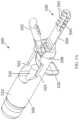
- FIG. 4shows another exemplary camera assembly 400 .
- the camera assembly 400comprises a camera 406 located within a capsule 402 .
- the capsule 402may also comprise one or more (e.g., two) light sources 404 , located on either side of the camera 406 .
- the camera 406may comprise an optical sensor (e.g., a charged coupled device (CCD) or complementary metal-oxide semiconductor (CMOS) optical sensor).
- the camera assembly 400may further comprise a magnetic portion 410 configured to be attracted to a magnetic field.
- the magnetic portion 410may comprise one or more permanent magnets and/or one or more electromagnets.
- Permanent magnetsmay be formed from suitable magnetic and ferromagnetic materials such as, but not limited to, rare-earth magnets (e.g., samarium-cobalt magnets, neodymium magnets), cobalt, gadolinium, iron, nickel, alnico alloys, ferrites, alloys thereof, combinations thereof, and the like.
- the magnetic portion 410may comprise any number of individual magnets, which in some instances may be formed in an array.
- the magnetic portion 410may have any suitable size and shape, such as cylindrical shape having a circular, oval, or semi-circle cross-section, a bar magnet having a rectangular or triangular cross section, a spherical magnet, or the like.
- the magnetic portion 410may comprise permanent magnets, while in other variations, the magnetic portion 410 may comprise electromagnets or electropermanent magnets. When the magnetic portion 410 comprises electromagnets or electropermanent magnets, the current may be manipulated to change the strength of the magnetic portion and/or to turn them on/off. In yet other variations, the magnetic portion 410 may comprise a ferromagnetic material that is attracted to but does not generate a magnetic field.
- the magnetic portion 410may be disposed in the camera assembly 400 such that the camera assembly 400 is asymmetrically attracted to an external magnetic field (e.g., the camera assembly 400 has one side that is more attracted to an external magnetic field). This may allow the camera assembly 400 to be oriented in a desired direction using a magnetic field such that the camera 406 may image a desired field of view.
- the camera assembly 400may comprise a capsule 402 comprising a magnetic portion 410 on a first side of the capsule 402 and a camera 406 disposed on a second side of the capsule 402 opposite the first side.
- the camera 406may transition between a first and second configuration.
- the first configurationmay be a retracted position where a lens of the camera 406 is covered by the capsule 402 and a second configuration may be an extended position in which the lens of the camera 406 is exposed.
- the camera 406may be configured to pan (e.g., move side to side), tilt (e.g., move up and down), and zoom (e.g., change a focal length of a lens).
- the camera assembly 400may comprise a wired or wireless transmitter for transmitting image data including images to a controller.
- the camera assembly 400may comprise a battery and/or a wire for power (e.g., power cable, power cord) for the camera 406 and/or light source 404 .
- the camera assembly 400may further comprise a lens cleaning device (not shown) configured to clear obstructions such as fluid and other debris that may accumulate on an exterior of a camera lens when the camera assembly 400 is disposed in a body cavity or lumen.
- the lens cleaning devicemay comprise one or more of a wiper, sponge, fabric, hydrogel, and fluid outlets (e.g., water and/or air jets). The lens cleaning device may be actuated by the operator and/or the controller, and/or may be automated.
- an intracavity devicemay comprise graspers used to grasp, retract or otherwise provide remote manipulation and/or traction to tissue.
- magnetically controlled graspersmay be advanced into a patient and releasably engage tissue.
- Graspers suitable for use in the surgical systems hereare described in U.S. patent application Ser. No. 14/019,370, filed Sep. 5, 2013, and titled “Grasper with Magnetically-Controlled Positioning;”
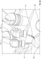
- FIGS. 5 A- 5 Cdepict a variation of a grasper 500 suitable for use in the surgical systems described here.
- FIGS. 5 A and 5 Bshow perspective and side views, respectively, of the grasper 500 .
- the grasper 500may comprise a first jaw 502 , a second jaw 504 , and a main body 506 .
- One or more portions of the grasper 500may be formed from or otherwise include a magnetic or ferromagnetic material, such that it may be attracted to a magnetic field produced by an external magnetic positioning device.
- the first jaw 502may be rotatably connected to the main body 506 at a pivot point 508 , such that the first jaw 502 may rotate relative to the main body 506 .
- the second jaw 504is shown in FIGS. 5 A- 5 C as being fixed relative to the main body 506 , it should be appreciated that in some variations the second jaw 504 may be rotatably connected to the main body 506 ).
- the first jaw 502 (and/or the second jaw 504 ) in variations where the second jaw 504 is rotatably connected to the main body 506 )may be rotated relative to the main body 506 to actuate the grasper 500 between an open configuration and a closed configuration.
- the first jaw 502 and the second jaw 504may be held in rotationally separated positions to define a space between the first jaw 502 and the second jaw 504 , as shown in FIG. 5 A .
- the first jaw 502 and second jaw 504may be rotationally biased toward each other, as shown in FIG. 5 B . While the first jaw 502 is shown as contacting the second jaw 504 in FIG. 5 B , it should be appreciated that when the grasper 500 is connected to tissue, tissue positioned between the first jaw 502 and the second jaw 504 may prevent the first jaw 502 from contacting the second jaw 504 when the grasper is in the closed configuration.
- the first jaw 502 and second jaw 504may be rotationally biased toward a closed configuration in any suitable manner (e.g., via a torsional spring (not shown)).
- the main body 506 of the grasper 500may comprise a barrel portion 510 with a lumen 512 extending therethrough.
- a portion of a delivery devicemay be advanced at least partially into the lumen 512 to actuate the grasper 500 between closed and open configurations, as described in more detail herein.
- the outer diameter of the barrel portion 510may be uniform, or may vary along the length of the barrel portion 510 .
- the first jaw 502may be configured to rotate in any suitable manner.
- the grasper 500may comprise a proximal arm 520 connected to the first jaw 502 such that rotation of the proximal arm 520 relative to the pivot point 508 rotates the first jaw 502 relative to the pivot point 508 (which may also rotate the first jaw 502 relative to the main body 506 and/or the second jaw 504 ).
- the proximal arm 520may be exposed relative to the main body 506 , which may allow a grasping device to grasp the proximal arm 520 to rotate the first jaw 502 relative to the second jaw 504 .
- the main body 506may comprise a barrel extension 560 between the barrel portion 510 and the pivot point 508 .
- the barrel extension 560may comprise a channel 562 extending at least partially through the barrel extension 560 .
- the channel 562may extend entirely through the barrel extension 560 .
- the barrel extension 560may have a wall 564 on one or both sides of the channel 562 .
- the barrel extension 560may have a wall 564 on each side of the channel 562 .
- the proximal arm 520may be positioned at least partially within the channel 562 , and may be configured to rotate through the channel 562 as the grasper 500 is actuated between open and closed configurations.
- each wall 564 of the barrel extension 560may have a top edge 566 and a bottom edge 568 .
- the top edge 566 and bottom edge 568may have any suitable profile, and together may define a height of the wall 564 .
- the bottom edge 568may be linear and substantially parallel to a longitudinal axis, while the top edge 566 may include a linear portion 580 positioned between two ramped segments (labeled 582 and 584 ).
- the height of the walls 564may decrease along each of the ramped segments 582 and 584 toward the linear portion 580 .
- Thismay facilitate grasping of the grasper 500 with a second grasping device (which may be non-magnetic) to apply forces 522 to open the jaw 502 , for example, for repositioning the grasper 500 on tissue.
- rib, groove, or rough surface featuresmay be located on the bottom edge 568 of the barrel extension 560 and/or the top surface of proximal arm 520 to increase traction or friction between the second grasping device and the grasper 500 .
- the top edge 566 and/or the bottom edge 568may have a curved profile.
- the graspers described heremay comprise a shuttle pin at least partially positioned in a lumen of the barrel portion of the grasper.
- the shuttle pinmay reduce the distance an actuation rod may need to be inserted into the barrel portion in order to actuate the grasper.
- the grasper 500may further comprise a shuttle pin 550 .
- the shuttle pin 550may be positioned at least partially within the lumen 512 of the barrel portion 510 of the grasper 500 and may be configured to slide relative to the lumen 512 .
- the shuttle pin 550may have a proximal end 552 and a distal end 554 , and may assist in actuation of the grasper 500 .
- advancement of a portion of a delivery deviceinto the lumen 512 of the barrel portion 510 may cause the delivery device to contact the proximal end 552 of the shuttle pin 550 and advance the shuttle pin 550 relative to the lumen 512 .
- the distal end 554 of the shuttle pin 550may press against the proximal arm 520 (or an eccentric cam member, in variations where the grasper includes an eccentric cam member), which may cause the proximal arm 520 to act as a cam member.
- an actuation rodmay otherwise need to be inserted into the barrel portion 510 until it contacts the proximal arm 520 directly.
- the return bias of the first jaw 502 toward a closed configurationmay push the shuttle pin 550 proximally relative to the lumen 512 of the barrel portion 510 .
- the graspermay be configured to help prevent the shuttle pin from disengaging from the grasper.
- at least a portion of a shuttle pinmay be configured to have an outer profile that is larger than at least a portion of the lumen of the barrel portion of a main body.
- the distal end 554may comprise a cap 556 that may have an outer diameter sized to be larger than the lumen 512 of the barrel portion 510 of the main body 506 .
- the grasper 500may be configured to limit the amount of distal advancement of the shuttle pin 550 .
- the grasper 500 shown in FIGS. 5 A- 5 Cmay be actuated in any suitable manner.
- the grasper 500may be configured such that it may be actuated by a force applied internally of the grasper 500 (e.g., via an actuation rod of a delivery device advanced through the lumen 512 of the barrel portion 510 of the grasper 500 , as discussed in more detail herein), and may be further configured such that it may be actuated by a force applied externally of a grasper 500 (e.g., via a grasping device).
- an intracavity devicemay comprise a retractor described used to retract or otherwise support and/or move internal organs of a patient.
- magnetically controlled retractorsmay be advanced into a patient and retract tissue to displace it from a surgical site inside the patient and/or otherwise engage tissue to increase surgical access to that tissue.
- the retractorsmay be configured to be maintained in position without requiring a handle or grasper.
- a retractormay be configured to form a sling to retract tissue.
- the terminal endsmay comprise a magnetic material or have magnetic masses disposed on them, such that they are configured to be attracted to a magnetic field.
- the retractormay be configured to transition between a substantially linear configuration and the curvilinear configuration.
- FIGS. 6 A- 6 Bshow a retractor 600 comprising a first retractor body 602 coupled to a first end of a connecting element 606 and a second retractor body 604 coupled to a second end of the connecting element 606 .
- the retractor 600may transition between a low-profile, substantially linear configuration and a curvilinear configuration (shown in FIGS. 6 A and 6 B ) that may support and suspend at least a portion of tissue (e.g., an internal organ) 620 from the patient wall 630 in response to a magnetic field generated by an external magnet 640 coupled to a support arm 650 .
- tissuee.g., an internal organ
- the first retractor body 602 and the second retractor body 604may comprise beads that may generally be cuboidal, spherical, or otherwise have generally atraumatic features to decrease the likelihood of tissue damage.
- retractors suitable for use in the surgical systems hereare described in International Patent Application No. PCT/US2016/027385, filed Apr. 13, 2016, and titled “Retractor Systems, Devices, and Methods for Use,” which is hereby incorporated by reference in its entirety.
- Other suitable retractorsmay include, for example, one or more of a coiled retractor, cradle retractor, lever retractor, platform retractor, and J-hook.
- the systems described heremay in some instances comprise one or more delivery devices.
- the delivery devices described hereinare generally configured to releasably carry one or more intracavity devices.
- a delivery devicemay be used to deliver one or more intracavity devices into a body cavity or lumen. Because the delivery devices may be releasably coupled to the intracavity devices, the delivery devices may be removed from the body cavity after delivery of the intracavity device, which may keep the access site (e.g. trocar or natural orifice) free for the delivery of other intracavity devices or other tools.
- the delivery devicemay be configured to re-couple to the intracavity device to reposition or remove the intracavity device from a body cavity or lumen.
- systemmay comprise a separate retrieval device configured to reposition or remove the intracavity device from a body cavity or lumen.
- delivery device or retrieval devicemay be further configured to actuate an intracavity device.
- the delivery devices described heremay be configured to releasably carry a grasper, and may be further configured to actuate the grasper to selectively connect the grasper to tissue or release the grasper from tissue.
- the delivery devicesmay be typically further configured to release the grasper from the delivery device (e.g., after the grasper has been connected to tissue).
- the delivery devicemay be configured to re-couple to the grasper to reposition or remove the grasper from a body cavity or lumen.
- the systemmay comprise a separate retrieval device configured to reposition or remove the grasper from a body cavity or lumen.
- the delivery device or retrieval devicemay be used with the grasper to remove tissue from the body.
- the graspermay be connected to a tissue such as a gall bladder, the tissue may be severed from the body (e.g., using one or more surgical tools), and the grasper may be retrieved using the delivery device or another retrieval device to remove the grasper and tissue from the body.
- a tissuesuch as a gall bladder
- the tissuemay be severed from the body (e.g., using one or more surgical tools)
- the graspermay be retrieved using the delivery device or another retrieval device to remove the grasper and tissue from the body.
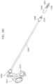
- FIGS. 10 A- 10 Cdepict one variation of a delivery device 1000 and a grasper 1050 .
- the graspermay be releasably coupled to the delivery device 1000 (as shown in FIGS. 10 A and 10 B ), and may be decoupled from the delivery device (as shown in FIG. 10 C ).
- the delivery device 1000may actuate the grasper to connect the grasper to tissue or release the grasper therefrom.
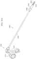
- the delivery device 1000may comprise a handle 1004 , a shaft 1006 extending from the handle 1004 , and a distal engagement portion 1008 at a distal end of the shaft 1006 .
- the delivery device 1000 and grasper 1050may be configured for laparoscopic introduction into the body. Accordingly, in some variations the grasper 1050 and delivery device 1000 may be configured for advancement through a 10 mm laparoscopic port. In these variations, the outer diameter of the grasper may be less than or equal to about 10 mm. Additionally, the delivery device 1000 may be configured such that the shaft 1006 and the distal engagement portion 1008 each have a diameter of less than or equal to about 10 mm.
- the distal engagement portion 1008may have an outer diameter of less than or equal to about 10 mm, while the shaft 1006 has an outer diameter of less than or equal to about 5 mm. In these variations, it may be possible to advance the distal engagement portion 1008 through a 10 mm laparoscopic port, and to further advance a second device having a diameter of about 5 mm or less through the port while the shaft 1006 is positioned in the port. It should be appreciated that shaft 1006 may have any suitable diameter (e.g., between about 1 mm and about 15 mm, between about 5 mm and about 10 mm, or the like).
- the shaft 1006 and distal engagement portion 1008may be formed from any suitable materials, such as one or more medical-grade, high-strength plastics or metals, such as stainless steel, cobalt chromium, PEEK, one or more nylons, polyimide, or the like.
- the grasper 1200when the grasper 1200 is temporarily coupled to the delivery device 1100 , at least a portion of the barrel portion 1210 may be positioned within the distal engagement portion 1108 , as shown in FIG. 11 B .
- the attractive force between the coupling magnet 1118 and the grasper 1200may hold the grasper 1200 in place.
- the grasper 1200has a barrel portion 1210 having a first segment having a first outer diameter and a second segment having a second outer diameter
- the first outer diametermay be sized to fit within the distal engagement portion 1108 while the second outer diameter may be sized such that it is too large to fit within the distal engagement portion 1108 .
- the second segment(or a tapered segment between the first segment and the second segment) may act as a stop to limit the amount of the barrel portion 1210 that may enter the distal engagement portion 1108 .
- the coupling magnet 1118may be withdrawn to the retracted position, such as shown in FIG. 11 D .
- the attractive force between the coupling magnet 1118 and the grasper 1200may pull the grasper 1200 proximally relative to the distal engagement portion 1108 .
- the second segment(or the tapered segment) may limit the withdrawal of the grasper 1200 , such that the distance between the coupling magnet 1118 and the grasper 1200 increases. This may decrease the attractive force between the coupling magnet 1118 and the grasper 1200 , which may allow the grasper 1200 to be pulled from, released from, or otherwise fall from the distal engagement portion 1108 .
- the coupling magnet 1118may be retracted in any suitable manner.
- the delivery device 1100may comprise an actuation rod 1114 slidably disposed in the shaft 1106 .
- the actuation rod 1114may be configured to retract the coupling magnet 1118 .
- the actuation rod 1114may be slidably disposed within a lumen 1122 of the coupling magnet 1118 .
- at least a segment of the actuation rod 1114may be sized and configured such that the portion of the actuation rod 1114 cannot fully pass through the lumen 1122 .
- a segment 1140 of the actuation rodmay have a diameter greater than a diameter of the lumen 1122 . Since the segment 1140 cannot fully pass through the lumen 1122 of the coupling magnet 1118 , further withdrawal in the proximal direction of the actuation rod 1114 may cause the segment of the actuation rod 1114 to pull on and withdraw the coupling magnet 1118 . When the actuation rod 1114 is subsequently advanced, the spring 1120 may advance the coupling magnet 1118 with the actuation rod 1114 until the coupling magnet 1118 reaches the advanced position.
- the actuation rod 1114may be advanced or retracted relative to the shaft 1106 to actuate and/or release the grasper 1200 .
- the triggermay be operatively connected to the actuation rod 1114 , such that movement of the trigger slides the actuation rod 1114 . Movement of the actuation rod 1114 may rotate the first jaw 1202 of the grasper 1200 .
- the actuation rod 1114may be aligned with the lumen 1212 of the barrel portion 1210 such that the actuation rod 1114 enters the lumen 1212 .
- the actuation rod 1114may press against the proximal end 1252 of the shuttle pin 1250 and advance the shuttle pin 1250 along the lumen 1212 .
- the distal end of the shuttle pin 1250may move into a channel of the barrel extension 1260 .
- the distal end of the shuttle pin 1250may in turn push against the proximal arm 1220 (e.g., against a portion of the proximal arm 1220 that is positioned in the channel 1262 and aligned with the lumen 1212 ).
- the proximal arm 1220may act as a cam to convert the linear motion of the shuttle pin 1250 into rotation of the proximal arm 1220 , which may in turn rotate the first jaw 1202 away from the second jaw 1204 .
- the rotation of the proximal arm 1220may overcome this spring bias, which may allow the actuation rod 1114 to hold the first jaw 1202 in its open position, as shown in FIG. 11 C .
- first jaw 1202may rotate back toward the second jaw 1204 when the actuation rod 1114 is retracted. Specifically, as the actuation rod 1114 is withdrawn, the return bias of the first jaw 1202 may cause the proximal arm 1220 to push against the shuttle pin 1250 , which may slide the shuttle pin 1250 proximally within the lumen 1212 . This may return the grasper to a closed configuration, such as shown in FIG. 11 B . When the grasper 1200 is closed around tissue, the actuation rod 1114 may be further retracted to release the grasper 1200 from the delivery device 1100 .
- placing the trigger in the first positionmay position the actuation rod 1114 in a position as illustrated in FIG. 11 B , in which the grasper 1200 may be coupled to the delivery device 1100 in a closed configuration.
- Moving the trigger to the second positionmay advance the actuation rod to the position illustrated in FIG. 11 C , in which the grasper 1200 may be releasably coupled to the delivery device 1100 in an open configuration.
- Moving the trigger to the third positionmay retract the actuation rod 1114 to the position illustrated in FIG. 11 D , in which the grasper 1200 may be decoupled from the delivery device 1100 .
- delivery devicesare described herein primarily with reference to use with a grasper, the delivery devices described herein may also be used to reversibly couple to another intracavity device to deliver, position and reposition, and/or remove another intracavity device.
- the delivery devicesmay be used to deliver, position and reposition, and/or remove a visualization device, such as a camera and/or light source.
- the surgical systems described hereinmay comprise one or more external magnetic positioning devices comprising an external magnet, support arm, and/or sensors.
- the external magnetsmay generate a magnetic field configured to attract one or more intracavity devices.
- the external magnetsmay control the position of the intracavity devices disposed within a body cavity or lumen of a patient. This may free space at an access site (e.g., port) of the patient to allow additional intracavity devices to be advanced into the patient and reduce, if not eliminate, the need for a second operator such as a skilled surgeon.
- the external magnetsmay be configured to generate a magnetic field, such that when the external magnet is positioned near a patient, a magnetic field may be generated inside the patient. This magnetic field may apply a force to and manipulate an intracavity device.
- the external magnetmay comprise one or more permanent magnets, one or more electromagnets, and/or one or more electropermanent magnets.
- Permanent magnetsmay be formed from suitable magnetic and ferromagnetic materials such as, but not limited to, rare-earth magnets (e.g., samarium-cobalt magnets, neodymium magnets), cobalt, gadolinium, iron, nickel, alnico alloys, ferrites, alloys thereof, combinations thereof, and the like.
- the set of Cartesian degrees of freedommay be represented by three translational (position) variables (e.g., surge, heave, sway) and by the three rotational (orientation) variables (e.g., roll, pitch, yaw).
- positione.g., surge, heave, sway
- rotational (orientation) variablese.g., roll, pitch, yaw
- the support armmay be configured to move over all areas of a patient body in up to three dimensions and may also maintain the external magnet at an orientation perpendicular to a surface of the patient.
- the support armmay comprise one or more motors configured to translate and/or rotate the joints and move the support arm to a desired location and orientation.
- the position of the support armmay be temporarily locked to fix the position of the external magnet.
- the support armmay be mounted to any suitable object, such as furniture (e.g., a bed rail), a wall, a medical cart, a ceiling, or may be self-standing. Additionally or alternatively, the support arm may be configured to be moved manually.
- the support armmay be configured to carry a payload comprising the support arm, external magnet), intracavity device magnetically coupled to the external magnet, and any tissue coupled to the intracavity device (e.g., a gallbladder held by a grasper). In some variations, each support arm may move a respective intracavity device.
- an external magnetic positioning deviceWhen an external magnetic positioning device is magnetically coupled to an intracavity device, movement of the external magnet via movement of the support arm may in turn move the intracavity device disposed within a body cavity or lumen of the patient. For example, coronal movement of the external magnet relative to the patient may result in a corresponding coronal movement of the intracavity device.
- moving the external magnet closer to the intracavity device using the support armmay increase the attraction between the external magnet and the intracavity device so as to bring the intracavity device in contact with a patient cavity wall, while moving the external magnet further away from the intracavity device may reduce the magnetic attraction and reposition the intracavity device away from the body cavity wall.
- the magnetic positioning devicemay control the position of the intracavity devices disposed within a body cavity or lumen of a patient.
- a strength and/or position of the external magnetmay be used to control a force of a magnetically coupled intracavity device against a body cavity wall or lumen wall using the sensors described in detail herein.
- the external magnetic positioning devicesmay optionally comprise one or more sensors to determine a location of a portion of one or more external magnetic positioning devices (e.g., support arms, external magnets), patient body surfaces (e.g., internal cavity wall, breasts), and surgical system components (e.g., intracavity devices, trocar, control console).
- an external magnetic positioning devicemay comprise one or more sensors configured to detect a location of a patient body surface and calculate a proximity of the magnetic positioning device relative to the patient such that the controller may ensure that the support arm and/or the external magnet do not contact the patient.
- each segment of a support armmay comprise an inductive proximity sensor to calculate a distance between the support arms.
- an infrared, radar, or ultrasonic range finder mounted on the support arm and/or external armmay be configured to calculate a distance to the patient.
- the magnetic positioning devicemay comprise optical sensors internal and/or external to the support arms configured to visualize the other support arms, operator, input/output device, patient platform, patient, or the like.
- a controllermay be configured to maintain a predetermined distance between the magnetic positioning device and a patient body surface such as a distance of about 1 mm, about 5 mm, or about 10 mm.
- the one or more sensorsmay be further configured to detect a proximity of the magnetic positioning device relative to other magnetic positioning devices and system components to prevent contact with each other or the patient.
- a controllermay be configured to maintain a predetermined distance between the magnetic positioning device and a patient body surface such as a distance of about 1 mm, about 5 mm, or about 10 mm.
- a controllermay limit a range of motion of the support arm.
- a magnetic field and/or position of an external magnetmay be controlled using a force sensor of the external magnetic positioning device and/or intracavity device, such as for an intracavity device in contact with an internal body cavity wall.
- a contact force of the intracavity device and/or external magnet with the body cavity wallmay be reduced if a force sensor detects that the force exceeds a predetermined threshold.
- the sensorsmay comprise one or more of a force sensor (e.g., Hall sensor, load cell, springs), proximity sensor, optical sensor, motion sensor, accelerometer, gyroscope, laser rangefinder, radar, and LIDAR.
- a surgical system 100may comprise a controller 110 in communication with a plurality of support arms 120 and/or intracavity devices 130 .
- the controller 110may comprise one or more processors 112 and one or more machine-readable memories 114 in communication with the one or more processors 112 .
- the controller 110may be connected to the support arms 120 and/or intracavity devices 130 by wired or wireless communication channels.
- the controller 110may be located in the same or different room as the patient. In some variations, the controller 110 may be coupled to a patient platform or disposed on a medical cart adjacent to the patient and/or operator.
- the controller 110may be configured to control one or more components of the system 100 , such as intracavity devices 130 that may visualize a body cavity or lumen, grasp tissue, retract tissue, hold and/or drive a needle, and the like. In some variations, the controller 110 may be configured to coordinate movement and orientation of intracavity devices 130 within a body cavity or lumen through corresponding movement and control of the support arms 120 and external magnets 122 .
- the controller 110may be implemented consistent with numerous general purpose or special purpose computing systems or configurations.
- Various exemplary computing systems, environments, and/or configurations that may be suitable for use with the systems and devices disclosed hereinmay include, but are not limited to software or other components within or embodied on personal computing devices, network appliances, servers or server computing devices such as routing/connectivity components, portable (e.g., hand-held) or laptop devices, multiprocessor systems, microprocessor-based systems, and distributed computing networks.
- portable computing devicesexamples include smartphones, personal digital assistants (PDAs), cell phones, tablet PCs, phablets (personal computing devices that are larger than a smartphone, but smaller than a tablet), wearable computers taking the form of smartwatches, portable music devices, and the like, and portable or wearable augmented reality devices that interface with an operator's environment through sensors and may use head-mounted displays for visualization, eye gaze tracking, and user input.
- PDAspersonal digital assistants
- cell phonescell phones
- tablet PCstablet PCs
- phabletspersonal computing devices that are larger than a smartphone, but smaller than a tablet
- wearable computerstaking the form of smartwatches, portable music devices, and the like
- portable or wearable augmented reality devicesthat interface with an operator's environment through sensors and may use head-mounted displays for visualization, eye gaze tracking, and user input.
- a single operatormay control one or more components of a surgical system 100 using one or more input devices 140 .
- Some variations of an input devicemay comprise at least one switch configured to generate a control signal.
- the input devicemay be coupled to a patient platform and/or disposed on a medical cart adjacent to the patient and/or operator. However, the input device may be mounted to any suitable object, such as furniture (e.g., a bed rail), a wall, a ceiling, or may be self-standing.
- the control signalmay include, for example, a movement signal, activation signal, magnetic field strength signal, and other signals.
- the input devicemay comprise a wired and/or wireless transmitter configured to transmit a control signal to a wired and/or wireless receiver of a controller.
- a plurality of input devicesmay be configured to control a single component of the surgical system (e.g., intracavity device) to enhance operator flexibility.
- a single component of the surgical systeme.g., intracavity device
- an operatormay choose to control a support arm using combinations of a joystick, directional pad, soft keys, voice commands, and the like.
- each input device of a surgical systemmay be associated with a corresponding component of the surgical system.
- a joystickmay be configured to control movement of a support arm;
- a touch screenmay be configured to pan, tilt, and/or zoom a visualization device;
- a jog dialmay be configured to control the jaw positions of a grasper; and
- a step switchmay be configured to release a delivery device from an intracavity device.
- button presses of varying durationmay execute different functions.
- a lumen output level of a light sourcemay be configured to increase with a longer button press.
- a shorter duration button pressmay correspond to a different function such as deactivating the light source.
- a surgical systemmay comprise a plurality of input devices provided in separate housings, where for example a first input device may be handheld and/or portable while a second input device may be stationary.
- a first input devicemay comprise a tablet including a touch screen display and a second input device may comprise a step switch or foot pedal.
- the step switchmay in some variations be a safety switch that must be engaged at the same time as contact with the touch screen before a control signal is transmitted to the surgical system. Output of a control signal upon simultaneous engagement of a first input device and second input device may confirm that operator input to the first input device is intentional.
- An output device 150 of a surgical system 100may output sensor data corresponding to a patient and/or surgical system, and may comprise one or more of a display device, audio device, and haptic device.
- the output devicemay be coupled to a patient platform and/or disposed on a medical cart adjacent to the patient and/or operator.
- the output devicemay be mounted to any suitable object, such as furniture (e.g., a bed rail), a wall, a ceiling, and may be self-standing.
- a display devicemay allow an operator to view images of one or more intracavity devices, support arms, external magnets, body cavities, and tissue.
- an intracavity devicecomprising a visualization device (e.g., camera, optical sensor) located in a body cavity or lumen of a patient may be configured to image an internal view of the body cavity or lumen and/or other intracavity devices.
- An external visualization devicemay be configured to image an external view of the patient and one or more external magnetic positioning devices. Accordingly, the display device may output one or both of internal and external images of the patient and system components.
- an output devicemay comprise a display device including at least one of a light emitting diode (LED), liquid crystal display (LCD), electroluminescent display (ELD), plasma display panel (PDP), thin film transistor (TFT), organic light emitting diodes (OLED), electronic paper/e-ink display, laser display, and/or holographic display.
- LEDlight emitting diode
- LCDliquid crystal display
- ELDelectroluminescent display
- PDPplasma display panel
- TFTthin film transistor
- OLEDorganic light emitting diodes
- An audio devicemay audibly output patient data, sensor data, system data, alarms and/or warnings.
- the audio devicemay output an audible warning when monitored patient data (e.g., blood pressure) falls outside a predetermined range or when a malfunction in a support arm is detected.
- audiomay be output when operator input is overridden by the surgical system to prevent potential harm to the patient and/or surgical system (e.g., collision of support arms with each other, excessive force of the intracavity device against a patient cavity wall).
- an audio devicemay comprise at least one of a speaker, piezoelectric audio device, magnetostrictive speaker, and/or digital speaker.
- an operatormay communicate to other users using the audio device and a communication channel.
- the operatormay form an audio communication channel (e.g., VoIP call) with a remote operator and/or observer.
- a haptic devicemay be incorporated into one or more of the input and output devices to provide additional sensory output (e.g., force feedback) to the operator.
- a haptic devicemay generate a tactile response (e.g., vibration) to confirm operator input to an input device (e.g., touch surface).
- Haptic feedbackmay in some variations simulate a resistance encountered by an intracavity device within a body cavity or lumen (e.g., magnetic field and tissue resistance). Additionally or alternatively, haptic feedback may notify that an operator input is overridden by the surgical system to prevent potential harm to the patient and/or system (e.g., collision of support arms with each other). Operator interaction with a user interface utilizing an input and output device is discussed in more detail herein.
- FIG. 7depicts an illustrative variation of surgical system 700 comprising an input/output (I/O) device 702 (e.g., user interface device comprising a touch surface and display), a plurality of external magnetic positioning devices 720 (e.g., support arms and external magnets) magnetically coupled to respective intracavity devices 730 , 732 (grasper and camera assembly, such as described herein).
- I/Oinput/output
- the intracavity devices 730 , 732may be advanced into a patient body cavity 742 (having a transparent cavity wall for ease of explanation) through a port 740 (e.g., trocar).
- a port 740e.g., trocar
- the intracavity devicesmay be delivered via a natural orifice, such as via the mouth/esophagus/stomach or rectum.
- the input/output device 702may comprise a graphical user interface (GUI) 704 configured to output patient data, system data, and sensor data from any internal and/or external sensor of the surgical system 700 .
- GUIgraphical user interface
- I/O device 702may be configured to display internal, real-time images 710 generated by a camera assembly 732 located within the body cavity 742 .
- the GUI 704may allow an operator to control (e.g., operate and move) a plurality of intracavity devices 730 , 732 magnetically coupled to respective external magnetic positioning devices 720 using a single input scheme.
- the GUI 704may display an image generated by, for example, an intracavity camera assembly, external camera, and/or stored images (e.g., computed tomography or magnetic resonance images).
- the operator 750may select an image source for display on the GUI 704 .
- the GUI 704may comprise text such as a time, date, system status, patient data, and other data. The text may be displayed over an image of the GUI 704 such as the internal image 710 .
- the GUI 704may display a plurality of soft keys for device selection and control.
- the device selector buttons 706 in FIG. 7may comprise one or more of a number, color, name, shape, and image identifying one or more intracavity devices for selection.
- a device selector button 706may select multiple devices within a group according to device characteristics such as function and type. For example, selection of button “2” in FIG. 7 may select for active control each of the graspers 730 . Active control refers to control of a selected device through input of one or more device control buttons (e.g., device control buttons 708 ). A subsequent selection of button “2” may deselect the graspers 730 from active control.
- selection of a group of intracavity devices 730 , 732may prompt display of a sub-menu (not shown) for selection of a subset of intracavity devices within the initially selected group.
- an operator 750may select a plurality of device groups for control through selection of a plurality of device selector buttons 706 . This may allow, for example, a set of graspers and camera assemblies to move and/or operate together within a body cavity or lumen.
- an operator 750may select an intracavity device 730 for control using a real-time internal image 710 generated by camera assembly 732 .
- a controllermay process the internal image 710 (e.g., using an image processing unit of a processor) to classify the intracavity devices 730 within the internal image 710 as an imaged intracavity device 712 .
- a device selector button 706may be defined by an outline of the imaged intracavity device 712 .
- Operator 750may contact the imaged intracavity device 712 displayed on the I/O device 702 as a device selector button for a predetermined duration to select the intracavity device 730 for active control.
- an operator 750may select a plurality of intracavity devices 730 , 732 for simultaneous control by selection of corresponding device selection buttons 706 . It may be useful in some variations to select a group of intracavity devices 730 , 732 for simultaneous device control. For example, concurrent selection and control of a group of graspers 730 grasping the same organ 744 may allow coordinated operation and movement. Movement of a single grasper 730 while another grasper 730 coupled to the same tissue is stationary may cause damage (e.g., tearing) to the grasped organ 744 . Additionally or alternatively, an operator 750 may select an intracavity device 730 , 732 for device control through a voice command. An audio device may output an audio confirmation of the selected intracavity device 730 , 732 .
- selection of a particular intracavity device 730 , 732 for control using device control buttons 708may also select for control of the external magnetic positioning device 720 magnetically coupled to the intracavity device 730 , 732 .
- Other functions of the intracavity device 730 , 732e.g., activation of a light source
- the device control buttons 708 in FIG. 7may comprise one or more of a number, color, name, shape, and image identifying a control function to be executed by the selected device.
- a device control button 708may execute the same function among multiple devices 730 , 732 .
- selection of button “>” (right arrow) in FIG. 7may command the support arms 720 to move each of the graspers 730 to the right relative to a predetermined coordinate system (e.g., based on a reference frame defined by the image or patient anatomical planes).
- the GUI 704may simultaneously display device control buttons 708 for a plurality of devices (e.g., camera pan/zoom control buttons and grasper movement control buttons). This may allow an operator 750 to input control signals to maintain the grasper 730 in view of the camera assembly 732 as the grasper 730 moves.
- an imaged intracavity device 712may function as a device control button 708 to move and/or control the selected intracavity device 730 .
- an operator 750may contact the imaged intracavity device 712 and perform a “drag and drop” touch input of sliding their finger across the I/O device 702 and releasing contact with the I/O device 702 to input a movement signal of the intracavity device 730 to the GUI 704 .
- a stored image or real-time image of the intracavity device 730may move across the GUI 704 with the operator input.
- the surgical systems described hereinmay comprise one or more sterile coverings configured to create a sterile barrier around portions of the surgical system.
- the surgical systemmay comprise one or more sterile coverings to form a sterile field.
- a sterile coveringmay be placed between the positioning devices and the patient, forming a barrier between an interior, non-sterile side including the patient and intracavity devices and an exterior, sterile side including the operator, support arm, and external magnet.
- components of the systemmay be sterilizable.
- the sterile coveringmay, for example, comprise a sterile drape configured to cover at least a portion of a system component.
- a sterile coveringe.g., sterile bag
- a sterile bagmay be configured to create a sterile barrier with respect to an external magnet of a magnetic positioning device.
- the sterile bagmay be clear and allow an operator to visualize and manually manipulate a position of the external magnet by, for example, an operator grabbing a handle of a support arm or a handle attached to an external magnet through the sterile bag.
- the sterile coveringmay conform tightly around one or more system components or may drape loosely so as to allow components to be adjusted within the sterile field (e.g., adjustment of mechanical bolts of a support arm).
- a single operatormay operate a surgical system comprising a plurality of intracavity devices without requiring assistance from another operator to operate the surgical system.
- the methods described herecomprise advancing one or more of intracavity devices into a body cavity or lumen of a patient, non-invasively coupling the intracavity devices to corresponding external magnetic positioning devices, controlling the intracavity devices, moving the intracavity devices within the body cavity or lumen through control of the corresponding external magnetic positioning devices, and actuating the intracavity devices.
- the operatormay thus control a surgical system comprising the intracavity device(s) from a single control console.
- the methods described heremay allow a single operator to perform a surgical procedure, even when that surgical procedure involves a number of tools. This may have numerous benefits, such as reducing the cost of surgery.
- FIG. 8is a flowchart 800 of an illustrative method of performing minimally invasive surgery.
- the method 800may begin with advancement of an intracavity device into a body cavity through an access site 802 .
- an intracavity device 910is initially disposed externally of the patient 950 .
- the intracavity device 910may be advanced through a port 920 disposed in an access site of a patient 950 .
- FIG. 9 Billustrates the intracavity device 910 advanced through the port 920 and disposed in a body cavity 952 (a body cavity wall is shown transparent for ease of explanation) of the patient 950 .
- the body cavityis not particularly limited and may be, for example, an abdominal cavity or thoracic cavity.
- the intracavity devicemay be advanced into a body lumen.
- the port 920may be, for example, a trocar disposed within a patient cavity wall, but in other variations the intracavity device may be delivered via a natural orifice.
- the intracavity device 910may have a size and configuration for advancement through the port 920 .
- the intracavity device 910may be advanced through the port 920 using a delivery device (such as those described herein) releasably coupled to the intracavity device 910 (not shown).
- the intracavity device disposed within a body cavity or lumenmay be coupled to an external magnetic positioning device through the patient cavity wall 804 .
- the intracavity device 910 comprising a magnetic portionmay be magnetically coupled to an external magnetic positioning device 930 comprising a support arm 932 and an external magnet 934 .
- the external magnet 934may generate a magnetic field to attract the intracavity device 910 towards the body cavity wall and external magnetic positioning device 930 .
- This magnetic couplingmay hold the intracavity device 910 relative to the external magnetic positioning device 930 with the patient cavity wall disposed therebetween.
- a determinationmay be performed of whether any other intracavity devices are to be advanced into the body cavity 806 . If so, steps 802 , 804 , and 806 may be repeated.
- each of a plurality of intracavity devicesmay be magnetically coupled to a corresponding external magnetic positioning device, thereby allowing independent control of each intracavity device within a body cavity or lumen.
- the support armmay position the external magnet at a predetermined position external to the patient.
- the external magnetmay be positioned directly above an opening of the port, which allows the intracavity device to be magnetically coupled to the external magnetic positioning device as the intracavity device is introduced into the body cavity or lumen.
- the intracavity devicemay be positioned relative to the external magnetic positioning device using a delivery device coupled to the intracavity device. The delivery device may, for example, release the intracavity device once the intracavity device is magnetically coupled to the external magnetic positioning device.
- one or more of the magnetic field strength of an external magnet and location of a support armmay be modified to change a position and/or orientation of the graspers 911 .
- an operatormay view internal images of the patient displayed on a display device as the operator inputs a control signal (e.g., FIG. 7 ).
- the operatormay further control each intracavity device individually or in groups.
- the operatormay manually control an intracavity device (e.g., using a delivery device as described herein) in conjunction with control of the surgical system.
- a contact force of the intracavity device and/or external magnet with the patient cavity wallmay be reduced to reduce potential harm to patient tissue when force sensors detect that the force exceeds a predetermined threshold.
- a magnetic field strength of the external magnetmay be reduced in response to force exceeding about 10 N.
- Some visualization devicesmay comprise a lens wiping device for cleaning the lens.
- Other intracavity devicesmay manipulate tissue.
- the graspers 911 in FIG. 9 Eare shown in a closed configuration where tissue 954 is grasped between the jaws of the grasper 911 .
- a retractormay be configured to transition between a low profile configuration and a curvilinear configuration.
- Other non-limiting examples of intracavity device controlinclude: a delivery/retrieval device configured to releasably carry one or more intracavity devices; an electrocautery hook configured to cauterize tissue; a suction device configured to suction fluid and/or tissue in the body cavity or lumen; a stapler configured to staple tissue.
- one or more internal and/or external sensorsmay be configured to be controlled by an operator such as a proximity sensor, force sensor, magnetic field sensor.
- a force sensormay be disposed on a side of the intracavity device that is more attracted to an external magnetic field (e.g., on a side opposite the light source 912 and optical sensor 914 ).
- the intracavity device 910may comprise a wireless transmitter (not shown) for transmitting sensor data (e.g., force sensor data) to a controller.
- an external magnetic positioning device 930may comprise a wired or wireless transmitter for transmitting sensor data (e.g., force sensor data, proximity data) to a controller.
- sensor datae.g., force sensor data, proximity data
- an external force sensormay be disposed on a side of the external magnet 934 opposite the support arm 932 . When the external magnet 934 and external force sensor are in contact with a patient body surface, the external force sensor may transmit external force data to the controller using the transmitter of the external magnetic positioning device 930 .
- An operatormay input a control signal using a GUI to advance each intracavity device out of the body cavity or lumen 812 .
- the external magnetic positioning devicemay move the support arms and/or modify a magnetic field of an external magnet coupled to the support arm to advance the intracavity device out through an access site and outside the patient.
- a retrieval device(not shown) may be advanced from the body cavity or lumen and through an access site (e.g., trocar or natural orifice) to an exterior of the patient.
- the external magnetic positioning devicemay be decoupled from the intracavity device by, for example, moving the external magnet away from the patient, by reducing a current applied to the external magnet where the external magnet is an electromagnet, or by applying energy to reduce the magnetic field when the external magnet is an electropermanent magnet.
- the intracavity devicemay then be advanced out of the body cavity or lumen using the retrieval device.
- the retrieval devicemay be the same as a delivery device used to advance the intracavity device into the body cavity or lumen, or a separate device.
- the methodmay comprise forming a sling using a retractor (such as one of the retractors described here) to retract tissue.
- the retractormay be releasably coupled with a delivery device and advanced into a patient body cavity through an access site.
- the retractormay be in a low-profile (e.g., substantially linear) configuration when coupled to the delivery device.
- a portion of the retractormay be positioned underneath a portion of tissue, such that at least a portion of the tissue may be suspended by the retractor and then moved towards the patient body cavity wall.
- the retractormay be configured to transition between a substantially linear configuration and the curvilinear configuration (e.g., by using an external magnetic field).
- the curvilinear configurationmay support and suspend at least a portion of tissue (e.g., an internal organ) from the patient wall in response to a magnetic field.
- This operator input control signalmay correspond to an output of an external magnetic positioning device control signal to increase the attraction of the retractor to the external magnetic field (e.g., by increasing the current to an external electromagnet and/or bringing the external magnet closer to the patient body surface) to thereby retract tissue.
Landscapes
- Health & Medical Sciences (AREA)
- Life Sciences & Earth Sciences (AREA)
- Surgery (AREA)
- Engineering & Computer Science (AREA)
- Public Health (AREA)
- Veterinary Medicine (AREA)
- Biomedical Technology (AREA)
- Heart & Thoracic Surgery (AREA)
- Medical Informatics (AREA)
- Molecular Biology (AREA)
- Animal Behavior & Ethology (AREA)
- General Health & Medical Sciences (AREA)
- Nuclear Medicine, Radiotherapy & Molecular Imaging (AREA)
- Pathology (AREA)
- Physics & Mathematics (AREA)
- Biophysics (AREA)
- Optics & Photonics (AREA)
- Radiology & Medical Imaging (AREA)
- Robotics (AREA)
- Oral & Maxillofacial Surgery (AREA)
- Human Computer Interaction (AREA)
- Mechanical Engineering (AREA)
- Ophthalmology & Optometry (AREA)
- Surgical Instruments (AREA)
Abstract
Description
Claims (18)
Priority Applications (1)
| Application Number | Priority Date | Filing Date | Title |
|---|---|---|---|
| US16/008,976US12262971B2 (en) | 2016-01-08 | 2018-06-14 | One-operator surgical system and methods of use |
Applications Claiming Priority (3)
| Application Number | Priority Date | Filing Date | Title |
|---|---|---|---|
| US201662276752P | 2016-01-08 | 2016-01-08 | |
| PCT/US2017/012628WO2017120540A1 (en) | 2016-01-08 | 2017-01-06 | One-operator surgical system and methods of use |
| US16/008,976US12262971B2 (en) | 2016-01-08 | 2018-06-14 | One-operator surgical system and methods of use |
Related Parent Applications (1)
| Application Number | Title | Priority Date | Filing Date |
|---|---|---|---|
| PCT/US2017/012628ContinuationWO2017120540A1 (en) | 2016-01-08 | 2017-01-06 | One-operator surgical system and methods of use |
Publications (2)
| Publication Number | Publication Date |
|---|---|
| US20180296289A1 US20180296289A1 (en) | 2018-10-18 |
| US12262971B2true US12262971B2 (en) | 2025-04-01 |
Family
ID=59274018
Family Applications (1)
| Application Number | Title | Priority Date | Filing Date |
|---|---|---|---|
| US16/008,976Active2038-05-24US12262971B2 (en) | 2016-01-08 | 2018-06-14 | One-operator surgical system and methods of use |
Country Status (3)
| Country | Link |
|---|---|
| US (1) | US12262971B2 (en) |
| EP (1) | EP3399902B1 (en) |
| WO (1) | WO2017120540A1 (en) |
Families Citing this family (79)
| Publication number | Priority date | Publication date | Assignee | Title |
|---|---|---|---|---|
| CA2706860C (en) | 2007-11-26 | 2017-08-01 | Eastern Virginia Medical School | Magnaretractor system and method |
| JP5938774B2 (en) | 2009-10-03 | 2016-06-22 | ハダシット メディカル リサーチ サービシズ アンド デベロップメント リミテッド | Transcutaneous antenna |
| US11871901B2 (en) | 2012-05-20 | 2024-01-16 | Cilag Gmbh International | Method for situational awareness for surgical network or surgical network connected device capable of adjusting function based on a sensed situation or usage |
| US8764769B1 (en) | 2013-03-12 | 2014-07-01 | Levita Magnetics International Corp. | Grasper with magnetically-controlled positioning |
| WO2015112645A1 (en) | 2014-01-21 | 2015-07-30 | Levita Magnetics International Corp. | Laparoscopic graspers and systems therefor |
| WO2016168377A1 (en) | 2015-04-13 | 2016-10-20 | Levita Magnetics International Corp. | Retractor systems, devices, and methods for use |
| ES2895900T3 (en) | 2015-04-13 | 2022-02-23 | Levita Magnetics Int Corp | Magnetically controlled location handle |
| EP3399902B1 (en)* | 2016-01-08 | 2024-06-12 | Levita Magnetics International Corp. | One-operator surgical system |
| US11020137B2 (en) | 2017-03-20 | 2021-06-01 | Levita Magnetics International Corp. | Directable traction systems and methods |
| US11950869B2 (en)* | 2017-08-30 | 2024-04-09 | Intuitive Surgical Operations, Inc. | System and method for providing on-demand functionality during a medical procedure |
| US11510741B2 (en) | 2017-10-30 | 2022-11-29 | Cilag Gmbh International | Method for producing a surgical instrument comprising a smart electrical system |
| US11291510B2 (en) | 2017-10-30 | 2022-04-05 | Cilag Gmbh International | Method of hub communication with surgical instrument systems |
| US11911045B2 (en) | 2017-10-30 | 2024-02-27 | Cllag GmbH International | Method for operating a powered articulating multi-clip applier |
| US11564756B2 (en) | 2017-10-30 | 2023-01-31 | Cilag Gmbh International | Method of hub communication with surgical instrument systems |
| US11801098B2 (en) | 2017-10-30 | 2023-10-31 | Cilag Gmbh International | Method of hub communication with surgical instrument systems |
| US11925373B2 (en) | 2017-10-30 | 2024-03-12 | Cilag Gmbh International | Surgical suturing instrument comprising a non-circular needle |
| US11311306B2 (en) | 2017-12-28 | 2022-04-26 | Cilag Gmbh International | Surgical systems for detecting end effector tissue distribution irregularities |
| US11678881B2 (en) | 2017-12-28 | 2023-06-20 | Cilag Gmbh International | Spatial awareness of surgical hubs in operating rooms |
| US11376002B2 (en) | 2017-12-28 | 2022-07-05 | Cilag Gmbh International | Surgical instrument cartridge sensor assemblies |
| US11969216B2 (en) | 2017-12-28 | 2024-04-30 | Cilag Gmbh International | Surgical network recommendations from real time analysis of procedure variables against a baseline highlighting differences from the optimal solution |
| US11179175B2 (en) | 2017-12-28 | 2021-11-23 | Cilag Gmbh International | Controlling an ultrasonic surgical instrument according to tissue location |
| US20190201090A1 (en) | 2017-12-28 | 2019-07-04 | Ethicon Llc | Capacitive coupled return path pad with separable array elements |
| US11304699B2 (en) | 2017-12-28 | 2022-04-19 | Cilag Gmbh International | Method for adaptive control schemes for surgical network control and interaction |
| US11324557B2 (en) | 2017-12-28 | 2022-05-10 | Cilag Gmbh International | Surgical instrument with a sensing array |
| US11202570B2 (en) | 2017-12-28 | 2021-12-21 | Cilag Gmbh International | Communication hub and storage device for storing parameters and status of a surgical device to be shared with cloud based analytics systems |
| WO2019133144A1 (en) | 2017-12-28 | 2019-07-04 | Ethicon Llc | Detection and escalation of security responses of surgical instruments to increasing severity threats |
| US11076921B2 (en) | 2017-12-28 | 2021-08-03 | Cilag Gmbh International | Adaptive control program updates for surgical hubs |
| US11166772B2 (en) | 2017-12-28 | 2021-11-09 | Cilag Gmbh International | Surgical hub coordination of control and communication of operating room devices |
| US11786251B2 (en) | 2017-12-28 | 2023-10-17 | Cilag Gmbh International | Method for adaptive control schemes for surgical network control and interaction |
| US11633237B2 (en) | 2017-12-28 | 2023-04-25 | Cilag Gmbh International | Usage and technique analysis of surgeon / staff performance against a baseline to optimize device utilization and performance for both current and future procedures |
| US11464559B2 (en) | 2017-12-28 | 2022-10-11 | Cilag Gmbh International | Estimating state of ultrasonic end effector and control system therefor |
| US20190206569A1 (en) | 2017-12-28 | 2019-07-04 | Ethicon Llc | Method of cloud based data analytics for use with the hub |
| US11013563B2 (en)* | 2017-12-28 | 2021-05-25 | Ethicon Llc | Drive arrangements for robot-assisted surgical platforms |
| US11832899B2 (en) | 2017-12-28 | 2023-12-05 | Cilag Gmbh International | Surgical systems with autonomously adjustable control programs |
| US12396806B2 (en) | 2017-12-28 | 2025-08-26 | Cilag Gmbh International | Adjustment of a surgical device function based on situational awareness |
| US12376855B2 (en) | 2017-12-28 | 2025-08-05 | Cilag Gmbh International | Safety systems for smart powered surgical stapling |
| US11896322B2 (en) | 2017-12-28 | 2024-02-13 | Cilag Gmbh International | Sensing the patient position and contact utilizing the mono-polar return pad electrode to provide situational awareness to the hub |
| US11026751B2 (en) | 2017-12-28 | 2021-06-08 | Cilag Gmbh International | Display of alignment of staple cartridge to prior linear staple line |
| US11132462B2 (en) | 2017-12-28 | 2021-09-28 | Cilag Gmbh International | Data stripping method to interrogate patient records and create anonymized record |
| US12062442B2 (en) | 2017-12-28 | 2024-08-13 | Cilag Gmbh International | Method for operating surgical instrument systems |
| US20190201039A1 (en) | 2017-12-28 | 2019-07-04 | Ethicon Llc | Situational awareness of electrosurgical systems |
| US12096916B2 (en) | 2017-12-28 | 2024-09-24 | Cilag Gmbh International | Method of sensing particulate from smoke evacuated from a patient, adjusting the pump speed based on the sensed information, and communicating the functional parameters of the system to the hub |
| US11857152B2 (en) | 2017-12-28 | 2024-01-02 | Cilag Gmbh International | Surgical hub spatial awareness to determine devices in operating theater |
| US11998193B2 (en) | 2017-12-28 | 2024-06-04 | Cilag Gmbh International | Method for usage of the shroud as an aspect of sensing or controlling a powered surgical device, and a control algorithm to adjust its default operation |
| US11818052B2 (en) | 2017-12-28 | 2023-11-14 | Cilag Gmbh International | Surgical network determination of prioritization of communication, interaction, or processing based on system or device needs |
| US11559308B2 (en) | 2017-12-28 | 2023-01-24 | Cilag Gmbh International | Method for smart energy device infrastructure |
| US20190201112A1 (en) | 2017-12-28 | 2019-07-04 | Ethicon Llc | Computer implemented interactive surgical systems |
| US11896443B2 (en) | 2017-12-28 | 2024-02-13 | Cilag Gmbh International | Control of a surgical system through a surgical barrier |
| US11696760B2 (en) | 2017-12-28 | 2023-07-11 | Cilag Gmbh International | Safety systems for smart powered surgical stapling |
| US11389164B2 (en) | 2017-12-28 | 2022-07-19 | Cilag Gmbh International | Method of using reinforced flexible circuits with multiple sensors to optimize performance of radio frequency devices |
| US11864728B2 (en) | 2017-12-28 | 2024-01-09 | Cilag Gmbh International | Characterization of tissue irregularities through the use of mono-chromatic light refractivity |
| US11612444B2 (en) | 2017-12-28 | 2023-03-28 | Cilag Gmbh International | Adjustment of a surgical device function based on situational awareness |
| US10758310B2 (en) | 2017-12-28 | 2020-09-01 | Ethicon Llc | Wireless pairing of a surgical device with another device within a sterile surgical field based on the usage and situational awareness of devices |
| US11744604B2 (en) | 2017-12-28 | 2023-09-05 | Cilag Gmbh International | Surgical instrument with a hardware-only control circuit |
| US11257589B2 (en) | 2017-12-28 | 2022-02-22 | Cilag Gmbh International | Real-time analysis of comprehensive cost of all instrumentation used in surgery utilizing data fluidity to track instruments through stocking and in-house processes |
| US11109866B2 (en) | 2017-12-28 | 2021-09-07 | Cilag Gmbh International | Method for circular stapler control algorithm adjustment based on situational awareness |
| US11969142B2 (en) | 2017-12-28 | 2024-04-30 | Cilag Gmbh International | Method of compressing tissue within a stapling device and simultaneously displaying the location of the tissue within the jaws |
| US12127729B2 (en) | 2017-12-28 | 2024-10-29 | Cilag Gmbh International | Method for smoke evacuation for surgical hub |
| US11259830B2 (en) | 2018-03-08 | 2022-03-01 | Cilag Gmbh International | Methods for controlling temperature in ultrasonic device |
| US11534196B2 (en) | 2018-03-08 | 2022-12-27 | Cilag Gmbh International | Using spectroscopy to determine device use state in combo instrument |
| US11986233B2 (en) | 2018-03-08 | 2024-05-21 | Cilag Gmbh International | Adjustment of complex impedance to compensate for lost power in an articulating ultrasonic device |
| IL258323B (en)* | 2018-03-22 | 2020-05-31 | Sadan Nir | A system and method for catheterization using an intraluminal elecrtomagnetic working capsule |
| US11589865B2 (en) | 2018-03-28 | 2023-02-28 | Cilag Gmbh International | Methods for controlling a powered surgical stapler that has separate rotary closure and firing systems |
| US11090047B2 (en) | 2018-03-28 | 2021-08-17 | Cilag Gmbh International | Surgical instrument comprising an adaptive control system |
| RU2693216C1 (en)* | 2018-05-24 | 2019-07-01 | Федеральное государственное бюджетное образовательное учреждение высшего образования "Московский государственный медико-стоматологический университет имени А.И. Евдокимова" (ФГБОУ ВО "МГМСУ им. А.И. Евдокимова") | Robotic multifunctional laser surgical complex |
| US11426059B2 (en)* | 2018-06-02 | 2022-08-30 | Ankon Medical Technologies (Shanghai) Co., Ltd. | Control system for capsule endoscope |
| US10908240B2 (en)* | 2018-06-22 | 2021-02-02 | Weinberg Medical Physics, Inc. | Method for acquiring an image and manipulating objects with magnetic gradients produced by one or more electropermanent magnet arrays |
| US11331100B2 (en) | 2019-02-19 | 2022-05-17 | Cilag Gmbh International | Staple cartridge retainer system with authentication keys |
| US11090122B2 (en)* | 2019-02-25 | 2021-08-17 | Verb Surgical Inc. | Systems and methods for magnetic sensing and docking with a trocar |
| US11478312B2 (en) | 2019-05-10 | 2022-10-25 | Verb Surgical Inc. | Unmatching/matching UID to robot grasper for engaging teleoperation |
| KR102269633B1 (en)* | 2019-07-25 | 2021-06-28 | 김형주 | Robot for dental treatment |
| WO2021087027A1 (en)* | 2019-10-30 | 2021-05-06 | Smith & Nephew, Inc. | Synchronized robotic arms for retracting openings in a repositionable manner |
| CN113662596A (en)* | 2020-05-14 | 2021-11-19 | 西安交通大学医学院第一附属医院 | Tissue Clip Assemblies and Clamps |
| WO2022076755A1 (en)* | 2020-10-09 | 2022-04-14 | Viseon, Inc. | Retractor, distractor, and camera system for cervical procedures |
| US12023116B2 (en) | 2020-12-21 | 2024-07-02 | Cilag Gmbh International | Dynamic trocar positioning for robotic surgical system |
| WO2024089379A1 (en)* | 2022-10-27 | 2024-05-02 | Crescent Health Solutions Limited | A device for use in surgery |
| EP4629927A2 (en)* | 2022-12-08 | 2025-10-15 | Arizona Board of Regents on behalf of Arizona State University | System and method for magnetic manipulation of tissue |
| US20240324864A1 (en)* | 2023-03-28 | 2024-10-03 | Liming Wang | Magnetically propelled capsule and methods of making and using the same |
| WO2025057139A1 (en)* | 2023-09-15 | 2025-03-20 | Multi-Scale Medical Robotics Center Limited | System and method for generating magnetic fields using an electromagnet array and a permanent magnet |
Citations (340)
| Publication number | Priority date | Publication date | Assignee | Title |
|---|---|---|---|---|
| US2678228A (en) | 1951-06-08 | 1954-05-11 | Bausch & Lomb | Diagnostic instrument with magnetic connector |
| US2863444A (en) | 1956-08-21 | 1958-12-09 | Winsten Joseph | Liver retractor for cholecystectomies |
| US3146381A (en) | 1960-09-12 | 1964-08-25 | Vente D Aimants Allevard Ugine | Magnetic force control or switching system |
| US3674014A (en) | 1969-10-28 | 1972-07-04 | Astra Meditec Ab | Magnetically guidable catheter-tip and method |
| US3789285A (en) | 1972-03-27 | 1974-01-29 | Handotai Kenkyu Shinkokai | Position control system using magnetic force |
| US3794091A (en) | 1971-10-07 | 1974-02-26 | Med General Inc | Sterile sheath for surgical illuminator |
| US4364377A (en) | 1979-02-02 | 1982-12-21 | Walker Scientific, Inc. | Magnetic field hemostasis |
| US4380999A (en) | 1980-07-15 | 1983-04-26 | Healy Keelin E | Stepped surgical retractor |
| US4706668A (en) | 1985-09-16 | 1987-11-17 | B & B Tools | Aneurysm clip pliers |
| US4756312A (en) | 1984-03-22 | 1988-07-12 | Advanced Hearing Technology, Inc. | Magnetic attachment device for insertion and removal of hearing aid |
| US4901405A (en) | 1988-08-25 | 1990-02-20 | Grover Alfred H | Self-aligning magnetic necklace clasp |
| US4915435A (en) | 1989-04-05 | 1990-04-10 | Levine Brian M | Mobile operating room with pre and post-operational areas |
| US4968136A (en) | 1988-09-02 | 1990-11-06 | Northrop Corporation | Ring laser gyro and magnetic mirror therefor |
| US4971067A (en) | 1988-05-05 | 1990-11-20 | Lee Bolduc | Biopsy instrument with a disposable cutting blade |
| US4976723A (en) | 1988-07-26 | 1990-12-11 | Karl Schad | Specimen excision forceps |
| US4997436A (en) | 1988-06-03 | 1991-03-05 | Oberlander Michael A | Arthroscopic clip insertion tool |
| US5002557A (en) | 1989-04-06 | 1991-03-26 | Hasson Harrith M | Laparoscopic cannula |
| US5154189A (en) | 1988-06-03 | 1992-10-13 | Oberlander Michael A | Method for repairing a torn meniscus |
| US5156609A (en) | 1989-12-26 | 1992-10-20 | Nakao Naomi L | Endoscopic stapling device and method |
| US5156608A (en) | 1990-07-30 | 1992-10-20 | Hans Troidl | Clip applicator for ligature clips |
| DE4212430A1 (en) | 1992-04-14 | 1993-10-21 | Franz Diemer | Surgical instrument for laparoscopic cholecystectomy - uses retractable wire basket to chop up gall-bladder and pieces fall into small bag |
| US5282806A (en) | 1992-08-21 | 1994-02-01 | Habley Medical Technology Corporation | Endoscopic surgical instrument having a removable, rotatable, end effector assembly |
| US5300081A (en) | 1992-10-09 | 1994-04-05 | United States Surgical Corporation | Surgical clip applier having clip advancement control |
| US5304183A (en) | 1992-03-23 | 1994-04-19 | Laparomed Corporation | Tethered clamp retractor |
| US5304185A (en) | 1992-11-04 | 1994-04-19 | Unisurge, Inc. | Needle holder |
| US5307805A (en) | 1992-07-10 | 1994-05-03 | Surgical Innovations I, L.P. | Surgical retractor assembly |
| US5340360A (en) | 1992-03-06 | 1994-08-23 | Ethicon, Inc. | Ligating clip applier |
| US5397325A (en) | 1993-11-09 | 1995-03-14 | Badiaco, Inc. | Laparoscopic suturing device |
| US5411535A (en) | 1992-03-03 | 1995-05-02 | Terumo Kabushiki Kaisha | Cardiac pacemaker using wireless transmission |
| US5415160A (en) | 1994-03-15 | 1995-05-16 | Ethicon, Inc. | Surgical lift method and apparatus |
| US5417701A (en) | 1993-03-30 | 1995-05-23 | Holmed Corporation | Surgical instrument with magnetic needle holder |
| US5449361A (en) | 1993-04-21 | 1995-09-12 | Amei Technologies Inc. | Orthopedic cable tensioner |
| US5449365A (en) | 1992-09-02 | 1995-09-12 | United States Surgical Corporation | Surgical clamp apparatus |
| US5450842A (en) | 1993-02-19 | 1995-09-19 | United States Surgical Corporation | Endoscopic surgical retractor |
| US5458693A (en) | 1991-11-22 | 1995-10-17 | Albany Nordiskafilt Ab | Fabric for papermaking machines and the like |
| US5458603A (en) | 1993-05-12 | 1995-10-17 | Futch, Sr.; William A. | Elongated drive tool for prosthesis in body cavity |
| US5465711A (en) | 1991-05-29 | 1995-11-14 | Origin Medsystems, Inc. | Surgical procedures using endoscopic inflatable retraction devices |
| US5496317A (en) | 1993-05-04 | 1996-03-05 | Gyrus Medical Limited | Laparoscopic surgical instrument |
| US5499986A (en) | 1994-01-07 | 1996-03-19 | Smith & Nephew Richards Inc. | Quick release handle apparatus for removing and inserting intramedullary nails |
| US5529568A (en) | 1994-03-18 | 1996-06-25 | Surgery Futures Research, Inc. | Magnetic operating table |
| US5538098A (en) | 1995-05-18 | 1996-07-23 | Trw Vehicle Safety Systems Inc. | Magnetically controlled retractor |
| US5567274A (en) | 1992-12-07 | 1996-10-22 | Ahlstrom Machinery Inc. | Method of controlling pressurized ozone to a pulp delignification reactor |
| US5569274A (en) | 1993-02-22 | 1996-10-29 | Heartport, Inc. | Endoscopic vascular clamping system and method |
| CN2244381Y (en) | 1995-12-05 | 1997-01-08 | 罗菲尔(天津)医学工程有限公司 | Surgical retractor |
| US5595562A (en) | 1994-11-10 | 1997-01-21 | Research Corporation Technologies, Inc. | Magnetic enteral gastrostomy |
| DE19534618A1 (en) | 1995-09-18 | 1997-03-20 | Karl Schad | Surgical instrument |
| JPH09192137A (en) | 1996-01-16 | 1997-07-29 | Takahiro Eguchi | Attachable and detachable cerebroaneurysm clip insertable into neuroendoscope |
| US5654864A (en) | 1994-07-25 | 1997-08-05 | University Of Virginia Patent Foundation | Control method for magnetic stereotaxis system |
| US5665100A (en) | 1989-12-05 | 1997-09-09 | Yoon; Inbae | Multifunctional instrument with interchangeable operating units for performing endoscopic procedures |
| US5681260A (en) | 1989-09-22 | 1997-10-28 | Olympus Optical Co., Ltd. | Guiding apparatus for guiding an insertable body within an inspected object |
| US5728121A (en) | 1996-04-17 | 1998-03-17 | Teleflex Medical, Inc. | Surgical grasper devices |
| US5733292A (en) | 1995-09-15 | 1998-03-31 | Midwest Orthopaedic Research Foundation | Arthroplasty trial prosthesis alignment devices and associated methods |
| US5749881A (en) | 1993-10-20 | 1998-05-12 | Applied Medical Resources | Laparoscopic surgical clamp |
| US5766189A (en) | 1996-02-29 | 1998-06-16 | Olympus Optical Co., Ltd. | Clip device |
| US5782748A (en) | 1996-07-10 | 1998-07-21 | Symbiosis Corporation | Endoscopic surgical instruments having detachable proximal and distal portions |
| US5797939A (en) | 1989-12-05 | 1998-08-25 | Yoon; Inbae | Endoscopic scissors with longitudinal operating channel |
| US5797911A (en) | 1996-09-24 | 1998-08-25 | Sdgi Holdings, Inc. | Multi-axial bone screw assembly |
| US5824041A (en) | 1994-06-08 | 1998-10-20 | Medtronic, Inc. | Apparatus and methods for placement and repositioning of intraluminal prostheses |
| US5848969A (en) | 1996-10-28 | 1998-12-15 | Ep Technologies, Inc. | Systems and methods for visualizing interior tissue regions using expandable imaging structures |
| US5849015A (en) | 1997-09-11 | 1998-12-15 | Bristol-Myers Squibb Company | Orthopaedic stem inserter with quick release lever and ratchet |
| US5888196A (en) | 1990-03-02 | 1999-03-30 | General Surgical Innovations, Inc. | Mechanically expandable arthroscopic retractors |
| US5893873A (en) | 1995-10-23 | 1999-04-13 | Johns Hopkins University | Surgical instrument having a handle with a removable, rotatable tip |
| US5933926A (en) | 1996-05-22 | 1999-08-10 | Romag Fasteners Inc | Magnetic snap fasteners |
| US6015414A (en) | 1997-08-29 | 2000-01-18 | Stereotaxis, Inc. | Method and apparatus for magnetically controlling motion direction of a mechanically pushed catheter |
| US6017358A (en) | 1997-05-01 | 2000-01-25 | Inbae Yoon | Surgical instrument with multiple rotatably mounted offset end effectors |
| US6096038A (en) | 1988-06-13 | 2000-08-01 | Michelson; Gary Karlin | Apparatus for inserting spinal implants |
| US6099550A (en) | 1989-12-05 | 2000-08-08 | Yoon; Inbae | Surgical instrument having jaws and an operating channel and method for use thereof |
| US6099537A (en) | 1996-02-26 | 2000-08-08 | Olympus Optical Co., Ltd. | Medical treatment instrument |
| WO2000051500A1 (en) | 1999-03-05 | 2000-09-08 | Board Of Regents, The University Of Texas System | Occlusion apparatus |
| US6123657A (en) | 1996-10-25 | 2000-09-26 | Nihon Kohden Corporation | Magnetic stimulating apparatus for a living body |
| US6126647A (en) | 1999-05-17 | 2000-10-03 | Hermetic Switch, Inc. | Magnetically guided catheter with sensor |
| US6127757A (en) | 1996-03-08 | 2000-10-03 | Bae Systems Electronics Limited | Levitation device |
| US6165180A (en) | 1997-05-28 | 2000-12-26 | Transneuronix, Inc. | Medical device handle for use in laparoscopic surgery |
| US6173715B1 (en) | 1999-03-01 | 2001-01-16 | Lucent Medical Systems, Inc. | Magnetic anatomical marker and method of use |
| US6212419B1 (en) | 1997-11-12 | 2001-04-03 | Walter M. Blume | Method and apparatus using shaped field of repositionable magnet to guide implant |
| US6216028B1 (en)* | 1997-05-08 | 2001-04-10 | Lucent Medical Systems, Inc. | Method to determine the location and orientation of an indwelling medical device |
| US6241671B1 (en) | 1998-11-03 | 2001-06-05 | Stereotaxis, Inc. | Open field system for magnetic surgery |
| US6311082B1 (en) | 1997-11-12 | 2001-10-30 | Stereotaxis, Inc. | Digital magnetic system for magnetic surgery |
| US6315709B1 (en) | 1998-08-07 | 2001-11-13 | Stereotaxis, Inc. | Magnetic vascular defect treatment system |
| US6330467B1 (en) | 1999-02-04 | 2001-12-11 | Stereotaxis, Inc. | Efficient magnet system for magnetically-assisted surgery |
| US6340365B2 (en) | 1997-05-27 | 2002-01-22 | Karl Storz Gmbh & Co. Kg | Dismountable medical instrument with a self-orienting coupling |
| US6358196B1 (en) | 1999-12-29 | 2002-03-19 | Reiza Rayman | Magnetic retraction system for laparoscopic surgery and method of use thereof |
| US6371973B1 (en) | 1999-08-04 | 2002-04-16 | Ron-Tech Medical Ltd. | Forceps useful for intrabody guiding and/or positioning of a medical instrument |
| US6399146B1 (en) | 1998-02-26 | 2002-06-04 | The University Of Birmingham | Method of applying a corrosion-resistant coating |
| US6398791B1 (en) | 1999-06-11 | 2002-06-04 | Scimed Life Systems Inc | Variable composite sheath with interrupted sections |
| US6401723B1 (en) | 2000-02-16 | 2002-06-11 | Stereotaxis, Inc. | Magnetic medical devices with changeable magnetic moments and method of navigating magnetic medical devices with changeable magnetic moments |
| US20020107533A1 (en) | 2001-02-07 | 2002-08-08 | Simon Solingen | Deployable surgical clamp with delivery/retrieval device and actuator |
| US20020116043A1 (en) | 2000-07-24 | 2002-08-22 | Garibaldi Jeffrey M. | Magnetically navigated pacing leads, and methods for delivering medical devices |
| US6440133B1 (en) | 2001-07-03 | 2002-08-27 | Sdgi Holdings, Inc. | Rod reducer instruments and methods |
| US6458146B1 (en) | 1998-10-22 | 2002-10-01 | East West Medical, Llp | Acupuncture treatment device and methods of use |
| US6459924B1 (en) | 1997-11-12 | 2002-10-01 | Stereotaxis, Inc. | Articulated magnetic guidance systems and devices and methods for using same for magnetically-assisted surgery |
| US6464710B1 (en) | 1995-03-06 | 2002-10-15 | Cook Urological Incorporated | Releasable, surgical clamp |
| US20020173805A1 (en) | 2001-02-06 | 2002-11-21 | Kiyotaka Matsuno | Clipping device |
| US6488615B1 (en) | 2000-03-31 | 2002-12-03 | Ferx Incorporated | Permanent magnet keeper-shield assembly |
| US6523919B1 (en) | 1999-07-21 | 2003-02-25 | Switchboard | Filing cabinet having vertically extensible drawers |
| US6537196B1 (en) | 2000-10-24 | 2003-03-25 | Stereotaxis, Inc. | Magnet assembly with variable field directions and methods of magnetically navigating medical objects |
| US6551304B1 (en) | 1999-12-01 | 2003-04-22 | Abbeymoor Medical, Inc. | Magnetic retrieval device and method of use |
| US20030114731A1 (en) | 2001-12-14 | 2003-06-19 | Cadeddu Jeffrey A. | Magnetic positioning system for trocarless laparoscopic instruments |
| US6594517B1 (en) | 1998-05-15 | 2003-07-15 | Robin Medical, Inc. | Method and apparatus for generating controlled torques on objects particularly objects inside a living body |
| US20030181945A1 (en) | 2002-03-15 | 2003-09-25 | Nmt Medical, Inc. | Coupling system useful in placement of implants |
| US6632229B1 (en) | 1999-08-19 | 2003-10-14 | Yugengaisha Pacs Optica Japan | Organ anastomosing apparatus and method |
| US6641595B1 (en) | 1999-08-20 | 2003-11-04 | Surgical Innovations Ltd. | Laparoscopic forceps handle |
| US20030208185A1 (en) | 2002-05-01 | 2003-11-06 | Michael Sheffer | Grasper device for use in minimally invasive surgery |
| US6656199B1 (en) | 2000-08-24 | 2003-12-02 | Scimed Life Systems, Inc. | Magnetic clamp assembly for an elongated flexible medical device |
| US6677752B1 (en) | 2000-11-20 | 2004-01-13 | Stereotaxis, Inc. | Close-in shielding system for magnetic medical treatment instruments |
| US6689119B1 (en) | 2000-06-02 | 2004-02-10 | Scimed Life Systems, Inc. | Self-aligning medical device |
| US20040044295A1 (en)* | 2002-08-19 | 2004-03-04 | Orthosoft Inc. | Graphical user interface for computer-assisted surgery |
| US6702804B1 (en) | 1999-10-04 | 2004-03-09 | Stereotaxis, Inc. | Method for safely and efficiently navigating magnetic devices in the body |
| US6705989B2 (en) | 1999-05-06 | 2004-03-16 | Karl Storz Gmbh & Co. Kg | Retractor for use in endoscopic surgery and medical instrument for introducing a retractor and method for the use of a retractor in endoscopic surgery |
| US20040050395A1 (en)* | 2002-09-13 | 2004-03-18 | Pentax Corporation | Magnetic anchor remote guidance system |
| US20040068173A1 (en) | 2002-08-06 | 2004-04-08 | Viswanathan Raju R. | Remote control of medical devices using a virtual device interface |
| US6719765B2 (en) | 2001-12-03 | 2004-04-13 | Bonutti 2003 Trust-A | Magnetic suturing system and method |
| US6761681B2 (en) | 2001-08-14 | 2004-07-13 | Phonak Ag | Percutaneous or transcutaneous access into the body |
| US20040158972A1 (en) | 2002-11-07 | 2004-08-19 | Creighton Francis M. | Method of making a compound magnet |
| US20040172057A1 (en) | 2003-02-27 | 2004-09-02 | Guillebon Henri De | Super atraumatic grasper apparatus |
| US20040186347A1 (en)* | 2003-02-26 | 2004-09-23 | Ako Shose | Surgical operation assistance system and surgical operation assisting method |
| US20040230100A1 (en) | 2003-05-16 | 2004-11-18 | Shluzas Alan E. | Access device for minimally invasive surgery |
| US6824511B1 (en) | 1999-06-23 | 2004-11-30 | Canica Design Inc. | Surgical fixation and retraction system |
| US20040249262A1 (en) | 2003-03-13 | 2004-12-09 | Werp Peter R. | Magnetic navigation system |
| JP2004357816A (en) | 2003-06-03 | 2004-12-24 | Pentax Corp | Endoscope grasping device and magnetic anchor remote guidance system |
| WO2005004734A1 (en) | 2003-06-13 | 2005-01-20 | Sherwood Services Ag | Vessel sealer and divider for use with small trocars and cannulas |
| JP2005021576A (en) | 2003-07-02 | 2005-01-27 | Pentax Corp | Endoscopic magnetic anchor remote guidance system and endoscopic treatment method using magnetic anchor remote guidance system |
| US20050080440A1 (en) | 2003-09-30 | 2005-04-14 | Durgin Russell F. | Through the scope tension member release clip |
| WO2005032370A1 (en)* | 2003-10-01 | 2005-04-14 | Olympus Corporation | Body inside observation device |
| US20050085696A1 (en)* | 2003-08-06 | 2005-04-21 | Akio Uchiyama | Medical apparatus, medical apparatus guide system, capsule type medical apparatus, and capsule type medical apparatus guide apparatus |
| US20050113628A1 (en) | 2002-01-23 | 2005-05-26 | Creighton Francis M.Iv | Rotating and pivoting magnet for magnetic navigation |
| US20050131390A1 (en) | 2002-04-25 | 2005-06-16 | Russell Heinrich | Surgical instruments including mems devices |
| US6916314B2 (en) | 2000-08-03 | 2005-07-12 | Karl Storz Gmbh & Co. Kg | Medical instrument with removable tool |
| US20050165449A1 (en) | 2003-12-02 | 2005-07-28 | Board Of Regents, The University Of Texas System | Surgical anchor and system |
| US20050220583A1 (en) | 2003-11-21 | 2005-10-06 | Lutz David W | Tiltable work platform |
| US20050250988A1 (en) | 2004-05-07 | 2005-11-10 | Usgi Medical Inc. | Removable apparatus for manipulating and securing tissue within a treatment space |
| US20050251183A1 (en) | 2002-09-13 | 2005-11-10 | Damage Control Surgical Technologies, Inc. | Method and apparatus for vascular and visceral clipping |
| US20050277975A1 (en) | 2004-06-09 | 2005-12-15 | Usgi Medical Corp. | Methods and apparatus for creating a working space within a body lumen or cavity |
| US20060015178A1 (en) | 2004-07-15 | 2006-01-19 | Shahram Moaddeb | Implants and methods for reshaping heart valves |
| US20060074448A1 (en) | 2004-09-29 | 2006-04-06 | The Regents Of The University Of California | Apparatus and methods for magnetic alteration of deformities |
| US20060079897A1 (en) | 2004-09-29 | 2006-04-13 | Harrison Michael R | Apparatus and methods for magnetic alteration of anatomical features |
| US20060089633A1 (en) | 2004-10-15 | 2006-04-27 | Baxano, Inc. | Devices and methods for tissue access |
| US20060116714A1 (en) | 2004-11-26 | 2006-06-01 | Ivan Sepetka | Coupling and release devices and methods for their assembly and use |
| US20060149135A1 (en) | 2003-07-02 | 2006-07-06 | Adrian Paz | Virtual ports devices and method |
| WO2006071120A1 (en) | 2004-12-29 | 2006-07-06 | Surgitech Norway As | An instrument, particularly for use in laparoscopic surgery |
| US20060152309A1 (en)* | 2005-01-11 | 2006-07-13 | Mintchev Martin P | Magnetic levitation of intraluminal microelectronic capsule |
| US7094245B2 (en) | 2001-10-05 | 2006-08-22 | Scimed Life Systems, Inc. | Device and method for through the scope endoscopic hemostatic clipping |
| DE102005006705A1 (en) | 2005-02-15 | 2006-08-24 | Robert Paspa | Device for creation of surgical stitches using endoscope, comprising kinematic chain as counter element |
| US20060228421A1 (en) | 2005-04-08 | 2006-10-12 | Nanobiomagnetics, Inc. | Device for moving magnetic nanoparticles through tissue |
| US20060241691A1 (en) | 2005-04-12 | 2006-10-26 | Wilk Patent, Llc | Medical treatment method and device utilizing magnetic elements |
| US20060247522A1 (en) | 2005-04-28 | 2006-11-02 | Boston Scientific Scimed, Inc. | Magnetic navigation systems with dynamic mechanically manipulatable catheters |
| US20060276738A1 (en) | 2005-06-06 | 2006-12-07 | Becker Bruce B | Lacrimal drainage bypass device and method |
| US20060293566A1 (en) | 2005-06-27 | 2006-12-28 | Brown Jerry M | Pediatric liver retractor |
| US20070004958A1 (en) | 2005-03-10 | 2007-01-04 | Olympus Medical Systems Corporation | Probing method and holding method for lumenal organ |
| US20070016010A1 (en) | 2002-01-23 | 2007-01-18 | Sterotaxis, Inc. | Magnetic navigation system |
| US20070027458A1 (en) | 2001-06-25 | 2007-02-01 | Sixto Jr Robert | Surgical Clip Applier Having Clip Chamber with Clip Chain |
| US20070043359A1 (en) | 2005-07-22 | 2007-02-22 | Moti Altarac | Systems and methods for stabilization of bone structures |
| US7182089B2 (en) | 2003-09-19 | 2007-02-27 | Siemens Aktiengesellschaft | Magnetically navigable device with associated magnetic element |
| US7189198B2 (en) | 2002-07-03 | 2007-03-13 | Stereotaxis, Inc. | Magnetically guidable carriers and methods for the targeted magnetic delivery of substances in the body |
| US20070073102A1 (en) | 2005-09-27 | 2007-03-29 | Kiyotaka Matsuno | Endoscope apparatus |
| WO2007067231A1 (en) | 2005-12-09 | 2007-06-14 | Boston Scientific Scimed, Inc. | Cardiac stimulation system |
| US20070135685A1 (en) | 2005-12-13 | 2007-06-14 | Alfred Cuschieri | Medical Instrument And Method For Manipulating, In Particular Retracting Tissue Or An Organ |
| US20070135803A1 (en) | 2005-09-14 | 2007-06-14 | Amir Belson | Methods and apparatus for performing transluminal and other procedures |
| US20070135802A1 (en) | 2005-12-14 | 2007-06-14 | Olympus Medical Systems Corp. | Method of lifting diseased part, tissue lifting system, and indwelling tool |
| US20070135678A1 (en) | 2005-12-14 | 2007-06-14 | Olympus Medical Systems Corp. | Lifting method for lesion area, and anchoring device |
| US20070156028A1 (en) | 2005-12-29 | 2007-07-05 | Van Lue Stephen J | Magnetic surgical/oral retractor |
| US20070191670A1 (en) | 2006-02-06 | 2007-08-16 | Donald Spector | Magnetic therapeutic wand, apparatus and method |
| US20070221233A1 (en)* | 2005-12-28 | 2007-09-27 | Olympus Medical Systems Corp. | Body-insertable device system and in-vivo observation method |
| US20070255273A1 (en) | 2006-04-29 | 2007-11-01 | Board Of Regents, The University Of Texas System | Devices for use in Transluminal and Endoluminal Surgery |
| US20070270629A1 (en) | 2006-05-19 | 2007-11-22 | Charles Filipi J | System and techniques for magnetic manipulation of internal organs during minimally invasive surgery |
| US20070282311A1 (en) | 2006-06-01 | 2007-12-06 | Scott Christopher P | Multi-joint fixture system |
| WO2007143162A2 (en) | 2006-06-01 | 2007-12-13 | Surgical Concept Designs, Llc | Surgical drape system |
| WO2007142977A2 (en) | 2006-06-01 | 2007-12-13 | Wilson-Cook Medical Inc. | Release mechanisms for a clip device |
| US7311107B2 (en) | 2001-04-18 | 2007-12-25 | Bbms Ltd. | Navigating and maneuvering of an in vivo vehicle by extracorporeal devices |
| US7314063B2 (en) | 2004-12-16 | 2008-01-01 | Arwa Ag | Single-lever mixing valve with stirrup-shaped handle |
| US20080081883A1 (en) | 2006-09-28 | 2008-04-03 | Battelle Memorial Institute | Polyester Polyols Derived From 2,5-Furandicarboxylic Acid, and Method |
| WO2008039237A1 (en) | 2006-09-29 | 2008-04-03 | Ethicon Endo-Surgery, Inc. | Surgical cutting and stapling device with closure apparatus for limiting maximum tissue compression force |
| US20080097496A1 (en) | 2006-10-20 | 2008-04-24 | Arvin Chang | System and method for securing an implantable interface to a mammal |
| US20080108860A1 (en) | 2006-11-02 | 2008-05-08 | Bell Stephen G | Methods and Apparatus for Magnetic Manipulation or Retrieval |
| US20080134474A1 (en) | 2006-12-12 | 2008-06-12 | Yuriy Uryasov | Magnetic retaining device |
| US7390298B2 (en) | 2003-01-06 | 2008-06-24 | City Of Hope | Expandable surgical retractor for internal body spaces approached with minimally invasive incisions or through existing orifices |
| CN201079412Y (en) | 2007-10-18 | 2008-07-02 | 中国人民解放军第三军医大学第一附属医院 | Liver retractor for peritoneoscope stomach operation |
| US20080171907A1 (en) | 2007-01-12 | 2008-07-17 | Ethicon Endo-Surgery, Inc. | Magnetic Tissue Grasping |
| WO2008085919A2 (en) | 2007-01-03 | 2008-07-17 | Tyco Healthcare Group Lp | Surgical system having a magnetic entry |
| CN201091596Y (en) | 2007-11-23 | 2008-07-30 | 徐生源 | Detachable and disposable operating forceps |
| US7416335B2 (en) | 2005-07-15 | 2008-08-26 | Sterotaxis, Inc. | Magnetically shielded x-ray tube |
| EP1972284A2 (en) | 2007-02-07 | 2008-09-24 | CODMAN & SHURTLEFF, INC. | Retractor ring holder |
| US20080243106A1 (en) | 2007-03-30 | 2008-10-02 | Ethicon Endo-Surgery, Inc. | Detachable end effectors |
| US7431726B2 (en) | 2003-12-23 | 2008-10-07 | Mitralign, Inc. | Tissue fastening systems and methods utilizing magnetic guidance |
| US20080249534A1 (en) | 2007-04-06 | 2008-10-09 | Gruber William H | Method and device for distending a gynecological cavity |
| WO2008131128A1 (en) | 2007-04-18 | 2008-10-30 | The Brigham And Women's Hospital, Inc. | Magnetic manipulation and retraction for surgical procedures |
| US20080300458A1 (en)* | 2004-06-21 | 2008-12-04 | Byung Kyu Kim | Capsule Type Endoscope Control System |
| US20090005636A1 (en) | 2005-11-28 | 2009-01-01 | Mport Pte Ltd | Device for Laparoscopic or Thoracoscopic Surgery |
| US20090004324A1 (en) | 2007-05-31 | 2009-01-01 | Daniel Viel | Device for injection molding a tubular element from synthetic material |
| WO2009008865A1 (en) | 2007-07-11 | 2009-01-15 | Surgical Concept Designs, Llc | Rail clamp |
| US20090026771A1 (en) | 2003-05-30 | 2009-01-29 | Northern Power Systems, Inc. | Wind Turbine Having a Direct-Drive Drivetrain |
| WO2009019288A2 (en) | 2007-08-07 | 2009-02-12 | Lopez, Ricardo Agustin | Magnetic surgical device to manipulate tissue in laparoscopic surgeries or via natural holes performed with a single trocar |
| US20090054909A1 (en) | 2007-07-12 | 2009-02-26 | Board Of Regents Of The University Of Nebraska | Methods and systems of actuation in robotic devices |
| US20090062772A1 (en) | 2007-08-30 | 2009-03-05 | Syncro Medical Innovations, Inc. | Guided catheter with removable magnetic guide |
| US20090076536A1 (en) | 2007-08-15 | 2009-03-19 | Board Of Regents Of The University Of Nebraska | Medical inflation, attachment, and delivery devices and related methods |
| US20090137984A1 (en) | 2007-11-26 | 2009-05-28 | Ethicon Endo-Surgery, Inc. | Tissue retractors |
| WO2009070743A1 (en) | 2007-11-26 | 2009-06-04 | Eastern Virginia Medical School | Magnaretractor system and method |
| US20090187074A1 (en) | 2008-01-17 | 2009-07-23 | Nidus Medical, Llc | Epicardial access and treatment systems |
| US20090192344A1 (en) | 2008-01-24 | 2009-07-30 | Ethicon Endo-Surgery, Inc. | Surgical devices for manipulating tissue |
| US20090222029A1 (en) | 2006-10-03 | 2009-09-03 | Udi Gordin | Clip for assisting surgical procedures |
| US20090267717A1 (en) | 2008-04-24 | 2009-10-29 | Baskett Michael D | Magnetic Mat for Holding Surgical Instruments |
| US7618435B2 (en) | 2003-03-04 | 2009-11-17 | Nmt Medical, Inc. | Magnetic attachment systems |
| US20090318762A1 (en)* | 2008-06-19 | 2009-12-24 | Olympus Medical Systems Corp. | Magnetically guiding system and magnetically guiding method |
| US20100010306A1 (en)* | 2008-07-08 | 2010-01-14 | Olympus Medical Systems Corp. | System for guiding capsule medical device |
| US20100030026A1 (en) | 2003-02-04 | 2010-02-04 | Olympus Corporation | Medical apparatus guiding system |
| US20100036399A1 (en) | 2008-08-05 | 2010-02-11 | Tyco Healthcare Group Lp | Magnetic compression anastomosis device |
| US20100036394A1 (en)* | 2007-01-31 | 2010-02-11 | Yoav Mintz | Magnetic Levitation Based Devices, Systems and Techniques for Probing and Operating in Confined Space, Including Performing Medical Diagnosis and Surgical Procedures |
| US7686827B2 (en) | 2004-10-21 | 2010-03-30 | Covidien Ag | Magnetic closure mechanism for hemostat |
| US20100081876A1 (en) | 2008-09-26 | 2010-04-01 | Ethicon Endo-Surgery, Inc. | Magnetic scope manipulator |
| US7691731B2 (en) | 2006-03-15 | 2010-04-06 | University Of Central Florida Research Foundation, Inc. | Deposition of crystalline layers on polymer substrates using nanoparticles and laser nanoforming |
| US20100105984A1 (en) | 2008-10-21 | 2010-04-29 | Reuben Brewer | System and Method for Guiding a Medical Instrument with Magnetic Force Control |
| US7708756B2 (en) | 2003-09-29 | 2010-05-04 | Ethicon Endo-Surgery, Inc. | Actuation mechanism for flexible endoscopic device |
| US20100114126A1 (en) | 2008-11-02 | 2010-05-06 | Marc Neff | Magnetic positioning of surgical mesh |
| US20100113872A1 (en)* | 2007-09-20 | 2010-05-06 | Olympus Medical Systems Corp. | Medical apparatus and procedure of installing medical apparatus in patient |
| WO2010056716A2 (en) | 2008-11-11 | 2010-05-20 | Board Of Regents, The University Of Texas System | Medical devices, apparatuses, systems, and methods |
| US20100137845A1 (en)* | 2008-12-03 | 2010-06-03 | Immersion Corporation | Tool Having Multiple Feedback Devices |
| US20100145147A1 (en) | 2008-09-02 | 2010-06-10 | Syncro Medical Innovations, Inc. | Magnetic device for guiding catheter and method of use therefor |
| US7736356B2 (en) | 2001-06-29 | 2010-06-15 | Intutive Surgical Operations, Inc. | Surgical tool having positively positionable tendon-actuated multi-disk wrist joint |
| US20100152539A1 (en)* | 2008-12-17 | 2010-06-17 | Ethicon Endo-Surgery, Inc. | Positionable imaging medical devices |
| US20100168523A1 (en) | 2008-12-30 | 2010-07-01 | Ducharme Richard W | Magnetic retraction device |
| WO2010083480A2 (en) | 2009-01-16 | 2010-07-22 | The Board Of Regents Of The University Of Texas System | Medical devices and methods |
| US7769427B2 (en) | 2002-07-16 | 2010-08-03 | Magnetics, Inc. | Apparatus and method for catheter guidance control and imaging |
| US20100193566A1 (en) | 2009-02-05 | 2010-08-05 | Ethicon Endo-Surgery, Inc. | Surgical stapling instrument |
| US7772950B2 (en) | 2005-08-10 | 2010-08-10 | Stereotaxis, Inc. | Method and apparatus for dynamic magnetic field control using multiple magnets |
| US20100204727A1 (en) | 2007-08-07 | 2010-08-12 | Dominguez Guillermo Manuel | Magnetic Surgical Device to Manipulate Tissue in Laparoscopic Surgeries or via Natural Holes Performed with a Single Trocar |
| WO2010089635A1 (en) | 2009-02-06 | 2010-08-12 | Biotech Innovations Ltda. | Remote traction and guidance system for mini-invasive surgery |
| US7780054B2 (en) | 2005-02-18 | 2010-08-24 | Ethicon Endo-Surgery, Inc. | Surgical instrument with laterally moved shaft actuator coupled to pivoting articulation joint |
| US20100217245A1 (en) | 2009-02-26 | 2010-08-26 | Prescott Anthony D | Surgical Instrument Having a Magnetically Driven Detachable Tool Assembly |
| US7799050B2 (en) | 2004-05-05 | 2010-09-21 | Boston Scientific Scimed, Inc. | Devices and methods for magnetically manipulating intravascular devices |
| US20100237206A1 (en) | 2004-03-17 | 2010-09-23 | John Christopher Barker | Magnetic-based releasable, adjustable camera or other device mount apparatus |
| US20100268254A1 (en) | 2007-11-12 | 2010-10-21 | Joe Alan Golden | Clamp System and Method of Using the Same |
| US7837612B2 (en) | 2005-04-08 | 2010-11-23 | Ethicon Endo-Surgery, Inc. | Tissue suspension device |
| US20110040152A1 (en) | 2009-08-13 | 2011-02-17 | National Cancer Center | Surgical retractor |
| US20110054306A1 (en) | 2008-04-16 | 2011-03-03 | Children's Medical Center Corporation | Tissue clip |
| WO2011044468A2 (en) | 2009-10-09 | 2011-04-14 | Ethicon Endo-Surgery, Inc. | Magnetic surgical sled with locking arm |
| WO2011044471A2 (en) | 2009-10-09 | 2011-04-14 | Ethicon Endo-Surgery, Inc. | Magnetic surgical sled with variable arm |
| US20110087249A1 (en) | 2009-10-09 | 2011-04-14 | Tyco Healthcare Group Lp | Internal Tissue Anchors |
| US20110105848A1 (en) | 2007-10-07 | 2011-05-05 | Niv Sadovsky | Laparoscopic tissue retractor |
| CN102068288A (en) | 2009-11-20 | 2011-05-25 | Tyco医疗健康集团 | Surgical stapling device with constrained anvil |
| US20110130787A1 (en) | 2008-07-29 | 2011-06-02 | Universite Joseph Fourier-Grenoble 1 | Modular surgical tool |
| US7963903B2 (en) | 2005-07-27 | 2011-06-21 | Neuronetics, Inc. | Magnetic core for medical procedures |
| US7967830B2 (en) | 2003-07-31 | 2011-06-28 | Cook Medical Technologies Llc | System and method for introducing multiple medical devices |
| US20110184440A1 (en) | 2010-01-26 | 2011-07-28 | Saldinger Pierre F | Magnetically manipulable surgical mesh and apparatus for the manipulation thereof |
| WO2011091483A1 (en) | 2010-01-26 | 2011-08-04 | Dokter Philippe Ehlinger, Besloten Vennootschap Met Beperkte Aansprakelijheid | Surgical thread and surgical device for lifting and suspension of soft tissues. |
| DE102010010417A1 (en) | 2010-03-05 | 2011-09-08 | Siemens Aktiengesellschaft | holding system |
| CA2733465A1 (en) | 2010-03-18 | 2011-09-18 | Tyco Healthcare Group Lp | Magnetically secured surgical station with force modulation |
| EP2366357A1 (en) | 2010-03-18 | 2011-09-21 | Tyco Healthcare Group LP | Magnetically secured surgical staiton with force modulation |
| US20110230869A1 (en) | 2009-01-16 | 2011-09-22 | Wom Industrias Srl | Surgical instrument equipment appropriate for mini-invasive surgery |
| US20110276941A1 (en) | 2010-05-06 | 2011-11-10 | Canon Kabushiki Kaisha | Connecting method and apparatus |
| US8060184B2 (en) | 2002-06-28 | 2011-11-15 | Stereotaxis, Inc. | Method of navigating medical devices in the presence of radiopaque material |
| US8057472B2 (en) | 2007-10-30 | 2011-11-15 | Ellipse Technologies, Inc. | Skeletal manipulation method |
| WO2011146698A2 (en) | 2010-05-19 | 2011-11-24 | The Board Of Regents Of The University Of Texas System | Medical devices, apparatuses, systems, and methods |
| US20110284014A1 (en) | 2010-05-19 | 2011-11-24 | The Board Of Regents Of The University Of Texas System | Medical Devices That Include Removable Magnet Units and Related Methods |
| US20110285488A1 (en)* | 2010-05-19 | 2011-11-24 | The Board Of Regents Of The University Of Texas System | Magnetic Throttling and Control: Magnetic Control |
| US8066715B2 (en) | 2007-10-03 | 2011-11-29 | Cook Medical Technologies Llc | Magnetic stent removal |
| US20110306840A1 (en) | 2009-01-30 | 2011-12-15 | The Trustees Of Columbia University In The City Of New York | Controllable magnetic source to fixture intracorporeal apparatus. |
| US8082035B2 (en) | 2008-01-10 | 2011-12-20 | Bioness Inc. | Methods and apparatus for implanting electronic implants within the body |
| US20120008535A1 (en) | 2010-07-08 | 2012-01-12 | Microsoft Corporation | Soft handoffs in networks |
| WO2012010910A1 (en) | 2010-07-23 | 2012-01-26 | The University Of Leeds | Surgical retraction device and procedure |
| US20120053406A1 (en) | 2010-09-01 | 2012-03-01 | Conlon Sean P | Minimally invasive surgery |
| US8133254B2 (en) | 2009-09-18 | 2012-03-13 | Tyco Healthcare Group Lp | In vivo attachable and detachable end effector assembly and laparoscopic surgical instrument and methods therefor |
| WO2012033925A1 (en) | 2010-09-10 | 2012-03-15 | Ethicon Endo-Surgery, Inc. | Non-clumping unit for use with a magnetic surgical system |
| US20120078292A1 (en) | 2010-03-11 | 2012-03-29 | Olympus Medical Systems Corp. | Surgical forceps |
| US20120085358A1 (en) | 2010-10-06 | 2012-04-12 | Jeffery Cadeddu | Systems and Methods for Magnetically Charging and Discharging a Member Configured for Medical Use |
| US8157149B2 (en) | 2009-03-31 | 2012-04-17 | Tyco Healthcare Group Lp | Crimp and release of suture holding buttress material |
| US20120101488A1 (en) | 2010-10-26 | 2012-04-26 | Ethicon Endo-Surgery, Inc. | Surgical instrument with magnetic clamping force |
| US20120116148A1 (en) | 2010-11-08 | 2012-05-10 | Weinberg Medical Physics Llc | Magnetic-assisted tumor confinement methodology and equipment |
| US8187286B2 (en) | 1999-11-18 | 2012-05-29 | Boston Scientific Scimed, Inc. | Apparatus and method for compressing body tissue |
| US8197494B2 (en) | 2006-09-08 | 2012-06-12 | Corpak Medsystems, Inc. | Medical device position guidance system with wireless connectivity between a noninvasive device and an invasive device |
| EP1942810B1 (en) | 2005-08-18 | 2012-08-08 | Civco Medical Instruments Co., Inc. | System for positioning a laparoscopic device |
| US8241322B2 (en) | 2005-07-27 | 2012-08-14 | Tyco Healthcare Group Lp | Surgical device |
| US8252021B2 (en) | 2007-11-16 | 2012-08-28 | Microline Surgical, Inc. | Fenestrated super atraumatic grasper apparatus |
| US20120227748A1 (en) | 2004-02-26 | 2012-09-13 | Ira Sanders | Methods and Devices for Treating Sleep Apnea and Snoring |
| US8267854B2 (en) | 2007-06-14 | 2012-09-18 | Olympus Medical Systems Corp. | Endoscope system |
| US20120238796A1 (en) | 2011-03-17 | 2012-09-20 | Ethicon Endo-Surgery, Inc. | Hand held surgical device for manipulating an internal magnet assembly within a patient |
| US8301226B2 (en) | 2007-04-24 | 2012-10-30 | Medtronic, Inc. | Method and apparatus for performing a navigated procedure |
| US8313497B2 (en) | 2005-07-01 | 2012-11-20 | Abbott Laboratories | Clip applier and methods of use |
| US8316862B2 (en) | 2009-02-25 | 2012-11-27 | University Of Maryland | Devices, systems and methods for magnetic-assisted therapeutic agent delivery |
| US20130030462A1 (en) | 2009-12-22 | 2013-01-31 | Neosurgical Limited | Laparoscopic surgical device |
| US8382754B2 (en) | 2005-03-31 | 2013-02-26 | Covidien Ag | Electrosurgical forceps with slow closure sealing plates and method of sealing tissue |
| US20130066304A1 (en) | 2009-02-27 | 2013-03-14 | Modular Surgical, Inc. | Apparatus and methods for hybrid endoscopic and laparoscopic surgery |
| US20130085341A1 (en) | 2011-09-30 | 2013-04-04 | Rudolph H. Nobis | Methods and devices for manipulating tissue in vivo |
| US20130090666A1 (en) | 2011-10-06 | 2013-04-11 | Ethicon Endo-Surgery, Inc. | Vacuum assisted tissue manipulation devices and surgical methods |
| US20130109267A1 (en) | 2011-10-31 | 2013-05-02 | Modular Robotics Incorporated | Modular Kinematic Construction Kit |
| US20130110128A1 (en) | 2011-10-28 | 2013-05-02 | Ovesco Endoscopy Ag | Magnetic end effector and device for guiding and positioning the same |
| US20130158660A1 (en) | 2011-12-20 | 2013-06-20 | Richard A. Bergs | Medical Devices, Apparatuses, Systems, and Methods with Magnetic Shielding |
| US20130158348A1 (en) | 2011-12-14 | 2013-06-20 | Ethicon Endo-Surgery, Inc. | Introducer for an internal magnetic camera |
| US20130158659A1 (en) | 2011-12-20 | 2013-06-20 | Richard A. Bergs | Medical Devices, Apparatuses, Systems, and Methods With Configurations for Shaping Magnetic-Fields and Interactions |
| US20130158523A1 (en) | 2011-12-20 | 2013-06-20 | Richard A. Bergs | Medical Devices, Apparatuses, Systems, and Methods for Magnetic Transmural and/or Transdermal Activation of Medical Tools |
| US20130172906A1 (en) | 2010-03-31 | 2013-07-04 | Eric S. Olson | Intuitive user interface control for remote catheter navigation and 3D mapping and visualization systems |
| US20130172672A1 (en)* | 2011-12-29 | 2013-07-04 | Given Imaging Ltd. | System and apparatus for anchoring and operation of in-vivo medical devices |
| US8491626B2 (en) | 2010-06-02 | 2013-07-23 | Covidien Lp | Apparatus for performing an electrosurgical procedure |
| US8517931B2 (en) | 2007-11-26 | 2013-08-27 | Ethicon Endo-Surgery, Inc. | Tissue retractors |
| US20130226226A1 (en) | 2010-06-02 | 2013-08-29 | Covidien Lp | Apparatus for performing an electrosurgical procedure |
| US20130245356A1 (en) | 2012-03-15 | 2013-09-19 | Board Of Regents Of The University Of Texas System | Hand held surgical device for manipulating an internal magnet assembly within a patient |
| US20130253256A1 (en) | 2012-03-20 | 2013-09-26 | David B. Griffith | Apparatuses, systems, and methods for use and transport of magnetic medical devices with transport fixtures or safety cages |
| US20130253275A1 (en) | 2011-06-28 | 2013-09-26 | Novatract Surgical, Inc. | Tissue Retractor Assembly |
| US20130253550A1 (en) | 2010-01-05 | 2013-09-26 | G. I. Windows, Inc. | Self-assembling magnetic anastomosis device having an exoskeleton |
| US20130267788A1 (en) | 2012-04-04 | 2013-10-10 | Ankon Technologies Co. Ltd. | System and Method for Orientation and Movement of Remote Objects |
| US8556919B2 (en) | 2009-05-15 | 2013-10-15 | Cook Medical Technologies Llc | Delivery system for magnetic anastomosis device |
| US20130289579A1 (en) | 2012-04-26 | 2013-10-31 | Bio-Medical Engineering (HK) Limited | Magnetic-anchored robotic system |
| US20130289617A1 (en) | 2012-03-21 | 2013-10-31 | Olympus Medical Systems Corp. | Endoscope treatment tool |
| US8579787B2 (en) | 2008-05-19 | 2013-11-12 | University Of Maryland College Park | Methods and systems for using therapeutic, diagnostic or prophylactic magnetic agents |
| US20130303851A1 (en) | 2012-05-14 | 2013-11-14 | Ethicon Endo-Surgery, Inc. | Apparatus for introducing a steerable camera assembly into a patient |
| US8585685B2 (en) | 2006-04-27 | 2013-11-19 | Erbe Elektromedizin Gmbh | Device for treatment of human or animal tissue by means of a magnetically movable instrument |
| US8608773B2 (en) | 1996-12-12 | 2013-12-17 | Intuitive Surgical Operations, Inc. | Surgical robotic tools, data architecture, and use |
| US8637818B2 (en) | 2008-05-22 | 2014-01-28 | Vladimir Balakin | Magnetic field control method and apparatus used in conjunction with a charged particle cancer therapy system |
| US20140135616A1 (en)* | 2012-11-09 | 2014-05-15 | Orthosensor Inc | Medical device motion and orientation tracking system |
| US8758394B2 (en) | 2007-10-12 | 2014-06-24 | Med-El Elektromedizinische Geraete Gmbh | Implant magnet insertion and removal tools |
| US20140176797A1 (en) | 2006-09-12 | 2014-06-26 | Savant Systems, Llc | Telephony services for programmable multimedia controller |
| US8764769B1 (en) | 2013-03-12 | 2014-07-01 | Levita Magnetics International Corp. | Grasper with magnetically-controlled positioning |
| US20140187857A1 (en) | 2012-02-06 | 2014-07-03 | Vantage Surgical Systems Inc. | Apparatus and Methods for Enhanced Visualization and Control in Minimally Invasive Surgery |
| US20140243597A1 (en) | 2013-02-27 | 2014-08-28 | Ethicon Endo-Surgery, Inc. | System for performing a minimally invasive surgical procedure |
| US20140243586A1 (en) | 2013-02-27 | 2014-08-28 | Mohammadreza Rohaninejad | Methods and systems for magnetically suspending tissue structures |
| US8820602B2 (en) | 2007-12-18 | 2014-09-02 | Abbott Laboratories | Modular clip applier |
| US8827891B2 (en) | 2007-08-10 | 2014-09-09 | Yale University | Suspension/retraction device for surgical manipulation |
| US20140257370A1 (en) | 2013-03-05 | 2014-09-11 | Covidien Lp | Anvil Grasper |
| US20140276335A1 (en) | 2013-03-14 | 2014-09-18 | Tva Medical, Inc. | Fistula formulation devices and methods therefor |
| WO2014159023A1 (en) | 2013-03-14 | 2014-10-02 | Levita Magnetics International Corp. | Magnetic control assemblies and systems therefor |
| US8894574B2 (en) | 2012-10-22 | 2014-11-25 | Alan G Ellman | Tissue retractor |
| CN203953720U (en) | 2014-07-10 | 2014-11-26 | 张自雄 | A kind of device of building chamber and be suitable for cervical region endoscopic surgery by Magnetic force tracting activity |
| US20140358162A1 (en) | 2011-05-31 | 2014-12-04 | Vanderbilt University | Robotic platform for mini-invasive surgery |
| US8926656B2 (en) | 2003-01-30 | 2015-01-06 | Integated Vascular Systems, Inc. | Clip applier and methods of use |
| US20150012010A1 (en)* | 2013-07-02 | 2015-01-08 | Gyrus Acmi, Inc. | Robotic surgery |
| US20150018614A1 (en) | 2013-04-18 | 2015-01-15 | ANKON TECHNOLOGIES Co., INC | Apparatus and method for controlling movement of a capsule endoscope in digestive tract of a human body |
| US8968332B2 (en) | 2006-06-22 | 2015-03-03 | Board Of Regents Of The University Of Nebraska | Magnetically coupleable robotic surgical devices and related methods |
| US8968356B2 (en) | 2012-08-06 | 2015-03-03 | Covidien Lp | Surgical device and handle assembly for use therewith |
| EP2842511A1 (en) | 2013-08-27 | 2015-03-04 | Vantage Surgical Systems, Inc. | Method for minimally invasive surgery stereoscopic visualization |
| US9011468B2 (en) | 2011-09-13 | 2015-04-21 | Abbott Cardiovascular Systems Inc. | Independent gripper |
| US20150141750A1 (en)* | 2012-05-10 | 2015-05-21 | GIVEN IMAGING LTD. a corporation | Method and apparatus for in-vivo cauterization of lesions and malignancies |
| WO2015112645A1 (en) | 2014-01-21 | 2015-07-30 | Levita Magnetics International Corp. | Laparoscopic graspers and systems therefor |
| WO2015142953A1 (en)* | 2014-03-17 | 2015-09-24 | Intuitive Surgical Operations, Inc. | System and method for recentering imaging devices and input controls |
| WO2016168380A1 (en) | 2015-04-13 | 2016-10-20 | Levita Magnetics International Corp. | Grasper with magnetically-controlled positioning |
| AU2016204942A1 (en)* | 2015-07-23 | 2017-02-09 | Biosense Webster (Israel) Ltd. | Surface registration of a ct image with a magnetic tracking system |
| US20180153633A1 (en)* | 2015-04-13 | 2018-06-07 | Levita Magnetics International Corp. | Retractor systems, devices, and methods for use |
| US20180271603A1 (en)* | 2015-08-30 | 2018-09-27 | M.S.T. Medical Surgery Technologies Ltd | Intelligent surgical tool control system for laparoscopic surgeries |
| US20180271550A1 (en) | 2017-03-20 | 2018-09-27 | Levita Magnetics International Corp. | Directable traction systems and methods |
| US20180296289A1 (en)* | 2016-01-08 | 2018-10-18 | Levita Magnetics International Corp. | One-operator surgical system and methods of use |
| US20180325604A1 (en)* | 2014-07-10 | 2018-11-15 | M.S.T. Medical Surgery Technologies Ltd | Improved interface for laparoscopic surgeries - movement gestures |
| US10143459B2 (en) | 2010-07-05 | 2018-12-04 | Virtual Ports Ltd. | Internal retractor |
- 2017
- 2017-01-06EPEP17736483.3Apatent/EP3399902B1/enactiveActive
- 2017-01-06WOPCT/US2017/012628patent/WO2017120540A1/ennot_activeCeased
- 2018
- 2018-06-14USUS16/008,976patent/US12262971B2/enactiveActive
Patent Citations (492)
| Publication number | Priority date | Publication date | Assignee | Title |
|---|---|---|---|---|
| US2678228A (en) | 1951-06-08 | 1954-05-11 | Bausch & Lomb | Diagnostic instrument with magnetic connector |
| US2863444A (en) | 1956-08-21 | 1958-12-09 | Winsten Joseph | Liver retractor for cholecystectomies |
| US3146381A (en) | 1960-09-12 | 1964-08-25 | Vente D Aimants Allevard Ugine | Magnetic force control or switching system |
| US3674014A (en) | 1969-10-28 | 1972-07-04 | Astra Meditec Ab | Magnetically guidable catheter-tip and method |
| US3794091A (en) | 1971-10-07 | 1974-02-26 | Med General Inc | Sterile sheath for surgical illuminator |
| US3789285A (en) | 1972-03-27 | 1974-01-29 | Handotai Kenkyu Shinkokai | Position control system using magnetic force |
| US4364377A (en) | 1979-02-02 | 1982-12-21 | Walker Scientific, Inc. | Magnetic field hemostasis |
| US4380999A (en) | 1980-07-15 | 1983-04-26 | Healy Keelin E | Stepped surgical retractor |
| US4756312A (en) | 1984-03-22 | 1988-07-12 | Advanced Hearing Technology, Inc. | Magnetic attachment device for insertion and removal of hearing aid |
| US4706668A (en) | 1985-09-16 | 1987-11-17 | B & B Tools | Aneurysm clip pliers |
| US4971067A (en) | 1988-05-05 | 1990-11-20 | Lee Bolduc | Biopsy instrument with a disposable cutting blade |
| US4997436A (en) | 1988-06-03 | 1991-03-05 | Oberlander Michael A | Arthroscopic clip insertion tool |
| US5154189A (en) | 1988-06-03 | 1992-10-13 | Oberlander Michael A | Method for repairing a torn meniscus |
| US6096038A (en) | 1988-06-13 | 2000-08-01 | Michelson; Gary Karlin | Apparatus for inserting spinal implants |
| US4976723A (en) | 1988-07-26 | 1990-12-11 | Karl Schad | Specimen excision forceps |
| US4901405A (en) | 1988-08-25 | 1990-02-20 | Grover Alfred H | Self-aligning magnetic necklace clasp |
| US4968136A (en) | 1988-09-02 | 1990-11-06 | Northrop Corporation | Ring laser gyro and magnetic mirror therefor |
| US4915435A (en) | 1989-04-05 | 1990-04-10 | Levine Brian M | Mobile operating room with pre and post-operational areas |
| US5002557A (en) | 1989-04-06 | 1991-03-26 | Hasson Harrith M | Laparoscopic cannula |
| US5681260A (en) | 1989-09-22 | 1997-10-28 | Olympus Optical Co., Ltd. | Guiding apparatus for guiding an insertable body within an inspected object |
| US6099550A (en) | 1989-12-05 | 2000-08-08 | Yoon; Inbae | Surgical instrument having jaws and an operating channel and method for use thereof |
| US5665100A (en) | 1989-12-05 | 1997-09-09 | Yoon; Inbae | Multifunctional instrument with interchangeable operating units for performing endoscopic procedures |
| US5797939A (en) | 1989-12-05 | 1998-08-25 | Yoon; Inbae | Endoscopic scissors with longitudinal operating channel |
| US5156609A (en) | 1989-12-26 | 1992-10-20 | Nakao Naomi L | Endoscopic stapling device and method |
| US5888196A (en) | 1990-03-02 | 1999-03-30 | General Surgical Innovations, Inc. | Mechanically expandable arthroscopic retractors |
| US5156608A (en) | 1990-07-30 | 1992-10-20 | Hans Troidl | Clip applicator for ligature clips |
| US5465711A (en) | 1991-05-29 | 1995-11-14 | Origin Medsystems, Inc. | Surgical procedures using endoscopic inflatable retraction devices |
| US5458693A (en) | 1991-11-22 | 1995-10-17 | Albany Nordiskafilt Ab | Fabric for papermaking machines and the like |
| US5411535A (en) | 1992-03-03 | 1995-05-02 | Terumo Kabushiki Kaisha | Cardiac pacemaker using wireless transmission |
| US5340360A (en) | 1992-03-06 | 1994-08-23 | Ethicon, Inc. | Ligating clip applier |
| US5304183A (en) | 1992-03-23 | 1994-04-19 | Laparomed Corporation | Tethered clamp retractor |
| DE4212430A1 (en) | 1992-04-14 | 1993-10-21 | Franz Diemer | Surgical instrument for laparoscopic cholecystectomy - uses retractable wire basket to chop up gall-bladder and pieces fall into small bag |
| US5307805A (en) | 1992-07-10 | 1994-05-03 | Surgical Innovations I, L.P. | Surgical retractor assembly |
| US5282806A (en) | 1992-08-21 | 1994-02-01 | Habley Medical Technology Corporation | Endoscopic surgical instrument having a removable, rotatable, end effector assembly |
| US5449365A (en) | 1992-09-02 | 1995-09-12 | United States Surgical Corporation | Surgical clamp apparatus |
| US5300081A (en) | 1992-10-09 | 1994-04-05 | United States Surgical Corporation | Surgical clip applier having clip advancement control |
| US5304185A (en) | 1992-11-04 | 1994-04-19 | Unisurge, Inc. | Needle holder |
| US5567274A (en) | 1992-12-07 | 1996-10-22 | Ahlstrom Machinery Inc. | Method of controlling pressurized ozone to a pulp delignification reactor |
| US5450842A (en) | 1993-02-19 | 1995-09-19 | United States Surgical Corporation | Endoscopic surgical retractor |
| US5569274A (en) | 1993-02-22 | 1996-10-29 | Heartport, Inc. | Endoscopic vascular clamping system and method |
| US5417701A (en) | 1993-03-30 | 1995-05-23 | Holmed Corporation | Surgical instrument with magnetic needle holder |
| US5449361A (en) | 1993-04-21 | 1995-09-12 | Amei Technologies Inc. | Orthopedic cable tensioner |
| US5496317A (en) | 1993-05-04 | 1996-03-05 | Gyrus Medical Limited | Laparoscopic surgical instrument |
| US5458603A (en) | 1993-05-12 | 1995-10-17 | Futch, Sr.; William A. | Elongated drive tool for prosthesis in body cavity |
| US5749881A (en) | 1993-10-20 | 1998-05-12 | Applied Medical Resources | Laparoscopic surgical clamp |
| US5397325A (en) | 1993-11-09 | 1995-03-14 | Badiaco, Inc. | Laparoscopic suturing device |
| US5499986A (en) | 1994-01-07 | 1996-03-19 | Smith & Nephew Richards Inc. | Quick release handle apparatus for removing and inserting intramedullary nails |
| US5415160A (en) | 1994-03-15 | 1995-05-16 | Ethicon, Inc. | Surgical lift method and apparatus |
| US5529568A (en) | 1994-03-18 | 1996-06-25 | Surgery Futures Research, Inc. | Magnetic operating table |
| US5593379A (en) | 1994-03-18 | 1997-01-14 | Surgery Futures Research, Inc. | Magnetic operating table |
| US5824041A (en) | 1994-06-08 | 1998-10-20 | Medtronic, Inc. | Apparatus and methods for placement and repositioning of intraluminal prostheses |
| US5654864A (en) | 1994-07-25 | 1997-08-05 | University Of Virginia Patent Foundation | Control method for magnetic stereotaxis system |
| US5595562A (en) | 1994-11-10 | 1997-01-21 | Research Corporation Technologies, Inc. | Magnetic enteral gastrostomy |
| US6464710B1 (en) | 1995-03-06 | 2002-10-15 | Cook Urological Incorporated | Releasable, surgical clamp |
| US5538098A (en) | 1995-05-18 | 1996-07-23 | Trw Vehicle Safety Systems Inc. | Magnetically controlled retractor |
| US5733292A (en) | 1995-09-15 | 1998-03-31 | Midwest Orthopaedic Research Foundation | Arthroplasty trial prosthesis alignment devices and associated methods |
| DE19534618A1 (en) | 1995-09-18 | 1997-03-20 | Karl Schad | Surgical instrument |
| US5893873A (en) | 1995-10-23 | 1999-04-13 | Johns Hopkins University | Surgical instrument having a handle with a removable, rotatable tip |
| CN2244381Y (en) | 1995-12-05 | 1997-01-08 | 罗菲尔(天津)医学工程有限公司 | Surgical retractor |
| JPH09192137A (en) | 1996-01-16 | 1997-07-29 | Takahiro Eguchi | Attachable and detachable cerebroaneurysm clip insertable into neuroendoscope |
| US6099537A (en) | 1996-02-26 | 2000-08-08 | Olympus Optical Co., Ltd. | Medical treatment instrument |
| US5766189A (en) | 1996-02-29 | 1998-06-16 | Olympus Optical Co., Ltd. | Clip device |
| US6127757A (en) | 1996-03-08 | 2000-10-03 | Bae Systems Electronics Limited | Levitation device |
| US5728121A (en) | 1996-04-17 | 1998-03-17 | Teleflex Medical, Inc. | Surgical grasper devices |
| US5933926A (en) | 1996-05-22 | 1999-08-10 | Romag Fasteners Inc | Magnetic snap fasteners |
| US5782748A (en) | 1996-07-10 | 1998-07-21 | Symbiosis Corporation | Endoscopic surgical instruments having detachable proximal and distal portions |
| US5797911A (en) | 1996-09-24 | 1998-08-25 | Sdgi Holdings, Inc. | Multi-axial bone screw assembly |
| US6123657A (en) | 1996-10-25 | 2000-09-26 | Nihon Kohden Corporation | Magnetic stimulating apparatus for a living body |
| US5848969A (en) | 1996-10-28 | 1998-12-15 | Ep Technologies, Inc. | Systems and methods for visualizing interior tissue regions using expandable imaging structures |
| US8608773B2 (en) | 1996-12-12 | 2013-12-17 | Intuitive Surgical Operations, Inc. | Surgical robotic tools, data architecture, and use |
| US6017358A (en) | 1997-05-01 | 2000-01-25 | Inbae Yoon | Surgical instrument with multiple rotatably mounted offset end effectors |
| US6216028B1 (en)* | 1997-05-08 | 2001-04-10 | Lucent Medical Systems, Inc. | Method to determine the location and orientation of an indwelling medical device |
| US6340365B2 (en) | 1997-05-27 | 2002-01-22 | Karl Storz Gmbh & Co. Kg | Dismountable medical instrument with a self-orienting coupling |
| US6165180A (en) | 1997-05-28 | 2000-12-26 | Transneuronix, Inc. | Medical device handle for use in laparoscopic surgery |
| US6015414A (en) | 1997-08-29 | 2000-01-18 | Stereotaxis, Inc. | Method and apparatus for magnetically controlling motion direction of a mechanically pushed catheter |
| US20030125752A1 (en) | 1997-08-29 | 2003-07-03 | Werp Peter R. | Method and apparatus for magnetically controlling motion direction of a mechanically pushed catheter |
| US20100174234A1 (en) | 1997-08-29 | 2010-07-08 | Werp Peter R | Method and apparatus for magnetically controlling motion direction of mechanically pushed catheter |
| US5849015A (en) | 1997-09-11 | 1998-12-15 | Bristol-Myers Squibb Company | Orthopaedic stem inserter with quick release lever and ratchet |
| US6459924B1 (en) | 1997-11-12 | 2002-10-01 | Stereotaxis, Inc. | Articulated magnetic guidance systems and devices and methods for using same for magnetically-assisted surgery |
| US6212419B1 (en) | 1997-11-12 | 2001-04-03 | Walter M. Blume | Method and apparatus using shaped field of repositionable magnet to guide implant |
| US6311082B1 (en) | 1997-11-12 | 2001-10-30 | Stereotaxis, Inc. | Digital magnetic system for magnetic surgery |
| US6399146B1 (en) | 1998-02-26 | 2002-06-04 | The University Of Birmingham | Method of applying a corrosion-resistant coating |
| US6594517B1 (en) | 1998-05-15 | 2003-07-15 | Robin Medical, Inc. | Method and apparatus for generating controlled torques on objects particularly objects inside a living body |
| US6315709B1 (en) | 1998-08-07 | 2001-11-13 | Stereotaxis, Inc. | Magnetic vascular defect treatment system |
| US6458146B1 (en) | 1998-10-22 | 2002-10-01 | East West Medical, Llp | Acupuncture treatment device and methods of use |
| US20010038683A1 (en) | 1998-11-03 | 2001-11-08 | Ritter Rogers C. | Open field system for magnetic surgery |
| US6241671B1 (en) | 1998-11-03 | 2001-06-05 | Stereotaxis, Inc. | Open field system for magnetic surgery |
| US20120330089A1 (en) | 1998-11-03 | 2012-12-27 | Ritter Rogers C | Open field system for magnetic surgery |
| US20040064153A1 (en) | 1999-02-04 | 2004-04-01 | Creighton Francis M. | Efficient magnet system for magnetically-assisted surgery |
| US6330467B1 (en) | 1999-02-04 | 2001-12-11 | Stereotaxis, Inc. | Efficient magnet system for magnetically-assisted surgery |
| US6630879B1 (en) | 1999-02-04 | 2003-10-07 | Stereotaxis, Inc. | Efficient magnet system for magnetically-assisted surgery |
| US20020100486A1 (en) | 1999-02-04 | 2002-08-01 | Creighton Francis M. | Efficient magnet system for magnetically-assisted surgery |
| US6173715B1 (en) | 1999-03-01 | 2001-01-16 | Lucent Medical Systems, Inc. | Magnetic anatomical marker and method of use |
| WO2000051500A1 (en) | 1999-03-05 | 2000-09-08 | Board Of Regents, The University Of Texas System | Occlusion apparatus |
| US6705989B2 (en) | 1999-05-06 | 2004-03-16 | Karl Storz Gmbh & Co. Kg | Retractor for use in endoscopic surgery and medical instrument for introducing a retractor and method for the use of a retractor in endoscopic surgery |
| US6126647A (en) | 1999-05-17 | 2000-10-03 | Hermetic Switch, Inc. | Magnetically guided catheter with sensor |
| US6398791B1 (en) | 1999-06-11 | 2002-06-04 | Scimed Life Systems Inc | Variable composite sheath with interrupted sections |
| US6824511B1 (en) | 1999-06-23 | 2004-11-30 | Canica Design Inc. | Surgical fixation and retraction system |
| US6523919B1 (en) | 1999-07-21 | 2003-02-25 | Switchboard | Filing cabinet having vertically extensible drawers |
| US6371973B1 (en) | 1999-08-04 | 2002-04-16 | Ron-Tech Medical Ltd. | Forceps useful for intrabody guiding and/or positioning of a medical instrument |
| US6632229B1 (en) | 1999-08-19 | 2003-10-14 | Yugengaisha Pacs Optica Japan | Organ anastomosing apparatus and method |
| US6641595B1 (en) | 1999-08-20 | 2003-11-04 | Surgical Innovations Ltd. | Laparoscopic forceps handle |
| US20040199074A1 (en) | 1999-10-04 | 2004-10-07 | Ritter Rogers C. | Method for safely and efficiently navigating magnetic devices in the body |
| US6702804B1 (en) | 1999-10-04 | 2004-03-09 | Stereotaxis, Inc. | Method for safely and efficiently navigating magnetic devices in the body |
| US7966059B2 (en) | 1999-10-04 | 2011-06-21 | Stereotaxis, Inc. | Rotating and pivoting magnet for magnetic navigation |
| US7264584B2 (en) | 1999-10-04 | 2007-09-04 | Stereotaxis, Inc. | Method for safely and efficiently navigating magnetic devices in the body |
| US8187286B2 (en) | 1999-11-18 | 2012-05-29 | Boston Scientific Scimed, Inc. | Apparatus and method for compressing body tissue |
| US8685043B2 (en) | 1999-11-18 | 2014-04-01 | Boston Scientific Scimed, Inc. | Apparatus and method for compressing body tissue |
| US6551304B1 (en) | 1999-12-01 | 2003-04-22 | Abbeymoor Medical, Inc. | Magnetic retrieval device and method of use |
| US6358196B1 (en) | 1999-12-29 | 2002-03-19 | Reiza Rayman | Magnetic retraction system for laparoscopic surgery and method of use thereof |
| US7341063B2 (en) | 2000-02-16 | 2008-03-11 | Stereotaxis, Inc. | Magnetic medical devices with changeable magnetic moments and method of navigating magnetic medical devices with changeable magnetic moments |
| US6786219B2 (en) | 2000-02-16 | 2004-09-07 | Stereotaxis, Inc. | Magnetic medical devices with changeable magnetic moments and method of navigating magnetic medical devices with changeable magnetic moments |
| US7017584B2 (en) | 2000-02-16 | 2006-03-28 | Stereotaxis, Inc. | Magnetic medical devices with changeable magnetic moments and method of navigating magnetic medical devices with changeable magnetic moments |
| US6401723B1 (en) | 2000-02-16 | 2002-06-11 | Stereotaxis, Inc. | Magnetic medical devices with changeable magnetic moments and method of navigating magnetic medical devices with changeable magnetic moments |
| US6488615B1 (en) | 2000-03-31 | 2002-12-03 | Ferx Incorporated | Permanent magnet keeper-shield assembly |
| US6689119B1 (en) | 2000-06-02 | 2004-02-10 | Scimed Life Systems, Inc. | Self-aligning medical device |
| US20020116043A1 (en) | 2000-07-24 | 2002-08-22 | Garibaldi Jeffrey M. | Magnetically navigated pacing leads, and methods for delivering medical devices |
| US6817364B2 (en) | 2000-07-24 | 2004-11-16 | Stereotaxis, Inc. | Magnetically navigated pacing leads, and methods for delivering medical devices |
| US6916314B2 (en) | 2000-08-03 | 2005-07-12 | Karl Storz Gmbh & Co. Kg | Medical instrument with removable tool |
| US6656199B1 (en) | 2000-08-24 | 2003-12-02 | Scimed Life Systems, Inc. | Magnetic clamp assembly for an elongated flexible medical device |
| US6537196B1 (en) | 2000-10-24 | 2003-03-25 | Stereotaxis, Inc. | Magnet assembly with variable field directions and methods of magnetically navigating medical objects |
| US6677752B1 (en) | 2000-11-20 | 2004-01-13 | Stereotaxis, Inc. | Close-in shielding system for magnetic medical treatment instruments |
| US20020173805A1 (en) | 2001-02-06 | 2002-11-21 | Kiyotaka Matsuno | Clipping device |
| US20020107533A1 (en) | 2001-02-07 | 2002-08-08 | Simon Solingen | Deployable surgical clamp with delivery/retrieval device and actuator |
| US7311107B2 (en) | 2001-04-18 | 2007-12-25 | Bbms Ltd. | Navigating and maneuvering of an in vivo vehicle by extracorporeal devices |
| US7942885B2 (en) | 2001-06-25 | 2011-05-17 | Ethicon Endo-Surgery, Inc. | Surgical clip applier having clip chamber with clip chain |
| US20070027458A1 (en) | 2001-06-25 | 2007-02-01 | Sixto Jr Robert | Surgical Clip Applier Having Clip Chamber with Clip Chain |
| US7736356B2 (en) | 2001-06-29 | 2010-06-15 | Intutive Surgical Operations, Inc. | Surgical tool having positively positionable tendon-actuated multi-disk wrist joint |
| US6440133B1 (en) | 2001-07-03 | 2002-08-27 | Sdgi Holdings, Inc. | Rod reducer instruments and methods |
| US6761681B2 (en) | 2001-08-14 | 2004-07-13 | Phonak Ag | Percutaneous or transcutaneous access into the body |
| US7094245B2 (en) | 2001-10-05 | 2006-08-22 | Scimed Life Systems, Inc. | Device and method for through the scope endoscopic hemostatic clipping |
| US6719765B2 (en) | 2001-12-03 | 2004-04-13 | Bonutti 2003 Trust-A | Magnetic suturing system and method |
| US20030114731A1 (en) | 2001-12-14 | 2003-06-19 | Cadeddu Jeffrey A. | Magnetic positioning system for trocarless laparoscopic instruments |
| US7313429B2 (en) | 2002-01-23 | 2007-12-25 | Stereotaxis, Inc. | Rotating and pivoting magnet for magnetic navigation |
| US20050113628A1 (en) | 2002-01-23 | 2005-05-26 | Creighton Francis M.Iv | Rotating and pivoting magnet for magnetic navigation |
| US20070016010A1 (en) | 2002-01-23 | 2007-01-18 | Sterotaxis, Inc. | Magnetic navigation system |
| US7344553B2 (en) | 2002-03-15 | 2008-03-18 | Nmt Medical, Inc. | Coupling system useful in placement of implants |
| US20030181945A1 (en) | 2002-03-15 | 2003-09-25 | Nmt Medical, Inc. | Coupling system useful in placement of implants |
| US9561031B2 (en) | 2002-04-25 | 2017-02-07 | Covidien Lp | Surgical instrument including MEMS devices |
| US20050131390A1 (en) | 2002-04-25 | 2005-06-16 | Russell Heinrich | Surgical instruments including mems devices |
| US20120016362A1 (en) | 2002-04-25 | 2012-01-19 | Tyco Healthcare Group Lp | Surgical Instrument Including MEMS Devices |
| US20030208185A1 (en) | 2002-05-01 | 2003-11-06 | Michael Sheffer | Grasper device for use in minimally invasive surgery |
| US8060184B2 (en) | 2002-06-28 | 2011-11-15 | Stereotaxis, Inc. | Method of navigating medical devices in the presence of radiopaque material |
| US7189198B2 (en) | 2002-07-03 | 2007-03-13 | Stereotaxis, Inc. | Magnetically guidable carriers and methods for the targeted magnetic delivery of substances in the body |
| US7769427B2 (en) | 2002-07-16 | 2010-08-03 | Magnetics, Inc. | Apparatus and method for catheter guidance control and imaging |
| US20040068173A1 (en) | 2002-08-06 | 2004-04-08 | Viswanathan Raju R. | Remote control of medical devices using a virtual device interface |
| US20040044295A1 (en)* | 2002-08-19 | 2004-03-04 | Orthosoft Inc. | Graphical user interface for computer-assisted surgery |
| US7169104B2 (en) | 2002-09-13 | 2007-01-30 | Pentax Corporation | Magnetic anchor remote guidance system |
| US20050251183A1 (en) | 2002-09-13 | 2005-11-10 | Damage Control Surgical Technologies, Inc. | Method and apparatus for vascular and visceral clipping |
| US20040050395A1 (en)* | 2002-09-13 | 2004-03-18 | Pentax Corporation | Magnetic anchor remote guidance system |
| US20040158972A1 (en) | 2002-11-07 | 2004-08-19 | Creighton Francis M. | Method of making a compound magnet |
| US7390298B2 (en) | 2003-01-06 | 2008-06-24 | City Of Hope | Expandable surgical retractor for internal body spaces approached with minimally invasive incisions or through existing orifices |
| US8926656B2 (en) | 2003-01-30 | 2015-01-06 | Integated Vascular Systems, Inc. | Clip applier and methods of use |
| US20100030026A1 (en) | 2003-02-04 | 2010-02-04 | Olympus Corporation | Medical apparatus guiding system |
| US20040186347A1 (en)* | 2003-02-26 | 2004-09-23 | Ako Shose | Surgical operation assistance system and surgical operation assisting method |
| US7182775B2 (en) | 2003-02-27 | 2007-02-27 | Microline Pentax, Inc. | Super atraumatic grasper apparatus |
| US20040172057A1 (en) | 2003-02-27 | 2004-09-02 | Guillebon Henri De | Super atraumatic grasper apparatus |
| US7618435B2 (en) | 2003-03-04 | 2009-11-17 | Nmt Medical, Inc. | Magnetic attachment systems |
| US20040249262A1 (en) | 2003-03-13 | 2004-12-09 | Werp Peter R. | Magnetic navigation system |
| US7774046B2 (en) | 2003-03-13 | 2010-08-10 | Stereotaxis, Inc. | Magnetic navigation system |
| US20040230100A1 (en) | 2003-05-16 | 2004-11-18 | Shluzas Alan E. | Access device for minimally invasive surgery |
| US20090026771A1 (en) | 2003-05-30 | 2009-01-29 | Northern Power Systems, Inc. | Wind Turbine Having a Direct-Drive Drivetrain |
| JP2004357816A (en) | 2003-06-03 | 2004-12-24 | Pentax Corp | Endoscope grasping device and magnetic anchor remote guidance system |
| JP4320214B2 (en) | 2003-06-03 | 2009-08-26 | Hoya株式会社 | Endoscopic grasping device and magnetic anchor remote guidance system |
| WO2005004734A1 (en) | 2003-06-13 | 2005-01-20 | Sherwood Services Ag | Vessel sealer and divider for use with small trocars and cannulas |
| US8038612B2 (en) | 2003-07-02 | 2011-10-18 | Virtual Ports Ltd. | Virtual ports devices and method |
| JP2005021576A (en) | 2003-07-02 | 2005-01-27 | Pentax Corp | Endoscopic magnetic anchor remote guidance system and endoscopic treatment method using magnetic anchor remote guidance system |
| US8360972B2 (en) | 2003-07-02 | 2013-01-29 | Adrian Paz | Virtual ports devices and method |
| US20060149135A1 (en) | 2003-07-02 | 2006-07-06 | Adrian Paz | Virtual ports devices and method |
| US7967830B2 (en) | 2003-07-31 | 2011-06-28 | Cook Medical Technologies Llc | System and method for introducing multiple medical devices |
| US20050085696A1 (en)* | 2003-08-06 | 2005-04-21 | Akio Uchiyama | Medical apparatus, medical apparatus guide system, capsule type medical apparatus, and capsule type medical apparatus guide apparatus |
| US7182089B2 (en) | 2003-09-19 | 2007-02-27 | Siemens Aktiengesellschaft | Magnetically navigable device with associated magnetic element |
| US7708756B2 (en) | 2003-09-29 | 2010-05-04 | Ethicon Endo-Surgery, Inc. | Actuation mechanism for flexible endoscopic device |
| US20050080440A1 (en) | 2003-09-30 | 2005-04-14 | Durgin Russell F. | Through the scope tension member release clip |
| WO2005032370A1 (en)* | 2003-10-01 | 2005-04-14 | Olympus Corporation | Body inside observation device |
| US20050220583A1 (en) | 2003-11-21 | 2005-10-06 | Lutz David W | Tiltable work platform |
| US7429259B2 (en) | 2003-12-02 | 2008-09-30 | Cadeddu Jeffrey A | Surgical anchor and system |
| US20080269779A1 (en) | 2003-12-02 | 2008-10-30 | Board Of Regents, The University Of Texas System | Surgical anchor and system |
| US20050165449A1 (en) | 2003-12-02 | 2005-07-28 | Board Of Regents, The University Of Texas System | Surgical anchor and system |
| US9033957B2 (en) | 2003-12-02 | 2015-05-19 | Board Of Regents, The University Of Texas System | Surgical anchor and system |
| US7431726B2 (en) | 2003-12-23 | 2008-10-07 | Mitralign, Inc. | Tissue fastening systems and methods utilizing magnetic guidance |
| US20120227748A1 (en) | 2004-02-26 | 2012-09-13 | Ira Sanders | Methods and Devices for Treating Sleep Apnea and Snoring |
| US20100237206A1 (en) | 2004-03-17 | 2010-09-23 | John Christopher Barker | Magnetic-based releasable, adjustable camera or other device mount apparatus |
| US7799050B2 (en) | 2004-05-05 | 2010-09-21 | Boston Scientific Scimed, Inc. | Devices and methods for magnetically manipulating intravascular devices |
| US20050250988A1 (en) | 2004-05-07 | 2005-11-10 | Usgi Medical Inc. | Removable apparatus for manipulating and securing tissue within a treatment space |
| US20050277975A1 (en) | 2004-06-09 | 2005-12-15 | Usgi Medical Corp. | Methods and apparatus for creating a working space within a body lumen or cavity |
| US20080300458A1 (en)* | 2004-06-21 | 2008-12-04 | Byung Kyu Kim | Capsule Type Endoscope Control System |
| US20060015178A1 (en) | 2004-07-15 | 2006-01-19 | Shahram Moaddeb | Implants and methods for reshaping heart valves |
| US20060074448A1 (en) | 2004-09-29 | 2006-04-06 | The Regents Of The University Of California | Apparatus and methods for magnetic alteration of deformities |
| US20060079897A1 (en) | 2004-09-29 | 2006-04-13 | Harrison Michael R | Apparatus and methods for magnetic alteration of anatomical features |
| US8043290B2 (en) | 2004-09-29 | 2011-10-25 | The Regents Of The University Of California, San Francisco | Apparatus and methods for magnetic alteration of deformities |
| US20060089633A1 (en) | 2004-10-15 | 2006-04-27 | Baxano, Inc. | Devices and methods for tissue access |
| US7686827B2 (en) | 2004-10-21 | 2010-03-30 | Covidien Ag | Magnetic closure mechanism for hemostat |
| US20060116714A1 (en) | 2004-11-26 | 2006-06-01 | Ivan Sepetka | Coupling and release devices and methods for their assembly and use |
| US7314063B2 (en) | 2004-12-16 | 2008-01-01 | Arwa Ag | Single-lever mixing valve with stirrup-shaped handle |
| CN101090672A (en) | 2004-12-29 | 2007-12-19 | 外科技术挪威有限公司 | An instrument, particularly for use in laparoscopic surgery |
| WO2006071120A1 (en) | 2004-12-29 | 2006-07-06 | Surgitech Norway As | An instrument, particularly for use in laparoscopic surgery |
| US20060152309A1 (en)* | 2005-01-11 | 2006-07-13 | Mintchev Martin P | Magnetic levitation of intraluminal microelectronic capsule |
| DE102005006705A1 (en) | 2005-02-15 | 2006-08-24 | Robert Paspa | Device for creation of surgical stitches using endoscope, comprising kinematic chain as counter element |
| US7780054B2 (en) | 2005-02-18 | 2010-08-24 | Ethicon Endo-Surgery, Inc. | Surgical instrument with laterally moved shaft actuator coupled to pivoting articulation joint |
| US20070004958A1 (en) | 2005-03-10 | 2007-01-04 | Olympus Medical Systems Corporation | Probing method and holding method for lumenal organ |
| US7766810B2 (en) | 2005-03-10 | 2010-08-03 | Olympus Medical Systems Corp. | Probing method and holding method for luminal organ |
| US8382754B2 (en) | 2005-03-31 | 2013-02-26 | Covidien Ag | Electrosurgical forceps with slow closure sealing plates and method of sealing tissue |
| US7837612B2 (en) | 2005-04-08 | 2010-11-23 | Ethicon Endo-Surgery, Inc. | Tissue suspension device |
| US20060228421A1 (en) | 2005-04-08 | 2006-10-12 | Nanobiomagnetics, Inc. | Device for moving magnetic nanoparticles through tissue |
| US20060241691A1 (en) | 2005-04-12 | 2006-10-26 | Wilk Patent, Llc | Medical treatment method and device utilizing magnetic elements |
| US20060247522A1 (en) | 2005-04-28 | 2006-11-02 | Boston Scientific Scimed, Inc. | Magnetic navigation systems with dynamic mechanically manipulatable catheters |
| US20060276738A1 (en) | 2005-06-06 | 2006-12-07 | Becker Bruce B | Lacrimal drainage bypass device and method |
| US7300400B2 (en) | 2005-06-27 | 2007-11-27 | Automated Medical Products Corporation | Pediatric liver retractor |
| US20060293566A1 (en) | 2005-06-27 | 2006-12-28 | Brown Jerry M | Pediatric liver retractor |
| US8518057B2 (en) | 2005-07-01 | 2013-08-27 | Abbott Laboratories | Clip applier and methods of use |
| US8313497B2 (en) | 2005-07-01 | 2012-11-20 | Abbott Laboratories | Clip applier and methods of use |
| US7416335B2 (en) | 2005-07-15 | 2008-08-26 | Sterotaxis, Inc. | Magnetically shielded x-ray tube |
| US8226690B2 (en) | 2005-07-22 | 2012-07-24 | The Board Of Trustees Of The Leland Stanford Junior University | Systems and methods for stabilization of bone structures |
| US20070043359A1 (en) | 2005-07-22 | 2007-02-22 | Moti Altarac | Systems and methods for stabilization of bone structures |
| US8636762B2 (en) | 2005-07-27 | 2014-01-28 | Covidien Lp | Surgical device |
| US8241322B2 (en) | 2005-07-27 | 2012-08-14 | Tyco Healthcare Group Lp | Surgical device |
| US8246529B2 (en) | 2005-07-27 | 2012-08-21 | Neuronetics, Inc. | Magnetic core for medical procedures |
| US7963903B2 (en) | 2005-07-27 | 2011-06-21 | Neuronetics, Inc. | Magnetic core for medical procedures |
| US7772950B2 (en) | 2005-08-10 | 2010-08-10 | Stereotaxis, Inc. | Method and apparatus for dynamic magnetic field control using multiple magnets |
| EP1942810B1 (en) | 2005-08-18 | 2012-08-08 | Civco Medical Instruments Co., Inc. | System for positioning a laparoscopic device |
| US20070135803A1 (en) | 2005-09-14 | 2007-06-14 | Amir Belson | Methods and apparatus for performing transluminal and other procedures |
| US20070073102A1 (en) | 2005-09-27 | 2007-03-29 | Kiyotaka Matsuno | Endoscope apparatus |
| US20090005636A1 (en) | 2005-11-28 | 2009-01-01 | Mport Pte Ltd | Device for Laparoscopic or Thoracoscopic Surgery |
| US8409076B2 (en)* | 2005-11-28 | 2013-04-02 | Mport Pte Ltd | Device for laparoscopic or thoracoscopic surgery |
| WO2007067231A1 (en) | 2005-12-09 | 2007-06-14 | Boston Scientific Scimed, Inc. | Cardiac stimulation system |
| EP1797823A1 (en) | 2005-12-13 | 2007-06-20 | University of Dundee | Medical instrument and method for manipulating, in particular retracting tissue or an organ |
| US20070135685A1 (en) | 2005-12-13 | 2007-06-14 | Alfred Cuschieri | Medical Instrument And Method For Manipulating, In Particular Retracting Tissue Or An Organ |
| US8333695B2 (en) | 2005-12-13 | 2012-12-18 | University Of Dundee | Medical instrument and method for manipulating, in particular retracting tissue or an organ |
| US20070135678A1 (en) | 2005-12-14 | 2007-06-14 | Olympus Medical Systems Corp. | Lifting method for lesion area, and anchoring device |
| US20070135802A1 (en) | 2005-12-14 | 2007-06-14 | Olympus Medical Systems Corp. | Method of lifting diseased part, tissue lifting system, and indwelling tool |
| US8136888B2 (en) | 2005-12-14 | 2012-03-20 | Olympus Medical Systems Corp. | Lifting method for lesion area, and anchoring device |
| US20070221233A1 (en)* | 2005-12-28 | 2007-09-27 | Olympus Medical Systems Corp. | Body-insertable device system and in-vivo observation method |
| US20070156028A1 (en) | 2005-12-29 | 2007-07-05 | Van Lue Stephen J | Magnetic surgical/oral retractor |
| US20100160739A1 (en) | 2005-12-29 | 2010-06-24 | Stephen J. Van Lue | Magnetic surgical retractor |
| US8137268B2 (en) | 2005-12-29 | 2012-03-20 | Van Lue Veterinary Surgical, Llc | Magnetic surgical retractor |
| US20070191670A1 (en) | 2006-02-06 | 2007-08-16 | Donald Spector | Magnetic therapeutic wand, apparatus and method |
| US7850591B2 (en) | 2006-02-06 | 2010-12-14 | Donald Spector | Magnetic therapeutic wand, apparatus and method |
| US7691731B2 (en) | 2006-03-15 | 2010-04-06 | University Of Central Florida Research Foundation, Inc. | Deposition of crystalline layers on polymer substrates using nanoparticles and laser nanoforming |
| US8585685B2 (en) | 2006-04-27 | 2013-11-19 | Erbe Elektromedizin Gmbh | Device for treatment of human or animal tissue by means of a magnetically movable instrument |
| WO2007130382A3 (en) | 2006-04-29 | 2008-11-13 | Univ Texas | Devices for use in transluminal and endoluminal surgery |
| US8480668B2 (en) | 2006-04-29 | 2013-07-09 | Board Of Regents Of The University Of Texas System | Devices for use in transluminal and endoluminal surgery |
| US20100256636A1 (en) | 2006-04-29 | 2010-10-07 | Raul Fernandez | Devices for Use in Transluminal and Endoluminal Surgery |
| US20070255273A1 (en) | 2006-04-29 | 2007-11-01 | Board Of Regents, The University Of Texas System | Devices for use in Transluminal and Endoluminal Surgery |
| US7691103B2 (en) | 2006-04-29 | 2010-04-06 | Board Of Regents, The University Of Texas System | Devices for use in transluminal and endoluminal surgery |
| WO2007130382A2 (en) | 2006-04-29 | 2007-11-15 | Board Of Regents, The University Of Texas System | Devices for use in transluminal and endoluminal surgery |
| EP2012697A2 (en) | 2006-04-29 | 2009-01-14 | Board of Regents, The University of Texas System | Devices for use in transluminal and endoluminal surgery |
| US20070270629A1 (en) | 2006-05-19 | 2007-11-22 | Charles Filipi J | System and techniques for magnetic manipulation of internal organs during minimally invasive surgery |
| WO2007142977A2 (en) | 2006-06-01 | 2007-12-13 | Wilson-Cook Medical Inc. | Release mechanisms for a clip device |
| WO2007143170A3 (en) | 2006-06-01 | 2008-12-31 | Surgical Concept Designs Llc | Multi-joint fixture system |
| JP2009538699A (en) | 2006-06-01 | 2009-11-12 | ウィルソン−クック・メディカル・インコーポレーテッド | Release mechanism for clip device |
| WO2007143162A2 (en) | 2006-06-01 | 2007-12-13 | Surgical Concept Designs, Llc | Surgical drape system |
| US20140084761A1 (en) | 2006-06-01 | 2014-03-27 | Surgical Concept Designs Llc | Multi-joint fixture system |
| WO2007143162A3 (en) | 2006-06-01 | 2008-09-04 | Surgical Concept Designs Llc | Surgical drape system |
| WO2007143170A2 (en) | 2006-06-01 | 2007-12-13 | Surgical Concept Designs, Llc | Multi-joint fixture system |
| US8074657B2 (en) | 2006-06-01 | 2011-12-13 | Surgical Concept Designs, LLC. | Surgical drape system |
| WO2007142977A3 (en) | 2006-06-01 | 2008-05-29 | Wilson Cook Medical Inc | Release mechanisms for a clip device |
| US20070282311A1 (en) | 2006-06-01 | 2007-12-06 | Scott Christopher P | Multi-joint fixture system |
| US8968332B2 (en) | 2006-06-22 | 2015-03-03 | Board Of Regents Of The University Of Nebraska | Magnetically coupleable robotic surgical devices and related methods |
| US8197494B2 (en) | 2006-09-08 | 2012-06-12 | Corpak Medsystems, Inc. | Medical device position guidance system with wireless connectivity between a noninvasive device and an invasive device |
| US20140176797A1 (en) | 2006-09-12 | 2014-06-26 | Savant Systems, Llc | Telephony services for programmable multimedia controller |
| US20080081883A1 (en) | 2006-09-28 | 2008-04-03 | Battelle Memorial Institute | Polyester Polyols Derived From 2,5-Furandicarboxylic Acid, and Method |
| CN101534725A (en) | 2006-09-29 | 2009-09-16 | 伊西康内外科公司 | Surgical cutting and stapling instrument with self adjusting anvil |
| WO2008039237A1 (en) | 2006-09-29 | 2008-04-03 | Ethicon Endo-Surgery, Inc. | Surgical cutting and stapling device with closure apparatus for limiting maximum tissue compression force |
| US20090222029A1 (en) | 2006-10-03 | 2009-09-03 | Udi Gordin | Clip for assisting surgical procedures |
| US20080097496A1 (en) | 2006-10-20 | 2008-04-24 | Arvin Chang | System and method for securing an implantable interface to a mammal |
| US20080108860A1 (en) | 2006-11-02 | 2008-05-08 | Bell Stephen G | Methods and Apparatus for Magnetic Manipulation or Retrieval |
| US20080134474A1 (en) | 2006-12-12 | 2008-06-12 | Yuriy Uryasov | Magnetic retaining device |
| WO2008085919A2 (en) | 2007-01-03 | 2008-07-17 | Tyco Healthcare Group Lp | Surgical system having a magnetic entry |
| WO2008085919A3 (en) | 2007-01-03 | 2008-09-25 | Tyco Healthcare | Surgical system having a magnetic entry |
| US20080171907A1 (en) | 2007-01-12 | 2008-07-17 | Ethicon Endo-Surgery, Inc. | Magnetic Tissue Grasping |
| US20100036394A1 (en)* | 2007-01-31 | 2010-02-11 | Yoav Mintz | Magnetic Levitation Based Devices, Systems and Techniques for Probing and Operating in Confined Space, Including Performing Medical Diagnosis and Surgical Procedures |
| EP1972284A2 (en) | 2007-02-07 | 2008-09-24 | CODMAN & SHURTLEFF, INC. | Retractor ring holder |
| US8377044B2 (en) | 2007-03-30 | 2013-02-19 | Ethicon Endo-Surgery, Inc. | Detachable end effectors |
| US20080243106A1 (en) | 2007-03-30 | 2008-10-02 | Ethicon Endo-Surgery, Inc. | Detachable end effectors |
| US20080249534A1 (en) | 2007-04-06 | 2008-10-09 | Gruber William H | Method and device for distending a gynecological cavity |
| WO2008131128A1 (en) | 2007-04-18 | 2008-10-30 | The Brigham And Women's Hospital, Inc. | Magnetic manipulation and retraction for surgical procedures |
| US8301226B2 (en) | 2007-04-24 | 2012-10-30 | Medtronic, Inc. | Method and apparatus for performing a navigated procedure |
| US20090004324A1 (en) | 2007-05-31 | 2009-01-01 | Daniel Viel | Device for injection molding a tubular element from synthetic material |
| US8267854B2 (en) | 2007-06-14 | 2012-09-18 | Olympus Medical Systems Corp. | Endoscope system |
| US7566038B2 (en) | 2007-07-11 | 2009-07-28 | Surgical Concept Designs, Llc | Rail clamp |
| WO2009008865A1 (en) | 2007-07-11 | 2009-01-15 | Surgical Concept Designs, Llc | Rail clamp |
| US20090054909A1 (en) | 2007-07-12 | 2009-02-26 | Board Of Regents Of The University Of Nebraska | Methods and systems of actuation in robotic devices |
| US8828024B2 (en) | 2007-07-12 | 2014-09-09 | Board Of Regents Of The University Of Nebraska | Methods, systems, and devices for surgical access and procedures |
| US8343171B2 (en) | 2007-07-12 | 2013-01-01 | Board Of Regents Of The University Of Nebraska | Methods and systems of actuation in robotic devices |
| US20140350574A1 (en) | 2007-07-12 | 2014-11-27 | Board Of Regents Of The University Of Nebraska | Methods, Systems, and Devices for Surgical Access and Procedures |
| US20090043246A1 (en)* | 2007-08-07 | 2009-02-12 | Dominguez Guillermo Manuel | Magnetic Surgical Device to Manipulate Tissue in Laparoscopic Surgeries Performed with a Single Trocar or Via Natural Orifices |
| WO2009019288A2 (en) | 2007-08-07 | 2009-02-12 | Lopez, Ricardo Agustin | Magnetic surgical device to manipulate tissue in laparoscopic surgeries or via natural holes performed with a single trocar |
| WO2009019288A3 (en) | 2007-08-07 | 2009-04-30 | Lopez Ricardo Agustin | Magnetic surgical device to manipulate tissue in laparoscopic surgeries or via natural holes performed with a single trocar |
| US20100204727A1 (en) | 2007-08-07 | 2010-08-12 | Dominguez Guillermo Manuel | Magnetic Surgical Device to Manipulate Tissue in Laparoscopic Surgeries or via Natural Holes Performed with a Single Trocar |
| US8827891B2 (en) | 2007-08-10 | 2014-09-09 | Yale University | Suspension/retraction device for surgical manipulation |
| US20090076536A1 (en) | 2007-08-15 | 2009-03-19 | Board Of Regents Of The University Of Nebraska | Medical inflation, attachment, and delivery devices and related methods |
| US20090062772A1 (en) | 2007-08-30 | 2009-03-05 | Syncro Medical Innovations, Inc. | Guided catheter with removable magnetic guide |
| US20100113872A1 (en)* | 2007-09-20 | 2010-05-06 | Olympus Medical Systems Corp. | Medical apparatus and procedure of installing medical apparatus in patient |
| US8066715B2 (en) | 2007-10-03 | 2011-11-29 | Cook Medical Technologies Llc | Magnetic stent removal |
| US20110105848A1 (en) | 2007-10-07 | 2011-05-05 | Niv Sadovsky | Laparoscopic tissue retractor |
| US8758394B2 (en) | 2007-10-12 | 2014-06-24 | Med-El Elektromedizinische Geraete Gmbh | Implant magnet insertion and removal tools |
| CN201079412Y (en) | 2007-10-18 | 2008-07-02 | 中国人民解放军第三军医大学第一附属医院 | Liver retractor for peritoneoscope stomach operation |
| US8057472B2 (en) | 2007-10-30 | 2011-11-15 | Ellipse Technologies, Inc. | Skeletal manipulation method |
| US20100268254A1 (en) | 2007-11-12 | 2010-10-21 | Joe Alan Golden | Clamp System and Method of Using the Same |
| US8252021B2 (en) | 2007-11-16 | 2012-08-28 | Microline Surgical, Inc. | Fenestrated super atraumatic grasper apparatus |
| CN201091596Y (en) | 2007-11-23 | 2008-07-30 | 徐生源 | Detachable and disposable operating forceps |
| WO2009070743A1 (en) | 2007-11-26 | 2009-06-04 | Eastern Virginia Medical School | Magnaretractor system and method |
| US20190269394A1 (en) | 2007-11-26 | 2019-09-05 | Attractive Surgical, Llc | Magnaretractor system and method |
| US20230106676A1 (en) | 2007-11-26 | 2023-04-06 | Attractive Surgical, Llc | Magnaretractor system and method |
| US11413026B2 (en) | 2007-11-26 | 2022-08-16 | Attractive Surgical, Llc | Magnaretractor system and method |
| US20140066695A1 (en) | 2007-11-26 | 2014-03-06 | Eastern Virginia Medical School | Magnaretractor system and method |
| US20090137984A1 (en) | 2007-11-26 | 2009-05-28 | Ethicon Endo-Surgery, Inc. | Tissue retractors |
| US11413025B2 (en) | 2007-11-26 | 2022-08-16 | Attractive Surgical, Llc | Magnaretractor system and method |
| US20160038135A1 (en) | 2007-11-26 | 2016-02-11 | Todd DEUTCH | Magnaretractor system and method |
| US9386973B2 (en) | 2007-11-26 | 2016-07-12 | Attractive Surgical, Llc | Magnaretractor system and method |
| US9962148B2 (en) | 2007-11-26 | 2018-05-08 | Attractive Surgical, Llc | Magnaretractor system and method |
| US8602981B2 (en) | 2007-11-26 | 2013-12-10 | Eastern Virginia Medical School | Magnaretractor system and method |
| US20190350575A1 (en) | 2007-11-26 | 2019-11-21 | Attractive Surgical, Llc | Magnaretractor system and method |
| US8517931B2 (en) | 2007-11-26 | 2013-08-27 | Ethicon Endo-Surgery, Inc. | Tissue retractors |
| US10335134B2 (en) | 2007-11-26 | 2019-07-02 | Attractive Surgical, Llc | Magnaretractor system and method |
| US20100298645A1 (en) | 2007-11-26 | 2010-11-25 | Eastern Virginia Medical School | Magnaretractor system and method |
| US8820602B2 (en) | 2007-12-18 | 2014-09-02 | Abbott Laboratories | Modular clip applier |
| US8082035B2 (en) | 2008-01-10 | 2011-12-20 | Bioness Inc. | Methods and apparatus for implanting electronic implants within the body |
| US8364277B2 (en) | 2008-01-10 | 2013-01-29 | Bioness Inc. | Methods and apparatus for implanting electronic implants within the body |
| US20090187074A1 (en) | 2008-01-17 | 2009-07-23 | Nidus Medical, Llc | Epicardial access and treatment systems |
| US20090192344A1 (en) | 2008-01-24 | 2009-07-30 | Ethicon Endo-Surgery, Inc. | Surgical devices for manipulating tissue |
| US20110054306A1 (en) | 2008-04-16 | 2011-03-03 | Children's Medical Center Corporation | Tissue clip |
| US20090267717A1 (en) | 2008-04-24 | 2009-10-29 | Baskett Michael D | Magnetic Mat for Holding Surgical Instruments |
| US8579787B2 (en) | 2008-05-19 | 2013-11-12 | University Of Maryland College Park | Methods and systems for using therapeutic, diagnostic or prophylactic magnetic agents |
| US8637818B2 (en) | 2008-05-22 | 2014-01-28 | Vladimir Balakin | Magnetic field control method and apparatus used in conjunction with a charged particle cancer therapy system |
| US20090318762A1 (en)* | 2008-06-19 | 2009-12-24 | Olympus Medical Systems Corp. | Magnetically guiding system and magnetically guiding method |
| US20100010306A1 (en)* | 2008-07-08 | 2010-01-14 | Olympus Medical Systems Corp. | System for guiding capsule medical device |
| US20110130787A1 (en) | 2008-07-29 | 2011-06-02 | Universite Joseph Fourier-Grenoble 1 | Modular surgical tool |
| US20100036399A1 (en) | 2008-08-05 | 2010-02-11 | Tyco Healthcare Group Lp | Magnetic compression anastomosis device |
| US20100145147A1 (en) | 2008-09-02 | 2010-06-10 | Syncro Medical Innovations, Inc. | Magnetic device for guiding catheter and method of use therefor |
| US20100081876A1 (en) | 2008-09-26 | 2010-04-01 | Ethicon Endo-Surgery, Inc. | Magnetic scope manipulator |
| US20100105984A1 (en) | 2008-10-21 | 2010-04-29 | Reuben Brewer | System and Method for Guiding a Medical Instrument with Magnetic Force Control |
| US8316861B2 (en) | 2008-10-21 | 2012-11-27 | The Board Of Trustees Of The Leland Stanford Junior University | System and method for guiding a medical instrument with magnetic force control |
| US20100114126A1 (en) | 2008-11-02 | 2010-05-06 | Marc Neff | Magnetic positioning of surgical mesh |
| WO2010056716A3 (en) | 2008-11-11 | 2010-08-19 | Board Of Regents, The University Of Texas System | Medical devices, apparatuses, systems, and methods |
| WO2010056716A2 (en) | 2008-11-11 | 2010-05-20 | Board Of Regents, The University Of Texas System | Medical devices, apparatuses, systems, and methods |
| US20110313415A1 (en) | 2008-11-11 | 2011-12-22 | The Board Of Regents Of The University Of Texas System | Medical Devices, Apparatuses, Systems, and Methods |
| EP2355699A2 (en) | 2008-11-11 | 2011-08-17 | Board of Regents, The University of Texas System | Medical devices, apparatuses, systems, and methods |
| US20100137845A1 (en)* | 2008-12-03 | 2010-06-03 | Immersion Corporation | Tool Having Multiple Feedback Devices |
| US20100152539A1 (en)* | 2008-12-17 | 2010-06-17 | Ethicon Endo-Surgery, Inc. | Positionable imaging medical devices |
| WO2010077561A1 (en) | 2008-12-17 | 2010-07-08 | Ethicon Endo-Surgery, Inc. | Positionable imaging medical devices |
| US20100168523A1 (en) | 2008-12-30 | 2010-07-01 | Ducharme Richard W | Magnetic retraction device |
| US8303495B2 (en) | 2008-12-30 | 2012-11-06 | Cook Medical Technologies Llc | Magnetic retraction device |
| CA2748471A1 (en) | 2008-12-30 | 2010-07-08 | Cook Medical Technologies Llc | Magnetic retraction device |
| EP2391277A1 (en) | 2008-12-30 | 2011-12-07 | Cook Medical Technologies LLC | Magnetic retraction device |
| US20110230869A1 (en) | 2009-01-16 | 2011-09-22 | Wom Industrias Srl | Surgical instrument equipment appropriate for mini-invasive surgery |
| WO2010083480A3 (en) | 2009-01-16 | 2010-10-28 | The Board Of Regents Of The University Of Texas System | Medical devices and methods |
| WO2010083480A2 (en) | 2009-01-16 | 2010-07-22 | The Board Of Regents Of The University Of Texas System | Medical devices and methods |
| EP2381873A2 (en) | 2009-01-16 | 2011-11-02 | The Board Of Regents Of The University Of Texas System | Medical devices and methods |
| US8944997B2 (en) | 2009-01-16 | 2015-02-03 | Board Of Regents, The University Of Texas System | Medical devices and methods |
| US20120035416A1 (en) | 2009-01-16 | 2012-02-09 | Raul Fernandez | Medical Devices and Methods |
| US20110306840A1 (en) | 2009-01-30 | 2011-12-15 | The Trustees Of Columbia University In The City Of New York | Controllable magnetic source to fixture intracorporeal apparatus. |
| US20100193566A1 (en) | 2009-02-05 | 2010-08-05 | Ethicon Endo-Surgery, Inc. | Surgical stapling instrument |
| WO2010089635A1 (en) | 2009-02-06 | 2010-08-12 | Biotech Innovations Ltda. | Remote traction and guidance system for mini-invasive surgery |
| US9844391B2 (en) | 2009-02-06 | 2017-12-19 | Levita Magnetics International Corp. | Remote traction and guidance system for mini-invasive surgery |
| US8790245B2 (en) | 2009-02-06 | 2014-07-29 | Levita Magnetics International Corp. | Remote traction and guidance system for mini-invasive surgery |
| US9974546B2 (en) | 2009-02-06 | 2018-05-22 | Levita Magnetics International Corp. | Remote traction and guidance system for mini-invasive surgery |
| CN102355865A (en) | 2009-02-06 | 2012-02-15 | 生物技术创新有限公司 | Remote traction and guidance system for mini-invasive surgery |
| US20110295067A1 (en) | 2009-02-06 | 2011-12-01 | Biotech Innovations Ltda | Remote traction and guidance system for mini-invasive surgery |
| US8316862B2 (en) | 2009-02-25 | 2012-11-27 | University Of Maryland | Devices, systems and methods for magnetic-assisted therapeutic agent delivery |
| US20100217245A1 (en) | 2009-02-26 | 2010-08-26 | Prescott Anthony D | Surgical Instrument Having a Magnetically Driven Detachable Tool Assembly |
| US8403916B2 (en) | 2009-02-26 | 2013-03-26 | Enteroptyx | Surgical instrument having a magnetically driven detachable tool assembly |
| US20130066304A1 (en) | 2009-02-27 | 2013-03-14 | Modular Surgical, Inc. | Apparatus and methods for hybrid endoscopic and laparoscopic surgery |
| US8157149B2 (en) | 2009-03-31 | 2012-04-17 | Tyco Healthcare Group Lp | Crimp and release of suture holding buttress material |
| US8556919B2 (en) | 2009-05-15 | 2013-10-15 | Cook Medical Technologies Llc | Delivery system for magnetic anastomosis device |
| US20110040152A1 (en) | 2009-08-13 | 2011-02-17 | National Cancer Center | Surgical retractor |
| US8133254B2 (en) | 2009-09-18 | 2012-03-13 | Tyco Healthcare Group Lp | In vivo attachable and detachable end effector assembly and laparoscopic surgical instrument and methods therefor |
| WO2011044471A2 (en) | 2009-10-09 | 2011-04-14 | Ethicon Endo-Surgery, Inc. | Magnetic surgical sled with variable arm |
| US8623011B2 (en) | 2009-10-09 | 2014-01-07 | Ethicon Endo-Surgery, Inc. | Magnetic surgical sled with locking arm |
| WO2011044468A3 (en) | 2009-10-09 | 2011-10-20 | Ethicon Endo-Surgery, Inc. | Magnetic surgical sled with locking arm |
| WO2011044468A2 (en) | 2009-10-09 | 2011-04-14 | Ethicon Endo-Surgery, Inc. | Magnetic surgical sled with locking arm |
| WO2011044471A3 (en) | 2009-10-09 | 2011-09-09 | Ethicon Endo-Surgery, Inc. | Magnetic surgical sled with variable arm |
| US20110087224A1 (en) | 2009-10-09 | 2011-04-14 | Cadeddu Jeffrey A | Magnetic surgical sled with variable arm |
| US20110087223A1 (en) | 2009-10-09 | 2011-04-14 | Spivey James T | Magnetic surgical sled with locking arm |
| US20110087249A1 (en) | 2009-10-09 | 2011-04-14 | Tyco Healthcare Group Lp | Internal Tissue Anchors |
| US8235272B2 (en) | 2009-11-20 | 2012-08-07 | Tyco Healthcare Group Lp | Surgical stapling device with captive anvil |
| CN102068288A (en) | 2009-11-20 | 2011-05-25 | Tyco医疗健康集团 | Surgical stapling device with constrained anvil |
| US20110121050A1 (en) | 2009-11-20 | 2011-05-26 | Nicholas David A | Surgical stapling device with captive anvil |
| US20130030462A1 (en) | 2009-12-22 | 2013-01-31 | Neosurgical Limited | Laparoscopic surgical device |
| US20130253550A1 (en) | 2010-01-05 | 2013-09-26 | G. I. Windows, Inc. | Self-assembling magnetic anastomosis device having an exoskeleton |
| US20110184440A1 (en) | 2010-01-26 | 2011-07-28 | Saldinger Pierre F | Magnetically manipulable surgical mesh and apparatus for the manipulation thereof |
| WO2011091483A1 (en) | 2010-01-26 | 2011-08-04 | Dokter Philippe Ehlinger, Besloten Vennootschap Met Beperkte Aansprakelijheid | Surgical thread and surgical device for lifting and suspension of soft tissues. |
| DE102010010417A1 (en) | 2010-03-05 | 2011-09-08 | Siemens Aktiengesellschaft | holding system |
| US20120078292A1 (en) | 2010-03-11 | 2012-03-29 | Olympus Medical Systems Corp. | Surgical forceps |
| US20110230726A1 (en)* | 2010-03-18 | 2011-09-22 | Viola Frank J | Magnetically secured surgical station with force modulation |
| EP2366357A1 (en) | 2010-03-18 | 2011-09-21 | Tyco Healthcare Group LP | Magnetically secured surgical staiton with force modulation |
| CA2733465A1 (en) | 2010-03-18 | 2011-09-18 | Tyco Healthcare Group Lp | Magnetically secured surgical station with force modulation |
| US20130172906A1 (en) | 2010-03-31 | 2013-07-04 | Eric S. Olson | Intuitive user interface control for remote catheter navigation and 3D mapping and visualization systems |
| US20110276941A1 (en) | 2010-05-06 | 2011-11-10 | Canon Kabushiki Kaisha | Connecting method and apparatus |
| US20160120613A1 (en) | 2010-05-19 | 2016-05-05 | The Board Of Regents Of The University Of Texas System | Medical devices, apparatuses, systems and methods |
| US20110283822A1 (en) | 2010-05-19 | 2011-11-24 | Cadeddu Jeffrey A | Medical Devices, Apparatuses, Systems, and Methods |
| WO2011146698A3 (en) | 2010-05-19 | 2012-04-05 | The Board Of Regents Of The University Of Texas System | Medical devices, apparatuses, systems, and methods |
| US9627120B2 (en) | 2010-05-19 | 2017-04-18 | The Board Of Regents Of The University Of Texas System | Magnetic throttling and control: magnetic control |
| WO2011146691A2 (en) | 2010-05-19 | 2011-11-24 | The Board Of Regents Of The University Of Texas System | Medical devices, apparatuses, systems, and methods |
| WO2011146709A3 (en) | 2010-05-19 | 2012-03-08 | The Board Of Regents Of The University Of Texas System | Medical devices that include removable magnet units and related methods |
| US9044256B2 (en) | 2010-05-19 | 2015-06-02 | Board Of Regents, The University Of Texas System | Medical devices, apparatuses, systems, and methods |
| WO2011146698A2 (en) | 2010-05-19 | 2011-11-24 | The Board Of Regents Of The University Of Texas System | Medical devices, apparatuses, systems, and methods |
| US20110284014A1 (en) | 2010-05-19 | 2011-11-24 | The Board Of Regents Of The University Of Texas System | Medical Devices That Include Removable Magnet Units and Related Methods |
| EP2571443A2 (en) | 2010-05-19 | 2013-03-27 | The Board of Regents of The University of Texas System | Medical devices, apparatuses, systems, and methods |
| US20110285488A1 (en)* | 2010-05-19 | 2011-11-24 | The Board Of Regents Of The University Of Texas System | Magnetic Throttling and Control: Magnetic Control |
| WO2011146691A3 (en) | 2010-05-19 | 2012-04-05 | The Board Of Regents Of The University Of Texas System | Medical devices, apparatuses, systems, and methods |
| WO2011146709A2 (en) | 2010-05-19 | 2011-11-24 | The Board Of Regents Of The University Of Texas System | Medical devices that include removable magnet units and related methods |
| US20130226226A1 (en) | 2010-06-02 | 2013-08-29 | Covidien Lp | Apparatus for performing an electrosurgical procedure |
| US8491626B2 (en) | 2010-06-02 | 2013-07-23 | Covidien Lp | Apparatus for performing an electrosurgical procedure |
| US10143459B2 (en) | 2010-07-05 | 2018-12-04 | Virtual Ports Ltd. | Internal retractor |
| US20120008535A1 (en) | 2010-07-08 | 2012-01-12 | Microsoft Corporation | Soft handoffs in networks |
| WO2012010910A1 (en) | 2010-07-23 | 2012-01-26 | The University Of Leeds | Surgical retraction device and procedure |
| EP2595548A1 (en) | 2010-07-23 | 2013-05-29 | The University Of Leeds | Surgical retraction device and procedure |
| US20130123828A1 (en) | 2010-07-23 | 2013-05-16 | The University Of Leeds | Surgical Retraction Device and Procedure |
| US20120053402A1 (en) | 2010-09-01 | 2012-03-01 | Conlon Sean P | Minimally invasive surgery |
| WO2012031114A3 (en) | 2010-09-01 | 2012-04-26 | Ethicon Endo-Surgery, Inc. | Improved minimally invasive surgery |
| WO2012031114A2 (en) | 2010-09-01 | 2012-03-08 | Ethicon Endo-Surgery, Inc. | Improved minimally invasive surgery |
| US20120053406A1 (en) | 2010-09-01 | 2012-03-01 | Conlon Sean P | Minimally invasive surgery |
| US20120065627A1 (en) | 2010-09-10 | 2012-03-15 | Ghabrial Ragae M | Non-Clumping Unit For Use With A Magnetic Surgical System |
| WO2012033925A1 (en) | 2010-09-10 | 2012-03-15 | Ethicon Endo-Surgery, Inc. | Non-clumping unit for use with a magnetic surgical system |
| US20120085358A1 (en) | 2010-10-06 | 2012-04-12 | Jeffery Cadeddu | Systems and Methods for Magnetically Charging and Discharging a Member Configured for Medical Use |
| WO2012048102A2 (en) | 2010-10-06 | 2012-04-12 | The Board Of Regents Of The University Of Texas System | Systems and methods for magnetically charging and discharging a member configured for medical use |
| WO2012048102A3 (en) | 2010-10-06 | 2012-07-12 | The Board Of Regents Of The University Of Texas System | Systems and methods for magnetically charging and discharging a member configured for medical use |
| US8628529B2 (en) | 2010-10-26 | 2014-01-14 | Ethicon Endo-Surgery, Inc. | Surgical instrument with magnetic clamping force |
| US20120101488A1 (en) | 2010-10-26 | 2012-04-26 | Ethicon Endo-Surgery, Inc. | Surgical instrument with magnetic clamping force |
| US20120116148A1 (en) | 2010-11-08 | 2012-05-10 | Weinberg Medical Physics Llc | Magnetic-assisted tumor confinement methodology and equipment |
| US20120238796A1 (en) | 2011-03-17 | 2012-09-20 | Ethicon Endo-Surgery, Inc. | Hand held surgical device for manipulating an internal magnet assembly within a patient |
| US20140358162A1 (en) | 2011-05-31 | 2014-12-04 | Vanderbilt University | Robotic platform for mini-invasive surgery |
| US20130253275A1 (en) | 2011-06-28 | 2013-09-26 | Novatract Surgical, Inc. | Tissue Retractor Assembly |
| US9011468B2 (en) | 2011-09-13 | 2015-04-21 | Abbott Cardiovascular Systems Inc. | Independent gripper |
| US20130085341A1 (en) | 2011-09-30 | 2013-04-04 | Rudolph H. Nobis | Methods and devices for manipulating tissue in vivo |
| US20130090666A1 (en) | 2011-10-06 | 2013-04-11 | Ethicon Endo-Surgery, Inc. | Vacuum assisted tissue manipulation devices and surgical methods |
| US20130110128A1 (en) | 2011-10-28 | 2013-05-02 | Ovesco Endoscopy Ag | Magnetic end effector and device for guiding and positioning the same |
| US20130109267A1 (en) | 2011-10-31 | 2013-05-02 | Modular Robotics Incorporated | Modular Kinematic Construction Kit |
| US20130158348A1 (en) | 2011-12-14 | 2013-06-20 | Ethicon Endo-Surgery, Inc. | Introducer for an internal magnetic camera |
| US20130158659A1 (en) | 2011-12-20 | 2013-06-20 | Richard A. Bergs | Medical Devices, Apparatuses, Systems, and Methods With Configurations for Shaping Magnetic-Fields and Interactions |
| US20130158523A1 (en) | 2011-12-20 | 2013-06-20 | Richard A. Bergs | Medical Devices, Apparatuses, Systems, and Methods for Magnetic Transmural and/or Transdermal Activation of Medical Tools |
| US20130158660A1 (en) | 2011-12-20 | 2013-06-20 | Richard A. Bergs | Medical Devices, Apparatuses, Systems, and Methods with Magnetic Shielding |
| WO2013096470A1 (en) | 2011-12-20 | 2013-06-27 | Board Of Regents, The University Of Texas System | Medical devices, apparatuses, systems, and methods with configurations for shaping magnetic-fields and interactions |
| US20140358229A1 (en) | 2011-12-20 | 2014-12-04 | Board Of Regents, The University Of Texas System | Medical Devices, Apparatuses, Systems, and Methods With Magnetic Shielding |
| US20130172672A1 (en)* | 2011-12-29 | 2013-07-04 | Given Imaging Ltd. | System and apparatus for anchoring and operation of in-vivo medical devices |
| US20140187857A1 (en) | 2012-02-06 | 2014-07-03 | Vantage Surgical Systems Inc. | Apparatus and Methods for Enhanced Visualization and Control in Minimally Invasive Surgery |
| US20130245356A1 (en) | 2012-03-15 | 2013-09-19 | Board Of Regents Of The University Of Texas System | Hand held surgical device for manipulating an internal magnet assembly within a patient |
| US20130253256A1 (en) | 2012-03-20 | 2013-09-26 | David B. Griffith | Apparatuses, systems, and methods for use and transport of magnetic medical devices with transport fixtures or safety cages |
| US20130289617A1 (en) | 2012-03-21 | 2013-10-31 | Olympus Medical Systems Corp. | Endoscope treatment tool |
| US20130267788A1 (en) | 2012-04-04 | 2013-10-10 | Ankon Technologies Co. Ltd. | System and Method for Orientation and Movement of Remote Objects |
| US20130289579A1 (en) | 2012-04-26 | 2013-10-31 | Bio-Medical Engineering (HK) Limited | Magnetic-anchored robotic system |
| US20130289768A1 (en)* | 2012-04-26 | 2013-10-31 | Bio-Medical Engineering (HK) Limited | Magnetic-anchored robotic system |
| US20150141750A1 (en)* | 2012-05-10 | 2015-05-21 | GIVEN IMAGING LTD. a corporation | Method and apparatus for in-vivo cauterization of lesions and malignancies |
| US20130303851A1 (en) | 2012-05-14 | 2013-11-14 | Ethicon Endo-Surgery, Inc. | Apparatus for introducing a steerable camera assembly into a patient |
| US8968356B2 (en) | 2012-08-06 | 2015-03-03 | Covidien Lp | Surgical device and handle assembly for use therewith |
| US8894574B2 (en) | 2012-10-22 | 2014-11-25 | Alan G Ellman | Tissue retractor |
| US20140135616A1 (en)* | 2012-11-09 | 2014-05-15 | Orthosensor Inc | Medical device motion and orientation tracking system |
| WO2014133751A1 (en) | 2013-02-27 | 2014-09-04 | Rohaninejad Mohammadreza | Methods and systems for magnetically suspending tissue structures |
| US20140243597A1 (en) | 2013-02-27 | 2014-08-28 | Ethicon Endo-Surgery, Inc. | System for performing a minimally invasive surgical procedure |
| US20140243586A1 (en) | 2013-02-27 | 2014-08-28 | Mohammadreza Rohaninejad | Methods and systems for magnetically suspending tissue structures |
| US20140257370A1 (en) | 2013-03-05 | 2014-09-11 | Covidien Lp | Anvil Grasper |
| US20230021246A1 (en) | 2013-03-12 | 2023-01-19 | Levita Magnetics International Corp. | Grasper with magnetically-controlled positioning |
| US10130381B2 (en) | 2013-03-12 | 2018-11-20 | Levita Magnetics International Corp. | Grasper with magnetically-controlled positioning |
| US20190133631A1 (en) | 2013-03-12 | 2019-05-09 | Levita Magnetics International Corp. | Grasper with magnetically-controlled positioning |
| US20160228138A1 (en)* | 2013-03-12 | 2016-08-11 | Levita Magnetics International Corp. | Grasper with magnetically-controlled positioning |
| WO2014163872A1 (en) | 2013-03-12 | 2014-10-09 | Levita Magnetics International Corp. | Grasper with magnetically-controlled positioning |
| US9339285B2 (en) | 2013-03-12 | 2016-05-17 | Levita Magnetics International Corp. | Grasper with magnetically-controlled positioning |
| US20140277104A1 (en) | 2013-03-12 | 2014-09-18 | Levita Magnetics International Corp. | Grasper with magnetically-controlled positioning |
| US11357525B2 (en) | 2013-03-12 | 2022-06-14 | Levita Magnetics International Corp. | Grasper with magnetically-controlled positioning |
| US8764769B1 (en) | 2013-03-12 | 2014-07-01 | Levita Magnetics International Corp. | Grasper with magnetically-controlled positioning |
| US10010370B2 (en) | 2013-03-14 | 2018-07-03 | Levita Magnetics International Corp. | Magnetic control assemblies and systems therefor |
| US20140276335A1 (en) | 2013-03-14 | 2014-09-18 | Tva Medical, Inc. | Fistula formulation devices and methods therefor |
| WO2014159023A1 (en) | 2013-03-14 | 2014-10-02 | Levita Magnetics International Corp. | Magnetic control assemblies and systems therefor |
| US20150018614A1 (en) | 2013-04-18 | 2015-01-15 | ANKON TECHNOLOGIES Co., INC | Apparatus and method for controlling movement of a capsule endoscope in digestive tract of a human body |
| US20150012010A1 (en)* | 2013-07-02 | 2015-01-08 | Gyrus Acmi, Inc. | Robotic surgery |
| EP2842511A1 (en) | 2013-08-27 | 2015-03-04 | Vantage Surgical Systems, Inc. | Method for minimally invasive surgery stereoscopic visualization |
| US20160302811A1 (en) | 2014-01-21 | 2016-10-20 | Levita Magnetics International Corp. | Laparoscopic graspers and systems therefor |
| US20240108345A1 (en) | 2014-01-21 | 2024-04-04 | Levita Magnetics International Corp. | Laparoscopic graspers and systems therefor |
| US11730476B2 (en) | 2014-01-21 | 2023-08-22 | Levita Magnetics International Corp. | Laparoscopic graspers and systems therefor |
| WO2015112645A1 (en) | 2014-01-21 | 2015-07-30 | Levita Magnetics International Corp. | Laparoscopic graspers and systems therefor |
| US10537348B2 (en) | 2014-01-21 | 2020-01-21 | Levita Magnetics International Corp. | Laparoscopic graspers and systems therefor |
| US20200289140A1 (en) | 2014-01-21 | 2020-09-17 | Levita Magnetics International Corp. | Laparoscopic graspers and systems therefor |
| WO2015142953A1 (en)* | 2014-03-17 | 2015-09-24 | Intuitive Surgical Operations, Inc. | System and method for recentering imaging devices and input controls |
| US20180325604A1 (en)* | 2014-07-10 | 2018-11-15 | M.S.T. Medical Surgery Technologies Ltd | Improved interface for laparoscopic surgeries - movement gestures |
| CN203953720U (en) | 2014-07-10 | 2014-11-26 | 张自雄 | A kind of device of building chamber and be suitable for cervical region endoscopic surgery by Magnetic force tracting activity |
| US20180153633A1 (en)* | 2015-04-13 | 2018-06-07 | Levita Magnetics International Corp. | Retractor systems, devices, and methods for use |
| US20180092703A1 (en) | 2015-04-13 | 2018-04-05 | Levita Magnetics International Corp. | Grasper with magnetically-controlled positioning |
| US20210290330A1 (en) | 2015-04-13 | 2021-09-23 | Levita Magnetics International Corp. | Grasper with magnetically-controlled positioning |
| US20240156556A1 (en) | 2015-04-13 | 2024-05-16 | Levita Magnetics International Corp. | Grasper with magnetically-controlled positioning |
| US10905511B2 (en)* | 2015-04-13 | 2021-02-02 | Levita Magnetics International Corp. | Grasper with magnetically-controlled positioning |
| WO2016168380A1 (en) | 2015-04-13 | 2016-10-20 | Levita Magnetics International Corp. | Grasper with magnetically-controlled positioning |
| US11751965B2 (en) | 2015-04-13 | 2023-09-12 | Levita Magnetics International Corp. | Grasper with magnetically-controlled positioning |
| US20230277266A1 (en) | 2015-04-13 | 2023-09-07 | Levita Magnetics International Corp. | Retractor systems, devices, and methods for use |
| US11583354B2 (en) | 2015-04-13 | 2023-02-21 | Levita Magnetics International Corp. | Retractor systems, devices, and methods for use |
| AU2016204942A1 (en)* | 2015-07-23 | 2017-02-09 | Biosense Webster (Israel) Ltd. | Surface registration of a ct image with a magnetic tracking system |
| US20180271603A1 (en)* | 2015-08-30 | 2018-09-27 | M.S.T. Medical Surgery Technologies Ltd | Intelligent surgical tool control system for laparoscopic surgeries |
| US20180296289A1 (en)* | 2016-01-08 | 2018-10-18 | Levita Magnetics International Corp. | One-operator surgical system and methods of use |
| US11020137B2 (en) | 2017-03-20 | 2021-06-01 | Levita Magnetics International Corp. | Directable traction systems and methods |
| US20180271550A1 (en) | 2017-03-20 | 2018-09-27 | Levita Magnetics International Corp. | Directable traction systems and methods |
| US20220015789A1 (en) | 2017-03-20 | 2022-01-20 | Levita Magnetics International Corp. | Directable traction systems and methods |
Non-Patent Citations (121)
| Title |
|---|
| Aesculap, "Endoscopic Vascular surgery in the pelvic region," B/Braun, Aesculap AG & Co.KG, Catalog, 48 pages, 2006, document can be accessed at https://docplayer.net/22042174-Aesculap-endoscopic-technology-endoscopic-vascular-surgery-in-the-pelvic-region.html. |
| Best, S.L. et al. (2008). "Maximizing Coupling Strength of Magnetically Anchored Notes Instruments: How Thick Can We Go?" Surgical Endoscopy, vol. 22: S241. |
| Best, S.L. et al. (2010). "Development of magnetic anchoring and guidance systems for minimally invasive surgery," Indian J. of Urology 26:418-422. |
| Best, S.L. et al. (2010). "Solo Surgeon LESS Nephrectomy Facilitated by New Generation Magnetically Anchored and Guided (MAGS) Camera," World Congress of Endourology, PS38-14, Chicago IL, Sep. 2010. |
| Cadeddu, J. et al. (2009). "Novel Magnetically Guided Intraabdominal Camera to Facilitate Laparoendoscopic Single Site Surgery: Initial Human Experience," Surgical Endoscopy 23:1894-1899. |
| Cadeddu, J.A. et al. (2002). "Transabdominal magnetic anchoring system for trocar-less laparoscopic surgery," J. of Urology, vol. 167, No. 4, Supplement, Abstract No. 16, 1 total page. |
| Corrected Notice of Allowability mailed on Jul. 12, 2023, for U.S. Appl. No. 17/161,185, filed Jan. 28, 2021, 4 pages. |
| Dominguez (2007). "Colecistectomia con un trocar asistida por imanes de neodimio. Reporte de un caso." Asociacion Mexicana de Cirugia Endo. vol. 8. No. 4, pp. 172-176 (with English Abstract). |
| Dominguez, G. et al. (2009). "Retraction and triangulation with neodymium magnetic forceps for single-port laparoscopic cholecystectomy," Surg. Endosc. 23:1660-1666. |
| Duchene, D.A. et al. (2004). "Magnetic positioning system for trocarless laparoscopic instruments," J. of Endourology 18:693. |
| Extended European Search Report mailed on Aug. 22, 2019, for EP Application No. 17 736 483.3, filed on Jan. 6, 2017, 8 pages. |
| Extended European Search Report mailed on Dec. 20, 2016, for EP Application No. 09 839 564.3, filed on Oct. 1, 2009, 11 pages. |
| Extended European Search Report mailed on Feb. 17, 2022, for EP Application No. 21 189 492.8, filed on Feb. 25, 2014, 6 pages. |
| Extended European Search Report mailed on Jan. 18, 2022, for EP Application No. 21 187 437.5, filed on Apr. 13, 2016, 6 pages. |
| Extended European Search Report mailed on Jan. 4, 2022, for EP Application No. 21 189 505.7, filed on Apr. 13, 2016, 10 pages. |
| Extended European Search Report mailed on Jul. 20, 2016, for EP Application No. 14 778 895.4, filed on Feb. 25, 2014, 7 pages. |
| Extended European Search Report mailed on Jul. 22, 2019, for EP Application No. 19 151 941.2, filed on Feb. 25, 2014, 6 pages. |
| Extended European Search Report mailed on May 31, 2013, for EP Application No. 08 853 840.0, filed on Nov. 26, 2008, 11 pages. |
| Extended European Search Report mailed on Nov. 26, 2018, for EP Application No. 16 780 688.4, filed on Sep. 26, 2017, 9 pages. |
| Extended European Search Report mailed on Oct. 30, 2018, for EP Application No. 16 780 691.8, filed on Apr. 13, 2016, 6 pages. |
| Extended European Search Report mailed on Sep. 27, 2017, for EP Application No. 15 741 055.6, filed on Jan. 21, 2015, 9 pages. |
| Fernandez, R. et al. (2003). "Development of a Transabdominal Anchoring System for Trocar-Less Laparoscopic Surgery," Advances in Bioengineering—ASME International Mechanical Engineering Congress & Exposition, Washington DC, Nov. 2003, BED vol. 55, pp. 157-158. |
| Fernandez, R. et al. (2012). "Determining a Performance Envelope for Capture of Kidney Stones Functionalized with Superparamagnetic Particles," Journal of Endourology, 26(9):1227-30. |
| Final Office Action mailed on Dec. 28, 2016, for U.S. Appl. No. 14/200,302, filed Mar. 7, 2014, 15 pages. |
| Final Office Action mailed on Feb. 26, 2019, for U.S. Appl. No. 15/195,898, filed Jun. 28, 2016, 9 pages. |
| Final Office Action mailed on Jan. 25, 2016, for U.S. Appl. No. 14/337,082, filed Jul. 21, 2014, 9 pages. |
| Final Office Action mailed on Mar. 7, 2018, for U.S. Appl. No. 15/098,262, filed Apr. 13, 2016, 10 pages. |
| Final Office Action mailed on May 2, 2022, for U.S. Appl. No. 15/728,297, filed Oct. 9, 2017, 13 pages. |
| Final Office Action mailed on May 31, 2024, for U.S. Appl. No. 16/008,976, filed Jun. 14, 2018, 12 pages. |
| Final Office Action mailed on Nov. 25, 2020, for U.S. Appl. No. 15/728,297, filed Oct. 9, 2017, 11 pages. |
| Final Office Action mailed on Oct. 26, 2021, for U.S. Appl. No. 16/419,363, filed May 22, 2019, 7 pages. |
| Final Office Action mailed on Oct. 28, 2021, for U.S. Appl. No. 16/528,878, filed Aug. 1, 2019, 8 pages. |
| Final Office Action mailed on Sep. 16, 2016, for U.S. Appl. No. 14/704,828, filed May 5, 2015, 10 pages. |
| Final Office Action mailed on Sep. 3, 2021, for U.S. Appl. No. 16/149,576, filed Oct. 2, 2018, 14 pages. |
| Final Office Action mailed on Sep. 6, 2017, for U.S. Appl. No. 14/200,302, filed Mar. 7, 2014, 9 pages. |
| International Search Report for International Application No. PCT/IB2009/054307 dated Feb. 8, 2010, 4 pages. |
| International Search Report mailed on Apr. 3, 2017, for PCT Application No. PCT/US2017/012628, filed on Jan. 6, 2017, 2 pages. |
| International Search Report mailed on Apr. 9, 2009, for PCT Application No. PCT/US2008/084991, filed on Nov. 26, 2008, 3 pages. |
| International Search Report mailed on Aug. 22, 2016, for PCT Application No. PCT/US2016/027390, filed on Apr. 13, 2016, 4 pages. |
| International Search Report mailed on Jul. 15, 2016, for PCT Application No. PCT/US2016/027385, filed on Apr. 13, 2016, 2 pages. |
| International Search Report mailed on Jul. 18, 2014, for PCT Application No. PCT/US2014/018307, filed on Feb. 25, 2014, 4 pages. |
| International Search Report mailed on Jul. 30, 2014, for PCT Application No. PCT/US2014/021537, filed on Mar. 7, 2014, 2 pages. |
| International Search Report mailed on May 4, 2015, for PCT Application No. PCT/US2015/012319, filed on Jan. 21, 2015, 2 pages. |
| Leong, F. et al. (2016). "Magnetic surgical instruments for robotic abdominal surgery," IEEE Reviews in Biomedical Engineering 9:66-78. |
| Mashaud, L. et al. (2010). "Magnetic Cautery Dissector Suitability for Traditional or Single Site Laparoscopic Cholecystectomy in Human Cadaver Models," 12th World Congress of Endoscopic Surgery, P246, National Harbor, MD, Apr. 2010. |
| Mashaud, L. et al. (2010). "Tissue Compression Analysis for Magnetically Anchored Cautery Dissector During Single Site Laparoscopic Cholecystectomy," Gastroenterology, 138:5 (Supplement 1):S-882. |
| Mashaud, L. et al. (2011). "Tissue Compression Analysis for Magnetically Anchored Cautery Dissector During Single Site Laparoscopic Cholecystectomy," Journal of Gastrointestinal Surgery 15:902-907. |
| Milki et al. (1998). Vaginal ultrasound probe coverage leakage: implications for patient care, fertility and sterility, American Society for Reproductive Medicine, vol. 69, No. 3. |
| Non-Final Office Action mailed on Apr. 15, 2021, for U.S. Appl. No. 16/528,878, filed Aug. 1, 2019, 6 pages. |
| Non-Final Office Action mailed on Apr. 29, 2021, for U.S. Appl. No. 16/419,363, filed May 22, 2019, 9 pages. |
| Non-Final Office Action mailed on Dec. 22, 2020, for U.S. Appl. No. 16/149,576, filed Oct. 2, 2018, 10 pages. |
| Non-Final Office Action mailed on Feb. 16, 2024, for U.S. Appl. No. 17/332,876, filed May 27, 2021, 10 pages. |
| Non-Final Office Action mailed on Jan. 25, 2016, for U.S. Appl. No. 14/704,828, filed May 5, 2015, 9 pages. |
| Non-Final Office Action mailed on Jul. 13, 2015, for U.S. Appl. No. 14/337,082, filed Jul. 21, 2014, 10 pages. |
| Non-Final Office Action mailed on Jul. 14, 2015, for U.S. Appl. No. 14/704,828, filed May 5, 2015, 10 pages. |
| Non-Final Office Action mailed on Jul. 18, 2024, for U.S. Appl. No. 17/836,867, filed Jun. 9, 2022, 10 pages. |
| Non-Final Office Action mailed on Jul. 21, 2016, for U.S. Appl. No. 14/337,082, filed Jul. 21, 2014, 9 pages. |
| Non-Final Office Action mailed on Jul. 24, 2017, for U.S. Appl. No. 15/098,262, filed Apr. 13, 2016, 9 pages. |
| Non-Final Office Action mailed on Jun. 29, 2018, for U.S. Appl. No. 15/195,898, filed Jun. 28, 2016, 9 pages. |
| Non-Final Office Action mailed on Mar. 3, 2020, for U.S. Appl. No. 15/728,302, filed Oct. 9, 2017, 14 pages. |
| Non-Final Office Action mailed on Mar. 6, 2020, for U.S. Appl. No. 15/926,578, filed Mar. 20, 2018, 9 pages. |
| Non-Final Office Action mailed on May 21, 2013 for U.S. Appl. No. 13/132,185, filed Aug. 17, 2011, 18 pages. |
| Non-Final Office Action mailed on May 22, 2017, for U.S. Appl. No. 14/200,302, filed Mar. 7, 2014, 14 pages. |
| Non-Final Office Action mailed on May 25, 2016, for U.S. Appl. No. 14/200,302, filed Mar. 7, 2014, 12 pages. |
| Non-Final Office Action mailed on May 3, 2017, for U.S. Appl. No. 14/704,828, filed May 5, 2015, 8 pages. |
| Non-Final Office Action mailed on Oct. 12, 2022, for U.S. Appl. No. 16/746,448, filed Jan. 17, 2020, 16 pages. |
| Non-Final Office Action mailed on Oct. 22, 2015, for U.S. Appl. No. 14/019,404, filed Sep. 5, 2013, 6 pages. |
| Non-Final Office Action mailed on Oct. 24, 2013, for U.S. Appl. No. 14/019,370, filed Sep. 5, 2013, 7 pages. |
| Non-Final Office Action mailed on Oct. 28, 2022, for U.S. Appl. No. 17/161,185, filed Jan. 28, 2021, 9 pages. |
| Non-Final Office Action mailed on Sep. 13, 2024, for U.S. Appl. No. 18/220,192, filed Jul. 10, 2023, 11 pages. |
| Non-Final Office Action mailed on Sep. 15, 2021, for U.S. Appl. No. 15/728,297, filed Oct. 9, 2017, 11 pages. |
| Non-Final Office Action mailed on Sep. 17, 2019, for U.S. Appl. No. 15/728,297, filed Oct. 9, 2017, 8 pages. |
| Notice of Allowance mailed on Apr. 10, 2023, for U.S. Appl. No. 17/161,185, filed Jan. 28, 2021, 9 pages. |
| Notice of Allowance mailed on Apr. 20, 2022, for U.S. Appl. No. 16/419,363, filed May 22, 2019, 6 pages. |
| Notice of Allowance mailed on Apr. 3, 2023, for U.S. Appl. No. 16/746,448, filed Jan. 17, 2020, 12 pages. |
| Notice of Allowance mailed on Apr. 7, 2022, for U.S. Appl. No. 16/528,878, filed Aug. 1, 2019, 6 pages. |
| Notice of Allowance mailed on Aug. 14, 2024, for U.S. Appl. No. 18/346,089, filed Jun. 30, 2023, 14 pages. |
| Notice of Allowance mailed on Aug. 24, 2018, for U.S. Appl. No. 15/098,262, filed Apr. 13, 2016, 9 pages. |
| Notice of Allowance mailed on Aug. 25, 2017, for U.S. Appl. No. 14/337,082, filed Jul. 21, 2014, 7 pages. |
| Notice of Allowance mailed on Feb. 14, 2014, for U.S. Appl. No. 14/019,370, filed Sep. 5, 2013, 7 pages. |
| Notice of Allowance mailed on Feb. 14, 2022, for U.S. Appl. No. 16/149,576, filed Oct. 2, 2018, 9 pages. |
| Notice of Allowance mailed on Feb. 5, 2021, for U.S. Appl. No. 15/926,578, filed Mar. 20, 2018, 9 pages. |
| Notice of Allowance mailed on Jan. 19, 2018, for U.S. Appl. No. 14/704,828, filed May 5, 2015, 7 pages. |
| Notice of Allowance mailed on Mar. 14, 2014, for U.S. Appl. No. 13/132,185, filed Aug. 17, 2011, 7 pages. |
| Notice of Allowance mailed on Mar. 14, 2016, for U.S. Appl. No. 14/019,404, filed Sep. 5, 2013, 7 pages. |
| Notice of Allowance mailed on May 3, 2017, for U.S. Appl. No. 14/337,082, filed Jul. 21, 2014, 7 pages. |
| Notice of Allowance mailed on Nov. 22, 2017, for U.S. Appl. No. 14/200,302, filed Mar. 7, 2014, 5 pages. |
| Notice of Allowance mailed on Nov. 26, 2019, for U.S. Appl. No. 15/195,898, filed Jun. 28, 2016, 6 pages. |
| Notice of Allowance mailed on Oct. 19, 2022, for U.S. Appl. No. 15/728,297, filed Oct. 9, 2017, 8 pages. |
| Notice of Allowance mailed on Sep. 11, 2019, for U.S. Appl. No. 15/195,898, filed Jun. 28, 2016, 9 pages. |
| Notice of Allowance mailed on Sep. 29, 2020, for U.S. Appl. No. 15/728,302, filed Oct. 9, 2017, 8 pages. |
| Notice of Allowance mailed on Sep. 5, 2024, for U.S. Appl. No. 17/332,876, filed May 27, 2021, 7 pages. |
| Odwin et al. (1990). Prove covers and disinfectants for transvaginal transducers, JDMS, 6:130-135. |
| Park, S. et al. (2007). "Trocar-less instrumentation for laparoscopy magnetic positioning of intra-abdominal camera and retractor," Surgical Technique 245:379-384. |
| Raman, J. (2009). "Complete Transvaginal Notes Nephrectomy Using Magnetically Anchored Instrumentation," Journal of Endourology 23:367-371. |
| Rivas, H. et al. (2005). "A Magnetic Positioning System to Drive Trocarless Laparoscopic Instruments," First International Minimally Invasive Robotic Association (MIRA) Conference on Robotic Surgery, Innsbruck, Austria, Dec. 2005. |
| Scott, D. et al. (2007). "Completely Transvaginal Cholecystectomy Using Magnetically Anchored Instruments," Surgical Endoscopy, vol. 21: S335. |
| Scott, D. et al. (2007). "Short-Term Survival Outcomes Following Transvaginal Notes Cholecystectomy Using Magnetically Anchored Instruments," Gastrointestinal Endoscopy, vol. 65: AB109. |
| Scott, D. et al. (2007). "Transgastric, Transcolonic, and Transvaginal Cholecystectomy Using Magnetically Anchored Instruments," Surgical Endoscopy, vol. 21: S474. |
| Scott, D. et al. (2008). "A Randomized Comparison of Laparoscopic, Flexible Endoscopic, and Wired and Wireless Magnetic Notes Cameras on Ex-Vivo and In-Vivo Surgical Performance," Gastrointestinal Endoscopy, vol. 67: AB115. |
| Scott, D. et al. (2008). "Optimizing Magnetically Anchored Camera, Light Source, Graspers, and Cautery Dissector for Transvaginal Notes Cholecystectomy," Surgical Endoscopy 22:S244. |
| Scott, D. et al. (2008). "Transvaginal Single Access "Pure" Notes Sleeve Gastrectomy Using a Deployable Magnetically Anchored Video Camera," Gastrointestinal Endoscopy, vol. 67: AB116. |
| Scott, D.J. et al. (2007). "Completely transvaginal Notes cholecystectomy using magnetically anchored instruments," Surg. Endosc. 21:2308-2316. |
| Supplemental Notice of Allowability mailed on Dec. 18, 2020, for U.S. Appl. No. 15/728,302, filed Oct. 9, 2017, 3 pages. |
| Swain, C. et al. (2008). "Linear Stapler Formation of Ileo-Rectal, Entero-Enteral and Gastrojejunal Anastomoses During Dual and Single Access "Pure" Notes Procedures: Methods, Magnets and Stapler Modifications," Gastrointestinal Endoscopy, vol. 67: AB119. |
| Swain, P. et al. (2008). "Wireless Endosurgery for Notes," Gastrointestinal Endoscopy, vol. 67: AB104. |
| Tan, Y. (2011). "Modeling of Magnetic Tools for Use with Superparamagnetic Particles for Magnetic Stone Extraction," 26th Engineering & Urology Society Annual Meeting, p. 29, Washington DC, May 14, 2011. |
| Tan, Y. (2012). "In Vitro Comparison of Prototype Magnetic Tool with Conventional Nitinol Basket for Ureteroscopic Retrieval of Stone Fragments Rendered Paramagnetic with Iron-Oxide Microparticles," The Journal of Urology, vol. 187, Issue 4, pp. e857-858. |
| Tang, S. (2008). "Live Video Manipulator for Endoscopy and Notes," Gastrointestinal Endoscopy 68:559-564. |
| Tillander, H. (1951). "Magnetic guidance of a catheter with articulated steel tip," Acta Radiologica pp. 62-64. |
| U.S. Appl. No. 61/113,495, filed Nov. 25, 2008, by Fernandez et al. |
| Wikipedia (2015). "Stainless Steel," retrieved from https://en.wikipedia.org/wiki/Stainless_steel, 13 pages. |
| Written Opinion of the International Searching Authority for International Application No. PCT/IB2009/054307 dated Feb. 8, 2010. |
| Written Opinion of the International Searching Authority mailed on Apr. 3, 2017, for PCT Application No. PCT/US2017/012628, filed on Jan. 6, 2017, 7 pages. |
| Written Opinion of the International Searching Authority mailed on Apr. 9, 2009, for PCT Application No. PCT/US2008/084991, filed on Nov. 26, 2008, 12 pages. |
| Written Opinion of the International Searching Authority mailed on Aug. 22, 2016, for PCT Application No. PCT/US2016/027390, filed on Apr. 13, 2016, 9 pages. |
| Written Opinion of the International Searching Authority mailed on Jul. 15, 2016, for PCT Application No. PCT/US2016/027385, filed on Apr. 13, 2016, 11 pages. |
| Written Opinion of the International Searching Authority mailed on Jul. 18, 2014, for PCT Application No. PCT/US2014/018307, filed on Feb. 25, 2014, 5 pages. |
| Written Opinion of the International Searching Authority mailed on Jul. 30, 2014, for PCT Application No. PCT/US2014/021537, filed on Mar. 7, 2014, 5 pages. |
| Written Opinion of the International Searching Authority mailed on May 4, 2015, for PCT Application No. PCT/US2015/012319, filed on Jan. 21, 2015, 5 pages. |
| Zeltser, I.S. et al. (2007). "Single trocar laparoscopic nephrectomy using magnetic anchoring and guidance system in the porcine model," J. of Urology 178:1-4. |
Also Published As
| Publication number | Publication date |
|---|---|
| EP3399902A1 (en) | 2018-11-14 |
| WO2017120540A1 (en) | 2017-07-13 |
| EP3399902C0 (en) | 2024-06-12 |
| EP3399902B1 (en) | 2024-06-12 |
| US20180296289A1 (en) | 2018-10-18 |
| EP3399902A4 (en) | 2019-09-25 |
Similar Documents
| Publication | Publication Date | Title |
|---|---|---|
| US12262971B2 (en) | One-operator surgical system and methods of use | |
| US20200397515A1 (en) | Interface for Laparoscopic Surgeries - Movement Gestures | |
| US11607280B2 (en) | Apparatus and method for using a remote control system in surgical procedures | |
| CN110087559B (en) | Robotic surgical system with selectable motion-controlled breakout field | |
| US11638615B2 (en) | Intelligent surgical tool control system for laparoscopic surgeries | |
| Schurr et al. | Robotics and telemanipulation technologies for endoscopic surgery: a review of the ARTEMIS project | |
| Sun et al. | Enhancement of a master-slave robotic system for natural orifice transluminal endoscopic surgery | |
| US9561081B2 (en) | Control methods of single-port surgical robots | |
| US9632573B2 (en) | Medical manipulator and method of controlling the same | |
| Kobayashi et al. | Development of a robotic system with six‐degrees‐of‐freedom robotic tool manipulators for single‐port surgery | |
| US20250186142A1 (en) | Intelligent robotic comanipulation assistant for surgery | |
| Dolghi et al. | Miniature in vivo robot for laparoendoscopic single-site surgery | |
| US20140046128A1 (en) | Surgical robot system and control method thereof | |
| Wortman et al. | Laparoendoscopic single‐site surgery using a multi‐functional miniature in vivo robot | |
| US9668815B2 (en) | Surgical robot | |
| KR102195714B1 (en) | Trocar for surgery and method for obtaining image using the same | |
| US20220354596A1 (en) | Robotic surgery systems, devices, and methods of use | |
| Bowersox et al. | Remote operative urology using a surgical telemanipulator system: preliminary observations | |
| Suzuki et al. | Scorpion shaped endoscopic surgical robot for NOTES and SPS with augmented reality functions | |
| US10085616B2 (en) | Endoscope system configured to prevent mis-insertion of treatment tool in channel and method of operating the same | |
| Zeltser et al. | A novel magnetic anchoring and guidance system to facilitate single trocar laparoscopic nephrectomy | |
| US20250186143A1 (en) | Robotic surgery systems, devices, and methods of use | |
| Rassweiler, T. Frede, O. Seemann, C. Stock, L. Sentker | Telepresence surgery: first experiences with laparoscopic radical prostatectomy | |
| Oleynikov et al. | In vivo camera robots provide improved vision for laparoscopic surgery | |
| Amato et al. | A versatile mechatronic tool for minimally invasive surgery |
Legal Events
| Date | Code | Title | Description |
|---|---|---|---|
| FEPP | Fee payment procedure | Free format text:ENTITY STATUS SET TO UNDISCOUNTED (ORIGINAL EVENT CODE: BIG.); ENTITY STATUS OF PATENT OWNER: SMALL ENTITY | |
| FEPP | Fee payment procedure | Free format text:ENTITY STATUS SET TO SMALL (ORIGINAL EVENT CODE: SMAL); ENTITY STATUS OF PATENT OWNER: SMALL ENTITY | |
| STPP | Information on status: patent application and granting procedure in general | Free format text:DOCKETED NEW CASE - READY FOR EXAMINATION | |
| STPP | Information on status: patent application and granting procedure in general | Free format text:NON FINAL ACTION MAILED | |
| AS | Assignment | Owner name:LEVITA MAGNETICS INTERNATIONAL CORP., CALIFORNIA Free format text:ASSIGNMENT OF ASSIGNORS INTEREST;ASSIGNORS:RODRIGUEZ-NAVARRO, ALBERTO;LOOMAS, BRYAN;SIGNING DATES FROM 20181025 TO 20210303;REEL/FRAME:055628/0829 | |
| STPP | Information on status: patent application and granting procedure in general | Free format text:RESPONSE TO NON-FINAL OFFICE ACTION ENTERED AND FORWARDED TO EXAMINER | |
| STPP | Information on status: patent application and granting procedure in general | Free format text:NON FINAL ACTION MAILED | |
| STPP | Information on status: patent application and granting procedure in general | Free format text:RESPONSE TO NON-FINAL OFFICE ACTION ENTERED AND FORWARDED TO EXAMINER | |
| STPP | Information on status: patent application and granting procedure in general | Free format text:FINAL REJECTION MAILED | |
| STPP | Information on status: patent application and granting procedure in general | Free format text:RESPONSE TO NON-FINAL OFFICE ACTION ENTERED AND FORWARDED TO EXAMINER | |
| STPP | Information on status: patent application and granting procedure in general | Free format text:NON FINAL ACTION MAILED | |
| STPP | Information on status: patent application and granting procedure in general | Free format text:FINAL REJECTION MAILED | |
| STPP | Information on status: patent application and granting procedure in general | Free format text:DOCKETED NEW CASE - READY FOR EXAMINATION | |
| STPP | Information on status: patent application and granting procedure in general | Free format text:NON FINAL ACTION MAILED | |
| STPP | Information on status: patent application and granting procedure in general | Free format text:RESPONSE TO NON-FINAL OFFICE ACTION ENTERED AND FORWARDED TO EXAMINER | |
| STPP | Information on status: patent application and granting procedure in general | Free format text:FINAL REJECTION MAILED | |
| STPP | Information on status: patent application and granting procedure in general | Free format text:DOCKETED NEW CASE - READY FOR EXAMINATION | |
| STPP | Information on status: patent application and granting procedure in general | Free format text:NOTICE OF ALLOWANCE MAILED -- APPLICATION RECEIVED IN OFFICE OF PUBLICATIONS | |
| STPP | Information on status: patent application and granting procedure in general | Free format text:AWAITING TC RESP., ISSUE FEE NOT PAID | |
| STPP | Information on status: patent application and granting procedure in general | Free format text:NOTICE OF ALLOWANCE MAILED -- APPLICATION RECEIVED IN OFFICE OF PUBLICATIONS | |
| STPP | Information on status: patent application and granting procedure in general | Free format text:PUBLICATIONS -- ISSUE FEE PAYMENT VERIFIED | |
| STCF | Information on status: patent grant | Free format text:PATENTED CASE |