US12262952B2 - Systems and methods to optimize reachability, workspace, and dexterity in minimally invasive surgery - Google Patents
Systems and methods to optimize reachability, workspace, and dexterity in minimally invasive surgeryDownload PDFInfo
- Publication number
- US12262952B2 US12262952B2US17/349,900US202117349900AUS12262952B2US 12262952 B2US12262952 B2US 12262952B2US 202117349900 AUS202117349900 AUS 202117349900AUS 12262952 B2US12262952 B2US 12262952B2
- Authority
- US
- United States
- Prior art keywords
- error
- tool
- various embodiments
- component
- trajectories
- Prior art date
- Legal status (The legal status is an assumption and is not a legal conclusion. Google has not performed a legal analysis and makes no representation as to the accuracy of the status listed.)
- Active, expires
Links
Images


Classifications
- A—HUMAN NECESSITIES
- A61—MEDICAL OR VETERINARY SCIENCE; HYGIENE
- A61B—DIAGNOSIS; SURGERY; IDENTIFICATION
- A61B34/00—Computer-aided surgery; Manipulators or robots specially adapted for use in surgery
- A61B34/10—Computer-aided planning, simulation or modelling of surgical operations
- A—HUMAN NECESSITIES
- A61—MEDICAL OR VETERINARY SCIENCE; HYGIENE
- A61B—DIAGNOSIS; SURGERY; IDENTIFICATION
- A61B34/00—Computer-aided surgery; Manipulators or robots specially adapted for use in surgery
- A61B34/20—Surgical navigation systems; Devices for tracking or guiding surgical instruments, e.g. for frameless stereotaxis
- A—HUMAN NECESSITIES
- A61—MEDICAL OR VETERINARY SCIENCE; HYGIENE
- A61B—DIAGNOSIS; SURGERY; IDENTIFICATION
- A61B34/00—Computer-aided surgery; Manipulators or robots specially adapted for use in surgery
- A61B34/30—Surgical robots
- A—HUMAN NECESSITIES
- A61—MEDICAL OR VETERINARY SCIENCE; HYGIENE
- A61B—DIAGNOSIS; SURGERY; IDENTIFICATION
- A61B34/00—Computer-aided surgery; Manipulators or robots specially adapted for use in surgery
- A61B34/10—Computer-aided planning, simulation or modelling of surgical operations
- A61B2034/101—Computer-aided simulation of surgical operations
- A61B2034/105—Modelling of the patient, e.g. for ligaments or bones
- A—HUMAN NECESSITIES
- A61—MEDICAL OR VETERINARY SCIENCE; HYGIENE
- A61B—DIAGNOSIS; SURGERY; IDENTIFICATION
- A61B34/00—Computer-aided surgery; Manipulators or robots specially adapted for use in surgery
- A61B34/10—Computer-aided planning, simulation or modelling of surgical operations
- A61B2034/107—Visualisation of planned trajectories or target regions
- A—HUMAN NECESSITIES
- A61—MEDICAL OR VETERINARY SCIENCE; HYGIENE
- A61B—DIAGNOSIS; SURGERY; IDENTIFICATION
- A61B34/00—Computer-aided surgery; Manipulators or robots specially adapted for use in surgery
- A61B34/20—Surgical navigation systems; Devices for tracking or guiding surgical instruments, e.g. for frameless stereotaxis
- A61B2034/2068—Surgical navigation systems; Devices for tracking or guiding surgical instruments, e.g. for frameless stereotaxis using pointers, e.g. pointers having reference marks for determining coordinates of body points
- A—HUMAN NECESSITIES
- A61—MEDICAL OR VETERINARY SCIENCE; HYGIENE
- A61B—DIAGNOSIS; SURGERY; IDENTIFICATION
- A61B34/00—Computer-aided surgery; Manipulators or robots specially adapted for use in surgery
- A61B34/30—Surgical robots
- A61B2034/302—Surgical robots specifically adapted for manipulations within body cavities, e.g. within abdominal or thoracic cavities
- A—HUMAN NECESSITIES
- A61—MEDICAL OR VETERINARY SCIENCE; HYGIENE
- A61B—DIAGNOSIS; SURGERY; IDENTIFICATION
- A61B90/00—Instruments, implements or accessories specially adapted for surgery or diagnosis and not covered by any of the groups A61B1/00 - A61B50/00, e.g. for luxation treatment or for protecting wound edges
- A61B90/36—Image-producing devices or illumination devices not otherwise provided for
- A61B2090/364—Correlation of different images or relation of image positions in respect to the body
- A61B2090/366—Correlation of different images or relation of image positions in respect to the body using projection of images directly onto the body
Definitions
- Embodiments of the present disclosuregenerally relate to optimization of reachability, workspace, and dexterity of a minimally invasive surgical robot.
- the present disclosuredescribes a method of determining an error-minimizing incision placement to optimize the reachability, workspace, and dexterity of the surgical robot.
- the systemincludes a first robotic arm having a proximal end and a distal end. The proximal end is fixed to a base.
- the systemfurther includes a surgical instrument disposed at the distal end of the robotic arm and the surgical instrument has a proximal end and a distal end.
- the systemfurther includes a tool coupled to the distal end of the surgical instrument and a computing node including a computer readable storage medium having program instructions embodied therewith.
- the program instructionsare executable by a processor of the computing node to cause the processor to perform a method where an error-minimizing incision site is determined in a patient.
- a tool orientation error for the toolis determined based on one or more locations of anatomical structures and the error-minimizing incision site.
- the surgical robotis adjusted based on the tool orientation error thereby minimizing the tool orientation error.
- a surgical trajectory to the one or more locations of anatomical structuresmay be determined.
- the surgical trajectoryis discretized with a plurality of points defined along the surgical trajectory.
- the tool orientation erroris determined for each of the plurality of points along the surgical trajectory.
- determining an error-minimizing incision site in a patientincludes discretizing a surface of an anatomical model of the patient thereby generating a plurality of candidate incision sites on the surface. In various embodiments, determining the error-minimizing incision site in a patient includes determining tool orientation error for each of the plurality of candidate incision sites. In various embodiments, one of the plurality of candidate incision sites having a smallest error metric is selected. In various embodiments, an error-minimizing position of a base of the surgical robot is determined and the error-minimizing position is based on the selected incision site. In various embodiments, determining the error-minimizing position of the base includes discretizing a space exterior to the patient into a plurality of candidate base locations.
- a second tool orientation error based on the discretized surgical trajectoryis determined for each of the plurality of candidate base locations.
- a methodfor determining an error-minimizing workspace for a surgical robot having a proximal end and a distal end and a surgical instrument at the distal end having a tool, where an error-minimizing incision site in a patient is determined.
- a tool orientation error for the toolis determined based on one or more locations of anatomical structures and the error-minimizing incision site.
- the surgical robotis adjusted based on the tool orientation error thereby minimizing the tool orientation error.
- a surgical trajectory to the one or more locations of anatomical structuresmay be determined.
- the surgical trajectoryis discretized with a plurality of points defined along the surgical trajectory.
- the tool orientation erroris determined for each of the plurality of points along the surgical trajectory.
- determining an error-minimizing incision site in a patientincludes discretizing a surface of an anatomical model of the patient thereby generating a plurality of candidate incision sites on the surface. In various embodiments, determining the error-minimizing incision site in a patient includes determining tool orientation error for each of the plurality of candidate incision sites. In various embodiments, one of the plurality of candidate incision sites having a smallest error metric is selected. In various embodiments, an error-minimizing position of a base of the surgical robot is determined and the error-minimizing position is based on the selected incision site. In various embodiments, determining the error-minimizing position of the base includes discretizing a space exterior to the patient into a plurality of candidate base locations.
- a second tool orientation error based on the discretized surgical trajectoryis determined for each of the plurality of candidate base locations.
- computer program productsfor determining an error-minimizing workspace for a surgical robot having a proximal end and a distal end and a surgical instrument at the distal end having a tool.
- the computer program productincludes a computer readable storage medium having program instructions embodied therewith.
- the program instructionsare executable by a processor of the computing node to cause the processor to perform a method where an error-minimizing incision site is determined in a patient.
- a tool orientation error for the toolis determined based on one or more locations of anatomical structures and the error-minimizing incision site.
- the surgical robotis adjusted based on the tool orientation error thereby minimizing the tool orientation error.
- a surgical trajectory to the one or more locations of anatomical structuresmay be determined.
- the surgical trajectoryis discretized with a plurality of points defined along the surgical trajectory.
- the tool orientation erroris determined for each of the plurality of points along the surgical trajectory.
- determining an error-minimizing incision site in a patientincludes discretizing a surface of an anatomical model of the patient thereby generating a plurality of candidate incision sites on the surface. In various embodiments, determining the error-minimizing incision site in a patient includes determining tool orientation error for each of the plurality of candidate incision sites. In various embodiments, one of the plurality of candidate incision sites having a smallest error metric is selected. In various embodiments, an error-minimizing position of a base of the surgical robot is determined and the error-minimizing position is based on the selected incision site. In various embodiments, determining the error-minimizing position of the base includes discretizing a space exterior to the patient into a plurality of candidate base locations.
- a second tool orientation error based on the discretized surgical trajectoryis determined for each of the plurality of candidate base locations.
- a systemincludes a first robotic arm having a proximal end and a distal end. The proximal end is fixed to a base.
- a surgical instrumentis disposed at the distal end of the robotic arm and the surgical instrument has a proximal end and a distal end. A tool is coupled to the distal end of the surgical instrument.
- the systemfurther includes a computing node including computer readable storage medium having program instructions embodied therewith.
- the program instructionsare executable by a processor of the computing node to cause the processor to perform a method where a first orientation of the end effector is determined.
- the first orientationincludes a first x-component, a first y-component, and a first z-component.
- a desired orientation of the end effectoris determined.
- the desired orientationincludes a second x-component, a second y-component, and a second z-component.
- a first angle between the first x-component and the second x-componentis determined, a second angle between the first y-component and the second y-component is determined, and a third angle between the first z-component and the second z-component is determined.
- an anatomical model of a patientis determined.
- a first incision site on the anatomical modelis selected and the error metric corresponds to the first incision site.
- the anatomical modelincludes an anatomical atlas.
- the anatomical modelincludes a three-dimensional reconstruction of patient anatomy based on imaging of the patient.
- determining the error metricincludes maintaining a fixed three-dimensional position at a proximal location along the surgical instrument.
- the proximal locationcorresponds to the incision site on the anatomical model.
- the anatomical modelcomprises a target anatomical structure.
- one or more additional error metricsare determined such that each of the additional error metrics corresponds to a different location of a plurality of locations within the anatomical model.
- the different locationscorrespond to a 2D Cartesian grid.
- a graph of error metrics for each of the plurality of locations within the anatomical modelis displayed.
- the methodfurther includes selecting a one or more additional incision sites on the anatomical model and, for each additional incision site, determining a map of error metrics for each of a plurality of locations within the anatomical model. In various embodiments, one of the incision sites having the smallest error metric is selected.
- a method for determining error in the orientation of an end effectorwhere a first orientation of the end effector is determined.
- the first orientationincludes a first x-component, a first y-component, and a first z-component.
- a desired orientation of the end effectoris determined.
- the desired orientationincludes a second x-component, a second y-component, and a second z-component.
- a first angle between the first x-component and the second x-componentis determined, a second angle between the first y-component and the second y-component is determined, and a third angle between the first z-component and the second z-component is determined.
- an anatomical model of a patientis determined.
- a first incision site on the anatomical modelis selected and the error metric corresponds to the first incision site.
- the anatomical modelincludes an anatomical atlas.
- the anatomical modelincludes a three-dimensional reconstruction of patient anatomy based on imaging of the patient.
- determining the error metricincludes maintaining a fixed three-dimensional position at a proximal location along the surgical instrument.
- the proximal locationcorresponds to the incision site on the anatomical model.
- the anatomical modelcomprises a target anatomical structure.
- one or more additional error metricsare determined such that each of the additional error metrics corresponds to a different location of a plurality of locations within the anatomical model.
- the different locationscorrespond to a 2D Cartesian grid.
- a graph of error metrics for each of the plurality of locations within the anatomical modelis displayed.
- the methodfurther includes selecting a one or more additional incision sites on the anatomical model and, for each additional incision site, determining a map of error metrics for each of a plurality of locations within the anatomical model. In various embodiments, one of the incision sites having the smallest error metric is selected.
- a computer program product for determining error in the orientation of an end effectorin the form of a computer readable storage medium having program instructions embodied therewith.
- the program instructionsare executable by a processor to cause the processor to perform a method where ⁇ first orientation of the end effector is determined.
- the first orientationincludes a first x-component, a first y-component, and a first z-component.
- a desired orientation of the end effectoris determined.
- the desired orientationincludes a second x-component, a second y-component, and a second z-component.
- a first angle between the first x-component and the second x-componentis determined, a second angle between the first y-component and the second y-component is determined, and a third angle between the first z-component and the second z-component is determined.
- an anatomical model of a patientis determined.
- a first incision site on the anatomical modelis selected and the error metric corresponds to the first incision site.
- the anatomical modelincludes an anatomical atlas.
- the anatomical modelincludes a three-dimensional reconstruction of patient anatomy based on imaging of the patient.
- determining the error metricincludes maintaining a fixed three-dimensional position at a proximal location along the surgical instrument.
- the proximal locationcorresponds to the incision site on the anatomical model.
- the anatomical modelcomprises a target anatomical structure.
- one or more additional error metricsare determined such that each of the additional error metrics corresponds to a different location of a plurality of locations within the anatomical model.
- the different locationscorrespond to a 2D Cartesian grid.
- a graph of error metrics for each of the plurality of locations within the anatomical modelis displayed.
- the methodfurther includes selecting a one or more additional incision sites on the anatomical model and, for each additional incision site, determining a map of error metrics for each of a plurality of locations within the anatomical model. In various embodiments, one of the incision sites having the smallest error metric is selected.
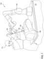
- FIG. 1illustrates a robotic arm system for performing laparoscopic surgery according to an embodiment of the present disclosure.
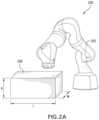
- FIGS. 2 A- 2 Billustrate a robotic arm system for performing laparoscopic surgery according to an embodiment of the present disclosure.
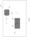
- FIG. 2 Cillustrates a top view of a robotic arm system for performing laparoscopic surgery according to an embodiment of the present disclosure.
- FIG. 3 Aillustrates two orientations of a surgical instrument and tool within an abdomen according to an embodiment of the present disclosure.
- FIG. 3 Billustrates various orientations of a surgical instrument and tool within an abdomen according to an embodiment of the present disclosure.
- FIGS. 4 A- 4 Billustrate a tool orientation according to an embodiment of the present disclosure.
- FIG. 5 Aillustrates a discretized anatomical model according to an embodiment of the present disclosure.
- FIG. 5 Billustrates a discretized anatomical model according to an embodiment of the present disclosure.
- FIGS. 6 A- 6 Billustrate graphical representations of tool orientation error according to an embodiment of the present disclosure.
- FIG. 7illustrates a graphical representation of tool orientation error according to an embodiment of the present disclosure.
- FIG. 8illustrates a diagram of a robotic surgical system according to an embodiment of the present disclosure.
- FIG. 9illustrates a flowchart of a method for computing tool error according to an embodiment of the present disclosure.
- FIG. 10depicts an exemplary computing node according to various embodiments of the present disclosure.
- surgical robotsIn fully automated robotic surgical procedures, surgical robots generally include a surgical instrument attached thereto having a tool that is inserted through a trocar placed in a small, keyhole incision in the abdomen of a patient.
- a keyhole incisionmay refer to a minimally invasive incision that is about 0.25 inch to 1 inch in size.
- the toolmay include any suitable medical tool, such as, for example, a camera, a cutting tool, a gripping tool, a crimping tool, an electrocautery tool, or any other suitable tool as is known in the art.
- the range of motion and/or possible orientations of the toolmay be limited based on the position of the trocar in the patient. If the trocar position is not optimized based on the range of motion and/or possible orientations, the tool may not be capable of reaching certain regions of or objects (e.g., a major artery) within a workspace (e.g., a body cavity) and, thus, may not be able to perform the surgical task (e.g., cutting, gripping, etc.) for which it is intended.
- a workspacee.g., a body cavity
- an anatomical objecte.g., a kidney
- a target object of a surgical proceduremay be out of the working range of the tool, thus complicating the surgical process.
- FIG. 1illustrates a robotic arm system 100 for performing laparoscopic surgery according to an embodiment of the present disclosure.
- the robotic arm system 100includes a robotic arm 102 affixed to a base 101 at a proximal end.
- the robotic arm 102further includes a surgical instrument 104 at the distal end and the surgical instrument 104 includes a tool (not shown), such as, for example, a grasper, electrocautery tool, a cutting tool, etc.
- a trocar 105is inserted into an incision 106 in the abdomen 108 to thereby provide access to a body cavity (e.g., abdominal cavity) in which a surgical procedure will take place.
- a surgeon 110 overseeing the robotic surgerymay insert the surgical instrument 104 (and the tool) through the trocar 105 and into the body cavity.
- FIGS. 2 A- 2 Billustrate a robotic arm system 200 for performing laparoscopic surgery according to an embodiment of the present disclosure.
- the robotic arm system 200includes a robotic arm 202 positioned over an abdomen 208 (modeled as a rectangular box having dimensions of 40 cm ⁇ 40 cm ⁇ 20 cm).
- the dimensions of the abdomen 208may vary based on the particular patient.
- FIG. 2 Bshows an abdomen 208 including a first incision 206 a corresponding to a first case and a second keyhole incision 206 b corresponding to a second case.
- the tool at the end of the surgical instrumentmay have a different orientation error depending on the location of the incision for a given surgical process. The variability of end effector orientation error will be discussed in more detail with respect to FIGS. 6 A, 6 B and 7 .
- FIG. 2 Cillustrates a top view of a robotic arm system 200 for performing laparoscopic surgery according to an embodiment of the present disclosure.
- the second keyhole incision 206 b in the abdomen 208(approximately in the center of the abdomen) is positioned approximately 30 cm from the base in either direction.
- an optimization algorithmmay be applied to each potential incision 206 a , 206 b to determine the maximum error in the tool based on a particular surgical procedure.
- FIG. 3 Aillustrates two orientations of a surgical instrument 304 a , 304 b and tool 307 a , 307 b within an abdomen 308 according to an embodiment of the present disclosure.
- a surgical instrument 304 a and a tool 307 aare placed in a first orientation within the incision 306 in the abdomen 308 .
- the tool 307 amay not be capable of a desired orientation, such as the orientation shown by surgical instrument 304 b with the tool 307 b having a different orientation than the orientation of the tool 307 a .
- cone 350 arepresents all possible orientations of the tool 307 a when surgical instrument 304 a is in that particular location.
- cone 350 brepresents all possible orientations of the tool 307 b when surgical instrument 304 b is in that particular location. As shown in FIG. 3 A , cone 350 b does not collide with object 320 and can access anatomical structure 322 .
- the surgical instrumentmay have a limited workspace within a particular body cavity.
- one or more objects 320e.g., a bone or blood vessel
- an anatomical structure 322e.g., a kidney.
- the tool 307 amay not be capable of performing a surgical maneuver on the anatomical structure 322 in certain portions of the abdomen 308
- the surgical instrument 304 bis capable of performing the surgical maneuver on the anatomical structure 322 .
- the surgical instrument(and tool) may have a limited workspace within a particular body cavity based on placement of the base of the robotic arm. In various embodiments, if the base of the robotic arm is incorrectly positioned (e.g., placed too far away from the patient), the surgical instrument may not be capable of adopting a particular, desired orientation (such as the orientation shown by tool 307 b of surgical instrument 304 b ) to access an anatomical structure 322 (e.g., a kidney).
- a particular, desired orientationsuch as the orientation shown by tool 307 b of surgical instrument 304 b
- FIG. 3 Billustrates various orientations of a surgical instrument 304 a , 304 b , 304 c , 304 d and tool 307 a , 307 b , 307 c , 307 d within an abdomen 308 according to an embodiment of the present disclosure.
- the desired orientation for the toolin a first orientation of the surgical instrument 304 a , is not achievable due to the presence of an object 320 (e.g., a nerve and/or vascular structure) blocking the tool.
- an object 320e.g., a nerve and/or vascular structure
- the desired orientation for the toolis not achievable due to the incision site 306 and/or trocar as only orientations that fall inside the cone 350 are achievable.
- tools 307 b and 307 cmay have the least tool orientation error with respect to the desired tool orientation 307 a .
- 307 bis not achievable due to the incision site 306 and, thus, tool 307 c orientation would be selected.
- the location if the incision (and subsequent trocar placement)imposes a kinematics constraint on a surgical robot.
- one constraintis that the instrument should not move laterally at the incision site (e.g., to avoid damaging the incision).
- the maneuverability at the toolmay be significantly reduced when a procedure is performed laparoscopically (because of this constraint at the incision/trocar).
- proper placement of the incision siteis important to preserve maneuverability of the instrument given a surgical target (e.g., an organ).
- the toolmay encounter issues when attempting to reach a target from a certain angle because, for example, the incision site restricts the motion of the instrument and/or tool.
- FIGS. 4 A- 4 Billustrate a tool 407 orientation according to an embodiment of the present disclosure.
- the tool 407has an orientation based on a distal most point 412 .
- the orientation of the tool 407includes three vectors: an x-component 414 a , a y-component 414 b , and a z-component 414 c that together define the orientation of the tool 407 in 3D space.
- FIG. 4 Billustrates the distal point 412 without the tool 407 illustrated in FIG. 4 A .
- the tool 407includes an actual orientation including the x-component 414 a , the y-component 414 b , and the z-component 414 c .
- the actual orientationis different than the desired orientation, which is represented by a x′-component 416 a , a y′-component 416 b , and a z′-component 416 c that together define the desired orientation of the tool 407 .
- anglesmay be measured between the particular axes and their desired configurations. For example, an angle ⁇ is measured between the x-component 414 a and the x′-component 416 a , an angle ⁇ is measured between the y-component 414 b and the y′-component 416 b , and an angle ⁇ is measured between the z-component 414 c and the z′-component 416 c .
- a surgical targetmay be identified.
- the surgical targetmay be a tissue, organ, structure, and/or any other suitable target of a surgical procedure.
- a surgical task(e.g., suturing a tissue) may be specified.
- the surgical taskmay be specified with respect to a trajectory of the distal-most end of the tool.
- the trajectorymay include one or more lines.
- the trajectorymay include one or more curves.
- the trajectorymay include a spline.
- the trajectorymay be discretized into a finite set of discrete points.
- the discretized trajectorymay include a set of discrete points having a pre-determined distance between each point.
- the pre-determined distance between each pointmay be different. For example, points along a straight line may have a larger distance between each point while points on a curve may have a smaller distance between each point.
- the trajectorymay be discretized using any suitable known discretization algorithm.
- a desired orientation of the toolis determined.
- the desired orientationis compared to one or more possible orientations.
- the one or more possible orientationsmay be the actual orientation of the tool.
- the actual orientationis compared to the desired orientation at each discretized point using equation 1 above to determine error for each discretized point along the trajectory.
- the error for a trajectory performed from a given incision locationmay be visualized as shown in FIGS. 6 A, 6 B, and 7 .
- a tool orientationis selected from the one or more possible orientations having the lowest error when compared to the desired orientation. In various embodiments when one of the possible orientations includes the desired orientation, that orientation is selected. In various embodiments, when the desired orientation is included among the possible orientations, the error may be zero.
- the determined error at each discretized pointmay be summed to determine a total error metric for the entire trajectory given a particular candidate incision location.
- the total error metricmay be computed for each of a plurality of candidate incision locations.
- the trajectory and/or total error metricmay depend on the type of surgical subtasks (e.g., suturing), type of surgery, design of surgery, dimension of the instrument and/or tool (e.g., 4 DOF, 5 DOF, 6 DOF), surgical complexity, and/or circumstances (e.g., surrounding nerves that should be avoided).
- the plurality of candidate incision locationsmay collectively define a mesh.
- the meshmay include discretized points along a surface of an anatomical model as described in more detail below with respect to FIGS. 5 A and 5 B .
- one incision point having the smallest total error metricis selected among the candidate incision points.
- the selected incision pointis presented to the user (e.g., a surgeon).
- two or more incision pointsmay be highlighted when the two or more incision points have the same, smallest total error metric.
- the two or more highlighted incision pointsmay be displayed to a user (e.g., a surgeon).
- the usere.g., surgeon
- the systemmay receive user input selecting one of the two or more highlighted incision sites that will be used for the surgical procedure.
- the process described hereinmay be a two-phase optimization which includes incision placement and robotic base placement.
- a usere.g., a surgeon
- the processmay determine a location for the base of the robot such that the instrument tool tip is capable of reaching the surgical target.
- the process of determining the placement of the robot baseis independent from the incision placement.
- the processmay include intraoperative optimization.
- the incision sitehas already been selected and created on the patient's body.
- a trocarhas been inserted into the incision site.
- the robot basehas been locked into place.
- an algorithmintraoperatively minimizes the error between any actual and desired orientation of the surgical instrument and/or tool.
- FIG. 5 Aillustrates a discretized anatomical model 508 according to an embodiment of the present disclosure.
- the anatomical modelmay include any portion of anatomy (e.g., a complete anatomical model or only a portion of an anatomical model).
- the anatomical model 508is a portion of a full model and includes the human torso.
- the anatomical model 508may be retrieved from a generic 3D anatomical atlas.
- the anatomical model 508may be retrieved from patient pre-surgical imaging.
- the anatomical modelmay include a three-dimensional reconstruction of the patient based on prior imaging (e.g., pre-surgical imaging).
- one or more surfaces of the anatomical model 508may be discretized using any suitable discretization algorithm.
- the top surface of the anatomical model 508may be discretized using a polygonal mesh 509 (e.g., surface mesh).
- the mesh 509may include a plurality of vertices 511 .
- a vertex (or vertices), as used herein,may be any intersection point of two edges in a grid used to discretize a surface into a plurality of discrete segments (i.e., a mesh).
- each vertex 511may represent a potential incision site for a minimally invasive surgical procedure.
- one or more computationsmay be carried out at each vertex.
- the computation(s)may be iterated based on the results of adjacent vertices. In various embodiments, the computation(s) may be iterated until the results converge to a result (e.g., the result does not change by more than a predetermined percent from iteration to iteration).
- an incision (and trocar) placement algorithm to optimize a surgical robot workspacemay be computed at each of the vertices 511 .
- one or more error-minimizing incision site 513may be displayed on the 3D anatomical model 508 . In various embodiments, one or more error-minimizing incision site 513 may be projected onto the patient (e.g., while on the surgical table) via a projector.
- each vertexcomprises a three-dimensional point.
- each vertexmay be located on any suitable surface of the body where ⁇ candidate incision may be placed.
- predetermined areas of the bodymay be excluded from the mesh, for example, where no suitable incision can be made.
- the mesh 509may be projected onto the patient via a projector.
- the projected meshmay be, for example, a Cartesian grid.
- a cameramay record an image of the patient and the projected mesh 509 .
- the systemmay register the image of the patient with 3D anatomy (e.g., an anatomical atlas).
- the systemmay determine the available workspace and/or tool orientation error at each of the vertices 511 of the mesh 509 for the tool to reach a particular location and/or anatomical structure within the 3D anatomy.
- FIG. 5 Billustrates a discretized anatomical model 508 according to an embodiment of the present disclosure.
- an anatomical region of a patient having a complex shapemay be represented by a simpler shape.
- the anatomical model 508is a simple three-dimensional shape, e.g., a rectangular box, a cube, a sphere, an ellipsoid, a cylinder, etc.
- an abdomen of a patientmay be represented as a box having a length (L), a width (W), and a depth (D).
- one or more surfaces of the boxmay be discretized using any suitable discretization algorithm.
- the top surface of the boxmay be discretized using a polygonal (e.g., rectangular, square, triangular, etc.) mesh 509 (e.g., surface mesh).
- the mesh 509may include a plurality of vertices 511 .
- each vertex 511may represent a potential incision site for a minimally invasive surgical procedure.
- one or more computationsmay be carried out at each vertex 511 .
- the computation(s)may be iterated based on the results of adjacent vertices 511 .
- the computation(s)may be iterated until the results converge to a result (e.g., the result does not change by more than a predetermined percent from iteration to iteration).
- an incision (and trocar) placement algorithm to optimize a surgical robot workspacemay be computed at each of the vertices 511 .
- an incisionmay be 3D.
- all points along the incisionmay have the same depth (e.g., z-value) if the box is aligned with the base of the robot.
- a surgical pathmay be determined for each vertex 511 in the mesh 509 .
- an error metricmay be determined for each vertex in the mesh 509 .
- a plote.g., surface plot
- the error metricmay be displayed to a user (e.g., a surgeon) separately from the model 508 .
- a plote.g., surface plot
- the plotmay be color coded with a range of colors such that one color (e.g., blue) represents the lowest or negligible determined error while another color (e.g., red) represents the highest determined error.
- the systemmay provide an indication to the user (e.g., surgeon) of the error-minimizing incision point(s) for a particular surgery.
- the usere.g., surgeon
- more than one incision pointmay be returned as error-minimizing for performing a particular surgery.
- an error-minimizing incision site 513(to access target anatomical structure 522 within the volume of the anatomical model 508 ) may be selected after tool orientation error has been determined at each vertex 511 of the mesh 509 .
- the target anatomical structure 522may be represented by one or more point in three-dimensional space (x, y, z).
- the point in three-dimensional spacemay correspond to any suitable part of the anatomical structure 522 .
- the pointmay correspond to a centroid.
- the one or more pointmay correspond to any discrete point along the surface of the anatomical structure 522 .
- the one or more pointmay correspond to any discrete point within the volume of the anatomical structure 522 .
- the target anatomical structure 522may be modeled (i.e., shape and/or position within the anatomical model 508 ) from a generic 3D anatomical atlas.
- the target anatomical structure 522may be modeled (i.e., shape and/or position within the anatomical model 508 ) as a 3D reconstruction of patient imaging (e.g., pre-surgical imaging).
- the target anatomical structuremay be represented as a simplified shape (e.g., a rectangular box, a cube, a sphere, an ellipsoid, a cylinder, etc.).
- target anatomical structure 508may be a kidney represented as an ellipsoid.
- iterative optimization techniquesare applied to select the error-minimizing incision site.
- FIGS. 6 A- 6 Billustrate graphical representations of tool orientation error according to an embodiment of the present disclosure.
- a desired orientation for the tool distal-most tipis provided and X and Y values for the tool were incremented by a predetermined value.
- the algorithm described abovewas performed to compute tool orientation error.
- the error-minimizing orientationhas the smallest amount of error between the given orientation and desired orientation.
- the computed errorsmay be visualized in graphical form.
- FIG. 6 Arepresents a first incision position using the first keyhole incision as described above and shows that tool orientation error is the highest in the center of the abdomen model.
- FIG. 6 Bshows the error calculation of FIG. 6 A with a refined (i.e., higher resolution) mesh.
- a surgeonmay be provided with a map of tool error.
- the visualized erroris representative of error caused by kinematic constraints of performing a task.
- the surgeonmay be provided with two or more recommended incision sites along with the map of tool error for a particular procedure (i.e., trajectory).
- the recommended incision sitesmay include those with the lowest error.
- the recommended incision sitesmay include the incision site with the absolute lowest error.
- the recommended incision sitesmay include the incision sites having the lowest 5%, 10%, 15%, 20%, 25%, 30%, 35%, 40%, etc. of error.
- the pre-operative algorithmmay minimize the error at the tool tip based on the pre-selected kinematic constraints,
- FIG. 7illustrates a graphical representation of tool orientation error according to an embodiment of the present disclosure.
- FIG. 7represents a second incision position using the second keyhole incision as described above and shows that tool orientation error is the highest in the top-right corner of the abdomen model.
- the error distributionvaries depending on the incision location. While these experiments were performed with a single orientation, certain surgical maneuvers (e.g., suturing) require multiple orientations through any combination of, e.g., rotations and/or translations of the surgical instrument and/or tool. Therefore, the error-minimizing incision placement requires knowledge about the procedure (how many points and in which directions). For a suturing example, if a suitable suturing procedure is known, error-minimizing incision placement may be determined from the known motions for performing the particular suture procedure.
- FIG. 8illustrates a diagram of a robotic surgical system 800 according to an embodiment of the present disclosure.
- the robotic surgical system 800is similar to the systems described above in that the system 800 includes a robotic arm 802 affixed to a base 801 .
- the robotic arm 802includes a surgical instrument 804 disposed at a distal end of the robotic arm 802 .
- the surgical instrument 804is inserted through a trocar 805 placed within an incision 806 and includes a tool at a distal-most end 812 .
- iterative optimization techniquesare applied to select an error-minimizing incision point, an error-minimizing trocar position, and an error-minimizing base position such that tool orientation error is minimized.
- an exhaustive searchis performed of one or more position variable. For example, for a given base position, error may be computed for every point on a predetermined grid of potential incision points. Once the computation has been performed for each potential position for a given variable, the lowest error configuration is selected.
- mathematical optimization methodsare used, thereby avoiding an exhaustive search. For example, gradient descent may be applied to arrive at an error minimizing selection of positional variables. It will be appreciated that a variety of mathematical optimization methods are useful for minimizing error based on placement variables, e.g., differential evolution, local search, gradient descent, or simulated annealing.
- an error-minimizing incision positionmay be selected on the patient to provide the error-minimizing amount of workspace to access one or more target anatomical structures 822 within a body cavity (e.g., abdominal cavity) of an anatomical model 808 .
- a body cavitye.g., abdominal cavity
- a position of a base 801 of the robotic arm 802is determined.
- the position of the base 801is determined based on the selected error-minimizing incision site 806 from the first step.
- the position of the basemay include two or more potential error-minimizing positions that allow for optimal laparoscopic workspace for a particular surgical procedure.
- the surgical trajectory, surgical target (e.g., target anatomy), and instrument typeare given.
- an incision sitemay be selected prior to determining the location of the base.
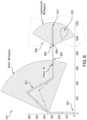
- a pre-determined space outside the patientmay discretized into a grid of points, where each point is candidate location for the base.
- reachability of the robot arm and/or toolmay be determined.
- the reachabilitymay be constrained to a region defined by an arc, as shown in FIG. 8 .
- moving the basechanges the shape and/or volume of the workspace.
- an error metricmay be determined.
- the error metricmay be based on the trajectory of the tool, similar to the error determination described above.
- the trajectory of the toolis discretized and an error is determined for the candidate base location.
- one or more locations of the basemay have the similar (e.g., same) error as computed for the tool by itself where the robot workspace is capable of performing the trajectory (e.g., with minimal error between the actual and desired orientation).
- the tool orientationmay significantly differ from the desired tool orientation because the robot is not capable of assuming an error-minimizing tool orientation given the constraint of the incision site (and trocar).
- one or more of the discretized locationsmay be excluded.
- the excluded location(s)may correspond to location(s) that are unavailable for positioning the robotic base.
- required healthcare equipmente.g., an anesthesia monitor/delivery device
- an anesthesia monitor/delivery devicemay be located near the patient.
- the candidate base location(s) with the least errorare recommended for the robot placement.
- a map of errormay be provided to the user with recommended base location(s) for the surgical robot.
- tool orientation erroris determined as described above.
- tool orientation errormay be minimized to avoid one or more objects within the laparoscopic workspace (e.g., critical nerves and/or blood vessels).
- a toolhas a desired orientation and a cone extending therefrom representing possible orientations.
- one orientation in the conewill minimize the error as defined in equation 1.
- the erroris zero.
- the tool orientation errormay be determined as the difference between an actual trajectory and a desired trajectory of pathing of the distal-most end of the tool.
- FIG. 9illustrates a flowchart of a method 900 for computing end effector error according to an embodiment of the present disclosure.
- a first robotic armis provided where the robotic arm includes a trocar and an end effector.
- a first orientation of the end effectoris determined. The first orientation includes a first x-component, a first y-component, and a first z-component.
- a desired orientation of the end effectoris determined, the desired orientation comprising a second x-component, a second y-component, and a second z-component.
- a first angle between the first x-component and the second x-componentis determined, a second angle between the first y-component and the second y-component is determined, and a third angle between the first z-component and the second z-component is determined.
- an error metric based on the first angle, the second angle, and the third angleis determined.
- determining an error metricmay include summing the squares of each of the first angle, the second angle, and the third angle. In various embodiments, two or more error metrics may be determined, such that each error metric corresponds to a different trocar position. In various embodiments, the determined error metrics for each trocar position may be compared to determine an error-minimizing trocar position for a particular surgical procedure.
- the algorithm inputs for determining end effector orientation errormay include, for example, trocar position, abdominal cavity size and position, and desired end effector tip orientation.
- error in the end effector orientationmay be determined for two or more potential incision sites and the errors may be compared to determine an error-minimizing incision site for a particular surgical procedure.
- FIG. 10a schematic of an exemplary computing node is shown that may be used with the computer vision systems described herein.
- Computing node 10is only one example of a suitable computing node and is not intended to suggest any limitation as to the scope of use or functionality of embodiments described herein. Regardless, computing node 10 is capable of being implemented and/or performing any of the functionality set forth hereinabove.
- computing node 10there is a computer system/server 12 , which is operational with numerous other general purpose or special purpose computing system environments or configurations.
- Examples of well-known computing systems, environments, and/or configurations that may be suitable for use with computer system/server 12include, but are not limited to, personal computer systems, server computer systems, thin clients, thick clients, handheld or laptop devices, multiprocessor systems, microprocessor-based systems, set top boxes, programmable consumer electronics, network PCs, minicomputer systems, mainframe computer systems, and distributed cloud computing environments that include any of the above systems or devices, and the like.
- Computer system/server 12may be described in the general context of computer system-executable instructions, such as program modules, being executed by a computer system.
- program modulesmay include routines, programs, objects, components, logic, data structures, and so on that perform particular tasks or implement particular abstract data types.
- Computer system/server 12may be practiced in distributed cloud computing environments where tasks are performed by remote processing devices that are linked through a communications network.
- program modulesmay be located in both local and remote computer system storage media including memory storage devices.
- Bus 18represents one or more of any of several types of bus structures, including a memory bus or memory controller, a peripheral bus, an accelerated graphics port, and a processor or local bus using any of a variety of bus architectures.
- bus architecturesinclude Industry Standard Architecture (ISA) bus, Micro Channel Architecture (MCA) bus, Enhanced ISA (EISA) bus, Video Electronics Standards Association (VESA) local bus, and Peripheral Component Interconnect (PCI) bus.
- Computer system/server 12typically includes a variety of computer system readable media. Such media may be any available media that is accessible by computer system/server 12 , and it includes both volatile and non-volatile media, removable and non-removable media.
- System memory 28can include computer system readable media in the form of volatile memory, such as random access memory (RAM) 30 and/or cache memory 32 .
- Computer system/server 12may further include other removable/non-removable, volatile/non-volatile computer system storage media.
- storage system 34can be provided for reading from and writing to a non-removable, non-volatile magnetic media (not shown and typically called a “hard drive”).
- a magnetic disk drivefor reading from and writing to a removable, non-volatile magnetic disk (e.g., a “floppy disk”).
- an optical disk drivefor reading from or writing to a removable, non-volatile optical disk such as a CD-ROM, DVD-ROM or other optical media can be provided.
- memory 28may include at least one program product having a set (e.g., at least one) of program modules that are configured to carry out the functions of embodiments of the disclosure.
- Program/utility 40having a set (at least one) of program modules 42 , may be stored in memory 28 by way of example, and not limitation, as well as an operating system, one or more application programs, other program modules, and program data. Each of the operating system, one or more application programs, other program modules, and program data or some combination thereof, may include an implementation of a networking environment.
- Program modules 42generally carry out the functions and/or methodologies of embodiments described herein.
- Computer system/server 12may also communicate with one or more external devices 14 such as a keyboard, a pointing device, a display 24 , etc.; one or more devices that enable a user to interact with computer system/server 12 ; and/or any devices (e.g., network card, modem, etc.) that enable computer system/server 12 to communicate with one or more other computing devices. Such communication can occur via Input/Output (I/O) interfaces 22 . Still yet, computer system/server 12 can communicate with one or more networks such as a local area network (LAN), a general wide area network (WAN), and/or a public network (e.g., the Internet) via network adapter 20 .
- LANlocal area network
- WANwide area network
- public networke.g., the Internet
- network adapter 20communicates with the other components of computer system/server 12 via bus 18 .
- bus 18It should be understood that although not shown, other hardware and/or software components could be used in conjunction with computer system/server 12 . Examples, include, but are not limited to: microcode, device drivers, redundant processing units, external disk drive arrays, RAID systems, tape drives, and data archival storage systems, etc.
- the computer system/servermay be connected to one or more cameras (e.g., digital cameras, light-field cameras) or other imaging/sensing devices (e.g., infrared cameras or sensors).
- camerase.g., digital cameras, light-field cameras
- imaging/sensing devicese.g., infrared cameras or sensors.
- the present disclosureincludes a system, a method, and/or a computer program product.
- the computer program productmay include a computer readable storage medium (or media) having computer readable program instructions thereon for causing a processor to carry out aspects of the present disclosure.
- the computer readable storage mediumcan be a tangible device that can retain and store instructions for use by an instruction execution device.
- the computer readable storage mediummay be, for example, but is not limited to, an electronic storage device, a magnetic storage device, an optical storage device, an electromagnetic storage device, a semiconductor storage device, or any suitable combination of the foregoing.
- a non-exhaustive list of more specific examples of the computer readable storage mediumincludes the following: a portable computer diskette, a hard disk, a random access memory (RAM), a read-only memory (ROM), an erasable programmable read-only memory (EPROM or Flash memory), a static random access memory (SRAM), a portable compact disc read-only memory (CD-ROM), a digital versatile disk (DVD), a memory stick, a floppy disk, a mechanically encoded device such as punch-cards or raised structures in a groove having instructions recorded thereon, and any suitable combination of the foregoing.
- RAMrandom access memory
- ROMread-only memory
- EPROM or Flash memoryerasable programmable read-only memory
- SRAMstatic random access memory
- CD-ROMcompact disc read-only memory
- DVDdigital versatile disk
- memory sticka floppy disk
- a mechanically encoded devicesuch as punch-cards or raised structures in a groove having instructions recorded thereon
- a computer readable storage mediumis not to be construed as being transitory signals per se, such as radio waves or other freely propagating electromagnetic waves, electromagnetic waves propagating through a waveguide or other transmission media (e.g., light pulses passing through a fiber-optic cable), or electrical signals transmitted through a wire.
- Computer readable program instructions described hereincan be downloaded to respective computing/processing devices from a computer readable storage medium or to an external computer or external storage device via a network, for example, the Internet, a local area network, a wide area network and/or a wireless network.
- the networkmay comprise copper transmission cables, optical transmission fibers, wireless transmission, routers, firewalls, switches, gateway computers and/or edge servers.
- a network adapter card or network interface in each computing/processing devicereceives computer readable program instructions from the network and forwards the computer readable program instructions for storage in a computer readable storage medium within the respective computing/processing device.
- Computer readable program instructions for carrying out operations of the present disclosuremay be assembler instructions, instruction-set-architecture (ISA) instructions, machine instructions, machine dependent instructions, microcode, firmware instructions, state-setting data, or either source code or object code written in any combination of one or more programming languages, including an object oriented programming language such as Smalltalk, C++ or the like, and conventional procedural programming languages, such as the “C” programming language or similar programming languages.
- the computer readable program instructionsmay execute entirely on the user's computer, partly on the user's computer, as a stand-alone software package, partly on the user's computer and partly on a remote computer or entirely on the remote computer or server.
- each block in the flowchart or block diagramsmay represent a module, segment, or portion of instructions, which comprises one or more executable instructions for implementing the specified logical function(s).
- the functions noted in the blockmay occur out of the order noted in the figures. For example, two blocks shown in succession may, in fact, be executed substantially concurrently, or the blocks may sometimes be executed in the reverse order, depending upon the functionality involved.
Landscapes
- Health & Medical Sciences (AREA)
- Surgery (AREA)
- Engineering & Computer Science (AREA)
- Life Sciences & Earth Sciences (AREA)
- Biomedical Technology (AREA)
- Robotics (AREA)
- Nuclear Medicine, Radiotherapy & Molecular Imaging (AREA)
- Heart & Thoracic Surgery (AREA)
- Medical Informatics (AREA)
- Molecular Biology (AREA)
- Animal Behavior & Ethology (AREA)
- General Health & Medical Sciences (AREA)
- Public Health (AREA)
- Veterinary Medicine (AREA)
- Manipulator (AREA)
Abstract
Description
α2+β2+γ2=error (Eqn. 1)
Claims (21)
Priority Applications (1)
| Application Number | Priority Date | Filing Date | Title |
|---|---|---|---|
| US17/349,900US12262952B2 (en) | 2018-12-28 | 2021-06-16 | Systems and methods to optimize reachability, workspace, and dexterity in minimally invasive surgery |
Applications Claiming Priority (3)
| Application Number | Priority Date | Filing Date | Title |
|---|---|---|---|
| US201862785957P | 2018-12-28 | 2018-12-28 | |
| PCT/US2019/068778WO2020140056A1 (en) | 2018-12-28 | 2019-12-27 | Systems and methods to optimize reachability, workspace, and dexterity in minimally invasive surgery |
| US17/349,900US12262952B2 (en) | 2018-12-28 | 2021-06-16 | Systems and methods to optimize reachability, workspace, and dexterity in minimally invasive surgery |
Related Parent Applications (1)
| Application Number | Title | Priority Date | Filing Date |
|---|---|---|---|
| PCT/US2019/068778ContinuationWO2020140056A1 (en) | 2018-12-28 | 2019-12-27 | Systems and methods to optimize reachability, workspace, and dexterity in minimally invasive surgery |
Publications (2)
| Publication Number | Publication Date |
|---|---|
| US20220000557A1 US20220000557A1 (en) | 2022-01-06 |
| US12262952B2true US12262952B2 (en) | 2025-04-01 |
Family
ID=71127313
Family Applications (1)
| Application Number | Title | Priority Date | Filing Date |
|---|---|---|---|
| US17/349,900Active2042-05-20US12262952B2 (en) | 2018-12-28 | 2021-06-16 | Systems and methods to optimize reachability, workspace, and dexterity in minimally invasive surgery |
Country Status (7)
| Country | Link |
|---|---|
| US (1) | US12262952B2 (en) |
| EP (1) | EP3903165A4 (en) |
| JP (1) | JP2022516473A (en) |
| KR (1) | KR20210136975A (en) |
| CN (1) | CN113993474A (en) |
| CA (1) | CA3125185A1 (en) |
| WO (1) | WO2020140056A1 (en) |
Families Citing this family (7)
| Publication number | Priority date | Publication date | Assignee | Title |
|---|---|---|---|---|
| US9204939B2 (en)* | 2011-08-21 | 2015-12-08 | M.S.T. Medical Surgery Technologies Ltd. | Device and method for assisting laparoscopic surgery—rule based approach |
| WO2020140042A1 (en) | 2018-12-28 | 2020-07-02 | Activ Surgical, Inc. | User interface elements for orientation of remote camera during surgery |
| WO2020140056A1 (en) | 2018-12-28 | 2020-07-02 | Activ Surgical, Inc. | Systems and methods to optimize reachability, workspace, and dexterity in minimally invasive surgery |
| WO2020214821A1 (en) | 2019-04-19 | 2020-10-22 | Activ Surgical, Inc. | Systems and methods for trocar kinematics |
| EP4418414A4 (en) | 2021-10-14 | 2025-02-12 | LG Energy Solution, Ltd. | Pouch-type secondary battery, secondary battery module including same, and pouch used therefor |
| US12357395B2 (en)* | 2022-12-06 | 2025-07-15 | Verb Surgical Inc. | Method and system for estimating positional data in images |
| CN117770978B (en)* | 2023-11-17 | 2024-08-02 | 北京仁馨医疗科技有限公司 | Surgical incision position point determination method, system, medium and electronic equipment |
Citations (311)
| Publication number | Priority date | Publication date | Assignee | Title |
|---|---|---|---|---|
| US4772831A (en) | 1986-11-20 | 1988-09-20 | Unimation, Inc. | Multiaxis robot control having improved continuous path operation |
| US5808665A (en) | 1992-01-21 | 1998-09-15 | Sri International | Endoscopic surgical instrument and method for use |
| US5876325A (en) | 1993-11-02 | 1999-03-02 | Olympus Optical Co., Ltd. | Surgical manipulation system |
| US6001108A (en) | 1996-02-20 | 1999-12-14 | Computer Motion, Inc. | Method and apparatus for performing minimally invasive cardiac procedures |
| US6088105A (en) | 1998-04-04 | 2000-07-11 | Joh. & Ernst Link Gmbh & Co. Kg | Measuring unit for determining dimensions of test pieces, preferably of hollow bodies, in particular, of bores of workpieces, and method for measuring such dimensions |
| US6183485B1 (en) | 1993-08-25 | 2001-02-06 | Inlet Medical, Inc. | Insertable suture passing grasping probe and methodology for using same |
| US6206894B1 (en) | 1997-10-09 | 2001-03-27 | Ethicon Endo-Surgery, Inc. | Electrically powered needle holder to assist in suturing |
| US6309397B1 (en) | 1999-12-02 | 2001-10-30 | Sri International | Accessories for minimally invasive robotic surgery and methods |
| US6325808B1 (en) | 1998-12-08 | 2001-12-04 | Advanced Realtime Control Systems, Inc. | Robotic system, docking station, and surgical tool for collaborative control in minimally invasive surgery |
| US6373963B1 (en) | 1998-02-05 | 2002-04-16 | Textile/Clothing Technology Corporation | Systems, methods and computer program for measuring the surface contour of an object |
| US20020082612A1 (en)* | 1998-11-20 | 2002-06-27 | Intuitive Surgical, Inc. | Arm cart for telerobotic surgical system |
| US6491702B2 (en) | 1992-04-21 | 2002-12-10 | Sofamor Danek Holdings, Inc. | Apparatus and method for photogrammetric surgical localization |
| US6503195B1 (en) | 1999-05-24 | 2003-01-07 | University Of North Carolina At Chapel Hill | Methods and systems for real-time structured light depth extraction and endoscope using real-time structured light depth extraction |
| US6542249B1 (en) | 1999-07-20 | 2003-04-01 | The University Of Western Ontario | Three-dimensional measurement method and apparatus |
| US6549288B1 (en) | 1998-05-14 | 2003-04-15 | Viewpoint Corp. | Structured-light, triangulation-based three-dimensional digitizer |
| US6564086B2 (en) | 2000-05-03 | 2003-05-13 | Rocky Mountain Biosystems, Inc. | Prosthesis and method of making |
| US6563105B2 (en) | 1999-06-08 | 2003-05-13 | University Of Washington | Image acquisition with depth enhancement |
| US6613041B1 (en) | 1998-08-20 | 2003-09-02 | Bioshape Ag | Device for determining the surface shape of biological tissue |
| US6643563B2 (en) | 2001-07-13 | 2003-11-04 | Brooks Automation, Inc. | Trajectory planning and motion control strategies for a planar three-degree-of-freedom robotic arm |
| US6645196B1 (en) | 2000-06-16 | 2003-11-11 | Intuitive Surgical, Inc. | Guided tool change |
| US6697164B1 (en) | 1998-08-05 | 2004-02-24 | Cadent Ltd. | Imaging a three-dimensional structure by confocal focussing an array of light beams |
| US20040073257A1 (en) | 2002-10-09 | 2004-04-15 | Spitz Gregory A. | Methods and apparatus for the repair of hernias |
| US20040176751A1 (en) | 2002-08-14 | 2004-09-09 | Endovia Medical, Inc. | Robotic medical instrument system |
| US6800057B2 (en) | 2001-05-29 | 2004-10-05 | Fuji Photo Film Co., Ltd. | Image obtaining apparatus |
| US6850872B1 (en) | 2000-08-30 | 2005-02-01 | Microsoft Corporation | Facial image processing methods and systems |
| US6873867B2 (en) | 2000-04-05 | 2005-03-29 | Brainlab Ag | Referencing or registering a patient or a patient body part in a medical navigation system by means of irradiation of light points |
| US6885464B1 (en) | 1998-06-30 | 2005-04-26 | Sirona Dental Systems Gmbh | 3-D camera for recording surface structures, in particular for dental purposes |
| US20050090840A1 (en) | 2001-12-04 | 2005-04-28 | The Children's Medical Center Corporation | Tissue repair |
| US20050096515A1 (en) | 2003-10-23 | 2005-05-05 | Geng Z. J. | Three-dimensional surface image guided adaptive therapy system |
| USRE38800E1 (en) | 1997-10-16 | 2005-09-20 | The Research Foundation Of State University Of New York | NIR clinical opti-scan system |
| US6965690B2 (en) | 2000-11-22 | 2005-11-15 | Sanyo Electric Co., Ltd. | Three-dimensional modeling apparatus, method, and medium, and three-dimensional shape data recording apparatus, method, and medium |
| US6977732B2 (en) | 2002-12-26 | 2005-12-20 | National Taiwan University | Miniature three-dimensional contour scanner |
| US6987531B2 (en) | 2001-09-04 | 2006-01-17 | Minolta Co., Ltd. | Imaging system, photographing device and three-dimensional measurement auxiliary unit used for the system |
| US20060020272A1 (en) | 2004-06-24 | 2006-01-26 | Gildenberg Philip L | Semi-robotic suturing device |
| US7006236B2 (en) | 2002-05-22 | 2006-02-28 | Canesta, Inc. | Method and apparatus for approximating depth of an object's placement onto a monitored region with applications to virtual interface devices |
| US7068825B2 (en) | 1999-03-08 | 2006-06-27 | Orametrix, Inc. | Scanning system and calibration method for capturing precise three-dimensional information of objects |
| US7099732B2 (en) | 1999-03-29 | 2006-08-29 | Genex Technologies, Inc. | Sanitary sleeve or tip for intra-oral three-dimensional camera |
| US20060258938A1 (en) | 2005-05-16 | 2006-11-16 | Intuitive Surgical Inc. | Methods and system for performing 3-D tool tracking by fusion of sensor and/or camera derived data during minimally invasive robotic surgery |
| US7184150B2 (en) | 2003-03-24 | 2007-02-27 | D4D Technologies, Llc | Laser digitizer system for dental applications |
| US7200262B2 (en) | 2002-01-07 | 2007-04-03 | Canon Kabushiki Kaisha | 3-dimensional image processing method, 3-dimensional image processing device, and 3-dimensional image processing system |
| US20070115484A1 (en) | 2005-10-24 | 2007-05-24 | Peisen Huang | 3d shape measurement system and method including fast three-step phase shifting, error compensation and calibration |
| US7224384B1 (en) | 1999-09-08 | 2007-05-29 | 3Dv Systems Ltd. | 3D imaging system |
| US20070146719A1 (en) | 2005-12-16 | 2007-06-28 | Matthias Wedel | Scanning apparatus for optically scanning surfaces |
| US7242997B2 (en) | 2002-09-03 | 2007-07-10 | Genex Technologies, Inc. | Diffuse optical tomography system and method of use |
| US20070165243A1 (en) | 2004-02-09 | 2007-07-19 | Cheol-Gwon Kang | Device for measuring 3d shape using irregular pattern and method for the same |
| US20070213749A1 (en) | 2006-03-08 | 2007-09-13 | Olympus Medical Systems Corp. | Medical procedure performed inside abdominal cavity |
| US20070249911A1 (en) | 2006-04-21 | 2007-10-25 | Simon David A | Method and apparatus for optimizing a therapy |
| US20070280423A1 (en) | 2006-05-31 | 2007-12-06 | Robert Schmidt | Registration by means of radiation marking elements |
| US20070293734A1 (en) | 2001-06-07 | 2007-12-20 | Intuitive Surgical, Inc. | Methods and apparatus for surgical planning |
| US7313264B2 (en) | 1995-07-26 | 2007-12-25 | 3D Scanners Limited | Scanning apparatus and method |
| US7319529B2 (en) | 2004-06-17 | 2008-01-15 | Cadent Ltd | Method and apparatus for colour imaging a three-dimensional structure |
| US20080013809A1 (en) | 2006-07-14 | 2008-01-17 | Bracco Imaging, Spa | Methods and apparatuses for registration in image guided surgery |
| US20080107305A1 (en) | 2006-11-02 | 2008-05-08 | Northern Digital Inc. | Integrated mapping system |
| US7385708B2 (en) | 2002-06-07 | 2008-06-10 | The University Of North Carolina At Chapel Hill | Methods and systems for laser based real-time structured light depth extraction |
| US7435217B2 (en) | 2006-04-17 | 2008-10-14 | Microvision, Inc. | Scanned beam imagers and endoscopes with positionable light collector |
| US20080266391A1 (en) | 2005-10-19 | 2008-10-30 | Lee Sang-Yoon | Apparatus for and Method of Measuring Image |
| US7450783B2 (en) | 2003-09-12 | 2008-11-11 | Biopticon Corporation | Methods and systems for measuring the size and volume of features on live tissues |
| US7489408B2 (en) | 2005-11-15 | 2009-02-10 | General Electric Company | Optical edge break gage |
| US7491956B2 (en) | 2006-02-01 | 2009-02-17 | Siemens Aktiengesellschaft | Optical scanning device having a distance sensor and a determined focal distance for scanning objects |
| US7522764B2 (en) | 2003-01-31 | 2009-04-21 | Sirona Dental Systems Gmbh | Method and system for imaging an object |
| US7577299B2 (en) | 2003-03-05 | 2009-08-18 | Toyota Jidosha Kabushiki Kaisha | Image pickup apparatus and image pickup method |
| US20090221874A1 (en) | 2005-11-28 | 2009-09-03 | 3Shape A/S | Coded structure light |
| US20090244260A1 (en) | 2008-03-31 | 2009-10-01 | Hoya Corporation | Endoscope measuring 3-d profile |
| US7620209B2 (en) | 2004-10-14 | 2009-11-17 | Stevick Glen R | Method and apparatus for dynamic space-time imaging system |
| US20090326324A1 (en) | 2006-07-28 | 2009-12-31 | Universidad De Malaga | Robotic system for assisting in minimally-invasive surgery, which can position a surgical instrument in response to orders from a surgeon, is not attached to the operating table and does not require pre-calibration of the insertion point |
| US20100081875A1 (en) | 2003-07-15 | 2010-04-01 | EndoRobotics Inc. | Surgical Device For Minimal Access Surgery |
| US7704206B2 (en) | 2002-06-05 | 2010-04-27 | Olympus Corporation | Endoscope that provides selection of each illumination mode of four different illumination modes |
| US20100113921A1 (en) | 2008-06-02 | 2010-05-06 | Uti Limited Partnership | Systems and Methods for Object Surface Estimation |
| US7724932B2 (en) | 2004-01-27 | 2010-05-25 | Densys Ltd | Three-dimensional modeling of the oral cavity |
| US7751871B2 (en) | 1996-09-02 | 2010-07-06 | Orametrix, Inc. | Method and device for carrying out optical pick up |
| US7763841B1 (en) | 2009-05-27 | 2010-07-27 | Microsoft Corporation | Optical component for a depth sensor |
| WO2010096453A1 (en) | 2009-02-17 | 2010-08-26 | Board Of Regents, The University Of Texas System | Methods of producing laser speckle contrast images |
| WO2010096447A2 (en) | 2009-02-17 | 2010-08-26 | Board Of Regents, The University Of Texas System | Quantitative imaging with multi-exposure speckle imaging (mesi) |
| US7794388B2 (en) | 2004-02-11 | 2010-09-14 | Karl Storz Gmbh & Co. Kg | Method and apparatus for generating at least one section of a virtual 3D model of a body interior |
| US7821649B2 (en) | 2008-03-05 | 2010-10-26 | Ge Inspection Technologies, Lp | Fringe projection system and method for a probe suitable for phase-shift analysis |
| US7854700B2 (en) | 2004-08-04 | 2010-12-21 | Olympus Corporation | Capsule-type endoscope |
| US20110015518A1 (en) | 2002-06-13 | 2011-01-20 | Martin Schmidt | Method and instrument for surgical navigation |
| US20110043609A1 (en) | 2009-08-18 | 2011-02-24 | Seung Wook Choi | Apparatus and method for processing a 3d image |
| US7898651B2 (en) | 2005-10-24 | 2011-03-01 | General Electric Company | Methods and apparatus for inspecting an object |
| US20110057930A1 (en) | 2006-07-26 | 2011-03-10 | Inneroptic Technology Inc. | System and method of using high-speed, high-resolution depth extraction to provide three-dimensional imagery for endoscopy |
| US20110080471A1 (en) | 2009-10-06 | 2011-04-07 | Iowa State University Research Foundation, Inc. | Hybrid method for 3D shape measurement |
| US20110123098A1 (en) | 2009-11-24 | 2011-05-26 | Maurice Moshe Ernst | System and a Method for Three-dimensional Modeling of a Three-dimensional Scene Features with a Cooling System |
| US7951073B2 (en) | 2004-01-21 | 2011-05-31 | Boston Scientific Limited | Endoscopic device having spray mechanism and related methods of use |
| US7961912B2 (en) | 2004-10-14 | 2011-06-14 | Stevick Glen R | Method and apparatus for dynamic space-time imaging system |
| US7967743B2 (en) | 2006-02-23 | 2011-06-28 | Olympus Corporation | Endoscope observation device, observation device and observation method using endoscope |
| US7995798B2 (en) | 2007-10-15 | 2011-08-09 | Given Imaging Ltd. | Device, system and method for estimating the size of an object in a body lumen |
| US20110202068A1 (en) | 2010-02-12 | 2011-08-18 | Intuitive Surgical Operations, Inc. | Medical robotic system providing sensory feedback indicating a difference between a commanded state and a preferred pose of an articulated instrument |
| US8027710B1 (en) | 2005-01-28 | 2011-09-27 | Patrick Dannan | Imaging system for endoscopic surgery |
| US8038609B2 (en) | 2006-03-31 | 2011-10-18 | Fujinon Corporation | Electronic endoscope apparatus and program |
| US8052636B2 (en) | 2004-03-05 | 2011-11-08 | Hansen Medical, Inc. | Robotic catheter system and methods |
| US8084753B2 (en) | 2006-03-20 | 2011-12-27 | Baylor College Of Medicine | Method and system for non-contact fluorescence optical tomography with patterned illumination |
| US20120075432A1 (en) | 2010-09-27 | 2012-03-29 | Apple Inc. | Image capture using three-dimensional reconstruction |
| US20120130405A1 (en) | 1999-07-26 | 2012-05-24 | William Cohn | Suture system |
| US20120165681A1 (en) | 2010-12-23 | 2012-06-28 | Tyco Healthcare Group Lp | Delineating Skin or Surface Lesions |
| WO2012096878A2 (en) | 2011-01-10 | 2012-07-19 | East Carolina University | Methods, systems and computer program products for non-invasive determination of blood flow distribution using speckle imaging techniques and hemodynamic modeling |
| US8231610B2 (en)* | 2006-09-06 | 2012-07-31 | National Cancer Center | Robotic surgical system for laparoscopic surgery |
| US20120206587A1 (en) | 2009-12-04 | 2012-08-16 | Orscan Technologies Ltd | System and method for scanning a human body |
| US8257303B2 (en) | 2005-07-01 | 2012-09-04 | Hansen Medical, Inc. | Robotic catheter system and methods |
| US8264536B2 (en) | 2009-08-25 | 2012-09-11 | Microsoft Corporation | Depth-sensitive imaging via polarization-state mapping |
| US8279418B2 (en) | 2010-03-17 | 2012-10-02 | Microsoft Corporation | Raster scanning for depth detection |
| US8280152B2 (en) | 2007-11-15 | 2012-10-02 | Sirona Dental Systems Gmbh | Method for optical measurement of the three dimensional geometry of objects |
| US8320621B2 (en) | 2009-12-21 | 2012-11-27 | Microsoft Corporation | Depth projector system with integrated VCSEL array |
| US8326020B2 (en) | 2007-02-28 | 2012-12-04 | Sungkyunkwan University Foundation | Structural light based depth imaging method and system using signal separation coding, and error correction thereof |
| US20120310098A1 (en) | 2010-02-12 | 2012-12-06 | Koninklijke Philips Electronics N.V. | Laser enhanced reconstruction of 3d surface |
| US8330804B2 (en) | 2010-05-12 | 2012-12-11 | Microsoft Corporation | Scanned-beam depth mapping to 2D image |
| US20130023732A1 (en) | 2011-07-20 | 2013-01-24 | Samsung Electronics Co., Ltd. | Endoscope and endoscope system |
| US8395342B2 (en) | 2008-03-31 | 2013-03-12 | Intuitive Surgical Operations, Inc. | Medical robotic system adapted to inhibit motions resulting in excessive end effector forces |
| US8400494B2 (en) | 2005-10-11 | 2013-03-19 | Primesense Ltd. | Method and system for object reconstruction |
| US8406859B2 (en) | 2008-08-10 | 2013-03-26 | Board Of Regents, The University Of Texas System | Digital light processing hyperspectral imaging apparatus |
| US20130079928A1 (en) | 2011-09-28 | 2013-03-28 | Universal Robots A/S | Calibration and Programming of Robots |
| US20130085595A1 (en) | 2003-11-10 | 2013-04-04 | Christopher C. Kiley | Wafer center finding with kalman filter |
| US20130096576A1 (en) | 2005-01-24 | 2013-04-18 | Intuitive Surgical Operations, Inc. | Modular manipulator support for robotic surgery |
| US8471897B2 (en) | 2008-01-15 | 2013-06-25 | Universidad De La Laguna | Method and camera for the real-time acquisition of visual information from three-dimensional scenes |
| US20130253313A1 (en) | 2010-08-02 | 2013-09-26 | The Johns Hopkins University | Autofocusing endoscope and system |
| US8553939B2 (en) | 2009-01-30 | 2013-10-08 | Microsoft Corporation | Pose tracking pipeline |
| US8558873B2 (en) | 2010-06-16 | 2013-10-15 | Microsoft Corporation | Use of wavefront coding to create a depth image |
| US20130274596A1 (en) | 2012-04-16 | 2013-10-17 | Children's National Medical Center | Dual-mode stereo imaging system for tracking and control in surgical and interventional procedures |
| US20130296712A1 (en) | 2012-05-03 | 2013-11-07 | Covidien Lp | Integrated non-contact dimensional metrology tool |
| US20130304084A1 (en) | 2010-10-11 | 2013-11-14 | Ecole Polytechnique Federale De Lausanne (Epfl) | Mechanical manipulator for surgical instruments |
| US8593507B2 (en) | 2008-08-03 | 2013-11-26 | Microsoft International Holdings B.V. | Rolling camera system |
| EP2672715A2 (en) | 2012-06-07 | 2013-12-11 | Liberty Reach Inc. | 3-D imaging and processing system including at least one 3-D or depth sensor which is continually calibrated during use |
| US20130331644A1 (en) | 2010-12-10 | 2013-12-12 | Abhilash Pandya | Intelligent autonomous camera control for robotics with medical, military, and space applications |
| US20140031665A1 (en) | 2012-07-25 | 2014-01-30 | Covidien Lp | Telecentric Scale Projection System for Real-Time In-Situ Surgical Metrology |
| US8649024B2 (en) | 2010-12-03 | 2014-02-11 | Zygo Corporation | Non-contact surface characterization using modulated illumination |
| US20140052005A1 (en) | 2011-04-27 | 2014-02-20 | Olympus Corporation | Endoscope apparatus and measuring method |
| US8659765B2 (en) | 2012-03-30 | 2014-02-25 | Canon Kabushiki Kaisha | Three-dimensional shape determining apparatus and three-dimensional shape determining method |
| US20140092281A1 (en) | 2012-09-28 | 2014-04-03 | Pelican Imaging Corporation | Generating Images from Light Fields Utilizing Virtual Viewpoints |
| US8723923B2 (en) | 2010-01-14 | 2014-05-13 | Alces Technology | Structured light system |
| US8723118B2 (en) | 2009-10-01 | 2014-05-13 | Microsoft Corporation | Imager for constructing color and depth images |
| US20140148819A1 (en) | 2011-08-04 | 2014-05-29 | Olympus Corporation | Surgical instrument and control method thereof |
| US20140148816A1 (en) | 2012-11-26 | 2014-05-29 | Michael W. McDONALD | Surgery port placement system and related methods |
| US8755053B2 (en) | 2005-10-14 | 2014-06-17 | Applied Research Associates Nz Limited | Method of monitoring a surface feature and apparatus therefor |
| US20140194747A1 (en) | 2012-05-01 | 2014-07-10 | Empire Technology Development Llc | Infrared scanner and projector to indicate cancerous cells |
| US8792098B2 (en) | 2011-06-01 | 2014-07-29 | Digital Light Innovations | System and method for hyperspectral illumination |
| US8803952B2 (en) | 2010-12-20 | 2014-08-12 | Microsoft Corporation | Plural detector time-of-flight depth mapping |
| US20140243850A1 (en) | 2013-02-28 | 2014-08-28 | Intuitive Surgical Operations, Inc. | Surgical instrument with curved jaws for surgical system |
| US20140257329A1 (en) | 2013-03-08 | 2014-09-11 | Samsung Electronics Co., Ltd. | Control methods of single-port surgical robot |
| US20140277741A1 (en) | 2013-03-15 | 2014-09-18 | Samsung Electronics Co., Ltd. | Robots and methods of controlling the same |
| US20140276950A1 (en)* | 1999-09-17 | 2014-09-18 | Intuitive Surgical Operations, Inc. | Inter-Operative Switching of Tools in a Robotic Surgical System |
| WO2014152753A1 (en) | 2013-03-15 | 2014-09-25 | East Carolina University | Methods, systems and computer program products for non-invasive determination of blood flow distribution using speckle imaging techniques and hemodynamic modeling |
| US20140330288A1 (en)* | 2010-03-25 | 2014-11-06 | Precision Automation And Robotics India Ltd. | Articulating Arm for a Robotic Surgical Instrument System |
| US8891087B2 (en) | 2011-06-01 | 2014-11-18 | Digital Light Innovations | System and method for hyperspectral imaging |
| US8896594B2 (en) | 2012-06-30 | 2014-11-25 | Microsoft Corporation | Depth sensing with depth-adaptive illumination |
| US20150012016A1 (en) | 2013-07-03 | 2015-01-08 | Biomet Manufacturing, Llc | Suture passer |
| US8974378B2 (en) | 2012-08-07 | 2015-03-10 | Olympus Medical Systems Corp. | Scanning endoscope apparatus |
| US9001190B2 (en) | 2011-07-05 | 2015-04-07 | Microsoft Technology Licensing, Llc | Computer vision system and method using a depth sensor |
| WO2015070010A1 (en) | 2013-11-08 | 2015-05-14 | Board Of Trustees Of Michigan State University | Calibration system and method for calibrating industrial robot |
| US9057784B2 (en) | 2012-08-14 | 2015-06-16 | Microsoft Technology Licensing, Llc | Illumination light shaping for a depth camera |
| US9070194B2 (en) | 2012-10-25 | 2015-06-30 | Microsoft Technology Licensing, Llc | Planar surface detection |
| US9068824B2 (en) | 2009-08-27 | 2015-06-30 | Naviswiss Ag | Stereoscopic endoscope for measuring a three dimensional surface |
| US9074868B2 (en) | 2013-05-13 | 2015-07-07 | General Electric Company | Automated borescope measurement tip accuracy test |
| US9072445B2 (en) | 2008-01-24 | 2015-07-07 | Lifeguard Surgical Systems Inc. | Common bile duct surgical imaging system |
| US20150238276A1 (en) | 2012-09-30 | 2015-08-27 | M.S.T. Medical Surgery Technologies Ltd. | Device and method for assisting laparoscopic surgery - directing and maneuvering articulating tool |
| US9119552B2 (en) | 2011-11-29 | 2015-09-01 | Karl Storz Gmbh & Co. Kg | Apparatus and method for endoscopic 3D data collection |
| US9135502B2 (en) | 2009-05-11 | 2015-09-15 | Universitat Zu Lubeck | Method for the real-time-capable, computer-assisted analysis of an image sequence containing a variable pose |
| US9142025B2 (en) | 2011-10-05 | 2015-09-22 | Electronics And Telecommunications Research Institute | Method and apparatus for obtaining depth information using optical pattern |
| US20150266183A1 (en) | 2012-10-19 | 2015-09-24 | Inos Automationssoftware Gmbh | Method for In-Line Calibration of an Industrial Robot, Calibration System for Performing Such a Method and Industrial Robot Comprising Such a Calibration System |
| US9149281B2 (en) | 2002-03-20 | 2015-10-06 | P Tech, Llc | Robotic system for engaging a fastener with body tissue |
| US9149348B2 (en) | 2010-10-29 | 2015-10-06 | Shenzhen University | Intra-oral scanner for digital impression and real-time reconstruction system for inner surface topographic image of oral cavity |
| US9157733B2 (en) | 2010-09-10 | 2015-10-13 | Dimensional Photonics International, Inc. | Method of data acquisition for three-dimensional imaging |
| US9157728B2 (en) | 2009-07-24 | 2015-10-13 | Olympus Corporation | Endoscope apparatus and method |
| US9186053B2 (en) | 2012-05-03 | 2015-11-17 | Covidien Lp | Methods of using light to repair hernia defects |
| US9204952B2 (en) | 2012-10-30 | 2015-12-08 | Smart Optics Sensortechnik Gmbh | Method for optical 3D measurement of teeth with reduced point spread function |
| US9220570B2 (en) | 2012-06-29 | 2015-12-29 | Children's National Medical Center | Automated surgical and interventional procedures |
| US20150377613A1 (en) | 2014-06-30 | 2015-12-31 | Samsung Electronics Co., Ltd. | Systems and methods for reconstructing 3d surfaces of tubular lumens |
| US9226811B2 (en) | 2011-02-16 | 2016-01-05 | Covidien Lp | Hernia repair system |
| US9226645B2 (en) | 2004-12-08 | 2016-01-05 | The General Hospital Corporation | System and method for normalized diffuse emission epi-illumination imaging and normalized diffuse emission transillumination imaging |
| US9247865B2 (en) | 2006-05-31 | 2016-02-02 | National University Corporation Chiba University | Three-dimensional-image forming device, three dimensional-image forming method and program |
| US9254078B2 (en) | 2011-08-12 | 2016-02-09 | Intuitive Surgical Operations, Inc. | Image capture unit in a surgical instrument |
| US9254103B2 (en) | 2011-08-15 | 2016-02-09 | The Trustees Of Dartmouth College | Operative microscope having diffuse optical imaging system with tomographic image reconstruction and superposition in field of view |
| US9254076B2 (en) | 2011-08-12 | 2016-02-09 | Intuitive Surgical Operations, Inc. | Feature differentiation image capture unit and method in a surgical instrument |
| US9261356B2 (en) | 2014-07-03 | 2016-02-16 | Align Technology, Inc. | Confocal surface topography measurement with fixed focal positions |
| US9261358B2 (en) | 2014-07-03 | 2016-02-16 | Align Technology, Inc. | Chromatic confocal system |
| US9274047B2 (en) | 2013-05-24 | 2016-03-01 | Massachusetts Institute Of Technology | Methods and apparatus for imaging of occluded objects |
| US9282926B2 (en) | 2008-12-18 | 2016-03-15 | Sirona Dental Systems Gmbh | Camera for recording surface structures, such as for dental purposes |
| US9294758B2 (en) | 2013-04-18 | 2016-03-22 | Microsoft Technology Licensing, Llc | Determining depth data for a captured image |
| US9297889B2 (en) | 2012-08-14 | 2016-03-29 | Microsoft Technology Licensing, Llc | Illumination light projection for a depth camera |
| US9304603B2 (en) | 2012-11-12 | 2016-04-05 | Microsoft Technology Licensing, Llc | Remote control using depth camera |
| WO2016061052A1 (en) | 2014-10-14 | 2016-04-21 | East Carolina University | Methods, systems and computer program products for visualizing anatomical structures and blood flow and perfusion physiology using imaging techniques |
| US9330464B1 (en) | 2014-12-12 | 2016-05-03 | Microsoft Technology Licensing, Llc | Depth camera feedback |
| US20160128553A1 (en) | 2014-11-07 | 2016-05-12 | Zheng Jason Geng | Intra- Abdominal Lightfield 3D Endoscope and Method of Making the Same |
| US20160139039A1 (en) | 2013-05-30 | 2016-05-19 | National Institute Of Advanced Industrial Science And Technology | Imaging system and imaging method |
| US9345397B2 (en) | 2010-09-21 | 2016-05-24 | The Johns Hopkins University | Optical sensing system for cochlear implant surgery |
| US9345392B2 (en) | 2012-03-14 | 2016-05-24 | Fujifilm Corporation | Endoscope system and method for imaging exposure control |
| US9345389B2 (en) | 2010-11-12 | 2016-05-24 | Emory University | Additional systems and methods for providing real-time anatomical guidance in a diagnostic or therapeutic procedure |
| US9351643B2 (en) | 2013-03-12 | 2016-05-31 | Covidien Lp | Systems and methods for optical measurement for in-situ surgical applications |
| US20160157942A1 (en) | 2013-07-26 | 2016-06-09 | gomtec GmbH | Surgical robot system |
| US9364300B2 (en) | 2013-02-04 | 2016-06-14 | D4D Technologies, Llc | Intra-oral scanning device with illumination frames interspersed with image frames |
| US9380224B2 (en) | 2014-02-28 | 2016-06-28 | Microsoft Technology Licensing, Llc | Depth sensing using an infrared camera |
| US9375844B2 (en) | 2013-03-15 | 2016-06-28 | Intuitive Surgical Operations, Inc. | Geometrically appropriate tool selection assistance for determined work site dimensions |
| US9389068B2 (en) | 2012-03-14 | 2016-07-12 | National Institute Of Advanced Industrial Science And Technology | Method and device for analysing phase distribution of fringe image using high-dimensional intensity information, and program for the same |
| US20160206391A1 (en) | 2013-09-24 | 2016-07-21 | Chinmay Deodhar | A system to manipulate organs and instruments for minimally invasive surgery |
| US9402986B2 (en) | 2007-12-13 | 2016-08-02 | Insightra Medical, Inc. | Method for hernia repair |
| US9404741B2 (en) | 2012-07-25 | 2016-08-02 | Siemens Aktiengesellschaft | Color coding for 3D measurement, more particularly for transparent scattering surfaces |
| US20160239978A1 (en) | 2015-02-12 | 2016-08-18 | Nextvr Inc. | Methods and apparatus for making environmental measurements and/or using such measurements |
| US9432593B2 (en) | 2013-03-04 | 2016-08-30 | Beijing Lenovo Software Ltd. | Target object information acquisition method and electronic device |
| US20160260206A1 (en) | 2015-03-06 | 2016-09-08 | Samsung Electronics Co., Ltd. | Method and device for irradiating light for photographing iris |
| US9443310B2 (en) | 2013-10-09 | 2016-09-13 | Microsoft Technology Licensing, Llc | Illumination modules that emit structured light |
| US9444981B2 (en) | 2011-07-26 | 2016-09-13 | Seikowave, Inc. | Portable structured light measurement module/apparatus with pattern shifting device incorporating a fixed-pattern optic for illuminating a subject-under-test |
| US9439568B2 (en) | 2014-07-03 | 2016-09-13 | Align Technology, Inc. | Apparatus and method for measuring surface topography optically |
| US20160262615A1 (en) | 2015-03-12 | 2016-09-15 | Samsung Electronics Co., Ltd. | Method and device for radiating light used to capture iris |
| US9451872B2 (en) | 2011-05-24 | 2016-09-27 | Olympus Corporation | Endoscope and image acquisition method |
| US20160278678A1 (en) | 2012-01-04 | 2016-09-29 | The Trustees Of Dartmouth College | Method and apparatus for quantitative and depth resolved hyperspectral fluorescence and reflectance imaging for surgical guidance |
| WO2016153741A1 (en) | 2015-03-20 | 2016-09-29 | East Carolina University | Multi-spectral laser imaging (msli) methods and systems for blood flow and perfusion imaging and quantification |
| US9462253B2 (en) | 2013-09-23 | 2016-10-04 | Microsoft Technology Licensing, Llc | Optical modules that reduce speckle contrast and diffraction artifacts |
| US20160296225A1 (en) | 2012-12-11 | 2016-10-13 | Howmedica Osteonics Corp. | Systems for soft tissue repair |
| US20160300348A1 (en) | 2014-01-07 | 2016-10-13 | The Regents Of The University Of California | Method for extraction of spatial frequency information for quantitative tissue imaging |
| US9471864B2 (en) | 2012-06-22 | 2016-10-18 | Microsoft Technology Licensing, Llc | Encoding data in depth patterns |
| US20160309068A1 (en) | 2014-01-06 | 2016-10-20 | The Regents Of The University Of California | Spatial frequency domain imaging using custom patterns |
| US20160307326A1 (en) | 2015-04-20 | 2016-10-20 | Yibing Michelle Wang | Cmos image sensor for 2d imaging and depth measurement with ambient light rejection |
| US9491441B2 (en) | 2011-08-30 | 2016-11-08 | Microsoft Technology Licensing, Llc | Method to extend laser depth map range |
| US9494418B2 (en) | 2008-08-01 | 2016-11-15 | SIRONA DENTAL SYSTEMS, GmbH | 3D dental camera for recording surface structures of an object measured by means of triangulation |
| US20160335472A1 (en) | 2014-01-10 | 2016-11-17 | Koh Young Technology Inc | Device and method for measuring three-dimensional shape |
| US9506749B2 (en) | 2010-11-15 | 2016-11-29 | Seikowave, Inc. | Structured light 3-D measurement module and system for illuminating an area-under-test using a fixed-pattern optic |
| US20160346930A1 (en) | 2015-05-29 | 2016-12-01 | Cambridge Medical Robotics Limited | Characterising robot environments |
| US9513768B2 (en) | 2012-03-05 | 2016-12-06 | Microsoft Technology Licensing, Llc | Generation of depth images based upon light falloff |
| US9513113B2 (en) | 2012-10-29 | 2016-12-06 | 7D Surgical, Inc. | Integrated illumination and optical surface topology detection system and methods of use thereof |
| US9545220B2 (en) | 2014-03-02 | 2017-01-17 | V.T.M (Virtual Tape Measure) Technologies Ltd. | Endoscopic measurement system and method |
| US20170014030A1 (en) | 2014-03-07 | 2017-01-19 | Siemens Aktiengesellschaft | Endoscope Featuring Depth Ascertainment |
| US20170026633A1 (en) | 2015-05-28 | 2017-01-26 | University College Cork - National University Of Ireland, Cork | Coded access optical sensor |
| US20170020393A1 (en) | 2014-03-07 | 2017-01-26 | Siemens Aktiengesellschaft | Endoscope Having Depth Determination |
| US20170020615A1 (en) | 2015-07-23 | 2017-01-26 | Sri International | Robotic arm and robotic surgical system |
| US9557574B2 (en) | 2010-06-08 | 2017-01-31 | Microsoft Technology Licensing, Llc | Depth illumination and detection optics |
| US20170030710A1 (en) | 2014-04-11 | 2017-02-02 | Siemens Aktiengesellschaft | Measuring Depth Of A Surface Of A Test Object |
| US20170032531A1 (en) | 2013-12-27 | 2017-02-02 | Sony Corporation | Image processing device and image processing method |
| US9581802B2 (en) | 2011-05-24 | 2017-02-28 | Olympus Corporation | Endoscope device, and measurement method |
| US20170059305A1 (en) | 2015-08-25 | 2017-03-02 | Lytro, Inc. | Active illumination for enhanced depth map generation |
| US9585600B2 (en) | 2012-10-02 | 2017-03-07 | Covidien Lp | Magnetic field viewing film for tracking in-situ surgical applications |
| US20170100024A1 (en) | 2014-07-24 | 2017-04-13 | Z Square Ltd. | Illumination sources for multicore fiber endoscopes |
| US9622644B2 (en) | 2011-05-24 | 2017-04-18 | Olympus Corporation | Endoscope |
| US20170112368A1 (en) | 2005-09-29 | 2017-04-27 | Intuitive Surgical Operations, Inc. | Autofocus and/or Autoscaling in Telesurgery |
| US9638801B2 (en) | 2014-11-24 | 2017-05-02 | Mitsubishi Electric Research Laboratories, Inc | Depth sensing using optical pulses and fixed coded aperature |
| WO2017075602A1 (en) | 2015-10-31 | 2017-05-04 | Children's National Medical Center | Soft surgical tools |
| US9662018B2 (en) | 2012-03-30 | 2017-05-30 | Covidien Lp | Integrated self-fixating visualization devices, systems and methods |
| US9674436B2 (en) | 2012-06-18 | 2017-06-06 | Microsoft Technology Licensing, Llc | Selective imaging zones of an imaging sensor |
| US20170164836A1 (en) | 2014-02-04 | 2017-06-15 | The Trustees Of Dartmouth College | Apparatus and methods for structured light scatteroscopy |
| US20170172382A1 (en) | 2014-04-02 | 2017-06-22 | M.S.T. Medical Surgery Technologies Ltd | An articulated structured light based-laparoscope |
| US20170172801A1 (en)* | 2015-12-17 | 2017-06-22 | Novartis Ag | Ophthalmic Relaxing Incisions and Associated Devices, Systems, and Methods |
| US9690984B2 (en) | 2015-04-14 | 2017-06-27 | Microsoft Technology Licensing, Llc | Two-dimensional infrared depth sensing |
| US9696427B2 (en) | 2012-08-14 | 2017-07-04 | Microsoft Technology Licensing, Llc | Wide angle depth detection |
| US20170209031A1 (en) | 2014-11-12 | 2017-07-27 | Sony Corporation | Image processing apparatus, image processing method, and program |
| US9720506B2 (en) | 2014-01-14 | 2017-08-01 | Microsoft Technology Licensing, Llc | 3D silhouette sensing system |
| US9729860B2 (en) | 2013-05-24 | 2017-08-08 | Microsoft Technology Licensing, Llc | Indirect reflection suppression in depth imaging |
| US20170228879A1 (en) | 2015-06-30 | 2017-08-10 | Olympus Corporation | Image processing apparatus, capsule endoscope system, and endoscope system |
| US20170227942A1 (en) | 2010-11-16 | 2017-08-10 | Ectoscan Systems, Llc | Surface data acquisition, storage, and assessment system |
| US9739594B2 (en) | 2013-09-03 | 2017-08-22 | Universität Stuttgart | Robust one-shot interferometer |
| US9737239B2 (en) | 2011-10-17 | 2017-08-22 | Atlas5D, Inc. | Systems and methods for tracking body surfaces of individuals |
| US9746318B2 (en) | 2012-05-24 | 2017-08-29 | Mitsubishi Electric Engineering Company, Limited | Imaging apparatus and imaging method |
| US20170251900A1 (en) | 2015-10-09 | 2017-09-07 | 3Dintegrated Aps | Depiction system |
| US20170280970A1 (en) | 2016-03-31 | 2017-10-05 | Covidien Lp | Thoracic endoscope for surface scanning |
| US9782056B2 (en) | 2011-08-12 | 2017-10-10 | Intuitive Surgical Operations, Inc. | Image capture unit and method with an extended depth of field |
| US9788903B2 (en) | 2013-02-04 | 2017-10-17 | Children's National Medical Center | Hybrid control surgical robotic system |
| US9799117B2 (en) | 2013-09-30 | 2017-10-24 | Lenovo (Beijing) Co., Ltd. | Method for processing data and apparatus thereof |
| US9817159B2 (en) | 2015-01-31 | 2017-11-14 | Microsoft Technology Licensing, Llc | Structured light pattern generation |
| US9821456B2 (en) | 2013-10-15 | 2017-11-21 | Kuka Roboter Gmbh | Method for the manipulation of objects by means of at least two industrial robots, and associated industrial robot |
| US20170333030A1 (en) | 2016-03-02 | 2017-11-23 | Stryker Corporation | Suture passing instruments and methods |
| US20170347043A1 (en) | 2016-05-27 | 2017-11-30 | Verily Life Sciences Llc | Systems and Methods for Surface Topography Acquisition Using Laser Speckle |
| US9833145B2 (en) | 2010-08-11 | 2017-12-05 | Snu R&Db Foundation | Method for simultaneously detecting fluorescence and raman signals for multiple fluorescence and raman signal targets, and medical imaging device for simultaneously detecting multiple targets using the method |
| US9841496B2 (en) | 2014-11-21 | 2017-12-12 | Microsoft Technology Licensing, Llc | Multiple pattern illumination optics for time of flight system |
| US20170366773A1 (en) | 2016-06-21 | 2017-12-21 | Siemens Aktiengesellschaft | Projection in endoscopic medical imaging |
| US20180003943A1 (en) | 2016-06-29 | 2018-01-04 | Medical Intubation Technology Corporation | Endoscope with distance measurement function and distance measurement method used in same |
| US20180008371A1 (en) | 2015-01-28 | 2018-01-11 | Brainlab Ag | Light point identification method |
| US20180047165A1 (en) | 2015-07-03 | 2018-02-15 | Olympus Corporation | Image processing apparatus and endoscopic system |
| US20180042466A1 (en) | 2016-08-12 | 2018-02-15 | The Johns Hopkins University | Compact endoscope design for three-dimensional surgical guidance |
| US9901409B2 (en) | 2010-04-28 | 2018-02-27 | Ryerson University | System and methods for intraoperative guidance feedback |
| US9922249B2 (en) | 2013-04-15 | 2018-03-20 | Microsoft Technology Licensing, Llc | Super-resolving depth map by moving pattern projector |
| US9918640B2 (en) | 2010-02-12 | 2018-03-20 | Helmholtz Zentrum München Deutsches Forschungszentrum Für Gesundheit Und Umwelt Gmbh | Method and device for multi-spectral photonic imaging |
| WO2018067515A1 (en) | 2016-10-04 | 2018-04-12 | WortheeMed, Inc. | Enhanced reality medical guidance systems and methods of use |
| US9947099B2 (en) | 2016-07-27 | 2018-04-17 | Microsoft Technology Licensing, Llc | Reflectivity map estimate from dot based structured light systems |
| US9943271B2 (en) | 2014-06-06 | 2018-04-17 | Siemens Aktiengesellschaft | Method and control system for controlling a medical device |
| US20180104009A1 (en) | 2016-02-25 | 2018-04-19 | Kamyar ABHARI | Focused based depth map acquisition |
| US9955140B2 (en) | 2015-03-11 | 2018-04-24 | Microsoft Technology Licensing, Llc | Distinguishing foreground and background with inframed imaging |
| US9953428B2 (en) | 2015-03-03 | 2018-04-24 | Microsoft Technology Licensing, Llc | Digital camera unit with simultaneous structured and unstructured illumination |
| US9958758B2 (en) | 2015-01-21 | 2018-05-01 | Microsoft Technology Licensing, Llc | Multiple exposure structured light pattern |
| US9955861B2 (en) | 2015-10-16 | 2018-05-01 | Ricoh Company, Ltd. | Construction of an individual eye model using a plenoptic camera |
| US9958585B2 (en) | 2015-08-17 | 2018-05-01 | Microsoft Technology Licensing, Llc | Computer vision depth sensing at video rate using depth from defocus |
| US9962244B2 (en) | 2013-02-13 | 2018-05-08 | 3Shape A/S | Focus scanning apparatus recording color |
| US20180125586A1 (en) | 2015-07-13 | 2018-05-10 | Gal Sela | System and method for providing a contour video with a 3d surface in a medical navigation system |
| US9970753B2 (en) | 2014-09-24 | 2018-05-15 | General Electric Company | System and method of measuring geometric characteristics of object |
| US20180165823A1 (en) | 2016-07-11 | 2018-06-14 | Lester F. Ludwig | Advanced Lensless Light-Field Imaging Systems and Methods for Enabling a Wide Range of Entirely New Applications |
| US20180174318A1 (en) | 2015-10-16 | 2018-06-21 | CapsoVision, Inc. | Method and Apparatus for Endoscope with Distance Measuring for Object Scaling |
| US10011014B2 (en) | 2015-04-13 | 2018-07-03 | Siemens Aktiengesellschaft | Determining a unique spatial relationship of a medical device to a further object |
| US10018464B2 (en) | 2008-05-06 | 2018-07-10 | Flashscan3D, Llc | System and method for structured light illumination with frame subwindows |
| US20180214241A1 (en) | 2015-09-28 | 2018-08-02 | Fujifilm Corporation | Projection mapping apparatus |
| US10039439B2 (en) | 2014-09-30 | 2018-08-07 | Fujifilm Corporation | Endoscope system and method for operating the same |
| US10045882B2 (en) | 2009-10-30 | 2018-08-14 | The Johns Hopkins University | Surgical instrument and systems with integrated optical sensor |
| US10055856B2 (en) | 2016-03-14 | 2018-08-21 | Thomson Licensing | Method and device for processing lightfield data |
| US20180235715A1 (en) | 2017-02-22 | 2018-08-23 | Orthosoft Inc. | Bone and tool tracking in robotized computer-assisted surgery |
| US20180243043A1 (en) | 2017-02-24 | 2018-08-30 | Sony Olympus Medical Solutions Inc. | Endoscope device |
| US10066997B2 (en) | 2014-02-21 | 2018-09-04 | Universität Stuttgart | Method and device for generating multispectral or hyperspectral light, for hyperspectral imaging and/or for distance measurement and/or 2D or 3D profile measurement of an object by means of spectrometry |
| US10089737B2 (en) | 2013-11-27 | 2018-10-02 | Children's National Medical Center | 3D corrected imaging |
| US20180338806A1 (en) | 2017-05-24 | 2018-11-29 | KindHeart, Inc. | Surgical simulation system using force sensing and optical tracking and robotic surgery system |
| US20180345492A1 (en) | 2015-11-24 | 2018-12-06 | Kawasaki Jukogyo Kabushiki Kaisha | Direct teaching method of robot |
| WO2019045971A1 (en) | 2017-08-28 | 2019-03-07 | East Carolina University | Multi-spectral physiologic visualization (mspv) using laser imaging methods and systems for blood flow and perfusion imaging and quantification in an endoscopic design |
| US10244991B2 (en) | 2014-02-17 | 2019-04-02 | Children's National Medical Center | Method and system for providing recommendation for optimal execution of surgical procedures |
| US20190209241A1 (en)* | 2018-01-11 | 2019-07-11 | Covidien Lp | Systems and methods for laparoscopic planning and navigation |
| US10390718B2 (en) | 2015-03-20 | 2019-08-27 | East Carolina University | Multi-spectral physiologic visualization (MSPV) using laser imaging methods and systems for blood flow and perfusion imaging and quantification in an endoscopic design |
| WO2020006454A1 (en) | 2018-06-28 | 2020-01-02 | Children's National Medical Center | Methods and system for dye-free visualization of blood flow and tissue perfusion in laparoscopy |
| WO2020118244A1 (en) | 2018-12-07 | 2020-06-11 | Activ Surgical, Inc. | Mechanical coupling to join two collaborative robots together for means of calibration |
| WO2020140056A1 (en) | 2018-12-28 | 2020-07-02 | Activ Surgical, Inc. | Systems and methods to optimize reachability, workspace, and dexterity in minimally invasive surgery |
| WO2020140042A1 (en) | 2018-12-28 | 2020-07-02 | Activ Surgical, Inc. | User interface elements for orientation of remote camera during surgery |
| WO2020140048A1 (en) | 2018-12-28 | 2020-07-02 | Activ Surgical, Inc. | Kinematics of wristed laparoscopic instruments |
| US20200305721A1 (en) | 2019-03-26 | 2020-10-01 | East Carolina University | Near-Infrared Fluorescence Imaging for Blood Flow and Perfusion Visualization and Related Systems and Computer Program Products |
| US10792492B2 (en) | 2014-10-14 | 2020-10-06 | East Carolina University | Methods, systems and computer program products for determining physiologic status parameters using signals derived from multispectral blood flow and perfusion imaging |
| WO2020214821A1 (en) | 2019-04-19 | 2020-10-22 | Activ Surgical, Inc. | Systems and methods for trocar kinematics |
| US20210030277A1 (en) | 2014-10-14 | 2021-02-04 | East Carolina University | Methods, Systems and Computer Program Products for Calculating MetaKG Signals for Regions Having Multiple Sets of Optical Characteristics |
| US10948350B2 (en) | 2018-09-05 | 2021-03-16 | East Carolina University | Systems for detecting vascular and arterial disease in asymptomatic patients and related methods |
| US20210077195A1 (en)* | 2018-05-16 | 2021-03-18 | University Of Maryland, College Park | Confidence-based robotically-assisted surgery system |
| WO2022029308A1 (en) | 2020-08-07 | 2022-02-10 | Limis Development B.V. | Device for coupling coherent light into an endoscopic system |
| US11278220B2 (en) | 2018-06-08 | 2022-03-22 | East Carolina University | Determining peripheral oxygen saturation (SpO2) and hemoglobin concentration using multi-spectral laser imaging (MSLI) methods and systems |
| WO2022058499A1 (en) | 2020-09-18 | 2022-03-24 | Limis Development B.V. | Motion-compensated laser speckle contrast imaging |
- 2019
- 2019-12-27WOPCT/US2019/068778patent/WO2020140056A1/ennot_activeCeased
- 2019-12-27CACA3125185Apatent/CA3125185A1/enactivePending
- 2019-12-27KRKR1020217023670Apatent/KR20210136975A/ennot_activeWithdrawn
- 2019-12-27CNCN201980093186.0Apatent/CN113993474A/enactivePending
- 2019-12-27JPJP2021537827Apatent/JP2022516473A/enactivePending
- 2019-12-27EPEP19901561.1Apatent/EP3903165A4/ennot_activeWithdrawn
- 2021
- 2021-06-16USUS17/349,900patent/US12262952B2/enactiveActive
Patent Citations (376)
| Publication number | Priority date | Publication date | Assignee | Title |
|---|---|---|---|---|
| US4772831A (en) | 1986-11-20 | 1988-09-20 | Unimation, Inc. | Multiaxis robot control having improved continuous path operation |
| US6223100B1 (en) | 1992-01-21 | 2001-04-24 | Sri, International | Apparatus and method for performing computer enhanced surgery with articulated instrument |
| US5808665A (en) | 1992-01-21 | 1998-09-15 | Sri International | Endoscopic surgical instrument and method for use |
| US6491702B2 (en) | 1992-04-21 | 2002-12-10 | Sofamor Danek Holdings, Inc. | Apparatus and method for photogrammetric surgical localization |
| US20030083650A1 (en) | 1992-08-10 | 2003-05-01 | Yulun Wang | Method and apparatus for performing minimally invasive cardiac procedures |
| US20030083651A1 (en) | 1992-08-10 | 2003-05-01 | Yulun Wang | Method and apparatus for performing minimally invasive cardiac procedures |
| US6183485B1 (en) | 1993-08-25 | 2001-02-06 | Inlet Medical, Inc. | Insertable suture passing grasping probe and methodology for using same |
| US5876325A (en) | 1993-11-02 | 1999-03-02 | Olympus Optical Co., Ltd. | Surgical manipulation system |
| US7313264B2 (en) | 1995-07-26 | 2007-12-25 | 3D Scanners Limited | Scanning apparatus and method |
| US6001108A (en) | 1996-02-20 | 1999-12-14 | Computer Motion, Inc. | Method and apparatus for performing minimally invasive cardiac procedures |
| US7751871B2 (en) | 1996-09-02 | 2010-07-06 | Orametrix, Inc. | Method and device for carrying out optical pick up |
| US6206894B1 (en) | 1997-10-09 | 2001-03-27 | Ethicon Endo-Surgery, Inc. | Electrically powered needle holder to assist in suturing |
| USRE38800E1 (en) | 1997-10-16 | 2005-09-20 | The Research Foundation Of State University Of New York | NIR clinical opti-scan system |
| US6373963B1 (en) | 1998-02-05 | 2002-04-16 | Textile/Clothing Technology Corporation | Systems, methods and computer program for measuring the surface contour of an object |
| US6088105A (en) | 1998-04-04 | 2000-07-11 | Joh. & Ernst Link Gmbh & Co. Kg | Measuring unit for determining dimensions of test pieces, preferably of hollow bodies, in particular, of bores of workpieces, and method for measuring such dimensions |
| US6549288B1 (en) | 1998-05-14 | 2003-04-15 | Viewpoint Corp. | Structured-light, triangulation-based three-dimensional digitizer |
| US6885464B1 (en) | 1998-06-30 | 2005-04-26 | Sirona Dental Systems Gmbh | 3-D camera for recording surface structures, in particular for dental purposes |
| US7630089B2 (en) | 1998-08-05 | 2009-12-08 | Cadent Ltd. | Method and apparatus for imaging three-dimensional structure |
| US7092107B2 (en) | 1998-08-05 | 2006-08-15 | Cadent Ltd. | Method and apparatus for imaging three-dimensional structure |
| US7230725B2 (en) | 1998-08-05 | 2007-06-12 | Cadent Ltd | Method and apparatus for imaging three-dimensional structure |
| US8310683B2 (en) | 1998-08-05 | 2012-11-13 | Cadent Ltd. | Method and apparatus for imaging three-dimensional structure |
| US9089277B2 (en) | 1998-08-05 | 2015-07-28 | Align Technology, Inc. | Method and apparatus for imaging three-dimensional structure |
| US6697164B1 (en) | 1998-08-05 | 2004-02-24 | Cadent Ltd. | Imaging a three-dimensional structure by confocal focussing an array of light beams |
| US9615901B2 (en) | 1998-08-05 | 2017-04-11 | Align Technology, Inc. | Method and apparatus for imaging three-dimensional structure |
| US7944569B2 (en) | 1998-08-05 | 2011-05-17 | Cadent Ltd. | Method and apparatus for imaging three-dimensional structure |
| US7477402B2 (en) | 1998-08-05 | 2009-01-13 | Cadent Ltd. | Method and apparatus for imaging three-dimensional structure |
| US7990548B2 (en) | 1998-08-05 | 2011-08-02 | Cadent Ltd. | Method and apparatus for imaging three-dimensional structure |
| US6613041B1 (en) | 1998-08-20 | 2003-09-02 | Bioshape Ag | Device for determining the surface shape of biological tissue |
| US20020082612A1 (en)* | 1998-11-20 | 2002-06-27 | Intuitive Surgical, Inc. | Arm cart for telerobotic surgical system |
| US6325808B1 (en) | 1998-12-08 | 2001-12-04 | Advanced Realtime Control Systems, Inc. | Robotic system, docking station, and surgical tool for collaborative control in minimally invasive surgery |
| US7068825B2 (en) | 1999-03-08 | 2006-06-27 | Orametrix, Inc. | Scanning system and calibration method for capturing precise three-dimensional information of objects |
| US7305110B2 (en) | 1999-03-08 | 2007-12-04 | Orametrix, Inc. | Scanning system and calibration method for capturing precise three-dimensional information of objects |
| US7099732B2 (en) | 1999-03-29 | 2006-08-29 | Genex Technologies, Inc. | Sanitary sleeve or tip for intra-oral three-dimensional camera |
| US6503195B1 (en) | 1999-05-24 | 2003-01-07 | University Of North Carolina At Chapel Hill | Methods and systems for real-time structured light depth extraction and endoscope using real-time structured light depth extraction |
| US6563105B2 (en) | 1999-06-08 | 2003-05-13 | University Of Washington | Image acquisition with depth enhancement |
| US6542249B1 (en) | 1999-07-20 | 2003-04-01 | The University Of Western Ontario | Three-dimensional measurement method and apparatus |
| US20120130405A1 (en) | 1999-07-26 | 2012-05-24 | William Cohn | Suture system |
| US7224384B1 (en) | 1999-09-08 | 2007-05-29 | 3Dv Systems Ltd. | 3D imaging system |
| US20140276950A1 (en)* | 1999-09-17 | 2014-09-18 | Intuitive Surgical Operations, Inc. | Inter-Operative Switching of Tools in a Robotic Surgical System |
| US6309397B1 (en) | 1999-12-02 | 2001-10-30 | Sri International | Accessories for minimally invasive robotic surgery and methods |
| US6873867B2 (en) | 2000-04-05 | 2005-03-29 | Brainlab Ag | Referencing or registering a patient or a patient body part in a medical navigation system by means of irradiation of light points |
| US20030195623A1 (en) | 2000-05-03 | 2003-10-16 | Rocky Mountain Biosystems, Inc. | Prosthesis and method of making |
| US6564086B2 (en) | 2000-05-03 | 2003-05-13 | Rocky Mountain Biosystems, Inc. | Prosthesis and method of making |
| US6645196B1 (en) | 2000-06-16 | 2003-11-11 | Intuitive Surgical, Inc. | Guided tool change |
| US7124066B2 (en) | 2000-08-30 | 2006-10-17 | Microsoft Corporation | Facial image processing methods and systems |
| US7492927B2 (en) | 2000-08-30 | 2009-02-17 | Microsoft Corporation | Facial image processing methods and systems |
| US6850872B1 (en) | 2000-08-30 | 2005-02-01 | Microsoft Corporation | Facial image processing methods and systems |
| US7152024B2 (en) | 2000-08-30 | 2006-12-19 | Microsoft Corporation | Facial image processing methods and systems |
| US7363201B2 (en) | 2000-08-30 | 2008-04-22 | Microsoft Corporation | Facial image processing methods and systems |
| US7433807B2 (en) | 2000-08-30 | 2008-10-07 | Microsoft Corporation | Facial image processing |
| US6965690B2 (en) | 2000-11-22 | 2005-11-15 | Sanyo Electric Co., Ltd. | Three-dimensional modeling apparatus, method, and medium, and three-dimensional shape data recording apparatus, method, and medium |
| US6800057B2 (en) | 2001-05-29 | 2004-10-05 | Fuji Photo Film Co., Ltd. | Image obtaining apparatus |
| US20070293734A1 (en) | 2001-06-07 | 2007-12-20 | Intuitive Surgical, Inc. | Methods and apparatus for surgical planning |
| US20170112576A1 (en) | 2001-06-07 | 2017-04-27 | Intuitive Surgical Operations, Inc. | Methods and Apparatus for Surgical Planning |
| US6643563B2 (en) | 2001-07-13 | 2003-11-04 | Brooks Automation, Inc. | Trajectory planning and motion control strategies for a planar three-degree-of-freedom robotic arm |
| US6987531B2 (en) | 2001-09-04 | 2006-01-17 | Minolta Co., Ltd. | Imaging system, photographing device and three-dimensional measurement auxiliary unit used for the system |
| US20050090840A1 (en) | 2001-12-04 | 2005-04-28 | The Children's Medical Center Corporation | Tissue repair |
| US7200262B2 (en) | 2002-01-07 | 2007-04-03 | Canon Kabushiki Kaisha | 3-dimensional image processing method, 3-dimensional image processing device, and 3-dimensional image processing system |
| US9192395B2 (en) | 2002-03-20 | 2015-11-24 | P Tech, Llc | Robotic fastening system |
| US9155544B2 (en) | 2002-03-20 | 2015-10-13 | P Tech, Llc | Robotic systems and methods |
| US9149281B2 (en) | 2002-03-20 | 2015-10-06 | P Tech, Llc | Robotic system for engaging a fastener with body tissue |
| US7006236B2 (en) | 2002-05-22 | 2006-02-28 | Canesta, Inc. | Method and apparatus for approximating depth of an object's placement onto a monitored region with applications to virtual interface devices |
| US7704206B2 (en) | 2002-06-05 | 2010-04-27 | Olympus Corporation | Endoscope that provides selection of each illumination mode of four different illumination modes |
| US7385708B2 (en) | 2002-06-07 | 2008-06-10 | The University Of North Carolina At Chapel Hill | Methods and systems for laser based real-time structured light depth extraction |
| US20110015518A1 (en) | 2002-06-13 | 2011-01-20 | Martin Schmidt | Method and instrument for surgical navigation |
| US20150164329A1 (en) | 2002-06-13 | 2015-06-18 | Moeller-Wedel Gmbh | Method and instrument for surgical navigation |
| US20070239178A1 (en) | 2002-08-14 | 2007-10-11 | Hansen Medical, Inc. | Robotic medical instrument system |
| US20040176751A1 (en) | 2002-08-14 | 2004-09-09 | Endovia Medical, Inc. | Robotic medical instrument system |
| US20080177281A1 (en) | 2002-08-14 | 2008-07-24 | Hansen Medical, Inc. | Robotic medical instrument system |
| US20070232855A1 (en) | 2002-08-14 | 2007-10-04 | Hansen Medical, Inc. | Robotic medical instrument system |
| US20070250097A1 (en) | 2002-08-14 | 2007-10-25 | Hansen Medical, Inc. | Robotic medical instrument system |
| US7959557B2 (en) | 2002-08-14 | 2011-06-14 | Hansen Medical, Inc. | Robotic medical instrument system |
| US20070250072A1 (en) | 2002-08-14 | 2007-10-25 | Hansen Medical, Inc. | Robotic medical instrument system |
| US7242997B2 (en) | 2002-09-03 | 2007-07-10 | Genex Technologies, Inc. | Diffuse optical tomography system and method of use |
| US20040073257A1 (en) | 2002-10-09 | 2004-04-15 | Spitz Gregory A. | Methods and apparatus for the repair of hernias |
| US6977732B2 (en) | 2002-12-26 | 2005-12-20 | National Taiwan University | Miniature three-dimensional contour scanner |
| US7522764B2 (en) | 2003-01-31 | 2009-04-21 | Sirona Dental Systems Gmbh | Method and system for imaging an object |
| US7577299B2 (en) | 2003-03-05 | 2009-08-18 | Toyota Jidosha Kabushiki Kaisha | Image pickup apparatus and image pickup method |
| US7184150B2 (en) | 2003-03-24 | 2007-02-27 | D4D Technologies, Llc | Laser digitizer system for dental applications |
| US20100081875A1 (en) | 2003-07-15 | 2010-04-01 | EndoRobotics Inc. | Surgical Device For Minimal Access Surgery |
| US7450783B2 (en) | 2003-09-12 | 2008-11-11 | Biopticon Corporation | Methods and systems for measuring the size and volume of features on live tissues |
| US20050096515A1 (en) | 2003-10-23 | 2005-05-05 | Geng Z. J. | Three-dimensional surface image guided adaptive therapy system |
| US20130085595A1 (en) | 2003-11-10 | 2013-04-04 | Christopher C. Kiley | Wafer center finding with kalman filter |
| US7951073B2 (en) | 2004-01-21 | 2011-05-31 | Boston Scientific Limited | Endoscopic device having spray mechanism and related methods of use |
| US7724932B2 (en) | 2004-01-27 | 2010-05-25 | Densys Ltd | Three-dimensional modeling of the oral cavity |
| US20070165243A1 (en) | 2004-02-09 | 2007-07-19 | Cheol-Gwon Kang | Device for measuring 3d shape using irregular pattern and method for the same |
| US7794388B2 (en) | 2004-02-11 | 2010-09-14 | Karl Storz Gmbh & Co. Kg | Method and apparatus for generating at least one section of a virtual 3D model of a body interior |
| US8052636B2 (en) | 2004-03-05 | 2011-11-08 | Hansen Medical, Inc. | Robotic catheter system and methods |
| US7724378B2 (en) | 2004-06-17 | 2010-05-25 | Cadent Ltd. | Method and apparatus for colour imaging a three-dimensional structure |
| US7511829B2 (en) | 2004-06-17 | 2009-03-31 | Cadent Ltd. | Method and apparatus for colour imaging a three-dimensional structure |
| US7319529B2 (en) | 2004-06-17 | 2008-01-15 | Cadent Ltd | Method and apparatus for colour imaging a three-dimensional structure |
| US20060020272A1 (en) | 2004-06-24 | 2006-01-26 | Gildenberg Philip L | Semi-robotic suturing device |
| US8517928B2 (en) | 2004-08-04 | 2013-08-27 | Olympus Corporation | Capsule-type endoscope |
| US7854700B2 (en) | 2004-08-04 | 2010-12-21 | Olympus Corporation | Capsule-type endoscope |
| US7961912B2 (en) | 2004-10-14 | 2011-06-14 | Stevick Glen R | Method and apparatus for dynamic space-time imaging system |
| US7620209B2 (en) | 2004-10-14 | 2009-11-17 | Stevick Glen R | Method and apparatus for dynamic space-time imaging system |
| US9226645B2 (en) | 2004-12-08 | 2016-01-05 | The General Hospital Corporation | System and method for normalized diffuse emission epi-illumination imaging and normalized diffuse emission transillumination imaging |
| US20130096576A1 (en) | 2005-01-24 | 2013-04-18 | Intuitive Surgical Operations, Inc. | Modular manipulator support for robotic surgery |
| US8027710B1 (en) | 2005-01-28 | 2011-09-27 | Patrick Dannan | Imaging system for endoscopic surgery |
| US20060258938A1 (en) | 2005-05-16 | 2006-11-16 | Intuitive Surgical Inc. | Methods and system for performing 3-D tool tracking by fusion of sensor and/or camera derived data during minimally invasive robotic surgery |
| US8257303B2 (en) | 2005-07-01 | 2012-09-04 | Hansen Medical, Inc. | Robotic catheter system and methods |
| US9457168B2 (en) | 2005-07-01 | 2016-10-04 | Hansen Medical, Inc. | Robotic catheter system and methods |
| US8617102B2 (en) | 2005-07-01 | 2013-12-31 | Hansen Medical, Inc. | Robotic catheter system and methods |
| US20170112368A1 (en) | 2005-09-29 | 2017-04-27 | Intuitive Surgical Operations, Inc. | Autofocus and/or Autoscaling in Telesurgery |
| US8400494B2 (en) | 2005-10-11 | 2013-03-19 | Primesense Ltd. | Method and system for object reconstruction |
| US9377295B2 (en) | 2005-10-14 | 2016-06-28 | Aranz Healthcare Limited | Method of monitoring a surface feature and apparatus therefor |
| US8755053B2 (en) | 2005-10-14 | 2014-06-17 | Applied Research Associates Nz Limited | Method of monitoring a surface feature and apparatus therefor |
| US20080266391A1 (en) | 2005-10-19 | 2008-10-30 | Lee Sang-Yoon | Apparatus for and Method of Measuring Image |
| US7898651B2 (en) | 2005-10-24 | 2011-03-01 | General Electric Company | Methods and apparatus for inspecting an object |
| US20070115484A1 (en) | 2005-10-24 | 2007-05-24 | Peisen Huang | 3d shape measurement system and method including fast three-step phase shifting, error compensation and calibration |
| US7489408B2 (en) | 2005-11-15 | 2009-02-10 | General Electric Company | Optical edge break gage |
| US20090221874A1 (en) | 2005-11-28 | 2009-09-03 | 3Shape A/S | Coded structure light |
| US20070146719A1 (en) | 2005-12-16 | 2007-06-28 | Matthias Wedel | Scanning apparatus for optically scanning surfaces |
| US7491956B2 (en) | 2006-02-01 | 2009-02-17 | Siemens Aktiengesellschaft | Optical scanning device having a distance sensor and a determined focal distance for scanning objects |
| US7967743B2 (en) | 2006-02-23 | 2011-06-28 | Olympus Corporation | Endoscope observation device, observation device and observation method using endoscope |
| US20070213749A1 (en) | 2006-03-08 | 2007-09-13 | Olympus Medical Systems Corp. | Medical procedure performed inside abdominal cavity |
| US8084753B2 (en) | 2006-03-20 | 2011-12-27 | Baylor College Of Medicine | Method and system for non-contact fluorescence optical tomography with patterned illumination |
| US8038609B2 (en) | 2006-03-31 | 2011-10-18 | Fujinon Corporation | Electronic endoscope apparatus and program |
| US7435217B2 (en) | 2006-04-17 | 2008-10-14 | Microvision, Inc. | Scanned beam imagers and endoscopes with positionable light collector |
| US20070249911A1 (en) | 2006-04-21 | 2007-10-25 | Simon David A | Method and apparatus for optimizing a therapy |
| US20070280423A1 (en) | 2006-05-31 | 2007-12-06 | Robert Schmidt | Registration by means of radiation marking elements |
| US9247865B2 (en) | 2006-05-31 | 2016-02-02 | National University Corporation Chiba University | Three-dimensional-image forming device, three dimensional-image forming method and program |
| US20080013809A1 (en) | 2006-07-14 | 2008-01-17 | Bracco Imaging, Spa | Methods and apparatuses for registration in image guided surgery |
| US20110057930A1 (en) | 2006-07-26 | 2011-03-10 | Inneroptic Technology Inc. | System and method of using high-speed, high-resolution depth extraction to provide three-dimensional imagery for endoscopy |
| US20090326324A1 (en) | 2006-07-28 | 2009-12-31 | Universidad De Malaga | Robotic system for assisting in minimally-invasive surgery, which can position a surgical instrument in response to orders from a surgeon, is not attached to the operating table and does not require pre-calibration of the insertion point |
| US8231610B2 (en)* | 2006-09-06 | 2012-07-31 | National Cancer Center | Robotic surgical system for laparoscopic surgery |
| US20080107305A1 (en) | 2006-11-02 | 2008-05-08 | Northern Digital Inc. | Integrated mapping system |
| US8326020B2 (en) | 2007-02-28 | 2012-12-04 | Sungkyunkwan University Foundation | Structural light based depth imaging method and system using signal separation coding, and error correction thereof |
| US7995798B2 (en) | 2007-10-15 | 2011-08-09 | Given Imaging Ltd. | Device, system and method for estimating the size of an object in a body lumen |
| US8280152B2 (en) | 2007-11-15 | 2012-10-02 | Sirona Dental Systems Gmbh | Method for optical measurement of the three dimensional geometry of objects |
| US9402986B2 (en) | 2007-12-13 | 2016-08-02 | Insightra Medical, Inc. | Method for hernia repair |
| US8471897B2 (en) | 2008-01-15 | 2013-06-25 | Universidad De La Laguna | Method and camera for the real-time acquisition of visual information from three-dimensional scenes |
| US9072445B2 (en) | 2008-01-24 | 2015-07-07 | Lifeguard Surgical Systems Inc. | Common bile duct surgical imaging system |
| US7821649B2 (en) | 2008-03-05 | 2010-10-26 | Ge Inspection Technologies, Lp | Fringe projection system and method for a probe suitable for phase-shift analysis |
| US8395342B2 (en) | 2008-03-31 | 2013-03-12 | Intuitive Surgical Operations, Inc. | Medical robotic system adapted to inhibit motions resulting in excessive end effector forces |
| US20090244260A1 (en) | 2008-03-31 | 2009-10-01 | Hoya Corporation | Endoscope measuring 3-d profile |
| US10018464B2 (en) | 2008-05-06 | 2018-07-10 | Flashscan3D, Llc | System and method for structured light illumination with frame subwindows |
| US20100113921A1 (en) | 2008-06-02 | 2010-05-06 | Uti Limited Partnership | Systems and Methods for Object Surface Estimation |
| US9494418B2 (en) | 2008-08-01 | 2016-11-15 | SIRONA DENTAL SYSTEMS, GmbH | 3D dental camera for recording surface structures of an object measured by means of triangulation |
| US8593507B2 (en) | 2008-08-03 | 2013-11-26 | Microsoft International Holdings B.V. | Rolling camera system |
| US8406859B2 (en) | 2008-08-10 | 2013-03-26 | Board Of Regents, The University Of Texas System | Digital light processing hyperspectral imaging apparatus |
| US9198578B2 (en) | 2008-08-10 | 2015-12-01 | Board Of Regents, The University Of Texas System | Digital light processing hyperspectral imaging apparatus and method |
| US9622662B2 (en) | 2008-08-10 | 2017-04-18 | Board Of Regents, The University Of Texas System | Digital light processing hyperspectral imaging apparatus and method |
| US9282926B2 (en) | 2008-12-18 | 2016-03-15 | Sirona Dental Systems Gmbh | Camera for recording surface structures, such as for dental purposes |
| US8553939B2 (en) | 2009-01-30 | 2013-10-08 | Microsoft Corporation | Pose tracking pipeline |
| US8610665B2 (en) | 2009-01-30 | 2013-12-17 | Microsoft Corporation | Pose tracking pipeline |
| US20120095354A1 (en) | 2009-02-17 | 2012-04-19 | Andrew Dunn | Quantitative imaging with multi-exposure speckle imaging (mesi) |
| WO2010096453A1 (en) | 2009-02-17 | 2010-08-26 | Board Of Regents, The University Of Texas System | Methods of producing laser speckle contrast images |
| US8823790B2 (en) | 2009-02-17 | 2014-09-02 | Board Of Regents, The University Of Texas System | Methods of producing laser speckle contrast images |
| WO2010096447A2 (en) | 2009-02-17 | 2010-08-26 | Board Of Regents, The University Of Texas System | Quantitative imaging with multi-exposure speckle imaging (mesi) |
| US9135502B2 (en) | 2009-05-11 | 2015-09-15 | Universitat Zu Lubeck | Method for the real-time-capable, computer-assisted analysis of an image sequence containing a variable pose |
| US7763841B1 (en) | 2009-05-27 | 2010-07-27 | Microsoft Corporation | Optical component for a depth sensor |
| US9157728B2 (en) | 2009-07-24 | 2015-10-13 | Olympus Corporation | Endoscope apparatus and method |
| US20110043609A1 (en) | 2009-08-18 | 2011-02-24 | Seung Wook Choi | Apparatus and method for processing a 3d image |
| US8264536B2 (en) | 2009-08-25 | 2012-09-11 | Microsoft Corporation | Depth-sensitive imaging via polarization-state mapping |
| US9068824B2 (en) | 2009-08-27 | 2015-06-30 | Naviswiss Ag | Stereoscopic endoscope for measuring a three dimensional surface |
| US8723118B2 (en) | 2009-10-01 | 2014-05-13 | Microsoft Corporation | Imager for constructing color and depth images |
| US20110080471A1 (en) | 2009-10-06 | 2011-04-07 | Iowa State University Research Foundation, Inc. | Hybrid method for 3D shape measurement |
| US10045882B2 (en) | 2009-10-30 | 2018-08-14 | The Johns Hopkins University | Surgical instrument and systems with integrated optical sensor |
| US20110123098A1 (en) | 2009-11-24 | 2011-05-26 | Maurice Moshe Ernst | System and a Method for Three-dimensional Modeling of a Three-dimensional Scene Features with a Cooling System |
| US20120206587A1 (en) | 2009-12-04 | 2012-08-16 | Orscan Technologies Ltd | System and method for scanning a human body |
| US8320621B2 (en) | 2009-12-21 | 2012-11-27 | Microsoft Corporation | Depth projector system with integrated VCSEL array |
| US8723923B2 (en) | 2010-01-14 | 2014-05-13 | Alces Technology | Structured light system |
| US20110202068A1 (en) | 2010-02-12 | 2011-08-18 | Intuitive Surgical Operations, Inc. | Medical robotic system providing sensory feedback indicating a difference between a commanded state and a preferred pose of an articulated instrument |
| US20120310098A1 (en) | 2010-02-12 | 2012-12-06 | Koninklijke Philips Electronics N.V. | Laser enhanced reconstruction of 3d surface |
| US9918640B2 (en) | 2010-02-12 | 2018-03-20 | Helmholtz Zentrum München Deutsches Forschungszentrum Für Gesundheit Und Umwelt Gmbh | Method and device for multi-spectral photonic imaging |
| US9147253B2 (en) | 2010-03-17 | 2015-09-29 | Microsoft Technology Licensing, Llc | Raster scanning for depth detection |
| US8279418B2 (en) | 2010-03-17 | 2012-10-02 | Microsoft Corporation | Raster scanning for depth detection |
| US20140330288A1 (en)* | 2010-03-25 | 2014-11-06 | Precision Automation And Robotics India Ltd. | Articulating Arm for a Robotic Surgical Instrument System |
| US9901409B2 (en) | 2010-04-28 | 2018-02-27 | Ryerson University | System and methods for intraoperative guidance feedback |
| US8330804B2 (en) | 2010-05-12 | 2012-12-11 | Microsoft Corporation | Scanned-beam depth mapping to 2D image |
| US9557574B2 (en) | 2010-06-08 | 2017-01-31 | Microsoft Technology Licensing, Llc | Depth illumination and detection optics |
| US8558873B2 (en) | 2010-06-16 | 2013-10-15 | Microsoft Corporation | Use of wavefront coding to create a depth image |
| US20130253313A1 (en) | 2010-08-02 | 2013-09-26 | The Johns Hopkins University | Autofocusing endoscope and system |
| US9833145B2 (en) | 2010-08-11 | 2017-12-05 | Snu R&Db Foundation | Method for simultaneously detecting fluorescence and raman signals for multiple fluorescence and raman signal targets, and medical imaging device for simultaneously detecting multiple targets using the method |
| US9157733B2 (en) | 2010-09-10 | 2015-10-13 | Dimensional Photonics International, Inc. | Method of data acquisition for three-dimensional imaging |
| US9345397B2 (en) | 2010-09-21 | 2016-05-24 | The Johns Hopkins University | Optical sensing system for cochlear implant surgery |
| US20120075432A1 (en) | 2010-09-27 | 2012-03-29 | Apple Inc. | Image capture using three-dimensional reconstruction |
| US20130304084A1 (en) | 2010-10-11 | 2013-11-14 | Ecole Polytechnique Federale De Lausanne (Epfl) | Mechanical manipulator for surgical instruments |
| US9149348B2 (en) | 2010-10-29 | 2015-10-06 | Shenzhen University | Intra-oral scanner for digital impression and real-time reconstruction system for inner surface topographic image of oral cavity |
| US9345389B2 (en) | 2010-11-12 | 2016-05-24 | Emory University | Additional systems and methods for providing real-time anatomical guidance in a diagnostic or therapeutic procedure |
| US9506749B2 (en) | 2010-11-15 | 2016-11-29 | Seikowave, Inc. | Structured light 3-D measurement module and system for illuminating an area-under-test using a fixed-pattern optic |
| US20170227942A1 (en) | 2010-11-16 | 2017-08-10 | Ectoscan Systems, Llc | Surface data acquisition, storage, and assessment system |
| US8649024B2 (en) | 2010-12-03 | 2014-02-11 | Zygo Corporation | Non-contact surface characterization using modulated illumination |
| US20130331644A1 (en) | 2010-12-10 | 2013-12-12 | Abhilash Pandya | Intelligent autonomous camera control for robotics with medical, military, and space applications |
| US8803952B2 (en) | 2010-12-20 | 2014-08-12 | Microsoft Corporation | Plural detector time-of-flight depth mapping |
| US20120165681A1 (en) | 2010-12-23 | 2012-06-28 | Tyco Healthcare Group Lp | Delineating Skin or Surface Lesions |
| WO2012096878A2 (en) | 2011-01-10 | 2012-07-19 | East Carolina University | Methods, systems and computer program products for non-invasive determination of blood flow distribution using speckle imaging techniques and hemodynamic modeling |
| US9271658B2 (en) | 2011-01-10 | 2016-03-01 | East Carolina University | Methods, systems and computer program products for non-invasive determination of blood flow distribution using speckle imaging techniques and hemodynamic modeling |
| US9226673B2 (en) | 2011-01-10 | 2016-01-05 | East Carolina University | Methods, systems and computer program products for non-invasive determination of blood flow distribution using speckle imaging techniques and hemodynamic modeling |
| US9226811B2 (en) | 2011-02-16 | 2016-01-05 | Covidien Lp | Hernia repair system |
| US20140052005A1 (en) | 2011-04-27 | 2014-02-20 | Olympus Corporation | Endoscope apparatus and measuring method |
| US20170143237A1 (en) | 2011-04-27 | 2017-05-25 | Olympus Corporation | Endoscope apparatus and measuring method |
| US9451872B2 (en) | 2011-05-24 | 2016-09-27 | Olympus Corporation | Endoscope and image acquisition method |
| US9622644B2 (en) | 2011-05-24 | 2017-04-18 | Olympus Corporation | Endoscope |
| US20170172384A1 (en) | 2011-05-24 | 2017-06-22 | Olympus Corporation | Endoscope |
| US9581802B2 (en) | 2011-05-24 | 2017-02-28 | Olympus Corporation | Endoscope device, and measurement method |
| US8792098B2 (en) | 2011-06-01 | 2014-07-29 | Digital Light Innovations | System and method for hyperspectral illumination |
| US8891087B2 (en) | 2011-06-01 | 2014-11-18 | Digital Light Innovations | System and method for hyperspectral imaging |
| US9001190B2 (en) | 2011-07-05 | 2015-04-07 | Microsoft Technology Licensing, Llc | Computer vision system and method using a depth sensor |
| US20130023732A1 (en) | 2011-07-20 | 2013-01-24 | Samsung Electronics Co., Ltd. | Endoscope and endoscope system |
| US9444981B2 (en) | 2011-07-26 | 2016-09-13 | Seikowave, Inc. | Portable structured light measurement module/apparatus with pattern shifting device incorporating a fixed-pattern optic for illuminating a subject-under-test |
| US20140148819A1 (en) | 2011-08-04 | 2014-05-29 | Olympus Corporation | Surgical instrument and control method thereof |
| US9782056B2 (en) | 2011-08-12 | 2017-10-10 | Intuitive Surgical Operations, Inc. | Image capture unit and method with an extended depth of field |
| US9254078B2 (en) | 2011-08-12 | 2016-02-09 | Intuitive Surgical Operations, Inc. | Image capture unit in a surgical instrument |
| US9254076B2 (en) | 2011-08-12 | 2016-02-09 | Intuitive Surgical Operations, Inc. | Feature differentiation image capture unit and method in a surgical instrument |
| US9254103B2 (en) | 2011-08-15 | 2016-02-09 | The Trustees Of Dartmouth College | Operative microscope having diffuse optical imaging system with tomographic image reconstruction and superposition in field of view |
| US9491441B2 (en) | 2011-08-30 | 2016-11-08 | Microsoft Technology Licensing, Llc | Method to extend laser depth map range |
| US20130079928A1 (en) | 2011-09-28 | 2013-03-28 | Universal Robots A/S | Calibration and Programming of Robots |
| US20160136805A1 (en) | 2011-09-28 | 2016-05-19 | Universal Robots A/S | Calibration and Programming of Robots |
| US9142025B2 (en) | 2011-10-05 | 2015-09-22 | Electronics And Telecommunications Research Institute | Method and apparatus for obtaining depth information using optical pattern |
| US9737239B2 (en) | 2011-10-17 | 2017-08-22 | Atlas5D, Inc. | Systems and methods for tracking body surfaces of individuals |
| US9119552B2 (en) | 2011-11-29 | 2015-09-01 | Karl Storz Gmbh & Co. Kg | Apparatus and method for endoscopic 3D data collection |
| US20160278678A1 (en) | 2012-01-04 | 2016-09-29 | The Trustees Of Dartmouth College | Method and apparatus for quantitative and depth resolved hyperspectral fluorescence and reflectance imaging for surgical guidance |
| US9513768B2 (en) | 2012-03-05 | 2016-12-06 | Microsoft Technology Licensing, Llc | Generation of depth images based upon light falloff |
| US9345392B2 (en) | 2012-03-14 | 2016-05-24 | Fujifilm Corporation | Endoscope system and method for imaging exposure control |
| US9389068B2 (en) | 2012-03-14 | 2016-07-12 | National Institute Of Advanced Industrial Science And Technology | Method and device for analysing phase distribution of fringe image using high-dimensional intensity information, and program for the same |
| US8659765B2 (en) | 2012-03-30 | 2014-02-25 | Canon Kabushiki Kaisha | Three-dimensional shape determining apparatus and three-dimensional shape determining method |
| US9662018B2 (en) | 2012-03-30 | 2017-05-30 | Covidien Lp | Integrated self-fixating visualization devices, systems and methods |
| US20130274596A1 (en) | 2012-04-16 | 2013-10-17 | Children's National Medical Center | Dual-mode stereo imaging system for tracking and control in surgical and interventional procedures |
| US20140194747A1 (en) | 2012-05-01 | 2014-07-10 | Empire Technology Development Llc | Infrared scanner and projector to indicate cancerous cells |
| US20130296712A1 (en) | 2012-05-03 | 2013-11-07 | Covidien Lp | Integrated non-contact dimensional metrology tool |
| US9186053B2 (en) | 2012-05-03 | 2015-11-17 | Covidien Lp | Methods of using light to repair hernia defects |
| US9746318B2 (en) | 2012-05-24 | 2017-08-29 | Mitsubishi Electric Engineering Company, Limited | Imaging apparatus and imaging method |
| EP2672715A2 (en) | 2012-06-07 | 2013-12-11 | Liberty Reach Inc. | 3-D imaging and processing system including at least one 3-D or depth sensor which is continually calibrated during use |
| US9674436B2 (en) | 2012-06-18 | 2017-06-06 | Microsoft Technology Licensing, Llc | Selective imaging zones of an imaging sensor |
| US9471864B2 (en) | 2012-06-22 | 2016-10-18 | Microsoft Technology Licensing, Llc | Encoding data in depth patterns |
| US9220570B2 (en) | 2012-06-29 | 2015-12-29 | Children's National Medical Center | Automated surgical and interventional procedures |
| US10675040B2 (en) | 2012-06-29 | 2020-06-09 | Children's National Medical Center | Automated surgical and interventional procedures |
| US8896594B2 (en) | 2012-06-30 | 2014-11-25 | Microsoft Corporation | Depth sensing with depth-adaptive illumination |
| US9404741B2 (en) | 2012-07-25 | 2016-08-02 | Siemens Aktiengesellschaft | Color coding for 3D measurement, more particularly for transparent scattering surfaces |
| US20140031665A1 (en) | 2012-07-25 | 2014-01-30 | Covidien Lp | Telecentric Scale Projection System for Real-Time In-Situ Surgical Metrology |
| US8974378B2 (en) | 2012-08-07 | 2015-03-10 | Olympus Medical Systems Corp. | Scanning endoscope apparatus |
| US9696427B2 (en) | 2012-08-14 | 2017-07-04 | Microsoft Technology Licensing, Llc | Wide angle depth detection |
| US9297889B2 (en) | 2012-08-14 | 2016-03-29 | Microsoft Technology Licensing, Llc | Illumination light projection for a depth camera |
| US9057784B2 (en) | 2012-08-14 | 2015-06-16 | Microsoft Technology Licensing, Llc | Illumination light shaping for a depth camera |
| US20140092281A1 (en) | 2012-09-28 | 2014-04-03 | Pelican Imaging Corporation | Generating Images from Light Fields Utilizing Virtual Viewpoints |
| US20150238276A1 (en) | 2012-09-30 | 2015-08-27 | M.S.T. Medical Surgery Technologies Ltd. | Device and method for assisting laparoscopic surgery - directing and maneuvering articulating tool |
| US9585600B2 (en) | 2012-10-02 | 2017-03-07 | Covidien Lp | Magnetic field viewing film for tracking in-situ surgical applications |
| US20150266183A1 (en) | 2012-10-19 | 2015-09-24 | Inos Automationssoftware Gmbh | Method for In-Line Calibration of an Industrial Robot, Calibration System for Performing Such a Method and Industrial Robot Comprising Such a Calibration System |
| US9070194B2 (en) | 2012-10-25 | 2015-06-30 | Microsoft Technology Licensing, Llc | Planar surface detection |
| US20170079724A1 (en) | 2012-10-29 | 2017-03-23 | 7D Surgical Inc. | Integrated illumination and optical surface topology detection system and methods of use thereof |
| US9513113B2 (en) | 2012-10-29 | 2016-12-06 | 7D Surgical, Inc. | Integrated illumination and optical surface topology detection system and methods of use thereof |
| US9204952B2 (en) | 2012-10-30 | 2015-12-08 | Smart Optics Sensortechnik Gmbh | Method for optical 3D measurement of teeth with reduced point spread function |
| US9304603B2 (en) | 2012-11-12 | 2016-04-05 | Microsoft Technology Licensing, Llc | Remote control using depth camera |
| US20140148816A1 (en) | 2012-11-26 | 2014-05-29 | Michael W. McDONALD | Surgery port placement system and related methods |
| US20160296225A1 (en) | 2012-12-11 | 2016-10-13 | Howmedica Osteonics Corp. | Systems for soft tissue repair |
| US9364300B2 (en) | 2013-02-04 | 2016-06-14 | D4D Technologies, Llc | Intra-oral scanning device with illumination frames interspersed with image frames |
| US10398519B2 (en) | 2013-02-04 | 2019-09-03 | Children's National Medical Center | Hybrid control surgical robotic system |
| US9788903B2 (en) | 2013-02-04 | 2017-10-17 | Children's National Medical Center | Hybrid control surgical robotic system |
| US9962244B2 (en) | 2013-02-13 | 2018-05-08 | 3Shape A/S | Focus scanning apparatus recording color |
| US20140243850A1 (en) | 2013-02-28 | 2014-08-28 | Intuitive Surgical Operations, Inc. | Surgical instrument with curved jaws for surgical system |
| US9432593B2 (en) | 2013-03-04 | 2016-08-30 | Beijing Lenovo Software Ltd. | Target object information acquisition method and electronic device |
| US20140257329A1 (en) | 2013-03-08 | 2014-09-11 | Samsung Electronics Co., Ltd. | Control methods of single-port surgical robot |
| US9351643B2 (en) | 2013-03-12 | 2016-05-31 | Covidien Lp | Systems and methods for optical measurement for in-situ surgical applications |
| US9375844B2 (en) | 2013-03-15 | 2016-06-28 | Intuitive Surgical Operations, Inc. | Geometrically appropriate tool selection assistance for determined work site dimensions |
| US20140277741A1 (en) | 2013-03-15 | 2014-09-18 | Samsung Electronics Co., Ltd. | Robots and methods of controlling the same |
| WO2014152753A1 (en) | 2013-03-15 | 2014-09-25 | East Carolina University | Methods, systems and computer program products for non-invasive determination of blood flow distribution using speckle imaging techniques and hemodynamic modeling |
| US9922249B2 (en) | 2013-04-15 | 2018-03-20 | Microsoft Technology Licensing, Llc | Super-resolving depth map by moving pattern projector |
| US9294758B2 (en) | 2013-04-18 | 2016-03-22 | Microsoft Technology Licensing, Llc | Determining depth data for a captured image |
| US9074868B2 (en) | 2013-05-13 | 2015-07-07 | General Electric Company | Automated borescope measurement tip accuracy test |
| US9729860B2 (en) | 2013-05-24 | 2017-08-08 | Microsoft Technology Licensing, Llc | Indirect reflection suppression in depth imaging |
| US9274047B2 (en) | 2013-05-24 | 2016-03-01 | Massachusetts Institute Of Technology | Methods and apparatus for imaging of occluded objects |
| US20160139039A1 (en) | 2013-05-30 | 2016-05-19 | National Institute Of Advanced Industrial Science And Technology | Imaging system and imaging method |
| US20150012016A1 (en) | 2013-07-03 | 2015-01-08 | Biomet Manufacturing, Llc | Suture passer |
| US20160157942A1 (en) | 2013-07-26 | 2016-06-09 | gomtec GmbH | Surgical robot system |
| US9739594B2 (en) | 2013-09-03 | 2017-08-22 | Universität Stuttgart | Robust one-shot interferometer |
| US10024968B2 (en) | 2013-09-23 | 2018-07-17 | Microsoft Technology Licensing, Llc | Optical modules that reduce speckle contrast and diffraction artifacts |
| US9462253B2 (en) | 2013-09-23 | 2016-10-04 | Microsoft Technology Licensing, Llc | Optical modules that reduce speckle contrast and diffraction artifacts |
| US20160206391A1 (en) | 2013-09-24 | 2016-07-21 | Chinmay Deodhar | A system to manipulate organs and instruments for minimally invasive surgery |
| US9799117B2 (en) | 2013-09-30 | 2017-10-24 | Lenovo (Beijing) Co., Ltd. | Method for processing data and apparatus thereof |
| US9443310B2 (en) | 2013-10-09 | 2016-09-13 | Microsoft Technology Licensing, Llc | Illumination modules that emit structured light |
| US9821456B2 (en) | 2013-10-15 | 2017-11-21 | Kuka Roboter Gmbh | Method for the manipulation of objects by means of at least two industrial robots, and associated industrial robot |
| WO2015070010A1 (en) | 2013-11-08 | 2015-05-14 | Board Of Trustees Of Michigan State University | Calibration system and method for calibrating industrial robot |
| US10089737B2 (en) | 2013-11-27 | 2018-10-02 | Children's National Medical Center | 3D corrected imaging |
| US20170032531A1 (en) | 2013-12-27 | 2017-02-02 | Sony Corporation | Image processing device and image processing method |
| US20160309068A1 (en) | 2014-01-06 | 2016-10-20 | The Regents Of The University Of California | Spatial frequency domain imaging using custom patterns |
| US20160300348A1 (en) | 2014-01-07 | 2016-10-13 | The Regents Of The University Of California | Method for extraction of spatial frequency information for quantitative tissue imaging |
| US20160335472A1 (en) | 2014-01-10 | 2016-11-17 | Koh Young Technology Inc | Device and method for measuring three-dimensional shape |
| US9720506B2 (en) | 2014-01-14 | 2017-08-01 | Microsoft Technology Licensing, Llc | 3D silhouette sensing system |
| US20170164836A1 (en) | 2014-02-04 | 2017-06-15 | The Trustees Of Dartmouth College | Apparatus and methods for structured light scatteroscopy |
| US10244991B2 (en) | 2014-02-17 | 2019-04-02 | Children's National Medical Center | Method and system for providing recommendation for optimal execution of surgical procedures |
| US10066997B2 (en) | 2014-02-21 | 2018-09-04 | Universität Stuttgart | Method and device for generating multispectral or hyperspectral light, for hyperspectral imaging and/or for distance measurement and/or 2D or 3D profile measurement of an object by means of spectrometry |
| US9380224B2 (en) | 2014-02-28 | 2016-06-28 | Microsoft Technology Licensing, Llc | Depth sensing using an infrared camera |
| US9545220B2 (en) | 2014-03-02 | 2017-01-17 | V.T.M (Virtual Tape Measure) Technologies Ltd. | Endoscopic measurement system and method |
| US20170014030A1 (en) | 2014-03-07 | 2017-01-19 | Siemens Aktiengesellschaft | Endoscope Featuring Depth Ascertainment |
| US20170020393A1 (en) | 2014-03-07 | 2017-01-26 | Siemens Aktiengesellschaft | Endoscope Having Depth Determination |
| US20170172382A1 (en) | 2014-04-02 | 2017-06-22 | M.S.T. Medical Surgery Technologies Ltd | An articulated structured light based-laparoscope |
| US20170030710A1 (en) | 2014-04-11 | 2017-02-02 | Siemens Aktiengesellschaft | Measuring Depth Of A Surface Of A Test Object |
| US9943271B2 (en) | 2014-06-06 | 2018-04-17 | Siemens Aktiengesellschaft | Method and control system for controlling a medical device |
| US20150377613A1 (en) | 2014-06-30 | 2015-12-31 | Samsung Electronics Co., Ltd. | Systems and methods for reconstructing 3d surfaces of tubular lumens |
| US9752867B2 (en) | 2014-07-03 | 2017-09-05 | Align Technology, Inc. | Chromatic confocal system |
| US9675429B2 (en) | 2014-07-03 | 2017-06-13 | Align Technology, Inc. | Confocal surface topography measurement with fixed focal positions |
| US9261358B2 (en) | 2014-07-03 | 2016-02-16 | Align Technology, Inc. | Chromatic confocal system |
| US9261356B2 (en) | 2014-07-03 | 2016-02-16 | Align Technology, Inc. | Confocal surface topography measurement with fixed focal positions |
| US20170328704A1 (en) | 2014-07-03 | 2017-11-16 | Align Technology, Inc. | Chromatic confocal system |
| US9439568B2 (en) | 2014-07-03 | 2016-09-13 | Align Technology, Inc. | Apparatus and method for measuring surface topography optically |
| US9844427B2 (en) | 2014-07-03 | 2017-12-19 | Align Technology, Inc. | Apparatus and method for measuring surface topography optically |
| US9939258B2 (en) | 2014-07-03 | 2018-04-10 | Align Technology, Inc. | Confocal surface topography measurement with fixed focal positions |
| US20170100024A1 (en) | 2014-07-24 | 2017-04-13 | Z Square Ltd. | Illumination sources for multicore fiber endoscopes |
| US9970753B2 (en) | 2014-09-24 | 2018-05-15 | General Electric Company | System and method of measuring geometric characteristics of object |
| US10039439B2 (en) | 2014-09-30 | 2018-08-07 | Fujifilm Corporation | Endoscope system and method for operating the same |
| US20210030277A1 (en) | 2014-10-14 | 2021-02-04 | East Carolina University | Methods, Systems and Computer Program Products for Calculating MetaKG Signals for Regions Having Multiple Sets of Optical Characteristics |
| US10792492B2 (en) | 2014-10-14 | 2020-10-06 | East Carolina University | Methods, systems and computer program products for determining physiologic status parameters using signals derived from multispectral blood flow and perfusion imaging |
| US10722173B2 (en) | 2014-10-14 | 2020-07-28 | East Carolina University | Methods, systems and computer program products for visualizing anatomical structures and blood flow and perfusion physiology using imaging techniques |
| WO2016061052A1 (en) | 2014-10-14 | 2016-04-21 | East Carolina University | Methods, systems and computer program products for visualizing anatomical structures and blood flow and perfusion physiology using imaging techniques |
| US20160128553A1 (en) | 2014-11-07 | 2016-05-12 | Zheng Jason Geng | Intra- Abdominal Lightfield 3D Endoscope and Method of Making the Same |
| US20170209031A1 (en) | 2014-11-12 | 2017-07-27 | Sony Corporation | Image processing apparatus, image processing method, and program |
| US9841496B2 (en) | 2014-11-21 | 2017-12-12 | Microsoft Technology Licensing, Llc | Multiple pattern illumination optics for time of flight system |
| US9638801B2 (en) | 2014-11-24 | 2017-05-02 | Mitsubishi Electric Research Laboratories, Inc | Depth sensing using optical pulses and fixed coded aperature |
| US9330464B1 (en) | 2014-12-12 | 2016-05-03 | Microsoft Technology Licensing, Llc | Depth camera feedback |
| US9958758B2 (en) | 2015-01-21 | 2018-05-01 | Microsoft Technology Licensing, Llc | Multiple exposure structured light pattern |
| US20180008371A1 (en) | 2015-01-28 | 2018-01-11 | Brainlab Ag | Light point identification method |
| US9817159B2 (en) | 2015-01-31 | 2017-11-14 | Microsoft Technology Licensing, Llc | Structured light pattern generation |
| US20160239978A1 (en) | 2015-02-12 | 2016-08-18 | Nextvr Inc. | Methods and apparatus for making environmental measurements and/or using such measurements |
| US9953428B2 (en) | 2015-03-03 | 2018-04-24 | Microsoft Technology Licensing, Llc | Digital camera unit with simultaneous structured and unstructured illumination |
| US20160260206A1 (en) | 2015-03-06 | 2016-09-08 | Samsung Electronics Co., Ltd. | Method and device for irradiating light for photographing iris |
| US9955140B2 (en) | 2015-03-11 | 2018-04-24 | Microsoft Technology Licensing, Llc | Distinguishing foreground and background with inframed imaging |
| US20160262615A1 (en) | 2015-03-12 | 2016-09-15 | Samsung Electronics Co., Ltd. | Method and device for radiating light used to capture iris |
| US10058256B2 (en) | 2015-03-20 | 2018-08-28 | East Carolina University | Multi-spectral laser imaging (MSLI) methods and systems for blood flow and perfusion imaging and quantification |
| WO2016153741A1 (en) | 2015-03-20 | 2016-09-29 | East Carolina University | Multi-spectral laser imaging (msli) methods and systems for blood flow and perfusion imaging and quantification |
| US10390718B2 (en) | 2015-03-20 | 2019-08-27 | East Carolina University | Multi-spectral physiologic visualization (MSPV) using laser imaging methods and systems for blood flow and perfusion imaging and quantification in an endoscopic design |
| US10011014B2 (en) | 2015-04-13 | 2018-07-03 | Siemens Aktiengesellschaft | Determining a unique spatial relationship of a medical device to a further object |
| US9690984B2 (en) | 2015-04-14 | 2017-06-27 | Microsoft Technology Licensing, Llc | Two-dimensional infrared depth sensing |
| US20160307326A1 (en) | 2015-04-20 | 2016-10-20 | Yibing Michelle Wang | Cmos image sensor for 2d imaging and depth measurement with ambient light rejection |
| US20160307325A1 (en) | 2015-04-20 | 2016-10-20 | Yibing Michelle Wang | Cmos image sensor for depth measurement using triangulation with point scan |
| US20170026633A1 (en) | 2015-05-28 | 2017-01-26 | University College Cork - National University Of Ireland, Cork | Coded access optical sensor |
| US9943964B2 (en) | 2015-05-29 | 2018-04-17 | Cmr Surgical Limited | Characterising robot environments |
| US20160346930A1 (en) | 2015-05-29 | 2016-12-01 | Cambridge Medical Robotics Limited | Characterising robot environments |
| US20170228879A1 (en) | 2015-06-30 | 2017-08-10 | Olympus Corporation | Image processing apparatus, capsule endoscope system, and endoscope system |
| US20180047165A1 (en) | 2015-07-03 | 2018-02-15 | Olympus Corporation | Image processing apparatus and endoscopic system |
| US20180125586A1 (en) | 2015-07-13 | 2018-05-10 | Gal Sela | System and method for providing a contour video with a 3d surface in a medical navigation system |
| US20170020615A1 (en) | 2015-07-23 | 2017-01-26 | Sri International | Robotic arm and robotic surgical system |
| US9958585B2 (en) | 2015-08-17 | 2018-05-01 | Microsoft Technology Licensing, Llc | Computer vision depth sensing at video rate using depth from defocus |
| US20170059305A1 (en) | 2015-08-25 | 2017-03-02 | Lytro, Inc. | Active illumination for enhanced depth map generation |
| US20180214241A1 (en) | 2015-09-28 | 2018-08-02 | Fujifilm Corporation | Projection mapping apparatus |
| US20170251900A1 (en) | 2015-10-09 | 2017-09-07 | 3Dintegrated Aps | Depiction system |
| US20180174318A1 (en) | 2015-10-16 | 2018-06-21 | CapsoVision, Inc. | Method and Apparatus for Endoscope with Distance Measuring for Object Scaling |
| US9955861B2 (en) | 2015-10-16 | 2018-05-01 | Ricoh Company, Ltd. | Construction of an individual eye model using a plenoptic camera |
| WO2017075602A1 (en) | 2015-10-31 | 2017-05-04 | Children's National Medical Center | Soft surgical tools |
| US11135028B2 (en) | 2015-10-31 | 2021-10-05 | Children's National Medical Center | Soft surgical tools |
| US20180345492A1 (en) | 2015-11-24 | 2018-12-06 | Kawasaki Jukogyo Kabushiki Kaisha | Direct teaching method of robot |
| US20170172801A1 (en)* | 2015-12-17 | 2017-06-22 | Novartis Ag | Ophthalmic Relaxing Incisions and Associated Devices, Systems, and Methods |
| US20180104009A1 (en) | 2016-02-25 | 2018-04-19 | Kamyar ABHARI | Focused based depth map acquisition |
| US20170333030A1 (en) | 2016-03-02 | 2017-11-23 | Stryker Corporation | Suture passing instruments and methods |
| US10055856B2 (en) | 2016-03-14 | 2018-08-21 | Thomson Licensing | Method and device for processing lightfield data |
| US20170280970A1 (en) | 2016-03-31 | 2017-10-05 | Covidien Lp | Thoracic endoscope for surface scanning |
| US20170347043A1 (en) | 2016-05-27 | 2017-11-30 | Verily Life Sciences Llc | Systems and Methods for Surface Topography Acquisition Using Laser Speckle |
| US20170366773A1 (en) | 2016-06-21 | 2017-12-21 | Siemens Aktiengesellschaft | Projection in endoscopic medical imaging |
| US20180003943A1 (en) | 2016-06-29 | 2018-01-04 | Medical Intubation Technology Corporation | Endoscope with distance measurement function and distance measurement method used in same |
| US20180165823A1 (en) | 2016-07-11 | 2018-06-14 | Lester F. Ludwig | Advanced Lensless Light-Field Imaging Systems and Methods for Enabling a Wide Range of Entirely New Applications |
| US9947099B2 (en) | 2016-07-27 | 2018-04-17 | Microsoft Technology Licensing, Llc | Reflectivity map estimate from dot based structured light systems |
| US20180042466A1 (en) | 2016-08-12 | 2018-02-15 | The Johns Hopkins University | Compact endoscope design for three-dimensional surgical guidance |
| WO2018067515A1 (en) | 2016-10-04 | 2018-04-12 | WortheeMed, Inc. | Enhanced reality medical guidance systems and methods of use |
| US20180235715A1 (en) | 2017-02-22 | 2018-08-23 | Orthosoft Inc. | Bone and tool tracking in robotized computer-assisted surgery |
| US20180243043A1 (en) | 2017-02-24 | 2018-08-30 | Sony Olympus Medical Solutions Inc. | Endoscope device |
| US20180338806A1 (en) | 2017-05-24 | 2018-11-29 | KindHeart, Inc. | Surgical simulation system using force sensing and optical tracking and robotic surgery system |
| WO2019045971A1 (en) | 2017-08-28 | 2019-03-07 | East Carolina University | Multi-spectral physiologic visualization (mspv) using laser imaging methods and systems for blood flow and perfusion imaging and quantification in an endoscopic design |
| US20190209241A1 (en)* | 2018-01-11 | 2019-07-11 | Covidien Lp | Systems and methods for laparoscopic planning and navigation |
| US20210077195A1 (en)* | 2018-05-16 | 2021-03-18 | University Of Maryland, College Park | Confidence-based robotically-assisted surgery system |
| US11278220B2 (en) | 2018-06-08 | 2022-03-22 | East Carolina University | Determining peripheral oxygen saturation (SpO2) and hemoglobin concentration using multi-spectral laser imaging (MSLI) methods and systems |
| WO2020006454A1 (en) | 2018-06-28 | 2020-01-02 | Children's National Medical Center | Methods and system for dye-free visualization of blood flow and tissue perfusion in laparoscopy |
| US20210282654A1 (en) | 2018-06-28 | 2021-09-16 | Children's National Medical Center | Methods and system for dye-free visualization of blood flow and tissue perfusion in laparoscopy |
| US10948350B2 (en) | 2018-09-05 | 2021-03-16 | East Carolina University | Systems for detecting vascular and arterial disease in asymptomatic patients and related methods |
| US20210354285A1 (en) | 2018-12-07 | 2021-11-18 | Activ Surgical, Inc. | Mechanical coupling to join two collaborative robots together for means of calibration |
| WO2020118244A1 (en) | 2018-12-07 | 2020-06-11 | Activ Surgical, Inc. | Mechanical coupling to join two collaborative robots together for means of calibration |
| WO2020140042A1 (en) | 2018-12-28 | 2020-07-02 | Activ Surgical, Inc. | User interface elements for orientation of remote camera during surgery |
| WO2020140048A1 (en) | 2018-12-28 | 2020-07-02 | Activ Surgical, Inc. | Kinematics of wristed laparoscopic instruments |
| US20220015844A1 (en) | 2018-12-28 | 2022-01-20 | Activ Surgical, Inc. | Kinematics of wristed laparoscopic instruments |
| US20220020160A1 (en) | 2018-12-28 | 2022-01-20 | Activ Surgical, Inc. | User interface elements for orientation of remote camera during surgery |
| WO2020140056A1 (en) | 2018-12-28 | 2020-07-02 | Activ Surgical, Inc. | Systems and methods to optimize reachability, workspace, and dexterity in minimally invasive surgery |
| US20200305721A1 (en) | 2019-03-26 | 2020-10-01 | East Carolina University | Near-Infrared Fluorescence Imaging for Blood Flow and Perfusion Visualization and Related Systems and Computer Program Products |
| WO2020214821A1 (en) | 2019-04-19 | 2020-10-22 | Activ Surgical, Inc. | Systems and methods for trocar kinematics |
| US20220175471A1 (en) | 2019-04-19 | 2022-06-09 | Activ Surgical, Inc. | Systems and methods for trocar kinematics |
| WO2022029308A1 (en) | 2020-08-07 | 2022-02-10 | Limis Development B.V. | Device for coupling coherent light into an endoscopic system |
| WO2022058499A1 (en) | 2020-09-18 | 2022-03-24 | Limis Development B.V. | Motion-compensated laser speckle contrast imaging |
Non-Patent Citations (12)
| Title |
|---|
| Dunn, et al. Laser speckle contrast imaging in biomedical optics. Journal of Biomedical Optics 15(1), 011109 (Jan./Feb. 2010). |
| EP19901561.1 Extended European Search Report dated Jan. 4, 2023. |
| EP19902562.8 Extended Search Report dated Aug. 22, 2022. |
| Holstein-Rathlou et al. Nephron blood flow dynamics measured by laser speckle contrast imaging. Am J Physiol Renal Physiol 300: F319-F329, 2011. |
| PCT/US19/068756 Search Report & Written Opinion dated Apr. 1, 2020. |
| PCT/US19/068765 Search Report & Written Opinion dated Apr. 1, 2020. |
| PCT/US19/068778 Search Report & Written Opinion dated Apr. 1, 2020. |
| PCT/US19/65056 International Search Report and Written Opinion dated Nov. 6, 2020. |
| PCT/US20/28536 Search Report & Written Opinion dated Jul. 21, 2020. |
| Richards et al. Intraoperative laser speckle contrast imaging with retrospective motion correction for quantitative assessment of cerebral blood flow. Neurophotonics 1(1), 015006 (Jul.-Sep. 2014). |
| Richards et al. Low-cost laser speckle contrast imaging of blood flow using a webcam. 2013 Optical Society of America. |
| U.S. Appl. No. 17/338,030 Office Action dated Oct. 4, 2023. |
Also Published As
| Publication number | Publication date |
|---|---|
| CA3125185A1 (en) | 2020-07-02 |
| CN113993474A (en) | 2022-01-28 |
| US20220000557A1 (en) | 2022-01-06 |
| EP3903165A1 (en) | 2021-11-03 |
| KR20210136975A (en) | 2021-11-17 |
| WO2020140056A1 (en) | 2020-07-02 |
| JP2022516473A (en) | 2022-02-28 |
| EP3903165A4 (en) | 2023-01-25 |
Similar Documents
| Publication | Publication Date | Title |
|---|---|---|
| US12262952B2 (en) | Systems and methods to optimize reachability, workspace, and dexterity in minimally invasive surgery | |
| JP6765021B2 (en) | Graphical user interface for robotic surgery system | |
| US20240033014A1 (en) | Guidance for placement of surgical ports | |
| US11589933B2 (en) | Guiding a robotic surgical system to perform a surgical procedure | |
| CN110049742B (en) | Image-guided motion scaling for robot control | |
| US12201387B2 (en) | Systems and methods for trocar kinematics | |
| CN109171975B (en) | System and method for managing multiple null-space targets and saturated SLI behavior | |
| JP2023549687A (en) | Laparoscopic surgical robot system with internal joint degrees of freedom | |
| Weede et al. | An intelligent and autonomous endoscopic guidance system for minimally invasive surgery | |
| US20200261155A1 (en) | Image based robot guidance | |
| EP4090254A1 (en) | Systems and methods for autonomous suturing | |
| US20220015844A1 (en) | Kinematics of wristed laparoscopic instruments | |
| JP2019509103A (en) | Inverse kinematics control system for robotic surgical system | |
| US12279841B2 (en) | Robotic surgical safety via video processing | |
| JP2016503676A (en) | Positioning and navigation using 3D tracking sensors | |
| US20210145523A1 (en) | Robotic surgery depth detection and modeling | |
| Hayashibe et al. | Preoperative planning system for surgical robotics setup with kinematics and haptics | |
| Molnár et al. | Visual servoing-based camera control for the da vinci surgical system | |
| WO2020118244A1 (en) | Mechanical coupling to join two collaborative robots together for means of calibration | |
| Adhami et al. | Planning and simulation of robotically assisted minimal invasive surgery | |
| US20230024942A1 (en) | Computer assisted surgery system, surgical control apparatus and surgical control method | |
| Coste-Manière et al. | Planning, simulation, and augmented reality for robotic cardiac procedures: the STARS system of the ChIR team | |
| Abdurahiman et al. | Human-computer interfacing for control of angulated scopes in robotic scope assistant systems | |
| Cheng et al. | An augmented reality framework for optimization of computer assisted navigation in endovascular surgery | |
| CN119257733A (en) | A surgical robot planning and navigation method, device, equipment and storage medium |
Legal Events
| Date | Code | Title | Description |
|---|---|---|---|
| FEPP | Fee payment procedure | Free format text:ENTITY STATUS SET TO UNDISCOUNTED (ORIGINAL EVENT CODE: BIG.); ENTITY STATUS OF PATENT OWNER: SMALL ENTITY | |
| FEPP | Fee payment procedure | Free format text:ENTITY STATUS SET TO SMALL (ORIGINAL EVENT CODE: SMAL); ENTITY STATUS OF PATENT OWNER: SMALL ENTITY | |
| STPP | Information on status: patent application and granting procedure in general | Free format text:DOCKETED NEW CASE - READY FOR EXAMINATION | |
| AS | Assignment | Owner name:ACTIV SURGICAL, INC., MASSACHUSETTS Free format text:ASSIGNMENT OF ASSIGNORS INTEREST;ASSIGNOR:DEHGHANI, HOSSEIN;REEL/FRAME:058913/0881 Effective date:20200127 | |
| STPP | Information on status: patent application and granting procedure in general | Free format text:NON FINAL ACTION MAILED | |
| STPP | Information on status: patent application and granting procedure in general | Free format text:RESPONSE TO NON-FINAL OFFICE ACTION ENTERED AND FORWARDED TO EXAMINER | |
| STPP | Information on status: patent application and granting procedure in general | Free format text:NOTICE OF ALLOWANCE MAILED -- APPLICATION RECEIVED IN OFFICE OF PUBLICATIONS | |
| STPP | Information on status: patent application and granting procedure in general | Free format text:PUBLICATIONS -- ISSUE FEE PAYMENT RECEIVED | |
| STPP | Information on status: patent application and granting procedure in general | Free format text:AWAITING TC RESP, ISSUE FEE PAYMENT VERIFIED | |
| STPP | Information on status: patent application and granting procedure in general | Free format text:PUBLICATIONS -- ISSUE FEE PAYMENT VERIFIED | |
| STCF | Information on status: patent grant | Free format text:PATENTED CASE |