US12262927B2 - Screw insertion instrument and methods of use - Google Patents
Screw insertion instrument and methods of useDownload PDFInfo
- Publication number
- US12262927B2 US12262927B2US17/544,363US202117544363AUS12262927B2US 12262927 B2US12262927 B2US 12262927B2US 202117544363 AUS202117544363 AUS 202117544363AUS 12262927 B2US12262927 B2US 12262927B2
- Authority
- US
- United States
- Prior art keywords
- instrument
- stylet
- handle
- pillar
- recesses
- Prior art date
- Legal status (The legal status is an assumption and is not a legal conclusion. Google has not performed a legal analysis and makes no representation as to the accuracy of the status listed.)
- Active, expires
Links
Images


Classifications
- A—HUMAN NECESSITIES
- A61—MEDICAL OR VETERINARY SCIENCE; HYGIENE
- A61B—DIAGNOSIS; SURGERY; IDENTIFICATION
- A61B17/00—Surgical instruments, devices or methods
- A61B17/56—Surgical instruments or methods for treatment of bones or joints; Devices specially adapted therefor
- A61B17/58—Surgical instruments or methods for treatment of bones or joints; Devices specially adapted therefor for osteosynthesis, e.g. bone plates, screws or setting implements
- A61B17/68—Internal fixation devices, including fasteners and spinal fixators, even if a part thereof projects from the skin
- A61B17/70—Spinal positioners or stabilisers, e.g. stabilisers comprising fluid filler in an implant
- A61B17/7074—Tools specially adapted for spinal fixation operations other than for bone removal or filler handling
- A61B17/7076—Tools specially adapted for spinal fixation operations other than for bone removal or filler handling for driving, positioning or assembling spinal clamps or bone anchors specially adapted for spinal fixation
- A61B17/7082—Tools specially adapted for spinal fixation operations other than for bone removal or filler handling for driving, positioning or assembling spinal clamps or bone anchors specially adapted for spinal fixation for driving, i.e. rotating, screws or screw parts specially adapted for spinal fixation, e.g. for driving polyaxial or tulip-headed screws
- A—HUMAN NECESSITIES
- A61—MEDICAL OR VETERINARY SCIENCE; HYGIENE
- A61B—DIAGNOSIS; SURGERY; IDENTIFICATION
- A61B17/00—Surgical instruments, devices or methods
- A61B17/56—Surgical instruments or methods for treatment of bones or joints; Devices specially adapted therefor
- A61B17/58—Surgical instruments or methods for treatment of bones or joints; Devices specially adapted therefor for osteosynthesis, e.g. bone plates, screws or setting implements
- A61B17/68—Internal fixation devices, including fasteners and spinal fixators, even if a part thereof projects from the skin
- A61B17/70—Spinal positioners or stabilisers, e.g. stabilisers comprising fluid filler in an implant
- A61B17/7074—Tools specially adapted for spinal fixation operations other than for bone removal or filler handling
- A61B17/7091—Tools specially adapted for spinal fixation operations other than for bone removal or filler handling for applying, tightening or removing longitudinal element-to-bone anchor locking elements, e.g. caps, set screws, nuts or wedges
- A—HUMAN NECESSITIES
- A61—MEDICAL OR VETERINARY SCIENCE; HYGIENE
- A61B—DIAGNOSIS; SURGERY; IDENTIFICATION
- A61B17/00—Surgical instruments, devices or methods
- A61B17/56—Surgical instruments or methods for treatment of bones or joints; Devices specially adapted therefor
- A61B17/58—Surgical instruments or methods for treatment of bones or joints; Devices specially adapted therefor for osteosynthesis, e.g. bone plates, screws or setting implements
- A61B17/68—Internal fixation devices, including fasteners and spinal fixators, even if a part thereof projects from the skin
- A61B17/84—Fasteners therefor or fasteners being internal fixation devices
- A61B17/86—Pins or screws or threaded wires; nuts therefor
- A61B17/864—Pins or screws or threaded wires; nuts therefor hollow, e.g. with socket or cannulated
Definitions
- Spinal fixation apparatusare widely employed in surgical processes for correcting spinal injuries and diseases. For instance, in order to facilitate stabilizing the spine and maintaining vertebral bodies in a desired alignment, implants, such as longitudinally linked rods, are secured to coupling elements which, in turn, are secured to vertebral bodies by fasteners, such as pedicle screws.
- pedicle screwsutilize a coupling element or tulip, which engages the pedicle screw head and is pivotable and/or rotatable in relation to the axis of the screw shank (e.g., polyaxial to the shank axis). While this ability more easily facilitates alignment of the tulip with the longitudinally linked rods, it may cause the pedicle screw to be difficult to handle.
- the use of an insertion instrumenttypically provides more positive control over the placement of the pedicle screw.
- insertion instrumentsPrior to the placement of the pedicle screw into the vertebral body, many insertion instruments utilize devices, such as, for example, a guidewire or K-wire to aid in the introduction of the pedicle screw into the vertebral body and to control its trajectory so that it may be more accurately secured to the vertebral body.
- devicessuch as, for example, a guidewire or K-wire to aid in the introduction of the pedicle screw into the vertebral body and to control its trajectory so that it may be more accurately secured to the vertebral body.
- Screw insertion instrumentsexist that use a stylet in place of a guidewire for introducing the pedicle screw into the vertebral body. Such instruments hold the stylet and screw at fixed positions such that the stylet extends distally from the tip of the screw by a small distance. Because pedicle screws are available in various lengths, a screw insertion instrument capable of holding the stylet at a variable location may be advantageous in certain situations.
- a stylet holdermay be releasably couplable with a cannulated screw driving instrument.
- the stylet holdermay be able to retain a stylet head at one of multiple discrete locations, such that a user may vary a distance that a point of the stylet extends from a distal end of the instrument by choosing which of the discrete locations to insert the stylet head into before coupling the stylet holder to the instrument.
- the stylet holdermay include a channel extending along an axis, and the multiple discrete locations may be defined by ribs opposed sides of the channel.
- the stylet holdermay further include a series of apertures, each aperture opening into the channel at one of the multiple discrete locations.
- the stylet holdermay be couplable to the instrument by inserting the stylet, followed by the stylet holder, into a cannulation of the instrument while the stylet head is retained within one of the multiple discrete locations within the stylet holder.
- the instrumentmay include a ratcheting handle capable of rotation in one direction about a central axis of the instrument relative to other components of the instrument.
- a ratcheting function of the handlemay be provided by a gear disposed within the handle, and a pawl fixed to the handle shaped to allow the gear to rotate relative to the handle in only one direction about the central axis.
- the handlemay be lockable to reversibly disable the ratcheting function.
- the ratcheting functionmay be reversibly disabled by actuation of a post moveable radially relative to the central axis.
- the postmay include post on a radially inner end, and the post teeth may engage the gear when the post is in a radially inner position.
- the handlemay include a retainer biased to engage the post when the post is in the radially inner position to prevent the post from travelling out of the radially inner position.
- the retainermay be manipulable to release the post from the radially inner position, and the post may be biased to move to a radially outer position when released by the retainer.
- the gearmay be engageable by a clip of the stylet holder to facilitate the releasable coupling between the stylet holder and the instrument.
- the gearmay include an annular groove, and the clip may be moveable between a position wherein it may engage the annular groove and a position wherein it may not engage the annular groove.
- screw driving instrumentmay include a handle, a passage extending through the handle and along a central axis of the instrument, and an insert receivable in a portion of the passage extending through the handle.
- the insertmay include a clip engageable to the handle, a pillar including a channel extending axially to define an elongate slot on one side of the pillar, and axial column of recesses on at least one side of the channel.
- the recessesmay be defined by a column of radially extending ribs on the at one side of the channel.
- the instrumentmay include a column of apertures opening into the channel and extending along an opposite side of the pillar from the elongate slot, each aperture being axially aligned with one of the recesses.
- the instrumentmay include opposed pairs of recesses defined on two sides of the channel.
- the instrumentmay include a column of apertures opening into the channel and extending along an opposite side of the pillar from the elongate slot, each aperture being axially aligned with one of the opposed pairs of recesses on the sides of the channel.
- the handlemay include a ratchet mechanism.
- the ratchet mechanismmay include a gear disposed within a body of the handle and including an axial bore through which the insert is insertable.
- the ratchet mechanismmay further include a pawl fixed to the handle allowing rotation of the body of the handle relative to the gear in only one direction about the central axis of the instrument.
- the ratchet mechanismmay comprise a post disposed within the body of the handle and having a radially inner end with post teeth.
- the postmay be actuatable between a radially inner position wherein the post teeth engage the gear and prevent rotation of the body of the handle relative to the gear about the central axis of the instrument and a radially outer position wherein the post teeth do not engage the gear.
- a screw driving instrumentmay include a cannulated drive shaft including a distal end defining a drive head and extending along a central axis of the instrument.
- the instrumentmay further include a stylet including a proximal end defining a stylet head.
- the instrumentmay further include a stylet holder engageable to the instrument and including a pillar configured to retain the stylet head at one of a variety of discrete positions relative to the instrument while the stylet holder is coupled to the instrument.
- the stylet holdermay be couplable to the instrument such that the stylet head may not be removable from the pillar while the stylet holder is coupled to the instrument.
- the instrumentmay include a ratcheting handle.
- the ratcheting handlemay be releasably engageable with the drive shaft.
- the handlemay include a gear and pawl assembly providing ratcheting function to the handle, the gear including a bore through which the pillar is received while the stylet holder is coupled to the instrument.
- reversible coupling between the stylet holder and the instrumentmay be facilitated by a clip of the stylet holder being engageable with the gear.
- the handlemay be reversibly lockable such that ratcheting is prevented while the handle is locked.
- a method of use of a screw driving instrumentmay include disposing a portion of a stylet within a stylet holder capable of retaining the portion of the stylet at multiple locations along an axis such that the portion of the stylet is retained at one of the multiple locations along the axis.
- the methodmay further include inserting the stylet and stylet holder into the instrument such that a distal end of the stylet extends out of a distal end of the instrument while the portion of the stylet is retained at the one of the multiple locations along the axis.
- the methodmay include creating a pilot hole in a solid object with the stylet, and introducing a screw into the pilot hole with the instrument.
- the methodmay further include removing the stylet holder and stylet from the instrument after introducing the screw into the pilot hole.
- the stylet holdermay be removed from the instrument by use of opposed ends of a removal tool to simultaneously depress a button to decouple the stylet holder from the instrument with one of the opposed ends and wedge between the instrument and stylet holder with another of the opposed ends.
- the multiple locationsmay be discrete and predefined.
- the multiple locations along the axismay be predefined by recesses extending axially along at least one side of a channel extending along a portion of the stylet holder.
- the instrumentmay include a ratcheting handle capable of being locked to reversibly disable ratcheting.
- FIG. 1 Ais a side elevation view of a screw driving instrument according to an aspect of the disclosure in a fully assembled state.
- FIG. 1 Bis the side elevation view of the instrument of FIG. 1 A in a partially disassembled state.
- FIG. 2 Ais an exploded perspective view of a handle of the instrument of FIGS. 1 A and 1 B .
- FIG. 2 Bis a cross-sectional elevation view of the handle of FIG. 2 A in a fully assembled state.
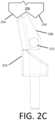
- FIG. 2 Cis a top view of a portion of a pawl and gear assembly located within the handle of FIGS. 2 A and 2 B .
- FIG. 2 Dis a cross-sectional elevation view of an adapter of the handle of FIGS. 2 A and 2 B .
- FIG. 2 Eis a cross-sectional elevation view of the gear of the handle of FIGS. 2 A and 2 B and the pawl and gear assembly of FIG. 2 C .
- FIG. 3 Ais an exploded perspective view of a stylet holder of the instrument of FIGS. 1 A and 1 B .
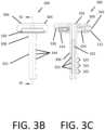
- FIG. 3 Bis a side elevation view of the stylet holder of FIG. 3 A .
- FIG. 3 Cis a view along section 3 C- 3 C of FIG. 3 B .
- FIG. 3 Dis a side elevation view of a stylet of the instrument of FIGS. 3 A and 3 B .
- FIG. 4 Ais a side elevation view of a drive assembly of the instrument of FIGS. 1 A and 1 B in a disassembled state.
- FIG. 4 Bis a side elevation view of the drive assembly of FIG. 4 A in an unlocked position.
- FIG. 4 Cis a side elevation view of the drive assembly of FIGS. 4 A and 4 B in a locked position.
- FIG. 5is a side elevation view of a removal tool for use with the instrument of FIGS. 1 A and 1 B .
- proximalmeans closer to the operator/surgeon
- distalmeans further away from the operator/surgeon
- the instrument 100 and its componentsextend generally along a central axis X.
- the terms “axial,” “radial,” and “tangential”refer to directions relative to the central axis X, except where specified otherwise.
- the central axis Xis illustrated with regard to any component of the instrument 100 in FIGS. 2 A- 6 , it indicates that component's orientation relative to the central axis X in the fully assembled state of the instrument 100 as shown in FIG. 1 A .
- the instrument 100includes a ratcheting handle 200 at its proximal end, with a stylet holder 300 disposed through the handle 200 .
- a stylet 310extends along the central axis X from a proximal end of the stylet holder 300 to a distal tip of the stylet 310 that extends distally beyond a distal tip of the attached pedicle screw 110 .
- a drive assembly 400is connected at a distal end of the handle 200 . As shown in FIG. 1 B , the drive assembly 400 includes a sheath assembly 404 and a cannulated driver 408 that extends proximally from the sheath assembly 404 into the handle 200 and distally from the sheath assembly 404 to drive the pedicle screw 110 .
- the sheath assembly 408further includes a knob 410 near its proximal end and a tube 412 extending through and distally beyond the knob 410 .
- the tube 412 as shown in FIG. 1 Bincludes a threaded section 414 at its distal end, but in alternative arrangements the tube 412 may include other coupling features, and in further arrangements the threaded section 414 or other coupling features may be located away from the distal end of the tube 412 .
- an extension assembly 120may be coupled to the drive assembly 400 , such as by internal threading engaged with the threaded section 414 of tube 412 , or by other coupling features the extension assembly 120 and tube 412 may have.
- the extension assembly 120holds a head or tulip feature of the pedicle screw 110 at a distal position relative to the drive assembly 400 such that the driver 408 may drivingly engage the pedicle screw 110 .
- FIG. 2 AAn exemplary arrangement of parts for the ratcheting handle 200 is illustrated in FIG. 2 A , with a cross-section of the fully assembled handle 200 shown in FIG. 2 B .
- a pawl 208is inserted into a cavity 211 in a body 204 of the handle 200 .
- the body 204includes a first arm 207 a and a second arm 207 b extending in mutually opposite radial directions.
- the cavity 211extends from a first opening 203 shown FIG. 2 B at a radial extremity of the first arm 207 a to a second opening 205 at a radial extremity of the second arm 207 b .
- a handle recess 215 at a proximal side of the body 204opens distally into the cavity 211 .
- the pawl 208is positioned within the first arm 207 a such that the pawl tapers to be narrower with increasing proximity to the central axis X.
- the pawl 208once positioned, is secured with a pawl pin 212 that may be inserted through a corresponding hole in the first arm 207 a of the body 204 .
- the pawl pin 212 of the illustrated arrangementincludes threading for engaging threads in the corresponding hole in the first arm 207 a .
- the pawl pin 212fixes the pawl 208 in place within the first arm 207 a , but the pawl 208 is able to pivot about the pawl pin 212 .
- a washer 228is inserted into a disc shaped space within an externally threaded proximal annulus 202 a of a proximal adapter 202 .
- the proximal annulus 202 ais then threaded into a threaded distal opening of the body 204 .
- a gear 206is inserted into the cavity 211 through the handle recess 215 .
- An externally threaded neck 236 of a distal adapter 230is inserted through the proximal adapter 202 and washer 228 into the cavity 211 and threaded into an internal bore of the gear 206 .
- a flat radial shoulder 227 of the distal adapter 230seats against the washer 228 to prevent the gear 206 from moving axially after the neck 226 is threaded into the washer 228 while allowing the gear 206 and distal adapter 230 to rotate smoothly about the central axis X.
- a block 210is inserted into the first opening 203 , followed by a block spring 216 and a lock screw 214 .
- the lock screw 214is threaded into the first opening 203 to close the first opening 203 and hold the block spring 216 against the block 210 .
- the pawl 208 , block 210 , and gear 206are thus positioned with respect to one another within the cavity 211 approximately as shown in FIG. 2 C .
- the pawl 208is asymmetrical to permit the gear 206 to rotate in only one direction about the central axis X. More specifically, the pawl 208 is shaped and located such that, if the gear 206 rotates in a counter-clockwise direction from the perspective of FIG.
- a gear tooth 254will act to compress the pawl 208 against the pawl pin 212 , causing the gear 206 against the pawl 208 .
- the gear 206rotates in a clockwise direction from the perspective of FIG. 2 C , the pawl 208 will pivot about the pawl pin 212 and permit the gear teeth 206 to pass by.
- the gear 206causes the pawl 208 to pivot, the pawl 208 pushes the block 210 back toward the lock screw 214 .
- the block spring 216pushes back on the block 210 to cause the block 210 to push, in turn, on the pawl 208 , thereby causing the pawl 208 to return to position between each gear tooth 254 when the gear 206 rotates.
- the block 210 and block spring 212thereby prevent the pawl 208 from skipping over gear teeth 254 and ensures rotation of the gear 206 in the binding direction will consistently be prohibited.
- the pawl pin 208is fixed within the first arm 207 a of the body 204 , but the gear 206 is free to rotate relative to the body 204 , the foregoing description of FIG. 2 C similarly to movement of the body 204 relative to the gear 206 .
- the pawl 208permits the body 204 to be rotated relative to the gear 206 in a counter-clockwise direction from the perspective of FIG. 2 C , but not in a clockwise direction.
- a retainer spring 222is inserted into the cavity 211 through a second arm aperture 223 on a surface of the second arm 207 b , followed by a retainer 220 .
- a lock post spring 224is inserted into the cavity 211 through the second opening 205 and retainer 220 , and a lock post 218 is inserted through the second opening 205 , lock post spring 224 , and retainer 220 .
- the lock post 218is secured within the cavity by inserting a lock post pin 226 through a corresponding hole in the second arm 207 b of the body 204 and through a post track 219 defined through the lock post 218 .
- the lock post pin 226includes threads for engaging threads of the corresponding hole in the second arm 207 b . Securing the lock post 218 within the cavity 211 also prevents the retainer 220 from being removed through the second arm aperture 223 .
- the lock post 218 and retainer 220cooperate to selectively lock and release the body 204 relative to the gear 206 .
- a radially inner end of the lock post 218includes post teeth 217 for engaging the gear 206 .
- the post track 219permits some radial movement of the lock post 218 relative to the lock post pin 226 , while a shape of the cavity 211 within the second arm 207 b restricts the lock post 218 to only radial movement.
- the post teeth 217engage the gear 206 , thereby preventing the body 204 and gear 206 from rotating relative to one another about the central axis X in both the clockwise and counterclockwise directions.
- the retainer spring 222biases the retainer 220 into engagement with a post notch 225 of the lock post 218 .
- the retainer 220prevents the lock post 218 from travelling out of the radially innermost position, so the post teeth 217 remain in engagement with the gear 206 after pressure is removed from the lock post button 221 .
- Pressuremay be applied to the retainer 220 through the second arm aperture 223 to compress the retainer spring 221 and move the retainer 220 out of engagement with the post notch 225 , thereby releasing the lock post 218 from the radially innermost position.
- the lock post spring 224biases the lock post 218 radially outward and away from the gear 206 , freeing the gear 206 and body 204 to rotate relative to one another about the central axis X in the direction permitted by the pawl 208 .
- the distal adapter 230includes a core 232 and a cover 234 surrounding a distal portion of the core 232 as shown in FIG. 2 D .
- the core 232in turn includes an axial passage 238 extending through an entire axial length of the distal adapter 230 .
- the axial passage 238includes a polygonal portion 240 at its distal end.
- the polygonal portion 240has a polygonal axial cross-section shaped to receive and drive a polygonal head 418 of the driver 408 , shown in FIGS. 4 A- 4 C .
- FIGS. 4 A- 4 CAs noted above, additional details regarding interaction between a similar handle and drive assembly can be found in the '224 publication.
- a proximal end of the polygonal portion 240 of the axial passage 238is defined by an annular shelf 242 extending radially into the axial passage 238 .
- the core 232is structured to transfer distal axial force on the shoulder 327 to the shelf 242 so that the shelf 242 can, in turn transfer the distal axial force to the polygonal head 418 of the driver 408 .
- the core 232 and cover 234include an opposed outer ridge 246 and inner ridge 244 , respectively.
- the outer ridge 246extends to contact an interior of the cover 234 and the inner ridge 244 extends to contact an exterior of the core 232 , so the outer ridge 246 and inner ridge 244 cooperate to define an annular pocket 248 between the core 232 and the cover 234 .
- An adapter spring 250is disposed within the pocket 248 surrounding the core 232 and extending between the outer ridge 246 and inner ridge 248 .
- the adapter spring 250thereby acts to bias the cover 234 distally toward a resting position relative to the core 232 .
- the adapter spring 250will bias the cover 234 to return to the resting position when the force is removed.
- a distal portion of the core 232may expand radially outward around the polygonal space 240 when the polygonal head 418 is inserted.
- the cover 234restricts the expansion of the core 232 . The cover 234 may therefore be retracted proximally to facilitate insertion and removal of the polygonal head 418 of the driver 408 into the distal adapter 230 .
- the gear 206includes an internal bore 260 extending from its proximal face to its distal face, and a distal portion of the bore 260 includes internal threading 258 for engaging the threaded neck 236 of the distal adapter 230 .
- the gear 206further includes a teethed portion 252 , having the gear teeth 254 for engaging the pawl 208 and post teeth 217 , and a raised portion 256 .
- the raised portion 256has a narrower diameter relative to the central axis X than the teethed portion 252 .
- the raised portion 256includes an annular groove 262 for engagement with a clip 342 of the stylet holder 300 shown in FIG. 3 A .
- the stylet holder 300 illustrated in FIGS. 3 A- 3 Cincludes a tablet 304 , a pillar 306 , the clip 312 , and a clip spring 314 .
- the clip 312in turn includes a gap 334 , a clip button 342 , and a shim 338 that extends into the gap 334 .
- the stylet holder 300acts as an insert receivable in the handle 200 , and retains the stylet 310 in a fixed position when the instrument 100 is assembled as shown in FIGS. 1 A or 1 B .
- the clip spring 214is into a lateral slot 316 within the tablet 304 .
- the clip 312is inserted into the lateral slot 316 to push against the clip spring 314 .
- the pillar 306is inserted from a proximal side of the tablet 304 though a tablet opening 321 and through the gap 334 in the clip 312 .
- the pillar 306includes a flat head 326 that seats inside a counter bore of the tablet opening 321 such that a proximal face of the tablet 304 and a proximal face of the flat head 326 are coplanar or the flat head 326 is slightly recessed from the proximal face of the tablet 304 .
- the flat head 326can be secured within the counter bore of the tablet opening 321 , such as by adhesive or a weld.
- the clip pin 318is inserted through a corresponding hole in the tablet 304 and into the clip track 343 .
- the clip track 343allows the clip 312 to translate within the lateral slot 314 in a direction perpendicular to the central axis X.
- the stylet holder 300may be installed within the instrument 100 by inserting the pillar 306 into the bore 260 of the gear 206 and the axial passage 238 of the core 230 .
- the stylet holder 300reaches an installed location, wherein the tablet 304 is within the proximal face of the tablet 304 is within the handle recess 215 and the proximal face of the tablet 304 is coplanar with or slightly distal of proximal faces of the arms 207 a , 207 b , the clip 312 may engage the annular groove 262 of the gear 206 .
- the clip spring 314biases the clip 312 into a position wherein the shim 338 extends into the annular groove 262 , thereby coupling the stylet holder 300 to the instrument 100 .
- the clip 312can be disengaged from the annular gear 206 by applying pressure to the clip button 342 to compress the clip spring 314 and move the shim 338 out of the annular groove 262 .
- the stylet holder 300 and stylet 310may be removed from the instrument 100 after the clip 312 is disengaged from the annular groove 262 , such as by hooking a finger or removal tool under a tablet notch 330 opposite from the clip button 342 .
- the stylet 310includes a shank 346 ending distally in a point 348 , and ending proximally at a stylet head 350 .
- the stylet head 350has a cylindrical shape with its circular faces defined on planes parallel to the central axis X. A height of the cylindrical shape of the stylet head 350 , defined as a distance between the two circular faces, is greater than a diameter of the shank 346 .
- the pillar 306 of the stylet holder 300includes an axial channel 322 for accepting the stylet head 350 . As shown in FIG.
- FIGS. 3 A and 3 Bshow a column of pillar apertures 344 extending axially along a side of the pillar 306 opposite from the elongate slot defined by the channel 322 .
- the pillar apertures 344open into the channel 322 .
- a column of parallel, generally radially extending ribs 323extends axially down each of two opposed sides of the channel 344 , defining an axial column of recesses between the ribs 323 on the two opposed sides of the channel 344 .
- the ribs 323therefore define opposed pairs of recesses 325 on opposite sides of the channel 322 , with each opposed pair of recesses being axially aligned with one of the pillar apertures 344 .
- the opposed pairs of recesses 325are each shaped and dimensioned to receive the circular faces of the stylet head 350 , while a width of the channel 322 between opposed pairs of ribs 323 is less than the height of the cylindrical shape of the stylet head 350 , but greater than or equal to the diameter of the shank 346 .
- the opposed pairs of recesses 325 and pillar apertures 344thus define discrete, predefined locations along the central axis X wherein the stylet holder 300 can retain the stylet head 350 .
- the stylet head 350is slotted into the channel 322 of the pillar 306 such that the two circular faces of the stylet head 350 are received in an opposed pair of recesses 325 and edge of the stylet head 350 extends into the pillar aperture 344 axially aligned with the opposed pair of recesses.
- a fit of the stylet head 350 within the opposed pair of recesses 325 and the pillar aperture 344allows the stylet head 350 to rotate relative to the pillar 306 .
- the stylet 310is then turned to axially align the shank 346 with the pillar 306 within the channel 322 .
- the stylet 310is then be inserted through the bore 260 of the gear 206 and guided through the instrument 100 to protrude from a distal end of the driver 408 .
- the stylet holder 300is inserted into the instrument 100 and coupled to the handle 200 via the annular groove 262 of the gear 206 as discussed above.
- the stylet 310is largely constrained into alignment with the central axis X of the instrument 100 .
- the pillar 306extends into the axial passage 238 of the distal adapter 230 , and the axial passage 238 of the distal adapter 230 is dimensioned to prevent the stylet head 350 from exiting the channel 322 .
- Other features that the shank 346 passes through between the axial passage 238 of the distal adapter 230 and the distal end of the driver 408are narrower than the axial passage 238 , and therefore serve to further constrain the stylet 310 within the instrument 100 .
- Selection and placement of the stylet 310may be in view of details specific to a patient, operation, or fastener.
- the stylet 310is selected or constructed to have a desired length determined in view of the instrument 100 and the screw 110 .
- the opposed pair of recesses 325 and pillar aperture 344 into which the stylet head 350 is disposed before the stylet holder 300 is inserted into the handle 200are selected in view of the length of the stylet 310 , instrument 100 , and screw 110 .
- the length of the stylet 310 , the opposed pair of recesses 325 and aperture 344 , or both,are selected such that the point 348 of the stylet 310 will be a predetermined distance from a tip of the screw 110 when the instrument 100 is fully assembled.
- the predetermined distanceis 5 mm, 10 mm, or 15 mm
- the drive assembly 400includes the sheath assembly 404 and the driver 408 , which is insertable through the sheath assembly 404 as shown in FIGS. 4 A- 4 C such that the distal end of the driver 408 , defined by a drive head 416 , extends distally beyond the tube 412 .
- the drive head 416is any known screw driving feature suitable for driving engagement with a head of the screw 110 .
- an exemplary drive head and engagement thereof with an exemplary bone screwreference can be made to the '724 patent.
- the knob 410is axially actuatable relative to the tube 412 of the sheath assembly 404 between a locked position, wherein the sheath assembly 404 is rotationally coupled to the driver 408 , and an unlocked position, wherein the sheath assembly 404 is free to rotate relative to the driver 408 .
- the unlocked positionshown in FIG. 4 B
- the locked positionis distal of the locked position, shown in FIG. 4 C .
- Assembly of the instrument 100 of the illustrated arrangementincludes inserting the driver 408 into the sheath assembly 404 .
- the sheath assembly 404with the knob 410 in the unlocked position, is rotated about the driver 408 to thread the threaded portion 414 of the tube 412 into engagement with the extension assembly 120 .
- the knob 410is then actuated to the locked position to rotationally couple the sheath assembly 404 to the driver 400 .
- the knob 410includes an L-shaped track 426 in cooperation with a boss 428 extending radially outward from the tube 414 and through the L-shaped track 426 , permitting the knob 410 to rotate about the tube 414 a short distance when the knob 410 is in the locked position.
- the usermay therefore turn the knob 410 after actuating the knob 410 to the locked position to locate the boss 428 away from a vertical leg of the L-shaped track, enabling the application of axial force on the knob 410 without moving the knob 410 to the unlocked position.
- Rotational force on the knob 410is transferred to the tube 412 by edges of the L-shaped track 426 bearing on the boss 428 .
- the rotational coupling and uncoupling of the sheath assembly 404 and driver 408is achieved by cooperation of internal contours and a moveable spline element (not illustrated) within the knob 410 .
- the spline elementis axially and rotationally coupled to the tube 412 , but axially uncoupled from the knob 410 .
- Axial actuation of the knob 410therefore causes the internal contours of the knob to move relative to the spline element while the spline element remains in a constant axial location relative to the tube 412 .
- Movement of the knob 410 axially into the locked positioncauses the internal contours of the knob 410 to guide the spline element radially into engagement with the splined portion 422 of the driver 408 , thereby rotationally coupling the tube 412 and sheath assembly 404 to the driver 408 .
- movement of the knob 410 axially into the unlocked positioncauses the internal contours of the knob 410 to guide the spline element radially out of engagement with the spline portion of the driver 408 , thereby rotationally uncoupling the tube 412 and sheath assembly 404 from the driver.
- the instrument 100 and its components described abovemay be made of any material or combination of materials suitable for driving known screws into solid objects. In medical applications particularly, biocompatible or non-toxic materials are preferred, as are materials that are suitable for sterilization and repeated use. Stainless steel, titanium, and alloys thereof are specifically contemplated as suitable for any part of the driver. However, some components, including but not limited to the handle body 204 , adapters 202 , 230 , block 210 , post 221 , washer 228 , or any sub-components thereof, may be made of any of a wide variety of rigid polymers. Additionally, any component of the instrument other than necessarily flexible components such as springs or the core 232 of the distal adapter 230 may be made of ceramic.
- FIG. 5illustrates a removal tool 500 for removing the stylet holder 300 and stylet 310 from the instrument 100 .
- the removal tool 500includes a first grip 534 a and a second grip 534 b joined at a hinge 538 .
- a first leaf spring 536 a and second leaf spring 536 bare attached to the first grip 534 a and second grip 534 b , respectively, and at rest curve toward the opposite grip 534 a , 534 b .
- the grips 534 a , 535 b of the illustrated arrangementare wider than the leaf springs 536 a , 536 b , so the leaf springs 536 a , 536 b may pass by each other to contact the opposite grip 534 a , 534 b.
- the first grip 534 ais integrally connected to a hook 540 a on an opposite side of the hinge 538
- the second grip 534 bis integrally connected to a wedge 540 b on the opposite side of the hinge 538 .
- the hook 540 ais shaped to match a contour of the clip button 342
- the wedge 540 bis shaped to slide under the tablet notch 330 .
- the removal tool 500therefore cooperates with shapes of the tablet 304 and clip 312 to facilitate removal of the stylet holder 300 and styled 310 from the instrument.
- the removal tool 500may be positioned such that when the grips 534 a , 534 b are drawn close to one another, the hook 540 a covers the clip button 342 , and the wedge 540 b slides under the tablet notch 330 .
- the hook 540 apushes the clip button 342 to disengage the clip 312 from the annular groove 262 of the gear 206 while the wedge 540 b pushes the tablet 304 proximally.
- the removal tool 500can therefore be used to easily remove the stylet holder 300 and stylet 310 from the instrument 100 .
- the removal tool 500can be made from any of a variety of materials including metals, such as stainless steel, titanium, or alloys thereof, rigid polymers, or, with the exception of the leaf springs 536 a , 536 b , ceramic. Again, in medical applications, materials that are non-toxic, biocompatible, and conducive to sanitization and reuse are preferred.
- the handle 200 , stylet holder 300 , and drive assembly 400are separately assembled, as described above.
- the extension assembly 120is coupled to the screw 110 .
- a stylet 310is constructed at a desired length or selected from a plurality of stylets 310 having various predetermined lengths.
- the drive assembly 400is inserted into the extension assembly 120 .
- the drive head 416is positioned for driving engagement with the head of the screw 110 .
- the knob 410With the knob 410 in the unlocked position, the drive assembly 400 is rotated about the driver 408 such that the threaded portion 414 of the tube 410 engages the extension assembly 120 , thereby retaining the drive head 416 in driving engagement with the head of the screw 110 .
- the knob 410is then actuated to the locked position.
- the cover 234 of the distal adapter 230 of the handle 200is retracted proximally relative to the core 232 while the polygonal head 418 of the driver 408 is inserted into the polygonal portion 240 of the axial passage 238 of the distal adapter 230 .
- the cover 234is allowed to return distally over the core 232 , compressing the core 232 around the polygonal head 418 .
- the stylet 310is disposed within one of multiple discrete, predefined locations within the stylet holder 300 , each of the predefined locations corresponding to the pillar apertures 344 and opposed pairs of recesses 325 in the pillar 306 such that the stylet 310 will extend a desired distance distally beyond the tip of the screw 110 when the instrument 100 is fully assembled.
- the stylet 310 and stylet holder 300are inserted into the handle 200 such that the stylet 310 extends through the handle 200 , drive assembly 400 , and screw 110 , and the clip 312 engages the annular groove 262 on the raised portion 256 of the gear 206 .
- the foregoing stepsmay be performed in any order that results in an assembled instrument 100 generally as shown in FIGS. 1 A and 1 B .
- the point 348 of the stylet 310is used to pierce an exterior surface of a solid object, such as a bone, or specifically a vertebral pedicle, thereby providing a pilot hole. Force is applied to the instrument 100 until the tip of the screw 110 enters the pilot hole.
- the handle 200is used to drive the screw 110 into the object. Action of the pawl 208 on the gear 206 provides the handle 200 with a ratcheting function, such that torque applied to the handle 200 in a direction that drives the screw 110 into the object is transferred to the screw 110 , but torque applied to the handle 200 in an opposite direction causes the handle 200 to rotate relative to the instrument 100 without being transferred to the screw 110 .
- the extension assemblyis decoupled from the screw 110 and the instrument 100 is withdrawn.
- the stylet holder 300 and stylet 310are removed from the instrument 100 by pulling proximally on the tablet 304 by hand or with the removal tool 500 .
- torqueis applied to the instrument 100 beyond the handle 200 in a direction opposite from that used to drive the screw 110 into the object by depressing the post button 221 to cause the post teeth 217 to lock the gear 206 relative to the body 204 of the handle 200 before turning the handle 200 .
- Ratcheting functionis then restored by depressing the retainer 220 to allow the post 218 to return radially outward and disengage the gear 206 .
Landscapes
- Health & Medical Sciences (AREA)
- Orthopedic Medicine & Surgery (AREA)
- Neurology (AREA)
- Life Sciences & Earth Sciences (AREA)
- Surgery (AREA)
- Heart & Thoracic Surgery (AREA)
- Engineering & Computer Science (AREA)
- Biomedical Technology (AREA)
- Nuclear Medicine, Radiotherapy & Molecular Imaging (AREA)
- Medical Informatics (AREA)
- Molecular Biology (AREA)
- Animal Behavior & Ethology (AREA)
- General Health & Medical Sciences (AREA)
- Public Health (AREA)
- Veterinary Medicine (AREA)
- Surgical Instruments (AREA)
Abstract
Description
Claims (19)
Priority Applications (1)
| Application Number | Priority Date | Filing Date | Title |
|---|---|---|---|
| US17/544,363US12262927B2 (en) | 2020-12-10 | 2021-12-07 | Screw insertion instrument and methods of use |
Applications Claiming Priority (2)
| Application Number | Priority Date | Filing Date | Title |
|---|---|---|---|
| US202063123772P | 2020-12-10 | 2020-12-10 | |
| US17/544,363US12262927B2 (en) | 2020-12-10 | 2021-12-07 | Screw insertion instrument and methods of use |
Publications (2)
| Publication Number | Publication Date |
|---|---|
| US20220183726A1 US20220183726A1 (en) | 2022-06-16 |
| US12262927B2true US12262927B2 (en) | 2025-04-01 |
Family
ID=78827542
Family Applications (1)
| Application Number | Title | Priority Date | Filing Date |
|---|---|---|---|
| US17/544,363Active2042-12-06US12262927B2 (en) | 2020-12-10 | 2021-12-07 | Screw insertion instrument and methods of use |
Country Status (2)
| Country | Link |
|---|---|
| US (1) | US12262927B2 (en) |
| EP (1) | EP4011306B1 (en) |
Cited By (1)
| Publication number | Priority date | Publication date | Assignee | Title |
|---|---|---|---|---|
| US20230320771A1 (en)* | 2022-04-11 | 2023-10-12 | Spineology Inc. | Surgical screwdriver system |
Families Citing this family (1)
| Publication number | Priority date | Publication date | Assignee | Title |
|---|---|---|---|---|
| US11793558B2 (en) | 2019-08-30 | 2023-10-24 | K2M, Inc. | All in one plate holder and spring loaded awl |
Citations (116)
| Publication number | Priority date | Publication date | Assignee | Title |
|---|---|---|---|---|
| US4838282A (en) | 1987-02-26 | 1989-06-13 | Manan Manufacturing Co., Inc. | Bone biopsy needle assembly |
| US5189422A (en) | 1990-11-09 | 1993-02-23 | U.S. Philips Corporation | Analog-to-digital converter with delay correction |
| US5423819A (en) | 1989-02-06 | 1995-06-13 | American Cyanamid Company | Screw and driver for securing a bone block |
| US5484440A (en) | 1992-11-03 | 1996-01-16 | Zimmer, Inc. | Bone screw and screwdriver |
| US5549931A (en) | 1995-02-27 | 1996-08-27 | Council Of Scientific & Industrial Research | Process for the preparation of uniform ultra thin films of metal oxide, metal chalco-genides and metal halides |
| US5946988A (en) | 1992-02-27 | 1999-09-07 | Howmedica Gmbh | Tool for driving pedicle screws |
| US6312394B1 (en) | 2000-04-25 | 2001-11-06 | Manan Medical Products, Inc. | Bone marrow biopsy device |
| US20020091386A1 (en) | 2001-01-05 | 2002-07-11 | Greg Martin | Pedicle screw assembly |
| US6436100B1 (en) | 1998-08-07 | 2002-08-20 | J. Lee Berger | Cannulated internally threaded bone screw and reduction driver device |
| US20040138662A1 (en) | 2002-10-30 | 2004-07-15 | Landry Michael E. | Spinal stabilization systems and methods |
| US6827722B1 (en) | 2001-12-11 | 2004-12-07 | Biomet, Inc. | Method and apparatus for use of a guide wire capturing surgical instrument |
| US20050137601A1 (en) | 2003-10-23 | 2005-06-23 | Assell Robert L. | Spinal nucleus extraction tool |
| US20060122597A1 (en) | 2004-12-02 | 2006-06-08 | Jones Robert J | Instruments and methods for adjusting separation distance of vertebral bodies with a minimally invasive spinal stabilization procedure |
| US20070239159A1 (en) | 2005-07-22 | 2007-10-11 | Vertiflex, Inc. | Systems and methods for stabilization of bone structures |
| US7296500B1 (en) | 2005-01-15 | 2007-11-20 | Nu Vasive, Inc. | System and method for applying torque to a fastener |
| US20080045970A1 (en) | 2006-08-17 | 2008-02-21 | Sean Saidha | Push-off driver and method for inserting bone screws |
| US20080243133A1 (en) | 2007-02-27 | 2008-10-02 | Warsaw Orthopedic, Inc. | Surgical Driver |
| US20090187220A1 (en) | 2008-01-17 | 2009-07-23 | Hamada James S | Pedicle dart system |
| US20090187194A1 (en) | 2008-01-17 | 2009-07-23 | Hamada James S | One step entry pedicular preparation device and disc access system |
| US7572264B2 (en) | 2005-06-28 | 2009-08-11 | Warsaw Orthopedic, Inc. | Driver instrument for use in a surgical application |
| US20090264895A1 (en) | 2008-04-22 | 2009-10-22 | Warsaw Orthopedic, Inc. | Systems and methods for implanting a bone fastener and delivering a bone filling material |
| US20090275954A1 (en) | 2008-04-30 | 2009-11-05 | Phan Christopher U | Apparatus and methods for inserting facet screws |
| US20100036381A1 (en) | 2008-08-07 | 2010-02-11 | Ryan Vanleeuwen | Cavity creator with integral cement delivery lumen |
| US7758584B2 (en) | 2006-04-11 | 2010-07-20 | Synthes Usa, Llc | Minimally invasive fixation system |
| US20100204703A1 (en) | 2009-02-12 | 2010-08-12 | Bradshaw Medical, Inc. | Torque measuring mechanism using cam engagement |
| US20100298838A1 (en) | 2009-05-19 | 2010-11-25 | Alphatec Spine, Inc. | Surgical screwdriver |
| US7846093B2 (en) | 2005-09-26 | 2010-12-07 | K2M, Inc. | Minimally invasive retractor and methods of use |
| US20110054537A1 (en) | 2009-08-28 | 2011-03-03 | Zimmer Spine Austin, Inc. | Fusion method and pedicle access tool |
| US7947048B2 (en) | 2006-09-28 | 2011-05-24 | Karl Storz Gmbh & Co. Kg | Screwdriver for handling a screw in the body of a person or an animal |
| US8002798B2 (en) | 2003-09-24 | 2011-08-23 | Stryker Spine | System and method for spinal implant placement |
| US20110257690A1 (en) | 2010-04-20 | 2011-10-20 | Warsaw Orthopedic, Inc. | Transverse and Sagittal Adjusting Screw |
| US8062340B2 (en) | 2006-08-16 | 2011-11-22 | Pioneer Surgical Technology, Inc. | Spinal rod anchor device and method |
| US8100916B2 (en) | 2005-07-21 | 2012-01-24 | Depuy Spine, Inc. | Instrument for inserting, adjusting and removing a surgical implant |
| US20120055296A1 (en) | 2010-09-03 | 2012-03-08 | Greatbatch Ltd. | Torque limiting mechanism with lock bushing |
| US8221431B2 (en) | 2006-12-18 | 2012-07-17 | Greatbatch Medical S.A. | Calibrated mechanical orthopedic driver with wear-compensated torque-limiting mechanism |
| US8231635B2 (en) | 2007-01-18 | 2012-07-31 | Stryker Spine | Polyaxial screwdriver for a pedicle screw system |
| US20120198972A1 (en) | 2010-07-28 | 2012-08-09 | John Nino | Robust nose torque-limiting device |
| US20120203287A1 (en) | 2011-02-03 | 2012-08-09 | Alphatec Spine, Inc. | Material delivery apparatus for a bone screw |
| US20120203288A1 (en) | 2009-10-05 | 2012-08-09 | Robert Lange | Spinal fixation system and screwdriver tool for use with the same |
| US8262662B2 (en) | 2006-11-20 | 2012-09-11 | Depuy Spine, Inc. | Break-off screw extensions |
| US20120239052A1 (en) | 2011-03-14 | 2012-09-20 | Aesculap Ag | Surgical k-wire and surgical screw system |
| US8273089B2 (en) | 2004-11-23 | 2012-09-25 | Jackson Roger P | Spinal fixation tool set and method |
| US8308729B2 (en) | 2008-06-11 | 2012-11-13 | K2M, Inc. | Rod reduction device |
| US8343165B2 (en) | 2005-09-26 | 2013-01-01 | Pioneer Surgical Technology, Inc. | Apparatus and method for implantation of surgical devices |
| US20130013003A1 (en) | 2010-02-23 | 2013-01-10 | K2M, Inc. | Polyaxial bonescrew assembly |
| US8377065B2 (en) | 2009-05-27 | 2013-02-19 | Synthes Usa, Llc | Surgical instrument for fixing a clamp to a bone fixation device |
| US8394108B2 (en) | 2010-06-18 | 2013-03-12 | Spine Wave, Inc. | Screw driver for a multiaxial bone screw |
| US8485075B1 (en) | 2010-05-18 | 2013-07-16 | Gauthier Biomedical, Inc. | Electronic torque wrench |
| US8512344B2 (en) | 2006-08-16 | 2013-08-20 | Pioneer Surgical Technology, Inc. | Insertion instrument for a spinal fixation system |
| US20130276597A1 (en) | 2012-04-18 | 2013-10-24 | Eca Medical Instruments | Disposable torque limiting device with belt counter |
| US20130276598A1 (en) | 2012-04-23 | 2013-10-24 | Eca Medical Instruments | Disposable torque limiting device with tooth belt counter |
| US20130310842A1 (en) | 2012-05-15 | 2013-11-21 | Tobias Winkler | Installation tool for bone screw |
| US20130327190A1 (en) | 2012-06-06 | 2013-12-12 | LAMP S.r.I | Torque-controlled screwdriver for medical use |
| US8663292B2 (en) | 2006-08-22 | 2014-03-04 | DePuy Synthes Products, LLC | Reduction sleeve |
| US8715293B2 (en) | 2004-01-29 | 2014-05-06 | Biomet Manufacturing, Llc | Method and apparatus for retaining a guide wire |
| US8747411B2 (en) | 2009-09-30 | 2014-06-10 | Michael David Mitchell | Fluid delivery and bone screw driver apparatus |
| US20140194886A1 (en) | 2013-01-08 | 2014-07-10 | Nicholas Poulos | Fenestrated bone screw and method of injecting bone cement into bone structure |
| US20140276893A1 (en) | 2013-03-14 | 2014-09-18 | Konrad Schaller | Torque Limiting Instrument, System and Related Methods |
| US20140277212A1 (en) | 2013-03-15 | 2014-09-18 | Aesculap Implant Systems, Llc | Surgical ratchet tool, system and method |
| US20140277206A1 (en) | 2013-03-14 | 2014-09-18 | Stryker Spine | Systems and methods for percutaneous spinal fusion |
| US20140277164A1 (en)* | 2013-03-14 | 2014-09-18 | DePuy Synthes Products, LLC | Bone anchors and surgical instruments with integrated guide tips |
| US20140277188A1 (en) | 2013-03-15 | 2014-09-18 | Nicholas Poulos | Self drilling, self-tapping bone screw and method of installing for bicortical purchase |
| US20140276891A1 (en) | 2013-03-13 | 2014-09-18 | Ebi, Llc | Screw driver, combination, and related methods |
| US8852239B2 (en) | 2013-02-15 | 2014-10-07 | Roger P Jackson | Sagittal angle screw with integral shank and receiver |
| US8858605B1 (en) | 2014-03-06 | 2014-10-14 | Amendia, Inc. | Tab bone screw system |
| US20140324062A1 (en) | 2013-04-29 | 2014-10-30 | Silony Medical International AG | Screwdriver for bone screws |
| US20140330315A1 (en) | 2013-05-06 | 2014-11-06 | Life Spine, Inc. | Systems and methods for spinal rod insertion and reduction |
| US8894655B2 (en) | 2006-02-06 | 2014-11-25 | Stryker Spine | Rod contouring apparatus and method for percutaneous pedicle screw extension |
| US20150066084A1 (en) | 2012-04-02 | 2015-03-05 | Safe Orthopaedics | Instrument Kit for Spinal Osteosynthesis |
| US20150094781A1 (en) | 2013-09-30 | 2015-04-02 | Z-Medical Gmbh & Co. Kg | Surgical instrument |
| US20150164569A1 (en) | 2013-12-13 | 2015-06-18 | Stryker European Holdings I, Llc | Tissue retraction and vertebral displacement devices, systems, and methods for posterior spinal fusion |
| US20150164540A1 (en) | 2013-07-25 | 2015-06-18 | Cardiovascular Systems, Inc. | Rotational atherectomy device with exchangeable drive shaft and meshing gears |
| US20150250521A1 (en) | 2012-10-18 | 2015-09-10 | Deroyal Industries Inc. | Driver Apparatus For A Pedicle Screw Assembly |
| US9131946B2 (en) | 2010-12-13 | 2015-09-15 | D.L.P. | Surgical instrument for a technique for attaching bone fragments using a cannulated screw |
| US20150282855A1 (en) | 2014-04-04 | 2015-10-08 | K2M, Inc. | Screw insertion instrument |
| WO2015186080A2 (en) | 2014-06-03 | 2015-12-10 | Premia Spine Ltd. | Minimally invasive surgery (mis) assembly |
| US20150367487A1 (en) | 2013-03-12 | 2015-12-24 | Eca Medical Instruments | Ratcheting torque wrench |
| US9242357B2 (en) | 2011-02-19 | 2016-01-26 | Eca Medical Instruments | Enhanced high torque device |
| US20160030100A1 (en)* | 2014-08-04 | 2016-02-04 | DePuy Synthes Products, LLC | Methods and Devices for Spinal Screw Insertion |
| US9254160B2 (en) | 2013-03-14 | 2016-02-09 | Aesculap Implant Systems, Llc | Driver assembly with guidewire control mechanism |
| US20160101508A1 (en) | 2014-10-14 | 2016-04-14 | Brian James Cutler | Shaft ratchet release and sealing mechanism |
| US9409285B2 (en) | 2012-08-30 | 2016-08-09 | Eca Medical Instruments | Base for disposable selectable torque limiting device |
| US9451954B2 (en) | 2013-03-15 | 2016-09-27 | Howmedica Osteonics Corp. | Ratcheting inserter device and suture anchor arrangement |
| US20160296266A1 (en) | 2015-04-13 | 2016-10-13 | Medos International Sarl | Driver instruments and related methods |
| US20160354906A1 (en) | 2014-04-01 | 2016-12-08 | Eca Medical Instruments | Fortified high torque device |
| US20170105813A1 (en) | 2014-04-03 | 2017-04-20 | MIS Implants Technologies Ltd. | A rotatable fastening device with an integral torque limiter |
| US20170128116A1 (en) | 2015-11-06 | 2017-05-11 | Globus Medical, Inc. | Torque limiting devices and methods of use |
| WO2017127502A1 (en) | 2016-01-19 | 2017-07-27 | K2M, Inc. | Tissue dilation system and methods of use |
| US20170217000A1 (en) | 2014-10-13 | 2017-08-03 | Mercator Innovations Bvba | Combination screwdriver and torque limiting system |
| US9750508B1 (en) | 2009-11-11 | 2017-09-05 | Nuvasive, Inc. | Insulated pedicle access system and related methods |
| US20170333093A1 (en) | 2016-05-18 | 2017-11-23 | Clariance | Self-locking screwdriver |
| US20180092671A1 (en) | 2016-10-05 | 2018-04-05 | Stryker European Holdings I, Llc | Apparatus and method for fenestrated screw augmentation |
| US20180133871A1 (en) | 2016-11-11 | 2018-05-17 | Zimmer Biomet Spine, Inc. | Tool torque limiter |
| US20180146990A1 (en) | 2016-11-29 | 2018-05-31 | MIS IP I Holdings LLC | Apparatus and method for accessing the spine and placing pedicle screws without the use of guide-wires |
| US20180146982A1 (en) | 2015-04-22 | 2018-05-31 | Stryker Corporation | Access Cannula Assembly With A Stylet That Includes A Flexible Lock Arm |
| US20180177536A1 (en) | 2016-12-23 | 2018-06-28 | Medos International Sarl | Driver instruments and related methods |
| US20180235677A1 (en) | 2015-08-13 | 2018-08-23 | K2M, Inc. | Extended tab systems for reducing spinal rods |
| US20180368892A1 (en) | 2017-06-23 | 2018-12-27 | Thierry Marnay | System for inserting and removing a locator-pin in a bone |
| US20180368893A1 (en)* | 2017-06-27 | 2018-12-27 | Medos International Sarl | Spinal Screw Insertion Devices and Methods |
| US20190022833A1 (en) | 2017-07-19 | 2019-01-24 | Zimmer, Inc. | Disposable surgical screwdriver |
| US10194967B2 (en) | 2012-09-21 | 2019-02-05 | Atlas Spine, Inc. | Minimally invasive spine surgery instruments: guide wire handle with a guide wire locking mechanism |
| US10219845B2 (en) | 2009-12-28 | 2019-03-05 | Safe Orthopaedics | Device and method for spinal surgery |
| US20190083147A1 (en) | 2017-09-15 | 2019-03-21 | Alphatec Spine, Inc. | Instrument assembly for use with an expandable pedicle screw |
| US20190125421A1 (en)* | 2017-11-02 | 2019-05-02 | Medos International Sarl | Bone Anchor Insertion Instruments and Methods |
| EP3501438A1 (en) | 2017-12-21 | 2019-06-26 | Globus Medical, Inc. | Headless compression screw driver system |
| US20190247102A1 (en) | 2018-02-09 | 2019-08-15 | Biedermann Technologies Gmbh & Co. Kg | System of a bone anchor and an elongate instrument |
| US20190298416A1 (en) | 2015-03-11 | 2019-10-03 | Warsaw Orthopedic, Inc. | Surgical instrument and method |
| US20190336180A1 (en) | 2015-12-23 | 2019-11-07 | Power T Handle, Llc | Multi-mode torque drivers employing anti-backdrive units for managing pedicle screw attachments with vertebrae, and related systems and methods |
| US10575888B2 (en) | 2014-08-13 | 2020-03-03 | In2Bones | Gripping handle for a surgical tool, and method and machine for producing such a gripping handle |
| US20200093530A1 (en)* | 2018-09-24 | 2020-03-26 | Astura Medical Inc. | Stylet screw driver |
| US20200268427A1 (en) | 2017-08-31 | 2020-08-27 | Conmed Corporation | Cannulated t-handle driver |
| US20200281608A1 (en)* | 2019-03-06 | 2020-09-10 | K2M, Inc. | Bone Screws, Instrumentation, and Methods of Using of Same |
| US11045232B2 (en)* | 2016-02-02 | 2021-06-29 | Aesculap Ag | Instrument for guiding a rod into an implant holder |
| US20210228245A1 (en)* | 2018-12-20 | 2021-07-29 | Integrity Implants Inc. | Surgical guidance device |
| US20210244424A1 (en)* | 2020-02-06 | 2021-08-12 | Aesculap Implant Systems, Llc | Surgical instrumentation for fixation of cervical spine |
| US20220061895A1 (en)* | 2020-08-28 | 2022-03-03 | Nuvasive, Inc. | Ratchet retracting handles and methods of using the same |
Family Cites Families (1)
| Publication number | Priority date | Publication date | Assignee | Title |
|---|---|---|---|---|
| US10973558B2 (en) | 2017-06-12 | 2021-04-13 | K2M, Inc. | Screw insertion instrument and methods of use |
- 2021
- 2021-12-07USUS17/544,363patent/US12262927B2/enactiveActive
- 2021-12-08EPEP21213255.9Apatent/EP4011306B1/enactiveActive
Patent Citations (131)
| Publication number | Priority date | Publication date | Assignee | Title |
|---|---|---|---|---|
| US4838282A (en) | 1987-02-26 | 1989-06-13 | Manan Manufacturing Co., Inc. | Bone biopsy needle assembly |
| US5423819A (en) | 1989-02-06 | 1995-06-13 | American Cyanamid Company | Screw and driver for securing a bone block |
| US5189422A (en) | 1990-11-09 | 1993-02-23 | U.S. Philips Corporation | Analog-to-digital converter with delay correction |
| US5946988A (en) | 1992-02-27 | 1999-09-07 | Howmedica Gmbh | Tool for driving pedicle screws |
| US5484440A (en) | 1992-11-03 | 1996-01-16 | Zimmer, Inc. | Bone screw and screwdriver |
| US5549931A (en) | 1995-02-27 | 1996-08-27 | Council Of Scientific & Industrial Research | Process for the preparation of uniform ultra thin films of metal oxide, metal chalco-genides and metal halides |
| US6436100B1 (en) | 1998-08-07 | 2002-08-20 | J. Lee Berger | Cannulated internally threaded bone screw and reduction driver device |
| US6312394B1 (en) | 2000-04-25 | 2001-11-06 | Manan Medical Products, Inc. | Bone marrow biopsy device |
| US20020091386A1 (en) | 2001-01-05 | 2002-07-11 | Greg Martin | Pedicle screw assembly |
| US6827722B1 (en) | 2001-12-11 | 2004-12-07 | Biomet, Inc. | Method and apparatus for use of a guide wire capturing surgical instrument |
| US20040138662A1 (en) | 2002-10-30 | 2004-07-15 | Landry Michael E. | Spinal stabilization systems and methods |
| US8002798B2 (en) | 2003-09-24 | 2011-08-23 | Stryker Spine | System and method for spinal implant placement |
| US20050137601A1 (en) | 2003-10-23 | 2005-06-23 | Assell Robert L. | Spinal nucleus extraction tool |
| USRE47348E1 (en) | 2003-11-08 | 2019-04-16 | Stryker European Holdings I, Llc | System and method for spinal implant placement |
| US8715293B2 (en) | 2004-01-29 | 2014-05-06 | Biomet Manufacturing, Llc | Method and apparatus for retaining a guide wire |
| US8273089B2 (en) | 2004-11-23 | 2012-09-25 | Jackson Roger P | Spinal fixation tool set and method |
| US20060122597A1 (en) | 2004-12-02 | 2006-06-08 | Jones Robert J | Instruments and methods for adjusting separation distance of vertebral bodies with a minimally invasive spinal stabilization procedure |
| US7296500B1 (en) | 2005-01-15 | 2007-11-20 | Nu Vasive, Inc. | System and method for applying torque to a fastener |
| US7572264B2 (en) | 2005-06-28 | 2009-08-11 | Warsaw Orthopedic, Inc. | Driver instrument for use in a surgical application |
| US8100916B2 (en) | 2005-07-21 | 2012-01-24 | Depuy Spine, Inc. | Instrument for inserting, adjusting and removing a surgical implant |
| US20070239159A1 (en) | 2005-07-22 | 2007-10-11 | Vertiflex, Inc. | Systems and methods for stabilization of bone structures |
| US7846093B2 (en) | 2005-09-26 | 2010-12-07 | K2M, Inc. | Minimally invasive retractor and methods of use |
| US8343165B2 (en) | 2005-09-26 | 2013-01-01 | Pioneer Surgical Technology, Inc. | Apparatus and method for implantation of surgical devices |
| US8894655B2 (en) | 2006-02-06 | 2014-11-25 | Stryker Spine | Rod contouring apparatus and method for percutaneous pedicle screw extension |
| US7758584B2 (en) | 2006-04-11 | 2010-07-20 | Synthes Usa, Llc | Minimally invasive fixation system |
| US8512344B2 (en) | 2006-08-16 | 2013-08-20 | Pioneer Surgical Technology, Inc. | Insertion instrument for a spinal fixation system |
| US8062340B2 (en) | 2006-08-16 | 2011-11-22 | Pioneer Surgical Technology, Inc. | Spinal rod anchor device and method |
| US8460307B2 (en) | 2006-08-17 | 2013-06-11 | Synthes Usa, Llc | Push-off driver and method for inserting bone screws |
| US20080045970A1 (en) | 2006-08-17 | 2008-02-21 | Sean Saidha | Push-off driver and method for inserting bone screws |
| US8663292B2 (en) | 2006-08-22 | 2014-03-04 | DePuy Synthes Products, LLC | Reduction sleeve |
| US7947048B2 (en) | 2006-09-28 | 2011-05-24 | Karl Storz Gmbh & Co. Kg | Screwdriver for handling a screw in the body of a person or an animal |
| US8262662B2 (en) | 2006-11-20 | 2012-09-11 | Depuy Spine, Inc. | Break-off screw extensions |
| US8221431B2 (en) | 2006-12-18 | 2012-07-17 | Greatbatch Medical S.A. | Calibrated mechanical orthopedic driver with wear-compensated torque-limiting mechanism |
| US8231635B2 (en) | 2007-01-18 | 2012-07-31 | Stryker Spine | Polyaxial screwdriver for a pedicle screw system |
| US20080243133A1 (en) | 2007-02-27 | 2008-10-02 | Warsaw Orthopedic, Inc. | Surgical Driver |
| US20090187220A1 (en) | 2008-01-17 | 2009-07-23 | Hamada James S | Pedicle dart system |
| US20090187194A1 (en) | 2008-01-17 | 2009-07-23 | Hamada James S | One step entry pedicular preparation device and disc access system |
| US8075579B2 (en) | 2008-01-17 | 2011-12-13 | Life Spine, Inc. | Pedicle dart system |
| US20090264895A1 (en) | 2008-04-22 | 2009-10-22 | Warsaw Orthopedic, Inc. | Systems and methods for implanting a bone fastener and delivering a bone filling material |
| US20090275954A1 (en) | 2008-04-30 | 2009-11-05 | Phan Christopher U | Apparatus and methods for inserting facet screws |
| US8308729B2 (en) | 2008-06-11 | 2012-11-13 | K2M, Inc. | Rod reduction device |
| US20100036381A1 (en) | 2008-08-07 | 2010-02-11 | Ryan Vanleeuwen | Cavity creator with integral cement delivery lumen |
| US20100204703A1 (en) | 2009-02-12 | 2010-08-12 | Bradshaw Medical, Inc. | Torque measuring mechanism using cam engagement |
| US20100298838A1 (en) | 2009-05-19 | 2010-11-25 | Alphatec Spine, Inc. | Surgical screwdriver |
| US8377065B2 (en) | 2009-05-27 | 2013-02-19 | Synthes Usa, Llc | Surgical instrument for fixing a clamp to a bone fixation device |
| US8814914B2 (en) | 2009-08-28 | 2014-08-26 | Zimmer Spine, Inc. | Fusion method and pedicle access tool |
| US20110054537A1 (en) | 2009-08-28 | 2011-03-03 | Zimmer Spine Austin, Inc. | Fusion method and pedicle access tool |
| US8747411B2 (en) | 2009-09-30 | 2014-06-10 | Michael David Mitchell | Fluid delivery and bone screw driver apparatus |
| US20120203288A1 (en) | 2009-10-05 | 2012-08-09 | Robert Lange | Spinal fixation system and screwdriver tool for use with the same |
| US9750508B1 (en) | 2009-11-11 | 2017-09-05 | Nuvasive, Inc. | Insulated pedicle access system and related methods |
| US10219845B2 (en) | 2009-12-28 | 2019-03-05 | Safe Orthopaedics | Device and method for spinal surgery |
| US20130013003A1 (en) | 2010-02-23 | 2013-01-10 | K2M, Inc. | Polyaxial bonescrew assembly |
| US20110257690A1 (en) | 2010-04-20 | 2011-10-20 | Warsaw Orthopedic, Inc. | Transverse and Sagittal Adjusting Screw |
| US8485075B1 (en) | 2010-05-18 | 2013-07-16 | Gauthier Biomedical, Inc. | Electronic torque wrench |
| US8394108B2 (en) | 2010-06-18 | 2013-03-12 | Spine Wave, Inc. | Screw driver for a multiaxial bone screw |
| US20120198972A1 (en) | 2010-07-28 | 2012-08-09 | John Nino | Robust nose torque-limiting device |
| US20120055296A1 (en) | 2010-09-03 | 2012-03-08 | Greatbatch Ltd. | Torque limiting mechanism with lock bushing |
| US8714056B2 (en) | 2010-09-03 | 2014-05-06 | Greatbatch Ltd. | Torque limiting mechanism with lock bushing |
| US9131946B2 (en) | 2010-12-13 | 2015-09-15 | D.L.P. | Surgical instrument for a technique for attaching bone fragments using a cannulated screw |
| US20120203287A1 (en) | 2011-02-03 | 2012-08-09 | Alphatec Spine, Inc. | Material delivery apparatus for a bone screw |
| US9877764B2 (en) | 2011-02-18 | 2018-01-30 | Eca Medical Instruments | Robust nose torque-limiting device |
| US9242357B2 (en) | 2011-02-19 | 2016-01-26 | Eca Medical Instruments | Enhanced high torque device |
| US20120239052A1 (en) | 2011-03-14 | 2012-09-20 | Aesculap Ag | Surgical k-wire and surgical screw system |
| US20150066084A1 (en) | 2012-04-02 | 2015-03-05 | Safe Orthopaedics | Instrument Kit for Spinal Osteosynthesis |
| US20130276597A1 (en) | 2012-04-18 | 2013-10-24 | Eca Medical Instruments | Disposable torque limiting device with belt counter |
| US20130276598A1 (en) | 2012-04-23 | 2013-10-24 | Eca Medical Instruments | Disposable torque limiting device with tooth belt counter |
| US20130310842A1 (en) | 2012-05-15 | 2013-11-21 | Tobias Winkler | Installation tool for bone screw |
| US20130327190A1 (en) | 2012-06-06 | 2013-12-12 | LAMP S.r.I | Torque-controlled screwdriver for medical use |
| US9409285B2 (en) | 2012-08-30 | 2016-08-09 | Eca Medical Instruments | Base for disposable selectable torque limiting device |
| US10194967B2 (en) | 2012-09-21 | 2019-02-05 | Atlas Spine, Inc. | Minimally invasive spine surgery instruments: guide wire handle with a guide wire locking mechanism |
| US20150250521A1 (en) | 2012-10-18 | 2015-09-10 | Deroyal Industries Inc. | Driver Apparatus For A Pedicle Screw Assembly |
| US20140194886A1 (en) | 2013-01-08 | 2014-07-10 | Nicholas Poulos | Fenestrated bone screw and method of injecting bone cement into bone structure |
| US8852239B2 (en) | 2013-02-15 | 2014-10-07 | Roger P Jackson | Sagittal angle screw with integral shank and receiver |
| US20150367487A1 (en) | 2013-03-12 | 2015-12-24 | Eca Medical Instruments | Ratcheting torque wrench |
| US20140276891A1 (en) | 2013-03-13 | 2014-09-18 | Ebi, Llc | Screw driver, combination, and related methods |
| US20140277164A1 (en)* | 2013-03-14 | 2014-09-18 | DePuy Synthes Products, LLC | Bone anchors and surgical instruments with integrated guide tips |
| US20140277206A1 (en) | 2013-03-14 | 2014-09-18 | Stryker Spine | Systems and methods for percutaneous spinal fusion |
| US9433445B2 (en) | 2013-03-14 | 2016-09-06 | DePuy Synthes Products, Inc. | Bone anchors and surgical instruments with integrated guide tips |
| US10413339B2 (en) | 2013-03-14 | 2019-09-17 | DePuy Synthes Products, Inc. | Bone anchors and surgical instruments with integrated guide tips |
| US20140276893A1 (en) | 2013-03-14 | 2014-09-18 | Konrad Schaller | Torque Limiting Instrument, System and Related Methods |
| US9254160B2 (en) | 2013-03-14 | 2016-02-09 | Aesculap Implant Systems, Llc | Driver assembly with guidewire control mechanism |
| US20140277188A1 (en) | 2013-03-15 | 2014-09-18 | Nicholas Poulos | Self drilling, self-tapping bone screw and method of installing for bicortical purchase |
| US9451954B2 (en) | 2013-03-15 | 2016-09-27 | Howmedica Osteonics Corp. | Ratcheting inserter device and suture anchor arrangement |
| US20140277212A1 (en) | 2013-03-15 | 2014-09-18 | Aesculap Implant Systems, Llc | Surgical ratchet tool, system and method |
| US20140324062A1 (en) | 2013-04-29 | 2014-10-30 | Silony Medical International AG | Screwdriver for bone screws |
| US20140330315A1 (en) | 2013-05-06 | 2014-11-06 | Life Spine, Inc. | Systems and methods for spinal rod insertion and reduction |
| US20150164540A1 (en) | 2013-07-25 | 2015-06-18 | Cardiovascular Systems, Inc. | Rotational atherectomy device with exchangeable drive shaft and meshing gears |
| US20150094781A1 (en) | 2013-09-30 | 2015-04-02 | Z-Medical Gmbh & Co. Kg | Surgical instrument |
| US10687881B2 (en) | 2013-09-30 | 2020-06-23 | Z-Medical Gmbh & Co. Kg | Surgical instrument |
| US20150164569A1 (en) | 2013-12-13 | 2015-06-18 | Stryker European Holdings I, Llc | Tissue retraction and vertebral displacement devices, systems, and methods for posterior spinal fusion |
| US8858605B1 (en) | 2014-03-06 | 2014-10-14 | Amendia, Inc. | Tab bone screw system |
| US20160354906A1 (en) | 2014-04-01 | 2016-12-08 | Eca Medical Instruments | Fortified high torque device |
| US20170105813A1 (en) | 2014-04-03 | 2017-04-20 | MIS Implants Technologies Ltd. | A rotatable fastening device with an integral torque limiter |
| US9526553B2 (en) | 2014-04-04 | 2016-12-27 | K2M, Inc. | Screw insertion instrument |
| US20150282855A1 (en) | 2014-04-04 | 2015-10-08 | K2M, Inc. | Screw insertion instrument |
| EP2939621A1 (en) | 2014-04-04 | 2015-11-04 | K2M, Inc. | Screw insertion instrument |
| US10667849B2 (en) | 2014-06-03 | 2020-06-02 | Premia Spine Ltd. | Minimally invasive surgery (MIS) assembly |
| WO2015186080A2 (en) | 2014-06-03 | 2015-12-10 | Premia Spine Ltd. | Minimally invasive surgery (mis) assembly |
| US9855087B2 (en) | 2014-08-04 | 2018-01-02 | DePuy Synthes Products, LLC | Methods and devices for spinal screw insertion |
| US20160030100A1 (en)* | 2014-08-04 | 2016-02-04 | DePuy Synthes Products, LLC | Methods and Devices for Spinal Screw Insertion |
| US10575888B2 (en) | 2014-08-13 | 2020-03-03 | In2Bones | Gripping handle for a surgical tool, and method and machine for producing such a gripping handle |
| US20170217000A1 (en) | 2014-10-13 | 2017-08-03 | Mercator Innovations Bvba | Combination screwdriver and torque limiting system |
| US20160101508A1 (en) | 2014-10-14 | 2016-04-14 | Brian James Cutler | Shaft ratchet release and sealing mechanism |
| US20190298416A1 (en) | 2015-03-11 | 2019-10-03 | Warsaw Orthopedic, Inc. | Surgical instrument and method |
| US20160296266A1 (en) | 2015-04-13 | 2016-10-13 | Medos International Sarl | Driver instruments and related methods |
| US20180146982A1 (en) | 2015-04-22 | 2018-05-31 | Stryker Corporation | Access Cannula Assembly With A Stylet That Includes A Flexible Lock Arm |
| US20180235677A1 (en) | 2015-08-13 | 2018-08-23 | K2M, Inc. | Extended tab systems for reducing spinal rods |
| US20170128116A1 (en) | 2015-11-06 | 2017-05-11 | Globus Medical, Inc. | Torque limiting devices and methods of use |
| US20190336180A1 (en) | 2015-12-23 | 2019-11-07 | Power T Handle, Llc | Multi-mode torque drivers employing anti-backdrive units for managing pedicle screw attachments with vertebrae, and related systems and methods |
| WO2017127502A1 (en) | 2016-01-19 | 2017-07-27 | K2M, Inc. | Tissue dilation system and methods of use |
| US11045232B2 (en)* | 2016-02-02 | 2021-06-29 | Aesculap Ag | Instrument for guiding a rod into an implant holder |
| US20170333093A1 (en) | 2016-05-18 | 2017-11-23 | Clariance | Self-locking screwdriver |
| US20180092671A1 (en) | 2016-10-05 | 2018-04-05 | Stryker European Holdings I, Llc | Apparatus and method for fenestrated screw augmentation |
| US20180133871A1 (en) | 2016-11-11 | 2018-05-17 | Zimmer Biomet Spine, Inc. | Tool torque limiter |
| US20180146990A1 (en) | 2016-11-29 | 2018-05-31 | MIS IP I Holdings LLC | Apparatus and method for accessing the spine and placing pedicle screws without the use of guide-wires |
| US20180177536A1 (en) | 2016-12-23 | 2018-06-28 | Medos International Sarl | Driver instruments and related methods |
| US20180368892A1 (en) | 2017-06-23 | 2018-12-27 | Thierry Marnay | System for inserting and removing a locator-pin in a bone |
| US10433883B2 (en) | 2017-06-27 | 2019-10-08 | Medos International Sarl | Spinal screw insertion devices and methods |
| WO2019002992A1 (en) | 2017-06-27 | 2019-01-03 | Medos International Sàrl | Spinal screw insertion devices and methods |
| US20180368893A1 (en)* | 2017-06-27 | 2018-12-27 | Medos International Sarl | Spinal Screw Insertion Devices and Methods |
| US20190022833A1 (en) | 2017-07-19 | 2019-01-24 | Zimmer, Inc. | Disposable surgical screwdriver |
| US20200268427A1 (en) | 2017-08-31 | 2020-08-27 | Conmed Corporation | Cannulated t-handle driver |
| US20190083147A1 (en) | 2017-09-15 | 2019-03-21 | Alphatec Spine, Inc. | Instrument assembly for use with an expandable pedicle screw |
| US20190125421A1 (en)* | 2017-11-02 | 2019-05-02 | Medos International Sarl | Bone Anchor Insertion Instruments and Methods |
| EP3501438A1 (en) | 2017-12-21 | 2019-06-26 | Globus Medical, Inc. | Headless compression screw driver system |
| US20190247102A1 (en) | 2018-02-09 | 2019-08-15 | Biedermann Technologies Gmbh & Co. Kg | System of a bone anchor and an elongate instrument |
| US20200093530A1 (en)* | 2018-09-24 | 2020-03-26 | Astura Medical Inc. | Stylet screw driver |
| US20210228245A1 (en)* | 2018-12-20 | 2021-07-29 | Integrity Implants Inc. | Surgical guidance device |
| US20200281608A1 (en)* | 2019-03-06 | 2020-09-10 | K2M, Inc. | Bone Screws, Instrumentation, and Methods of Using of Same |
| US20210244424A1 (en)* | 2020-02-06 | 2021-08-12 | Aesculap Implant Systems, Llc | Surgical instrumentation for fixation of cervical spine |
| US20220061895A1 (en)* | 2020-08-28 | 2022-03-03 | Nuvasive, Inc. | Ratchet retracting handles and methods of using the same |
Non-Patent Citations (1)
| Title |
|---|
| Extended European Search Report issued in EP Appln. No. 21213255.9 mailed May 16, 2022 (2 pages). |
Cited By (1)
| Publication number | Priority date | Publication date | Assignee | Title |
|---|---|---|---|---|
| US20230320771A1 (en)* | 2022-04-11 | 2023-10-12 | Spineology Inc. | Surgical screwdriver system |
Also Published As
| Publication number | Publication date |
|---|---|
| US20220183726A1 (en) | 2022-06-16 |
| EP4011306B1 (en) | 2025-07-16 |
| EP4011306A1 (en) | 2022-06-15 |
Similar Documents
| Publication | Publication Date | Title |
|---|---|---|
| US12408909B2 (en) | Apparatus and method for enlarging an incision | |
| US11337736B2 (en) | Driver instruments and related methods | |
| CA2432732C (en) | Universal handle for surgical instruments | |
| JP6660398B2 (en) | Surgical retractor system and method | |
| US7357804B2 (en) | Quick-release drill-guide assembly for bone-plate | |
| AU2003297867B2 (en) | Surgical retractor system | |
| US12369954B2 (en) | Rod reduction assemblies and related methods | |
| CN110811746A (en) | Rotary knob assembly and surgical instrument including the same | |
| JP7580472B2 (en) | General-purpose drill guide system | |
| US12262927B2 (en) | Screw insertion instrument and methods of use | |
| JP2007501063A (en) | Drill guide assembly for bone fixation device | |
| US12201335B2 (en) | All in one plate holder and spring loaded awl | |
| US20250120754A1 (en) | Combination derotation and reducer instruments and methods |
Legal Events
| Date | Code | Title | Description |
|---|---|---|---|
| FEPP | Fee payment procedure | Free format text:ENTITY STATUS SET TO UNDISCOUNTED (ORIGINAL EVENT CODE: BIG.); ENTITY STATUS OF PATENT OWNER: LARGE ENTITY | |
| STPP | Information on status: patent application and granting procedure in general | Free format text:DOCKETED NEW CASE - READY FOR EXAMINATION | |
| AS | Assignment | Owner name:K2M, INC., VIRGINIA Free format text:ASSIGNMENT OF ASSIGNORS INTEREST;ASSIGNORS:GENOVESE, DANIEL;MARRON, ERICA LYNN;RUBIN, JOSHUA DAVID;AND OTHERS;SIGNING DATES FROM 20220107 TO 20220309;REEL/FRAME:059207/0617 | |
| STPP | Information on status: patent application and granting procedure in general | Free format text:NON FINAL ACTION MAILED | |
| STPP | Information on status: patent application and granting procedure in general | Free format text:RESPONSE TO NON-FINAL OFFICE ACTION ENTERED AND FORWARDED TO EXAMINER | |
| STPP | Information on status: patent application and granting procedure in general | Free format text:NOTICE OF ALLOWANCE MAILED -- APPLICATION RECEIVED IN OFFICE OF PUBLICATIONS | |
| STPP | Information on status: patent application and granting procedure in general | Free format text:PUBLICATIONS -- ISSUE FEE PAYMENT RECEIVED | |
| STPP | Information on status: patent application and granting procedure in general | Free format text:PUBLICATIONS -- ISSUE FEE PAYMENT VERIFIED | |
| STCF | Information on status: patent grant | Free format text:PATENTED CASE | |
| AS | Assignment | Owner name:STRYKER CORPORATION, MICHIGAN Free format text:ASSIGNMENT OF ASSIGNORS INTEREST;ASSIGNOR:K2M, INC.;REEL/FRAME:071271/0170 Effective date:20250328 | |
| AS | Assignment | Owner name:VB SPINE US OPCO LLC, DELAWARE Free format text:ASSIGNMENT OF ASSIGNORS INTEREST;ASSIGNOR:STRYKER CORPORATION;REEL/FRAME:071312/0356 Effective date:20250505 | |
| AS | Assignment | Owner name:ANKURA TRUST COMPANY, LLC, AS COLLATERAL AGENT, CONNECTICUT Free format text:PATENT SECURITY AGREEMENT;ASSIGNORS:K2M, INC.;VB SPINE US OPCO LLC;VB SPINE LLC;REEL/FRAME:071682/0116 Effective date:20250616 |