US12262103B2 - Vehicular camera with enhanced EMI shielding - Google Patents
Vehicular camera with enhanced EMI shieldingDownload PDFInfo
- Publication number
- US12262103B2 US12262103B2US18/049,037US202218049037AUS12262103B2US 12262103 B2US12262103 B2US 12262103B2US 202218049037 AUS202218049037 AUS 202218049037AUS 12262103 B2US12262103 B2US 12262103B2
- Authority
- US
- United States
- Prior art keywords
- shield element
- camera assembly
- metallic shield
- seam
- circuit board
- Prior art date
- Legal status (The legal status is an assumption and is not a legal conclusion. Google has not performed a legal analysis and makes no representation as to the accuracy of the status listed.)
- Active, expires
Links
Images


Classifications
- H—ELECTRICITY
- H04—ELECTRIC COMMUNICATION TECHNIQUE
- H04N—PICTORIAL COMMUNICATION, e.g. TELEVISION
- H04N23/00—Cameras or camera modules comprising electronic image sensors; Control thereof
- H04N23/50—Constructional details
- H04N23/52—Elements optimising image sensor operation, e.g. for electromagnetic interference [EMI] protection or temperature control by heat transfer or cooling elements
- H—ELECTRICITY
- H04—ELECTRIC COMMUNICATION TECHNIQUE
- H04N—PICTORIAL COMMUNICATION, e.g. TELEVISION
- H04N23/00—Cameras or camera modules comprising electronic image sensors; Control thereof
- H04N23/50—Constructional details
- H04N23/51—Housings
- H—ELECTRICITY
- H04—ELECTRIC COMMUNICATION TECHNIQUE
- H04N—PICTORIAL COMMUNICATION, e.g. TELEVISION
- H04N23/00—Cameras or camera modules comprising electronic image sensors; Control thereof
- H04N23/57—Mechanical or electrical details of cameras or camera modules specially adapted for being embedded in other devices
Definitions
- the present inventionrelates generally to a vehicle vision system for a vehicle and, more particularly, to a vehicle vision system that utilizes one or more cameras at a vehicle.
- Implementations hereininclude a vehicular camera assembly that includes a printed circuit board and a metallic shield element at least partially enclosing the printed circuit board.
- the assemblyincludes a housing at least partially enclosing the metallic shield element.
- the housingincludes a front housing portion accommodating a lens.
- An imageris disposed at the printed circuit board and is optically aligned with the lens.
- the assemblyincludes an electrical connector for electrically connecting an electrical connecting element of the printed circuit board to a wire harness of a vehicle equipped with the vehicular camera assembly.
- the electrical connectorprotrudes through an aperture in the metallic shield element and the housing to electrically connect with the wire harness of the equipped vehicle.
- the metallic shield elementincludes at least one seam.
- Each respective seam of the at least one seamincludes (i) a respective gap between opposing edge regions of the metallic shield element and (ii) a respective overlapping tab extending from one of the opposing edge regions that at least partially closes the respective seam.
- the housing and the metallic shield elementare in contact.
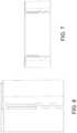
- FIG. 1is a plan view of a vehicle with a vision system that incorporates cameras
- FIGS. 2 A- 2 Care plan views of conventional techniques for minimizing gaps in electromagnetic interference (EMI) shielding
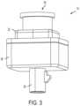
- FIG. 3is a perspective view of a vehicular camera
- FIG. 4is a perspective view of a portion of EMI shielding that includes one or more overlapping tabs to reduce a length of gaps in the EMI shielding;
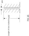
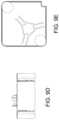
- FIG. 5 Ais a comparison of a traditional gap and a gap with the overlapping tab of FIG. 4 ;
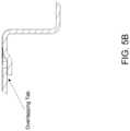
- FIG. 5 Bis a plan view of the overlapping tab of FIG. 4 ;
- FIGS. 6 and 7are additional exemplary plan views of the overlapping tabs of FIG. 4 ;
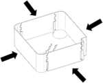
- FIG. 8is a perspective view of EMI shielding including a plurality of seams or gaps with one or more overlapping tabs;
- FIGS. 9 A- 9 Eprovide additional exemplary views of the EMI shielding of FIG. 8 ;
- FIGS. 10 A- 11 Bare cross-sectional views of the EMI shielding of FIG. 8 ;
- FIG. 12is a perspective view of the EMI shielding of FIG. 8 and a housing that at least partially surrounds the EMI shielding;
- FIG. 13is a perspective view of the EMI shielding of FIG. 8 , a housing, and a printed circuit board (PCB).
- PCBprinted circuit board
- a vehicle vision system and/or driver or driving assist system and/or object detection system and/or alert systemoperates to capture images exterior of the vehicle and may process the captured image data to display images and to detect objects at or near the vehicle and in the predicted path of the vehicle, such as to assist a driver of the vehicle in maneuvering the vehicle in a rearward direction.
- the vision systemincludes an image processor or image processing system that is operable to receive image data from one or more cameras and provide an output to a display device for displaying images representative of the captured image data.
- the vision systemmay provide display, such as a rearview display or a top down or bird's eye or surround view display or the like.
- a vehicle 10includes an imaging system or vision system 12 that includes at least one exterior viewing imaging sensor or camera, such as a rearward viewing imaging sensor or camera 14 a (and the system may optionally include multiple exterior viewing imaging sensors or cameras, such as a forward viewing camera 14 b at the front (or at the windshield) of the vehicle, and a sideward/rearward viewing camera 14 c , 14 d at respective sides of the vehicle), which captures images exterior of the vehicle, with the camera having a lens for focusing images at or onto an imaging array or imaging plane or imager of the camera ( FIG. 1 ).
- an imaging system or vision system 12that includes at least one exterior viewing imaging sensor or camera, such as a rearward viewing imaging sensor or camera 14 a (and the system may optionally include multiple exterior viewing imaging sensors or cameras, such as a forward viewing camera 14 b at the front (or at the windshield) of the vehicle, and a sideward/rearward viewing camera 14 c , 14 d at respective sides of the vehicle), which captures images exterior of the vehicle, with
- a forward viewing cameramay be disposed at the windshield of the vehicle and view through the windshield and forward of the vehicle, such as for a machine vision system (such as for traffic sign recognition, headlamp control, pedestrian detection, collision avoidance, lane marker detection and/or the like).
- the vision system 12includes a control or electronic control unit (ECU) 18 having electronic circuitry and associated software, with the electronic circuitry including a data processor or image processor that is operable to process image data captured by the camera or cameras, whereby the ECU may detect or determine presence of objects or the like and/or the system provide displayed images at a display device 16 for viewing by the driver of the vehicle (although shown in FIG.
- the data transfer or signal communication from the camera to the ECUmay comprise any suitable data or communication link, such as a vehicle network bus or the like of the equipped vehicle.
- Electromagnetic shieldingis an important requirement of vehicular digital cameras. Cameras typically at least partially rely on shielding (e.g., metal plating) that at least partially surrounds the camera to protect from electromagnetic interference (EMI), such as a metal shield that at least partially surrounds or is at least partially surrounded by a camera housing.
- EMIelectromagnetic interference
- long gaps or seams in the walls of the shieldallow for EMI to escape and/or enter the enclosure ( FIG. 2 A ). These gaps are a result of the manufacturing process of the shield which is typically done by sheet metal stamping.
- these gapsallow for flexibility of the shield during assembly. Shield flexibility is important because the shield should press against the plastic housing for efficient thermal transfer between the housing and the external environment of the camera and because flexibility generally eases assembly.
- FIGS. 2 B and 2 Cwelding or crimping the gaps closed ( FIG. 2 B ) will connect them electrically and therefore effectively shorten the length of the slot at every connection point, but this prevents flexibility for assembly and requires additional processing steps during manufacturing.
- a stepped geometry to the gapFIG. 2 C ), such as a zig-zag or elongated skew pattern (e.g., an isogonal elongated skew apeirogon pattern) interrupts the overall length of the gap (increasing effectiveness of the shield), but it is not as effective as a shield that has contact points across the gap or a shield that has a blocking wall.
- the camera 14 of the vision system 12includes a first or front housing portion 22 that includes a lens or lens assembly 24 , and further includes a second or rear housing portion 26 that has a connector portion 28 for electrically connecting to or receiving one or more connecting ends of wires of the vehicle when the camera is disposed at the vehicle.
- Implementations hereininclude an EMI shield (i.e., shield element for reducing the effects of EMI on the camera) that includes areas of one or more overlapping tabs ( FIG. 4 ) to allow for a flexible assembly state while simultaneously reducing the effective slot length (i.e., the length of the slot without interruption) and increasing shield effectiveness.
- the addition of the overlap tab(s)may reduce the length of any area that has the step feature ( FIGS. 4 and 5 A ).
- the shieldmay compress perpendicular to each wall face during assembly to a housing of the camera (e.g., a plastic housing) when the size of the shield is larger than the inside of the plastic housing and the shielding at least partially surrounds the plastic housing.
- the gaps in the shieldallow the walls to flex inward (and thus better transfer heat away from the camera). Long gaps reduce shielding effectiveness, but the overlapping tabs reduce the length of the slot created by the gap by blocking access for EMI to escape or enter.
- the overlapping tabsmay also contact the adjacent wall once assembled into the housing to give the benefits of a welded housing (i.e., by reducing or eliminating gaps in the shield) while still allowing the flexibility to assemble.
- the overlapping tabmay extend for any length of the “seam” (i.e., the gap) in the shielding. As shown in FIG. 6 , the overlapping tab may be oriented along approximately half of the seam. That is, half of the seam includes the overlapping tab(s) and the other half includes small slot steps (e.g., where an overlap tab may or may not be possible). In some examples, the tab extends the length of the seam while in other examples the tab extends less than half the length of the seam. The tab may overlap or extend over the shield by any amount (e.g., at least one centimeter, at least five centimeters, etc.).
- a portion of the shield that the tab overlapsmay be thinner (i.e., thinner than other portions of the shield that are not overlapped by the tab) in order to better accommodate the overlapping tab.
- the shieldingmay include any number of overlapping tabs.
- one side of the shieldmay have zero, one, or two seams that include overlapping tabs ( FIG. 7 ).
- the shieldmay include a total of four seams, each seam with one or more overlapping tabs. Two of the seams may be on one side of the shielding while the remaining two seams may be on the opposite side of the shielding.
- the seamsallow the shield to be assembled together from multiple smaller pieces (e.g., four pieces).
- the tabshelp assemble and/or bond the pieces of the shield together after assembly.
- friction or force provided by the tab contacting the shield at the overlapping portionmay serve to at least partially fasten the pieces of the shield together.
- the pieces of the shieldmay fastened or further fastened using any other means, such as welding, adhesive, etc.
- Each piece of the shieldmay be stamped from sheet metal or the like.
- FIGS. 9 A- 9 Eprovide additional exemplary views of the shielding that includes multiple seams with overlapping tabs that reduce the length of seam/slot, thereby decreasing the amount of EMI that is passed through.
- the shieldmay include apertures or cutouts to allow, for example, cables, wires, wiring harnesses, etc., to pass through the shield.
- FIGS. 10 A- 11 Bprovide exemplary cross-sectional views of the shielding or shield element.
- a shield element 30may be at least partially encompassed by the camera housing (e.g., the rear camera housing 26 ), which may be made of a material such as plastic. In other examples, the shielding encompasses the housing. In yet other examples, the shielding and housing are integrated together. As shown in FIG. 13 , a printed circuit board (PCB) 32 may be included within a cavity formed by the shielding and/or housing. In the illustrated embodiment, the shielding element includes an opening at the rear end of the element through which an electrical connector is disposed to provide electrical connection between circuitry of the PCB and a wire harness of a vehicle when the camera is installed at the vehicle. The shielding element may include tabs that engage and connect at the connector to ground the shielding element to a grounding portion of the connector.
- the camera housinge.g., the rear camera housing 26
- the shieldingencompasses the housing.
- the shielding and housingare integrated together.
- a printed circuit board (PCB) 32may be included within a cavity formed by the shielding and
- EMI shielding techniquesfor a vehicular camera, however it is understood that the EMI shielding techniques are applicable to any other sensors or processing systems that benefit from EMI shielding and from flexible installation processes (e.g., radar sensors, lidar, etc.).
- the EMI shieldmay include aspects described in U.S. Pat. Nos. 10,926,714; 10,484,587 and/or 10,128,595, which are hereby incorporated herein by reference in their entireties.
- the cameramay include a PCB disposed at or in the front or rear camera housing portion at a lens holder (that accommodates a lens).
- the PCBmay comprise an imager printed circuit board with an imager disposed at a front side of the PCB and aligned with the lens.
- An electrical connectionmay extend from a rear side of the PCB for passing through the rear end or portion of the camera housing and EMI shield for electrical connection of circuitry of the PCB to a wire harness of a vehicle.
- the cameramay house or include the imager PCB at the front camera housing and a connector PCB that is disposed in the camera housing and is electrically connected to circuitry of the imager PCB (such as via a flexible ribbon cable or header connectors or the like), with the connector PCB having electrical connection that extends from a rear side of the connector PCB for passing through the rear end or portion of the camera housing and EMI shield for electrical connection of circuitry of the PCBs to a wire harness of a vehicle.
- the cameras and connectorsmay utilize aspects of the cameras described in described in U.S. Pat. Nos.
- the camera or sensormay comprise any suitable camera or sensor.
- the cameramay comprise a “smart camera” that includes the imaging sensor array and associated circuitry and image processing circuitry and electrical connectors and the like as part of a camera module, such as by utilizing aspects of the vision systems described in U.S. Pat. Nos. 10,099,614 and/or 10,071,687, which are hereby incorporated herein by reference in their entireties.
- the systemincludes an image processor operable to process image data captured by the camera or cameras, such as for detecting objects or other vehicles or pedestrians or the like in the field of view of one or more of the cameras.
- the image processormay comprise an image processing chip selected from the EYEQ family of image processing chips available from Mobileye Vision Technologies Ltd. of Jerusalem, Israel, and may include object detection software (such as the types described in U.S. Pat. Nos. 7,855,755; 7,720,580 and/or 7,038,577, which are hereby incorporated herein by reference in their entireties), and may analyze image data to detect vehicles and/or other objects.
- the systemmay generate an alert to the driver of the vehicle and/or may generate an overlay at the displayed image to highlight or enhance display of the detected object or vehicle, in order to enhance the driver's awareness of the detected object or vehicle or hazardous condition during a driving maneuver of the equipped vehicle.
Landscapes
- Engineering & Computer Science (AREA)
- Multimedia (AREA)
- Signal Processing (AREA)
- Physics & Mathematics (AREA)
- Electromagnetism (AREA)
- Studio Devices (AREA)
Abstract
Description
Claims (21)
Priority Applications (1)
| Application Number | Priority Date | Filing Date | Title |
|---|---|---|---|
| US18/049,037US12262103B2 (en) | 2021-10-25 | 2022-10-24 | Vehicular camera with enhanced EMI shielding |
Applications Claiming Priority (2)
| Application Number | Priority Date | Filing Date | Title |
|---|---|---|---|
| US202163262980P | 2021-10-25 | 2021-10-25 | |
| US18/049,037US12262103B2 (en) | 2021-10-25 | 2022-10-24 | Vehicular camera with enhanced EMI shielding |
Publications (2)
| Publication Number | Publication Date |
|---|---|
| US20230128640A1 US20230128640A1 (en) | 2023-04-27 |
| US12262103B2true US12262103B2 (en) | 2025-03-25 |
Family
ID=86055370
Family Applications (1)
| Application Number | Title | Priority Date | Filing Date |
|---|---|---|---|
| US18/049,037Active2043-05-04US12262103B2 (en) | 2021-10-25 | 2022-10-24 | Vehicular camera with enhanced EMI shielding |
Country Status (1)
| Country | Link |
|---|---|
| US (1) | US12262103B2 (en) |
Citations (54)
| Publication number | Priority date | Publication date | Assignee | Title |
|---|---|---|---|---|
| US5550677A (en) | 1993-02-26 | 1996-08-27 | Donnelly Corporation | Automatic rearview mirror system using a photosensor array |
| US5670935A (en) | 1993-02-26 | 1997-09-23 | Donnelly Corporation | Rearview vision system for vehicle including panoramic view |
| US6211457B1 (en)* | 1997-12-18 | 2001-04-03 | Eastman Kodak Company | EMI-shielded connector in an electronic device |
| US6433825B1 (en)* | 1997-12-18 | 2002-08-13 | Eastman Kodak Company | EMI-protected eject interface for an electronic device |
| US20030185536A1 (en)* | 2002-04-01 | 2003-10-02 | White Rock Networks | Systems and methods for managing optical fiber media in a communications switch component |
| US20050001901A1 (en) | 2003-07-03 | 2005-01-06 | Helmuth Eggers | Camera system for a motor vehicle |
| US20060171704A1 (en) | 2002-11-14 | 2006-08-03 | Bingle Robert L | Imaging system for vehicle |
| US20060189183A1 (en) | 2005-02-18 | 2006-08-24 | Ming-Hsun Yang | Camera module connector |
| US20060209523A1 (en)* | 2005-03-15 | 2006-09-21 | Tortured Path-Emi Solutions Llc | Three-dimensional configurations providing electromagnetic interference shielding for electronics enclosures |
| US20090115891A1 (en) | 2007-11-01 | 2009-05-07 | Samsung Electronics Co., Ltd. | Camera module |
| US20090244361A1 (en) | 2005-10-28 | 2009-10-01 | Magna Electronics Inc. | Camera module for vehicle vision system |
| US7901215B1 (en) | 2009-10-20 | 2011-03-08 | GM Global Technology Operations LLC | Electrical harness assemblies |
| US20110122267A1 (en)* | 2009-11-06 | 2011-05-26 | Samsung Techwin Co., Ltd. | Shake correction module, camera module comprising the same, and method of manufacturing the camera module |
| US20110163904A1 (en)* | 2008-10-08 | 2011-07-07 | Delphi Technologies, Inc. | Integrated radar-camera sensor |
| US20110310248A1 (en) | 2009-02-06 | 2011-12-22 | Magna Electronics Inc. | A camera for mounting on a vehicle |
| US20120218412A1 (en) | 2009-06-12 | 2012-08-30 | Magna Electronics Inc. | Scalable integrated electronic control unit for vehicle |
| US8503061B2 (en) | 2009-03-30 | 2013-08-06 | Magna Mirrors Of America, Inc. | Electro-optic rearview mirror assembly for vehicle |
| US20130222595A1 (en) | 2010-11-04 | 2013-08-29 | Magna Electronics, Inc. | Vehicular camera system with reduced number of pins and conduits |
| US20130242099A1 (en) | 2012-03-06 | 2013-09-19 | Magna Electronics Inc. | Vehicle camera with tolerance compensating connector |
| US8542451B2 (en) | 2009-03-25 | 2013-09-24 | Magna Electronics Inc. | Vehicular camera and lens assembly |
| US20130328672A1 (en) | 2011-02-25 | 2013-12-12 | Magna Electronics Inc. | Vehicular camera with aligned housing members and electrical connection between aligned housing members |
| US20130344736A1 (en) | 2012-06-14 | 2013-12-26 | Magna Electronics Inc. | Electrical connector with sealed pins |
| US20140043525A1 (en)* | 2012-08-10 | 2014-02-13 | Eddie Azuma | Auto-Focus Camera Module with Flexible Printed Circuit Extension |
| US20140138140A1 (en) | 2012-11-19 | 2014-05-22 | Magna Electronics Inc. | Pcb pad for imager of vehicle vision system |
| US20140218535A1 (en) | 2011-09-21 | 2014-08-07 | Magna Electronics Inc. | Vehicle vision system using image data transmission and power supply via a coaxial cable |
| US20140320636A1 (en) | 2013-04-29 | 2014-10-30 | Magna Electronics Inc. | Rear vision system for vehicle with dual purpose signal lines |
| US20140340510A1 (en) | 2011-11-28 | 2014-11-20 | Magna Electronics Inc. | Vision system for vehicle |
| US20140362209A1 (en) | 2013-06-10 | 2014-12-11 | Magna Electronics Inc. | Coaxial cable with bidirectional data transmission |
| US20140373345A1 (en) | 2013-06-24 | 2014-12-25 | Magna Electronics Inc. | Vehicle vision system camera with coaxial cable connector |
| US20150042807A1 (en) | 2013-08-12 | 2015-02-12 | Magna Electronics Inc. | Head unit with uniform vision processing unit interface |
| US8994878B2 (en) | 2008-10-16 | 2015-03-31 | Magna Electronics Inc. | Camera for vehicular applications |
| US20150124098A1 (en) | 2013-11-07 | 2015-05-07 | Magna Electronics Inc. | Camera for vehicle vision system |
| US9041806B2 (en) | 2009-09-01 | 2015-05-26 | Magna Electronics Inc. | Imaging and display system for vehicle |
| US20150222795A1 (en) | 2014-02-03 | 2015-08-06 | Magna Electronics Inc. | Vehicle camera housing with tolerance compensating connector |
| US9126525B2 (en) | 2009-02-27 | 2015-09-08 | Magna Electronics Inc. | Alert system for vehicle |
| US20150266430A1 (en) | 2014-03-24 | 2015-09-24 | Magna Electronics Inc. | Vehicle camera housing with tolerance compensating contacts |
| US20150327398A1 (en) | 2014-05-09 | 2015-11-12 | Magna Electronics Inc. | Vehicle vision system with forward viewing camera |
| US20150365569A1 (en) | 2014-06-11 | 2015-12-17 | Magna Electronics Inc. | Camera module for vehicle vision system |
| US20160037028A1 (en) | 2014-08-04 | 2016-02-04 | Magna Electroncs Inc. | Vehicle vision system with camera having molded interconnect device |
| US20160243987A1 (en) | 2015-02-24 | 2016-08-25 | Magna Mirrors Of America, Inc. | Mirror assembly with spring-loaded electrical connectors |
| US20160268716A1 (en) | 2015-03-09 | 2016-09-15 | Magna Electronics Inc. | Vehicle camera with connector system for high speed transmission |
| US20160286103A1 (en) | 2015-03-23 | 2016-09-29 | Magna Electronics Inc. | Vehicle camera with enhanced imager and pcb assembly |
| US20170054881A1 (en) | 2015-08-17 | 2017-02-23 | Magna Electronics Inc. | Vehicle camera assembly |
| US20170129419A1 (en) | 2015-11-05 | 2017-05-11 | Magna Electronics Inc. | Vehicle camera with modular construction |
| US20170133811A1 (en) | 2015-11-05 | 2017-05-11 | Magna Electronics Inc. | Overmolded harness connector for vehicle camera |
| US20170201661A1 (en)* | 2015-03-09 | 2017-07-13 | Magna Electronics Inc. | Vehicle camera with connector system for high speed transmission |
| US20170280034A1 (en) | 2016-03-23 | 2017-09-28 | Magna Electronics Inc. | Vehicle vision system camera with enhanced imager and lens assembly |
| US20170289457A1 (en)* | 2016-04-01 | 2017-10-05 | Tdk Taiwan Corp. | Camera module |
| US20170295306A1 (en) | 2016-04-08 | 2017-10-12 | Magna Electronics Inc. | Camera for vehicle vision system |
| US20170302829A1 (en) | 2016-04-14 | 2017-10-19 | Magna Electronics Inc. | Camera for vehicle vision system |
| US20180072239A1 (en) | 2014-08-04 | 2018-03-15 | Magna Electronics Inc. | Vehicle camera having molded interconnect device |
| US20180098033A1 (en) | 2016-10-03 | 2018-04-05 | Magna Electronics Inc. | Vehicle camera with compliant coaxial connector |
| US20180352127A1 (en)* | 2015-12-01 | 2018-12-06 | Ningbo Sunny Opotech Co., Ltd. | Photographing module and electric bracket thereof |
| US10926714B2 (en) | 2017-11-10 | 2021-02-23 | Magna Electronics Inc. | Vehicle camera with EMI shielding |
- 2022
- 2022-10-24USUS18/049,037patent/US12262103B2/enactiveActive
Patent Citations (69)
| Publication number | Priority date | Publication date | Assignee | Title |
|---|---|---|---|---|
| US5670935A (en) | 1993-02-26 | 1997-09-23 | Donnelly Corporation | Rearview vision system for vehicle including panoramic view |
| US5949331A (en) | 1993-02-26 | 1999-09-07 | Donnelly Corporation | Display enhancements for vehicle vision system |
| US5550677A (en) | 1993-02-26 | 1996-08-27 | Donnelly Corporation | Automatic rearview mirror system using a photosensor array |
| US6211457B1 (en)* | 1997-12-18 | 2001-04-03 | Eastman Kodak Company | EMI-shielded connector in an electronic device |
| US6433825B1 (en)* | 1997-12-18 | 2002-08-13 | Eastman Kodak Company | EMI-protected eject interface for an electronic device |
| US20030185536A1 (en)* | 2002-04-01 | 2003-10-02 | White Rock Networks | Systems and methods for managing optical fiber media in a communications switch component |
| US7965336B2 (en) | 2002-11-14 | 2011-06-21 | Donnelly Corporation | Imaging system for vehicle |
| US20060171704A1 (en) | 2002-11-14 | 2006-08-03 | Bingle Robert L | Imaging system for vehicle |
| US20050001901A1 (en) | 2003-07-03 | 2005-01-06 | Helmuth Eggers | Camera system for a motor vehicle |
| US20060189183A1 (en) | 2005-02-18 | 2006-08-24 | Ming-Hsun Yang | Camera module connector |
| US20060209523A1 (en)* | 2005-03-15 | 2006-09-21 | Tortured Path-Emi Solutions Llc | Three-dimensional configurations providing electromagnetic interference shielding for electronics enclosures |
| US20090244361A1 (en) | 2005-10-28 | 2009-10-01 | Magna Electronics Inc. | Camera module for vehicle vision system |
| US20090115891A1 (en) | 2007-11-01 | 2009-05-07 | Samsung Electronics Co., Ltd. | Camera module |
| US20110163904A1 (en)* | 2008-10-08 | 2011-07-07 | Delphi Technologies, Inc. | Integrated radar-camera sensor |
| US8994878B2 (en) | 2008-10-16 | 2015-03-31 | Magna Electronics Inc. | Camera for vehicular applications |
| US20110310248A1 (en) | 2009-02-06 | 2011-12-22 | Magna Electronics Inc. | A camera for mounting on a vehicle |
| US8866907B2 (en) | 2009-02-06 | 2014-10-21 | Magna Electronics Inc. | Camera for mounting on a vehicle |
| US9126525B2 (en) | 2009-02-27 | 2015-09-08 | Magna Electronics Inc. | Alert system for vehicle |
| US9277104B2 (en) | 2009-03-25 | 2016-03-01 | Magna Electronics Inc. | Vehicular camera and lens assembly and method of manufacturing same |
| US8542451B2 (en) | 2009-03-25 | 2013-09-24 | Magna Electronics Inc. | Vehicular camera and lens assembly |
| US8503061B2 (en) | 2009-03-30 | 2013-08-06 | Magna Mirrors Of America, Inc. | Electro-optic rearview mirror assembly for vehicle |
| US20120218412A1 (en) | 2009-06-12 | 2012-08-30 | Magna Electronics Inc. | Scalable integrated electronic control unit for vehicle |
| US9041806B2 (en) | 2009-09-01 | 2015-05-26 | Magna Electronics Inc. | Imaging and display system for vehicle |
| US7901215B1 (en) | 2009-10-20 | 2011-03-08 | GM Global Technology Operations LLC | Electrical harness assemblies |
| US20110122267A1 (en)* | 2009-11-06 | 2011-05-26 | Samsung Techwin Co., Ltd. | Shake correction module, camera module comprising the same, and method of manufacturing the camera module |
| US20130222595A1 (en) | 2010-11-04 | 2013-08-29 | Magna Electronics, Inc. | Vehicular camera system with reduced number of pins and conduits |
| US9233641B2 (en) | 2011-02-25 | 2016-01-12 | Magna Electronics Inc. | Vehicular camera with aligned housing members and electrical connection between aligned housing members |
| US20130328672A1 (en) | 2011-02-25 | 2013-12-12 | Magna Electronics Inc. | Vehicular camera with aligned housing members and electrical connection between aligned housing members |
| US20140218535A1 (en) | 2011-09-21 | 2014-08-07 | Magna Electronics Inc. | Vehicle vision system using image data transmission and power supply via a coaxial cable |
| US20140340510A1 (en) | 2011-11-28 | 2014-11-20 | Magna Electronics Inc. | Vision system for vehicle |
| US9565342B2 (en) | 2012-03-06 | 2017-02-07 | Magna Electronics Inc. | Vehicle camera with tolerance compensating connector |
| US20130242099A1 (en) | 2012-03-06 | 2013-09-19 | Magna Electronics Inc. | Vehicle camera with tolerance compensating connector |
| US9077098B2 (en) | 2012-06-14 | 2015-07-07 | Magna Electronics Inc. | Electrical connector with sealed pins |
| US20130344736A1 (en) | 2012-06-14 | 2013-12-26 | Magna Electronics Inc. | Electrical connector with sealed pins |
| US20140043525A1 (en)* | 2012-08-10 | 2014-02-13 | Eddie Azuma | Auto-Focus Camera Module with Flexible Printed Circuit Extension |
| US20140138140A1 (en) | 2012-11-19 | 2014-05-22 | Magna Electronics Inc. | Pcb pad for imager of vehicle vision system |
| US20140320636A1 (en) | 2013-04-29 | 2014-10-30 | Magna Electronics Inc. | Rear vision system for vehicle with dual purpose signal lines |
| US20140362209A1 (en) | 2013-06-10 | 2014-12-11 | Magna Electronics Inc. | Coaxial cable with bidirectional data transmission |
| US9609757B2 (en) | 2013-06-24 | 2017-03-28 | Magna Electronics Inc. | Vehicle vision system camera assembly with coaxial connector |
| US20140373345A1 (en) | 2013-06-24 | 2014-12-25 | Magna Electronics Inc. | Vehicle vision system camera with coaxial cable connector |
| US20150042807A1 (en) | 2013-08-12 | 2015-02-12 | Magna Electronics Inc. | Head unit with uniform vision processing unit interface |
| US20150124098A1 (en) | 2013-11-07 | 2015-05-07 | Magna Electronics Inc. | Camera for vehicle vision system |
| US20150222795A1 (en) | 2014-02-03 | 2015-08-06 | Magna Electronics Inc. | Vehicle camera housing with tolerance compensating connector |
| US20150266430A1 (en) | 2014-03-24 | 2015-09-24 | Magna Electronics Inc. | Vehicle camera housing with tolerance compensating contacts |
| US20150327398A1 (en) | 2014-05-09 | 2015-11-12 | Magna Electronics Inc. | Vehicle vision system with forward viewing camera |
| US20150365569A1 (en) | 2014-06-11 | 2015-12-17 | Magna Electronics Inc. | Camera module for vehicle vision system |
| US9621769B2 (en) | 2014-06-11 | 2017-04-11 | Magna Electronics Inc. | Camera module for vehicle vision system |
| US20160037028A1 (en) | 2014-08-04 | 2016-02-04 | Magna Electroncs Inc. | Vehicle vision system with camera having molded interconnect device |
| US20180072239A1 (en) | 2014-08-04 | 2018-03-15 | Magna Electronics Inc. | Vehicle camera having molded interconnect device |
| US20160243987A1 (en) | 2015-02-24 | 2016-08-25 | Magna Mirrors Of America, Inc. | Mirror assembly with spring-loaded electrical connectors |
| US10484587B2 (en) | 2015-03-09 | 2019-11-19 | Magna Electronics Inc. | Vehicle camera with connector system for high speed transmission |
| US10128595B2 (en) | 2015-03-09 | 2018-11-13 | Magna Electronics Inc. | Vehicle camera with connector system for high speed transmission |
| US20170201661A1 (en)* | 2015-03-09 | 2017-07-13 | Magna Electronics Inc. | Vehicle camera with connector system for high speed transmission |
| US20160268716A1 (en) | 2015-03-09 | 2016-09-15 | Magna Electronics Inc. | Vehicle camera with connector system for high speed transmission |
| US20160286103A1 (en) | 2015-03-23 | 2016-09-29 | Magna Electronics Inc. | Vehicle camera with enhanced imager and pcb assembly |
| US20170054881A1 (en) | 2015-08-17 | 2017-02-23 | Magna Electronics Inc. | Vehicle camera assembly |
| US10272857B2 (en) | 2015-08-17 | 2019-04-30 | Magna Electronics Inc. | Vehicle camera assembly |
| US20170133811A1 (en) | 2015-11-05 | 2017-05-11 | Magna Electronics Inc. | Overmolded harness connector for vehicle camera |
| US10250004B2 (en) | 2015-11-05 | 2019-04-02 | Magna Electronics Inc. | Method of forming a connector for an electrical cable for electrically connecting to a camera of a vehicle |
| US20170129419A1 (en) | 2015-11-05 | 2017-05-11 | Magna Electronics Inc. | Vehicle camera with modular construction |
| US20180352127A1 (en)* | 2015-12-01 | 2018-12-06 | Ningbo Sunny Opotech Co., Ltd. | Photographing module and electric bracket thereof |
| US20170280034A1 (en) | 2016-03-23 | 2017-09-28 | Magna Electronics Inc. | Vehicle vision system camera with enhanced imager and lens assembly |
| US20170289457A1 (en)* | 2016-04-01 | 2017-10-05 | Tdk Taiwan Corp. | Camera module |
| US10142532B2 (en) | 2016-04-08 | 2018-11-27 | Magna Electronics Inc. | Camera for vehicle vision system |
| US20170295306A1 (en) | 2016-04-08 | 2017-10-12 | Magna Electronics Inc. | Camera for vehicle vision system |
| US10230875B2 (en) | 2016-04-14 | 2019-03-12 | Magna Electronics Inc. | Camera for vehicle vision system |
| US20170302829A1 (en) | 2016-04-14 | 2017-10-19 | Magna Electronics Inc. | Camera for vehicle vision system |
| US20180098033A1 (en) | 2016-10-03 | 2018-04-05 | Magna Electronics Inc. | Vehicle camera with compliant coaxial connector |
| US10926714B2 (en) | 2017-11-10 | 2021-02-23 | Magna Electronics Inc. | Vehicle camera with EMI shielding |
Also Published As
| Publication number | Publication date |
|---|---|
| US20230128640A1 (en) | 2023-04-27 |
Similar Documents
| Publication | Publication Date | Title |
|---|---|---|
| US11267408B2 (en) | Vehicular camera with electrically conductive elements at the rear camera housing portion and at the electrical connector | |
| US10604084B2 (en) | Vehicle camera with modular construction | |
| US11683449B2 (en) | Method for assembling a vehicular camera having a coaxial electrical connector | |
| US20210337094A1 (en) | Vehicle camera with connector system for high speed transmission | |
| US12208750B2 (en) | Vehicular camera with pliable material disposed between and contacting stacked PCBs | |
| US10250004B2 (en) | Method of forming a connector for an electrical cable for electrically connecting to a camera of a vehicle | |
| US20210385963A1 (en) | Vehicular radar sensor with mechanical coupling of sensor housing | |
| US10652437B2 (en) | Vehicle camera with aluminum extruded body | |
| US11683911B2 (en) | Vehicular sensing device with cooling feature | |
| US10560613B2 (en) | Vehicle camera with modular construction | |
| US11831971B2 (en) | Onboard camera | |
| US11638362B2 (en) | Vehicular radar sensor with enhanced housing and PCB construction | |
| CN111225831B (en) | Sensor support, sensor module and vehicle for vehicle | |
| US12262103B2 (en) | Vehicular camera with enhanced EMI shielding |
Legal Events
| Date | Code | Title | Description |
|---|---|---|---|
| FEPP | Fee payment procedure | Free format text:ENTITY STATUS SET TO UNDISCOUNTED (ORIGINAL EVENT CODE: BIG.); ENTITY STATUS OF PATENT OWNER: LARGE ENTITY | |
| STPP | Information on status: patent application and granting procedure in general | Free format text:DOCKETED NEW CASE - READY FOR EXAMINATION | |
| STPP | Information on status: patent application and granting procedure in general | Free format text:NON FINAL ACTION MAILED | |
| STPP | Information on status: patent application and granting procedure in general | Free format text:NOTICE OF ALLOWANCE MAILED -- APPLICATION RECEIVED IN OFFICE OF PUBLICATIONS | |
| AS | Assignment | Owner name:MAGNA ELECTRONICS INC., MICHIGAN Free format text:ASSIGNMENT OF ASSIGNORS INTEREST;ASSIGNORS:SMITH, JAMES L.;CONGER, JONATHAN D.;SIGNING DATES FROM 20221122 TO 20241121;REEL/FRAME:069649/0748 | |
| STPP | Information on status: patent application and granting procedure in general | Free format text:AWAITING TC RESP., ISSUE FEE NOT PAID | |
| STPP | Information on status: patent application and granting procedure in general | Free format text:NOTICE OF ALLOWANCE MAILED -- APPLICATION RECEIVED IN OFFICE OF PUBLICATIONS | |
| STPP | Information on status: patent application and granting procedure in general | Free format text:PUBLICATIONS -- ISSUE FEE PAYMENT RECEIVED | |
| STCF | Information on status: patent grant | Free format text:PATENTED CASE |