US12261926B2 - Fabric control protocol for data center networks with packet spraying over multiple alternate data paths - Google Patents
Fabric control protocol for data center networks with packet spraying over multiple alternate data pathsDownload PDFInfo
- Publication number
- US12261926B2 US12261926B2US17/454,731US202117454731AUS12261926B2US 12261926 B2US12261926 B2US 12261926B2US 202117454731 AUS202117454731 AUS 202117454731AUS 12261926 B2US12261926 B2US 12261926B2
- Authority
- US
- United States
- Prior art keywords
- access node
- packets
- destination
- packet
- fcp
- Prior art date
- Legal status (The legal status is an assumption and is not a legal conclusion. Google has not performed a legal analysis and makes no representation as to the accuracy of the status listed.)
- Active
Links
Images


Classifications
- H—ELECTRICITY
- H04—ELECTRIC COMMUNICATION TECHNIQUE
- H04L—TRANSMISSION OF DIGITAL INFORMATION, e.g. TELEGRAPHIC COMMUNICATION
- H04L69/00—Network arrangements, protocols or services independent of the application payload and not provided for in the other groups of this subclass
- H04L69/26—Special purpose or proprietary protocols or architectures
- H—ELECTRICITY
- H04—ELECTRIC COMMUNICATION TECHNIQUE
- H04L—TRANSMISSION OF DIGITAL INFORMATION, e.g. TELEGRAPHIC COMMUNICATION
- H04L12/00—Data switching networks
- H04L12/28—Data switching networks characterised by path configuration, e.g. LAN [Local Area Networks] or WAN [Wide Area Networks]
- H04L12/46—Interconnection of networks
- H04L12/4633—Interconnection of networks using encapsulation techniques, e.g. tunneling
- H—ELECTRICITY
- H04—ELECTRIC COMMUNICATION TECHNIQUE
- H04L—TRANSMISSION OF DIGITAL INFORMATION, e.g. TELEGRAPHIC COMMUNICATION
- H04L45/00—Routing or path finding of packets in data switching networks
- H04L45/16—Multipoint routing
- H—ELECTRICITY
- H04—ELECTRIC COMMUNICATION TECHNIQUE
- H04L—TRANSMISSION OF DIGITAL INFORMATION, e.g. TELEGRAPHIC COMMUNICATION
- H04L45/00—Routing or path finding of packets in data switching networks
- H04L45/42—Centralised routing
- H—ELECTRICITY
- H04—ELECTRIC COMMUNICATION TECHNIQUE
- H04L—TRANSMISSION OF DIGITAL INFORMATION, e.g. TELEGRAPHIC COMMUNICATION
- H04L45/00—Routing or path finding of packets in data switching networks
- H04L45/64—Routing or path finding of packets in data switching networks using an overlay routing layer
- H—ELECTRICITY
- H04—ELECTRIC COMMUNICATION TECHNIQUE
- H04L—TRANSMISSION OF DIGITAL INFORMATION, e.g. TELEGRAPHIC COMMUNICATION
- H04L47/00—Traffic control in data switching networks
- H04L47/10—Flow control; Congestion control
- H04L47/15—Flow control; Congestion control in relation to multipoint traffic
- H—ELECTRICITY
- H04—ELECTRIC COMMUNICATION TECHNIQUE
- H04L—TRANSMISSION OF DIGITAL INFORMATION, e.g. TELEGRAPHIC COMMUNICATION
- H04L47/00—Traffic control in data switching networks
- H04L47/10—Flow control; Congestion control
- H04L47/18—End to end
- H—ELECTRICITY
- H04—ELECTRIC COMMUNICATION TECHNIQUE
- H04L—TRANSMISSION OF DIGITAL INFORMATION, e.g. TELEGRAPHIC COMMUNICATION
- H04L47/00—Traffic control in data switching networks
- H04L47/50—Queue scheduling
- H04L47/52—Queue scheduling by attributing bandwidth to queues
- H—ELECTRICITY
- H04—ELECTRIC COMMUNICATION TECHNIQUE
- H04L—TRANSMISSION OF DIGITAL INFORMATION, e.g. TELEGRAPHIC COMMUNICATION
- H04L49/00—Packet switching elements
- H04L49/25—Routing or path finding in a switch fabric
- H—ELECTRICITY
- H04—ELECTRIC COMMUNICATION TECHNIQUE
- H04L—TRANSMISSION OF DIGITAL INFORMATION, e.g. TELEGRAPHIC COMMUNICATION
- H04L69/00—Network arrangements, protocols or services independent of the application payload and not provided for in the other groups of this subclass
- H04L69/30—Definitions, standards or architectural aspects of layered protocol stacks
- H04L69/32—Architecture of open systems interconnection [OSI] 7-layer type protocol stacks, e.g. the interfaces between the data link level and the physical level
- H04L69/322—Intralayer communication protocols among peer entities or protocol data unit [PDU] definitions
- H04L69/324—Intralayer communication protocols among peer entities or protocol data unit [PDU] definitions in the data link layer [OSI layer 2], e.g. HDLC
Definitions
- the inventionrelates to computer networks and, more particularly, data center networks.
- a data centermay comprise a facility that hosts applications and services for subscribers, i.e., customers of the data center.
- the data centermay, for example, host all of the infrastructure equipment, such as compute nodes, networking and storage systems, power systems, and environmental control systems.
- clusters of storage systems and application serversare interconnected via a high-speed switch fabric provided by one or more tiers of physical network switches and routers.
- Data centersvary greatly in size, with some public data centers containing hundreds of thousands of servers, and are usually distributed across multiple geographies for redundancy.
- a typical data center switch fabricincludes multiple tiers of interconnected switches and routers.
- packets for a given packet flow between a source server and a destination server or storage systemare always forwarded from the source to the destination along a single path through the routers and switches comprising the switching fabric.
- Example implementations of a new data transmission protocolare described for use within a data center or other computing environment.
- the fabric control protocolmay provide certain advantages in environments in which a switch fabric provides full mesh interconnectivity such that any of the servers may communicate packet data for a given packet flow to any other of the servers using any of a number of parallel data paths within the data center switch fabric.
- example implementations of the fabric control protocolenable spraying of individual packets for a given packet flow across some or all of the multiple parallel data paths in the data center switch fabric and, optionally, reordering of the packets for delivery to the destination.
- the fabric control protocol packet structureis carried over an underlying protocol, such as the User Datagram Protocol (UDP).
- UDPUser Datagram Protocol
- the fabric control protocolmay provide end-to-end bandwidth scaling and flow fairness within a single tunnel based on endpoint-controlled requests and grants for flows.
- the fabric control protocolmay delay packet segmentation for flows until a grant is received, provide fault tolerant and hardware-based adaptive rate control of requests and grants, provide adaptive request window scaling, encrypt and authenticate requests and grants, and improve explicit congestion notification (ECN) marking support.
- ECNexplicit congestion notification
- the fabric control protocolincludes end-to-end admission control mechanisms in which a sender explicitly requests a receiver with the intention to transfer a certain number of bytes of payload data. In response, the receiver issues a grant based on its buffer resources, quality of service (QoS), and/or a measure of fabric congestion.
- the fabric control protocolincludes admission control mechanisms through which a source node requests permission before transmitting a packet on the fabric to a destination node. For example, the source node sends a request message to the destination node requesting a certain number of bytes to be transferred, and the destination node sends a grant message to the source node after reserving the egress bandwidth.
- the fabric control protocolenables packets of an individual packet flow to be sprayed across all available paths between a source node and a destination node.
- the source nodeassigns a packet sequence number to each packet of the flow, and the destination node may use the packet sequence numbers to put the incoming packets of the same flow in order.
- this disclosureis directed to a network system comprising a plurality of servers; a switch fabric comprising a plurality of core switches; and a plurality of access nodes, each of the access nodes coupled to a subset of the servers and coupled to a subset of the core switches, wherein the access nodes include a source access node and a destination access node each executing a fabric control protocol (FCP).
- FCPfabric control protocol
- the source access nodeis configured to send an FCP request message for an amount of data to be transferred in a packet flow from a source server coupled to the source access node to a destination server coupled to the destination access node, and in response to receipt of an FCP grant message indicating an amount of bandwidth reserved for the packet flow, spray FCP packets of the packet flow across a plurality of parallel data paths in accordance with the reserved bandwidth.
- the destination access nodeis configured to, in response to receipt of the FCP request message, perform grant scheduling and send the FCP grant message indicating the amount of bandwidth reserved for the packet flow, and in response to receiving the FCP packets of the packet flow, deliver the data transferred in the packet flow to the destination server.
- this disclosureis directed to a method comprising establishing a logical tunnel over a plurality of parallel data paths between a source access node and a destination access node within a computer network, wherein the source and destination access nodes are respectively coupled to one or more servers, wherein the source and destination access nodes are connected by an intermediate network comprising a switch fabric having a plurality of core switches, and wherein the source and destination access nodes are each executing a fabric control protocol (FCP); sending, by the source access node, an FCP request message for an amount of data to be transferred in a packet flow from a source server coupled to the source access node to a destination server coupled to the destination access node; and in response to receipt of an FCP grant message indicating an amount of bandwidth reserved for the packet flow, forwarding FCP packets of the packet flow by spraying, by the source access node, the FCP packets across the plurality of parallel data paths in accordance with the reserved bandwidth.
- FCPfabric control protocol
- this disclosureis directed to a method comprising establishing a logical tunnel over a plurality of parallel paths between a source access node and a destination access node within a computer network, wherein the source and destination access nodes are respectively coupled to one or more servers, wherein the source and destination access nodes are connected by an intermediate network comprising a switch fabric having a plurality of core switches, and wherein the source and destination access nodes are each executing a fabric control protocol (FCP); in response to receipt of an FCP request message for an amount of data to be transferred in a packet flow from a source server coupled to the source access node to a destination server coupled to the destination access node, performing, by the destination access node, grant scheduling; sending, by the destination access node, an FCP grant message indicating an amount of bandwidth reserved for the packet flow; and in response to receiving FCP packets of the packet flow, delivering, by the destination access node, the data transferred in the packet flow to the destination server.
- FCPfabric control protocol
- FIG. 1is a block diagram illustrating an example network having a data center in which examples of the techniques described herein may be implemented.
- FIG. 2is a block diagram illustrating in further detail the logical interconnectivity provided by access nodes and switch fabric within a data center.
- FIG. 3is a block diagram illustrating one example of network storage compute unit (NSCU) 40 including an access node group and its supported servers.
- NSCUnetwork storage compute unit
- FIG. 4is a block diagram illustrating an example logical rack arrangement including two NSCUs from FIG. 3 .
- FIG. 5is a block diagram illustrating an example of full mesh connectivity between two access node groups within a logical rack.
- FIG. 6is a block diagram illustrating an example arrangement of a full physical rack including two logical racks from FIG. 4 .
- FIG. 7 Ais a block diagram showing a logical view of the networking data paths and operations within an access node.
- FIG. 7 Bis a block diagram illustrating an example first-level network fanout achieved between a set of access nodes within a logical rack.
- FIG. 8is a block diagram illustrating an example multi-level network fanout across a data center switch fabric between access nodes.
- FIG. 9is a block diagram illustrating an example access node including a networking unit and two or more processing cores.
- FIG. 10is a block diagram illustrating an example networking unit of an access node.
- FIG. 11is a conceptual diagram illustrating an example network fabric between a source access node and a destination access node.
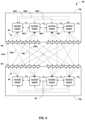
- FIG. 12is a conceptual diagram illustrating an example fabric control protocol queue pair structure between source and destination access nodes.
- FIG. 13is a conceptual diagram illustrating an example of fabric control protocol queue states at source and destination access nodes.
- FIG. 14is a conceptual diagram illustrating an example fabric control protocol operation to transfer an input packet stream from a source access node to a destination access node.
- FIG. 15is a conceptual diagram illustrating an example fabric control protocol source access node operation flow.
- FIG. 16is a conceptual diagram illustrating an example fabric control protocol destination access node operation flow.
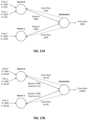
- FIGS. 17 A and 17 Bare conceptual diagrams illustrating an example of flow fairness achieved using a fabric control protocol grant scheduler at a destination access node.
- FIG. 18is a conceptual diagram illustrating an example format of a fabric control protocol control packet for request messages or grant messages.
- FIG. 19is a conceptual diagram illustrating an example format of a fabric control protocol data packet.
- FIG. 20is a block diagram illustrating an example system having a packet switched network with multiple network access node virtual fabrics dynamically configured over the packet switched network, in accordance with the techniques described herein.
- FIG. 21is a flowchart illustrating an example of operation of a network system in accordance with the techniques described herein.
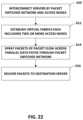
- FIG. 22is a flowchart illustrating another example of operation of a network system in accordance with the techniques described herein.
- Today's large-scale data center networkscan connect over 100,000 two-socket servers and are often designed to operate at close to 25% of the bisection throughput. Most of the data centers therefore need to provide large bisection bandwidth as the demand for capacity grows.
- the data centersmust also support ever increasing variety of applications from big-data analytics to financial services. They also must be agile and allow the applications to be deployed to any server to be efficient and cost effective.
- Data centersutilize various flow scheduling techniques to attempt to balance utilization of the underlying interconnection fabric of the network.
- ECMPequal cost multi-path
- ECMPoften results in poor load-balancing as it randomly hashes packet flows to network paths. With hash collisions, and a few large flows, the fabric of the data center often becomes severely imbalanced.
- ECMP coupled with flowlet switchingmay somewhat improve the load balancing as a new path is chosen every time flowlet switching takes place.
- ECMPuses local decisions to split traffic among equal cost path without any feedback about any possible congestion or link failure in the downstream for any of the chosen paths. As a result, a failure can significantly reduce the effective throughput even though the network may have built-in redundancy.
- HederaAnother flow scheduling technique, referred to as Hedera, attempts to provide dynamic flow scheduling for data center networks. Hedera collects flow information from constituent switches, computes non-conflicting paths for flows and instructs the switches to reroute traffic accordingly. By taking a high-level view of routing and traffic demands, Hedera attempts to enable the scheduling system to see the bottlenecks that the load switching elements cannot. However, Hedera is too slow for traffic volatility of today's data centers as it requires monitoring a flow for some time and its estimated ideal demand before making a redistribution decision.
- MPTCPmulti-path transmission control protocol
- MPTCPsplits the large TCP flow into multiple TCP flows and the payload is striped across the MPTCP flows so that each MPTCP flow is small enough that it does not run into ECMP bottlenecks due to hash collisions.
- the MPTCPdoes require changes in the end-host network stack that is usually not controlled by network operators. Even if a network operator does have a control over the network stack, some of the high bandwidth low latency applications, such as storage traffic, may bypass the kernel and implement their own transport. Further the MPTCP adds complexity to already complex transport layer burdened by low latency and burst absorption requirements of today's datacenters.
- CONGAdistributed congestion-aware load balancing for data centers splits TCP flows into flowlets, estimates real time congestion in the fabric paths, and allocates flowlets to paths based on feedback from remote switches.
- the feedback from remote switchesenables CONGA to seamlessly handle asymmetry, without requiring any TCP modifications.
- the CONGAhas to be implemented in custom ASICs as part of a new network fabric to be able to react to the congestion in microseconds.
- FCPfabric control protocol
- FCPmay provide fabric admission control.
- a source nodemaintains a queue for each destination node and traffic class. Before transmitting a packet on the fabric, the source node asks permission by sending a request message to the destination node requesting a certain number of bytes to be transferred. The destination node sends a grant message to the source after reserving egress bandwidth. The source node then transmits the packets until it sends the granted number of bytes to the destination stopping at the packet boundary.
- FCPenables spray of packets of the same packet flow to all available paths between a source and a destination node.
- a data center networkhas many paths from a source node to reach a destination node through a typical leaf/spine topology.
- switching elementsdetermine a path for the flow through 5-tuple hash and ECMP forwarding algorithm. All packets of the flow (based on hash bucket) travel on the same path to avoid packet reordering.
- Paths to connect multiple layers of switches in the networkuse low bandwidth links. Low bandwidth links limit the maximum bandwidth carried by a TCP flow.
- FCPallows packets to be sprayed to all available links between a source node and a destination node lifting a limitation on size of TCP flow.
- the source nodeassigns a packet sequence number to every packet.
- the destination nodemay use the packet sequence numbers to put incoming packets in order before delivering them to higher layers such as TCP.
- example implementation of FCPmay be used to provide resilience against request/grant packet loss, and out of order delivery.
- the request and grant messagesare not required to be reordered by the end nodes and do not carry packet sequence numbers.
- the request/grant messagesuse sliding window based markers to communicate the size information making the underlying transport for request/grant messages to be resilient against loss/drops or out of order delivery.
- the data packets carrying payloadare explicitly re-ordered by the destination node using packet sequence numbers. Data packet loss is handled through reorder timeouts and the loss is recovered by higher levels such as TCP through retransmission.
- FCPenables an adaptive and low latency fabric implementation.
- the source/destination nodesuse adaptive bandwidth control techniques through outgoing request and grant messages that react to long term fabric congestion caused by fabric failures.
- By adaptively controlling the request and grant ratesthe amount of data entering/leaving the fabric is controlled.
- the FCPmaintains a congestion free fabric operation and thereby achieves a predictable latency for packets traversing through the fabric.
- FCPprovides fault recovery, adaptive to network switch/link failures to support minimal impact.
- the FCPadopts to any fabric failures that are detected by hardware within the round trip time (RTT) to minimize the packet loss.
- RTTround trip time
- FCPhas reduced or minimal protocol overhead cost.
- the FCPinvolves explicit request/grant message exchange for every segment of payload to be transferred between nodes.
- the payload packetis encapsulated over UDP+FCP header.
- the FCPprovides various advantages listed here at the cost of latency and certain amount of bandwidth. The latency impact is minimized to small flows via unsolicited transmission of the packets without an explicit request grant handshake.
- FCPprovides support for unsolicited packet transfer.
- the FCPallows a limited fabric bandwidth to be used for sending unsolicited packets (without explicit request-grant handshake) from a sender to the receiver.
- a small amount of creditcan be configured to allow a small amount of bandwidth to be used for unsolicited transfers.
- Unsolicited trafficis only allowed from the queues that are very shallow (based on threshold).
- the request/grant rate limitersadjust for the unsolicited and non-FCP traffic so as to not cause sustained fabric congestion.
- FCPprovides support for FCP capable/incapable nodes to coexist.
- the FCPallows FCP incapable nodes (non-FCP) to coexist in the same network as the FCP capable nodes.
- the non-FCP nodesmay use ECMP or any other mode of packet transport and load balancing.
- FCPprovides flow-aware fair bandwidth distribution.
- the trafficis governed through a flow-aware admission control scheduler at the destination node.
- the request/grant mechanismuses a “pull” model (via grants), and it ensures flow-aware fair bandwidth distribution among incast flows.
- FCPprovides transmit buffer management through adaptive request window scaling.
- the destination nodeprovides a scale factor based on a global view of active incast flows.
- the source nodeadjusts the outstanding request window based on the scale factor and thereby limits the total transmit buffer in use for every FCP queue based on its drain rate.
- the transmit bufferis thus efficiently used for various large vs. small flows based on their respective drain rates.
- FCPenables receive buffer occupancy based grant management.
- the FCPcontrols the grant generation through an explicit grant pacing algorithm.
- the grant generationreacts to receive buffer occupancy, number of granted blocks in the fabric, and number of blocks in reorder buffer.
- FCPsupports improved end-to-end QoS.
- the FCPprovides improved end-to-end QoS through the grant scheduler at the destination.
- the destinationviews the incoming requests from multiple sources grouped based on priority and schedules the grants based on the desired QoS behavior across the priority groups. Assuming that the FCP achieves a low latency fabric operation due to admission control, the QoS aware grant scheduling removes any dependency of QoS behavior from underlying fabric.
- FCPsupports security through encryption and end-to-end authentication.
- the FCPsupports end-to-end privacy through encryption and also supports authentication for FCP packets protecting all the FCP specific protocol handshake.
- FCPenables improved ECN marking support.
- the FCP grant schedulerprovides a unique view of total load based on the sum total of all pending requests seen at the grant scheduler.
- the ECN marking based on a global load seen by the destination endpointprovides a major improvement over ECN marking based on local congestion seen by individual switches/paths through the fabric.
- the ECN marking based on global view of output egress queue at the grant scheduleris a significant improvement compared to disjoint and localized view of some of the paths through the fabric and provides better congestion management at TCP level.
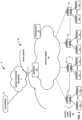
- FIG. 1is a block diagram illustrating an example system 8 having a data center 10 in which examples of the techniques described herein may be implemented.
- data center 10provides an operating environment for applications and services for customers 11 coupled to the data center by content/service provider network 7 and gateway device 20 .
- content/service provider network 7may be a data center wide-area network (DC WAN), private network or other type of network.
- Data center 10may, for example, host infrastructure equipment, such as compute nodes, networking and storage systems, redundant power supplies, and environmental controls.
- Content/service provider network 7may be coupled to one or more networks administered by other providers, and may thus form part of a large-scale public network infrastructure, e.g., the Internet.
- data center 10may represent one of many geographically distributed network data centers.
- data center 10is a facility that provides information services for customers 11 .
- Customers 11may be collective entities such as enterprises and governments or individuals.
- a network data centermay host web services for several enterprises and end users.
- Other exemplary servicesmay include data storage, virtual private networks, file storage services, data mining services, scientific- or super-computing services, and so on.
- data center 10includes a set of storage systems and application servers 12 interconnected via a high-speed switch fabric 14 .
- servers 12are arranged into multiple different server groups, each including any number of servers up to, for example, n servers 12 1 - 12 n .
- Servers 12provide computation and storage facilities for applications and data associated with customers 11 and may be physical (bare-metal) servers, virtual machines running on physical servers, virtualized containers running on physical servers, or combinations thereof.
- software-defined networking (SDN) controller 21provides a high-level controller for configuring and managing the routing and switching infrastructure of data center 10 .
- SDN controller 21provides a logically and in some cases physically centralized controller for facilitating operation of one or more virtual networks within data center 10 in accordance with one or more embodiments of this disclosure.
- SDN controller 21may operate in response to configuration input received from a network administrator.
- SDN controller 21operates to configure access nodes 17 to logically establish one or more virtual fabrics as overlay networks dynamically configured on top of the physical underlay network provided by switch fabric 14 , in accordance with the techniques described herein. Virtual fabrics and the operation of access nodes to establish virtual fabrics are described below with respect to FIG. 20 .
- data center 10may also include, for example, one or more non-edge switches, routers, hubs, gateways, security devices such as firewalls, intrusion detection, and/or intrusion prevention devices, servers, computer terminals, laptops, printers, databases, wireless mobile devices such as cellular phones or personal digital assistants, wireless access points, bridges, cable modems, application accelerators, or other network devices.
- security devicessuch as firewalls, intrusion detection, and/or intrusion prevention devices
- serverscomputer terminals, laptops, printers, databases
- wireless mobile devicessuch as cellular phones or personal digital assistants, wireless access points, bridges, cable modems, application accelerators, or other network devices.
- each of servers 12is coupled to switch fabric 14 by an access node 17 .
- each access node 17is a highly programmable I/O processor specially designed for offloading certain functions from servers 12 .
- each of access nodes 17includes one or more processing cores consisting of a number of internal processor clusters, e.g., MIPS cores, equipped with hardware engines that offload cryptographic functions, compression and regular expression (RegEx) processing, data storage functions and networking operations.
- each access node 17includes components for fully implementing and processing network and storage stacks on behalf of one or more servers 12 .
- access nodes 18may be programmatically configured to serve as a security gateway for its respective servers 12 , freeing up the processors of the servers to dedicate resources to application workloads.
- each access node 17may be viewed as a network interface subsystem that implements full offload of the handling of data packets (with zero copy in server memory) and storage acceleration for the attached server systems.
- each access node 17may be implemented as one or more application-specific integrated circuit (ASIC) or other hardware and software components, each supporting a subset of the servers.
- ASICapplication-specific integrated circuit
- Access nodes 17may also be referred to as data processing units (DPUs), or devices including DPUs.
- DPUsdata processing units
- access nodemay be used herein interchangeably with the term DPU. Additional example details of various example DPUs are described in U.S. patent application Ser. No. 16/031,921, filed Jul. 10, 2018, entitled “Data Processing Unit for Compute Nodes and Storage Nodes,” and U.S. patent application Ser. No. 16/031,945, filed Jul. 10, 2018, entitled “Data Processing Unit for Stream Processing,” the entire content of each of which is incorporated herein by reference.
- access nodes 17are configurable to operate in a standalone network appliance having one or more access nodes.
- access nodes 17may be arranged into multiple different access node groups 19 , each including any number of access nodes up to, for example, x access nodes 17 1 - 17 x .
- multiple access nodes 17may be grouped (e.g., within a single electronic device or network appliance), referred to herein as an access node group 19 , for providing services to a group of servers supported by the set of access nodes internal to the device.
- an access node group 19may comprise four access nodes 17 , each supporting four servers so as to support a group of sixteen servers.
- each access node 17provides connectivity to switch fabric 14 for a different group of servers 12 and may be assigned respective IP addresses and provide routing operations for the servers 12 coupled thereto. As described herein, access nodes 17 provide routing and/or switching functions for communications from/directed to the individual servers 12 .
- each access node 17includes a set of edge-facing electrical or optical local bus interfaces for communicating with a respective group of servers 12 and one or more core-facing electrical or optical interfaces for communicating with core switches within switch fabric 14 .
- access nodes 17 described hereinmay provide additional services, such as storage (e.g., integration of solid-state storage devices), security (e.g., encryption), acceleration (e.g., compression), I/O offloading, and the like.
- one or more of access nodes 17may include storage devices, such as high-speed solid-state drives or rotating hard drives, configured to provide network accessible storage for use by applications executing on the servers.
- access nodes 17may be directly coupled to each other, such as direct coupling between access nodes in a common access node group 19 , to provide direct interconnectivity between the access nodes of the same group.
- multiple access nodes 17e.g., 4 access nodes
- each access node group 19 of multiple access nodes 17may be configured as standalone network device, and may be implemented as a two rack unit (2RU) device that occupies two rack units (e.g., slots) of an equipment rack.
- access node 17may be integrated within a server, such as a single 1RU server in which four CPUs are coupled to the forwarding ASICs described herein on a mother board deployed within a common computing device.
- one or more of access nodes 17 and servers 12may be integrated in a suitable size (e.g., 10RU) frame that may, in such an example, become a network storage compute unit (NSCU) for data center 10 .
- NSCUnetwork storage compute unit
- an access node 17may be integrated within a mother board of a server 12 or otherwise co-located with a server in a single chassis.
- example implementationsare described in which access nodes 17 interface and utilize switch fabric 14 so as to provide full mesh (any-to-any) interconnectivity such that any of servers 12 may communicate packet data for a given packet flow to any other of the servers using any of a number of parallel data paths within the data center 10 .
- Example network architectures and techniquesare described in which access nodes, in example implementations, spray individual packets for packet flows between the access nodes and across some or all of the multiple parallel data paths in the data center switch fabric 14 and, optionally, reorder the packets for delivery to the destinations so as to provide full mesh connectivity.
- FCPFabric Control Protocol
- a senderexplicitly requests a receiver with the intention to transfer a certain number of bytes of payload data.
- the receiverissues a grant based on its buffer resources, QoS, and/or a measure of fabric congestion.
- FCPenables spray of packets of a flow to all paths between a source and a destination node, and may provide any of the advantages and techniques described herein, including resilience against request/grant packet loss, adaptive and low latency fabric implementations, fault recovery, reduced or minimal protocol overhead cost, support for unsolicited packet transfer, support for FCP capable/incapable nodes to coexist, flow-aware fair bandwidth distribution, transmit buffer management through adaptive request window scaling, receive buffer occupancy based grant management, improved end-to-end QoS, security through encryption and end-to-end authentication and/or improved ECN marking support.
- the techniquesmay provide certain advantages. For example, the techniques may increase significantly the bandwidth utilization of the underlying switch fabric 14 . Moreover, in example implementations, the techniques may provide full mesh interconnectivity between the servers of the data center and may nevertheless be non-blocking and drop-free. More specifically, based on the end-to-end admission control mechanisms of FCP and packet spraying in proportion to available bandwidth, switch fabric 14 may comprise a drop-free fabric at high efficiency without use of link level flow control.
- access nodes 17are described in FIG. 1 with respect to switch fabric 14 of data center 10 , in other examples, access nodes may provide full mesh interconnectivity over any packet switched network.
- the packet switched networkmay include a local area network (LAN), a wide area network (WAN), or a collection of one or more networks.
- the packet switched networkmay have any topology, e.g., flat or multi-tiered, as long as there is full connectivity between the access nodes.
- the packet switched networkmay use any technology, including IP over Ethernet as well as other technologies.
- access nodesmay spray individual packets for packet flows between the access nodes and across multiple parallel data paths in the packet switched network and, optionally, reorder the packets for delivery to the destinations so as to provide full mesh connectivity.
- FIG. 2is a block diagram illustrating in further detail the logical interconnectivity provided by access nodes 17 and switch fabric 14 within the data center.
- access nodes 17 and switch fabric 14may be configured to provide full mesh interconnectivity such that access nodes 17 may communicate packet data for any of servers 12 to any other of the servers 12 using any of a number of M parallel data paths to any of core switches 22 A- 22 M (collectively “core switches 22 ”).
- access nodes 17 and switch fabric 14may be configured and arranged in a way such that the M parallel data paths in switch fabric 14 provide reduced L2/L3 hops and full mesh interconnections (e.g., bipartite graph) between servers 12 , even in massive data centers having tens of thousands of servers.
- switches 22are not connected to each other, which makes it much more likely that any failure of one or more of the switches will be independent of each other.
- the switch fabric itselfmay be implemented using multiple layers of interconnected switches as in a CLOS network.
- each access node 17may, therefore, have multiple parallel data paths for reaching any given other access node 17 and the servers 12 reachable through those access nodes.
- switch fabric 14may be configured such that access nodes 17 may, for any given packet flow between servers 12 , spray the packets of the packet flow across all or a subset of the M parallel data paths of switch fabric 14 by which a given destination access node 17 for a destination server 12 can be reached.
- access nodes 17may spray the packets of individual packet flows across the M paths end-to-end forming a virtual tunnel between a source access node and a destination access node.
- the number of layers included in switch fabric 14 or the number of hops along the M parallel data pathsmay not matter for implementation of the packet spraying techniques described in this disclosure.
- the technique of spraying packets of individual packet flows across all or a subset of the M parallel data paths of switch fabric 14enables the number of layers of network devices within switch fabric 14 to be reduced, e.g., to a bare minimum of one. Further, it enables fabric architectures in which the switches are not connected to each other, reducing the likelihood of failure dependence between two switches and thereby increasing the reliability of the switch fabric.
- Flattening switch fabric 14may reduce cost by eliminating layers of network devices that require power and reduce latency by eliminating layers of network devices that perform packet switching.
- the flattened topology of switch fabric 14may result in a core layer that includes only one level of spine switches, e.g., core switches 22 , that may not communicate directly with one another but form a single hop along the M parallel data paths.
- any access node 17 sourcing traffic into switch fabric 14may reach any other access node 17 by a single, one-hop L3 lookup by one of core switches 22 .
- An access node 17 sourcing a packet flow for a source server 12may use any technique for spraying the packets across the available parallel data paths, such as available bandwidth, random, round-robin, hash-based or other mechanism that may be designed to maximize, for example, utilization of bandwidth or otherwise avoid congestion.
- flow-based load balancingneed not necessarily be utilized and more effective bandwidth utilization may be used by allowing packets of a given packet flow (five tuple) sourced by a server 12 to traverse different paths of switch fabric 14 between access nodes 17 coupled to the source and destinations servers.
- the respective destination access node 17 associated with the destination server 12may be configured to reorder the variable length IP packets of the packet flow into the original sequence in which they were sent and deliver the reordered packets to the destination server.
- the respective destination access node 17 associated with the destination server 12may not reorder the packets of the packet flows prior to delivering the packets to the destination server.
- the destination access node 17may instead deliver the packets to the destination server in the order in which the packets arrive at the destination access node 17 .
- packets that comprise storage access requests or responses to a destination storage appliancemay not need to be reordered into the original sequence in which they were sent. Instead, such storage access requests and responses may be delivered to the destination storage appliance in the order in which they arrive.
- each access node 17implements at least four different operational networking components or functions: (1) a source component operable to receive traffic from server 12 , (2) a source switching component operable to switch source traffic to other source switching components of different access nodes 17 (possibly of different access node groups) or to core switches 22 , (3) a destination switching component operable to switch inbound traffic received from other source switching components or from cores switches 22 and (4) a destination component operable to reorder packet flows and provide the packet flows to destination servers 12 .
- servers 12are connected to source components of the access nodes 17 to inject traffic into the switch fabric 14 , and servers 12 are similarly coupled to the destination components within the access nodes 17 to receive traffic therefrom. Because of the full-mesh, parallel data paths provided by switch fabric 14 , each source switching component and destination switching component within a given access node 17 need not perform L2/L3 switching. Instead, access nodes 17 may apply spraying algorithms to spray packets of a packet flow, e.g., based on available bandwidth, randomly, round-robin, quality of service (QoS)/scheduling or otherwise, to efficiently forward packets without requiring packet analysis and lookup operations.
- QoSquality of service
- Destination switching components of access nodes 17may provide a limited lookup necessary only to select the proper output port for forwarding packets to local servers 12 . As such, with respect to full routing tables for the data center, only core switches 22 may need to perform full lookup operations.
- switch fabric 14provides a highly-scalable, flat, high-speed interconnect in which servers 12 are, in some embodiments, effectively one L2/L3 hop from any other server 12 within the data center.
- Access nodes 17may need to connect to a fair number of core switches 22 in order to communicate packet data to any other of access nodes 17 and the servers 12 accessible through those access nodes.
- access nodes 17may connect to core switches 22 via top of rack (TOR) Ethernet switches, electrical permutation devices, or optical permutation (OP) devices (not shown in FIG. 2 ).
- TORtop of rack
- OPoptical permutation
- source components of the access nodes 17may be configured to spray packets of individual packet flows of the traffic received from server 12 across a set of the other access nodes 17 included in one or more access node groups 19 .
- access node 17may achieve an 8 ⁇ multiplier effect from inter-access node spraying, and an additional 8 ⁇ multiplier effect from OP devices to connect to up to sixty-four core switches 22 .
- Flow-based routing and switching over Equal Cost Multi-Path (ECMP) paths through a networkmay be susceptible to highly variable load-dependent latency.
- the networkmay include many small bandwidth flows and a few large bandwidth flows.
- the source access nodemay select the same path for two of the large bandwidth flows leading to large latencies over that path.
- an administratormay be forced to keep the utilization of the network below 25-30%, for example.
- the techniques described in this disclosure of configuring access nodes 17 to spray packets of individual packet flows across all available pathsenables higher network utilization, e.g., 85-90%, while maintaining bounded or limited latencies.
- the packet spraying techniquesenable a source access node 17 to fairly distribute packets of a given flow across all the available paths while taking link failures into account. In this way, regardless of the bandwidth size of the given flow, the load can be fairly spread across the available paths through the network to avoid over utilization of a particular path.
- the disclosed techniquesenable the same amount of networking devices to pass three times the amount of data traffic through the network while maintaining low latency characteristics and reducing a number of layers of network devices that consume energy.
- access nodes 17may be arranged into multiple different access node groups 19 1 - 19 Y (ANGs in FIG. 2 ), each including any number of access nodes 17 up to, for example, x access nodes 17 1 - 17 x .
- multiple access nodes 17may be grouped and arranged (e.g., within a single electronic device or network appliance), referred to herein as an access node group (ANG) 19 , for providing services to a group of servers supported by the set of access nodes internal to the device.
- ANGaccess node group
- each access node group 19may be configured as standalone network device, and may be implemented as a device configured for installation within a compute rack, a storage rack or a converged rack. In general, each access node group 19 may be configured to operate as a high-performance I/O hub designed to aggregate and process network and/or storage I/O for multiple servers 12 . As described above, the set of access nodes 17 within each of the access node groups 19 provide highly-programmable, specialized I/O processing circuits for handling networking and communications operations on behalf of servers 12 . In addition, in some examples, each of access node groups 19 may include storage devices 27 , such as high-speed solid-state hard drives, configured to provide network accessible storage for use by applications executing on the servers. Each access node group 19 including its set of access nodes 17 , storage devices 27 , and the set of servers 12 supported by the access nodes 17 of that access node group may be referred to herein as a network storage compute unit (NSCU) 40 .
- NSCUnetwork storage compute unit
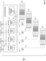
- FIG. 3is a block diagram illustrating one example of network storage compute unit (NSCU) 40 including an access node group 19 and its supported servers 52 .
- Access node group 19may be configured to operate as a high-performance I/O hub designed to aggregate and process network and storage I/O to multiple servers 52 .
- access node group 19includes four access nodes 17 1 - 17 4 (collectively, “access nodes 17 ”) connected to a pool of local solid state storage 41 .
- access node group 19supports a total of sixteen server nodes 12 1 - 12 16 (collectively, “server nodes 12 ”) with each of the four access nodes 17 within access node group 19 supporting four of server nodes 12 .
- each of the four server nodes 12 supported by each of the access nodes 17may be arranged as a server 52 .
- the “servers 12 ” described throughout this applicationmay be dual-socket or dual-processor “server nodes” that are arranged in groups of two or more within a standalone server device, e.g., servers 52 .
- access node group 19is illustrated in FIG. 3 as including four access nodes 17 that are all connected to a single pool of solid state storage 41 , an access node group may be arranged in other ways.
- each of the four access nodes 17may be included on an individual access node sled that also includes solid state storage and/or other types of storage for the access node.
- an access node groupmay include four access node sleds each having an access node and a set of local storage devices.
- access nodes 17 within access node group 19connect to servers 52 and solid state storage 41 using Peripheral Component Interconnect express (PCIe) links 48 , 50 , and connect to other access nodes and the datacenter switch fabric 14 using Ethernet links 42 , 44 , 46 .
- PCIePeripheral Component Interconnect express
- each of access nodes 17may support six high-speed Ethernet connections, including two externally-available Ethernet connections 42 for communicating with the switch fabric, one externally-available Ethernet connection 44 for communicating with other access nodes in other access node groups, and three internal Ethernet connections 46 for communicating with other access nodes 17 in the same access node group 19 .
- each of externally-available connections 42may be a 100 Gigabit Ethernet (GE) connection.
- GEGigabit Ethernet
- access node group 19has 8 ⁇ 100 GE externally-available ports to connect to the switch fabric 14 .
- connections 42may be copper, i.e., electrical, links arranged as 8 ⁇ 25 GE links between each of access nodes 17 and optical ports of access node group 19 .
- connections 42may be optical Ethernet connections coupled to the optical ports of access node group 19 .
- the optical Ethernet connectionsmay connect to one or more optical devices within the switch fabric, e.g., optical permutation devices described in more detail below.
- the optical Ethernet connectionsmay support more bandwidth than electrical connections without increasing the number of cables in the switch fabric.
- each optical cable coupled to access node group 19may carry 4 ⁇ 100 GE optical fibers with each fiber carrying optical signals at four different wavelengths or lambdas.
- the externally-available connections 42may remain as electrical Ethernet connections to the switch fabric.
- the four remaining Ethernet connections supported by each of access nodes 17include one Ethernet connection 44 for communication with other access nodes within other access node groups, and three Ethernet connections 46 for communication with the other three access nodes within the same access node group 19 .
- connections 44may be referred to as “inter-access node group links” and connections 46 may be referred to as “intra-access node group links.”
- Ethernet connections 44 , 46provide full-mesh connectivity between access nodes within a given structural unit.
- a structural unitmay be referred to herein as a logical rack (e.g., a half-rack or a half physical rack) that includes two NSCUs 40 having two AGNs 19 and supports an 8-way mesh of eight access nodes 17 for those AGNs.
- connections 46would provide full-mesh connectivity between the four access nodes 17 within the same access node group 19
- connections 44would provide full-mesh connectivity between each of access nodes 17 and four other access nodes within one other access node group of the logical rack (i.e., structural unit).
- access node group 19may have enough, e.g., sixteen, externally-available Ethernet ports to connect to the four access nodes in the other access node group.
- each of access nodes 17may be connected to each of the other seven access nodes by a 50 GE connection.
- each of connections 46 between the four access nodes 17 within the same access node group 19may be a 50 GE connection arranged as 2 ⁇ 25 GE links.
- Each of connections 44 between the four access nodes 17 and the four access nodes in the other access node groupmay include four 50 GE links.
- each of the four 50 GE linksmay be arranged as 2 ⁇ 25 GE links such that each of connections 44 includes 8 ⁇ 25 GE links to the other access nodes in the other access node group. This example is described in more detail below with respect to FIG. 5 .
- Ethernet connections 44 , 46provide full-mesh connectivity between access nodes within a given structural unit that is a full-rack or a full physical rack that includes four NSCUs 40 having four AGNs 19 and supports a 16-way mesh of access nodes 17 for those AGNs.
- connections 46provide full-mesh connectivity between the four access nodes 17 within the same access node group 19
- connections 44provide full-mesh connectivity between each of access nodes 17 and twelve other access nodes within three other access node group.
- access node group 19may have enough, e.g., forty-eight, externally-available Ethernet ports to connect to the four access nodes in the other access node group.
- each of access nodes 17may be connected to each of the other fifteen access nodes by a 25 GE connection, for example.
- each of connections 46 between the four access nodes 17 within the same access node group 19may be a single 25 GE link.
- Each of connections 44 between the four access nodes 17 and the twelve other access nodes in the three other access node groupsmay include 12 ⁇ 25 GE links.
- each of access nodes 17 within an access node group 19may also support a set of high-speed PCIe connections 48 , 50 , e.g., PCIe Gen 3.0 or PCIe Gen 4.0 connections, for communication with solid state storage 41 within access node group 19 and communication with servers 52 within NSCU 40 .
- Each of servers 52includes four server nodes 12 supported by one of access nodes 17 within access node group 19 .
- Solid state storage 41may be a pool of Non-Volatile Memory express (NVMe)-based solid state drive (SSD) storage devices accessible by each of access nodes 17 via connections 48 .
- NVMeNon-Volatile Memory express
- solid state storage 41may include twenty-four SSD devices with six SSD devices for each of access nodes 17 .
- the twenty-four SSD devicesmay be arranged in four rows of six SSD devices with each row of SSD devices being connected to one of access nodes 17 .
- Each of the SSD devicesmay provide up to 16 Terabytes (TB) of storage for a total of 384 TB per access node group 19 .
- a physical rackmay include four access node groups 19 and their supported servers 52 . In that case, a typical physical rack may support approximately 1.5 Petabytes (PB) of local solid state storage.
- solid state storage 41may include up to 32 U.2 ⁇ 4 SSD devices.
- NSCU 40may support other SSD devices, e.g., 2.5′′ Serial ATA (SATA) SSDs, mini-SATA (mSATA) SSDs, M.2 SSDs, and the like.
- each of the access node sledsmay include four SSD devices and some additional storage that may be hard drive or solid state drive devices.
- the four SSD devices and the additional storagemay provide approximately the same amount of storage per access node as the six SSD devices described in the previous example.
- each of access nodes 17supports a total of 96 PCIe lanes.
- each of connections 48may be an 8 ⁇ 4-lane PCI Gen 3.0 connection via which each of access nodes 17 may communicate with up to eight SSD devices within solid state storage 41 .
- each of connections 50 between a given access node 17 and the four server nodes 12 within the server 52 supported by the access node 17may be a 4 ⁇ 16-lane PCIe Gen 3.0 connection.
- access node group 19has a total of 256 external facing PCIe links that interface with servers 52 .
- access nodes 17may support redundant server connectivity such that each of access nodes 17 connects to eight server nodes 12 within two different servers 52 using an 8 ⁇ 8-lane PCIe Gen 3.0 connection.
- each of access nodes 17supports a total of 64 PCIe lanes.
- each of connections 48may be an 8 ⁇ 4-lane PCI Gen 3.0 connection via which each of access nodes 17 may communicate with up to eight SSD devices within solid state storage 41 .
- each of connections 50 between a given access node 17 and the four server nodes 12 within the server 52 supported by the access node 17may be a 4 ⁇ 8-lane PCIe Gen 4.0 connection.
- access node group 19has a total of 128 external facing PCIe links that interface with servers 52 .
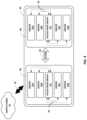
- FIG. 4is a block diagram illustrating an example logical rack arrangement 60 including two NSCUs 40 1 and 40 2 from FIG. 3 .
- each of NSCUs 40may be referred to as a “compute sandwich” based on the structural arrangement of access node group 19 “sandwiched” between two servers 52 on the top and two servers 52 on the bottom.
- server 52 Amay be referred to as a top second server
- server 52 Bmay be referred to as a top server
- server 52 Cmay be referred to as a bottom server
- server 52 Dmay be referred to as a bottom second server.
- Each of servers 52may include four server nodes, and each server node may be a dual-socket or dual-processor server sled.
- Each of access node groups 19connects to servers 52 using PCIe links 50 , and to switch fabric 14 using Ethernet links 42 .
- Access node groups 19 1 and 19 2may each include four access nodes connected to each other using Ethernet links and local solid state storage connected to the access nodes using PCIe links as described above with respect to FIG. 3 .
- the access nodes within access node groups 19 1 and 19 2are connected to each other in a full mesh 64 , which is described in more detail with respect to FIG. 5 .
- each of access node groups 19supports PCIe connections 50 to servers 52 .
- each of connections 50may be a 4 ⁇ 16-lane PCIe Gen 3.0 connection such that access node group 19 has a total of 256 externally-available PCIe links that interface with servers 52 .
- each of connections 50may be a 4 ⁇ 8-lane PCIe Gen 4.0 connection for communication between access nodes within access node group 19 and server nodes within servers 52 .
- connections 50may provide a raw throughput of 512 Gigabits per access node 19 or approximately 128 Gigabits of bandwidth per server node without accounting for any overhead bandwidth costs.
- each of NSCUs 40supports 8 ⁇ 100 GE links 42 from access node group 19 to switch fabric 14 .
- Each of NSCUs 40thus provides support for up to sixteen server nodes in four servers 52 , local solid state storage, and 800 Gbps of full duplex (i.e., bidirectional) network bandwidth.
- Each of access node groups 19may, therefore, provide true hyper-convergence of compute, storage, networking and security of servers 52 .
- Logical rack 60including two NSCUs 40 , therefore, provides support for up to thirty-two server nodes in eight servers 52 , local solid state storage at access node groups 19 , and 16 ⁇ 100 GE links 42 to switch fabric 14 , which results in 1.6 Terabits per second (Tbps) of full duplex network bandwidth.
- TbpsTerabits per second
- FIG. 5is a block diagram illustrating an example of full mesh connectivity between two access node groups 19 1 , 19 2 within a logical rack 60 .
- access node group 19 1includes four access nodes 17 1 - 17 4 and access node group 19 2 also include four access nodes 17 5 - 17 8 .
- Each of access nodes 17connects to the other access nodes within the logical rack in a mesh fabric topology.
- the eight access nodes 17 included in the mesh topologymay be referred to as an access node “cluster.” In this way, each of access nodes 17 is able to spray incoming packets to each of the other access nodes in the cluster.
- each access node 17connects via full mesh connectivity to each of the other seven access nodes in the cluster.
- the mesh topology between access nodes 17includes intra-access node group links 46 between the four access nodes included in the same access node group 19 , and inter-access node group links 44 between access nodes 17 1 - 17 4 in access node group 19 1 and access nodes 17 5 - 17 8 in access node group 19 2 .
- each of connections 44 , 46are bidirectional such that each access node connects to each other access node in the cluster via a separate link.
- Each of access nodes 17 1 - 17 4 within first access node group 19 1has three intra-access node group connections 46 to the other access nodes in first access node group 19 1 .
- access node 17 1supports connection 46 A to access node 17 4 , connection 46 B to access node 17 3 , and connection 46 C to access node 17 2 .
- Access node 17 2supports connection 46 A to access node 17 1 , connection 46 D to access node 17 4 , and connection 46 E to access node 17 3 .
- Access node 17 3supports connection 46 B to access node 17 1 , connection 46 E to access node 17 2 , and connection 46 F to access node 17 4 .
- Access node 17 4supports connection 46 A to access node 17 1 , connection 46 D to access node 17 2 , and connection 46 F to access node 17 3 .
- the access nodes 17 5 - 17 8are similarly connected within second access node group 19 2 .
- Each of access nodes 17 1 - 17 4 within first access node group 19 1also has four inter-access node group connections 44 to the access nodes 17 5 - 17 8 in second access node group 19 2 .
- first access node group 19 1 and second access node group 19 2each has sixteen externally-available ports 66 to connect to each other.
- access node 17 1supports connections 44 A, 44 B, 44 C, and 44 D through four external facing ports 66 of first access node group 19 1 to four externally-available ports 66 of second access node group 19 2 to reach access nodes 17 5 - 17 8 .
- access node 17 1supports connection 44 A to access node 17 5 within second access node group 19 2 , connection 44 B to access node 17 6 within second access node group 19 2 , connection 44 C to access node 17 7 within second access node group 19 2 , and connection 44 D to access node 17 8 within second access node group 19 2 .
- the remaining access nodes 17 2 - 17 4 within first access node group 19 1are similarly connected to access nodes 17 5 - 17 8 within second access node group 19 2 .
- the access nodes 17 5 - 17 8are similarly connected to access nodes 17 1 - 17 4 within first access node group 19 1 .
- Each of access nodes 17may be configured to support up to 400 Gigabits of bandwidth to connect to other access nodes in the cluster.
- each of access nodes 17may support up to eight 50 GE links to the other access nodes.
- 50 Gigabits of bandwidthmay be leftover and used for managing the access node.
- each of connections 44 , 46may be single 50 GE connections.
- each of connections 44 , 46may be 2 ⁇ 25 GE connections.
- each of intra-access node group connections 46may be 2 ⁇ 25 GE connections
- each of inter-access node group connections 44may be single 50 GE connections to reduce a number of inter-box cables.
- 4 ⁇ 50 GE linksgo off box to connect to access nodes 17 5 - 17 8 in second access node group 19 2 .
- the 4 ⁇ 50 GE linksmay be taken out from each of the access nodes 17 using DAC cables.
- FIG. 6is a block diagram illustrating an example arrangement of a full physical rack 70 including two logical racks 60 from FIG. 4 .
- rack 70has 42 rack units or slots in vertical height including a 2 rack unit (2RU) top of rack (TOR) device 72 for providing connectivity to devices within switch fabric 14 .
- TOR device 72comprises a top of rack Ethernet switch.
- TOR device 72comprises an optical permutor.
- rack 70may not include an additional TOR device 72 and instead have the typical 40 rack units.
- rack 70includes four access node groups 19 1 - 19 4 that are each separate network appliances 2RU in height.
- Each of the access node groups 19includes four access nodes and may be configured as shown in the example of FIG. 3 .
- access node group 19 1includes access nodes AN1-AN4
- access node group 19 2includes access nodes AN5-AN8,
- access node group 19 3includes access nodes AN9-AN12
- access node group 19 4includes access nodes AN13-AN16.
- Access nodes AN1-AN16may be substantially similar to access nodes 17 described above.
- each of the access node groups 19supports sixteen server nodes.
- access node group 19 1supports server nodes A1-A16
- access node group 19 2supports server nodes B1-B16
- access node group 19 3supports server nodes C1-C16
- access node group 19 4supports server nodes D1-D16.
- a server nodemay be a dual-socket or dual-processor server sled that is 1 ⁇ 2Rack in width and 1RU in height.
- four of the server nodesmay be arranged into a server 52 that is 2RU in height.
- server 52 Aincludes server nodes A1-A4
- server 52 Bincludes server nodes A5-A8
- server 52 Cincludes server nodes A9-A12
- server 52 Dincludes server nodes A13-A16.
- Server nodes B1-B16, C1-C16, and D1-D16may be similarly arranged into servers 52 .
- Access node groups 19 and servers 52are arranged into NSCUs 40 from FIGS. 3 - 4 .
- NSCUs 40are 10RU in height and each include one 2RU access node group 19 and four 2RU servers 52 .
- access node groups 19 and servers 52may be structured as a compute sandwich, in which each access node group 19 is “sandwiched” between two servers 52 on the top and two servers 52 on the bottom.
- server 52 Amay be referred to as a top second server
- server 52 Bmay be referred to as a top server
- server 52 Cmay be referred to as a bottom server
- server 52 Dmay be referred to as a bottom second server.
- access node groups 19are separated by eight rack units to accommodate the bottom two 2RU servers 52 supported by one access node group and the top two 2RU servers 52 supported by another access node group.
- NSCUs 40may be arranged into logical racks 60 , i.e., half physical racks, from FIG. 5 .
- Logical racks 60are 20RU in height and each include two NSCUs 40 having full mesh connectivity.
- access node group 19 1 and access node group 19 2are included in the same logical rack 60 along with their respective supported server nodes A1-A16 and B1-B16.
- access nodes AN1-AN8 included the same logical rack 60are connected to each other in an 8-way mesh.
- Access nodes AN9-AN16may be similarly connected in an 8-way mesh within another logical rack 60 includes access nodes groups 19 3 and 19 4 along with their respective server nodes C1-C16 and D1-D16.
- Logical racks 60 within rack 70may be connected to the switch fabric directly or through an intermediate top of rack device 72 .
- TOR device 72comprises a top of rack Ethernet switch.
- TOR device 72comprises an optical permutor that transports optical signals between access nodes 17 and core switches 22 and that is configured such that optical communications are “permuted” based on wavelength so as to provide full-mesh connectivity between the upstream and downstream ports without any optical interference.
- each of the access node groups 19may connect to TOR device 72 via one or more of the 8 ⁇ 100 GE links supported by the access node group to reach the switch fabric.
- the two logical racks 60 within rack 70may each connect to one or more ports of TOR device 72 , and TOR device 72 may also receive signals from one or more logical racks within neighboring physical racks.
- rack 70may not itself include TOR device 72 , but instead logical racks 60 may connect to one or more TOR devices included in one or more neighboring physical racks.
- each of the access node groups 19may use approximately 1 kW of power resulting in approximately 4 kW of power for access node groups.
- each of the server nodesmay use approximately 200 W of power resulting in around 12.8 kW of power for servers 52 .
- the 40RU arrangement of access node groups 19 and servers 52therefore, uses around 16.8 kW of power.
- FIG. 7 Ais a block diagram showing a logical view of the networking data paths and operations within an access node 17 .
- each access node 17implements at least four different operational networking components or functions: (1) a source (SF) component 30 operable to receive traffic from a set of servers 12 supported by the access node, (2) a source switching (SX) component 32 operable to switch source traffic to other source switching components of different access nodes 17 (possibly of different access node groups) or to core switches 22 , (3) a destination switching (DX) component 34 operable to switch inbound traffic received from other source switching components or from cores switches 22 and (4) a destination (DF) component 36 operable to reorder packet flows and provide the packet flows to destination servers 12 .
- SFsource
- SXsource switching
- DXdestination switching
- DFdestination
- the different operational networking components of access node 17may perform flow-based switching and ECMP based load balancing for Transmission Control Protocol (TCP) packet flows.
- TCPTransmission Control Protocol
- ECMP loadbalances poorly as it randomly hashes the flows to paths such that a few large flows may be assigned to the same path and severely imbalance the fabric.
- ECMPrelies on local path decisions and does not use any feedback about possible congestion or link failure downstream for any of the chosen paths.
- FCPFabric Control Protocol
- a senderexplicitly requests a receiver with the intention to transfer a certain number of bytes of payload data.
- the receiverissues a grant based on its buffer resources, QoS, and/or a measure of fabric congestion.
- the FCPincludes admission control mechanisms through which a source node requests permission before transmitting a packet on the fabric to a destination node. For example, the source node sends a request message to the destination node requesting a certain number of bytes to be transferred, and the destination node sends a grant message to the source node after reserving the egress bandwidth.
- the FCPinstead of the flow-based switching and ECMP forwarding used to send all packets of a TCP flow on the same path to avoid packet reordering, the FCP enables packets of an individual packet flow to be sprayed to all available links between a source node and a destination node.
- the source nodeassigns a packet sequence number to each packet of the flow, and the destination node may use the packet sequence numbers to put the incoming packets of the same flow in order.
- SF component 30 of access node 17is considered a source node of the fabric.
- SF component 30is configured to spray its input bandwidth (e.g., 200 Gbps) over links to multiple SX components of access nodes within a logical rack.
- SF component 30may spray packets of the same flow across eight links to SX component 32 and seven other SX components of other access nodes within a logical rack.
- SF component 30is configured to select one of the connected SX components to which to send packets of the same flow.
- SX component 32 of access node 17may receive incoming packets from multiple SF components of access nodes within the logical rack, e.g., SF component 30 and seven other SF components of other access nodes within the logical rack.
- SX component 32is also configured to spray its incoming bandwidth over links to multiple core switches in the fabric. For example, as described in more detail with respect to FIG. 8 , SX component 32 may spray its bandwidth across eight links to eight core switches. In some cases, SX component 32 may spray its bandwidth across eight links to four or eight intermediate devices, e.g., TOR Ethernet switches, electrical permutation devices, or optical permutation devices, which in turn forward traffic to the core switches.
- SX component 32is configured to select one of the core switches to which to send packets of the same packet flow. Since the incoming bandwidth to SX component 32 and the outgoing bandwidth from SX component 32 is same (e.g., 200 Gbps), congestion should not occur at the SX stage even for a large number of packet flows.
- DX component 34 of access node 17may receive incoming packets from multiple core switches either directly or via one or more intermediate devices, e.g., TOR Ethernet switches, electrical permutation devices, or optical permutation devices.
- DX component 34may receive incoming packets from eight core switches, or four or eight intermediate devices.
- DX component 34is configured to select a DF component to which to send the received packets.
- DX component 34may be connected to DF component 36 and seven other DF components of other access nodes within the logical rack.
- DX component 34may become a congestion point because DX component 34 may receive a large amount of bandwidth (e.g., 200 Gbps) that is all to be sent to the same DF component.
- DX component 34may avoid long term congestion using the admission control mechanisms of FCP.
- DF component 36 of access node 17may receive incoming packets from multiple DX components of access nodes within the logical rack, e.g., DX component 34 and seven other DX components of other access nodes within the logical rack.
- DF component 36is considered a destination node of the fabric.
- DF component 36is configured to recorder packets of the same flow prior to transmitting the flow to a destination server 12 .
- SX component 32 and DX component 34 of access node 17may use the same forwarding table to perform packet switching.
- the personality of access node 17 and the nexthop identified by the forwarding table for the same destination IP addressmay depend on a source port type of the received data packet. For example, if a source packet is received from a SF component, access node 17 operates as SX component 32 and determines a nexthop to forward the source packet over the fabric toward a destination node. If a packet is received from a fabric-facing port, access node 17 operates as DX component 34 and determines a final nexthop to forward the incoming packet directly to a destination node.
- the received packetmay include an input tag that specifies its source port type.
- FIG. 7 Bis a block diagram illustrating an example first-level network fanout achieved between a set of access nodes 17 1 - 17 8 within a logical rack 60 .
- logical rack 60includes two access node groups 19 1 and 19 2 containing eight access nodes 17 1 - 17 8 and server nodes 12 supported by each of the access nodes.
- SF components 30 A- 30 H and SX components 32 A- 32 H of access nodes 17 within logical rack 60have full mesh connectivity in that each SF component 30 is connected to all of the SX components 32 of the eight access nodes 17 within logical rack 60 .
- the eight access nodes 17 within logical rack 60may be connected to each other by an 8-way mesh of electrical Ethernet connections.
- SF components 30 of access nodes 17 within logical rack 60apply spraying algorithms to spray packets for any given packet flow across all available links to SX components 32 . In this way, SF components 30 need not necessarily perform a full lookup operation for L2/L3 switching of outbound packets of packet flows originating from servers 12 .
- packets for a given packet flowmay be received by an SF component 30 , such as SF component 30 A, and sprayed across some or all of the links to SX components 32 for the logical rack 60 .
- access nodes 17 for a logical rackachieve a first-level fan out of, in this example, 1:8 and may do so, in some examples, without incurring any L2/L3 forwarding lookup relative to keying information in the packet headers.
- packets for a single packet flowneed not follow the same path when sprayed by a given SF component 30 .
- SF component 30 A implemented by access node 17 1upon receiving source traffic from one of servers 12 , SF component 30 A implemented by access node 17 1 , for example, performs an 8-way spray of packets of the same flow across all available links to SX components 32 implemented by access nodes 17 included in logical rack 60 . More specifically, SF component 30 A sprays across one internal SX component 32 A of the same access node 17 1 and seven external SX components 32 B- 32 H of the other access nodes 17 2 - 17 8 within logical rack 60 . In some implementations, this 8-way spray between SFs 30 and SXs 32 within logical rack 60 may be referred to as a first-stage spray.
- a second-stage spraymay be performed over a second-level network fanout within the switch fabric between access nodes 17 and core switches 22 .
- the second-stage spraymay be performed through an intermediate device, such as a TOR Ethernet switch, an electric permutation device, or an optical permutation device.
- the first four access nodes 17 1 - 17 4may be included in a first access node group 19 1 and the second four access nodes 17 4 - 17 8 may be included in a second access node group 19 2 .
- the access nodes 17 within the first and second access node groups 19may be connected to each other via a full-mesh in order to allow the 8-way spray between SFs 30 and SXs 32 within logical rack 60 .
- logical rack 60 including the two access nodes groups together with their supported servers 12may be referred to as a half-rack or a half physical rack.
- more or fewer access nodesmay be connected together using full-mesh connectivity.
- sixteen access nodes 17may be connected together in a full-mesh to enable a first-stage 16-way spray within a full physical rack.
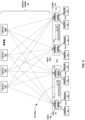
- FIG. 8is a block diagram illustrating an example multi-level network fanout across a data center switch fabric between access nodes 17 .
- each of the logical racks 60includes eight access nodes 17 1 - 17 8 and server nodes 12 supported by each of the access nodes.
- the first logical rack 60 1is connected to the second logical rack 60 2 through core switches 22 within the switch fabric.
- the first logical rack 60 1 and the second logical rack 60 2may be the same logical rack.
- the switch fabriccomprises FCP-based flow control and network communication within a network fabric.
- the network fabricmay be visualized as including multiple channels, e.g., a request channel, a grant channel, an FCP data channel, and a non-FCP data channel, as described in more detail with respect to FIG. 11 .
- the FCP data channelcarries data packets via a logical tunnel 100 that includes all paths between a source node, e.g., SF component 30 A of access node 17 1 , in a first logical rack 60 1 and a destination node, e.g., DF component 36 A of access node 17 1 , in a second logical rack 60 2 .
- the FCP data channelcarries the data packets using the FCP protocol.
- the FCP packetsare sprayed over the fabric from the source node to the destination node through a suitable load balancing scheme.
- the FCP packetsare not expected to be delivered in order, but the destination node may perform packet reordering. For example, packets of a traffic flow received from a source server 12 by SF component 30 A of access node 17 1 may be sprayed over some or all possible links within logical tunnel 100 toward DF component 36 A of access node 17 1 .
- DF component 36 Ais configured to reorder the received packets to recreate the original sequence of the packet flow prior to transmitting the packet flow to the destination server 12 .
- DF component 36 Amay not need to reorder the received packets of the packet flow prior to transmitting the packet flow to the destination server 12 .
- DF component 36 Amay instead deliver the packets to the destination server 12 in the order in which the packets arrive. For example, packets that comprise storage access requests or responses to a destination storage appliance may not need to be reordered into the original sequence in which they were sent.
- the request channel within the network fabricmay be used to carry FCP request messages from the source node to the destination node. Similar to the FCP data packets, the FCP request messages may be sprayed over all available paths toward the destination node, but the request messages do not need to be reordered.
- the grant channel within the network fabricmay be used to carry FCP grant messages from the destination node to source node. The FCP grant messages may also be sprayed over all available paths toward the source node, and the grant messages do not need to be reordered.
- the non-FCP data channel within the network fabriccarries data packets that do not use the FCP protocol. The non-FCP data packets may be forwarded or routed using ECMP based load balancing, and, for a given flow identified by a five tuple, the packets are expected to be delivered in order to the destination node.
- FIG. 8illustrates both the first-level network fanout between the access nodes 17 within first logical rack 60 1 , as described above with respect to FIG. 7 B , and a second-level network fanout between the access nodes 17 and the core switches 22 .
- the eight access nodes 17 within first logical rack 60 1are connected to core switches 22 using either electrical or optical Ethernet connections.
- the eight access nodes 17 within second logical rack 60 2are similarly connected to the core switches 22 .
- each of access nodes 17may connect to eight of core switches 22 .
- SX components 32 of access nodes 17 within first logical rack 60 1apply spraying algorithms to spray packets for any given packet flow across all available paths to the core switches 22 . In this way, the SX components 32 may not perform a full lookup operation for L2/L3 switching of received packets.
- an SF component 30 A of access node 17 1 in the first logical rack 60 1Upon receiving source traffic from one of the servers 12 , an SF component 30 A of access node 17 1 in the first logical rack 60 1 performs an 8-way spray of FCP packets of the traffic flow across all available paths to SX components 32 implemented by the access nodes 17 in the first logical rack 60 1 . As further illustrated in FIG. 8 , each of the SX components 32 then sprays the FCP packets of the traffic flow across all available paths to the core switches 22 .
- the multi-level fanoutis 8-by-8 and, therefore, supports up to sixty-four core switches 22 1 - 22 64 . In other examples, in which the first-level fanout is 1:16 within a full physical rack, the multi-level fanout may be 16-by-16 and support up to 256 core switches.
- the second-level fanoutmay be performed through one or more TOR devices, such as top of rack Ethernet switches, optical permutation devices, or electrical permutation devices.
- the multi-level network fanoutenables packets of a traffic flow received at any of the access nodes 17 within the first logical rack 60 1 to reach core switches 22 for further forwarding to any of the access nodes 17 within the second logical rack 60 2 .
- each of SF components 30 and SX components 32uses an FCP spray engine configured to apply a suitable load balancing scheme to spray the packets of a given FCP packet flow across all available paths to a destination node.
- the load balancing schememay direct each of the FCP packets of the packet flow to one of the parallel data paths selected based on available bandwidth (i.e., least loaded path).
- the load balancing schememay direct each of the FCP packets of the packet flow to a randomly, pseudo-randomly, or round-robin selected one of the parallel data paths.
- the load balancing schememay direct each of the FCP packets of the packet flow to a weighted randomly selected one of the parallel data paths in proportion to available bandwidth in the switch fabric.
- the FCP spray enginemay track a number of bytes transmitted on each path in order to select a least loaded path on which to forward a packet.
- the FCP spray enginemay track path failures downstream to provide flow fairness by spraying packets in proportion to bandwidth weight on each active path. For example, if one of core switches 22 1 - 22 8 connected to SX component 32 A fails, then the path weights between SF component 30 A and SX components 32 change to reflect the smaller proportion of switch fabric bandwidth available behind access node 17 1 within first logical rack 60 1 . In this example, SF component 30 A will spray to SX components 32 in proportion to the available bandwidth behind access nodes 17 within first logical rack 60 1 .
- SF component 30 Awill spray fewer packets to SX component 32 A then the other SX components 32 based on the reduced switch fabric bandwidth behind access node 17 1 within first logical rack 60 1 due to the failure of one of the connected core switches 22 1 - 22 8 .
- the spray of packetsmay not be uniform across the available paths toward the destination node, but bandwidth will be balanced across the active paths even over relatively short periods.
- the source nodee.g., SF component 30 A of access node 17 1
- the destination nodee.g., DF component 36 A of access node 17 1
- the destination nodesends a grant message to the source node after reserving the egress bandwidth.
- the source nodealso determines whether any link failures have occurred between core switches 22 and logical rack 60 2 that includes the destination node. The source node may then use all active links in proportion to the source and destination bandwidths.
- SF components 30 and SX components 32use the FCP spray engine to distribute FCP packets of the traffic flow based on the load on each link toward the destination node, proportion to its weight.
- the spray enginemaintains credit memory to keep track of credits (i.e., available bandwidth) per nexthop member link, uses packet length included in an FCP header to deduct credits (i.e., reduce available bandwidth), and associates a given packet to the one of the active links having the most credits (i.e., the least loaded link).
- the SF components 30 and SX components 32spray packets across member links of a nexthop for a destination node in proportion to the member links' bandwidth weights.
- each of SF components 30 or SX components 32modifies a UDP portion of a header for each of the FCP packets of a packet flow in order to force the packet spraying downstream to core switches 22 . More specifically, each of SF components 30 or SX components 32 is configured to randomly set a different UDP source port in the UDP portion of the header for each of the FCP packets of the packet flow. Each of core switches 22 computes a hash of N-fields from the UDP portion of the header for each of the FCP packets and, based on the randomly set UDP source port for each of the FCP packets, selects one of the parallel data paths on which to spray the FCP packet. This example implementation enables spraying by core switches 22 without modifying core switches 22 to understand the FCP.
- Core switches 22operate as the single hop along logical tunnel 100 between the source node, e.g., SF component 30 A of access node 17 1 , in first logical rack 60 1 and the destination node, e.g., DF component 36 A of access node 17 1 , in the second logical rack 60 2 .
- Core switches 22perform a full lookup operation for L2/L3 switching of the received packets. In this way, core switches 22 may forward all the packets for the same traffic flow toward the destination node, e.g., DF component 36 A of access node 17 1 , in the second logical rack 60 2 that supports the destination server 12 .
- DX components 34 and DF components 36 of access nodes 17 within second logical rack 60 2also have full mesh connectivity in that each DX component 34 is connected to all of the DF components 36 within second logical rack 60 2 .
- the DX components 34forward the packets on a direct path to DF component 36 A of access node 17 1 .
- DF component 36 Amay perform a limited lookup necessary only to select the proper output port for forwarding the packets to the destination server 12 .
- DF component 36 A of access node 17 1 within second logical rack 60 2may reorder the packets of the traffic flow based on sequence numbers of the packets.
- the switch fabricprovides a highly-scalable, flat, high-speed interconnect in which servers are effectively one L2/L3 hop from any other server 12 within the data center.
- FIGS. 1 - 8 BMore details on the data center network architecture and interconnected access node illustrated in FIGS. 1 - 8 B are available in U.S. patent application Ser. No. 15/939,227, filed Mar. 28, 2018, entitled “Non-Blocking Any-to-Any Data Center Network with Packet Spraying Over Multiple Alternate Data Paths,” the entire content of which is incorporated herein by reference.
- access nodes 17are fabric end points (FEPs) to the network fabric, which is made up of switching elements, e.g., core switches 22 , arranged in a leaf-spine topology.
- FEPsfabric end points
- the network fabricallows one access node 17 to communicate with another one through multiple paths.
- Core switches 22 inside the network fabrichave shallow packet buffers.
- the cross-sectional bandwidth of the network fabricis equal to or greater than the sum of all end point bandwidths. In this way, if each access node 17 limits the incoming data rate to the network fabric, none of the paths inside the network fabric should be congested long term with very high probability.
- Tunnel 100is considered to be unidirectional from the source node to the destination node, and an FCP partner tunnel may be established in the other direction from the destination node to the source node.
- the control plane protocolnegotiates the capabilities (e.g., block size, maximum transmission unit (MTU) size, etc.) of both end points, and establishes the FCP connection between the end points by setting up tunnel 100 and its partner tunnel and an initializing queue state context for each tunnel.
- MTUmaximum transmission unit
- a destination queueis identified by the local tunnel ID and priority, and a source tunnel ID is identified from the lookup table based on the local tunnel ID.
- the source nodeWhen the source node is communicating with the destination node, the source node encapsulates the packets using an FCP over UDP encapsulation.
- the FCP headercarries fields identifying tunnel IDs, queue IDs, packet sequence numbers (PSNs) for packets, and request, grant, and data block sequence numbers between the two end points.
- PSNspacket sequence numbers
- the incoming tunnel IDis unique for all packets from the specific source node.
- the tunnel encapsulationcarries the packet forwarding as well as the reordering information used by the destination node.
- a single tunnelcarries packets for one or multiple queues between the source and destination nodes. Only the packets within the single tunnel are reordered based on sequence number tags that span across the queues of the same tunnel.
- the source nodetags the packets with tunnel PSNs when they are sent over the tunnel toward the destination node.
- the destination nodemay reorder the packets based on the tunnel ID and the PSNs. At the end of the reorder, the destination node strips the tunnel encapsulation and forwards the packets to the respective destination queues.
- a source server 12 having an IP address of A0sends an IP packet for a destination server 12 having an IP address of B0.
- the source FCP endpointe.g., access node 17 1 within first logical rack 60 1 , transmits an FCP request packet with source IP address A and destination IP address B.
- the FCP request packethas an FCP header to carry the Request Block Number (RBN) and other fields.
- the FCP request packetis transmitted over UDP over IP.
- the destination FCP end pointe.g., access node 17 1 within second logical rack 60 2 , sends an FCP grant packet back to the source FCP end point.
- the FCP grant packethas an FCP header to carry the Grant Block Number (GBN) and other fields.
- the FCP grant packetis transmitted over UDP over IP.
- the source end pointtransmits the FCP data packet after receiving the FCP grant packet.
- the source end pointappends a new (IP+UDP+FCP) data header on the input data packet.
- the destination end pointremoves the appended (IP+UDP+FCP) data header before delivering the packet to the destination host server.
- FIG. 9is a block diagram illustrating an example access node 130 including a networking unit 142 and two or more processing cores 140 A- 140 N (collectively “cores 140 ”).
- Access node 130generally represents a hardware chip implemented in digital logic circuitry.
- access node 130may be provided as an integrated circuit mounted on a motherboard of a computing device or installed on a card connected to the motherboard of the computing device via PCIe, or the like.
- access node 130may be an integrated circuit within an access node group (e.g., one of access node groups 19 ) configured as a standalone network device for installation within a compute rack, a storage rack, or a converged rack.
- an access node groupe.g., one of access node groups 19
- Access node 130may operate substantially similar to any of the access nodes 17 of FIGS. 1 - 8 .
- access node 130may be communicatively coupled to a data center fabric (e.g., switch fabric 14 ), one or more server devices (e.g., server nodes 12 or servers 52 ), storage media (e.g., solid state storage 41 of FIG. 3 ), one or more network devices, random access memory, or the like, e.g., via PCIe, Ethernet (wired or wireless), or other such communication media in order to interconnect each of these various elements.
- a data center fabrice.g., switch fabric 14
- server devicese.g., server nodes 12 or servers 52
- storage mediae.g., solid state storage 41 of FIG. 3
- network devicese.g., random access memory, or the like, e.g., via PCIe, Ethernet (wired or wireless), or other such communication media in order to interconnect each of these various elements.
- access node 130includes a plurality of cores 140 coupled to an on-chip memory unit 134 .
- memory unit 134may include a cache memory.
- memory unit 134may include two types of memory or memory devices, namely coherent cache memory and non-coherent buffer memory. More details on the bifurcated memory system are available in U.S. patent application Ser. No. 15/949,892, filed Apr. 10, 2018, and titled “Relay Consistent Memory Management in a Multiple Processor System,”, the entire content of which is incorporated herein by reference.
- the plurality of cores 140may include at least two processing cores. In one specific example, the plurality of cores 140 may include six processing cores 140 .
- Access node 130also includes a networking unit 142 , one or more host units 146 , a memory controller 144 , and one or more accelerators 148 . As illustrated in FIG. 9 , each of cores 140 , networking unit 142 , memory controller 144 , host units 146 , accelerators 148 , and memory unit 134 are communicatively coupled to each other. In addition, access node 130 is coupled to an off-chip external memory 150 . External memory 150 may comprise random access memory (RAM) or dynamic random access memory (DRAM).
- RAMrandom access memory
- DRAMdynamic random access memory
- access node 130represents a high performance, hyper-converged network, storage, and data processor and input/output hub.
- Cores 140may comprise one or more of MIPS (microprocessor without interlocked pipeline stages) cores, ARM (advanced RISC (reduced instruction set computing) machine) cores, PowerPC (performance optimization with enhanced RISC—performance computing) cores, RISC-V (RISC five) cores, or CISC (complex instruction set computing or x86) cores.
- MIPSmicroprocessor without interlocked pipeline stages
- ARMadvanced RISC (reduced instruction set computing) machine) cores
- PowerPCperformance optimization with enhanced RISC—performance computing
- RISC-VRISC five
- CISCcomplex instruction set computing or x86 cores.
- Each of cores 140may be programmed to process one or more events or activities related to a given data packet such as, for example, a networking packet or a storage packet.
- Each of cores 140may be programmable using
- the new processing architecture utilizing access node 130may be especially efficient for stream processing applications and environments.
- stream processingis a type of data processing architecture well suited for high performance and high efficiency processing.
- a streamis defined as an ordered, unidirectional sequence of computational objects that can be of unbounded or undetermined length.
- a streamoriginates in a producer and terminates at a consumer, and is operated on sequentially.
- a streamcan be defined as a sequence of stream fragments; each stream fragment including a memory block contiguously addressable in physical address space, an offset into that block, and a valid length.
- Streamscan be discrete, such as a sequence of packets received from the network, or continuous, such as a stream of bytes read from a storage device.
- a stream of one typemay be transformed into another type as a result of processing.
- TCP receive (Rx) processingconsumes segments (fragments) to produce an ordered byte stream.
- the reverse processingis performed in the transmit (Tx) direction.
- stream manipulationrequires efficient fragment manipulation, where a fragment is as defined above.
- the plurality of cores 140may be capable of processing a plurality of events related to each data packet of one or more data packets, received by networking unit 142 and/or host units 146 , in a sequential manner using one or more “work units.”
- work unitsare sets of data exchanged between cores 140 and networking unit 142 and/or host units 146 where each work unit may represent one or more of the events related to a given data packet of a stream.
- a work unitis a container that is associated with a stream state and used to describe (i.e. point to) data within a stream (stored).
- work unitsmay dynamically originate within a peripheral unit coupled to the multi-processor system (e.g.
- one or more processing cores 40 of access node 130may be configured to execute program instructions using a work unit (WU) stack.
- WUwork unit
- a first one of the plurality of cores 140in processing the plurality of events related to each data packet, may process a first event of the plurality of events.
- first core 140 Amay provide to a second one of plurality of cores 140 , e.g., core 140 B, a first work unit of the one or more work units.
- second core 140 Bmay process a second event of the plurality of events in response to receiving the first work unit from first core 140 B.
- Access node 130may act as a combination of a switch/router and a number of network interface cards.
- networking unit 142may be configured to receive one or more data packets from and transmit one or more data packets to one or more external devices, e.g., network devices.
- Networking unit 142may perform network interface card functionality, packet switching, and the like, and may use large forwarding tables and offer programmability.
- Networking unit 142may expose Ethernet ports for connectivity to a network, such as switch fabric 14 of FIG. 1 . In this way, access node 130 supports one or more high-speed network interfaces, e.g., Ethernet ports, without the need for a separate network interface card (NIC).
- NICnetwork interface card
- Each of host units 146may support one or more host interfaces, e.g., PCI-e ports, for connectivity to an application processor (e.g., an x86 processor of a server device) or a storage device (e.g., an SSD). Access node 130 may also include one or more high bandwidth interfaces for connectivity to off-chip external memory 150 .
- Each of accelerators 148may be configured to perform acceleration for various data-processing functions, such as look-ups, matrix multiplication, cryptography, compression, regular expressions, or the like.
- accelerators 148may comprise hardware implementations of look-up engines, matrix multipliers, cryptographic engines, compression engines, regular expression interpreters, or the like.
- Memory controller 144may control access to on-chip memory unit 134 by cores 140 , networking unit 142 , and any number of external devices, e.g., network devices, servers, external storage devices, or the like. Memory controller 144 may be configured to perform a number of operations to perform memory management in accordance with the present disclosure. For example, memory controller 144 may be capable of mapping accesses from one of the cores 140 to a coherent cache memory or a non-coherent buffer memory of memory unit 134 . In some examples, memory controller 144 may map the accesses based on one or more of an address range, an instruction or an operation code within the instruction, a special access, or a combination thereof.
- FIG. 10is a block diagram illustrating an example networking unit 142 of access node 130 from FIG. 9 , in more detail.
- Networking unit (NU) 142exposes Ethernet ports, also referred to herein as fabric ports, to connect access node 130 to the switch fabric.
- NU 142connects to processing cores 140 and external servers and/or storage devices, such as SSD devices, via endpoint ports.
- NU 142supports switching packets from one fabric port to another fabric port without storing the complete packet (i.e., transit switching), which helps to achieve low latency for transit traffic. In this way, NU 142 enables creation of a fabric of access nodes with or without external switching elements.
- NU 142may fulfill the following roles: (1) transmit packets from PCIe devices (servers and/or SSDs) to the switch fabric, and receive packets from the switch fabric and send them to the PCIe devices; (2) support switching packets from one fabric port to another fabric port; (3) support sending network control packets to an access node controller; and (4) implement FCP tunneling.
- PCIe devicesservers and/or SSDs
- NU 142includes a fabric port group (FPG) 170 .
- FPG 170includes two or more fabric ports connected to the switch network.
- FPG 170is configured to receive Ethernet packets from the switch fabric and transmit packets to the switch fabric.
- FPG 170may be responsible for generating and receiving link pause and priority flow control (PFC) frames.
- PFClink pause and priority flow control
- FPG 170may have a flexible parser to parse incoming bytes and generate a parsed result vector (PRV).
- PRVparsed result vector
- FPG 170may have a packet rewrite sub-unit to modify the outgoing packets based on the rewrite instructions stored with the packet.
- NU 142has a single forwarding block 172 to forward the packets coming from the fabric ports of FPG 170 and from the endpoint ports of source agent block 180 .
- Forwarding block 172has a fixed pipeline that is configured to process one PRV, received from FPG 170 and/or source agent block 180 , every cycle.
- the forwarding pipeline of forwarding block 172may include the following processing sections: attributes, ingress filter, packet lookup, nexthop resolution, egress filter, packet replication, and statistics.
- different forwarding attributessuch as virtual layer 2 interface, virtual routing interface, and traffic class, are determined. These forwarding attributes are passed to further processing sections in the pipeline.
- a search keycan be prepared from different fields of a PRV and searched against programmed rules.
- the ingress filter blockcan be used to modify the normal forwarding behavior using the set of rules.
- certain fields of the PRVare looked up in tables to determine the nexthop index.
- the packet lookup blocksupports exact match and longest prefix match lookups.
- nexthop instructionsare resolved and the destination egress port and the egress queue are determined.
- the nexthop resolution blocksupports different nexthops such as final nexthop, indirect nexthop, equal cost multi-path (ECMP) nexthop, and weighted cost multi-path (WCMP) nexthop.
- the final nexthopstores the information of the egress stream and how egress packets should be rewritten.
- the indirect nexthopmay be used by software to embed an address of the nexthop in memory, which can be used to perform an atomic nexthop update.
- the WECMP nexthopmay have multiple members and be used to spray packets over all links between SF components and SX components of access nodes (see, e.g., SF components 30 and SX components 32 of FIG. 8 ). Due to failure of links between rack and spine switches, SFs may need to spray among SXs based on the active links for a destination rack IP address. For FCP traffic, the FCP spray engine sprays packets based on the load on each link proportional to its weight. The WECMP nexthop stores an address of the credits memory, and the FCP spray engine selects the link with the most credits and deducts its credits based on packet length.
- the ECMP nexthopmay have multiple members and be used to spray packets over all links connected to spine switches of access nodes (see, e.g., core switches 22 of FIG. 8 ).
- the FCP spray engineagain sprays packets based on the load on each link proportional to its weight.
- the ECMP nexthopstores an address of the credits memory, and the FCP spray engine selects the link with the most credits and deducts its credits based on packet length.
- the egress filter processing sectionpackets are filtered based on the egress port and the egress queue.
- the egress filter blockcannot change the egress destination or egress queue, but can sample or mirror packets using the rule sets. If any of the processing stages has determined to create a copy of a packet, the packet replication block generates its associated data. NU 142 can create only one extra copy of the incoming packet.
- the statistics processing sectionhas a set of counters to collect statistics for network management purpose. The statistics block also supports metering to control packet rate to some of the ports or queues.
- NU 142also includes a packet buffer 174 to store packets for port bandwidth oversubscription.
- Packet buffer 174may be used to store three kinds of packets: (1) transmit packets received from processing cores 140 on the endpoint ports of source agent block 180 to be transmitted to the fabric ports of FPG 170 ; (2) receive packets received from the fabric ports of FPG 170 to be transmitted to the processing cores 140 via the endpoint ports of destination agent block 182 ; and (3) transit packets coming on the fabric ports of FPG 170 and leaving on the fabric ports of FPG 170 .
- the packet reader sub-unitreads cells from packet memory and sends them to FPG 170 .
- the first 64 bytes of the packetmay carry rewrite information.
- the resource manager sub-unitkeeps track of usage of packet memory for different pools and queues.
- the packet writer blockconsults the resource manager block to determine if a packet should be dropped.
- the resource manager blockmay be responsible to assert flow control to a work unit scheduler or send PFC frames to the ports.
- the cell free pool sub-unitmanages a free pool of packet buffer cell pointers. The cell free pool allocates cell pointers when the packet writer block wants to write a new cell to the packet buffer memory, and deallocates cell pointers when the packet reader block dequeues a cell from the packet buffer memory.
- NU 142includes source agent control block 180 and destination agent control block 182 that, collectively, are responsible for FCP control packets.
- source agent control block 180 and destination control block 182may comprise a single control block.
- Source agent control block 180generates FCP request messages for every tunnel.
- source agent block 180instructs packet buffer 174 to send FCP data packets based on the amount of bandwidth allocated by the FCP grant messages.
- NU 142includes an endpoint transmit pipe (not shown) that sends packets to packet buffer 174 .
- the endpoint transmit pipemay perform the following functions: packet spraying, packet fetching from memory 178 , packet segmentation based on programmed MTU size, packet encapsulation, packet encryption, and packet parsing to create a PRV.
- the endpoint transmit pipemay be included in source agent block 180 or packet buffer 174 .
- Destination agent control block 182generates FCP grant messages for every tunnel. In response to received FCP request messages, destination agent block 182 updates a state of the tunnel and sends FCP grant messages allocating bandwidth on the tunnel, as appropriate. In response to FCP data packets received in response to the FCP grant messages, packet buffer 174 sends the received data packets to packet reorder engine 176 for reordering and reassembly before storage in memory 178 .
- Memory 178may comprise an on-chip memory or an external, off-chip memory. Memory 178 may comprise RAM or DRAM.
- NU 142includes an endpoint receive pipe (not shown) that receives packets from packet buffer 174 .
- FIG. 11is a conceptual diagram illustrating an example FCP-based flow control and network communication within a network fabric 200 , such as a date center switch fabric or other packet-based network.
- network fabric 200is visualized as a fabric with multiple channels between a source access node 196 and a destination access node 198 .
- the FCP data channel 206carries traffic for multiple tunnels and for multiple queues within each tunnel. Each channel is designated for specific type of traffic. The various channels and their attributes are described below.
- the control channel 202has a strict priority over all other channels.
- the expected use for this channelis to carry grant messages.
- the grant messagesare sprayed over all available paths towards the requesting or source node, e.g., source access node 196 . They are not expected to arrive at the requesting node in order.
- the control channel 202is rate limited to minimize overhead on network fabric 200 .
- the high priority channel 204has a higher priority over data and non-FCP channels.
- the high priority channel 204is used to carry FCP request messages.
- the messagesare sprayed over all available paths towards the granting or destination node, e.g., destination access node 198 , and are not expected to arrive at the granting node in order.
- the high priority channel 204is rate limited to minimize overhead on the fabric.
- the FCP data channel 206carries data packets using FCP.
- the data channel 206has a higher priority over a non-FCP data channel.
- the FCP packetsare sprayed over network fabric 200 through a suitable load balancing scheme.
- the FCP packetsare not expected to be delivered at destination access node 198 in order and destination access node 198 is expected to have a packet reorder implementation.
- the non-FCP data channel 208carries data packets that do not use FCP.
- the non-FCP data channel 208has the lowest priority over all other channels.
- the FCP data channel 206carries a strict priority over the non-FCP data channel 208 .
- the non-FCP packetstherefore, use opportunistic bandwidth in the network and, depending upon the requirements, the FCP data rate can be controlled through request/grant pacing schemes allowing non-FCP traffic to gain a required share of the bandwidth.
- the non-FCP data packetsare forwarded/routed using ECMP based load balancing and for a given flow (identified by a five tuple) the packets are expected to be always delivered in order at destination access node 198 .
- the non-FCP data channel 208may have multiple queues with any prioritization/QoS applied at the time of scheduling the packets to the fabric.
- the non-FCP data channel 208may support 8-queues per link-port based on priority of the packet flow.
- the FCP data packetsare sent between source access node 196 and destination access node 198 via a logical tunnel.
- the tunnelis considered unidirectional and, for a destination, the incoming tunnel identifier (ID) is unique for all packets from a specific source node.
- the tunnel encapsulationcarries the packet forwarding as well as the reordering information.
- a single tunnelcarries packets for one or multiple source queues ( 210 ) between source access node 196 and destination access node 198 . Only the packets within a tunnel are reordered based on sequence number tags that span across queues of the same tunnel.
- the packetsare tagged with a tunnel packet sequence number (PSN) when they are sent from the source access node 196 .
- the destination access node 198reorders the packets based on the tunnel ID and PSN ( 212 ).
- the tunnel encapsulationis stripped at the end of reorder and packets are forwarded to respective destination queues ( 214
- the queuesare defined as buckets of independent traffic streams that use FCP to transport payload across network fabric 200 .
- An FCP queueis identified by the [Tunnel-ID, Priority] whereas the Tunnel ID is identified by the source/destination access node pair.
- the access nodes 196 , 198may use a mapping table to derive Tunnel ID, and queue/priority pair based on internal FCP queue ID.
- a fabric tunnelmay support 1, 2, 4, or 8 queues per tunnel. The number of queues per tunnel is a network fabric property and should be configured at the time of deployment.
- An access nodemay support a maximum of 16K queues. All tunnels within the network fabric 200 may support the same number of queues per tunnel.
- the FCP messagesinclude request, grant, and data messages.
- the request messageis generated when source access node 196 wishes to transfer a certain amount of data to destination access node 198 .
- the request messagecarries a destination tunnel ID, queue ID, request block number (RBN) of the queue, and metadata.
- the request messageis sent over high priority channel 204 on the network fabric 200 and the message is sprayed over all available paths.
- the metadatamay be used to indicate a request retry among other things.
- the grant messageis generated when destination access node 198 responds to a request from source access node 196 to transfer a certain amount of data.
- the grant messagecarries the source tunnel ID, queue ID, grant block number (GBN) of the queue, metadata (scale factor, etc.), and timestamp.
- the grant messageis sent over control channel 202 on network fabric 200 and the message is sprayed over all available paths.
- the control packet structure of request and grant messagesis described below with respect to FIG. 18 .
- FCP data packetscarry an FCP header containing the destination tunnel ID, queue ID, packet sequence number (PSN) and data block number (DBN), and metadata.
- the FCP data packetsmay have an average size of ⁇ 800 B.
- the maximum transmission unit (MTU) for FCPmay be ⁇ 1.6 KB-2 KB to minimize packet latency jitter in the fabric.
- the FCP data packet structureis described below with respect to FIG. 19 .
- FIG. 12is a conceptual diagram illustrating an example FCP queue pair structure between source and destination access nodes.
- FCPis an end-to-end admission control protocol.
- the senderexplicitly requests the receiver with intention to transfer a certain number of payload data.
- the receiverissues a grant based on its buffer resources, QoS, and a measure of fabric congestion.
- a fabric endpoint (FEP) nodeis a node that connects to the fabric made of switching elements (leaf-spine topology).
- the fabricallows one endpoint to communicate with the other one through multiple paths. Switching elements inside the fabric have shallow packet buffers.
- the cross-section bandwidth of the fabricis equal or more to the sum of all fabric endpoints' bandwidth. If each fabric endpoint limits the incoming data rate to the fabric, none of the paths inside fabric should be congested for long term with high probability.
- FCPsets up a pair of tunnels 220 , 222 between two FCP endpoints (i.e., source access node 216 and destination access node 218 ) as each tunnel 220 , 222 is considered to be uni-directional.
- Each node 216 , 218has been assigned a source tunnel ID and a corresponding destination tunnel ID.
- the queue IDis derived based on assigned Tunnel-ID, priority at each of the endpoints.
- Each node 216 , 218communicates from a local queue to a remote queue through the set of tunnels 220 , 222 .
- the FCP headercarries fields identifying tunnel IDs, queue-ID, packet sequence numbers for packets, and request, grant, and data block sequence numbers between source access node 216 and destination access node 218 .
- a control plane protocolnegotiates the capabilities of both the endpoints (e.g., block size, MTU size, etc.) and establishes an FCP connection between them by setting up tunnels 220 , 222 and initializing queue state context.
- Each endpoint 216 , 218allocates a local tunnel handle from a pool of handles and communicates the handle to its the FCP connection partner (e.g., in FIG. 12 , destination access node 218 is the FCP connection partner of the source access node 216 ).
- the local tunnel handlemay be stored in a local tunnel ID table (e.g., local tunnel ID table 226 of source access node 216 and local tunnel ID table 228 of destination access node 218 ).
- the FCP partner tunnel handleis stored in a lookup table (e.g., mapping table 224 of source access node 216 , and mapping table 230 of destination access node 218 ) and referenced from the local tunnel handle.
- the source queueis identified by [local Tunnel-ID, Priority], and the destination tunnel ID is identified by the MAP[local Tunnel ID].
- the queueis identified by [local Tunnel ID, priority].
- source access node 216has a source or local tunnel ID of “4” in local tunnel ID table 226 , which maps to a remote or destination tunnel ID of “1024” in mapping table 224 .
- destination access node 218has a source or local tunnel ID of “1024” in local tunnel ID table 228 , which maps to a remote or destination tunnel ID of “4” in mapping table 230 .
- FIG. 13is a conceptual diagram illustrating an example of FCP queue states at source and destination access nodes.
- Each FCP queue at an access node endpointmaintains a set of block sequence numbers for respective sender/receiver queues to track the queue state.
- the sequence numbersindicate the amount of data that has flown through the queue at any given time.
- the sequence numbersmay be in units of bytes (similar to TCP), or in units of blocks (to reduce FCP header overheads).
- the block sizemay be 64, 128, or 256 Bytes, and may be negotiated at the time of FCP connection setup.
- the FCP headermay carry a 16-bit block sequence number and span over 8 MBytes of data (128B) before wrapping around. In this example, the assumption is that the round trip time (RTT) or network delay is too low for the sequence number to wrap around in one RTT.
- RTTround trip time
- Each access node endpointmaintains the following set of block sequence numbers to track enqueued blocks, pending requests, or pending/ungranted blocks.
- a queue tail block numberrepresents the tail block in the transmit queue 240 at the source access node 236 .
- the transmit queue 240only keeps track of WU boundaries at the time of dequeue, which guarantees never to transmit partial WUs on the fabric. A WU however may be split into multiple MTU size packets at the time of transmission.
- request block numberindicates the last block for which a request has been sent over the fabric by the source access node 236 .
- the difference between QBN and RBN at the source access node 236represents the number of unrequested blocks in the transmit queue 240 . If QBN is larger than RBN, the source access node 236 can send a request message for the unrequested blocks through a local request scheduler.
- the local request schedulermay rate limit the outgoing request messages. It may also throttle down overall requested bandwidth throughput via a request rate limiter as a function of long term “near” fabric congestion.
- the near fabric congestionis termed as a local phenomenon at the sender access node 236 due to spine link loss.
- RBNis incremented based on the maximum allowed/configured request size.
- the outgoing request messagecarries the updated RBN value.
- RBNindicates the last block for which a request is received from the fabric by the destination access node 238 .
- destination access node 238updates its RBN with the message RBN if the request message RBN is newer compared to previously accepted RBN. Out of order request messages are discarded if they carry RBN older than the accepted RBN. When a request message is lost, the subsequent request message carrying a newer RBN successfully updates the RBN at destination access node 238 , thus recovering from the lost request message.
- source access node 236sends its last request message and the request message gets lost, destination access node 238 is not aware of the request message loss since it was the last request from the source access node 236 .
- the source access node 236may maintain a request retry timer and if, at the end of timeout, source access node 236 has not received a grant message, source access node 236 may retransmit the request again in an attempt to recover from presumed loss.
- grant block numberindicates the last granted block in the receive queue 242 .
- the distance between RBN and GBNrepresents the number of ungranted blocks at the receive queue 242 .
- An egress grant schedulermay move GBN forward after grant is issued for the receive queue 242 .
- the GBNis updated by the minimum of an allowed grant size or the difference between RBN and GBN.
- GBNindicates the last block number that is granted by the destination access node 238 .
- GBNlike RBN, may not conform to a WU boundary in the output queue 240 .
- the distance between RBN and GBNrepresents the number of ungranted blocks at the transmit queue 240 .
- the transmitteris allowed to go over the GBN to complete the current WU processing.
- source access node 236updates its GBN with the newest GBN compared to previously accepted GBN. Out of order grant messages are discarded if they carry GBN older than the accepted GBN. When a grant message is lost, the subsequent grant message successfully updates the GBN at source access node 236 , thus recovering from the lost grant message.
- destination access node 238When the destination access node 238 sends a last grant message and the grant message is lost or when source access node 236 receives the grant and sends the packet that is dropped in the fabric, destination access node 238 is not aware of the grant message loss or the packet loss since it only knows that it sent the grant and failed to get a packet back. If there are more packets in the tunnel, the tunnel will recover from the loss due to reorder timeout. The destination access node 238 may maintain a timeout and if, at the end of timeout, destination access node 238 has not received a packet, destination access node 238 retransmits the grant again in an attempt to recover from the grant/packet loss.
- source access node 236may send a packet with zero payload, only carrying the DBN.
- the zero length packettravels through regular data channel and updates the receiver state for the packet loss.
- source access node 236responds to the timeout grant with a regular packet transmission.
- data block numberindicates the last block that was transmitted from the transmit queue 240 .
- the distance between the GBN and DBNrepresents the number of granted blocks to be transmitted. The transmitter is allowed to transmit blocks till the end of a current WU segment.
- DBNindicates the last block that has been received after the reorder processing is complete. The DBN is updated when the packet received from the fabric.
- the distance between GBN and DBNrepresents pending number of granted blocks not yet received or awaiting reorder at receive queue 242 .
- a data packetarrives out of order at destination access node 238 , it goes through a packet reorder engine. At the end of reorder process, the packets are sent to one of the processing cores (e.g., cores 140 from FIG. 9 ). If a packet is lost in the fabric, the reorder engine times out and moves on to the next packet provided there are more packets in the tunnel after the lost packet. If the packet is the last packet in the sender queue at source access node 236 , the loss may be detected after a timeout grant described above. The source access node 236 may send a zero length packet in response to the timeout grant and destination access node 238 updates its state when the zero length packet is received. The lost packet is recovered through upper layer protocols.
- the processing corese.g., cores 140 from FIG. 9
- FIG. 14is a conceptual diagram illustrating an example FCP operation to transfer an input packet stream from a source access node to a destination access node.
- the main goal of the FCP protocolis to transfer an input packet stream from one endpoint to another endpoint in an efficient manner with predictable latency maximizing fabric utilization.
- the source endpointsprays packets among available paths.
- the destination endpointreorders the packets of a queue-pair based on packet sequence numbers.
- FIG. 14describes the handshake between source/destination queues.
- the example of FIG. 14includes two source access nodes 250 A and 250 B (collectively “source nodes 250 ”), each has a queue 254 A, 254 B of packets to be transmitted to the same destination access node (“DN”) 252 .
- Destination access node 252maintains request queues 256 .
- Source access nodes 250request bandwidth for the packets within queues 254 A, 254 B by sending the request messages (shown as dashed lines) to respective request queues 256 at destination access node 252 .
- the requestsare paced using rate limiters (RLs) of source access nodes 250 .
- Destination access node 252distributes bandwidth in response to the request messages by sending the grant messages (shown as dot-and-dashed lines) to the source nodes 250 . Distribution of egress bandwidth is traffic flow weight aware (more details discussed later in the receiver node operation with respect to FIGS. 17 A- 17 B ). Destination access node 252 keeps track of buffer occupancy, pending grants based on skid meter 258 , and tracks long term fabric congestion to pace out grant messages. The grants are paced by a rate limiter (RL) of destination access node 252 at slightly lower than maximum rate to make sure that the fabric buffering is minimal or the fabric latency jitter is low. The level of skid meter 258 can be used to control the number of pending bytes on the fabric.
- RLrate limiter
- the skid meter 258is incremented on the grant transmit time and decremented on the packet arrival time.
- the destination access node 252recovers from a request loss or an out of order request arrival based on the request number in the message.
- the lost request messagesare recovered by a next incoming request message.
- source nodes 250transmit packets (illustrated as dotted lines) from queues 254 A, 254 B to destination access node 252 .
- packetsare reordered on a per tunnel context before they are pushed to application queues 259 .
- FIG. 14shows that the destination access node 252 is performing packet reordering and enqueuing a packet after the reorder is complete. Due to packet loss, the reorder engine times out and enqueues the next packet in order for processing.
- the request/grant messagesare not reordered when received by the endpoint node. Instead, the sliding window queue block sequence numbers are cumulative. Due to the sliding window nature of request/grant handshake, each new message provides updated information about the window. The receiver, hence, only needs to pay attention to the message that updates the window going forward.
- the block sequence numbersare used such that the endpoint node only needs to remember the highest sequence number received for each type of message that updates the forward window movement.
- FIG. 15is a conceptual diagram illustrating an example FCP source access node operation flow.
- Packets/payload to be transported across a network fabricare first enqueued in packet queues awaiting grant for transmitting the packets/payload to a destination access node ( 270 ), ( 272 ).
- Packet queue manager 260maintains the queues for both FCP and non-FCP traffic flows ( 272 ). The packets for FCP and non-FCP should be pushed into separate queues.
- the flow-processorscalculate a flow weight based on an amount of data that needs to be transferred using a given FCP queue.
- the derived flow weightis a dynamic entity for the queue that is updated constantly based on the dynamics of transfer work requirements.
- the sendercommunicates the flow weight to the destination node through every outgoing FCP request message.
- Request message generation at the source access nodeis described.
- the request scheduler in FCP operationmay be split in two functions: request scheduling and rate limiting, although this is one example implementation.
- each requesting FCP queuearbitrates through the request scheduler to send out requests.
- the FCP queuesare grouped into priority-based groups (e.g., up to 8 priorities) for scheduling purposes.
- the request schedulermay select one of the priority groups through a hierarchical deficit weighted round-robin (DWRR) scheme. Once a priority group is selected, the FCP queues within the priority group are served in a round-robin (RR) manner.
- DWRRhierarchical deficit weighted round-robin
- the requestcan carry up to a maximum configured request size worth of requested blocks or till the end of the queue.
- the FCP queuemay only be allowed to participate for the request scheduler if it has more unrequested blocks (QBN>RBN).
- QBNunrequested blocks
- the assumptionis that the flow-processor of the source access node will react to the request window scale down factor from the destination and cease to enqueue WUs in the source queue.
- the incoming grantcarries the scale factor that may increase/reduce the allowed request window.
- the request rateis controlled so that the source access node does not make requests for data faster than it can transmit data.
- the ratereferred to as the request data rate limiter, should be software programmable.
- the source access nodemay be able to source more than 400G of host bandwidth from its PCIe interfaces, but can only support a 200G of outgoing network connectivity. If the source access node is allowed to send all of the ⁇ 400G worth of requests to different destination access nodes and if the source access node receives an incast of grants (grant collisions), it will not be able to deliver the promised bandwidth to the destination access nodes. In this example, the source access node will cause a near-end congestion and thereby becoming the master controller of traffic admitted to the fabric. The destination grant scheduler will no longer be able to pull data from the source access node with a predictable latency or RTT.
- the request data rate limiterpaces out requests based on the capability of the transmitted data rate.
- the rate limiteruses block size carried in the request message to pace the request messages. The block sizes are rounded to the block boundary for every packet and a correction is performed for the request pacer when the actual packets are transmitted to the fabric.
- the request data rate limiteris charged whenever a speculative or non-FCP packet is transmitted so that the source node transmit bandwidth is at no time oversubscribed.
- the outgoing requestsmay be paced to about 200G of throughput (1 ⁇ ) where ⁇ is a small number between 0-1.
- FCPcan limit the rate at which the source access node can generate requests towards the fabric.
- the source access nodemay also control bandwidth consumed by the request messages themselves.
- the source access nodemay include another rate limiter referred to as request control rate limiter.
- the source access nodeschedules FCP/non-FCP packets based on incoming grant messages (FCP) and based on scheduling criteria and buffer occupancy (non-FCP).
- the traffic streams from FCP/non-FCP queuesmay be optionally separately rate limited and subjected to DWRR arbitration or the FCP traffic can be configured with strict priority.
- the overall trafficis subjected to a global rate limiter to limit the outgoing traffic to max bandwidth throughput.
- the non-FCP schedulermay receive a per non-FCP queue back pressure from the per queue packet port buffer due to destination queue congestion. The non-FCP scheduler schedules packets to queues that are not being back pressured.
- the FCP packetswhen not being rate limited or bandwidth share limited, may only be subjected to a temporary link level datapath back pressure from downstream modules.
- the overall bandwidth rate limitercontrols the amount of bandwidth being injected in the network in case that FCP grants cause a temporary grant congestion at the source access node. As the overall grant and request rates are controlled to operate slightly less than the overall maximum bisection bandwidth, the source queue congestion will be only temporary.
- the share of FCP traffic and non-FCP trafficmay be explicitly carved out.
- the networkguarantees the delivery of FCP packets (i.e., data/request/grant) at a higher priority over non-FCP traffic. For example, if the non-FCP traffic experiences congestion, the network may drop the non-FCP packets. The FCP packets, however, should not be dropped as the congestion in the FCP traffic may be temporary due to end-to-end admission control.
- Non-FCP packets/payload segmentsare scheduled whenever the non-FCP queues are non-empty.
- the outgoing non-FCP packetsare enqueued with the packet scheduler where they are rate limited if the traffic needs to be shared between FCP/non-FCP queues.
- the regular FCP packets/payload segmentsare scheduled whenever a grant is received for the queue.
- the FCP packet queuehas the highest priority and the it is served ahead of non-FCP.
- the source access nodesends traffic until the current packet/segment boundary and updates the DBN based on the transferred packet size. Any additional bytes sent by the source access node due to the packet boundary transfer constraint are compensated at the grant pacer at the destination access node.
- the outgoing packetsmay not always end at block boundary. The rounding off error is compensated at the request pacer for every outgoing packet.
- the techniques of this disclosureenable delayed packet segmentation at the source access node until the FCP grant message is received.
- transport layer FCP packet segmentationmay be performed on the data identified in the queue.
- the generated FCP packetsmay then include additional data received from the processing cores after the request message was sent but before the grant message was received for the queue.
- Allowing a small flow to send packets without an explicit request grant handshakemay reduce both the latency and the overhead on the network.
- the speculative bandwidthshould be used very carefully, however, as it can cause a destination access node to be overwhelmed with unsolicited incast traffic.
- every source access nodemay be allowed to use a certain share of its bandwidth (destination node buffer) for unsolicited traffic and, if the un-granted queue build-up is small and below a certain threshold, the queue may be allowed to send unsolicited packets without waiting for an explicit request/grant message exchange.
- the unsolicited packetsmay only be sent by the source access node provided the un-granted queue size is small, and the source access node has available bandwidth share for unsolicited traffic.
- the FCP packetsare served in order of grant arrival, for scheduled packets due to the arrival of FCP grant, or in the order of enqueue, for unsolicited packets.
- the unsolicited packetspotentially have lower latency as they avoid a round trip delay of request and grant message exchange.
- FIG. 16is a conceptual diagram illustrating an example FCP destination access node operation flow.
- An FCP receiver state handler 310maintains a per queue FCP egress context such as RBN, GBN, DBN, etc.
- An egress reorder state handler 312maintains a database of packet reorder contexts per tunnel.
- An FCP grant scheduler 314may support two or more grant queues for high and low priority. Grants may be rate limited/paced by grant rate limiter 316 based on fabric congestion.
- the FCP receiver state handler 310receives request messages from the network fabric ( 290 ) and after the initial parsing (e.g., filtering of duplicates), the accepted request messages update the FCP egress per queue context at FCP receiver state handler 310 . Once a request queue at FCP receiver state handler 310 is non-empty, it is scheduled for grant generation by the grant scheduler 314 ( 292 ). The winner queue is allowed to send a grant message when grant rate limiter 316 allows the next grant message to be generated ( 294 ).
- the grant scheduler 314reacts to the reorder buffer state at egress reorder state handler 312 ( 296 ) and stops sending all the new grants if the reorder buffer state (out of order bytes, grants in flight, and buffer occupancy) reaches a limit.
- the grantsmay also react to fabric congestion and faults, and the grant rate may be modulated in reaction to measure of fabric congestion.
- the base grant rateis configured by software.
- the grant size per grantis based on a request queue size and limited up to a maximum allowed grant size.
- the network fabric interfacereceives packets and they are stored in a packet receive buffer 318 awaiting reorder ( 298 ).
- the packetsare enqueued to downstream blocks once the they are reordered ( 300 ).
- the egress reorder state handler 312maintains a per tunnel reorder state context.
- the reorder engine at egress reorder state handler 312performs a reorder based on packet arrival on a tunnel and maintains a reorder timer on a per tunnel basis. If a tunnel has out-of-order packets and an expected packet does not arrive in the reorder timer timeout period ( ⁇ 2xRTT), a timeout causes the reorder engine to skip the packet and search for the next packet.
- the FCP destination node operationcan be split into following main sections: grant generation, fabric load balancing, and receive buffer management.
- the grant generation operationcan be divided into a grant queue scheduler and a grant pacer.
- the grant schedulerprovides flow fair bandwidth distribution for traffic delivered to the destination access node (described in more detail below with respect to FIGS. 17 A- 17 B ).
- the grant scheduleralso limits the grants based on buffer usage, number of outstanding granted blocks, and the status of reorder buffer.
- the FCP queuesare split as tunnels and priorities.
- the FCP grant schedulergroups the queues based on their priority (e.g., up to 8 priorities) for scheduling purposes.
- the grant schedulermay select one of the priority groups through strict priority or a hierarchical deficit weighted round-robin (DWRR) scheme.
- DWRRhierarchical deficit weighted round-robin
- a flow aware algorithmmay be used to arbitrate among FCP queues that are part of the priority group. Incoming flow weights from FCP queues may be normalized and used by the DWRR grant scheduler for updating credits to the arbitrating FCP queues.
- the grant pacerprovides admission control and manages fabric congestion.
- the grant pacermay be implemented at as a leaky bucket that allows a grant to be sent whenever the bucket level falls below a certain threshold.
- the bucketis loaded with size granted blocks in the grant message.
- the bucketis leaked down at a certain rate (software programmed) that is a function of the incoming fabric rate and number of active fabric links connected to the rack.
- the grant paceris compensated for corrections based on actual arriving packet size, and non-FCP packets so that the fabric remains un-congested in the long term.
- the destination access nodecontrols the rate of incoming data packets through pacing FCP grants using a grant data rate limiter and a grant control rate limiter, which are similar to the request data rate limiter and the request control rate limiter described above with respect to the source access node operation.
- the grant pacerkeeps track of pending blocks over fabric by incrementing a granted block counter at the time of sending FCP grant messages and decrementing the counter with the data block count at the time of receiving FCP data packets.
- the grant paceralso keeps track of pending packets in the reorder buffer and stops generating new FCP grants if the pending packets in reorder are more than a threshold.
- the destination access nodemay perform explicit congestion notification (ECN) marking of FCP packets based on a global view of packet flows in the switch fabric.
- ECNexplicit congestion notification
- the grant schedulerprovides a unique view of total load based on the sum total of all pending requests seen at the grant scheduler.
- the ECN marking based on a global load seen by the destination endpointprovides a major improvement over ECN marking based on local congestion seen by individual switches/paths through the fabric.
- the ECN marking based on global view of output egress queue at the grant scheduleris a significant improvement compared to disjoint and localized view of some of the paths through the fabric and provides better congestion management at TCP level.
- Fabric load balancing at the destination access nodeis described briefly here.
- FCPrequires that all outgoing fabric links are balanced.
- One example scheme for implementationis to use a random shuffled DRR.
- SDRRis a regular deficit round robin scheduler that carries equal weights for all available links. The random shuffling of the RR pointer provides randomness in selection of a link and allows the fabric not to follow a set pattern.
- the grant schedulergenerates FCP grant message for a queue if its RBN is ahead of GBN and grant pacer credits are available.
- the source access nodetransmits data packets after it receives FCP grant messages for a queue.
- the destination access nodestores incoming data packets in the buffer memory.
- the destination access nodereorders work unit messages based on packet sequence number and sends a work unit to an associated flow-processor in the destination access node.
- the flow-processormay have descriptors (addresses of the host memory), and may move the data from the receiver buffer in on-chip buffer memory to the host memory in the server. If the flow-processor cannot move the data from buffer memory to host memory, it should move the data to the external memory (e.g., external memory 150 of FIG. 9 ).
- FIGS. 17 A and 17 Bare conceptual diagrams illustrating an example of flow fairness achieved using an FCP grant scheduler at a destination access node. If the grant scheduler generates a grant without knowledge of the number of flows per source access node, it may divide the bandwidth unfairly among the flows.
- the following example with respect to FIG. 17 Aillustrates an unfair bandwidth distribution.
- the bandwidth numbers used in this exampleare purely exemplary and non-limiting.
- Two sources(source 0 and source 1) are sending traffic to the destination.
- Two flows (flow 0 and flow 1)are active at source 0 and one flow (flow 2) is active at source 1.
- Each flowwould like to send traffic at 100G rate such that source 0 sends a request message for 200G and source 1 sends a request message for 100G.
- the destinationdistributes bandwidth between the two sources, independent of the number of active flows at each of the sources.
- the destination drain rateis 200G, and the destination divides the bandwidth by the number of sources (i.e., 2) and sends grant messages to source 0 at 100G and source 1 at 100G.
- Source 0distributes its 100G bandwidth among its two flows such that flow 0 and flow 1 are each granted a 50G rate.
- Flow 2 active at source 1, however,is granted the full 100G rate.
- flow 0 and flow 1 sent from source 0experience a high end-to-end latency compared to flow 2 sent from source 1, which experiences a nominal or low end-to-end latency.
- the grant scheduleris configured to distribute bandwidth proportional to the number of flows active at each source and equalize the latency experienced by all the flows.
- the bandwidth numbers used in this exampleare purely exemplary and non-limiting.
- each sourcesends its intended load to the destination through a flow weight carried in a request message.
- the destination grant schedulerschedules grants to the sources in accordance to the communicated weights.
- the destination drain rateis again 200G, and the destination divides the bandwidth by the number of flows (i.e., 3) and sends grant messages to source 0 at 133.3G and source 1 at 66.6G.
- Source 0distributes its 133.3G bandwidth among its two flows such that flow 0 and flow 1 are each granted a 66.6G rate, and flow 2 active at source 1 is also granted the 66.6G rate.
- the destinationBy performing the flow fair grant scheduling, the destination provides fair bandwidth distribution to the incast sources in response to their intended load. With this modification, the techniques may achieve flow fairness. As shown in FIG. 17 B , all flows (flow 0, flow 1, and flow 2) are granted similar bandwidth and experience similar latencies.
- the grant schedulermay constantly update the flow weights from incoming requests. The source may change its intended weight anytime and the grant scheduler may adjust the bandwidth distribution based on the new weight.
- FIGS. 18 - 19illustrate example formats of FCP packets.
- each of the FCP packetsincludes at least an Ethernet header, an IP header, and an FCP header.
- the FCP data packet format of FIG. 19also includes a data payload.
- Each of the FCP packetsmay include an optional UDP header, and option FCP security header, and/or an optional integrity check value (ICV).
- IOVintegrity check value
- FCP packetsmay be carried over UDP over IPv4 and, thus, include the optional UDP header.
- FCP packetsmay be carried directly over IPv6.
- Each of the example FCP packetsincludes the FCP header to carry information for the other side.
- the FCP headermay be a multiple of 4 bytes and variable in size.
- the FCP headermay generally include an FCP version field, an FCP packet type field (e.g., request, grant, data, or control), a next protocol field identifying the protocol following the FCP header (e.g., IPv4 or IPv6), FCP flags (e.g., global ports health (GPH) matrix size, timestamp present, FCP security header present), an FCP tunnel number that is local to the destination access node, FCP QoS level, one or more FCP block sequence numbers, and optional fields of GPH matrix, timestamp, and the FCP security header as indicted by the FCP flags.
- the FCP header fieldsmay be protected with Ethernet frame cyclic redundancy check (CRC) or with the FCP security header (when present).
- FCP control softwareestablishes bidirectional tunnels between a source access node and destination access node.
- FCP tunnelsare optionally secured (encrypted and authenticated).
- a control protocolmay handle the creation and distributions of keys for use by the encryption algorithm.
- the FCP frame formatmay include four distinct contiguous regions defined by whether the data is encrypted and/or authenticated.
- the pre-FCP headerse.g., the Ethernet header, the IP header except source address and destination address in the IP header, and the UDP header
- the source address and destination address of the IP header, the FCP header, the FCP security header, and some payloadare authenticated but not encrypted; the remaining payload is both encrypted and authenticated; and the ICV is appended to the frame.
- the block sequence numberse.g., RBN, GBN, DBN, and/or PSN
- Authentication of the block sequence numbersavoids spoofing of request and grant messages, and protects the source/destination queue state machines.
- FIG. 18is a conceptual diagram illustrating an example format of an FCP control packet for request messages or grant messages.
- a source access nodegenerates an FCP request packet.
- the FCP header of the FCP request packetcarries a RBN (request block number) and an FCP request weight field that identifies the flow weight for the request packet.
- the grant scheduler at the destination access nodemay use the flow weight to fairly distribute the egress bandwidth for FCP grant generation.
- a destination access nodegenerates an FCP grant packet.
- the FCP header of the FCP grant packetcarries a GBN (grant block number) and an FCP scale down field to request a scale down of the request window at the source access node.
- FIG. 19is a conceptual diagram illustrating an example format of an FCP data packet.
- a source access nodesends FCP data packets in response to an FCP grant message.
- the FCP header of the FCP data packetincludes a PSN (packet sequence number) and a DBN (data block number).
- the source access nodemay optionally send a null FCP data packet with zero payload bytes and a “next protocol” field programmed with “no payload.”
- FIG. 20is a block diagram illustrating an example system having a packet switched network with multiple network access node virtual fabrics dynamically configured over the packet switched network, in accordance with the techniques described herein.
- customers 411are coupled to a packet switched network 410 by content/service provider network 407 and gateway device 420 .
- Service provider network 407 and gateway device 420may be substantially similar to service provider network 7 and gateway device 20 described with respect to FIG. 1 .
- Access nodes 417 A- 417 Gare coupled to packet switched network 410 for processing streams of information, such as network packets or storage packets, between groups of servers (not shown in FIG.
- Access nodes 417may operate substantially similar to any of access nodes 17 or access node 132 described in detail above. Access nodes 417 may also be referred to as data processing units (DPUs), or devices including DPUs.
- DPUsdata processing units
- software-defined networking (SDN) controller 421provides a high-level, centralized controller for configuring and managing the routing and switching infrastructure of packet switched network 420 .
- SDN controller 421provides a logically and in some cases physically centralized controller for facilitating operation of one or more virtual networks within packet switched network 420 .
- SDN controller 421may operate in response to configuration input received from a network administrator.
- SDN controller 421is configured to establish one or more virtual fabrics 430 A- 430 D (collectively “virtual fabrics 430 ”) as overlay networks on top of the physical underlay network of packet switched network 410 .
- SDN controller 421learns and maintains knowledge of access nodes 417 coupled to packet switched network 410 .
- SDN controller 421then establishes a communication control channel with each of access nodes 417 .
- SDN controller 421uses its knowledge of access nodes 417 to define multiple sets (groups) of two of more access nodes 417 to establish different virtual fabrics 430 over packet switch network 420 .
- SDN controller 421may use the communication control channels to notify each of access nodes 417 for a given set which other access nodes are included in the same set.
- access nodes 417dynamically setup FCP tunnels with the other access nodes included in the same set as a virtual fabric over packet switched network 410 .
- SDN controller 421defines the sets of access nodes 417 for each of virtual fabrics 430 , and the access nodes are responsible for establishing the virtual fabrics 430 .
- packet switched network 410may be unaware of virtual fabrics 430 .
- access nodes 417interface and utilize packet switched network 410 so as to provide full mesh (any-to-any) interconnectivity between access nodes of the same virtual fabric 430 .
- the servers connected to any of the access nodes forming a given one of virtual fabrics 430may communicate packet data for a given packet flow to any other of the servers coupled to the access nodes for that virtual fabric using any of a number of parallel data paths within packet switched network 410 that interconnect the access nodes of that virtual fabric.
- Packet switched network 410may comprise a routing and switching fabric of one or more data centers, a local area network (LAN), a wide area network (WAN), or a collection of one or more networks.
- Packet switched network 410may have any topology, e.g., flat or multi-tiered, as long as there is full connectivity between access nodes 417 of the same virtual fabric. Packet switched network 410 may use any technology, including IP over Ethernet as well as other technologies.
- SDN controller 421defines four groups of access nodes for which respective virtual fabrics should be established.
- SDN controller 421defines a first group as including access nodes 417 A and 417 B, and access nodes 417 A and 417 B setup FCP tunnels as virtual fabric 430 A, where the FCP tunnels are configured to traverse any available path through packet switched network 410 between the two access nodes.
- SDN controller 421defines a second group as including access nodes 417 B- 417 D, and access nodes 417 B- 417 D setup FCP tunnels as virtual fabric 430 B, where the FCP tunnels are configured to similarly traverse any available path through packet switched network 410 between the access nodes.
- SDN controller 421defines a third group as including access nodes 417 D and 417 E, and access nodes 417 D and 417 E setup FCP tunnels as virtual fabric 430 C.
- SDN controller 421also defines a fourth group as including access nodes 417 E- 417 G, and access nodes 417 E- 417 G setup FCP tunnels as virtual fabric 430 D.
- the FCP tunnels for the four virtual fabrics 430are configured by the access nodes 417 of each group to traverse any or a subset of the available paths through packet switched network 410 for the access nodes of the particular virtual fabric.
- Access nodes 17 for a defined groupuse FCP control software to establish the FCP tunnels with the other access nodes for the same group to set up the virtual fabric, thereby supporting spraying of packets across the available paths.
- the FCP tunnel between access node 417 A and access node 417 B for virtual fabric 430 Aincludes all or a subset of the paths through packet switched network 410 between access nodes 417 A and 417 B.
- Access node 417 Amay then spray individual packets for the same packet flows across some or all of the multiple parallel data paths in packet switched network 410 to access node 417 B, and access node 417 B may perform packet reordering so at to provide full mesh connectivity within virtual fabric 430 A.
- Each of virtual fabrics 430may be isolated from the other virtual fabrics established over packet switched network 410 .
- the access nodes for a given one of virtual fabrics 430e.g., virtual fabric 430 A
- different security parametersmay be exchanged for the set of access nodes 417 defined for each of virtual fabrics 430 .
- FCPsupports end-to-end encryption for tunnels.
- SDN controller 421may create and distribute different encryption keys for use by the access nodes within the defined set of access nodes for each of the different virtual fabrics 430 . In this way, only the set of access nodes for a given one of virtual fabrics 430 , e.g., virtual fabric 430 A, may decrypt packets exchanged over virtual fabric 430 A.
- FIG. 21is a flowchart illustrating an example of operation of a network system in accordance with the techniques described herein. For ease of illustration the flowchart of FIG. 21 is described with respect to network system 8 of FIG. 1 , including servers 12 , access nodes 17 , and switch fabric 14 of data center 10 . Nevertheless, the techniques illustrated by FIG. 21 are readily applicable to the other example network implementations described herein.
- a set of access nodes 17exchange control plane messages to establish a logical tunnel over a plurality of parallel data paths that provide packet-based connectivity between the access nodes ( 510 ).
- switch fabric 14may comprise one or more tiers of switches and/or routers that provide multiple paths for forwarding communications between access nodes 17 .
- Respective pairs of access nodes 17possibly in response to direction from SDN controller 21 , exchange the control plane messages to negotiate a logical, end-to-end tunnel configured over multiple, parallel paths between the access nodes.
- one of the access nodesmay receive outbound packets associated with the same packet flow, e.g., from an application or storage source server 12 ( 512 ).
- the source access nodesends an FCP request message for an amount of data to be transferred in the packet flow ( 514 ).
- another one of the access nodes(referred to as the ‘destination access node’ in FIG. 21 ) performs grant scheduling ( 522 ) and sends an FCP grant message indicating an amount of bandwidth reserved for the packet flow ( 524 ).
- the source access nodeUpon receipt of the FCP grant message from the destination access node, the source access node encapsulates the outbound packets within payloads of FCP packets, thereby forming each FCP packet to have a header for traversing the logical tunnel and a payload containing one or more of the outbound packets ( 516 ). The source access node then forwards the FCP packets by spraying the FCP packets across the parallel data paths through switch fabric 14 ( 518 ).
- the source access nodemay, prior to forwarding the FCP packets across switch fabric 14 , spray the FCP packets across a subset of access nodes that, for example, form one or more access node groups (e.g., within one or more logical rack groups proximate to the source access node), thereby providing a first-level fanout for distributing the FCP packets across the parallel data paths.
- access node groupse.g., within one or more logical rack groups proximate to the source access node
- each of the subset of access nodesmay spray the FCP packets to a subset of core switches included in switch fabric 14 , thereby providing a second-level fanout reaching additional parallel data paths so as to provide increased scalability of the network system while still providing a high-level of connectivity between access nodes.
- the destination access nodeUpon receipt of the FCP packets, the destination access node extracts the outbound packets that are encapsulated within the FCP packets ( 526 ), and delivers the outbound packets to the destination server ( 528 ). In some examples, prior to extracting and delivering the outbound packets, the destination access node first reorders the FCP packets into an original sequence of the packet flow sent by the source server. The source access node may assign a packet sequence number to each of the FCP packets of the packet flow, enabling the destination access node to reorder the FCP packets based on the packet sequence number of each of the FCP packets.
- FIG. 22is a flowchart illustrating another example of operation of a network system in accordance with the techniques described herein.
- the flowchart of FIG. 22is described with respect to network system 408 of FIG. 20 , including packet switched network 410 , access nodes 417 , SDN controller 421 , and virtual fabrics 430 . Nevertheless, the techniques illustrated by FIG. 22 are readily applicable to the other example network implementations described herein.
- SDN controller 421 of packet switched network 410provides a high-level, centralized controller for configuring and managing the routing and switching infrastructure of packet switched network 420 .
- SDN controller 421provides a logically and in some cases physically centralized controller for facilitating operation of one or more virtual networks within packet switched network 420 .
- SDN controller 421establishes virtual fabrics 430 that each includes a set of two or more of access nodes 417 ( 612 ). Virtual fabrics 430 are established as overlay networks on top of the physical underlay network of packet switched network 410 .
- the access nodes for a given setexchange control plane messages to establish logical tunnels between the access nodes for the given set as a virtual fabric (e.g., virtual fabric 430 B) over packet switched network 410 .
- the access nodesmay use FCP to establish the tunnels as the virtual fabric.
- a first one of the access nodes for virtual fabric 430 Bmay receive a packet flow of packets from a source server coupled to the first one of the access nodes and directed to a destination server coupled to a second one of the access nodes for virtual fabric 430 B.
- the first one of the access nodessprays the packets across parallel data paths through packet switched network 410 to the second one of the access nodes for virtual fabric 430 B ( 614 ).
- the second one of the access nodes for virtual fabric 430 Bdelivers the packets to the destination server ( 616 ).
- the second one of the access nodesreorders the packets into an original sequence of the packet flow sent by the source server.
Landscapes
- Engineering & Computer Science (AREA)
- Computer Networks & Wireless Communication (AREA)
- Signal Processing (AREA)
- Computer Security & Cryptography (AREA)
- Computing Systems (AREA)
- Data Exchanges In Wide-Area Networks (AREA)
Abstract
Description
- Fabric under-utilization due to load imbalance in spite of built-in redundancy.
- Fabric not being reactive to traffic pattern changes, and component/link failures leading to even more inefficiency
- TCP congestion avoidance uses AIMD (Additive Increase/Multiplicative Decrease) mechanism with multitude of congestion management algorithms cause the traffic flows to fluctuate throughput whenever the network experiences congestion.
- Lack of admission control at the end hosts require a TCP slow start between the hosts to prevent over-subscription at the end point and the network resources at the expense of latency.
- Sophisticated algorithms such as ECN (explicit congestion notification) react to local traffic congestion seen by the local switch element and depending upon the traffic profile and network topology cause unfairness among sources for TCP incast at the cost of congestion control.
Claims (20)
Priority Applications (1)
| Application Number | Priority Date | Filing Date | Title |
|---|---|---|---|
| US17/454,731US12261926B2 (en) | 2017-09-29 | 2021-11-12 | Fabric control protocol for data center networks with packet spraying over multiple alternate data paths |
Applications Claiming Priority (4)
| Application Number | Priority Date | Filing Date | Title |
|---|---|---|---|
| US201762566060P | 2017-09-29 | 2017-09-29 | |
| US201862638788P | 2018-03-05 | 2018-03-05 | |
| US16/147,070US11178262B2 (en) | 2017-09-29 | 2018-09-28 | Fabric control protocol for data center networks with packet spraying over multiple alternate data paths |
| US17/454,731US12261926B2 (en) | 2017-09-29 | 2021-11-12 | Fabric control protocol for data center networks with packet spraying over multiple alternate data paths |
Related Parent Applications (1)
| Application Number | Title | Priority Date | Filing Date |
|---|---|---|---|
| US16/147,070ContinuationUS11178262B2 (en) | 2017-09-29 | 2018-09-28 | Fabric control protocol for data center networks with packet spraying over multiple alternate data paths |
Publications (2)
| Publication Number | Publication Date |
|---|---|
| US20220103661A1 US20220103661A1 (en) | 2022-03-31 |
| US12261926B2true US12261926B2 (en) | 2025-03-25 |
Family
ID=63963474
Family Applications (4)
| Application Number | Title | Priority Date | Filing Date |
|---|---|---|---|
| US16/147,070ActiveUS11178262B2 (en) | 2017-09-29 | 2018-09-28 | Fabric control protocol for data center networks with packet spraying over multiple alternate data paths |
| US16/147,099Active2039-03-09US10904367B2 (en) | 2017-09-29 | 2018-09-28 | Network access node virtual fabrics configured dynamically over an underlay network |
| US17/248,354ActiveUS11412076B2 (en) | 2017-09-29 | 2021-01-21 | Network access node virtual fabrics configured dynamically over an underlay network |
| US17/454,731ActiveUS12261926B2 (en) | 2017-09-29 | 2021-11-12 | Fabric control protocol for data center networks with packet spraying over multiple alternate data paths |
Family Applications Before (3)
| Application Number | Title | Priority Date | Filing Date |
|---|---|---|---|
| US16/147,070ActiveUS11178262B2 (en) | 2017-09-29 | 2018-09-28 | Fabric control protocol for data center networks with packet spraying over multiple alternate data paths |
| US16/147,099Active2039-03-09US10904367B2 (en) | 2017-09-29 | 2018-09-28 | Network access node virtual fabrics configured dynamically over an underlay network |
| US17/248,354ActiveUS11412076B2 (en) | 2017-09-29 | 2021-01-21 | Network access node virtual fabrics configured dynamically over an underlay network |
Country Status (3)
| Country | Link |
|---|---|
| US (4) | US11178262B2 (en) |
| CN (2) | CN111201757B (en) |
| WO (2) | WO2019068010A1 (en) |
Families Citing this family (115)
| Publication number | Priority date | Publication date | Assignee | Title |
|---|---|---|---|---|
| US10164861B2 (en) | 2015-12-28 | 2018-12-25 | Silver Peak Systems, Inc. | Dynamic monitoring and visualization for network health characteristics |
| US10805840B2 (en) | 2008-07-03 | 2020-10-13 | Silver Peak Systems, Inc. | Data transmission via a virtual wide area network overlay |
| US9948496B1 (en) | 2014-07-30 | 2018-04-17 | Silver Peak Systems, Inc. | Determining a transit appliance for data traffic to a software service |
| US9875344B1 (en) | 2014-09-05 | 2018-01-23 | Silver Peak Systems, Inc. | Dynamic monitoring and authorization of an optimization device |
| US10397315B2 (en)* | 2016-05-26 | 2019-08-27 | Fujitsu Limited | Information processing apparatus and load distribution control method |
| US10432484B2 (en) | 2016-06-13 | 2019-10-01 | Silver Peak Systems, Inc. | Aggregating select network traffic statistics |
| US9967056B1 (en) | 2016-08-19 | 2018-05-08 | Silver Peak Systems, Inc. | Forward packet recovery with constrained overhead |
| US10771394B2 (en) | 2017-02-06 | 2020-09-08 | Silver Peak Systems, Inc. | Multi-level learning for classifying traffic flows on a first packet from DNS data |
| US11044202B2 (en) | 2017-02-06 | 2021-06-22 | Silver Peak Systems, Inc. | Multi-level learning for predicting and classifying traffic flows from first packet data |
| US10892978B2 (en) | 2017-02-06 | 2021-01-12 | Silver Peak Systems, Inc. | Multi-level learning for classifying traffic flows from first packet data |
| WO2018183542A1 (en) | 2017-03-29 | 2018-10-04 | Fungible, Inc. | Non-blocking any-to-any data center network with packet spraying over multiple alternate data paths |
| CN110710139A (en) | 2017-03-29 | 2020-01-17 | 芬基波尔有限责任公司 | Non-blocking full mesh data center network with optical displacers |
| CN110710172A (en) | 2017-03-29 | 2020-01-17 | 芬基波尔有限责任公司 | Non-blocking any-to-any data center network with multiplexed packet injection within groups of access nodes |
| US10565112B2 (en) | 2017-04-10 | 2020-02-18 | Fungible, Inc. | Relay consistent memory management in a multiple processor system |
| WO2019014237A1 (en) | 2017-07-10 | 2019-01-17 | Fungible, Inc. | Access node for data centers |
| EP3625679A1 (en) | 2017-07-10 | 2020-03-25 | Fungible, Inc. | Data processing unit for stream processing |
| US11212210B2 (en) | 2017-09-21 | 2021-12-28 | Silver Peak Systems, Inc. | Selective route exporting using source type |
| US12341687B2 (en) | 2017-09-29 | 2025-06-24 | Microsoft Technology Licensing, Llc | Reliable fabric control protocol extensions for data center networks with failure resilience |
| US12278763B2 (en) | 2017-09-29 | 2025-04-15 | Microsoft Technology Licensing, Llc | Fabric control protocol with congestion control for data center networks |
| US12294470B2 (en) | 2017-09-29 | 2025-05-06 | Microsoft Technology Licensing, Llc | Fabric control protocol for large-scale multi-stage data center networks |
| CN111201757B (en) | 2017-09-29 | 2022-04-26 | 芬基波尔有限责任公司 | Virtual fabric of network access nodes dynamically configured on the underlying network |
| US12212495B2 (en) | 2017-09-29 | 2025-01-28 | Microsoft Technology Licensing, Llc | Reliable fabric control protocol extensions for data center networks with unsolicited packet spraying over multiple alternate data paths |
| US12231353B2 (en) | 2017-09-29 | 2025-02-18 | Microsoft Technology Licensing, Llc | Fabric control protocol for data center networks with packet spraying over multiple alternate data paths |
| CN111164938A (en) | 2017-09-29 | 2020-05-15 | 芬基波尔有限责任公司 | Resilient network communication using selective multipath packet stream injection |
| US10841245B2 (en) | 2017-11-21 | 2020-11-17 | Fungible, Inc. | Work unit stack data structures in multiple core processor system for stream data processing |
| WO2019118356A1 (en) | 2017-12-11 | 2019-06-20 | Fungible, Inc. | Durable block storage in data center access nodes with inline erasure coding |
| US10540288B2 (en) | 2018-02-02 | 2020-01-21 | Fungible, Inc. | Efficient work unit processing in a multicore system |
| CN112866127B (en)* | 2018-02-14 | 2022-12-30 | 华为技术有限公司 | Method and device for controlling flow in packet network |
| US10637721B2 (en) | 2018-03-12 | 2020-04-28 | Silver Peak Systems, Inc. | Detecting path break conditions while minimizing network overhead |
| WO2019178264A1 (en) | 2018-03-14 | 2019-09-19 | Fungible, Inc. | Flexible processing of network packets |
| WO2019237029A1 (en) | 2018-06-08 | 2019-12-12 | Fungible, Inc. | Directed graph traversal using content-addressable memory |
| WO2019237010A1 (en) | 2018-06-08 | 2019-12-12 | Fungible, Inc. | Early acknowledgment for write operations |
| US10983721B2 (en) | 2018-07-13 | 2021-04-20 | Fungible, Inc. | Deterministic finite automata node construction and memory mapping for regular expression accelerator |
| US10656949B2 (en) | 2018-07-13 | 2020-05-19 | Fungible, Inc. | Instruction-based non-deterministic finite state automata accelerator |
| US11314868B2 (en) | 2018-08-31 | 2022-04-26 | Fungible, Inc. | Rapidly establishing a chain of trust in a computing system |
| US11256644B2 (en) | 2018-09-05 | 2022-02-22 | Fungible, Inc. | Dynamically changing configuration of data processing unit when connected to storage device or computing device |
| US11102129B2 (en)* | 2018-09-09 | 2021-08-24 | Mellanox Technologies, Ltd. | Adjusting rate of outgoing data requests for avoiding incast congestion |
| US11252109B1 (en)* | 2018-09-21 | 2022-02-15 | Marvell Asia Pte Ltd | Out of order placement of data in network devices |
| CN110943933B (en)* | 2018-09-25 | 2023-09-01 | 华为技术有限公司 | A method, device and system for realizing data transmission |
| US12238076B2 (en)* | 2018-10-02 | 2025-02-25 | Arista Networks, Inc. | In-line encryption of network data |
| US10958770B2 (en) | 2018-10-15 | 2021-03-23 | Fungible, Inc. | Realization of a programmable forwarding pipeline through packet header summaries in a data processing unit |
| US11070474B1 (en)* | 2018-10-22 | 2021-07-20 | Juniper Networks, Inc. | Selective load balancing for spraying over fabric paths |
| US10761931B2 (en) | 2018-10-24 | 2020-09-01 | Fungible, Inc. | Inline reliability coding for storage on a network |
| US10990478B2 (en) | 2019-02-01 | 2021-04-27 | Fungible, Inc. | Flexible reliability coding for storage on a network |
| US10929175B2 (en) | 2018-11-21 | 2021-02-23 | Fungible, Inc. | Service chaining hardware accelerators within a data stream processing integrated circuit |
| US10887091B2 (en)* | 2018-11-27 | 2021-01-05 | Bae Systems Information And Electronic Systems Integration Inc. | Multi-hop security amplification |
| US10932307B2 (en)* | 2018-12-31 | 2021-02-23 | Wipro Limited | Method and device for providing wireless data communication in datacenters |
| US11971861B2 (en) | 2019-03-15 | 2024-04-30 | Microsoft Technology Licensing, Llc | Providing scalable and concurrent file systems |
| US11258726B2 (en) | 2019-03-27 | 2022-02-22 | Fungible, Inc. | Low latency packet switch architecture |
| US10785094B1 (en)* | 2019-04-24 | 2020-09-22 | Cisco Technology, Inc. | Repairing fallen leaves in an SDN fabric using super pods |
| US11418399B2 (en)* | 2019-04-30 | 2022-08-16 | Cisco Technology, Inc. | Multi-fabric deployment and management platform |
| US11240143B2 (en) | 2019-05-02 | 2022-02-01 | Fungible, Inc. | Embedded network packet data for use of alternative paths within a group of network devices |
| US12137045B2 (en) | 2019-05-13 | 2024-11-05 | Juniper Networks, Inc. | Metric-based multi-hop path selection |
| US10999182B2 (en) | 2019-05-13 | 2021-05-04 | 128 Technology, Inc. | Routing using segment-based metrics |
| US11451464B2 (en) | 2019-05-13 | 2022-09-20 | 128 Technology, Inc. | Central authority for service and topology exchange |
| US11070465B2 (en) | 2019-05-13 | 2021-07-20 | 128 Technology, Inc. | Distribution of multicast information in a routing system |
| US11153202B2 (en) | 2019-05-13 | 2021-10-19 | 128 Technology, Inc. | Service and topology exchange protocol |
| US11005749B2 (en) | 2019-05-13 | 2021-05-11 | 128 Technology, Inc. | Multicast source and receiver access control |
| US11329912B2 (en) | 2019-05-13 | 2022-05-10 | 128 Technology, Inc. | Source-based routing |
| CN113728598A (en) | 2019-05-23 | 2021-11-30 | 慧与发展有限责任合伙企业 | System and method for a reduction engine to facilitate self-management |
| WO2020243125A1 (en) | 2019-05-27 | 2020-12-03 | Massachusetts Institute Of Technology | Adaptive causal network coding with feedback |
| CN112039795B (en)* | 2019-06-04 | 2022-08-26 | 华为技术有限公司 | Load sharing method, device and network equipment |
| US11064020B2 (en) | 2019-06-25 | 2021-07-13 | Western Digital Technologies, Inc. | Connection load distribution in distributed object storage systems |
| US11343308B2 (en)* | 2019-06-25 | 2022-05-24 | Western Digital Technologies, Inc. | Reduction of adjacent rack traffic in multi-rack distributed object storage systems |
| US10877817B1 (en)* | 2019-06-28 | 2020-12-29 | Intel Corporation | Technologies for providing inter-kernel application programming interfaces for an accelerated architecture |
| US20200412670A1 (en)* | 2019-06-28 | 2020-12-31 | Intel Corporation | Output queueing with scalability for segmented traffic in a high-radix switch |
| US11070480B2 (en)* | 2019-07-03 | 2021-07-20 | Kaloom Inc. | Method and computing devices for enforcing packet order based on packet marking |
| CN110474981A (en)* | 2019-08-13 | 2019-11-19 | 中科天御(苏州)科技有限公司 | A kind of software definition dynamic security storage method and device |
| US11552907B2 (en) | 2019-08-16 | 2023-01-10 | Fungible, Inc. | Efficient packet queueing for computer networks |
| US11636154B2 (en) | 2019-09-26 | 2023-04-25 | Fungible, Inc. | Data flow graph-driven analytics platform using data processing units having hardware accelerators |
| US11636115B2 (en) | 2019-09-26 | 2023-04-25 | Fungible, Inc. | Query processing using data processing units having DFA/NFA hardware accelerators |
| US11263190B2 (en) | 2019-09-26 | 2022-03-01 | Fungible, Inc. | Data ingestion and storage by data processing unit having stream-processing hardware accelerators |
| US11425042B2 (en)* | 2019-09-27 | 2022-08-23 | Amazon Technologies, Inc. | Managing data throughput in a distributed endpoint network |
| US11552898B2 (en) | 2019-09-27 | 2023-01-10 | Amazon Technologies, Inc. | Managing data throughput in a distributed endpoint network |
| US11579802B2 (en) | 2019-10-04 | 2023-02-14 | Fungible, Inc. | Pipeline using match-action blocks |
| US12212502B2 (en)* | 2019-10-31 | 2025-01-28 | Intel Corporation | Reliable transport architecture |
| ES2972036T3 (en)* | 2019-11-06 | 2024-06-10 | Deutsche Telekom Ag | Procedure and network device for multipath communication |
| US11316796B2 (en) | 2019-12-30 | 2022-04-26 | Juniper Networks, Inc. | Spraying for unequal link connections in an internal switch fabric |
| US11637773B2 (en) | 2020-02-11 | 2023-04-25 | Fungible, Inc. | Scaled-out transport as connection proxy for device-to-device communications |
| US11934964B2 (en) | 2020-03-20 | 2024-03-19 | Microsoft Technology Licensing, Llc | Finite automata global counter in a data flow graph-driven analytics platform having analytics hardware accelerators |
| US11296987B2 (en)* | 2020-04-20 | 2022-04-05 | Hewlett Packard Enterprise Development Lp | Congestion management mechanism |
| US11630729B2 (en) | 2020-04-27 | 2023-04-18 | Fungible, Inc. | Reliability coding with reduced network traffic |
| US11489762B2 (en)* | 2020-06-02 | 2022-11-01 | Cisco Technology, Inc. | Distributed sub-controller permission for control of data-traffic flow within software-defined networking (SDN) mesh network |
| US11477115B2 (en) | 2020-06-24 | 2022-10-18 | Juniper Networks, Inc. | Layer-2 network extension over layer-3 network using encapsulation |
| EP4164187A4 (en)* | 2020-07-17 | 2023-11-29 | Huawei Technologies Co., Ltd. | Load balancing method, apparatus and system |
| US11290380B2 (en) | 2020-07-30 | 2022-03-29 | S.C Correct Networks S.R.L. | Method for transferring information across a data center network |
| US11671360B2 (en)* | 2020-11-04 | 2023-06-06 | Cisco Technology, Inc. | Selecting forwarding paths and return paths in a networked environment |
| US12278762B2 (en) | 2020-11-23 | 2025-04-15 | Pensando Systems Inc. | Systems and methods to prevent packet reordering when establishing a flow entry |
| CN112911716B (en)* | 2021-02-05 | 2023-02-17 | 贵州久华信电子技术有限公司 | Data transmission method, device, equipment and storage medium |
| US11469958B1 (en)* | 2021-02-25 | 2022-10-11 | Juniper Networks, Inc. | Network controller deployment |
| CN113067819A (en)* | 2021-03-18 | 2021-07-02 | 哈尔滨工业大学 | Distributed asynchronous parallel detection algorithm for multi-path attack of MPTCP (Multi-path Transmission control protocol) |
| CN113326275B (en)* | 2021-06-09 | 2022-09-13 | 烽火通信科技股份有限公司 | Data aging method and system for router |
| US11729099B2 (en)* | 2021-07-30 | 2023-08-15 | Avago Technologies International Sales Pte. Limited | Scalable E2E network architecture and components to support low latency and high throughput |
| CN113726614B (en)* | 2021-10-20 | 2023-01-24 | 迈普通信技术股份有限公司 | Method and device for preventing packet loss, distributed equipment and storage medium |
| US11968115B2 (en) | 2021-10-31 | 2024-04-23 | Avago Technologies International Sales Pte. Limited | Method for verifying data center network performance |
| US12411712B2 (en) | 2021-12-01 | 2025-09-09 | Microsoft Technology Licensing, Llc | Predictable and adaptive quality of service for storage |
| US12126513B2 (en)* | 2021-12-10 | 2024-10-22 | Nokia Solutions And Networks Oy | Network processor with external memory protection |
| US12063163B2 (en)* | 2021-12-16 | 2024-08-13 | Microsoft Technology Licensing, Llc | Sending and receiving messages including training data using a multi-path packet spraying protocol |
| US12413508B2 (en) | 2022-03-04 | 2025-09-09 | Microsoft Technology Licensing, Llc | System and method for fault recovery in spray based networks |
| US11743138B1 (en)* | 2022-03-29 | 2023-08-29 | Vmware, Inc. | Discovery of physical network architecture |
| CN115118448B (en)* | 2022-04-21 | 2023-09-01 | 腾讯科技(深圳)有限公司 | Data processing method, device, equipment and storage medium |
| US20230353472A1 (en)* | 2022-04-28 | 2023-11-02 | Avago Technologies International Sales Pte. Limited | Method for verifying flow completion times in data centers |
| US12081460B2 (en)* | 2022-05-27 | 2024-09-03 | Corning Research & Development Corporation | Out-of-order data packet processing in a wireless communications system (WCS) |
| US12174889B2 (en) | 2022-06-07 | 2024-12-24 | HCL America Inc. | Method and system for analyzing and interacting with centralized telecommunication networks through multi-layer graphs |
| CN115086185B (en)* | 2022-06-10 | 2024-04-02 | 清华大学深圳国际研究生院 | Data center network system and data center transmission method |
| WO2023244948A1 (en) | 2022-06-14 | 2023-12-21 | Microsoft Technology Licensing, Llc | Graph-based storage management |
| US20240202154A1 (en)* | 2022-12-20 | 2024-06-20 | Cornelis Networks, Inc. | Mirrored switch configuration |
| US20240333636A1 (en)* | 2023-03-28 | 2024-10-03 | International Business Machines Corporation | Coordinating selection of a path between a source node and a destination node in a network |
| US20240333519A1 (en)* | 2023-03-31 | 2024-10-03 | Advanced Micro Devices, Inc. | Systems and methods for improving resource utilization and system performance in end-to-end encryption |
| US12120028B1 (en)* | 2023-03-31 | 2024-10-15 | Scatr, Corp | Secure data routing with channel resiliency |
| US11929908B1 (en) | 2023-05-22 | 2024-03-12 | Uab 360 It | Accessing local network devices via mesh network devices |
| US12335160B2 (en) | 2023-06-30 | 2025-06-17 | Scatr Llc | Secure data routing with dynamic packet spoofing |
| US12432042B2 (en) | 2023-06-30 | 2025-09-30 | Scatr, Corp | Network traffic obfuscation |
| US20250147915A1 (en)* | 2023-11-08 | 2025-05-08 | Cornelis Networks, Inc. | Host fabric adapter with fabric switch |
| CN117811874B (en)* | 2023-12-07 | 2025-01-10 | 中科驭数(北京)科技有限公司 | Tunnel creation method, data transmission method, device, equipment and medium |
Citations (276)
| Publication number | Priority date | Publication date | Assignee | Title |
|---|---|---|---|---|
| US4872159A (en) | 1988-03-31 | 1989-10-03 | American Telephone And Telegraph Company At&T Bell Laboratories | Packet network architecture for providing rapid response time |
| US4872157A (en) | 1988-03-31 | 1989-10-03 | American Telephone And Telegraph Company, At&T Bell Laboratories | Architecture and organization of a high performance metropolitan area telecommunications packet network |
| US5301324A (en) | 1992-11-19 | 1994-04-05 | International Business Machines Corp. | Method and apparatus for dynamic work reassignment among asymmetric, coupled processors |
| US5812549A (en) | 1996-06-25 | 1998-09-22 | International Business Machines Corporation | Route restrictions for deadlock free routing with increased bandwidth in a multi-stage cross point packet switch |
| US5828860A (en) | 1992-10-16 | 1998-10-27 | Fujitsu Limited | Data processing device equipped with cache memory and a storage unit for storing data between a main storage or CPU cache memory |
| US6021473A (en) | 1996-08-27 | 2000-02-01 | Vlsi Technology, Inc. | Method and apparatus for maintaining coherency for data transaction of CPU and bus device utilizing selective flushing mechanism |
| US6055579A (en) | 1997-11-17 | 2000-04-25 | Silicon Graphics, Inc. | Distributed control and synchronization of multiple data processors using flexible command queues |
| EP1079571A2 (en) | 1999-08-25 | 2001-02-28 | Nippon Telegraph and Telephone Corporation | Optical packet routing network system based on optical label switching technique |
| US6314491B1 (en) | 1999-03-01 | 2001-11-06 | International Business Machines Corporation | Peer-to-peer cache moves in a multiprocessor data processing system |
| US20020015387A1 (en) | 2000-08-02 | 2002-02-07 | Henry Houh | Voice traffic packet capture and analysis tool for a data network |
| US20020049859A1 (en) | 2000-08-25 | 2002-04-25 | William Bruckert | Clustered computer system and a method of forming and controlling the clustered computer system |
| US20020075862A1 (en) | 2000-12-20 | 2002-06-20 | Mayes Mark G. | Recursion based switch fabric for aggregate tipor |
| US20020094151A1 (en) | 2000-06-16 | 2002-07-18 | Li Shuo-Yen Robert | Conditionally nonblocking switch of the upturned compressor type |
| US20020118415A1 (en) | 2000-12-29 | 2002-08-29 | Dasylva Abel C. | Technique for optically converting wavelengths in a multi-wavelength system |
| US20020126671A1 (en) | 2001-03-06 | 2002-09-12 | Ellis Steven Clay | Method and apparatus for distributing routing instructions over multiple interfaces of a data router |
| US20020126634A1 (en) | 2001-03-06 | 2002-09-12 | Deepak Mansharamani | System for fabric packet control |
| US6526022B1 (en) | 1998-06-30 | 2003-02-25 | Sun Microsystems | Detecting congestion by comparing successive loss of packets in windows to provide congestion control in reliable multicast protocol |
| US20030043798A1 (en) | 2001-08-30 | 2003-03-06 | Pugel Michael Anthony | Method, apparatus and data structure enabling multiple channel data stream transmission |
| US6553030B2 (en) | 2000-12-28 | 2003-04-22 | Maple Optical Systems Inc. | Technique for forwarding multi-cast data packets |
| US20030091271A1 (en) | 2000-07-31 | 2003-05-15 | Dragone Corrado P | Non-blocking switching arrangements with minimum number of 2x2 elements |
| US20030229839A1 (en) | 2002-06-08 | 2003-12-11 | Axiowave Networks, Inc. | Method of and apparatus for protecting against and correcting errors in data packet flow streams in closed ring sequential address generators and the like and in other data pack flow paths, without data flow stream interruption |
| US20040236912A1 (en) | 2003-05-20 | 2004-11-25 | Newisys, Inc. A Delaware Corporation | Methods and apparatus for providing cache state information |
| EP1489796A2 (en) | 2003-04-25 | 2004-12-22 | Alcatel IP Networks, Inc. | Fabric access node integrated circuit configured to bound cell reorder buffer depth |
| US6842906B1 (en) | 1999-08-31 | 2005-01-11 | Accenture Llp | System and method for a refreshable proxy pool in a communication services patterns environment |
| US20050013311A1 (en) | 2003-07-18 | 2005-01-20 | Ramaprasad Samudrala | Switching device with asymmetric port speeds |
| EP1501246A2 (en) | 2003-04-25 | 2005-01-26 | Alcatel IP Networks, Inc. | Network data re-routing |
| US20050073963A1 (en) | 2003-10-03 | 2005-04-07 | 3Com Corporation | Switching fabrics and control protocols for them |
| US20050100035A1 (en) | 2003-11-11 | 2005-05-12 | Avici Systems, Inc. | Adaptive source routing and packet processing |
| US20050108444A1 (en) | 2003-11-19 | 2005-05-19 | Flauaus Gary R. | Method of detecting and monitoring fabric congestion |
| US6901500B1 (en) | 2000-07-28 | 2005-05-31 | Silicon Graphics, Inc. | Method and apparatus for prefetching information and storing the information in a stream buffer |
| US6901451B1 (en) | 2000-10-31 | 2005-05-31 | Fujitsu Limited | PCI bridge over network |
| US20050166086A1 (en) | 2002-09-20 | 2005-07-28 | Fujitsu Limited | Storage control apparatus, storage control method, and computer product |
| US20050259632A1 (en) | 2004-03-31 | 2005-11-24 | Intel Corporation | Load balancing and failover |
| US6990063B1 (en) | 2000-03-07 | 2006-01-24 | Cisco Technology, Inc. | Distributing fault indications and maintaining and using a data structure indicating faults to route traffic in a packet switching system |
| US6993630B1 (en) | 2002-09-26 | 2006-01-31 | Unisys Corporation | Data pre-fetch system and method for a cache memory |
| US20060029323A1 (en) | 2001-10-17 | 2006-02-09 | Nikonov Dmitri E | Integrated optical circuit having an integrated arrayed waveguide grating (awg) and optical amplifier(s) |
| US20060056406A1 (en) | 2004-09-10 | 2006-03-16 | Cavium Networks | Packet queuing, scheduling and ordering |
| US20060067273A1 (en) | 2004-09-30 | 2006-03-30 | Das Suman | Active session mobility solution for radio link protocol |
| US7035914B1 (en) | 1996-01-26 | 2006-04-25 | Simpleair Holdings, Inc. | System and method for transmission of data |
| US20060112226A1 (en) | 2004-11-19 | 2006-05-25 | Hady Frank T | Heterogeneous processors sharing a common cache |
| US7058009B1 (en) | 2000-09-15 | 2006-06-06 | Pluris, Inc. | Router-level automatic protection switching |
| US7102999B1 (en) | 1999-11-24 | 2006-09-05 | Juniper Networks, Inc. | Switching device |
| US20060277421A1 (en) | 2005-06-03 | 2006-12-07 | James Balestriere | Techniques for controlling power and communications to a set of devices |
| US20070030807A1 (en) | 1999-10-27 | 2007-02-08 | Broadcom Corporation | System and method for combining requests for data bandwidth by a data source for transmission of data over a wireless communication medium |
| US20070036072A1 (en) | 2005-08-15 | 2007-02-15 | Raj Alex E | Method and apparatus using multiprotocol label switching (MPLS) label distribution protocol (LDP) to establish label switching paths (LSPS) for directed forwarding |
| US20070073966A1 (en) | 2005-09-23 | 2007-03-29 | Corbin John R | Network processor-based storage controller, compute element and method of using same |
| US20070172235A1 (en) | 2006-01-23 | 2007-07-26 | Snider Gregory S | Compute clusters employing photonic interconnections for transmitting optical signals between compute cluster nodes |
| US20070192545A1 (en) | 2006-02-10 | 2007-08-16 | International Business Machines Corporation | Low complexity speculative multithreading system based on unmodified microprocessor core |
| US20070198656A1 (en) | 2006-01-24 | 2007-08-23 | Citrix Systems, Inc. | Methods and servers for establishing a connection between a client system and a virtual machine executing in a terminal services session and hosting a requested computing environment |
| US7275103B1 (en) | 2002-12-18 | 2007-09-25 | Veritas Operating Corporation | Storage path optimization for SANs |
| US7289964B1 (en) | 1999-08-31 | 2007-10-30 | Accenture Llp | System and method for transaction services patterns in a netcentric environment |
| US7289513B1 (en) | 2001-06-15 | 2007-10-30 | Cisco Technology, Inc. | Switching fabric port mapping in large scale redundant switches |
| US7289436B2 (en) | 2002-01-24 | 2007-10-30 | Alcatel Canada Inc. | System and method for providing management of fabric links for a network element |
| US20070255906A1 (en) | 2006-04-27 | 2007-11-01 | Handgen Erin A | Coherency directory updating |
| US20080002702A1 (en) | 2006-06-30 | 2008-01-03 | Symbol Technologies, Inc. | Systems and methods for processing data packets using a multi-core abstraction layer (MCAL) |
| US20080138067A1 (en) | 2006-12-12 | 2008-06-12 | Maged E Beshai | Network with a Fast-Switching Optical Core |
| US20080244231A1 (en) | 2007-03-30 | 2008-10-02 | Aaron Kunze | Method and apparatus for speculative prefetching in a multi-processor/multi-core message-passing machine |
| US20080253294A1 (en) | 2001-12-14 | 2008-10-16 | Alberto Alessandro Della Ripa | Data link fault tolerance |
| US7480304B2 (en) | 2004-12-29 | 2009-01-20 | Alcatel Lucent | Predictive congestion management in a data communications switch using traffic and system statistics |
| US20090024836A1 (en) | 2007-07-18 | 2009-01-22 | Shen Gene W | Multiple-core processor with hierarchical microcode store |
| US7483370B1 (en) | 2003-12-22 | 2009-01-27 | Extreme Networks, Inc. | Methods and systems for hitless switch management module failover and upgrade |
| US7486678B1 (en) | 2002-07-03 | 2009-02-03 | Greenfield Networks | Multi-slice network processor |
| US20090046587A1 (en) | 2007-08-16 | 2009-02-19 | Cisco Technology, Inc. | Fast computation of alterative packet routes |
| US20090046576A1 (en) | 2007-08-16 | 2009-02-19 | Ian Michael Charles Shand | Forwarding data in a data communications network |
| US20090083263A1 (en) | 2007-09-24 | 2009-03-26 | Cognitive Electronics, Inc. | Parallel processing computer systems with reduced power consumption and methods for providing the same |
| US20090135832A1 (en) | 2001-01-03 | 2009-05-28 | Juniper Networks, Inc. | Pipeline scheduler with fairness and minimum bandwidth guarantee |
| US20090135739A1 (en) | 2007-11-27 | 2009-05-28 | Hoover Russell D | Network On Chip With Partitions |
| US20090154391A1 (en) | 2007-12-14 | 2009-06-18 | Raptor Networks Technology, Inc. | Surface-Space Managed Network Fabric |
| US20090228690A1 (en) | 2008-03-10 | 2009-09-10 | Adam James Muff | Early Exit Processing of Iterative Refinement Algorithm Using Register Dependency Disable |
| US20090228890A1 (en) | 2008-03-07 | 2009-09-10 | Nokia Corporation | Data Processing arrangement |
| US20090234987A1 (en) | 2008-03-12 | 2009-09-17 | Mips Technologies, Inc. | Efficient, Scalable and High Performance Mechanism for Handling IO Requests |
| US20090285228A1 (en) | 2008-05-19 | 2009-11-19 | Rohati Systems, Inc. | Multi-stage multi-core processing of network packets |
| US7623524B2 (en) | 2003-12-22 | 2009-11-24 | Intel Corporation | Scheduling system utilizing pointer perturbation mechanism to improve efficiency |
| US20090303880A1 (en) | 2008-06-09 | 2009-12-10 | Microsoft Corporation | Data center interconnect and traffic engineering |
| US20090310610A1 (en) | 2008-06-12 | 2009-12-17 | Optimum Communications Services, Inc. | Packet-Layer Transparent Packet-Switching Network |
| US7664110B1 (en) | 2004-02-07 | 2010-02-16 | Habanero Holdings, Inc. | Input/output controller for coupling the processor-memory complex to the fabric in fabric-backplane interprise servers |
| US20100061257A1 (en) | 2008-09-08 | 2010-03-11 | Jun Kitawaki | Network monitoring device, network monitoring method, and network monitoring program |
| US20100061391A1 (en) | 2008-09-11 | 2010-03-11 | Pradeep Sindhu | Methods and apparatus related to a low cost data center architecture |
| US20100125903A1 (en) | 2008-11-19 | 2010-05-20 | Zscaler, Inc. | Traffic redirection in cloud based security services |
| US7733781B2 (en) | 2006-04-24 | 2010-06-08 | Broadcom Corporation | Distributed congestion avoidance in a network switching system |
| US7738452B1 (en) | 2005-06-22 | 2010-06-15 | Cisco Technology, Inc. | Techniques for load balancing subscriber-aware application proxies |
| US7802001B1 (en) | 2002-10-18 | 2010-09-21 | Astute Networks, Inc. | System and method for flow control within a stateful protocol processing system |
| US7822731B1 (en) | 2008-03-28 | 2010-10-26 | Emc Corporation | Techniques for management of information regarding a sequential stream |
| US7843907B1 (en) | 2004-02-13 | 2010-11-30 | Habanero Holdings, Inc. | Storage gateway target for fabric-backplane enterprise servers |
| US20100318725A1 (en) | 2009-06-12 | 2010-12-16 | Kwon Jin-Hyoung | Multi-Processor System Having Function of Preventing Data Loss During Power-Off in Memory Link Architecture |
| US20110055827A1 (en) | 2009-08-25 | 2011-03-03 | International Business Machines Corporation | Cache Partitioning in Virtualized Environments |
| US20110113184A1 (en) | 2009-11-06 | 2011-05-12 | Phison Electronics Corp. | Data backup method for a flash memory and controller and storage system using the same |
| CN102123052A (en) | 2011-03-30 | 2011-07-13 | 北京星网锐捷网络技术有限公司 | Method and system for estimating service system availability |
| US20110173392A1 (en) | 2010-01-08 | 2011-07-14 | International Business Machines Corporation | Evict on write, a management strategy for a prefetch unit and/or first level cache in a multiprocessor system with speculative execution |
| US20110170553A1 (en) | 2008-05-01 | 2011-07-14 | Jon Beecroft | Method of data delivery across a network fabric in a router or ethernet bridge |
| US20110202658A1 (en) | 2010-02-18 | 2011-08-18 | Hitachi, Ltd. | Information system, apparatus and method |
| US20110225594A1 (en) | 2010-03-15 | 2011-09-15 | International Business Machines Corporation | Method and Apparatus for Determining Resources Consumed by Tasks |
| US20110228783A1 (en) | 2010-03-19 | 2011-09-22 | International Business Machines Corporation | Implementing ordered and reliable transfer of packets while spraying packets over multiple links |
| US20110238923A1 (en) | 2010-03-29 | 2011-09-29 | Via Technologies, Inc. | Combined l2 cache and l1d cache prefetcher |
| US20110238816A1 (en) | 2010-03-23 | 2011-09-29 | Juniper Networks, Inc. | Methods and apparatus for automatically provisioning resources within a distributed control plane of a switch |
| US20110289279A1 (en) | 2009-04-27 | 2011-11-24 | Lsi Corporation | Data caching in a network communications processor architecture |
| US20110289180A1 (en) | 2009-04-27 | 2011-11-24 | Lsi Corporation | Data caching in a network communications processor architecture |
| US20110289179A1 (en) | 2009-04-27 | 2011-11-24 | Lsi Corporation | Dynamic configuration of processing modules in a network communications processor architecture |
| US20120030431A1 (en) | 2010-07-27 | 2012-02-02 | Anderson Timothy D | Predictive sequential prefetching for data caching |
| US20120036178A1 (en) | 2010-08-05 | 2012-02-09 | Anil Kumar Gavini | Systems and methods for cookie proxy jar management across cores in a multi-core system |
| US20120076153A1 (en) | 2009-04-27 | 2012-03-29 | Lsi Corporation | Statistics module for network processors in virtual local area networks |
| US20120096211A1 (en) | 2009-10-30 | 2012-04-19 | Calxeda, Inc. | Performance and power optimized computer system architectures and methods leveraging power optimized tree fabric interconnect |
| US20120177047A1 (en) | 2011-01-06 | 2012-07-12 | Amir Roitshtein | Network device with a programmable core |
| US20120176890A1 (en) | 2011-01-10 | 2012-07-12 | Florin Balus | Method and apparatus for using g.8031 extensions to enable coexistence of g.8031-based protection and lag-like loadsharing for ethernet paths |
| US20120207165A1 (en) | 2009-10-30 | 2012-08-16 | Calxeda, Inc. | System and Method for Using a Multi-Protocol Fabric Module Across a Distributed Server Interconnect Fabric |
| US20120254587A1 (en) | 2011-03-31 | 2012-10-04 | International Business Machines Corporation | Accelerator engine commands submission over an interconnect link |
| US20120314710A1 (en) | 2010-02-12 | 2012-12-13 | Hitachi, Ltd. | Information processing device, information processing system, and information processing method |
| US8345675B1 (en) | 2010-12-28 | 2013-01-01 | Juniper Networks, Inc. | Orderly offlining in a distributed, multi-stage switch fabric architecture |
| US20130003725A1 (en) | 2011-06-30 | 2013-01-03 | Broadcom Corporation | Universal Network Interface Controller |
| US20130010636A1 (en) | 2011-07-05 | 2013-01-10 | Plx Technology, Inc. | Three dimensional fat tree networks |
| US20130024875A1 (en) | 2011-07-22 | 2013-01-24 | Yilin Wang | Event System And Methods For Using Same |
| US20130028083A1 (en) | 2011-03-09 | 2013-01-31 | Panasonic Corporation | Router, method for controlling router, and program |
| US8386540B1 (en) | 2008-03-31 | 2013-02-26 | Amazon Technologies, Inc. | Scalable relational database service |
| US20130060940A1 (en) | 2010-07-06 | 2013-03-07 | Teemu Koponen | Network virtualization |
| US20130088971A1 (en) | 2011-10-06 | 2013-04-11 | International Business Machines Corporation | Partioning large flat data centers into multiple switching domains |
| CN103067291A (en) | 2012-12-24 | 2013-04-24 | 杭州华三通信技术有限公司 | Method and device of up-down link correlation |
| US20130145375A1 (en) | 2010-07-01 | 2013-06-06 | Neodana, Inc. | Partitioning processes across clusters by process type to optimize use of cluster specific configurations |
| US20130191443A1 (en) | 2012-01-20 | 2013-07-25 | Huawei Technologies Co., Ltd. | Method, system, and node for node interconnection on content delivery network |
| US20130258912A1 (en) | 1999-05-21 | 2013-10-03 | Wi-Lan, Inc. | Method and apparatus for bandwidth request/grant protocols in a wireless communication system |
| US8560757B2 (en) | 2011-10-25 | 2013-10-15 | Cavium, Inc. | System and method to reduce memory access latencies using selective replication across multiple memory ports |
| US8565218B2 (en) | 2008-06-05 | 2013-10-22 | Hewlett-Packard Development Company, L.P. | Flow path discovery in network to guarantee multiple metric QoS constraints |
| US8582440B2 (en) | 2010-02-05 | 2013-11-12 | Juniper Networks, Inc. | Oversubscribed packet stream-based interconnect protocol |
| US20130308597A1 (en) | 2012-05-16 | 2013-11-21 | Juniper Networks, Inc. | Methods and apparatus for virtual soft handoff |
| WO2013184846A1 (en) | 2012-06-06 | 2013-12-12 | Juniper Networks, Inc. | Physical path determination for virtual network packet flows |
| US20130330076A1 (en) | 2012-06-08 | 2013-12-12 | Scuola Superiore Sant'anna | Methods and Devices for Space-Time Multi-Plane Optical Networks |
| US20130346789A1 (en) | 2011-03-15 | 2013-12-26 | Alcatel-Lucent | Backup sip server for the survivability of an enterprise network using sip |
| US8625427B1 (en) | 2009-09-03 | 2014-01-07 | Brocade Communications Systems, Inc. | Multi-path switching with edge-to-edge flow control |
| US20140023080A1 (en) | 2012-07-23 | 2014-01-23 | Cisco Technology, Inc. | System and Method for Scaling IPv6 on a Three-Tier Network Architecture at a Large Data Center |
| US20140040909A1 (en) | 2010-10-21 | 2014-02-06 | Paul Winser | Data processing systems |
| US20140044128A1 (en) | 2012-08-07 | 2014-02-13 | Broadcom Corporation | Serial replication of multicast packets |
| US20140059537A1 (en) | 2012-08-21 | 2014-02-27 | International Business Machines Corporation | Processing of overlay networks using an accelerated network interface card |
| US20140075085A1 (en) | 2012-09-10 | 2014-03-13 | Marvell World Trade Ltd. | Method and apparatus for transferring packets between interface control modules of line cards |
| US8689049B2 (en) | 2011-11-03 | 2014-04-01 | Hewlett-Packard Development Company, L.P. | Corrective actions based on probabilities |
| US8737410B2 (en) | 2009-10-30 | 2014-05-27 | Calxeda, Inc. | System and method for high-performance, low-power data center interconnect fabric |
| US20140161450A1 (en) | 2012-12-11 | 2014-06-12 | Futurewei Technologies, Inc. | System and Method for Accelerating and Decelerating Packets |
| US20140187317A1 (en) | 2012-12-31 | 2014-07-03 | Activision Publishing, Inc. | Streaming of media streams from a game console |
| US8798077B2 (en) | 2010-12-29 | 2014-08-05 | Juniper Networks, Inc. | Methods and apparatus for standard protocol validation mechanisms deployed over a switch fabric system |
| US8811183B1 (en) | 2011-10-04 | 2014-08-19 | Juniper Networks, Inc. | Methods and apparatus for multi-path flow control within a multi-stage switch fabric |
| US20140237156A1 (en) | 2012-10-25 | 2014-08-21 | Plx Technology, Inc. | Multi-path id routing in a pcie express fabric environment |
| US20140258479A1 (en)* | 2013-03-11 | 2014-09-11 | Amazon Technologies, Inc. | Managing configuration updates |
| CN104052618A (en) | 2013-03-15 | 2014-09-17 | 国际商业机器公司 | Control plane for integrated switch wavelength division multiplexing |
| US20140269261A1 (en) | 2013-03-14 | 2014-09-18 | Telefonaktiebolaget L M Ericsson (Publ) | Method and apparatus for ip/mpls fast reroute |
| US20140269351A1 (en) | 2013-03-15 | 2014-09-18 | Futurewei Technologies, Inc. | System and Method for Steering Packet Streams |
| US8850125B2 (en) | 2011-10-25 | 2014-09-30 | Cavium, Inc. | System and method to provide non-coherent access to a coherent memory system |
| US8848728B1 (en) | 2010-04-08 | 2014-09-30 | Marvell Israel (M.I.S.L) Ltd. | Dynamic load balancing switch architecture |
| US8854953B2 (en) | 2011-09-27 | 2014-10-07 | Telefonaktiebolaget L M Ericsson (Publ) | Optimizing endpoint selection of MRT-FRR detour paths |
| US20140310467A1 (en) | 2011-10-28 | 2014-10-16 | The Regents Of The University Of California | Multiple-core computer processor for reverse time migration |
| WO2014178854A1 (en) | 2013-04-30 | 2014-11-06 | Hewlett-Packard Development Company, L.P. | Memory network to route memory traffic and i/o traffic |
| US8918631B1 (en) | 2009-03-31 | 2014-12-23 | Juniper Networks, Inc. | Methods and apparatus for dynamic automated configuration within a control plane of a switch fabric |
| US20150019702A1 (en) | 2013-07-10 | 2015-01-15 | Brocade Communications Systems, Inc. | Flexible flow offload |
| US8937865B1 (en) | 2012-08-21 | 2015-01-20 | Juniper Networks, Inc. | Scheduling traffic over aggregated bundles of links |
| US20150037032A1 (en) | 2013-08-05 | 2015-02-05 | Telefonaktiebolaget L M Ericsson (Publ) | High Connectivity Multiple Dimension Optical Network in Glass |
| US8953441B2 (en) | 2012-06-06 | 2015-02-10 | Juniper Networks, Inc. | Re-routing network traffic after link failure |
| US20150043330A1 (en) | 2013-08-12 | 2015-02-12 | Nec Laboratories America, Inc. | End-to-end hitless protection in packet switched networks |
| US8966152B2 (en) | 2011-08-02 | 2015-02-24 | Cavium, Inc. | On-chip memory (OCM) physical bank parallelism |
| US20150117860A1 (en) | 2012-05-04 | 2015-04-30 | Deutsche Telekom Ag | Method and device for setting up and operating a modular, highly scalable, very simple, cost-efficient and enduring transparent optically routed network for network capacities of greater than 1 petabit/s |
| US20150124826A1 (en) | 2013-11-05 | 2015-05-07 | Cisco Technology, Inc. | Network fabric overlay |
| US20150143045A1 (en) | 2013-11-20 | 2015-05-21 | Electronics And Telecommunications Research Institute | Cache control apparatus and method |
| US20150143073A1 (en) | 2013-10-23 | 2015-05-21 | Bluwireless Technology Limited | Data processing systems |
| US20150146526A1 (en) | 2013-11-27 | 2015-05-28 | Cisco Technologies Inc. | Network congestion management using flow rebalancing |
| US20150163171A1 (en) | 2008-09-11 | 2015-06-11 | Juniper Networks, Inc. | Methods and apparatus related to a flexible data center security architecture |
| WO2015087474A1 (en) | 2013-12-13 | 2015-06-18 | International Business Machines Corporation | Trill network with multipath redundancy |
| US20150180603A1 (en) | 2013-12-20 | 2015-06-25 | Alcatel-Lucent Usa Inc. | Wavelength-Selective Cross-Connect Device Having a Variable Number of Common Ports |
| US20150186313A1 (en) | 2013-12-27 | 2015-07-02 | Inder M. Sodhi | Managing Shared Resources Between Multiple Processing Devices |
| US20150222533A1 (en) | 2014-02-05 | 2015-08-06 | Intel Corporation | Transport of ethernet packet data with wire-speed and packet data rate match |
| US20150244617A1 (en) | 2012-06-06 | 2015-08-27 | Juniper Networks, Inc. | Physical path determination for virtual network packet flows |
| US20150256405A1 (en) | 2013-12-27 | 2015-09-10 | Dell Products L.P. | N-Node Virtual Link Trunking (VLT) Supporting Arbitrary Topologies |
| CN104937892A (en) | 2013-01-23 | 2015-09-23 | 思科技术公司 | Multi-node virtual switching system (MVSS) |
| CN104954251A (en) | 2014-03-31 | 2015-09-30 | 瞻博网络公司 | High-performance, scalable and call-drop-free data center switching fabric |
| US20150278148A1 (en) | 2014-03-31 | 2015-10-01 | Juniper Networks, Inc. | PCIe-BASED HOST NETWORK ACCELERATORS (HNAS) FOR DATA CENTER OVERLAY NETWORK |
| US20150278984A1 (en) | 2014-03-27 | 2015-10-01 | Altug Koker | System coherency in a distributed graphics processor hierarchy |
| US20150280939A1 (en) | 2014-03-31 | 2015-10-01 | Juniper Networks, Inc. | Host network accelerator for data center overlay network |
| CN105024844A (en) | 2014-04-30 | 2015-11-04 | 中国电信股份有限公司 | Method, server and system for computing cross-domain routing |
| US20150325272A1 (en) | 2014-05-08 | 2015-11-12 | Richard C. Murphy | In-memory lightweight coherency |
| US20150324205A1 (en) | 2014-05-12 | 2015-11-12 | International Business Machines Corporation | Processing of multiple instruction streams in a parallel slice processor |
| US20150334202A1 (en) | 2009-07-14 | 2015-11-19 | Saguna Networks Ltd. | Methods circuits devices systems and associated machine executable code for efficient delivery of multi-unicast communication traffic |
| US20150334034A1 (en)* | 2014-05-19 | 2015-11-19 | Bay Microsystems, Inc. | Methods and systems for accessing remote digital data over a wide area network (wan) |
| US9225628B2 (en) | 2011-05-24 | 2015-12-29 | Mellanox Technologies Ltd. | Topology-based consolidation of link state information |
| US20150378776A1 (en) | 2005-09-30 | 2015-12-31 | Synopsys, Inc. | Scheduling in a multicore architecture |
| US20160056911A1 (en) | 2014-08-20 | 2016-02-25 | Shanghai Jiao Tong University | Arrayed waveguide grating based modular interconnection networks and methods for constructing and applying the same |
| US20160062800A1 (en) | 2014-09-02 | 2016-03-03 | Ab Initio Technology Llc | Controlling data processing tasks |
| US9282384B1 (en) | 2014-10-07 | 2016-03-08 | Huawei Technologies Co., Ltd. | System and method for commutation in photonic switching |
| WO2016037262A1 (en) | 2014-09-09 | 2016-03-17 | Viscore Technologies Inc. | Low latency optically distributed dynamic optical interconnection networks |
| US9294398B2 (en) | 2012-05-31 | 2016-03-22 | International Business Machines Corporation | Multipath effectuation within singly contiguous network fabric via switching device routing logic programming |
| US20160087885A1 (en) | 2014-09-24 | 2016-03-24 | Pluribus Networks, Inc. | Connecting fabrics via switch-to-switch tunneling transparent to network servers |
| US20160154756A1 (en) | 2014-03-31 | 2016-06-02 | Avago Technologies General Ip (Singapore) Pte. Ltd | Unordered multi-path routing in a pcie express fabric environment |
| US20160164625A1 (en) | 2013-07-16 | 2016-06-09 | Commscope Technologies Llc | Distributed wave division multiplexing systems |
| US9369408B1 (en) | 2014-01-31 | 2016-06-14 | Google Inc. | High performance and resilience in wide area networking |
| US20160212038A1 (en) | 2013-08-30 | 2016-07-21 | Nokia Solutions And Networks Oy | Methods and apparatus |
| US20160210159A1 (en) | 2015-01-19 | 2016-07-21 | Microsoft Microsoft Technology Licensing, LLC | User Mode Driver Extension and Preprocessing |
| US20160241430A1 (en) | 2015-02-16 | 2016-08-18 | Juniper Networks, Inc. | Multi-stage switch fabric fault detection and handling |
| US20160269278A1 (en) | 2015-03-10 | 2016-09-15 | Dell Products L.P. | Path selection based on error analysis |
| US20160337723A1 (en) | 2015-05-13 | 2016-11-17 | Huawei Technologies Co., Ltd. | System and Method for Hybrid Photonic Electronic Switching |
| US20160364333A1 (en) | 2015-06-11 | 2016-12-15 | Arm Limited | Hardware based coherency between a data processing device and interconnect |
| US20160364334A1 (en) | 2012-03-29 | 2016-12-15 | Advanced Micro Devices, Inc. | Managing coherent memory between an accelerated processing device and a central processing unit |
| US20160380885A1 (en) | 2015-06-25 | 2016-12-29 | Nrupal Jani | Apparatus and method for hardware-accelerated packet processing |
| US20170005921A1 (en) | 2013-12-23 | 2017-01-05 | Telefonaktiebolaget Lm Ericsson (Publ) | Technique for network service availability |
| US20170031719A1 (en) | 2015-07-27 | 2017-02-02 | Advanced Micro Devices, Inc. | Mechanism for resource utilization metering in a computer system |
| US20170032011A1 (en) | 2015-07-27 | 2017-02-02 | Cisco Technology, Inc. | Scalable spine nodes with partial replication of routing information in a network environment |
| US9565114B1 (en) | 2014-03-08 | 2017-02-07 | Google Inc. | Weighted load balancing using scaled parallel hashing |
| US20170061566A1 (en) | 2015-08-26 | 2017-03-02 | Intel Corporation | Technologies for offloading network packet processing to a gpu |
| US20170060615A1 (en) | 2015-08-28 | 2017-03-02 | Vmware, Inc. | Hybrid infrastructure provisioning framework tethering remote datacenters |
| US9632936B1 (en) | 2014-12-09 | 2017-04-25 | Parallel Machines Ltd. | Two-tier distributed memory |
| US9660897B1 (en) | 2013-12-04 | 2017-05-23 | Juniper Networks, Inc. | BGP link-state extensions for segment routing |
| US20170163569A1 (en) | 2015-12-07 | 2017-06-08 | Brocade Communications Systems, Inc. | Interconnection of switches based on hierarchical overlay tunneling |
| US20170187632A1 (en) | 2014-05-07 | 2017-06-29 | Adtran, Inc. | Telecommunication systems and methods using dynamic shaping for allocating network bandwidth |
| US20170235581A1 (en) | 2009-09-23 | 2017-08-17 | Nvidia Corporation | Instructions for managing a parallel cache hierarchy |
| US20170265220A1 (en) | 2016-03-10 | 2017-09-14 | Cable Television Laboratories, Inc. | Latency reduction in wireless service |
| CN107196854A (en) | 2017-06-20 | 2017-09-22 | 西安交通大学 | Datum plane abnormality eliminating method in a kind of software defined network |
| US20170279708A1 (en) | 2014-08-22 | 2017-09-28 | Huawei Technologies Co., Ltd. | Multi-link convergence method, server, client, and system |
| US20170286143A1 (en) | 2016-03-30 | 2017-10-05 | Amazon Technologies, Inc. | Processing pre-existing data sets at an on demand code execution environment |
| US20170286157A1 (en) | 2016-04-02 | 2017-10-05 | Intel Corporation | Work Conserving, Load Balancing, and Scheduling |
| US9800495B2 (en) | 2009-09-30 | 2017-10-24 | Infinera Corporation | Fast protection path activation using control plane messages |
| US20170346766A1 (en) | 2016-05-24 | 2017-11-30 | Brocade Communications Systems, Inc. | Facilitating hot-swappable switch fabric cards |
| US9853901B2 (en) | 2011-08-18 | 2017-12-26 | Telefonaktiebolaget Lm Ericsson (Publ) | Centralized control of data plane applications |
| US20180011739A1 (en) | 2015-01-26 | 2018-01-11 | Dragonfly Data Factory Llc | Data factory platform and operating system |
| US20180026901A1 (en) | 2015-01-08 | 2018-01-25 | Coriant Operations, Inc. | Procedures, apparatuses, systems, and computer program products for adaptive tunnel bandwidth by using software defined networking |
| US20180024771A1 (en) | 2016-07-22 | 2018-01-25 | Intel Corporation | Storage Sled and Techniques for a Data Center |
| US9946671B1 (en) | 2015-12-15 | 2018-04-17 | Cavium, Inc. | Methods and systems for processing read and write requests |
| US20180115494A1 (en) | 2015-12-31 | 2018-04-26 | Alcatel-Lucent Usa Inc. | Data plane for processing function scalability |
| US20180152317A1 (en) | 2016-11-29 | 2018-05-31 | Intel IP Corporation | Technologies for remote accelerator interface |
| US10003552B2 (en) | 2015-01-05 | 2018-06-19 | Brocade Communications Systems, Llc. | Distributed bidirectional forwarding detection protocol (D-BFD) for cluster of interconnected switches |
| US20180183673A1 (en) | 2016-12-28 | 2018-06-28 | Juniper Networks, Inc. | Allocating and advertising available bandwidth due to switching fabric degradation |
| US20180234300A1 (en) | 2017-02-11 | 2018-08-16 | Nicira, Inc. | Method and system of connecting to a multipath hub in a cluster |
| US20180241688A1 (en) | 2017-02-22 | 2018-08-23 | Cisco Technology, Inc. | Distributing and Rate Limiting Packets Among Multiple Paths in a Single Stage Switching Topology to a Reordering Node |
| US20180239702A1 (en) | 2017-02-23 | 2018-08-23 | Advanced Micro Devices, Inc. | Locality-aware and sharing-aware cache coherence for collections of processors |
| US20180262392A1 (en) | 2017-03-08 | 2018-09-13 | Linkedin Corporation | Automatically detecting roles of nodes in layered network topologies |
| US20180287858A1 (en) | 2017-03-31 | 2018-10-04 | Intel Corporation | Technologies for efficiently managing link faults between switches |
| US20180288505A1 (en) | 2017-03-29 | 2018-10-04 | Fungible, Inc. | Non-blocking, full-mesh data center network having optical permutors |
| US20180287818A1 (en) | 2017-03-29 | 2018-10-04 | Fungible, Inc. | Non-blocking any-to-any data center network having multiplexed packet spraying within access node groups |
| US20180287965A1 (en) | 2017-03-29 | 2018-10-04 | Fungible, Inc. | Non-blocking any-to-any data center network with packet spraying over multiple alternate data paths |
| US20180293168A1 (en) | 2017-04-10 | 2018-10-11 | Fungible, Inc. | Relay consistent memory management in a multiple processor system |
| US20180300928A1 (en) | 2017-04-17 | 2018-10-18 | Intel Corporation | Guaranteed forward progress mechanism |
| US20180307494A1 (en) | 2017-04-24 | 2018-10-25 | Intel Corporation | Mixed inference using low and high precision |
| US20180307535A1 (en) | 2016-01-07 | 2018-10-25 | Hitachi, Ltd. | Computer system and method for controlling computer |
| US20180322386A1 (en) | 2017-05-05 | 2018-11-08 | Intel Corporation | Fine-grain compute communication execution for deep learning frameworks |
| US20180357169A1 (en) | 2017-06-13 | 2018-12-13 | Microsoft Technology Licensing, Llc | Low power multi-core coherency |
| US20190005176A1 (en) | 2017-06-30 | 2019-01-03 | Intel Corporation | Systems and methods for accessing storage-as-memory |
| US20190012278A1 (en) | 2017-07-10 | 2019-01-10 | Fungible, Inc. | Data processing unit for compute nodes and storage nodes |
| US20190012350A1 (en) | 2017-07-10 | 2019-01-10 | Fungible, Inc. | Data processing unit for stream processing |
| US20190018806A1 (en) | 2017-07-14 | 2019-01-17 | Intel Corporation | Techniques for managing access to hardware accelerator memory |
| US20190042292A1 (en) | 2017-09-01 | 2019-02-07 | Intel Corporation | Technologies for application-specific network acceleration with unified coherency domain |
| US20190042518A1 (en) | 2017-09-01 | 2019-02-07 | Intel Corporation | Platform interface layer and protocol for accelerators |
| US10218629B1 (en) | 2014-12-23 | 2019-02-26 | Juniper Networks, Inc. | Moving packet flows between network paths |
| US20190095333A1 (en) | 2017-09-28 | 2019-03-28 | Intel Corporation | Independent tuning of multiple hardware prefetchers |
| US20190104057A1 (en) | 2017-09-29 | 2019-04-04 | Fungible, Inc. | Resilient network communication using selective multipath packet flow spraying |
| US20190102311A1 (en) | 2017-09-29 | 2019-04-04 | Intel Corporation | Accelerator fabric |
| US20190104206A1 (en) | 2017-09-29 | 2019-04-04 | Fungible, Inc. | Fabric control protocol for data center networks with packet spraying over multiple alternate data paths |
| US20190158428A1 (en) | 2017-11-21 | 2019-05-23 | Fungible, Inc. | Work unit stack data structures in multiple core processor system for stream data processing |
| US10304154B2 (en) | 2017-04-24 | 2019-05-28 | Intel Corporation | Coordination and increased utilization of graphics processors during inference |
| US20190188079A1 (en) | 2017-12-11 | 2019-06-20 | Fungible, Inc. | Durable block storage in data center access nodes with inline erasure coding |
| US20190243765A1 (en) | 2018-02-02 | 2019-08-08 | Fungible, Inc. | Efficient work unit processing in a multicore system |
| US10387179B1 (en) | 2014-12-16 | 2019-08-20 | Amazon Technologies, Inc. | Environment aware scheduling |
| US20190319871A1 (en) | 2018-04-17 | 2019-10-17 | Cisco Technology, Inc. | Multi-VRF Universal Device Internet Protocol Address for Fabric Edge Devices |
| US20190363989A1 (en) | 2015-12-28 | 2019-11-28 | Amazon Technologies, Inc. | Multi-path transport design |
| US20200021664A1 (en) | 2018-07-13 | 2020-01-16 | Fungible, Inc. | Arc caching for determininstic finite automata of regular expression accelerator |
| US20200067839A1 (en) | 2015-07-02 | 2020-02-27 | Cisco Technology, Inc. | Network traffic load balancing |
| US20200084155A1 (en) | 2017-05-15 | 2020-03-12 | Huawei Technologies Co., Ltd. | Congestion control method, network device, and network interface controller |
| US20200119903A1 (en) | 2018-10-11 | 2020-04-16 | Fungible, Inc. | Multimode cryptographic processor |
| US20200133771A1 (en) | 2018-10-24 | 2020-04-30 | Fungible, Inc. | Inline reliability coding for storage on a network |
| US20200145680A1 (en) | 2018-11-02 | 2020-05-07 | Fungible, Inc. | Parallel coding of syntax elements for jpeg accelerator |
| US20200159859A1 (en) | 2018-11-19 | 2020-05-21 | Fungible, Inc. | History-based compression pipeline for data compression accelerator of a data processing unit |
| US20200162282A1 (en) | 2018-11-21 | 2020-05-21 | Cisco Technology, Inc. | Distributed internet access in an overlay fabric using combined local and remote extranet policies |
| US20200159568A1 (en) | 2018-11-21 | 2020-05-21 | Fungible, Inc. | Service chaining hardware accelerators within a data stream processing integrated circuit |
| US20200169513A1 (en) | 2017-09-29 | 2020-05-28 | Fungible, Inc. | Fabric control protocol for data center networks with packet spraying over multiple alternate data paths |
| US20200236052A1 (en) | 2020-03-04 | 2020-07-23 | Arvind Srinivasan | Improving end-to-end congestion reaction using adaptive routing and congestion-hint based throttling for ip-routed datacenter networks |
| US20210097108A1 (en) | 2019-09-26 | 2021-04-01 | Fungible, Inc. | Data flow graph-driven analytics platform using data processing units having hardware accelerators |
| US11070474B1 (en) | 2018-10-22 | 2021-07-20 | Juniper Networks, Inc. | Selective load balancing for spraying over fabric paths |
| US20210297343A1 (en) | 2017-09-29 | 2021-09-23 | Fungible, Inc. | Reliable fabric control protocol extensions for data center networks with failure resilience |
| US20210297350A1 (en) | 2017-09-29 | 2021-09-23 | Fungible, Inc. | Reliable fabric control protocol extensions for data center networks with unsolicited packet spraying over multiple alternate data paths |
| US20210297351A1 (en) | 2017-09-29 | 2021-09-23 | Fungible, Inc. | Fabric control protocol with congestion control for data center networks |
| US20210320820A1 (en) | 2017-09-29 | 2021-10-14 | Fungible, Inc. | Fabric control protocol for large-scale multi-stage data center networks |
| US11165691B1 (en) | 2020-05-19 | 2021-11-02 | Juniper Networks, Inc. | Assignment of segment identifiers in segment routing |
| US20210399941A1 (en) | 2020-06-17 | 2021-12-23 | Credo Technology Group Limited | Physical layer interface with redundant data paths |
| US20230269184A1 (en) | 2022-02-22 | 2023-08-24 | Marvell Israel (M.I.S.L) Ltd. | Notification-based load balancing in a network |
| US11934964B2 (en) | 2020-03-20 | 2024-03-19 | Microsoft Technology Licensing, Llc | Finite automata global counter in a data flow graph-driven analytics platform having analytics hardware accelerators |
Family Cites Families (1)
| Publication number | Priority date | Publication date | Assignee | Title |
|---|---|---|---|---|
| US20080270220A1 (en) | 2005-11-05 | 2008-10-30 | Jorey Ramer | Embedding a nonsponsored mobile content within a sponsored mobile content |
- 2018
- 2018-09-28CNCN201880063473.2Apatent/CN111201757B/enactiveActive
- 2018-09-28USUS16/147,070patent/US11178262B2/enactiveActive
- 2018-09-28WOPCT/US2018/053586patent/WO2019068010A1/ennot_activeCeased
- 2018-09-28USUS16/147,099patent/US10904367B2/enactiveActive
- 2018-09-28CNCN201880062872.7Apatent/CN111149329A/enactivePending
- 2018-09-28WOPCT/US2018/053591patent/WO2019068013A1/ennot_activeCeased
- 2021
- 2021-01-21USUS17/248,354patent/US11412076B2/enactiveActive
- 2021-11-12USUS17/454,731patent/US12261926B2/enactiveActive
Patent Citations (331)
| Publication number | Priority date | Publication date | Assignee | Title |
|---|---|---|---|---|
| US4872157A (en) | 1988-03-31 | 1989-10-03 | American Telephone And Telegraph Company, At&T Bell Laboratories | Architecture and organization of a high performance metropolitan area telecommunications packet network |
| US4872159A (en) | 1988-03-31 | 1989-10-03 | American Telephone And Telegraph Company At&T Bell Laboratories | Packet network architecture for providing rapid response time |
| US5828860A (en) | 1992-10-16 | 1998-10-27 | Fujitsu Limited | Data processing device equipped with cache memory and a storage unit for storing data between a main storage or CPU cache memory |
| US5301324A (en) | 1992-11-19 | 1994-04-05 | International Business Machines Corp. | Method and apparatus for dynamic work reassignment among asymmetric, coupled processors |
| US7035914B1 (en) | 1996-01-26 | 2006-04-25 | Simpleair Holdings, Inc. | System and method for transmission of data |
| US5812549A (en) | 1996-06-25 | 1998-09-22 | International Business Machines Corporation | Route restrictions for deadlock free routing with increased bandwidth in a multi-stage cross point packet switch |
| US6021473A (en) | 1996-08-27 | 2000-02-01 | Vlsi Technology, Inc. | Method and apparatus for maintaining coherency for data transaction of CPU and bus device utilizing selective flushing mechanism |
| US6055579A (en) | 1997-11-17 | 2000-04-25 | Silicon Graphics, Inc. | Distributed control and synchronization of multiple data processors using flexible command queues |
| US6526022B1 (en) | 1998-06-30 | 2003-02-25 | Sun Microsystems | Detecting congestion by comparing successive loss of packets in windows to provide congestion control in reliable multicast protocol |
| US6314491B1 (en) | 1999-03-01 | 2001-11-06 | International Business Machines Corporation | Peer-to-peer cache moves in a multiprocessor data processing system |
| US20130258912A1 (en) | 1999-05-21 | 2013-10-03 | Wi-Lan, Inc. | Method and apparatus for bandwidth request/grant protocols in a wireless communication system |
| EP1079571A2 (en) | 1999-08-25 | 2001-02-28 | Nippon Telegraph and Telephone Corporation | Optical packet routing network system based on optical label switching technique |
| US6842906B1 (en) | 1999-08-31 | 2005-01-11 | Accenture Llp | System and method for a refreshable proxy pool in a communication services patterns environment |
| US7289964B1 (en) | 1999-08-31 | 2007-10-30 | Accenture Llp | System and method for transaction services patterns in a netcentric environment |
| US20070030807A1 (en) | 1999-10-27 | 2007-02-08 | Broadcom Corporation | System and method for combining requests for data bandwidth by a data source for transmission of data over a wireless communication medium |
| US7102999B1 (en) | 1999-11-24 | 2006-09-05 | Juniper Networks, Inc. | Switching device |
| US20120163375A1 (en) | 1999-11-24 | 2012-06-28 | Juniper Networks, Inc. | Switching device |
| US7342887B1 (en) | 1999-11-24 | 2008-03-11 | Juniper Networks, Inc. | Switching device |
| US6990063B1 (en) | 2000-03-07 | 2006-01-24 | Cisco Technology, Inc. | Distributing fault indications and maintaining and using a data structure indicating faults to route traffic in a packet switching system |
| US20020094151A1 (en) | 2000-06-16 | 2002-07-18 | Li Shuo-Yen Robert | Conditionally nonblocking switch of the upturned compressor type |
| US6901500B1 (en) | 2000-07-28 | 2005-05-31 | Silicon Graphics, Inc. | Method and apparatus for prefetching information and storing the information in a stream buffer |
| US20030091271A1 (en) | 2000-07-31 | 2003-05-15 | Dragone Corrado P | Non-blocking switching arrangements with minimum number of 2x2 elements |
| US20020015387A1 (en) | 2000-08-02 | 2002-02-07 | Henry Houh | Voice traffic packet capture and analysis tool for a data network |
| US20020049859A1 (en) | 2000-08-25 | 2002-04-25 | William Bruckert | Clustered computer system and a method of forming and controlling the clustered computer system |
| US7058009B1 (en) | 2000-09-15 | 2006-06-06 | Pluris, Inc. | Router-level automatic protection switching |
| US6901451B1 (en) | 2000-10-31 | 2005-05-31 | Fujitsu Limited | PCI bridge over network |
| US20020075862A1 (en) | 2000-12-20 | 2002-06-20 | Mayes Mark G. | Recursion based switch fabric for aggregate tipor |
| US6553030B2 (en) | 2000-12-28 | 2003-04-22 | Maple Optical Systems Inc. | Technique for forwarding multi-cast data packets |
| US20020118415A1 (en) | 2000-12-29 | 2002-08-29 | Dasylva Abel C. | Technique for optically converting wavelengths in a multi-wavelength system |
| US20090135832A1 (en) | 2001-01-03 | 2009-05-28 | Juniper Networks, Inc. | Pipeline scheduler with fairness and minimum bandwidth guarantee |
| US20020126634A1 (en) | 2001-03-06 | 2002-09-12 | Deepak Mansharamani | System for fabric packet control |
| US20020126671A1 (en) | 2001-03-06 | 2002-09-12 | Ellis Steven Clay | Method and apparatus for distributing routing instructions over multiple interfaces of a data router |
| US7289513B1 (en) | 2001-06-15 | 2007-10-30 | Cisco Technology, Inc. | Switching fabric port mapping in large scale redundant switches |
| US20030043798A1 (en) | 2001-08-30 | 2003-03-06 | Pugel Michael Anthony | Method, apparatus and data structure enabling multiple channel data stream transmission |
| US20060029323A1 (en) | 2001-10-17 | 2006-02-09 | Nikonov Dmitri E | Integrated optical circuit having an integrated arrayed waveguide grating (awg) and optical amplifier(s) |
| US7965624B2 (en) | 2001-12-14 | 2011-06-21 | Qualcomm Incorporated | Data link fault tolerance |
| US20080253294A1 (en) | 2001-12-14 | 2008-10-16 | Alberto Alessandro Della Ripa | Data link fault tolerance |
| US7289436B2 (en) | 2002-01-24 | 2007-10-30 | Alcatel Canada Inc. | System and method for providing management of fabric links for a network element |
| US20030229839A1 (en) | 2002-06-08 | 2003-12-11 | Axiowave Networks, Inc. | Method of and apparatus for protecting against and correcting errors in data packet flow streams in closed ring sequential address generators and the like and in other data pack flow paths, without data flow stream interruption |
| US7486678B1 (en) | 2002-07-03 | 2009-02-03 | Greenfield Networks | Multi-slice network processor |
| US20050166086A1 (en) | 2002-09-20 | 2005-07-28 | Fujitsu Limited | Storage control apparatus, storage control method, and computer product |
| US6993630B1 (en) | 2002-09-26 | 2006-01-31 | Unisys Corporation | Data pre-fetch system and method for a cache memory |
| US7802001B1 (en) | 2002-10-18 | 2010-09-21 | Astute Networks, Inc. | System and method for flow control within a stateful protocol processing system |
| US7275103B1 (en) | 2002-12-18 | 2007-09-25 | Veritas Operating Corporation | Storage path optimization for SANs |
| US7633861B2 (en) | 2003-04-25 | 2009-12-15 | Alcatel-Lucent Usa Inc. | Fabric access integrated circuit configured to bound cell reorder depth |
| EP1489796A2 (en) | 2003-04-25 | 2004-12-22 | Alcatel IP Networks, Inc. | Fabric access node integrated circuit configured to bound cell reorder buffer depth |
| EP1501246A2 (en) | 2003-04-25 | 2005-01-26 | Alcatel IP Networks, Inc. | Network data re-routing |
| US20040236912A1 (en) | 2003-05-20 | 2004-11-25 | Newisys, Inc. A Delaware Corporation | Methods and apparatus for providing cache state information |
| US20050013311A1 (en) | 2003-07-18 | 2005-01-20 | Ramaprasad Samudrala | Switching device with asymmetric port speeds |
| US20050073963A1 (en) | 2003-10-03 | 2005-04-07 | 3Com Corporation | Switching fabrics and control protocols for them |
| US20050100035A1 (en) | 2003-11-11 | 2005-05-12 | Avici Systems, Inc. | Adaptive source routing and packet processing |
| US20050108444A1 (en) | 2003-11-19 | 2005-05-19 | Flauaus Gary R. | Method of detecting and monitoring fabric congestion |
| US7623524B2 (en) | 2003-12-22 | 2009-11-24 | Intel Corporation | Scheduling system utilizing pointer perturbation mechanism to improve efficiency |
| US7483370B1 (en) | 2003-12-22 | 2009-01-27 | Extreme Networks, Inc. | Methods and systems for hitless switch management module failover and upgrade |
| US7664110B1 (en) | 2004-02-07 | 2010-02-16 | Habanero Holdings, Inc. | Input/output controller for coupling the processor-memory complex to the fabric in fabric-backplane interprise servers |
| US7843907B1 (en) | 2004-02-13 | 2010-11-30 | Habanero Holdings, Inc. | Storage gateway target for fabric-backplane enterprise servers |
| US20050259632A1 (en) | 2004-03-31 | 2005-11-24 | Intel Corporation | Load balancing and failover |
| US20060056406A1 (en) | 2004-09-10 | 2006-03-16 | Cavium Networks | Packet queuing, scheduling and ordering |
| US20060067273A1 (en) | 2004-09-30 | 2006-03-30 | Das Suman | Active session mobility solution for radio link protocol |
| US20060112226A1 (en) | 2004-11-19 | 2006-05-25 | Hady Frank T | Heterogeneous processors sharing a common cache |
| US7480304B2 (en) | 2004-12-29 | 2009-01-20 | Alcatel Lucent | Predictive congestion management in a data communications switch using traffic and system statistics |
| US20060277421A1 (en) | 2005-06-03 | 2006-12-07 | James Balestriere | Techniques for controlling power and communications to a set of devices |
| US7738452B1 (en) | 2005-06-22 | 2010-06-15 | Cisco Technology, Inc. | Techniques for load balancing subscriber-aware application proxies |
| US20070036072A1 (en) | 2005-08-15 | 2007-02-15 | Raj Alex E | Method and apparatus using multiprotocol label switching (MPLS) label distribution protocol (LDP) to establish label switching paths (LSPS) for directed forwarding |
| US20070073966A1 (en) | 2005-09-23 | 2007-03-29 | Corbin John R | Network processor-based storage controller, compute element and method of using same |
| US20150378776A1 (en) | 2005-09-30 | 2015-12-31 | Synopsys, Inc. | Scheduling in a multicore architecture |
| US20070172235A1 (en) | 2006-01-23 | 2007-07-26 | Snider Gregory S | Compute clusters employing photonic interconnections for transmitting optical signals between compute cluster nodes |
| US20070198656A1 (en) | 2006-01-24 | 2007-08-23 | Citrix Systems, Inc. | Methods and servers for establishing a connection between a client system and a virtual machine executing in a terminal services session and hosting a requested computing environment |
| US20070192545A1 (en) | 2006-02-10 | 2007-08-16 | International Business Machines Corporation | Low complexity speculative multithreading system based on unmodified microprocessor core |
| US7733781B2 (en) | 2006-04-24 | 2010-06-08 | Broadcom Corporation | Distributed congestion avoidance in a network switching system |
| US20070255906A1 (en) | 2006-04-27 | 2007-11-01 | Handgen Erin A | Coherency directory updating |
| US20080002702A1 (en) | 2006-06-30 | 2008-01-03 | Symbol Technologies, Inc. | Systems and methods for processing data packets using a multi-core abstraction layer (MCAL) |
| US20080138067A1 (en) | 2006-12-12 | 2008-06-12 | Maged E Beshai | Network with a Fast-Switching Optical Core |
| US20080244231A1 (en) | 2007-03-30 | 2008-10-02 | Aaron Kunze | Method and apparatus for speculative prefetching in a multi-processor/multi-core message-passing machine |
| US20090024836A1 (en) | 2007-07-18 | 2009-01-22 | Shen Gene W | Multiple-core processor with hierarchical microcode store |
| US20090046587A1 (en) | 2007-08-16 | 2009-02-19 | Cisco Technology, Inc. | Fast computation of alterative packet routes |
| US20090046576A1 (en) | 2007-08-16 | 2009-02-19 | Ian Michael Charles Shand | Forwarding data in a data communications network |
| US20090083263A1 (en) | 2007-09-24 | 2009-03-26 | Cognitive Electronics, Inc. | Parallel processing computer systems with reduced power consumption and methods for providing the same |
| US20090135739A1 (en) | 2007-11-27 | 2009-05-28 | Hoover Russell D | Network On Chip With Partitions |
| US20090154391A1 (en) | 2007-12-14 | 2009-06-18 | Raptor Networks Technology, Inc. | Surface-Space Managed Network Fabric |
| US20090228890A1 (en) | 2008-03-07 | 2009-09-10 | Nokia Corporation | Data Processing arrangement |
| US20090228690A1 (en) | 2008-03-10 | 2009-09-10 | Adam James Muff | Early Exit Processing of Iterative Refinement Algorithm Using Register Dependency Disable |
| WO2009114554A2 (en) | 2008-03-12 | 2009-09-17 | Mips Technologies, Inc. | Efficient, scalable and high performance mechanism for handling io requests |
| US20090234987A1 (en) | 2008-03-12 | 2009-09-17 | Mips Technologies, Inc. | Efficient, Scalable and High Performance Mechanism for Handling IO Requests |
| US7822731B1 (en) | 2008-03-28 | 2010-10-26 | Emc Corporation | Techniques for management of information regarding a sequential stream |
| US8386540B1 (en) | 2008-03-31 | 2013-02-26 | Amazon Technologies, Inc. | Scalable relational database service |
| US20110170553A1 (en) | 2008-05-01 | 2011-07-14 | Jon Beecroft | Method of data delivery across a network fabric in a router or ethernet bridge |
| US20090285228A1 (en) | 2008-05-19 | 2009-11-19 | Rohati Systems, Inc. | Multi-stage multi-core processing of network packets |
| US8565218B2 (en) | 2008-06-05 | 2013-10-22 | Hewlett-Packard Development Company, L.P. | Flow path discovery in network to guarantee multiple metric QoS constraints |
| EP2289206A2 (en) | 2008-06-09 | 2011-03-02 | Microsoft Corporation | Data center interconnect and traffic engineering |
| US20090303880A1 (en) | 2008-06-09 | 2009-12-10 | Microsoft Corporation | Data center interconnect and traffic engineering |
| US20090310610A1 (en) | 2008-06-12 | 2009-12-17 | Optimum Communications Services, Inc. | Packet-Layer Transparent Packet-Switching Network |
| US20100061257A1 (en) | 2008-09-08 | 2010-03-11 | Jun Kitawaki | Network monitoring device, network monitoring method, and network monitoring program |
| US20100061391A1 (en) | 2008-09-11 | 2010-03-11 | Pradeep Sindhu | Methods and apparatus related to a low cost data center architecture |
| US20150163171A1 (en) | 2008-09-11 | 2015-06-11 | Juniper Networks, Inc. | Methods and apparatus related to a flexible data center security architecture |
| US20100125903A1 (en) | 2008-11-19 | 2010-05-20 | Zscaler, Inc. | Traffic redirection in cloud based security services |
| US8918631B1 (en) | 2009-03-31 | 2014-12-23 | Juniper Networks, Inc. | Methods and apparatus for dynamic automated configuration within a control plane of a switch fabric |
| US20110289279A1 (en) | 2009-04-27 | 2011-11-24 | Lsi Corporation | Data caching in a network communications processor architecture |
| US20110289180A1 (en) | 2009-04-27 | 2011-11-24 | Lsi Corporation | Data caching in a network communications processor architecture |
| US20110289179A1 (en) | 2009-04-27 | 2011-11-24 | Lsi Corporation | Dynamic configuration of processing modules in a network communications processor architecture |
| US20120076153A1 (en) | 2009-04-27 | 2012-03-29 | Lsi Corporation | Statistics module for network processors in virtual local area networks |
| US20100318725A1 (en) | 2009-06-12 | 2010-12-16 | Kwon Jin-Hyoung | Multi-Processor System Having Function of Preventing Data Loss During Power-Off in Memory Link Architecture |
| US20150334202A1 (en) | 2009-07-14 | 2015-11-19 | Saguna Networks Ltd. | Methods circuits devices systems and associated machine executable code for efficient delivery of multi-unicast communication traffic |
| US20110055827A1 (en) | 2009-08-25 | 2011-03-03 | International Business Machines Corporation | Cache Partitioning in Virtualized Environments |
| US8625427B1 (en) | 2009-09-03 | 2014-01-07 | Brocade Communications Systems, Inc. | Multi-path switching with edge-to-edge flow control |
| US20170235581A1 (en) | 2009-09-23 | 2017-08-17 | Nvidia Corporation | Instructions for managing a parallel cache hierarchy |
| US9800495B2 (en) | 2009-09-30 | 2017-10-24 | Infinera Corporation | Fast protection path activation using control plane messages |
| US20120207165A1 (en) | 2009-10-30 | 2012-08-16 | Calxeda, Inc. | System and Method for Using a Multi-Protocol Fabric Module Across a Distributed Server Interconnect Fabric |
| US9876735B2 (en) | 2009-10-30 | 2018-01-23 | Iii Holdings 2, Llc | Performance and power optimized computer system architectures and methods leveraging power optimized tree fabric interconnect |
| US20140359044A1 (en) | 2009-10-30 | 2014-12-04 | Iii Holdings 2, Llc | Remote memory access functionality in a cluster of data processing nodes |
| US10135731B2 (en) | 2009-10-30 | 2018-11-20 | Iii Holdings 2, Llc | Remote memory access functionality in a cluster of data processing nodes |
| US8737410B2 (en) | 2009-10-30 | 2014-05-27 | Calxeda, Inc. | System and method for high-performance, low-power data center interconnect fabric |
| US20160239415A1 (en) | 2009-10-30 | 2016-08-18 | Iii Holdings 2, Llc | Remote memory access functionality in a cluster of data processing nodes |
| US8599863B2 (en) | 2009-10-30 | 2013-12-03 | Calxeda, Inc. | System and method for using a multi-protocol fabric module across a distributed server interconnect fabric |
| US20170068639A1 (en) | 2009-10-30 | 2017-03-09 | Iii Holdings 2, Llc | Memcached server functionality in a cluster of data processing nodes |
| US10140245B2 (en) | 2009-10-30 | 2018-11-27 | Iii Holdings 2, Llc | Memcached server functionality in a cluster of data processing nodes |
| US20150381528A9 (en) | 2009-10-30 | 2015-12-31 | Calxeda, Inc. | Performance and power optimized computer system architectures and methods leveraging power optimized tree fabric interconnect |
| US9262225B2 (en) | 2009-10-30 | 2016-02-16 | Iii Holdings 2, Llc | Remote memory access functionality in a cluster of data processing nodes |
| US20120096211A1 (en) | 2009-10-30 | 2012-04-19 | Calxeda, Inc. | Performance and power optimized computer system architectures and methods leveraging power optimized tree fabric interconnect |
| US20110113184A1 (en) | 2009-11-06 | 2011-05-12 | Phison Electronics Corp. | Data backup method for a flash memory and controller and storage system using the same |
| US20110173392A1 (en) | 2010-01-08 | 2011-07-14 | International Business Machines Corporation | Evict on write, a management strategy for a prefetch unit and/or first level cache in a multiprocessor system with speculative execution |
| US8582440B2 (en) | 2010-02-05 | 2013-11-12 | Juniper Networks, Inc. | Oversubscribed packet stream-based interconnect protocol |
| US20120314710A1 (en) | 2010-02-12 | 2012-12-13 | Hitachi, Ltd. | Information processing device, information processing system, and information processing method |
| US20110202658A1 (en) | 2010-02-18 | 2011-08-18 | Hitachi, Ltd. | Information system, apparatus and method |
| US20110225594A1 (en) | 2010-03-15 | 2011-09-15 | International Business Machines Corporation | Method and Apparatus for Determining Resources Consumed by Tasks |
| US20110228783A1 (en) | 2010-03-19 | 2011-09-22 | International Business Machines Corporation | Implementing ordered and reliable transfer of packets while spraying packets over multiple links |
| US20110238816A1 (en) | 2010-03-23 | 2011-09-29 | Juniper Networks, Inc. | Methods and apparatus for automatically provisioning resources within a distributed control plane of a switch |
| US20110238923A1 (en) | 2010-03-29 | 2011-09-29 | Via Technologies, Inc. | Combined l2 cache and l1d cache prefetcher |
| US8848728B1 (en) | 2010-04-08 | 2014-09-30 | Marvell Israel (M.I.S.L) Ltd. | Dynamic load balancing switch architecture |
| US20130145375A1 (en) | 2010-07-01 | 2013-06-06 | Neodana, Inc. | Partitioning processes across clusters by process type to optimize use of cluster specific configurations |
| US20130060940A1 (en) | 2010-07-06 | 2013-03-07 | Teemu Koponen | Network virtualization |
| US20120030431A1 (en) | 2010-07-27 | 2012-02-02 | Anderson Timothy D | Predictive sequential prefetching for data caching |
| US20120036178A1 (en) | 2010-08-05 | 2012-02-09 | Anil Kumar Gavini | Systems and methods for cookie proxy jar management across cores in a multi-core system |
| US20140040909A1 (en) | 2010-10-21 | 2014-02-06 | Paul Winser | Data processing systems |
| US8345675B1 (en) | 2010-12-28 | 2013-01-01 | Juniper Networks, Inc. | Orderly offlining in a distributed, multi-stage switch fabric architecture |
| US8798077B2 (en) | 2010-12-29 | 2014-08-05 | Juniper Networks, Inc. | Methods and apparatus for standard protocol validation mechanisms deployed over a switch fabric system |
| US20120177047A1 (en) | 2011-01-06 | 2012-07-12 | Amir Roitshtein | Network device with a programmable core |
| US20120176890A1 (en) | 2011-01-10 | 2012-07-12 | Florin Balus | Method and apparatus for using g.8031 extensions to enable coexistence of g.8031-based protection and lag-like loadsharing for ethernet paths |
| US20130028083A1 (en) | 2011-03-09 | 2013-01-31 | Panasonic Corporation | Router, method for controlling router, and program |
| US20130346789A1 (en) | 2011-03-15 | 2013-12-26 | Alcatel-Lucent | Backup sip server for the survivability of an enterprise network using sip |
| CN102123052A (en) | 2011-03-30 | 2011-07-13 | 北京星网锐捷网络技术有限公司 | Method and system for estimating service system availability |
| US9405550B2 (en) | 2011-03-31 | 2016-08-02 | International Business Machines Corporation | Methods for the transmission of accelerator commands and corresponding command structure to remote hardware accelerator engines over an interconnect link |
| US20120254587A1 (en) | 2011-03-31 | 2012-10-04 | International Business Machines Corporation | Accelerator engine commands submission over an interconnect link |
| US9225628B2 (en) | 2011-05-24 | 2015-12-29 | Mellanox Technologies Ltd. | Topology-based consolidation of link state information |
| US20130003725A1 (en) | 2011-06-30 | 2013-01-03 | Broadcom Corporation | Universal Network Interface Controller |
| US20130010636A1 (en) | 2011-07-05 | 2013-01-10 | Plx Technology, Inc. | Three dimensional fat tree networks |
| US20130024875A1 (en) | 2011-07-22 | 2013-01-24 | Yilin Wang | Event System And Methods For Using Same |
| US8966152B2 (en) | 2011-08-02 | 2015-02-24 | Cavium, Inc. | On-chip memory (OCM) physical bank parallelism |
| US9065860B2 (en) | 2011-08-02 | 2015-06-23 | Cavium, Inc. | Method and apparatus for multiple access of plural memory banks |
| US9853901B2 (en) | 2011-08-18 | 2017-12-26 | Telefonaktiebolaget Lm Ericsson (Publ) | Centralized control of data plane applications |
| US8854953B2 (en) | 2011-09-27 | 2014-10-07 | Telefonaktiebolaget L M Ericsson (Publ) | Optimizing endpoint selection of MRT-FRR detour paths |
| US8811183B1 (en) | 2011-10-04 | 2014-08-19 | Juniper Networks, Inc. | Methods and apparatus for multi-path flow control within a multi-stage switch fabric |
| US20130088971A1 (en) | 2011-10-06 | 2013-04-11 | International Business Machines Corporation | Partioning large flat data centers into multiple switching domains |
| US8850125B2 (en) | 2011-10-25 | 2014-09-30 | Cavium, Inc. | System and method to provide non-coherent access to a coherent memory system |
| US8850101B2 (en) | 2011-10-25 | 2014-09-30 | Cavium, Inc. | System and method to reduce memory access latencies using selective replication across multiple memory ports |
| US9569366B2 (en) | 2011-10-25 | 2017-02-14 | Cavium, Inc. | System and method to provide non-coherent access to a coherent memory system |
| US8560757B2 (en) | 2011-10-25 | 2013-10-15 | Cavium, Inc. | System and method to reduce memory access latencies using selective replication across multiple memory ports |
| US20140310467A1 (en) | 2011-10-28 | 2014-10-16 | The Regents Of The University Of California | Multiple-core computer processor for reverse time migration |
| US8689049B2 (en) | 2011-11-03 | 2014-04-01 | Hewlett-Packard Development Company, L.P. | Corrective actions based on probabilities |
| US20130191443A1 (en) | 2012-01-20 | 2013-07-25 | Huawei Technologies Co., Ltd. | Method, system, and node for node interconnection on content delivery network |
| US20160364334A1 (en) | 2012-03-29 | 2016-12-15 | Advanced Micro Devices, Inc. | Managing coherent memory between an accelerated processing device and a central processing unit |
| US20150117860A1 (en) | 2012-05-04 | 2015-04-30 | Deutsche Telekom Ag | Method and device for setting up and operating a modular, highly scalable, very simple, cost-efficient and enduring transparent optically routed network for network capacities of greater than 1 petabit/s |
| US20130308597A1 (en) | 2012-05-16 | 2013-11-21 | Juniper Networks, Inc. | Methods and apparatus for virtual soft handoff |
| US9294398B2 (en) | 2012-05-31 | 2016-03-22 | International Business Machines Corporation | Multipath effectuation within singly contiguous network fabric via switching device routing logic programming |
| US8953441B2 (en) | 2012-06-06 | 2015-02-10 | Juniper Networks, Inc. | Re-routing network traffic after link failure |
| US20150244617A1 (en) | 2012-06-06 | 2015-08-27 | Juniper Networks, Inc. | Physical path determination for virtual network packet flows |
| WO2013184846A1 (en) | 2012-06-06 | 2013-12-12 | Juniper Networks, Inc. | Physical path determination for virtual network packet flows |
| US20130330076A1 (en) | 2012-06-08 | 2013-12-12 | Scuola Superiore Sant'anna | Methods and Devices for Space-Time Multi-Plane Optical Networks |
| US20140023080A1 (en) | 2012-07-23 | 2014-01-23 | Cisco Technology, Inc. | System and Method for Scaling IPv6 on a Three-Tier Network Architecture at a Large Data Center |
| US20140044128A1 (en) | 2012-08-07 | 2014-02-13 | Broadcom Corporation | Serial replication of multicast packets |
| US20140059537A1 (en) | 2012-08-21 | 2014-02-27 | International Business Machines Corporation | Processing of overlay networks using an accelerated network interface card |
| US8937865B1 (en) | 2012-08-21 | 2015-01-20 | Juniper Networks, Inc. | Scheduling traffic over aggregated bundles of links |
| US20140075085A1 (en) | 2012-09-10 | 2014-03-13 | Marvell World Trade Ltd. | Method and apparatus for transferring packets between interface control modules of line cards |
| US20140237156A1 (en) | 2012-10-25 | 2014-08-21 | Plx Technology, Inc. | Multi-path id routing in a pcie express fabric environment |
| US20140161450A1 (en) | 2012-12-11 | 2014-06-12 | Futurewei Technologies, Inc. | System and Method for Accelerating and Decelerating Packets |
| CN103067291A (en) | 2012-12-24 | 2013-04-24 | 杭州华三通信技术有限公司 | Method and device of up-down link correlation |
| US20140187317A1 (en) | 2012-12-31 | 2014-07-03 | Activision Publishing, Inc. | Streaming of media streams from a game console |
| US9154376B2 (en) | 2013-01-23 | 2015-10-06 | Cisco Technology, Inc. | Multi-node virtual switching system |
| CN104937892A (en) | 2013-01-23 | 2015-09-23 | 思科技术公司 | Multi-node virtual switching system (MVSS) |
| US20140258479A1 (en)* | 2013-03-11 | 2014-09-11 | Amazon Technologies, Inc. | Managing configuration updates |
| US20140269261A1 (en) | 2013-03-14 | 2014-09-18 | Telefonaktiebolaget L M Ericsson (Publ) | Method and apparatus for ip/mpls fast reroute |
| US9118984B2 (en) | 2013-03-15 | 2015-08-25 | International Business Machines Corporation | Control plane for integrated switch wavelength division multiplexing |
| US20140269351A1 (en) | 2013-03-15 | 2014-09-18 | Futurewei Technologies, Inc. | System and Method for Steering Packet Streams |
| CN104052618A (en) | 2013-03-15 | 2014-09-17 | 国际商业机器公司 | Control plane for integrated switch wavelength division multiplexing |
| US20160092362A1 (en) | 2013-04-25 | 2016-03-31 | Hewlett-Packard Development Company, L.P. | Memory network to route memory traffic and i/o traffic |
| WO2014178854A1 (en) | 2013-04-30 | 2014-11-06 | Hewlett-Packard Development Company, L.P. | Memory network to route memory traffic and i/o traffic |
| US20150019702A1 (en) | 2013-07-10 | 2015-01-15 | Brocade Communications Systems, Inc. | Flexible flow offload |
| US20160164625A1 (en) | 2013-07-16 | 2016-06-09 | Commscope Technologies Llc | Distributed wave division multiplexing systems |
| US20150037032A1 (en) | 2013-08-05 | 2015-02-05 | Telefonaktiebolaget L M Ericsson (Publ) | High Connectivity Multiple Dimension Optical Network in Glass |
| US20150043330A1 (en) | 2013-08-12 | 2015-02-12 | Nec Laboratories America, Inc. | End-to-end hitless protection in packet switched networks |
| US20160212038A1 (en) | 2013-08-30 | 2016-07-21 | Nokia Solutions And Networks Oy | Methods and apparatus |
| US20150143073A1 (en) | 2013-10-23 | 2015-05-21 | Bluwireless Technology Limited | Data processing systems |
| US20150124826A1 (en) | 2013-11-05 | 2015-05-07 | Cisco Technology, Inc. | Network fabric overlay |
| US20150143045A1 (en) | 2013-11-20 | 2015-05-21 | Electronics And Telecommunications Research Institute | Cache control apparatus and method |
| US20150146526A1 (en) | 2013-11-27 | 2015-05-28 | Cisco Technologies Inc. | Network congestion management using flow rebalancing |
| US9660897B1 (en) | 2013-12-04 | 2017-05-23 | Juniper Networks, Inc. | BGP link-state extensions for segment routing |
| WO2015087474A1 (en) | 2013-12-13 | 2015-06-18 | International Business Machines Corporation | Trill network with multipath redundancy |
| CN105814848A (en) | 2013-12-13 | 2016-07-27 | 国际商业机器公司 | Multi-link transparent internetworking with multi-path redundancy |
| US20150180603A1 (en) | 2013-12-20 | 2015-06-25 | Alcatel-Lucent Usa Inc. | Wavelength-Selective Cross-Connect Device Having a Variable Number of Common Ports |
| US20170005921A1 (en) | 2013-12-23 | 2017-01-05 | Telefonaktiebolaget Lm Ericsson (Publ) | Technique for network service availability |
| US20150186313A1 (en) | 2013-12-27 | 2015-07-02 | Inder M. Sodhi | Managing Shared Resources Between Multiple Processing Devices |
| US20150256405A1 (en) | 2013-12-27 | 2015-09-10 | Dell Products L.P. | N-Node Virtual Link Trunking (VLT) Supporting Arbitrary Topologies |
| US9369408B1 (en) | 2014-01-31 | 2016-06-14 | Google Inc. | High performance and resilience in wide area networking |
| US20150222533A1 (en) | 2014-02-05 | 2015-08-06 | Intel Corporation | Transport of ethernet packet data with wire-speed and packet data rate match |
| US9565114B1 (en) | 2014-03-08 | 2017-02-07 | Google Inc. | Weighted load balancing using scaled parallel hashing |
| US20150278984A1 (en) | 2014-03-27 | 2015-10-01 | Altug Koker | System coherency in a distributed graphics processor hierarchy |
| US20150281128A1 (en) | 2014-03-31 | 2015-10-01 | Juniper Networks, Inc. | High-performance, scalable and drop-free data center switch fabric |
| CN104954251A (en) | 2014-03-31 | 2015-09-30 | 瞻博网络公司 | High-performance, scalable and call-drop-free data center switching fabric |
| US20160154756A1 (en) | 2014-03-31 | 2016-06-02 | Avago Technologies General Ip (Singapore) Pte. Ltd | Unordered multi-path routing in a pcie express fabric environment |
| EP2928134A2 (en) | 2014-03-31 | 2015-10-07 | Juniper Networks, Inc. | High-performance, scalable and drop-free data center switch fabric |
| US9294304B2 (en) | 2014-03-31 | 2016-03-22 | Juniper Networks, Inc. | Host network accelerator for data center overlay network |
| US20150280939A1 (en) | 2014-03-31 | 2015-10-01 | Juniper Networks, Inc. | Host network accelerator for data center overlay network |
| US20150278148A1 (en) | 2014-03-31 | 2015-10-01 | Juniper Networks, Inc. | PCIe-BASED HOST NETWORK ACCELERATORS (HNAS) FOR DATA CENTER OVERLAY NETWORK |
| CN105024844A (en) | 2014-04-30 | 2015-11-04 | 中国电信股份有限公司 | Method, server and system for computing cross-domain routing |
| US20170187632A1 (en) | 2014-05-07 | 2017-06-29 | Adtran, Inc. | Telecommunication systems and methods using dynamic shaping for allocating network bandwidth |
| US20150325272A1 (en) | 2014-05-08 | 2015-11-12 | Richard C. Murphy | In-memory lightweight coherency |
| US20150324205A1 (en) | 2014-05-12 | 2015-11-12 | International Business Machines Corporation | Processing of multiple instruction streams in a parallel slice processor |
| US20150334034A1 (en)* | 2014-05-19 | 2015-11-19 | Bay Microsystems, Inc. | Methods and systems for accessing remote digital data over a wide area network (wan) |
| US20160056911A1 (en) | 2014-08-20 | 2016-02-25 | Shanghai Jiao Tong University | Arrayed waveguide grating based modular interconnection networks and methods for constructing and applying the same |
| US20170279708A1 (en) | 2014-08-22 | 2017-09-28 | Huawei Technologies Co., Ltd. | Multi-link convergence method, server, client, and system |
| US20160062800A1 (en) | 2014-09-02 | 2016-03-03 | Ab Initio Technology Llc | Controlling data processing tasks |
| WO2016037262A1 (en) | 2014-09-09 | 2016-03-17 | Viscore Technologies Inc. | Low latency optically distributed dynamic optical interconnection networks |
| US20160087885A1 (en) | 2014-09-24 | 2016-03-24 | Pluribus Networks, Inc. | Connecting fabrics via switch-to-switch tunneling transparent to network servers |
| US9282384B1 (en) | 2014-10-07 | 2016-03-08 | Huawei Technologies Co., Ltd. | System and method for commutation in photonic switching |
| US9632936B1 (en) | 2014-12-09 | 2017-04-25 | Parallel Machines Ltd. | Two-tier distributed memory |
| US10387179B1 (en) | 2014-12-16 | 2019-08-20 | Amazon Technologies, Inc. | Environment aware scheduling |
| US10218629B1 (en) | 2014-12-23 | 2019-02-26 | Juniper Networks, Inc. | Moving packet flows between network paths |
| US10003552B2 (en) | 2015-01-05 | 2018-06-19 | Brocade Communications Systems, Llc. | Distributed bidirectional forwarding detection protocol (D-BFD) for cluster of interconnected switches |
| US20180026901A1 (en) | 2015-01-08 | 2018-01-25 | Coriant Operations, Inc. | Procedures, apparatuses, systems, and computer program products for adaptive tunnel bandwidth by using software defined networking |
| US20160210159A1 (en) | 2015-01-19 | 2016-07-21 | Microsoft Microsoft Technology Licensing, LLC | User Mode Driver Extension and Preprocessing |
| US20180011739A1 (en) | 2015-01-26 | 2018-01-11 | Dragonfly Data Factory Llc | Data factory platform and operating system |
| US20160241430A1 (en) | 2015-02-16 | 2016-08-18 | Juniper Networks, Inc. | Multi-stage switch fabric fault detection and handling |
| US9866427B2 (en) | 2015-02-16 | 2018-01-09 | Juniper Networks, Inc. | Multi-stage switch fabric fault detection and handling |
| US20160269278A1 (en) | 2015-03-10 | 2016-09-15 | Dell Products L.P. | Path selection based on error analysis |
| US20160337723A1 (en) | 2015-05-13 | 2016-11-17 | Huawei Technologies Co., Ltd. | System and Method for Hybrid Photonic Electronic Switching |
| US20160364333A1 (en) | 2015-06-11 | 2016-12-15 | Arm Limited | Hardware based coherency between a data processing device and interconnect |
| US20160380885A1 (en) | 2015-06-25 | 2016-12-29 | Nrupal Jani | Apparatus and method for hardware-accelerated packet processing |
| US20200067839A1 (en) | 2015-07-02 | 2020-02-27 | Cisco Technology, Inc. | Network traffic load balancing |
| US20170031719A1 (en) | 2015-07-27 | 2017-02-02 | Advanced Micro Devices, Inc. | Mechanism for resource utilization metering in a computer system |
| US20170032011A1 (en) | 2015-07-27 | 2017-02-02 | Cisco Technology, Inc. | Scalable spine nodes with partial replication of routing information in a network environment |
| US20170061566A1 (en) | 2015-08-26 | 2017-03-02 | Intel Corporation | Technologies for offloading network packet processing to a gpu |
| US20170060615A1 (en) | 2015-08-28 | 2017-03-02 | Vmware, Inc. | Hybrid infrastructure provisioning framework tethering remote datacenters |
| US20170163569A1 (en) | 2015-12-07 | 2017-06-08 | Brocade Communications Systems, Inc. | Interconnection of switches based on hierarchical overlay tunneling |
| US9946671B1 (en) | 2015-12-15 | 2018-04-17 | Cavium, Inc. | Methods and systems for processing read and write requests |
| US20190363989A1 (en) | 2015-12-28 | 2019-11-28 | Amazon Technologies, Inc. | Multi-path transport design |
| US20180115494A1 (en) | 2015-12-31 | 2018-04-26 | Alcatel-Lucent Usa Inc. | Data plane for processing function scalability |
| US20180307535A1 (en) | 2016-01-07 | 2018-10-25 | Hitachi, Ltd. | Computer system and method for controlling computer |
| US20170265220A1 (en) | 2016-03-10 | 2017-09-14 | Cable Television Laboratories, Inc. | Latency reduction in wireless service |
| US20170286143A1 (en) | 2016-03-30 | 2017-10-05 | Amazon Technologies, Inc. | Processing pre-existing data sets at an on demand code execution environment |
| US20170286157A1 (en) | 2016-04-02 | 2017-10-05 | Intel Corporation | Work Conserving, Load Balancing, and Scheduling |
| US20170346766A1 (en) | 2016-05-24 | 2017-11-30 | Brocade Communications Systems, Inc. | Facilitating hot-swappable switch fabric cards |
| US20180024771A1 (en) | 2016-07-22 | 2018-01-25 | Intel Corporation | Storage Sled and Techniques for a Data Center |
| US20180152317A1 (en) | 2016-11-29 | 2018-05-31 | Intel IP Corporation | Technologies for remote accelerator interface |
| US20180183673A1 (en) | 2016-12-28 | 2018-06-28 | Juniper Networks, Inc. | Allocating and advertising available bandwidth due to switching fabric degradation |
| US20180234300A1 (en) | 2017-02-11 | 2018-08-16 | Nicira, Inc. | Method and system of connecting to a multipath hub in a cluster |
| US20180241688A1 (en) | 2017-02-22 | 2018-08-23 | Cisco Technology, Inc. | Distributing and Rate Limiting Packets Among Multiple Paths in a Single Stage Switching Topology to a Reordering Node |
| US20180239702A1 (en) | 2017-02-23 | 2018-08-23 | Advanced Micro Devices, Inc. | Locality-aware and sharing-aware cache coherence for collections of processors |
| US20180262392A1 (en) | 2017-03-08 | 2018-09-13 | Linkedin Corporation | Automatically detecting roles of nodes in layered network topologies |
| US10637685B2 (en) | 2017-03-29 | 2020-04-28 | Fungible, Inc. | Non-blocking any-to-any data center network having multiplexed packet spraying within access node groups |
| US10686729B2 (en) | 2017-03-29 | 2020-06-16 | Fungible, Inc. | Non-blocking any-to-any data center network with packet spraying over multiple alternate data paths |
| US20180287818A1 (en) | 2017-03-29 | 2018-10-04 | Fungible, Inc. | Non-blocking any-to-any data center network having multiplexed packet spraying within access node groups |
| US20200021898A1 (en) | 2017-03-29 | 2020-01-16 | Fungible, Inc. | Data center network having optical permutors |
| US20180287965A1 (en) | 2017-03-29 | 2018-10-04 | Fungible, Inc. | Non-blocking any-to-any data center network with packet spraying over multiple alternate data paths |
| US10425707B2 (en) | 2017-03-29 | 2019-09-24 | Fungible, Inc. | Non-blocking, full-mesh data center network having optical permutors |
| US20230388222A1 (en) | 2017-03-29 | 2023-11-30 | Microsoft Technology Licensing, Llc | Data center network with packet spraying |
| US20180288505A1 (en) | 2017-03-29 | 2018-10-04 | Fungible, Inc. | Non-blocking, full-mesh data center network having optical permutors |
| US20200314026A1 (en) | 2017-03-29 | 2020-10-01 | Fungible, Inc. | Data center network with packet spraying |
| US20200259682A1 (en) | 2017-03-29 | 2020-08-13 | Fungible, Inc. | Data center network with multiplexed communication of data packets across servers |
| US20180287858A1 (en) | 2017-03-31 | 2018-10-04 | Intel Corporation | Technologies for efficiently managing link faults between switches |
| US20180293168A1 (en) | 2017-04-10 | 2018-10-11 | Fungible, Inc. | Relay consistent memory management in a multiple processor system |
| US20200183841A1 (en) | 2017-04-10 | 2020-06-11 | Fungible, Inc. | Relay consistent memory management in a multiple processor system |
| US10565112B2 (en) | 2017-04-10 | 2020-02-18 | Fungible, Inc. | Relay consistent memory management in a multiple processor system |
| US20180300928A1 (en) | 2017-04-17 | 2018-10-18 | Intel Corporation | Guaranteed forward progress mechanism |
| US10304154B2 (en) | 2017-04-24 | 2019-05-28 | Intel Corporation | Coordination and increased utilization of graphics processors during inference |
| US20180307494A1 (en) | 2017-04-24 | 2018-10-25 | Intel Corporation | Mixed inference using low and high precision |
| US20180322386A1 (en) | 2017-05-05 | 2018-11-08 | Intel Corporation | Fine-grain compute communication execution for deep learning frameworks |
| US20200084155A1 (en) | 2017-05-15 | 2020-03-12 | Huawei Technologies Co., Ltd. | Congestion control method, network device, and network interface controller |
| US20180357169A1 (en) | 2017-06-13 | 2018-12-13 | Microsoft Technology Licensing, Llc | Low power multi-core coherency |
| CN107196854A (en) | 2017-06-20 | 2017-09-22 | 西安交通大学 | Datum plane abnormality eliminating method in a kind of software defined network |
| US20190005176A1 (en) | 2017-06-30 | 2019-01-03 | Intel Corporation | Systems and methods for accessing storage-as-memory |
| US20200356414A1 (en) | 2017-07-10 | 2020-11-12 | Fungible, Inc. | Data processing unit for stream processing |
| US20190012278A1 (en) | 2017-07-10 | 2019-01-10 | Fungible, Inc. | Data processing unit for compute nodes and storage nodes |
| US20190012350A1 (en) | 2017-07-10 | 2019-01-10 | Fungible, Inc. | Data processing unit for stream processing |
| US20190013965A1 (en) | 2017-07-10 | 2019-01-10 | Fungible, Inc. | Access node for data centers |
| US20200280462A1 (en) | 2017-07-10 | 2020-09-03 | Fungible, Inc. | Access node for data centers |
| WO2019014268A1 (en) | 2017-07-10 | 2019-01-17 | Fungible, Inc. | Data processing unit for stream processing |
| US10725825B2 (en) | 2017-07-10 | 2020-07-28 | Fungible, Inc. | Data processing unit for stream processing |
| US10659254B2 (en) | 2017-07-10 | 2020-05-19 | Fungible, Inc. | Access node integrated circuit for data centers which includes a networking unit, a plurality of host units, processing clusters, a data network fabric, and a control network fabric |
| US20190018806A1 (en) | 2017-07-14 | 2019-01-17 | Intel Corporation | Techniques for managing access to hardware accelerator memory |
| US20190042518A1 (en) | 2017-09-01 | 2019-02-07 | Intel Corporation | Platform interface layer and protocol for accelerators |
| US20190042292A1 (en) | 2017-09-01 | 2019-02-07 | Intel Corporation | Technologies for application-specific network acceleration with unified coherency domain |
| US20190095333A1 (en) | 2017-09-28 | 2019-03-28 | Intel Corporation | Independent tuning of multiple hardware prefetchers |
| US20210218665A1 (en) | 2017-09-29 | 2021-07-15 | Fungible, Inc. | Resilient network communication using selective multipath packet flow spraying |
| US20210297343A1 (en) | 2017-09-29 | 2021-09-23 | Fungible, Inc. | Reliable fabric control protocol extensions for data center networks with failure resilience |
| US20230208748A1 (en) | 2017-09-29 | 2023-06-29 | Fungible, Inc. | Resilient network communication using selective multipath packet flow spraying |
| US11178262B2 (en) | 2017-09-29 | 2021-11-16 | Fungible, Inc. | Fabric control protocol for data center networks with packet spraying over multiple alternate data paths |
| US20210320820A1 (en) | 2017-09-29 | 2021-10-14 | Fungible, Inc. | Fabric control protocol for large-scale multi-stage data center networks |
| US20210297351A1 (en) | 2017-09-29 | 2021-09-23 | Fungible, Inc. | Fabric control protocol with congestion control for data center networks |
| US20190104057A1 (en) | 2017-09-29 | 2019-04-04 | Fungible, Inc. | Resilient network communication using selective multipath packet flow spraying |
| US20210297350A1 (en) | 2017-09-29 | 2021-09-23 | Fungible, Inc. | Reliable fabric control protocol extensions for data center networks with unsolicited packet spraying over multiple alternate data paths |
| US20210176347A1 (en) | 2017-09-29 | 2021-06-10 | Fungible, Inc. | Network access node virtual fabrics configured dynamically over an underlay network |
| US10965586B2 (en) | 2017-09-29 | 2021-03-30 | Fungible, Inc. | Resilient network communication using selective multipath packet flow spraying |
| US20200169513A1 (en) | 2017-09-29 | 2020-05-28 | Fungible, Inc. | Fabric control protocol for data center networks with packet spraying over multiple alternate data paths |
| US20190102311A1 (en) | 2017-09-29 | 2019-04-04 | Intel Corporation | Accelerator fabric |
| US10904367B2 (en) | 2017-09-29 | 2021-01-26 | Fungible, Inc. | Network access node virtual fabrics configured dynamically over an underlay network |
| US20190104207A1 (en) | 2017-09-29 | 2019-04-04 | Fungible, Inc. | Network access node virtual fabrics configured dynamically over an underlay network |
| US20190104206A1 (en) | 2017-09-29 | 2019-04-04 | Fungible, Inc. | Fabric control protocol for data center networks with packet spraying over multiple alternate data paths |
| US20190158428A1 (en) | 2017-11-21 | 2019-05-23 | Fungible, Inc. | Work unit stack data structures in multiple core processor system for stream data processing |
| US10841245B2 (en) | 2017-11-21 | 2020-11-17 | Fungible, Inc. | Work unit stack data structures in multiple core processor system for stream data processing |
| US20190188079A1 (en) | 2017-12-11 | 2019-06-20 | Fungible, Inc. | Durable block storage in data center access nodes with inline erasure coding |
| US20190243765A1 (en) | 2018-02-02 | 2019-08-08 | Fungible, Inc. | Efficient work unit processing in a multicore system |
| US10540288B2 (en) | 2018-02-02 | 2020-01-21 | Fungible, Inc. | Efficient work unit processing in a multicore system |
| US20200151101A1 (en) | 2018-02-02 | 2020-05-14 | Fungible, Inc. | Efficient work unit processing in a multicore system |
| US11048634B2 (en) | 2018-02-02 | 2021-06-29 | Fungible, Inc. | Efficient work unit processing in a multicore system |
| US20190319871A1 (en) | 2018-04-17 | 2019-10-17 | Cisco Technology, Inc. | Multi-VRF Universal Device Internet Protocol Address for Fabric Edge Devices |
| US10645187B2 (en) | 2018-07-13 | 2020-05-05 | Fungible, Inc. | ARC caching for determininstic finite automata of regular expression accelerator |
| US20200021664A1 (en) | 2018-07-13 | 2020-01-16 | Fungible, Inc. | Arc caching for determininstic finite automata of regular expression accelerator |
| US20200119903A1 (en) | 2018-10-11 | 2020-04-16 | Fungible, Inc. | Multimode cryptographic processor |
| US11070474B1 (en) | 2018-10-22 | 2021-07-20 | Juniper Networks, Inc. | Selective load balancing for spraying over fabric paths |
| US20200133771A1 (en) | 2018-10-24 | 2020-04-30 | Fungible, Inc. | Inline reliability coding for storage on a network |
| US20200145680A1 (en) | 2018-11-02 | 2020-05-07 | Fungible, Inc. | Parallel coding of syntax elements for jpeg accelerator |
| US20200159859A1 (en) | 2018-11-19 | 2020-05-21 | Fungible, Inc. | History-based compression pipeline for data compression accelerator of a data processing unit |
| US20200162282A1 (en) | 2018-11-21 | 2020-05-21 | Cisco Technology, Inc. | Distributed internet access in an overlay fabric using combined local and remote extranet policies |
| US20200159568A1 (en) | 2018-11-21 | 2020-05-21 | Fungible, Inc. | Service chaining hardware accelerators within a data stream processing integrated circuit |
| US10929175B2 (en) | 2018-11-21 | 2021-02-23 | Fungible, Inc. | Service chaining hardware accelerators within a data stream processing integrated circuit |
| US20210097108A1 (en) | 2019-09-26 | 2021-04-01 | Fungible, Inc. | Data flow graph-driven analytics platform using data processing units having hardware accelerators |
| US20200236052A1 (en) | 2020-03-04 | 2020-07-23 | Arvind Srinivasan | Improving end-to-end congestion reaction using adaptive routing and congestion-hint based throttling for ip-routed datacenter networks |
| US11934964B2 (en) | 2020-03-20 | 2024-03-19 | Microsoft Technology Licensing, Llc | Finite automata global counter in a data flow graph-driven analytics platform having analytics hardware accelerators |
| US11165691B1 (en) | 2020-05-19 | 2021-11-02 | Juniper Networks, Inc. | Assignment of segment identifiers in segment routing |
| US20210399941A1 (en) | 2020-06-17 | 2021-12-23 | Credo Technology Group Limited | Physical layer interface with redundant data paths |
| US20230269184A1 (en) | 2022-02-22 | 2023-08-24 | Marvell Israel (M.I.S.L) Ltd. | Notification-based load balancing in a network |
Non-Patent Citations (103)
| Title |
|---|
| "Non Final Office Action Issued in U.S. Appl. No. 16/774,941", dated May 24, 2023, 18 Pages. |
| "Non-Final Office Action Issued in U.S. Appl. No. 18/175,376", dated Aug. 3, 2023, 22 Pages. |
| "QFX10000 Switches System Architecture," White Paper, Juniper Networks, Apr. 2015, 15 pp. |
| "Transmission Control Protocol," DARPA Internet Program Protocol Specification, Information Sciences Institute, RFC 793, Sep. 1981, 91 pp. |
| Advisory Action from U.S. Appl. No. 16/901,991 dated Jun. 27, 2022, 5 pp. |
| Adya et al., "Cooperative Task Management without Manual Stack Management," Proceedings of the 2002 Usenix Annual Technical Conference, Jun. 2002, 14 pp. |
| Al-Fares et al., "Hedera: Dynamic Flow Scheduling for Data Center Networks," NSDI'10 Proceedings of the 7th USENIX Conference on Networked Systems Design and Implementation, Apr. 28-30, 2010, 15 pp. |
| Alizadeh et al., "Analysis of DCTCP: Stability, Convergence, and Fairness," Department of Electrical Engineering, Stanford University, SIGMETRICS'11, Jun. 7-11, 2011, 14 pp. |
| Alizadeh et al., "CONGA: Distributed Congestion-Aware Load Balancing for Datacenters," SIGCOMM '14 Proceedings of the 2014 ACM Conference on SIGCOMM, Aug. 17-22, 2014, pp. 503-514. |
| Allman et al., "TCP Congestion Control", IETF Network Working Group, RFC 5681, Sep. 2009, 18 pp. |
| Bakkum et al., "Accelerating SQL Database Operations on a GPU with CUDA," Proceedings of the 3rd Workshop on Genral-Purpose Computation on Graphics Processing Units, Mar. 14, 2010, 10 pp. |
| Banga et al., "Better operating system features for faster network servers," ACM Sigmetrics Performance Evaluation Review, vol. 26, Issue 3, Dec. 1998, 11 pp. |
| Barroso et al., "Attack of the killer Microseconds," Communications of the ACM, vol. 60, No. 4, Apr. 2017, 7 pp. |
| Bensley et al., "Data Center TCP (DCTCP): TCP Congestion Control for Data Centers", IETF, RFC 8257, Oct. 2017, 17 pp. |
| Benson et al., "MicroTE: Fine Grained Traffic Engineering for Data Centers," CoNEXT '11 Proceedings of the Seventh Conference on emerging Networking EXperiments and Technologies Article No. 8, Dec. 6-9, 2011, 12 pp. |
| Benson et al., "Network Traffic Characteristics of Data Centers in the Wild," IMC '10 Proceedings of the 10th ACM SIGCOMM Conference on Internet Measurement, Nov. 1-30, 2010, pp. 267-280. |
| Cardwell et al., "BBR Congestion Control", IETF Draft, Jul. 3, 2017, 34 pp. |
| Cardwell et al., "BBR Congestion Control", IETF, Nov. 2016, 37 pp. |
| Chen et al., " Data Center Congestion Management requirements; draft-yueven-tsvwg-dccm-requirements-01," TSVWG, Internet-Draft, Retrieved Jul. 7, 2021 from: https://tools.ietf.org/id/draft-yueven-tsvwg-dccm-requirements-01.html, Jul. 7, 2019, 7 pp. |
| Deutsch, "DEFLATE Compressed Data Format Specification version 1.3," IEFT Network Working Group, RFC 1951, May 1996, 15 pp. |
| Final Office Action from U.S. Appl. No. 16/901,991, dated Mar. 28, 2022, 10 pp. |
| Final Office Action mailed on Jul. 2, 2021, in U.S. Appl. No. 16/774,941, 27 pages. |
| Final Office Action mailed on Sep. 12, 2022, in U.S. Appl. No. 16/774,941, 18 pages. |
| First Office Action and Search Report, and translation thereof, from counterpart Chinese Application No. 201880062872.7 dated Oct. 8, 2021, 11 pp. |
| First Office Action and Search Report, and translation thereof, from counterpart Chinese Application No. 201880063473.2, dated Aug. 18, 2021, 8 pages. |
| Ford et al., "TCP Extensions for Multipath Operation with Multiple Addresses," Internet Engineering Task Force (IETF), RFC 6824, Jan. 2013, 64 pp. |
| Friedman et al., "Programming with Continuations," Technical Report 151, Nov. 1983, 14 pp. |
| Gay et al., "The nesC Language: A Holistic Approach to Networked Embedded Systems," accessed from http://nescc.sourceforge.net, last updated Dec. 14, 2004, 11 pp. |
| Halbwachs et al., "The Synchronous Data Flow Programming Language LUSTRE," Proceedings of the IEEE, vol. 79, No. 9, Sep. 1991, 16 pp. |
| Haynes et al., "Continuations and Coroutines," Technical Report No. 158, Jun. 1984, 19 pp. |
| Hewitt, "Viewing Control Structures as Patterns of Passing Messages," Massachusetts Institute of Technology, Artificial Intelligence Laboratory, Dec. 1976, 61 pp. |
| Hseush et al., Data Path Debugging: Data-Oriented Debugging for a Concurrent Programming Language, PADD '88 Proceedings of the 1988 ACM SIGPLAN and SIGOPS workshop on Parallel and distributed debugging, May 5-6, 1988, 12 pp. |
| Huang et al., "Erasure Coding in Windows Azure Storage," 2012 USENIX Annual Technical Conference, Jun. 13-15, 2012, 12 pp. |
| Hurson, "Advances in Computers, vol. 92," Jan. 13, 2014, Academic Press, XP055510879, 94-95 pp. |
| International Preliminary Report on Patentability from International Application No. PCT/US2018/053591, dated Dec. 18, 2019, 38 pp. |
| International Search Report and Written Opinion of International Application No. PCT/US2018/053586, mailed Jan. 17, 2019, 15 pages. |
| International Search Report and Written Opinion of International Application No. PCT/US2018/053591, dated Jan. 17, 2019, 20 pp. |
| International Search Report and Written Opinion of International Application No. PCT/US2018/053597, mailed Jan. 17, 2019, 18 pages. |
| Isen et al., "ESKIMO—Energy Savings using Semantic Knowledge of Inconsequential Memory Occupancy for DRAM subsystem," 42nd Annual IEEE/ACM International Symposium on Microarchitecture (MICRO), Dec. 12-16, 2009, 10 pp. |
| Jacobson et al., "TCP Extensions for High Performance", IETF Network Working Group, RFC 1323, May 1992, 37 pp. |
| Kahn et al., "Actors as a Special Case of Concurrent Constraint Programming," ECOOP/OOPSLA '90 Proceedings, Oct. 21-25, 1990, 10 pp. |
| Kaminow, "Optical Integrated Circuits: A Personal Perspective," Journal of Lightwave Technology, vol. 26, No. 9, May 1, 2008, pp. 994-1004. |
| Kandula et al., "Dynamic Load Balancing Without Packet Reordering," SIGCOMM Computer Communication Review, vol. 37, No. 2, Apr. 2007, pp. 53-62. |
| Kandula et al., "The Nature of Datacenter Traffic: Measurements & Analysis," IMC '09 Proceedings of the 9th ACM SIGCOMM conference on Internet measurement, Nov. 4-6, 2009, pp. 202-208. |
| Kelly et al., A Block Diagram Compiler, The Bell System Technical Journal, Dec. 7, 1960, 10 pp. |
| Kounavis et al., "Programming the data path in network processor-based routers," Software—Practice and Experience, Oct. 21, 2003, 38 pp. |
| Larus et al., "Using Cohort Scheduling to Enhance Server Performance," Usenix Annual Technical Conference, Jun. 2002, 12 pp. |
| Levis et al., "Tiny OS: An Operating System for Sensor Networks," Ambient Intelligence, Jan. 2005, 34 pp. |
| Lin et al., A Parameterized Dataflow Language Extension for Embedded Streaming Systems, 2008 International Conference on Embedded Computer Systems: Architectures, Modeling, and Simulation, Jul. 21-24, 2008, 8 pp. |
| Mathis et al., "TCP Selective Acknowledgment Options", IETF Network Working Group, RFC 2018, Oct. 1996, 12 pp. |
| Mishra et al., "Thread-based vs Event-based Implementation of a Group Communication Service," Proceedings of the First Merged International Parallel Processing Symposium and Symposium on Parallel and Distributed Processing, Mar. 30-Apr. 3, 1998, 5 pp. |
| Mittal et al., "Revisiting Network Support for RDMA", Department of Electrical Engineering, Stanford University, SIGMETRICS, Jun. 21, 2018, 18 pp. |
| Non Final office mailed on Oct. 10, 2024 in U.S. Appl. 17/303,900 19 Pages. |
| Non-Final Office Action dated Feb. 13, 2024, in U.S. Appl. No. 17/303,887, 21 pages. |
| Non-Final Office Action mailed on Apr. 5, 2024, in U.S. Appl. No. 17/304,654, 19 pages. |
| Non-Final Office Action mailed on Aug. 17, 2020, in U.S. Appl. No. 16/147,134, 18 pages. |
| Non-Final Office Action mailed on Jan. 1, 2021, in U.S. Appl. No. 16/774,941, 24 pages. |
| Non-Final Office Action mailed on Mar. 21, 2024, in U.S. Appl. No. 17/303,901, 26 pages. |
| Non-Final Office Action mailed on Mar. 3, 2022, in U.S. Appl. No. 16/774,941, 16 pages. |
| Notice of Allowance dated Dec. 4, 2023, in U.S. Appl. No. 18/175,376, 9 pages. |
| Notice of Allowance dated Feb. 12, 2024, in U.S. Appl. No. 16/774,941, 02 pages. |
| Notice of Allowance dated Nov. 22, 2023 in U.S. Appl. No. 16/774,941, 9 Pages. |
| Notice of Allowance from U.S. Appl. No. 16/901,991 dated Feb. 10, 2023, 7 pp. |
| Notice of Allowance from U.S. Appl. No. 17/248,354, dated Apr. 12, 2022, 9 pp. |
| Notice of Allowance from U.S. Appl. No. 17/301,185 dated Oct. 11, 2022, 9 pp. |
| Notice of Allowance mailed on Aug. 2, 2024, in U.S. Appl. No. 17/303,901, 10 pages. |
| Notice of Allowance mailed on Aug. 30, 2024, in U.S. Appl. No. 17/304,654, 6 pages. |
| Notice of Allowance mailed on Dec. 11, 2024, in U.S. Appl. No. 17/303,901, 09 Pages. |
| Notice of Allowance mailed on Dec. 4, 2020, in U.S. Appl. No. 16/147,134, 9 pages. |
| Notice of Allowance mailed on Jul. 15, 2024, in U.S. Appl. No. 18/175,376, 9 pages. |
| Notice of Allowance mailed on Jun. 12, 2024, in U.S. Appl. No. 17/303,887, 9 pages. |
| Notice of Allowance mailed on Jun. 17, 2024, in U.S. Appl. No. 16/774,941, 09 pages. |
| Notice of Allowance mailed on Mar. 18, 2024, in U.S. Appl. No. 18/175,376, 9 pages. |
| Notice of Allowance mailed on Oct. 1, 2024, in U.S. Appl. No. 16/774,941, 7 Pages. |
| Notice of Allowance mailed on Sep. 25, 2020, in U.S. Appl. No. 16/147,099, 9 pages. |
| Office Action from U.S. Appl. No. 16/901,991 dated Oct. 24, 2022, 10 pp. |
| Office Action from U.S. Appl. No. 16/901,991, dated Nov. 3, 2021, 12 pp. |
| Office Action from U.S. Appl. No. 17/248,354, dated Dec. 9, 2021, 11 pp. |
| Office Action from U.S. Appl. No. 17/301,185, dated Apr. 26, 2022, 20 pp. |
| Oh et al., "Feedback-Based Path Failure Detection and Buffer Blocking Protection for MPTCP," IEEE/ACM Transactions on Networking, vol. 24, No. 6, Dec. 2016, 12 pp. |
| Paxson et al . . . , "Known TCP Implementation Problems", IETF Network Working Group, RFC 2525, Mar. 1999, 61 pp. |
| Prosecution History from U.S. Appl. No. 15/939,227, dated Jun. 26, 2019 through Apr. 23, 2020, 51 pp. |
| Prosecution History from U.S. Appl. No. 16/147,070, now issued U.S. Pat. No. 11,178,262, dated Dec. 31, 2019 through Sep. 23, 2021, 284 pp. |
| Prosecution History from U.S. Appl. No. 16/147,099, dated Jan. 8, 2020 through Dec. 30, 2020, 41 pp. |
| Prosecution History from U.S. Appl. No. 16/147,134 dated Jan. 31, 2020 through Mar. 4, 2021, 80 pp. |
| Raiciu et al., "Improving Datacenter Performance and Robustness with Multipath TCP," ACM SIGCOMM Computer Communication Review—SIGCOMM '11, vol. 41, No. 4, Aug. 2011, pp. 266-277. |
| Response to Final Office Action dated Mar. 28, 2022 from U.S. Appl. No. 16/901,991, filed filed Jun. 28, 2022, 10 pp. |
| Response to Final Office Action dated Mar. 28, 2022, from U.S. Appl. No. 16/901,991, filed May 31, 2022, 9 pp. |
| Response to Office Action dated Apr. 26, 2022 from U.S. Appl. No. 17/301,185, filed Jul. 26, 2022, 10 pp. |
| Response to Office Action dated Dec. 9, 2021, from U.S. Appl. No. 17/248,354, filed Mar. 4, 2022, 3 pp. |
| Response to Office Action dated Nov. 3, 2021, from U.S. Appl. No. 16/901,991, filed Feb. 2, 2022, 8 pp. |
| Response to Office Action dated Oct. 24, 2022 from U.S. Appl. No. 16/901,991, filed Jan. 24, 2023, 9 pp. |
| Response to Second Written Opinion dated Sep. 10, 2019, from International Application No. PCT/ US2018/053591, filed Nov. 8, 2019, 9 pp. |
| Response to Written Opinion dated Jan. 17, 2019, from International Application No. PCT/US2018/053591, filed Jul. 29, 2019, 5 pp. |
| Schroeder et al., "Flash Reliability in Production: The Expected and the Unexpected," 14th USENIX Conference on File and Storage Technologies (FAST '16), Feb. 22-25, 2016, 15 pp. |
| Second Written Opinion of International Application No. PCT/US2018/053591, dated Sep. 10, 2019, 10 pp. |
| Stevens, "TCP Slow Start, Congestion Avoidance, Fast Retransmit and Fast Recovery Algorithms", IETF Network Working Group, RFC 2001, Jan. 1997, 6 pp. |
| Varela et al., "The Salsa Programming Language 2.0.0alpha Release Tutorial," Tensselaer Polytechnic Institute, Nov. 2009, 52 pp. |
| Von Behren et al., "Why Events Are A Bad Idea (for high-concurrency servers)," Proceedings of HotOS IX, May 2003, 6 pp. |
| Wang et al., "A Spatial and Temporal Locality-Aware Adaptive Cache Design with Network Optimization for Tiled Many-Core Architectures," IEEE Transactions on Very Large Scale Integration (VLSI) Systems, vol. 25, No. 9, Sep. 2017, pp. 2419-2433. |
| Welsh et al., "SEDA: An Architecture for Well-Conditioned, Scalable Internet Services," Eighteenth Symposium on Operating Systems Principles, Oct. 21-24, 2001, 14 pp. |
| Zhang et al., "A LDP Fast Protection Switching Scheme for Concurrent Multiple Failures in MPLS Network," IEEE, 2009 International Conference on Multimedia Information Networking and Security, Nov. 18-20, 2009, pp. 259-262. |
| Zhu et al., "Congestion Control for Large-Scale RDMA Deployments," SIGCOMM '15 Proceedings of the 2015 ACM Conference on Special Interest Group on Data Communication, Aug. 17-21, 2015, pp. 523-536. |
Also Published As
| Publication number | Publication date |
|---|---|
| US20210176347A1 (en) | 2021-06-10 |
| US11178262B2 (en) | 2021-11-16 |
| US11412076B2 (en) | 2022-08-09 |
| US10904367B2 (en) | 2021-01-26 |
| US20190104206A1 (en) | 2019-04-04 |
| WO2019068010A1 (en) | 2019-04-04 |
| CN111201757B (en) | 2022-04-26 |
| CN111201757A (en) | 2020-05-26 |
| CN111149329A (en) | 2020-05-12 |
| WO2019068013A1 (en) | 2019-04-04 |
| US20190104207A1 (en) | 2019-04-04 |
| US20220103661A1 (en) | 2022-03-31 |
Similar Documents
| Publication | Publication Date | Title |
|---|---|---|
| US12261926B2 (en) | Fabric control protocol for data center networks with packet spraying over multiple alternate data paths | |
| US20240250919A1 (en) | Fabric control protocol for data center networks with packet spraying over multiple alternate data paths | |
| US12294470B2 (en) | Fabric control protocol for large-scale multi-stage data center networks | |
| US12212495B2 (en) | Reliable fabric control protocol extensions for data center networks with unsolicited packet spraying over multiple alternate data paths | |
| US12278763B2 (en) | Fabric control protocol with congestion control for data center networks | |
| US11601359B2 (en) | Resilient network communication using selective multipath packet flow spraying | |
| US11546189B2 (en) | Access node for data centers | |
| US12341687B2 (en) | Reliable fabric control protocol extensions for data center networks with failure resilience | |
| US7376125B1 (en) | Service processing switch | |
| Hoefler et al. | Data center ethernet and remote direct memory access: Issues at hyperscale | |
| Hoefler et al. | Datacenter ethernet and rdma: Issues at hyperscale | |
| Kheirkhah Sabetghadam | Mmptcp: a novel transport protocol for data centre networks |
Legal Events
| Date | Code | Title | Description |
|---|---|---|---|
| FEPP | Fee payment procedure | Free format text:ENTITY STATUS SET TO UNDISCOUNTED (ORIGINAL EVENT CODE: BIG.); ENTITY STATUS OF PATENT OWNER: LARGE ENTITY | |
| FEPP | Fee payment procedure | Free format text:ENTITY STATUS SET TO SMALL (ORIGINAL EVENT CODE: SMAL); ENTITY STATUS OF PATENT OWNER: LARGE ENTITY | |
| AS | Assignment | Owner name:HERCULES CAPITAL, INC., AS AGENT, CALIFORNIA Free format text:SECURITY INTEREST;ASSIGNOR:FUNGIBLE, INC.;REEL/FRAME:058533/0429 Effective date:20211216 | |
| STPP | Information on status: patent application and granting procedure in general | Free format text:DOCKETED NEW CASE - READY FOR EXAMINATION | |
| AS | Assignment | Owner name:FUNGIBLE, INC., CALIFORNIA Free format text:RELEASE BY SECURED PARTY;ASSIGNOR:HERCULES CAPITAL, INC., AS AGENT;REEL/FRAME:062335/0803 Effective date:20230106 | |
| FEPP | Fee payment procedure | Free format text:ENTITY STATUS SET TO UNDISCOUNTED (ORIGINAL EVENT CODE: BIG.); ENTITY STATUS OF PATENT OWNER: LARGE ENTITY | |
| AS | Assignment | Owner name:FUNGIBLE, INC., CALIFORNIA Free format text:ASSIGNMENT OF ASSIGNORS INTEREST;ASSIGNORS:GOEL, DEEPAK;GATHOO, NARENDRA JAYAWANT;THOMAS, PHILIP A.;AND OTHERS;SIGNING DATES FROM 20181026 TO 20181110;REEL/FRAME:064087/0880 | |
| STPP | Information on status: patent application and granting procedure in general | Free format text:NON FINAL ACTION MAILED | |
| AS | Assignment | Owner name:MICROSOFT TECHNOLOGY LICENSING, LLC, WASHINGTON Free format text:ASSIGNMENT OF ASSIGNORS INTEREST;ASSIGNOR:FUNGIBLE, INC.;REEL/FRAME:064434/0430 Effective date:20230727 | |
| STPP | Information on status: patent application and granting procedure in general | Free format text:RESPONSE TO NON-FINAL OFFICE ACTION ENTERED AND FORWARDED TO EXAMINER | |
| STPP | Information on status: patent application and granting procedure in general | Free format text:NOTICE OF ALLOWANCE MAILED -- APPLICATION RECEIVED IN OFFICE OF PUBLICATIONS | |
| ZAAA | Notice of allowance and fees due | Free format text:ORIGINAL CODE: NOA | |
| ZAAB | Notice of allowance mailed | Free format text:ORIGINAL CODE: MN/=. | |
| STPP | Information on status: patent application and granting procedure in general | Free format text:PUBLICATIONS -- ISSUE FEE PAYMENT VERIFIED | |
| ZAAA | Notice of allowance and fees due | Free format text:ORIGINAL CODE: NOA | |
| FEPP | Fee payment procedure | Free format text:ENTITY STATUS SET TO SMALL (ORIGINAL EVENT CODE: SMAL); ENTITY STATUS OF PATENT OWNER: LARGE ENTITY | |
| STPP | Information on status: patent application and granting procedure in general | Free format text:WITHDRAW FROM ISSUE AWAITING ACTION | |
| STPP | Information on status: patent application and granting procedure in general | Free format text:DOCKETED NEW CASE - READY FOR EXAMINATION | |
| STPP | Information on status: patent application and granting procedure in general | Free format text:NOTICE OF ALLOWANCE MAILED -- APPLICATION RECEIVED IN OFFICE OF PUBLICATIONS | |
| ZAAB | Notice of allowance mailed | Free format text:ORIGINAL CODE: MN/=. | |
| FEPP | Fee payment procedure | Free format text:ENTITY STATUS SET TO UNDISCOUNTED (ORIGINAL EVENT CODE: BIG.); ENTITY STATUS OF PATENT OWNER: LARGE ENTITY | |
| STPP | Information on status: patent application and granting procedure in general | Free format text:AWAITING TC RESP., ISSUE FEE NOT PAID | |
| STPP | Information on status: patent application and granting procedure in general | Free format text:NOTICE OF ALLOWANCE MAILED -- APPLICATION RECEIVED IN OFFICE OF PUBLICATIONS | |
| STPP | Information on status: patent application and granting procedure in general | Free format text:PUBLICATIONS -- ISSUE FEE PAYMENT RECEIVED | |
| STPP | Information on status: patent application and granting procedure in general | Free format text:PUBLICATIONS -- ISSUE FEE PAYMENT VERIFIED | |
| STCF | Information on status: patent grant | Free format text:PATENTED CASE |