US12257405B2 - Ergonomic IV systems and methods - Google Patents
Ergonomic IV systems and methodsDownload PDFInfo
- Publication number
- US12257405B2 US12257405B2US16/922,918US202016922918AUS12257405B2US 12257405 B2US12257405 B2US 12257405B2US 202016922918 AUS202016922918 AUS 202016922918AUS 12257405 B2US12257405 B2US 12257405B2
- Authority
- US
- United States
- Prior art keywords
- catheter
- needle
- component
- wing
- hub
- Prior art date
- Legal status (The legal status is an assumption and is not a legal conclusion. Google has not performed a legal analysis and makes no representation as to the accuracy of the status listed.)
- Active, expires
Links
Images


Classifications
- A—HUMAN NECESSITIES
- A61—MEDICAL OR VETERINARY SCIENCE; HYGIENE
- A61M—DEVICES FOR INTRODUCING MEDIA INTO, OR ONTO, THE BODY; DEVICES FOR TRANSDUCING BODY MEDIA OR FOR TAKING MEDIA FROM THE BODY; DEVICES FOR PRODUCING OR ENDING SLEEP OR STUPOR
- A61M5/00—Devices for bringing media into the body in a subcutaneous, intra-vascular or intramuscular way; Accessories therefor, e.g. filling or cleaning devices, arm-rests
- A61M5/178—Syringes
- A61M5/31—Details
- A61M5/32—Needles; Details of needles pertaining to their connection with syringe or hub; Accessories for bringing the needle into, or holding the needle on, the body; Devices for protection of needles
- A61M5/3205—Apparatus for removing or disposing of used needles or syringes, e.g. containers; Means for protection against accidental injuries from used needles
- A61M5/321—Means for protection against accidental injuries by used needles
- A61M5/3243—Means for protection against accidental injuries by used needles being axially-extensible, e.g. protective sleeves coaxially slidable on the syringe barrel
- A61M5/3275—Means for protection against accidental injuries by used needles being axially-extensible, e.g. protective sleeves coaxially slidable on the syringe barrel being connected to the needle hub or syringe by radially deflectable members, e.g. longitudinal slats, cords or bands
- A—HUMAN NECESSITIES
- A61—MEDICAL OR VETERINARY SCIENCE; HYGIENE
- A61M—DEVICES FOR INTRODUCING MEDIA INTO, OR ONTO, THE BODY; DEVICES FOR TRANSDUCING BODY MEDIA OR FOR TAKING MEDIA FROM THE BODY; DEVICES FOR PRODUCING OR ENDING SLEEP OR STUPOR
- A61M25/00—Catheters; Hollow probes
- A61M25/0009—Making of catheters or other medical or surgical tubes
- A61M25/0014—Connecting a tube to a hub
- A—HUMAN NECESSITIES
- A61—MEDICAL OR VETERINARY SCIENCE; HYGIENE
- A61M—DEVICES FOR INTRODUCING MEDIA INTO, OR ONTO, THE BODY; DEVICES FOR TRANSDUCING BODY MEDIA OR FOR TAKING MEDIA FROM THE BODY; DEVICES FOR PRODUCING OR ENDING SLEEP OR STUPOR
- A61M25/00—Catheters; Hollow probes
- A61M25/0009—Making of catheters or other medical or surgical tubes
- A61M25/0015—Making lateral openings in a catheter tube, e.g. holes, slits, ports, piercings of guidewire ports; Methods for processing the holes, e.g. smoothing the edges
- A—HUMAN NECESSITIES
- A61—MEDICAL OR VETERINARY SCIENCE; HYGIENE
- A61M—DEVICES FOR INTRODUCING MEDIA INTO, OR ONTO, THE BODY; DEVICES FOR TRANSDUCING BODY MEDIA OR FOR TAKING MEDIA FROM THE BODY; DEVICES FOR PRODUCING OR ENDING SLEEP OR STUPOR
- A61M25/00—Catheters; Hollow probes
- A61M25/0097—Catheters; Hollow probes characterised by the hub
- A—HUMAN NECESSITIES
- A61—MEDICAL OR VETERINARY SCIENCE; HYGIENE
- A61M—DEVICES FOR INTRODUCING MEDIA INTO, OR ONTO, THE BODY; DEVICES FOR TRANSDUCING BODY MEDIA OR FOR TAKING MEDIA FROM THE BODY; DEVICES FOR PRODUCING OR ENDING SLEEP OR STUPOR
- A61M25/00—Catheters; Hollow probes
- A61M25/01—Introducing, guiding, advancing, emplacing or holding catheters
- A61M25/0102—Insertion or introduction using an inner stiffening member, e.g. stylet or push-rod
- A—HUMAN NECESSITIES
- A61—MEDICAL OR VETERINARY SCIENCE; HYGIENE
- A61M—DEVICES FOR INTRODUCING MEDIA INTO, OR ONTO, THE BODY; DEVICES FOR TRANSDUCING BODY MEDIA OR FOR TAKING MEDIA FROM THE BODY; DEVICES FOR PRODUCING OR ENDING SLEEP OR STUPOR
- A61M25/00—Catheters; Hollow probes
- A61M25/01—Introducing, guiding, advancing, emplacing or holding catheters
- A61M25/06—Body-piercing guide needles or the like
- A61M25/0606—"Over-the-needle" catheter assemblies, e.g. I.V. catheters
- A—HUMAN NECESSITIES
- A61—MEDICAL OR VETERINARY SCIENCE; HYGIENE
- A61M—DEVICES FOR INTRODUCING MEDIA INTO, OR ONTO, THE BODY; DEVICES FOR TRANSDUCING BODY MEDIA OR FOR TAKING MEDIA FROM THE BODY; DEVICES FOR PRODUCING OR ENDING SLEEP OR STUPOR
- A61M25/00—Catheters; Hollow probes
- A61M25/01—Introducing, guiding, advancing, emplacing or holding catheters
- A61M25/06—Body-piercing guide needles or the like
- A61M25/0612—Devices for protecting the needle; Devices to help insertion of the needle, e.g. wings or holders
- A61M25/0618—Devices for protecting the needle; Devices to help insertion of the needle, e.g. wings or holders having means for protecting only the distal tip of the needle, e.g. a needle guard
- A61M25/0625—Devices for protecting the needle; Devices to help insertion of the needle, e.g. wings or holders having means for protecting only the distal tip of the needle, e.g. a needle guard with a permanent connection to the needle hub, e.g. a guiding rail, a locking mechanism or a guard advancement mechanism
- A—HUMAN NECESSITIES
- A61—MEDICAL OR VETERINARY SCIENCE; HYGIENE
- A61M—DEVICES FOR INTRODUCING MEDIA INTO, OR ONTO, THE BODY; DEVICES FOR TRANSDUCING BODY MEDIA OR FOR TAKING MEDIA FROM THE BODY; DEVICES FOR PRODUCING OR ENDING SLEEP OR STUPOR
- A61M25/00—Catheters; Hollow probes
- A61M25/01—Introducing, guiding, advancing, emplacing or holding catheters
- A61M25/06—Body-piercing guide needles or the like
- A61M25/0612—Devices for protecting the needle; Devices to help insertion of the needle, e.g. wings or holders
- A61M25/0637—Butterfly or winged devices, e.g. for facilitating handling or for attachment to the skin
- A—HUMAN NECESSITIES
- A61—MEDICAL OR VETERINARY SCIENCE; HYGIENE
- A61M—DEVICES FOR INTRODUCING MEDIA INTO, OR ONTO, THE BODY; DEVICES FOR TRANSDUCING BODY MEDIA OR FOR TAKING MEDIA FROM THE BODY; DEVICES FOR PRODUCING OR ENDING SLEEP OR STUPOR
- A61M25/00—Catheters; Hollow probes
- A61M25/01—Introducing, guiding, advancing, emplacing or holding catheters
- A61M25/06—Body-piercing guide needles or the like
- A61M25/0693—Flashback chambers
- A—HUMAN NECESSITIES
- A61—MEDICAL OR VETERINARY SCIENCE; HYGIENE
- A61M—DEVICES FOR INTRODUCING MEDIA INTO, OR ONTO, THE BODY; DEVICES FOR TRANSDUCING BODY MEDIA OR FOR TAKING MEDIA FROM THE BODY; DEVICES FOR PRODUCING OR ENDING SLEEP OR STUPOR
- A61M39/00—Tubes, tube connectors, tube couplings, valves, access sites or the like, specially adapted for medical use
- A61M39/02—Access sites
- A61M39/06—Haemostasis valves, i.e. gaskets sealing around a needle, catheter or the like, closing on removal thereof
- A61M39/0606—Haemostasis valves, i.e. gaskets sealing around a needle, catheter or the like, closing on removal thereof without means for adjusting the seal opening or pressure
- A—HUMAN NECESSITIES
- A61—MEDICAL OR VETERINARY SCIENCE; HYGIENE
- A61M—DEVICES FOR INTRODUCING MEDIA INTO, OR ONTO, THE BODY; DEVICES FOR TRANSDUCING BODY MEDIA OR FOR TAKING MEDIA FROM THE BODY; DEVICES FOR PRODUCING OR ENDING SLEEP OR STUPOR
- A61M5/00—Devices for bringing media into the body in a subcutaneous, intra-vascular or intramuscular way; Accessories therefor, e.g. filling or cleaning devices, arm-rests
- A61M5/14—Infusion devices, e.g. infusing by gravity; Blood infusion; Accessories therefor
- A61M5/158—Needles for infusions; Accessories therefor, e.g. for inserting infusion needles, or for holding them on the body
- A61M2005/1586—Holding accessories for holding infusion needles on the body
- A—HUMAN NECESSITIES
- A61—MEDICAL OR VETERINARY SCIENCE; HYGIENE
- A61M—DEVICES FOR INTRODUCING MEDIA INTO, OR ONTO, THE BODY; DEVICES FOR TRANSDUCING BODY MEDIA OR FOR TAKING MEDIA FROM THE BODY; DEVICES FOR PRODUCING OR ENDING SLEEP OR STUPOR
- A61M25/00—Catheters; Hollow probes
- A61M2025/0008—Catheters; Hollow probes having visible markings on its surface, i.e. visible to the naked eye, for any purpose, e.g. insertion depth markers, rotational markers or identification of type
- A—HUMAN NECESSITIES
- A61—MEDICAL OR VETERINARY SCIENCE; HYGIENE
- A61M—DEVICES FOR INTRODUCING MEDIA INTO, OR ONTO, THE BODY; DEVICES FOR TRANSDUCING BODY MEDIA OR FOR TAKING MEDIA FROM THE BODY; DEVICES FOR PRODUCING OR ENDING SLEEP OR STUPOR
- A61M25/00—Catheters; Hollow probes
- A61M2025/0098—Catheters; Hollow probes having a strain relief at the proximal end, e.g. sleeve
- A—HUMAN NECESSITIES
- A61—MEDICAL OR VETERINARY SCIENCE; HYGIENE
- A61M—DEVICES FOR INTRODUCING MEDIA INTO, OR ONTO, THE BODY; DEVICES FOR TRANSDUCING BODY MEDIA OR FOR TAKING MEDIA FROM THE BODY; DEVICES FOR PRODUCING OR ENDING SLEEP OR STUPOR
- A61M2205/00—General characteristics of the apparatus
- A61M2205/58—Means for facilitating use, e.g. by people with impaired vision
- A61M2205/586—Ergonomic details therefor, e.g. specific ergonomics for left or right-handed users
- A—HUMAN NECESSITIES
- A61—MEDICAL OR VETERINARY SCIENCE; HYGIENE
- A61M—DEVICES FOR INTRODUCING MEDIA INTO, OR ONTO, THE BODY; DEVICES FOR TRANSDUCING BODY MEDIA OR FOR TAKING MEDIA FROM THE BODY; DEVICES FOR PRODUCING OR ENDING SLEEP OR STUPOR
- A61M2205/00—General characteristics of the apparatus
- A61M2205/60—General characteristics of the apparatus with identification means
- A61M2205/6063—Optical identification systems
Definitions
- the present disclosureis generally directed to systems and methods for intravenous (“IV”) delivery, by which fluids can be administered directly to the vascular system of a patient. More particularly, the present disclosure is directed to IV catheter systems and methods that facilitate insertion into the patient and/or motion from an insertion configuration to a fluid delivery configuration in which fluid can be delivered to the patient through the IV catheter system.
- An IV catheter system according to the disclosureis used broadly herein to describe components used to deliver the fluid to the patient, for use in arterial, intravenous, intravascular, peritoneal, and/or non-vascular administration of fluid. Of course, one of skill in the art may use an IV catheter system to administer fluids to other locations within a patient's body.
- Known IV catheter systems and methodshave a number of deficiencies. Many such systems require the clinician to use two hands to position the IV catheter system and/or insert the needle into the fluid delivery location on the patient (for example, the vein into which fluid is to be delivered). Further, many such systems require the clinician to use two hands to move the IV catheter system from the insertion configuration to a fluid delivery configuration, in which the needle is removed from the cannula to permit fluid to be delivered to the vein through the cannula. Thus, the clinician is required to stabilize the patient's arm or other body part having the fluid delivery location prior to insertion of the IV catheter system. As a result, extra time is required for the clinician to initiate transfusion. Further, the clinician is unable to perform any other task, such as stabilizing or reassuring the patient, during insertion and/or motion to the fluid delivery configuration.
- Embodiments of the present disclosureare generally directed to an IV catheter system with enhanced ergonomics.
- the IV catheter systemmay be inserted and moved to the fluid delivery configuration with only one hand.
- the IV catheter systemmay have a catheter component with a catheter component and a needle component.
- the catheter componentmay have a catheter hub with a catheter hub distal end and a catheter hub proximal end.
- the catheter hubmay be shaped to define a chamber extending between the catheter hub distal end and the catheter hub proximal end, and a needle port at the catheter hub proximal end that provides access to the chamber.
- the catheter componentmay also have a cannula extending distally from the catheter hub distal end, and a push feature protruding outwardly from the catheter hub.
- the needle componentmay have a needle hub with a needle hub distal end and a needle hub proximal end, a needle extending distally from the needle hub distal end along an axis, and a grip extending from the needle hub, generally parallel to the axis.
- the gripmay have a pull feature.
- the needleIn the insertion configuration, the needle may be positioned within the cannula and the needle hub distal end may be seated in the needle port.
- the needleIn the fluid delivery configuration, the needle may be positioned outside the catheter hub.
- the push featuremay be positioned to receive first contact from a first digit of a hand of a user to urge the catheter hub distally. Further, the pull feature may be positioned to receive second contact from a second digit of the hand simultaneously with receipt of the first contact such that the first and second contacts cooperate to urge the IV catheter system to move from the insertion configuration to the fluid delivery configuration.
- the catheter hubmay have a catheter hub intermediate portion between the catheter hub proximal end and the catheter hub distal end.
- the catheter componentmay further have an extension tubing junction extending outwardly from the catheter hub intermediate portion to connect the catheter hub to extension tubing.
- the push featuremay have a push surface extending between the catheter hub intermediate portion and the extension tubing junction. The push surface may be oriented substantially perpendicular to the axis.
- the gripmay have a recess shaped to receive the extension tubing junction in the insertion configuration.
- Moving the IV catheter system from the insertion configuration to the fluid delivery configurationmay include rotating the needle component relative to the catheter component about the axis to withdraw the extension tubing junction from the recess.
- the catheter componentmay further have a septum within the chamber, through which the needle passes in the insertion configuration.
- the septummay be configured to provide a sufficiently low resistance to withdrawal of the needle through the septum to enable the hand, alone, to move the IV catheter system from the insertion configuration to the fluid delivery configuration.
- the catheter componentmay further have a securement platform with a first wing extending from the catheter hub, generally parallel to the axis.
- the first wingmay rest on skin of a patient receiving fluid through the IV catheter system.
- the securement platformmay further have a second wing extending from the catheter hub, generally coplanar with the first wing. In the fluid delivery configuration, the second wing may also rest on the skin.
- the first wing and the gripmay be generally parallel to each other and may be positioned in abutting relation to each other.
- the gripmay slide along the first wing.
- At least one of the first wing and the gripmay have one or more alignment features.
- the alignment featuresmay cause the first wing and the grip to remain positioned in abutting relation to each other during motion of the IV catheter system from the insertion configuration toward the fluid delivery configuration.
- At least one of the first wing and the gripmay have one or more locking features.
- the locking featuresmay cause the IV catheter system to remain in the insertion configuration until the first contact and the second contact cooperate to provide a disengagement force sufficient to unlock the one or more locking features.
- the pull featuremay be a leading edge of the grip.
- the leading edgemay be shaped and sized to comfortably receive the second contact.
- the IV catheter systemmay again have an insertion configuration and a fluid delivery configuration.
- the methodmay include positioning the IV catheter system proximate a fluid delivery location of a patient.
- the IV catheter systemmay have a catheter component and a needle component.
- the catheter componentmay have a catheter hub that has a catheter hub distal end and a catheter hub proximal end.
- the catheter hubmay be shaped to define a chamber extending between the catheter hub distal end and the catheter hub proximal end, and a needle port at the catheter hub proximal end that provides access to the chamber.
- the catheter componentmay also have a cannula extending distally from the catheter hub distal end, and a push feature protruding outwardly from the catheter hub.
- the needle componentmay have a needle hub that has a needle hub distal end and a needle hub proximal end.
- the needle componentmay also have a needle extending distally from the needle hub distal end along an axis, and a grip extending generally parallel to the axis, the grip comprising a pull feature.
- the methodmay also include, with the IV catheter system in the insertion configuration, in which the needle is positioned within the cannula and the needle hub distal end is seated in the needle port, using a single hand to insert the needle and the cannula into the fluid delivery location.
- the methodmay include, with the needle and cannula in the fluid delivery location, using the single hand to push the push feature while pulling the pull feature to urge the IV catheter system to move from the insertion configuration to the fluid delivery configuration, in which the needle is positioned outside the catheter hub.
- the catheter hubmay have a catheter hub intermediate portion between the catheter hub proximal end and the catheter hub distal end.
- the catheter componentmay further have an extension tubing junction extending outwardly from the catheter hub intermediate portion to connect the catheter hub to extension tubing.
- the push featuremay be a push surface extending between the catheter hub intermediate portion and the extension tubing junction. The push surface may be oriented substantially perpendicular to the axis. Pushing the push feature may include pressing on the push surface.
- the catheter componentmay further have a securement platform with a first wing extending from the catheter hub, generally parallel to the axis. Urging the IV catheter system to move from the insertion configuration to the fluid delivery configuration may include positioning the first wing to rest on skin of the patient.
- the first wing and the gripmay be generally parallel to each other and may be positioned in abutting relation to each other. Urging the IV catheter system to move from the insertion configuration to the fluid delivery configuration may include causing the grip to slide along the first wing.
- At least one of the first wing and the gripmay have one or more alignment features. Urging the IV catheter system to move from the insertion configuration to the fluid delivery configuration may include, with the one or more alignment features, causing the first wing and the grip to remain positioned in abutting relation to each other during motion of the IV catheter system from the insertion configuration toward the fluid delivery configuration.
- At least one of the first wing and the gripmay have one or more locking features.
- Urging the IV catheter system to move from the insertion configuration to the fluid delivery configurationmay include providing a disengagement force sufficient to unlock the one or more locking features.
- the pull featuremay be a leading edge of the grip. Pulling the pull feature may include pulling on the leading edge with the single hand.
- an IV catheter systemmay have an insertion configuration and a fluid delivery configuration.
- the IV catheter systemmay have a catheter component and a needle component.
- the catheter componentmay have a catheter hub with a catheter hub distal end, a catheter hub proximal end, and a catheter hub intermediate portion between the catheter hub proximal end and the catheter hub distal end.
- the catheter hubmay be shaped to define a chamber extending between the catheter hub distal end and the catheter hub proximal end, and a needle port at the catheter hub proximal end that provides access to the chamber.
- the catheter componentmay also have a cannula extending distally from the catheter hub distal end, an extension tubing junction extending outwardly from the catheter hub intermediate portion to connect the catheter hub to extension tubing, a septum within the chamber, and a push feature protruding outwardly from the catheter hub.
- the needle componentmay have a needle hub with a needle hub distal end and a needle hub proximal end, a needle extending distally from the needle hub distal end along an axis, and a grip extending generally parallel to the axis.
- the gripmay have a pull feature defined by a leading edge of the grip.
- the needleIn the insertion configuration, the needle may be positioned within the cannula, the needle may pass through the septum, and the needle hub distal end may be seated in the needle port. In the fluid delivery configuration, the needle may be positioned outside the catheter hub.
- the push featuremay be positioned to receive first contact from a first digit of a hand of a user to urge the catheter hub distally. Further, the pull feature may be positioned to receive second contact from a second digit of the hand simultaneously with receipt of the first contact such that the first and second contacts cooperate to urge the IV catheter system to move from the insertion configuration to the fluid delivery configuration.
- the leading edgemay be shaped and sized to comfortably receive the second contact.
- the septummay be configured to provide a sufficiently low resistance to withdrawal of the needle through the septum to enable the hand, alone, to move the IV catheter system from the insertion configuration to the fluid delivery configuration.
- the push featuremay have a push surface extending between the catheter hub intermediate portion and the extension tubing junction.
- the push surfacemay be oriented substantially perpendicular to the axis.
- the catheter componentmay further have a securement platform with a first wing extending from the catheter hub, generally parallel to the axis such that, in the fluid delivery configuration, the first wing rests on skin of a patient receiving fluid through the IV catheter system.
- the catheter componentmay have a second wing extending from the catheter hub, generally coplanar with the first wing such that, in the fluid delivery configuration, the second wing also rests on the skin.
- the first wing and the gripmay be generally parallel to each other and may be positioned in abutting relation to each other. During motion of the IV catheter system from the insertion configuration to the fluid delivery configuration, the grip may slide along the first wing.
- an IV catheter systemcomprising an insertion configuration and a fluid delivery configuration, the IV catheter system comprising a catheter component comprising: a catheter hub comprising a catheter hub distal end and a catheter hub proximal end, wherein the catheter hub is shaped to define a chamber extending between the catheter hub distal end and the catheter hub proximal end, and a needle port at the catheter hub proximal end that provides access to the chamber; a cannula extending distally from the catheter hub distal end; and a push feature protruding outwardly from the catheter hub.
- the IV catheter systemfurther comprises a needle component comprising: a needle hub comprising a needle hub distal end and a needle hub proximal end; a needle extending distally from the needle hub distal end along an axis; and a grip extending from the needle hub, generally parallel to the axis, the grip comprising a pull feature, wherein, in the insertion configuration, the needle is positioned within the cannula and the needle hub distal end is seated in the needle port, and wherein, in the fluid delivery configuration, the needle is positioned outside the catheter hub, and wherein the push feature is positioned to receive first contact from a first digit of a hand of a user to urge the catheter hub distally and the pull feature is positioned to receive second contact from a second digit of the hand simultaneously with receipt of the first contact such that the first and second contacts cooperate to urge the IV catheter system to move from the insertion configuration to the fluid delivery configuration.
- a needle componentcomprising: a needle hub comprising a needle hub distal end and
- the catheter hub of the IV catheter systemfurther comprises a catheter hub intermediate portion between the catheter hub proximal end and the catheter hub distal end, wherein the catheter component further comprises an extension tubing junction extending outwardly from the catheter hub intermediate portion to connect the catheter hub to extension tubing, wherein the push feature comprises a push surface extending between the catheter hub intermediate portion and the extension tubing junction, wherein the push surface is oriented substantially perpendicular to the axis.
- the grip of the IV catheter systemfurther comprises a recess shaped to receive the extension tubing junction in the insertion configuration, wherein moving the IV catheter system from the insertion configuration to the fluid delivery configuration comprises rotating the needle component relative to the catheter component about the axis to withdraw the extension tubing junction from the recess.
- the catheter component of the IV catheter systemfurther comprises a septum within the chamber, through which the needle passes in the insertion configuration, wherein the septum is configured to provide a sufficiently low resistance to withdrawal of the needle through the septum to enable the hand, alone, to move the IV catheter system from the insertion configuration to the fluid delivery configuration.
- the catheter componentfurther comprises a securement platform comprising a first wing extending from the catheter hub, generally parallel to the axis such that, in the fluid delivery configuration, the first wing rests on skin of a patient receiving fluid through the IV catheter system.
- the securement platform of the IV catheter systemfurther comprises a second wing extending from the catheter hub, generally coplanar with the first wing such that, in the fluid delivery configuration, the second wing also rests on the skin.
- the first wing and the gripare generally parallel to each other and are positioned in abutting relation to each other in the insertion configuration of the IV catheter system, wherein, during motion of the IV catheter system from the insertion configuration to the fluid delivery configuration, the grip slides along the first wing.
- At least one of the first wing and the grip of the IV catheter systemcomprises one or more alignment features that cause the first wing and the grip to remain positioned in abutting relation to each other during motion of the IV catheter system from the insertion configuration toward the fluid delivery configuration.
- at least one of the first wing and the gripcomprises one or more locking features that cause the IV catheter system to remain in the insertion configuration until the first contact and the second contact cooperate to provide a disengagement force sufficient to unlock the one or more locking features.
- the pull feature of the IV catheter systemcomprises a leading edge of the grip, wherein the leading edge is shaped and sized to comfortably receive the second contact.
- a methodfor preparing an IV catheter system to deliver fluid to a patient, the IV catheter system comprising an insertion configuration and a fluid delivery configuration, and the method comprising: 1) positioning the IV catheter system proximate a fluid delivery location of a patient, wherein the IV catheter system comprises a catheter component comprising: a catheter hub comprising a catheter hub distal end and a catheter hub proximal end, wherein the catheter hub is shaped to define a chamber extending between the catheter hub distal end and the catheter hub proximal end, and a needle port at the catheter hub proximal end that provides access to the chamber; a cannula extending distally from the catheter hub distal end; and a push feature protruding outwardly from the catheter hub; and a needle component comprising: a needle hub comprising a needle hub distal end and a needle hub proximal end; a needle extending distally from the needle hub distal end along an axis; and
- the catheter hub of the IV catheter system of the methodcomprises a catheter hub intermediate portion between the catheter hub proximal end and the catheter hub distal end, wherein the catheter component further comprises an extension tubing junction extending outwardly from the catheter hub intermediate portion to connect the catheter hub to extension tubing, wherein the push feature comprises a push surface extending between the catheter hub intermediate portion and the extension tubing junction, wherein the push surface is oriented substantially perpendicular to the axis, wherein pushing the push feature comprises pressing on the push surface.
- the catheter component of the IV catheter system of the methodfurther comprises a securement platform comprising a first wing extending from the catheter hub, generally parallel to the axis, wherein urging the IV catheter system to move from the insertion configuration to the fluid delivery configuration comprises positioning the first wing to rest on skin of the patient.
- the first wing and the gripare generally parallel to each other and are positioned in abutting relation to each other, wherein urging the IV catheter system to move from the insertion configuration to the fluid delivery configuration comprises causing the grip to slide along the first wing.
- at least one of the first wing and the gripcomprises one or more alignment features, wherein urging the IV catheter system to move from the insertion configuration to the fluid delivery configuration comprises, with the one or more alignment features, causing the first wing and the grip to remain positioned in abutting relation to each other during motion of the IV catheter system from the insertion configuration toward the fluid delivery configuration.
- At least one of the first wing and the grip of the IV catheter system of the methodcomprises one or more locking features, wherein urging the IV catheter system to move from the insertion configuration to the fluid delivery configuration comprises providing a disengagement force sufficient to unlock the one or more locking features.
- the pull feature of the IV catheter system of the methodfurther comprises a leading edge of the grip, wherein pulling the pull feature comprises pulling on the leading edge with the single hand.
- an IV catheter systemcomprising an insertion configuration and a fluid delivery configuration, the IV catheter system comprising: a catheter component comprising: a catheter hub comprising a catheter hub distal end, a catheter hub proximal end, and a catheter hub intermediate portion between the catheter hub proximal end and the catheter hub distal end, wherein the catheter hub is shaped to define a chamber extending between the catheter hub distal end and the catheter hub proximal end, and a needle port at the catheter hub proximal end that provides access to the chamber; a cannula extending distally from the catheter hub distal end; an extension tubing junction extending outwardly from the catheter hub intermediate portion to connect the catheter hub to extension tubing; a septum within the chamber; and a push feature protruding outwardly from the catheter hub; and a needle component comprising: a needle hub comprising a needle hub distal end and a needle hub proximal end; a needle extending distally
- the push feature of the IV catheter systemfurther comprises a push surface extending between the catheter hub intermediate portion and the extension tubing junction, wherein the push surface is oriented substantially perpendicular to the axis.
- the catheter componentfurther comprises a securement platform comprising: a first wing extending from the catheter hub, generally parallel to the axis such that, in the fluid delivery configuration, the first wing rests on skin of a patient receiving fluid through the IV catheter system; and a second wing extending from the catheter hub, generally coplanar with the first wing such that, in the fluid delivery configuration, the second wing also rests on the skin, wherein, in the insertion configuration, the first wing and the grip are generally parallel to each other and are positioned in abutting relation to each other, wherein, during motion of the IV catheter system from the insertion configuration to the fluid delivery configuration, the grip slides along the first wing.
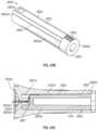
- the catheter hub of the IV catheter systemfurther comprises a catheter hub intermediate portion between the catheter hub proximal end and the catheter hub distal end, wherein the catheter component further comprises an extension tubing junction extending outwardly from the catheter hub intermediate portion to connect the catheter hub to extension tubing, and wherein the first wing extends between the catheter hub intermediate portion and the extension tubing junction but does not extend outwardly beyond the extension tubing junction.
- the needle component of the IV catheter systemfurther includes a flash component having a proximal vent and at least one side vent.
- the catheter componentincludes a visual indicator.
- the visual indicatoris covered by the needle hub distal end when a tip of the needle extends distally beyond the cannula and that is exposed when the tip of the needle is withdrawn into the cannula.
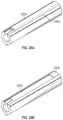
- the needle component of the IV catheter systemincludes side grips and the catheter component includes a push tab.
- the needle componentincludes a flash chamber, the side grips being formed on the flash chamber.
- the catheter componentfurther comprises: a securement platform comprising a first wing extending from the catheter hub, generally parallel to the axis such that, in the fluid delivery configuration, the first wing rests on skin of a patient receiving fluid through the IV catheter system; and an extension tubing junction extending outwardly from the catheter hub intermediate portion to connect the catheter hub to extension tubing, wherein the extension tubing junction extends in an opposite direction of the first wing.
- the catheter component of the IV catheter systemfurther comprises a second wing that extends in the opposite direction of the first wing, the second wing incorporating but not extending beyond the extension tubing junction.
- the second wingis formed of a rigid material and the first wing is formed of a flexible material.
- the first wingis configured to pivot with respect to the catheter hub about the axis.
- the first wingincludes a hinge that enables the pivoting.
- the first wingis formed of a flexible material that enables the pivoting.
- an IV catheter systemcomprising: a catheter component comprising: a catheter hub comprising a catheter hub distal end and a catheter hub proximal end, wherein the catheter hub is shaped to define a chamber extending between the catheter hub distal end and the catheter hub proximal end, and a needle port at the catheter hub proximal end that provides access to the chamber; a cannula extending distally from the catheter hub distal end; and a push tab positioned at the catheter hub proximal end; and a needle component comprising: a needle hub comprising a needle hub distal end and a needle hub proximal end, the needle hub distal end including a cut-out that aligns with the push tab formed at the catheter hub proximal end; and a needle extending distally from the needle hub distal end along an axis.
- the catheter component of the IV catheter systemincludes a securement platform.
- the push tab and the securement platformare connected via one or more connecting channels.
- the catheter componentincludes a strain relief positioned at the catheter hub distal end around the cannula, the strain relief being coupled to the securement platform by a connecting channel.
- the catheter component and the needle componenteach include a protrusion which interface to limit rotation of the needle component relative to the catheter component.
- the needle componentincludes a wing and wherein the protrusions prevent the wing from rotating downward below the securement platform.
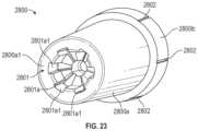
- the IV catheter systemfurther comprises a flash component that includes a path-defining structure for controlling flow of blood within the flash component.
- FIG. 1is a perspective view of an IV catheter system according to one embodiment
- FIG. 2is a perspective view of a portion of an IV catheter system according to one alternative embodiment
- FIGS. 3 A and 3 Bare perspective and plan views, respectively, of a portion of an IV catheter system according to another alternative embodiment
- FIG. 4is a plan view of an IV catheter system according to another alternative embodiment
- FIG. 5is a perspective view of an IV catheter system according to another alternative embodiment
- FIG. 6is a perspective view of an IV catheter system according to another alternative embodiment
- FIG. 7is a perspective view of an IV catheter system according to another alternative embodiment
- FIG. 8is a plan view of an IV catheter system according to another alternative embodiment
- FIGS. 9 A and 9 Bare perspective and side elevation, section views, respectively, of an IV catheter system according to yet another alternative embodiment
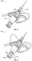
- FIGS. 10 A, 10 B, and 10 Care perspective views of an IV catheter system according to still another alternative embodiment, with the catheter component and needle component partially separated, in the insertion configuration, and with the catheter component and needle component partially separated, respectively;
- FIG. 11is a flowchart diagram depicting one method of preparing an IV catheter system to deliver fluid to a patient, according to one embodiment.
- FIGS. 12 A and 12 Bare perspective views of an IV catheter system according to yet another alternative embodiment, in a fully-assembled state and in an exploded state, respectively.
- FIGS. 13 A and 13 Bare perspective views of an IV catheter system according to yet another alternative embodiment, in an open state and a compacted state, respectively.
- FIGS. 14 A, 14 B, 14 C, and 14 Dare perspective views of an IV catheter system according to yet another alternative embodiment, in the insertion configuration in a compacted state, with the catheter component in isolation, in the insertion configuration in an open state, and with the flash component in an exploded state, respectively.
- FIGS. 15 A, 15 B, 15 C, and 15 Dare perspective views of an IV catheter system according to yet another alternative embodiment, in the insertion configuration in a compacted state, with the catheter component and needle component in isolation, in the insertion configuration in an open state, and with the flash component in an exploded state, respectively.
- FIG. 16is a perspective view of an IV catheter system according to various embodiments in which the securement platform includes a wing that extends only between the catheter component and the extension tubing junction.
- FIG. 17is a perspective view of an IV catheter system according to yet another alternative embodiment in which a flash component that is incorporated into a needle component includes side vents.
- FIGS. 18 A and 18 Bare perspective and side views respectively of an IV catheter system according to various embodiments in which the catheter component includes a visual indicator to provide an indication of when the needle reaches the hooded position.
- FIGS. 19 A and 19 Bare perspective and side views respectively of an IV catheter system according to various embodiments in which an elongated flash component includes side grips and the catheter component includes a push tab.
- FIG. 20is a perspective view of an IV catheter system according to various embodiments that provide a number of additional features.
- FIG. 21illustrates an example of an anti-rotation feature that can be employed with one or more embodiments of an IV catheter system.
- FIGS. 22 A and 22 Billustrate how many of the disclosed features can be provided on an open IV catheter system.
- FIG. 23illustrates a path-defining structure that can be employed within a flash chamber in embodiments of an IV catheter system.
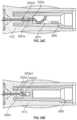
- FIGS. 24 A- 24 Eeach illustrate a cross-sectional view of a flash chamber that includes the path-defining structure of FIG. 23 .
- FIGS. 25 A and 25 Billustrate another path-defining structure that can be employed within a flash chamber in embodiments of an IV catheter system.
- FIG. 25 Cillustrates a cross-sectional view of a flash chamber that includes the path-defining structure of FIGS. 25 A and 25 B .
- FIG. 26illustrates how a vent plug can be employed in conjunction with a path-defining structure.
- FIGS. 27 A- 27 Ceach illustrate different ways in which a path-defining structure can be secured within a flash chamber.
- FIGS. 28 A and 28 Billustrate how a path-defining structure can include a porous material.
- FIG. 29illustrates how a path-defining structure can be altered to delay when visual confirmation of proper catheter placement is provided.
- FIG. 30illustrates how a sealing cap can be employed on a flash chamber to prevent saline from flowing into the flash chamber when an IV catheter system is pre-primed.
- FIG. 1may show simplified or partial views, and the dimensions of elements in the Figures may be exaggerated or otherwise not in proportion for clarity.
- the singular forms “a,” “an,” and “the”include plural referents unless the context clearly dictates otherwise.
- reference to a terminalincludes reference to one or more terminals.
- reference is made to a list of elementse.g., elements a, b, c
- such referenceis intended to include any one of the listed elements by itself, any combination of less than all of the listed elements, and/or a combination of all of the listed elements.
- proximalrefers to a location on the device that is closest to the clinician using the device and farthest from the patient in connection with whom the device is used when the device is used in its normal operation.
- distalrefers to a location on the device that is farthest from the clinician using the device and closest to the patient in connection with whom the device is used when the device is used in its normal operation.
- the term “in” or “inwardly”refers to a location with respect to the device that, during normal use, is toward the inside of the device. Conversely, as used herein, the term “out” or “outwardly” refers to a location with respect to the device that, during normal use, is toward the outside of the device.
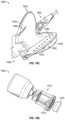
- FIG. 1is a perspective view of an IV catheter system 100 according to one embodiment.
- the IV catheter system 100may be connected to a supply of fluid to be infused.
- the fluid supply(not shown) may include a bag of blood or medication to be delivered to the patient, a drip chamber that regulates flow of the fluid to the IV catheter system 100 , and/or other components involved with the supply of fluid to the IV catheter system 100 .
- the IV catheter system 100may have a number of components, as shown in the exemplary embodiment of FIG. 1 . These components may include a catheter component 102 , a needle component 104 , an extension tube 106 , a clamp 108 , and/or a luer lock adapter 110 .
- the catheter component 102may be inserted into the fluid delivery location in the patient in order to convey the fluid to the patient.
- the needle component 104may facilitate insertion of the catheter component 102 to the fluid delivery location.
- the extension tube 106may convey the fluid to the catheter component 102 .
- the clamp 108may be used to manually block fluid flow to the catheter component 102 when it is desired to stop or pause fluid delivery.
- the luer lock adapter 110may be readily connected to the fluid supply, for example, via connection to a complementary luer lock (not shown) of the fluid supply.
- the IV catheter system 100may be an integrated IV catheter system, as the extension tube 106 is pre-attached to the catheter component 102 .
- IV catheter systemsof various open, integrated, and/or safety integrated configurations may be used.
- the catheter component 102may have various components, which may include a catheter hub 120 , a securement platform 122 , an extension tubing junction 124 , and a cannula 126 .
- the catheter hub 120may have a generally tubular and/or hollow conical configuration, and may have a proximal end 130 and a distal end 132 .
- the catheter hub 120may be shaped to define a chamber 134 through which the fluid flows to reach the fluid delivery location.
- the catheter hub 120may have a needle port 136 at the proximal end 130 .
- the chamber 134may contain a septum 138 that is designed to block flow of blood and/or the fluid to be delivered from the chamber 134 through the needle port 136 .
- the cannula 126may be secured to the distal end 132 of the catheter hub 120 .
- the securement platform 122may have a generally planar configuration designed to permit the securement platform 122 to be secured to the skin of the patient, proximate the fluid delivery location, to keep the catheter component 102 securely in place as fluid delivery takes place.
- the securement platform 122may have a first wing 140 with a generally planar shape, and a second wing 142 that also has a generally planar shape generally coplanar with the first wing 140 .
- the second wing 142may be positioned on the opposite side of the catheter hub 120 from the first wing 140 .
- the first wing 140 and the second wing 142may extend outward in opposite directions from the catheter hub 120 .
- the first wing 140 and the second wing 142may both be fixedly secured to the catheter hub 120 , and may each have a generally triangular shape when viewed from along a direction perpendicular to the securement platform 122 .
- the first wing 140 and/or the second wing 142may have any shape, including but not limited to polygonal shapes such as triangular and rectangular shapes, and non-polygonal shapes such as circular, semicircular, oval, oblong, and irregular shapes. Some examples of these alternative shapes will be shown in subsequent embodiments.
- the first wing 140 and the second wing 142may each have a trailing edge 144 oriented toward the proximal end 130 of the catheter hub 120 .
- the needle component 104may have a needle hub 150 , a grip 152 , and a needle 154 .
- the needle hub 150may be detachably coupled to the catheter hub 120 of the catheter component 102 .
- the grip 152may extend outward from the needle hub 150 .
- the needle 154may be removably positioned within the cannula 126 such that the needle 154 facilitates the process of accessing the fluid delivery location (for example, a vein) and proper positioning of the cannula 126 to deliver the fluid to the fluid delivery location.
- the needle hub 150may have a generally tubular shape with a proximal end 160 and a distal end 162 .
- the needle hub 150may have a boss 164 positioned at the distal end 162 ; the boss 164 may be insertable into the needle port 136 of the catheter hub 120 of the catheter component 102 .
- the grip 152may have a generally planar shape that extends outward from the needle hub 150 . When viewed from a direction perpendicular to the grip 152 , the grip 152 may have an oblong and/or partially elliptical shape.
- the grip 152 , the first wing 140 , and/or the second wing 142may have one or more grip features 170 , as shown on the grip 252 , which may help provide a secure interface that facilitates gripping and/or moving the grip 152 by hand.
- the grip 152may have a leading edge 172 .
- the IV catheter system 100may have an insertion configuration, in which the IV catheter system 100 is readily insertable to position the cannula 126 in the fluid delivery location, and a fluid delivery configuration, in which the fluid flow through the cannula 126 is relatively unimpeded.
- the IV catheter system 100is in the insertion configuration.
- the needle 154is positioned within the cannula 126 to provide a sharpened tip for penetrating tissue and a relatively stiff body that supports the cannula 126 during insertion.
- the boss 164 of the needle hub 150is positioned within the needle port 136 of the catheter hub 120 .
- the needle 154passes through the septum 138 of the catheter component 102 .
- the IV catheter system 100may be inserted into position by positioning the tip of the cannula 126 proximate the fluid delivery location (for example, the patient's vein).
- the securement platform 122may be placed on the patient's skin, proximate the fluid delivery location and/or held in the clinician's hand.
- the catheter component 102 and the needle component 104may be advanced to push the cannula 126 until the tip of the cannula 126 penetrates the surrounding tissue and reaches the fluid delivery location. If desired, the catheter component 102 may be advanced by pushing a push surface of the catheter component 102 .
- the “push surface”is a surface that is generally proximally-oriented, and thus can receive contact from the clinician's hand to urge the catheter component 102 and the needle component 104 , together, distally.
- the IV catheter system 100may be moved to the fluid delivery configuration. This may be done by withdrawing the needle component 104 proximally from the catheter component 102 . This may initially cause the boss 164 to be withdrawn proximally from within the needle port 136 .
- the needle 154may also be withdrawn proximally from the cannula 126 , and then through the chamber 134 , including the septum 138 .
- the needle 154may pass out of the chamber 134 through the needle port 136 , thus completing motion of the IV catheter system 100 to the fluid delivery configuration.
- Fluid flow to the fluid delivery locationmay now be accomplished by urging the fluid to flow through the extension tube 106 , into the chamber 134 , and through the cannula 126 to the fluid delivery location.
- the IV catheter system 100may advantageously be designed to facilitate insertion to the fluid delivery location to be readily performed with a single hand.
- the clinicianmay, with one hand, hold the catheter component 102 and the needle component 104 , for example, by grasping the securement platform 122 and the grip 152 .
- the clinicianmay then, with the same hand, apply gentle pressure to one or more push surfaces of the catheter component 102 (for example, the trailing edges 144 of the first wing 140 and/or the second wing 142 ) to urge the tip of the cannula 126 to penetrate the patient's skin and ultimately reach the fluid delivery location.
- one or more locking featuresmay be used to hold the catheter component 102 and the needle component 104 together until the clinician applies a threshold force to move the IV catheter system 100 from the insertion configuration to the fluid delivery configuration.
- Such locking featuresmay take the form of interlocking features (not shown) between the boss 164 and the needle port 136 , and/or the like.
- the IV catheter system 100may be designed to provide visual confirmation of proper placement in a blood vessel.
- the catheter hub 120may be translucent to provide visibility into the chamber 134 .
- the resulting blood flow, or “flash”may be visible through the exterior wall of the catheter hub 120 as the blood enters the chamber 134 .
- the extension tubing junction 124 and the extension tube 106may also, optionally, be translucent.
- the flashmay extend through the extension tube 106 to the luer lock adapter 110 .
- the luer lock adapter 110may be coupled to the fluid supply in a manner that substantially prevents blood leakage.
- the IV catheter system 100may advantageously be designed to facilitate motion from the insertion configuration to the fluid delivery configuration with a single hand.
- the clinicianmay, with a single hand, which may be the same hand used to insert the IV catheter system 100 into the fluid delivery location, grasp the catheter component 102 and the needle component 104 and withdraw the needle component 104 proximally from the catheter component 102 .
- the catheter component 102may be left substantially in place so that only the needle component 104 moves significantly to move the IV catheter system 100 from the insertion configuration to the fluid delivery configuration.
- the trailing edges 144 of the securement platform 122may act as push surfaces, while the edge 172 of the grip 152 may act as a pull surface.
- the clinicianmay place one or more fingers on the leading edge 172 of the grip 152 and pulling proximally, while pushing with a thumb and/or one or more other fingers on the trailing edges 144 of the securement platform 122 .
- the catheter component 102may be kept in place with the tip of the cannula 126 at the fluid delivery location while the needle component 104 is withdrawn proximally from the catheter component 102 to unblock the fluid delivery path to the fluid delivery location.
- the relative positions of the pull and push surfacesmay facilitate single-handed operation in the manner described above.
- the coupling of the needle hub 150 with the catheter hub 120may be such that the needle hub 150 is rotatable relative to the catheter hub 120 while the IV catheter system 100 is in the insertion configuration.
- the clinicianmay, with the hand, rotate the grip 152 to an orientation that is most comfortable for pulling on the leading edge 172 , prior to pulling on the leading edge 172 and pushing on the trailing edges 144 .
- the septum 138may have a “low friction” or “low drag” design configured to provide relatively low resistance to withdrawal of the needle 154 proximally through the septum 138 , which occurs as the IV catheter system 100 transitions from the insertion configuration to the fluid delivery configuration.
- the resistance to withdrawal of the needle 154 through the septum 138may be sufficiently low that the clinician can relatively easily move the IV catheter system 100 from the insertion configuration to the fluid delivery configuration with only a single hand.
- the resistance to withdrawalmay be, on average, less than about 50 gf.
- FIG. 2is a perspective view of a portion of an IV catheter system 200 according to one alternative embodiment.
- the IV catheter system 200may have components that generally correspond to those of the IV catheter system 100 of FIG. 1 .
- FIG. 2illustrates only a catheter component 202 , a needle component 204 , and the distal end of an extension tube 206 connected to the catheter component 202 .
- the IV catheter system 200may have a configuration similar to that of the IV catheter system 100 of FIG. 1 ; however, some components may be shaped differently to provide alternative ergonomics.
- the catheter component 202may have a catheter hub 220 , a securement platform 222 , an extension tubing junction 224 , and a cannula 226 .
- the catheter hub 220may have a generally tubular and/or hollow conical shape, with a proximal end 230 and a distal end 232 .
- the catheter hub 220may have a generally translucent exterior wall shaped to define a chamber 234 through which fluid flows to reach the fluid delivery location through the cannula 226 .
- the catheter hub 220may have a needle port 236 that connects to the needle component 204 , proximate the proximal end 230 of the catheter hub 220 .
- the catheter hub 220may also have a septum 238 positioned within the chamber 234 .
- the septum 238may be a “low drag” septum as described previously.
- the securement platform 222may be attached to the skin of the patient during fluid delivery to keep the cannula 226 in place at the fluid delivery location.
- the securement platform 222may have a first wing 240 and a second wing 242 , which may both be generally planar in shape, and may extend in opposite directions relative to the catheter hub 220 .
- Each of the first wing 240 and the second wing 242may have a generally rectangular shape when viewed from perpendicular to the securement platform 222 , with a trailing edge 244 that can act as a push surface.
- the needle component 204may have a needle hub 250 , a grip 252 , and a needle 254 .
- the needle hub 250may have a generally cylindrical shape with a proximal end 260 and a distal end 262 .
- the needle hub 250may also have a boss 264 that protrudes from the distal end 262 to interface with the needle port 236 of the catheter hub 220 .
- the grip 252may have a generally planar shape, with a generally rectangular shape when viewed from perpendicular to the grip 252 . However, the grip 252 may have any other suitable shape.
- the grip 252may have a leading edge (not visible), which may serve as a pull surface.
- the grip 252 , the first wing 240 , and/or the second wing 242may have one or more grip features 270 , which may help provide a secure interface that facilitates gripping and/or moving the grip 152 by hand.
- the clinicianmay position a digit (for example, a finger) on the leading edge of the grip 252 , and a digit (for example, a finger or thumb) on the trailing edge 244 of the first wing 240 and/or the second wing 242 .
- the clinicianmay then pull the leading edge proximally, as indicated by the arrow 290 , and may push the trailing edge 244 of the first wing 240 and/or the second wing 242 distally, as indicated by the arrow 292 . This may cause the catheter component 202 to remain in place while the needle component 204 is withdrawn proximally from the catheter component 202 .
- the grip 252 and the first wing 240may be positioned parallel to each other, and may be positioned in close proximity to each other such that they are in abutting relation to each other in the insertion configuration, and during the initial stages of motion from the insertion configuration to the fluid delivery configuration.
- the grip 252 and/or the first wing 240may have one or more alignment features that maintain relative positioning and/or orientation between the first wing 240 and the grip 252 .
- the grip 252may have an alignment feature in the form of an alignment ridge 280 , which may protrude toward the first wing 240 , and may be received in a complementary alignment feature (not shown) such as a trough or other feature on the surface of the first wing 240 that faces toward the grip 252 .
- the alignment ridge 280 and the complementary alignment featuremay help keep the needle 254 parallel to the cannula 226 during motion of the IV catheter system 200 to the fluid delivery configuration. This may help ensure that the needle component 204 can be smoothly withdrawn from the catheter component 202 . More specifically, application of imbalanced force on the catheter component 202 and/or the needle component 204 may urge the needle component 204 to rotate relative to the catheter component 202 .
- the alignment ridge 280 and the complementary alignment feature of the first wing 240may help ensure that such relative rotation does not occur until the needle component 204 has been withdrawn from the catheter component 202 sufficiently to detach the alignment ridge 280 from the complementary alignment feature of the first wing 240 . Thus, binding and/or other undesired interactions between the catheter component 202 and the needle component 204 may be avoided during motion from the insertion configuration to the fluid delivery configuration.
- FIGS. 3 A and 3 Bare perspective and plan views, respectively, of a portion of an IV catheter system 300 according to another alternative embodiment.
- the IV catheter system 300may have components that generally correspond to those of FIGS. 1 and 2 .
- FIGS. 3 A and 3 Billustrate only a catheter component 302 , a needle component 304 , and the distal end of an extension tube 306 connected to the catheter component 302 .
- the IV catheter system 300may have a configuration similar to those of previous embodiments; however, some components may be shaped differently to provide alternative ergonomics.
- the catheter component 302may have a catheter hub 320 , a securement platform 322 , an extension tubing junction 324 , and a cannula 326 .
- the catheter hub 320may have a generally tubular and/or hollow conical shape, with a proximal end 330 and a distal end 332 .
- the catheter hub 320may have a generally translucent exterior wall shaped to define a chamber 334 through which fluid flows to reach the fluid delivery location through the cannula 326 .
- the catheter hub 320may have a needle port 336 that connects to the needle component 304 , proximate the proximal end 330 of the catheter hub 320 .
- the catheter hub 320may also have a septum 338 positioned within the chamber 334 .
- the septum 338may be a “low drag” septum as described previously.
- the securement platform 322may be attached to the skin of the patient during fluid delivery to keep the cannula 326 in place at the fluid delivery location.
- the securement platform 322may have only a single wing in the form of a first wing 340 , which may be generally planar in shape, and may have a generally trapezoidal shape when viewed from perpendicular to the securement platform 322 , with a trailing edge 344 that can act as a push surface.
- the first wing 340may be integrated with the extension tubing junction 324 such that the extension tubing junction 324 defines a leading edge of the first wing 340 .
- the extension tubing junction 324may provide an enlargement to the width of the first wing 340 at the leading edge; this enlargement may enable the extension tubing junction 324 to serve as a push surface. More specifically, the clinician may push on the trailing portion of the extension tubing junction 324 , where the extension tubing junction 324 merges with the first wing 340 , to urge the catheter component 302 forward.
- the needle component 304may have a needle hub 350 , a grip 352 , and a needle 354 .
- the needle hub 350may have a generally cylindrical shape with a proximal end 360 and a distal end 362 .
- the needle hub 350may also have a boss 364 that protrudes from the distal end 362 to interface with the needle port 336 of the catheter hub 320 .
- the grip 352may have a generally planar shape, with a generally trapezoidal shape when viewed from perpendicular to the grip 352 .
- the grip 352may have a leading edge 372 , which may serve as a pull surface.
- the grip 352 and/or the first wing 340may have one or more grip features 370 , which may help provide a secure interface that facilitates gripping and/or moving the grip 152 by hand.
- the clinicianmay position a digit (for example, a finger) on the leading edge 372 of the grip 352 and/or on the leading edge of the tab 384 , and a digit (for example, a finger or thumb) on the trailing edge 344 of the first wing 340 .
- the clinicianmay then pull the leading edge 372 and/or the leading edge of the tab 384 proximally, and may push the trailing edge 344 of the first wing 340 distally. This may cause the catheter component 302 to remain in place while the needle component 304 is withdrawn proximally from the catheter component 302 .
- the grip 352 and the first wing 340may be positioned parallel to each other, and may be positioned in close proximity to each other such that they are in abutting relation to each other in the insertion configuration, and during the initial stages of motion from the insertion configuration to the fluid delivery configuration.
- the grip 352 and/or the first wing 340may have one or more alignment features that maintain relative positioning and/or orientation between the first wing 340 and the grip 352 .
- the grip 352may have an alignment feature in the form of a pair of alignment ridges 380 , which may protrude toward the first wing 340 , and may be received in complementary alignment features in the form of slots 382 formed in the first wing 340 .
- the alignment ridges 380 and the slots 382may help keep the needle component 304 parallel to the catheter component 302 during motion of the IV catheter system 300 to the fluid delivery configuration, which may facilitate motion to the fluid delivery configuration as described in the previous embodiment.
- the first wing 340may be translucent so as to facilitate user visualization of the grip 352 , and more specifically, of the edge 372 .
- the needle component 304may have a tab 384 that protrudes outward from the needle hub 350 in a direction generally opposite to that in which the grip 352 protrudes.
- the tab 384may provide a pull surface that can be used by a clinician, in addition to and/or in the alternative to the leading edge 372 of the grip 352 . This may provide additional options for the clinician to insert the IV catheter system 300 with a single hand and/or to move the IV catheter system 300 from the insertion configuration to the fluid delivery configuration with a single hand.
- FIG. 4is a plan view of an IV catheter system 400 according to another alternative embodiment.
- the IV catheter system 400may have components similar to those of the IV catheter system 300 of FIGS. 3 A and 3 B .
- FIG. 4illustrates only a catheter component 402 , a needle component 404 , and the distal end of an extension tube 406 connected to the catheter component 402 .
- the IV catheter system 400may have a configuration similar to that of the IV catheter system 300 ; however, some components may be shaped differently to provide alternative ergonomics.
- the catheter component 402may have a catheter hub 420 , a securement platform 422 , an extension tubing junction 424 , and a cannula 426 .
- the catheter hub 420may have a generally tubular and/or hollow conical shape, with a proximal end 430 and a distal end 432 .
- the catheter hub 420may have a generally translucent exterior wall shaped to define a chamber 434 through which fluid flows to reach the fluid delivery location through the cannula 426 .
- the catheter hub 420may have a needle port 436 that connects to the needle component 404 , proximate the proximal end 430 of the catheter hub 420 .
- the catheter hub 420may also have a septum 438 positioned within the chamber 434 .
- the septum 438may be a “low drag” septum as described previously.
- the securement platform 422may be attached to the skin of the patient during fluid delivery to keep the cannula 426 in place at the fluid delivery location.
- the securement platform 422may have only a single wing in the form of a first wing 440 , which may be generally planar in shape, and may have a generally triangular shape when viewed from perpendicular to the securement platform 422 , with a trailing edge 444 that can act as a push surface.
- the first wing 440may be integrated with the extension tubing junction 424 such that the extension tubing junction 424 defines a leading edge of the first wing 440 .
- the extension tubing junction 424may provide an enlargement to the width of the first wing 440 at the leading edge; this enlargement may enable the extension tubing junction 424 to serve as a push surface. More specifically, the clinician may push on the trailing portion of the extension tubing junction 424 , where the extension tubing junction 424 merges with the first wing 440 , to urge the catheter component 402 forward.
- the needle component 404may have a needle hub 450 , a grip 452 , and a needle 454 .
- the needle hub 450may have a generally cylindrical shape with a proximal end 460 and a distal end 462 .
- the needle hub 450may also have a boss 464 that protrudes from the distal end 462 to interface with the needle port 436 of the catheter hub 420 .
- the grip 452may have a generally planar shape, with a generally triangular shape when viewed from perpendicular to the grip 452 .
- the grip 452may have a leading edge 472 , which may serve as a pull surface.
- the grip 452 and/or the first wing 440may have one or more grip features 470 , which may help provide a secure interface that facilitates gripping and/or moving the grip 452 by hand.
- the clinicianmay position a digit (for example, a finger) on the leading edge 472 of the grip 452 and/or the leading edge of the tab 484 , and a digit (for example, a finger or thumb) on the trailing edge 444 of the first wing 440 .
- the clinicianmay then pull the leading edge 472 and/or the leading edge of the tab 484 proximally, and may push the trailing edge 444 of the first wing 440 distally. This may cause the catheter component 402 to remain in place while the needle component 404 is withdrawn proximally from the catheter component 402 .
- the grip 452 and the first wing 440may be positioned parallel to each other, and may be positioned in close proximity to each other such that they are in abutting relation to each other in the insertion configuration, and during the initial stages of motion from the insertion configuration to the fluid delivery configuration.
- the grip 452 and/or the first wing 440may have one or more alignment features that maintain relative positioning and/or orientation between the first wing 440 and the grip 452 .
- the grip 452may have an alignment feature in the form of a pair of alignment ridges 480 , which may protrude toward the first wing 440 , and may be received in complementary alignment features in the form of slots 482 formed in the first wing 440 .
- the alignment ridges 480 and the slots 482may help keep the needle component 404 parallel to the catheter component 402 during motion of the IV catheter system 400 to the fluid delivery configuration, which may facilitate motion to the fluid delivery configuration as described in the previous embodiment.
- the first wing 440may be translucent so as to facilitate user visualization of the grip 452 , and more specifically, of the edge 472 .
- the needle component 404may have a tab 484 that protrudes outward from the needle hub 450 in a direction generally opposite to that in which the grip 452 protrudes.
- the tab 484may provide a pull surface that can be used by a clinician, in addition to and/or in the alternative to the leading edge 472 of the grip 452 . This may provide additional options for the clinician to insert the IV catheter system 400 with a single hand and/or to move the IV catheter system 400 from the insertion configuration to the fluid delivery configuration with a single hand.
- the first wing 440 and the grip 452may have a more triangular, swept shape, as shown. This different shape may cause the leading edge 472 of the grip 452 to be positioned at a different angle and/or position, which may facilitate single-handed operation for some users.
- the alignment ridges 480may be relatively short, thereby providing low frictional resistance to motion of the IV catheter system 400 from the insertion configuration to the fluid delivery configuration.
- FIG. 5is a perspective view of an IV catheter system 500 according to another alternative embodiment.
- the IV catheter system 500may have components similar to those of the IV catheter systems of previous embodiments.
- FIG. 5illustrates only a catheter component 502 , a needle component 504 , and the distal end of an extension tube 506 connected to the catheter component 502 .
- the catheter component 502may have a catheter hub 520 , a securement platform 522 , an extension tubing junction 524 , and a cannula 526 .
- the catheter hub 520may have a generally tubular and/or hollow conical shape, with a proximal end 530 and a distal end 532 .
- the catheter hub 520may have a generally translucent exterior wall shaped to define a chamber 534 through which fluid flows to reach the fluid delivery location through the cannula 526 .
- the catheter hub 520may have a needle port 536 that connects to the needle component 504 , proximate the proximal end 530 of the catheter hub 520 .
- the catheter hub 520may also have a septum 538 positioned within the chamber 534 .
- the septum 538may be a “low drag” septum as described previously.
- the securement platform 522may be attached to the skin of the patient during fluid delivery to keep the cannula 526 in place at the fluid delivery location.
- the securement platform 522may have a first wing 540 and a second wing 542 , each of which may be generally planar in shape.
- the first wing 540 and the second wing 542may each have a generally trapezoidal shape when viewed from perpendicular to the securement platform 522 , with a trailing edge 544 that can act as a push surface.
- the first wing 540may be integrated with the extension tubing junction 524 such that the extension tubing junction 524 defines a leading edge of the first wing 540 .
- the extension tubing junction 524may provide an enlargement to the width of the first wing 540 at the leading edge; this enlargement may enable the extension tubing junction 524 to serve as a push surface. More specifically, the clinician may push on the trailing portion of the extension tubing junction 524 , where the extension tubing junction 524 merges with the first wing 540 , to urge the catheter component 502 forward.
- the second wing 542may be rotatably coupled to the catheter hub 520 .
- the clinicianmay position the second wing 542 at substantially any orientation about the axis defined by the cannula 526 and/or the needle 554 .
- the second wing 542may rotate relatively freely about the catheter hub 520 such that the clinician can rotate the second wing 542 , relative to the first wing 540 , with a single hand to obtain the desired grip prior to and/or during insertion of the IV catheter system 500 into the fluid delivery location and/or motion of the IV catheter system 500 from the insertion configuration to the fluid delivery configuration.
- the needle component 504may have a needle hub 550 , a grip 552 , and a needle 554 .
- the needle hub 550may have a generally cylindrical shape with a proximal end 560 and a distal end 562 .
- the needle hub 550may also have a boss 564 that protrudes from the distal end 562 to interface with the needle port 536 of the catheter hub 520 .
- the grip 552may have a generally planar shape, with a generally trapezoidal shape when viewed from perpendicular to the grip 552 .
- the grip 552may have a leading edge 572 , which may serve as a pull surface.
- the grip 552 and/or the first wing 540may have one or more grip features 570 , which may help provide a secure interface that facilitates gripping and/or moving the grip 552 by hand.
- the grip 552 and the first wing 540may be positioned parallel to each other, and may be positioned in close proximity to each other such that they are in abutting relation to each other in the insertion configuration, and during the initial stages of motion from the insertion configuration to the fluid delivery configuration.
- the grip 552 and/or the first wing 540may have one or more alignment features that maintain relative positioning and/or orientation between the first wing 540 and the grip 552 .
- the grip 552may have an alignment feature in the form of a pair of alignment ridges 580 , which may protrude toward the first wing 540 , and may be received in complementary alignment features in the form of slots 582 formed in the first wing 540 .
- the alignment ridges 580 and the slots 582may help keep the needle component 504 parallel to the catheter component 502 during motion of the IV catheter system 500 to the fluid delivery configuration, which may facilitate motion to the fluid delivery configuration as described in the previous embodiment.
- the first wing 540 and/or the second wing 542may be translucent so as to facilitate user visualization of the grip 552 , and more specifically, of the edge 572 .
- the needle component 504may have a tab 584 that protrudes outward from the needle hub 550 in a direction generally opposite to that in which the grip 552 protrudes.
- the tab 584may provide a pull surface that can be used by a clinician, in addition to and/or in the alternative to the leading edge 572 of the grip 552 . This may provide additional options for the clinician to insert the IV catheter system 500 with a single hand and/or to move the IV catheter system 500 from the insertion configuration to the fluid delivery configuration with a single hand.
- the clinicianmay position a digit (for example, a finger) on the leading edge 572 of the grip 552 and/or the leading edge of the tab 584 , and a digit (for example, a finger or thumb) on the trailing edge 544 of the first wing 540 .
- the clinicianmay then pull the leading edge 572 and/or the leading edge of the tab 484 proximally, and may push the trailing edge 544 of the first wing 540 distally. This may cause the catheter component 502 to remain in place while the needle component 504 is withdrawn proximally from the catheter component 502 .
- FIG. 6is a perspective view of an IV catheter system 600 according to another alternative embodiment.
- the IV catheter system 600may have components similar to those of the IV catheter systems of previous embodiments.
- FIG. 6illustrates only a catheter component 602 , a needle component 604 , and the distal end of an extension tube 606 connected to the catheter component 602 .
- the catheter component 602may have a catheter hub 620 , a securement platform 622 , an extension tubing junction 624 , and a cannula 626 .
- the catheter hub 620may have a generally tubular and/or hollow conical shape, with a proximal end 630 and a distal end 632 .
- the catheter hub 620may have a generally translucent exterior wall shaped to define a chamber (not visible) through which fluid flows to reach the fluid delivery location through the cannula 626 .
- the catheter hub 620may have a needle port 636 that connects to the needle component 604 , proximate the proximal end 630 of the catheter hub 620 .
- the catheter hub 620may also have a septum (not visible) positioned within the chamber.
- the septummay be a “low drag” septum as described previously.
- the catheter hub 620may have a kink resistance feature that helps to avoid kinking of the cannula 626 during insertion and/or infusion.
- the kink resistance featuremay take the form of a proximal extension 628 on the distal end 632 of the catheter hub 620 .
- the proximal extension 628may receive the cannula 626 , and may provide some resistance to bending of the cannula 626 at the juncture of the cannula 626 to the proximal end 630 to relieve the bending strain at that location, thereby helping avoid kinking or other undesired bending of the cannula 626 .
- the securement platform 622may be attached to the skin of the patient during fluid delivery to keep the cannula 626 in place at the fluid delivery location.
- the securement platform 622may have a first wing 640 and a second wing 642 , each of which may be generally planar in shape.
- the first wing 640 and the second wing 642may each have a generally triangular shape when viewed from perpendicular to the securement platform 622 , with a trailing edge 644 that can act as a push surface.
- the first wing 640 and the second wing 642may extend in opposite directions, outward from the axis of the catheter hub 620 .
- the second wing 642may be integrated with the extension tubing junction 624 such that the extension tubing junction 624 passes through the trailing edge 644 of the second wing 642 .
- the extension tubing junction 624may provide an enlargement to the width of the second wing 642 proximate the trailing edge 644 ; this enlargement may enable the extension tubing junction 624 to serve as a push surface.
- the catheter component 602may have a push feature in the form of a push surface 646 that extends between the extension tubing junction 624 and the intermediate portion of the catheter hub 620 , between the proximal end 630 and the distal end 632 .
- the push surface 646may have a size selected to enable the clinician to relatively easily push on the push surface 646 with a digit to urge the catheter component 602 forward.
- the push surface 646may be oriented substantially perpendicular to the axis of the catheter component 602 and the needle component 604 .
- the needle component 604may have a needle hub 650 , a grip 652 , and a needle (not visible).
- the needle hub 650may have a generally cylindrical shape with a proximal end 660 and a distal end 662 .
- the needle hub 650may also have a boss 664 that protrudes from the distal end 662 to interface with the needle port 636 of the catheter hub 620 .
- the grip 652may have a generally planar shape, with a generally irregular shape when viewed from perpendicular to the grip 652 .
- the grip 652may have a narrow portion 666 that extends from the needle hub 650 to connect to a larger portion 668 that lies in abutting relation to the first wing 640 of the securement platform 622 when the IV catheter system 600 is in the insertion configuration.
- the grip 652may have a leading edge 672 , which may serve as a pull surface.
- the grip 652 and/or the first wing 640may have one or more grip features (not shown), which may help provide a secure interface that facilitates gripping and/or moving the grip 652 by hand.
- the clinicianmay position a digit (for example, a finger) on the leading edge 672 of the grip 652 , and a digit (for example, a finger or thumb) on the trailing edge 644 of the first wing 640 and/or the push surface 646 .
- the clinicianmay then pull the leading edge 672 proximally, and may push the trailing edge 644 and/or the push surface 646 distally. This may cause the catheter component 602 to remain in place while the needle component 604 is withdrawn proximally from the catheter component 602 .
- FIG. 7is a perspective view of an IV catheter system 700 according to another alternative embodiment.
- the IV catheter system 700may have components similar to those of the IV catheter systems of previous embodiments.
- FIG. 7illustrates only a catheter component 702 , a needle component 704 , and the distal end of an extension tube 706 connected to the catheter component 702 .
- the catheter component 702may have a catheter hub 720 , a securement platform 722 , an extension tubing junction 724 , and a cannula 726 .
- the catheter hub 720may have a generally tubular and/or hollow conical shape, with a proximal end 730 and a distal end 732 .
- the catheter hub 720may have a generally translucent exterior wall shaped to define a chamber (not visible) through which fluid flows to reach the fluid delivery location through the cannula 726 .
- the catheter hub 720may have a needle port 736 that connects to the needle component 704 , proximate the proximal end 730 of the catheter hub 720 .
- the catheter hub 720may also have a septum (not visible) positioned within the chamber.
- the septummay be a “low drag” septum as described previously.
- the catheter hub 720may have a kink resistance feature that helps to avoid kinking of the cannula 726 during insertion and/or infusion.
- the kink resistance featuremay take the form of a proximal extension 728 on the distal end 732 of the catheter hub 720 .
- the proximal extension 728may receive the cannula 726 , and may provide some resistance to bending of the cannula 726 at the juncture of the cannula 726 to the proximal end 730 to relieve the bending strain at that location, thereby helping avoid kinking or other undesired bending of the cannula 726 .
- the securement platform 722may be attached to the skin of the patient during fluid delivery to keep the cannula 726 in place at the fluid delivery location.
- the securement platform 722may have a first wing 740 and a second wing 742 , each of which may be generally planar in shape.
- the first wing 740 and the second wing 742may each have a generally triangular shape when viewed from perpendicular to the securement platform 722 , with a trailing edge 744 that can act as a push surface.
- the first wing 740 and the second wing 742may extend in opposite directions, outward from the axis of the catheter hub 720 .
- the second wing 742may be integrated with the extension tubing junction 724 such that the extension tubing junction 724 passes through the trailing edge 744 of the second wing 742 .
- the extension tubing junction 724may provide an enlargement to the width of the second wing 742 proximate the trailing edge 744 ; this enlargement may enable the extension tubing junction 724 to serve as a push surface.
- the catheter component 702may have a push feature in the form of a push surface 746 that extends between the extension tubing junction 724 and the intermediate portion of the catheter hub 720 , between the proximal end 730 and the distal end 732 .
- the push surface 746may have a size selected to enable the clinician to relatively easily push on the push surface 746 with a digit to urge the catheter component 702 forward.
- the push surface 746may be oriented substantially perpendicular to the axis of the catheter component 702 and the needle component 704 .
- the needle component 704may have a needle hub 750 , a grip 752 , and a needle (not visible).
- the needle hub 750may have a generally cylindrical shape with a proximal end 760 and a distal end 762 .
- the needle hub 750may also have a boss 764 that protrudes from the distal end 762 to interface with the needle port 736 of the catheter hub 720 .
- the grip 752may have a generally planar shape, with a generally irregular shape when viewed from perpendicular to the grip 752 .
- the grip 752may have a narrow portion 766 that extends from the needle hub 750 to connect to a larger portion 768 that lies in abutting relation to the first wing 740 of the securement platform 722 when the IV catheter system 700 is in the insertion configuration.
- the grip 752may have a leading edge 772 , which may serve as a pull surface.
- the grip 752 and/or the first wing 740may have one or more grip features (not shown), which may help provide a secure interface that facilitates gripping and/or moving the grip 752 by hand.
- the first wing 740 and/or the grip 752may have one or more locking features that help to keep the IV catheter system 700 in the insertion configuration until the clinician applies a threshold disengagement force sufficient to detach the needle component 704 from the catheter component 702 .
- the locking featuresmay include a locking tab 780 on the first wing 740 and a locking tab 782 on the grip 752 .
- the locking tab 780 of the first wing 740may overhang the locking tab 782 of the 752 .
- the locking tab 780 and the locking tab 782may be interlocked in the insertion configuration such that one or both of the locking tab 780 and the locking tab 782 must flex to permit the locking tab 780 and the locking tab 782 to disengage from each other.
- the clinicianmay position a digit (for example, a finger) on the leading edge 772 of the grip 752 , and a digit (for example, a finger or thumb) on the trailing edge 744 of the first wing 740 and/or the push surface 746 .
- the clinicianmay then pull the leading edge 772 proximally, and may push the trailing edge 744 and/or the push surface 746 distally.
- Application of the required threshold disengagement forcemay disengage the locking tab 782 from the locking tab 780 , thereby permitting the needle component 704 to move proximally with respect to the catheter component 702 .
- the catheter component 702may then remain in place while the needle component 704 is withdrawn proximally from the catheter component 702 .
- FIG. 8is a plan view of an IV catheter system 800 according to another alternative embodiment.
- the IV catheter system 800may have components similar to those of the IV catheter systems of previous embodiments.
- FIG. 8illustrates only a catheter component 802 , a needle component 804 , and the distal end of an extension tube 806 connected to the catheter component 702 .
- the catheter component 802may have a catheter hub 820 , an extension tubing junction 824 , and a cannula 826 .
- the catheter component 802may not have a securement platform.
- the presence of a securement platformis optional.
- the catheter hub 820may instead be secured directly to the patient's skin to keep the cannula 826 in place at the fluid delivery location.
- the catheter hub 820may have a generally tubular and/or hollow conical shape, with a proximal end 830 and a distal end 832 .
- the catheter hub 820may have a generally translucent exterior wall shaped to define a chamber 834 through which fluid flows to reach the fluid delivery location through the cannula 826 .
- the catheter hub 820may have a needle port 836 that connects to the needle component 804 , proximate the proximal end 830 of the catheter hub 820 .
- the catheter hub 820may also have a septum 838 positioned within the chamber.
- the septum 838may be a “low drag” septum as described previously.
- the catheter component 802may have a push feature in the form of a push surface 846 that extends between the extension tubing junction 824 and the intermediate portion of the catheter hub 820 , between the proximal end 830 and the distal end 832 .
- the push surface 846may have a size selected to enable the clinician to relatively easily push on the push surface 846 with a digit to urge the catheter component 802 forward.
- the push surface 846may be oriented substantially perpendicular to the axis of the catheter component 802 and the needle component 804 .
- the needle component 804may have a needle hub 850 , a grip 852 , and a needle 854 .
- the needle hub 850may have a generally cylindrical shape with a proximal end 860 and a distal end 862 .
- the needle hub 850may also have a boss 864 that protrudes from the distal end 862 to interface with the needle port 836 of the catheter hub 820 .
- the grip 852may have a generally planar shape, with a generally irregular shape when viewed from perpendicular to the grip 852 .
- the grip 852may have a narrow portion 866 that extends from the needle hub 850 to connect to a larger portion 868 that may be coupled to the extension tubing junction 824 when the IV catheter system 800 is in the insertion configuration.
- the grip 852may have a leading edge 872 , which may serve as a pull surface.
- the grip 852may have one or more grip features 870 , which may help provide a secure interface that facilitates gripping and/or moving the grip 852 by hand.
- the grip 852may have a recess 874 that receives the extension tubing junction 824 when the IV catheter system 800 is in the insertion configuration.
- the recess 874may be shaped to receive the extension tubing junction 824 and the push surface 846 to maintain alignment between the catheter component 802 and the needle component 804 during insertion. Positioning of the extension tubing junction 824 and the push surface 846 within the recess 874 may interfere with relative axial motion between the catheter component 802 and the needle component 804 .
- the needle component 804(and thence, the grip 852 with the recess 874 ) may be rotated relative to the catheter component 802 to withdraw the extension tubing junction 824 and the push surface 846 from within the recess 874 . Proximal motion of the needle component 804 relative to the catheter component 802 may then be unimpeded. In some embodiments, however, the needle component 804 does not require rotation relative to the catheter component 802 in order to withdraw the extension tubing junction 824 and the push surface 846 from within the recess 874 (e.g., due to the flexibility of the extension tubing junction 824 and the push surface 846 ).
- the needle component 804may have a tab 884 that protrudes outward from the needle hub 850 in a direction generally opposite to that in which the grip 852 protrudes.
- the tab 884may provide a pull surface that can be used by a clinician, in addition to and/or in the alternative to the leading edge 872 of the grip 852 . This may provide additional options for the clinician to insert the IV catheter system 800 with a single hand and/or to move the IV catheter system 800 from the insertion configuration to the fluid delivery configuration with a single hand.
- the clinicianmay first rotate the needle component 804 relative to the catheter component 802 to withdraw the extension tubing junction 824 and the push surface 846 from within the recess 874 as described above. Then, the clinician may position a digit (for example, a finger) on the leading edge 872 of the grip 852 and/or on the leading edge of the tab 884 , and a digit (for example, a finger or thumb) on the push surface 846 . The clinician may then pull the leading edge 872 and/or the tab 884 proximally, and may push the push surface 846 distally. The catheter component 802 may then remain in place while the needle component 804 is withdrawn proximally from the catheter component 802 .
- a digitfor example, a finger
- FIGS. 9 A and 9 Bare perspective and side elevation, section views, respectively, of an IV catheter system 900 according to yet another alternative embodiment.
- the IV catheter system 900may have components similar to those of the IV catheter systems of previous embodiments.
- FIGS. 9 A and 9 Billustrate only a catheter component 902 and a needle component 904 .
- the IV catheter system 900may be an open system rather than an integrated system; hence, the IV catheter system may not have an integrated extension tube or extension tubing junction.
- the catheter component 902may have a catheter hub 920 , a tab 924 , and a cannula 926 .
- the catheter component 902may not have a securement platform. If desired, the catheter hub 920 may be secured directly to the patient's skin to keep the cannula 926 in place at the fluid delivery location.
- the catheter hub 920may have a generally tubular and/or hollow conical shape, with a proximal end 930 and a distal end 932 .
- the catheter hub 920may have a generally translucent exterior wall shaped to define a chamber 934 through which fluid flows to reach the fluid delivery location through the cannula 926 .
- the catheter hub 920may have a needle port 936 that connects to the needle component 904 , proximate the proximal end 930 of the catheter hub 920 .
- the catheter hub 920may have a septum 938 , which may be a “low drag” septum as described previously.
- the catheter hub 920may not have a septum. Rather, fluid may flow through the body of the catheter hub 920 , from the proximal end 930 to the distal end 932 , to reach the cannula 926 . After the cannula 926 has been positioned at the fluid delivery location and the needle component 804 has been withdrawn from the catheter component 802 , the fluid supply may be connected to the needle port 936 of the catheter hub 920 to supply the fluid to be infused to the proximal end 930 of the catheter hub 920 .
- the tab 924may extend outward from the catheter hub 920 , and may provide a ready gripping surface that facilitates user manipulation of the catheter hub 920 .
- the tab 924may have a main portion 940 and an upraised distal end 942 .
- a plurality of grip features 944may be positioned on the main portion 940 and the distal end 942 .
- the tab 924may serve as a push feature that can be readily pushed with a digit of a hand to facilitate insertion of the IV catheter system 900 and/or motion of the IV catheter system 900 from the insertion configuration to the fluid delivery configuration.
- the usermay place a digit on the main portion 940 and/or on the upraised distal end 942 of the tab 924 .
- the shape of the upraised distal end 942may define a push surface 946 oriented substantially perpendicular to the axis of the cannula 926 .
- the usermay place a digit on the main portion 940 , abutting the push surface 946 , to facilitate exertion of forward (i.e., distal) pressure on the catheter component 902 .
- the needle component 904may have a needle hub 950 , a first grip 952 , a second grip 953 , and a needle 954 .
- the needle hub 950may have a generally cylindrical shape with a proximal end 960 and a distal end 962 .
- the needle hub 950may also have a boss 964 that protrudes from the distal end 962 to interface with the needle port 936 of the catheter hub 920 .
- the first grip 952 and the second grip 953may each have a generally planar shape, with an irregular shape when viewed from perpendicular to the first grip 952 and the second grip 953 .
- Each of the first grip 952 and the second grip 953may have a narrow portion 966 that extends from the needle hub 950 to connect to a larger portion 968 .
- the first grip 952 and the second grip 953may each have a leading edge 972 , which may serve as a pull surface.
- the leading edges 972 of the first grip 952 and the second grip 953may cooperate to define a single continuous surface that extends around the periphery of the distal end 932 of the catheter hub 920 to connect the first grip 952 to the second grip 953 .
- This interconnection between the first grip 952 and the second grip 953may act as a kink-resistant feature and/or provide additional support tending to keep the needle component 904 and the catheter component 902 parallel during insertion and/or transition from the insertion configuration to the fluid delivery configuration.
- the clinicianmay position a digit (for example, a finger) on the leading edge 972 of the first grip 952 and/or the leading edge 972 of the second grip 953 , and a digit (for example, a finger or thumb) on the tab 924 (for example, on the push surface 946 ).
- the clinicianmay then pull the leading edge 972 proximally, and may push the push surface 946 distally.
- the catheter component 902may then remain in place while the needle component 904 is withdrawn proximally from the catheter component 902 .
- FIGS. 10 A, 10 B, and 10 Care perspective views of an IV catheter system 1000 according to still another alternative embodiment, with the catheter component 1002 and needle component 1004 partially separated, in the insertion configuration, and with the catheter component 1002 and needle component 1004 partially separated, respectively.
- the IV catheter system 1000may have components similar to those of the IV catheter systems of previous embodiments.
- FIG. 6illustrates only a catheter component 1002 , a needle component 1004 , and the distal end of an extension tube 1006 connected to the catheter component 1002 .
- the catheter component 1002may have a catheter hub 1020 , a securement platform 1022 , an extension tubing junction 1024 , and a cannula 1026 .
- the catheter hub 1020may have a generally tubular and/or hollow conical shape, with a proximal end 1030 and a distal end 1032 .
- the catheter hub 1020may have a generally translucent exterior wall shaped to define a chamber 1034 through which fluid flows to reach the fluid delivery location through the cannula 1026 .
- the catheter hub 1020may have a needle port 1036 that connects to the needle component 1004 , proximate the proximal end 1030 of the catheter hub 1020 .
- the catheter hub 1020may also have a septum 1038 positioned within the chamber 1034 .
- the septummay be a “low drag” septum as described previously.
- the catheter hub 1020may have a kink resistance feature that helps to avoid kinking of the cannula 1026 during insertion and/or infusion.
- the kink resistance featuremay take the form of a proximal extension 1028 on the distal end 1032 of the catheter hub 1020 .
- the proximal extension 1028may receive the cannula 1026 , and may provide some resistance to bending of the cannula 1026 at the juncture of the cannula 1026 to the proximal end 1030 to relieve the bending strain at that location, thereby helping avoid kinking or other undesired bending of the cannula 1026 .
- the securement platform 1022may be attached to the skin of the patient during fluid delivery to keep the cannula 1026 in place at the fluid delivery location.
- the securement platform 1022may have a first wing 1040 and a second wing 1042 , each of which may be generally planar in shape.
- the first wing 1040 and the second wing 1042may each have a trailing edge 1044 that can act as a push surface.
- the first wing 1040 and the second wing 1042may extend in opposite directions, outward from the axis of the catheter hub 1020 .
- the first wing 1040may be adjacent to the extension tubing junction 1024 .
- the needle component 1004may have a needle hub 1050 , a grip 1052 , and a needle 1054 .
- the needle hub 1050may have a generally cylindrical shape with a proximal end 1060 and a distal end 1062 .
- the needle hub 1050may also have a boss 1064 that protrudes from the distal end 1062 to interface with the needle port 1036 of the catheter hub 1020 .
- the needle hub 1050may have a plurality of ridges 1066 that protrude outwardly.
- the needle hub 1050may be elongated so that the user can grip the ridges 1066 at any of various locations along the length of the needle hub 1050 .
- the ridges 1066may optionally act as pull surfaces 1068 that facilitate gripping of the needle component 1004 to move the IV catheter system 1000 from the insertion configuration to the fluid delivery configuration.
- the grip 1052may have a generally planar shape, with a generally rectangular shape when viewed from perpendicular to the grip 1052 .
- the grip 1052may lie in abutting relation to the first wing 1040 of the securement platform 1022 when the IV catheter system 1000 is in the insertion configuration.
- the grip 1052may have a leading edge 1072 , which may serve as a pull surface.
- the grip 1052 and/or the first wing 1040may have one or more grip features (not shown), which may help provide a secure interface that facilitates gripping and/or moving the grip 1052 by hand.
- the clinicianmay position a digit (for example, a finger) on the leading edge 1072 of the grip 1052 and/or the pull surfaces 1068 , and a digit (for example, a finger or thumb) on the trailing edge 1044 of the first wing 1040 and/or the trailing edge 1044 of the second wing 1042 .
- the clinicianmay then pull one or both of the leading edges 1072 proximally, and may push the trailing edge 1044 and/or the pull surfaces 1068 distally. This may cause the catheter component 1002 to remain in place while the needle component 1004 is withdrawn proximally from the catheter component 1002 .
- FIG. 11is a flowchart diagram depicting one method of preparing an IV catheter system to deliver fluid to a patient, according to one embodiment.
- the method of FIG. 11may be carried out with any of the IV catheter systems disclosed in FIGS. 1 through 10 C , or with other IV catheter system embodiments that are not specifically shown or described herein.
- the methodwill be described in connection with the IV catheter system 100 of FIG. 1 .
- the method of FIG. 11is merely exemplary; other methods may be used in conjunction with any of the IV catheter system embodiments included within the scope of the present disclosure.
- the methodmay start 1110 with a step 1120 in which the catheter system is prepared.
- This preparationmay include connecting various components (such as the catheter component 102 , the needle component 104 , the extension tube 106 , the clamp 108 , and/or the luer lock adapter 110 of FIG. 1 , by way of example) together. Further, this may include preparing any adhesives needed to secure the catheter component 102 to the patient, preparing components of the fluid source to be connected to the IV catheter system 100 , and/or the like.
- the IV catheter system 100may be grasped with a single hand. This may involve placing digits of the hand to contact the pull surface(s) of the needle component 104 and the push surface(s) of the catheter component 102 , as described above. Notably, the surfaces that serve as pull surfaces and push surfaces may vary, depending on the specific embodiment utilized. Further, catheter insertion may involve primarily pushing; accordingly, the clinician may elect not to make contact with the pull surfaces at this stage, but to contact them when the IV catheter system 100 is to be moved to the fluid delivery configuration.
- the IV catheter system 100may be manipulated to insert the cannula 126 into the patient. This may optionally be done with a single hand. Insertion may continue until the tip of the cannula 126 has reached the fluid delivery location. Insertion may be carried out by pushing on the push surfaces and/or other surfaces of the catheter component 102 and/or the needle component 104 .
- the IV catheter system 100may be moved from the insertion configuration to the fluid delivery configuration. If the clinician has not yet contacted the pull surface(s) of the needle component 104 , he or she may do this now with one or more digits of a hand. Optionally, the same hand used to insert the IV catheter system 100 may be used, exclusively (i.e., without assistance from the other hand) to move the IV catheter system 100 to the fluid delivery configuration. The clinician may pull the pull surface(s) proximally, while pushing on the push surface(s) to keep the catheter component 102 in place. Thus, the catheter component 102 may be kept in place with the tip of the cannula 126 at the fluid delivery location while the needle component 104 is withdrawn proximally from the catheter component 102 to unblock the fluid delivery path to the fluid delivery location.
- the other handmay be used to perform other tasks during insertion and/or motion of the IV catheter system 100 to the fluid delivery configuration.
- the clinicianmay use the other hand to hold the patient's arm (or other body part in which the fluid delivery location is located), prepare other components for interconnection with the IV catheter system 100 , prepare any necessary blood testing materials, and/or the like.
- the methodmay then end 1190 .
- the fluid sourcemay then be connected to the catheter component 102 to deliver the fluid to the patient.
- An IV catheter systemmay have a wide variety of alternative configurations within the scope of the present disclosure. Supplemental embodiments will be shown and described in brief, with reference to FIGS. 12 A through 15 D .
- FIGS. 12 A and 12 Bare perspective views of an IV catheter system 1200 according to yet another alternative embodiment, in a fully-assembled state and in an exploded state, respectively.
- the IV catheter system 1200may have components similar to those of the IV catheter systems of previous embodiments.
- FIG. 12 Aillustrates a catheter component 1202 , a needle component 1204 , extension tubing 1206 , a clamp 1208 , and a luer lock adapter 1210 . Only the catheter component 1202 , the needle component 1204 , and the extension tubing 1206 are illustrated in FIG. 12 B .
- the IV catheter system 1200may be an integrated system, as in some of the previous embodiments; hence, the extension tubing 1206 may be pre-attached to the catheter component 1202 .
- Several components of the IV catheter system 1200may be similar to those of previous embodiments and thus will not be described explicitly; rather, understanding of the configuration and operation of these components can be obtained by referring to the descriptions of previously described drawings.
- the catheter component 1202may have a securement platform 1222 with a first wing 1240 and a second wing 1242 .
- the first wing 1240may be integrated with an extension tubing junction 1224 that connects the extension tubing 1206 to the catheter component 1202 .
- the second wing 1242may overlie a grip 1252 of the needle component 1204 in the insertion configuration such that the distal ends of the grip 1242 and the second wing 1242 have substantially the same, generally elliptical shape.
- the securement platform 1222may optionally be “soft,” i.e., formed of a relatively compliant material that conforms easily to the skin of the patient.
- the securement platform 1222may be formed of a soft plastic, an elastomer such as silicone rubber, and/or the like.
- the securement platform 1222 and the grip 1252may have one or more grip features 1270 that facilitate gripping and/or manipulation of the securement platform 1222 and/or the grip 1252 by hand.
- the securement platform 1222 and/or the grip 1252may optionally have features that further facilitate motion of the IV catheter system 1200 from the insertion configuration to the fluid delivery configuration.
- the second wing 1242may have a distal ridge 1280 that may act as a push feature.
- the distal ridge 1280may be positioned so that a digit can easily contact the proximal side of the distal ridge 1280 to apply distal pressure on the second wing 1242 .
- the grip 1252may have a peripheral ridge 1282 positioned at an exterior edge of the grip 1252 .
- the peripheral ridge 1282may act as a pull feature.
- the peripheral ridge 1282may be positioned such that a digit can easily contact the apex and/or the distal side of the peripheral ridge 1282 to apply proximal pressure on the grip 1252 .
- the peripheral ridge 1282may optionally be positioned just outward of the outermost edge of the second wing 1242 when the IV catheter system 1200 is in the insertion configuration, so that the peripheral ridge 1282 can be contacted by the digit even when the second wing 1242 is positioned to overlie the grip 1252 .
- the securement platform 1222 and/or the grip 1252may have one or more friction reducing features that facilitate motion from the insertion configuration to the fluid delivery configuration.
- Such friction reducing featuresmay optionally reduce the level of friction between the grip 1252 and the second wing 1242 so that the grip 1252 and the second wing 1242 can more easily slide past each other.
- One such friction reducing featuremay be a central ridge 1284 on the second wing 1242 , which may protrude toward the grip 1252 .
- the central ridge 1284may abut the grip 1252 in the insertion configuration to reduce the surface area of the second wing 1242 that is in contact with the grip 1252 , thereby reducing frictional resistance to sliding motion between the grip 1252 and the second wing 1242 .
- the central ridge 1284may thus reduce the force required to move the IV catheter system 1200 from the insertion configuration to the fluid delivery configuration, thereby making this transition easier to accomplish with only a single hand.
- FIGS. 13 A and 13 Bare perspective views of an IV catheter system 1300 according to yet another alternative embodiment, in an open state and a compacted state, respectively.
- the clinicianmay have the flexibility to insert and/or move the IV catheter system to the fluid delivery configuration in the open state or in the compacted state.
- One or both statesmay facilitate manipulation of the IV catheter system 1300 with the digits of a single hand.
- the IV catheter system 1300may have components similar to those of the IV catheter systems of previous embodiments.
- FIGS. 13 A and 13 Billustrate a catheter component 1302 , a needle component 1304 , and extension tubing 1306 .
- the IV catheter system 1300may be an integrated system, as in some of the previous embodiments; hence, the extension tubing 1306 may be pre-attached to the catheter component 1302 .
- Several components of the IV catheter system 1300may be similar to those of previous embodiments and thus will not be described explicitly; rather, understanding of the configuration and operation of these components can be obtained by referring to the descriptions of previously described drawings.
- the catheter component 1302may have a securement platform 1322 with a first wing 1340 and no second wing.
- the first wing 1340may be integrated with an extension tubing junction 1324 that connects the extension tubing 1306 to the catheter component 1302 .
- the first wing 1340may overlie a grip 1352 of the needle component 1304 such that the distal ends of the grip 1352 and the first wing 1340 have substantially the same, generally elliptical shape.
- the first wing 1340 and the grip 1352may extend in generally opposite directions, providing a generally symmetrical profile.
- the securement platform 1322may optionally be “soft,” i.e., formed of a relatively compliant material that conforms easily to the skin of the patient.
- the securement platform 1322may be formed of a soft plastic, an elastomer such as silicone rubber, and/or the like.
- the securement platform 1322 and the grip 1352may have one or more grip features 1370 that facilitate gripping and/or manipulation of the securement platform 1322 and/or the grip 1352 by hand.
- the securement platform 1322 and/or the grip 1352may have one or more friction reducing features that facilitate motion from the insertion configuration to the fluid delivery configuration.
- Such friction reducing featuresmay optionally reduce the level of friction between the grip 1352 and the first wing 1340 so that the grip 1252 and the first wing 1340 can more easily slide past each other in the compacted state.
- One such friction reducing featuremay be a central ridge 1384 on the grip 1352 , which may protrude toward the first wing 1340 in the compacted state.
- the central ridge 1384may abut the first wing 1340 in the insertion configuration, in the compacted state to reduce the surface area of the grip 1352 that is in contact with the first wing 1340 , thereby reducing frictional resistance to sliding motion between the grip 1352 and the first wing 1340 .
- the central ridge 1384may thus reduce the force required to move the IV catheter system 1300 from the insertion configuration to the fluid delivery configuration, thereby making this transition easier to accomplish with only a single hand when in the closed configuration.
- FIGS. 14 A, 14 B, 14 C, and 14 Dare perspective views of an IV catheter system 1400 according to yet another alternative embodiment, in the insertion configuration in a compacted state, with the catheter component 1402 in isolation, in the insertion configuration in an open state, and with the flash component 1412 in an exploded state, respectively.
- the IV catheter system 1400may have components similar to those of the IV catheter systems of previous embodiments.
- FIG. 14 Aillustrates a catheter component 1402 , a needle component 1404 , extension tubing 1406 , and a flash component 1412 .
- the IV catheter system 1400may be an integrated system, as in some of the previous embodiments; hence, the extension tubing 1406 may be pre-attached to the catheter component 1402 .
- Several components of the IV catheter system 1400may be similar to those of previous embodiments and thus will not be described explicitly; rather, understanding of the configuration and operation of these components can be obtained by referring to the descriptions of previously described drawings.
- the catheter component 1402may have a securement platform 1422 with a first wing 1440 and a second wing 1442 .
- the first wing 1440may be integrated with an extension tubing junction 1424 that connects the extension tubing 1406 to the catheter component 1402 .
- the second wing 1442may overlie a grip 1452 of the needle component 1404 in the insertion configuration such that the distal ends of the grip 1442 and the second wing 1442 have substantially the same, generally elliptical shape, except that the grip 1452 may be slightly larger than the second wing 1442 .
- the grip 1452may extend beyond the profile of the second wing 1442 .
- the securement platform 1422may optionally be “soft,” i.e., formed of a relatively compliant material that conforms easily to the skin of the patient.
- the securement platform 1422may be formed of a soft plastic, an elastomer such as silicone rubber, and/or the like.
- the securement platform 1422 and the grip 1452may have one or more grip features 1470 that facilitate gripping and/or manipulation of the securement platform 1422 and/or the grip 1452 by hand.
- the securement platform 1422 and/or the grip 1452may optionally have features that further facilitate motion of the IV catheter system 1400 from the insertion configuration to the fluid delivery configuration.
- the extension tubing junction 1424may have a depression 1480 that may act as a push feature.
- the depression 1480may be positioned so that a digit can easily contact the extension tubing junction 1424 , and thence the first wing 1440 , to apply distal pressure on the first wing 1440 .
- the second wing 1442may have stepdown 1482 at which the second wing 1442 moves from a greater thickness toward the distal end of the second wing 1442 to a lesser thickness toward the proximal end of the second 1442 .
- the stepdown 1482may thus provide a proximally-oriented surface that can also act as a push feature.
- the clinicianmay place a digit on the proximally-oriented surface of the second wing 1442 to facilitate exertion of distal pressure on the second wing 1442 .
- the grip 1452may have a proximal ridge 1483 positioned at a proximal edge of the grip 1452 .
- the proximal ridge 1483may act as a pull feature.
- the proximal ridge 1483may be positioned such that a digit can easily contact the apex and/or the distal side of the proximal ridge 1483 to apply proximal pressure on the grip 1452 .
- the proximal ridge 1483may optionally be positioned just proximally of the proximal edge of the second wing 1442 when the IV catheter system 1400 is in the insertion configuration, so that the proximal ridge 1483 can be contacted by the digit even when the second wing 1442 is positioned to overlie the grip 1452 .
- the securement platform 1422 and/or the grip 1452may have one or more friction reducing features that facilitate motion from the insertion configuration to the fluid delivery configuration.
- Such friction reducing featuresmay optionally reduce the level of friction between the grip 1452 and the second wing 1442 so that the grip 1452 and the second wing 1442 can more easily slide past each other.
- One such friction reducing featuremay be a series of central bumps 1484 on the grip 1452 , which may protrude toward the second wing 1442 .
- the central bumps 1484may abut the second wing 1442 in the insertion configuration to reduce the surface area of the second wing 1442 that is in contact with the grip 1452 , thereby reducing frictional resistance to sliding motion between the grip 1452 and the second wing 1442 .
- the central bumps 1484may thus reduce the force required to move the IV catheter system 1400 from the insertion configuration to the fluid delivery configuration, thereby making this transition easier to accomplish with only a single hand.
- the central bumps 1484may optionally be aligned with a central trough 1485 formed in the surface of the second wing 1442 that faces the grip 1452 .
- the central trough 1485may receive the central bumps 1484 .
- the central bumps 1484 and the central trough 1485may act as alignment features to maintain alignment between the second wing 1442 and the grip 1452 , thereby reducing the likelihood of binding or other resistance to motion to the fluid delivery configuration that could otherwise be caused by misalignment between the catheter component 1402 and the needle component 1404 .
- FIG. 14 Cillustrates an open state in which the needle component 1404 is rotated relative to the catheter component 1402 in a manner that positions the grip 1452 substantially perpendicular to the securement platform 1422 .
- the IV catheter system 1400may provide alternative ergonomics for inserting the cannula into the fluid delivery location and/or moving the IV catheter system 1400 to the fluid delivery configuration.
- the central bumps 1484may not be positioned within the central trough 1485 .
- the central bumps 1484may enter the central trough 1485 to ensure proper alignment between the needle component 1404 is rotated relative to the catheter component 1402 .
- the flash component 1412may indicate proper placement of the cannula of the catheter component 1402 .
- the resulting blood flowmay pass into the catheter component 1402 and through the needle component 1404 to reach the flash component 1412 , which may be secured to the proximal end of the needle component 1404 .
- the bloodmay enter a flash chamber 1414 of the flash component 1412 , which may be visible to the user through transparent walls of the flash component 1412 .
- the flash component 1412may also have a vent 1416 that permits egress of any air in the IV catheter system 1400 as the blood enters, to ensure that the blood is able to fill the flash component 1412 .
- FIGS. 15 A, 15 B, 15 C, and 15 Dare perspective views of an IV catheter system 1500 according to yet another alternative embodiment, in the insertion configuration in a compacted state, with the catheter component 1502 and needle component 1504 in isolation, in the insertion configuration in an open state, and with the flash component 1512 in an exploded state, respectively.
- the IV catheter system 1500may have components similar to those of the IV catheter systems of previous embodiments.
- FIG. 15 Aillustrates a catheter component 1502 , a needle component 1504 , extension tubing 1506 , and a flash component 1512 .
- the IV catheter system 1500may be an integrated system, as in some of the previous embodiments; hence, the extension tubing 1506 may be pre-attached to the catheter component 1502 .
- Several components of the IV catheter system 1500may be similar to those of previous embodiments and thus will not be described explicitly; rather, understanding of the configuration and operation of these components can be obtained by referring to the descriptions of previously described drawings.
- the catheter component 1502may have a securement platform 1522 with a first wing 1540 and a second wing 1542 .
- the first wing 1540may be integrated with an extension tubing junction 1524 that connects the extension tubing 1506 to the catheter component 1502 .
- the second wing 1542may overlie a grip 1552 of the needle component 1504 in the insertion configuration such that the distal ends of the grip 1542 and the second wing 1542 have substantially the same, generally elliptical shape, except that the grip 1552 may be slightly larger than the second wing 1542 .
- the grip 1552may extend beyond the profile of the second wing 1542 .
- the securement platform 1522may optionally be “soft,” i.e., formed of a relatively compliant material that conforms easily to the skin of the patient.
- the securement platform 1522may be formed of a soft plastic, an elastomer such as silicone rubber, and/or the like.
- the securement platform 1522 and the grip 1552may have one or more grip features 1570 that facilitate gripping and/or manipulation of the securement platform 1522 and/or the grip 1552 by hand.
- the securement platform 1522 and/or the grip 1552may optionally have features that further facilitate motion of the IV catheter system 1500 from the insertion configuration to the fluid delivery configuration.
- the extension tubing junction 1524may have a depression 1580 that may act as a push feature.
- the depression 1580may be positioned so that a digit can easily contact the extension tubing junction 1524 , and thence the first wing 1540 , to apply distal pressure on the first wing 1540 .
- the second wing 1542may have stepdown 1582 at which the second wing 1542 moves from a greater thickness toward the distal end of the second wing 1542 to a lesser thickness toward the proximal end of the second 1542 .
- the stepdown 1582may thus provide a proximally-oriented surface that can also act as a push feature.
- the clinicianmay place a digit on the proximally-oriented surface of the second wing 1542 to facilitate exertion of distal pressure on the second wing 1542 .
- a stepdown ridge 1588may be positioned proximate the stepdown 1582 to broaden the size of the proximally-facing surface provided by the stepdown 1582 , thereby facilitating use of the stepdown 1582 as a push feature.
- the grip 1552may have a peripheral ridge 1583 positioned at an outer edge of the grip 1552 .
- the peripheral ridge 1583may act as a pull feature.
- the peripheral ridge 1583may be positioned such that a digit can easily contact the apex and/or the distal side of the peripheral ridge 1583 to apply proximal pressure on the grip 1552 .
- the peripheral ridge 1583may optionally be positioned outward of the outer edge of the second wing 1542 when the IV catheter system 1500 is in the insertion configuration, so that the peripheral ridge 1583 can be contacted by the digit even when the second wing 1542 is positioned to overlie the grip 1552 .
- the peripheral ridge 1583may define the boundary of a distal recess 1586 of the grip 1552 within which the second wing 1542 can reside in the insertion configuration.
- the grip 1552may have a proximal recess 1584 .
- the upraised edges of the grip 1552 that surround and define the proximal recess 1584may also act as pull features. The clinician may place the digit of a hand on any of these edges to exert proximal pressure on the grip 1552 .
- the securement platform 1522 and/or the grip 1552may have one or more friction reducing features that facilitate motion from the insertion configuration to the fluid delivery configuration.
- Such friction reducing featuresmay optionally reduce the level of friction between the grip 1552 and the second wing 1542 so that the grip 1552 and the second wing 1542 can more easily slide past each other.
- One such friction reducing featuremay be a central ridge 1592 on the second wing 1542 , which may protrude toward the grip 1552 .
- the central ridge 1592may abut the grip 1552 in the insertion configuration to reduce the surface area of the second wing 1542 that is in contact with the grip 1552 , thereby reducing frictional resistance to sliding motion between the grip 1552 and the second wing 1542 .
- the central ridge 1592may thus reduce the force required to move the IV catheter system 1500 from the insertion configuration to the fluid delivery configuration, thereby making this transition easier to accomplish with only a single hand.
- the central ridge 1590may optionally be aligned with a central trough 1592 formed in the surface of the grip 1552 that faces the second wing 1542 .
- the central trough 1592may receive the central ridge 1590 .
- the central ridge 1590 and the central trough 1592may act as alignment features to maintain alignment between the second wing 1542 and the grip 1552 , thereby reducing the likelihood of binding or other resistance to motion to the fluid delivery configuration that could otherwise be caused by misalignment between the catheter component 1502 and the needle component 1504 .
- FIG. 15 Cillustrates an open state in which the needle component 1504 is rotated relative to the catheter component 1502 in a manner that positions the grip 1552 substantially perpendicular to the securement platform 1522 .
- the IV catheter system 1500may provide alternative ergonomics for inserting the cannula into the fluid delivery location and/or moving the IV catheter system 1500 to the fluid delivery configuration.
- the central ridge 1590may not be positioned within the central trough 1592 .
- the central ridge 1590may enter the central trough 1592 to ensure proper alignment between the needle component 1504 is rotated relative to the catheter component 1502 .
- the flash component 1512may indicate proper placement of the cannula of the catheter component 1502 .
- the resulting blood flowmay pass into the catheter component 1502 and through the needle component 1504 to reach the flash component 1512 , which may be secured to the proximal end of the needle component 1504 .
- the bloodmay enter a flash chamber 1514 of the flash component 1512 , which may be visible to the user through transparent walls of the flash component 1512 .
- a safety mechanismconfigured to secure the sharpened, distal tip of the introducer needle following removal and separation of the needle component from the catheter component.
- a safety mechanismmay include any compatible device known in the art.
- the safety mechanismis configured to interact with a needle feature, such as a ferrule, notch, crimp or bump on the needle. The crimp or bump formed in the needle cause a slight out of round configuration that can be used to activate a safety mechanism.
- the safety mechanismcomprises an arm or lever that is actuated to capture the needle tip within the mechanism and prevent the tip from emerging prior to safe disposal.
- the safety mechanismis attached to the body of the needle and is capable of sliding along the length thereof.
- an initial or assembled position of the safety mechanismis located in proximity to the base or proximal end of the needle component prior to catheterization.
- the assembled position of the safety mechanismis between the proximal end of the needle hub and the proximal end of the catheter hub or securement platform, wherein the safety mechanism does not overlap the catheter hub or securement platform.
- a portion of the safety mechanismis positioned within the catheter hub, with the balance of the safety mechanism being positioned external to the catheter hub, such as within the needle hub.
- a portion of the catheter hub or securement platformis extended proximally to provide a housing in which at least a portion of the safety mechanism is housed. In some instances, the entire safety mechanism is housed within the housing of the catheter hub or securement platform prior to catheterization.
- the assembled position of the safety mechanismpositions the proximal end of the catheter hub between the distal end of the safety mechanism and a distal end of a grip of the needle component. In some instances, the assembled position of the safety mechanism positions the proximal end of the catheter hub between the distal end of the safety mechanism and a proximal end of a grip of the needle component. In some instances, a portion of the safety mechanism overlaps a portion of a grip of the needle component. In some embodiments, at least some portion of at least one of the catheter hub and the grip overlaps at least some portion of the safety mechanism. In some embodiments, no portion of the catheter hub or grip overlaps any portion of the safety mechanism.
- a defeatable mechanical connectionis provided between the safety mechanism and at least one other component of the IV catheter system.
- a distal end of the safety mechanismis selectively coupled to a proximal end of the catheter hub.
- the safety mechanisminterlocks internally to the proximal end of the catheter hub.
- the safety mechanisminterlocks externally to the proximal end of the catheter hub.
- a distal end of the safety mechanismis selectively coupled to a proximal end of the securement platform.
- a surface of the safety mechanismis selectively coupled to at least one surface of at least one of the catheter hub, a blood control valve, an extension tube, and the securement platform. In some instances, the mechanical connection is defeated upon securement of the needle tip within the safety mechanism.
- FIGS. 16 , 17 , 18 A, 18 B, 19 A, and 19 Bdepict various modifications that can be made to many of the IV catheter systems described above. For illustrative purposes, these modifications will be described with reference to IV catheter system 1400 shown in FIGS. 14 A and 14 B . However, these modifications could equally be made to other IV catheter systems described herein.
- FIG. 16illustrates an IV catheter system 1600 that is configured in the same manner as IV catheter system 1400 except that first wing 1440 only extends between catheter component 1402 and extension tubing junction 1424 .
- first wing 1440does not extend outwardly beyond extension tubing junction 1424 .
- first wing 1440may extend between catheter component 1402 and extension tubing junction 1424 to provide reinforcement to extension tubing junction 1424 thereby facilitating the use of extension tubing junction 1424 as a gripping surface during insertion.
- the portion of the first wing that extends beyond the extension tubing junctioncould also be removed.
- FIG. 17illustrates an IV catheter system 1700 that is configured in the same manner as IV catheter system 1400 except that flash component 1412 includes a side vent.
- flash component 1412can include a proximal vent 1416 a as is described above (and labeled 1416 in FIG. 14 ).
- flash component 1412can include one or more side vents 1416 b that are formed through the sidewall of flash component 1412 . These side vents can be positioned proximal to a vent membrane 1701 and provide an alternative or additional venting pathway for air as it exits flash chamber 1412 .
- IV catheter system 1700can include side vents 1416 b which will provide an alternative pathway for airflow in instances where proximal vent 1416 a may be blocked.
- Side vents 1416 bcan be shaped in any suitable manner.
- flash component 1412could be elongated to accommodate appropriately-sized side vents. Any of the other above-described IV catheter systems that also employ a flash component may also be configured with side vents.
- a portion of proximal vent 1416 aextends onto the sidewall of flash component 1412 to form side vent 1416 b .
- the user's thumbmay block the portion of proximal vent 1416 a located on the proximal end of flash component 1412 without contacting or blocking the portion of the proximal vent located on, and thereby forming side vent 1416 b.
- FIGS. 18 A and 18 Billustrate perspective and side views respectively of an IV catheter system 1800 that is configured in the same manner as IV catheter system 1400 except that catheter component 1402 includes a visual indicator 1801 at a proximal end.
- Visual indicator 1801is positioned on catheter component 1402 so that it will be covered by needle component 1404 prior to insertion of the catheter.
- needle component 1404can be slightly withdrawn with respect to catheter component 1402 which would result in the tip of the needle being withdrawn into, or “hooded” within the catheter.
- the relative positions of catheter component 1402 and needle component 1404 when the needle is in this hooded positionare depicted in FIG. 18 A .
- Catheter component 1402can include visual indicator 1801 as a means of informing the clinician when the needle tip is in the hooded position.
- needle component 1404will be positioned overtop visual indicator 1801 (e.g., similar to what is shown in FIG. 14 A ). Then, as the clinician slides needle component 1404 backwards away from catheter component 1402 , visual indicator 1801 will be revealed as shown in FIG. 18 A thereby informing the clinician when the needle tip has reached the hooded position.
- visual indicator 1801is located on catheter component 1402 at a position selected to reveal visual indicator 1801 when catheter component 1402 has been removed or withdrawn from the needle adapter a desired distance.
- the needle tipis hooded within the catheter when catheter component 1402 is removed from the needle adapter a distance of 2 mm.
- visual indicator 1801is positioned within the needle adapter at a distance of approximately 2 mm when catheter component 1402 is fully seated within the distal end or opening of the needle adapter.
- FIG. 18 Bprovides a side view of catheter component 1402 of IV catheter system 1800 in isolation.
- visual indicator 1801is positioned near a proximal end of catheter component 1402 .
- the exact position of visual indicator 1801will be dependent on how needle component 1404 and catheter component 1402 overlap.
- visual indicator 1801can be positioned so that it becomes exposed once the needle tip reaches the hooded position but prior to needle component 1404 decoupling from catheter component 1402 . In some instances, the exposure occurs after a translational movement of approximately 2 mm. In this way, the clinician can easily separate needle component 1404 from catheter component 1402 to reach the hooded position while still maintaining sufficient coupling between the two components to facilitate further insertion of the catheter.
- a visual indicator similar to visual indicator 1801could be added to any of the above-described IV catheter systems to provide the indication of when the needle has reached the hooded position.
- a tactile indicator in place of or in addition to a visual indicatorcould be employed.
- needle component 1404 and/or catheter component 1402may include one or more features (e.g., ridges or grooves) that provide a tactile indication of when the needle has reached the hooded position.
- FIGS. 19 A and 19 Billustrate perspective and side views respectively of an IV catheter system 1900 that is configured in a similar manner as IV catheter system 1400 except that catheter component 1402 and needle component 1404 are configured to facilitate various types of insertion grip techniques.
- flash component 1412is elongated in comparison to the flash component depicted in FIG. 14 A .
- flash component 1412includes side grips 1902 which constitute features formed on opposing sides of flash component 1412 which facilitate gripping flash component 1412 between the thumb and middle finger.
- side grips 1902can comprise flattened surfaces and/or other types of gripping features such as ridges.
- catheter component 1402may include a push tab 1901 which extends upwardly from a top surface of catheter component 1402 .
- Push tab 1901can serve as a surface against which the clinician's index finger may push while gripping side grips 1902 between the thumb and middle finger.
- the length of flash component 1412can be configured so that push tab 1901 is spaced from side grips 1902 at a distance corresponding to the average length of a clinician's index finger.
- the additional length of flash component 1412can also allow flash to be visualized for a longer period of time.
- Other IV catheter systems described herein that incorporate a flash component into the needle componentmay also be configured to include side grips and a push tab in a similar manner as shown in FIGS. 19 A and 19 B .
- FIG. 20illustrates an IV catheter system 2000 that is configured in a similar manner as IV catheter system 1400 but with a number of additional features.
- IV catheter system 2000includes a catheter component having a securement platform 1422 , extension tubing, and a needle component incorporating a flash component 1412 .
- IV catheter system 2000also includes a soft integral push tab 2001 , a push tab cut-out 2002 , and an integrated strain relief 2003 .
- Push tab 2001can be integrally molded from the same material as securement platform 1422 .
- push tab 2001can include a base 2001 a that is positioned on top of and towards the proximal end of the catheter adapter.
- Base 2001 amay be connected to securement platform 1422 by connecting channels 2001 b which extend downwardly from base 2001 a on both sides of the catheter adapter.
- Connecting channels 2001 bcan reinforce base 2001 a and can facilitate the molding process.
- a number of ridges 2001 cmay extend upwardly from base 2001 a and can function as a surface against which a clinician may push while inserting the needle and/or when separating the needle component from the catheter component, such as when hooding the needle during catheterization. In some embodiments, textures and/or indents may be employed in place of or in conjunction with ridges 2001 c.
- Cut-out 2002can be formed in a top surface of the distal end of the needle component such that cut-out 2002 will substantially align with base 2001 a . Cut-out 2002 therefore creates a region in which the clinician can place his or her finger or thumb to more easily apply a distal force against push tab 2001 .
- Strain relief 2003can also be integrally molded from the same material as securement platform 1422 .
- a connecting channel 2003 acan be formed between securement platform 1422 and strain relief 2003 .
- push tab 2001 and strain relief 2003are shown as including connecting channels, each of these features could equally be molded separately from securement platform 1422 (i.e., molded without connecting channels) in some embodiments. Also, each of push tab 2001 , cut-out 2002 , and strain relief 2003 could be included on any of the other IV catheter systems described herein.
- IV catheter system 2000may include an anti-rotation feature.
- this anti-rotation featurecan be comprised of a protrusion 2010 formed at a proximal end of the catheter component and a corresponding protrusion 2011 formed within the portion of needle component into which the catheter component inserts.
- Protrusions 2010 and 2011can be positioned relative to one another to prevent the wing from being rotated downwardly away from the securement platform.
- protrusion 2011may be configured to contact protrusion 2010 when the wing is oriented directly below the securement platform so that the wing cannot be further rotated in a counterclockwise direction relative to the catheter component. In this way, the wing can be prevented from sagging downward. At the same time, however, the wing will still be able to rotate in a clockwise direction to easily accommodate different grip techniques.
- This anti-rotation featurecould also be included in any of the other embodiments of IV catheter systems described herein.
- FIGS. 22 A and 22 Billustrate an example of an open IV catheter system 2200 that is otherwise substantially the same as IV catheter system 2000 .
- IV catheter system 2200includes a catheter component 1402 a that does not incorporate extension tubing. Because it is an open system, catheter component 1402 a can be configured to provide intravascular access once the needle component has been removed.
- catheter component 1402 acan include an internal, blood control feature, whether single use or multi-use (not shown), and a threaded luer connection 2202 to thereby allow other devices to be coupled to the catheter component.
- catheter component 1402 amay not include a blood control feature.
- IV catheter system 2200is shown as including a flash chamber 1412 that includes a path-defining structure 2800 .
- a path-defining structure 2800within the flash chamber to enhance the visualization of proper catheter placement. More particularly, a path-defining structure can cause blood to flow through the flash chamber at a more controlled rate that facilitates identifying when the catheter is properly positioned within the vasculature.
- FIG. 23illustrates path-defining structure 2800 in isolation.
- Path-defining structure 2800includes a distal portion 2800 a and a proximal portion 2800 b .
- proximal portion 2800 bcan have an outer dimension that substantially matches an inner dimension of a proximal end of flash component 1412 such that a fluid-tight seal is formed between the two components.
- Proximal portion 2800 bcan include venting grooves 2802 which are sized to allow air, but not fluid, to escape from within flash component 1412 . In other words, proximal portion 2800 b can function as a vent plug.
- Distal portion 2800 acan have a reduced outer dimension compared to the outer dimension of proximal portion 2800 b .
- the inner dimension of a chamber 3210 b of flash component 1412 (see FIG. 24 A ) with respect to the outer dimension of distal portion 2800 acan also be configured such that a spacing or channel will exist between distal portion 2800 a and the inner wall of chamber 3210 b only along the top of flash component 1412 . For example, as shown in FIG. 24 A , with path-defining structure 2800 inserted into chamber 3210 b , a channel will exist above path-defining structure 2800 .
- distal portion 2800 acan contact the inner wall of chamber 3210 b .
- blood/fluidwill only be allowed to flow along the outer surface of distal portion 2800 a within the channel. Since this channel is formed along the top of flash component 1412 , which will be oriented towards the clinician during insertion, the clinician will be able to visualize the rate of blood flow.
- an opening 2801can be formed in a distal end 2800 a 1 of distal portion 2800 a as is best shown in FIG. 24 A .
- Opening 2801can include a central portion 2801 a that extends further into distal portion 2800 a then the remainder of opening 2801 .
- the proximal end (or at least a proximal opening) of needle 3202 acan be positioned within this central portion 2801 a .
- a number of leaking channels 2801 a 1can be symmetrically spaced around an inner surface of opening 2801 and can extend from distal end 2800 a 1 to central portion 2801 a . Any of leaking channels 2801 a 1 can serve as a fluid pathway by which blood escaping the proximal end of needle 3202 a can flow from central portion 2801 a towards the channel formed above path-defining structure 2800 .
- Leaking channels 2801 a 1can be symmetrically spaced around opening 2801 to thereby allow path-defining structure 2800 to be inserted into chamber 3210 b in any orientation.
- at least one leaking channel 2801 a 1will be positioned in an upward orientation and will intersect with the channel to thereby provide a pathway to the channel.
- the inner surface of chamber 3210 bcan be shaped such that the channel will wrap around distal end 2800 a 1 at the top of chamber 3210 b (i.e., a gap will exist between a top portion of distal end 2800 a 1 and the inner surface of chamber 3210 b ). Accordingly, as represented by the arrow in FIG.
- bloodcan flow out of needle 3202 a via opening 3202 a 1 and into central portion 2801 a .
- a fluid pathwaywill only be provided between the leaking channel that is oriented upward due to distal end 2800 a 1 contacting the inner wall of chamber 3210 b where the other leaking channels are positioned. Therefore, as the blood fills central portion 2801 a and leaking channels 2801 a 1 , it will ultimately flow around the top portion of distal end 2800 a 1 and then proximally within the channel.
- needle 3202 ais shown as having a proximal portion 3202 a 2 that extends proximally beyond opening 3202 a 1 and through a proximal wall of central portion 2801 a .
- path-defining structure 2800includes a proximal chamber 2810 opposite central portion 2801 a within which proximal portion 3202 a 2 of needle 3202 a is positioned.
- Proximal portion 3202 a 2can be curled or otherwise altered to prevent it from being pulled distally through the passageway between central portion 2801 a and proximal chamber 2810 .
- adhesive pottingmay be deposited within proximal chamber 2810 around proximal portion 3202 a 2 to further secure proximal portion 3202 a 2 .
- the adhesive pottingmay additionally seal the passageway to prevent blood from flowing into proximal chamber 2810 .
- the passagewaymay be sized such that proximal portion 3202 a 2 alone blocks fluid flow into proximal chamber 2810 .
- FIG. 24 Dillustrates an alternate embodiment for securing needle 3202 a in position.
- needle 3202 amay include a bumped area 3202 a 3 that has an outer dimension sufficient to prevent needle 3202 a from being pulled through needle retaining portion 3202 c .
- Bumped area 3202 a 3can be positioned relative to opening 3202 a 1 so that opening 3202 a 1 remains positioned within central portion 2801 a .
- needle retaining portion 3202 cmay include a recessed section into which bumped area 3202 a 3 can be positioned to further prevent area 3202 a from moving in a proximal or distal direction.
- needle 3202 amay be modified to reduce the rate at which blood will flow through the needle.
- needle 3202 ais shown as having a crimp 3202 a 4 towards its proximal end. Crimp 3202 a 4 reduces the inside dimension of needle 3202 a thereby slowing the rate at which blood will flow into central portion 2801 a . Reducing the rate of blood flow into central portion 2801 a will likewise reduce the rate of blood flow along the channel formed above path-defining structure 2800 thereby facilitating identifying when needle 3202 a has been properly positioned within the patient.
- FIGS. 25 A and 25 Billustrate another embodiment of a path-defining structure 2900 that can function in a similar manner as path-defining structure 2800 .
- path-defining structure 2900can be configured to cause blood to flow along a visualization channel formed at the top of flash component 1412 .
- Path-defining structure 2900can include a distal portion 2900 a and a proximal portion 2900 b .
- Proximal portion 2900 bcan include venting grooves 2902 that function to vent air but not blood from a proximal end of flash component 1412 .
- distal portion 2900 a of path-defining structure 2900is not configured to be oriented at any position within flash component 1412 .
- distal portion 2900 acan include a visualization channel 2903 and various alignment ribs 2904 that are configured for a particular orientation.
- chamber 3210 bcan be configured to accommodate alignment ribs 2904 in such a manner that path-defining structure 2900 will be oriented with visualization channel 2903 facing upwards.
- chamber 3210 bcould include lengthwise grooves or tabs which interface with alignment ribs 2904 to require insertion of path-defining structure 2900 in the correct orientation and to prevent rotation.
- Distal portion 2900 a of path-defining structure 2900can include a distal end 2900 a 1 having an opening 2901 .
- a leaking channel 2901 acan extend between opening 2901 and visualization channel 2903 .
- bloodcan flow out of opening 3202 a 1 into opening 2901 through leaking channel 2901 a and into visualization channel 2903 as represented by the arrows in FIG. 25 C .
- the various configurations of needle 3202 a shown in FIGS. 24 C- 24 Ecan also be employed in conjunction with path-defining structure 2900 .
- FIG. 26illustrates an embodiment of a flash component 1412 in which a vent plug 3000 is employed in place of proximal portion 2900 b .
- vent plug 3000could equally be employed in place of proximal portion 2800 b .
- vent plug 3000is separate from and positioned proximally to path-defining structure 2900 .
- Vent plug 3000can primarily function to vent air but block fluid.
- vent plug 3000may also be configured to secure path-defining structure 2800 / 2900 in place.
- flash component 1412can include protrusions 3010 that are positioned proximally to vent plug 3000 when vent plug 3000 is inserted into chamber 3210 b . Protrusions 3010 can prevent vent plug 3000 , and therefore path-defining structure 2800 / 2900 , from moving proximally within chamber 3210 b.
- FIGS. 27 A- 27 Ceach represent a different way in which path-defining structure 2800 or 2900 could be secured within chamber 3210 b .
- opening 2901is shown as having an inner dimension that corresponds closely with the outer dimension of needle retaining portion 3202 c such that a press-fit interface is formed. Opening 2801 could equally be configured in this manner. Alternatively, opening 2801 / 2901 could be molded overtop needle retaining portion 3202 c.
- path-defining structure 2800 / 2900can be retained within chamber 3210 b using an interface between proximal portion 2800 b / 2900 b and an inner surface of chamber 3210 b .
- chamber 3210 bcan include a sloped retention bump 3101 .
- the slope of bump 3101can cause a distal facing ledge to be formed against which a proximal end of proximal portion 2800 b or 2900 b contacts. This sloping facilitates inserting path-defining structure 2800 or 2900 but prevents it from being later withdrawn.
- FIG. 27 Cillustrates an example where proximal portion 2800 b or 2900 b includes a retention rib 3102 a which inserts into a retention trench 3102 b formed on an inner surface of chamber 3210 b .
- path-defining structure 2800 or 2900can be inserted into chamber 3210 b until retention rib 3102 a inserts into retention trench 3102 b .
- retention rib 3102 awill prevent the path-defining structure from being proximally withdrawn.
- a porous materialcould be employed within the channel created by the path-defining structure.
- a porous material 3200can be fabricated into visualization channel 2903 and extend through the portion of proximal portion 2900 b that includes venting grooves 2902 .
- Porous material 3200can function to vent air while also wicking the blood at a rate that will be easily visualized.
- porous material 3200may only be positioned within the portion of proximal portion 2900 b as shown in FIG. 28 B .
- FIGS. 29 and 30each depict additional variations that can be made to embodiments that employ either path-defining structure 2800 or 2900 .
- opening 2901is shown having a larger depth. With this larger depth, more fluid volume will be required before blood will flow through the channel. Accordingly, the depth of opening 2801 or 2901 can be selected to generally control when visual feedback of proper vein confirmation will be provided.
- a sealing cap 3400is positioned overtop the proximal opening of flash component 1412 . Sealing cap 3400 can block the flow of air until removed. Therefore, sealing cap 3400 can be employed in situations where an extension tube is pre-primed with saline to prevent the saline from flowing proximally into flash component 1412 . More specifically, with sealing cap 3400 in place, the saline will only be allowed to flow distally within needle 3202 a . After insertion of the needle, sealing cap 3400 can be removed to allow flash component 1412 to be employed in the manner described above.
- a safety mechanismconfigured to secure the sharpened, distal tip of the introducer needle following removal and separation of the needle hub from the catheter adapter.
- a safety mechanismmay include any compatible device known in the art.
- the safety mechanismis configured to interact with a needle feature, such as a ferrule, notch, crimp or bump on the cannula. The crimp or bump formed in the cannula causes a slight out of round configuration that can be used to activate a safety mechanism.
- the safety mechanismcomprises an arm or lever that is actuated to capture the needle tip within the mechanism and prevent the tip from emerging prior to safe disposal.
- the safety mechanismis attached to the body of the needle and is capable of sliding along the length thereof.
- an initial or assembled position of the safety mechanismis located in proximity to the base or proximal end of the catheter adapter prior to catheterization.
- the assembled position of the safety mechanismis between the proximal end of the needle hub and the proximal end of the catheter adapter or stabilization platform, wherein the safety mechanism does not overlap the catheter adapter or stabilization platform.
- a portion of the safety mechanismis positioned within the catheter adapter, with the balance of the safety mechanism being positioned external to the catheter adapter, such as within the needle hub.
- a portion of the catheter adapter or stabilization platformis extended proximally to provide a housing in which at least a portion of the safety mechanism is housed. In some instances, the entire safety mechanism is housed within the housing of the catheter adapter or stabilization platform prior to catheterization.
- the assembled position of the safety mechanismpositions the proximal end of the catheter adapter between the distal end of the safety mechanism and a distal end of a paddle grip of the needle hub. In some instances, the assembled position of the safety mechanism positions the proximal end of the catheter adapter between the distal end of the safety mechanism and a proximal end of a paddle grip of the needle hub. In some instances, a portion of the safety mechanism overlaps a portion of a paddle grip of the needle hub. In some embodiments, at least some portion of at least one of the catheter adapter and the paddle grip overlaps at least some portion of the safety mechanism. In some embodiments, no portion of the catheter adapter or paddle grip overlaps any portion of the safety mechanism.
- a defeatable mechanical connectionis provided between the safety mechanism and at least one other component of the access device.
- a distal end of the safety mechanismis selectively coupled to a proximal end of the catheter adapter.
- the safety mechanisminterlocks internally to the proximal end of the catheter adapter.
- the safety mechanisminterlocks externally to the proximal end of the catheter adapter.
- a distal end of the safety mechanismis selectively coupled to a proximal end of the stabilization platform.
- a surface of the safety mechanismis selectively coupled to at least one surface of at least one of the catheter adapter, a blood control valve, an extension tube, and the stabilization platform.
- the mechanical connectionis defeated upon securement of the needle tip within the safety mechanism.
- a particular catheter devicesuch as, for example, the catheter device of any of the FIGS. 1 - 30 , may include a needle safety mechanism.
- the safety mechanismmay include any safety mechanism configured to secure a sharpened, distal tip of an introducer needle when the needle is withdrawn from a catheter of the particular catheter device, preventing accidental needle sticks.
- the safety mechanismmay be coupled with the particular catheter device in any number of ways.
- the safety mechanismmay include an internal interlock in which the safety mechanism is coupled with an internal surface of a catheter adapter. Coupling may include threading, fitting, snapping, connecting, attaching, fastening, clipping, hooking, or any other suitable means of coupling.
- Non-limiting examples of safety mechanisms that include an internal interlockare provided in: U.S. Pat. No. 8,496,623, titled BI-DIRECTIONAL CANNULA FEATURE CAPTURE MECHANISM, filed Mar. 2, 2009; U.S. Pat. No. 9,399,120, titled BI-DIRECTIONAL CANNULA FEATURE CAPTURE MECHANISM, filed Jul. 11, 2013; U.S.
- the safety mechanismmay include a clip disposed within the catheter adapter, a non-limiting example of which is provided in U.S. Pat. No. 6,117,108, titled SPRING CLIP SAFETY IV CATHETER, filed Jun. 12, 1998, which is herein incorporated by reference in its entirety.
- the safety mechanismmay include an external interlock in which the safety mechanism is coupled with an external surface of the catheter adapter. In some embodiments, the safety mechanism may be coupled with an external surface of the catheter adapter and an internal and/or external surface of a needle hub. Coupling may include threading, fitting, snapping, connecting, attaching, fastening, clipping, hooking, or any other suitable means of coupling.
- Non-limiting examples of safety mechanisms that include an external interlockare provided in U.S. patent application Ser. No. 14/295,953, titled PORTED IV CATHETER HAVING EXTERNAL NEEDLE SHIELD AND INTERNAL BLOOD CONTROL SEPTUM, filed Jun. 4, 2014, which is herein incorporated by reference in its entirety.
- the safety mechanismmay include a V-clip or a similar clip.
- V-clipA non-limiting example of a V-clip is provided in U.S. patent application Ser. No. 14/295,953, titled PORTED IV CATHETER HAVING EXTERNAL NEEDLE SHIELD AND INTERNAL BLOOD CONTROL SEPTUM, filed Jun. 4, 2014, which is herein incorporated by reference in its entirety.
- the V-clipmay selectively retain a portion of the catheter adapter.
- a defeatable mechanical connectionis provided between the safety mechanism and at least one other component of the IV catheter system.
- the mechanical connectionis defeated upon securement of the distal tip of the needle within the safety mechanism.
- a surface of the safety mechanismis selectively coupled to one or more of the following: the catheter adapter, a blood control valve, an extension tube, and one or more paddle grips.
- the safety mechanismmay include a safety barrel, which may be spring-loaded.
- the safety barrelmay be spring loaded as in the BDTM Insyte® AutoguardTM BC shielded protective IV catheter.
- the safety mechanismmay be passively and/or actively activated.
- the safety mechanismmay be configured to interact with a needle feature, such as a ferrule, notch, crimp or bump on the needle.
- the safety mechanismmay include an arm or lever that may be actuated to capture the distal tip within the safety mechanism and prevent the tip from emerging prior to safe disposal.
- the safety mechanismmay be attached to a body of the needle and may be capable of sliding along the length thereof.
- the safety mechanismin an assembled position prior to catheterization, may be disposed between the catheter adapter and the needle hub. In some embodiments, the catheter adapter and the needle hub may be spaced apart by at least a portion of the safety mechanism in the assembled position prior to catheterization. In some embodiments, in the assembled position prior to catheterization, a proximal end of the catheter adapter may be disposed between a distal end of the safety mechanism and a distal end of a grip of the needle hub, such as, for example, a paddle grip. In some embodiments, in the assembled position prior to catheterization, the proximal end of the catheter adapter body may be disposed between the distal end of the safety mechanism and a proximal end of the grip of the needle hub.
- a portion of the safety mechanismmay overlap with a portion of the grip of the needle hub. In some embodiments, at least a portion of at least one of the catheter adapter and the grip overlaps at least some portion of the safety mechanism. In some embodiments, no portion of the catheter adapter body or the grip overlaps any portion of the safety mechanism.
- a wingmay be formed in such a manner that it may pivot about an axis defined along the longitudinal length of the catheter component.
- second wing 1442may be formed of a flexible material and/or may be configured with a hinge (e.g., by forming the wing with a thinned portion along the length of the catheter hub) which allows the wing to pivot upwardly and downwardly about the longitudinal axis.
- a hingee.g., by forming the wing with a thinned portion along the length of the catheter hub
- One benefit of this type of pivotingis that it allows second wing 1442 to be angled upwardly away from the patient's skin during insertion.
- the components of the securement platformmay be formed of the same material by injection molding or other processes.
- This materialmay be an elastomeric or other low-durometer material that is relatively gentle against the patient's skin and/or dressings used to keep the catheter component in place during fluid delivery.
- some embodiments of the present disclosurecomprise a low-durometer material having a durometer hardness of from approximately 30 Shore A to approximately 90 Shore D.
- a low-durometer materialcomprises a durometer hardness of from approximately 50 Shore A to approximately 90 Shore D.
- the components of the securement platformmay be formed of a thermoplastic elastomer (TPE) or the like.
- the grip and/or other elements of the needle componentmay be formed of a clear or white material while some or all of the components of the securement platform may be formed with a color (e.g., green, pink, blue, yellow, purple, etc.) that is specific to the gauge of the catheter.
- the color contrastmay facilitate identification by the clinician of parts of the catheter system that separate from one another during insertion of the catheter system into the vein of the patient, including, for example, hooding of the catheter.
Landscapes
- Health & Medical Sciences (AREA)
- Life Sciences & Earth Sciences (AREA)
- Heart & Thoracic Surgery (AREA)
- Engineering & Computer Science (AREA)
- Hematology (AREA)
- Anesthesiology (AREA)
- Biomedical Technology (AREA)
- Animal Behavior & Ethology (AREA)
- General Health & Medical Sciences (AREA)
- Public Health (AREA)
- Veterinary Medicine (AREA)
- Pulmonology (AREA)
- Biophysics (AREA)
- Vascular Medicine (AREA)
- Environmental & Geological Engineering (AREA)
- Infusion, Injection, And Reservoir Apparatuses (AREA)
- Media Introduction/Drainage Providing Device (AREA)
Abstract
Description
Claims (9)
Priority Applications (1)
| Application Number | Priority Date | Filing Date | Title |
|---|---|---|---|
| US16/922,918US12257405B2 (en) | 2015-10-28 | 2020-07-07 | Ergonomic IV systems and methods |
Applications Claiming Priority (11)
| Application Number | Priority Date | Filing Date | Title |
|---|---|---|---|
| US201562247617P | 2015-10-28 | 2015-10-28 | |
| US201562247599P | 2015-10-28 | 2015-10-28 | |
| US201562247624P | 2015-10-28 | 2015-10-28 | |
| US201562247621P | 2015-10-28 | 2015-10-28 | |
| US201562247626P | 2015-10-28 | 2015-10-28 | |
| US201562247607P | 2015-10-28 | 2015-10-28 | |
| US201562247596P | 2015-10-28 | 2015-10-28 | |
| US201662296385P | 2016-02-17 | 2016-02-17 | |
| US201662296383P | 2016-02-17 | 2016-02-17 | |
| US15/286,168US10744305B2 (en) | 2015-10-28 | 2016-10-05 | Ergonomic IV systems and methods |
| US16/922,918US12257405B2 (en) | 2015-10-28 | 2020-07-07 | Ergonomic IV systems and methods |
Related Parent Applications (1)
| Application Number | Title | Priority Date | Filing Date |
|---|---|---|---|
| US15/286,168ContinuationUS10744305B2 (en) | 2015-10-28 | 2016-10-05 | Ergonomic IV systems and methods |
Publications (2)
| Publication Number | Publication Date |
|---|---|
| US20200353220A1 US20200353220A1 (en) | 2020-11-12 |
| US12257405B2true US12257405B2 (en) | 2025-03-25 |
Family
ID=57137321
Family Applications (2)
| Application Number | Title | Priority Date | Filing Date |
|---|---|---|---|
| US15/286,168Active2038-09-30US10744305B2 (en) | 2015-10-28 | 2016-10-05 | Ergonomic IV systems and methods |
| US16/922,918Active2038-10-18US12257405B2 (en) | 2015-10-28 | 2020-07-07 | Ergonomic IV systems and methods |
Family Applications Before (1)
| Application Number | Title | Priority Date | Filing Date |
|---|---|---|---|
| US15/286,168Active2038-09-30US10744305B2 (en) | 2015-10-28 | 2016-10-05 | Ergonomic IV systems and methods |
Country Status (10)
| Country | Link |
|---|---|
| US (2) | US10744305B2 (en) |
| EP (1) | EP3368125A1 (en) |
| JP (4) | JP6861705B2 (en) |
| CN (4) | CN206652048U (en) |
| AU (2) | AU2016346887B2 (en) |
| CA (1) | CA3002665C (en) |
| MX (2) | MX2018004611A (en) |
| MY (1) | MY187878A (en) |
| SG (2) | SG10202110992XA (en) |
| WO (1) | WO2017074682A1 (en) |
Families Citing this family (37)
| Publication number | Priority date | Publication date | Assignee | Title |
|---|---|---|---|---|
| US10569052B2 (en)* | 2014-05-15 | 2020-02-25 | Auris Health, Inc. | Anti-buckling mechanisms for catheters |
| US10744305B2 (en)* | 2015-10-28 | 2020-08-18 | Becton, Dickinson And Company | Ergonomic IV systems and methods |
| US10245416B2 (en) | 2015-10-28 | 2019-04-02 | Becton, Dickinson And Company | Intravenous catheter device with integrated extension tube |
| US10814106B2 (en) | 2015-10-28 | 2020-10-27 | Becton, Dickinson And Company | Soft push tabs for catheter adapter |
| US10639455B2 (en) | 2015-10-28 | 2020-05-05 | Becton, Dickinson And Company | Closed IV access device with paddle grip needle hub and flash chamber |
| US10549072B2 (en) | 2015-10-28 | 2020-02-04 | Becton, Dickinson And Company | Integrated catheter with independent fluid paths |
| US10525237B2 (en) | 2015-10-28 | 2020-01-07 | Becton, Dickinson And Company | Ergonomic IV systems and methods |
| US10682495B2 (en)* | 2015-12-18 | 2020-06-16 | B. Braun Melsungen Ag | Needle devices with adjustable grips and related methods |
| US11344220B2 (en) | 2016-05-13 | 2022-05-31 | Becton, Dickinson And Company | Invasive medical device cover with magnet |
| US10032552B2 (en)* | 2016-08-30 | 2018-07-24 | Becton, Dickinson And Company | Cover for tissue penetrating device with integrated magnets and magnetic shielding |
| US10238852B2 (en) | 2016-10-05 | 2019-03-26 | Becton, Dickinson And Company | Septum housing |
| USD828653S1 (en) | 2016-12-14 | 2018-09-11 | Brandon Penland | Treatment applicator |
| US10426929B2 (en)* | 2017-07-19 | 2019-10-01 | Becton, Dickinson And Company | Integrated peripheral intra-venous catheter with improved extension tube port probe access |
| US11819639B2 (en) | 2018-08-07 | 2023-11-21 | Becton, Dickinson And Company | Systems and methods for catheter insertion and blood flashback |
| US11406810B2 (en)* | 2018-09-10 | 2022-08-09 | Beeton, Dickinson and Company | Systems and methods of facilitating instrument delivery to a catheter assembly |
| CA3061396A1 (en)* | 2018-11-30 | 2020-05-30 | Becton, Dickinson And Company | Tactile features to guide user interaction with fluid connector |
| US11638805B2 (en)* | 2019-02-27 | 2023-05-02 | Avent, Inc. | Multi-headed catheter for fluid delivery |
| US11590323B2 (en)* | 2019-05-13 | 2023-02-28 | Becton, Dickinson And Company | Catheter assembly support device, systems, and methods |
| US12337127B2 (en)* | 2019-06-20 | 2025-06-24 | Becton, Dickinson And Company | Providing resistance to separation of a catheter adapter and a needle hub |
| US11660423B2 (en)* | 2019-08-28 | 2023-05-30 | Becton, Dickinson And Company | Catheter system with extendable extension tube |
| CA3169051A1 (en) | 2019-09-10 | 2021-03-18 | Medsource International Llc | An intravenous catheter device |
| US11559666B2 (en)* | 2019-09-17 | 2023-01-24 | Becton, Dickinson And Company | Blood collection devices, systems, and methods facilitating blood flashback |
| SE543601C2 (en)* | 2019-10-23 | 2021-04-13 | Anesteasy Ab | Intravascular catheter device |
| SE543600C2 (en) | 2019-10-23 | 2021-04-13 | Anesteasy Ab | A catheter device comprising a levering member |
| US11752299B2 (en)* | 2019-12-15 | 2023-09-12 | Advocath LLC | Self-intermittent urinary catheter extension with infection detection, a catheter assembly having an extension with infection detection and a catheter assembly having infection detection |
| US11752298B2 (en)* | 2019-12-15 | 2023-09-12 | Advocath LLC | Self-intermittent urinary catheter extension with infection detection, a catheter assembly having an extension with infection detection and a catheter assembly having infection detection |
| US11883608B2 (en)* | 2020-03-31 | 2024-01-30 | Becton, Dickinson And Company | Pediatric catheter system and related devices and methods |
| US12329918B2 (en) | 2020-06-09 | 2025-06-17 | Becton, Dickinson And Company | Needle cover retention |
| US20220023592A1 (en)* | 2020-07-22 | 2022-01-27 | Becton, Dickinson And Company | Catheter tip control device and related systems and methods |
| CN114425120B (en)* | 2020-10-29 | 2025-07-29 | 贝克顿·迪金森公司 | Catheter Assemblies and Diaphragms |
| US12097344B2 (en)* | 2020-11-16 | 2024-09-24 | Becton, Dickinson And Company | Introducer needle having a bump and related systems and methods |
| EP4245333A4 (en)* | 2020-11-18 | 2023-12-27 | TERUMO Kabushiki Kaisha | Indwelling needle |
| US12337123B2 (en) | 2021-05-06 | 2025-06-24 | Medsource Labs, Llc | Safety intravenous cannula |
| WO2022250956A1 (en)* | 2021-05-10 | 2022-12-01 | Innovital, Llc | Access device |
| US11759611B2 (en)* | 2021-08-09 | 2023-09-19 | Evolve Medicus, Inc. | Integrated catheter assembly |
| US12186497B2 (en) | 2022-01-14 | 2025-01-07 | Medsource International Llc | Intravenous cannula |
| US20240066272A1 (en)* | 2022-08-29 | 2024-02-29 | Becton, Dickinson And Company | Catheter Assembly with Distally-Directed Tube |
Citations (319)
| Publication number | Priority date | Publication date | Assignee | Title |
|---|---|---|---|---|
| US3046984A (en) | 1958-12-29 | 1962-07-31 | Florence O Eby | Anchoring devices |
| US3547119A (en) | 1967-12-08 | 1970-12-15 | Baxter Laboratories Inc | Catheter assembly |
| US3589361A (en) | 1968-06-10 | 1971-06-29 | Abbott Lab | Intravenous catheter unit with flexible wing support and inserter means |
| US3827434A (en) | 1972-06-21 | 1974-08-06 | Vicra Sterile Inc | Catheter insertion device |
| US3853127A (en) | 1973-04-03 | 1974-12-10 | R Spademan | Elastic sealing member |
| US3859998A (en) | 1972-06-05 | 1975-01-14 | Johnson & Johnson | Intravenous needle assembly |
| US4003403A (en) | 1974-06-10 | 1977-01-18 | International Paper Company | Stopcock |
| US4043346A (en) | 1976-03-10 | 1977-08-23 | Baylor College Of Medicine | Catheter |
| US4099528A (en) | 1977-02-17 | 1978-07-11 | Sorenson Research Co., Inc. | Double lumen cannula |
| US4106491A (en) | 1975-07-24 | 1978-08-15 | Guerra Luis A | Device for prolonged intravascular infusion |
| US4149539A (en) | 1977-08-03 | 1979-04-17 | The Kendall Company | Hemostatic device |
| JPS5464886A (en) | 1977-10-07 | 1979-05-25 | Wallace Ltd H G | Catheter having liquid flow controller |
| US4172448A (en) | 1977-07-25 | 1979-10-30 | Sherwood Medical Industries Inc. | Fluid sampling device |
| US4177809A (en) | 1977-09-15 | 1979-12-11 | Warner-Lambert Company | Intravenous catheter apparatus and method |
| US4193399A (en) | 1977-07-08 | 1980-03-18 | Travenol Laboratories, Inc. | Self venting plug for venous entry unit |
| US4200096A (en) | 1976-06-09 | 1980-04-29 | Guy Charvin | Device for introducing a liquid other than blood in a blood vessel |
| US4269186A (en) | 1978-06-16 | 1981-05-26 | The Deseret Company | Intravenous needle assembly with air bleed plug |
| JPS56102253A (en) | 1980-01-17 | 1981-08-15 | Abbott Lab | Improved intravenous injecting apparatus |
| US4311137A (en) | 1980-04-30 | 1982-01-19 | Sherwood Medical Industries Inc. | Infusion device |
| US4317445A (en) | 1980-03-31 | 1982-03-02 | Baxter Travenol Laboratories, Inc. | Catheter insertion unit with separate flashback indication for the cannula |
| US4326519A (en) | 1980-02-21 | 1982-04-27 | Abbott Laboratories | Venipuncture device |
| US4362156A (en) | 1979-04-18 | 1982-12-07 | Riverain Corporation | Intravenous infusion assembly |
| US4365630A (en) | 1981-03-10 | 1982-12-28 | Mcfarlane Richard H | Flashback chamber for catheter |
| JPS5832774A (en) | 1981-08-19 | 1983-02-25 | テルモ株式会社 | Staying needle |
| US4387879A (en) | 1978-04-19 | 1983-06-14 | Eduard Fresenius Chemisch Pharmazeutische Industrie Kg | Self-sealing connector for use with plastic cannulas and vessel catheters |
| US4419094A (en) | 1981-06-08 | 1983-12-06 | The Kendall Company | Suprapubic catheter system |
| US4445893A (en) | 1982-05-13 | 1984-05-01 | Sherwood Medical Company | Infusion apparatus |
| US4449693A (en) | 1982-09-30 | 1984-05-22 | Gereg Gordon A | Catheter check valve |
| US4496348A (en) | 1979-11-29 | 1985-01-29 | Abbott Laboratories | Venipuncture device |
| EP0139872A1 (en) | 1983-08-18 | 1985-05-08 | Abbott Laboratories | Flashback indicating system |
| US4525157A (en) | 1983-07-28 | 1985-06-25 | Manresa, Inc. | Closed system catheter with guide wire |
| US4531935A (en) | 1983-01-13 | 1985-07-30 | Med-West, Incorporated | Cardioplegia/air aspiration cannula |
| JPS61253073A (en) | 1985-03-14 | 1986-11-10 | クリテイコン・リミテツド | catheter for intravascular use |
| US4682980A (en) | 1981-08-19 | 1987-07-28 | Terumo Corporation | Puncture needle assembly |
| US4701162A (en) | 1985-09-24 | 1987-10-20 | The Kendall Company | Foley catheter assembly |
| US4703761A (en) | 1986-08-04 | 1987-11-03 | Rathbone R Rodion | Blood sampling device for obtaining small quantity of venous blood |
| US4710173A (en) | 1986-03-24 | 1987-12-01 | Mcfarlane Richard H | Flashback structure |
| EP0268480A1 (en) | 1986-11-20 | 1988-05-25 | Pharmacia Biosystems Limited | Improvements in or relating to devices for sampling, drainage or infusion of liquids from or to the human or animal body |
| US4758225A (en) | 1985-11-08 | 1988-07-19 | Pharmacia Limited | Devices for sampling, drainage or infusion of liquids from or to the human or animal body |
| US4765588A (en) | 1986-08-18 | 1988-08-23 | Vernay Laboratories, Inc. | Check valve for use with a syringe |
| US4767408A (en) | 1986-03-24 | 1988-08-30 | Taut, Inc. | Flashback structure |
| US4772264A (en) | 1986-06-23 | 1988-09-20 | Regents Of The University Of Minnesota | Catheter introduction set |
| WO1988007388A1 (en) | 1987-03-31 | 1988-10-06 | George Pillari | Puncture needle assembly |
| US4813939A (en) | 1987-12-04 | 1989-03-21 | Joel Marcus | Winged infusion apparatus for patient implantable access ports |
| US4842591A (en) | 1988-01-21 | 1989-06-27 | Luther Ronald B | Connector with one-way septum valve, and assembly |
| US4874377A (en) | 1988-05-26 | 1989-10-17 | Davis Newgard Revocable Family Living Trust | Self-occluding intravascular cannula assembly |
| DE3834600C1 (en) | 1988-10-11 | 1989-12-21 | B. Braun Melsungen Ag, 3508 Melsungen, De | Puncturing and introduction device for elongate articles |
| US4894052A (en) | 1988-08-22 | 1990-01-16 | Becton, Dickinson And Company | Flash detection in an over the needle catheter with a restricted needle bore |
| US4917671A (en) | 1988-07-20 | 1990-04-17 | Critikon, Inc. | Flash plug for I.V. catheters |
| US4917668A (en) | 1988-03-18 | 1990-04-17 | B.. Braun Melsungen Ag | Valve for permanent venous cannulae or for catheter insertion means |
| US4925444A (en) | 1987-08-07 | 1990-05-15 | Baxter Travenol Laboratories, Inc. | Closed multi-fluid delivery system and method |
| US4950257A (en) | 1988-09-15 | 1990-08-21 | Mallinckrodt, Inc. | Catheter introducer with flexible tip |
| US4966586A (en) | 1987-09-04 | 1990-10-30 | Vaillancourt Vincent L | Closed system over-the-needle I.V. catheter |
| USD315822S (en) | 1990-01-18 | 1991-03-26 | Ryan Medical, Inc. | Safety shield for intravenous needles |
| US5007898A (en) | 1988-06-02 | 1991-04-16 | Advanced Surgical Intervention, Inc. | Balloon dilatation catheter |
| US5032116A (en) | 1991-01-09 | 1991-07-16 | Becton, Dickinson And Company | Flashback plug |
| US5041097A (en) | 1990-02-26 | 1991-08-20 | Johnson Gerald W | Intravenous catheter fitting with protective end seal |
| US5053014A (en) | 1990-02-01 | 1991-10-01 | Critikon, Inc. | Catheter with controlled valve |
| US5057087A (en) | 1989-04-24 | 1991-10-15 | Harmon James E | Hypodermic needle safety system |
| US5059186A (en) | 1988-03-07 | 1991-10-22 | Vitaphore Corporation | Percutaneous access device |
| US5062836A (en) | 1990-03-14 | 1991-11-05 | The Kendall Company | Placement device for a catheter and guide wire |
| US5064416A (en) | 1988-05-26 | 1991-11-12 | Newgard Kent W | Self-occluding intravascular cannula assembly |
| US5084023A (en) | 1990-03-22 | 1992-01-28 | Critikon, Inc. | Bloodless catheter with self-shielding needle |
| US5085645A (en) | 1990-08-15 | 1992-02-04 | Becton, Dickinson And Company | Apparatus and method for a catheter adapter with valve |
| US5108374A (en) | 1990-05-02 | 1992-04-28 | Critikon, Inc. | Stickless catheter with manual shut-off valve |
| US5127905A (en) | 1990-05-02 | 1992-07-07 | Critikon, Inc. | Stickless catheter with manual shut-off valve |
| US5135504A (en) | 1989-07-17 | 1992-08-04 | Mclees Donald J | Needle tip guard |
| US5154703A (en) | 1990-10-30 | 1992-10-13 | Care Medical Devices, Inc. | Bloodless catheter |
| US5156596A (en) | 1991-02-04 | 1992-10-20 | Menlo Care, Inc. | Catheter with changeable number of lumens |
| US5176662A (en) | 1990-08-23 | 1993-01-05 | Minimed Technologies, Ltd. | Subcutaneous injection set with improved cannula mounting arrangement |
| US5176653A (en) | 1990-02-15 | 1993-01-05 | Joel Metals | Improvements to implantable vascular access devices |
| US5186712A (en) | 1991-08-23 | 1993-02-16 | Kansas Creative Devices, Inc. | Intravenous catheter launching device |
| US5201717A (en) | 1990-12-05 | 1993-04-13 | Philip Wyatt | Safety enclosure |
| US5211634A (en) | 1991-08-06 | 1993-05-18 | Vaillancourt Vincent L | Composite seal structure and a coupling arrangement for a cannula |
| US5215525A (en) | 1992-09-29 | 1993-06-01 | Sturman Warren M | Safety casing for intravenous catheter needle |
| US5215528A (en) | 1992-02-07 | 1993-06-01 | Becton, Dickinson And Company | Catheter introducer assembly including needle tip shield |
| US5215529A (en) | 1990-10-03 | 1993-06-01 | Tri-State Hospital Supply Corporation | Medical connector |
| US5226883A (en) | 1992-03-31 | 1993-07-13 | Sherwood Medical Company | Flashback ventilation cap |
| US5234410A (en) | 1992-10-23 | 1993-08-10 | Vlv Associates | Catheter assembly |
| US5242411A (en) | 1991-01-18 | 1993-09-07 | Terumo Kabushiki Kaisha | Piercing needle having hydrophobic filter vent |
| US5254097A (en) | 1992-01-06 | 1993-10-19 | Datascope Investment Corp. | Combined percutaneous cardiopulmonary bypass (PBY) and intra-aortic balloon (IAB) access cannula |
| US5267971A (en) | 1993-03-17 | 1993-12-07 | Becton, Dickinson And Company | Catheter introducer with notched needle |
| US5269764A (en) | 1992-08-21 | 1993-12-14 | Devices For Vascular Intervention, Inc. | Hemostatic gasket and valve assembly |
| US5273546A (en) | 1991-08-01 | 1993-12-28 | Medtronic, Inc. | Hemostasis valve |
| US5290222A (en) | 1991-10-15 | 1994-03-01 | Jiyu Feng | Injection port connector with rotatable locking lug |
| US5290246A (en) | 1991-01-18 | 1994-03-01 | Terumo Kabushiki Kaisha | Piercing needle |
| US5295969A (en) | 1992-04-27 | 1994-03-22 | Cathco, Inc. | Vascular access device with air-tight blood containment capability |
| JPH0686821A (en) | 1990-03-22 | 1994-03-29 | Critikon Inc | Bites-preventing catheter provided with mutually connecting nose tip |
| US5300045A (en) | 1993-04-14 | 1994-04-05 | Plassche Jr Walter M | Interventional needle having an automatically capping stylet |
| US5306243A (en) | 1992-03-11 | 1994-04-26 | Care Medical Devices, Inc. | Medical valve |
| US5312359A (en) | 1991-12-03 | 1994-05-17 | Wallace Henry G | Intravenous cannula insertion assembly with protective shield |
| US5328482A (en) | 1989-02-01 | 1994-07-12 | Sero-Guard Corporation | Catheter with automatic needle guard |
| US5330435A (en) | 1993-04-08 | 1994-07-19 | Vaillancourt Vincent L | Valve for a catheter assembly |
| US5342315A (en) | 1993-04-12 | 1994-08-30 | Ethicon, Inc. | Trocar seal/protector assemblies |
| US5350363A (en) | 1993-06-14 | 1994-09-27 | Cordis Corporation | Enhanced sheath valve |
| US5352205A (en) | 1993-09-16 | 1994-10-04 | Lawrence Dales | Bloodless insertion catheter assembly |
| US5354281A (en) | 1994-03-25 | 1994-10-11 | Chen Shih Shuan | Safety disposable infusion set |
| US5356381A (en) | 1990-03-01 | 1994-10-18 | Ensminger William D | Implantable access devices |
| US5368029A (en) | 1992-04-16 | 1994-11-29 | Holcombe; David A. | Integral catheter and blood tester |
| JPH07501961A (en) | 1991-12-10 | 1995-03-02 | アボツト・ラボラトリーズ | Connection device with pre-slit seal |
| CA2133053A1 (en) | 1993-09-29 | 1995-03-30 | Floyd V. Edwards | Catheter introducer with blood seal |
| US5405323A (en) | 1994-02-22 | 1995-04-11 | Aeroquip Corporation | Catheter check valve assembly |
| US5447501A (en) | 1991-04-11 | 1995-09-05 | Boc Ohmeda Aktiebolag | Needle protection device |
| US5456675A (en) | 1993-04-08 | 1995-10-10 | Fresenius Ag | Port cannula arrangement for connection to a port |
| US5458658A (en) | 1989-02-01 | 1995-10-17 | Sero-Guard Corporation | Positive locking needle-mounted needle guard for needle supported catheters |
| US5487728A (en) | 1994-05-19 | 1996-01-30 | Vaillancourt; Vincent L. | Connector assembly |
| US5498241A (en) | 1994-12-08 | 1996-03-12 | Abbott Laboratories | Winged needle assembly with protective member |
| US5509912A (en) | 1994-10-24 | 1996-04-23 | Vlv Associates | Connector |
| US5520666A (en) | 1994-12-06 | 1996-05-28 | Abbott Laboratories | Valved intravenous fluid line connector |
| US5542932A (en) | 1995-07-20 | 1996-08-06 | Daugherty; Charles W. | Bloodless flashback vent |
| US5549577A (en) | 1993-12-29 | 1996-08-27 | Ivac Corporation | Needleless connector |
| US5549566A (en) | 1994-10-27 | 1996-08-27 | Abbott Laboratories | Valved intravenous fluid line infusion device |
| US5549576A (en) | 1993-05-07 | 1996-08-27 | C. R. Bard, Inc. | Vascular introducer valve with proximal self-lubrication |
| EP0732120A1 (en) | 1995-03-16 | 1996-09-18 | Becton, Dickinson and Company | Control forward/flashback forward one hand introducer needle and catheter assembly |
| US5562631A (en) | 1995-06-07 | 1996-10-08 | Johnson & Johnson Medical, Inc. | Catheter arrangement with interlocking sequenced guarding members for protecting cannula |
| US5562633A (en) | 1991-09-25 | 1996-10-08 | Sterimatic Holdings Limited | Catheter placement units |
| US5573510A (en) | 1994-02-28 | 1996-11-12 | Isaacson; Dennis R. | Safety intravenous catheter assembly with automatically retractable needle |
| US5575769A (en) | 1995-05-30 | 1996-11-19 | Vaillancourt; Vincent L. | Cannula for a slit septum and a lock arrangement therefore |
| US5575777A (en) | 1993-11-15 | 1996-11-19 | Becton Dickinson And Company | Retractable needle cannula insertion set with refinements to better control leakage, retraction speed and reuse |
| US5584809A (en) | 1993-07-20 | 1996-12-17 | Graphic Controls Corporation | Safety catheter |
| US5599310A (en) | 1995-06-07 | 1997-02-04 | Johnson & Johnson Medical, Inc. | I.V. catheter assembly with automatic cannula tip guard |
| US5601536A (en) | 1990-04-20 | 1997-02-11 | Becton Dickinson And Company | Needle tip cover |
| US5613663A (en) | 1994-11-29 | 1997-03-25 | B. Braun Melsungen Ag | Valve device |
| US5651772A (en) | 1996-02-28 | 1997-07-29 | Aeroquip Corporation | Needle guard assembly |
| US5657963A (en) | 1993-06-16 | 1997-08-19 | United States Surgical Corporation | Seal assembly for accommodating introduction of surgical instruments |
| JPH09509075A (en) | 1993-12-10 | 1997-09-16 | パラシャー ホールディングス プロプライエタリー リミテッド | Catheter or cannula device |
| US5676656A (en) | 1995-03-16 | 1997-10-14 | Becton Dickinson And Company | Control forward introducer needle and catheter assembly |
| US5690612A (en) | 1993-07-23 | 1997-11-25 | Icu Medical, Inc. | Medical connection indicator |
| US5690619A (en) | 1995-03-07 | 1997-11-25 | Becton Dickinson And Company | Catheter-advancement actuated needle retraction system |
| WO1997045151A1 (en) | 1996-05-30 | 1997-12-04 | Cuppy Michael J | Catheter system |
| US5697907A (en) | 1993-07-20 | 1997-12-16 | Graphic Controls Corporation | Safety catheter |
| US5697915A (en) | 1994-02-15 | 1997-12-16 | Lynn; Lawrence A. | Displacement-activated medical check valve |
| EP0812601A2 (en) | 1996-06-10 | 1997-12-17 | Becton, Dickinson and Company | Radially vented flashback chamber and plug assembly |
| US5699821A (en) | 1993-10-13 | 1997-12-23 | Paradis; Joseph R. | Control of fluid flow |
| US5700244A (en) | 1992-04-17 | 1997-12-23 | Science Incorporated | Fluid dispenser with fill adapter |
| US5704919A (en) | 1992-12-04 | 1998-01-06 | Travenol Laboratories (Israel) Ltd. | Intravenous cannula assembly |
| US5718688A (en) | 1994-08-24 | 1998-02-17 | Sterimatic Holdings Limited | Catheter placement units |
| US5730123A (en) | 1994-05-18 | 1998-03-24 | Ballard Medical Products | Medical multiple access low dead space anti-microbial aspirating/ventilating closed system improvements and methods |
| US5738144A (en) | 1996-10-11 | 1998-04-14 | Aeroquip Corporation | Luer connecting coupling |
| US5749856A (en) | 1995-11-24 | 1998-05-12 | Zadini; Filiberto P. | Needle stick protective apparatus for manual catheter placement devices |
| US5749861A (en) | 1996-02-26 | 1998-05-12 | Industrie Borla S.P.A. | Connector with protection valve for medical infusion/transfusion lines and the like |
| USD395501S (en) | 1995-12-07 | 1998-06-23 | Becton Dickinson And Company | Winged catheter |
| US5772636A (en) | 1996-12-02 | 1998-06-30 | Becton Dickinson And Company | Catheter assembly with interlocking telescoping needle shield |
| US5800399A (en) | 1996-08-27 | 1998-09-01 | Johnson & Johnson Medical, Inc. | Low-cost method of assembling an extruded cannula holder for a catheter insertion device |
| US5806831A (en) | 1993-10-13 | 1998-09-15 | Paradis; Joseph R. | Control of fluid flow with internal cannula |
| US5810780A (en) | 1996-05-10 | 1998-09-22 | Becton Dickinson And Company | Multiple cross section needle and elastic plug assembly for a medical device |
| US5810835A (en) | 1994-12-28 | 1998-09-22 | Abbott Laboratories | Catheter insertion device with valve |
| WO1998042393A1 (en) | 1997-03-26 | 1998-10-01 | Bio-Plexus, Inc. | Parenteral fluid transfer apparatus |
| US5817069A (en) | 1996-02-28 | 1998-10-06 | Vadus, Inc. | Valve assembly |
| US5843046A (en) | 1997-05-29 | 1998-12-01 | Paul J. Motisi | Catheter apparatus |
| US5853393A (en) | 1995-06-07 | 1998-12-29 | Johnson & Johnson Medical, Inc. | Catheter needle locking and catheter hub unlocking mechanism |
| US5882345A (en) | 1996-05-22 | 1999-03-16 | Yoon; Inbae | Expandable endoscopic portal |
| US5911710A (en) | 1997-05-02 | 1999-06-15 | Schneider/Namic | Medical insertion device with hemostatic valve |
| WO1999034849A1 (en) | 1998-01-09 | 1999-07-15 | Cordis Corporation | Catheter sheath introducer for reducing friction |
| US5935109A (en) | 1997-04-29 | 1999-08-10 | Smiths Industries Public Limited Company | Catheter and needle assemblies |
| US5947932A (en) | 1994-08-25 | 1999-09-07 | Baxter International Inc. | Closed system blood sampling device |
| US5954698A (en) | 1997-01-08 | 1999-09-21 | Vadus, Inc. | Catheter apparatus having valved catheter hub and needle protector |
| US5967490A (en) | 1997-01-08 | 1999-10-19 | Vadus, Inc. | Catheter hubs having a valve |
| US6039302A (en) | 1996-11-18 | 2000-03-21 | Nypro Inc. | Swabbable luer-activated valve |
| EP0993839A1 (en) | 1998-10-13 | 2000-04-19 | Terumo Kabushiki Kaisha | Self-retaining needle assembly and valve element for use therein |
| US6077244A (en) | 1998-04-30 | 2000-06-20 | Mdc Investment Holdings, Inc. | Catheter insertion device with retractable needle |
| EP1016429A1 (en) | 1998-12-28 | 2000-07-05 | Ethicon, Inc. | Positive engagement-disengagement catheter sleeve |
| US6117108A (en) | 1997-08-20 | 2000-09-12 | Braun Melsungen Ag | Spring clip safety IV catheter |
| JP2000279527A (en) | 1999-03-31 | 2000-10-10 | Terumo Corp | Indwelling needle assembly and valve element |
| US6142981A (en) | 1997-01-07 | 2000-11-07 | Daig Corporation | Hemostasis valve |
| US6156010A (en) | 1997-06-17 | 2000-12-05 | Injectimed, Inc. | Method and apparatus for introducing an intravenous catheter |
| US6171287B1 (en) | 1998-05-29 | 2001-01-09 | Lawrence A. Lynn | Luer receiver and method for fluid transfer |
| WO2001012254A1 (en) | 1999-08-18 | 2001-02-22 | Becton, Dickinson And Company | Protected peelable u-wing introducer |
| US6206851B1 (en) | 1995-06-07 | 2001-03-27 | Biolink Corporation | Hemodialysis access apparatus |
| US6221047B1 (en) | 1998-07-31 | 2001-04-24 | Albany Medical College | Safety intravenous catheter assembly and method for use with a needle |
| US6224569B1 (en) | 1999-09-24 | 2001-05-01 | Becton, Dickinson And Company | Compact needle point shield |
| US6273869B1 (en) | 1996-06-13 | 2001-08-14 | Vincent L. Vaillancourt | Valve connector |
| USD451600S1 (en) | 2001-01-05 | 2001-12-04 | Becton, Dickinson And Company | Needle assembly |
| USD451599S1 (en) | 2001-01-05 | 2001-12-04 | Becton, Dickinson And Company | Needle assembly |
| US20010053895A1 (en) | 2000-06-15 | 2001-12-20 | Vaillancourt Vincent L. | Bloodless catheter |
| US6379332B1 (en) | 1998-10-29 | 2002-04-30 | Smiths Industries Public Limited Company | Needle protector devices and assemblies |
| USD458678S1 (en) | 2001-05-25 | 2002-06-11 | Becton, Dickinson And Company | Introducer needle assembly |
| US20020072712A1 (en) | 2000-10-12 | 2002-06-13 | Nool Jeffrey A. | Medical wire introducer and protective sheath |
| USD458994S1 (en) | 2001-05-25 | 2002-06-18 | Becton, Dickinson And Company | Introducer needle and integrated catheter assembly |
| US20020082546A1 (en) | 2000-12-21 | 2002-06-27 | Justin Crank | Infusion devices and method |
| US6440119B1 (en) | 1997-07-22 | 2002-08-27 | Terumo Kabushiki Kaisha | Indwelling catheter assembly |
| US6461362B1 (en) | 2001-04-30 | 2002-10-08 | Mdc Investment Holdings, Inc. | Catheter insertion device with retractable needle |
| US6485473B1 (en) | 1999-08-12 | 2002-11-26 | Lawrence A. Lynn | Luer receiving vascular access system |
| US20020177814A1 (en) | 2001-05-25 | 2002-11-28 | Meng Clement Wan Chye | Catheter having a low drag septum |
| WO2002096494A1 (en) | 2001-05-25 | 2002-12-05 | Becton, Dickinson And Company | Cantilever push tab for an intravenous medical device |
| US6497994B1 (en) | 2000-06-29 | 2002-12-24 | Ethicon, Inc. | Photolithographic process for the formation of a one-piece needle |
| USD469870S1 (en) | 2001-09-18 | 2003-02-04 | Volker Niermann | Needle assembly |
| US20030083620A1 (en) | 2001-10-31 | 2003-05-01 | Luther Ronald B. | Universal passive protector for an IV catheter |
| EP1306097A1 (en) | 2001-10-24 | 2003-05-02 | Becton, Dickinson and Company | Retractable needle assembly |
| US6565542B2 (en) | 2001-06-22 | 2003-05-20 | Minnesota High-Tech Resources | Epidural needle having a distal flare |
| US6575960B2 (en) | 1999-03-11 | 2003-06-10 | Advanced Cardiovascular Systems, Inc. | Bleed back control assembly and method |
| US6595981B2 (en) | 1999-12-16 | 2003-07-22 | Vygon | Automatically-closing connector for connecting a liquid injection head to an injection outlet |
| US6595954B1 (en) | 2000-03-13 | 2003-07-22 | Luther Research Partners, Llc | Insertion needle and soft catheter system with tip protector |
| US6616630B1 (en) | 1997-08-20 | 2003-09-09 | B. Braun Melsungen A.G. | Spring clip safety IV catheter |
| US20030208165A1 (en) | 2002-05-01 | 2003-11-06 | Christensen Kelly David | Needless luer access connector |
| US6652486B2 (en) | 2001-09-27 | 2003-11-25 | Medex, Inc. | Safety catheter |
| JP2003339857A (en) | 2002-05-28 | 2003-12-02 | Becton Dickinson & Co | Needle assembly |
| US6663592B2 (en) | 2001-09-06 | 2003-12-16 | Medex, Inc. | Catheter introducer assembly having safety shielded needle |
| US6689102B2 (en) | 1998-07-31 | 2004-02-10 | Albany Medical College | Safety intravenous catheter assembly |
| US6709419B2 (en) | 1999-12-01 | 2004-03-23 | B. Braun Melsungen Ag | Short catheter |
| WO2004032995A2 (en) | 2002-10-10 | 2004-04-22 | Becton, Dickinson And Company | Method of delivering local anesthesia |
| US20040078003A1 (en) | 2001-03-15 | 2004-04-22 | Smith Daniel K. | Resettable safety shield for medical needles |
| US20040092889A1 (en) | 2002-11-07 | 2004-05-13 | Ferguson F. Mark | Safety shield for medical needles |
| USD491266S1 (en) | 2003-03-10 | 2004-06-08 | Becton Dickinson And Company | Integrated catheter |
| US6749588B1 (en) | 1998-04-09 | 2004-06-15 | Becton Dickinson And Company | Catheter and introducer needle assembly with needle shield |
| USD492031S1 (en) | 2003-03-10 | 2004-06-22 | Becton Dickinson And Company | Introducer needle and integrated catheter assembly |
| USD492774S1 (en) | 2003-03-10 | 2004-07-06 | Becton Dickinson And Company | Introducer needle assembly |
| US20040181192A1 (en) | 2003-03-11 | 2004-09-16 | Cuppy Michael John | Vascular access device and method of using same |
| WO2004082727A1 (en) | 2003-03-21 | 2004-09-30 | Givaudan Sa | Top mounting for a container for a volatile liquid dispenser |
| US20040193112A1 (en) | 2003-03-26 | 2004-09-30 | Medamicus, Inc. | Safety introducer assembly and method |
| WO2004087247A2 (en) | 2003-03-25 | 2004-10-14 | Becton, Dickinson And Company | Iv catheter and needle assembly and method |
| US20040225260A1 (en) | 2001-07-31 | 2004-11-11 | Danilo Villa | Protective device for a needle |
| WO2004098685A1 (en) | 2003-05-08 | 2004-11-18 | Novo Nordisk A/S | External inserter for transcutaneous device |
| US20040243061A1 (en) | 2003-04-08 | 2004-12-02 | Mcgurk Joseph P. | Safety needle and catheter assembly |
| US20040243060A1 (en) | 2002-02-08 | 2004-12-02 | Daniel Rossi | Medical kit comprising a catheter, a needle and its case |
| US6837884B2 (en) | 2001-06-18 | 2005-01-04 | Arthrocare Corporation | Electrosurgical apparatus having compound return electrode |
| US20050015071A1 (en) | 2002-06-21 | 2005-01-20 | Brimhall Greg L | Method of and apparatus for controlling flashback in an introducer needle and catheter assembly |
| US6883778B1 (en) | 1996-11-18 | 2005-04-26 | Nypro Inc. | Apparatus for reducing fluid drawback through a medical valve |
| JP2005526526A (en) | 2001-08-09 | 2005-09-08 | エム ディー シー インベストメント ホールディングス インコーポレイテッド | Medical device having a safe flexible needle member |
| US20050251092A1 (en) | 2004-05-10 | 2005-11-10 | Becton, Dickinson And Company | Needle assembly with tether |
| US20050273019A1 (en) | 2004-06-02 | 2005-12-08 | Becton, Dickinson And Company | Blood collection set with venting mechanism |
| US20050277879A1 (en) | 2004-06-15 | 2005-12-15 | Universal Patents And Trademarks | Needle safety device for an intravenous catheter apparatus and method of use |
| JP2006019580A (en) | 2004-07-02 | 2006-01-19 | Alps Electric Co Ltd | Waterproof case for electronic equipment |
| US7008404B2 (en) | 2001-03-12 | 2006-03-07 | Medikit Co., Ltd. | Indwelling catheter |
| WO2006027923A1 (en) | 2004-09-03 | 2006-03-16 | Terumo Kabushiki Kaisha | Indwelling needle assembly |
| WO2006037638A1 (en) | 2004-10-06 | 2006-04-13 | Sherwood Services Ag | Connection structure of transfusion line, and connector having connection structure |
| EP1679043A1 (en) | 2005-01-06 | 2006-07-12 | Tyco Healthcare Group Lp | Surgical seal for use in a surgical access apparatus |
| US20060163515A1 (en) | 2003-06-17 | 2006-07-27 | Ruschke Ricky R | Fluid handling device and method of making same |
| US20070010796A1 (en) | 2005-06-23 | 2007-01-11 | Derek Moran | Catheter device |
| US20070008826A1 (en) | 2005-07-07 | 2007-01-11 | Chin-Cheng Hung | Baby feeding timer |
| US20070043334A1 (en) | 2005-07-25 | 2007-02-22 | Industrie Borla S.P.A. | Medical valve connector |
| US20070083162A1 (en) | 2005-10-11 | 2007-04-12 | Span-America Medical Systems, Inc. | Valve for intravenous catheter |
| US20070083157A1 (en) | 2005-10-11 | 2007-04-12 | Belley Richard A | IV catheter with in-line valve and methods related thereto |
| US20070093778A1 (en) | 2005-10-25 | 2007-04-26 | Chris Cindrich | One piece low drag septum |
| WO2007052655A1 (en) | 2005-11-01 | 2007-05-10 | Terumo Kabushiki Kaisha | Needle-stent device |
| US20070191777A1 (en) | 2006-02-16 | 2007-08-16 | Medex, Inc. | Enclosed Needle Device with Fluid Path Access |
| US20070225648A1 (en) | 2006-03-24 | 2007-09-27 | Chris Winsor | Intravenous injection site with split septum and pressure activated flow control valve |
| US20070233007A1 (en) | 2006-03-01 | 2007-10-04 | Becton, Dickinson And Company | Controlled flashback for vascular access devices |
| US20070270758A1 (en) | 2006-05-22 | 2007-11-22 | Gert Hanner | IV catheter assembly with an ergonomic needle grip |
| EP1884257A1 (en) | 2006-08-02 | 2008-02-06 | Ming-Jeng Shue | Intravenous catheter introducing device with a tubular outlet member |
| US20080039796A1 (en) | 2006-08-11 | 2008-02-14 | Hiroaki Nakajima | Indwelling catheter, hollow needle, and indwelling needle assembly |
| WO2008022258A2 (en) | 2006-08-16 | 2008-02-21 | Surmodics, Inc. | Methods and materials for increasing the adhesion of elution control matrices to substrates |
| US7347839B2 (en) | 2003-02-12 | 2008-03-25 | Nipro Corporation | Indwelling catheter |
| WO2008045761A2 (en) | 2006-10-11 | 2008-04-17 | Becton, Dickinson And Company | Vascular access devices including a tear-resistant septum |
| JP2008097955A (en) | 2006-10-11 | 2008-04-24 | Yazaki Corp | Connector locking mechanism |
| US20080108944A1 (en) | 2006-11-03 | 2008-05-08 | Kevin Woehr | Catheter assembly and components thereof |
| WO2008058132A2 (en) | 2006-11-06 | 2008-05-15 | Becton, Dickinson And Company | Extravascular system venting |
| WO2008058133A2 (en) | 2006-11-06 | 2008-05-15 | Becton, Dickinson And Company | Vascular access device housing venting |
| US7396346B2 (en) | 2002-06-26 | 2008-07-08 | Medikit Co., Ltd. | Indwelling catheter set |
| US20080167577A1 (en) | 2006-12-29 | 2008-07-10 | Weilbacher Eugene E | Vented phlebotomy needle with flashback chamber |
| US20080255473A1 (en) | 2006-06-21 | 2008-10-16 | Corey Dalebout | Systems, methods, and devices for sampling bodily fluid |
| US7470254B2 (en) | 2003-08-18 | 2008-12-30 | Medical Components, Inc. | Needle with sealing valve |
| EP2022421A1 (en) | 2007-08-01 | 2009-02-11 | Tradinco AB | A peripheral catheter assembly with haemostasis valve |
| US20090054845A1 (en) | 2006-04-19 | 2009-02-26 | Arne Puhasmagi | Catheter tubing, catheter, and catheter assembly |
| EP2044970A1 (en) | 2007-10-04 | 2009-04-08 | Medi-Line Srl | Closed system safety device for venous and arterial cannulation |
| US20090099431A1 (en) | 2006-06-21 | 2009-04-16 | Corey Dalebout | Bodily fluid sampling systems, methods, and devices |
| USD592302S1 (en) | 2007-12-17 | 2009-05-12 | Becton, Dickinson And Company | Integrated catheter device |
| WO2009114833A1 (en) | 2008-03-14 | 2009-09-17 | Access Scientific, Inc. | Access device |
| US20090287189A1 (en) | 2008-05-14 | 2009-11-19 | Becton, Dickinson And Company | Optimal radiopaque catheter |
| DE202009009602U1 (en) | 2009-07-15 | 2009-12-10 | B. Braun Melsungen Ag | Catheter device with needle guard |
| US7736339B2 (en) | 2002-07-04 | 2010-06-15 | B.Braun Melsungen Ag | Catheter insertion device |
| US20100168827A1 (en) | 2008-12-30 | 2010-07-01 | Schultz Jeffrey W | Deflectable sheath introducer |
| US20100204648A1 (en) | 2009-02-11 | 2010-08-12 | Becton, Dickinson And Company | Systems and methods for providing a flushable catheter assembly |
| US20100204652A1 (en) | 2007-07-06 | 2010-08-12 | Ray Morrissey | Cannula insertion device |
| US20100222746A1 (en) | 2009-03-02 | 2010-09-02 | Becton, Dickinson And Company | Bi-directional cannula feature capture mechanism |
| WO2010111283A1 (en) | 2009-03-26 | 2010-09-30 | Becton, Dickinson And Company | Systems and methods for providing a safety integrated catheter with universal grip |
| WO2010111285A1 (en) | 2009-03-26 | 2010-09-30 | Becton, Dickinson And Company | Systems and methods for providing a conventional integrated catheter with universal grip |
| CN101879341A (en) | 2010-06-24 | 2010-11-10 | 张亚平 | Safety venous indwelling needle with needleless interface positive-pressure closing valve |
| US20110046570A1 (en) | 2009-08-20 | 2011-02-24 | Becton, Dickinson And Company | Systems and methods for providing a flushable catheter assembly |
| US20110054403A1 (en) | 2009-08-27 | 2011-03-03 | Terumo Kabushiki Kaisha | Indwelling needle assembly and method of using the same |
| US7905856B2 (en) | 2000-12-06 | 2011-03-15 | Rex Medical, L.P. | Introducer sheath with retainer |
| WO2011055287A2 (en) | 2009-11-03 | 2011-05-12 | Alberto Rizzo | Infusion kit with a retractable needle |
| EP2327434A1 (en) | 2008-09-10 | 2011-06-01 | Terumo Kabushiki Kaisha | Medical device |
| US20110130728A1 (en) | 2006-05-08 | 2011-06-02 | Becton, Dickinson And Company | Vascular access device time sensitive status indication |
| WO2011109542A1 (en) | 2010-03-03 | 2011-09-09 | Venetec International , Inc. | Medical article with rotable wings |
| US8066670B2 (en) | 2006-11-06 | 2011-11-29 | Becton, Dickinson And Company | Vascular access device septum venting |
| US8070725B2 (en) | 2008-08-15 | 2011-12-06 | Becton, Dickinson And Company | Luer integrated air venting system |
| US20120016307A1 (en) | 2010-07-15 | 2012-01-19 | Becton, Dickinson And Company | Removable flash chamber |
| US20120016265A1 (en) | 2010-07-19 | 2012-01-19 | Becton, Dickinson And Company | Device and method for collecting a blood sample |
| CN102355924A (en) | 2009-02-12 | 2012-02-15 | 贝克顿·迪金森公司 | Arterial flashback confirmation chamber |
| WO2012020633A1 (en) | 2010-08-10 | 2012-02-16 | テルモ株式会社 | Indwelling needle and indwelling needle assembly |
| US20120053523A1 (en) | 2010-09-01 | 2012-03-01 | Becton, Dickinson And Company | Neonatal and pediatric catheter system |
| CN102440822A (en) | 2011-09-20 | 2012-05-09 | 邹最 | Puncture needle assembly capable of continuously judging locations of tips of internal penetrating needle and external cannula |
| CN102716541A (en) | 2012-03-03 | 2012-10-10 | 许春燕 | Disposable single hand insertion tube type vein detaining needle |
| JP2012200425A (en) | 2011-03-25 | 2012-10-22 | Terumo Corp | Catheter assembly |
| US8357119B2 (en) | 2010-07-15 | 2013-01-22 | Becton, Dickinson And Company | Catheter assembly and pierced septum valve |
| US8361020B2 (en) | 2010-07-15 | 2013-01-29 | Becton, Dickinson And Company | Catheter assembly and pierced septum valve |
| US20130090608A1 (en) | 2011-10-06 | 2013-04-11 | Becton, Dickinson And Company | Systems and methods for sealing a septum within a catheter device |
| US20130150793A1 (en) | 2011-12-09 | 2013-06-13 | Jason Ryan Beissel | Novel enhanced introducer assembly |
| US20130218082A1 (en) | 2012-02-22 | 2013-08-22 | Becton, Dickinson And Company | Low drag, high pressure septum |
| US20130237925A1 (en) | 2012-03-12 | 2013-09-12 | Becton, Dickinson And Company | Catheter adapter port valve |
| US8574203B2 (en) | 2009-02-11 | 2013-11-05 | Becton, Dickinson And Company | Systems and methods for providing a flushable catheter assembly |
| US8591473B2 (en) | 2005-09-22 | 2013-11-26 | Covidien Lp | Manually retracted safety needle with rigid wing structure |
| US8641675B2 (en) | 2011-03-07 | 2014-02-04 | Becton, Dickinson And Company | Systems and methods for preventing septum damage in an intravascular device |
| JP3188771U (en) | 2013-11-26 | 2014-02-06 | メディキット株式会社 | Needle assembly |
| US8679063B2 (en) | 2009-02-11 | 2014-03-25 | Becton, Dickinson And Company | Systems and methods for providing a catheter assembly |
| US20140107584A1 (en) | 2012-10-11 | 2014-04-17 | Interrad Medical, Inc. | Systems and methods for anchoring medical devices |
| US8702658B2 (en) | 2011-12-29 | 2014-04-22 | William L. Spearman | IV catheter insertion device and method |
| GB2508466A (en) | 2013-08-21 | 2014-06-04 | Braun Melsungen Ag | Catheter hub with dual valve assembly |
| USD713522S1 (en) | 2012-12-17 | 2014-09-16 | B. Braun Melsungen Ag | Distal catheter hub body |
| US20140364809A1 (en) | 2013-06-07 | 2014-12-11 | Becton, Dickinson And Company | Ported iv catheter having external needle shield and internal blood control septum |
| US20150224296A1 (en) | 2014-02-10 | 2015-08-13 | Nexus Medical, Llc | Split septum assembly for an intravenous injection site |
| WO2015161299A1 (en) | 2014-04-18 | 2015-10-22 | Becton, Dickinson And Company | Needle capture safety interlock for catheter |
| WO2016152169A1 (en) | 2015-03-26 | 2016-09-29 | テルモ株式会社 | Medical connector |
| US20170080205A1 (en) | 2014-03-14 | 2017-03-23 | Fresenius Medical Care Deutschland Gmbh | Medical Functional Device with a Valve Seat for A Remanent Check Valve |
| WO2017074685A2 (en) | 2015-10-28 | 2017-05-04 | Becton, Dickinson And Company | Soft push tabs for catheter adapter |
| US20170120008A1 (en) | 2015-10-28 | 2017-05-04 | Becton, Dickinson And Company | Catheter Adapter With Distal Inner Diameter Curvature Providing Kink Resistance |
| US20170120014A1 (en) | 2015-10-28 | 2017-05-04 | Becton, Dickinson And Company | Intravenous catheter device with integrated extension tube |
| US20170216535A1 (en) | 2014-10-24 | 2017-08-03 | Gemtier Medical (Shanghai) Inc. | Disposable Safe Vein Transfusion Puncture Needle |
| CN206652049U (en) | 2015-10-28 | 2017-11-21 | 贝克顿·迪金森公司 | conduit system |
| CN206652048U (en) | 2015-10-28 | 2017-11-21 | 贝克顿·迪金森公司 | IV conduit systems |
| US20170347913A1 (en) | 2016-06-01 | 2017-12-07 | Becton, Dickinson And Company | Invasive Medical Devices Including Magnetic Region And Systems And Methods |
| USD819802S1 (en) | 2016-10-05 | 2018-06-05 | Becton, Dickinson And Company | Catheter adapter |
| JP2018532012A (en) | 2015-09-18 | 2018-11-01 | タイガー コーティングス ゲゼルシャフト ミット ベシュレンクテル ハフツング ウント コンパニー コマンディトゲゼルシャフト | Powder coating material and method for producing powder coating material |
| USD835262S1 (en) | 2016-10-05 | 2018-12-04 | Becton, Dickinson And Company | Intravenous catheter assembly |
| USD837368S1 (en) | 2016-10-05 | 2019-01-01 | Becton, Dickinson And Company | Catheter adapter grip |
| AU2016344417B2 (en) | 2015-10-28 | 2019-05-16 | Becton, Dickinson And Company | Ergonomic IV systems and methods |
| US10463840B2 (en) | 2015-10-28 | 2019-11-05 | Becton, Dickinson And Company | Compliant catheter adapter having self-slitting needle |
| US10639455B2 (en) | 2015-10-28 | 2020-05-05 | Becton, Dickinson And Company | Closed IV access device with paddle grip needle hub and flash chamber |
Family Cites Families (14)
| Publication number | Priority date | Publication date | Assignee | Title |
|---|---|---|---|---|
| ES2036222T3 (en)* | 1986-04-21 | 1993-05-16 | Immuno Aktiengesellschaft | BIOPSY INSTALLATION WITH A BIOPSY CANNULA OF TWO OR MORE LUMENS. |
| EP0409057A1 (en)* | 1989-07-20 | 1991-01-23 | Rotkreuzstiftung Zentrallaboratorium Blutspendedienst Srk | Device for injection fluid administration or body liquid removal |
| JP3188771B2 (en) | 1992-10-12 | 2001-07-16 | 朝日基礎株式会社 | Underground continuous wall forming machine |
| AU745466C (en)* | 1997-11-12 | 2003-02-20 | Mdc Investment Holdings, Inc. | Catheter insertion device with retractable needle |
| CN1134272C (en)* | 1998-08-19 | 2004-01-14 | 刘文能 | Multipurpose safety automatic transfusion vein retaining needle |
| US6336914B1 (en)* | 2000-01-13 | 2002-01-08 | Gillespie, Iii Richard D. | Releasable interlock assembly having axial and rotational engagement |
| US7041066B2 (en)* | 2003-03-13 | 2006-05-09 | Becton, Dickinson & Company | Needle assembly |
| JP2009268727A (en)* | 2008-05-08 | 2009-11-19 | Nippon Zeon Co Ltd | Caulking pin and tube member |
| JP6347912B2 (en) | 2012-11-30 | 2018-06-27 | ニプロ株式会社 | Indwelling needle assembly |
| CN103191496B (en)* | 2013-04-10 | 2014-10-29 | 上海维朴芮国际贸易有限公司 | Butterfly-type needle assembly and butterfly-type needle protective sleeve |
| CN203154451U (en)* | 2013-04-12 | 2013-08-28 | 王国强 | Y-shaped puncture-proof indwelling needle |
| CN203852671U (en) | 2014-05-09 | 2014-10-01 | 广州阳普医疗科技股份有限公司 | Single-handed puncture indwelling needle |
| US20160008582A1 (en) | 2014-07-08 | 2016-01-14 | Becton, Dickinson And Company | Peripheral intravenous catheter with winged grip |
| US10792484B2 (en) | 2015-10-06 | 2020-10-06 | Praxis Powder Technology, Inc. | Vascular access ports and processes for their manufacture |
- 2016
- 2016-10-05USUS15/286,168patent/US10744305B2/enactiveActive
- 2016-10-06MYMYPI2018000573Apatent/MY187878A/enunknown
- 2016-10-06WOPCT/US2016/055859patent/WO2017074682A1/ennot_activeCeased
- 2016-10-06EPEP16781981.2Apatent/EP3368125A1/enactivePending
- 2016-10-06SGSG10202110992XApatent/SG10202110992XA/enunknown
- 2016-10-06CACA3002665Apatent/CA3002665C/enactiveActive
- 2016-10-06SGSG11201802994TApatent/SG11201802994TA/enunknown
- 2016-10-06JPJP2018522549Apatent/JP6861705B2/enactiveActive
- 2016-10-06AUAU2016346887Apatent/AU2016346887B2/enactiveActive
- 2016-10-06MXMX2018004611Apatent/MX2018004611A/enunknown
- 2016-10-28CNCN201621182973.2Upatent/CN206652048U/enactiveActive
- 2016-10-28CNCN201610958946.8Apatent/CN106620941B/enactiveActive
- 2016-10-28CNCN202310064557.0Apatent/CN115944829A/enactivePending
- 2016-10-28CNCN202110388998.7Apatent/CN113082369B/enactiveActive
- 2018
- 2018-04-13MXMX2022009647Apatent/MX2022009647A/enunknown
- 2019
- 2019-06-18AUAU2019204246Apatent/AU2019204246B2/enactiveActive
- 2020
- 2020-04-24JPJP2020077387Apatent/JP7021284B2/enactiveActive
- 2020-07-07USUS16/922,918patent/US12257405B2/enactiveActive
- 2022
- 2022-02-03JPJP2022015714Apatent/JP7331169B2/enactiveActive
- 2023
- 2023-08-09JPJP2023130009Apatent/JP7609938B2/enactiveActive
Patent Citations (384)
| Publication number | Priority date | Publication date | Assignee | Title |
|---|---|---|---|---|
| US3046984A (en) | 1958-12-29 | 1962-07-31 | Florence O Eby | Anchoring devices |
| US3547119A (en) | 1967-12-08 | 1970-12-15 | Baxter Laboratories Inc | Catheter assembly |
| US3589361A (en) | 1968-06-10 | 1971-06-29 | Abbott Lab | Intravenous catheter unit with flexible wing support and inserter means |
| US3859998A (en) | 1972-06-05 | 1975-01-14 | Johnson & Johnson | Intravenous needle assembly |
| US3827434A (en) | 1972-06-21 | 1974-08-06 | Vicra Sterile Inc | Catheter insertion device |
| US3853127A (en) | 1973-04-03 | 1974-12-10 | R Spademan | Elastic sealing member |
| US4003403A (en) | 1974-06-10 | 1977-01-18 | International Paper Company | Stopcock |
| US4106491A (en) | 1975-07-24 | 1978-08-15 | Guerra Luis A | Device for prolonged intravascular infusion |
| US4043346A (en) | 1976-03-10 | 1977-08-23 | Baylor College Of Medicine | Catheter |
| US4200096A (en) | 1976-06-09 | 1980-04-29 | Guy Charvin | Device for introducing a liquid other than blood in a blood vessel |
| US4099528A (en) | 1977-02-17 | 1978-07-11 | Sorenson Research Co., Inc. | Double lumen cannula |
| US4193399A (en) | 1977-07-08 | 1980-03-18 | Travenol Laboratories, Inc. | Self venting plug for venous entry unit |
| US4172448A (en) | 1977-07-25 | 1979-10-30 | Sherwood Medical Industries Inc. | Fluid sampling device |
| US4149539A (en) | 1977-08-03 | 1979-04-17 | The Kendall Company | Hemostatic device |
| US4177809A (en) | 1977-09-15 | 1979-12-11 | Warner-Lambert Company | Intravenous catheter apparatus and method |
| JPS5464886A (en) | 1977-10-07 | 1979-05-25 | Wallace Ltd H G | Catheter having liquid flow controller |
| US4387879A (en) | 1978-04-19 | 1983-06-14 | Eduard Fresenius Chemisch Pharmazeutische Industrie Kg | Self-sealing connector for use with plastic cannulas and vessel catheters |
| US4269186A (en) | 1978-06-16 | 1981-05-26 | The Deseret Company | Intravenous needle assembly with air bleed plug |
| US4362156A (en) | 1979-04-18 | 1982-12-07 | Riverain Corporation | Intravenous infusion assembly |
| US4496348A (en) | 1979-11-29 | 1985-01-29 | Abbott Laboratories | Venipuncture device |
| JPS56102253A (en) | 1980-01-17 | 1981-08-15 | Abbott Lab | Improved intravenous injecting apparatus |
| US4353369A (en) | 1980-01-17 | 1982-10-12 | Abbott Laboratories | Venipuncture device |
| US4326519A (en) | 1980-02-21 | 1982-04-27 | Abbott Laboratories | Venipuncture device |
| US4317445A (en) | 1980-03-31 | 1982-03-02 | Baxter Travenol Laboratories, Inc. | Catheter insertion unit with separate flashback indication for the cannula |
| US4311137A (en) | 1980-04-30 | 1982-01-19 | Sherwood Medical Industries Inc. | Infusion device |
| US4365630A (en) | 1981-03-10 | 1982-12-28 | Mcfarlane Richard H | Flashback chamber for catheter |
| US4419094A (en) | 1981-06-08 | 1983-12-06 | The Kendall Company | Suprapubic catheter system |
| JPS5832774A (en) | 1981-08-19 | 1983-02-25 | テルモ株式会社 | Staying needle |
| US4682980A (en) | 1981-08-19 | 1987-07-28 | Terumo Corporation | Puncture needle assembly |
| US4445893A (en) | 1982-05-13 | 1984-05-01 | Sherwood Medical Company | Infusion apparatus |
| US4449693A (en) | 1982-09-30 | 1984-05-22 | Gereg Gordon A | Catheter check valve |
| US4531935A (en) | 1983-01-13 | 1985-07-30 | Med-West, Incorporated | Cardioplegia/air aspiration cannula |
| US4525157A (en) | 1983-07-28 | 1985-06-25 | Manresa, Inc. | Closed system catheter with guide wire |
| EP0139872A1 (en) | 1983-08-18 | 1985-05-08 | Abbott Laboratories | Flashback indicating system |
| JPS61253073A (en) | 1985-03-14 | 1986-11-10 | クリテイコン・リミテツド | catheter for intravascular use |
| US4701162A (en) | 1985-09-24 | 1987-10-20 | The Kendall Company | Foley catheter assembly |
| US4758225A (en) | 1985-11-08 | 1988-07-19 | Pharmacia Limited | Devices for sampling, drainage or infusion of liquids from or to the human or animal body |
| US4767408A (en) | 1986-03-24 | 1988-08-30 | Taut, Inc. | Flashback structure |
| US4710173A (en) | 1986-03-24 | 1987-12-01 | Mcfarlane Richard H | Flashback structure |
| US4772264A (en) | 1986-06-23 | 1988-09-20 | Regents Of The University Of Minnesota | Catheter introduction set |
| US4703761A (en) | 1986-08-04 | 1987-11-03 | Rathbone R Rodion | Blood sampling device for obtaining small quantity of venous blood |
| US4765588A (en) | 1986-08-18 | 1988-08-23 | Vernay Laboratories, Inc. | Check valve for use with a syringe |
| EP0268480A1 (en) | 1986-11-20 | 1988-05-25 | Pharmacia Biosystems Limited | Improvements in or relating to devices for sampling, drainage or infusion of liquids from or to the human or animal body |
| US4935010A (en) | 1986-11-20 | 1990-06-19 | Pharmacia Limited | Devices for sampling, drainage or infusion of liquids from or to the human or animal body |
| WO1988007388A1 (en) | 1987-03-31 | 1988-10-06 | George Pillari | Puncture needle assembly |
| US4834708A (en)* | 1987-03-31 | 1989-05-30 | George Pillari | Puncture needle assembly |
| US4925444A (en) | 1987-08-07 | 1990-05-15 | Baxter Travenol Laboratories, Inc. | Closed multi-fluid delivery system and method |
| US4966586A (en) | 1987-09-04 | 1990-10-30 | Vaillancourt Vincent L | Closed system over-the-needle I.V. catheter |
| US4813939A (en) | 1987-12-04 | 1989-03-21 | Joel Marcus | Winged infusion apparatus for patient implantable access ports |
| US4842591A (en) | 1988-01-21 | 1989-06-27 | Luther Ronald B | Connector with one-way septum valve, and assembly |
| US5059186A (en) | 1988-03-07 | 1991-10-22 | Vitaphore Corporation | Percutaneous access device |
| US4917668A (en) | 1988-03-18 | 1990-04-17 | B.. Braun Melsungen Ag | Valve for permanent venous cannulae or for catheter insertion means |
| US4874377A (en) | 1988-05-26 | 1989-10-17 | Davis Newgard Revocable Family Living Trust | Self-occluding intravascular cannula assembly |
| US5064416A (en) | 1988-05-26 | 1991-11-12 | Newgard Kent W | Self-occluding intravascular cannula assembly |
| US5007898A (en) | 1988-06-02 | 1991-04-16 | Advanced Surgical Intervention, Inc. | Balloon dilatation catheter |
| US4917671A (en) | 1988-07-20 | 1990-04-17 | Critikon, Inc. | Flash plug for I.V. catheters |
| US4894052A (en) | 1988-08-22 | 1990-01-16 | Becton, Dickinson And Company | Flash detection in an over the needle catheter with a restricted needle bore |
| US4950257A (en) | 1988-09-15 | 1990-08-21 | Mallinckrodt, Inc. | Catheter introducer with flexible tip |
| DE3834600C1 (en) | 1988-10-11 | 1989-12-21 | B. Braun Melsungen Ag, 3508 Melsungen, De | Puncturing and introduction device for elongate articles |
| US5458658A (en) | 1989-02-01 | 1995-10-17 | Sero-Guard Corporation | Positive locking needle-mounted needle guard for needle supported catheters |
| US5328482A (en) | 1989-02-01 | 1994-07-12 | Sero-Guard Corporation | Catheter with automatic needle guard |
| US5057087A (en) | 1989-04-24 | 1991-10-15 | Harmon James E | Hypodermic needle safety system |
| US5135504A (en) | 1989-07-17 | 1992-08-04 | Mclees Donald J | Needle tip guard |
| USD315822S (en) | 1990-01-18 | 1991-03-26 | Ryan Medical, Inc. | Safety shield for intravenous needles |
| US5053014A (en) | 1990-02-01 | 1991-10-01 | Critikon, Inc. | Catheter with controlled valve |
| US5176653A (en) | 1990-02-15 | 1993-01-05 | Joel Metals | Improvements to implantable vascular access devices |
| US5041097A (en) | 1990-02-26 | 1991-08-20 | Johnson Gerald W | Intravenous catheter fitting with protective end seal |
| US5356381A (en) | 1990-03-01 | 1994-10-18 | Ensminger William D | Implantable access devices |
| US5062836A (en) | 1990-03-14 | 1991-11-05 | The Kendall Company | Placement device for a catheter and guide wire |
| US5084023A (en) | 1990-03-22 | 1992-01-28 | Critikon, Inc. | Bloodless catheter with self-shielding needle |
| JPH0686821A (en) | 1990-03-22 | 1994-03-29 | Critikon Inc | Bites-preventing catheter provided with mutually connecting nose tip |
| US5601536A (en) | 1990-04-20 | 1997-02-11 | Becton Dickinson And Company | Needle tip cover |
| US5108374A (en) | 1990-05-02 | 1992-04-28 | Critikon, Inc. | Stickless catheter with manual shut-off valve |
| US5127905A (en) | 1990-05-02 | 1992-07-07 | Critikon, Inc. | Stickless catheter with manual shut-off valve |
| US5085645A (en) | 1990-08-15 | 1992-02-04 | Becton, Dickinson And Company | Apparatus and method for a catheter adapter with valve |
| US5176662A (en) | 1990-08-23 | 1993-01-05 | Minimed Technologies, Ltd. | Subcutaneous injection set with improved cannula mounting arrangement |
| US5215529A (en) | 1990-10-03 | 1993-06-01 | Tri-State Hospital Supply Corporation | Medical connector |
| US5154703A (en) | 1990-10-30 | 1992-10-13 | Care Medical Devices, Inc. | Bloodless catheter |
| US5201717A (en) | 1990-12-05 | 1993-04-13 | Philip Wyatt | Safety enclosure |
| US5032116A (en) | 1991-01-09 | 1991-07-16 | Becton, Dickinson And Company | Flashback plug |
| US5290246A (en) | 1991-01-18 | 1994-03-01 | Terumo Kabushiki Kaisha | Piercing needle |
| US5242411A (en) | 1991-01-18 | 1993-09-07 | Terumo Kabushiki Kaisha | Piercing needle having hydrophobic filter vent |
| US5156596A (en) | 1991-02-04 | 1992-10-20 | Menlo Care, Inc. | Catheter with changeable number of lumens |
| US5447501A (en) | 1991-04-11 | 1995-09-05 | Boc Ohmeda Aktiebolag | Needle protection device |
| US5273546A (en) | 1991-08-01 | 1993-12-28 | Medtronic, Inc. | Hemostasis valve |
| US5211634A (en) | 1991-08-06 | 1993-05-18 | Vaillancourt Vincent L | Composite seal structure and a coupling arrangement for a cannula |
| US5186712A (en) | 1991-08-23 | 1993-02-16 | Kansas Creative Devices, Inc. | Intravenous catheter launching device |
| US5562633A (en) | 1991-09-25 | 1996-10-08 | Sterimatic Holdings Limited | Catheter placement units |
| US5290222A (en) | 1991-10-15 | 1994-03-01 | Jiyu Feng | Injection port connector with rotatable locking lug |
| US5312359A (en) | 1991-12-03 | 1994-05-17 | Wallace Henry G | Intravenous cannula insertion assembly with protective shield |
| US5961497A (en) | 1991-12-10 | 1999-10-05 | Abbott Laboratories | Connection device with pre-slit seal |
| JPH07501961A (en) | 1991-12-10 | 1995-03-02 | アボツト・ラボラトリーズ | Connection device with pre-slit seal |
| US5254097A (en) | 1992-01-06 | 1993-10-19 | Datascope Investment Corp. | Combined percutaneous cardiopulmonary bypass (PBY) and intra-aortic balloon (IAB) access cannula |
| US5215528C1 (en) | 1992-02-07 | 2001-09-11 | Becton Dickinson Co | Catheter introducer assembly including needle tip shield |
| US5215528A (en) | 1992-02-07 | 1993-06-01 | Becton, Dickinson And Company | Catheter introducer assembly including needle tip shield |
| US5306243A (en) | 1992-03-11 | 1994-04-26 | Care Medical Devices, Inc. | Medical valve |
| US5226883A (en) | 1992-03-31 | 1993-07-13 | Sherwood Medical Company | Flashback ventilation cap |
| US5368029A (en) | 1992-04-16 | 1994-11-29 | Holcombe; David A. | Integral catheter and blood tester |
| US5700244A (en) | 1992-04-17 | 1997-12-23 | Science Incorporated | Fluid dispenser with fill adapter |
| US5295969A (en) | 1992-04-27 | 1994-03-22 | Cathco, Inc. | Vascular access device with air-tight blood containment capability |
| US5269764A (en) | 1992-08-21 | 1993-12-14 | Devices For Vascular Intervention, Inc. | Hemostatic gasket and valve assembly |
| US5215525A (en) | 1992-09-29 | 1993-06-01 | Sturman Warren M | Safety casing for intravenous catheter needle |
| US5234410A (en) | 1992-10-23 | 1993-08-10 | Vlv Associates | Catheter assembly |
| US5704919A (en) | 1992-12-04 | 1998-01-06 | Travenol Laboratories (Israel) Ltd. | Intravenous cannula assembly |
| US5267971A (en) | 1993-03-17 | 1993-12-07 | Becton, Dickinson And Company | Catheter introducer with notched needle |
| US5330435A (en) | 1993-04-08 | 1994-07-19 | Vaillancourt Vincent L | Valve for a catheter assembly |
| US5456675A (en) | 1993-04-08 | 1995-10-10 | Fresenius Ag | Port cannula arrangement for connection to a port |
| US5342315A (en) | 1993-04-12 | 1994-08-30 | Ethicon, Inc. | Trocar seal/protector assemblies |
| US5300045A (en) | 1993-04-14 | 1994-04-05 | Plassche Jr Walter M | Interventional needle having an automatically capping stylet |
| US5549576A (en) | 1993-05-07 | 1996-08-27 | C. R. Bard, Inc. | Vascular introducer valve with proximal self-lubrication |
| US5350363A (en) | 1993-06-14 | 1994-09-27 | Cordis Corporation | Enhanced sheath valve |
| US5657963A (en) | 1993-06-16 | 1997-08-19 | United States Surgical Corporation | Seal assembly for accommodating introduction of surgical instruments |
| US5584809A (en) | 1993-07-20 | 1996-12-17 | Graphic Controls Corporation | Safety catheter |
| US5697907A (en) | 1993-07-20 | 1997-12-16 | Graphic Controls Corporation | Safety catheter |
| US5690612A (en) | 1993-07-23 | 1997-11-25 | Icu Medical, Inc. | Medical connection indicator |
| US5352205A (en) | 1993-09-16 | 1994-10-04 | Lawrence Dales | Bloodless insertion catheter assembly |
| CA2133053A1 (en) | 1993-09-29 | 1995-03-30 | Floyd V. Edwards | Catheter introducer with blood seal |
| US5806831A (en) | 1993-10-13 | 1998-09-15 | Paradis; Joseph R. | Control of fluid flow with internal cannula |
| US5699821A (en) | 1993-10-13 | 1997-12-23 | Paradis; Joseph R. | Control of fluid flow |
| US5575777A (en) | 1993-11-15 | 1996-11-19 | Becton Dickinson And Company | Retractable needle cannula insertion set with refinements to better control leakage, retraction speed and reuse |
| JPH09509075A (en) | 1993-12-10 | 1997-09-16 | パラシャー ホールディングス プロプライエタリー リミテッド | Catheter or cannula device |
| US5549577A (en) | 1993-12-29 | 1996-08-27 | Ivac Corporation | Needleless connector |
| US5697915A (en) | 1994-02-15 | 1997-12-16 | Lynn; Lawrence A. | Displacement-activated medical check valve |
| US5405323A (en) | 1994-02-22 | 1995-04-11 | Aeroquip Corporation | Catheter check valve assembly |
| US6056726A (en) | 1994-02-28 | 2000-05-02 | Isaacson; Dennis Ray | Self-contained safety intravenous catheter insertion device |
| US5573510A (en) | 1994-02-28 | 1996-11-12 | Isaacson; Dennis R. | Safety intravenous catheter assembly with automatically retractable needle |
| US5354281A (en) | 1994-03-25 | 1994-10-11 | Chen Shih Shuan | Safety disposable infusion set |
| US5730123A (en) | 1994-05-18 | 1998-03-24 | Ballard Medical Products | Medical multiple access low dead space anti-microbial aspirating/ventilating closed system improvements and methods |
| US5487728A (en) | 1994-05-19 | 1996-01-30 | Vaillancourt; Vincent L. | Connector assembly |
| US5718688A (en) | 1994-08-24 | 1998-02-17 | Sterimatic Holdings Limited | Catheter placement units |
| US5947932A (en) | 1994-08-25 | 1999-09-07 | Baxter International Inc. | Closed system blood sampling device |
| US5509912A (en) | 1994-10-24 | 1996-04-23 | Vlv Associates | Connector |
| US5549566A (en) | 1994-10-27 | 1996-08-27 | Abbott Laboratories | Valved intravenous fluid line infusion device |
| US5613663A (en) | 1994-11-29 | 1997-03-25 | B. Braun Melsungen Ag | Valve device |
| US5520666A (en) | 1994-12-06 | 1996-05-28 | Abbott Laboratories | Valved intravenous fluid line connector |
| US5498241A (en) | 1994-12-08 | 1996-03-12 | Abbott Laboratories | Winged needle assembly with protective member |
| US5810835A (en) | 1994-12-28 | 1998-09-22 | Abbott Laboratories | Catheter insertion device with valve |
| US5700250A (en) | 1995-03-07 | 1997-12-23 | Becton Dickinson And Company | Catheter-advancement actuated needle retraction system |
| US5690619A (en) | 1995-03-07 | 1997-11-25 | Becton Dickinson And Company | Catheter-advancement actuated needle retraction system |
| EP0732120A1 (en) | 1995-03-16 | 1996-09-18 | Becton, Dickinson and Company | Control forward/flashback forward one hand introducer needle and catheter assembly |
| US5676656A (en) | 1995-03-16 | 1997-10-14 | Becton Dickinson And Company | Control forward introducer needle and catheter assembly |
| US5697914A (en) | 1995-03-16 | 1997-12-16 | Becton Dickinson And Company | Control forward/flashback forward one hand introducer needle and catheter assembly |
| US5935110A (en) | 1995-03-16 | 1999-08-10 | Becton Dickinson And Company | Control forward/flashback forward one hand introducer needle and catheter assembly |
| JPH08257129A (en) | 1995-03-16 | 1996-10-08 | Becton Dickinson & Co | Assembly of catheter and introducing needle |
| US5575769A (en) | 1995-05-30 | 1996-11-19 | Vaillancourt; Vincent L. | Cannula for a slit septum and a lock arrangement therefore |
| US5562631A (en) | 1995-06-07 | 1996-10-08 | Johnson & Johnson Medical, Inc. | Catheter arrangement with interlocking sequenced guarding members for protecting cannula |
| US5599310A (en) | 1995-06-07 | 1997-02-04 | Johnson & Johnson Medical, Inc. | I.V. catheter assembly with automatic cannula tip guard |
| US5853393A (en) | 1995-06-07 | 1998-12-29 | Johnson & Johnson Medical, Inc. | Catheter needle locking and catheter hub unlocking mechanism |
| US6206851B1 (en) | 1995-06-07 | 2001-03-27 | Biolink Corporation | Hemodialysis access apparatus |
| US5542932A (en) | 1995-07-20 | 1996-08-06 | Daugherty; Charles W. | Bloodless flashback vent |
| US5749856A (en) | 1995-11-24 | 1998-05-12 | Zadini; Filiberto P. | Needle stick protective apparatus for manual catheter placement devices |
| USD395501S (en) | 1995-12-07 | 1998-06-23 | Becton Dickinson And Company | Winged catheter |
| US5749861A (en) | 1996-02-26 | 1998-05-12 | Industrie Borla S.P.A. | Connector with protection valve for medical infusion/transfusion lines and the like |
| US5651772A (en) | 1996-02-28 | 1997-07-29 | Aeroquip Corporation | Needle guard assembly |
| US5817069A (en) | 1996-02-28 | 1998-10-06 | Vadus, Inc. | Valve assembly |
| US5810780A (en) | 1996-05-10 | 1998-09-22 | Becton Dickinson And Company | Multiple cross section needle and elastic plug assembly for a medical device |
| US5882345A (en) | 1996-05-22 | 1999-03-16 | Yoon; Inbae | Expandable endoscopic portal |
| WO1997045151A1 (en) | 1996-05-30 | 1997-12-04 | Cuppy Michael J | Catheter system |
| EP0812601A2 (en) | 1996-06-10 | 1997-12-17 | Becton, Dickinson and Company | Radially vented flashback chamber and plug assembly |
| US6273869B1 (en) | 1996-06-13 | 2001-08-14 | Vincent L. Vaillancourt | Valve connector |
| US5800399A (en) | 1996-08-27 | 1998-09-01 | Johnson & Johnson Medical, Inc. | Low-cost method of assembling an extruded cannula holder for a catheter insertion device |
| US5738144A (en) | 1996-10-11 | 1998-04-14 | Aeroquip Corporation | Luer connecting coupling |
| US6039302A (en) | 1996-11-18 | 2000-03-21 | Nypro Inc. | Swabbable luer-activated valve |
| US6883778B1 (en) | 1996-11-18 | 2005-04-26 | Nypro Inc. | Apparatus for reducing fluid drawback through a medical valve |
| US5772636A (en) | 1996-12-02 | 1998-06-30 | Becton Dickinson And Company | Catheter assembly with interlocking telescoping needle shield |
| US6142981A (en) | 1997-01-07 | 2000-11-07 | Daig Corporation | Hemostasis valve |
| US5954698A (en) | 1997-01-08 | 1999-09-21 | Vadus, Inc. | Catheter apparatus having valved catheter hub and needle protector |
| US5967490A (en) | 1997-01-08 | 1999-10-19 | Vadus, Inc. | Catheter hubs having a valve |
| WO1998042393A1 (en) | 1997-03-26 | 1998-10-01 | Bio-Plexus, Inc. | Parenteral fluid transfer apparatus |
| US5935109A (en) | 1997-04-29 | 1999-08-10 | Smiths Industries Public Limited Company | Catheter and needle assemblies |
| US5911710A (en) | 1997-05-02 | 1999-06-15 | Schneider/Namic | Medical insertion device with hemostatic valve |
| US5843046A (en) | 1997-05-29 | 1998-12-01 | Paul J. Motisi | Catheter apparatus |
| US6156010A (en) | 1997-06-17 | 2000-12-05 | Injectimed, Inc. | Method and apparatus for introducing an intravenous catheter |
| US6440119B1 (en) | 1997-07-22 | 2002-08-27 | Terumo Kabushiki Kaisha | Indwelling catheter assembly |
| US6117108A (en) | 1997-08-20 | 2000-09-12 | Braun Melsungen Ag | Spring clip safety IV catheter |
| US6616630B1 (en) | 1997-08-20 | 2003-09-09 | B. Braun Melsungen A.G. | Spring clip safety IV catheter |
| US6287278B1 (en) | 1997-08-20 | 2001-09-11 | B. Braun Melsungen, Ag | Spring dip safety IV catheter |
| JP2001514943A (en) | 1997-08-20 | 2001-09-18 | ベー・ブラウン・メルズンゲン・アクチエンゲゼルシャフト | Spring clip for needle tip protection of safety intravenous catheter |
| WO1999034849A1 (en) | 1998-01-09 | 1999-07-15 | Cordis Corporation | Catheter sheath introducer for reducing friction |
| US20040204681A1 (en) | 1998-04-09 | 2004-10-14 | Thoresen Stephen L. | Catheter and introducer needle assembly with needle shield |
| US6749588B1 (en) | 1998-04-09 | 2004-06-15 | Becton Dickinson And Company | Catheter and introducer needle assembly with needle shield |
| US6077244A (en) | 1998-04-30 | 2000-06-20 | Mdc Investment Holdings, Inc. | Catheter insertion device with retractable needle |
| US6171287B1 (en) | 1998-05-29 | 2001-01-09 | Lawrence A. Lynn | Luer receiver and method for fluid transfer |
| US6695814B2 (en) | 1998-07-31 | 2004-02-24 | Albany Medical College | Safety intravenous catheter assembly and method for use with a needle |
| US6221047B1 (en) | 1998-07-31 | 2001-04-24 | Albany Medical College | Safety intravenous catheter assembly and method for use with a needle |
| US6689102B2 (en) | 1998-07-31 | 2004-02-10 | Albany Medical College | Safety intravenous catheter assembly |
| EP0993839A1 (en) | 1998-10-13 | 2000-04-19 | Terumo Kabushiki Kaisha | Self-retaining needle assembly and valve element for use therein |
| US6379332B1 (en) | 1998-10-29 | 2002-04-30 | Smiths Industries Public Limited Company | Needle protector devices and assemblies |
| EP1016429A1 (en) | 1998-12-28 | 2000-07-05 | Ethicon, Inc. | Positive engagement-disengagement catheter sleeve |
| US6575960B2 (en) | 1999-03-11 | 2003-06-10 | Advanced Cardiovascular Systems, Inc. | Bleed back control assembly and method |
| JP2000279527A (en) | 1999-03-31 | 2000-10-10 | Terumo Corp | Indwelling needle assembly and valve element |
| US6740063B2 (en) | 1999-08-12 | 2004-05-25 | Lawrence A. Lynn | Luer receiving vascular access system |
| US6485473B1 (en) | 1999-08-12 | 2002-11-26 | Lawrence A. Lynn | Luer receiving vascular access system |
| WO2001012254A1 (en) | 1999-08-18 | 2001-02-22 | Becton, Dickinson And Company | Protected peelable u-wing introducer |
| US6224569B1 (en) | 1999-09-24 | 2001-05-01 | Becton, Dickinson And Company | Compact needle point shield |
| US6709419B2 (en) | 1999-12-01 | 2004-03-23 | B. Braun Melsungen Ag | Short catheter |
| US6595981B2 (en) | 1999-12-16 | 2003-07-22 | Vygon | Automatically-closing connector for connecting a liquid injection head to an injection outlet |
| US6595954B1 (en) | 2000-03-13 | 2003-07-22 | Luther Research Partners, Llc | Insertion needle and soft catheter system with tip protector |
| US6699221B2 (en) | 2000-06-15 | 2004-03-02 | Vincent L. Vaillancourt | Bloodless catheter |
| US20010053895A1 (en) | 2000-06-15 | 2001-12-20 | Vaillancourt Vincent L. | Bloodless catheter |
| US6497994B1 (en) | 2000-06-29 | 2002-12-24 | Ethicon, Inc. | Photolithographic process for the formation of a one-piece needle |
| US20020072712A1 (en) | 2000-10-12 | 2002-06-13 | Nool Jeffrey A. | Medical wire introducer and protective sheath |
| US7905856B2 (en) | 2000-12-06 | 2011-03-15 | Rex Medical, L.P. | Introducer sheath with retainer |
| US20020082546A1 (en) | 2000-12-21 | 2002-06-27 | Justin Crank | Infusion devices and method |
| USD451599S1 (en) | 2001-01-05 | 2001-12-04 | Becton, Dickinson And Company | Needle assembly |
| USD451600S1 (en) | 2001-01-05 | 2001-12-04 | Becton, Dickinson And Company | Needle assembly |
| US7008404B2 (en) | 2001-03-12 | 2006-03-07 | Medikit Co., Ltd. | Indwelling catheter |
| US20040078003A1 (en) | 2001-03-15 | 2004-04-22 | Smith Daniel K. | Resettable safety shield for medical needles |
| US6461362B1 (en) | 2001-04-30 | 2002-10-08 | Mdc Investment Holdings, Inc. | Catheter insertion device with retractable needle |
| US6719726B2 (en) | 2001-05-25 | 2004-04-13 | Becton Dickinson And Company | Catheter having a low drag septum |
| USD458994S1 (en) | 2001-05-25 | 2002-06-18 | Becton, Dickinson And Company | Introducer needle and integrated catheter assembly |
| US6506181B2 (en) | 2001-05-25 | 2003-01-14 | Becton, Dickinson And Company | Catheter having a low drag septum |
| WO2002096494A1 (en) | 2001-05-25 | 2002-12-05 | Becton, Dickinson And Company | Cantilever push tab for an intravenous medical device |
| WO2002096495A2 (en) | 2001-05-25 | 2002-12-05 | Becton Dickinson And Company | Catheter having a low drag septum |
| US20020177814A1 (en) | 2001-05-25 | 2002-11-28 | Meng Clement Wan Chye | Catheter having a low drag septum |
| US20040102735A1 (en) | 2001-05-25 | 2004-05-27 | Moulton William G. | Cantilever push tab for an intravenous medical device |
| JP2004528127A (en) | 2001-05-25 | 2004-09-16 | ベクトン・ディキンソン・アンド・カンパニー | Catheter with low resistance septum |
| USD458678S1 (en) | 2001-05-25 | 2002-06-11 | Becton, Dickinson And Company | Introducer needle assembly |
| US6837884B2 (en) | 2001-06-18 | 2005-01-04 | Arthrocare Corporation | Electrosurgical apparatus having compound return electrode |
| US6565542B2 (en) | 2001-06-22 | 2003-05-20 | Minnesota High-Tech Resources | Epidural needle having a distal flare |
| US20040225260A1 (en) | 2001-07-31 | 2004-11-11 | Danilo Villa | Protective device for a needle |
| JP2005526526A (en) | 2001-08-09 | 2005-09-08 | エム ディー シー インベストメント ホールディングス インコーポレイテッド | Medical device having a safe flexible needle member |
| US6663592B2 (en) | 2001-09-06 | 2003-12-16 | Medex, Inc. | Catheter introducer assembly having safety shielded needle |
| USD469870S1 (en) | 2001-09-18 | 2003-02-04 | Volker Niermann | Needle assembly |
| US6652486B2 (en) | 2001-09-27 | 2003-11-25 | Medex, Inc. | Safety catheter |
| EP1306097A1 (en) | 2001-10-24 | 2003-05-02 | Becton, Dickinson and Company | Retractable needle assembly |
| US20030083620A1 (en) | 2001-10-31 | 2003-05-01 | Luther Ronald B. | Universal passive protector for an IV catheter |
| US20040243060A1 (en) | 2002-02-08 | 2004-12-02 | Daniel Rossi | Medical kit comprising a catheter, a needle and its case |
| JP2005523782A (en) | 2002-05-01 | 2005-08-11 | ベクトン・ディキンソン・アンド・カンパニー | Needleless lure access connector |
| US20030208165A1 (en) | 2002-05-01 | 2003-11-06 | Christensen Kelly David | Needless luer access connector |
| JP2003339857A (en) | 2002-05-28 | 2003-12-02 | Becton Dickinson & Co | Needle assembly |
| US20050015071A1 (en) | 2002-06-21 | 2005-01-20 | Brimhall Greg L | Method of and apparatus for controlling flashback in an introducer needle and catheter assembly |
| US7396346B2 (en) | 2002-06-26 | 2008-07-08 | Medikit Co., Ltd. | Indwelling catheter set |
| US7736339B2 (en) | 2002-07-04 | 2010-06-15 | B.Braun Melsungen Ag | Catheter insertion device |
| WO2004032995A2 (en) | 2002-10-10 | 2004-04-22 | Becton, Dickinson And Company | Method of delivering local anesthesia |
| US20040092889A1 (en) | 2002-11-07 | 2004-05-13 | Ferguson F. Mark | Safety shield for medical needles |
| US7347839B2 (en) | 2003-02-12 | 2008-03-25 | Nipro Corporation | Indwelling catheter |
| US7914494B2 (en) | 2003-02-12 | 2011-03-29 | Nipro Corporation | Indwelling catheter |
| USD492774S1 (en) | 2003-03-10 | 2004-07-06 | Becton Dickinson And Company | Introducer needle assembly |
| USD492031S1 (en) | 2003-03-10 | 2004-06-22 | Becton Dickinson And Company | Introducer needle and integrated catheter assembly |
| USD491266S1 (en) | 2003-03-10 | 2004-06-08 | Becton Dickinson And Company | Integrated catheter |
| US20040181192A1 (en) | 2003-03-11 | 2004-09-16 | Cuppy Michael John | Vascular access device and method of using same |
| WO2004082727A1 (en) | 2003-03-21 | 2004-09-30 | Givaudan Sa | Top mounting for a container for a volatile liquid dispenser |
| WO2004087247A2 (en) | 2003-03-25 | 2004-10-14 | Becton, Dickinson And Company | Iv catheter and needle assembly and method |
| US7694403B2 (en) | 2003-03-25 | 2010-04-13 | Becton, Dickinson And Company | Method of forming IV catheter and needle assembly |
| US20060264833A1 (en) | 2003-03-25 | 2006-11-23 | Moulton William G | IV catheter and needle assembly and method |
| US20040193112A1 (en) | 2003-03-26 | 2004-09-30 | Medamicus, Inc. | Safety introducer assembly and method |
| US20040243061A1 (en) | 2003-04-08 | 2004-12-02 | Mcgurk Joseph P. | Safety needle and catheter assembly |
| WO2004098685A1 (en) | 2003-05-08 | 2004-11-18 | Novo Nordisk A/S | External inserter for transcutaneous device |
| US20060163515A1 (en) | 2003-06-17 | 2006-07-27 | Ruschke Ricky R | Fluid handling device and method of making same |
| US7470254B2 (en) | 2003-08-18 | 2008-12-30 | Medical Components, Inc. | Needle with sealing valve |
| US20050251092A1 (en) | 2004-05-10 | 2005-11-10 | Becton, Dickinson And Company | Needle assembly with tether |
| US20050273019A1 (en) | 2004-06-02 | 2005-12-08 | Becton, Dickinson And Company | Blood collection set with venting mechanism |
| US20050277879A1 (en) | 2004-06-15 | 2005-12-15 | Universal Patents And Trademarks | Needle safety device for an intravenous catheter apparatus and method of use |
| JP2006019580A (en) | 2004-07-02 | 2006-01-19 | Alps Electric Co Ltd | Waterproof case for electronic equipment |
| CN101010113A (en) | 2004-09-03 | 2007-08-01 | 泰尔茂株式会社 | Indwelling needle assembly |
| WO2006027923A1 (en) | 2004-09-03 | 2006-03-16 | Terumo Kabushiki Kaisha | Indwelling needle assembly |
| US20080103449A1 (en) | 2004-09-03 | 2008-05-01 | Terumo Kabushiki Kaisha | Indwelling Needle Assembly |
| WO2006037638A1 (en) | 2004-10-06 | 2006-04-13 | Sherwood Services Ag | Connection structure of transfusion line, and connector having connection structure |
| EP1679043A1 (en) | 2005-01-06 | 2006-07-12 | Tyco Healthcare Group Lp | Surgical seal for use in a surgical access apparatus |
| US20070010796A1 (en) | 2005-06-23 | 2007-01-11 | Derek Moran | Catheter device |
| US20070008826A1 (en) | 2005-07-07 | 2007-01-11 | Chin-Cheng Hung | Baby feeding timer |
| US20070043334A1 (en) | 2005-07-25 | 2007-02-22 | Industrie Borla S.P.A. | Medical valve connector |
| US8591473B2 (en) | 2005-09-22 | 2013-11-26 | Covidien Lp | Manually retracted safety needle with rigid wing structure |
| US20070083162A1 (en) | 2005-10-11 | 2007-04-12 | Span-America Medical Systems, Inc. | Valve for intravenous catheter |
| US20070083157A1 (en) | 2005-10-11 | 2007-04-12 | Belley Richard A | IV catheter with in-line valve and methods related thereto |
| US20100168675A1 (en) | 2005-10-25 | 2010-07-01 | Becton, Dickinson And Company | One piece low drag septum |
| US20070093778A1 (en) | 2005-10-25 | 2007-04-26 | Chris Cindrich | One piece low drag septum |
| US8066675B2 (en) | 2005-10-25 | 2011-11-29 | Becton, Dickinson And Company | One piece low drag septum |
| CN101296720A (en) | 2005-10-25 | 2008-10-29 | 贝克顿·迪金森公司 | One piece low drag septum |
| US7670317B2 (en) | 2005-10-25 | 2010-03-02 | Becton, Dickinson And Company | One piece low drag septum |
| EP1944049A1 (en) | 2005-11-01 | 2008-07-16 | Terumo Kabushiki Kaisha | Needle-stent device |
| CN101321549A (en) | 2005-11-01 | 2008-12-10 | 泰尔茂株式会社 | Needle-stent device |
| US20100280455A1 (en) | 2005-11-01 | 2010-11-04 | Terumo Kabushiki Kaisha | Needle-stent device |
| WO2007052655A1 (en) | 2005-11-01 | 2007-05-10 | Terumo Kabushiki Kaisha | Needle-stent device |
| US20070191777A1 (en) | 2006-02-16 | 2007-08-16 | Medex, Inc. | Enclosed Needle Device with Fluid Path Access |
| US20070233007A1 (en) | 2006-03-01 | 2007-10-04 | Becton, Dickinson And Company | Controlled flashback for vascular access devices |
| US20070225648A1 (en) | 2006-03-24 | 2007-09-27 | Chris Winsor | Intravenous injection site with split septum and pressure activated flow control valve |
| US20090054845A1 (en) | 2006-04-19 | 2009-02-26 | Arne Puhasmagi | Catheter tubing, catheter, and catheter assembly |
| US20110130728A1 (en) | 2006-05-08 | 2011-06-02 | Becton, Dickinson And Company | Vascular access device time sensitive status indication |
| US20070270758A1 (en) | 2006-05-22 | 2007-11-22 | Gert Hanner | IV catheter assembly with an ergonomic needle grip |
| CN101448543A (en) | 2006-05-22 | 2009-06-03 | 贝克顿·迪金森公司 | Iv catheter assembly with an ergonomic needle grip |
| US20080255473A1 (en) | 2006-06-21 | 2008-10-16 | Corey Dalebout | Systems, methods, and devices for sampling bodily fluid |
| US20090099431A1 (en) | 2006-06-21 | 2009-04-16 | Corey Dalebout | Bodily fluid sampling systems, methods, and devices |
| EP1884257A1 (en) | 2006-08-02 | 2008-02-06 | Ming-Jeng Shue | Intravenous catheter introducing device with a tubular outlet member |
| US20080039796A1 (en) | 2006-08-11 | 2008-02-14 | Hiroaki Nakajima | Indwelling catheter, hollow needle, and indwelling needle assembly |
| WO2008022258A2 (en) | 2006-08-16 | 2008-02-21 | Surmodics, Inc. | Methods and materials for increasing the adhesion of elution control matrices to substrates |
| US20080132832A1 (en) | 2006-10-11 | 2008-06-05 | Becton, Dickinson And Company | Vascular access device including a tear-resistant septum |
| WO2008045761A2 (en) | 2006-10-11 | 2008-04-17 | Becton, Dickinson And Company | Vascular access devices including a tear-resistant septum |
| JP2008097955A (en) | 2006-10-11 | 2008-04-24 | Yazaki Corp | Connector locking mechanism |
| US20080108944A1 (en) | 2006-11-03 | 2008-05-08 | Kevin Woehr | Catheter assembly and components thereof |
| WO2008052790A2 (en) | 2006-11-03 | 2008-05-08 | B. Braun Melsungen Ag | Catheter assembly and components thereof |
| US20100204675A1 (en) | 2006-11-03 | 2010-08-12 | Kevin Woehr | Catheter assembly and components thereof |
| WO2008058132A2 (en) | 2006-11-06 | 2008-05-15 | Becton, Dickinson And Company | Extravascular system venting |
| WO2008058133A2 (en) | 2006-11-06 | 2008-05-15 | Becton, Dickinson And Company | Vascular access device housing venting |
| US8066670B2 (en) | 2006-11-06 | 2011-11-29 | Becton, Dickinson And Company | Vascular access device septum venting |
| US20080287906A1 (en) | 2006-11-06 | 2008-11-20 | Becton, Dickinson And Company | Extravascular system venting |
| US20080167577A1 (en) | 2006-12-29 | 2008-07-10 | Weilbacher Eugene E | Vented phlebotomy needle with flashback chamber |
| US20100204652A1 (en) | 2007-07-06 | 2010-08-12 | Ray Morrissey | Cannula insertion device |
| EP2022421A1 (en) | 2007-08-01 | 2009-02-11 | Tradinco AB | A peripheral catheter assembly with haemostasis valve |
| EP2044970A1 (en) | 2007-10-04 | 2009-04-08 | Medi-Line Srl | Closed system safety device for venous and arterial cannulation |
| USD592302S1 (en) | 2007-12-17 | 2009-05-12 | Becton, Dickinson And Company | Integrated catheter device |
| WO2009114833A1 (en) | 2008-03-14 | 2009-09-17 | Access Scientific, Inc. | Access device |
| US20090287189A1 (en) | 2008-05-14 | 2009-11-19 | Becton, Dickinson And Company | Optimal radiopaque catheter |
| US8070725B2 (en) | 2008-08-15 | 2011-12-06 | Becton, Dickinson And Company | Luer integrated air venting system |
| CN102143774A (en) | 2008-09-10 | 2011-08-03 | 泰尔茂株式会社 | Medical device |
| EP2327434A1 (en) | 2008-09-10 | 2011-06-01 | Terumo Kabushiki Kaisha | Medical device |
| US20100168827A1 (en) | 2008-12-30 | 2010-07-01 | Schultz Jeffrey W | Deflectable sheath introducer |
| US20140046258A1 (en) | 2009-02-11 | 2014-02-13 | Becton, Dickinson And Company | Systems and methods for providing a flushable catheter assembly |
| US8574203B2 (en) | 2009-02-11 | 2013-11-05 | Becton, Dickinson And Company | Systems and methods for providing a flushable catheter assembly |
| US8679063B2 (en) | 2009-02-11 | 2014-03-25 | Becton, Dickinson And Company | Systems and methods for providing a catheter assembly |
| US20100204648A1 (en) | 2009-02-11 | 2010-08-12 | Becton, Dickinson And Company | Systems and methods for providing a flushable catheter assembly |
| WO2010093791A1 (en) | 2009-02-11 | 2010-08-19 | Becton, Dickinson And Company | Systems and methods for providing a flushable catheter assembly |
| CN102355924A (en) | 2009-02-12 | 2012-02-15 | 贝克顿·迪金森公司 | Arterial flashback confirmation chamber |
| US20100222746A1 (en) | 2009-03-02 | 2010-09-02 | Becton, Dickinson And Company | Bi-directional cannula feature capture mechanism |
| JP2012521796A (en) | 2009-03-26 | 2012-09-20 | ベクトン・ディキンソン・アンド・カンパニー | System and method for providing a safe integral catheter with a universal grip |
| WO2010111283A1 (en) | 2009-03-26 | 2010-09-30 | Becton, Dickinson And Company | Systems and methods for providing a safety integrated catheter with universal grip |
| JP2012521797A (en) | 2009-03-26 | 2012-09-20 | ベクトン・ディキンソン・アンド・カンパニー | System and method for providing a standard integrated catheter with a universal grip |
| CN102802716A (en) | 2009-03-26 | 2012-11-28 | 贝克顿·迪金森公司 | Systems and methods for providing a secure integrated catheter with a universal grip |
| WO2010111285A1 (en) | 2009-03-26 | 2010-09-30 | Becton, Dickinson And Company | Systems and methods for providing a conventional integrated catheter with universal grip |
| DE202009009602U1 (en) | 2009-07-15 | 2009-12-10 | B. Braun Melsungen Ag | Catheter device with needle guard |
| US20110046570A1 (en) | 2009-08-20 | 2011-02-24 | Becton, Dickinson And Company | Systems and methods for providing a flushable catheter assembly |
| US8388583B2 (en) | 2009-08-20 | 2013-03-05 | Becton, Dickinson And Company | Systems and methods for providing a flushable catheter assembly |
| CN201798996U (en) | 2009-08-27 | 2011-04-20 | 泰尔茂株式会社 | Assembly body of remaining needle |
| JP2011045544A (en) | 2009-08-27 | 2011-03-10 | Terumo Corp | Indwelling needle assembly |
| US20110054403A1 (en) | 2009-08-27 | 2011-03-03 | Terumo Kabushiki Kaisha | Indwelling needle assembly and method of using the same |
| WO2011055287A2 (en) | 2009-11-03 | 2011-05-12 | Alberto Rizzo | Infusion kit with a retractable needle |
| WO2011109542A1 (en) | 2010-03-03 | 2011-09-09 | Venetec International , Inc. | Medical article with rotable wings |
| CN101879341A (en) | 2010-06-24 | 2010-11-10 | 张亚平 | Safety venous indwelling needle with needleless interface positive-pressure closing valve |
| US8357119B2 (en) | 2010-07-15 | 2013-01-22 | Becton, Dickinson And Company | Catheter assembly and pierced septum valve |
| US8597252B2 (en) | 2010-07-15 | 2013-12-03 | Becton, Dickinson And Company | Removable flash chamber |
| US8361020B2 (en) | 2010-07-15 | 2013-01-29 | Becton, Dickinson And Company | Catheter assembly and pierced septum valve |
| US20120016307A1 (en) | 2010-07-15 | 2012-01-19 | Becton, Dickinson And Company | Removable flash chamber |
| CN103068434A (en) | 2010-07-15 | 2013-04-24 | 贝克顿·迪金森公司 | A removable flash chamber |
| US20120016265A1 (en) | 2010-07-19 | 2012-01-19 | Becton, Dickinson And Company | Device and method for collecting a blood sample |
| WO2012020633A1 (en) | 2010-08-10 | 2012-02-16 | テルモ株式会社 | Indwelling needle and indwelling needle assembly |
| US20120053523A1 (en) | 2010-09-01 | 2012-03-01 | Becton, Dickinson And Company | Neonatal and pediatric catheter system |
| US8641675B2 (en) | 2011-03-07 | 2014-02-04 | Becton, Dickinson And Company | Systems and methods for preventing septum damage in an intravascular device |
| JP2012200425A (en) | 2011-03-25 | 2012-10-22 | Terumo Corp | Catheter assembly |
| CN102440822A (en) | 2011-09-20 | 2012-05-09 | 邹最 | Puncture needle assembly capable of continuously judging locations of tips of internal penetrating needle and external cannula |
| US20130090608A1 (en) | 2011-10-06 | 2013-04-11 | Becton, Dickinson And Company | Systems and methods for sealing a septum within a catheter device |
| US20130150793A1 (en) | 2011-12-09 | 2013-06-13 | Jason Ryan Beissel | Novel enhanced introducer assembly |
| US8702658B2 (en) | 2011-12-29 | 2014-04-22 | William L. Spearman | IV catheter insertion device and method |
| CN104411358A (en) | 2012-02-22 | 2015-03-11 | 贝克顿·迪金森公司 | Low resistance high pressure diaphragm |
| US20130218082A1 (en) | 2012-02-22 | 2013-08-22 | Becton, Dickinson And Company | Low drag, high pressure septum |
| CN102716541A (en) | 2012-03-03 | 2012-10-10 | 许春燕 | Disposable single hand insertion tube type vein detaining needle |
| US20130237925A1 (en) | 2012-03-12 | 2013-09-12 | Becton, Dickinson And Company | Catheter adapter port valve |
| US20140107584A1 (en) | 2012-10-11 | 2014-04-17 | Interrad Medical, Inc. | Systems and methods for anchoring medical devices |
| USD713522S1 (en) | 2012-12-17 | 2014-09-16 | B. Braun Melsungen Ag | Distal catheter hub body |
| US20140364809A1 (en) | 2013-06-07 | 2014-12-11 | Becton, Dickinson And Company | Ported iv catheter having external needle shield and internal blood control septum |
| GB2508466A (en) | 2013-08-21 | 2014-06-04 | Braun Melsungen Ag | Catheter hub with dual valve assembly |
| JP3188771U (en) | 2013-11-26 | 2014-02-06 | メディキット株式会社 | Needle assembly |
| US20150224296A1 (en) | 2014-02-10 | 2015-08-13 | Nexus Medical, Llc | Split septum assembly for an intravenous injection site |
| US20170080205A1 (en) | 2014-03-14 | 2017-03-23 | Fresenius Medical Care Deutschland Gmbh | Medical Functional Device with a Valve Seat for A Remanent Check Valve |
| WO2015161299A1 (en) | 2014-04-18 | 2015-10-22 | Becton, Dickinson And Company | Needle capture safety interlock for catheter |
| US20170216535A1 (en) | 2014-10-24 | 2017-08-03 | Gemtier Medical (Shanghai) Inc. | Disposable Safe Vein Transfusion Puncture Needle |
| WO2016152169A1 (en) | 2015-03-26 | 2016-09-29 | テルモ株式会社 | Medical connector |
| JP2018532012A (en) | 2015-09-18 | 2018-11-01 | タイガー コーティングス ゲゼルシャフト ミット ベシュレンクテル ハフツング ウント コンパニー コマンディトゲゼルシャフト | Powder coating material and method for producing powder coating material |
| US20170120009A1 (en) | 2015-10-28 | 2017-05-04 | Becton, Dickinson And Company | Soft push tabs for catheter adapter |
| US10463840B2 (en) | 2015-10-28 | 2019-11-05 | Becton, Dickinson And Company | Compliant catheter adapter having self-slitting needle |
| WO2017074685A3 (en) | 2015-10-28 | 2017-06-08 | Becton, Dickinson And Company | Soft push tabs for catheter adapter |
| US20170120008A1 (en) | 2015-10-28 | 2017-05-04 | Becton, Dickinson And Company | Catheter Adapter With Distal Inner Diameter Curvature Providing Kink Resistance |
| CN206652049U (en) | 2015-10-28 | 2017-11-21 | 贝克顿·迪金森公司 | conduit system |
| CN206652048U (en) | 2015-10-28 | 2017-11-21 | 贝克顿·迪金森公司 | IV conduit systems |
| CA3002701C (en) | 2015-10-28 | 2021-03-16 | Becton, Dickinson And Company | Soft push tabs for catheter adapter |
| US20170120014A1 (en) | 2015-10-28 | 2017-05-04 | Becton, Dickinson And Company | Intravenous catheter device with integrated extension tube |
| MX2018004611A (en) | 2015-10-28 | 2018-08-01 | Becton Dickinson Co | Ergonomic iv systems. |
| EP3368127A1 (en) | 2015-10-28 | 2018-09-05 | Becton, Dickinson and Company | Integrated catheter with independent fluid paths |
| EP3368118A2 (en) | 2015-10-28 | 2018-09-05 | Becton, Dickinson and Company | Soft push tabs for catheter adapter |
| WO2017074685A2 (en) | 2015-10-28 | 2017-05-04 | Becton, Dickinson And Company | Soft push tabs for catheter adapter |
| US11571551B2 (en) | 2015-10-28 | 2023-02-07 | Becton, Dickinson And Company | Ergonomic IV systems and methods |
| CA3096888C (en) | 2015-10-28 | 2022-10-11 | Becton, Dickinson And Company | Ergonomic iv systems and methods |
| US10245416B2 (en) | 2015-10-28 | 2019-04-02 | Becton, Dickinson And Company | Intravenous catheter device with integrated extension tube |
| AU2016344417B2 (en) | 2015-10-28 | 2019-05-16 | Becton, Dickinson And Company | Ergonomic IV systems and methods |
| JP6877421B2 (en) | 2015-10-28 | 2021-05-26 | ベクトン・ディキンソン・アンド・カンパニーBecton, Dickinson And Company | Ergonomic IV system and method |
| US10525237B2 (en) | 2015-10-28 | 2020-01-07 | Becton, Dickinson And Company | Ergonomic IV systems and methods |
| US10639455B2 (en) | 2015-10-28 | 2020-05-05 | Becton, Dickinson And Company | Closed IV access device with paddle grip needle hub and flash chamber |
| US10744305B2 (en) | 2015-10-28 | 2020-08-18 | Becton, Dickinson And Company | Ergonomic IV systems and methods |
| AU2019216675B2 (en) | 2015-10-28 | 2020-09-03 | Becton, Dickinson And Company | Ergonomic IV systems and methods |
| US10814106B2 (en) | 2015-10-28 | 2020-10-27 | Becton, Dickinson And Company | Soft push tabs for catheter adapter |
| US20170347913A1 (en) | 2016-06-01 | 2017-12-07 | Becton, Dickinson And Company | Invasive Medical Devices Including Magnetic Region And Systems And Methods |
| USD819802S1 (en) | 2016-10-05 | 2018-06-05 | Becton, Dickinson And Company | Catheter adapter |
| USD837368S1 (en) | 2016-10-05 | 2019-01-01 | Becton, Dickinson And Company | Catheter adapter grip |
| USD835262S1 (en) | 2016-10-05 | 2018-12-04 | Becton, Dickinson And Company | Intravenous catheter assembly |
Non-Patent Citations (1)
| Title |
|---|
| Silva, Elson, Email Regarding "Respecting Hydrology Science and IP Rights—US Pat. Application 20110130728," pp. 1-6 (Jun. 2, 2011). |
Also Published As
| Publication number | Publication date |
|---|---|
| AU2016346887A1 (en) | 2018-05-10 |
| JP2022063875A (en) | 2022-04-22 |
| MY187878A (en) | 2021-10-26 |
| JP7609938B2 (en) | 2025-01-07 |
| CN113082369B (en) | 2023-02-03 |
| AU2019204246A1 (en) | 2019-07-04 |
| SG11201802994TA (en) | 2018-05-30 |
| CN113082369A (en) | 2021-07-09 |
| MX2022009647A (en) | 2022-09-07 |
| JP2023138740A (en) | 2023-10-02 |
| JP6861705B2 (en) | 2021-04-21 |
| SG10202110992XA (en) | 2021-11-29 |
| US10744305B2 (en) | 2020-08-18 |
| CN206652048U (en) | 2017-11-21 |
| WO2017074682A1 (en) | 2017-05-04 |
| JP7331169B2 (en) | 2023-08-22 |
| AU2016346887B2 (en) | 2019-03-21 |
| CN106620941A (en) | 2017-05-10 |
| CN115944829A (en) | 2023-04-11 |
| JP2020121173A (en) | 2020-08-13 |
| JP2018531760A (en) | 2018-11-01 |
| US20200353220A1 (en) | 2020-11-12 |
| CA3002665A1 (en) | 2017-05-04 |
| US20170120011A1 (en) | 2017-05-04 |
| JP7021284B2 (en) | 2022-02-16 |
| CA3002665C (en) | 2021-07-13 |
| AU2019204246B2 (en) | 2020-07-16 |
| CN106620941B (en) | 2021-05-04 |
| MX2018004611A (en) | 2018-08-01 |
| EP3368125A1 (en) | 2018-09-05 |
Similar Documents
| Publication | Publication Date | Title |
|---|---|---|
| US12257405B2 (en) | Ergonomic IV systems and methods | |
| US11571551B2 (en) | Ergonomic IV systems and methods | |
| US20240277973A1 (en) | Soft push tabs for catheter adapter | |
| CN108697875B (en) | closed system conduit | |
| CN106620940B (en) | Closed IV access device with paddle handle, needle hub and flashback chamber |
Legal Events
| Date | Code | Title | Description |
|---|---|---|---|
| FEPP | Fee payment procedure | Free format text:ENTITY STATUS SET TO UNDISCOUNTED (ORIGINAL EVENT CODE: BIG.); ENTITY STATUS OF PATENT OWNER: LARGE ENTITY | |
| STPP | Information on status: patent application and granting procedure in general | Free format text:DOCKETED NEW CASE - READY FOR EXAMINATION | |
| AS | Assignment | Owner name:BECTON, DICKINSON AND COMPANY, NEW JERSEY Free format text:ASSIGNMENT OF ASSIGNORS INTEREST;ASSIGNORS:BURKHOLZ, JONATHAN KARL;PETERSON, BART D.;LIU, HUIBIN;AND OTHERS;SIGNING DATES FROM 20200713 TO 20201111;REEL/FRAME:058543/0014 | |
| STPP | Information on status: patent application and granting procedure in general | Free format text:NON FINAL ACTION MAILED | |
| STPP | Information on status: patent application and granting procedure in general | Free format text:RESPONSE TO NON-FINAL OFFICE ACTION ENTERED AND FORWARDED TO EXAMINER | |
| STPP | Information on status: patent application and granting procedure in general | Free format text:FINAL REJECTION MAILED | |
| STPP | Information on status: patent application and granting procedure in general | Free format text:DOCKETED NEW CASE - READY FOR EXAMINATION | |
| STPP | Information on status: patent application and granting procedure in general | Free format text:NON FINAL ACTION MAILED | |
| STPP | Information on status: patent application and granting procedure in general | Free format text:RESPONSE TO NON-FINAL OFFICE ACTION ENTERED AND FORWARDED TO EXAMINER | |
| STPP | Information on status: patent application and granting procedure in general | Free format text:FINAL REJECTION MAILED | |
| STPP | Information on status: patent application and granting procedure in general | Free format text:NOTICE OF ALLOWANCE MAILED -- APPLICATION RECEIVED IN OFFICE OF PUBLICATIONS | |
| STPP | Information on status: patent application and granting procedure in general | Free format text:AWAITING TC RESP., ISSUE FEE NOT PAID | |
| STPP | Information on status: patent application and granting procedure in general | Free format text:NOTICE OF ALLOWANCE MAILED -- APPLICATION RECEIVED IN OFFICE OF PUBLICATIONS | |
| STPP | Information on status: patent application and granting procedure in general | Free format text:AWAITING TC RESP, ISSUE FEE PAYMENT VERIFIED Free format text:PUBLICATIONS -- ISSUE FEE PAYMENT VERIFIED | |
| STPP | Information on status: patent application and granting procedure in general | Free format text:PUBLICATIONS -- ISSUE FEE PAYMENT VERIFIED | |
| STCF | Information on status: patent grant | Free format text:PATENTED CASE |