US12257083B2 - Methods for saturation correction and dynamic gain configuration and apparatuses for performing the same - Google Patents
Methods for saturation correction and dynamic gain configuration and apparatuses for performing the sameDownload PDFInfo
- Publication number
- US12257083B2 US12257083B2US17/666,129US202217666129AUS12257083B2US 12257083 B2US12257083 B2US 12257083B2US 202217666129 AUS202217666129 AUS 202217666129AUS 12257083 B2US12257083 B2US 12257083B2
- Authority
- US
- United States
- Prior art keywords
- ray
- saturated
- energy
- radiation
- detector
- Prior art date
- Legal status (The legal status is an assumption and is not a legal conclusion. Google has not performed a legal analysis and makes no representation as to the accuracy of the status listed.)
- Active, expires
Links
Images


Classifications
- G—PHYSICS
- G01—MEASURING; TESTING
- G01T—MEASUREMENT OF NUCLEAR OR X-RADIATION
- G01T7/00—Details of radiation-measuring instruments
- G01T7/005—Details of radiation-measuring instruments calibration techniques
- A—HUMAN NECESSITIES
- A61—MEDICAL OR VETERINARY SCIENCE; HYGIENE
- A61B—DIAGNOSIS; SURGERY; IDENTIFICATION
- A61B6/00—Apparatus or devices for radiation diagnosis; Apparatus or devices for radiation diagnosis combined with radiation therapy equipment
- A61B6/02—Arrangements for diagnosis sequentially in different planes; Stereoscopic radiation diagnosis
- A61B6/03—Computed tomography [CT]
- A61B6/032—Transmission computed tomography [CT]
- A—HUMAN NECESSITIES
- A61—MEDICAL OR VETERINARY SCIENCE; HYGIENE
- A61B—DIAGNOSIS; SURGERY; IDENTIFICATION
- A61B6/00—Apparatus or devices for radiation diagnosis; Apparatus or devices for radiation diagnosis combined with radiation therapy equipment
- A61B6/48—Diagnostic techniques
- A61B6/482—Diagnostic techniques involving multiple energy imaging
- A—HUMAN NECESSITIES
- A61—MEDICAL OR VETERINARY SCIENCE; HYGIENE
- A61B—DIAGNOSIS; SURGERY; IDENTIFICATION
- A61B6/00—Apparatus or devices for radiation diagnosis; Apparatus or devices for radiation diagnosis combined with radiation therapy equipment
- A61B6/52—Devices using data or image processing specially adapted for radiation diagnosis
- A61B6/5205—Devices using data or image processing specially adapted for radiation diagnosis involving processing of raw data to produce diagnostic data
- A—HUMAN NECESSITIES
- A61—MEDICAL OR VETERINARY SCIENCE; HYGIENE
- A61B—DIAGNOSIS; SURGERY; IDENTIFICATION
- A61B6/00—Apparatus or devices for radiation diagnosis; Apparatus or devices for radiation diagnosis combined with radiation therapy equipment
- A61B6/52—Devices using data or image processing specially adapted for radiation diagnosis
- A61B6/5258—Devices using data or image processing specially adapted for radiation diagnosis involving detection or reduction of artifacts or noise
- A—HUMAN NECESSITIES
- A61—MEDICAL OR VETERINARY SCIENCE; HYGIENE
- A61B—DIAGNOSIS; SURGERY; IDENTIFICATION
- A61B6/00—Apparatus or devices for radiation diagnosis; Apparatus or devices for radiation diagnosis combined with radiation therapy equipment
- A61B6/54—Control of apparatus or devices for radiation diagnosis
- A61B6/542—Control of apparatus or devices for radiation diagnosis involving control of exposure
- A—HUMAN NECESSITIES
- A61—MEDICAL OR VETERINARY SCIENCE; HYGIENE
- A61B—DIAGNOSIS; SURGERY; IDENTIFICATION
- A61B6/00—Apparatus or devices for radiation diagnosis; Apparatus or devices for radiation diagnosis combined with radiation therapy equipment
- A61B6/58—Testing, adjusting or calibrating thereof
- A61B6/582—Calibration
- A61B6/585—Calibration of detector units
- G—PHYSICS
- G01—MEASURING; TESTING
- G01T—MEASUREMENT OF NUCLEAR OR X-RADIATION
- G01T1/00—Measuring X-radiation, gamma radiation, corpuscular radiation, or cosmic radiation
- G01T1/16—Measuring radiation intensity
- G01T1/17—Circuit arrangements not adapted to a particular type of detector
- G—PHYSICS
- G01—MEASURING; TESTING
- G01T—MEASUREMENT OF NUCLEAR OR X-RADIATION
- G01T1/00—Measuring X-radiation, gamma radiation, corpuscular radiation, or cosmic radiation
- G01T1/29—Measurement performed on radiation beams, e.g. position or section of the beam; Measurement of spatial distribution of radiation
- G01T1/2914—Measurement of spatial distribution of radiation
- G01T1/2985—In depth localisation, e.g. using positron emitters; Tomographic imaging (longitudinal and transverse section imaging; apparatus for radiation diagnosis sequentially in different planes, steroscopic radiation diagnosis)
Definitions
- This disclosurerelates to imaging utilizing low-energy radiation (e.g., kilovolt (kV)) and high-energy radiation (e.g., megavolt (MV)) in combination for improved imaging, including for computed tomography (CT) scans.
- low-energy radiatione.g., kilovolt (kV)
- high-energy radiatione.g., megavolt (MV)
- Various dual-energy CT systemsinclude a flat panel detector that is configured to detect the radiation beams.
- flat panel detectorscan be limited in their dynamic range.
- a conventional flat panel detectorhas 16 bits, as compared to 20 or 24 bits typically employed in a CT detector.
- the detectormay be saturated at low attenuation paths by the high-energy pulse or even by the low energy pulse.
- a method for correcting saturation in at least one saturated raycomprises: identifying a saturated ray corresponding to a first ray of a radiation source received at a radiation detector after passing through a reference point during a current view of the radiation detector; identifying at least one non-saturated ray corresponding to a second ray of the radiation source received at the radiation detector after passing through the reference point during a previous view of the radiation detector or a third ray of the radiation source received at the radiation detector after passing through the reference point during a next view of the radiation detector; and responsive to the identifying, adjusting a value for the saturated ray based on a value of the at least one non-saturated ray.
- Each of the previous view of the radiation detector and the next view of the radiation detectoris adjacent to the current view; and the radiation source has a first energy for the current view and a second energy for the previous view and the next view, the second energy being different than the first energy.
- a method for correcting saturation in at least one saturated raycomprises: identifying a saturated ray corresponding to a first ray of a radiation source received at a radiation detector after passing through a reference point during a current view of the radiation detector; identifying at least one non-saturated ray corresponding to a second ray of the radiation source received at the radiation detector after passing through the reference point during a conjugate view; and responsive to the identifying, adjusting a value for the saturated ray based on a value of the at least one non-saturated ray.
- the second rayis adjacent to a third ray which is rotated 180° with respect to the first ray; and
- a method of operating a dual-energy imaging systemcomprises: emitting, from a radiation source, a first plurality of photons at a first energy level; receiving at least some of the first plurality of photons at a radiation detector; outputting from the radiation detector a first signal indicative of a first quantity of the at least some of the first plurality of photons received at the radiation detector amplified by a first gain level for the radiation detector; emitting, from the radiation source, a second plurality of photons at a second energy level; receiving at least some of the second plurality of photons at the radiation detector; and outputting from the radiation detector a second signal indicative of a quantity of the at least some of the second plurality of photons received at the radiation detector amplified by a second gain level for the radiation detector.
- the first gain level and the second gain levelare selected to avoid saturation of a first signal corresponding to the first plurality of photons and a second signal corresponding to the second plurality of photons.
- FIG. 1is an example radiotherapy delivery device according to one or more embodiments described herein;
- FIG. 2is an example diagram of a radiotherapy delivery device according to one or more embodiments described herein;
- FIG. 3is an example device configuration in accordance with one or more embodiments described herein;
- FIG. 4is a flow chart of an example method of performing saturation correction in saturated rays according to one or more embodiments shown and described herein;
- FIG. 5is another example device configuration in accordance with one or more embodiments described herein
- FIG. 6is a flow chart of another example method of performing saturation correction in saturated rays according to one or more embodiments shown and described herein;
- FIG. 7is another example device configuration in accordance with one or more embodiments described herein.
- Componentcan be defined as a portion of hardware, a portion of software, or a combination thereof.
- a portion of hardwarecan include at least a processor and a portion of memory, wherein the memory includes an instruction to execute.
- a componentmay be associated with a device.
- a multiple rotation scanwhich may be, for example, a continuous scan (e.g., with a helical source trajectory about a central axis together with longitudinal movement of a patient support through a gantry bore), a non-continuous circular stop-and-reverse scan with incremental longitudinal movement of a patient support, step-and-shoot circular scans, etc.
- a multiple rotation scanwhich may be, for example, a continuous scan (e.g., with a helical source trajectory about a central axis together with longitudinal movement of a patient support through a gantry bore), a non-continuous circular stop-and-reverse scan with incremental longitudinal movement of a patient support, step-and-shoot circular scans, etc.
- the phrase “dual scan,” as used hereinrefers to scans including multiple rotations, which may be continuous or non-continuous.
- Logicsynonymous with “circuit” as used herein, includes but is not limited to hardware, firmware, software and/or combinations of each to perform a function(s) or an action(s). For example, based on a desired application or needs, logic may include a software-controlled microprocessor, discrete logic such as an application specific integrated circuit (ASIC), or other programmed logic device and/or controller. Logic may also be fully embodied as software.
- ASICapplication specific integrated circuit
- processorincludes, but is not limited to, one or more of virtually any number of processor systems or stand-alone processors, such as microprocessors, microcontrollers, central processing units (CPUs), and digital signal processors (DSPs), in any combination.
- the processormay be associated with various other circuits that support operation of the processor, such as random access memory (RAM), read-only memory (ROM), programmable read-only memory (PROM), erasable programmable read-only memory (EPROM), clocks, decoders, memory controllers, or interrupt controllers, etc.
- RAMrandom access memory
- ROMread-only memory
- PROMprogrammable read-only memory
- EPROMerasable programmable read-only memory
- clocksdecoders
- memory controllersor interrupt controllers, etc.
- These support circuitsmay be internal or external to the processor or its associated electronic packaging.
- the support circuitsare in operative communication with the processor.
- the support circuitsare not necessarily shown separate from the processor in block diagrams or
- Signalincludes, but is not limited to, one or more electrical signals, including analog or digital signals, one or more computer instructions, a bit or bit stream, or the like.
- Softwareincludes but is not limited to one or more computer readable and/or executable instructions that cause a computer, processor, logic, and/or other electronic device to perform functions, actions, and/or behave in a desired manner.
- the instructionsmay be embodied in various forms such as routines, algorithms, modules, or programs including separate applications or code from dynamically linked sources or libraries.
- saturation in at least one saturated ray of a current viewis corrected by identifying at least one non-saturated ray corresponding to a subsequent ray of a radiation source received at a radiation detector after passing through a reference point and adjusting a value for the saturated ray based on the value of the at least one non-saturated ray.
- the subsequent raymay be, for example, a ray received at the radiation detector after passing through the reference point during a previous view of the radiation detector, a next view of the radiation detector, or during a conjugate view of the radiation detector, or during a previous or future rotation (at the same or similar angle).
- the radiation sourcehas a first energy for the current view and a second energy for the previous view, the next view, or the conjugate view, where the second energy is different from the first energy. Accordingly, data from an adjacent or conjugate view of a non-saturated ray can be used to adjust a value of the saturated ray, enabling a flat panel detector to be used in a dual energy imaging system despite its limited dynamic range.
- a gain value of the radiation detectorcan be switched in conjunction with the switching energy of the radiation source.
- photonsare emitted from a radiation source at a first energy level and at least some of those photons are received at a radiation detector, which outputs a first signal that is indicative of the quantity of received photons amplified by a first gain level.
- the radiation sourceemits photons at a second energy level and at least some of those photons are received at the radiation detector, which outputs a second signal that is indicative of the quantity of received photons amplified by a second gain level.
- the first gain levelis lower than the second gain level.
- the first energy levelis lower than the second energy level, such that high energy pulses are detected using a lower gain level as compared to low energy pulses. Accordingly, the gain level of the detector can be dynamically adjusted based on the expected amount of energy to be deposited at the detector, enabling a flat panel detector to be used in a dual energy imaging system despite its limited dynamic range.
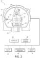
- the multimodal apparatus 10may be associated with and/or integrated into a radiotherapy device (as shown in FIG. 2 ) that can be used for a variety of applications, including, but not limited to IGRT, for example, as an IGRT delivery system.
- the multimodal apparatus 10includes a rotatable gantry system, referred to as the gantry 12 , supported by or otherwise housed in a support unit or housing 14 .
- the gantryherein refers to a gantry system that comprises one or more gantries (e.g., ring or C-arm) capable of supporting one or more radiation sources and/or associated detectors as they rotate around a target.
- a rotatable ring gantry 12may be capable of 10 rpm or more.
- the rotatable gantry 12defines a gantry bore 16 into and through which a patient can be moved and positioned for imaging and/or treatment.
- the rotatable gantry 12is configured as a slip ring gantry to provide continuous rotation of radiation sources and associated radiation detector(s) while providing sufficient bandwidth for the high-quality imaging data received by the detector(s).
- a slip-ring gantrycan eliminate gantry rotations in alternating directions in order to wind and unwind cables carrying the power and signals associated with the device. Such a configuration will allow for continuous helical computed tomography, including CBCT, even when integrated into an IGRT system.
- a patient support 18is positioned adjacent to the rotatable gantry 12 and configured to support a patient, typically in a horizontal position, for longitudinal movement into and within the rotatable gantry 12 .
- the patient support 18can move the patient, for example, in a direction perpendicular to the plane of rotation of the gantry 12 (along or parallel to the rotation axis of the gantry 12 ).
- the patient support 18can be operatively coupled to a patient support controller for controlling movement of the patient and patient support 18 .
- the patient support controllercan be synchronized with the rotatable gantry 12 and sources of radiation mounted to the rotating gantry for rotation about a patient longitudinal axis in accordance with a commanded imaging and/or treatment plan.
- the patient supportcan also be moved in a limited range up and down, left and right once it is in the bore 16 to adjust the patient position for optimal treatment.
- Axes x, y, and zare shown, where, viewing from the front of the gantry 12 , the x-axis is horizontal and points to the right, the y-axis points into the gantry plane, and the z-axis is vertical and points to the top.
- the x-, y-, and z-axesfollow the right-hand rule.
- the multimodal apparatus 10includes a radiation source 30 coupled to or otherwise supported by the rotatable gantry 12 .
- the radiation source 30is a source of imaging radiation and emits a radiation beam (indicated generally as 32 ) for generating high-quality images.
- the source of imaging radiationis an x-ray source 30 , configured as a kilovoltage (kV) source (e.g., a clinical x-ray source having an energy level in the range of about 20 kV to about 150 kV).
- the low energy radiation sourcecomprises a kilo-electron volt peak photon energy (keV) up to 150 keV.
- the imaging radiation sourcecan be any type of transmission source suitable for imaging.
- the imaging radiation sourcemay be, for example, an x-ray generating source.
- References herein to x-ray, x-ray imaging, x-ray imaging source, etc.are exemplary for particular embodiments.
- Other imaging transmission sourcescan be used interchangeably in various other embodiments.
- the radiation source 30is rapidly switched between a first voltage (e.g., about 80 kV) and a second voltage (e.g., about 140 kV) between projection views, thereby providing near-simultaneous registered dual-energy data.
- the voltage of the radiation source 30is switched from the first voltage to the second voltage between two consecutive projection views such that a current view at the first voltage has a previous adjacent view and a next adjacent view at the second voltage.
- the voltage of the radiation source 30is switched according to a pre-determined sequence (e.g., a repeating sequence of three pulses at the first voltage followed by one pulse at the second voltage or the like).
- An x-ray detector 34(e.g., two-dimensional flat detector) is coupled to or otherwise supported by the rotatable gantry 12 .
- the x-ray detector 34is positioned to receive radiation from the x-ray source 30 and can rotate along with the x-ray source 30 .
- the x-ray detector 34can take on a number of configurations without departing from the scope of the disclosed technology.
- the x-ray detector 34can be configured as a flat-panel detector (e.g., a multi-row flat panel detector).
- the detector 34can detect or otherwise measure the amount of radiation not attenuated and therefore infer what was in fact attenuated by the patient or associated patient ROI (by comparison to what was initially generated).
- the detector 34can detect or otherwise collect attenuation data from different angles as the radiation source 30 rotates around and emits radiation toward the patient.
- FIGS. 1 and 2depict a multimodal apparatus 10 with a radiation source 30 mounted to a ring gantry 12
- other embodimentsmay include other types of rotatable imaging apparatuses, including, for example, C-arm gantries and robotic arm-based systems.
- a gantryrotates the imaging radiation source 30 around an axis passing through the isocenter.
- Gantry-based systemsinclude C-arm gantries, in which the imaging radiation source 30 is mounted, in a cantilever-like manner, over and rotates about the axis passing through the isocenter.
- Gantry-based systemsfurther include ring gantries, for example, rotatable gantry 12 , having generally toroidal shapes in which the patient's body extends through a bore of the ring/toroid, and the imaging radiation source 30 is mounted on the perimeter of the ring and rotates about the axis passing through the isocenter.
- the gantry 12rotates continuously.
- the gantry 12utilizes a cable-based system that rotates and reverses repeatedly.
- a collimator or beamformer assembly(indicated generally as 36 ) is positioned relative to the x-ray source 30 to selectively control and adjust a shape of a radiation beam 32 emitted by the x-ray source 30 to selectively expose a portion or region of the active area of the x-ray detector 34 .
- the beamformercan also control how the radiation beam 32 is positioned on the x-ray detector 34 .
- the beamformer 36could have one degree/dimension of motion (e.g., to make a thinner or fatter slit).
- the beamformer 36can have two degrees/dimensions of motion (e.g., to make various sized rectangles).
- the beamformer 36may be capable of various other dynamically-controlled shapes, including, for example, parallelograms. All of these shapes may be dynamically adjusted during a scan. In some embodiments, blocking portions of the beamformer can be rotated and/or translated.
- the beamformer 36may be configured in a variety of ways that allow it to adjust the shape of the radiation beam 32 emitted by the x-ray source 30 .
- the beamformer 36can be configured to include a set of jaws or other suitable members that define and selectively adjust the size of an aperture through which the radiation beam from the x-ray source 30 may pass in a collimated manner.
- the beamformer 36can include an upper jaw and a lower jaw, where the upper and lower jaws are movable in different directions (e.g., parallel directions) to adjust the size of the aperture through which the radiation beam from the x-ray source 30 passes, and also to adjust the beam 32 position relative to the patient to illuminate only the portion of the patient to be imaged for optimized imaging and minimized patient dose.
- the multimodal apparatus 10may be integrated with a radiotherapy device that includes a high-energy radiation source (e.g., MV) 20 coupled to or otherwise supported by the rotatable gantry 12 .
- a high-energy radiation sourcee.g., MV
- the high-energy radiation source 20is configured as a source of therapeutic radiation, such as a high-energy source of radiation used for treatment of a tumor within a patient in a region of interest.
- the high-energy radiation source 20is also configured as a source of imaging radiation, or at least utilized as such.
- the source of therapeutic radiationcan be a high-energy x-ray beam (e.g., MV x-ray beam), and/or a high-energy particle beam (e.g., a beam of electrons, a beam of protons, or a beam of heavier ions, such as carbon) or another suitable form of high-energy radiation.
- the high-energy radiation source 20comprises a mega-electron volt peak photon energy (MeV) of 1 MeV or greater.
- the high-energy x-ray beamhas an average energy greater than about 0.8 MeV.
- the high-energy x-ray beamhas an average energy greater than about 0.2 MeV.
- the high-energy x-ray beamhas an average energy greater than about 150 keV.
- the high-energy radiation source 20has a higher energy level (peak and/or average, etc.) than the low-energy radiation source 30 .
- the high-energy radiation source 20is a LINAC producing therapeutic radiation (e.g., MV) and the imaging system comprises an independent low-energy radiation source 30 producing relatively low intensity and lower energy imaging radiation (e.g., kV).
- the therapeutic radiation source 20could be a radioisotope, such as, for example, Co-60, which can generally have energy of greater than about 1 MeV.
- the high-energy radiation source 20can emit one or more beams of radiation (indicated generally by 22 ) toward a region-of-interest (ROI) within a patient supported on the patient support 18 in accordance with a treatment plan.
- ROIregion-of-interest
- the high-energy radiation source 20is utilized as a source of therapeutic radiation and a source of imaging radiation.
- sources of radiation 20 , 30may be used in conjunction with one another to provide higher quality and better utilized images.
- References to the therapeutic radiation source 20 hereinare to distinguish the high-energy radiation source 20 from the low-energy radiation source 30 , which may be used only for imaging.
- references to the therapeutic radiation source 20include embodiments where the therapeutic radiation source 20 (high-energy radiation source) can be utilized for therapy and/or imaging.
- at least one additional radiation sourcecan be coupled to the rotatable gantry 12 and operated to acquire projection data at a peak photon energy distinct from the peak photon energies of sources of radiation 20 , 30 .
- the multimodal apparatus 10can include an operator/user interface 48 , where an operator of the apparatus 10 can interact with or otherwise control the apparatus 10 to provide input relating to scan or imaging parameters and the like.
- the operator interface 48can include any suitable input devices, such as a keyboard, mouse, voice-activated controller, or the like.
- the apparatus 10can also include a display 52 or other human-readable element to provide output to the operator of the apparatus 10 .
- the display 52can allow the operator to observe reconstructed patient images and other information, such as imaging or scan parameters, related to operation of the apparatus 10 .
- the multimodal apparatus 10includes a controller (indicated generally as 60 ) operatively coupled to one or more components of the apparatus 10 .
- the controller 60controls the overall functioning and operation of apparatus 10 , including providing power and timing signals to the x-ray source 30 and/or the therapeutic radiation source 20 , gain signals to the detector 34 , and a gantry motor controller that controls rotational speed and position of the rotatable gantry 12 .
- the controller 60can encompass one or more of the following: a patient support controller, a gantry controller, a controller coupled to the therapeutic radiation source 20 and/or the x-ray source 30 , a beamformer controller, a controller coupled to the detector 24 and/or the x-ray detector 34 , and the like.
- the controller 60is a system controller that can control other components, devices, and/or controllers.
- the reconstruction processor 40may be combined into one or more components or devices.
- the apparatus 10may include various components, logic, and software.
- the controller 60comprises a processor, a memory, and software.
- a multimodal apparatus and/or radiotherapy systemcan include various other devices and components (e.g., gantries, radiation sources, collimators, detectors, controllers, power sources, patient supports, among others) that can implement one or more routines or steps related to imaging and/or IGRT for a specific application, wherein a routine can include imaging, image-based pre-delivery steps, and/or treatment delivery, including respective device settings, configurations, and/or positions (e.g., paths/trajectories), which may be stored in memory.
- devices and componentse.g., gantries, radiation sources, collimators, detectors, controllers, power sources, patient supports, among others
- routines or steps related to imaging and/or IGRTfor a specific application
- a routinecan include imaging, image-based pre-delivery steps, and/or treatment delivery, including respective device settings, configurations, and/or
- controller(s)can directly or indirectly control one or more devices and/or components in accordance with one or more routines or processes stored in memory.
- An example of direct controlis the setting of various radiation source or collimator parameters (power, speed, position, timing, modulation, etc.) associated with imaging or treatment.
- An example of indirect controlis the communication of position, path, speed, etc. to a patient support controller or other peripheral device.
- the hierarchy of the various controllers that may be associated with the apparatuscan be arranged in any suitable manner to communicate the appropriate commands and/or information to the desired devices and components.
- the systems and methodsmay be implemented with other computer system configurations.
- the illustrated aspects of the inventionmay be practiced in distributed computing environments where certain tasks are performed by local or remote processing devices that are linked through a communications network.
- the reconstruction processor 40may be associated with a separate system.
- program modulesmay be located in both local and remote memory storage devices.
- a remote database, a local database, a cloud-computing platform, a cloud database, or a combination thereofcan be utilized with apparatus 10 .
- Multimodal apparatus 10can utilize an exemplary environment for implementing various aspects of the invention including a computer, wherein the computer includes the controller 60 (e.g., including a processor and a memory, which may be memory 44 ) and a system bus.
- the system buscan couple system components including, but not limited to the memory to the processor, and can communicate with other systems, controllers, components, devices, and processors.
- Memorycan include read only memory (ROM), random access memory (RAM), hard drives, flash drives, and any other form of computer readable media.
- Memorycan store various software and data, including routines and parameters, which may comprise, for example, a treatment plan.
- the therapeutic radiation source 20 and/or x-ray source 30can be operatively coupled to a controller 60 configured to control the relative operation of the therapeutic radiation source 20 and the x-ray source 30 .
- the x-ray source 30can be controlled and operated simultaneously with the therapeutic radiation source 20 .
- the x-ray source 30can be controlled and operated sequentially with the therapeutic radiation source 20 , depending on the particular treatment and/or imaging plan being implemented.
- the radiation sources 20 , 30can be operated such that the measured projection data from the radiation sources 20 , 30 are acquired simultaneously (or essentially/nearly (quasi-) simultaneous, e.g., within about 50 ms of each other) or sequentially (e.g., separated by seconds, minutes, etc.).
- radiation sources 20 , 30 and detector(s) 24 , 34can be configured to provide rotation around the patient during an imaging and/or treatment scan in a number of ways.
- synchronizing the motion and exposure of the source 20 , 30 with the longitudinal motion of the patient support 18can provide a continuous helical acquisition or scan of a patient image during a procedure.
- continuous rotation of the radiation sources 20 , 30 and detector(s) 24 , 34e.g., continuous and constant rotation of the gantry with constant patient motion speed
- the rotatable gantry 12 and patient supportcan be controlled such that the gantry 12 rotates in a “back-and-forth” manner (e.g., alternating clockwise rotation and counterclockwise rotation) around a patient supported on the patient support (as opposed to continuously, as is described above) as the support is controlled to move (at a constant or variable speed) relative to the rotatable gantry 12 .
- a “back-and-forth” mannere.g., alternating clockwise rotation and counterclockwise rotation
- movement of the patient support 18 in the longitudinal direction (step)alternates with a scanning revolution by the rotatable gantry 12 (shoot) until the desired volume is captured.
- the multimodal apparatus 10is capable of volume-based and planar-based imaging acquisitions.
- the multimodal apparatus 10may be used to acquire volume images and/or planar images and execute the associated processing.
- Non-continuous motion of the radiation source and/or patient supportmay be utilized, including in combination with the various embodiments of apparatus 10 described above.
- Non-continuous motion of the radiation source and/or patient supportcontinuous but variable/non-constant (including linear and non-linear) movement, speed, and/or trajectories, etc., and combinations thereof may be used, including in combination with the various embodiments of apparatus 10 described above.
- the gantry 12 rotation speed, the patient support 18 speed, the beamformer shape, and/or the detector readoutcould all be constant during image acquisition. In other embodiments, one or more of these variables could change dynamically during image acquisition and/or treatment.
- these featurescan be combined with one or more other image-based activities or procedures, including, for example, patient set up, adaptive therapy monitoring, treatment planning, etc.
- both the source (e.g., source 30 ) and detector (e.g., 34 )move along an angular path as the gantry 12 rotates.
- Source 36 and detector 34may move along their respective paths in a synchronized manner.
- Datais collected at various positions along the angular path, e.g., when the detector 34 is located at positions 303 , 305 , 307 , as shown in FIG. 3 .
- the data typemay be image data I, which is data relating to the traversal of x-ray from source 30 through an object 26 of interest (sometimes referred to herein as the “scanned object”), or background B data, which is data detected by the detector 34 when the source 30 is powered off.
- Image data Imay be, for example, diagnostic data related to a patient. However, other data may be obtained in the context of the present disclosure. Image data I can be reconstructed to form a 3D representation of the patient using tomographic methods.
- source 30To detect image I data, source 30 must be powered up and emitting x-rays. Although referred to herein as “emitting x-rays,” it should be understood that the source 30 emits a stream (e.g., a ray) of photons that together are referred to as an x-ray or a ray.
- the radiation source 30is rapidly switched between a first voltage (e.g., about 140 kV) and a second voltage (e.g., about 80 kV) between projection views, as shown in FIG. 3 .
- a first voltagee.g., about 140 kV
- a second voltagee.g., about 80 kV
- FIG. 3the position of the radiation source 30 and the x-ray detector 34 in the current view 304 are darkened, while the position of the radiation source 30 and the x-ray detector 34 in the previous and next views are shown in broken lines.
- the radiation sourceis at position 306 and the x-ray detector is at position 307
- the radiation sourceis at position 302 and the x-ray detector is at position 303 .
- a plurality of raysare emitted by the radiation source 30 and received by the x-ray detector 34 at each view
- a single ray emitted by the radiation source 30 at each positionis illustrated in FIG. 3 , and additional rays are omitted for clarity.
- Ray Cis emitted during the current view
- ray Pis emitted during the previous view
- ray Nis emitted during the next view.
- each of the illustrated rays C, N, and Ppasses through a reference point R in the scanned object 26 .
- the reference point Ris located in a peripheral region of the scanned object 26 .
- the location of the reference point Ris not limited to the peripheral region, it is believed that attenuation of the x-ray by the scanned object is less, making saturation more likely to happen. Accordingly, although the reference point R may be described in various embodiments as being located in a peripheral region, it is contemplated that the reference point R may be located anywhere in the field of view.
- Each of the rays C, N, and Pis received at the radiation detector 34 after passing through the reference point R.
- the reference point Ris configured as the closest point on the ray to the isocenter.
- the voltage switchingis interleaved, meaning that the emission at one view (e.g., the current view) at the first voltage is followed by an emission at the next view at the second voltage and is preceded by an emission at the previous view at the second voltage.
- emissions from the radiation sourcealternate between the first and second voltages.
- saturation correctioncan be performed on at least one saturated ray using information from non-saturated rays or frames from the current and/or next or previous views.
- saturation correctionis described herein as using non-saturated rays, it is contemplated that multiple non-saturated rays from the same frame (i.e., a non-saturated frame) can be used (e.g., averaged) to correct the saturated ray.
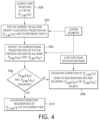
- FIG. 4is a flow chart of an example method of saturation correction using adjacent frames according to various embodiments.
- the current viewwill be discussed as including an emission at the first voltage (e.g., about 140 kV), and the previous view and the next view will be discussed as including an emission at the second voltage (e.g., about 80 kV).
- the second voltagee.g. 80 kV
- the non-saturated datacan come from one or more non-saturated rays that are neighboring (e.g., adjacent) to the saturated ray in three-dimensional space, whether located during the same rotation or a different rotation, provided that the non-saturated ray has substantially the same path length through the reference point as the saturated ray.
- the amount of energy received by the x-ray detector 34 at position 305 as a result of the ray Cexceeds the dynamic range of the x-ray detector 34 .
- a controller associated with the x-ray detector 34determines that the projection ray C is saturated (block 502 in FIG. 4 ).
- the amount of energy received by the x-ray detector 34 as a result of each of the rays P and Ndoes not exceed the dynamic range of the x-ray detector 34 .
- the controller associated with the x-ray detector 34identifies the corresponding projection ray from the previous view (e.g., ray P) and the corresponding projection ray from the next view (e.g., ray N) through a reference point R of projection ray C at block 504 in FIG. 4 . Based on the amount of energy received by the x-ray detector 34 as a result of ray P and ray N, the controller determines that the projection rays P and N are not saturated (e.g., a “no” at decision block 506 ). In other words, the controller identifies at least one non-saturated ray from a previous or next view of the x-ray detector.
- the determination of whether a given projection ray is saturated or notcan be the result of the controller comparing an output of the x-ray detector in response to the received energy for a given ray to a threshold output value for the x-ray detector.
- the controllercompares the signal output by the x-ray detector as a result of the receipt of ray C to a maximum signal output value and, upon determining that the signal output by the x-ray detector is equal to the maximum signal output value, the controller determines that the projection ray C is saturated.
- the controllercompares the signal output by the x-ray detector as a result of the receipt of ray P and/or ray N to a maximum signal output value and, upon determining that the signal output by the x-ray detector is less than the maximum signal output value, the controller determines that the corresponding projection ray P or N is not saturated (block 506 ). In various embodiments, upon determination that the projection rays P and/or N are not saturated (e.g., a “no” at block 506 ), the data from the corresponding projection rays P and/or N is used to correct the saturated ray of the current ray C (block 508 ).
- both of ray P from the previous view and ray N of the next vieware not saturated and, accordingly, the saturation correction of ray C can be performed using data from both of ray P and ray N.
- the current ray Cis saturated and one of ray P and ray N is not saturated while the other is saturated.
- the data from the corresponding projection ray that is not saturatedis used for saturation correction while data from the other corresponding projection ray is ignored for the purposes of saturation correction.
- the data from ray Pis used for saturation correction while the data from ray N is ignored for saturation correction purposes.
- the data from ray Nis used for saturation correction while the data from ray P is ignored for saturation correction purposes.
- the neighboring non-saturated projection datais used for saturation correction without data from the adjacent (e.g., previous or next) views (block 510 ).
- the controllerperforms saturation correction using linear or advanced interpolation schemes with the neighboring non-saturated projection data and any non-saturated corresponding projection rays from previous or next views as inputs.
- the saturation correction performed by the controlleris effective to adjust a value for the saturated ray based on a value of the at least one non-saturated ray.
- a simple linear interpolation schemecan be employed.
- One example linear interpolation schemeis averaging the neighboring non-saturated rays (e.g., (ray 1 +ray 2 )*0.5).
- a spectrum-derived interpolation scheme with scalingcan be employed.
- the correction factorcan be calculated using imaging chain information (e.g., spectra) and system geometry with the first pass reconstructed image to virtually generate two projections: one for each of the energies.
- the correction factorcan then be determined and applied to the values of the neighboring non-saturated rays to determine an appropriate value for the saturated ray.
- the correction factor determination processescan be performed several times to improve the accuracy of the correction factor.
- the high and low voltage pulsesare interleaved. Accordingly, this ensures that the energy for the current view is different from the energy of the previous and next views.
- the high and low voltage pulsesmay or may not be interleaved. Accordingly, in some such embodiments, saturation correction can be performed using conjugate frames instead of adjacent views.
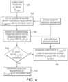
- FIG. 6is a flow chart of an example method of saturation correction using conjugate frames according to various embodiments.
- the current viewwill be discussed as including an emission at the first voltage (e.g., about 140 kV), and the conjugate views will be discussed as including an emission at the second voltage (e.g., about 80 kV).
- the voltages of the current and conjugate viewscan be reversed.
- the controller associated with the x-ray detector 34identifies the corresponding projection rays from the conjugate views C 1 and C 2 through a reference point R of projection ray C at block 704 in FIG. 6 .
- corresponding projection raysare identified based on system geometry triggering information, including x-ray source trajectory information and x-ray cone-beam projection geometry (e.g., information regarding how the detector is positioned relative to the source).
- the controllerdetermines that the conjugate projection rays C 1 and C 2 are not saturated (e.g., a “no” at decision block 706 ). In other words, the controller identifies at least one non-saturated ray.
- the data from ray C 1is used for saturation correction while the data from ray C 2 is ignored for saturation correction purposes.
- the data from ray C 2is used for saturation correction while the data from ray C 1 is ignored for saturation correction purposes.
- FIG. 7illustrates an example embodiment in which the dynamic gain setting is varied for high and low voltage pulses.
- varying the dynamic gain settingcan be implemented in configurations in which the tube current varies in addition to the voltage.
- such embodimentscan be used to select appropriate gain settings to reduce or even eliminate saturated rays in future scans.
- a first plurality of photonsis emitted from a radiation source 30 at a first energy level and a second plurality of photons is emitted from the radiation source 30 at a second energy level.
- a first pulsehas a first voltage (e.g., 140 kV) and a first current (e.g., 80 mAs) when the radiation source 30 is at a first position 800
- a second pulsehas a second voltage (e.g., 80 kV) and a second current (e.g., 120 mAs) when the radiation source 30 is at a second position 802 .
- At least some of the first plurality of photons and at least some of the second plurality of photonsare received at the x-ray detector 34 .
- the x-ray detector 34is at position 804
- the x-ray detectoris at position 806 . It should be understood that the particular voltage and current for each pulse can vary depending on the particular embodiment.
- the energy received by the detector from the high energy pulsesmay be twice as much (or more) as that received by from the low energy pulses. Accordingly, a first detector gain (e.g., a high detector gain) can be selected for the first pulse configuration and a second detector gain (e.g., a low detector gain) can be selected for the second pulse configuration.
- a first detector gaine.g., a high detector gain
- a second detector gaine.g., a low detector gain
- the x-ray detectoroutputs a signal indicative of the quantity of the photons received. For example, upon receipt of some of the first plurality of photons, the x-ray detector outputs a first signal indicative of a first quantity of the first plurality of photons received at the x-ray detector. In embodiments, the first signal is an amplification of the first quantity by a factor of the first gain level. Upon receipt of some of the second plurality of photons, the x-ray detector outputs a second signal indicative of a second quantity of the second plurality of photons received at the x-ray detector.
- the second signalis an amplification of the second quantity by a factor of the second gain level. Accordingly, the amplification of the quantity of received photons as a result of each pulse can be varied to generate a signal that can be utilized in image reconstruction.
- the first and second gain levelscan be adjusted (e.g., increased or reduced depending on the values) to reduce or eliminate the number of saturated signals emitted during the next scan.
- a first gain level and a second gain levelare selected to avoid saturation of a first signal corresponding to the first plurality of photons and a second signal corresponding to the second plurality of photons.
- Selection of each gain levelcan be based, for example, on saturation information obtained during previous scans (e.g., whether saturated signals were output for a particular pulse configuration during a previous scan, energy levels and gain levels utilized during the previous scan, etc.).
- the output of a saturated signal during a first scancan cause the controller to adjust the gain level for a subsequent scan.
- the adjusted gain levelcan be determined based on the energy level and gain level of the previous scan during output of the saturated signal and the energy level for the subsequent scan.
Landscapes
- Health & Medical Sciences (AREA)
- Life Sciences & Earth Sciences (AREA)
- Engineering & Computer Science (AREA)
- Medical Informatics (AREA)
- Physics & Mathematics (AREA)
- High Energy & Nuclear Physics (AREA)
- Molecular Biology (AREA)
- Surgery (AREA)
- Biomedical Technology (AREA)
- Veterinary Medicine (AREA)
- Biophysics (AREA)
- Public Health (AREA)
- Nuclear Medicine, Radiotherapy & Molecular Imaging (AREA)
- Optics & Photonics (AREA)
- Pathology (AREA)
- Radiology & Medical Imaging (AREA)
- General Health & Medical Sciences (AREA)
- Heart & Thoracic Surgery (AREA)
- Animal Behavior & Ethology (AREA)
- General Physics & Mathematics (AREA)
- Spectroscopy & Molecular Physics (AREA)
- Computer Vision & Pattern Recognition (AREA)
- Pulmonology (AREA)
- Theoretical Computer Science (AREA)
- Apparatus For Radiation Diagnosis (AREA)
Abstract
Description
Claims (11)
Priority Applications (4)
| Application Number | Priority Date | Filing Date | Title |
|---|---|---|---|
| US17/666,129US12257083B2 (en) | 2022-02-07 | 2022-02-07 | Methods for saturation correction and dynamic gain configuration and apparatuses for performing the same |
| JP2023016064AJP2023115001A (en) | 2022-02-07 | 2023-02-06 | Method for saturation correction and dynamic gain configuration, and device for implementing the same |
| EP23155102.9AEP4224215A1 (en) | 2022-02-07 | 2023-02-06 | Method for saturation correction and dynamic gain configuration |
| CN202310119307.2ACN116559932A (en) | 2022-02-07 | 2023-02-07 | Method for saturation correction and dynamic gain configuration and device for performing the method |
Applications Claiming Priority (1)
| Application Number | Priority Date | Filing Date | Title |
|---|---|---|---|
| US17/666,129US12257083B2 (en) | 2022-02-07 | 2022-02-07 | Methods for saturation correction and dynamic gain configuration and apparatuses for performing the same |
Publications (2)
| Publication Number | Publication Date |
|---|---|
| US20230248329A1 US20230248329A1 (en) | 2023-08-10 |
| US12257083B2true US12257083B2 (en) | 2025-03-25 |
Family
ID=85175781
Family Applications (1)
| Application Number | Title | Priority Date | Filing Date |
|---|---|---|---|
| US17/666,129Active2043-01-26US12257083B2 (en) | 2022-02-07 | 2022-02-07 | Methods for saturation correction and dynamic gain configuration and apparatuses for performing the same |
Country Status (4)
| Country | Link |
|---|---|
| US (1) | US12257083B2 (en) |
| EP (1) | EP4224215A1 (en) |
| JP (1) | JP2023115001A (en) |
| CN (1) | CN116559932A (en) |
Families Citing this family (1)
| Publication number | Priority date | Publication date | Assignee | Title |
|---|---|---|---|---|
| US12257083B2 (en)* | 2022-02-07 | 2025-03-25 | Accuray Inc. | Methods for saturation correction and dynamic gain configuration and apparatuses for performing the same |
Citations (122)
| Publication number | Priority date | Publication date | Assignee | Title |
|---|---|---|---|---|
| US4190773A (en) | 1977-07-01 | 1980-02-26 | Braden Arthur B | Shutter for rotating source CT scanner |
| JPH08252248A (en) | 1995-03-16 | 1996-10-01 | Toshiba Corp | X-ray CT system |
| US5615279A (en) | 1993-11-02 | 1997-03-25 | Hitachi Medical Corporation | Method of and apparatus for correcting scattered X-rays for X-ray computerized tomograph |
| JPH09218939A (en) | 1996-02-09 | 1997-08-19 | Toshiba Corp | Image processing device |
| JPH105210A (en) | 1996-06-21 | 1998-01-13 | Toshiba Corp | X-ray CT apparatus and its misalignment correction method |
| CN1271261A (en) | 1997-08-01 | 2000-10-25 | 模拟技术公司 | Asymmetric detector halfscan CT reconstruction |
| EP1062914A1 (en) | 1998-03-12 | 2000-12-27 | Quanta Vision, Inc. | Ultra-small-angle x-ray tomography |
| US6233478B1 (en) | 1998-09-28 | 2001-05-15 | Advanced Research & Technology Institute | Apparatus and method for constructing computed tomography image slices of an object undergoing cyclic motion |
| US6307909B1 (en) | 1998-11-27 | 2001-10-23 | Siemens Aktiengesellschaft | Method for image reconstruction in a computed tomography device |
| US20030007601A1 (en) | 2000-02-18 | 2003-01-09 | Jaffray David A. | Cone-beam computerized tomography with a flat-panel imager |
| US20030076927A1 (en) | 2001-10-18 | 2003-04-24 | Shigeyuki Nakashima | X-ray computed tomography apparatus |
| JP2004000356A (en) | 2002-06-03 | 2004-01-08 | Hitachi Medical Corp | Multi-slice x-ray ct apparatus and method therefor |
| US20040068169A1 (en) | 2002-10-05 | 2004-04-08 | Stan Mansfield | Imaging device for radiation treatment applications |
| US20040091079A1 (en) | 2002-11-12 | 2004-05-13 | Zapalac Geordie Henry | Method and apparatus for scatter measurement using an occluded detector ring |
| JP2004136021A (en) | 2002-10-21 | 2004-05-13 | Toshiba Corp | Centralized radiation therapy equipment |
| US20040102688A1 (en) | 2002-11-27 | 2004-05-27 | Walker Matthew Joseph | Methods and apparatus for facilitating a reduction in artifacts |
| JP2004223255A (en) | 2003-01-22 | 2004-08-12 | Siemens Ag | Tomographic image forming device |
| JP2004530467A (en) | 2001-03-09 | 2004-10-07 | トモセラピー インコーポレイテッド | System and method for fusion matching and reprojecting incomplete data |
| US20040202360A1 (en) | 2003-04-11 | 2004-10-14 | Besson Guy M. | Scatter rejection for composite medical imaging systems |
| US20050053188A1 (en) | 2003-09-09 | 2005-03-10 | Makoto Gohno | Radiation tomography apparatus |
| US20050251029A1 (en) | 2004-04-21 | 2005-11-10 | Ali Khamene | Radiation therapy treatment plan |
| WO2005112753A2 (en) | 2004-05-14 | 2005-12-01 | Manzione James V | Combination of multi-modality imaging technologies |
| JP2006122679A (en) | 2004-10-25 | 2006-05-18 | Siemens Ag | Tomographic apparatus for creating a multi-energy image and method of creating a multi-energy image for a tomographic apparatus |
| US20060104496A1 (en) | 2004-11-18 | 2006-05-18 | Arenson Jerome S | Method and system for controlling an X-ray imaging system |
| US7050528B2 (en) | 2004-09-30 | 2006-05-23 | Wisconsin Alumni Research Foundation | Correction of CT images for truncated or incomplete projections |
| US20060109954A1 (en) | 2004-11-25 | 2006-05-25 | Ge Medical Systems Global Technology Company, Llc | Radiation imaging apparatus |
| JP2006141999A (en) | 2004-11-18 | 2006-06-08 | Toshiba Corp | X-ray CT system |
| WO2006078386A2 (en) | 2005-01-20 | 2006-07-27 | Carestream Health, Inc. | Radiation therapy method with target detection |
| JP2006239003A (en) | 2005-03-01 | 2006-09-14 | Ge Medical Systems Global Technology Co Llc | Scatter correction method, scatter measurement method, and X-ray CT apparatus |
| US7108421B2 (en) | 2002-03-19 | 2006-09-19 | Breakaway Imaging, Llc | Systems and methods for imaging large field-of-view objects |
| US20060262894A1 (en) | 2005-05-17 | 2006-11-23 | Siemens Aktiengesellschaft | Method for minimizing image artifacts and medical imaging system |
| CN1947154A (en) | 2004-04-21 | 2007-04-11 | 皇家飞利浦电子股份有限公司 | Cone beam CT apparatus using truncated projections and a previously acquired 3D CT image |
| US20070127621A1 (en) | 2003-10-14 | 2007-06-07 | Michael Grass | Asymmetric csct |
| DE102006007058A1 (en) | 2006-02-15 | 2007-07-12 | Siemens Ag | CT system with at least two focus / detector systems |
| US20070189444A1 (en) | 2004-03-17 | 2007-08-16 | Koninklijke Philips Electronic, N.V. | Beam-hardening and attenuation correction for coherent-scatter ct |
| US20070237288A1 (en) | 2006-03-31 | 2007-10-11 | Tkaczyk J E | Image-based material decomposition |
| US7302038B2 (en) | 2004-09-24 | 2007-11-27 | Wisconsin Alumni Research Foundation | Correction of patient rotation errors in radiotherapy using couch translation |
| JP2008036275A (en) | 2006-08-09 | 2008-02-21 | Toshiba Corp | X-ray CT system |
| US20080103834A1 (en) | 2006-10-25 | 2008-05-01 | Bruce Reiner | Method and apparatus of providing a radiation scorecard |
| US20080099689A1 (en)* | 2006-10-31 | 2008-05-01 | Einar Nygard | Photon counting imaging detector system |
| US20080112532A1 (en) | 2005-01-12 | 2008-05-15 | Koninklijke Philips Electronics, N.V. | Computer Tomography Apparatus |
| US7433443B1 (en) | 2007-08-29 | 2008-10-07 | General Electric Company | System and method of CT imaging with second tube/detector patching |
| US7453976B1 (en) | 2005-05-17 | 2008-11-18 | Fang-Fang Yin | Computerized tomography image reconstruction |
| JP2008544831A (en) | 2005-06-29 | 2008-12-11 | アキュレイ・インコーポレーテッド | High-precision overlay of X-ray images on cone-beam CT scan for image-guided radiation treatment |
| US20090080603A1 (en) | 2007-09-26 | 2009-03-26 | Shukla Himanshu P | Online igrt using digital tomosynthesis |
| US20090135994A1 (en) | 2007-11-23 | 2009-05-28 | Lifeng Yu | System And Method For Creating Mixed Image From Dual-Energy CT Data |
| CN101466313A (en) | 2006-04-14 | 2009-06-24 | 威廉博蒙特医院 | Scanning slot cone-beam computed tomography and scanning focused spot cone-beam computed tomography |
| US20090161826A1 (en) | 2007-12-23 | 2009-06-25 | Oraya Therapeutics, Inc. | Methods and devices for orthovoltage ocular radiotherapy and treatment planning |
| US20090225932A1 (en) | 2008-02-27 | 2009-09-10 | Lei Zhu | Cone-beam CT imaging scheme |
| JP2009533086A (en) | 2006-04-07 | 2009-09-17 | ヴァリアン メディカル システムズ テクノロジーズ インコーポレイテッド | Patient positioning using tomosynthesis technology |
| US20090283682A1 (en) | 2008-05-19 | 2009-11-19 | Josh Star-Lack | Multi-energy x-ray imaging |
| US20090304142A1 (en) | 2008-06-09 | 2009-12-10 | Arineta Ltd. | Ct scanner with scatter radiation correction and method of using same |
| JP2009297314A (en) | 2008-06-16 | 2009-12-24 | Ge Medical Systems Global Technology Co Llc | X-ray tomographic apparatus |
| WO2010014288A1 (en) | 2008-07-26 | 2010-02-04 | Tomotherapy Incorporated | Radiation therapy imaging and delivery utilizing coordinated motion of jaws, gantry, and couch |
| US7660380B2 (en) | 2007-08-03 | 2010-02-09 | Siemens Aktiengesellschaft | Method for correction of truncation artifacts in a reconstruction method for tomographic imaging with truncated projection data |
| US20100046819A1 (en) | 2008-06-20 | 2010-02-25 | Noo Frederic | Method and image reconstruction device for generating computed tomography image data |
| US20100142791A1 (en) | 2008-12-05 | 2010-06-10 | Fujifilm Corporation | Image processing apparatus and image processing method |
| WO2010070583A1 (en)* | 2008-12-17 | 2010-06-24 | Koninklijke Philips Electronics N.V. | X-ray examination device and method |
| US20100208964A1 (en) | 2007-06-29 | 2010-08-19 | Koninklijke Philips Electronics N.V. | Method for eliminating scatter artefacts |
| WO2010099621A1 (en) | 2009-03-05 | 2010-09-10 | University Health Network | A method of low energy imaging in the presence of high energy radiation |
| JP2010284325A (en) | 2009-06-11 | 2010-12-24 | Toshiba Corp | X-ray computed tomography system |
| US20110060566A1 (en) | 2008-05-21 | 2011-03-10 | Koninklijke Philips Electronics N.V. | Method and apparatus for scatter correction |
| JP2011067555A (en) | 2009-09-28 | 2011-04-07 | Hitachi Medical Corp | X-ray ct apparatus |
| US20110142312A1 (en) | 2009-12-11 | 2011-06-16 | Toth Thomas L | System and method of mitigating low signal data for dual energy ct |
| US20110176717A1 (en) | 2008-10-03 | 2011-07-21 | Palodex Group Oy | Method and device for x-ray computer tomography |
| US20110255656A1 (en) | 2010-04-15 | 2011-10-20 | Varian Medical Systems, Inc. | Methods of scatter correction of x-ray projection data 2 |
| US20110255657A1 (en) | 2008-12-15 | 2011-10-20 | Koninklijke Philips Electronics N.V. | Semicircular inversed offset scanning for enlarged field of view 3d |
| EP2383702A1 (en) | 2010-04-30 | 2011-11-02 | General Electric Company | Method and apparatus for computed tomography |
| US20120014582A1 (en) | 2009-03-26 | 2012-01-19 | Koninklijke Philips Electronics N.V. | Method and apparatus for computed tomography image reconstruction |
| US20120018646A1 (en)* | 2010-07-23 | 2012-01-26 | Canon Kabushiki Kaisha | X-ray imaging apparatus, x-ray imaging method, and computer storage medium |
| JP2012024145A (en) | 2010-07-20 | 2012-02-09 | Toshiba Corp | Radiotherapy system and control method for the same |
| US8116430B1 (en) | 2002-12-18 | 2012-02-14 | Varian Medical Systems, Inc. | Multi-mode cone beam CT radiotherapy simulator and treatment machine with a flat panel imager |
| US20120121157A1 (en) | 2009-09-11 | 2012-05-17 | Toshiyuki Irie | X-ray ct device |
| US20120207370A1 (en) | 2010-12-20 | 2012-08-16 | Benjamin Pooya Fahimian | Systems and Methods for Simultaneous Acquisition of Scatter and Image Projection Data in Computed Tomography |
| CN102711617A (en) | 2009-11-16 | 2012-10-03 | 皇家飞利浦电子股份有限公司 | Scan plan field of view adjustor, determiner, and/or quality assessor |
| US20120263360A1 (en) | 2011-04-15 | 2012-10-18 | Georgia Tech Research Corporation | Scatter correction methods |
| US20120294504A1 (en) | 2011-05-16 | 2012-11-22 | Siemens Aktiengesellschaft | Method for providing an image data record with suppressed aliasing artifacts overlapping the field of view and x-ray image recording apparatus |
| US20130004052A1 (en) | 2011-06-28 | 2013-01-03 | Siemens Aktiengesellschaft | Subtraction of projection data in medical diagnostic imaging |
| US20130101082A1 (en) | 2011-10-21 | 2013-04-25 | Petr Jordan | Apparatus for generating multi-energy x-ray images and methods of using the same |
| US8467497B2 (en) | 2007-10-25 | 2013-06-18 | Tomotherapy Incorporated | System and method for motion adaptive optimization for radiation therapy delivery |
| DE102012200150A1 (en) | 2012-01-05 | 2013-07-11 | Siemens Aktiengesellschaft | Method for scattered radiation correction of X-ray image of object of patient, involves locating portion at edge of detector elements to receive scattered radiation data such that scattering radiation data corrects image data |
| CN103339657A (en) | 2011-02-01 | 2013-10-02 | 皇家飞利浦有限公司 | Method and system for dual energy ct image reconstruction |
| US20130294570A1 (en) | 2011-01-27 | 2013-11-07 | Koninklijke Philips Electronics N.V. | Truncation compensation for iterative cone-beam ct reconstruction for spect/ct systems |
| US8588363B2 (en) | 2010-09-30 | 2013-11-19 | Siemens Aktiengesellschaft | Dual-source CT device and method for spiral scanning |
| US20130343515A1 (en) | 2012-06-26 | 2013-12-26 | Analogic Corporation | Dynamic adjustment of x-ray acquisition parameters |
| US20140018671A1 (en) | 2005-09-19 | 2014-01-16 | Yongwang Li | Medical Imaging System and Method with Separate Primary and Scattered Components |
| US20140086383A1 (en) | 2012-09-27 | 2014-03-27 | Siemens Aktiengesellschaft | Method and computerized tomography system for determining bone mineral density values |
| US20140105352A1 (en) | 2012-10-15 | 2014-04-17 | Elekta Ab (Publ) | Dual-Energy Cone-Beam CT Scanning |
| JP2014511186A (en) | 2010-12-21 | 2014-05-15 | レニショウ (アイルランド) リミテッド | Method and apparatus for analyzing images |
| US20140177786A1 (en)* | 2012-12-21 | 2014-06-26 | General Electric Company | Photon-counting ct-system with reduced detector counting-rate requirements |
| US20140247919A1 (en) | 2006-04-14 | 2014-09-04 | William Beaumont Hospital | Image Guided Radiotherapy with Dual Source and Dual Detector Arrays Tetrahedron Beam Computed Tomography |
| JP2014528767A (en) | 2011-08-16 | 2014-10-30 | コーニンクレッカ フィリップス エヌ ヴェ | Method for estimating movements of and between organs in fractions for adaptive external beam radiotherapy |
| WO2015103184A1 (en) | 2013-12-31 | 2015-07-09 | The Medical College Of Wisconsin, Inc. | Adaptive replanning based on multimodality imaging |
| US20150297165A1 (en) | 2012-11-30 | 2015-10-22 | Hitachi Medical Corporation | X-ray ct apparatus and tomography method |
| US20150305696A1 (en) | 2010-07-13 | 2015-10-29 | Telesystems Co., Ltd. | X-ray tomogram imaging device |
| US20160005194A1 (en) | 2009-01-21 | 2016-01-07 | Koninklijke Philips N.V. | Method and apparatus for large field of view imaging and detection and compensation of motion artifacts |
| US20160016009A1 (en) | 2012-02-21 | 2016-01-21 | Koninklijke Philips N.V. | Adaptive radiotherapy with spectral tissue of interest imaging and tracking |
| US20160120486A1 (en) | 2014-10-31 | 2016-05-05 | Kabushiki Kaisha Toshiba | X-ray ct apparatus |
| US20160220844A1 (en) | 2015-02-03 | 2016-08-04 | Varian Medical Systems International Ag. | Radiography imaging parameter selection based on extant patient information |
| US20160262709A1 (en) | 2013-11-26 | 2016-09-15 | The Johns Hopkins University | Dual-energy cone-beam computed tomography with a multiple source, single-detector configuration |
| US20170000428A1 (en) | 2014-01-15 | 2017-01-05 | Hitachi, Ltd. | X-ray ct apparatus and contrast imaging method |
| WO2017104700A1 (en) | 2015-12-17 | 2017-06-22 | 国立大学法人東京大学 | Image processing device and image processing method |
| US20170197098A1 (en) | 2014-09-22 | 2017-07-13 | Shimadzu Corporation | Fluoroscopic Device, Moving Body Tracking Device for Radiation Therapy, and X-Ray Detector |
| US20170205360A1 (en) | 2014-07-22 | 2017-07-20 | Universite Grenoble Alpes | X-ray imaging system allowing the correction of the scatter radiation and precise detection of the distance between the source and the detector |
| JP2017131496A (en) | 2016-01-29 | 2017-08-03 | 株式会社日立製作所 | X-ray CT apparatus, imaging condition setting method, and imaging condition setting program |
| US20170278277A1 (en) | 2016-03-25 | 2017-09-28 | Varian Medical Systems International Ag | Methods and systems for improving image quality of projection image data acquired using flat panel detectors |
| JP2017185219A (en) | 2016-03-31 | 2017-10-12 | ジーイー・メディカル・システムズ・グローバル・テクノロジー・カンパニー・エルエルシー | CT imaging apparatus, CT imaging method, and X-ray transmission / reception component for CT imaging apparatus |
| JP2017531228A (en) | 2014-08-08 | 2017-10-19 | ケアストリーム ヘルス インク | Mapping facial texture to volume images |
| US20170332982A1 (en) | 2014-11-06 | 2017-11-23 | Koninklijke Philips N.V. | Computed tomography system |
| US20180028143A1 (en) | 2014-06-04 | 2018-02-01 | Varian Medical Systems, Inc. | Imaging-based self-adjusting radiation therapy systems, devices, and methods |
| US20180070894A1 (en) | 2016-09-01 | 2018-03-15 | Toshiba Medical Systems Corporation | X-ray ct apparatus |
| US20180144510A1 (en) | 2016-11-21 | 2018-05-24 | Elekta Limited | Systems and methods for real-time imaging |
| US20180192978A1 (en) | 2017-01-06 | 2018-07-12 | Accuray Incorporated | Coordinated motion of a rotating 2d x-ray imager and a linear accelerator |
| WO2018156968A1 (en) | 2017-02-24 | 2018-08-30 | The Regents Of The University Of California | Systems and methods for image-guided radiotherapy using dual robot architecture |
| WO2018183748A1 (en) | 2017-03-30 | 2018-10-04 | Reflexion Medical, Inc. | Radiation therapy systems and methods with tumor tracking |
| US20180345042A1 (en) | 2017-05-30 | 2018-12-06 | Reflexion Medical, Inc. | Methods for real-time image guided radiation therapy |
| US20190099149A1 (en) | 2017-09-29 | 2019-04-04 | Shanghai United Imaging Healthcare Co., Ltd. | Collimators, imaging devices, and methods for tracking and calibrating x-ray focus positions |
| US20200121267A1 (en) | 2018-10-18 | 2020-04-23 | medPhoton GmbH | Mobile imaging ring system |
| US20200170590A1 (en) | 2018-11-30 | 2020-06-04 | Accuray, Inc. | Apparatus and methods for scalable field of view imaging using a multi-source system |
| US20200402644A1 (en) | 2017-10-06 | 2020-12-24 | Canon Medical Systems Corporation | Medical image processing apparatus and medical image processing system |
| US20210165122A1 (en) | 2003-04-25 | 2021-06-03 | Rapiscan Systems, Inc. | X-Ray Scanners |
| US20230248329A1 (en)* | 2022-02-07 | 2023-08-10 | Accuray Inc. | Methods for saturation correction and dynamic gain configuration and apparatuses for performing the same |
- 2022
- 2022-02-07USUS17/666,129patent/US12257083B2/enactiveActive
- 2023
- 2023-02-06EPEP23155102.9Apatent/EP4224215A1/enactivePending
- 2023-02-06JPJP2023016064Apatent/JP2023115001A/enactivePending
- 2023-02-07CNCN202310119307.2Apatent/CN116559932A/enactivePending
Patent Citations (142)
| Publication number | Priority date | Publication date | Assignee | Title |
|---|---|---|---|---|
| US4190773A (en) | 1977-07-01 | 1980-02-26 | Braden Arthur B | Shutter for rotating source CT scanner |
| US5615279A (en) | 1993-11-02 | 1997-03-25 | Hitachi Medical Corporation | Method of and apparatus for correcting scattered X-rays for X-ray computerized tomograph |
| JPH08252248A (en) | 1995-03-16 | 1996-10-01 | Toshiba Corp | X-ray CT system |
| JPH09218939A (en) | 1996-02-09 | 1997-08-19 | Toshiba Corp | Image processing device |
| JPH105210A (en) | 1996-06-21 | 1998-01-13 | Toshiba Corp | X-ray CT apparatus and its misalignment correction method |
| CN1271261A (en) | 1997-08-01 | 2000-10-25 | 模拟技术公司 | Asymmetric detector halfscan CT reconstruction |
| EP1062914A1 (en) | 1998-03-12 | 2000-12-27 | Quanta Vision, Inc. | Ultra-small-angle x-ray tomography |
| US6233478B1 (en) | 1998-09-28 | 2001-05-15 | Advanced Research & Technology Institute | Apparatus and method for constructing computed tomography image slices of an object undergoing cyclic motion |
| US6307909B1 (en) | 1998-11-27 | 2001-10-23 | Siemens Aktiengesellschaft | Method for image reconstruction in a computed tomography device |
| US20030007601A1 (en) | 2000-02-18 | 2003-01-09 | Jaffray David A. | Cone-beam computerized tomography with a flat-panel imager |
| JP2004530467A (en) | 2001-03-09 | 2004-10-07 | トモセラピー インコーポレイテッド | System and method for fusion matching and reprojecting incomplete data |
| US20030076927A1 (en) | 2001-10-18 | 2003-04-24 | Shigeyuki Nakashima | X-ray computed tomography apparatus |
| US7108421B2 (en) | 2002-03-19 | 2006-09-19 | Breakaway Imaging, Llc | Systems and methods for imaging large field-of-view objects |
| JP2004000356A (en) | 2002-06-03 | 2004-01-08 | Hitachi Medical Corp | Multi-slice x-ray ct apparatus and method therefor |
| US20040068169A1 (en) | 2002-10-05 | 2004-04-08 | Stan Mansfield | Imaging device for radiation treatment applications |
| JP2004136021A (en) | 2002-10-21 | 2004-05-13 | Toshiba Corp | Centralized radiation therapy equipment |
| US20040091079A1 (en) | 2002-11-12 | 2004-05-13 | Zapalac Geordie Henry | Method and apparatus for scatter measurement using an occluded detector ring |
| US20040102688A1 (en) | 2002-11-27 | 2004-05-27 | Walker Matthew Joseph | Methods and apparatus for facilitating a reduction in artifacts |
| US7272429B2 (en)* | 2002-11-27 | 2007-09-18 | Ge Medical Systems Global Technology Company, Llc | Methods and apparatus for facilitating a reduction in artifacts |
| US8116430B1 (en) | 2002-12-18 | 2012-02-14 | Varian Medical Systems, Inc. | Multi-mode cone beam CT radiotherapy simulator and treatment machine with a flat panel imager |
| JP2004223255A (en) | 2003-01-22 | 2004-08-12 | Siemens Ag | Tomographic image forming device |
| US20040202360A1 (en) | 2003-04-11 | 2004-10-14 | Besson Guy M. | Scatter rejection for composite medical imaging systems |
| US20210165122A1 (en) | 2003-04-25 | 2021-06-03 | Rapiscan Systems, Inc. | X-Ray Scanners |
| US20050053188A1 (en) | 2003-09-09 | 2005-03-10 | Makoto Gohno | Radiation tomography apparatus |
| JP2005080919A (en) | 2003-09-09 | 2005-03-31 | Ge Medical Systems Global Technology Co Llc | Radiation tomograph apparatus |
| US20070127621A1 (en) | 2003-10-14 | 2007-06-07 | Michael Grass | Asymmetric csct |
| US20070189444A1 (en) | 2004-03-17 | 2007-08-16 | Koninklijke Philips Electronic, N.V. | Beam-hardening and attenuation correction for coherent-scatter ct |
| US20050251029A1 (en) | 2004-04-21 | 2005-11-10 | Ali Khamene | Radiation therapy treatment plan |
| CN1947154A (en) | 2004-04-21 | 2007-04-11 | 皇家飞利浦电子股份有限公司 | Cone beam CT apparatus using truncated projections and a previously acquired 3D CT image |
| WO2005112753A2 (en) | 2004-05-14 | 2005-12-01 | Manzione James V | Combination of multi-modality imaging technologies |
| US7302038B2 (en) | 2004-09-24 | 2007-11-27 | Wisconsin Alumni Research Foundation | Correction of patient rotation errors in radiotherapy using couch translation |
| US7050528B2 (en) | 2004-09-30 | 2006-05-23 | Wisconsin Alumni Research Foundation | Correction of CT images for truncated or incomplete projections |
| US20060109951A1 (en)* | 2004-10-25 | 2006-05-25 | Stefan Popescu | X-ray tomography apparatus and operating method for generating multiple energy images |
| JP2006122679A (en) | 2004-10-25 | 2006-05-18 | Siemens Ag | Tomographic apparatus for creating a multi-energy image and method of creating a multi-energy image for a tomographic apparatus |
| US7209537B2 (en)* | 2004-10-25 | 2007-04-24 | Siemens Aktiengesellschaft | X-ray tomography apparatus and operating method for generating multiple energy images |
| US20060104496A1 (en) | 2004-11-18 | 2006-05-18 | Arenson Jerome S | Method and system for controlling an X-ray imaging system |
| JP2006141999A (en) | 2004-11-18 | 2006-06-08 | Toshiba Corp | X-ray CT system |
| US7649974B2 (en)* | 2004-11-18 | 2010-01-19 | General Electric Company | Method and system for controlling an X-ray imaging system |
| US20060109954A1 (en) | 2004-11-25 | 2006-05-25 | Ge Medical Systems Global Technology Company, Llc | Radiation imaging apparatus |
| US20080112532A1 (en) | 2005-01-12 | 2008-05-15 | Koninklijke Philips Electronics, N.V. | Computer Tomography Apparatus |
| WO2006078386A2 (en) | 2005-01-20 | 2006-07-27 | Carestream Health, Inc. | Radiation therapy method with target detection |
| JP2006239003A (en) | 2005-03-01 | 2006-09-14 | Ge Medical Systems Global Technology Co Llc | Scatter correction method, scatter measurement method, and X-ray CT apparatus |
| US7336759B2 (en) | 2005-03-01 | 2008-02-26 | Ge Medical Systems Global Technology Company, Llc | Scattering compensating method and scattering measuring method |
| US20060262894A1 (en) | 2005-05-17 | 2006-11-23 | Siemens Aktiengesellschaft | Method for minimizing image artifacts and medical imaging system |
| US7453976B1 (en) | 2005-05-17 | 2008-11-18 | Fang-Fang Yin | Computerized tomography image reconstruction |
| JP2008544831A (en) | 2005-06-29 | 2008-12-11 | アキュレイ・インコーポレーテッド | High-precision overlay of X-ray images on cone-beam CT scan for image-guided radiation treatment |
| US20140018671A1 (en) | 2005-09-19 | 2014-01-16 | Yongwang Li | Medical Imaging System and Method with Separate Primary and Scattered Components |
| DE102006007058A1 (en) | 2006-02-15 | 2007-07-12 | Siemens Ag | CT system with at least two focus / detector systems |
| US20070237288A1 (en) | 2006-03-31 | 2007-10-11 | Tkaczyk J E | Image-based material decomposition |
| JP2009533086A (en) | 2006-04-07 | 2009-09-17 | ヴァリアン メディカル システムズ テクノロジーズ インコーポレイテッド | Patient positioning using tomosynthesis technology |
| US20140247919A1 (en) | 2006-04-14 | 2014-09-04 | William Beaumont Hospital | Image Guided Radiotherapy with Dual Source and Dual Detector Arrays Tetrahedron Beam Computed Tomography |
| CN101466313A (en) | 2006-04-14 | 2009-06-24 | 威廉博蒙特医院 | Scanning slot cone-beam computed tomography and scanning focused spot cone-beam computed tomography |
| JP2008036275A (en) | 2006-08-09 | 2008-02-21 | Toshiba Corp | X-ray CT system |
| US20080103834A1 (en) | 2006-10-25 | 2008-05-01 | Bruce Reiner | Method and apparatus of providing a radiation scorecard |
| US7829860B2 (en)* | 2006-10-31 | 2010-11-09 | Dxray, Inc. | Photon counting imaging detector system |
| US20080099689A1 (en)* | 2006-10-31 | 2008-05-01 | Einar Nygard | Photon counting imaging detector system |
| US20100208964A1 (en) | 2007-06-29 | 2010-08-19 | Koninklijke Philips Electronics N.V. | Method for eliminating scatter artefacts |
| US7660380B2 (en) | 2007-08-03 | 2010-02-09 | Siemens Aktiengesellschaft | Method for correction of truncation artifacts in a reconstruction method for tomographic imaging with truncated projection data |
| US7433443B1 (en) | 2007-08-29 | 2008-10-07 | General Electric Company | System and method of CT imaging with second tube/detector patching |
| US20090080603A1 (en) | 2007-09-26 | 2009-03-26 | Shukla Himanshu P | Online igrt using digital tomosynthesis |
| US8467497B2 (en) | 2007-10-25 | 2013-06-18 | Tomotherapy Incorporated | System and method for motion adaptive optimization for radiation therapy delivery |
| US20090135994A1 (en) | 2007-11-23 | 2009-05-28 | Lifeng Yu | System And Method For Creating Mixed Image From Dual-Energy CT Data |
| US20090161826A1 (en) | 2007-12-23 | 2009-06-25 | Oraya Therapeutics, Inc. | Methods and devices for orthovoltage ocular radiotherapy and treatment planning |
| US20090225932A1 (en) | 2008-02-27 | 2009-09-10 | Lei Zhu | Cone-beam CT imaging scheme |
| US20140110594A1 (en) | 2008-05-19 | 2014-04-24 | Varian Medical Systems International Ag | Multi-energy x-ray imaging |
| US9400332B2 (en) | 2008-05-19 | 2016-07-26 | Varian Medical Systems International Ag | Multi-energy X-ray imaging |
| US20090283682A1 (en) | 2008-05-19 | 2009-11-19 | Josh Star-Lack | Multi-energy x-ray imaging |
| US20110060566A1 (en) | 2008-05-21 | 2011-03-10 | Koninklijke Philips Electronics N.V. | Method and apparatus for scatter correction |
| US20090304142A1 (en) | 2008-06-09 | 2009-12-10 | Arineta Ltd. | Ct scanner with scatter radiation correction and method of using same |
| JP2009297314A (en) | 2008-06-16 | 2009-12-24 | Ge Medical Systems Global Technology Co Llc | X-ray tomographic apparatus |
| US20100046819A1 (en) | 2008-06-20 | 2010-02-25 | Noo Frederic | Method and image reconstruction device for generating computed tomography image data |
| WO2010014288A1 (en) | 2008-07-26 | 2010-02-04 | Tomotherapy Incorporated | Radiation therapy imaging and delivery utilizing coordinated motion of jaws, gantry, and couch |
| US20110176717A1 (en) | 2008-10-03 | 2011-07-21 | Palodex Group Oy | Method and device for x-ray computer tomography |
| US20100142791A1 (en) | 2008-12-05 | 2010-06-10 | Fujifilm Corporation | Image processing apparatus and image processing method |
| US20110255657A1 (en) | 2008-12-15 | 2011-10-20 | Koninklijke Philips Electronics N.V. | Semicircular inversed offset scanning for enlarged field of view 3d |
| WO2010070583A1 (en)* | 2008-12-17 | 2010-06-24 | Koninklijke Philips Electronics N.V. | X-ray examination device and method |
| US20160005194A1 (en) | 2009-01-21 | 2016-01-07 | Koninklijke Philips N.V. | Method and apparatus for large field of view imaging and detection and compensation of motion artifacts |
| WO2010099621A1 (en) | 2009-03-05 | 2010-09-10 | University Health Network | A method of low energy imaging in the presence of high energy radiation |
| US20120014582A1 (en) | 2009-03-26 | 2012-01-19 | Koninklijke Philips Electronics N.V. | Method and apparatus for computed tomography image reconstruction |
| JP2010284325A (en) | 2009-06-11 | 2010-12-24 | Toshiba Corp | X-ray computed tomography system |
| US20120121157A1 (en) | 2009-09-11 | 2012-05-17 | Toshiyuki Irie | X-ray ct device |
| JP2011067555A (en) | 2009-09-28 | 2011-04-07 | Hitachi Medical Corp | X-ray ct apparatus |
| US20140169652A1 (en) | 2009-11-16 | 2014-06-19 | Koninklijke Philips N.V. | Scan plan field of view adjustor, determiner, and/or quality assessor |
| CN102711617A (en) | 2009-11-16 | 2012-10-03 | 皇家飞利浦电子股份有限公司 | Scan plan field of view adjustor, determiner, and/or quality assessor |
| US20110142312A1 (en) | 2009-12-11 | 2011-06-16 | Toth Thomas L | System and method of mitigating low signal data for dual energy ct |
| US8199873B2 (en)* | 2010-04-15 | 2012-06-12 | Varian Medical Systems Inc. | Methods of scatter correction of x-ray projection data 2 |
| US20110255656A1 (en) | 2010-04-15 | 2011-10-20 | Varian Medical Systems, Inc. | Methods of scatter correction of x-ray projection data 2 |
| EP2383702A1 (en) | 2010-04-30 | 2011-11-02 | General Electric Company | Method and apparatus for computed tomography |
| US20150305696A1 (en) | 2010-07-13 | 2015-10-29 | Telesystems Co., Ltd. | X-ray tomogram imaging device |
| JP2012024145A (en) | 2010-07-20 | 2012-02-09 | Toshiba Corp | Radiotherapy system and control method for the same |
| US20120018646A1 (en)* | 2010-07-23 | 2012-01-26 | Canon Kabushiki Kaisha | X-ray imaging apparatus, x-ray imaging method, and computer storage medium |
| US8395126B2 (en)* | 2010-07-23 | 2013-03-12 | Canon Kabushiki Kaisha | X-ray imaging apparatus, X-ray imaging method, and computer storage medium |
| US8588363B2 (en) | 2010-09-30 | 2013-11-19 | Siemens Aktiengesellschaft | Dual-source CT device and method for spiral scanning |
| US20120207370A1 (en) | 2010-12-20 | 2012-08-16 | Benjamin Pooya Fahimian | Systems and Methods for Simultaneous Acquisition of Scatter and Image Projection Data in Computed Tomography |
| JP2014511186A (en) | 2010-12-21 | 2014-05-15 | レニショウ (アイルランド) リミテッド | Method and apparatus for analyzing images |
| US20130294570A1 (en) | 2011-01-27 | 2013-11-07 | Koninklijke Philips Electronics N.V. | Truncation compensation for iterative cone-beam ct reconstruction for spect/ct systems |
| US9247919B2 (en)* | 2011-02-01 | 2016-02-02 | Koninklijke Philips N.V. | Method and system for dual energy CT image reconstruction |
| JP2014503332A (en) | 2011-02-01 | 2014-02-13 | コーニンクレッカ フィリップス エヌ ヴェ | Method and system for dual energy CT image reconstruction |
| CN103339657A (en) | 2011-02-01 | 2013-10-02 | 皇家飞利浦有限公司 | Method and system for dual energy ct image reconstruction |
| US20130308745A1 (en)* | 2011-02-01 | 2013-11-21 | Koninklijke Philips N.V. | Method and system for dual energy ct image reconstruction |
| US20120263360A1 (en) | 2011-04-15 | 2012-10-18 | Georgia Tech Research Corporation | Scatter correction methods |
| US20120294504A1 (en) | 2011-05-16 | 2012-11-22 | Siemens Aktiengesellschaft | Method for providing an image data record with suppressed aliasing artifacts overlapping the field of view and x-ray image recording apparatus |
| US20130004052A1 (en) | 2011-06-28 | 2013-01-03 | Siemens Aktiengesellschaft | Subtraction of projection data in medical diagnostic imaging |
| JP2014528767A (en) | 2011-08-16 | 2014-10-30 | コーニンクレッカ フィリップス エヌ ヴェ | Method for estimating movements of and between organs in fractions for adaptive external beam radiotherapy |
| US20130101082A1 (en) | 2011-10-21 | 2013-04-25 | Petr Jordan | Apparatus for generating multi-energy x-ray images and methods of using the same |
| DE102012200150A1 (en) | 2012-01-05 | 2013-07-11 | Siemens Aktiengesellschaft | Method for scattered radiation correction of X-ray image of object of patient, involves locating portion at edge of detector elements to receive scattered radiation data such that scattering radiation data corrects image data |
| US20160016009A1 (en) | 2012-02-21 | 2016-01-21 | Koninklijke Philips N.V. | Adaptive radiotherapy with spectral tissue of interest imaging and tracking |
| US20130343515A1 (en) | 2012-06-26 | 2013-12-26 | Analogic Corporation | Dynamic adjustment of x-ray acquisition parameters |
| US20140086383A1 (en) | 2012-09-27 | 2014-03-27 | Siemens Aktiengesellschaft | Method and computerized tomography system for determining bone mineral density values |
| CN103690184A (en) | 2012-09-27 | 2014-04-02 | 西门子公司 | Method and computerized tomography system for determining bone mineral density values |
| US20140105352A1 (en) | 2012-10-15 | 2014-04-17 | Elekta Ab (Publ) | Dual-Energy Cone-Beam CT Scanning |
| US20150297165A1 (en) | 2012-11-30 | 2015-10-22 | Hitachi Medical Corporation | X-ray ct apparatus and tomography method |
| US20140177786A1 (en)* | 2012-12-21 | 2014-06-26 | General Electric Company | Photon-counting ct-system with reduced detector counting-rate requirements |
| US9952164B2 (en) | 2012-12-21 | 2018-04-24 | General Electric Company | Photon-counting CT-system with reduced detector counting-rate requirements |
| US20160262709A1 (en) | 2013-11-26 | 2016-09-15 | The Johns Hopkins University | Dual-energy cone-beam computed tomography with a multiple source, single-detector configuration |
| WO2015103184A1 (en) | 2013-12-31 | 2015-07-09 | The Medical College Of Wisconsin, Inc. | Adaptive replanning based on multimodality imaging |
| US20170000428A1 (en) | 2014-01-15 | 2017-01-05 | Hitachi, Ltd. | X-ray ct apparatus and contrast imaging method |
| US20180028143A1 (en) | 2014-06-04 | 2018-02-01 | Varian Medical Systems, Inc. | Imaging-based self-adjusting radiation therapy systems, devices, and methods |
| US20170205360A1 (en) | 2014-07-22 | 2017-07-20 | Universite Grenoble Alpes | X-ray imaging system allowing the correction of the scatter radiation and precise detection of the distance between the source and the detector |
| JP2017531228A (en) | 2014-08-08 | 2017-10-19 | ケアストリーム ヘルス インク | Mapping facial texture to volume images |
| US20170197098A1 (en) | 2014-09-22 | 2017-07-13 | Shimadzu Corporation | Fluoroscopic Device, Moving Body Tracking Device for Radiation Therapy, and X-Ray Detector |
| US20160120486A1 (en) | 2014-10-31 | 2016-05-05 | Kabushiki Kaisha Toshiba | X-ray ct apparatus |
| US20170332982A1 (en) | 2014-11-06 | 2017-11-23 | Koninklijke Philips N.V. | Computed tomography system |
| US20160220844A1 (en) | 2015-02-03 | 2016-08-04 | Varian Medical Systems International Ag. | Radiography imaging parameter selection based on extant patient information |
| WO2017104700A1 (en) | 2015-12-17 | 2017-06-22 | 国立大学法人東京大学 | Image processing device and image processing method |
| JP2017131496A (en) | 2016-01-29 | 2017-08-03 | 株式会社日立製作所 | X-ray CT apparatus, imaging condition setting method, and imaging condition setting program |
| US10176601B2 (en)* | 2016-03-25 | 2019-01-08 | Varian Medical Systems International Ag | Methods and systems for improving image quality of projection image data acquired using flat panel detectors |
| US20170278277A1 (en) | 2016-03-25 | 2017-09-28 | Varian Medical Systems International Ag | Methods and systems for improving image quality of projection image data acquired using flat panel detectors |
| JP2017185219A (en) | 2016-03-31 | 2017-10-12 | ジーイー・メディカル・システムズ・グローバル・テクノロジー・カンパニー・エルエルシー | CT imaging apparatus, CT imaging method, and X-ray transmission / reception component for CT imaging apparatus |
| US20180070894A1 (en) | 2016-09-01 | 2018-03-15 | Toshiba Medical Systems Corporation | X-ray ct apparatus |
| US20180144510A1 (en) | 2016-11-21 | 2018-05-24 | Elekta Limited | Systems and methods for real-time imaging |
| US20180192978A1 (en) | 2017-01-06 | 2018-07-12 | Accuray Incorporated | Coordinated motion of a rotating 2d x-ray imager and a linear accelerator |
| WO2018156968A1 (en) | 2017-02-24 | 2018-08-30 | The Regents Of The University Of California | Systems and methods for image-guided radiotherapy using dual robot architecture |
| WO2018183748A1 (en) | 2017-03-30 | 2018-10-04 | Reflexion Medical, Inc. | Radiation therapy systems and methods with tumor tracking |
| US20200016432A1 (en) | 2017-03-30 | 2020-01-16 | Reflexion Medical, Inc. | Radiation therapy systems and methods with tumor tracking |
| US20180345042A1 (en) | 2017-05-30 | 2018-12-06 | Reflexion Medical, Inc. | Methods for real-time image guided radiation therapy |
| US20190099149A1 (en) | 2017-09-29 | 2019-04-04 | Shanghai United Imaging Healthcare Co., Ltd. | Collimators, imaging devices, and methods for tracking and calibrating x-ray focus positions |
| US20200402644A1 (en) | 2017-10-06 | 2020-12-24 | Canon Medical Systems Corporation | Medical image processing apparatus and medical image processing system |
| US20200121267A1 (en) | 2018-10-18 | 2020-04-23 | medPhoton GmbH | Mobile imaging ring system |
| US20200170590A1 (en) | 2018-11-30 | 2020-06-04 | Accuray, Inc. | Apparatus and methods for scalable field of view imaging using a multi-source system |
| US11337668B2 (en) | 2018-11-30 | 2022-05-24 | Accuray, Inc. | Computed tomography system and method for image improvement using prior image |
| US20230248329A1 (en)* | 2022-02-07 | 2023-08-10 | Accuray Inc. | Methods for saturation correction and dynamic gain configuration and apparatuses for performing the same |
Non-Patent Citations (93)
| Title |
|---|
| Alvarez, et al., Energy-selective Reconstructions in X-ray Computerized Tomography, Physics in Medicine and Biology, 1976, pp. 733-744, vol. 21, No. 5. |
| Anas, et al., High-quality 3D correction of ring and radiant artifacts in flat panel detector-based cone beam volume CT imaging, Phys. Med. Biol., 2011, pp. 6495-6519, vol. 56. |
| Bootsma, et al., Spatial frequency spectrum of the x-ray scatter distribution in CBCT projections, Med. Phys., Nov. 2013, pp. 111901-1-111901-15, vol. 40, No. 11. |
| Cho, et al., Cone-Beam CT From Width-Truncated Projections, Computerized Medical Imaging and Graphics, 1996, pp. 1-9, vol. 20, No. 1. |
| Clackdoyle, et al., Data consistency conditions for truncated fanbeam and parallel projections, Med. Phys. Feb. 2015, pp. 831-845, vol. 42, No. 2. |
| Defrise, et al., A solution to the long-object problem in helical cone-beam tomography, Physics in Medicine and Biology, 2000, pp. 623-643, vol. 45. |
| European Search Report from EP 23155102.9 dated Jul. 4, 2023. |
| Hsieh, et al., A novel reconstruction algorithm to extend the CT scan field-of-view, Med. Phys., Sep. 2004, pp. 2385-2391, vol. 31, No. 9. |
| International Search Report and Written Opinion from PCT/US2019/063071 dated Mar. 18, 2020. |
| International Search Report and Written Opinion from PCT/US2019/063073 dated Apr. 3, 2020. |
| International Search Report and Written Opinion from PCT/US2019/063074 dated Mar. 23, 2020. |
| International Search Report and Written Opinion from PCT/US2019/063076 dated Mar. 16, 2020. |
| International Search Report and Written Opinion from PCT/US2019/063077 dated Mar. 16, 2020. |
| International Search Report and Written Opinion from PCT/US2019/063078 dated Oct. 8, 2020. |
| International Search Report and Written Opinion from PCT/US2019/063080 dated Mar. 16, 2020. |
| International Search Report and Written Opinion from PCT/US2019/063083 dated Mar. 16, 2020. |
| International Search Report and Written Opinion from PCT/US2019/063085 dated Mar. 16, 2020. |
| International Search Report and Written Opinion from PCT/US2019/063086 dated Nov. 16, 2020. |
| International Search Report and Written Opinion from PCT/US2019/063087 dated Apr. 3, 2020. |
| International Search Report and Written Opinion from PCT/US2021/039824 dated Mar. 4, 2022. |
| International Search Report and Written Opinion from PCT/US2021/042906 dated Mar. 21, 2022. |
| Invitation to Pay Additional Fees from PCT/US2019/063086 dated Mar. 26, 2020. |
| Invitation to Pay Additional Fees from PCT/US2022/035500 dated Oct. 13, 2022, 14 pages. |
| Jeon, et al., Generation of hybrid sinograms for the recovery of kV-CT images with metal artifacts for helical tomotherapy. |
| Johnson, Thorsten, Dual-Energy CT: General Principles, American Journal of Roentgenology, Nov. 2012, pp. S3-S8, vol. 199. |
| Kang, et al., Accurate positioning for head and neck cancer patients using 2D and 3D image guidance, Journal of Applied Clinical Medical Physics, Mar. 2011, pp. 1-14, vol. 12, No. 1. |
| Katsevich, A., An improved exact filtered backprojection algorithm for spiral computed tomography, Advances in Applied Mathematics, 2004, pp. 691-697, vol. 32. |
| Kudo, et al., Exact and approximate algorithms for helical cone-beam CT, Physics in Medicine and Biology, 2004, pp. 1-26, vol. 49, No. 13. |
| Kunze, et al., Cone beam reconstruction with displaced flat panel detector, 10th International Meeting on Fully Three-Dimensional Image Reconstruction in Radiology and Nuclear Medicine, 2009, pp. 138-141. |
| Li, et al., Scatter kernel estimation with an edge-spread function method for cone-beam computed tomography imaging, Physics in Medicine and Biology, pp. 6729-6748, vol. 51. |
| Lindsay, et al., Investigation of combined kV/MV CBCT imaging with a high-DQE MV detector, Med. Phys., Feb. 2019, pp. 563-575, vol. 46, No. 2. |
| Liu, et al., X-Ray micro-CT with a displaced detector array: Application to helical cone-beam reconstruction, Medical Physics, Oct. 2003, pp. 2758-2761, vol. 30, No. 10. |
| Maslowski, et al., Acuros CTS: A fast, linear Boltzmann transport equation solver for computed tomography scatter—Part I: Core algorithms and validation, Med. Phys., 2018, pp. 1-15. |
| Myronakis, et al., Spectral imaging using clinical megavoltage beams and a novel multi-layer imager, Physics in Medicine and Biology, Nov. 2018, pp. 9127-9139, vol. 62, No. 23. |
| Ning, et al., X-ray scatter correction algorithm for cone beam CT imaging, Med. Phys., May 2004, pp. 1195-1202, vol. 31, No. 5. |
| Noo, et al., A new scheme for view-dependent data differentiation in fan-beam and cone-beam computed tomography, Physics in Medicine and Biology, 2007, pp. 5593-5414, vol. 52. |
| Notice of Allowance from U.S. Appl. No. 16/694,190 dated Jun. 23, 2021, 8 pages. |
| Notice of Allowance from U.S. Appl. No. 17/383,740 dated Mar. 15, 2023, 11 pages. |
| Notice of Allowance from U.S. Appl. No. 17/479,645 dated Sep. 27, 2023, 78 pages. |
| Office Action from Chinese Application No. 201980078473.4 dated Apr. 1, 2024, 23 pages. |
| Office Action from Chinese Application No. 201980078487.6 dated Mar. 1, 2024, 29 pages. |
| Office Action from Chinese Application No. 201980078495.0 dated Mar. 25, 2024, 7 pages. |
| Office Action from Chinese Application No. 201980078496.5 dated Mar. 26, 2024, 26 pages. |
| Office Action from Chinese Application No. 201980079075.4 dated Apr. 1, 2024, 35 pages. |
| Office Action from Chinese Application No. 201980079114.0 dated Mar. 26, 2024, 17 pages. |
| Office Action from Chinese Application No. 201980079137.1 dated Apr. 2, 2024, 28 pages. |
| Office Action from Chinese Application No. 201980079186.5 dated Mar. 26, 2024, 20 pages. |
| Office Action from European Application No. 19824059.0 dated Jul. 18, 2023, 4 pages. |
| Office Action from European Application No. 19824059.0 dated May 3, 2024, 3 pages. |
| Office Action from European Application No. 19824061.6 dated Jul. 24, 2023, 4 pages. |
| Office Action from European Application No. 19824061.6 dated May 3, 2024, 3 pages. |
| Office Action from Japanese Application No. 2021-521751 dated Aug. 29, 2023, 5 pages. |
| Office Action from Japanese Application No. 2021-521751 dated Feb. 7, 2024, 8 pages. |
| Office Action from Japanese Application No. 2021-521757 dated Oct. 3, 2023, 18 pages. |
| Office Action from Japanese Application No. 2021-521836 dated Aug. 15, 2023, 19 pages. |
| Office Action from Japanese Application No. 2021-521845 dated Aug. 29, 2023, 4 pages. |
| Office Action from Japanese Application No. 2021-521849 dated Mar. 12, 2024, 13 pages. |
| Office Action from Japanese Application No. 2021-521849 dated Sep. 26, 2023, 16 pages. |
| Office Action from Japanese Application No. 2021-531084 dated Jul. 25, 2023, 8 pages. |
| Office Action from Japanese Application No. 2021-531085 dated Jul. 25, 2023, 8 pages. |
| Office Action from Japanese Application No. 2021-531086 dated Jul. 11, 2023, 3 pages. |
| Office Action from Japanese Application No. 2021-531088 dated Mar. 26, 2024, 12 pages. |
| Office Action from Japanese Application No. 2021-531088 dated Sep. 26, 2023, 14 pages. |
| Office Action from U.S. Appl. No. 16/694,145 dated Mar. 17, 2021, 10 pages. |
| Office Action from U.S. Appl. No. 16/694,161 dated Sep. 13, 2021, 18 pages. |
| Office Action from U.S. Appl. No. 16/694,190 dated Mar. 26, 2021, 9 pages. |
| Office Action from U.S. Appl. No. 16/694,192 dated Jun. 10, 2021, 10 pages. |
| Office Action from U.S. Appl. No. 16/694,202 dated Apr. 9, 2021, 12 pages. |
| Office Action from U.S. Appl. No. 16/694,218 dated Apr. 15, 2021, 7 pages. |
| Office Action from U.S. Appl. No. 16/694,230 dated Apr. 1, 2021, 6 pages. |
| Pearson, et al., Dual-energy (MV/kV) CT with probabilistic attenuation mapping for IGRT applications, Physics of Medical Imaging, 2015, pp. 1-9, vol. 9412. |
| Ramamurthi, et al., Region of Interest Cone Beam Tomography With Prior CT Data, Conference Record of the 37th Asilomar Conference on Signals, Systems, & Computers, Nov. 2003, pp. 1924-1927, vol. 2. |
| Restriction Requirement from U.S. Appl. No. 16/694,210 dated Jun. 10, 2021, 6 pages. |
| Rührnschopf, et al., A general framework and review of scatter correction methods in cone beam CT. Part 2: Scatter estimation approaches, Med. Phys. Sep. 2011, pp. 5186-5199, vol. 38, No. 9. |
| Schäfer, et al., Cone-beam filtered back-projection for circular X-ray tomography with off-center detector, 10th International Meeting on Fully Three-Dimensional Image Reconstruction in Radiology and Nuclear Medicine, 2009, pp. 86-89. |
| Schäfer, et al., FBP and BPF reconstruction methods for circular X-ray tomography with off-center detector, Med. Phys., Jul. 2011, pp. S85-S94, vol. 38, No. 7. |
| Search Report from Chinese Application No. 201980078473.4 dated Apr. 1, 2024, 5 pages. |
| Search Report from Chinese Application No. 201980078495.0 dated Mar. 25, 2024, 8 pages. |
| Search Report from Chinese Application No. 201980078496.5 dated Mar. 26, 2024, 5 pages. |
| Siewerdsen, et al., A simple, direct method for x-ray scatter estimation and correction in digital radiography and cone-beam CT, Med. Phys., Jan. 2006, pp. 187-197, vol. 33, No. 1. |
| Spearman, et al., Effect of Automated Attenuation-based Tube Voltage Selection on Radiation Dose at CT: An Observational Study on a Global Scale, Radiology, Apr. 2016, pp. 167-174, vol. 279, No. 1. |
| Sun, et al., Improved scatter correction using adaptive scatter kernel superposition, Physics in Medicine and Biology, Oct. 2010, pp. 6695-6720, vol. 55. |
| Tang, et al., A sinogram extrapolation method for CT field of view extension, Proceedings of the Fifth CT Meeting, 2018, pp. 206-209. |
| Wang, et al., A General Cone-Beam Reconstruction Algorithm, IEEE Transactions on Medical Imaging, Sep. 1993, pp. 486-496, vol. 12, No. 3. |
| Wang, Ge, X-Ray micro-CT with a displaced detector array, Medical Physics, Jul. 2002, pp. 1634-1636, vol. 29, No. 7. |
| Wertz, et al., Fast kilovoltage/megavoltage (kVMV) breathhold cone-beam CT for image-guided radiotherapy of lung cancer, Physics in Medicine and Biology, 2010, pp. 4203-4217, vol. 55. |
| Wu, et al., Metal artifact correction for x-ray computed tomography using kV and selective MV imaging, Medical Physics, Dec. 2014, pp. 121910-1-121910-15, vol. 41, No. 12. |
| Yang, et al., Scattering estimation for cone-Beam CT Using Local Measurement Based on Compressed Sensing, IEEE transactions on Nuclear Science, Mar. 2018, pp. 941-949, vol. 65, No. 3. |
| Yu, et al., Radiation dose reduction in computed tomography: techniques and future perspective, Imaging Med., Oct. 2009, pp. 65-84, vol. 1. |
| Zamyatin, et al., Helical cone beam CT with an asymmetrical detector, Medical Physics, Oct. 2005, pp. 3117-3127, vol. 32, No. 10. |
| Zbijewski, et al., Efficient Monte Carlo Based Scatter Artifact Reduction in Cone-Beam Micro-CT, IEEE Transactions on Medical Imaging, Jul. 2006, pp. 817-827, vol. 25, No. 7. |
| Zhu, et al. Noise suppression in scatter correction for cone-beam CT, American Association of Physicists in Medicine, 2009, pp. 741-752, vol. 36, No. 3. |
| Zhu, et al., Scatter Correction Method for X-ray CT Using Primary Modulation: Theory and Preliminary Results, IEEE Transactions on Medical Imaging, Dec. 2006, pp. 1573-1587, vol. 25, No. 12. |
Also Published As
| Publication number | Publication date |
|---|---|
| EP4224215A1 (en) | 2023-08-09 |
| CN116559932A (en) | 2023-08-08 |
| US20230248329A1 (en) | 2023-08-10 |
| JP2023115001A (en) | 2023-08-18 |
Similar Documents
| Publication | Publication Date | Title |
|---|---|---|
| US11337668B2 (en) | Computed tomography system and method for image improvement using prior image | |
| EP4224215A1 (en) | Method for saturation correction and dynamic gain configuration | |
| US11854123B2 (en) | Sparse background measurement and correction for improving imaging | |
| EP4373404A1 (en) | Sparse background measurement and correction for improving imaging |
Legal Events
| Date | Code | Title | Description |
|---|---|---|---|
| AS | Assignment | Owner name:ACCURAY INC., CALIFORNIA Free format text:ASSIGNMENT OF ASSIGNORS INTEREST;ASSIGNORS:YU, ZHICONG;JAIN, AMIT;GAGNON, DANIEL;AND OTHERS;SIGNING DATES FROM 20220202 TO 20220204;REEL/FRAME:058913/0452 | |
| FEPP | Fee payment procedure | Free format text:ENTITY STATUS SET TO UNDISCOUNTED (ORIGINAL EVENT CODE: BIG.); ENTITY STATUS OF PATENT OWNER: LARGE ENTITY | |
| STPP | Information on status: patent application and granting procedure in general | Free format text:DOCKETED NEW CASE - READY FOR EXAMINATION | |
| STPP | Information on status: patent application and granting procedure in general | Free format text:NON FINAL ACTION MAILED | |
| STPP | Information on status: patent application and granting procedure in general | Free format text:RESPONSE TO NON-FINAL OFFICE ACTION ENTERED AND FORWARDED TO EXAMINER | |
| STPP | Information on status: patent application and granting procedure in general | Free format text:NOTICE OF ALLOWANCE MAILED -- APPLICATION RECEIVED IN OFFICE OF PUBLICATIONS | |
| STPP | Information on status: patent application and granting procedure in general | Free format text:PUBLICATIONS -- ISSUE FEE PAYMENT VERIFIED | |
| STCF | Information on status: patent grant | Free format text:PATENTED CASE | |
| AS | Assignment | Owner name:ACCURAY LLC, WISCONSIN Free format text:ASSIGNMENT OF ASSIGNORS INTEREST;ASSIGNOR:ACCURAY, INC.;REEL/FRAME:072427/0928 Effective date:20250822 |