US12257013B2 - Robotic surgical systems with mechanisms for scaling camera magnification according to proximity of surgical tool to tissue - Google Patents
Robotic surgical systems with mechanisms for scaling camera magnification according to proximity of surgical tool to tissueDownload PDFInfo
- Publication number
- US12257013B2 US12257013B2US16/354,444US201916354444AUS12257013B2US 12257013 B2US12257013 B2US 12257013B2US 201916354444 AUS201916354444 AUS 201916354444AUS 12257013 B2US12257013 B2US 12257013B2
- Authority
- US
- United States
- Prior art keywords
- surgical
- distance
- tissue
- motion
- robotic
- Prior art date
- Legal status (The legal status is an assumption and is not a legal conclusion. Google has not performed a legal analysis and makes no representation as to the accuracy of the status listed.)
- Active, expires
Links
- 230000007246mechanismEffects0.000titledescription20
- 230000033001locomotionEffects0.000claimsabstractdescription432
- 238000012800visualizationMethods0.000claimsabstractdescription195
- 230000004044responseEffects0.000claimsabstractdescription55
- 230000015654memoryEffects0.000claimsdescription38
- 230000005540biological transmissionEffects0.000claimsdescription12
- 210000001519tissueAnatomy0.000description197
- 238000000034methodMethods0.000description157
- 230000008569processEffects0.000description133
- 239000012636effectorSubstances0.000description132
- 238000003384imaging methodMethods0.000description84
- 238000001356surgical procedureMethods0.000description46
- 230000003595spectral effectEffects0.000description34
- 210000000707wristAnatomy0.000description26
- 238000010586diagramMethods0.000description25
- 230000003287optical effectEffects0.000description23
- 238000004891communicationMethods0.000description20
- 210000003484anatomyAnatomy0.000description17
- 238000000701chemical imagingMethods0.000description17
- 230000006870functionEffects0.000description14
- 238000013507mappingMethods0.000description14
- 239000000463materialSubstances0.000description13
- 230000000694effectsEffects0.000description12
- 238000012545processingMethods0.000description11
- 238000005096rolling processMethods0.000description11
- 210000000626ureterAnatomy0.000description11
- 238000013459approachMethods0.000description9
- 230000007423decreaseEffects0.000description9
- 210000001503jointAnatomy0.000description9
- 230000000712assemblyEffects0.000description8
- 238000000429assemblyMethods0.000description8
- 238000005259measurementMethods0.000description8
- 238000012986modificationMethods0.000description8
- 230000004048modificationEffects0.000description8
- 210000000056organAnatomy0.000description8
- 230000003190augmentative effectEffects0.000description7
- 230000006378damageEffects0.000description7
- 238000002432robotic surgeryMethods0.000description7
- 238000003860storageMethods0.000description7
- 210000004369bloodAnatomy0.000description6
- 239000008280bloodSubstances0.000description6
- 238000005516engineering processMethods0.000description6
- 230000014509gene expressionEffects0.000description6
- 210000005036nerveAnatomy0.000description6
- 238000001228spectrumMethods0.000description6
- 238000003491arrayMethods0.000description5
- 210000001367arteryAnatomy0.000description5
- 230000008859changeEffects0.000description5
- 238000012876topographyMethods0.000description5
- 206010028980NeoplasmDiseases0.000description4
- 238000006243chemical reactionMethods0.000description4
- 238000004590computer programMethods0.000description4
- 238000010276constructionMethods0.000description4
- 238000001514detection methodMethods0.000description4
- 238000006073displacement reactionMethods0.000description4
- 230000005670electromagnetic radiationEffects0.000description4
- 238000002594fluoroscopyMethods0.000description4
- 210000004247handAnatomy0.000description4
- 230000010354integrationEffects0.000description4
- 210000004072lungAnatomy0.000description4
- 238000012544monitoring processMethods0.000description4
- 238000013519translationMethods0.000description4
- 230000009471actionEffects0.000description3
- 239000003086colorantSubstances0.000description3
- 210000002808connective tissueAnatomy0.000description3
- 238000002224dissectionMethods0.000description3
- 210000002310elbow jointAnatomy0.000description3
- 230000004927fusionEffects0.000description3
- 230000000670limiting effectEffects0.000description3
- 238000002595magnetic resonance imagingMethods0.000description3
- 230000000149penetrating effectEffects0.000description3
- 239000000523sampleSubstances0.000description3
- 230000035945sensitivityEffects0.000description3
- 238000002604ultrasonographyMethods0.000description3
- 210000004291uterusAnatomy0.000description3
- 230000000007visual effectEffects0.000description3
- 230000003213activating effectEffects0.000description2
- 230000008901benefitEffects0.000description2
- 210000004204blood vesselAnatomy0.000description2
- 230000001149cognitive effectEffects0.000description2
- 230000000295complement effectEffects0.000description2
- 238000002591computed tomographyMethods0.000description2
- 230000008878couplingEffects0.000description2
- 238000010168coupling processMethods0.000description2
- 238000005859coupling reactionMethods0.000description2
- 230000003247decreasing effectEffects0.000description2
- 230000003111delayed effectEffects0.000description2
- 238000002405diagnostic procedureMethods0.000description2
- 238000011156evaluationMethods0.000description2
- 238000007667floatingMethods0.000description2
- 210000000245forearmAnatomy0.000description2
- MOFVSTNWEDAEEK-UHFFFAOYSA-Mindocyanine greenChemical compound[Na+].[O-]S(=O)(=O)CCCCN1C2=CC=C3C=CC=CC3=C2C(C)(C)C1=CC=CC=CC=CC1=[N+](CCCCS([O-])(=O)=O)C2=CC=C(C=CC=C3)C3=C2C1(C)CMOFVSTNWEDAEEK-UHFFFAOYSA-M0.000description2
- 229960004657indocyanine greenDrugs0.000description2
- 238000002955isolationMethods0.000description2
- 238000001208nuclear magnetic resonance pulse sequenceMethods0.000description2
- 230000005693optoelectronicsEffects0.000description2
- 230000008447perceptionEffects0.000description2
- 238000009877renderingMethods0.000description2
- 230000003252repetitive effectEffects0.000description2
- 210000000323shoulder jointAnatomy0.000description2
- 239000007787solidSubstances0.000description2
- 238000006467substitution reactionMethods0.000description2
- 238000012549trainingMethods0.000description2
- 230000007704transitionEffects0.000description2
- 210000003462veinAnatomy0.000description2
- 206010002091AnaesthesiaDiseases0.000description1
- 102000008186CollagenHuman genes0.000description1
- 108010035532CollagenProteins0.000description1
- 230000005355Hall effectEffects0.000description1
- 206010036437PosturingDiseases0.000description1
- 238000002679ablationMethods0.000description1
- 230000004075alterationEffects0.000description1
- 230000037005anaesthesiaEffects0.000description1
- 238000004458analytical methodMethods0.000description1
- 230000003416augmentationEffects0.000description1
- 230000006399behaviorEffects0.000description1
- 230000015572biosynthetic processEffects0.000description1
- 238000012512characterization methodMethods0.000description1
- 239000003795chemical substances by applicationSubstances0.000description1
- 230000009693chronic damageEffects0.000description1
- 229920001436collagenPolymers0.000description1
- 230000001010compromised effectEffects0.000description1
- 230000009849deactivationEffects0.000description1
- 238000009826distributionMethods0.000description1
- 230000009977dual effectEffects0.000description1
- 238000010304firingMethods0.000description1
- 230000002452interceptive effectEffects0.000description1
- 210000001363mesenteric artery superiorAnatomy0.000description1
- 229910044991metal oxideInorganic materials0.000description1
- 150000004706metal oxidesChemical class0.000description1
- 238000002324minimally invasive surgeryMethods0.000description1
- 239000003607modifierSubstances0.000description1
- 210000000944nerve tissueAnatomy0.000description1
- 230000008520organizationEffects0.000description1
- 238000004091panningMethods0.000description1
- 210000003105phrenic nerveAnatomy0.000description1
- 210000003240portal veinAnatomy0.000description1
- 230000000644propagated effectEffects0.000description1
- 230000008439repair processEffects0.000description1
- 230000000452restraining effectEffects0.000description1
- 230000002441reversible effectEffects0.000description1
- 239000004065semiconductorSubstances0.000description1
- 230000035807sensationEffects0.000description1
- 238000010183spectrum analysisMethods0.000description1
- 239000000758substrateSubstances0.000description1
- 230000000153supplemental effectEffects0.000description1
- 230000001360synchronised effectEffects0.000description1
- 238000003786synthesis reactionMethods0.000description1
- 238000003325tomographyMethods0.000description1
- 238000012546transferMethods0.000description1
- 230000001960triggered effectEffects0.000description1
- 239000013598vectorSubstances0.000description1
- 238000001429visible spectrumMethods0.000description1
- 238000007794visualization techniqueMethods0.000description1
Images


Classifications
- A—HUMAN NECESSITIES
- A61—MEDICAL OR VETERINARY SCIENCE; HYGIENE
- A61B—DIAGNOSIS; SURGERY; IDENTIFICATION
- A61B34/00—Computer-aided surgery; Manipulators or robots specially adapted for use in surgery
- A61B34/30—Surgical robots
- A61B34/37—Leader-follower robots
- A—HUMAN NECESSITIES
- A61—MEDICAL OR VETERINARY SCIENCE; HYGIENE
- A61B—DIAGNOSIS; SURGERY; IDENTIFICATION
- A61B1/00—Instruments for performing medical examinations of the interior of cavities or tubes of the body by visual or photographical inspection, e.g. endoscopes; Illuminating arrangements therefor
- A61B1/00002—Operational features of endoscopes
- A61B1/00004—Operational features of endoscopes characterised by electronic signal processing
- A61B1/00006—Operational features of endoscopes characterised by electronic signal processing of control signals
- A—HUMAN NECESSITIES
- A61—MEDICAL OR VETERINARY SCIENCE; HYGIENE
- A61B—DIAGNOSIS; SURGERY; IDENTIFICATION
- A61B1/00—Instruments for performing medical examinations of the interior of cavities or tubes of the body by visual or photographical inspection, e.g. endoscopes; Illuminating arrangements therefor
- A61B1/00002—Operational features of endoscopes
- A61B1/00004—Operational features of endoscopes characterised by electronic signal processing
- A61B1/00009—Operational features of endoscopes characterised by electronic signal processing of image signals during a use of endoscope
- A61B1/000094—Operational features of endoscopes characterised by electronic signal processing of image signals during a use of endoscope extracting biological structures
- A—HUMAN NECESSITIES
- A61—MEDICAL OR VETERINARY SCIENCE; HYGIENE
- A61B—DIAGNOSIS; SURGERY; IDENTIFICATION
- A61B1/00—Instruments for performing medical examinations of the interior of cavities or tubes of the body by visual or photographical inspection, e.g. endoscopes; Illuminating arrangements therefor
- A61B1/00002—Operational features of endoscopes
- A61B1/00039—Operational features of endoscopes provided with input arrangements for the user
- A61B1/00042—Operational features of endoscopes provided with input arrangements for the user for mechanical operation
- A—HUMAN NECESSITIES
- A61—MEDICAL OR VETERINARY SCIENCE; HYGIENE
- A61B—DIAGNOSIS; SURGERY; IDENTIFICATION
- A61B1/00—Instruments for performing medical examinations of the interior of cavities or tubes of the body by visual or photographical inspection, e.g. endoscopes; Illuminating arrangements therefor
- A61B1/00002—Operational features of endoscopes
- A61B1/00043—Operational features of endoscopes provided with output arrangements
- A61B1/00045—Display arrangement
- A61B1/0005—Display arrangement combining images e.g. side-by-side, superimposed or tiled
- A—HUMAN NECESSITIES
- A61—MEDICAL OR VETERINARY SCIENCE; HYGIENE
- A61B—DIAGNOSIS; SURGERY; IDENTIFICATION
- A61B1/00—Instruments for performing medical examinations of the interior of cavities or tubes of the body by visual or photographical inspection, e.g. endoscopes; Illuminating arrangements therefor
- A61B1/00064—Constructional details of the endoscope body
- A61B1/00066—Proximal part of endoscope body, e.g. handles
- A—HUMAN NECESSITIES
- A61—MEDICAL OR VETERINARY SCIENCE; HYGIENE
- A61B—DIAGNOSIS; SURGERY; IDENTIFICATION
- A61B1/00—Instruments for performing medical examinations of the interior of cavities or tubes of the body by visual or photographical inspection, e.g. endoscopes; Illuminating arrangements therefor
- A61B1/00064—Constructional details of the endoscope body
- A61B1/00071—Insertion part of the endoscope body
- A61B1/0008—Insertion part of the endoscope body characterised by distal tip features
- A61B1/00097—Sensors
- A—HUMAN NECESSITIES
- A61—MEDICAL OR VETERINARY SCIENCE; HYGIENE
- A61B—DIAGNOSIS; SURGERY; IDENTIFICATION
- A61B1/00—Instruments for performing medical examinations of the interior of cavities or tubes of the body by visual or photographical inspection, e.g. endoscopes; Illuminating arrangements therefor
- A61B1/00147—Holding or positioning arrangements
- A61B1/00149—Holding or positioning arrangements using articulated arms
- A—HUMAN NECESSITIES
- A61—MEDICAL OR VETERINARY SCIENCE; HYGIENE
- A61B—DIAGNOSIS; SURGERY; IDENTIFICATION
- A61B1/00—Instruments for performing medical examinations of the interior of cavities or tubes of the body by visual or photographical inspection, e.g. endoscopes; Illuminating arrangements therefor
- A61B1/00163—Optical arrangements
- A61B1/00188—Optical arrangements with focusing or zooming features
- A—HUMAN NECESSITIES
- A61—MEDICAL OR VETERINARY SCIENCE; HYGIENE
- A61B—DIAGNOSIS; SURGERY; IDENTIFICATION
- A61B1/00—Instruments for performing medical examinations of the interior of cavities or tubes of the body by visual or photographical inspection, e.g. endoscopes; Illuminating arrangements therefor
- A61B1/00163—Optical arrangements
- A61B1/00193—Optical arrangements adapted for stereoscopic vision
- A—HUMAN NECESSITIES
- A61—MEDICAL OR VETERINARY SCIENCE; HYGIENE
- A61B—DIAGNOSIS; SURGERY; IDENTIFICATION
- A61B1/00—Instruments for performing medical examinations of the interior of cavities or tubes of the body by visual or photographical inspection, e.g. endoscopes; Illuminating arrangements therefor
- A61B1/04—Instruments for performing medical examinations of the interior of cavities or tubes of the body by visual or photographical inspection, e.g. endoscopes; Illuminating arrangements therefor combined with photographic or television appliances
- A61B1/045—Control thereof
- A—HUMAN NECESSITIES
- A61—MEDICAL OR VETERINARY SCIENCE; HYGIENE
- A61B—DIAGNOSIS; SURGERY; IDENTIFICATION
- A61B34/00—Computer-aided surgery; Manipulators or robots specially adapted for use in surgery
- A61B34/20—Surgical navigation systems; Devices for tracking or guiding surgical instruments, e.g. for frameless stereotaxis
- A—HUMAN NECESSITIES
- A61—MEDICAL OR VETERINARY SCIENCE; HYGIENE
- A61B—DIAGNOSIS; SURGERY; IDENTIFICATION
- A61B34/00—Computer-aided surgery; Manipulators or robots specially adapted for use in surgery
- A61B34/25—User interfaces for surgical systems
- A—HUMAN NECESSITIES
- A61—MEDICAL OR VETERINARY SCIENCE; HYGIENE
- A61B—DIAGNOSIS; SURGERY; IDENTIFICATION
- A61B34/00—Computer-aided surgery; Manipulators or robots specially adapted for use in surgery
- A61B34/70—Manipulators specially adapted for use in surgery
- A61B34/74—Manipulators with manual electric input means
- A—HUMAN NECESSITIES
- A61—MEDICAL OR VETERINARY SCIENCE; HYGIENE
- A61B—DIAGNOSIS; SURGERY; IDENTIFICATION
- A61B90/00—Instruments, implements or accessories specially adapted for surgery or diagnosis and not covered by any of the groups A61B1/00 - A61B50/00, e.g. for luxation treatment or for protecting wound edges
- A61B90/36—Image-producing devices or illumination devices not otherwise provided for
- A61B90/361—Image-producing devices, e.g. surgical cameras
- A—HUMAN NECESSITIES
- A61—MEDICAL OR VETERINARY SCIENCE; HYGIENE
- A61B—DIAGNOSIS; SURGERY; IDENTIFICATION
- A61B90/00—Instruments, implements or accessories specially adapted for surgery or diagnosis and not covered by any of the groups A61B1/00 - A61B50/00, e.g. for luxation treatment or for protecting wound edges
- A61B90/36—Image-producing devices or illumination devices not otherwise provided for
- A61B90/37—Surgical systems with images on a monitor during operation
- G—PHYSICS
- G01—MEASURING; TESTING
- G01S—RADIO DIRECTION-FINDING; RADIO NAVIGATION; DETERMINING DISTANCE OR VELOCITY BY USE OF RADIO WAVES; LOCATING OR PRESENCE-DETECTING BY USE OF THE REFLECTION OR RERADIATION OF RADIO WAVES; ANALOGOUS ARRANGEMENTS USING OTHER WAVES
- G01S17/00—Systems using the reflection or reradiation of electromagnetic waves other than radio waves, e.g. lidar systems
- G01S17/02—Systems using the reflection of electromagnetic waves other than radio waves
- G01S17/06—Systems determining position data of a target
- G01S17/08—Systems determining position data of a target for measuring distance only
- G—PHYSICS
- G01—MEASURING; TESTING
- G01S—RADIO DIRECTION-FINDING; RADIO NAVIGATION; DETERMINING DISTANCE OR VELOCITY BY USE OF RADIO WAVES; LOCATING OR PRESENCE-DETECTING BY USE OF THE REFLECTION OR RERADIATION OF RADIO WAVES; ANALOGOUS ARRANGEMENTS USING OTHER WAVES
- G01S17/00—Systems using the reflection or reradiation of electromagnetic waves other than radio waves, e.g. lidar systems
- G01S17/86—Combinations of lidar systems with systems other than lidar, radar or sonar, e.g. with direction finders
- G—PHYSICS
- G01—MEASURING; TESTING
- G01S—RADIO DIRECTION-FINDING; RADIO NAVIGATION; DETERMINING DISTANCE OR VELOCITY BY USE OF RADIO WAVES; LOCATING OR PRESENCE-DETECTING BY USE OF THE REFLECTION OR RERADIATION OF RADIO WAVES; ANALOGOUS ARRANGEMENTS USING OTHER WAVES
- G01S17/00—Systems using the reflection or reradiation of electromagnetic waves other than radio waves, e.g. lidar systems
- G01S17/88—Lidar systems specially adapted for specific applications
- G01S17/89—Lidar systems specially adapted for specific applications for mapping or imaging
- A—HUMAN NECESSITIES
- A61—MEDICAL OR VETERINARY SCIENCE; HYGIENE
- A61B—DIAGNOSIS; SURGERY; IDENTIFICATION
- A61B34/00—Computer-aided surgery; Manipulators or robots specially adapted for use in surgery
- A61B34/20—Surgical navigation systems; Devices for tracking or guiding surgical instruments, e.g. for frameless stereotaxis
- A61B2034/2046—Tracking techniques
- A61B2034/2055—Optical tracking systems
- A61B2034/2057—Details of tracking cameras
- A—HUMAN NECESSITIES
- A61—MEDICAL OR VETERINARY SCIENCE; HYGIENE
- A61B—DIAGNOSIS; SURGERY; IDENTIFICATION
- A61B34/00—Computer-aided surgery; Manipulators or robots specially adapted for use in surgery
- A61B34/20—Surgical navigation systems; Devices for tracking or guiding surgical instruments, e.g. for frameless stereotaxis
- A61B2034/2046—Tracking techniques
- A61B2034/2059—Mechanical position encoders
- A—HUMAN NECESSITIES
- A61—MEDICAL OR VETERINARY SCIENCE; HYGIENE
- A61B—DIAGNOSIS; SURGERY; IDENTIFICATION
- A61B34/00—Computer-aided surgery; Manipulators or robots specially adapted for use in surgery
- A61B34/20—Surgical navigation systems; Devices for tracking or guiding surgical instruments, e.g. for frameless stereotaxis
- A61B2034/2072—Reference field transducer attached to an instrument or patient
- A—HUMAN NECESSITIES
- A61—MEDICAL OR VETERINARY SCIENCE; HYGIENE
- A61B—DIAGNOSIS; SURGERY; IDENTIFICATION
- A61B34/00—Computer-aided surgery; Manipulators or robots specially adapted for use in surgery
- A61B34/25—User interfaces for surgical systems
- A61B2034/254—User interfaces for surgical systems being adapted depending on the stage of the surgical procedure
- A—HUMAN NECESSITIES
- A61—MEDICAL OR VETERINARY SCIENCE; HYGIENE
- A61B—DIAGNOSIS; SURGERY; IDENTIFICATION
- A61B34/00—Computer-aided surgery; Manipulators or robots specially adapted for use in surgery
- A61B34/30—Surgical robots
- A61B2034/302—Surgical robots specifically adapted for manipulations within body cavities, e.g. within abdominal or thoracic cavities
- A—HUMAN NECESSITIES
- A61—MEDICAL OR VETERINARY SCIENCE; HYGIENE
- A61B—DIAGNOSIS; SURGERY; IDENTIFICATION
- A61B90/00—Instruments, implements or accessories specially adapted for surgery or diagnosis and not covered by any of the groups A61B1/00 - A61B50/00, e.g. for luxation treatment or for protecting wound edges
- A61B90/06—Measuring instruments not otherwise provided for
- A61B2090/061—Measuring instruments not otherwise provided for for measuring dimensions, e.g. length
- A—HUMAN NECESSITIES
- A61—MEDICAL OR VETERINARY SCIENCE; HYGIENE
- A61B—DIAGNOSIS; SURGERY; IDENTIFICATION
- A61B90/00—Instruments, implements or accessories specially adapted for surgery or diagnosis and not covered by any of the groups A61B1/00 - A61B50/00, e.g. for luxation treatment or for protecting wound edges
- A61B90/36—Image-producing devices or illumination devices not otherwise provided for
- A61B90/361—Image-producing devices, e.g. surgical cameras
- A61B2090/3616—Magnifying glass
- A—HUMAN NECESSITIES
- A61—MEDICAL OR VETERINARY SCIENCE; HYGIENE
- A61B—DIAGNOSIS; SURGERY; IDENTIFICATION
- A61B90/00—Instruments, implements or accessories specially adapted for surgery or diagnosis and not covered by any of the groups A61B1/00 - A61B50/00, e.g. for luxation treatment or for protecting wound edges
- A61B90/36—Image-producing devices or illumination devices not otherwise provided for
- A61B2090/364—Correlation of different images or relation of image positions in respect to the body
- A61B2090/365—Correlation of different images or relation of image positions in respect to the body augmented reality, i.e. correlating a live optical image with another image
- A—HUMAN NECESSITIES
- A61—MEDICAL OR VETERINARY SCIENCE; HYGIENE
- A61B—DIAGNOSIS; SURGERY; IDENTIFICATION
- A61B90/00—Instruments, implements or accessories specially adapted for surgery or diagnosis and not covered by any of the groups A61B1/00 - A61B50/00, e.g. for luxation treatment or for protecting wound edges
- A61B90/36—Image-producing devices or illumination devices not otherwise provided for
- A61B90/37—Surgical systems with images on a monitor during operation
- A61B2090/371—Surgical systems with images on a monitor during operation with simultaneous use of two cameras
- A—HUMAN NECESSITIES
- A61—MEDICAL OR VETERINARY SCIENCE; HYGIENE
- A61B—DIAGNOSIS; SURGERY; IDENTIFICATION
- A61B90/00—Instruments, implements or accessories specially adapted for surgery or diagnosis and not covered by any of the groups A61B1/00 - A61B50/00, e.g. for luxation treatment or for protecting wound edges
- A61B90/36—Image-producing devices or illumination devices not otherwise provided for
- A61B90/37—Surgical systems with images on a monitor during operation
- A61B2090/373—Surgical systems with images on a monitor during operation using light, e.g. by using optical scanners
- A—HUMAN NECESSITIES
- A61—MEDICAL OR VETERINARY SCIENCE; HYGIENE
- A61B—DIAGNOSIS; SURGERY; IDENTIFICATION
- A61B90/00—Instruments, implements or accessories specially adapted for surgery or diagnosis and not covered by any of the groups A61B1/00 - A61B50/00, e.g. for luxation treatment or for protecting wound edges
- A61B90/36—Image-producing devices or illumination devices not otherwise provided for
- A61B90/37—Surgical systems with images on a monitor during operation
- A61B2090/378—Surgical systems with images on a monitor during operation using ultrasound
- A—HUMAN NECESSITIES
- A61—MEDICAL OR VETERINARY SCIENCE; HYGIENE
- A61B—DIAGNOSIS; SURGERY; IDENTIFICATION
- A61B34/00—Computer-aided surgery; Manipulators or robots specially adapted for use in surgery
- A61B34/30—Surgical robots
Definitions
- a robotic surgical systemincluding a surgical visualization system, an input control device, and a robotic surgical system component movable with respect to a tissue of a patient in response to an instrument motion control signal generated by the input control device in response to a user input.
- the robotic surgical systemfurther includes a control circuit configured to determine a distance between the robotic surgical system component and the tissue, select between a gross motion mode and a fine motion mode of the robotic surgical system component based on the distance between the robotic surgical system component and the tissue, and increase a field of view of the surgical visualization system in the gross motion mode.
- a robotic surgical systemincluding a surgical visualization system and a surgical tool movable with respect to a tissue of a patient.
- the robotic surgical systemfurther includes a control circuit configured to receive a user input signal indicative of a user input identifying a target location in the tissue, identify a target zone with respect to the target location, determine a distance between the surgical tool and the target zone, and select between a gross motion mode and a fine motion mode of the surgical tool based on the distance between the surgical tool and the target zone.
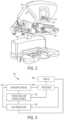
- FIG. 1is a plan view of a robotic surgical system being used to perform a surgery, according to at least one aspect of the present disclosure.
- FIG. 2is a perspective view of a surgeon's control console of the robotic surgical system of FIG. 1 , according to at least one aspect of the present disclosure.
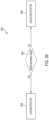
- FIG. 3is a diagram of a robotic surgical system, according to at least one aspect of the present disclosure.
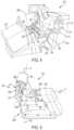
- FIG. 4is a perspective view of a surgeon's control console of a robotic surgical system, according to at least one aspect of the present disclosure.
- FIG. 9 Ais a schematic of a control system for a surgical visualization system, according to at least one aspect of the present disclosure.
- FIG. 10 Billustrates a combinational logic circuit configured to control aspects of a surgical visualization system, according to at least one aspect of the present disclosure.
- FIG. 100illustrates a sequential logic circuit configured to control aspects of a surgical visualization system, according to at least one aspect of the present disclosure.
- FIG. 11is a schematic depicting triangularization between the surgical device, the imaging device, and the critical structure of FIG. 8 to determine a depth d A of the critical structure below the tissue surface, according to at least one aspect of the present disclosure.
- FIG. 12is a schematic of a surgical visualization system configured to identify a critical structure below a tissue surface, wherein the surgical visualization system includes a pulsed light source for determining a depth d A of the critical structure below the tissue surface, according to at least one aspect of the present disclosure.
- FIG. 13is a schematic of a surgical visualization system including an imaging device and a surgical device, the surgical visualization system configured to identify a critical structure below a tissue surface, according to at least one aspect of the present disclosure.
- FIG. 13 Ais a schematic of a surgical visualization system utilizing a camera that is moved axially between a plurality of known positions to determine a position of an embedded critical structure, according to at least one aspect of the present disclosure.
- FIG. 13 Bis a schematic of the surgical visualization system of FIG. 13 A , in which the camera is moved axially and rotationally between a plurality of known positions to determine a position of the embedded critical structure, according to at least one aspect of the present disclosure.
- FIG. 13 Cis a schematic of a near infrared (NIR) time-of-flight measurement system configured to sense distance to a critical anatomical structure, the time-of-flight measurement system including a transmitter (emitter) and a receiver (sensor) positioned on a common device, according to at least one aspect of the present disclosure.
- NIRnear infrared
- FIG. 13 Dis a schematic of an emitted wave, a received wave, and a delay between the emitted wave and the received wave of the NIR time-of-flight measurement system of FIG. 13 C , according to at least one aspect of the present disclosure.
- FIG. 13 Eillustrates a NIR time-of-flight measurement system configured to sense a distance to different structures, the time-of-flight measurement system including a transmitter (emitter) and a receiver (sensor) on separate devices, according to one aspect of the present disclosure.
- FIG. 13 Fis a schematic of a surgical visualization system including a three-dimensional camera, wherein the surgical visualization system is configured to identify a critical structure that is embedded within tissue, according to at least one aspect of the present disclosure.
- FIGS. 13 G and 13 Hare views of the critical structure taken by the three-dimensional camera of FIG. 13 F , in which FIG. 13 G is a view from a left-side lens of the three-dimensional camera and FIG. 13 H is a view from a right-side lens of the three-dimensional camera, according to at least one aspect of the present disclosure.
- FIG. 13 Iis a schematic of the surgical visualization system of FIG. 13 F , in which a camera-to-critical structure distance d w from the three-dimensional camera to the critical structure can be determined, according to at least one aspect of the present disclosure.
- FIG. 13 Jis a schematic of a surgical visualization system utilizing two cameras to determine the position of an embedded critical structure, according to at least one aspect of the present disclosure.
- FIG. 13 Kis a schematic of a structured light source for a surgical visualization system, according to at least one aspect of the present disclosure.
- FIGS. 13 L- 13 Ndepict illustrative hyperspectral identifying signatures to differentiate anatomy from obscurants, wherein FIG. 13 L is a graphical representation of a ureter signature versus obscurants, FIG. 13 M is a graphical representation of an artery signature versus obscurants, and FIG. 13 N is a graphical representation of a nerve signature versus obscurants, according to at least one aspect of the present disclosure.
- FIG. 14is a logic flow diagram of a process for controlling the movement of a robotic surgical system, in accordance with at least one aspect of the present disclosure.
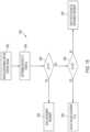
- FIG. 15is a logic flow diagram of a process for controlling the movement of a robotic surgical system, in accordance with at least one aspect of the present disclosure.
- FIG. 16is graph of the required force to be exerted on an input control device to move the robotic surgical system versus the proximity of a surgical tool end effector to a patient, in accordance with at least one aspect of the present disclosure.
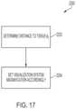
- FIG. 17is a logic flow diagram of a process for controlling a visualization system of a robotic surgical system, in accordance with at least one aspect of the present disclosure.
- FIG. 18is a graph of the magnification of the visualization system versus the distance between the robotic surgical system component and the patient, in accordance with at least one aspect of the present disclosure.
- FIG. 19is a graph of the field of view (FOV) of the visualization system versus the distance between the robotic surgical system component and the patient, in accordance with at least one aspect of the present disclosure.
- FOVfield of view
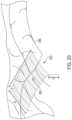
- FIG. 20is a perspective view of a robotic surgical system user interface for tagging locations, in accordance with at least one aspect of the present disclosure.
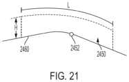
- FIG. 21is an elevational view of a tagged zone defined via the user interface, in accordance with at least one aspect of the present disclosure.
- FIG. 22is a logic flow diagram of a process for controlling a robotic surgical system according to whether a component thereof is positioned within a tagged zone, in accordance with at least one aspect of the present disclosure.
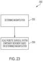
- FIG. 23is a logic flow diagram of a process for controlling the movement of a robotic surgical system according to camera magnification, in accordance with at least one aspect of the present disclosure.
- FIG. 24is a graph of a robotic surgical system movement scale factor versus camera magnification, in accordance with at least one aspect of the present disclosure.
- FIG. 25is a logic flow diagram of a process for controlling an end effector, in accordance with at least one aspect of the present disclosure.
- FIG. 25 Ais a logic flow diagram of a process for controlling an end effector, in accordance with at least one aspect of the present disclosure.
- FIG. 26is a logic flow diagram of a process for controlling an end effector, in accordance with at least one aspect of the present disclosure.
- FIG. 26 Ais a logic flow diagram of a process for controlling an end effector, in accordance with at least one aspect of the present disclosure.
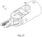
- FIG. 27is a perspective view of an end effector comprising an indicator configured to signal the lock state of the surgical tool, in accordance with at least one aspect of the present disclosure.
- FIG. 28is a graph illustrating four motion scaling profiles, in accordance with at least one aspect of the present disclosure.
- FIG. 29is a motion scaling profile selector, in accordance with at least one aspect of the present disclosure.
- FIG. 30is a lookup table stored in a memory, in accordance with at least one aspect of the present disclosure.
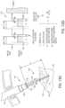
- FIG. 31is pedal assembly, in accordance with at least one aspect of the present disclosure.
- FIG. 32is a logic flow diagram of a process for selecting between motion scaling profiles for a surgical tool, in accordance with at least one aspect of the present disclosure.
- the surgical robot 122can manipulate at least one removably coupled tool assembly 126 (hereinafter referred to as a “tool”) through a minimally invasive incision in the body of the patient 112 while the surgeon 118 views the surgical site through the console 116 .
- An image of the surgical sitecan be obtained by an imaging device such as a stereoscopic endoscope 128 , which can be manipulated by the surgical robot 122 to orient the endoscope 128 .
- Alternative imaging devicesare also contemplated.
- the electronics cart 124can be used to process the images of the surgical site for subsequent display to the surgeon 118 through the surgeon's console 116 .
- the electronics of the electronics cart 124can be incorporated into another structure in the operating room, such as the operating table 114 , the surgical robot 122 , the surgeon's console 116 , and/or another control station, for example.
- the number of robotic tools 126 used at one timewill generally depend on the diagnostic or surgical procedure and the space constraints within the operating room among other factors. If it is necessary to change one or more of the robotic tools 126 being used during a procedure, an assistant 120 may remove the robotic tool 126 from the surgical robot 122 and replace it with another tool 126 from a tray 130 in the operating room.
- the surgeon's console 116includes a left eye display 132 and a right eye display 134 for presenting the surgeon 118 with a coordinated stereo view of the surgical site that enables depth perception.
- the console 116further includes one or more input control devices 136 , which in turn cause the surgical robot 122 to manipulate one or more tools 126 .
- the input control devices 136can provide the same degrees of freedom as their associated tools 126 to provide the surgeon with telepresence, or the perception that the input control devices 136 are integral with the robotic tools 126 so that the surgeon has a strong sense of directly controlling the robotic tools 126 .
- position, force, and tactile feedback sensorsmay be employed to transmit position, force, and tactile sensations from the robotic tools 126 back to the surgeon's hands through the input control devices 136 .
- the surgeon's console 116can be located in the same room as the patient 112 so that the surgeon 118 may directly monitor the procedure, be physically present if necessary, and speak to an assistant 120 directly rather than over the telephone or other communication medium.
- the surgeon 118can be located in a different room, a completely different building, or other remote location from the patient 112 allowing for remote surgical procedures.
- a sterile fieldcan be defined around the surgical site. In various instances, the surgeon 118 can be positioned outside the sterile field.
- the robotic system 110can incorporate a surgical visualization system, as further described herein, such that an augmented view of the surgical site that includes hidden critical structures, three-dimensional topography, and/or one or more distances can be conveyed to the surgeon at the surgeon's console 116 .
- FIG. 3diagrammatically illustrates a robotic surgery system 150 , such as the MIRS system 110 ( FIG. 1 ).
- a surgeon's console 152such as the surgeon's console 116 ( FIGS. 1 and 2 ) can be used by a surgeon to control a surgical robot 154 , such as the surgical robot 122 ( FIG. 1 ), during a minimally invasive procedure.
- the surgical robot 154can use an imaging device, such as a stereoscopic endoscope, for example, to capture images of the surgical site and output the captured images to an electronics cart 156 , such as the electronics cart 124 ( FIG. 1 ).
- the electronics cart 156can process the captured images in a variety of ways prior to any subsequent display.
- the electronics cart 156can overlay the captured images with a virtual control interface prior to displaying the combined images to the surgeon via the surgeon's console 152 .
- the surgical robot 154can output the captured images for processing outside the electronics cart 156 .
- the surgical robot 154can output the captured images to a processor 158 , which can be used to process the captured images.
- the imagescan also be processed by a combination of the electronics cart 156 and the processor 158 , which can be coupled together to process the captured images jointly, sequentially, and/or combinations thereof.
- One or more separate displays 160can also be coupled with the processor 158 and/or the electronics cart 156 for local and/or remote display of images, such as images of the surgical site, or other related images.
- the surgical robot 122 shownprovides for the manipulation of three robotic tools 126 and the imaging device 128 , such as a stereoscopic endoscope used for the capture of images of the site of the procedure, for example. Manipulation is provided by robotic mechanisms having a number of robotic joints. The imaging device 128 and the robotic tools 126 can be positioned and manipulated through incisions in the patient so that a kinematic remote center or virtual pivot is maintained at the incision to minimize the size of the incision.
- Images of the surgical sitecan include images of the distal ends of the robotic tools 126 when they are positioned within the field-of-view (FOV) of the imaging device 128 .
- Each tool 126is detachable from and carried by a respective surgical manipulator, which is located at the distal end of one or more of the robotic joints.
- the surgical manipulatorprovides a moveable platform for moving the entirety of a tool 126 with respect to the surgical robot 122 , via movement of the robotic joints.
- the surgical manipulatoralso provides power to operate the robotic tool 126 using one or more mechanical and/or electrical interfaces.
- one or more motorscan be housed in the surgical manipulator for generating controls motions.
- One or more transmissionscan be employed to selectively couple the motors to various actuation systems in the robotic tool.
- a surgeon's console, or control unit, 250is shown.
- the surgeon's console 250can be used in connection with a robotic system to control any two surgical tools coupled to the robotic system.
- the surgical toolscan be controlled by the handle assemblies 256 of the surgeon's console 250 .
- the handle assemblies 256 and robotic armshave a master-slave relationship so that movement of the handle assemblies 256 produces a corresponding movement of the surgical tools.
- a controller 254receives input signals from the handle assemblies 256 , computes a corresponding movement of the surgical tools, and provides output signals to move the robotic arms and the surgical tools.
- the handle assemblies 256are located adjacent to a surgeon's chair 258 and coupled to the controller 254 .
- the controller 254may include one or more microprocessors, memory devices, drivers, etc. that convert input information from the handle assemblies 256 into output control signals which move the robotic arms and/or actuate the surgical tools.
- the surgeon's chair 258 and the handle assemblies 256may be in front of a video console 248 , which can be linked to an endoscope to provide video images of the patient.
- the surgeon's console 250may also include a screen 260 coupled to the controller 254 .
- the screen 260may display graphical user interfaces (GUIs) that allow the surgeon to control various functions and parameters of the robotic system.
- GUIsgraphical user interfaces
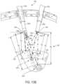
- Each handle assembly 256includes a handle/wrist assembly 262 .
- the handle/wrist assembly 262has a handle 264 that is coupled to a wrist 266 .
- the wrist 266is connected to a forearm linkage 268 that slides along a slide bar 270 .
- the slide bar 270is pivotally connected to an elbow joint 272 .
- the elbow joint 272is pivotally connected to a shoulder joint 274 that is attached to the controller 254 .
- the surgeon sitting at the surgeon's console 250can provide input control motions to the handle assemblies 256 to effect movements and/or actuations of a surgical tool communicatively coupled thereto. For example, the surgeon can advance the forearm linkage 268 along the slide bar 270 to advance the surgical tool toward a surgical site.
- Rotations at the wrist 266 , elbow joint 272 , and/or shoulder joint 274can effect rotation and/or articulation of the surgical tool about the corresponding axes.
- the robotic system and surgeon's console 250are further described in U.S. Pat. No. 6,951,535, titled TELE-MEDICINE SYSTEM THAT TRANSMITS AN ENTIRE STATE OF A SUBSYSTEM, which issued Oct. 4, 2005, the entire disclosure of which is incorporated by reference herein.
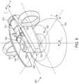
- FIG. 5A handle assembly for use at a surgeon's console is further depicted in FIG. 5 .
- the handle assembly of FIG. 5includes a control input wrist 352 and a touch sensitive handle 325 .
- the control input wrist 352is a gimbaled device that pivotally supports the touch sensitive handle 325 to generate control signals that are used to control a robotic surgical manipulator and the robotic surgical tools.
- a pair of control input wrists 352 and touch sensitive handles 325can be supported by a pair of control input arms in a workspace of the surgeon's console.
- the control input wrist 352includes first, second, and third gimbal members 362 , 364 , and 366 , respectively.
- the third gimbal member 366can be rotationally mounted to a control input arm.
- the touch sensitive handle 325include a tubular support structure 351 , a first grip 350 A, and a second grip 350 B.
- the first grip 350 A and the second grip 350 Bare supported at one end by the tubular support structure 351 .
- the touch sensitive handle 325can be rotated about axis G.
- the grips 350 A, 350 Bcan be squeezed or pinched together about the tubular support structure 351 .
- the “pinching” or grasping degree of freedom in the gripsis indicated by arrows Ha and Hb.
- the touch sensitive handle 325is rotatably supported by the first gimbal member 362 by means of a rotational joint 356 g .
- the first gimbal member 362is in turn, rotatably supported by the second gimbal member 364 by means of the rotational joint 356 f .
- the second gimbal member 364is rotatably supported by the third gimbal member 366 using a rotational joint 356 e .
- the control input wrist 352allows the touch sensitive handle 325 to be moved and oriented in the workspace using three degrees of freedom.
- the movements in the gimbals 362 , 364 , 366 of the control input wrist 352 to reorient the touch sensitive handle 325 in spacecan be translated into control signals to control a robotic surgical manipulator and the robotic surgical tools.
- the movements in the grips 350 A and 350 B of the touch sensitive handle 325can also be translated into control signals to control the robotic surgical manipulator and the robotic surgical tools.
- the squeezing motion of the grips 350 A and 350 B over their freedom of movement indicated by arrows Ha and Hbmay be used to control the end effectors of the robotic surgical tools.
- sensorscan be mounted in the handle 325 as well as the first gimbal member 362 of the control input wrist 352 .
- Exemplary sensorsmay be a pressure sensor, a Hall Effect transducer, a potentiometer, and/or an encoder, for example.
- the robotic surgical systems and handle assembly of FIG. 5are further described in U.S. Pat. No. 8,224,484, titled METHODS OF USER INTERFACE WITH ALTERNATIVE TOOL MODE FOR ROBOTIC SURGICAL TOOLS, which issued Jul. 17, 2012, the entire disclosure of which is incorporated by reference herein.
- Existing robotic systemscan incorporate a surgical visualization system, as further described herein.
- additional information regarding the surgical sitecan be determined and/or conveyed to the clinician(s) in the surgical theater, such as to a surgeon positioned at a surgeon's console.
- the clinician(s)can observe an augmented view of reality of the surgical site that includes additional information such as various contours of the tissue surface, hidden critical structures, and/or one or more distances with respect to anatomical structures.
- proximity datacan be leveraged to improve one or more operations of the robotic surgical system and or controls thereof, as further described herein.
- the surgeon's console 152allows the surgeon to provide manual input commands to the surgical robot 154 to effect control of the surgical tool and the various actuations thereof. Movement of an input control device by a surgeon at the surgeon's console 152 within a predefined working volume, or work envelope, results in a corresponding movement or operation of the surgical tool. For example, referring again to FIG. 2 , a surgeon can engage each input control device 136 with one hand and move the input control devices 136 within the work envelope to provide control motions to the surgical tool. Surgeon's consoles (e.g. the surgeon's console 116 in FIGS. 1 and 2 and the surgeon's console 250 in FIG. 4 ) can be expensive and require a large footprint.
- the working volume of the input control devicee.g. the handle/wrist assembly 262 in FIG. 4 and the control input wrist 352 and touch sensitive handle 325 in FIG. 5
- the working volume of the input control devicecan necessitate a large footprint, which impacts the usable space in the operating room (OR), training modalities, and cooperative procedures, for example.
- a large footprintcan preclude the option of having multiple control stations in the OR, such as additional control stations for training or use by an assistant.
- the size and bulkiness of a surgeon's consolecan be cumbersome to relocate within an operating room or move between operating rooms, for example.
- Ergonomicsis an important consideration for surgeons who may spend many hours each day in surgery and/or at the surgeon's console. Excessive, repetitive motions during surgical procedures can lead to fatigue and chronic injury for the surgeon. It can be desirable to maintain a comfortable posture and/or body position while providing inputs to the robotic system. However, in certain instances, the surgeon's posture and/or position may be compromised to ensure proper positioning of a surgical tool. For example, surgeons are often prone to contort their hands and/or extend their arms for long durations of time. In one instance, a gross control motion to move the surgical tool to the surgical site may result in the surgeon's arms being uncomfortably too outstretched and/or cramped uncomfortably close upon reaching the surgical site.
- poor ergonomic posturing achieved during the gross control motionmay be maintained during a subsequent fine control motion, e.g. when manipulating tissue at the surgical site, which can further exasperate the poor ergonomics for the surgeon.
- Existing input control devicespropose a one-size-fits-all approach regardless of the surgeon's anthropometrics; however, the ergonomic impact to a surgeon can vary and certain body types may be more burdened by the architecture of existing input control devices.
- an input control devicecan be restrained within the work envelope that defines its range of motion.
- the structure of the surgeon's console and/or the linkages on the input control devicecan limit the range of the motion of the input control device.
- the input control devicecan reach the end of its range of motion before the surgical tool is appropriately positioned.
- a clutching mechanismcan be required to reposition the input control device within the work envelope to complete the positioning of the surgical tool.
- a hypothetical work envelope 280is shown in FIG. 4 , for example.
- the surgeoncan be required to actuate a clutch (often in the form of a foot pedal or additional button on the handle of the input control device) to temporarily disengage the input control device from the surgical tool while the input control device is relocated to a desired position within the work envelope.
- a clutchoften in the form of a foot pedal or additional button on the handle of the input control device
- This non-surgical motion by the surgeoncan be referred to as a “rowing” motion to properly reposition the input control device within the work envelope because of the arm motion of the surgeon at the surgeon's console.
- the motions of the input control devicecan again control the surgical tool.
- Clutching the input control device to maintain a suitable position within the work envelopeposes an additional cognitive burden to the surgeon. In such instances, the surgeon is required to constantly monitor the position and orientation of his/her hands relative to the boundaries of the work envelope. Additionally, the clutching or “rowing” motion can be tedious to the surgeon and such a monotonous, repetitive motion does not match the analogous workflow of a surgical procedure outside the context of robotic surgery. Clutching also requires the surgeon to match a previous orientation of the handle when reengaging the system.
- the surgeon and/or surgical robotupon completion of a complex range of motion in which the surgeon “rows” or clutches the input control device back to a comfortable, home position, the surgeon and/or surgical robot must match the orientation of the handle of the input control device in the home position to the previous orientation of the handle in the extended position, which can be challenging. and/or require complex logic and/or mechanics.
- Requiring a clutch mechanismalso limits the availability of controls on the handle of the input control device.
- a clutch actuatorcan take up valuable real estate on the handle, which cognitively and physically limits the availability of other controls on the handle.
- the complexity of other subsystems, such as a peddle board,is increased and the surgeon may be required to utilize multiple input systems to complete a simple task.
- Non-clutched alternatives to such input control devicescan reduce the footprint and cost of the surgeon's console, improve the surgeon's ergonomic experience, eliminate the physical and cognitive burdens associated with clutching, and/or provide additional real estate on the input control device for additional input controls, for example.
- Exemplary non-clutched input control devicesare further described herein. Such non-clutched input control devices can be employed with a variety of robotic systems. Moreover, as further described herein, the non-clutched input control devices can leverage information from various distance determining subsystems also disclosed herein.
- real-time structured light and three-dimensional shape modelingcan inform the logic of such non-clutched input control devices such that a first mode and/or first collection of controls are enabled outside a predefined distance from an anatomical surface and/or critical structure and a second mode and/or second collection of controls are enabled within a predefined distance of the anatomical structure and/or critical structure.
- tissue proximity applicationsare further described herein.
- the input control device 1000is a clutchless input control device, as further described herein.
- the input control device 1000can be utilized at a surgeon's console or workspace for a robotic surgical system.
- the input control device 1000can be incorporated into a surgical system, such as the surgical system 110 ( FIG. 1 ) or the surgical system 150 ( FIG. 3 ), for example, to provide control signals to a surgical robot and/or surgical tool coupled thereto based on a user input.
- the input control device 1000includes input controls for moving the robotic arm and/or the surgical tool in three-dimensional space.
- the surgical tool controlled by the input control device 1000can be configured to move and/or rotate relative to X, Y, and Z axes.
- the surgical tool 1050is a grasper that includes an end effector 1052 having opposing jaws, which are configured to releasably grab tissue.
- the surgical tool 1050can be maneuvered in three dimensional space by translating the surgical tool 1050 along the X t , Y t , and Z t axes thereof.
- the surgical tool 1050also includes a plurality of joints such that the surgical tool can be rotated and/or articulated into a desired configuration.
- the surgical tool 1050can be configured to rotate or roll about the X t axis defined by the longitudinal shaft of the surgical tool 1050 , rotate or articulate about a first articulation axis parallel to the Y t axis, and rotate or articulate about a second articulation axis parallel to the Z t axis.
- Rolling about the X t axiscorresponds to a rolling motion of the end effector 1052 in the direction R t
- articulation about the first articulation axiscorresponds to a pitching motion of the end effector 1052 in the direction P t
- articulation about the second articulation axiscorresponds to a yawing or twisting motion in the direction T t .
- An input control devicesuch as the input control device 1000 , for example, can be configured to control the translation and rotation of the end effector 1052 .
- the input control device 1000includes corresponding input controls.
- the input control device 1000includes at least six degrees of freedom of input controls for moving the surgical tool 1050 in three dimensional space along the X t , Y t , and Z t axes, for rolling the end effector 1052 about the X t axis, and for articulating the end effector 1052 about the first and second articulation axes.
- the input control device 1000includes an end effector actuator for actuating the opposing jaws of the end effector 1052 to manipulate or grip tissue.
- the input control device 1000includes a multi-dimensional space joint 1006 having a central portion 1002 supported on a base 1004 .
- the base 1004is structured to rest on a surface, such as a desk or work surface at a surgeon's console or workspace.
- the base 1004defines a circular base with a contoured edge; however, alternative geometries are contemplated.
- the base 1004can remain in a fixed, stationary position relative to an underlying surface upon application of the input controls thereto.
- the base 1004can be releasably secured and/or clamped to the underlying surface with fasteners, such as threaded fasteners, for example.
- the base 1004can include a sticky or tacking bottom surface and/or suction features (e.g. suction cups or magnets) for gripping an underlying surface.
- the base 1004can include a ribbed and/or grooved bottom surface for engaging a complementary underlying support surface to maintain the base 1004 in a stationary state.
- the space joint 1006is configured to receive multi-dimensional manual inputs from a surgeon (e.g. the surgeon's hand or arm) corresponding to control motions for the surgical tool 1050 in multi-dimensional space.
- the central portion 1002 of the space joint 1006is configured to receive input forces in multiple directions, such as forces along and/or about the X, Y, and Z axes.
- the central portion 1002can include a raising, lowering, and rotating cylinder, shaft, or hemisphere, for example, projecting from the base 1004 .
- the central portion 1002is flexibly supported relative to the base 1004 such that the cylinder, shaft, and/or hemisphere is configured to move or float within a small predefined zone upon receipt of force control inputs thereto.
- the central portion 1002can be a floating shaft that is supported on the base 1004 by one or more elastomeric members such as springs, for example.
- the central portion 1002can be configured to move or float within a predefined three-dimensional volume.
- elastomeric couplingscan permit movement of the central portion 1002 relative to the base 1004 ; however, restraining plates, pins, and/or other structures can be configured to limit the range of motion of the central portion 1002 relative to the base 1004 .
- the space joint 1006includes a multi-axis force and/or torque sensor arrangement 1048 (see FIG. 9 ) configured to detect the input forces and moments applied to the central portion 1002 and transferred to the space joint 1006 .
- the sensor arrangement 1048is positioned on one or more of the surfaces at the interface between the central portion 1002 and the base 1004 .
- the sensor arrangement 1048can be embedded in the central portion 1002 or the base 1004 .
- the sensor arrangement 1048can be positioned on a floating member positioned intermediate the central portion 1002 and the base 1004 .
- the sensor arrangement 1048can include one or more resistive strain gauges, optical force sensors, optical distance sensors, miniature cameras in the range of about 1.0 mm to about 3.0 mm in size, and/or time of flight sensors utilizing a pulsed light source, for example.
- the sensor arrangement 1048includes a plurality of resistive strain gauges configured to detect the different force vectors applied thereto.
- the strain gaugescan define a Wheatstone bridge configuration, for example.
- the sensor arrangement 1048can include a plurality of optoelectronic sensors, such as measuring cells comprising a position-sensitive detector illuminated by a light-emitting element, such as an LED.
- Alternative force-detecting sensor arrangementsare also contemplated. Exemplary multi-dimensional input devices and/or sensor arrangements are further described in the following references, which are incorporated by reference herein in their respective entireties:
- a joystick 1008extends from the central portion 1002 . Forces exerted on the central portion 1002 via the joystick 1008 define input motions for the sensor arrangement 1048 .
- the sensor arrangement 1048 in the base 1004can be configured to detect the input forces and moments applied by a surgeon to the joystick 1008 .
- the joystick 1008can be spring-biased toward a central, or home, position, in which the joystick 1008 is aligned with the Z axis, a vertical axis through the joystick 1008 , central portion 1002 , and the space joint 1006 .
- Drivinge.g.
- pushing and/or pulling) the joystick 1008 away from the Z axis in any directioncan be configured to “drive” an end effector of an associated surgical tool in the corresponding direction.
- the joystick 1008can be configured to return to the central, or home, position and motion of the end effector can be halted.
- the central portion 1002 and joystick 1008can be spring-biased toward the home position.
- the space joint 1006 and the joystick 1008 coupled theretodefine a six degree-of-freedom input control.
- the forces on the joystick 1008 of the input device 1000 in the X directioncorrespond to displacement of the end effector 1052 along the X t axis thereof (e.g. longitudinally)
- forces on the joystick 1008 in the Y directioncorrespond to displacement of the end effector 1052 along the Y t axis thereof (e.g. laterally)
- forces on the joystick 1008 in the Z directioncorrespond to displacement of the end effector 1052 along the Z t axis (e.g. vertically/up and down).
- forces on the joystick 1008 about the X axisresult in rotation of the end effector 1052 about the X t axis (e.g. a rolling motion about a longitudinal axis in the direction R t )
- forces on the joystick 1008 about the Y axisresult in articulation of the end effector 1052 about the Y t axis (e.g. a pitching motion in the direction P t )
- forces on the joystick 1008 about the Z axis(the moment forces T) result in articulation of the end effector 1052 about the Z t axis of the end effector (e.g. a yawing or twisting motion in the direction T t ).
- the input device 1000comprises a six-degree of freedom joystick, which is configured to receive and detect six degrees-of-freedom-forces along the X, Y, and Z axes and moments about the X, Y, and Z axes.
- the forcescan correspond to translational input and the moments can correspond to rotational inputs for the end effector 1052 of the associated surgical tool 1050 .
- Six degree-of-freedom input devicesare further described herein. Additional degrees of freedom (e.g. for actuating the jaws of an end effector or rolling the end effector about a longitudinal axis) can be provided by additional joints supported by the joystick 1008 , as further described herein.
- the input control device 1000includes a joint or wrist 1010 that is offset from the space joint 1006 .
- the wrist 1010is offset from the space joint 1006 by a shaft, or lever, 1012 extending along the shaft axis S that is parallel to the axis X in the configuration shown in FIG. 6 .
- the joystick 1008can extend upright vertically from the central portion 1002 and the base 1004 , and the joystick 1008 can support the shaft 1012 .
- the space joint 1006can define the input control motions for multiple degrees of freedom.
- the space joint 1006can define the input control motions for translation of the surgical tool in three-dimensional space and articulation of the surgical tool about at least one axis.
- Rolling motionscan also be controlled by inputs to the space joint 1006 , as further described herein.
- the wrist 1010can define input control motions for at least one degree of freedom.
- the wrist 1010can define the input control motions for the rolling motion of the end effector.
- the wrist 1010can support an end effector actuator 1020 , which is further described herein, to apply open and closing motions to the end effector.
- the rolling, yawing, and pitching motions of the input control device 1000are translatable motions that define corresponding input control motions for the related end effector.
- the input control device 1000can utilize adjustable scaling and/or gains such that the motion of the end effector is scalable in relationship to the control motions delivered at the wrist 1010 .
- the input control device 1000includes a plurality of mechanical joints, which can be elastically-coupled components, sliders, journaled shafts, hinges, and/or rotary bearings, for example.
- the mechanical jointsinclude a first joint 1040 (at the space joint 1006 ) intermediate the base 1004 and the central portion 1002 , which allows rotation and tilting of the central portion 1002 relative to the base 1004 , and a second joint 1044 , which allows rotation of the wrist 1010 relative to the joystick 1008 .
- six degrees of freedom of a robotic end effectore.g. three-dimensional translation and rotation about three different axes
- the central portion 1002can be configured to float relative to the base 1004 at elastic couplings.
- the wrist 1010can be rotatably coupled to the shaft 1012 , such that the wrist 1010 can rotate in the direction R ( FIG. 6 ) about the shaft axis S. Rotation of the wrist 1010 relative to the shaft 1012 can correspond to a rolling motion of an end effector about a central tool axis, such as the rolling of the end effector 1052 about the X t axis.
- Rotation of the wrist 1010 by the surgeon to roll an end effectorprovides control of the rolling motion at the surgeon's fingertips and corresponds to a first-person perspective control of the end effector (i.e. from the surgeon's perspective, being “positioned” at the jaws of the remotely-positioned end effector at the surgical site).
- a first-person perspective control of the end effectori.e. from the surgeon's perspective, being “positioned” at the jaws of the remotely-positioned end effector at the surgical site.
- placement and perspectivecan be utilized to supply precision control motions to the input control device 1000 during portions of a surgical procedure (e.g. a precision motion mode).
- the various rotary joints of the input control devicecan include a sensor arrangement configured to detect the rotary input controls applied thereto.
- the wrist 1010can include a rotary sensor, which can be a rotary force/torque sensor and/or transducer, rotary strain gauge and/or strain gauge on a spring, and/or an optical sensor to detect rotary displacement at the joint, for example.
- the input control device 1000can include one or more additional joints and/or hinges for the application of rotational input motions corresponding to articulation of an end effector.
- the input control device 1000can include a hinge along the shaft 1012 and/or between the shaft 1012 and the joystick 1008 .
- hinged input motions at such a jointcan be detected by another sensor arrangement and converted to rotary input control motions for the end effector, such as a yawing or pitching articulation of the end effector.
- Such an arrangementrequires one or more additional sensor arrangements and would increase the mechanical complexity of the input control device.
- the input control device 1000also includes at least one additional actuator, such as the actuation buttons 1026 , 1028 , for example, which can provide additional controls at the surgeon's fingertips.
- the actuation buttons 1026 , 1028are positioned on the joystick 1008 of the input control device.
- the actuation buttons 1026 , 1028can correspond to buttons for activating the surgical tool, such as firing and/or retracting a knife, energizing one or more electrodes, and/or adjusting an energy modularity, for example.
- the actuation buttons 1026 , 1028can provide inputs to an imaging system to adjust a view of the surgical tool, such as zooming in/out, panning, tracking, titling and/or rotating, for example.
- the actuation buttons 1026 and 1028are used to select between different motion scaling modes of the surgical tool 1050 .
- the actuation buttons 1026 and 1028can be assigned to a gross motion mode and fine motion mode of the surgical tool 1050 .
- the motion scaling of the surgical tool 1050can be selectably adjusted to user input forces received by the input control device 1000 , for example.
- the information available to the clinician via the “naked eye” and/or an imaging systemmay provide an incomplete view of the surgical site.
- certain structuressuch as structures embedded or buried within an organ, can be at least partially concealed or hidden from view.
- certain dimensions and/or relative distancescan be difficult to ascertain with existing sensor systems and/or difficult for the “naked eye” to perceive.
- certain structurescan move preoperatively (e.g. before a surgical procedure but after a preoperative scan) and/or intraoperatively. In such instances, the clinician can be unable to accurately determine the location of a critical structure intraoperatively.
- a clinician's decision-making processcan be inhibited. For example, a clinician may avoid certain areas in order to avoid inadvertent dissection of a critical structure; however, the avoided area may be unnecessarily large and/or at least partially misplaced. Due to uncertainty and/or overly/excessive exercises in caution, the clinician may not access certain desired regions. For example, excess caution may cause a clinician to leave a portion of a tumor and/or other undesirable tissue in an effort to avoid a critical structure even if the critical structure is not in the particular area and/or would not be negatively impacted by the clinician working in that particular area. In certain instances, surgical results can be improved with increased knowledge and/or certainty, which can allow a surgeon to be more accurate and, in certain instances, less conservative/more aggressive with respect to particular anatomical areas.
- a visualization systemcan include a first light emitter configured to emit a plurality of spectral waves, a second light emitter configured to emit a light pattern, and one or more receivers, or sensors, configured to detect visible light, molecular responses to the spectral waves (spectral imaging), and/or the light pattern.
- the surgical visualization systemcan also include an imaging system and a control circuit in signal communication with the receiver(s) and the imaging system. Based on output from the receiver(s), the control circuit can determine a geometric surface map, i.e. three-dimensional surface topography, of the visible surfaces at the surgical site and one or more distances with respect to the surgical site. In certain instances, the control circuit can determine one more distances to an at least partially concealed structure.
- the imaging systemcan convey the geometric surface map and the one or more distances to a clinician.
- an augmented view of the surgical site provided to the cliniciancan provide a representation of the concealed structure within the relevant context of the surgical site.
- the imaging systemcan virtually augment the concealed structure on the geometric surface map of the concealing and/or obstructing tissue similar to a line drawn on the ground to indicate a utility line below the surface.
- the imaging systemcan convey the proximity of one or more surgical tools to the visible and obstructing tissue and/or to the at least partially concealed structure and/or the depth of the concealed structure below the visible surface of the obstructing tissue.
- the visualization systemcan determine a distance with respect to the augmented line on the surface of the visible tissue and convey the distance to the imaging system.
- a surgical visualization systemfor intraoperative identification and avoidance of critical structures.
- a surgical visualization systemcan provide valuable information to a clinician during a surgical procedure.
- the cliniciancan confidently maintain momentum throughout the surgical procedure knowing that the surgical visualization system is tracking a critical structure such as a ureter, specific nerves, and/or critical blood vessels, for example, which may be approached during dissection, for example.
- the surgical visualization systemcan provide an indication to the clinician in sufficient time for the clinician to pause and/or slow down the surgical procedure and evaluate the proximity to the critical structure to prevent inadvertent damage thereto.
- the surgical visualization systemcan provide an ideal, optimized, and/or customizable amount of information to the clinician to allow the clinician to move confidently and/or quickly through tissue while avoiding inadvertent damage to healthy tissue and/or critical structure(s) and, thus, to minimize the risk of harm resulting from the surgical procedure.
- FIG. 8is a schematic of a surgical visualization system 1500 according to at least one aspect of the present disclosure.
- the surgical visualization system 1500can create a visual representation of a critical structure 1501 within an anatomical field.
- the surgical visualization system 1500can be used for clinical analysis and/or medical intervention, for example.
- the surgical visualization system 1500can be used intraoperatively to provide real-time, or near real-time, information to the clinician regarding proximity data, dimensions, and/or distances during a surgical procedure.
- the surgical visualization system 1500is configured for intraoperative identification of critical structure(s) and/or to facilitate the avoidance of the critical structure(s) 1501 by a surgical device.
- a cliniciancan avoid maneuvering a surgical device around the critical structure 1501 and/or a region in a predefined proximity of the critical structure 1501 during a surgical procedure.
- the cliniciancan avoid dissection of and/or near a vein, artery, nerve, and/or vessel, for example, identified as the critical structure 1501 , for example.
- the critical structure 1501can be determined on a patient-by-patient and/or a procedure-by-procedure basis.
- the surgical visualization system 1500incorporates tissue identification and geometric surface mapping in combination with a distance sensor system 1504 .
- these features of the surgical visualization system 1500can determine a position of a critical structure 1501 within the anatomical field and/or the proximity of a surgical device 1502 to the surface 1505 of the visible tissue and/or to the critical structure 1501 .
- the surgical visualization system 1500includes an imaging system that includes an imaging device 1520 , such as a camera, for example, configured to provide real-time views of the surgical site.
- the imaging device 1520is a spectral camera (e.g.
- the surgical visualization system 1500includes a plurality of subsystems—an imaging subsystem, a surface mapping subsystem, a tissue identification subsystem, and/or a distance determining subsystem. These subsystems can cooperate to intraoperatively provide advanced data synthesis and integrated information to the clinician(s).
- the imaging devicecan include a camera or imaging sensor that is configured to detect visible light, spectral light waves (visible or invisible), and a structured light pattern (visible or invisible), for example.
- the imaging systemcan include an imaging device such as an endoscope, for example. Additionally or alternatively, the imaging system can include an imaging device such as an arthroscope, angioscope, bronchoscope, choledochoscope, colonoscope, cytoscope, duodenoscope, enteroscope, esophagogastro-duodenoscope (gastroscope), laryngoscope, nasopharyngo-neproscope, sigmoidoscope, thoracoscope, ureteroscope, or exoscope, for example. In other instances, such as in open surgery applications, the imaging system may not include a scope.
- the tissue identification subsystemcan be achieved with a spectral imaging system.
- the spectral imaging systemcan rely on hyperspectral imaging, multispectral imaging, or selective spectral imaging, for example.
- Hyperspectral imaging of tissueis further described in U.S. Pat. No. 9,274,047, titled METHODS AND APPARATUS FOR IMAGING OF OCCLUDED OBJECTS, issued Mar. 1, 2016, which is incorporated by reference herein in its entirety.
- the surface mapping subsystemcan be achieved with a light pattern system, as further described herein.
- a light patternor structured light
- Known surface mapping techniquescan be utilized in the surgical visualization systems described herein.
- Structured lightis the process of projecting a known pattern (often a grid or horizontal bars) on to a surface.
- U.S. Patent Application Publication No. 2017/0055819, titled SET COMPRISING A SURGICAL INSTRUMENT, published Mar. 2, 2017, and U.S. Patent Application Publication No. 2017/0251900, titled DEPICTION SYSTEM, published Sep. 7, 2017,disclose a surgical system comprising a light source and a projector for projecting a light pattern.
- U.S. Patent Application Publication No. 2017/0055819, titled SET COMPRISING A SURGICAL INSTRUMENT, published Mar. 2, 2017, and U.S. Patent Application Publication No. 2017/0251900, titled DEPICTION SYSTEM, published Sep. 7, 2017,are incorporated by reference herein in their respective entireties.
- the distance determining systemcan be incorporated into the surface mapping system.
- structured lightcan be utilized to generate a three-dimensional virtual model of the visible surface and determine various distances with respect to the visible surface.
- the distance determining systemcan rely on time-of-flight measurements to determine one or more distances to the identified tissue (or other structures) at the surgical site.
- FIG. 9is a schematic diagram of a control system 1533 , which can be utilized with the surgical visualization system 1500 .
- the control system 1533includes a control circuit 1532 in signal communication with a memory 1534 .
- the memory 1534stores instructions executable by the control circuit 1532 to determine and/or recognize critical structures (e.g. the critical structure 1501 in FIG. 8 ), determine and/or compute one or more distances and/or three-dimensional digital representations, and to communicate certain information to one or more clinicians.
- the memory 1534stores surface mapping logic 1536 , imaging logic 1538 , tissue identification logic 1540 , or distance determining logic 1541 or any combinations of the logic 1536 , 1538 , 1540 , and 1541 .
- the control system 1533also includes an imaging system 1542 having one or more cameras 1544 (like the imaging device 1520 in FIG. 8 ), one or more displays 1546 , or one or more controls 1548 or any combinations of these elements.
- the camera 1544can include one or more image sensors 1535 to receive signals from various light sources emitting light at various visible and invisible spectra (e.g. visible light, spectral imagers, three-dimensional lens, among others).
- the display 1546can include one or more screens or monitors for depicting real, virtual, and/or virtually-augmented images and/or information to one or more clinicians.
- the heart of the camera 1544is the image sensor 1535 .
- image sensors 1535are solid-state electronic devices containing up to millions of discrete photodetector sites called pixels.
- the image sensor 1535 technologyfalls into one of two categories: Charge-Coupled Device (CCD) and Complementary Metal Oxide Semiconductor (CMOS) imagers and more recently, short-wave infrared (SWIR) is an emerging technology in imaging.
- CCDCharge-Coupled Device
- CMOSComplementary Metal Oxide Semiconductor
- SWIRshort-wave infrared
- Another type of image sensor 1535employs a hybrid CCD/CMOS architecture (sold under the name “sCMOS”) and consists of CMOS readout integrated circuits (ROICs) that are bump bonded to a CCD imaging substrate.
- sCMOShybrid CCD/CMOS architecture
- ROICsCMOS readout integrated circuits
- CCD and CMOS image sensors 1535are sensitive to wavelengths from approximately 350-1050 nm, although the range is usually given from 400-1000 nm.
- CMOS sensorsare, in general, more sensitive to IR wavelengths than CCD sensors.
- Solid state image sensors 1535are based on the photoelectric effect and, as a result, cannot distinguish between colors. Accordingly, there are two types of color CCD cameras: single chip and three-chip.
- Single chip color CCD camerasoffer a common, low-cost imaging solution and use a mosaic (e.g. Bayer) optical filter to separate incoming light into a series of colors and employ an interpolation algorithm to resolve full color images. Each color is, then, directed to a different set of pixels.
- a mosaice.g. Bayer
- Three-chip color CCD camerasprovide higher resolution by employing a prism to direct each section of the incident spectrum to a different chip. More accurate color reproduction is possible, as each point in space of the object has separate RGB intensity values, rather than using an algorithm to determine the color. Three-chip cameras offer extremely high resolutions.
- the control system 1533also includes a spectral light source 1550 and a structured light source 1552 .
- a single sourcecan be pulsed to emit wavelengths of light in the spectral light source 1550 range and wavelengths of light in the structured light source 1552 range.
- a single light sourcecan be pulsed to provide light in the invisible spectrum (e.g. infrared spectral light) and wavelengths of light on the visible spectrum.
- the spectral light source 1550can be a hyperspectral light source, a multispectral light source, and/or a selective spectral light source, for example.
- the tissue identification logic 1540can identify critical structure(s) via data from the spectral light source 1550 received by the image sensor 1535 portion of the camera 1544 .
- the surface mapping logic 1536can determine the surface contours of the visible tissue based on reflected structured light.
- the distance determining logic 1541can determine one or more distance(s) to the visible tissue and/or the critical structure 1501 .
- One or more outputs from the surface mapping logic 1536 , the tissue identification logic 1540 , and the distance determining logic 1541can be provided to the imaging logic 1538 , and combined, blended, and/or overlaid to be conveyed to a clinician via the display 1546 of the imaging system 1542 .
- the control system 600is a conversion system that integrates spectral signature tissue identification and structured light tissue positioning to identify critical structures, especially when those structures are obscured by other tissue, such as fat, connective tissue, blood, and/or other organs, for example. Such technology could also be useful for detecting tissue variability, such as differentiating tumors and/or non-healthy tissue from healthy tissue within an organ.
- the control system 600is configured for implementing a hyperspectral imaging and visualization system in which a molecular response is utilized to detect and identify anatomy in a surgical field of view.
- the control system 600includes a conversion logic circuit 648 to convert tissue data to surgeon usable information.
- the variable reflectance based on wavelengths with respect to obscuring materialcan be utilized to identify the critical structure in the anatomy.
- the control system 600combines the identified spectral signature and the structural light data in an image.
- the control system 600can be employed to create of three-dimensional data set for surgical use in a system with augmentation image overlays. Techniques can be employed both intraoperatively and preoperatively using additional visual information.
- the control system 600is configured to provide warnings to a clinician when in the proximity of one or more critical structures.
- Various algorithmscan be employed to guide robotic automation and semi-automated approaches based on the surgical procedure and proximity to the critical structure(s).
- a projected array of lightsis employed to determine tissue shape and motion intraoperatively.
- flash Lidarmay be utilized for surface mapping of the tissue.
- the control system 600is configured to detect the critical structure(s) and provide an image overlay of the critical structure and measure the distance to the surface of the visible tissue and the distance to the embedded/buried critical structure(s). In other instances, the control system 600 can measure the distance to the surface of the visible tissue or detect the critical structure(s) and provide an image overlay of the critical structure.
- the control system 600includes a spectral control circuit 602 .
- the spectral control circuit 602can be a field programmable gate array (FPGA) or another suitable circuit configuration.
- the spectral control circuit 602includes a processor 604 to receive video input signals from a video input processor 606 .
- the processor 604can be configured for hyperspectral processing and can utilize C/C++ code, for example.
- the video input processor 606receives video-in of control (metadata) data such as shutter time, wave length, and sensor analytics, for example.
- the processor 604is configured to process the video input signal from the video input processor 606 and provide a video output signal to a video output processor 608 , which includes a hyperspectral video-out of interface control (metadata) data, for example.
- the video output processor 608provides the video output signal to an image overlay controller 610 .
- the video input processor 606is coupled to a camera 612 at the patient side via a patient isolation circuit 614 .
- the camera 612includes a solid state image sensor 634 .
- the patient isolation circuitcan include a plurality of transformers so that the patient is isolated from other circuits in the system.
- the camera 612receives intraoperative images through optics 632 and the image sensor 634 .
- the image sensor 634can include a CMOS image sensor, for example.
- the camera 612outputs images in 14 bit/pixel signals. It will be appreciated that higher or lower pixel resolutions may be employed without departing from the scope of the present disclosure.
- the isolated camera output signal 613is provided to a color RGB fusion circuit 616 , which employs a hardware register 618 and a Nios2 co-processor 620 to process the camera output signal 613 .
- a color RGB fusion output signalis provided to the video input processor 606 and a laser pulsing control circuit 622 .
- the laser pulsing control circuit 622controls a laser light engine 624 .
- the laser light engine 624outputs light in a plurality of wavelengths ( ⁇ 1 , ⁇ 2 , ⁇ 3 . . . ⁇ n ) including near infrared (NIR).
- the laser light engine 624can operate in a plurality of modes. In one aspect, the laser light engine 624 can operate in two modes, for example. In a first mode, e.g. a normal operating mode, the laser light engine 624 outputs an illuminating signal. In a second mode, e.g. an identification mode, the laser light engine 624 outputs RGBG and NIR light. In various instances, the laser light engine 624 can operate in a polarizing mode.
- Light output 626 from the laser light engine 624illuminates targeted anatomy in an intraoperative surgical site 627 .
- the laser pulsing control circuit 622also controls a laser pulse controller 628 for a laser pattern projector 630 that projects a laser light pattern 631 , such as a grid or pattern of lines and/or dots, at a predetermined wavelength ( ⁇ 2 ) on the operative tissue or organ at the surgical site 627 .
- the camera 612receives the patterned light as well as the reflected light output through the camera optics 632 .
- the image sensor 634converts the received light into a digital signal.
- the color RGB fusion circuit 616also outputs signals to the image overlay controller 610 and a video input module 636 for reading the laser light pattern 631 projected onto the targeted anatomy at the surgical site 627 by the laser pattern projector 630 .
- a processing module 638processes the laser light pattern 631 and outputs a first video output signal 640 representative of the distance to the visible tissue at the surgical site 627 .
- the datais provided to the image overlay controller 610 .
- the processing module 638also outputs a second video signal 642 representative of a three-dimensional rendered shape of the tissue or organ of the targeted anatomy at the surgical site.
- the first and second video output signals 640 , 642include data representative of the position of the critical structure on a three-dimensional surface model, which is provided to an integration module 643 .
- the integration module 643can determine the distance d A ( FIG. 1 ) to a buried critical structure (e.g. via triangularization algorithms 644 ), and the distance d A can be provided to the image overlay controller 610 via a video out processor 646 .
- the foregoing conversion logiccan encompass the conversion logic circuit 648 intermediate video monitors 652 and the camera 612 , the laser light engine 624 , and laser pattern projector 630 positioned at the surgical site 627 .
- Preoperative data 650 from a CT or MRI scancan be employed to register or align certain three-dimensional deformable tissue in various instances.
- Such preoperative data 650can be provided to the integration module 643 and ultimately to the image overlay controller 610 so that such information can be overlaid with the views from the camera 612 and provided to the video monitors 652 .
- the video monitors 652can output the integrated/augmented views from the image overlay controller 610 .
- a cliniciancan select and/or toggle between different views on one or more monitors.
- the cliniciancan toggle between (A) a view in which a three-dimensional rendering of the visible tissue is depicted and (B) an augmented view in which one or more hidden critical structures are depicted over the three-dimensional rendering of the visible tissue.
- the cliniciancan toggle on distance measurements to one or more hidden critical structures and/or the surface of visible tissue, for example.
- control system 600 and/or various control circuits thereofcan be incorporated into various surgical visualization systems disclosed herein.
- FIGS. 10 A- 10 Cdescribe various aspects of the control circuits 1532 , 600 for controlling various aspects of the surgical visualization system 1500 .
- FIG. 10 Athere is illustrated a control circuit 1600 configured to control aspects of the surgical visualization system 1500 , according to at least one aspect of this disclosure.
- the control circuit 1600can be configured to implement various processes described herein.
- the control circuit 1600may comprise a microcontroller comprising one or more processors 1602 (e.g., microprocessor, microcontroller) coupled to at least one memory circuit 1604 .
- the memory circuit 1604stores machine-executable instructions that, when executed by the processor 1602 , cause the processor 1602 to execute machine instructions to implement various processes described herein.
- the processor 1602may be any one of a number of single-core or multicore processors known in the art.
- the memory circuit 1604may comprise volatile and non-volatile storage media.
- the processor 1602may include an instruction processing unit 1606 and an arithmetic unit 1608 .
- the instruction processing unitmay be configured to receive instructions from the memory circuit 1604 of this disclosure.
- FIG. 10 Billustrates a combinational logic circuit 1610 configured to control aspects of the surgical visualization system 1500 , according to at least one aspect of this disclosure.
- the combinational logic circuit 1610can be configured to implement various processes described herein.
- the combinational logic circuit 1610may comprise a finite state machine comprising a combinational logic 1612 configured to receive data associated with the surgical instrument or tool at an input 1614 , process the data by the combinational logic 1612 , and provide an output 1616 .
- FIG. 10 Cillustrates a sequential logic circuit 1620 configured to control aspects of the surgical visualization system 1500 , according to at least one aspect of this disclosure.
- the sequential logic circuit 1620 or the combinational logic 1622can be configured to implement various processes described herein.
- the sequential logic circuit 1620may comprise a finite state machine.
- the sequential logic circuit 1620may comprise a combinational logic 1622 , at least one memory circuit 1624 , and a clock 1629 , for example.
- the at least one memory circuit 1624can store a current state of the finite state machine.
- the sequential logic circuit 1620may be synchronous or asynchronous.
- the critical structure 1501can be an anatomical structure of interest.
- the critical structure 1501can be a ureter, an artery such as a superior mesenteric artery, a vein such as a portal vein, a nerve such as a phrenic nerve, and/or a tumor, among other anatomical structures.
- the critical structure 1501can be a foreign structure in the anatomical field, such as a surgical device, surgical fastener, clip, tack, bougie, band, and/or plate, for example.
- Example critical structuresare further described in U.S. patent application Ser. No. 16/128,192, titled VISUALIZATION OF SURGICAL DEVICES, filed Sep. 11, 2018, which is hereby incorporated by reference herein in its entirety.
- FIG. 8also depicts the surgical device 1502 .
- the surgical device 1502includes an end effector having opposing jaws extending from the distal end of the shaft of the surgical device 1502 .
- the surgical device 1502can be any suitable surgical device such as, for example, a dissector, a stapler, a grasper, a clip applier, and/or an energy device including mono-polar probes, bi-polar probes, ablation probes, and/or an ultrasonic end effector. Additionally or alternatively, the surgical device 1502 can include another imaging or diagnostic modality, such as an ultrasound device, for example.
- the surgical visualization system 1500can be configured to achieve identification of one or more critical structures 1501 and the proximity of the surgical device 1502 to the critical structure(s) 1501 .
- the imaging device 1520 of the surgical visualization system 1500is configured to detect light at various wavelengths, such as, for example, visible light, spectral light waves (visible or invisible), and a structured light pattern (visible or invisible).
- the imaging device 1520may include a plurality of lenses, sensors, and/or receivers for detecting the different signals.
- the imaging device 1520can be a hyperspectral, multispectral, or selective spectral camera, as further described herein.
- the imaging device 1520can also include a waveform sensor 1522 (such as a spectral image sensor, detector, and/or three-dimensional camera lens).
- the imaging device 1520can include a right-side lens and a left-side lens used together to record two two-dimensional images at the same time and, thus, generate a three-dimensional image of the surgical site, render a three-dimensional image of the surgical site, and/or determine one or more distances at the surgical site. Additionally or alternatively, the imaging device 1520 can be configured to receive images indicative of the topography of the visible tissue and the identification and position of hidden critical structures, as further described herein. For example, the field of view of the imaging device 1520 can overlap with a pattern of light (structured light) on the surface 1505 of the tissue, as shown in FIG. 8 .
- the surgical visualization system 1500may be incorporated into a robotic system 1510 .
- the robotic system 1510may include a first robotic arm 1512 and a second robotic arm 1514 .
- the robotic arms 1512 , 1514include rigid structural members 1516 and joints 1518 , which can include servomotor controls.
- the first robotic arm 1512is configured to maneuver the surgical device 1502
- the second robotic arm 1514is configured to maneuver the imaging device 1520 .
- a robotic control unitcan be configured to issue control motions to the robotic arms 1512 , 1514 , which can affect the surgical device 1502 and the imaging device 1520 , for example.
- the surgical visualization system 1500also includes an emitter 1506 , which is configured to emit a pattern of light, such as stripes, grid lines, and/or dots, to enable the determination of the topography or landscape of the surface 1505 .
- projected light arrays 1530can be used for three-dimensional scanning and registration on the surface 1505 .
- the projected light arrays 1530can be emitted from the emitter 1506 located on the surgical device 1502 and/or one of the robotic arms 1512 , 1514 and/or the imaging device 1520 , for example.
- the projected light array 1530is employed to determine the shape defined by the surface 1505 of the tissue 1503 and/or the motion of the surface 1505 intraoperatively.
- the imaging device 1520is configured to detect the projected light arrays 1530 reflected from the surface 1505 to determine the topography of the surface 1505 and various distances with respect to the surface 1505 .
- the imaging device 1520also may include an optical waveform emitter 1523 that is configured to emit an array 1529 of electromagnetic radiation 1524 (NIR photons) that can penetrate the surface 1505 of the tissue 1503 and reach the critical structure 1501 .
- the imaging device 1520 and the optical waveform emitter 1523 thereoncan be positionable by the robotic arm 1514 .
- a corresponding waveform sensor 1522an image sensor, spectrometer, or vibrational sensor, for example
- the wavelengths of the electromagnetic radiation 1524 emitted by the optical waveform emitter 1523can be configured to enable the identification of the type of anatomical and/or physical structure, such as the critical structure 1501 .
- the identification of the critical structure 1501can be accomplished through spectral analysis, photo-acoustics, and/or ultrasound, for example.
- the wavelengths of the electromagnetic radiation 1524may be variable.
- the waveform sensor 1522 and optical waveform emitter 1523may be inclusive of a multispectral imaging system and/or a selective spectral imaging system, for example. In other instances, the waveform sensor 1522 and optical waveform emitter 1523 may be inclusive of a photoacoustic imaging system, for example. In other instances, the optical waveform emitter 1523 can be positioned on a separate surgical device from the imaging device 1520 .
- the surgical visualization system 1500also may include the distance sensor system 1504 configured to determine one or more distances at the surgical site.
- the time-of-flight distance sensor system 1504may be a time-of-flight distance sensor system that includes an emitter, such as the emitter 1506 , and a receiver 1508 , which can be positioned on the surgical device 1502 .
- the time-of-flight emittercan be separate from the structured light emitter.
- the emitter 1506 portion of the time-of-flight distance sensor system 1504may include a very tiny laser source and the receiver 1508 portion of the time-of-flight distance sensor system 1504 may include a matching sensor.
- the distance sensor system 1504can be employed to determine the emitter-to-tissue distance d e .
- the device-to-tissue distance d tis obtainable from the known position of the emitter 1506 on the shaft of the surgical device 1502 relative to the distal end of the surgical device 1502 . In other words, when the distance between the emitter 1506 and the distal end of the surgical device 1502 is known, the device-to-tissue distance d t can be determined from the emitter-to-tissue distance d e .
- the shaft of the surgical device 1502can include one or more articulation joints, and can be articulatable with respect to the emitter 1506 and the jaws.
- the articulation configurationcan include a multi-joint vertebrae-like structure, for example.
- a three-dimensional cameracan be utilized to triangulate one or more distances to the surface 1505 .
- the imaging device 1520includes the time-of-flight receiver 1508 to determine the distance from the emitter 1506 to the surface 1505 of the tissue 1503 using a line between the emitter 1506 on the surgical device 1502 and the imaging device 1520 .
- the distance d ecan be triangulated based on known positions of the emitter 1506 (on the surgical device 1502 ) and the receiver 1508 (on the imaging device 1520 ) of the time-of-flight distance sensor system 1504 .
- the three-dimensional position of the receiver 1508can be known and/or registered to the robot coordinate plane intraoperatively.
- the position of the emitter 1506 of the time-of-flight distance sensor system 1504can be controlled by the first robotic arm 1512 and the position of the receiver 1508 of the time-of-flight distance sensor system 1504 can be controlled by the second robotic arm 1514 .
- the surgical visualization system 1500can be utilized apart from a robotic system. In such instances, the distance sensor system 1504 can be independent of the robotic system.
- one or more of the robotic arms 1512 , 1514may be separate from a main robotic system used in the surgical procedure. At least one of the robotic arms 1512 , 1514 can be positioned and registered to a particular coordinate system without a servomotor control. For example, a closed-loop control system and/or a plurality of sensors for the robotic arms 1512 , 1514 can control and/or register the position of the robotic arm(s) 1512 , 1514 relative to the particular coordinate system. Similarly, the position of the surgical device 1502 and the imaging device 1520 can be registered relative to a particular coordinate system.
- d wis the camera-to-critical structure distance from the optical waveform emitter 1523 located on the imaging device 1520 to the surface of the critical structure 1501
- d Ais the depth of the critical structure 1501 below the surface 1505 of the tissue 1503 (i.e., the distance between the portion of the surface 1505 closest to the surgical device 1502 and the critical structure 1501 ).
- the time-of-flight of the optical waveforms emitted from the optical waveform emitter 1523 located on the imaging device 1520can be configured to determine the camera-to-critical structure distance d w .
- the use of spectral imaging in combination with time-of-flight sensorsis further described herein.
- FIG. 1The use of spectral imaging in combination with time-of-flight sensors is further described herein.
- the depth d A of the critical structure 1501 relative to the surface 1505 of the tissue 1503can be determined by triangulating from the distance d w and known positions of the emitter 1506 on the surgical device 1502 and the optical waveform emitter 1523 on the imaging device 1520 (and, thus, the known distance d w therebetween) to determine the distance d y , which is the sum of the distances d e and d A .
- time-of-flight from the optical waveform emitter 1523can be configured to determine the distance from the optical waveform emitter 1523 to the surface 1505 of the tissue 1503 .
- a first waveform(or range of waveforms) can be utilized to determine the camera-to-critical structure distance d w and a second waveform (or range of waveforms) can be utilized to determine the distance to the surface 1505 of the tissue 1503 .
- the different waveformscan be utilized to determine the depth of the critical structure 1501 below the surface 1505 of the tissue 1503 .
- the distance d Acan be determined from an ultrasound, a registered magnetic resonance imaging (MRI) or computerized tomography (CT) scan.
- the distance d Acan be determined with spectral imaging because the detection signal received by the imaging device can vary based on the type of material. For example, fat can decrease the detection signal in a first way, or a first amount, and collagen can decrease the detection signal in a different, second way, or a second amount.
- a surgical device 1562includes the optical waveform emitter 1523 and the waveform sensor 1522 that is configured to detect the reflected waveforms.
- the optical waveform emitter 1523can be configured to emit waveforms for determining the distances d t and d w from a common device, such as the surgical device 1562 , as further described herein.
- various information regarding visible tissue, embedded critical structures, and surgical devicescan be determined by utilizing a combination approach that incorporates one or more time-of-flight distance sensors, spectral imaging, and/or structured light arrays in combination with an image sensor configured to detect the spectral wavelengths and the structured light arrays.
- the image sensorcan be configured to receive visible light and, thus, provide images of the surgical site to an imaging system.
- Logic or algorithmsare employed to discern the information received from the time-of-flight sensors, spectral wavelengths, structured light, and visible light and render three-dimensional images of the surface tissue and underlying anatomical structures.
- the imaging device 1520can include multiple image sensors.
- the surgical visualization system 1700can determine the distance d w with spectral imaging and time-of-flight sensors, for example. In various instances, the surgical visualization system 1700 can determine (e.g. triangulate) the tissue-to-ureter distance d A (or depth) based on other distances and/or the surface mapping logic described herein.
- the surgical visualization systems 1500 , 1700can determine the distance or relative position of critical structures utilizing fluoroscopy visualization techniques (e.g., utilizing a pair of cameras to triangulate the position of a structure or the contents thereof treated with a fluorescent agent) or employing dithering cameras, as are disclosed in U.S. patent application Ser. No. 16/128,180, titled CONTROLLING AN EMITTER ASSEMBLY PULSE SEQUENCE, filed Sep. 11, 2018, which is hereby incorporated by reference herein in its entirety.
- a fluoroscopy visualization technologysuch as fluorescent Indocyanine green (ICG), for example, can be utilized to illuminate a critical structure 3201 , as shown in FIGS. 13 F- 13 I .
- a camera 3220can include two optical waveforms sensors 3222 , 3224 , which take simultaneous left-side and right-side images of the critical structure 3201 ( FIGS. 13 G and 13 H ). In such instances, the camera 3220 can depict a glow of the critical structure 3201 below the surface 3205 of the tissue 3203 , and the distance d w can be determined by the known distance between the sensors 3222 and 3224 . In certain instances, distances can be determined more accurately by utilizing more than one camera or by moving a camera between multiple locations.
- one cameracan be controlled by a first robotic arm and a second camera by another robotic arm. In such a robotic system, one camera can be a follower camera on a follower arm, for example. The follower arm, and camera thereon, can be programmed to track the other camera and to maintain a particular distance and/or lens angle, for example.
- the surgical visualization system 1500may employ two separate waveform receivers (i.e. cameras/image sensors) to determine d w .
- two separate waveform receiversi.e. cameras/image sensors
- the actual locationcan be triangulated from two separate cameras 3320 a , 3320 b at known locations.
- FIG. 13 Killustrates a structured (or patterned) light system 700 , according to at least one aspect of the present disclosure.
- structured light in the form of stripes or linescan be projected from a light source and/or projector 706 onto the surface 705 of targeted anatomy to identify the shape and contours of the surface 705 .
- a camera 720which can be similar in various respects to the imaging device 520 ( FIG. 24 ), for example, can be configured to detect the projected pattern of light on the surface 705 . The way that the projected pattern deforms upon striking the surface 705 allows vision systems to calculate the depth and surface information of the targeted anatomy.
- invisible (or imperceptible) structured lightcan be utilized, in which case the structured light is used without interfering with other computer vision tasks for which the projected pattern may be confusing.
- infrared light or extremely fast frame rates of visible lightthat alternate between two exact opposite patterns can be utilized to prevent interference.
- Structured lightis further described at en.wikipedia.org/wiki/Structured light.
- hyperspectral imaging technologycan be employed to identify signatures in anatomical structures in order to differentiate a critical structure from obscurants.
- Hyperspectral imaging technologymay provide a visualization system that can provide a way to identify critical structures such as ureters and/or blood vessels, for example, especially when those structures are obscured by fat, connective tissue, blood, or other organs, for example.
- the use of the difference in reflectance of different wavelengths in the infrared (IR) spectrummay be employed to determine the presence of key structures versus obscurants.
- FIGS. 13 L- 13 Nillustrative hyperspectral signatures for a ureter, an artery, and nerve tissue with respect to obscurants such as fat, lung tissue, and blood, for example, are depicted.
- FIG. 13 Lis a graphical representation 950 of an illustrative ureter signature versus obscurants. The plots represent reflectance as a function of wavelength (nm) for wavelengths for fat, lung tissue, blood, and a ureter.
- FIG. 13 Mis a graphical representation 952 of an illustrative artery signature versus obscurants. The plots represent reflectance as a function of wavelength (nm) for fat, lung tissue, blood, and a vessel.
- FIG. 13 Nis a graphical representation 954 of an illustrative nerve signature versus obscurants. The plots represent reflectance as a function of wavelength (nm) for fat, lung tissue, blood, and a nerve.
- a surgical visualization system 1500may employ a dithering or moving camera 440 to determine the distance d w .
- the camera 440is robotically-controlled such that the three-dimensional coordinates of the camera 440 at the different positions are known.
- the camera 440can pivot at a cannula or patient interface. For example, if a critical structure 401 or the contents thereof (e.g. a vessel or the contents of the vessel) can emit a signal, such as with fluoroscopy, for example, then the actual location can be triangulated from the camera 440 moved rapidly between two or more known locations. In FIG. 13 A , the camera 440 is moved axially along an axis A.
- the camera 440translates a distance d 1 closer to the critical structure 401 along the axis A to the location indicated as a location 440 ′, such as by moving in and out on a robotic arm.
- the distance to the critical structure 401can be calculated.
- a 4.28 mm axial translation(the distance d 1 ) can correspond to an angle ⁇ 1 of 6.28 degrees and an angle ⁇ 2 of 8.19 degrees.
- the camera 440can rotate or sweep along an arc between different positions. Referring now to FIG.
- the camera 440is moved axially along the axis A and is rotated an angle ⁇ 3 about the axis A.
- a pivot point 442 for rotation of the camera 440is positioned at the cannula/patient interface.
- the camera 440is translated and rotated to a location 440 ′′.
- the distance to the critical structure 401can be calculated.
- a distance d 2can be 9.01 mm, for example, and the angle ⁇ 3 can be 0.9 degrees, for example.
- Spectral imagingcan be utilized intraoperatively to measure the distance between a waveform emitter and a critical structure that is obscured by tissue.
- a time-of-flight sensor system 1104utilizing waveforms 1124 , 1125 is shown.
- the time-of-flight sensor system 1104can be incorporated into the surgical visualization system 1500 ( FIG. 8 ) in certain instances.
- the time-of-flight sensor system 1104includes a waveform emitter 1106 and a waveform receiver 1108 on the same surgical device 1102 .
- the emitted wave 1124extends to the critical structure 1101 from the emitter 1106 and the received wave 1125 is reflected back to the receiver 1108 from the critical structure 1101 .
- the surgical device 1102is positioned through a trocar 1110 that extends into a cavity 1107 in a patient.
- the waveforms 1124 , 1125are configured to penetrate obscuring tissue 1103 .
- the wavelengths of the waveforms 1124 , 1125can be in the NIR or SWIR spectrum of wavelengths.
- a spectral signale.g. hyperspectral, multispectral, or selective spectral
- a photoacoustic signalcan be emitted from the emitter 1106 and can penetrate the tissue 1103 in which the critical structure 1101 is concealed.
- the emitted waveform 1124can be reflected by the critical structure 1101 .
- the received waveform 1125can be delayed due to the distance d between the distal end of the surgical device 1102 and the critical structure 1101 .
- the waveforms 1124 , 1125can be selected to target the critical structure 1101 within the tissue 1103 based on the spectral signature of the critical structure 1101 , as further described herein.
- the emitter 1106is configured to provide a binary signal on and off, as shown in FIG. 13 D , for example, which can be measured by the receiver 1108 .
- the time-of-flight sensor system 1104is configured to determine the distance d ( FIG. 13 C ).
- a time-of-flight timing diagram 1130 for the emitter 1106 and the receiver 1108 of FIG. 13 Cis shown in FIG. 13 D .
- the delayis a function of the distance d and the distance d is given by:
- the time-of-flight of the waveforms 1124 , 1125corresponds to the distance din FIG. 13 C .
- additional emitters/receivers and/or pulsing signals from the emitter 1106can be configured to emit a non-penetrating signal.
- the non-penetrating tissuecan be configured to determine the distance from the emitter to the surface 1105 of the obscuring tissue 1103 .
- a time-of-flight sensor system 1204utilizing waves 1224 a , 1224 b , 1224 c , 1225 a , 1225 b , 1225 c is shown.
- the time-of-flight sensor system 1204can be incorporated into the surgical visualization system 1500 ( FIG. 8 ) in certain instances.
- the time-of-flight sensor system 1204includes a waveform emitter 1206 and a waveform receiver 1208 .
- the waveform emitter 1206is positioned on a first surgical device 1202 a
- the waveform receiver 1208is positioned on a second surgical device 1202 b .
- the surgical devices 1202 a , 1202 bare positioned through their respective trocars 1210 a , 1210 b , respectively, which extend into a cavity 1207 in a patient.
- the emitted waves 1224 a , 1224 b , 1224 cextend toward a surgical site from the emitter 1206 and the received waves 1225 a , 1225 b , 1225 c are reflected back to the receiver 1208 from various structures and/or surfaces at the surgical site.
- the different emitted waves 1224 a , 1224 b , 1224 care configured to target different types of material at the surgical site.
- the wave 1224 atargets the obscuring tissue 1203
- the wave 1224 btargets a first critical structure 1201 a (e.g. a vessel)
- the wave 1224 ctargets a second critical structure 1201 b (e.g. a cancerous tumor).
- the wavelengths of the waves 1224 a , 1224 b , 1224 ccan be in the visible light, NIR, or SWIR spectrum of wavelengths.
- visible lightcan be reflected off a surface 1205 of the tissue 1203 and NIR and/or SWIR waveforms can be configured to penetrate the surface 1205 of the tissue 1203 .
- a spectral signale.g. hyperspectral, multispectral, or selective spectral
- a photoacoustic signalcan be emitted from the emitter 1206 .
- the waves 1224 b , 1224 ccan be selected to target the critical structures 1201 a , 1201 b within the tissue 1203 based on the spectral signature of the critical structure 1201 a , 1201 b , as further described herein.
- Photoacoustic imagingis further described herein and in the aforementioned contemporaneously-filed U.S. patent applications, which are incorporated by reference herein in their respective entireties.
- the emitted waves 1224 a , 1224 b , 1224 ccan be reflected off the targeted material (i.e. the surface 1205 , the first critical structure 1201 a , and the second structure 1201 b , respectively).
- the received waveforms 1225 a , 1225 b , 1225 ccan be delayed due to the distances d 1a , d 2a , d 3a , d 1b , d 2b , d 3b indicated in FIG. 13 E .
- the various distances d 1a , d 2a , d 3a , d 1b , d 2b , d 3bcan be calculated from the known position of the emitter 1206 and the receiver 1208 .
- the positionscan be known when the surgical devices 1202 a , 1202 b are robotically-controlled.
- the distance to the obscured critical structures 1201 a , 1201 bcan be triangulated using penetrating wavelengths. Because the speed of light is constant for any wavelength of visible or invisible light, the time-of-flight sensor system 1204 can determine the various distances.
- the receiver 1208can be rotated such that the center of mass of the target structure in the resulting images remains constant, i.e., in a plane perpendicular to the axis of a select target structures 1203 , 1201 a , or 1201 b .
- Such an orientationcan quickly communicate one or more relevant distances and/or perspectives with respect to the critical structure.
- the surgical siteis displayed from a viewpoint in which the critical structure 1201 a is perpendicular to the viewing plane (i.e. the vessel is oriented in/out of the page).
- such an orientationcan be default setting; however, the view can be rotated or otherwise adjusted by a clinician.
- the cliniciancan toggle between different surfaces and/or target structures that define the viewpoint of the surgical site provided by the imaging system.
- the receiver 1208can be mounted on a trocar or cannula, such as the trocar 1210 b , for example, through which the surgical device 1202 b is positioned. In other instances, the receiver 1208 can be mounted on a separate robotic arm for which the three-dimensional position is known. In various instances, the receiver 1208 can be mounted on a movable arm that is separate from the robot that controls the surgical device 1202 a or can be mounted to an operating room (OR) table that is intraoperatively registerable to the robot coordinate plane. In such instances, the position of the emitter 1206 and the receiver 1208 can be registerable to the same coordinate plane such that the distances can be triangulated from outputs from the time-of-flight sensor system 1204 .
Landscapes
- Health & Medical Sciences (AREA)
- Life Sciences & Earth Sciences (AREA)
- Engineering & Computer Science (AREA)
- Surgery (AREA)
- Physics & Mathematics (AREA)
- Nuclear Medicine, Radiotherapy & Molecular Imaging (AREA)
- Heart & Thoracic Surgery (AREA)
- Biomedical Technology (AREA)
- Medical Informatics (AREA)
- Molecular Biology (AREA)
- Animal Behavior & Ethology (AREA)
- General Health & Medical Sciences (AREA)
- Public Health (AREA)
- Veterinary Medicine (AREA)
- Pathology (AREA)
- Radiology & Medical Imaging (AREA)
- Biophysics (AREA)
- Optics & Photonics (AREA)
- Robotics (AREA)
- Radar, Positioning & Navigation (AREA)
- Remote Sensing (AREA)
- Electromagnetism (AREA)
- Computer Networks & Wireless Communication (AREA)
- General Physics & Mathematics (AREA)
- Signal Processing (AREA)
- Mechanical Engineering (AREA)
- Oral & Maxillofacial Surgery (AREA)
- Human Computer Interaction (AREA)
- Gynecology & Obstetrics (AREA)
- Manipulator (AREA)
Abstract
Description
- U.S. patent application Ser. No. 16/354,417, titled INPUT CONTROLS FOR ROBOTIC SURGERY, now U.S. Pat. No. 11,666,401;
- U.S. patent application Ser. No. 16/354,420, titled DUAL MODE CONTROLS FOR ROBOTIC SURGERY, now U.S. Patent Application Publication No. 2020/0289228;
- U.S. patent application Ser. No. 16/354,422, titled MOTION CAPTURE CONTROLS FOR ROBOTIC SURGERY, now U.S. Patent Application Publication No. 2020/0289216;
- U.S. patent application Ser. No. 16/354,440, titled ROBOTIC SURGICAL SYSTEMS WITH MECHANISMS FOR SCALING SURGICAL TOOL MOTION ACCORDING TO TISSUE PROXIMITY, now U.S. Patent Application Publication No. 2020/0289220;
- U.S. patent application Ser. No. 16/354,454, titled ROBOTIC SURGICAL SYSTEMS WITH SELECTIVELY LOCKABLE END EFFECTORS, now U.S. Pat. No. 11,471,229;
- U.S. patent application Ser. No. 16/354,461, titled SELECTABLE VARIABLE RESPONSE OF SHAFT MOTION OF SURGICAL ROBOTIC SYSTEMS, now U.S. Pat. No. 11,701,190;
- U.S. patent application Ser. No. 16/354,470, titled SEGMENTED CONTROL INPUTS FOR SURGICAL ROBOTIC SYSTEMS, now U.S. Pat. No. 11,690,690;
- U.S. patent application Ser. No. 16/354,474, titled ROBOTIC SURGICAL CONTROLS HAVING FEEDBACK CAPABILITIES, now U.S. Pat. No. 11,490,981;
- U.S. patent application Ser. No. 16/354,478, titled ROBOTIC SURGICAL CONTROLS WITH FORCE FEEDBACK, now U.S. Pat. No. 11,284,957; and.
- U.S. patent application Ser. No. 16/354,481, titled JAW COORDINATION OF ROBOTIC SURGICAL CONTROLS, now U.S. Pat. No. 11,583,350.
- U.S. patent application Ser. No. 16/128,179, titled SURGICAL VISUALIZATION PLATFORM;
- U.S. patent application Ser. No. 16/128,180, titled CONTROLLING AN EMITTER ASSEMBLY PULSE SEQUENCE;
- U.S. patent application Ser. No. 16/128,198, titled SINGULAR EMR SOURCE EMITTER ASSEMBLY;
- U.S. patent application Ser. No. 16/128,207, titled COMBINATION EMITTER AND CAMERA ASSEMBLY;
- U.S. patent application Ser. No. 16/128,176, titled SURGICAL VISUALIZATION WITH PROXIMITY TRACKING FEATURES;
- U.S. patent application Ser. No. 16/128,187, titled SURGICAL VISUALIZATION OF MULTIPLE TARGETS;
- U.S. patent application Ser. No. 16/128,192, titled VISUALIZATION OF SURGICAL DEVICES;
- U.S. patent application Ser. No. 16/128,163, titled OPERATIVE COMMUNICATION OF LIGHT;
- U.S. patent application Ser. No. 16/128,197, titled ROBOTIC LIGHT PROJECTION TOOLS;
- U.S. patent application Ser. No. 16/128,164, titled SURGICAL VISUALIZATION FEEDBACK SYSTEM;
- U.S. patent application Ser. No. 16/128,193, titled SURGICAL VISUALIZATION AND MONITORING;
- U.S. patent application Ser. No. 16/128,195, titled INTEGRATION OF IMAGING DATA;
- U.S. patent application Ser. No. 16/128,170, titled ROBOTICALLY-ASSISTED SURGICAL SUTURING SYSTEMS;
- U.S. patent application Ser. No. 16/128,183, titled SAFETY LOGIC FOR SURGICAL SUTURING SYSTEMS;
- U.S. patent application Ser. No. 16/128,172, titled ROBOTIC SYSTEM WITH SEPARATE PHOTOACOUSTIC RECEIVER; and
- U.S. patent application Ser. No. 16/128,185, titled FORCE SENSOR THROUGH STRUCTURED LIGHT DEFLECTION.
- U.S. patent application Ser. No. 15/940,627, titled DRIVE ARRANGEMENTS FOR ROBOT-ASSISTED SURGICAL PLATFORMS;
- U.S. patent application Ser. No. 15/940,676, titled AUTOMATIC TOOL ADJUSTMENTS FOR ROBOT-ASSISTED SURGICAL PLATFORMS;
- U.S. patent application Ser. No. 15/940,711, titled SENSING ARRANGEMENTS FOR ROBOT-ASSISTED SURGICAL PLATFORMS; and
- U.S. patent application Ser. No. 15/940,722, titled CHARACTERIZATION OF TISSUE IRREGULARITIES THROUGH THE USE OF MONO-CHROMATIC LIGHT REFRACTIVITY.
- U.S. Pat. No. 4,785,180, titled OPTOELECTRIC SYSTEM HOUSED IN A PLASTIC SPHERE, issued Nov. 15, 1988;
- U.S. Pat. No. 6,804,012, titled ARRANGEMENT FOR THE DETECTION OF RELATIVE MOVEMENTS OR RELATIVE POSITION OF TWO OBJECTS, issued Oct. 12, 2004;
- European Patent Application No. 1,850,210, titled OPTOELECTRONIC DEVICE FOR DETERMINING RELATIVE MOVEMENTS OR RELATIVE POSITIONS OF TWO OBJECTS, published Oct. 31, 2007;
- U.S. Patent Application Publication No. 2008/0001919, titled USER INTERFACE DEVICE, published Jan. 3, 2008; and
- U.S. Pat. No. 7,516,675, titled JOYSTICK SENSOR APPARATUS, issued Apr. 14, 2009.
dA=dw−dt.
where:
- c=the speed of light;
- t=length of pulse;
- q1=accumulated charge while light is emitted; and
- q2=accumulated charge while light is not being emitted.
dA=dw−dt.
where:
- dA=the depth of the
critical structure 1101 below thesurface 1105 of the obscuringtissue 1103; - dw=the distance from the
emitter 1106 to the critical structure1101 (dinFIG.13C ); and - dt=the distance from the emitter1106 (on the distal end of the surgical device1102) to the
surface 1105 of the obscuringtissue 1103.
- dA=the depth of the
- Example 1—A surgical system comprising a surgical tool, a motor operably coupled to the surgical tool, and a control circuit coupled to the motor. The control circuit is configured to receive an instrument motion control signal indicative of a user input, cause the motor to move the surgical tool in response to the instrument motion control signal, receive an input signal indicative of a distance between the surgical tool and tissue, and scale the movement of the surgical tool to the user input in accordance with the input signal.
- Example 2—The surgical system of Example 1, wherein the control circuit is configured to scale the movement of the surgical tool to the user input while the distance is greater than or equal to a threshold.
- Example 3—The surgical system of Example 2, wherein the control circuit is configured to deactivate the scaling of the movement of the surgical tool to the user input when the distance is below the threshold.
- Example 4—The surgical system of Examples 2 or 3, wherein the threshold is a first threshold. The control circuit is configured to adjust the scaling in accordance with the distance while the distance is between the first threshold and a second threshold.
- Example 5—The surgical system of any one of Examples 1-4, wherein the control circuit is configured to determine the distance between the surgical tool and the tissue by causing a transmission of an electromagnetic wave from the surgical tool to the tissue and calculating a time-of-flight of the electromagnetic wave reflected by the tissue.
- Example 6—The surgical system of any one of Examples 1-5, further comprising an input control device configured to transmit the instrument motion control signal to the control circuit.
- Example 7—The surgical system of Example 6, wherein the input control device comprises a sensor for measuring a parameter of the user input.
- Example 8—The surgical system of Example 7, wherein the sensor is a force sensor and the parameter is a force applied to the input control device.
- Example 9—The surgical system of any one of Examples 1-8, wherein scaling the movement of the surgical tool comprises adjusting a force required to move the surgical tool at a given speed.
- Example 10—A surgical system comprising a surgical tool, a motor operably coupled to the surgical tool, and a control circuit coupled to the motor. The control circuit is configured to receive an instrument motion control signal indicative of a user input, cause the motor to move the surgical tool in response to the instrument motion control signal, determine a distance between the surgical tool and tissue, and scale the movement of the surgical tool to the user input in accordance with the distance.
- Example 11—The surgical system of Example 10, wherein the control circuit is configured to scale the movement of the surgical tool to the user input while the distance is greater than or equal to a threshold.
- Example 12—The surgical system of Example 11, wherein the control circuit is configured to deactivate the scaling of the movement of the surgical tool to the user input when the distance is below the threshold.
- Example 13—The surgical system of Examples 11 or 12, wherein the threshold is a first threshold. The control circuit is configured to adjust the scaling in accordance with the distance while the distance is between the first threshold and a second threshold.
- Example 14—The surgical system of any one of Examples 10-13, wherein determining the distance between the surgical tool and the tissue comprises causing a transmission of an electromagnetic wave from the surgical tool to the tissue and calculating a time-of-flight of the electromagnetic wave reflected by the tissue.
- Example 15—The surgical system of any one of Examples 10-14, further comprising an input control device configured to transmit the instrument motion control signal to the control circuit.
- Example 16—The surgical system of Example 15, wherein the input control device comprises a sensor for measuring a parameter of the user input.
- Example 17—The surgical system of Example 16, wherein the sensor is a force sensor and the parameter is a force applied to the input control device.
- Example 18—A surgical system comprising a surgical tool, a motor operably coupled to the surgical tool, and a control circuit coupled to the motor. The control circuit is configured to receive an instrument motion control signal indicative of a user input, cause the motor to move the surgical tool in response to the instrument motion control signal, receive an input signal indicative of a distance between the surgical tool and tissue, and select between a gross motion mode and a fine motion mode of the surgical tool based on distance between the surgical tool and the tissue.
- Example 19—The surgical system of Example 18, wherein the control circuit is configured to select the gross motion mode when the input signal is indicative of a distance greater than or equal to a threshold.
- Example 20—The surgical system of Example 18, wherein the control circuit is configured to select the fine motion mode when the input signal is indicative of a distance less than or equal to a threshold.
- Example 1—A surgical visualization system for use with a robotic surgical system that includes a surgical tool movable with respect to a tissue of a patient in response to an instrument motion control signal. The surgical visualization system comprises a camera and a control circuit coupled to the camera. The control circuit is configured to determine a distance between the surgical tool and the tissue and adjust a magnification of the camera based on the distance between the surgical tool and the tissue.
- Example 2—The surgical visualization system of Example 1, wherein adjusting the magnification of the camera comprises retrieving a magnification value from a memory.
- Example 3—The surgical visualization system of Examples 1 or 2, wherein determining the distance between the surgical tool and the tissue comprises receiving a signal indicative of a distance value.
- Example 4—The surgical visualization system of Examples 1 or 2, wherein determining the distance between the surgical tool and the tissue comprises causing a transmission of an electromagnetic wave to the tissue and calculating a time-of-flight of the electromagnetic wave reflected by the tissue.
- Example 5—The surgical visualization system of any one of Examples 1-4, wherein the magnification is linearly scaled to movement of the surgical tool.
- Example 6—The surgical visualization system of any one of Examples 1-4, wherein the magnification is non-linearly scaled to movement of the surgical tool.
- Example 7—The surgical visualization system of any one of Examples 1-6, further comprising a toggling mechanism for switching the surgical visualization system between automatic magnification and manual magnification.
- Example 8—A robotic surgical system comprising a surgical visualization system, an input control device, and a robotic surgical system component movable with respect to a tissue of a patient in response to an instrument motion control signal generated by the input control device in response to a user input. The robotic surgical system further comprises a control circuit configured to determine a distance between the robotic surgical system component and the tissue and set a field of view of the surgical visualization system in accordance with the distance between the robotic surgical system component and the tissue.
- Example 9—The robotic surgical system of Example 8, wherein the robotic surgical system component comprises a camera.
- Example 10—The robotic surgical system of Examples 8 or 9, wherein determining the distance between the robotic surgical system component and the tissue comprises causing a transmission of an electromagnetic wave to the tissue and calculating a time-of-flight of the electromagnetic wave reflected by the tissue.
- Example 11—The robotic surgical system of Examples 8 or 9, wherein determining the distance between the robotic surgical system component and the tissue comprises receiving a signal indicative of a distance value.
- Example 12—The robotic surgical system of any one of Examples 8-11, wherein setting the field of view of the surgical visualization system comprises gradually adjusting.
- Example 13—The robotic surgical system of any one of Examples 8-11, wherein setting the field of view of the surgical visualization system comprising selecting between a first field of view and a second field of view.
- Example 14—A robotic surgical system comprising a surgical visualization system, an input control device, and a robotic surgical system component movable with respect to a tissue of a patient in response to an instrument motion control signal generated by the input control device in response to a user input. The robotic surgical system further comprises a control circuit configured to determine a distance between the robotic surgical system component and the tissue, select between a gross motion mode and a fine motion mode of the robotic surgical system component based on the distance between the robotic surgical system component and the tissue, and increase a field of view of the surgical visualization system in the gross motion mode.
- Example 15—The robotic surgical system of Example 14, wherein the robotic surgical system component comprises a camera.
- Example 16—The robotic surgical system of Examples 14 or 15, wherein determining the distance between the robotic surgical system component and the tissue comprises causing a transmission of an electromagnetic wave to the tissue and calculating a time-of-flight of the electromagnetic wave reflected by the tissue.
- Example 17—The robotic surgical system of Examples 14 or 15, wherein determining the distance between the robotic surgical system component and the tissue comprises receiving a signal indicative of a distance value.
- Example 18—The robotic surgical system of any one of Examples 14-17, wherein increasing the field of view is a gradual increase.
- Example 19—A robotic surgical system comprising a surgical visualization system and a surgical tool movable with respect to a tissue of a patient. The robotic surgical system further comprises a control circuit configured to receive a user input signal indicative of a user input identifying a target location in the tissue, identify a target zone with respect to the target location, determine a distance between the surgical tool and the target zone, and select between a gross motion mode and a fine motion mode of the surgical tool based on the distance between the surgical tool and the target zone.
- Example 20—The robotic surgical system of Example 19, wherein the control circuit is configured to cause the surgical tool to automatically return to the target zone.
- Example 1—A robotic surgical system comprising an end effector movable relative to a tissue of a patient. The robotic surgical system further comprises a control circuit configured to determine a distance between the end effector and the tissue and cause the end effector to be transitioned between a locked configuration and an unlocked configuration based on the distance.
- Example 2—The robotic surgical system of Example 1, wherein determining the distance between the end effector and the tissue comprises transmitting an electromagnetic wave from the end effector to the tissue and calculating a time-of-flight of the electromagnetic wave reflected by the tissue.
- Example 3—The robotic surgical system of Examples 1 or 2, wherein the control circuit is configured to cause the end effector to be in the locked configuration if the distance is greater than or equal to a predetermined threshold.
- Example 4—The robotic surgical system of Examples 1 or 2, wherein the control circuit is configured to cause the end effector to be in the unlocked configuration if the distance is less than or equal to a predetermined threshold.
- Example 5—The robotic surgical system of any one of Examples 1-4, further comprising an indicator. The indicator comprises a first state representing the locked configuration and a second state representing the unlocked configuration. The control circuit is configured to switch the indicator between the first state and the second state based on the distance.
- Example 6—The robotic surgical system of Example 5, wherein the indicator is disposed on the end effector.
- Example 7—The robotic surgical system of any one of Examples 1 or 3-6, wherein determining the distance between the end effector and the tissue comprises receiving an input signal indicative of the distance.
- Example 8—The robotic surgical system of any one of Examples 1-7, wherein the locked configuration comprises an electronic lock.
- Example 9—A robotic surgical system comprising an end effector movable relative to a tissue of a patient. The robotic surgical system further comprises a control circuit configured to determine a distance between the end effector and the tissue, determine that the end effector is in an unstressed position, and maintain the end effector in a locked configuration as long as the distance remains greater than or equal to a predetermined threshold.
- Example 10—The robotic surgical system of Example 9, wherein determining the distance between the end effector and the tissue comprises transmitting an electromagnetic wave from the end effector to the tissue and calculating a time-of-flight of the electromagnetic wave reflected by the tissue.
- Example 11—The robotic surgical system of Examples 9 or 10, wherein the control circuit is configured to cause the end effector to be in an unlocked configuration if the distance is less than the predetermined threshold.
- Example 12—The robotic surgical system of any one of Examples 9-11, further comprising an indicator. The indicator comprises a first state representing the locked configuration and a second state representing an unlocked configuration. The control circuit is configured to switch the indicator between the first state and the second state based on the distance.
- Example 13—The robotic surgical system of Example 12, wherein the indicator is disposed on the end effector.
- Example 14—The robotic surgical system of any one of Examples 9 or 11-13, wherein determining the distance between the end effector and the tissue comprises receiving an input signal indicative of the distance.
- Example 15—The robotic surgical system of any one of Examples 9-14, wherein the locked configuration comprises an electronic lock.
- Example 16—A robotic surgical system comprising an end effector movable relative to a tissue of a patient. The robotic surgical system further comprises a control circuit configured to determine a distance between the end effector and the tissue, determine that the end effector is in a stressed position, cause the end effector to be transitioned from the stressed position to an unstressed position, cause the end effector to be in a locked configuration in the unstressed position, and maintain the end effector in the locked configuration as long as the distance remains greater than or equal to a predetermined threshold.
- Example 17—The robotic surgical system of Example 16, wherein determining the distance between the end effector and the tissue comprises transmitting an electromagnetic wave from the end effector to the tissue and calculating a time-of-flight of the electromagnetic wave reflected by the tissue.
- Example 18—The robotic surgical system of Examples 16 or 17, wherein the control circuit is configured to cause the end effector to be in an unlocked configuration if the distance is less than the predetermined threshold.
- Example 19—The robotic surgical system of Example 16, further comprising an indicator. The indicator comprises a first state representing the locked configuration and a second state representing an unlocked configuration. The control circuit is configured to switch the indicator between the first state and the second state based on the distance.
- Example 20—The robotic surgical system of any one of Examples 16, 18, or 19, wherein determining the distance between the end effector and the tissue comprises receiving an input signal indicative of the distance.
- Example 1—A robotic surgical system for treating a patient, the robotic surgical system comprises a surgical tool movable relative to the patient and a user input device comprising a base and a controller movable relative to the base to effect a motion of the surgical tool in response to a user input force. The robotic surgical system further comprises a control circuit configured to receive a user selection signal indicative of a selection between a first motion scaling profile of the motion of the surgical tool and a second motion scaling profile of the motion of the surgical tool, receive a motion control signal from the user input device indicative of a user input force, and cause the surgical tool to be moved in response to the motion control signal in accordance with the first motion scaling profile or the second motion scaling profile based on the user selection signal. The first motion scaling profile is different than the second motion scaling profile.
- Example 2—The robotic surgical system of Example 1, wherein the base is stationary.
- Example 3—The robotic surgical system of Examples 1 or 2, wherein the selection is made using a dial.
- Example 4—The robotic surgical system of Examples 1 or 2, wherein the selection is made using a pedal assembly.
- Example 5—The robotic surgical system of Examples 1 or 2, wherein the selection is made using a touch screen.
- Example 6—The robotic surgical system of any one of Examples 1-5, wherein the user input device comprises a force sensor for measuring the user input force.
- Example 7—A robotic surgical system for treating a patient, the robotic surgical system comprising a surgical tool movable relative to the patient and a user input device comprising a base and a controller movable relative to the base to effect a motion of the surgical tool in response to a user input force. The robotic surgical system further comprises a control circuit configured to determine a distance between the surgical tool and the patient, receive a motion control signal from the user input device indicative of the user input force, and cause the surgical tool to be moved in response to the motion control signal in accordance with a first motion scaling profile of the motion of the surgical tool or a second motion scaling profile of the motion of the surgical tool based on the distance between the surgical tool and the patient. The first motion scaling profile is different than the second motion scaling profile.
- Example 8—The robotic surgical system of Example 7, wherein determining the distance between the surgical tool and the patient comprises transmitting an electromagnetic wave from the surgical tool to the patient and calculating a time-of-flight of the electromagnetic wave reflected by the patient.
- Example 9—The robotic surgical system of Example 7, wherein determining the distance between the surgical tool and the patient comprises receiving an input signal indicative of the distance.
- Example 10—The robotic surgical system of any one of Examples 7-9, wherein the control circuit is configured to compare the distance to a threshold distance.
- Example 11—The robotic surgical system of Example 10, wherein the control circuit is configured to select the first motion scaling profile if the distance is greater than or equal to the threshold distance.
- Example 12—The robotic surgical system of Example 10, wherein the control circuit is configured to select the second motion scaling profile if the distance is less than or equal to the threshold distance.
- Example 13—A robotic surgical system for treating a patient, the robotic surgical system comprising a surgical tool and a user input device configured to cause the surgical tool to move relative to the patient in response to user input forces. The robotic surgical system further comprise a control circuit configured to receive a first motion control signal from the user input device indicative of a first user input force, receive a second motion control signal from the user input device indicative of a second user input force different than the first user input force, cause the surgical tool to be moved at a predetermined rate of motion in response the first motion control signal, and cause the surgical tool to be moved at the predetermined rate of motion in response the second motion control signal.
- Example 14—The robotic surgical system of Example 13, wherein the second user input force is greater than the first user input force.
- Example 15—The robotic surgical system of Examples 13 or 14, wherein the control circuit is configured to cause the surgical tool to be moved at the predetermined rate of motion in response the first motion control signal in a gross motion mode of the user input device.
- Example 16—The robotic surgical system of any one of Examples 13-15, wherein the control circuit is configured to cause the surgical tool to be moved at the predetermined rate of motion in response the second motion control signal in a fine motion mode of the user input device.
- Example 17—The robotic surgical system of any one of Examples 13-16, wherein the user input device comprises a base and a controller movable relative to the base in response to the user input forces.
- Example 18—The robotic surgical system of Example 17, wherein the base is stationary.
- Example 19—The robotic surgical system of any one of Examples 13-18, wherein the user input device comprises a force sensor for measuring the user input forces.
Claims (22)
Priority Applications (4)
| Application Number | Priority Date | Filing Date | Title |
|---|---|---|---|
| US16/354,444US12257013B2 (en) | 2019-03-15 | 2019-03-15 | Robotic surgical systems with mechanisms for scaling camera magnification according to proximity of surgical tool to tissue |
| PCT/IB2020/051797WO2020188384A1 (en) | 2019-03-15 | 2020-03-03 | Robotic surgical systems with mechanisms for scaling surgical tool motion according to tissue proximity |
| EP20711652.6AEP3937823A1 (en) | 2019-03-15 | 2020-03-03 | Robotic surgical systems with mechanisms for scaling surgical tool motion according to tissue proximity |
| CN202080035816.1ACN114340544A (en) | 2019-03-15 | 2020-03-03 | Robotic surgical system with mechanism for scaling surgical tool motion according to tissue proximity |
Applications Claiming Priority (1)
| Application Number | Priority Date | Filing Date | Title |
|---|---|---|---|
| US16/354,444US12257013B2 (en) | 2019-03-15 | 2019-03-15 | Robotic surgical systems with mechanisms for scaling camera magnification according to proximity of surgical tool to tissue |
Publications (2)
| Publication Number | Publication Date |
|---|---|
| US20200289205A1 US20200289205A1 (en) | 2020-09-17 |
| US12257013B2true US12257013B2 (en) | 2025-03-25 |
Family
ID=72423959
Family Applications (1)
| Application Number | Title | Priority Date | Filing Date |
|---|---|---|---|
| US16/354,444Active2041-04-03US12257013B2 (en) | 2019-03-15 | 2019-03-15 | Robotic surgical systems with mechanisms for scaling camera magnification according to proximity of surgical tool to tissue |
Country Status (1)
| Country | Link |
|---|---|
| US (1) | US12257013B2 (en) |
Cited By (1)
| Publication number | Priority date | Publication date | Assignee | Title |
|---|---|---|---|---|
| US20240115272A1 (en)* | 2022-06-15 | 2024-04-11 | Nissin Manufacturing Co., Ltd. | Cutting Machining Apparatus |
Families Citing this family (43)
| Publication number | Priority date | Publication date | Assignee | Title |
|---|---|---|---|---|
| US10299773B2 (en)* | 2011-08-21 | 2019-05-28 | Transenterix Europe S.A.R.L. | Device and method for assisting laparoscopic surgery—rule based approach |
| US11571205B2 (en) | 2018-07-16 | 2023-02-07 | Cilag Gmbh International | Surgical visualization feedback system |
| JP7192359B2 (en)* | 2018-09-28 | 2022-12-20 | セイコーエプソン株式会社 | Controller for controlling robot, and control method |
| US11254009B2 (en)* | 2018-12-20 | 2022-02-22 | Auris Health, Inc. | Systems and methods for robotic arm alignment and docking |
| US11583350B2 (en) | 2019-03-15 | 2023-02-21 | Cilag Gmbh International | Jaw coordination of robotic surgical controls |
| US11284957B2 (en) | 2019-03-15 | 2022-03-29 | Cilag Gmbh International | Robotic surgical controls with force feedback |
| US11690690B2 (en) | 2019-03-15 | 2023-07-04 | Cilag Gmbh International | Segmented control inputs for surgical robotic systems |
| US11701190B2 (en) | 2019-03-15 | 2023-07-18 | Cilag Gmbh International | Selectable variable response of shaft motion of surgical robotic systems |
| US11471229B2 (en) | 2019-03-15 | 2022-10-18 | Cilag Gmbh International | Robotic surgical systems with selectively lockable end effectors |
| US11992282B2 (en) | 2019-03-15 | 2024-05-28 | Cilag Gmbh International | Motion capture controls for robotic surgery |
| US11666401B2 (en) | 2019-03-15 | 2023-06-06 | Cilag Gmbh International | Input controls for robotic surgery |
| US11490981B2 (en) | 2019-03-15 | 2022-11-08 | Cilag Gmbh International | Robotic surgical controls having feedback capabilities |
| US11648081B2 (en)* | 2019-04-02 | 2023-05-16 | Intuitive Surgical Operations, Inc. | System and method for image detection during instrument grasping and stapling |
| US11944273B2 (en) | 2019-06-20 | 2024-04-02 | Cilag Gmbh International | Fluorescence videostroboscopy of vocal cords |
| US11832996B2 (en) | 2019-12-30 | 2023-12-05 | Cilag Gmbh International | Analyzing surgical trends by a surgical system |
| US12207881B2 (en) | 2019-12-30 | 2025-01-28 | Cilag Gmbh International | Surgical systems correlating visualization data and powered surgical instrument data |
| US11744667B2 (en) | 2019-12-30 | 2023-09-05 | Cilag Gmbh International | Adaptive visualization by a surgical system |
| US12002571B2 (en) | 2019-12-30 | 2024-06-04 | Cilag Gmbh International | Dynamic surgical visualization systems |
| US11896442B2 (en) | 2019-12-30 | 2024-02-13 | Cilag Gmbh International | Surgical systems for proposing and corroborating organ portion removals |
| US11648060B2 (en) | 2019-12-30 | 2023-05-16 | Cilag Gmbh International | Surgical system for overlaying surgical instrument data onto a virtual three dimensional construct of an organ |
| US12053223B2 (en) | 2019-12-30 | 2024-08-06 | Cilag Gmbh International | Adaptive surgical system control according to surgical smoke particulate characteristics |
| US11284963B2 (en) | 2019-12-30 | 2022-03-29 | Cilag Gmbh International | Method of using imaging devices in surgery |
| US11776144B2 (en) | 2019-12-30 | 2023-10-03 | Cilag Gmbh International | System and method for determining, adjusting, and managing resection margin about a subject tissue |
| US11219501B2 (en) | 2019-12-30 | 2022-01-11 | Cilag Gmbh International | Visualization systems using structured light |
| US11759283B2 (en) | 2019-12-30 | 2023-09-19 | Cilag Gmbh International | Surgical systems for generating three dimensional constructs of anatomical organs and coupling identified anatomical structures thereto |
| CN113276111B (en)* | 2021-04-30 | 2025-02-28 | 武汉联影智融医疗科技有限公司 | Surgical robot control system and control method |
| US20220104687A1 (en)* | 2020-10-06 | 2022-04-07 | Asensus Surgical Us, Inc. | Use of computer vision to determine anatomical structure paths |
| US20220104887A1 (en)* | 2020-10-06 | 2022-04-07 | Asensus Surgical Us, Inc. | Surgical record creation using computer recognition of surgical events |
| US12059170B2 (en) | 2020-12-30 | 2024-08-13 | Cilag Gmbh International | Surgical tool with tool-based translation and lock for the same |
| US12070287B2 (en) | 2020-12-30 | 2024-08-27 | Cilag Gmbh International | Robotic surgical tools having dual articulation drives |
| US11813746B2 (en) | 2020-12-30 | 2023-11-14 | Cilag Gmbh International | Dual driving pinion crosscheck |
| US12239404B2 (en) | 2020-12-30 | 2025-03-04 | Cilag Gmbh International | Torque-based transition between operating gears |
| EP4062852A1 (en) | 2021-03-23 | 2022-09-28 | Cilag GmbH International | Surgical systems for generating three dimensional constructs of anatomical organs and coupling identified anatomical structures thereto |
| EP4066771A1 (en) | 2021-03-29 | 2022-10-05 | Cilag GmbH International | Visualization systems using structured light |
| EP4066772A1 (en) | 2021-03-29 | 2022-10-05 | Cilag GmbH International | System and method for determining, adjusting, and managing resection margin about a subject tissue |
| EP4105939A1 (en) | 2021-06-15 | 2022-12-21 | Cilag GmbH International | Analyzing surgical trends by a surgical system |
| EP4104744A1 (en) | 2021-06-15 | 2022-12-21 | Cilag GmbH International | Method of using imaging devices in surgery |
| EP4302721A2 (en) | 2021-06-15 | 2024-01-10 | Cilag GmbH International | Method of using imaging devices in surgery |
| US12376910B2 (en)* | 2021-09-29 | 2025-08-05 | Cilag Gmbh International | Methods for controlling cooperative surgical instruments |
| US12137904B2 (en) | 2022-06-15 | 2024-11-12 | Cilag Gmbh International | Impact mechanism for grasp clamp fire |
| CN115363750A (en)* | 2022-09-06 | 2022-11-22 | 上海微创医疗机器人(集团)股份有限公司 | A method and system for limiting the speed of a surgical robot |
| JP2024036816A (en)* | 2022-09-06 | 2024-03-18 | 川崎重工業株式会社 | Control method for surgical support system and operating device |
| WO2025019594A1 (en)* | 2023-07-18 | 2025-01-23 | Intuitive Surgical Operations, Inc. | Systems and methods for implementing a zoom feature associated with an imaging device in an imaging space |
Citations (486)
| Publication number | Priority date | Publication date | Assignee | Title |
|---|---|---|---|---|
| US3901602A (en) | 1974-05-13 | 1975-08-26 | Us Commerce | Light scattering method and apparatus for the chemical characterization of particulate matter |
| US4753641A (en) | 1987-09-10 | 1988-06-28 | Vaslow Dale F | Emergency medical needle |
| US4785180A (en) | 1986-04-04 | 1988-11-15 | Deutsche Forschungs-Und Versuchsanstalt Fur Luft-Und Raumfahrt E.V. | Optoelectronic system housed in a plastic sphere |
| US4986262A (en) | 1987-03-31 | 1991-01-22 | Kabushiki Kaisha Toshiba | Measuring endoscope |
| US5434667A (en) | 1988-09-15 | 1995-07-18 | Eastman Kodak Company | Characterization of particles by modulated dynamic light scattering |
| US5460182A (en) | 1992-09-14 | 1995-10-24 | Sextant Medical Corporation | Tissue penetrating apparatus and methods |
| US5609562A (en) | 1993-11-16 | 1997-03-11 | Worldwide Optical Trocar Licensing Corporation | Visually directed trocar and method |
| US20010012327A1 (en) | 2000-02-09 | 2001-08-09 | Siemens Aktiengesellschaft | Method for automatically aligning a medical instrument in the body of a patient using a computed tomography apparatus |
| US6350233B1 (en) | 1998-07-30 | 2002-02-26 | David Z. Lubowski | Sigmoidoscope |
| US20030069591A1 (en) | 2001-02-27 | 2003-04-10 | Carson Christopher Patrick | Computer assisted knee arthroplasty instrumentation, systems, and processes |
| US6614453B1 (en) | 2000-05-05 | 2003-09-02 | Koninklijke Philips Electronics, N.V. | Method and apparatus for medical image display for surgical tool planning and navigation in clinical environments |
| US6632183B2 (en) | 2001-02-12 | 2003-10-14 | Thermal Technologies, Inc. | Perfusion sensitive biopsy extractor |
| US20040082842A1 (en) | 2002-10-28 | 2004-04-29 | Lumba Vijay K. | System for monitoring fetal status |
| US20040106916A1 (en) | 2002-03-06 | 2004-06-03 | Z-Kat, Inc. | Guidance system and method for surgical procedures with improved feedback |
| US20040147926A1 (en) | 2001-04-06 | 2004-07-29 | Iversen Bjorn Franc | Computer assisted insertion of an artificial hip joint |
| US20040176751A1 (en) | 2002-08-14 | 2004-09-09 | Endovia Medical, Inc. | Robotic medical instrument system |
| US6804012B2 (en) | 2001-11-30 | 2004-10-12 | 3D Connection Gmbh | Arrangement for the detection for relative movements or relative position of two objects |
| US20040230199A1 (en) | 2002-10-04 | 2004-11-18 | Jansen Herbert Andre | Computer-assisted hip replacement surgery |
| US6869430B2 (en) | 2000-03-31 | 2005-03-22 | Rita Medical Systems, Inc. | Tissue biopsy and treatment apparatus and method |
| US20050113846A1 (en) | 2001-02-27 | 2005-05-26 | Carson Christopher P. | Surgical navigation systems and processes for unicompartmental knee arthroplasty |
| US20050124975A1 (en) | 2000-09-12 | 2005-06-09 | Law Peter K. | Myogenic cell transfer catheter and method |
| US20050167621A1 (en) | 2000-12-19 | 2005-08-04 | Haishan Zeng | Imaging methods for fluorescence and reflectance imaging and spectroscopy and for contemporaneous measurements of electromagnetic radiation with multiple measuring devices |
| US20050177181A1 (en) | 2002-11-01 | 2005-08-11 | Jonathan Kagan | Devices and methods for treating morbid obesity |
| US6951535B2 (en) | 2002-01-16 | 2005-10-04 | Intuitive Surgical, Inc. | Tele-medicine system that transmits an entire state of a subsystem |
| US20050228291A1 (en) | 1998-02-11 | 2005-10-13 | Britton Chance | Imaging and characterization of brain tissue |
| US20050279354A1 (en) | 2004-06-21 | 2005-12-22 | Harvey Deutsch | Structures and Methods for the Joint Delivery of Fluids and Light |
| US20060013454A1 (en) | 2003-04-18 | 2006-01-19 | Medispectra, Inc. | Systems for identifying, displaying, marking, and treating suspect regions of tissue |
| US20060079841A1 (en) | 2004-10-07 | 2006-04-13 | University Technologies International Inc. | Rapid insufflation drug compartment |
| US20060206007A1 (en) | 2005-03-14 | 2006-09-14 | Bala John L | Disposable illuminator endoscope |
| US20060224045A1 (en) | 2005-03-31 | 2006-10-05 | Depuy Spine, Inc. | Integrated access device and light source for surgical procedures |
| US20060227324A1 (en) | 2004-09-17 | 2006-10-12 | Jmar Research, Inc. | Systems and methods for detecting scattered light from a particle using illumination incident at an angle |
| JP2006280591A (en) | 2005-03-31 | 2006-10-19 | Olympus Medical Systems Corp | Surgery support device |
| US7137980B2 (en) | 1998-10-23 | 2006-11-21 | Sherwood Services Ag | Method and system for controlling output of RF medical generator |
| US20060282096A1 (en) | 2005-06-13 | 2006-12-14 | Papa Christopher A | Quick load mechanism for a surgical suturing apparatus |
| US20060293557A1 (en) | 2005-03-11 | 2006-12-28 | Bracco Imaging, S.P.A. | Methods and apparati for surgical navigation and visualization with microscope ("Micro Dex-Ray") |
| US20070014784A1 (en) | 2005-06-23 | 2007-01-18 | Medtronic Vascular, Inc. | Methods and Systems for Treating Injured Cardiac Tissue |
| US20070019781A1 (en) | 2005-07-25 | 2007-01-25 | Gabriel Haras | Computer-tomographic system for carrying out a monitored intervention |
| US20070040906A1 (en) | 2005-08-18 | 2007-02-22 | Pentax Corporation | Electronic endoscope, endoscope light unit, endoscope processor, and electronic endoscope system |
| US20070066970A1 (en) | 2005-09-16 | 2007-03-22 | Leonard Ineson | Integrated electrosurgical cart and surgical smoke evacuator unit |
| US20070083098A1 (en)* | 2005-09-29 | 2007-04-12 | Intuitive Surgical Inc. | Autofocus and/or autoscaling in telesurgery |
| US20070093748A1 (en) | 2005-06-23 | 2007-04-26 | Medtronic Vascular, Inc. | Methods and systems for treating injured cardiac tissue |
| US20070100210A1 (en) | 2005-11-02 | 2007-05-03 | Depuy Spine, Inc. | Illuminated surgical access system including a surgical access device and coupled light emitter |
| US20070156021A1 (en)* | 2005-09-14 | 2007-07-05 | Bradford Morse | Remote imaging apparatus having an adaptive lens |
| US20070172472A1 (en) | 2005-06-23 | 2007-07-26 | Asha Nayak | Methods and Systems for Treating Injured Cardiac Tissue |
| US20070175955A1 (en) | 2006-01-31 | 2007-08-02 | Shelton Frederick E Iv | Surgical cutting and fastening instrument with closure trigger locking mechanism |
| US20070239149A1 (en) | 2005-03-21 | 2007-10-11 | Lieponis Jonas V | Multi-purpose surgical instrument with integral optical system |
| US20070265495A1 (en) | 2005-12-15 | 2007-11-15 | Medivision, Inc. | Method and apparatus for field of view tracking |
| US7314048B2 (en) | 2002-04-17 | 2008-01-01 | Orthosoft Inc. | CAS drill guide and drill tracking system |
| US20080001919A1 (en) | 2004-03-17 | 2008-01-03 | 3D Connexion Gmbh | User Interface Device |
| US20080004633A1 (en) | 2006-05-19 | 2008-01-03 | Mako Surgical Corp. | System and method for verifying calibration of a surgical device |
| US20080015664A1 (en) | 2004-10-06 | 2008-01-17 | Podhajsky Ronald J | Systems and methods for thermally profiling radiofrequency electrodes |
| US20080069433A1 (en) | 2006-08-09 | 2008-03-20 | Peter Corcoran | Detection of airborne flash artifacts using preflash image |
| WO2008033133A2 (en) | 2005-09-13 | 2008-03-20 | The Trustees Of Columbia University In The City Of New York | Insertable device and system for minimal access procedure |
| US20080077158A1 (en) | 2006-06-16 | 2008-03-27 | Hani Haider | Method and Apparatus for Computer Aided Surgery |
| US20080130965A1 (en) | 2004-11-23 | 2008-06-05 | Avinash Gopal B | Method and apparatus for parameter assisted image-guided surgery (PAIGS) |
| US20080144906A1 (en) | 2006-10-09 | 2008-06-19 | General Electric Company | System and method for video capture for fluoroscopy and navigation |
| JP4106991B2 (en) | 2002-07-15 | 2008-06-25 | ブラザー工業株式会社 | Sewing machine control device, sewing machine control method, and sewing machine control program |
| US20080151233A1 (en) | 2004-12-30 | 2008-06-26 | Danmarks Tekniske Universitet | Method And Apparatus For Classification Of Surfaces |
| US20080194930A1 (en) | 2007-02-09 | 2008-08-14 | Harris Melvyn L | Infrared-visible needle |
| US20080205588A1 (en) | 2005-02-11 | 2008-08-28 | Siyong Kim | System Including Computed Tomography Device For Image Guided Treatment |
| US20080228104A1 (en) | 2004-03-11 | 2008-09-18 | Uber Arthur E | Energy Assisted Medical Devices, Systems and Methods |
| US20080234866A1 (en)* | 2007-03-20 | 2008-09-25 | Kosuke Kishi | Master-slave manipulator system |
| US20080269596A1 (en) | 2004-03-10 | 2008-10-30 | Ian Revie | Orthpaedic Monitoring Systems, Methods, Implants and Instruments |
| US20080297360A1 (en) | 2004-11-12 | 2008-12-04 | Vfs Technologies Limited | Particle Detector, System and Method |
| US20080319491A1 (en) | 2007-06-19 | 2008-12-25 | Ryan Schoenefeld | Patient-matched surgical component and methods of use |
| US20090000627A1 (en) | 2002-03-06 | 2009-01-01 | Mako Surgical Corp. | Haptic guidance system and method |
| US20090012533A1 (en)* | 2007-04-23 | 2009-01-08 | Hansen Medical, Inc. | Robotic instrument control system |
| US7477931B2 (en) | 2004-12-06 | 2009-01-13 | Cambridge Research & Instruments, Inc. | Systems and methods for in-vivo and optical imaging and measurement |
| US20090057559A1 (en)* | 2007-08-31 | 2009-03-05 | Canon Kabushiki Kaisha | Distance adjusting apparatus and method, and object examining apparatus and method |
| US7516675B2 (en) | 2007-07-03 | 2009-04-14 | Kulite Semiconductor Products, Inc. | Joystick sensor apparatus |
| US20090234223A1 (en) | 2005-03-31 | 2009-09-17 | Fumiyuki Onoda | Surgery Assisting Apparatus and Treatment Assisting Apparatus |
| US20090322864A1 (en) | 2008-06-30 | 2009-12-31 | Olympus Medical Systems Corp. | Medical apparatus and medical equipment |
| US20090326336A1 (en) | 2008-06-25 | 2009-12-31 | Heinz Ulrich Lemke | Process for comprehensive surgical assist system by means of a therapy imaging and model management system (TIMMS) |
| US20100030231A1 (en) | 2005-06-02 | 2010-02-04 | Ian Revie | Surgical system and method |
| US20100036374A1 (en) | 2008-08-11 | 2010-02-11 | Tyco Healthcare Group Lp | Electrosurgical System Having a Sensor for Monitoring Smoke or Aerosols |
| US20100081875A1 (en) | 2003-07-15 | 2010-04-01 | EndoRobotics Inc. | Surgical Device For Minimal Access Surgery |
| US20100087755A1 (en) | 2007-04-02 | 2010-04-08 | Boezaart Andre P | Medical/surgical tool for both identifying subcutaneous target tissue by means of emitting an interrogation signal and positioning a catheter at the target |
| US7726171B2 (en) | 2004-09-15 | 2010-06-01 | Ao Technology Ag | Device and process for calibrating geometrical measurements of surgical tools and orienting the same in space |
| US20100137882A1 (en) | 2002-03-06 | 2010-06-03 | Z-Kat, Inc. | System and method for interactive haptic positioning of a medical device |
| US20100152539A1 (en) | 2008-12-17 | 2010-06-17 | Ethicon Endo-Surgery, Inc. | Positionable imaging medical devices |
| US7740623B2 (en) | 2001-01-13 | 2010-06-22 | Medtronic, Inc. | Devices and methods for interstitial injection of biologic agents into tissue |
| US7766210B2 (en) | 2006-01-31 | 2010-08-03 | Ethicon Endo-Surgery, Inc. | Motor-driven surgical cutting and fastening instrument with user feedback system |
| US20100194574A1 (en) | 2009-01-30 | 2010-08-05 | David James Monk | Particle detection system and method of detecting particles |
| US7770775B2 (en) | 2006-01-31 | 2010-08-10 | Ethicon Endo-Surgery, Inc. | Motor-driven surgical cutting and fastening instrument with adaptive user feedback |
| US20100217278A1 (en) | 2009-02-20 | 2010-08-26 | Ashok Burton Tripathi | Real-time surgical reference indicium apparatus and methods for intraocular lens implantation |
| US7798385B2 (en) | 2007-05-16 | 2010-09-21 | The Invention Science Fund I, Llc | Surgical stapling instrument with chemical sealant |
| US7810691B2 (en) | 2007-05-16 | 2010-10-12 | The Invention Science Fund I, Llc | Gentle touch surgical stapler |
| US20100280493A1 (en) | 2005-06-23 | 2010-11-04 | Asha Nayak | Methods and Systems for Treating Injured Cardiac Tissue |
| US20110014181A1 (en) | 2009-07-20 | 2011-01-20 | Medtronic Vascular, Inc. | Microneedle Delivery Device and Methods of Using Same |
| US20110046476A1 (en) | 2007-08-24 | 2011-02-24 | Universite Joseph Fourier- Grenoble 1 | System and method for analysing a surgical operation by endoscopy |
| US7901353B2 (en) | 2005-04-04 | 2011-03-08 | Invuity, Inc. | Illuminated cannula |
| US7905840B2 (en) | 2003-10-17 | 2011-03-15 | Nuvasive, Inc. | Surgical access system and related methods |
| US20110071531A1 (en) | 2001-02-27 | 2011-03-24 | Carson Christopher P | Systems using imaging data to facilitate surgical procedures |
| US20110082369A1 (en) | 2009-10-07 | 2011-04-07 | Intuitive Surgical, Inc. | Methods and apparatus for displaying enhanced imaging data on a clinical image |
| US7975894B2 (en) | 2007-05-16 | 2011-07-12 | The Invention Science Fund I, Llc | Sensing surgical fastener |
| US20110201881A1 (en) | 2010-02-16 | 2011-08-18 | Frederick Emch | Laser guided endoscopic surgical tool |
| US8041089B2 (en) | 2006-11-24 | 2011-10-18 | Brainlab Ag | Method and device for registering an anatomical structure using markers |
| US20110257611A1 (en) | 2010-04-16 | 2011-10-20 | Kci Licensing, Inc. | Systems, apparatuses, and methods for sizing a subcutaneous, reduced-pressure treatment device |
| US20110257661A1 (en) | 2009-01-20 | 2011-10-20 | Seung Wook Choi | Surgical robot for liposuction |
| US8063883B2 (en) | 2006-04-05 | 2011-11-22 | 3DConnection Holding SA | Optoelectronic device for determining relative movements or relative positions of two objects |
| US8073528B2 (en) | 2007-09-30 | 2011-12-06 | Intuitive Surgical Operations, Inc. | Tool tracking systems, methods and computer products for image guided surgery |
| US20110306873A1 (en) | 2010-05-07 | 2011-12-15 | Krishna Shenai | System for performing highly accurate surgery |
| US20110306985A1 (en) | 2010-06-09 | 2011-12-15 | National University Corporation Tokyo University | Surgical Assistance System |
| US20120004894A1 (en) | 2007-09-21 | 2012-01-05 | Edwin Brian Butler | Systems, Methods and Apparatuses for Generating and using Representations of Individual or Aggregate Human Medical Data |
| US20120046668A1 (en) | 2010-08-23 | 2012-02-23 | Bernard Gantes | Robotic surgery system |
| US8142450B2 (en) | 2007-03-13 | 2012-03-27 | Longevity Surgical, Inc. | Methods for reducing gastric volume |
| US8161977B2 (en) | 2006-01-31 | 2012-04-24 | Ethicon Endo-Surgery, Inc. | Accessing data stored in a memory of a surgical instrument |
| US20120143341A1 (en) | 2006-12-12 | 2012-06-07 | Arthrodisc, L.L.C. | Devices and methods for visual differentiation of intervertebral spaces |
| KR20120068597A (en) | 2010-12-17 | 2012-06-27 | 주식회사 이턴 | Surgical robot system and adaptive control method thereof |
| US20120165837A1 (en) | 2010-06-25 | 2012-06-28 | Suturenetics, Inc. | Endoscopic Suturing Device, System and Method |
| US8224484B2 (en) | 2007-09-30 | 2012-07-17 | Intuitive Surgical Operations, Inc. | Methods of user interface with alternate tool mode for robotic surgical tools |
| US8231639B2 (en) | 2001-11-28 | 2012-07-31 | Aptus Endosystems, Inc. | Systems and methods for attaching a prosthesis within a body lumen or hollow organ |
| US20120239058A1 (en) | 2011-03-15 | 2012-09-20 | Olympus Corporation | Surgical system |
| US20120265022A1 (en) | 2011-04-18 | 2012-10-18 | Tyco Healthcare Group Lp | Trocar with integrated light and/or scope optical fibers |
| US20120300051A1 (en) | 2011-05-27 | 2012-11-29 | Daigo Kenji | Imaging apparatus, and display method using the same |
| US20130035583A1 (en) | 2011-08-02 | 2013-02-07 | Samsung Electronics Co., Ltd. | Method and apparatus for processing medical image, and robotic surgery system using image guidance |
| US20130053679A1 (en) | 2011-08-31 | 2013-02-28 | Analogic Corporation | Multi-modality image acquisition |
| US20130090554A1 (en) | 2010-06-24 | 2013-04-11 | Uc-Care Ltd. | Focused prostate cancer treatment system and method |
| US20130100250A1 (en) | 2011-10-07 | 2013-04-25 | Massachusetts Institute Of Technology | Methods and apparatus for imaging of occluded objects from scattered light |
| WO2013093391A1 (en) | 2011-12-20 | 2013-06-27 | Smiths Medical International Limited | Imaging and illumination apparatus |
| US20130172902A1 (en) | 2011-12-29 | 2013-07-04 | Mako Surgical Corp. | Neural Monitor-Based Dynamic Haptics |
| US20130211244A1 (en) | 2012-01-25 | 2013-08-15 | Surgix Ltd. | Methods, Devices, Systems, Circuits and Associated Computer Executable Code for Detecting and Predicting the Position, Orientation and Trajectory of Surgical Tools |
| US8523043B2 (en) | 2010-12-07 | 2013-09-03 | Immersion Corporation | Surgical stapler having haptic feedback |
| US20130274596A1 (en) | 2012-04-16 | 2013-10-17 | Children's National Medical Center | Dual-mode stereo imaging system for tracking and control in surgical and interventional procedures |
| US20130274674A1 (en) | 2011-08-24 | 2013-10-17 | Ablative Solutions, Inc. | Intravascular ablation catheter with precision depth of penetration calibration |
| US20130274673A1 (en) | 2011-08-24 | 2013-10-17 | Ablative Solutions, Inc. | Intravascular ablation catheter with enhanced fluoroscopic visibility |
| WO2013163391A1 (en) | 2012-04-25 | 2013-10-31 | The Trustees Of Columbia University In The City Of New York | Surgical structured light system |
| US20130296712A1 (en) | 2012-05-03 | 2013-11-07 | Covidien Lp | Integrated non-contact dimensional metrology tool |
| US20140005685A1 (en) | 2011-03-17 | 2014-01-02 | Brainlab Ag | Method for preparing the reconstruction of a damaged bone structure |
| US8632468B2 (en) | 2009-02-25 | 2014-01-21 | Koninklijke Philips N.V. | Method, system and devices for transjugular intrahepatic portosystemic shunt (TIPS) procedures |
| US20140024945A1 (en) | 2012-07-23 | 2014-01-23 | ClariTrac Inc. | Ultrasound device for needle procedures |
| US20140035762A1 (en) | 2013-10-01 | 2014-02-06 | Ethicon Endo-Surgery, Inc. | Providing Near Real Time Feedback To A User Of A Surgical Instrument |
| US8652148B2 (en) | 2010-02-25 | 2014-02-18 | Zimmer, Inc. | Tracked cartilage repair system |
| EP2700365A1 (en) | 2012-08-23 | 2014-02-26 | Nederlandse Organisatie voor toegepast -natuurwetenschappelijk onderzoek TNO | Suturing toolkit |
| US8706211B2 (en) | 2007-08-17 | 2014-04-22 | The Invention Science Fund I, Llc | Systems, devices, and methods including catheters having self-cleaning surfaces |
| US20140114180A1 (en) | 2011-06-27 | 2014-04-24 | Koninklijke Philips N.V. | Live 3d angiogram using registration of a surgical tool curve to an x-ray image |
| US20140148679A1 (en) | 2012-11-29 | 2014-05-29 | University Of Washington Through Its Center For Commercialization | Methods and Systems for Determining Tumor Boundary Characteristics |
| US20140163359A1 (en) | 2011-08-21 | 2014-06-12 | Mordehai Sholev | Device and method for assisting laparoscopic surgery - rule based approach |
| US20140163664A1 (en) | 2006-11-21 | 2014-06-12 | David S. Goldsmith | Integrated system for the ballistic and nonballistic infixion and retrieval of implants with or without drug targeting |
| US8755576B2 (en) | 2011-09-09 | 2014-06-17 | Calgary Scientific Inc. | Determining contours of a vessel using an active contouring model |
| US20140171793A1 (en) | 2011-08-31 | 2014-06-19 | Feng Lin | Methods for detecting and tracking needle |
| US20140175150A1 (en) | 2013-10-01 | 2014-06-26 | Ethicon Endo-Surgery, Inc. | Providing Near Real Time Feedback To A User of A Surgical Instrument |
| US20140179997A1 (en) | 2012-12-20 | 2014-06-26 | avateramedical GmBH | System with Decoupled Multiple Cameras for Use in Minimal-Invasive Surgery |
| US8763879B2 (en) | 2006-01-31 | 2014-07-01 | Ethicon Endo-Surgery, Inc. | Accessing data stored in a memory of surgical instrument |
| EP2754383A2 (en) | 2013-01-10 | 2014-07-16 | M.S.T. Medical Surgery Technologies Ltd. | Device and method for assisting laparoscopic surgery - rule based approach |
| US8820603B2 (en) | 2006-01-31 | 2014-09-02 | Ethicon Endo-Surgery, Inc. | Accessing data stored in a memory of a surgical instrument |
| US20140267549A1 (en) | 2012-11-26 | 2014-09-18 | Intouch Health | Enhanced video interaction for a user interface of a telepresence network |
| US8840616B2 (en) | 2009-05-29 | 2014-09-23 | Smith & Nephew, Inc. | Methods and apparatus for performing knee arthroplasty |
| US20140320684A1 (en) | 2007-04-03 | 2014-10-30 | David Chatenever | Universal Control Unit and Display With Non-Contact Adjustment Functionality |
| US20140336461A1 (en) | 2012-04-25 | 2014-11-13 | The Trustees Of Columbia University In The City Of New York | Surgical structured light system |
| US20140358162A1 (en) | 2011-05-31 | 2014-12-04 | Vanderbilt University | Robotic platform for mini-invasive surgery |
| US20140378843A1 (en) | 2012-01-20 | 2014-12-25 | The Trustees Of Dartmouth College | Method And Apparatus For Quantitative Hyperspectral Fluorescence And Reflectance Imaging For Surgical Guidance |
| US20150009473A1 (en) | 2012-03-17 | 2015-01-08 | Visunex Medical Systems Co. Ltd. | Eye imaging apparatus with a wide field of view and related methods |
| US8934003B2 (en) | 2010-01-08 | 2015-01-13 | Koninklijkle Philips N.V. | Uncalibrated visual servoing using real-time velocity optimization |
| US8932208B2 (en) | 2005-05-26 | 2015-01-13 | Maquet Cardiovascular Llc | Apparatus and methods for performing minimally-invasive surgical procedures |
| US20150018999A1 (en) | 2013-07-09 | 2015-01-15 | Hyundai Motor Company | Joint guarantee system for vehicle assembly and control method of the same |
| US20150025548A1 (en) | 2012-03-08 | 2015-01-22 | Neutar, Llc | Patient and Procedure Customized Fixation and Targeting Devices for Stereotactic Frames |
| US20150032140A1 (en) | 2012-05-04 | 2015-01-29 | Roger Khouri | Surgical tools and methods for their use |
| US20150051460A1 (en) | 2012-04-04 | 2015-02-19 | Noopur Saxena | System and method for locating blood vessels and analysing blood |
| US20150066107A1 (en) | 2013-09-04 | 2015-03-05 | Northwestern University | System and method for animal-human neural interface |
| US8989528B2 (en) | 2006-02-22 | 2015-03-24 | Hansen Medical, Inc. | Optical fiber grating sensors and methods of manufacture |
| US8992558B2 (en) | 2008-12-18 | 2015-03-31 | Osteomed, Llc | Lateral access system for the lumbar spine |
| US9005118B2 (en) | 2005-11-02 | 2015-04-14 | DePuy Synthes Products, LLC | Illuminated surgical access system including a surgical access device and coupled light emitter |
| US20150133909A1 (en) | 2006-07-14 | 2015-05-14 | Neuwave Medical, Inc. | Energy delivery systems and uses thereof |
| US20150145966A1 (en) | 2013-11-27 | 2015-05-28 | Children's National Medical Center | 3d corrected imaging |
| US9044230B2 (en) | 2012-02-13 | 2015-06-02 | Ethicon Endo-Surgery, Inc. | Surgical cutting and fastening instrument with apparatus for determining cartridge and firing motion status |
| US9064173B2 (en) | 2012-03-07 | 2015-06-23 | Blue River Technology, Inc. | Method and apparatus for automated plant necrosis |
| US9072535B2 (en) | 2011-05-27 | 2015-07-07 | Ethicon Endo-Surgery, Inc. | Surgical stapling instruments with rotatable staple deployment arrangements |
| US9072501B2 (en) | 2013-03-15 | 2015-07-07 | Regents Of The University Of Minnesota | Micro-orifice surgical access system |
| US20150202005A1 (en) | 2014-01-20 | 2015-07-23 | Omniguide, Inc. | System and Method To Control Surgical Energy Devices |
| US20150209035A1 (en) | 2007-10-05 | 2015-07-30 | Covidien Lp | Methods to shorten calibration times for powered devices |
| US20150223903A1 (en) | 2014-01-31 | 2015-08-13 | The Johns Hopkins University | Method and system for transcranial photoacoustic imaging for guiding skull base surgeries |
| US20150243056A1 (en) | 2014-02-24 | 2015-08-27 | Samsung Electronics Co., Ltd. | Diagnostic imaging method and apparatus, and recording medium thereof |
| US20150238276A1 (en) | 2012-09-30 | 2015-08-27 | M.S.T. Medical Surgery Technologies Ltd. | Device and method for assisting laparoscopic surgery - directing and maneuvering articulating tool |
| US20150238071A1 (en)* | 2012-10-18 | 2015-08-27 | The Arizona Board Of Regents On Behalf Of The University Of Arizona | Multi-Resolution Foveated Endoscope/Laparoscope |
| US9119670B2 (en) | 2010-04-28 | 2015-09-01 | Ryerson University | System and methods for intraoperative guidance feedback |
| US20150245878A1 (en) | 2014-02-28 | 2015-09-03 | Branislav Jaramaz | System and methods for positioning bone cut guide |
| WO2015135058A1 (en) | 2014-03-14 | 2015-09-17 | Synaptive Medical (Barbados) Inc. | Methods and systems for intraoperatively confirming location of tissue structures |
| US9141868B2 (en) | 2012-06-26 | 2015-09-22 | Xerox Corporation | Contemporaneously reconstructing images captured of a scene illuminated with unstructured and structured illumination sources |
| US20150272557A1 (en) | 2014-03-26 | 2015-10-01 | Ethicon Endo-Surgery, Inc. | Modular surgical instrument system |
| US9161820B2 (en) | 2004-10-28 | 2015-10-20 | Nico Corporation | Surgical access assembly and method of using same |
| US9161817B2 (en) | 2008-03-27 | 2015-10-20 | St. Jude Medical, Atrial Fibrillation Division, Inc. | Robotic catheter system |
| US20150297177A1 (en) | 2014-04-17 | 2015-10-22 | The Johns Hopkins University | Robot assisted ultrasound system |
| US20150305650A1 (en) | 2014-04-23 | 2015-10-29 | Mark Hunter | Apparatuses and methods for endobronchial navigation to and confirmation of the location of a target tissue and percutaneous interception of the target tissue |
| US9179890B2 (en) | 2011-07-14 | 2015-11-10 | Siemens Aktiengesellschaft | Model-based positioning for intracardiac echocardiography volume stitching |
| US9179822B2 (en) | 2010-03-17 | 2015-11-10 | Fujifilm Corporation | Endoscopic observation supporting system, method, device and program |
| US20150366628A1 (en) | 2014-06-18 | 2015-12-24 | Covidien Lp | Augmented surgical reality environment system |
| US20150374435A1 (en) | 2013-02-07 | 2015-12-31 | Shanghai Golden Leaf Med Tec Co., Ltd | Radio frequency ablation method, system and radio frequency ablation device thereof |
| US20160000516A1 (en) | 2014-06-09 | 2016-01-07 | The Johns Hopkins University | Virtual rigid body optical tracking system and method |
| US20160007827A1 (en) | 2011-08-21 | 2016-01-14 | M.S.T. Medical Surgery Technologies Ltd | Device and method for asissting laparoscopic surgery - rule based approach |
| US20160014328A1 (en)* | 2013-03-27 | 2016-01-14 | Olympus Corporation | Image processing device, endoscope apparatus, information storage device, and image processing method |
| US9241693B2 (en) | 2010-07-20 | 2016-01-26 | The Johns Hopkins University | Interferometric force sensor for surgical instruments |
| US20160022146A1 (en) | 2013-03-15 | 2016-01-28 | Synaptive Medical (Barbados) Inc. | Insert Imaging Device for Surgical Procedures |
| US9254103B2 (en) | 2011-08-15 | 2016-02-09 | The Trustees Of Dartmouth College | Operative microscope having diffuse optical imaging system with tomographic image reconstruction and superposition in field of view |
| US20160038004A1 (en) | 2013-05-23 | 2016-02-11 | Olympus Corporation | Endoscope apparatus and method for operating endoscope apparatus |
| US9259290B2 (en) | 2009-06-08 | 2016-02-16 | MRI Interventions, Inc. | MRI-guided surgical systems with proximity alerts |
| US9265587B2 (en) | 2010-05-03 | 2016-02-23 | General Electric Company | Method for determining an insertion trajectory of a tool in a deformable tissular matrix and robotic system executing the method |
| US9274047B2 (en) | 2013-05-24 | 2016-03-01 | Massachusetts Institute Of Technology | Methods and apparatus for imaging of occluded objects |
| US20160070436A1 (en) | 2013-03-15 | 2016-03-10 | Monroe M. Thomas | Planning, navigation and simulation systems and methods for minimally invasive therapy |
| US9282878B2 (en) | 2008-08-13 | 2016-03-15 | Invuity, Inc. | Cyclo olefin polymer and copolymer medical devices |
| US20160086380A1 (en) | 2014-09-22 | 2016-03-24 | Invuity, Inc | Hyperspectral imager |
| US9295773B2 (en) | 2010-11-09 | 2016-03-29 | Frank Prosl | Hemodialysis access system |
| US9326770B2 (en) | 2006-01-31 | 2016-05-03 | Ethicon Endo-Surgery, Llc | Surgical instrument |
| US20160135909A1 (en)* | 2013-07-26 | 2016-05-19 | Olympus Corporation | Medical system and method for controlling the same |
| US9345389B2 (en) | 2010-11-12 | 2016-05-24 | Emory University | Additional systems and methods for providing real-time anatomical guidance in a diagnostic or therapeutic procedure |
| US20160183841A1 (en) | 2013-08-15 | 2016-06-30 | Intuitive Surgical Operations Inc. | Graphical User Interface For Catheter Positioning And Insertion |
| US20160192960A1 (en) | 2013-09-06 | 2016-07-07 | Raphael Bueno | System and method for a tissue resection margin measurement device |
| US20160206204A1 (en) | 2013-08-28 | 2016-07-21 | Konica Minolta, Inc. | Organ Imaging Device |
| US9402726B2 (en) | 2011-08-15 | 2016-08-02 | Conformis, Inc. | Revision systems, tools and methods for revising joint arthroplasty implants |
| US20160228090A1 (en) | 2015-02-09 | 2016-08-11 | The Johns Hopkins University | Photoacoustic tracking and registration in interventional ultrasound |
| US20160235304A1 (en) | 2015-02-13 | 2016-08-18 | HELMHOLTZ ZENTRUM MUENCHEN DEUTSCHES FORSCHUNGSZENTRUM etc. | Device and method for multispectral optoacoustic imaging |
| US20160256101A1 (en) | 2013-10-14 | 2016-09-08 | Avraham Aharoni | Device and System Device and System for Imaging Veins |
| US20160270861A1 (en) | 2013-10-31 | 2016-09-22 | Health Research, Inc. | System and methods for a situation and awareness-based intelligent surgical system |
| US9480534B2 (en) | 2012-08-03 | 2016-11-01 | Stryker Corporation | Navigation system and method for removing a volume of tissue from a patient |
| US20160331467A1 (en) | 2006-02-06 | 2016-11-17 | Conformis, Inc. | Revision Systems, Tools and Methods for Revising Joint Arthroplasty Implants |
| US20160338795A1 (en) | 2015-05-19 | 2016-11-24 | Invuity, Inc. | Multispectral light source |
| US20160346034A1 (en) | 2015-05-29 | 2016-12-01 | Covidien Lp | Surgical device with an end effector assembly and system for monitoring of tissue before and after a surgical procedure |
| US20170007350A1 (en) | 2014-02-04 | 2017-01-12 | Koninklijke Philips N.V. | Visualization of depth and position of blood vessels and robot guided visualization of blood vessel cross section |
| US9547940B1 (en) | 2014-09-12 | 2017-01-17 | University Of South Florida | Systems and methods for providing augmented reality in minimally invasive surgery |
| US20170020460A1 (en) | 2014-04-08 | 2017-01-26 | Polyvalor, Limited Partnership | System and method for assessing a cancer status of biological tissue |
| US9561019B2 (en) | 2012-03-07 | 2017-02-07 | Ziteo, Inc. | Methods and systems for tracking and guiding sensors and instruments |
| US9561082B2 (en) | 2013-12-30 | 2017-02-07 | National Taiwan University | Handheld robot for orthopedic surgery and control method thereof |
| US20170059408A1 (en) | 2014-02-21 | 2017-03-02 | Universität Stuttgart | Method and Device for Generating Multispectral or Hyperspectral Light, for Hyperspectral Imaging and/or for Distance Measurement and/or 2D or 3D Profile Measurement of an Object by Means of Spectrometry |
| US20170055819A1 (en) | 2014-02-21 | 2017-03-02 | 3Dintegrated Aps | Set comprising a surgical instrument |
| US20170071475A1 (en) | 2014-06-30 | 2017-03-16 | Fujifilm Corporation | Photoacoustic image generation apparatus, signal processing device, and photoacoustic image generation method |
| US20170071688A1 (en)* | 2014-09-04 | 2017-03-16 | Memic Innovative Surgery Ltd. | Device and system including mechanical arms |
| WO2017042171A1 (en) | 2015-09-10 | 2017-03-16 | Koninklijke Philips N.V. | Apparatus for imaging in a medical treatment |
| US9597054B2 (en) | 2012-01-18 | 2017-03-21 | Koninklijke Philips N.V. | Ultrasonic guidance of a needle path during biopsy |
| DE102015115903A1 (en) | 2015-09-21 | 2017-03-23 | Karl Storz Gmbh & Co. Kg | Micro-invasive medical instrument |
| US20170079530A1 (en) | 2014-10-29 | 2017-03-23 | Spectral Md, Inc. | Reflective mode multi-spectral time-resolved optical imaging methods and apparatuses for tissue classification |
| US20170099479A1 (en) | 2014-05-20 | 2017-04-06 | University Of Washington Through Its Center For Commercialization | Systems and methods for mediated-reality surgical visualization |
| US9649109B2 (en) | 2013-03-14 | 2017-05-16 | C.R. Bard, Inc. | Surgical instrument with an actuation lockout |
| US20170165008A1 (en) | 2015-12-14 | 2017-06-15 | Nuvasive, Inc. | 3D Visualization During Surgery with Reduced Radiation Exposure |
| US20170172382A1 (en) | 2014-04-02 | 2017-06-22 | M.S.T. Medical Surgery Technologies Ltd | An articulated structured light based-laparoscope |
| US20170172662A1 (en) | 2014-03-28 | 2017-06-22 | Intuitive Surgical Operations, Inc. | Quantitative three-dimensional visualization of instruments in a field of view |
| US20170180704A1 (en) | 2014-03-28 | 2017-06-22 | Intuitive Surgical Operations, Inc. | Quantitative three-dimensional imaging of surgical scenes from multiport perspectives |
| US20170181809A1 (en) | 2014-03-28 | 2017-06-29 | Intuitive Surgical Operations, Inc. | Alignment of q3d models with 3d images |
| US20170181808A1 (en) | 2014-03-28 | 2017-06-29 | Intuitive Surgical Operations, Inc. | Surgical system with haptic feedback based upon quantitative three-dimensional imaging |
| US20170189006A1 (en) | 2015-10-13 | 2017-07-06 | Entourage Medical Technologies, Inc. | Surgical closure configurations |
| US20170197028A1 (en) | 2016-01-12 | 2017-07-13 | David S. Goldsmith | Nonjacketing side-entry connectors and prosthetic disorder response systems |
| US20170202624A1 (en) | 2014-06-08 | 2017-07-20 | M.S.T. Medical Surgery Technologies Ltd | Device and method for assisting laparoscopic surgery utilizing a touch screen |
| US9720076B2 (en) | 2014-08-29 | 2017-08-01 | Omnivision Technologies, Inc. | Calibration circuitry and method for a time of flight imaging system |
| US9730690B2 (en) | 2010-09-20 | 2017-08-15 | Entourage Medical Technologies, Inc. | Method for providing surgical access |
| US20170238962A1 (en) | 2015-07-21 | 2017-08-24 | 3Dintegrated Aps | Cannula assembly kit |
| US20170251900A1 (en) | 2015-10-09 | 2017-09-07 | 3Dintegrated Aps | Depiction system |
| US9760989B2 (en) | 2014-05-15 | 2017-09-12 | Vida Diagnostics, Inc. | Visualization and quantification of lung disease utilizing image registration |
| US20170258526A1 (en) | 2016-03-12 | 2017-09-14 | Philipp K. Lang | Devices and methods for surgery |
| US20170265943A1 (en) | 2016-03-16 | 2017-09-21 | Gal Sela | Trajectory alignment system and methods |
| US20170265947A1 (en) | 2016-03-16 | 2017-09-21 | Kelly Noel Dyer | Trajectory guidance alignment system and methods |
| US9775497B2 (en) | 2012-03-30 | 2017-10-03 | Olympus Corporation | Endoscope apparatus for outputting signals corresponding to first and second narrowband wavelength bands |
| US9788851B2 (en) | 2012-04-18 | 2017-10-17 | Ethicon Llc | Surgical instrument with tissue density sensing |
| US20170296213A1 (en) | 2016-04-15 | 2017-10-19 | Ethicon Endo-Surgery, Llc | Systems and methods for controlling a surgical stapling and cutting instrument |
| US20170304007A1 (en) | 2013-03-15 | 2017-10-26 | Synaptive Medical (Barbados) Inc. | Context aware surgical systems |
| US9801685B2 (en) | 2011-12-23 | 2017-10-31 | Orthosoft Inc. | Connection method for MEMS navigation unit for computer-assisted surgery |
| US20170312032A1 (en) | 2016-04-27 | 2017-11-02 | Arthrology Consulting, Llc | Method for augmenting a surgical field with virtual guidance content |
| US20170319057A1 (en) | 2014-12-17 | 2017-11-09 | Carestream Health, Inc. | Intra-oral 3-d fluorescence imaging |
| US20170366773A1 (en) | 2016-06-21 | 2017-12-21 | Siemens Aktiengesellschaft | Projection in endoscopic medical imaging |
| US20170367580A1 (en) | 2014-10-29 | 2017-12-28 | Spectral Md, Inc. | Reflective mode multi-spectral time-resolved optical imaging methods and apparatuses for tissue classification |
| US9857167B2 (en) | 2015-06-23 | 2018-01-02 | Hand Held Products, Inc. | Dual-projector three-dimensional scanner |
| US9855317B2 (en) | 2015-04-27 | 2018-01-02 | Reflex Medical, Inc. | Systems and methods for sympathetic cardiopulmonary neuromodulation |
| US20180000533A1 (en) | 2016-07-01 | 2018-01-04 | Cynosure, Inc. | Non-invasive uniform and non-uniform rf methods and systems |
| US20180014777A1 (en) | 2015-06-15 | 2018-01-18 | Haim Amir | Systems and methods for adaptive skin treatment |
| US20180014851A1 (en) | 2015-07-21 | 2018-01-18 | 3Dintegrated Aps | Minimally invasive surgery system |
| US9883857B2 (en) | 2013-10-29 | 2018-02-06 | Entourage Medical Technologies, Inc. | System for providing surgical access |
| US9911187B2 (en) | 2015-08-19 | 2018-03-06 | Brainlab Ag | Determining a straight line trajectory for a medical procedure |
| US20180064498A1 (en) | 2015-03-10 | 2018-03-08 | Covidien Lp | Measuring health of a connector member of a robotic surgical system |
| US9918640B2 (en) | 2010-02-12 | 2018-03-20 | Helmholtz Zentrum München Deutsches Forschungszentrum Für Gesundheit Und Umwelt Gmbh | Method and device for multi-spectral photonic imaging |
| US20180082480A1 (en) | 2016-09-16 | 2018-03-22 | John R. White | Augmented reality surgical technique guidance |
| US9987019B2 (en) | 2015-09-17 | 2018-06-05 | Olympus Corporation | Endoscopic treatment tool |
| US20180168741A1 (en) | 2016-12-19 | 2018-06-21 | Ethicon Endo-Surgery, Inc. | Surgical system with augmented reality display |
| US10010326B2 (en) | 2015-09-17 | 2018-07-03 | Olympus Corporation | Endoscopic treatment tool |
| US10022199B2 (en) | 2013-01-29 | 2018-07-17 | Brainlab Ag | Registration correction based on shift detection in image data |
| US20180214016A1 (en) | 2015-09-04 | 2018-08-02 | Medos International Sarl | Surgical visualization systems and related methods |
| US10042150B2 (en) | 2013-05-15 | 2018-08-07 | The Administrators Of The Tulane Educational Fund | Microscopy of a tissue sample using structured illumination |
| US10045763B2 (en) | 2015-09-17 | 2018-08-14 | Olympus Corporation | Endoscopic treatment tool set |
| US20180228559A1 (en) | 2017-01-31 | 2018-08-16 | Cambridge Medical Robotics Limited | Surgical instrument engagement detection |
| US20180228501A1 (en) | 2013-03-14 | 2018-08-16 | Think Surgical, Inc. | Systems and methods for monitoring a surgical procedure with critical regions |
| US20180228555A1 (en) | 2017-02-15 | 2018-08-16 | Synaptive Medical Inc. | Digitally enhanced surgical instruments |
| US20180235715A1 (en) | 2017-02-22 | 2018-08-23 | Orthosoft Inc. | Bone and tool tracking in robotized computer-assisted surgery |
| EP3367387A1 (en) | 2017-02-28 | 2018-08-29 | Digital Surgery Ltd | Methods and system for providing real-time surgical guidance |
| US20180247128A1 (en) | 2017-02-28 | 2018-08-30 | Digital Surgery Limited | Surgical tracking and procedural map analysis tool |
| US20180242967A1 (en) | 2017-02-26 | 2018-08-30 | Endoevolution, Llc | Apparatus and method for minimally invasive suturing |
| US20180247153A1 (en) | 2017-02-28 | 2018-08-30 | Verily Life Sciences Llc | System and method for multiclass classification of images using a programmable light source |
| US10068173B2 (en) | 2014-05-22 | 2018-09-04 | Invuity, Inc. | Medical device featuring cladded waveguide |
| US20180250086A1 (en)* | 2017-03-02 | 2018-09-06 | KindHeart, Inc. | Telerobotic surgery system using minimally invasive surgical tool with variable force scaling and feedback and relayed communications between remote surgeon and surgery station |
| US10070929B2 (en) | 2013-06-11 | 2018-09-11 | Atsushi Tanji | Surgical operation support system, surgical operation support apparatus, surgical operation support method, surgical operation support program, and information processing apparatus |
| US20180271603A1 (en) | 2015-08-30 | 2018-09-27 | M.S.T. Medical Surgery Technologies Ltd | Intelligent surgical tool control system for laparoscopic surgeries |
| WO2018171851A1 (en) | 2017-03-20 | 2018-09-27 | 3Dintegrated Aps | A 3d reconstruction system |
| US20180271615A1 (en) | 2017-03-21 | 2018-09-27 | Amit Mahadik | Methods and systems to automate surgical interventions |
| US10085611B2 (en) | 2013-07-11 | 2018-10-02 | Olympus Corporation | Light source apparatus for driving light sources based on generated light adjustment information |
| US10105470B2 (en) | 2012-10-24 | 2018-10-23 | Stryker Corporation | Mobile instrument assembly for use as part of a medical/surgical waste collection system, the assembly including a vacuum source to which a mobile waste collection cart can be releasably attached |
| WO2018200767A1 (en) | 2017-04-27 | 2018-11-01 | Arthrology Consulting, Llc | Method for augmenting a surgical with virtual guidance content |
| US20180317743A1 (en) | 2017-05-04 | 2018-11-08 | Boston Scientific Scimed, Inc. | Medical system and related methods |
| US10123706B2 (en) | 2016-07-27 | 2018-11-13 | Align Technology, Inc. | Intraoral scanner with dental diagnostics capabilities |
| US20180325619A1 (en) | 2017-05-09 | 2018-11-15 | Boston Scientific Scimed, Inc. | Operating room devices, methods, and systems |
| US20180333210A1 (en) | 2015-11-20 | 2018-11-22 | Stichting Het Nederlands Kanker Instituut-Antoni van Leeuwenhoek Ziekenhuis | Method and system of providing visual information about a location of a tumour under a body surface of a human or animal body, computer program, and computer program product |
| US10136959B2 (en) | 2016-12-28 | 2018-11-27 | Auris Health, Inc. | Endolumenal object sizing |
| US20180338814A1 (en) | 2015-12-18 | 2018-11-29 | MediLux Capital Holdings, S.a.r.l. | Mixed Reality Imaging Apparatus and Surgical Suite |
| US20180343381A1 (en)* | 2016-02-09 | 2018-11-29 | Fujifilm Corporation | Distance image acquisition apparatus and application thereof |
| US20180338806A1 (en) | 2017-05-24 | 2018-11-29 | KindHeart, Inc. | Surgical simulation system using force sensing and optical tracking and robotic surgery system |
| US10143470B2 (en) | 2016-01-06 | 2018-12-04 | Olympus Corporation | Tissue-fastening tool indwelling device |
| US20180344140A1 (en) | 2017-05-30 | 2018-12-06 | Endochoice, Inc. | Illuminator window for a multiple viewing element endoscope |
| CN109011149A (en) | 2018-09-04 | 2018-12-18 | 清华大学 | Fixation device, processing method and the implantable medical devices of implantable medical devices |
| US20180368883A1 (en) | 2017-05-17 | 2018-12-27 | The Governors Of The University Of Alberta | Hand-held device and computer-implemented system and method for assisted steering of a percutaneously inserted needle |
| US10170205B2 (en) | 2013-07-24 | 2019-01-01 | Karl Storz Endoscopy-America, Inc. | Multi-dimensional surgical safety countermeasure system |
| US20190000478A1 (en) | 2017-06-28 | 2019-01-03 | Ethicon Llc | Surgical system couplable with staple cartridge and radio frequency cartridge, and method of using same |
| US20190000314A1 (en) | 2016-02-12 | 2019-01-03 | Nanophthalmos Llc | Systems and Methods for Posterior Segment Visualization and Surgery |
| US20190008579A1 (en) | 2017-07-10 | 2019-01-10 | Covidien Lp | Energy-based surgical devices facilitating breakdown of tissue specimens for removal |
| US20190022418A1 (en) | 2017-07-18 | 2019-01-24 | Sensus Healthcare, Inc. | Real-Time X-Ray Dosimetry in Intraoperative Radiation Therapy |
| US10194981B2 (en) | 2015-07-29 | 2019-02-05 | Medlumics S.L. | Radiofrequency ablation catheter with optical tissue evaluation |
| US10194990B2 (en) | 2016-04-27 | 2019-02-05 | Arthrology Consulting, Llc | Method for augmenting a surgical field with virtual guidance content |
| US20190046276A1 (en) | 2016-02-26 | 2019-02-14 | Trophy | Guided surgery apparatus and method |
| US20190053872A1 (en) | 2016-03-02 | 2019-02-21 | Covidien Lp | Systems and methods for removing occluding objects in surgical images and/or video |
| US20190053691A1 (en) | 2015-10-09 | 2019-02-21 | 3Dintegrated Aps | A laparoscopic tool system for minimally invasive surgery |
| US20190059736A1 (en) | 2015-11-05 | 2019-02-28 | Deutsches Krebsforschungszentrum Stiftung des öffentlichen Rechts | System for Fluorescence Aided Surgery |
| US10219738B2 (en) | 2013-03-15 | 2019-03-05 | Convergent Dental, Inc. | System and method for imaging in laser dental treatment |
| US20190069824A1 (en) | 2015-10-13 | 2019-03-07 | Hypermed Imaging, Inc. | Compact light sensors for surgical applications and shock detection |
| US10226299B2 (en) | 2014-02-24 | 2019-03-12 | Vida Diagnostics, Inc. | Treatment outcome prediction for lung volume reduction procedures |
| US20190076186A1 (en) | 2012-10-29 | 2019-03-14 | Ablative Solutions, Inc. | Peri-vascular tissue ablation catheters |
| US10238356B2 (en) | 2014-05-19 | 2019-03-26 | Toshiba Medical Systems Corporation | X-ray computed tomography apparatus and medical image display apparatus |
| US20190099226A1 (en) | 2017-10-04 | 2019-04-04 | Novartis Ag | Surgical suite integration and optimization |
| US20190104919A1 (en) | 2012-05-20 | 2019-04-11 | Ethicon Llc | Method for situational awareness for surgical network or surgical network connected device capable of adjusting function based on a sensed situation or usage |
| US20190110924A1 (en) | 2017-10-18 | 2019-04-18 | Jesus Moreno | Opthalmic microsurgical instrument |
| US20190117319A1 (en) | 2017-10-20 | 2019-04-25 | Massachusetts Institute Of Technology | Medical probes and methods of use |
| US20190125454A1 (en) | 2017-10-30 | 2019-05-02 | Ethicon Llc | Method of hub communication with surgical instrument systems |
| US20190125361A1 (en) | 2017-10-30 | 2019-05-02 | Ethicon Llc | Method for operating a powered articulating multi-clip applier |
| US20190125457A1 (en) | 2017-10-30 | 2019-05-02 | Ethicon Llc | Method for communicating with surgical instrument systems |
| US20190125459A1 (en) | 2014-10-30 | 2019-05-02 | Ethicon Llc | Method of hub communication with surgical instrument systems |
| US20190125455A1 (en) | 2017-10-30 | 2019-05-02 | Ethicon Llc | Method of hub communication with surgical instrument systems |
| US20190125456A1 (en) | 2017-10-30 | 2019-05-02 | Ethicon Llc | Method of hub communication with surgical instrument systems |
| US20190142524A1 (en) | 2016-04-28 | 2019-05-16 | Intellijoint Surgical Inc. | Systems, methods and devices to scan 3d surfaces for intra-operative localization |
| US20190172371A1 (en) | 2017-12-06 | 2019-06-06 | Ethicon Llc | Modeling air leaks in lungs |
| US10314463B2 (en) | 2014-10-24 | 2019-06-11 | Auris Health, Inc. | Automated endoscope calibration |
| US20190180865A1 (en) | 2016-06-16 | 2019-06-13 | Sony Corporation | Information processing apparatus, information processing method, program, and medical observation system |
| US20190175272A1 (en) | 2016-08-10 | 2019-06-13 | Australian Institute of Robotic Orthopaedics Pty Ltd | Robot-assisted laser surgical system |
| US20190192145A1 (en) | 2017-12-21 | 2019-06-27 | Ethicon Llc | Continuous use self-propelled stapling instrument |
| US20190201137A1 (en) | 2017-12-28 | 2019-07-04 | Ethicon Llc | Method of robotic hub communication, detection, and control |
| US20190204201A1 (en) | 2017-12-28 | 2019-07-04 | Ethicon Llc | Adjustments based on airborne particle properties |
| US20190206564A1 (en) | 2017-12-28 | 2019-07-04 | Ethicon Llc | Method for facility data collection and interpretation |
| US20190200844A1 (en) | 2017-12-28 | 2019-07-04 | Ethicon Llc | Method of hub communication, processing, storage and display |
| US20190201136A1 (en) | 2017-12-28 | 2019-07-04 | Ethicon Llc | Method of hub communication |
| US20190205567A1 (en) | 2017-12-28 | 2019-07-04 | Ethicon Llc | Data pairing to interconnect a device measured parameter with an outcome |
| US20190206562A1 (en) | 2017-12-28 | 2019-07-04 | Ethicon Llc | Method of hub communication, processing, display, and cloud analytics |
| US20190201047A1 (en) | 2017-12-28 | 2019-07-04 | Ethicon Llc | Method for smart energy device infrastructure |
| US20190201120A1 (en) | 2017-12-28 | 2019-07-04 | Ethicon Llc | Sensing arrangements for robot-assisted surgical platforms |
| US20190201102A1 (en) | 2017-12-28 | 2019-07-04 | Ethicon Llc | Surgical network recommendations from real time analysis of procedure variables against a baseline highlighting differences from the optimal solution |
| US20190201045A1 (en) | 2017-12-28 | 2019-07-04 | Ethicon Llc | Method for smoke evacuation for surgical hub |
| US20190200981A1 (en) | 2017-12-28 | 2019-07-04 | Ethicon Llc | Method of compressing tissue within a stapling device and simultaneously displaying the location of the tissue within the jaws |
| US20190201046A1 (en) | 2017-12-28 | 2019-07-04 | Ethicon Llc | Method for controlling smart energy devices |
| US20190201142A1 (en) | 2017-12-28 | 2019-07-04 | Ethicon Llc | Automatic tool adjustments for robot-assisted surgical platforms |
| US20190208641A1 (en) | 2017-12-28 | 2019-07-04 | Ethicon Llc | Method of using reinforced flexible circuits with multiple sensors to optimize performance of radio frequency devices |
| US20190206563A1 (en) | 2017-12-28 | 2019-07-04 | Ethicon Llc | Method for adaptive control schemes for surgical network control and interaction |
| US20190201116A1 (en) | 2017-12-28 | 2019-07-04 | Ethicon Llc | Cooperative utilization of data derived from secondary sources by intelligent surgical hubs |
| WO2019130085A1 (en) | 2017-12-28 | 2019-07-04 | Ethicon Llc | Safety systems for smart powered surgical stapling |
| US20190201111A1 (en) | 2017-12-28 | 2019-07-04 | Ethicon Llc | Drive arrangements for robot-assisted surgical platforms |
| US20190201594A1 (en) | 2017-12-28 | 2019-07-04 | Ethicon Llc | Method of sensing particulate from smoke evacuated from a patient, adjusting the pump speed based on the sensed information, and communicating the functional parameters of the system to the hub |
| US20190201075A1 (en) | 2017-12-28 | 2019-07-04 | Ethicon Llc | Mechanisms for controlling different electromechanical systems of an electrosurgical instrument |
| US20190200906A1 (en) | 2017-12-28 | 2019-07-04 | Ethicon Llc | Dual cmos array imaging |
| US20190206569A1 (en) | 2017-12-28 | 2019-07-04 | Ethicon Llc | Method of cloud based data analytics for use with the hub |
| US20190200905A1 (en) | 2017-12-28 | 2019-07-04 | Ethicon Llc | Characterization of tissue irregularities through the use of mono-chromatic light refractivity |
| US10357253B2 (en) | 2015-09-17 | 2019-07-23 | Olympus Corporation | Endoscopic treatment tool |
| US10357317B2 (en) | 2015-07-29 | 2019-07-23 | Synaptive Medical (Barbados) Inc. | Handheld scanner for rapid registration in a medical navigation system |
| US20190223961A1 (en) | 2018-01-19 | 2019-07-25 | Verily Life Sciences Llc | Step-based system for providing surgical intraoperative cues |
| US20190247050A1 (en) | 2006-11-21 | 2019-08-15 | David S. Goldsmith | Integrated system for the infixion and retrieval of implants |
| US10390835B2 (en) | 2015-12-10 | 2019-08-27 | Covidien Lp | Surgical fastener apparatus with linear position sensor |
| US20190269476A1 (en) | 2012-08-03 | 2019-09-05 | Stryker Corporation | Surgical robotic system and method for commanding instrument position based on iterative boundary evaluation |
| US20190279524A1 (en) | 2018-03-06 | 2019-09-12 | Digital Surgery Limited | Techniques for virtualized tool interaction |
| US20190293554A1 (en) | 2016-03-28 | 2019-09-26 | Sony Corporation | Imaging apparatus and imaging method |
| US20190290524A1 (en) | 2018-03-26 | 2019-09-26 | Augustine Biomedical + Design, LLC | Relocation modules and methods for surgical field |
| US10433911B2 (en) | 2013-09-18 | 2019-10-08 | iMIRGE Medical INC. | Optical targeting and visualization of trajectories |
| US20190307524A1 (en)* | 2016-12-07 | 2019-10-10 | Koninklijke Philips N.V. | Image guided motion scaling for robot control |
| US20190311542A1 (en) | 2018-04-10 | 2019-10-10 | Robert E. Douglas | Smart operating room equipped with smart surgical devices |
| US20190320117A1 (en) | 2016-12-27 | 2019-10-17 | Zhejiang Dahua Technology Co., Ltd. | Methods and systems of multi-camera |
| US20190325574A1 (en) | 2018-04-20 | 2019-10-24 | Verily Life Sciences Llc | Surgical simulator providing labeled data |
| US20190320878A1 (en) | 2017-01-09 | 2019-10-24 | Intuitive Surgical Operations, Inc. | Systems and methods for registering elongate devices to three dimensional images in image-guided procedures |
| US20190321118A1 (en) | 2018-04-24 | 2019-10-24 | Titan Medical Inc. | System and apparatus for positioning an instrument in a body cavity for performing a surgical procedure |
| US10467752B2 (en) | 2013-06-11 | 2019-11-05 | Atsushi Tanji | Bone cutting support system, information processing apparatus, image processing method, and image processing program |
| US10470763B2 (en) | 2008-02-14 | 2019-11-12 | Ethicon Llc | Surgical cutting and fastening instrument including a sensing system |
| US10470687B2 (en) | 2012-12-07 | 2019-11-12 | University Of Houston | Surgical procedure management systems and methods |
| US20190374140A1 (en) | 2018-06-08 | 2019-12-12 | East Carolina University | Determining Peripheral Oxygen Saturation (SpO2) and Hemoglobin Concentration Using Multi-Spectral Laser Imaging (MSLI) Methods and Systems |
| US10506991B2 (en) | 2017-08-31 | 2019-12-17 | Biosense Webster (Israel) Ltd. | Displaying position and optical axis of an endoscope in an anatomical image |
| US10510149B2 (en) | 2015-07-17 | 2019-12-17 | ams Sensors Singapore Pte. Ltd | Generating a distance map based on captured images of a scene |
| US10512518B2 (en) | 2005-04-04 | 2019-12-24 | Invuity, Inc. | Illuminated telescoping cannula |
| US20190388157A1 (en) | 2018-06-21 | 2019-12-26 | Acclarent, Inc. | Surgical navigation system with pattern recognition for fail-safe tissue removal |
| US10531074B2 (en) | 2015-10-16 | 2020-01-07 | CapsoVision, Inc. | Endoscope employing structured light providing physiological feature size measurement |
| US20200008879A1 (en) | 2016-12-19 | 2020-01-09 | Koninklijke Philips N.V. | Ultrasound guidance of actuatable medical tool |
| US20200015904A1 (en) | 2018-07-16 | 2020-01-16 | Ethicon Llc | Surgical visualization controls |
| US20200018844A1 (en) | 2016-11-10 | 2020-01-16 | Imagesat Israel Ltd. | Multi satellite detection and tracking of moving objects |
| US10546423B2 (en) | 2015-02-03 | 2020-01-28 | Globus Medical, Inc. | Surgeon head-mounted display apparatuses |
| US20200030036A1 (en) | 2018-07-25 | 2020-01-30 | Think Surgical Inc. | Intraoperative adjustment of a pre-operatively planned implant cavity to improve implant fit |
| US20200035348A1 (en) | 2018-07-26 | 2020-01-30 | Covidien Lp | Systems and methods for providing assistance during surgery |
| US10548679B2 (en) | 2014-08-22 | 2020-02-04 | Intuitive Surgical Operations Inc. | Systems and methods for adaptive input mapping |
| US20200037858A1 (en) | 2018-07-01 | 2020-02-06 | Luiz Lanat Pedreira de Cerqueira Filho | Fairing for free scar instrument and method |
| US10561465B2 (en) | 2013-10-09 | 2020-02-18 | Nuvasive, Inc. | Surgical spinal correction |
| US20200060725A1 (en) | 2017-05-16 | 2020-02-27 | Olympus Corporation | Tissue-fastening tool indwelling system and method for indwelling tissue-fastening tool |
| US10576246B2 (en) | 2011-08-24 | 2020-03-03 | Ablative Solutions, Inc. | Intravascular fluid catheter with minimal internal fluid volume |
| US10587659B2 (en) | 2011-10-28 | 2020-03-10 | Magic Leap, Inc. | System and method for augmented and virtual reality |
| US20200078120A1 (en) | 2018-09-07 | 2020-03-12 | Ethicon Llc | Modular surgical energy system with module positional awareness with digital logic |
| US10588699B2 (en) | 2013-03-15 | 2020-03-17 | Synaptive Medical (Barbados) Inc. | Intelligent positioning system and methods therefore |
| US10607738B2 (en) | 2015-05-15 | 2020-03-31 | University Health Network | System and method for minimally invasive thermal ablation treatment planning |
| US20200121245A1 (en) | 2017-04-04 | 2020-04-23 | Aranz Healthcare Limited | Anatomical surface assessment methods, devices and systems |
| US10643371B2 (en) | 2014-08-11 | 2020-05-05 | Covidien Lp | Treatment procedure planning system and method |
| US10666928B2 (en) | 2015-02-06 | 2020-05-26 | The University Of Akron | Optical imaging system and methods thereof |
| WO2020116991A1 (en) | 2018-12-06 | 2020-06-11 | 한국 한의학 연구원 | Ultrasonic imaging device having acupuncture guide function |
| US20200188032A1 (en) | 2018-12-13 | 2020-06-18 | Covidien Lp | Thoracic imaging, distance measuring, and notification system and method |
| US10695166B2 (en) | 2015-08-14 | 2020-06-30 | Timothy R. Willis | Intraocular lenses (IOLs) and related assemblies and intraocular attachment methods |
| US10704093B2 (en) | 2017-07-05 | 2020-07-07 | The Regents Of The Universtiy Of California | Assay for pre-operative prediction of organ function recovery |
| US10702186B2 (en) | 2016-12-06 | 2020-07-07 | Siemens Healthcare Gmbh | Method and apparatus for identifying an organ structure of an examined object in magnetic resonance image data |
| US20200222146A1 (en) | 2019-01-10 | 2020-07-16 | Covidien Lp | Endoscopic imaging with augmented parallax |
| US20200246073A1 (en) | 2019-02-04 | 2020-08-06 | Covidien Lp | Systems and methods facilitating pre-operative prediction of post-operative tissue function |
| US20200253669A1 (en)* | 2017-10-13 | 2020-08-13 | Intutive Surgical Operations, Inc. | Systems and methods for detecting environmental forces on an elongate device |
| US10751133B2 (en) | 2017-03-31 | 2020-08-25 | Koninklijke Philips N.V. | Markerless robot tracking systems, controllers and methods |
| US20200271565A1 (en) | 2017-09-14 | 2020-08-27 | Sensirion Ag | Particulate matter sensor device |
| US20200273577A1 (en) | 2019-02-21 | 2020-08-27 | Theator inc. | System for updating a predicted outcome |
| US10758310B2 (en) | 2017-12-28 | 2020-09-01 | Ethicon Llc | Wireless pairing of a surgical device with another device within a sterile surgical field based on the usage and situational awareness of devices |
| US20200281662A1 (en) | 2017-11-21 | 2020-09-10 | Shenzhen Mindray Bio-Medical Electronics Co., Ltd. | Ultrasound system and method for planning ablation |
| US20200289222A1 (en) | 2019-03-15 | 2020-09-17 | Ethicon Llc | Selectable variable response of shaft motion of surgical robotic systems |
| US20200289221A1 (en) | 2019-03-15 | 2020-09-17 | Ethicon Llc | Robotic surgical systems with selectively lockable end effectors |
| US20200289223A1 (en) | 2019-03-15 | 2020-09-17 | Ethicon Llc | Segmented control inputs for surgical robotic systems |
| US20200289216A1 (en) | 2019-03-15 | 2020-09-17 | Ethicon Llc | Motion capture controls for robotic surgery |
| US20200289219A1 (en) | 2019-03-15 | 2020-09-17 | Ethicon Llc | Input controls for robotic surgery |
| US20200289217A1 (en) | 2019-03-15 | 2020-09-17 | Ethicon Llc | Jaw coordination of robotic surgical controls |
| US20200289230A1 (en) | 2019-03-15 | 2020-09-17 | Ethicon Llc | Robotic surgical controls with force feedback |
| US20200289229A1 (en) | 2019-03-15 | 2020-09-17 | Ethicon Llc | Robotic surgical controls having feedback capabilities |
| US20200289228A1 (en) | 2019-03-15 | 2020-09-17 | Ethicon Llc | Dual mode controls for robotic surgery |
| US20200315721A1 (en) | 2016-06-09 | 2020-10-08 | Intuitive Surgical Operations, Inc. | Computer-assisted tele-operated surgery systems and methods |
| US10806518B2 (en) | 2016-04-27 | 2020-10-20 | Arthrology Consulting, Llc | Methods for augmenting a surgical field with virtual guidance and tracking and adapting to deviation from a surgical plan |
| US20200330166A1 (en) | 2018-01-10 | 2020-10-22 | Covidien Lp | Guidance for placement of surgical ports |
| US10813700B2 (en) | 2016-04-27 | 2020-10-27 | Arthrology Consulting, Llc | Methods for augmenting a surgical field with virtual guidance and tracking and adapting to deviation from a surgical plan |
| US20200345451A1 (en)* | 2017-09-05 | 2020-11-05 | Covidien Lp | Camera control for surgical robotic systems |
| US20200367970A1 (en) | 2019-05-24 | 2020-11-26 | University Health Network | System and method for multi-client deployment of augmented reality instrument tracking |
| US20200367972A1 (en) | 2018-02-12 | 2020-11-26 | Shenzhen Mindray Bio-Medical Electronics Co., Ltd. | Display method and system for ultrasound-guided intervention |
| US10861197B2 (en) | 2016-10-17 | 2020-12-08 | Canon Kabushiki Kaisha | Radiographing apparatus, radiographing system, radiographing method, and storage medium |
| US10866783B2 (en) | 2011-08-21 | 2020-12-15 | Transenterix Europe S.A.R.L. | Vocally activated surgical control system |
| US20200397266A1 (en) | 2017-03-10 | 2020-12-24 | Transenterix Surgical, Inc. | Apparatus and method for enhanced tissue visualization |
| US20200405395A1 (en) | 2017-07-03 | 2020-12-31 | Spine Align, Llc | Intraoperative alignment assessment system and method |
| US10881458B2 (en) | 2012-10-29 | 2021-01-05 | Ablative Solutions, Inc. | Peri-vascular tissue ablation catheters |
| US10898064B2 (en) | 2012-03-07 | 2021-01-26 | Transenterix Europe S.A.R.L. | Endoscopic control and maneuvering system in at least two degrees of freedom |
| US20210045838A1 (en) | 2018-05-10 | 2021-02-18 | Memorial Sloan Kettering Cancer Center | Systems for augmented reality surgical and clinical visualization |
| US10925465B2 (en) | 2019-04-08 | 2021-02-23 | Activ Surgical, Inc. | Systems and methods for medical imaging |
| US10939967B2 (en) | 2015-01-22 | 2021-03-09 | Koninklijke Philips N.V. | Robotic control of an endovascular deployment device with optical shape sensing feedback |
| US20210068908A1 (en) | 2017-11-13 | 2021-03-11 | Koninklijke Philips N.V. | Robotic tool control |
| US10945796B2 (en) | 2014-02-12 | 2021-03-16 | Koninklijke Philips N.V. | Robotic control of surgical instrument visibility |
| US10945787B2 (en) | 2012-10-29 | 2021-03-16 | Ablative Solutions, Inc. | Peri-vascular tissue ablation catheters |
| US10973519B2 (en) | 2016-01-29 | 2021-04-13 | Intuitive Surgical Operations, Inc. | System and method for variable velocity surgical instrument |
| US10980420B2 (en) | 2016-01-26 | 2021-04-20 | Stryker European Operations Limited | Configurable platform |
| US10987176B2 (en) | 2018-06-19 | 2021-04-27 | Tornier, Inc. | Virtual guidance for orthopedic surgical procedures |
| US10986999B2 (en) | 2017-04-27 | 2021-04-27 | Curadel, LLC | Range-finding in optical imaging |
| US11006100B1 (en) | 2018-04-10 | 2021-05-11 | Robert Edwin Douglas | Smart glasses system |
| US20210137634A1 (en) | 2017-09-11 | 2021-05-13 | Philipp K. Lang | Augmented Reality Display for Vascular and Other Interventions, Compensation for Cardiac and Respiratory Motion |
| US20210153943A1 (en) | 2013-03-15 | 2021-05-27 | Synaptive Medical Inc. | Intermodal synchronization of surgical data |
| US11020016B2 (en) | 2013-05-30 | 2021-06-01 | Auris Health, Inc. | System and method for displaying anatomy and devices on a movable display |
| US20210199557A1 (en) | 2019-12-30 | 2021-07-01 | Ethicon Llc | Adaptive surgical system control according to surgical smoke particulate characteristics |
| US20210196383A1 (en) | 2019-12-30 | 2021-07-01 | Ethicon Llc | Surgical systems correlating visualization data and powered surgical instrument data |
| US20210196108A1 (en) | 2019-12-30 | 2021-07-01 | Ethicon Llc | Adaptive surgical system control according to surgical smoke cloud characteristics |
| US20210196425A1 (en) | 2019-12-30 | 2021-07-01 | Ethicon Llc | Method of using imaging devices in surgery |
| US20210196109A1 (en) | 2019-12-30 | 2021-07-01 | Ethicon Llc | Adaptive visualization by a surgical system |
| US20210196423A1 (en) | 2019-12-30 | 2021-07-01 | Ethicon Llc | System and method for determining, adjusting, and managing resection margin about a subject tissue |
| US20210196098A1 (en) | 2019-12-30 | 2021-07-01 | Ethicon Llc | Surgical system control based on multiple sensed parameters |
| US20210196381A1 (en) | 2019-12-30 | 2021-07-01 | Ethicon Llc | Surgical systems for proposing and corroborating organ portion removals |
| US20210196385A1 (en) | 2019-12-30 | 2021-07-01 | Ethicon Llc | Surgical systems for generating three dimensional constructs of anatomical organs and coupling identified anatomical structures thereto |
| US20210196384A1 (en) | 2019-12-30 | 2021-07-01 | Ethicon Llc | Dynamic surgical visualization systems |
| US20210196382A1 (en) | 2019-12-30 | 2021-07-01 | Ethicon Llc | Surgical system for overlaying surgical instrument data onto a virtual three dimensional construct of an organ |
| US20210196386A1 (en) | 2019-12-30 | 2021-07-01 | Ethicon Llc | Analyzing surgical trends by a surgical system |
| US11058501B2 (en) | 2015-06-09 | 2021-07-13 | Intuitive Surgical Operations, Inc. | Configuring surgical system with surgical procedures atlas |
| US20210212794A1 (en) | 2019-12-30 | 2021-07-15 | Ethicon Llc | Visualization systems using structured light |
| US11100631B2 (en) | 2017-12-28 | 2021-08-24 | Cilag Gmbh International | Use of laser light and red-green-blue coloration to determine properties of back scattered light |
| US20210259660A1 (en) | 2018-06-29 | 2021-08-26 | Koninklijke Philips N.V. | Biopsy prediction and guidance with ultrasound imaging and associated devices, systems, and methods |
| US20210259789A1 (en) | 2018-10-12 | 2021-08-26 | Sony Corporation | Surgical support system, data processing apparatus and method |
| US11109866B2 (en) | 2017-12-28 | 2021-09-07 | Cilag Gmbh International | Method for circular stapler control algorithm adjustment based on situational awareness |
| US11122987B2 (en) | 2016-12-27 | 2021-09-21 | Sensible Medical Innovations Ltd. | Method and system for radiofrequency (RF) tissue(s) monitoring |
| US20210315645A1 (en) | 2018-10-03 | 2021-10-14 | Cmr Surgical Limited | Feature identification |
| US11183141B2 (en) | 2017-01-31 | 2021-11-23 | Wacom Co., Ltd. | Display device and method for controlling same |
| US11204322B2 (en) | 2016-06-20 | 2021-12-21 | Plair S.a. | Device and method for detecting and/or characterizing fluid-borne particles |
| US20220000565A1 (en) | 2018-11-15 | 2022-01-06 | Comofi Medtech Private Limited | System for renal puncturing assistance |
| US20220000559A1 (en) | 2020-07-05 | 2022-01-06 | Asensus Surgical Us, Inc. | Providing surgical assistance via automatic tracking and visual feedback during surgery |
| US20220047259A1 (en) | 2020-08-13 | 2022-02-17 | Covidien Lp | Endoluminal robotic systems and methods for suturing |
| US11257589B2 (en) | 2017-12-28 | 2022-02-22 | Cilag Gmbh International | Real-time analysis of comprehensive cost of all instrumentation used in surgery utilizing data fluidity to track instruments through stocking and in-house processes |
| US11269173B2 (en) | 2019-08-19 | 2022-03-08 | Covidien Lp | Systems and methods for displaying medical video images and/or medical 3D models |
| US11276175B2 (en) | 2017-05-18 | 2022-03-15 | Brainlab Ag | Determining a clinical target volume |
| US20220079675A1 (en) | 2018-11-16 | 2022-03-17 | Philipp K. Lang | Augmented Reality Guidance for Surgical Procedures with Adjustment of Scale, Convergence and Focal Plane or Focal Point of Virtual Data |
| US11315438B1 (en) | 2016-06-24 | 2022-04-26 | Verily Life Sciences Llc | Surgical training systems and methods |
| US20220133412A1 (en) | 2018-11-22 | 2022-05-05 | Vuze Medical Ltd. | Apparatus and methods for use with image-guided skeletal procedures |
| US11410259B2 (en) | 2017-12-28 | 2022-08-09 | Cilag Gmbh International | Adaptive control program updates for surgical devices |
| US11424027B2 (en) | 2017-12-28 | 2022-08-23 | Cilag Gmbh International | Method for operating surgical instrument systems |
| US11583349B2 (en) | 2017-06-28 | 2023-02-21 | Intuitive Surgical Operations, Inc. | Systems and methods for projecting an endoscopic image to a three-dimensional volume |
- 2019
- 2019-03-15USUS16/354,444patent/US12257013B2/enactiveActive
Patent Citations (537)
| Publication number | Priority date | Publication date | Assignee | Title |
|---|---|---|---|---|
| US3901602A (en) | 1974-05-13 | 1975-08-26 | Us Commerce | Light scattering method and apparatus for the chemical characterization of particulate matter |
| US4785180A (en) | 1986-04-04 | 1988-11-15 | Deutsche Forschungs-Und Versuchsanstalt Fur Luft-Und Raumfahrt E.V. | Optoelectronic system housed in a plastic sphere |
| US4986262A (en) | 1987-03-31 | 1991-01-22 | Kabushiki Kaisha Toshiba | Measuring endoscope |
| US4753641A (en) | 1987-09-10 | 1988-06-28 | Vaslow Dale F | Emergency medical needle |
| US5434667A (en) | 1988-09-15 | 1995-07-18 | Eastman Kodak Company | Characterization of particles by modulated dynamic light scattering |
| US5460182A (en) | 1992-09-14 | 1995-10-24 | Sextant Medical Corporation | Tissue penetrating apparatus and methods |
| US5609562A (en) | 1993-11-16 | 1997-03-11 | Worldwide Optical Trocar Licensing Corporation | Visually directed trocar and method |
| US20050228291A1 (en) | 1998-02-11 | 2005-10-13 | Britton Chance | Imaging and characterization of brain tissue |
| US6350233B1 (en) | 1998-07-30 | 2002-02-26 | David Z. Lubowski | Sigmoidoscope |
| US7137980B2 (en) | 1998-10-23 | 2006-11-21 | Sherwood Services Ag | Method and system for controlling output of RF medical generator |
| US6386758B2 (en) | 2000-02-09 | 2002-05-14 | Siemens Aktiengesellschaft | Method for automatically aligning a medical instrument in the body of a patient using a computed tomography apparatus |
| US20010012327A1 (en) | 2000-02-09 | 2001-08-09 | Siemens Aktiengesellschaft | Method for automatically aligning a medical instrument in the body of a patient using a computed tomography apparatus |
| US6869430B2 (en) | 2000-03-31 | 2005-03-22 | Rita Medical Systems, Inc. | Tissue biopsy and treatment apparatus and method |
| US6614453B1 (en) | 2000-05-05 | 2003-09-02 | Koninklijke Philips Electronics, N.V. | Method and apparatus for medical image display for surgical tool planning and navigation in clinical environments |
| US20050124975A1 (en) | 2000-09-12 | 2005-06-09 | Law Peter K. | Myogenic cell transfer catheter and method |
| US20050167621A1 (en) | 2000-12-19 | 2005-08-04 | Haishan Zeng | Imaging methods for fluorescence and reflectance imaging and spectroscopy and for contemporaneous measurements of electromagnetic radiation with multiple measuring devices |
| US7740623B2 (en) | 2001-01-13 | 2010-06-22 | Medtronic, Inc. | Devices and methods for interstitial injection of biologic agents into tissue |
| US6632183B2 (en) | 2001-02-12 | 2003-10-14 | Thermal Technologies, Inc. | Perfusion sensitive biopsy extractor |
| US20050113846A1 (en) | 2001-02-27 | 2005-05-26 | Carson Christopher P. | Surgical navigation systems and processes for unicompartmental knee arthroplasty |
| US20110071531A1 (en) | 2001-02-27 | 2011-03-24 | Carson Christopher P | Systems using imaging data to facilitate surgical procedures |
| US20070123912A1 (en) | 2001-02-27 | 2007-05-31 | Carson Christopher P | Surgical navigation systems and processes for unicompartmental knee arthroplasty |
| US20030069591A1 (en) | 2001-02-27 | 2003-04-10 | Carson Christopher Patrick | Computer assisted knee arthroplasty instrumentation, systems, and processes |
| US20040147926A1 (en) | 2001-04-06 | 2004-07-29 | Iversen Bjorn Franc | Computer assisted insertion of an artificial hip joint |
| US8231639B2 (en) | 2001-11-28 | 2012-07-31 | Aptus Endosystems, Inc. | Systems and methods for attaching a prosthesis within a body lumen or hollow organ |
| US6804012B2 (en) | 2001-11-30 | 2004-10-12 | 3D Connection Gmbh | Arrangement for the detection for relative movements or relative position of two objects |
| US6951535B2 (en) | 2002-01-16 | 2005-10-04 | Intuitive Surgical, Inc. | Tele-medicine system that transmits an entire state of a subsystem |
| US20040106916A1 (en) | 2002-03-06 | 2004-06-03 | Z-Kat, Inc. | Guidance system and method for surgical procedures with improved feedback |
| US20190159848A1 (en) | 2002-03-06 | 2019-05-30 | Mako Surgical Corp. | Surgical guidance system and method |
| US20090000627A1 (en) | 2002-03-06 | 2009-01-01 | Mako Surgical Corp. | Haptic guidance system and method |
| US20100137882A1 (en) | 2002-03-06 | 2010-06-03 | Z-Kat, Inc. | System and method for interactive haptic positioning of a medical device |
| US7314048B2 (en) | 2002-04-17 | 2008-01-01 | Orthosoft Inc. | CAS drill guide and drill tracking system |
| JP4106991B2 (en) | 2002-07-15 | 2008-06-25 | ブラザー工業株式会社 | Sewing machine control device, sewing machine control method, and sewing machine control program |
| US20040176751A1 (en) | 2002-08-14 | 2004-09-09 | Endovia Medical, Inc. | Robotic medical instrument system |
| US20040230199A1 (en) | 2002-10-04 | 2004-11-18 | Jansen Herbert Andre | Computer-assisted hip replacement surgery |
| US20040082842A1 (en) | 2002-10-28 | 2004-04-29 | Lumba Vijay K. | System for monitoring fetal status |
| US20050177181A1 (en) | 2002-11-01 | 2005-08-11 | Jonathan Kagan | Devices and methods for treating morbid obesity |
| US20060013454A1 (en) | 2003-04-18 | 2006-01-19 | Medispectra, Inc. | Systems for identifying, displaying, marking, and treating suspect regions of tissue |
| US20100081875A1 (en) | 2003-07-15 | 2010-04-01 | EndoRobotics Inc. | Surgical Device For Minimal Access Surgery |
| US7905840B2 (en) | 2003-10-17 | 2011-03-15 | Nuvasive, Inc. | Surgical access system and related methods |
| US20080269596A1 (en) | 2004-03-10 | 2008-10-30 | Ian Revie | Orthpaedic Monitoring Systems, Methods, Implants and Instruments |
| US20080228104A1 (en) | 2004-03-11 | 2008-09-18 | Uber Arthur E | Energy Assisted Medical Devices, Systems and Methods |
| US20080001919A1 (en) | 2004-03-17 | 2008-01-03 | 3D Connexion Gmbh | User Interface Device |
| US20050279354A1 (en) | 2004-06-21 | 2005-12-22 | Harvey Deutsch | Structures and Methods for the Joint Delivery of Fluids and Light |
| US7726171B2 (en) | 2004-09-15 | 2010-06-01 | Ao Technology Ag | Device and process for calibrating geometrical measurements of surgical tools and orienting the same in space |
| US20060227324A1 (en) | 2004-09-17 | 2006-10-12 | Jmar Research, Inc. | Systems and methods for detecting scattered light from a particle using illumination incident at an angle |
| US20080015664A1 (en) | 2004-10-06 | 2008-01-17 | Podhajsky Ronald J | Systems and methods for thermally profiling radiofrequency electrodes |
| US20060079841A1 (en) | 2004-10-07 | 2006-04-13 | University Technologies International Inc. | Rapid insufflation drug compartment |
| US9161820B2 (en) | 2004-10-28 | 2015-10-20 | Nico Corporation | Surgical access assembly and method of using same |
| US20190099070A1 (en) | 2004-10-28 | 2019-04-04 | Nico Corporation | Surgical access assembly and method of using same |
| US20080297360A1 (en) | 2004-11-12 | 2008-12-04 | Vfs Technologies Limited | Particle Detector, System and Method |
| US20080130965A1 (en) | 2004-11-23 | 2008-06-05 | Avinash Gopal B | Method and apparatus for parameter assisted image-guided surgery (PAIGS) |
| US7477931B2 (en) | 2004-12-06 | 2009-01-13 | Cambridge Research & Instruments, Inc. | Systems and methods for in-vivo and optical imaging and measurement |
| US20080151233A1 (en) | 2004-12-30 | 2008-06-26 | Danmarks Tekniske Universitet | Method And Apparatus For Classification Of Surfaces |
| US20080205588A1 (en) | 2005-02-11 | 2008-08-28 | Siyong Kim | System Including Computed Tomography Device For Image Guided Treatment |
| US20060293557A1 (en) | 2005-03-11 | 2006-12-28 | Bracco Imaging, S.P.A. | Methods and apparati for surgical navigation and visualization with microscope ("Micro Dex-Ray") |
| US20060206007A1 (en) | 2005-03-14 | 2006-09-14 | Bala John L | Disposable illuminator endoscope |
| US20070239149A1 (en) | 2005-03-21 | 2007-10-11 | Lieponis Jonas V | Multi-purpose surgical instrument with integral optical system |
| US20060224045A1 (en) | 2005-03-31 | 2006-10-05 | Depuy Spine, Inc. | Integrated access device and light source for surgical procedures |
| JP2006280591A (en) | 2005-03-31 | 2006-10-19 | Olympus Medical Systems Corp | Surgery support device |
| US20090234223A1 (en) | 2005-03-31 | 2009-09-17 | Fumiyuki Onoda | Surgery Assisting Apparatus and Treatment Assisting Apparatus |
| US7901353B2 (en) | 2005-04-04 | 2011-03-08 | Invuity, Inc. | Illuminated cannula |
| US10512518B2 (en) | 2005-04-04 | 2019-12-24 | Invuity, Inc. | Illuminated telescoping cannula |
| US8932208B2 (en) | 2005-05-26 | 2015-01-13 | Maquet Cardiovascular Llc | Apparatus and methods for performing minimally-invasive surgical procedures |
| US20100030231A1 (en) | 2005-06-02 | 2010-02-04 | Ian Revie | Surgical system and method |
| US20060282096A1 (en) | 2005-06-13 | 2006-12-14 | Papa Christopher A | Quick load mechanism for a surgical suturing apparatus |
| US20070172472A1 (en) | 2005-06-23 | 2007-07-26 | Asha Nayak | Methods and Systems for Treating Injured Cardiac Tissue |
| US20070093748A1 (en) | 2005-06-23 | 2007-04-26 | Medtronic Vascular, Inc. | Methods and systems for treating injured cardiac tissue |
| US20070014784A1 (en) | 2005-06-23 | 2007-01-18 | Medtronic Vascular, Inc. | Methods and Systems for Treating Injured Cardiac Tissue |
| US20100280493A1 (en) | 2005-06-23 | 2010-11-04 | Asha Nayak | Methods and Systems for Treating Injured Cardiac Tissue |
| US20070019781A1 (en) | 2005-07-25 | 2007-01-25 | Gabriel Haras | Computer-tomographic system for carrying out a monitored intervention |
| US20070040906A1 (en) | 2005-08-18 | 2007-02-22 | Pentax Corporation | Electronic endoscope, endoscope light unit, endoscope processor, and electronic endoscope system |
| WO2008033133A2 (en) | 2005-09-13 | 2008-03-20 | The Trustees Of Columbia University In The City Of New York | Insertable device and system for minimal access procedure |
| US20070156021A1 (en)* | 2005-09-14 | 2007-07-05 | Bradford Morse | Remote imaging apparatus having an adaptive lens |
| US20070066970A1 (en) | 2005-09-16 | 2007-03-22 | Leonard Ineson | Integrated electrosurgical cart and surgical smoke evacuator unit |
| US20070083098A1 (en)* | 2005-09-29 | 2007-04-12 | Intuitive Surgical Inc. | Autofocus and/or autoscaling in telesurgery |
| US8079950B2 (en) | 2005-09-29 | 2011-12-20 | Intuitive Surgical Operations, Inc. | Autofocus and/or autoscaling in telesurgery |
| US20070100210A1 (en) | 2005-11-02 | 2007-05-03 | Depuy Spine, Inc. | Illuminated surgical access system including a surgical access device and coupled light emitter |
| US9005118B2 (en) | 2005-11-02 | 2015-04-14 | DePuy Synthes Products, LLC | Illuminated surgical access system including a surgical access device and coupled light emitter |
| US20070265495A1 (en) | 2005-12-15 | 2007-11-15 | Medivision, Inc. | Method and apparatus for field of view tracking |
| US9326770B2 (en) | 2006-01-31 | 2016-05-03 | Ethicon Endo-Surgery, Llc | Surgical instrument |
| US20070175955A1 (en) | 2006-01-31 | 2007-08-02 | Shelton Frederick E Iv | Surgical cutting and fastening instrument with closure trigger locking mechanism |
| US7766210B2 (en) | 2006-01-31 | 2010-08-03 | Ethicon Endo-Surgery, Inc. | Motor-driven surgical cutting and fastening instrument with user feedback system |
| US8820603B2 (en) | 2006-01-31 | 2014-09-02 | Ethicon Endo-Surgery, Inc. | Accessing data stored in a memory of a surgical instrument |
| US7770775B2 (en) | 2006-01-31 | 2010-08-10 | Ethicon Endo-Surgery, Inc. | Motor-driven surgical cutting and fastening instrument with adaptive user feedback |
| US8763879B2 (en) | 2006-01-31 | 2014-07-01 | Ethicon Endo-Surgery, Inc. | Accessing data stored in a memory of surgical instrument |
| US8161977B2 (en) | 2006-01-31 | 2012-04-24 | Ethicon Endo-Surgery, Inc. | Accessing data stored in a memory of a surgical instrument |
| US20160331467A1 (en) | 2006-02-06 | 2016-11-17 | Conformis, Inc. | Revision Systems, Tools and Methods for Revising Joint Arthroplasty Implants |
| US8989528B2 (en) | 2006-02-22 | 2015-03-24 | Hansen Medical, Inc. | Optical fiber grating sensors and methods of manufacture |
| US8063883B2 (en) | 2006-04-05 | 2011-11-22 | 3DConnection Holding SA | Optoelectronic device for determining relative movements or relative positions of two objects |
| US20170020613A1 (en) | 2006-05-19 | 2017-01-26 | Mako Surgical Corp. | Method and apparatus for controlling a haptic device |
| US20080004633A1 (en) | 2006-05-19 | 2008-01-03 | Mako Surgical Corp. | System and method for verifying calibration of a surgical device |
| US20080077158A1 (en) | 2006-06-16 | 2008-03-27 | Hani Haider | Method and Apparatus for Computer Aided Surgery |
| US20140039520A1 (en) | 2006-06-16 | 2014-02-06 | Hani Haider | Method and apparatus for computer aided surgery |
| US20150133909A1 (en) | 2006-07-14 | 2015-05-14 | Neuwave Medical, Inc. | Energy delivery systems and uses thereof |
| US20080069433A1 (en) | 2006-08-09 | 2008-03-20 | Peter Corcoran | Detection of airborne flash artifacts using preflash image |
| US20080144906A1 (en) | 2006-10-09 | 2008-06-19 | General Electric Company | System and method for video capture for fluoroscopy and navigation |
| US20140163664A1 (en) | 2006-11-21 | 2014-06-12 | David S. Goldsmith | Integrated system for the ballistic and nonballistic infixion and retrieval of implants with or without drug targeting |
| US20190247050A1 (en) | 2006-11-21 | 2019-08-15 | David S. Goldsmith | Integrated system for the infixion and retrieval of implants |
| US8041089B2 (en) | 2006-11-24 | 2011-10-18 | Brainlab Ag | Method and device for registering an anatomical structure using markers |
| US20120143341A1 (en) | 2006-12-12 | 2012-06-07 | Arthrodisc, L.L.C. | Devices and methods for visual differentiation of intervertebral spaces |
| US20080194930A1 (en) | 2007-02-09 | 2008-08-14 | Harris Melvyn L | Infrared-visible needle |
| US8142450B2 (en) | 2007-03-13 | 2012-03-27 | Longevity Surgical, Inc. | Methods for reducing gastric volume |
| US20080234866A1 (en)* | 2007-03-20 | 2008-09-25 | Kosuke Kishi | Master-slave manipulator system |
| US20100087755A1 (en) | 2007-04-02 | 2010-04-08 | Boezaart Andre P | Medical/surgical tool for both identifying subcutaneous target tissue by means of emitting an interrogation signal and positioning a catheter at the target |
| US20140320684A1 (en) | 2007-04-03 | 2014-10-30 | David Chatenever | Universal Control Unit and Display With Non-Contact Adjustment Functionality |
| US20090012533A1 (en)* | 2007-04-23 | 2009-01-08 | Hansen Medical, Inc. | Robotic instrument control system |
| US7798385B2 (en) | 2007-05-16 | 2010-09-21 | The Invention Science Fund I, Llc | Surgical stapling instrument with chemical sealant |
| US7975894B2 (en) | 2007-05-16 | 2011-07-12 | The Invention Science Fund I, Llc | Sensing surgical fastener |
| US7810691B2 (en) | 2007-05-16 | 2010-10-12 | The Invention Science Fund I, Llc | Gentle touch surgical stapler |
| US20080319491A1 (en) | 2007-06-19 | 2008-12-25 | Ryan Schoenefeld | Patient-matched surgical component and methods of use |
| US7516675B2 (en) | 2007-07-03 | 2009-04-14 | Kulite Semiconductor Products, Inc. | Joystick sensor apparatus |
| US8706211B2 (en) | 2007-08-17 | 2014-04-22 | The Invention Science Fund I, Llc | Systems, devices, and methods including catheters having self-cleaning surfaces |
| US20110046476A1 (en) | 2007-08-24 | 2011-02-24 | Universite Joseph Fourier- Grenoble 1 | System and method for analysing a surgical operation by endoscopy |
| US20090057559A1 (en)* | 2007-08-31 | 2009-03-05 | Canon Kabushiki Kaisha | Distance adjusting apparatus and method, and object examining apparatus and method |
| US20120004894A1 (en) | 2007-09-21 | 2012-01-05 | Edwin Brian Butler | Systems, Methods and Apparatuses for Generating and using Representations of Individual or Aggregate Human Medical Data |
| US8224484B2 (en) | 2007-09-30 | 2012-07-17 | Intuitive Surgical Operations, Inc. | Methods of user interface with alternate tool mode for robotic surgical tools |
| US8073528B2 (en) | 2007-09-30 | 2011-12-06 | Intuitive Surgical Operations, Inc. | Tool tracking systems, methods and computer products for image guided surgery |
| US20150209035A1 (en) | 2007-10-05 | 2015-07-30 | Covidien Lp | Methods to shorten calibration times for powered devices |
| US10470763B2 (en) | 2008-02-14 | 2019-11-12 | Ethicon Llc | Surgical cutting and fastening instrument including a sensing system |
| US9161817B2 (en) | 2008-03-27 | 2015-10-20 | St. Jude Medical, Atrial Fibrillation Division, Inc. | Robotic catheter system |
| US20090326336A1 (en) | 2008-06-25 | 2009-12-31 | Heinz Ulrich Lemke | Process for comprehensive surgical assist system by means of a therapy imaging and model management system (TIMMS) |
| US20090322864A1 (en) | 2008-06-30 | 2009-12-31 | Olympus Medical Systems Corp. | Medical apparatus and medical equipment |
| US20100036374A1 (en) | 2008-08-11 | 2010-02-11 | Tyco Healthcare Group Lp | Electrosurgical System Having a Sensor for Monitoring Smoke or Aerosols |
| US9282878B2 (en) | 2008-08-13 | 2016-03-15 | Invuity, Inc. | Cyclo olefin polymer and copolymer medical devices |
| US20100152539A1 (en) | 2008-12-17 | 2010-06-17 | Ethicon Endo-Surgery, Inc. | Positionable imaging medical devices |
| US8992558B2 (en) | 2008-12-18 | 2015-03-31 | Osteomed, Llc | Lateral access system for the lumbar spine |
| US10687797B2 (en) | 2008-12-18 | 2020-06-23 | Howmedica Osteonics Corp. | Lateral access system for the lumbar spine |
| US20110257661A1 (en) | 2009-01-20 | 2011-10-20 | Seung Wook Choi | Surgical robot for liposuction |
| US20100194574A1 (en) | 2009-01-30 | 2010-08-05 | David James Monk | Particle detection system and method of detecting particles |
| US20100217278A1 (en) | 2009-02-20 | 2010-08-26 | Ashok Burton Tripathi | Real-time surgical reference indicium apparatus and methods for intraocular lens implantation |
| US8632468B2 (en) | 2009-02-25 | 2014-01-21 | Koninklijke Philips N.V. | Method, system and devices for transjugular intrahepatic portosystemic shunt (TIPS) procedures |
| US8840616B2 (en) | 2009-05-29 | 2014-09-23 | Smith & Nephew, Inc. | Methods and apparatus for performing knee arthroplasty |
| US9259290B2 (en) | 2009-06-08 | 2016-02-16 | MRI Interventions, Inc. | MRI-guided surgical systems with proximity alerts |
| US20110014181A1 (en) | 2009-07-20 | 2011-01-20 | Medtronic Vascular, Inc. | Microneedle Delivery Device and Methods of Using Same |
| US20110082369A1 (en) | 2009-10-07 | 2011-04-07 | Intuitive Surgical, Inc. | Methods and apparatus for displaying enhanced imaging data on a clinical image |
| US8934003B2 (en) | 2010-01-08 | 2015-01-13 | Koninklijkle Philips N.V. | Uncalibrated visual servoing using real-time velocity optimization |
| US9918640B2 (en) | 2010-02-12 | 2018-03-20 | Helmholtz Zentrum München Deutsches Forschungszentrum Für Gesundheit Und Umwelt Gmbh | Method and device for multi-spectral photonic imaging |
| US20110201881A1 (en) | 2010-02-16 | 2011-08-18 | Frederick Emch | Laser guided endoscopic surgical tool |
| US8652148B2 (en) | 2010-02-25 | 2014-02-18 | Zimmer, Inc. | Tracked cartilage repair system |
| US9179822B2 (en) | 2010-03-17 | 2015-11-10 | Fujifilm Corporation | Endoscopic observation supporting system, method, device and program |
| US20110257611A1 (en) | 2010-04-16 | 2011-10-20 | Kci Licensing, Inc. | Systems, apparatuses, and methods for sizing a subcutaneous, reduced-pressure treatment device |
| US9119670B2 (en) | 2010-04-28 | 2015-09-01 | Ryerson University | System and methods for intraoperative guidance feedback |
| US9901409B2 (en) | 2010-04-28 | 2018-02-27 | Ryerson University | System and methods for intraoperative guidance feedback |
| US9265587B2 (en) | 2010-05-03 | 2016-02-23 | General Electric Company | Method for determining an insertion trajectory of a tool in a deformable tissular matrix and robotic system executing the method |
| US20110306873A1 (en) | 2010-05-07 | 2011-12-15 | Krishna Shenai | System for performing highly accurate surgery |
| US20110306985A1 (en) | 2010-06-09 | 2011-12-15 | National University Corporation Tokyo University | Surgical Assistance System |
| US20130090554A1 (en) | 2010-06-24 | 2013-04-11 | Uc-Care Ltd. | Focused prostate cancer treatment system and method |
| US20120165837A1 (en) | 2010-06-25 | 2012-06-28 | Suturenetics, Inc. | Endoscopic Suturing Device, System and Method |
| US9241693B2 (en) | 2010-07-20 | 2016-01-26 | The Johns Hopkins University | Interferometric force sensor for surgical instruments |
| US20120046668A1 (en) | 2010-08-23 | 2012-02-23 | Bernard Gantes | Robotic surgery system |
| US9730690B2 (en) | 2010-09-20 | 2017-08-15 | Entourage Medical Technologies, Inc. | Method for providing surgical access |
| US9295773B2 (en) | 2010-11-09 | 2016-03-29 | Frank Prosl | Hemodialysis access system |
| US9345389B2 (en) | 2010-11-12 | 2016-05-24 | Emory University | Additional systems and methods for providing real-time anatomical guidance in a diagnostic or therapeutic procedure |
| US8523043B2 (en) | 2010-12-07 | 2013-09-03 | Immersion Corporation | Surgical stapler having haptic feedback |
| KR20120068597A (en) | 2010-12-17 | 2012-06-27 | 주식회사 이턴 | Surgical robot system and adaptive control method thereof |
| US20120239058A1 (en) | 2011-03-15 | 2012-09-20 | Olympus Corporation | Surgical system |
| US20140005685A1 (en) | 2011-03-17 | 2014-01-02 | Brainlab Ag | Method for preparing the reconstruction of a damaged bone structure |
| US20120265022A1 (en) | 2011-04-18 | 2012-10-18 | Tyco Healthcare Group Lp | Trocar with integrated light and/or scope optical fibers |
| US9072535B2 (en) | 2011-05-27 | 2015-07-07 | Ethicon Endo-Surgery, Inc. | Surgical stapling instruments with rotatable staple deployment arrangements |
| US20120300051A1 (en) | 2011-05-27 | 2012-11-29 | Daigo Kenji | Imaging apparatus, and display method using the same |
| US20140358162A1 (en) | 2011-05-31 | 2014-12-04 | Vanderbilt University | Robotic platform for mini-invasive surgery |
| US20140114180A1 (en) | 2011-06-27 | 2014-04-24 | Koninklijke Philips N.V. | Live 3d angiogram using registration of a surgical tool curve to an x-ray image |
| US9179890B2 (en) | 2011-07-14 | 2015-11-10 | Siemens Aktiengesellschaft | Model-based positioning for intracardiac echocardiography volume stitching |
| US20130035583A1 (en) | 2011-08-02 | 2013-02-07 | Samsung Electronics Co., Ltd. | Method and apparatus for processing medical image, and robotic surgery system using image guidance |
| US9402726B2 (en) | 2011-08-15 | 2016-08-02 | Conformis, Inc. | Revision systems, tools and methods for revising joint arthroplasty implants |
| US9254103B2 (en) | 2011-08-15 | 2016-02-09 | The Trustees Of Dartmouth College | Operative microscope having diffuse optical imaging system with tomographic image reconstruction and superposition in field of view |
| US20160007827A1 (en) | 2011-08-21 | 2016-01-14 | M.S.T. Medical Surgery Technologies Ltd | Device and method for asissting laparoscopic surgery - rule based approach |
| US20140163359A1 (en) | 2011-08-21 | 2014-06-12 | Mordehai Sholev | Device and method for assisting laparoscopic surgery - rule based approach |
| US10866783B2 (en) | 2011-08-21 | 2020-12-15 | Transenterix Europe S.A.R.L. | Vocally activated surgical control system |
| US10576246B2 (en) | 2011-08-24 | 2020-03-03 | Ablative Solutions, Inc. | Intravascular fluid catheter with minimal internal fluid volume |
| US20130274674A1 (en) | 2011-08-24 | 2013-10-17 | Ablative Solutions, Inc. | Intravascular ablation catheter with precision depth of penetration calibration |
| US20130274673A1 (en) | 2011-08-24 | 2013-10-17 | Ablative Solutions, Inc. | Intravascular ablation catheter with enhanced fluoroscopic visibility |
| US20130053679A1 (en) | 2011-08-31 | 2013-02-28 | Analogic Corporation | Multi-modality image acquisition |
| US20140171793A1 (en) | 2011-08-31 | 2014-06-19 | Feng Lin | Methods for detecting and tracking needle |
| US8755576B2 (en) | 2011-09-09 | 2014-06-17 | Calgary Scientific Inc. | Determining contours of a vessel using an active contouring model |
| US20130100250A1 (en) | 2011-10-07 | 2013-04-25 | Massachusetts Institute Of Technology | Methods and apparatus for imaging of occluded objects from scattered light |
| US10587659B2 (en) | 2011-10-28 | 2020-03-10 | Magic Leap, Inc. | System and method for augmented and virtual reality |
| WO2013093391A1 (en) | 2011-12-20 | 2013-06-27 | Smiths Medical International Limited | Imaging and illumination apparatus |
| US9801685B2 (en) | 2011-12-23 | 2017-10-31 | Orthosoft Inc. | Connection method for MEMS navigation unit for computer-assisted surgery |
| US20130172902A1 (en) | 2011-12-29 | 2013-07-04 | Mako Surgical Corp. | Neural Monitor-Based Dynamic Haptics |
| US9597054B2 (en) | 2012-01-18 | 2017-03-21 | Koninklijke Philips N.V. | Ultrasonic guidance of a needle path during biopsy |
| US20140378843A1 (en) | 2012-01-20 | 2014-12-25 | The Trustees Of Dartmouth College | Method And Apparatus For Quantitative Hyperspectral Fluorescence And Reflectance Imaging For Surgical Guidance |
| US20130211244A1 (en) | 2012-01-25 | 2013-08-15 | Surgix Ltd. | Methods, Devices, Systems, Circuits and Associated Computer Executable Code for Detecting and Predicting the Position, Orientation and Trajectory of Surgical Tools |
| US9044230B2 (en) | 2012-02-13 | 2015-06-02 | Ethicon Endo-Surgery, Inc. | Surgical cutting and fastening instrument with apparatus for determining cartridge and firing motion status |
| US9064173B2 (en) | 2012-03-07 | 2015-06-23 | Blue River Technology, Inc. | Method and apparatus for automated plant necrosis |
| US9561019B2 (en) | 2012-03-07 | 2017-02-07 | Ziteo, Inc. | Methods and systems for tracking and guiding sensors and instruments |
| US10898064B2 (en) | 2012-03-07 | 2021-01-26 | Transenterix Europe S.A.R.L. | Endoscopic control and maneuvering system in at least two degrees of freedom |
| US20150025548A1 (en) | 2012-03-08 | 2015-01-22 | Neutar, Llc | Patient and Procedure Customized Fixation and Targeting Devices for Stereotactic Frames |
| US20150009473A1 (en) | 2012-03-17 | 2015-01-08 | Visunex Medical Systems Co. Ltd. | Eye imaging apparatus with a wide field of view and related methods |
| US9775497B2 (en) | 2012-03-30 | 2017-10-03 | Olympus Corporation | Endoscope apparatus for outputting signals corresponding to first and second narrowband wavelength bands |
| US20150051460A1 (en) | 2012-04-04 | 2015-02-19 | Noopur Saxena | System and method for locating blood vessels and analysing blood |
| US20130274596A1 (en) | 2012-04-16 | 2013-10-17 | Children's National Medical Center | Dual-mode stereo imaging system for tracking and control in surgical and interventional procedures |
| US9788851B2 (en) | 2012-04-18 | 2017-10-17 | Ethicon Llc | Surgical instrument with tissue density sensing |
| WO2013163391A1 (en) | 2012-04-25 | 2013-10-31 | The Trustees Of Columbia University In The City Of New York | Surgical structured light system |
| US20140336461A1 (en) | 2012-04-25 | 2014-11-13 | The Trustees Of Columbia University In The City Of New York | Surgical structured light system |
| US20130296712A1 (en) | 2012-05-03 | 2013-11-07 | Covidien Lp | Integrated non-contact dimensional metrology tool |
| US20150032140A1 (en) | 2012-05-04 | 2015-01-29 | Roger Khouri | Surgical tools and methods for their use |
| US20190104919A1 (en) | 2012-05-20 | 2019-04-11 | Ethicon Llc | Method for situational awareness for surgical network or surgical network connected device capable of adjusting function based on a sensed situation or usage |
| US9141868B2 (en) | 2012-06-26 | 2015-09-22 | Xerox Corporation | Contemporaneously reconstructing images captured of a scene illuminated with unstructured and structured illumination sources |
| US20140024945A1 (en) | 2012-07-23 | 2014-01-23 | ClariTrac Inc. | Ultrasound device for needle procedures |
| US9480534B2 (en) | 2012-08-03 | 2016-11-01 | Stryker Corporation | Navigation system and method for removing a volume of tissue from a patient |
| US20190269476A1 (en) | 2012-08-03 | 2019-09-05 | Stryker Corporation | Surgical robotic system and method for commanding instrument position based on iterative boundary evaluation |
| EP2700365A1 (en) | 2012-08-23 | 2014-02-26 | Nederlandse Organisatie voor toegepast -natuurwetenschappelijk onderzoek TNO | Suturing toolkit |
| US20150238276A1 (en) | 2012-09-30 | 2015-08-27 | M.S.T. Medical Surgery Technologies Ltd. | Device and method for assisting laparoscopic surgery - directing and maneuvering articulating tool |
| US20150238071A1 (en)* | 2012-10-18 | 2015-08-27 | The Arizona Board Of Regents On Behalf Of The University Of Arizona | Multi-Resolution Foveated Endoscope/Laparoscope |
| US10105470B2 (en) | 2012-10-24 | 2018-10-23 | Stryker Corporation | Mobile instrument assembly for use as part of a medical/surgical waste collection system, the assembly including a vacuum source to which a mobile waste collection cart can be releasably attached |
| US10881458B2 (en) | 2012-10-29 | 2021-01-05 | Ablative Solutions, Inc. | Peri-vascular tissue ablation catheters |
| US20190076186A1 (en) | 2012-10-29 | 2019-03-14 | Ablative Solutions, Inc. | Peri-vascular tissue ablation catheters |
| US10945787B2 (en) | 2012-10-29 | 2021-03-16 | Ablative Solutions, Inc. | Peri-vascular tissue ablation catheters |
| US20140267549A1 (en) | 2012-11-26 | 2014-09-18 | Intouch Health | Enhanced video interaction for a user interface of a telepresence network |
| US20140148679A1 (en) | 2012-11-29 | 2014-05-29 | University Of Washington Through Its Center For Commercialization | Methods and Systems for Determining Tumor Boundary Characteristics |
| US10470687B2 (en) | 2012-12-07 | 2019-11-12 | University Of Houston | Surgical procedure management systems and methods |
| US20140179997A1 (en) | 2012-12-20 | 2014-06-26 | avateramedical GmBH | System with Decoupled Multiple Cameras for Use in Minimal-Invasive Surgery |
| EP2754383A2 (en) | 2013-01-10 | 2014-07-16 | M.S.T. Medical Surgery Technologies Ltd. | Device and method for assisting laparoscopic surgery - rule based approach |
| US10022199B2 (en) | 2013-01-29 | 2018-07-17 | Brainlab Ag | Registration correction based on shift detection in image data |
| US20150374435A1 (en) | 2013-02-07 | 2015-12-31 | Shanghai Golden Leaf Med Tec Co., Ltd | Radio frequency ablation method, system and radio frequency ablation device thereof |
| US9649109B2 (en) | 2013-03-14 | 2017-05-16 | C.R. Bard, Inc. | Surgical instrument with an actuation lockout |
| US20180228501A1 (en) | 2013-03-14 | 2018-08-16 | Think Surgical, Inc. | Systems and methods for monitoring a surgical procedure with critical regions |
| US20160022146A1 (en) | 2013-03-15 | 2016-01-28 | Synaptive Medical (Barbados) Inc. | Insert Imaging Device for Surgical Procedures |
| US10255723B2 (en) | 2013-03-15 | 2019-04-09 | Synaptive Medical (Barbados) Inc. | Planning, navigation and simulation systems and methods for minimally invasive therapy |
| US20160070436A1 (en) | 2013-03-15 | 2016-03-10 | Monroe M. Thomas | Planning, navigation and simulation systems and methods for minimally invasive therapy |
| US20210153943A1 (en) | 2013-03-15 | 2021-05-27 | Synaptive Medical Inc. | Intermodal synchronization of surgical data |
| US20170304007A1 (en) | 2013-03-15 | 2017-10-26 | Synaptive Medical (Barbados) Inc. | Context aware surgical systems |
| US9072501B2 (en) | 2013-03-15 | 2015-07-07 | Regents Of The University Of Minnesota | Micro-orifice surgical access system |
| US10588699B2 (en) | 2013-03-15 | 2020-03-17 | Synaptive Medical (Barbados) Inc. | Intelligent positioning system and methods therefore |
| US10219738B2 (en) | 2013-03-15 | 2019-03-05 | Convergent Dental, Inc. | System and method for imaging in laser dental treatment |
| US20160014328A1 (en)* | 2013-03-27 | 2016-01-14 | Olympus Corporation | Image processing device, endoscope apparatus, information storage device, and image processing method |
| US10042150B2 (en) | 2013-05-15 | 2018-08-07 | The Administrators Of The Tulane Educational Fund | Microscopy of a tissue sample using structured illumination |
| US10768402B2 (en) | 2013-05-15 | 2020-09-08 | The Administrators Of The Tulane Educational Fund | Microscopy of a tissue sample using structured illumination |
| US20160038004A1 (en) | 2013-05-23 | 2016-02-11 | Olympus Corporation | Endoscope apparatus and method for operating endoscope apparatus |
| US9274047B2 (en) | 2013-05-24 | 2016-03-01 | Massachusetts Institute Of Technology | Methods and apparatus for imaging of occluded objects |
| US11020016B2 (en) | 2013-05-30 | 2021-06-01 | Auris Health, Inc. | System and method for displaying anatomy and devices on a movable display |
| US10467752B2 (en) | 2013-06-11 | 2019-11-05 | Atsushi Tanji | Bone cutting support system, information processing apparatus, image processing method, and image processing program |
| US10070929B2 (en) | 2013-06-11 | 2018-09-11 | Atsushi Tanji | Surgical operation support system, surgical operation support apparatus, surgical operation support method, surgical operation support program, and information processing apparatus |
| US20150018999A1 (en) | 2013-07-09 | 2015-01-15 | Hyundai Motor Company | Joint guarantee system for vehicle assembly and control method of the same |
| US10085611B2 (en) | 2013-07-11 | 2018-10-02 | Olympus Corporation | Light source apparatus for driving light sources based on generated light adjustment information |
| US10170205B2 (en) | 2013-07-24 | 2019-01-01 | Karl Storz Endoscopy-America, Inc. | Multi-dimensional surgical safety countermeasure system |
| US20160135909A1 (en)* | 2013-07-26 | 2016-05-19 | Olympus Corporation | Medical system and method for controlling the same |
| US20160183841A1 (en) | 2013-08-15 | 2016-06-30 | Intuitive Surgical Operations Inc. | Graphical User Interface For Catheter Positioning And Insertion |
| US20160206204A1 (en) | 2013-08-28 | 2016-07-21 | Konica Minolta, Inc. | Organ Imaging Device |
| US20150066107A1 (en) | 2013-09-04 | 2015-03-05 | Northwestern University | System and method for animal-human neural interface |
| US20160192960A1 (en) | 2013-09-06 | 2016-07-07 | Raphael Bueno | System and method for a tissue resection margin measurement device |
| US10433911B2 (en) | 2013-09-18 | 2019-10-08 | iMIRGE Medical INC. | Optical targeting and visualization of trajectories |
| US20140175150A1 (en) | 2013-10-01 | 2014-06-26 | Ethicon Endo-Surgery, Inc. | Providing Near Real Time Feedback To A User of A Surgical Instrument |
| US20140035762A1 (en) | 2013-10-01 | 2014-02-06 | Ethicon Endo-Surgery, Inc. | Providing Near Real Time Feedback To A User Of A Surgical Instrument |
| US10561465B2 (en) | 2013-10-09 | 2020-02-18 | Nuvasive, Inc. | Surgical spinal correction |
| US20160256101A1 (en) | 2013-10-14 | 2016-09-08 | Avraham Aharoni | Device and System Device and System for Imaging Veins |
| US9883857B2 (en) | 2013-10-29 | 2018-02-06 | Entourage Medical Technologies, Inc. | System for providing surgical access |
| US20160270861A1 (en) | 2013-10-31 | 2016-09-22 | Health Research, Inc. | System and methods for a situation and awareness-based intelligent surgical system |
| US20150145966A1 (en) | 2013-11-27 | 2015-05-28 | Children's National Medical Center | 3d corrected imaging |
| US9561082B2 (en) | 2013-12-30 | 2017-02-07 | National Taiwan University | Handheld robot for orthopedic surgery and control method thereof |
| US20150202005A1 (en) | 2014-01-20 | 2015-07-23 | Omniguide, Inc. | System and Method To Control Surgical Energy Devices |
| US20150223903A1 (en) | 2014-01-31 | 2015-08-13 | The Johns Hopkins University | Method and system for transcranial photoacoustic imaging for guiding skull base surgeries |
| US20170007350A1 (en) | 2014-02-04 | 2017-01-12 | Koninklijke Philips N.V. | Visualization of depth and position of blood vessels and robot guided visualization of blood vessel cross section |
| US10945796B2 (en) | 2014-02-12 | 2021-03-16 | Koninklijke Philips N.V. | Robotic control of surgical instrument visibility |
| US20170055819A1 (en) | 2014-02-21 | 2017-03-02 | 3Dintegrated Aps | Set comprising a surgical instrument |
| US20170059408A1 (en) | 2014-02-21 | 2017-03-02 | Universität Stuttgart | Method and Device for Generating Multispectral or Hyperspectral Light, for Hyperspectral Imaging and/or for Distance Measurement and/or 2D or 3D Profile Measurement of an Object by Means of Spectrometry |
| US10226299B2 (en) | 2014-02-24 | 2019-03-12 | Vida Diagnostics, Inc. | Treatment outcome prediction for lung volume reduction procedures |
| US20150243056A1 (en) | 2014-02-24 | 2015-08-27 | Samsung Electronics Co., Ltd. | Diagnostic imaging method and apparatus, and recording medium thereof |
| US20150245878A1 (en) | 2014-02-28 | 2015-09-03 | Branislav Jaramaz | System and methods for positioning bone cut guide |
| WO2015135058A1 (en) | 2014-03-14 | 2015-09-17 | Synaptive Medical (Barbados) Inc. | Methods and systems for intraoperatively confirming location of tissue structures |
| US20150272557A1 (en) | 2014-03-26 | 2015-10-01 | Ethicon Endo-Surgery, Inc. | Modular surgical instrument system |
| US20170181808A1 (en) | 2014-03-28 | 2017-06-29 | Intuitive Surgical Operations, Inc. | Surgical system with haptic feedback based upon quantitative three-dimensional imaging |
| US20170172662A1 (en) | 2014-03-28 | 2017-06-22 | Intuitive Surgical Operations, Inc. | Quantitative three-dimensional visualization of instruments in a field of view |
| US20170180704A1 (en) | 2014-03-28 | 2017-06-22 | Intuitive Surgical Operations, Inc. | Quantitative three-dimensional imaging of surgical scenes from multiport perspectives |
| US20170181809A1 (en) | 2014-03-28 | 2017-06-29 | Intuitive Surgical Operations, Inc. | Alignment of q3d models with 3d images |
| US20170172382A1 (en) | 2014-04-02 | 2017-06-22 | M.S.T. Medical Surgery Technologies Ltd | An articulated structured light based-laparoscope |
| US20170020460A1 (en) | 2014-04-08 | 2017-01-26 | Polyvalor, Limited Partnership | System and method for assessing a cancer status of biological tissue |
| US20150297177A1 (en) | 2014-04-17 | 2015-10-22 | The Johns Hopkins University | Robot assisted ultrasound system |
| US20150305650A1 (en) | 2014-04-23 | 2015-10-29 | Mark Hunter | Apparatuses and methods for endobronchial navigation to and confirmation of the location of a target tissue and percutaneous interception of the target tissue |
| US10255679B2 (en) | 2014-05-15 | 2019-04-09 | Vida Diagnostics, Inc. | Visualization and quantification of lung disease utilizing image registration |
| US9760989B2 (en) | 2014-05-15 | 2017-09-12 | Vida Diagnostics, Inc. | Visualization and quantification of lung disease utilizing image registration |
| US10238356B2 (en) | 2014-05-19 | 2019-03-26 | Toshiba Medical Systems Corporation | X-ray computed tomography apparatus and medical image display apparatus |
| US20170099479A1 (en) | 2014-05-20 | 2017-04-06 | University Of Washington Through Its Center For Commercialization | Systems and methods for mediated-reality surgical visualization |
| US10068173B2 (en) | 2014-05-22 | 2018-09-04 | Invuity, Inc. | Medical device featuring cladded waveguide |
| US20170202624A1 (en) | 2014-06-08 | 2017-07-20 | M.S.T. Medical Surgery Technologies Ltd | Device and method for assisting laparoscopic surgery utilizing a touch screen |
| US20160000516A1 (en) | 2014-06-09 | 2016-01-07 | The Johns Hopkins University | Virtual rigid body optical tracking system and method |
| US20150366628A1 (en) | 2014-06-18 | 2015-12-24 | Covidien Lp | Augmented surgical reality environment system |
| US20170071475A1 (en) | 2014-06-30 | 2017-03-16 | Fujifilm Corporation | Photoacoustic image generation apparatus, signal processing device, and photoacoustic image generation method |
| US10643371B2 (en) | 2014-08-11 | 2020-05-05 | Covidien Lp | Treatment procedure planning system and method |
| US10548679B2 (en) | 2014-08-22 | 2020-02-04 | Intuitive Surgical Operations Inc. | Systems and methods for adaptive input mapping |
| US9720076B2 (en) | 2014-08-29 | 2017-08-01 | Omnivision Technologies, Inc. | Calibration circuitry and method for a time of flight imaging system |
| US20170071688A1 (en)* | 2014-09-04 | 2017-03-16 | Memic Innovative Surgery Ltd. | Device and system including mechanical arms |
| US9547940B1 (en) | 2014-09-12 | 2017-01-17 | University Of South Florida | Systems and methods for providing augmented reality in minimally invasive surgery |
| US20160086380A1 (en) | 2014-09-22 | 2016-03-24 | Invuity, Inc | Hyperspectral imager |
| US10314463B2 (en) | 2014-10-24 | 2019-06-11 | Auris Health, Inc. | Automated endoscope calibration |
| US20170367580A1 (en) | 2014-10-29 | 2017-12-28 | Spectral Md, Inc. | Reflective mode multi-spectral time-resolved optical imaging methods and apparatuses for tissue classification |
| US20170079530A1 (en) | 2014-10-29 | 2017-03-23 | Spectral Md, Inc. | Reflective mode multi-spectral time-resolved optical imaging methods and apparatuses for tissue classification |
| US20190125459A1 (en) | 2014-10-30 | 2019-05-02 | Ethicon Llc | Method of hub communication with surgical instrument systems |
| US20170319057A1 (en) | 2014-12-17 | 2017-11-09 | Carestream Health, Inc. | Intra-oral 3-d fluorescence imaging |
| US10939967B2 (en) | 2015-01-22 | 2021-03-09 | Koninklijke Philips N.V. | Robotic control of an endovascular deployment device with optical shape sensing feedback |
| US10546423B2 (en) | 2015-02-03 | 2020-01-28 | Globus Medical, Inc. | Surgeon head-mounted display apparatuses |
| US10666928B2 (en) | 2015-02-06 | 2020-05-26 | The University Of Akron | Optical imaging system and methods thereof |
| US20160228090A1 (en) | 2015-02-09 | 2016-08-11 | The Johns Hopkins University | Photoacoustic tracking and registration in interventional ultrasound |
| US20160235304A1 (en) | 2015-02-13 | 2016-08-18 | HELMHOLTZ ZENTRUM MUENCHEN DEUTSCHES FORSCHUNGSZENTRUM etc. | Device and method for multispectral optoacoustic imaging |
| US20180064498A1 (en) | 2015-03-10 | 2018-03-08 | Covidien Lp | Measuring health of a connector member of a robotic surgical system |
| US9855317B2 (en) | 2015-04-27 | 2018-01-02 | Reflex Medical, Inc. | Systems and methods for sympathetic cardiopulmonary neuromodulation |
| US10607738B2 (en) | 2015-05-15 | 2020-03-31 | University Health Network | System and method for minimally invasive thermal ablation treatment planning |
| US20160338795A1 (en) | 2015-05-19 | 2016-11-24 | Invuity, Inc. | Multispectral light source |
| US20160346034A1 (en) | 2015-05-29 | 2016-12-01 | Covidien Lp | Surgical device with an end effector assembly and system for monitoring of tissue before and after a surgical procedure |
| US11058501B2 (en) | 2015-06-09 | 2021-07-13 | Intuitive Surgical Operations, Inc. | Configuring surgical system with surgical procedures atlas |
| US20180014777A1 (en) | 2015-06-15 | 2018-01-18 | Haim Amir | Systems and methods for adaptive skin treatment |
| US9857167B2 (en) | 2015-06-23 | 2018-01-02 | Hand Held Products, Inc. | Dual-projector three-dimensional scanner |
| US10510149B2 (en) | 2015-07-17 | 2019-12-17 | ams Sensors Singapore Pte. Ltd | Generating a distance map based on captured images of a scene |
| US20180014851A1 (en) | 2015-07-21 | 2018-01-18 | 3Dintegrated Aps | Minimally invasive surgery system |
| US20170238962A1 (en) | 2015-07-21 | 2017-08-24 | 3Dintegrated Aps | Cannula assembly kit |
| US10194981B2 (en) | 2015-07-29 | 2019-02-05 | Medlumics S.L. | Radiofrequency ablation catheter with optical tissue evaluation |
| US10357317B2 (en) | 2015-07-29 | 2019-07-23 | Synaptive Medical (Barbados) Inc. | Handheld scanner for rapid registration in a medical navigation system |
| US10695166B2 (en) | 2015-08-14 | 2020-06-30 | Timothy R. Willis | Intraocular lenses (IOLs) and related assemblies and intraocular attachment methods |
| US9911187B2 (en) | 2015-08-19 | 2018-03-06 | Brainlab Ag | Determining a straight line trajectory for a medical procedure |
| US20180271603A1 (en) | 2015-08-30 | 2018-09-27 | M.S.T. Medical Surgery Technologies Ltd | Intelligent surgical tool control system for laparoscopic surgeries |
| US20180214016A1 (en) | 2015-09-04 | 2018-08-02 | Medos International Sarl | Surgical visualization systems and related methods |
| WO2017042171A1 (en) | 2015-09-10 | 2017-03-16 | Koninklijke Philips N.V. | Apparatus for imaging in a medical treatment |
| US9987019B2 (en) | 2015-09-17 | 2018-06-05 | Olympus Corporation | Endoscopic treatment tool |
| US10357253B2 (en) | 2015-09-17 | 2019-07-23 | Olympus Corporation | Endoscopic treatment tool |
| US10045763B2 (en) | 2015-09-17 | 2018-08-14 | Olympus Corporation | Endoscopic treatment tool set |
| US10010326B2 (en) | 2015-09-17 | 2018-07-03 | Olympus Corporation | Endoscopic treatment tool |
| DE102015115903A1 (en) | 2015-09-21 | 2017-03-23 | Karl Storz Gmbh & Co. Kg | Micro-invasive medical instrument |
| US20190053691A1 (en) | 2015-10-09 | 2019-02-21 | 3Dintegrated Aps | A laparoscopic tool system for minimally invasive surgery |
| US20170251900A1 (en) | 2015-10-09 | 2017-09-07 | 3Dintegrated Aps | Depiction system |
| US20190069824A1 (en) | 2015-10-13 | 2019-03-07 | Hypermed Imaging, Inc. | Compact light sensors for surgical applications and shock detection |
| US20170189006A1 (en) | 2015-10-13 | 2017-07-06 | Entourage Medical Technologies, Inc. | Surgical closure configurations |
| US10531074B2 (en) | 2015-10-16 | 2020-01-07 | CapsoVision, Inc. | Endoscope employing structured light providing physiological feature size measurement |
| US20190059736A1 (en) | 2015-11-05 | 2019-02-28 | Deutsches Krebsforschungszentrum Stiftung des öffentlichen Rechts | System for Fluorescence Aided Surgery |
| US20180333210A1 (en) | 2015-11-20 | 2018-11-22 | Stichting Het Nederlands Kanker Instituut-Antoni van Leeuwenhoek Ziekenhuis | Method and system of providing visual information about a location of a tumour under a body surface of a human or animal body, computer program, and computer program product |
| US10390835B2 (en) | 2015-12-10 | 2019-08-27 | Covidien Lp | Surgical fastener apparatus with linear position sensor |
| US20170165008A1 (en) | 2015-12-14 | 2017-06-15 | Nuvasive, Inc. | 3D Visualization During Surgery with Reduced Radiation Exposure |
| US20180338814A1 (en) | 2015-12-18 | 2018-11-29 | MediLux Capital Holdings, S.a.r.l. | Mixed Reality Imaging Apparatus and Surgical Suite |
| US10143470B2 (en) | 2016-01-06 | 2018-12-04 | Olympus Corporation | Tissue-fastening tool indwelling device |
| US20170197028A1 (en) | 2016-01-12 | 2017-07-13 | David S. Goldsmith | Nonjacketing side-entry connectors and prosthetic disorder response systems |
| US10980420B2 (en) | 2016-01-26 | 2021-04-20 | Stryker European Operations Limited | Configurable platform |
| US10973519B2 (en) | 2016-01-29 | 2021-04-13 | Intuitive Surgical Operations, Inc. | System and method for variable velocity surgical instrument |
| US20180343381A1 (en)* | 2016-02-09 | 2018-11-29 | Fujifilm Corporation | Distance image acquisition apparatus and application thereof |
| US20190000314A1 (en) | 2016-02-12 | 2019-01-03 | Nanophthalmos Llc | Systems and Methods for Posterior Segment Visualization and Surgery |
| US20190046276A1 (en) | 2016-02-26 | 2019-02-14 | Trophy | Guided surgery apparatus and method |
| US20190053872A1 (en) | 2016-03-02 | 2019-02-21 | Covidien Lp | Systems and methods for removing occluding objects in surgical images and/or video |
| US20170258526A1 (en) | 2016-03-12 | 2017-09-14 | Philipp K. Lang | Devices and methods for surgery |
| US20170265943A1 (en) | 2016-03-16 | 2017-09-21 | Gal Sela | Trajectory alignment system and methods |
| US20170265947A1 (en) | 2016-03-16 | 2017-09-21 | Kelly Noel Dyer | Trajectory guidance alignment system and methods |
| US20190293554A1 (en) | 2016-03-28 | 2019-09-26 | Sony Corporation | Imaging apparatus and imaging method |
| US20170296213A1 (en) | 2016-04-15 | 2017-10-19 | Ethicon Endo-Surgery, Llc | Systems and methods for controlling a surgical stapling and cutting instrument |
| US20170312032A1 (en) | 2016-04-27 | 2017-11-02 | Arthrology Consulting, Llc | Method for augmenting a surgical field with virtual guidance content |
| US10813700B2 (en) | 2016-04-27 | 2020-10-27 | Arthrology Consulting, Llc | Methods for augmenting a surgical field with virtual guidance and tracking and adapting to deviation from a surgical plan |
| US10806518B2 (en) | 2016-04-27 | 2020-10-20 | Arthrology Consulting, Llc | Methods for augmenting a surgical field with virtual guidance and tracking and adapting to deviation from a surgical plan |
| US20200038112A1 (en) | 2016-04-27 | 2020-02-06 | Arthrology Consulting, Llc | Method for augmenting a surgical field with virtual guidance content |
| US10194990B2 (en) | 2016-04-27 | 2019-02-05 | Arthrology Consulting, Llc | Method for augmenting a surgical field with virtual guidance content |
| US20190142524A1 (en) | 2016-04-28 | 2019-05-16 | Intellijoint Surgical Inc. | Systems, methods and devices to scan 3d surfaces for intra-operative localization |
| US20200315721A1 (en) | 2016-06-09 | 2020-10-08 | Intuitive Surgical Operations, Inc. | Computer-assisted tele-operated surgery systems and methods |
| US20190180865A1 (en) | 2016-06-16 | 2019-06-13 | Sony Corporation | Information processing apparatus, information processing method, program, and medical observation system |
| US11204322B2 (en) | 2016-06-20 | 2021-12-21 | Plair S.a. | Device and method for detecting and/or characterizing fluid-borne particles |
| US20170366773A1 (en) | 2016-06-21 | 2017-12-21 | Siemens Aktiengesellschaft | Projection in endoscopic medical imaging |
| US11315438B1 (en) | 2016-06-24 | 2022-04-26 | Verily Life Sciences Llc | Surgical training systems and methods |
| US20180000533A1 (en) | 2016-07-01 | 2018-01-04 | Cynosure, Inc. | Non-invasive uniform and non-uniform rf methods and systems |
| US10123706B2 (en) | 2016-07-27 | 2018-11-13 | Align Technology, Inc. | Intraoral scanner with dental diagnostics capabilities |
| US20190175272A1 (en) | 2016-08-10 | 2019-06-13 | Australian Institute of Robotic Orthopaedics Pty Ltd | Robot-assisted laser surgical system |
| US20180082480A1 (en) | 2016-09-16 | 2018-03-22 | John R. White | Augmented reality surgical technique guidance |
| US10861197B2 (en) | 2016-10-17 | 2020-12-08 | Canon Kabushiki Kaisha | Radiographing apparatus, radiographing system, radiographing method, and storage medium |
| US20200018844A1 (en) | 2016-11-10 | 2020-01-16 | Imagesat Israel Ltd. | Multi satellite detection and tracking of moving objects |
| US10702186B2 (en) | 2016-12-06 | 2020-07-07 | Siemens Healthcare Gmbh | Method and apparatus for identifying an organ structure of an examined object in magnetic resonance image data |
| US20190307524A1 (en)* | 2016-12-07 | 2019-10-10 | Koninklijke Philips N.V. | Image guided motion scaling for robot control |
| US20200008879A1 (en) | 2016-12-19 | 2020-01-09 | Koninklijke Philips N.V. | Ultrasound guidance of actuatable medical tool |
| US20180168741A1 (en) | 2016-12-19 | 2018-06-21 | Ethicon Endo-Surgery, Inc. | Surgical system with augmented reality display |
| US20190320117A1 (en) | 2016-12-27 | 2019-10-17 | Zhejiang Dahua Technology Co., Ltd. | Methods and systems of multi-camera |
| US11122987B2 (en) | 2016-12-27 | 2021-09-21 | Sensible Medical Innovations Ltd. | Method and system for radiofrequency (RF) tissue(s) monitoring |
| US10136959B2 (en) | 2016-12-28 | 2018-11-27 | Auris Health, Inc. | Endolumenal object sizing |
| US20190320878A1 (en) | 2017-01-09 | 2019-10-24 | Intuitive Surgical Operations, Inc. | Systems and methods for registering elongate devices to three dimensional images in image-guided procedures |
| US11183141B2 (en) | 2017-01-31 | 2021-11-23 | Wacom Co., Ltd. | Display device and method for controlling same |
| US20180228559A1 (en) | 2017-01-31 | 2018-08-16 | Cambridge Medical Robotics Limited | Surgical instrument engagement detection |
| US20180228555A1 (en) | 2017-02-15 | 2018-08-16 | Synaptive Medical Inc. | Digitally enhanced surgical instruments |
| US20180235715A1 (en) | 2017-02-22 | 2018-08-23 | Orthosoft Inc. | Bone and tool tracking in robotized computer-assisted surgery |
| US20180242967A1 (en) | 2017-02-26 | 2018-08-30 | Endoevolution, Llc | Apparatus and method for minimally invasive suturing |
| EP3367387A1 (en) | 2017-02-28 | 2018-08-29 | Digital Surgery Ltd | Methods and system for providing real-time surgical guidance |
| US20180247128A1 (en) | 2017-02-28 | 2018-08-30 | Digital Surgery Limited | Surgical tracking and procedural map analysis tool |
| US20180247153A1 (en) | 2017-02-28 | 2018-08-30 | Verily Life Sciences Llc | System and method for multiclass classification of images using a programmable light source |
| US20180250086A1 (en)* | 2017-03-02 | 2018-09-06 | KindHeart, Inc. | Telerobotic surgery system using minimally invasive surgical tool with variable force scaling and feedback and relayed communications between remote surgeon and surgery station |
| US20200397266A1 (en) | 2017-03-10 | 2020-12-24 | Transenterix Surgical, Inc. | Apparatus and method for enhanced tissue visualization |
| WO2018171851A1 (en) | 2017-03-20 | 2018-09-27 | 3Dintegrated Aps | A 3d reconstruction system |
| US20180271615A1 (en) | 2017-03-21 | 2018-09-27 | Amit Mahadik | Methods and systems to automate surgical interventions |
| US10751133B2 (en) | 2017-03-31 | 2020-08-25 | Koninklijke Philips N.V. | Markerless robot tracking systems, controllers and methods |
| US20200121245A1 (en) | 2017-04-04 | 2020-04-23 | Aranz Healthcare Limited | Anatomical surface assessment methods, devices and systems |
| WO2018200767A1 (en) | 2017-04-27 | 2018-11-01 | Arthrology Consulting, Llc | Method for augmenting a surgical with virtual guidance content |
| US10986999B2 (en) | 2017-04-27 | 2021-04-27 | Curadel, LLC | Range-finding in optical imaging |
| US20180317743A1 (en) | 2017-05-04 | 2018-11-08 | Boston Scientific Scimed, Inc. | Medical system and related methods |
| US20180325619A1 (en) | 2017-05-09 | 2018-11-15 | Boston Scientific Scimed, Inc. | Operating room devices, methods, and systems |
| US20200060725A1 (en) | 2017-05-16 | 2020-02-27 | Olympus Corporation | Tissue-fastening tool indwelling system and method for indwelling tissue-fastening tool |
| US20180368883A1 (en) | 2017-05-17 | 2018-12-27 | The Governors Of The University Of Alberta | Hand-held device and computer-implemented system and method for assisted steering of a percutaneously inserted needle |
| US11276175B2 (en) | 2017-05-18 | 2022-03-15 | Brainlab Ag | Determining a clinical target volume |
| US20180338806A1 (en) | 2017-05-24 | 2018-11-29 | KindHeart, Inc. | Surgical simulation system using force sensing and optical tracking and robotic surgery system |
| US20180344140A1 (en) | 2017-05-30 | 2018-12-06 | Endochoice, Inc. | Illuminator window for a multiple viewing element endoscope |
| US11583349B2 (en) | 2017-06-28 | 2023-02-21 | Intuitive Surgical Operations, Inc. | Systems and methods for projecting an endoscopic image to a three-dimensional volume |
| US20190000478A1 (en) | 2017-06-28 | 2019-01-03 | Ethicon Llc | Surgical system couplable with staple cartridge and radio frequency cartridge, and method of using same |
| US20200405395A1 (en) | 2017-07-03 | 2020-12-31 | Spine Align, Llc | Intraoperative alignment assessment system and method |
| US10704093B2 (en) | 2017-07-05 | 2020-07-07 | The Regents Of The Universtiy Of California | Assay for pre-operative prediction of organ function recovery |
| US20200291476A1 (en) | 2017-07-05 | 2020-09-17 | The Regents Of The University Of California | Assay for pre-operative prediction of organ function recovery |
| US20190008579A1 (en) | 2017-07-10 | 2019-01-10 | Covidien Lp | Energy-based surgical devices facilitating breakdown of tissue specimens for removal |
| US20190022418A1 (en) | 2017-07-18 | 2019-01-24 | Sensus Healthcare, Inc. | Real-Time X-Ray Dosimetry in Intraoperative Radiation Therapy |
| US10506991B2 (en) | 2017-08-31 | 2019-12-17 | Biosense Webster (Israel) Ltd. | Displaying position and optical axis of an endoscope in an anatomical image |
| US20200345451A1 (en)* | 2017-09-05 | 2020-11-05 | Covidien Lp | Camera control for surgical robotic systems |
| US20210137634A1 (en) | 2017-09-11 | 2021-05-13 | Philipp K. Lang | Augmented Reality Display for Vascular and Other Interventions, Compensation for Cardiac and Respiratory Motion |
| US20200271565A1 (en) | 2017-09-14 | 2020-08-27 | Sensirion Ag | Particulate matter sensor device |
| US20190099226A1 (en) | 2017-10-04 | 2019-04-04 | Novartis Ag | Surgical suite integration and optimization |
| US20200253669A1 (en)* | 2017-10-13 | 2020-08-13 | Intutive Surgical Operations, Inc. | Systems and methods for detecting environmental forces on an elongate device |
| US20190110924A1 (en) | 2017-10-18 | 2019-04-18 | Jesus Moreno | Opthalmic microsurgical instrument |
| US20190117319A1 (en) | 2017-10-20 | 2019-04-25 | Massachusetts Institute Of Technology | Medical probes and methods of use |
| US20190125456A1 (en) | 2017-10-30 | 2019-05-02 | Ethicon Llc | Method of hub communication with surgical instrument systems |
| US20190125455A1 (en) | 2017-10-30 | 2019-05-02 | Ethicon Llc | Method of hub communication with surgical instrument systems |
| US20190125457A1 (en) | 2017-10-30 | 2019-05-02 | Ethicon Llc | Method for communicating with surgical instrument systems |
| US20190125361A1 (en) | 2017-10-30 | 2019-05-02 | Ethicon Llc | Method for operating a powered articulating multi-clip applier |
| US20190125454A1 (en) | 2017-10-30 | 2019-05-02 | Ethicon Llc | Method of hub communication with surgical instrument systems |
| US20210068908A1 (en) | 2017-11-13 | 2021-03-11 | Koninklijke Philips N.V. | Robotic tool control |
| US20200281662A1 (en) | 2017-11-21 | 2020-09-10 | Shenzhen Mindray Bio-Medical Electronics Co., Ltd. | Ultrasound system and method for planning ablation |
| US20190172371A1 (en) | 2017-12-06 | 2019-06-06 | Ethicon Llc | Modeling air leaks in lungs |
| US20190192145A1 (en) | 2017-12-21 | 2019-06-27 | Ethicon Llc | Continuous use self-propelled stapling instrument |
| US20190192150A1 (en) | 2017-12-21 | 2019-06-27 | Ethicon Llc | Surgical instrument configured to determine firing path |
| US20190192151A1 (en) | 2017-12-21 | 2019-06-27 | Ethicon Llc | Surgical instrument having a display comprising image layers |
| US10743868B2 (en) | 2017-12-21 | 2020-08-18 | Ethicon Llc | Surgical instrument comprising a pivotable distal head |
| US20190205567A1 (en) | 2017-12-28 | 2019-07-04 | Ethicon Llc | Data pairing to interconnect a device measured parameter with an outcome |
| US20190201137A1 (en) | 2017-12-28 | 2019-07-04 | Ethicon Llc | Method of robotic hub communication, detection, and control |
| US20190201102A1 (en) | 2017-12-28 | 2019-07-04 | Ethicon Llc | Surgical network recommendations from real time analysis of procedure variables against a baseline highlighting differences from the optimal solution |
| US20190201045A1 (en) | 2017-12-28 | 2019-07-04 | Ethicon Llc | Method for smoke evacuation for surgical hub |
| US20190201047A1 (en) | 2017-12-28 | 2019-07-04 | Ethicon Llc | Method for smart energy device infrastructure |
| US20190206562A1 (en) | 2017-12-28 | 2019-07-04 | Ethicon Llc | Method of hub communication, processing, display, and cloud analytics |
| US11410259B2 (en) | 2017-12-28 | 2022-08-09 | Cilag Gmbh International | Adaptive control program updates for surgical devices |
| US20190200905A1 (en) | 2017-12-28 | 2019-07-04 | Ethicon Llc | Characterization of tissue irregularities through the use of mono-chromatic light refractivity |
| US11100631B2 (en) | 2017-12-28 | 2021-08-24 | Cilag Gmbh International | Use of laser light and red-green-blue coloration to determine properties of back scattered light |
| US20190206569A1 (en) | 2017-12-28 | 2019-07-04 | Ethicon Llc | Method of cloud based data analytics for use with the hub |
| US20190200906A1 (en) | 2017-12-28 | 2019-07-04 | Ethicon Llc | Dual cmos array imaging |
| US20190201075A1 (en) | 2017-12-28 | 2019-07-04 | Ethicon Llc | Mechanisms for controlling different electromechanical systems of an electrosurgical instrument |
| US20190201594A1 (en) | 2017-12-28 | 2019-07-04 | Ethicon Llc | Method of sensing particulate from smoke evacuated from a patient, adjusting the pump speed based on the sensed information, and communicating the functional parameters of the system to the hub |
| US20190201111A1 (en) | 2017-12-28 | 2019-07-04 | Ethicon Llc | Drive arrangements for robot-assisted surgical platforms |
| US20190200981A1 (en) | 2017-12-28 | 2019-07-04 | Ethicon Llc | Method of compressing tissue within a stapling device and simultaneously displaying the location of the tissue within the jaws |
| US11109866B2 (en) | 2017-12-28 | 2021-09-07 | Cilag Gmbh International | Method for circular stapler control algorithm adjustment based on situational awareness |
| WO2019130085A1 (en) | 2017-12-28 | 2019-07-04 | Ethicon Llc | Safety systems for smart powered surgical stapling |
| US20190201116A1 (en) | 2017-12-28 | 2019-07-04 | Ethicon Llc | Cooperative utilization of data derived from secondary sources by intelligent surgical hubs |
| US20190206563A1 (en) | 2017-12-28 | 2019-07-04 | Ethicon Llc | Method for adaptive control schemes for surgical network control and interaction |
| US20190208641A1 (en) | 2017-12-28 | 2019-07-04 | Ethicon Llc | Method of using reinforced flexible circuits with multiple sensors to optimize performance of radio frequency devices |
| US11257589B2 (en) | 2017-12-28 | 2022-02-22 | Cilag Gmbh International | Real-time analysis of comprehensive cost of all instrumentation used in surgery utilizing data fluidity to track instruments through stocking and in-house processes |
| US11424027B2 (en) | 2017-12-28 | 2022-08-23 | Cilag Gmbh International | Method for operating surgical instrument systems |
| US20190201136A1 (en) | 2017-12-28 | 2019-07-04 | Ethicon Llc | Method of hub communication |
| US20190201120A1 (en) | 2017-12-28 | 2019-07-04 | Ethicon Llc | Sensing arrangements for robot-assisted surgical platforms |
| US20190201142A1 (en) | 2017-12-28 | 2019-07-04 | Ethicon Llc | Automatic tool adjustments for robot-assisted surgical platforms |
| US20190200844A1 (en) | 2017-12-28 | 2019-07-04 | Ethicon Llc | Method of hub communication, processing, storage and display |
| US20190204201A1 (en) | 2017-12-28 | 2019-07-04 | Ethicon Llc | Adjustments based on airborne particle properties |
| US10758310B2 (en) | 2017-12-28 | 2020-09-01 | Ethicon Llc | Wireless pairing of a surgical device with another device within a sterile surgical field based on the usage and situational awareness of devices |
| US20190201046A1 (en) | 2017-12-28 | 2019-07-04 | Ethicon Llc | Method for controlling smart energy devices |
| US20190206564A1 (en) | 2017-12-28 | 2019-07-04 | Ethicon Llc | Method for facility data collection and interpretation |
| US20200330166A1 (en) | 2018-01-10 | 2020-10-22 | Covidien Lp | Guidance for placement of surgical ports |
| US20190223961A1 (en) | 2018-01-19 | 2019-07-25 | Verily Life Sciences Llc | Step-based system for providing surgical intraoperative cues |
| US20200367972A1 (en) | 2018-02-12 | 2020-11-26 | Shenzhen Mindray Bio-Medical Electronics Co., Ltd. | Display method and system for ultrasound-guided intervention |
| US20190279524A1 (en) | 2018-03-06 | 2019-09-12 | Digital Surgery Limited | Techniques for virtualized tool interaction |
| US20190290524A1 (en) | 2018-03-26 | 2019-09-26 | Augustine Biomedical + Design, LLC | Relocation modules and methods for surgical field |
| US11006100B1 (en) | 2018-04-10 | 2021-05-11 | Robert Edwin Douglas | Smart glasses system |
| US20190311542A1 (en) | 2018-04-10 | 2019-10-10 | Robert E. Douglas | Smart operating room equipped with smart surgical devices |
| US20190325574A1 (en) | 2018-04-20 | 2019-10-24 | Verily Life Sciences Llc | Surgical simulator providing labeled data |
| US20190321118A1 (en) | 2018-04-24 | 2019-10-24 | Titan Medical Inc. | System and apparatus for positioning an instrument in a body cavity for performing a surgical procedure |
| US20210045838A1 (en) | 2018-05-10 | 2021-02-18 | Memorial Sloan Kettering Cancer Center | Systems for augmented reality surgical and clinical visualization |
| US20190374140A1 (en) | 2018-06-08 | 2019-12-12 | East Carolina University | Determining Peripheral Oxygen Saturation (SpO2) and Hemoglobin Concentration Using Multi-Spectral Laser Imaging (MSLI) Methods and Systems |
| US10987176B2 (en) | 2018-06-19 | 2021-04-27 | Tornier, Inc. | Virtual guidance for orthopedic surgical procedures |
| US20190388157A1 (en) | 2018-06-21 | 2019-12-26 | Acclarent, Inc. | Surgical navigation system with pattern recognition for fail-safe tissue removal |
| US20210259660A1 (en) | 2018-06-29 | 2021-08-26 | Koninklijke Philips N.V. | Biopsy prediction and guidance with ultrasound imaging and associated devices, systems, and methods |
| US20200037858A1 (en) | 2018-07-01 | 2020-02-06 | Luiz Lanat Pedreira de Cerqueira Filho | Fairing for free scar instrument and method |
| US20200015898A1 (en) | 2018-07-16 | 2020-01-16 | Ethicon Llc | Surgical visualization feedback system |
| US10925598B2 (en) | 2018-07-16 | 2021-02-23 | Ethicon Llc | Robotically-assisted surgical suturing systems |
| US20200015907A1 (en) | 2018-07-16 | 2020-01-16 | Ethicon Llc | Integration of imaging data |
| US10792034B2 (en) | 2018-07-16 | 2020-10-06 | Ethicon Llc | Visualization of surgical devices |
| US20200015904A1 (en) | 2018-07-16 | 2020-01-16 | Ethicon Llc | Surgical visualization controls |
| US20200015914A1 (en) | 2018-07-16 | 2020-01-16 | Ethicon Llc | Robotic systems with separate photoacoustic receivers |
| US20220273288A1 (en) | 2018-07-16 | 2022-09-01 | Cilag Gmbh International | Operative communication of light |
| US20220323066A1 (en) | 2018-07-16 | 2022-10-13 | Cilag Gmbh International | Surgical visualization and monitoring |
| US20230046220A1 (en) | 2018-07-16 | 2023-02-16 | Cilag Gmbh International | Robotic systems with separate photoacoustic receivers |
| US20200015901A1 (en) | 2018-07-16 | 2020-01-16 | Ethicon Llc | Safety logic for surgical suturing systems |
| US20230074951A1 (en) | 2018-07-16 | 2023-03-09 | Cilag Gmbh International | Safety logic for surgical suturing systems |
| US20200015923A1 (en) | 2018-07-16 | 2020-01-16 | Ethicon Llc | Surgical visualization platform |
| US20200015924A1 (en) | 2018-07-16 | 2020-01-16 | Ethicon Llc | Robotic light projection tools |
| US20200015902A1 (en) | 2018-07-16 | 2020-01-16 | Ethicon Llc | Force sensor through structured light deflection |
| US20200015903A1 (en) | 2018-07-16 | 2020-01-16 | Ethicon Llc | Surgical visualization of multiple targets |
| US20200015906A1 (en) | 2018-07-16 | 2020-01-16 | Ethicon Llc | Surgical visualization and monitoring |
| US20200015668A1 (en) | 2018-07-16 | 2020-01-16 | Ethicon Llc | Singular emr source emitter assembly |
| US20200015925A1 (en) | 2018-07-16 | 2020-01-16 | Ethicon Llc | Combination emitter and camera assembly |
| US20200015899A1 (en) | 2018-07-16 | 2020-01-16 | Ethicon Llc | Surgical visualization with proximity tracking features |
| US20200015897A1 (en) | 2018-07-16 | 2020-01-16 | Ethicon Llc | Operative communication of light |
| US20200015900A1 (en) | 2018-07-16 | 2020-01-16 | Ethicon Llc | Controlling an emitter assembly pulse sequence |
| US20200030036A1 (en) | 2018-07-25 | 2020-01-30 | Think Surgical Inc. | Intraoperative adjustment of a pre-operatively planned implant cavity to improve implant fit |
| US20200035348A1 (en) | 2018-07-26 | 2020-01-30 | Covidien Lp | Systems and methods for providing assistance during surgery |
| CN109011149A (en) | 2018-09-04 | 2018-12-18 | 清华大学 | Fixation device, processing method and the implantable medical devices of implantable medical devices |
| US20200078120A1 (en) | 2018-09-07 | 2020-03-12 | Ethicon Llc | Modular surgical energy system with module positional awareness with digital logic |
| US20210315645A1 (en) | 2018-10-03 | 2021-10-14 | Cmr Surgical Limited | Feature identification |
| US20210259789A1 (en) | 2018-10-12 | 2021-08-26 | Sony Corporation | Surgical support system, data processing apparatus and method |
| US20220000565A1 (en) | 2018-11-15 | 2022-01-06 | Comofi Medtech Private Limited | System for renal puncturing assistance |
| US20220079675A1 (en) | 2018-11-16 | 2022-03-17 | Philipp K. Lang | Augmented Reality Guidance for Surgical Procedures with Adjustment of Scale, Convergence and Focal Plane or Focal Point of Virtual Data |
| US20220133412A1 (en) | 2018-11-22 | 2022-05-05 | Vuze Medical Ltd. | Apparatus and methods for use with image-guided skeletal procedures |
| WO2020116991A1 (en) | 2018-12-06 | 2020-06-11 | 한국 한의학 연구원 | Ultrasonic imaging device having acupuncture guide function |
| US20200188032A1 (en) | 2018-12-13 | 2020-06-18 | Covidien Lp | Thoracic imaging, distance measuring, and notification system and method |
| US20200222146A1 (en) | 2019-01-10 | 2020-07-16 | Covidien Lp | Endoscopic imaging with augmented parallax |
| US20200246073A1 (en) | 2019-02-04 | 2020-08-06 | Covidien Lp | Systems and methods facilitating pre-operative prediction of post-operative tissue function |
| US20200273577A1 (en) | 2019-02-21 | 2020-08-27 | Theator inc. | System for updating a predicted outcome |
| US20200289221A1 (en) | 2019-03-15 | 2020-09-17 | Ethicon Llc | Robotic surgical systems with selectively lockable end effectors |
| US20200289222A1 (en) | 2019-03-15 | 2020-09-17 | Ethicon Llc | Selectable variable response of shaft motion of surgical robotic systems |
| US20200289223A1 (en) | 2019-03-15 | 2020-09-17 | Ethicon Llc | Segmented control inputs for surgical robotic systems |
| US20200289216A1 (en) | 2019-03-15 | 2020-09-17 | Ethicon Llc | Motion capture controls for robotic surgery |
| US20200289219A1 (en) | 2019-03-15 | 2020-09-17 | Ethicon Llc | Input controls for robotic surgery |
| US20200289220A1 (en) | 2019-03-15 | 2020-09-17 | Ethicon Llc | Robotic surgical systems with mechanisms for scaling surgical tool motion according to tissue proximity |
| US20200289217A1 (en) | 2019-03-15 | 2020-09-17 | Ethicon Llc | Jaw coordination of robotic surgical controls |
| US20200289230A1 (en) | 2019-03-15 | 2020-09-17 | Ethicon Llc | Robotic surgical controls with force feedback |
| US20200289229A1 (en) | 2019-03-15 | 2020-09-17 | Ethicon Llc | Robotic surgical controls having feedback capabilities |
| US20200289228A1 (en) | 2019-03-15 | 2020-09-17 | Ethicon Llc | Dual mode controls for robotic surgery |
| US10925465B2 (en) | 2019-04-08 | 2021-02-23 | Activ Surgical, Inc. | Systems and methods for medical imaging |
| US20200367970A1 (en) | 2019-05-24 | 2020-11-26 | University Health Network | System and method for multi-client deployment of augmented reality instrument tracking |
| US11269173B2 (en) | 2019-08-19 | 2022-03-08 | Covidien Lp | Systems and methods for displaying medical video images and/or medical 3D models |
| US20210275252A1 (en) | 2019-12-30 | 2021-09-09 | Ethicon Llc | Surgical systems for generating three dimensional constructs of anatomical organs and coupling identified anatomical structures thereto |
| US11219501B2 (en) | 2019-12-30 | 2022-01-11 | Cilag Gmbh International | Visualization systems using structured light |
| US20210307868A1 (en) | 2019-12-30 | 2021-10-07 | Cilag Gmbh International | Method of using imaging devices in surgery |
| US20210307835A1 (en) | 2019-12-30 | 2021-10-07 | Cilag Gmbh International | Analyzing surgical trends by a surgical system |
| US20210307865A1 (en) | 2019-12-30 | 2021-10-07 | Cilag Gmbh International | Method of using imaging devices in surgery |
| US20210307866A1 (en) | 2019-12-30 | 2021-10-07 | Cilag Gmbh International | Method of using imaging devices in surgery |
| US20210307869A1 (en) | 2019-12-30 | 2021-10-07 | Cilag Gmbh International | Method of using imaging devices in surgery |
| US20210307867A1 (en) | 2019-12-30 | 2021-10-07 | Cilag Gmbh International | Method of using imaging devices in surgery |
| US20210196109A1 (en) | 2019-12-30 | 2021-07-01 | Ethicon Llc | Adaptive visualization by a surgical system |
| US20210196425A1 (en) | 2019-12-30 | 2021-07-01 | Ethicon Llc | Method of using imaging devices in surgery |
| US20210196108A1 (en) | 2019-12-30 | 2021-07-01 | Ethicon Llc | Adaptive surgical system control according to surgical smoke cloud characteristics |
| US20210196383A1 (en) | 2019-12-30 | 2021-07-01 | Ethicon Llc | Surgical systems correlating visualization data and powered surgical instrument data |
| US20210205019A1 (en) | 2019-12-30 | 2021-07-08 | Ethicon Llc | Surgical systems for generating three dimensional constructs of anatomical organs and coupling identified anatomical structures thereto |
| US20210307870A1 (en) | 2019-12-30 | 2021-10-07 | Cilag Gmbh International | Method of using imaging devices in surgery |
| US20210196382A1 (en) | 2019-12-30 | 2021-07-01 | Ethicon Llc | Surgical system for overlaying surgical instrument data onto a virtual three dimensional construct of an organ |
| US20210199557A1 (en) | 2019-12-30 | 2021-07-01 | Ethicon Llc | Adaptive surgical system control according to surgical smoke particulate characteristics |
| US20210196423A1 (en) | 2019-12-30 | 2021-07-01 | Ethicon Llc | System and method for determining, adjusting, and managing resection margin about a subject tissue |
| US20210282861A1 (en) | 2019-12-30 | 2021-09-16 | Cilag Gmbh International | Surgical systems for proposing and corroborating organ portion removals |
| US20210196386A1 (en) | 2019-12-30 | 2021-07-01 | Ethicon Llc | Analyzing surgical trends by a surgical system |
| US20210275251A1 (en) | 2019-12-30 | 2021-09-09 | Ethicon Llc | Surgical systems for generating three dimensional constructs of anatomical organs and coupling identified anatomical structures thereto |
| US20210196098A1 (en) | 2019-12-30 | 2021-07-01 | Ethicon Llc | Surgical system control based on multiple sensed parameters |
| US20210196381A1 (en) | 2019-12-30 | 2021-07-01 | Ethicon Llc | Surgical systems for proposing and corroborating organ portion removals |
| US20210196385A1 (en) | 2019-12-30 | 2021-07-01 | Ethicon Llc | Surgical systems for generating three dimensional constructs of anatomical organs and coupling identified anatomical structures thereto |
| US20210196384A1 (en) | 2019-12-30 | 2021-07-01 | Ethicon Llc | Dynamic surgical visualization systems |
| US20210212794A1 (en) | 2019-12-30 | 2021-07-15 | Ethicon Llc | Visualization systems using structured light |
| US20210212792A1 (en) | 2019-12-30 | 2021-07-15 | Ethicon Llc | System and method for determining, adjusting, and managing resection margin about a subject tissue |
| US20220000559A1 (en) | 2020-07-05 | 2022-01-06 | Asensus Surgical Us, Inc. | Providing surgical assistance via automatic tracking and visual feedback during surgery |
| US20220047259A1 (en) | 2020-08-13 | 2022-02-17 | Covidien Lp | Endoluminal robotic systems and methods for suturing |
Non-Patent Citations (14)
| Title |
|---|
| "ATM-MPLS Networking Version 2.0, af-aic-0178.001" ATM Standard, The ATM Forum Technical Committee, published Aug. 2003. |
| Brainlab Ag: "iPlan Cranial—Software user guide", Jan. 1, 2014, Retrieved from the internet: URL: https://userguides.brainlab.com/wp-content/uploads/2019/12/iPlan-Cranial-3.0-Software-User-Guide-English-60914-63EN-Rev.1.4.pdf, pp. 1-268 (Jan. 1, 2014). |
| Brecht, Hans-Peter et al., "Whole-body three-dimensional optoacoustic tomography system for small animals," Journal of Biomedical Optics, vol. 14, No. 6, 064007-1-064007-7 (2009). |
| Elhaj, et al., "Sleeve Gastrectomy Surgical Assistive Instrument for Accurate Remnant Stomach Volume," ASME, J. Med. Devices, vol. 4, pp. 1-10, Jun. 2010. |
| Fuchs et al., "Three-dimensional visualization and virtual simulation of resections in pediatric solid tumors," Journal of Pediatric Surgery (2005) 40, 364-370. |
| Ge, Jiawei et al., "Landmark-Guided Deformable Image Registration for Supervised Autonomous Robotic Tumor Resection," Advances in Intelligent Data Analysis XIX, LNCS, Springer International Publishing, pp. 320-328, Oct. 10, 2019. |
| IEEE Std 802.3-2012 (Revision of IEEE Std 802.3-2008, published Dec. 28, 2012. |
| Kurata et al. "Time-of-flight Near-infrared Spectroscopy for Nondestructive Measurement of Internal Quality in Grapefruit," J. Amer. Soc. Hort. Sci. 138(3): 225-228, 2013. |
| Lacy, Antonio, "Main Steps to Perform a Sleeve Gastrectomy," retrieved from https://aischannel.com/society/main-steps-to-perform-a-sleeve-gastrectomy/ on Feb. 14, 2020. pp. 1-7, Jun. 11, 2015. |
| Open Technique for Low Anterior Resection, retrieved from https://abdominalkey.com/open-technique-for-low-anterior-resection/ on Feb. 4, 2020. 6 pages. |
| Sukumar et al., "Robotic Partial Nephrectomy Using Robotic Bulldog Clamps," JSLS: Journal of the Society of Laparoendoscopic Surgeons, 15(4), pp. 520-526, 2011. |
| Thyroid Fine Needle Aspiration (FNA) Biopsy, retrieved from www.fairview.org/patient-education/90246 on Feb. 4, 2020. 3 pages. |
| Ueda et al., "Quantitative computed tomography for the prediction of pulmonary function after lung cancer surgery: a simple method using simulation software," European Journal of Cardio-thoracic Surgery, 35 (2009) 414-418. |
| X12C4 Robotic Drop-In, retrieved from https://bkultrasound.com/transducers/x12c4-robotic-drop-in on Feb. 13, 2020. 2 pages. |
Cited By (2)
| Publication number | Priority date | Publication date | Assignee | Title |
|---|---|---|---|---|
| US20240115272A1 (en)* | 2022-06-15 | 2024-04-11 | Nissin Manufacturing Co., Ltd. | Cutting Machining Apparatus |
| US12390228B2 (en)* | 2022-06-15 | 2025-08-19 | Nissin Manufacturing Co., Ltd. | Cutting machining apparatus |
Also Published As
| Publication number | Publication date |
|---|---|
| US20200289205A1 (en) | 2020-09-17 |
Similar Documents
| Publication | Publication Date | Title |
|---|---|---|
| US12257013B2 (en) | Robotic surgical systems with mechanisms for scaling camera magnification according to proximity of surgical tool to tissue | |
| US11701190B2 (en) | Selectable variable response of shaft motion of surgical robotic systems | |
| US11471229B2 (en) | Robotic surgical systems with selectively lockable end effectors | |
| US11490981B2 (en) | Robotic surgical controls having feedback capabilities | |
| US11284957B2 (en) | Robotic surgical controls with force feedback | |
| US11690690B2 (en) | Segmented control inputs for surgical robotic systems | |
| US11583350B2 (en) | Jaw coordination of robotic surgical controls | |
| US11992282B2 (en) | Motion capture controls for robotic surgery | |
| US11666401B2 (en) | Input controls for robotic surgery | |
| US20200289228A1 (en) | Dual mode controls for robotic surgery | |
| US12078724B2 (en) | Surgical visualization and monitoring | |
| US11589731B2 (en) | Visualization systems using structured light | |
| WO2020188390A1 (en) | Input controls for robotic surgery | |
| KR20140115575A (en) | Surgical robot system and method for controlling the same | |
| KR20140126473A (en) | Marker and method for estimating surgical instrument pose using the same | |
| US20220287776A1 (en) | Systems and methods for performance of external body wall data and internal depth data-based performance of operations associated with a computer-assisted surgical system | |
| WO2020188391A1 (en) | Robotic surgical controls having feedback capabilities | |
| EP4066771A1 (en) | Visualization systems using structured light |
Legal Events
| Date | Code | Title | Description |
|---|---|---|---|
| FEPP | Fee payment procedure | Free format text:ENTITY STATUS SET TO UNDISCOUNTED (ORIGINAL EVENT CODE: BIG.); ENTITY STATUS OF PATENT OWNER: LARGE ENTITY | |
| AS | Assignment | Owner name:ETHICON LLC, PUERTO RICO Free format text:ASSIGNMENT OF ASSIGNORS INTEREST;ASSIGNORS:SCHEIB, CHARLES J.;SWAYZE, JEFFREY S.;REEL/FRAME:048828/0437 Effective date:20190327 | |
| AS | Assignment | Owner name:CILAG GMBH INTERNATIONAL, SWITZERLAND Free format text:ASSIGNMENT OF ASSIGNORS INTEREST;ASSIGNOR:ETHICON LLC;REEL/FRAME:056601/0339 Effective date:20210405 | |
| STPP | Information on status: patent application and granting procedure in general | Free format text:NON FINAL ACTION MAILED | |
| STPP | Information on status: patent application and granting procedure in general | Free format text:RESPONSE TO NON-FINAL OFFICE ACTION ENTERED AND FORWARDED TO EXAMINER | |
| STPP | Information on status: patent application and granting procedure in general | Free format text:FINAL REJECTION MAILED | |
| STPP | Information on status: patent application and granting procedure in general | Free format text:DOCKETED NEW CASE - READY FOR EXAMINATION | |
| STPP | Information on status: patent application and granting procedure in general | Free format text:NON FINAL ACTION MAILED | |
| STPP | Information on status: patent application and granting procedure in general | Free format text:FINAL REJECTION MAILED | |
| STPP | Information on status: patent application and granting procedure in general | Free format text:RESPONSE AFTER FINAL ACTION FORWARDED TO EXAMINER | |
| STPP | Information on status: patent application and granting procedure in general | Free format text:ADVISORY ACTION MAILED | |
| STPP | Information on status: patent application and granting procedure in general | Free format text:DOCKETED NEW CASE - READY FOR EXAMINATION | |
| STPP | Information on status: patent application and granting procedure in general | Free format text:NON FINAL ACTION MAILED | |
| STPP | Information on status: patent application and granting procedure in general | Free format text:RESPONSE TO NON-FINAL OFFICE ACTION ENTERED AND FORWARDED TO EXAMINER | |
| STPP | Information on status: patent application and granting procedure in general | Free format text:FINAL REJECTION MAILED | |
| STPP | Information on status: patent application and granting procedure in general | Free format text:RESPONSE AFTER FINAL ACTION FORWARDED TO EXAMINER | |
| STPP | Information on status: patent application and granting procedure in general | Free format text:NOTICE OF ALLOWANCE MAILED -- APPLICATION RECEIVED IN OFFICE OF PUBLICATIONS | |
| STPP | Information on status: patent application and granting procedure in general | Free format text:PUBLICATIONS -- ISSUE FEE PAYMENT VERIFIED | |
| STCF | Information on status: patent grant | Free format text:PATENTED CASE |