US12252127B2 - Dynamically calculating lane change trajectories - Google Patents
Dynamically calculating lane change trajectoriesDownload PDFInfo
- Publication number
- US12252127B2 US12252127B2US17/659,833US202217659833AUS12252127B2US 12252127 B2US12252127 B2US 12252127B2US 202217659833 AUS202217659833 AUS 202217659833AUS 12252127 B2US12252127 B2US 12252127B2
- Authority
- US
- United States
- Prior art keywords
- lane change
- trajectory
- change trajectory
- preferred offset
- determining
- Prior art date
- Legal status (The legal status is an assumption and is not a legal conclusion. Google has not performed a legal analysis and makes no representation as to the accuracy of the status listed.)
- Active, expires
Links
Images


Classifications
- B—PERFORMING OPERATIONS; TRANSPORTING
- B60—VEHICLES IN GENERAL
- B60W—CONJOINT CONTROL OF VEHICLE SUB-UNITS OF DIFFERENT TYPE OR DIFFERENT FUNCTION; CONTROL SYSTEMS SPECIALLY ADAPTED FOR HYBRID VEHICLES; ROAD VEHICLE DRIVE CONTROL SYSTEMS FOR PURPOSES NOT RELATED TO THE CONTROL OF A PARTICULAR SUB-UNIT
- B60W10/00—Conjoint control of vehicle sub-units of different type or different function
- B60W10/20—Conjoint control of vehicle sub-units of different type or different function including control of steering systems
- B—PERFORMING OPERATIONS; TRANSPORTING
- B60—VEHICLES IN GENERAL
- B60W—CONJOINT CONTROL OF VEHICLE SUB-UNITS OF DIFFERENT TYPE OR DIFFERENT FUNCTION; CONTROL SYSTEMS SPECIALLY ADAPTED FOR HYBRID VEHICLES; ROAD VEHICLE DRIVE CONTROL SYSTEMS FOR PURPOSES NOT RELATED TO THE CONTROL OF A PARTICULAR SUB-UNIT
- B60W30/00—Purposes of road vehicle drive control systems not related to the control of a particular sub-unit, e.g. of systems using conjoint control of vehicle sub-units
- B60W30/18—Propelling the vehicle
- B60W30/18009—Propelling the vehicle related to particular drive situations
- B60W30/18163—Lane change; Overtaking manoeuvres
- B—PERFORMING OPERATIONS; TRANSPORTING
- B60—VEHICLES IN GENERAL
- B60W—CONJOINT CONTROL OF VEHICLE SUB-UNITS OF DIFFERENT TYPE OR DIFFERENT FUNCTION; CONTROL SYSTEMS SPECIALLY ADAPTED FOR HYBRID VEHICLES; ROAD VEHICLE DRIVE CONTROL SYSTEMS FOR PURPOSES NOT RELATED TO THE CONTROL OF A PARTICULAR SUB-UNIT
- B60W40/00—Estimation or calculation of non-directly measurable driving parameters for road vehicle drive control systems not related to the control of a particular sub unit, e.g. by using mathematical models
- B60W40/10—Estimation or calculation of non-directly measurable driving parameters for road vehicle drive control systems not related to the control of a particular sub unit, e.g. by using mathematical models related to vehicle motion
- B—PERFORMING OPERATIONS; TRANSPORTING
- B60—VEHICLES IN GENERAL
- B60W—CONJOINT CONTROL OF VEHICLE SUB-UNITS OF DIFFERENT TYPE OR DIFFERENT FUNCTION; CONTROL SYSTEMS SPECIALLY ADAPTED FOR HYBRID VEHICLES; ROAD VEHICLE DRIVE CONTROL SYSTEMS FOR PURPOSES NOT RELATED TO THE CONTROL OF A PARTICULAR SUB-UNIT
- B60W50/00—Details of control systems for road vehicle drive control not related to the control of a particular sub-unit, e.g. process diagnostic or vehicle driver interfaces
- B60W50/08—Interaction between the driver and the control system
- B60W50/085—Changing the parameters of the control units, e.g. changing limit values, working points by control input
- B—PERFORMING OPERATIONS; TRANSPORTING
- B60—VEHICLES IN GENERAL
- B60W—CONJOINT CONTROL OF VEHICLE SUB-UNITS OF DIFFERENT TYPE OR DIFFERENT FUNCTION; CONTROL SYSTEMS SPECIALLY ADAPTED FOR HYBRID VEHICLES; ROAD VEHICLE DRIVE CONTROL SYSTEMS FOR PURPOSES NOT RELATED TO THE CONTROL OF A PARTICULAR SUB-UNIT
- B60W60/00—Drive control systems specially adapted for autonomous road vehicles
- B60W60/001—Planning or execution of driving tasks
- B—PERFORMING OPERATIONS; TRANSPORTING
- B60—VEHICLES IN GENERAL
- B60W—CONJOINT CONTROL OF VEHICLE SUB-UNITS OF DIFFERENT TYPE OR DIFFERENT FUNCTION; CONTROL SYSTEMS SPECIALLY ADAPTED FOR HYBRID VEHICLES; ROAD VEHICLE DRIVE CONTROL SYSTEMS FOR PURPOSES NOT RELATED TO THE CONTROL OF A PARTICULAR SUB-UNIT
- B60W50/00—Details of control systems for road vehicle drive control not related to the control of a particular sub-unit, e.g. process diagnostic or vehicle driver interfaces
- B60W2050/0062—Adapting control system settings
- B60W2050/0075—Automatic parameter input, automatic initialising or calibrating means
- B—PERFORMING OPERATIONS; TRANSPORTING
- B60—VEHICLES IN GENERAL
- B60W—CONJOINT CONTROL OF VEHICLE SUB-UNITS OF DIFFERENT TYPE OR DIFFERENT FUNCTION; CONTROL SYSTEMS SPECIALLY ADAPTED FOR HYBRID VEHICLES; ROAD VEHICLE DRIVE CONTROL SYSTEMS FOR PURPOSES NOT RELATED TO THE CONTROL OF A PARTICULAR SUB-UNIT
- B60W2510/00—Input parameters relating to a particular sub-units
- B60W2510/20—Steering systems
- B60W2510/205—Steering speed
- B—PERFORMING OPERATIONS; TRANSPORTING
- B60—VEHICLES IN GENERAL
- B60W—CONJOINT CONTROL OF VEHICLE SUB-UNITS OF DIFFERENT TYPE OR DIFFERENT FUNCTION; CONTROL SYSTEMS SPECIALLY ADAPTED FOR HYBRID VEHICLES; ROAD VEHICLE DRIVE CONTROL SYSTEMS FOR PURPOSES NOT RELATED TO THE CONTROL OF A PARTICULAR SUB-UNIT
- B60W2520/00—Input parameters relating to overall vehicle dynamics
- B60W2520/06—Direction of travel
- B—PERFORMING OPERATIONS; TRANSPORTING
- B60—VEHICLES IN GENERAL
- B60W—CONJOINT CONTROL OF VEHICLE SUB-UNITS OF DIFFERENT TYPE OR DIFFERENT FUNCTION; CONTROL SYSTEMS SPECIALLY ADAPTED FOR HYBRID VEHICLES; ROAD VEHICLE DRIVE CONTROL SYSTEMS FOR PURPOSES NOT RELATED TO THE CONTROL OF A PARTICULAR SUB-UNIT
- B60W2540/00—Input parameters relating to occupants
- B60W2540/215—Selection or confirmation of options
- B—PERFORMING OPERATIONS; TRANSPORTING
- B60—VEHICLES IN GENERAL
- B60W—CONJOINT CONTROL OF VEHICLE SUB-UNITS OF DIFFERENT TYPE OR DIFFERENT FUNCTION; CONTROL SYSTEMS SPECIALLY ADAPTED FOR HYBRID VEHICLES; ROAD VEHICLE DRIVE CONTROL SYSTEMS FOR PURPOSES NOT RELATED TO THE CONTROL OF A PARTICULAR SUB-UNIT
- B60W2552/00—Input parameters relating to infrastructure
- B60W2552/10—Number of lanes
- B—PERFORMING OPERATIONS; TRANSPORTING
- B60—VEHICLES IN GENERAL
- B60W—CONJOINT CONTROL OF VEHICLE SUB-UNITS OF DIFFERENT TYPE OR DIFFERENT FUNCTION; CONTROL SYSTEMS SPECIALLY ADAPTED FOR HYBRID VEHICLES; ROAD VEHICLE DRIVE CONTROL SYSTEMS FOR PURPOSES NOT RELATED TO THE CONTROL OF A PARTICULAR SUB-UNIT
- B60W2552/00—Input parameters relating to infrastructure
- B60W2552/30—Road curve radius
- B—PERFORMING OPERATIONS; TRANSPORTING
- B60—VEHICLES IN GENERAL
- B60W—CONJOINT CONTROL OF VEHICLE SUB-UNITS OF DIFFERENT TYPE OR DIFFERENT FUNCTION; CONTROL SYSTEMS SPECIALLY ADAPTED FOR HYBRID VEHICLES; ROAD VEHICLE DRIVE CONTROL SYSTEMS FOR PURPOSES NOT RELATED TO THE CONTROL OF A PARTICULAR SUB-UNIT
- B60W2555/00—Input parameters relating to exterior conditions, not covered by groups B60W2552/00, B60W2554/00
- B60W2555/20—Ambient conditions, e.g. wind or rain
- B—PERFORMING OPERATIONS; TRANSPORTING
- B60—VEHICLES IN GENERAL
- B60W—CONJOINT CONTROL OF VEHICLE SUB-UNITS OF DIFFERENT TYPE OR DIFFERENT FUNCTION; CONTROL SYSTEMS SPECIALLY ADAPTED FOR HYBRID VEHICLES; ROAD VEHICLE DRIVE CONTROL SYSTEMS FOR PURPOSES NOT RELATED TO THE CONTROL OF A PARTICULAR SUB-UNIT
- B60W2720/00—Output or target parameters relating to overall vehicle dynamics
- B60W2720/24—Direction of travel
Definitions
- Autonomous driving technologiesare increasingly being implemented in vehicles. Such technologies enable vehicles to adjust speeds, apply brakes, and even steer the vehicles in which they are implemented. While operating in autonomous modes, many vehicles are able to execute lane changes, triggered either automatically or via a user input (e.g., a turn signal switch). Trajectories for the lane changes are calculated and the vehicles follow the calculated trajectories. The calculated trajectories, however, are often statically determined (e.g., they are the same for every driver and road condition). Static trajectories may lead to lane changes that are either not what drivers expect or unsafe for certain conditions.
- the systems and apparatusesmay include components or means (e.g., processing systems) for performing the techniques and methods described herein.
- Some aspects described belowinclude a system including at least one processor configured to receive a request for a lane change trajectory for a lane change of a host vehicle that is traveling along a roadway.
- the processoris also configured to determine whether a preferred offset corresponding to an asymmetry of the lane change trajectory exists for the host vehicle. Responsive to determining that the preferred offset exists, the processor is further configured to calculate the lane change trajectory based on the preferred offset. Responsive to determining that the preferred offset does not exist, the processor is further configured to calculate the lane change trajectory as a symmetrical lane change trajectory.
- the processoris further configured to provide the lane change trajectory to a vehicle component effective to cause the vehicle component to execute the lane change according to the lane change trajectory.
- Some aspects described belowinclude a method that includes receiving a request for a lane change trajectory for a lane change of a host vehicle that is traveling along a roadway. The method also includes determining whether a preferred offset corresponding to an asymmetry of the lane change trajectory exists for the host vehicle. Responsive to determining that the preferred offset exists, the method further includes calculating the lane change trajectory based on the preferred offset. The method also includes providing the lane change trajectory to a vehicle component effective to cause the vehicle component to execute the lane change according to the lane change trajectory.
- the componentsmay include computer-readable media (e.g., non-transitory storage media) including instructions that, when executed by the above system, another system or component, or a combination thereof, implement the method above and other methods.
- computer-readable storage mediaincluding instructions that, when executed, cause at least one processor to receive a request for a lane change trajectory for a lane change of a host vehicle that is traveling along a roadway.
- the instructionsfurther cause the processor to determine whether a preferred offset corresponding to an asymmetry of the lane change trajectory exists for the host vehicle. Responsive to determining that the preferred offset exists, the instructions further cause the processor to calculate the lane change trajectory based on the preferred offset.
- the instructionsfurther cause the processor to calculate the lane change trajectory as a symmetrical lane change trajectory.
- the instructionsalso cause the processor to provide the lane change trajectory to a vehicle component effective to cause the vehicle component to execute the lane change according to the lane change trajectory.
- FIG. 1illustrates, in accordance with techniques of this disclosure, an example environment where dynamically calculating lane change trajectories may be used.
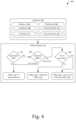
- FIG. 2illustrates, in accordance with techniques of this disclosure, an example system of a host vehicle configured for dynamically calculating lane change trajectories.
- FIG. 3illustrates, in accordance with techniques of this disclosure, an example flow of dynamically calculating lane change trajectories.
- FIG. 4illustrates, in accordance with techniques of this disclosure, an example flow of generating offsets for dynamically calculating lane change trajectories.
- FIG. 5illustrates, in accordance with techniques of this disclosure, an example method of dynamically calculating lane change trajectories.
- Autonomous driving technologiesenable vehicles to execute lane changes, triggered either automatically or via a user input (e.g., a turn signal switch). Trajectories for the lane changes are calculated and the vehicles follow the calculated trajectories.
- a user inpute.g., a turn signal switch
- the trajectoriesare often symmetric (e.g., the entries and exists have equal aggressiveness). Although some techniques have been developed to generate asymmetric trajectories, they are often fixed in their asymmetry (e.g., they are static trajectories). In many cases, a driver may wish to adjust the asymmetry due to preference or for various scenarios. Furthermore, the asymmetric trajectories may not be suitable for certain road and weather conditions.
- the techniques and systems hereinare configured for dynamically calculating lane change trajectories.
- An offset that corresponds to an amount of asymmetry of a lane change trajectory(a zero-offset may be a symmetrical lane change trajectory) is determined for a lane change based on vehicle/driver preferences, road curvature, and/or road conditions.
- the offsetis then used to calculate the lane change trajectory for the lane change, which is then provided to a vehicle system to execute the lane change according to the lane change trajectory.
- lane change trajectoriesmay be tailored to driver preferences, including asymmetry preferences and actions for different types of curves, as well as for road and weather conditions. Doing so, may not only improve driver experience due to better emulation of their behavior but also increase safety by decreasing unsafe lane change trajectories.
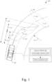
- FIG. 1illustrates an example environment 100 where dynamically calculating lane change trajectories may be used.
- the example environment 100contains a host vehicle 102 that is traveling in a lane 104 of a roadway 106 .
- the host vehicle 102may be any type of system (automobile, car, truck, motorcycle, e-bike, boat, air vehicle, and so on).
- a trajectory module 108 of the host vehicle 102receives a request to generate a lane change trajectory 110 for a lane change from the lane 104 to an adjacent lane 112 .
- the roadway 106has a curvature 114 (magnitude and left/right relative to a heading of the host vehicle 102 ) and, in the example environment 100 , the lane change is from an outer lane to an inner lane (relative to the curve).
- a driver of the host vehicle 102 or a vehicle component 116may initiate the lane change, which causes the request to be received by the trajectory module 108 .
- the trajectory module 108calculates the lane change trajectory 110 and outputs it for receipt by the vehicle component 116 that uses the lane change trajectory 110 to execute the lane change.
- the lane change trajectory 110has an asymmetry. That is, the entry and exits of the lane change do not have equal steering intensities (e.g., aggressiveness of steering inputs).
- the lane change trajectory 110has a relaxed entry and an aggressive exit. This may be due to vehicle/driver preferences, a speed of the host vehicle 102 , and/or the curvature 114 (e.g., whether the roadway is curving left or right relative to the heading of the host vehicle 102 ).
- a driver of the host vehicle 102may wish to have the lane change trajectory 110 as shown (e.g., a relaxed entry and aggressive exit) because the lane change is from an outer to an inner lane (relative to the curve).
- generated lane change trajectoriesmay be symmetrical or have an asymmetry different than that of lane change trajectory 110 .
- a symmetrical lane change trajectory 118is shown as an alternative to the lane change trajectory 110 .
- the symmetrical lane change trajectory 118has equal entry and exit steering intensities.
- another lane change trajectory 120 with a different asymmetry than the lane change trajectory 110is shown.
- the other lane change trajectory 120has an aggressive entry and a relaxed exit.
- An offset 122is used to define symmetry/asymmetry of the lane change trajectory 110 .
- the offset 122corresponds to a distance and direction from an inflection point of the symmetrical lane change trajectory 118 for the environment to an inflection point of the lane change trajectory 110 .
- the inflection point of the symmetrical lane change trajectory 118is at a distance 124 that is half of a total distance 126 between the start and end points.
- the offset 122is positive, indicating the relaxed entry and aggressive exit.
- the offset 122is negative for the other lane change trajectory 120 , indicating the aggressive entry and relaxed exit.
- the symmetrical lane change trajectory 118may not have an offset or have a zero offset. It should be noted that the start and end points of the lane change are environment-dependent, thus, each environment/situation may have a lane change trajectory 110 that is different.
- the offset 122may be a percentage of the distance 126 (e.g., the symmetrical lane change trajectory 116 has an offset of 50% and the offset 122 is 75%).
- the offset 122is shown in the longitudinal direction, the offset 122 may be relative to any direction (e.g., lateral, along a direction between the start and end points of the lane change, or some other reference). Further, the offset 122 may be relative to another point (e.g., the start point of the lane change, the end point of the lane change). Regardless of how it is referenced, the offset 122 corresponds to an asymmetry (or lack thereof) of the lane change trajectory 110 and is dynamic (e.g., it changes based on the environment).
- the trajectory module 108may be a stand-alone component (e.g., having dedicated computer-readable storage media comprising instructions and/or executed on dedicated hardware, such as a dedicated processor, pre-programmed field-programmable-gate-array (FPGA), system on chip (SOC), and the like).
- the processor 202 and the computer-readable storage media 204may be any number of components, comprise multiple components distributed throughout the host vehicle 102 , located remote to the host vehicle 102 , dedicated or shared with other components, modules, or systems of the host vehicle 102 , and/or configured differently than illustrated without departing from the scope of this disclosure.
- the computer-readable storage media 204also contains sensor data 210 generated by one or more sensors or types of sensors (not shown) that may be local or remote to the example system 200 .
- the sensor data 210indicates or otherwise enables the determination of information usable to perform the techniques described herein.
- the sensorsmay generate sensor data 210 indicative of aspects of an environment around the host vehicle 102 (e.g., the example environment 100 ).
- the sensor data 210may come from a remote source (e.g., via link 208 ).
- the example system 200may contain a communication system (not shown) that receives sensor data 210 from the remote source.
- the vehicle component 116contains one or more systems or components that are communicatively coupled to the trajectory module 108 and configured to use the lane change trajectory 110 to execute a lane change.
- the vehicle component 116may comprise an ADAS or autonomous driving system with means for accelerating, steering, or braking the host vehicle 102 .
- the vehicle component 116is communicatively coupled to the trajectory module 108 via the link 208 .
- the trajectory module 108may be part of the vehicle component 116 and visa-versa.
- the trajectory module 108also obtains attributes 304 that may affect the lane change trajectory 110 .
- the attributes 304may be of an environment (e.g., the example environment 100 ) and/or vehicle/driver settings. As shown, the attributes 304 include aspects about the roadway 106 and preferences 306 .
- the aspects of the roadway 106include conditions 308 and the curvature 114 .
- the conditions 308include dynamic aspects that may affect a safety or viability of certain lane change trajectories (e.g., weather, road surface conditions, road surface, gradient(s), quality of lane markings).
- the curvature 114may indicate a radius of the roadway 106 at a location of the lane change and/or whether the roadway 106 curves to the left or right of a heading of the host vehicle 102 .
- the preferences 306include aspects of vehicle and/or driver preferences for lane changes, including a preferred offset 310 and a curve inversion 312 .
- the preferred offset 310is indicative of a preference for a certain shape of the lane change trajectory 110 .
- the preferred offset 310may correspond to an aggressive entry and relaxed exit (e.g., the other lane change trajectory 120 in the example environment 100 ), a symmetrical lane change (e.g., the symmetrical lane change trajectory 118 in the example environment 100 ), a relaxed entry and aggressive exit (e.g., the lane change trajectory 110 in the example environment 100 ), or anything in-between.
- the preferred offset 310may be a relative value (e.g., 0-100 with 0 being the most aggressive entry and most relaxed exit, 50 being the symmetrical lane change, and 100 being the most relaxed entry and most aggressive exit), an actual offset amount (distance), or some other value that influences a shape of the lane change trajectory 110 .
- the curve inversion 312is indicative of a preference to invert the preferred offset 310 for an inside curve lane change (e.g., from an outer lane to an inner lane relative to the curvature 114 ). In other words, the entry and exit are reversed from the preferred offset 310 in such environments.
- there may be a threshold for applying the curve inversion 312for example, the curve inversion 312 may only be applied if a radius of the roadway 106 is below a certain value (e.g., the curve needs to be sharp enough to implement the curve inversion 312 ).
- the thresholdmay also be dynamic (e.g., based on a speed of the host vehicle 102 ).
- the lane changeis from an outer lane to an inner lane.
- the curve inversion 312is set to “yes” and that the preferred offset 310 indicates a preference for an aggressive entry and relaxed exit (e.g., the other lane change trajectory 120 )
- the trajectory module 108generates the lane change trajectory 110 that has a relaxed entry and an aggressive exit (opposite the preferred offset 310 ).
- the preferences 306may be vehicle specific, driver specific, or some combination thereof. For example, there may be a single set of preferences 306 for the host vehicle 102 or there may be different preferences 306 for different drivers.
- the trajectory module 108may determine a driver of the host vehicle 102 and obtain the preferences 306 for that driver.
- the preferences 306may be input via at least one user input (e.g., button, knob, graphical user interface (GUI), touchscreen, navigation device, voice-control).
- GUIgraphical user interface
- a driver of the host vehicle 102may move a slider, select a value, or input a value.
- Limits of the preferred offset 310may be pre-determined to ensure safe operation and may be vehicle-specific (e.g., very aggressive steering inputs may be unsafe, and thus, not selectable by the driver).
- the attributes 304may be acquired, received, or determined by the trajectory module 108 .
- the trajectory module 108may determine the attributes 304 directly from the sensor data 210 , from a bus or interface connected to sensors that interface with the example system 200 , or from another module or system of the example system 200 . Regardless of how or where the attributes 304 are gathered, received, derived, or calculated, the trajectory module 108 is configured to use the attributes 304 to determine the offset 122 and calculate the lane change trajectory 110 .
- the attributes 304are input into an offset module 314 that determines the offset 122 based on the example flow 400 discussed below.
- a path module 316generates the lane change trajectory 110 using the offset 122 .
- the path module 316may use any number of methods to generate the lane change trajectory 110 such that the offset 122 is achieved (e.g., a jerk optimal polynomial).
- the offset 122may provide a point through-which the lane change trajectory 110 should go.
- the offset 122along with known start and end points allows the path module 316 to calculate/generate the lane change trajectory 110 .
- the lane change trajectory 110is then output, by the trajectory module 108 , for receipt by the vehicle component 116 .
- the vehicle component 116then executes the lane change according to the lane change trajectory 110 .
- the vehicle component 116may be an autonomous driving system that automatically steers the host vehicle 102 along the lane change trajectory 110 .
- FIG. 4is an example flow 400 of determining the offset 122 .
- the example flow 400may be implemented in any of the previously described environments and by any of the previously described systems or components.
- the example flow 400can be implemented in the example environment 100 and/or by the example system 200 .
- the example flow 400may also be implemented in other environments, by other systems or components, and utilizing other flows or techniques.
- the example flow 400may be implemented by one or more entities (e.g., the offset module 314 ).
- the order in which the operations are shown and/or describedis not intended to be construed as a limitation, and the order may be rearranged without departing from the scope of this disclosure.
- any number of the operationscan be combined with any other number of the operations to implement the example flow or an alternate flow.
- the offset module 314determines whether an asymmetric lane change trajectory is safe. For example, the offset module 314 may determine, based on the conditions 308 , that an asymmetric lane change trajectory is unsafe.
- the conditions 308may indicate that there is snow or ice on the road, that the road is wet, that the surface is uneven, or any other condition that may cause an unsafe lane change if aggressive steering inputs are used (e.g., an asymmetric lane change).
- Responsive to determining that an asymmetric lane change trajectory is unsafee.g., a “no” out of decision 402
- the offset module 314sets the offset 122 to zero (or whatever value indicates a symmetrical lane change trajectory).
- the offset module 314may indicate that the lane change trajectory 110 should be symmetrical.
- the example flow 400proceeds to decision 404 .
- the offset module 314determines whether the preferred offset 310 exists (e.g., for the host vehicle 102 and/or a driver of the host vehicle 102 ). If the preferred offset 310 does not exist, is zero, or otherwise indicates a preference for symmetrical lane change trajectories (e.g., a “no” out of decision 404 ), the offset module 314 sets the offset 122 to zero (or whatever value indicates a symmetrical lane change trajectory). Alternatively, the offset module 314 may indicate that the lane change trajectory 110 should be symmetrical.
- the example flow 400proceeds to decision 406 .
- the offset module 314determines whether the curve inversion 312 exists (e.g., for the host vehicle 102 and/or a driver of the host vehicle 102 ). If the curve inversion 312 does not exist or otherwise indicates a preference for not inverting preferred offsets for inside curves (e.g., a “no” out of decision 406 ), the offset module 314 sets the offset 122 to the preferred offset 310 .
- the offset module 314sets the offset 122 to the inverse of the preferred offset 310 .
- the inverse of the preferred offset 310may correspond to an offset 122 that is at a similar distance from midpoint of a symmetrical lane change trajectory but opposite the midpoint of the symmetrical lane change trajectory. Regardless of how the preferred offset 310 is implemented, the inverse of the preferred offset 310 causes the lane change trajectory 110 to have reversed aggressiveness compared to the that generated by the preferred offset 310 . In other words, the aggressiveness' of the entry and exit of the lane change will be reversed.
- the order of the decisions 402 , 404 , and 406are not intended to be limiting.
- the example flow 400may be modified (either by those skilled in the art or by a compiler or other program) and achieve similar results.
- the decision 402may be performed after determining a result of the decision 404 and/or the decision 406 , such that the decision 402 acts as a gate for any asymmetric lane change trajectories (e.g., a “yes” from the decision 402 may cause any offset 122 that is non-zero to be zero).
- the preferred offset 310is zero, than decisions 402 and 406 may not be performed, as the lane change trajectory 110 would be symmetrical independent of the attributes 304 .
- the offset module 314By dynamically setting the offset 122 as zero, the preferred offset 310 , or an inverse of the preferred offset 310 based on the attributes 304 , the offset module 314 is able to better select the offset 122 in a wider variety of environments and situations. Consequently, the path module 316 (and thus, the trajectory module 108 as a whole) is able to dynamically generate the lane change trajectory 110 based on the offset 122 (that is based on the attributes 304 ). Doing so allows the vehicle component 116 to emulate a specific/preferred driving pattern more accurately while also increasing safety.
- FIG. 5is an example method 500 for dynamically calculating lane change trajectories.
- the example method 500may be implemented in any of the previously described environments, by any of the previously described systems or components, and by utilizing any of the previously described flows, process flows, or techniques.
- the example method 500can be implemented in the example environment 100 , by the example system 200 , and/or by following the example flows 300 and/or 400 .
- the example method 500may also be implemented in other environments, by other systems or components, and utilizing other flows, process flows, or techniques.
- Example method 500may be implemented by one or more entities (e.g., the trajectory module 108 ).
- the offset module 314may determine whether the preferred offset 310 exists or is non-zero (e.g., at decision 404 ).
- the lane change trajectoryis calculated based on the preferred offset.
- the offset module 314may determine the offset 122 as the preferred offset 310 or an inverse of the preferred offset 310 (depending on decision 406 ). In some situations, the offset module 314 may set the offset 122 as zero (e.g., according to decision 402 ). The offset 122 may then be used by the path module 316 to calculate the lane change trajectory 110 .
- the lane change trajectoryis provided to a vehicle component effective to cause the vehicle component to execute the lane change according to the lane change trajectory.
- the path module 316may output the lane change trajectory 110 such that the vehicle component 116 can execute a lane change according to the lane change trajectory 110 .
- Example 2The method of example 1, further comprising, responsive to determining that the preferred offset does not exist, calculating the lane change trajectory as a symmetrical lane change trajectory.
- Example 3The method of example 1 or 2, further comprising, receiving a user input indicating the preferred offset.
- Example 4The method of example 3, wherein the preferred offset corresponds to a symmetrical lane change trajectory.
- Example 5The method of any preceding example, further comprising: determining whether road conditions of the roadway are appropriate for an asymmetric lane change trajectory; and responsive to determining that the road conditions are not appropriate for an asymmetric lane change trajectory, calculating the lane change trajectory as a symmetrical lane change trajectory.
- Example 6The method of example 5, wherein the calculating the lane change trajectory based on the preferred offset is further responsive to determining that the road conditions are appropriate for an asymmetric lane change trajectory.
- Example 7The method of any preceding example, further comprising determining whether a preference invert the preferred offset for an inside curve lane change exists for the host vehicle, wherein the calculating the lane change trajectory is further responsive to determining that the preference invert the preferred offset for an inside curve lane change does not exist.
- Example 8The method of example 7, further comprising, responsive to determining that the preference invert the preferred offset for an inside curve lane change does exist, determining a road curvature of the roadway, wherein the calculating the lane change trajectory is based further on the road curvature.
- Example 9The method of example 8, wherein: the road curvature comprises a direction of the road curvature relative to a heading of the host vehicle; and the calculating the lane change trajectory is based further on the direction of the road curvature.
- Example 10The method of example 9, further comprising: determining whether the lane change is into the direction of the road curvature; and responsive to determining that the lane change is into the direction of the road curvature, calculating the lane change trajectory based on an inversion of the preferred offset.
- Example 11The method of example 10, wherein the determining that the lane change is into the direction of the road curvature comprises determining that the lane change is from an outer lane to an inner lane relative to the road curvature.
- Example 12The method of any preceding example, wherein the preferred offset corresponds to a distance from a midpoint between a start point and an end point of the lane change trajectory.
- Example 13The method of any preceding example, wherein: the preferred offset is negative and corresponds to an aggressive entry and a relaxed exit of the lane change; or the preferred offset is positive and corresponds to a relaxed entry and an aggressive exit of the lane change.
- Example 14A system comprising at least one processor configured to: receive a request for a lane change trajectory for a lane change of a host vehicle that is traveling along a roadway; determine whether a preferred offset corresponding to an asymmetry of the lane change trajectory exists for the host vehicle; responsive to determining that the preferred offset exists, calculate the lane change trajectory based on the preferred offset; responsive to determining that the preferred offset does not exist, calculate the lane change trajectory as a symmetrical lane change trajectory; and provide the lane change trajectory to a vehicle component effective to cause the vehicle component to execute the lane change according to the lane change trajectory.
- Example 15The system of example 14, wherein the processor is further configured to receive a user input indicating the preferred offset.
- Example 16The system of example 15, wherein the preferred offset corresponds to a symmetrical lane change trajectory.
- Example 17The system of any of examples 14 to 16, wherein the processor is further configured to: determine whether road conditions of the roadway are appropriate for an asymmetric lane change trajectory; responsive to determining that the road conditions are not appropriate for the asymmetric lane change trajectory, calculate the lane change trajectory as the symmetrical lane change trajectory; responsive to determining that the road conditions are appropriate for the asymmetric lane change trajectory and that that the preferred offset exists, calculate the lane change trajectory based on the preferred offset; and responsive to determining that the road conditions are appropriate for the asymmetric lane change trajectory and that the preferred offset does not exist, calculate the lane change trajectory as the symmetrical lane change trajectory.
- Example 18The system of any of examples 14 to 17, wherein the processor is further configured to: determine whether a preference invert the preferred offset for an inside curve lane change exists for the host vehicle; responsive to determining that the preference invert the preferred offset for an inside curve lane change does not exist and that the preferred offset exists, calculate the lane change trajectory based on the preferred offset; responsive to determining that the preference invert the preferred offset for an inside curve lane change does not exist and that the preferred offset does not exist, calculate the lane change trajectory as the symmetrical lane change trajectory; and responsive to determining that the preference invert the preferred offset for an inside curve lane change does exist: determine whether the lane change is into a curvature of the roadway; responsive to determining that the lane change is not into the curvature of the roadway and that the preferred offset exists, calculate the lane change trajectory based on the preferred offset; responsive to determining that the lane change is not into the curvature of the roadway and that the preferred offset does not exist, calculate the lane change trajectory as the symmetrical lane change trajectory
- Example 19The system of example 18, wherein: the determination that the lane change is into the curvature of the roadway comprises determining that the lane change is from an outer lane to an inner lane relative to the curvature; and the determination that the lane change is not into the curvature of the roadway comprises determining that the lane change is from an inner lane to an outer lane relative to the curvature.
- Example 20Computer-readable storage media comprising instructions that, when executed, cause at least one processor to: receive a request for a lane change trajectory for a lane change of a host vehicle that is traveling along a roadway; determine whether a preferred offset corresponding to an asymmetry of the lane change trajectory exists for the host vehicle; responsive to determining that the preferred offset exists, calculate the lane change trajectory based on the preferred offset; responsive to determining that the preferred offset does not exist, calculate the lane change trajectory as a symmetrical lane change trajectory; and provide the lane change trajectory to a vehicle component effective to cause the vehicle component to execute the lane change according to the lane change trajectory.
- Example 21A system comprising: at least one processor configured to perform the method of any of examples 1-13.
- Example 22Computer-readable storage media comprising instructions that, when executed, cause at least one processor to perform the method of any of examples 1-13.
- Example 23A system comprising means for performing the method of any of examples 1-13.
- Example 24A method performed by the system of any of examples 14-19.
- Example 25A method comprised by the instructions of example 20.
- “at least one of: a, b, or c”is intended to cover a, b, c, a-b, a-c, b-c, and a-b-c, as well as any combination with multiples of the same element (e.g., a-a, a-a-a, a-a-b, a-a-c, a-b-b, a-c-c, b-b, b-b-b, b-b-c, c-c, and c-c-c or any other ordering of a, b, and c).
Landscapes
- Engineering & Computer Science (AREA)
- Automation & Control Theory (AREA)
- Transportation (AREA)
- Mechanical Engineering (AREA)
- Human Computer Interaction (AREA)
- Chemical & Material Sciences (AREA)
- Combustion & Propulsion (AREA)
- Physics & Mathematics (AREA)
- Mathematical Physics (AREA)
- Traffic Control Systems (AREA)
Abstract
Description
Claims (22)
Priority Applications (3)
| Application Number | Priority Date | Filing Date | Title |
|---|---|---|---|
| US17/659,833US12252127B2 (en) | 2022-04-19 | 2022-04-19 | Dynamically calculating lane change trajectories |
| EP23159570.3AEP4265498B1 (en) | 2022-04-19 | 2023-03-02 | Dynamically calculating lane change trajectories |
| CN202310373936.8ACN116901994A (en) | 2022-04-19 | 2023-04-10 | Dynamically calculating lane change trajectories |
Applications Claiming Priority (1)
| Application Number | Priority Date | Filing Date | Title |
|---|---|---|---|
| US17/659,833US12252127B2 (en) | 2022-04-19 | 2022-04-19 | Dynamically calculating lane change trajectories |
Publications (2)
| Publication Number | Publication Date |
|---|---|
| US20230331231A1 US20230331231A1 (en) | 2023-10-19 |
| US12252127B2true US12252127B2 (en) | 2025-03-18 |
Family
ID=85415425
Family Applications (1)
| Application Number | Title | Priority Date | Filing Date |
|---|---|---|---|
| US17/659,833Active2043-01-11US12252127B2 (en) | 2022-04-19 | 2022-04-19 | Dynamically calculating lane change trajectories |
Country Status (3)
| Country | Link |
|---|---|
| US (1) | US12252127B2 (en) |
| EP (1) | EP4265498B1 (en) |
| CN (1) | CN116901994A (en) |
Families Citing this family (6)
| Publication number | Priority date | Publication date | Assignee | Title |
|---|---|---|---|---|
| JP7508953B2 (en)* | 2020-08-31 | 2024-07-02 | トヨタ自動車株式会社 | Vehicle display device, display method, and program |
| JP7355057B2 (en)* | 2021-03-24 | 2023-10-03 | 株式会社デンソー | Vehicle control device and vehicle control method |
| US12252127B2 (en)* | 2022-04-19 | 2025-03-18 | Aptiv Technologies AG | Dynamically calculating lane change trajectories |
| KR20230172776A (en)* | 2022-06-16 | 2023-12-26 | 현대모비스 주식회사 | Lane following system and method considering driving assistance lane |
| US12233902B2 (en)* | 2022-11-21 | 2025-02-25 | Ford Global Technologies, Llc | Systems and methods for determining steer while stopped behavior for a vehicle using dynamic limits |
| US12107945B2 (en)* | 2023-01-13 | 2024-10-01 | Raytheon Company | Electrical signal delay calibration system |
Citations (133)
| Publication number | Priority date | Publication date | Assignee | Title |
|---|---|---|---|---|
| JPH05297943A (en)* | 1992-04-17 | 1993-11-12 | Toyota Central Res & Dev Lab Inc | Control system for unmanned vehicles |
| US5521579A (en)* | 1993-04-26 | 1996-05-28 | Mercedes-Benz Ag | Method for providing guiding assistance for a vehicle in changing lane |
| JPH09301207A (en)* | 1996-05-15 | 1997-11-25 | Koyo Seiko Co Ltd | Steering device for vehicle |
| JPH09301206A (en)* | 1996-05-09 | 1997-11-25 | Honda Motor Co Ltd | Vehicle steering assist device |
| DE19727225A1 (en)* | 1996-06-27 | 1998-01-08 | Toyota Motor Co Ltd | Detection system for locating object on road |
| US5845222A (en)* | 1994-10-04 | 1998-12-01 | Honda Giken Kogyo Kabushiki Kaisha | Vehicle steering control system |
| US6634109B1 (en)* | 2001-11-26 | 2003-10-21 | Snap-On Technologies, Inc. | Method and system for determining symmetry and Ackermann geometry status of the steering system of a vehicle |
| US20040090199A1 (en)* | 2002-10-30 | 2004-05-13 | Koji Kanda | Vehicle steering apparatus |
| US20040148080A1 (en)* | 2002-12-20 | 2004-07-29 | Jonas Ekmark | Control strategy for computer-controlled steering |
| US6813562B2 (en)* | 2002-10-15 | 2004-11-02 | General Motors Corporation | Threat assessment algorithm for forward collision warning |
| US20060069481A1 (en)* | 2004-09-27 | 2006-03-30 | Nissan Motor Co., Ltd. | Vehicular steering control apparatus |
| US20070027597A1 (en)* | 2003-09-23 | 2007-02-01 | Daimlerchrysler Ag | Method and device for recognising lane changing operations for a motor vehicle |
| US20070219691A1 (en)* | 2006-03-15 | 2007-09-20 | Mazda Motor Corporation | Steering apparatus for vehicle |
| US7292152B2 (en)* | 2003-06-12 | 2007-11-06 | Temic Automotive Of North America, Inc. | Method and apparatus for classifying vehicle operator activity state |
| US20080119978A1 (en)* | 2006-11-20 | 2008-05-22 | Hunter Engineering Company | Method and Apparatus For Wheel Assembly Force Moment Arm Measurement |
| US7519471B2 (en)* | 2004-10-15 | 2009-04-14 | Aisin Aw Co., Ltd. | Driving support methods, apparatus, and programs |
| DE10354018B4 (en)* | 2002-11-20 | 2009-08-13 | Nissan Motor Co., Ltd., Yokohama-shi | Lane departure avoidance system for a motor vehicle |
| US7579942B2 (en)* | 2006-10-09 | 2009-08-25 | Toyota Motor Engineering & Manufacturing North America, Inc. | Extra-vehicular threat predictor |
| US20090319113A1 (en)* | 2008-06-20 | 2009-12-24 | Gm Global Technology Operations, Inc. | Path generation algorithm for automated lane centering and lane changing control system |
| US20100036563A1 (en)* | 2008-08-06 | 2010-02-11 | Denso Corporation | Apparatus for travel support |
| US20100082195A1 (en)* | 2008-06-20 | 2010-04-01 | Gm Global Technology Operations, Inc. | Method to adaptively control vehicle operation using an autonomic vehicle control system |
| US20100111338A1 (en)* | 2008-11-04 | 2010-05-06 | Gn Resound A/S | Asymmetric adjustment |
| US20100174442A1 (en)* | 2009-01-07 | 2010-07-08 | Honda Motor Co., Ltd. | Electric power steering system with failure detection |
| US7797107B2 (en)* | 2003-09-16 | 2010-09-14 | Zvi Shiller | Method and system for providing warnings concerning an imminent vehicular collision |
| US20100256835A1 (en) | 2009-04-06 | 2010-10-07 | Gm Global Technology Operations, Inc. | Fail-safe speed profiles for cooperative autonomous vehicles |
| US20110029235A1 (en)* | 2009-07-30 | 2011-02-03 | Qinetiq Limited | Vehicle Control |
| US20110048600A1 (en)* | 2009-05-29 | 2011-03-03 | Toyo Tire & Rubber Co. Ltd. | Pneumatic Tire |
| US7913803B2 (en)* | 2004-10-25 | 2011-03-29 | Denso Corporation | Vehicular steering apparatus with capability of providing suitable steering angle correction and power assistance |
| US20110153162A1 (en)* | 2007-12-14 | 2011-06-23 | Mitsubishi Electric Corporation | Motor-driven power steering control appartus |
| US20110202250A1 (en)* | 2008-10-14 | 2011-08-18 | Hitachi Automotive Systems, Ltd. | Brake Control Apparatus |
| US8086406B2 (en)* | 2004-02-24 | 2011-12-27 | Robert Bosch Gmbh | Safety system for a means of transportation and a method relating to the same |
| US20120041632A1 (en)* | 2010-08-12 | 2012-02-16 | Robert Bosch Gmbh | Combined lane change assist and rear, cross-traffic alert functionality |
| US20120109458A1 (en)* | 2010-10-28 | 2012-05-03 | Gm Global Technology Operations, Inc. | Method and system for determining a reference yaw rate for a vehicle |
| US20120179350A1 (en)* | 2011-01-10 | 2012-07-12 | Bendix Commercial Vehicle Systems, Llc | Acc and am braking range variable based on lateral and longitudinal position of forward vehicle and curvature of road |
| US20120176234A1 (en)* | 2011-01-10 | 2012-07-12 | Bendix Commercial Vehicle Systems, Llc | Acc and am braking range variable based on internal and external factors |
| US8260498B2 (en)* | 2009-10-27 | 2012-09-04 | GM Global Technology Operations LLC | Function decomposition and control architecture for complex vehicle control system |
| US20120316744A1 (en)* | 2010-09-29 | 2012-12-13 | Toyota Jidosha Kabushiki Kaisha | Vehicle control system |
| US8374743B2 (en)* | 2008-05-16 | 2013-02-12 | GM Global Technology Operations LLC | Method and apparatus for driver control of a limited-ability autonomous vehicle |
| US20130041541A1 (en)* | 2010-04-28 | 2013-02-14 | Nissan Motor Co., Ltd. | Device for improving vehicle behavior when steering |
| US20130057397A1 (en)* | 2011-09-01 | 2013-03-07 | GM Global Technology Operations LLC | Method of operating a vehicle safety system |
| US20130124043A1 (en)* | 2011-11-02 | 2013-05-16 | GM Global Technology Operations LLC | Electrical limitation of a steering gear travel path |
| US8615357B2 (en)* | 2008-02-26 | 2013-12-24 | Robert Bosch Gmbh | Method for assisting a user of a vehicle, control device for a driver-assistance system of a vehicle and vehicle having such a control device |
| US20140067250A1 (en)* | 2011-05-20 | 2014-03-06 | Honda Motor Co., Ltd. | Lane change assist information visualization system |
| US20140067252A1 (en)* | 2012-09-03 | 2014-03-06 | Robert Bosch Gmbh | Method for determining an evasion trajectory for a motor vehicle, and safety device or safety system |
| US8781170B2 (en)* | 2011-12-06 | 2014-07-15 | GM Global Technology Operations LLC | Vehicle ghosting on full windshield display |
| US20140222331A1 (en)* | 2008-10-01 | 2014-08-07 | Navteq B.V. | Bezier Curves for Advanced Driver Assistance System Applications |
| US8977464B1 (en)* | 2013-09-30 | 2015-03-10 | Hitachi, Ltd. | Method and apparatus for performing driving assistance |
| US20150094927A1 (en)* | 2013-09-30 | 2015-04-02 | Hitachi, Ltd. | Method and Apparatus for Performing Driving Assistance |
| US9020732B2 (en)* | 2011-01-05 | 2015-04-28 | Ford Global Technologies, Llc | Vehicle and powertrain control based on rearward approaching object |
| US20150120137A1 (en)* | 2013-10-28 | 2015-04-30 | GM Global Technology Operations LLC | Path planning for evasive steering maneuver in presence of target vehicle and surrounding objects |
| US20150165850A1 (en)* | 2013-12-13 | 2015-06-18 | Honda Motor Co., Ltd. | Method and system for stability control |
| US20150225014A1 (en)* | 2012-10-04 | 2015-08-13 | Nissan Motor Co., Ltd. | Steering control device |
| US9108664B2 (en)* | 2012-11-06 | 2015-08-18 | Hyundai Mobis Co., Ltd. | Control apparatus of vehicle for changing lane and control method of the same |
| US20150232124A1 (en)* | 2012-10-04 | 2015-08-20 | Nissan Motor Co., Ltd. | Steering control device |
| US20150259006A1 (en)* | 2011-12-26 | 2015-09-17 | Toyota Jidosha Kabushiki Kaisha | Travel trajectory control device for a vehicle |
| US20150353082A1 (en)* | 2014-06-05 | 2015-12-10 | Carnegie Mellon University | Unified motion planning algorithm for autonomous driving vehicle in obstacle avoidance maneuver |
| US20150353127A1 (en)* | 2013-01-10 | 2015-12-10 | Nissan Motor Co., Ltd. | Steering control device |
| US9211911B2 (en)* | 2008-09-10 | 2015-12-15 | Continental Teves Ag & Co. Ohg | Method for steering assistance during an emergency maneuver |
| US20150367852A1 (en)* | 2013-01-31 | 2015-12-24 | Hitachi Automotive Systems, Ltd. | Vehicle motion control system |
| US9229453B1 (en)* | 2014-08-29 | 2016-01-05 | GM Global Technology Operations LLC | Unified motion planner for autonomous driving vehicle in avoiding the moving obstacle |
| US9227632B1 (en)* | 2014-08-29 | 2016-01-05 | GM Global Technology Operations LLC | Method of path planning for evasive steering maneuver |
| US20160018229A1 (en)* | 2014-07-16 | 2016-01-21 | GM Global Technology Operations LLC | Accurate curvature estimation algorithm for path planning of autonomous driving vehicle |
| US9266429B2 (en)* | 2013-03-08 | 2016-02-23 | Volkswagen Ag | Human machine interface |
| US20160052546A1 (en)* | 2013-03-29 | 2016-02-25 | Tokyo Keiki Inc. | Automatic steering system for working vehicle |
| US20160059852A1 (en)* | 2013-03-29 | 2016-03-03 | Hitachi Automotive Systems, Ltd. | Vehicle Motion Control Device |
| US20160082971A1 (en)* | 2014-09-23 | 2016-03-24 | Robert Bosch Gmbh | Driver assistance system for motor vehicles |
| US20160091896A1 (en)* | 2014-09-29 | 2016-03-31 | Fuji Jukogyo Kabushiki Kaisha | Driving support controller |
| CN105612091A (en)* | 2013-10-10 | 2016-05-25 | 日立汽车系统株式会社 | Vehicle motion control device |
| US20160185388A1 (en)* | 2014-12-30 | 2016-06-30 | Mando Corporation | Lane change control device and control method |
| WO2016110732A1 (en)* | 2015-01-05 | 2016-07-14 | 日産自動車株式会社 | Target route generation device and travel control device |
| US20160304126A1 (en)* | 2015-04-14 | 2016-10-20 | Toyota Jidosha Kabushiki Kaisha | Vehicle control device |
| US20170001650A1 (en)* | 2015-07-03 | 2017-01-05 | Lg Electronics Inc. | Driver assistance apparatus and vehicle including the same |
| US20170018189A1 (en)* | 2014-03-20 | 2017-01-19 | Aisin Aw Co., Ltd. | Automatic drive assist device, method, and program for a vehicle |
| KR20170069715A (en)* | 2015-12-11 | 2017-06-21 | 현대자동차주식회사 | MDPS reverse input torque compensation system |
| US9731762B2 (en)* | 2013-06-03 | 2017-08-15 | Trw Automotive Gmbh | Control unit and method for an emergency steering support function |
| US20170259819A1 (en)* | 2016-03-14 | 2017-09-14 | Honda Motor Co., Ltd. | Vehicle control system, vehicle control method, and vehicle control program |
| US20170297611A1 (en)* | 2016-04-13 | 2017-10-19 | Ford Global Technologies, Llc | Steering assist system and related methods |
| US20170305416A1 (en)* | 2014-09-29 | 2017-10-26 | Hitachi Automotive Systems, Ltd. | Method and Device for Controlling Vehicle Motion and Vehicle Equipped with Same |
| US20170320521A1 (en)* | 2014-10-22 | 2017-11-09 | Nissan Motor Co., Ltd. | Drive Assist Device |
| US20170350975A1 (en)* | 2016-06-03 | 2017-12-07 | Fujitsu Ten Limited | Radar device and signal processing method |
| US20170349173A1 (en)* | 2016-06-06 | 2017-12-07 | Honda Motor Co., Ltd. | Vehicle and lane change timing determination method |
| US20180001888A1 (en)* | 2016-06-30 | 2018-01-04 | Mazda Motor Corporation | Vehicle behavior control device |
| DE102016215528A1 (en) | 2016-08-18 | 2018-02-22 | Volkswagen Aktiengesellschaft | Automated operation of a motor vehicle |
| WO2018055916A1 (en)* | 2016-09-23 | 2018-03-29 | 日立オートモティブシステムズ株式会社 | Vehicle movement control device |
| US20180158262A1 (en)* | 2016-12-05 | 2018-06-07 | Toyota Jidosha Kabushiki Kaisha | Vehicle control device |
| JP2018090248A (en)* | 2017-12-26 | 2018-06-14 | 株式会社ショーワ | Vehicle control device and vehicle |
| US20180178716A1 (en)* | 2016-12-26 | 2018-06-28 | Toyota Jidosha Kabushiki Kaisha | Lane change assist device for a vehicle |
| US20180181132A1 (en)* | 2016-12-26 | 2018-06-28 | Toyota Jidosha Kabushiki Kaisha | Autonomous vehicle |
| US10077056B1 (en) | 2015-04-24 | 2018-09-18 | State Farm Mutual Automobile Insurance Company | Managing self-driving behavior of autonomous or semi-autonomous vehicle based upon actual driving behavior of driver |
| US20180286242A1 (en)* | 2017-03-31 | 2018-10-04 | Ford Global Technologies, Llc | Steering wheel actuation |
| DE102018107502A1 (en)* | 2017-03-31 | 2018-10-04 | Ford Global Technologies, Llc | Lane change assistant |
| DE102018107340A1 (en)* | 2017-03-31 | 2018-10-04 | Ford Global Technologies, Llc | STEERING CONTROL |
| DE102018107341A1 (en)* | 2017-03-31 | 2018-10-04 | Ford Global Technologies, Llc | LANE CHANGE GUIDE |
| CN104097637B (en)* | 2013-04-11 | 2018-10-12 | 现代自动车株式会社 | Method and system for controlling lane changing |
| US20180297640A1 (en)* | 2017-04-12 | 2018-10-18 | Toyota Jidosha Kabushiki Kaisha | Lane change assist apparatus for vehicle |
| DE102017221408A1 (en)* | 2017-08-24 | 2019-02-28 | Hyundai Motor Company | SYSTEM AND METHOD FOR PRODUCING A PATH WHEN A TRAIL IS CHANGED |
| DE102018212753A1 (en)* | 2017-08-11 | 2019-03-21 | Jaguar Land Rover Limited | Control system for a steering system |
| US20190212749A1 (en) | 2018-01-07 | 2019-07-11 | Nvidia Corporation | Guiding vehicles through vehicle maneuvers using machine learning models |
| US20190378415A1 (en)* | 2018-06-08 | 2019-12-12 | Toyota Jidosha Kabushiki Kaisha | Lane change assist system, lane change assist device, and lane change assist method |
| US20200207353A1 (en) | 2018-12-31 | 2020-07-02 | Chongqing Jinkang New Energy Vehicle, Ltd. | Automatic Lane Change with Lane-Biased Strategy |
| US20200247416A1 (en)* | 2019-02-05 | 2020-08-06 | Honda Motor Co., Ltd. | Vehicle, and control apparatus and control method thereof |
| US20200247414A1 (en)* | 2019-02-05 | 2020-08-06 | Honda Motor Co., Ltd. | Vehicle, and control apparatus and control method thereof |
| WO2020166113A1 (en) | 2019-02-14 | 2020-08-20 | 日立オートモティブシステムズ株式会社 | Steering control device |
| US10759416B1 (en)* | 2017-10-18 | 2020-09-01 | Zoox, Inc. | Independent control of vehicle wheels |
| US20200290621A1 (en)* | 2019-03-11 | 2020-09-17 | Hyundai Mobis Co., Ltd. | Vehicle lane change control apparatus and method |
| US20200339134A1 (en)* | 2019-04-23 | 2020-10-29 | GM Global Technology Operations LLC | Method and apparatus for dynamic yaw rate bias estimation |
| EP3744602A1 (en) | 2019-05-29 | 2020-12-02 | Zenuity AB | Method for controlling an autonomous driving configuration or driving assistance configuration |
| US20200377082A1 (en)* | 2019-05-28 | 2020-12-03 | GM Global Technology Operations LLC | Method and apparatus for vision based lateral acceleration prediction |
| US20210046864A1 (en)* | 2018-03-26 | 2021-02-18 | Michael ELGRABLY | Indications for vehicles |
| US20210055426A1 (en)* | 2019-08-19 | 2021-02-25 | GM Global Technology Operations LLC | Method and apparatus for kalman filter parameter selection using map data |
| US20210063162A1 (en)* | 2019-08-26 | 2021-03-04 | Mobileye Vision Technologies Ltd. | Systems and methods for vehicle navigation |
| EP3825979A1 (en)* | 2018-07-16 | 2021-05-26 | Nissan Motor Co., Ltd. | Travel assistance method and travel assistance device |
| US20210213959A1 (en) | 2020-01-09 | 2021-07-15 | GM Global Technology Operations LLC | System and method for learning driver preference and adapting lane centering controls to driver behavior |
| US11136021B1 (en)* | 2017-10-18 | 2021-10-05 | Zoox, Inc. | Independent control of vehicle wheels |
| US20210380117A1 (en) | 2018-10-26 | 2021-12-09 | Bayerische Motoren Werke Aktiengesellschaft | Method and Control Unit for Adapting an at Least Partially Autonomous Vehicle to a User |
| US20220017094A1 (en) | 2020-07-15 | 2022-01-20 | Mobile Drive Technology Co.,Ltd. | Lane change planning method and vehicle-mounted device |
| US20220073076A1 (en) | 2019-09-09 | 2022-03-10 | Tencent Technology (Shenzhen) Company Limited | Method, apparatus, and device for constructing simulated vehicle lane change trajectory, and storage medium |
| US20220073098A1 (en) | 2020-09-09 | 2022-03-10 | GM Global Technology Operations LLC | Method and apparatus for predicting lateral acceleration prior to an automated lane change |
| US20220089221A1 (en)* | 2020-09-21 | 2022-03-24 | Volkswagen Aktiengesellschaft | Determining a steering reference state by means of wheel speed values |
| US20220119004A1 (en) | 2020-10-15 | 2022-04-21 | Atieva, Inc. | Defining driving envelope for assisted-driving system |
| US20220215603A1 (en)* | 2020-03-30 | 2022-07-07 | Mobileye Vision Technologies Ltd. | Navigation using points on splines |
| US20220266823A1 (en)* | 2019-07-25 | 2022-08-25 | Hitachi Astemo, Ltd. | Vehicle Motion Control Device, Vehicle Motion Control Method, and Vehicle Motion Control System |
| US20230104188A1 (en)* | 2021-09-28 | 2023-04-06 | Here Global B.V. | Method, apparatus, and system for calibrating vehicle motion data based on mobile device sensor data |
| US20230139711A1 (en)* | 2020-03-04 | 2023-05-04 | Continental Automotive Technologies GmbH | Method for steering a vehicle |
| US20230211786A1 (en)* | 2020-05-12 | 2023-07-06 | Renault S.A.S | Path-controlling module, associated path-controlling device and associated method |
| US20230331232A1 (en)* | 2022-04-15 | 2023-10-19 | Mitsubishi Electric Corporation | Control calculation apparatus |
| US20230331231A1 (en)* | 2022-04-19 | 2023-10-19 | Aptiv Technologies Limited | Dynamically Calculating Lane Change Trajectories |
| US20230406300A1 (en)* | 2022-06-16 | 2023-12-21 | Hyundai Mobis Co., Ltd. | Lane following system and method considering driving assistance lane |
| DE102022206105A1 (en)* | 2022-06-17 | 2023-12-28 | Volkswagen Aktiengesellschaft | Method for detecting an asymmetry of a chassis geometry of a motor vehicle and method for operating a motor vehicle |
| CN117690288A (en)* | 2023-11-23 | 2024-03-12 | 中山大学·深圳 | Mixed traffic flow simulation method and system considering bus stops |
| US20240092364A1 (en)* | 2021-01-25 | 2024-03-21 | Renault S.A.S | Path calculation module, and associated path control device and method |
| CN117818642A (en)* | 2023-12-26 | 2024-04-05 | 苏州科技大学 | Vehicle lane change model construction method under different weather conditions |
| US20240182035A1 (en)* | 2022-12-02 | 2024-06-06 | Mobile Drive Technology Co.,Ltd. | Lane change control method, vehicle-mounted device and readable storage medium |
- 2022
- 2022-04-19USUS17/659,833patent/US12252127B2/enactiveActive
- 2023
- 2023-03-02EPEP23159570.3Apatent/EP4265498B1/enactiveActive
- 2023-04-10CNCN202310373936.8Apatent/CN116901994A/enactivePending
Patent Citations (145)
| Publication number | Priority date | Publication date | Assignee | Title |
|---|---|---|---|---|
| JPH05297943A (en)* | 1992-04-17 | 1993-11-12 | Toyota Central Res & Dev Lab Inc | Control system for unmanned vehicles |
| US5521579A (en)* | 1993-04-26 | 1996-05-28 | Mercedes-Benz Ag | Method for providing guiding assistance for a vehicle in changing lane |
| US5845222A (en)* | 1994-10-04 | 1998-12-01 | Honda Giken Kogyo Kabushiki Kaisha | Vehicle steering control system |
| JPH09301206A (en)* | 1996-05-09 | 1997-11-25 | Honda Motor Co Ltd | Vehicle steering assist device |
| JPH09301207A (en)* | 1996-05-15 | 1997-11-25 | Koyo Seiko Co Ltd | Steering device for vehicle |
| DE19727225A1 (en)* | 1996-06-27 | 1998-01-08 | Toyota Motor Co Ltd | Detection system for locating object on road |
| US6634109B1 (en)* | 2001-11-26 | 2003-10-21 | Snap-On Technologies, Inc. | Method and system for determining symmetry and Ackermann geometry status of the steering system of a vehicle |
| US6813562B2 (en)* | 2002-10-15 | 2004-11-02 | General Motors Corporation | Threat assessment algorithm for forward collision warning |
| US20040090199A1 (en)* | 2002-10-30 | 2004-05-13 | Koji Kanda | Vehicle steering apparatus |
| DE10354018B4 (en)* | 2002-11-20 | 2009-08-13 | Nissan Motor Co., Ltd., Yokohama-shi | Lane departure avoidance system for a motor vehicle |
| US20040148080A1 (en)* | 2002-12-20 | 2004-07-29 | Jonas Ekmark | Control strategy for computer-controlled steering |
| US7292152B2 (en)* | 2003-06-12 | 2007-11-06 | Temic Automotive Of North America, Inc. | Method and apparatus for classifying vehicle operator activity state |
| US7797107B2 (en)* | 2003-09-16 | 2010-09-14 | Zvi Shiller | Method and system for providing warnings concerning an imminent vehicular collision |
| US20070027597A1 (en)* | 2003-09-23 | 2007-02-01 | Daimlerchrysler Ag | Method and device for recognising lane changing operations for a motor vehicle |
| US8086406B2 (en)* | 2004-02-24 | 2011-12-27 | Robert Bosch Gmbh | Safety system for a means of transportation and a method relating to the same |
| US20060069481A1 (en)* | 2004-09-27 | 2006-03-30 | Nissan Motor Co., Ltd. | Vehicular steering control apparatus |
| US7519471B2 (en)* | 2004-10-15 | 2009-04-14 | Aisin Aw Co., Ltd. | Driving support methods, apparatus, and programs |
| US7913803B2 (en)* | 2004-10-25 | 2011-03-29 | Denso Corporation | Vehicular steering apparatus with capability of providing suitable steering angle correction and power assistance |
| US20070219691A1 (en)* | 2006-03-15 | 2007-09-20 | Mazda Motor Corporation | Steering apparatus for vehicle |
| US7579942B2 (en)* | 2006-10-09 | 2009-08-25 | Toyota Motor Engineering & Manufacturing North America, Inc. | Extra-vehicular threat predictor |
| US20080119978A1 (en)* | 2006-11-20 | 2008-05-22 | Hunter Engineering Company | Method and Apparatus For Wheel Assembly Force Moment Arm Measurement |
| US20110153162A1 (en)* | 2007-12-14 | 2011-06-23 | Mitsubishi Electric Corporation | Motor-driven power steering control appartus |
| US8615357B2 (en)* | 2008-02-26 | 2013-12-24 | Robert Bosch Gmbh | Method for assisting a user of a vehicle, control device for a driver-assistance system of a vehicle and vehicle having such a control device |
| US8374743B2 (en)* | 2008-05-16 | 2013-02-12 | GM Global Technology Operations LLC | Method and apparatus for driver control of a limited-ability autonomous vehicle |
| US20090319113A1 (en)* | 2008-06-20 | 2009-12-24 | Gm Global Technology Operations, Inc. | Path generation algorithm for automated lane centering and lane changing control system |
| US8170739B2 (en)* | 2008-06-20 | 2012-05-01 | GM Global Technology Operations LLC | Path generation algorithm for automated lane centering and lane changing control system |
| US20100082195A1 (en)* | 2008-06-20 | 2010-04-01 | Gm Global Technology Operations, Inc. | Method to adaptively control vehicle operation using an autonomic vehicle control system |
| US20100036563A1 (en)* | 2008-08-06 | 2010-02-11 | Denso Corporation | Apparatus for travel support |
| US9211911B2 (en)* | 2008-09-10 | 2015-12-15 | Continental Teves Ag & Co. Ohg | Method for steering assistance during an emergency maneuver |
| US20140222331A1 (en)* | 2008-10-01 | 2014-08-07 | Navteq B.V. | Bezier Curves for Advanced Driver Assistance System Applications |
| US20110202250A1 (en)* | 2008-10-14 | 2011-08-18 | Hitachi Automotive Systems, Ltd. | Brake Control Apparatus |
| US20100111338A1 (en)* | 2008-11-04 | 2010-05-06 | Gn Resound A/S | Asymmetric adjustment |
| US20100174442A1 (en)* | 2009-01-07 | 2010-07-08 | Honda Motor Co., Ltd. | Electric power steering system with failure detection |
| US20100256835A1 (en) | 2009-04-06 | 2010-10-07 | Gm Global Technology Operations, Inc. | Fail-safe speed profiles for cooperative autonomous vehicles |
| US20110048600A1 (en)* | 2009-05-29 | 2011-03-03 | Toyo Tire & Rubber Co. Ltd. | Pneumatic Tire |
| US20110029235A1 (en)* | 2009-07-30 | 2011-02-03 | Qinetiq Limited | Vehicle Control |
| US8260498B2 (en)* | 2009-10-27 | 2012-09-04 | GM Global Technology Operations LLC | Function decomposition and control architecture for complex vehicle control system |
| US20130041541A1 (en)* | 2010-04-28 | 2013-02-14 | Nissan Motor Co., Ltd. | Device for improving vehicle behavior when steering |
| US20120041632A1 (en)* | 2010-08-12 | 2012-02-16 | Robert Bosch Gmbh | Combined lane change assist and rear, cross-traffic alert functionality |
| US20120316744A1 (en)* | 2010-09-29 | 2012-12-13 | Toyota Jidosha Kabushiki Kaisha | Vehicle control system |
| US20120109458A1 (en)* | 2010-10-28 | 2012-05-03 | Gm Global Technology Operations, Inc. | Method and system for determining a reference yaw rate for a vehicle |
| US9020732B2 (en)* | 2011-01-05 | 2015-04-28 | Ford Global Technologies, Llc | Vehicle and powertrain control based on rearward approaching object |
| US8543309B2 (en)* | 2011-01-10 | 2013-09-24 | Bendix Commercial Vehicle Systems Llc | ACC and AM braking range variable based on lateral and longitudinal position of forward vehicle and curvature of road |
| US20120176234A1 (en)* | 2011-01-10 | 2012-07-12 | Bendix Commercial Vehicle Systems, Llc | Acc and am braking range variable based on internal and external factors |
| US20120179350A1 (en)* | 2011-01-10 | 2012-07-12 | Bendix Commercial Vehicle Systems, Llc | Acc and am braking range variable based on lateral and longitudinal position of forward vehicle and curvature of road |
| US8972147B2 (en)* | 2011-01-10 | 2015-03-03 | Bendix Commercial Vehicle Systems Llc | ACC and AM braking range variable based on internal and external factors |
| US20140067250A1 (en)* | 2011-05-20 | 2014-03-06 | Honda Motor Co., Ltd. | Lane change assist information visualization system |
| US20130057397A1 (en)* | 2011-09-01 | 2013-03-07 | GM Global Technology Operations LLC | Method of operating a vehicle safety system |
| US20130124043A1 (en)* | 2011-11-02 | 2013-05-16 | GM Global Technology Operations LLC | Electrical limitation of a steering gear travel path |
| US8781170B2 (en)* | 2011-12-06 | 2014-07-15 | GM Global Technology Operations LLC | Vehicle ghosting on full windshield display |
| US20150259006A1 (en)* | 2011-12-26 | 2015-09-17 | Toyota Jidosha Kabushiki Kaisha | Travel trajectory control device for a vehicle |
| US20140067252A1 (en)* | 2012-09-03 | 2014-03-06 | Robert Bosch Gmbh | Method for determining an evasion trajectory for a motor vehicle, and safety device or safety system |
| US8918273B2 (en)* | 2012-09-03 | 2014-12-23 | Robert Bosch Gmbh | Method for determining an evasion trajectory for a motor vehicle, and safety device or safety system |
| US20150225014A1 (en)* | 2012-10-04 | 2015-08-13 | Nissan Motor Co., Ltd. | Steering control device |
| US20150232124A1 (en)* | 2012-10-04 | 2015-08-20 | Nissan Motor Co., Ltd. | Steering control device |
| US9108664B2 (en)* | 2012-11-06 | 2015-08-18 | Hyundai Mobis Co., Ltd. | Control apparatus of vehicle for changing lane and control method of the same |
| US20150353127A1 (en)* | 2013-01-10 | 2015-12-10 | Nissan Motor Co., Ltd. | Steering control device |
| US20150367852A1 (en)* | 2013-01-31 | 2015-12-24 | Hitachi Automotive Systems, Ltd. | Vehicle motion control system |
| US9266429B2 (en)* | 2013-03-08 | 2016-02-23 | Volkswagen Ag | Human machine interface |
| US20160059852A1 (en)* | 2013-03-29 | 2016-03-03 | Hitachi Automotive Systems, Ltd. | Vehicle Motion Control Device |
| US20160052546A1 (en)* | 2013-03-29 | 2016-02-25 | Tokyo Keiki Inc. | Automatic steering system for working vehicle |
| CN104097637B (en)* | 2013-04-11 | 2018-10-12 | 现代自动车株式会社 | Method and system for controlling lane changing |
| US9731762B2 (en)* | 2013-06-03 | 2017-08-15 | Trw Automotive Gmbh | Control unit and method for an emergency steering support function |
| US8977464B1 (en)* | 2013-09-30 | 2015-03-10 | Hitachi, Ltd. | Method and apparatus for performing driving assistance |
| US20150094927A1 (en)* | 2013-09-30 | 2015-04-02 | Hitachi, Ltd. | Method and Apparatus for Performing Driving Assistance |
| CN105612091A (en)* | 2013-10-10 | 2016-05-25 | 日立汽车系统株式会社 | Vehicle motion control device |
| US20150120137A1 (en)* | 2013-10-28 | 2015-04-30 | GM Global Technology Operations LLC | Path planning for evasive steering maneuver in presence of target vehicle and surrounding objects |
| US20150165850A1 (en)* | 2013-12-13 | 2015-06-18 | Honda Motor Co., Ltd. | Method and system for stability control |
| US20170018189A1 (en)* | 2014-03-20 | 2017-01-19 | Aisin Aw Co., Ltd. | Automatic drive assist device, method, and program for a vehicle |
| US20150353082A1 (en)* | 2014-06-05 | 2015-12-10 | Carnegie Mellon University | Unified motion planning algorithm for autonomous driving vehicle in obstacle avoidance maneuver |
| US20160018229A1 (en)* | 2014-07-16 | 2016-01-21 | GM Global Technology Operations LLC | Accurate curvature estimation algorithm for path planning of autonomous driving vehicle |
| US9227632B1 (en)* | 2014-08-29 | 2016-01-05 | GM Global Technology Operations LLC | Method of path planning for evasive steering maneuver |
| US9229453B1 (en)* | 2014-08-29 | 2016-01-05 | GM Global Technology Operations LLC | Unified motion planner for autonomous driving vehicle in avoiding the moving obstacle |
| US20160082971A1 (en)* | 2014-09-23 | 2016-03-24 | Robert Bosch Gmbh | Driver assistance system for motor vehicles |
| US20160091896A1 (en)* | 2014-09-29 | 2016-03-31 | Fuji Jukogyo Kabushiki Kaisha | Driving support controller |
| US20170305416A1 (en)* | 2014-09-29 | 2017-10-26 | Hitachi Automotive Systems, Ltd. | Method and Device for Controlling Vehicle Motion and Vehicle Equipped with Same |
| US20170320521A1 (en)* | 2014-10-22 | 2017-11-09 | Nissan Motor Co., Ltd. | Drive Assist Device |
| US20160185388A1 (en)* | 2014-12-30 | 2016-06-30 | Mando Corporation | Lane change control device and control method |
| WO2016110732A1 (en)* | 2015-01-05 | 2016-07-14 | 日産自動車株式会社 | Target route generation device and travel control device |
| US20160304126A1 (en)* | 2015-04-14 | 2016-10-20 | Toyota Jidosha Kabushiki Kaisha | Vehicle control device |
| US10077056B1 (en) | 2015-04-24 | 2018-09-18 | State Farm Mutual Automobile Insurance Company | Managing self-driving behavior of autonomous or semi-autonomous vehicle based upon actual driving behavior of driver |
| US20170001650A1 (en)* | 2015-07-03 | 2017-01-05 | Lg Electronics Inc. | Driver assistance apparatus and vehicle including the same |
| KR20170069715A (en)* | 2015-12-11 | 2017-06-21 | 현대자동차주식회사 | MDPS reverse input torque compensation system |
| US20170259819A1 (en)* | 2016-03-14 | 2017-09-14 | Honda Motor Co., Ltd. | Vehicle control system, vehicle control method, and vehicle control program |
| US20170297611A1 (en)* | 2016-04-13 | 2017-10-19 | Ford Global Technologies, Llc | Steering assist system and related methods |
| US20170350975A1 (en)* | 2016-06-03 | 2017-12-07 | Fujitsu Ten Limited | Radar device and signal processing method |
| US20170349173A1 (en)* | 2016-06-06 | 2017-12-07 | Honda Motor Co., Ltd. | Vehicle and lane change timing determination method |
| US20180001888A1 (en)* | 2016-06-30 | 2018-01-04 | Mazda Motor Corporation | Vehicle behavior control device |
| US10220837B2 (en)* | 2016-06-30 | 2019-03-05 | Mazda Motor Corporation | Vehicle behavior control device |
| DE102016215528A1 (en) | 2016-08-18 | 2018-02-22 | Volkswagen Aktiengesellschaft | Automated operation of a motor vehicle |
| US20190196487A1 (en)* | 2016-09-23 | 2019-06-27 | Hitachi Automotive Systems, Ltd. | Vehicle movement control device |
| WO2018055916A1 (en)* | 2016-09-23 | 2018-03-29 | 日立オートモティブシステムズ株式会社 | Vehicle movement control device |
| US20180158262A1 (en)* | 2016-12-05 | 2018-06-07 | Toyota Jidosha Kabushiki Kaisha | Vehicle control device |
| US20180178716A1 (en)* | 2016-12-26 | 2018-06-28 | Toyota Jidosha Kabushiki Kaisha | Lane change assist device for a vehicle |
| US20180181132A1 (en)* | 2016-12-26 | 2018-06-28 | Toyota Jidosha Kabushiki Kaisha | Autonomous vehicle |
| US20180281804A1 (en)* | 2017-03-31 | 2018-10-04 | Ford Global Technologies, Llc | Virtual steerable path |
| DE102018107502A1 (en)* | 2017-03-31 | 2018-10-04 | Ford Global Technologies, Llc | Lane change assistant |
| DE102018107341A1 (en)* | 2017-03-31 | 2018-10-04 | Ford Global Technologies, Llc | LANE CHANGE GUIDE |
| US20180284266A1 (en)* | 2017-03-31 | 2018-10-04 | Ford Global Technologies, Llc | Lane change advisor |
| DE102018107340A1 (en)* | 2017-03-31 | 2018-10-04 | Ford Global Technologies, Llc | STEERING CONTROL |
| US20180286242A1 (en)* | 2017-03-31 | 2018-10-04 | Ford Global Technologies, Llc | Steering wheel actuation |
| CN108688665A (en)* | 2017-03-31 | 2018-10-23 | 福特全球技术公司 | Human-machine interface controls |
| US10145953B2 (en)* | 2017-03-31 | 2018-12-04 | Ford Global Technologies, Llc | Virtual steerable path |
| US20180297640A1 (en)* | 2017-04-12 | 2018-10-18 | Toyota Jidosha Kabushiki Kaisha | Lane change assist apparatus for vehicle |
| DE102018212753A1 (en)* | 2017-08-11 | 2019-03-21 | Jaguar Land Rover Limited | Control system for a steering system |
| DE102017221408A1 (en)* | 2017-08-24 | 2019-02-28 | Hyundai Motor Company | SYSTEM AND METHOD FOR PRODUCING A PATH WHEN A TRAIL IS CHANGED |
| US11136021B1 (en)* | 2017-10-18 | 2021-10-05 | Zoox, Inc. | Independent control of vehicle wheels |
| US10759416B1 (en)* | 2017-10-18 | 2020-09-01 | Zoox, Inc. | Independent control of vehicle wheels |
| JP2018090248A (en)* | 2017-12-26 | 2018-06-14 | 株式会社ショーワ | Vehicle control device and vehicle |
| US20190212749A1 (en) | 2018-01-07 | 2019-07-11 | Nvidia Corporation | Guiding vehicles through vehicle maneuvers using machine learning models |
| US20210271254A1 (en)* | 2018-01-07 | 2021-09-02 | Nvidia Corporation | Guiding vehicles through vehicle maneuvers using machine learning models |
| US20210046864A1 (en)* | 2018-03-26 | 2021-02-18 | Michael ELGRABLY | Indications for vehicles |
| US20190378415A1 (en)* | 2018-06-08 | 2019-12-12 | Toyota Jidosha Kabushiki Kaisha | Lane change assist system, lane change assist device, and lane change assist method |
| US20210269040A1 (en)* | 2018-07-16 | 2021-09-02 | Nissan Motor Co., Ltd. | Driving assist method and driving assist device |
| EP3825979A1 (en)* | 2018-07-16 | 2021-05-26 | Nissan Motor Co., Ltd. | Travel assistance method and travel assistance device |
| US20210380117A1 (en) | 2018-10-26 | 2021-12-09 | Bayerische Motoren Werke Aktiengesellschaft | Method and Control Unit for Adapting an at Least Partially Autonomous Vehicle to a User |
| US20200207353A1 (en) | 2018-12-31 | 2020-07-02 | Chongqing Jinkang New Energy Vehicle, Ltd. | Automatic Lane Change with Lane-Biased Strategy |
| US20200247414A1 (en)* | 2019-02-05 | 2020-08-06 | Honda Motor Co., Ltd. | Vehicle, and control apparatus and control method thereof |
| US20200247416A1 (en)* | 2019-02-05 | 2020-08-06 | Honda Motor Co., Ltd. | Vehicle, and control apparatus and control method thereof |
| WO2020166113A1 (en) | 2019-02-14 | 2020-08-20 | 日立オートモティブシステムズ株式会社 | Steering control device |
| US20200290621A1 (en)* | 2019-03-11 | 2020-09-17 | Hyundai Mobis Co., Ltd. | Vehicle lane change control apparatus and method |
| US20200339134A1 (en)* | 2019-04-23 | 2020-10-29 | GM Global Technology Operations LLC | Method and apparatus for dynamic yaw rate bias estimation |
| US20200377082A1 (en)* | 2019-05-28 | 2020-12-03 | GM Global Technology Operations LLC | Method and apparatus for vision based lateral acceleration prediction |
| EP3744602A1 (en) | 2019-05-29 | 2020-12-02 | Zenuity AB | Method for controlling an autonomous driving configuration or driving assistance configuration |
| US20220266823A1 (en)* | 2019-07-25 | 2022-08-25 | Hitachi Astemo, Ltd. | Vehicle Motion Control Device, Vehicle Motion Control Method, and Vehicle Motion Control System |
| US20210055426A1 (en)* | 2019-08-19 | 2021-02-25 | GM Global Technology Operations LLC | Method and apparatus for kalman filter parameter selection using map data |
| US20210063162A1 (en)* | 2019-08-26 | 2021-03-04 | Mobileye Vision Technologies Ltd. | Systems and methods for vehicle navigation |
| US20220073076A1 (en) | 2019-09-09 | 2022-03-10 | Tencent Technology (Shenzhen) Company Limited | Method, apparatus, and device for constructing simulated vehicle lane change trajectory, and storage medium |
| US20210213959A1 (en) | 2020-01-09 | 2021-07-15 | GM Global Technology Operations LLC | System and method for learning driver preference and adapting lane centering controls to driver behavior |
| US20230139711A1 (en)* | 2020-03-04 | 2023-05-04 | Continental Automotive Technologies GmbH | Method for steering a vehicle |
| US20220215603A1 (en)* | 2020-03-30 | 2022-07-07 | Mobileye Vision Technologies Ltd. | Navigation using points on splines |
| US20230211786A1 (en)* | 2020-05-12 | 2023-07-06 | Renault S.A.S | Path-controlling module, associated path-controlling device and associated method |
| US20220017094A1 (en) | 2020-07-15 | 2022-01-20 | Mobile Drive Technology Co.,Ltd. | Lane change planning method and vehicle-mounted device |
| US20220073098A1 (en) | 2020-09-09 | 2022-03-10 | GM Global Technology Operations LLC | Method and apparatus for predicting lateral acceleration prior to an automated lane change |
| US20220089221A1 (en)* | 2020-09-21 | 2022-03-24 | Volkswagen Aktiengesellschaft | Determining a steering reference state by means of wheel speed values |
| US20220119004A1 (en) | 2020-10-15 | 2022-04-21 | Atieva, Inc. | Defining driving envelope for assisted-driving system |
| US20240092364A1 (en)* | 2021-01-25 | 2024-03-21 | Renault S.A.S | Path calculation module, and associated path control device and method |
| US20230104188A1 (en)* | 2021-09-28 | 2023-04-06 | Here Global B.V. | Method, apparatus, and system for calibrating vehicle motion data based on mobile device sensor data |
| US20230331232A1 (en)* | 2022-04-15 | 2023-10-19 | Mitsubishi Electric Corporation | Control calculation apparatus |
| US20230331231A1 (en)* | 2022-04-19 | 2023-10-19 | Aptiv Technologies Limited | Dynamically Calculating Lane Change Trajectories |
| US20230406300A1 (en)* | 2022-06-16 | 2023-12-21 | Hyundai Mobis Co., Ltd. | Lane following system and method considering driving assistance lane |
| DE102022206105A1 (en)* | 2022-06-17 | 2023-12-28 | Volkswagen Aktiengesellschaft | Method for detecting an asymmetry of a chassis geometry of a motor vehicle and method for operating a motor vehicle |
| US20240182035A1 (en)* | 2022-12-02 | 2024-06-06 | Mobile Drive Technology Co.,Ltd. | Lane change control method, vehicle-mounted device and readable storage medium |
| CN117690288A (en)* | 2023-11-23 | 2024-03-12 | 中山大学·深圳 | Mixed traffic flow simulation method and system considering bus stops |
| CN117818642A (en)* | 2023-12-26 | 2024-04-05 | 苏州科技大学 | Vehicle lane change model construction method under different weather conditions |
Non-Patent Citations (11)
| Title |
|---|
| "A dynamic lane-changing trajectory planning scheme for autonomous vehicles on structured road;" Jia et al. ; 2020 IEEE 9th International Power Electronics and Motion Control Conference (IPEMC2020-ECCE Asia) (pp. 2222-2227); Nov. 29, 2020. (Year : 2020).* |
| "Automated Lane Change Featuring Re-Planning in Dynamic Environments and Sensitivity Analysis of Main Operational Parameters;" Lex et al.; IEEE Access (vol. 10, pp. 8604-8616); Jan. 1, 2022. (Year: 2022).* |
| "Embedded Driver-Assistance System Using Multiple Sensors for Safe Overtaking Maneuver;" Chiang et al.; IEEE Systems Journal (vol. 8, Issue: 3, pp. 681-698); Sep. 12, 2014. (Year: 2014).* |
| "Extended European Search Report", EP Application No. 21212702.1, May 11, 2022, 11 pages. |
| "Extended European Search Report", EP Application No. 23159570.3, Aug. 22, 2023, 8 pages. |
| "Foreign Office Action", EP Application No. 21212702.1, Feb. 14, 2023, 6 pages. |
| "Lane-centering problems may limit drivers' acceptance of automated systems", Retrieved at: https://www.iihs.org/news/detail/lane-centering-problems-may-limit-drivers-acceptance-of-automated-systems, Oct. 3, 2019, 4 pages. |
| Gorzelany, et al., "Safety Last? Driver-Assist Features That Are Most Often Switched Off", Jul. 7, 2000, 5 pages. |
| Heil, et al., "Adaptive and Efficient Lane Change Path Planning for Automated Vehicles", Nov. 2016, pp. 479-484. |
| Phelan, "Surprising tech features land these vehicles atop Wards' 10-best UX list", Retrieved at: https://www.freep.com/story/money/cars/mark-phelan/2020/08/07/peppy-wake-up-tunes-remote-park-these-cars-surprise-you/3323143001/, Aug. 7, 2020, 7 pages. |
| Sporrer, et al., "Realsimulation von Spurwechselvorgängen im Strassenverkehr", Verkehrsunfall Und Fahrzeugtechnik, vol. 31, Jan. 1, 1998, 8 pages. |
Also Published As
| Publication number | Publication date |
|---|---|
| US20230331231A1 (en) | 2023-10-19 |
| EP4265498A1 (en) | 2023-10-25 |
| EP4265498B1 (en) | 2024-10-30 |
| CN116901994A (en) | 2023-10-20 |
Similar Documents
| Publication | Publication Date | Title |
|---|---|---|
| US12252127B2 (en) | Dynamically calculating lane change trajectories | |
| US9969394B2 (en) | Distance regulating system, motor vehicle and computer program product | |
| JP6076394B2 (en) | Vehicle steering apparatus and vehicle steering control method | |
| US10239524B2 (en) | Method and system for indicating a potential lane shift of a vehicle | |
| US8744685B2 (en) | Lane departure control system | |
| US20130190985A1 (en) | Lane departure control system | |
| US20190143963A1 (en) | Method for determining a safe speed at a future way point | |
| CN110435654A (en) | A kind of follow the bus method, apparatus and equipment for intelligent navigation system | |
| US9561803B2 (en) | Method for calculating a desired yaw rate for a vehicle | |
| CN108349489A (en) | Vehicle travel control device | |
| JP2007331580A (en) | Vehicle speed control system | |
| JP5821288B2 (en) | Road shape prediction device | |
| JP6500118B2 (en) | Vehicle speed matching method and apparatus for vehicle | |
| KR101926935B1 (en) | Method for side slip angle variable control of vehicle having rear wheel steering | |
| JP2008059366A (en) | Steering angle determination device, automobile and steering angle determination method | |
| JP2004276657A (en) | Vehicle motion control device | |
| KR101208369B1 (en) | Vehicle course estimating apparatus and method for estimating the same | |
| WO2012098963A1 (en) | Reaction force control device | |
| KR102562411B1 (en) | Method for assisting a driver of an ego-vehicle when driving through a curve lying ahead | |
| US20170015311A1 (en) | A Vehicle Control System | |
| US11390320B2 (en) | Vehicle control system, vehicle control method, and electric power steering system | |
| JP2006341739A (en) | Lane estimation device | |
| JP2016147506A (en) | Vehicle control apparatus and vehicle control method | |
| JP6390665B2 (en) | Vehicle control device | |
| JP2005170327A (en) | Automatic steering control device for vehicle |
Legal Events
| Date | Code | Title | Description |
|---|---|---|---|
| AS | Assignment | Owner name:APTIV TECHNOLOGIES LIMITED, BARBADOS Free format text:ASSIGNMENT OF ASSIGNORS INTEREST;ASSIGNORS:MUJUMDAR, TAPAN R.;KHAYYER, PARDIS;SIGNING DATES FROM 20220418 TO 20220419;REEL/FRAME:059642/0711 | |
| FEPP | Fee payment procedure | Free format text:ENTITY STATUS SET TO UNDISCOUNTED (ORIGINAL EVENT CODE: BIG.); ENTITY STATUS OF PATENT OWNER: LARGE ENTITY | |
| STPP | Information on status: patent application and granting procedure in general | Free format text:DOCKETED NEW CASE - READY FOR EXAMINATION | |
| AS | Assignment | Owner name:APTIV TECHNOLOGIES (2) S.A R.L., LUXEMBOURG Free format text:ENTITY CONVERSION;ASSIGNOR:APTIV TECHNOLOGIES LIMITED;REEL/FRAME:066746/0001 Effective date:20230818 Owner name:APTIV TECHNOLOGIES AG, SWITZERLAND Free format text:ASSIGNMENT OF ASSIGNORS INTEREST;ASSIGNOR:APTIV MANUFACTURING MANAGEMENT SERVICES S.A R.L.;REEL/FRAME:066551/0219 Effective date:20231006 Owner name:APTIV MANUFACTURING MANAGEMENT SERVICES S.A R.L., LUXEMBOURG Free format text:MERGER;ASSIGNOR:APTIV TECHNOLOGIES (2) S.A R.L.;REEL/FRAME:066566/0173 Effective date:20231005 | |
| STPP | Information on status: patent application and granting procedure in general | Free format text:NON FINAL ACTION MAILED | |
| STPP | Information on status: patent application and granting procedure in general | Free format text:RESPONSE TO NON-FINAL OFFICE ACTION ENTERED AND FORWARDED TO EXAMINER | |
| STPP | Information on status: patent application and granting procedure in general | Free format text:FINAL REJECTION MAILED | |
| STPP | Information on status: patent application and granting procedure in general | Free format text:RESPONSE AFTER FINAL ACTION FORWARDED TO EXAMINER | |
| STPP | Information on status: patent application and granting procedure in general | Free format text:ADVISORY ACTION MAILED | |
| STPP | Information on status: patent application and granting procedure in general | Free format text:DOCKETED NEW CASE - READY FOR EXAMINATION | |
| STPP | Information on status: patent application and granting procedure in general | Free format text:NOTICE OF ALLOWANCE MAILED -- APPLICATION RECEIVED IN OFFICE OF PUBLICATIONS | |
| STPP | Information on status: patent application and granting procedure in general | Free format text:PUBLICATIONS -- ISSUE FEE PAYMENT VERIFIED | |
| STCF | Information on status: patent grant | Free format text:PATENTED CASE |