US12246994B2 - High temperature oxidation protection for composites - Google Patents
High temperature oxidation protection for compositesDownload PDFInfo
- Publication number
- US12246994B2 US12246994B2US17/079,239US202017079239AUS12246994B2US 12246994 B2US12246994 B2US 12246994B2US 202017079239 AUS202017079239 AUS 202017079239AUS 12246994 B2US12246994 B2US 12246994B2
- Authority
- US
- United States
- Prior art keywords
- boron
- silicon
- compound
- various embodiments
- weight
- Prior art date
- Legal status (The legal status is an assumption and is not a legal conclusion. Google has not performed a legal analysis and makes no representation as to the accuracy of the status listed.)
- Active, expires
Links
- 239000002131composite materialSubstances0.000titleclaimsabstractdescription243
- 238000007254oxidation reactionMethods0.000titleclaimsabstractdescription87
- 230000003647oxidationEffects0.000titleclaimsabstractdescription86
- 239000002002slurrySubstances0.000claimsabstractdescription185
- VYPSYNLAJGMNEJ-UHFFFAOYSA-NSilicium dioxideChemical compoundO=[Si]=OVYPSYNLAJGMNEJ-UHFFFAOYSA-N0.000claimsabstractdescription170
- 150000001875compoundsChemical class0.000claimsabstractdescription119
- 238000000034methodMethods0.000claimsabstractdescription118
- 229910052760oxygenInorganic materials0.000claimsabstractdescription85
- 239000001301oxygenSubstances0.000claimsabstractdescription85
- 239000000376reactantSubstances0.000claimsabstractdescription83
- 239000000377silicon dioxideSubstances0.000claimsabstractdescription82
- QVGXLLKOCUKJST-UHFFFAOYSA-Natomic oxygenChemical compound[O]QVGXLLKOCUKJST-UHFFFAOYSA-N0.000claimsabstractdescription66
- 239000005388borosilicate glassSubstances0.000claimsabstractdescription59
- 238000010438heat treatmentMethods0.000claimsabstractdescription53
- HBMJWWWQQXIZIP-UHFFFAOYSA-Nsilicon carbideChemical compound[Si+]#[C-]HBMJWWWQQXIZIP-UHFFFAOYSA-N0.000claimsabstractdescription27
- 229910052580B4CInorganic materials0.000claimsabstractdescription26
- INAHAJYZKVIDIZ-UHFFFAOYSA-Nboron carbideChemical compoundB12B3B4C32B41INAHAJYZKVIDIZ-UHFFFAOYSA-N0.000claimsabstractdescription26
- 229910010271silicon carbideInorganic materials0.000claimsabstractdescription22
- 239000012530fluidSubstances0.000claimsabstractdescription21
- 239000002245particleSubstances0.000claimsdescription183
- 239000000203mixtureSubstances0.000claimsdescription120
- JKWMSGQKBLHBQQ-UHFFFAOYSA-Ndiboron trioxideChemical compoundO=BOB=OJKWMSGQKBLHBQQ-UHFFFAOYSA-N0.000claimsdescription118
- 150000001639boron compoundsChemical class0.000claimsdescription96
- XUIMIQQOPSSXEZ-UHFFFAOYSA-NSiliconChemical compound[Si]XUIMIQQOPSSXEZ-UHFFFAOYSA-N0.000claimsdescription88
- 229910052710siliconInorganic materials0.000claimsdescription88
- 239000010703siliconSubstances0.000claimsdescription88
- 235000012239silicon dioxideNutrition0.000claimsdescription58
- XLYOFNOQVPJJNP-UHFFFAOYSA-NwaterSubstancesOXLYOFNOQVPJJNP-UHFFFAOYSA-N0.000claimsdescription57
- TWNQGVIAIRXVLR-UHFFFAOYSA-Noxo(oxoalumanyloxy)alumaneChemical compoundO=[Al]O[Al]=OTWNQGVIAIRXVLR-UHFFFAOYSA-N0.000claimsdescription55
- 239000000843powderSubstances0.000claimsdescription24
- 229910019142PO4Inorganic materials0.000claimsdescription15
- NBIIXXVUZAFLBC-UHFFFAOYSA-KphosphateChemical compound[O-]P([O-])([O-])=ONBIIXXVUZAFLBC-UHFFFAOYSA-K0.000claimsdescription15
- 239000010452phosphateSubstances0.000claimsdescription15
- KKCBUQHMOMHUOY-UHFFFAOYSA-NNa2OInorganic materials[O-2].[Na+].[Na+]KKCBUQHMOMHUOY-UHFFFAOYSA-N0.000claimsdescription10
- PNEYBMLMFCGWSK-UHFFFAOYSA-Naluminium oxideInorganic materials[O-2].[O-2].[O-2].[Al+3].[Al+3]PNEYBMLMFCGWSK-UHFFFAOYSA-N0.000claimsdescription10
- 229910052681coesiteInorganic materials0.000claims3
- 229910052906cristobaliteInorganic materials0.000claims3
- 229910052682stishoviteInorganic materials0.000claims3
- 229910052905tridymiteInorganic materials0.000claims3
- 229910052593corundumInorganic materials0.000claims2
- 229910001845yogo sapphireInorganic materials0.000claims2
- BPQQTUXANYXVAA-UHFFFAOYSA-NOrthosilicateChemical compound[O-][Si]([O-])([O-])[O-]BPQQTUXANYXVAA-UHFFFAOYSA-N0.000claims1
- 239000011521glassSubstances0.000description120
- 150000003377silicon compoundsChemical class0.000description114
- ZOXJGFHDIHLPTG-UHFFFAOYSA-NBoronChemical compound[B]ZOXJGFHDIHLPTG-UHFFFAOYSA-N0.000description84
- 229910052796boronInorganic materials0.000description84
- 238000007789sealingMethods0.000description72
- 239000005365phosphate glassSubstances0.000description34
- NBIIXXVUZAFLBC-UHFFFAOYSA-NPhosphoric acidChemical compoundOP(O)(O)=ONBIIXXVUZAFLBC-UHFFFAOYSA-N0.000description26
- CREMABGTGYGIQB-UHFFFAOYSA-Ncarbon carbonChemical compoundC.CCREMABGTGYGIQB-UHFFFAOYSA-N0.000description26
- 239000011203carbon fibre reinforced carbonSubstances0.000description26
- KJLLKLRVCJAFRY-UHFFFAOYSA-NmebutizideChemical compoundClC1=C(S(N)(=O)=O)C=C2S(=O)(=O)NC(C(C)C(C)CC)NC2=C1KJLLKLRVCJAFRY-UHFFFAOYSA-N0.000description25
- ILRRQNADMUWWFW-UHFFFAOYSA-Kaluminium phosphateChemical compoundO1[Al]2OP1(=O)O2ILRRQNADMUWWFW-UHFFFAOYSA-K0.000description24
- -1silicide compoundChemical class0.000description19
- 229910000147aluminium phosphateInorganic materials0.000description13
- 229910052726zirconiumInorganic materials0.000description13
- QCWXUUIWCKQGHC-UHFFFAOYSA-NZirconiumChemical compound[Zr]QCWXUUIWCKQGHC-UHFFFAOYSA-N0.000description11
- 239000004094surface-active agentSubstances0.000description11
- 229910052810boron oxideInorganic materials0.000description10
- 230000007423decreaseEffects0.000description10
- 239000006185dispersionSubstances0.000description10
- 230000002401inhibitory effectEffects0.000description10
- 239000002105nanoparticleSubstances0.000description10
- 230000001680brushing effectEffects0.000description9
- 239000011575calciumSubstances0.000description9
- 239000011734sodiumSubstances0.000description9
- 238000005507sprayingMethods0.000description9
- IUHFWCGCSVTMPG-UHFFFAOYSA-N[C].[C]Chemical class[C].[C]IUHFWCGCSVTMPG-UHFFFAOYSA-N0.000description8
- 229910052791calciumInorganic materials0.000description8
- 239000011777magnesiumSubstances0.000description8
- 239000010936titaniumSubstances0.000description8
- QYEXBYZXHDUPRC-UHFFFAOYSA-NB#[Ti]#BChemical compoundB#[Ti]#BQYEXBYZXHDUPRC-UHFFFAOYSA-N0.000description7
- 229910052582BNInorganic materials0.000description7
- PZNSFCLAULLKQX-UHFFFAOYSA-NBoron nitrideChemical compoundN#BPZNSFCLAULLKQX-UHFFFAOYSA-N0.000description7
- 229910033181TiB2Inorganic materials0.000description7
- 238000000137annealingMethods0.000description7
- 229910052788bariumInorganic materials0.000description7
- 230000008901benefitEffects0.000description7
- 229910052744lithiumInorganic materials0.000description7
- 229910052749magnesiumInorganic materials0.000description7
- 229910052700potassiumInorganic materials0.000description7
- 229910021332silicideInorganic materials0.000description7
- ZRBFEDMQRDRUDG-UHFFFAOYSA-Nsilicon hexaborideChemical compoundB12B3[Si]45B3B2B4B51ZRBFEDMQRDRUDG-UHFFFAOYSA-N0.000description7
- 229910052708sodiumInorganic materials0.000description7
- 229910052712strontiumInorganic materials0.000description7
- 239000000758substrateSubstances0.000description7
- 229910052719titaniumInorganic materials0.000description7
- 229910052727yttriumInorganic materials0.000description7
- XKRFYHLGVUSROY-UHFFFAOYSA-NArgonChemical compound[Ar]XKRFYHLGVUSROY-UHFFFAOYSA-N0.000description6
- OKTJSMMVPCPJKN-UHFFFAOYSA-NCarbonChemical compound[C]OKTJSMMVPCPJKN-UHFFFAOYSA-N0.000description6
- 229910000323aluminium silicateInorganic materials0.000description6
- 229910052799carbonInorganic materials0.000description6
- HNPSIPDUKPIQMN-UHFFFAOYSA-Ndioxosilane;oxo(oxoalumanyloxy)alumaneChemical compoundO=[Si]=O.O=[Al]O[Al]=OHNPSIPDUKPIQMN-UHFFFAOYSA-N0.000description6
- 239000000463materialSubstances0.000description6
- 239000010453quartzSubstances0.000description6
- OYPRJOBELJOOCE-UHFFFAOYSA-NCalciumChemical compound[Ca]OYPRJOBELJOOCE-UHFFFAOYSA-N0.000description5
- DGAQECJNVWCQMB-PUAWFVPOSA-MIlexoside XXIXChemical compoundC[C@@H]1CC[C@@]2(CC[C@@]3(C(=CC[C@H]4[C@]3(CC[C@@H]5[C@@]4(CC[C@@H](C5(C)C)OS(=O)(=O)[O-])C)C)[C@@H]2[C@]1(C)O)C)C(=O)O[C@H]6[C@@H]([C@H]([C@@H]([C@H](O6)CO)O)O)O.[Na+]DGAQECJNVWCQMB-PUAWFVPOSA-M0.000description5
- WHXSMMKQMYFTQS-UHFFFAOYSA-NLithiumChemical compound[Li]WHXSMMKQMYFTQS-UHFFFAOYSA-N0.000description5
- FYYHWMGAXLPEAU-UHFFFAOYSA-NMagnesiumChemical compound[Mg]FYYHWMGAXLPEAU-UHFFFAOYSA-N0.000description5
- ZLMJMSJWJFRBEC-UHFFFAOYSA-NPotassiumChemical compound[K]ZLMJMSJWJFRBEC-UHFFFAOYSA-N0.000description5
- RTAQQCXQSZGOHL-UHFFFAOYSA-NTitaniumChemical compound[Ti]RTAQQCXQSZGOHL-UHFFFAOYSA-N0.000description5
- XGCTUKUCGUNZDN-UHFFFAOYSA-N[B].O=OChemical compound[B].O=OXGCTUKUCGUNZDN-UHFFFAOYSA-N0.000description5
- DSAJWYNOEDNPEQ-UHFFFAOYSA-Nbarium atomChemical compound[Ba]DSAJWYNOEDNPEQ-UHFFFAOYSA-N0.000description5
- 239000011591potassiumSubstances0.000description5
- CIOAGBVUUVVLOB-UHFFFAOYSA-Nstrontium atomChemical compound[Sr]CIOAGBVUUVVLOB-UHFFFAOYSA-N0.000description5
- 239000000080wetting agentSubstances0.000description5
- VWQVUPCCIRVNHF-UHFFFAOYSA-Nyttrium atomChemical compound[Y]VWQVUPCCIRVNHF-UHFFFAOYSA-N0.000description5
- IJGRMHOSHXDMSA-UHFFFAOYSA-NAtomic nitrogenChemical compoundN#NIJGRMHOSHXDMSA-UHFFFAOYSA-N0.000description4
- OBNDGIHQAIXEAO-UHFFFAOYSA-N[O].[Si]Chemical compound[O].[Si]OBNDGIHQAIXEAO-UHFFFAOYSA-N0.000description4
- 239000000654additiveSubstances0.000description4
- 230000004888barrier functionEffects0.000description4
- KGBXLFKZBHKPEV-UHFFFAOYSA-Nboric acidChemical compoundOB(O)OKGBXLFKZBHKPEV-UHFFFAOYSA-N0.000description4
- 239000004327boric acidSubstances0.000description4
- 238000003763carbonizationMethods0.000description4
- 239000000969carrierSubstances0.000description4
- 229910010293ceramic materialInorganic materials0.000description4
- 238000005229chemical vapour depositionMethods0.000description4
- 238000000576coating methodMethods0.000description4
- 239000000356contaminantSubstances0.000description4
- 238000000280densificationMethods0.000description4
- 230000035515penetrationEffects0.000description4
- 230000008569processEffects0.000description4
- 239000011819refractory materialSubstances0.000description4
- 229910000272alkali metal oxideInorganic materials0.000description3
- 229910052786argonInorganic materials0.000description3
- 238000006243chemical reactionMethods0.000description3
- 239000011248coating agentSubstances0.000description3
- 230000004927fusionEffects0.000description3
- 239000007789gasSubstances0.000description3
- 238000011065in-situ storageMethods0.000description3
- 230000008595infiltrationEffects0.000description3
- 238000001764infiltrationMethods0.000description3
- XEEYBQQBJWHFJM-UHFFFAOYSA-NironSubstances[Fe]XEEYBQQBJWHFJM-UHFFFAOYSA-N0.000description3
- 239000000314lubricantSubstances0.000description3
- 230000005012migrationEffects0.000description3
- 238000013508migrationMethods0.000description3
- 229910052756noble gasInorganic materials0.000description3
- 150000002835noble gasesChemical class0.000description3
- 239000011148porous materialSubstances0.000description3
- 239000002243precursorSubstances0.000description3
- PXHVJJICTQNCMI-UHFFFAOYSA-NNickelChemical compound[Ni]PXHVJJICTQNCMI-UHFFFAOYSA-N0.000description2
- 229910052775ThuliumInorganic materials0.000description2
- ATJFFYVFTNAWJD-UHFFFAOYSA-NTinChemical compound[Sn]ATJFFYVFTNAWJD-UHFFFAOYSA-N0.000description2
- LFVGISIMTYGQHF-UHFFFAOYSA-Nammonium dihydrogen phosphateChemical compound[NH4+].OP(O)([O-])=OLFVGISIMTYGQHF-UHFFFAOYSA-N0.000description2
- 229910000387ammonium dihydrogen phosphateInorganic materials0.000description2
- 238000000429assemblyMethods0.000description2
- 230000000712assemblyEffects0.000description2
- 230000015572biosynthetic processEffects0.000description2
- 238000009835boilingMethods0.000description2
- 239000003575carbonaceous materialSubstances0.000description2
- 230000003197catalytic effectEffects0.000description2
- 238000005336crackingMethods0.000description2
- 230000003247decreasing effectEffects0.000description2
- 230000003301hydrolyzing effectEffects0.000description2
- 229910052742ironInorganic materials0.000description2
- 230000000116mitigating effectEffects0.000description2
- 239000003607modifierSubstances0.000description2
- 235000019837monoammonium phosphateNutrition0.000description2
- 230000036961partial effectEffects0.000description2
- 229910052718tinInorganic materials0.000description2
- ZSLUVFAKFWKJRC-IGMARMGPSA-N232ThChemical compound[232Th]ZSLUVFAKFWKJRC-IGMARMGPSA-N0.000description1
- 229920000049Carbon (fiber)Polymers0.000description1
- 229910052684CeriumInorganic materials0.000description1
- VYZAMTAEIAYCRO-UHFFFAOYSA-NChromiumChemical compound[Cr]VYZAMTAEIAYCRO-UHFFFAOYSA-N0.000description1
- RYGMFSIKBFXOCR-UHFFFAOYSA-NCopperChemical compound[Cu]RYGMFSIKBFXOCR-UHFFFAOYSA-N0.000description1
- 229910052692DysprosiumInorganic materials0.000description1
- 229910052691ErbiumInorganic materials0.000description1
- 229910052693EuropiumInorganic materials0.000description1
- 229910052688GadoliniumInorganic materials0.000description1
- GYHNNYVSQQEPJS-UHFFFAOYSA-NGalliumChemical compound[Ga]GYHNNYVSQQEPJS-UHFFFAOYSA-N0.000description1
- 229910052689HolmiumInorganic materials0.000description1
- 229910052779NeodymiumInorganic materials0.000description1
- KWYUFKZDYYNOTN-UHFFFAOYSA-MPotassium hydroxideChemical compound[OH-].[K+]KWYUFKZDYYNOTN-UHFFFAOYSA-M0.000description1
- 229910052777PraseodymiumInorganic materials0.000description1
- 229910052772SamariumInorganic materials0.000description1
- 239000004115Sodium SilicateSubstances0.000description1
- NINIDFKCEFEMDL-UHFFFAOYSA-NSulfurChemical compound[S]NINIDFKCEFEMDL-UHFFFAOYSA-N0.000description1
- 229910052771TerbiumInorganic materials0.000description1
- BOTDANWDWHJENH-UHFFFAOYSA-NTetraethyl orthosilicateChemical compoundCCO[Si](OCC)(OCC)OCCBOTDANWDWHJENH-UHFFFAOYSA-N0.000description1
- 229910052776ThoriumInorganic materials0.000description1
- 229910052770UraniumInorganic materials0.000description1
- 229910052769YtterbiumInorganic materials0.000description1
- HCHKCACWOHOZIP-UHFFFAOYSA-NZincChemical compound[Zn]HCHKCACWOHOZIP-UHFFFAOYSA-N0.000description1
- CFOAUMXQOCBWNJ-UHFFFAOYSA-N[B].[Si]Chemical compound[B].[Si]CFOAUMXQOCBWNJ-UHFFFAOYSA-N0.000description1
- 229910052767actiniumInorganic materials0.000description1
- QQINRWTZWGJFDB-UHFFFAOYSA-Nactinium atomChemical compound[Ac]QQINRWTZWGJFDB-UHFFFAOYSA-N0.000description1
- 239000003513alkaliSubstances0.000description1
- 229910052783alkali metalInorganic materials0.000description1
- 150000001340alkali metalsChemical class0.000description1
- 229910052782aluminiumInorganic materials0.000description1
- XAGFODPZIPBFFR-UHFFFAOYSA-NaluminiumChemical compound[Al]XAGFODPZIPBFFR-UHFFFAOYSA-N0.000description1
- WNROFYMDJYEPJX-UHFFFAOYSA-Kaluminium hydroxideChemical compound[OH-].[OH-].[OH-].[Al+3]WNROFYMDJYEPJX-UHFFFAOYSA-K0.000description1
- 229910052787antimonyInorganic materials0.000description1
- WATWJIUSRGPENY-UHFFFAOYSA-Nantimony atomChemical compound[Sb]WATWJIUSRGPENY-UHFFFAOYSA-N0.000description1
- 229910052785arsenicInorganic materials0.000description1
- RQNWIZPPADIBDY-UHFFFAOYSA-Narsenic atomChemical compound[As]RQNWIZPPADIBDY-UHFFFAOYSA-N0.000description1
- 239000012298atmosphereSubstances0.000description1
- 229910052797bismuthInorganic materials0.000description1
- JCXGWMGPZLAOME-UHFFFAOYSA-Nbismuth atomChemical compound[Bi]JCXGWMGPZLAOME-UHFFFAOYSA-N0.000description1
- 229910052793cadmiumInorganic materials0.000description1
- BDOSMKKIYDKNTQ-UHFFFAOYSA-Ncadmium atomChemical compound[Cd]BDOSMKKIYDKNTQ-UHFFFAOYSA-N0.000description1
- 229910052792caesiumInorganic materials0.000description1
- TVFDJXOCXUVLDH-UHFFFAOYSA-Ncaesium atomChemical compound[Cs]TVFDJXOCXUVLDH-UHFFFAOYSA-N0.000description1
- 239000004917carbon fiberSubstances0.000description1
- 239000003054catalystSubstances0.000description1
- 239000000919ceramicSubstances0.000description1
- ZMIGMASIKSOYAM-UHFFFAOYSA-NceriumChemical compound[Ce][Ce][Ce][Ce][Ce][Ce][Ce][Ce][Ce][Ce][Ce][Ce][Ce][Ce][Ce][Ce][Ce][Ce][Ce][Ce][Ce][Ce][Ce][Ce][Ce][Ce][Ce][Ce][Ce][Ce][Ce][Ce][Ce][Ce][Ce][Ce][Ce][Ce]ZMIGMASIKSOYAM-UHFFFAOYSA-N0.000description1
- 229910052804chromiumInorganic materials0.000description1
- 239000011651chromiumSubstances0.000description1
- 238000004140cleaningMethods0.000description1
- 229910017052cobaltInorganic materials0.000description1
- 239000010941cobaltSubstances0.000description1
- GUTLYIVDDKVIGB-UHFFFAOYSA-Ncobalt atomChemical compound[Co]GUTLYIVDDKVIGB-UHFFFAOYSA-N0.000description1
- 230000006835compressionEffects0.000description1
- 238000007906compressionMethods0.000description1
- 239000000470constituentSubstances0.000description1
- 238000011109contaminationMethods0.000description1
- 229910052802copperInorganic materials0.000description1
- 239000010949copperSubstances0.000description1
- 230000008878couplingEffects0.000description1
- 238000010168coupling processMethods0.000description1
- 238000005859coupling reactionMethods0.000description1
- FSBVERYRVPGNGG-UHFFFAOYSA-Ndimagnesium dioxido-bis[[oxido(oxo)silyl]oxy]silane hydrateChemical compoundO.[Mg+2].[Mg+2].[O-][Si](=O)O[Si]([O-])([O-])O[Si]([O-])=OFSBVERYRVPGNGG-UHFFFAOYSA-N0.000description1
- 238000001035dryingMethods0.000description1
- KBQHZAAAGSGFKK-UHFFFAOYSA-Ndysprosium atomChemical compound[Dy]KBQHZAAAGSGFKK-UHFFFAOYSA-N0.000description1
- 230000000694effectsEffects0.000description1
- UYAHIZSMUZPPFV-UHFFFAOYSA-NerbiumChemical compound[Er]UYAHIZSMUZPPFV-UHFFFAOYSA-N0.000description1
- OGPBJKLSAFTDLK-UHFFFAOYSA-Neuropium atomChemical compound[Eu]OGPBJKLSAFTDLK-UHFFFAOYSA-N0.000description1
- 239000000835fiberSubstances0.000description1
- UIWYJDYFSGRHKR-UHFFFAOYSA-Ngadolinium atomChemical compound[Gd]UIWYJDYFSGRHKR-UHFFFAOYSA-N0.000description1
- 229910052733galliumInorganic materials0.000description1
- 229910052732germaniumInorganic materials0.000description1
- GNPVGFCGXDBREM-UHFFFAOYSA-Ngermanium atomChemical compound[Ge]GNPVGFCGXDBREM-UHFFFAOYSA-N0.000description1
- 230000009477glass transitionEffects0.000description1
- KJZYNXUDTRRSPN-UHFFFAOYSA-Nholmium atomChemical compound[Ho]KJZYNXUDTRRSPN-UHFFFAOYSA-N0.000description1
- 239000004615ingredientSubstances0.000description1
- 229910052746lanthanumInorganic materials0.000description1
- FZLIPJUXYLNCLC-UHFFFAOYSA-Nlanthanum atomChemical compound[La]FZLIPJUXYLNCLC-UHFFFAOYSA-N0.000description1
- 230000000670limiting effectEffects0.000description1
- 229910001947lithium oxideInorganic materials0.000description1
- 239000000391magnesium silicateSubstances0.000description1
- 229910052919magnesium silicateInorganic materials0.000description1
- 235000019792magnesium silicateNutrition0.000description1
- WPBNNNQJVZRUHP-UHFFFAOYSA-Lmanganese(2+);methyl n-[[2-(methoxycarbonylcarbamothioylamino)phenyl]carbamothioyl]carbamate;n-[2-(sulfidocarbothioylamino)ethyl]carbamodithioateChemical compound[Mn+2].[S-]C(=S)NCCNC([S-])=S.COC(=O)NC(=S)NC1=CC=CC=C1NC(=S)NC(=O)OCWPBNNNQJVZRUHP-UHFFFAOYSA-L0.000description1
- 239000011159matrix materialSubstances0.000description1
- 230000008018meltingEffects0.000description1
- 238000002844meltingMethods0.000description1
- QSHDDOUJBYECFT-UHFFFAOYSA-NmercuryChemical compound[Hg]QSHDDOUJBYECFT-UHFFFAOYSA-N0.000description1
- 229910052753mercuryInorganic materials0.000description1
- 229910044991metal oxideInorganic materials0.000description1
- 150000004706metal oxidesChemical class0.000description1
- QEFYFXOXNSNQGX-UHFFFAOYSA-Nneodymium atomChemical compound[Nd]QEFYFXOXNSNQGX-UHFFFAOYSA-N0.000description1
- 229910052759nickelInorganic materials0.000description1
- 229910052757nitrogenInorganic materials0.000description1
- 230000001590oxidative effectEffects0.000description1
- 238000006213oxygenation reactionMethods0.000description1
- 229940072033potashDrugs0.000description1
- BWHMMNNQKKPAPP-UHFFFAOYSA-Lpotassium carbonateSubstances[K+].[K+].[O-]C([O-])=OBWHMMNNQKKPAPP-UHFFFAOYSA-L0.000description1
- 235000015320potassium carbonateNutrition0.000description1
- PUDIUYLPXJFUGB-UHFFFAOYSA-Npraseodymium atomChemical compound[Pr]PUDIUYLPXJFUGB-UHFFFAOYSA-N0.000description1
- 230000009257reactivityEffects0.000description1
- 229910052701rubidiumInorganic materials0.000description1
- IGLNJRXAVVLDKE-UHFFFAOYSA-Nrubidium atomChemical compound[Rb]IGLNJRXAVVLDKE-UHFFFAOYSA-N0.000description1
- 150000003839saltsChemical class0.000description1
- KZUNJOHGWZRPMI-UHFFFAOYSA-Nsamarium atomChemical compound[Sm]KZUNJOHGWZRPMI-UHFFFAOYSA-N0.000description1
- 239000013535sea waterSubstances0.000description1
- VSZWPYCFIRKVQL-UHFFFAOYSA-Nselanylidenegallium;seleniumChemical compound[Se].[Se]=[Ga].[Se]=[Ga]VSZWPYCFIRKVQL-UHFFFAOYSA-N0.000description1
- 150000004760silicatesChemical class0.000description1
- XJKVPKYVPCWHFO-UHFFFAOYSA-Nsilicon;hydrateChemical compoundO.[Si]XJKVPKYVPCWHFO-UHFFFAOYSA-N0.000description1
- NTHWMYGWWRZVTN-UHFFFAOYSA-Nsodium silicateChemical compound[Na+].[Na+].[O-][Si]([O-])=ONTHWMYGWWRZVTN-UHFFFAOYSA-N0.000description1
- 229910052911sodium silicateInorganic materials0.000description1
- 239000007921spraySubstances0.000description1
- 229910052717sulfurInorganic materials0.000description1
- 239000011593sulfurSubstances0.000description1
- GZCRRIHWUXGPOV-UHFFFAOYSA-Nterbium atomChemical compound[Tb]GZCRRIHWUXGPOV-UHFFFAOYSA-N0.000description1
- 239000011135tinSubstances0.000description1
- DNYWZCXLKNTFFI-UHFFFAOYSA-NuraniumChemical compound[U][U][U][U][U][U][U][U][U][U][U][U][U][U][U][U][U][U][U][U][U][U][U][U][U][U][U][U][U][U][U][U][U][U][U][U][U][U][U][U][U][U][U][U][U][U][U][U][U][U][U][U][U][U][U][U][U][U][U][U][U][U][U][U][U][U][U][U][U][U][U][U][U][U][U][U][U][U][U][U][U][U][U][U][U][U][U][U][U][U][U][U][U][U][U][U][U][U][U][U][U][U][U][U][U][U][U][U][U][U][U][U][U][U]DNYWZCXLKNTFFI-UHFFFAOYSA-N0.000description1
- 229910052720vanadiumInorganic materials0.000description1
- GPPXJZIENCGNKB-UHFFFAOYSA-NvanadiumChemical compound[V]#[V]GPPXJZIENCGNKB-UHFFFAOYSA-N0.000description1
- 230000003313weakening effectEffects0.000description1
- NAWDYIZEMPQZHO-UHFFFAOYSA-NytterbiumChemical compound[Yb]NAWDYIZEMPQZHO-UHFFFAOYSA-N0.000description1
- 229910052725zincInorganic materials0.000description1
- 239000011701zincSubstances0.000description1
Images


Classifications
- C—CHEMISTRY; METALLURGY
- C04—CEMENTS; CONCRETE; ARTIFICIAL STONE; CERAMICS; REFRACTORIES
- C04B—LIME, MAGNESIA; SLAG; CEMENTS; COMPOSITIONS THEREOF, e.g. MORTARS, CONCRETE OR LIKE BUILDING MATERIALS; ARTIFICIAL STONE; CERAMICS; REFRACTORIES; TREATMENT OF NATURAL STONE
- C04B41/00—After-treatment of mortars, concrete, artificial stone or ceramics; Treatment of natural stone
- C04B41/45—Coating or impregnating, e.g. injection in masonry, partial coating of green or fired ceramics, organic coating compositions for adhering together two concrete elements
- C04B41/50—Coating or impregnating, e.g. injection in masonry, partial coating of green or fired ceramics, organic coating compositions for adhering together two concrete elements with inorganic materials
- C04B41/5053—Coating or impregnating, e.g. injection in masonry, partial coating of green or fired ceramics, organic coating compositions for adhering together two concrete elements with inorganic materials non-oxide ceramics
- C04B41/5057—Carbides
- C04B41/5058—Boron carbide
- C—CHEMISTRY; METALLURGY
- C04—CEMENTS; CONCRETE; ARTIFICIAL STONE; CERAMICS; REFRACTORIES
- C04B—LIME, MAGNESIA; SLAG; CEMENTS; COMPOSITIONS THEREOF, e.g. MORTARS, CONCRETE OR LIKE BUILDING MATERIALS; ARTIFICIAL STONE; CERAMICS; REFRACTORIES; TREATMENT OF NATURAL STONE
- C04B35/00—Shaped ceramic products characterised by their composition; Ceramics compositions; Processing powders of inorganic compounds preparatory to the manufacturing of ceramic products
- C04B35/71—Ceramic products containing macroscopic reinforcing agents
- C04B35/78—Ceramic products containing macroscopic reinforcing agents containing non-metallic materials
- C04B35/80—Fibres, filaments, whiskers, platelets, or the like
- C04B35/83—Carbon fibres in a carbon matrix
- C—CHEMISTRY; METALLURGY
- C04—CEMENTS; CONCRETE; ARTIFICIAL STONE; CERAMICS; REFRACTORIES
- C04B—LIME, MAGNESIA; SLAG; CEMENTS; COMPOSITIONS THEREOF, e.g. MORTARS, CONCRETE OR LIKE BUILDING MATERIALS; ARTIFICIAL STONE; CERAMICS; REFRACTORIES; TREATMENT OF NATURAL STONE
- C04B41/00—After-treatment of mortars, concrete, artificial stone or ceramics; Treatment of natural stone
- C04B41/0072—Heat treatment
- C—CHEMISTRY; METALLURGY
- C04—CEMENTS; CONCRETE; ARTIFICIAL STONE; CERAMICS; REFRACTORIES
- C04B—LIME, MAGNESIA; SLAG; CEMENTS; COMPOSITIONS THEREOF, e.g. MORTARS, CONCRETE OR LIKE BUILDING MATERIALS; ARTIFICIAL STONE; CERAMICS; REFRACTORIES; TREATMENT OF NATURAL STONE
- C04B41/00—After-treatment of mortars, concrete, artificial stone or ceramics; Treatment of natural stone
- C04B41/009—After-treatment of mortars, concrete, artificial stone or ceramics; Treatment of natural stone characterised by the material treated
- C—CHEMISTRY; METALLURGY
- C04—CEMENTS; CONCRETE; ARTIFICIAL STONE; CERAMICS; REFRACTORIES
- C04B—LIME, MAGNESIA; SLAG; CEMENTS; COMPOSITIONS THEREOF, e.g. MORTARS, CONCRETE OR LIKE BUILDING MATERIALS; ARTIFICIAL STONE; CERAMICS; REFRACTORIES; TREATMENT OF NATURAL STONE
- C04B41/00—After-treatment of mortars, concrete, artificial stone or ceramics; Treatment of natural stone
- C04B41/45—Coating or impregnating, e.g. injection in masonry, partial coating of green or fired ceramics, organic coating compositions for adhering together two concrete elements
- C04B41/4505—Coating or impregnating, e.g. injection in masonry, partial coating of green or fired ceramics, organic coating compositions for adhering together two concrete elements characterised by the method of application
- C04B41/4535—Coating or impregnating, e.g. injection in masonry, partial coating of green or fired ceramics, organic coating compositions for adhering together two concrete elements characterised by the method of application applied as a solution, emulsion, dispersion or suspension
- C—CHEMISTRY; METALLURGY
- C04—CEMENTS; CONCRETE; ARTIFICIAL STONE; CERAMICS; REFRACTORIES
- C04B—LIME, MAGNESIA; SLAG; CEMENTS; COMPOSITIONS THEREOF, e.g. MORTARS, CONCRETE OR LIKE BUILDING MATERIALS; ARTIFICIAL STONE; CERAMICS; REFRACTORIES; TREATMENT OF NATURAL STONE
- C04B41/00—After-treatment of mortars, concrete, artificial stone or ceramics; Treatment of natural stone
- C04B41/45—Coating or impregnating, e.g. injection in masonry, partial coating of green or fired ceramics, organic coating compositions for adhering together two concrete elements
- C04B41/4584—Coating or impregnating of particulate or fibrous ceramic material
- C—CHEMISTRY; METALLURGY
- C04—CEMENTS; CONCRETE; ARTIFICIAL STONE; CERAMICS; REFRACTORIES
- C04B—LIME, MAGNESIA; SLAG; CEMENTS; COMPOSITIONS THEREOF, e.g. MORTARS, CONCRETE OR LIKE BUILDING MATERIALS; ARTIFICIAL STONE; CERAMICS; REFRACTORIES; TREATMENT OF NATURAL STONE
- C04B41/00—After-treatment of mortars, concrete, artificial stone or ceramics; Treatment of natural stone
- C04B41/45—Coating or impregnating, e.g. injection in masonry, partial coating of green or fired ceramics, organic coating compositions for adhering together two concrete elements
- C04B41/50—Coating or impregnating, e.g. injection in masonry, partial coating of green or fired ceramics, organic coating compositions for adhering together two concrete elements with inorganic materials
- C04B41/5022—Coating or impregnating, e.g. injection in masonry, partial coating of green or fired ceramics, organic coating compositions for adhering together two concrete elements with inorganic materials with vitreous materials
- C04B41/5023—Glass-ceramics
- C—CHEMISTRY; METALLURGY
- C04—CEMENTS; CONCRETE; ARTIFICIAL STONE; CERAMICS; REFRACTORIES
- C04B—LIME, MAGNESIA; SLAG; CEMENTS; COMPOSITIONS THEREOF, e.g. MORTARS, CONCRETE OR LIKE BUILDING MATERIALS; ARTIFICIAL STONE; CERAMICS; REFRACTORIES; TREATMENT OF NATURAL STONE
- C04B41/00—After-treatment of mortars, concrete, artificial stone or ceramics; Treatment of natural stone
- C04B41/45—Coating or impregnating, e.g. injection in masonry, partial coating of green or fired ceramics, organic coating compositions for adhering together two concrete elements
- C04B41/50—Coating or impregnating, e.g. injection in masonry, partial coating of green or fired ceramics, organic coating compositions for adhering together two concrete elements with inorganic materials
- C04B41/5025—Coating or impregnating, e.g. injection in masonry, partial coating of green or fired ceramics, organic coating compositions for adhering together two concrete elements with inorganic materials with ceramic materials
- C04B41/5031—Alumina
- C—CHEMISTRY; METALLURGY
- C04—CEMENTS; CONCRETE; ARTIFICIAL STONE; CERAMICS; REFRACTORIES
- C04B—LIME, MAGNESIA; SLAG; CEMENTS; COMPOSITIONS THEREOF, e.g. MORTARS, CONCRETE OR LIKE BUILDING MATERIALS; ARTIFICIAL STONE; CERAMICS; REFRACTORIES; TREATMENT OF NATURAL STONE
- C04B41/00—After-treatment of mortars, concrete, artificial stone or ceramics; Treatment of natural stone
- C04B41/45—Coating or impregnating, e.g. injection in masonry, partial coating of green or fired ceramics, organic coating compositions for adhering together two concrete elements
- C04B41/50—Coating or impregnating, e.g. injection in masonry, partial coating of green or fired ceramics, organic coating compositions for adhering together two concrete elements with inorganic materials
- C04B41/5025—Coating or impregnating, e.g. injection in masonry, partial coating of green or fired ceramics, organic coating compositions for adhering together two concrete elements with inorganic materials with ceramic materials
- C04B41/5035—Silica
- C—CHEMISTRY; METALLURGY
- C04—CEMENTS; CONCRETE; ARTIFICIAL STONE; CERAMICS; REFRACTORIES
- C04B—LIME, MAGNESIA; SLAG; CEMENTS; COMPOSITIONS THEREOF, e.g. MORTARS, CONCRETE OR LIKE BUILDING MATERIALS; ARTIFICIAL STONE; CERAMICS; REFRACTORIES; TREATMENT OF NATURAL STONE
- C04B41/00—After-treatment of mortars, concrete, artificial stone or ceramics; Treatment of natural stone
- C04B41/45—Coating or impregnating, e.g. injection in masonry, partial coating of green or fired ceramics, organic coating compositions for adhering together two concrete elements
- C04B41/50—Coating or impregnating, e.g. injection in masonry, partial coating of green or fired ceramics, organic coating compositions for adhering together two concrete elements with inorganic materials
- C04B41/5053—Coating or impregnating, e.g. injection in masonry, partial coating of green or fired ceramics, organic coating compositions for adhering together two concrete elements with inorganic materials non-oxide ceramics
- C04B41/5057—Carbides
- C04B41/5059—Silicon carbide
- C—CHEMISTRY; METALLURGY
- C04—CEMENTS; CONCRETE; ARTIFICIAL STONE; CERAMICS; REFRACTORIES
- C04B—LIME, MAGNESIA; SLAG; CEMENTS; COMPOSITIONS THEREOF, e.g. MORTARS, CONCRETE OR LIKE BUILDING MATERIALS; ARTIFICIAL STONE; CERAMICS; REFRACTORIES; TREATMENT OF NATURAL STONE
- C04B41/00—After-treatment of mortars, concrete, artificial stone or ceramics; Treatment of natural stone
- C04B41/45—Coating or impregnating, e.g. injection in masonry, partial coating of green or fired ceramics, organic coating compositions for adhering together two concrete elements
- C04B41/50—Coating or impregnating, e.g. injection in masonry, partial coating of green or fired ceramics, organic coating compositions for adhering together two concrete elements with inorganic materials
- C04B41/5053—Coating or impregnating, e.g. injection in masonry, partial coating of green or fired ceramics, organic coating compositions for adhering together two concrete elements with inorganic materials non-oxide ceramics
- C04B41/5062—Borides, Nitrides or Silicides
- C04B41/507—Borides
- C—CHEMISTRY; METALLURGY
- C04—CEMENTS; CONCRETE; ARTIFICIAL STONE; CERAMICS; REFRACTORIES
- C04B—LIME, MAGNESIA; SLAG; CEMENTS; COMPOSITIONS THEREOF, e.g. MORTARS, CONCRETE OR LIKE BUILDING MATERIALS; ARTIFICIAL STONE; CERAMICS; REFRACTORIES; TREATMENT OF NATURAL STONE
- C04B41/00—After-treatment of mortars, concrete, artificial stone or ceramics; Treatment of natural stone
- C04B41/45—Coating or impregnating, e.g. injection in masonry, partial coating of green or fired ceramics, organic coating compositions for adhering together two concrete elements
- C04B41/52—Multiple coating or impregnating multiple coating or impregnating with the same composition or with compositions only differing in the concentration of the constituents, is classified as single coating or impregnation
- C—CHEMISTRY; METALLURGY
- C04—CEMENTS; CONCRETE; ARTIFICIAL STONE; CERAMICS; REFRACTORIES
- C04B—LIME, MAGNESIA; SLAG; CEMENTS; COMPOSITIONS THEREOF, e.g. MORTARS, CONCRETE OR LIKE BUILDING MATERIALS; ARTIFICIAL STONE; CERAMICS; REFRACTORIES; TREATMENT OF NATURAL STONE
- C04B41/00—After-treatment of mortars, concrete, artificial stone or ceramics; Treatment of natural stone
- C04B41/80—After-treatment of mortars, concrete, artificial stone or ceramics; Treatment of natural stone of only ceramics
- C04B41/81—Coating or impregnation
- C04B41/89—Coating or impregnation for obtaining at least two superposed coatings having different compositions
- C—CHEMISTRY; METALLURGY
- C04—CEMENTS; CONCRETE; ARTIFICIAL STONE; CERAMICS; REFRACTORIES
- C04B—LIME, MAGNESIA; SLAG; CEMENTS; COMPOSITIONS THEREOF, e.g. MORTARS, CONCRETE OR LIKE BUILDING MATERIALS; ARTIFICIAL STONE; CERAMICS; REFRACTORIES; TREATMENT OF NATURAL STONE
- C04B2235/00—Aspects relating to ceramic starting mixtures or sintered ceramic products
- C04B2235/70—Aspects relating to sintered or melt-casted ceramic products
- C04B2235/96—Properties of ceramic products, e.g. mechanical properties such as strength, toughness, wear resistance
- C04B2235/9669—Resistance against chemicals, e.g. against molten glass or molten salts
- C04B2235/9684—Oxidation resistance
Definitions
- the present disclosurerelates generally to composites and, more specifically, to oxidation protection systems for carbon-carbon composite structures.
- Oxidation protection systems for carbon-carbon compositesare typically designed to minimize loss of carbon material due to oxidation at operating conditions, which include temperatures of 900° C. (1652° F.) or higher. Oxidation protection systems may be configured to reduce infiltration of oxygen and oxidation catalysts into the composite structure. However, despite the use of such oxidation protection systems, significant oxidation of the carbon-carbon composites may still occur during operation of components such as, for example, aircraft braking systems. Oxidation protection systems having coatings of boron carbide and silicon carbide may exhibit hydrolytic instability, as boron oxide, which may be formed during operation of the component at increased temperatures, is water soluble.
- the methodmay comprise applying a composite slurry to the composite structure, the composite slurry may comprise a boron compound, a silicon compound, a glass compound, an oxygen reactant compound, and a carrier fluid.
- the methodmay further include heating the composite structure to a temperature sufficient to form a boron-silicon-glass-oxygen reactant layer on the composite structure.
- the boron compoundmay comprise boron carbide and the silicon compound may comprise silicon carbide.
- the glass compoundmay comprise borosilicate glass and the oxygen reactant compound may comprise silicon dioxide.
- the methodmay further comprise applying a pretreatment composition to the composite structure.
- the pretreatment compositionmay comprise at least one of aluminum oxide or silicon dioxide.
- the boron compoundmay comprise at least one of titanium diboride, boron nitride, boron carbide, zirconium boride, silicon hexaboride, or elemental boron
- the silicon compoundmay comprise at least one of silicon carbide, silicon dioxide, a silicide compound, silicon, or silicon carbonitride
- the oxygen reactant compoundmay comprise at least one of a silica forming component, an alumina forming component, a phosphate, or a glass composition represented by the formula A′O x where A′ is selected from lithium, sodium, magnesium, barium, strontium, calcium, potassium, titanium, zirconium, and yttrium.
- the oxygen reactant compoundmay be between 1.0% and 10.0% of a dry weight of the composite slurry.
- the oxidation protection systemmay comprise a boron layer disposed over the outer surface and a silicon layer disposed on the boron layer.
- the boron layermay comprise a boron compound and a first glass compound.
- the silicon layermay comprise a silicon compound and a second glass compound.
- the boron compoundmay comprise at least one of titanium diboride, boron nitride, boron carbide, zirconium boride, silicon hexaboride, or elemental boron
- the silicon compoundmay comprise at least one of silicon carbide, silicon dioxide, a silicide compound, silicon, or silicon carbonitride.
- At least one of the boron layer or the silicon layermay include an oxygen reactant compound.
- the oxygen reactant compoundmay comprise at least one of a silica forming component, an alumina forming component, a phosphate, or a glass composition represented by the formula A′O x where A′ is selected from lithium, sodium, magnesium, barium, strontium, calcium, potassium, titanium, zirconium, and yttrium.
- the boron compoundmay comprise boron carbide
- the silicon compoundmay comprise silicon carbide
- the oxygen reactant compoundmay comprise silicon dioxide
- a pretreatment layermay be formed between the boron layer and the outer surface of the substrate.
- the pretreatment layermay include at least one of aluminum oxide or silicon dioxide.
- a sealing layermay be formed over the silicon layer.
- the sealing layermay comprise at least one of phosphate glass, borosilicate glass, or monoaluminum phosphate and phosphoric acid.
- a method for forming an oxidation protection system on a composite structuremay comprise applying pretreatment composition to the composite structure, forming a boron layer over the pretreatment composition, and forming a silicon layer over the boron layer.
- the pretreatment compositionmay comprise at least one of aluminum oxide or silicon dioxide.
- At least one of the boron slurry or the silicon slurrymay further comprise an oxygen reactant compound.
- the oxygen reactant compoundmay comprise at least one of a silica forming component, an alumina forming component, a phosphate, or a glass composition represented by the formula A′O x where A′ is selected from lithium, sodium, magnesium, barium, strontium, calcium, potassium, titanium, zirconium, and yttrium.
- the methodmay further comprise forming a sealing layer over the silicon layer.
- At least one of the boron layer or the silicon layermay be formed using chemical vapor deposition.
- forming the sealing layermay comprise applying a sealing slurry to the silicon layer, and heating the composite structure to a temperature sufficient to form the sealing layer.
- the sealing slurrymay comprise monoaluminum phosphate solution and phosphoric acid.
- the sealing slurrymay be a phosphate glass sealing slurry comprising a pre-slurry composition.
- the pre-slurry compositionmay comprise a phosphate glass composition
- FIG. 1 Aillustrates a cross sectional view of an aircraft wheel braking assembly, in accordance with various embodiments
- FIG. 1 Billustrates a partial side view of an aircraft wheel braking assembly, in accordance with various embodiments
- FIGS. 2 A and 2 Billustrate a method for forming an oxidation protection system on a composite structure, the oxidation protection system having a boron-silicon-glass-oxygen reactant layer, in accordance with various embodiments;
- FIGS. 3 A and 3 Billustrate a method for forming an oxidation protection system on a composite structure, the oxidation protection system having a silicon-oxygen reactant layer formed over a boron-oxygen reactant layer in accordance with various embodiments;
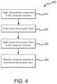
- FIG. 4illustrates a method for forming an oxidation protection system on a composite structure, in accordance with various embodiments
- FIG. 5illustrates a method for forming an oxidation protection system on a composite structure, in accordance with various embodiments.
- FIGS. 6 A and 6 Billustrate a method for forming an oxidation protection system on a composite structure, in accordance with various embodiments.
- Aircraft wheel braking assembly 10such as may be found on an aircraft, in accordance with various embodiments is illustrated.
- Aircraft wheel braking assemblymay, for example, comprise a bogie axle 12 , a wheel 14 including a hub 16 and a wheel well 18 , a web 20 , a torque take-out assembly 22 , one or more torque bars 24 , a wheel rotational axis 26 , a wheel well recess 28 , an actuator 30 , multiple brake rotors 32 , multiple brake stators 34 , a pressure plate 36 , an end plate 38 , a heat shield 40 , multiple heat shield sections 42 , multiple heat shield carriers 44 , an air gap 46 , multiple torque bar bolts 48 , a torque bar pin 50 , a wheel web hole 52 , multiple heat shield fasteners 53 , multiple rotor lugs 54 , and multiple stator slots 56 .
- FIG. 1 Billustrates a portion of aircraft wheel braking assembly 10 as viewed into wheel well
- the various components of aircraft wheel braking assembly 10may be subjected to the application of compositions and methods for protecting the components from oxidation.
- Brake diskse.g., interleaved rotors 32 and stators 34
- Rotors 32are secured to torque bars 24 for rotation with wheel 14
- stators 34are engaged with torque take-out assembly 22 .
- At least one actuator 30is operable to compress interleaved rotors 32 and stators 34 for stopping the aircraft.
- actuator 30is shown as a hydraulically actuated piston, but many types of actuators are suitable, such as an electromechanical actuator.
- Pressure plate 36 and end plate 38are disposed at opposite ends of the interleaved rotors 32 and stators 34 .
- Rotors 32 and stators 34can comprise any material suitable for friction disks, including ceramics or carbon materials, such as a carbon/carbon composite.
- Torque take-out assembly 22is secured to a stationary portion of the landing gear truck such as a bogie beam or other landing gear strut, such that torque take-out assembly 22 and stators 34 are prevented from rotating during braking of the aircraft.
- Carbon-carbon composites(also referred to herein as composite structures, composite substrates, and carbon-carbon composite structures, interchangeably) in the friction disks may operate as a heat sink to absorb large amounts of kinetic energy converted to heat during slowing of the aircraft.
- Heat shield 40may reflect thermal energy away from wheel well 18 and back toward rotors 32 and stators 34 .
- FIG. 1 Aa portion of wheel well 18 and torque bar 24 is removed to better illustrate heat shield 40 and heat shield sections 42 .
- heat shield 40is attached to wheel 14 and is concentric with wheel well 18 .
- Individual heat shield sections 42may be secured in place between wheel well 18 and rotors 32 by respective heat shield carriers 44 fixed to wheel well 18 .
- Air gap 46is defined annularly between heat shield sections 42 and wheel well 18 .
- Torque bars 24 and heat shield carriers 44can be secured to wheel 14 using bolts or other fasteners.
- Torque bar bolts 48can extend through a hole formed in a flange or other mounting surface on wheel 14 .
- Each torque bar 24can optionally include at least one torque bar pin 50 at an end opposite torque bar bolts 48 , such that torque bar pin 50 can be received through wheel web hole 52 in web 20 .
- Heat shield sections 42 and respective heat shield carriers 44can then be fastened to wheel well 18 by heat shield fasteners 53 .
- carbon-carbon compositesmay be prone to material loss from oxidation of the carbon.
- various carbon-carbon composite components of aircraft wheel braking assembly 10may experience both catalytic oxidation and inherent thermal oxidation caused by heating the composite during operation.
- composite rotors 32 and stators 34may be heated to sufficiently high temperatures that may oxidize the carbon surfaces exposed to air.
- infiltration of air and contaminantsmay cause internal oxidation and weakening, especially in and around brake rotor lugs 54 or stator slots 56 securing the friction disks to the respective torque bar 24 and torque take-out assembly 22 .
- carbon-carbon composite components of aircraft wheel braking assembly 10may retain heat for a substantial time period after slowing the aircraft, oxygen from the ambient atmosphere may react with the carbon matrix and/or carbon fibers to accelerate material loss. Further, damage to brake components may be caused by the oxidation enlargement of cracks around fibers or enlargement of cracks in a reaction-formed porous barrier coating (e.g., a silicon-based barrier coating) applied to the carbon-carbon composite.
- a reaction-formed porous barrier coatinge.g., a silicon-based barrier coating
- Elements identified in severely oxidized regions of carbon-carbon composite brake componentsinclude potassium (K) and sodium (Na). These alkali contaminants may come into contact with aircraft brakes as part of cleaning or de-icing materials. Other sources include salt deposits left from seawater or sea spray. These and other contaminants (e.g. Ca, Fe, etc.) can penetrate and leave deposits in pores of carbon-carbon composite aircraft brakes, including the substrate and any reaction-formed porous barrier coating. When such contamination occurs, the rate of carbon loss by oxidation can be increased by one to two orders of magnitude.
- brake disks of aircraft wheel braking assembly 10may reach operating temperatures in the range from about 100° C. (212° F.) up to about 900° C. (1652° F.), or higher (e.g., 1093° C. (2000° F.)).
- oxidation protection systems compositions and methods of the present disclosuremay be readily adapted to many parts in this and other braking assemblies, as well as to other carbon-carbon composite structures susceptible to oxidation losses from infiltration of atmospheric oxygen and/or catalytic contaminants.
- a method for limiting an oxidation reaction in a substratemay comprise forming an oxidation protection system on the composite structure.
- a method 200 for forming an oxidation protection system on a composite structureis illustrated.
- method 200may, for example, comprise applying an oxidation inhibiting composition to non-wearing surfaces of carbon-carbon composite brake components, such as non-wear surfaces 45 and/or lugs 54 .
- Non-wear surface 45as labeled in FIG.
- non-wear surfaces similar to non-wear surface 45may be present on any brake disks (e.g., rotors 32 , stators 34 , pressure plate 36 , end plate 38 , or the like).
- method 200may be used on the back face of pressure plate 36 and/or end plate 38 , an inner diameter (ID) surface of stators 34 including slots 56 , as well as outer diameter (OD) surfaces of rotors 32 including lugs 54 .
- the oxidation inhibiting composition of method 200may be applied to preselected regions of a carbon-carbon composite structure that may be otherwise susceptible to oxidation.
- aircraft brake disksmay have the oxidation inhibiting composition applied on or proximate stator slots 56 , rotor lugs 54 , and/or non-wear surface 45 .
- Method 200may be performed on densified carbon-carbon composites. In this regard, method 200 may be performed after carbonization and densification of the carbon-carbon composite.
- method 200may comprise forming a composite slurry (step 210 ) by combining a boron compound, a silicon compound, a glass compound, and an oxygen reactant compound with a carrier fluid (such as, for example, water).
- a carrier fluidsuch as, for example, water.
- the boron compoundmay comprise at least one boron-comprising refractory material (e.g., ceramic material).
- the boron compoundmay comprise boron carbide, titanium diboride, boron nitride, zirconium boride, silicon hexaboride, and/or elemental boron.
- the silicon compoundmay comprise silicon carbide, a silicide compound, silicon, silicon dioxide (SiO 2 ), and/or silicon carbonitride.
- the glass compoundmay be a borosilicate glass composition in the form of a glass frit.
- the borosilicate glass compositionmay comprise silicon dioxide, boron trioxide (B 2 O 3 ), and/or aluminum oxide (Al 2 O 3 ).
- the borosilicate glass compositionmay comprise in weight percentage 13% B 2 O 3 , 61% SiO 2 , 2% Al 2 O 3 , and 4% sodium oxide (Na 2 O), and may have a coefficient of thermal expansion (CTE) of 3.3 ⁇ 10 ⁇ 6 cm/C, a working point of 2286° F. (1252° C.), and an annealing point of 1040° F. (560° C.).
- the glass compoundmay comprise a lithia potash borosilicate glass composition in the form of a glass frit, powder, or other suitable pulverized form and having a CTE of 3. ⁇ 10 ⁇ 6 cm/C, a working point of 1954° F.
- the glass compoundmay comprise borophosphates, a borosilicate composition including in weight percentage, 96% SiO 2 and 4% B 2 O 3 (which is available under the trade name VYCOR® from Corning Incorporated of Corning, New York, USA), quartz, aluminosilicate, boroaluminosilicate, and/or any other suitable glass compound, which may be in the form of a glass frit, powder, or other suitable pulverized form.
- borophosphatesa borosilicate composition including in weight percentage, 96% SiO 2 and 4% B 2 O 3 (which is available under the trade name VYCOR® from Corning Incorporated of Corning, New York, USA), quartz, aluminosilicate, boroaluminosilicate, and/or any other suitable glass compound, which may be in the form of a glass frit, powder, or other suitable pulverized form.
- the oxygen reactant compoundcomprises a compound that reacts with oxygen.
- the oxygen reactant compoundtends to reduce the amount of oxygen available for oxidizing the boron component of the boron compound.
- the oxygen reactant compoundcompetes with the boron component of the boron compound for available oxygen, thereby inhibiting oxidation of the boron component.
- the oxygen reactant compoundalso reacts with oxidized boron (i.e., boron oxide) to form a glassy boron component (e.g., borosilicates, aluminoborates, borophosphates, etc.).
- oxidized boroni.e., boron oxide
- a glassy boron componente.g., borosilicates, aluminoborates, borophosphates, etc.
- the oxygen reactant compoundmay be selected from one or more silica forming components such as, for example, SiO 2 , silicon, silicon carbide, silicon oxycarbide (SiOC), silicates (e.g., sodium silicate, magnesium silicate, etc.), organosilicates (e.g., tetraethylorthosilicate); one or more alumina forming components such as, for example, aluminum oxide, aluminum hydroxide, etc.; a phosphate; a glass composition represented by the formula A′O x where A′ is selected from lithium (Li), Na, magnesium (Mg), barium (Ba), strontium (Sr), calcium (Ca), K, titanium (Ti), zirconium (Zr), and yttrium (Y); or combinations thereof.
- silica forming componentssuch as, for example, SiO 2 , silicon, silicon carbide, silicon oxycarbide (SiOC), silicates (e.g., sodium silicate, magnesium silicate, etc
- the oxygen reactant compoundmay form a 0.5% to 20.0% dry weight percentage of the composite slurry (i.e., the weight of the oxygen reactant compound is between 0.5% and 20% of the total weight of the combination of the boron compound, the silicon compound, the glass compound, and the oxygen reactant compound). In various embodiments, the oxygen reactant compound may form a 1.0% to 10.0% dry weight percentage of the composite slurry.
- the weight percentage of the boron compound, the silicon compound, the glass compound, and the oxygen reactant compound within the composite slurrymay be any suitable weight percentage.
- the composite slurrycomprises 60% to 70% by weight boron compound, silicon compound, glass compound, and oxygen reactant compound. Stated differently, in various embodiments, the composite slurry comprises 40% to 30% by weight carrier fluid. In various embodiments, the composite slurry comprises 62% to 67% by weight boron compound, silicon compound, glass compound, and oxygen reactant compound; or about a 66% by weight boron compound, silicon compound, glass compound, and oxygen reactant compound. As used in this context only, the term “about” means plus or minus one weight percent.
- the oxygen reactant compoundmay comprise a powder.
- the oxygen reactant compoundmay comprise particles having an average particle size between 20 nanometers (nm) and 20 micrometers ( ⁇ m) (between 7.9 ⁇ 10 ⁇ 7 inch and 7.9 ⁇ 10 ⁇ 4 inch), between 30 nm and 10 ⁇ m (between 1.2 ⁇ 10 ⁇ 6 inch and 3.9 ⁇ 10 ⁇ 4 inch), between 30 nm and 2.0 ⁇ m (between 1.2 ⁇ 10 ⁇ 6 inch and 7.9 ⁇ 10 ⁇ 5 inch), or between 50 nm and 0.5 ⁇ m (between 2.0 ⁇ 10 ⁇ 6 inch and 2.0 ⁇ 10 ⁇ 5 inch inch).
- the composite slurrymay comprise from 5% to 50% by weight boron compound, from 10% to 40% by weight boron compound, from 20% to 30% by weight boron compound, from 20% to 25% by weight boron compound, from 21% to 22% by weight boron compound, or about 21.1% by weight boron compound.
- the term “about”means plus or minus 1 weight percent.
- the boron compoundmay comprise a boron compound powder (e.g., boron carbide powder).
- the boron compoundcomprises particles having an average particle size between 100 nm and 100 ⁇ m (between 3.9 ⁇ 10 ⁇ 6 inch and 0.0039 inch), between 500 nm and 100 ⁇ m (between 2 ⁇ 10 ⁇ 5 inch and 0.0039 inch), between 500 nm and 1 ⁇ m (between 2 ⁇ 10 ⁇ 5 inch and 3.9 ⁇ 10 ⁇ 5 inch), between 1 ⁇ m and 50 ⁇ m (between 3.9 ⁇ 10 ⁇ 5 inch and 0.002 inch), between 1 ⁇ m and 20 ⁇ m (between 3.9 ⁇ 10 ⁇ 5 inch and 0.0008 inch), between 1 ⁇ m and 10 ⁇ m (between 3.9 ⁇ 10 ⁇ 5 inch and 0.0004 inch), about 0.7 ⁇ m (2.8 ⁇ 10 ⁇ 5 inch), about 9.3 ⁇ m (0.0004 inch), and/or about 50 ⁇ m (0.0020 inches).
- the term “about”means plus
- the boron compoundmay comprise particles of varying size. In various embodiments, the boron compound comprises a first group of particles having a first average particle size and a second group of particles having a second average particle size greater than the first average particle size.
- the particles of the first groupmay have an average particle size between 100 nm and 20 ⁇ m (between 3.9 ⁇ 10 ⁇ 6 inch and 0.0008 inch), between 500 nm and 10 ⁇ m (between 2 ⁇ 10 ⁇ 5 inch and 0.0004 inch), between 500 nm and 1.0 ⁇ m (2 ⁇ 10 ⁇ 5 inch and 3.9 ⁇ 10 ⁇ 5 inch), or about 0.7 ⁇ m (2.8 ⁇ 10 ⁇ 5 inch).
- the term “about”means plus or minus ten percent of the associated value.
- the particles of the second groupmay have an average particle size between 500 nm and 60 ⁇ m (2 ⁇ 10 ⁇ 5 inch and 0.0008 inch), 1 ⁇ m and 15 ⁇ m (between 2 ⁇ 10 ⁇ 5 and 0.0006 inch), between 8 ⁇ m and 10.0 ⁇ m (between 0.0003 inch and 0.0008 inch), between 45 ⁇ m and 55 ⁇ m (between 0.0018 inch and 0.0022 inch), about 50 ⁇ m (0.0020 inch), and/or about 9.3 ⁇ m (0.00039 inch).
- the term “about”means plus or minus ten percent of the associated value.
- the composite slurrymay comprise from 10% to 40% by weight silicon compound, from 20% to 35% by weight silicon compound, from 25% to 30% by weight silicon compound, and/or about 27.2% by weight silicon compound.
- the term “about”means plus or minus one weight percent.
- the silicon compoundmay comprise a silicon compound powder (e.g., silicon carbide powder).
- the silicon compoundcomprises particles having an average particle size between 100 nm and 50 ⁇ m (between 3.9 ⁇ 10 ⁇ 6 inch and 0.0039 inch), between 500 nm and 20 ⁇ m (between 2 ⁇ 10 ⁇ 5 inch and 0.0039 inch), between 500 nm and 1.5 ⁇ m (between 2 ⁇ 10 ⁇ 5 inch and 3.9 ⁇ 10 ⁇ 5 inch), between 15 ⁇ m and 20 ⁇ m (between 3.9 ⁇ 10 ⁇ 5 inch and 0.002 inch), about 17 ⁇ m (0.0007 inch), and/or about 1.0 ⁇ m (4 ⁇ 10 ⁇ 5 inch).
- the term “about”means plus or minus ten percent of the associated value.
- the silicon compoundmay comprise silicon compound particles of varying size.
- the silicon compoundcomprises a first group of silicon compound particles having a first average particle size and a second group of silicon compound particles having a second average particle size.
- the first silicon compound average particle sizemay be less than the second silicon compound average particle size.
- the silicon compound particles of the first grouphave an average particle size between 100 nm and 20 ⁇ m (between 3.9 ⁇ 10 ⁇ 6 inch and 0.0008 inch), 500 nm and 10 ⁇ m (between 2 ⁇ 10 ⁇ 5 and 0.0004 inch); between 500 nm and 1.5 ⁇ m (between 2 ⁇ 10 ⁇ 5 and 6 ⁇ 10 ⁇ 5 ), or about 1.0 ⁇ m (4 ⁇ 10 ⁇ 5 inch).
- the silicon compound particles of the second groupmay have an average particle size between 1 ⁇ m and 50 ⁇ m (between 4 ⁇ 10 ⁇ 5 inch and 0.002 inch), between 5 ⁇ m and 25 ⁇ m (between 0.0002 inch and 0.001), between 16 ⁇ m and 18 ⁇ m (between 0.0006 inch and 0.0007 inch), or about 17 ⁇ m (0.00067 inches).
- the term “about”means plus or minus ten percent of the associated value.
- the silicon compound particles of the first average particle sizeform a larger weight percentage of the composite slurry as compared to the weight percentage formed by the silicon compound particles of the second average particle size.
- the composite slurrymay comprise from 1% to 35% by weight glass compound, from 5% to 25% by weight glass compound, from 12% to 20% by weight glass compound, from 17% to 19% by weight glass compound, or about 18.1% by weight glass compound.
- the term “about”means plus or minus one weight percent.
- the glass compoundcomprises particles having an average particle size between 500 nm and 50 ⁇ m (between 3.9 ⁇ 10 ⁇ 6 inch and 0.0039 inch), between 5 ⁇ m and 25 ⁇ m (between 2 ⁇ 10 ⁇ 5 inch and 0.0039 inch), between 10 ⁇ m and 15 ⁇ m (between 2 ⁇ 10 ⁇ 5 inch and 3.9 ⁇ 10 ⁇ 5 inch), between 11.5 ⁇ m and 13 ⁇ m (between 3.9 ⁇ 10 ⁇ 5 inch and 0.002 inch), or about 12.3 ⁇ m (0.0004 inch).
- the term “about”means the term “about” means plus or minus ten percent of the associated value.
- the remaining weight percent of the composite slurry other than the boron compound, the silicon compound, the glass compound, and the oxygen reactant compoundmay comprise the carrier fluid and/or any other suitable additives.
- the composite slurryconsists of boron carbide, silicon carbide, borosilicate glass, silicon dioxide, and water.
- the composite slurrymay be substantially free of phosphate. In this case, “substantially free” means less than 0.01 percent by weight of the composite slurry.
- the composite slurrymay comprise about 21.1% by weight boron carbide having an average particle size of about 9.3 ⁇ m (0.0004 inch), about 27.1% by weight silicon carbide having an average particle size of about 1 ⁇ m (4 ⁇ 10 ⁇ 5 inch), about 18.1% by weight borosilicate glass having an average particle size of about 12.3 ⁇ m (0.0005 inch), between about 0.5% and 0.6% by weight silicon dioxide, and about 33.2% by weight water; the borosilicate glass being comprised, in weight percentage of the borosilicate glass, of about 13% B 2 O 3 , about 61% SiO 2 , about 2% Al 2 O 3 , and about 4% Na 2 O.
- the term “about” plus or minus ten percent of the associated valuemay comprise about 21.1% by weight boron carbide having an average particle size of about 9.3 ⁇ m (0.0004 inch), about 27.1% by weight silicon carbide having an average particle size of about 1 ⁇ m (4 ⁇ 10 ⁇ 5 inch), about 18.1% by weight boros
- method 200further comprises applying the composite slurry to a composite structure (step 220 ).
- Applying the composite slurrymay comprise, for example, spraying or brushing the composite slurry to an outer surface of the composite structure.
- the carrier fluid for the composite slurryis water tends to cause the aqueous composite slurry to be more suitable for spraying or brushing application processes.
- Any suitable manner of applying the composite slurry to the composite structureis within the scope of the present disclosure.
- the composite structuremay refer to a carbon-carbon composite structure.
- the composite slurrymay be applied directly on (i.e., in physical contact with) the surface of the composite structure.
- method 200generally does not include a pretreatment composition and/or a pretreating step and/or forming a sealing layer prior to applying the composite slurry.
- method 200may further comprise heating the composite structure to form a boron-silicon-glass-oxygen reactant layer on the composite structure (step 230 ).
- the boron-silicon-glass-oxygen reactant layermay be formed directly adjacent to the composite structure. The heating of the composite structure may remove the carrier fluid from the composite slurry to form the boron-silicon-glass-oxygen reactant layer.
- step 230may comprise heating the composite structure at a first, lower temperature followed by heating the composite structure at a second, higher temperature.
- the composite structuremay undergo a first heat treatment at a first temperature of about 150° F. (65.5° C.) to about 250° F. (121.1° C.) followed by a second heat treatment at a second temperature of about 1600° F. (871° C.) to about 1700° F. (927° C.).
- the first temperaturemay be about 200° F. (93.3° C.) and the second temperature may about 1650° F. (899° C.).
- the term “about”means plus or minus 25° F. (4° C.).
- the second temperatureis selected to be below the working point of the glass compound, for example, below the working point of the borosilicate glass in the composite slurry.
- step 230may be performed in an inert environment, such as under a blanket of inert or less reactive gas (e.g., nitrogen (N 2 ), argon, other noble gases, and the like).
- the composite structuremay be heated prior to application of composite slurry to aid in the penetration of the composite slurry.
- the temperature risemay be controlled at a rate that removes water without boiling and provides temperature uniformity throughout the composite structure.
- step 230may, for example, comprise heating the composite structure at the first temperature for 5 minutes to 8 hours, 10 minutes to 2 hours, 10 minutes to 30 minutes, or about 10 minutes, wherein the term “about” in this context only means plus or minus ten percent of the associated value.
- the compositemay be heated at the second temperature for any suitable length of time for the desired application.
- step 230may, for example, comprise heating the composite structure at the second temperature for 5 minutes to 8 hours, 0.5 hours to 4 hours, about 1.5 hours to about 2.5 hours, or about 2 hours, wherein the term “about” in this context only means plus or minus ten percent of the associated value.
- step 230may be the final step, as method 200 generally does not include a sealing layer step, as may be associated with other oxidation protection systems, for example, oxidation protection systems comprising phosphate sealing layers and/or aluminum phosphate sealing layers.
- the boron-silicon-glass-oxygen reactant layermay form an exterior surface of the oxidation protection system. Stated differently, the boron-silicon-glass-oxygen reactant layer extends from the surface of the composite substrate to the exterior surface of the oxidation protection system.
- wear surfacessuch as wear surface 33
- wear surface 33of brake disks may reach extremely high temperatures during operation (temperatures in excess of 1093° C. (2000° F.)).
- the oxidation protection systems on non-wear surfaces adjacent to the wear surfacemay experience heating.
- a “wear” surfacerefers to a surface of a friction disk that physically contacts an adjacent friction disk surface.
- a “non-wear” surfacerefers to a surface of a friction disk that does not physically contact the surface of an adjacent friction disk.
- oxygenmay diffuse through and/or travel through cracks in the boron-silicon-glass-oxygen reactant layer of the oxidation protection system and oxidize the boron compound in the boron-silicon-glass-oxygen reactant layer into boron trioxide (B 2 O 3 ).
- elevated temperaturese.g., around 1700° F. (927° C.) or 1800° F. (982° C.)
- the silicon compound in the boron-silicon-glass-oxygen reactant layermay also react (e.g., oxidize) to form silica.
- the silicamay react with the boron trioxide to form borosilicate glass.
- the borosilicate glassmay be formed in the cracks of the boron-silicon-glass-oxygen reactant layer. Therefore, the oxidation protection systems described herein have self-healing properties to protect against cracks formed in the layers of the oxidation protection systems, preventing, or mitigating against oxygen penetration and the resulting oxidation and loss of material.
- the oxygen reactant compoundmay also react (e.g., oxidize) to form, for example, additional silica, and/or alumina (i.e., aluminum oxide).
- the oxygen reactant compoundreacts with the boron trioxide forming, for example, borosilicate glass, aluminoborate glass, borophosphate glass, etc.
- the oxygen reactant compound reacting with the boron trioxidetends to decrease or eliminate unreacted boron trioxide from the boron-silicon-glass-oxygen reactant layer, thereby increasing the hydrolytic stability of the boron-silicon-glass-oxygen reactant layer.
- method 250may further comprise applying a pretreatment composition (step 215 ) prior to applying the composite slurry (step 220 ).
- step 215may, for example, comprise applying a pretreatment composition to an outer surface of a composite structure, such as a component of aircraft wheel braking assembly 10 .
- the pretreatment compositioncomprises an aluminum oxide, a silicon dioxide, or combinations thereof in water.
- the aluminum oxide and/or silicon dioxide from the pretreatment compositionmay react with the boron trioxide, which may form in the boron-silicon-glass-oxygen reactant layer at elevated temperatures.
- the aluminum oxide and/or silicon dioxide reacting with the boron trioxidetends to decrease or eliminate unreacted boron trioxide from the boron-silicon-glass-oxygen reactant layer, thereby increasing the water stability of the boron-silicon-glass-oxygen reactant layer.
- migration of free boron oxide to the wear surfaceis limited due to reaction with the pretreatment composition.
- Boric acidis a lubricant; thus, it is desirable to eliminate any mobilization of such species to the wear surface.
- method 300may, for example, comprise applying an oxidation inhibiting composition to non-wearing surfaces of carbon-carbon composite brake components, such as non-wear surfaces 45 and/or lugs 54 .
- the oxidation inhibiting composition of method 300may be applied to preselected regions of a carbon-carbon composite structure that may be otherwise susceptible to oxidation.
- aircraft brake disksmay have the oxidation inhibiting composition applied on non-wear surfaces 45 .
- Method 300may be performed on densified carbon-carbon composites. In this regard, method 300 may be performed after carbonization and densification of the carbon-carbon composite.
- method 300may comprise forming a boron slurry (step 310 ) by combining a boron compound, a glass compound, and an oxygen reactant compound with a carrier fluid (such as, for example, water).
- a carrier fluidsuch as, for example, water
- the boron compoundmay comprise at least one boron-comprising refractory material (e.g., ceramic materials).
- the boron compoundmay comprise titanium diboride, boron nitride, boron carbide, zirconium boride, silicon hexaboride, and/or elemental boron.
- the glass compoundmay comprise a borosilicate glass.
- the oxygen reactant compoundmay be selected from one or more silica forming components, one or more alumina forming components, a phosphate, a glass composition represented by the formula A′O x where A′ is selected from Li, Na, Mg, Ba, Sr, Ca, K, Ti, Zr, and Y, or combinations thereof.
- the oxygen reactant compoundmay form 0.5% to 20.0% of the dry weight percentage of the composite slurry (i.e., the weight of the oxygen reactant compound is between 0.5% and 20% of the total weight of the combination of the boron compound, the glass compound, and the oxygen reactant compound). In various embodiments, the oxygen reactant compound may form a 1.0% to 10.0% dry weight percentage of the boron slurry.
- the boron slurrymay comprise from 5% to 50% by weight boron compound, from 15% to 40% by weight boron compound, from 30% to 40% by weight boron compound, or about 35% by weight boron compound.
- the term “about”means plus or minus 1 weight percent.
- the boron compoundmay comprise a boron compound powder (e.g., boron carbide powder) comprising particles as described previously with regard to method 200 .
- the boron compoundmay comprise particles of varying size as previously with regard to method 200 .
- the boron compoundcomprises a first group of particles having a first average particle size, as previously with regard to method 200 , and a second group of particles having a second average particle size, as previously with regard to method 200 , that is greater than the first average particle size.
- the boron compound particles of the second average particle sizeform a larger weight percentage of the boron slurry as compared to the weight percentage formed by the boron compound particles of the first size.
- the glass compound of the boron slurrymay comprise a borosilicate glass composition, borophosphate, quartz, aluminosilicate, boroaluminosilicate, and/or any other suitable glass compound, which may be in the form of a glass frit, powder, or other suitable pulverized form.
- the borosilicate glass compositionmay comprise in weight percentage 13% B 2 O 3 , 61% SiO 2 , 2% Al 2 O 3 , and 4% sodium oxide (Na 2 O), and may have a CTE of 3.3 ⁇ 10 ⁇ 6 cm/C, a working point of 2286° F. (1252° C.), and an annealing point of 1040° F. (560° C.).
- the boron slurrymay comprise from 1% to 35% by weight glass compound, from 5% to 15% by weight glass compound, or about 10% by weight glass compound.
- the term “about”means plus or minus one weight percent.
- method 300further comprises applying the boron slurry to a composite structure (step 320 ).
- Applying the boron slurrymay comprise, for example, spraying or brushing the boron slurry to an outer surface of the composite structure. Any suitable manner of applying the boron slurry to the composite structure is within the scope of the present disclosure.
- the composite structuremay refer to a carbon-carbon composite structure.
- the boron slurrymay be applied directly on (i.e., in physical contact with) the surface of the composite structure.
- method 300generally does not include a pretreatment composition and/or a pretreating step and/or forming a sealing layer prior to applying the boron slurry or the silicon slurry.
- method 300may further comprise performing a first low temperature bake (step 330 ).
- Step 330may include heating the composite structure at a relatively low temperature (for example, a temperature of about 250° F. (121° C.) to about 350° F. (177° C.), or at about 300° F. (149° C.), wherein the term “about” in this context only means plus or minus 25° F. (4° C.)).
- Step 330may include heating the composite structure for about 5 minutes to 8 hours, about 10 minutes to 2 hours, or about 1 hour, wherein the term “about” in this context only means plus or minus ten percent of the associated value.
- method 300may comprise forming a silicon slurry (step 340 ) by combining a silicon compound, a glass compound, and an oxygen reactant compound with a carrier fluid (such as, for example, water).
- a carrier fluidsuch as, for example, water.
- the silicon compoundmay comprise silicon carbide, a silicide compound, silicon, silicon dioxide, and/or silicon carbonitride.
- the glass compoundmay comprise a borosilicate glass composition, borophosphate, quartz, aluminosilicate, boroaluminosilicate, and/or any other suitable glass compound, which may be in the form of a glass frit, powder, or other suitable pulverized form.
- the borosilicate glass compositionmay comprise in weight percentage 13% B 2 O 3 , 61% SiO 2 , 2% Al 2 O 3 , and 4% sodium oxide (Na 2 O), and may have a CTE of 3.3 ⁇ 10 ⁇ 6 cm/C, a working point of 2286° F. (1252° C.), and an annealing point of 1040° F. (560° C.).
- the oxygen reactant compoundmay be selected from one or more silica forming components, one or more alumina forming components, a phosphate, a glass composition represented by the formula A′O x where A′ is selected from Li, Na, Mg, Ba, Sr, Ca, K, Ti, Zr, and Y, or combinations thereof.
- the oxygen reactant compoundmay form a 0.5% to 20.0% dry weight percentage of the composite slurry (i.e., the weight of the oxygen reactant compound is between 0.5% and 20% of the total weight of the combination of the boron compound, the glass compound, and the oxygen reactant compound). In various embodiments, the oxygen reactant compound may form a 1.0% to 10.0% dry weight percentage of the boron slurry.
- method 300describes forming both the boron slurry and the silicon slurry including an oxygen reactant compound, it is further contemplated and understood that oxygen reactant compound may be eliminated from either the boron slurry or the silicon slurry. In this regard, in various embodiments, method 300 may include forming either the boron slurry or the silicon slurry including an oxygen reactant compound.
- the silicon slurrymay comprise from 10% to 70% by weight silicon compound, from 20% to 55% by weight silicon compound, from 40% to 50% by weight silicon compound, or about 45% by weight silicon compound.
- the term “about”means plus or minus 2 weight percent.
- the silicon compoundmay comprise a silicon compound powder (e.g., silicon carbide powder) comprising particles, as described previously with regard to method 200 .
- the silicon compoundmay comprise silicon compound particles of varying size, as described previously with regard to method 200 .
- the silicon compoundcomprises a first group of silicon compound particles having a first average particle size, as described previously with regard to method 200 , and a second group of silicon compound particles having a second average particle size, as described previously with regard to method 200 .
- the first silicon compound average particle sizemay be less than the second silicon compound average particle size.
- the silicon compound particles of the first average particle sizeform a larger weight percentage of the silicon slurry as compared to the weight percentage formed by the silicon compound particles of the second average particle size.
- the silicon slurrymay comprise from 1% to 35% by weight glass compound, from 5% to 15% by weight glass compound, or about 10% by weight glass compound.
- the term “about”means plus or minus one weight percent.
- method 300further comprises applying the silicon slurry to the composite structure (step 350 ).
- the silicon slurrymay be applied over the boron compound of the boron slurry and after the low temperature bake of step 330 .
- the only heat treatment between application of the boron slurry (step 320 ) and the application of the silicon slurry (step 350 )may be the first low temperature bake (step 330 ).
- Applying the silicon slurrymay comprise, for example, spraying or brushing the boron slurry to an outer surface of the composite structure. Any suitable manner of applying the silicon slurry to the composite structure is within the scope of the present disclosure.
- the composite structuremay refer to a carbon-carbon composite structure.
- method 300may further comprise performing a second low temperature bake (step 360 ).
- Step 360may include heating the composite structure at a relatively low temperature (for example, a temperature of about 250° F. (121° C.) to about 350° F. (177° C.), or at about 300° F. (149° C.), wherein the term “about” in this context only means plus or minus 25° F. (4° C.)).
- Step 360may include heating the composite structure for about 5 minutes to 8 hours, about 10 minutes to 2 hours, or about 1 hour, wherein the term “about” in this context only means plus or minus ten percent of the associated value.
- method 300may further comprise performing a high temperature heat treatment to form a boron-oxygen reactant layer and a silicon-oxygen reactant layer on the composite structure (step 370 ).
- Step 370may include heating the composite structure at a relatively high temperature, for example, a temperature of about 1500° F. (816° C.) to about 1700° F. (927° C.), or at about 1650° F. (899° C.), wherein the term “about” in this context only means plus or minus 25° F. (4° C.)).
- Step 370may include heating the composite structure for about 5 minutes to 8 hours, about 30 minutes to 5 hours, or about 2 hours, wherein the term “about” in this context only means plus or minus ten percent of the associated value.
- Step 370is performed after the second low temperature bake (step 360 ).
- boron componentsmay become oxidized during service at high temperatures (e.g., temperatures greater than 1300° F. (704° C.)), thereby forming boron trioxide.
- the boron trioxidemay come into contact with oxidized silicon components to form a borosilicate in situ, providing a method of self-healing.
- the probability of boron trioxide reacting with oxidized silicon compoundsis kinetically controlled and influenced by the amount of each component, surface area, aspect ratio, etc. Boron trioxide is also volatile, especially when hydrated to form boric acid, and may be lost during extended service time.
- Method 300tends to increase the probability of self-healing borosilicate formation by creating a layer of silicon compound by which boron trioxide must transport through prior to volatilization, reducing the dependence on aspect ratio and total amount of components in the slurry.
- the oxygen reactant compound in the boron-oxygen reactant layer and/or silicon-oxygen reactant layermay also react (e.g., oxidize) to form, for example, additional silica, and/or alumina (i.e., aluminum oxide).
- the oxygen reactant compoundmay also react with the boron trioxide forming, for example, borosilicate glass, aluminoborate glass, borophosphate glass, etc.
- the oxygen reactant compound reacting with the boron trioxidetends to decrease or eliminate unreacted boron trioxide, thereby increasing the water stability of the oxidation protection system.
- method 390may comprise applying a pretreatment composition to the composite structure (step 315 ) prior to applying the boron slurry (step 320 ).
- Step 315may, for example, comprise applying a pretreatment composition to an outer surface of a composite structure, such as a component of aircraft wheel braking assembly 10 .
- the pretreatment compositioncomprises an aluminum oxide, a silicon dioxide, or combinations thereof in water.
- the aluminum oxidemay comprise a nanoparticle dispersion of aluminum oxide and/or a nanoparticle dispersion of silicon dioxide.
- the pretreatment compositionmay further comprise a surfactant or a wetting agent.
- the composite structureis heated to remove water and fix the aluminum oxide and/or silicon dioxide in place.
- the composite structuremay be heated between about 100° C. (212° F.) and 200° C. (392° F.) or between 100° C. (212° F.) and 150° C. (302° F.).
- method 390may include applying the boron slurry (step 320 ) after applying the pretreatment composition.
- the aluminum oxide and/or silicon dioxide from the pretreatment compositionmay react with the boron trioxide, which may form in the boron-oxygen reactant layer at elevated temperatures.
- the aluminum oxide and/or silicon dioxide reacting with the boron trioxidetends to decrease or eliminate unreacted boron trioxide, thereby increasing the water stability of the oxidation protection system.
- method 400may, for example, comprise applying an oxidation inhibiting composition to non-wearing surfaces of carbon-carbon composite brake components, such as non-wear surfaces 45 and/or lugs 54 in FIG. 1 A .
- Method 400may be performed on densified carbon-carbon composites. In this regard, method 400 may be performed after carbonization and densification of the carbon-carbon composite.
- method 400may comprise applying a pretreatment composition to an outer surface of a composite structure (step 410 ).
- the composite structuremay be a component of aircraft wheel braking assembly 10 in FIG. 1 A .
- the pretreatment compositioncomprises an aluminum oxide, a silicon dioxide, or combinations thereof in water.
- the aluminum oxidemay comprise a nanoparticle dispersion of aluminum oxide and/or a nanoparticle dispersion of silicon dioxide.
- the pretreatment compositionmay further comprise a surfactant or a wetting agent.
- the composite structureis heated to remove water and fix the aluminum oxide and/or silicon dioxide in place.
- the composite structuremay be heated between about 100° C. (212° F.) and 200° C. (392° F.), between 100° C. (212° F.) and 150° C. (302° F.).
- Method 400may further includes forming a boron-silicon-glass slurry (step 420 ) by combining a boron compound, a silicon compound, and a glass compound with a carrier fluid (such as, for example, water).
- a carrier fluidsuch as, for example, water.
- the boron compoundmay comprise at least one boron-comprising refractory material (e.g., ceramic material).
- the boron compoundmay comprise boron carbide, titanium diboride, boron nitride, zirconium boride, silicon hexaboride, and/or elemental boron.
- the silicon compoundmay comprise silicon carbide, a silicide compound, silicon, silicon dioxide, or silicon carbonitride.
- the glass compoundmay be a borosilicate glass composition, borophosphate, quartz, aluminosilicate, boroaluminosilicate, and/or any other suitable glass compound, which may be in the form of a glass frit, powder, or other suitable pulverized form.
- the borosilicate glass compositionmay comprise in weight percentage 13% B 2 O 3 , 61% SiO 2 , 2% Al 2 O 3 , and 4% sodium oxide (Na 2 O), and may have a CTE of 3.3 ⁇ 10 ⁇ 6 cm/C, a working point of 2286° F. (1252° C.), and an annealing point of 1040° F. (560° C.).
- the composite slurrymay comprise from 5% to 50% by weight boron compound, from 10% to 40% by weight boron compound, from 20% to 30% by weight boron compound, from 20% to 25% by weight boron compound, from 21% to 22% by weight boron compound, or about 21.2% by weight boron compound.
- the term “about”means plus or minus 1 weight percent.
- the boron compoundmay comprise a boron compound powder (e.g., boron carbide powder) with particles having an average particle size as previously described with respect to method 200 .
- the boron compoundmay comprise particles of varying size as previously described with respect to method 200 .
- the boron compoundcomprises a first group of particles having a first average particle size and a second group of particles having a second average particle size greater than the first average particle size.
- the particles of the first groupmay have an average particle size between 100 nm and 20 ⁇ m (between 3.9 ⁇ 10 ⁇ 6 inch and 0.0008 inch), between 500 nm and 10 ⁇ m (between 2 ⁇ 10 ⁇ 5 inch and 0.0004 inch), between 500 nm and 1.0 ⁇ m (2 ⁇ 10 ⁇ 5 inch and 3.9 ⁇ 10 ⁇ 5 inch), or about 0.7 ⁇ m (2.8 ⁇ 10 ⁇ 5 inch).
- the term “about”means plus or minus ten percent of the associated value.
- the particles of the second groupmay have an average particle size between 500 nm and 60 ⁇ m (2 ⁇ 10 ⁇ 5 inch and 0.0008 inch), 1 ⁇ m and 15 ⁇ m (between 2 ⁇ 10 ⁇ 5 and 0.0006 inch), between 8 ⁇ m and 10.0 ⁇ m (between 0.0003 inch and 0.0008 inch), between 45 ⁇ m and 55 ⁇ m (between 0.0018 inch and 0.0022 inch), about 50 ⁇ m (0.0020 inch), and/or about 9.3 ⁇ m (0.00039 inch).
- the term “about”means plus or minus ten percent of the associated value.
- the boron compound particles of the second average particle sizeform a larger weight percentage of the boron-silicon-glass slurry as compared to the weight percentage formed by the boron compound particles of the first average size.
- the boron-silicon-glass slurrymay comprise from 0% to 20% by weight the boron compound first average particle size, 5% to 8% by weight the boron compound first average particle size, about 6.36% by weight the first boron compound average particle size, or about 7.24% by weight the first boron compound average particle size.
- the term “about”means plus or minus 0.5% weight percent.
- the boron-silicon-glass slurrymay comprise from 5% to 30% by weight the second boron compound average particle size, 10% to 25% by weight the second boron compound average particle size, 14% to 23% by weight the second boron compound average particle size, about 14.9% by weight the second boron compound average particle size about 16.9% by weight the second boron compound average particle size, or about 21.2% by weight the second boron compound average particle size.
- the term “about”means plus or minus 0.5% weight percent.
- the boron-silicon-glass slurrymay comprise from 10% to 40% by weight silicon compound, from 25% to 35% by weight silicon compound, from 27% to 32% by weight silicon compound, about 27.3% by weight silicon compound, or about 31.0% by weight silicon compound.
- the term “about”means plus or minus one weight percent.
- the silicon compoundmay comprise a silicon compound powder (e.g., silicon carbide powder) with particles having an average particle size as described previously with regard to method 200 .
- a silicon compound powdere.g., silicon carbide powder
- the silicon compoundmay comprise silicon compound particles of varying size.
- the silicon compoundcomprises a first group of silicon compound particles having a first average particle size and a second group of silicon compound particles having a second average particle size.
- the first silicon compound average particle sizemay be less than the second silicon compound average particle size.
- the silicon compound particles of the first grouphave an average particle size between 100 nm and 20 ⁇ m (between 3.9 ⁇ 10 ⁇ 6 inch and 0.0008 inch), 500 nm and 10 ⁇ m (between 2 ⁇ 10 ⁇ 5 and 0.0004 inch); between 500 nm and 1.5 ⁇ m (between 2 ⁇ 10 ⁇ 5 and 6 ⁇ 10 ⁇ 5 ), or about 1.0 ⁇ m (4 ⁇ 10 ⁇ 5 inch).
- the silicon compound particles of the second groupmay have an average particle size between 1 ⁇ m and 50 ⁇ m (between 4 ⁇ 10 ⁇ 5 inch and 0.002 inch), between 5 ⁇ m and 25 ⁇ m (between 0.0002 inch and 0.001), between 16 ⁇ m and 18 ⁇ m (between 0.0006 inch and 0.0007 inch), or about 17 ⁇ m (0.00067 inches).
- the term “about”means plus or minus ten percent of the associated value.
- the silicon compound particles of the first average particle sizeform a larger weight percentage of the boron-silicon-glass composite slurry as compared to the weight percentage formed by the silicon compound particles of the second average particle size.
- the boron-silicon-glass slurrymay comprise from 0% to 30% by weight the second silicon compound average particle size, 0% to 25% by weight the second silicon compound average particle size, or about 9.3% by weight the second silicon compound average particle size. As used in this context only, the term “about” means plus or minus 1% weight percent.
- the boron-silicon-glass slurrymay comprise from 5% to 40% by weight the first silicon compound average particle size, 10% to 35% by weight the first silicon compound average particle size, 20% to 30% by weight the first silicon compound average particle size, about 21.7% by weight the second silicon compound average particle size, about 27.3% by weight the second silicon compound average particle size, or about 29.0% by weight the second silicon compound average particle size.
- the term “about”means plus or minus 1% weight percent.
- the boron-silicon-glass slurrymay comprise from 1% to 35% by weight glass compound, from 5% to 30% by weight glass compound, from 12% to 20% by weight glass compound, from 17% to 19% by weight glass compound, or about 18.2% by weight glass compound.
- the term “about”means plus or minus one weight percent.
- the glass compoundcomprises particles, the average particle size may be between 500 nm and 50 ⁇ m (between 3.9 ⁇ 10 ⁇ 6 inch and 0.0039 inch), between 5 ⁇ m and 25 ⁇ m (between 2 ⁇ 10 ⁇ 5 inch and 0.0039 inch), between 10 ⁇ m and 15 ⁇ m (between 2 ⁇ 10 ⁇ 5 inch and 3.9 ⁇ 10 ⁇ 5 inch), between 11.5 ⁇ m and 13 ⁇ m (between 3.9 ⁇ 10 ⁇ 5 inch and 0.002 inch), or about 12.3 ⁇ m (0.0004 inch).
- the term “about”means the term “about” means plus or minus ten percent of the associated value.
- the remaining weight percent of the boron-silicon-glass composite slurry other than the boron compound, the silicon compound, and the glass compoundmay comprise the carrier fluid and/or any other suitable additives.
- the boron-silicon-glass slurryconsists of boron carbide, silicon carbide, borosilicate glass, and water.
- the boron-silicon-glass slurrymay be substantially free of phosphate. In this case, “substantially free” means less than 0.01 percent by weight of the composite slurry.
- the boron-silicon-glass slurrymay comprise about 21.2% by weight boron carbide having an average particle size of about 9.3 ⁇ m (0.0004 inch), about 27.3% by weight silicon carbide having an average particle size of about 1 ⁇ m (4 ⁇ 10 ⁇ 5 inch), about 18.2% by weight borosilicate glass having an average particle size of about 12.3 ⁇ m (0.0005 inch), and about 33.3% by weight water; the borosilicate glass being comprised, in weight percentage of the borosilicate glass, of about 13% B 2 O 3 , about 61% SiO 2 , about 2% Al 2 O 3 , and about 4% Na 2 O.
- the term “about” plus or minus ten percent of the associated valuemay comprise about 21.2% by weight boron carbide having an average particle size of about 9.3 ⁇ m (0.0004 inch), about 27.3% by weight silicon carbide having an average particle size of about 1 ⁇ m (4 ⁇ 10 ⁇ 5 inch), about 18.2% by weight borosilicate glass having an
- method 400further comprises applying the boron-silicon-glass slurry to a composite structure (step 430 ).
- Applying the boron-silicon-glass slurrymay comprise, for example, spraying or brushing the composite slurry to an outer surface of the composite structure.
- the carrier fluid for the composite slurryis water tends to cause the aqueous composite slurry to be more suitable for spraying or brushing application processes. Any suitable manner of applying the composite slurry to the composite structure is within the scope of the present disclosure.
- the composite structuremay refer to a carbon-carbon composite structure.
- the boron-silicon-glass slurrymay be applied over the aluminum oxide and/or silicon dioxide of the pretreatment composition.
- method 400may further comprise heating the composite structure to form a boron-silicon-glass layer on the composite structure (step 440 ).
- Step 440may remove the carrier fluid from the boron-silicon-glass slurry to form the boron-silicon-glass layer.
- step 440may comprise heating the composite structure at a first, lower temperature followed by heating the composite structure at a second, higher temperature.
- the composite structuremay undergo a first heat treatment at a first temperature of about 150° F. (65.5° C.) to about 250° F. (121.1° C.) followed by a second heat treatment at a second temperature of about 1600° F. (871° C.) to about 1700° F. (927° C.).
- the first temperaturemay be about 200° F. (93.3° C.) and the second temperature may about 1650° F. (899° C.).
- the term “about”means plus or minus 25° F. (4° C.).
- the second temperatureis selected to be below the working point of the glass compound, for example, below the working point of the borosilicate glass in the composite slurry.
- step 440may be performed in an inert environment, such as under a blanket of inert or less reactive gas (e.g., nitrogen (N 2 ), argon, other noble gases, and the like).
- the composite structuremay be heated prior to application of composite slurry to aid in the penetration of the composite slurry.
- the temperature risemay be controlled at a rate that removes water without boiling and provides temperature uniformity throughout the composite structure.
- step 440may, for example, comprise heating the composite structure at the first temperature for 5 minutes to 8 hours, 10 minutes to 2 hours, 10 minutes to 30 minutes, or about 10 minutes, wherein the term “about” in this context only means plus or minus ten percent of the associated value.
- the compositemay be heated at the second temperature for any suitable length of time for the desired application.
- step 440may, for example, comprise heating the composite structure at the second temperature for 5 minutes to 8 hours, 0.5 hours to 4 hours, about 1.5 hours to about 2.5 hours, or about 2 hours, wherein the term “about” in this context only means plus or minus ten percent of the associated value.
- step 440may be the final step, as method 400 generally does not include a sealing layer step, as may be associated with other oxidation protection systems, for example, oxidation protection systems comprising phosphate sealing layers and/or aluminum phosphate sealing layers.
- oxidation protection systemscomprising phosphate sealing layers and/or aluminum phosphate sealing layers.
- the boron-silicon-glass layermay form an exterior surface of the oxidation protection system.
- boron componentsmay become oxidized during service at high temperatures (e.g., temperatures greater than 1300° F. (704° C.)), thereby forming boron trioxide.
- the boron trioxidemay come into contact with oxidized silicon components to form a borosilicate in situ, providing a method of self-healing.
- the aluminum oxide and/or silicon dioxide from the pretreatment compositionmay also react with the boron trioxide, which may form in the boron-silicon-glass layer at elevated temperatures.
- the aluminum oxide and/or silicon dioxide reacting with the boron trioxidetends to decrease or eliminate unreacted boron trioxide, thereby increasing the water stability of the oxidation protection system.
- method 500may, for example, comprise applying an oxidation inhibiting composition to non-wearing surfaces of carbon-carbon composite brake components, such as non-wear surfaces 45 and/or lugs 54 in FIG. 1 A .
- the oxidation inhibiting composition of method 500may be applied to preselected regions of a carbon-carbon composite structure that may be otherwise susceptible to oxidation.
- Method 500may be performed on densified carbon-carbon composites. In this regard, method 500 may be performed after carbonization and densification of the carbon-carbon composite.
- method 500may comprise applying a pretreatment composition to an outer surface of a composite structure (step 505 ).
- the composite structuremay be a component of aircraft wheel braking assembly 10 in FIG. 1 A .
- the pretreatment compositioncomprises an aluminum oxide, a silicon dioxide, or combinations thereof in water.
- the aluminum oxidemay comprise a nanoparticle dispersion of aluminum oxide and/or a nanoparticle dispersion of silicon dioxide.
- the pretreatment compositionmay further comprise a surfactant or a wetting agent.
- the composite structureis heated to remove water and fix the aluminum oxide and/or silicon dioxide in place.
- the composite structuremay be heated between about 100° C. (212° F.) and 200° C. (392° F.), between 100° C. (212° F.) and 150° C. (302° F.).
- Method 500may further includes forming a boron slurry (step 510 ) by combining a boron compound and a glass compound with a carrier fluid (such as, for example, water).
- a carrier fluidsuch as, for example, water.
- the boron compoundmay comprise at least one boron-comprising refractory material (e.g., ceramic materials).
- the boron compoundmay comprise titanium diboride, boron nitride, boron carbide, zirconium boride, silicon hexaboride, and/or elemental boron.
- the glass compoundmay comprise a borosilicate glass.
- the boron-silicon-glass composite slurrymay comprise from 5% to 50% by weight boron compound, from 15% to 40% by weight boron compound, from 30% to 40% by weight boron compound, or about 35% by weight boron compound.
- the term “about”means plus or minus 1 weight percent.
- the boron compoundmay comprise a boron compound powder (e.g., boron carbide powder) with particles having an average particle size as described previous with respect to method 200 .
- the boron compoundmay comprise particles of varying size.
- the boron compoundcomprises a first group of particles having a first average particle size and a second group of particles having a second average particle size greater than the first average particle size.
- the particles of the first groupmay have an average particle size between 100 nm and 20 ⁇ m (between 3.9 ⁇ 10 ⁇ 6 inch and 0.0008 inch), between 500 nm and 10 ⁇ m (between 2 ⁇ 10 ⁇ 5 inch and 0.0004 inch), between 500 nm and 1.0 ⁇ m (2 ⁇ 10 ⁇ 5 inch and 3.9 ⁇ 10 ⁇ 5 inch), or about 0.7 ⁇ m (2.8 ⁇ 10 ⁇ 5 inch).
- the term “about”means plus or minus ten percent of the associated value.
- the particles of the second groupmay have an average particle size between 500 nm and 60 ⁇ m (2 ⁇ 10 ⁇ 5 inch and 0.0008 inch), 1 ⁇ m and 15 ⁇ m (between 2 ⁇ 10 ⁇ 5 and 0.0006 inch), between 8 ⁇ m and 10.0 ⁇ m (between 0.0003 inch and 0.0008 inch), between 45 ⁇ m and 55 ⁇ m (between 0.0018 inch and 0.0022 inch), about 50 ⁇ m (0.0020 inch), and/or about 9.3 ⁇ m (0.00039 inch).
- the term “about”means plus or minus ten percent of the associated value.
- the boron compound particles of the second average particle sizeform a larger weight percentage of the boron slurry as compared to the weight percentage formed by the boron compound particles of the first size.
- the boron-silicon-glass composite slurrymay comprise from 0% to 20% by weight the boron compound first average particle size, 5% to 15% by weight the boron compound first average particle size, or about 10.5% by weight the first boron compound average particle size.
- the term “about”means plus or minus 0.5% weight percent.
- the boron slurrymay comprise from 5% to 50% by weight the second boron compound average particle size, 10% to 30% by weight the second boron compound average particle size, 20% to 25% by weight the second boron compound average particle size, or about 24.5% by weight the second boron compound average particle size.
- the term “about”means plus or minus 0.5% weight percent.
- the glass compound of the boron slurrymay be a borosilicate glass composition, borophosphate, quartz, aluminosilicate, boroaluminosilicate, and/or any other suitable glass compound, which may be in the form of a glass frit, powder, or other suitable pulverized form.
- the borosilicate glass compositionmay comprise in weight percentage 13% B 2 O 3 , 61% SiO 2 , 2% Al 2 O 3 , and 4% sodium oxide (Na 2 O), and may have a CTE of 3.3 ⁇ 10 ⁇ 6 cm/C, a working point of 2286° F. (1252° C.), and an annealing point of 1040° F. (560° C.).
- the boron-slurrymay comprise from 1% to 35% by weight glass compound, from 5% to 15% by weight glass compound, or about 10% by weight glass compound.
- the term “about”means plus or minus 0.5 weight percent.
- the glass compoundcomprises particles, the average particle size may be between 500 nm and 50 ⁇ m (between 3.9 ⁇ 10 ⁇ 6 inch and 0.0039 inch), between 5 ⁇ m and 25 ⁇ m (between 2 ⁇ 10 ⁇ 5 inch and 0.0039 inch), between 10 ⁇ m and 15 ⁇ m (between 2 ⁇ 10 ⁇ 5 inch and 3.9 ⁇ 10 ⁇ 5 inch), between 11.5 ⁇ m and 13 ⁇ m (between 3.9 ⁇ 10 ⁇ 5 inch and 0.002 inch), or between about 12.3 ⁇ m (0.0004 inch).
- the term “about”means plus or minus 0.5 weight percent.
- method 500further comprises applying the boron slurry to a composite structure (step 520 ).
- Applying the boron slurrymay comprise, for example, spraying or brushing the boron slurry to an outer surface of the composite structure. Any suitable manner of applying the boron-slurry to the composite structure is within the scope of the present disclosure.
- the composite structuremay refer to a carbon-carbon composite structure.
- the boron slurrymay be applied over the aluminum oxide and/or silicon dioxide of the pretreatment composition.
- method 500may further comprise performing a first low temperature bake (step 530 ).
- Step 530may include heating the composite structure at a relatively low temperature (for example, a temperature of about 250° F. (121° C.) to about 350° F. (177° C.), or at about 300° F. (149° C.), wherein the term “about” in this context only means plus or minus 25° F. (4° C.)).
- Step 530may include heating the composite structure for about 5 minutes to 8 hours, about 10 minutes to 2 hours, or about 1 hour, wherein the term “about” in this context only means plus or minus ten percent of the associated value.
- method 500may comprise forming a silicon slurry (step 540 ) by combining a silicon compound and a glass compound with a carrier fluid (such as, for example, water).
- a carrier fluidsuch as, for example, water.
- the silicon compoundmay comprise silicon carbide, a silicide compound, silicon, silicon dioxide, and/or silicon carbonitride.
- the weight percentage of the silicon compound within the silicon slurrymay be any suitable weight percentage for the desired application.
- the silicon slurrymay comprise from 10% to 70% by weight silicon compound, from 20% to 55% by weight silicon compound, from 40% to 50% by weight silicon compound, or about 45% by weight silicon compound.
- the term “about”means plus or minus 2 weight percent.
- the silicon compoundmay comprise a silicon compound powder (e.g., silicon carbide powder) including particles having an average particle size as described previously with respect to method 200 .
- the silicon compoundmay comprise silicon compound particles of varying size.
- the silicon compoundcomprises a first group of silicon compound particles having a first average particle size and a second group of silicon compound particles having a second average particle size. The first silicon compound average particle size may be less than the second silicon compound average particle size.
- the silicon compound particles of the first grouphave an average particle size between 100 nm and 20 ⁇ m (between 3.9 ⁇ 10 ⁇ 6 inch and 0.0008 inch), 500 nm and 10 ⁇ m (between 2 ⁇ 10 ⁇ 5 and 0.0004 inch); between 500 nm and 1.5 ⁇ m (between 2 ⁇ 10 ⁇ 5 and 6 ⁇ 10 ⁇ 5 ), or about 1.0 ⁇ m (4 ⁇ 10 ⁇ 5 inch).
- the silicon compound particles of the second groupmay have an average particle size between 1 ⁇ m and 50 ⁇ m (between 4 ⁇ 10 ⁇ 5 inch and 0.002 inch), between 5 ⁇ m and 25 ⁇ m (between 0.0002 inch and 0.001), between 16 ⁇ m and 18 ⁇ m (between 0.0006 inch and 0.0007 inch), or about 17 ⁇ m (0.00067 inches).
- the term “about”means plus or minus ten percent of the associated value.
- the silicon compound particles of the first average particle sizeform a larger weight percentage of the boron-silicon-glass composite slurry as compared to the weight percentage formed by the silicon compound particles of the second average particle size.
- the silicon slurrymay comprise from 0% to 30% by weight the second silicon compound average particle size, 0% to 20% by weight the second silicon compound average particle size, or about 13% by weight the second silicon compound average particle size.
- the term “about”means plus or minus 1% weight percent.
- the silicon slurrymay comprise from 5% to 80% by weight the first silicon compound average particle size, 20% to 60% by weight the first silicon compound average particle size, 30% to 50% by weight the first silicon compound average particle size, about 31.5% by weight the second silicon compound average particle size, or about 45.0% by weight the second silicon compound average particle size.
- the term “about”means plus or minus 1% weight percent.
- the glass compound of the silicon slurrymay be a borosilicate glass composition, borophosphate, quartz, aluminosilicate, boroaluminosilicate, and/or any other suitable glass compound, which may be in the form of a glass frit, powder, or other suitable pulverized form.
- the borosilicate glass compositionmay comprise in weight percentage 13% B 2 O 3 , 61% SiO 2 , 2% Al 2 O 3 , and 4% sodium oxide (Na 2 O), and may have a CTE of 3.3 ⁇ 10 ⁇ 6 cm/C, a working point of 2286° F. (1252° C.), and an annealing point of 1040° F. (560° C.).
- the silicon slurrymay comprise from 1% to 35% by weight glass compound, from 5% to 15% by weight glass compound, or about 10% by weight glass compound.
- the term “about”means plus or minus 0.5 weight percent.
- the glass compoundcomprises particles having an average particle size of between 500 nm and 50 ⁇ m (between 3.9 ⁇ 10 ⁇ 6 inch and 0.0039 inch), between 5 ⁇ m and 25 ⁇ m (between 2 ⁇ 10 ⁇ 5 inch and 0.0039 inch), between 10 ⁇ m and 15 ⁇ m (between 2 ⁇ 10 ⁇ 5 inch and 3.9 ⁇ 10 ⁇ 5 inch), between 11.5 ⁇ m and 13 ⁇ m (between 3.9 ⁇ 10 ⁇ 5 inch and 0.002 inch), or about 12.3 ⁇ m (0.0004 inch).
- the term “about”means plus or minus 0.5 weight percent.
- method 500further comprises applying the silicon slurry to the composite structure (step 550 ).
- the silicon slurrymay be applied over the boron compound of the boron slurry and after the low temperature bake of step 530 .
- the only heat treatment between application of the boron slurry (step 520 ) and the application of the silicon slurry (step 550 )may be the first low temperature bake (step 530 ).
- Applying the silicon slurrymay comprise, for example, spraying or brushing the silicon slurry over an outer surface of the composite structure. Any suitable manner of applying the silicon slurry to the composite structure is within the scope of the present disclosure.
- the composite structuremay refer to a carbon-carbon composite structure.
- method 500may further comprise performing a second low temperature bake (step 560 ).
- Step 560may include heating the composite structure at a relatively low temperature (for example, a temperature of about 250° F. (121° C.) to about 350° F. (177° C.), or at about 300° F. (149° C.), wherein the term “about” in this context only means plus or minus 25° F. (4° C.)).
- Step 560may include heating the composite structure for about 5 minutes to 8 hours, about 10 minutes to 2 hours, or about 1 hour, wherein the term “about” in this context only means plus or minus ten percent of the associated value.
- method 500may further comprise performing a high temperature heat treatment to form the boron layer and the silicon layer (step 570 ).
- Step 570may include heating the composite structure at a relatively high temperature (for example, a temperature of about 1500° F. (816° C.) to about 1700° F. (927° C.), or at about 1650° F. (899° C.), wherein the term “about” in this context only means plus or minus 25° F. (4° C.)).
- Step 570may include heating the composite structure for about 5 minutes to 8 hours, about 30 minutes to 5 hours, or about 2 hours, wherein the term “about” in this context only means plus or minus 10% of the associated value.
- Step 570is performed after the second low temperature bake (step 560 ).
- boron componentsmay become oxidized during service at high temperatures (e.g., temperatures greater than 1300° F. (704° C.)), thereby forming boron trioxide.
- the boron trioxidemay come into contact with oxidized silicon components to form a borosilicate in situ, providing a method of self-healing.
- Method 500tends to increase the probability of self-healing borosilicate formation by creating a layer of silicon compound by which boron trioxide must transport through prior to volatilization, reducing the dependence on aspect ratio and total amount of components in the slurry.
- the aluminum oxide and/or silicon dioxide from the pretreatment compositionmay react with the boron trioxide.
- the aluminum oxide and/or silicon dioxide reacting with the boron trioxidetends to decrease or eliminate unreacted boron trioxide, thereby increasing the water stability of the oxidation protection system. Further, locating the silicon layer (e.g., a silicon carbide layer) over the boron layer (e.g., a boron carbide layer), such that the boron layer is between the composite structure and the silicon layer tends to protect the boron layer, which may slow the rate of oxidation of boron within the boron layer.
- a silicon carbide layere.g., a silicon carbide layer
- method 600may comprise applying a pretreatment composition to the composite structure (step 610 ).
- Step 610may, for example, comprise applying a pretreatment composition to an outer surface of a composite structure, such as a component of aircraft wheel braking assembly 10 .
- the pretreatment compositioncomprises an aluminum oxide, a silicon dioxide, or combinations thereof in water.
- the aluminum oxidemay comprise a nanoparticle dispersion of aluminum oxide (for example, NanoBYK-3600®, sold by BYK Additives & Instruments) and/or a nanoparticle dispersion of silicon dioxide.
- the pretreatment compositionmay further comprise a surfactant or a wetting agent.
- the composite structuremay be porous, allowing the pretreatment composition to penetrate at least a portion of the pores of the composite structure.
- the composite structureis heated to remove water and fix the aluminum oxide and/or silicon dioxide in place and thereby form a pretreatment layer comprised of aluminum oxide and/or silicon dioxide on the composite structure.
- the componentmay be heated between about 100° C. (212° F.) and 200° C. (392° F.) or between 100° C. (212° F.) and 150° C. (302° F.).
- method 600may further include forming a boron layer over the composite structure (step 620 ) after applying the pretreatment composition.
- Step 620may be performed after the water is removed from the pretreatment composition.
- the boron layermay be formed using chemical vapor deposition (CVD).
- the boron layercomprises a boron compound.
- the boron compoundmay be at least one of titanium diboride, boron nitride, boron carbide, zirconium boride, silicon hexaboride, or elemental boron.
- the pretreatment layeris located between the boron layer and the surface of the composite structure.
- method 600may further include forming a silicon layer over the boron layer (step 630 ).
- the silicon layermay be formed using CVD.
- the silicon layercomprises a silicon compound.
- the silicon compoundmay comprise silicon carbide, a silicide compound, silicon, silicon dioxide (SiO 2 ), or silicon carbonitride.
- the boron layeris located between the pretreatment layer and the silicon layer.
- the boron layercomprises boron carbide and the silicon layer comprises silicon carbide.
- the aluminum oxide and/or silicon dioxide from the pretreatment compositionmay react with the boron trioxide, which may form in the boron layer at elevated temperatures.
- the aluminum oxide and/or silicon dioxide reacting with the boron trioxidetends to decrease or eliminate unreacted boron trioxide from the boron layer, thereby increasing the water stability of the boron layer.
- migration of free boron oxide to the wear surfaceis limited due to reaction with the pretreatment composition.
- Boric acidis a lubricant, therefore, it is desirable to eliminate any mobilization of such species to the wear surface.
- locating the silicon layer over the boron layertends to protect and/or form a barrier over the boron layer, which may slow the oxidation rate of boron within the boron layer.
- method 650may further comprise applying a sealing layer (step 640 ) on the silicon layer (i.e., after step 630 ).
- Step 640may, for example, comprise forming a sealing slurry and applying the sealing slurry over the silicon layer.
- the sealing slurrymay be in direct contact with the silicon layer.
- Applying the sealing slurrymay comprise, for example, spraying or brushing the sealing slurry to the silicon layer. Any suitable manner of applying the slurry to the composite structure is within the scope of the present disclosure.
- the sealing slurrymay comprise a monoaluminum phosphate solution and a carrier fluid (e.g., water).
- the monoaluminum phosphate solutionmay comprise any suitable make-up.
- the monoaluminum phosphate solutionmay comprise about 50% by weight monoaluminum phosphate and about 50% by weight carrier fluid (e.g., water), wherein “about” as used in this context means plus or minus 40% by weight.
- the sealing slurrymay further comprise phosphoric acid.
- the sealing slurrymay comprise about 10% to 30% by weight phosphoric acid, about 20% to 30% by weight phosphoric acid, about 20% by weight phosphoric acid, and/or about 25% by weight phosphoric acid (“about” used in this context means plus or minus 5% weight).
- the sealing slurrymay further comprise water and/or a surfactant.
- the sealing slurrymay comprise about 10% to 20% by weight water, about 15% to 20% by weight water, or about 19% by weight water (“about” used in this context means plus or minus 3% weight), and about 1% by weight surfactant (“about” used in this context means plus or minus 0.5% weight).
- the surfactantmay comprise, for example, a silicon-based surfactant.
- the sealing slurrymay comprise about 25% by weight phosphoric acid and about 75% by weight monoaluminum phosphate solution, the monoaluminum phosphate solution being 50% by weight monoaluminum phosphate and 50% by weight water.
- the term “about”means plus or minus 10% by weight.
- the sealing slurrymay comprise about 20% by weight phosphoric acid, about 20% by weight water, about 1% by weight silicon based surfactant, and about 60% by weight monoaluminum phosphate solution, the monoaluminum phosphate solution being 50% by weight monoaluminum phosphate and 50% by weight water.
- the term “about”means plus or minus 10% by weight.
- the sealing slurrymay be a phosphate glass sealing slurry comprising a pre-slurry composition and a carrier fluid (such as, for example, water).
- the pre-slurry compositionmay comprise a phosphate glass composition in glass frit or powder form.
- the pre-slurry compositionmay further comprise ammonium dihydrogen phosphate (ADHP) and/or aluminum orthophosphate.
- ADHPammonium dihydrogen phosphate
- the phosphate glass compositionmay comprise and/or be combined with one or more alkali metal glass modifiers, one or more glass network modifiers and/or one or more additional glass formers.
- boron oxide or a precursormay optionally be combined with the P 2 O 5 mixture to form a borophosphate glass, which has improved self-healing properties at the operating temperatures typically seen in aircraft braking assemblies.
- the phosphate glass and/or borophosphate glassmay be characterized by the absence of an oxide of silicon. Further, the ratio of P 2 O 5 to metal oxide in the fused glass may be in the range from about 0.25 to about 5 by weight.
- the phosphate glass compositionmay be prepared by combining the above ingredients and heating them to a fusion temperature.
- the fusion temperaturemay be in the range from about 700° C. (1292° F.) to about 1500° C. (2732° F.).
- the resultant meltmay then be cooled and pulverized and/or ground to form a glass frit or powder.
- the phosphate glass compositionmay be annealed to a rigid, friable state prior to being pulverized. Glass transition temperature (Tg), glass softening temperature (Ts) and glass melting temperature (Tm) may be increased by increasing refinement time and/or temperature.
- the phosphate glass compositioncomprises from about 20 mol % to about 80 mol % of P 2 O 5 . In various embodiments, the phosphate glass composition comprises from about 30 mol % to about 70 mol % P 2 O 5 , or precursor thereof. In various embodiments, the phosphate glass composition comprises from about 40 mol % to about 60 mol % of P 2 O 5 . In this context, the term “about” means plus or minus 5 mol %.
- the phosphate glass compositionmay comprise, or be combined with, from about 5 mol % to about 50 mol % of the alkali metal oxide. In various embodiments, the phosphate glass composition may comprise, or be combined with, from about 10 mol % to about 40 mol % of the alkali metal oxide. Further, the phosphate glass composition may comprise, or be combined with, from about 15 mol % to about 30 mol % of the alkali metal oxide or one or more precursors thereof. In various embodiments, the phosphate glass composition may comprise, or be combined with, from about 0.5 mol % to about 50 mol % of one or more of the above-indicated glass formers.
- the phosphate glass compositionmay comprise, or be combined with, about 5 mol % to about 20 mol % of one or more of the above-indicated glass formers.
- mol %is defined as the number of moles of a constituent per the total moles of the solution.
- the phosphate glass compositionmay be represented by the formula: a (A′ 2 O) x (P 2 O 5 ) y1 b (G f O) y2 c (A′′O) z [1]
- A′is selected from: lithium, sodium, potassium, rubidium, cesium, and mixtures thereof;
- G fis selected from: boron, silicon, sulfur, germanium, arsenic, antimony, and mixtures thereof;
- the phosphate glass sealing slurrymay comprise any suitable weight percentage phosphate glass composition.
- the phosphate glass sealing slurrymay comprise between 20% and 50% by weight phosphate glass composition, between 20% and 40% by weight phosphate glass composition, between 20% and 30% by weight phosphate glass composition, and/or between 30% and 40% by weight phosphate glass composition.
- the pre-slurry composition (and/or the resulting glass sealing layer)may comprise any suitable weight percentage of phosphate glass composition.
- the pre-slurry compositionmay comprise between 50% and 95% by weight phosphate glass composition, between 60% and 90% by weight phosphate glass composition, and/or between 70% and 80% by weight phosphate glass composition.
- the sealing slurrymay be a borosilicate glass sealing slurry comprising a borosilicate glass and a carrier fluid (e.g., water).
- the borosilicate glass sealing slurrymay comprise from 10% to 60% by weight borosilicate glass, from 20% to 50% by weight borosilicate glass, and/or from about 30% to 40% by weight borosilicate glass.
- the borosilicate glass sealing slurrymay comprise about 40% by weight borosilicate glass.
- the borosilicate glass sealing slurrymay comprise about 60% by weight water.
- the borosilicate glass sealing slurrymay comprise from 40% to 90% by weight water, from 50% to 80% by weight water, and/or from 60% to 70% by weight water. In various embodiments, the borosilicate glass sealing slurry may comprise about 40% by weight borosilicate glass and 60% by weight water. In this context, “about” means plus or minus 5% by weight. In various embodiments, the borosilicate glass comprised in the borosilicate glass sealing slurry may comprise any suitable borosilicate glass and/or any suitable composition. In various embodiments, the borosilicate glass may comprise silicon dioxide (SiO 2 ), boron trioxide (B 2 O 3 ), and/or aluminum oxide (Al 2 O 3 ).
- step 640may further comprise heating the composite structure to form a sealing layer from the sealing slurry (including, for example, forming a borosilicate and/or phosphate glass sealing layer from the borosilicate and/or phosphate glass sealing slurry).
- the composite structuremay be heated to 200° C. (292° F.) to about 1000° C. (1832° F.).
- the composite structuremay be heated at a temperature sufficient to adhere the sealing layer to the silicon layer by, for example, drying or baking the carbon-carbon composite structure at a temperature in the range from about 200° C. (392° F.) to about 1000° C. (1832° F.).
- the composite structureis heated to a temperature in a range from about 600° C.
- step 260may, for example, comprise heating the composite structure for a period between about 0.5 hour and 3 hours, between about 0.5 hour and about 8 hours, or for about 2 hours, where the term “about” in this context only means plus or minus 0.25 hours.
- step 640may comprise heating the composite structure to a first, lower temperature (for example, about 30° C. (86° F.) to about 300° C. (572° F.)) followed by heating at a second, higher temperature (for example, about 300° C. (572° F.) to about 1000° C. (1832° F.)). Further, step 640 may be performed in an inert environment, such as under a blanket of inert or less reactive gas (e.g., nitrogen, argon, other noble gases, and the like).
- a blanket of inert or less reactive gase.g., nitrogen, argon, other noble gases, and the like.
- the oxidation protection systemmay comprise one sealing layer comprising monoaluminum phosphate and phosphoric acid, and/or a borosilicate and/or phosphate glass sealing layer. In various embodiments, the oxidation protection system may comprise multiple sealing layers in any suitable layering order atop the silicon layer.
- forming an oxidation protection systemmay comprise disposing a sealing layer comprising monoaluminum phosphate and phosphoric acid onto the composite structure (e.g., onto the silicon layer of the oxidation protection system), heating the composite structure to form a first phosphate sealing layer as described herein, disposing a second sealing slurry (e.g., a glass sealing slurry) onto the first phosphate sealing layer, and heating the composite structure as described herein to form a phosphate glass sealing layer.
- a sealing layercomprising monoaluminum phosphate and phosphoric acid onto the composite structure (e.g., onto the silicon layer of the oxidation protection system), heating the composite structure to form a first phosphate sealing layer as described herein, disposing a second sealing slurry (e.g., a glass sealing slurry) onto the first phosphate sealing layer, and heating the composite structure as described herein to form a phosphate glass sealing layer.
- a sealing slurrye.g., a
- step 640may comprise applying a first sealing slurry to the silicon layer, heating the composite structure to a temperature sufficient to form a first sealing layer, applying a second sealing slurry to the first sealing layer, and heating the composite structure to a temperature sufficient to form a second sealing layer.
- the first sealing slurrymay comprise about 20% by weight phosphoric acid, about 20% by weight water, about 1% by weight silicon based surfactant, and about 60% by weight monoaluminum phosphate solution, the monoaluminum phosphate solution being 50% by weight monoaluminum phosphate and 50% by weight water.
- the second sealing slurrymay comprise about 25% by weight phosphoric acid and about 75% by weight monoaluminum phosphate solution, the monoaluminum phosphate solution being 50% by weight monoaluminum phosphate and 50% by weight water.
- the term “about”means plus or minus 10% by weight.
- the sealing slurrymay comprise about 25% by weight phosphoric acid and about 75% by weight monoaluminum phosphate solution, the monoaluminum phosphate solution being 50% by weight monoaluminum phosphate and 50% by weight water.
- the term “about”means plus or minus 10% by weight.
- the sealing slurrymay
- the silicon layer and/or the boron layer of the oxidation protection systemmay experience cracking during thermal oxidation.
- the effects of the crackingmay be mitigated by adding sealing layer(s), for example, phosphate sealing layers and/or aluminum phosphate sealing layers, over the silicon layer.
- oxygenmay diffuse and/or travel through cracks in the silicon layer and/or on the sealing layer(s) of the oxidation protection system and oxidize the boron compound in the boron layer into boron trioxide (B 2 O 3 ).
- the silicon compound in the silicon layermay also react (e.g., oxidize) to form silica.
- the silicamay react with the boron trioxide to form borosilicate glass.
- the borosilicate glassmay be formed in the cracks in the silicon layer and/or sealing layer(s), and/or flow into cracks formed in the silicon layer and/or sealing layer(s). Therefore, the oxidation protection systems described herein have self-healing properties to protect against cracks formed in the layers of the oxidation protection systems, preventing, or mitigating against oxygen penetration and the resulting oxidation and loss of material. Further, the aluminum oxide and/or silicon dioxide from the pretreatment composition may react with the boron trioxide, which may form in the boron layer at elevated temperatures.
- the aluminum oxide and/or silicon dioxide reacting with the boron trioxidetends to decrease or eliminate unreacted boron trioxide from the boron layer, thereby increasing the water stability of the oxidation protection system.
- migration of free boron oxide to the wear surfaceis limited due to reaction with the pretreatment composition.
- Boric acidis a lubricant; thus, it is desirable to eliminate any mobilization of such species to the wear surface.
- references to “one embodiment,” “an embodiment,” “an example embodiment,” etc.indicate that the embodiment described may include a particular feature, structure, or characteristic, but every embodiment may not necessarily include the particular feature, structure, or characteristic. Moreover, such phrases are not necessarily referring to the same embodiment. Further, when a particular feature, structure, or characteristic is described in connection with an embodiment, it is submitted that it is within the knowledge of one skilled in the art to affect such feature, structure, or characteristic in connection with other embodiments whether or not explicitly described. After reading the description, it will be apparent to one skilled in the relevant art(s) how to implement the disclosure in alternative embodiments.
Landscapes
- Chemical & Material Sciences (AREA)
- Engineering & Computer Science (AREA)
- Ceramic Engineering (AREA)
- Materials Engineering (AREA)
- Structural Engineering (AREA)
- Organic Chemistry (AREA)
- Inorganic Chemistry (AREA)
- Dispersion Chemistry (AREA)
- Physics & Mathematics (AREA)
- Thermal Sciences (AREA)
- Composite Materials (AREA)
- Chemical Kinetics & Catalysis (AREA)
- Manufacturing & Machinery (AREA)
- Glass Compositions (AREA)
Abstract
Description
a(A′2O)x(P2O5)y1b(GfO)y2c(A″O)z [1]
Claims (12)
Priority Applications (3)
| Application Number | Priority Date | Filing Date | Title |
|---|---|---|---|
| US17/079,239US12246994B2 (en) | 2019-12-27 | 2020-10-23 | High temperature oxidation protection for composites |
| EP20216996.7AEP3842404A1 (en) | 2019-12-27 | 2020-12-23 | High temperature oxidation protection for composites |
| US19/041,004US20250178977A1 (en) | 2019-12-27 | 2025-01-30 | High temperature oxidation protection for composites |
Applications Claiming Priority (2)
| Application Number | Priority Date | Filing Date | Title |
|---|---|---|---|
| US201962954113P | 2019-12-27 | 2019-12-27 | |
| US17/079,239US12246994B2 (en) | 2019-12-27 | 2020-10-23 | High temperature oxidation protection for composites |
Related Child Applications (1)
| Application Number | Title | Priority Date | Filing Date |
|---|---|---|---|
| US19/041,004DivisionUS20250178977A1 (en) | 2019-12-27 | 2025-01-30 | High temperature oxidation protection for composites |
Publications (2)
| Publication Number | Publication Date |
|---|---|
| US20210198159A1 US20210198159A1 (en) | 2021-07-01 |
| US12246994B2true US12246994B2 (en) | 2025-03-11 |
Family
ID=73857102
Family Applications (2)
| Application Number | Title | Priority Date | Filing Date |
|---|---|---|---|
| US17/079,239Active2042-04-29US12246994B2 (en) | 2019-12-27 | 2020-10-23 | High temperature oxidation protection for composites |
| US19/041,004PendingUS20250178977A1 (en) | 2019-12-27 | 2025-01-30 | High temperature oxidation protection for composites |
Family Applications After (1)
| Application Number | Title | Priority Date | Filing Date |
|---|---|---|---|
| US19/041,004PendingUS20250178977A1 (en) | 2019-12-27 | 2025-01-30 | High temperature oxidation protection for composites |
Country Status (2)
| Country | Link |
|---|---|
| US (2) | US12246994B2 (en) |
| EP (1) | EP3842404A1 (en) |
Families Citing this family (11)
| Publication number | Priority date | Publication date | Assignee | Title |
|---|---|---|---|---|
| US10526253B2 (en) | 2016-12-15 | 2020-01-07 | Goodrich Corporation | High temperature oxidation protection for composites |
| US11046619B2 (en) | 2018-08-13 | 2021-06-29 | Goodrich Corporation | High temperature oxidation protection for composites |
| US11634213B2 (en) | 2018-11-14 | 2023-04-25 | Goodrich Corporation | High temperature oxidation protection for composites |
| US12246994B2 (en) | 2019-12-27 | 2025-03-11 | Goodrich Corporation | High temperature oxidation protection for composites |
| US12330996B2 (en) | 2021-05-05 | 2025-06-17 | Goodrich Corporation | High temperature oxidation protection for carbon-carbon composites |
| US12065380B2 (en) | 2021-11-16 | 2024-08-20 | Goodrich Corporation | High temperature oxidation protection for carbon-carbon composites |
| US12344564B2 (en)* | 2022-01-07 | 2025-07-01 | Goodrich Corporation | Oxidation protection with improved water resistance for composites |
| US20230257313A1 (en)* | 2022-02-14 | 2023-08-17 | Goodrich Corporation | Oxidation protection with improved water resistance for composites |
| US12319622B2 (en)* | 2022-05-18 | 2025-06-03 | Goodrich Corporation | Oxidation protection of composites |
| US20240318695A1 (en)* | 2023-03-20 | 2024-09-26 | Goodrich Corporation | Self healing ops through viscosity lowering |
| US20240317635A1 (en)* | 2023-03-20 | 2024-09-26 | Goodrich Corporation | Advanced oxidation protection system with broad temperature range capability |
Citations (183)
| Publication number | Priority date | Publication date | Assignee | Title |
|---|---|---|---|---|
| US2685541A (en) | 1952-03-14 | 1954-08-03 | Great Lakes Carbon Corp | Refractory carbon and method of producing the same |
| US2685542A (en) | 1953-04-07 | 1954-08-03 | Great Lakes Carbon Corp | Refractory carbon and method of producing the same |
| US2685540A (en) | 1952-03-14 | 1954-08-03 | Great Lakes Carbon Corp | Refractory carbon and method of producing the same |
| US2685539A (en) | 1951-12-21 | 1954-08-03 | Great Lakes Carbon Corp | Refractory carbon and method of producing the same |
| US2989153A (en) | 1956-10-25 | 1961-06-20 | Rech Etudes Prod | Disc brakes |
| US3342627A (en) | 1964-05-05 | 1967-09-19 | Pure Carbon Company Inc | Method for impregnating graphite bodies and the article produced therefrom |
| US3510347A (en) | 1964-09-02 | 1970-05-05 | Carborundum Co | Oxidation resistant carbon |
| US3692150A (en) | 1970-10-26 | 1972-09-19 | Bendix Corp | Oxidation barrier for a carbon friction disc |
| US3713882A (en) | 1971-03-05 | 1973-01-30 | Brunner R De | Method of protecting carbonaceous material from oxidation at high temperature |
| US3794509A (en) | 1971-06-29 | 1974-02-26 | Goodyear Tire & Rubber | Carbon disk processing technique to retard oxidation |
| US3972395A (en) | 1974-03-29 | 1976-08-03 | The Bendix Corporation | Oxidation inhibiting caps for carbon friction disc |
| JPS56105442A (en) | 1980-01-24 | 1981-08-21 | Tatsuro Kuratomi | Composite agglomerated body of cubic boron nitride and hard carbide and production thereof |
| US4290510A (en) | 1978-12-14 | 1981-09-22 | Chrysler Corporation | Wear resistant coated article |
| US4330572A (en) | 1980-07-25 | 1982-05-18 | Nasa | Method for repair of thin glass coatings |
| US4332856A (en) | 1980-09-29 | 1982-06-01 | Great Lakes Carbon Corporation | Carbon or graphite article and method of making by impregnating with a lignin sulfonate complex |
| US4425407A (en) | 1982-06-24 | 1984-01-10 | United Technologies Corporation | CVD SiC pretreatment for carbon-carbon composites |
| US4439491A (en) | 1982-11-18 | 1984-03-27 | Great Lakes Carbon Corporation | Oxidation retardant for graphite |
| US4454193A (en) | 1983-02-28 | 1984-06-12 | Union Oil Company Of California | Carbon-metal phosphate ester composite and method of making |
| US4471023A (en) | 1983-03-29 | 1984-09-11 | Ltv Aerospace And Defense Company | Enhancement coating and process for carbonaceous substrates |
| JPS6011353A (en) | 1983-06-17 | 1985-01-21 | 三菱レイヨン株式会社 | Novel composite molded shape |
| US4500602A (en) | 1981-08-10 | 1985-02-19 | Ltv Aerospace And Defense Co. | Composite protective coating for carbon-carbon substrates |
| US4548957A (en) | 1981-09-25 | 1985-10-22 | Union Oil Company Of California | Densified carbonaceous bodies with improved surface finishes |
| US4567103A (en)* | 1983-07-28 | 1986-01-28 | Union Carbide Corporation | Carbonaceous articles having oxidation prohibitive coatings thereon |
| US4599256A (en) | 1982-09-29 | 1986-07-08 | Avco Corporation | Self-healing oxidation-resistant carbon structure |
| US4617232A (en) | 1982-04-15 | 1986-10-14 | Kennecott Corporation | Corrosion and wear resistant graphite material |
| US4621017A (en) | 1982-04-15 | 1986-11-04 | Kennecott Corporation | Corrosion and wear resistant graphite material and method of manufacture |
| EP0200568A2 (en) | 1985-05-02 | 1986-11-05 | Refractory Composites Inc. | Refractory composite material and method of producing material |
| US4663060A (en) | 1985-04-11 | 1987-05-05 | Dow Corning Gmbh | Solid lubricant combination and utilization thereof in friction linings |
| US4702960A (en) | 1980-07-30 | 1987-10-27 | Avco Corporation | Surface treatment for carbon and product |
| US4711666A (en) | 1987-02-02 | 1987-12-08 | Zyp Coatings, Inc. | Oxidation prevention coating for graphite |
| US4726995A (en) | 1985-11-13 | 1988-02-23 | Union Carbide Corporation | Oxidation retarded graphite or carbon electrode and method for producing the electrode |
| US4760900A (en) | 1980-03-25 | 1988-08-02 | The Japan Steel Works, Ltd. | Friction brakes |
| US4837073A (en) | 1987-03-30 | 1989-06-06 | Allied-Signal Inc. | Barrier coating and penetrant providing oxidation protection for carbon-carbon materials |
| US4863001A (en) | 1987-02-18 | 1989-09-05 | The Bf Goodrich Company | Brake apparatus |
| US4892790A (en) | 1984-11-30 | 1990-01-09 | General Atomics | Oxidation-inhibited carbonous materials |
| US4958998A (en) | 1986-11-10 | 1990-09-25 | Kao Corporation | Glasslike carbon composite material and method of preparing the same |
| US4960817A (en) | 1989-03-31 | 1990-10-02 | The United States Of America As Represented By The Secretary Of The Navy | High-temperature, corrosion-preventive coating |
| CN1046517A (en) | 1990-03-24 | 1990-10-31 | 广州师范学院 | Refractory, energy saving and corrosion-resisting ceramics coating |
| US5073454A (en) | 1989-09-05 | 1991-12-17 | Westates Carbon | Oxidation resistant activated carbon and method of preparation |
| US5077130A (en) | 1986-07-01 | 1991-12-31 | Mitsubishi Kasei Corporation | Carbon fiber-reinforced carbon composite material |
| US5094901A (en) | 1990-07-19 | 1992-03-10 | E. I. Du Pont De Nemours And Company | Oxidation resistant ceramic matrix composites |
| US5102698A (en) | 1988-12-20 | 1992-04-07 | Societe Europeenne De Propulsion | Process for obtaining an article made of a carbon-containing composite material protected against oxidation |
| US5153070A (en) | 1990-08-01 | 1992-10-06 | Corning Incorporated | Coated refractory article and method |
| US5179048A (en) | 1988-10-24 | 1993-01-12 | Ethyl Corporation | Preceramic compositions and ceramic products |
| US5198152A (en) | 1991-01-15 | 1993-03-30 | Ethyl Corporation | Preceramic compositions and ceramic products with an unsaturated organic or organosilicon compound |
| US5215563A (en) | 1990-05-04 | 1993-06-01 | Alfred University | Process for preparing a durable glass composition |
| US5224572A (en) | 1991-07-29 | 1993-07-06 | Smolen Jr George W | Lightweight brake rotor with a thin, heat resistant ceramic coating |
| US5242746A (en) | 1990-05-10 | 1993-09-07 | Le Carbone-Lorraine | Friction elements of composite carbon-carbon material and of differential texture |
| US5256448A (en) | 1990-10-25 | 1993-10-26 | British Technology Group Ltd. | Sol-gel method of making silicon carbide and of protecting a substrate |
| US5273819A (en) | 1986-10-15 | 1993-12-28 | Jex Edward R | Fiber reinforced resin composites, method of manufacture and improved composite products |
| US5298311A (en) | 1989-12-13 | 1994-03-29 | The B. F. Goodrich Company | Moisture and oxidation resistant carbon/carbon composites |
| US5324541A (en) | 1983-07-25 | 1994-06-28 | Loral Vought Systems Corporation | Post coating treatment of silicon carbide coated carbon-carbon substrates |
| US5352494A (en) | 1989-11-09 | 1994-10-04 | Societe Nationale Industrielle Et Aerospatiale | Process for the production of a composite material protected against oxidation and material obtained by this process |
| US5360638A (en) | 1990-10-24 | 1994-11-01 | Societe Nationale Industrielle Et Aerospatiale | Process for the production of a carbon-containing composite material part protected against oxidation |
| US5401440A (en) | 1993-01-13 | 1995-03-28 | The B. F. Goodrich Company | Inhibition of catalyzed oxidation of carbon-carbon composites |
| US5427823A (en) | 1993-08-31 | 1995-06-27 | American Research Corporation Of Virginia | Laser densification of glass ceramic coatings on carbon-carbon composite materials |
| US5439080A (en) | 1991-10-29 | 1995-08-08 | Nissin Kogyo Co., Ltd. | Pitch-reinforced carbon fiber brake disc and pyrolytic carbon/resin-reinforced carbon fiber friction pads |
| EP0677499A2 (en) | 1994-03-18 | 1995-10-18 | The B.F. Goodrich Company | Inhibition of catalyzed oxidation of carbon-carbon composites |
| US5480676A (en) | 1990-01-12 | 1996-01-02 | Lanxide Technology Company, Lp | Method of making ceramic composite bodies having a protective surface region thereon and bodies made thereby |
| JPH0812477A (en) | 1994-06-30 | 1996-01-16 | Kawasaki Steel Corp | Heat and oxidation resistant carbon material and method for producing the same |
| US5501306A (en) | 1994-06-10 | 1996-03-26 | Martino; Gerald | Brake rotor with a heat-resistant ceramic coating |
| US5518683A (en) | 1995-02-10 | 1996-05-21 | General Electric Company | High temperature anti-fretting wear coating combination |
| US5518816A (en) | 1981-04-08 | 1996-05-21 | Loral Vought Systems Corporation | Composition and method for forming a protective coating on carbon-carbon chemical vapor deposition densified substrates |
| US5536574A (en) | 1993-08-02 | 1996-07-16 | Loral Vought Systems Corporation | Oxidation protection for carbon/carbon composites |
| US5622751A (en) | 1991-12-30 | 1997-04-22 | Societe Europeenne De Propulsion | Method of protecting products of composite material against oxidizing and products protected thereby |
| US5629101A (en) | 1994-03-25 | 1997-05-13 | Gec Alsthom Transport Sa | Multimaterial disk for high-energy braking |
| US5643663A (en) | 1992-07-23 | 1997-07-01 | Le Carbone Lorraine | Carbon-carbon composite friction material with divided porosity |
| US5686144A (en) | 1994-04-05 | 1997-11-11 | Societe Europeenne De Propulsion | Method for applying an anti-oxidative coating on brake disks of a carbon-containing composite material |
| WO1997042135A1 (en) | 1996-05-02 | 1997-11-13 | Alliedsignal Inc. | Improved oxidation protection for carbon/carbon composites and graphites |
| JPH09301786A (en) | 1996-05-13 | 1997-11-25 | Kobe Steel Ltd | Carbonaceous compact, antioxidant of carbonaceous compact and method for preventing its oxidation |
| US5714244A (en) | 1994-04-05 | 1998-02-03 | Societe Europeenne De Propulsion | Method for protecting a porous carbon-containing material from oxidation, and material obtained thereby |
| US5725955A (en) | 1991-12-30 | 1998-03-10 | Societe Europeenne De Propulsion | Process for protecting products made of composite material containing carbon against oxidation, and products obtained by the said process |
| US5759622A (en) | 1994-03-18 | 1998-06-02 | The B.F. Goodrich Company | Method of inhibiting catalyzed oxidation of carbon-carbon composites |
| US5856015A (en) | 1993-12-29 | 1999-01-05 | Cookson Matthey Ceramics & Materials Limited | Glaze for refractory materials |
| US5871820A (en) | 1995-04-06 | 1999-02-16 | General Electric Company | Protection of thermal barrier coating with an impermeable barrier coating |
| US5878849A (en) | 1996-05-02 | 1999-03-09 | The Dow Chemical Company | Ceramic metal composite brake components and manufacture thereof |
| US5878843A (en) | 1997-09-24 | 1999-03-09 | Hayes Lemmerz International, Inc. | Laminated brake rotor |
| US5901818A (en) | 1995-05-16 | 1999-05-11 | Martino; Gerald | Brake rotors with heat-resistant ceramic coatings |
| US5958846A (en) | 1995-05-17 | 1999-09-28 | Chemetall Ges. M.B.H. | Solid lubricant, especially for friction linings, friction lining mixtures |
| US5965266A (en) | 1995-03-28 | 1999-10-12 | Societe Nationale D'etude Et De Construction De Moteurs D'aviation | Composite material protected against oxidation by a self-healing matrix, and a method of manufacturing it |
| US5971113A (en) | 1997-03-10 | 1999-10-26 | Alliedsignal Inc. | Coated friction pad for brake assembly |
| US5981072A (en) | 1997-04-04 | 1999-11-09 | Ucar Carbon Technology Corporation | Oxidation and corrosion resistant flexible graphite composite sheet and method |
| US6016450A (en) | 1998-07-02 | 2000-01-18 | Crock; Leander | Method and apparatus for stimulating the healing of living tissue using aura therapy |
| US6036762A (en) | 1998-04-30 | 2000-03-14 | Sambasivan; Sankar | Alcohol-based precursor solutions for producing metal phosphate materials and coating |
| US6071603A (en) | 1997-03-19 | 2000-06-06 | Kawasaki Jukogyo Kaushiki Kaisha | Glass-impregnated fiber-reinforced ceramic and method of manufacturing the same |
| US6071615A (en) | 1996-04-23 | 2000-06-06 | Man Technologie Aktiengesellschaft | Protective coating for workpieces, especially of carbon composite material, workpieces with a protective coating of this type, and process for producing such protective coating |
| WO2000051950A1 (en) | 1999-03-04 | 2000-09-08 | Alliedsignal Inc. | Oxidation-protective coatings for carbon-carbon components |
| EP1043290A1 (en) | 1999-04-08 | 2000-10-11 | Ngk Insulators, Ltd. | Carbonaceous material having oxidation-resistant protective layer and method for producing the same |
| US6225248B1 (en) | 1998-11-02 | 2001-05-01 | The United States Of America As Represented By The Administrator Of The National Aeronautics And Space Administration | Refractory oxidative-resistant ceramic carbon insulation |
| US6228453B1 (en) | 1995-06-07 | 2001-05-08 | Lanxide Technology Company, Lp | Composite materials comprising two jonal functions and methods for making the same |
| US6331362B1 (en) | 1996-06-19 | 2001-12-18 | European Atomic Energy Community (Eurotom) | Refractory composite materials protected against oxidising at high temperature, precursors of the said materials, their preparation |
| US6346331B2 (en) | 1997-04-17 | 2002-02-12 | Sdc Coatings, Inc. | Composition for providing an abrasion resistant coating on a substrate |
| US20020058576A1 (en) | 2000-09-20 | 2002-05-16 | Mazany Anthony M. | Inorganic matrix composition and composites incorporating the matrix composition |
| US20020096407A1 (en) | 2000-12-06 | 2002-07-25 | Gray Paul E. | Oxidation protection for carbon/carbon composite and graphite friction materials |
| US20020123592A1 (en) | 2001-03-02 | 2002-09-05 | Zenastra Photonics Inc. | Organic-inorganic hybrids surface adhesion promoter |
| US6461415B1 (en) | 2000-08-23 | 2002-10-08 | Applied Thin Films, Inc. | High temperature amorphous composition based on aluminum phosphate |
| US6497307B1 (en) | 1999-01-20 | 2002-12-24 | Alliedsignal Bremsbelag Gmbh | Friction surface coating for a friction material of a brake system |
| US20030021975A1 (en) | 2001-07-13 | 2003-01-30 | Roland Martin | Oxidation-protected brake disk and method of making same |
| US6551701B1 (en) | 1998-01-20 | 2003-04-22 | Kimberly-Clark Worldwide, Inc. | Coating composition containing beads of high refractive index |
| US6555173B1 (en) | 2000-11-08 | 2003-04-29 | Honeywell International Inc. | Carbon barrier controlled metal infiltration layer for enhanced oxidation protection |
| US6632762B1 (en) | 2001-06-29 | 2003-10-14 | The United States Of America As Represented By The Secretary Of The Navy | Oxidation resistant coating for carbon |
| US20030194574A1 (en) | 2002-04-09 | 2003-10-16 | Jacques Thebault | Protecting composite material parts against oxidation |
| US6676887B2 (en) | 2001-02-07 | 2004-01-13 | Board Of Trustees Of Southern Illinois University | Oxidation resistant carbon composites with improved friction performance and methods for making and using them |
| US20040038043A1 (en) | 1999-03-04 | 2004-02-26 | Ilan Golecki | Fluidizing oxidation protection systems |
| US20040038032A1 (en) | 2002-08-20 | 2004-02-26 | Walker Terence B. | High temperature oxidation inhibitors for carbon-carbon friction materials |
| US20040062009A1 (en) | 2002-09-27 | 2004-04-01 | Hideyo Osanai | Combined member of aluminum-ceramics |
| US6759117B2 (en) | 2001-07-11 | 2004-07-06 | Sgl Carbon Ag | Multilayer ceramic composite and process for forming the composite |
| US20040213906A1 (en) | 2003-04-22 | 2004-10-28 | Goodrich Corporation | Oxidation inhibition of carbon-carbon composites |
| US20050022698A1 (en) | 2000-09-20 | 2005-02-03 | Mazany Anthony M. | Inorganic matrix compositions and composites incorporating the matrix composition |
| KR20050022947A (en) | 2003-08-27 | 2005-03-09 | 주식회사 데크 | Method Of Inhibiting Oxidation Of Carbon-Carbon Composites |
| US6896968B2 (en) | 2001-04-06 | 2005-05-24 | Honeywell International Inc. | Coatings and method for protecting carbon-containing components from oxidation |
| US20050127146A1 (en) | 2001-10-29 | 2005-06-16 | Valerie Chaumat | Process for the metallization and/or brazing with a silicon alloy of parts made of an oxide ceramic unable to be wetted by the said alloy |
| JP2006036551A (en) | 2004-07-22 | 2006-02-09 | Mitsubishi Kagaku Sanshi Corp | Antioxidant for carbon material, carbon material excellent in oxidation resistance, and production method thereof |
| US7011888B2 (en) | 2001-12-13 | 2006-03-14 | Sgl Carbon Ag | Process for protecting fiber-reinforced carbon-containing composites against oxidation |
| US20060159909A1 (en) | 2003-06-13 | 2006-07-20 | Leibniz-Institut Fuer Neue Materialien Gemeinnuetzige Gmbh | Antiadhesive high temperature layers |
| EP1693262A1 (en) | 2005-02-18 | 2006-08-23 | Hydro-Aire, Inc. | Method and system to reduce carbon brake wear through residual brake force |
| US7160618B2 (en) | 2004-07-06 | 2007-01-09 | Honeywell International Inc. | Antioxidant system for carbon—carbon brake materials with enhanced resistance to humidity exposure |
| US20070026153A1 (en) | 2005-08-01 | 2007-02-01 | Nathalie Nicolaus | Anti-oxidation protection for parts made of carbon-containing composite material |
| US20070154712A1 (en)* | 2005-12-22 | 2007-07-05 | Mazany Anthony M | Oxidation inhibition of carbon-carbon composites |
| EP1834937A2 (en) | 2006-03-17 | 2007-09-19 | Honeywell International Inc. | Bi-or tri-layer anti-oxidation system for carbon composite brakes |
| US7311944B2 (en) | 2002-12-23 | 2007-12-25 | Applied Thin Films, Inc. | Aluminum phosphate coatings |
| US20080058193A1 (en) | 2006-08-29 | 2008-03-06 | Melinda Ann Drake | Lead-free frits for plasma displays and other glass devices utilizing glass sealing materials |
| US20080142148A1 (en) | 2004-12-28 | 2008-06-19 | Technical University Of Denmark | Method of Producing Metal to Glass, Metal to Metal or Metal to Ceramic Connections |
| US20080311301A1 (en) | 2005-11-29 | 2008-12-18 | Snecma Propulsion Solide | Protection Against the Oxidation of Composite Materials Containing Carbon |
| CN101328077A (en) | 2008-07-17 | 2008-12-24 | 居小平 | Oxidation-protective air-blocking layer coating for carbon/carbon composite aerospace brake parts |
| KR20090035732A (en) | 2006-08-03 | 2009-04-10 | 옥세인 머티리얼스, 인크. | Propane Compositions and Methods of Preparation |
| WO2010001021A2 (en) | 2008-06-06 | 2010-01-07 | Snecma Propulsion Solide | Process for producing a self-healing layer on a part made of a c/c composite |
| US20100044730A1 (en) | 2008-02-14 | 2010-02-25 | Kwon Oh-June | Organic light emitting diode display device and method of fabricating the same |
| CN101712563A (en) | 2009-12-16 | 2010-05-26 | 西安超码科技有限公司 | Surface anti-oxidation processing method for aircraft carbon brake disc |
| US7785712B2 (en) | 2004-10-21 | 2010-08-31 | Graftech International Holdings Inc. | Carbon foam structural insulated panel |
| GB2468378A (en) | 2009-03-03 | 2010-09-08 | Goodrich Corp | Brake dragging detection means |
| CN101898906A (en) | 2010-06-11 | 2010-12-01 | 陕西科技大学 | Preparation method of carbon/carbon composite material SiO2-mullite-Al2O3 gradient outer coating |
| US7938877B2 (en) | 2005-11-16 | 2011-05-10 | Geo2 Technologies, Inc. | Low coefficient of thermal expansion materials including modified aluminosilicate fibers and methods of manufacture |
| US8021758B2 (en) | 2002-12-23 | 2011-09-20 | Applied Thin Films, Inc. | Aluminum phosphate compounds, coatings, related composites and applications |
| US8124184B2 (en) | 2002-07-24 | 2012-02-28 | Applied Thin Films, Inc. | Aluminum phosphate compounds, compositions, materials and related metal coatings |
| US8137802B1 (en) | 2009-02-05 | 2012-03-20 | Sandia Corporation | Multilayer ultra-high-temperature ceramic coatings |
| CN102515850A (en) | 2011-12-22 | 2012-06-27 | 西北有色金属研究院 | Carbon/carbon composite material ultrahigh temperature oxidation resistant coating and preparation method thereof |
| US8322754B2 (en) | 2006-12-01 | 2012-12-04 | Tenaris Connections Limited | Nanocomposite coatings for threaded connections |
| US20130022826A1 (en) | 2011-07-22 | 2013-01-24 | Kmetz Michael A | Ceramic composite article having laminar ceramic matrix |
| CN103274760A (en) | 2013-05-17 | 2013-09-04 | 汕头市西北航空用品有限公司 | Anti-oxidative coating of charcoal/charcoal composite material and application of anti-oxidative coating |
| EP2684752A1 (en) | 2012-07-11 | 2014-01-15 | Goodrich Corporation | Systems and method for dragging brake detection |
| WO2014035413A1 (en) | 2012-08-31 | 2014-03-06 | Applied Thin Films, Inc. | Protective internal coatings for porous substrates |
| US20140196502A1 (en) | 2011-07-27 | 2014-07-17 | Noriaki Masuda | Glass substrate with sealing material layer, organic el device using same, and manufacturing method for electronic device |
| US20140227511A1 (en) | 2013-02-13 | 2014-08-14 | Goodrich Corporation | Formulations and methods for oxidation protection of composite articles |
| EP2774900A1 (en) | 2013-03-05 | 2014-09-10 | Refratechnik Holding GmbH | Coating additive for coating fire resistant products containing carbon and/or silicon carbide and use of the offset |
| US20140349016A1 (en) | 2013-03-14 | 2014-11-27 | Board Of Trustees, Southern Illinois University | Glass ceramics based antioxidants for the oxidation protection of carbon carbon composites |
| US8962083B2 (en) | 2005-06-03 | 2015-02-24 | Huntercombe Consultancy Limited | Material for a brake disc |
| US20150183998A1 (en) | 2012-11-09 | 2015-07-02 | Irina Belov | Chromate-free ceramic coating compositions |
| EP2930162A1 (en) | 2014-04-10 | 2015-10-14 | Messier-Bugatti-Dowty | Protecting parts made of carbon-containing composite material from oxidation |
| WO2015169024A1 (en) | 2014-05-09 | 2015-11-12 | 房殊 | Friction disk of metal/continuous-structure phase ceramic composite material and method for manufacturing same |
| US20150362029A1 (en) | 2014-06-13 | 2015-12-17 | Meggitt Aerospace Limited | Carbon Article Having an Improved Anti-Oxidant Coating |
| CN105237039A (en) | 2015-08-31 | 2016-01-13 | 长安大学 | Anti-oxidizing coating material of carbon/carbon brake material and method of preparing the coating |
| US20160122231A1 (en) | 2013-05-28 | 2016-05-05 | Nippon Electric Glass Co., Ltd. | Composite powder, composite powder paste, and glass plate with colored layer |
| CN105646007A (en) | 2014-12-02 | 2016-06-08 | 中国科学院金属研究所 | Preparation method of low-temperature long-time oxidation-resistant coating layer on carbon/carbon composite material surfaces |
| EP3072865A1 (en) | 2015-03-27 | 2016-09-28 | Goodrich Corporation | Formulations for oxidation protection of composite articles |
| EP3072866A1 (en) | 2015-03-27 | 2016-09-28 | Goodrich Corporation | Multiphase compositions for oxidation protection of composite articles |
| US20170036945A1 (en) | 2014-01-14 | 2017-02-09 | Nippon Electric Glass Co., Ltd. | Composite powder and paste of composite powder |
| US9657409B2 (en) | 2013-05-02 | 2017-05-23 | Melior Innovations, Inc. | High purity SiOC and SiC, methods compositions and applications |
| EP3184228A1 (en) | 2015-12-22 | 2017-06-28 | Ewald Dörken Ag | Use of oxygen barrier coatings on metallic substrates |
| US20170267595A1 (en) | 2016-03-21 | 2017-09-21 | Goodrich Corporation | High temperature oxidation protection for composites |
| US20170342555A1 (en) | 2016-05-31 | 2017-11-30 | Goodrich Corporation | High temperature oxidation protection for composites |
| US20170349825A1 (en) | 2016-06-06 | 2017-12-07 | Goodrich Corporation | Nanocomposite coatings for oxidation protection of composites |
| US20170369713A1 (en) | 2016-06-27 | 2017-12-28 | Goodrich Corporation | High temperature oxidation protection for composites |
| EP3282038A2 (en) | 2016-08-11 | 2018-02-14 | Goodrich Corporation | High temperature oxidation protection for composites |
| CN107935634A (en) | 2017-11-07 | 2018-04-20 | 航天材料及工艺研究所 | A kind of refractory metal compound high-temperature oxidation resistant coating and preparation method thereof |
| CN107986807A (en) | 2017-12-05 | 2018-05-04 | 上海航天设备制造总厂 | Anti-oxidant C for a long timefThe preparation method of/C-SiBCN composite materials |
| US20190055393A1 (en) | 2016-02-15 | 2019-02-21 | Kuraray Co., Ltd. | Thermoplastic resin film, its manufacturing method, and laminated body |
| US20190233324A1 (en) | 2018-02-01 | 2019-08-01 | Goodrich Corporation | High temperature oxidation protection for composites |
| EP3530637A1 (en) | 2018-02-23 | 2019-08-28 | Safran Landing Systems | Method for protecting against oxidation of a part made from composite material |
| US10526253B2 (en) | 2016-12-15 | 2020-01-07 | Goodrich Corporation | High temperature oxidation protection for composites |
| EP3590910A1 (en) | 2018-07-06 | 2020-01-08 | Goodrich Corporation | High temperature oxidation protection for composites |
| US20200148340A1 (en) | 2018-11-14 | 2020-05-14 | Goodrich Corporation | High temperature oxidation protection for composites |
| EP3702342A1 (en) | 2019-02-27 | 2020-09-02 | Hamilton Sundstrand Corporation | Oxidation protection of composites |
| US20210087102A1 (en) | 2017-08-02 | 2021-03-25 | National Research Council Of Canada | Boron nitride nanotube-silicate glass composites |
| US20210094887A1 (en) | 2019-10-01 | 2021-04-01 | Goodrich Corporation | High temperature oxidation protection for composites |
| US11001533B2 (en) | 2016-05-31 | 2021-05-11 | Goodrich Corporation | High temperature oxidation protection for composites |
| US11046619B2 (en) | 2018-08-13 | 2021-06-29 | Goodrich Corporation | High temperature oxidation protection for composites |
| EP3842404A1 (en) | 2019-12-27 | 2021-06-30 | Goodrich Corporation | High temperature oxidation protection for composites |
| US11072565B2 (en) | 2015-02-27 | 2021-07-27 | General Electric Company | Ceramic matrix composite structures with controlled microstructures fabricated using chemical vapor infiltration (CVI) |
| CN113831155A (en) | 2021-09-29 | 2021-12-24 | 湖北瑞宇空天高新技术有限公司 | Improved high-temperature oxidation-resistant composite coating with adjustable oxygen partial pressure technology and preparation method and application thereof |
| EP4086234A1 (en) | 2021-05-05 | 2022-11-09 | Goodrich Corporation | High temperature oxidation protection for carbon-carbon composites |
| EP4227286A1 (en) | 2022-02-14 | 2023-08-16 | Goodrich Corporation | Oxidation protection with glass modifiers for composites |
| EP4279472A1 (en) | 2022-05-18 | 2023-11-22 | Goodrich Corporation | Oxidation protection of composites |
- 2020
- 2020-10-23USUS17/079,239patent/US12246994B2/enactiveActive
- 2020-12-23EPEP20216996.7Apatent/EP3842404A1/enactivePending
- 2025
- 2025-01-30USUS19/041,004patent/US20250178977A1/enactivePending
Patent Citations (224)
| Publication number | Priority date | Publication date | Assignee | Title |
|---|---|---|---|---|
| US2685539A (en) | 1951-12-21 | 1954-08-03 | Great Lakes Carbon Corp | Refractory carbon and method of producing the same |
| US2685541A (en) | 1952-03-14 | 1954-08-03 | Great Lakes Carbon Corp | Refractory carbon and method of producing the same |
| US2685540A (en) | 1952-03-14 | 1954-08-03 | Great Lakes Carbon Corp | Refractory carbon and method of producing the same |
| US2685542A (en) | 1953-04-07 | 1954-08-03 | Great Lakes Carbon Corp | Refractory carbon and method of producing the same |
| US2989153A (en) | 1956-10-25 | 1961-06-20 | Rech Etudes Prod | Disc brakes |
| US3342627A (en) | 1964-05-05 | 1967-09-19 | Pure Carbon Company Inc | Method for impregnating graphite bodies and the article produced therefrom |
| US3510347A (en) | 1964-09-02 | 1970-05-05 | Carborundum Co | Oxidation resistant carbon |
| US3692150A (en) | 1970-10-26 | 1972-09-19 | Bendix Corp | Oxidation barrier for a carbon friction disc |
| US3713882A (en) | 1971-03-05 | 1973-01-30 | Brunner R De | Method of protecting carbonaceous material from oxidation at high temperature |
| US3794509A (en) | 1971-06-29 | 1974-02-26 | Goodyear Tire & Rubber | Carbon disk processing technique to retard oxidation |
| US3972395A (en) | 1974-03-29 | 1976-08-03 | The Bendix Corporation | Oxidation inhibiting caps for carbon friction disc |
| US4290510A (en) | 1978-12-14 | 1981-09-22 | Chrysler Corporation | Wear resistant coated article |
| JPS56105442A (en) | 1980-01-24 | 1981-08-21 | Tatsuro Kuratomi | Composite agglomerated body of cubic boron nitride and hard carbide and production thereof |
| US4760900A (en) | 1980-03-25 | 1988-08-02 | The Japan Steel Works, Ltd. | Friction brakes |
| US4330572A (en) | 1980-07-25 | 1982-05-18 | Nasa | Method for repair of thin glass coatings |
| US4702960A (en) | 1980-07-30 | 1987-10-27 | Avco Corporation | Surface treatment for carbon and product |
| US4332856A (en) | 1980-09-29 | 1982-06-01 | Great Lakes Carbon Corporation | Carbon or graphite article and method of making by impregnating with a lignin sulfonate complex |
| US5518816A (en) | 1981-04-08 | 1996-05-21 | Loral Vought Systems Corporation | Composition and method for forming a protective coating on carbon-carbon chemical vapor deposition densified substrates |
| US4500602A (en) | 1981-08-10 | 1985-02-19 | Ltv Aerospace And Defense Co. | Composite protective coating for carbon-carbon substrates |
| US4548957A (en) | 1981-09-25 | 1985-10-22 | Union Oil Company Of California | Densified carbonaceous bodies with improved surface finishes |
| US4617232A (en) | 1982-04-15 | 1986-10-14 | Kennecott Corporation | Corrosion and wear resistant graphite material |
| US4621017A (en) | 1982-04-15 | 1986-11-04 | Kennecott Corporation | Corrosion and wear resistant graphite material and method of manufacture |
| US4425407A (en) | 1982-06-24 | 1984-01-10 | United Technologies Corporation | CVD SiC pretreatment for carbon-carbon composites |
| US4599256A (en) | 1982-09-29 | 1986-07-08 | Avco Corporation | Self-healing oxidation-resistant carbon structure |
| US4439491A (en) | 1982-11-18 | 1984-03-27 | Great Lakes Carbon Corporation | Oxidation retardant for graphite |
| US4454193A (en) | 1983-02-28 | 1984-06-12 | Union Oil Company Of California | Carbon-metal phosphate ester composite and method of making |
| US4471023A (en) | 1983-03-29 | 1984-09-11 | Ltv Aerospace And Defense Company | Enhancement coating and process for carbonaceous substrates |
| JPS6011353A (en) | 1983-06-17 | 1985-01-21 | 三菱レイヨン株式会社 | Novel composite molded shape |
| US5324541A (en) | 1983-07-25 | 1994-06-28 | Loral Vought Systems Corporation | Post coating treatment of silicon carbide coated carbon-carbon substrates |
| US4567103A (en)* | 1983-07-28 | 1986-01-28 | Union Carbide Corporation | Carbonaceous articles having oxidation prohibitive coatings thereon |
| US4892790A (en) | 1984-11-30 | 1990-01-09 | General Atomics | Oxidation-inhibited carbonous materials |
| US4663060A (en) | 1985-04-11 | 1987-05-05 | Dow Corning Gmbh | Solid lubricant combination and utilization thereof in friction linings |
| EP0200568A2 (en) | 1985-05-02 | 1986-11-05 | Refractory Composites Inc. | Refractory composite material and method of producing material |
| US4726995A (en) | 1985-11-13 | 1988-02-23 | Union Carbide Corporation | Oxidation retarded graphite or carbon electrode and method for producing the electrode |
| US5077130A (en) | 1986-07-01 | 1991-12-31 | Mitsubishi Kasei Corporation | Carbon fiber-reinforced carbon composite material |
| US5273819A (en) | 1986-10-15 | 1993-12-28 | Jex Edward R | Fiber reinforced resin composites, method of manufacture and improved composite products |
| US4958998A (en) | 1986-11-10 | 1990-09-25 | Kao Corporation | Glasslike carbon composite material and method of preparing the same |
| US4958998B1 (en) | 1986-11-10 | 1996-10-08 | Kao Corp | Glasslike carbon composite material and method of preparing the same |
| US4711666A (en) | 1987-02-02 | 1987-12-08 | Zyp Coatings, Inc. | Oxidation prevention coating for graphite |
| US4863001A (en) | 1987-02-18 | 1989-09-05 | The Bf Goodrich Company | Brake apparatus |
| US4837073A (en) | 1987-03-30 | 1989-06-06 | Allied-Signal Inc. | Barrier coating and penetrant providing oxidation protection for carbon-carbon materials |
| US5179048A (en) | 1988-10-24 | 1993-01-12 | Ethyl Corporation | Preceramic compositions and ceramic products |
| US5102698A (en) | 1988-12-20 | 1992-04-07 | Societe Europeenne De Propulsion | Process for obtaining an article made of a carbon-containing composite material protected against oxidation |
| US4960817A (en) | 1989-03-31 | 1990-10-02 | The United States Of America As Represented By The Secretary Of The Navy | High-temperature, corrosion-preventive coating |
| US5073454A (en) | 1989-09-05 | 1991-12-17 | Westates Carbon | Oxidation resistant activated carbon and method of preparation |
| US5352494A (en) | 1989-11-09 | 1994-10-04 | Societe Nationale Industrielle Et Aerospatiale | Process for the production of a composite material protected against oxidation and material obtained by this process |
| US5298311A (en) | 1989-12-13 | 1994-03-29 | The B. F. Goodrich Company | Moisture and oxidation resistant carbon/carbon composites |
| US5480676A (en) | 1990-01-12 | 1996-01-02 | Lanxide Technology Company, Lp | Method of making ceramic composite bodies having a protective surface region thereon and bodies made thereby |
| CN1046517A (en) | 1990-03-24 | 1990-10-31 | 广州师范学院 | Refractory, energy saving and corrosion-resisting ceramics coating |
| US5215563A (en) | 1990-05-04 | 1993-06-01 | Alfred University | Process for preparing a durable glass composition |
| US5242746A (en) | 1990-05-10 | 1993-09-07 | Le Carbone-Lorraine | Friction elements of composite carbon-carbon material and of differential texture |
| US5094901A (en) | 1990-07-19 | 1992-03-10 | E. I. Du Pont De Nemours And Company | Oxidation resistant ceramic matrix composites |
| US5153070A (en) | 1990-08-01 | 1992-10-06 | Corning Incorporated | Coated refractory article and method |
| US5360638A (en) | 1990-10-24 | 1994-11-01 | Societe Nationale Industrielle Et Aerospatiale | Process for the production of a carbon-containing composite material part protected against oxidation |
| US5256448A (en) | 1990-10-25 | 1993-10-26 | British Technology Group Ltd. | Sol-gel method of making silicon carbide and of protecting a substrate |
| US5198152A (en) | 1991-01-15 | 1993-03-30 | Ethyl Corporation | Preceramic compositions and ceramic products with an unsaturated organic or organosilicon compound |
| US5224572A (en) | 1991-07-29 | 1993-07-06 | Smolen Jr George W | Lightweight brake rotor with a thin, heat resistant ceramic coating |
| US5439080A (en) | 1991-10-29 | 1995-08-08 | Nissin Kogyo Co., Ltd. | Pitch-reinforced carbon fiber brake disc and pyrolytic carbon/resin-reinforced carbon fiber friction pads |
| US5725955A (en) | 1991-12-30 | 1998-03-10 | Societe Europeenne De Propulsion | Process for protecting products made of composite material containing carbon against oxidation, and products obtained by the said process |
| US5622751A (en) | 1991-12-30 | 1997-04-22 | Societe Europeenne De Propulsion | Method of protecting products of composite material against oxidizing and products protected thereby |
| US5643663A (en) | 1992-07-23 | 1997-07-01 | Le Carbone Lorraine | Carbon-carbon composite friction material with divided porosity |
| US5401440A (en) | 1993-01-13 | 1995-03-28 | The B. F. Goodrich Company | Inhibition of catalyzed oxidation of carbon-carbon composites |
| US5536574A (en) | 1993-08-02 | 1996-07-16 | Loral Vought Systems Corporation | Oxidation protection for carbon/carbon composites |
| US5427823A (en) | 1993-08-31 | 1995-06-27 | American Research Corporation Of Virginia | Laser densification of glass ceramic coatings on carbon-carbon composite materials |
| US5856015A (en) | 1993-12-29 | 1999-01-05 | Cookson Matthey Ceramics & Materials Limited | Glaze for refractory materials |
| US6551709B1 (en) | 1994-03-18 | 2003-04-22 | Goodrich Corporation | Methods of inhibiting catalyzed oxidation of carbon-carbon composites using phosphoric acid, a zinc salt, and an aluminum salt and articles made therefrom |
| EP0677499A2 (en) | 1994-03-18 | 1995-10-18 | The B.F. Goodrich Company | Inhibition of catalyzed oxidation of carbon-carbon composites |
| US5759622A (en) | 1994-03-18 | 1998-06-02 | The B.F. Goodrich Company | Method of inhibiting catalyzed oxidation of carbon-carbon composites |
| US5629101A (en) | 1994-03-25 | 1997-05-13 | Gec Alsthom Transport Sa | Multimaterial disk for high-energy braking |
| US5714244A (en) | 1994-04-05 | 1998-02-03 | Societe Europeenne De Propulsion | Method for protecting a porous carbon-containing material from oxidation, and material obtained thereby |
| US5686144A (en) | 1994-04-05 | 1997-11-11 | Societe Europeenne De Propulsion | Method for applying an anti-oxidative coating on brake disks of a carbon-containing composite material |
| US5501306A (en) | 1994-06-10 | 1996-03-26 | Martino; Gerald | Brake rotor with a heat-resistant ceramic coating |
| JPH0812477A (en) | 1994-06-30 | 1996-01-16 | Kawasaki Steel Corp | Heat and oxidation resistant carbon material and method for producing the same |
| US5682596A (en) | 1995-02-10 | 1997-10-28 | General Electric Company | High temperature anti-fretting wear coating combination |
| US5518683A (en) | 1995-02-10 | 1996-05-21 | General Electric Company | High temperature anti-fretting wear coating combination |
| US5965266A (en) | 1995-03-28 | 1999-10-12 | Societe Nationale D'etude Et De Construction De Moteurs D'aviation | Composite material protected against oxidation by a self-healing matrix, and a method of manufacturing it |
| US5871820A (en) | 1995-04-06 | 1999-02-16 | General Electric Company | Protection of thermal barrier coating with an impermeable barrier coating |
| US5901818A (en) | 1995-05-16 | 1999-05-11 | Martino; Gerald | Brake rotors with heat-resistant ceramic coatings |
| US5958846A (en) | 1995-05-17 | 1999-09-28 | Chemetall Ges. M.B.H. | Solid lubricant, especially for friction linings, friction lining mixtures |
| US6228453B1 (en) | 1995-06-07 | 2001-05-08 | Lanxide Technology Company, Lp | Composite materials comprising two jonal functions and methods for making the same |
| US6071615A (en) | 1996-04-23 | 2000-06-06 | Man Technologie Aktiengesellschaft | Protective coating for workpieces, especially of carbon composite material, workpieces with a protective coating of this type, and process for producing such protective coating |
| US5878849A (en) | 1996-05-02 | 1999-03-09 | The Dow Chemical Company | Ceramic metal composite brake components and manufacture thereof |
| WO1997042135A1 (en) | 1996-05-02 | 1997-11-13 | Alliedsignal Inc. | Improved oxidation protection for carbon/carbon composites and graphites |
| JPH09301786A (en) | 1996-05-13 | 1997-11-25 | Kobe Steel Ltd | Carbonaceous compact, antioxidant of carbonaceous compact and method for preventing its oxidation |
| US6331362B1 (en) | 1996-06-19 | 2001-12-18 | European Atomic Energy Community (Eurotom) | Refractory composite materials protected against oxidising at high temperature, precursors of the said materials, their preparation |
| US5971113A (en) | 1997-03-10 | 1999-10-26 | Alliedsignal Inc. | Coated friction pad for brake assembly |
| US6071603A (en) | 1997-03-19 | 2000-06-06 | Kawasaki Jukogyo Kaushiki Kaisha | Glass-impregnated fiber-reinforced ceramic and method of manufacturing the same |
| US6460374B2 (en) | 1997-03-19 | 2002-10-08 | Kawasaki Jukogyo Kabushiki Kaisha | Method of manufacturing glass-impregnated fiber-reinforced ceramic |
| US5981072A (en) | 1997-04-04 | 1999-11-09 | Ucar Carbon Technology Corporation | Oxidation and corrosion resistant flexible graphite composite sheet and method |
| US6346331B2 (en) | 1997-04-17 | 2002-02-12 | Sdc Coatings, Inc. | Composition for providing an abrasion resistant coating on a substrate |
| US5878843A (en) | 1997-09-24 | 1999-03-09 | Hayes Lemmerz International, Inc. | Laminated brake rotor |
| DE69830510T2 (en) | 1997-10-27 | 2006-03-23 | Lanxide Technology Co. Lp, Newark | COMPOSITE MATERIALS AND METHOD FOR THE PRODUCTION THEREOF |
| US6551701B1 (en) | 1998-01-20 | 2003-04-22 | Kimberly-Clark Worldwide, Inc. | Coating composition containing beads of high refractive index |
| US6036762A (en) | 1998-04-30 | 2000-03-14 | Sambasivan; Sankar | Alcohol-based precursor solutions for producing metal phosphate materials and coating |
| US6016450A (en) | 1998-07-02 | 2000-01-18 | Crock; Leander | Method and apparatus for stimulating the healing of living tissue using aura therapy |
| US6225248B1 (en) | 1998-11-02 | 2001-05-01 | The United States Of America As Represented By The Administrator Of The National Aeronautics And Space Administration | Refractory oxidative-resistant ceramic carbon insulation |
| US6497307B1 (en) | 1999-01-20 | 2002-12-24 | Alliedsignal Bremsbelag Gmbh | Friction surface coating for a friction material of a brake system |
| US6737120B1 (en) | 1999-03-04 | 2004-05-18 | Honeywell International Inc. | Oxidation-protective coatings for carbon-carbon components |
| US6913821B2 (en) | 1999-03-04 | 2005-07-05 | Honeywell International Inc. | Fluidizing oxidation protection systems |
| US20040038043A1 (en) | 1999-03-04 | 2004-02-26 | Ilan Golecki | Fluidizing oxidation protection systems |
| WO2000051950A1 (en) | 1999-03-04 | 2000-09-08 | Alliedsignal Inc. | Oxidation-protective coatings for carbon-carbon components |
| EP1043290A1 (en) | 1999-04-08 | 2000-10-11 | Ngk Insulators, Ltd. | Carbonaceous material having oxidation-resistant protective layer and method for producing the same |
| US6461415B1 (en) | 2000-08-23 | 2002-10-08 | Applied Thin Films, Inc. | High temperature amorphous composition based on aluminum phosphate |
| US6969422B2 (en) | 2000-09-20 | 2005-11-29 | Goodrich Corporation | Inorganic matrix composition and composites incorporating the matrix composition |
| US20020058576A1 (en) | 2000-09-20 | 2002-05-16 | Mazany Anthony M. | Inorganic matrix composition and composites incorporating the matrix composition |
| US20050022698A1 (en) | 2000-09-20 | 2005-02-03 | Mazany Anthony M. | Inorganic matrix compositions and composites incorporating the matrix composition |
| US7732358B2 (en) | 2000-09-20 | 2010-06-08 | Goodrich Corporation | Inorganic matrix compositions and composites incorporating the matrix composition |
| US20030143436A1 (en) | 2000-11-08 | 2003-07-31 | Forsythe George D. | Carbon barrier controlled metal infiltration layer for enhanced oxidation protection |
| US6555173B1 (en) | 2000-11-08 | 2003-04-29 | Honeywell International Inc. | Carbon barrier controlled metal infiltration layer for enhanced oxidation protection |
| US20020096407A1 (en) | 2000-12-06 | 2002-07-25 | Gray Paul E. | Oxidation protection for carbon/carbon composite and graphite friction materials |
| US6668984B2 (en) | 2000-12-06 | 2003-12-30 | Honeywell Advanced Composites Inc. | Oxidation protection for carbon/carbon composite and graphite friction materials |
| US6676887B2 (en) | 2001-02-07 | 2004-01-13 | Board Of Trustees Of Southern Illinois University | Oxidation resistant carbon composites with improved friction performance and methods for making and using them |
| US20020123592A1 (en) | 2001-03-02 | 2002-09-05 | Zenastra Photonics Inc. | Organic-inorganic hybrids surface adhesion promoter |
| US6896968B2 (en) | 2001-04-06 | 2005-05-24 | Honeywell International Inc. | Coatings and method for protecting carbon-containing components from oxidation |
| US6632762B1 (en) | 2001-06-29 | 2003-10-14 | The United States Of America As Represented By The Secretary Of The Navy | Oxidation resistant coating for carbon |
| US6759117B2 (en) | 2001-07-11 | 2004-07-06 | Sgl Carbon Ag | Multilayer ceramic composite and process for forming the composite |
| US20030021975A1 (en) | 2001-07-13 | 2003-01-30 | Roland Martin | Oxidation-protected brake disk and method of making same |
| US20050127146A1 (en) | 2001-10-29 | 2005-06-16 | Valerie Chaumat | Process for the metallization and/or brazing with a silicon alloy of parts made of an oxide ceramic unable to be wetted by the said alloy |
| US7011888B2 (en) | 2001-12-13 | 2006-03-14 | Sgl Carbon Ag | Process for protecting fiber-reinforced carbon-containing composites against oxidation |
| US6740408B2 (en) | 2002-04-09 | 2004-05-25 | Snecma Propulsion Solide | Protecting composite material parts against oxidation |
| WO2003084899A1 (en) | 2002-04-09 | 2003-10-16 | Snecma Propulsion Solide | Protection against oxidation of parts made of composite material |
| US20030194574A1 (en) | 2002-04-09 | 2003-10-16 | Jacques Thebault | Protecting composite material parts against oxidation |
| US8124184B2 (en) | 2002-07-24 | 2012-02-28 | Applied Thin Films, Inc. | Aluminum phosphate compounds, compositions, materials and related metal coatings |
| US20040038032A1 (en) | 2002-08-20 | 2004-02-26 | Walker Terence B. | High temperature oxidation inhibitors for carbon-carbon friction materials |
| US7118805B2 (en) | 2002-08-20 | 2006-10-10 | Honeywell International Inc. | High temperature oxidation inhibitors for carbon-carbon friction materials |
| US6884467B2 (en) | 2002-08-20 | 2005-04-26 | Honeywell International Inc. | Method for simultaneously protecting carbon-containing components against catalytic oxidation and high temperature non-catalytic oxidation |
| US20040062009A1 (en) | 2002-09-27 | 2004-04-01 | Hideyo Osanai | Combined member of aluminum-ceramics |
| US7311944B2 (en) | 2002-12-23 | 2007-12-25 | Applied Thin Films, Inc. | Aluminum phosphate coatings |
| US8021758B2 (en) | 2002-12-23 | 2011-09-20 | Applied Thin Films, Inc. | Aluminum phosphate compounds, coatings, related composites and applications |
| US20040213906A1 (en) | 2003-04-22 | 2004-10-28 | Goodrich Corporation | Oxidation inhibition of carbon-carbon composites |
| US7641941B2 (en) | 2003-04-22 | 2010-01-05 | Goodrich Corporation | Oxidation inhibition of carbon-carbon composites |
| US7968192B2 (en) | 2003-04-22 | 2011-06-28 | Goodrich Corporation | Oxidation inhibition of carbon-carbon composites |
| US8021474B2 (en) | 2003-04-22 | 2011-09-20 | Goodrich Corporation | Oxidation inhibition of carbon-carbon composites |
| US20060159909A1 (en) | 2003-06-13 | 2006-07-20 | Leibniz-Institut Fuer Neue Materialien Gemeinnuetzige Gmbh | Antiadhesive high temperature layers |
| KR20050022947A (en) | 2003-08-27 | 2005-03-09 | 주식회사 데크 | Method Of Inhibiting Oxidation Of Carbon-Carbon Composites |
| US7160618B2 (en) | 2004-07-06 | 2007-01-09 | Honeywell International Inc. | Antioxidant system for carbon—carbon brake materials with enhanced resistance to humidity exposure |
| JP2006036551A (en) | 2004-07-22 | 2006-02-09 | Mitsubishi Kagaku Sanshi Corp | Antioxidant for carbon material, carbon material excellent in oxidation resistance, and production method thereof |
| US7785712B2 (en) | 2004-10-21 | 2010-08-31 | Graftech International Holdings Inc. | Carbon foam structural insulated panel |
| US20080142148A1 (en) | 2004-12-28 | 2008-06-19 | Technical University Of Denmark | Method of Producing Metal to Glass, Metal to Metal or Metal to Ceramic Connections |
| EP1693262A1 (en) | 2005-02-18 | 2006-08-23 | Hydro-Aire, Inc. | Method and system to reduce carbon brake wear through residual brake force |
| US8962083B2 (en) | 2005-06-03 | 2015-02-24 | Huntercombe Consultancy Limited | Material for a brake disc |
| CN101233341A (en)* | 2005-08-01 | 2008-07-30 | 马塞尔-布加蒂股份有限公司 | Anti-oxidation protection of pieces made from a composite material containing carbon |
| US20070026153A1 (en) | 2005-08-01 | 2007-02-01 | Nathalie Nicolaus | Anti-oxidation protection for parts made of carbon-containing composite material |
| US7938877B2 (en) | 2005-11-16 | 2011-05-10 | Geo2 Technologies, Inc. | Low coefficient of thermal expansion materials including modified aluminosilicate fibers and methods of manufacture |
| US20080311301A1 (en) | 2005-11-29 | 2008-12-18 | Snecma Propulsion Solide | Protection Against the Oxidation of Composite Materials Containing Carbon |
| US20100266770A1 (en) | 2005-12-22 | 2010-10-21 | Goodrich Corporation | Oxidation inhibition of carbon-carbon composites |
| US20070154712A1 (en)* | 2005-12-22 | 2007-07-05 | Mazany Anthony M | Oxidation inhibition of carbon-carbon composites |
| WO2007078419A2 (en) | 2005-12-22 | 2007-07-12 | Goodrich Corporation | Oxidation inhibition of carbon-carbon composites |
| EP1968914A2 (en) | 2005-12-22 | 2008-09-17 | Goodrich Corporation | Oxidation inhibition of carbon-carbon composites |
| EP1834937A2 (en) | 2006-03-17 | 2007-09-19 | Honeywell International Inc. | Bi-or tri-layer anti-oxidation system for carbon composite brakes |
| US7501181B2 (en) | 2006-03-17 | 2009-03-10 | Honeywell International Inc. | Bi-or tri-layer anti-oxidation system for carbon composite brakes |
| KR20090035732A (en) | 2006-08-03 | 2009-04-10 | 옥세인 머티리얼스, 인크. | Propane Compositions and Methods of Preparation |
| US20080058193A1 (en) | 2006-08-29 | 2008-03-06 | Melinda Ann Drake | Lead-free frits for plasma displays and other glass devices utilizing glass sealing materials |
| US8322754B2 (en) | 2006-12-01 | 2012-12-04 | Tenaris Connections Limited | Nanocomposite coatings for threaded connections |
| US20100044730A1 (en) | 2008-02-14 | 2010-02-25 | Kwon Oh-June | Organic light emitting diode display device and method of fabricating the same |
| WO2010001021A2 (en) | 2008-06-06 | 2010-01-07 | Snecma Propulsion Solide | Process for producing a self-healing layer on a part made of a c/c composite |
| US9126873B2 (en) | 2008-06-06 | 2015-09-08 | Snecma Propulsion Solide | Process for producing a self-healing layer on a part made of a C/C composite |
| US20110311804A1 (en) | 2008-06-06 | 2011-12-22 | Snecma Propulsion Solide | Process for producing a self-healing layer on a part made of a c/c composite |
| CN101328077A (en) | 2008-07-17 | 2008-12-24 | 居小平 | Oxidation-protective air-blocking layer coating for carbon/carbon composite aerospace brake parts |
| US8137802B1 (en) | 2009-02-05 | 2012-03-20 | Sandia Corporation | Multilayer ultra-high-temperature ceramic coatings |
| GB2468378A (en) | 2009-03-03 | 2010-09-08 | Goodrich Corp | Brake dragging detection means |
| CN101712563A (en) | 2009-12-16 | 2010-05-26 | 西安超码科技有限公司 | Surface anti-oxidation processing method for aircraft carbon brake disc |
| CN101898906A (en) | 2010-06-11 | 2010-12-01 | 陕西科技大学 | Preparation method of carbon/carbon composite material SiO2-mullite-Al2O3 gradient outer coating |
| US20130022826A1 (en) | 2011-07-22 | 2013-01-24 | Kmetz Michael A | Ceramic composite article having laminar ceramic matrix |
| US20140196502A1 (en) | 2011-07-27 | 2014-07-17 | Noriaki Masuda | Glass substrate with sealing material layer, organic el device using same, and manufacturing method for electronic device |
| CN102515850A (en) | 2011-12-22 | 2012-06-27 | 西北有色金属研究院 | Carbon/carbon composite material ultrahigh temperature oxidation resistant coating and preparation method thereof |
| EP2684752A1 (en) | 2012-07-11 | 2014-01-15 | Goodrich Corporation | Systems and method for dragging brake detection |
| WO2014035413A1 (en) | 2012-08-31 | 2014-03-06 | Applied Thin Films, Inc. | Protective internal coatings for porous substrates |
| US20150183998A1 (en) | 2012-11-09 | 2015-07-02 | Irina Belov | Chromate-free ceramic coating compositions |
| US20140227511A1 (en) | 2013-02-13 | 2014-08-14 | Goodrich Corporation | Formulations and methods for oxidation protection of composite articles |
| EP2767529A2 (en) | 2013-02-13 | 2014-08-20 | Goodrich Corporation | Formulations and methods for oxidation protection of composite articles |
| EP2774900A1 (en) | 2013-03-05 | 2014-09-10 | Refratechnik Holding GmbH | Coating additive for coating fire resistant products containing carbon and/or silicon carbide and use of the offset |
| US20140349016A1 (en) | 2013-03-14 | 2014-11-27 | Board Of Trustees, Southern Illinois University | Glass ceramics based antioxidants for the oxidation protection of carbon carbon composites |
| US9388087B2 (en) | 2013-03-14 | 2016-07-12 | Board Of Trustees, Southern Illinois University | Glass ceramics based antioxidants for the oxidation protection of carbon-carbon composites |
| US9657409B2 (en) | 2013-05-02 | 2017-05-23 | Melior Innovations, Inc. | High purity SiOC and SiC, methods compositions and applications |
| CN103274760A (en) | 2013-05-17 | 2013-09-04 | 汕头市西北航空用品有限公司 | Anti-oxidative coating of charcoal/charcoal composite material and application of anti-oxidative coating |
| US20160122231A1 (en) | 2013-05-28 | 2016-05-05 | Nippon Electric Glass Co., Ltd. | Composite powder, composite powder paste, and glass plate with colored layer |
| US20170036945A1 (en) | 2014-01-14 | 2017-02-09 | Nippon Electric Glass Co., Ltd. | Composite powder and paste of composite powder |
| EP2930162A1 (en) | 2014-04-10 | 2015-10-14 | Messier-Bugatti-Dowty | Protecting parts made of carbon-containing composite material from oxidation |
| US20170369714A1 (en) | 2014-04-10 | 2017-12-28 | Messier-Bugatti-Dowty | Protecting parts made of carbon-containing composite material from oxidation |
| US9758678B2 (en) | 2014-04-10 | 2017-09-12 | Messier-Bugatti-Dowty | Protecting parts made of carbon-containing composite material from oxidation |
| US20150291805A1 (en) | 2014-04-10 | 2015-10-15 | Messier-Bugatti-Dowty | Protecting parts made of carbon-containing composite material from oxidation |
| WO2015169024A1 (en) | 2014-05-09 | 2015-11-12 | 房殊 | Friction disk of metal/continuous-structure phase ceramic composite material and method for manufacturing same |
| US20150362029A1 (en) | 2014-06-13 | 2015-12-17 | Meggitt Aerospace Limited | Carbon Article Having an Improved Anti-Oxidant Coating |
| CN105646007A (en) | 2014-12-02 | 2016-06-08 | 中国科学院金属研究所 | Preparation method of low-temperature long-time oxidation-resistant coating layer on carbon/carbon composite material surfaces |
| US11072565B2 (en) | 2015-02-27 | 2021-07-27 | General Electric Company | Ceramic matrix composite structures with controlled microstructures fabricated using chemical vapor infiltration (CVI) |
| EP3072866A1 (en) | 2015-03-27 | 2016-09-28 | Goodrich Corporation | Multiphase compositions for oxidation protection of composite articles |
| US20160280612A1 (en) | 2015-03-27 | 2016-09-29 | Goodrich Corporation | Multiphase compositions for oxidation protection of composite articles |
| US20160280585A1 (en) | 2015-03-27 | 2016-09-29 | Goodrich Corporation | Formulations for oxidation protection of composite articles |
| US9790133B2 (en) | 2015-03-27 | 2017-10-17 | Goodrich Corporation | Multiphase compositions for oxidation protection of composite articles |
| EP3072865A1 (en) | 2015-03-27 | 2016-09-28 | Goodrich Corporation | Formulations for oxidation protection of composite articles |
| CN105237039A (en) | 2015-08-31 | 2016-01-13 | 长安大学 | Anti-oxidizing coating material of carbon/carbon brake material and method of preparing the coating |
| EP3184228A1 (en) | 2015-12-22 | 2017-06-28 | Ewald Dörken Ag | Use of oxygen barrier coatings on metallic substrates |
| US20190055393A1 (en) | 2016-02-15 | 2019-02-21 | Kuraray Co., Ltd. | Thermoplastic resin film, its manufacturing method, and laminated body |
| US20170267595A1 (en) | 2016-03-21 | 2017-09-21 | Goodrich Corporation | High temperature oxidation protection for composites |
| EP3222602A1 (en) | 2016-03-21 | 2017-09-27 | Goodrich Corporation | High temperature oxidation protection for composites |
| US20170342555A1 (en) | 2016-05-31 | 2017-11-30 | Goodrich Corporation | High temperature oxidation protection for composites |
| US11001533B2 (en) | 2016-05-31 | 2021-05-11 | Goodrich Corporation | High temperature oxidation protection for composites |
| US10941486B2 (en) | 2016-05-31 | 2021-03-09 | Goodrich Corporation | High temperature oxidation protection for composites |
| EP3255027A1 (en) | 2016-06-06 | 2017-12-13 | Goodrich Corporation | Nanocomposite coatings for oxidation protection of composites |
| US20170349825A1 (en) | 2016-06-06 | 2017-12-07 | Goodrich Corporation | Nanocomposite coatings for oxidation protection of composites |
| US20170369713A1 (en) | 2016-06-27 | 2017-12-28 | Goodrich Corporation | High temperature oxidation protection for composites |
| US10508206B2 (en) | 2016-06-27 | 2019-12-17 | Goodrich Corporation | High temperature oxidation protection for composites |
| EP3282038A2 (en) | 2016-08-11 | 2018-02-14 | Goodrich Corporation | High temperature oxidation protection for composites |
| US20180044537A1 (en) | 2016-08-11 | 2018-02-15 | Goodrich Corporation | High temperature oxidation protection for composites |
| US10767059B2 (en) | 2016-08-11 | 2020-09-08 | Goodrich Corporation | High temperature oxidation protection for composites |
| US11091402B2 (en) | 2016-12-15 | 2021-08-17 | Goodrich Coporation | High temperature oxidation protection for composites |
| US10526253B2 (en) | 2016-12-15 | 2020-01-07 | Goodrich Corporation | High temperature oxidation protection for composites |
| US20210087102A1 (en) | 2017-08-02 | 2021-03-25 | National Research Council Of Canada | Boron nitride nanotube-silicate glass composites |
| CN107935634A (en) | 2017-11-07 | 2018-04-20 | 航天材料及工艺研究所 | A kind of refractory metal compound high-temperature oxidation resistant coating and preparation method thereof |
| CN107986807A (en) | 2017-12-05 | 2018-05-04 | 上海航天设备制造总厂 | Anti-oxidant C for a long timefThe preparation method of/C-SiBCN composite materials |
| US20190233324A1 (en) | 2018-02-01 | 2019-08-01 | Goodrich Corporation | High temperature oxidation protection for composites |
| EP3530637A1 (en) | 2018-02-23 | 2019-08-28 | Safran Landing Systems | Method for protecting against oxidation of a part made from composite material |
| EP3590910A1 (en) | 2018-07-06 | 2020-01-08 | Goodrich Corporation | High temperature oxidation protection for composites |
| US11046619B2 (en) | 2018-08-13 | 2021-06-29 | Goodrich Corporation | High temperature oxidation protection for composites |
| US20200148340A1 (en) | 2018-11-14 | 2020-05-14 | Goodrich Corporation | High temperature oxidation protection for composites |
| EP3702342A1 (en) | 2019-02-27 | 2020-09-02 | Hamilton Sundstrand Corporation | Oxidation protection of composites |
| US20210094887A1 (en) | 2019-10-01 | 2021-04-01 | Goodrich Corporation | High temperature oxidation protection for composites |
| EP3842404A1 (en) | 2019-12-27 | 2021-06-30 | Goodrich Corporation | High temperature oxidation protection for composites |
| US20210198159A1 (en) | 2019-12-27 | 2021-07-01 | Goodrich Corporation | High temperature oxidation protection for composites |
| EP4086234A1 (en) | 2021-05-05 | 2022-11-09 | Goodrich Corporation | High temperature oxidation protection for carbon-carbon composites |
| CN113831155A (en) | 2021-09-29 | 2021-12-24 | 湖北瑞宇空天高新技术有限公司 | Improved high-temperature oxidation-resistant composite coating with adjustable oxygen partial pressure technology and preparation method and application thereof |
| EP4227286A1 (en) | 2022-02-14 | 2023-08-16 | Goodrich Corporation | Oxidation protection with glass modifiers for composites |
| EP4279472A1 (en) | 2022-05-18 | 2023-11-22 | Goodrich Corporation | Oxidation protection of composites |
Non-Patent Citations (189)
| Title |
|---|
| "Yang et al: ""Effect of Al2O3 addition on the microstructure and oxidation behavior of SiC coating prepared by pack cementation on C/C composites"", Ceramics International, Elsevier, Amsterdam, NL, vol. 47, No. 20, Jul. 13, 2021 (Jul. 13, 2021) , pp. 29309-29319, XP086762324, ISSN: 0272-8842, DOI: 10.1016/J.CERAMINT.2021.07.096 [retrieved on Jul. 13, 2021]". |
| Air Products and Chemicals, Inc., "Complete Product Offering," 4 pages, retrieved from www.airproducts.com on Jun. 28, 2004. |
| Almatis Website, C-333, Accessed Feb. 8, 2011, p. 1. |
| Anthony Mazany, U.S. Appl. No. 16/116,665, filed Aug. 29, 2018 titled "Formulations for Oxidation Protection of Composite Articles", 30 pages. |
| Buchanan F J, et al. "Particulate-containing glass sealants for carbon-carbon composites" Carbon, Elsevier Oxford, GB, vol. 33, No. 4, 1995, pp. 491-497. |
| Chemical Abstracts, (Aug. 12, 1985), vol. 103, ISSN 0009-2258, XP000189303 [A] 1-15 abstract. |
| D.D.L. Chung: "Acid Aluminum Phosphate for the Binding and Coating of Materials", Journal of Materials Science, vol. 38, No. 13, 2003, pp. 2785-2791. |
| European Patent Office, Communication pursuant to Article 94(3) dated Aug. 28, 2019 in Application No. 17173707.5. |
| European Patent Office, Communication Pursuant to Article 94(3) dated Jan. 3, 2018 in European Application No. 16161832.7. |
| European Patent Office, Communication Pursuant to Article 94(3) EPC dated Feb. 9, 2009 in European Application No. 06837063.4. |
| European Patent Office, Communication Pursuant to Article 94(3) EPC dated Oct. 28, 2008 in European Application No. 06837063.4. |
| European Patent Office, Communication under Rule 71(3) EPC dated Feb. 4, 2010 in European Application No. 06837063.4. |
| European Patent Office, European Office Action date Jul. 16, 2018 in Application No. 17174481.6. |
| European Patent Office, European Office Action date Jun. 21, 2019 in Application No. 19155021.9. |
| European Patent Office, European Office Action dated Apr. 12, 2023 in Application No. 22207343.9. |
| European Patent Office, European Office Action dated Aug. 18, 2022 in Application No. 17183478.1. |
| European Patent Office, European Office Action dated Aug. 27, 2024 in Application No. 1919130601014. |
| European Patent Office, European Office Action dated Feb. 17, 2023 in Application No. 1718011.7. |
| European Patent Office, European Office Action dated Jan. 26, 2023 in Application No. 19207148.8. |
| European Patent Office, European Office Action dated Jul. 7, 2021 in Application No. 17183478.1. |
| European Patent Office, European Office Action dated May 23, 2023 in Application No. 23150808.6. |
| European Patent Office, European Office Action dated Nov. 24, 2022 in Application No. 19184523.9 |
| European Patent Office, European Office Action dated Oct. 22, 2020 in Application No. 17173709.1. |
| European Patent Office, European Office Action dated Oct. 22, 2021 in Application No. 19191306.0. |
| European Patent Office, European Office Action dated Sep. 1, 2023 in Application No. 19184523.9. |
| European Patent Office, European Search Report dated Apr. 11, 2018 in European Application No. 17183478.1-1103. |
| European Patent Office, European Search Report dated Apr. 13, 2018 in European Application No. 17207767.9-1106. |
| European Patent Office, European Search Report dated Aug. 27, 2024 in Application No. 24163857.6. |
| European Patent Office, European Search Report dated Aug. 27, 2024 in Application No. 24164939.1. |
| European Patent Office, European Search Report dated Dec. 13, 2019 in Application No. 19191306.0. |
| European Patent Office, European Search Report dated Jul. 7, 2023 in Application No. 23156560.7. |
| European Patent Office, European Search Report dated Mar. 23, 2020 in Application No. 19207148.8. |
| European Patent Office, European Search Report dated May 10, 2021 in Application No. 20216996.7. |
| European Patent Office, European Search Report dated Nov. 20, 2023 in Application No. 23179864.6. |
| European Patent Office, European Search Report dated Nov. 25, 2019 in Application No. 19184523.9. |
| European Patent Office, European Search Report dated Sep. 22, 2023 in Application No. 23173619.0. |
| European Patent Office, European Search Report dated Sep. 23, 2022 in Application No. 22171665.7. |
| European Patent Office, European Search Report dated Sep. 4, 2024 in Application No. 24164789.0. |
| European Patent Office, Extended European Search Report dated Aug. 2, 2017 in European Application No. 17159538.2. |
| European Patent Office, Extended European Search Report dated Jul. 26, 2016 in European Application No. 16161832.7. |
| European Patent Office, Extended European Search Report dated May 4, 2011 in European Application No. 10169627.6. |
| European Patent Office, Extended European Search Report dated Nov. 20, 2017 in European Application No. 17175809.7. |
| European Patent Office, Extended European Search Report dated Nov. 20, 2017 in European Application No. 17178011.7. |
| European Patent Office, Extended European Search Report dated Nov. 6, 2017 in European Application No. 17174481.6. |
| European Patent Office, Extended European Search Report dated Oct. 17, 2017 in European Application No. 17173707.5. |
| European Patent Office, Extended European Search Report dated Oct. 9, 2017 in European Application No. 17173709.1. |
| European Patent Office, Office Action dated Jan. 4, 2008 in Application No. 04816727.4. |
| European Patent Office, Partial European Search Report dated Jan. 13, 2018 in European Application No. 17183478.1. |
| European Patent Office, Partial European Search Report dated Oct. 29, 2010 in European Application No. 10169627.6. |
| International Searching Authority, International Preliminary Report on Patentability dated Aug. 18, 2005 in Application No. PCT/US2004/012222. |
| International Searching Authority, International Preliminary Report on Patentability dated Mar. 12, 2008 in Application No. PCT/US2006/043343. |
| International Searching Authority, International Search Report and Written Opinion dated Apr. 20, 2005 in Application No. PCT/US2004/012222. |
| International Searching Authority, International Search Report and Written Opinion dated Jul. 3, 2007 in Application No. PCT/US2006/043343. |
| McKee, Chemistry and Physics of Carbon, vol. 16, P.L. Walker and P.A. Thrower eds., Marcel Dekker, 1981, p. 30-42. |
| Montedo et al., Crystallisation Kinetics of a B-Spodumene-Based Glass Ceramic, Advances in Materials Science and Engineering, pp. 1-9, vol. 2012, Article ID 525428, Hindawi Publishing Corporation. |
| Pechentkovskaya L. E. et al, "Effect of the different crystal structures of boron nitride on its high-temperature stability in oxygen", Soviet Powder Metallurgy and Metal Ceramics, [Online] vol. 20, No. 7, Jul. 1981 (Jul. 1981), pp. 510-512, DOI: 10.1007/BF00800535, Retrieved from the Internet: url: https://link.springer.com/article/10.1007/BF00800535, [retrieved on Sep. 13, 2023]. |
| Rockwood Lithium, Spodumene Concentrate SC 7.5 premium, Aug. 2015, pp. 1-2, the Lithium Company. |
| Rovner; "A Haven for Glass, Ceramics"; Science & Technology; May 24, 2004; pp. 33-39. |
| Sosman, "The Common Refractory Oxides," The Journal of Industrial and Engineering Chemistry, vol. 8, No. 11, Nov. 1916, pp. 985-990. |
| Steven A. Poteet, et al., U.S. Appl. No. 15/886,671, filed Feb. 1, 2018 titled "High Temperature Oxidation Protection for Composites ," 45 pages. |
| Steven A. Poteet, et al., U.S. Appl. No. 16/029,134, filed Jul. 6, 2018 titled "High Temperature Oxidation Protection for Composites ," 43 pages. |
| Steven A. Poteet, U.S. Appl. No. 16/102,100, filed Aug. 13, 2018 titled "High Temperature Oxidation Protection for Composites ," 47 pages. |
| Steven A. Poteet, U.S. Appl. No. 16/190,817, filed Nov. 14, 2018 titled "High Temperature Oxidation Protection for Composites", 38 pages. |
| Steven A. Poteet, U.S. Appl. No. 16/666,809, filed Oct. 29, 2019 titled "High Temperature Oxidation Protection for Composites ," 45 pages. |
| Sun Lee W et al., "Comparative study of thermally conductive fillers in underfill for the electronic components", Diamond and Related Materials, Elsevier Science Publishers, Amsterdam, NL, vol. 14, No. 10, Oct. 1, 2005 (Oct. 1, 2005), pp. 1647-1653. |
| The National Academics Press, Committee on Advanced Fibers for High-Temperature Ceramic Composites, Ceramic Fibers and Coatings: Advanced Materials for the Twenty-First Century, Chapter 6: Interfacial Coatings, (1998), p. 1-48 (Year: 1998). |
| Tsung-Ming et al.: "On the Oxidation Kinetics and Mechanisms of Various SiC-Coated Carbon-Carbon Composites", Carbon, Elsevier Oxford, GB, vol. 29, No. 8, 1991, pp. 1257-1265, XP024029999, ISSN: 0008-6223, DOI: 10.1016/ 0008-6223(91)90045-K. |
| U.S. Appl. No. 15/076,348, filed Mar. 21, 2016 titled "High Temperature Oxidation Protection for Composites," 42 pages. |
| U.S. Appl. No. 15/169,219, filed May 31, 2016 titled "High Temperature Oxidation Protection for Composites," 37 pages. |
| U.S. Appl. No. 15/169,257, filed May 31, 2016 titled "High Temperature Oxidation Protection for Composites," 40 pages. |
| U.S. Appl. No. 15/174,537, filed Jun. 6, 2016 titled "Nanocomposite Coatings for Oxidation Protection for Composites," 44 pages. |
| U.S. Appl. No. 15/194,034, filed Jun. 27, 2016 titled "High Temperature Oxidation Protection for Composites," 49 pages. |
| U.S. Appl. No. 15/234,903, filed Aug. 11, 2016 titled "High Temperature Oxidation Protection for Composites," 41 pages. |
| U.S. Appl. No. 15/380,442, filed Dec. 15, 2016 titled "High Temperature Oxidation Protection for Composites," 41 pages. |
| U.S. Appl. No. 17/308,776, filed May 5, 2021 titled "High Temperature Oxidation Protection for Carbon-Carbon Composites," 41 pages. |
| U.S. Appl. No. 17/527,423, filed Nov. 16, 2021 entitled "High Temperature Oxidation Protection for Carbon-Carbon Composites," 41 pages. |
| U.S. Appl. No. 17/527,423, filed Nov. 16, 2021 titled "High Temperature Oxidation Protection for Carbon-Carbon Composites," 41 pages. |
| U.S. Appl. No. 17/671,361, filed Feb. 14, 2022 entitled "Oxidation Protection With Improved Water Resistance for Composites," 38 pages. |
| USPTO, Advisory Action dated Apr. 7, 2021 in U.S. Appl. No. 16/666,809. |
| USPTO, Advisory Action dated Dec. 8, 2023 in U.S. Appl. No. 17/671,361. |
| USPTO, Advisory Action dated Feb. 25, 2010 in U.S. Appl. No. 11/315,592. |
| USPTO, Advisory Action dated Mar. 30, 2018 in U.S. Appl. No. 14/671,637. |
| USPTO, Advisory Action dated May 17, 2019 in U.S. Appl. No. 15/174,537. |
| USPTO, Advisory Action dated Nov. 1, 2022 in U.S. Appl. No. 16/029,134. |
| USPTO, Advisory Action dated Nov. 17, 2020 in U.S. Appl. No. 15/886,671. |
| USPTO, Advisory Action dated Oct. 27, 2011 in U.S. Appl. No. 12/829,178. |
| USPTO, Advisory Action filed Dec. 28, 2018 in U.S. Appl. No. 15/076,348. |
| USPTO, Advisory Action filed Jan. 17, 2019 in U.S. Appl. No. 15/234,903. |
| USPTO, Advisory Action filed Nov. 20, 2019 in U.S. Appl. No. 15/234,903. |
| USPTO, Corrected Notice of Allowance dated Jul. 19, 2022 in U.S. Appl. No. 17/378,207. |
| USPTO, Corrected Notice of Allowance dated Jun. 22, 2018 in U.S. Appl. No. 14/671,637. |
| USPTO, Corrected Notice of Allowance dated Mar. 1, 2023 in U.S. Appl. No. 16/190,817. |
| USPTO, Corrected Notice of Allowance dated May 28, 2020 in U.S. Appl. No. 16/116,665. |
| USPTO, Corrected Notice of Allowance dated Oct. 17, 2022 in U.S. Appl. No. 17/378,207. |
| USPTO, Corrected Notice of Allowance filed Aug. 7, 2020 in U.S. Appl. No. 15/234,903. |
| USPTO, Corrected Notice of Allowance filed Jul. 9, 2020 in U.S. Appl. No. 15/234,903. |
| USPTO, Decision on Appeal dated Apr. 5, 2021 in U.S. Appl. No. 15/076,348. |
| USPTO, Examiner's Answer to Appeal Brief dated Sep. 7, 2023 in U.S. Appl. No. 16/029,134. |
| USPTO, Final Office Action dated Aug. 19, 2011 in U.S. Appl. No. 12/829,178. |
| USPTO, Final Office Action dated Aug. 22, 2022 in U.S. Appl. No. 16/029,134. |
| USPTO, Final Office Action dated Dec. 11, 2009 in U.S. Appl. No. 11/315,592. |
| USPTO, Final Office Action dated Feb. 2, 2021 in U.S. Appl. No. 16/666,809. |
| USPTO, Final Office Action dated Jan. 17, 2018 in U.S. Appl. No. 14/671,637. |
| USPTO, Final Office Action dated Jan. 29, 2009 in U.S. Appl. No. 10/829,144. |
| USPTO, Final Office Action dated Jul. 16, 2008 in U.S. Appl. No. 10/829,144. |
| USPTO, Final Office Action dated May 15, 2019 in U.S. Appl. No. 15/194,034. |
| USPTO, Final Office Action dated Nov. 5, 2018 in U.S. Appl. No. 15/076,348. |
| USPTO, Final Office Action dated Oct. 26, 2018 in U.S. Appl. No. 15/234,903. |
| USPTO, Final Office Action dated Sep. 28, 2023 in U.S. Appl. No. 17/671,361. |
| USPTO, Final Office Action dated Sep. 9, 2020 in U.S. Appl. No. 15/886,671. |
| USPTO, Final Office Action filed Aug. 30, 2019 in U.S. Appl. No. 15/234,903. |
| USPTO, Final Office Action filed Feb. 14, 2019 in U.S. Appl. No. 15/174,537. |
| USPTO, First Action Interview Office Action dated Jun. 30, 2022 in U.S. Appl. No. 16/190,817. |
| USPTO, First Action Interview Office Action dated Jun. 4, 2020 in U.S. Appl. No. 15/886,671. |
| USPTO, First Action Interview Office Action dated May 12, 2017 in U.S. Appl. No. 14/671,637. |
| USPTO, First Action Interview Office Action dated May 9, 2022 in U.S. Appl. No. 16/029,134. |
| USPTO, Non-Final Office Action dated Apr. 16, 2019 in U.S. Appl. No. 15/076,348. |
| USPTO, Non-Final Office Action dated Feb. 1, 2024 in U.S. Appl. No. 17/671,361. |
| USPTO, Non-Final Office Action dated Jan. 16, 2024 in U.S. Appl. No. 17/527,423. |
| USPTO, Non-Final Office Action dated Jul. 27, 2018 in U.S. Appl. No. 15/174,537. |
| USPTO, Non-Final Office Action dated Mar. 28, 2018 in U.S. Appl. No. 15/234,903. |
| USPTO, Non-Final Office Action dated Mar. 30, 2023 in U.S. Appl. No. 17/671,361. |
| USPTO, Non-Final Office Action dated May 1, 2018 in U.S. Appl. No. 15/076,348. |
| USPTO, Non-Final Office Action dated Nov. 18, 2021 in U.S. Appl. No. 15/076,348. |
| USPTO, Non-Final Office Action dated Oct. 29, 2020 in U.S. Appl. No. 16/666,809. |
| USPTO, Non-Final Office Action filed Dec. 19, 2018 in U.S. Appl. No. 15/169,219. |
| USPTO, Non-Final Office Action filed Dec. 19, 2018 in U.S. Appl. No. 15/169,257. |
| USPTO, Non-Final Office Action filed Dec. 21, 2018 in U.S. Appl. No. 15/194,034. |
| USPTO, Non-Final Office Action filed Feb. 25, 2019 in U.S. Appl. No. 15/234,903. |
| USPTO, Non-Final Office Action filed Jun. 7, 2019 in U.S. Appl. No. 15/174,537. |
| USPTO, Non-Final Office Action filed Nov. 17, 2020 in U.S. Appl. No. 16/102,100. |
| USPTO, Notice of Allowance dated Apr. 15, 2021 in U.S. Appl. No. 16/668,852. |
| USPTO, Notice of Allowance dated Apr. 3, 2019 in U.S. Appl. No. 15/169,257. |
| USPTO, Notice of Allowance dated Aug. 13, 2019 in U.S. Appl. No. 15/194,034. |
| USPTO, Notice of Allowance dated Aug. 24, 2018 in U.S. Appl. No. 14/671,637. |
| USPTO, Notice of Allowance dated Aug. 31, 2022 in U.S. Appl. No. 17/330,163. |
| USPTO, Notice of Allowance dated Dec. 21, 2022 in U.S. Appl. No. 16/190,817. |
| USPTO, Notice of Allowance dated Dec. 7, 2020 in U.S. Appl. No. 16/589,368. |
| USPTO, Notice of Allowance dated Feb. 1, 2022 in U.S. Appl. No. 17/185,016. |
| USPTO, Notice of Allowance dated Feb. 21, 2020 in U.S. Appl. No. 16/116,665. |
| USPTO, Notice of Allowance dated Jan. 1, 2021 in U.S. Appl. No. 16/453,593. |
| USPTO, Notice of Allowance dated Jul. 12, 2021 in U.S. Appl. No. 16/666,809. |
| USPTO, Notice of Allowance dated Jul. 8, 2022 in U.S. Appl. No. 17/330,163. |
| USPTO, Notice of Allowance dated Jun. 11, 2021 in U.S. Appl. No. 16/668,852. |
| USPTO, Notice of Allowance dated Jun. 17, 2019 in U.S. Appl. No. 15/169,257. |
| USPTO, Notice of Allowance dated Jun. 29, 2022 in U.S. Appl. No. 17/378,207. |
| USPTO, Notice of Allowance dated Jun. 4, 2021 in U.S. Appl. No. 16/102,100. |
| USPTO, Notice of Allowance dated Jun. 5, 2018 in U.S. Appl. No. 14/671,637. |
| USPTO, Notice of Allowance dated Mar. 8, 2021 in U.S. Appl. No. 16/102,100. |
| USPTO, Notice of Allowance dated May 25, 2022 in U.S. Appl. No. 17/330,163. |
| USPTO, Notice of Allowance dated Oct. 1, 2009 in U.S. Appl. No. 10/829,144. |
| USPTO, Notice of Allowance dated Sep. 25, 2019 in U.S. Appl. No. 15/380,442. |
| USPTO, Notice of Allowance filed Jun. 26, 2019 in U.S. Appl. No. 15/169,219. |
| USPTO, Notice of Allowance filed May 1, 2020 in U.S. Appl. No. 15/234,903. |
| USPTO, Office Action dated Apr. 1, 2010 in U.S. Appl. No. 11/315,592. |
| USPTO, Office Action dated Feb. 22, 2011 in U.S. Appl. No. 12/829,178. |
| USPTO, Office Action dated Feb. 26, 2008 in U.S. Appl. No. 10/829,144. |
| USPTO, Office Action dated Feb. 4, 2011 in U.S. Appl. No. 12/619,061. |
| USPTO, Office Action dated Jun. 9, 2009 in U.S. Appl. No. 11/315,592. |
| USPTO, Office Action dated May 29, 2009 in U.S. Appl. No. 10/829,144. |
| USPTO, Office Action dated Oct. 24, 2008 in U.S. Appl. No. 10/829,144. |
| USPTO, Pre-Interview First Office Action dated Apr. 17, 2020 in U.S. Appl. No. 15/886,671. |
| USPTO, Pre-Interview First Office Action dated Jul. 26, 2019 in U.S. Appl. No. 15/380,442. |
| USPTO, Pre-Interview First Office Action dated Mar. 21, 2022 in U.S. Appl. No. 16/029,134. |
| USPTO, Pre-Interview First Office Action dated Mar. 6, 2017 in U.S. Appl. No. 14/671,637. |
| USPTO, Pre-Interview Office Action dated Mar. 1, 2022, 2022 in U.S. Appl. No. 16/190,817. |
| USPTO, Restriction Requirement dated Feb. 5, 2009 in U.S. Appl. No. 11/315,592. |
| USPTO, Restriction Requirement dated Jan. 5, 2018 in U.S. Appl. No. 15/076,348. |
| USPTO, Restriction Requirement dated Nov. 7, 2016 in U.S. Appl. No. 14/671,637. |
| USPTO, Restriction/Election Requirement dated Apr. 30, 2020 in U.S. Appl. No. 16/029,134. |
| USPTO, Restriction/Election Requirement dated Apr. 5, 2019 in U.S. Appl. No. 15/380,442. |
| USPTO, Restriction/Election Requirement dated Aug. 30, 2018 in U.S. Appl. No. 15/169,219. |
| USPTO, Restriction/Election Requirement dated Aug. 30, 2018 in U.S. Appl. No. 15/169,257. |
| USPTO, Restriction/Election Requirement dated Dec. 1, 2021 in U.S. Appl. No. 16/190,817. |
| USPTO, Restriction/Election Requirement dated Dec. 13, 2019 in U.S. Appl. No. 15/886,671. |
| USPTO, Restriction/Election Requirement dated Dec. 15, 2023 in U.S. Appl. No. 17/308,776. |
| USPTO, Restriction/Election Requirement dated Jun. 19, 2018 in U.S. Appl. No. 15/194,034. |
| USPTO, Restriction/Election Requirement dated May 24, 2018 in U.S. Appl. No. 15/174,537. |
| USPTO, Restriction/Election Requirement filed Jul. 14, 2020 in U.S. Appl. No. 16/102,100. |
| USPTO, Supplemental Notice of Allowance dated Feb. 24, 2022 in U.S. Appl. No. 17/185,016. |
| USPTO, Supplemental Notice of Allowance dated Feb. 9, 2021 in U.S. Appl. No. 16/453,593. |
| USPTO, Supplemental Notice of Allowance dated Feb. 9, 2021 in U.S. Appl. No. 16/589,368. |
| USPTO, Supplemental Notice of Allowance dated Mar. 2, 2021 in U.S. Appl. No. 16/453,593. |
| USPTO, Supplemental Notice of Allowance filed Oct. 2, 2019 in U.S. Appl. No. 15/169,219. |
| USPTO; Advisory Action dated Sep. 5, 2024 in U.S. Appl. No. 17/671,361. |
| USPTO; Final Office Action dated Jun. 27, 2024 in U.S. Appl. No. 17/671,361. |
| USPTO; Non-Final Office Action dated Jun. 18, 2024 in U.S. Appl. No. 17/308,776. |
| USPTO; Notice of Allowance dated Apr. 19, 2024 in U.S. Appl. No. 17/527,423. |
| USPTO; Requirement for Restriction/ Election dated Jul. 17, 2024 in U.S. Appl. No. 17/747,816. |
Also Published As
| Publication number | Publication date |
|---|---|
| US20210198159A1 (en) | 2021-07-01 |
| US20250178977A1 (en) | 2025-06-05 |
| EP3842404A1 (en) | 2021-06-30 |
Similar Documents
| Publication | Publication Date | Title |
|---|---|---|
| US12246994B2 (en) | High temperature oxidation protection for composites | |
| US12397907B2 (en) | High temperature oxidation protection for composites | |
| US10689290B2 (en) | Formulations for oxidation protection of composite articles | |
| EP3222602B1 (en) | High temperature oxidation protection for composites | |
| US9790133B2 (en) | Multiphase compositions for oxidation protection of composite articles | |
| US11091402B2 (en) | High temperature oxidation protection for composites | |
| EP3255027B1 (en) | Coatings for oxidation protection of composites | |
| EP3521265B1 (en) | High temperature oxidation protection for composites | |
| US11873260B2 (en) | High temperature oxidation protection for composites | |
| EP4227286A1 (en) | Oxidation protection with glass modifiers for composites | |
| EP4086234B1 (en) | High temperature oxidation protection for carbon-carbon composites | |
| US12344564B2 (en) | Oxidation protection with improved water resistance for composites | |
| US12415759B2 (en) | High temperature oxidation protection for carbon-carbon composites | |
| EP4292999B1 (en) | Oxidation protection for carbon-carbon composites |
Legal Events
| Date | Code | Title | Description |
|---|---|---|---|
| AS | Assignment | Owner name:GOODRICH CORPORATION, NORTH CAROLINA Free format text:ASSIGNMENT OF ASSIGNORS INTEREST;ASSIGNORS:POTEET, STEVEN A.;PIMENTEL, KATHERINE URENA;SHEEHAN, PHILIP;AND OTHERS;SIGNING DATES FROM 20201012 TO 20201023;REEL/FRAME:054200/0098 | |
| FEPP | Fee payment procedure | Free format text:ENTITY STATUS SET TO UNDISCOUNTED (ORIGINAL EVENT CODE: BIG.); ENTITY STATUS OF PATENT OWNER: LARGE ENTITY | |
| STPP | Information on status: patent application and granting procedure in general | Free format text:APPLICATION DISPATCHED FROM PREEXAM, NOT YET DOCKETED | |
| STPP | Information on status: patent application and granting procedure in general | Free format text:DOCKETED NEW CASE - READY FOR EXAMINATION | |
| STPP | Information on status: patent application and granting procedure in general | Free format text:RESPONSE TO NON-FINAL OFFICE ACTION ENTERED AND FORWARDED TO EXAMINER | |
| STPP | Information on status: patent application and granting procedure in general | Free format text:NON FINAL ACTION MAILED | |
| STPP | Information on status: patent application and granting procedure in general | Free format text:RESPONSE TO NON-FINAL OFFICE ACTION ENTERED AND FORWARDED TO EXAMINER | |
| STPP | Information on status: patent application and granting procedure in general | Free format text:FINAL REJECTION MAILED | |
| STPP | Information on status: patent application and granting procedure in general | Free format text:RESPONSE AFTER FINAL ACTION FORWARDED TO EXAMINER | |
| STPP | Information on status: patent application and granting procedure in general | Free format text:ADVISORY ACTION MAILED | |
| STPP | Information on status: patent application and granting procedure in general | Free format text:DOCKETED NEW CASE - READY FOR EXAMINATION | |
| STPP | Information on status: patent application and granting procedure in general | Free format text:NON FINAL ACTION MAILED | |
| STPP | Information on status: patent application and granting procedure in general | Free format text:RESPONSE TO NON-FINAL OFFICE ACTION ENTERED AND FORWARDED TO EXAMINER | |
| STPP | Information on status: patent application and granting procedure in general | Free format text:NOTICE OF ALLOWANCE MAILED -- APPLICATION RECEIVED IN OFFICE OF PUBLICATIONS | |
| STPP | Information on status: patent application and granting procedure in general | Free format text:PUBLICATIONS -- ISSUE FEE PAYMENT VERIFIED | |
| STCF | Information on status: patent grant | Free format text:PATENTED CASE |