US12246336B2 - Volatile material dispenser - Google Patents
Volatile material dispenserDownload PDFInfo
- Publication number
- US12246336B2 US12246336B2US18/077,899US202218077899AUS12246336B2US 12246336 B2US12246336 B2US 12246336B2US 202218077899 AUS202218077899 AUS 202218077899AUS 12246336 B2US12246336 B2US 12246336B2
- Authority
- US
- United States
- Prior art keywords
- volatile material
- material dispenser
- refill
- base
- cover
- Prior art date
- Legal status (The legal status is an assumption and is not a legal conclusion. Google has not performed a legal analysis and makes no representation as to the accuracy of the status listed.)
- Active
Links
Images


Classifications
- A—HUMAN NECESSITIES
- A61—MEDICAL OR VETERINARY SCIENCE; HYGIENE
- A61L—METHODS OR APPARATUS FOR STERILISING MATERIALS OR OBJECTS IN GENERAL; DISINFECTION, STERILISATION OR DEODORISATION OF AIR; CHEMICAL ASPECTS OF BANDAGES, DRESSINGS, ABSORBENT PADS OR SURGICAL ARTICLES; MATERIALS FOR BANDAGES, DRESSINGS, ABSORBENT PADS OR SURGICAL ARTICLES
- A61L9/00—Disinfection, sterilisation or deodorisation of air
- A61L9/015—Disinfection, sterilisation or deodorisation of air using gaseous or vaporous substances, e.g. ozone
- A61L9/04—Disinfection, sterilisation or deodorisation of air using gaseous or vaporous substances, e.g. ozone using substances evaporated in the air without heating
- A61L9/12—Apparatus, e.g. holders, therefor
- A—HUMAN NECESSITIES
- A01—AGRICULTURE; FORESTRY; ANIMAL HUSBANDRY; HUNTING; TRAPPING; FISHING
- A01M—CATCHING, TRAPPING OR SCARING OF ANIMALS; APPARATUS FOR THE DESTRUCTION OF NOXIOUS ANIMALS OR NOXIOUS PLANTS
- A01M1/00—Stationary means for catching or killing insects
- A01M1/02—Stationary means for catching or killing insects with devices or substances, e.g. food, pheronones attracting the insects
- A—HUMAN NECESSITIES
- A01—AGRICULTURE; FORESTRY; ANIMAL HUSBANDRY; HUNTING; TRAPPING; FISHING
- A01M—CATCHING, TRAPPING OR SCARING OF ANIMALS; APPARATUS FOR THE DESTRUCTION OF NOXIOUS ANIMALS OR NOXIOUS PLANTS
- A01M1/00—Stationary means for catching or killing insects
- A01M1/20—Poisoning, narcotising, or burning insects
- A01M1/2022—Poisoning or narcotising insects by vaporising an insecticide
- A01M1/2027—Poisoning or narcotising insects by vaporising an insecticide without heating
- A01M1/2044—Holders or dispensers for liquid insecticide, e.g. using wicks
- A—HUMAN NECESSITIES
- A01—AGRICULTURE; FORESTRY; ANIMAL HUSBANDRY; HUNTING; TRAPPING; FISHING
- A01M—CATCHING, TRAPPING OR SCARING OF ANIMALS; APPARATUS FOR THE DESTRUCTION OF NOXIOUS ANIMALS OR NOXIOUS PLANTS
- A01M1/00—Stationary means for catching or killing insects
- A01M1/20—Poisoning, narcotising, or burning insects
- A01M1/2022—Poisoning or narcotising insects by vaporising an insecticide
- A01M1/2061—Poisoning or narcotising insects by vaporising an insecticide using a heat source
- A01M1/2077—Poisoning or narcotising insects by vaporising an insecticide using a heat source using an electrical resistance as heat source
- A—HUMAN NECESSITIES
- A61—MEDICAL OR VETERINARY SCIENCE; HYGIENE
- A61L—METHODS OR APPARATUS FOR STERILISING MATERIALS OR OBJECTS IN GENERAL; DISINFECTION, STERILISATION OR DEODORISATION OF AIR; CHEMICAL ASPECTS OF BANDAGES, DRESSINGS, ABSORBENT PADS OR SURGICAL ARTICLES; MATERIALS FOR BANDAGES, DRESSINGS, ABSORBENT PADS OR SURGICAL ARTICLES
- A61L9/00—Disinfection, sterilisation or deodorisation of air
- A61L9/015—Disinfection, sterilisation or deodorisation of air using gaseous or vaporous substances, e.g. ozone
- A61L9/04—Disinfection, sterilisation or deodorisation of air using gaseous or vaporous substances, e.g. ozone using substances evaporated in the air without heating
- A61L9/12—Apparatus, e.g. holders, therefor
- A61L9/125—Apparatus, e.g. holders, therefor emanating multiple odours
- A—HUMAN NECESSITIES
- A61—MEDICAL OR VETERINARY SCIENCE; HYGIENE
- A61L—METHODS OR APPARATUS FOR STERILISING MATERIALS OR OBJECTS IN GENERAL; DISINFECTION, STERILISATION OR DEODORISATION OF AIR; CHEMICAL ASPECTS OF BANDAGES, DRESSINGS, ABSORBENT PADS OR SURGICAL ARTICLES; MATERIALS FOR BANDAGES, DRESSINGS, ABSORBENT PADS OR SURGICAL ARTICLES
- A61L9/00—Disinfection, sterilisation or deodorisation of air
- A61L9/015—Disinfection, sterilisation or deodorisation of air using gaseous or vaporous substances, e.g. ozone
- A61L9/04—Disinfection, sterilisation or deodorisation of air using gaseous or vaporous substances, e.g. ozone using substances evaporated in the air without heating
- A61L9/12—Apparatus, e.g. holders, therefor
- A61L9/127—Apparatus, e.g. holders, therefor comprising a wick
- A—HUMAN NECESSITIES
- A61—MEDICAL OR VETERINARY SCIENCE; HYGIENE
- A61L—METHODS OR APPARATUS FOR STERILISING MATERIALS OR OBJECTS IN GENERAL; DISINFECTION, STERILISATION OR DEODORISATION OF AIR; CHEMICAL ASPECTS OF BANDAGES, DRESSINGS, ABSORBENT PADS OR SURGICAL ARTICLES; MATERIALS FOR BANDAGES, DRESSINGS, ABSORBENT PADS OR SURGICAL ARTICLES
- A61L9/00—Disinfection, sterilisation or deodorisation of air
- A61L9/14—Disinfection, sterilisation or deodorisation of air using sprayed or atomised substances including air-liquid contact processes
- B—PERFORMING OPERATIONS; TRANSPORTING
- B05—SPRAYING OR ATOMISING IN GENERAL; APPLYING FLUENT MATERIALS TO SURFACES, IN GENERAL
- B05B—SPRAYING APPARATUS; ATOMISING APPARATUS; NOZZLES
- B05B17/00—Apparatus for spraying or atomising liquids or other fluent materials, not covered by the preceding groups
- B05B17/04—Apparatus for spraying or atomising liquids or other fluent materials, not covered by the preceding groups operating with special methods
- B05B17/06—Apparatus for spraying or atomising liquids or other fluent materials, not covered by the preceding groups operating with special methods using ultrasonic or other kinds of vibrations
- B05B17/0607—Apparatus for spraying or atomising liquids or other fluent materials, not covered by the preceding groups operating with special methods using ultrasonic or other kinds of vibrations generated by electrical means, e.g. piezoelectric transducers
- B05B17/0638—Apparatus for spraying or atomising liquids or other fluent materials, not covered by the preceding groups operating with special methods using ultrasonic or other kinds of vibrations generated by electrical means, e.g. piezoelectric transducers spray being produced by discharging the liquid or other fluent material through a plate comprising a plurality of orifices
- B05B17/0646—Vibrating plates, i.e. plates being directly subjected to the vibrations, e.g. having a piezoelectric transducer attached thereto
- B—PERFORMING OPERATIONS; TRANSPORTING
- B05—SPRAYING OR ATOMISING IN GENERAL; APPLYING FLUENT MATERIALS TO SURFACES, IN GENERAL
- B05B—SPRAYING APPARATUS; ATOMISING APPARATUS; NOZZLES
- B05B17/00—Apparatus for spraying or atomising liquids or other fluent materials, not covered by the preceding groups
- B05B17/04—Apparatus for spraying or atomising liquids or other fluent materials, not covered by the preceding groups operating with special methods
- B05B17/06—Apparatus for spraying or atomising liquids or other fluent materials, not covered by the preceding groups operating with special methods using ultrasonic or other kinds of vibrations
- B05B17/0607—Apparatus for spraying or atomising liquids or other fluent materials, not covered by the preceding groups operating with special methods using ultrasonic or other kinds of vibrations generated by electrical means, e.g. piezoelectric transducers
- B05B17/0653—Details
- B05B17/0676—Feeding means
- B05B17/0684—Wicks or the like
- A—HUMAN NECESSITIES
- A01—AGRICULTURE; FORESTRY; ANIMAL HUSBANDRY; HUNTING; TRAPPING; FISHING
- A01M—CATCHING, TRAPPING OR SCARING OF ANIMALS; APPARATUS FOR THE DESTRUCTION OF NOXIOUS ANIMALS OR NOXIOUS PLANTS
- A01M2200/00—Kind of animal
- A01M2200/01—Insects
- A—HUMAN NECESSITIES
- A61—MEDICAL OR VETERINARY SCIENCE; HYGIENE
- A61L—METHODS OR APPARATUS FOR STERILISING MATERIALS OR OBJECTS IN GENERAL; DISINFECTION, STERILISATION OR DEODORISATION OF AIR; CHEMICAL ASPECTS OF BANDAGES, DRESSINGS, ABSORBENT PADS OR SURGICAL ARTICLES; MATERIALS FOR BANDAGES, DRESSINGS, ABSORBENT PADS OR SURGICAL ARTICLES
- A61L2209/00—Aspects relating to disinfection, sterilisation or deodorisation of air
- A61L2209/10—Apparatus features
- A61L2209/11—Apparatus for controlling air treatment
- A—HUMAN NECESSITIES
- A61—MEDICAL OR VETERINARY SCIENCE; HYGIENE
- A61L—METHODS OR APPARATUS FOR STERILISING MATERIALS OR OBJECTS IN GENERAL; DISINFECTION, STERILISATION OR DEODORISATION OF AIR; CHEMICAL ASPECTS OF BANDAGES, DRESSINGS, ABSORBENT PADS OR SURGICAL ARTICLES; MATERIALS FOR BANDAGES, DRESSINGS, ABSORBENT PADS OR SURGICAL ARTICLES
- A61L2209/00—Aspects relating to disinfection, sterilisation or deodorisation of air
- A61L2209/10—Apparatus features
- A61L2209/12—Lighting means
- A—HUMAN NECESSITIES
- A61—MEDICAL OR VETERINARY SCIENCE; HYGIENE
- A61L—METHODS OR APPARATUS FOR STERILISING MATERIALS OR OBJECTS IN GENERAL; DISINFECTION, STERILISATION OR DEODORISATION OF AIR; CHEMICAL ASPECTS OF BANDAGES, DRESSINGS, ABSORBENT PADS OR SURGICAL ARTICLES; MATERIALS FOR BANDAGES, DRESSINGS, ABSORBENT PADS OR SURGICAL ARTICLES
- A61L2209/00—Aspects relating to disinfection, sterilisation or deodorisation of air
- A61L2209/10—Apparatus features
- A61L2209/13—Dispensing or storing means for active compounds
- A61L2209/132—Piezo or ultrasonic elements for dispensing
- A—HUMAN NECESSITIES
- A61—MEDICAL OR VETERINARY SCIENCE; HYGIENE
- A61L—METHODS OR APPARATUS FOR STERILISING MATERIALS OR OBJECTS IN GENERAL; DISINFECTION, STERILISATION OR DEODORISATION OF AIR; CHEMICAL ASPECTS OF BANDAGES, DRESSINGS, ABSORBENT PADS OR SURGICAL ARTICLES; MATERIALS FOR BANDAGES, DRESSINGS, ABSORBENT PADS OR SURGICAL ARTICLES
- A61L2209/00—Aspects relating to disinfection, sterilisation or deodorisation of air
- A61L2209/10—Apparatus features
- A61L2209/13—Dispensing or storing means for active compounds
- A61L2209/133—Replaceable cartridges, refills
- F—MECHANICAL ENGINEERING; LIGHTING; HEATING; WEAPONS; BLASTING
- F21—LIGHTING
- F21S—NON-PORTABLE LIGHTING DEVICES; SYSTEMS THEREOF; VEHICLE LIGHTING DEVICES SPECIALLY ADAPTED FOR VEHICLE EXTERIORS
- F21S10/00—Lighting devices or systems producing a varying lighting effect
- F21S10/02—Lighting devices or systems producing a varying lighting effect changing colors
Definitions
- the present disclosurerelates generally to volatile material dispensers for emitting volatile materials and, more particularly, to volatile material dispensers having a piezoelectric element and lighting assembly.
- volatile material dispensersare known in the art, most of which deliver fragrance to the surrounding environment by a variety of different mechanisms. For example, some dispensers spray a volatile containing a fragrance into the surrounding environment, while other dispensers allow for the evaporation of a volatile containing a fragrance into the surrounding environment.
- Such volatile material dispensersgenerally include a housing with a refill inserted therein.
- the refillgenerally includes a container for holding a volatile material, and the volatile material may include various components such as aroma chemicals, water, solvents, surfactants, alcohols, and/or other components.
- Some refillsinclude a wick in contact with the volatile material and extending out of the refill to carry the volatile material out of the refill.
- refillsinclude a gel-like substance that is emitted through a semi-permeable membrane.
- the refillmay be inserted into a volatile material dispenser having a heater, a piezoelectric element, an aerosol actuator, and/or any other diffusion element that may assist in delivering the volatile material.
- a volatile material dispensercomprises a base that houses a printed circuit board.
- the volatile material dispenseralso comprises a stand assembly that is coupled with the base.
- the stand assemblyincludes a platform, a stand that extends from the platform, and a manifold that extends from the stand.
- the manifoldcontains a circular piezoelectric element.
- the volatile material dispenserfurther comprises a shroud positioned on the base.
- the shrouddefines a chimney that is centered along a longitudinal axis.
- the manifoldincludes an annular wall that extends from the manifold.
- a springis disposed within the manifold and is coaxial with the annular wall. A top end of the spring is wrapped around the annular wall and a bottom end of the spring applies a force against the piezoelectric element.
- the springhas a spring wire with a diameter of between about 0.50 mm and about 0.60 mm. In some embodiments, the diameter of the spring wire is about 0.55 mm.
- the volatile material dispenserfurther comprises a fan.
- the volatile material dispenserfurther comprises a refill that includes a wick, and the refill is removably coupled with the manifold.
- the springcauses a force to be exerted against the wick of the refill when the refill is inserted into the manifold.
- the annular wallextends entirely around the longitudinal axis.
- the manifolddefines a refill cavity, and a plurality of refill retaining ribs extend from the manifold into the refill cavity.
- the manifoldcomprises a chassis and a crown that is snap fit to the chassis.
- a volatile material dispensercomprises a base that houses a printed circuit board.
- the volatile material dispenseralso comprises a stand assembly that is coupled with the base.
- the basecomprises a plurality of light emitting diodes.
- the stand assemblyincludes a manifold.
- the manifoldcontains a piezoelectric assembly.
- the volatile material dispenserfurther comprises a shroud and a refill that comprises a wick.
- the shrouddefines a chimney that is centered along a longitudinal axis.
- the refillis removably coupled with the manifold.
- the refillis positioned entirely within the shroud when the refill is coupled with the manifold.
- the manifoldincludes an annular wall that extends from the manifold.
- a springis disposed within the manifold and is coaxial with the annular wall. A top of the spring is wrapped around the annular wall and a bottom end of the spring is in contact with the piezoelectric assembly.
- the annular wallextends entirely around the longitudinal axis.
- the basedefines a sidewall, and the base includes at least one button that projects from the sidewall.
- the buttonis configured to activate the piezoelectric assembly.
- the volatile material dispenserfurther comprises a fan.
- a volatile material dispensercomprises a base that houses a printed circuit board.
- the baseincludes a port that is capable of being electronically coupled with a power source.
- the volatile material dispenseralso comprises a stand assembly and a shroud.
- the stand assemblyis coupled with the base.
- the stand assemblyincludes a platform, a stand that extends from the platform, and a manifold that extends from the stand.
- the manifoldincludes a refill chassis and a crown.
- the manifoldcontains a piezoelectric element.
- the shrouddefines a chimney that is centered along a longitudinal axis.
- the crownincludes an annular wall that extends from the crown.
- the annular wallis coaxial with the chimney.
- a springis disposed within the manifold and is coaxial with the annular wall. A top end of the spring is wrapped around the annular wall and a bottom end of the spring applies a force against the piezoelectric element.
- the crowncomprises a top surface. In some embodiments, a portion of the annular wall extends above the top surface of the crown and a portion of the annular wall extends below the top surface of the crown. In some embodiments, the annular wall extends entirely around the longitudinal axis.
- the volatile material dispenserfurther comprises a refill that includes a wick, and the refill is removably coupled with the refill chassis. In some embodiments, the refill is positioned above the platform and entirely within the shroud when the refill is coupled with the refill chassis.
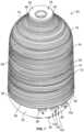
- FIG. 1is a front, top, and right isometric view of a volatile material dispenser in accordance with the present disclosure
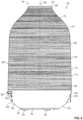
- FIG. 2is a front elevational view of the volatile material dispenser of FIG. 1 ;
- FIG. 3is a rear elevational view of the volatile material dispenser of FIG. 1 ;
- FIG. 4is a left side elevational view of the volatile material dispenser of FIG. 1 ;
- FIG. 5is a top plan view of the volatile material dispenser of FIG. 1 ;
- FIG. 6is a bottom plan view of the volatile material dispenser of FIG. 1 ;
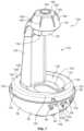
- FIG. 7is a front, top, and right isometric view of an internal stand and a base of the volatile material dispenser of FIG. 1 with a shroud having been removed for clarity;
- FIG. 8is a right side elevational view of the stand and base of FIG. 7 ;
- FIG. 9is a front elevational view of the stand and base of FIG. 7 ;
- FIG. 10is a front, top, and right isometric view of a refill for use with the volatile material dispenser of FIG. 1 ;
- FIG. 11is a front, top, and right isometric view of the refill of FIG. 10 with a cap having been removed;
- FIG. 12is a side cross-sectional view of the refill taken through line 12 - 12 of FIG. 11 ;
- FIG. 13is a cross-sectional view of the volatile material dispenser taken through line 13 - 13 of FIG. 5 ;
- FIG. 14is a cross-sectional view of the volatile material dispenser taken through line 14 - 14 of FIG. 5 ;
- FIG. 15is a front, top, and left isometric view of various electrical components of the volatile material dispenser of FIG. 1 , including a piezoelectric element;
- FIG. 16is a top plan view of a printed circuit board and some of the electrical components shown in FIG. 15 ;
- FIG. 17is a front, top, and right isometric view of the piezoelectric element shown in FIG. 16 ;
- FIG. 18 Ais a cross-sectional view of the piezoelectric element taken through line 18 - 18 of FIG. 17 ;
- FIG. 18 Bis a schematic illustration of a circular-shaped array of apertures along the piezoelectric element of FIG. 17 ;
- FIG. 18 Cis a schematic illustration of an oval-shaped array of apertures along the piezoelectric element of FIG. 17 ;
- FIG. 19is a detail view of an upper portion of the internal stand of FIG. 14 ;
- FIG. 20is a detail view of the upper portion of the internal stand of FIG. 19 with the refill of FIG. 10 inserted into a manifold of the stand;
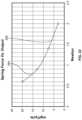
- FIG. 21is a line graph illustrating the results of various tests of springs having varying thicknesses
- FIG. 22is a line graph illustrating the results of a piezoelectric element and various tests comparing spring force against a resultant fragrance output
- FIG. 23is a front, right, and top view of the stand and base of FIG. 7 with the refill of FIG. 10 being inserted into a head cavity thereof;
- FIG. 24is a front, right, and top view of the stand and base of FIG. 23 with the refill having been inserted into an engaged configuration
- FIG. 25is a front, right, and top view of the stand and base of FIG. 23 with a shroud being engaged with the base.
- the present disclosureis directed to volatile material dispensers or diffusers and methods of emitting volatile materials therefrom. While the present disclosure may be embodied in many different forms, several specific embodiments are discussed herein with the understanding that the present disclosure is to be considered only an exemplification of the principles of the disclosure, and it is not intended to limit the disclosure to the embodiments illustrated. Throughout the disclosure, the terms “about” and “approximately” refer to a range of values ⁇ 5% of the numeric value that each term precedes.
- the volatile material dispensers or diffusers disclosed hereinare multisensory devices that use a piezoelectric engine to create and eject micro droplets of liquid fragrance into the surrounding environment.
- the volatile material dispensersare configured to accept a replaceable fragrance oil bottle or refill.
- the dispensersare further configured to run on low voltage, and feature a fragrance intensity selector that provides visual feedback to a user in the form of a glowing light.
- the dispenserincludes a shroud, a stand assembly, and a base that collectively house control buttons, a power connector, lights, and a piezo engine.
- the shroudis primarily decorative and provides a light transmission shade. Before a first use of the volatile material dispenser, the shroud is removed to insert a fragrance oil bottle or refill into the stand assembly.
- the volatile material dispensers disclosed hereininclude improvements to a piezo plate-to-wick interface, which, through testing, has been found to increase system performance and consistency. Specifically, testing has revealed a sensitivity and variations in consistency based upon a downward contact force of the piezo plate and a top of the wick. For example, a constant force provides a more consistent output and minimized variance. Through testing, it has also been determined that force differences can create variances in output rate as a result of changing load conditions on the piezo plate. Too high of a downward load onto the piezo plate has been found to dampen an amplitude of mechanical vibration of the piezo plate, which can minimize droplet output. Conversely, too light of a downward force has been found to limit the plate-to-wick interface contact, which has been found to result in high, undamped output. This is likely because under such circumstances, contact between the piezo plate and the wick can be lost entirely.
- FIGS. 1 - 7depict a volatile material dispenser 50 embodying aspects of the present disclosure.
- the dispenser 50may be adapted to accommodate a refill 52 (see FIGS. 10 - 12 ) and dispense a volatile material in the form of water and/or fragranced oil from the refill 52 .
- the dispenser 50includes a shroud or cover 54 and a base 56 .
- the shroud 54defines a lower edge 58 that interfaces with an upper edge 60 of the base 56 .
- a sidewall 62 of the shroud 54extends upward from the lower edge 58 toward a lip 64 at an upper end 66 of the shroud 54 .
- the sidewall 62 of the shroud 54defines a frustoconical lower portion 68 and a spline-shaped upper portion 70 , when viewed in cross-section.
- a plurality of ridges or design features 72are provided along an outer surface 74 of the shroud 54 . Any number of design features 72 may be provided along the outer surface 74 of the shroud 54 .
- the lower portion 68 and the upper portion 70 of the shroud 54intersect at a rounded shoulder 76 , from which the upper portion 70 extends toward a chimney 78 that is centered about a central longitudinal axis 80 ( FIG. 2 ) of the dispenser 50 .
- the chimney 78is defined as the portion interior to the lip 64 .
- the shroud 54 , and the base 56comprise polypropylene (PP), however, the shroud 54 and the base 56 may comprise a wide variety of polymeric materials.
- the sidewall 62 along the upper portion 70extends from the shoulder 76 toward the lip 64 .
- a flange 84 of the shroud 54extends downward from the lip 64 toward the longitudinal axis 80 and into the chimney 78 .
- the angle at which the flange 84 extends downward from the lip 64is best illustrated in the cross-sectional views of FIGS. 13 and 14 .
- the chimney 78may define a variety of diameters, the chimney 78 is illustrated having a diameter D 1 that is about 30% of a widest diameter D 2 of the shroud 54 taken at the lower edge 58 thereof.
- the diameter D 1may be between about 5% and about 60% of the diameter D 2 , or between about 10% and about 45% of the diameter D 2 , or between about 15% and about 35% of the diameter D 2 . In some embodiments, the diameter D 1 is about 10%, or about 20%, or about 30%, or about 40%, or about 50% of the diameter D 2 .
- the base 56also defines a sidewall 90 that extends from the upper edge 60 of the base 56 downward, toward a bottom wall 92 thereof.
- a plurality of feet 94extend downward from the bottom wall 92 , and are provided to allow the dispenser 50 to rest upon a flat surface (not shown).
- the sidewall 90 of the base 56is generally curved, and extends from the upper edge 60 downward and inward, toward the longitudinal axis 80 .
- the sidewall 90 of the base 56may define a radius of curvature along a portion of the sidewall 90 .
- a first button 96 , a second button 98 , and a third button 100extend from the base 56 outward, away from the longitudinal axis 80 .
- the first button 96 , the second button 98 , and the third button 100may be used for a variety of purposes, and may have a variety of different functions, as discussed hereinafter below.
- the first button 96 , the second button 98 , and the third button 100may be provided along the base 56 of the dispenser 50 .
- the first button 96may be a power button that allows a user to turn the dispenser 50 on and off.
- the second button 98may be a fragrance strength adjusting button that allows a user to cycle through settings of the dispenser 50 . For example, the user may be able to switch between a low setting, a medium setting, and a high setting.
- a plurality of light indicators 102may be visible through the base 56 adjacent or below the second button 98 .
- the light indicators 102may provide visual feedback to a user regarding the strength or intensity of the chosen setting. In the illustrated embodiment, there are three of the light indicators 102 .
- the third button 100may be a light illumination button that, when pressed by a user, cycles through various light brightness settings and color settings.
- a usercan select an option for light and/or color based on personal preference.
- the dispenser 50may run for a pre-determined amount of time, e.g., 8 hours, and may subsequently enter into a sleep mode for a pre-determined amount of time, e.g., 16 hours. The dispenser 50 may repeat this cycle every 24 hours unless manually turned off via the first button 96 by a user.
- the dispenser 50includes an automatic shut-off function that deactivates the dispenser 50 after a particular period of time, for example, after seven 24-hour cycles, i.e., one week.
- a limit switch(not shown) may be provided along the base 56 which only allows the dispenser 50 to be activated when the shroud 54 is engaged with the base 56 .
- the dispenser 50further includes a low voltage receptacle or port 104 for receiving a low-voltage electrical connector of a low voltage wire, such as a USB cord (not shown).
- a low-voltage electrical connector of a low voltage wiresuch as a USB cord (not shown).
- electrical prongs, a cord, or another suitable electrical connectormay be electrically coupled with the dispenser 50 so as to allow electrical power to be provided to the dispenser 50 .
- FIG. 4illustrates a left side of the dispenser 50 .
- the buttons 96 , 98 , 100 and the port 104extend outward from the sidewall 90 of the base 56 and cause interruptions of the sidewall 90 .
- the sidewall 90 of the baseis rotationally symmetrical, but the entire base 56 is symmetric about a plane 13 - 13 (see FIG. 5 ) that bisects the second button 98 and the port 104 .
- Additional featuresmay be provided within or along the shroud 54 and/or the base 56 .
- additional bodies defining one or more sidewallsmay be provided between, above, or below the base 56 and the shroud 54 .
- FIG. 5a top view of the dispenser 50 is depicted.
- the chimney 78is shown in greater detail, which is centered along the longitudinal axis 80 .
- a piezoelectric assembly 110is shown within the chimney 78 , which is also centered along the longitudinal axis 80 .
- An annular piezoelectric element 112is also visible through the chimney 78 , the piezoelectric element 112 defining a circular rim of the piezoelectric assembly 110 .
- the piezoelectric element 112includes a central aperture 114 through which liquid volatile within the refill is dispersed when the dispenser 50 is activated. When the dispenser 50 is activated, a stream of the volatile is dispensed through the chimney 78 of the shroud 54 and out of the dispenser 50 , as discussed in greater detail hereinafter below.
- the plurality of feet 94extend from the bottom wall 92 .
- the plurality of feet 94are provided in a generally circular shape, with alternating circular and elongate feet 94 .
- Alternative configurations or shapes of the feet 94are contemplated, while in some embodiments additional structure may be included in addition to the feet 94 .
- the second button 98 and the port 104are provided 180 degrees offset from one another about the longitudinal axis 80 .
- the first button 96 , the second button 98 , and the third button 100are also equally spaced apart from one another.
- Alternative configurations of the port 104 and the buttons 96 , 98 , 100are also contemplated.
- the stand assembly 116includes a platform 118 , a stand 120 , a refill chassis 122 , and a crown 124 .
- the refill chassis 122 and the crown 124define a manifold 126 that retains the refill 52 and the piezoelectric assembly 110 .
- the platform 118extends upward from the base 56 and is inset from the sidewall 90 thereof.
- a plurality of retention protrusions 128extend outward from the platform 118 , which operate to engage the shroud 54 when it is coupled with the base 56 .
- the retention protrusions 128are a form of retention mechanism that couples the shroud 54 with the base 56 .
- Alternative retention mechanismsmay include elements that cause a snap fit, a friction fit, or an interference fit.
- the platform 118is permanently coupled with the base 56 via a plurality of fasteners 130 (see FIG. 13 ), the channels for which are covered by the feet 94 after assembly thereof.
- the fasteners 130are a form of fastening mechanism, additional examples of which include rivets, nails, bolts, or cables.
- the platform 118defines an outer cylindrical surface 132 that extends upward to a corner 134 .
- An angled surface 136extends inward and downward from the corner 134 , toward a well 138 defined within a central portion 140 of the platform 118 .
- a slot 142is defined within the angled surface 136 along a front portion 144 of the platform 118 .
- the slot 142may be included to aid in the insertion of the refill 52 into an operable configuration.
- the well 138may include additional features that aid in retaining the refill 52 or another component.
- the well 138 of the platform 118may be sized and shaped to retain a cap 146 (see FIG. 10 ) of the refill 52 after the cap 146 has been removed from the refill 52 .
- the stand assembly 116includes the stand 120 , which extends upward from the platform 118 along a rear portion 148 thereof.
- the stand assembly 116comprises a unitary piece that extends upward from the platform 118 toward the manifold 126 , which extends inward, and aligns with the longitudinal axis 80 .
- Elements of the stand assembly 116may also comprise polypropylene or another type of polymeric material.
- the manifold 126includes the crown 124 and the refill or chassis 122 , which extends downward from the crown 124 .
- the chassis 122includes the first and second tabs 150 that depend downward to retain an annular rim 152 (see FIG. 11 ) of the refill 52 .
- the first and second tabs 150may be formed to flex outward when the refill 52 is laterally inserted into the chassis 122 until the rim 152 of the refill engages with the tabs 150 .
- the refill 52may be removed from the tabs 150 by a user grabbing the refill 52 and laterally pulling the refill down. In some embodiments, the forces required for insertion and removal of the refill 52 are low enough to simply allow for lateral insertion and removal. However, in some embodiments, the refill 52 may be removed by squeezing the tabs 150 to deflect the tabs 150 outward, thereby releasing the rim 152 from engagement therewith. In some embodiments, the refill 52 may be disengaged by rotating the refill 52 such that threading 154 (see FIG. 11 ) allows the refill to be rotated and translate downward, away from the crown 124 , for removal from the manifold 126 . Alternative removal mechanisms may be implemented, such as one or more buttons (not shown) that could be depressed to cause the refill 52 to be released from the chassis 122 .
- the crown 124extends upward from the chassis 122 and defines a generally frusto-conical side surface 156 that terminates at a top surface 158 .
- a plurality of ribs 160are radially disposed along the side surface 156 , which may be formed to aid in physical engagement with an underside 162 (see FIG. 13 ) of the shroud 54 .
- the ribs 160are spaced apart about the longitudinal axis 80 .
- a cylindrical wall 164extends upward from the top surface 158 of the crown 124 , the cylindrical wall 164 having a center that is coaxial with the longitudinal axis 80 .
- the cylindrical wall 164is also coaxial with the chimney 78 defined by the shroud 54 .
- the cylindrical wall 164is aligned with the second button 98 and the port 104 , i.e., the plane 13 - 13 (see FIG. 5 ) extends through all of the cylindrical wall 164 , the second button 98 , and the port 104 . While the shroud 54 generally comprises radial symmetry notwithstanding the design features 72 , the platform 118 , the stand 120 , and the manifold 126 may be characterized as being symmetric about the plane 13 - 13 that intersects the second button 98 and extends through the longitudinal axis 80 .
- the refill 52comprises a cap 146 and a container 170 defining a body 172 , a shoulder 174 , and a head 176 .
- the body 172comprises a cylindrical outer wall 178 that extends upward from a lower wall 180 thereof to the shoulder 174 .
- the head 176extends upward from the shoulder 174 and defines a finish 182 .
- the head 176joins the body 172 at the shoulder 174 .
- the refill 52further includes a cap 146 that is threadably coupled with the threading 154 (see FIGS. 11 and 12 ) disposed along a neck 184 of the refill 52 . Referring to FIG.
- the container 170holds a volatile material therein, and the container 170 is adapted to be retained within the dispenser 50 .
- a wick holder or plug 186is disposed within the neck 184 for holding a wick 188 with a first end of the wick 188 in contact with the volatile material and a second end of the wick 188 extending out of the container 170 through the neck 184 .
- the wick 188may be formed of extruded fibers that are bundled together into the shape of a rod.
- the wick 188may be formed of rope or one or more cotton cords.
- the wick 188comprises an upper wick 192 and a lower wick 194 .
- the upper wick 192has different properties than the lower wick 194 , however, in some embodiments, the upper wick 192 and the lower wick 188 have the same properties.
- the upper wick 192is pliable and/or fibrous, while the lower wick 194 may be sintered or more rigid than the upper wick 192 .
- the upper wick 192may have properties that allow the upper wick 192 to deform into the piezoelectric assembly 110 .
- the lower wick 194includes a lower end 196 disposed adjacent and spaced apart from the lower wall 180 , and has an upper end 198 that is engaged with the upper wick 192 .
- the upper wick 192is nested within a wick cavity 200 at the upper end 198 of the lower wick 194 .
- An upper cambered or angled surface 202surrounds an inner periphery of the wick cavity 200 .
- the upper angled surface 202may aid in alignment of the upper wick 192 within the wick cavity 200 during assembly of the refill 52 .
- the upper wick 192is snugly retained by the plug 186 and has a distal end 204 that extends upward, out of the container 170 .
- the wick 188may be formed in any suitable shape or of any suitable material, however, the upper wick 192 is preferably more pliable than the lower wick 194 .
- the plug 186is retained within the neck 184 of the refill 52 by an interference fit, a friction fit, or in any other suitable manner that holds the plug 186 in place within the neck 184 .
- the shoulder 174 of the container 170extends upward to the finish 182 and the neck 184 of the head 176 .
- the threading 154circumscribes the neck 184 and extends outward therefrom.
- the annular rim 152also circumscribes the finish 182 , which may be used to engage the refill 52 with the depending tabs 150 of the chassis 122 .
- the lower wall 180 of the refill 52is generally concave and extends upward, toward the wick 188 .
- An air hole 208(see FIG. 11 ) is provided within the plug 186 to allow air to enter into a cavity 210 of the refill 52 as liquid (not shown) is dispersed out of the refill 52 into the surrounding atmosphere.
- a refill 52is shown and described with particularity, it is contemplated that any type of refill may be used with variations of the dispensers described herein.
- a refill with a flexible containermay be utilized.
- the delivery systemi.e., the wick
- the size and/or the shape of the container 170may be different than those described herein.
- the volatile material disposed in the container 170may be any type of volatile material adapted to be dispensed into an environment.
- the material within the container 170may include a cleaner, an insecticide, an insect repellant, an insect attractant, a disinfectant, a mold or mildew inhibitor, a fragrance, a disinfectant, an air purifier, an aromatherapy scent, an antiseptic, an odor eliminator, a positive fragrancing volatile material, an air-freshener, a deodorizer, or the like, and combinations thereof.
- Additivesmay be included in the volatile material, such as, for example, fragrances and/or preservatives. In fact, any fluid may be provided within the container 170 .
- FIGS. 13 and 14internal components of the dispenser 50 are shown in greater detail.
- the base 56is shown being connected with the stand assembly 116 via one of the fasteners 130 .
- the fastener 130is disposed within a fastener channel 214 that is covered from view by one of the feet 94 after the stand assembly 116 has been fastened to the base 56 .
- there are three fasteners 130 that secure the base 56 with the stand assembly 116however, only a single fastener 130 is shown in the cross-section of FIG. 13 .
- a printed circuit board (PCB) 216is shown intermediate the base 56 and the stand assembly 116 .
- a plurality of light emitting diodes (LEDs) 218are shown electrically coupled with the PCB 216 , the plurality of LEDs 218 being disposed above the PCB 216 .
- the plurality of LEDs 218are disposed above and below the PCB 216 .
- some of the LEDs 218are disposed adjacent the front, rear, and sides of the dispenser 50 .
- the LEDs 218are intended to be used to emit light through the shroud 54 depending on the chosen setting, which can vary based on user preference.
- the LEDs 218may alternatively be positioned in any suitable location within the dispenser 50 .
- the one or more LEDs 218may indicate that the dispenser 50 is on or off, may provide an alert, and/or may provide any other suitable indicator for a user. As noted above, a color and/or a brightness of the LEDs 218 may be adjusted depending on a desired brightness and/or color of light to be emitted through the shroud 54 .
- a first one of the LEDs 218may illuminate a first color when the dispenser 50 is in a “Low” setting
- a second one of the LEDs 218may illuminate a second color when the dispenser 50 is in a “Medium” setting
- a third one of the LEDs 218may illuminate a third color when the dispenser 50 is in a “High” setting.
- the third LED 218may illuminate by itself in the high setting, or the lighting may be additive, such that both that first LED 218 , the second LED 218 , and the third LED 218 illuminate in the high setting, in which they may have the same or different colors and/or intensities.
- the first LED 218may be illuminated when the dispenser 50 is plugged in but not on, and the second LED 218 may be illuminated when the dispenser 50 is plugged in and turned on.
- the dispenser 50may include one or more separate openings in the shroud 54 or translucent portions of the shroud 54 to permit passage of the light emitted by each LED 218 .
- the second button 98is shown protruding through the base 56 . While the second button 98 is shown and referred to hereinafter below, the first button 96 and the third button 100 have an identical setup and functionality.
- the second button 98is shown adjacent a switch 220 , the switch 220 being operable to be adjusted between various settings of the dispenser 50 .
- the switch 220may be a push button switch that, when depressed, may cause the dispenser 50 to initiate one or more functions, such as turning the dispenser 50 on or off, causing an adjustment in the amount of fragrance that is dispensed, or adjusting the color or brightness of one or more of the LEDs 218 .
- the switch 220 that is visible in FIG. 13is one of a plurality of switches 220 that are visible in FIG. 16 .
- the switches 220may be the same switches, or the switches 220 may be different.
- dispenser 50is disclosed as having particular switches, one skilled in the art will appreciate the dispenser may include any number of switches and/or may include any suitable types of switches, for example, timing switches, on/off switches, setting switches, switches controlling another component within the assembly, such as a heater or a fan, and/or any other suitable switches.
- the stand assembly 116is shown in cross section, and the components that are disposed therein are visible.
- a wire tube 222is shown, which extends from a terminal 224 that is disposed along the PCB 216 , through the stand 120 , and into the chassis 122 .
- First and second wires 226are disposed within the wire tube 222 , which are electrically connected to the terminal 224 and to the piezoelectric assembly 110 , which is disposed within the crown 124 of the stand assembly 116 .
- the stand 120is fixedly coupled with the chassis 122 , which is also fixedly coupled with the crown 124 .
- the stand 120 , the chassis 122 , and the crown 124are all separate components, and may be coupled with one another via a snap fit, friction fit, interference fit, adhesive, or another method of coupling.
- the stand 120 , the chassis 122 , and the crown 124may all comprise polypropylene, or another polymeric material.
- the wires 226are electrically coupled with the piezoelectric assembly 110 , which is disposed within the crown 124 .
- a wire tube guide 228is further disposed within the stand 120 , which is situated to retain the wire tube 222 within the stand 120 .
- the wire tube guide 228may comprise a horizontal portion having a cutout that retains the wire tube 222 in a static configuration. As further shown in FIG.
- the piezoelectric assembly 110is centrally located along the longitudinal axis 80 . While the stand 120 , the chassis 122 , the platform 118 , the base 56 , and the shroud 54 are illustrated as comprising a polymer, other types of materials are contemplated.
- a plurality of refill retaining ribs 230are disposed along an interior of the chassis 122 , which may be used to guide the neck 184 of the refill 52 upward, into position within the chassis 122 until the tabs 150 lock into place with the rim 152 along the refill 52 .
- a spring 232is shown, which is used to apply a force against the piezoelectric assembly 110 .
- the spring 232applies a constant force against the piezoelectric assembly 110 to retain it in a static configuration until the refill 52 as it is positioned within the chassis 122 by a user.
- the piezoelectric assembly 110is translated upward, causing the spring 232 to compress.
- the spring 232defines a spring wire 234 that has a wire diameter, which is further discussed below.
- One of the tabs 150is also shown, the tab 150 including an inwardly-depending catch 236 that is configured to translate outward, away from the longitudinal axis 80 as the refill 52 is being inserted into the chassis 122 , and snaps back inward to secure the refill 52 in place within the chassis 122 by engaging with the rim 152 (see FIG. 20 ).
- the piezoelectric assembly 110is disposed above a refill cavity 240 , and is configured to receive the distal end 204 of the wick 188 when the refill 52 is inserted into the chassis 122 .
- FIG. 14another cross-sectional view of the dispenser 50 is shown.
- the wire guide 228 and the wires 226are shown in cross-section, and a plurality of LEDs 218 are shown being disposed above the PCB 216 .
- additional refill guide ribs 230are shown, which partially define a profile of the head 176 of the refill 52 , and are configured to snugly receive the refill 52 within the chassis 122 .
- the spring 232comprises a top end 242 and a bottom end 244 .
- the piezoelectric assembly 110is also shown in FIG. 14 , and is disposed below the bottom end 244 of the spring 232 .
- the bottom end of the spring 232may be fixedly attached with the piezoelectric assembly 110 , or may be separate but disposed in physical contact with one another.
- the bottom end 244 of the spring 232is formed to receive the piezoelectric assembly 110 , which is in turn formed to receive the upper wick 194 when the refill 52 is engaged therewith.
- the top end 242 of the spring 232is wrapped around and secured to the cylindrical wall 164 of the crown 124 .
- the chassis 122includes an outer ledge 250 that is engaged with an inner ledge 252 of the crown 124 .
- the chassis 122 and the crown 124are snap fit together, however, the chassis 122 and the crown 124 may be coupled together in another fashion, such as via adhesive, fasteners, an interference fit, or a friction fit.
- Fastener walls 254 defining two of the fastener channels 214are also shown clearly in FIG. 14 , the fastener walls 254 extending between the bottom wall 92 of the base 56 and the platform 118 .
- the printed circuit board (PCB) 216 , the wire guide 222 and the piezoelectric assembly 110are shown in an isometric view.
- a controller 246 and a timer 248are shown in schematic view along the PCB 216 .
- the controller 246may be a microcontroller, and may be disposed within or along the PCB 216 .
- the controller 246may also be a separate component that is electrically coupled with the PCB 216 .
- the timer 248may further be disposed within or along the PCB 216 , or may be a separate component.
- the timer 248is used to time when the dispenser 50 is activated, while the controller 246 is operable to receive instructions from the buttons 96 , 98 , 100 to activate the piezoelectric assembly 110 , the timer 248 , and/or the LEDs 218 .
- the PCB 216is disposed between the base 56 and the platform 118 , which are both removed from the view of FIG. 15 for clarity.
- a limit switch 256is further shown, which provides a signal to the controller 246 that the shroud 54 has been secured to the base 56 , and does not allow the dispenser 50 to be activated until the shroud 54 has been secured to the base 56 . In some embodiments, there is no limit switch 256 .
- the terminal 224is further shown disposed along the PCB 216 . Other electrical components, such as resistors, transistors, capacitors, processors, controllers, and relays may further be disposed along or within the PCB 216 . In some embodiments, a plurality of batteries (not shown) may be enclosed within a casing (not shown) and may be electrically connected to the PCB 216 for providing electrical power to the PCB 216 and other electrical components of the dispenser 50 .
- a top view of the PCB 216is shown with the wire guide 222 and the piezoelectric assembly 110 having been removed for clarity.
- the switches 220are shown in greater detail, and are shown positioned adjacent each of the first button 96 , second button 98 , and third button 100 .
- three sets of three LEDs 218each are shown in detail in a triangular configuration along the PCB 216 .
- the different sets of LEDs 218may emit different colored lights, or may emit the same color. Further, the LEDs 218 may have the same intensity or a different intensity from one another.
- the port 104is further shown along the PCB 216 at an opposite end of the second button 98 .
- the PCB 216has a generally circular profile, however, the PCB 216 may have any profile that allows it to be securely retained within the profile of the shroud 54 .
- the piezoelectric assembly 110includes a piezoelectric plate 260 and the piezoelectric element 112 that circumscribes the periphery of an upper surface 262 of the piezoelectric plate 260 .
- the piezoelectric platemay comprise stainless steel, which may be SUS 316L steel.
- the piezoelectric plate 260is caused to expand and contract, thereby releasing a volatile into the surrounding environment.
- the piezoelectric plate 260further includes a central dome 264 that is generally concave and circular in shape.
- the piezoelectric assembly 110includes an apertured section 266 , at least a portion of which extends along the central dome 264 .
- the apertured section 266 of the piezoelectric plate 260includes a plurality of orifices 268 having a diameter or at least one width dimension of between about 3 microns and about 9 micron, or between about 5 and 7 micron, or about 6.5 micron.
- the piezoelectric plate 260includes a plurality of orifices having a diameter of between about 3 micron and about 5 micron.
- the piezoelectric assembly 110when in use, is positioned adjacent the wick 188 .
- the piezoelectric element 112may be formed as a ring and may be made of ceramic.
- the piezoelectric assembly 110may be formed in any suitable shape and/or may be made of any suitable material having piezoelectric properties and which causes the material to change dimensionally in response to an applied electric field.
- suitable materialsinclude, but are not limited to, lead zirconate titanate (PZT) or lead metaniobate (PN). While a particular piezoelectric element is described, any actuator may be utilized, for example, a piezoelectric vibrating mesh actuator, a piezoelectric standing wave actuator, a piezoelectric vibrating needle, or any other suitable piezoelectric actuator.
- the plurality of orifices 268 along the piezoelectric plate 260may define an array 269 that is circular in nature.
- the array 269 of orificesmay be defined along the entire dome 264 , as shown in FIG. 266 .
- the array 269may alternatively be disposed along only a portion of the dome 264 , or may extend beyond the dome 264 , as depicted in FIG. 18 C .
- the array 269may have alternative configurations, and may be in the shape of a triangle, a square, an oval, or a polygon.
- the orifices 268may be in the shape of a circle ( FIG. 18 B ), a rectangle or square ( FIG. 18 C ), or another shape.
- orifices 268 depicted in the schematic views of FIGS. 18 B and 18 Cdo not represent the actual size or actual number of the orifices 268 , rather, the orifices 268 may define dimensions as noted herein.
- the array 269has a diameter or at least one width dimension of between about 0.5 mm and about 10.0 mm, or between about 1.0 mm and about 9.0 mm, or between about 2.0 mm and about 8.0 mm, or between about 3.0 mm and about 7.0 mm.
- a wick diameter DW and an array diameter DAmay define a ratio of DA/DW of between about 1.0 and about 3.0. In some embodiments, the ratio is about 1.1. In some embodiments, the wick diameter DW is between about 3.0 mm and about 5.5 mm, or between about 3.5 mm and about 4.0 mm, or about 3.8 mm.
- the array diameter DAis between about 3.0 mm and about 6.0 mm, or between about 4.0 mm and about 5.0 mm, or about 4.5 mm.
- the ratio of wick diametersmay affect the accuracy and consistency of the plume of the volatile that is emitted by the dispenser 50 . For example, having a ratio DW/DA of about 1.1 has been found to create a repeatable and accurate dispersal of volatile from the dispenser 50 .
- the array 269may comprise between about 100 and about 400 orifices, or between about 150 and about 350 orifices, or about 316 orifices, or about 200 orifices.
- FIGS. 19 and 20detail views of the upper end of the stand assembly 116 are shown without and with a refill having been inserted therein, respectively.
- the piezoelectric assembly 110is shown in greater detail.
- a soft materialsuch as loading foam, may be provided along an underside of the piezoelectric assembly 110 .
- Additional materialsmay be provided along an underside of the piezoelectric assembly 110 to aid in accuracy or consistency of the plume of volatile generated when the dispenser 50 is activated. The additional materials may also be provided to enhance or reduce a dampening effect that could be caused by the spring 232 , the wick 188 , and/or the piezoelectric plate 260 .
- the top end 242 of the spring 232is shown wrapped around the cylindrical wall 164 , while the bottom end 244 of the spring 232 is shown in contact with and applying a force against the piezoelectric assembly 110 .
- the chassis 122further includes a piezo platform 270 , which is unitary with the chassis 122 and defines a surface to which the piezoelectric assembly 110 is secured.
- the piezo platform 270retains the piezoelectric assembly 110 in place, and prevents the piezoelectric assembly 110 from being displaced farther than the piezo platform 270 .
- the piezo platform 270is generally circular and includes an aperture 272 in a center thereof, which allows the distal end 204 of the wick 188 to engage in physical contact with the piezoelectric assembly 110 when inserted into the chassis 122 .
- the spring 232is positioned to provide an opposing force against the refill 52 when it has been inserted into the chassis 122 . As noted below, when the wick 188 is engaged with the piezoelectric assembly 110 , the spring 232 is compressed and the piezoelectric assembly 110 is displaced a distance X above the piezoelectric platform 270 . This displacement is discussed in greater detail hereinafter below.
- the refill 52is shown having been inserted into the manifold 126 . Because the refill 52 has been inserted into the refill cavity 240 of the chassis 122 , the spring 232 has been compressed, thus, the spring 232 is shown in a compressed configuration. Still referring to FIG. 20 , the rim 152 of the refill 52 is also shown engaged with the catches 236 of the tabs 150 , and the distal end 204 of the wick 188 is shown in physical contact with a lower surface 276 (see FIG. 18 ) of the piezoelectric assembly 110 . The compression of the spring 232 shown in FIG.
- FIG. 20is a result of the size and type of spring that is used in the dispenser 50 , which may be chosen based upon a variety of factors, as discussed below.
- the piezoelectric assembly 110having been translated upward due to the force applied by the wick 232 , and the catches 236 of the tabs 150 having been engaged with the rim 152 of the refill 52 , no other elements of the manifold 126 are moved or manipulated when the refill 52 is inserted into the manifold 126 .
- FIG. 20shows the refill 52 in an operational state, where the dispenser 50 could be activated to disperse the volatile by providing an electrical pulse to the piezoelectric assembly 110 .
- an absorbent materialmay be included between the wick 188 and the piezoelectric assembly 110 .
- the absorbent materialmay be a felt pad and/or cotton wool.
- the absorbent materialmay be formed of a velour pad, cotton cloth, chenille yarn, chenille fabric, polyester cloth, paper towel, synthetic cloth, synthetic nonwoven material, a cotton ball or swab, combinations thereof, or other suitable absorbent material(s).
- the absorbent materialmay be a component of the nebulizer assembly or may be attached or otherwise in communication with the wick 188 of the refill 52 .
- the piezoelectric assembly 110is actuated, either continuously or intermittently, to dispense volatile material. More particularly, an oscillating electric field is applied to the piezoelectric element 112 , which causes expansion and contraction of the piezoelectric plate 260 in a radial direction. The expansion and contraction causes the piezoelectric plate 260 to vibrate in an axial direction (along a longitudinal axis of the dispenser 50 ), forcing volatile material retained within the orifices of the piezoelectric plate 260 away from the piezoelectric assembly 110 , through a channel 280 defined by the cylindrical wall 164 , and through the chimney 78 of the shroud 54 .
- the three groups of springscomprise spring wires 226 having a diameter of 0.50 mm, a spring having a diameter of 0.55 mm, and a spring having a diameter of 0.60 mm.
- the graphillustrates a spring force measured in Newtons (N) against a spring compression distance measured in millimeters (mm).
- the spring compression distanceis the distance X noted above, i.e., a distance between the piezoelectric platform 270 and the piezoelectric assembly 110 after the wick 188 causes the piezoelectric assembly 110 to be translated upward.
- the graphfurther illustrates a minimum, an average, and a maximum for each of the three springs.
- Testinginvolved iteratively compressing springs from 1.0 mm to 8.0 mm while recording the resulting force output (N). While the three different spring diameters, i.e., 0.50 mm, 0.55 mm, and 0.60 mm, achieved different results, the results suggest that at a compression of 7.0 mm, each of the three springs saw a non-linear increase in measured spring force.
- the spring 232may have an uncompressed height of between about 7 mm and about 20 mm, or between about 10 mm and about 17 mm, or about 13 mm. Further, in some embodiments, the spring 232 may have between about 2 turns and about 10 turns, or between about 3 turns and about 7 turns, or about 4.5 turns. In a preferred embodiment, the spring 232 has a spring wire diameter of about 0.6 mm, an uncompressed height of about 13 mm, and comprises about 4.5 turns.
- the graph of FIG. 22illustrates results from the testing displayed in FIG. 21 .
- the results of the testssuggest that the dispenser 50 emits a greater volume of fragrance when the springs induce lower compressive forces upon the piezoelectric plate 260 .
- Fragrance emission patternscan be simplified into a first linear region 284 and a second linear region 286 .
- the first region 284occurs between 0.6 and 0.9 N and has an approximate slope of ⁇ 25 mg/cycle/N.
- the second region 286occurs between 0.9 and 2.0 N and has an approximate slope of ⁇ 8.33 mg/cycle/N.
- the fragrance deviceemits a larger volume of fragrance when subjected to lower spring forces.
- a particular springmay be identified for use with the dispenser 50 .
- the 0.50 mm or 0.55 mm springwould likely be utilized if one desired to achieve a fragrance output within the first linear region 284 and the 0.60 mm spring would likely be utilized if one desired to achieve a fragrance output within the second linear region 286 .
- FIGS. 23 - 25a method of inserting the refill 52 into the stand assembly 116 and assembling the dispenser 50 are depicted.
- the refill 52is positioned with the head 176 thereof being inserted into the manifold 126 .
- the lower wall 180 of the refill 52is slid through the slot 142 of the platform 118 and the refill 52 is moved upward so that the head 176 is inserted into the manifold 126 .
- the refill 52can be characterized as being secured within the manifold 126 .
- the cap 146 of the refill 52may be inserted into the well 138 to securely retain the cap 146 while the refill 52 is in use.
- the shroud 54is aligned with the base 56 and is rotated until the protrusions 128 along the base 56 engage with features along the underside 162 of the shroud 54 .
- the shroud 54may alternatively be engaged with the base 56 in another way. Once the shroud 54 has been coupled with the base 56 , one end of a power cord (not shown) is plugged into the port 104 and the other end is plugged into a power source such as a power adapter, a laptop, or another low voltage outlet.
- the first button 96is a power button
- the second button 98is a fragrance strength button
- the third button 100is a light button.
- the first button 96may be pressed once to turn the dispenser on.
- the dispenser 50will begin to dispense fragrance once the first button 96 has been depressed.
- the second button 98 and the third button 100may be pressed to personalize the preference of the fragrance strength and/or the light scheme.
- Dispensersare commonly used to dispense a variety of volatile materials such as air fresheners, deodorants, insecticides, germicides, perfumes, and the like, that are stored within refill containers.
- Piezoelectric enginesallow the volatile materials to be volatilized and then distributed into an environment in order for the contents thereof to be released without human interaction, for example, continuously or according to a predetermined time schedule
Landscapes
- Life Sciences & Earth Sciences (AREA)
- Pest Control & Pesticides (AREA)
- Health & Medical Sciences (AREA)
- General Health & Medical Sciences (AREA)
- Veterinary Medicine (AREA)
- Public Health (AREA)
- Animal Behavior & Ethology (AREA)
- Epidemiology (AREA)
- Engineering & Computer Science (AREA)
- Wood Science & Technology (AREA)
- Environmental Sciences (AREA)
- Insects & Arthropods (AREA)
- Zoology (AREA)
- Toxicology (AREA)
- Disinfection, Sterilisation Or Deodorisation Of Air (AREA)
- Catching Or Destruction (AREA)
- Mechanical Treatment Of Semiconductor (AREA)
- General Engineering & Computer Science (AREA)
- Packaging Of Annular Or Rod-Shaped Articles, Wearing Apparel, Cassettes, Or The Like (AREA)
Abstract
Description
Claims (24)
Priority Applications (1)
| Application Number | Priority Date | Filing Date | Title |
|---|---|---|---|
| US18/077,899US12246336B2 (en) | 2019-09-23 | 2022-12-08 | Volatile material dispenser |
Applications Claiming Priority (3)
| Application Number | Priority Date | Filing Date | Title |
|---|---|---|---|
| US16/579,489US11407000B2 (en) | 2019-09-23 | 2019-09-23 | Volatile material dispenser |
| US17/844,579US12017244B2 (en) | 2019-09-23 | 2022-06-20 | Volatile material dispenser |
| US18/077,899US12246336B2 (en) | 2019-09-23 | 2022-12-08 | Volatile material dispenser |
Related Parent Applications (1)
| Application Number | Title | Priority Date | Filing Date |
|---|---|---|---|
| US17/844,579ContinuationUS12017244B2 (en) | 2019-09-23 | 2022-06-20 | Volatile material dispenser |
Publications (2)
| Publication Number | Publication Date |
|---|---|
| US20230094331A1 US20230094331A1 (en) | 2023-03-30 |
| US12246336B2true US12246336B2 (en) | 2025-03-11 |
Family
ID=72659926
Family Applications (4)
| Application Number | Title | Priority Date | Filing Date |
|---|---|---|---|
| US16/579,489Active2040-05-21US11407000B2 (en) | 2019-09-23 | 2019-09-23 | Volatile material dispenser |
| US17/844,579ActiveUS12017244B2 (en) | 2019-09-23 | 2022-06-20 | Volatile material dispenser |
| US18/077,899ActiveUS12246336B2 (en) | 2019-09-23 | 2022-12-08 | Volatile material dispenser |
| US18/670,370PendingUS20240316590A1 (en) | 2019-09-23 | 2024-05-21 | Volatile material dispenser |
Family Applications Before (2)
| Application Number | Title | Priority Date | Filing Date |
|---|---|---|---|
| US16/579,489Active2040-05-21US11407000B2 (en) | 2019-09-23 | 2019-09-23 | Volatile material dispenser |
| US17/844,579ActiveUS12017244B2 (en) | 2019-09-23 | 2022-06-20 | Volatile material dispenser |
Family Applications After (1)
| Application Number | Title | Priority Date | Filing Date |
|---|---|---|---|
| US18/670,370PendingUS20240316590A1 (en) | 2019-09-23 | 2024-05-21 | Volatile material dispenser |
Country Status (10)
| Country | Link |
|---|---|
| US (4) | US11407000B2 (en) |
| EP (1) | EP4033894A1 (en) |
| JP (1) | JP2022551408A (en) |
| KR (2) | KR20250039507A (en) |
| CN (1) | CN114828625B (en) |
| AR (1) | AR120037A1 (en) |
| AU (3) | AU2020352901B2 (en) |
| BR (1) | BR112022005110A2 (en) |
| MX (1) | MX2022003305A (en) |
| WO (1) | WO2021061433A1 (en) |
Families Citing this family (11)
| Publication number | Priority date | Publication date | Assignee | Title |
|---|---|---|---|---|
| US11524089B2 (en)* | 2018-10-11 | 2022-12-13 | Dongguan Yih Teh Electric Products Co., Ltd. | Hand wash cleaning and environmental purification diffuser |
| DE102020204134A1 (en)* | 2020-03-30 | 2021-09-30 | Robert Bosch Gesellschaft mit beschränkter Haftung | Media output device, media application system, method for a targeted output of a medium by means of a media output device and use of a media output device for applying a color |
| US20220096687A1 (en)* | 2020-09-29 | 2022-03-31 | Tabitha Angel Bryant | Sanitizer Aerosol Dispensing Apparatus |
| USD979112S1 (en)* | 2020-11-19 | 2023-02-21 | Vincent Sheppard N.V. | Solar powered lamp |
| US12016981B2 (en)* | 2021-04-29 | 2024-06-25 | The Yankee Candle Company, Inc. | Fragrance diffuser |
| TWI796142B (en)* | 2022-02-21 | 2023-03-11 | 大陸商廣州市創韋電子科技有限公司 | Liquid atomization device |
| EP4565285A1 (en)* | 2022-08-01 | 2025-06-11 | S.C. Johnson & Son, Inc. | Volatile material dispenser |
| WO2024170046A1 (en)* | 2023-02-17 | 2024-08-22 | Ctr, Lda | Piezoelectrically operated dispenser for dispensing liquid and/or volatile substances and method |
| WO2024243385A1 (en)* | 2023-05-24 | 2024-11-28 | Thermacell Repellents, Inc. | Insect repeller device |
| WO2025006587A2 (en) | 2023-06-30 | 2025-01-02 | S. C. Johnson & Son, Inc. | Systems and methods for controlling a volatile material dispenser |
| US20240173450A1 (en)* | 2024-02-06 | 2024-05-30 | Shen Zhen Lamho Photoelectricity & Technology Co., Ltd | Adjustable wax melting lamp |
Citations (107)
| Publication number | Priority date | Publication date | Assignee | Title |
|---|---|---|---|---|
| US3970250A (en) | 1974-09-25 | 1976-07-20 | Siemens Aktiengesellschaft | Ultrasonic liquid atomizer |
| USD310723S (en) | 1988-05-23 | 1990-09-18 | Cheng-Yuan Su | Atomizer |
| US6269976B1 (en) | 2000-08-17 | 2001-08-07 | Saint-Gobain Calmar Inc. | Vial access spike adapter for pump sprayer |
| US6290103B1 (en) | 1998-09-15 | 2001-09-18 | Lir-Usa Manufacturing Co., Inc. | Collapsible cap mechanism for shielding pump actuator and liquid material-dispensing container including the same |
| US6296196B1 (en) | 1999-03-05 | 2001-10-02 | S. C. Johnson & Son, Inc. | Control system for atomizing liquids with a piezoelectric vibrator |
| US6382522B2 (en) | 1999-03-08 | 2002-05-07 | S. C. Johnson & Son, Inc. | Attachment method for piezoelectric elements |
| US6386462B1 (en) | 2000-07-31 | 2002-05-14 | S. C. Johnson & Son, Inc. | Method and apparatus for dispensing liquids in aerosolized form with minimum spillage |
| WO2004010762A2 (en) | 2002-07-29 | 2004-02-05 | S.C. Johnson & Son, Inc. | System for controlling insects |
| US6786427B2 (en) | 2002-12-19 | 2004-09-07 | S. C. Johnson & Son, Inc. | Liquid sealing arrangements for replaceable liquid reservoirs |
| US6899280B2 (en) | 2002-10-08 | 2005-05-31 | S. C. Johnson & Son, Inc. | Wick-based delivery system with wick having sections of varying porosities |
| WO2006004891A1 (en) | 2004-06-30 | 2006-01-12 | S. C. Johnson & Son, Inc. | Electromechanical apparatus for dispensing volatile substances with single dispensing mechanism and cartridge for holding multiple receptacles |
| US7007863B2 (en) | 2002-10-08 | 2006-03-07 | S.C. Johnson & Son, Inc. | Wick-based delivery system with wick made of different composite materials |
| US7032831B2 (en) | 2003-03-21 | 2006-04-25 | S.C. Johnson & Son, Inc. | Container for a device for dispensing a volatile liquid |
| USD532301S1 (en) | 2004-10-19 | 2006-11-21 | Lumson S.P.A. | Spray stopper |
| US20070056914A1 (en) | 2005-09-15 | 2007-03-15 | Slager Joseph A | Agricultural cleaning and treatment apparatus and method |
| US7244398B2 (en) | 2003-03-21 | 2007-07-17 | S. C. Johnson & Son, Inc. | Device for dispensing a volatile liquid using a wick in an ambient air stream |
| EP1651280B1 (en) | 2004-06-24 | 2007-09-05 | S.C.JOHNSON & SON, INC. | Wick assembly |
| USD553499S1 (en) | 2005-01-07 | 2007-10-23 | Norda S.P.A. | Bottle |
| USD555004S1 (en) | 2005-02-28 | 2007-11-13 | S.C. Johnson & Son, Inc. | Bottle |
| US7309024B2 (en) | 2003-06-30 | 2007-12-18 | S.C. Johnson & Son, Inc. | Wick assembly for dispensing a volatile liquid from a container and method of assembling same |
| EP1807322B1 (en) | 2004-10-12 | 2008-01-09 | S.C.Johnson & Son, Inc | Automatic spray device |
| US20080011874A1 (en) | 2006-07-14 | 2008-01-17 | Munagavalasa Murthy S | Diffusion device |
| WO2008035303A2 (en) | 2006-09-22 | 2008-03-27 | The Procter & Gamble Company | Improved delivery system for dispensing volatiles |
| US20080197213A1 (en)* | 2007-02-20 | 2008-08-21 | Flashinski Stanley J | Active material diffuser and method of providing and using same |
| CN101258003A (en) | 2005-09-06 | 2008-09-03 | 吉莱特公司 | Powered wet-shaving razor |
| US7455245B2 (en) | 2006-07-14 | 2008-11-25 | S.C. Johnson & Son, Inc. | Diffusion device |
| USD583678S1 (en) | 2008-04-07 | 2008-12-30 | Shiseido Co., Ltd. | Skin lotion bottle |
| WO2009002430A1 (en) | 2007-06-25 | 2008-12-31 | S.C. Johnson & Son, Inc. | Active material emitting device and method of dispensing an active material |
| US7538473B2 (en) | 2004-02-03 | 2009-05-26 | S.C. Johnson & Son, Inc. | Drive circuits and methods for ultrasonic piezoelectric actuators |
| US7540473B2 (en) | 2003-03-21 | 2009-06-02 | S.C. Johnson & Son, Inc. | Dispensing system for a volatile liquid |
| US20090159720A1 (en)* | 2007-12-25 | 2009-06-25 | Kunshan Pant Piezoelectric Tech Co., Ltd. | Sandwich Piezoelectric Ceramic Ultrasonic Atomizer |
| EP1952059B1 (en) | 2005-11-02 | 2009-07-15 | S.C.Johnson & Son, Inc | Control and an integrated circuit for a multisensory apparatus |
| USD596939S1 (en) | 2007-07-16 | 2009-07-28 | Lumson, S.p.A. | Aerosol dispenser cap |
| AU327391S (en) | 2009-06-17 | 2009-08-28 | Vip Plastic Packaging Pty Ltd | Bottle body |
| US7610118B2 (en) | 2002-11-08 | 2009-10-27 | S.C. Johnson & Son, Inc. | Dispensing of multiple volatile substances |
| US7622073B2 (en) | 2005-04-12 | 2009-11-24 | S.C. Johnson & Son, Inc. | Apparatus for and method of dispensing active materials |
| EP1954407B1 (en) | 2005-11-30 | 2009-12-09 | Microflow Engineering SA | Volatile liquid droplet dispenser device |
| US7757902B2 (en) | 2006-09-06 | 2010-07-20 | Emsar, Inc. | Dispenser assembly for a fluid dispensing receptacle and method of assembling same |
| US7775459B2 (en) | 2004-06-17 | 2010-08-17 | S.C. Johnson & Son, Inc. | Liquid atomizing device with reduced settling of atomized liquid droplets |
| RU96719U1 (en) | 2010-04-05 | 2010-08-20 | Государственное образовательное учреждение высшего профессионального образования "Мордовский государственный университет им. Н.П. Огарева" | EXPERIMENTAL TROLLEY FOR TEST STAND |
| US20100284168A1 (en) | 2007-10-29 | 2010-11-11 | Walter Scott D | Illumination devices with volatile active emissions |
| USD628066S1 (en) | 2009-07-30 | 2010-11-30 | Meadwestvaco Calmar, Inc. | Spray device |
| US20110042481A1 (en) | 2008-01-16 | 2011-02-24 | Sanyo Electric Co., Ltd. | Atomizing apparatus |
| US7932482B2 (en) | 2003-02-07 | 2011-04-26 | S.C. Johnson & Son, Inc. | Diffuser with light emitting diode nightlight |
| US20110139883A1 (en)* | 2009-12-15 | 2011-06-16 | Gasper Thomas P | Volatile material dispenser and method of retaining refills in same |
| USD643737S1 (en) | 2010-04-09 | 2011-08-23 | Method Products, Inc. | Bottle |
| US8061562B2 (en) | 2004-10-12 | 2011-11-22 | S.C. Johnson & Son, Inc. | Compact spray device |
| USD651086S1 (en) | 2009-12-20 | 2011-12-27 | Mark Gullickson | Bottle |
| US8135265B2 (en) | 2008-05-20 | 2012-03-13 | The Procter & Gamble Company | Device for emitting volatile compositions while reducing surface deposition and improving scent noticeability |
| EP2509890A1 (en) | 2009-12-09 | 2012-10-17 | S.C. Johnson & Son, Inc. | Method of operating a volatile material dispenser |
| USD671004S1 (en) | 2011-08-08 | 2012-11-20 | Nordico Market Development, Inc. | Liquid spray bottle |
| US20120300433A1 (en)* | 2011-05-26 | 2012-11-29 | Lee Huan-Ping | Mist Lamp |
| US20130079733A1 (en) | 2009-11-18 | 2013-03-28 | Reckitt Benckiser Llc | Surface Treatment Device and Method |
| USD679607S1 (en) | 2011-11-17 | 2013-04-09 | Amorepacific Corporation | Packing container |
| USD680443S1 (en) | 2011-10-31 | 2013-04-23 | Amorepacific Corporation | Cosmetic container |
| USD680444S1 (en) | 2011-11-17 | 2013-04-23 | Amorepacific Corporation | Packing container |
| USD681475S1 (en) | 2012-04-11 | 2013-05-07 | Amorepacific Corporation | Packing container |
| US8480248B2 (en) | 2007-10-29 | 2013-07-09 | S.C. Johnson & Son, Inc. | Circuit for color changing LED devices with volatile active emissions |
| USD688138S1 (en) | 2012-01-12 | 2013-08-20 | Amorepacific Corporation | Cosmetic container |
| US8540169B2 (en) | 2009-02-09 | 2013-09-24 | Murata Manufacturing Co., Ltd. | Atomizing member and atomizer including the same |
| JP2013230430A (en) | 2012-04-27 | 2013-11-14 | Sumitomo Chemical Co Ltd | Ultrasonic atomization device |
| US8636039B2 (en) | 2011-02-11 | 2014-01-28 | The Procter & Gamble Company | Methods, devices and systems for refilling a fluid dispenser |
| US8657160B2 (en) | 2010-10-18 | 2014-02-25 | Better Science, Llc | Pump bottle adapter |
| US8733670B2 (en) | 2002-10-08 | 2014-05-27 | S.C. Johnson & Son, Inc. | Container for holding a volatile material and a wick |
| USD705660S1 (en) | 2010-09-22 | 2014-05-27 | Societe Anonyme Des Eaux Minerales D'evian | Bottle |
| EP2320959B1 (en) | 2008-08-20 | 2014-06-04 | S.C. Johnson & Son, Inc. | Diffusion device with odor sensor |
| US8746505B2 (en) | 2007-10-29 | 2014-06-10 | S.C. Johnson & Son, Inc. | Multi-sensory product combining reeds, volatile actives diffusion, form-within-a-form construction, and light show capabilities |
| USD707133S1 (en) | 2012-11-14 | 2014-06-17 | Amorepacific Corporation | Cosmetic container |
| US8758606B2 (en) | 2008-02-05 | 2014-06-24 | L V M H Recherche | Fluid dispenser device and a dispensing method |
| AU360406S (en) | 2014-07-30 | 2015-02-20 | Reckitt Benckiser Brands Ltd | Aerosol container |
| EP1988933B1 (en) | 2006-03-01 | 2015-04-01 | Givaudan SA | Liquid transfer and evaporation device |
| CA158743S (en) | 2014-03-07 | 2015-04-20 | San Benedetto Acqua Minerale | Bottle |
| USD729569S1 (en) | 2014-06-19 | 2015-05-19 | O2Cool, Llc | Drinking and misting bottle with drinking spout |
| JP2015097675A (en) | 2013-11-19 | 2015-05-28 | 株式会社平和 | Game machine |
| CN303245831S (en) | 2015-06-17 | |||
| WO2015117625A1 (en) | 2014-02-10 | 2015-08-13 | Aptar Dortmund Gmbh | Dispensing device |
| WO2015175527A2 (en) | 2014-05-12 | 2015-11-19 | S.C. Johnson & Son, Inc. | Volatile material dispenser with nebulizer and nebulizer assembly |
| JP1540816S (en) | 2014-06-19 | 2015-12-28 | ||
| USD758877S1 (en) | 2014-12-30 | 2016-06-14 | Scentsible, LLC | Dispensing bottle |
| US9434530B2 (en) | 2013-05-19 | 2016-09-06 | KLC Product Innovation Corp. | Selectable, multiple chamber container having single nozzle assembly |
| WO2017015273A1 (en) | 2015-07-20 | 2017-01-26 | S.C. Johnson & Son, Inc. | Water-based fragrance composition, fragrance delivery device, and method of providing a long-lasting scent |
| US9586228B2 (en) | 2012-04-23 | 2017-03-07 | Air Aroma Research Pty Ltd | Atomiser system |
| USD781150S1 (en) | 2014-03-07 | 2017-03-14 | Acqua Minerale San Benedetto S.P.A. | Bottle |
| US20170072084A1 (en)* | 2015-09-16 | 2017-03-16 | The Procter & Gamble Company | Microfluidic delivery system and cartridge having an outer cover |
| WO2017048666A1 (en) | 2015-09-16 | 2017-03-23 | The Procter & Gamble Company | Microfluidic delivery system and cartridge |
| WO2017048665A1 (en) | 2015-09-16 | 2017-03-23 | The Procter & Gamble Company | Microfluidic delivery system and cartridge having an outer cover |
| WO2017100070A1 (en) | 2015-12-11 | 2017-06-15 | The Procter & Gamble Company | Microfluidic delivery cartridges and methods of connecting cartridges with microfluidic delivery systems |
| US20170165392A1 (en) | 2015-12-10 | 2017-06-15 | Earl Vaughn Sevy | Annular separator apparatus and method |
| US20170341849A1 (en) | 2016-05-27 | 2017-11-30 | S.C. Johnson & Son, Inc. | Plastic bottle and base cup for a pressurized dispensing system |
| USD804951S1 (en) | 2014-10-10 | 2017-12-12 | Pepsico, Inc. | Bottle |
| USD806568S1 (en) | 2016-09-05 | 2018-01-02 | Ecomo Inc. | Water bottle with detachable bracelet |
| USD811889S1 (en) | 2017-02-28 | 2018-03-06 | Zhejiang Haoqi Ind. and Trade Co., Ltd. | Bottle |
| US20180099806A1 (en) | 2016-10-12 | 2018-04-12 | Guizhou Green Tea Technology Development Co. Ltd. | Bottle for cold-brewed tea |
| USD815908S1 (en) | 2017-02-01 | 2018-04-24 | Can't Live Without It, LLC | Bottle with attached cap |
| USD821201S1 (en) | 2015-09-21 | 2018-06-26 | S. C. Johnson & Son, Inc. | Container with base |
| USD821203S1 (en) | 2015-09-21 | 2018-06-26 | S. C. Johnson & Son, Inc. | Container with cap and base |
| USD821205S1 (en) | 2017-09-12 | 2018-06-26 | S. C. Johnson & Son, Inc. | Container with base and actuator |
| USD821877S1 (en) | 2017-09-12 | 2018-07-03 | S. C. Johnson & Son, Inc. | Container with base |
| USD831482S1 (en) | 2016-10-11 | 2018-10-23 | Runway Blue, Llc | Mouthpiece |
| EP2004334B1 (en) | 2006-04-11 | 2018-11-14 | S.C. Johnson & Son, Inc. | Electronic aerosol device |
| US10232393B2 (en) | 2014-12-19 | 2019-03-19 | Albea Le Treport | System for actuating a member for dispensing a fluid product |
| WO2019060441A1 (en) | 2017-09-19 | 2019-03-28 | Bio Creative Enterprises | Essential oil diffuser |
| USD846397S1 (en) | 2015-09-21 | 2019-04-23 | S.C. Johnson & Son, Inc. | Container with base |
| US20190118210A1 (en) | 2017-09-19 | 2019-04-25 | Bio Creative Enterprises | Essential oil diffuser |
| WO2019113447A1 (en) | 2017-12-08 | 2019-06-13 | S.C. Johnson & Son, Inc. | Pressurized dispensing system including a plastic bottle and process of minimizing the formation of stress cracks in a plastic bottle |
| WO2019125805A2 (en) | 2017-12-21 | 2019-06-27 | S. C. Johnson & Son, Inc. | Piezoelectric active emitting device with improved air flow output |
| EP3756696A1 (en) | 2019-06-26 | 2020-12-30 | CTR, Lda | Piezoelectrically operated dispenser for dispensing liquid or volatile substances |
Family Cites Families (25)
| Publication number | Priority date | Publication date | Assignee | Title |
|---|---|---|---|---|
| CA2220953A1 (en) | 1995-05-26 | 1996-11-28 | Jan Torben Lang | Floor textile material |
| US7691336B2 (en)* | 2000-12-05 | 2010-04-06 | The Procter & Gamble Company | Devices and systems for dispensing volatile materials |
| WO2004007800A1 (en) | 2002-07-15 | 2004-01-22 | Aviza Technology, Inc. | Thermal processing apparatus and method for evacuating a process chamber |
| US7824627B2 (en)* | 2004-02-03 | 2010-11-02 | S.C. Johnson & Son, Inc. | Active material and light emitting device |
| GB2412871A (en)* | 2004-04-07 | 2005-10-12 | Reckitt Benckiser | Piezoelectric device for emitting fragrances or insecticides |
| US7389943B2 (en)* | 2004-06-30 | 2008-06-24 | S.C. Johnson & Son, Inc. | Electromechanical apparatus for dispensing volatile substances with single dispensing mechanism and cartridge for holding multiple receptacles |
| US7954730B2 (en)* | 2005-05-02 | 2011-06-07 | Hong Kong Piezo Co. Ltd. | Piezoelectric fluid atomizer apparatuses and methods |
| US7465288B2 (en) | 2005-06-28 | 2008-12-16 | St. Jude Medical, Atrial Fibrillation Division, Inc. | Actuation handle for a catheter |
| AU2006265898A1 (en) | 2005-06-30 | 2007-01-11 | Archemix Corp. | Polynucleotides and polypeptides of the IL-12 family of cytokines |
| JP4689373B2 (en) | 2005-07-04 | 2011-05-25 | シャープ株式会社 | How to reuse silicon |
| JP4860285B2 (en)* | 2006-02-03 | 2012-01-25 | エステー株式会社 | Drug atomizer |
| JP4975372B2 (en)* | 2006-05-26 | 2012-07-11 | エステー株式会社 | Drug atomizer |
| EP2047269B1 (en) | 2006-07-14 | 2014-04-30 | Eötvös Lorand University | Measurement of complement activation products on antigen microarrays |
| CA2663842C (en)* | 2006-09-22 | 2013-07-23 | The Procter & Gamble Company | Delivery system for generating liquid active materials using an ultrasonic transducer |
| CN201371109Y (en)* | 2009-03-05 | 2009-12-30 | 合世生医科技股份有限公司 | Droplet generating apparatus |
| BR112012016754B8 (en)* | 2010-01-11 | 2021-06-22 | Koninklijke Philips Electronics Nv | removable insert and apparatus for the aerosol dispensing of a substance |
| JP2011147913A (en)* | 2010-01-25 | 2011-08-04 | Murata Mfg Co Ltd | Atomizer |
| WO2011114922A1 (en)* | 2010-03-19 | 2011-09-22 | 株式会社村田製作所 | Atomization device |
| JP2011235202A (en)* | 2010-05-01 | 2011-11-24 | Optnics Precision Co Ltd | Atomizing device |
| JP5984359B2 (en)* | 2010-11-09 | 2016-09-06 | 住友化学株式会社 | Ultrasonic atomization unit |
| US9078938B2 (en)* | 2013-03-15 | 2015-07-14 | Serene House International Enterprise Ltd. | Aromatic nebulizing diffuser |
| JP6314441B2 (en)* | 2013-11-20 | 2018-04-25 | カシオ計算機株式会社 | Fragrance equipment |
| TWI548461B (en)* | 2014-02-21 | 2016-09-11 | Double chamber full cover sealed piezoelectric atomization module | |
| US9433696B2 (en)* | 2014-06-20 | 2016-09-06 | The Procter & Gamble Company | Microfluidic delivery system for releasing fluid compositions |
| CN204240521U (en)* | 2014-11-10 | 2015-04-01 | 广州市番禺奥迪威电子有限公司 | A kind of micropore atomization sheet and humidifier |
- 2019
- 2019-09-23USUS16/579,489patent/US11407000B2/enactiveActive
- 2020
- 2020-09-14BRBR112022005110Apatent/BR112022005110A2/enunknown
- 2020-09-14KRKR1020257008080Apatent/KR20250039507A/enactivePending
- 2020-09-14MXMX2022003305Apatent/MX2022003305A/enunknown
- 2020-09-14JPJP2022518292Apatent/JP2022551408A/enactivePending
- 2020-09-14AUAU2020352901Apatent/AU2020352901B2/enactiveActive
- 2020-09-14CNCN202080066733.9Apatent/CN114828625B/enactiveActive
- 2020-09-14KRKR1020227008159Apatent/KR20220044814A/enactivePending
- 2020-09-14EPEP20781200.9Apatent/EP4033894A1/enactivePending
- 2020-09-14WOPCT/US2020/050703patent/WO2021061433A1/ennot_activeCeased
- 2020-09-23ARARP200102647Apatent/AR120037A1/enactiveIP Right Grant
- 2022
- 2022-06-20USUS17/844,579patent/US12017244B2/enactiveActive
- 2022-08-29AUAU2022224701Apatent/AU2022224701B2/enactiveActive
- 2022-12-08USUS18/077,899patent/US12246336B2/enactiveActive
- 2023
- 2023-05-17AUAU2023203075Apatent/AU2023203075B2/enactiveActive
- 2024
- 2024-05-21USUS18/670,370patent/US20240316590A1/enactivePending
Patent Citations (164)
| Publication number | Priority date | Publication date | Assignee | Title |
|---|---|---|---|---|
| CN303245831S (en) | 2015-06-17 | |||
| CN303254324S (en) | 2015-06-24 | |||
| CN303305455S (en) | 2015-07-29 | |||
| US3970250A (en) | 1974-09-25 | 1976-07-20 | Siemens Aktiengesellschaft | Ultrasonic liquid atomizer |
| USD310723S (en) | 1988-05-23 | 1990-09-18 | Cheng-Yuan Su | Atomizer |
| US6290103B1 (en) | 1998-09-15 | 2001-09-18 | Lir-Usa Manufacturing Co., Inc. | Collapsible cap mechanism for shielding pump actuator and liquid material-dispensing container including the same |
| US6296196B1 (en) | 1999-03-05 | 2001-10-02 | S. C. Johnson & Son, Inc. | Control system for atomizing liquids with a piezoelectric vibrator |
| US6382522B2 (en) | 1999-03-08 | 2002-05-07 | S. C. Johnson & Son, Inc. | Attachment method for piezoelectric elements |
| US6386462B1 (en) | 2000-07-31 | 2002-05-14 | S. C. Johnson & Son, Inc. | Method and apparatus for dispensing liquids in aerosolized form with minimum spillage |
| US6269976B1 (en) | 2000-08-17 | 2001-08-07 | Saint-Gobain Calmar Inc. | Vial access spike adapter for pump sprayer |
| WO2004010762A2 (en) | 2002-07-29 | 2004-02-05 | S.C. Johnson & Son, Inc. | System for controlling insects |
| EP1549139B1 (en) | 2002-10-08 | 2011-11-02 | S. C. Johnson & Son, Inc. | Wick-based delivery system with wick having sections of varying porosities |
| EP2301332B1 (en) | 2002-10-08 | 2017-03-01 | S.C.Johnson & Son, Inc. | Wick-based delivery system with wick having sections of varying porosities |
| US8733670B2 (en) | 2002-10-08 | 2014-05-27 | S.C. Johnson & Son, Inc. | Container for holding a volatile material and a wick |
| US7007863B2 (en) | 2002-10-08 | 2006-03-07 | S.C. Johnson & Son, Inc. | Wick-based delivery system with wick made of different composite materials |
| US7281670B2 (en) | 2002-10-08 | 2007-10-16 | S.C. Johnson & Son, Inc. | Wick-based delivery system with wick made of different composite materials |
| US6899280B2 (en) | 2002-10-08 | 2005-05-31 | S. C. Johnson & Son, Inc. | Wick-based delivery system with wick having sections of varying porosities |
| US7610118B2 (en) | 2002-11-08 | 2009-10-27 | S.C. Johnson & Son, Inc. | Dispensing of multiple volatile substances |
| US6786427B2 (en) | 2002-12-19 | 2004-09-07 | S. C. Johnson & Son, Inc. | Liquid sealing arrangements for replaceable liquid reservoirs |
| US7932482B2 (en) | 2003-02-07 | 2011-04-26 | S.C. Johnson & Son, Inc. | Diffuser with light emitting diode nightlight |
| EP2384771B1 (en) | 2003-02-07 | 2013-01-23 | S.C.Johnson & Son, Inc. | Diffuser with light emitting diode nightlight |
| US7540473B2 (en) | 2003-03-21 | 2009-06-02 | S.C. Johnson & Son, Inc. | Dispensing system for a volatile liquid |
| EP1613363B1 (en) | 2003-03-21 | 2010-10-06 | S. C. Johnson & Son, Inc. | Device for dispensing volatile liquids and corresponding container |
| EP1613362B1 (en) | 2003-03-21 | 2010-12-22 | S. C. Johnson & Son, Inc. | Device for dispensing a volatile liquid using a wick in an ambient air stream |
| US7032831B2 (en) | 2003-03-21 | 2006-04-25 | S.C. Johnson & Son, Inc. | Container for a device for dispensing a volatile liquid |
| US8157188B2 (en) | 2003-03-21 | 2012-04-17 | S.C. Johnson & Son, Inc. | Container for a device for dispensing a volatile liquid |
| US7244398B2 (en) | 2003-03-21 | 2007-07-17 | S. C. Johnson & Son, Inc. | Device for dispensing a volatile liquid using a wick in an ambient air stream |
| US7309024B2 (en) | 2003-06-30 | 2007-12-18 | S.C. Johnson & Son, Inc. | Wick assembly for dispensing a volatile liquid from a container and method of assembling same |
| US7538473B2 (en) | 2004-02-03 | 2009-05-26 | S.C. Johnson & Son, Inc. | Drive circuits and methods for ultrasonic piezoelectric actuators |
| US7775459B2 (en) | 2004-06-17 | 2010-08-17 | S.C. Johnson & Son, Inc. | Liquid atomizing device with reduced settling of atomized liquid droplets |
| US7303143B2 (en) | 2004-06-24 | 2007-12-04 | S.C. Johnson & Son, Inc. | Wick assembly |
| EP1651280B8 (en) | 2004-06-24 | 2007-11-21 | S.C.JOHNSON & SON, INC. | Wick assembly |
| EP1651280B1 (en) | 2004-06-24 | 2007-09-05 | S.C.JOHNSON & SON, INC. | Wick assembly |
| WO2006004891A1 (en) | 2004-06-30 | 2006-01-12 | S. C. Johnson & Son, Inc. | Electromechanical apparatus for dispensing volatile substances with single dispensing mechanism and cartridge for holding multiple receptacles |
| US8091734B2 (en) | 2004-10-12 | 2012-01-10 | S.C. Johnson & Son, Inc. | Compact spray device |
| US9457951B2 (en) | 2004-10-12 | 2016-10-04 | S. C. Johnson & Son, Inc. | Compact spray device |
| US8061562B2 (en) | 2004-10-12 | 2011-11-22 | S.C. Johnson & Son, Inc. | Compact spray device |
| US7837065B2 (en) | 2004-10-12 | 2010-11-23 | S.C. Johnson & Son, Inc. | Compact spray device |
| EP1832526B1 (en) | 2004-10-12 | 2008-12-31 | S.C.Johnson & Son, Inc | Method of operating a dispensing unit |
| US7954667B2 (en) | 2004-10-12 | 2011-06-07 | S.C. Johnson & Son, Inc. | Compact spray device |
| US8678233B2 (en) | 2004-10-12 | 2014-03-25 | S.C. Johnson & Son, Inc. | Compact spray device |
| US8342363B2 (en) | 2004-10-12 | 2013-01-01 | S.C. Johnson & Son, Inc. | Compact spray device |
| US8887954B2 (en) | 2004-10-12 | 2014-11-18 | S.C. Johnson & Son, Inc. | Compact spray device |
| EP1807322B1 (en) | 2004-10-12 | 2008-01-09 | S.C.Johnson & Son, Inc | Automatic spray device |
| US10011419B2 (en) | 2004-10-12 | 2018-07-03 | S. C. Johnson & Son, Inc. | Compact spray device |
| USD532301S1 (en) | 2004-10-19 | 2006-11-21 | Lumson S.P.A. | Spray stopper |
| USD553499S1 (en) | 2005-01-07 | 2007-10-23 | Norda S.P.A. | Bottle |
| USD555004S1 (en) | 2005-02-28 | 2007-11-13 | S.C. Johnson & Son, Inc. | Bottle |
| US7622073B2 (en) | 2005-04-12 | 2009-11-24 | S.C. Johnson & Son, Inc. | Apparatus for and method of dispensing active materials |
| CN101258003A (en) | 2005-09-06 | 2008-09-03 | 吉莱特公司 | Powered wet-shaving razor |
| US20070056914A1 (en) | 2005-09-15 | 2007-03-15 | Slager Joseph A | Agricultural cleaning and treatment apparatus and method |
| EP1952059B1 (en) | 2005-11-02 | 2009-07-15 | S.C.Johnson & Son, Inc | Control and an integrated circuit for a multisensory apparatus |
| EP1954407B1 (en) | 2005-11-30 | 2009-12-09 | Microflow Engineering SA | Volatile liquid droplet dispenser device |
| US9604242B2 (en) | 2005-11-30 | 2017-03-28 | Aptar France Sas | Volatile liquid droplet dispenser device |
| US9393334B2 (en) | 2006-03-01 | 2016-07-19 | Givaudan S.A. | Liquid transfer and evaporation device |
| EP1988933B1 (en) | 2006-03-01 | 2015-04-01 | Givaudan SA | Liquid transfer and evaporation device |
| EP2004334B1 (en) | 2006-04-11 | 2018-11-14 | S.C. Johnson & Son, Inc. | Electronic aerosol device |
| US20080011874A1 (en) | 2006-07-14 | 2008-01-17 | Munagavalasa Murthy S | Diffusion device |
| US7455245B2 (en) | 2006-07-14 | 2008-11-25 | S.C. Johnson & Son, Inc. | Diffusion device |
| EP2054167B1 (en) | 2006-08-14 | 2015-04-15 | S.C. Johnson & Son, Inc. | Drive circuits and methods for ultrasonic piezoelectric actuators |
| US7757902B2 (en) | 2006-09-06 | 2010-07-20 | Emsar, Inc. | Dispenser assembly for a fluid dispensing receptacle and method of assembling same |
| US8061567B2 (en) | 2006-09-06 | 2011-11-22 | Aptargroup, Inc. | Dispenser assembly for a fluid dispensing receptacle and method of assembling same |
| WO2008035303A2 (en) | 2006-09-22 | 2008-03-27 | The Procter & Gamble Company | Improved delivery system for dispensing volatiles |
| US20080197213A1 (en)* | 2007-02-20 | 2008-08-21 | Flashinski Stanley J | Active material diffuser and method of providing and using same |
| EP2079647B1 (en) | 2007-03-19 | 2017-05-03 | S.C. Johnson & Son, Inc. | Compact spray device |
| CA2680448C (en) | 2007-03-19 | 2012-01-17 | S.C. Johnson & Son, Inc. | Method of operating a spray device |
| EP2465791B1 (en) | 2007-03-19 | 2020-04-29 | S.C. Johnson & Son, Inc. | Compact spray device |
| WO2009002430A1 (en) | 2007-06-25 | 2008-12-31 | S.C. Johnson & Son, Inc. | Active material emitting device and method of dispensing an active material |
| USD596939S1 (en) | 2007-07-16 | 2009-07-28 | Lumson, S.p.A. | Aerosol dispenser cap |
| US8480248B2 (en) | 2007-10-29 | 2013-07-09 | S.C. Johnson & Son, Inc. | Circuit for color changing LED devices with volatile active emissions |
| US8746505B2 (en) | 2007-10-29 | 2014-06-10 | S.C. Johnson & Son, Inc. | Multi-sensory product combining reeds, volatile actives diffusion, form-within-a-form construction, and light show capabilities |
| US20100284168A1 (en) | 2007-10-29 | 2010-11-11 | Walter Scott D | Illumination devices with volatile active emissions |
| US20090159720A1 (en)* | 2007-12-25 | 2009-06-25 | Kunshan Pant Piezoelectric Tech Co., Ltd. | Sandwich Piezoelectric Ceramic Ultrasonic Atomizer |
| US20110042481A1 (en) | 2008-01-16 | 2011-02-24 | Sanyo Electric Co., Ltd. | Atomizing apparatus |
| US8758606B2 (en) | 2008-02-05 | 2014-06-24 | L V M H Recherche | Fluid dispenser device and a dispensing method |
| USD583678S1 (en) | 2008-04-07 | 2008-12-30 | Shiseido Co., Ltd. | Skin lotion bottle |
| US8483553B2 (en) | 2008-05-20 | 2013-07-09 | The Procter & Gamble Company | Volatile emitter with reduced surface deposition and improved scent noticeability |
| US8135265B2 (en) | 2008-05-20 | 2012-03-13 | The Procter & Gamble Company | Device for emitting volatile compositions while reducing surface deposition and improving scent noticeability |
| EP2320959B1 (en) | 2008-08-20 | 2014-06-04 | S.C. Johnson & Son, Inc. | Diffusion device with odor sensor |
| US8955765B2 (en) | 2008-08-20 | 2015-02-17 | S.C. Johnson & Son, Inc. | Diffusion device with odor sensor |
| US8540169B2 (en) | 2009-02-09 | 2013-09-24 | Murata Manufacturing Co., Ltd. | Atomizing member and atomizer including the same |
| USD646572S1 (en) | 2009-06-17 | 2011-10-11 | Vip Plastic Packaging Pty Ltd | Bottle body |
| AU327391S (en) | 2009-06-17 | 2009-08-28 | Vip Plastic Packaging Pty Ltd | Bottle body |
| USD628066S1 (en) | 2009-07-30 | 2010-11-30 | Meadwestvaco Calmar, Inc. | Spray device |
| US20130079733A1 (en) | 2009-11-18 | 2013-03-28 | Reckitt Benckiser Llc | Surface Treatment Device and Method |
| US9101676B2 (en) | 2009-12-09 | 2015-08-11 | S.C. Johnson & Son, Inc. | Method of operating a volatile material dispenser |
| EP2509890A1 (en) | 2009-12-09 | 2012-10-17 | S.C. Johnson & Son, Inc. | Method of operating a volatile material dispenser |
| US20110139883A1 (en)* | 2009-12-15 | 2011-06-16 | Gasper Thomas P | Volatile material dispenser and method of retaining refills in same |
| USD651086S1 (en) | 2009-12-20 | 2011-12-27 | Mark Gullickson | Bottle |
| RU96719U1 (en) | 2010-04-05 | 2010-08-20 | Государственное образовательное учреждение высшего профессионального образования "Мордовский государственный университет им. Н.П. Огарева" | EXPERIMENTAL TROLLEY FOR TEST STAND |
| USD643737S1 (en) | 2010-04-09 | 2011-08-23 | Method Products, Inc. | Bottle |
| USD705660S1 (en) | 2010-09-22 | 2014-05-27 | Societe Anonyme Des Eaux Minerales D'evian | Bottle |
| US8657160B2 (en) | 2010-10-18 | 2014-02-25 | Better Science, Llc | Pump bottle adapter |
| US8636039B2 (en) | 2011-02-11 | 2014-01-28 | The Procter & Gamble Company | Methods, devices and systems for refilling a fluid dispenser |
| US20120300433A1 (en)* | 2011-05-26 | 2012-11-29 | Lee Huan-Ping | Mist Lamp |
| USD671004S1 (en) | 2011-08-08 | 2012-11-20 | Nordico Market Development, Inc. | Liquid spray bottle |
| USD680443S1 (en) | 2011-10-31 | 2013-04-23 | Amorepacific Corporation | Cosmetic container |
| USD680444S1 (en) | 2011-11-17 | 2013-04-23 | Amorepacific Corporation | Packing container |
| USD679607S1 (en) | 2011-11-17 | 2013-04-09 | Amorepacific Corporation | Packing container |
| USD688138S1 (en) | 2012-01-12 | 2013-08-20 | Amorepacific Corporation | Cosmetic container |
| USD681475S1 (en) | 2012-04-11 | 2013-05-07 | Amorepacific Corporation | Packing container |
| US9586228B2 (en) | 2012-04-23 | 2017-03-07 | Air Aroma Research Pty Ltd | Atomiser system |
| EP2841208B1 (en) | 2012-04-23 | 2018-02-28 | Air Aroma Research Pty. Limited | Atomiser system |
| US10143768B2 (en) | 2012-04-23 | 2018-12-04 | Air Aroma Research Pty Ltd | Atomiser system |
| JP2013230430A (en) | 2012-04-27 | 2013-11-14 | Sumitomo Chemical Co Ltd | Ultrasonic atomization device |
| EP2842641A1 (en) | 2012-04-27 | 2015-03-04 | Sumitomo Chemical Company Limited | Ultrasonic atomization device |
| USD707133S1 (en) | 2012-11-14 | 2014-06-17 | Amorepacific Corporation | Cosmetic container |
| US9434530B2 (en) | 2013-05-19 | 2016-09-06 | KLC Product Innovation Corp. | Selectable, multiple chamber container having single nozzle assembly |
| JP2015097675A (en) | 2013-11-19 | 2015-05-28 | 株式会社平和 | Game machine |
| WO2015117625A1 (en) | 2014-02-10 | 2015-08-13 | Aptar Dortmund Gmbh | Dispensing device |
| US10040083B2 (en) | 2014-02-10 | 2018-08-07 | Aptar Dortmund Gmbh | Dispensing device |
| USD781150S1 (en) | 2014-03-07 | 2017-03-14 | Acqua Minerale San Benedetto S.P.A. | Bottle |
| CA158743S (en) | 2014-03-07 | 2015-04-20 | San Benedetto Acqua Minerale | Bottle |
| US10702884B2 (en) | 2014-05-12 | 2020-07-07 | S. C. Johnson & Son, Inc. | Volatile material dispenser with nebulizer and nebulizer assembly |
| EP3142713A2 (en) | 2014-05-12 | 2017-03-22 | S.C. Johnson & Son, Inc. | Volatile material dispenser with nebulizer and nebulizer assembly |
| US20170056914A1 (en) | 2014-05-12 | 2017-03-02 | S. C. Johnson & Son, Inc. | Volatile material dispenser with nebulizer and nebulizer assembly |
| WO2015175527A2 (en) | 2014-05-12 | 2015-11-19 | S.C. Johnson & Son, Inc. | Volatile material dispenser with nebulizer and nebulizer assembly |
| JP1540816S (en) | 2014-06-19 | 2015-12-28 | ||
| USD794450S1 (en) | 2014-06-19 | 2017-08-15 | Aptar France Sas | Dispenser |
| USD729569S1 (en) | 2014-06-19 | 2015-05-19 | O2Cool, Llc | Drinking and misting bottle with drinking spout |
| CA160735S (en) | 2014-07-30 | 2015-10-13 | Reckitt Benckiser Brands Ltd | Container for aerosol dispenser |
| USD758206S1 (en) | 2014-07-30 | 2016-06-07 | Reckitt Benckiser (Brands) Limited | Aerosol dispenser |
| AU360406S (en) | 2014-07-30 | 2015-02-20 | Reckitt Benckiser Brands Ltd | Aerosol container |
| USD804951S1 (en) | 2014-10-10 | 2017-12-12 | Pepsico, Inc. | Bottle |
| US10232393B2 (en) | 2014-12-19 | 2019-03-19 | Albea Le Treport | System for actuating a member for dispensing a fluid product |
| USD758877S1 (en) | 2014-12-30 | 2016-06-14 | Scentsible, LLC | Dispensing bottle |
| US10610611B2 (en) | 2015-07-20 | 2020-04-07 | S. C. Johnson & Son, Inc. | Water-based fragrance composition, fragrance delivery device, and method of providing a long-lasting scent |
| WO2017015273A1 (en) | 2015-07-20 | 2017-01-26 | S.C. Johnson & Son, Inc. | Water-based fragrance composition, fragrance delivery device, and method of providing a long-lasting scent |
| EP3325022A1 (en) | 2015-07-20 | 2018-05-30 | S.C. Johnson & Son, Inc. | Water-based fragrance composition, fragrance delivery device, and method of providing a long-lasting scent |
| US9636430B2 (en) | 2015-09-16 | 2017-05-02 | The Procter & Gamble Company | Microfluidic delivery system and cartridge having an outer cover |
| EP3349806A1 (en) | 2015-09-16 | 2018-07-25 | The Procter and Gamble Company | Microfluidic delivery system and cartridge having an outer cover |
| US10780192B2 (en) | 2015-09-16 | 2020-09-22 | The Procter & Gamble Company | Microfluidic delivery cartridges and methods of connecting cartridges with microfluidic delivery systems |
| US20170072084A1 (en)* | 2015-09-16 | 2017-03-16 | The Procter & Gamble Company | Microfluidic delivery system and cartridge having an outer cover |
| WO2017048663A1 (en) | 2015-09-16 | 2017-03-23 | The Procter & Gamble Company | Microfluidic delivery system and cartridge having an outer cover |
| CA2997276C (en) | 2015-09-16 | 2020-04-14 | The Procter & Gamble Company | Microfluidic delivery system and cartridge having an outer cover |
| WO2017048666A1 (en) | 2015-09-16 | 2017-03-23 | The Procter & Gamble Company | Microfluidic delivery system and cartridge |
| WO2017048665A1 (en) | 2015-09-16 | 2017-03-23 | The Procter & Gamble Company | Microfluidic delivery system and cartridge having an outer cover |
| USD846397S1 (en) | 2015-09-21 | 2019-04-23 | S.C. Johnson & Son, Inc. | Container with base |
| USD821201S1 (en) | 2015-09-21 | 2018-06-26 | S. C. Johnson & Son, Inc. | Container with base |
| USD821203S1 (en) | 2015-09-21 | 2018-06-26 | S. C. Johnson & Son, Inc. | Container with cap and base |
| US20170165392A1 (en) | 2015-12-10 | 2017-06-15 | Earl Vaughn Sevy | Annular separator apparatus and method |
| CA3007941A1 (en) | 2015-12-11 | 2017-06-15 | The Procter & Gamble Company | Microfluidic delivery cartridges and methods of connecting cartridges with microfluidic delivery systems |
| EP3386553A1 (en) | 2015-12-11 | 2018-10-17 | The Procter & Gamble Company | Microfluidic delivery cartridges and methods of connecting cartridges with microfluidic delivery systems |
| WO2017100070A1 (en) | 2015-12-11 | 2017-06-15 | The Procter & Gamble Company | Microfluidic delivery cartridges and methods of connecting cartridges with microfluidic delivery systems |
| WO2017205199A1 (en) | 2016-05-27 | 2017-11-30 | S. C. Johnson & Son, Inc. | Plastic bottle and base cup for a pressurized dispensing system |
| US20170341849A1 (en) | 2016-05-27 | 2017-11-30 | S.C. Johnson & Son, Inc. | Plastic bottle and base cup for a pressurized dispensing system |
| USD806568S1 (en) | 2016-09-05 | 2018-01-02 | Ecomo Inc. | Water bottle with detachable bracelet |
| USD831482S1 (en) | 2016-10-11 | 2018-10-23 | Runway Blue, Llc | Mouthpiece |
| US20180099806A1 (en) | 2016-10-12 | 2018-04-12 | Guizhou Green Tea Technology Development Co. Ltd. | Bottle for cold-brewed tea |
| USD817096S1 (en) | 2017-02-01 | 2018-05-08 | Can't Live Without It, LLC | Bottle with cap |
| USD817095S1 (en) | 2017-02-01 | 2018-05-08 | Can't Live Without It, LLC | Bottle with cap |
| USD815908S1 (en) | 2017-02-01 | 2018-04-24 | Can't Live Without It, LLC | Bottle with attached cap |
| USD811889S1 (en) | 2017-02-28 | 2018-03-06 | Zhejiang Haoqi Ind. and Trade Co., Ltd. | Bottle |
| USD821205S1 (en) | 2017-09-12 | 2018-06-26 | S. C. Johnson & Son, Inc. | Container with base and actuator |
| USD821877S1 (en) | 2017-09-12 | 2018-07-03 | S. C. Johnson & Son, Inc. | Container with base |
| WO2019060441A1 (en) | 2017-09-19 | 2019-03-28 | Bio Creative Enterprises | Essential oil diffuser |
| EP3684518A1 (en) | 2017-09-19 | 2020-07-29 | Bio Creative Enterprises | Essential oil diffuser |
| US20190118210A1 (en) | 2017-09-19 | 2019-04-25 | Bio Creative Enterprises | Essential oil diffuser |
| US20190177147A1 (en) | 2017-12-08 | 2019-06-13 | S.C. Johnson & Son, Inc. | Pressurized dispensing system including a plastic bottle and process of minimizing the information of stress cracks in a plastic bottle |
| WO2019113447A1 (en) | 2017-12-08 | 2019-06-13 | S.C. Johnson & Son, Inc. | Pressurized dispensing system including a plastic bottle and process of minimizing the formation of stress cracks in a plastic bottle |
| WO2019125805A2 (en) | 2017-12-21 | 2019-06-27 | S. C. Johnson & Son, Inc. | Piezoelectric active emitting device with improved air flow output |
| US20190192717A1 (en) | 2017-12-21 | 2019-06-27 | S. C. Johnson & Son, Inc. | Piezoelectric active emitting device with improved air flow output |
| EP3727480A2 (en) | 2017-12-21 | 2020-10-28 | S.C. Johnson & Son, Inc. | Piezoelectric active emitting device with improved air flow output |
| EP3756696A1 (en) | 2019-06-26 | 2020-12-30 | CTR, Lda | Piezoelectrically operated dispenser for dispensing liquid or volatile substances |
Non-Patent Citations (3)
| Title |
|---|
| Invitation to Pay Additional Fees and Communication Relating to Results to Partial International Search Report from corresponding PCT Application No. PCT/US2020/050703 dated Nov. 24, 2020 (13 pages). |
| Japanese Office Action from corresponding Application No. 2022-518292 dated Sep. 24, 2024, 8 pages. |
| Korean Office Action based on Application No. 10-2022-7008159, dated Jun. 17, 2024, 10 pages. |
Also Published As
| Publication number | Publication date |
|---|---|
| AU2022224701B2 (en) | 2023-04-27 |
| KR20250039507A (en) | 2025-03-20 |
| EP4033894A1 (en) | 2022-08-03 |
| US20240316590A1 (en) | 2024-09-26 |
| AU2023203075B2 (en) | 2024-09-19 |
| AU2022224701A1 (en) | 2022-09-22 |
| AU2023203075A1 (en) | 2023-06-08 |
| AU2020352901B2 (en) | 2023-06-01 |
| CN114828625A (en) | 2022-07-29 |
| JP2022551408A (en) | 2022-12-09 |
| US20210086220A1 (en) | 2021-03-25 |
| CN114828625B (en) | 2023-11-21 |
| KR20220044814A (en) | 2022-04-11 |
| US12017244B2 (en) | 2024-06-25 |
| US20230094331A1 (en) | 2023-03-30 |
| US20220314262A1 (en) | 2022-10-06 |
| WO2021061433A1 (en) | 2021-04-01 |
| BR112022005110A2 (en) | 2022-06-21 |
| AR120037A1 (en) | 2022-01-26 |
| MX2022003305A (en) | 2022-04-07 |
| US11407000B2 (en) | 2022-08-09 |
| AU2020352901A1 (en) | 2022-04-07 |
Similar Documents
| Publication | Publication Date | Title |
|---|---|---|
| US12246336B2 (en) | Volatile material dispenser | |
| KR102340031B1 (en) | Volatile material dispenser with nebulizer and nebulizer assembly | |
| US20220362430A1 (en) | Volatile material dispenser | |
| JP4912408B2 (en) | Multisensory device controller and integrated circuit of multisensory device | |
| EP2099502B1 (en) | Diffusion device | |
| JP2009515299A (en) | Active materials and light emitting devices | |
| EP2092234A2 (en) | Active material and light emitting device | |
| AU2023317524A1 (en) | Volatile material dispenser | |
| KR20070022642A (en) | Device that provides harmonized emission of light and volatile active substances |
Legal Events
| Date | Code | Title | Description |
|---|---|---|---|
| FEPP | Fee payment procedure | Free format text:ENTITY STATUS SET TO UNDISCOUNTED (ORIGINAL EVENT CODE: BIG.); ENTITY STATUS OF PATENT OWNER: LARGE ENTITY | |
| STPP | Information on status: patent application and granting procedure in general | Free format text:SENT TO CLASSIFICATION CONTRACTOR | |
| STPP | Information on status: patent application and granting procedure in general | Free format text:NON FINAL ACTION MAILED | |
| STPP | Information on status: patent application and granting procedure in general | Free format text:RESPONSE TO NON-FINAL OFFICE ACTION ENTERED AND FORWARDED TO EXAMINER | |
| STPP | Information on status: patent application and granting procedure in general | Free format text:FINAL REJECTION MAILED | |
| STPP | Information on status: patent application and granting procedure in general | Free format text:DOCKETED NEW CASE - READY FOR EXAMINATION | |
| AS | Assignment | Owner name:S. C. JOHNSON & SON, INC., WISCONSIN Free format text:ASSIGNMENT OF ASSIGNORS INTEREST;ASSIGNORS:HASIK, SEBASTIAN D.;PIEPER, GREGORY G.;CUSATIS, KATHERINE;AND OTHERS;SIGNING DATES FROM 20200108 TO 20200212;REEL/FRAME:067293/0409 | |
| STPP | Information on status: patent application and granting procedure in general | Free format text:NOTICE OF ALLOWANCE MAILED -- APPLICATION RECEIVED IN OFFICE OF PUBLICATIONS | |
| STPP | Information on status: patent application and granting procedure in general | Free format text:DOCKETED NEW CASE - READY FOR EXAMINATION | |
| STPP | Information on status: patent application and granting procedure in general | Free format text:NOTICE OF ALLOWANCE MAILED -- APPLICATION RECEIVED IN OFFICE OF PUBLICATIONS | |
| STPP | Information on status: patent application and granting procedure in general | Free format text:PUBLICATIONS -- ISSUE FEE PAYMENT VERIFIED | |
| STPP | Information on status: patent application and granting procedure in general | Free format text:WITHDRAW FROM ISSUE AWAITING ACTION | |
| STPP | Information on status: patent application and granting procedure in general | Free format text:AWAITING TC RESP., ISSUE FEE NOT PAID | |
| STPP | Information on status: patent application and granting procedure in general | Free format text:PUBLICATIONS -- ISSUE FEE PAYMENT VERIFIED | |
| STCF | Information on status: patent grant | Free format text:PATENTED CASE |