US12246143B2 - Systems, apparatuses, and methods for guide wire delivery - Google Patents
Systems, apparatuses, and methods for guide wire deliveryDownload PDFInfo
- Publication number
- US12246143B2 US12246143B2US16/712,774US201916712774AUS12246143B2US 12246143 B2US12246143 B2US 12246143B2US 201916712774 AUS201916712774 AUS 201916712774AUS 12246143 B2US12246143 B2US 12246143B2
- Authority
- US
- United States
- Prior art keywords
- catheter
- magnetic member
- lumen
- pericardial
- distal end
- Prior art date
- Legal status (The legal status is an assumption and is not a legal conclusion. Google has not performed a legal analysis and makes no representation as to the accuracy of the status listed.)
- Active, expires
Links
Images


Classifications
- A—HUMAN NECESSITIES
- A61—MEDICAL OR VETERINARY SCIENCE; HYGIENE
- A61M—DEVICES FOR INTRODUCING MEDIA INTO, OR ONTO, THE BODY; DEVICES FOR TRANSDUCING BODY MEDIA OR FOR TAKING MEDIA FROM THE BODY; DEVICES FOR PRODUCING OR ENDING SLEEP OR STUPOR
- A61M25/00—Catheters; Hollow probes
- A61M25/01—Introducing, guiding, advancing, emplacing or holding catheters
- A61M25/0105—Steering means as part of the catheter or advancing means; Markers for positioning
- A61M25/0127—Magnetic means; Magnetic markers
- A—HUMAN NECESSITIES
- A61—MEDICAL OR VETERINARY SCIENCE; HYGIENE
- A61M—DEVICES FOR INTRODUCING MEDIA INTO, OR ONTO, THE BODY; DEVICES FOR TRANSDUCING BODY MEDIA OR FOR TAKING MEDIA FROM THE BODY; DEVICES FOR PRODUCING OR ENDING SLEEP OR STUPOR
- A61M25/00—Catheters; Hollow probes
- A61M25/0021—Catheters; Hollow probes characterised by the form of the tubing
- A61M25/0023—Catheters; Hollow probes characterised by the form of the tubing by the form of the lumen, e.g. cross-section, variable diameter
- A61M25/0026—Multi-lumen catheters with stationary elements
- A—HUMAN NECESSITIES
- A61—MEDICAL OR VETERINARY SCIENCE; HYGIENE
- A61M—DEVICES FOR INTRODUCING MEDIA INTO, OR ONTO, THE BODY; DEVICES FOR TRANSDUCING BODY MEDIA OR FOR TAKING MEDIA FROM THE BODY; DEVICES FOR PRODUCING OR ENDING SLEEP OR STUPOR
- A61M25/00—Catheters; Hollow probes
- A61M25/01—Introducing, guiding, advancing, emplacing or holding catheters
- A61M25/0105—Steering means as part of the catheter or advancing means; Markers for positioning
- A61M25/0113—Mechanical advancing means, e.g. catheter dispensers
- A—HUMAN NECESSITIES
- A61—MEDICAL OR VETERINARY SCIENCE; HYGIENE
- A61B—DIAGNOSIS; SURGERY; IDENTIFICATION
- A61B18/00—Surgical instruments, devices or methods for transferring non-mechanical forms of energy to or from the body
- A61B18/04—Surgical instruments, devices or methods for transferring non-mechanical forms of energy to or from the body by heating
- A61B18/12—Surgical instruments, devices or methods for transferring non-mechanical forms of energy to or from the body by heating by passing a current through the tissue to be heated, e.g. high-frequency current
- A61B18/14—Probes or electrodes therefor
- A61B18/1492—Probes or electrodes therefor having a flexible, catheter-like structure, e.g. for heart ablation
- A—HUMAN NECESSITIES
- A61—MEDICAL OR VETERINARY SCIENCE; HYGIENE
- A61B—DIAGNOSIS; SURGERY; IDENTIFICATION
- A61B17/00—Surgical instruments, devices or methods
- A61B2017/00831—Material properties
- A61B2017/00876—Material properties magnetic
- A—HUMAN NECESSITIES
- A61—MEDICAL OR VETERINARY SCIENCE; HYGIENE
- A61B—DIAGNOSIS; SURGERY; IDENTIFICATION
- A61B18/00—Surgical instruments, devices or methods for transferring non-mechanical forms of energy to or from the body
- A61B2018/00315—Surgical instruments, devices or methods for transferring non-mechanical forms of energy to or from the body for treatment of particular body parts
- A61B2018/00345—Vascular system
- A61B2018/00351—Heart
- A—HUMAN NECESSITIES
- A61—MEDICAL OR VETERINARY SCIENCE; HYGIENE
- A61B—DIAGNOSIS; SURGERY; IDENTIFICATION
- A61B18/00—Surgical instruments, devices or methods for transferring non-mechanical forms of energy to or from the body
- A61B2018/00571—Surgical instruments, devices or methods for transferring non-mechanical forms of energy to or from the body for achieving a particular surgical effect
- A61B2018/00577—Ablation
- A—HUMAN NECESSITIES
- A61—MEDICAL OR VETERINARY SCIENCE; HYGIENE
- A61B—DIAGNOSIS; SURGERY; IDENTIFICATION
- A61B90/00—Instruments, implements or accessories specially adapted for surgery or diagnosis and not covered by any of the groups A61B1/00 - A61B50/00, e.g. for luxation treatment or for protecting wound edges
- A61B90/39—Markers, e.g. radio-opaque or breast lesions markers
- A61B2090/3966—Radiopaque markers visible in an X-ray image
- A—HUMAN NECESSITIES
- A61—MEDICAL OR VETERINARY SCIENCE; HYGIENE
- A61B—DIAGNOSIS; SURGERY; IDENTIFICATION
- A61B2218/00—Details of surgical instruments, devices or methods for transferring non-mechanical forms of energy to or from the body
- A61B2218/001—Details of surgical instruments, devices or methods for transferring non-mechanical forms of energy to or from the body having means for irrigation and/or aspiration of substances to and/or from the surgical site
- A61B2218/002—Irrigation
- A—HUMAN NECESSITIES
- A61—MEDICAL OR VETERINARY SCIENCE; HYGIENE
- A61B—DIAGNOSIS; SURGERY; IDENTIFICATION
- A61B2218/00—Details of surgical instruments, devices or methods for transferring non-mechanical forms of energy to or from the body
- A61B2218/001—Details of surgical instruments, devices or methods for transferring non-mechanical forms of energy to or from the body having means for irrigation and/or aspiration of substances to and/or from the surgical site
- A61B2218/007—Aspiration
- A—HUMAN NECESSITIES
- A61—MEDICAL OR VETERINARY SCIENCE; HYGIENE
- A61M—DEVICES FOR INTRODUCING MEDIA INTO, OR ONTO, THE BODY; DEVICES FOR TRANSDUCING BODY MEDIA OR FOR TAKING MEDIA FROM THE BODY; DEVICES FOR PRODUCING OR ENDING SLEEP OR STUPOR
- A61M25/00—Catheters; Hollow probes
- A61M2025/0004—Catheters; Hollow probes having two or more concentrically arranged tubes for forming a concentric catheter system
- A—HUMAN NECESSITIES
- A61—MEDICAL OR VETERINARY SCIENCE; HYGIENE
- A61M—DEVICES FOR INTRODUCING MEDIA INTO, OR ONTO, THE BODY; DEVICES FOR TRANSDUCING BODY MEDIA OR FOR TAKING MEDIA FROM THE BODY; DEVICES FOR PRODUCING OR ENDING SLEEP OR STUPOR
- A61M25/00—Catheters; Hollow probes
- A61M25/01—Introducing, guiding, advancing, emplacing or holding catheters
- A61M2025/0175—Introducing, guiding, advancing, emplacing or holding catheters having telescopic features, interengaging nestable members movable in relations to one another
- A—HUMAN NECESSITIES
- A61—MEDICAL OR VETERINARY SCIENCE; HYGIENE
- A61M—DEVICES FOR INTRODUCING MEDIA INTO, OR ONTO, THE BODY; DEVICES FOR TRANSDUCING BODY MEDIA OR FOR TAKING MEDIA FROM THE BODY; DEVICES FOR PRODUCING OR ENDING SLEEP OR STUPOR
- A61M2210/00—Anatomical parts of the body
- A61M2210/12—Blood circulatory system
- A61M2210/122—Pericardium
- A—HUMAN NECESSITIES
- A61—MEDICAL OR VETERINARY SCIENCE; HYGIENE
- A61M—DEVICES FOR INTRODUCING MEDIA INTO, OR ONTO, THE BODY; DEVICES FOR TRANSDUCING BODY MEDIA OR FOR TAKING MEDIA FROM THE BODY; DEVICES FOR PRODUCING OR ENDING SLEEP OR STUPOR
- A61M25/00—Catheters; Hollow probes
- A61M25/0067—Catheters; Hollow probes characterised by the distal end, e.g. tips
- A61M25/0068—Static characteristics of the catheter tip, e.g. shape, atraumatic tip, curved tip or tip structure
- A—HUMAN NECESSITIES
- A61—MEDICAL OR VETERINARY SCIENCE; HYGIENE
- A61M—DEVICES FOR INTRODUCING MEDIA INTO, OR ONTO, THE BODY; DEVICES FOR TRANSDUCING BODY MEDIA OR FOR TAKING MEDIA FROM THE BODY; DEVICES FOR PRODUCING OR ENDING SLEEP OR STUPOR
- A61M25/00—Catheters; Hollow probes
- A61M25/0067—Catheters; Hollow probes characterised by the distal end, e.g. tips
- A61M25/0082—Catheter tip comprising a tool
- A—HUMAN NECESSITIES
- A61—MEDICAL OR VETERINARY SCIENCE; HYGIENE
- A61M—DEVICES FOR INTRODUCING MEDIA INTO, OR ONTO, THE BODY; DEVICES FOR TRANSDUCING BODY MEDIA OR FOR TAKING MEDIA FROM THE BODY; DEVICES FOR PRODUCING OR ENDING SLEEP OR STUPOR
- A61M25/00—Catheters; Hollow probes
- A61M25/0097—Catheters; Hollow probes characterised by the hub
- A—HUMAN NECESSITIES
- A61—MEDICAL OR VETERINARY SCIENCE; HYGIENE
- A61M—DEVICES FOR INTRODUCING MEDIA INTO, OR ONTO, THE BODY; DEVICES FOR TRANSDUCING BODY MEDIA OR FOR TAKING MEDIA FROM THE BODY; DEVICES FOR PRODUCING OR ENDING SLEEP OR STUPOR
- A61M25/00—Catheters; Hollow probes
- A61M25/01—Introducing, guiding, advancing, emplacing or holding catheters
- A61M25/0105—Steering means as part of the catheter or advancing means; Markers for positioning
- A61M25/0133—Tip steering devices
- A—HUMAN NECESSITIES
- A61—MEDICAL OR VETERINARY SCIENCE; HYGIENE
- A61M—DEVICES FOR INTRODUCING MEDIA INTO, OR ONTO, THE BODY; DEVICES FOR TRANSDUCING BODY MEDIA OR FOR TAKING MEDIA FROM THE BODY; DEVICES FOR PRODUCING OR ENDING SLEEP OR STUPOR
- A61M25/00—Catheters; Hollow probes
- A61M25/01—Introducing, guiding, advancing, emplacing or holding catheters
- A61M25/06—Body-piercing guide needles or the like
- A61M25/065—Guide needles
Definitions
- the embodiments described hereinrelate generally to medical devices and methods for delivery catheters, and more particularly to delivery catheters configured for creating a passage in and/or through a target tissue for placement of a guidewire.
- a devicesuch as a catheter or the like
- accessmay be limited (e.g., by the anatomy or the like).
- atrial fibrillation of a heartis typically treated by isolating portions of the atria.
- isolation of the atriacan be done by open-heart surgery (e.g., a modified Maze procedure) or, most commonly, by a trans-venous catheter technique.
- the doctorcauterizes the left atrial muscle tissues using radiofrequency ablation techniques, with the ablation lesion targeting and/or circumscribing the pulmonary veins.
- Isolation of these anatomic portions of atriaprevents the electrical propagation of the arrhythmia into the remainder of the atria.
- the operatore.g., surgeon or interventionalist
- electrophysiologic cathetersinto the right heart. Under fluoroscopic guidance, a catheter is advanced adjacent to the atrial septum. In most cases, a puncture of the atrial septum (right to left) is made with a specialized needle catheter. A guidewire is then advanced into the left atrium.
- the trans-septal catheteris removed and a guide catheter is delivered over the wire into the left atrium.
- An ablation catheteris then advanced into the left atrium under fluoroscopic guidance.
- electrophysiologistsuse additional imaging and mapping technology to improve safety and efficacy of the procedure, such as intracardiac ultrasound, cardiac computed tomography (CT), or non-contact mapping systems.
- CTcardiac computed tomography
- the operatordelivers radiofrequency energy to the target sites.
- the operatormoves the ablation catheter in a point-by-point fashion connecting the lesions, which in effect, electrically isolates the pulmonary veins from the rest of the atrium.
- pericardial techniques for treating atrial fibrillationare employed; however, such known techniques also have various limitations.
- most current pericardial ablation strategiesinclude an operator blindly navigating recesses of the pericardial space with an ablation catheter.
- reflections formed in the pericardial spacealso described as “pericardial reflections”, can pose an obstacle to delivery of a single contiguous lesion using these techniques.
- the anatomy of the pericardial spacelimits the efficacy and technical ease of current pericardial/epicardial catheter-based procedures.
- the membranous reflections of the pericardial spaceare thin and relatively avascular, the angle, spatial limitations, and orientation of the surgical access point relative to the pericardial reflections does not facilitate simple puncture with a blunt catheter or a standard needle. Moreover, the large vessel and cardiac chambers adjacent to the pericardial reflections make the proposition of blind puncture with conventional catheters impractical.
- an apparatuscan include a first catheter defining a first longitudinal axis and a first lumen therethrough.
- a first actuatorcan be coupled to the first catheter and configured to rotate about the first longitudinal axis to deflect a distal end of the first catheter relative to the first longitudinal axis.
- a second cathetercan define a second longitudinal axis and a second lumen therethrough. At least a portion of the second catheter can be configured to slide within the first lumen.
- a magnetic membercan be coupled to a distal end of the second catheter. The magnetic member can define a third lumen therethrough. The third lumen can be in fluid communication with the second lumen.
- a second actuatorcan be coupled to the second catheter. The second actuator can be configured to move linearly along the second longitudinal axis so as to vary a spacing between the magnetic member and a distal end of the first catheter.
- FIG. 1is a schematic, cross-sectional illustration of a delivery device in a first configuration according to an embodiment.
- FIG. 2is a schematic, cross-sectional illustration of a delivery device in a second configuration according to an embodiment.
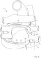
- FIG. 3is a schematic illustration of the delivery device of FIGS. 1 and 2 and a second delivery device, which are coupled together with a portion of a target tissue disposed therebetween.
- FIG. 4is a top view of a delivery device according to an embodiment.
- FIG. 5is a side view of a delivery device according to an embodiment.
- FIG. 6is a side view of the delivery device of FIG. 4 in a first configuration, shown without a portion of a handle to illustrate internal components of the delivery device.
- FIG. 7is side view of the delivery device of FIG. 5 in a second configuration, shown without a portion of a handle to illustrate internal components of the delivery device.
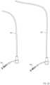
- FIG. 8is a schematic illustration of a first magnetic member and a second magnetic member configured to form a magnetic coupling therebetween according to an embodiment.
- FIG. 9is a schematic illustration of a first magnetic member and a second magnetic member configured to form a magnetic coupling therebetween according to an embodiment.
- FIG. 11is a schematic illustration of a first magnetic member and a second magnetic member configured to form a magnetic coupling therebetween according to an embodiment.
- FIG. 12is a schematic illustration of a first magnetic member and a second magnetic member configured to form a magnetic coupling therebetween according to an embodiment.
- FIG. 13is a schematic illustration of a first magnetic member and a second magnetic member configured to form a magnetic coupling therebetween according to an embodiment.
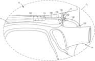
- FIG. 14is an illustration of a portion of a first delivery device and a portion of a second delivery device disposed within a pericardial space of a heart according to an embodiment.
- FIG. 15is an illustration of a portion of a first delivery device disposed within a pericardial space of a heart according to an embodiment.
- FIG. 16is an illustration of a portion of a first delivery device disposed within the pericardial space of the heart and a portion of the second delivery device disposed within the pericardial space of the heart via a posterior approach.
- FIG. 16 Ais an illustration of a portion of a first delivery device disposed within a pericardial space of the heart and a portion of a second delivery device disposed within the pericardial space of the heart via an anterior approach.
- FIG. 17is an enlarged illustration of a portion of the first delivery device and a portion of the second delivery device of FIGS. 14 - 16 A within the heart, identified in FIGS. 16 - 16 A as region Z 1 .
- FIG. 18is an enlarged illustration of a portion of the first delivery device and a portion of the second delivery device of FIGS. 14 - 16 within the heart, identified in FIGS. 16 - 16 A as region Z 1 .
- FIG. 19is an illustration of a portion of a first delivery device and a portion of a second delivery device configured to place a guidewire and/or catheter within a pericardial space of a heart according to an embodiment.
- FIG. 20is an enlarged illustration of a portion of the first delivery device and a portion of the second delivery device of FIGS. 14 - 16 within the heart, identified in FIG. 19 as region Z 2 .
- FIG. 21is an enlarged illustration of a portion of the first delivery device and a portion of the second delivery device of FIGS. 14 - 16 within the heart, identified in FIG. 19 as region Z 2 .
- FIG. 22is an illustration of a guidewire disposed within the pericardial space and about the pulmonary veins of the heart.
- FIG. 23is an illustration of an ablation catheter disposed within the pericardial space and about the pulmonary veins of the heart via the guidewire of FIG. 22 .
- FIG. 24is a flowchart illustrating a method of delivering a catheter to cardiac tissue according to an embodiment.
- FIG. 25is a schematic illustration of a first delivery catheter and second delivery catheter, according to an embodiment.
- FIG. 26is a schematic illustration of a kit, according to an embodiment.
- FIG. 27 Ais a flowchart illustrating a method of delivering a catheter to cardiac tissue according to an embodiment.
- FIG. 27 Bis a flowchart illustrating a method of delivering a catheter to cardiac tissue according to an embodiment.
- an apparatusincludes a first catheter and a second catheter.
- the first cathetercan include a first port in fluid communication with a first lumen
- the second cathetercan include a second port in fluid communication with a second lumen.
- the apparatuscan also include a third catheter.
- the third cathetercan define a third longitudinal axis and a fourth lumen therethrough.
- the third cathetercan include a handle and a third port in fluid communication with the fourth lumen.
- the apparatuscan be configured to transition between a first configuration and a second configuration in response to actuation of the second actuator.
- a distal end of the first cathetercan be disposed within the third catheter in the first configuration.
- the distal end of the first cathetercan be at least partially disposed distal to a distal end of the third catheter in the second configuration.
- a proximal end of the third cathetercan include the third port.
- the magnetic membercan include one or more of an electromagnet, a paramagnet, and a permanent magnet.
- the magnetic membercan be at least partly constructed from radiopaque material.
- the first catheter and the magnetic membercan have substantially the same diameter.
- the third lumencan be non-coaxial with a longitudinal axis of the magnetic member.
- a distal end of the magnetic membercan include a convex or frustoconical shape.
- the second actuatorcan be coupled to a proximal end of the second catheter.
- the first actuatorcan be movably coupled to a proximal end of the handle.
- the rotation of the first actuatorcan be configured to deflect a distal end of the second catheter.
- the rotation of the first actuatorcan be configured to deflect a distal end of the third catheter.
- the first actuatorcan include a rotation member and a translation member.
- the rotation membercan be coupled to a proximal end of the handle and the translation member can be movably disposed within the handle. Rotation of the rotation member can correspond to translation of the translation member along the first longitudinal axis.
- the translation membercan be operably coupled to a distal end of the first catheter via a linkage.
- the third portcan be configured to provide one or more of suction and lavage.
- the second actuatorcan include the second port.
- the second port, the second lumen, and the third lumencan be collectively configured to receive and advance a guidewire during use.
- the second actuatorcan include a push rod disposed within the first lumen and coupled to a proximal end of the second catheter.
- a lumen of the push rodcan be in fluid communication with the second lumen.
- a lumen of the first port, the second lumen, and the lumen of the push rodcan be co-axial.
- the handlecan be configured for single-handed operation.
- the handlecan be coupled to a proximal end of the third catheter.
- a conduitcan define a lumen therethrough.
- the conduitcan be configured to couple to a fluid source.
- the conduitcan be at least partially disposed within the handle.
- the lumen of the conduitcan be in fluid communication with the first lumen and fluidically isolated from the second lumen.
- At least a portion of the first cathetercan be configured to slide within the fourth lumen.
- a proximal end of the first cathetercan include the first port.
- the second and third lumencan be substantially the same diameter.
- a diameter of the first cathetercan be between about 6 French and about 15 French.
- At least a portion of the second cathetercan include a nickel-titanium alloy.
- a proximal end of the first cathetercan be fixedly disposed within the handle.
- a proximal end of the first catheterincludes a protrusion movably disposed within the second actuator.
- the second actuatorcan include a channel configured to movably receive the protrusion.
- a flexibility of the third cathetercan be less than one or more of a flexibility of the first and second catheter.
- the flexibility of the first cathetercan be less than the flexibility of the second catheter.
- the flexibility of the second cathetercan be greater than the flexibility of the first and third catheter.
- the first cathetercan have a bending stiffness between approximately 3 ⁇ 10 ⁇ 5 Netwon-meters 2 and approximately 10 ⁇ 3 Netwon-meters 2 .
- the second cathetercan have a flexural modulus of about 3 ⁇ 10 ⁇ 5 Netwon-meters 2 or less.
- a systemcan include a first device and second device.
- the first devicecan include a first catheter defining a first longitudinal axis and a first lumen therethrough.
- a first actuatorcan be coupled to the first catheter and configured to rotate about the first longitudinal axis to deflect a distal end of the first catheter relative to the first longitudinal axis.
- a second cathetercan define a second longitudinal axis and a second lumen therethrough. At least a portion of the second catheter can be configured to slide within the first lumen.
- a first magnetic membercan be coupled to a distal end of the second catheter.
- the first magnetic membercan define a third lumen therethrough.
- the third lumencan be in fluid communication with the second lumen.
- a second actuatorcan be coupled to the second catheter.
- the second actuatorcan be configured to move linearly along the second longitudinal axis so as to vary a spacing between the first magnetic member and a distal end of the first catheter.
- the second devicecan include a fourth catheter defining a fourth longitudinal axis and a fourth lumen therethrough.
- a fourth actuatorcan be coupled to the fourth catheter and configured to rotate about the fourth longitudinal axis to deflect a distal end of the fourth catheter relative to the fourth longitudinal axis.
- a fifth cathetercan define a fifth longitudinal axis and a fifth lumen therethrough. At least a portion of the fifth catheter can be configured to slide within the fourth lumen.
- a second magnetic membercan be coupled to a distal end of the fifth catheter.
- the second magnetic membercan define a sixth lumen therethrough.
- the sixth lumencan be in fluid communication with the fifth lumen.
- the second magnetic membercan have a polarity opposite the first magnetic member such that the first and second magnetic members are configured to couple magnetically with the third lumen aligned to the sixth lumen.
- a fifth actuatorcan be coupled to the fifth catheter. The fifth actuator can be configured to move linearly along the fifth longitudinal axis so as to vary a spacing between the second magnetic member and a distal end of the fourth catheter.
- the first cathetercan include a first port in fluid communication with the first lumen.
- the second cathetercan include a second port in fluid communication with the second lumen.
- the first devicecan include a third catheter defining a third longitudinal axis and a lumen therethrough.
- the third cathetercan include a handle and a third port in fluid communication with the lumen of the third catheter.
- the fourth cathetercan include a fourth port in fluid communication with the fourth lumen.
- the fifth cathetercan include a fifth port in fluid communication with the fifth lumen.
- the second devicecan include a sixth catheter defining a sixth longitudinal axis and a lumen therethrough.
- the sixth cathetercan include a handle and a sixth port in fluid communication with the lumen of the sixth catheter.
- a distal end of the first magnetic member and a distal end of the second magnetic membercan include complimentary shapes.
- the first devicecan include a first catheter defining a first longitudinal axis and a first lumen therethrough.
- a second cathetercan define a second longitudinal axis and a second lumen therethrough. At least a portion of the second catheter can be configured to slide within the first lumen.
- a first magnetic membercan be coupled to a distal end of the second catheter. The first magnetic member can define a third lumen therethrough. The third lumen can be in fluid communication with the second lumen.
- a second devicecan be inserted into the pericardial tissue of the heart such that a distal end of the second device is disposed within the pericardial space on a second side of the first pericardial reflection opposite the first side.
- the second devicecan include a fourth catheter defining a fourth longitudinal axis and a fourth lumen therethrough.
- a fifth cathetercan define a fifth longitudinal axis and a fifth lumen therethrough. At least a portion of the fifth catheter can be configured to slide within the fourth lumen.
- a second magnetic membercan be coupled to a distal end of the fifth catheter.
- the second magnetic membercan define a sixth lumen therethrough.
- the sixth lumencan be in fluid communication with the fifth lumen.
- the first magnetic membercan be advanced to place the first magnetic member close to the first side of the first pericardial reflection.
- the second magnetic membercan be advanced to place the second magnetic member close to the second side of the first pericardial reflection such that the first magnetic member couples to the second magnetic member across the first pericardial reflection via a magnetic force when the first magnetic member is close to the first side of the first pericardial reflection and the second magnetic member is close to the second side of the first pericardial reflection.
- a crossing wirecan be advanced through the third lumen, the first pericardial reflection, and at least a portion of the sixth lumen to create an opening in the first pericardial reflection.
- a portion of one of the first and second magnetic memberscan be advanced through the opening and the first pericardial reflection.
- a guidewirecan be advanced through the first lumen and the first pericardial reflection such that a portion of the guidewire is disposed on the second side of the first pericardial reflection.
- Advancing the first magnetic membercan include actuating a first actuator of the first device. Actuating the first actuator can advance the second catheter relative to the first catheter. Actuating the first actuator can deflect a distal end of the first catheter.
- Advancing the second magnetic membercan include actuating a second actuator of the second device. Actuating the second actuator can advance the fifth catheter relative to the fourth catheter. Actuating the second actuator can deflect a distal end of the second catheter.
- the opening in the first pericardial reflectioncan be dilated.
- the crossing wirecan be withdrawn from the first pericardial reflection and the third lumen.
- the first and second devices disposed within the pericardial spacecan be fluoroscopically imaged.
- a methodcan include the steps of inserting a first device into pericardial tissue of a heart such that a distal end of the first device is disposed within a pericardial space of the heart and on a first side of a first pericardial reflection.
- the first devicecan include a first catheter defining a first longitudinal axis and a first lumen therethrough.
- a second cathetercan define a second longitudinal axis and a second lumen therethrough. At least a portion of the second catheter can be configured to slide within the first lumen.
- a first magnetic membercan be coupled to a distal end of the second catheter.
- the first magnetic membercan define a third lumen therethrough.
- the third lumencan be in fluid communication with the second lumen.
- a second devicecan be inserted into the pericardial tissue of the heart such that a distal end of the second device is disposed within the pericardial space on a second side of the first pericardial reflection opposite the first side.
- the second devicecan include a fourth catheter defining a fourth longitudinal axis and a fourth lumen therethrough.
- a fifth cathetercan define a fifth longitudinal axis and a fifth lumen therethrough. At least a portion of the fifth catheter can be configured to slide within the fourth lumen.
- a second magnetic membercan be coupled to a distal end of the fifth catheter.
- the second magnetic membercan define a sixth lumen therethrough.
- the sixth lumencan be in fluid communication with the fifth lumen.
- the first magnetic membercan be advanced to place the first magnetic member close to the first side of the first pericardial reflection.
- the second magnetic membercan be advanced to place the second magnetic member close to the second side of the first pericardial reflection such that the first magnetic member couples to the second magnetic member across the first pericardial reflection via a magnetic force when the first magnetic member is close to the first side of the first pericardial reflection and the second magnetic member is close to the second side of the first pericardial reflection.
- a crossing wirecan be advanced through the third lumen, the first pericardial reflection, and at least a portion of the sixth lumen to create an opening in the first pericardial reflection.
- a portion of one of the first and second magnetic memberscan be advanced through the opening and the first pericardial reflection.
- the distal end of the first devicecan be advanced on a first side of a second pericardial reflection.
- the distal end of the second devicecan be advanced on a second side of the second pericardial reflection.
- the first magnetic membercan be advanced to place the first magnetic member close to the first side of the second pericardial reflection.
- the second magnetic membercan be advanced to place the second magnetic member close to the second side of the second pericardial reflection such that the first magnetic member couples to the second magnetic member across the second pericardial reflection via a magnetic force when the first magnetic member is close to the first side of the second pericardial reflection and the second magnetic member is close to the second side of the first second reflection.
- the crossing wirecan be advanced through the third lumen, the second pericardial reflection, and at least a portion of the sixth lumen to create an opening in the second pericardial reflection.
- the portion of one of the first and second magnetic memberscan be advanced through the opening and the second pericardial reflection.
- the crossing wirecan be withdrawn from the second pericardial reflection and the third lumen.
- a guidewirecan be delivered through the third lumen, the opening in the first pericardial reflection, the opening in the second pericardial reflection, and the sixth lumen.
- the first and second devicescan be withdrawn from a body of a subject while leaving the guidewire in place.
- a medical devicecan be advanced over the guidewire and through the openings in the first and second pericardial reflections. At least part of the left and right pulmonary veins can be encircled with the medical device.
- the medical devicecan include an ablation catheter.
- a circumferential ablation lesioncan be formed using the ablation catheter.
- a guidewirecan be advance through the first lumen and the second pericardial reflection such that a portion of the guidewire is disposed on the second side of the second pericardial reflection.
- the opening in the second pericardial reflectioncan be dilated.
- the first and second devicescan be inserted into the pericardial tissue and include inserting an introducer catheter into a body of a subject.
- the first devicecan be inserted into the pericardial tissue and include advancing the first device along a transverse sinus of the heart.
- the second devicecan be inserted into the pericardial tissue and include advancing the second device along an oblique sinus of the heart.
- an apparatusin some embodiments, includes a handle, a first catheter, a second catheter, a third catheter, a magnetic member, a first actuator, and a second actuator.
- the first catheterhas a proximal end portion and a distal end portion and defines a lumen therethrough.
- the proximal end portion of the first catheteroperably couples to the handle and includes a first port in fluid communication with the lumen of the first catheter.
- the second catheterhas a proximal end portion and a distal end portion and defines a lumen therethrough.
- the second catheteris at least partially disposed within the lumen of the first catheter.
- the proximal end portion of the second catheteris fixedly disposed within the handle and includes a second port in fluid communication with the lumen of the second catheter.
- the third catheterhas a proximal end portion and a distal end portion and defining a lumen therethrough. At least a portion of the third catheter is movably disposed within the lumen of the second catheter.
- the magnetic memberis coupled to the distal end portion of the third catheter.
- the magnetic memberdefines a lumen extending therethrough that is in fluid communication with the lumen of the third catheter.
- the first actuatoris coupled to the proximal end portion of the third catheter such that an access port of the first actuator is in fluid communication with the lumen of the third catheter.
- the first actuatoris configured to be moved linearly relative to the housing to move the third catheter within the lumen of the second catheter between a proximal position, in which the magnetic member is adjacent to a distal surface of the second catheter, and a distal position, in which the magnetic member is distal to and spaced apart from the distal surface of the second catheter.
- the second actuatoris operably coupled to the distal end portion of the second catheter such that rotation of the second actuator deflects the distal end portion of the second catheter in a non-linear direction.
- a systemin some embodiments, includes a first delivery device, a second delivery device, and a guidewire.
- the first delivery deviceincludes a handle, a first catheter, a second catheter, and an actuator.
- the first catheter of the first delivery devicehas a proximal end portion disposed within the handle of the first delivery device and a distal end portion configured for insertion into the body and defines a lumen extending therethrough.
- the second catheterhas a proximal end portion and a distal end portion and defines a lumen therethrough.
- the distal end portion of the second catheter of the first delivery deviceincludes a magnetic member. At least a portion of the second catheter of the first delivery device is movably disposed within the lumen of the first catheter of the first delivery device.
- the actuator of the first delivery deviceis movably coupled to the proximal end portion of the second catheter of the first delivery device such that a port of the actuator is in fluid communication with the lumen of the second catheter.
- the actuator of the first delivery deviceis configured to move relative to the handle to place the magnetic member of the first delivery device adjacent to a first side of a target tissue when the distal end portion of the first catheter is inserted into the body.
- the second delivery deviceincludes a handle, a first catheter, a second catheter, and an actuator.
- the first catheter of the second delivery devicehas a proximal end portion disposed within the handle of the second delivery device and a distal end portion configured for insertion into the body and defines a lumen extending therethrough.
- the second catheterhas a proximal end portion and a distal end portion and defines a lumen therethrough.
- the distal end portion of the second catheter of the second delivery deviceincludes a magnetic member having a length between approximately 2.0 millimeters (mm) and approximately 10.0 mm, including all values and sub-ranges in between.
- At least a portion of the second catheter of the second delivery deviceis movably disposed within the lumen of the first catheter of the second delivery device.
- the actuator of the second delivery deviceis movably coupled to the proximal end portion of the second catheter of the second delivery device such that a port of the actuator is in fluid communication with the lumen of the second catheter.
- the actuator of the second delivery deviceis configured to move relative to the handle to place the magnetic member of the second delivery device adjacent to a second side of the target tissue when the distal end portion of the first catheter is inserted into the body.
- the guidewireis configured to be inserted, via the port of the actuator of the first delivery device, through the second catheter of the first delivery device, the target tissue, and at least a portion of the second catheter of the second delivery device.
- the guidewireis configured to define a path circumscribing at least a portion of an anatomic structure.
- a methodincludes inserting a delivery catheter of a first delivery device into pericardial tissue of a heart such that a distal end portion of the delivery catheter is disposed within a pericardial space of the heart and on a first side of a pericardial reflection.
- a delivery catheter of a second delivery deviceis inserted into the pericardial tissue of the heart such that a distal end portion of the delivery catheter of the second delivery device is disposed within the pericardial space on a second side of the pericardial reflection opposite the first side.
- An actuator of the first delivery deviceis actuated to advance a magnetic member of the first delivery device relative to the delivery catheter of the first delivery device to place the magnetic member of the first delivery device close to the first side of the pericardial reflection.
- the absolute distancecan be from about 0 mm to about 30 mm, including all values and sub-ranges in between.
- the relative distancecan be relative to a dimension of a particular catheter component. For example, if the magnetic member has a length (say) L (for example, L can have a value in the range between about 2 mm and about 11 mm), the tip of the magnetic member can be less than about a distance about four times the length L (4*L) from the pericardial reflection when the magnetic member is “close to” the pericardial reflection.
- An actuator of the second delivery deviceis actuated to advance a magnetic member of the second delivery device relative to the delivery catheter of the second delivery device to place the magnetic member of the second delivery device close to the second side of the pericardial reflection.
- the magnetic member of the first delivery device and the magnetic member of the second delivery deviceare coupled via a magnetic coupling when the magnetic member of the first delivery device is close to the first side of the pericardial reflection and the magnetic member of the second delivery device is close to the second side of the pericardial reflection (e.g., if the magnetic member of the second delivery device has a length, the tip of the magnetic member can be less than about a distance of approximately four times the length L (4*L) from the second side of the pericardial reflection).
- a needlee.g., a trocar, stylet, wire, and/or other sharpened elongate member
- a needleis advanced through a lumen of the magnetic member of the first delivery device, the pericardial reflection, and at least a portion of a lumen of the magnetic member of the second delivery device.
- the opening defined in the pericardial reflection as a result of the advancing the needleis dilated.
- a portion of the delivery catheter of the first delivery deviceis advanced through the opening defined in the pericardial reflection to place the magnetic member of the first delivery device on the second side of the pericardial reflection.
- a guidewireis then advanced through the lumen of the delivery catheter of the first delivery device and the pericardial reflection such that a portion of the guidewire is disposed on the second side of the pericardial reflection.
- a methodincludes positioning a distal end of a first delivery catheter proximate to a first side of a first pericardial reflection of a subject.
- the first delivery catheterhas a lumen extending therethrough.
- a first catheter of a first deviceis disposed in the lumen of the first delivery catheter.
- the first catheter of the first deviceis extended towards the first pericardial reflection to lie outside a distal portion of the first delivery catheter.
- the first catheterhaving a lumen extending therethrough.
- a second catheter of the first devicedisposed in the first lumen of the first catheter.
- the second catheter of the first deviceis extended towards the first pericardial reflection to lie outside a distal portion of the first catheter of the first device such that the second catheter of the first device contacts the first pericardial reflection.
- a distal end portion of a second delivery catheteris positioned proximate to a second side of the first pericardial reflection of the subject.
- the second delivery catheterhas a lumen extending therethrough.
- a first catheter of a second deviceis disposed in the lumen of the second delivery catheter.
- the first catheter of the second deviceis extended towards the first pericardial reflection to lie outside a distal portion of the second delivery catheter.
- the first catheter of the second devicehas a lumen extending therethrough.
- a second catheter of the first deviceis disposed in the lumen of the first catheter.
- the second catheter of the second deviceis extended towards the first pericardial reflection to lie outside a distal portion of the first catheter of the second device such that the second catheter of the second device contacts the first pericardial reflection.
- a first magnet assembly of the second catheter of the first device and a second magnet assembly of the second catheter of the second deviceare magnetically coupled across the first pericardial reflection when the second catheter of the second device is extended such that the lumen of the second catheter of the first device is substantially axially aligned with the lumen of the second catheter of the second device.
- the first pericardial reflectionis pierced by advancing a sharpened guidewire through the lumen of the second catheter of the first device, through the first pericardial reflection, and into the lumen of the second catheter of the second device to define a pierced portion in the first pericardial reflection.
- the sharpened guidewireis withdrawn from the lumen of the second catheter of the second device and from the first pericardial reflection.
- the second catheter of the first deviceis withdrawn into the first catheter of the first device and the first catheter of the first device is withdrawn into the first delivery catheter.
- the second catheter of the second deviceis withdrawn into the first catheter of the second device and the first catheter of the second device is withdrawn into the second delivery catheter.
- the distal end portion of the first delivery catheteris positioned proximate to a first side of a second pericardial reflection of the subject.
- the first catheter of the first deviceis extended from the first delivery catheter towards the second pericardial reflection to lie outside the distal portion of the first delivery catheter.
- the second catheter of the first deviceis extended towards the second pericardial reflection to lie outside the distal portion of the first catheter of the first device such that the second catheter of the first device contacts the second pericardial reflection.
- a distal end of the second delivery catheteris positioned proximate to a second side of the second pericardial reflection of the subject.
- the first catheter of the second deviceis extended from the second delivery catheter towards the second pericardial reflection to lie outside the distal portion of the second delivery catheter.
- the second catheter of the second deviceis extended towards the second pericardial reflection to lie outside the distal portion of the first catheter of the second device such that the second catheter of the second device contacts the first pericardial reflection.
- the first magnet assembly of the second catheter of the first device and the second magnet assembly of the second catheter of the second deviceare magnetically coupled across the second pericardial reflection when the second catheter of the second device is extended such that the lumen of the second catheter of the first device is substantially axially aligned with the lumen of the second catheter of the second device.
- the second pericardial reflectionis pierced by advancing the sharpened guidewire through the lumen of the second catheter of the first device, through the second pericardial reflection, and into the lumen of the second catheter of the second device to define a pierced portion in the second pericardial reflection.
- the sharpened guidewireis then withdrawn from the lumen of the second catheter and from the second pericardial reflection.
- a guidewireis delivered through the lumen of the second catheter of the first device, the pierced portion in the first pericardial reflection, the pierced portion in the second pericardial reflection, and the lumen of the second catheter of the second device.
- the first device, the first delivery catheter, the second device, and the second catheterare withdrawn from the body of the subject while leaving the guidewire in place.
- a medical deviceis then positioned in the pericardial space of the heart of the subject by passing the medical device over the guidewire, through the pierced portion of the first pericardial reflection, and through the pierced portion of the second pericardial reflection, such that a central portion of the medical device at least partially encircles the left pulmonary veins and the right pulmonary veins.
- a reference to “A and/or B”, when used in conjunction with open-ended language such as “comprising”can refer, in one embodiment, to A only (optionally including elements other than B); in another embodiment, to B only (optionally including elements other than A); in yet another embodiment, to both A and B (optionally including other elements); etc.
- proximal and distalrefer to direction closer to and away from, respectively, an operator of the medical device.
- the end of a catheter or delivery device contacting the patient's bodywould be the distal end of the medicament delivery device, while the end opposite the distal end (i.e., the end operated by the user) would be the proximal end of the catheter or delivery device.
- the terms “about” and/or “approximately” when used in conjunction with numerical values and/or rangesgenerally refer to those numerical values and/or ranges near to a recited numerical value and/or range. In some instances, the terms “about” and “approximately” can mean within ⁇ 10% of the recited value. For example, in some instances, “about 100 [units]” can mean within ⁇ 10% of 100 (e.g., from 90 to 110). The terms “about” and “approximately” can be used interchangeably.
- term “substantially” when used in connection with, for example, a geometric relationship, a numerical value, and/or a rangeis intended to convey that the geometric relationship (or the structures described thereby), the number, and/or the range so defined is nominally the recited geometric relationship, number, and/or range.
- two structures described herein as being “substantially parallel”is intended to convey that, although a parallel geometric relationship is desirable, some non-parallelism can occur in a “substantially parallel” arrangement.
- tolerancescan result from manufacturing tolerances, measurement tolerances, and/or other practical considerations (such as, for example, minute imperfections, age of a structure so defined, a pressure or a force exerted within a system, and/or the like).
- a suitable tolerancecan be, for example, of ⁇ 1%, ⁇ 2%, ⁇ 3%, ⁇ 4%, ⁇ 5%, ⁇ 6%, ⁇ 7%, ⁇ 8%, ⁇ 9%, or ⁇ 10% of the stated geometric construction, numerical value, and/or range.
- a numerical value modified by the term “substantially”can allow for and/or otherwise encompass a tolerance of the stated numerical value, it is not intended to exclude the exact numerical value stated.
- the term “stiffness”is related to an object's resistance to deflection, deformation, and/or displacement that is produced by an applied force, and is generally understood to be the opposite of the object's “flexibility.” For example, a wall with greater stiffness is more resistant to deflection, deformation, and/or displacement when exposed to a force than a wall having a lower stiffness. Similarly stated, an object having a higher stiffness can be characterized as being more rigid than an object having a lower stiffness. Stiffness can be characterized in terms of the amount of force applied to the object and the resulting distance through which a first portion of the object deflects, deforms, and/or displaces with respect to a second portion of the object.
- the deflected distancecan be measured as the deflection of a portion of the object different from the portion of the object to which the force is directly applied. Said another way, in some objects, the point of deflection is distinct from the point where force is applied.
- Stiffnessis an extensive property of the object being described, and thus is dependent upon the material from which the object is formed as well as certain physical characteristics of the object (e.g., cross-sectional shape, length, boundary conditions, etc.).
- the stiffness of an objectcan be increased or decreased by selectively including in the object a material having a desired modulus of elasticity, flexural modulus, and/or hardness.
- the modulus of elasticityis an intensive property of (i.e., is intrinsic to) the constituent material and describes an object's tendency to elastically (i.e., non-permanently) deform in response to an applied force.
- the stiffness of the objectcan be decreased, for example, by introducing into the object and/or constructing the object of a material having a relatively low modulus of elasticity.
- the stiffness of the objectcan be increased or decreased by changing the flexural modulus of a material of which the object is constructed.
- Flexural modulusis used to describe the ratio of the applied stress on an object in flexure to the corresponding strain in the outermost portions of the object.
- the flexural modulusrather than the modulus of elasticity, is used to characterize certain materials, for example plastics, that do not have material properties that are substantially linear over a range of conditions.
- An object with a first flexural modulusis less elastic and has a greater strain on the outermost portions of the object than an object with a second flexural modulus lower than the first flexural modulus.
- the stiffness of an objectcan be increased by including in the object a material having a high flexural modulus.
- the stiffness of an objectcan also be increased or decreased by changing a physical characteristic of the object, such as the shape or cross-sectional area of the object.
- a physical characteristic of the objectsuch as the shape or cross-sectional area of the object.
- an object having a length and a cross-sectional areacan have a greater stiffness than an object having an identical length but a smaller cross-sectional area.
- the stiffness of an objectcan be reduced by including one or more stress concentration risers (or discontinuous boundaries) that cause deformation to occur under a lower stress and/or at a particular location of the object.
- the stiffness of the objectcan be decreased by decreasing and/or changing the shape of the object.
- the embodiments described hereincan be formed or constructed of one or more biocompatible materials.
- suitable biocompatible materialsinclude metals, glasses, ceramics, or polymers.
- suitable metalsinclude pharmaceutical grade stainless steel, gold, titanium, nickel, iron, platinum, tin, chromium, copper, and/or alloys thereof.
- a biocompatible polymer materialcan be biodegradable or non-biodegradable.
- suitable biodegradable polymersinclude polylactides, polyglycolides, polylactide-co-glycolides (PLGA), polyanhydrides, polyorthoesters, polyetheresters, polycaprolactones, polyesteramides, poly(butyric acid), poly(valeric acid), polyurethanes, and/or blends and copolymers thereof.
- non-biodegradable polymersinclude nylons, polyesters, polycarbonates, polyacrylates, polymers of ethylene-vinyl acetates and other acyl substituted cellulose acetates, non-degradable polyurethanes, polystyrenes, polyvinyl chloride, polyvinyl fluoride, poly(vinyl imidazole), chlorosulphonate polyolefins, polyethylene oxide, and/or blends and copolymers thereof. While specific examples of materials are listed above, it should be understood that the list is not exhaustive and thus, some embodiments described herein can be formed of biocompatible materials other than those listed.
- any of the embodiments and/or components described hereincan be formed of and/or can include a material that is visible under known imaging techniques such as, for example, X-Ray, fluoroscopy, computed tomography (CT), etc.
- one or more componentscan be formed of and/or can include a radiopaque material, such as a radiopaque band and/or marker.
- the embodimentscan include, be used with, and/or used to place devices in the pericardial space, such as devices including one or more electrodes and/or electrode portions.
- Any of the electrodes or electrode portions described hereincan be constructed from any suitable material having any suitable range of electrical conductivity.
- any of the electrode portions described hereincan be constructed from silver, palladium, stainless steel, titanium, platinum, nickel, and any alloys thereof.
- the electrodes and/or electrode portions described hereincan be constructed using any suitable procedures.
- the electrode materials with chosen electrical conductivitiescan be plated, coated, and/or otherwise applied in an appropriately thick layer on top of a different substrate material.
- electrode portionscan be coupled together using annealing, soldering, welding, crimping, and/or lamination to ensure good electrical contact at all interfaces.
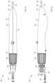
- FIGS. 1 and 2are schematic illustrations of a delivery device 100 (also sometimes referred to herein as a “first device”) in a first configuration and a second configuration, respectively, according to an embodiment.
- the delivery device 100can be used to deliver a catheter, guidewire, needle, etc. to a target tissue.
- the delivery device 100can be used with a second delivery device 100 ′ (also sometimes referred to herein as a “second device”) substantially similar to the delivery device 100 to place a guidewire and/or a catheter in, at, and/or around a target tissue (see e.g., FIG. 3 ).
- the delivery device(s) 100 and/or 100 ′can be used to place a guidewire within the pericardial space and about the pulmonary veins of a heart.
- an ablation catheter or the likecan be advanced along the guidewire and once placed, can be used to produce a circumferential ablation lesion suitable to treat, for example, atrial fibrillation, and/or the like.
- portions of the delivery device 100can be similar in form and/or function to those described in PCT Patent Publication No. WO2014/025394 entitled, “Catheters, Catheter Systems, and Methods for Puncturing Through a Tissue Structure,” filed Mar.
- the delivery device(s) 100 and/or 100 ′are not described in further detail herein.
- the delivery devices 100 and 100 ′can be similar or substantially the same, while in other instances, the delivery devices 100 and 100 ′ can be structurally and/or functionally different, based on the intended use of the respective device. For example, a device placed in a longer route to reach its intended target can be longer than one intended to traverse a shorter distance.
- the discussion of the delivery device 100is intended to apply equally to the delivery device 100 ′ unless clearly indicated otherwise.
- the delivery device 100(includes a handle 110 , a delivery catheter 102 (also sometimes referred to herein as a “third catheter”), a first catheter 120 , a second catheter 130 , a magnetic member 135 , a first actuator 150 , and a second actuator 160 .
- the handle 110can be any suitable shape, size, and/or configuration. In some embodiments, for example, the handle 110 can have a size and/or shape suitable for single-handed operation (either left hand or right hand operation). In some embodiments, the size and/or shape of the handle 110 can be configured to increase the ergonomics and/or ease of use of the device 100 .
- the delivery catheter 102can be any suitable shape, size, and/or configuration.
- the delivery catheter 102has a proximal end portion and a distal end portion and defines a lumen therethrough.
- the proximal end portion of the delivery catheter 102is coupled to the handle 110 .
- the delivery catheter 102can be included in and/or coupled to any suitable portion of the device other than the handle 110 .
- the proximal end portion of the delivery catheter 102includes and/or defines a port 103 (also sometimes referred to as “third port”) in fluid communication with the lumen.
- the port 103can be used to provide (e.g., lavage) or withdraw (e.g., suction) a fluid through the lumen of the delivery catheter 103 , which in some instances, can facilitate the advancement of the delivery catheter 102 through portions of the body.
- the lumen of the delivery catheter 102movably receives at least a portion of the first catheter 120 , the second catheter 130 , and the magnetic member 135 .
- the delivery catheter 102is disposed about at least a portion of the first catheter 120 , the second catheter 130 , and the magnetic member 135 .
- the delivery catheter 102can be formed of a relatively flexible material such as any of those described herein.
- the delivery catheter 102can be formed from one or more materials and can have a flexibility that is lesser than a flexibility of the first catheter 120 and/or the second catheter 130 .
- the delivery catheter 102can be configured to support, protect, and/or otherwise deliver the distal end portions of the catheters 120 and 130 and the magnetic member 135 to a desired position within a portion of the body.
- at least a portion of the delivery catheter 102can be non-linear (e.g., can have and/or can define one or more curved sections).
- the delivery catheter 102can be curved in such a manner as to facilitate access to epicardial or pericardial locations on an anterior and/or posterior surface(s) of the heart.
- the delivery catheter 102can be inserted into and advanced through the pericardial space of a heart to place, for example, the magnetic member 135 close to a pericardial reflection (e.g., within about four times the length of the magnetic member), as described in further detail herein with reference to specific embodiments.
- the first catheter 120can be any suitable catheter configured to be inserted into a portion of a patient.
- the first catheter 120can be relatively flexible to allow a portion of the first catheter 120 to bend, flex, deflect, and/or otherwise elastically deform as the first catheter 120 is advanced within a portion of the body.
- the first catheter 120can have a flexibility that is greater than a flexibility of the delivery catheter 102 but less than a flexibility of the second catheter 130 , as described in further detail herein.
- the first catheter 120can have a size (e.g., diameter) that is associated with and/or otherwise suitable for insertion into the handle 110 and/or the delivery catheter 102 .
- the first catheter 120has a proximal end portion 121 and a distal end portion 122 and defines a first longitudinal axis and a first lumen therethrough.
- the proximal end portion 121 of the first catheter 120is fixedly disposed within the handle 110 .
- the proximal end portion 121 of the first catheter 120can be movably coupled to and/or movably disposed in the handle 110 .
- the proximal end portion 121 of the first catheter 120includes, defines, and/or is otherwise coupled to a port 125 (also sometimes referred to as “first port”).
- the port 125is in fluid communication with the lumen of the first catheter 120 and can be used to provide (e.g., lavage) or withdraw (e.g., suction) a fluid through the lumen of the first catheter 120 .
- the distal end portion 122 of the first catheter 120is disposed distal to and outside of the handle 110 and is at least partially and/or at least temporarily disposed within a lumen defined by the delivery catheter 102 , as described in further detail herein.
- the distal end portion 122 of the first catheter 120can be disposed within the lumen (also sometimes referred to as a “fourth lumen”) of the delivery catheter 102 when the device 100 is in the first configuration (e.g., FIG.
- the distal end portion 122 of the first catheter 120is operably coupled to the first actuator 150 such that actuation of the first actuator 150 results in a deflection of at least the distal end portion 122 of the first catheter 120 .
- a proximal end of the first cathetercan be configured to slide within the fourth lumen.
- the second catheter 130can be any suitable catheter configured to be inserted into a portion of the patient and can have a size (e.g., diameter) that is associated with and/or otherwise suitable for insertion into the lumen of the first catheter 120 .
- the second catheter 130can be formed of a relatively flexible material (e.g., a material having a relatively low stiffness) such as any of those described above.
- the second catheter 130can have a stiffness that is less than a stiffness of the first catheter 120 (and less than a stiffness of the delivery catheter 102 ).
- the second catheter 130can be more flexible than the first catheter 120 and the delivery catheter 102 .
- the second catheter 130can be the most flexible catheter 130 included in the delivery device 100 . At least a portion of the second catheter 130 can be configured to slide within the first lumen.
- the second catheter 130has a proximal end portion 131 and a distal end portion 132 and defines a second longitudinal axis and a second lumen 133 therethrough. As shown in FIGS. 1 and 2 , the distal end portion 132 of the second catheter 130 is coupled to the magnetic member 135 such that a third lumen 137 of the magnetic member 135 is in fluid communication with the second lumen 133 of the second catheter 130 , as described in further detail herein. While the lumens 133 and 137 are shown in FIGS.
- a second lumen 133 of the second catheter 130can have a diameter that is less than or, alternatively, that is greater than, a diameter of the third lumen 137 of the magnetic member 135 .
- the proximal end portion 131 of the second catheter 130is coupled to the second actuator 160 such that the second catheter 130 is moved within the first lumen of the first catheter 120 between a first position (e.g., FIG. 1 ) and a second position (e.g., FIG. 2 ) in response to an actuation of the second actuator 160 , as described in further detail herein.
- the devicecan be configured to transition between a first configuration and a second configuration in response to actuation of the second actuator 160 .
- a distal end of the first cathetercan be disposed within the third catheter in the first configuration.
- the distal end of the first cathetercan be at least partially disposed distal to a distal end of the third catheter in the second configuration.
- the devicecan be configured to transition between any suitable number of configurations (e.g., one, two, three, four, or more configurations), and can transition between any two configurations in a stepwise manner or continuous manner.
- the magnetic member 135is included in and/or coupled to the distal end portion 132 of the second catheter 130 .
- the magnetic member 135is coupled to the distal end portion 132 of the second catheter 130 via a weld, adhesive, and/or mechanical fastener.
- the magnetic member 135can be integrally formed with the distal end portion 132 of the second catheter 130 (e.g., co-molded, over-molded, etc.).
- the distal end portion 132 of the second catheter 130can be at least partially formed of a magnetic constituent material or the like.
- the arrangement of the second catheter 130 and the magnetic member 135is such that the second lumen 133 of the second catheter 130 is in fluid communication with the third lumen 137 of the magnetic member 135 . More particularly, as shown in FIGS. 1 and 2 , the lumens 133 and 137 can be aligned and/or co-axial.
- the magnetic member 135can be any suitable shape, size, and/or configuration.
- the magnetic member 135can be, for example, an electromagnet, a paramagnet, a permanent magnet, and/or any other suitable magnetic member.
- the magnetic member 135can be formed of any suitable magnetic material and/or any material capable of being magnetized.
- the magnetic member 135can be formed of a material configured to be visible within a portion of the body via fluoroscopic imaging techniques (e.g., a radiopaque material or the like).
- the magnetic member 135can be polygonal (e.g., triangular, square, rectangular, pentagonal, etc.), rounded (e.g., semi-circular, circular, elliptical, oblong, etc.), and/or a combination thereof.
- the magnetic member 135can be at least partially cylindrical or the like and can have a diameter that is substantially similar to a diameter of the first catheter 120 (see e.g., FIG. 1 ).
- the magnetic member 135can have a size and/or shape configured to be matingly coupled to a corresponding magnetic member of a second (e.g., separate) delivery device.
- the size and/or shape of the magnetic member 135can increase and/or otherwise direct a magnetic flux or force operable to increase a likelihood of a magnetic coupling between the magnetic member 135 and a corresponding magnetic member through a target tissue (e.g., magnetically coupled such that a portion of the target tissue is disposed therebetween), as described in further detail herein.
- a target tissuee.g., magnetically coupled such that a portion of the target tissue is disposed therebetween
- a target tissuee.g., magnetically coupled such that a portion of the target tissue is disposed therebetween
- a force operable to magnetically couple the magnetic memberscan be sufficient to bend, flex, and/or move the distal end portion 132 of the second catheter 130 to allow the magnetic members 135 , 135 ′ to couple together.
- the first actuator 150can be any suitable shape, size, and/or configuration.
- the first actuator 150is movably coupled to the proximal end portion of the handle 110 and operably coupled to the distal end portion 122 of the first catheter 120 .
- the first actuator 150is configured to rotate relative to the handle 110 and about the second actuator 160 (e.g., the second actuator 160 defines an axis of rotation).
- the first actuator 150can be coupled to the handle 110 in any suitable manner and/or position.
- the first actuator 150can be operably coupled to the distal end portion 122 of the first catheter 120 in any suitable manner.
- the first actuator 150is operably coupled to the distal end portion 122 of the first catheter 120 via a wire, tether, and/or any other suitable linkage. In this manner, movement of the first actuator 150 relative to the handle 110 results in movement of the distal end portion 122 of the first catheter 120 , which in turn, can result in movement of the second catheter 130 .
- rotation of the first actuator 150 relative to the handle 110results in an elastic deformation and/or a deflection (e.g., bending, curving, twisting, and/or any other suitable reconfiguration) of the distal end portion 122 of the first catheter 120 .
- the first actuator 150can be coupled to the first catheter 120 and configured to rotate about the first longitudinal axis to deflect a distal end of the first catheter 120 relative to the first longitudinal axis.
- the deflection of the first catheter 120can result in an associated and/or similar deflection of the second catheter 130 .
- deflection of the distal end portion 122 of the first catheter 120can facilitate the placement of the magnetic member 135 within a desired portion of the body, as described in further detail herein.
- forming the first catheter 120 from a relatively flexible materialcan allow for steering and/or fine control of the distal end portion 122 of the first catheter 120 during placement near and/or at a target location and/or tissue within the body such as, for example, a pericardial reflection, as described herein.
- the first actuator 150can be actuated while the distal end portion 122 of the first catheter 120 is disposed within the lumen of the delivery catheter 102 , which in turn, can result in deflection of both the distal end portion of the delivery catheter 102 and the distal end portion 122 of the first catheter 120 (as well as the second catheter 130 disposed within the first catheter 120 , as described above).
- the delivery catheter 102can be formed of a material that is sufficiently flexible to allow the distal end portion of the delivery catheter 102 to deflect when the distal end portion 122 of the first catheter 120 is disposed therein and in response to an actuation of the first actuator 150 .
- the delivery catheter 102can be formed of a material that is not sufficiently flexible (e.g., a stiffness of the material is too large) to deflect in response to the deflection of the first catheter 120 .
- a force associated with a deflection of the distal end portion 122 of the first catheter 120in response to an actuation of the first actuator 150 , is not sufficient to deflect the distal end portion of the delivery catheter 102 when disposed therein.
- the second actuator 160is coupled to the proximal end portion 131 of the second catheter 130 and is configured to move the second catheter 130 relative to the first catheter 120 .
- the second actuator 160is slidably and/or movably coupled to a proximal end portion of the handle 110 and is configured to move linearly in a proximal and/or distal direction to move the second catheter 130 between a first position (e.g., a proximal position as shown in FIG. 1 ) and a second position (e.g., a distal position as shown in FIG. 2 ).
- the second actuator 160can be configured to move linearly along the second longitudinal axis so as to vary a spacing between the magnetic member 135 and a distal end of the first catheter 120 .
- the second actuator 160includes and/or defines an access port 166 that is in fluid communication with the lumen 133 of the second catheter 130 .
- any suitable member, device, substance, and/or the likecan be delivered to and/or withdrawn from the lumen 133 of the second catheter 130 .
- a needle and/or a guidewirecan be inserted into the access port 166 of the second actuator 160 and advanced through the lumen 133 of the second catheter 130 and/or the lumen 137 of the magnetic member 135 .
- a needle and/or a sharpened guidewirecan be inserted into the access port 166 and through the lumens 133 and 137 to pierce, puncture, and/or otherwise define an opening in, for example, a pericardial reflection.
- a guidewiree.g., a non-sharpened guidewire
- a catheter and/or the likecan be advanced along the guidewire and through the opening in the pericardial reflection, as described in further detail herein.
- the device 100can be used to deliver a guidewire, a catheter, and/or the like to any suitable target location within, for example, a body. More specifically, the device 100 can be used with a corresponding device such as the device 100 ′ shown in FIG. 3 collectively to deliver a guidewire, catheter, and/or the like.
- the devices 100 and 100 ′can be used to deliver a guidewire to a desired position within the pericardial space of a heart such that the guidewire circumscribes and/or is otherwise positioned around the pulmonary veins.
- FIG. 1the example described herein with reference to FIG.
- the devices 100 and 100 ′are substantially the same and thus, the components of the device 100 ′ are substantially the same as the corresponding components in the device 100 and are referred to using the same reference characters with prime notation.
- a usere.g., surgeon, technician, interventionalist, doctor, etc.
- a usercan advance the delivery catheter 102 of the first device 100 to dispose a distal end of the delivery catheter 102 of the first device 100 on a first side of the target tissue T (e.g., a first or superior pericardial reflection) and can advance the delivery catheter 102 ′ of the second device 100 ′ to dispose a distal end of the deliver catheter 102 ′ of the second device 100 ′ on a second side of the target tissue T.
- a usercan advance the delivery catheter 102 of the first device 100 to dispose a distal end of the delivery catheter 102 of the first device 100 on a first side of the target tissue T (e.g., a first or superior pericardial reflection) and can advance the delivery catheter 102 ′ of the second device 100 ′ to dispose a distal end of the deliver catheter 102 ′ of the second device 100 ′ on a second side of the target tissue T.
- a first side of the target tissue Te.g., a first or superior pericardial reflection
- the usercan then manipulate the first device 100 to advance the first catheter 120 , the second catheter 130 , and the magnetic member 135 in a distal direction relative to the delivery catheter 102 and toward the target tissue T.
- the usercan manipulate the first actuator 150 of the first device 100 concurrently (or in one or more separate processes) as the first catheter 120 , the second catheter 130 , and the magnetic member 135 are advanced (e.g., collectively) relative to the delivery catheter 102 to advance and/or steer the first catheter 120 , the second catheter 130 , and the magnetic member 135 toward the first side of the target tissue T.
- first catheter 120 ′, the second catheter 130 ′, and the magnetic member 135 ′ of the second device 100 ′can be advanced and/or steered toward the second side of the target tissue T.
- first catheter 120 , the second catheter 130 , and the magnetic member 135 of the first device 100can be advanced and/or steered within the pericardial space toward a first or superior pericardial reflection.
- the distal end portions 122 and 122 ′ of the first catheters 120 and 120 ′can be advanced and/or steered toward the target tissue T to positions in which an attractive magnetic force between the magnetic members 135 and 135 ′ results in a magnetic coupling of the magnetic member 135 of the first device 100 to the magnetic member 135 ′ of the second device 100 ′ with a portion of the target tissue T disposed therebetween.
- the arrangement, shape, size, and/or configuration of the magnetic members 135 and/or 135 ′can be configured to facilitate and/or enhance a coupling of the magnetic members 135 and 135 ′ and/or an alignment of the magnetic members 135 and 135 ′ once coupled.
- the first catheter 120 of the first device 100can be placed in a desired position on a first side of a first or superior pericardial reflection and the first catheter 120 ′ of the second device 100 ′ can be placed in a desired position on a second side of the first or superior pericardial reflection such that a magnetic coupling is formed between the magnetic member 135 of the first device 100 and the magnetic member 135 ′ of the second device 100 ′ with a portion of the first or superior pericardial reflection disposed therebetween.
- the usercan advance, for example, a needle or a sharpened guidewire (not shown in FIGS. 1 - 3 ) through the access port 166 of the second actuator 160 , the lumen 133 of the second catheter 130 , and the lumen 137 of the magnetic member 135 of the first device 100 (or, alternatively, the second device 100 ′) to pierce the portion of the target tissue T disposed between the magnetically coupled magnetic members 135 and 135 ′.
- the usercan then retract the needle and/or sharpened guidewire and can subsequently advance a guidewire (not shown in FIGS.
- At least the first catheter 120 , the second catheter 130 , and the magnetic member 135 of the first device 100can be advanced through the opening in the target tissue T (e.g., advanced along the placed guidewire).
- the usercan advance a dilation catheter or the like into the opening of the target tissue T (e.g., along the guidewire or without the use of the guidewire) prior to advancing at least the first catheter 120 , the second catheter 130 , and the magnetic member 135 of the first device 100 .
- the dilation cathetercan be actuated to dilate the opening defined in the target tissue T to a suitable size to receive at least the first catheter 120 , the second catheter 130 , and the magnetic member 135 of the first device 100 therethrough.
- the first catheters 120 and 120 ′, the second catheters 130 and 130 ′, and the magnetic members 135 and 135 ′can then be positioned relative to a second target tissue (not shown in FIG. 3 ) in a substantially similar manner as described above with reference to the target tissue T.
- the first catheters 120 and 120 ′, the second catheters 130 and 130 ′, and the magnetic members 135 and 135 ′can be positioned (as described above) in desired positions relative to a second or posterior pericardial reflection.
- the usercan manipulate the second actuators 160 and 160 ′ of the devices 100 and 100 ′, respectively, as described above, to magnetically couple the magnetic members 135 and 135 ′ such that a portion of the second or posterior pericardial reflection is disposed therebetween.
- the usercan then advance the needle or sharpened guidewire (not shown) to pierce the second or posterior pericardial reflection and after retracting the needle, can subsequently advance the guidewire through the opening defined by the second or posterior pericardial reflection.
- advancing the guidewire through the first or superior pericardial reflection and the second or posterior pericardial reflectioncan be such that the guidewire is disposed and/or positioned about the pulmonary veins.
- an ablation catheterfor example, can be advanced along the guidewire to be disposed around and/or about the pulmonary veins.
- the devices 100 and 100 ′can be used to place an ablation catheter within the pericardial space such that the ablation catheter circumscribes a portion of the pulmonary veins.
- the ablation cathetercan then be used to form a continuous lesion along the cardiac tissue as described in detail in the '394 publication incorporated by reference herein and presented herewith as Exhibit A.
- FIGS. 4 - 7illustrate an example delivery device 200 according to an embodiment.
- the delivery device 200can be any suitable device configured to deliver a catheter, guidewire, needle, and/or any suitable medical device to a target tissue.
- a pair of delivery devices 200can be used collectively to place a guidewire and/or a catheter (e.g., an ablation catheter or the like) within the pericardial space of a patient's heart, as described above with reference to the devices 100 and 100 ′ in FIG. 3 .
- a cathetere.g., an ablation catheter or the like
- the delivery device 200can be used to place a guidewire within the pericardial space and about the pulmonary veins of a heart, which in turn, can define a path along which an ablation catheter and/or any other suitable medical device can be advanced.
- an ablation cathetercan be disposed about the pulmonary veins of a heart and can be used to produce a circumferential ablation lesion suitable to treat, for example, atrial fibrillation or the like.
- portions of the delivery device 200can be similar in form and/or function to those described above with reference to the delivery device 100 .
- the delivery device 200can be substantially similar in form and/or function to those described in the '394 publication incorporated by reference herein and presented herewith as Exhibit A. As such, some portions of the delivery device 200 are not described in further detail herein.
- the delivery device 200(also referred to herein as “device”) includes a handle 210 , a first catheter 220 , a second catheter 230 , a conduit 240 , a magnetic member 235 , a first actuator 250 and a second actuator 260 .
- the handle 210can be any suitable shape, size, and/or configuration. In some embodiments, for example, the handle 210 can have a size and/or shape suitable for single-handed operation (either left hand or right hand operation). In some embodiments, the size and/or shape of the handle 210 can be configured to increase the ergonomics and/or ease of use of the device 200 (see e.g., FIGS. 4 and 5 ).
- the handle 210can be a two-part assembly, in which a first part is coupled to a second part to collectively form the handle 210 .
- the first part and the second partcan be coupled during a manufacturing process or can be coupled, for example, by an end user (e.g., packaged and shipped in an unassembled configuration).
- the handle 210defines an inner volume 213 configured to receive and/or house at least a portion of the first catheter 220 , the second catheter 230 , and the actuator assembly 250 , as described in further detail herein.
- the first catheter 220can be any suitable catheter configured to be inserted into a portion of a patient.
- the first catheter 220can be formed of a relatively flexible material (e.g., formed of a material having a relatively low stiffness) such as any of those described herein.
- the first catheter 220can be formed of a material having a bending stiffness between approximately 3 ⁇ 10 ⁇ 5 Newton-meters 2 (N-m 2 ) and approximately 10 ⁇ 3 N-m 2 , including all values and sub-ranged in between. In this manner, at least a portion of the first catheter 220 can bend, flex, deflect, and/or otherwise elastically deform as the first catheter 220 is advanced within a portion of the body.
- the first catheter 220can have a size (e.g., diameter) that is associated with and/or otherwise suitable for insertion into the handle 210 .
- the diameter of the first catheter 220can be in a range between approximately 6 French (e.g., about 2.0 mm) and approximately 15 French (e.g., about 5.0 mm), including all values and sub-ranges in between.
- the first catheter 220has a proximal end portion 221 and a distal end portion 222 and defines a lumen therethrough (not shown in FIGS. 4 - 7 ).
- the proximal end portion 221 of the first catheter 220is fixedly disposed within the handle 210 .
- the proximal end portion 221 of the first catheter 221includes a protrusion 224 that is movably disposed within the second actuator 260 . Said another way, the protrusion 224 is disposed within a portion of the second actuator 260 and is maintained in a relatively fixed position as the second actuator 260 is moved relative to the handle 210 , as described in further detail herein.
- the distal end portion 222 of the first catheter 220is disposed distal to and outside of the handle 210 .
- the distal end portion 222 of the first catheter 220 and/or a portion of the first catheter 220 disposed distal to and outside of the handle 210can be at least temporarily disposed within a lumen defined by a delivery catheter, as described above with reference to the delivery catheter 102 in FIGS. 1 - 3 .
- the distal end portion of the first catheter 220can be disposed within the lumen of the delivery catheter when the device 200 is in a first configuration (e.g., FIG.
- the distal end portion of the first catheter 220is operably coupled to the first actuator 250 such that actuation of the first actuator 250 results in a deflection of the distal end portion of the first catheter 220 .
- the second catheter 230can be any suitable catheter configured to be inserted into a portion of the patient and can have a size (e.g., diameter) that is associated with and/or otherwise suitable for insertion into the lumen of the first catheter 220 .
- the second catheter 230can be formed of a flexible material such as any of those described above.
- the second catheter 230can have a stiffness that is less than a stiffness of the first catheter 220 .
- the second catheter 230can have a flexural modulus of about 3 ⁇ 10 ⁇ 5 N-m 2 or less.
- the second catheter 230can be formed of and/or can include a nickel-titanium alloy (nitinol).
- the second catheter 230can be configured to bend and/or deflect a relatively large amount prior to permanent deformation and/or otherwise prior to failure (e.g., buckling, kinking, breaking, etc.).
- the first catheter 220can be configured to provide structural support to the second catheter 230 as the catheters 220 and 230 are advanced through a portion of the body (e.g., pericardial space).
- the second catheter 230has a proximal end portion (not shown in FIGS. 4 - 7 ) and a distal end portion 232 and defines a lumen therethrough (not shown in FIGS. 4 - 7 ).
- the distal end portion 232 of the second catheter 230is coupled to the magnetic member 235 such that a lumen of the magnetic member 235 is in fluid communication with the lumen of the second catheter 230 , as described in further detail herein.
- the proximal end portion of the second catheter 230is coupled to the second actuator 260 such that the lumen of the second catheter 230 is in fluid communication with an access port 266 of the second actuator 260 .
- the second catheter 230is configured to be moved within the lumen of the first catheter 220 between a first position (e.g., FIG. 6 ) and a second position (e.g., FIG. 7 ) in response to an actuation of the second actuator 260 .
- the magnetic member 235is included in and/or coupled to the distal end portion of the second catheter 230 .
- the magnetic member 235is coupled to the second catheter 230 via a weld, adhesive, and/or mechanical fastener.
- the magnetic member 235can be integrally formed with the distal end portion of the second catheter 230 (e.g., co-molded, over-molded, etc.).
- the distal end portion of the second catheter 230can be at least partially formed of a magnetic constituent material or the like.
- the arrangement of the second catheter 230 and the magnetic member 235is such that the lumen 233 of the second catheter 230 is in fluid communication with the lumen 237 of the magnetic member 235 (e.g., aligned and/or co-axial).
- the magnetic member 235can be any suitable shape, size, and/or configuration.
- the magnetic member 235can be, for example, an electromagnet, a paramagnet, a permanent magnet, and/or any other suitable magnetic member.
- the magnetic member 235can be formed of any suitable magnetic material and/or a material visible under known imaging techniques such as fluoroscopy or the like (e.g., a radiopaque material).
- the magnetic member 235can be at least partially cylindrical or the like and can have a diameter that is substantially similar to a diameter of the first catheter 220 (see e.g., FIGS. 4 - 7 ).
- the magnetic member 235can include a distal end portion that is convex or frustoconical. In some embodiments, the magnetic member 235 can have a size and/or shape configured to be matingly coupled to a corresponding magnetic member of a second (e.g., separate) delivery device. In some embodiments, the size and/or shape of the magnetic member 235 can increase and/or otherwise direct a magnetic flux or force operable to increase a likelihood of a magnetic coupling between the magnetic member 235 and a corresponding magnetic member through a target tissue (e.g., magnetically coupled such that a portion of the target tissue is disposed therebetween), as described in further detail herein.
- a target tissuee.g., magnetically coupled such that a portion of the target tissue is disposed therebetween
- the conduit 240can be any suitable shape, size, and/or configuration. As shown in FIGS. 6 and 7 , the conduit 240 has a proximal end portion 241 and a distal end portion 242 and defines a lumen therethrough (not shown). The conduit 240 is at least partially disposed in the handle 210 . The proximal end portion 241 of the conduit 240 is disposed outside of the proximal end portion 211 of the handle 210 and is coupled to a port 244 or the like.
- the port 244can be, for example, a Luer Lok® or other coupling device configured to physically and fluidically couple the conduit 240 to a fluid reservoir and/or a fluid source.
- the distal end portion 242 of the conduit 240is disposed within the inner volume 213 of the handle 210 and includes and/or is coupled to an adapter 245 . As shown in FIGS. 6 and 7 , the adapter 245 also receives and/or is coupled to the proximal end portion 221 of the first catheter 220 . Although not shown, the arrangement of the catheters 220 , 230 , the conduit 240 , and the adapter 245 is such that the lumen defined by the conduit 240 is in fluid communication with the lumen of the first catheter 220 and fluidically isolated from the lumen of the second catheter 230 .
- the lumen of the conduit 240is in fluid communication with a portion of the lumen of the first catheter 220 defined between an inner surface of the first catheter 220 and an outer surface of the second catheter 230 disposed therein.
- the lumen of the conduit 240can be in fluid communication with the lumen of the first catheter 220 and the lumen of the second catheter 230 .
- the port 244can be coupled to a fluid source or the like to provide, for example, irrigation through the lumen of the first catheter 220 and/or the lumen of the second catheter 230 or can be coupled to a fluid reservoir or vacuum source to provide, for example, suction through the lumen of the first catheter 220 and/or the lumen of the second catheter 230 .
- the first actuator 250can be any suitable shape, size, and/or configuration.
- the first actuator 250is movably coupled to the proximal end portion of the handle 210 and operably coupled to the distal end portion of the first catheter 220 .
- a portion of the first actuator 250is configured to rotate relative to the handle 210 and about the second actuator 260 (e.g., the second actuator 260 defines an axis of rotation) to deflect, bend, turn, steer, etc. the distal end portion of the first catheter 222 .
- the first actuator 250includes a rotation member 251 and a translation member 252 .
- the rotation member 251is rotatably coupled to the proximal end portion 211 of the handle 210 .
- the rotation member 251includes an inner surface that can be threaded or the like and configured to selectively engage the translation member 252 .
- the translation member 252is movably disposed within the handle 210 and is configured for translational motion (e.g., linear motion in the proximal direction and/or the distal direction). In other words, rotation of the translation member 252 member within the handle 210 is limited and/or substantially restricted while an amount of translation of the translation member 252 is permitted (e.g., a predetermined range of motion). As shown in FIGS.
- the translation member 252has an outer surface that is threaded or the like. In this manner, the threaded outer surface of the translation member 252 can form a threaded coupling with the threaded inner surface of the rotation member 251 .
- the arrangement of the first actuator 250is such that rotation of the rotation member 251 results in a translation of the translation member 252 in a proximal direction or a distal direction along a first longitudinal axis (e.g., depending on a direction of rotation of the rotation member 251 ).
- the translation member 252can be operably coupled to the distal end portion of the first catheter 220 in any suitable manner.
- the translation member 252is operably coupled to the distal end portion of the first catheter 220 via a wire, tether, and/or any other suitable linkage.
- a usercan manipulate and/or actuate the first actuator 250 to deflect, bend, turn, steer, etc. the distal end portion of the first catheter 220 .
- a usercan rotate the rotation member 251 relative to the handle 210 , which in turn, results in a translation of the translation member 252 in the proximal direction or the distal direction (as described above).
- the second actuator 260includes a proximal end portion 262 and a distal end portion 263 .
- the second actuator 260is slidably and/or movably coupled to the handle 210 .
- the second actuator 260is configured to movably extend through the proximal end portion 211 of the handle 210 such that the proximal end portion 262 of the second actuator 260 is disposed outside of the handle 210 while the distal end portion 263 of the second actuator 260 is disposed within the inner volume 213 defined by the handle 210 .
- the second actuator 260defines a channel 264 configured to movably receive the proximal end portion 221 and the protrusion 224 of the first catheter 220 .
- an actuation forcecan be exerted on, for example, the proximal end portion 262 of the first actuator to slide the second actuator 260 in a distal direction (or a proximal direction) relative to the handle 210 and the first catheter 220 , as indicated by the arrow AA in FIG. 7 .
- the second actuator 260is at least operably coupled to the proximal end portion of the second catheter 230 such that the access port 266 of the first actuator 260 is in fluid communication with the lumen 233 of the second catheter 230 .
- the second catheter 260can be coupled to a proximal end of the second catheter.
- the second actuator 260includes a push rod 267 formed of a relatively rigid or stiff material that is fixedly coupled to the access port 266 .
- a distal end of the push rod 267is disposed within the lumen of the first catheter 220 and is coupled to and/or in contact with a proximal end of the second catheter 230 .
- the push rod 267operably couples the second catheter 230 to the second actuator 260 such that movement of the second actuator 260 relative to the handle 210 and first catheter 220 results in a similar movement of the second catheter 230 and the magnetic member 235 relative to the handle 210 and first catheter 220 , as indicated by the arrow BB in FIG. 7 .
- a usercan exert a force on the second actuator 260 to move the second actuator 260 , the second catheter 230 , and the magnetic member 235 in, for example, a distal direction to transition the device 200 from a first configuration ( FIG. 6 ) to a second configuration ( FIG. 7 ).
- the force exerted on the second actuator 260does not result in a bending, flexing, and/or deforming thereof, which might otherwise occur in the second catheter 230 if the second catheter 230 were coupled directly to the access port 266 .
- the push rod 267defines a lumen that is in fluid communication with the lumen of the access port 266 and the lumen of the second catheter 230 .
- the push rod 267establishes fluid communication between the access port 266 and the second catheter 230 .
- the lumens of the access port 266 , the push rod 267 , and the second catheter 230are aligned and/or otherwise co-axial. In this manner, any suitable member, device, substance, and/or the like can be delivered to and/or withdrawn from the lumen 233 of the second catheter 230 .
- a needle and/or a guidewirecan be inserted into the access port 266 of the first actuator 260 and advanced through the lumen 233 of the second catheter 230 and/or the lumen 237 of the magnetic member 235 .
- a needlecan be inserted into the access port 266 and through the lumens 233 and 237 to pierce, puncture, and/or otherwise define an opening in, for example, a pericardial reflection.
- a guidewirecan be inserted into the access port 266 and advanced through the lumens 233 and 237 and the opening in the pericardial reflection.
- the second port, second lumen, and third lumencan be collectively configured to receive and advance a guidewire during use.
- a catheter and/or the likecan be advanced along the guidewire and through the opening in the pericardial reflection, as described in further detail herein.
- the device 200can be used to deliver a catheter, guidewire, and/or the like to any suitable target location within, for example, a body.
- the device 200can be used to deliver an ablation catheter to a desired position within the pericardial space of a heart.
- the device 200can be used with a similar device and/or a device that is substantially the same as the device 200 (e.g., as described above with reference to devices 100 and 100 ′ shown in FIG. 3 ) to deliver a guidewire within the pericardial space.
- the guidewire placed within the pericardial spacecan provide a path along which a catheter (e.g., an ablation catheter) can be advanced, as described in detail above with reference to the devices 100 and/or 100 ′ in FIGS. 1 - 3 as well as the '394 publication incorporated by reference herein and presented herewith as Exhibit A. Therefore, the operation of the device 200 is not described in further detail herein.
- a cathetere.g., an ablation catheter
- the devices 100 and 200include the magnetic members 135 and 235 , respectively, configured to form a magnetic coupling with a corresponding magnetic member of a second device (e.g., a device similar to or substantially the same as the devices 100 and/or 200 , respectively).
- a delivery devicecan include any suitable magnetic member.
- FIGS. 8 - 10is a schematic illustration of a first magnetic member 335 and a second magnetic member 335 ′ according to an embodiment.
- the magnetic members 335 and 335 ′can be included in any suitable device such as those described herein.
- the first magnetic member 335can be included in a first delivery device such as, for example, the delivery devices 100 and/or 200 .
- the delivery devices 100 and/or 200are configured to be used in conjunction with, for example, a corresponding delivery device (e.g., the device 100 ′ shown in FIG. 3 ).
- the second magnetic member 335 ′can be included in a second delivery device configured to be used in conjunction with the first delivery device.
- the magnetic members 335 and 335 ′can be any suitable shape, size, and/or configuration and can be formed from any suitable material.
- the magnetic members 335 and 335 ′can be, for example, electromagnets, paramagnets, permanent magnets, and/or any other suitable magnetic member, or a combination thereof.
- the magnetic members 335 and 335 ′can be formed of any suitable magnetic material and/or any material capable of being magnetized.
- the magnetic members 335 and 335 ′can be formed of a material configured to be visible within a portion of the body via fluoroscopic imaging techniques (e.g., a radiopaque material or the like).
- the magnetic members 335 and 335 ′can be the same type of magnet and/or formed from the same material.
- the first magnetic member 335can be a first type of magnet and/or formed of a first material and the second magnetic member 335 ′ can be a second type of magnet and/or formed of a second material different from the first type and/or first material, respectively.
- the first magnetic member 335can have a first polarity and the second magnetic member 335 ′ can have a second polarity opposite the first polarity.
- the first magnetic member 335includes a distal surface 336 and defines a lumen 337 extending through the first magnetic member 335 .
- the first magnetic member 335can be coupled to a catheter (e.g., the second catheters 130 and/or 230 ) such that the lumen 337 of the first magnetic member 335 is in fluid communication with a lumen of the catheter coupled thereto.
- the third lumen 337 of the first magnetic member 335can be off-centered and/or non-coaxial with a centerline and/or longitudinal axis of the first magnetic member 335 (e.g., parallel to but offset from the centerline and/or longitudinal axis), as shown in FIGS. 8 - 10 .
- the lumen 337 of the first magnetic member 335can be centered and/or can be coaxial with the centerline of the first magnetic member 335 .
- the distal surface 336 of the first magnetic member 335can be any suitable shape, size, or configuration. For example, in the embodiment shown in FIGS.
- the distal surface 336is a substantially planar surface forming a slope and/or angled surface (e.g., a surface that is not orthogonal to a horizontal or a vertical plane).
- the slope of the distal surface 335can be and/or can form any suitable angle relative to, for example, a horizontal or vertical plane (e.g., 5°, 10°, 15°, 20°, 30°, 45°, 60°, or more).
- the angle and/or slope of the distal surface 336can, for example, increase an area of the distal surface 336 , which in turn, can facilitate a magnetic coupling between the first magnetic member 335 and the second magnetic member 335 ′, as described in further detail herein.
- the second magnetic member 335 ′includes a distal surface 336 ′ and defines a lumen 337 ′ extending through the second magnetic member 335 ′.
- the second magnetic member 335 ′can be coupled to a catheter such that the lumen 337 ′ of the second magnetic member 335 ′ is in fluid communication with the lumen of the catheter coupled thereto.
- the lumen 337 ′ of the second magnetic member 335 ′is off-center and/or non-coaxial with a centerline of the second magnetic member 335 ′.
- the distal surface 336 ′ of the second magnetic member 335 ′can be substantially planar with a slope and/or angle that is associated with and/or corresponds to the slope and/or angle of the first magnetic member 335 .
- the distal surfaces 336 and 336 ′can be complimentary or the like (e.g., the angles of the distal surfaces 336 and 336 ′ can be supplementary angles).
- the arrangement of the distal surface 336 of the first magnetic member 335 and the distal surface 336 ′ of the second magnetic member 335 ′can facilitate a magnetic coupling therebetween when disposed within a portion of the body.
- the first magnetic member 335can be inserted into a portion of the body and positioned on a first side of a target tissue T (see e.g., FIGS. 9 and 10 ), while the second magnetic member 335 ′ can be inserted into the portion of the body and positioned on a second side of the target tissue T.
- the first magnetic member 335can be inserted into the pericardial space of a heart and positioned on a first side of a pericardial reflection and the second magnetic member 335 ′ can be inserted into the pericardial space and positioned on a second side of the pericardial reflection opposite the first side.
- an attractive magnetic force between the magnetic members 335 and 335 ′e.g., due to opposite polarities
- the magnetic members 335 and 335 ′can pull the magnetic members 335 and 335 ′ toward the target tissue T, as indicated by the arrows CC in FIG. 9 .
- the magnetic forcecan at least temporarily couple the magnetic members 335 and 335 ′ with a portion of the target tissue T disposed therebetween.
- the arrangement of the distal surfaces 336 and 336 ′can facilitate the magnetic coupling therebetween and/or can facilitate the alignment of the lumens 337 and 337 ′.
- the angled and/or sloped distal surfaces 336 and 336 ′can increase an amount of magnetic flux and/or can otherwise direct an amount of magnetic flux operable to couple the magnetic members 335 and 335 ′.
- a guidewire, sharpened guidewire, or flexible needlecan be advanced through, for example, the lumen 337 of the first magnetic member 335 (and a lumen of the catheter coupled thereto) to pierce and/or define an opening in the portion of the target tissue T (e.g., a pericardial reflection or the like) disposed between the distal surfaces 336 and 336 ′, as indicated by the arrow DD in FIG. 10 .
- the target tissue Te.g., a pericardial reflection or the like
- a standard guidewirecan similarly be advanced through the opening in the target tissue T and the guidewire, in turn, can be configured to provide and/or define a path along which one or more catheters or other suitable medical device can be advanced such that at least a portion of the one or more catheters or other suitable medical device extends through the target tissue T, as described in detail above with reference to the device 100 shown in FIGS. 1 - 3 .
- FIG. 11is a schematic illustration of a first magnetic member 435 and a second magnetic member 435 ′ according to an embodiment.
- the first magnetic member 435includes a distal surface 436 and can couple to a catheter such that a lumen 437 of the first magnetic member 435 is in fluid communication with a lumen of the catheter coupled thereto.
- the lumen 437is substantially centered and/coaxial with a centerline of the first magnetic member 435 .
- the first magnetic member 435can be any suitable shape, size, and/or configuration.
- the first magnetic member 435is substantially cylindrical and the distal surface 436 is substantially convex.
- the distal surface 436 of the first magnetic member 435can be at least partially frustoconical or the like.
- the second magnetic member 435 ′includes a distal surface 436 ′ and defines a lumen 437 ′ extending through the second magnetic member 435 ′.
- the second magnetic member 435 ′can be coupled to a catheter such that the lumen 437 ′ of the second magnetic member 435 ′ is in fluid communication with the lumen of the catheter coupled thereto.
- the lumen 437 ′ of the second magnetic member 435 ′is centered and/or coaxial with a centerline of the second magnetic member 435 ′.
- the second magnetic member 435 ′is substantially cylindrical and the distal surface 436 ′ of the second magnetic member 435 ′ is substantially concave.
- the concave distal surface 436 ′ of the second magnetic member 435 ′can have a radius of curvature that is substantially similar to a radius of curvature of the convex distal surface 436 of the first magnetic member 435 .
- the distal surfaces 436 and 437 ′can be complimentary or the like (e.g., physically and magnetically).
- the arrangement of the first magnetic member 435 and the second magnetic member 435 ′can facilitate a magnetic coupling therebetween and/or an alignment of a lumen 437 of the first magnetic member 435 and the lumen 437 ′ of the second magnetic member 435 ′, as described above with reference to the magnetic members 335 and 335 ′.
- the curved distal surfaces 436 and 436 ′e.g., convex and concave, respectively
- FIG. 12is a schematic illustration of a first magnetic member 535 according to an embodiment that is configured to form a magnetic coupling with, for example, the second magnetic member 435 ′ described above with reference to FIG. 11 .
- the first magnetic member 535is substantially circular or spherical with a rounded or convex distal surface 536 .
- the distal surface 536can have a radius of curvature that is substantially similar to the radius of curvature of the distal surface 336 of the magnetic member 335 .
- the first magnetic member 535e.g., the spherical magnetic member
- at least the distal surface 536 thereofcan have any suitable radius of curvature. As described above with reference to FIG.
- the arrangement of the first magnetic member 535 and the second magnetic member 435 ′can facilitate a magnetic coupling therebetween and/or can facilitate an alignment of a lumen 537 of the first magnetic member 535 and the lumen 437 ′ of the second magnetic member 435 ′.
- FIG. 13is a schematic illustration of a first magnetic member 635 and a second magnetic member 635 ′ according to another embodiment.
- the first magnetic member 635 and the second magnetic member 635 ′can be substantially similar in at least function to the magnetic members 335 and 335 ′, respectively, described above with reference to FIG. 8 .
- the first magnetic member 635includes a distal surface 636 and defines a lumen 637 extending through the first magnetic member 635 .
- the second magnetic member 635 ′includes a distal surface 636 ′ and defines a lumen 637 ′ extending through the second magnetic member 635 ′.
- FIG. 13is a schematic illustration of a first magnetic member 635 and a second magnetic member 635 ′ according to another embodiment.
- the first magnetic member 635 and the second magnetic member 635 ′can be substantially similar in at least function to the magnetic members 335 and 335 ′, respectively, described above with reference to FIG. 8 .
- the first magnetic member 635includes a distal surface 6
- the distal surface 636 of the first magnetic member 635is substantially elongated with a reduced diameter relative to, for example, the distal surface 336 of the first magnetic member 335 shown in FIG. 8 . That is to say, the first magnetic member 635 tapers from a relatively larger first diameter to a relatively smaller second diameter formed, at least in part, by the distal surface 636 .
- the distal surface 636 ′ of the second magnetic member 635 ′is a substantially elongated concave surface with a size and shape that substantially corresponds with a size and shape of the distal surface 636 of the first magnetic member 635 .
- the arrangement of the magnetic members 635 and 635 ′ shown in FIG. 13can facilitate a magnetic coupling therebetween and can facilitate an alignment of the lumens 637 and 637 ′.
- any of the delivery devices and/or portions thereofcan be used during a procedure to deliver a catheter, guidewire, and/or the like to any suitable target location within, for example, a body.
- the devices described hereine.g., the devices 100 and/or 200
- the devicecan be one of a pair of similar devices (e.g., corresponding devices) to deliver the ablation catheter.
- a first delivery device 700is used in conjunction with a second delivery device 700 ′, as described above with reference to the devices 100 and 100 ′ shown in FIG. 3 .
- the first delivery device 700(also referred to as “first device”) includes at least a first catheter 720 , a second catheter 730 , a magnetic member 735 , and a delivery catheter 702 .
- the second delivery device 700 ′(also referred to as “second device”) includes at least a fourth catheter 720 ′, a fifth catheter 730 ′, a second magnetic member 735 ′, and a delivery catheter 702 ′ (e.g., sixth catheter).
- the devices 700 and/or 700 ′can also include a handle, and two actuators configured to move the first catheter 720 and fourth catheter 720 ′, respectively, and/or the second catheter 730 and fifth catheter 730 ′, respectively.
- each of the devices 700 and 700 ′can be substantially similar in form and/or function to the device 100 described above with reference to FIGS. 1 - 3 and/or the device 200 described above with reference to FIGS. 4 - 7 .
- each of the devices 700 and 700 ′can include one or more ports in fluid communication with a lumen of the first catheter 720 and fourth catheter 720 ′, respectively, a lumen of the second catheter 730 and fifth catheter 730 ′, respectively, and/or a lumen of the third catheter 702 and sixth catheter 702 ′, respectively.
- the portsin turn, can be coupled to a fluid source, fluid reservoir, pump, and/or the like to provide lavage or suction as desired.
- the portscan be in fluid communication with the lumen of the first catheter 720 and fourth catheter 720 ′ to provide lavage or suction through one or more openings, holes, apertures, ports, etc. disposed at or near a distal end portion of the first catheter 720 and fourth catheter 720 ′ (see e.g., the distal end portion of the first catheter 720 in FIG. 17 ).
- the portscan be used to inject a contrast agent through the lumen of the first catheter 720 and/or fourth catheter 720 ′ and out of the openings, which in turn, can facilitate visualization of the anatomy and/or portion of the first device 700 and/or second device 700 ′ during use.
- an operator or usere.g., surgeon
- can remove the first device 700 and/or the second device 700 ′ from a sterile packaginge.g., the devices 700 and 700 ′ can be packaged and sold together as a kit or can be packaged and sold individually.
- the operatorcan remove an introducer catheter 704 from a sterile packaging (e.g., the same packaging as the devices 700 and 700 ′ or a separate package).
- the introducer catheter 704can be any suitable catheter commonly used to advance devices and/or materials through a lumen thereof. Thus, the introducer catheter 704 is not described in further detail herein.
- the operatorcan insert the introducer catheter 704 into the body of the patient via, for example, subxiphoid access or the like.
- the introducer catheter 704can be advanced to be partially inserted through an incision in the pericardium 11 of the heart 10 to place the lumen of the introducer catheter 704 in fluid communication with the pericardial space, as shown in FIG. 14 .
- the operatorcan manipulate the first device 700 and the second device 700 ′ to advance the delivery catheters 702 and 702 ′, respectively, through the lumen of the introducer catheter 704 and into the pericardial space of the heart 10 .
- the first catheter 720 , the second catheter 730 , and the magnetic member 735 of the first device 700can each be disposed within the delivery catheter 702 of the first device 700 as the delivery catheter 702 is advanced.
- the first catheter 720 ′, the second catheter 730 ′, and the magnetic member 735 ′ of the second device 700 ′can each be disposed within the delivery catheter 702 ′ of the second device 700 ′ as the delivery catheter 702 ′ is advanced.
- the delivery catheters 702 and 702 ′are shown as being advanced through the introducer catheter 704 to be inserted into the pericardial space of the heart 10 , in other instances, the delivery catheters 702 and 702 ′ can be delivered and inserted into the pericardium without using an introducer catheter such as the introducer catheter 704 .
- the operatorcan advance the delivery catheter 702 (sometimes referred to as the “transverse sinus catheter”) of the first device 700 in a first direction around and/or relative to, for example, the pulmonary veins 14 to dispose a distal end of the delivery catheter 702 of the first device 700 in a desired position within the pericardial space and on a first side of a superior pericardial reflection 12 .
- the delivery catheter 702can be passed through and/or along the transverse sinus of the heart.
- the operatorcan also advance the delivery catheter 702 ′ (sometimes referred to as the “oblique sinus catheter”) of the second device 700 ′ in a second direction around the epicardial surface to dispose a distal end of the deliver catheter 702 ′ of the second device 700 ′ in a desired position within the pericardial space and on a second side of the superior pericardial reflection 12 .
- the delivery catheter 702 ′can be passed through and/or along the oblique sinus of the heart.
- the desired position of the delivery catheters 702 and 702 ′can be a position in which a distal surface of the delivery catheter 702 and 702 ′ is within about five centimeters (cm) from the first or superior pericardial reflection 12 (also referred to henceforth as “superior pericardial reflection”).
- the delivery catheter 702 ′ of the second device 700 ′(e.g., the oblique sinus catheter) is shown in FIG. 16 as being passed around the posterior side of the heart 10 (e.g., inferior to the pulmonary veins 14 ) to the desired position on the second side of the superior pericardial reflection 12
- the delivery catheter 702 ′can be placed in the desired position via a different path along or relative to the heart 10 .
- the delivery catheter 702 ′can remain substantially on the anterior side of the heart 10 and can be positioned on the second side of the superior pericardial reflection 12 , as shown in FIG. 16 A .
- the delivery catheter 702 ′is shown in FIG.
- the delivery catheter 702 ′can be passed around the right side of the heart 10 to be placed in the desired position relative to the superior pericardial reflection 12 , as indicated by the arrow EE in FIG. 16 A .
- the operatorcan advance the first catheter 720 , the second catheter 730 , and the first magnetic member 735 of the first device 700 in a distal direction relative to the first delivery catheter 702 toward the superior pericardial reflection 12 .
- the operatorcan actuate the second actuator of the first device 700 (e.g., the second actuators 160 and/or 260 described above) to advance the second catheter 730 and the first magnetic member 735 coupled thereto in a distal direction and relative to the first catheter 720 toward the superior pericardial reflection 12 .
- the operatorcan also manipulate the first actuator (e.g., the first actuators 150 and/or 250 described above) to move, bend, deflect, etc. a distal end portion of the first catheter 720 , as described in detail above. In this manner, the second catheter 730 and the magnetic member 735 of the first device 700 can be advanced and/or steered within the pericardial space toward the superior pericardial reflection 12 .
- the operatorcan similarly manipulate the second device 700 ′ to advance the fourth catheter 720 ′, the fifth catheter 730 ′, and the second magnetic member 735 ′ of the second device 700 ′ in a distal direction relative to the delivery catheter 702 toward the superior pericardial reflection 12 .
- the operatorcan similarly manipulate the second device 700 ′ to advance the fourth catheter 720 ′, the fifth catheter 730 ′, and the second magnetic member 735 ′ of the second device 700 ′ in a distal direction relative to the delivery catheter 702 toward the superior pericardial reflection 12 .
- advancing the second catheter 730 and fifth catheter 730 ′can place the magnetic members 735 and 735 ′, respectively, in positions such that an attractive magnetic force between the magnetic members 735 and 735 ′ results in a magnetic coupling of the first magnetic member 735 of the first device 700 to the second magnetic member 735 ′ of the second device 700 ′ with a portion of the superior pericardial reflection 12 disposed therebetween.
- the arrangement, shape, size, and/or configuration of the magnetic members 735 and 735 ′can be configured to facilitate and/or enhance a coupling of the magnetic members 735 and 735 ′ and/or an alignment of the magnetic members 735 and 735 ′ once magnetically coupled.
- the operatorcan advance, for example, a flexible needle 775 (or a crossing wire such as a sharpened guidewire) through the lumen of the second catheter 730 and a lumen of the magnetic member 735 of the first device 700 to pierce the portion of the superior pericardial reflection 12 disposed between the magnetically coupled magnetic members 735 and 735 ′.
- a flexible needle 775or a crossing wire such as a sharpened guidewire
- an actuator and/or any other suitable portion of the first device 700can include a port that is in fluid communication with the lumen of the second catheter 730 .
- the crossing wire 775can be advanced through, for example, a handle of the first device 700 , the second catheter 730 , and the magnetic member 735 and through the superior pericardial reflection 12 .
- the operatorcan retract the crossing wire 775 .
- the operatorcan advance a dilation catheter or the like (not shown) through the lumens of the second catheter 730 and magnetic member 735 of the first device 700 and into the opening of the superior pericardial reflection 12 .
- the dilation cathetercan be actuated and/or otherwise employed to dilate the opening defined in the superior pericardial reflection 12 to a sufficient size such that at least the first catheter 720 , the second catheter 730 , and the magnetic member 735 of the first device 700 can be extended out of the delivery catheter 702 and advanced through the opening.
- the openingcan be dilated to a size sufficient to allow an ablation catheter to be passed therethrough, as described in further detail herein.
- the openingneed not be dilated prior to advancing the first catheter 720 , the second catheter 730 , and the magnetic member 735 .
- the first catheter 720 and fourth catheter 720 ′, the second catheter 730 and fifth catheter 730 ′, and the magnetic members 735 and 735 ′can extend out of the delivery catheters 702 and 702 ′, respectively, and can be moved and/or repositioned to be disposed in a desired position relative to a second or posterior pericardial reflection 13 (referred to henceforth as “inferior pericardial reflection 13 ”). More particularly, as shown in FIG.
- the first catheter 720 , the second catheter 730 , and the first magnetic member 735 of the first device 700can be advanced on a posterior side of the heart 10 around the right pulmonary veins 14 to be placed in a desired position relative to the inferior pericardial reflection 13 .
- the fourth catheter 720 ′, the fifth catheter 730 ′, and the second magnetic member 735 ′ of the second device 700 ′can be retracted into the delivery catheter 702 ′ (the oblique sinus catheter 702 ′). Once retracted, the oblique sinus catheter can be repositioned relative to the heart 10 and, for example, advanced around the left side of the heart 10 from an anterior position to a posterior position.
- the oblique sinus catheter 702 ′can be advanced around the heart 10 through, for example, the oblique sinus to the desired position relative to the inferior pericardial reflection 13 , as shown in FIG. 19 .
- the oblique sinus catheter 702 ′is designed and usable for being positioned on the posterior side of the heart as described herein from both the right side of the heart (e.g., via the anterior approach shown in FIG. 16 A ) and the left side of the heart (e.g., via the posterior approach shown in FIG. 16 ).
- the operatorcan manipulate the devices 700 and 700 ′ to magnetically couple the magnetic members 735 and 735 ′ with a portion of the inferior pericardial reflection 13 disposed therebetween (see e.g., FIG. 20 ), as described in detail above with reference to the superior pericardial reflection 12 .
- the operatorcan manipulate the first device 700 to advance the crossing wire 775 to pierce and/or puncture the inferior pericardial reflection 13 ( FIG. 20 ).
- the operatorcan retract the crossing wire 775 and can subsequently advance the guidewire 780 through the opening defined by the inferior pericardial reflection 13 , as shown in FIG. 21 .
- the guidewire 780can be advanced through the lumen of the second catheter 730 and the lumen of the magnetic member 735 of the first device; through the opening in the inferior pericardial reflection 13 , and through the lumen of the second magnetic member 735 ′ and the lumen of the fifth catheter 730 ′ of the second device 700 ′.
- the guidewire 780can be advanced through the lumens such that a proximal end portion of the guidewire 780 (not shown) extends and/or is disposed proximal to the handle of the first device 700 and a distal end portion of the guidewire 780 (not shown) extends and/or is disposed proximal to the handle of the second device 700 ′.
- the end portions of the guidewire 780need not extend through the devices 700 and/or 700 ′.
- the guidewire 780is advanced through the lumens such that the guidewire 780 is disposed and/or positioned about the pulmonary veins 14 .
- the operatorcan manipulate the first device 700 to retract the delivery catheter 702 , the first catheter 720 , the second catheter 730 , and the first magnetic member 735 from the body of the patient without retracting the guidewire 780 .
- a single continuous guidewirei.e., the guidewire 780
- the guidewire 780is disposed within the pericardial space and substantially circumscribes the pulmonary veins 14 , as shown in FIG. 22 .
- a medical devicesuch as an ablation catheter 785 can be advanced within the pericardial space along the guidewire 780 (see FIG. 23 ).
- the operatorcan dispose each end of the ablation catheter 785 within in a lumen of a cinch tool 790 , which in turn, can be advanced such that the ablation catheter 785 forms a loop that substantially circumscribes the pulmonary veins 14 .
- advancing the cinch tool 790 in a distal directioncan, for example, tighten the ablation catheter 785 about the pulmonary veins 14 .
- the ablation catheter 785can then be used to ablate the cardiac tissue around the pulmonary veins 14 .
- the ablation catheter 785can be used to form a continuous lesion along the cardiac tissue as described in detail in the '394 publication incorporated by reference herein and presented herewith as Exhibit A.
- Exhibit Athe function and/or operation of the ablation catheter 785 is not described in further detail herein.
- FIG. 24is a flowchart illustrating a method 10 of using one or more devices such as those described herein, according to an embodiment.
- the steps of the method 10can be substantially similar to steps of the method of using the devices 700 and 700 ′ described above with reference to FIGS. 14 - 23 .
- the method 10includes inserting a delivery catheter of a first delivery device into pericardial tissue of a heart such that a distal end portion of the delivery catheter is disposed within a pericardial space of the heart and on a first side of a pericardial reflection, at 11 .
- the first delivery device(also referred to herein as “first device”) can be similar to the device(s) 100 , 100 ′, 200 , 700 , and/or 700 ′ described herein.
- the first delivery devicecan include the delivery catheter, a handle, a first catheter, a second catheter, a magnetic member, and an actuator (e.g., a first actuator and a second actuator, as described above).
- the delivery catheter of the first devicecan be inserted into the pericardial space via an incision and/or opening formed in the pericardium.
- an operatore.g., a surgeon or doctor
- can move the handle of the first device in a distal directione.g., towards the heart
- the pericardial reflectionis a first or superior pericardial reflection, as described above with reference to FIGS. 15 - 18 .
- a delivery catheter of a second delivery deviceis inserted into the pericardial tissue of the heart such that a distal end portion of the delivery catheter of the second delivery device is disposed within the pericardial space on a second side of the pericardial reflection opposite the first side, at 12 .
- the second delivery device(also referred to herein as “second device”) can be substantially similar to the first device, as described above, for example, with reference to the devices 100 and 100 ′.
- the operatorcan move the handle of the second device in a distal direction to place the distal end portion of the delivery catheter on the second side of the pericardial reflection (see e.g., FIG. 16 ).
- the actuator of the first deviceis then actuated to advance the magnetic member of the first device relative to the delivery catheter of the first device to place the magnetic member of the first device close to the first side of the pericardial reflection, at 13 .
- an actuator of the second deviceis actuated to advance a magnetic member of the second device relative to the delivery catheter of the second device to place the magnetic member of the second device close to the second side of the pericardial reflection, at 14 .
- the magnetic members of the first device and the second devicecan be substantially similar to any of those described herein (e.g., the magnetic members 135 , 135 ′, 235 , 335 , 335 ′, 435 , 435 ′, 535 , 535 ′, 635 , 635 ′, 735 , and/or 735 ′).
- the magnetic member of the first deviceWhen the magnetic member of the first device is close to the first side of the pericardial reflection and the magnetic member of the second device is close to the second side of the pericardial reflection, the magnetic member of the first device is coupled, via magnetic force, to the magnetic member of the second device, at 15 . More particularly, the magnetic members of the first device and the second device are coupled such that a portion of the pericardial reflection is disposed therebetween (see e.g., FIG. 17 ).
- a flexible needle or sharpened guide wire(also referred to herein as a crossing wire) is advanced through a lumen of the magnetic member of the first device, the pericardial reflection, and at least a portion of a lumen of the magnetic member of the second device, at 16 (see e.g., FIG. 17 ).
- the crossing wirecan be withdrawn such that a distal end of the crossing wire is at least within or proximal to a distal end of the magnetic member of the first device. In other instances, the crossing wire can be completely withdrawn from the first device and the second device.
- the method 10optionally includes dilating the opening defined in the pericardial reflection as a result of the advancing the crossing wire, at 17 .
- a dilation cathetercan be advanced into the pericardial space (e.g., via the delivery catheter or outside of the delivery catheter).
- the crossing wirecan include a dilation portion or the like that can be actuated and/or otherwise dilated. In such instances, the crossing wire can remain in an advanced position (e.g., as shown in FIG. 17 ).
- a diameter of the opening defined in the pericardial reflectioncan be increased such that, for example, the diameter of the opening is larger than at least an outer diameter of the first catheter of the first device.
- a portion of the first catheter of the first deviceis advanced through the opening defined in the pericardial reflection to place the magnetic member of the first device on the second side of the pericardial reflection, at 18 .
- the second catheter and the magnetic membercan be retracted into the first catheter prior to the first catheter being advanced through the pericardial reflection.
- such a retraction into the first cathetercan limit and/or substantially prevent damage to and/or bending of the more flexible second catheter (as described above with reference to the device 200 ).
- a portion of the first catheter, a portion of the second catheter, and the magnetic memberare disposed on the second side of the pericardial reflection, as shown in FIGS. 18 and 19 .
- a guidewireis advanced through the lumen of the first catheter and the opening defined by the pericardial reflection such that a portion of the guidewire is disposed on the second side of the pericardial reflection, at 19 .
- a cathetere.g., an ablation catheter or the like
- any other suitable medical devicecan be advanced along the guidewire and through the pericardial reflection.
- the first device and the second devicecan be used to define an opening in, for example, a second pericardial reflection prior to the advancing of the guidewire through the delivery catheter and the opening defined by the pericardial reflection.
- the method 10can optionally include positioning the first catheter of the first device in a desired position on a first side of a second or inferior pericardial reflection and positioning the first catheter (retracted into the delivery catheter or extending from the delivery catheter) of the second device on a second side of the second or posterior pericardial reflection.
- an operatorcan then manipulate the devices to magnetically couple the magnetic members such that a portion of the posterior pericardial reflection is disposed therebetween. Once the magnetic members are coupled, the operator can then advance the crossing wire through the first device, the inferior pericardial reflection, and into the lumen of the magnetic member of the second device, as shown, for example, in FIG. 20 .
- the guidewirecan then be advanced through the first device (e.g., a lumen of the second catheter and the lumen of the magnetic member of the first device), the superior pericardial reflection, the inferior pericardial reflection, and into the second device (e.g., into the lumen of the second magnetic member and a lumen of the fifth catheter of the second device), as shown in FIG. 20 .
- the guidewirecan be positioned within the pericardial space to surround and/or substantially circumscribe the pulmonary veins of the heart.
- an ablation cathetercan then be advanced along the guidewire to circumscribe the pulmonary veins within the pericardial space, as described above and as described, for example, in the '394 publication incorporated by reference herein and presented herewith as Exhibit A.
- FIGS. 27 A- 27 Bare flowcharts illustrating a method 2700 of using one or more devices such as those described herein, according to an embodiment.
- the steps of the method 2700can be substantially similar to steps of the method of using the devices 700 and 700 ′ described above with reference to FIGS. 14 - 23 .
- the method 2700includes inserting a first device into pericardial tissue of a heart of a subject such that a distal end of the first device is disposed within a pericardial space of the heart and on a first side of a first pericardial reflection, at 2702 .
- the first delivery device(also sometimes referred to herein as “first device”) can be similar to the device(s) 100 , 100 ′, 200 , 700 , and/or 700 ′ described herein.
- the first devicecan include a first catheter defining a first longitudinal axis and a first lumen therethrough and a second catheter defining a second longitudinal axis and a second lumen therethrough. At least a portion of the second catheter can be configured to slide within the first lumen.
- a first magnetic membercan be coupled to a distal end of the second catheter. The first magnetic member can define a third lumen therethrough. The third lumen can be in fluid communication with the second lumen. As described above with reference to FIG.
- the first devicecan be inserted into the pericardial space via an incision and/or opening formed in the pericardium.
- an operatore.g., a surgeon or doctor
- can move a handle of the first device in a distal directione.g., towards the heart
- the pericardial reflectionis a first or superior pericardial reflection, as described above with reference to FIGS. 15 - 18 .
- a second devicecan be inserted into the pericardial tissue of the heart such that a distal end of the second device is disposed within the pericardial space on a second side of the first pericardial reflection opposite the first side, at 2704 .
- the second delivery device(also referred to herein as “second device”) can be substantially similar to the first device, as described above, for example, with reference to the devices 100 and 100 ′.
- the operatorcan move a handle of the second device in a distal direction to place the distal end of the second device on the second side of the pericardial reflection (see e.g., FIG. 16 ).
- the second devicecan include a fourth catheter defining a fourth longitudinal axis and a fourth lumen therethrough, and a fifth catheter defining a fifth longitudinal axis and a fifth lumen therethrough. At least a portion of the fifth catheter can be configured to slide within the fourth lumen.
- a second magnetic membercan be coupled to a distal end of the fifth catheter. The second magnetic member can define a sixth lumen therethrough. The sixth lumen can be in fluid communication with the fifth lumen.
- the first magnetic membermay be advanced (e.g., by actuation of an actuator of the first device) to place the first magnetic member close to the first side of the first pericardial reflection, at 2706 .
- the second magnetic membercan be advanced to place the second magnetic member close to the second side of the first pericardial reflection such that the first magnetic member couples to the second magnetic member across the first pericardial reflection via a magnetic force when the first magnetic member is close to the first side of the first pericardial reflection and the second magnetic member is close to the second side of the first pericardial reflection, at 2708 .
- the magnetic members of the first device and the second devicecan be substantially similar to any of those described herein (e.g., the magnetic members 135 , 135 ′, 235 , 335 , 335 ′, 435 , 435 ′, 535 , 535 ′, 635 , 635 ′, 735 , and/or 735 ′).
- the magnetic members of the first device and the second deviceare coupled such that a portion of the first pericardial reflection is disposed therebetween (see e.g., FIG. 17 ).
- a flexible needle or sharpened guide wirealso sometimes referred to herein as a crossing wire
- a flexible needle or sharpened guide wireis advanced through the third lumen of the magnetic member of the first device, the first pericardial reflection, and at least a portion of the sixth lumen of the second magnetic member of the second device to create an opening in the first pericardial reflection, at 2710 (see e.g., FIG. 17 ).
- the crossing wirecan be withdrawn such that a distal end of the crossing wire is at least within or proximal to a distal end of the first magnetic member of the first device. In other instances, the crossing wire can be completely withdrawn from the first device and the second device.
- the method 2700optionally includes dilating the opening defined in the pericardial reflection as a result of the advancing the crossing wire.
- a dilation cathetercan be advanced into the pericardial space (e.g., via the delivery catheter or outside of the delivery catheter).
- the crossing wirecan include a dilation portion or the like that can be actuated and/or otherwise dilated. In such instances, the crossing wire can remain in an advanced position (e.g., as shown in FIG. 17 ).
- a diameter of the opening defined in the first pericardial reflectioncan be increased such that, for example, the diameter of the opening is larger than at least an outer diameter of the first catheter of the first device.
- a portion of one of the first and second magnetic membersmay be advanced through the opening and the first pericardial reflection, at 2712 .
- a portion of the first catheter, a portion of the second catheter, and the first magnetic membercan be disposed on the second side of the first pericardial reflection, as shown in FIGS. 18 and 19 .
- a guidewireis advanced through the first lumen of the first catheter and the opening defined by the first pericardial reflection such that a portion of the guidewire is disposed on the second side of the first pericardial reflection.
- a cathetere.g., an ablation catheter or the like
- any other suitable medical devicecan be advanced along the guidewire and through the pericardial reflection.
- the first device and the second devicecan be used to define an opening in, for example, a second pericardial reflection prior to the advancing of the guidewire through the delivery catheter and the opening defined by the first pericardial reflection.
- the method 2700can include advancing the distal end of the first device on a first side of a second or posterior pericardial reflection, at 2714 .
- the distal end of the second devicecan be advanced on a second side of the second pericardial reflection, at 2716 .
- the first magnetic membercan be advanced to place the first magnetic member close to the first side of the second pericardial reflection, at 2718 .
- the second magnetic membermay be advanced to place the second magnetic member close to the second side of the second pericardial reflection such that the first magnetic member couples to the second magnetic member across the second pericardial reflection via a magnetic force when the first magnetic member is close to the first side of the second pericardial reflection and the second magnetic member is close to the second side of the first second reflection, at 2720 .
- the crossing wiremay be advanced through the third lumen, the second pericardial reflection, and at least a portion of the sixth lumen to create an opening in the second pericardial reflection, at 2722 .
- the portion of one of the first and second magnetic membersmay be advanced through the opening and the second pericardial reflection, at 2724 .
- an operatorcan then manipulate the devices to magnetically couple the magnetic members such that a portion of the posterior pericardial reflection is disposed therebetween. Once the magnetic members are coupled, the operator can then advance the crossing wire through the first device, the inferior pericardial reflection, and into the lumen of the magnetic member of the second device, as shown, for example, in FIG. 20 .
- the guidewirecan then be advanced through the first device (e.g., a second lumen of the second catheter and the third lumen of the first magnetic member of the first device), the superior pericardial reflection, the inferior pericardial reflection, and into the second device (e.g., into the sixth lumen of the second magnetic member and a fifth lumen of the fifth catheter of the second device).
- the guidewirecan be positioned within the pericardial space to surround and/or substantially circumscribe the pulmonary veins of the heart.
- an ablation cathetercan then be advanced along the guidewire to circumscribe the pulmonary veins within the pericardial space, as described above and as described, for example, in the '394 publication incorporated by reference herein and presented herewith as Exhibit A.
- any of the embodiments described hereincan be used with any suitable devices, catheters, and/or systems to place, for example, a catheter in a desired position when anatomic structures or the like might otherwise block and/or present challenges to catheterization.
- any of the embodiments described hereincan be used in any suitable procedure such as, for example, any of those described in the '394 publication incorporated by reference herein and presented herewith as Exhibit A.
- the ablation catheters and/or the like described hereine.g., the ablation catheter 785
- any of the ablation catheters described hereincan have electrode designs adapted for various procedures and/or uses, depending on the devices and/or procedures in which such electrodes are to be employed.
- examples presented hereindescribe using one or more devices to place an ablation catheter, in some embodiments, the devices and/or methods described herein can be used in any suitable procedure to place a catheter or the like within a portion of a body.
- any of the embodiments described hereincan be used with any suitable delivery catheter configured to receive a portion of one or more catheters to allow for insertion and/or placement of the one or more catheters into or at a target tissue.
- any of the embodiments described hereincan be used with one or more delivery catheters such as, for example, the delivery catheters 102 and 102 ′ described above with reference to FIGS. 1 - 3 and/or the delivery catheters 702 and 702 ′ described above with reference to FIGS. 14 - 23 . As shown in FIG.
- any of the devices described hereincan be used with a first delivery catheter 802 (e.g., a transverse sinus catheter) and/or a second delivery catheter 802 ′ (e.g., an oblique sinus catheter).
- the first delivery catheters 802 and/or 802 ′can be substantially similar in form and/or function to the delivery catheters 102 , 702 and/or the delivery catheters 102 ′, 702 ′, respectively.
- each of the first delivery catheter 802 and the second delivery catheter 802 ′can include a port 803 and 803 ′, respectively, as illustrated.
- the ports 803 and 803 ′are in fluid communication with a lumen of the delivery catheters 802 and 802 ′ and can, for example, be coupled to a fluid source and/or vacuum source to provide lavage and/or suction, respectively.
- the ports 803 and 803 ′can be substantially similar in form and/or function to the port 103 of the first delivery device 102 and/or port 103 ′ of the second delivery device 102 ′.
- the ports 803 and/or 803 ′can be substantially similar in form and/or function to the port 244 of the delivery device 200 , described above with reference to FIGS. 4 - 7 .
- the delivery catheters 802 and 802 ′can be formed of or from any suitable material and/or combination of materials.
- the delivery catheters 802 and 802 ′can be formed from a relatively rigid plastic or the like (e.g., a plastic with a relatively high stiffness).
- the delivery catheters 802 and 802 ′can be formed of polyether block amide (Pebax), polyurethane, nylon, polyethylene, and/or fluoropolymers such as polytetrafluoroethylene (PTFE) or fluorinated ethylene propylene (FEP), and/or combinations thereof.
- Pebaxpolyether block amide
- PTFEpolytetrafluoroethylene
- FEPfluorinated ethylene propylene
- the delivery catheters 802 and 802 ′can be formed of any suitable material(s) having a durometer ranging between about 25 shore D and 80 shore D, including all values and sub-ranges in between.
- the delivery catheters 802 and 802 ′can be formed of a material with a stiffness sufficient to retain and/or regain a shape of the delivery catheters 802 and 802 ′ upon or after application of force (e.g., under their own weight).
- the delivery catheters 802 and 802 ′can be pre-formed with any desired bend, curve, twist, etc. that can be associated with, for example, a target tissue within the body.
- the delivery catheters 802 and 802 ′can be substantially similar to the delivery catheters 702 and 702 ′, respectively, described above with reference to FIGS. 14 - 23 .
- the first delivery catheter 802(the transverse sinus catheter) can be formed with a shape (e.g., bend, curve, and/or the like) suitable for placing a distal end portion of the first delivery catheter 802 within the pericardial space of a heart at a desired position relative to, for example, access to a superior pericardial reflection (e.g., advancing the transverse sinus catheter 802 through the transverse sinus of the heart to be disposed on a first side of the reflection).
- a shapee.g., bend, curve, and/or the like
- the second delivery catheter 802 ′can be formed with a shape (e.g., bend, curve, and/or the like) suitable for placing a distal end portion of the second delivery catheter 802 ′ within the pericardial space of the heart at a desired position relative to access to a second side of the superior pericardial reflection (e.g., on a second side of the reflection).
- the approximate size and/or shape of the delivery catheters 802 and 802 ′can be associated with and/or at least partially based on a predetermined and/or desired path from an insertion point to a target tissue.
- the second delivery catheter 802 ′can be longer than the first delivery catheter 802 due to, for example, a longer distance along a predetermined path from an insertion point to the target tissue.
- the relatively smaller curve of the first delivery catheter 802can be useful for accessing the transverse sinus anteriorly
- the relatively larger curve of the second delivery catheter 802 ′is useful for accessing the superior reflection anteriorly, for accessing the inferior reflection posteriorly (after partial insertion), and for subsequent wrapping around the heart.
- the length and/or shape of the second delivery catheter 802 ′can be useful for advancing the oblique sinus catheter 802 ′ through the oblique sinus of the heart to be disposed in a desired position relative to the inferior reflection.
- any of the embodiments described hereincan include components that are manufactured, packaged, and sold independently or collectively.
- any of the components in the various embodiments described hereincan be manufactured, assembled, and packaged collectively during a manufacturing process.
- the packagecan be sold and/or otherwise provided as a kit.
- FIG. 26is an illustration of a kit 906 according to an embodiment.
- the kit 906can include any of the components, devices, and/or apparatus described herein.
- the kit 906includes a first delivery device 900 and a second delivery device 900 ′, which are each disposed within a package 908 .
- the first delivery device 900 and the second delivery device 900 ′are each substantially similar in form and/or function to the delivery device 200 described above with reference to FIGS. 4 - 7 .
- the first delivery device 900includes a handle 910 , a first catheter 920 , a second catheter 930 , a magnetic member 935 , a first actuator 950 , and a second actuator 960 .
- the second delivery device 900 ′includes a handle 910 ′, a first catheter 920 ′, a second catheter 930 ′, a magnetic member 935 ′, a first actuator 950 ′, and a second actuator 950 ′.
- the package 908can be any suitable package.
- the package 908can be formed from a fluid impermeable plastic or the like and can be in a substantially sealed configuration prior to a user (e.g., a doctor, surgeon, interventionalist, etc.) opening the package 908 for use.
- a usere.g., a doctor, surgeon, interventionalist, etc.
- such an arrangementcan allow the package 908 to define a substantially sterile environment within which the delivery devices 900 and 900 ′ are disposed prior to use.
- the kit 906can be assembled during a manufacturing process occurring within, for example, an environment configured to sterilize the package 908 , and the delivery devices 900 and 900 ′ (e.g., ethylene oxide or the like). Therefore, when the package 908 is placed in the sealed configuration, the delivery devices 900 and 900 ′ are maintained in a sterilized environment.
- the kit 906can include any other suitable device and/or component.
- the kit 906can optionally include a first delivery catheter 902 and a second delivery catheter 902 ′, as shown in FIG. 26 .
- the first delivery catheter 902 and the second delivery catheter 902 ′can be substantially similar to the delivery catheters described herein (e.g., the delivery catheters 702 and 702 ′).
- the package 908can maintain the first delivery device 900 , the second delivery device 900 ′, the first delivery catheter 902 , and the second delivery catheter 902 ′ within a substantially sterile environment prior to use (e.g., during shipping and/or storage).
- the kit 906can include multiple first delivery catheters 902 and multiple second delivery catheters 902 ′. In such embodiments, each delivery catheter 902 and/or 902 ′ can have a different bend, shape, length, diameter, etc.
- providing various lengths, sizes, and/or shapes of the delivery catheters 902 and/or 902 ′can allow a surgeon or user to select a desired delivery catheter 902 and/or 902 ′ based at least in part on a patient's cardiac anatomy (and/or for any other suitable reason).
- the kit 906can also include, for example, a guidewire, a needle, a sharpened guidewire, and/or the like (e.g., the needle 775 and/or the guidewire 780 described above with reference to FIGS. 14 - 23 ).
- the kit 906can include an ablation catheter as disclosed in the in the '394 publication incorporated by reference herein and presented herewith as Exhibit A.
- the kit 906can include, for example, one or more pajunk needle(s), micropuncture set(s), and/or any other suitable epicardial access device, guidewire, and/or catheter.
Landscapes
- Health & Medical Sciences (AREA)
- Life Sciences & Earth Sciences (AREA)
- Engineering & Computer Science (AREA)
- Animal Behavior & Ethology (AREA)
- Veterinary Medicine (AREA)
- Public Health (AREA)
- Biomedical Technology (AREA)
- Heart & Thoracic Surgery (AREA)
- General Health & Medical Sciences (AREA)
- Anesthesiology (AREA)
- Hematology (AREA)
- Pulmonology (AREA)
- Biophysics (AREA)
- Surgery (AREA)
- Nuclear Medicine, Radiotherapy & Molecular Imaging (AREA)
- Plasma & Fusion (AREA)
- Physics & Mathematics (AREA)
- Otolaryngology (AREA)
- Cardiology (AREA)
- Medical Informatics (AREA)
- Molecular Biology (AREA)
- Media Introduction/Drainage Providing Device (AREA)
- Surgical Instruments (AREA)
Abstract
Description
Claims (16)
Priority Applications (1)
| Application Number | Priority Date | Filing Date | Title |
|---|---|---|---|
| US16/712,774US12246143B2 (en) | 2016-06-16 | 2019-12-12 | Systems, apparatuses, and methods for guide wire delivery |
Applications Claiming Priority (5)
| Application Number | Priority Date | Filing Date | Title |
|---|---|---|---|
| US201662351159P | 2016-06-16 | 2016-06-16 | |
| US201762489643P | 2017-04-25 | 2017-04-25 | |
| PCT/US2017/037609WO2017218734A1 (en) | 2016-06-16 | 2017-06-15 | Systems, apparatuses, and methods for guide wire delivery |
| US15/672,916US10507302B2 (en) | 2016-06-16 | 2017-08-09 | Systems, apparatuses, and methods for guide wire delivery |
| US16/712,774US12246143B2 (en) | 2016-06-16 | 2019-12-12 | Systems, apparatuses, and methods for guide wire delivery |
Related Parent Applications (1)
| Application Number | Title | Priority Date | Filing Date |
|---|---|---|---|
| US15/672,916DivisionUS10507302B2 (en) | 2016-06-16 | 2017-08-09 | Systems, apparatuses, and methods for guide wire delivery |
Publications (2)
| Publication Number | Publication Date |
|---|---|
| US20200114121A1 US20200114121A1 (en) | 2020-04-16 |
| US12246143B2true US12246143B2 (en) | 2025-03-11 |
Family
ID=60663794
Family Applications (2)
| Application Number | Title | Priority Date | Filing Date |
|---|---|---|---|
| US15/672,916ActiveUS10507302B2 (en) | 2016-06-16 | 2017-08-09 | Systems, apparatuses, and methods for guide wire delivery |
| US16/712,774Active2038-10-16US12246143B2 (en) | 2016-06-16 | 2019-12-12 | Systems, apparatuses, and methods for guide wire delivery |
Family Applications Before (1)
| Application Number | Title | Priority Date | Filing Date |
|---|---|---|---|
| US15/672,916ActiveUS10507302B2 (en) | 2016-06-16 | 2017-08-09 | Systems, apparatuses, and methods for guide wire delivery |
Country Status (3)
| Country | Link |
|---|---|
| US (2) | US10507302B2 (en) |
| EP (1) | EP3471631A4 (en) |
| WO (1) | WO2017218734A1 (en) |
Families Citing this family (41)
| Publication number | Priority date | Publication date | Assignee | Title |
|---|---|---|---|---|
| CA2881462C (en) | 2012-08-09 | 2020-07-14 | University Of Iowa Research Foundation | Catheters, catheter systems, and methods for puncturing through a tissue structure |
| EP3091921B1 (en) | 2014-01-06 | 2019-06-19 | Farapulse, Inc. | Apparatus for renal denervation ablation |
| EP3495018B1 (en) | 2014-05-07 | 2023-09-06 | Farapulse, Inc. | Apparatus for selective tissue ablation |
| WO2015175944A1 (en) | 2014-05-16 | 2015-11-19 | Gary Long | Methods and apparatus for multi-catheter tissue ablation |
| WO2015192018A1 (en) | 2014-06-12 | 2015-12-17 | Iowa Approach Inc. | Method and apparatus for rapid and selective tissue ablation with cooling |
| EP3154463B1 (en) | 2014-06-12 | 2019-03-27 | Farapulse, Inc. | Apparatus for rapid and selective transurethral tissue ablation |
| EP3206613B1 (en) | 2014-10-14 | 2019-07-03 | Farapulse, Inc. | Apparatus for rapid and safe pulmonary vein cardiac ablation |
| US20170189097A1 (en) | 2016-01-05 | 2017-07-06 | Iowa Approach Inc. | Systems, apparatuses and methods for delivery of ablative energy to tissue |
| US10172673B2 (en) | 2016-01-05 | 2019-01-08 | Farapulse, Inc. | Systems devices, and methods for delivery of pulsed electric field ablative energy to endocardial tissue |
| US12144541B2 (en) | 2016-01-05 | 2024-11-19 | Boston Scientific Scimed, Inc. | Systems, apparatuses and methods for delivery of ablative energy to tissue |
| US10130423B1 (en) | 2017-07-06 | 2018-11-20 | Farapulse, Inc. | Systems, devices, and methods for focal ablation |
| US10660702B2 (en) | 2016-01-05 | 2020-05-26 | Farapulse, Inc. | Systems, devices, and methods for focal ablation |
| EP3471631A4 (en) | 2016-06-16 | 2020-03-04 | Farapulse, Inc. | GUIDE WIRE DISTRIBUTION SYSTEMS, APPARATUSES AND METHODS |
| US12403305B2 (en) | 2016-06-27 | 2025-09-02 | Galvanize Therapeutics, Inc. | Immunostimulation in the treatment of viral infection |
| WO2018005511A1 (en) | 2016-06-27 | 2018-01-04 | Gala Therapeutics, Inc. | Generator and a catheter with an electrode and a method for treating a lung passageway |
| US11045627B2 (en)* | 2017-04-18 | 2021-06-29 | Edwards Lifesciences Corporation | Catheter system with linear actuation control mechanism |
| US9987081B1 (en) | 2017-04-27 | 2018-06-05 | Iowa Approach, Inc. | Systems, devices, and methods for signal generation |
| US10617867B2 (en) | 2017-04-28 | 2020-04-14 | Farapulse, Inc. | Systems, devices, and methods for delivery of pulsed electric field ablative energy to esophageal tissue |
| JP7586706B2 (en) | 2017-09-12 | 2024-11-19 | ボストン サイエンティフィック サイムド,インコーポレイテッド | Systems, devices and methods for focal ventricular ablation - Patents.com |
| EP3749238B1 (en) | 2018-02-08 | 2023-08-16 | Farapulse, Inc. | Apparatus for controlled delivery of pulsed electric field ablative energy to tissue |
| US20190336198A1 (en) | 2018-05-03 | 2019-11-07 | Farapulse, Inc. | Systems, devices, and methods for ablation using surgical clamps |
| CN119074196A (en) | 2018-05-07 | 2024-12-06 | 波士顿科学医学有限公司 | Systems, devices and methods for filtering high voltage noise induced by pulsed electric field ablation |
| WO2019217433A1 (en) | 2018-05-07 | 2019-11-14 | Farapulse, Inc. | Systems, apparatuses and methods for delivery of ablative energy to tissue |
| CN112087978B (en) | 2018-05-07 | 2023-01-17 | 波士顿科学医学有限公司 | epicardial ablation catheter |
| US10687892B2 (en) | 2018-09-20 | 2020-06-23 | Farapulse, Inc. | Systems, apparatuses, and methods for delivery of pulsed electric field ablative energy to endocardial tissue |
| WO2020081597A1 (en) | 2018-10-15 | 2020-04-23 | Aharon Alon S | Magnetic puncture access and delivery systems and methods |
| US10625080B1 (en) | 2019-09-17 | 2020-04-21 | Farapulse, Inc. | Systems, apparatuses, and methods for detecting ectopic electrocardiogram signals during pulsed electric field ablation |
| US11065047B2 (en) | 2019-11-20 | 2021-07-20 | Farapulse, Inc. | Systems, apparatuses, and methods for protecting electronic components from high power noise induced by high voltage pulses |
| US11497541B2 (en) | 2019-11-20 | 2022-11-15 | Boston Scientific Scimed, Inc. | Systems, apparatuses, and methods for protecting electronic components from high power noise induced by high voltage pulses |
| US10842572B1 (en) | 2019-11-25 | 2020-11-24 | Farapulse, Inc. | Methods, systems, and apparatuses for tracking ablation devices and generating lesion lines |
| WO2022020478A1 (en) | 2020-07-24 | 2022-01-27 | Boston Scientific Scimed Inc | Electric field application for single shot cardiac ablation by irreversible electroporation |
| US12310652B2 (en) | 2020-07-24 | 2025-05-27 | Boston Scientific Scimed, Inc. | Hybrid electroporation ablation catheter |
| WO2022072385A2 (en) | 2020-09-30 | 2022-04-07 | Boston Scientific Scimed Inc | Pretreatment waveform for irreversible electroporation |
| EP4255333A4 (en)* | 2020-12-02 | 2024-10-30 | Bionaut Labs Ltd. | DEVICE FOR DRIVING AN OBJECT IN ONE LUMEN VIA A DRIVER IN ANOTHER LUMEN |
| JP2024504184A (en) | 2021-01-27 | 2024-01-30 | ボストン サイエンティフィック サイムド,インコーポレイテッド | Voltage-controlled pulse sequence for irreversible electroporation ablation |
| CR20230475A (en) | 2021-04-07 | 2024-01-19 | Btl Medical Dev A S | Pulsed field ablation device and method |
| EP4366637B1 (en) | 2021-07-06 | 2025-06-25 | BTL Medical Development A.S. | Pulsed field ablation device |
| WO2023150435A2 (en)* | 2022-02-02 | 2023-08-10 | The General Hospital Corporation | An ultra-flexible miniature optical coherence tomography catheter and imaging method for endomicroscopy of the inner ear |
| US12408906B1 (en)* | 2022-06-26 | 2025-09-09 | Brainwaves Medical, LLC | Methods and devices for treating neuropathies in cardiac tissue |
| IL319700A (en) | 2022-10-05 | 2025-05-01 | Btl Medical Dev A S | Pulsed field ablation device and method |
| EP4556046A1 (en)* | 2023-11-16 | 2025-05-21 | Artedrone | A delivery system for a medical device, a guidewire, a catheter device, a medical device, and a method of treating a patient |
Citations (530)
| Publication number | Priority date | Publication date | Assignee | Title |
|---|---|---|---|---|
| US4200104A (en) | 1977-11-17 | 1980-04-29 | Valleylab, Inc. | Contact area measurement apparatus for use in electrosurgery |
| US4470407A (en) | 1982-03-11 | 1984-09-11 | Laserscope, Inc. | Endoscopic device |
| US4739759A (en) | 1985-02-26 | 1988-04-26 | Concept, Inc. | Microprocessor controlled electrosurgical generator |
| WO1992007622A1 (en) | 1990-11-05 | 1992-05-14 | Bsd Medical Corporation | Urethral inserted applicator for prostate hyperthermia |
| WO1992021285A1 (en) | 1991-05-24 | 1992-12-10 | Ep Technologies, Inc. | Combination monophasic action potential/ablation catheter and high-performance filter system |
| US5234004A (en) | 1988-11-21 | 1993-08-10 | Technomed International | Method and apparatus for the surgical treatment of tissues by thermal effect, and in particular the prostate, using a urethral microwave-emitting probe means |
| US5242441A (en) | 1992-02-24 | 1993-09-07 | Boaz Avitall | Deflectable catheter with rotatable tip electrode |
| US5257635A (en) | 1988-11-25 | 1993-11-02 | Sensor Electronics, Inc. | Electrical heating catheter |
| US5281213A (en) | 1992-04-16 | 1994-01-25 | Implemed, Inc. | Catheter for ice mapping and ablation |
| WO1994007413A1 (en) | 1992-09-25 | 1994-04-14 | Ep Technologies, Inc. | Catheters and methods for performing cardiac diagnosis and treatment |
| US5304214A (en) | 1992-01-21 | 1994-04-19 | Med Institute, Inc. | Transurethral ablation catheter |
| US5306296A (en) | 1992-08-21 | 1994-04-26 | Medtronic, Inc. | Annuloplasty and suture rings |
| US5334193A (en) | 1992-11-13 | 1994-08-02 | American Cardiac Ablation Co., Inc. | Fluid cooled ablation catheter |
| US5342301A (en) | 1992-08-13 | 1994-08-30 | Advanced Polymers Incorporated | Multi-lumen balloons and catheters made therewith |
| US5341807A (en) | 1992-06-30 | 1994-08-30 | American Cardiac Ablation Co., Inc. | Ablation catheter positioning system |
| US5443463A (en) | 1992-05-01 | 1995-08-22 | Vesta Medical, Inc. | Coagulating forceps |
| US5454370A (en) | 1993-12-03 | 1995-10-03 | Avitall; Boaz | Mapping and ablation electrode configuration |
| US5515848A (en) | 1991-10-22 | 1996-05-14 | Pi Medical Corporation | Implantable microelectrode |
| US5531685A (en) | 1993-06-11 | 1996-07-02 | Catheter Research, Inc. | Steerable variable stiffness device |
| US5545161A (en) | 1992-12-01 | 1996-08-13 | Cardiac Pathways Corporation | Catheter for RF ablation having cooled electrode with electrically insulated sleeve |
| US5578040A (en) | 1994-06-14 | 1996-11-26 | Smith; Albert C. | Ocular repair system and apparatus |
| US5617854A (en) | 1994-06-22 | 1997-04-08 | Munsif; Anand | Shaped catheter device and method |
| US5624430A (en) | 1994-11-28 | 1997-04-29 | Eton; Darwin | Magnetic device to assist transcorporeal guidewire placement |
| WO1997024073A1 (en) | 1995-12-29 | 1997-07-10 | Gyrus Medical Limited | An electrosurgical instrument and an electrosurgical electrode assembly |
| WO1997025917A1 (en) | 1996-01-19 | 1997-07-24 | Ep Technologies, Inc. | Multi-function electrode structures for electrically analyzing and heating body tissue |
| US5667491A (en) | 1988-01-21 | 1997-09-16 | Massachusetts Institute Of Technology | Method for rapid temporal control of molecular transport across tissue |
| US5672170A (en) | 1996-06-20 | 1997-09-30 | Cynosure, Inc. | Laser transmyocardial revascularization arrangement |
| WO1997037719A1 (en) | 1996-04-04 | 1997-10-16 | Minnesota Mining And Manufacturing Company | Biomedical electrode with lossy dielectric properties |
| US5700243A (en) | 1992-10-30 | 1997-12-23 | Pdt Systems, Inc. | Balloon perfusion catheter |
| US5702438A (en) | 1995-06-08 | 1997-12-30 | Avitall; Boaz | Expandable recording and ablation catheter system |
| US5706823A (en) | 1995-08-18 | 1998-01-13 | Quinton Instrument Company | Electrophysiology filtering system |
| US5722402A (en) | 1994-10-11 | 1998-03-03 | Ep Technologies, Inc. | Systems and methods for guiding movable electrode elements within multiple-electrode structures |
| US5722400A (en) | 1995-02-16 | 1998-03-03 | Daig Corporation | Guiding introducers for use in the treatment of left ventricular tachycardia |
| US5749914A (en) | 1989-01-06 | 1998-05-12 | Advanced Coronary Intervention | Catheter for obstructed stent |
| US5779699A (en) | 1996-03-29 | 1998-07-14 | Medtronic, Inc. | Slip resistant field focusing ablation catheter electrode |
| US5788692A (en) | 1995-06-30 | 1998-08-04 | Fidus Medical Technology Corporation | Mapping ablation catheter |
| US5810762A (en) | 1995-04-10 | 1998-09-22 | Genetronics, Inc. | Electroporation system with voltage control feedback for clinical applications |
| US5833710A (en) | 1993-08-11 | 1998-11-10 | Ela Medical S.A. | Protection circuit for implantable electronic device |
| US5836874A (en) | 1996-04-08 | 1998-11-17 | Ep Technologies, Inc. | Multi-function electrode structures for electrically analyzing and heating body tissue |
| US5836947A (en) | 1994-10-07 | 1998-11-17 | Ep Technologies, Inc. | Flexible structures having movable splines for supporting electrode elements |
| US5843154A (en) | 1996-09-27 | 1998-12-01 | Sulzer Osypka Gmbh | Apparatus for performing diagnostic and/or therapeutical heart interventions with a catheter |
| US5849028A (en) | 1997-05-16 | 1998-12-15 | Irvine Biomedical, Inc. | Catheter and method for radiofrequency ablation of cardiac tissue |
| US5863291A (en) | 1996-04-08 | 1999-01-26 | Cardima, Inc. | Linear ablation assembly |
| WO1999004851A1 (en) | 1997-07-22 | 1999-02-04 | Emed Corporation | Iontophoretic delivery of an agent into cardiac tissue |
| US5868736A (en) | 1996-04-12 | 1999-02-09 | Ep Technologies, Inc. | Systems and methods to control tissue heating or ablation with porous electrode structures |
| US5871523A (en) | 1993-10-15 | 1999-02-16 | Ep Technologies, Inc. | Helically wound radio-frequency emitting electrodes for creating lesions in body tissue |
| US5876336A (en) | 1994-10-11 | 1999-03-02 | Ep Technologies, Inc. | Systems and methods for guiding movable electrode elements within multiple-electrode structure |
| US5885278A (en) | 1994-10-07 | 1999-03-23 | E.P. Technologies, Inc. | Structures for deploying movable electrode elements |
| US5895404A (en) | 1997-09-29 | 1999-04-20 | Ruiz; Carlos E. | Apparatus and methods for percutaneously forming a passageway between adjacent vessels or portions of a vessel |
| US5899917A (en) | 1997-03-12 | 1999-05-04 | Cardiosynopsis, Inc. | Method for forming a stent in situ |
| WO1999022659A1 (en) | 1997-10-31 | 1999-05-14 | C.R. Bard, Inc. | Ring electrode structure for diagnostic and ablation catheters |
| US5904709A (en) | 1996-04-17 | 1999-05-18 | The United States Of America As Represented By The Administrator Of The National Aeronautics And Space Administration | Microwave treatment for cardiac arrhythmias |
| US5916213A (en) | 1997-02-04 | 1999-06-29 | Medtronic, Inc. | Systems and methods for tissue mapping and ablation |
| US5916158A (en) | 1995-10-06 | 1999-06-29 | Cordis Webster, Inc. | Split tip electrode catheter |
| US5921924A (en) | 1993-12-03 | 1999-07-13 | Avitall; Boaz | Mapping and ablation catheter system utilizing multiple control elements |
| US5928270A (en) | 1997-12-02 | 1999-07-27 | Cardiocommand, Inc. | Method and apparatus for incremental cardioversion or defibrillation |
| US5928269A (en) | 1994-04-04 | 1999-07-27 | Alt; Eckhard | Apparatus and method for temporary atrial defibrillation with external defibrillator and implanted transvenous catheter and electrodes |
| WO1999056650A1 (en) | 1998-05-01 | 1999-11-11 | Perfect Surgical Techniques, Inc. | Bipolar surgical instruments having focused electrical fields |
| WO1999059486A2 (en) | 1998-05-20 | 1999-11-25 | New England Medical Center | System for cardiac arrhythmias treatment by ablation, and tmr |
| US6002955A (en) | 1996-11-08 | 1999-12-14 | Medtronic, Inc. | Stabilized electrophysiology catheter and method for use |
| US6006131A (en) | 1996-08-13 | 1999-12-21 | Uab Research Foundation | Dual current pathway atrial defibrillation apparatus |
| US6009351A (en) | 1997-07-14 | 1999-12-28 | Urologix, Inc. | System and method for transurethral heating with rectal cooling |
| US6014579A (en) | 1997-07-21 | 2000-01-11 | Cardiac Pathways Corp. | Endocardial mapping catheter with movable electrode |
| US6029671A (en) | 1991-07-16 | 2000-02-29 | Heartport, Inc. | System and methods for performing endovascular procedures |
| US6035238A (en) | 1997-08-13 | 2000-03-07 | Surx, Inc. | Noninvasive devices, methods, and systems for shrinking of tissues |
| US6033403A (en) | 1998-10-08 | 2000-03-07 | Irvine Biomedical, Inc. | Long electrode catheter system and methods thereof |
| US6045550A (en) | 1998-05-05 | 2000-04-04 | Cardiac Peacemakers, Inc. | Electrode having non-joined thermocouple for providing multiple temperature-sensitive junctions |
| US6068653A (en) | 1992-11-13 | 2000-05-30 | Scimed Life Systems, Inc. | Electrophysiology catheter device |
| US6071281A (en) | 1998-05-05 | 2000-06-06 | Ep Technologies, Inc. | Surgical method and apparatus for positioning a diagnostic or therapeutic element within the body and remote power control unit for use with same |
| US6071274A (en) | 1996-12-19 | 2000-06-06 | Ep Technologies, Inc. | Loop structures for supporting multiple electrode elements |
| US6074389A (en) | 1995-03-10 | 2000-06-13 | Seedling Enterprises, Llc | Electrosurgery with cooled electrodes |
| US6076012A (en) | 1996-12-19 | 2000-06-13 | Ep Technologies, Inc. | Structures for supporting porous electrode elements |
| US6090104A (en) | 1995-06-07 | 2000-07-18 | Cordis Webster, Inc. | Catheter with a spirally wound flat ribbon electrode |
| US6096036A (en) | 1998-05-05 | 2000-08-01 | Cardiac Pacemakers, Inc. | Steerable catheter with preformed distal shape and method for use |
| US6113595A (en) | 1995-12-14 | 2000-09-05 | Bip Acquisition Company Inc. | Device for the linear high-frequency catheter ablation of endomyocardial tissue |
| US6119041A (en) | 1996-03-06 | 2000-09-12 | Cardiac Pathways Corporation | Apparatus and method for linear lesion ablation |
| US6120500A (en) | 1997-11-12 | 2000-09-19 | Daig Corporation | Rail catheter ablation and mapping system |
| EP1042990A1 (en) | 1999-04-05 | 2000-10-11 | Medtronic, Inc. | Ablation catheter and method for isolating a pulmonary vein |
| US6146381A (en) | 1998-05-05 | 2000-11-14 | Cardiac Pacemakers, Inc. | Catheter having distal region for deflecting axial forces |
| US6167291A (en) | 1998-03-12 | 2000-12-26 | Cardima, Inc. | Protected pin connector for an electrophysiology catheter |
| US6164283A (en) | 1997-07-08 | 2000-12-26 | The Regents Of The University Of California | Device and method for forming a circumferential conduction block in a pulmonary vein |
| US6171305B1 (en) | 1998-05-05 | 2001-01-09 | Cardiac Pacemakers, Inc. | RF ablation apparatus and method having high output impedance drivers |
| US6216034B1 (en) | 1997-08-01 | 2001-04-10 | Genetronics, Inc. | Method of programming an array of needle electrodes for electroporation therapy of tissue |
| US6219582B1 (en) | 1998-12-30 | 2001-04-17 | Daig Corporation | Temporary atrial cardioversion catheter |
| US6223085B1 (en) | 1997-05-06 | 2001-04-24 | Urologix, Inc. | Device and method for preventing restenosis |
| US6231518B1 (en) | 1998-05-26 | 2001-05-15 | Comedicus Incorporated | Intrapericardial electrophysiological procedures |
| US6245064B1 (en) | 1997-07-08 | 2001-06-12 | Atrionix, Inc. | Circumferential ablation device assembly |
| US6251128B1 (en) | 1998-09-01 | 2001-06-26 | Fidus Medical Technology Corporation | Microwave ablation catheter with loop configuration |
| US6251107B1 (en) | 1998-06-25 | 2001-06-26 | Cardima, Inc. | Ep catheter |
| US20010007070A1 (en) | 1999-04-05 | 2001-07-05 | Medtronic, Inc. | Ablation catheter assembly and method for isolating a pulmonary vein |
| US6270476B1 (en) | 1999-04-23 | 2001-08-07 | Cryocath Technologies, Inc. | Catheter |
| US6272384B1 (en) | 1999-05-27 | 2001-08-07 | Urologix, Inc. | Microwave therapy apparatus |
| US6287306B1 (en) | 1998-06-22 | 2001-09-11 | Daig Corporation | Even temperature linear lesion ablation catheter |
| US6314963B1 (en) | 1996-10-22 | 2001-11-13 | Epicor, Inc. | Method of ablating tissue from an epicardial location |
| US20010044624A1 (en) | 2000-03-31 | 2001-11-22 | Seraj Mahmoud K. | Intraluminal visualization system with deflectable mechanism |
| US6322559B1 (en) | 1998-07-06 | 2001-11-27 | Vnus Medical Technologies, Inc. | Electrode catheter having coil structure |
| US6350263B1 (en) | 1998-04-15 | 2002-02-26 | BIOTRONIK MESS- UND THERAPIEGERäTE GMBH & CO. INGENIEURBURO BERLIN | Ablating arrangement |
| US6370412B1 (en) | 1999-10-07 | 2002-04-09 | Massachusetts Institute Of Technology | Method and apparatus for guiding ablative therapy of abnormal biological electrical excitation |
| US6391024B1 (en) | 1999-06-17 | 2002-05-21 | Cardiac Pacemakers, Inc. | RF ablation apparatus and method having electrode/tissue contact assessment scheme and electrocardiogram filtering |
| US20020077627A1 (en) | 2000-07-25 | 2002-06-20 | Johnson Theodore C. | Method for detecting and treating tumors using localized impedance measurement |
| US20020087169A1 (en) | 1998-02-24 | 2002-07-04 | Brock David L. | Flexible instrument |
| US20020095176A1 (en) | 2001-01-18 | 2002-07-18 | Richard Wolf Gmbh | Surgical instrument |
| WO2002056782A2 (en) | 2001-01-19 | 2002-07-25 | Celon Ag Medical Instruments | Device for the electrothermal treatment of the human or animal body |
| US20020111618A1 (en) | 1999-04-05 | 2002-08-15 | Stewart Mark T. | Ablation catheter assembly with radially decreasing helix and method of use |
| US6447505B2 (en) | 1998-02-11 | 2002-09-10 | Cosman Company, Inc. | Balloon catheter method for intra-urethral radio-frequency urethral enlargement |
| US6464699B1 (en) | 1997-10-10 | 2002-10-15 | Scimed Life Systems, Inc. | Method and apparatus for positioning a diagnostic or therapeutic element on body tissue and mask element for use with same |
| US6470211B1 (en) | 1997-06-03 | 2002-10-22 | Uab Research Foundation | Method and apparatus for treating cardiac arrhythmia |
| US20020156526A1 (en) | 2001-04-24 | 2002-10-24 | Hlavka Edwin J. | Method and apparatus for catheter-based annuloplasty |
| US20020161323A1 (en) | 2001-02-13 | 2002-10-31 | Miller David J. | Method for increasing the battery life of an alternating current iontophoresis device using a barrier-modifying agent |
| US20020169445A1 (en) | 2001-03-01 | 2002-11-14 | Jain Mudit K. | Radio frequency ablation system and method linking energy delivery with fluid flow |
| US20020177765A1 (en) | 2001-05-24 | 2002-11-28 | Bowe Wade A. | Ablation and high-resolution mapping catheter system for pulmonary vein foci elimination |
| US20020183638A1 (en) | 1995-07-28 | 2002-12-05 | Swanson David K. | Systems and methods for conducting electrophysiological testing using high-voltage energy pulses to stun tissue |
| US6503247B2 (en) | 1997-06-27 | 2003-01-07 | Daig Corporation | Process and device for the treatment of atrial arrhythmia |
| US6502576B1 (en) | 1997-07-08 | 2003-01-07 | The Regents Of The University Of California | Device and method for forming a circumferential conduction block in a pulmonary vein |
| US20030014098A1 (en) | 2001-07-06 | 2003-01-16 | Quijano Rodolfo C. | Device for treating tissue and methods thereof |
| US20030018374A1 (en) | 2001-07-16 | 2003-01-23 | Paulos Lonnie E. | Treatment probe using RF energy |
| US20030028189A1 (en) | 1998-08-11 | 2003-02-06 | Arthrocare Corporation | Systems and methods for electrosurgical tissue treatment |
| US6517534B1 (en) | 1998-02-11 | 2003-02-11 | Cosman Company, Inc. | Peri-urethral ablation |
| US6527724B1 (en) | 1998-12-04 | 2003-03-04 | Consiglio Nazionale Delle Richerche | Catheter guidance by magnetocardiographic mapping |
| US20030050637A1 (en) | 1997-07-08 | 2003-03-13 | Maguire Mark A. | Tissue ablation device assembly and method for electrically isolating a pulmonary vein ostium from an atrial wall |
| US20030114849A1 (en) | 2001-12-18 | 2003-06-19 | Ethicon, Inc. | Method and device to enhance RF electrode performance |
| WO2003053289A1 (en) | 2001-12-21 | 2003-07-03 | Simcha Milo | Implantation system for annuloplasty rings |
| US20030125729A1 (en) | 2000-04-27 | 2003-07-03 | Hooven Michael D. | Transmural ablation device |
| US20030130711A1 (en) | 2001-09-28 | 2003-07-10 | Pearson Robert M. | Impedance controlled tissue ablation apparatus and method |
| US20030130598A1 (en) | 2002-01-07 | 2003-07-10 | Cardiac Pacemaker, Inc. | Steerable guide catheter with pre-shaped rotatable shaft |
| US6592581B2 (en) | 1998-05-05 | 2003-07-15 | Cardiac Pacemakers, Inc. | Preformed steerable catheter with movable outer sleeve and method for use |
| US6595991B2 (en) | 2000-02-25 | 2003-07-22 | Biotronik Mess- Und Therapiegerate Gmbh & Co. Ingenieurburo Berlin | Ablation catheter for the generation of linear lesions in the myocardium |
| WO2003065916A1 (en) | 2002-02-06 | 2003-08-14 | Thermage, Inc. | Handpiece for rf treatment of tissue |
| US6607520B2 (en) | 1999-09-15 | 2003-08-19 | The General Hospital Corporation | Coiled ablation catheter system |
| US6623480B1 (en) | 1998-07-24 | 2003-09-23 | University Of Kentucky Research Foundation | Flexible recording/high energy electrode catheter with anchor for ablation of atrial flutter by radio frequency energy |
| US6638278B2 (en) | 1998-11-23 | 2003-10-28 | C. R. Bard, Inc. | Intracardiac grasp catheter |
| US20030204161A1 (en) | 2002-04-25 | 2003-10-30 | Bozidar Ferek-Petric | Implantable electroporation therapy device and method for using same |
| US20030229379A1 (en) | 2002-06-06 | 2003-12-11 | Maynard Ramsey | Method for cardioversion or defibrillation using electrical impulses at pacing strength |
| US6666863B2 (en) | 2001-03-01 | 2003-12-23 | Scimed Life Systems, Inc. | Device and method for percutaneous myocardial revascularization |
| US6669693B2 (en) | 2001-11-13 | 2003-12-30 | Mayo Foundation For Medical Education And Research | Tissue ablation device and methods of using |
| US20040049182A1 (en) | 1997-10-10 | 2004-03-11 | Koblish Josef V. | Method and apparatus for positioning a diagnostic or therapeutic element within the body and tip electrode for use with same |
| US6719756B1 (en) | 1999-08-17 | 2004-04-13 | Axel Muntermann | Electrode catheter with reduced noise activity as well as a related processing method for the electrode surface |
| US6723092B2 (en) | 2000-12-15 | 2004-04-20 | Tony R. Brown | Atrial fibrillation RF treatment device and method |
| US6728563B2 (en) | 2000-11-29 | 2004-04-27 | St. Jude Medical, Daig Division, Inc. | Electrophysiology/ablation catheter having “halo” configuration |
| US20040082859A1 (en) | 2002-07-01 | 2004-04-29 | Alan Schaer | Method and apparatus employing ultrasound energy to treat body sphincters |
| US20040087939A1 (en) | 1993-05-10 | 2004-05-06 | Arthrocare Corporation | Methods for electrosurgical tissue treatment between spaced apart electrodes |
| US6743225B2 (en) | 2001-03-27 | 2004-06-01 | Uab Research Foundation | Electrophysiologic measure of endpoints for ablation lesions created in fibrillating substrates |
| US6743239B1 (en) | 2000-05-25 | 2004-06-01 | St. Jude Medical, Inc. | Devices with a bendable tip for medical procedures |
| US6743226B2 (en) | 2001-02-09 | 2004-06-01 | Cosman Company, Inc. | Adjustable trans-urethral radio-frequency ablation |
| WO2004045442A1 (en) | 2002-11-15 | 2004-06-03 | C.R.Bard, Inc. | Electrophysiology catheter with ablation electrode |
| US6764486B2 (en) | 2002-04-24 | 2004-07-20 | Biotronik Mess- und Therapieger{haeck over (a)}te GmbH & Co. Ingenieurbüro Berlin | Ablation device for cardiac tissue, especially for forming a circular lesion around a vessel orifice in the heart |
| US20040199157A1 (en) | 2002-05-03 | 2004-10-07 | Palanker Daniel V. | Method and apparatus for plasma-mediated thermo-electrical ablation |
| US6807447B2 (en) | 1998-09-25 | 2004-10-19 | Ep Medsystems, Inc. | Triple array defibrillation catheter and method of using the same |
| US6805128B1 (en) | 1996-10-22 | 2004-10-19 | Epicor Medical, Inc. | Apparatus and method for ablating tissue |
| US20040215139A1 (en) | 2002-12-20 | 2004-10-28 | Todd Cohen | Apparatus and method for implanting left ventricular pacing leads within the coronary sinus |
| US20040236360A1 (en) | 1996-03-15 | 2004-11-25 | Trans Vascular, Inc. | Catheter apparatus and methodology for generating a fistula on-demand between closely associated blood vessels at a pre-chosen anatomic site in-vivo |
| US20040231683A1 (en) | 2003-05-21 | 2004-11-25 | Michael Eng | Electrophysiology catheter |
| US20040254607A1 (en) | 2003-06-10 | 2004-12-16 | Cryocath Technologies Inc. | Minimally invasive surgical clamp having treatment elements |
| US20040267337A1 (en) | 2003-06-30 | 2004-12-30 | Cardiac Pacemakers, Inc. | Method and apparatus for diverting blood flow during ablation procedures |
| US20050033282A1 (en) | 2000-04-27 | 2005-02-10 | Hooven Michael D. | Transmural ablation device with parallel electrodes |
| US6892091B1 (en) | 2000-02-18 | 2005-05-10 | Biosense, Inc. | Catheter, method and apparatus for generating an electrical map of a chamber of the heart |
| US6893438B2 (en) | 2000-04-25 | 2005-05-17 | Uab Research Foundation | Ablation catheter, system, and method of use thereof |
| US6926714B1 (en) | 2002-02-05 | 2005-08-09 | Jasbir S. Sra | Method for pulmonary vein isolation and catheter ablation of other structures in the left atrium in atrial fibrillation |
| US20050187545A1 (en) | 2004-02-20 | 2005-08-25 | Hooven Michael D. | Magnetic catheter ablation device and method |
| US20050222632A1 (en) | 1992-05-17 | 2005-10-06 | Obino Stan F | Device and method for the treatment of cardiac disorders |
| US6960207B2 (en) | 2003-01-21 | 2005-11-01 | St Jude Medical, Daig Division, Inc. | Ablation catheter having a virtual electrode comprising portholes and a porous conductor |
| US20050251130A1 (en) | 2005-04-22 | 2005-11-10 | Boveja Birinder R | Method and system of stopping energy delivery of an ablation procedure with a computer based device for increasing safety of ablation procedures |
| US20050261672A1 (en) | 2004-05-18 | 2005-11-24 | Mark Deem | Systems and methods for selective denervation of heart dysrhythmias |
| US6973339B2 (en) | 2003-07-29 | 2005-12-06 | Biosense, Inc | Lasso for pulmonary vein mapping and ablation |
| US6972016B2 (en) | 2001-05-01 | 2005-12-06 | Cardima, Inc. | Helically shaped electrophysiology catheter |
| US6979331B2 (en) | 2002-04-24 | 2005-12-27 | Biotronik Gmbh & Co. Kg | Ablation device for cardiac tissue, in particular for a circular lesion around a vessel orifice in the heart |
| US6985776B2 (en) | 2003-04-25 | 2006-01-10 | Medtronic, Inc. | Method and apparatus for coronary sinus cannulation |
| US6984232B2 (en) | 2003-01-17 | 2006-01-10 | St. Jude Medical, Daig Division, Inc. | Ablation catheter assembly having a virtual electrode comprising portholes |
| US20060009755A1 (en) | 2003-09-04 | 2006-01-12 | Sra Jasbir S | Method and system for ablation of atrial fibrillation and other cardiac arrhythmias |
| US20060015165A1 (en) | 2001-12-04 | 2006-01-19 | Bertolero Arthur A | Conduction block verification probe and method of use |
| US20060015095A1 (en) | 2002-05-27 | 2006-01-19 | Kai Desinger | Device for electrosurgically destroying body tissue |
| US20060024359A1 (en) | 1995-06-07 | 2006-02-02 | Walker Jeffrey P | Drug delivery system and method |
| US7001383B2 (en) | 2002-10-21 | 2006-02-21 | Biosense, Inc. | Real-time monitoring and mapping of ablation lesion formation in the heart |
| US20060058781A1 (en) | 2004-09-13 | 2006-03-16 | Long Gary L | Mucosal ablation device |
| US20060111702A1 (en) | 2004-11-24 | 2006-05-25 | Ablation Frontiers, Inc. | Atrial ablation catheter adapted for treatment of septal wall arrhythmogenic foci and method of use |
| US20060142801A1 (en) | 2002-04-08 | 2006-06-29 | Ardian, Inc. | Methods and apparatus for intravascularly-induced neuromodulation |
| US20060217703A1 (en) | 2001-08-13 | 2006-09-28 | Chornenky Victor I | Apparatus and method for treatment of benign prostatic hyperplasia |
| US20060241734A1 (en) | 2005-04-25 | 2006-10-26 | Marshall Mark T | Medical electrical electrodes with conductive polymer |
| US20060264752A1 (en) | 2005-04-27 | 2006-11-23 | The Regents Of The University Of California | Electroporation controlled with real time imaging |
| US20060270900A1 (en) | 2005-05-26 | 2006-11-30 | Chin Albert K | Apparatus and methods for performing ablation |
| US20060287648A1 (en) | 2005-06-16 | 2006-12-21 | Yitzhack Schwartz | Less invasive methods for ablation of fat pads |
| US20060293731A1 (en) | 2005-06-24 | 2006-12-28 | Boris Rubinsky | Methods and systems for treating tumors using electroporation |
| US20060293730A1 (en) | 2005-06-24 | 2006-12-28 | Boris Rubinsky | Methods and systems for treating restenosis sites using electroporation |
| US20070005053A1 (en)* | 2005-06-30 | 2007-01-04 | Dando Jeremy D | Ablation catheter with contoured openings in insulated electrodes |
| WO2007006055A2 (en) | 2005-07-06 | 2007-01-11 | Vascular Pathways Inc. | Intravenous catheter insertion device and method of use |
| US20070021744A1 (en) | 2005-07-07 | 2007-01-25 | Creighton Francis M Iv | Apparatus and method for performing ablation with imaging feedback |
| US7171263B2 (en) | 1999-06-04 | 2007-01-30 | Impulse Dynamics Nv | Drug delivery device |
| US7182725B2 (en) | 2001-09-24 | 2007-02-27 | Best Vascular, Inc. | Methods and apparatus employing ionizing radiation for treatment of cardiac arrhythmia |
| US20070060989A1 (en) | 2005-09-07 | 2007-03-15 | Deem Mark E | Apparatus and method for disrupting subcutaneous structures |
| US20070066972A1 (en) | 2001-11-29 | 2007-03-22 | Medwaves, Inc. | Ablation catheter apparatus with one or more electrodes |
| US7195628B2 (en) | 2002-12-11 | 2007-03-27 | St. Jude Medical, Atrial Fibrillation Division, Inc. | Atrial fibrillation therapy with pulmonary vein support |
| US7207989B2 (en) | 2003-10-27 | 2007-04-24 | Biosense Webster, Inc. | Method for ablating with needle electrode |
| US7207988B2 (en) | 1999-10-29 | 2007-04-24 | Medtronic Inc. | Method and apparatus for providing intra-pericardial access |
| US20070129721A1 (en) | 1999-11-22 | 2007-06-07 | Phan Huy D | Apparatus For Mapping And Coagulating Soft Tissue In Or Around Body Orifices |
| US20070129760A1 (en) | 2002-04-08 | 2007-06-07 | Ardian, Inc. | Methods and apparatus for intravasculary-induced neuromodulation or denervation |
| US7229402B2 (en) | 2001-02-09 | 2007-06-12 | Cardiac Output Technologies, Inc. | Minimally invasive ventricular assist technology and method |
| US7229437B2 (en) | 2003-09-22 | 2007-06-12 | St. Jude Medical, Atrial Fibrillation Division, Inc. | Medical device having integral traces and formed electrodes |
| US20070156135A1 (en) | 2006-01-03 | 2007-07-05 | Boris Rubinsky | System and methods for treating atrial fibrillation using electroporation |
| US20070167940A1 (en) | 2003-03-28 | 2007-07-19 | Debbie Stevens-Wright | Method and apparatus for selecting operating parameter values in electrophysiology procedures |
| US20070167740A1 (en) | 2005-12-30 | 2007-07-19 | Grunewald Debby E | Magnetic stabilization of catheter location sensor |
| US20070173878A1 (en)* | 2006-01-25 | 2007-07-26 | Heuser Richard R | Catheter system for connecting adjacent blood vessels |
| US7250049B2 (en) | 2004-05-27 | 2007-07-31 | St. Jude Medical, Atrial Fibrillation Division, Inc. | Ablation catheter with suspension system incorporating rigid and flexible components |
| US20070208329A1 (en) | 2004-12-10 | 2007-09-06 | Jim Ward | Ablative treatment of atrial fibrillation via the coronary sinus |
| US20070225589A1 (en) | 2005-01-11 | 2007-09-27 | Viswanathan Raju R | Single catheter diagnosis, navigation and treatment of arrhythmias |
| US7282057B2 (en) | 2004-03-30 | 2007-10-16 | Wilson-Cook Medical, Inc. | Pediatric atresia magnets |
| US7285116B2 (en) | 2004-05-15 | 2007-10-23 | Irvine Biomedical Inc. | Non-contact tissue ablation device and methods thereof |
| US20070249923A1 (en) | 2003-02-19 | 2007-10-25 | Erick Keenan | Composite flexible and conductive catheter electrode |
| US20070260223A1 (en) | 2006-05-03 | 2007-11-08 | Scheibe Grant A | Deflectable sheath handle assembly and method therefor |
| US20070270792A1 (en) | 2006-05-08 | 2007-11-22 | Willard Hennemann | Interferometric characterization of ablated tissue |
| US20080009855A1 (en) | 2004-10-29 | 2008-01-10 | Jacques Hamou | Device For Resection And/Or Ablation Of Organic Tissue By Means Of High-Frequency Current |
| US20080033426A1 (en) | 2006-07-27 | 2008-02-07 | Machell Charles H | Catheter system and method of use thereof |
| US20080065061A1 (en) | 2006-09-08 | 2008-03-13 | Viswanathan Raju R | Impedance-Based Cardiac Therapy Planning Method with a Remote Surgical Navigation System |
| US20080086120A1 (en) | 2006-09-29 | 2008-04-10 | Mahmood Mirza | Radiofrequency perforation apparatus |
| US20080091195A1 (en) | 1998-09-21 | 2008-04-17 | Sliwa John W | Apparatus and method for ablating tissue |
| US20080103545A1 (en) | 2006-10-13 | 2008-05-01 | Apnex Medical, Inc. | Obstructive sleep apnea treatment devices, systems and methods |
| US7367974B2 (en) | 2004-09-20 | 2008-05-06 | Wisconsin Alumni Research Foundation | Electrode array for tissue ablation |
| US20080132885A1 (en) | 2006-12-01 | 2008-06-05 | Boris Rubinsky | Methods for treating tissue sites using electroporation |
| US7387629B2 (en) | 2003-01-21 | 2008-06-17 | St. Jude Medical, Atrial Fibrillation Division, Inc. | Catheter design that facilitates positioning at tissue to be diagnosed or treated |
| US7387630B2 (en) | 2003-10-24 | 2008-06-17 | Biosense Webster, Inc. | Catheter with ablation needle and mapping assembly |
| US20080161789A1 (en) | 2006-12-29 | 2008-07-03 | Chou Thao | Contact-sensitive pressure-sensitive conductive composite electrode and method for ablation |
| US20080172048A1 (en) | 2007-01-12 | 2008-07-17 | Keith Edward Martin | Ablation system, clamp and method of use |
| US20080200913A1 (en) | 2007-02-07 | 2008-08-21 | Viswanathan Raju R | Single Catheter Navigation for Diagnosis and Treatment of Arrhythmias |
| US7416552B2 (en) | 2005-08-22 | 2008-08-26 | St. Jude Medical, Atrial Fibrillation Division, Inc. | Multipolar, multi-lumen, virtual-electrode catheter with at least one surface electrode and method for ablation |
| US20080208118A1 (en) | 2002-02-01 | 2008-08-28 | Vascular Designs, Inc. | Multi-function catheter and use thereof |
| US7419477B2 (en) | 2002-03-22 | 2008-09-02 | Cardiac Pacemakers, Inc. | Catheterization method using proximal articulation and pre-formed distal end |
| US7422591B2 (en) | 2002-02-19 | 2008-09-09 | Boston Scientific Scimed, Inc. | Apparatus for converting a clamp into an electrophysiology device |
| US7429261B2 (en) | 2004-11-24 | 2008-09-30 | Ablation Frontiers, Inc. | Atrial ablation catheter and method of use |
| US20080243214A1 (en) | 2007-03-26 | 2008-10-02 | Boston Scientific Scimed, Inc. | High resolution electrophysiology catheter |
| US7435248B2 (en) | 2003-09-26 | 2008-10-14 | Boston Scientific Scimed, Inc. | Medical probes for creating and diagnosing circumferential lesions within or around the ostium of a vessel |
| US20080281322A1 (en) | 2007-05-11 | 2008-11-13 | Ablation Frontiers, Inc. | RF Energy Delivery System and Method |
| US20080300588A1 (en) | 2005-12-02 | 2008-12-04 | Koninklijke Philips Electronics, N.V. | Automating the Ablation Procedure to Minimize the Need for Manual Intervention |
| US20090024084A1 (en) | 2007-07-16 | 2009-01-22 | Peritec Biosciences Ltd. | Multi-lumen catheter assembly and method of providing relative motion thereto |
| US20090062788A1 (en) | 2007-08-31 | 2009-03-05 | Long Gary L | Electrical ablation surgical instruments |
| US20090076500A1 (en) | 2007-09-14 | 2009-03-19 | Lazure Technologies, Llc | Multi-tine probe and treatment by activation of opposing tines |
| US7513896B2 (en) | 2006-01-24 | 2009-04-07 | Covidien Ag | Dual synchro-resonant electrosurgical apparatus with bi-directional magnetic coupling |
| US20090105654A1 (en) | 2007-10-19 | 2009-04-23 | Paul Kurth | Transseptal guidewire |
| US7527625B2 (en) | 2004-08-04 | 2009-05-05 | Olympus Corporation | Transparent electrode for the radiofrequency ablation of tissue |
| US20090138009A1 (en) | 2007-11-05 | 2009-05-28 | Viswanathan Raju R | Magnetically guided energy delivery apparatus |
| EP1009303B1 (en) | 1997-07-08 | 2009-06-10 | The Regents of the University of California | Circumferential ablation device assembly |
| US20090149917A1 (en) | 2007-12-06 | 2009-06-11 | Advanced Bionics Corporation | Multimodal neurostimulation systems and methods |
| US20090163905A1 (en) | 2007-12-21 | 2009-06-25 | Winkler Matthew J | Ablation device with internally cooled electrodes |
| WO2009082710A1 (en) | 2007-12-21 | 2009-07-02 | Endometabolic Solutions, Inc. | Methods and devices for endoscopically creating an anastomosis |
| US7578816B2 (en) | 2005-04-22 | 2009-08-25 | Abl Technologies, Llc | Method and system of increasing safety of cardiac ablation procedures |
| US20090228003A1 (en) | 2008-03-04 | 2009-09-10 | Prorhythm, Inc. | Tissue ablation device using radiofrequency and high intensity focused ultrasound |
| US20090240248A1 (en) | 2005-12-30 | 2009-09-24 | C.R. Bard , Inc | Methods and Apparatus for Ablation of Cardiac Tissue |
| US20090275827A1 (en) | 2005-12-06 | 2009-11-05 | Aiken Robert D | System and method for assessing the proximity of an electrode to tissue in a body |
| US20090281477A1 (en) | 2008-05-09 | 2009-11-12 | Angiodynamics, Inc. | Electroporation device and method |
| US7623899B2 (en) | 2005-09-16 | 2009-11-24 | Biosense Webster, Inc. | Catheter with flexible pre-shaped tip section |
| US20090306651A1 (en) | 2008-06-09 | 2009-12-10 | Clint Schneider | Catheter assembly with front-loaded tip |
| US20100004661A1 (en) | 2006-07-12 | 2010-01-07 | Les Hopitaux Universitaires De Geneve | Medical device for tissue ablation |
| US20100023004A1 (en) | 2008-07-28 | 2010-01-28 | David Francischelli | Systems and methods for cardiac tissue electroporation ablation |
| US7678108B2 (en) | 2004-06-02 | 2010-03-16 | Medtronic, Inc. | Loop ablation apparatus and method |
| US7681579B2 (en) | 2005-08-02 | 2010-03-23 | Biosense Webster, Inc. | Guided procedures for treating atrial fibrillation |
| US20100137861A1 (en) | 2008-12-01 | 2010-06-03 | Daniel Soroff | Spectral analysis of intracardiac electrograms to predict identification of radiofrequency ablation sites |
| US20100185186A1 (en) | 2008-01-25 | 2010-07-22 | James Longoria | Methods of treating a cardiac arrhythmia by thoracoscopic production of a cox maze iii lesion set |
| US20100185140A1 (en)* | 2006-06-30 | 2010-07-22 | Kassab Ghassan S | Devices, systems, and methods for promotion of infarct healing and reinforcement of border zone |
| US20100191112A1 (en) | 2002-04-08 | 2010-07-29 | Ardian, Inc. | Ultrasound apparatuses for thermally-induced renal neuromodulation |
| US20100191232A1 (en) | 2009-01-27 | 2010-07-29 | Boveda Marco Medical Llc | Catheters and methods for performing electrophysiological interventions |
| US20100241185A1 (en) | 2007-11-09 | 2010-09-23 | University Of Virginia Patent Foundation | Steerable epicardial pacing catheter system placed via the subxiphoid process |
| US7805182B2 (en) | 2005-01-31 | 2010-09-28 | Koninklijke Philips Electronics N.V. | System and method for the guidance of a catheter in electrophysiologic interventions |
| US20100261994A1 (en) | 2009-04-09 | 2010-10-14 | Rafael Davalos | Integration of very short electric pulses for minimally to noninvasive electroporation |
| US20100274238A1 (en) | 2009-04-22 | 2010-10-28 | Klimovitch Gleb V | Method and apparatus for radiofrequency ablation with increased depth and/or decreased volume of ablated tissue |
| US20100280513A1 (en) | 2009-04-14 | 2010-11-04 | Old Dominion University Research Foundation | System and method for applying plasma sparks to tissue |
| US20100280539A1 (en) | 2009-03-02 | 2010-11-04 | Olympus Corporation | endoscopic heart surgery method |
| US20100292687A1 (en) | 2007-11-21 | 2010-11-18 | Kauphusman James V | Methods and Systems for Occluding Vessels During Cardiac Ablation |
| US20100312300A1 (en) | 2006-06-23 | 2010-12-09 | Pacesetter, Inc. | Optimizing anti-tachycardia pacing for terminating atrial fibrillation |
| US20100312096A1 (en) | 2009-06-08 | 2010-12-09 | Michael Guttman | Mri-guided interventional systems that can track and generate dynamic visualizations of flexible intrabody devices in near real time |
| US7850685B2 (en) | 2005-06-20 | 2010-12-14 | Medtronic Ablation Frontiers Llc | Ablation catheter |
| US7850642B2 (en) | 2004-03-05 | 2010-12-14 | Hansen Medical, Inc. | Methods using a robotic catheter system |
| US7857809B2 (en) | 2005-12-30 | 2010-12-28 | Biosense Webster, Inc. | Injection molded irrigated tip electrode and catheter having the same |
| US7857808B2 (en) | 2002-10-25 | 2010-12-28 | The Regents Of The University Of Michigan | Ablation catheters |
| US7869865B2 (en) | 2005-01-07 | 2011-01-11 | Biosense Webster, Inc. | Current-based position sensing |
| US20110028964A1 (en) | 2009-07-28 | 2011-02-03 | Edwards Thomas R K | Electrosurgical instrument |
| US20110028962A1 (en) | 2009-07-31 | 2011-02-03 | Randell Werneth | Adjustable pulmonary vein ablation catheter |
| US7896873B2 (en) | 2003-12-01 | 2011-03-01 | Biotronik Crm Patent Ag | Electrode catheter for the electrotherapy of cardiac tissue |
| WO2011028310A1 (en) | 2009-09-02 | 2011-03-10 | Circulite, Inc. | Coaxial transseptal guide-wire and needle assembly |
| US7917211B2 (en) | 2003-11-06 | 2011-03-29 | Medtronic Inc. | Inotropic orthorhythmic cardiac stimulator |
| US7918850B2 (en) | 2006-02-17 | 2011-04-05 | Biosense Wabster, Inc. | Lesion assessment by pacing |
| US7918819B2 (en) | 2002-11-15 | 2011-04-05 | Health & Human Services - NIH | Variable curve catheter |
| US20110098694A1 (en) | 2009-10-28 | 2011-04-28 | Ethicon Endo-Surgery, Inc. | Methods and instruments for treating cardiac tissue through a natural orifice |
| US20110106221A1 (en) | 2008-04-29 | 2011-05-05 | Neal Ii Robert E | Treatment planning for electroporation-based therapies |
| US20110130708A1 (en) | 2009-05-13 | 2011-06-02 | Minnow Medical, Inc. | Directional Delivery of Energy and Bioactives |
| US7955827B2 (en) | 1999-07-21 | 2011-06-07 | The Regents Of The University Of California | Controlled electroporation and mass transfer across cell membranes |
| US20110144524A1 (en) | 2005-12-06 | 2011-06-16 | Fish Jeffrey M | Graphical user interface for real-time rf lesion depth display |
| US20110144633A1 (en) | 2009-12-11 | 2011-06-16 | Assaf Govari | Pre-formed curved ablation catheter |
| US20110160785A1 (en) | 2008-09-11 | 2011-06-30 | Kenji Mori | Defibrillation catheter |
| US20110190659A1 (en) | 2010-01-29 | 2011-08-04 | Ethicon Endo-Surgery, Inc. | Surgical instrument comprising an electrode |
| US20110190727A1 (en) | 2010-02-02 | 2011-08-04 | Boston Scientific Scimed, Inc. | Intervascular catheter, system and method |
| US20110213231A1 (en) | 2007-05-09 | 2011-09-01 | Hall Sacha C | Bendable catheter arms having varied flexibility |
| US8048067B2 (en) | 2003-12-24 | 2011-11-01 | The Regents Of The University Of California | Tissue ablation with irreversible electroporation |
| EP2382935A1 (en) | 2010-04-28 | 2011-11-02 | Biosense Webster, Inc. | Irrigated ablation catheter with improved fluid flow |
| US20110276047A1 (en) | 2010-05-05 | 2011-11-10 | Automated Medical Instruments, Inc. | Anchored cardiac ablation catheter |
| US20110276075A1 (en) | 2010-04-13 | 2011-11-10 | Sentreheart, Inc. | Methods and devices for accessing and delivering devices to a heart |
| US20110288547A1 (en) | 2001-08-15 | 2011-11-24 | Nuortho Surgical Inc. | Electrosurgical Plenum |
| US20110288544A1 (en) | 2008-07-17 | 2011-11-24 | Maestroheart Sa | Medical device for tissue ablation |
| US20110313417A1 (en) | 2010-06-16 | 2011-12-22 | St. Jude Medical, Inc. | Ablation catheter having flexible tip with multiple flexible electrode segments |
| US8100895B2 (en) | 2006-11-29 | 2012-01-24 | Cathrx Ltd | Heat treating a biological site in a patient's body |
| US8100900B2 (en) | 2007-05-11 | 2012-01-24 | Board Of Trustees Of The Leland Stanford Junior University | System for delivering therapy |
| US8108069B2 (en) | 2007-01-10 | 2012-01-31 | Hansen Medical, Inc. | Robotic catheter system and methods |
| US20120029512A1 (en) | 2010-07-30 | 2012-02-02 | Willard Martin R | Balloon with surface electrodes and integral cooling for renal nerve ablation |
| US20120046570A1 (en) | 2010-03-08 | 2012-02-23 | Alpha Orthopaedics, Inc. | Methods and devices for real time monitoring of collagen content and for altering collagen status |
| US20120053581A1 (en) | 2009-02-12 | 2012-03-01 | Frederik Henricus Mattheus Wittkampf | Ablation Catheter and Method for Electrically Isolating Cardiac Tissue |
| US20120059255A1 (en) | 2010-09-02 | 2012-03-08 | Saurav Paul | Catheter systems |
| US8133220B2 (en) | 2003-06-02 | 2012-03-13 | Biosense Webster, Inc. | Enhanced ablation and mapping catheter and method for treating atrial fibrillation |
| JP2012050538A (en) | 2010-08-31 | 2012-03-15 | Terumo Corp | Ablation device |
| US8137342B2 (en) | 2005-12-24 | 2012-03-20 | Crossman Arthur W | Circumferential ablation guide wire system and related method of using the same |
| US20120071872A1 (en) | 2006-12-01 | 2012-03-22 | Boris Rubinsky | Systems for Treating Tissue Sites Using Electroporation |
| US8145289B2 (en) | 2005-07-22 | 2012-03-27 | Fiab S.P.A. | Esophageal electrocatheter |
| US20120078343A1 (en) | 2010-06-28 | 2012-03-29 | Vela Biosystems Llc | Method and apparatus for the endoluminal delivery of intravascular devices |
| US8147486B2 (en) | 2003-09-22 | 2012-04-03 | St. Jude Medical, Atrial Fibrillation Division, Inc. | Medical device with flexible printed circuit |
| US20120089089A1 (en) | 2010-10-12 | 2012-04-12 | Ethicon Endo-Surgery, Inc. | Methods of magnetically guiding and axially aligning distal ends of surgical devices |
| US8160690B2 (en) | 2007-06-14 | 2012-04-17 | Hansen Medical, Inc. | System and method for determining electrode-tissue contact based on amplitude modulation of sensed signal |
| US20120095459A1 (en) | 2010-10-13 | 2012-04-19 | Peter Callas | System and Method for Electrically Ablating Tissue of a Patient |
| US20120101413A1 (en) | 2010-10-20 | 2012-04-26 | Medtronic Ardian Luxembourg S.a.r.I. | Catheter apparatuses having expandable mesh structures for renal neuromodulation and associated systems and methods |
| US8175680B2 (en) | 2001-11-09 | 2012-05-08 | Boston Scientific Scimed, Inc. | Systems and methods for guiding catheters using registered images |
| US8182477B2 (en) | 2004-10-08 | 2012-05-22 | Covidien Ag | Electrosurgical system employing multiple electrodes and method thereof |
| US20120158021A1 (en) | 2010-12-19 | 2012-06-21 | Mitralign, Inc. | Steerable guide catheter having preformed curved shape |
| US8206384B2 (en) | 2001-04-27 | 2012-06-26 | C. R. Bard, Inc. | Electrophysiology catheter for mapping and/or ablation |
| US8206385B2 (en) | 2008-06-09 | 2012-06-26 | St. Jude Medical, Atrial Fibrillation Division, Inc. | Catheter assembly with front-loaded tip and multi-contact connector |
| US20120165667A1 (en) | 2010-12-22 | 2012-06-28 | Andres Claudio Altmann | Lasso catheter with ultrasound transducer |
| US20120172859A1 (en) | 2011-01-05 | 2012-07-05 | Medtronic Ablation Frontiers Llc | Multipolarity epicardial radiofrequency ablation |
| US20120172867A1 (en) | 2010-12-29 | 2012-07-05 | Kyungmoo Ryu | System and method for treating arrhythmias in the heart using information obtained from heart wall motion |
| US8216221B2 (en) | 2007-05-21 | 2012-07-10 | Estech, Inc. | Cardiac ablation systems and methods |
| US8226648B2 (en) | 2007-12-31 | 2012-07-24 | St. Jude Medical, Atrial Fibrillation Division, Inc. | Pressure-sensitive flexible polymer bipolar electrode |
| US8228065B2 (en) | 2006-12-22 | 2012-07-24 | Koninklijke Philips Electronics N.V. | Transmission line for use in magnetic resonance system |
| US20120197100A1 (en) | 2011-01-05 | 2012-08-02 | Mehdi Razavi | Guided Ablation Devices, Systems, And Methods |
| US8235986B2 (en) | 2007-10-05 | 2012-08-07 | Coaptus Medical Corporation | Systems and methods for transeptal cardiac procedures, including tissue penetrating members and associated methods |
| US8235988B2 (en) | 2008-01-24 | 2012-08-07 | Coherex Medical, Inc. | Systems and methods for reduction of atrial fibrillation |
| US20120209260A1 (en) | 2010-12-27 | 2012-08-16 | Endosense Sa | Prediction of atrial wall electrical reconnection based on contact force measured during rf ablation |
| US8251986B2 (en) | 2000-08-17 | 2012-08-28 | Angiodynamics, Inc. | Method of destroying tissue cells by eletroporation |
| US20120220998A1 (en) | 2011-02-28 | 2012-08-30 | Ethicon Endo-Surgery, Inc. | Electrical ablation devices and methods |
| US8287532B2 (en) | 2009-04-13 | 2012-10-16 | Biosense Webster, Inc. | Epicardial mapping and ablation catheter |
| US20120265198A1 (en) | 2010-11-19 | 2012-10-18 | Crow Loren M | Renal nerve detection and ablation apparatus and method |
| US20120283582A1 (en) | 2007-03-19 | 2012-11-08 | University Of Virginia Patent Foundation | Systems and methods for determining location of an access needle in a subject |
| WO2012153928A2 (en) | 2011-05-12 | 2012-11-15 | (주) 태웅메디칼 | High-frequency heat therapy electrode device equipped with flexible tube |
| US20120303019A1 (en) | 2010-12-25 | 2012-11-29 | Xue Zhao | Kind of cardiac ablation catheter with guide-wire |
| US20120310237A1 (en) | 2011-05-31 | 2012-12-06 | Estech, Inc. (Endoscopic Technologies, Inc.) | High-voltage pulse ablation systems and methods |
| US20120310230A1 (en) | 2011-06-01 | 2012-12-06 | Angiodynamics, Inc. | Coaxial dual function probe and method of use |
| US20120310052A1 (en) | 2009-09-11 | 2012-12-06 | University Of Virginia Patent Foundation | Systems and methods for determining location of an access needle in a subject |
| EP2532320A2 (en) | 2007-04-19 | 2012-12-12 | Miramar Labs, Inc. | Apparatus for reducing sweat production |
| US20120316557A1 (en) | 2011-06-08 | 2012-12-13 | Tyco Healthcare Group Lp | Septoplasty Instrument |
| US20130030430A1 (en) | 2011-07-29 | 2013-01-31 | Stewart Mark T | Intracardiac tools and methods for delivery of electroporation therapies |
| US20130079768A1 (en) | 2010-06-09 | 2013-03-28 | Viviana De Luca | Catheter with reversible adhesiveness, for stabilization during transcatheter ablation by means of radio frequency |
| US8414508B2 (en) | 2008-10-30 | 2013-04-09 | Vytronus, Inc. | System and method for delivery of energy to tissue while compensating for collateral tissue |
| US20130090651A1 (en) | 2011-10-11 | 2013-04-11 | Boston Scientific Scimed, Inc. | Off-wall electrode device and methods for nerve modulation |
| US20130096655A1 (en) | 2007-05-23 | 2013-04-18 | Boston Scientific Neuromodulation Corporation | Short duration pre-pulsing to reduce stimulation-evoked side-effects |
| US20130103064A1 (en) | 2006-05-12 | 2013-04-25 | Vytronus, Inc. | Integrated ablation and mapping system |
| US8430875B2 (en) | 2009-05-19 | 2013-04-30 | Estech, Inc. (Endoscopic Technologies, Inc.) | Magnetic navigation systems and methods |
| US8433394B2 (en) | 2006-06-13 | 2013-04-30 | Rhythmia Medical, Inc. | Cardiac mapping |
| US20130131662A1 (en) | 2010-07-30 | 2013-05-23 | Umc Utrecht Holding B.V. | Generator, Combination of a Generator and a Catheter, and Method for Providing an Electrical Pulse |
| US8449535B2 (en) | 2005-12-06 | 2013-05-28 | St. Jude Medical, Atrial Fibrillation Division, Inc. | System and method for assessing coupling between an electrode and tissue |
| US8454594B2 (en) | 2002-04-08 | 2013-06-04 | Medtronic Ardian Luxembourg S.A.R.L. | Apparatus for performing a non-continuous circumferential treatment of a body lumen |
| US8463368B2 (en) | 2008-04-02 | 2013-06-11 | Rhythmia Medical, Inc. | Intra-cardiac tracking system |
| US8475450B2 (en) | 2008-12-30 | 2013-07-02 | Biosense Webster, Inc. | Dual-purpose lasso catheter with irrigation |
| US20130172864A1 (en) | 2008-05-21 | 2013-07-04 | Estech, Inc. (Endoscopic Technologies, Inc.) | Stabilized ablation systems and methods |
| US20130172875A1 (en) | 2012-01-04 | 2013-07-04 | Assaf Govari | Contact assessment based on phase measurement |
| US8486063B2 (en) | 2004-10-14 | 2013-07-16 | Medtronic Ablation Frontiers Llc | Ablation catheter |
| US20130184702A1 (en) | 2011-07-15 | 2013-07-18 | II Robert E. Neal | Device and Method for Electroporation Based Treatment of Stenosis of a Tubular Body Part |
| US8500733B2 (en) | 2009-02-20 | 2013-08-06 | Boston Scientific Scimed, Inc. | Asymmetric dual directional steerable catheter sheath |
| US20130218157A1 (en) | 2012-02-08 | 2013-08-22 | Angiodynamics, Inc. | System and method for increasing a target zone for electrical ablation |
| US20130237984A1 (en) | 2010-05-05 | 2013-09-12 | Martin J. Sklar | Anchored ablation catheter |
| US8535304B2 (en) | 2006-03-31 | 2013-09-17 | Ablacor Medical Corporation | System and method for advancing, orienting, and immobilizing on internal body tissue a catheter or other therapeutic device |
| US8538501B2 (en) | 2008-01-09 | 2013-09-17 | Mayo Foundation For Medical Education And Research | Mapping and ablation catheter system |
| US20130253415A1 (en) | 2008-04-29 | 2013-09-26 | Virginia Tech Intellectual Properties, Inc. | Irreversible electroporation using tissue vasculature to treat aberrant cell masses or create tissue scaffolds |
| US8562588B2 (en) | 2009-02-10 | 2013-10-22 | Angiodynamics, Inc. | Irreversible electroporation and tissue regeneration |
| US8568406B2 (en) | 2008-10-27 | 2013-10-29 | Rhythmia Medical, Inc. | Tracking system using field mapping |
| US8571635B2 (en) | 2005-04-28 | 2013-10-29 | Boston Scientific Scimed, Inc. | Automated activation/deactivation of imaging device based on tracked medical device position |
| US8571647B2 (en) | 2009-05-08 | 2013-10-29 | Rhythmia Medical, Inc. | Impedance based anatomy generation |
| US20130296679A1 (en) | 2012-05-01 | 2013-11-07 | Medtronic Ablation Frontiers Llc | Impedance detection of venous placement of multi-electrode catheters |
| US8585695B2 (en) | 2008-07-22 | 2013-11-19 | Hue-Teh Shih | Systems and methods for noncontact ablation |
| US20130310829A1 (en) | 2011-03-08 | 2013-11-21 | Todd J. Cohen | Ablation catheter system with safety features |
| US8597288B2 (en) | 2008-10-01 | 2013-12-03 | St. Jude Medical, Artial Fibrillation Division, Inc. | Vacuum-stabilized ablation system |
| US8608735B2 (en) | 2009-12-30 | 2013-12-17 | Biosense Webster (Israel) Ltd. | Catheter with arcuate end section |
| US20130338467A1 (en) | 2010-11-19 | 2013-12-19 | St. Jude Medical, Atrial Fibrillation Division, Inc. | Electrode catheter device with indifferent electrode for direct current tissue therapies |
| US20140005664A1 (en) | 2012-07-02 | 2014-01-02 | Assaf Govari | Real time assessment of ablation from electrocardiogram signals |
| US8632534B2 (en) | 2009-04-03 | 2014-01-21 | Angiodynamics, Inc. | Irreversible electroporation (IRE) for congestive obstructive pulmonary disease (COPD) |
| WO2014025394A1 (en) | 2012-08-09 | 2014-02-13 | University Of Iowa Research Foundation | Catheters, catheter systems, and methods for puncturing through a tissue structure |
| US20140052118A1 (en) | 2012-08-17 | 2014-02-20 | Medtronic Ablation Frontiers Llc | Catheters and methods for intracardiac electrical mapping |
| US20140052216A1 (en) | 2012-08-15 | 2014-02-20 | Ethicon Endo-Surgery, Inc. | Methods for promoting wound healing |
| US20140052126A1 (en) | 2012-08-15 | 2014-02-20 | Ethicon Endo-Surgery, Inc. | Electrosurgical devices and methods |
| WO2014031800A1 (en) | 2012-08-22 | 2014-02-27 | Energize Medical Llc | Therapeutic energy systems |
| US20140058377A1 (en) | 2002-04-08 | 2014-02-27 | Medtronic Ardian Luxembourg S.A.R.L. | Methods and apparatus for renal neuromodulation |
| EP2708181A1 (en) | 2012-09-13 | 2014-03-19 | Nihon Kohden Corporation | Renal denervation catheter |
| US20140081113A1 (en) | 2008-01-16 | 2014-03-20 | Catheter Robotics Inc. | Remotely controlled catheter insertion system |
| US20140100563A1 (en) | 2012-10-10 | 2014-04-10 | Biosense Webster (Israel), Ltd. | Ablation power control based on contact force |
| US20140142408A1 (en) | 2007-05-09 | 2014-05-22 | St. Jude Medical, Cardiology Division, Inc. | Basket catheter having multiple electrodes |
| US8734442B2 (en) | 2006-12-29 | 2014-05-27 | St. Jude Medical, Atrial Fibrillation Division, Inc. | Ablation catheter with thermally mediated catheter body for mitigating blood coagulation and creating larger lesion |
| US20140148804A1 (en) | 2012-11-29 | 2014-05-29 | Zane R. Ward | Quadripolar forceps |
| US20140163546A1 (en) | 2012-12-07 | 2014-06-12 | Biosense Webster (Israel), Ltd. | Lasso catheter with tip electrode |
| US20140163480A1 (en) | 2012-12-11 | 2014-06-12 | Biosense Webster (Israel), Ltd. | Lasso catheter with guide wire |
| US20140171942A1 (en) | 2005-08-22 | 2014-06-19 | Medtronic Ablation Frontiers Llc | User interface for tissue ablation system |
| US20140180035A1 (en) | 2012-12-21 | 2014-06-26 | Volcano Corporation | Functional gain measurement technique and representation |
| US20140187916A1 (en) | 2012-12-31 | 2014-07-03 | Biosense Webster (Israel), Ltd. | Catheter with combined position and pressure sensing structures |
| US20140194716A1 (en) | 2013-01-08 | 2014-07-10 | Biosense Webster (Israel), Ltd. | Catheter with multiple spines of different lengths arranged in one or more distal assemblies |
| US20140194867A1 (en) | 2005-12-06 | 2014-07-10 | St. Jude Medical, Atrial Fibrillation Division, Inc. | System and method for assessing the formation of a lesion in tissue |
| US20140200567A1 (en) | 2011-07-19 | 2014-07-17 | Adagio Medical, Inc. | Methods and devices for the treatment of atrial fibrillation |
| US8808281B2 (en) | 2008-10-21 | 2014-08-19 | Microcube, Llc | Microwave treatment devices and methods |
| US8808273B2 (en) | 2012-02-10 | 2014-08-19 | Biosense Webster (Israel) Ltd. | Electrophysiology catheter with mechanical use limiter |
| US20140235988A1 (en) | 2013-02-21 | 2014-08-21 | Medtronic, Inc. | Methods for simultaneous cardiac substrate mapping using spatial correlation maps between neighboring unipolar electrograms |
| US20140235989A1 (en) | 2011-07-05 | 2014-08-21 | Cardioinsight Technologies, Inc. | Localization for electrocardiographic mapping |
| US8834461B2 (en) | 2005-07-11 | 2014-09-16 | Medtronic Ablation Frontiers Llc | Low power tissue ablation system |
| EP2777579A1 (en) | 2013-03-11 | 2014-09-17 | Covidien LP | Systems and methods for detecting abnormalities within a circuit of an electrosurgical generator |
| US20140276760A1 (en) | 2013-03-12 | 2014-09-18 | Biosense Webster (Israel), Ltd. | Force feedback device and method for catheters |
| US20140276791A1 (en) | 2013-03-15 | 2014-09-18 | Medtronic Ardian Luxembourg S.A.R.L. | Treatment Device With Electrode Contact Surface Configured for Enhancing Uniformity of Electrical Energy Distribution and Associated Devices and Methods |
| US20140276782A1 (en) | 2013-03-15 | 2014-09-18 | Larry D. Paskar | Catheter system |
| US8868169B2 (en) | 2010-04-08 | 2014-10-21 | The Regents Of The University Of California | Method and system for detection of biological rhythm disorders |
| US8880195B2 (en) | 2007-09-14 | 2014-11-04 | Lazure Technologies, Llc | Transurethral systems and methods for ablation treatment of prostate tissue |
| US8876817B2 (en) | 2012-01-10 | 2014-11-04 | Boston Scientific Scimed Inc. | Electrophysiology system and methods |
| US8886309B2 (en) | 2011-06-15 | 2014-11-11 | Max-Planck-Gesellschaft Zur Foerderung Der Wissenschaften E.V. | Apparatus for and method of terminating a high frequency arrhythmic electric state of a biological tissue |
| US20140343549A1 (en) | 2000-03-31 | 2014-11-20 | Medtronic, Inc. | System and method for positioning implantable medical devices within coronary veins |
| US8903488B2 (en) | 2009-05-28 | 2014-12-02 | Angiodynamics, Inc. | System and method for synchronizing energy delivery to the cardiac rhythm |
| US20140364845A1 (en) | 2000-11-29 | 2014-12-11 | St. Jude Medical, Atrial Fibrillation Division, Inc. | Electrophysiology/ablation catheter having lariat configuration of variable radius |
| US8920411B2 (en) | 2006-06-28 | 2014-12-30 | Kardium Inc. | Apparatus and method for intra-cardiac mapping and ablation |
| US8932287B2 (en) | 2007-11-16 | 2015-01-13 | Kardium Inc. | Medical device for use in bodily lumens, for example an atrium |
| US8945117B2 (en) | 2009-02-11 | 2015-02-03 | Boston Scientific Scimed, Inc. | Insulated ablation catheter devices and methods of use |
| US20150066108A1 (en) | 2013-08-29 | 2015-03-05 | Boston Scientific Neuromodulation Corporation | Systems and method of adjusting the compliance voltage in a neuromodulation device |
| US8986278B2 (en) | 2010-04-13 | 2015-03-24 | Sentreheart, Inc. | Methods and devices for pericardial access |
| US9002442B2 (en) | 2011-01-13 | 2015-04-07 | Rhythmia Medical, Inc. | Beat alignment and selection for cardiac mapping |
| US9011425B2 (en) | 2008-03-12 | 2015-04-21 | Afreeze Gmbh | Ablation system |
| US20150119674A1 (en) | 2013-10-25 | 2015-04-30 | Ablative Solutions, Inc. | Intravascular catheter with peri-vascular nerve activity sensors |
| US20150126840A1 (en) | 2013-11-01 | 2015-05-07 | Boston Scientific Scimed, Inc. | Cardiac mapping using latency interpolation |
| US20150141978A1 (en) | 2013-11-20 | 2015-05-21 | Boston Scientific Scimed, Inc. | Ablation medical devices and methods for making and using ablation medical devices |
| US20150138977A1 (en) | 2002-10-28 | 2015-05-21 | Dynamic Mesh Networks, Inc. Dba Meshdynamics | Terse message networks |
| US20150142041A1 (en) | 2005-05-26 | 2015-05-21 | Maquet Cardiovascular Llc | Apparatus and methods for performing minimally-invasive surgical procedures |
| US20150150472A1 (en) | 2006-06-13 | 2015-06-04 | Rhythmia Medical, Inc. | Cardiac mapping with catheter shape information |
| US20150157412A1 (en) | 2004-03-05 | 2015-06-11 | Hansen Medical, Inc. | Robotic catheter system |
| US9055959B2 (en) | 1999-07-19 | 2015-06-16 | St. Jude Medical, Atrial Fibrillation Division, Inc. | Methods and devices for ablation |
| US20150164584A1 (en) | 2008-04-29 | 2015-06-18 | Virginia Tech Intellectual Properties Inc. | Electroporation with cooling to treat tissue |
| US20150174404A1 (en) | 2004-03-10 | 2015-06-25 | Impulse Dynamics Nv | Protein activity modification |
| US20150173828A1 (en) | 2013-12-23 | 2015-06-25 | Boaz Avitall | Small loop ablation catheter |
| WO2015103574A1 (en) | 2014-01-06 | 2015-07-09 | Iowa Approach Inc. | Apparatus and methods for renal denervation ablation |
| WO2015103530A1 (en) | 2014-01-06 | 2015-07-09 | Iowa Approach Inc. | Devices and methods for delivering therapeutic electrical impulses |
| US9078667B2 (en) | 2012-12-11 | 2015-07-14 | St. Jude Medical, Atrial Fibrillation Division, Inc. | Catheter having reduced force concentration at tissue contact site |
| US9101374B1 (en) | 2012-08-07 | 2015-08-11 | David Harris Hoch | Method for guiding an ablation catheter based on real time intracardiac electrical signals and apparatus for performing the method |
| US20150230699A1 (en) | 2014-02-17 | 2015-08-20 | Children's National Medical Center | Delivery tool and method for devices in the pericardial space |
| US9119533B2 (en) | 2008-10-07 | 2015-09-01 | Mc10, Inc. | Systems, methods, and devices having stretchable integrated circuitry for sensing and delivering therapy |
| US9131897B2 (en) | 2010-06-08 | 2015-09-15 | Toray Industries, Inc. | Catheter for measuring electric potential |
| US20150258344A1 (en) | 2009-09-03 | 2015-09-17 | The Johns Hopkins University | Method and device for treating cardiac arrhythmias |
| US20150265342A1 (en) | 2009-01-12 | 2015-09-24 | Ethicon Endo-Surgery, Inc. | Electrical ablation devices |
| US20150265344A1 (en) | 2012-12-05 | 2015-09-24 | University Of Rochester | Catheter with integrated transseptal puncture needle |
| US20150272656A1 (en) | 2012-11-13 | 2015-10-01 | Shaoliang Chen | Multi-pole synchronous pulmonary artery radiofrequency ablation catheter |
| US20150272667A1 (en) | 2014-03-27 | 2015-10-01 | Biosense Webster (Israel) Ltd. | Temperature measurement in catheter |
| US9155590B2 (en) | 2010-03-03 | 2015-10-13 | Medtronic Ablation Frontiers, Llc | Variable-output radiofrequency ablation power supply |
| US20150289923A1 (en) | 2014-04-14 | 2015-10-15 | Virginia Tech Intellectual Properties, Inc. | Treatment planning for electrical-energy based therapies based on cell characteristics |
| US20150304879A1 (en) | 2008-11-24 | 2015-10-22 | MeshDynamics | Chirp networks |
| US9179972B2 (en) | 2012-05-04 | 2015-11-10 | St. Jude Medical, Atrial Fibrillation Division, Inc. | System and method for controlling delivery of ablation energy to tissue |
| US20150320481A1 (en) | 2014-05-06 | 2015-11-12 | Chenes Llc | Electrosurgical generator |
| WO2015171921A2 (en) | 2014-05-07 | 2015-11-12 | Mickelson Steven R | Methods and apparatus for selective tissue ablation |
| US9186481B2 (en) | 2004-11-04 | 2015-11-17 | Boston Scientific Scimed Inc. | Preshaped ablation catheter for ablating pulmonary vein ostia within the heart |
| WO2015175944A1 (en) | 2014-05-16 | 2015-11-19 | Gary Long | Methods and apparatus for multi-catheter tissue ablation |
| US9192769B2 (en) | 2008-10-31 | 2015-11-24 | Medtronic, Inc. | Shunt-current reduction techniques for an implantable therapy system |
| US20150342532A1 (en) | 2013-04-11 | 2015-12-03 | Biosense Webster (Israel) Ltd. | High electrode density basket catheter |
| US20150343212A1 (en) | 2005-02-17 | 2015-12-03 | Metacure Limited | Non-immediate effects of therapy |
| US20150351836A1 (en) | 2013-01-31 | 2015-12-10 | Renal Dynamics Ltd. | Unipolar and/or bipolar ablation catheter |
| US9211405B2 (en) | 2007-03-22 | 2015-12-15 | University Of Virginia Patent Foundation | Electrode catheter for ablation purposes and related method thereof |
| WO2015192018A1 (en) | 2014-06-12 | 2015-12-17 | Iowa Approach Inc. | Method and apparatus for rapid and selective tissue ablation with cooling |
| WO2015192027A1 (en) | 2014-06-12 | 2015-12-17 | Iowa Approach Inc. | Method and apparatus for rapid and selective transurethral tissue ablation |
| US9216055B2 (en) | 2009-08-05 | 2015-12-22 | Scr Inc. | Systems, devices and methods for treating the heart with ablation |
| US20160000500A1 (en) | 2013-04-08 | 2016-01-07 | Amr Salahieh | Visualization inside an expandable medical device |
| US20160008065A1 (en) | 2012-08-20 | 2016-01-14 | Biosense Webster (Israel) Ltd. | Machine learning in determining catheter electrode contact |
| US9237926B2 (en) | 2010-12-23 | 2016-01-19 | Siemens Aktiengesellschaft | Pair of endocardial and epicardial catheters, catheter and method for positioning electrodes on a cardiac wall and method for the ablation of cardiac muscle tissue |
| US20160029960A1 (en) | 2013-03-27 | 2016-02-04 | Autonomix Medical, Inc. | Systems and methods for neurological traffic and/or receptor functional evaluation and/or modification |
| US20160038772A1 (en) | 2008-10-30 | 2016-02-11 | Vytronus, Inc. | System and method for anatomical mapping of tissue and planning ablation paths therein |
| US9262252B2 (en) | 2007-12-27 | 2016-02-16 | St. Jude Medical, Atrail Fibrillation Division, Inc. | Integration of control software with a medical device and system |
| US20160051204A1 (en) | 2009-05-08 | 2016-02-25 | Rhythmia Medical, Inc. | Impedance based anatomy generation |
| US20160058504A1 (en)* | 2007-01-02 | 2016-03-03 | Baylis Medical Company Inc. | Electrosurgical Pericardial Puncture |
| US20160058493A1 (en) | 2014-08-28 | 2016-03-03 | Angiodynamics, Inc. | System and method for ablating a tissue site by electroporation with real-time pulse monitoring |
| US9282910B2 (en) | 2011-05-02 | 2016-03-15 | The Regents Of The University Of California | System and method for targeting heart rhythm disorders using shaped ablation |
| US20160074679A1 (en) | 2008-10-30 | 2016-03-17 | Vytronus, Inc. | System and method for energy delivery to tissue while monitoring position, lesion depth, and wall motion |
| US9289258B2 (en) | 2011-03-08 | 2016-03-22 | Nexus Control Systems, Llc | Ablation catheter system with safety features |
| US9301801B2 (en) | 2002-02-28 | 2016-04-05 | Biosense Webster, Inc. | Catheter having circular ablation assembly |
| US20160095653A1 (en) | 2010-12-27 | 2016-04-07 | St. Jude Medical Luxembourg Holding S.À.R.L. | Prediction of atrial wall electrical reconnection based on contact force measured during RF ablation |
| US20160095642A1 (en) | 2005-12-06 | 2016-04-07 | St. Jude Medical, Atrial Fibrillation Division, Inc. | System and method for assessing coupling between an electrode and tissue |
| US20160100797A1 (en) | 2007-03-19 | 2016-04-14 | University Of Virginia Patent Foundation | Access needle with direct visualization and related methods |
| US20160100884A1 (en) | 2014-10-13 | 2016-04-14 | Boston Scientific Scimed Inc. | Tissue diagnosis and treatment using mini-electrodes |
| US20160106498A1 (en) | 2014-10-20 | 2016-04-21 | Biosense Webster (Israel) Ltd. | Methods for contemporaneous assessment of renal denervation |
| WO2016060983A1 (en) | 2014-10-14 | 2016-04-21 | Iowa Approach Inc. | Method and apparatus for rapid and safe pulmonary vein cardiac ablation |
| US20160113712A1 (en) | 2014-10-24 | 2016-04-28 | Boston Scientific Scimed Inc. | Medical devices with a flexible electrode assembly coupled to an ablation tip |
| US20160113709A1 (en) | 2013-06-05 | 2016-04-28 | Tel Hashomer Medical Research Infrastructure And Services Ltd | Myocardial ablation by irreversible electroporation |
| US20160128770A1 (en) | 2009-05-13 | 2016-05-12 | St. Jude Medical, Atrial Fibrillation Division, Inc. | System and method for presenting information representative of lesion formation in tissue during an ablation procedure |
| WO2016090175A1 (en) | 2014-12-03 | 2016-06-09 | Metavention, Inc. | Systems and methods for modulating nerves or other tissue |
| US20160166310A1 (en) | 2014-12-15 | 2016-06-16 | Medtronic Ablation Frontiers Llc | Timed energy delivery |
| US20160174865A1 (en) | 2014-12-18 | 2016-06-23 | Boston Scientific Scimed Inc. | Real-time morphology analysis for lesion assessment |
| US9375268B2 (en) | 2007-02-15 | 2016-06-28 | Ethicon Endo-Surgery, Inc. | Electroporation ablation apparatus, system, and method |
| US20160184004A1 (en) | 2014-12-31 | 2016-06-30 | St. Jude Medical, Cardiology Division, Inc. | Filter circuit for electrophysiology system |
| US20160184003A1 (en) | 2013-08-06 | 2016-06-30 | Memorial Sloan Kettering Cancer Center | System, method and computer-accessible medium for in-vivo tissue ablation and/or damage |
| US20160213282A1 (en) | 2009-05-08 | 2016-07-28 | St. Jude Medical International Holding S.À.R.L. | Method and apparatus for controlling lesion size in catheter-based ablation treatment |
| US20160220307A1 (en) | 2005-12-06 | 2016-08-04 | St. Jude Medical, Atrial Fibrillation Division, Inc. | System and method for assessing lesions in tissue |
| US20160287314A1 (en) | 2009-04-09 | 2016-10-06 | Virginia Tech Intellectual Properties, Inc. | High frequency electroporation for cancer therapy |
| US9474486B2 (en) | 2013-03-08 | 2016-10-25 | St. Jude Medical, Atrial Fibrillation Division, Inc. | Basket for a multi-electrode array catheter |
| US9480525B2 (en) | 2011-01-21 | 2016-11-01 | Kardium, Inc. | High-density electrode-based medical device system |
| US20160324564A1 (en) | 2013-12-27 | 2016-11-10 | Empire Technology Development Llc | Devices and techniques for ablative treatment |
| US9492227B2 (en) | 2011-01-21 | 2016-11-15 | Kardium Inc. | Enhanced medical device for use in bodily cavities, for example an atrium |
| US20160331441A1 (en) | 2015-05-12 | 2016-11-17 | Umc Utrecht Holding B.V. | Asymmetric balanced waveform for ac cardiac irreversible electroporation |
| US20160331459A1 (en) | 2015-05-12 | 2016-11-17 | National University Of Ireland, Galway | Devices for therapeutic nasal neuromodulation and associated methods and systems |
| US20160354142A1 (en) | 2009-03-31 | 2016-12-08 | Angiodynamics, Inc. | System and Method for Estimating A Treatment Region for a Medical Treatment Device |
| US9517103B2 (en) | 2014-11-19 | 2016-12-13 | Advanced Cardiac Therapeutics, Inc. | Medical instruments with multiple temperature sensors |
| US20160361109A1 (en) | 2015-06-11 | 2016-12-15 | Massachusetts Institute Of Technology | Methods for inducing electroporation and tissue ablation |
| US9532831B2 (en) | 2012-05-21 | 2017-01-03 | Kardium Inc. | Systems and methods for activating transducers |
| EP3111871A1 (en) | 2015-06-29 | 2017-01-04 | Biosense Webster (Israel) Ltd. | Catheter with stacked spine electrode assembly |
| US20170001016A1 (en) | 2015-07-02 | 2017-01-05 | Dirk De Ridder | Methods of sensing cross-frequency coupling and neuromodulation |
| US20170035499A1 (en) | 2015-08-06 | 2017-02-09 | Medtronic, Inc. | Cardiac pulsed field ablation |
| US20170042615A1 (en) | 2010-05-12 | 2017-02-16 | Amr Salahieh | Ablation catheters |
| US20170042449A1 (en) | 2014-02-25 | 2017-02-16 | St. Jude Medical, Cardiology Division, Inc. | System and method for local electrophysiological characterization of cardiac substrate using multi-electrode catheters |
| US20170056648A1 (en) | 2014-03-21 | 2017-03-02 | Mayo Foundation For Medical Education And Research | Multi-electrode epicardial pacing |
| US20170071543A1 (en) | 2015-09-14 | 2017-03-16 | Biosense Webster (Israel) Ltd. | Convertible basket catheter |
| US20170095291A1 (en) | 2015-10-06 | 2017-04-06 | Halcyon Medical, Inc. | Aorticorenal Ganglion Detection |
| US20170105793A1 (en) | 2015-10-15 | 2017-04-20 | Boston Scientific Scimed, Inc. | Energy delivery devices and related methods of use |
| US20170146584A1 (en) | 2000-12-28 | 2017-05-25 | Senorx, Inc. | Electrosurgical medical system and method |
| US20170172654A1 (en) | 2014-02-11 | 2017-06-22 | St. Jude Medical, Cardiology Division, Inc. | Ablation catheter and associated methods |
| US20170181795A1 (en) | 2014-10-13 | 2017-06-29 | Dr Philippe Debruyne Bvba | Limited ablation for the treatment of sick sinus syndrome and other inappropriate sinus bradycardias |
| US20170189097A1 (en) | 2016-01-05 | 2017-07-06 | Iowa Approach Inc. | Systems, apparatuses and methods for delivery of ablative energy to tissue |
| WO2017120169A1 (en) | 2016-01-05 | 2017-07-13 | Iowa Approach, Inc. | Systems, devices, and methods for delivery of pulsed electric field ablative energy to endocardial tissue |
| WO2017119934A1 (en) | 2016-01-05 | 2017-07-13 | Iowa Approach Inc. | Systems, apparatuses and methods for delivery of ablative energy to tissue |
| US20170246455A1 (en) | 2016-02-29 | 2017-08-31 | Pulse Biosciences, Inc. | High-voltage analog circuit pulser and pulse generator discharge circuit |
| US20170245928A1 (en) | 2016-02-29 | 2017-08-31 | Pulse Biosciences, Inc. | High-voltage analog circuit pulser with feedback control |
| US9782099B2 (en) | 2014-12-31 | 2017-10-10 | Biosense Webster (Israel) Ltd. | Basket catheter with improved spine flexibility |
| US9795442B2 (en) | 2008-11-11 | 2017-10-24 | Shifamed Holdings, Llc | Ablation catheters |
| US20170312027A1 (en) | 2016-05-02 | 2017-11-02 | Affera, Inc. | Catheter sensing and irrigating |
| WO2017218734A1 (en) | 2016-06-16 | 2017-12-21 | Iowa Approach, Inc. | Systems, apparatuses, and methods for guide wire delivery |
| US9913685B2 (en) | 2010-04-28 | 2018-03-13 | Biosense Webster (Israel) Ltd. | Irrigated ablation catheter having irrigation ports with reduced hydraulic resistance |
| US20180085160A1 (en) | 2016-01-05 | 2018-03-29 | Iowa Approach, Inc. | Systems, devices, and methods for delivery of pulsed electric field ablative energy to endocardial tissue |
| US9931487B2 (en) | 2015-08-06 | 2018-04-03 | Boston Scientific Scimed, Inc. | Bidirectional steering control apparatus for a catheter |
| EP3151773B1 (en) | 2014-06-04 | 2018-04-04 | Boston Scientific Scimed, Inc. | Electrode assembly |
| US9987081B1 (en) | 2017-04-27 | 2018-06-05 | Iowa Approach, Inc. | Systems, devices, and methods for signal generation |
| US20180303488A1 (en) | 2017-04-20 | 2018-10-25 | Medtronic, Inc. | Stabilization of a transseptal delivery device |
| US20180311497A1 (en) | 2017-04-28 | 2018-11-01 | Iowa Approach, Inc. | Systems, devices, and methods for delivery of pulsed electric field ablative energy to esophageal tissue |
| US10130423B1 (en) | 2017-07-06 | 2018-11-20 | Farapulse, Inc. | Systems, devices, and methods for focal ablation |
| US20180360534A1 (en) | 2017-06-19 | 2018-12-20 | St. Jude Medical, Cardiology Division, Inc. | Apparatuses and methods for high-density sensing and ablation during a medical procedure |
| US20190231421A1 (en) | 2016-01-05 | 2019-08-01 | Farapulse, Inc. | Systems, devices, and methods for focal ablation |
- 2017
- 2017-06-15EPEP17814062.0Apatent/EP3471631A4/ennot_activeWithdrawn
- 2017-06-15WOPCT/US2017/037609patent/WO2017218734A1/ennot_activeCeased
- 2017-08-09USUS15/672,916patent/US10507302B2/enactiveActive
- 2019
- 2019-12-12USUS16/712,774patent/US12246143B2/enactiveActive
Patent Citations (669)
| Publication number | Priority date | Publication date | Assignee | Title |
|---|---|---|---|---|
| US4200104A (en) | 1977-11-17 | 1980-04-29 | Valleylab, Inc. | Contact area measurement apparatus for use in electrosurgery |
| US4470407A (en) | 1982-03-11 | 1984-09-11 | Laserscope, Inc. | Endoscopic device |
| US4739759A (en) | 1985-02-26 | 1988-04-26 | Concept, Inc. | Microprocessor controlled electrosurgical generator |
| US5667491A (en) | 1988-01-21 | 1997-09-16 | Massachusetts Institute Of Technology | Method for rapid temporal control of molecular transport across tissue |
| US5234004A (en) | 1988-11-21 | 1993-08-10 | Technomed International | Method and apparatus for the surgical treatment of tissues by thermal effect, and in particular the prostate, using a urethral microwave-emitting probe means |
| US5257635A (en) | 1988-11-25 | 1993-11-02 | Sensor Electronics, Inc. | Electrical heating catheter |
| US5749914A (en) | 1989-01-06 | 1998-05-12 | Advanced Coronary Intervention | Catheter for obstructed stent |
| WO1992007622A1 (en) | 1990-11-05 | 1992-05-14 | Bsd Medical Corporation | Urethral inserted applicator for prostate hyperthermia |
| WO1992021278A1 (en) | 1991-05-24 | 1992-12-10 | Ep Technologies, Inc. | Combination monophasic action potential/ablation catheter and high-performance filter system |
| WO1992021285A1 (en) | 1991-05-24 | 1992-12-10 | Ep Technologies, Inc. | Combination monophasic action potential/ablation catheter and high-performance filter system |
| JPH06507797A (en) | 1991-05-24 | 1994-09-08 | イーピー・テクノロジーズ・インコーポレーテッド | Single-phase action potential/ablation combination catheter and high-performance filter system |
| US5398683A (en) | 1991-05-24 | 1995-03-21 | Ep Technologies, Inc. | Combination monophasic action potential/ablation catheter and high-performance filter system |
| US6029671A (en) | 1991-07-16 | 2000-02-29 | Heartport, Inc. | System and methods for performing endovascular procedures |
| US5515848A (en) | 1991-10-22 | 1996-05-14 | Pi Medical Corporation | Implantable microelectrode |
| US5304214A (en) | 1992-01-21 | 1994-04-19 | Med Institute, Inc. | Transurethral ablation catheter |
| US5242441A (en) | 1992-02-24 | 1993-09-07 | Boaz Avitall | Deflectable catheter with rotatable tip electrode |
| US5281213A (en) | 1992-04-16 | 1994-01-25 | Implemed, Inc. | Catheter for ice mapping and ablation |
| US5443463A (en) | 1992-05-01 | 1995-08-22 | Vesta Medical, Inc. | Coagulating forceps |
| US20050222632A1 (en) | 1992-05-17 | 2005-10-06 | Obino Stan F | Device and method for the treatment of cardiac disorders |
| US5341807A (en) | 1992-06-30 | 1994-08-30 | American Cardiac Ablation Co., Inc. | Ablation catheter positioning system |
| US5342301A (en) | 1992-08-13 | 1994-08-30 | Advanced Polymers Incorporated | Multi-lumen balloons and catheters made therewith |
| US5306296A (en) | 1992-08-21 | 1994-04-26 | Medtronic, Inc. | Annuloplasty and suture rings |
| WO1994007413A1 (en) | 1992-09-25 | 1994-04-14 | Ep Technologies, Inc. | Catheters and methods for performing cardiac diagnosis and treatment |
| US5700243A (en) | 1992-10-30 | 1997-12-23 | Pdt Systems, Inc. | Balloon perfusion catheter |
| US6068653A (en) | 1992-11-13 | 2000-05-30 | Scimed Life Systems, Inc. | Electrophysiology catheter device |
| US5334193A (en) | 1992-11-13 | 1994-08-02 | American Cardiac Ablation Co., Inc. | Fluid cooled ablation catheter |
| US5545161A (en) | 1992-12-01 | 1996-08-13 | Cardiac Pathways Corporation | Catheter for RF ablation having cooled electrode with electrically insulated sleeve |
| US20040087939A1 (en) | 1993-05-10 | 2004-05-06 | Arthrocare Corporation | Methods for electrosurgical tissue treatment between spaced apart electrodes |
| US5531685A (en) | 1993-06-11 | 1996-07-02 | Catheter Research, Inc. | Steerable variable stiffness device |
| US5833710A (en) | 1993-08-11 | 1998-11-10 | Ela Medical S.A. | Protection circuit for implantable electronic device |
| US5871523A (en) | 1993-10-15 | 1999-02-16 | Ep Technologies, Inc. | Helically wound radio-frequency emitting electrodes for creating lesions in body tissue |
| US5454370A (en) | 1993-12-03 | 1995-10-03 | Avitall; Boaz | Mapping and ablation electrode configuration |
| US5921924A (en) | 1993-12-03 | 1999-07-13 | Avitall; Boaz | Mapping and ablation catheter system utilizing multiple control elements |
| US5928269A (en) | 1994-04-04 | 1999-07-27 | Alt; Eckhard | Apparatus and method for temporary atrial defibrillation with external defibrillator and implanted transvenous catheter and electrodes |
| US5578040A (en) | 1994-06-14 | 1996-11-26 | Smith; Albert C. | Ocular repair system and apparatus |
| US5617854A (en) | 1994-06-22 | 1997-04-08 | Munsif; Anand | Shaped catheter device and method |
| US5836947A (en) | 1994-10-07 | 1998-11-17 | Ep Technologies, Inc. | Flexible structures having movable splines for supporting electrode elements |
| US5885278A (en) | 1994-10-07 | 1999-03-23 | E.P. Technologies, Inc. | Structures for deploying movable electrode elements |
| US5876336A (en) | 1994-10-11 | 1999-03-02 | Ep Technologies, Inc. | Systems and methods for guiding movable electrode elements within multiple-electrode structure |
| US5722402A (en) | 1994-10-11 | 1998-03-03 | Ep Technologies, Inc. | Systems and methods for guiding movable electrode elements within multiple-electrode structures |
| US5624430A (en) | 1994-11-28 | 1997-04-29 | Eton; Darwin | Magnetic device to assist transcorporeal guidewire placement |
| US5722400A (en) | 1995-02-16 | 1998-03-03 | Daig Corporation | Guiding introducers for use in the treatment of left ventricular tachycardia |
| US6074389A (en) | 1995-03-10 | 2000-06-13 | Seedling Enterprises, Llc | Electrosurgery with cooled electrodes |
| US5810762A (en) | 1995-04-10 | 1998-09-22 | Genetronics, Inc. | Electroporation system with voltage control feedback for clinical applications |
| US20060024359A1 (en) | 1995-06-07 | 2006-02-02 | Walker Jeffrey P | Drug delivery system and method |
| US6090104A (en) | 1995-06-07 | 2000-07-18 | Cordis Webster, Inc. | Catheter with a spirally wound flat ribbon electrode |
| US5702438A (en) | 1995-06-08 | 1997-12-30 | Avitall; Boaz | Expandable recording and ablation catheter system |
| US5788692A (en) | 1995-06-30 | 1998-08-04 | Fidus Medical Technology Corporation | Mapping ablation catheter |
| US20020183638A1 (en) | 1995-07-28 | 2002-12-05 | Swanson David K. | Systems and methods for conducting electrophysiological testing using high-voltage energy pulses to stun tissue |
| US5706823A (en) | 1995-08-18 | 1998-01-13 | Quinton Instrument Company | Electrophysiology filtering system |
| US5916158A (en) | 1995-10-06 | 1999-06-29 | Cordis Webster, Inc. | Split tip electrode catheter |
| US6113595A (en) | 1995-12-14 | 2000-09-05 | Bip Acquisition Company Inc. | Device for the linear high-frequency catheter ablation of endomyocardial tissue |
| WO1997024073A1 (en) | 1995-12-29 | 1997-07-10 | Gyrus Medical Limited | An electrosurgical instrument and an electrosurgical electrode assembly |
| WO1997025917A1 (en) | 1996-01-19 | 1997-07-24 | Ep Technologies, Inc. | Multi-function electrode structures for electrically analyzing and heating body tissue |
| US6119041A (en) | 1996-03-06 | 2000-09-12 | Cardiac Pathways Corporation | Apparatus and method for linear lesion ablation |
| US7387636B2 (en) | 1996-03-15 | 2008-06-17 | Medtronic Vascular, Inc. | Catheter apparatus and methodology for generating a fistula on-demand between closely associated blood vessels at a pre-chosen anatomic site in-vivo |
| US20040236360A1 (en) | 1996-03-15 | 2004-11-25 | Trans Vascular, Inc. | Catheter apparatus and methodology for generating a fistula on-demand between closely associated blood vessels at a pre-chosen anatomic site in-vivo |
| US5779699A (en) | 1996-03-29 | 1998-07-14 | Medtronic, Inc. | Slip resistant field focusing ablation catheter electrode |
| JP2000508196A (en) | 1996-04-04 | 2000-07-04 | ミネソタ マイニング アンド マニュファクチャリング カンパニー | Biomedical electrodes with lossy dielectric properties |
| WO1997037719A1 (en) | 1996-04-04 | 1997-10-16 | Minnesota Mining And Manufacturing Company | Biomedical electrode with lossy dielectric properties |
| US5836942A (en) | 1996-04-04 | 1998-11-17 | Minnesota Mining And Manufacturing Company | Biomedical electrode with lossy dielectric properties |
| US5836874A (en) | 1996-04-08 | 1998-11-17 | Ep Technologies, Inc. | Multi-function electrode structures for electrically analyzing and heating body tissue |
| US5863291A (en) | 1996-04-08 | 1999-01-26 | Cardima, Inc. | Linear ablation assembly |
| US5868736A (en) | 1996-04-12 | 1999-02-09 | Ep Technologies, Inc. | Systems and methods to control tissue heating or ablation with porous electrode structures |
| US5904709A (en) | 1996-04-17 | 1999-05-18 | The United States Of America As Represented By The Administrator Of The National Aeronautics And Space Administration | Microwave treatment for cardiac arrhythmias |
| US5672170A (en) | 1996-06-20 | 1997-09-30 | Cynosure, Inc. | Laser transmyocardial revascularization arrangement |
| US6006131A (en) | 1996-08-13 | 1999-12-21 | Uab Research Foundation | Dual current pathway atrial defibrillation apparatus |
| US5843154A (en) | 1996-09-27 | 1998-12-01 | Sulzer Osypka Gmbh | Apparatus for performing diagnostic and/or therapeutical heart interventions with a catheter |
| US6314963B1 (en) | 1996-10-22 | 2001-11-13 | Epicor, Inc. | Method of ablating tissue from an epicardial location |
| US6805128B1 (en) | 1996-10-22 | 2004-10-19 | Epicor Medical, Inc. | Apparatus and method for ablating tissue |
| US6002955A (en) | 1996-11-08 | 1999-12-14 | Medtronic, Inc. | Stabilized electrophysiology catheter and method for use |
| US6076012A (en) | 1996-12-19 | 2000-06-13 | Ep Technologies, Inc. | Structures for supporting porous electrode elements |
| US6071274A (en) | 1996-12-19 | 2000-06-06 | Ep Technologies, Inc. | Loop structures for supporting multiple electrode elements |
| US5916213A (en) | 1997-02-04 | 1999-06-29 | Medtronic, Inc. | Systems and methods for tissue mapping and ablation |
| US5899917A (en) | 1997-03-12 | 1999-05-04 | Cardiosynopsis, Inc. | Method for forming a stent in situ |
| US6223085B1 (en) | 1997-05-06 | 2001-04-24 | Urologix, Inc. | Device and method for preventing restenosis |
| US6955173B2 (en) | 1997-05-09 | 2005-10-18 | The Regents Of The University Of California | Device and method for forming a circumferential conduction block in a pulmonary vein |
| US5849028A (en) | 1997-05-16 | 1998-12-15 | Irvine Biomedical, Inc. | Catheter and method for radiofrequency ablation of cardiac tissue |
| US6470211B1 (en) | 1997-06-03 | 2002-10-22 | Uab Research Foundation | Method and apparatus for treating cardiac arrhythmia |
| US6503247B2 (en) | 1997-06-27 | 2003-01-07 | Daig Corporation | Process and device for the treatment of atrial arrhythmia |
| US20030050637A1 (en) | 1997-07-08 | 2003-03-13 | Maguire Mark A. | Tissue ablation device assembly and method for electrically isolating a pulmonary vein ostium from an atrial wall |
| EP1009303B1 (en) | 1997-07-08 | 2009-06-10 | The Regents of the University of California | Circumferential ablation device assembly |
| US6164283A (en) | 1997-07-08 | 2000-12-26 | The Regents Of The University Of California | Device and method for forming a circumferential conduction block in a pulmonary vein |
| US6502576B1 (en) | 1997-07-08 | 2003-01-07 | The Regents Of The University Of California | Device and method for forming a circumferential conduction block in a pulmonary vein |
| US6245064B1 (en) | 1997-07-08 | 2001-06-12 | Atrionix, Inc. | Circumferential ablation device assembly |
| US6009351A (en) | 1997-07-14 | 1999-12-28 | Urologix, Inc. | System and method for transurethral heating with rectal cooling |
| US6014579A (en) | 1997-07-21 | 2000-01-11 | Cardiac Pathways Corp. | Endocardial mapping catheter with movable electrode |
| WO1999004851A1 (en) | 1997-07-22 | 1999-02-04 | Emed Corporation | Iontophoretic delivery of an agent into cardiac tissue |
| US6216034B1 (en) | 1997-08-01 | 2001-04-10 | Genetronics, Inc. | Method of programming an array of needle electrodes for electroporation therapy of tissue |
| US6035238A (en) | 1997-08-13 | 2000-03-07 | Surx, Inc. | Noninvasive devices, methods, and systems for shrinking of tissues |
| US5895404A (en) | 1997-09-29 | 1999-04-20 | Ruiz; Carlos E. | Apparatus and methods for percutaneously forming a passageway between adjacent vessels or portions of a vessel |
| US6464699B1 (en) | 1997-10-10 | 2002-10-15 | Scimed Life Systems, Inc. | Method and apparatus for positioning a diagnostic or therapeutic element on body tissue and mask element for use with same |
| US20040049182A1 (en) | 1997-10-10 | 2004-03-11 | Koblish Josef V. | Method and apparatus for positioning a diagnostic or therapeutic element within the body and tip electrode for use with same |
| WO1999022659A1 (en) | 1997-10-31 | 1999-05-14 | C.R. Bard, Inc. | Ring electrode structure for diagnostic and ablation catheters |
| US6120500A (en) | 1997-11-12 | 2000-09-19 | Daig Corporation | Rail catheter ablation and mapping system |
| US5928270A (en) | 1997-12-02 | 1999-07-27 | Cardiocommand, Inc. | Method and apparatus for incremental cardioversion or defibrillation |
| US6447505B2 (en) | 1998-02-11 | 2002-09-10 | Cosman Company, Inc. | Balloon catheter method for intra-urethral radio-frequency urethral enlargement |
| US6517534B1 (en) | 1998-02-11 | 2003-02-11 | Cosman Company, Inc. | Peri-urethral ablation |
| US20020087169A1 (en) | 1998-02-24 | 2002-07-04 | Brock David L. | Flexible instrument |
| US6167291A (en) | 1998-03-12 | 2000-12-26 | Cardima, Inc. | Protected pin connector for an electrophysiology catheter |
| US6350263B1 (en) | 1998-04-15 | 2002-02-26 | BIOTRONIK MESS- UND THERAPIEGERäTE GMBH & CO. INGENIEURBURO BERLIN | Ablating arrangement |
| WO1999056650A1 (en) | 1998-05-01 | 1999-11-11 | Perfect Surgical Techniques, Inc. | Bipolar surgical instruments having focused electrical fields |
| US6592581B2 (en) | 1998-05-05 | 2003-07-15 | Cardiac Pacemakers, Inc. | Preformed steerable catheter with movable outer sleeve and method for use |
| US6096036A (en) | 1998-05-05 | 2000-08-01 | Cardiac Pacemakers, Inc. | Steerable catheter with preformed distal shape and method for use |
| US6171305B1 (en) | 1998-05-05 | 2001-01-09 | Cardiac Pacemakers, Inc. | RF ablation apparatus and method having high output impedance drivers |
| US6045550A (en) | 1998-05-05 | 2000-04-04 | Cardiac Peacemakers, Inc. | Electrode having non-joined thermocouple for providing multiple temperature-sensitive junctions |
| US6071281A (en) | 1998-05-05 | 2000-06-06 | Ep Technologies, Inc. | Surgical method and apparatus for positioning a diagnostic or therapeutic element within the body and remote power control unit for use with same |
| US6146381A (en) | 1998-05-05 | 2000-11-14 | Cardiac Pacemakers, Inc. | Catheter having distal region for deflecting axial forces |
| US20020052602A1 (en) | 1998-05-20 | 2002-05-02 | Wang Paul J. | Device and method for forming a lesion |
| US6527767B2 (en) | 1998-05-20 | 2003-03-04 | New England Medical Center | Cardiac ablation system and method for treatment of cardiac arrhythmias and transmyocardial revascularization |
| WO1999059486A2 (en) | 1998-05-20 | 1999-11-25 | New England Medical Center | System for cardiac arrhythmias treatment by ablation, and tmr |
| US7041095B2 (en) | 1998-05-20 | 2006-05-09 | New England Medical Center | Cardiac ablation system and method for treatment of cardiac arrhythmias and transmyocardial revascularization |
| US6231518B1 (en) | 1998-05-26 | 2001-05-15 | Comedicus Incorporated | Intrapericardial electrophysiological procedures |
| US20040039382A1 (en) | 1998-06-22 | 2004-02-26 | Daig Corporation | Even temperature linear lesion ablation catheter |
| US6287306B1 (en) | 1998-06-22 | 2001-09-11 | Daig Corporation | Even temperature linear lesion ablation catheter |
| US6780181B2 (en) | 1998-06-22 | 2004-08-24 | St. Jude Medical, Daig Division, Inc. | Even temperature linear lesion ablation catheter |
| US6251107B1 (en) | 1998-06-25 | 2001-06-26 | Cardima, Inc. | Ep catheter |
| US6322559B1 (en) | 1998-07-06 | 2001-11-27 | Vnus Medical Technologies, Inc. | Electrode catheter having coil structure |
| US6623480B1 (en) | 1998-07-24 | 2003-09-23 | University Of Kentucky Research Foundation | Flexible recording/high energy electrode catheter with anchor for ablation of atrial flutter by radio frequency energy |
| US20030028189A1 (en) | 1998-08-11 | 2003-02-06 | Arthrocare Corporation | Systems and methods for electrosurgical tissue treatment |
| US6251128B1 (en) | 1998-09-01 | 2001-06-26 | Fidus Medical Technology Corporation | Microwave ablation catheter with loop configuration |
| US20080091195A1 (en) | 1998-09-21 | 2008-04-17 | Sliwa John W | Apparatus and method for ablating tissue |
| US6807447B2 (en) | 1998-09-25 | 2004-10-19 | Ep Medsystems, Inc. | Triple array defibrillation catheter and method of using the same |
| US6033403A (en) | 1998-10-08 | 2000-03-07 | Irvine Biomedical, Inc. | Long electrode catheter system and methods thereof |
| US6638278B2 (en) | 1998-11-23 | 2003-10-28 | C. R. Bard, Inc. | Intracardiac grasp catheter |
| US6527724B1 (en) | 1998-12-04 | 2003-03-04 | Consiglio Nazionale Delle Richerche | Catheter guidance by magnetocardiographic mapping |
| US6219582B1 (en) | 1998-12-30 | 2001-04-17 | Daig Corporation | Temporary atrial cardioversion catheter |
| US20040111087A1 (en) | 1999-03-09 | 2004-06-10 | Stern Roger A. | Handpiece for treatment of tissue |
| US20020111618A1 (en) | 1999-04-05 | 2002-08-15 | Stewart Mark T. | Ablation catheter assembly with radially decreasing helix and method of use |
| US8834464B2 (en) | 1999-04-05 | 2014-09-16 | Mark T. Stewart | Ablation catheters and associated systems and methods |
| US20040082948A1 (en) | 1999-04-05 | 2004-04-29 | Medtronic, Inc. | Ablation catheter assembly and method for isolating a pulmonary vein |
| US7771421B2 (en) | 1999-04-05 | 2010-08-10 | Medtronic, Inc. | Ablation catheter assembly with radially decreasing helix and method of use |
| EP1042990A1 (en) | 1999-04-05 | 2000-10-11 | Medtronic, Inc. | Ablation catheter and method for isolating a pulmonary vein |
| US6702811B2 (en) | 1999-04-05 | 2004-03-09 | Medtronic, Inc. | Ablation catheter assembly with radially decreasing helix and method of use |
| US20040049181A1 (en) | 1999-04-05 | 2004-03-11 | Medtronic, Inc. | Ablation catheter assembly with radially decreasing helix and method of use |
| US20010007070A1 (en) | 1999-04-05 | 2001-07-05 | Medtronic, Inc. | Ablation catheter assembly and method for isolating a pulmonary vein |
| US9554848B2 (en) | 1999-04-05 | 2017-01-31 | Medtronic, Inc. | Ablation catheters and associated systems and methods |
| US7285119B2 (en) | 1999-04-05 | 2007-10-23 | Medtronic, Inc. | Ablation catheter assembly and method for isolating a pulmonary vein |
| US6270476B1 (en) | 1999-04-23 | 2001-08-07 | Cryocath Technologies, Inc. | Catheter |
| US6272384B1 (en) | 1999-05-27 | 2001-08-07 | Urologix, Inc. | Microwave therapy apparatus |
| US7171263B2 (en) | 1999-06-04 | 2007-01-30 | Impulse Dynamics Nv | Drug delivery device |
| US6391024B1 (en) | 1999-06-17 | 2002-05-21 | Cardiac Pacemakers, Inc. | RF ablation apparatus and method having electrode/tissue contact assessment scheme and electrocardiogram filtering |
| US9055959B2 (en) | 1999-07-19 | 2015-06-16 | St. Jude Medical, Atrial Fibrillation Division, Inc. | Methods and devices for ablation |
| US7955827B2 (en) | 1999-07-21 | 2011-06-07 | The Regents Of The University Of California | Controlled electroporation and mass transfer across cell membranes |
| US6719756B1 (en) | 1999-08-17 | 2004-04-13 | Axel Muntermann | Electrode catheter with reduced noise activity as well as a related processing method for the electrode surface |
| US6607520B2 (en) | 1999-09-15 | 2003-08-19 | The General Hospital Corporation | Coiled ablation catheter system |
| US6960206B2 (en) | 1999-09-15 | 2005-11-01 | The General Hospital Corporation | Coiled ablation catheter system |
| US6370412B1 (en) | 1999-10-07 | 2002-04-09 | Massachusetts Institute Of Technology | Method and apparatus for guiding ablative therapy of abnormal biological electrical excitation |
| US7207988B2 (en) | 1999-10-29 | 2007-04-24 | Medtronic Inc. | Method and apparatus for providing intra-pericardial access |
| US20070129721A1 (en) | 1999-11-22 | 2007-06-07 | Phan Huy D | Apparatus For Mapping And Coagulating Soft Tissue In Or Around Body Orifices |
| US6892091B1 (en) | 2000-02-18 | 2005-05-10 | Biosense, Inc. | Catheter, method and apparatus for generating an electrical map of a chamber of the heart |
| US6595991B2 (en) | 2000-02-25 | 2003-07-22 | Biotronik Mess- Und Therapiegerate Gmbh & Co. Ingenieurburo Berlin | Ablation catheter for the generation of linear lesions in the myocardium |
| US20140343549A1 (en) | 2000-03-31 | 2014-11-20 | Medtronic, Inc. | System and method for positioning implantable medical devices within coronary veins |
| US20010044624A1 (en) | 2000-03-31 | 2001-11-22 | Seraj Mahmoud K. | Intraluminal visualization system with deflectable mechanism |
| US6893438B2 (en) | 2000-04-25 | 2005-05-17 | Uab Research Foundation | Ablation catheter, system, and method of use thereof |
| US20030125729A1 (en) | 2000-04-27 | 2003-07-03 | Hooven Michael D. | Transmural ablation device |
| US7113831B2 (en) | 2000-04-27 | 2006-09-26 | Atricure, Inc. | Transmural ablation device |
| US20050033282A1 (en) | 2000-04-27 | 2005-02-10 | Hooven Michael D. | Transmural ablation device with parallel electrodes |
| US6743239B1 (en) | 2000-05-25 | 2004-06-01 | St. Jude Medical, Inc. | Devices with a bendable tip for medical procedures |
| US20020077627A1 (en) | 2000-07-25 | 2002-06-20 | Johnson Theodore C. | Method for detecting and treating tumors using localized impedance measurement |
| US8647338B2 (en) | 2000-08-17 | 2014-02-11 | Angiodynamics, Inc. | Method of destroying tissue cells by electroporation |
| US8251986B2 (en) | 2000-08-17 | 2012-08-28 | Angiodynamics, Inc. | Method of destroying tissue cells by eletroporation |
| US6728563B2 (en) | 2000-11-29 | 2004-04-27 | St. Jude Medical, Daig Division, Inc. | Electrophysiology/ablation catheter having “halo” configuration |
| US20140364845A1 (en) | 2000-11-29 | 2014-12-11 | St. Jude Medical, Atrial Fibrillation Division, Inc. | Electrophysiology/ablation catheter having lariat configuration of variable radius |
| US6723092B2 (en) | 2000-12-15 | 2004-04-20 | Tony R. Brown | Atrial fibrillation RF treatment device and method |
| US20170146584A1 (en) | 2000-12-28 | 2017-05-25 | Senorx, Inc. | Electrosurgical medical system and method |
| US20020095176A1 (en) | 2001-01-18 | 2002-07-18 | Richard Wolf Gmbh | Surgical instrument |
| WO2002056782A2 (en) | 2001-01-19 | 2002-07-25 | Celon Ag Medical Instruments | Device for the electrothermal treatment of the human or animal body |
| US6743226B2 (en) | 2001-02-09 | 2004-06-01 | Cosman Company, Inc. | Adjustable trans-urethral radio-frequency ablation |
| US7229402B2 (en) | 2001-02-09 | 2007-06-12 | Cardiac Output Technologies, Inc. | Minimally invasive ventricular assist technology and method |
| US20020161323A1 (en) | 2001-02-13 | 2002-10-31 | Miller David J. | Method for increasing the battery life of an alternating current iontophoresis device using a barrier-modifying agent |
| US6666863B2 (en) | 2001-03-01 | 2003-12-23 | Scimed Life Systems, Inc. | Device and method for percutaneous myocardial revascularization |
| US20020169445A1 (en) | 2001-03-01 | 2002-11-14 | Jain Mudit K. | Radio frequency ablation system and method linking energy delivery with fluid flow |
| US6743225B2 (en) | 2001-03-27 | 2004-06-01 | Uab Research Foundation | Electrophysiologic measure of endpoints for ablation lesions created in fibrillating substrates |
| US20020156526A1 (en) | 2001-04-24 | 2002-10-24 | Hlavka Edwin J. | Method and apparatus for catheter-based annuloplasty |
| US8206384B2 (en) | 2001-04-27 | 2012-06-26 | C. R. Bard, Inc. | Electrophysiology catheter for mapping and/or ablation |
| US20140107644A1 (en) | 2001-04-27 | 2014-04-17 | Boston Scientific Scimed, Inc. | Electrophysiology catheter for mapping and/or ablation |
| US6972016B2 (en) | 2001-05-01 | 2005-12-06 | Cardima, Inc. | Helically shaped electrophysiology catheter |
| US20020177765A1 (en) | 2001-05-24 | 2002-11-28 | Bowe Wade A. | Ablation and high-resolution mapping catheter system for pulmonary vein foci elimination |
| US20030014098A1 (en) | 2001-07-06 | 2003-01-16 | Quijano Rodolfo C. | Device for treating tissue and methods thereof |
| US20030018374A1 (en) | 2001-07-16 | 2003-01-23 | Paulos Lonnie E. | Treatment probe using RF energy |
| US20060217703A1 (en) | 2001-08-13 | 2006-09-28 | Chornenky Victor I | Apparatus and method for treatment of benign prostatic hyperplasia |
| US20110288547A1 (en) | 2001-08-15 | 2011-11-24 | Nuortho Surgical Inc. | Electrosurgical Plenum |
| US7182725B2 (en) | 2001-09-24 | 2007-02-27 | Best Vascular, Inc. | Methods and apparatus employing ionizing radiation for treatment of cardiac arrhythmia |
| US20030130711A1 (en) | 2001-09-28 | 2003-07-10 | Pearson Robert M. | Impedance controlled tissue ablation apparatus and method |
| US8175680B2 (en) | 2001-11-09 | 2012-05-08 | Boston Scientific Scimed, Inc. | Systems and methods for guiding catheters using registered images |
| US6669693B2 (en) | 2001-11-13 | 2003-12-30 | Mayo Foundation For Medical Education And Research | Tissue ablation device and methods of using |
| US20070066972A1 (en) | 2001-11-29 | 2007-03-22 | Medwaves, Inc. | Ablation catheter apparatus with one or more electrodes |
| US20060015165A1 (en) | 2001-12-04 | 2006-01-19 | Bertolero Arthur A | Conduction block verification probe and method of use |
| US20030114849A1 (en) | 2001-12-18 | 2003-06-19 | Ethicon, Inc. | Method and device to enhance RF electrode performance |
| WO2003053289A1 (en) | 2001-12-21 | 2003-07-03 | Simcha Milo | Implantation system for annuloplasty rings |
| US20030130598A1 (en) | 2002-01-07 | 2003-07-10 | Cardiac Pacemaker, Inc. | Steerable guide catheter with pre-shaped rotatable shaft |
| US20080208118A1 (en) | 2002-02-01 | 2008-08-28 | Vascular Designs, Inc. | Multi-function catheter and use thereof |
| US6926714B1 (en) | 2002-02-05 | 2005-08-09 | Jasbir S. Sra | Method for pulmonary vein isolation and catheter ablation of other structures in the left atrium in atrial fibrillation |
| WO2003065916A1 (en) | 2002-02-06 | 2003-08-14 | Thermage, Inc. | Handpiece for rf treatment of tissue |
| JP2005516666A (en) | 2002-02-06 | 2005-06-09 | サーメイジ インコーポレイテッド | Handpiece for tissue treatment by RF |
| US7422591B2 (en) | 2002-02-19 | 2008-09-09 | Boston Scientific Scimed, Inc. | Apparatus for converting a clamp into an electrophysiology device |
| US9301801B2 (en) | 2002-02-28 | 2016-04-05 | Biosense Webster, Inc. | Catheter having circular ablation assembly |
| US7419477B2 (en) | 2002-03-22 | 2008-09-02 | Cardiac Pacemakers, Inc. | Catheterization method using proximal articulation and pre-formed distal end |
| US20060142801A1 (en) | 2002-04-08 | 2006-06-29 | Ardian, Inc. | Methods and apparatus for intravascularly-induced neuromodulation |
| US20070129760A1 (en) | 2002-04-08 | 2007-06-07 | Ardian, Inc. | Methods and apparatus for intravasculary-induced neuromodulation or denervation |
| US20100191112A1 (en) | 2002-04-08 | 2010-07-29 | Ardian, Inc. | Ultrasound apparatuses for thermally-induced renal neuromodulation |
| US9757193B2 (en) | 2002-04-08 | 2017-09-12 | Medtronic Ardian Luxembourg S.A.R.L. | Balloon catheter apparatus for renal neuromodulation |
| US8454594B2 (en) | 2002-04-08 | 2013-06-04 | Medtronic Ardian Luxembourg S.A.R.L. | Apparatus for performing a non-continuous circumferential treatment of a body lumen |
| US20140058377A1 (en) | 2002-04-08 | 2014-02-27 | Medtronic Ardian Luxembourg S.A.R.L. | Methods and apparatus for renal neuromodulation |
| US6979331B2 (en) | 2002-04-24 | 2005-12-27 | Biotronik Gmbh & Co. Kg | Ablation device for cardiac tissue, in particular for a circular lesion around a vessel orifice in the heart |
| US6764486B2 (en) | 2002-04-24 | 2004-07-20 | Biotronik Mess- und Therapieger{haeck over (a)}te GmbH & Co. Ingenieurbüro Berlin | Ablation device for cardiac tissue, especially for forming a circular lesion around a vessel orifice in the heart |
| US20030204161A1 (en) | 2002-04-25 | 2003-10-30 | Bozidar Ferek-Petric | Implantable electroporation therapy device and method for using same |
| US20040199157A1 (en) | 2002-05-03 | 2004-10-07 | Palanker Daniel V. | Method and apparatus for plasma-mediated thermo-electrical ablation |
| US20060015095A1 (en) | 2002-05-27 | 2006-01-19 | Kai Desinger | Device for electrosurgically destroying body tissue |
| US20030229379A1 (en) | 2002-06-06 | 2003-12-11 | Maynard Ramsey | Method for cardioversion or defibrillation using electrical impulses at pacing strength |
| US20040082859A1 (en) | 2002-07-01 | 2004-04-29 | Alan Schaer | Method and apparatus employing ultrasound energy to treat body sphincters |
| US7001383B2 (en) | 2002-10-21 | 2006-02-21 | Biosense, Inc. | Real-time monitoring and mapping of ablation lesion formation in the heart |
| US7857808B2 (en) | 2002-10-25 | 2010-12-28 | The Regents Of The University Of Michigan | Ablation catheters |
| US20150138977A1 (en) | 2002-10-28 | 2015-05-21 | Dynamic Mesh Networks, Inc. Dba Meshdynamics | Terse message networks |
| WO2004045442A1 (en) | 2002-11-15 | 2004-06-03 | C.R.Bard, Inc. | Electrophysiology catheter with ablation electrode |
| US7918819B2 (en) | 2002-11-15 | 2011-04-05 | Health & Human Services - NIH | Variable curve catheter |
| JP2006506184A (en) | 2002-11-15 | 2006-02-23 | シー・アール・バード・インコーポレーテッド | Electrophysiology catheter with ablation electrode |
| US20060167448A1 (en) | 2002-11-15 | 2006-07-27 | Kozel Peter D | Electrophysiology catheter with ablation electrode |
| US7195628B2 (en) | 2002-12-11 | 2007-03-27 | St. Jude Medical, Atrial Fibrillation Division, Inc. | Atrial fibrillation therapy with pulmonary vein support |
| US20040215139A1 (en) | 2002-12-20 | 2004-10-28 | Todd Cohen | Apparatus and method for implanting left ventricular pacing leads within the coronary sinus |
| US6984232B2 (en) | 2003-01-17 | 2006-01-10 | St. Jude Medical, Daig Division, Inc. | Ablation catheter assembly having a virtual electrode comprising portholes |
| US7419489B2 (en) | 2003-01-17 | 2008-09-02 | St. Jude Medical, Atrial Fibrillation Division, Inc. | Ablation catheter assembly having a virtual electrode comprising portholes |
| US6960207B2 (en) | 2003-01-21 | 2005-11-01 | St Jude Medical, Daig Division, Inc. | Ablation catheter having a virtual electrode comprising portholes and a porous conductor |
| US7387629B2 (en) | 2003-01-21 | 2008-06-17 | St. Jude Medical, Atrial Fibrillation Division, Inc. | Catheter design that facilitates positioning at tissue to be diagnosed or treated |
| US7326208B2 (en) | 2003-01-21 | 2008-02-05 | St. Jude Medical, Atrial Fibrillation Division, Inc. | Ablation catheter having a virtual electrode comprising portholes and a porous conductor |
| US20070249923A1 (en) | 2003-02-19 | 2007-10-25 | Erick Keenan | Composite flexible and conductive catheter electrode |
| US20070167940A1 (en) | 2003-03-28 | 2007-07-19 | Debbie Stevens-Wright | Method and apparatus for selecting operating parameter values in electrophysiology procedures |
| US7922714B2 (en) | 2003-03-28 | 2011-04-12 | C.R. Bard, Inc. | Method and apparatus for selecting operating parameter values in electrophysiology procedures |
| US6985776B2 (en) | 2003-04-25 | 2006-01-10 | Medtronic, Inc. | Method and apparatus for coronary sinus cannulation |
| US7346379B2 (en) | 2003-05-21 | 2008-03-18 | Stereotaxis, Inc. | Electrophysiology catheter |
| US20040231683A1 (en) | 2003-05-21 | 2004-11-25 | Michael Eng | Electrophysiology catheter |
| US8133220B2 (en) | 2003-06-02 | 2012-03-13 | Biosense Webster, Inc. | Enhanced ablation and mapping catheter and method for treating atrial fibrillation |
| US20040254607A1 (en) | 2003-06-10 | 2004-12-16 | Cryocath Technologies Inc. | Minimally invasive surgical clamp having treatment elements |
| US20040267337A1 (en) | 2003-06-30 | 2004-12-30 | Cardiac Pacemakers, Inc. | Method and apparatus for diverting blood flow during ablation procedures |
| US6973339B2 (en) | 2003-07-29 | 2005-12-06 | Biosense, Inc | Lasso for pulmonary vein mapping and ablation |
| US20060009755A1 (en) | 2003-09-04 | 2006-01-12 | Sra Jasbir S | Method and system for ablation of atrial fibrillation and other cardiac arrhythmias |
| US8147486B2 (en) | 2003-09-22 | 2012-04-03 | St. Jude Medical, Atrial Fibrillation Division, Inc. | Medical device with flexible printed circuit |
| US7229437B2 (en) | 2003-09-22 | 2007-06-12 | St. Jude Medical, Atrial Fibrillation Division, Inc. | Medical device having integral traces and formed electrodes |
| US7435248B2 (en) | 2003-09-26 | 2008-10-14 | Boston Scientific Scimed, Inc. | Medical probes for creating and diagnosing circumferential lesions within or around the ostium of a vessel |
| US7387630B2 (en) | 2003-10-24 | 2008-06-17 | Biosense Webster, Inc. | Catheter with ablation needle and mapping assembly |
| US7207989B2 (en) | 2003-10-27 | 2007-04-24 | Biosense Webster, Inc. | Method for ablating with needle electrode |
| US7917211B2 (en) | 2003-11-06 | 2011-03-29 | Medtronic Inc. | Inotropic orthorhythmic cardiac stimulator |
| US7896873B2 (en) | 2003-12-01 | 2011-03-01 | Biotronik Crm Patent Ag | Electrode catheter for the electrotherapy of cardiac tissue |
| US20150173824A1 (en) | 2003-12-24 | 2015-06-25 | The Regents Of The University Of California | Tissue ablation with irreversible electroporation |
| US9005189B2 (en) | 2003-12-24 | 2015-04-14 | The Regents Of The University Of California | Tissue ablation with irreversible electroporation |
| US8048067B2 (en) | 2003-12-24 | 2011-11-01 | The Regents Of The University Of California | Tissue ablation with irreversible electroporation |
| US8282631B2 (en) | 2003-12-24 | 2012-10-09 | The Regents Of The University Of California | Tissue ablation with irreversible electroporation |
| US20050187545A1 (en) | 2004-02-20 | 2005-08-25 | Hooven Michael D. | Magnetic catheter ablation device and method |
| US7850642B2 (en) | 2004-03-05 | 2010-12-14 | Hansen Medical, Inc. | Methods using a robotic catheter system |
| US20150157412A1 (en) | 2004-03-05 | 2015-06-11 | Hansen Medical, Inc. | Robotic catheter system |
| US20150174404A1 (en) | 2004-03-10 | 2015-06-25 | Impulse Dynamics Nv | Protein activity modification |
| US7282057B2 (en) | 2004-03-30 | 2007-10-16 | Wilson-Cook Medical, Inc. | Pediatric atresia magnets |
| US7285116B2 (en) | 2004-05-15 | 2007-10-23 | Irvine Biomedical Inc. | Non-contact tissue ablation device and methods thereof |
| US20050261672A1 (en) | 2004-05-18 | 2005-11-24 | Mark Deem | Systems and methods for selective denervation of heart dysrhythmias |
| US7250049B2 (en) | 2004-05-27 | 2007-07-31 | St. Jude Medical, Atrial Fibrillation Division, Inc. | Ablation catheter with suspension system incorporating rigid and flexible components |
| US7678108B2 (en) | 2004-06-02 | 2010-03-16 | Medtronic, Inc. | Loop ablation apparatus and method |
| US7527625B2 (en) | 2004-08-04 | 2009-05-05 | Olympus Corporation | Transparent electrode for the radiofrequency ablation of tissue |
| US20060058781A1 (en) | 2004-09-13 | 2006-03-16 | Long Gary L | Mucosal ablation device |
| US7367974B2 (en) | 2004-09-20 | 2008-05-06 | Wisconsin Alumni Research Foundation | Electrode array for tissue ablation |
| US8182477B2 (en) | 2004-10-08 | 2012-05-22 | Covidien Ag | Electrosurgical system employing multiple electrodes and method thereof |
| US20130331831A1 (en) | 2004-10-14 | 2013-12-12 | Medtronic Ablation Frontiers Llc | Ablation catheter |
| US8486063B2 (en) | 2004-10-14 | 2013-07-16 | Medtronic Ablation Frontiers Llc | Ablation catheter |
| US20080009855A1 (en) | 2004-10-29 | 2008-01-10 | Jacques Hamou | Device For Resection And/Or Ablation Of Organic Tissue By Means Of High-Frequency Current |
| US9186481B2 (en) | 2004-11-04 | 2015-11-17 | Boston Scientific Scimed Inc. | Preshaped ablation catheter for ablating pulmonary vein ostia within the heart |
| US20160066993A1 (en) | 2004-11-04 | 2016-03-10 | Boston Scientific Scimed Inc. | Preshaped ablation catheter for ablating pulmonary vein ostia within the heart |
| US7429261B2 (en) | 2004-11-24 | 2008-09-30 | Ablation Frontiers, Inc. | Atrial ablation catheter and method of use |
| US20060111702A1 (en) | 2004-11-24 | 2006-05-25 | Ablation Frontiers, Inc. | Atrial ablation catheter adapted for treatment of septal wall arrhythmogenic foci and method of use |
| US9005194B2 (en) | 2004-11-24 | 2015-04-14 | Medtronic Ablation Frontiers Llc | Atrial ablation catheter adapted for treatment of septal wall arrhythmogenic foci and method of use |
| US20070208329A1 (en) | 2004-12-10 | 2007-09-06 | Jim Ward | Ablative treatment of atrial fibrillation via the coronary sinus |
| US7869865B2 (en) | 2005-01-07 | 2011-01-11 | Biosense Webster, Inc. | Current-based position sensing |
| US20070225589A1 (en) | 2005-01-11 | 2007-09-27 | Viswanathan Raju R | Single catheter diagnosis, navigation and treatment of arrhythmias |
| US7805182B2 (en) | 2005-01-31 | 2010-09-28 | Koninklijke Philips Electronics N.V. | System and method for the guidance of a catheter in electrophysiologic interventions |
| US20150343212A1 (en) | 2005-02-17 | 2015-12-03 | Metacure Limited | Non-immediate effects of therapy |
| US20050251130A1 (en) | 2005-04-22 | 2005-11-10 | Boveja Birinder R | Method and system of stopping energy delivery of an ablation procedure with a computer based device for increasing safety of ablation procedures |
| US7578816B2 (en) | 2005-04-22 | 2009-08-25 | Abl Technologies, Llc | Method and system of increasing safety of cardiac ablation procedures |
| US7588567B2 (en) | 2005-04-22 | 2009-09-15 | Abl Technologies, Llc | Method and system of stopping energy delivery of an ablation procedure with a computer based device for increasing safety of ablation procedures |
| US20060241734A1 (en) | 2005-04-25 | 2006-10-26 | Marshall Mark T | Medical electrical electrodes with conductive polymer |
| JP2008538997A (en) | 2005-04-25 | 2008-11-13 | メドトロニック・インコーポレーテッド | Medical electrode with conductive polymer |
| WO2006115902A2 (en) | 2005-04-25 | 2006-11-02 | Medtronic, Inc. | Medical electrical electrodes with conductive polymer |
| US20060264752A1 (en) | 2005-04-27 | 2006-11-23 | The Regents Of The University Of California | Electroporation controlled with real time imaging |
| US8571635B2 (en) | 2005-04-28 | 2013-10-29 | Boston Scientific Scimed, Inc. | Automated activation/deactivation of imaging device based on tracked medical device position |
| US20140051993A1 (en) | 2005-04-28 | 2014-02-20 | Boston Scientific Scimed, Inc. | Automated activation/deactivation of imaging device based on tracked medical device position |
| US20060270900A1 (en) | 2005-05-26 | 2006-11-30 | Chin Albert K | Apparatus and methods for performing ablation |
| US20150142041A1 (en) | 2005-05-26 | 2015-05-21 | Maquet Cardiovascular Llc | Apparatus and methods for performing minimally-invasive surgical procedures |
| US20060287648A1 (en) | 2005-06-16 | 2006-12-21 | Yitzhack Schwartz | Less invasive methods for ablation of fat pads |
| US20150157402A1 (en) | 2005-06-20 | 2015-06-11 | Medtronic Ablation Frontiers Llc | Ablation catheter |
| US8979841B2 (en) | 2005-06-20 | 2015-03-17 | Medtronic Ablation Frontiers Llc | Ablation catheter |
| US7850685B2 (en) | 2005-06-20 | 2010-12-14 | Medtronic Ablation Frontiers Llc | Ablation catheter |
| US9468495B2 (en) | 2005-06-20 | 2016-10-18 | Medtronic Ablation Frontiers Llc | Ablation catheter |
| US8771267B2 (en) | 2005-06-20 | 2014-07-08 | Medtronic Ablation Frontiers Llc | Ablation catheter |
| US20060293731A1 (en) | 2005-06-24 | 2006-12-28 | Boris Rubinsky | Methods and systems for treating tumors using electroporation |
| US20060293730A1 (en) | 2005-06-24 | 2006-12-28 | Boris Rubinsky | Methods and systems for treating restenosis sites using electroporation |
| US20070005053A1 (en)* | 2005-06-30 | 2007-01-04 | Dando Jeremy D | Ablation catheter with contoured openings in insulated electrodes |
| US9162037B2 (en) | 2005-07-06 | 2015-10-20 | Vascular Pathways, Inc. | Intravenous catheter insertion device and method of use |
| US20080300574A1 (en) | 2005-07-06 | 2008-12-04 | Amir Belson | Intravenous Catheter Insertion Device and Method of Use |
| JP2009500129A (en) | 2005-07-06 | 2009-01-08 | バスキュラー・パスウェイズ・インコーポレイテッド | Intravenous catheter insertion device and method of using the same |
| WO2007006055A2 (en) | 2005-07-06 | 2007-01-11 | Vascular Pathways Inc. | Intravenous catheter insertion device and method of use |
| US20070021744A1 (en) | 2005-07-07 | 2007-01-25 | Creighton Francis M Iv | Apparatus and method for performing ablation with imaging feedback |
| US8834461B2 (en) | 2005-07-11 | 2014-09-16 | Medtronic Ablation Frontiers Llc | Low power tissue ablation system |
| US20150005767A1 (en) | 2005-07-11 | 2015-01-01 | Medtronic Ablation Frontiers Llc | Low power tissue ablation system |
| US8145289B2 (en) | 2005-07-22 | 2012-03-27 | Fiab S.P.A. | Esophageal electrocatheter |
| US7681579B2 (en) | 2005-08-02 | 2010-03-23 | Biosense Webster, Inc. | Guided procedures for treating atrial fibrillation |
| US7416552B2 (en) | 2005-08-22 | 2008-08-26 | St. Jude Medical, Atrial Fibrillation Division, Inc. | Multipolar, multi-lumen, virtual-electrode catheter with at least one surface electrode and method for ablation |
| US20140171942A1 (en) | 2005-08-22 | 2014-06-19 | Medtronic Ablation Frontiers Llc | User interface for tissue ablation system |
| US20070060989A1 (en) | 2005-09-07 | 2007-03-15 | Deem Mark E | Apparatus and method for disrupting subcutaneous structures |
| US7623899B2 (en) | 2005-09-16 | 2009-11-24 | Biosense Webster, Inc. | Catheter with flexible pre-shaped tip section |
| US20080300588A1 (en) | 2005-12-02 | 2008-12-04 | Koninklijke Philips Electronics, N.V. | Automating the Ablation Procedure to Minimize the Need for Manual Intervention |
| US20160220307A1 (en) | 2005-12-06 | 2016-08-04 | St. Jude Medical, Atrial Fibrillation Division, Inc. | System and method for assessing lesions in tissue |
| US20110144524A1 (en) | 2005-12-06 | 2011-06-16 | Fish Jeffrey M | Graphical user interface for real-time rf lesion depth display |
| US8449535B2 (en) | 2005-12-06 | 2013-05-28 | St. Jude Medical, Atrial Fibrillation Division, Inc. | System and method for assessing coupling between an electrode and tissue |
| US20160095642A1 (en) | 2005-12-06 | 2016-04-07 | St. Jude Medical, Atrial Fibrillation Division, Inc. | System and method for assessing coupling between an electrode and tissue |
| US20090275827A1 (en) | 2005-12-06 | 2009-11-05 | Aiken Robert D | System and method for assessing the proximity of an electrode to tissue in a body |
| US20140194867A1 (en) | 2005-12-06 | 2014-07-10 | St. Jude Medical, Atrial Fibrillation Division, Inc. | System and method for assessing the formation of a lesion in tissue |
| US8137342B2 (en) | 2005-12-24 | 2012-03-20 | Crossman Arthur W | Circumferential ablation guide wire system and related method of using the same |
| US7857809B2 (en) | 2005-12-30 | 2010-12-28 | Biosense Webster, Inc. | Injection molded irrigated tip electrode and catheter having the same |
| US20090240248A1 (en) | 2005-12-30 | 2009-09-24 | C.R. Bard , Inc | Methods and Apparatus for Ablation of Cardiac Tissue |
| US20070167740A1 (en) | 2005-12-30 | 2007-07-19 | Grunewald Debby E | Magnetic stabilization of catheter location sensor |
| US20070156135A1 (en) | 2006-01-03 | 2007-07-05 | Boris Rubinsky | System and methods for treating atrial fibrillation using electroporation |
| US7513896B2 (en) | 2006-01-24 | 2009-04-07 | Covidien Ag | Dual synchro-resonant electrosurgical apparatus with bi-directional magnetic coupling |
| US7374567B2 (en) | 2006-01-25 | 2008-05-20 | Heuser Richard R | Catheter system for connecting adjacent blood vessels |
| US20070173878A1 (en)* | 2006-01-25 | 2007-07-26 | Heuser Richard R | Catheter system for connecting adjacent blood vessels |
| US7918850B2 (en) | 2006-02-17 | 2011-04-05 | Biosense Wabster, Inc. | Lesion assessment by pacing |
| US9554851B2 (en) | 2006-03-31 | 2017-01-31 | Ablacor Medical Corporation | System and method for advancing, orienting, and immobilizing on internal body tissue a catheter or other therapeutic device |
| US8535304B2 (en) | 2006-03-31 | 2013-09-17 | Ablacor Medical Corporation | System and method for advancing, orienting, and immobilizing on internal body tissue a catheter or other therapeutic device |
| US20130317385A1 (en) | 2006-03-31 | 2013-11-28 | Ablacor Medical Corporation | System and method for advancing, orienting, and immobilizing on internal body tissue a catheter or other therapeutic device |
| US20070260223A1 (en) | 2006-05-03 | 2007-11-08 | Scheibe Grant A | Deflectable sheath handle assembly and method therefor |
| US20070270792A1 (en) | 2006-05-08 | 2007-11-22 | Willard Hennemann | Interferometric characterization of ablated tissue |
| US20130103064A1 (en) | 2006-05-12 | 2013-04-25 | Vytronus, Inc. | Integrated ablation and mapping system |
| US20150150472A1 (en) | 2006-06-13 | 2015-06-04 | Rhythmia Medical, Inc. | Cardiac mapping with catheter shape information |
| US20150196217A1 (en) | 2006-06-13 | 2015-07-16 | Rhythmia Medical, Inc. | Cardiac mapping |
| US8433394B2 (en) | 2006-06-13 | 2013-04-30 | Rhythmia Medical, Inc. | Cardiac mapping |
| US20100312300A1 (en) | 2006-06-23 | 2010-12-09 | Pacesetter, Inc. | Optimizing anti-tachycardia pacing for terminating atrial fibrillation |
| US8920411B2 (en) | 2006-06-28 | 2014-12-30 | Kardium Inc. | Apparatus and method for intra-cardiac mapping and ablation |
| US9119634B2 (en) | 2006-06-28 | 2015-09-01 | Kardium Inc. | Apparatus and method for intra-cardiac mapping and ablation |
| US20100185140A1 (en)* | 2006-06-30 | 2010-07-22 | Kassab Ghassan S | Devices, systems, and methods for promotion of infarct healing and reinforcement of border zone |
| US8048072B2 (en) | 2006-07-12 | 2011-11-01 | Les Hospitaux Universitaires de Geneva | Medical device for tissue ablation |
| US20100004661A1 (en) | 2006-07-12 | 2010-01-07 | Les Hopitaux Universitaires De Geneve | Medical device for tissue ablation |
| US20080033426A1 (en) | 2006-07-27 | 2008-02-07 | Machell Charles H | Catheter system and method of use thereof |
| US20080065061A1 (en) | 2006-09-08 | 2008-03-13 | Viswanathan Raju R | Impedance-Based Cardiac Therapy Planning Method with a Remote Surgical Navigation System |
| US20080086120A1 (en) | 2006-09-29 | 2008-04-10 | Mahmood Mirza | Radiofrequency perforation apparatus |
| US20080103545A1 (en) | 2006-10-13 | 2008-05-01 | Apnex Medical, Inc. | Obstructive sleep apnea treatment devices, systems and methods |
| US8100895B2 (en) | 2006-11-29 | 2012-01-24 | Cathrx Ltd | Heat treating a biological site in a patient's body |
| US20080132885A1 (en) | 2006-12-01 | 2008-06-05 | Boris Rubinsky | Methods for treating tissue sites using electroporation |
| US20120071872A1 (en) | 2006-12-01 | 2012-03-22 | Boris Rubinsky | Systems for Treating Tissue Sites Using Electroporation |
| US8228065B2 (en) | 2006-12-22 | 2012-07-24 | Koninklijke Philips Electronics N.V. | Transmission line for use in magnetic resonance system |
| US8734442B2 (en) | 2006-12-29 | 2014-05-27 | St. Jude Medical, Atrial Fibrillation Division, Inc. | Ablation catheter with thermally mediated catheter body for mitigating blood coagulation and creating larger lesion |
| US20080161789A1 (en) | 2006-12-29 | 2008-07-03 | Chou Thao | Contact-sensitive pressure-sensitive conductive composite electrode and method for ablation |
| US20160058504A1 (en)* | 2007-01-02 | 2016-03-03 | Baylis Medical Company Inc. | Electrosurgical Pericardial Puncture |
| US8108069B2 (en) | 2007-01-10 | 2012-01-31 | Hansen Medical, Inc. | Robotic catheter system and methods |
| US20080172048A1 (en) | 2007-01-12 | 2008-07-17 | Keith Edward Martin | Ablation system, clamp and method of use |
| US20080200913A1 (en) | 2007-02-07 | 2008-08-21 | Viswanathan Raju R | Single Catheter Navigation for Diagnosis and Treatment of Arrhythmias |
| US9375268B2 (en) | 2007-02-15 | 2016-06-28 | Ethicon Endo-Surgery, Inc. | Electroporation ablation apparatus, system, and method |
| US20160100797A1 (en) | 2007-03-19 | 2016-04-14 | University Of Virginia Patent Foundation | Access needle with direct visualization and related methods |
| US20120283582A1 (en) | 2007-03-19 | 2012-11-08 | University Of Virginia Patent Foundation | Systems and methods for determining location of an access needle in a subject |
| US9211405B2 (en) | 2007-03-22 | 2015-12-15 | University Of Virginia Patent Foundation | Electrode catheter for ablation purposes and related method thereof |
| US20080243214A1 (en) | 2007-03-26 | 2008-10-02 | Boston Scientific Scimed, Inc. | High resolution electrophysiology catheter |
| US20150133914A1 (en) | 2007-03-26 | 2015-05-14 | Boston Scientific Scimed, Inc. | High resolution electrophysiology catheter |
| EP2532320A2 (en) | 2007-04-19 | 2012-12-12 | Miramar Labs, Inc. | Apparatus for reducing sweat production |
| US20140142408A1 (en) | 2007-05-09 | 2014-05-22 | St. Jude Medical, Cardiology Division, Inc. | Basket catheter having multiple electrodes |
| US8588885B2 (en) | 2007-05-09 | 2013-11-19 | St. Jude Medical, Atrial Fibrillation Division, Inc. | Bendable catheter arms having varied flexibility |
| US20110213231A1 (en) | 2007-05-09 | 2011-09-01 | Hall Sacha C | Bendable catheter arms having varied flexibility |
| US8100900B2 (en) | 2007-05-11 | 2012-01-24 | Board Of Trustees Of The Leland Stanford Junior University | System for delivering therapy |
| US20080281322A1 (en) | 2007-05-11 | 2008-11-13 | Ablation Frontiers, Inc. | RF Energy Delivery System and Method |
| US8628522B2 (en) | 2007-05-21 | 2014-01-14 | Estech, Inc. (Endoscopic Technologies, Inc.) | Cardiac ablation systems and methods |
| US20140288556A1 (en) | 2007-05-21 | 2014-09-25 | Estech, Inc. | Cardiac ablation systems and methods |
| US8216221B2 (en) | 2007-05-21 | 2012-07-10 | Estech, Inc. | Cardiac ablation systems and methods |
| US20130096655A1 (en) | 2007-05-23 | 2013-04-18 | Boston Scientific Neuromodulation Corporation | Short duration pre-pulsing to reduce stimulation-evoked side-effects |
| US8160690B2 (en) | 2007-06-14 | 2012-04-17 | Hansen Medical, Inc. | System and method for determining electrode-tissue contact based on amplitude modulation of sensed signal |
| US20090024084A1 (en) | 2007-07-16 | 2009-01-22 | Peritec Biosciences Ltd. | Multi-lumen catheter assembly and method of providing relative motion thereto |
| US20090062788A1 (en) | 2007-08-31 | 2009-03-05 | Long Gary L | Electrical ablation surgical instruments |
| US20090076500A1 (en) | 2007-09-14 | 2009-03-19 | Lazure Technologies, Llc | Multi-tine probe and treatment by activation of opposing tines |
| US8880195B2 (en) | 2007-09-14 | 2014-11-04 | Lazure Technologies, Llc | Transurethral systems and methods for ablation treatment of prostate tissue |
| US8235986B2 (en) | 2007-10-05 | 2012-08-07 | Coaptus Medical Corporation | Systems and methods for transeptal cardiac procedures, including tissue penetrating members and associated methods |
| US20090105654A1 (en) | 2007-10-19 | 2009-04-23 | Paul Kurth | Transseptal guidewire |
| US20090138009A1 (en) | 2007-11-05 | 2009-05-28 | Viswanathan Raju R | Magnetically guided energy delivery apparatus |
| US20100241185A1 (en) | 2007-11-09 | 2010-09-23 | University Of Virginia Patent Foundation | Steerable epicardial pacing catheter system placed via the subxiphoid process |
| US8932287B2 (en) | 2007-11-16 | 2015-01-13 | Kardium Inc. | Medical device for use in bodily lumens, for example an atrium |
| US20100292687A1 (en) | 2007-11-21 | 2010-11-18 | Kauphusman James V | Methods and Systems for Occluding Vessels During Cardiac Ablation |
| US20090149917A1 (en) | 2007-12-06 | 2009-06-11 | Advanced Bionics Corporation | Multimodal neurostimulation systems and methods |
| WO2009082710A1 (en) | 2007-12-21 | 2009-07-02 | Endometabolic Solutions, Inc. | Methods and devices for endoscopically creating an anastomosis |
| US20090163905A1 (en) | 2007-12-21 | 2009-06-25 | Winkler Matthew J | Ablation device with internally cooled electrodes |
| US9539010B2 (en) | 2007-12-21 | 2017-01-10 | Michel Gagner | Methods and devices for endoscopically creating an anastomosis |
| US9262252B2 (en) | 2007-12-27 | 2016-02-16 | St. Jude Medical, Atrail Fibrillation Division, Inc. | Integration of control software with a medical device and system |
| US20160120564A1 (en) | 2007-12-27 | 2016-05-05 | St. Jude Medical, Atrial Fibrillation Division, Inc. | Integration of control software with a medical device and system |
| US8226648B2 (en) | 2007-12-31 | 2012-07-24 | St. Jude Medical, Atrial Fibrillation Division, Inc. | Pressure-sensitive flexible polymer bipolar electrode |
| US8538501B2 (en) | 2008-01-09 | 2013-09-17 | Mayo Foundation For Medical Education And Research | Mapping and ablation catheter system |
| JP2011509158A (en) | 2008-01-09 | 2011-03-24 | ヴァスキュラー デザインズ,インク. | Multi-function catheter and use thereof |
| WO2009089343A1 (en) | 2008-01-09 | 2009-07-16 | Vascular Designs, Inc. | Multi-function catheter and use thereof |
| US8708952B2 (en) | 2008-01-16 | 2014-04-29 | Catheter Robotics, Inc. | Remotely controlled catheter insertion system |
| US20140081113A1 (en) | 2008-01-16 | 2014-03-20 | Catheter Robotics Inc. | Remotely controlled catheter insertion system |
| US20140243851A1 (en) | 2008-01-16 | 2014-08-28 | Catheter Robotics Inc. | Remotely controlled catheter insertion system |
| US8235988B2 (en) | 2008-01-24 | 2012-08-07 | Coherex Medical, Inc. | Systems and methods for reduction of atrial fibrillation |
| US20100185186A1 (en) | 2008-01-25 | 2010-07-22 | James Longoria | Methods of treating a cardiac arrhythmia by thoracoscopic production of a cox maze iii lesion set |
| US20090228003A1 (en) | 2008-03-04 | 2009-09-10 | Prorhythm, Inc. | Tissue ablation device using radiofrequency and high intensity focused ultrasound |
| US9011425B2 (en) | 2008-03-12 | 2015-04-21 | Afreeze Gmbh | Ablation system |
| US8463368B2 (en) | 2008-04-02 | 2013-06-11 | Rhythmia Medical, Inc. | Intra-cardiac tracking system |
| US20150223726A1 (en) | 2008-04-02 | 2015-08-13 | Rhythmia Medical, Inc. | Intracardiac tracking system |
| US20130253415A1 (en) | 2008-04-29 | 2013-09-26 | Virginia Tech Intellectual Properties, Inc. | Irreversible electroporation using tissue vasculature to treat aberrant cell masses or create tissue scaffolds |
| US20150164584A1 (en) | 2008-04-29 | 2015-06-18 | Virginia Tech Intellectual Properties Inc. | Electroporation with cooling to treat tissue |
| US20110106221A1 (en) | 2008-04-29 | 2011-05-05 | Neal Ii Robert E | Treatment planning for electroporation-based therapies |
| US20090281477A1 (en) | 2008-05-09 | 2009-11-12 | Angiodynamics, Inc. | Electroporation device and method |
| US20130172864A1 (en) | 2008-05-21 | 2013-07-04 | Estech, Inc. (Endoscopic Technologies, Inc.) | Stabilized ablation systems and methods |
| US9474574B2 (en) | 2008-05-21 | 2016-10-25 | Atricure, Inc. | Stabilized ablation systems and methods |
| US8206385B2 (en) | 2008-06-09 | 2012-06-26 | St. Jude Medical, Atrial Fibrillation Division, Inc. | Catheter assembly with front-loaded tip and multi-contact connector |
| US20090306651A1 (en) | 2008-06-09 | 2009-12-10 | Clint Schneider | Catheter assembly with front-loaded tip |
| US20110288544A1 (en) | 2008-07-17 | 2011-11-24 | Maestroheart Sa | Medical device for tissue ablation |
| US20140039288A1 (en) | 2008-07-22 | 2014-02-06 | Hue-Teh Shih | Systems and Methods for Noncontact Ablation |
| US8585695B2 (en) | 2008-07-22 | 2013-11-19 | Hue-Teh Shih | Systems and methods for noncontact ablation |
| US20100023004A1 (en) | 2008-07-28 | 2010-01-28 | David Francischelli | Systems and methods for cardiac tissue electroporation ablation |
| US8221411B2 (en) | 2008-07-28 | 2012-07-17 | Medtronic, Inc. | Systems and methods for cardiac tissue electroporation ablation |
| US20110160785A1 (en) | 2008-09-11 | 2011-06-30 | Kenji Mori | Defibrillation catheter |
| US8597288B2 (en) | 2008-10-01 | 2013-12-03 | St. Jude Medical, Artial Fibrillation Division, Inc. | Vacuum-stabilized ablation system |
| US9119533B2 (en) | 2008-10-07 | 2015-09-01 | Mc10, Inc. | Systems, methods, and devices having stretchable integrated circuitry for sensing and delivering therapy |
| US8808281B2 (en) | 2008-10-21 | 2014-08-19 | Microcube, Llc | Microwave treatment devices and methods |
| US8568406B2 (en) | 2008-10-27 | 2013-10-29 | Rhythmia Medical, Inc. | Tracking system using field mapping |
| US20140024911A1 (en) | 2008-10-27 | 2014-01-23 | Rhythmia Medical, Inc. | Tracking system using field mapping |
| US8414508B2 (en) | 2008-10-30 | 2013-04-09 | Vytronus, Inc. | System and method for delivery of energy to tissue while compensating for collateral tissue |
| US20160038772A1 (en) | 2008-10-30 | 2016-02-11 | Vytronus, Inc. | System and method for anatomical mapping of tissue and planning ablation paths therein |
| US20160074679A1 (en) | 2008-10-30 | 2016-03-17 | Vytronus, Inc. | System and method for energy delivery to tissue while monitoring position, lesion depth, and wall motion |
| US9192769B2 (en) | 2008-10-31 | 2015-11-24 | Medtronic, Inc. | Shunt-current reduction techniques for an implantable therapy system |
| US9795442B2 (en) | 2008-11-11 | 2017-10-24 | Shifamed Holdings, Llc | Ablation catheters |
| US20150304879A1 (en) | 2008-11-24 | 2015-10-22 | MeshDynamics | Chirp networks |
| US20100137861A1 (en) | 2008-12-01 | 2010-06-03 | Daniel Soroff | Spectral analysis of intracardiac electrograms to predict identification of radiofrequency ablation sites |
| US8475450B2 (en) | 2008-12-30 | 2013-07-02 | Biosense Webster, Inc. | Dual-purpose lasso catheter with irrigation |
| US20150265342A1 (en) | 2009-01-12 | 2015-09-24 | Ethicon Endo-Surgery, Inc. | Electrical ablation devices |
| US20100191232A1 (en) | 2009-01-27 | 2010-07-29 | Boveda Marco Medical Llc | Catheters and methods for performing electrophysiological interventions |
| US8562588B2 (en) | 2009-02-10 | 2013-10-22 | Angiodynamics, Inc. | Irreversible electroporation and tissue regeneration |
| US8945117B2 (en) | 2009-02-11 | 2015-02-03 | Boston Scientific Scimed, Inc. | Insulated ablation catheter devices and methods of use |
| US20150148796A1 (en) | 2009-02-11 | 2015-05-28 | Boston Scientific Scimed, Inc. | Insulated ablation catheter devices and methods of use |
| US20120053581A1 (en) | 2009-02-12 | 2012-03-01 | Frederik Henricus Mattheus Wittkampf | Ablation Catheter and Method for Electrically Isolating Cardiac Tissue |
| US8500733B2 (en) | 2009-02-20 | 2013-08-06 | Boston Scientific Scimed, Inc. | Asymmetric dual directional steerable catheter sheath |
| US20100280539A1 (en) | 2009-03-02 | 2010-11-04 | Olympus Corporation | endoscopic heart surgery method |
| US20160354142A1 (en) | 2009-03-31 | 2016-12-08 | Angiodynamics, Inc. | System and Method for Estimating A Treatment Region for a Medical Treatment Device |
| US9295516B2 (en) | 2009-04-03 | 2016-03-29 | Angiodynamics, Inc. | Irreversible electroporation (IRE) for congestive obstructive pulmonary disease (COPD) |
| US8632534B2 (en) | 2009-04-03 | 2014-01-21 | Angiodynamics, Inc. | Irreversible electroporation (IRE) for congestive obstructive pulmonary disease (COPD) |
| US20100261994A1 (en) | 2009-04-09 | 2010-10-14 | Rafael Davalos | Integration of very short electric pulses for minimally to noninvasive electroporation |
| US20160287314A1 (en) | 2009-04-09 | 2016-10-06 | Virginia Tech Intellectual Properties, Inc. | High frequency electroporation for cancer therapy |
| US8287532B2 (en) | 2009-04-13 | 2012-10-16 | Biosense Webster, Inc. | Epicardial mapping and ablation catheter |
| US20100280513A1 (en) | 2009-04-14 | 2010-11-04 | Old Dominion University Research Foundation | System and method for applying plasma sparks to tissue |
| US20100274238A1 (en) | 2009-04-22 | 2010-10-28 | Klimovitch Gleb V | Method and apparatus for radiofrequency ablation with increased depth and/or decreased volume of ablated tissue |
| US20140235986A1 (en) | 2009-05-08 | 2014-08-21 | Rhythmia Medical, Inc. | Impedance based anatomy generation |
| US20160213282A1 (en) | 2009-05-08 | 2016-07-28 | St. Jude Medical International Holding S.À.R.L. | Method and apparatus for controlling lesion size in catheter-based ablation treatment |
| US20160051204A1 (en) | 2009-05-08 | 2016-02-25 | Rhythmia Medical, Inc. | Impedance based anatomy generation |
| US8571647B2 (en) | 2009-05-08 | 2013-10-29 | Rhythmia Medical, Inc. | Impedance based anatomy generation |
| US20110130708A1 (en) | 2009-05-13 | 2011-06-02 | Minnow Medical, Inc. | Directional Delivery of Energy and Bioactives |
| US20160128770A1 (en) | 2009-05-13 | 2016-05-12 | St. Jude Medical, Atrial Fibrillation Division, Inc. | System and method for presenting information representative of lesion formation in tissue during an ablation procedure |
| US20130226174A1 (en) | 2009-05-19 | 2013-08-29 | Estech, Inc. (Endoscopic Technologies, Inc.) | Magnetic navigation systems and methods |
| US8430875B2 (en) | 2009-05-19 | 2013-04-30 | Estech, Inc. (Endoscopic Technologies, Inc.) | Magnetic navigation systems and methods |
| US8903488B2 (en) | 2009-05-28 | 2014-12-02 | Angiodynamics, Inc. | System and method for synchronizing energy delivery to the cardiac rhythm |
| US20100312096A1 (en) | 2009-06-08 | 2010-12-09 | Michael Guttman | Mri-guided interventional systems that can track and generate dynamic visualizations of flexible intrabody devices in near real time |
| US20110028964A1 (en) | 2009-07-28 | 2011-02-03 | Edwards Thomas R K | Electrosurgical instrument |
| US20110028962A1 (en) | 2009-07-31 | 2011-02-03 | Randell Werneth | Adjustable pulmonary vein ablation catheter |
| US20160058506A1 (en) | 2009-08-05 | 2016-03-03 | Scr Inc. | Systems, devices and methods for treating the heart with ablation |
| US9216055B2 (en) | 2009-08-05 | 2015-12-22 | Scr Inc. | Systems, devices and methods for treating the heart with ablation |
| WO2011028310A1 (en) | 2009-09-02 | 2011-03-10 | Circulite, Inc. | Coaxial transseptal guide-wire and needle assembly |
| US20150321021A1 (en) | 2009-09-03 | 2015-11-12 | The Johns Hopkins University | Method and device for treating cardiac arrhythmias |
| US20150258344A1 (en) | 2009-09-03 | 2015-09-17 | The Johns Hopkins University | Method and device for treating cardiac arrhythmias |
| US20120310052A1 (en) | 2009-09-11 | 2012-12-06 | University Of Virginia Patent Foundation | Systems and methods for determining location of an access needle in a subject |
| US20110098694A1 (en) | 2009-10-28 | 2011-04-28 | Ethicon Endo-Surgery, Inc. | Methods and instruments for treating cardiac tissue through a natural orifice |
| US20130158538A1 (en) | 2009-12-11 | 2013-06-20 | Biosense Webster (Israel), Ltd. | Pre-formed curved ablation catheter |
| US8926589B2 (en) | 2009-12-11 | 2015-01-06 | Biosense Webster (Israel) Ltd. | Pre-formed curved ablation catheter |
| US20110144633A1 (en) | 2009-12-11 | 2011-06-16 | Assaf Govari | Pre-formed curved ablation catheter |
| US8608735B2 (en) | 2009-12-30 | 2013-12-17 | Biosense Webster (Israel) Ltd. | Catheter with arcuate end section |
| US20110190659A1 (en) | 2010-01-29 | 2011-08-04 | Ethicon Endo-Surgery, Inc. | Surgical instrument comprising an electrode |
| US20110190727A1 (en) | 2010-02-02 | 2011-08-04 | Boston Scientific Scimed, Inc. | Intervascular catheter, system and method |
| US9155590B2 (en) | 2010-03-03 | 2015-10-13 | Medtronic Ablation Frontiers, Llc | Variable-output radiofrequency ablation power supply |
| US20120046570A1 (en) | 2010-03-08 | 2012-02-23 | Alpha Orthopaedics, Inc. | Methods and devices for real time monitoring of collagen content and for altering collagen status |
| US20160095531A1 (en) | 2010-04-08 | 2016-04-07 | Topera, Inc. | System and method for reconstructing cardiac signals associated with a complex rhythm disorder |
| US8868169B2 (en) | 2010-04-08 | 2014-10-21 | The Regents Of The University Of California | Method and system for detection of biological rhythm disorders |
| US20140371613A1 (en) | 2010-04-08 | 2014-12-18 | The Regents Of The University Of California | Method and system for detection of biological rhythm disorders |
| US20110276075A1 (en) | 2010-04-13 | 2011-11-10 | Sentreheart, Inc. | Methods and devices for accessing and delivering devices to a heart |
| US20140303721A1 (en) | 2010-04-13 | 2014-10-09 | Sentreheart, Inc. | Methods and devices for accessing and delivering devices to a heart |
| US8795310B2 (en) | 2010-04-13 | 2014-08-05 | Sentreheart, Inc. | Methods and devices for accessing and delivering devices to a heart |
| US8986278B2 (en) | 2010-04-13 | 2015-03-24 | Sentreheart, Inc. | Methods and devices for pericardial access |
| US20160008061A1 (en) | 2010-04-13 | 2016-01-14 | Sentreheart, Inc. | Methods and devices for treating atrial fibrillation |
| EP2382935A1 (en) | 2010-04-28 | 2011-11-02 | Biosense Webster, Inc. | Irrigated ablation catheter with improved fluid flow |
| US9913685B2 (en) | 2010-04-28 | 2018-03-13 | Biosense Webster (Israel) Ltd. | Irrigated ablation catheter having irrigation ports with reduced hydraulic resistance |
| US20130060247A1 (en) | 2010-05-05 | 2013-03-07 | Martin J. Sklar | Anchored cardiac ablation catheter |
| US20130237984A1 (en) | 2010-05-05 | 2013-09-12 | Martin J. Sklar | Anchored ablation catheter |
| US20110276047A1 (en) | 2010-05-05 | 2011-11-10 | Automated Medical Instruments, Inc. | Anchored cardiac ablation catheter |
| US20130060248A1 (en) | 2010-05-05 | 2013-03-07 | Martin J. Sklar | Anchored cardiac ablation catheter |
| US20130103027A1 (en) | 2010-05-05 | 2013-04-25 | Martin J. Sklar | Anchored cardiac ablation catheter |
| US20170042615A1 (en) | 2010-05-12 | 2017-02-16 | Amr Salahieh | Ablation catheters |
| US9131897B2 (en) | 2010-06-08 | 2015-09-15 | Toray Industries, Inc. | Catheter for measuring electric potential |
| US20130079768A1 (en) | 2010-06-09 | 2013-03-28 | Viviana De Luca | Catheter with reversible adhesiveness, for stabilization during transcatheter ablation by means of radio frequency |
| US20110313417A1 (en) | 2010-06-16 | 2011-12-22 | St. Jude Medical, Inc. | Ablation catheter having flexible tip with multiple flexible electrode segments |
| US20120078343A1 (en) | 2010-06-28 | 2012-03-29 | Vela Biosystems Llc | Method and apparatus for the endoluminal delivery of intravascular devices |
| US20120029512A1 (en) | 2010-07-30 | 2012-02-02 | Willard Martin R | Balloon with surface electrodes and integral cooling for renal nerve ablation |
| US20130131662A1 (en) | 2010-07-30 | 2013-05-23 | Umc Utrecht Holding B.V. | Generator, Combination of a Generator and a Catheter, and Method for Providing an Electrical Pulse |
| JP2012050538A (en) | 2010-08-31 | 2012-03-15 | Terumo Corp | Ablation device |
| US9289606B2 (en) | 2010-09-02 | 2016-03-22 | St. Jude Medical, Atrial Fibrillation Division, Inc. | System for electroporation therapy |
| US20120059255A1 (en) | 2010-09-02 | 2012-03-08 | Saurav Paul | Catheter systems |
| US20120089089A1 (en) | 2010-10-12 | 2012-04-12 | Ethicon Endo-Surgery, Inc. | Methods of magnetically guiding and axially aligning distal ends of surgical devices |
| US9700368B2 (en) | 2010-10-13 | 2017-07-11 | Angiodynamics, Inc. | System and method for electrically ablating tissue of a patient |
| US20120095459A1 (en) | 2010-10-13 | 2012-04-19 | Peter Callas | System and Method for Electrically Ablating Tissue of a Patient |
| US20120101413A1 (en) | 2010-10-20 | 2012-04-26 | Medtronic Ardian Luxembourg S.a.r.I. | Catheter apparatuses having expandable mesh structures for renal neuromodulation and associated systems and methods |
| US20120265198A1 (en) | 2010-11-19 | 2012-10-18 | Crow Loren M | Renal nerve detection and ablation apparatus and method |
| US20130338467A1 (en) | 2010-11-19 | 2013-12-19 | St. Jude Medical, Atrial Fibrillation Division, Inc. | Electrode catheter device with indifferent electrode for direct current tissue therapies |
| US20120158021A1 (en) | 2010-12-19 | 2012-06-21 | Mitralign, Inc. | Steerable guide catheter having preformed curved shape |
| US20120165667A1 (en) | 2010-12-22 | 2012-06-28 | Andres Claudio Altmann | Lasso catheter with ultrasound transducer |
| US9237926B2 (en) | 2010-12-23 | 2016-01-19 | Siemens Aktiengesellschaft | Pair of endocardial and epicardial catheters, catheter and method for positioning electrodes on a cardiac wall and method for the ablation of cardiac muscle tissue |
| US20120303019A1 (en) | 2010-12-25 | 2012-11-29 | Xue Zhao | Kind of cardiac ablation catheter with guide-wire |
| US20120209260A1 (en) | 2010-12-27 | 2012-08-16 | Endosense Sa | Prediction of atrial wall electrical reconnection based on contact force measured during rf ablation |
| US20160095653A1 (en) | 2010-12-27 | 2016-04-07 | St. Jude Medical Luxembourg Holding S.À.R.L. | Prediction of atrial wall electrical reconnection based on contact force measured during RF ablation |
| US20120172867A1 (en) | 2010-12-29 | 2012-07-05 | Kyungmoo Ryu | System and method for treating arrhythmias in the heart using information obtained from heart wall motion |
| US20120197100A1 (en) | 2011-01-05 | 2012-08-02 | Mehdi Razavi | Guided Ablation Devices, Systems, And Methods |
| US9044245B2 (en) | 2011-01-05 | 2015-06-02 | Medtronic Ablation Frontiers Llc | Multipolarity epicardial radiofrequency ablation |
| US20120172859A1 (en) | 2011-01-05 | 2012-07-05 | Medtronic Ablation Frontiers Llc | Multipolarity epicardial radiofrequency ablation |
| US20150282729A1 (en) | 2011-01-13 | 2015-10-08 | Rhythmia Medical, Inc. | Beat alignment and selection for cardiac mapping |
| US9002442B2 (en) | 2011-01-13 | 2015-04-07 | Rhythmia Medical, Inc. | Beat alignment and selection for cardiac mapping |
| US9480525B2 (en) | 2011-01-21 | 2016-11-01 | Kardium, Inc. | High-density electrode-based medical device system |
| US9526573B2 (en) | 2011-01-21 | 2016-12-27 | Kardium Inc. | Enhanced medical device for use in bodily cavities, for example an atrium |
| US9492228B2 (en) | 2011-01-21 | 2016-11-15 | Kardium Inc. | Enhanced medical device for use in bodily cavities, for example an atrium |
| US9492227B2 (en) | 2011-01-21 | 2016-11-15 | Kardium Inc. | Enhanced medical device for use in bodily cavities, for example an atrium |
| US9486273B2 (en) | 2011-01-21 | 2016-11-08 | Kardium Inc. | High-density electrode-based medical device system |
| US20120220998A1 (en) | 2011-02-28 | 2012-08-30 | Ethicon Endo-Surgery, Inc. | Electrical ablation devices and methods |
| US20130310829A1 (en) | 2011-03-08 | 2013-11-21 | Todd J. Cohen | Ablation catheter system with safety features |
| US9289258B2 (en) | 2011-03-08 | 2016-03-22 | Nexus Control Systems, Llc | Ablation catheter system with safety features |
| US20150272664A9 (en) | 2011-03-08 | 2015-10-01 | Todd J. Cohen | Ablation catheter system with safety features |
| US9282910B2 (en) | 2011-05-02 | 2016-03-15 | The Regents Of The University Of California | System and method for targeting heart rhythm disorders using shaped ablation |
| US20160166167A1 (en) | 2011-05-02 | 2016-06-16 | The Regents Of The University Of California | System and method for targeting heart rhythm disorders using shaped ablation |
| WO2012153928A2 (en) | 2011-05-12 | 2012-11-15 | (주) 태웅메디칼 | High-frequency heat therapy electrode device equipped with flexible tube |
| US20150359583A1 (en) | 2011-05-31 | 2015-12-17 | Atricure, Inc. | High-voltage pulse ablation systems and methods |
| US20120310237A1 (en) | 2011-05-31 | 2012-12-06 | Estech, Inc. (Endoscopic Technologies, Inc.) | High-voltage pulse ablation systems and methods |
| US9072518B2 (en) | 2011-05-31 | 2015-07-07 | Atricure, Inc. | High-voltage pulse ablation systems and methods |
| US20120310230A1 (en) | 2011-06-01 | 2012-12-06 | Angiodynamics, Inc. | Coaxial dual function probe and method of use |
| US20120316557A1 (en) | 2011-06-08 | 2012-12-13 | Tyco Healthcare Group Lp | Septoplasty Instrument |
| US8886309B2 (en) | 2011-06-15 | 2014-11-11 | Max-Planck-Gesellschaft Zur Foerderung Der Wissenschaften E.V. | Apparatus for and method of terminating a high frequency arrhythmic electric state of a biological tissue |
| US9233248B2 (en) | 2011-06-15 | 2016-01-12 | Max-Planck-Gesellschaft Zur Foerderung Der Wissenschaften E.V.) | Apparatus for terminating a high frequency arrhythmic electric state of a heart |
| US20140235989A1 (en) | 2011-07-05 | 2014-08-21 | Cardioinsight Technologies, Inc. | Localization for electrocardiographic mapping |
| US20130184702A1 (en) | 2011-07-15 | 2013-07-18 | II Robert E. Neal | Device and Method for Electroporation Based Treatment of Stenosis of a Tubular Body Part |
| US20140200567A1 (en) | 2011-07-19 | 2014-07-17 | Adagio Medical, Inc. | Methods and devices for the treatment of atrial fibrillation |
| US20130030430A1 (en) | 2011-07-29 | 2013-01-31 | Stewart Mark T | Intracardiac tools and methods for delivery of electroporation therapies |
| US20160051324A1 (en) | 2011-07-29 | 2016-02-25 | Medtronic Ablation Frontiers Llc | Intracardiac tools and methods for delivery of electroporation therapies |
| US20130090651A1 (en) | 2011-10-11 | 2013-04-11 | Boston Scientific Scimed, Inc. | Off-wall electrode device and methods for nerve modulation |
| US20130172875A1 (en) | 2012-01-04 | 2013-07-04 | Assaf Govari | Contact assessment based on phase measurement |
| US20150011995A1 (en) | 2012-01-10 | 2015-01-08 | Boston Scientific Scimed Inc. | Electrophysiology system and methods |
| US8876817B2 (en) | 2012-01-10 | 2014-11-04 | Boston Scientific Scimed Inc. | Electrophysiology system and methods |
| US20130218157A1 (en) | 2012-02-08 | 2013-08-22 | Angiodynamics, Inc. | System and method for increasing a target zone for electrical ablation |
| US20160235470A1 (en) | 2012-02-08 | 2016-08-18 | Angiodynamics, Inc. | System and Method for Increasing a Target Zone for Electrical Ablation |
| US9414881B2 (en) | 2012-02-08 | 2016-08-16 | Angiodynamics, Inc. | System and method for increasing a target zone for electrical ablation |
| US8808273B2 (en) | 2012-02-10 | 2014-08-19 | Biosense Webster (Israel) Ltd. | Electrophysiology catheter with mechanical use limiter |
| US20130296679A1 (en) | 2012-05-01 | 2013-11-07 | Medtronic Ablation Frontiers Llc | Impedance detection of venous placement of multi-electrode catheters |
| US9179972B2 (en) | 2012-05-04 | 2015-11-10 | St. Jude Medical, Atrial Fibrillation Division, Inc. | System and method for controlling delivery of ablation energy to tissue |
| US20160106500A1 (en) | 2012-05-04 | 2016-04-21 | St. Jude Medical,Atrial Fibrillation Division,Inc. | System and method for controlling delivery of ablation energy to tissue |
| US9532831B2 (en) | 2012-05-21 | 2017-01-03 | Kardium Inc. | Systems and methods for activating transducers |
| US20140005664A1 (en) | 2012-07-02 | 2014-01-02 | Assaf Govari | Real time assessment of ablation from electrocardiogram signals |
| US9101374B1 (en) | 2012-08-07 | 2015-08-11 | David Harris Hoch | Method for guiding an ablation catheter based on real time intracardiac electrical signals and apparatus for performing the method |
| US9861802B2 (en) | 2012-08-09 | 2018-01-09 | University Of Iowa Research Foundation | Catheters, catheter systems, and methods for puncturing through a tissue structure |
| WO2014025394A1 (en) | 2012-08-09 | 2014-02-13 | University Of Iowa Research Foundation | Catheters, catheter systems, and methods for puncturing through a tissue structure |
| US20180200497A1 (en) | 2012-08-09 | 2018-07-19 | University Of Iowa Research Foundation | Catheters, catheter systems, and methods for puncturing through a tissue structure and ablating a tissue region |
| US20170151029A1 (en) | 2012-08-09 | 2017-06-01 | University Of Iowa Research Foundation | Catheters, catheter systems, and methods for puncturing through a tissue structure and ablating a tissue region |
| US20180093088A1 (en) | 2012-08-09 | 2018-04-05 | University Of Iowa Research Foundation | Catheters, catheter systems, and methods for puncturing through a tissue structure and ablating a tissue region |
| US9724170B2 (en) | 2012-08-09 | 2017-08-08 | University Of Iowa Research Foundation | Catheters, catheter systems, and methods for puncturing through a tissue structure and ablating a tissue region |
| US20150182740A1 (en)* | 2012-08-09 | 2015-07-02 | University Of Iowa Research Foundation | Catheters, catheter systems, and methods for puncturing through a tissue structure |
| US20140052216A1 (en) | 2012-08-15 | 2014-02-20 | Ethicon Endo-Surgery, Inc. | Methods for promoting wound healing |
| US9277957B2 (en) | 2012-08-15 | 2016-03-08 | Ethicon Endo-Surgery, Inc. | Electrosurgical devices and methods |
| US20160166311A1 (en) | 2012-08-15 | 2016-06-16 | Ethicon Endo-Surgery, Inc. | Electrosurgical system energy source |
| US20140052126A1 (en) | 2012-08-15 | 2014-02-20 | Ethicon Endo-Surgery, Inc. | Electrosurgical devices and methods |
| US20140052118A1 (en) | 2012-08-17 | 2014-02-20 | Medtronic Ablation Frontiers Llc | Catheters and methods for intracardiac electrical mapping |
| US20160008065A1 (en) | 2012-08-20 | 2016-01-14 | Biosense Webster (Israel) Ltd. | Machine learning in determining catheter electrode contact |
| WO2014031800A1 (en) | 2012-08-22 | 2014-02-27 | Energize Medical Llc | Therapeutic energy systems |
| EP2708181A1 (en) | 2012-09-13 | 2014-03-19 | Nihon Kohden Corporation | Renal denervation catheter |
| US20140100563A1 (en) | 2012-10-10 | 2014-04-10 | Biosense Webster (Israel), Ltd. | Ablation power control based on contact force |
| US20150272656A1 (en) | 2012-11-13 | 2015-10-01 | Shaoliang Chen | Multi-pole synchronous pulmonary artery radiofrequency ablation catheter |
| US20140148804A1 (en) | 2012-11-29 | 2014-05-29 | Zane R. Ward | Quadripolar forceps |
| US20150265344A1 (en) | 2012-12-05 | 2015-09-24 | University Of Rochester | Catheter with integrated transseptal puncture needle |
| US20140163546A1 (en) | 2012-12-07 | 2014-06-12 | Biosense Webster (Israel), Ltd. | Lasso catheter with tip electrode |
| US20140163480A1 (en) | 2012-12-11 | 2014-06-12 | Biosense Webster (Israel), Ltd. | Lasso catheter with guide wire |
| US9078667B2 (en) | 2012-12-11 | 2015-07-14 | St. Jude Medical, Atrial Fibrillation Division, Inc. | Catheter having reduced force concentration at tissue contact site |
| US20140180035A1 (en) | 2012-12-21 | 2014-06-26 | Volcano Corporation | Functional gain measurement technique and representation |
| US20140187916A1 (en) | 2012-12-31 | 2014-07-03 | Biosense Webster (Israel), Ltd. | Catheter with combined position and pressure sensing structures |
| US20140194716A1 (en) | 2013-01-08 | 2014-07-10 | Biosense Webster (Israel), Ltd. | Catheter with multiple spines of different lengths arranged in one or more distal assemblies |
| US20150351836A1 (en) | 2013-01-31 | 2015-12-10 | Renal Dynamics Ltd. | Unipolar and/or bipolar ablation catheter |
| US20140235988A1 (en) | 2013-02-21 | 2014-08-21 | Medtronic, Inc. | Methods for simultaneous cardiac substrate mapping using spatial correlation maps between neighboring unipolar electrograms |
| US9474486B2 (en) | 2013-03-08 | 2016-10-25 | St. Jude Medical, Atrial Fibrillation Division, Inc. | Basket for a multi-electrode array catheter |
| EP2777579A1 (en) | 2013-03-11 | 2014-09-17 | Covidien LP | Systems and methods for detecting abnormalities within a circuit of an electrosurgical generator |
| US9486272B2 (en) | 2013-03-12 | 2016-11-08 | Biosense Webster (Israel) Ltd. | Force feedback device and method for catheters |
| US20140276760A1 (en) | 2013-03-12 | 2014-09-18 | Biosense Webster (Israel), Ltd. | Force feedback device and method for catheters |
| US20140276782A1 (en) | 2013-03-15 | 2014-09-18 | Larry D. Paskar | Catheter system |
| US20140276791A1 (en) | 2013-03-15 | 2014-09-18 | Medtronic Ardian Luxembourg S.A.R.L. | Treatment Device With Electrode Contact Surface Configured for Enhancing Uniformity of Electrical Energy Distribution and Associated Devices and Methods |
| US20160029960A1 (en) | 2013-03-27 | 2016-02-04 | Autonomix Medical, Inc. | Systems and methods for neurological traffic and/or receptor functional evaluation and/or modification |
| US20160000500A1 (en) | 2013-04-08 | 2016-01-07 | Amr Salahieh | Visualization inside an expandable medical device |
| US20150342532A1 (en) | 2013-04-11 | 2015-12-03 | Biosense Webster (Israel) Ltd. | High electrode density basket catheter |
| US20160113709A1 (en) | 2013-06-05 | 2016-04-28 | Tel Hashomer Medical Research Infrastructure And Services Ltd | Myocardial ablation by irreversible electroporation |
| US20160184003A1 (en) | 2013-08-06 | 2016-06-30 | Memorial Sloan Kettering Cancer Center | System, method and computer-accessible medium for in-vivo tissue ablation and/or damage |
| US20150066108A1 (en) | 2013-08-29 | 2015-03-05 | Boston Scientific Neuromodulation Corporation | Systems and method of adjusting the compliance voltage in a neuromodulation device |
| US20150119674A1 (en) | 2013-10-25 | 2015-04-30 | Ablative Solutions, Inc. | Intravascular catheter with peri-vascular nerve activity sensors |
| US20150126840A1 (en) | 2013-11-01 | 2015-05-07 | Boston Scientific Scimed, Inc. | Cardiac mapping using latency interpolation |
| US20150141978A1 (en) | 2013-11-20 | 2015-05-21 | Boston Scientific Scimed, Inc. | Ablation medical devices and methods for making and using ablation medical devices |
| US20150173828A1 (en) | 2013-12-23 | 2015-06-25 | Boaz Avitall | Small loop ablation catheter |
| US20160324564A1 (en) | 2013-12-27 | 2016-11-10 | Empire Technology Development Llc | Devices and techniques for ablative treatment |
| US20160310211A1 (en) | 2014-01-06 | 2016-10-27 | Iowa Approach Inc. | Apparatus and methods for renal denervation ablation |
| WO2015103574A1 (en) | 2014-01-06 | 2015-07-09 | Iowa Approach Inc. | Apparatus and methods for renal denervation ablation |
| WO2015103530A1 (en) | 2014-01-06 | 2015-07-09 | Iowa Approach Inc. | Devices and methods for delivering therapeutic electrical impulses |
| US20160324573A1 (en) | 2014-01-06 | 2016-11-10 | Iowa Approach Inc. | Devices and methods for delivering therapeutic electrical impulses |
| US20170172654A1 (en) | 2014-02-11 | 2017-06-22 | St. Jude Medical, Cardiology Division, Inc. | Ablation catheter and associated methods |
| US20150230699A1 (en) | 2014-02-17 | 2015-08-20 | Children's National Medical Center | Delivery tool and method for devices in the pericardial space |
| US20170042449A1 (en) | 2014-02-25 | 2017-02-16 | St. Jude Medical, Cardiology Division, Inc. | System and method for local electrophysiological characterization of cardiac substrate using multi-electrode catheters |
| US20170056648A1 (en) | 2014-03-21 | 2017-03-02 | Mayo Foundation For Medical Education And Research | Multi-electrode epicardial pacing |
| US20150272667A1 (en) | 2014-03-27 | 2015-10-01 | Biosense Webster (Israel) Ltd. | Temperature measurement in catheter |
| US20150289923A1 (en) | 2014-04-14 | 2015-10-15 | Virginia Tech Intellectual Properties, Inc. | Treatment planning for electrical-energy based therapies based on cell characteristics |
| US20150320481A1 (en) | 2014-05-06 | 2015-11-12 | Chenes Llc | Electrosurgical generator |
| WO2015171921A2 (en) | 2014-05-07 | 2015-11-12 | Mickelson Steven R | Methods and apparatus for selective tissue ablation |
| US20180042674A1 (en) | 2014-05-07 | 2018-02-15 | Iowa Approach, Inc. | Methods and apparatus for selective tissue ablation |
| US20170065339A1 (en) | 2014-05-07 | 2017-03-09 | Iowa Approach Inc. | Methods and apparatus for selective tissue ablation |
| WO2015175944A1 (en) | 2014-05-16 | 2015-11-19 | Gary Long | Methods and apparatus for multi-catheter tissue ablation |
| US20180042675A1 (en) | 2014-05-16 | 2018-02-15 | Iowa Approach, Inc. | Methods and apparatus for multi-catheter tissue ablation |
| US20170065340A1 (en) | 2014-05-16 | 2017-03-09 | Iowa Approach Inc. | Methods and apparatus for multi-catheter tissue ablation |
| EP3151773B1 (en) | 2014-06-04 | 2018-04-04 | Boston Scientific Scimed, Inc. | Electrode assembly |
| WO2015192027A1 (en) | 2014-06-12 | 2015-12-17 | Iowa Approach Inc. | Method and apparatus for rapid and selective transurethral tissue ablation |
| WO2015192018A1 (en) | 2014-06-12 | 2015-12-17 | Iowa Approach Inc. | Method and apparatus for rapid and selective tissue ablation with cooling |
| US10433906B2 (en) | 2014-06-12 | 2019-10-08 | Farapulse, Inc. | Method and apparatus for rapid and selective transurethral tissue ablation |
| US20170065330A1 (en) | 2014-06-12 | 2017-03-09 | Iowa Approach Inc. | Method and apparatus for rapid and selective tissue ablation with cooling |
| US20170065343A1 (en) | 2014-06-12 | 2017-03-09 | Iowa Approach Inc. | Method and apparatus for rapid and selective transurethral tissue ablation |
| US20160058493A1 (en) | 2014-08-28 | 2016-03-03 | Angiodynamics, Inc. | System and method for ablating a tissue site by electroporation with real-time pulse monitoring |
| US20170181795A1 (en) | 2014-10-13 | 2017-06-29 | Dr Philippe Debruyne Bvba | Limited ablation for the treatment of sick sinus syndrome and other inappropriate sinus bradycardias |
| US20160100884A1 (en) | 2014-10-13 | 2016-04-14 | Boston Scientific Scimed Inc. | Tissue diagnosis and treatment using mini-electrodes |
| WO2016060983A1 (en) | 2014-10-14 | 2016-04-21 | Iowa Approach Inc. | Method and apparatus for rapid and safe pulmonary vein cardiac ablation |
| US9999465B2 (en) | 2014-10-14 | 2018-06-19 | Iowa Approach, Inc. | Method and apparatus for rapid and safe pulmonary vein cardiac ablation |
| US20170215953A1 (en) | 2014-10-14 | 2017-08-03 | Iowa Approach, Inc. | Method and apparatus for rapid and safe pulmonary vein cardiac ablation |
| US20180064488A1 (en) | 2014-10-14 | 2018-03-08 | Iowa Approach, Inc. | Method and apparatus for rapid and safe pulmonary vein cardiac ablation |
| US20160106498A1 (en) | 2014-10-20 | 2016-04-21 | Biosense Webster (Israel) Ltd. | Methods for contemporaneous assessment of renal denervation |
| US20160113712A1 (en) | 2014-10-24 | 2016-04-28 | Boston Scientific Scimed Inc. | Medical devices with a flexible electrode assembly coupled to an ablation tip |
| US9517103B2 (en) | 2014-11-19 | 2016-12-13 | Advanced Cardiac Therapeutics, Inc. | Medical instruments with multiple temperature sensors |
| WO2016090175A1 (en) | 2014-12-03 | 2016-06-09 | Metavention, Inc. | Systems and methods for modulating nerves or other tissue |
| US20160166310A1 (en) | 2014-12-15 | 2016-06-16 | Medtronic Ablation Frontiers Llc | Timed energy delivery |
| US20160174865A1 (en) | 2014-12-18 | 2016-06-23 | Boston Scientific Scimed Inc. | Real-time morphology analysis for lesion assessment |
| US20160184004A1 (en) | 2014-12-31 | 2016-06-30 | St. Jude Medical, Cardiology Division, Inc. | Filter circuit for electrophysiology system |
| US9782099B2 (en) | 2014-12-31 | 2017-10-10 | Biosense Webster (Israel) Ltd. | Basket catheter with improved spine flexibility |
| US20160331441A1 (en) | 2015-05-12 | 2016-11-17 | Umc Utrecht Holding B.V. | Asymmetric balanced waveform for ac cardiac irreversible electroporation |
| US20160331459A1 (en) | 2015-05-12 | 2016-11-17 | National University Of Ireland, Galway | Devices for therapeutic nasal neuromodulation and associated methods and systems |
| US20160361109A1 (en) | 2015-06-11 | 2016-12-15 | Massachusetts Institute Of Technology | Methods for inducing electroporation and tissue ablation |
| EP3111871A1 (en) | 2015-06-29 | 2017-01-04 | Biosense Webster (Israel) Ltd. | Catheter with stacked spine electrode assembly |
| US20170001016A1 (en) | 2015-07-02 | 2017-01-05 | Dirk De Ridder | Methods of sensing cross-frequency coupling and neuromodulation |
| US9931487B2 (en) | 2015-08-06 | 2018-04-03 | Boston Scientific Scimed, Inc. | Bidirectional steering control apparatus for a catheter |
| US20170035499A1 (en) | 2015-08-06 | 2017-02-09 | Medtronic, Inc. | Cardiac pulsed field ablation |
| US20170071543A1 (en) | 2015-09-14 | 2017-03-16 | Biosense Webster (Israel) Ltd. | Convertible basket catheter |
| US20170095291A1 (en) | 2015-10-06 | 2017-04-06 | Halcyon Medical, Inc. | Aorticorenal Ganglion Detection |
| US20170105793A1 (en) | 2015-10-15 | 2017-04-20 | Boston Scientific Scimed, Inc. | Energy delivery devices and related methods of use |
| US20170189097A1 (en) | 2016-01-05 | 2017-07-06 | Iowa Approach Inc. | Systems, apparatuses and methods for delivery of ablative energy to tissue |
| US10433908B2 (en) | 2016-01-05 | 2019-10-08 | Farapulse, Inc. | Systems, devices, and methods for delivery of pulsed electric field ablative energy to endocardial tissue |
| US20180043153A1 (en) | 2016-01-05 | 2018-02-15 | Iowa Approach, Inc. | Systems, apparatuses and methods for delivery of ablative energy to tissue |
| WO2017119934A1 (en) | 2016-01-05 | 2017-07-13 | Iowa Approach Inc. | Systems, apparatuses and methods for delivery of ablative energy to tissue |
| US20180085160A1 (en) | 2016-01-05 | 2018-03-29 | Iowa Approach, Inc. | Systems, devices, and methods for delivery of pulsed electric field ablative energy to endocardial tissue |
| WO2017120169A1 (en) | 2016-01-05 | 2017-07-13 | Iowa Approach, Inc. | Systems, devices, and methods for delivery of pulsed electric field ablative energy to endocardial tissue |
| US20190151015A1 (en) | 2016-01-05 | 2019-05-23 | Farapulse, Inc. | Systems, devices, and methods for delivery of pulsed electric field ablative energy to endocardial tissue |
| US10322286B2 (en) | 2016-01-05 | 2019-06-18 | Farapulse, Inc. | Systems, apparatuses and methods for delivery of ablative energy to tissue |
| US10172673B2 (en) | 2016-01-05 | 2019-01-08 | Farapulse, Inc. | Systems devices, and methods for delivery of pulsed electric field ablative energy to endocardial tissue |
| US20190231421A1 (en) | 2016-01-05 | 2019-08-01 | Farapulse, Inc. | Systems, devices, and methods for focal ablation |
| US20190269912A1 (en) | 2016-01-05 | 2019-09-05 | Farapulse, Inc. | Systems, apparatuses and methods for delivery of ablative energy to tissue |
| US20170245928A1 (en) | 2016-02-29 | 2017-08-31 | Pulse Biosciences, Inc. | High-voltage analog circuit pulser with feedback control |
| US20170246455A1 (en) | 2016-02-29 | 2017-08-31 | Pulse Biosciences, Inc. | High-voltage analog circuit pulser and pulse generator discharge circuit |
| WO2017192495A1 (en) | 2016-05-02 | 2017-11-09 | Affera, Inc. | System comprising a catheter and an expandable electrode and a method of forming a lesion |
| WO2017192477A1 (en) | 2016-05-02 | 2017-11-09 | Affera, Inc. | Method of inserting a catheter with an expandable tip and a system comprising a catheter, a sheath and an insertion sleeve |
| US20170312027A1 (en) | 2016-05-02 | 2017-11-02 | Affera, Inc. | Catheter sensing and irrigating |
| US20170312024A1 (en) | 2016-05-02 | 2017-11-02 | Affera, Inc. | Lesion formation |
| US20170312025A1 (en) | 2016-05-02 | 2017-11-02 | Affera, Inc. | Pulsed radiofrequency ablation |
| WO2017218734A1 (en) | 2016-06-16 | 2017-12-21 | Iowa Approach, Inc. | Systems, apparatuses, and methods for guide wire delivery |
| US10507302B2 (en) | 2016-06-16 | 2019-12-17 | Farapulse, Inc. | Systems, apparatuses, and methods for guide wire delivery |
| US20180303488A1 (en) | 2017-04-20 | 2018-10-25 | Medtronic, Inc. | Stabilization of a transseptal delivery device |
| US10016232B1 (en) | 2017-04-27 | 2018-07-10 | Iowa Approach, Inc. | Systems, devices, and methods for signal generation |
| WO2018200800A1 (en) | 2017-04-27 | 2018-11-01 | Farapulse, Inc. | Systems, devices, and methods for signal generation |
| US9987081B1 (en) | 2017-04-27 | 2018-06-05 | Iowa Approach, Inc. | Systems, devices, and methods for signal generation |
| US20180311497A1 (en) | 2017-04-28 | 2018-11-01 | Iowa Approach, Inc. | Systems, devices, and methods for delivery of pulsed electric field ablative energy to esophageal tissue |
| US20180360534A1 (en) | 2017-06-19 | 2018-12-20 | St. Jude Medical, Cardiology Division, Inc. | Apparatuses and methods for high-density sensing and ablation during a medical procedure |
| US20190069950A1 (en) | 2017-07-06 | 2019-03-07 | Farapulse, Inc. | Systems, devices, and methods for focal ablation |
| US10130423B1 (en) | 2017-07-06 | 2018-11-20 | Farapulse, Inc. | Systems, devices, and methods for focal ablation |
Non-Patent Citations (11)
Also Published As
| Publication number | Publication date |
|---|---|
| EP3471631A1 (en) | 2019-04-24 |
| WO2017218734A1 (en) | 2017-12-21 |
| US20200114121A1 (en) | 2020-04-16 |
| US10507302B2 (en) | 2019-12-17 |
| US20180001056A1 (en) | 2018-01-04 |
| EP3471631A4 (en) | 2020-03-04 |
Similar Documents
| Publication | Publication Date | Title |
|---|---|---|
| US12246143B2 (en) | Systems, apparatuses, and methods for guide wire delivery | |
| US11395695B2 (en) | Guide and flexible sleeve for use with catheters | |
| US11419673B2 (en) | Steerable sheath access device | |
| EP2685919B1 (en) | Transseptal puncturing device | |
| JP5162580B2 (en) | Transseptal needle assembly and method | |
| EP3656327A1 (en) | Rf ablation catheter for treating hypertrophic cardiomyopathy and method of treating hypertrophic cardiomyopahty by using same | |
| US20150057570A1 (en) | Devices and methods for obtaining tissue samples | |
| US11696783B2 (en) | Methods and devices for diastolic assist | |
| EP2887988A1 (en) | Catheter having reduced force concentration at tissue contact site | |
| US10772678B2 (en) | Methods and devices for diastolic assist | |
| US12251127B2 (en) | Methods and devices for diastolic assist | |
| CN120168092B (en) | A monopolar adjustable ablation device | |
| US20250057561A1 (en) | Pericardial transection devices and methods | |
| CN117122403A (en) | Port and depth stop for transseptal penetration devices and end features | |
| JP2018050734A (en) | Medical system, medical device, and treatment method | |
| CN117297748A (en) | Devices and methods for transseptal penetration and dilation | |
| WO2025054191A1 (en) | Apparatus and method for septal penetration |
Legal Events
| Date | Code | Title | Description |
|---|---|---|---|
| FEPP | Fee payment procedure | Free format text:ENTITY STATUS SET TO UNDISCOUNTED (ORIGINAL EVENT CODE: BIG.); ENTITY STATUS OF PATENT OWNER: LARGE ENTITY | |
| FEPP | Fee payment procedure | Free format text:ENTITY STATUS SET TO SMALL (ORIGINAL EVENT CODE: SMAL); ENTITY STATUS OF PATENT OWNER: LARGE ENTITY | |
| STPP | Information on status: patent application and granting procedure in general | Free format text:APPLICATION DISPATCHED FROM PREEXAM, NOT YET DOCKETED | |
| AS | Assignment | Owner name:AUST DEVELOPMENT, LLC, CALIFORNIA Free format text:ASSIGNMENT OF ASSIGNORS INTEREST;ASSIGNORS:LEEFLANG, STEPHEN A.;EVERSULL, CHRISTIAN S.;REEL/FRAME:051795/0293 Effective date:20200127 Owner name:FARAPULSE, INC., CALIFORNIA Free format text:ASSIGNMENT OF ASSIGNORS INTEREST;ASSIGNOR:AUST DEVELOPMENT, LLC;REEL/FRAME:051795/0326 Effective date:20200127 | |
| AS | Assignment | Owner name:BOSTON SCIENTIFIC SCIMED, INC., MASSACHUSETTS Free format text:SECURITY INTEREST;ASSIGNOR:FARAPULSE, INC.;REEL/FRAME:053596/0364 Effective date:20200821 | |
| STPP | Information on status: patent application and granting procedure in general | Free format text:DOCKETED NEW CASE - READY FOR EXAMINATION | |
| STPP | Information on status: patent application and granting procedure in general | Free format text:NON FINAL ACTION MAILED | |
| AS | Assignment | Owner name:BOSTON SCIENTIFIC SCIMED, INC., MINNESOTA Free format text:ASSIGNMENT OF ASSIGNORS INTEREST;ASSIGNOR:FARAPULSE, INC.;REEL/FRAME:060802/0286 Effective date:20210806 | |
| STPP | Information on status: patent application and granting procedure in general | Free format text:RESPONSE TO NON-FINAL OFFICE ACTION ENTERED AND FORWARDED TO EXAMINER | |
| STPP | Information on status: patent application and granting procedure in general | Free format text:FINAL REJECTION MAILED | |
| STPP | Information on status: patent application and granting procedure in general | Free format text:RESPONSE AFTER FINAL ACTION FORWARDED TO EXAMINER | |
| STPP | Information on status: patent application and granting procedure in general | Free format text:ADVISORY ACTION MAILED | |
| FEPP | Fee payment procedure | Free format text:ENTITY STATUS SET TO UNDISCOUNTED (ORIGINAL EVENT CODE: BIG.); ENTITY STATUS OF PATENT OWNER: LARGE ENTITY | |
| STPP | Information on status: patent application and granting procedure in general | Free format text:RESPONSE TO NON-FINAL OFFICE ACTION ENTERED AND FORWARDED TO EXAMINER | |
| STPP | Information on status: patent application and granting procedure in general | Free format text:FINAL REJECTION MAILED | |
| STPP | Information on status: patent application and granting procedure in general | Free format text:RESPONSE AFTER FINAL ACTION FORWARDED TO EXAMINER | |
| STPP | Information on status: patent application and granting procedure in general | Free format text:ADVISORY ACTION MAILED | |
| STPP | Information on status: patent application and granting procedure in general | Free format text:DOCKETED NEW CASE - READY FOR EXAMINATION | |
| STPP | Information on status: patent application and granting procedure in general | Free format text:NON FINAL ACTION MAILED | |
| STPP | Information on status: patent application and granting procedure in general | Free format text:RESPONSE TO NON-FINAL OFFICE ACTION ENTERED AND FORWARDED TO EXAMINER | |
| STPP | Information on status: patent application and granting procedure in general | Free format text:FINAL REJECTION MAILED | |
| STPP | Information on status: patent application and granting procedure in general | Free format text:NOTICE OF ALLOWANCE MAILED -- APPLICATION RECEIVED IN OFFICE OF PUBLICATIONS | |
| STPP | Information on status: patent application and granting procedure in general | Free format text:PUBLICATIONS -- ISSUE FEE PAYMENT RECEIVED | |
| STPP | Information on status: patent application and granting procedure in general | Free format text:PUBLICATIONS -- ISSUE FEE PAYMENT VERIFIED | |
| STCF | Information on status: patent grant | Free format text:PATENTED CASE |