US12246132B2 - Medical tubes for respiratory systems - Google Patents
Medical tubes for respiratory systemsDownload PDFInfo
- Publication number
- US12246132B2 US12246132B2US16/926,410US202016926410AUS12246132B2US 12246132 B2US12246132 B2US 12246132B2US 202016926410 AUS202016926410 AUS 202016926410AUS 12246132 B2US12246132 B2US 12246132B2
- Authority
- US
- United States
- Prior art keywords
- medical tube
- wires
- circuit board
- printed circuit
- connector
- Prior art date
- Legal status (The legal status is an assumption and is not a legal conclusion. Google has not performed a legal analysis and makes no representation as to the accuracy of the status listed.)
- Active, expires
Links
Images


Classifications
- A—HUMAN NECESSITIES
- A61—MEDICAL OR VETERINARY SCIENCE; HYGIENE
- A61M—DEVICES FOR INTRODUCING MEDIA INTO, OR ONTO, THE BODY; DEVICES FOR TRANSDUCING BODY MEDIA OR FOR TAKING MEDIA FROM THE BODY; DEVICES FOR PRODUCING OR ENDING SLEEP OR STUPOR
- A61M16/00—Devices for influencing the respiratory system of patients by gas treatment, e.g. ventilators; Tracheal tubes
- A61M16/08—Bellows; Connecting tubes ; Water traps; Patient circuits
- A61M16/0816—Joints or connectors
- A—HUMAN NECESSITIES
- A61—MEDICAL OR VETERINARY SCIENCE; HYGIENE
- A61M—DEVICES FOR INTRODUCING MEDIA INTO, OR ONTO, THE BODY; DEVICES FOR TRANSDUCING BODY MEDIA OR FOR TAKING MEDIA FROM THE BODY; DEVICES FOR PRODUCING OR ENDING SLEEP OR STUPOR
- A61M16/00—Devices for influencing the respiratory system of patients by gas treatment, e.g. ventilators; Tracheal tubes
- A61M16/0003—Accessories therefor, e.g. sensors, vibrators, negative pressure
- A—HUMAN NECESSITIES
- A61—MEDICAL OR VETERINARY SCIENCE; HYGIENE
- A61M—DEVICES FOR INTRODUCING MEDIA INTO, OR ONTO, THE BODY; DEVICES FOR TRANSDUCING BODY MEDIA OR FOR TAKING MEDIA FROM THE BODY; DEVICES FOR PRODUCING OR ENDING SLEEP OR STUPOR
- A61M16/00—Devices for influencing the respiratory system of patients by gas treatment, e.g. ventilators; Tracheal tubes
- A61M16/08—Bellows; Connecting tubes ; Water traps; Patient circuits
- A61M16/0808—Condensation traps
- A—HUMAN NECESSITIES
- A61—MEDICAL OR VETERINARY SCIENCE; HYGIENE
- A61M—DEVICES FOR INTRODUCING MEDIA INTO, OR ONTO, THE BODY; DEVICES FOR TRANSDUCING BODY MEDIA OR FOR TAKING MEDIA FROM THE BODY; DEVICES FOR PRODUCING OR ENDING SLEEP OR STUPOR
- A61M16/00—Devices for influencing the respiratory system of patients by gas treatment, e.g. ventilators; Tracheal tubes
- A61M16/08—Bellows; Connecting tubes ; Water traps; Patient circuits
- A61M16/0875—Connecting tubes
- A—HUMAN NECESSITIES
- A61—MEDICAL OR VETERINARY SCIENCE; HYGIENE
- A61M—DEVICES FOR INTRODUCING MEDIA INTO, OR ONTO, THE BODY; DEVICES FOR TRANSDUCING BODY MEDIA OR FOR TAKING MEDIA FROM THE BODY; DEVICES FOR PRODUCING OR ENDING SLEEP OR STUPOR
- A61M16/00—Devices for influencing the respiratory system of patients by gas treatment, e.g. ventilators; Tracheal tubes
- A61M16/10—Preparation of respiratory gases or vapours
- A61M16/1075—Preparation of respiratory gases or vapours by influencing the temperature
- A61M16/1095—Preparation of respiratory gases or vapours by influencing the temperature in the connecting tubes
- A—HUMAN NECESSITIES
- A61—MEDICAL OR VETERINARY SCIENCE; HYGIENE
- A61M—DEVICES FOR INTRODUCING MEDIA INTO, OR ONTO, THE BODY; DEVICES FOR TRANSDUCING BODY MEDIA OR FOR TAKING MEDIA FROM THE BODY; DEVICES FOR PRODUCING OR ENDING SLEEP OR STUPOR
- A61M16/00—Devices for influencing the respiratory system of patients by gas treatment, e.g. ventilators; Tracheal tubes
- A61M16/10—Preparation of respiratory gases or vapours
- A61M16/14—Preparation of respiratory gases or vapours by mixing different fluids, one of them being in a liquid phase
- A61M16/16—Devices to humidify the respiration air
- A—HUMAN NECESSITIES
- A61—MEDICAL OR VETERINARY SCIENCE; HYGIENE
- A61M—DEVICES FOR INTRODUCING MEDIA INTO, OR ONTO, THE BODY; DEVICES FOR TRANSDUCING BODY MEDIA OR FOR TAKING MEDIA FROM THE BODY; DEVICES FOR PRODUCING OR ENDING SLEEP OR STUPOR
- A61M39/00—Tubes, tube connectors, tube couplings, valves, access sites or the like, specially adapted for medical use
- A61M39/10—Tube connectors; Tube couplings
- F—MECHANICAL ENGINEERING; LIGHTING; HEATING; WEAPONS; BLASTING
- F16—ENGINEERING ELEMENTS AND UNITS; GENERAL MEASURES FOR PRODUCING AND MAINTAINING EFFECTIVE FUNCTIONING OF MACHINES OR INSTALLATIONS; THERMAL INSULATION IN GENERAL
- F16L—PIPES; JOINTS OR FITTINGS FOR PIPES; SUPPORTS FOR PIPES, CABLES OR PROTECTIVE TUBING; MEANS FOR THERMAL INSULATION IN GENERAL
- F16L25/00—Construction or details of pipe joints not provided for in, or of interest apart from, groups F16L13/00 - F16L23/00
- F16L25/01—Construction or details of pipe joints not provided for in, or of interest apart from, groups F16L13/00 - F16L23/00 specially adapted for realising electrical conduction between the two pipe ends of the joint or between parts thereof
- H—ELECTRICITY
- H01—ELECTRIC ELEMENTS
- H01R—ELECTRICALLY-CONDUCTIVE CONNECTIONS; STRUCTURAL ASSOCIATIONS OF A PLURALITY OF MUTUALLY-INSULATED ELECTRICAL CONNECTING ELEMENTS; COUPLING DEVICES; CURRENT COLLECTORS
- H01R13/00—Details of coupling devices of the kinds covered by groups H01R12/70 or H01R24/00 - H01R33/00
- H01R13/005—Electrical coupling combined with fluidic coupling
- A—HUMAN NECESSITIES
- A61—MEDICAL OR VETERINARY SCIENCE; HYGIENE
- A61M—DEVICES FOR INTRODUCING MEDIA INTO, OR ONTO, THE BODY; DEVICES FOR TRANSDUCING BODY MEDIA OR FOR TAKING MEDIA FROM THE BODY; DEVICES FOR PRODUCING OR ENDING SLEEP OR STUPOR
- A61M16/00—Devices for influencing the respiratory system of patients by gas treatment, e.g. ventilators; Tracheal tubes
- A61M16/10—Preparation of respiratory gases or vapours
- A61M16/1075—Preparation of respiratory gases or vapours by influencing the temperature
- A61M16/109—Preparation of respiratory gases or vapours by influencing the temperature the humidifying liquid or the beneficial agent
- A—HUMAN NECESSITIES
- A61—MEDICAL OR VETERINARY SCIENCE; HYGIENE
- A61M—DEVICES FOR INTRODUCING MEDIA INTO, OR ONTO, THE BODY; DEVICES FOR TRANSDUCING BODY MEDIA OR FOR TAKING MEDIA FROM THE BODY; DEVICES FOR PRODUCING OR ENDING SLEEP OR STUPOR
- A61M16/00—Devices for influencing the respiratory system of patients by gas treatment, e.g. ventilators; Tracheal tubes
- A61M16/10—Preparation of respiratory gases or vapours
- A61M16/14—Preparation of respiratory gases or vapours by mixing different fluids, one of them being in a liquid phase
- A61M16/16—Devices to humidify the respiration air
- A61M16/161—Devices to humidify the respiration air with means for measuring the humidity
- A—HUMAN NECESSITIES
- A61—MEDICAL OR VETERINARY SCIENCE; HYGIENE
- A61M—DEVICES FOR INTRODUCING MEDIA INTO, OR ONTO, THE BODY; DEVICES FOR TRANSDUCING BODY MEDIA OR FOR TAKING MEDIA FROM THE BODY; DEVICES FOR PRODUCING OR ENDING SLEEP OR STUPOR
- A61M16/00—Devices for influencing the respiratory system of patients by gas treatment, e.g. ventilators; Tracheal tubes
- A61M16/0003—Accessories therefor, e.g. sensors, vibrators, negative pressure
- A61M2016/0027—Accessories therefor, e.g. sensors, vibrators, negative pressure pressure meter
- A—HUMAN NECESSITIES
- A61—MEDICAL OR VETERINARY SCIENCE; HYGIENE
- A61M—DEVICES FOR INTRODUCING MEDIA INTO, OR ONTO, THE BODY; DEVICES FOR TRANSDUCING BODY MEDIA OR FOR TAKING MEDIA FROM THE BODY; DEVICES FOR PRODUCING OR ENDING SLEEP OR STUPOR
- A61M16/00—Devices for influencing the respiratory system of patients by gas treatment, e.g. ventilators; Tracheal tubes
- A61M16/0003—Accessories therefor, e.g. sensors, vibrators, negative pressure
- A61M2016/003—Accessories therefor, e.g. sensors, vibrators, negative pressure with a flowmeter
- A—HUMAN NECESSITIES
- A61—MEDICAL OR VETERINARY SCIENCE; HYGIENE
- A61M—DEVICES FOR INTRODUCING MEDIA INTO, OR ONTO, THE BODY; DEVICES FOR TRANSDUCING BODY MEDIA OR FOR TAKING MEDIA FROM THE BODY; DEVICES FOR PRODUCING OR ENDING SLEEP OR STUPOR
- A61M39/00—Tubes, tube connectors, tube couplings, valves, access sites or the like, specially adapted for medical use
- A61M39/02—Access sites
- A61M39/0247—Semi-permanent or permanent transcutaneous or percutaneous access sites to the inside of the body
- A61M2039/0267—Semi-permanent or permanent transcutaneous or percutaneous access sites to the inside of the body comprising sensors or electrical contacts
- A—HUMAN NECESSITIES
- A61—MEDICAL OR VETERINARY SCIENCE; HYGIENE
- A61M—DEVICES FOR INTRODUCING MEDIA INTO, OR ONTO, THE BODY; DEVICES FOR TRANSDUCING BODY MEDIA OR FOR TAKING MEDIA FROM THE BODY; DEVICES FOR PRODUCING OR ENDING SLEEP OR STUPOR
- A61M2205/00—General characteristics of the apparatus
- A61M2205/33—Controlling, regulating or measuring
- A61M2205/3331—Pressure; Flow
- A—HUMAN NECESSITIES
- A61—MEDICAL OR VETERINARY SCIENCE; HYGIENE
- A61M—DEVICES FOR INTRODUCING MEDIA INTO, OR ONTO, THE BODY; DEVICES FOR TRANSDUCING BODY MEDIA OR FOR TAKING MEDIA FROM THE BODY; DEVICES FOR PRODUCING OR ENDING SLEEP OR STUPOR
- A61M2205/00—General characteristics of the apparatus
- A61M2205/33—Controlling, regulating or measuring
- A61M2205/3368—Temperature
- A—HUMAN NECESSITIES
- A61—MEDICAL OR VETERINARY SCIENCE; HYGIENE
- A61M—DEVICES FOR INTRODUCING MEDIA INTO, OR ONTO, THE BODY; DEVICES FOR TRANSDUCING BODY MEDIA OR FOR TAKING MEDIA FROM THE BODY; DEVICES FOR PRODUCING OR ENDING SLEEP OR STUPOR
- A61M2205/00—General characteristics of the apparatus
- A61M2205/36—General characteristics of the apparatus related to heating or cooling
- A61M2205/3653—General characteristics of the apparatus related to heating or cooling by Joule effect, i.e. electric resistance
- A—HUMAN NECESSITIES
- A61—MEDICAL OR VETERINARY SCIENCE; HYGIENE
- A61M—DEVICES FOR INTRODUCING MEDIA INTO, OR ONTO, THE BODY; DEVICES FOR TRANSDUCING BODY MEDIA OR FOR TAKING MEDIA FROM THE BODY; DEVICES FOR PRODUCING OR ENDING SLEEP OR STUPOR
- A61M2207/00—Methods of manufacture, assembly or production
- F—MECHANICAL ENGINEERING; LIGHTING; HEATING; WEAPONS; BLASTING
- F16—ENGINEERING ELEMENTS AND UNITS; GENERAL MEASURES FOR PRODUCING AND MAINTAINING EFFECTIVE FUNCTIONING OF MACHINES OR INSTALLATIONS; THERMAL INSULATION IN GENERAL
- F16L—PIPES; JOINTS OR FITTINGS FOR PIPES; SUPPORTS FOR PIPES, CABLES OR PROTECTIVE TUBING; MEANS FOR THERMAL INSULATION IN GENERAL
- F16L53/00—Heating of pipes or pipe systems; Cooling of pipes or pipe systems
- F16L53/30—Heating of pipes or pipe systems
- F16L53/35—Ohmic-resistance heating
- F16L53/38—Ohmic-resistance heating using elongate electric heating elements, e.g. wires or ribbons
- H—ELECTRICITY
- H01—ELECTRIC ELEMENTS
- H01R—ELECTRICALLY-CONDUCTIVE CONNECTIONS; STRUCTURAL ASSOCIATIONS OF A PLURALITY OF MUTUALLY-INSULATED ELECTRICAL CONNECTING ELEMENTS; COUPLING DEVICES; CURRENT COLLECTORS
- H01R2201/00—Connectors or connections adapted for particular applications
- H01R2201/12—Connectors or connections adapted for particular applications for medicine and surgery
Definitions
- the present disclosuregenerally relates to respiratory humidification systems. More particularly, the present disclosure relates to medical tubes for respiratory humidification systems.
- Respiratory systemsare used to provide respiratory gases to a patient.
- a respiratory systemmay include a humidification device to condition the gases provided to a patient. These gases may be heated or humidified prior to delivery.
- Gasesare delivered to a patient via a medical tube in fluid communication with a patient interface. Examples of a patient interface include an oral mask, a nasal mask, a nasal cannula, a tracheal mask, an endotracheal tube, or a combination of oral and nasal masks.
- Gases delivered to patients at 100% relative humidity and 37° C.mimic the properties resulting from the transformation of air that occurs as it passes through the nose to the lungs. This promotes efficient gas exchange and ventilation in the lungs, aids defence mechanisms in the airways and increases patient comfort during treatment.
- Medical tubes for delivering gases to a patientmay have a wire, such as a heater wire to keep the heated, humidified gases warm and prevent condensate forming in the medical tube, or a sensor wire to convey data from a sensor in the medical tube.
- a connectormay be used to form an electrical and/or pneumatic connection between the medical tube and a respiratory system component, such as a humidification device or a patient interface.
- a medical tubemay have a wire, such as a heater wire, a sensor wire, or any other type of electrical conductor.
- a wiremay lie within the medical tube, or may be embedded in the wall of the medical tube, or may be positioned on the exterior of the medical tube. Other ways of including a wire in a medical tube may also be used.
- a medical tubemay have an embedded wire in the wall of the medical tube to reduce or eliminate the likelihood of the wire being exposed to the gases flow.
- a wiremay need to form an electrical connection to a respiratory system component through, or via, a connector, without affecting the pneumatic connection between the medical tube and the connector. It may be difficult to form a reliable connection between the medical tube with an embedded wire and a connector.
- Embodimentsare disclosed that provide a medical tube that is configured to connect to a connector in a way that provides solutions to the problems in the prior art.
- the medical tubemay have one or more wires and may terminate at a connector.
- the connection between a medical tube and a connectormay facilitate an electrical and pneumatic connection.
- a medical tubemay comprise a first elongate member and a second elongate member.
- the one or more wiresmay be embedded in the second elongate member.
- the second elongate membermay terminate with a flattened portion that exposes the one or more wires such that it can be attached to a connector.
- the second elongate membermay terminate with a flattened portion that exposes the one or more wires and have a second flattened portion that may aid attachment of the one or more wires to a connector.
- a medical tubeis configured to deliver respiratory gases to a patient.
- the medical tubecomprises a first elongate member and a second elongate member.
- the second elongate membercomprises one or more embedded wires.
- the second elongate memberterminates at the end of the tube as a tail.
- the tailcomprises a flattened portion and an exposed portion.
- the one or more wiresis exposed in the exposed portion so as to form an electrical connection with a respiratory system component.
- the electrical componentis a connector that is configured to connect the medical tube to a respiratory system component.
- the one or more wirescomprises at least one heater wire and/or at least one sensing wire.
- the at least one sensing wireis used to sense one of temperature, flow, humidity, or pressure.
- the one or more wirescomprises four wires.
- the one or more wirescomprises two heater wires and two sensing wires.
- the tailcomprises a second flattened portion following the exposed portion.
- the spacing between each of the one or more wiresis configured for attachment to the respiratory system component.
- the one or more wirescan be relatively more spaced in the exposed portion than in an unflattened portion of the second elongate member.
- the spacing between each of the one or more wiresis configured for attachment to a printed circuit board.
- a connectoris joined to an end of the tube.
- the connectoris at least one of a patient-end connector and a chamber-end connector.
- the connectorcomprises a housing that is connected to the end of the tube. In some such configurations, the connector is configured to form an electrical and pneumatic connection between the medical tube and a respiratory system component. In some such configurations, the tail is connected to the connector. In some such configurations, the tail is connected to a printed circuit board.
- the printed circuit boardcan be supported by a housing. In some such configurations, the printed circuit board is integrated into a housing of the connector using overmolding. In some such configurations, the printed circuit board spans a diameter of a passage through the housing. In some such configurations, the printed circuit board is supported by a ledge that extends along a portion of the printed circuit board to which the one or more wires is soldered.
- a combis positioned on a first lateral side of the printed circuit board and the one or more wires is soldered adjacent to a second lateral side of the printed circuit board that is opposite of the first lateral side of the printed circuit board.
- the second lateral side of the printed circuit boardcomprises notches that receive the one or more wires.
- an exposed portion of the one or more wiresextends between the printed circuit board and the comb.
- the printed circuit boardcomprises pairs of notches that receive the one or more wires, each pair of notches comprises a notch on a first lateral side of the printed circuit board and a notch on a second lateral side of the printed circuit board, and each of the one or more wires is soldered to one of each pair of notches.
- at least one of the one or more wiresis soldered to a notch on the first lateral side of the printed circuit board and at least one of the one or more wires is soldered to a notch on the second lateral side of the printed circuit board.
- buttressesextend outward from the ledge at locations defined between the notches on the second lateral side of the printed circuit board.
- the one or more wirescomprise two sensing wires and two heater wires and four attachment features are positioned on one lateral side of the printed circuit board.
- the sensing wiresare soldered to an inner two of the four attachment features
- the heater wiresare soldered to an outer two of the four attachment features.
- the one or more wirescomprises at least one heater wire and at least one sensor wire, the at least one heater wire is soldered to a notch of one of the first and second lateral sides of the printed circuit board, and the at least one sensor wire is soldered to a notch of the other of the first and second lateral sides of the printed circuit board.
- the one or more wirescomprises at least one heater wire and at least one sensor wire, the at least one heater wire is soldered to an attachment feature on a first side or face of the printed circuit board, and the at least one sensor wire is soldered to an attachment feature on an opposite second side or face of the printed circuit board.
- the tailcan be positioned between a cover and a surface of the housing.
- the coveris hingedly connected to the housing.
- the coverhas a curved inner surface that complements the surface of the housing.
- the covercomprises one or more retention members.
- the one or more retention memberssecure the cover to the housing.
- the one or more retention memberssecure the cover to the ledge.
- the one or more retention memberssecure the cover along an edge of the cover.
- the one or more retention memberssecure the cover to a post.
- the second flattened portion of the tailis positioned between the cover and the surface of the housing.
- a juncture between the medical tube and the housingis covered with an overmold material.
- the overmold materialalso covers an electrical connection between the medical tube and the housing.
- the overmold materialseals the first elongate member.
- the overmold materialat least partially melts the second elongate member.
- the overmold materialat least partially melts the first elongate member.
- the housingcomprises one or more external features that guide a connection of the tube to the housing.
- the one or more external featurescomprise a helical rib.
- the helical ribdoes not completely surround the housing.
- a pitch of the helical ribcorresponds to a pitch of the first elongate member and applies pressure to the first elongate member when the medical tube is connected to the housing.
- the one or more external featurescomprises a guidance tab.
- the one or more external featurescomprises a drift limit post.
- the tailcomprises an unflattened portion between an end of the first elongate member and the flattened portion
- the overmold materialcovers a juncture between the medical tube and the housing of the connector.
- the overmold materialat least partially surrounds the unflattened portion.
- the connectorcan comprise a bridge, and the unflattened portion can be configured to extend over the bridge such that the bridge is configured to lift the unflattened portion away from the housing.
- a drift limit postis positioned at one end of the bridge.
- the connectorcomprises a helical rib having a first end, a second end, and a longitudinal bridge connecting the first end and the second end, and the helical rib and bridge are configured to act as a liquid barrier.
- the unflattened portionis configured to extend over the longitudinal bridge such that the bridge lifts the unflattened portion away from the housing.
- a bridge configured to lift the unflattened portion away from the housingcomprises a pad coupled to the housing.
- the housingcomprises a recessed portion, and the unflattened portion is configured to extend over the recessed portion.
- the connectorcomprises a channel axially cut into the housing, and the unflattened portion is configured to extend over the channel.
- the overmold material that covers a juncture between the medical tube and the housing of the connectoris configured to bond to the first elongate member, the second elongate member, the body of the connector, the printed surface board, and the exposed portion of the one or more wires.
- the connector housingcomprises polypropylene.
- the first and second members of the medical tubecan comprise polyolefin elastomers.
- the printed circuit boardcomprises a plasma-treated glass-reinforced epoxy-laminate.
- the overmold materialcomprises an ethylene copolymer and methylacrylate.
- FIG. 1is a schematic of a respiratory system to deliver respiratory gases to a patient.
- FIG. 2is a perspective view of a medical tube.
- FIGS. 3 and 4are perspective views of different embodiments of the termination of a medical tube to aid connection to a respiratory system component.
- FIGS. 5 and 6are perspective views of a medical tube with different embodiments of the termination of a medical tube to aid connection to a respiratory system component.
- FIG. 7is a perspective view of a tube assembly employing connections between two conduit segments, in which the connections are established by connectors that are shown without outer covers for clarity.
- FIG. 7 Ais a perspective view of a tube assembly having a single conduit segment and a connector at each end.
- FIGS. 7 B- 7 Dillustrate an example embodiment of a midpoint assembly that can be used to join two conduit segments.
- FIGS. 7 E and 7 Fillustrates another example embodiment of a midpoint assembly that can be used to joint conduit segments.
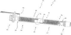
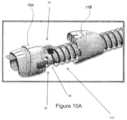
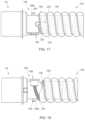
- FIGS. 8 - 10 Aare perspective views of a portion of a chamber-end connector and an end of a conduit.
- FIGS. 11 A- 11 Care views of another example embodiment of a chamber-end connector.
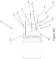
- FIG. 12is a perspective view of a portion of a patient-end connector.
- FIG. 13is a cross section of a portion of a patient-end connector.
- FIG. 13 Ais a side view of a portion of a patient-end connector.
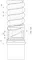
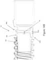
- FIGS. 14 A- 14 Fare views of another example embodiment of a patient-end connector.
- FIG. 15is a perspective view of a portion of an embodiment of a patient-end connector including a bridge piece.
- FIG. 16is a perspective view of the bridge piece of FIG. 15 .
- FIGS. 17 - 19are various side views of a portion of a conduit coupled to an embodiment of a patient-end connector including a channel.
- FIG. 20illustrates a portion of an example embodiment of a patient-end connector having a bridge formed by neighboring recesses.
- FIG. 1shows a respiratory system 1 which can include, but is not limited to, the following components: a pressurized gases source 2 , such as a blower or ventilator, adapted to generate a supply of gases to be delivered to a patient 3 ; a humidification device 4 adapted to condition the supply of gases; a medical tube 6 adapted to deliver the gases to a patient interface 8 , which then delivers the gases to the patient 3 ; and a connector 16 adapted to connect the medical tube 6 to the humidification device 4 .
- a pressurized gases source 2such as a blower or ventilator
- the patient interface 8 as described hereinmay refer to a mask, nasal mask, nasal prongs, oral mask, tracheal mask, or nasal pillows.
- the humidification device 4 as described hereinmay refer to any device that conditions gases. This may include heating the gases and/or humidifying the gases.
- Gases as described hereinmay refer to air, oxygen, carbon dioxide, or a mixture of any such gases, or a combination of any such gases with one or more medicaments or aerosols that may be delivered to the patient 3 via the patient interface 8 .
- the medical tube 6 as described hereinmay refer to a tube, conduit, circuit, or hose.
- the medical tube 6 illustratedmay comprise a first elongate member 10 and a second elongate member 12 .
- the medical tube 6 illustratedmay comprise one or more wires 15 .
- the one or more wires 15may comprise at least one heater wire, at least one sensor wire, and/or any other type of electrical conductor.
- the one or more wires 15may be within the medical tube 6 .
- the one or more wires 15may be lying along an inner or outer surface of the medical tube 6 .
- the one or more wires 15may be spirally wound onto the medical tube 6 or into the medical tube 6 such that the one or more wires 15 may be embedded in the wall of the medical tube 6 .
- the medical tube 6may be heated or unheated.
- the medical tube 6may include insulation to reduce condensate from forming within the medical tube 6 .
- the first elongate member 10may provide such insulation. Condensate may form if the heated, humidified gases within the medical tube 6 cool down during transit. To reduce or eliminate condensate formation, the medical tube 6 may be heated. This heating may be provided by the one or more wires 15 comprising one or more heater wires 14 , as shown in FIGS. 5 and 6 .
- the second elongate member 12may comprise the one or more wires 15 .
- a terminating portion of the medical tube 6may be provided to terminate the one or more wires 15 at the connector 16 such that an electrical connection may be formed between the medical tube 6 and a component of the respiratory system 1 .
- the terminating elementmay comprise a tail 20 or a tail 30 , as illustrated in relation to the medical tube 6 in FIGS. 5 and 6 , and also as illustrated close up in FIGS. 3 and 4 .
- the connector 16may provide a pneumatic connection between the medical tube 6 and a component of the respiratory system 1 .
- a component of the respiratory system 1 as described hereinmay refer to a patient interface or a humidification device.
- the connector 16may provide either one of or both an electrical and pneumatic connection between the medical tube 6 and a component of the respiratory system 1 .
- the one or more wires 15may also comprise one or more sensing wires 18 , as illustrated in FIGS. 5 and 6 .
- the one or more sensing wires 18may be used to sense gases properties such as temperature, flow, humidity, or pressure. In some embodiments, the one or more sensing wires 18 may be used to sense temperature. In some embodiments, the one or more sensing wires 18 may be connected to one or more sensors that may be used to sense one or more of these gases properties.
- the one or more wires 15are embedded in the medical tube 6 .
- the one or more wires 15may be embedded in the second elongate member 12 .
- the one or more wires 15may be embedded in the first elongate member 10 .
- both the one or more heater wires 14 and the one or more sensing wires 18may be embedded in the second elongate member 12 .
- both the one or more heater wires 14 and the one or more sensing wires 18may be embedded in the first elongate member 10 .
- At least one of the one or more heater wires 14 and the one or more sensing wires 18may be embedded in the second elongate member 12 , and at least one other of the one or more heater wires 14 and the one or more sensing wires 18 may be embedded in the first elongate member 10 . In some embodiments, there may be no heater wires 14 within the second elongate member 12 . In some embodiments, there may be no sensing wires 18 within the second elongate member 12 . There may be any other such combination.
- the one or more heater wires 14may comprise two heater wires. In some embodiments, the one or more sensing wires 18 may comprise two sensing wires. In some embodiments, the one or more sensing wires 18 may be located near the one or more heater wires 14 . In some embodiments, the one or more heater wires 14 may comprise a first heater wire and a second heater wire, and the one or more sensing wires 18 may be located between the first heater wire and the second heater wire.
- the first elongate member 10 and the second elongate member 12may be made from different materials.
- the first elongate member 10may be flexible and/or may provide thermal insulation properties to the medical tube 6 .
- the second elongate member 12may be made from material that provides reinforcing properties and/or structural support to the medical tube 6 .
- the first elongate member 10may provide reinforcing properties and/or structural support for the medical tube 6 .
- the second elongate member 12may be flexible and/or may provide thermal insulation properties. Different combinations may also be provided.
- the medical tube 6may comprise a single elongate member.
- the medical tube 6may comprise two or more first elongate members.
- the medical tube 6may comprise two or more second elongate members.
- the tails 20 , 30may extend from the second elongate member 12 , as illustrated in FIGS. 5 and 6 . In some embodiments, the tails 20 , 30 may extend from the first elongate member 10 . In some embodiments, the tails 20 , 30 may extend from a combination of the first elongate member 10 and the second elongate member 12 . Similarly, if greater than two elongate members are used, the tails 20 , 30 may extend from any one of or from more than one elongate member in the system.
- the tails 20 , 30 as described hereinrefer to terminating portions of the first elongate member 10 and/or the second elongate member 12 that have been adapted to enable connection of the first elongate member 10 and/or the second elongate member 12 to an electrical component.
- An electrical componentmay refer, for example, to a printed circuit board or an electrical connector.
- the tail 20may comprise a flattened portion 22 and an exposed portion 24 .
- the tail 20may comprise a transition or preliminary portion, between the first elongate member 10 and/or the second elongate member 12 and the flattened portion 22 , that is not flattened or is less flattened than the flattened portion 22 .
- the tail 30may comprise a first flattened portion 32 , an exposed portion 34 , and a second flattened portion 36 .
- the tail 30may comprise a transition or preliminary portion, between the first elongate member 10 and/or the second elongate member 12 and the first flattened portion 32 , that is not flattened or is less flattened than the first flattened portion 32 .
- the tails 20 , 30may comprise only the exposed portions 24 , 34 , respectively; however, the flattened portion 22 , the first flattened portion 32 , and/or the second flattened portion 36 may aid in handling and connection of the one or more wires 15 to an electrical component.
- the flattened portion 22 and/or the first flattened portion 32may be made from the same material as the second elongate member 12 .
- the width W of the flattened portion 22 , the first flattened portion 32 , and/or the second flattened portion 36may be at most 11.0 mm, at most 9.0 mm, or at most 8.5 mm.
- the length L 1 of the flattened portion 22 and/or the first flattened portion 32may be at least 8.0 mm.
- the length L 2 of the exposed portion 24 and/or the exposed portion 34may be at least 8.0 mm or at least 10.0 mm.
- the length L 3 of the second flattened portion 36may be at least twice the length of the exposed portion 34 , at most 32.0 mm, or at most 25.0 mm.
- the flattened portion 22describes a portion of the tail 20
- the first flattened portion 32describes a portion of the tail 30 , wherein the one or more wires 15 may become spaced. Spacing as herein described may refer to the separation or moving apart of the one or more wires 15 , and may refer to the location and position of the one or more wires 15 within the flattened portion 22 , the first flattened portion 32 , and/or the second flattened portion 36 .
- each of the one or more wires 15may be spaced relative to each other. This spacing may be to aid attachment of the one or more wires 15 to an electrical component. This spacing may be determined by the width of the flattened portion 22 and/or the first flattened portion 32 . In some embodiments, the spacing between each of the one or more wires 15 may be 2.5 mm, at most 4.0 mm, or at least 1.0 mm. In some configurations, the distance between any two outermost wires may be less than 9.0 mm or less than 8.0 mm. A range of separation or spacing distances between each of the one or more wires 15 may be used.
- the flattened portion 22 and/or the first flattened portion 32may extend beyond either side of the one or more wires 15 .
- the flattened portion 22 and/or the first flattened portion 32may encase the one or more wires 15 .
- the amount of the flattened portion 22 and/or the first flattened portion 32 encasing the one or more wires 15may be within a range of values.
- the flattened portion 22 and/or the first flattened portion 32may extend by 0.25 mm on either side of the one or more wires 15 .
- the flattened portion 22 and/or the first flattened portion 32may extend on either side of the one or more wires 15 by more, or less, as required.
- the flattened portion 22 and the first flattened portion 32 of the second elongate member 12may be formed using known flattening techniques.
- the length of the flattened materialmay be important with regard to spacing and to maintaining the spacing of the one or more wires 15 . If the one or more wires 15 comprises more than one wire, the length of the flattened material that forms the flattened portion 22 and the first flattened portion 32 may help to space each of the one or more wires 15 relative to each other. Each of the one or more wires 15 may be spaced relative to each other before they are exposed. In some embodiments, the one or more wires 15 may be spaced relative to each other after they have been exposed.
- each of the one or more wires 15may be spaced from each other as they are exposed. Spacing of each of the one or more wires 15 relative to each other may reduce the likelihood that the order of the one or more wires 15 will be confused. This may aid an assembly operator with regards to usability and handling. The spacing between the wires can be as described above.
- the exposed portions 24 , 34may be discrete portions that follow the flattened portion 22 or the first flattened portion 32 , respectively.
- the one or more wires 15may be exposed in the exposed portions 24 , 34 .
- the length of the exposed portions 24 , 34may be important.
- the exposed portions of the one or more wires 15may be attached to an electrical component. Any suitable method to expose a portion of the flattened portion 22 and/or the first flattened portion 32 may be used.
- the exposed portions 24 , 34may have lengths that facilitate attachment of the one or more wires 15 to an electrical component.
- FIGS. 4 and 6show embodiments in which the second flattened portion 36 may be used to facilitate attachment of the second elongate member 12 to an electrical component.
- the second flattened portion 36may be located away from or at the other end of the exposed portion 34 relative to the first flattened portion 32 .
- the second flattened portion 36may cover the one or more wires 15 and may extend beyond the length of the one or more wires 15 .
- the second flattened portion 36may be useful in attaching the second elongate member 12 to an electrical component.
- the second flattened portion 36may facilitate wrapping of the tail 30 around an electrical component and/or a connector, such as the connector 16 .
- the second flattened portion 36may also further maintain the spacing of the one or more wires 15 within the tail 30 .
- the second flattened portion 36may be made using the same material as the second elongate member 12 . In some embodiments, the second flattened portion 36 may be made using a different material. The second flattened portion 36 may aid handling of the one or more wires 15 . For example, it may not be necessary to handle each of the one or more wires 15 individually, which may improve the efficiency of assembling the medical tube 6 to a connector, such as the connector 16 . In some embodiments, the second flattened portion 36 may be unused. Other mechanisms or techniques to maintain the positioning and spacing of the one or more wires 15 could be used.
- An electrical componentmay be attached to the one or more wires 15 .
- the electrical componentmay be connected to the medical tube 6 by, for example, overmolding or adhesive, or by using a clipping mechanism.
- the connector 16may form a connection between the medical tube 6 and an electrical component or another component of the respiratory system 1 .
- the connector 16may form a connection between the medical tube 6 and the humidification device 4 .
- the connector 16may form a connection between the medical tube 6 and the patient interface 8 .
- the connector 16may also be used to form a connection between the medical tube 6 and the blower 2 .
- the connector 16may be used to form an electrical and pneumatic connection between the medical tube 6 and at least one other medical tube.
- the medical tube 6may be for infant, paediatric, or adult use.
- the medical tube 6may be connected pneumatically to at least one other medical tube.
- the one or more wires 15may be terminated at the connector 16 without forming an electrical connection.
- the tails 20 , 30may still be used in these embodiments to aid in connecting the medical tube 6 to the connector 16 .
- the tails 20 , 30may be unused or may be omitted.
- known ways to attach the medical tube 6 to the connector 16may be used.
- the connector 16is not limited to the connections it may form, and other connections between a medical tube and a component of the respiratory system 1 may be arranged and configured in accordance with certain features, aspects and advantages of the present disclosure.
- a housing of the connector 16may be formed from a transparent material.
- the transparent materialmay allow an operator to assess if the one or more wires 15 have been separated and/or positioned correctly on the connector 16 .
- the housing of the connector 16may be a coloured material.
- the housing of the connector 16may be an opaque material, such that a user may be unable to see through the material.
- the tube 6is illustrated in a configuration that defines a breathing tube 50 .
- the illustrated breathing tube 50has a chamber-end connector 52 and a patient-end connector 54 .
- the chamber-end connector 52can be configured as described in PCT/NZ2014/000201, filed Sep. 15, 2014 (FPHCR.371/WO) and PCT/NZ2013/000222, filed Dec. 4, 2013 (FPCHR.273WO2), each of which is hereby incorporated by reference in its entirety.
- the patient-end connector 54can be configured as described in PCT/NZ2013/000208, filed Nov. 14, 2013 (FPHCR.335WO) and PCT/NZ2013/000222, filed Dec.
- the breathing tube 50also comprises an intermediate connector 56 .
- the intermediate connector 56can be configured as described in PCT/NZ2013/000208, filed Nov. 14, 2013 (FPHCR.335WO) and PCT/NZ2013/000222, filed Dec. 4, 2013 (FPCHR.273WO2), each of which is hereby incorporated by reference in its entirety.
- each of the connectors 52 , 54 , 56can comprise suitable outer covers, for example as shown and described in FIGS.
- the breathing tube 50comprises more than one intermediate connector 56 ; other configurations of the intermediate connector 56 may be used.
- the intermediate connector 56joins a first tube segment 60 and a second tube segment 62 .
- the first tube segment 60can be connected to the chamber-end connector 52 and the second tube segment 62 can be connected to the patient-end connector 54 .
- an electrical pathextends from the chamber-end connector 52 through the first tube segment 60 to the intermediate connector 56 , across the intermediate connector 56 , and from the intermediate connector 56 through the second tube segment 62 and to the patient-end connector 54 .
- an unbroken electrical connectionextends from the chamber-end connector 52 to the patient-end connector 54 .
- a pneumatic pathextends from the chamber-end connector 52 through the first tube segment 60 to the intermediate connector 56 , through the intermediate connector 56 , and from the intermediate connector 56 through the second tube segment 62 and to the patient-end connector 54 .
- an unbroken pneumatic connectionextends from the chamber-end connector 52 to the patient-end connector 54 .
- An unbroken pneumatic connectioncan also extend from a pneumatic component (e.g., a humidifier chamber, not shown) connected to the chamber-end connector 52 through to a pneumatic component (e.g., a patient interface, not shown) connected to the patient-end connector 54 . In effect, these components combine together to define a single medical tube that comprises two or more segments.
- the first tube segment 60comprises a first end 64 and a second end 66 .
- at least one of the first end 64 and the second end 66comprises a tail 70 .
- the first end 64comprises the tail 70 while the second end 66 also comprises a tail 72 .
- the tails 70 , 72can have any suitable configuration, including any of the configurations embodied by tails 20 , 30 .
- the second tube segment 62comprises a first end 74 and a second end 76 .
- at least one of the first end 74 and the second end 76comprises a tail 80 .
- the first end 74comprises the tail 80 while the second end 76 also comprises a tail 82 .
- the tails 80 , 82can have any suitable configuration, including any of the configurations embodied by tails 20 , 30 .
- the tube 6 in a configuration that defines a breathing tube 50may comprise a chamber-end connector 52 and a patient-end connector 54 , but does not comprise an intermediate connector.
- the tube 6 in a configuration that defines a breathing tube 50can comprise a chamber-end connector 52 , a patient-end connector 54 , and a midpoint assembly.
- An example embodiment of a midpoint assembly 400is shown in FIGS. 7 B- 7 D . Additional details regarding the midpoint assembly 400 are discussed below.
- the chamber-end connector 52comprises a plug portion 90 .
- the plug portion 90can support a printed circuit board or PCB 92 .
- the plug portion 90comprises a main body 94 .
- the main body 94can be generally cylindrical.
- a mounting flange 96can extend away from the main body 94 .
- the mounting flange 96can extend outward from the main body 94 .
- the mounting flange 96can define structure onto which the outer covers or housings can connect.
- the mounting flange 96defines a passage 98 through which the printed circuit board 92 can extend.
- a shroud 99extends from the mounting flange 96 and generally forms an extension of the passage 98 through with the PCB 92 extends.
- a support ledge 100Adjacent to the passage 98 , a support ledge 100 can be formed.
- the support ledge 100is arranged and configured to underlie the printed circuit board 92 .
- the support ledge 100extends radially outward from the main body 94 .
- the support ledge 100is an axially extending ridge that extends radially outward from the main body 94 .
- the support ledge 100is connected to the mounting flange 96 .
- the support ledge 100can be reinforced by one or more buttresses 102 .
- the support ledge 100is reinforced by three buttresses 102 .
- all of the buttresses 102extend outward from a single side of the support ledge 100 .
- the support ledge 100can comprise an upturned hook 104 .
- the upturned hook 104can turn back toward the mounting flange 96 .
- the upturned hook 104is arranged and configured to overlie at least a portion of the printed circuit board 92 .
- a protrusioncan be positioned inside of the upturned hook 104 , which protrusion extends in an axial direction and which protrusion can be received within a recess defined on the axial end of the printed circuit board 92 .
- the upturned hook 104has a larger lateral dimension than the support ledge 100 .
- the upturned hook 104 and a portion of the support ledge 100 underlying the upturned hook 104both have a larger lateral dimension than a portion of the support ledge 100 not underlying the upturned hook 104 .
- the upturned hook 104extends from an axial end of the support ledge 100 .
- the printed circuit board 92comprises one or more solder pads 106 .
- the printed circuit board 92can comprise attachment notches 108 that are at least partially surrounded by the solder pads 106 .
- the attachment notches 108can have any suitable configuration. In the illustrated configuration, the attachment notches 108 are positioned at locations that correspond to gaps positioned between the buttresses 102 . In some configurations, the attachment notches 108 are positioned at locations that align with the gaps defined between the buttresses 102 when the end of the printed circuit board 92 is seated within the upturned hook 104 .
- the printed circuit board 92can also comprise wire alignment components, such as alignment notches 110 , for example but without limitation.
- the attachment notches 108are on one side of the printed circuit board 92 and the alignment notches 110 are on the opposite side of the printed circuit board 92 .
- the alignment notches 110can receive wires of the tail 70 .
- the alignment notches 110can generally align with the locations of the attachment notches 108 .
- the alignment notches 110can help to reduce or eliminate the likelihood of wires of the tail 70 crossing each other and can help to maintain wires of the tail 70 taut during soldering to the printed circuit board 92 .
- two or more of the alignment notches 110can be separated by a greater distance than the separation distance between the corresponding attachment notches 108 , causing wires of the tail 70 to fan out from the attachment notches 108 to the alignment notches 110 in order to improve access for soldering and to further reduce the likelihood of wires of the tail 70 crossing each other.
- the alignment notches 110can be sized and configured to accommodate wires of the tail 70 . While the alignment notches 110 are illustrated as a portion of the printed circuit board 92 , the alignment notches 110 can be formed of a separate component, such as the support ledge 100 or the upturned hook 104 , for example but without limitation.
- the upturned hook 104can help resist twisting of the printed circuit board 92 when the tail 70 is pulled into position such that wires of the tail 70 are secured within the attachment notches 108 and the alignment notches 110 .
- the buttresses 102can help reduce the likelihood of bending or warping of the printed circuit board 92 during soldering of wires of the tail 70 to the solder pads 106 .
- the conduit 112can have any suitable configuration, including any configuration described elsewhere herein.
- the illustrated conduit 112comprises a first element 114 and a second element 116 .
- the first element 114may terminate before the second element 116 , with the tail 70 extending from the second element 116 .
- the tail 70 of the second element 116may extend further along the plug portion 90 than the first element 114 .
- the tail 70may extend from the first element 114 .
- the tail 70may extend from a combination of the first element 114 and the second element 116 .
- the first element 114 and the second element 116are helically wound at a certain pitch.
- the second element 116can comprise a bead that incorporates one or more wires 118 .
- the wires 118can have any suitable configuration. In some configurations, the wires 118 can be coated to have two or more colors. In other words, in some configurations, the wires 118 can be variantly coated or otherwise colored such that some of the wires 118 , e.g., the outermost of the wires 118 , can be visually distinguished from other of the wires 118 , e.g., the innermost of the wires 118 .
- Such a configuration, or another configuration that allows visual distinction between or among the wires 118advantageously allows verification that the wires 118 are in a desired location and order in the respective attachment notches 108 prior to being soldered to the solder pads 106 of the printed circuit board 92 .
- the tail 70can comprise a first flattened region 120 and a second flattened region 122 , and the wires 118 can be exposed between the first flattened region 120 and the second flattened region 122 .
- the tail 70can have any suitable configuration, including any of those described herein.
- the second flattened region 122can be omitted.
- the first flattened region 120 and the second flattened region 122can be omitted.
- the first flattened region 120 and the second flattened region 122help to reduce the likelihood of contact between the wires 118 during or following manufacture.
- the tail 70can comprise a transition or preliminary portion, between the first element 114 and/or the second element 116 and the first flattened region 120 , that is not flattened or is less flattened than the first flattened region 120 .
- the second flattened region 122can be restrained in position during manufacture using a cover 124 .
- the cover 124can be integrally formed with the plug portion 90 .
- the cover 124can be formed separate of the plug portion 90 .
- the separately formed cover 124can be secured to the plug portion 90 in any suitable configuration.
- a living hinge 126can be used to secure the integrally formed cover 124 to the plug portion 90 .
- Other suitable configurationsalso can be used.
- the cover 124can comprise a curved inner surface 128 .
- the curved inner surface 128can be used to secure at least a portion of the second flattened region 122 against an outer surface 130 of the plug portion 90 .
- a least a portion of the second flattened region 122can be secured between the outer surface 130 of the plug portion 90 and the curved inner surface 128 of the cover 124 .
- at least a portion of the first flattened region 120can be secured between the outer surface 130 of the plug portion 90 and the inner surface 128 of the cover 124 .
- at least a portion of the wires 118 exposed between the first flattened region 120 and the second flattened region 122can be secured between the outer surface 130 of the plug portion 90 and the inner surface 128 of the cover 124 .
- the cover 124can comprise one or more retention members 132 .
- two retention members 132are provided.
- Each of the retention members 132can comprise a hook member 134 .
- the two retention members 132can be separated from each other by a tab 136 .
- the tab 136can provide a surface for the operator to press to close the cover 124 against the plug portion 90 .
- the tab 136can also cover at least a part of the second flattened region 120 when the cover 124 is closed against the plug portion 90 .
- Other configurationscan be used that do not comprise the tab 136 , keeping in mind the desire to provide for ease of assembly and coverage of the second flattened region 120 .
- the plug portion 90can comprise one or more catches 138 .
- the catches 138can be positioned on the support ledge 100 .
- the catches 138can be positioned on a lower surface of the support ledge 100 .
- Other configurationsare possible keeping in mind a desire to secure the cover 124 in a closed position that captures the second flattened region 122 .
- the cover 124can be rotated about the living hinge 126 until the retention members 132 engage with the catches 138 , which traps the second flattened region 122 between the outer surface 130 and the curved inner surface 128 of the cover 124 .
- connection between the conduit 112 and the plug portion 90 and/or the connection between the wires 118 and the printed circuit board 92can be overmolded.
- the cover 124can be overmolded.
- connection between the conduit 112 and the plug portion 90 , as well as the connection between the wires 118 and the printed circuit board 92 , and the cover 124can be overmolded.
- a flow of an overmold material 142can be limited during overmolding.
- the overmold material 142can be any suitable material.
- the overmold material 142can be any material suitable for use in lower pressure overmolding.
- the overmold material 142can be a thermoplastic elastomer (TPE), such as a thermoplastic polyurethane (TPU), a thermoplastic vulcanizate (TPV), or a polyolefin elastomer (POE), similar to or the same as the material used to form the tube 6 .
- TPEthermoplastic elastomer
- TPUthermoplastic polyurethane
- TPVthermoplastic vulcanizate
- POEpolyolefin elastomer
- the overmold material 142can be a thermoplastic polymer such as a low-density polyethylene (LDPE) or a polypropylene (PP).
- LDPElow-density polyethylene
- PPpolypropylene
- the overmold material 142can be an ethylene copolymer with a methylacrylate component, which bonds to the plug portion 90 , the tails 70 , 72 , and the printed circuit board 92 and thereby provides pneumatic leak protection and liquid ingress protection.
- the printed circuit board 92may be insert-molded as part of, or otherwise bonded to, the plug portion 90 , and the overmold material 142 can be a thermoplastic elastomer selected to bond to the plug portion 90 and the tails 70 , 72 .
- the overmold material 142can flow into at least a portion of the first element 114 .
- the first element 114can be an elongate hollow element and the overmold material 142 can flow into at least a portion of the elongate hollow element to help reduce the likelihood of leaks.
- the overmold material 142can at least partially melt the second element 116 . By at least partially melting the second element 116 , the overmold material 142 and the second element 116 can help to reduce the likelihood of leaks.
- the overmold material 142can provide protection to the electrical components (e.g., can effectively pot the electrical components).
- the plug portion 90can comprise a guidance tab 144 .
- the guidance tab 144can be integrally formed with the plug portion 90 .
- the guidance tab 144can act as a positive stop for the conduit 112 during assembly of the conduit 112 onto the plug portion 90 .
- the plug portion 90comprises a helical rib 146 .
- the helical rib 146can align with the pitch of the conduit 112 .
- the plug portion 90can be inserted into the conduit 112 until the guidance tab 144 is positioned between the tail 70 and the conduit 112 .
- the helical rib 146can then help to hold the conduit 112 in place on the plug portion 90 by pressing into the first element 114 .
- the guidance tab 144is bent toward the mounting flange 96 . which can help direct the tail 70 towards the printed circuit board 92 . Because the length of the tail 70 and the length of the first flattened region 120 are known, it is possible to provide a desired length between the end of the first element 114 and the point of connection of the exposed wires 118 to the solder pads 106 of the printed circuit board 92 . Other configurations are possible keeping in mind a desire to properly locate the terminal end of the conduit 112 relative to the printed circuit board 92 .
- the assembly discussed abovecan be encapsulated by a first outer cover 148 and a second outer cover 150 .
- the two outer covers 148 , 150can be secured in any suitable manner. In the illustrated configuration, the two outer covers 148 , 150 can be snap-fit to the mounting flange 96 of the plug portion 90 . Other configurations are possible.
- FIGS. 11 A- 11 Cillustrate another example embodiment of a chamber-end connector 352 .
- FIGS. 11 A- 11 Billustrate the chamber-end connector 352 without an outer cover or housing
- FIG. 11 Cillustrates the chamber-end connector 352 encapsulated by a first outer cover 348 and a second outer cover 350 that are secured to each other and/or underlying components of the connector 352 .
- the chamber-end connector 352comprises a plug portion 390 that can support a printed circuit board or PCB 392 .
- the plug portion 390comprises a main body 394 that can be generally cylindrical.
- a mounting flange 396can extend away from the main body 394 .
- the mounting flange 396defines a passage 398 through which the PCB 392 can extend.
- the mounting flange 396also defines an extension 398 a of the passage 398 extending from the passage 398 , and extending from the PCB 392 when the PCB 392 extends through the passage 398 . In the embodiment shown in FIG.
- an electronic component 93such as but not limited to an ID resistor, is positioned on the PCB 92 on the chamber side of the mounting flange 96 , i.e., on the opposite side of the mounting flange 96 from the alignment notches 110 .
- an electronic component 393such as but not limited to an ID resistor, is positioned on the PCB 392 on the conduit side of the mounting flange 396 , i.e., on the same side of the mounting flange 396 as alignment notches 310 .
- Placement of the electronic component 393 on the conduit side of the mounting flange 396allows the electronic component 393 to be covered by the overmold material as described herein to advantageously help protect the electronic component 393 from liquid.
- the extension 398 a of the passage 398provides an opening for the electronic component 393 to pass through the mounting flange 396 during assembly.
- a support ledge 300can be formed adjacent to the passage 398 .
- the support ledge 300is arranged and configured to underlie and support the PCB 392 .
- the support ledge 300has a height that is 0.02 to 0.1 mm higher, i.e., farther from the central axis of the plug portion 390 , than the bottom of the passage 398 . This increased height causes the portion of the PCB 392 on the conduit side of the mounting flange 396 to bend or lift slightly upwards, i.e., away from the central axis of the plug portion 390 .
- the portion of the PCB 392 on the chamber side of the mounting flange 396to be deflected or bent slightly downward, i.e., closer to the central axis of the plug portion 390 , which forces the chamber end of the PCB 392 , i.e., the end of the PCB 392 on the chamber side of the mounting flange 396 , more tightly into contact with the underlying surface of the chamber-end connector 352 .
- the second outer cover 350configured to enclose portions of the plug portion 390 and the PCB 392 comprises a ledge 351 .
- the ledge 351is configured to underlie and support the chamber end of the PCB 392 .
- the height of the support ledge 300 pressing upward on the portion of the PCB 392 on the conduit side of the mounting flange 396drives the portion of the PCB 392 on the chamber side of the mounting flange 396 downwards, which helps promote the chamber end of the PCB 392 lying flush with, or slightly below the upper surface of, the ledge 351 . This helps inhibit the PCB 392 from potentially being snagged on surrounding objects and reduces the likelihood of separation between the PCB 392 and the ledge 351 .
- the ledge 351can contain a recess that receives at least a portion of the PCB 392 .
- the support ledge 300is reinforced by two buttresses 302 .
- the support ledge 300can comprise an upturned hook 304 to overlie a portion of the PCB 392 .
- the PCB 392comprises one or more attachment notches 308 , solder pads 306 that at least partially surround the attachment notches 308 , and alignment notches 310 .
- the PCB 392comprises four attachment notches 308 at least partially surrounded by four solder pads 306 and four corresponding alignment notches 310 .
- the outermost two attachment notches 308 a and solder pads 306 aare positioned on a first edge of the PCB 392
- the corresponding outermost two alignment notches 310 aare positioned on the second, opposing edge of the PCB 392 in alignment with the attachment notches 308 a.
- the inner two attachment notches 308 b and solder pads 306 bare positioned on the second edge of the PCB 392 between the outer alignment notches 310 a, and the inner two alignment notches 310 b are positioned on the first edge of the PCB 392 between the attachment notches 308 a and in alignment with the attachment notches 308 b.
- the outer solder pads 306 aare configured to be soldered to the heater wires 14
- the inner solder pads 306 bare configured to be soldered to the sensing wires 18 .
- Soldering the heater wires 14 to the outer solder pads 306 a and on the opposite edge of the PCB 392 from the sensing wire solder pads 306 badvantageously increases the separation between the heater wire solder pads 306 a and the sensing wire solder pads 306 b. This helps inhibit or reduce the likelihood of liquid bridging between the heater wire solder pads 306 a and the sensing wire solder pads 306 b and thus shorting the heater wires 14 to the sensing wires 18 .
- the PCB 392also comprises a slot 395 .
- the slot 395extends lengthwise along a portion of the PCB 392 on the conduit side of the PCB 392 .
- the slot 395is positioned between the outer solder pads 306 a and the inner solder pads 306 b.
- overmold materialflows into the slot 395 , which also helps to separate the heater wire solder pads 306 a from the sensing wire solder pads 306 b and helps to inhibit liquid from bridging between them.
- the separation between the heater wire solder pads 306 a and the sensing wire solder pads 306 balso helps to reduce the likelihood of heat transfer between the heater wires and the sensing wires.
- the chamber-end connector 352 of FIGS. 11 A- 11 Ccan also comprise a cover (not shown) configured to restrain the second flattened region 122 during manufacture.
- the covercan be similar to the cover 124 shown in FIGS. 8 and 9 .
- the cover for the embodiment shown in FIGS. 11 A- 11 Cmay only comprise one retention member 132 . In other words, the cover may attach to only one end of the support ledge 300 rather than attaching to two ends of the support ledge 300 .
- portions of and/or connections among the plug portion 390 , the wires 118 , the conduit 112 , and the PCB 392can be overmolded similar to the embodiment of FIGS. 8 - 10 A .
- the electronic component 393can also be overmolded due to the placement of the electronic component 393 on the conduit side of the PCB 392 .
- the plug portion 390can comprise a partitioning wall 397 as shown in FIGS. 11 A- 11 B .
- the partitioning wall 397divides the space below the PCB 392 between the mounting flange 396 and the buttresses 302 of the support ledge 300 . The division of this space into two smaller spaces by the partitioning wall 397 advantageously helps reduce the likelihood of the overmold material forming voids or shrinking excessively as it cools.
- the plug portion 390can comprise a guidance tab 344 that can act as a positive stop for the conduit 112 during assembly of the conduit 112 onto the plug portion 390 .
- the guidance tab 344protrudes from the plug portion 390 normal to the plug portion 390 wall rather than at an angle as in the embodiment of FIGS. 8 - 10 A .
- the plug portion 390comprises two helical ribs 346 , 347 .
- the first helical rib 346 and/or the second helical rib 347can align with the pitch of the conduit 112 .
- the second helical rib 347has a roughly trapezoidal cross section that creates a sharp transition or change in slope from the outer surface of the plug portion 390 to the outer surface of the second helical rib 347
- the first helical rib 346has a roughly semicircular cross section that creates a smoother transition.
- the sharp angles of the second helical rib 347can help prevent or reduce the likelihood of liquid passing over the second helical rib 347 .
- the plug portion 390can be inserted into the conduit 112 until the guidance tab 344 is positioned against a cut portion of the first element 114 .
- the first helical rib 346can then help to hold the conduit 112 on the plug portion 90 by pressing into the first element 114 .
- the guidance tab 344can extend from the first helical rib 346 .
- the second helical rib 347is positioned between the first helical rib 346 and the support ledge 300 . As shown in FIG. 11 A , the second helical rib 347 comprises a longitudinal bridging segment 347 a such that the second helical rib 347 fully encircles the plug portion 390 .
- the second helical rib 347can act as a liquid barrier to inhibit liquid from transferring from the conduit 112 toward the PCB 392 .
- the patient-end connector 54is shown coupled to an end of a conduit 160 .
- the patient-end connector 54can comprise a single integrally formed main body 158 . Other configurations also are possible.
- the conduit 160can have any suitable configuration, including any configuration described elsewhere herein.
- the illustrated conduit 160comprises a first element 162 and a second element 164 .
- the first element 162may terminate before the second element 164 , with the tail 82 (not visible in FIG. 12 ) extending from the second element 164 .
- the tail 82 of the second element 164may extend further along the main body 158 of the patient-end connector 54 than the first element 162 .
- the tail 82may extend from the first element 162 .
- the tail 82may extend from a combination of the first element 162 and the second element 164 .
- the first element 162 and the second element 164are helically wound with a certain pitch.
- the second element 164can comprise a bead that incorporates one or more wires 166 .
- the wires 166can have any suitable configuration. In some configurations, the wires 166 can be coated to have two or more colors. In other words, in some configurations, the wires 166 can be variantly coated or otherwise colored such that some of the wires 166 , e.g., the outermost of the wires 166 , can be visually distinguished from other of the wires 166 , e.g., the innermost of the wires 166 . Such a configuration, or another configuration that allows visual distinction between or among the wires 166 , advantageously allows verification that the wires 166 are in a desired location and order for connection to a printed circuit board 168 .
- the tail 82can comprise a first flattened region 170 and a second flattened region 172 (not visible in FIG. 12 ), and the wires 166 can be exposed between the first flattened region 170 and the second flattened region 172 .
- the tail 82thus, can have any suitable configuration, including any of those described elsewhere herein.
- the second flattened region 172can be omitted.
- the first flattened region 170 and the second flattened region 172can be omitted. The first flattened region 170 and the second flattened region 172 , however, help to reduce the likelihood of contact between the wires 166 during or following manufacture.
- the tail 82can comprise a transition or preliminary portion, between the first element 162 and/or the second element 164 and the first flattened region 170 , that is not flattened or is less flattened than the first flattened region 170 .
- the second flattened region 172can be restrained in position during manufacture using a cover 174 .
- the cover 174can be integrally formed with the main body 158 .
- the cover 174can be formed separate of the main body 158 .
- the separately formed cover 174can be secured to the main body 158 in any suitable configuration.
- a living hinge 176can be used to secure the integrally-formed cover 174 to the plug portion 90 .
- two separate living hinges 176have been used.
- Other suitable configurationsalso can be used.
- the second flattened region 172can be cut off after the exposed wires 118 have been soldered to the solder pads 106 , and no cover is used.
- the cover 174comprises a first edge 188 and a second edge 190 and comprises a recess 178 that can be positioned along the first edge 188 .
- a post 180 of the main body 158can be used to secure the cover 174 in a closed position.
- the post 180 and the recess 178can interact to secure the cover 174 in the closed position.
- a spine 192can align with the pitch of the conduit 160 .
- the second edge 190can align with the pitch of (or extend generally parallel to) the spine 192 .
- the second edge 190 and the spine 192when thus aligned, can interact to help secure the cover 174 in the closed position by preventing movement of the recess 178 away from the post 180 .
- the cover 174can secure the second flattened region 172 and/or the wires 166 in position between the main body 158 and the cover 174 .
- the main body 158can comprise a wire alignment component, such as a comb 182 , for example but without limitation.
- the comb 182can comprise a plurality of fingers spaced by gaps or alignment notches that receive the wires 166 .
- the comb 182can help to reduce or eliminate the likelihood of the wires 166 crossing each other and can help to maintain the wires 166 taut during soldering to the printed circuit board 168 .
- the comb 182extends generally normal to the printed circuit board 168 .
- the printed circuit board 168preferably extends fully through the diameter of the main body 158 . In other words, at least a portion of the printed circuit board 168 can be exposed beyond the main body 158 at either or both ends of the printed circuit board 168 . As illustrated in FIG. 13 , the printed circuit board 168 has a wider head part 168 b and a narrower stem part 168 a that extends through the gases flow path of the main body 158 . At least a portion of the head part 168 b preferably extends beyond the main body 158 . In some embodiments, as illustrated in FIG. 13 , at least a portion of the stem part 168 a extends beyond the main body 158 .
- the stem part 168 aextends into a thickness of the main body 158 but not beyond the main body 158 .
- the stem part 168 ajoins to the head part 168 b within a thickness of the main body 158 .
- at least a portion of the head part 168 bis embedded within the wall of the main body 158 , as shown in FIG. 13 .
- the head part 168 bcomprises the solder pads 106 , and embedding a portion of the head part 168 b into the wall of the main body 158 helps the printed circuit board 168 to resist flexure during assembly.
- the printed circuit board 168is shown with a thermistor 184 attached to the printed circuit board 168 .
- the thermistor 184can be a surface mount thermistor. Other sensors can be mounted to the printed circuit board 168 .
- the thermistor 184is used to sense temperature and to feed a value representing the temperature back to the printed circuit board 168 and from the printed circuit board 168 to a further medical device.
- the thermistor 184 as well as the printed circuit board 168can be overmolded during formation of the patient-end connector 54 . Because of the clamping and material flow pressures that occur during the overmolding process, the orientation of the components and the bending or flexure of the printed circuit board 168 become important considerations. For this reason, the thermistor 184 is mounted lengthwise in the direction of gases flow through the patient-end connector 54 . The lengthwise mounting in the direction of gases flow reduces the impact of possible flexure of the printed circuit board 168 during the overmolding operation. In other words, the thermistor 184 preferably is mounted with the terminals oriented relative to each other in a direction that has the least amount of flexure of the printed circuit board 168 .
- the thermistor 184can be positioned on an extended portion of the printed circuit board 168 that extends further upstream into the gases flow relative to other portions of the printed circuit board 168 and the mounting of the printed circuit board 168 to the main body 158 . By positioning the thermistor 184 on this extended portion of the printed circuit board 168 , the thermistor 184 will be positioned in a more laminar gases flow, before the turbulence in the gases flow that can be created by the other portions of the printed circuit board 168 and the mounting of the printed circuit board 168 to the main body 158 .
- thermoelectric thermistor 184on the extended portion of the printed circuit board 168 can help to reduce the impact of stem effects on the readings from the thermistor 184 that can be caused by temperature variations generated by other electronic components on the printed circuit board 168 and/or ambient conditions.
- the main body 158can comprise a guidance tab 186 .
- the guidance tab 186can be integrally formed with the main body 158 .
- the guidance tab 186can act as a positive stop during assembly of the conduit 160 onto the main body 158 .
- the main body 158comprises a helical rib 194
- the helical rib 194can match or simulate the pitch of the conduit 160 .
- the conduit 160can be threaded onto the main body 158 (or the main body 158 can be threaded into the conduit 160 ) until the first element 162 (e.g., the elongate hollow portion of the conduit 160 ) bumps against the guidance tab 186 .
- the guidance tab 186may be bent away from the body of the conduit 160 , which can help direct the tail 82 towards the printed circuit board 168 . In some embodiments, the guidance tab 186 protrudes normal to the main body 158 . Because the length of the tail 82 and the length of the first flattened region 170 are known, it is possible to provide a desired length between the end of the first element 162 and the connection of the exposed wires 166 to the solder pads 106 of the printed circuit board 168 . Other configurations are possible keeping in mind a desire to properly locate the terminal end of the conduit 160 relative to the printed circuit board 168 .
- connection between the conduit 160 and the main body 158 and/or the connection between the printed circuit board 168 and the wires 166can be overmolded.
- an overmold material 189is shown at the juncture between the conduit 160 and the main body 158 .
- the overmold material 189can envelop the printed circuit board 168 and the wires 166 .
- the overmold material 189can be similar to, and have similar characteristics to, the overmold material 142 described above.
- a cover membercan connect to the main body 158 to enshroud the connection between the conduit 160 and the main body 158 .
- the intermediate connector 56also can employ similar connections to the wires 166 and the conduit 160 .
- the main body 158can comprise features to allow the overmold material 189 to flow into any gaps to help seal the interface between the conduit 160 and the main body 158 .
- the overmold material 189can therefore help better protect the electrical components from condensate or other liquids.
- the overmold material 189can also help create an improved pneumatic seal between the conduit 160 and the main body 158 .
- FIGS. 15 - 19illustrate example embodiments of such features.
- the patient-end connector 54comprises a bridge piece 210 .
- the bridge piece 210can be disposed on the outer surface of the main body 158 .
- the bridge piece 210can be positioned between the outer surface of the main body 158 and at least a portion of the conduit 160 .
- the bridge piece 210can be positioned between the outer surface of the main body 158 and the second element 164 or bead of the conduit 160 .
- FIG. 16illustrates a perspective view of the bridge piece 210 .
- the bridge piece 210comprises a pad portion 212 , an extension portion 214 , and a peg 216 .
- the pad portion 212can be generally square or rectangular. Other configurations also are possible.
- the pad portion 212has a lower surface that is configured to contact the connector.
- the pad portion 212has an upper surface that is configured to contact the conduit 160 or the second element 164 or bead of the conduit 160 .
- the extension portion 214extends outward and upward from the pad portion 212 .
- the extension portion 214is generally triangular, although other shapes or configurations are also possible.
- the extension portion 214has a side surface.
- the peg 216extends from the extension portion 214 . In the illustrated configuration, the peg 216 extends from the side surface of the extension portion 214 .
- the stem part 168 a of the printed circuit board 168 extending from the main body 158comprises a hole 202 .
- the peg 216is configured to be received in the hole 202 , as shown in FIG. 15 .
- the bridge piece 210is coupled to the main body 158 .
- the stem part 168 a of the printed circuit board 168is extended or slightly widened to provide additional strength and better support to the peg 216 and the bridge piece 210 .
- the bridge piece 210is positioned on the main body 158 proximate and proximal to the guidance tab 186 .
- the bridge piece 210is positioned such that the second element 164 , comprising the bead, extends over the pad portion 212 when the conduit 160 is coupled to the main body 158 .
- the pad portion 212therefore causes the second element 164 to lift away from the outer surface of the main body 158 , thereby creating a gap between the second element 164 and the outer surface of the main body 158 on either side of the pad portion 212 (i.e., in the circumferential direction of the connector).
- the overmold material 189When the overmold material 189 is applied to the juncture between the conduit 160 and main body 158 , the overmold material 189 can flow into the gaps created by the bridge piece 210 , thereby bonding the second element 164 to the outer surface of the main body 158 . Bonding the second element 164 to the outer surface of the main body 158 can inhibit or prevent liquid from seeping between the outer surface of the main body 158 and the second element 164 or bead of the conduit 160 and thus can reduce or eliminate the likelihood of liquid reaching the electrical connections.
- FIG. 20illustrates an alternative embodiment in which a bridge member is formed on the main body 158 by two neighboring recesses 211 positioned between the stem part 168 a and the tab 186 .
- the second element 164extends over the recesses 211 , allowing overmold material to flow into the recesses 211 such that the overmold surrounds the second element 164 and bonds the second element 164 to the outer surface of the main body 158 . Bonding the second element 164 to the outer surface of the main body 158 can inhibit or prevent liquid from seeping between the outer surface of the main body 158 and the second element 164 to reduce or eliminate the likelihood of liquid reaching the electrical connections.
- the patient-end connector 54comprises a channel 220 formed in the main body 158 .
- the channel 220allows the overmold material 189 to flow between the inner surface of the conduit 160 and the outer surface of the main body 158 .
- the channel 220is recessed from, or formed as a recess in, the outer surface of the main body 158 .
- the channel 220can have any suitable configuration.
- the channel 220can extend around at least a portion of a circumference of the main body 158 .
- the channel 220can extend in a spiral or a partial spiral.
- the channel 220can be positioned and formed such that the second element 164 extends over, along, or in the channel 220 .
- the overmold material 189can flow into the channel 220 and under the second element 164 , thereby bonding the second element 164 to the outer surface of the main body 158 .
- the overmold material 189bonds the second element 164 or the conduit 160 to the recessed surface defined by the channel 220 .
- the channel 220 and the second element 164can be positioned so that the channel 220 extends to both sides of the second element 164 (i.e., in an axial direction of the connector). As shown in FIG. 17 , at least a portion 222 of the channel 220 is proximal of the second element 164 . In some configurations, the channel 220 can extend below more than one wrap of the helically winding second element 164 . In some configurations, a lip or a ridge 224 can be configured along or adjacent to the channel 220 and the lip or ridge 224 can be oriented to extend across the second element 164 . The lip or ridge 224 can lift the second element 164 away from the outer surface of the main body 158 similar to the pad discussed above.
- FIGS. 14 A- 14 Fillustrate another example embodiment of a patient-end connector 354 .
- the patient-end connector 354can comprise an integrally formed main body 358 and printed circuit board or PCB 368 .
- the second flattened region 172 of the tail 82is cut off after the exposed wires 118 are soldered to the solder pads, and therefore no cover is used.
- the main body 358can comprise a wire alignment component, such as a comb 382 .
- the comb 382can comprise alignment notches that receive the wires 166 to help keep the wires 166 separated from each other and taut during soldering to the PCB 368 .
- the PCB 368extends through the diameter of the main body 358 and comprises a wider head part 368 b and narrower stem part 368 a.
- the head part 368 bcomprises solder pads 306 .
- the outer two solder pads 306 aare positioned on the side of the head part 368 b facing away from the comb 382
- the inner two solder pads 306 bare positioned on the opposite side of the head part 368 b, i.e., facing the comb 382 .
- the outer two solder pads 306 acan be configured to be soldered to the heater wires 14
- the inner two solder pads 306 bcan be configured to be soldered to the sensing wires 18 .
- This arrangementadvantageously increases the separation between the heater wire solder pads 306 a and the sensing wire solder pads 306 b to help reducing the likelihood of liquid bridging between them and potentially causing a short.
- the patient-end connector 354can comprise a first helical rib 494 that helps to hold the conduit 160 on the main body 358 during assembly by pressing into the first element 162 , a guidance tab 386 that acts as a stop for the conduit 160 during assembly of the conduit 160 onto the main body 358 , and a second helical rib 495 that acts as a liquid barrier to inhibit liquid from the conduit 160 from reaching the PCB 368 .
- the guidance tab 386protrudes from the main body 358 normal to the main body 358 . As shown in FIG.
- the first element 162 of the conduit 160 at the end of the conduit 160 threaded onto the connector 352can be cut in the middle of the first element 162 , and the main body 358 can be inserted into the conduit 160 until guidance tab 386 is positioned against the cut edge of the first element 162 .
- the second helical rib 495comprises a longitudinal bridging segment 495 a so that the second helical rib 495 completely encircles the main body 358 to create a liquid barrier.
- the guidance tab 396is positioned at the end of the longitudinal bridging segment 495 a closest to the first helical rib 494 .
- a drift limit post 388is positioned at the opposite end of the longitudinal bridging segment 495 a from the guidance tab 396 .
- the tail 82extends over the longitudinal bridging segment 495 a as it extends to the PCB 368 .
- the drift limit post 388helps inhibit the tail 82 from drifting too far toward the stem part 368 a of the PCB 368 to help keep the tail 82 in the desired location during overmolding.
- the stem part 368 a of the PCB 368is offset or not centered relative to the head part 368 b. This advantageously shifts the exposed end of the stem part 368 a farther away from the drift limit post 388 .
- connection between the conduit 160 and the main body 358 of the patient-end connector 354 and/or the connection between the conduit 160 and the PCB 368can be overmolded.
- the patient-end connector 354can comprise features to allow overmold material to flow into any gaps to better seal the interface between the conduit 160 and the main body 358 .
- the main body 358comprises a series of bridge members that lift the tail 82 away from the main body 358 to allow the overmold material to fully encapsulate the tail 82 .
- the longitudinal bridging segment 495 a of the second helical rib 495forms the first bridge member.
- Two additional bridge members 389 a, 389 bare positioned between the longitudinal bridging segment 495 a and the head part 368 b of the PCB, although more or fewer bridge members are also possible.
- the main body 358can have a reduced outer diameter in the region surrounding the bridge members. For example, as shown in FIG. 14 E , the outer diameter can be reduced (compared to a diameter the main body 358 would have if circular, indicated by reference arc D in FIG. 14 E ) in the area 358 a adjacent to the drift limit post 388 between the drift limit post 388 and bridge member 389 a.
- the outer diametercan then gradually increase from region 358 a to the region 358 b adjacent the head part 368 b of the PCB 368 .
- This decreased outer diameter portion of the main body 358can also help allow more overmold material to flow under the tail 82 to more completely encapsulate the tail 82 .
- a cover member 355can also connect to the main body 358 to enshroud the connection between the conduit 160 and the main body 358 .
- FIGS. 7 B- 7 Dillustrate an example embodiment of a midpoint assembly 400 that can be used to couple two conduit segments, such as the conduit segments 60 and 62 shown in FIG. 7 .
- the midpoint assembly 400as illustrated comprises a main body 402 , a PCB 404 , and a power diode 401 .
- the midpoint assembly 400may also comprise a sensor diode and a sensor, such as a thermistor.
- the midpoint assembly 400can comprise various features similar in structure and/or function to those of the chamber-end connector 352 and the patient-end connector 354 shown and described herein, although the midpoint assembly 400 can comprise two each of many of these features, one at either end, as the midpoint assembly 400 is configured to couple to conduits at each end.
- the midpoint assembly 400comprises two alignment components, such as combs 410 a, 410 b .
- the first comb 410 aextends generally perpendicularly to the PCB 404 on one side of the PCB 404
- the second comb 410 bextends generally perpendicularly to the PCB 404 on the other side of the PCB 404 .
- solder pads 406are alternated on either side of the PCB 404 to advantageously increase the separation between the adjacent solder pads 406 on each side of the PCB 404 to reduce the likelihood of shorts.
- Each end of the midpoint assembly 400comprises a first helical rib 412 that allows for the conduit to be threaded onto the main body 402 and a second helical rib 414 that acts as a liquid barrier between the conduit and the PCB 404 and comprises a longitudinal bridging segment 414 a so that the second helical rib 414 completely encircles the main body 402 .
- Each endalso comprises a guidance tab 416 at one end of the longitudinal bridging segment 414 a.
- Each endfurther comprises two bridging members 420 that lift tails of the conduit segments away from the main body 402 to allow overmold material to fully encapsulate the tails.
- FIGS. 7 E- 7 Fillustrate another example embodiment of a midpoint assembly.
- the illustrated midpoint assemblycan be similar to the midpoint assembly 400 of
- FIGS. 7 B- 7 Dthe first helical rib 412 and second helical rib 414 on the chamber end of the midpoint assembly and the first helical rib 412 and second helical rib 414 on the patient end of the midpoint assembly begin and end at substantially (e.g., within 5° or 10°) the same circumferential location.
- the longitudinal bridging segments 414 a on the chamber and patient ends of the midpoint assemblycan be positioned at substantially (e.g., within 5° or 10°) the same circumferential location.
- the start and end of the first 412 and second 414 helical ribs on one of the chamber end and patient end of the midpoint assemblyare offset or displaced in a circumferential direction relative to the start and end of the first 412 and second 414 helical ribs on the other of the chamber end and patient end of the midpoint assembly.
- the longitudinal bridging segment 414 a on one of the chamber and patient ends of the midpoint assemblyis offset or displaced in a circumferential direction relative to the longitudinal bridging segment 414 a on the other of the chamber and patient ends of the midpoint assembly.
- the start and end of the first and second helical ribs and/or the longitudinal bridging segment on one of the chamber and patient ends of the midpoint assemblyis offset or displaced by 90° in a circumferential direction relative to the start and end of the first and second helical ribs and/or the longitudinal bridging segment on the other of the chamber and patient ends.
- This arrangementadvantageously allows the chamber end connector, midpoint assembly, and patient end connector to be placed in an assembly jig in the correct orientation during manufacturing without kinking one of the tube segments.
- the midpoint assemblycan include an indicator to show an orientation of the midpoint assembly.
- the midpoint assemblyincludes an arrow 403 pointing toward the patient end of the midpoint assembly.
- the wires exposed in one or more of the tails 20 , 30 , 70 , 72 , 80 , 82can be tinned prior to being soldered. In some configurations, the wires exposed in one or more of the tails 20 , 30 , 70 , 72 , 80 , 82 can be tinned and the respective second flattened portion 36 or second flattened region 122 , 172 is omitted. In some configurations, the wires exposed in one or more of the tails 20 , 30 , 70 , 72 , 80 , 82 can be tinned and the respective second flattened portion 36 or second flattened region 122 , 172 is not omitted.
- the tinning of wirescan improve and simplify the soldering process. In addition, the tinning of wires can reduce the likelihood of wires crossing or making contact with each other. In some configurations, the wires exposed in one or more of the tails 20 , 30 , 70 , 72 , 80 , 82 can be tinned and the respective cover 124 , 174 still is used to secure portions of the one or more of the tails 20 , 30 , 70 , 72 , 80 , 82 in position.
- the wires exposed in one or more of the tails 20 , 30 , 70 , 72 , 80 , 82can be tinned and the respective cover 124 , 174 is not used to secure portions of the one or more of the tails 20 , 30 , 70 , 72 , 80 , 82 in position.
- the wires exposed in one or more of the tails 20 , 30 , 70 , 72 , 80 , 82can be not tinned and the respective cover 124 , 174 is used to secure portions of the one or more of the tails 20 , 30 , 70 , 72 , 80 , 82 in position, as described above.
- the wires exposed in one or more of the tails 20 , 30 , 70 , 72 , 80 , 82can be not tinned and the respective cover 124 , 174 is not used to secure portions of the one or more of the tails 20 , 30 , 70 , 72 , 80 , 82 in position. Any other suitable configuration can be used.
- the methods disclosed hereinmay include certain actions taken by a practitioner; however, the methods can also include any third-party instruction of those actions, either expressly or by implication.
- the ranges disclosed hereinalso encompass any and all overlap, sub-ranges, and combinations thereof.
- Language such as “up to,” “at least,” “greater than,” “less than,” “between,” and the likeincludes the number recited.
- Numerical values providedare provided as examples and are not limited to those specific values; rather, the scope of the disclosure includes values that are about, approximately, or within a reasonable range of the provided values as reasonable under the circumstances.
Landscapes
- Health & Medical Sciences (AREA)
- Engineering & Computer Science (AREA)
- Heart & Thoracic Surgery (AREA)
- Animal Behavior & Ethology (AREA)
- Public Health (AREA)
- Pulmonology (AREA)
- Anesthesiology (AREA)
- Biomedical Technology (AREA)
- Hematology (AREA)
- Life Sciences & Earth Sciences (AREA)
- Veterinary Medicine (AREA)
- General Health & Medical Sciences (AREA)
- Emergency Medicine (AREA)
- General Engineering & Computer Science (AREA)
- Mechanical Engineering (AREA)
- Endoscopes (AREA)
- Pipe Accessories (AREA)
- Medical Preparation Storing Or Oral Administration Devices (AREA)
- Details Of Connecting Devices For Male And Female Coupling (AREA)
- Measurement And Recording Of Electrical Phenomena And Electrical Characteristics Of The Living Body (AREA)
- Measurement Of The Respiration, Hearing Ability, Form, And Blood Characteristics Of Living Organisms (AREA)
- External Artificial Organs (AREA)
Abstract
Description
Claims (22)
Priority Applications (2)
| Application Number | Priority Date | Filing Date | Title |
|---|---|---|---|
| US16/926,410US12246132B2 (en) | 2014-03-17 | 2020-07-10 | Medical tubes for respiratory systems |
| US19/019,259US20250312551A1 (en) | 2014-03-17 | 2025-01-13 | Medical tubes for respiratory systems |
Applications Claiming Priority (7)
| Application Number | Priority Date | Filing Date | Title |
|---|---|---|---|
| US201461954230P | 2014-03-17 | 2014-03-17 | |
| US201462031666P | 2014-07-31 | 2014-07-31 | |
| US201462047536P | 2014-09-08 | 2014-09-08 | |
| US201562131173P | 2015-03-10 | 2015-03-10 | |
| PCT/NZ2015/050028WO2015142192A1 (en) | 2014-03-17 | 2015-03-17 | Medical tubes for respiratory systems |
| US201615126566A | 2016-09-15 | 2016-09-15 | |
| US16/926,410US12246132B2 (en) | 2014-03-17 | 2020-07-10 | Medical tubes for respiratory systems |
Related Parent Applications (2)
| Application Number | Title | Priority Date | Filing Date |
|---|---|---|---|
| US15/126,566ContinuationUS10751498B2 (en) | 2014-03-17 | 2015-03-17 | Medical tubes for respiratory systems |
| PCT/NZ2015/050028ContinuationWO2015142192A1 (en) | 2014-03-17 | 2015-03-17 | Medical tubes for respiratory systems |
Related Child Applications (1)
| Application Number | Title | Priority Date | Filing Date |
|---|---|---|---|
| US19/019,259ContinuationUS20250312551A1 (en) | 2014-03-17 | 2025-01-13 | Medical tubes for respiratory systems |
Publications (2)
| Publication Number | Publication Date |
|---|---|
| US20200338295A1 US20200338295A1 (en) | 2020-10-29 |
| US12246132B2true US12246132B2 (en) | 2025-03-11 |
Family
ID=54145017
Family Applications (3)
| Application Number | Title | Priority Date | Filing Date |
|---|---|---|---|
| US15/126,566Active2037-12-22US10751498B2 (en) | 2014-03-17 | 2015-03-17 | Medical tubes for respiratory systems |
| US16/926,410Active2037-06-17US12246132B2 (en) | 2014-03-17 | 2020-07-10 | Medical tubes for respiratory systems |
| US19/019,259PendingUS20250312551A1 (en) | 2014-03-17 | 2025-01-13 | Medical tubes for respiratory systems |
Family Applications Before (1)
| Application Number | Title | Priority Date | Filing Date |
|---|---|---|---|
| US15/126,566Active2037-12-22US10751498B2 (en) | 2014-03-17 | 2015-03-17 | Medical tubes for respiratory systems |
Family Applications After (1)
| Application Number | Title | Priority Date | Filing Date |
|---|---|---|---|
| US19/019,259PendingUS20250312551A1 (en) | 2014-03-17 | 2025-01-13 | Medical tubes for respiratory systems |
Country Status (7)
| Country | Link |
|---|---|
| US (3) | US10751498B2 (en) |
| EP (3) | EP3119463B1 (en) |
| JP (5) | JP6731398B2 (en) |
| CN (2) | CN111265754B (en) |
| AU (4) | AU2015232050B2 (en) |
| DE (1) | DE112015001316T5 (en) |
| WO (1) | WO2015142192A1 (en) |
Families Citing this family (56)
| Publication number | Priority date | Publication date | Assignee | Title |
|---|---|---|---|---|
| DK3685877T3 (en) | 2011-06-03 | 2023-10-02 | Fisher & Paykel Healthcare Ltd | MEDICAL TUBES CONSISTING OF CONDUCTIVE FILAMENTS AND METHODS OF PRODUCTION |
| CN103857434B (en)* | 2011-06-28 | 2017-11-24 | 费雪派克医疗保健有限公司 | Improved medical tube |
| GB2575363B (en) | 2012-11-14 | 2020-04-22 | Fisher & Paykel Healthcare Ltd | Zone heating for respiratory circuits |
| GB2527210B (en) | 2012-12-04 | 2020-02-05 | Fisher & Paykel Healthcare Ltd | A Breathing Tube and Method of Manufacturing a Breathing Tube |
| EP2968808B1 (en) | 2013-03-14 | 2019-06-05 | Fisher & Paykel Healthcare Limited | Catheter mount with suction port |
| US10814091B2 (en) | 2013-10-24 | 2020-10-27 | Fisher & Paykel Healthcare Limited | System for delivery of respiratory gases |
| CN106029147B (en) | 2013-12-20 | 2020-01-21 | 费雪派克医疗保健有限公司 | Humidification system connection |
| CN111265754B (en) | 2014-03-17 | 2023-06-06 | 费雪派克医疗保健有限公司 | Medical tube for respiratory system |
| USD762843S1 (en) | 2014-03-18 | 2016-08-02 | Resmed Limited | Air delivery tube |
| CN112316272B (en)* | 2014-07-07 | 2023-10-31 | 费雪派克医疗保健有限公司 | Medical tube and connector for gas delivery system |
| US11446462B2 (en) | 2015-03-31 | 2022-09-20 | Fisher & Paykel Healthcare Limited | Apparatus for use in a respiratory support system |
| NZ737589A (en)* | 2015-06-24 | 2023-03-31 | Fisher & Paykel Healthcare Ltd | Breathing assistance apparatus |
| WO2017037660A1 (en) | 2015-09-04 | 2017-03-09 | Fisher & Paykel Healthcare Limited | Connectors for conduits |
| WO2017043981A1 (en) | 2015-09-09 | 2017-03-16 | Po-Yen Liu | Zone heating for respiratory circuits |
| USD807995S1 (en)* | 2015-09-22 | 2018-01-16 | Fisher & Paykel Healthcare Limited | Circuit kit for a humidifier |
| USD841147S1 (en)* | 2015-09-30 | 2019-02-19 | Fisher & Paykel Healthcare Limited | Circuit kit for a humidifier |
| USD805630S1 (en) | 2016-02-02 | 2017-12-19 | Resmed Limited | Air delivery tube |
| USD809656S1 (en) | 2016-06-10 | 2018-02-06 | Fisher & Paykel Healthcare Limited | Connector for a breathing circuit |
| USD841148S1 (en)* | 2016-07-21 | 2019-02-19 | Fisher & Paykel Healthcare Limited | Breathing tube |
| SG11201900525QA (en) | 2016-07-22 | 2019-02-27 | Fisher & Paykel Healthcare Ltd | Sensing for respiratory circuits |
| WO2018097738A1 (en) | 2016-11-23 | 2018-05-31 | Fisher And Paykel Healthcare Limited | High flow luer connector |
| USD865158S1 (en) | 2016-11-23 | 2019-10-29 | ResMed Pty Ltd | Respiratory mask |
| USD863545S1 (en)* | 2016-11-30 | 2019-10-15 | ResMed Pty Ltd | Air delivery adapter for respiratory mask |
| USD882757S1 (en) | 2016-11-30 | 2020-04-28 | ResMed Pty Ltd | Respiratory mask air delivery adapter assembly |
| EP3551270B1 (en) | 2016-12-09 | 2023-07-19 | Fisher & Paykel Healthcare Limited | Filter assembly |
| EP3544662B1 (en)* | 2016-12-22 | 2024-11-27 | Fisher & Paykel Healthcare Limited | Medical tubes and methods of manufacture |
| US11052214B2 (en)* | 2017-01-30 | 2021-07-06 | Globalmed, Inc. | Heated respiratory hose wiring |
| EP4380308A3 (en)* | 2017-05-26 | 2024-08-07 | Fisher & Paykel Healthcare Limited | Neonatal flexible and hybrid medical tubes |
| FR3069900B1 (en)* | 2017-08-07 | 2019-08-16 | Serge Ferrari Sas | RETRACTABLE PIPE BASED ON A DOUBLE ETOFFE TEXTILE |
| USD895788S1 (en)* | 2018-01-30 | 2020-09-08 | Inovytec Medical Solutions Ltd. | Patient circuit for gas delivery |
| JP7737895B2 (en)* | 2018-08-13 | 2025-09-11 | フィッシャー アンド ペイケル ヘルスケア リミテッド | Devices used in respiratory support systems |
| WO2020079553A1 (en)* | 2018-10-15 | 2020-04-23 | ResMed Pty Ltd | Wire heated tube for respiratory apparatus |
| USD973862S1 (en)* | 2018-10-29 | 2022-12-27 | Fisher & Paykel Healthcare Limited | Expiratory tube |
| USD958968S1 (en)* | 2018-11-28 | 2022-07-26 | Fisher & Paykel Healthcare Limited | Breathing tube with mesh |
| US20210299392A1 (en)* | 2019-02-15 | 2021-09-30 | Vincent Medical (Dong Guan) Manufacturing Co., Ltd | A breathing circuit having an embedded heating wire and temperature sensor |
| TWI865509B (en) | 2019-03-26 | 2024-12-11 | 紐西蘭商費雪派克保健有限公司 | Humidification chamber and inlet thereof |
| EP3946528A4 (en)* | 2019-03-29 | 2022-12-28 | Fisher & Paykel Healthcare Limited | MEASUREMENT OF PRESSURE IN SURGICAL GAS SUPPLY |
| CN217067329U (en)* | 2019-07-08 | 2022-07-29 | 费雪派克医疗保健有限公司 | Medical tube assembly |
| USD968587S1 (en) | 2019-07-08 | 2022-11-01 | Fisher & Paykel Healthcare Limited | Breathing tube |
| USD930150S1 (en)* | 2019-08-21 | 2021-09-07 | ResMed Asia Pte Ltd | Patient interface |
| USD933814S1 (en) | 2019-08-23 | 2021-10-19 | ResMed Pty Ltd | Patient interface |
| USD941993S1 (en)* | 2019-08-23 | 2022-01-25 | ResMed Pty Ltd | Tube headgear for patient interface |
| USD948027S1 (en) | 2019-09-10 | 2022-04-05 | Fisher & Paykel Healthcare Limited | Connector for a breathing conduit |
| WO2021077173A1 (en)* | 2019-10-25 | 2021-04-29 | ResMed Pty Ltd | Sensor assembly for respiratory apparatus |
| USD940861S1 (en) | 2020-03-03 | 2022-01-11 | Fisher & Paykel Healthcare Limited | Connector for a respiratory system conduit |
| USD1057935S1 (en)* | 2020-04-16 | 2025-01-14 | ResMed Pty Ltd | Air delivery conduit for positive airway pressure delivery console |
| JP2023526599A (en)* | 2020-05-15 | 2023-06-22 | フィッシャー アンド ペイケル ヘルスケア リミテッド | Moisture detection in medical conduits carrying gases |
| USD974551S1 (en) | 2020-12-09 | 2023-01-03 | Fisher & Paykel Healthcare Limited | Connector assembly and connector |
| TWI773226B (en)* | 2021-03-30 | 2022-08-01 | 福展美科技有限公司 | System and medical tube for use with user interface in respiratory therapy |
| MX2023012440A (en) | 2021-04-21 | 2024-02-23 | Steward Plastics | Helically wound tubing with exposed conductors. |
| USD1073919S1 (en) | 2021-05-17 | 2025-05-06 | Fisher & Paykel Healthcare Limited | Respiratory system conduit with connector |
| USD995758S1 (en) | 2021-06-11 | 2023-08-15 | Fisher & Paykel Healthcare Limited | Tube assembly and connector |
| USD1064254S1 (en) | 2021-10-21 | 2025-02-25 | Hamilton Medical Ag | Breathing tube for medical respiratory apparatus |
| WO2023195865A1 (en) | 2022-04-08 | 2023-10-12 | Fisher & Paykel Healthcare Limited | Medical gases conduit |
| WO2024069548A1 (en)* | 2022-09-30 | 2024-04-04 | Fisher & Paykel Healthcare Limited | Medical tubes for a breathing circuit |
| WO2024112211A1 (en)* | 2022-11-21 | 2024-05-30 | Fisher & Paykel Healthcare Limited | Swivel connector for breathing tube assembly |
Citations (395)
| Publication number | Priority date | Publication date | Assignee | Title |
|---|---|---|---|---|
| US485127A (en) | 1892-10-25 | Island | ||
| US2073335A (en) | 1935-10-05 | 1937-03-09 | Connell Karl | Breathing tube |
| US2516864A (en) | 1948-08-24 | 1950-08-01 | Gen Electric | Method of making hose from elastomeric composition |
| US2602608A (en) | 1950-08-09 | 1952-07-08 | Ralph E Darling | Personal equipment for aircraft pilots |
| US2788936A (en) | 1954-12-21 | 1957-04-16 | Gen Electric | Blower connections for vacuum cleaners |
| US2874722A (en) | 1952-10-06 | 1959-02-24 | Eva F Hamblin | Buoyant, insulated flexible tubing and method of making same |
| US2895001A (en) | 1955-07-05 | 1959-07-14 | Dayton Rubber Company | Combination hose and electrical conductors |
| GB836599A (en) | 1955-07-05 | 1960-06-09 | Dayton Rubber Company | Flexible conduit and method of making same |
| US2970475A (en) | 1956-10-08 | 1961-02-07 | Rosemount Eng Co Ltd | Gas temperature probe |
| GB897292A (en) | 1957-04-10 | 1962-05-23 | Isopad Ltd | Improvements in or relating to electrically heated flexible hose |
| US3117596A (en) | 1961-06-07 | 1964-01-14 | Acme Hamilton Mfg Corp | Buoyant flexible hose |
| US3163707A (en) | 1962-12-27 | 1964-12-29 | Ralph E Darling | Non-stretch flexible tube with conductors therein |
| US3188866A (en) | 1961-03-13 | 1965-06-15 | Honeywell Inc | High speed temperature sensing device |
| US3283580A (en) | 1963-09-24 | 1966-11-08 | Nanmac Corp | Fast response right angle thermocouple |
| US3394954A (en) | 1966-05-06 | 1968-07-30 | Sarns Inc | Tube coupling for medical appliances |
| GB1167551A (en) | 1965-12-01 | 1969-10-15 | Texas Instruments Inc | Heaters and Methods of Making Same |
| US3495628A (en) | 1964-09-14 | 1970-02-17 | Polva Nederland Bv | Tubular construction |
| US3582968A (en) | 1968-12-23 | 1971-06-01 | Texas Instruments Inc | Heaters and methods of making same |
| US3584193A (en) | 1968-04-25 | 1971-06-08 | Hans Badertscher | Water vaporizers |
| US3638926A (en) | 1967-09-27 | 1972-02-01 | Alfred W Melville | Humidification |
| US3695267A (en) | 1969-07-01 | 1972-10-03 | Hans Hirtz | Inhalator for moist air |
| JPS4831555U (en) | 1971-08-20 | 1973-04-17 | ||
| SU379270A1 (en) | 1971-02-01 | 1973-04-20 | DRUG ADAPTER | |
| US3766914A (en) | 1970-07-29 | 1973-10-23 | H Jacobs | High pressure resuscitating and ventilating system incorporating humidifying means for the breathing mixture |
| US3914349A (en) | 1973-04-23 | 1975-10-21 | Sunbeam Corp | Portable humidifier |
| US3926223A (en) | 1972-06-21 | 1975-12-16 | Aristovoulos George Petzetakis | Large diameter hollow bodies of helical thermoplastic strip |
| US3963856A (en) | 1974-11-25 | 1976-06-15 | Steward Plastics, Inc. | Flexible, corrugated, plastic tubing having conductive helical bead |
| US3990727A (en) | 1976-01-26 | 1976-11-09 | Stephen Franics Gallagher | Quick detachable coupler |
| US4013742A (en) | 1974-07-29 | 1977-03-22 | Volker Lang | Device for wetting and heating gases, preferably breathing gases in respirators |
| US4013122A (en) | 1975-05-05 | 1977-03-22 | Richard William Long | Diver's gas heater |
| US4033808A (en) | 1972-06-21 | 1977-07-05 | Aristovoulos George Petzetakis | Apparatus for the production of hollow bodies, especially large-diameter ducts from thermoplastic synthetic resin |
| US4038519A (en) | 1973-11-15 | 1977-07-26 | Rhone-Poulenc S.A. | Electrically heated flexible tube having temperature measuring probe |
| US4038980A (en) | 1973-11-12 | 1977-08-02 | Imre Fodor | Air humidifiers |
| US4051205A (en) | 1972-09-13 | 1977-09-27 | Graham Cameron Grant | Apparatus for saturated gas delivery |
| US4060576A (en) | 1972-09-13 | 1977-11-29 | Graham Cameron Grant | Method and apparatus for vapor saturated gas delivery |
| US4098853A (en) | 1974-03-25 | 1978-07-04 | Chemetron Corporation | Humidifier and automatic control system therefor |
| US4110419A (en) | 1975-04-18 | 1978-08-29 | Respiratory Care, Inc. | High-volume disposable and semi-disposable cartridge humidifier with self-contained cartridge sterilizing means, and related method |
| US4111197A (en) | 1976-03-05 | 1978-09-05 | Dragerwerk Aktiengesellschaft | Respiratory device coupling construction |
| JPS5432785A (en) | 1977-08-17 | 1979-03-10 | Hitachi Cable Ltd | Tape electric wire and its manufacturing method |
| US4160466A (en) | 1976-02-24 | 1979-07-10 | Les Produits Associates Lpa Sa | Flexible multi-conduit tube and its manufacture |
| US4172105A (en) | 1979-02-15 | 1979-10-23 | Respiratory Care, Inc. | Pediatric cartridge humidifier |
| GB2056611A (en) | 1979-08-16 | 1981-03-18 | Dayco Corp | Vacuum cleaner hose assembly and method of making same |
| JPS56109189U (en) | 1980-01-18 | 1981-08-24 | ||
| US4301200A (en) | 1979-09-10 | 1981-11-17 | Pont-A-Mousson S.A. | Plastic tube formed by spiral winding of a snap locking profile strip |
| JPS5710781U (en) | 1980-06-20 | 1982-01-20 | ||
| US4333451A (en) | 1980-12-12 | 1982-06-08 | Paluch Bernard R | Positive pressure breathing apparatus with condensate removal |
| US4428403A (en) | 1980-12-19 | 1984-01-31 | Extracorporeal Medical Specialties, Inc. | Conduit having spirally wound monofilament material |
| US4430994A (en) | 1981-05-11 | 1984-02-14 | Clawson Burrell E | Respiratory gas heating and humidifying methods and apparatus |
| EP0111248A2 (en) | 1982-12-14 | 1984-06-20 | Siemens Aktiengesellschaft | Double-walled elastic hose |
| DE3311811A1 (en) | 1983-03-31 | 1984-10-04 | Hirtz & Co, 5000 Köln | Device for treating the airways with hot air |
| US4487232A (en) | 1981-09-18 | 1984-12-11 | Shiro Kanao | Doubled-walled corrugated synthetic resin pipe |
| US4490575A (en) | 1983-05-26 | 1984-12-25 | Automation Industries, Inc. | Flexible hose with external sheathed electrical conductor |
| US4500480A (en) | 1982-08-23 | 1985-02-19 | Respiratory Care, Inc. | Pediatric cartridge humidifier |
| US4529867A (en) | 1984-02-09 | 1985-07-16 | Inspiron Corporation | Humidifier and heater |
| US4553023A (en) | 1981-11-27 | 1985-11-12 | Nordson Corporation | Thermally insulated electrically heated hose for transmitting hot liquids |
| US4574188A (en) | 1982-04-16 | 1986-03-04 | Raychem Corporation | Elongate electrical assemblies |
| US4597917A (en) | 1983-04-19 | 1986-07-01 | Lunsford Kevin S | Portable medical gas warming system |
| GB2173274A (en) | 1985-04-04 | 1986-10-08 | Boc Group Plc | Delivery hose for medical humidifier |
| US4621632A (en) | 1984-11-01 | 1986-11-11 | Bear Medical Systems, Inc. | Humidifier system |
| US4640804A (en) | 1984-04-02 | 1987-02-03 | Sharp Kabushiki Kaisha | Humidifier blowoff portion |
| US4676237A (en) | 1985-01-29 | 1987-06-30 | Boutade Worldwide Investments Nv | Inhaler device |
| US4684786A (en) | 1984-08-01 | 1987-08-04 | Navistar International Corporation | Electrically heated fuel pick-up assembly for vehicle fuel tanks |
| EP0232864A2 (en) | 1986-02-07 | 1987-08-19 | Kuraray Co., Ltd. | Reinforced Therapeutic Tube |
| US4695955A (en) | 1983-12-26 | 1987-09-22 | A2F | Electronic device providing a universal interface between sensors and an acquisition and processing unit of the signals originating from said sensors |
| US4708831A (en) | 1985-05-22 | 1987-11-24 | Fisher & Paykel Limited | Methods of and/or apparatus for humidifying gases |
| US4710887A (en) | 1984-08-21 | 1987-12-01 | Her Majesty The Queen In Right Of Canada, As Represented By The Minister Of National Defence | Computer controlled constant concentration and size particulate general system |
| DE3629353C1 (en) | 1986-08-28 | 1988-01-07 | Draegerwerk Ag | Ventilation device |
| US4719945A (en) | 1986-12-05 | 1988-01-19 | Fabricated Plastics, Inc. | Hose with composite joints |
| US4722334A (en) | 1985-07-16 | 1988-02-02 | Transpirator Technologies, Inc. | Method and apparatus for pulmonary and cardiovascular conditioning of racehorses and competition animals |
| EP0258928A1 (en) | 1986-08-26 | 1988-03-09 | "Ponnet, Gilman En Anthony" | Device for supplying air or medical gases in a conditioned, particularly a moistened and/or heated state to a patient |
| US4753758A (en) | 1983-05-19 | 1988-06-28 | Intertech Resources Inc. | Respiratory humidifier |
| US4773448A (en) | 1987-02-26 | 1988-09-27 | Francis Norman L | Freeze-resistant plastic pipe and method for its manufacture |
| US4780247A (en) | 1985-09-18 | 1988-10-25 | Shigeyuki Yasuda | Method for controlling steady state exothermic temperature in the use of heat sensitive-electrically resistant composites |
| US4825863A (en) | 1984-05-22 | 1989-05-02 | Centre National De La Recherche Scientifique (C.N.R.S.) | Portable hot, humid air inhalator for combatting hypothermia in humans |
| US4829781A (en) | 1986-01-21 | 1989-05-16 | Venta Industrieanlagen Gmbh | Appliance for purifying and/or humidifying and dehumidifying gases, especially air |
| US4829997A (en) | 1988-02-18 | 1989-05-16 | University Of Victoria | Portable heat exchanger for inhalation rewarming |
| US4829998A (en) | 1988-02-25 | 1989-05-16 | Jackson Richard R | Delivering breathable gas |
| US4844512A (en) | 1987-07-06 | 1989-07-04 | Ems-Inventa Ag | Freely rotatable snap-fit connector for pipes |
| US4861523A (en) | 1987-07-13 | 1989-08-29 | Beran Anthony V | Humidification in respiratory systems |
| EP0342802A2 (en) | 1988-05-20 | 1989-11-23 | Smiths Industries Public Limited Company | Ducting |
| US4903736A (en) | 1987-05-23 | 1990-02-27 | Vobau Artur Baston Gesellschaft Fur Vorrichtungsbau Mit Beschrankter Haftung | Hollow cylindrical body made from spirally wound extruded plastic strip material |
| US4911357A (en) | 1988-04-11 | 1990-03-27 | Shibaura Electronics Company, Ltd. | Humidity controller utilizing absolute humidity |
| US4911157A (en) | 1988-01-07 | 1990-03-27 | Pegasus Research Corporation | Self-regulating, heated nebulizer system |
| US4921642A (en) | 1987-12-03 | 1990-05-01 | Puritan-Bennett Corporation | Humidifier module for use in a gas humidification assembly |
| US4941469A (en) | 1987-11-12 | 1990-07-17 | Carmeli Adahan | Portable ventilator apparatus |
| US4953986A (en) | 1989-04-27 | 1990-09-04 | The United States Of America As Represented By The Secretary Of The Navy | Air/sea temperature probe |
| US4967744A (en) | 1988-11-03 | 1990-11-06 | Airoflex Medical, Inc. | Flexible breathing circuit |
| GB9027822D0 (en) | 1989-12-25 | 1991-02-13 | Hochiki Co | Heat sensor |
| US5031612A (en) | 1990-04-24 | 1991-07-16 | Devilbiss Health Care, Inc. | System and method for delivering warm humidified air |
| JPH03236112A (en) | 1990-02-09 | 1991-10-22 | Sumitomo Wiring Syst Ltd | Flat type multiconductor cable and forming method thereof |
| US5062145A (en) | 1988-09-29 | 1991-10-29 | Fisher & Paykel Limited | Humidifying apparatus |
| DE4020522A1 (en) | 1990-06-28 | 1992-01-09 | Fresenius Ag | Medical equipment system with identification of one-time use articles - uses electrical resistors with values specifying types and sizes |
| JPH046964A (en) | 1990-04-24 | 1992-01-10 | Matsushita Electric Ind Co Ltd | Solid-state image pickup device |
| US5092326A (en) | 1987-11-19 | 1992-03-03 | Winn Bryan D | Apparatus and method for a ventilator system |
| US5101820A (en) | 1989-11-02 | 1992-04-07 | Christopher Kent L | Apparatus for high continuous flow augmentation of ventilation and method therefor |
| EP0481459A1 (en) | 1990-10-19 | 1992-04-22 | Dar Societa' Per Azioni | Apparatus for continuous positive airway pressure breathing (CPAP) |
| DE4034611A1 (en) | 1990-10-31 | 1992-05-07 | Stiebel Eltron Gmbh & Co Kg | Two=stage throughflow electric heater - has NTC resistance in second stage avoiding abrupt temp. rise on switching to higher flow rate |
| DE9200567U1 (en) | 1992-01-18 | 1992-07-02 | HEW - Kabel Heinz Eilentropp KG, 5272 Wipperfürth | Heated ventilation tube |
| US5127442A (en) | 1988-08-17 | 1992-07-07 | Oy Kwh Pipe Ab | Plastic tube formed by spiral winding of hollow section |
| DE4102223A1 (en) | 1991-01-23 | 1992-07-30 | Peter Dr Sc Techn Schaller | Patient hose heating for respirator - has heat exchanger heated by controlled heating element between breathing gas humidifier and inspiration hose |
| US5148801A (en) | 1990-03-23 | 1992-09-22 | University Of Victoria | Electronic heater-humidifier for hypothermia treatment |
| JPH04328211A (en) | 1991-04-26 | 1992-11-17 | Hirata Kiko Kk | Flat cable its manufacture and mounting method |
| US5164652A (en) | 1989-04-21 | 1992-11-17 | Motorola, Inc. | Method and apparatus for determining battery type and modifying operating characteristics |
| WO1992021163A1 (en) | 1991-05-10 | 1992-11-26 | Bicore Monitoring Systems | Disposable electro-fluidic connector with data storage |
| US5213376A (en) | 1991-09-03 | 1993-05-25 | Itt Corporation | Squeeze-to-release quick connector |
| US5224923A (en) | 1990-03-26 | 1993-07-06 | Air-Shields, Inc. | Infant incubator |
| US5230331A (en) | 1990-07-19 | 1993-07-27 | R. J. Instruments | Hot wire anemometer adapted for insertion in a calibration socket of a pulmonary gas flow monitor |
| US5231979A (en) | 1992-02-14 | 1993-08-03 | Puritan-Bennett Corporation | Humidifier for CPAP device |
| EP0556561A1 (en) | 1992-01-18 | 1993-08-25 | Eilentropp Kg | Heated respiratory hose |
| US5252691A (en) | 1991-01-11 | 1993-10-12 | Shin-Etsu Chemical Co., Ltd. | P-vinylphenoxydimethylphenylcarbyldimethylsilane homopolymer |
| JPH05317428A (en) | 1992-05-22 | 1993-12-03 | Masahide Ootsuka | Heating/humidifying apparatus with dew formation sensor |
| US5336156A (en) | 1990-03-26 | 1994-08-09 | Air-Shields, Inc. | Infant incubator humidifier |
| US5346128A (en) | 1993-07-22 | 1994-09-13 | Honeywell Inc. | Humidity control system |
| US5347211A (en) | 1993-03-11 | 1994-09-13 | Innova Electronics Corporation | Selectable output power converter |
| EP0616166A1 (en) | 1993-03-17 | 1994-09-21 | Applied Materials, Inc. | Heated fluid line |
| EP0621050A2 (en) | 1993-04-19 | 1994-10-26 | Mallinckrodt Medical S.p.A. | Spiral tube for devices for the artificial ventilation of patients |
| DE9409231U1 (en) | 1994-06-07 | 1994-11-03 | Madaus Schwarzer Medizintechnik GmbH & Co. KG, 81245 München | Respirator for sleep medicine |
| GB2277689A (en) | 1993-05-06 | 1994-11-09 | Smiths Industries Plc | Heater for a component of a breathing gas circuit |
| US5367604A (en) | 1992-04-24 | 1994-11-22 | Fisher & Paykel Limited | Humidifier apparatus and/or gases distribution chambers and/or temperature probe |
| US5388443A (en) | 1993-06-24 | 1995-02-14 | Manaka; Junji | Atmosphere sensor and method for manufacturing the sensor |
| US5392770A (en) | 1993-06-29 | 1995-02-28 | Clawson; Burrell E. | Tubing circuit systems for humidified respiratory gas |
| US5404729A (en) | 1991-12-27 | 1995-04-11 | Nissan Motor Co., Ltd. | Heat pump type air conditioner for automotive vehicle |
| US5428752A (en) | 1991-09-28 | 1995-06-27 | Motorola, Inc. | Processor system option module identification system |
| US5449234A (en) | 1993-11-29 | 1995-09-12 | Caterpillar Inc. | Air temperature sensor |
| US5450859A (en) | 1991-01-17 | 1995-09-19 | The Catholic University Of America | Protection of living systems from adverse effects of electric, magnetic and electromagnetic fields |
| EP0672430A2 (en) | 1994-03-15 | 1995-09-20 | FISHER & PAYKEL LIMITED | A humidifier conduit |
| US5454061A (en) | 1994-05-27 | 1995-09-26 | Steward Plastics, Inc. | Apparatus and method for making flexible tubing with helically wound heating conductor |
| US5482031A (en) | 1991-09-20 | 1996-01-09 | Gibeck Respiration Ab | Arrangement for connecting a patient to a respirator, and the use of a moisture-heat-exchanger in the arrangement |
| JPH0861731A (en) | 1994-08-24 | 1996-03-08 | Matsushita Electric Ind Co Ltd | Air supply / exhaust device |
| DE4436547A1 (en) | 1994-10-13 | 1996-04-18 | Telefunken Microelectron | Housing for electronic modules mounted on circuit board for insertion in motor vehicles |
| US5512732A (en) | 1990-09-20 | 1996-04-30 | Thermon Manufacturing Company | Switch controlled, zone-type heating cable and method |
| US5516466A (en) | 1994-10-27 | 1996-05-14 | Armstrong International, Inc. | Steam humidifier system |
| US5529060A (en) | 1991-05-22 | 1996-06-25 | Fisher & Paykel Limited | Humidifiers with control systems to prevent condensation |
| WO1996020748A1 (en) | 1995-01-03 | 1996-07-11 | Mallinckrodt Medical, Inc. | Ventilation tube, particularly for medical devices |
| US5537996A (en) | 1993-11-22 | 1996-07-23 | Fisher & Paykel Limited | Heated respiratory humidifier conduit |
| US5551731A (en) | 1993-04-23 | 1996-09-03 | Electrolux Corporation | Handle system for vacuum cleaner |
| US5558084A (en) | 1991-10-04 | 1996-09-24 | Fisher & Paykel Limited | Humidifier with delivery tube condensation preventing structure and control |
| US5564415A (en) | 1995-06-07 | 1996-10-15 | Lifecare International, Inc. | Humidifier for a ventilator |
| CN2243015Y (en) | 1996-03-15 | 1996-12-18 | 许建新 | Sealed telescopic metal flexible tube |
| US5588423A (en) | 1994-08-20 | 1996-12-31 | Fisher & Paykel Limited | Humidifier chamber |
| US5591292A (en) | 1992-04-30 | 1997-01-07 | Oy Kwh Pipe Ab | Welding method in the manufacture of a spirally wound tube and a welding head for performing the method |
| US5600752A (en) | 1994-03-11 | 1997-02-04 | Industrial Design Laboratories, Inc. | Flexible gas hose assembly with concentric helical tube members having reinforcement spring coils |
| US5630806A (en) | 1991-08-13 | 1997-05-20 | Hudson International Conductors | Spiral wrapped medical tubing |
| WO1997018001A1 (en) | 1995-11-13 | 1997-05-22 | Fisher & Paykel Limited | Heated respiratory conduit |
| JPH09234247A (en) | 1995-12-27 | 1997-09-09 | Nikkiso Y S I Kk | Artificial respiratory apparatus and improved heating/ humidifying device |
| JPH09276408A (en) | 1996-04-11 | 1997-10-28 | Sanyo Denshi Kogyo Kk | Gas for respiration supply device |
| DE19647548A1 (en) | 1996-11-16 | 1998-05-28 | Bgm Buerk Ges Fuer Vertrieb Un | Heating arrangement for medical breathing apparatus |
| US5759149A (en) | 1993-12-17 | 1998-06-02 | Hill-Rom, Inc. | Patient thermal support device |
| JPH10149996A (en) | 1996-11-15 | 1998-06-02 | Kokusai Electric Co Ltd | Semiconductor manufacturing equipment |
| US5769071A (en) | 1995-02-16 | 1998-06-23 | Smiths Industries Plc | Humidifier systems |
| WO1998026826A1 (en) | 1996-12-18 | 1998-06-25 | William A. Cook Australia Pty. Ltd. | Gas flow through medical humidifier |
| US5778872A (en) | 1996-11-18 | 1998-07-14 | Medlis, Inc. | Artificial ventilation system and methods of controlling carbon dioxide rebreathing |
| US5803770A (en)* | 1994-02-23 | 1998-09-08 | Baxter International Inc. | Connector for electrical cable and method of making |
| US5848223A (en) | 1994-05-27 | 1998-12-08 | Steward Plastics, Inc. | Double-walled flexible tubing product with helical support bead and heating conductor and apparatus and method for making |
| EP0885623A2 (en) | 1997-06-17 | 1998-12-23 | FISHER & PAYKEL LIMITED | Respiratory humidification system |
| CN1204266A (en) | 1995-11-13 | 1999-01-06 | 菲舍尔和佩克尔有限公司 | Heated breathing tube |
| JPH1133119A (en) | 1997-07-18 | 1999-02-09 | Frontier:Kk | Breath circuit |
| US5906201A (en) | 1994-12-01 | 1999-05-25 | Louis Gibeck AB | Heat and moisture exchanger |
| US5943473A (en) | 1997-05-29 | 1999-08-24 | Levine; Walter | Heated cartridge humidifier |
| JPH11286058A (en) | 1998-03-31 | 1999-10-19 | Takiron Co Ltd | Production of plastic corrugated pipe |
| EP0956068A1 (en) | 1996-06-13 | 1999-11-17 | Mallinckrodt, Inc. | Ventilation tube, particularly for medical devices |
| US5988164A (en) | 1995-07-31 | 1999-11-23 | Paluch; Bernard | Breathing circuits with humidity controls |
| US5991507A (en) | 1995-03-20 | 1999-11-23 | Perycut-Chemie Ag | Vaporizer |
| US6024694A (en) | 1995-09-25 | 2000-02-15 | Hill-Rom, Inc. | Humidifier for a thermal support apparatus |
| US6038457A (en) | 1997-12-05 | 2000-03-14 | Motorola, Inc. | Apparatus and method for detecting and powering an accessory |
| US6050260A (en) | 1996-12-02 | 2000-04-18 | Fisher & Paykel Limited | Humidifier sleep apnea treatment apparatus |
| US6095505A (en) | 1998-07-15 | 2000-08-01 | Pegasus Research Corporation | Patient-end humidifier |
| US6105649A (en) | 1998-09-30 | 2000-08-22 | Jerry C. Levingston | Pipe extrusion apparatus including winding a hollow profile |
| US6109782A (en) | 1995-12-28 | 2000-08-29 | Omron Corporation | Infrared thermometer |
| JP2000252450A (en) | 1999-03-04 | 2000-09-14 | Hitachi Ltd | Semiconductor integrated circuit device and method of manufacturing the same |
| US6120496A (en) | 1998-05-05 | 2000-09-19 | Scimed Life Systems, Inc. | Surgical method and apparatus for positioning a diagnostic or therapeutic element within the body and coupling device for use with same |
| US6125847A (en) | 1997-10-22 | 2000-10-03 | Lin; Chung-Yuan | Anesthetic applicator with a temperature humidity regulating capability |
| US6138674A (en) | 1997-10-16 | 2000-10-31 | Datex-Ohmeda, Inc. | Active temperature and humidity compensator for anesthesia monitoring systems |
| US6142974A (en) | 1998-09-18 | 2000-11-07 | Estill Medical Technologies, Incorporated | Portable I.V. fluid warming system |
| US6158431A (en) | 1998-02-13 | 2000-12-12 | Tsi Incorporated | Portable systems and methods for delivery of therapeutic material to the pulmonary system |
| US6167883B1 (en) | 1998-01-23 | 2001-01-02 | Respiratory Support Products, Inc. | Medical air hose internal flow heater |
| AU727989B2 (en) | 1995-11-13 | 2001-01-04 | Fisher & Paykel Healthcare Limited | Heated respiratory conduit |
| WO2001010489A2 (en) | 1999-08-05 | 2001-02-15 | MAP Medizintechnik für Arzt und Patient GmbH & Co. KG | Device for supplying a respiratory gas, humidifying device, respiratory gas tube, and connecting device therefor |
| US6189870B1 (en) | 1997-07-01 | 2001-02-20 | Gordon Withall | Dual port medical oxygen humidifier |
| EP1078645A2 (en) | 1999-08-20 | 2001-02-28 | Smiths Industries Public Limited Company | Medico-surgical tube assemblies |
| US6219490B1 (en) | 1996-06-13 | 2001-04-17 | Mallinckrodt Inc. | Ventilation tube, particularly for medical devices |
| JP2001129091A (en) | 1999-11-09 | 2001-05-15 | Kofurotsuku Kk | Medical oxygen concentrator |
| JP2001511507A (en) | 1997-07-24 | 2001-08-14 | ノルトン・ジェシル | Flexible conduits such as medical or surgical hoses |
| EP1127583A2 (en) | 2000-02-24 | 2001-08-29 | Siemens-Elema AB | Conduit with transmission line |
| DE19958296C1 (en) | 1999-12-03 | 2001-09-20 | Map Gmbh | Heated breathing tube for patient has heating element formed by tube wall and consisting of layer of electrically conductive synthetic material, voltage supply line integrated into tube wall |
| EP1138341A2 (en) | 2000-03-21 | 2001-10-04 | FISHER & PAYKEL LIMITED | Humidification apparatus |
| EP1145678A2 (en) | 1994-02-08 | 2001-10-17 | Vorwerk & Co. Interholding GmbH | Connection plug for suction pipe |
| US6311958B1 (en) | 1998-12-01 | 2001-11-06 | Emerson Electric Co. | Humidifier with detachable fan assembly |
| WO2001095965A1 (en) | 2000-06-14 | 2001-12-20 | Fisher & Paykel Healthcare Limited | Breathing assistance apparatus |
| US20020017302A1 (en) | 1996-11-18 | 2002-02-14 | Fukunaga Atsuo F. | Unilimb respiratory conduit and components |
| US6347646B2 (en) | 2000-03-08 | 2002-02-19 | Totaku Industries, Inc. | Flexible hose |
| WO2002017030A2 (en) | 2000-08-22 | 2002-02-28 | Onwafer Technologies, Inc. | Methods and apparatus for obtaining data for process operation, optimization, monitoring, and control |
| US20020038392A1 (en) | 1999-10-22 | 2002-03-28 | Carlos De La Huerga | Method and apparatus for controlling an infusion pump or the like |
| US6367472B1 (en) | 1996-05-29 | 2002-04-09 | Dragerwerk Aktiengesellschaft | Respiration humidifier |
| US6367510B1 (en) | 2000-06-02 | 2002-04-09 | Eric Carlson | Tubing product having a helical support bead with lumen and method |
| US6374864B1 (en) | 2000-09-07 | 2002-04-23 | Perry Philp | Helically-wound conduit |
| WO2002032486A1 (en) | 2000-10-16 | 2002-04-25 | Fisher & Paykel Healthcare Limited | Improvements to apparatus used for the humidification of gases in medical procedures |
| US6384755B1 (en) | 1999-04-09 | 2002-05-07 | Hewlett-Packard Company | Method and apparatus for analog to digital conversion using an impedance device as an identifier |
| DE20202906U1 (en) | 2002-02-25 | 2002-05-23 | Winkler Klaus | Heated line |
| US6394084B1 (en) | 1996-07-16 | 2002-05-28 | Respironics, Inc. | Humidification unit, method of making same, and ventilatory system using such a humidification unit |
| US6397846B1 (en) | 1998-09-09 | 2002-06-04 | Siemens-Elema Ab | Moisture barrier and bacteria barrier for medical components |
| US6398197B1 (en) | 1999-05-10 | 2002-06-04 | Fisher & Paykel Limited | Water chamber |
| US6397841B1 (en) | 1997-06-18 | 2002-06-04 | Resmed Limited | Apparatus for supplying breathable gas |
| US20020120236A1 (en) | 2001-02-23 | 2002-08-29 | Diaz Luis A. | Integrated medication delivery system |
| US20020124847A1 (en) | 2000-03-21 | 2002-09-12 | Smith Daniel John | Humidified gases delivery apparatus |
| US6463925B2 (en) | 1999-11-22 | 2002-10-15 | The United States Of America As Represented By The Secretary Of The Navy | Hot water heater for diver using hydrogen catalytic reactions |
| US6474335B1 (en) | 1997-12-04 | 2002-11-05 | Medisize B.V. | Artificial respiration system |
| US20020173717A1 (en) | 2001-05-21 | 2002-11-21 | Rohling Kenneth William | Apparatus for use in neonatal magnetic resonance imaging |
| US20020170905A1 (en) | 2001-04-03 | 2002-11-21 | Peterson Gregory A. | Heat sink for printed circuit board components |
| US20020186966A1 (en) | 2001-06-08 | 2002-12-12 | Zimmer George M. | Vaporizer with capacity control valve |
| AU756477B2 (en) | 1998-12-23 | 2003-01-16 | Fisher & Paykel Healthcare Limited | Fault protection system for a respiratory conduit heater element |
| EP1147004B1 (en) | 1998-12-01 | 2003-02-26 | Uponor Innovation Ab | Spiral wound pipe and a method for manufacturing the same |
| WO2003022342A1 (en) | 2001-09-13 | 2003-03-20 | Intersurgical Limited | Anti-condensation sheath for breathing tube |
| US6537405B1 (en) | 1997-10-16 | 2003-03-25 | Nomaco, Inc. | Spiral formed products and method of manufacture |
| US20030059213A1 (en) | 2000-03-21 | 2003-03-27 | Mackie Scott Robert | Gases delivery conduit |
| US6540734B1 (en) | 2000-02-16 | 2003-04-01 | Advanced Cardiovascular Systems, Inc. | Multi-lumen extrusion tubing |
| WO2003026721A2 (en) | 2001-09-24 | 2003-04-03 | Fukunaga Atsuo F | Breathing circuits having unconventional respiratory conduits and systems and methods for optimising utilisation of fresh gases |
| US6543412B2 (en) | 2000-03-29 | 2003-04-08 | Hitachi, Ltd. | Intake air control device and internal combustion engine mounting the same |
| US20030079790A1 (en) | 1999-12-10 | 2003-05-01 | Atkinson Alan William | Flexible protective sleeve |
| JP2003130747A (en) | 2001-10-23 | 2003-05-08 | Nok Corp | Pressure sensor |
| US6564011B1 (en) | 2000-08-23 | 2003-05-13 | Fmc Technologies, Inc. | Self-regulating heat source for subsea equipment |
| JP2003139276A (en) | 2001-11-06 | 2003-05-14 | Tomonao Ikeda | Universal pipe |
| WO2003055554A1 (en) | 2001-12-16 | 2003-07-10 | Brian John Henry Richardson | A conduit for delivering air to a mask |
| US6594366B1 (en) | 1997-12-02 | 2003-07-15 | Siemens Information & Communication Networks, Inc. | Headset/radio auto sensing jack |
| US6619556B1 (en) | 2002-07-17 | 2003-09-16 | Delphi Technologies, Inc. | Integrated switch pad and sensor holder/thermal isolator |
| US20030183294A1 (en) | 2002-03-28 | 2003-10-02 | Eric Carlson | Multi-mode tubing product and method |
| EP1352670A1 (en) | 2002-04-11 | 2003-10-15 | Armstrong Medical Limited | Coaxial breathing system |
| US20030236015A1 (en)* | 2002-06-05 | 2003-12-25 | Edirisuriya Deshitha Airawana | Connector for breathing conduits |
| US6668828B1 (en) | 2000-10-16 | 2003-12-30 | Pulmonox Technologies Corporations | System and elements for managing therapeutic gas administration to a spontaneously breathing non-ventilated patient |
| WO2004001873A2 (en) | 2002-06-21 | 2003-12-31 | Fuelcell Energy, Ltd. | Fuel cell insulating heat exchanger |
| EP1380276A1 (en) | 2002-07-12 | 2004-01-14 | Pontificia Universidad Catolica del Peru | Neonatal bubble |
| WO2004011072A1 (en) | 2002-07-31 | 2004-02-05 | Fisher & Paykel Healthcare Limited | Isolated temperature sensor for humidification system |
| US6691707B1 (en) | 1999-06-18 | 2004-02-17 | Resmed Limited | Connector for a respiratory mask and a respiratory mask |
| US6698457B2 (en) | 1999-01-11 | 2004-03-02 | Tigers Polymer Corporation | Flexible hose, manufacturing method thereof and extruder |
| EP1396277A2 (en) | 2002-09-09 | 2004-03-10 | Fisher & Paykel Healthcare Limited | Conduit and method of forming |
| WO2004024429A1 (en) | 2002-09-11 | 2004-03-25 | Fisher & Paykel Healthcare Limited | Conduits and method of forming |
| US6718974B1 (en) | 2000-10-06 | 2004-04-13 | Mallinckrodt, Inc. | CPAP humidifier having sliding access door |
| US20040074495A1 (en) | 2000-12-29 | 2004-04-22 | Wickham Peter John Deacon | Characterisation of mask systems |
| US20040079371A1 (en) | 2002-09-09 | 2004-04-29 | Gray Nathan Lee | Limb for breathing circuit |
| DE10312881B3 (en) | 2003-03-22 | 2004-05-06 | Drägerwerk AG | Respiration hose for medical respiration apparatus incorporating signal line for signal transmission between sensor device and respiration apparatus at its opposite ends |
| WO2004039444A1 (en) | 2002-11-01 | 2004-05-13 | Fisher & Paykel Healthcare Limited | System for sensing the delivery of gases to a patient |
| WO2004043256A2 (en) | 2002-11-12 | 2004-05-27 | Prourocare, Inc. | Intelligent medical device barrier |
| US20040099268A1 (en) | 2000-05-10 | 2004-05-27 | Fisher & Paykel Healthcare Limited | Expiratory limb for a breathing circuit |
| US20040101026A1 (en) | 2001-05-23 | 2004-05-27 | Metran Co., Ltd. | Inspired air temperature measuring device in respiratory circuit |
| EP1457223A1 (en) | 2003-03-11 | 2004-09-15 | Weinmann Geräte für Medizin GmbH & Co. KG | Breathing device |
| CN1549910A (en) | 2001-07-24 | 2004-11-24 | ֣���� | Polytene helix tube |
| US6827109B2 (en) | 2002-03-25 | 2004-12-07 | Salem-Republic Rubber Company | Flexible hose and method of manufacture |
| WO2004105848A1 (en) | 2003-05-30 | 2004-12-09 | E.M.E. (Electro Medical Equipment) Limited | Heaters for breathing tubes |
| WO2004105847A1 (en) | 2003-05-27 | 2004-12-09 | Hudson Respiratory Care, Inc. | Heated wire respiratory circuit |
| US20040244585A1 (en) | 2003-05-22 | 2004-12-09 | Rudiger Meckes | Device for enriching air with oxygen in an aircraft, and a method for operating the device |
| WO2004112873A1 (en) | 2003-06-20 | 2004-12-29 | Resmed Limited | Breathable gas apparatus with humidifier |
| CN2676448Y (en) | 2003-10-30 | 2005-02-02 | 梁宇和 | network connector |
| WO2005021076A2 (en) | 2003-08-28 | 2005-03-10 | E.M.E. (Electro Medical Equipment) Limited | Heater for ventilator conduit |
| US20050059957A1 (en) | 2003-01-17 | 2005-03-17 | Campbell Carey V. | Catheter assembly |
| AU780911B2 (en) | 2000-06-21 | 2005-04-21 | Fisher & Paykel Healthcare Limited | Conduit with heated wick |
| EP1535722A2 (en) | 2003-11-28 | 2005-06-01 | Fisher & Paykel Healthcare Limited | Conduit and method of forming |
| JP2005161012A (en) | 2003-11-13 | 2005-06-23 | San D Cloth:Kk | Fire-proof/heat-proof loop and hook fastener, and fire-protection clothes and fire-protection equipment using the same |
| DE202004006484U1 (en) | 2004-04-21 | 2005-09-08 | GRÜNDLER GmbH | Heatable hose for artificial respiration, respiratory therapies and the like incorporates a temperature sensor which permanently extends into the hose interior |
| RU48212U1 (en) | 2005-04-08 | 2005-09-27 | Закрытое акционерное общество "МедСил" (ЗАО "МедСил") | SILICONE TUBE REINFORCED COMBINED |
| EP1579984A2 (en) | 2001-07-16 | 2005-09-28 | Massachusetts Insitute of Technology | Method of forming a fiber waveguide |
| JP2005331101A (en) | 2004-04-21 | 2005-12-02 | Ube Ind Ltd | Laminated hose |
| EP1634614A2 (en) | 1997-06-17 | 2006-03-15 | Fisher & Paykel Healthcare Limited | Respiratory humidification system |
| US7043979B2 (en) | 2001-01-31 | 2006-05-16 | Fisher & Paykel Healthcare Limited | Respiratory humidification system |
| US7086422B2 (en) | 2000-02-18 | 2006-08-08 | Map Medizin-Technologie Gmbh | Respiratory gas hose system for supplying a respiratory gas |
| WO2006092001A1 (en) | 2005-03-01 | 2006-09-08 | Resmed Limited | Recognition system for an apparatus that delivers breathable gas to a patient |
| WO2006094576A1 (en) | 2005-03-09 | 2006-09-14 | Dräger Medical AG & Co. KG | Heatable tube system |
| WO2006095151A1 (en) | 2005-03-08 | 2006-09-14 | Smiths Group Plc | Hoses |
| DE202005008156U1 (en) | 2005-05-21 | 2006-10-05 | GRÜNDLER GmbH | Disposable heated hose with integral temperature sensor for breathing/breathing therapy has hose heating, temperature sensor wires in common multi-wire connecting cable and/or common connecting element, is specified for one-time use |
| DE202005008152U1 (en) | 2005-05-21 | 2006-10-05 | GRÜNDLER GmbH | Condensation prevention device for active breathing gas humidification has breathing gas humidifier controller with adjustable element for regulating heating unit for heating exhaling valve/sensing arrangement |
| US7140367B2 (en) | 2002-02-20 | 2006-11-28 | Fisher & Paykel Healtcare Limited | Conduit overheating detection system |
| US20060283447A1 (en) | 2005-05-23 | 2006-12-21 | Dhuper Sunil K | Patient interface assemblies for use in ventilator systems to deliver medication to a patient |
| US7156127B2 (en) | 2001-12-17 | 2007-01-02 | Flexible Technologies, Inc. | Current carrying stretch hose |
| US7157035B2 (en) | 2001-12-14 | 2007-01-02 | Fisher & Paykel Healthcare Limited | Method of forming a respiratory conduit |
| US20070012317A1 (en) | 2005-07-08 | 2007-01-18 | Flagler Robert W | Medical device tube |
| CN1899641A (en) | 2005-07-22 | 2007-01-24 | 崇仁科技事业股份有限公司 | Respirator catheter |
| US20070047733A1 (en) | 1999-12-15 | 2007-03-01 | Gordon Bremer | System and Method for Premises End Crosstalk Compensation |
| US7189103B1 (en) | 2005-12-07 | 2007-03-13 | Avocent Corporation | Wire comb overlying spark gap |
| US20070079982A1 (en) | 2003-09-19 | 2007-04-12 | Laurent Kristopher P M | Connector |
| WO2007048414A1 (en) | 2005-10-27 | 2007-05-03 | Hotwatch Aps | Portable device for heating intravenous fluids |
| WO2007051230A1 (en) | 2005-10-31 | 2007-05-10 | Resmed Ltd | Sensing cuff for breathing apparatus |
| US20070107737A1 (en) | 2005-09-12 | 2007-05-17 | Mergenet Medical, Inc. | Nasal cannula |
| US20070144519A1 (en) | 2005-12-21 | 2007-06-28 | Resmed Limited | Identification system and method for mask and ventilator components |
| CN2926729Y (en) | 2006-07-31 | 2007-07-25 | 四川天鑫塑胶管业有限公司 | Reinforced steel-band spiral wound pipe |
| US20070169776A1 (en) | 2005-09-23 | 2007-07-26 | Jeffrey Kepler | Modular pressure support system |
| CN101018582A (en) | 2004-08-20 | 2007-08-15 | 菲舍尔和佩克尔保健有限公司 | device for measuring properties of gas supplied to a patient |
| DE202006007397U1 (en) | 2006-05-08 | 2007-09-20 | GRÜNDLER GmbH | Ventilation hose with different heating zones |
| EP1741462B1 (en) | 2005-07-06 | 2007-11-14 | Deas S.R.L. | Flexible duct with heating devices and elements for transmitting parameters sensed by sensing probes |
| US20070277828A1 (en) | 2006-06-05 | 2007-12-06 | Ho Peter C F | Flexible connector |
| US20080028560A1 (en) | 2006-08-07 | 2008-02-07 | Nicola John Policicchio | Duster system for damp and dry dusting |
| US20080078259A1 (en) | 2006-10-03 | 2008-04-03 | Alan John Duff | Method and Apparatus for Simplified and Hygienic Access to a Fluid Chamber |
| US20080105257A1 (en)* | 2006-11-08 | 2008-05-08 | Resmed Limited | Humidifier for respiratory apparatus |
| US20080105258A1 (en) | 2003-10-07 | 2008-05-08 | Deane Geoffrey F | Portable gas fractionalization system |
| WO2008055307A1 (en) | 2006-11-08 | 2008-05-15 | Resmed Ltd | Humidifier for respiratory apparatus |
| WO2008060295A2 (en) | 2005-12-14 | 2008-05-22 | Mergenet Medical Inc. | High flow therapy device |
| WO2008060046A1 (en) | 2006-11-15 | 2008-05-22 | Jae Young Park | Method and device for manufacturing plastic multiple-walled tube and plastic-walled thereof |
| DE102006056781A1 (en) | 2006-12-01 | 2008-06-05 | Rehau Ag + Co. | Supporting coil for supporting expanded flexible sleeve, has profile with absorption section and transmission section in cross section, where absorption section absorbs laser light of defined wavelength range |
| WO2008076230A2 (en) | 2006-12-14 | 2008-06-26 | Mergenet Medical Inc. | High flow therapy device utilizing a non-sealing respiratory interface and related methods |
| US20080173305A1 (en) | 2007-01-11 | 2008-07-24 | Resmed Limited | Fastenable conduit for breathable gas delivery |
| DE102007003454A1 (en) | 2007-01-18 | 2008-07-31 | Schaller, Peter, Dr.-Ing.habil. | Heater for heating e.g. breathing gas tube, has electrical connections respectively formed at ends of heating sections between heating wires, where resistance of one of connections is controllable, and other is controllable or not |
| DE102007003455A1 (en) | 2007-01-18 | 2008-08-07 | Schaller, Peter, Dr.-Ing.habil. | Heater for breathing tube, has adapter with control circuit, where inputs of control circuit is electrically connected with control module by cable and outputs of control circuit is connected with connectors for heating sections |
| US20080251073A1 (en) | 2005-10-20 | 2008-10-16 | Intersurgical Ag | Ventilation Tubes |
| US20080264413A1 (en) | 2007-04-25 | 2008-10-30 | Resmed Limited | Connectors for connecting components of a breathing apparatus |
| US20090017651A1 (en)* | 2007-07-10 | 2009-01-15 | Hosiden Corporation | Cable assembly |
| WO2009015410A1 (en) | 2007-07-31 | 2009-02-05 | Resmed Ltd | Heating element, humidifier for respiratory apparatus including heating element, and respiratory apparatus |
| WO2009022004A2 (en) | 2007-08-14 | 2009-02-19 | Plastiflex Belgium | A respiratory system |
| US20090050150A1 (en) | 2007-08-21 | 2009-02-26 | Drager Medical Ag & Co. Kg | Respiration humidifier |
| US20090078440A1 (en) | 2007-09-25 | 2009-03-26 | Steward Plastics, Inc. | Flexible tubing with imbedded helical conductors and method of making |
| US20090078259A1 (en) | 2007-09-20 | 2009-03-26 | Resmed Limited | Retractable tube for cpap |
| US20090110379A1 (en) | 2007-10-29 | 2009-04-30 | Smiths Medical Asd, Inc. | Pid coefficient adjustment for respiratory heater closed loop control |
| US20090107493A1 (en) | 2007-10-29 | 2009-04-30 | Smiths Medical Asd, Inc. | Redundant power control for respiratory system heaters |
| US20090107496A1 (en) | 2007-10-29 | 2009-04-30 | Smiths Medical Asd, Inc. | Rainout reduction in a breathing circuit |
| EP2055339A2 (en) | 2007-10-29 | 2009-05-06 | Smiths Medical ASD, Inc. | Respiratory system heater unit |
| US20090149696A1 (en) | 2007-12-05 | 2009-06-11 | Draeger Medical Systems, Inc. | Method and apparatus for providing treatment in a warming device |
| EP2075026A1 (en) | 2007-12-28 | 2009-07-01 | Deas S.R.L. | Fluid delivery conduit and manufacturing method thereof |
| US7559324B2 (en) | 2000-06-21 | 2009-07-14 | Fisher & Paykel Healthcare Limited | Conduit with heated wick |
| CN101496228A (en) | 2006-07-24 | 2009-07-29 | 3M创新有限公司 | Connector assembly including insulation displacement element configured for connection to a printed circuit |
| US7588186B2 (en) | 2000-02-01 | 2009-09-15 | Tecpharma Licensing Ag | Container and device for administering a substance |
| CN101534889A (en) | 2006-11-10 | 2009-09-16 | 德拉格医疗股份两合公司 | Breathing tube system comprising a heating element |
| JP4422293B2 (en) | 2000-05-15 | 2010-02-24 | パナソニック電工株式会社 | Storage device |
| US20100083965A1 (en) | 2007-02-09 | 2010-04-08 | Resmed Ltd. | Humidification arrangement for a respiratory apparatus |
| CN201440479U (en) | 2009-05-14 | 2010-04-21 | 富士康(昆山)电脑接插件有限公司 | Cable Connector Assembly |
| US20100116272A1 (en) | 2008-09-17 | 2010-05-13 | Resmed Limited | Cuff for air delivery conduit |
| WO2010084183A2 (en) | 2009-01-22 | 2010-07-29 | Plastiflex Belgium | Heated sleeve for respiratory conduit |
| WO2010098022A1 (en) | 2009-02-26 | 2010-09-02 | テルモ株式会社 | Condition monitoring device |
| JP2010194130A (en) | 2009-02-26 | 2010-09-09 | Terumo Corp | Living body dynamic measuring apparatus |
| US20100224276A1 (en) | 2009-01-15 | 2010-09-09 | Forrester Martin E | Flexible, stretchable, crush resistant hose well suited for medical applications |
| JP2010256993A (en) | 2009-04-21 | 2010-11-11 | Hitachi Ltd | Print management system, thin client terminal, server, other server, and information processing apparatus for printing |
| CN201672170U (en) | 2010-04-27 | 2010-12-15 | 吴耕田 | Structured-wall pipe molded and wound from fibrous composite material |
| EP2269680A1 (en) | 2009-06-30 | 2011-01-05 | Covidien AG | Respiratory gases humidification system with a uniform humidity level |
| US20110022748A1 (en) | 2009-07-24 | 2011-01-27 | Welch Allyn, Inc. | Configurable health-care equipment apparatus |
| US20110023874A1 (en) | 2009-07-31 | 2011-02-03 | Resmed Limited | Wire heated tube with temperature control system, tube type detection, and active over temperature protection for humidifier for respiratory apparatus |
| US20110046494A1 (en) | 2009-08-19 | 2011-02-24 | Mindray Ds Usa, Inc. | Blood Pressure Cuff and Connector Incorporating an Electronic Component |
| WO2011030251A1 (en) | 2009-09-11 | 2011-03-17 | Koninklijke Philips Electronics N.V. | Humidifier with wireless temperature sensing |
| WO2011051870A1 (en) | 2009-10-29 | 2011-05-05 | Plastiflex Belgium | Flexible stretch hose |
| WO2011051837A1 (en) | 2009-10-28 | 2011-05-05 | Koninklijke Philips Electronics N.V. | Pressure support system with inductive tubing |
| US7938113B2 (en) | 2005-12-01 | 2011-05-10 | Hydrate, Inc. | Inline vaporizer |
| US20110108031A1 (en) | 2009-11-11 | 2011-05-12 | Carefusion 2200 Inc. | Heated conduit for respiratory humidification |
| JP2011118836A (en) | 2009-12-07 | 2011-06-16 | Mizuho Information & Research Institute Inc | Recording medium protection device |
| EP2337604A1 (en) | 2008-09-17 | 2011-06-29 | ResMed Limited | Humidification of respiratory gases |
| US20110168287A1 (en) | 2007-09-25 | 2011-07-14 | Steward Plastics, Inc. | Flexible tubing with dual-level imbedded helical conductors and method of making |
| US20110186048A1 (en) | 2008-07-29 | 2011-08-04 | Benjamin Wilson Casse | Connection interface between a breathing assistance unit and a peripheral device |
| US7997267B2 (en) | 2002-04-23 | 2011-08-16 | Resmed Limited | Ergonomic and adjustable respiratory mask assembly with elbow assembly |
| EP2133611B1 (en) | 2008-06-10 | 2011-09-28 | Covidien AG | Hoses with connection portions |
| WO2011136665A1 (en) | 2010-04-27 | 2011-11-03 | Fisher & Paykel Healthcare Limited | Apparatus for supplying gases to a patient |
| WO2011162622A1 (en) | 2010-06-22 | 2011-12-29 | Fisher & Paykel Healthcare Limited | Components for medical circuits |
| US20120000703A1 (en)* | 2010-06-30 | 2012-01-05 | Apple Inc. | High-speed connector inserts and cables |
| US8091547B2 (en) | 2000-03-21 | 2012-01-10 | Fisher & Paykel Healthcare Limited | Apparatus for delivering humidified gases |
| WO2012053910A1 (en) | 2010-10-18 | 2012-04-26 | Fisher & Paykel Healthcare Limited | A nasal cannula, conduit and securement system |
| US20120146251A1 (en) | 2010-11-15 | 2012-06-14 | GRÜNDLER GmbH | Methods and devices in the field of treatment with medical gases |
| US20120160024A1 (en) | 2010-12-28 | 2012-06-28 | Hitachi Automotive Systems, Ltd. | Intake temperature sensor |
| JP2012134934A (en) | 2010-12-18 | 2012-07-12 | Shigeru Makino | Encryption device |
| US20120255758A1 (en) | 2011-04-07 | 2012-10-11 | Hyun Mi Lee | Extension Hose for Vacuum Cleaners |
| EP2514478A1 (en) | 2011-04-21 | 2012-10-24 | Plastiflex Group | Flexible plastic hose and method for manufacturing same |
| WO2012154064A2 (en) | 2011-05-06 | 2012-11-15 | Fisher & Paykel Healthcare Limited | Component for medical circuit |
| WO2012164407A1 (en) | 2011-06-03 | 2012-12-06 | Fisher & Paykel Healthcare Corporation Limited | Medical tubes and methods of manufacture |
| US8333199B2 (en) | 2005-09-12 | 2012-12-18 | Mergenet Medical, Inc. | High flow therapy artificial airway interfaces and related methods |
| US8360059B2 (en) | 2008-08-21 | 2013-01-29 | Dräger Medical GmbH | Respirator with a breathing tube system |
| WO2013022356A1 (en) | 2011-08-10 | 2013-02-14 | Fisher & Paykel Healthcare Limited | Conduit connector for a patient breathing device |
| WO2013026901A2 (en) | 2011-08-23 | 2013-02-28 | Armstrong Medical Limited | Humidified gas delivery system |
| US20130081620A1 (en) | 2011-09-30 | 2013-04-04 | Neil Korneff | Fluted heater wire |
| WO2013045575A1 (en) | 2011-10-01 | 2013-04-04 | Hamilton Bonaduz Ag | Connection system for a respiratory humidifier |
| CN103050801A (en) | 2011-10-11 | 2013-04-17 | 日本航空电子工业株式会社 | Lead frame, method of manufacturing a contact group, and connector |
| DE102011055439A1 (en) | 2011-11-17 | 2013-05-23 | Hamilton Bonaduz Ag | Hose for a ventilation system |
| US8511651B2 (en) | 2011-03-29 | 2013-08-20 | Smiths Medical Asd, Inc. | Heater unit humidification chamber monitor |
| WO2013127474A1 (en) | 2012-03-02 | 2013-09-06 | Hamilton Bonaduz Ag | Respiratory tube |
| WO2013137753A1 (en) | 2012-03-15 | 2013-09-19 | Fisher & Paykel Healthcare Limited | Respiratory gas humidification system |
| US20130255677A1 (en) | 2012-03-30 | 2013-10-03 | Christopher M. Varga | Disposable respiratory circuit coupled with a disposable temperature sensor |
| WO2013147623A1 (en) | 2012-03-30 | 2013-10-03 | Dexter Chi Lun Cheung | Humidification system |
| US8563863B2 (en) | 2007-09-25 | 2013-10-22 | Eric Carlson | Flexible tubing with improved signal transmission and method of making |
| US8563864B2 (en) | 2007-09-25 | 2013-10-22 | Eric Carlson | Flexible tubing and novel manufacturing methods for making such a tubing |
| US20130280055A1 (en) | 2001-12-10 | 2013-10-24 | Resmed Limited | Double-ended blower and volutes therefor |
| WO2013165263A1 (en) | 2012-05-02 | 2013-11-07 | Fisher & Paykel Healthcare Limited | Respiratory humidifier communication systems and methods |
| US20130333701A1 (en) | 2012-06-18 | 2013-12-19 | Roy Herron | Heated cpap hose and fitting |
| EP2689174A1 (en) | 2011-03-24 | 2014-01-29 | Eric Carlson | Flexible tubing with embedded helical conductors and method of making |
| WO2014025266A1 (en) | 2012-08-08 | 2014-02-13 | Fisher & Paykel Healthcare Limited | Breathing tube assemblies with adjustable elbow |
| US8701966B2 (en)* | 2012-01-24 | 2014-04-22 | Apple Inc. | Induction bonding |
| US20140111946A1 (en) | 2011-07-06 | 2014-04-24 | Abb Ag | Arrangement for cooling subassemblies of an automation or control system |
| WO2014077706A1 (en) | 2012-11-14 | 2014-05-22 | Fisher & Paykel Healthcare Limited | Zone heating for respiratory circuits |
| WO2014088430A1 (en) | 2012-12-04 | 2014-06-12 | Fisher & Paykel Healthcare Limited | Medical tubes and methods of manufacture |
| US20140191457A1 (en)* | 2010-12-03 | 2014-07-10 | Volex Plc | Wire holder and method of terminating wire conductors |
| US20140216459A1 (en) | 2013-02-01 | 2014-08-07 | Resmed Limited | Wire heated tube with temperature control system for humidifier for respiratory apparatus |
| US20140236083A1 (en) | 2011-06-28 | 2014-08-21 | Fisher & Paykel Healthcare Limited | Medical tubing |
| US20140238397A1 (en) | 2011-10-01 | 2014-08-28 | Hamilton Bonaduz Ag | Ventilation Tube System |
| US8844522B2 (en) | 2008-09-10 | 2014-09-30 | Resmed Limited | Power management in respiratory treatment apparatus |
| WO2014205513A1 (en) | 2013-06-25 | 2014-12-31 | Resmed Limited | Outlet connection assembly and method of making the same |
| WO2015038013A1 (en) | 2013-09-13 | 2015-03-19 | Fisher And Paykel Healthcare Limited | Connections for humidifcation system |
| US20150177037A1 (en) | 2011-12-21 | 2015-06-25 | Robert Bosch Gmbh | Sensor device for detecting at least the moisture of a flowing fluid medium |
| NZ620739A (en) | 2008-09-17 | 2015-08-28 | Resmed Ltd | Humidification of respiratory gases |
| WO2015142192A1 (en) | 2014-03-17 | 2015-09-24 | Fisher & Paykel Healthcare Limited | Medical tubes for respiratory systems |
| US20160199612A1 (en)* | 2013-06-25 | 2016-07-14 | Resmed Limited | Outlet connection assembly and method of making the same |
| US20160271356A1 (en) | 2013-10-24 | 2016-09-22 | Natalie May ROBERTSON | Delivery of respiratory gases |
| WO2017043981A1 (en) | 2015-09-09 | 2017-03-16 | Po-Yen Liu | Zone heating for respiratory circuits |
| WO2018116187A1 (en) | 2016-12-22 | 2018-06-28 | Fisher & Paykel Healthcare Limited | Medical tubes and methods of manufacture |
| US20180214657A1 (en) | 2017-01-30 | 2018-08-02 | Globalmed Inc. | Heated respiratory hose wiring |
| NZ765241A (en) | 2006-11-08 | 2022-02-25 | ResMed Pty Ltd | Conduit for use in a respiratory apparatus |
- 2015
- 2015-03-17CNCN202010117069.8Apatent/CN111265754B/enactiveActive
- 2015-03-17JPJP2017500793Apatent/JP6731398B2/enactiveActive
- 2015-03-17DEDE112015001316.4Tpatent/DE112015001316T5/ennot_activeWithdrawn
- 2015-03-17EPEP15764768.6Apatent/EP3119463B1/enactiveActive
- 2015-03-17CNCN201580021246.XApatent/CN106232167B/enactiveActive
- 2015-03-17USUS15/126,566patent/US10751498B2/enactiveActive
- 2015-03-17EPEP20214771.6Apatent/EP3824932A1/enactivePending
- 2015-03-17WOPCT/NZ2015/050028patent/WO2015142192A1/enactiveApplication Filing
- 2015-03-17AUAU2015232050Apatent/AU2015232050B2/enactiveActive
- 2015-03-17EPEP19150552.8Apatent/EP3501586B1/enactiveActive
- 2020
- 2020-04-22AUAU2020202690Apatent/AU2020202690A1/ennot_activeAbandoned
- 2020-07-06JPJP2020116168Apatent/JP7271477B2/enactiveActive
- 2020-07-10USUS16/926,410patent/US12246132B2/enactiveActive
- 2021
- 2021-10-15AUAU2021250960Apatent/AU2021250960B2/enactiveActive
- 2023
- 2023-01-04JPJP2023000311Apatent/JP2023052204A/enactivePending
- 2023-12-13JPJP2023210461Apatent/JP7573092B2/enactiveActive
- 2023-12-20AUAU2023285780Apatent/AU2023285780A1/enactivePending
- 2024
- 2024-10-10JPJP2024178357Apatent/JP2025004214A/enactivePending
- 2025
- 2025-01-13USUS19/019,259patent/US20250312551A1/enactivePending
Patent Citations (541)
| Publication number | Priority date | Publication date | Assignee | Title |
|---|---|---|---|---|
| US485127A (en) | 1892-10-25 | Island | ||
| US2073335A (en) | 1935-10-05 | 1937-03-09 | Connell Karl | Breathing tube |
| US2516864A (en) | 1948-08-24 | 1950-08-01 | Gen Electric | Method of making hose from elastomeric composition |
| US2602608A (en) | 1950-08-09 | 1952-07-08 | Ralph E Darling | Personal equipment for aircraft pilots |
| US2874722A (en) | 1952-10-06 | 1959-02-24 | Eva F Hamblin | Buoyant, insulated flexible tubing and method of making same |
| US2788936A (en) | 1954-12-21 | 1957-04-16 | Gen Electric | Blower connections for vacuum cleaners |
| US2895001A (en) | 1955-07-05 | 1959-07-14 | Dayton Rubber Company | Combination hose and electrical conductors |
| GB836599A (en) | 1955-07-05 | 1960-06-09 | Dayton Rubber Company | Flexible conduit and method of making same |
| US2970475A (en) | 1956-10-08 | 1961-02-07 | Rosemount Eng Co Ltd | Gas temperature probe |
| GB897292A (en) | 1957-04-10 | 1962-05-23 | Isopad Ltd | Improvements in or relating to electrically heated flexible hose |
| US3188866A (en) | 1961-03-13 | 1965-06-15 | Honeywell Inc | High speed temperature sensing device |
| US3117596A (en) | 1961-06-07 | 1964-01-14 | Acme Hamilton Mfg Corp | Buoyant flexible hose |
| US3163707A (en) | 1962-12-27 | 1964-12-29 | Ralph E Darling | Non-stretch flexible tube with conductors therein |
| US3283580A (en) | 1963-09-24 | 1966-11-08 | Nanmac Corp | Fast response right angle thermocouple |
| US3495628A (en) | 1964-09-14 | 1970-02-17 | Polva Nederland Bv | Tubular construction |
| GB1167551A (en) | 1965-12-01 | 1969-10-15 | Texas Instruments Inc | Heaters and Methods of Making Same |
| US3394954A (en) | 1966-05-06 | 1968-07-30 | Sarns Inc | Tube coupling for medical appliances |
| US3638926A (en) | 1967-09-27 | 1972-02-01 | Alfred W Melville | Humidification |
| US3584193A (en) | 1968-04-25 | 1971-06-08 | Hans Badertscher | Water vaporizers |
| US3582968A (en) | 1968-12-23 | 1971-06-01 | Texas Instruments Inc | Heaters and methods of making same |
| US3695267A (en) | 1969-07-01 | 1972-10-03 | Hans Hirtz | Inhalator for moist air |
| US3766914A (en) | 1970-07-29 | 1973-10-23 | H Jacobs | High pressure resuscitating and ventilating system incorporating humidifying means for the breathing mixture |
| SU379270A1 (en) | 1971-02-01 | 1973-04-20 | DRUG ADAPTER | |
| JPS4831555U (en) | 1971-08-20 | 1973-04-17 | ||
| US4033808A (en) | 1972-06-21 | 1977-07-05 | Aristovoulos George Petzetakis | Apparatus for the production of hollow bodies, especially large-diameter ducts from thermoplastic synthetic resin |
| US3926223A (en) | 1972-06-21 | 1975-12-16 | Aristovoulos George Petzetakis | Large diameter hollow bodies of helical thermoplastic strip |
| US4051205A (en) | 1972-09-13 | 1977-09-27 | Graham Cameron Grant | Apparatus for saturated gas delivery |
| US4060576A (en) | 1972-09-13 | 1977-11-29 | Graham Cameron Grant | Method and apparatus for vapor saturated gas delivery |
| US3914349A (en) | 1973-04-23 | 1975-10-21 | Sunbeam Corp | Portable humidifier |
| US4038980A (en) | 1973-11-12 | 1977-08-02 | Imre Fodor | Air humidifiers |
| US4038519A (en) | 1973-11-15 | 1977-07-26 | Rhone-Poulenc S.A. | Electrically heated flexible tube having temperature measuring probe |
| US4098853A (en) | 1974-03-25 | 1978-07-04 | Chemetron Corporation | Humidifier and automatic control system therefor |
| US4013742A (en) | 1974-07-29 | 1977-03-22 | Volker Lang | Device for wetting and heating gases, preferably breathing gases in respirators |
| US3963856A (en) | 1974-11-25 | 1976-06-15 | Steward Plastics, Inc. | Flexible, corrugated, plastic tubing having conductive helical bead |
| US4110419A (en) | 1975-04-18 | 1978-08-29 | Respiratory Care, Inc. | High-volume disposable and semi-disposable cartridge humidifier with self-contained cartridge sterilizing means, and related method |
| US4013122A (en) | 1975-05-05 | 1977-03-22 | Richard William Long | Diver's gas heater |
| US3990727A (en) | 1976-01-26 | 1976-11-09 | Stephen Franics Gallagher | Quick detachable coupler |
| US4160466A (en) | 1976-02-24 | 1979-07-10 | Les Produits Associates Lpa Sa | Flexible multi-conduit tube and its manufacture |
| US4111197A (en) | 1976-03-05 | 1978-09-05 | Dragerwerk Aktiengesellschaft | Respiratory device coupling construction |
| JPS5432785A (en) | 1977-08-17 | 1979-03-10 | Hitachi Cable Ltd | Tape electric wire and its manufacturing method |
| US4172105A (en) | 1979-02-15 | 1979-10-23 | Respiratory Care, Inc. | Pediatric cartridge humidifier |
| GB2056611A (en) | 1979-08-16 | 1981-03-18 | Dayco Corp | Vacuum cleaner hose assembly and method of making same |
| US4301200A (en) | 1979-09-10 | 1981-11-17 | Pont-A-Mousson S.A. | Plastic tube formed by spiral winding of a snap locking profile strip |
| JPS56109189U (en) | 1980-01-18 | 1981-08-24 | ||
| JPS5710781U (en) | 1980-06-20 | 1982-01-20 | ||
| US4333451A (en) | 1980-12-12 | 1982-06-08 | Paluch Bernard R | Positive pressure breathing apparatus with condensate removal |
| US4428403A (en) | 1980-12-19 | 1984-01-31 | Extracorporeal Medical Specialties, Inc. | Conduit having spirally wound monofilament material |
| US4430994A (en) | 1981-05-11 | 1984-02-14 | Clawson Burrell E | Respiratory gas heating and humidifying methods and apparatus |
| US4487232A (en) | 1981-09-18 | 1984-12-11 | Shiro Kanao | Doubled-walled corrugated synthetic resin pipe |
| US4553023A (en) | 1981-11-27 | 1985-11-12 | Nordson Corporation | Thermally insulated electrically heated hose for transmitting hot liquids |
| US4574188A (en) | 1982-04-16 | 1986-03-04 | Raychem Corporation | Elongate electrical assemblies |
| US4500480A (en) | 1982-08-23 | 1985-02-19 | Respiratory Care, Inc. | Pediatric cartridge humidifier |
| EP0111248A2 (en) | 1982-12-14 | 1984-06-20 | Siemens Aktiengesellschaft | Double-walled elastic hose |
| US4531551A (en) | 1982-12-14 | 1985-07-30 | Siemens Aktiengesellschaft | Double-walled, flexible hose |
| JPS59113392A (en) | 1982-12-14 | 1984-06-30 | シ−メンス,アクチエンゲゼルシヤフト | Double wall structure flexible hose and its manufacture |
| DE3311811A1 (en) | 1983-03-31 | 1984-10-04 | Hirtz & Co, 5000 Köln | Device for treating the airways with hot air |
| US4597917A (en) | 1983-04-19 | 1986-07-01 | Lunsford Kevin S | Portable medical gas warming system |
| US4753758A (en) | 1983-05-19 | 1988-06-28 | Intertech Resources Inc. | Respiratory humidifier |
| US4490575A (en) | 1983-05-26 | 1984-12-25 | Automation Industries, Inc. | Flexible hose with external sheathed electrical conductor |
| US4695955A (en) | 1983-12-26 | 1987-09-22 | A2F | Electronic device providing a universal interface between sensors and an acquisition and processing unit of the signals originating from said sensors |
| US4529867A (en) | 1984-02-09 | 1985-07-16 | Inspiron Corporation | Humidifier and heater |
| US4640804A (en) | 1984-04-02 | 1987-02-03 | Sharp Kabushiki Kaisha | Humidifier blowoff portion |
| US4825863A (en) | 1984-05-22 | 1989-05-02 | Centre National De La Recherche Scientifique (C.N.R.S.) | Portable hot, humid air inhalator for combatting hypothermia in humans |
| US4684786A (en) | 1984-08-01 | 1987-08-04 | Navistar International Corporation | Electrically heated fuel pick-up assembly for vehicle fuel tanks |
| US4710887A (en) | 1984-08-21 | 1987-12-01 | Her Majesty The Queen In Right Of Canada, As Represented By The Minister Of National Defence | Computer controlled constant concentration and size particulate general system |
| US4621632A (en) | 1984-11-01 | 1986-11-11 | Bear Medical Systems, Inc. | Humidifier system |
| US4676237A (en) | 1985-01-29 | 1987-06-30 | Boutade Worldwide Investments Nv | Inhaler device |
| EP0201985A1 (en) | 1985-04-04 | 1986-11-20 | The BOC Group plc | Inhalation apparatus |
| GB2173274A (en) | 1985-04-04 | 1986-10-08 | Boc Group Plc | Delivery hose for medical humidifier |
| US4686354A (en) | 1985-04-04 | 1987-08-11 | The Boc Group Plc | Inhalation apparatus |
| US4708831A (en) | 1985-05-22 | 1987-11-24 | Fisher & Paykel Limited | Methods of and/or apparatus for humidifying gases |
| US4722334A (en) | 1985-07-16 | 1988-02-02 | Transpirator Technologies, Inc. | Method and apparatus for pulmonary and cardiovascular conditioning of racehorses and competition animals |
| US4780247A (en) | 1985-09-18 | 1988-10-25 | Shigeyuki Yasuda | Method for controlling steady state exothermic temperature in the use of heat sensitive-electrically resistant composites |
| US4829781A (en) | 1986-01-21 | 1989-05-16 | Venta Industrieanlagen Gmbh | Appliance for purifying and/or humidifying and dehumidifying gases, especially air |
| EP0232864A2 (en) | 1986-02-07 | 1987-08-19 | Kuraray Co., Ltd. | Reinforced Therapeutic Tube |
| EP0258928A1 (en) | 1986-08-26 | 1988-03-09 | "Ponnet, Gilman En Anthony" | Device for supplying air or medical gases in a conditioned, particularly a moistened and/or heated state to a patient |
| DE3629353C1 (en) | 1986-08-28 | 1988-01-07 | Draegerwerk Ag | Ventilation device |
| US4719945A (en) | 1986-12-05 | 1988-01-19 | Fabricated Plastics, Inc. | Hose with composite joints |
| US4773448A (en) | 1987-02-26 | 1988-09-27 | Francis Norman L | Freeze-resistant plastic pipe and method for its manufacture |
| US4903736A (en) | 1987-05-23 | 1990-02-27 | Vobau Artur Baston Gesellschaft Fur Vorrichtungsbau Mit Beschrankter Haftung | Hollow cylindrical body made from spirally wound extruded plastic strip material |
| US4844512A (en) | 1987-07-06 | 1989-07-04 | Ems-Inventa Ag | Freely rotatable snap-fit connector for pipes |
| US4861523A (en) | 1987-07-13 | 1989-08-29 | Beran Anthony V | Humidification in respiratory systems |
| US4941469A (en) | 1987-11-12 | 1990-07-17 | Carmeli Adahan | Portable ventilator apparatus |
| US5092326A (en) | 1987-11-19 | 1992-03-03 | Winn Bryan D | Apparatus and method for a ventilator system |
| US4921642A (en) | 1987-12-03 | 1990-05-01 | Puritan-Bennett Corporation | Humidifier module for use in a gas humidification assembly |
| US4911157A (en) | 1988-01-07 | 1990-03-27 | Pegasus Research Corporation | Self-regulating, heated nebulizer system |
| US4829997A (en) | 1988-02-18 | 1989-05-16 | University Of Victoria | Portable heat exchanger for inhalation rewarming |
| US4829998A (en) | 1988-02-25 | 1989-05-16 | Jackson Richard R | Delivering breathable gas |
| US4911357A (en) | 1988-04-11 | 1990-03-27 | Shibaura Electronics Company, Ltd. | Humidity controller utilizing absolute humidity |
| EP0342802A2 (en) | 1988-05-20 | 1989-11-23 | Smiths Industries Public Limited Company | Ducting |
| US5127442A (en) | 1988-08-17 | 1992-07-07 | Oy Kwh Pipe Ab | Plastic tube formed by spiral winding of hollow section |
| US5062145A (en) | 1988-09-29 | 1991-10-29 | Fisher & Paykel Limited | Humidifying apparatus |
| US4967744A (en) | 1988-11-03 | 1990-11-06 | Airoflex Medical, Inc. | Flexible breathing circuit |
| US5164652A (en) | 1989-04-21 | 1992-11-17 | Motorola, Inc. | Method and apparatus for determining battery type and modifying operating characteristics |
| US4953986A (en) | 1989-04-27 | 1990-09-04 | The United States Of America As Represented By The Secretary Of The Navy | Air/sea temperature probe |
| US5101820A (en) | 1989-11-02 | 1992-04-07 | Christopher Kent L | Apparatus for high continuous flow augmentation of ventilation and method therefor |
| GB9027822D0 (en) | 1989-12-25 | 1991-02-13 | Hochiki Co | Heat sensor |
| JPH03236112A (en) | 1990-02-09 | 1991-10-22 | Sumitomo Wiring Syst Ltd | Flat type multiconductor cable and forming method thereof |
| US5148801A (en) | 1990-03-23 | 1992-09-22 | University Of Victoria | Electronic heater-humidifier for hypothermia treatment |
| US5224923A (en) | 1990-03-26 | 1993-07-06 | Air-Shields, Inc. | Infant incubator |
| US5336156A (en) | 1990-03-26 | 1994-08-09 | Air-Shields, Inc. | Infant incubator humidifier |
| JPH046964A (en) | 1990-04-24 | 1992-01-10 | Matsushita Electric Ind Co Ltd | Solid-state image pickup device |
| US5031612A (en) | 1990-04-24 | 1991-07-16 | Devilbiss Health Care, Inc. | System and method for delivering warm humidified air |
| DE4020522A1 (en) | 1990-06-28 | 1992-01-09 | Fresenius Ag | Medical equipment system with identification of one-time use articles - uses electrical resistors with values specifying types and sizes |
| US5230331A (en) | 1990-07-19 | 1993-07-27 | R. J. Instruments | Hot wire anemometer adapted for insertion in a calibration socket of a pulmonary gas flow monitor |
| US5512732A (en) | 1990-09-20 | 1996-04-30 | Thermon Manufacturing Company | Switch controlled, zone-type heating cable and method |
| EP0481459A1 (en) | 1990-10-19 | 1992-04-22 | Dar Societa' Per Azioni | Apparatus for continuous positive airway pressure breathing (CPAP) |
| DE4034611A1 (en) | 1990-10-31 | 1992-05-07 | Stiebel Eltron Gmbh & Co Kg | Two=stage throughflow electric heater - has NTC resistance in second stage avoiding abrupt temp. rise on switching to higher flow rate |
| US5252691A (en) | 1991-01-11 | 1993-10-12 | Shin-Etsu Chemical Co., Ltd. | P-vinylphenoxydimethylphenylcarbyldimethylsilane homopolymer |
| US5450859A (en) | 1991-01-17 | 1995-09-19 | The Catholic University Of America | Protection of living systems from adverse effects of electric, magnetic and electromagnetic fields |
| DE4102223A1 (en) | 1991-01-23 | 1992-07-30 | Peter Dr Sc Techn Schaller | Patient hose heating for respirator - has heat exchanger heated by controlled heating element between breathing gas humidifier and inspiration hose |
| JPH04328211A (en) | 1991-04-26 | 1992-11-17 | Hirata Kiko Kk | Flat cable its manufacture and mounting method |
| WO1992021163A1 (en) | 1991-05-10 | 1992-11-26 | Bicore Monitoring Systems | Disposable electro-fluidic connector with data storage |
| US5405269A (en) | 1991-05-10 | 1995-04-11 | Stupecky; Josef J. | Disposable electro-fluidic connector with data storage |
| US5529060A (en) | 1991-05-22 | 1996-06-25 | Fisher & Paykel Limited | Humidifiers with control systems to prevent condensation |
| US5630806A (en) | 1991-08-13 | 1997-05-20 | Hudson International Conductors | Spiral wrapped medical tubing |
| US5213376A (en) | 1991-09-03 | 1993-05-25 | Itt Corporation | Squeeze-to-release quick connector |
| US5482031A (en) | 1991-09-20 | 1996-01-09 | Gibeck Respiration Ab | Arrangement for connecting a patient to a respirator, and the use of a moisture-heat-exchanger in the arrangement |
| US5428752A (en) | 1991-09-28 | 1995-06-27 | Motorola, Inc. | Processor system option module identification system |
| US5558084A (en) | 1991-10-04 | 1996-09-24 | Fisher & Paykel Limited | Humidifier with delivery tube condensation preventing structure and control |
| US5404729A (en) | 1991-12-27 | 1995-04-11 | Nissan Motor Co., Ltd. | Heat pump type air conditioner for automotive vehicle |
| EP0556561A1 (en) | 1992-01-18 | 1993-08-25 | Eilentropp Kg | Heated respiratory hose |
| DE9200567U1 (en) | 1992-01-18 | 1992-07-02 | HEW - Kabel Heinz Eilentropp KG, 5272 Wipperfürth | Heated ventilation tube |
| US5357948A (en) | 1992-01-18 | 1994-10-25 | Heinz Eilentropp | Heatable respiratory hose |
| US5231979A (en) | 1992-02-14 | 1993-08-03 | Puritan-Bennett Corporation | Humidifier for CPAP device |
| US5367604A (en) | 1992-04-24 | 1994-11-22 | Fisher & Paykel Limited | Humidifier apparatus and/or gases distribution chambers and/or temperature probe |
| US5591292A (en) | 1992-04-30 | 1997-01-07 | Oy Kwh Pipe Ab | Welding method in the manufacture of a spirally wound tube and a welding head for performing the method |
| JPH05317428A (en) | 1992-05-22 | 1993-12-03 | Masahide Ootsuka | Heating/humidifying apparatus with dew formation sensor |
| US5347211A (en) | 1993-03-11 | 1994-09-13 | Innova Electronics Corporation | Selectable output power converter |
| EP0616166A1 (en) | 1993-03-17 | 1994-09-21 | Applied Materials, Inc. | Heated fluid line |
| EP0621050A2 (en) | 1993-04-19 | 1994-10-26 | Mallinckrodt Medical S.p.A. | Spiral tube for devices for the artificial ventilation of patients |
| US5551731A (en) | 1993-04-23 | 1996-09-03 | Electrolux Corporation | Handle system for vacuum cleaner |
| GB2277689A (en) | 1993-05-06 | 1994-11-09 | Smiths Industries Plc | Heater for a component of a breathing gas circuit |
| US5388443A (en) | 1993-06-24 | 1995-02-14 | Manaka; Junji | Atmosphere sensor and method for manufacturing the sensor |
| US5392770A (en) | 1993-06-29 | 1995-02-28 | Clawson; Burrell E. | Tubing circuit systems for humidified respiratory gas |
| US5346128A (en) | 1993-07-22 | 1994-09-13 | Honeywell Inc. | Humidity control system |
| US5537996A (en) | 1993-11-22 | 1996-07-23 | Fisher & Paykel Limited | Heated respiratory humidifier conduit |
| US5449234A (en) | 1993-11-29 | 1995-09-12 | Caterpillar Inc. | Air temperature sensor |
| US5759149A (en) | 1993-12-17 | 1998-06-02 | Hill-Rom, Inc. | Patient thermal support device |
| EP1145678A2 (en) | 1994-02-08 | 2001-10-17 | Vorwerk & Co. Interholding GmbH | Connection plug for suction pipe |
| US5803770A (en)* | 1994-02-23 | 1998-09-08 | Baxter International Inc. | Connector for electrical cable and method of making |
| US5600752A (en) | 1994-03-11 | 1997-02-04 | Industrial Design Laboratories, Inc. | Flexible gas hose assembly with concentric helical tube members having reinforcement spring coils |
| JPH08109984A (en) | 1994-03-15 | 1996-04-30 | Fisher & Paykel Ltd | Conduit for sending humidified gas and its manufacturing process |
| EP0672430A2 (en) | 1994-03-15 | 1995-09-20 | FISHER & PAYKEL LIMITED | A humidifier conduit |
| US5640951A (en) | 1994-03-15 | 1997-06-24 | Fisher & Paykel Limited | Humidifier conduit |
| US5848223A (en) | 1994-05-27 | 1998-12-08 | Steward Plastics, Inc. | Double-walled flexible tubing product with helical support bead and heating conductor and apparatus and method for making |
| US6190480B1 (en) | 1994-05-27 | 2001-02-20 | Steward Plastics, Inc. | Method of making a double-walled flexible tubing product with helical support bead and heating conductor |
| US5454061A (en) | 1994-05-27 | 1995-09-26 | Steward Plastics, Inc. | Apparatus and method for making flexible tubing with helically wound heating conductor |
| US5637168A (en) | 1994-05-27 | 1997-06-10 | Steward Plastics, Inc. | Apparatus and method for making flexible tubing with helically wound heating conductor |
| DE9409231U1 (en) | 1994-06-07 | 1994-11-03 | Madaus Schwarzer Medizintechnik GmbH & Co. KG, 81245 München | Respirator for sleep medicine |
| US5588423A (en) | 1994-08-20 | 1996-12-31 | Fisher & Paykel Limited | Humidifier chamber |
| JPH0861731A (en) | 1994-08-24 | 1996-03-08 | Matsushita Electric Ind Co Ltd | Air supply / exhaust device |
| DE4436547A1 (en) | 1994-10-13 | 1996-04-18 | Telefunken Microelectron | Housing for electronic modules mounted on circuit board for insertion in motor vehicles |
| US5516466A (en) | 1994-10-27 | 1996-05-14 | Armstrong International, Inc. | Steam humidifier system |
| US5906201A (en) | 1994-12-01 | 1999-05-25 | Louis Gibeck AB | Heat and moisture exchanger |
| WO1996020748A1 (en) | 1995-01-03 | 1996-07-11 | Mallinckrodt Medical, Inc. | Ventilation tube, particularly for medical devices |
| US5769071A (en) | 1995-02-16 | 1998-06-23 | Smiths Industries Plc | Humidifier systems |
| US5991507A (en) | 1995-03-20 | 1999-11-23 | Perycut-Chemie Ag | Vaporizer |
| US5673687A (en) | 1995-06-07 | 1997-10-07 | Respironics, Inc. | Humidifier for a ventilator and an associated attachment |
| US5564415A (en) | 1995-06-07 | 1996-10-15 | Lifecare International, Inc. | Humidifier for a ventilator |
| US5988164A (en) | 1995-07-31 | 1999-11-23 | Paluch; Bernard | Breathing circuits with humidity controls |
| US6024694A (en) | 1995-09-25 | 2000-02-15 | Hill-Rom, Inc. | Humidifier for a thermal support apparatus |
| WO1997018001A1 (en) | 1995-11-13 | 1997-05-22 | Fisher & Paykel Limited | Heated respiratory conduit |
| US6078730A (en) | 1995-11-13 | 2000-06-20 | Fisher & Paykel Limited | Heat respiratory conduit |
| AU727989B2 (en) | 1995-11-13 | 2001-01-04 | Fisher & Paykel Healthcare Limited | Heated respiratory conduit |
| CN1204266A (en) | 1995-11-13 | 1999-01-06 | 菲舍尔和佩克尔有限公司 | Heated breathing tube |
| JPH09234247A (en) | 1995-12-27 | 1997-09-09 | Nikkiso Y S I Kk | Artificial respiratory apparatus and improved heating/ humidifying device |
| US6109782A (en) | 1995-12-28 | 2000-08-29 | Omron Corporation | Infrared thermometer |
| CN2243015Y (en) | 1996-03-15 | 1996-12-18 | 许建新 | Sealed telescopic metal flexible tube |
| JPH09276408A (en) | 1996-04-11 | 1997-10-28 | Sanyo Denshi Kogyo Kk | Gas for respiration supply device |
| US6367472B1 (en) | 1996-05-29 | 2002-04-09 | Dragerwerk Aktiengesellschaft | Respiration humidifier |
| US6219490B1 (en) | 1996-06-13 | 2001-04-17 | Mallinckrodt Inc. | Ventilation tube, particularly for medical devices |
| EP0956068A1 (en) | 1996-06-13 | 1999-11-17 | Mallinckrodt, Inc. | Ventilation tube, particularly for medical devices |
| US6394084B1 (en) | 1996-07-16 | 2002-05-28 | Respironics, Inc. | Humidification unit, method of making same, and ventilatory system using such a humidification unit |
| JPH10149996A (en) | 1996-11-15 | 1998-06-02 | Kokusai Electric Co Ltd | Semiconductor manufacturing equipment |
| DE19647548A1 (en) | 1996-11-16 | 1998-05-28 | Bgm Buerk Ges Fuer Vertrieb Un | Heating arrangement for medical breathing apparatus |
| US5778872A (en) | 1996-11-18 | 1998-07-14 | Medlis, Inc. | Artificial ventilation system and methods of controlling carbon dioxide rebreathing |
| US20020017302A1 (en) | 1996-11-18 | 2002-02-14 | Fukunaga Atsuo F. | Unilimb respiratory conduit and components |
| US6050260A (en) | 1996-12-02 | 2000-04-18 | Fisher & Paykel Limited | Humidifier sleep apnea treatment apparatus |
| US6010118A (en) | 1996-12-18 | 2000-01-04 | William A. Cook Australia Pty, Ltd. | Medical humidifier |
| WO1998026826A1 (en) | 1996-12-18 | 1998-06-25 | William A. Cook Australia Pty. Ltd. | Gas flow through medical humidifier |
| US5943473A (en) | 1997-05-29 | 1999-08-24 | Levine; Walter | Heated cartridge humidifier |
| US6584972B2 (en) | 1997-06-17 | 2003-07-01 | Fisher & Paykel Limited | Respiratory humidification system |
| US6349722B1 (en) | 1997-06-17 | 2002-02-26 | Fisher & Paykel Limited | Respiratory humidification system |
| US6694974B1 (en) | 1997-06-17 | 2004-02-24 | Fisher & Paykel Limited | Respiratory humidification system |
| US6272933B1 (en) | 1997-06-17 | 2001-08-14 | Fisher & Paykel Limited | Respiratory humidification system |
| EP0885623A2 (en) | 1997-06-17 | 1998-12-23 | FISHER & PAYKEL LIMITED | Respiratory humidification system |
| EP1634614A2 (en) | 1997-06-17 | 2006-03-15 | Fisher & Paykel Healthcare Limited | Respiratory humidification system |
| US6397841B1 (en) | 1997-06-18 | 2002-06-04 | Resmed Limited | Apparatus for supplying breathable gas |
| US6189870B1 (en) | 1997-07-01 | 2001-02-20 | Gordon Withall | Dual port medical oxygen humidifier |
| JPH1133119A (en) | 1997-07-18 | 1999-02-09 | Frontier:Kk | Breath circuit |
| JP2001511507A (en) | 1997-07-24 | 2001-08-14 | ノルトン・ジェシル | Flexible conduits such as medical or surgical hoses |
| US6394145B1 (en) | 1997-07-24 | 2002-05-28 | Norton Gessil | Flexible conduit, such as pipe for medical or surgical use |
| US6537405B1 (en) | 1997-10-16 | 2003-03-25 | Nomaco, Inc. | Spiral formed products and method of manufacture |
| US6138674A (en) | 1997-10-16 | 2000-10-31 | Datex-Ohmeda, Inc. | Active temperature and humidity compensator for anesthesia monitoring systems |
| US6125847A (en) | 1997-10-22 | 2000-10-03 | Lin; Chung-Yuan | Anesthetic applicator with a temperature humidity regulating capability |
| US6594366B1 (en) | 1997-12-02 | 2003-07-15 | Siemens Information & Communication Networks, Inc. | Headset/radio auto sensing jack |
| US6474335B1 (en) | 1997-12-04 | 2002-11-05 | Medisize B.V. | Artificial respiration system |
| US6038457A (en) | 1997-12-05 | 2000-03-14 | Motorola, Inc. | Apparatus and method for detecting and powering an accessory |
| US6167883B1 (en) | 1998-01-23 | 2001-01-02 | Respiratory Support Products, Inc. | Medical air hose internal flow heater |
| US6158431A (en) | 1998-02-13 | 2000-12-12 | Tsi Incorporated | Portable systems and methods for delivery of therapeutic material to the pulmonary system |
| JPH11286058A (en) | 1998-03-31 | 1999-10-19 | Takiron Co Ltd | Production of plastic corrugated pipe |
| US6120496A (en) | 1998-05-05 | 2000-09-19 | Scimed Life Systems, Inc. | Surgical method and apparatus for positioning a diagnostic or therapeutic element within the body and coupling device for use with same |
| US6095505A (en) | 1998-07-15 | 2000-08-01 | Pegasus Research Corporation | Patient-end humidifier |
| US6397846B1 (en) | 1998-09-09 | 2002-06-04 | Siemens-Elema Ab | Moisture barrier and bacteria barrier for medical components |
| US6142974A (en) | 1998-09-18 | 2000-11-07 | Estill Medical Technologies, Incorporated | Portable I.V. fluid warming system |
| US6105649A (en) | 1998-09-30 | 2000-08-22 | Jerry C. Levingston | Pipe extrusion apparatus including winding a hollow profile |
| US6311958B1 (en) | 1998-12-01 | 2001-11-06 | Emerson Electric Co. | Humidifier with detachable fan assembly |
| EP1147004B1 (en) | 1998-12-01 | 2003-02-26 | Uponor Innovation Ab | Spiral wound pipe and a method for manufacturing the same |
| US6598604B1 (en) | 1998-12-23 | 2003-07-29 | Fisher & Paykel Limited | Fault protection system for a respiratory conduit heater element |
| AU756477B2 (en) | 1998-12-23 | 2003-01-16 | Fisher & Paykel Healthcare Limited | Fault protection system for a respiratory conduit heater element |
| US6698457B2 (en) | 1999-01-11 | 2004-03-02 | Tigers Polymer Corporation | Flexible hose, manufacturing method thereof and extruder |
| JP2000252450A (en) | 1999-03-04 | 2000-09-14 | Hitachi Ltd | Semiconductor integrated circuit device and method of manufacturing the same |
| US6384755B1 (en) | 1999-04-09 | 2002-05-07 | Hewlett-Packard Company | Method and apparatus for analog to digital conversion using an impedance device as an identifier |
| US6398197B1 (en) | 1999-05-10 | 2002-06-04 | Fisher & Paykel Limited | Water chamber |
| US6691707B1 (en) | 1999-06-18 | 2004-02-17 | Resmed Limited | Connector for a respiratory mask and a respiratory mask |
| US8469025B2 (en) | 1999-08-05 | 2013-06-25 | Resmed R&D Germany Gmbh | Apparatus for humidifying a respiratory gas |
| US20110073109A1 (en) | 1999-08-05 | 2011-03-31 | Map Medizin-Technologie Gmbh | Apparatus for humidifying a respiratory gas |
| WO2001010489A2 (en) | 1999-08-05 | 2001-02-15 | MAP Medizintechnik für Arzt und Patient GmbH & Co. KG | Device for supplying a respiratory gas, humidifying device, respiratory gas tube, and connecting device therefor |
| US7096864B1 (en) | 1999-08-05 | 2006-08-29 | Map Medizin-Technologie Gmbh | Device for supplying respiratory gas |
| EP1078645A2 (en) | 1999-08-20 | 2001-02-28 | Smiths Industries Public Limited Company | Medico-surgical tube assemblies |
| US20020038392A1 (en) | 1999-10-22 | 2002-03-28 | Carlos De La Huerga | Method and apparatus for controlling an infusion pump or the like |
| JP2001129091A (en) | 1999-11-09 | 2001-05-15 | Kofurotsuku Kk | Medical oxygen concentrator |
| US6463925B2 (en) | 1999-11-22 | 2002-10-15 | The United States Of America As Represented By The Secretary Of The Navy | Hot water heater for diver using hydrogen catalytic reactions |
| DE19958296C1 (en) | 1999-12-03 | 2001-09-20 | Map Gmbh | Heated breathing tube for patient has heating element formed by tube wall and consisting of layer of electrically conductive synthetic material, voltage supply line integrated into tube wall |
| US20030079790A1 (en) | 1999-12-10 | 2003-05-01 | Atkinson Alan William | Flexible protective sleeve |
| US20070047733A1 (en) | 1999-12-15 | 2007-03-01 | Gordon Bremer | System and Method for Premises End Crosstalk Compensation |
| US7588186B2 (en) | 2000-02-01 | 2009-09-15 | Tecpharma Licensing Ag | Container and device for administering a substance |
| US6540734B1 (en) | 2000-02-16 | 2003-04-01 | Advanced Cardiovascular Systems, Inc. | Multi-lumen extrusion tubing |
| US7637288B2 (en) | 2000-02-18 | 2009-12-29 | Map Medizin-Technologie Gmbh | Respiratory gas hose system for supplying a respiratory gas |
| US7086422B2 (en) | 2000-02-18 | 2006-08-08 | Map Medizin-Technologie Gmbh | Respiratory gas hose system for supplying a respiratory gas |
| US20080202512A1 (en) | 2000-02-18 | 2008-08-28 | Map Medizin-Technologie Gmbh | Respiratory gas hose system for supplying a respiratory gas |
| EP1127583A2 (en) | 2000-02-24 | 2001-08-29 | Siemens-Elema AB | Conduit with transmission line |
| US20010017134A1 (en) | 2000-02-24 | 2001-08-30 | Siemens Elema Ab | Conduit for connecting a fluid transfer device to a patient |
| US6347646B2 (en) | 2000-03-08 | 2002-02-19 | Totaku Industries, Inc. | Flexible hose |
| US9555210B2 (en) | 2000-03-21 | 2017-01-31 | Fisher & Paykel Healthcare Limited | Breathing assistance apparatus |
| US20010050080A1 (en) | 2000-03-21 | 2001-12-13 | Seakins Paul John | Breathing assistance apparatus |
| US20170095637A1 (en) | 2000-03-21 | 2017-04-06 | Fisher & Paykel Healthcare Limited | Breathing assistance apparatus |
| US20040149284A1 (en) | 2000-03-21 | 2004-08-05 | Fisher & Paykel Healthcare Limited | Humidified gases delivery apparatus |
| US20020124847A1 (en) | 2000-03-21 | 2002-09-12 | Smith Daniel John | Humidified gases delivery apparatus |
| US20070051368A1 (en) | 2000-03-21 | 2007-03-08 | Seakins Paul J | Breathing assistance apparatus |
| US6918389B2 (en) | 2000-03-21 | 2005-07-19 | Fisher & Paykel Healthcare Limited | Breathing assistance apparatus |
| US20030059213A1 (en) | 2000-03-21 | 2003-03-27 | Mackie Scott Robert | Gases delivery conduit |
| EP1138341A2 (en) | 2000-03-21 | 2001-10-04 | FISHER & PAYKEL LIMITED | Humidification apparatus |
| US20040074493A1 (en) | 2000-03-21 | 2004-04-22 | Fisher & Paykel Healthcare Limited | Breathing assistance apparatus |
| US8091547B2 (en) | 2000-03-21 | 2012-01-10 | Fisher & Paykel Healthcare Limited | Apparatus for delivering humidified gases |
| US7120354B2 (en) | 2000-03-21 | 2006-10-10 | Fisher & Paykel Healthcare Limited | Gases delivery conduit |
| US8235041B2 (en) | 2000-03-21 | 2012-08-07 | Fisher & Paykel Healthcare Limited | Breathing assistance apparatus |
| US7588029B2 (en) | 2000-03-21 | 2009-09-15 | Fisher & Paykel Healthcare Limited | Humidified gases delivery apparatus |
| US20150090260A1 (en) | 2000-03-21 | 2015-04-02 | Fisher & Paykel Healthcare Limited | Breathing assistance apparatus |
| US6543412B2 (en) | 2000-03-29 | 2003-04-08 | Hitachi, Ltd. | Intake air control device and internal combustion engine mounting the same |
| US20040099268A1 (en) | 2000-05-10 | 2004-05-27 | Fisher & Paykel Healthcare Limited | Expiratory limb for a breathing circuit |
| JP4422293B2 (en) | 2000-05-15 | 2010-02-24 | パナソニック電工株式会社 | Storage device |
| US6367510B1 (en) | 2000-06-02 | 2002-04-09 | Eric Carlson | Tubing product having a helical support bead with lumen and method |
| WO2001095965A1 (en) | 2000-06-14 | 2001-12-20 | Fisher & Paykel Healthcare Limited | Breathing assistance apparatus |
| AU780911B2 (en) | 2000-06-21 | 2005-04-21 | Fisher & Paykel Healthcare Limited | Conduit with heated wick |
| US7559324B2 (en) | 2000-06-21 | 2009-07-14 | Fisher & Paykel Healthcare Limited | Conduit with heated wick |
| WO2002017030A2 (en) | 2000-08-22 | 2002-02-28 | Onwafer Technologies, Inc. | Methods and apparatus for obtaining data for process operation, optimization, monitoring, and control |
| US6564011B1 (en) | 2000-08-23 | 2003-05-13 | Fmc Technologies, Inc. | Self-regulating heat source for subsea equipment |
| US6374864B1 (en) | 2000-09-07 | 2002-04-23 | Perry Philp | Helically-wound conduit |
| US6718974B1 (en) | 2000-10-06 | 2004-04-13 | Mallinckrodt, Inc. | CPAP humidifier having sliding access door |
| WO2002032486A1 (en) | 2000-10-16 | 2002-04-25 | Fisher & Paykel Healthcare Limited | Improvements to apparatus used for the humidification of gases in medical procedures |
| US6668828B1 (en) | 2000-10-16 | 2003-12-30 | Pulmonox Technologies Corporations | System and elements for managing therapeutic gas administration to a spontaneously breathing non-ventilated patient |
| US20040074495A1 (en) | 2000-12-29 | 2004-04-22 | Wickham Peter John Deacon | Characterisation of mask systems |
| US7043979B2 (en) | 2001-01-31 | 2006-05-16 | Fisher & Paykel Healthcare Limited | Respiratory humidification system |
| US20020120236A1 (en) | 2001-02-23 | 2002-08-29 | Diaz Luis A. | Integrated medication delivery system |
| US20020170905A1 (en) | 2001-04-03 | 2002-11-21 | Peterson Gregory A. | Heat sink for printed circuit board components |
| US20020173717A1 (en) | 2001-05-21 | 2002-11-21 | Rohling Kenneth William | Apparatus for use in neonatal magnetic resonance imaging |
| US20040101026A1 (en) | 2001-05-23 | 2004-05-27 | Metran Co., Ltd. | Inspired air temperature measuring device in respiratory circuit |
| US20020186966A1 (en) | 2001-06-08 | 2002-12-12 | Zimmer George M. | Vaporizer with capacity control valve |
| EP1579984A2 (en) | 2001-07-16 | 2005-09-28 | Massachusetts Insitute of Technology | Method of forming a fiber waveguide |
| CN1549910A (en) | 2001-07-24 | 2004-11-24 | ֣���� | Polytene helix tube |
| US20040244858A1 (en) | 2001-07-24 | 2004-12-09 | In-Seon Jeong | Spiral hose using polyethylene |
| WO2003022342A1 (en) | 2001-09-13 | 2003-03-20 | Intersurgical Limited | Anti-condensation sheath for breathing tube |
| WO2003026721A2 (en) | 2001-09-24 | 2003-04-03 | Fukunaga Atsuo F | Breathing circuits having unconventional respiratory conduits and systems and methods for optimising utilisation of fresh gases |
| JP2003130747A (en) | 2001-10-23 | 2003-05-08 | Nok Corp | Pressure sensor |
| JP2003139276A (en) | 2001-11-06 | 2003-05-14 | Tomonao Ikeda | Universal pipe |
| US20130280055A1 (en) | 2001-12-10 | 2013-10-24 | Resmed Limited | Double-ended blower and volutes therefor |
| US7157035B2 (en) | 2001-12-14 | 2007-01-02 | Fisher & Paykel Healthcare Limited | Method of forming a respiratory conduit |
| WO2003055554A1 (en) | 2001-12-16 | 2003-07-10 | Brian John Henry Richardson | A conduit for delivering air to a mask |
| US7156127B2 (en) | 2001-12-17 | 2007-01-02 | Flexible Technologies, Inc. | Current carrying stretch hose |
| US7140367B2 (en) | 2002-02-20 | 2006-11-28 | Fisher & Paykel Healtcare Limited | Conduit overheating detection system |
| DE20202906U1 (en) | 2002-02-25 | 2002-05-23 | Winkler Klaus | Heated line |
| US6827109B2 (en) | 2002-03-25 | 2004-12-07 | Salem-Republic Rubber Company | Flexible hose and method of manufacture |
| US20030183294A1 (en) | 2002-03-28 | 2003-10-02 | Eric Carlson | Multi-mode tubing product and method |
| US6932119B2 (en) | 2002-03-28 | 2005-08-23 | Eric Carlson | Multi-mode tubing product and method |
| EP1352670A1 (en) | 2002-04-11 | 2003-10-15 | Armstrong Medical Limited | Coaxial breathing system |
| US7997267B2 (en) | 2002-04-23 | 2011-08-16 | Resmed Limited | Ergonomic and adjustable respiratory mask assembly with elbow assembly |
| US20130174839A1 (en) | 2002-04-23 | 2013-07-11 | Resmed Limited | Ergonomic and adjustable respiratory mask assembly with elbow assembly |
| US20030236015A1 (en)* | 2002-06-05 | 2003-12-25 | Edirisuriya Deshitha Airawana | Connector for breathing conduits |
| US6953354B2 (en) | 2002-06-05 | 2005-10-11 | Fisher & Paykel Healthcare Limited | Connector for breathing conduits |
| WO2004001873A2 (en) | 2002-06-21 | 2003-12-31 | Fuelcell Energy, Ltd. | Fuel cell insulating heat exchanger |
| EP1380276A1 (en) | 2002-07-12 | 2004-01-14 | Pontificia Universidad Catolica del Peru | Neonatal bubble |
| US6619556B1 (en) | 2002-07-17 | 2003-09-16 | Delphi Technologies, Inc. | Integrated switch pad and sensor holder/thermal isolator |
| WO2004011072A1 (en) | 2002-07-31 | 2004-02-05 | Fisher & Paykel Healthcare Limited | Isolated temperature sensor for humidification system |
| US7291240B2 (en) | 2002-09-09 | 2007-11-06 | Fisher & Paykel Healthcare Limited | Method of forming a conduit using a wound sacrificial layer |
| US20090126817A1 (en) | 2002-09-09 | 2009-05-21 | Nathan Lee Gray | Limb for breathing circuit |
| US20040079371A1 (en) | 2002-09-09 | 2004-04-29 | Gray Nathan Lee | Limb for breathing circuit |
| US20040081784A1 (en) | 2002-09-09 | 2004-04-29 | Smith Daniel John | Conduit and method of forming |
| JP2004148817A (en) | 2002-09-09 | 2004-05-27 | Fisher & Paykel Healthcare Ltd | Conduit and its manufacture method |
| EP1396277A2 (en) | 2002-09-09 | 2004-03-10 | Fisher & Paykel Healthcare Limited | Conduit and method of forming |
| US7468116B2 (en) | 2002-09-09 | 2008-12-23 | Fisher & Paykel Healthcare Limited | Conduit and method of forming |
| US20060165829A1 (en) | 2002-09-11 | 2006-07-27 | Smith Daniel J | Conduits and method of forming |
| WO2004024429A1 (en) | 2002-09-11 | 2004-03-25 | Fisher & Paykel Healthcare Limited | Conduits and method of forming |
| US8709187B2 (en) | 2002-09-11 | 2014-04-29 | Fisher & Paykel Healthcare Limited | Method of forming a conduit |
| US20060118113A1 (en) | 2002-11-01 | 2006-06-08 | Bremner Michael B E | System for sensing the delivery of gases to a patient |
| AU2003278649A1 (en) | 2002-11-01 | 2004-05-25 | Fisher & Paykel Healthcare Limited | System for sensing the delivery of gases to a patient |
| WO2004039444A1 (en) | 2002-11-01 | 2004-05-13 | Fisher & Paykel Healthcare Limited | System for sensing the delivery of gases to a patient |
| US7814907B2 (en) | 2002-11-01 | 2010-10-19 | Fisher & Paykel Healthcare Limited | System for sensing the delivery of gases to a patient |
| WO2004043256A2 (en) | 2002-11-12 | 2004-05-27 | Prourocare, Inc. | Intelligent medical device barrier |
| US20050059957A1 (en) | 2003-01-17 | 2005-03-17 | Campbell Carey V. | Catheter assembly |
| EP1457223A1 (en) | 2003-03-11 | 2004-09-15 | Weinmann Geräte für Medizin GmbH & Co. KG | Breathing device |
| US20040182392A1 (en) | 2003-03-22 | 2004-09-23 | Henning Gerder | Breathing gas tube for a respirator |
| DE10312881B3 (en) | 2003-03-22 | 2004-05-06 | Drägerwerk AG | Respiration hose for medical respiration apparatus incorporating signal line for signal transmission between sensor device and respiration apparatus at its opposite ends |
| US7647926B2 (en) | 2003-03-22 | 2010-01-19 | Drägerwerk AG | Breathing gas tube for a respirator |
| US20040244585A1 (en) | 2003-05-22 | 2004-12-09 | Rudiger Meckes | Device for enriching air with oxygen in an aircraft, and a method for operating the device |
| WO2004105847A1 (en) | 2003-05-27 | 2004-12-09 | Hudson Respiratory Care, Inc. | Heated wire respiratory circuit |
| WO2004105848A1 (en) | 2003-05-30 | 2004-12-09 | E.M.E. (Electro Medical Equipment) Limited | Heaters for breathing tubes |
| WO2004112873A1 (en) | 2003-06-20 | 2004-12-29 | Resmed Limited | Breathable gas apparatus with humidifier |
| WO2005021076A2 (en) | 2003-08-28 | 2005-03-10 | E.M.E. (Electro Medical Equipment) Limited | Heater for ventilator conduit |
| US20070079982A1 (en) | 2003-09-19 | 2007-04-12 | Laurent Kristopher P M | Connector |
| US20080105258A1 (en) | 2003-10-07 | 2008-05-08 | Deane Geoffrey F | Portable gas fractionalization system |
| CN2676448Y (en) | 2003-10-30 | 2005-02-02 | 梁宇和 | network connector |
| JP2005161012A (en) | 2003-11-13 | 2005-06-23 | San D Cloth:Kk | Fire-proof/heat-proof loop and hook fastener, and fire-protection clothes and fire-protection equipment using the same |
| EP1535722A2 (en) | 2003-11-28 | 2005-06-01 | Fisher & Paykel Healthcare Limited | Conduit and method of forming |
| US20050152733A1 (en) | 2003-11-28 | 2005-07-14 | Bhavna Patel | Conduit and method of forming |
| US7766050B2 (en) | 2003-11-28 | 2010-08-03 | Fisher & Paykel Healthcare Limited | Conduit and method of forming |
| DE202004006484U1 (en) | 2004-04-21 | 2005-09-08 | GRÜNDLER GmbH | Heatable hose for artificial respiration, respiratory therapies and the like incorporates a temperature sensor which permanently extends into the hose interior |
| JP2005331101A (en) | 2004-04-21 | 2005-12-02 | Ube Ind Ltd | Laminated hose |
| US20080028850A1 (en) | 2004-08-20 | 2008-02-07 | Payton Matthew J | Apparatus for Measuring Properties of Gases Supplied To a Patient |
| US8186345B2 (en) | 2004-08-20 | 2012-05-29 | Fisher & Paykel Healthcare Limited | Apparatus for supplying gases to a patient |
| US8453641B2 (en) | 2004-08-20 | 2013-06-04 | Fisher & Paykel Healthcare Limited | Apparatus for measuring properties of gases supplied to a patient |
| CN101018582A (en) | 2004-08-20 | 2007-08-15 | 菲舍尔和佩克尔保健有限公司 | device for measuring properties of gas supplied to a patient |
| WO2006092001A1 (en) | 2005-03-01 | 2006-09-08 | Resmed Limited | Recognition system for an apparatus that delivers breathable gas to a patient |
| US20160008560A1 (en) | 2005-03-01 | 2016-01-14 | Resmed Limited | Recognition system for an apparatus that delivers breathable gas to a patient |
| US20100147301A1 (en) | 2005-03-01 | 2010-06-17 | Resmed Limited | Recognition System for an Apparatus That Delivers Breathable Gas to a Patient |
| WO2006095151A1 (en) | 2005-03-08 | 2006-09-14 | Smiths Group Plc | Hoses |
| WO2006094576A1 (en) | 2005-03-09 | 2006-09-14 | Dräger Medical AG & Co. KG | Heatable tube system |
| RU48212U1 (en) | 2005-04-08 | 2005-09-27 | Закрытое акционерное общество "МедСил" (ЗАО "МедСил") | SILICONE TUBE REINFORCED COMBINED |
| DE202005008156U1 (en) | 2005-05-21 | 2006-10-05 | GRÜNDLER GmbH | Disposable heated hose with integral temperature sensor for breathing/breathing therapy has hose heating, temperature sensor wires in common multi-wire connecting cable and/or common connecting element, is specified for one-time use |
| DE202005008152U1 (en) | 2005-05-21 | 2006-10-05 | GRÜNDLER GmbH | Condensation prevention device for active breathing gas humidification has breathing gas humidifier controller with adjustable element for regulating heating unit for heating exhaling valve/sensing arrangement |
| US7870857B2 (en) | 2005-05-23 | 2011-01-18 | Aeon Research And Technology, Inc. | Patient interface assemblies for use in ventilator systems to deliver medication to a patient |
| US20060283447A1 (en) | 2005-05-23 | 2006-12-21 | Dhuper Sunil K | Patient interface assemblies for use in ventilator systems to deliver medication to a patient |
| EP1741462B1 (en) | 2005-07-06 | 2007-11-14 | Deas S.R.L. | Flexible duct with heating devices and elements for transmitting parameters sensed by sensing probes |
| US20070012317A1 (en) | 2005-07-08 | 2007-01-18 | Flagler Robert W | Medical device tube |
| CN1899641A (en) | 2005-07-22 | 2007-01-24 | 崇仁科技事业股份有限公司 | Respirator catheter |
| US8333194B2 (en) | 2005-09-12 | 2012-12-18 | Mergenet Medical, Inc. | High flow therapy device utilizing a non-sealing respiratory interface and related methods |
| US20130104901A1 (en) | 2005-09-12 | 2013-05-02 | Mergenet Medical, Inc. | High Flow Therapy Artificial Airway Interfaces and Related Methods |
| US20130104888A1 (en) | 2005-09-12 | 2013-05-02 | Mergenet Medical, Inc. | High Flow Therapy Device Utilizing A Non-Sealing Respiratory Interface and Related Methods |
| US8333199B2 (en) | 2005-09-12 | 2012-12-18 | Mergenet Medical, Inc. | High flow therapy artificial airway interfaces and related methods |
| US8522782B2 (en) | 2005-09-12 | 2013-09-03 | Mergenet Medical, Inc. | High flow therapy device utilizing a non-sealing respiratory interface and related methods |
| US20140318536A1 (en) | 2005-09-12 | 2014-10-30 | Mergenet Medicial, Inc. | Nasal cannula |
| US20130340752A1 (en) | 2005-09-12 | 2013-12-26 | Mergenet Medical, Inc. | High flow therapy device utilizing a non-sealing respiratory interface and related methods |
| US20070107737A1 (en) | 2005-09-12 | 2007-05-17 | Mergenet Medical, Inc. | Nasal cannula |
| US20070169776A1 (en) | 2005-09-23 | 2007-07-26 | Jeffrey Kepler | Modular pressure support system |
| US20080251073A1 (en) | 2005-10-20 | 2008-10-16 | Intersurgical Ag | Ventilation Tubes |
| WO2007048414A1 (en) | 2005-10-27 | 2007-05-03 | Hotwatch Aps | Portable device for heating intravenous fluids |
| WO2007051230A1 (en) | 2005-10-31 | 2007-05-10 | Resmed Ltd | Sensing cuff for breathing apparatus |
| US7938113B2 (en) | 2005-12-01 | 2011-05-10 | Hydrate, Inc. | Inline vaporizer |
| US7189103B1 (en) | 2005-12-07 | 2007-03-13 | Avocent Corporation | Wire comb overlying spark gap |
| WO2008060295A2 (en) | 2005-12-14 | 2008-05-22 | Mergenet Medical Inc. | High flow therapy device |
| US20070144519A1 (en) | 2005-12-21 | 2007-06-28 | Resmed Limited | Identification system and method for mask and ventilator components |
| DE202006007397U1 (en) | 2006-05-08 | 2007-09-20 | GRÜNDLER GmbH | Ventilation hose with different heating zones |
| US20070277828A1 (en) | 2006-06-05 | 2007-12-06 | Ho Peter C F | Flexible connector |
| CN101496228A (en) | 2006-07-24 | 2009-07-29 | 3M创新有限公司 | Connector assembly including insulation displacement element configured for connection to a printed circuit |
| CN2926729Y (en) | 2006-07-31 | 2007-07-25 | 四川天鑫塑胶管业有限公司 | Reinforced steel-band spiral wound pipe |
| US20080028560A1 (en) | 2006-08-07 | 2008-02-07 | Nicola John Policicchio | Duster system for damp and dry dusting |
| US20080078259A1 (en) | 2006-10-03 | 2008-04-03 | Alan John Duff | Method and Apparatus for Simplified and Hygienic Access to a Fluid Chamber |
| US9855398B2 (en) | 2006-11-08 | 2018-01-02 | Resmed Limited | Humidifier for respiratory apparatus |
| US20160256657A1 (en) | 2006-11-08 | 2016-09-08 | Resmed Limited | Humidifier for respiratory apparatus |
| US20220023578A1 (en) | 2006-11-08 | 2022-01-27 | ResMed Pty Ltd | Humidifier for respiratory apparatus |
| CN101541367A (en) | 2006-11-08 | 2009-09-23 | 雷斯梅德有限公司 | Catheter for use in a respiratory device |
| EP2079505A1 (en) | 2006-11-08 | 2009-07-22 | ResMed Ltd. | Conduit for use in a respiratory apparatus |
| US20090320840A1 (en) | 2006-11-08 | 2009-12-31 | Resmed Ltd. | Humidifer for respiratory apparatus |
| WO2008055307A1 (en) | 2006-11-08 | 2008-05-15 | Resmed Ltd | Humidifier for respiratory apparatus |
| NZ625605A (en) | 2006-11-08 | 2016-04-29 | Resmed Ltd | Conduit for use in a respiratory apparatus |
| WO2008055308A1 (en) | 2006-11-08 | 2008-05-15 | Resmed Ltd | Conduit for use in a respiratory apparatus |
| US20080105257A1 (en)* | 2006-11-08 | 2008-05-08 | Resmed Limited | Humidifier for respiratory apparatus |
| AU2007317198A1 (en) | 2006-11-08 | 2008-05-15 | ResMed Pty Ltd | Conduit for use in a respiratory apparatus |
| US11338104B2 (en) | 2006-11-08 | 2022-05-24 | ResMed Pty Ltd | Humidifier for respiratory apparatus |
| US9440040B2 (en) | 2006-11-08 | 2016-09-13 | Resmed Limited | Humidifier for respiratory apparatus |
| NZ605326A (en) | 2006-11-08 | 2014-07-25 | Resmed Ltd | Conduit for use in a respiratory apparatus |
| NZ765241A (en) | 2006-11-08 | 2022-02-25 | ResMed Pty Ltd | Conduit for use in a respiratory apparatus |
| NZ575837A (en) | 2006-11-08 | 2012-07-27 | Resmed Ltd | Conduit for heating a breathable gas in a respiratory apparatus |
| NZ597827A (en) | 2006-11-08 | 2013-06-28 | Resmed Ltd | A respiratory apparatus with a ribbon or tape heater which humidifies gas in a conduit |
| CN101534889A (en) | 2006-11-10 | 2009-09-16 | 德拉格医疗股份两合公司 | Breathing tube system comprising a heating element |
| WO2008060046A1 (en) | 2006-11-15 | 2008-05-22 | Jae Young Park | Method and device for manufacturing plastic multiple-walled tube and plastic-walled thereof |
| DE102006056781A1 (en) | 2006-12-01 | 2008-06-05 | Rehau Ag + Co. | Supporting coil for supporting expanded flexible sleeve, has profile with absorption section and transmission section in cross section, where absorption section absorbs laser light of defined wavelength range |
| WO2008076230A2 (en) | 2006-12-14 | 2008-06-26 | Mergenet Medical Inc. | High flow therapy device utilizing a non-sealing respiratory interface and related methods |
| US20080173305A1 (en) | 2007-01-11 | 2008-07-24 | Resmed Limited | Fastenable conduit for breathable gas delivery |
| DE202007018764U1 (en) | 2007-01-18 | 2009-06-18 | Schaller, Peter, Dr.-Ing.habil. | Heating system for a breathing tube |
| DE102007003454A1 (en) | 2007-01-18 | 2008-07-31 | Schaller, Peter, Dr.-Ing.habil. | Heater for heating e.g. breathing gas tube, has electrical connections respectively formed at ends of heating sections between heating wires, where resistance of one of connections is controllable, and other is controllable or not |
| DE102007003455A1 (en) | 2007-01-18 | 2008-08-07 | Schaller, Peter, Dr.-Ing.habil. | Heater for breathing tube, has adapter with control circuit, where inputs of control circuit is electrically connected with control module by cable and outputs of control circuit is connected with connectors for heating sections |
| US20100083965A1 (en) | 2007-02-09 | 2010-04-08 | Resmed Ltd. | Humidification arrangement for a respiratory apparatus |
| US20210205564A1 (en) | 2007-02-09 | 2021-07-08 | Resmed Limited | Humidification arrangement for a respiratory apparatus |
| US20220008678A1 (en) | 2007-02-09 | 2022-01-13 | ResMed Pty Ltd | Humidification arrangement for a respiratory apparatus |
| US20080264413A1 (en) | 2007-04-25 | 2008-10-30 | Resmed Limited | Connectors for connecting components of a breathing apparatus |
| US20090017651A1 (en)* | 2007-07-10 | 2009-01-15 | Hosiden Corporation | Cable assembly |
| WO2009015410A1 (en) | 2007-07-31 | 2009-02-05 | Resmed Ltd | Heating element, humidifier for respiratory apparatus including heating element, and respiratory apparatus |
| US20130239966A1 (en) | 2007-07-31 | 2013-09-19 | Resmed Limited | Heating element, humidifier for respiratory apparatus including heating element, and respiratory apparatus |
| US8459259B2 (en) | 2007-07-31 | 2013-06-11 | Resmed Limited | Heating element, humidifier for respiratory apparatus including heating element, and respiratory apparatus |
| US9119933B2 (en) | 2007-08-14 | 2015-09-01 | Plastiflex Group | Respiratory system |
| WO2009022004A2 (en) | 2007-08-14 | 2009-02-19 | Plastiflex Belgium | A respiratory system |
| NZ583968A (en) | 2007-08-14 | 2012-10-26 | Plastiflex Group | Respiratory system with a humidifier and a pre-conditioning system with a dewpoint controller |
| US20120125333A1 (en) | 2007-08-14 | 2012-05-24 | Plastiflex Belgium | Respiratory system |
| US20090050150A1 (en) | 2007-08-21 | 2009-02-26 | Drager Medical Ag & Co. Kg | Respiration humidifier |
| US20090078259A1 (en) | 2007-09-20 | 2009-03-26 | Resmed Limited | Retractable tube for cpap |
| US20110168287A1 (en) | 2007-09-25 | 2011-07-14 | Steward Plastics, Inc. | Flexible tubing with dual-level imbedded helical conductors and method of making |
| US7965930B2 (en) | 2007-09-25 | 2011-06-21 | Eric Carlson | Flexible tubing with imbedded helical conductors and method of making |
| US20090078440A1 (en) | 2007-09-25 | 2009-03-26 | Steward Plastics, Inc. | Flexible tubing with imbedded helical conductors and method of making |
| US20140037276A1 (en) | 2007-09-25 | 2014-02-06 | Eric Carlson | Flexible tubing with embedded helical conductors and method of making |
| US8563864B2 (en) | 2007-09-25 | 2013-10-22 | Eric Carlson | Flexible tubing and novel manufacturing methods for making such a tubing |
| US8563863B2 (en) | 2007-09-25 | 2013-10-22 | Eric Carlson | Flexible tubing with improved signal transmission and method of making |
| EP2055340A1 (en) | 2007-10-29 | 2009-05-06 | Smiths Medical ASD, Inc. | Redundant power control for respiratory system heaters |
| AU2008237550A1 (en) | 2007-10-29 | 2009-05-14 | Smiths Medical Asd, Inc. | Rainout reduction in a breathing circuit |
| US20090110379A1 (en) | 2007-10-29 | 2009-04-30 | Smiths Medical Asd, Inc. | Pid coefficient adjustment for respiratory heater closed loop control |
| US20090107493A1 (en) | 2007-10-29 | 2009-04-30 | Smiths Medical Asd, Inc. | Redundant power control for respiratory system heaters |
| JP2009106746A (en) | 2007-10-29 | 2009-05-21 | Smiths Medical Asd Inc | Reducing rainouts in the breathing circuit |
| US20090107496A1 (en) | 2007-10-29 | 2009-04-30 | Smiths Medical Asd, Inc. | Rainout reduction in a breathing circuit |
| AU2008237548A1 (en) | 2007-10-29 | 2009-05-14 | Smiths Medical Asd, Inc. | Redundant power control for respiratory system heaters |
| US8511305B2 (en) | 2007-10-29 | 2013-08-20 | Smiths Medical Asd, Inc. | Redundant power control for respiratory system heaters |
| EP2055338A1 (en) | 2007-10-29 | 2009-05-06 | Smiths Medical ASD, Inc. | PID coefficient adjustment for respiratory heater closed loop control |
| US8122882B2 (en) | 2007-10-29 | 2012-02-28 | Smiths Medical Asd, Inc. | Rainout reduction in a breathing circuit |
| EP2055339A2 (en) | 2007-10-29 | 2009-05-06 | Smiths Medical ASD, Inc. | Respiratory system heater unit |
| US8253076B2 (en) | 2007-10-29 | 2012-08-28 | Smiths Medical Asd, Inc. | Respiratory system heater unit |
| EP2055336A1 (en) | 2007-10-29 | 2009-05-06 | Smiths Medical ASD, Inc. | Rainout reduction in a breathing circuit |
| US7983542B2 (en) | 2007-10-29 | 2011-07-19 | Smiths Medical Asd, Inc. | PID coefficient adjustment for respiratory heater closed loop control |
| US20090149696A1 (en) | 2007-12-05 | 2009-06-11 | Draeger Medical Systems, Inc. | Method and apparatus for providing treatment in a warming device |
| EP2075026A1 (en) | 2007-12-28 | 2009-07-01 | Deas S.R.L. | Fluid delivery conduit and manufacturing method thereof |
| EP2133611B1 (en) | 2008-06-10 | 2011-09-28 | Covidien AG | Hoses with connection portions |
| US20110186048A1 (en) | 2008-07-29 | 2011-08-04 | Benjamin Wilson Casse | Connection interface between a breathing assistance unit and a peripheral device |
| CA2674249C (en) | 2008-08-21 | 2014-04-22 | Draeger Medical Ag & Co. Kg | Respirator with a breathing tube system |
| US8360059B2 (en) | 2008-08-21 | 2013-01-29 | Dräger Medical GmbH | Respirator with a breathing tube system |
| US8844522B2 (en) | 2008-09-10 | 2014-09-30 | Resmed Limited | Power management in respiratory treatment apparatus |
| US20140366876A1 (en) | 2008-09-10 | 2014-12-18 | Resmed Limited | Power management in respiratory treatment apparatus |
| US8631789B2 (en) | 2008-09-17 | 2014-01-21 | Resmed Limited | Humidification of respiratory gases |
| NZ710351A (en) | 2008-09-17 | 2017-01-27 | Resmed Ltd | Humidification of respiratory gases |
| NZ607629A (en) | 2008-09-17 | 2014-07-25 | Resmed Ltd | Humidification of respiratory gases |
| NZ605324A (en) | 2008-09-17 | 2014-06-27 | Resmed Ltd | Cuff for air delivery conduit |
| NZ589766A (en) | 2008-09-17 | 2012-05-25 | Resmed Ltd | Cuff for Air Delivery Conduit, for breathing apparatus and to engage cylindrical exterior, with inner annular bead having width less than maximum insertion distance |
| US20140130802A1 (en) | 2008-09-17 | 2014-05-15 | Resmed Limited | Humidification of respiratory gases |
| NZ625795A (en) | 2008-09-17 | 2015-06-26 | Resmed Ltd | Cuff for air delivery conduit |
| NZ590924A (en) | 2008-09-17 | 2013-08-30 | Resmed Ltd | Humidification of respiratory gases |
| NZ620739A (en) | 2008-09-17 | 2015-08-28 | Resmed Ltd | Humidification of respiratory gases |
| US20110155132A1 (en) | 2008-09-17 | 2011-06-30 | Resmed Limited | Humidification of respiratory gases |
| EP2337604A1 (en) | 2008-09-17 | 2011-06-29 | ResMed Limited | Humidification of respiratory gases |
| US20100116272A1 (en) | 2008-09-17 | 2010-05-13 | Resmed Limited | Cuff for air delivery conduit |
| NZ579384A (en) | 2008-09-17 | 2011-05-27 | Resmed Ltd | Cuff for Air Delivery Conduit with connector end with internal taper and resilient bead for sealing |
| NZ597179A (en) | 2008-09-17 | 2013-09-27 | Resmed Ltd | Cuff for air delivery conduit |
| US20100224276A1 (en) | 2009-01-15 | 2010-09-09 | Forrester Martin E | Flexible, stretchable, crush resistant hose well suited for medical applications |
| WO2010084183A2 (en) | 2009-01-22 | 2010-07-29 | Plastiflex Belgium | Heated sleeve for respiratory conduit |
| JP2010194130A (en) | 2009-02-26 | 2010-09-09 | Terumo Corp | Living body dynamic measuring apparatus |
| WO2010098022A1 (en) | 2009-02-26 | 2010-09-02 | テルモ株式会社 | Condition monitoring device |
| JP2010256993A (en) | 2009-04-21 | 2010-11-11 | Hitachi Ltd | Print management system, thin client terminal, server, other server, and information processing apparatus for printing |
| CN201440479U (en) | 2009-05-14 | 2010-04-21 | 富士康(昆山)电脑接插件有限公司 | Cable Connector Assembly |
| EP2269680A1 (en) | 2009-06-30 | 2011-01-05 | Covidien AG | Respiratory gases humidification system with a uniform humidity level |
| EP2269680B1 (en) | 2009-06-30 | 2012-09-19 | Covidien AG | Respiratory gases humidification system with a uniform humidity level |
| US20110022748A1 (en) | 2009-07-24 | 2011-01-27 | Welch Allyn, Inc. | Configurable health-care equipment apparatus |
| US20190001091A1 (en) | 2009-07-31 | 2019-01-03 | Resmed Limited | Wire heated tube with temperature control system, tube type detection, and active over temperature protection for humidifier for respiratory apparatus |
| US8733349B2 (en) | 2009-07-31 | 2014-05-27 | Resmed Limited | Wire heated tube with temperature control system, tube type detection, and active over temperature protection for humidifier for respiratory apparatus |
| NZ701541A (en) | 2009-07-31 | 2015-05-29 | Resmed Ltd | Wire heated tube with temperature control system, tube type detection, and active over temperature protection for humidifier for respiratory apparatus |
| US20140202460A1 (en) | 2009-07-31 | 2014-07-24 | Resmed Limited | Wire heated tube with temperature control system, tube type detection, and active over temperature protection for humidifier for respiratory apparatus |
| NZ600986A (en) | 2009-07-31 | 2013-08-30 | Resmed Ltd | Wire Heater Tube with Temperature Control System, Tube Type Detection, and Active Over Termperature Protection for Humidifier for Respiratory Apparatus |
| US20110023874A1 (en) | 2009-07-31 | 2011-02-03 | Resmed Limited | Wire heated tube with temperature control system, tube type detection, and active over temperature protection for humidifier for respiratory apparatus |
| NZ587113A (en) | 2009-07-31 | 2011-12-22 | Resmed Ltd | Heated tube for respiratory apparatus, with monitoring and control of temperature of tube |
| NZ610299A (en) | 2009-07-31 | 2014-11-28 | Resmed Ltd | Wire heater tube with temperature control system, tube type detection, and active over termperature protection for humidifier for respiratory apparatus |
| US20110046494A1 (en) | 2009-08-19 | 2011-02-24 | Mindray Ds Usa, Inc. | Blood Pressure Cuff and Connector Incorporating an Electronic Component |
| WO2011030251A1 (en) | 2009-09-11 | 2011-03-17 | Koninklijke Philips Electronics N.V. | Humidifier with wireless temperature sensing |
| WO2011051837A1 (en) | 2009-10-28 | 2011-05-05 | Koninklijke Philips Electronics N.V. | Pressure support system with inductive tubing |
| WO2011051870A1 (en) | 2009-10-29 | 2011-05-05 | Plastiflex Belgium | Flexible stretch hose |
| US20110108031A1 (en) | 2009-11-11 | 2011-05-12 | Carefusion 2200 Inc. | Heated conduit for respiratory humidification |
| JP2011118836A (en) | 2009-12-07 | 2011-06-16 | Mizuho Information & Research Institute Inc | Recording medium protection device |
| WO2011136665A1 (en) | 2010-04-27 | 2011-11-03 | Fisher & Paykel Healthcare Limited | Apparatus for supplying gases to a patient |
| CN201672170U (en) | 2010-04-27 | 2010-12-15 | 吴耕田 | Structured-wall pipe molded and wound from fibrous composite material |
| WO2011162622A1 (en) | 2010-06-22 | 2011-12-29 | Fisher & Paykel Healthcare Limited | Components for medical circuits |
| US20120000703A1 (en)* | 2010-06-30 | 2012-01-05 | Apple Inc. | High-speed connector inserts and cables |
| WO2012053910A1 (en) | 2010-10-18 | 2012-04-26 | Fisher & Paykel Healthcare Limited | A nasal cannula, conduit and securement system |
| US20120146251A1 (en) | 2010-11-15 | 2012-06-14 | GRÜNDLER GmbH | Methods and devices in the field of treatment with medical gases |
| US20140191457A1 (en)* | 2010-12-03 | 2014-07-10 | Volex Plc | Wire holder and method of terminating wire conductors |
| JP2012134934A (en) | 2010-12-18 | 2012-07-12 | Shigeru Makino | Encryption device |
| US20120160024A1 (en) | 2010-12-28 | 2012-06-28 | Hitachi Automotive Systems, Ltd. | Intake temperature sensor |
| EP2689174A1 (en) | 2011-03-24 | 2014-01-29 | Eric Carlson | Flexible tubing with embedded helical conductors and method of making |
| US8511651B2 (en) | 2011-03-29 | 2013-08-20 | Smiths Medical Asd, Inc. | Heater unit humidification chamber monitor |
| US20120255758A1 (en) | 2011-04-07 | 2012-10-11 | Hyun Mi Lee | Extension Hose for Vacuum Cleaners |
| EP2514478A1 (en) | 2011-04-21 | 2012-10-24 | Plastiflex Group | Flexible plastic hose and method for manufacturing same |
| WO2012154064A2 (en) | 2011-05-06 | 2012-11-15 | Fisher & Paykel Healthcare Limited | Component for medical circuit |
| US20190076620A1 (en) | 2011-06-03 | 2019-03-14 | Fisher & Paykel Healthcare Limited | Medical tubes and methods of manufacture |
| US20220211966A1 (en) | 2011-06-03 | 2022-07-07 | Fisher & Paykel Healthcare Limited | Medical tubes and methods of manufacture |
| WO2012164407A1 (en) | 2011-06-03 | 2012-12-06 | Fisher & Paykel Healthcare Corporation Limited | Medical tubes and methods of manufacture |
| US10080866B2 (en) | 2011-06-03 | 2018-09-25 | Fisher & Paykel Healthcare Limited | Medical tubes and methods of manufacture |
| US20140236083A1 (en) | 2011-06-28 | 2014-08-21 | Fisher & Paykel Healthcare Limited | Medical tubing |
| US20140111946A1 (en) | 2011-07-06 | 2014-04-24 | Abb Ag | Arrangement for cooling subassemblies of an automation or control system |
| WO2013022356A1 (en) | 2011-08-10 | 2013-02-14 | Fisher & Paykel Healthcare Limited | Conduit connector for a patient breathing device |
| EP2747816B1 (en) | 2011-08-23 | 2018-01-10 | Armstrong Medical Limited | Humidified gas delivery system |
| US20150108670A1 (en) | 2011-08-23 | 2015-04-23 | Armstrong Medical Limited | Humidified gas delivery system |
| WO2013026901A2 (en) | 2011-08-23 | 2013-02-28 | Armstrong Medical Limited | Humidified gas delivery system |
| US20130081620A1 (en) | 2011-09-30 | 2013-04-04 | Neil Korneff | Fluted heater wire |
| US20140246021A1 (en) | 2011-10-01 | 2014-09-04 | Hamilton Bonaduz Ag | Connection System for a Respiratory Humidifier |
| US20140238397A1 (en) | 2011-10-01 | 2014-08-28 | Hamilton Bonaduz Ag | Ventilation Tube System |
| WO2013045575A1 (en) | 2011-10-01 | 2013-04-04 | Hamilton Bonaduz Ag | Connection system for a respiratory humidifier |
| CN103050801A (en) | 2011-10-11 | 2013-04-17 | 日本航空电子工业株式会社 | Lead frame, method of manufacturing a contact group, and connector |
| DE102011055439A1 (en) | 2011-11-17 | 2013-05-23 | Hamilton Bonaduz Ag | Hose for a ventilation system |
| US9517321B2 (en) | 2011-11-17 | 2016-12-13 | Hamilton Bonaduz Ag | Tube for a respirator system |
| WO2013072119A1 (en) | 2011-11-17 | 2013-05-23 | Hamilton Bonaduz Ag | Tube for a respirator system |
| US20140311487A1 (en)* | 2011-11-17 | 2014-10-23 | Hamilton Bonaduz Ag | Tube for a Respirator System |
| US20150177037A1 (en) | 2011-12-21 | 2015-06-25 | Robert Bosch Gmbh | Sensor device for detecting at least the moisture of a flowing fluid medium |
| US8701966B2 (en)* | 2012-01-24 | 2014-04-22 | Apple Inc. | Induction bonding |
| WO2013127474A1 (en) | 2012-03-02 | 2013-09-06 | Hamilton Bonaduz Ag | Respiratory tube |
| WO2013137753A1 (en) | 2012-03-15 | 2013-09-19 | Fisher & Paykel Healthcare Limited | Respiratory gas humidification system |
| US20130255677A1 (en) | 2012-03-30 | 2013-10-03 | Christopher M. Varga | Disposable respiratory circuit coupled with a disposable temperature sensor |
| WO2013147623A1 (en) | 2012-03-30 | 2013-10-03 | Dexter Chi Lun Cheung | Humidification system |
| WO2013165263A1 (en) | 2012-05-02 | 2013-11-07 | Fisher & Paykel Healthcare Limited | Respiratory humidifier communication systems and methods |
| US20130333701A1 (en) | 2012-06-18 | 2013-12-19 | Roy Herron | Heated cpap hose and fitting |
| WO2014025266A1 (en) | 2012-08-08 | 2014-02-13 | Fisher & Paykel Healthcare Limited | Breathing tube assemblies with adjustable elbow |
| US10589050B2 (en) | 2012-11-14 | 2020-03-17 | Fisher & Paykel Healthcare Limited | Zone heating for respiratory circuits |
| US11129954B2 (en) | 2012-11-14 | 2021-09-28 | Fisher & Paykel Healthcare Limited | Zone heating for respiratory circuits |
| WO2014077706A1 (en) | 2012-11-14 | 2014-05-22 | Fisher & Paykel Healthcare Limited | Zone heating for respiratory circuits |
| US20220040437A1 (en) | 2012-11-14 | 2022-02-10 | Fisher & Paykel Healthcare Limited | Zone heating for respiratory circuits |
| US20200016361A1 (en) | 2012-11-14 | 2020-01-16 | Matthew Liam Buswell | Zone heating for respiratory circuits |
| WO2014088430A1 (en) | 2012-12-04 | 2014-06-12 | Fisher & Paykel Healthcare Limited | Medical tubes and methods of manufacture |
| US20210353895A1 (en) | 2012-12-04 | 2021-11-18 | Fisher & Paykel Healthcare Limited | Medical tubes and methods of manufacture |
| US20150306333A1 (en) | 2012-12-04 | 2015-10-29 | Christopher Jaye Norman Amadio | Medical tubes and methods of manufacture |
| US20140216459A1 (en) | 2013-02-01 | 2014-08-07 | Resmed Limited | Wire heated tube with temperature control system for humidifier for respiratory apparatus |
| US9572949B2 (en) | 2013-02-01 | 2017-02-21 | Resmed Limited | Wire heated tube with temperature control system for humidifier for respiratory apparatus |
| WO2014205513A1 (en) | 2013-06-25 | 2014-12-31 | Resmed Limited | Outlet connection assembly and method of making the same |
| NZ631008A (en) | 2013-06-25 | 2017-07-28 | Resmed Ltd | Outlet connection assembly and method of making the same |
| US20160199612A1 (en)* | 2013-06-25 | 2016-07-14 | Resmed Limited | Outlet connection assembly and method of making the same |
| WO2015038013A1 (en) | 2013-09-13 | 2015-03-19 | Fisher And Paykel Healthcare Limited | Connections for humidifcation system |
| US20210069448A1 (en) | 2013-10-24 | 2021-03-11 | Fisher & Paykel Healthcare Limited | Delivery of respiratory gases |
| US20160271356A1 (en) | 2013-10-24 | 2016-09-22 | Natalie May ROBERTSON | Delivery of respiratory gases |
| WO2015142192A1 (en) | 2014-03-17 | 2015-09-24 | Fisher & Paykel Healthcare Limited | Medical tubes for respiratory systems |
| US20170100556A1 (en) | 2014-03-17 | 2017-04-13 | Fisher & Paykel Healthcare Limited | Medical tubes for respiratory systems |
| US10960167B2 (en) | 2015-09-09 | 2021-03-30 | Fisher & Paykel Healthcare Limited | Zone heating for respiratory circuits |
| US20210260330A1 (en) | 2015-09-09 | 2021-08-26 | Fisher & Paykel Healthcare Limited | Zone heating for respiratory circuits |
| US20180280651A1 (en) | 2015-09-09 | 2018-10-04 | Fisher & Paykel Healthcare Limited | Zone heating for respiratory circuits |
| WO2017043981A1 (en) | 2015-09-09 | 2017-03-16 | Po-Yen Liu | Zone heating for respiratory circuits |
| US11311695B2 (en) | 2016-12-22 | 2022-04-26 | Fisher & Paykel Healthcare Limited | Medical tubes and methods of manufacture |
| WO2018116187A1 (en) | 2016-12-22 | 2018-06-28 | Fisher & Paykel Healthcare Limited | Medical tubes and methods of manufacture |
| US20220273902A1 (en) | 2016-12-22 | 2022-09-01 | Fisher & Paykel Healthcare Limited | Medical tubes and methods of manufacture |
| US20180214657A1 (en) | 2017-01-30 | 2018-08-02 | Globalmed Inc. | Heated respiratory hose wiring |
| US20180214659A1 (en) | 2017-01-30 | 2018-08-02 | Globalmed Inc. | Heated respiratory hose assembly |
Non-Patent Citations (23)
| Title |
|---|
| CN Office Action; dated Sep. 3, 2002, 10 pages. |
| Fisher & Paykel Healthcare, 900HC506 Heated Wall Tube Part Brochure, Jul. 10, 2001, in 1 page. |
| Fisher & Paykel Healthcare, 900HC506/505 Product Specification, Jul. 10, 2001, in 3 pages. |
| Fisher & Paykel Healthcare, Annual Report 2003. |
| Fisher & Paykel Healthcare, Full Year Analyst Briefing, Jun. 5, 2002. |
| Fisher & Paykel Healthcare, FY04 Full Year Overview & Update, May 24, 2004. |
| Freescale Semiconductors, Inc., White Paper: Thermal Analysis of Semiconductor Systems, 2008, p. 1-24. (Year: 2008).* |
| International Preliminary Report on Patentability for Application No. PCT/IB2012/001786 filed May 30, 2012, Dated Dec. 19, 2013, in 6 pages. |
| International Preliminary Report on Patentability for PCT Application No. PCT/NZ2013/000222 filed on Dec. 4, 2013, dated Jun. 9, 2015. |
| International Preliminary Report on Patentability in corresponding International Patent Application No. PCT/NZ2013/000208, issued May 19, 2015, in 8 pages. |
| International Search Report and Written Opinion for PCT/IB2017/058182 dated Feb. 13, 2018 in 19 pages. |
| International Search Report for Application No. PCT/IB2012/001786 dated Nov. 21, 2012, in 6 pages. |
| International Search Report for Application No. PCT/NZ2016/050144, dated Dec. 22, 2016, in 9 pages. |
| International Search Report with Written Opinion for Application No. PCT/NZ2015/050028 dated May 21, 2015, in 7 pages. |
| International Search Report; PCT/NZ2014/000223; dated Mar. 13, 2015, 9 pages. |
| ISO, "Respiratory Tract Humidifiers for Medical Use—Particular Requirements for Respiratory Humidification Systems," https://www.iso.org/obp/ui#iso:std:iso:8185:ed-3:v2:en, Jul. 1, 2007, in 58 pages. |
| Merriam-Webster, Definition of "Lateral", Downloaded to pdf on Apr. 7, 2023. https://www.merriam-webster.com/dictionary/lateral (Year: 2023).* |
| MR810 Respiratory Humidifier Technical Manual, Revision C. |
| MR850 Respiratory Humidifier Instruction Sheet, Rev. G, Feb. 2004. |
| NIV Masks & Heated Wire Circuits Brochure, 2018, 16 pages. |
| US 10,426,912 B2, 10/2019, Buswell et al. (withdrawn) |
| Wilkes, "Humidification: its importance and delivery," BJA CEPD Reviews, vol. 1, Issue 2, Apr. 2001, pp. 40-43. |
| Zhang et al., Thermal Design and Thermal Analysis of Printed Circuit Board, Modern Electronic Technology, vol. 30, No. 18, pp. 180-192, 2007. |
Also Published As
| Publication number | Publication date |
|---|---|
| EP3119463A1 (en) | 2017-01-25 |
| AU2023285780A1 (en) | 2024-01-18 |
| CN106232167B (en) | 2020-03-24 |
| JP2017508592A (en) | 2017-03-30 |
| EP3824932A1 (en) | 2021-05-26 |
| AU2021250960B2 (en) | 2024-01-25 |
| JP7271477B2 (en) | 2023-05-11 |
| JP2025004214A (en) | 2025-01-14 |
| EP3119463B1 (en) | 2019-01-09 |
| CN111265754A (en) | 2020-06-12 |
| JP2023052204A (en) | 2023-04-11 |
| AU2015232050B2 (en) | 2020-01-23 |
| AU2020202690A1 (en) | 2020-05-14 |
| EP3501586A1 (en) | 2019-06-26 |
| DE112015001316T5 (en) | 2016-12-01 |
| WO2015142192A1 (en) | 2015-09-24 |
| US10751498B2 (en) | 2020-08-25 |
| AU2021250960A1 (en) | 2021-11-11 |
| JP7573092B2 (en) | 2024-10-24 |
| JP6731398B2 (en) | 2020-07-29 |
| CN106232167A (en) | 2016-12-14 |
| US20250312551A1 (en) | 2025-10-09 |
| AU2015232050A1 (en) | 2016-10-06 |
| US20200338295A1 (en) | 2020-10-29 |
| CN111265754B (en) | 2023-06-06 |
| JP2024023658A (en) | 2024-02-21 |
| JP2020179192A (en) | 2020-11-05 |
| EP3119463A4 (en) | 2017-11-01 |
| EP3501586B1 (en) | 2021-02-17 |
| US20170100556A1 (en) | 2017-04-13 |
Similar Documents
| Publication | Publication Date | Title |
|---|---|---|
| US12246132B2 (en) | Medical tubes for respiratory systems | |
| JP5328293B2 (en) | Thermistor for respiratory system protected from environment | |
| EP1948277B1 (en) | Ventilation tube for use in a respiratory circuit | |
| CN109550129B (en) | Medical tube and method for manufacturing same | |
| US20190070382A1 (en) | Component for medical circuit | |
| CN214512211U (en) | Connectors and Medical Tube Assemblies for Medical Tubing | |
| US8303173B2 (en) | Dual potting temperature probe | |
| JPS61232864A (en) | Composite flexible feed-out hose used along with medical humidifier | |
| TW202428224A (en) | Medical tubes for a breathing circuit |
Legal Events
| Date | Code | Title | Description |
|---|---|---|---|
| FEPP | Fee payment procedure | Free format text:ENTITY STATUS SET TO UNDISCOUNTED (ORIGINAL EVENT CODE: BIG.); ENTITY STATUS OF PATENT OWNER: LARGE ENTITY | |
| STPP | Information on status: patent application and granting procedure in general | Free format text:DOCKETED NEW CASE - READY FOR EXAMINATION | |
| STPP | Information on status: patent application and granting procedure in general | Free format text:NON FINAL ACTION MAILED | |
| STPP | Information on status: patent application and granting procedure in general | Free format text:RESPONSE TO NON-FINAL OFFICE ACTION ENTERED AND FORWARDED TO EXAMINER | |
| STPP | Information on status: patent application and granting procedure in general | Free format text:FINAL REJECTION MAILED | |
| STPP | Information on status: patent application and granting procedure in general | Free format text:DOCKETED NEW CASE - READY FOR EXAMINATION | |
| STPP | Information on status: patent application and granting procedure in general | Free format text:NOTICE OF ALLOWANCE MAILED -- APPLICATION RECEIVED IN OFFICE OF PUBLICATIONS | |
| AS | Assignment | Owner name:FISHER & PAYKEL HEALTHCARE LIMITED, NEW ZEALAND Free format text:ASSIGNMENT OF ASSIGNORS INTEREST;ASSIGNORS:MUNKELT, KATJA;EDWARDS, THOMAS JAMES;SIGNING DATES FROM 20160811 TO 20160816;REEL/FRAME:070064/0789 Owner name:FISHER & PAYKEL HEALTHCARE LIMITED, NEW ZEALAND Free format text:ASSIGNMENT OF ASSIGNORS INTEREST;ASSIGNORS:SIMS, CHRISTOPHER GARETH;FRATER, SETH MCLAY;BUSWELL, MATTHEW LIAM;AND OTHERS;REEL/FRAME:070065/0116 Effective date:20150317 | |
| STPP | Information on status: patent application and granting procedure in general | Free format text:PUBLICATIONS -- ISSUE FEE PAYMENT VERIFIED | |
| STCF | Information on status: patent grant | Free format text:PATENTED CASE |