US12245767B2 - Handheld electromechanical surgical system - Google Patents
Handheld electromechanical surgical systemDownload PDFInfo
- Publication number
- US12245767B2 US12245767B2US17/347,129US202117347129AUS12245767B2US 12245767 B2US12245767 B2US 12245767B2US 202117347129 AUS202117347129 AUS 202117347129AUS 12245767 B2US12245767 B2US 12245767B2
- Authority
- US
- United States
- Prior art keywords
- preset
- gap distance
- stroke
- annular
- anvil assembly
- Prior art date
- Legal status (The legal status is an assumption and is not a legal conclusion. Google has not performed a legal analysis and makes no representation as to the accuracy of the status listed.)
- Active, expires
Links
Images


Classifications
- A—HUMAN NECESSITIES
- A61—MEDICAL OR VETERINARY SCIENCE; HYGIENE
- A61B—DIAGNOSIS; SURGERY; IDENTIFICATION
- A61B17/00—Surgical instruments, devices or methods
- A61B17/11—Surgical instruments, devices or methods for performing anastomosis; Buttons for anastomosis
- A61B17/115—Staplers for performing anastomosis, e.g. in a single operation
- A61B17/1155—Circular staplers comprising a plurality of staples
- A—HUMAN NECESSITIES
- A61—MEDICAL OR VETERINARY SCIENCE; HYGIENE
- A61B—DIAGNOSIS; SURGERY; IDENTIFICATION
- A61B17/00—Surgical instruments, devices or methods
- A61B17/32—Surgical cutting instruments
- A61B17/3209—Incision instruments
- A—HUMAN NECESSITIES
- A61—MEDICAL OR VETERINARY SCIENCE; HYGIENE
- A61B—DIAGNOSIS; SURGERY; IDENTIFICATION
- A61B17/00—Surgical instruments, devices or methods
- A61B2017/00017—Electrical control of surgical instruments
- A—HUMAN NECESSITIES
- A61—MEDICAL OR VETERINARY SCIENCE; HYGIENE
- A61B—DIAGNOSIS; SURGERY; IDENTIFICATION
- A61B17/00—Surgical instruments, devices or methods
- A61B2017/00367—Details of actuation of instruments, e.g. relations between pushing buttons, or the like, and activation of the tool, working tip, or the like
- A61B2017/00398—Details of actuation of instruments, e.g. relations between pushing buttons, or the like, and activation of the tool, working tip, or the like using powered actuators, e.g. stepper motors, solenoids
- A—HUMAN NECESSITIES
- A61—MEDICAL OR VETERINARY SCIENCE; HYGIENE
- A61B—DIAGNOSIS; SURGERY; IDENTIFICATION
- A61B17/00—Surgical instruments, devices or methods
- A61B2017/0046—Surgical instruments, devices or methods with a releasable handle; with handle and operating part separable
- A—HUMAN NECESSITIES
- A61—MEDICAL OR VETERINARY SCIENCE; HYGIENE
- A61B—DIAGNOSIS; SURGERY; IDENTIFICATION
- A61B17/00—Surgical instruments, devices or methods
- A61B2017/00477—Coupling
- A—HUMAN NECESSITIES
- A61—MEDICAL OR VETERINARY SCIENCE; HYGIENE
- A61B—DIAGNOSIS; SURGERY; IDENTIFICATION
- A61B17/00—Surgical instruments, devices or methods
- A61B2017/00477—Coupling
- A61B2017/00486—Adaptors for coupling parts with incompatible geometries
- A—HUMAN NECESSITIES
- A61—MEDICAL OR VETERINARY SCIENCE; HYGIENE
- A61B—DIAGNOSIS; SURGERY; IDENTIFICATION
- A61B17/00—Surgical instruments, devices or methods
- A61B2017/00526—Methods of manufacturing
- A61B2017/0053—Loading magazines or sutures into applying tools
- A—HUMAN NECESSITIES
- A61—MEDICAL OR VETERINARY SCIENCE; HYGIENE
- A61B—DIAGNOSIS; SURGERY; IDENTIFICATION
- A61B17/00—Surgical instruments, devices or methods
- A61B17/068—Surgical staplers, e.g. containing multiple staples or clamps
- A61B17/072—Surgical staplers, e.g. containing multiple staples or clamps for applying a row of staples in a single action, e.g. the staples being applied simultaneously
- A61B2017/07214—Stapler heads
- A61B2017/07257—Stapler heads characterised by its anvil
- A—HUMAN NECESSITIES
- A61—MEDICAL OR VETERINARY SCIENCE; HYGIENE
- A61B—DIAGNOSIS; SURGERY; IDENTIFICATION
- A61B17/00—Surgical instruments, devices or methods
- A61B17/068—Surgical staplers, e.g. containing multiple staples or clamps
- A61B17/072—Surgical staplers, e.g. containing multiple staples or clamps for applying a row of staples in a single action, e.g. the staples being applied simultaneously
- A61B2017/07214—Stapler heads
- A61B2017/07285—Stapler heads characterised by its cutter
- A—HUMAN NECESSITIES
- A61—MEDICAL OR VETERINARY SCIENCE; HYGIENE
- A61B—DIAGNOSIS; SURGERY; IDENTIFICATION
- A61B90/00—Instruments, implements or accessories specially adapted for surgery or diagnosis and not covered by any of the groups A61B1/00 - A61B50/00, e.g. for luxation treatment or for protecting wound edges
- A61B90/06—Measuring instruments not otherwise provided for
- A61B2090/064—Measuring instruments not otherwise provided for for measuring force, pressure or mechanical tension
- A—HUMAN NECESSITIES
- A61—MEDICAL OR VETERINARY SCIENCE; HYGIENE
- A61B—DIAGNOSIS; SURGERY; IDENTIFICATION
- A61B2560/00—Constructional details of operational features of apparatus; Accessories for medical measuring apparatus
- A61B2560/04—Constructional details of apparatus
- A61B2560/0431—Portable apparatus, e.g. comprising a handle or case
Definitions
- the present disclosurerelates to surgical devices. More specifically, the present disclosure relates to handheld electromechanical surgical systems for performing surgical procedures.
- One type of surgical deviceis a circular clamping, cutting and stapling device. Such a device may be employed in a surgical procedure to reattach rectum portions that were previously transected, or similar procedures.
- Conventional circular clamping, cutting and stapling instrumentsinclude a pistol or linear grip-styled structure having an elongated shaft extending therefrom and a staple cartridge supported on the distal end of the elongated shaft.
- a physicianmay insert an anvil assembly of the circular stapling instrument into a rectum of a patient and maneuver the anvil assembly up the colonic tract of the patient toward the transected rectum portions.
- the physicianmay also insert the remainder of the circular stapling instrument (including the cartridge assembly) through an incision and toward the transected rectum portions.
- the anvil and cartridge assembliesare approximated toward one another and staples are ejected from the cartridge assembly toward the anvil assembly to form the staples in tissue to affect an end-to-end anastomosis, and an annular knife is fired to core a portion of the clamped tissue portions.
- the circular stapling apparatusis removed from the surgical site.
- the surgical devicesinclude a powered handle assembly, which is reusable, and a disposable staple cartridge assembly, end effector or the like that is selectively connected to the powered handle assembly prior to use and then disconnected from the staple cartridge assembly or end effector following use in order to be disposed of or in some instances sterilized for re-use.
- powered electro and endomechanical surgical staplersincluding intelligent battery power
- Advanced technology and informatics within these intelligent battery-powered stapling devicesprovide the ability to gather clinical data and drive design improvements to ultimately improve patient outcomes. Accordingly, a need exists for improved powered electro and endomechanical surgical staplers that are capable of evaluating conditions that affect staple formation with the intention of building a more intelligent stapling algorithm.
- a surgical instrumentin accordance with an aspect of the disclosure, includes a handle assembly, an adapter assembly configured to selectively couple to the handle assembly, and an end effector.
- the handle assemblyincludes a memory having instructions stored therein, and a processor configured to execute the instructions.
- the adapter assemblyincludes a trocar and the end effector includes an anvil assembly configured to be coupled to the trocar, and an annular reload configured to selectively couple to a distal portion of the adapter assembly.
- the anvil assemblyis configured to be moved relative to the annular reload between an open position and a preset closed position, in which the anvil assembly and the annular reload define a preset gap distance therebetween.
- the processorusing the instructions stored in the memory, is configured to determine a difference between the preset gap distance and an actual gap distance gap distance between the anvil assembly and the annular reload.
- the processoris further configured to adjust a staple stroke and a cutting stroke by the determined difference between the preset gap distance and the actual gap distance.
- the annular reloadmay include a plurality of staples and the staple stroke may be a linear distance traveled by the staples during ejection of the staples from the annular reload.
- the annular reloadmay further include an annular knife and the cutting stroke may be a linear distance traveled by the annular knife during a cutting sequence of the annular knife.
- the memorymay have stored therein a preset staple stroke and a preset cutting stroke each corresponding to the preset gap distance.
- the adjusted staple strokemay be the preset staple stroke minus the determined difference between the preset gap distance and the actual gap distance
- the adjusted cutting strokemay be the preset cutting stroke minus the difference between the preset gap distance and the actual gap distance.
- the processormay be further configured to determine whether the actual gap distance is less than the preset gap distance.
- the processormay be further configured to determine, when the end effector is in the closed position, whether a force exerted on the trocar is less than a threshold force.
- the processormay be further configured to retract the anvil assembly toward the annular reload in response to determining that the force exerted on the trocar is less than the threshold force.
- the processormay be further configured to set the gap distance upon determining that the force exerted on the trocar is at the threshold force.
- a method of using a surgical instrumentincludes retracting an anvil assembly toward an annular reload from an open position to a closed position, in which a gap distance defined between the anvil assembly and the annular reload is at a preset gap distance; further retracting the anvil assembly toward the annular reload from the preset gap distance to an adjusted gap distance; and adjusting a staple stroke and a cutting stroke by a difference between the preset gap distance and the adjusted gap distance.
- the staple strokemay be a linear distance traveled by staples during ejection of the staples from the annular reload
- the cutting strokemay be a linear distance traveled by an annular knife during a cutting sequence of the annular knife
- the adjusted staple strokemay be equal to a preset staple stroke minus the difference between the preset gap distance and the adjusted gap distance
- the adjusted cutting strokemay be equal to a preset cutting stroke minus the difference between the preset gap distance and the adjusted gap distance
- the methodmay further include ejecting the staples from the annular reload by the adjusted staple stroke; and advancing the annular knife from the annular reload by the adjusted cutting stroke.
- the methodmay further include determining, when the anvil assembly is in the closed position, whether a force exerted on the anvil assembly by tissue is less than a threshold force.
- the anvil assemblymay be further retracted in response to determining that the force exerted on the trocar is less than the threshold force.
- the methodmay further include setting the gap distance upon determining that the force exerted on the anvil assembly is at the threshold force.
- a surgical instrumentin another aspect of the disclosure, includes an adapter assembly including a trocar, an end effector and a handle assembly configured to couple to the adapter assembly.
- the end effectorincludes an annular reload configured to selectively couple to a distal portion of the adapter assembly and an anvil assembly.
- the annular reloadincludes a plurality of staples and an annular knife.
- the anvil assemblyis configured to be coupled to the trocar and moved relative to the annular reload between an open position and a preset closed position, in which the anvil assembly and the annular reload define a preset gap distance therebetween.
- the handle assemblyincludes a processor configured to: determine a difference between the preset gap distance and an actual gap distance between the anvil assembly and the annular reload; and adjust a staple stroke and a cutting stroke by the determined difference between the preset gap distance and the actual gap distance.
- the handle assemblymay include a memory storing a preset staple stroke and a preset cutting stroke each corresponding to the preset gap distance,
- the adjusted staple strokemay be the preset staple stroke minus the determined difference between the preset gap distance and the actual gap distance.
- the adjusted cutting strokemay be the preset cutting stroke minus the difference between the preset gap distance and the actual gap distance.
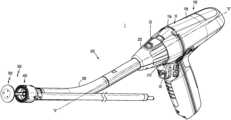
- FIG. 1is a perspective view of a handheld surgical instrument including a handle assembly, an adapter assembly, and an end effector, in accordance with an embodiment of the present disclosure
- FIG. 2is a schematic diagram of the handle assembly, the adapter assembly, and the end effector of FIG. 1 ;
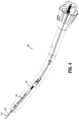
- FIG. 3is a side perspective view of the adapter assembly and the end effector (e.g., an annular reload and an anvil assembly) attached to the adapter assembly;
- the end effectore.g., an annular reload and an anvil assembly
- FIG. 4is a perspective view of the adapter assembly, shown partially in phantom, without the end effector (e.g., the annular reload and the anvil assembly);
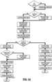
- FIG. 5 Ais a flow chart of a method for carrying out a stapling function of the surgical instrument of FIG. 1 ;
- FIG. 5 Bis a flow chart of a method for carrying out a cutting function of the surgical instrument of FIG. 1 .
- distalrefers to that portion of the surgical instrument, or component thereof, farther from the user
- proximalrefers to that portion of the surgical instrument, or component thereof, closer to the user.
- An intelligent surgical instrumentsuch as a hand-held surgical instrument, includes a handle assembly, an adapter assembly coupled to the handle assembly, and an end effector coupled to the adapter assembly.
- the staplerallows for full, independent control of three functions: clamping, stapling, and cutting. This allows certain portions of the stapler to adapt if the tissue presents a non-ideal situation. For example, in a case where extremely thin tissue is being treated, it may be advantageous to move an anvil of the end effector closer to a distal end of the adapter assembly in order to confirm that an anvil is attached to the adapter assembly.
- This disclosurerelates to software that will allow and compensate for anvil movement in situations when the stapler is already fully clamped and there is less than a target threshold load on the anvil.
- the staplermay move the anvil toward the adapter assembly (e.g., proximally) until the target threshold load is detected.
- the staple stroke and cut strokeare adjusted to the corresponding delta anvil position. This maintains a consistent firing, regardless of clamp distance.
- the adjusted staple strokemaintains a consistent staple crimp even with the anvil out of position; and the adjusted cut stroke ensures a correct cut distance regardless of the anvil position.
- FIG. 1illustrates a surgical instrument, such as, for example, a circular stapler 1 , including a handle assembly 100 , which is configured for selective connection with an adapter assembly 200 , and, in turn, adapter assembly 200 is configured for selective connection with an end effector 300 , which includes a reload 400 (of a plurality of reloads) and an anvil assembly 500 .
- the end effector 300is configured to produce a surgical effect on tissue of a patient.
- the handle assembly 100is a powered electromechanical handle assembly including a power handle 101 ( FIG. 2 ) and an outer shell housing 10 configured to selectively receive and encase power handle 101 .
- Outer shell housing 10includes a distal half-section 10 a and a proximal half-section 10 b pivotably connected to distal half-section 10 a . When joined, distal and proximal half-sections 10 a , 10 b define a shell cavity therein in which power handle 101 is selectively situated.
- the motor controller 143includes a plurality of sensors 408 a , 408 b , . . . 408 n configured to measure operational states of the motor 152 and the battery 144 .
- the sensors 408 a - nmay include voltage sensors, current sensors, temperature sensors, telemetry sensors, optical sensors, and combinations thereof.
- the sensors 408 a - 408 nmay measure voltage, current, and other electrical properties of the electrical energy supplied by the battery 144 .
- the sensors 408 a - 408 nmay also measure angular velocity (e.g., rotational speed) as revolutions per minute (RPM), torque, temperature, current draw, and other operational properties of the motor 152 .
- angular velocitye.g., rotational speed
- RPMrevolutions per minute
- Angular velocitymay be determined by measuring the rotation of the motor 152 or a drive shaft (not shown) coupled thereto and rotatable by the motor 152 .
- the position of various axially movable drive shaftsmay also be determined by using various linear sensors disposed in or in proximity to the shafts or extrapolated from the RPM measurements.
- torquemay be calculated based on the regulated current draw of the motor 152 at a constant RPM.
- the motor controller 143 and/or the main controller 147may measure time and process the above-described values as a function of time, including integration and/or differentiation, e.g., to determine the rate of change in the measured values.
- the main controller 147is also configured to determine distance traveled of various components of the circular adapter assembly 200 and/or the end effector 300 by counting revolutions of the motor 152 .
- the motor controller 143is coupled to the main controller 147 , which includes a plurality of inputs and outputs for interfacing with the motor controller 143 .
- the main controller 147receives measured sensor signals from the motor controller 143 regarding operational status of the motor 152 and the battery 144 and, in turn, outputs control signals to the motor controller 143 to control the operation of the motor 152 based on the sensor readings and specific algorithm instructions.
- the main controller 147is also configured to accept a plurality of user inputs from a user interface (e.g., switches, buttons, touch screen, etc. coupled to the main controller 147 ).
- the main controller 147is also coupled to a memory 141 .
- the memory 141may include volatile (e.g., RAM) and non-volatile storage configured to store data, including software instructions for operating the power handle 101 .
- the main controller 147is also coupled to a strain gauge (not explicitly shown) of the circular adapter assembly 200 using a wired or a wireless connection and is configured to receive strain measurements from the strain gauge which are used during operation of the power handle 101 .
- the power handle 101further includes a second motor (not explicitly shown) and a third motor (not explicitly shown) each electrically connected to controller circuit board 142 and battery 144 .
- Each motor 152includes a respective motor shaft (not explicitly shown) extending therefrom. Rotation of the motor shafts by the respective motors 152 function to drive shafts and/or gear components of adapter assembly 200 in order to perform the various operations of handle assembly 100 .
- motors 152 of power handle 101are configured to drive shafts and/or gear components of adapter assembly 200 in order to selectively extend/retract a trocar member 274 ( FIG.
- adapter assembly 200includes an outer knob housing 202 and an outer tube 206 extending from a distal end of knob housing 202 .
- Knob housing 202 and outer tube 206are configured and dimensioned to house the components of adapter assembly 200 .
- Adapter assembly 200is configured to convert a rotation of coupling shafts (not explicitly shown) of handle assembly 100 into axial translations useful for operating trocar assembly 270 of adapter assembly 200 , anvil assembly 500 , and/or staple driver assembly (not explicitly shown) or knife assembly (not explicitly shown) of reload 400 .
- Adapter assembly 200further includes the trocar assembly 270 removably supported in a distal end of outer tube 206 .
- Trocar assembly 270includes a trocar member 274 and a drive screw 276 operably received within trocar member 274 for axially moving trocar member 274 relative to outer tube 206 .
- a distal end 274 b of trocar member 274is configured to selectively engage anvil assembly 500 , such that axial movement of trocar member 274 , via a rotation of drive screw 276 , results in a concomitant axial movement of anvil assembly 500 .
- Forces during an actuation of trocar member 274 or a closing of end effector 300may be measured by the strain gauge in order to monitor and control a firing of staples from reload 400 ; monitor forces during a firing and formation of the staples as the staples are being ejected from reload 400 ; optimize formation of the staples (e.g., staple crimp height) as the staples are being ejected from reload 400 for different indications of tissue; and monitor and control a firing of the annular knife of reload 400 .
- the strain gauge of adapter assembly 200measures and monitors the retraction of trocar member 274 .
- a reaction forceis exerted on anvil assembly 500 which is in a generally distal direction. This distally directed reaction force is communicated from anvil assembly 500 to the strain gauge.
- the strain gaugethen communicates signals to main controller circuit board 142 of power handle 101 of handle assembly 100 . Graphics are then displayed on a display screen (not shown) of handle assembly 100 to provide the user with real-time information related to the status of the firing of handle assembly 100 .
- the anvil assembly 500(already positioned by surgeon) is attached to the trocar member 274 and the user begins the clamping process on the tissue interposed between circular reload 400 and the anvil assembly 500 by pressing on the bottom of the toggle control button 30 .
- the anvil assembly 500is retracted toward the circular reload 400 until reaching a preset, fully clamped position, namely a position of the anvil assembly 500 at which the tissue is fully clamped between the anvil assembly 500 and the reload 400 .
- the preset, fully clamped positionvaries for each of the different types of reloads (e.g., the distance is about 29 mm for 25 mm reloads).
- the strain gaugecontinuously provides measurements to the main controller 147 on the force imparted on the trocar member 274 as it moves the anvil assembly 500 to compress tissue between the anvil assembly 500 and the annular reload 400 .
- the main controller 147determines, using the measurements taken by the strain gauge, whether the measured force is at or less than a target threshold load. If the main controller 147 determines that the measured force is less than the target threshold load, this is an indication that the clamped tissue is extremely thin, and will therefore require that the gap distance between the anvil assembly 500 and the reload 400 be reduced to below the preset gap distance of the fully clamped position. As such, the anvil assembly 500 is further retracted beyond the fully clamped position until the target threshold load is detected, in which the anvil assembly 500 is in an over-clamped state.
- the gap distance between the anvil assembly 500 and the reload 400is less than the preprogrammed gap distance for the end effector 300 , the total amount of distal movement of the staples and the annular knife (e.g., the staple stroke and the cut stroke, respectively) during the respective stapling and cutting sequences should also be adjusted.
- FIG. 5 Awhich shows a flow chart of the stapling process
- software stored in the memory 141instructs the main controller 147 to determine whether the anvil assembly 500 is in the over-clamped state noted above. If the main controller 147 determines that the anvil assembly 500 has been retracted to the over-clamped state (e.g., due to the tissue having a thickness that is less than the pre-programmed gap distance), the main controller 147 calculates a staple adjustment. Staple adjustment may include decreasing the distance of the staple stroke compared with a preset staple stroke. The preset staple stroke may be adjusted (e.g., reduced) by the difference between the gap distance in the over-clamped state and the gap distance in the fully clamped state.
- the userpresses down on the toggle control button 30 , which results in ejection of the staples from the reload 400 into the anvil assembly 500 to deform the staples through the tissue.
- the staplesare ejected from the reload 400 by the adjusted staple stroke to staple tissue.
- the main controller 147determines that the stapling process is completed successfully if the measured strain was within minimum and maximum stapling force limits. Progress of staple firing is illustrated by an animation of the anastomosis, a firing progress bar, and staple formation.
- the software stored in the memory 141includes instructions that when executed by the main controller 147 allows the main controller 147 to determine whether the anvil assembly 500 is in the over-clamped state. If the main controller 147 determines that the anvil assembly 510 has been approximated to the over-clamped state (e.g., due to the tissue having a thickness that is less than the pre-programmed gap distance), the main controller 147 calculates a cutting adjustment, such as, for example, a decrease in cutting stroke compared with a preset cutting stroke. The preset cutting stroke is adjusted (e.g., reduced) by the difference between the gap distance in the over-clamped state and the gap distance in the fully clamped state. As such, upon actuating the cutting function, the knife is translated from the reload 400 by the adjusted cutting stroke.
- a cutting adjustmentsuch as, for example, a decrease in cutting stroke compared with a preset cutting stroke.
- the preset cutting strokeis adjusted (e.g., reduced) by the difference between the gap distance in the over-clam
- the described techniquesmay be implemented in hardware, software, firmware, or any combination thereof. If implemented in software, the functions may be stored as one or more instructions or code on a computer-readable medium and executed by a hardware-based processing unit.
- Computer-readable mediamay include non-transitory computer-readable media, which corresponds to a tangible medium such as data storage media (e.g., RAM, ROM, EEPROM, flash memory, or any other medium that can be used to store desired program code in the form of instructions or data structures and that can be accessed by a computer).
- processorssuch as one or more digital signal processors (DSPs), general purpose microprocessors, application specific integrated circuits (ASICs), field programmable logic arrays (FPGAs), or other equivalent integrated or discrete logic circuitry.
- DSPsdigital signal processors
- ASICsapplication specific integrated circuits
- FPGAsfield programmable logic arrays
- processorsmay refer to any of the foregoing structure or any other physical structure suitable for implementation of the described techniques. Also, the techniques could be fully implemented in one or more circuits or logic elements.
Landscapes
- Health & Medical Sciences (AREA)
- Life Sciences & Earth Sciences (AREA)
- Surgery (AREA)
- Heart & Thoracic Surgery (AREA)
- Engineering & Computer Science (AREA)
- Biomedical Technology (AREA)
- Nuclear Medicine, Radiotherapy & Molecular Imaging (AREA)
- Medical Informatics (AREA)
- Molecular Biology (AREA)
- Animal Behavior & Ethology (AREA)
- General Health & Medical Sciences (AREA)
- Public Health (AREA)
- Veterinary Medicine (AREA)
- Surgical Instruments (AREA)
Abstract
Description
Claims (20)
Priority Applications (6)
| Application Number | Priority Date | Filing Date | Title |
|---|---|---|---|
| US17/347,129US12245767B2 (en) | 2020-07-13 | 2021-06-14 | Handheld electromechanical surgical system |
| CN202110756810.XACN113925550A (en) | 2020-07-13 | 2021-07-05 | Hand-held electromechanical surgical system |
| ES21185126TES2974075T3 (en) | 2020-07-13 | 2021-07-12 | Portable electromechanical surgical system |
| JP2021114769AJP2022017205A (en) | 2020-07-13 | 2021-07-12 | Handheld electromechanical surgical system |
| EP21185126.6AEP3939521B1 (en) | 2020-07-13 | 2021-07-12 | Handheld electromechanical surgical system |
| US19/037,550US20250169821A1 (en) | 2020-07-13 | 2025-01-27 | Handheld electromechanical surgical system |
Applications Claiming Priority (2)
| Application Number | Priority Date | Filing Date | Title |
|---|---|---|---|
| US202063051026P | 2020-07-13 | 2020-07-13 | |
| US17/347,129US12245767B2 (en) | 2020-07-13 | 2021-06-14 | Handheld electromechanical surgical system |
Related Child Applications (1)
| Application Number | Title | Priority Date | Filing Date |
|---|---|---|---|
| US19/037,550ContinuationUS20250169821A1 (en) | 2020-07-13 | 2025-01-27 | Handheld electromechanical surgical system |
Publications (2)
| Publication Number | Publication Date |
|---|---|
| US20220008078A1 US20220008078A1 (en) | 2022-01-13 |
| US12245767B2true US12245767B2 (en) | 2025-03-11 |
Family
ID=76890920
Family Applications (2)
| Application Number | Title | Priority Date | Filing Date |
|---|---|---|---|
| US17/347,129Active2042-03-23US12245767B2 (en) | 2020-07-13 | 2021-06-14 | Handheld electromechanical surgical system |
| US19/037,550PendingUS20250169821A1 (en) | 2020-07-13 | 2025-01-27 | Handheld electromechanical surgical system |
Family Applications After (1)
| Application Number | Title | Priority Date | Filing Date |
|---|---|---|---|
| US19/037,550PendingUS20250169821A1 (en) | 2020-07-13 | 2025-01-27 | Handheld electromechanical surgical system |
Country Status (5)
| Country | Link |
|---|---|
| US (2) | US12245767B2 (en) |
| EP (1) | EP3939521B1 (en) |
| JP (1) | JP2022017205A (en) |
| CN (1) | CN113925550A (en) |
| ES (1) | ES2974075T3 (en) |
Citations (30)
| Publication number | Priority date | Publication date | Assignee | Title |
|---|---|---|---|---|
| EP0536882A2 (en) | 1991-08-23 | 1993-04-14 | Ethicon, Inc. | Surgical anastomosis stapling instrument |
| US5383880A (en) | 1992-01-17 | 1995-01-24 | Ethicon, Inc. | Endoscopic surgical system with sensing means |
| US5810811A (en) | 1993-07-22 | 1998-09-22 | Ethicon Endo-Surgery, Inc. | Electrosurgical hemostatic device |
| US20040153124A1 (en) | 1999-06-02 | 2004-08-05 | Whitman Michael P. | Electromechanical driver and remote surgical instrument attachment having computer assisted control capabilities |
| US7032798B2 (en) | 1999-06-02 | 2006-04-25 | Power Medical Interventions, Inc. | Electro-mechanical surgical device |
| US20080251568A1 (en) | 2007-04-13 | 2008-10-16 | Michael Zemlok | Powered surgical instrument |
| US20080272172A1 (en) | 2007-05-01 | 2008-11-06 | Michael Zemlok | Powered surgical stapling device platform |
| US20090012556A1 (en) | 2007-03-28 | 2009-01-08 | Boudreaux Chad P | Laparoscopic tissue thickness and clamp load measuring devices |
| EP2027819A1 (en) | 2007-08-21 | 2009-02-25 | Tyco Healthcare Group LP | Powered surgical instrument |
| US20090057369A1 (en) | 2005-07-26 | 2009-03-05 | Smith Kevin W | Electrically Self-Powered Surgical Instrument With Manual Release |
| US20090090763A1 (en) | 2007-10-05 | 2009-04-09 | Tyco Healthcare Group Lp | Powered surgical stapling device |
| US20090112271A1 (en) | 2005-04-12 | 2009-04-30 | Moskowitz Mosheh T | Bi-directional fixating transvertebral body screws, zero-profile horizontal intervertebral miniplates, expansile intervertebral body fusion devices, and posterior motion-calibrating interarticulating joint stapling device for spinal fusion |
| US20090108048A1 (en) | 2007-10-31 | 2009-04-30 | Tyco Healthcare Group Lp | Powered surgical instrument |
| US20100133318A1 (en) | 2007-06-22 | 2010-06-03 | Boudreaux Chad P | Surgical Stapling Instrument With A Geared Return Mechanism |
| US20100270355A1 (en) | 2009-04-27 | 2010-10-28 | Whitman Michael P | Device and method for controlling compression of tissue |
| US20110017801A1 (en) | 2007-10-05 | 2011-01-27 | Tyco Healthcare Group Lp | Internal backbone structural chassis for a surgical device |
| US20110125138A1 (en) | 2009-11-20 | 2011-05-26 | Donald Malinouskas | Surgical console and hand-held surgical device |
| US20120211542A1 (en) | 2011-02-23 | 2012-08-23 | Tyco Healthcare Group I.P | Controlled tissue compression systems and methods |
| US8808311B2 (en) | 2002-04-25 | 2014-08-19 | Covidien Lp | Surgical instruments including MEMS devices |
| US20160066916A1 (en)* | 2014-09-05 | 2016-03-10 | Ethicon Endo-Surgery, Inc. | Multiple motor control for powered medical device |
| US20170311938A1 (en) | 2007-10-05 | 2017-11-02 | Covidien Lp | Hand-held surgical devices |
| US20190099181A1 (en)* | 2016-12-21 | 2019-04-04 | Ethicon Llc | Lockout arrangements for surgical end effectors and replaceable tool assemblies |
| EP3498191A2 (en) | 2017-12-15 | 2019-06-19 | Ethicon LLC | Methods of operating surgical end effectors |
| US20190200996A1 (en)* | 2017-12-28 | 2019-07-04 | Ethicon Llc | Adjustment of staple height of at least one row of staples based on the sensed tissue thickness or force in closing |
| US20190200998A1 (en) | 2017-12-28 | 2019-07-04 | Ethicon Llc | Method for circular stapler control algorithm adjustment based on situational awareness |
| US10363036B2 (en) | 2015-09-23 | 2019-07-30 | Ethicon Llc | Surgical stapler having force-based motor control |
| US20190261991A1 (en)* | 2015-02-27 | 2019-08-29 | Ethicon Llc | Modular stapling assembly |
| US20200281594A1 (en)* | 2019-03-08 | 2020-09-10 | Ethicon Llc | Electrical potential shifting circuit for powered surgical stapler |
| US20200405311A1 (en)* | 2019-06-28 | 2020-12-31 | Ethicon Llc | Method of using multiple rfid chips with a surgical assembly |
| EP3795094A1 (en) | 2019-09-18 | 2021-03-24 | Ethicon LLC | Method for calibrating movements of actuated members of powered surgical stapler |
Family Cites Families (11)
| Publication number | Priority date | Publication date | Assignee | Title |
|---|---|---|---|---|
| GB935490A (en)* | 1959-09-15 | 1963-08-28 | Res Inst Of Ex Surgical Appara | An instrument for suturing blood vessels and nerves |
| US4319576A (en)* | 1980-02-26 | 1982-03-16 | Senco Products, Inc. | Intralumenal anastomosis surgical stapling instrument |
| JP4257446B2 (en)* | 1999-01-29 | 2009-04-22 | マニー株式会社 | Medical stapler |
| US7951071B2 (en)* | 1999-06-02 | 2011-05-31 | Tyco Healthcare Group Lp | Moisture-detecting shaft for use with an electro-mechanical surgical device |
| US8459520B2 (en)* | 2007-01-10 | 2013-06-11 | Ethicon Endo-Surgery, Inc. | Surgical instrument with wireless communication between control unit and remote sensor |
| US8066167B2 (en)* | 2009-03-23 | 2011-11-29 | Ethicon Endo-Surgery, Inc. | Circular surgical stapling instrument with anvil locking system |
| US9993258B2 (en)* | 2015-02-27 | 2018-06-12 | Ethicon Llc | Adaptable surgical instrument handle |
| MX2019007294A (en)* | 2016-12-21 | 2019-10-15 | Ethicon Llc | Firing assembly comprising a lockout. |
| US11045199B2 (en)* | 2017-06-09 | 2021-06-29 | Covidien Lp | Handheld electromechanical surgical system |
| US11179151B2 (en)* | 2017-12-21 | 2021-11-23 | Cilag Gmbh International | Surgical instrument comprising a display |
| US11241233B2 (en)* | 2018-07-10 | 2022-02-08 | Covidien Lp | Apparatus for ensuring strain gauge accuracy in medical reusable device |
- 2021
- 2021-06-14USUS17/347,129patent/US12245767B2/enactiveActive
- 2021-07-05CNCN202110756810.XApatent/CN113925550A/enactivePending
- 2021-07-12ESES21185126Tpatent/ES2974075T3/enactiveActive
- 2021-07-12JPJP2021114769Apatent/JP2022017205A/enactivePending
- 2021-07-12EPEP21185126.6Apatent/EP3939521B1/enactiveActive
- 2025
- 2025-01-27USUS19/037,550patent/US20250169821A1/enactivePending
Patent Citations (34)
| Publication number | Priority date | Publication date | Assignee | Title |
|---|---|---|---|---|
| EP0536882A2 (en) | 1991-08-23 | 1993-04-14 | Ethicon, Inc. | Surgical anastomosis stapling instrument |
| US5383880A (en) | 1992-01-17 | 1995-01-24 | Ethicon, Inc. | Endoscopic surgical system with sensing means |
| US5667517A (en) | 1992-01-17 | 1997-09-16 | Ethicon, Inc. | Endoscopic surgical system with sensing means |
| US5810811A (en) | 1993-07-22 | 1998-09-22 | Ethicon Endo-Surgery, Inc. | Electrosurgical hemostatic device |
| US20040153124A1 (en) | 1999-06-02 | 2004-08-05 | Whitman Michael P. | Electromechanical driver and remote surgical instrument attachment having computer assisted control capabilities |
| US7032798B2 (en) | 1999-06-02 | 2006-04-25 | Power Medical Interventions, Inc. | Electro-mechanical surgical device |
| US8808311B2 (en) | 2002-04-25 | 2014-08-19 | Covidien Lp | Surgical instruments including MEMS devices |
| US20090112271A1 (en) | 2005-04-12 | 2009-04-30 | Moskowitz Mosheh T | Bi-directional fixating transvertebral body screws, zero-profile horizontal intervertebral miniplates, expansile intervertebral body fusion devices, and posterior motion-calibrating interarticulating joint stapling device for spinal fusion |
| US20090057369A1 (en) | 2005-07-26 | 2009-03-05 | Smith Kevin W | Electrically Self-Powered Surgical Instrument With Manual Release |
| US20090012556A1 (en) | 2007-03-28 | 2009-01-08 | Boudreaux Chad P | Laparoscopic tissue thickness and clamp load measuring devices |
| US20080251568A1 (en) | 2007-04-13 | 2008-10-16 | Michael Zemlok | Powered surgical instrument |
| US20080272172A1 (en) | 2007-05-01 | 2008-11-06 | Michael Zemlok | Powered surgical stapling device platform |
| US20100133318A1 (en) | 2007-06-22 | 2010-06-03 | Boudreaux Chad P | Surgical Stapling Instrument With A Geared Return Mechanism |
| EP2027819A1 (en) | 2007-08-21 | 2009-02-25 | Tyco Healthcare Group LP | Powered surgical instrument |
| US20090090763A1 (en) | 2007-10-05 | 2009-04-09 | Tyco Healthcare Group Lp | Powered surgical stapling device |
| US20170311938A1 (en) | 2007-10-05 | 2017-11-02 | Covidien Lp | Hand-held surgical devices |
| US20110017801A1 (en) | 2007-10-05 | 2011-01-27 | Tyco Healthcare Group Lp | Internal backbone structural chassis for a surgical device |
| US20090108048A1 (en) | 2007-10-31 | 2009-04-30 | Tyco Healthcare Group Lp | Powered surgical instrument |
| EP2245994A1 (en) | 2009-04-27 | 2010-11-03 | Power Medical Interventions, LLC | Device and method for controlling compression of tissue |
| US8012170B2 (en) | 2009-04-27 | 2011-09-06 | Tyco Healthcare Group Lp | Device and method for controlling compression of tissue |
| US20100270355A1 (en) | 2009-04-27 | 2010-10-28 | Whitman Michael P | Device and method for controlling compression of tissue |
| US20110125138A1 (en) | 2009-11-20 | 2011-05-26 | Donald Malinouskas | Surgical console and hand-held surgical device |
| US10278698B2 (en) | 2011-02-23 | 2019-05-07 | Covidien Lp | Controlled tissue compression systems and methods |
| US20120211542A1 (en) | 2011-02-23 | 2012-08-23 | Tyco Healthcare Group I.P | Controlled tissue compression systems and methods |
| US20160066916A1 (en)* | 2014-09-05 | 2016-03-10 | Ethicon Endo-Surgery, Inc. | Multiple motor control for powered medical device |
| US20190261991A1 (en)* | 2015-02-27 | 2019-08-29 | Ethicon Llc | Modular stapling assembly |
| US10363036B2 (en) | 2015-09-23 | 2019-07-30 | Ethicon Llc | Surgical stapler having force-based motor control |
| US20190099181A1 (en)* | 2016-12-21 | 2019-04-04 | Ethicon Llc | Lockout arrangements for surgical end effectors and replaceable tool assemblies |
| EP3498191A2 (en) | 2017-12-15 | 2019-06-19 | Ethicon LLC | Methods of operating surgical end effectors |
| US20190200996A1 (en)* | 2017-12-28 | 2019-07-04 | Ethicon Llc | Adjustment of staple height of at least one row of staples based on the sensed tissue thickness or force in closing |
| US20190200998A1 (en) | 2017-12-28 | 2019-07-04 | Ethicon Llc | Method for circular stapler control algorithm adjustment based on situational awareness |
| US20200281594A1 (en)* | 2019-03-08 | 2020-09-10 | Ethicon Llc | Electrical potential shifting circuit for powered surgical stapler |
| US20200405311A1 (en)* | 2019-06-28 | 2020-12-31 | Ethicon Llc | Method of using multiple rfid chips with a surgical assembly |
| EP3795094A1 (en) | 2019-09-18 | 2021-03-24 | Ethicon LLC | Method for calibrating movements of actuated members of powered surgical stapler |
Non-Patent Citations (1)
| Title |
|---|
| European Search Report dated Nov. 30, 2021, issued in corresponding EP Appln. No. 21185126, 7 pages. |
Also Published As
| Publication number | Publication date |
|---|---|
| US20250169821A1 (en) | 2025-05-29 |
| EP3939521B1 (en) | 2023-12-06 |
| EP3939521A1 (en) | 2022-01-19 |
| ES2974075T3 (en) | 2024-06-25 |
| US20220008078A1 (en) | 2022-01-13 |
| CN113925550A (en) | 2022-01-14 |
| JP2022017205A (en) | 2022-01-25 |
Similar Documents
| Publication | Publication Date | Title |
|---|---|---|
| US12161341B2 (en) | Slow speed staple and staple relaxation for stapling optimization | |
| US20250221712A1 (en) | Handheld electromechanical surgical system | |
| JP2024528888A (en) | HANDHELD ELECTROMECHANICAL STAPLER WITH TISSUE THICKNESS DETECTION - Patent application | |
| US11771432B2 (en) | Stapling and cutting to default values in the event of strain gauge data integrity loss | |
| WO2022259121A1 (en) | Handheld electromechanical surgical system | |
| US12245767B2 (en) | Handheld electromechanical surgical system | |
| US12343016B2 (en) | Handheld electromechanical surgical system | |
| US11832823B2 (en) | Determination of anvil release during anastomosis | |
| US12016556B2 (en) | Handheld electromechanical surgical system | |
| US12213674B2 (en) | Determination of premature staple ejection | |
| WO2025088481A1 (en) | Powered surgical stapler and method for determining staple and cut force based on clamping distance | |
| EP4561462A1 (en) | Handheld electromechanical surgical system with low tissue compression indication |
Legal Events
| Date | Code | Title | Description |
|---|---|---|---|
| FEPP | Fee payment procedure | Free format text:ENTITY STATUS SET TO UNDISCOUNTED (ORIGINAL EVENT CODE: BIG.); ENTITY STATUS OF PATENT OWNER: LARGE ENTITY | |
| AS | Assignment | Owner name:COVIDIEN LP, MASSACHUSETTS Free format text:ASSIGNMENT OF ASSIGNORS INTEREST;ASSIGNORS:KOLLAR, CHARLES R.;VALENTINE, DAVID E.;HART, ALEXANDER J.;AND OTHERS;SIGNING DATES FROM 20200626 TO 20200713;REEL/FRAME:056879/0365 | |
| STPP | Information on status: patent application and granting procedure in general | Free format text:DOCKETED NEW CASE - READY FOR EXAMINATION | |
| STPP | Information on status: patent application and granting procedure in general | Free format text:NON FINAL ACTION MAILED | |
| STPP | Information on status: patent application and granting procedure in general | Free format text:RESPONSE TO NON-FINAL OFFICE ACTION ENTERED AND FORWARDED TO EXAMINER | |
| STPP | Information on status: patent application and granting procedure in general | Free format text:FINAL REJECTION MAILED | |
| STPP | Information on status: patent application and granting procedure in general | Free format text:RESPONSE AFTER FINAL ACTION FORWARDED TO EXAMINER | |
| STPP | Information on status: patent application and granting procedure in general | Free format text:ADVISORY ACTION MAILED | |
| STPP | Information on status: patent application and granting procedure in general | Free format text:DOCKETED NEW CASE - READY FOR EXAMINATION | |
| STPP | Information on status: patent application and granting procedure in general | Free format text:NON FINAL ACTION MAILED | |
| STPP | Information on status: patent application and granting procedure in general | Free format text:RESPONSE TO NON-FINAL OFFICE ACTION ENTERED AND FORWARDED TO EXAMINER | |
| STPP | Information on status: patent application and granting procedure in general | Free format text:FINAL REJECTION MAILED | |
| STPP | Information on status: patent application and granting procedure in general | Free format text:DOCKETED NEW CASE - READY FOR EXAMINATION | |
| STPP | Information on status: patent application and granting procedure in general | Free format text:NOTICE OF ALLOWANCE MAILED -- APPLICATION RECEIVED IN OFFICE OF PUBLICATIONS | |
| AS | Assignment | Owner name:COVIDIEN LP, MASSACHUSETTS Free format text:ASSIGNMENT OF ASSIGNORS INTEREST;ASSIGNOR:STRASSNER, HALEY;REEL/FRAME:069611/0383 Effective date:20200702 | |
| STPP | Information on status: patent application and granting procedure in general | Free format text:PUBLICATIONS -- ISSUE FEE PAYMENT RECEIVED | |
| STPP | Information on status: patent application and granting procedure in general | Free format text:PUBLICATIONS -- ISSUE FEE PAYMENT VERIFIED | |
| STCF | Information on status: patent grant | Free format text:PATENTED CASE |