US12244595B2 - Air gap-based network isolation device - Google Patents
Air gap-based network isolation deviceDownload PDFInfo
- Publication number
- US12244595B2 US12244595B2US18/111,431US202318111431AUS12244595B2US 12244595 B2US12244595 B2US 12244595B2US 202318111431 AUS202318111431 AUS 202318111431AUS 12244595 B2US12244595 B2US 12244595B2
- Authority
- US
- United States
- Prior art keywords
- memory resource
- signal
- network
- component
- controller
- Prior art date
- Legal status (The legal status is an assumption and is not a legal conclusion. Google has not performed a legal analysis and makes no representation as to the accuracy of the status listed.)
- Active
Links
- 238000002955isolationMethods0.000titleabstractdescription30
- 230000007246mechanismEffects0.000claimsdescription24
- 230000004044responseEffects0.000claimsdescription15
- 230000008859changeEffects0.000claimsdescription7
- 238000000034methodMethods0.000description40
- 238000004891communicationMethods0.000description39
- 230000000875corresponding effectEffects0.000description19
- 230000008569processEffects0.000description18
- QVFWZNCVPCJQOP-UHFFFAOYSA-NchloralodolChemical compoundCC(O)(C)CC(C)OC(O)C(Cl)(Cl)ClQVFWZNCVPCJQOP-UHFFFAOYSA-N0.000description15
- 230000001413cellular effectEffects0.000description9
- 230000004913activationEffects0.000description7
- 238000012545processingMethods0.000description5
- 230000001960triggered effectEffects0.000description5
- 238000010586diagramMethods0.000description4
- 238000012795verificationMethods0.000description4
- 230000009471actionEffects0.000description3
- 238000001228spectrumMethods0.000description3
- 238000013475authorizationMethods0.000description2
- 230000008901benefitEffects0.000description2
- 238000005516engineering processMethods0.000description2
- 230000006870functionEffects0.000description2
- 239000000758substrateSubstances0.000description2
- 230000003213activating effectEffects0.000description1
- 238000013459approachMethods0.000description1
- 230000005540biological transmissionEffects0.000description1
- 238000004590computer programMethods0.000description1
- 230000001276controlling effectEffects0.000description1
- 230000002596correlated effectEffects0.000description1
- 238000001514detection methodMethods0.000description1
- 230000009977dual effectEffects0.000description1
- 230000003993interactionEffects0.000description1
- 230000005055memory storageEffects0.000description1
- 230000002085persistent effectEffects0.000description1
- 239000000523sampleSubstances0.000description1
- 230000011664signalingEffects0.000description1
- 230000005236sound signalEffects0.000description1
- 230000003068static effectEffects0.000description1
- 230000007704transitionEffects0.000description1
Images


Classifications
- H—ELECTRICITY
- H04—ELECTRIC COMMUNICATION TECHNIQUE
- H04L—TRANSMISSION OF DIGITAL INFORMATION, e.g. TELEGRAPHIC COMMUNICATION
- H04L63/00—Network architectures or network communication protocols for network security
- H04L63/08—Network architectures or network communication protocols for network security for authentication of entities
- H04L63/0876—Network architectures or network communication protocols for network security for authentication of entities based on the identity of the terminal or configuration, e.g. MAC address, hardware or software configuration or device fingerprint
- H—ELECTRICITY
- H04—ELECTRIC COMMUNICATION TECHNIQUE
- H04L—TRANSMISSION OF DIGITAL INFORMATION, e.g. TELEGRAPHIC COMMUNICATION
- H04L63/00—Network architectures or network communication protocols for network security
- H04L63/10—Network architectures or network communication protocols for network security for controlling access to devices or network resources
- H—ELECTRICITY
- H04—ELECTRIC COMMUNICATION TECHNIQUE
- H04L—TRANSMISSION OF DIGITAL INFORMATION, e.g. TELEGRAPHIC COMMUNICATION
- H04L63/00—Network architectures or network communication protocols for network security
- H04L63/08—Network architectures or network communication protocols for network security for authentication of entities
- H—ELECTRICITY
- H04—ELECTRIC COMMUNICATION TECHNIQUE
- H04L—TRANSMISSION OF DIGITAL INFORMATION, e.g. TELEGRAPHIC COMMUNICATION
- H04L63/00—Network architectures or network communication protocols for network security
- H04L63/16—Implementing security features at a particular protocol layer
- H04L63/164—Implementing security features at a particular protocol layer at the network layer
- H—ELECTRICITY
- H04—ELECTRIC COMMUNICATION TECHNIQUE
- H04L—TRANSMISSION OF DIGITAL INFORMATION, e.g. TELEGRAPHIC COMMUNICATION
- H04L69/00—Network arrangements, protocols or services independent of the application payload and not provided for in the other groups of this subclass
- H04L69/18—Multiprotocol handlers, e.g. single devices capable of handling multiple protocols
- H—ELECTRICITY
- H04—ELECTRIC COMMUNICATION TECHNIQUE
- H04W—WIRELESS COMMUNICATION NETWORKS
- H04W12/00—Security arrangements; Authentication; Protecting privacy or anonymity
- H04W12/60—Context-dependent security
- H04W12/69—Identity-dependent
- H04W12/71—Hardware identity
Definitions
- Examplesinclude a storage system that utilizes discrete on-demand memory resources.
- FIG. 1illustrates an example storage device to persistently store a sensitive data set.
- FIG. 2 Aillustrates an example storage system that utilizes discrete on-demand memory resources.
- FIG. 2 B through FIG. 2 Eillustrate variations of a signal interface, for use with storage devices such as described with examples of FIG. 1 and FIG. 2 A .
- FIG. 3illustrates an example method for storing sensitive data using a discrete on-demand memory resource.
- FIG. 4illustrates a method for providing a storage module that is inaccessible until remotely activated using a non-IP network communication channel or link.
- FIG. 5illustrates a method for managing an array of memory resource components, where each memory resource component of the array is selectively activated through an initial connection made through a non-IP network channel or link.
- FIG. 6illustrates a client system to access a remote memory resource component of a user account, according to one or more examples.
- FIG. 7is a block diagram that illustrates a computing device upon which examples described herein may be implemented.
- FIG. 8illustrates a method for operating a computing device of a user to access a service that provides a memory resource component to store sensitive data of the user, according to one or more examples.
- FIG. 9is a block diagram illustrating a network isolation device, in accordance with examples described herein.
- FIG. 10is a flow chart describing a method of authenticating an out-of-band signal to connect an isolated network to an external network, according to examples described herein.
- a storage deviceincludes a discrete memory resource and a controller.
- the memory resourcemay have a characteristic of existing in each of an off-state and an on-state.
- the memory resourcemay be structured to persistently store a sensitive data set when in the off-state, and to enable read and/or write access only when in the on-state.
- the controllermay be coupled to the memory resource to provide an electrical signal to the memory resource in response to an external trigger signal.
- the electrical signalmay cause the memory resource to switch from the off-state into the on-state for a duration that is based on, for example, one or more of (i) a duration of the external trigger signal, (ii) a predetermined duration that is triggered with the external trigger signal, and/or (iii) an occurrence of an ending event, following the external trigger signal.
- the controllermay enable at least one of a read or write operation while the memory resource is in the on-state.
- the controllercontrols switching of the memory resource between the on and off states.
- the controllercan switch the memory resource into the on-state by manipulating the memory resource to physically contact a signal line for electrical input.
- the controllermay switch the memory resource into the off-state by manipulating the memory resource to separate, or otherwise form an airgap with the signal line for the electrical input.
- the controllermay be remotely accessible to a user using a non-IP (Internet Protocol) communication channel (e.g., Public Switch Telephone Network (PSTN)).
- PSTNPublic Switch Telephone Network
- the controllerswitches the memory resource to the on-state, enabling the memory resource to be remotely accessible over an IP channel.
- the memory resourcecan receive and implement read and write operations using the IP channel.
- a storage systemincludes a call router to receive incoming telephone calls, and multiple on-demand discrete memory resources.
- the call routerreceives incoming telephone calls, and for each incoming telephone call, the call router selects a discrete memory resource based on caller information provided with the respective incoming call.
- Each discrete memory resourcemay be structured to persistently store a sensitive data set when in the off-state, and to enable read and/or write access only when in the on-state.
- a method for operating a storage deviceincludes receiving an incoming telephone call, and selecting a discrete memory resource from a plurality of discrete memory resources based on caller information of the incoming telephone call. Additionally, an example includes providing an electrical input signal to the selected discrete memory resource, where the electrical input signal causes the discrete memory resource to be accessible for a duration that can be determined by, for example, one or more of the incoming telephone call, timer, or the occurrence of one or more events (e.g., start and ending events).
- a storage system or deviceselects a memory resource component from an array of memory resources components, where each memory resource component is not accessible over the Internet until that memory resource component is switched from an unconnected state into a connected state.
- the memory resource componentWhen in the unconnected state, the memory resource component is not accessible over a data network such as the Internet.
- the selected memory resource componentbecomes accessible over the data network (e.g., over the Internet).
- the memory resource componentWhen in the connected state, the memory resource component may also be said to be activated (as opposed to deactivated).
- the storage system or devicegenerates a trigger signal that activates the selected memory resource component, such that the activated memory resource component is accessible over a data network that includes the Internet for a given duration.
- the transition from an unconnected state to a connected statemay coincide with a state change of a corresponding switch (e.g., airgap switch).
- a state change of the corresponding switchmay connect the selected memory resource component to a network communication resource (e.g., gateway), which makes the memory resource component accessible over a data network (e.g., Internet Protocol network).
- a data networke.g., Internet Protocol network
- the state change of the corresponding switchmay connect the selected memory resource component to a power source, which then makes the memory access component accessible over a data network.
- the selection of the memory resource componentcan be based on information provided with or determined from the incoming call.
- the selection of the memory resourcecan be based on a phone number that is specified by the call (e.g., the dialed phone number), a code which the caller specifies when a call is connected, and/or a phone number of the caller.
- an air gap-based network isolation devicethat includes hardware componentry for isolating downstream networks and computing devices from external networks.
- the network isolation deviceincludes an out-of-band receiver coupled to an airgap control device—such as a mechanical relay, an actuator, or an optocoupler—that closes and opens a physical air gap in response to an out-of-band signal.
- an internal networke.g., an Ethernet network utilizing an Internet Protocol (IP)
- IPInternet Protocol
- the internal networkcan be comprised of computing devices, memory resources, and/or other digital assets of an entity that desires increased security to isolate its computing devices from other networks in an on-demand manner.
- the network isolation deviceincludes an internal network interface, such as a universal serial bus (USB) and/or R345 port, that connects the network isolation device to the internal network.
- the network isolation devicefurther includes a second network port (e.g., on an opposing end of the device) that connects the network isolation device to an external network, such as the Internet.
- the network isolation devicecan further include circuitry comprising a signal receiver controlling a device that opens and closes an air gap.
- the signal receivercan comprise a telephone receiver, a cellular receiver, a radio signal receiver, a LoRa receiver, or any suitable non-IP receiver.
- the signal receivercan include a dedicated hardware signal filter that provides an initial analog authentication layer for incoming access signals (e.g., out-of-band wireless signals, such as radio, LoRa, SMS, etc., or wired signals utilizing protocols that are distinct from the external network communication protocols).
- the hardware signal filtercan comprise a specialized chip (e.g., an application-specific integrated circuit (ASIC)) representing an encryption and/or decryption algorithm that prevents unwanted access to signal authentication software executing on the signal receiver. It is contemplated that utilization of a dedicated hardware authentication layer renders any attempts at unwanted access to the internal network virtually impossible.
- the signal receivercan include a digital signal processor or other processing device executing authentication instructions to authenticate the wireless access signal.
- the signal receivercan control the device (e.g., mechanical relay, actuator, or optocoupler) to close the air gap and provide network connectivity to the external network(s).
- the network isolation devicecan be controlled remotely using any type of out-of-band signal that corresponds to the signal receiver.
- the signal receivermay receive an SMS message from a particular phone number that includes a specified code for authentication.
- the hardware signal filtercan pre-process the SMS message (e.g., verify that it came from a correct phone number or an authorized device identifier).
- the SMS messagemay be further processed by the signal authenticator of the signal receiver, which can verify a secondary code embedded in the message (e.g., via a decryption algorithm). Once verified, the signal receiver can control the device to close the air gap and enable access, or open the air gap to remove access.
- examplesrecognize that a primary source of vulnerability to online accounts and digital assets is that the computers which host the accounts are continuously present and accessible on the Internet. Because these computers are accessible, attackers can garner information about the accounts which the maintain, even when the accounts are not in use.
- examplesprovide for a system which maintains the physical source (e.g., storage devices or memory resource components) of a user's account offline (e.g., in an off-state, or without access to data network connectivity) until the user needs access to his or her data set. By keeping such devices or components offline, examples prevent unauthorized access by, for example, attackers who could otherwise discover or probe for sources of online information.
- One or more examples describedprovide that methods, techniques, and actions performed by a computing device are performed programmatically, or as a computer-implemented method.
- Programmaticallymeans through the use of code or computer-executable instructions. These instructions can be stored in one or more memory resources of the computing device.
- a programmatically performed stepmay or may not be automatic.
- a programmatic module, engine, or componentcan include a program, a sub-routine, a portion of a program, or a software component or a hardware component capable of performing one or more stated tasks or functions.
- a module or componentcan exist on a hardware component independently of other modules or components.
- a module or componentcan be a shared element or process of other modules, programs, or machines.
- Some examples describedcan generally require the use of computing devices, including processing and memory resources.
- computing devicesincluding processing and memory resources.
- one or more examples describedmay be implemented, in whole or in part, on computing devices such as servers, desktop computers, cellular or smartphones, and tablet devices.
- Memory, processing, and network resourcesmay all be used in connection with the establishment, use, or performance of any example described herein (including with the performance of any method or with the implementation of any system).
- one or more examples describedmay be implemented through the use of instructions that are executable by one or more processors. These instructions may be carried on a computer-readable medium.
- Machines shown or described with figures belowprovide examples of processing resources and computer-readable mediums on which instructions for implementing examples described can be carried and/or executed.
- the numerous machines shown with examples describedinclude processor(s) and various forms of memory for holding data and instructions.
- Examples of computer-readable mediumsinclude permanent memory storage devices, such as hard drives on personal computers or servers.
- Other examples of computer storage mediumsinclude portable storage units, such as CD or DVD units, flash memory (such as carried on smartphones, multifunctional devices or tablets), and magnetic memory.
- Computers, terminals, network enabled devicesare all examples of machines and devices that utilize processors, memory, and instructions stored on computer-readable mediums. Additionally, examples may be implemented in the form of computer-programs, or a computer usable carrier medium capable of carrying such a program.
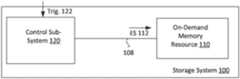
- FIG. 1illustrates an example storage system to persistently store a sensitive data set.
- the storage system 100includes a control sub-system 120 and a discrete, on-demand memory resource 110 that is capable of persistently storing data in an off-state.
- An external trigger signalcan be supplied to the storage system 100 , to cause the memory resource 110 to switch to an on-state for a duration that is defined by a duration of the external trigger signal 122 .
- the storage system 100can store sensitive data (e.g., cryptocurrency) on a network computer system, using a respective memory resource 110 that, by default, exists in an off-state. In the off-state, the memory resource is not accessible over the IP channel.
- the storage system 100can make the memory resource 110 accessible to an authorized party who can provide an external trigger signal 122 to the storage system 100 . In this way, the accessibility of the memory resource 110 may be limited in time, to a duration that is based on or responsive to the control sub-system 120 receiving the external trigger signal 122 . Additionally, access to the memory resource 110 may be limited to a party that can be authorized by way of generating the external trigger signal 122 .
- the storage system 100can be associated with a telephone number, and the external trigger signal 122 can be provided by a telephonic call.
- the memory resource 110can be made accessible to a party that can be authorized by placing a telephone call using the telephone number that is associated with the storage system 100 .
- control sub-system 120is coupled to the memory resource 110 by a signal path 108 .
- a bit state of individual memory cells that comprise the memory resource 110are static and inaccessible, meaning the bit state of the individual memory cells cannot be read or changed without application of an electrical input to the individual memory cells.
- the memory resource 110is not readable or writeable when in the off-state.
- the memory resource 110can be switched intermittingly into the on-state.
- the memory resource 110can be subjected to read operations, as well as write operations which change the respective bit state of the individual memory cells that comprise the memory resource 110 .
- the bit state of select memory cells of the memory resource 110may be changed to reflect values that correspond to a sensitive data set.
- the control sub-system 120uses the signal path 108 to send an electrical signal 112 to the memory resource 110 across the signal path 108 .
- the electrical signal 112provides electrical input for memory cells of the memory resource 110 , to enable, for example, read and write operations to be performed on the memory resource 110 .
- the memory resource 110is switched instantly into the on-state with application of the electrical signal 112 .
- the control sub-system 120can terminate the electrical signal 112 , causing the memory resource 110 to switch instantly to the off-state.
- the memory resource 110exists by default in the off-state, during which the memory cells of the memory resource 110 are inert.
- the control sub-system 120provides the electrical signal 112 to the memory resource 110 upon the control sub-system 120 receiving an external trigger signal 122 .
- the control sub-system 120may receive an incoming telephone call as the external trigger signal 122 .
- the control sub-system 120is triggered into providing the electrical signal 112 to the memory resource 110 upon receiving an incoming call.
- the control sub-system 120terminates the electrical signal 112 , causing the memory resource 110 to return instantly to the off-state.
- the memory resource 110 and the control sub-system 120 of storage system 100are co-located on a common substrate 106 , such as a circuit board.
- the control sub-system 120can include resources to receive the external trigger signal 122 , and to provide the electrical signal 112 to the memory resource 110 via the signal path 108 .
- the storage system 100is assigned to a telephone number, and the control sub-system 120 can receive an incoming telephone call for the assigned telephone number in order to generate the electrical signal 112 for the memory resource 110 .
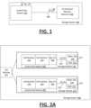
- FIG. 2 Aillustrates an example storage system that utilizes discrete on-demand memory resources.
- a storage system 200includes multiple storage modules 210 , with each of the multiple storage modules 210 being assigned to a corresponding telephone number 215 .
- functional components of the control sub-system 202may be co-located with a device of storage module 210 .
- the control sub-system 202can be implemented on one or more devices that are physically separated from a device of the storage module 210 .
- the control sub-system 202can be implemented a network computer (e.g., server), separate from a substrate or computing device of the storage module 210 .
- a network computere.g., server
- control sub-system 202includes a call router 220 to receive and route incoming telephone calls to respective storage devices that are assigned the corresponding telephone numbers.
- the call router 220may, for example, include a lookup table that matches an incoming telephone call to a storage device identifier.
- the control sub-systemincludes a call receiver 212 , an authentication component 214 , a signal interface 216 and an on-demand memory resource 218 .
- the call receiver 212can receive an incoming telephone call 211 .
- the call receiver 212connects to an incoming telephone call 211 which specifies the telephone number 215 assigned to the storage module 210 .
- the call receiver 212sustains the connection with incoming telephone call 211 for a duration determined by the incoming telephone call 211 (e.g., until caller hangs up).
- FIG. 2 Billustrates a first example of a signal interface for a storage module 210 .
- each storage module 210 or devicemay be implemented so that the signal interface 216 generates an electrical input for the memory resource 218 , using power drawn from, for example, the call receiver 212 when the call receiver 212 makes the call connection.
- the call receiver 212may, for example, activate to generate a call receiver input 241 when an incoming phone is received.
- the signal interface 216includes a signal converter 246 , corresponding to, for example, circuit elements which convert the call receiver input 241 to the electrical input or signal 221 .
- the signal converter 246can, for example, shape the call receiver input 241 and/or set the voltage value of the electrical signal 221 based on the requirements of the memory resource 218 .
- the signal interface 216signals the electrical signal 221 over the signal line 219 to the memory resource 218 , so that the memory resource is in the on-state.
- the memory resource 218is accessible to a network communication channel, represented by IP channel 231 .
- the memory resource 218is not active, and/or not connected to the IP channel 231 .
- FIG. 2 Cillustrates another example of a signal interface for a storage module 210 .
- the storage module 210implements the signal interface 216 to include a switching mechanism 256 that is triggered to switch states by the call receiver 212 , based on the call receiver input 241 (e.g., based on whether the incoming call is received).
- the signal interface 216may be an open switch (as shown in FIG. 2 C ), and once the telephone call is received by the call receiver 212 , the switching mechanism 256 is closed.
- the storage module 210may use a battery or other power source to provide electrical input to the memory resource 218 over the signal line 219 when the signal interface 216 is a closed switch.
- FIG. 2 Dillustrates another variation of a signal interface for a storage module 210 .
- each storage module 210implements the signal interface 216 to include a robotic mechanism 266 that includes a seat 268 (e.g., housing element) that moves (e.g., translates, rotates) or otherwise positions (e.g., aligns, orients, etc.) the memory resource 218 and/or signal line 219 with respect to one another.
- the robotic mechanism 266can, for example, move the memory resource 218 (as well as the memory microprocessor 222 and IP channel 231 ) between a seated and unseated position. In the seated position, the memory resource 218 connects to the signal line 219 to receive electrical signal 221 .
- the electrical signal 221may be provided by various sources, such as by an external power source or battery. Thus, depending on implementation, the electrical signal 221 can be persistent, or intermittent (e.g., when the call receiver 212 receives an incoming call). In such an example, the robotic mechanism 266 may maintain the seat 268 in the unseated position (or detached state), such that an airgap exists between the memory resource 218 and the signal line 219 (from which the electrical signal 221 is provided). Once the telephone call is received, the robotic mechanism 266 moves the seat 268 and the memory resource 218 relative to the signal line 219 into the seated or attached state, so that the memory resource 218 switch receives electrical signal 221 .
- the robotic mechanism 266may maintain the seat 268 in the unseated position (or detached state), such that an airgap exists between the memory resource 218 and the signal line 219 (from which the electrical signal 221 is provided). Once the telephone call is received, the robotic mechanism 266 moves the seat 268 and the memory resource 218 relative to the signal line 219 into
- FIG. 2 Eillustrates another variation of a signal interface for a storage module 210 .
- each storage module 210implements the signal interface 216 to include the robotic mechanism 266 connecting the memory resource 218 to the memory microprocessor 222 and/or IP channel 231 when in the seated position.
- the robotic mechanism 266may keep the seat 268 unseated or detached, until the call receiver input 241 is received.
- the call receiver input 241triggers the robotic mechanism 266 to move the seat 268 from the unseated position (or detached state) to the seated and attached state.
- the memory resource 218may only receive electrical signal 221 when in the seated position.
- FIG. 2 Eillustrates another variation of a signal interface for a storage module 210 .
- FIG. 2 Eeach storage module 210 implements the signal interface 216 to include the robotic mechanism 266 connecting the memory resource 218 to the memory microprocessor 222 and/or IP channel 231 when in the seated position.
- the robotic mechanism 266may keep the seat 268 unseated or detached,
- the memory resource 218connects to the memory microprocessor 222 and IP channel 231 only when the seat 268 is in the seated position.
- the memory resource 218may be remotely accessible (e.g., for read and write operations) via the IP channel 231 and memory microprocessor 222 .
- the duration of the seated positionmay be based on the call receiver input 241 (e.g., duration of incoming call).
- the robotic mechanism 266may reposition or otherwise move the seat 268 so that the memory resource 218 is not accessible via the IP channel 231 .
- FIG. 2 A through 2 Eprovide for access to the memory resource 218 to be terminated based on the call receiver signal 241 (e.g., while incoming call connection is present, or call is terminated), in variations, access to the memory resource 218 may be terminated based on the occurrence of other conditions.
- signal interface 216may cause the switching element (e.g., see FIG.
- a timer conditione.g., initiated when the call receiver 212 receives incoming call, or terminates incoming call
- user commandprovided by, for example, DTMF input or through the IP channel 231 .
- the authentication component 214can include logic to authenticate an incoming call 211 .
- the authentication component 214may authenticate an incoming call as a trigger signal to activate the memory resource 218 based on, for example, caller information (e.g., telephone number of caller) or other metadata associated with the incoming telephone call.
- caller informatione.g., telephone number of caller
- the authentication component 214uses audio information to authenticate the telephone call as the trigger signal for activating the memory resource 218 .
- the audio informationmay correspond to, for example, a voice signal or pattern, which the authentication component 214 may recognize as belonging to a specific authorized caller.
- the authentication component 214may authenticate the incoming telephone call before the signal interface 216 is triggered to switch the memory resource 218 to the on-state.
- the audio informationmay correspond to a spoken utterance, a dual tone multi-frequency signal (“DTMF”) or another audio signal which can be recognized, or otherwise correlated to an authentication input.
- the authentication component 214may generate an electrical signal 221 via the signal interface 216 to activate (or switch to on-state) the memory resource 218 . While the memory resource 218 is in the on-state with application of the electrical signal 221 , the memory resource 218 may be accessible to read and write operations via the IP channel 231 .
- read and/or write operationsmay be communicated for memory resource 218 when in the on-state, using a memory microprocessor 222 .
- the memory microprocessor 222can process read and/or write operations received through the incoming telephone call 211 .
- the read and/or operationcan be communicated through a pattern or sequence of tones of the incoming telephone call 211 .
- the memory microprocessor 222can receive read and/or write operations and communicate respective responses to the operations through an alternative data channel (e.g., IP channel 231 ).
- the network connectionmay thus be active when the memory resource 218 is in the on-state.
- the memory microprocessor 222may include additional security logic, such as additional authentication logic to authenticate a user who attempts to access the memory resource 218 while it is active.
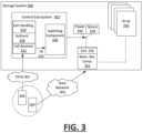
- FIG. 3illustrates another example of a storage system, according to one or more embodiments.
- a storage system 300includes a control sub-system 302 and an array 330 of memory resource components 332 .
- the array 330includes a plurality of memory resource components 332 , with each memory resource component being associated with a specific account and/or identifier.
- the memory resource components 332 of the array 330are disabled by default.
- the control sub-system 302uses an incoming telephone call from a user to enable a corresponding memory resource component 332 associated with the incoming call to be accessible to the user via a data network 303 .
- each memory resource component 332 of the array 330is physically separated from one another.
- each memory resource component 332includes a discrete memory resource, such as described with an example of FIG. 1 .
- the memory resource component 332can include an associated memory access controller that can receive read operation commands from another computing source,
- the memory resource component 332can correspond to a micro-computer.
- the memory resource components 332can share resources, such as a central processor that accesses discrete memory resources of the respective memory resource components 332 .
- the control sub-system 302includes a call handling component 310 to receive incoming calls, and a switching component 320 that enables network access to specific memory resource component 332 of the array 330 that are identified by respective incoming calls.
- the call handling component 310can identify a memory resource component 332 of the array 330 from an incoming call initiated by the user device 305 .
- the switching component 320can implement a switching operation or action to enable the memory resource component 332 identified by the incoming call to be accessible over a data network (e.g., IP network, the Internet).
- a data networke.g., IP network, the Internet
- the switching component 320is implemented as a mechanism that closes an airgap, in order to enable an identified memory resource component 332 to be accessible on a data network. In variations, the switching component 320 is implemented as a mechanism that electrically connects the identified memory resource component 332 .
- the call handling component 310may be accessible to user devices (or collection of user devices) over a telephony connection.
- the call handling component 310is accessible over a Public Switch Telephony Network (“PSTN”) 201 to receive telephony calls from a telephony-enabled user device 305 .
- PSTNPublic Switch Telephony Network
- the call handling component 310can include, for example, a receiver 312 to receive the incoming call.
- the receiver 312can initiate one or more processes in response to the incoming call. Additionally, the receiver 312 can convert the incoming call to a digital output that identifies a specific account.
- a memory resource component 332 that is associated with an account of the usercan be enabled for access over a data network (e.g., IP network, Internet).
- a data networke.g., IP network, Internet
- the memory resource component 332can be switched from an unconnected state to a connected or activated state, where, for example, network connectivity and/or power is provided to the memory resource component 332 .
- the usercan operate a computing device (e.g., the telephony-enabled computing device 305 , or another user device) to access the memory resource component 332 over the data network.
- the receiver 312includes caller authentication logic 316 .
- the receiver 312can execute the caller authentication logic 316 to authenticate the caller based on one or more signal characteristics carried by the incoming call signal.
- the caller authentication logic 316can include, for example an authentication data store that stores authentication tokens (e.g., number passcode, password, answers to secret questions, etc.) for each user account (e.g., for individual account identifiers).
- the receiver 312can identify one or more authentication data items and an account identifier from an incoming call, and then perform a comparison operation to compare the authentication item with a stored token of the account identifier.
- the caller authentication logic 316processes a sequence of acoustic tones, where the sequence correlates to numbers of a dial pad that a user is interfacing with on the respective user device 305 .
- the receiver 312implements the caller authentication logic 316 to perform recognition of a user's voice input, to determine, for example, utterances of the user corresponding to a number, password, or secret. Still further, the receiver 312 can implement the caller authentication logic 316 to recognize the user's voice.
- the memory resource component 332 of the array 330includes a switch interface 335 that can selectively link to at least one of a power resource 336 or a network communication resource 338 .
- the power resource 336can correspond to a battery, a power inlet, or a power bridge that is shared with other memory resource components 332 of the array 330 .
- the network communication resource 338can correspond to a data port and/or transceiver for receiving network communications over a data network (e.g., Internet Protocol (IP) network, the Internet).
- IPInternet Protocol
- the network communication resource 338can include a data port and link for an external gateway to a data network (e.g., the Internet).
- the call handling component 310can respond to an incoming call by generating a trigger signal 325 for the switching component 320 .
- the trigger signal 325( i ) identifies the particular memory resource component 332 that is associated with an identifier provided by the incoming call, and (ii) causes the switching component to form a connection 334 (e.g., closes an airgap 339 or electrical switch) to link the memory resource component 332 to the power resource and/or the network communication resource 338 via the switch interface 335 of the memory resource component 332 .
- the connection 334enables the identified memory resource component 332 to be accessed by the user device 305 over the data network 303 .
- the switching component 320can be implemented as a mechanism that responds to the trigger signal 325 by forming the connection 334 using the switch interface 335 of the identified memory resource component 332 and the corresponding network communication resource 338 .
- the connection 334enables the user to access the memory resource component 332 over the corresponding data network 303 (e.g., IP network, the Internet, etc.).
- the switching component 320can be implemented as a mechanism that responds to the trigger signal 325 by forming the connection 334 to connect the memory resource component 332 to the power resource 336 .
- the switching component 320forms the connection 334 to enable the memory resource component 332 to be accessible (e.g., available for read operations) using a network communication resource of that memory resource component 332 .
- the switching component 320can include timing logic that maintains the formed connection for the identified memory resource component 332 for a duration of time following, for example, the respective incoming call connection being made or terminated.
- the switching component 320can communicate with the receiver 312 to detect when the incoming call is received and terminated. The switching component 320 can then maintain the connection that enables access to the identified memory resource component 332 for a duration that correlates to when the incoming call is received and terminated.
- the switching component 320can implement logic to form the connection for enabling the identified memory resource component 332 upon the respective incoming call being received. The switching component 320 can terminate the connection for enabling the memory resource component 332 upon the receiver 312 receiving a second call that specifies the identified memory resource component 332 .
- the call handling component 310can be implemented as a server, or combination of servers, which match an incoming phone number to a port identifier that is assigned to the memory resource component 332 .
- the call handling component 310can implement the authentication logic 316 to authenticate the caller. Once the caller is authenticated, the call handling component 310 generates the trigger signal 325 for the switching component 320 .
- the switching component 320responds to the trigger signal 325 by connecting the network communication resource 338 to the port identified by the incoming call.
- the switching component 320can, for example, implement an A/B gang relay that links the port corresponding to the identified memory resource component 332 to the network communication resource 338 .
- FIG. 4illustrates a method for providing a storage module that is inaccessible until remotely activated using a non-IP network communication channel or link.
- a method such as described with an example of FIG. 4may be implemented using, for example, a storage system such as described with an example of FIG. 2 A through FIG. 2 E . Accordingly, reference may be made to elements of FIG. 2 A through FIG. 2 E for purpose of illustrating suitable components for performing a step or sub-step being described.
- storage system 200receives an incoming telephone call ( 410 ).
- the incoming telephone callmay be received over the PSTN network.
- the storage system 200receives an incoming communication over another type of non-IP network.
- the storage system 200may directly interface with an analog network or communication medium, which in turn may be accessible to other types of networks (e.g., the Internet).
- the system 200may route the incoming telephone call to one of multiple available storage modules 210 , based on the telephone number associated with the incoming telephone call ( 420 ). Once the telephone call is routed and the call connection is made, the memory resource 218 of the selected storage module 210 may be switched from an unconnected state to a connected or activated state. In one implementation, the storage module 210 is powered when in the connected or activated state. As an addition or variation, the storage module 210 is accessible over an IP-network (e.g., the Internet) when in the connected or activated state. Conversely, the storage module 210 may be unconnected or without power when the unconnected state.
- IP-networke.g., the Internet
- the storage module 210uses the incoming telephone call to supply electrical input to the memory resource 218 , thereby causing the memory resource 218 to become available (e.g., in the on-state).
- the signal interface 216can draw power from the call receiver 212 when the incoming telephone call is received, and the drawn power can be signaled over the electrical signal line 219 to the memory resource 218 .
- the storage module 210physically manipulates the memory resource to make contact with an electrical input line.
- the signal interface 216may correspond to a robotic component that manipulates the orientation of the memory resource 218 relative to the storage module 210 , in order to cause physical contact between the electrical input line 219 (or switch thereto) and the memory resource 218 .
- the electrical input signalcauses the memory resource 218 to be accessible for a duration that can be determined by the incoming telephone call ( 430 ).
- the memory resource 218is accessible over an IP channel 231 , so that it can be read or written to by a remote terminal.
- the durationcan be determined from the telephone call, such as from user input (e.g., user enters DTMF command).
- the memory resource 218may be accessible for a duration that is determined by the user input, received from, for example, the IP channel 231 .
- the durationmay be determined from a timer and/or predetermined condition.
- the telephone call to the storage module 210is terminated, the memory resource 218 is switched to the off-state ( 440 ).
- the signal interface 216terminates the electrical input provided over the electrical signal line 219 , as the signal interface 216 can no longer draw power from the call receiver 212 .
- the signal interface 216responds to termination of the telephone call by manipulating the memory resource 218 relative to the storage device, to disconnect or force an air gap with an electrical input signal line. In this way, once the telephone call is terminated, the memory resource is switched to the off-state, so that it is no longer accessible over the IP channel 231 .
- the termination to the memory resource 218may be provided by other triggers or conditions. For example, access to the memory resource 218 may be terminated when the user makes a second call that is received by the call receiver 212 . Alternatively, access to the memory resource 218 may be terminated by a timer condition (e.g., timer initiated when incoming call is received or terminated), after which access to the memory resource 218 is terminated. Still further, access to the memory resource 218 may be terminated in response to the user signaling a command over the IP channel 231 when access is present.
- a timer conditione.g., timer initiated when incoming call is received or terminated
- FIG. 5illustrates a method for managing an array of memory resource components, where each memory resource component of the array is selectively activated (e.g., switched to an on-state or otherwise connected to a network link) through an initial connection made through a non-IP network channel or link.
- a method such as described with an example of FIG. 5may be implemented using, for example, a system such as described with an example of FIG. 3 . Accordingly, reference may be made to elements of FIG. 3 for purpose of illustrating suitable components for performing a step or sub-step being described.
- storage system 200receives an incoming telephone call over the PSTN network, or alternatively, over another type of non-IP network ( 510 ).
- the control sub-system 302 of the storage system 300directly interfaces with an analog network or other communication medium, which in turn may be accessible to other types of networks (e.g., the Internet).
- the incoming callmay be received on a server control sub-system 302 that manages incoming phone calls, separate from the array 330 of memory resource components 332 .
- the storage system 200Based on information determined from the call, the storage system 200 identifies the memory resource component 332 associated with the caller ( 520 ). In some examples, the memory resource component 332 is identified from the phone number that is used to access the storage system 300 . As an addition or variation, the storage system 300 can use input from the user (e.g., sequence code, voice authentication) to authenticate that the caller is to have access to the identified memory resource component 332 .
- the usere.g., sequence code, voice authentication
- the control sub-system 302uses a switching component 320 to activate the memory resource component 332 identified by the incoming call ( 530 ).
- the switching component 320provides closure of an airgap 339 to each of multiple memory resources components 332 of the array 330 .
- each airgap closuremay be implemented using an A/B gangway having a physical layer relay that can be programmatically triggered between open and closed states.
- the switching component 320can utilize a switch management component (e.g., SWITCHMASTER R6100) to house and manage each switch, so that activation results in closure of the airgap corresponding to a particular memory resource component 332 identified by the incoming call.
- the activationresults in the corresponding memory resource component 332 being connected to the network communication resource 338 (e.g., Internet gateway), thereby enabling the memory resource component 332 to be accessible over the data network 303 .
- the network communication resource 338e.g., Internet gateway
- the control sub-system 302may further terminate activation in response to a condition or event ( 540 ). For example, the control sub-system 302 may activate a particular memory resource component in response to receipt of a corresponding telephone call (e.g., phone call using phone number of particular memory resource component 332 ). The activation of the memory resource component 332 may also initiate a timer that deactivates the memory resource component 332 after a designated time period. As an addition or variation, the control sub-system 302 can deactivate the identified memory resource component 332 upon receiving a second phone call for the same phone number of the activated memory resource 332 .
- a condition or event540
- the control sub-system 302may activate a particular memory resource component in response to receipt of a corresponding telephone call (e.g., phone call using phone number of particular memory resource component 332 ).
- the activation of the memory resource component 332may also initiate a timer that deactivates the memory resource component 332 after a designated time period.
- FIG. 6illustrates a client system to access a remote memory resource component of a user account, according to one or more examples.
- a user of client system 600may have authorization to access a memory resource component that is maintained by a storage system, such as described with an example of FIG. 3 . Accordingly, reference may be made to elements of FIG. 3 for purpose of illustrating suitable components for use in implementing or using functionality and components described with an example of FIG. 6 .
- the client system 600can be implemented by one or multiple computing devices of the user.
- the client system 600can be implemented using a telephony-enabled device and a browser-enabled device.
- the client system 600can be implemented by a multi-purpose computing device that is capable of telephony and IP communications.
- the client system 600can include a programmatic component or interface that is provided for use with a service of storage system 300 .
- the client system 600can be implemented using a service application that executes on the user's mobile computing devices.
- the client system 600can be implemented by a platform, including applications, plug-ins, or other programmatic components that operate on multiple devices of the user.
- the client system 600includes a presentation layer 612 , a telephonic component 614 , and a service interface component 616 .
- the componentscan be implemented through, for example, a service application on a single device, or distributed in whole or in part on multiple devices of a user.
- the client system 600also includes a framework 608 , which implements rules with respect to the operations of the respective components.
- the service interface component 616can utilize one or more IP networks (e.g., Internet) to establish a communication channel with the storage system 300 .
- the service interface component 616can include or be implemented as a browser component.
- the service interface component 616can be implemented as an interface (e.g., plug-in, extension, etc.) for a local third-party browser of the client system 600 .
- the framework 608can restrict use of the operations of the service interface component 616 , such that the service interface component 616 has, or can be operated in a mode which is dedicated for communications with the storage system 300 , under rules of framework 608 .
- the framework 608can implement rules that result in functionality such as (i) dedicating the service interface component 616 to access a designated network site or location, as provided by the storage system 300 or other approved source; (ii) implementing encryption for any communication channel or exchange with the storage system 300 ; (iii) concealing the network address used to access the memory resource component 332 of the user; and/or (iv) restricting access to the service interface component 616 and/or storage system 300 without additional authentication being provided by a user (e.g., login and password credentials from user, biometric input through device of the service interface component 616 , etc.).
- rules that result in functionalitysuch as (i) dedicating the service interface component 616 to access a designated network site or location, as provided by the storage system 300 or other approved source; (ii) implementing encryption for any communication channel or exchange with the storage system 300 ; (iii) concealing the network address used to access the memory resource component 332 of the user; and/or (iv) restricting access to the service interface component 616 and
- the telephonic component 614can enable telephony communications using a cellular or wireless receiver of a local user device.
- telephonic component 614can be implemented as an interface to a phone application or resource for making a call connection on the computing device.
- the telephonic component 614can interface with a voice service, such as a cellular voice service or a voice over Internet Protocol (VOIP) service.
- VOIPvoice over Internet Protocol
- the framework 608can also implement rules that restrict use or functionality of the telephony component 614 .
- the framework 608can implement rules to (i) specify a phone number, and/or source for obtaining the phone number that can be automatically dialed through the presentation layer 612 , to access the storage network 300 ; (ii) restricting use of the telephony component 614 to making call connections for only the designated phone number(s); and/or (iii) concealing the phone number that is being called from the user or other source.
- the telephony component 614can automate or facilitate additional functionality.
- the telephonic component 614can receive, or decode a signal from the storage system 300 that identifies a credential or the network address that the service interface component 616 is to use.
- the telephonic component 614can also implement an authentication process using a local login or biometric credential of the user.
- the telephonic component 614can also trigger execution of the service interface component 616 , such that, for example, the service interface component 616 accesses the memory resource component 332 (or a service of the 300 ) using the corresponding network address, once a predetermined event is detected through the telephonic component 614 (e.g., the telephonic component 614 terminating initial phone call, the telephonic component 614 providing authentication credentials over call connection, etc.). Still further, the telephonic component 614 can receive or obtain the network address for the service interface component 616 .
- the presentation layer 612can be provided as part of the platform or application(s) that run on device(s) of the client system 600 .
- the client system 600provides a call feature that the user can interact with in order to initiate a phone call to the remote site of the storage system 300 (or related service).
- the userselects or otherwise interacts with the call feature provided through the presentation layer 612 , without specifying a phone number that is linked to a remote site.
- the servicecan change the phone number associated with the particular memory resource component 332 of the user.
- the phone numbercan be specific to the account or device(s) of the user.
- the telephonic component 614automatically identifies the phone number from an application memory.
- the client system 600can establish a background process that causes, for example, a service application or other program running on the user's mobile device to periodically receive check and/or update the current phone number that is to be used by the particular user.
- the service application or other program of the client system 600can acquire the phone number as a response to an event or condition, such as the user indicating a desire to access protected data stored with a service that uses or is provided with the storage system 300 .
- the client system 600can initiate a timer based on a condition or event such as the call connection being made or terminated.
- the service interface component 616is able to use the network address to access the memory resource component 332 during a defined duration that is defined in part by the timer.
- the service interface component 616can be enabled for a duration that extends until the user operates the telephonic interface 614 to make a second call connection to the service. While the service interface component 616 is enabled, the client system 600 can use the communication channel to access and use the memory resource component.
- FIG. 7is a block diagram that illustrates a computing device upon which examples described herein may be implemented.
- a computing device 700may correspond to a mobile computing device, such as a cellular device that is capable of telephony, messaging, and data services.
- the computing device 700can correspond to a smartphone (or feature phone) on which an application (“app”) can execute.
- the user device 700can correspond to a tablet, ultraportable computing device, laptop or desktop computer.
- the computing device 700includes a processor 710 , memory resources 720 , a display device 730 (e.g., such as a touch-sensitive display device), one or more communication sub-systems 740 (including wireless communication sub-systems), one or more sensors 750 (e.g., accelerometer, gyroscope, barometer, altimeter, microphone, camera), and one or more location detection mechanisms (e.g., GPS component) 760 .
- at least one of the communication sub-systems 740sends and receives cellular data over both data channels (e.g., IP networks) and voice channels.
- the communications sub-systems 740can include a cellular transceiver and one or more short-range wireless transceivers to enable (i) placement of a phone call, and (ii) communication with a remote service that utilizes a storage system such as described with FIG. 1 through FIG. 3 .
- the memory resources 720can also store instructions for a service application 725 that can implement a client system for remotely accessing a memory resource component of a user, as described by examples of FIG. 6 .
- the service application 725initiates and automates communications with, for example, storage system 300 .
- the processor 710can be configured with software and/or other logic to perform one or more processes, steps, and other functions described with client system 600 (see FIG. 6 ).
- the service application 725can run to provide telephonic component 614 (see FIG. 6 ) and service interface component 616 (see FIG. 6 ). Additionally, the service application 725 can provide presentation layer 612 (see FIG. 6 ) to enable, for example, programmatic use of a storage service provided with the storage system 300 .
- the service application 725can implement functionality of client system 600 , such as described by examples of FIG. 6 .
- the service application 725can be associated with an account identifier 711 and/or other credential information 715 that is specific to the user, user account or device (e.g., mobile device phone number).
- the service application 725can include processes for implementing the telephonic component 614 and the service interface component 616 , as described with examples of FIG. 6 .
- the service application 725can be configured to enable the service interface component 616 in response to an event and/or condition that is caused by the telephonic process 614 , using the phone number to make the call connection.
- the service application 725can enable the service interface component 616 in response to one or more events that include the call connection being made, the user providing additional authentication information using the call connection, and/or the user terminating the call connection.
- the service interface component 616is enabled once the user is authenticated during the phone call.
- the servicecan communicate the network address to the application, and the service interface component 616 can utilize the address to access the remote service once the user is authenticated during the call connection.
- the service interface component 616can establish, for example, an Internet Protocol data communication channel with the service.
- a usercan access data stored on the user's memory resource component 332 , as hosted by the storage system 300 , by launching the service application 725 .
- the service application 725automatically or programmatically (e.g., in response to a single user input) makes a call connection to the storage system 300 , using a unique phone number that is specific to the user or account. From the call connection, the user can be provided a duration of time during which the service application 725 can be used to access the memory resource component 332 .
- the usercan utilize a phone number that contacts the 300 , and then subsequently provide additional authentication information to enable network access to the memory resource component 332 of the user or account.
- the service application 725can be used to access the memory resource component 332 .
- the service application 725can, for example, implement a browser process to make the network connection with the memory resource component 332 , by automatically acquiring and/or using the network address for locating the memory resource component 332 over one or more IP networks.
- the usercan correspond to a group of users (e.g., enterprise).
- an administratorfor example, can provide the mobile computing device 700 with a set of credentials and/or other identifiers (e.g., phone number for use in contacting the storage system 300 ).
- the administratorcan also provide the individual user with additional credentials for locally authenticating the user, and/or authenticating the user with the storage system 300 .
- the memory resource component 332can be shared amongst multiple users.
- the service application 725can generate a user interface that indicates a status of a memory resource component 332 that is assigned to the user.
- the usercan interact with the service application 725 to activate the memory resource component 732 .
- the usercan initiate a trigger for the telephonic component 614 (see FIG. 6 ) through the service application 725 to cause the mobile computing device 700 to initiate a telephony call to a storage service that is provided with storage system 300 .
- the service application 725can execute to generate DTMF tones (or other analog input) for the storage service. In this way, the service application 725 can identify and/or authenticate the user to the storage service.
- the service application 725can use the service interface component 616 to establish a data connection with the storage service.
- the data connectioncan be used to generate content for the presentation layer 612 (see FIG. 6 ) to, for example, view contents of the memory resource component, such as, for example, a value of a user's current crypto-currency.
- the operations of the service application 725 following an initial user triggercan be substantially automated.
- the service application 725can monitor the telephony connection for an acknowledgement that the memory resource component 332 that is assigned to the user has been activated, then automatically perform operations that establish the connection with the memory resource component 332 over the data network.
- the computing device 700may execute to monitor for one or more events (e.g., passage of time) that result in termination of the memory resource activation, and/or cause the mobile computing device to generate a command to terminate the activation.
- FIG. 8illustrates a method for operating a computing device of a user to access a service that provides a memory resource component to store sensitive data of the user, according to one or more examples.
- a method such as described with an example of FIG. 8may be implemented using, for example, a client system such as described with an example of FIG. 6 , or a mobile computing device such as described with an example of FIG. 7 . Accordingly, reference may be made to elements of FIG. 6 and FIG. 7 for purpose of illustrating suitable components for performing a step or sub-step being described.
- a usercan operate client system 600 to make a call connection (e.g., place a phone call) with a storage service that is provided in conjunction with storage system 300 ( 810 ).
- the client system 600can be implemented using the mobile computing device 700 , executing the service application 725 .
- the service application 725can be used to place a phone call to a storage service provided by the storage system 300 . using telephony resources of the computing device.
- the service application 725may execute to transparently initiate a phone call via phone application and cellular telephony capabilities of the computing device.
- the usermay place the phone call to store system 300 as a separate action or event.
- the usercan place the phone call to storage system 300 before the user launches the service application 725 .
- the usermay use a first device (e.g., mobile computing device 700 ) to make the call connection, and a second device (e.g., browser device) to form a communication channel over one or more IP networks.
- a first devicee.g., mobile computing device 700
- a second devicee.g., browser device
- the memory resource component 332 that corresponds to the phone number used for placement of the phone callcan be identified and activated as a result of the call connection.
- the user and/or the mobile computing device 700can specify additional input to authenticate the user. For example, the computing device 700 can automatically generate a sequence of tones that correspond to a passcode of the user. Alternatively, the user may be prompted to provide an utterance, either by the computing device 700 and/or by the system 300 .
- the service application 725can execute on the computing device 700 to detect one or more events corresponding to activation of the memory resource component 332 , as identified by the phone number and/or other input provided over the telephony link of the call connection ( 820 ). The detected event may correspond to, or indicate the availability of the memory resource component 332 .
- the control sub-system 302generate one or more audible sounds to programmatically communicate the status of the memory resource component 332 which is to be activated.
- the computing device 700may execute the service application 725 to detect and interpret the audible communications generated by, for example, the control sub-system 302 .
- the computing device 700can establish a communication channel over the data network 303 (e.g., the Internet) with the identified memory resource component 332 ( 830 ).
- the establishment of the connection over the data network 303can be done automatically, such as in response to detecting audible acknowledgment over the telephony link that the memory resource 332 for the identified phone number has been activated.
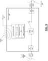
- FIG. 9is a block diagram illustrating a network isolation device 900 , in accordance with examples described herein.
- the air gap-based network isolation device 900includes hardware componentry for isolating downstream networks and computing devices from external networks 950 , such as Internet Protocol-based networks.
- the network isolation device 900includes an out-of-band signal receiver 902 coupled to an airgap device 916 (e.g., a mechanical relay, actuator, or optocoupler) that closes and opens a physical air gap 919 in response to an out-of-band wireless signal 905 or an out-of-band signal received through an out-of-band line 907 coupled to the out-of-band signal receiver 902 .
- an airgap device 916e.g., a mechanical relay, actuator, or optocoupler
- the out-of-band signal 905can be wirelessly transmitted or broadcasted from an authorized signal source (e.g., a mobile computing device, a LoRa signal generator, etc.), and can comprise an encrypted communication (e.g., a short message service (SMS) message or a modulated spread spectrum LoRa signal) which can be processed by an out-of-band signal receiver 902 of the network isolation device 900 to control the airgap device 916 that physically opens and closes the air gap 919 .
- SMSshort message service
- the out-of-band signalcan be received through a wire via an out-of-band line 907 coupled to the out-of-band signal receiver 902 .
- the signal receiver 902can include a dedicated hardware signal filter 912 that provides an initial analog authentication layer for an incoming wireless access signal 905 or access signal received via the out-of-band line 907 .
- the hardware signal filter 912can comprise a specialized chip comprising a hardware representation of an encryption and/or decryption algorithm that prevents unwanted access to signal authentication software executing on the signal receiver 902 . Accordingly, a detected signal by the signal receiver 902 may be first processed by the hardware filter 912 before the signal is permitted to be processed by a signal authenticator 914 of the signal receiver 902 .
- the signal receiver 902can include a signal authenticator 914 , such as a digital signal processor or other processing device executing authentication or decryption instructions to authenticate the out-of-band access signal.
- a signal authenticator 914Upon receiving the signal, the signal authenticator 914 can perform an authentication process to determine whether the signal is from an authorized source and/or includes an authorized access code.
- the signal authenticator 914may do so using any type of suitable authentication technique(s), a such as code decryption and/or device identifier verification technique.
- a trigger processor 915 of the signal receiver 902can control the airgap device 916 to close the air gap 919 and connect the internal network 940 to the external network(s) 950 .
- the network isolation device 900can be controlled remotely using any type of out-of-band signal that corresponds to the signal receiver 902 .
- the signal receiver 902may receive an SMS message from a particular phone number that includes a specified code for authentication.
- the hardware signal filter 912can pre-process the SMS message (e.g., verify that it came from a correct phone number or an authorized device identifier).
- the SMS messagemay be further processed by the signal authenticator 914 of the signal receiver 902 , which can, for example, verify a secondary code embedded in the message (e.g., via a decryption algorithm). Once verified, the signal receiver 902 can control the airgap device 916 to close the air gap 919 and enable access or open the air gap 919 to remove access to the internal network 940 .
- LoRa technologyinvolves the use of low power, long range radio frequency transmissions utilizing spread spectrum modulation (e.g., chirp spread spectrum (CSS) modulation) to encode signals.
- a LoRa signal generatormay use common battery power (e.g., AA or AAA batteries) which can power the LoRa signal generator for long periods of time (e.g., years) without replacement.
- AA or AAA batteriescommon battery power
- an enterprise having a sensitive internal network 940 of computing devices, memory resources, and/or other digital assetsmay utilize a single LoRa signal generator to connect and disconnect its internal network 940 from the external network 950 as needed.
- the LoRa signal generatorcan encode an out-of-band LoRa signal 905 using CSS modulation and transmit or broadcast the signal 905 such that it is detectable by the signal receiver 902 .
- the signal receiver 902then decrypts or decodes the LoRa signal, authenticates the LoRa signal generator and/or the LoRa signal itself, and controls the airgap device 916 to open or close the air gap 919 on-demand.
- FIG. 10is a flow chart describing a method of authenticating an out-of-band signal to connect an isolated network 940 to an external network 950 , according to examples described herein.
- FIG. 10reference may be made to reference characters representing like features as shown and described with respect to FIG. 9 .
- the processes described in connection with FIG. 10may be performed by an example network isolation device 900 as shown and described with respect to FIG. 9 .
- any the steps shown in the flow chart of FIG. 10may be omitted or rearranged to precede or follow any other step.
- the network isolation device 900can receive an out-of-band signal (e.g., out-of-band wireless signal 905 or signal received via the out-of-band line 907 ) from a signal source ( 1010 ).
- the out-of-band signalcan comprise any signal that corresponds to the signal receiver 902 of the network isolation device 900 , and can utilize a communication protocol that is distinct from the communication protocol(s) utilized by the external network 950 .
- the signal receiver 902can include a hardware signal filter 912 that pre-processes the incoming signal and acts as an initial filter prior to decoding, decrypting, or otherwise verifying the signal or source of the signal ( 1015 ).
- a signal authenticator 914 of the receiver 902can further process the signal 905 through decoding, decryption, or other verification techniques described herein ( 1020 ).
- the signal authenticator 914may then determine if the signal 905 and/or signal source is valid ( 1025 ). If not ( 1027 ), the signal receiver 902 denies access to the isolated network 940 by maintaining the air gap 919 in an open state ( 1030 ). However, if the signal and/or signal source is valid ( 1029 ), then the signal receiver 902 controls the airgap device 916 to close the air gap 919 and connect the isolated network 940 to the external network 950 ( 1035 ). To isolate the internal network 940 from the external network 950 , the same or a similar authentication process is performed to verify the signal 905 and/or signal source and open the air gap 919 accordingly.
Landscapes
- Engineering & Computer Science (AREA)
- Computer Security & Cryptography (AREA)
- Computer Networks & Wireless Communication (AREA)
- Signal Processing (AREA)
- Computer Hardware Design (AREA)
- Computing Systems (AREA)
- General Engineering & Computer Science (AREA)
- Power Engineering (AREA)
- Telephonic Communication Services (AREA)
Abstract
Description
Claims (20)
Priority Applications (2)
| Application Number | Priority Date | Filing Date | Title |
|---|---|---|---|
| US18/111,431US12244595B2 (en) | 2017-12-05 | 2023-02-17 | Air gap-based network isolation device |
| US19/030,875US20250240295A1 (en) | 2017-12-05 | 2025-01-17 | Air gap-based network isolation device |
Applications Claiming Priority (5)
| Application Number | Priority Date | Filing Date | Title |
|---|---|---|---|
| US201762594963P | 2017-12-05 | 2017-12-05 | |
| US16/016,488US11115390B2 (en) | 2017-12-05 | 2018-06-22 | Storage system utilizing discrete on-demand memory resources |
| US17/467,151US12238103B2 (en) | 2017-12-05 | 2021-09-03 | Air gap-based network isolation device |
| US17/689,812US11616781B2 (en) | 2017-12-05 | 2022-03-08 | Air gap-based network isolation device |
| US18/111,431US12244595B2 (en) | 2017-12-05 | 2023-02-17 | Air gap-based network isolation device |
Related Parent Applications (1)
| Application Number | Title | Priority Date | Filing Date |
|---|---|---|---|
| US17/689,812ContinuationUS11616781B2 (en) | 2017-12-05 | 2022-03-08 | Air gap-based network isolation device |
Related Child Applications (1)
| Application Number | Title | Priority Date | Filing Date |
|---|---|---|---|
| US19/030,875ContinuationUS20250240295A1 (en) | 2017-12-05 | 2025-01-17 | Air gap-based network isolation device |
Publications (2)
| Publication Number | Publication Date |
|---|---|
| US20230370463A1 US20230370463A1 (en) | 2023-11-16 |
| US12244595B2true US12244595B2 (en) | 2025-03-04 |
Family
ID=81942009
Family Applications (3)
| Application Number | Title | Priority Date | Filing Date |
|---|---|---|---|
| US17/689,812ActiveUS11616781B2 (en) | 2017-12-05 | 2022-03-08 | Air gap-based network isolation device |
| US18/111,431ActiveUS12244595B2 (en) | 2017-12-05 | 2023-02-17 | Air gap-based network isolation device |
| US19/030,875PendingUS20250240295A1 (en) | 2017-12-05 | 2025-01-17 | Air gap-based network isolation device |
Family Applications Before (1)
| Application Number | Title | Priority Date | Filing Date |
|---|---|---|---|
| US17/689,812ActiveUS11616781B2 (en) | 2017-12-05 | 2022-03-08 | Air gap-based network isolation device |
Family Applications After (1)
| Application Number | Title | Priority Date | Filing Date |
|---|---|---|---|
| US19/030,875PendingUS20250240295A1 (en) | 2017-12-05 | 2025-01-17 | Air gap-based network isolation device |
Country Status (1)
| Country | Link |
|---|---|
| US (3) | US11616781B2 (en) |
Families Citing this family (3)
| Publication number | Priority date | Publication date | Assignee | Title |
|---|---|---|---|---|
| US11616781B2 (en)* | 2017-12-05 | 2023-03-28 | Goldilock Secure s.r.o. | Air gap-based network isolation device |
| US12238103B2 (en) | 2017-12-05 | 2025-02-25 | Goldilock Secure Limited | Air gap-based network isolation device |
| US12333037B2 (en)* | 2022-10-26 | 2025-06-17 | Dell Products L.P. | On-demand operational airgap policy—value threshold |
Citations (94)
| Publication number | Priority date | Publication date | Assignee | Title |
|---|---|---|---|---|
| WO2001095069A2 (en) | 2000-06-09 | 2001-12-13 | Saafnet Canada Incorporated | Data line interrupter switch |
| US20020053032A1 (en) | 2000-09-14 | 2002-05-02 | Dowling William Race | System and method for secure data transmission |
| US6594762B1 (en)* | 1999-05-05 | 2003-07-15 | Ericsson Inc. | Methods and devices enabling displays of electronic devices based on separation thereof |
| US20030172145A1 (en) | 2002-03-11 | 2003-09-11 | Nguyen John V. | System and method for designing, developing and implementing internet service provider architectures |
| US20040085941A1 (en)* | 2002-11-06 | 2004-05-06 | Pei-Zhi Li | Information appliance control system |
| US20040260941A1 (en)* | 2003-06-17 | 2004-12-23 | Fearnley Jolyon A. | Infrastructure method and system for authenticated dynamic security domain boundary extension |
| WO2005101724A1 (en) | 2004-04-16 | 2005-10-27 | Huawei Technologies Co., Ltd. | Method for controlling a pluggab a port of a communication device interface board and the interface board |
| US20060013382A1 (en) | 2004-07-15 | 2006-01-19 | Takaaki Hoshikawa | Telephone exchange system and control method used for the same system |
| US20060242423A1 (en) | 2005-04-22 | 2006-10-26 | Kussmaul John W | Isolated authentication device and associated methods |
| US20070143398A1 (en) | 2005-12-16 | 2007-06-21 | Jean Graham | Central work-product management system for coordinated collaboration with remote users |
| US20070260687A1 (en)* | 2006-05-04 | 2007-11-08 | Rao Alok S Raghunath | Method and apparatus for collaboration among individuals |
| US20080082677A1 (en) | 2006-09-29 | 2008-04-03 | Brother Kogyo Kabushiki Kaisha | Communication System, and Server and Computer Usable Medium Therefor |
| US20090254572A1 (en) | 2007-01-05 | 2009-10-08 | Redlich Ron M | Digital information infrastructure and method |
| US20100318785A1 (en) | 2007-12-13 | 2010-12-16 | Attila Ozgit | Virtual air gap - vag system |
| US20100319063A1 (en) | 2009-06-12 | 2010-12-16 | Microsoft Corporation | Access control to secured application features using client trust levels |
| EP2317450A1 (en) | 2005-02-24 | 2011-05-04 | Xeround Inc. | Method and apparatus for distributed data management in a switching network |
| US20130257406A1 (en) | 2012-03-28 | 2013-10-03 | Lutron Electronics Co., Inc. | Method And Apparatus For Phase-Controlling A Load |
| US20130268931A1 (en) | 2012-04-06 | 2013-10-10 | Security First Corp. | Systems and methods for securing and restoring virtual machines |
| US20130324083A1 (en) | 2012-05-30 | 2013-12-05 | International Business Machines Corporation | Authentication Request Management |
| US20140052864A1 (en) | 2009-05-01 | 2014-02-20 | Citrix Systems, Inc. | Systems and methods for establishing a cloud bridge between virtual storage resources |
| US20140119727A1 (en) | 2012-10-31 | 2014-05-01 | Microtechnologies Llc D/B/A Microtech | Internet protocol switching system and associated method of use |
| US20140136671A1 (en)* | 2012-11-14 | 2014-05-15 | General Electric Company | Device and method for aggregating services for use across networks using separate data format protocols |
| US20140176182A1 (en) | 2012-12-20 | 2014-06-26 | Kelin J Kuhn | Shut-off mechanism in an integrated circuit device |
| US20140181315A1 (en)* | 2012-12-25 | 2014-06-26 | Toshiba Lighting & Technology Corporation | Network System and Network Connection Device |
| US20140297899A1 (en) | 2013-04-02 | 2014-10-02 | Realtek Semiconductor Corporation | Universal serial bus network interface controller and operation mode switching method |
| US20150024710A1 (en)* | 2013-07-17 | 2015-01-22 | Honeywell International Inc. | Secure remote access using wireless network |
| US20150047058A1 (en) | 2013-08-07 | 2015-02-12 | Red Hat, Inc | Certificate checkin service |
| US20150042464A1 (en) | 2013-08-08 | 2015-02-12 | Orange Electronic Co., Ltd. | Signal transponder transceiving signals using different communication protocols and method for transceiving signals using different communication protocols |
| US20150341209A1 (en) | 2014-05-23 | 2015-11-26 | Nant Holdings Ip, Llc | Fabric-Based Virtual Air Gap Provisioning, Systems and Methods |
| US9225352B2 (en) | 2012-03-07 | 2015-12-29 | Canon Kabushiki Kaisha | Signal transmission system, photoelectric conversion apparatus, and image pickup system |
| US20150381658A1 (en)* | 2014-06-30 | 2015-12-31 | Mcafee, Inc. | Premises-aware security and policy orchestration |
| US20160077762A1 (en)* | 2014-09-11 | 2016-03-17 | Kabushiki Kaisha Toshiba | Memory system, storage system |
| US20160180331A1 (en) | 2014-12-19 | 2016-06-23 | Verizon Patent And Licensing Inc. | Remote activation of hardware secure element/secure environment |
| US20160337359A1 (en) | 2015-05-11 | 2016-11-17 | Honeywell Spol. S.R.O. | Securing a control system application layer protocol |
| CN106572101A (en) | 2016-10-26 | 2017-04-19 | 努比亚技术有限公司 | Server, terminal and data management method |
| US20170195477A1 (en)* | 2016-01-04 | 2017-07-06 | Bank Of America Corporation | System for remotely controlling access to a mobile device |
| US20170272984A1 (en) | 2016-03-18 | 2017-09-21 | Futurewei Technologies, Inc. | Remove tcp deadlock caused by wireless device cross technology handover |
| US20170324566A1 (en)* | 2016-05-06 | 2017-11-09 | Pacific Star Communications, Inc. | Unified encryption configuration management and setup system |
| US20180007021A1 (en)* | 2016-06-29 | 2018-01-04 | Airwatch Llc | Public key pinning for private networks |
| US20180019999A1 (en)* | 2016-07-14 | 2018-01-18 | GM Global Technology Operations LLC | Securely establishing time values at connected devices |
| US20180176776A1 (en) | 2016-12-21 | 2018-06-21 | Silicon Laboratories Inc. | Systems And Methods For Initial Authentication Of Wireless Communication |
| US20180213002A1 (en) | 2017-01-23 | 2018-07-26 | Hysolate Ltd. | Techniques for controlling and regulating network access on air-gapped endpoints |
| US20180234437A1 (en)* | 2017-02-15 | 2018-08-16 | General Dynamics Mission Systems, Inc. | Cybersecure endpoint system for a network |
| US20180338017A1 (en) | 2017-05-17 | 2018-11-22 | CodeShop, B.V. | System and Method for Aggregation, Archiving and Compression of Internet Of Things wireless Sensor Data |
| US20180337948A1 (en) | 2017-05-17 | 2018-11-22 | Optimal Process Control Technologies Co., Ltd. | Method of industrial data communication with dedicated physical channel isolation and a system applying the method |
| US10154029B1 (en) | 2016-05-31 | 2018-12-11 | Wells Fargo Bank, N.A. | Biometric knowledge extraction for mutual and multi-factor authentication and key exchange |
| US20190068617A1 (en)* | 2017-08-24 | 2019-02-28 | L3 Technologies, Inc. | Service provider advanced threat protection |
| US20190098007A1 (en)* | 2017-09-28 | 2019-03-28 | L3 Technologies, Inc. | Endpoint protection and authentication |
| US20190114405A1 (en) | 2017-10-12 | 2019-04-18 | Olympus Corporation | Information acquisition device, information acquisition system, and information acquisition method |
| US20190141540A1 (en) | 2017-11-06 | 2019-05-09 | Cisco Technology, Inc. | Automated sensor coverage optimization with an actuating walker agent |
| CN105721476B (en) | 2016-02-25 | 2019-05-28 | 深圳市亿威尔信息技术股份有限公司 | A kind of network security management system and method |
| US20190173853A1 (en)* | 2017-12-05 | 2019-06-06 | Goldilock Inc. | Storage system utilizing discrete on-demand memory resources |
| US20190190891A1 (en)* | 2017-12-14 | 2019-06-20 | Nicira, Inc. | Secure communication protocol processing |
| US20190268165A1 (en) | 2018-02-27 | 2019-08-29 | Anchor Labs, Inc. | Cryptoasset custodial system with different rules governing access to logically separated cryptoassets |
| US10404474B1 (en)* | 2017-02-02 | 2019-09-03 | Citigroup Technology, Inc. | Systems and methods for container orchestration security |
| US20190312752A1 (en)* | 2018-04-09 | 2019-10-10 | Flex Ltd. | Flexible low-power wide-area network (lpwan) apparatus and architecture |
| US20190348232A1 (en)* | 2018-05-09 | 2019-11-14 | Uniform Industrial Corp. | Starting device |
| WO2019243657A1 (en) | 2018-06-21 | 2019-12-26 | Wärtsilä Finland Oy | Accessing a secure computer network |
| US20200065502A1 (en) | 2018-08-23 | 2020-02-27 | Travis Lockman | Securely accessing offline data with indirect communication |
| US20200120136A1 (en)* | 2018-10-11 | 2020-04-16 | Honeywell International Inc. | System and method for deploying and configuring cyber-security protection solution using portable storage device |
| US20200145434A1 (en) | 2018-11-06 | 2020-05-07 | Bank Of America Corporation | Processing System for Providing Console Access to a Cyber Range Virtual Environment |
| US20200145420A1 (en)* | 2018-11-06 | 2020-05-07 | Bank Of America Corporation | Processing System For Providing Console Access To A Cyber Range Virtual Environment |
| US10681793B1 (en)* | 2019-08-16 | 2020-06-09 | Pal Lighting, Llc | Direct wireless control of lighting systems for use in a high-moisture environment |
| US20200204435A1 (en) | 2018-12-21 | 2020-06-25 | Canon Kabushiki Kaisha | Communication method and control method in information processing apparatus |
| US20200204656A1 (en) | 2018-12-24 | 2020-06-25 | Samsung Electronics Co., Ltd. | Electronic device and method for scheduling of communication data link thereof |
| US20200252273A1 (en) | 2019-02-04 | 2020-08-06 | Hewlett Packard Enterprise Development Lp | Remote network interface card management |
| US20200304482A1 (en)* | 2017-05-10 | 2020-09-24 | Osr Enterprises Ag | Security Enforcement in a System with a Multiplicity of End Units |
| US20200342109A1 (en)* | 2019-04-29 | 2020-10-29 | Hewlett Packard Enterprise Development Lp | Baseboard management controller to convey data |
| US20200365345A1 (en)* | 2019-05-18 | 2020-11-19 | Amber Solutions, Inc. | Intelligent circuit breakers with air-gap and solid-state switches |
| US20200396911A1 (en)* | 2019-06-20 | 2020-12-24 | Reinke Manufacturing Co., Inc. | Monitoring and control of a movable tower in an irrigation system |
| US20210014229A1 (en) | 2019-07-08 | 2021-01-14 | Bank Of America Corporation | Protecting Enterprise Computing Resources by Implementing an Optical Air Gap System |
| US20210044563A1 (en) | 2019-08-06 | 2021-02-11 | International Business Machines Corporation | In-line cognitive network security plugin device |
| US20210110068A1 (en) | 2019-10-14 | 2021-04-15 | Michael Steven Voss | Air gap system and method using out of band signaling |
| US20210127244A1 (en) | 2019-10-28 | 2021-04-29 | Samsung Electronics Co., Ltd. | Electronic device supporting proximity communication service and method for obtaining information of short-range communication device using the same |
| US20210136644A1 (en) | 2019-11-05 | 2021-05-06 | Samsung Electronics Co., Ltd. | Method for shortening call connection time and electronic device therefor |
| US20210141893A1 (en) | 2019-11-08 | 2021-05-13 | Vmware, Inc. | Security-enhanced file open and download |
| US20210173907A1 (en) | 2019-12-10 | 2021-06-10 | Winkk, Inc | Automated transparent login without saved credentials or passwords |
| US20210176235A1 (en)* | 2019-12-10 | 2021-06-10 | Winkk, Inc | Security platform architecture |
| US20210224374A1 (en) | 2020-01-20 | 2021-07-22 | Ppip Llc | Challenge and Response in Continuous Multifactor Authentication on a Safe Case |
| US20210250333A1 (en) | 2016-05-18 | 2021-08-12 | Zscaler, Inc. | Private application access with browser isolation |
| US20220060476A1 (en) | 2017-12-05 | 2022-02-24 | Goldilock Secure s.r.o. | Air gap-based network isolation device |
| US20220094686A1 (en) | 2020-09-24 | 2022-03-24 | Microsoft Technology Licensing, Llc | Gatekeeper resource to protect cloud resources against rogue insider attacks |
| US20220150280A1 (en)* | 2020-11-06 | 2022-05-12 | Microsoft Technology Licensing, Llc | Context menu security policy enforcement |
| US20220182833A1 (en) | 2020-12-09 | 2022-06-09 | Valeo Comfort And Driving Assistance | Device, system, and method for cyber isolating mobility systems when a vehicle is in motion |
| US20220182388A1 (en)* | 2020-12-08 | 2022-06-09 | Michael Boodaei | Transfer of trust between authentication devices |
| US11362844B1 (en)* | 2021-07-28 | 2022-06-14 | Vidaloop, Inc. | Security device and methods for end-to-end verifiable elections |
| US11368437B2 (en)* | 2017-07-05 | 2022-06-21 | Siemens Mobility GmbH | Method and apparatus for repercussion-free unidirectional transfer of data to a remote application server |
| US11381473B1 (en)* | 2020-09-15 | 2022-07-05 | Amazon Technologies, Inc. | Generating resources in a secured network |
| US20220286441A1 (en)* | 2021-03-08 | 2022-09-08 | Oracle International Corporation | Semi-interactive one-way transfer of data to an isolated network |
| US20220326929A1 (en)* | 2021-04-12 | 2022-10-13 | EMC IP Holding Company LLC | Automated delivery of cloud native application updates using one or more user-connection gateways |
| US20220345457A1 (en)* | 2021-04-22 | 2022-10-27 | Microsoft Technology Licensing, Llc | Anomaly-based mitigation of access request risk |
| US20220353256A1 (en)* | 2021-04-29 | 2022-11-03 | Microsoft Technology Licensing, Llc | Usage-limited passcodes for authentication bootstrapping |
| US11616781B2 (en)* | 2017-12-05 | 2023-03-28 | Goldilock Secure s.r.o. | Air gap-based network isolation device |
| US11997112B1 (en)* | 2020-11-06 | 2024-05-28 | Wells Fargo Bank, N.A. | Access control threat detection |
Family Cites Families (59)
| Publication number | Priority date | Publication date | Assignee | Title |
|---|---|---|---|---|
| US20060129829A1 (en)* | 2004-12-13 | 2006-06-15 | Aaron Jeffrey A | Methods, systems, and computer program products for accessing data with a plurality of devices based on a security policy |
| US7567562B2 (en)* | 2005-03-02 | 2009-07-28 | Panasonic Corporation | Content based secure rendezvous chaotic routing system for ultra high speed mobile communications in ad hoc network environment |
| CN101496387B (en)* | 2006-03-06 | 2012-09-05 | 思科技术公司 | System and method for access authentication in a mobile wireless network |
| US8418231B2 (en)* | 2006-10-31 | 2013-04-09 | At&T Intellectual Property I, Lp | Methods, systems, and computer program products for managing media content by capturing media content at a client device and storing the media content at a network accessible media repository |
| US20080120698A1 (en)* | 2006-11-22 | 2008-05-22 | Alexander Ramia | Systems and methods for authenticating a device |
| US11423756B2 (en)* | 2007-06-12 | 2022-08-23 | Icontrol Networks, Inc. | Communication protocols in integrated systems |
| US20100190515A1 (en)* | 2009-01-29 | 2010-07-29 | Multitech Systems, Inc. | Sms device manager |
| US8984257B2 (en) | 2010-04-06 | 2015-03-17 | Hewlett-Packard Development Company, L.P. | Managing sensor and actuator data for a processor and service processor located on a common socket |
| US8812685B2 (en)* | 2010-07-16 | 2014-08-19 | At&T Intellectual Property I, L.P. | Advanced gateway device |
| US8995630B1 (en)* | 2010-08-01 | 2015-03-31 | Tulsa Holdings, Llc | Telephony and applications communication in a non-mobile telephone system |
| US8891420B2 (en)* | 2012-09-14 | 2014-11-18 | Fujitsu Limited | Fusion of cellular and non-cellular communications |
| US10303881B2 (en)* | 2013-02-05 | 2019-05-28 | Hackproof Technologies Inc. | Soft-wired radio (SWR) web machine |
| US20140282956A1 (en)* | 2013-03-12 | 2014-09-18 | Sony Corporation | System and method for user authentication |
| US9350717B1 (en)* | 2013-09-23 | 2016-05-24 | Amazon Technologies, Inc. | Location service for user authentication |
| US9386004B2 (en)* | 2013-10-23 | 2016-07-05 | Qualcomm Incorporated | Peer based authentication |
| US9455910B2 (en)* | 2014-01-03 | 2016-09-27 | Qualcomm Incorporated | Exchanging internet protocol version capability information between client devices over a communications network |
| US10075411B2 (en)* | 2015-01-07 | 2018-09-11 | Sony Corporation | Method and system for processing a geographical internet protocol (IP) lookup request |
| US10050949B2 (en)* | 2015-03-23 | 2018-08-14 | Amazon Technologies, Inc. | Accessing a secure network using a streaming device |
| US9942757B2 (en)* | 2016-01-19 | 2018-04-10 | Google Inc. | Identifying a mobile computing device |
| US9949130B2 (en)* | 2016-02-04 | 2018-04-17 | StarHome Mach GmbH | Data security for internet of things (IOT) devices |
| US11392117B2 (en)* | 2016-02-18 | 2022-07-19 | Sony Corporation | Method and device for managing interaction between a wearable device and a vehicle |
| US10097525B2 (en)* | 2016-03-08 | 2018-10-09 | Qualcomm Incorporated | System, apparatus and method for generating dynamic IPV6 addresses for secure authentication |
| US20180091526A1 (en)* | 2016-09-23 | 2018-03-29 | Qualcomm Incorporated | MITIGATING AN INTERNET OF THINGS (IoT) WORM |
| US10992711B2 (en)* | 2017-04-13 | 2021-04-27 | At&T Intellectual Property I, L.P. | Network aware data driven internet of things service engine |
| US11025627B2 (en)* | 2017-07-10 | 2021-06-01 | Intel Corporation | Scalable and secure resource isolation and sharing for IoT networks |
| KR101957032B1 (en)* | 2017-08-17 | 2019-03-11 | 재단법인 다차원 스마트 아이티 융합시스템 연구단 | Apparatus and system for usagebased insurance using vehicle status information, and the method thereof |
| US10582394B2 (en)* | 2017-11-15 | 2020-03-03 | Arris Enterprises Llc | Flexible gateway for heterogenous-device management |
| JP7171713B2 (en)* | 2017-11-16 | 2022-11-15 | インテル・コーポレーション | Distributed software-defined industrial system |
| WO2019113012A1 (en)* | 2017-12-05 | 2019-06-13 | RELAY WIRELESS NETWORK, LLC d/b/a AERWAVE | Adaptive and dynamic network provisioning |
| US11483418B2 (en)* | 2017-12-06 | 2022-10-25 | Intel Corporation | Plugin management for internet of things (IoT) network optimization |
| US11165866B2 (en)* | 2018-01-09 | 2021-11-02 | Stel Life, Inc. | Secure wireless communication platform |
| US10693883B2 (en)* | 2018-01-22 | 2020-06-23 | Salesforce.Com, Inc. | Technologies for integrating and sandboxing web resources |
| US12248877B2 (en)* | 2018-05-23 | 2025-03-11 | Movidius Ltd. | Hybrid neural network pruning |
| US11989328B2 (en)* | 2018-06-11 | 2024-05-21 | Grey Market Labs, PBC | Embedded device for control of data exposure |
| US11019027B2 (en)* | 2018-06-27 | 2021-05-25 | Cisco Technology, Inc. | Address translation for external network appliance |
| US11349913B2 (en)* | 2018-07-17 | 2022-05-31 | At&T Intellectual Property I, L.P. | Peer-to-peer network for telecommunication network traffic rerouting |
| US11038895B2 (en)* | 2018-09-28 | 2021-06-15 | Intel Corporation | Trust management mechanisms |
| US10979448B2 (en)* | 2018-11-02 | 2021-04-13 | KnowBe4, Inc. | Systems and methods of cybersecurity attack simulation for incident response training and awareness |
| US10735217B2 (en)* | 2018-11-21 | 2020-08-04 | Cisco Technology, Inc. | Distributed internet access in an overlay fabric using combined local and remote extranet policies |
| US11201873B2 (en)* | 2018-12-19 | 2021-12-14 | T-Mobile Usa, Inc. | Multi-factor authentication with geolocation and voice command |
| US11140175B2 (en)* | 2018-12-19 | 2021-10-05 | T-Mobile Usa, Inc. | Multi-factor authentication with geolocation and short-range communication |
| US10884725B2 (en)* | 2019-03-27 | 2021-01-05 | Wipro Limited | Accessing container images in a distributed ledger network environment |
| US11277373B2 (en)* | 2019-07-24 | 2022-03-15 | Lookout, Inc. | Security during domain name resolution and browsing |
| CN114667499A (en)* | 2019-09-11 | 2022-06-24 | 艾锐势有限责任公司 | Password and policy based device independent authentication |
| US11637831B2 (en)* | 2019-10-09 | 2023-04-25 | Salesforce, Inc. | Application programmer interface platform with direct data center access |
| US11706017B2 (en)* | 2019-10-24 | 2023-07-18 | Hewlett Packard Enterprise Development Lp | Integration of blockchain-enabled readers with blockchain network using machine-to-machine communication protocol |
| US11489676B2 (en)* | 2019-10-24 | 2022-11-01 | Hewlett Packard Enterprise Development Lp | Blockchain internet-of-things system and related method |
| US11729690B2 (en)* | 2019-11-07 | 2023-08-15 | Intel Corporation | Performance measurements for management of NF service, PFD and QoS flow releases |
| US12010538B2 (en)* | 2020-02-11 | 2024-06-11 | Intel Corporation | Method and apparatus to support performance data streaming end-to-end (E2E) procedures |
| US11637702B2 (en)* | 2020-03-04 | 2023-04-25 | Raytheon Bbn Technologies Corp. | Verifiable computation for cross-domain information sharing |
| US11470543B2 (en)* | 2020-03-20 | 2022-10-11 | Arris Enterprises Llc | Access restriction for a private or neutral-host network |
| US20210304218A1 (en)* | 2020-03-31 | 2021-09-30 | Fujitsu Limited | Automobile regulation based on distributed ledger |
| US11316782B2 (en)* | 2020-05-01 | 2022-04-26 | Cisco Technology, Inc. | Detecting and communicating with silent hosts in software-defined networks |
| US11588788B2 (en)* | 2020-05-06 | 2023-02-21 | Verizon Patent And Licensing Inc. | Systems and methods for facilitating data transmission to internet of things devices |
| US11206191B2 (en)* | 2020-05-22 | 2021-12-21 | Wipro Limited | Method and system for providing seamless data transfer between communication devices |
| US11516670B2 (en)* | 2020-07-06 | 2022-11-29 | T-Mobile Usa, Inc. | Security system for vulnerability-risk-threat (VRT) detection |
| US11095506B1 (en)* | 2020-07-22 | 2021-08-17 | Servicenow, Inc. | Discovery of resources associated with cloud operating system |
| CA3193236A1 (en)* | 2020-08-07 | 2022-02-10 | Navneeth N. Kannan | Multi-modal approach to a secure and closed solution monitoring and control of user data |
| US11902239B2 (en)* | 2021-01-11 | 2024-02-13 | Salesforce, Inc. | Unified application messaging service |
- 2022
- 2022-03-08USUS17/689,812patent/US11616781B2/enactiveActive
- 2023
- 2023-02-17USUS18/111,431patent/US12244595B2/enactiveActive
- 2025
- 2025-01-17USUS19/030,875patent/US20250240295A1/enactivePending
Patent Citations (99)
| Publication number | Priority date | Publication date | Assignee | Title |
|---|---|---|---|---|
| US6594762B1 (en)* | 1999-05-05 | 2003-07-15 | Ericsson Inc. | Methods and devices enabling displays of electronic devices based on separation thereof |
| WO2001095069A2 (en) | 2000-06-09 | 2001-12-13 | Saafnet Canada Incorporated | Data line interrupter switch |
| US20020053032A1 (en) | 2000-09-14 | 2002-05-02 | Dowling William Race | System and method for secure data transmission |
| US20030172145A1 (en) | 2002-03-11 | 2003-09-11 | Nguyen John V. | System and method for designing, developing and implementing internet service provider architectures |
| US20040085941A1 (en)* | 2002-11-06 | 2004-05-06 | Pei-Zhi Li | Information appliance control system |
| US20040260941A1 (en)* | 2003-06-17 | 2004-12-23 | Fearnley Jolyon A. | Infrastructure method and system for authenticated dynamic security domain boundary extension |
| WO2005101724A1 (en) | 2004-04-16 | 2005-10-27 | Huawei Technologies Co., Ltd. | Method for controlling a pluggab a port of a communication device interface board and the interface board |
| US20060013382A1 (en) | 2004-07-15 | 2006-01-19 | Takaaki Hoshikawa | Telephone exchange system and control method used for the same system |
| EP2317450A1 (en) | 2005-02-24 | 2011-05-04 | Xeround Inc. | Method and apparatus for distributed data management in a switching network |
| US20060242423A1 (en) | 2005-04-22 | 2006-10-26 | Kussmaul John W | Isolated authentication device and associated methods |
| US20070143398A1 (en) | 2005-12-16 | 2007-06-21 | Jean Graham | Central work-product management system for coordinated collaboration with remote users |
| US20070260687A1 (en)* | 2006-05-04 | 2007-11-08 | Rao Alok S Raghunath | Method and apparatus for collaboration among individuals |
| US20080082677A1 (en) | 2006-09-29 | 2008-04-03 | Brother Kogyo Kabushiki Kaisha | Communication System, and Server and Computer Usable Medium Therefor |
| US20090254572A1 (en) | 2007-01-05 | 2009-10-08 | Redlich Ron M | Digital information infrastructure and method |
| US20100318785A1 (en) | 2007-12-13 | 2010-12-16 | Attila Ozgit | Virtual air gap - vag system |
| US8984275B2 (en) | 2007-12-13 | 2015-03-17 | Attila Ozgit | Virtual air gap—VAG system |
| US20140052864A1 (en) | 2009-05-01 | 2014-02-20 | Citrix Systems, Inc. | Systems and methods for establishing a cloud bridge between virtual storage resources |
| US20100319063A1 (en) | 2009-06-12 | 2010-12-16 | Microsoft Corporation | Access control to secured application features using client trust levels |
| US9225352B2 (en) | 2012-03-07 | 2015-12-29 | Canon Kabushiki Kaisha | Signal transmission system, photoelectric conversion apparatus, and image pickup system |
| US20130257406A1 (en) | 2012-03-28 | 2013-10-03 | Lutron Electronics Co., Inc. | Method And Apparatus For Phase-Controlling A Load |
| US20130268931A1 (en) | 2012-04-06 | 2013-10-10 | Security First Corp. | Systems and methods for securing and restoring virtual machines |
| US20130324083A1 (en) | 2012-05-30 | 2013-12-05 | International Business Machines Corporation | Authentication Request Management |
| US20140119727A1 (en) | 2012-10-31 | 2014-05-01 | Microtechnologies Llc D/B/A Microtech | Internet protocol switching system and associated method of use |
| US20140136671A1 (en)* | 2012-11-14 | 2014-05-15 | General Electric Company | Device and method for aggregating services for use across networks using separate data format protocols |
| US20140176182A1 (en) | 2012-12-20 | 2014-06-26 | Kelin J Kuhn | Shut-off mechanism in an integrated circuit device |
| US20140181315A1 (en)* | 2012-12-25 | 2014-06-26 | Toshiba Lighting & Technology Corporation | Network System and Network Connection Device |
| US20140297899A1 (en) | 2013-04-02 | 2014-10-02 | Realtek Semiconductor Corporation | Universal serial bus network interface controller and operation mode switching method |
| US20150024710A1 (en)* | 2013-07-17 | 2015-01-22 | Honeywell International Inc. | Secure remote access using wireless network |
| US20150047058A1 (en) | 2013-08-07 | 2015-02-12 | Red Hat, Inc | Certificate checkin service |
| US20150042464A1 (en) | 2013-08-08 | 2015-02-12 | Orange Electronic Co., Ltd. | Signal transponder transceiving signals using different communication protocols and method for transceiving signals using different communication protocols |
| US20150341209A1 (en) | 2014-05-23 | 2015-11-26 | Nant Holdings Ip, Llc | Fabric-Based Virtual Air Gap Provisioning, Systems and Methods |
| US20150381658A1 (en)* | 2014-06-30 | 2015-12-31 | Mcafee, Inc. | Premises-aware security and policy orchestration |
| US20160077762A1 (en)* | 2014-09-11 | 2016-03-17 | Kabushiki Kaisha Toshiba | Memory system, storage system |
| US20160180331A1 (en) | 2014-12-19 | 2016-06-23 | Verizon Patent And Licensing Inc. | Remote activation of hardware secure element/secure environment |
| US20160337359A1 (en) | 2015-05-11 | 2016-11-17 | Honeywell Spol. S.R.O. | Securing a control system application layer protocol |
| US20170195477A1 (en)* | 2016-01-04 | 2017-07-06 | Bank Of America Corporation | System for remotely controlling access to a mobile device |
| CN105721476B (en) | 2016-02-25 | 2019-05-28 | 深圳市亿威尔信息技术股份有限公司 | A kind of network security management system and method |
| US20170272984A1 (en) | 2016-03-18 | 2017-09-21 | Futurewei Technologies, Inc. | Remove tcp deadlock caused by wireless device cross technology handover |
| US20170324566A1 (en)* | 2016-05-06 | 2017-11-09 | Pacific Star Communications, Inc. | Unified encryption configuration management and setup system |
| US20210250333A1 (en) | 2016-05-18 | 2021-08-12 | Zscaler, Inc. | Private application access with browser isolation |
| US10154029B1 (en) | 2016-05-31 | 2018-12-11 | Wells Fargo Bank, N.A. | Biometric knowledge extraction for mutual and multi-factor authentication and key exchange |
| US20180007021A1 (en)* | 2016-06-29 | 2018-01-04 | Airwatch Llc | Public key pinning for private networks |
| US20180019999A1 (en)* | 2016-07-14 | 2018-01-18 | GM Global Technology Operations LLC | Securely establishing time values at connected devices |
| CN106572101A (en) | 2016-10-26 | 2017-04-19 | 努比亚技术有限公司 | Server, terminal and data management method |
| US20180176776A1 (en) | 2016-12-21 | 2018-06-21 | Silicon Laboratories Inc. | Systems And Methods For Initial Authentication Of Wireless Communication |
| US20180213002A1 (en) | 2017-01-23 | 2018-07-26 | Hysolate Ltd. | Techniques for controlling and regulating network access on air-gapped endpoints |
| US20180211036A1 (en) | 2017-01-23 | 2018-07-26 | Hysolate Ltd. | Techniques for improving seamless user experience on air-gapped endpoints |
| US20200285734A1 (en) | 2017-01-23 | 2020-09-10 | Hysolate Ltd. | Operating a security zone on an air-gapped endpoint |
| US10404474B1 (en)* | 2017-02-02 | 2019-09-03 | Citigroup Technology, Inc. | Systems and methods for container orchestration security |
| US20180234437A1 (en)* | 2017-02-15 | 2018-08-16 | General Dynamics Mission Systems, Inc. | Cybersecure endpoint system for a network |
| US20200304482A1 (en)* | 2017-05-10 | 2020-09-24 | Osr Enterprises Ag | Security Enforcement in a System with a Multiplicity of End Units |
| US20180338017A1 (en) | 2017-05-17 | 2018-11-22 | CodeShop, B.V. | System and Method for Aggregation, Archiving and Compression of Internet Of Things wireless Sensor Data |
| US20180337948A1 (en) | 2017-05-17 | 2018-11-22 | Optimal Process Control Technologies Co., Ltd. | Method of industrial data communication with dedicated physical channel isolation and a system applying the method |
| US11368437B2 (en)* | 2017-07-05 | 2022-06-21 | Siemens Mobility GmbH | Method and apparatus for repercussion-free unidirectional transfer of data to a remote application server |
| US20190068617A1 (en)* | 2017-08-24 | 2019-02-28 | L3 Technologies, Inc. | Service provider advanced threat protection |
| US20190098007A1 (en)* | 2017-09-28 | 2019-03-28 | L3 Technologies, Inc. | Endpoint protection and authentication |
| US20190114405A1 (en) | 2017-10-12 | 2019-04-18 | Olympus Corporation | Information acquisition device, information acquisition system, and information acquisition method |
| US20190141540A1 (en) | 2017-11-06 | 2019-05-09 | Cisco Technology, Inc. | Automated sensor coverage optimization with an actuating walker agent |
| WO2019113237A1 (en) | 2017-12-05 | 2019-06-13 | Goldilock Inc. | Storage system utilizing discrete on-demand memory resources |
| US11616781B2 (en)* | 2017-12-05 | 2023-03-28 | Goldilock Secure s.r.o. | Air gap-based network isolation device |
| US20190173853A1 (en)* | 2017-12-05 | 2019-06-06 | Goldilock Inc. | Storage system utilizing discrete on-demand memory resources |
| US20220060476A1 (en) | 2017-12-05 | 2022-02-24 | Goldilock Secure s.r.o. | Air gap-based network isolation device |
| US11115390B2 (en)* | 2017-12-05 | 2021-09-07 | Goldilock Secure s.r.o. | Storage system utilizing discrete on-demand memory resources |
| US20190190891A1 (en)* | 2017-12-14 | 2019-06-20 | Nicira, Inc. | Secure communication protocol processing |
| US20190268165A1 (en) | 2018-02-27 | 2019-08-29 | Anchor Labs, Inc. | Cryptoasset custodial system with different rules governing access to logically separated cryptoassets |
| US20190312752A1 (en)* | 2018-04-09 | 2019-10-10 | Flex Ltd. | Flexible low-power wide-area network (lpwan) apparatus and architecture |
| US20190348232A1 (en)* | 2018-05-09 | 2019-11-14 | Uniform Industrial Corp. | Starting device |
| WO2019243657A1 (en) | 2018-06-21 | 2019-12-26 | Wärtsilä Finland Oy | Accessing a secure computer network |
| US20200065502A1 (en) | 2018-08-23 | 2020-02-27 | Travis Lockman | Securely accessing offline data with indirect communication |
| US20200120136A1 (en)* | 2018-10-11 | 2020-04-16 | Honeywell International Inc. | System and method for deploying and configuring cyber-security protection solution using portable storage device |
| US20200145420A1 (en)* | 2018-11-06 | 2020-05-07 | Bank Of America Corporation | Processing System For Providing Console Access To A Cyber Range Virtual Environment |
| US20200145434A1 (en) | 2018-11-06 | 2020-05-07 | Bank Of America Corporation | Processing System for Providing Console Access to a Cyber Range Virtual Environment |
| US20200204435A1 (en) | 2018-12-21 | 2020-06-25 | Canon Kabushiki Kaisha | Communication method and control method in information processing apparatus |
| US20200204656A1 (en) | 2018-12-24 | 2020-06-25 | Samsung Electronics Co., Ltd. | Electronic device and method for scheduling of communication data link thereof |
| US20200252273A1 (en) | 2019-02-04 | 2020-08-06 | Hewlett Packard Enterprise Development Lp | Remote network interface card management |
| US20200342109A1 (en)* | 2019-04-29 | 2020-10-29 | Hewlett Packard Enterprise Development Lp | Baseboard management controller to convey data |
| US20200365345A1 (en)* | 2019-05-18 | 2020-11-19 | Amber Solutions, Inc. | Intelligent circuit breakers with air-gap and solid-state switches |
| US20200396911A1 (en)* | 2019-06-20 | 2020-12-24 | Reinke Manufacturing Co., Inc. | Monitoring and control of a movable tower in an irrigation system |
| US20210014229A1 (en) | 2019-07-08 | 2021-01-14 | Bank Of America Corporation | Protecting Enterprise Computing Resources by Implementing an Optical Air Gap System |
| US20210044563A1 (en) | 2019-08-06 | 2021-02-11 | International Business Machines Corporation | In-line cognitive network security plugin device |
| US10681793B1 (en)* | 2019-08-16 | 2020-06-09 | Pal Lighting, Llc | Direct wireless control of lighting systems for use in a high-moisture environment |
| US20210110068A1 (en) | 2019-10-14 | 2021-04-15 | Michael Steven Voss | Air gap system and method using out of band signaling |
| US20210127244A1 (en) | 2019-10-28 | 2021-04-29 | Samsung Electronics Co., Ltd. | Electronic device supporting proximity communication service and method for obtaining information of short-range communication device using the same |
| US20210136644A1 (en) | 2019-11-05 | 2021-05-06 | Samsung Electronics Co., Ltd. | Method for shortening call connection time and electronic device therefor |
| US20210141893A1 (en) | 2019-11-08 | 2021-05-13 | Vmware, Inc. | Security-enhanced file open and download |
| US20210176235A1 (en)* | 2019-12-10 | 2021-06-10 | Winkk, Inc | Security platform architecture |
| US20210173907A1 (en) | 2019-12-10 | 2021-06-10 | Winkk, Inc | Automated transparent login without saved credentials or passwords |
| US20210224374A1 (en) | 2020-01-20 | 2021-07-22 | Ppip Llc | Challenge and Response in Continuous Multifactor Authentication on a Safe Case |
| US11381473B1 (en)* | 2020-09-15 | 2022-07-05 | Amazon Technologies, Inc. | Generating resources in a secured network |
| US20220094686A1 (en) | 2020-09-24 | 2022-03-24 | Microsoft Technology Licensing, Llc | Gatekeeper resource to protect cloud resources against rogue insider attacks |
| US20220150280A1 (en)* | 2020-11-06 | 2022-05-12 | Microsoft Technology Licensing, Llc | Context menu security policy enforcement |
| US11997112B1 (en)* | 2020-11-06 | 2024-05-28 | Wells Fargo Bank, N.A. | Access control threat detection |
| US20220182388A1 (en)* | 2020-12-08 | 2022-06-09 | Michael Boodaei | Transfer of trust between authentication devices |
| US20220182833A1 (en) | 2020-12-09 | 2022-06-09 | Valeo Comfort And Driving Assistance | Device, system, and method for cyber isolating mobility systems when a vehicle is in motion |
| US20220286441A1 (en)* | 2021-03-08 | 2022-09-08 | Oracle International Corporation | Semi-interactive one-way transfer of data to an isolated network |
| US20220326929A1 (en)* | 2021-04-12 | 2022-10-13 | EMC IP Holding Company LLC | Automated delivery of cloud native application updates using one or more user-connection gateways |
| US20220345457A1 (en)* | 2021-04-22 | 2022-10-27 | Microsoft Technology Licensing, Llc | Anomaly-based mitigation of access request risk |
| US20220353256A1 (en)* | 2021-04-29 | 2022-11-03 | Microsoft Technology Licensing, Llc | Usage-limited passcodes for authentication bootstrapping |
| US11362844B1 (en)* | 2021-07-28 | 2022-06-14 | Vidaloop, Inc. | Security device and methods for end-to-end verifiable elections |
Non-Patent Citations (3)
| Title |
|---|
| Examination Report dated Sep. 22, 2022, Application No. GB2204921.7 5 pages. |
| International Search Report and the Written Opinion of the International Searching Authority mailed Dec. 23, 2022, for related PCT Application No. PCT/GB2022/052250 filed Sep. 2, 2022, 19 pages. |
| International Search Report and the Written Opinion of the International Searching Authority mailed Mar. 14, 2019, for related PCT Application No. PCT/US18/064105 filed Dec. 5, 2018, 8 pages. |
Also Published As
| Publication number | Publication date |
|---|---|
| US20230370463A1 (en) | 2023-11-16 |
| US11616781B2 (en) | 2023-03-28 |
| US20250240295A1 (en) | 2025-07-24 |
| US20220191204A1 (en) | 2022-06-16 |
Similar Documents
| Publication | Publication Date | Title |
|---|---|---|
| US12244595B2 (en) | Air gap-based network isolation device | |
| US11832095B2 (en) | Wearable identity device for fingerprint bound access to a cloud service | |
| US8595810B1 (en) | Method for automatically updating application access security | |
| US20160344723A1 (en) | User Authentication in a Mobile Environment | |
| US9207650B2 (en) | Configurable personal digital identity device responsive to user interaction with user authentication factor captured in mobile device | |
| US20100197293A1 (en) | Remote computer access authentication using a mobile device | |
| US11115390B2 (en) | Storage system utilizing discrete on-demand memory resources | |
| US20250240296A1 (en) | Air gap-based network isolation device | |
| KR20110108300A (en) | Method and device for bearer and server independent parental control of smartphone under the management of smartphone | |
| EP2692162A1 (en) | Connecting mobile devices, internet-connected vehicles, and cloud services | |
| JP2018533864A (en) | Remote control method, device and portable terminal | |
| US20060143705A1 (en) | User authentication in a conversion system | |
| Young et al. | BadVoice: Soundless voice-control replay attack on modern smartphones | |
| US20150317468A1 (en) | Configurable personal digital identity device with authentication using image received over radio link | |
| US20250119414A1 (en) | Air gap-based network isolation device circuit board | |
| US20140270173A1 (en) | Personal digital identity device responsive to user interaction | |
| US20090063626A1 (en) | Call management system, call management method, management server, client server, client terminal, and call device | |
| CN105292020B (en) | Control method for vehicle, controller of vehicle and terminal | |
| US20140266605A1 (en) | Personal digital identity device with microphone responsive to user interaction | |
| US20140266603A1 (en) | Personal digital identity device with imager responsive to user interaction | |
| EP4396995A1 (en) | Air gap-based network isolation device circuit board | |
| GB2610458A (en) | Air gap-based network isolation device circuit board | |
| US20140273960A1 (en) | Personal digital identity device with user authentication factor captured in mobile device | |
| CN109788471A (en) | A kind of information Anti-theft method, server and computer readable storage medium |
Legal Events
| Date | Code | Title | Description |
|---|---|---|---|
| FEPP | Fee payment procedure | Free format text:ENTITY STATUS SET TO UNDISCOUNTED (ORIGINAL EVENT CODE: BIG.); ENTITY STATUS OF PATENT OWNER: SMALL ENTITY | |
| FEPP | Fee payment procedure | Free format text:ENTITY STATUS SET TO SMALL (ORIGINAL EVENT CODE: SMAL); ENTITY STATUS OF PATENT OWNER: SMALL ENTITY | |
| AS | Assignment | Owner name:GOLDILOCK SECURE LIMITED, UNITED KINGDOM Free format text:ASSIGNMENT OF ASSIGNORS INTEREST;ASSIGNOR:GOLDILOCK SECURE S.R.O.;REEL/FRAME:063754/0897 Effective date:20220501 Owner name:GOLDILOCK SECURE S.R.O., CZECH REPUBLIC Free format text:ASSIGNMENT OF ASSIGNORS INTEREST;ASSIGNORS:HASEK, ANTHONY;BATE, RICHARD;SIGNING DATES FROM 20211015 TO 20211120;REEL/FRAME:063754/0868 | |
| STPP | Information on status: patent application and granting procedure in general | Free format text:NON FINAL ACTION MAILED | |
| STPP | Information on status: patent application and granting procedure in general | Free format text:RESPONSE TO NON-FINAL OFFICE ACTION ENTERED AND FORWARDED TO EXAMINER | |
| STPP | Information on status: patent application and granting procedure in general | Free format text:FINAL REJECTION MAILED | |
| STPP | Information on status: patent application and granting procedure in general | Free format text:DOCKETED NEW CASE - READY FOR EXAMINATION | |
| AS | Assignment | Owner name:GOLDILOCK SECURE LIMITED, UNITED KINGDOM Free format text:ASSIGNMENT OF ASSIGNORS INTEREST;ASSIGNOR:BATE, RICHARD;REEL/FRAME:068803/0062 Effective date:20241002 Owner name:GOLDILOCK SECURE LIMITED, UNITED KINGDOM Free format text:ASSIGNMENT OF ASSIGNORS INTEREST;ASSIGNOR:HASEK, ANTHONY;REEL/FRAME:068803/0382 Effective date:20241003 | |
| STPP | Information on status: patent application and granting procedure in general | Free format text:NOTICE OF ALLOWANCE MAILED -- APPLICATION RECEIVED IN OFFICE OF PUBLICATIONS | |
| STPP | Information on status: patent application and granting procedure in general | Free format text:PUBLICATIONS -- ISSUE FEE PAYMENT RECEIVED | |
| STPP | Information on status: patent application and granting procedure in general | Free format text:PUBLICATIONS -- ISSUE FEE PAYMENT VERIFIED | |
| STCF | Information on status: patent grant | Free format text:PATENTED CASE |