US12241458B2 - Actuator with contracting member - Google Patents
Actuator with contracting memberDownload PDFInfo
- Publication number
- US12241458B2 US12241458B2US18/399,026US202318399026AUS12241458B2US 12241458 B2US12241458 B2US 12241458B2US 202318399026 AUS202318399026 AUS 202318399026AUS 12241458 B2US12241458 B2US 12241458B2
- Authority
- US
- United States
- Prior art keywords
- actuator
- outer body
- endcap
- body member
- contracting
- Prior art date
- Legal status (The legal status is an assumption and is not a legal conclusion. Google has not performed a legal analysis and makes no representation as to the accuracy of the status listed.)
- Active
Links
Images


Classifications
- F—MECHANICAL ENGINEERING; LIGHTING; HEATING; WEAPONS; BLASTING
- F03—MACHINES OR ENGINES FOR LIQUIDS; WIND, SPRING, OR WEIGHT MOTORS; PRODUCING MECHANICAL POWER OR A REACTIVE PROPULSIVE THRUST, NOT OTHERWISE PROVIDED FOR
- F03G—SPRING, WEIGHT, INERTIA OR LIKE MOTORS; MECHANICAL-POWER PRODUCING DEVICES OR MECHANISMS, NOT OTHERWISE PROVIDED FOR OR USING ENERGY SOURCES NOT OTHERWISE PROVIDED FOR
- F03G7/00—Mechanical-power-producing mechanisms, not otherwise provided for or using energy sources not otherwise provided for
- F03G7/06—Mechanical-power-producing mechanisms, not otherwise provided for or using energy sources not otherwise provided for using expansion or contraction of bodies due to heating, cooling, moistening, drying or the like
- F03G7/061—Mechanical-power-producing mechanisms, not otherwise provided for or using energy sources not otherwise provided for using expansion or contraction of bodies due to heating, cooling, moistening, drying or the like characterised by the actuating element
- F03G7/0614—Mechanical-power-producing mechanisms, not otherwise provided for or using energy sources not otherwise provided for using expansion or contraction of bodies due to heating, cooling, moistening, drying or the like characterised by the actuating element using shape memory elements
- F03G7/06143—Wires
Definitions
- the subject matter described hereinrelates in general to actuators and, more particularly, to actuators that include contracting members.
- Shape memory alloyschange shape when an activation input is provided to the material. When the activation input is discontinued, the material returns to its original shape. Shape memory alloys are used in some actuator designs.
- the present disclosureis directed to an actuator.
- the actuatorcan include an outer body. At least a portion of the outer body can be configured to pivot.
- the actuatorcan include a contracting member.
- the contracting membercan be operatively connected to opposing end portions of the actuator. When an activation input is provided to the contracting member, the contracting member can contract such that the opposing end portions of the actuator move toward each other. As a result, the actuator can be caused to morph into an activated configuration in which a dimension of the actuator increases.
- the present disclosureis directed to an actuator.
- the actuatorcan include an outer body.
- the outer bodycan include a first outer body portion and a second outer body portion arranged in a scissored configuration.
- the actuatorcan include a contracting member. When an activation input is provided to the contracting member, the contracting member can contract. As a result, the actuator can be caused to morph into an activated configuration in which a height of the actuator increases.
- the present disclosureis directed to an actuator.
- the actuatorcan include an outer body.
- the outer bodycan include a first portion and a second portion pivotably connected to each other.
- the actuatorcan include a contracting member operatively connected to the first portion and the second portion.
- the actuatorcan include a track. The first portion and the second portion can operatively engage the track.
- the contracting membercan contract.
- the actuatorcan be caused to morph into an activated configuration in which a height of the actuator increases.
- the present disclosureis directed to an actuator.
- the actuatorcan include an outer body.
- the outer bodycan include a first portion, a second portion, and a cross body member operatively connected to the first portion and the second portion.
- the actuatorcan include a contracting member operatively connected to the first portion and the second portion.
- the actuatorcan include a track. The first portion and the second portion can operatively engage the track.
- the contracting membercan contract.
- the actuatorcan be caused to morph into an activated configuration in which a height of the actuator increases.
- the present disclosureis directed to a system.
- the systemcan include an actuator.
- the actuatorcan include an outer body. At least a portion of the outer body can be configured to pivot.
- the actuatorcan include a contracting member.
- the systemcan include one or more processors operatively connected to selectively activate the contracting member. When an activation input is provided to the contracting member, the contracting member can contract. As a result, the actuator can be caused to morph into an activated configuration in which a dimension of the actuator increases.
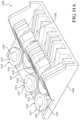
- FIG. 1is a view of an example of an actuator.
- FIG. 4is an example of a system including the actuator of FIG. 1 .
- FIGS. 5 A- 5 Fshow different views of an example of an endcap for the actuator of FIG. 1 .
- FIG. 6is an example of a first portion or a second portion of a first outer body member of the actuator of FIG. 1 .
- FIG. 7is an example of a base of a second outer body member of the actuator of FIG. 1 .
- FIG. 8is an example of a plush plate for the actuator of FIG. 1 .
- FIG. 9is an example of a first portion or a second portion of a second outer body member of the actuator of FIG. 1 .
- FIGS. 11 A- 11 Eshow different views of an endcap portion for the actuator of FIG. 10 .
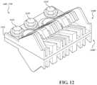
- FIG. 12is an example of an endcap for the actuator of FIG. 10 , showing two endcap portions connected to each other.
- FIG. 13is an example way of routing of a shape memory material member on the endcap shown in FIGS. 10 - 12 .
- FIG. 14is an example of a wire guide for use with the actuator of FIG. 1 or FIG. 10 .
- FIG. 15is another example of an actuator.
- FIG. 16is a view of the actuator of FIG. 15 .
- FIG. 17 Ais an example of the actuator of FIG. 15 , showing a non-activated configuration.
- FIG. 17 Bis an example of the actuator of FIG. 15 , showing an activated configuration.
- FIGS. 18 A- 18 Cshow different view of an example of a second outer body member for the actuator of FIG. 15 .
- FIGS. 19 A- 19 Bshow different views of an example of a first outer body member for the actuator of FIG. 15 .
- FIG. 20is an example of a first portion of an endcap for the actuator of FIG. 15 .
- FIG. 21is an example of a second portion of an endcap for the actuator of FIG. 15 .
- FIG. 22is another example of the second portion of an endcap for the actuator of FIG. 15 .
- FIG. 23is an example of a base of a second outer body member of the actuator of FIG. 15 .
- FIG. 24is another example of an actuator, showing a non-activated configuration.
- FIG. 25is a view of the actuator of FIG. 25 , showing an activated configuration.
- FIG. 26is an example of a plurality of the actuators of FIG. 25 , showing a non-activated condition.
- FIG. 27is a view of the plurality of actuators of FIG. 26 , showing an activated condition.
- FIG. 28is another example of an actuator, showing a non-activated configuration.
- FIG. 29is a view of the actuator of FIG. 25 , showing an activated configuration.
- FIG. 30is another example of an actuator of FIG. 15 , showing a central biasing member.
- the actuatorcan include one or more contracting members.
- the actuatorcan include an outer body member. At least a portion of the outer body can be configured to pivot.
- the actuatorcan have various configurations.
- the one or more contracting membercan contract.
- the actuatorcan be caused to morph into an activated configuration in which a dimension (e.g., height) of the actuator increases.
- the actuatorcan include one or more shape memory material members.
- the actuatorcan have any suitable form.
- One example of an actuatorwill be described herein. However, it will be understood this example is not intended to be limiting. Indeed, there are numerous actuator designs that include one or more shape memory material members that can be operated according to arrangements described herein.
- the actuator 100can have any suitable configuration.
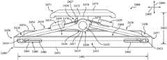
- the actuator 100can include a first outer body member 110 , a second outer body member 130 , a first endcap 160 , a second endcap 170 , and a shape memory material member 180 . These and other components will be described in turn below.
- the first outer body member 110can include a first portion 112 and a second portion 114 .
- the first portion 112 and the second portion 114can have any suitable size, shape, and/or configuration. In some arrangements, the first portion 112 and the second portion 114 can be substantially identical to each other, but they can be in different orientations. In other arrangements, the first portion 112 and the second portion 114 can be different from each other in one or more respects.
- One example of the first portion 112 and the second portion 114is shown in FIG. 6 .
- the first portion 112 and the second portion 114can be made of any suitable material, such as plastic or metal.
- the first portion 112 and the second portion 114can be operatively connected to each other such that the first portion 112 and the second portion 114 can move relative to each other.
- the first portion 112 and the second portion 114can be pivotably connected to each other.
- the first portion 112 and the second portion 114can be pivotably connected to each other by one or more hinges.
- the first portion 112 and the second portion 114can be pivotably connected to each other by one or more barrel hinges 122 .
- the one or more hingescan be a separate structure operatively connected to the first portion 112 and the second portion 114 .
- the one or more hingescan be at least partially defined by the first portion 112 and the second portion 114 .
- the first portion 112can include a first interfacing end 116 and a second interfacing end 117 .
- the second portion 114can include a first interfacing end 118 and a second interfacing end 119 .
- the first interfacing end 116 of the first portion 112 and the first interfacing end 118 of the second portion 114can be configured to interface with each other.
- the first interfacing end 116 of the first portion 112can include a knuckle 120
- the first interfacing end 118 of the second portion 114can include a knuckle 121 .
- the knuckles 120 , 121can include openings that can be substantially aligned with each other to form in part the hinge.
- a pin 123can pass through the aligned openings.
- the first portion 112 and the second portion 114can define the leaves of the hinge.
- the second interfacing end 117 of the first portion 112can be configured to interface with the first endcap 160 .
- the second interfacing end 117 of the first portion 112can include a lip 115 , protrusion, or other feature for mechanically engaging a portion of the first endcap 160 .
- the first endcap 160can be configured to retainably engage the second interfacing end 117 of the first portion 112 while allowing the first portion 112 to pivot therein.
- the second interfacing end 119 of the second portion 114can be configured to interface with the second endcap 170 .
- the second interfacing end 119 of the second portion 114can include a lip 115 , protrusion, or other feature for mechanical engagement with a portion of the second endcap 170 .
- the second endcap 170can be configured to retainably engage the second interfacing end 119 of the second portion 114 while allowing the second portion 114 to pivot therein.
- the first portion 112 and the second portion 114can be angled relative to each other.
- the first outer body member 110can have a generally V-shape.
- the first outer body member 110can have an outer side 124 and an inner side 126 .
- the actuator 100can include a biasing member 128 .
- the biasing member 128can be associated with the first outer body member 110 .
- the biasing member 128can be operatively positioned to bias the first outer body member 110 into a non-activated configuration of the actuator 100 . More particularly, the biasing member 128 can exert a force on the first portion 112 and the second portion 114 to bias them into the non-activated configuration.
- the biasing member 128can be any suitable element for imparting a biasing force of the first outer body member 110 .
- the biasing member 128can be a spring. More particularly, the biasing member 128 can be a torsion spring.
- the first outer body member 110can be configured to engage or retain a portion of the biasing member 128 .
- the first portion 112can include a retaining member 127
- the second portion 114can include a retaining member 129 .
- the retaining members 127 , 129can have any suitable size, shape, and/or configuration.
- the retaining members 127 , 129can be substantially L-shaped, as shown in FIGS. 2 , 3 , and 6 , substantially U-shaped, substantially V-shaped, or substantially J-shaped, just to name a few possibilities.
- the retaining members 127 , 129can be formed as a unitary structure with the respective one of the first portion 112 and the second portion 114 .
- the retaining members 127 , 129can be formed separately from the first portion 112 and the second portion 114 and subsequently connected thereto.
- the actuator 100can include a push plate 171 .
- the push plate 171can be configured to engage other structures or objects.
- the push plate 171can focus the force of the actuator 100 on an intended target object.
- the push plate 171can have any suitable size, shape, and/or configuration.
- the push plate 171can be substantially T-shaped.
- the push plate 171can include a platform 172 and a stem 174 .
- the platform 172can be substantially rectangular in conformation, as is shown.
- the platform 172can be substantially circular, substantially square, substantially triangular, substantially polygonal, substantially hexagonal, substantially octagonal, or substantially trapezoidal, just to name a few possibilities.
- the platform 172can have an engaging surface 173 .
- the engaging surface 173can be configured to provide a desired actuation effect on an intended target.
- the engaging surface 173can be substantially planar.
- the engaging surface 173can include one or more contours, protrusions, steps, elements, or other raised or non-planar features.
- the engaging surface 173can be configured to create a focal point for the actuation force of the actuator 100 .
- the engaging surface 173can be substantially parallel to the shape memory material member(s) 180 located within the cavity 158 and/or to a first dimension 200 of the actuator 100 . In some arrangements, the engaging surface 173 can be angled relative to the shape memory material member(s) 180 located within the cavity 158 and/or to the first dimension 200 of the actuator 100 .
- the engaging surface 173can have any suitable orientation to achieve a desired actuation force effect.
- the push plate 171can be operatively connected to the first outer body member 110 .
- a portion of the stem 174can be configured to include one or more openings 175 that can substantially align with the openings 125 in the knuckles 120 , 121 of the first portion 112 and the second portion 114 to form in part the hinge.
- the pin 123can pass through the aligned openings 125 , 175 .
- the push plate 171can substantially maintain its orientation.
- the push plate 171can be substantially centrally located on the first outer body member 110 .
- the second outer body member 130can include a first portion 132 , a second portion 134 , and a base 136 .
- the first portion 132 , the second portion 134 , and the base 136can have any suitable size, shape, and/or configuration.
- the first portion 132 and the second portion 134can be substantially identical to each other, but they can be in different orientations. However, in other embodiments, the first portion 132 and the second portion 134 can be different from each other in one or more respects.
- the first portion 132 and the second portion 134can be made of any suitable material, such as plastic or metal.
- the first portion 132 and the second portion 134 of the second outer body member 130can be substantially mirror images of the first portion 112 and the second portion 114 of the first outer body member 110 .
- the first portion 132can include a first interfacing end 140 and a second interfacing end 141 .
- the second portion 134can include a first interfacing end 142 and a second interfacing end 143 .
- the first portion 132 and the second portion 134can be operatively connected to another element such that the first portion 132 and the second portion 134 can move relative to each other. In one or more arrangements, the first portion 132 and the second portion 134 can be operatively connected to each other. In one or more arrangements, the first portion 132 and the second portion 134 can both be operatively connected to another structure. For instance, each of the first portion 132 and the second portion 134 can be pivotably connected another structure. In one or more arrangements, each of the first portion 132 and the second portion 134 can be pivotably connected to the base 136 .
- first portion 132can be pivotably connected to the base 136 by one or more hinges
- second portion 134can be pivotably connected to the base 136 by one or more hinges.
- first portion 132can be pivotably connected to the base 136 by one or more barrel hinges 138
- second portion 134can be pivotably connected to the base 136 by one or more barrel hinges 139 .
- the first portion 132 and the second portion 134can be located on opposite sides of the base 136 .
- the one or more hingescan be separate structures operatively connected to the first portion 132 and the base 136 and to the second portion 134 and the base 136 .
- the one or more hingescan be formed at least in part by the first portion 132 , the second portion 134 , and/or the base 136 .
- the base 136can have any suitable size, shape, and/or configuration.
- One example of the base 136is shown in FIG. 7 .
- the base 136can have a first interfacing end 148 and a second interfacing end 149 .
- the base 136can be configured to interface with the first portion 132 and the second portion 134 .
- the first interfacing end 140 of the first portion 132 and the first interfacing end 142 of the second portion 134can be configured to interface with the base 136 .
- the first interfacing end 140 of the first portion 132can include one or more knuckles 145
- the first interfacing end 142 of the second portion 134can include one or more knuckles 146 .
- the knuckles 145 , 146can define an opening 144 .
- the first interfacing end 148 of the base 136can include one or more knuckles 150
- the second interfacing end 149 of the base 136can include one or more knuckles 151 .
- the knuckles 150 , 151can define an opening 159 .
- the opening(s) 144 of the knuckle(s) 145 of the first portion 132 and the opening(s) 159 of the knuckle(s) 150 of the base 136can be substantially aligned with each other.
- a pin 152can be received in the aligned openings 144 , 159 .
- the first portion 132 and the base 136can be like the leaves of the hinge.
- the opening(s) 144 of the knuckle(s) 146 of the second portion 134 and the opening(s) 159 of the knuckle(s) 151 of the base 136can be substantially aligned with each other.
- a pin 153can be received in the aligned openings 144 , 159 .
- the second portion 134 and the base 136can be like the leaves of the hinge.
- the second interfacing end 141 of the first portion 132can be configured to interface with the first endcap 160 .
- the second interfacing end 141 of the first portion 132can include a lip 168 , protrusion, or other feature for mechanically engaging a portion of the first endcap 160 .
- the first endcap 160can be configured to retainably engage the second interfacing end 141 of the first portion 132 while allowing the first portion 132 to pivot therein.
- the second interfacing end 143 of the second portion 134can be configured to interface with the second endcap 170 .
- the second interfacing end 143 of the second portion 134can include a lip 168 , protrusion, or other feature for mechanical engagement with a portion of the second endcap 170 .
- the second endcap 170can be configured to retainably engage the second interfacing end 143 of the second portion 134 while allowing the second portion 134 to pivot therein.
- the first portion 132 and the second portion 134can be angled relative to each other.
- the second outer body member 130can have an outer side 131 and an inner side 133 .
- the biasing members 154 , 155can be any suitable element for imparting a biasing force on the second outer body member 130 .
- the biasing members 154 , 155can be springs. More particularly, the biasing members 154 , 155 can be torsion springs.
- the biasing members 128 , 154 , 155can be substantially identical to each other. In some arrangements, one or more of the biasing members 128 , 154 , 155 can be different from the other biasing members in one or more respects, such as in terms of size, shape, configuration, and/or biasing force, just to name a few possibilities.
- the second outer body member 130can be configured to engage or retain a portion of the biasing member 154 , 155 .
- the first portion 132can include a retaining member 156
- the second portion 134can include a retaining member 157 .
- the retaining members 156 , 157can have any suitable size, shape, and/or configuration.
- the retaining members 156 , 157can be substantially L-shaped, as shown in FIGS. 2 , 3 , and 9 , substantially U-shaped, substantially V-shaped, or substantially J-shaped, just to name a few possibilities.
- the retaining members 156 , 157can be formed as a unitary structure with the respective one of the first portion 132 and the second portion 134 .
- the retaining members 156 , 157can be formed separately from the first portion 132 and the second portion 134 and subsequently connected thereto.
- the base 136can have any suitable size, shape, and/or configuration. In one or more arrangements, the base 136 can be substantially rectangular.
- the base 136can be made of any suitable material, such as metal or plastic.
- the base 136can be made of the same material as the first outer body member 110 and/or the second outer body member 130 , or the base 136 can be made of a different material.
- the base 136can be configured to be supported on a surface.
- the base 136can include an engaging surface 137 .
- the engaging surface 137can be configured to substantially matingly engage a surface on which the base 136 is supported.
- the engaging surface 137can be substantially planar.
- the engaging surface 137can include one or more non-planar features, such as contours, protrusions, recesses, curves, etc.
- the base 136can be configured for connection to another surface.
- the base 136can include one or more apertures 135 to accommodate a fastener for attachment to another surface or structure.
- the actuator 100can include a first endcap 160 and a second endcap 170 .
- the first endcap 160 and the second endcap 170can be spaced apart.
- the first endcap 160 and the second endcap 170can face toward each other.
- the first endcap 160 and the second endcap 170can be substantially aligned with each other.
- the first endcap 160 and the second endcap 170can have any suitable size, shape, and/or configuration. In one or more arrangements, the first endcap 160 and the second endcap 170 can be substantially identical to each other. However, the first endcap 160 and the second endcap 170 can be oriented differently. The first endcap 160 and the second endcap 170 can be made of any suitable material, such as plastic or metal. In one or more arrangements, the first endcap 160 and the second endcap 170 can be different from each other in one or more respects.
- FIGS. 5 A- 5 FOne example of an endcap is shown in FIGS. 5 A- 5 F .
- the endcapwill be referred to as the first endcap 160 , but it will be understood that the description is also equally applicable to the second endcap 170 .
- the first endcap 160can be configured to engage the first outer body member 110 and the second outer body member 130 .
- the first endcap 160can include a first engaging cavity 161 and a second engaging cavity 162 .
- the first engaging cavity 161 and the second engaging cavity 162can be angled relative to a plane 163 of the first endcap 160 , as shown in FIG. 5 B .
- the first engaging cavity 161 and the second engaging cavity 162can be at an angle ⁇ of about 20 to about 25 degrees relative to the plane 163 .
- the first endcap 160can be substantially symmetrical about the plane 163 .
- the first engaging cavity 161 of the first endcap 160can be configured for operative connection to the first outer body member 110 . More particularly, the first engaging cavity 161 of the first endcap 160 can be configured for operative connection to the second interfacing end 117 of the first portion 112 . Further, the first engaging cavity 161 of the second endcap 170 can be configured for operative connection to the second interfacing end 119 of the second portion 114 .
- first outer body member 110can be operatively connected to the first engaging cavity 161 by mechanical engagement, one or more fasteners, one or more adhesives, and/or one or more brazes or weld, just to name a few possibilities.
- first outer body member 110can include a lip 115 , protrusion, or other features that can engage with the respective endcap within the first engaging cavity 161 , such as by interlocking engagement.
- the first outer body member 110can be retainably engaged by the first engaging cavity 161 .
- the first engaging cavity 161can provide end containment for the first portion 112 or the second portion 114 to pivot in when the actuator 100 is activated or deactivated.
- the second engaging cavity 162 of the first endcap 160can be configured for operative connection to the second outer body member 130 . More particularly, the second engaging cavity 162 of the first endcap 160 can be configured for operative connection to the second interfacing end 119 of the first portion 132 . Further, the second engaging cavity 162 of the second endcap 170 can be configured for operative connection to the second interfacing end 119 of the second portion 134 .
- the above discussion of the operative connection between the first outer body member 110 and the first engaging cavity 161applies equally to the connection between the second outer body member 130 and the second engaging cavity 162 .
- the first portion 132 and/or the second portion 134 of the second outer body member 130can include a lip 115 , protrusion, or other features can engage with the respective endcap within the second engaging cavity 162 , such as by interlocking engagement.
- the second outer body member 130can be retainably engaged by the second engaging cavity 162 .
- the second engaging cavity 162can provide end containment for the first portion 132 or the second portion 134 to pivot in when the actuator 100 is activated or deactivated.
- the first endcap 160can include a plurality of features to allow for engagement with the shape memory material member(s) 180 .
- the first endcap 160can include one or more features to enable the shape memory material member(s) 180 to turn around and extend toward the opposite endcap.
- each of the first endcap 160 and the second endcap 170can include a first groove 164 , a second groove 165 , and a post 166 .
- the shape memory material member 180can wrap around the post 166 .
- the shape memory material member 180can extend along the first groove 164 and/or the second groove 165 .
- the first groove 164 and the second groove 165can have any suitable size, shape, and/or configuration. In some arrangements, the first groove 164 and the second groove 165 can be substantially identical to each other. In other arrangements, the first groove 164 and the second groove 165 can be different from each other in one or more respects. In one or more arrangements, the first groove 164 and the second groove 165 can be substantially U-shaped.
- the post 166can have any suitable size, shape, and/or configuration. For instance, the post 166 can be substantially semi-cylindrical.
- the first endcap 160can include one or more inlet/outlet passages 177 that extend between the first groove 164 and the exterior of the first endcap 160 .
- the first endcap 160can include one or more inlet/outlet passages 178 that extend between the second groove 165 and the exterior of the first endcap 160 .
- the inlet/outlet passages 177 , 178can provide an entry or exit point for the shape memory material member(s) 180 from the first endcap 160 or the second endcap 170 .
- the shape memory material member(s) 180can be coated or covered with an insulating material.
- the portions of the shape memory material member(s) 180 that interact with the first groove 164 , the second groove 165 , and the post 166can be coated or covered with an insulating material 167 .
- the insulating material 167can be a sleeve or a wrap.
- the shape memory material member(s) 180can extend between the first endcap 160 and the second endcap 170 in any suitable manner.
- One non-limiting example of the routing of the shape memory material member(s) 180will now be described. From the exterior of the first endcap 160 , the shape memory material member 180 can enter the inlet/outlet passages 177 and extend substantially straight into a portion of the first groove 164 . The shape memory material member 180 can extend substantially straight out of the first groove 164 and into the cavity 158 . The shape memory material member 180 can extend across the cavity 158 and into the first groove 164 of the second endcap 170 . The shape memory material member 180 can turn around in the first groove 164 of the second endcap 170 .
- the shape memory material member 180can extend back across the cavity 158 and wrap around the post 166 of the first endcap 160 .
- the shape memory material member 180can then extend back across the cavity 158 and wrap around the post 166 of the second endcap 170 .
- the shape memory material member 180can extend across the cavity 158 and enter the second groove 165 of the first endcap 160 .
- the shape memory material member 180can extend within the second groove 165 and extend back across the cavity 158 and into the second groove 165 of the second endcap 170 .
- the shape memory material member 180can exit the second groove 165 via one of the inlet/outlet passages 178 of the second endcap 170 .
- the shape memory material member 180can extend between post 166 of the first endcap 160 and the second endcap 170 .
- the shape memory material member 180can extend between the first groove 164 of the first endcap 160 and the first groove 164 of the second endcap 170 .
- the shape memory material member 180can extend between the second groove 165 of the first endcap 160 and the second groove 165 of the second endcap 170 .
- the shape memory material member 180can extend between the first groove 164 of the first endcap 160 and the second groove 165 of the second endcap 170 .
- the shape memory material member 180can extend between the second groove 165 of the first endcap 160 and the first groove 164 of the second endcap 170 .
- the shape memory material member(s) 180can be routed in any combination of the above and other examples.
- the shape memory material member(s) 180when extending across the cavity 158 , can extend substantially straight across from one endcap to the other endcap. Alternatively, the shape memory material member(s) 180 can extend from one side of one of the endcaps to the opposite side of the other endcap. Thus, the shape memory material member(s) 180 can extend substantially diagonally across the cavity 158 . In some arrangements, the shape memory material member(s) 180 can be wrapped around the post 166 a plurality of times. For instance, in one or more arrangements, the shape memory material member(s) 180 can be wrapped twice around the post 166 .
- the first endcap 160can include a flange 169 .
- the flange 169can provide a connection point for an end of the shape memory material member(s) 180 .
- the shape memory material member(s) 180can operatively connected to another conductor or other element to a power source.
- the shape memory material member(s) 180can be operatively connected to the flange 169 , such as by one or more fasteners 179 ( FIG. 1 ), one or more adhesives, one or more forms of mechanical engagement, one or more other forms of connection, and/or any combination thereof.
- the actuator 100can include one or more shape memory material members 180 .
- the shape memory material members 180can be operatively connected to the first endcap 160 and the second endcap 170 . Any suitable manner of operative connection can be provided, such as one or more fasteners, one or more adhesives, one or more welds, one or more brazes, one or more forms of mechanical engagement, or any combination thereof.
- the shape memory material member(s) 180can extend across the cavity 158 .
- the shape memory material member 180can, for example, extend straight across the cavity from the first endcap 160 and the second endcap 170 .
- the shape memory material member 180can extend in a serpentine pattern between the first endcap 160 and the second endcap 170 .
- the first endcap 160 and the second endcap 170can be configured to allow the shape memory material member 180 to turn around and extend in the opposite direction, as described above.
- the plurality of shape memory material members 180can be distributed, arranged, and/or oriented in any suitable manner.
- the shape memory material members 180can extend substantially parallel to each other.
- one or more of the shape memory material members 180can extend non-parallel to the other shape memory material members 180 .
- some of the plurality of shape memory material members 180may cross over each other.
- the shape memory material member(s) 180can be configured to overcome the biasing forces exerted by the biasing members 128 , 154 , 155 .
- shape memory materialincludes materials that changes shape when an activation input is provided to the shape memory material and, when the activation input is discontinued, the material substantially returns to its original shape.
- shape memory materialsinclude shape memory alloys (SMA) and shape memory polymers (SMP).
- the shape memory material members 180can be shape memory material wires.
- the shape memory material members 180can be shape memory alloy wires.
- an activation inputi.e., heat
- Shape memory alloy wire(s)can be heated in any suitable manner, now known or later developed.
- shape memory alloy wire(s)can be heated by the Joule effect by passing electrical current through the wires.
- arrangementscan provide for cooling of the shape memory alloy wire(s), if desired, to facilitate the return of the wire(s) to a non-activated configuration.
- the wire(s)can have any suitable characteristics.
- the wire(s)can be high temperature wires with austenite finish temperatures from about 80 degrees Celsius to about 110 degrees Celsius.
- the wire(s)can have any suitable diameter.
- the wire(s)can be from about 0.2 millimeters (mm) to about 0.7 mm, from about 0.3 mm to about 0.5 mm, or from about 0.375 millimeters to about 0.5 millimeters in diameter.
- the wire(s)can have a stiffness of up to about 70 gigapascals.
- the pulling force of SMA wire(s)can be from about 150 MPA to about 400 MPa.
- the wire(s)can be configured to provide an initial moment of from about 300 to about 600 N ⁇ mm, or greater than about 500 N ⁇ mm, where the unit of newton millimeter (N ⁇ mm) is a unit of torque (also called moment) in the SI system.
- One newton meteris equal to the torque resulting from a force of one newton applied perpendicularly to the end of a moment arm that is one meter long.
- the wire(s)can be configured to transform in phase, causing the shape memory material members 180 to be moved from non-activated position to an activated position in about 3 seconds or less, about 2 seconds or less, about 1 second or less, or about 0.5 second or less.
- the wire(s)can be made of any suitable shape memory material, now known or later developed. Different materials can be used to achieve various balances, characteristics, properties, and/or qualities.
- an SMA wirecan include nickel-titanium (Ni—Ti, or nitinol).
- Ni—Tinickel-titanium
- nitinolnickel-titanium shape memory alloy
- FLEXINOLFLEXINOL
- the SMA wirescan be made of Cu—Al—Ni, Fe—Mn—Si, or Cu—Zn—Al.
- the SMA wirecan be configured to increase or decrease in length upon changing phase, for example, by being heated to a phase transition temperature T SMA .
- Utilization of the intrinsic property of SMA wirescan be accomplished by using heat, for example, via the passing of an electric current through the SMA wire in order provide heat generated by electrical resistance, in order to change a phase or crystal structure transformation (i.e., twinned martensite, detwinned martensite, and austenite) resulting in a lengthening or shortening the SMA wire.
- a phase or crystal structure transformationi.e., twinned martensite, detwinned martensite, and austenite
- the SMA wirecan experience a decrease in length of from about 2 to about 8 percent, or from about 3 percent to about 6 percent, and in certain aspects, about 3.5 percent, when heated from a temperature less than the T SMA to a temperature greater than the T SMA .
- Shape memory materialsa class of active materials, also sometimes referred to as smart materials, include materials or compositions that have the ability to remember their original shape, which can subsequently be recalled by applying an external stimulus, such as an activation signal.
- shape memory material member(s) 180are described, in some implementations, as being wires, it will be understood that the shape memory material member(s) 180 are not limited to being wires. Indeed, it is envisioned that suitable shape memory materials may be employed in a variety of other forms, such as sheets, plates, panels, strips, cables, tubes, or combinations thereof. In some arrangements, the shape memory material member(s) 180 may include an insulating coating or an insulating sleeve over at least a portion of their length.
- the shape memory material member(s) 180can be located substantially entirely within the overall envelope of the actuator 100 .
- a substantial majority of the shape memory material member(s) 180can be located within the cavity 158 .
- “Substantial majority”means about 60% or greater, about 65% or greater, about 70% or greater, about 75% or greater, about 80% or greater, about 85% or greater, about 90% or greater, or about 95% or greater.
- a portion of the shape memory material member(s) 180can be routed within the first endcap 160 and the second endcap 170 .
- a portion of the shape memory material member(s) 180can extend outside of a respective one of the endcaps 160 , 170 for connection to the flange 169 and/or to another conductor and/or power source.
- the actuator 100can be a self-contained unit.
- the actuator 100can include a first dimension 200 and the second dimension 210 .
- the first dimension 200can describe a width of the actuator 100
- the second dimension 210can describe a height of the actuator 100 .
- the first dimension 200 and the second dimension 210can be substantially perpendicular to each other.
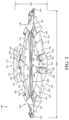
- FIG. 2shows an example of the actuator 100 in a non-activated configuration.
- the shape memory material member(s) 180are not activated.
- FIG. 3shows an example of the actuator 100 in an activated configuration.
- an activation inpute.g., electrical energy
- the shape memory material member(s) 180can contract. This contraction causes the shape memory material member(s) 180 to pull the first endcap 160 and the second endcap 170 toward each other in a direction that corresponds to the first dimension 200 .
- the first outer body member 110 and the second outer body member 130can extend outward and away from each other in a direction that corresponds to the second dimension 210 .
- the first dimension 200i.e., the width
- the second dimension 210i.e., the height
- the actuator 100can deliver a force in a direction that is out of plane or otherwise different from the direction of contraction of the shape memory material member(s) 180 .
- the push plate 171can be located at a higher elevation. Also, when the actuator 100 goes from a non-activated configuration to the activated configuration, the angle between the first portion 112 and the second portion 114 of the first outer body member 110 can decrease. Similarly, when the actuator 100 goes from a non-activated configuration to the activated configuration, the angle between the first portion 132 and the second portion 134 of the second outer body member 130 can decrease. It will be appreciated that the first endcap 160 and the second endcap 170 can be configured to accommodate the movement of the first outer body member 110 and the second outer body member 130 while maintaining the operative connection to them.
- the push plate 171can deliver an actuation force symmetrically, that is, substantially in line with a force direction of the actuator 100 (e.g., in direction of the second dimension 210 ).
- the actuator 100can be configured to deliver an actuation force that is asymmetric, that is, not in line with the force direction of the actuator 100 . Delivery of an asymmetric actuation force can be achieved in various ways.
- the first portion 112 and the second portion 114 of the first outer body member 110can have different lengths. Thus, one of the portions is longer than the other. As a result, the push plate 171 may no longer be substantially centrally located.
- the first portion 132 and the second portion 134 of the second outer body member 130can have different lengths.
- the push plate 171can be configured such that the engaging surface 173 or other portion of the push plate 171 is angled relative to the first dimension 200 .
- the push plate 171can be operatively connected to the first outer body member 110 such that the push plate 171 extends from the first outer body member 110 at an acute angle.
- the biasing force of the biasing members 154 , 155can be different from each other.
- the delivery of an asymmetric actuation forcecan be achieved by any combination of the above and other arrangements.
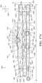
- the actuator 100 ′can include the first outer body member 110 , the second outer body member 130 , and the shape memory material member(s) 180 .
- the above description of the first outer body member 110 , the second outer body member 130 , and the shape memory material member(s) 180 made in connection with the actuator 100 shown in FIGS. 1 - 3applies equally to the same components here in connection with the actuator 100 ′ of FIG. 14 .
- the actuator 100 ′includes a first endcap 160 ′ and a second endcap 170 ′.
- the first endcap 160 ′ and the second endcap 170 ′ shown in FIG. 14are different than the first endcap 160 and the second endcap 170 shown in FIGS. 5 A- 5 F .
- the actuator 100 ′can include a first endcap 160 and a second endcap 170 .
- the first endcap 160 and the second endcap 170can be spaced apart.
- the first endcap 160 and the second endcap 170can face toward each other.
- the first endcap 160 and the second endcap 170can be substantially aligned with each other.
- the first endcap 160 ′ and the second endcap 170 ′can have any suitable size, shape, and/or configuration. In one or more arrangements, the first endcap 160 ′ and the second endcap 170 ′ can be substantially identical to each other. However, the first endcap 160 ′ and the second endcap 170 ′ can be oriented differently. The first endcap 160 ′ and the second endcap 170 ′ can be made of any suitable material, such as plastic or metal. In one or more arrangements, the first endcap 160 ′ and the second endcap 170 ′ can be different from each other in one or more respects.
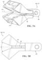
- first endcap 160 ′ and/or the second endcap 170 ′can be a unitary structure. In other arrangements, the first endcap 160 ′ and/or the second endcap 170 ′ can be made of a plurality of portions. Referring to FIGS. 11 A- 11 E , one example of an endcap portion 1100 of the first endcap 160 ′ and/or the second endcap 170 ′ is shown.
- the endcap portion 1100can be configured to engage the first outer body member 110 and the second outer body member 130 .
- the endcap portion 1100can include an interfacing surface 1104 .
- the interfacing surface 1104can be substantially planar.
- the endcap portion 1100can include an engaging cavity 1102 .
- the engaging cavity 1102can be angled relative to the interfacing surface 1104 .
- the engaging cavity 1102can be angled relative to a plane 1106 of the first endcap 160 ′ or the second endcap 170 ′, as shown in FIG. 10 .
- the engaging cavity 1102can be at an angle of about 20 to about 25 degrees relative to the plane 1106 and/or to the interfacing surface 1104 .
- the engaging cavity 1102 of the endcap portion 1100can be configured for operative connection to the first outer body member 110 and/or the second outer body member 130 . More particularly, the engaging cavity 1102 of the endcap portion 1100 can be configured for operative connection to the second interfacing end 117 of the first portion 112 , the second interfacing end 119 of the second portion 114 , the second interfacing end 119 of the first portion 132 , and/or the second interfacing end 119 of the second portion 134 .
- first outer body member 110 and/or the second outer body member 130can be operatively connected to the engaging cavity 1102 by mechanical engagement, one or more fasteners, one or more adhesives, and/or one or more brazes or weld, just to name a few possibilities.
- first outer body member 110 and/or the second outer body membercan include a lip 115 , protrusion, or other feature that can engage with the respective endcap within the engaging cavity 1102 , such as by interlocking engagement.
- the first outer body member 110 and/or the second outer body member 130can be retainably engaged by the engaging cavity 1102 .
- the engaging cavity 1102can provide end containment for the first portion 112 , the second portion 114 , the first portion 132 , and/or the second portion 134 to pivot in when the actuator 100 is activated or deactivated.
- the endcap portion 1100can include a plurality of features to allow for engagement with the shape memory material member(s) 180 .
- the endcap portion 1100can include one or more features to enable the shape memory material member(s) 180 to turn around and extend toward the opposite endcap, to enter the endcap portion 1100 , and/or to exit the endcap portion 1100 .
- endcap portion 1100can include a plurality of posts (e.g., a first post 1110 , a second post 1112 , and a third post 1114 ) and a plurality of grooves (e.g., a first groove 1120 , a second groove 1122 ).
- the endcap portion 1100can include one or more inlet/outlet notches 1130 .
- the endcap portion 1100can include various structures that can define a plurality of channels (e.g., a first channel 1141 , a second channel 1142 , a third channel 1143 , a fourth channel 1144 , a fifth channel 1145 , a sixth channel 1146 , a seventh channel 1147 , an eighth channel 1148 , and a ninth channel 1149 ).
- a plurality of channelse.g., a first channel 1141 , a second channel 1142 , a third channel 1143 , a fourth channel 1144 , a fifth channel 1145 , a sixth channel 1146 , a seventh channel 1147 , an eighth channel 1148 , and a ninth channel 1149 ).
- the shape memory material member(s) 180can extend along the groove(s).
- the first groove 1120 and the second groove 1122can have any suitable size, shape, and/or configuration. In some arrangements, the first groove 1120 and the second groove 1122 can be substantially identical to each other. In other arrangements, the first groove 1120 and the second groove 1122 can be different from each other in one or more respects. In one or more arrangements, the first groove 1120 and the second groove 1122 can be substantially U-shaped.
- the shape memory material member(s) 180can wrap around the post(s).
- the post(s)can have any suitable size, shape, and/or configuration.
- the post(s)can be substantially identical to each other. In other arrangements, the post(s) can be different from each other in one or more respects.
- the post(s)can include a shaft 1115 and a cap 1117 .
- the cap 1117can be larger than the shaft 1115 .
- the shaft 1115can be substantially cylindrical.
- the cap 1117can be configured to help retain the shape memory material member(s) 180 on the shaft 1115 .
- the cap 1117can physically prevent the shape memory material member(s) 180 from slipping off of the end of the shaft 1115 .
- An aperture 1118can be defined in each of the post(s). The apertures 1118 can extend through the endcap portion 1100 such that openings are defined in the cap 1117 and the interfacing surface 1104 .
- the post(s) and the groove(s)can alternate with each other.
- the groove(s) and the post(s)can be substantially equally spaced from each other.
- the groove(s) and the post(s)can be non-equally spaced in at least one or more areas.
- the post(s)can be located closer to an outboard end 1111 of the endcap portion 1100 than the groove(s).
- the endcap portion 1100can include one or more inlet/outlet notches 1130 .
- the inlet/outlet notch(es) 1130can be provided in any suitable locations on the endcap portion 1100 .
- the inlet/outlet notch(es) 1130can be located outboard of the groove(s) and the post(s).
- the inlet/outlet notch(es) 1130can provide an entry or exit point for the shape memory material member(s) 180 from the endcap portion 1100 .
- the shape memory material member(s) 180can extend to another endcap portion 1100 , to a portion of an exterior of the endcap 160 ′, 170 ′, or to some other structure.
- a plurality of endcap portions 1100can be joined to form an endcap (e.g., endcap 160 ′ or endcap 170 ′).
- a first endcap portion 1100 ′ and a second endcap portion 1100 ′′can be joined together to form the endcap 160 ′, 170 ′.
- the first endcap portion 1100 ′ and the second endcap portion 1100 ′′can be substantially identical to each other.
- the first endcap portion 1100 ′ and the second endcap portion 1100 ′′can be substantially mirror images of each other.
- the first endcap portion 1100 ′ and the second endcap portion 1100 ′′can be different from each other in one or more respects. While this example shows two endcap portions, it will be appreciated that there can be more than two endcap portions.
- first and second endcap portions 1100 ′, 1100 ′′When the first and second endcap portions 1100 ′, 1100 ′′ are joined, the interfacing surface 1104 of the first endcap portion 1100 ′ and the interfacing surface 1104 of the second endcap portion 1100 ′′ can directly contact each other.
- the first and second endcap portions 1100 ′, 1100 ′′can be joined in any suitable manner, now known or later developed.
- the first and second endcap portions 1100 ′, 1100 ′′can be joined by one or more fasteners, one or more adhesives, one or more forms of mechanical engagement, one or more other forms of connection, and/or any combination thereof.
- fastenersone or more adhesives
- forms of mechanical engagementone or more other forms of connection, and/or any combination thereof.
- the first and second endcap portions 1100 ′, 1100 ′′can be joined by a plurality of bolts 1119 , which can extend through the endcap portion 1100 .
- the head of the bolt 1119can engage the cap 1117 of the respective post.
- the bolt 1119can extend through the aperture 1118 in the first endcap portion 1100 ′.
- the bolt 1119can extend through the aperture 1118 in the second endcap portion 1100 ′′.
- a distal end of the boltcan pass outside of the cap 1117 of the second endcap portion 1100 ′′.
- the distal end of the bolt 1119can be engaged a retaining member, such as a nut or other retaining structure.
- the endcap 160 ′ and/or 170 ′can be unitary structures made of a single piece, such as by three-dimensional printing or injection molding.
- the shape memory material member(s) 180can extend between the first endcap 160 ′ and the second endcap 170 ′ in any suitable manner.
- One non-limiting example of the routing of the shape memory material member(s) 180will now be described in connection with one of the endcap portions 1100 in FIG. 13 .
- the shape memory material member 180can enter the first channel 1141 .
- the shape memory material member 180can be coming from the opposite endcap (either substantially horizontally across the cavity 158 or diagonally across the cavity 158 ).
- the shape memory material member 180can extend along the first channel 1141 to the first post 1110 .
- the shape memory material member 180can wrap around the first post 1110 so as to turn around and enter the second channel 1142 .
- the shape memory material member 180can be retained on the first post 1110 by the cap 1117 .
- the shape memory material member 180can extend along the second channel 1142 .
- the shape memory material member 180can extend back across the cavity 158 and into engagement with the opposite endcap.
- the shape memory material member 180can turn around in the opposite endcap, extend back across the cavity 158 , and enter the third channel 1143 .
- the shape memory material member 180can extend along the third channel 1143 to the first groove 1120 .
- the shape memory material member 180can wrap around the first groove 1120 so as to turn around and enter the fourth channel 1144 .
- the shape memory material member 180can extend back across the cavity 158 and into engagement with the opposite endcap.
- the shape memory material member 180can turn around in the opposite endcap and extend back across the cavity 158 .
- the routing of the shape memory material member 180can continue in the same manner with respect to the fifth channel 1145 , the second post 1112 , and the sixth channel 1146 .
- the shape memory material member 180can extend back across the cavity 158 and into engagement with the opposite endcap.
- the shape memory material member 180can turn around in the opposite endcap and extend back across the cavity 158 .
- the routing of the shape memory material member 180can continue in the same manner with respect to the seventh channel 1147 , the second groove 1122 , and the eighth channel 1148 .
- the shape memory material member 180can extend back across the cavity 158 and into engagement with the opposite endcap.
- the shape memory material member 180can turn around in the opposite endcap and extend back across the cavity 158 .
- the shape memory material member 180can enter the ninth channel 1149 .
- the shape memory material member 180can extend along the ninth channel.
- the shape memory material member 180can exit the endcap portion 1100 through the inlet/outlet notch 1130 . From there, the shape memory material member 180 can extend to a point external to the endcap, to an attachment point on the endcap, to the other endcap portion to which the endcap portion shown in FIG. 13 is attached (e.g., by entering the inlet/outlet notch 1130 on the other endcap portion).
- the shape memory material member 180can wrap around the third post 1114 prior to exiting the endcap portion 1100 through the inlet/outlet notch 1130 .
- the shape memory material member(s) 180can extend substantially straight across from one endcap to the other endcap. In such case, the shape memory material member(s) 180 can extend substantially parallel to the plane 1106 . Alternatively, the shape memory material member(s) 180 can extend from the upper or lower side of one of the endcaps to the opposite one of the upper or lower side of the other endcap. Thus, the shape memory material member(s) 180 can extend substantially diagonally across the cavity 158 .
- the shape memory material member(s) 180can be wrapped around one or more of the post(s) a plurality of times. For instance, in one or more arrangements, the shape memory material member(s) 180 can be wrapped twice around the post(s). In some arrangements, the shape memory material member(s) 180 can be wrapped around one or more of the groove(s) a plurality of times. Such wrapping of the shape memory material member(s) 180 can increase the actuation force imparted by the shape memory material member(s) 180 when activated.
- the endcaps 160 ′, 170 ′ or the endcap portions 1100can be configured to provide a connection point for an end of the shape memory material member(s) 180 .
- the endcaps 160 ′, 170 ′ or the endcap portions 1100can include a flange. The flange can provide a connection point for an end of the shape memory material member(s) 180 . In this location, the shape memory material member(s) 180 can operatively connected to another conductor or other element to a power source.
- the shape memory material member(s) 180can be operatively connected to the flange, such as by one or more fasteners, one or more adhesives, one or more forms of mechanical engagement, one or more other forms of connection, and/or any combination thereof.
- the shape memory material member(s) 180are bare, that is, they are not coated or covered with an insulating material. In some arrangements, at least a portion of the shape memory material member(s) 180 can be coated or covered with an insulating material. For instance, the portions of the shape memory material member(s) 180 that interact with the groove(s) and/or the post(s) can be coated or covered with an insulating material 167 . In some arrangements, the insulating material can be a sleeve or a wrap.
- FIG. 14is an example of a wire guide 1400 .
- the wire guide 1400can include a plurality of panels 1410 .
- a plurality of apertures 1420can be defined.
- the apertures 1420can be sized, shaped, and/or configured to allow passage of the shape memory material member(s) 180 as they are routed between the endcaps 160 , 170 , 160 ′, 170 ′.
- the plurality of panels 1410can be spaced apart from each other. In some arrangements, the panels 1410 can be substantially equally spaced from each other.
- the panels 1410can be non-equally spaced from the each other.
- the panels 1410can be connected to one or more frame members 1430 .
- the wire guide 1400can be made of any suitable material, such as one that does not interact with the shape memory material member(s) 180 .
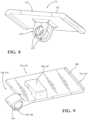
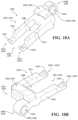
- the actuator 1500can include a first outer body member 1510 , a second outer body member 1530 , a first endcap 1560 , a second endcap 1570 , and one or more contracting members 1580 .
- the first outer body member 1510can include a first portion 1512 and a second portion 1514 .
- the second outer body member 1530can include a first portion 1532 , a second portion 1534 , and a base 1536 .
- the first outer body member 1510 the second outer body member 1530can be arranged in a scissored configuration. In one or more arrangements, a portion of the first outer body member 1510 can cross a portion of the second outer body member 1530 . More particularly, the first portion 1512 of the first outer body member 1510 and the first portion 1532 of the second outer body member 1530 can cross each other. Alternatively or additionally, the second portion 1514 of the first outer body member 1510 and the second portion 1534 of the second outer body member 1530 can cross each other.
- the first portion 1512 of the first outer body member 1510can pass through the first portion 1532 of the second outer body member 1530 and/or the second portion 1514 of the first outer body member 1510 can pass through the second portion 1534 of the second outer body member 1530 .
- An example of such an arrangementwill be described herein.
- the first portion 1532 of the second outer body member 1530can pass through the first portion 1512 of the first outer body member 1510 and/or the second portion 1534 of the second outer body member 1530 can pass through the second portion 1514 of the first outer body member 1510 .
- the first portion 1512 and the second portion 1514can have any suitable size, shape, and/or configuration. In some arrangements, the first portion 1512 and the second portion 1514 can be substantially identical to each other, but they can be in different orientations. In other arrangements, the first portion 1512 and the second portion 1514 can be different from each other in one or more respects.
- One example of the first portion 1512 and the second portion 1514is shown in FIGS. 19 A and 19 B .
- the first portion 1512 and the second portion 1514can be made of any suitable material, such as plastic or metal.
- the first portion 1512 and the second portion 1514can be operatively connected to each other such that the first portion 1512 and the second portion 1514 can move relative to each other.
- the first portion 1512 and the second portion 1514can be pivotably connected to each other.
- the first portion 1512 and the second portion 1514can be pivotably connected to each other by one or more hinges.
- the first portion 1512 and the second portion 1514can be pivotably connected to each other by one or more barrel hinges 1522 .
- the one or more hingescan be a separate structure operatively connected to the first portion 1512 and the second portion 1514 .
- the one or more hingescan be at least partially defined by the first portion 1512 and the second portion 1514 .
- the first portion 1512can include a first interfacing end 1516 and a second interfacing end 1517 .
- the second portion 1514can include a first interfacing end 1518 and a second interfacing end 1519 .
- the first interfacing end 1516 of the first portion 1512 and the first interfacing end 1518 of the second portion 1514can be configured to interface with each other.
- the first interfacing end 1516 of the first portion 1512can include a knuckle 1520
- the first interfacing end 1518 of the second portion 1514can include a knuckle 1521 .
- the knuckles 1520 , 1521can include openings 1625 that can be substantially aligned with each other to form in part the hinge.
- a pin 1523can pass through the aligned openings.
- the first portion 1512 and the second portion 1514can define the leaves of the hinge.
- the second interfacing end 1517 of the first portion 1512can be configured to interface with the first endcap 1560 .
- the second interfacing end 1517 of the first portion 1512can include a lip 1515 , hook, protrusion, tooth/teeth, or other feature for mechanically engaging a portion of the first endcap 1560 .
- the first endcap 1560can be configured to retainably engage the second interfacing end 1517 of the first portion 1512 while allowing the first portion 1512 to pivot therein.
- the second interfacing end 1519 of the second portion 1514can be configured to interface with the second endcap 1570 .
- the second interfacing end 1519 of the second portion 1514can include a lip 1515 , protrusion, or other feature for mechanical engagement with a portion of the second endcap 1570 .
- the second endcap 1570can be configured to retainably engage the second interfacing end 1519 of the second portion 1514 while allowing the second portion 1514 to pivot therein.
- the first portion 1512 and the second portion 1514can be angled relative to each other.
- the first outer body member 1510can have a generally V-shape.
- the actuator 1500can include a biasing member 1528 .
- the biasing member 1528can be associated with the first outer body member 1510 .
- the biasing member 1528can be operatively positioned to bias the first outer body member 1510 into a non-activated configuration of the actuator 1500 . More particularly, the biasing member 1528 can exert a force on the first portion 1512 and the second portion 1514 to bias them into the non-activated configuration.
- the biasing member 1528can be any suitable element for imparting a biasing force of the first outer body member 1510 .
- the biasing member 1528can be a spring. More particularly, the biasing member 1528 can be a torsion spring.
- the first outer body member 1510can be configured to engage or retain a portion of the biasing member 1528 .
- the first portion 1512can include a retaining member 1527
- the second portion 1514can include a retaining member 1529 .
- the retaining members 1527 , 1529can have any suitable size, shape, and/or configuration.
- the retaining members 1527 , 1529can define a channel into which a portion of the biasing member 1528 can be received.
- the retaining members 1527 , 1529can be substantially L-shaped, substantially U-shaped, substantially V-shaped, or substantially J-shaped, just to name a few possibilities.
- the retaining members 1527 , 1529can be similar to the retaining members 127 , 129 in FIGS. 1 - 3 .
- the retaining members 1527 , 1529can be formed as a unitary structure with the respective one of the first portion 1512 and the second portion 1514 .
- the retaining members 1527 , 1529can be formed separately from the first portion 1512 and the second portion 1514 and subsequently connected thereto.
- the actuator 1500can include a push structure 1571 .
- One example of the push structure 1571is shown in FIGS. 15 - 17 .
- the push structure 1571can be configured to engage other structures or objects.
- the push structure 1571can focus the force of the actuator 1500 on an intended target object.
- the push structure 1571can have any suitable size, shape, and/or configuration.
- the push structure 1571can be substantially T-shaped.
- the push structure 1571can include a platform 1572 and a stem 1574 .
- the platform 1572can have an engaging surface 1573 .
- the engaging surface 1573can be configured to provide a desired actuation effect on an intended target.
- the engaging surface 1573can be substantially planar.
- the engaging surface 1573can include one or more contours, protrusions, steps, elements, or other raised or non-planar features.
- the engaging surface 1573can be configured to create a focal point for the actuation force of the actuator 1500 .
- the engaging surface 1573can be substantially rectangular in conformation, as is shown. In other arrangements, the engaging surface 1573 can be substantially circular, substantially square, substantially triangular, substantially polygonal, substantially hexagonal, substantially octagonal, or substantially trapezoidal, just to name a few possibilities.
- the engaging surface 1573can be substantially parallel to the contracting member(s) 1580 and/or to a first dimension 1501 of the actuator 1500 . In some arrangements, the engaging surface 1573 can be angled relative to the first dimension 1501 of the actuator 1500 . The engaging surface 1573 can have any suitable orientation to achieve a desired actuation force effect.
- the push structure 1571can be operatively connected to the first outer body member 1510 and/or the second outer body member 1530 .
- a portion of the stem 1574can be configured to include one or more openings (like the openings 175 in FIG. 8 ) that can substantially align with the openings in the knuckles 1520 , 1521 of the first outer body member 1510 and the second outer body member 1530 to form in part the hinge.
- the pin 1523can pass through the aligned openings.
- the push structure 1571can substantially maintain its orientation.
- the push structure 1571can be substantially centrally located with respect to the first outer body member 1510 and the second outer body member 1530 .
- the second outer body member 1530can include a first portion 1532 , a second portion 1534 , and a base 1536 .
- the first portion 1532 , the second portion 1534 , and the base 1536can have any suitable size, shape, and/or configuration.
- the first portion 1532 and the second portion 134can be substantially identical to each other, but they can be in different orientations. However, in other embodiments, the first portion 1532 and the second portion 1534 can be different from each other in one or more respects.
- first portion 1532 and the second portion 1534is shown in FIG. 18 A- 18 C .
- the first portion 1532 and the second portion 1534can be made of any suitable material, such as plastic or metal.
- the second outer body member 1530can be configured to allow passage of the first outer body member 1510 through it.
- the second outer body member 1530can have a forked configuration including a first leg 1511 and a second leg 1513 .
- An aperture 1508can be defined between the first leg 1511 and the second leg 1513 .
- the aperture 1508can be sized, shaped, and/or configured to allow the first outer body member 1510 to pass therethrough.
- the aperture 1508can be sized, shaped, and/or configured to allow for movement of the first outer body member 1510 and the second outer body member 1530 when the actuator 1500 is activated or deactivated.
- the first portion 1532can include a first interfacing end 1540 and a second interfacing end 1541 .
- the second interfacing end 1541can have a first portion 1541 ′ and a second portion 1541 ′′.
- the second portion 1534can include a first interfacing end 1542 and a second interfacing end 1543 .
- the second interfacing end 1543can have a first portion 1543 ′ and a second portion 1543 ′′.
- the first portion 1532 and the second portion 1534can be operatively connected to another element such that the first portion 1532 and the second portion 1534 can move relative to each other.
- the first portion 1532 and the second portion 1534can be operatively connected to each other.
- the first portion 1532 and the second portion 1534can both be operatively connected to another structure.
- each of the first portion 1532 and the second portion 1534can be pivotably connected another structure.
- each of the first portion 1532 and the second portion 1534can be pivotably connected to the base 1536 .
- first portion 1532can be pivotably connected to the base 1536 by one or more hinges
- second portion 1534can be pivotably connected to the base 1536 by one or more hinges
- first portion 1532can be pivotably connected to the base 1536 by one or more barrel hinges 1538
- second portion 1534can be pivotably connected to the base 1536 by one or more barrel hinges 1533
- the first portion 1532 and the second portion 1534can be located on opposite sides of the base 1536 .
- the one or more hingescan be separate structures operatively connected to the first portion 1532 and the base 1536 and to the second portion 1534 and the base 1536 .
- the one or more hingescan be formed at least in part by the first portion 1532 , the second portion 1534 , and/or the base 1536 .
- the base 1536can have any suitable size, shape, and/or configuration.
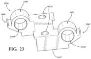
- One example of the base 1536is shown in FIG. 23 .
- the base 1536can have a first interfacing end 1548 and a second interfacing end 1549 .
- the base 1536can be configured to interface with the first portion 1532 and the second portion 1534 .
- the first interfacing end 1540 of the first portion 1532 and the first interfacing end 1542 of the second portion 1534can be configured to interface with the base 1536 .
- the first interfacing end 1540 of the first portion 1532can include one or more knuckles 1545
- the first interfacing end 1542 of the second portion 1534can include one or more knuckles 1546 .
- the knuckles 1545 , 1546can define an opening 1544 .
- the first interfacing end 1548 of the base 1536can include one or more knuckles 1550
- the second interfacing end 1549 of the base 1536can include one or more knuckles 1551 .
- the knuckles 1550 , 1551can define an opening 1559 .
- the opening(s) 1544 of the knuckle(s) 1545 of the first portion 1532 and the opening(s) 1559 of the knuckle(s) 1550 of the base 1536can be substantially aligned with each other.
- a pin 1552can be received in the aligned openings 1544 , 1559 .
- the first portion 1532 and the base 1536can be like the leaves of the hinge.
- the opening(s) 1544 of the knuckle(s) 1546 of the second portion 1534 and the opening(s) 1559 of the knuckle(s) 1551 of the base 1536can be substantially aligned with each other.
- a pin 1553can be received in the aligned openings 1544 , 1559 .
- the second portion 1534 and the base 1536can be like the leaves of the hinge.
- the second interfacing end 1541 of the first portion 1532can be configured to interface with the first endcap 1560 .
- the second interfacing end 1541 of the first portion 1532can include a lip 1515 , hook, protrusion, tooth/teeth, or other feature for mechanically engaging a portion of the first endcap 1560 .
- the first endcap 1560can be configured to retainably engage the second interfacing end 1541 of the first portion 1532 while allowing the first portion 1532 to pivot therein.
- the second interfacing end 1543 of the second portion 1534can be configured to interface with the second endcap 1570 .
- the second interfacing end 1543 of the second portion 1534can include a lip 1525 , hook, tooth/teeth, protrusion, or other feature for mechanical engagement with a portion of the second endcap 1570 .
- the second endcap 1570can be configured to retainably engage the second interfacing end 1543 of the second portion 1534 while allowing the second portion 1534 to pivot therein.
- biasing memberscan be associated with the second outer body member 1530 .
- a biasing member 1554can be associated with the first portion 1532 and the base 1536
- a biasing member 1555can be associated with the second portion 1534 and the base 1536 .
- the biasing members 1554 , 1555can be operatively positioned to bias the second outer body member 1530 into a non-activated configuration of the actuator 1500 . More particularly, the biasing member 1554 can exert a force on the first portion 1532 and the base 1536 to bias at least the first portion 1532 into the non-activated configuration. Further, the biasing member 1555 can exert a force on the second portion 1534 and the base 1536 to bias at least the second portion 1534 into the non-activated configuration.
- the biasing members 1554 , 1555can be any suitable element for imparting a biasing force on the second outer body member 1530 .
- the biasing members 1554 , 1555can be springs. More particularly, the biasing members 1554 , 1555 can be torsion springs.
- the biasing members 1528 , 1554 , 1555can be substantially identical to each other. In some arrangements, one or more of the biasing members 1528 , 1554 , 1555 can be different from the other biasing members in one or more respects, such as in terms of size, shape, configuration, and/or biasing force, just to name a few possibilities.
- the second outer body member 1530can be configured to engage or retain a portion of the biasing member 1554 , 1555 .
- the first portion 1532can include a retaining member 1556
- the second portion 1534can include a retaining member 1557 .
- the retaining members 1556 , 1557can have any suitable size, shape, and/or configuration.
- the retaining members 1556 , 1557can be substantially L-shaped (as shown in FIGS. 18 A- 18 C ), substantially U-shaped, substantially V-shaped, or substantially J-shaped, just to name a few possibilities.
- the retaining members 1556 , 1557can be formed as a unitary structure with the respective one of the first portion 1532 and the second portion 1534 .
- the retaining members 1556 , 1557can be formed separately from the first portion 1532 and the second portion 1534 and subsequently connected thereto.
- the base 1536can have any suitable size, shape, and/or configuration. In one or more arrangements, the base 1536 can be substantially rectangular.
- the base 1536can be made of any suitable material, such as metal or plastic.
- the base 1536can be made of the same material as the first outer body member 1510 and/or the second outer body member 1530 , or the base 1536 can be made of a different material.
- the base 1536can be configured to be supported on a surface.
- the base 1536can include an engaging surface 1547 .
- the engaging surface 1547can be configured to substantially matingly engage a surface on which the base 1536 is supported.
- the engaging surface 1547can be substantially planar.
- the engaging surface 1547can include one or more non-planar features, such as contours, protrusions, recesses, curves, etc.
- the base 1536can be configured for connection to another surface.
- the base 1536can include one or more apertures 1535 to accommodate a fastener for attachment to another surface or structure.
- the actuator 1500can include a first endcap 1560 and a second endcap 1570 .
- the first endcap 1560 and the second endcap 1570can be spaced apart, such as in a direction corresponding to the first dimension 1501 of the actuator 1500 .
- the first endcap 1560 and the second endcap 1570can face toward each other.
- the first endcap 1560 and the second endcap 1570can be substantially aligned with each other.
- the first endcap 1560 and the second endcap 1570can have any suitable size, shape, and/or configuration. In one or more arrangements, the first endcap 1560 and the second endcap 1570 can be substantially identical to each other. However, the first endcap 1560 and the second endcap 1570 can be oriented differently. The first endcap 1560 and the second endcap 1570 can be made of any suitable material, such as plastic or metal. In one or more arrangements, the first endcap 1560 and the second endcap 1570 can be different from each other in one or more respects.
- first endcap 1560 and the second endcap 1570can be configured to engage the first outer body member 1510 and the second outer body member 1530 . Further, the first endcap 1560 and the second endcap 1570 can be configured to engage the contracting member(s) 1580 .
- FIGS. 15 - 17 and 20 - 22One example of an endcap is shown in FIGS. 15 - 17 and 20 - 22 .
- the endcapwill be referred to as the first endcap 1560 , but it will be understood that the description is also equally applicable to the second endcap 1570 .
- the first endcap 1560can have any suitable construction.
- the first endcap 1560can include a first portion 1565 ( FIG. 20 ) and a second portion 1566 ( FIG. 21 ).
- the first portion 1565 and the second portion 1566can be operatively connected to collectively form the first endcap 1560 , such as by one or more fasteners (e.g., bolts 1505 ), one or more adhesives, one or more welds, one or more brazes, one or more forms of mechanical engagement, one or more other forms of connection, or any combination thereof.
- the first endcap 1560can be configured to engage the first outer body member 1510 and the second outer body member 1530 .
- the first endcap 1560can include one or more first engaging cavities 1561 and one or more second engaging cavities 1562 .
- the first engaging cavity 1561 and the second engaging cavity 1562can be angled relative to a central plane 1563 of the first endcap 1560 .
- the first engaging cavity 1561 and the second engaging cavity 1562can be at an angle of about 20 to about 25 degrees relative to the central plane 1563 .
- the first endcap 1560can be substantially symmetrical about the central plane 1563 .
- the first engaging cavity 1561 of the first endcap 1560can be configured for operative connection to the second outer body member 1530 . More particularly, the first engaging cavity 1561 of the first endcap 1560 can be configured for operative connection to the second interfacing end 1541 of the first portion 1532 . In the forked configuration example of the second outer body member 1530 , the first engaging cavity 1561 can be a single cavity or two separate cavities to accommodate the first and second portions 1541 ′, 1541 ′′ of the second interfacing end 1541 .
- first engaging cavity 1561 of the second endcap 1570can be configured for operative connection to the second outer body member 1530 . More particularly, the first engaging cavity 1561 of the second endcap 1570 can be configured for operative connection to the second interfacing end 1543 of the second portion 1534 . In the forked configuration example of the second outer body member 1530 , the first engaging cavity 1561 can be a single cavity or two separate cavities to accommodate the first and second portions 1543 ′, 1543 ′′ of the second interfacing end 1543 .
- the second outer body member 1530can be operatively connected to the first engaging cavity 1561 by mechanical engagement, one or more fasteners, one or more adhesives, and/or one or more brazes or weld, just to name a few possibilities.
- the second outer body member 1530can include a lip 1525 , hook, tooth/teeth, protrusion, or other feature(s) that can engage with the respective endcap within the first engaging cavity 1561 , such as by interlocking engagement.
- the second outer body member 1530can be retainably engaged by the first engaging cavity 1561 .
- the first engaging cavity 1561can provide end containment for the first portion 1532 or the second portion 1534 to pivot in when the actuator 1500 is activated or deactivated.
- the second engaging cavity 1562 of the first endcap 1560can be configured for operative connection to the first outer body member 1510 . More particularly, the second engaging cavity 1562 of the first endcap 1560 can be configured for operative connection to the second interfacing end 1517 of the first portion 1512 . Further, the second engaging cavity 1562 of the second endcap 1570 can be configured for operative connection to the second interfacing end 1519 of the second portion 1514 .
- the above discussion of the operative connection between the second outer body member 1530 and the first engaging cavity 1561applies equally to the connection between the first outer body member 1510 and the second engaging cavity 1562 .
- the first portion 1512 and/or the second portion 1514 of the first outer body member 1510can include a lip 1515 , hook, tooth/teeth, protrusion, or other features can engage with the respective endcap within the second engaging cavity 1562 , such as by interlocking engagement.
- the first outer body member 1510can be retainably engaged by the second engaging cavity 1562 .
- the second engaging cavity 1562can provide end containment for the first portion 1512 or the second portion 1514 to pivot in when the actuator 1500 is activated or deactivated.
- the first endcap 1560 , the first engaging cavity 1561 , the second engaging cavity 1562 , and the second interfacing ends 1517 , 1519 , 1541 , 1543can be configured to allow the second interfacing ends 1517 , 1519 , 1541 , 1543 to be inserted substantially horizontally into their respective engaging cavity. As a result, assembly of the actuator 1500 can be facilitated.
- the second interfacing ends 1517 , 1519 of the first outer body member 1510can be located lower than the second interfacing ends 1541 , 1543 of the second outer body member 1530 .
- the first endcap 1560 and the second endcap 1570can include one or more features for engaging the contracting member(s) 1580 .
- the first endcap 1560can include one or more features to enable the contracting member(s) 1580 to turn around and extend toward the second endcap 1570 .
- the first endcap 1560 and/or the second endcap 1570can include one or more post(s) 1576 .
- the contracting member(s) 1580can wrap around the post(s) 1576 .
- the first endcap 1560 and/or the second endcap 1570can include one or more guide(s) 1564 .
- the guide(s) 1564can be any structure that can direct, constrain, influence, or guide the position of the contracting member(s) 1580 .
- the contracting member(s) 1580can be routed in part by the guide(s) 1564 .
- the posts(s) 1576 , the guide(s) 1564 , and/or other features for engaging the contracting member(s) 1580can be any quantity of the posts(s) 1576 , the guide(s) 1564 , and/or other features for engaging the contracting member(s) 1580 .
- the one or more features for engaging the contracting member(s) 1580can be provided on one or more sides of the first endcap 1560 and the second endcap 1570 .
- the one or more feature for engaging the contracting member(s) 1580can be provided on opposite sides of the first endcap 1560 and the second endcap 1570 .
- first endcap 1560Some examples of the first endcap 1560 will now be described with respect to FIGS. 20 - 22 . It will be understood that this discussion applies equally to the second endcap 1570 . Further, it will be understood that the features and structures shown are merely an example, and arrangements described herein are not limited to the examples shown.
- the first endcap 1560can be a single piece. Alternatively, the first endcap 1560 can be made of a plurality of pieces. Referring to FIGS. 20 and 21 , the first endcap 1560 can be made of a first portion 1565 and a second portion 1566 .
- the first portion 1565can include a body 1569 .
- the body 1569can define one or more engaging cavities.
- the body 1569can define the first engaging cavity 1561 and the second engaging cavity 1562 .
- the first engaging cavity 1561 and the second engaging cavity 1562can extend across the entire width of the first portion 1565 . In such case, the first engaging cavity 1561 and the second engaging cavity 1562 can open to the lateral sides 1567 , 1568 of the first portion 1565 .
- first engaging cavity 1561 and the second engaging cavity 1562can extend partially across the width of the first portion 1565 .
- the first engaging cavity 1561 and the second engaging cavity 1562may open to only one of the lateral sides 1567 , 1568 or neither of the lateral sides 1567 , 1568 .
- the first engaging cavity 1561can be a single cavity or two separate cavities to accommodate the first and second portions 1541 ′, 1541 ′′ of the second interfacing end 1541 .
- the first portion 1565can include one or more guides 1564 on the lateral sides 1567 and/or 1568 . In some instances, two or more of the guides 1564 can cooperate to define a routing for the contracting member(s) 1580 .
- the first portion 1565can include one or more apertures 1578 to facilitate the assembly of the first endcap 1560 .
- the second portion 1566can include one or more features for engaging the contracting member(s) 1580 .
- the second portion 1566can include the posts 1576 and the guides 1564 .
- Apertures 1579can be defined in the posts 1576 .
- the apertures 1578 , 1579can be substantially aligned.
- a fastenere.g., bolt 1505
- a fastenercan be received in the aligned apertures 1578 , 1579 to operatively connect the first portion 1565 and the second portion 1566 .
- the second portion 1566When assembled, the second portion 1566 can cover at least a portion of the first engaging cavity 1561 and/or the second engaging cavity 1562 As a result, the second portion 1566 can prevent the second interfacing ends 1517 , 1519 , 1541 , 1543 from coming out of the lateral sides 1567 , 1568 of the first portion 1565 .
- the second portion 1566 in FIG. 21is merely one example.
- FIG. 22shows an alternative example of the second portion 1566 .
- the guides 1564can be different from those shown in FIG. 21 .
- first endcap 1560 and the second endcap 1570 shownare merely one example.
- the actuator 1500can include any of the endcaps shown in various endcaps shown in FIGS. 1 - 3 , 5 , and 1013 or any other suitable type of endcap.
- the contracting member(s) 1580can extend between the first endcap 1560 and the second endcap 1570 in any suitable manner.
- One non-limiting example of the routing of the contracting member(s) 1580will now be described in connection with FIG. 17 A .
- the contracting member 1580can be operatively connected to the first endcap 1560 , such as by a fastener 1710 and/or in any other suitable manner. In this location, the contracting member 1580 can operatively connected to another conductor or other element to a power source.
- the contracting member 1580can extend from the first endcap 1560 to the second endcap 1570 , passing through the wire guides 1600 along the way.
- the contracting member 1580can be routed by the guide structure 1564 a on the second endcap 1570 .
- the contracting member 1580can wrap around the post 1576 a and extend back toward the first endcap 1560 , guided by the guide structure 1564 b , the wire guides 1600 , and the guide structure 1564 c .
- the contracting member 1580can wrap around the post 1576 b and turn back toward the second endcap 1570 .
- the contracting member 1580can be routed by the guide structure 1564 d , the wire guides 1600 , and the guide structure 1564 b .
- the contracting member 1580can wrap around the post 1576 c and turn back toward the first endcap 1560 .
- the contracting member 1580can be routed by the guide structure 1564 e and the wire guides 1600 .
- the contracting member 1580can end here, or it can be operatively connected to another structure (e.g., the first endcap 1560 ) or to a power source. In such instances, there can be another contracting member 1580 extending between the first endcap 1560 and the second endcap 1570 on the other side of the actuator 1500 .
- the routing of the contracting member 1580 on one side of the actuator 1500can be substantially the same as the routing on the other side of the actuator 1500 .
- the routing of the contracting member 1580 on one side of the actuator 1500can be different from the routing on the other side of the actuator 1500 in one or more respects.
- the contracting member 1580can extend around a back side 1650 of the first endcap 1560 and then continue to be routed on the opposite side of the actuator 1500 between the first endcap 1560 and the second endcap 1570 .
- a single contracting member 1580can be used on both sides of the actuator 1500 .
- the routing of the contracting member 1580 on one side of the actuator 1500can be substantially the same as the routing on the other side of the actuator 1500 .
- the routing of the contracting member 1580 one side of the actuator 1500can be different from the routing on the other side of the actuator 1500 in one or more respects.
- the routing shown in FIG. 17 Ais merely one example.
- the example routing of the contracting member(s) 1580 shown in FIG. 17 Ashows the contracting member(s) 1580 routed on the outboard sides of the actuator 1500 .
- the contracting member(s) 1580can be routed within the overall envelope of the actuator 1500 .
- the contracting member(s) 1580can be routed in the space between the first outer body member 1510 and the second outer body member 1530 .
- the first endcap 1560 and the second endcap 1570 of the actuator 1500can be any suitable endcap, including of those shown and described in connection with FIGS. 1 - 3 , 5 , and 10 13 .
- FIGS. 17 A and 17 Bshow the contracting member 1580 extending substantially straight across from one endcap to the other endcap.
- the contracting member(s) 1580can extend substantially parallel to the direction corresponding to the first dimension 1501 .
- the contracting member(s) 1580can extend non-parallel to the direction corresponding to the first dimension 1501 .
- the contracting member(s) 1580can extend from the upper or lower side of one of the endcaps to the opposite one of the upper or lower side of the other endcap.
- the contracting member(s) 1580can extend substantially diagonally.
- the contracting member(s) 1580can be wrapped around one or more of the post(s) 1576 a plurality of times. Such wrapping of the contracting member(s) 1580 can increase the actuation force imparted by the contracting member(s) 1580 when activated.
- the contracting member(s) 1580can be bare, that is, they are not coated or covered with an insulating material. In some arrangements, at least a portion of the contracting member(s) 1580 can be coated or covered with an insulating material. For instance, the portions of the contracting member(s) 1580 that interact with the post(s) 1576 and/or the guide(s) 1564 can be coated or covered with an insulating material. In some arrangements, the insulating material can be a sleeve or a wrap.
- the above-described actuatorscan use one or more wire guides 1600 to facilitate routing of the contracting member(s) 1580 .
- the wire guide(s) 1600can include one or more panels 1610 .
- a plurality of apertures 1620can be defined in the panel(s) 1610 .
- the apertures 1620can be sized, shaped, and/or configured to allow passage of the contracting member(s) 1580 (e.g., the shape memory material member(s) 1581 ) as they are routed between the endcaps 1560 , 1570 .
- the wire guide 1600can be made of any suitable material, such as one that does not interact with or otherwise affect the performance of the contracting member(s) 1580 .
- FIG. 17 Ashows an example of the actuator 1500 in a non-activated configuration.
- the contracting member(s) 1580are not activated.
- FIG. 17 Bshows an example of the actuator 100 in an activated configuration.
- an activation inpute.g., energy, electrical energy, heat, etc.
- the contracting member(s) 1580can contract. This contraction causes the contracting member(s) 1580 to pull the first endcap 1560 and the second endcap 1570 toward each other in a direction 1503 that corresponds to the first dimension 1501 .
- the first outer body member 1510 and the second outer body member 1530can extend outward and away from each other in a direction 1504 that corresponds to the second dimension 1502 .
- the first dimension 1501i.e., the width
- the second dimension 1502i.e., the height
- the actuator 1500can deliver a force in a direction that is out of plane or otherwise different from the direction of contraction of the contracting member(s) 1580 .
- the push structure 1571can be located at a higher elevation. Also, when the actuator 1500 goes from a non-activated configuration to the activated configuration, the angle between the first portion 1512 and the second portion 1514 of the first outer body member 1510 can decrease. Similarly, when the actuator 1500 goes from a non-activated configuration to the activated configuration, the angle between the first portion 1532 and the second portion 1534 of the second outer body member 1530 can decrease. It will be appreciated that the first endcap 1560 and the second endcap 1570 can be configured to accommodate the movement of the first outer body member 1510 and the second outer body member 1530 while maintaining the operative connection to them.
- the push structure 1571can deliver an actuation force symmetrically, that is, substantially in line with a force direction of the actuator 1500 (e.g., in direction of the second dimension 1502 ).
- the actuator 1500can be configured to deliver an actuation force that is asymmetric, that is, not in line with the force direction of the actuator 1500 . Delivery of an asymmetric actuation force can be achieved in various ways.
- the first portion 1512 and the second portion 1514 of the first outer body member 1510can have different lengths. Thus, one of the portions is longer than the other. As a result, the push structure 1571 may no longer be substantially centrally located.
- first portion 1532 and the second portion 1534 of the second outer body member 1530can have different lengths.
- the push structure 1571can be configured such that the engaging surface 1573 or other portion of the push structure 1571 is angled relative to the first dimension 1501 .
- the push structure 1571can be operatively connected to the first outer body member 110 such that the push structure 1571 extends from the first outer body member 1510 at an acute angle.
- the biasing force of the biasing members 1554 , 1555can be different from each other.
- the delivery of an asymmetric actuation forcecan be achieved by any combination of the above and other arrangements.
- FIG. 30is an alternative arrangement of the actuator 1500 .
- the actuator 1500can have a central biasing member 3000 .
- the central biasing member 3000can be a spring and, more particularly, a compression spring.
- the central biasing member 3000can be any suitable biasing member, now known or later developed.
- the central biasing member 3000can be operatively connected to one or more portions of the actuator 1500 .
- the central biasing member 3000can be operatively connected to the first outer body member 1510 and the second outer body member 1530 . More particularly, the central biasing member 3000 can be operatively connected a portion of the first outer body member 1510 where the first portion 1512 and the second portion 1514 come together. Further, the central biasing member 3000 can be operatively connected to the base 1536 of the second outer body member 1530 .
- central biasing member 3000there can be any suitable form of operative connection between the central biasing member 3000 and the one or more portions of the actuator 1500 , including, for example, one or more welds, one or more brazes, one or more adhesives, one or more forms of mechanical engagement, one or more fasteners, or any combination thereof.
- the central biasing member 3000can provide improved comfort.
- the central biasing member 3000can extend the force curve drop-off over a longer stroke.
- the central biasing membercan be configured to bias the actuator 1500 to the non-activated configuration. It will be appreciated that the central biasing member 3000 can be used in connection with any of the actuators described herein.
- the actuator 1500can provide numerous advantages. For instance, the actuator 1500 can provide a more compact design with respect to the other actuators 100 , 100 ′.
- the actuator 1500can provide a lower height profile compared to the other actuators 100 , 100 ′.
- the slimmer profile of the actuator 1500can facilitate integration of the actuator 1500 into the vehicle seat.
- the actuator 1500can minimize or avoid enlargement of the vehicle seat, which, in turn, can minimize or avoid encroachment of the space behind the vehicle seat (e.g., second row leg room).
- the length on the vehicledoes not have to be increased to accommodate the actuator 1500 and, as a result, the weight of the vehicle does not have to increase significantly.
- the actuator 2400can have any suitable configuration.
- the actuator 2400can include a first outer body member 2410 , a second outer body member 2420 , and one or more contracting members 2480 . These and other components will be described in turn below.
- the first outer body member 2410 and the second outer body member 2420can have any suitable size, shape, and/or configuration. In some arrangements, the first outer body member 2410 and the second outer body member 2420 can be substantially identical to each other, but they can be in different orientations. In other arrangements, the first outer body member 2410 and the second outer body member 2420 can be different from each other in one or more respects. In some arrangements, the first outer body member 2410 and the second outer body member 2420 can be similar to the examples of the first portion 112 and the second portion 114 is shown in FIG. 6 . While the first outer body member 2410 and the second outer body member 2420 are shown as being generally rectangular in shape, it will be appreciated that arrangements herein are not limited to any particular shape. The first outer body member 2410 and the second outer body member 2420 can be made of any suitable material, such as plastic or metal.
- the first outer body member 2410 and the second outer body member 2420can be operatively connected to each other such that the first outer body member 2410 and the second outer body member 2420 can move relative to each other.
- the first outer body member 2410 and the second outer body member 2420can be pivotably connected to each other.
- the first outer body member 2410 and the second outer body member 2420can be pivotably connected to each other by one or more hinges.
- the first outer body member 2410 and the second outer body member 2420can be pivotably connected to each other by one or more barrel hinges 2430 .
- the one or more hingescan be a separate structure operatively connected to the first outer body member 2410 and the second outer body member 2420 .
- the one or more hingescan be at least partially defined by the first outer body member 2410 and/or the second outer body member 2420 .
- the first outer body member 2410can include a first interfacing end portion 2416 and a second interfacing end portion 2418 .
- the second outer body member 2420can include a first interfacing end portion 2426 and a second interfacing end portion 2428 .
- the first interfacing end portion 2416 of the first outer body member 2410 and the first interfacing end portion 2426 of the second outer body member 2420can be configured to interface with each other.
- the first interfacing end portion 2416 of the first outer body member 2410can include a knuckle 2417
- the first interfacing end portion 2426 of the second outer body member 2420can include a knuckle 2427 .
- the knuckle 2417can define an opening 2415
- the knuckle 2427can define an opening (not visible in FIG. 24 ).
- the opening of the knuckle 2417 and the opening of the knuckle 2427can be substantially aligned with each other to form in part the hinge.
- a pin 2432can pass through the aligned openings.
- the first outer body member 2410 and the second outer body member 2420can define the leaves of the hinge.
- the first outer body member 2410 and the second outer body member 2420can be angled relative to each other.
- the actuator 2400can generally form an inverted V-shape or an A-shape.
- the actuator 2400can include a track 2450 .
- the track 2450can be made of any suitable material, such as plastic or metal.
- the track 2450can have any suitable size, shape, and/or configuration.
- the track 2450can include an upper side 2451 , a lower side 2452 , a first lateral side 2453 , and a second lateral side 2454 .
- the terms “upper,” “lower,” and “lateral”are used for convenience to facilitate the discussion with respect to the orientation of the actuator 2400 shown in FIGS. 24 and 25 . Accordingly, it will be understood that these terms are not intended to be limiting.
- the first outer body member 2410 and the second outer body member 2420can be configured to interface with the track 2450 .
- the first outer body member 2410 and the second outer body member 2420can be configured to be slidable within the track 2450 .
- the track 2450can have any suitable configuration.
- the track 2450can include a channel 2455 into which a portion of the first outer body member 2410 and a portion of the second outer body member 2420 can be received. More particularly, the second interfacing end portion 2418 of the first outer body member 2410 and the second interfacing end portion 2428 of the second outer body member 2420 can be received in the channel 2455 .
- the channel 2455can be open to the upper side 2451 of the track 2450 .
- the channel 2455can define an opening 2460 in the track 2450 .
- the first outer body member 2410 and the second outer body member 2420can extend through the opening 2460 .
- the channel 2455can include a first lateral end 2456 and a second lateral end 2457 .
- the first lateral end 2456 and the second lateral end 2457 of the channel 2455can be closed to prevent the portions of the first outer body member 2410 and the second outer body member 2420 from leaving coming out of the channel 2455 at an open end.
- the first lateral end 2456 and/or the second lateral end 2457 of the channel 2455can include a closure element or blocking structure to physically block the lateral outward movement of the first outer body member 2410 and the second outer body member 2420 .
- the first lateral end 2456 and/or the second lateral end 2457 of the channel 2455can be closed as a result of the construction of the track 2450 .
- the track 2450can be made of a machined block of material in which at least one of the first lateral end 2456 and the second lateral end 2457 is closed.
- the track 2450 , the channel 2455 , the second interfacing end portion 2418 of the first outer body member 2410 , and/or the second interfacing end portion 2428 of the second outer body member 2420can be configured so that the second interfacing end portions 2418 , 2428 are retainable received within the channel 2455 .
- the second interfacing end portions 2418 , 2428can include a lip, protrusion, an enlarged portion, or other feature for mechanically engaging a portion of the channel 2455 .
- the second interfacing end portions 2418 , 2428 and the channel 2455can be configured for interlocking engagement.
- the first outer body member 2410 and the second outer body member 2420cannot separate from the channel 2455 through the opening 2460 in the upper side 2451 of the track 2450 .
- the track 2450 , the channel 2455 , the first outer body member 2410 , and/or the second outer body member 2420can be configured to facilitate movement of the first outer body member 2410 and the second outer body member 2420 within the channel 2455 .
- the channel 2455 , the first outer body member 2410 , and/or the second outer body member 2420can include one or more friction reducing coatings, lubricants, materials, substances, and/or treatments.
- the channel 2455 , the first outer body member 2410 , and/or the second outer body member 2420can include one or more rollers, bearings, or low shear materials.
- the track 2450 , the channel 2455 , the first outer body member 2410 , and/or the second outer body member 2420can be configured to define the range of movement of the first outer body member 2410 and the second outer body member 2420 within the channel 2455 .
- the track 2450can include a first slot 2461 and a second slot 2462 .
- the first slot 2461 and the second slot 2462can be substantially identical to each other.
- the first slot 2461 and the second slot 2462can be different from each other in one or more respects, including size, shape, length, width, and/or configuration.
- the first outer body member 2410can include a protrusion 2411
- the second outer body member 2420can include a protrusion 2421 .
- the protrusion 2411can be received within the first slot 2461
- the protrusion 2421can be received within the second slot 2462 .
- the range of movement of the first outer body member 2410 , and/or the second outer body member 2420can be defined by the range of movement of the protrusions 2411 , 2421 within the slots 2461 , 2462 .
- the range of movement of the first outer body member 2410 and/or the second outer body member 2420can be defined by the channel 2455 .
- the slots 2461 , 2462 and protrusions 2411 , 2421can be provided on only one side of track 2450 and the outer body members 2410 , 2420 .
- the slots 2461 , 2462 and protrusions 2411 , 2421can be provided on opposite sides of track 2450 and the outer body members 2410 , 2420 .
- the actuator 2400can include one or more biasing members 2470 .
- the biasing member(s) 2470can be associated with the first outer body member 2410 and/or the second outer body member 2420 .
- the biasing member(s) 2470can be operatively positioned to bias the first outer body member 2410 and/or the second outer body member 2420 into a non-activated configuration of the actuator 2400 . More particularly, the biasing member(s) 2470 can exert a force on the first outer body member 2410 and the second outer body member 2420 to bias them into the non-activated configuration.
- the biasing member(s) 2470can be any suitable element for imparting a biasing force on the first outer body member 2410 and/or the second outer body member 2420 .
- the biasing member(s) 2470can be a spring. More particularly, the biasing member(s) 2470 can be a torsion spring.
- first outer body member 2410 and the second outer body member 2420can be configured to engage or retain a portion of the biasing member 2470 .
- first outer body member 2410can include a retaining member 2419
- second outer body member 2420can include a retaining member 2429 .
- the retaining members 2419 , 2429can have any suitable size, shape, and/or configuration.
- the retaining members 2419 , 2429can be substantially L-shaped (as shown in FIGS. 24 - 25 ), substantially U-shaped, substantially V-shaped, or substantially J-shaped, just to name a few possibilities.
- the retaining members 2419 , 2429can be formed as a unitary structure with the respective one of the first outer body member 2410 and the second outer body member 2420 . In some arrangements, the retaining members 2419 , 2429 can be formed separately from the first outer body member 2410 and the second outer body member 2420 and subsequently connected thereto. The retaining members 2419 , 2429 can be substantially identical to each other, or they can be different from each other in one or more respects.
- the actuator 2400can include a push structure 2471 .
- One example of the push structure 2471is shown in FIGS. 24 - 25 .
- the push structure 2471can be configured to engage other structures or objects.
- the push structure 2471can focus the force of the actuator 2400 on an intended target object.
- the push structure 2471can have any suitable size, shape, and/or configuration.
- the push structure 2471can be substantially T-shaped.
- the push structure 2471can include a platform 2472 and a stem 2474 .
- the platform 2472can have an engaging surface 2473 .
- the engaging surface 2473can be configured to provide a desired actuation effect on an intended target.
- the engaging surface 2473can be substantially planar.
- the engaging surface 2473can include one or more contours, protrusions, steps, elements, or other raised or non-planar features.
- the engaging surface 2473can be configured to create a focal point for the actuation force of the actuator 2400 .
- the engaging surface 2473can be substantially rectangular in conformation, as is shown. In other arrangements, the engaging surface 2473 can be substantially circular, substantially square, substantially triangular, substantially polygonal, substantially hexagonal, substantially octagonal, or substantially trapezoidal, just to name a few possibilities.
- the engaging surface 2473can be substantially parallel to the contracting member(s) 2480 and/or to a first dimension 2401 of the actuator 2400 . In some arrangements, the engaging surface 2473 can be angled relative to the contracting member(s) 2480 and/or to the first dimension 2401 of the actuator 2400 . The engaging surface 2473 can have any suitable orientation to achieve a desired actuation force effect.
- the push structure 2471can be operatively connected to the first outer body member 2410 and/or the second outer body member 2420 .
- a portion of the stem 2474can be configured to include one or more openings (see e.g., openings 175 in FIG. 8 ) that can substantially align with the openings in the knuckles 2417 , 2427 of the first outer body member 2410 and the second outer body member 2420 to form in part the hinge.
- the pin 2432can pass through the aligned openings. While the first outer body member 2410 and the second outer body member 2420 can pivot relative to each other, the push structure 2471 can substantially maintain its orientation. In some arrangements, the push structure 2471 can be substantially centrally located with respect to the first outer body member 2410 and the second outer body member 2420 .
- the actuator 2400can have one or more contracting members 2480 .
- the contracting member(s) 2480can be any member or material that, when an activation input is provided to the contracting member, the contracting member can contract.
- the actuator 2400can include one or more shape memory material members 2481 .
- the shape memory material member(s) 2481can be operatively connected to the first outer body member 2410 and the second outer body member 2420 . More particularly, the shape memory material member(s) 2481 can be operatively connected to the second interfacing end portion 2418 of the first outer body member 2410 and the second interfacing end portion 2428 of the second outer body member 2420 . Any suitable manner of operative connection can be provided, such as one or more fasteners, one or more adhesives, one or more welds, one or more brazes, one or more forms of mechanical engagement, or any combination thereof.
- the shape memory material member(s) 2481can extend within the channel 2455 . In some arrangements, the shape memory material member(s) 2481 can extend within the opening 2460 . In some arrangements, the shape memory material member(s) 2481 can extend outside of the track 2450 . In some arrangements, the shape memory material member(s) 2481 can extend substantially parallel to the channel 2455 .
- the shape memory material member 2481can, for example, extend straight between the first outer body member 2410 and the second outer body member 2420 .
- the shape memory material member 2481can extend in a serpentine or zigzag pattern between the first outer body member 2410 and the second outer body member 2420 .
- the first outer body member 2410 and the second outer body member 2420can be configured to allow the shape memory material member 2481 to turn around and extend in the opposite direction, such as by providing one or more posts, channels, eyelets, or other features that can enable such turning around.
- the shape memory material member(s) 2481can be configured to overcome the biasing forces exerted by the biasing member(s) 2470 .
- the plurality of shape memory material members 2481can be distributed, arranged, and/or oriented in any suitable manner.
- the shape memory material members 2481can extend substantially parallel to each other.
- one or more of the shape memory material members 2481can extend non-parallel to the other shape memory material members 2481 .
- some of the plurality of shape memory material members 2481may cross over each other.
- the shape memory material member(s) 2481can be configured to overcome the biasing forces exerted by the biasing members 2470 .
- shape memory material member(s) 2481can be located substantially entirely within the overall envelope of the actuator 2400 . “Substantial majority” means about 60% or greater, about 65% or greater, about 70% or greater, about 75% or greater, about 80% or greater, about 85% or greater, about 90% or greater, or about 95% or greater. In some arrangements, a portion of the shape memory material member(s) 2481 can extend outside of the overall envelope of the actuator 2400 for operative connection to conductor and/or power source.
- the actuator 2400can include a first dimension 2401 and the second dimension 2402 .
- the first dimension 2401can describe a width of the actuator 2400
- the second dimension 2402can describe a height of the actuator 2400 .
- the first dimension 2401 and the second dimension 2402can be substantially perpendicular to each other.
- FIG. 24shows an example of the actuator 2400 in a non-activated configuration.
- the contracting member 2480is not activated.
- FIG. 25shows an example of the actuator 2400 in an activated configuration.
- an activation inpute.g., electrical energy, heat, energy, etc.
- the contracting member(s) 2480can contract.
- This contractioncauses the contracting member(s) 2480 to pull the first outer body member 2410 and the second outer body member 2420 toward each other in a first direction 2403 that corresponds to the first dimension 2401 .
- the second interfacing end portion 2418 of the first outer body member 2410 and the second interfacing end portion 2428 of the second outer body member 2420can be pulled toward each other in the direction 2403 that corresponds to the first dimension 2401 .
- first outer body member 2410 and the second outer body member 2420can extend outward in a second direction 2404 that corresponds to the second dimension 2402 . More particularly, the first interfacing end portion 2416 of the first outer body member 2410 and the first interfacing end portion 2426 of the second outer body member 2420 can extend outward and away from the track 2450 in the direction 2404 that corresponds to the second dimension 2402 .
- the first dimension 2401i.e., the width
- the second dimension 2402i.e., the height
- the actuator 2400can deliver a force in a direction that is out of plane or otherwise different from the direction of contraction of the contracting member(s) 2480 .
- the location of the push structure 2471can be change. In the orientation of FIGS. 24 and 25 , the push structure 2471 can be located at a higher elevation when the actuator 2400 is activated. Also, when the actuator 2400 goes from a non-activated configuration to the activated configuration, the angle between the first outer body member 2410 and the second outer body member 2420 can decrease. It will be appreciated that the track 2450 can be configured to accommodate the movement of the first outer body member 2410 and the second outer body member 2420 while maintaining the operative connection to them.
- the push structure 2471can deliver an actuation force symmetrically, that is, substantially in line with a force direction of the actuator 2400 (e.g., in direction of the second dimension 2402 ).
- the actuator 2400can be configured to deliver an actuation force that is asymmetric, that is, not in line with the force direction of the actuator 2400 . Delivery of an asymmetric actuation force can be achieved in various ways.
- the first outer body member 2410 and the second outer body member 2420can have different lengths. As a result, the push structure 2471 may no longer be substantially centrally located.
- the push structure 2471can be configured such that the engaging surface 2473 or other portion of the push structure 2471 is angled relative to the first dimension 2401 .
- the push structure 2471can be operatively connected so as to extend from the first outer body member 2410 or the second outer body member 2420 at an acute angle.
- delivery of an asymmetric actuation forcecan be achieved by any combination of the above and other arrangements.
- FIGS. 26 - 27show an arrangement in which there are a plurality of the actuators 2400 .
- the above discussion of the actuator 2400 in connection with FIGS. 24 - 25applies equally to each individual actuator 2400 of the arrangement shown in FIGS. 26 - 27 .
- the plurality of actuators 2400can be activated and/or deactivated individually.
- each of the plurality of actuators 2400can include one or more contracting members 2480 .
- an activation inputis provided to the contracting member(s) 2480 for an individual one of the plurality of actuators 2400 , only that particular actuator will be activated.
- the plurality of actuators 2400can be activated and/or deactivated collectively.
- One example of such collective activationwill now be described.
- the plurality of actuators 2400can include three actuators: a first actuator 2400 ′, a second actuator 2400 ′′, and a third actuator 2400 ′′′. While FIG. 26 shows an example in which there are three actuators, it will be appreciated that there can be any number of actuators.
- the plurality of actuators 2400can be substantially identical to each other. Alternatively, one or more of the plurality of actuators 2400 can be different from the other actuators in one or more respects, including, for example, size, shape, configuration, activation force, activation time, height, width, structure, or in any other manner.
- the single contracting member 2480can be routed in any suitable manner between the plurality of actuators 2400 .
- the single contracting member 2480can be operatively connected to the first outer body member 2410 and the second outer body member 2420 of each of the plurality of actuators 2400 .
- the single contracting member 2480can extend through apertures in one or more of the first outer body member 2410 and the second outer body member 2420 of the plurality of actuators 2400 .
- FIGS. 26 and 27show each individual actuator 2400 as having its own first slot 2461 and second slot 2462 , it will be appreciated that arrangements are not limited in this regard. Indeed, in some arrangements, two or more of the actuators 2400 or portions thereof can share a slot. In other arrangements, there can be a single slot for all of the actuators 2400 . In further arrangements, the track 2450 may not include slots, and the first and second interfacing end portions 2418 , 2428 of the actuators 2400 ′ 2400 ′′, 2400 ′′′ can all be located within the channel 2455 .
- FIG. 26shows an example of the plurality of actuators 2400 in a non-activated configuration.
- the contracting member 2480is not activated.
- FIG. 27shows an example of the actuator 2400 in an activated configuration.
- an activation inpute.g., electrical energy, heat, energy, etc.
- the contracting member(s) 2480can contract.
- This contractioncauses the contracting member(s) 2480 to pull the first outer body member 2410 and the second outer body member 2420 of each individual actuator 2400 toward each other in a direction that corresponds to the first dimension 2401 .
- the second interfacing end portion 2418 of the first outer body member 2410 and the second interfacing end portion 2428 of the second outer body member 2420 of each actuator 2400can be pulled toward each other in a direction that corresponds to the first dimension 2401 .
- first outer body member 2410 and the second outer body member 2420 of each actuator 2400can extend outward in a direction that corresponds to the second dimension 2402 .
- first interfacing end portion 2416 of the first outer body member 2410 and the first interfacing end portion 2426 of the second outer body member 2420 of each actuator 2400can extend outward and away from the track 2450 in a direction that corresponds to the second dimension 2402 .
- the first dimension 2401i.e., the width
- the second dimension 2402i.e., the height
- the plurality of actuators 2400can deliver a force in a direction that is out of plane or otherwise different from the direction of contraction of the contracting member(s) 2480 .
- the location of the push structures 2471can be change. In the orientation of FIGS. 26 and 27 , the push structures 2471 can be located at a higher elevation when the actuator 2400 is activated. Also, when the plurality of actuators 2400 go from a non-activated configuration to the activated configuration, the angle between the first outer body member 2410 and the second outer body member 2420 can decrease. It will be appreciated that the track 2450 can be configured to accommodate the movement of the first outer body member 2410 and the second outer body member 2420 of each actuator 2400 while maintaining the operative connection to them.
- the plurality of actuators 2400can be selectively activated individually and/or collectively.
- the actuator 2800can have any suitable configuration.
- the actuator 2800can include a first outer body member 2810 , a second outer body member 2820 , a cross body member 2890 , and one or more contracting members 2880 .
- the first outer body member 2810 and the second outer body member 2820can be angled relative to the cross body member 2890 .
- the actuator 2800can generally form a trapezoidal shape.
- the actuator 2800can include a first dimension 2801 and the second dimension 2802 .
- the first dimension 2801can describe a width of the actuator 2800
- the second dimension 2802can describe a height of the actuator 2800 .
- the first dimension 2801 and the second dimension 2802can be substantially perpendicular to each other.
- the first outer body member 2810 and the second outer body member 2820can have any suitable size, shape, and/or configuration. In some arrangements, the first outer body member 2810 and the second outer body member 2820 can be substantially identical to each other, but they can be in different orientations. In other arrangements, the first outer body member 2810 and the second outer body member 2820 can be different from each other in one or more respects. In some arrangements, the first outer body member 2810 and the second outer body member 2820 can be similar to the examples of the first portion 112 and the second portion 114 as shown in FIG. 6 or they can be similar to the examples of the first portion 132 and the second portion 134 as shown in connection with FIG. 9 .
- first outer body member 2810 and the second outer body member 2820are shown as being generally rectangular in shape, it will be appreciated that arrangements herein are not limited to any particular shape.
- the first outer body member 2810 and the second outer body member 2820can be made of any suitable material, such as plastic or metal.
- the first outer body member 2810 and the second outer body member 2820can be operatively connected to a cross body member 2890 .
- the first outer body member 2810 and the second outer body member 2820can be movably connected to the cross body member 2890 .
- the first outer body member 2810 and the second outer body member 2820can be pivotably connected to the cross body member 2890 .
- each of the first outer body member 2810 and the second outer body member 2820be pivotably connected to the cross body member 2890 .
- the first outer body member 2810can be pivotably connected to the cross body member 2890 by one or more hinges
- the second outer body member 2820can be pivotably connected to the cross body member 2890 by one or more hinges.
- first outer body member 2810can be pivotably connected to the cross body member 2890 by one or more barrel hinges 2838
- the second outer body member 2820can be pivotably connected to the cross body member 2890 by one or more barrel hinges 2839 .
- the first outer body member 2810 and the second outer body member 2820can be located on opposite sides of the cross body member 2890 .
- the one or more hingescan be separate structures operatively connected to the first outer body member 2810 and the cross body member 2890 and to the second outer body member 2820 and the cross body member 2890 .
- the one or more hingescan be formed at least in part by the first outer body member 2810 , the second outer body member 2820 , and/or the cross body member 2890 .
- the first outer body member 2810can include a first interfacing end portion 2816 and a second interfacing end portion 2818 .
- the first interfacing end portion 2816 of the first outer body member 2810can include one or more knuckles 2814 defining an opening 2815 .
- the second outer body member 2820can include a first interfacing end portion 2826 and a second interfacing end portion 2828 .
- the first interfacing end portion 2826 of the second outer body member 2820can include one or more knuckles 2824 defining an opening (not visible in FIG. 28 ).
- the cross body member 2890can have any suitable size, shape, and/or configuration.
- the cross body member 2890can include a main body portion 2898 .
- the main body portion 2898can be substantially rectangular.
- the main body portion 2898can define a surface 2899 .
- the surface 2899can extend substantially parallel to the first dimension 2801 of the actuator 2800 .
- the cross body member 2890can be made of any suitable material, such as metal or plastic.
- the cross body member 2890can be made of the same material as the first outer body member 2810 and/or the second outer body member 2820 , or the cross body member 2890 can be made of a different material.
- the cross body member 2890can have a first interfacing end portion 2891 and a second interfacing end portion 2892 .
- the first interfacing end portion 2891 of the cross body member 2890can include one or more knuckles 2894 defining an opening (not visible in FIG. 28 ), and the second interfacing end portion 2892 of the cross body member 2890 can include one or more knuckles 2896 defining an opening 2897 .
- the cross body member 2890can be configured to interface with the first outer body member 2810 and the second outer body member 2820 . More particularly, the first interfacing end portion 2816 of the first outer body member 2810 and the first interfacing end portion 2826 of the second outer body member 2820 can be configured to interface with the cross body member 2890 .
- the opening(s) 2815 of the knuckle(s) 2814 of the first interfacing end portion 2816 and the opening(s) of the knuckle(s) 2894 of the first interfacing end portion 2891 of the cross body member 2890can be substantially aligned with each other.
- a pin 2900can be received in the aligned opening(s) 2815 of the knuckle(s) 2814 and opening(s) of the knuckle(s) 2894 .
- the opening(s) of the knuckle(s) 2824 of the second outer body member 2820 and the opening(s) 2897 of the knuckle(s) 2896 of the second interfacing end portion 2892 of the cross body member 2890can be substantially aligned with each other.
- a pin 2902can be received in the aligned opening(s) of the knuckle(s) 2824 and the opening(s) 2897 of the knuckle(s) 2896 .
- biasing members 2910can be associated with the first outer body member 2810 and the cross body member 2890 .
- One or more biasing members 2915can be associated with the second outer body member 2820 and the cross body member 2890 .
- the biasing members 2910 , 2915can be operatively positioned to bias the first outer body member 2810 and the second outer body member 2820 into a non-activated configuration of the actuator 2800 . More particularly, the biasing member(s) 2910 can exert a force on the first outer body member 2810 and the cross body member 2890 to bias at least the first outer body member 2810 into the non-activated configuration. Further, the biasing member(s) 2915 can exert a force on the second outer body member 2820 and the cross body member 2890 to bias at least the second outer body member 2820 into the non-activated configuration.
- the biasing members 2910 , 2915can be any suitable element for imparting a biasing force on the first outer body member 2810 and the second outer body member 2820 .
- the biasing members 2910 , 2915can be springs. More particularly, the biasing members 2910 , 2915 can be torsion springs.
- the biasing members 2910 , 2915can be substantially identical to each other. In some arrangements, one or more of the biasing members 2910 , 2915 can be different from the other biasing members in one or more respects, such as in terms of size, shape, configuration, and/or biasing force, just to name a few possibilities.
- first outer body member 2810 and the second outer body member 2820can be configured to engage or retain a portion of the biasing member(s) 2910 , 2915 , respectively.
- first outer body member 2810can include a retaining member 2812
- second outer body member 2820can include a retaining member 2822 .
- the retaining members 2812 , 2822can have any suitable size, shape, and/or configuration.
- the retaining members 2812 , 2822can be substantially L-shaped, as shown in FIGS. 28 - 29 , substantially U-shaped, substantially V-shaped, or substantially J-shaped, just to name a few possibilities.
- the retaining members 2812 , 2822can be formed as a unitary structure with the respective one of the first outer body member 2810 and/or the second outer body member 2820 . In some arrangements, the retaining members 2812 , 2822 can be formed separately from first outer body member 2810 and/or the second outer body member 2820 and subsequently connected thereto.
- the actuator 2800can include a push structure 2920 .
- One example of the push structure 2920is shown in FIGS. 28 - 29 .
- the push structure 2920can be configured to engage other structures or objects.
- the push structure 2920can focus the force of the actuator 2800 on an intended target object.
- the push structure 2920can have any suitable size, shape, and/or configuration.
- the push structure 2920can be substantially T-shaped.
- the push structure 2920can include a platform 2922 and a stem 2924 .
- the platform 2922can have an engaging surface 2923 .
- the engaging surface 2923can be configured to provide a desired actuation effect on an intended target.
- the engaging surface 2923can be substantially planar.
- the engaging surface 2923can include one or more contours, protrusions, steps, elements, or other raised or non-planar features.
- the engaging surface 2923can be configured to create a focal point for the actuation force of the actuator 2800 .
- the engaging surface 2923can be substantially rectangular in conformation, as is shown. In other arrangements, the engaging surface 2923 can be substantially circular, substantially square, substantially triangular, substantially polygonal, substantially hexagonal, substantially octagonal, or substantially trapezoidal, just to name a few possibilities.
- the engaging surface 2923can be substantially parallel to the contracting member(s) 2880 , the surface 2899 , and/or to a first dimension 2801 of the actuator 2800 . In some arrangements, the engaging surface 2923 can be angled relative to the contracting member(s) 2880 , the surface 2899 , and/or to a first dimension 2801 of the actuator 2800 . The engaging surface 2923 can have any suitable orientation to achieve a desired actuation force effect.
- the push structure 2920can be operatively connected to the cross body member 2890 .
- the stem 2924can be configured to be operatively connected to the surface 2899 of the cross body member 2890 .
- Any suitable form(s) of operative connectioncan be provided, such one or more fasteners, one or more welds, one or more brazes, one or more forms of mechanical engagement, one or more adhesives, one or more other forms of operative connection, or any combination thereof.
- the push structure 2920can be substantially centrally located with respect to the cross body member 2890 .
- the actuator 2800may not have a push structure 2920 . Instead, the push force of the actuator 2800 can be delivered by the cross body member 2890 .
- the actuator 2800can include a track 2850 .
- the track 2850can be made of any suitable material, such as plastic or metal.
- the track 2850can have any suitable size, shape, and/or configuration.
- the track 2850can include an upper side 2851 , a lower side 2852 , a first lateral side 2853 , and a second lateral side 2854 .
- the terms “upper,” “lower,” and “lateral”are used for convenience to facilitate the discussion with respect to the orientation of the actuator 2800 shown in FIGS. 28 and 29 . Accordingly, it will be understood that these terms are not intended to be limiting.
- the first outer body member 2810 and the second outer body member 2820can be configured to interface with the track 2850 .
- the first outer body member 2810 and the second outer body member 2820can be configured to be slidable within the track 2850 .
- the track 2850can have any suitable configuration.
- the track 2850can include a channel 2855 into which a portion of the first outer body member 2810 and a portion of the second outer body member 2820 can be received. More particularly, the second interfacing end portion 2818 of the first outer body member 2810 and the second interfacing end portion 2828 of the second outer body member 2820 can be received in the channel 2855 .
- the channel 2855can be open to the upper side 2851 of the track 2850 .
- the channel 2855can define an opening 2860 in the track 2850 .
- the first outer body member 2810 and the second outer body member 2820can extend through the opening 2860 .
- the channel 2855can include a first lateral end 2856 and a second lateral end 2857 .
- the first lateral end 2856 and the second lateral end 2857 of the channel 2855can be closed to prevent the portions of the first outer body member 2810 and the second outer body member 2820 from leaving coming out of the channel 2855 at an open end.
- the first lateral end 2856 and/or the second lateral end 2857 of the channel 2855can include a closure element or blocking structure to physically block the lateral outward movement of the first outer body member 2810 and the second outer body member 2820 .
- the first lateral end 2856 and/or the second lateral end 2857 of the channel 2855can be closed as a result of the construction of the track 2850 .
- the trackcan be made of a machined block of material in which at least one of the first lateral end 2856 and the second lateral end 2857 is closed.
- the track 2850 , the channel 2855 , the second interfacing end portion 2818 of the first outer body member 2810 , and/or the second interfacing end portion 2828 of the second outer body member 2820can be configured so that the second interfacing end portions 2818 , 2828 are retainably received within the channel 2855 .
- the second interfacing end portions 2818 , 2828can include a lip, protrusion, an enlarged portion, or other feature for mechanically engaging a portion of the channel 2855 .
- the second interfacing end portions 2818 , 2828 and the channel 2855can be configured for interlocking engagement.
- the first outer body member 2810 and the second outer body member 2820cannot separate from the channel 2855 through the opening 2860 in the upper side 2851 of the track 2850 .
- the track 2850 , the channel 2855 , the first outer body member 2810 , and/or the second outer body member 2820can be configured to facilitate movement of the first outer body member 2810 and the second outer body member 2820 within the channel 2855 .
- the channel 2855 , the first outer body member 2810 , and/or the second outer body member 2820can include one or more friction reducing coatings, lubricants, materials, substances, and/or treatments.
- the channel 2855 , the first outer body member 2810 , and/or the second outer body member 2820can include one or more rollers, bearings, or low shear materials.
- the track 2850 , the channel 2855 , the first outer body member 2810 , and/or the second outer body member 2820can be configured to define the range of movement of the first outer body member 2810 and the second outer body member 2820 within the channel 2855 .
- the track 2850can include a first slot 2861 and a second slot 2862 .
- the first slot 2861 and the second slot 2862can be substantially identical to each other.
- the first slot 2861 and the second slot 2862can be different from each other in one or more respects, including size, shape, length, width, and/or configuration.
- the first outer body member 2810can include a protrusion 2811
- the second outer body member 2820can include a protrusion 2821 .
- the protrusion 2811can be received within the first slot 2861 , and the protrusion 2821 can be received within the second slot 2862 .
- the range of movement of the first outer body member 2810 , and/or the second outer body member 2820can be defined by the range of movement of the protrusions 2811 , 2821 within the slots 2861 , 2862 .
- the range of movement of the first outer body member 2810 and/or the second outer body member 2820can be defined by the channel 2855 .
- the slots 2861 , 2862 and protrusions 2811 , 2821can be provided on only one side of track 2850 and the outer body members 2810 , 2820 .
- the slots 2861 , 2862 and protrusions 2811 , 2821can be provided on opposite sides of track 2850 and the outer body members 2810 , 2820 .
- the actuator 2800can have one or more contracting members 2880 .
- the contracting member(s) 2880can be any member or material that, when an activation input is provided to the contracting member, the contracting member can contract.
- the actuator 2800can include one or more shape memory material members 2881 .
- the shape memory material member(s) 2881can be operatively connected to the first outer body member 2810 and the second outer body member 2820 .
- FIG. 28shows an example of the actuator 2800 in a non-activated configuration.
- the contracting member 2880is not activated.
- FIG. 29shows an example of the actuator 2800 in an activated configuration.
- an activation inpute.g., electrical energy, heat, energy, etc.
- the contracting member(s) 2880can contract.
- This contractioncauses the contracting member(s) 2880 to pull the first outer body member 2810 and the second outer body member 2820 toward each other in a direction 2803 that corresponds to the first dimension 2801 .
- the second interfacing end portion 2818 of the first outer body member 2820 and the second interfacing end portion 2828 of the second outer body member 2820can be pulled toward each other in the direction 2803 that corresponds to the first dimension 2801 .
- first outer body member 2810 , the second outer body member 2820 , and the cross body member 2890can extend outward in a direction 2804 that corresponds to the second dimension 2802 . More particularly, the first interfacing end portion 2816 of the first outer body member 2820 , the first interfacing end portion 2826 of the second outer body member 2820 , and the cross body member 2890 can extend outward and away from the track 2850 in the direction 2804 that corresponds to the second dimension 2802 .
- the first dimension 2801i.e., the width
- the second dimension 2802i.e., the height
- the actuator 2800can deliver a force in a direction that is out of plane or otherwise different from the direction of contraction of the contracting member(s) 2880 .
- the location of the cross body member 2890 and the push structure 2920can be change. In the orientation of FIGS. 28 and 29 , the cross body member 2890 and the push structure 2920 can be located at a higher elevation when the actuator 2800 is activated. Also, when the actuator 2800 goes from a non-activated configuration to the activated configuration, the angle between the first outer body member 2810 and the second outer body member 2820 can decrease. Further, when the actuator 2800 goes from a non-activated configuration to the activated configuration, the angle between the first outer body member 2810 and the cross body member 2890 can decrease. Still further, when the actuator 2800 goes from a non-activated configuration to the activated configuration, the angle between the second outer body member 2820 and the cross body member 2890 can decrease.
- the track 2850can be configured to accommodate the movement of the first outer body member 2810 and the second outer body member 2820 while maintaining the operative connection to them.
- the cross body member 2890 and/or the push structure 2920can deliver an actuation force symmetrically, that is, substantially in line with a force direction of the actuator 2800 (e.g., in the direction 2804 that corresponds to the second dimension 2802 ).
- the actuator 2800can be configured to deliver an actuation force that is asymmetric, that is, not in line with the force direction of the actuator 2800 .
- FIGS. 28 - 29show a single actuators 2800 , there can be a plurality of the actuators 2800 .
- the above discussion of the plurality of actuators 2400 in connection with FIGS. 26 - 27can apply equally to a plurality of the actuators 2800 .
- FIG. 4shows an example of a system 400 .
- the system 400can include various elements. Some of the possible elements of the system 400 are shown in FIG. 4 and will now be described. It will be understood that it is not necessary for the system 400 to have all of the elements shown in FIG. 4 or described herein.
- the system 400can have any combination of the various elements shown in FIG. 4 . Further, the system 400 can have additional elements to those shown in FIG. 4 . In some arrangements, the system 400 may not include one or more of the elements shown in FIG. 4 . Further, while the various elements may be located on or within a chair, it will be understood that one or more of these elements can be located external to the chair. Further, the elements shown may be physically separated by large distances.
- the system 400can include one or more of the actuators 100 as described above.
- the actuators 100can be operatively connected to one or more of the elements of the system 400 .
- the system 400can include one or more processors 410 , one or more data stores 420 , one or more sensors 430 , one or more power sources 440 , one or more input interfaces 450 , one or more output interfaces 460 , one or more of the actuators 100 , and one or more control modules 470 . Each of these elements will be described in turn below.
- the system 400can include one or more processors 410 .
- “Processor”means any component or group of components that are configured to execute any of the processes described herein or any form of instructions to carry out such processes or cause such processes to be performed.
- the processor(s) 410may be implemented with one or more general-purpose and/or one or more special-purpose processors. Examples of suitable processors include microprocessors, microcontrollers, DSP processors, and other circuitry that can execute software.
- processorsinclude, but are not limited to, a central processing unit (CPU), an array processor, a vector processor, a digital signal processor (DSP), a field-programmable gate array (FPGA), a programmable logic array (PLA), an application specific integrated circuit (ASIC), programmable logic circuitry, and a controller.
- the processor(s) 410can include at least one hardware circuit (e.g., an integrated circuit) configured to carry out instructions contained in program code. In arrangements in which there is a plurality of processors 410 , such processors can work independently from each other, or one or more processors can work in combination with each other.
- the system 400can include one or more data stores 420 for storing one or more types of data.
- the data store(s) 420can include volatile and/or non-volatile memory. Examples of suitable data stores 420 include RAM (Random Access Memory), flash memory, ROM (Read Only Memory), PROM (Programmable Read-Only Memory), EPROM (Erasable Programmable Read-Only Memory), EEPROM (Electrically Erasable Programmable Read-Only Memory), registers, magnetic disks, optical disks, hard drives, or any other suitable storage medium, or any combination thereof.
- the data store(s) 420can be a component of the processor(s) 410 , or the data store(s) 420 can be operatively connected to the processor(s) 410 for use thereby.
- the term “operatively connected,” as used throughout this description,can include direct or indirect connections, including connections without direct physical contact.
- the system 400can include one or more sensors 430 .
- Sensormeans any device, component and/or system that can detect, determine, assess, monitor, measure, quantify, acquire, and/or sense something.
- the one or more sensorscan detect, determine, assess, monitor, measure, quantify, acquire, and/or sense in real-time.
- real-timemeans a level of processing responsiveness that a user or system senses as sufficiently immediate for a particular process or determination to be made, or that enables the processor to keep up with some external process.
- the sensorscan work independently from each other.
- two or more of the sensorscan work in combination with each other.
- the two or more sensorscan form a sensor network.
- the sensor(s) 430can be operatively connected to the processor(s) 410 , the data store(s) 420 , and/or other elements of the system 400 (including any of the elements shown in FIG. 1 ).
- the system 400can include one or more power sources 440 .
- the power source(s) 440can be any power source capable of and/or configured to energize the shape memory material member(s) 180 of the actuator 100 .
- the power source(s) 440can include one or more batteries, one or more fuel cells, one or more generators, one or more alternators, one or more solar cells, and combinations thereof.
- the system 400can include one or more input interfaces 450 .
- An “input interface”includes any device, component, system, element or arrangement or groups thereof that enable information/data to be entered into a machine.
- the input interface(s) 450can receive an input from a chair occupant. Any suitable input interface 450 can be used, including, for example, a keypad, display, touch screen, multi-touch screen, button, joystick, mouse, trackball, microphone and/or combinations thereof.
- the system 400can include one or more output interfaces 460 .
- An “output interface”includes any device, component, system, element or arrangement or groups thereof that enable information/data to be presented to a chair occupant.
- the output interface(s) 460can present information/data to a chair occupant.
- the output interface(s) 460can include a display, an earphone, and/or speaker.
- Some components of the system 400may serve as both a component of the input interface(s) 450 and a component of the output interface(s) 460 .
- the system 400can include one or more modules, at least some of which will be described herein.
- the modulescan be implemented as computer readable program code that, when executed by a processor, implement one or more of the various processes described herein.
- One or more of the modulescan be a component of the processor(s) 410 , or one or more of the modules can be executed on and/or distributed among other processing systems to which the processor(s) 410 is operatively connected.
- the modulescan include instructions (e.g., program logic) executable by one or more processor(s) 410 .
- one or more data stores 420may contain such instructions.
- the modules described hereincan include artificial or computational intelligence elements, e.g., neural network, fuzzy logic, or other machine learning algorithms. Further, in one or more arrangements, the modules can be distributed among a plurality of modules. In one or more arrangements, two or more of the modules described herein can be combined into a single module.
- artificial or computational intelligence elementse.g., neural network, fuzzy logic, or other machine learning algorithms.
- the modulescan be distributed among a plurality of modules. In one or more arrangements, two or more of the modules described herein can be combined into a single module.
- the system 400can include one or more control modules 470 .
- the control module(s) 470can be configured to receive signals, data, information, and/or other inputs from one or more elements of the system 400 .
- the control module(s) 470can be configured to analyze these signals, data, information, and/or other inputs.
- the control module(s) 470can be configured to select one or more of the actuator(s) 100 to be activated or deactivated to achieve a desired effect.
- the control module(s) 470can be configured to select a predefined actuation profile from the data store(s) 420 to effectuate a desired actuation.
- control module(s) 470can be configured to detect user inputs (e.g., commands) provided on the input interface(s) 450 .
- the control module(s) 470can be configured to send control signals or commands over a communication network 490 to one or more elements of the system 400 , including the actuator(s) 100 , the shape memory material member(s) 180 , and/or any portion thereof.
- the control module(s) 470can be configured to cause the selected one or more of the actuator(s) 100 to be activated or deactivated by activating or deactivating the respective shape memory material member(s) 180 associated with the selected actuator(s) 100 .
- “cause” or “causing”means to make, force, compel, direct, command, instruct, and/or enable an event or action to occur or at least be in a state where such event or action may occur, either in a direct or indirect manner.
- the control module(s) 470can selectively provide an activation input to the actuator(s) 100 or, more particularly, to the shape memory material member(s) 180 associated with the selected actuator(s) 100 .
- the control module(s) 470can selectively permit or prevent the flow of electrical energy from the power source(s) 440 .
- the various elements of the system 400can be communicatively linked to one another or one or more other elements through one or more communication networks 490 .
- the term “communicatively linked”can include direct or indirect connections through a communication channel, bus, pathway or another component or system.
- a “communication network”means one or more components designed to transmit and/or receive information from one source to another.
- the data store(s) 420 and/or one or more other elements of the system 400can include and/or execute suitable communication software, which enables the various elements to communicate with each other through the communication network and perform the functions disclosed herein.
- the one or more communication networks 490can be implemented as, or include, without limitation, a wide area network (WAN), a local area network (LAN), the Public Switched Telephone Network (PSTN), a wireless network, a mobile network, a Virtual Private Network (VPN), the Internet, a hardwired communication bus, and/or one or more intranets.
- WANwide area network
- LANlocal area network
- PSTNPublic Switched Telephone Network
- VPNVirtual Private Network
- the Interneta hardwired communication bus, and/or one or more intranets.
- the communication networkfurther can be implemented as or include one or more wireless networks, whether short range (e.g., a local wireless network built using a Bluetooth or one of the IEEE 802 wireless communication protocols, e.g., 802.11a/b/g/i, 802.15, 802.16, 802.20, Wi-Fi Protected Access (WPA), or WPA2) or long range (e.g., a mobile, cellular, and/or satellite-based wireless network; GSM, TDMA, CDMA, WCDMA networks or the like).
- the communication networkcan include wired communication links and/or wireless communication links.
- the communication networkcan include any combination of the above networks and/or other types of networks.
- the various actuators 100 , 100 ′, 1500 , 2400 , 2800 described hereincan have one or more shape memory material members or contracting members.
- the contracting member(s)can be any member or material that, when an activation input is provided to the contracting member, the contracting member can contract.
- the activation inputcan be energy, heat, or electrical energy, just to name a few examples.
- any of the actuators 100 , 100 ′, 1500 , 2400 , 2800 described hereincan remain in an activated configuration while an activation input (e.g., energy, electrical energy, heat, etc.) is provided to the contracting member(s).
- the actuatorscan be configured to maintain the activated configuration without an activation input being provided to the contracting member(s).
- any of the actuatorscan include one or more locking elements that can engage when the actuators morph into the activated condition. These locking element(s) can engage and/or disengage automatically or in response to a user input.
- These locking element(s)can be mechanical, electrostatic (e.g., electrostatic clutch), magnetic, or electromagnetic in nature. It will be appreciated that, by providing the locking element(s), the activation input does not have to continue to be provided to the actuator to maintain the activated condition. As a result, energy consumption can be reduced.
- arrangements described hereincan provide numerous benefits, including one or more of the benefits mentioned herein.
- arrangements described hereincan provide an actuator that can provide sufficient actuation force for numerous applications.
- Arrangements described hereincan use less shape memory material members than in other actuator designs.
- Arrangements described hereincan a reduced actuator footprint compared to at least some other shape memory alloy-based actuator designs.
- Arrangements described hereincan use less power to activate because the shape memory material members do not have to fight against thick and heavy actuator body members as in prior actuator designs.
- Arrangements described hereincan result in a lower cost actuator.
- Arrangements described hereincan decouple the strength of the first and second body members from the tension in these body members.
- Arrangements described hereincan allow for focusing of the actuation force by providing push plates of different sizes, shapes, and/or configurations. Arrangements described herein avoid large amounts of shape memory material member(s) located external to the actuator, which could create an unsightly appearance and make integration into different components challenging.
- arrangements described hereincan be used in various applications in which a force is imparted on another structure or person.
- a vehiclee.g., an automobile, a watercraft, an aircraft, a hovercraft, a spacecraft, any other form of transport (including motorized or powered transport).
- the actuatorscan be located within or operatively positioned relative to a vehicle seat.
- arrangements described hereincan be used in connection with a vehicle seat to provide a haptic, massaging, and/or other effect to an occupant of the vehicle seat.
- arrangements described hereincan be used to adjust the position of a vehicle component.
- arrangements described hereincan be used in connection with various non-vehicular applications, such as chairs, office chairs, massage chairs, beds, etc. Still further, arrangements described herein can be used in connection with massaging devices.
- each block in the flowcharts or block diagramsmay represent a module, segment, or portion of code, which comprises one or more executable instructions for implementing the specified logical function(s).
- the functions noted in the blockmay occur out of the order noted in the figures. For example, two blocks shown in succession may, in fact, be executed substantially concurrently, or the blocks may sometimes be executed in the reverse order, depending upon the functionality involved.
- the systems, components and/or processes described abovecan be realized in hardware or a combination of hardware and software and can be realized in a centralized fashion in one processing system or in a distributed fashion where different elements are spread across several interconnected processing systems. Any kind of processing system or other apparatus adapted for carrying out the methods described herein is suited.
- a typical combination of hardware and softwarecan be a processing system with computer-usable program code that, when being loaded and executed, controls the processing system such that it carries out the methods described herein.
- the systems, components and/or processesalso can be embedded in a computer-readable storage, such as a computer program product or other data programs storage device, readable by a machine, tangibly embodying a program of instructions executable by the machine to perform methods and processes described herein. These elements also can be embedded in an application product which comprises all the features enabling the implementation of the methods described herein and which when loaded in a processing system, is able to carry out these methods.
- arrangements described hereinmay take the form of a computer program product embodied in one or more computer-readable media having computer-readable program code embodied, e.g., stored, thereon. Any combination of one or more computer-readable media may be utilized.
- the computer-readable mediummay be a computer-readable signal medium or a computer-readable storage medium.
- the phrase “computer-readable storage medium”means a non-transitory storage medium.
- a computer-readable storage mediummay be, for example, but not limited to, an electronic, magnetic, optical, electromagnetic, infrared, or semiconductor system, apparatus, or device, or any suitable combination of the foregoing.
- a computer-readable storage mediummay be any tangible medium that can contain or store a program for use by or in connection with an instruction execution system, apparatus, or device.
- the terms “a” and “an,” as used herein,are defined as one or more than one.
- the term “plurality,” as used herein,is defined as two or more than two.
- the term “another,” as used herein,is defined as at least a second or more.
- the terms “including” and/or “having,” as used herein,are defined as comprising (i.e. open language).
- the term “or”is intended to mean an inclusive “or” rather than an exclusive “or.”
- the phrase “at least one of . . . and . . . ” as used hereinrefers to and encompasses any and all possible combinations of one or more of the associated listed items.
- the phrase “at least one of A, B and C”includes A only, B only, C only, or any combination thereof (e.g. AB, AC, BC or ABC).
- the term “substantially” or “about”includes exactly the term it modifies and slight variations therefrom.
- the term “substantially parallel”means exactly parallel and slight variations therefrom.
- “Slight variations therefrom”can include within 15 degrees/percent/units or less, within 14 degrees/percent/units or less, within 13 degrees/percent/units or less, within 12 degrees/percent/units or less, within 11 degrees/percent/units or less, within 10 degrees/percent/units or less, within 9 degrees/percent/units or less, within 8 degrees/percent/units or less, within 7 degrees/percent/units or less, within 6 degrees/percent/units or less, within 5 degrees/percent/units or less, within 4 degrees/percent/units or less, within 3 degrees/percent/units or less, within 2 degrees/percent/units or less, or within 1 degree/percent/unit or less. In some instances, “substantially” can include being within normal manufacturing tolerances.
Landscapes
- Engineering & Computer Science (AREA)
- Chemical & Material Sciences (AREA)
- Combustion & Propulsion (AREA)
- Mechanical Engineering (AREA)
- General Engineering & Computer Science (AREA)
- Prostheses (AREA)
- General Electrical Machinery Utilizing Piezoelectricity, Electrostriction Or Magnetostriction (AREA)
- Lock And Its Accessories (AREA)
Abstract
Description
Claims (59)
Priority Applications (4)
| Application Number | Priority Date | Filing Date | Title |
|---|---|---|---|
| US18/399,026US12241458B2 (en) | 2023-02-16 | 2023-12-28 | Actuator with contracting member |
| CN202480012926.4ACN120712410A (en) | 2023-02-16 | 2024-02-06 | Actuator with constriction member |
| PCT/US2024/014595WO2024173097A1 (en) | 2023-02-16 | 2024-02-06 | Actuator with contracting member |
| US19/041,197US20250172130A1 (en) | 2023-02-16 | 2025-01-30 | Actuator with contracting member |
Applications Claiming Priority (3)
| Application Number | Priority Date | Filing Date | Title |
|---|---|---|---|
| US202363485398P | 2023-02-16 | 2023-02-16 | |
| US18/329,217US12270386B2 (en) | 2023-02-16 | 2023-06-05 | Shape memory material member-based actuator |
| US18/399,026US12241458B2 (en) | 2023-02-16 | 2023-12-28 | Actuator with contracting member |
Related Parent Applications (1)
| Application Number | Title | Priority Date | Filing Date |
|---|---|---|---|
| US18/329,217Continuation-In-PartUS12270386B2 (en) | 2023-02-16 | 2023-06-05 | Shape memory material member-based actuator |
Related Child Applications (1)
| Application Number | Title | Priority Date | Filing Date |
|---|---|---|---|
| US19/041,197ContinuationUS20250172130A1 (en) | 2023-02-16 | 2025-01-30 | Actuator with contracting member |
Publications (2)
| Publication Number | Publication Date |
|---|---|
| US20240280090A1 US20240280090A1 (en) | 2024-08-22 |
| US12241458B2true US12241458B2 (en) | 2025-03-04 |
Family
ID=92305235
Family Applications (2)
| Application Number | Title | Priority Date | Filing Date |
|---|---|---|---|
| US18/399,026ActiveUS12241458B2 (en) | 2023-02-16 | 2023-12-28 | Actuator with contracting member |
| US19/041,197PendingUS20250172130A1 (en) | 2023-02-16 | 2025-01-30 | Actuator with contracting member |
Family Applications After (1)
| Application Number | Title | Priority Date | Filing Date |
|---|---|---|---|
| US19/041,197PendingUS20250172130A1 (en) | 2023-02-16 | 2025-01-30 | Actuator with contracting member |
Country Status (3)
| Country | Link |
|---|---|
| US (2) | US12241458B2 (en) |
| CN (1) | CN120712410A (en) |
| WO (1) | WO2024173097A1 (en) |
Citations (567)
| Publication number | Priority date | Publication date | Assignee | Title |
|---|---|---|---|---|
| US1658669A (en) | 1926-06-02 | 1928-02-07 | Gen Electric | Thermal responsive device |
| US2322755A (en) | 1941-04-01 | 1943-06-29 | Safride Ltd | Safety device for occupants of vehicles |
| US2588706A (en) | 1950-03-02 | 1952-03-11 | Neuman T Davis | Disappearing table for automobile instrument panels |
| US3394631A (en) | 1965-10-23 | 1968-07-30 | Tom H. Thompson | Bellows mechanism |
| US3706102A (en) | 1971-03-15 | 1972-12-19 | Andre Grenier | Ventilated garments |
| US4063826A (en) | 1975-05-20 | 1977-12-20 | Waldemar Riepe | Flexible, oscillating blade liquid pump |
| US4244140A (en) | 1977-11-14 | 1981-01-13 | Kibong Kim | Toys with shape memory alloys |
| JPS5760241U (en) | 1980-09-22 | 1982-04-09 | ||
| JPS5870892U (en) | 1981-11-06 | 1983-05-13 | クラリオン株式会社 | Gripping device for industrial robots |
| US4396220A (en) | 1980-06-20 | 1983-08-02 | Daimler-Benz Aktiengesellschaft | Vehicle seat |
| US4498851A (en) | 1980-05-02 | 1985-02-12 | Piezo Electric Products, Inc. | Solid state blower |
| US4522447A (en) | 1980-02-02 | 1985-06-11 | Snyder William F | Foam seat and back cushions |
| US4541885A (en) | 1983-06-10 | 1985-09-17 | General Motors Corporation | Method of manufacturing a vehicle seat cover |
| US4544988A (en) | 1983-10-27 | 1985-10-01 | Armada Corporation | Bistable shape memory effect thermal transducers |
| US4553393A (en) | 1983-08-26 | 1985-11-19 | The United States Of America As Represented By The Administrator Of The National Aeronautics And Space Administration | Memory metal actuator |
| US4595338A (en) | 1983-11-17 | 1986-06-17 | Piezo Electric Products, Inc. | Non-vibrational oscillating blade piezoelectric blower |
| JPS61277898A (en) | 1985-05-31 | 1986-12-08 | Matsushita Electric Ind Co Ltd | Air conditioner blower |
| US4780062A (en) | 1985-10-09 | 1988-10-25 | Murata Manufacturing Co., Ltd. | Piezoelectric fan |
| US4779852A (en) | 1987-08-17 | 1988-10-25 | Teleco Oilfield Services Inc. | Vibration isolator and shock absorber device with conical disc springs |
| US4806815A (en) | 1985-04-03 | 1989-02-21 | Naomitsu Tokieda | Linear motion actuator utilizing extended shape memory alloy member |
| US4811564A (en)* | 1988-01-11 | 1989-03-14 | Palmer Mark D | Double action spring actuator |
| US4834619A (en) | 1987-11-10 | 1989-05-30 | The Boeing Company | Ducted oscillatory blade fan |
| US4898426A (en) | 1988-04-11 | 1990-02-06 | Buderus-Sell Gmbh | Passenger seat for an airplane |
| US4923000A (en) | 1989-03-03 | 1990-05-08 | Microelectronics And Computer Technology Corporation | Heat exchanger having piezoelectric fan means |
| US4944755A (en) | 1986-10-21 | 1990-07-31 | Air Muscle Limited | Motorized joint |
| US4955196A (en) | 1988-10-17 | 1990-09-11 | Zhichun Lin | Internal energy engine (IEE) |
| US4964402A (en) | 1988-08-17 | 1990-10-23 | Royce Medical Company | Orthopedic device having gel pad with phase change material |
| US5069219A (en) | 1989-12-20 | 1991-12-03 | Spacelabs, Inc. | Self snugging universal blood pressure cuff |
| JPH03276698A (en) | 1990-03-26 | 1991-12-06 | Fujitsu Ltd | Fan motor using shape memory alloy |
| US5088115A (en) | 1990-12-12 | 1992-02-18 | E. D. Bullard Company | Ventilated full body protective garment |
| US5129753A (en) | 1990-11-13 | 1992-07-14 | Trw Inc. | Shape memory wire latch mechanism |
| US5250167A (en) | 1992-06-22 | 1993-10-05 | The United States Of America As Represented By The United States Department Of Energy | Electrically controlled polymeric gel actuators |
| US5255390A (en) | 1992-12-03 | 1993-10-26 | Chem-Tex Corporation | Gas ventilated garment having a low gas consumption valving configuration |
| US5279123A (en) | 1992-06-04 | 1994-01-18 | Iowa State University Research Foundation, Inc. | Apparatus for recovery and use of waste thermal energy |
| JPH0633895A (en) | 1992-07-15 | 1994-02-08 | Fuji Electric Co Ltd | Cooling fan and cold air circulation cooling device |
| US5482351A (en) | 1993-07-19 | 1996-01-09 | Erda, Inc. | Aircraft seat with crash absorbsion mechanism |
| US5488255A (en) | 1992-12-07 | 1996-01-30 | Hitachi, Ltd. | Cooling device for semiconductor packages, having flexible film heat expulsion means |
| US5522712A (en) | 1993-12-08 | 1996-06-04 | Winn; Ray | Low-powered cooling fan for dissipating heat |
| US5583844A (en) | 1993-06-19 | 1996-12-10 | The Walt Disney Company | Programming device and method for controlling ride vehicles in an amusement attraction |
| US5619177A (en) | 1995-01-27 | 1997-04-08 | Mjb Company | Shape memory alloy microactuator having an electrostatic force and heating means |
| US5622482A (en) | 1994-10-31 | 1997-04-22 | Daewood Electronics, Co., Ltd. | Pump using shape memory alloys |
| JPH09133069A (en) | 1995-11-09 | 1997-05-20 | Mitsubishi Heavy Ind Ltd | Actuator using semiconductor element |
| JPH09168285A (en) | 1996-11-20 | 1997-06-24 | Nippon Mektron Ltd | Electrostatic microactuator |
| US5662376A (en) | 1993-07-19 | 1997-09-02 | Erda, Inc. | Force dissipation seat pedestal |
| US5678247A (en) | 1996-04-01 | 1997-10-21 | Columbus Industries Inc | Odor-absorbing clothing article |
| US5686003A (en) | 1994-06-06 | 1997-11-11 | Innovative Dynamics, Inc. | Shape memory alloy de-icing technology |
| US5747140A (en) | 1995-03-25 | 1998-05-05 | Heerklotz; Siegfried | Flat upholstered body |
| US5771742A (en) | 1995-09-11 | 1998-06-30 | Tini Alloy Company | Release device for retaining pin |
| KR19980044089U (en) | 1996-12-26 | 1998-09-25 | 박병재 | Car seat |
| US5846629A (en) | 1996-05-31 | 1998-12-08 | Lord Corporation | Cushioning handle wrap for isolating vibration |
| JPH10337061A (en) | 1997-05-29 | 1998-12-18 | Tsutomu Ogawara | Actuator |
| US5853005A (en) | 1996-05-02 | 1998-12-29 | The United States Of America As Represented By The Secretary Of The Army | Acoustic monitoring system |
| US5861703A (en) | 1997-05-30 | 1999-01-19 | Motorola Inc. | Low-profile axial-flow single-blade piezoelectric fan |
| US6043978A (en) | 1997-12-15 | 2000-03-28 | Eaton Corporation | Cooling device for circuit breakers |
| US6053553A (en) | 1997-03-17 | 2000-04-25 | Daimlerchrysler Ag | Device for variable subdivision of a storage area |
| US6093910A (en) | 1998-10-30 | 2000-07-25 | Tachi-S Engineering, Usa Inc. | Electric seat heater |
| US6116257A (en) | 1997-03-28 | 2000-09-12 | New Technology Management Co., Ltd. | Micromotors, linear motors, micropumps, methods of using the same, microactuators, methods of controlling flow properties of fluids, and apparatuses for controlling flow properties of fluids |
| US6142563A (en) | 1998-10-09 | 2000-11-07 | Joalto Design | Vehicle seat with energy absorbing deformable structural material |
| US6155716A (en) | 1998-02-26 | 2000-12-05 | Thk Co., Ltd. | Guide apparatus for biaxial shifting motion and uniaxial turning motion |
| US6186047B1 (en) | 1996-02-14 | 2001-02-13 | Ready S.R.L. | Device for locking the sliding of the rod of a linear actuator and a linear actuator provided with the device |
| US6227515B1 (en) | 1999-10-27 | 2001-05-08 | Michelle Broyles | Variable mass platform |
| WO2002011648A1 (en) | 2000-08-04 | 2002-02-14 | Environmental Robots, Inc. | Refractive correction by active artificial muscle implants |
| US6379393B1 (en) | 1998-09-14 | 2002-04-30 | Rutgers, The State University Of New Jersey | Prosthetic, orthotic, and other rehabilitative robotic assistive devices actuated by smart materials |
| US6394001B1 (en) | 2000-05-16 | 2002-05-28 | Daimlerchrysler Corporation | Vehicle table apparatus |
| US6404098B1 (en) | 1999-04-15 | 2002-06-11 | Sony Corporation | Drive unit using shape memory alloy |
| US6422010B1 (en) | 2000-06-11 | 2002-07-23 | Nitinol Technologies, Inc. | Manufacturing of Nitinol parts and forms |
| US6443524B1 (en) | 2001-05-07 | 2002-09-03 | Tsai-Yun Yu | Bicycle saddle having a shock-absorbing structure |
| US20020130754A1 (en) | 2001-03-16 | 2002-09-19 | C.R.F. Societa Consortile Per Azioni | Shape memory actuator with bi-stable operation |
| US6481799B1 (en) | 2000-06-15 | 2002-11-19 | Fisher Dynamics Corporation | Vehicle sensitive inertia lockout |
| US20020179663A1 (en) | 2001-05-31 | 2002-12-05 | Donal Moore | Retractable cargo area compartmentalizing device |
| US20030000605A1 (en) | 2001-06-22 | 2003-01-02 | Dai Homma | Shape memory alloy actuator and method of designing the same |
| US6508437B1 (en) | 2002-01-15 | 2003-01-21 | Honeywell International Inc. | Launch lock for spacecraft payloads |
| US6546806B1 (en) | 1999-09-17 | 2003-04-15 | Ut-Battelle | Multi-range force sensors utilizing shape memory alloys |
| US6591188B1 (en) | 2000-11-01 | 2003-07-08 | Navigation Technologies Corp. | Method, system and article of manufacture for identifying regularly traveled routes |
| US20030182041A1 (en) | 2002-03-19 | 2003-09-25 | Watson W. Todd | Vehicle rollover detection system |
| US6628522B2 (en) | 2001-08-29 | 2003-09-30 | Intel Corporation | Thermal performance enhancement of heat sinks using active surface features for boundary layer manipulations |
| JP2003276698A (en) | 2002-03-27 | 2003-10-02 | Mitsubishi Electric Corp | Artificial satellite |
| DE20309196U1 (en) | 2002-05-17 | 2003-11-13 | Forschungszentrum Karlsruhe GmbH, 76133 Karlsruhe | Swivel device and swivel system |
| US6664718B2 (en) | 2000-02-09 | 2003-12-16 | Sri International | Monolithic electroactive polymers |
| US20040035108A1 (en) | 2002-05-06 | 2004-02-26 | Andrei Szilagyi | Actuator for two angular degrees of freedom |
| US20040041998A1 (en) | 2002-08-30 | 2004-03-04 | Haddad Waleed S. | Non-contact optical imaging system for biometric identification |
| US6719694B2 (en) | 1999-12-23 | 2004-04-13 | Therus Corporation | Ultrasound transducers for imaging and therapy |
| EP1420094A1 (en) | 2002-11-14 | 2004-05-19 | C.R.F. Società Consortile per Azioni | Fabric for composite materials comprising active threads, and method for obtaining said fabric |
| US6740994B2 (en) | 2000-12-22 | 2004-05-25 | Square D Company | Electrical bus powered cooling fan |
| US20040104580A1 (en) | 2002-02-27 | 2004-06-03 | Georg Spiessl | Unit having a memory metal actuator for latching devices of household appliances |
| US20040118854A1 (en) | 2002-12-20 | 2004-06-24 | Kutun Lawrence B. | Cargo storage and organization apparatus |
| US20040145230A1 (en) | 2001-05-16 | 2004-07-29 | Etsunori Fujita | Seat |
| US6773535B1 (en) | 2003-03-03 | 2004-08-10 | The United States Of America As Represented By The Secretary Of The Army | Article and method for controlled debonding of elements using shape memory alloy actuators |
| US20040195888A1 (en) | 2003-04-03 | 2004-10-07 | Johnson Controls Technology Company | Configurable vehicle seat |
| US6809462B2 (en) | 2000-04-05 | 2004-10-26 | Sri International | Electroactive polymer sensors |
| US20040256920A1 (en) | 2000-05-08 | 2004-12-23 | Gummin Mark A. | Shape memory alloy actuators |
| US20040261411A1 (en) | 1999-08-12 | 2004-12-30 | Macgregor Roderick | Shape-memory alloy actuators and control methods |
| WO2005004321A1 (en) | 2003-07-03 | 2005-01-13 | Eamex Corporation | Actuator element |
| US20050023086A1 (en) | 2003-06-30 | 2005-02-03 | Andrei Szilagyi | Shape memory alloy-actuated and bender-actuated helical spring brakes |
| EP1519055A2 (en) | 2003-09-29 | 2005-03-30 | Forschungszentrum Karlsruhe GmbH | Fluid actuator |
| US20050082897A1 (en) | 2003-10-20 | 2005-04-21 | Dale Ropp | Vehicle seat suspension force isolation apparatus |
| US6896324B1 (en) | 2002-04-19 | 2005-05-24 | Adam Aircraft Industries | Hybrid composite-metal energy absorbing seat |
| US20050111177A1 (en) | 2002-06-14 | 2005-05-26 | Kwitek Benjamin J. | Phase change material hand pads for laptop computers and other electronic devices |
| KR20050056526A (en) | 2003-12-10 | 2005-06-16 | 현대자동차주식회사 | Spring with variable elastic coefficient |
| US6910714B2 (en) | 2003-04-02 | 2005-06-28 | General Motors Corporation | Energy absorbing assembly and methods for operating the same |
| US6912748B2 (en) | 2002-11-22 | 2005-07-05 | L & P Property Management Company | Self inflating pneumatic seat cushion apparatus and method |
| US20050146147A1 (en) | 2003-11-13 | 2005-07-07 | Niskanen Jason D. | Vehicle lock controlled by a shape memory alloy actuator |
| US6943653B2 (en) | 2000-06-19 | 2005-09-13 | Tyco Electronics Amp Gmbh | Bistable electric switch and relay with a bi-stable electrical switch |
| US20050199845A1 (en) | 2004-03-12 | 2005-09-15 | Jones Gary L. | Active pressure relief valves and methods of use |
| US20050199455A1 (en) | 2004-03-12 | 2005-09-15 | Browne Alan L. | Customizable strut assemblies and articles that employ the same |
| US20050198904A1 (en) | 2004-03-12 | 2005-09-15 | Browne Alan L. | Active seal assemblies for movable windows |
| US20050211198A1 (en) | 2004-03-26 | 2005-09-29 | Froeschle Thomas A | Electromagnetic actuator and control |
| US20050210874A1 (en) | 2004-03-12 | 2005-09-29 | Browne Alan L | Positioning and locking mechanisms and articles that employ the same |
| US20050227607A1 (en) | 2004-04-05 | 2005-10-13 | Trw Automotive U.S. Llc | Pressure relief valve and method of forming the same |
| JP3706899B2 (en) | 1997-11-25 | 2005-10-19 | 独立行政法人産業技術総合研究所 | Focused ultrasonic generator |
| US20050253425A1 (en) | 2004-04-28 | 2005-11-17 | Massachusetts Institute Of Technology | Rapid heating, cooling and massaging for car seats using integrated shape memory alloy actuators and thermoelectric devices |
| US6972659B2 (en) | 2002-05-06 | 2005-12-06 | Alfmeier Praezision Ag | Reusable shape memory alloy activated latch |
| JP2006000347A (en) | 2004-06-17 | 2006-01-05 | Japan Science & Technology Agency | Fan tube actuator and lower limb drive device |
| JP2006006581A (en) | 2004-06-25 | 2006-01-12 | Matsushita Electric Works Ltd | Massage device |
| US6998546B1 (en) | 2005-02-18 | 2006-02-14 | Lear Corporation | Switch assembly for a vehicle |
| US20060033312A1 (en) | 2004-08-13 | 2006-02-16 | William Barvosa-Carter | Reversibly deployable energy absorbing assembly and methods for operating the same |
| US20060038745A1 (en) | 2004-08-19 | 2006-02-23 | Alex Naksen | Variable stiffness screen |
| US20060038643A1 (en) | 2004-08-20 | 2006-02-23 | Palo Alto Research Center Incorporated | Stressed material and shape memory material MEMS devices and methods for manufacturing |
| US7017345B2 (en) | 2002-05-06 | 2006-03-28 | Alfmeier Prazision Ag Baugruppen And Systemlosungen | High stroke, highly integrated SMA actuators |
| US20060074325A1 (en) | 2004-09-22 | 2006-04-06 | Omron Healthcare Co., Ltd. | Air pump, pump system, electronic blood pressure monitor, and massager |
| US7093903B2 (en) | 1998-08-13 | 2006-08-22 | Richard W. O'Connor | Winged headrest with safety features for vehicular use |
| US7100990B2 (en) | 2003-10-22 | 2006-09-05 | Tachi-S Co. Ltd. | Seat back structure of vehicle seat |
| US20060201149A1 (en) | 2005-03-11 | 2006-09-14 | Massachusetts Institute Of Technology | Thin, flexible actuator array to produce complex shapes and force distributions |
| US7108316B2 (en) | 2004-08-13 | 2006-09-19 | General Motors Corporation | Energy absorbing assembly utilizing reversibly expandable mechanical structures for impact management and methods for operating the same |
| JP2006248456A (en) | 2005-03-14 | 2006-09-21 | Japan Aerospace Exploration Agency | Aircraft wing and flap, and wing shape control method |
| US20060223637A1 (en) | 2005-03-31 | 2006-10-05 | Outland Research, Llc | Video game system combining gaming simulation with remote robot control and remote robot feedback |
| US20060226013A1 (en) | 2002-12-18 | 2006-10-12 | Decre Michel M J | Manipulation of objects with fluid droplets |
| US7125077B2 (en) | 2002-10-25 | 2006-10-24 | L&P Property Management Company | Seat bolster adjustment apparatus and method |
| US20060244293A1 (en) | 2005-04-29 | 2006-11-02 | Buffa John A | Adjustable lumbar support for vehicle seat |
| US20060265965A1 (en) | 2005-05-27 | 2006-11-30 | C.R.F. Societa Consortile Per Azioni | Motor-vehicle door provided with a device for moving the window pane when the door is opened and closed |
| DE10155119B4 (en) | 2001-11-09 | 2006-12-28 | Deutsches Zentrum für Luft- und Raumfahrt e.V. | actuator |
| US20070025575A1 (en) | 2005-02-18 | 2007-02-01 | So Sound Solutions Llc | System and method for integrating transducers into body support structures |
| US20070046074A1 (en) | 2005-08-30 | 2007-03-01 | Aisin Seiki Kabushiki Kaisha | Seat apparatus |
| US20070063566A1 (en) | 2005-09-07 | 2007-03-22 | Browne Alan L | Seat assemblies including a seat stroking device and methods of use |
| US20070084220A1 (en) | 2004-04-28 | 2007-04-19 | Massachusetts Institute Of Technology | Rapid cooling and heating of car seats with massaging effects |
| US7237847B2 (en) | 2002-02-12 | 2007-07-03 | Johnson Controls Technology Company | Automotive seat with active back |
| US20070188004A1 (en) | 2005-11-04 | 2007-08-16 | Gm Global Technology Operations, Inc. | Active material actuated headrest assemblies |
| US20070205853A1 (en) | 2003-02-27 | 2007-09-06 | University Of Washington | Design of membrane actuator based on ferromagnetic shape memory alloy composite for sythentic jet actuator |
| US20070236071A1 (en) | 2004-04-02 | 2007-10-11 | Delta Tooling Co., Ltd | Seat Structure |
| US20070246285A1 (en) | 2006-04-17 | 2007-10-25 | Gm Global Technology Operations, Inc. | Active material based conformable and reconfigurable seats |
| US20070246979A1 (en) | 2006-04-17 | 2007-10-25 | Gm Global Technology Operations, Inc. | Active material actuated headrest assemblies |
| US20070271939A1 (en) | 2003-12-25 | 2007-11-29 | Seft Development Laboratory Co., Ltd. | Air-Conditioning Garment |
| US20070277877A1 (en) | 2003-09-05 | 2007-12-06 | Ali Ghorbal | System, method and apparatus for reducing frictional forces and for compensating shape memory alloy-actuated valves and valve systems at high temperatures |
| US7306187B2 (en) | 2005-05-17 | 2007-12-11 | Lockheed Martin Corporation | Inflatable endurance unmanned aerial vehicle |
| US7309104B2 (en) | 2004-03-12 | 2007-12-18 | Gm Global Technology Operations, Inc. | Shape memory polymer seat assemblies |
| US20080006353A1 (en) | 2002-05-30 | 2008-01-10 | University Of Virginia Patent Foundation | Active energy absorbing cellular metals and method of manufacturing and using the same |
| JP2008014470A (en) | 2006-07-10 | 2008-01-24 | Jatco Ltd | Workpiece speed reducing shock absorber and workpiece supply device using the same |
| US20080018198A1 (en) | 2006-02-09 | 2008-01-24 | Juergen Sohn | Linear motion actuator |
| US7331616B2 (en)* | 2004-07-15 | 2008-02-19 | General Motors Corporation | Hood latch assemblies utilizing active materials and methods of use |
| US7336486B2 (en) | 2005-09-30 | 2008-02-26 | Intel Corporation | Synthetic jet-based heat dissipation device |
| CN201037277Y (en) | 2007-04-06 | 2008-03-19 | 大连理工大学 | Energy dissipation-reposition shape memory alloy damper |
| US7350851B2 (en) | 2005-03-08 | 2008-04-01 | Gm Global Technology Operations, Inc. | Reversibly expandable energy absorbing assembly and methods for operating the same |
| US20080085436A1 (en) | 2006-04-11 | 2008-04-10 | Langan Richard A | Fluid Manager Having a Chassis-Mounted Actuator and a Battery Including the Same |
| US20080100118A1 (en) | 2006-10-27 | 2008-05-01 | Lear Corporation | Dynamic headrest |
| US7371052B2 (en) | 2004-08-16 | 2008-05-13 | Harris Corporation | Embedded fluid mixing device using a homopolar motor |
| US20080114218A1 (en) | 2006-11-10 | 2008-05-15 | Kabushiki Kaisha Tokai Rika Denki Seisakusho | Condition improvement advisor |
| JP2008138558A (en) | 2006-11-30 | 2008-06-19 | Nidec Copal Corp | Cooling fan |
| JP2008154447A (en) | 2007-11-23 | 2008-07-03 | Jun Hirose | Artificial muscle using electrostatic actuator |
| US20080219501A1 (en) | 2005-03-04 | 2008-09-11 | Yoshio Matsumoto | Motion Measuring Device, Motion Measuring System, In-Vehicle Device, Motion Measuring Method, Motion Measurement Program, and Computer-Readable Storage |
| US20080267770A1 (en) | 2003-04-09 | 2008-10-30 | Webster John R | Seal |
| US7446450B2 (en) | 2004-06-07 | 2008-11-04 | California Institute Of Technology | Method and system using liquid dielectric for electrostatic power generation |
| US20080271559A1 (en) | 2005-08-11 | 2008-11-06 | Alfmeier Prazision Ag Baugruppen Und Systemlosungen | Turn-actuator with tensile element of shape memory alloy |
| US20080272259A1 (en) | 2007-05-04 | 2008-11-06 | Gm Global Technology Operations, Inc. | Active material adaptive object holders |
| US20080307786A1 (en) | 2003-11-17 | 2008-12-18 | Commissariat A L'energie Atomique | Multi-Stable Actuator Based on Shape Memory Alloy and Touch-Sensitive Interface Using Same |
| US20090009656A1 (en) | 2007-07-05 | 2009-01-08 | Konica Minolta Opto, Inc. | Sma actuator driving device, and image pickup device incorporated with the same |
| US7476224B2 (en) | 2003-03-17 | 2009-01-13 | Petrakis Dennis N | Temperature responsive systems |
| US20090030576A1 (en) | 2007-07-27 | 2009-01-29 | Peugeot Citroen Automobiles Sa | Method and device for detecting the position of an occupant of a vehicle seat |
| US7484735B2 (en) | 2004-12-09 | 2009-02-03 | General Motors Corporation | Reversible thermally expandable and/or contractible seal assemblies |
| US20090041085A1 (en) | 2001-03-23 | 2009-02-12 | Petrakis Dennis N | Temperature responsive systems |
| CN101367433A (en) | 2008-09-28 | 2009-02-18 | 哈尔滨工业大学 | A Shape Memory Alloy Spring-Driven Profile Deformable Wing Structure |
| US7501607B2 (en) | 2003-12-19 | 2009-03-10 | Mattson Technology Canada, Inc. | Apparatuses and methods for suppressing thermally-induced motion of a workpiece |
| US7506937B2 (en) | 2005-11-15 | 2009-03-24 | Faurecia Sieges D'automibile S.A. | Lateral honeycomb support for seat |
| US7511402B2 (en) | 2002-12-10 | 2009-03-31 | Sony Corporation | Polymer actuator |
| CN101417152A (en) | 2007-09-18 | 2009-04-29 | 科迪斯公司 | Local vascular delivery with the mTOR inhibitor of peroxisome Proliferator-activated receptor stimulant associating |
| US20090108607A1 (en) | 2007-10-30 | 2009-04-30 | Gm Global Technology Operations, Inc. | Active Material Enabled Self-Actuated Devices |
| US7527312B1 (en) | 2008-01-11 | 2009-05-05 | Ford Global Technologies, Llc | Adjustable load floor for a passenger vehicle |
| US20090115284A1 (en) | 2003-02-27 | 2009-05-07 | University Of Washington | Inchworm actuator based on shape memory alloy composite diaphragm |
| US20090131752A1 (en) | 2007-11-19 | 2009-05-21 | Chul Hi Park | Inflatable artificial muscle for elongated instrument |
| JP4273902B2 (en) | 2003-09-25 | 2009-06-03 | パナソニック電工株式会社 | Shape memory alloy actuator |
| US20090143730A1 (en) | 2007-11-29 | 2009-06-04 | Roche Diagnostics Operations, Inc. | Lead screw delivery device using reusable shape memory actuator device |
| WO2009079668A2 (en) | 2007-12-17 | 2009-06-25 | Rajasingham Arjuna Indraeswara | Vehicle occupant support |
| US20090173305A1 (en) | 2008-01-04 | 2009-07-09 | Gm Global Technology Operations, Inc. | Active air vent utilizing smart material actuation |
| JP2009162233A (en) | 2008-01-09 | 2009-07-23 | Rosati Fratelli Srl | Variable geometry fan and method for manufacturing blade thereof |
| US7578661B2 (en) | 2004-09-16 | 2009-08-25 | Harris Corporation | Embedded fluid pump using a homopolar motor |
| US20090212158A1 (en) | 2007-06-29 | 2009-08-27 | The Boeing Company | Aircraft Systems with Shape Memory Alloy (SMA) Actuators, and Associated Methods |
| US20090218858A1 (en) | 2008-03-03 | 2009-09-03 | Gm Global Technology Operations, Inc. | Manipulable seat bolster utilizing active material actuation |
| US20090224587A1 (en) | 2008-03-09 | 2009-09-10 | Gm Global Technology Operations, Inc. | Manipulable lumbar support utilizing active material actuation |
| US20090224584A1 (en) | 2008-03-04 | 2009-09-10 | Gm Global Technology Operations, Inc. | Active material actuated seat base extender |
| US20090242285A1 (en) | 2008-04-01 | 2009-10-01 | Whetstone Jr Henry M | Transportation cart with extendable arm and a throttle coupled thereto for controlling a motor and associated methods |
| US20090241537A1 (en) | 2008-03-31 | 2009-10-01 | Gm Global Technology Operations, Inc. | Energy harvesting, storing, and conversion utilizing shape memory activation |
| US7619894B2 (en) | 2008-02-22 | 2009-11-17 | Inventec Corporation | Heat dissipation device |
| US20090283643A1 (en) | 2008-05-14 | 2009-11-19 | Sar David R | Shape-changing structure member with embedded spring |
| US20090284059A1 (en) | 2006-02-10 | 2009-11-19 | Ferrari S.P.A. | Sports vehicle seat with adaptive lateral restraints |
| US20100001568A1 (en) | 2008-07-03 | 2010-01-07 | Dalton Trybus | Vehicle seat with cushion carrier |
| US20100027119A1 (en) | 2008-07-29 | 2010-02-04 | Gm Global Technology Operations, Inc. | Receiver/emitter cover utilizing active material actuation |
| US20100036567A1 (en) | 2008-08-05 | 2010-02-11 | Toyota Motor Engineering & Manufacturing North America, Inc. | Seat Assemblies for Vehicles |
| US20100031525A1 (en) | 2008-07-11 | 2010-02-11 | Thales | Measuring Tape With Thermal Deployment and Deployable Structure Comprising Said Measuring Tape |
| US7661764B2 (en) | 2006-08-30 | 2010-02-16 | Lear Corporation | Vehicle seat assembly having a hardness gradient via “A” surface intrusions and/or protrusions |
| US20100066142A1 (en) | 2008-09-12 | 2010-03-18 | Ussc Group, Llc | Seat assembly with cushion tilt |
| US7709995B2 (en) | 2008-02-06 | 2010-05-04 | Lear Corporation | Shape memory alloy wire latch actuator |
| US20100117663A1 (en) | 2008-05-08 | 2010-05-13 | Gm Global Technology Operations, Inc. | Method of controlling a shape memory alloy actuator utilizing resistance change |
| US7717520B2 (en) | 2006-12-29 | 2010-05-18 | The Boeing Company | Aircraft passenger seat cushions |
| JP2010117457A (en) | 2008-11-12 | 2010-05-27 | Konica Minolta Opto Inc | Drive unit |
| US7735940B2 (en) | 2005-10-27 | 2010-06-15 | Chi-Shen Chiu | Volume-adjustable unit and furniture comprising frame made of the same |
| US7756246B2 (en) | 2008-05-21 | 2010-07-13 | Fujifilm Corporation | Medical imaging apparatus |
| US7766423B2 (en) | 2007-04-12 | 2010-08-03 | Gm Global Technology Operations, Inc. | Active material head restraint assembly |
| US20100192567A1 (en) | 2007-06-27 | 2010-08-05 | Saes Getters S.P.A. | Actuator comprising elements made of shape memory alloy with broadened range of working temperatures |
| US7770391B2 (en)* | 2005-03-24 | 2010-08-10 | Fraunhofer-Gesellschaft zur Forderung der Angewandtwn Forschung E.V. | Device for effecting a bi-directional displacement of a means along a guide |
| US20100212312A1 (en)* | 2007-06-15 | 2010-08-26 | Dickory Rudduck | Stacked Morphing Actuator |
| US20100221124A1 (en) | 2008-08-26 | 2010-09-02 | Panasonic Corporation | Fluid transporting device using conductive polymer |
| US20100244505A1 (en) | 2009-03-31 | 2010-09-30 | Gm Global Technology Operations, Inc. | Video Screen Assembly For Vehicle |
| EP1904337B1 (en) | 2005-07-20 | 2010-10-13 | Prospective Concepts AG | Pneumatically adjustable side edges for vehicle seats |
| US7814810B2 (en) | 2006-07-05 | 2010-10-19 | Grand Haven Stamped Products, A Division Of Jsj Corporation | Shifter with actuator incorporating shape memory alloy |
| US7823382B2 (en) | 2006-08-09 | 2010-11-02 | Gm Global Technology Operations, Inc. | Active material actuator with modulated movement |
| US7823972B2 (en) | 2006-11-01 | 2010-11-02 | Gm Global Technology Operations, Inc. | Recliner adjustment utilizing active material sensors |
| US20100275592A1 (en) | 2007-12-03 | 2010-11-04 | Richard Topliss | Control of a shape memory alloy actuation apparatus |
| JP4576281B2 (en) | 2005-04-15 | 2010-11-04 | 株式会社日立エンジニアリング・アンド・サービス | Ultrasonic inspection method |
| US7834527B2 (en) | 2005-05-05 | 2010-11-16 | SmartMotion Technologies, Inc. | Dielectric elastomer fiber transducers |
| US20100287965A1 (en) | 2009-05-14 | 2010-11-18 | Steven Michael Bryant | Cooling Garment |
| US20100294476A1 (en) | 2006-10-16 | 2010-11-25 | David Gorni | Temperature controlled valve for regulating cooling gas flow |
| US20100308689A1 (en) | 2007-11-01 | 2010-12-09 | Qinetiq Limited | Transducer |
| US20100326070A1 (en) | 2009-06-25 | 2010-12-30 | Gm Global Technology Operations, Inc. | Actuator system including an active material |
| US20110021932A1 (en) | 2009-07-21 | 2011-01-27 | Samsung Electronics Co., Ltd. | Blood vessel pressing cuff, blood pressure measuring apparatus including the blood vessel pressing cuff, and blood pressure measuring method using the blood pressure measuring apparatus |
| US7883148B2 (en) | 2007-04-12 | 2011-02-08 | GM Global Technology Operations LLC | Active material head restraint assembly |
| WO2011017071A2 (en) | 2009-07-28 | 2011-02-10 | University Of Kansas | Method and apparatus for pressure adaptive morphing structure |
| US20110030380A1 (en) | 2009-08-06 | 2011-02-10 | The Boeing Company | High stiffness shape memory alloy actuated aerostructure |
| US7892630B1 (en) | 2004-08-13 | 2011-02-22 | Hrl Laboratories, Llc | Variable stiffness structure |
| US7901524B1 (en) | 2005-02-04 | 2011-03-08 | Hrl Laboratories, Llc | Actuation concepts for variable stiffness materials |
| US7905538B2 (en) | 2007-08-31 | 2011-03-15 | Gm Global Technology Operations, Inc. | Active material based concealment devices for seams |
| US20110111839A1 (en) | 2009-11-12 | 2011-05-12 | Wms Gaming Inc. | Gaming machine chair and wagering game systems and machines with a gaming chair |
| US20110120119A1 (en) | 2009-11-20 | 2011-05-26 | Gm Global Technology Operations, Inc. | Vehicle energy harvesting device having discrete sections of shape memory alloy |
| US7964290B2 (en) | 2007-08-30 | 2011-06-21 | Boise State University | Magnetic material with large magnetic-field-induced deformation |
| US7965509B2 (en) | 2009-04-06 | 2011-06-21 | International Business Machines Corporation | High performance dual-in-line memory (DIMM) array liquid cooling assembly and method |
| US20110150669A1 (en) | 2009-12-18 | 2011-06-23 | Frayne Shawn Michael | Non-Propeller Fan |
| US7971296B2 (en) | 2005-05-26 | 2011-07-05 | Thomas Hilfen Hilbeg Gmbh & Co. Kg | Stimulation actuator for moving supporting surfaces |
| US20110179790A1 (en) | 2008-08-11 | 2011-07-28 | Pretorius Jacob Van Reenen | Shape memory alloy radiation power harvester |
| US20110217031A1 (en) | 2010-03-03 | 2011-09-08 | Nokia Corporation | Method And Apparatus For Shape Memory Alloy Bender Actuator |
| US8016952B2 (en) | 2005-06-27 | 2011-09-13 | Japan Science And Technology Agency | Ferromagnetic shape memory alloy and its use |
| WO2011111769A1 (en) | 2010-03-11 | 2011-09-15 | 株式会社キッツ | Polymer actuator and valve using same |
| US8038215B2 (en) | 2008-08-07 | 2011-10-18 | C.R.F. Società Consortile Per Azioni | Ergonomic support device for the body of the occupant, for chairs or seats, particularly for motor-vehicle seats |
| US8052112B2 (en) | 2008-03-13 | 2011-11-08 | GM Global Technology Operations LLC | Fore-aft position adjuster utilizing active material actuation |
| US8056335B1 (en) | 2007-02-15 | 2011-11-15 | Brown James Holbrook | SMA actuator |
| DE102010021902A1 (en) | 2010-05-29 | 2011-12-01 | Faurecia Autositze Gmbh | Adjuster for adjusting length of bar of e.g. headrest of vehicle seat, has adjustable wire made from shape memory alloy, and helical gears blocking rear adjustment of adjusting element according to incremental adjusting path |
| US20110300358A1 (en) | 2010-06-04 | 2011-12-08 | The Boeing Company | Shape memory alloy/fiber reinforced polymeric composite structures and method for forming |
| US8100471B2 (en) | 2008-03-03 | 2012-01-24 | GM Global Technology Operations LLC | Adjustable seat ramp utilizing active material actuation |
| CN102333504A (en) | 2008-12-09 | 2012-01-25 | H医疗公司 | Devices, systems and methods for constraining and/or supporting tissue structures along airways |
| US20120019216A1 (en) | 2010-07-22 | 2012-01-26 | University Of Houston | Actuation of shape memory alloy materials using ultracapacitors |
| US8109567B2 (en) | 2006-10-31 | 2012-02-07 | GM Global Technology Operations LLC | Active material actuated headrest utilizing bar linkage deployment system |
| US8126615B2 (en) | 2004-07-15 | 2012-02-28 | Schukra of North America Co. | Adjustable seat bolster for easy access |
| US20120056459A1 (en) | 2010-09-07 | 2012-03-08 | Honda Motor Co., Ltd. | Vehicle seat |
| US20120081337A1 (en) | 2010-10-04 | 2012-04-05 | Sony Ericsson Mobile Communications Ab | Active Acoustic Multi-Touch and Swipe Detection for Electronic Devices |
| US20120109025A1 (en) | 2009-03-20 | 2012-05-03 | Northeastern University | Multiple degree of freedom rehabilitation system having a smart fluid-based, multi-mode actuator |
| US20120136126A1 (en) | 2010-11-30 | 2012-05-31 | Gm Global Technology Operations, Inc. | Deformable shape-memory polymer |
| US20120181896A1 (en) | 2004-03-12 | 2012-07-19 | Kornbluh Roy D | Mechanical meta-materials |
| US20120232783A1 (en) | 2011-03-08 | 2012-09-13 | Navteq North America, Llc | Energy Consumption Profiling |
| US20120239183A1 (en) | 2011-03-16 | 2012-09-20 | GM Global Technology Operations LLC | Multi-stage actuation for an active materials-based actuator |
| US20120237309A1 (en) | 2009-12-08 | 2012-09-20 | Korea Institute Of Machinery & Materials | Tool holder using shape memory alloy and tool holding method |
| US20120267928A1 (en) | 2009-02-24 | 2012-10-25 | GM Global Technology Operations LLC | Using resting load to augment active material actuator demand in power seats |
| US20120276807A1 (en) | 2011-04-29 | 2012-11-01 | Cabrera Pedro L | Shape memory alloy actuator assembly |
| US8313108B2 (en) | 2010-07-22 | 2012-11-20 | GM Global Technology Operations LLC | Stiffness control using smart actuators |
| CN102152309B (en) | 2011-03-08 | 2012-11-21 | 浙江工业大学 | Artificial muscle aggregation group |
| US20120292155A1 (en) | 2011-05-20 | 2012-11-22 | The Boeing Company | Shape memory alloy actuator system and method |
| US20120297763A1 (en)* | 2011-05-24 | 2012-11-29 | GM Global Technology Operations LLC | Quick-return active material actuator |
| US20120319445A1 (en) | 2011-06-16 | 2012-12-20 | Dynalloy, Inc.@@Gm Global Technology Operations Llc | Single input and multi-output drive system utilizing an active material actuated transmission |
| US20130005442A1 (en) | 2009-11-14 | 2013-01-03 | Wms Gaming, Inc. | Actuating gaming machine chair |
| US20130011806A1 (en) | 2011-07-07 | 2013-01-10 | Dynalloy, Inc. | Apparatus and method of controlling phase transformation temperature of a shape memory alloy |
| KR20130005989A (en) | 2011-07-08 | 2013-01-16 | 울산대학교 산학협력단 | Actuator using shape memory alloy |
| US8362882B2 (en) | 2008-12-10 | 2013-01-29 | Immersion Corporation | Method and apparatus for providing Haptic feedback from Haptic textile |
| US20130043354A1 (en) | 2011-08-16 | 2013-02-21 | Moushumi Shome | Variable camber fluid-dynamic body utilizing optimized smart materials |
| US20130075210A1 (en) | 2011-09-28 | 2013-03-28 | Sven Langbein | Adaptive spring, damping or hinge system |
| US8414366B2 (en) | 2008-10-20 | 2013-04-09 | GM Global Technology Operations LLC | Active material enabled pressure release valves and methods of use |
| CN103038094A (en) | 2010-06-24 | 2013-04-10 | 约翰逊控制技术公司 | Electro-mechanical push button vehicle seat actuation mechanism |
| US20130098029A1 (en) | 2011-10-25 | 2013-04-25 | GM Global Technology Operations LLC | Pumping assembly using active materials |
| US8446475B2 (en) | 2007-02-12 | 2013-05-21 | Cambridge Mechatronics Limited | Shape memory alloy actuation apparatus |
| US8448435B2 (en) | 2008-10-29 | 2013-05-28 | Cambridge Mechatronics Limited | Control of a shape memory alloy actuation arrangement |
| CN103147511A (en) | 2013-03-07 | 2013-06-12 | 哈尔滨工程大学 | Shock-absorbing energy-consuming supporting seat made of shape memory alloy |
| US20130188313A1 (en) | 2012-01-25 | 2013-07-25 | Toyota Motor Engineering & Manufacturing North America, Inc. | Cooling apparatuses, electronic device assemblies, and cooling assemblies using magnetic shape memory members |
| US20130205770A1 (en) | 2010-08-23 | 2013-08-15 | GM Global Technology Operations LLC | Methods of priming thermally activated active material elements |
| US8510924B2 (en) | 2005-01-19 | 2013-08-20 | GM Global Technology Operations LLC | Reconfigurable fixture device and methods of use |
| US20130227943A1 (en) | 2012-03-05 | 2013-09-05 | GM Global Technology Operations LLC | Shape memory alloy actuators with sensible coatings |
| US8585456B2 (en)* | 2010-09-22 | 2013-11-19 | Disney Enterprises, Inc. | Display packaging for soft toys |
| US8584456B1 (en) | 2010-05-21 | 2013-11-19 | Hrl Laboratories, Llc | Bistable actuator mechanism |
| US8593568B2 (en) | 2007-10-30 | 2013-11-26 | Cambridge Mechatronics Limited | Shape memory alloy actuation apparatus |
| US8649242B2 (en) | 2007-11-12 | 2014-02-11 | Super Sonic Imagine | Insonification device that includes a three-dimensional network of emitters arranged in at least two concentric spirals, which are designed to generate a beam of high-intensity focussed waves |
| US8695334B2 (en) | 2010-07-22 | 2014-04-15 | University Of Houston | Shape memory alloy powered hydraulic accumulator having wire clamps |
| US8702120B2 (en) | 2012-06-27 | 2014-04-22 | Ford Global Technologies, Llc | Active bolster deployed from vehicle seat |
| EP2723069A1 (en) | 2011-06-16 | 2014-04-23 | Aisin Seiki Kabushiki Kaisha | Vehicle periphery monitoring device |
| US8721557B2 (en) | 2011-02-18 | 2014-05-13 | Covidien Lp | Pattern of cuff inflation and deflation for non-invasive blood pressure measurement |
| KR101395364B1 (en) | 2012-11-20 | 2014-05-14 | 현대다이모스(주) | Control device for the bolster of car seat and the controlling method thereof |
| US20140130491A1 (en) | 2012-11-12 | 2014-05-15 | Toyota Motor Engineering & Manufacturing North America, Inc. | Shape memory alloy latch with stable on-off position |
| US20140196633A1 (en) | 2013-01-14 | 2014-07-17 | Mark D. Shaw | Secondary Containment Pallet Having Flexible Walls |
| CN103935495A (en) | 2014-04-28 | 2014-07-23 | 哈尔滨工程大学 | Multi-muscle combined heart-like underwater propeller |
| US20140207333A1 (en) | 2013-01-24 | 2014-07-24 | Ford Global Technologies, Llc | Vehicle seat massage system and method |
| US8793821B2 (en) | 2010-07-12 | 2014-08-05 | Doug Fowkes | Cushion with double stacked off-set honeycomb |
| US20140217792A1 (en) | 2011-09-09 | 2014-08-07 | Innovative Biomechanical Solutions, Llc | Vehicle seating system and method for reducing fatigue with dynamic actuator movement |
| US20140239677A1 (en) | 2013-02-27 | 2014-08-28 | The Boeing Company | Variable Thermal Resistance Device for Vehicular Seats |
| US8827709B1 (en) | 2008-05-08 | 2014-09-09 | ACME Worldwide Enterprises, Inc. | Dynamic motion seat |
| US8830335B2 (en) | 2010-02-26 | 2014-09-09 | Cambridge Mechatronics Limited | SMA actuation apparatus |
| US20140250881A1 (en) | 2011-08-09 | 2014-09-11 | Canon Kabushiki Kaisha | Actuator |
| WO2014145018A2 (en) | 2013-03-15 | 2014-09-18 | Levant Power Corporation | Active vehicle suspension improvements |
| US20140265479A1 (en) | 2013-03-15 | 2014-09-18 | Commercial Vehicle Group, Inc. | Seat adjustment system |
| US20140277739A1 (en) | 2013-03-15 | 2014-09-18 | Sri International | Exosuit System |
| US20140265468A1 (en) | 2013-03-13 | 2014-09-18 | Mark Greenhill | Adjustable riding seat |
| US8853916B2 (en) | 2011-09-30 | 2014-10-07 | GM Global Technology Operations LLC | Reconfigurable bi-stable device |
| US20140298794A1 (en) | 2011-09-05 | 2014-10-09 | Fraunhofer-Gesellschaft zur Förderung der angewandten Forschung e.V. | Actuator having at least one control element which has thermal transducer material |
| US20140316269A1 (en) | 2013-03-09 | 2014-10-23 | Kona Medical, Inc. | Transducers, systems, and manufacturing techniques for focused ultrasound therapies |
| WO2014172320A1 (en) | 2013-04-15 | 2014-10-23 | Flextronics Ap, Llc | Vehicle location-based home automation triggers |
| US20140314976A1 (en) | 2013-04-19 | 2014-10-23 | Massachusetts Institute Of Technology | Methods and Apparatus for Shape Control |
| US8880141B2 (en) | 2008-05-30 | 2014-11-04 | Stc. Unm | Photoacoustic imaging devices and methods of making and using the same |
| US8881347B2 (en) | 2012-08-24 | 2014-11-11 | Feinstein Patents Llc | Vibration and pressure damping device for gripping handles and steering mechanisms |
| US20140333088A1 (en) | 2011-06-16 | 2014-11-13 | GM Global Technology Operations LLC | Shape memory alloy hybrid drive for side door hardware |
| CN102765354B (en) | 2005-03-23 | 2014-11-19 | 法雷西亚内地工业公司 | Storage compartment comprising bistable opening/closing device |
| US20140338324A1 (en) | 2013-05-14 | 2014-11-20 | The Boeing Company | Shape Memory Alloy Actuation System for Variable Area Fan Nozzle |
| US8894142B2 (en) | 2010-07-03 | 2014-11-25 | GM Global Technology Operations LLC | Stowable active material actuated rear seat headrest |
| US8912709B2 (en) | 2009-09-07 | 2014-12-16 | Sonovia Holdings Llc | Flexi-PCB mounting of ultrasonic transducers for enhanced dermal and transdermal applications |
| US20150016968A1 (en) | 2012-02-02 | 2015-01-15 | Borgwarner Inc. | Mixed-flow turbocharger with variable turbine geometry |
| CN104290617A (en) | 2014-09-30 | 2015-01-21 | 东南大学 | Supporting point variable temperature adjusting type seat based on bimetallic strip and memory alloy effect |
| WO2015037600A1 (en) | 2013-09-10 | 2015-03-19 | テイ・エス テック株式会社 | Seat device for vehicle |
| US8991769B2 (en) | 2013-01-28 | 2015-03-31 | Toyota Motor Engineering & Manufacturing North America, Inc. | Two-dimensional morphing structure for wing |
| US20150130220A1 (en) | 2012-04-23 | 2015-05-14 | Global Ip Holdings, Llc | Cargo management system including a vehicle load floor having a cellulose-based core and made by a composite, compression molding process and having a wood grain finish |
| US9068561B2 (en) | 2010-08-20 | 2015-06-30 | Seidensha Corporation | Impact drive type actuator |
| US20150185764A1 (en) | 2013-12-27 | 2015-07-02 | Aleksander Magi | Wearable electronic device including a shape memory material for opening, closing or adjusting strap portions of the wearable electronic device |
| US20150197173A1 (en) | 2014-01-10 | 2015-07-16 | Ford Global Technologies, Llc | Electro-active polymer actuators for vehicle seating applications |
| JP5760241B2 (en) | 2011-09-12 | 2015-08-05 | 株式会社タチエス | Seat back structure of seat |
| US20150274078A1 (en)* | 2012-10-10 | 2015-10-01 | Saes Getters S.P.A. | Shape memory actuator with bistable driven element |
| US20150289994A1 (en) | 2014-04-10 | 2015-10-15 | Erik D. Engeberg | Antagonistically actuated shape memory alloy manipulator |
| US20150290015A1 (en) | 2014-04-09 | 2015-10-15 | The University Of Toledo | Ankle Foot Orthosis Using Shape Memory Alloys for Addressing Drop Foot |
| US9171686B2 (en) | 2011-10-28 | 2015-10-27 | Saes Getters S.P.A. | Bistable electric switch with shape memory actuator |
| US9168814B2 (en) | 2014-02-20 | 2015-10-27 | Toyota Motor Engineering & Manufacturing North America, Inc. | Tunable sound dampening system |
| CN204774820U (en) | 2015-07-14 | 2015-11-18 | 吉林大学 | Honeycomb type foaming structure seat |
| US20150331488A1 (en) | 2014-05-19 | 2015-11-19 | Immersion Corporation | Non-collocated haptic cues in immersive environments |
| US20150366350A1 (en) | 2014-06-19 | 2015-12-24 | Harman International Industries, Inc. | Technique for adjusting the posture of a seated person |
| US20160004298A1 (en) | 2008-04-07 | 2016-01-07 | Mohammad A. Mazed | Chemical Compositon And Its Devlivery For Lowering The Risks Of Alzheimer's Cardiovascular And Type -2 Diabetes Diseases |
| WO2016017057A1 (en) | 2014-08-01 | 2016-02-04 | ソニー株式会社 | Actuator and alarm device |
| US20160032997A1 (en) | 2014-08-01 | 2016-02-04 | Board Of Regents, The University Of Texas System | Negative stiffness honeycomb material |
| US9267495B2 (en) | 2013-01-21 | 2016-02-23 | Actuator Solutions GmbH | Actuator |
| US20160061345A1 (en) | 2013-03-12 | 2016-03-03 | A. Raymond & Cie | Shape memory alloy valve |
| US20160084665A1 (en) | 2010-09-08 | 2016-03-24 | Harman Becker Automotive Systems Gmbh | Vehicle navigation system |
| US20160082984A1 (en) | 2013-05-07 | 2016-03-24 | Siemens Aktiengesellschaft | Passenger table |
| US9298207B2 (en) | 2011-09-14 | 2016-03-29 | Gentherm Gmbh | Temperature control device |
| CN105517664A (en) | 2014-05-30 | 2016-04-20 | 深圳市大疆创新科技有限公司 | Systems and methods for uav docking |
| US20160123793A1 (en) | 2014-10-29 | 2016-05-05 | Ford Global Technologies, Llc | Apparatus for customizing a vehicle seat for an occupant |
| US9347609B2 (en) | 2012-02-27 | 2016-05-24 | GM Global Technology Operations LLC | Activation of safety mechanisms using smart materials |
| WO2016130719A2 (en) | 2015-02-10 | 2016-08-18 | Amnon Shashua | Sparse map for autonomous vehicle navigation |
| US20160246374A1 (en) | 2015-02-20 | 2016-08-25 | Ultrahaptics Limited | Perceptions in a Haptic System |
| US9428088B1 (en) | 2008-01-23 | 2016-08-30 | Arjuna Indraeswaran Rajasingham | Vehicle occupant support |
| US20160278459A1 (en) | 2015-03-27 | 2016-09-29 | Loren J. Hilty | Garment vent |
| US9457813B2 (en) | 2012-05-24 | 2016-10-04 | Bayerische Motoren Werke Aktiengesellschaft | Carriageway recognition |
| US9457887B2 (en) | 2014-03-05 | 2016-10-04 | Toyota Motor Engineering & Manufacturing North America, Inc. | Smart material trailing edge variable chord morphing wing |
| US20160325837A1 (en) | 2013-12-30 | 2016-11-10 | Bombardier Inc. | Aircraft seat |
| US9495875B2 (en) | 2012-06-06 | 2016-11-15 | X Development Llc | Obstacle evaluation technique |
| US20160345088A1 (en) | 2015-05-21 | 2016-11-24 | Nokia Technologies Oy | Controllably actuable fabric and associated method and apparatus for controlling the fabric |
| CN106168523A (en) | 2016-08-11 | 2016-11-30 | 浙江工业大学 | Artificial muscle group drives the moment measuring device of bionic joint |
| US9512829B2 (en) | 2013-04-05 | 2016-12-06 | Saes Getters S.P.A. | Shape memory actuator with multistable driven element |
| US20160375835A1 (en) | 2013-05-31 | 2016-12-29 | Ford Global Technologies, Llc | Vehicle cargo organiser |
| US9550466B2 (en) | 2014-03-05 | 2017-01-24 | Toyota Motor Engineering & Manufacturing North America, Inc. | Morphing energy absorber system for a vehicle assembly |
| US9588020B2 (en) | 2014-05-06 | 2017-03-07 | GM Global Technology Operations LLC | Test method |
| CN206029888U (en) | 2016-08-11 | 2017-03-22 | 浙江工业大学 | Robot joint of artificial muscle drive and structure decoupling zero |
| US20170116792A1 (en) | 2015-10-26 | 2017-04-27 | Telogis, Inc. | Automated vehicle identification and inspection data processing system |
| US20170121068A1 (en) | 2015-10-22 | 2017-05-04 | Autosplice, Inc. | Compact selective access apparatus and methods |
| US20170123499A1 (en) | 2014-07-11 | 2017-05-04 | New York University | Three dimensional tactile feedback system |
| WO2017077541A1 (en) | 2015-11-04 | 2017-05-11 | Philip Bogrash | Springs with dynamically variable stiffness and actuation capability |
| US20170148102A1 (en) | 2015-11-23 | 2017-05-25 | CSI Holdings I LLC | Damage assessment and repair based on objective surface data |
| US9664182B2 (en) | 2012-11-22 | 2017-05-30 | Saes Getters S.P.A. | Shape memory alloy actuating element with improved fatigue resistance |
| US9664210B2 (en) | 2013-10-19 | 2017-05-30 | Massachusetts Institute Of Technology | Methods and apparatus for layer jamming |
| US9662197B2 (en) | 2015-01-15 | 2017-05-30 | Electronics And Telecommunications Reserach Institute | Artificial muscle |
| US20170153707A1 (en) | 2014-01-07 | 2017-06-01 | Ultrahaptics Ip Ltd | Method and Apparatus for Providing Tactile Sensations |
| US20170158104A1 (en) | 2014-06-10 | 2017-06-08 | Zodiac Seats Us Llc | Monocoque and semi-monocoque passenger seats with ergonomic design |
| US20170166222A1 (en) | 2015-12-09 | 2017-06-15 | Toyota Motor Engineering & Manufacturing North America, Inc. | Assessment of human driving performance using autonomous vehicles |
| US9684183B2 (en) | 2012-11-14 | 2017-06-20 | Cambridge Mechatronics Limited | Control of an SMA actuation apparatus |
| US20170174236A1 (en) | 2015-12-18 | 2017-06-22 | General Electric Company | Sensor system |
| US9697708B2 (en) | 2014-05-14 | 2017-07-04 | Unlimited Liability, LLC | Smart memory material lock devices |
| US9696175B2 (en) | 2015-10-16 | 2017-07-04 | GM Global Technology Operations LLC | Centrally managed waypoints established, communicated and presented via vehicle telematics/infotainment infrastructure |
| US20170203432A1 (en) | 2016-01-16 | 2017-07-20 | Konstantinos Andrianesis | Actuation apparatus for wearable devices |
| US9714460B2 (en) | 2014-02-13 | 2017-07-25 | Marcus E. Merideth | System for management of mechanical stress in nitinol components |
| EP3196484A1 (en) | 2014-09-12 | 2017-07-26 | Advanced Telecommunications Research Institute International | Actuator device, power assist robot, and humanoid robot |
| US9719534B2 (en) | 2014-06-26 | 2017-08-01 | President And Fellows Of Harvard College | Pneumatic insect robots |
| US9731828B2 (en) | 2014-11-04 | 2017-08-15 | FUSIONCOPTER, Sp. z o.o | Aircraft seat, with crumple zones |
| US20170240075A1 (en) | 2016-02-22 | 2017-08-24 | Ford Global Technologies, Llc | Vehicle seat bottom with independently deployable devices |
| CN107111473A (en) | 2014-10-31 | 2017-08-29 | 微软技术许可有限责任公司 | User interface features for facilitating the interaction between the user and its environment |
| US20170252260A1 (en) | 2015-03-23 | 2017-09-07 | Miga Motor Company | Body massager using shape memory alloy components |
| US9764220B2 (en) | 2011-05-03 | 2017-09-19 | Massachusetts Institute Of Technology | Jamming methods and apparatus |
| JP2017175155A (en) | 2011-03-30 | 2017-09-28 | アンバチュア インコーポレイテッド | Electrical device, mechanical device, computer device, and/or other device formed of extremely low resistance material |
| US9784249B2 (en) | 2012-08-01 | 2017-10-10 | The Board Of Regents, The University Of Texas System | Coiled and non-coiled twisted nanofiber yarn torsional and tensile actuators |
| US20170328384A1 (en) | 2016-05-13 | 2017-11-16 | Kabushiki Kaisha Toshiba | Actuator, actuator system, and channel component |
| US9827888B2 (en) | 2016-01-04 | 2017-11-28 | Lear Corporation | Seat assemblies with adjustable side bolster actuators |
| DE102016210214A1 (en) | 2016-06-09 | 2017-12-14 | Bayerische Motoren Werke Aktiengesellschaft | User interface, means of locomotion and method of interaction between a means of locomotion and an occupant of the means of locomotion |
| US20170355288A1 (en) | 2016-06-10 | 2017-12-14 | Ford Global Technologies, Llc | Vehicle seatback |
| US9848814B2 (en) | 2014-02-20 | 2017-12-26 | Faurecia Automotive Seating, Llc | Vehicle seat with integrated sensors |
| US20180001113A1 (en) | 2016-06-30 | 2018-01-04 | L'oreal | Ultrasound device with topical conducting medium |
| US20180012433A1 (en) | 2016-07-07 | 2018-01-11 | NextEv USA, Inc. | Vehicle identification or authentication |
| US20180036198A1 (en) | 2015-03-12 | 2018-02-08 | Brose Fahrzeugteile Gmbh & Co. Kommanditgesellschaft, Coburg | Massage device for a vehicle seat |
| US20180073491A1 (en) | 2016-09-14 | 2018-03-15 | The Boeing Company | Shape memory alloy actuators with heat transfer structures, actuated assemblies including the shape memory alloy actuators, and methods of manufacturing the same |
| US20180084915A1 (en) | 2016-09-09 | 2018-03-29 | Steelcase Inc. | Office systems with shape memory materials |
| US9943437B2 (en) | 2009-10-22 | 2018-04-17 | Coolsystems, Inc. | Temperature and flow control methods in a thermal therapy device |
| US9945490B2 (en) | 2013-12-13 | 2018-04-17 | Kongsberg Automotive Ab | SMA valve for controlling pressurized air supply to an air cell in a vehicle seat |
| CN105946515B (en) | 2016-05-05 | 2018-04-20 | 吉林大学 | A kind of on-board air conditioner swing flap device of automatically controlled marmem driving |
| US20180115260A1 (en) | 2016-01-13 | 2018-04-26 | Rohm Co., Ltd. | Dielectric elastomer motor |
| FR3058108A1 (en) | 2016-11-03 | 2018-05-04 | Mecaplast France | FLOOR DEVICE FOR VEHICLE AND VEHICLE COMPRISING SAID FLOOR DEVICE |
| US20180130347A1 (en) | 2016-11-07 | 2018-05-10 | NextEv USA, Inc. | Method and system for collective autonomous operation database for autonomous vehicles |
| US20180132825A1 (en) | 2015-04-06 | 2018-05-17 | Sonocore, Inc. | Ultrasonic Diagnosis/Treatment Device and Ultrasonic Diagnosis/Treatment Method |
| US20180134191A1 (en) | 2016-11-15 | 2018-05-17 | Faurecia Automotive Seating, Llc | Occupant support system |
| US20180141562A1 (en) | 2016-11-21 | 2018-05-24 | NextEv USA, Inc. | Method and system for adaptive vehicle control in autonomous vehicles |
| KR101861620B1 (en) | 2016-09-23 | 2018-05-28 | 한국표준과학연구원 | Actuator and actuator pannel using electrostatic force |
| US9981421B2 (en) | 2014-07-16 | 2018-05-29 | The Boeing Company | Adaptive composite structure using shape memory alloys |
| US20180151035A1 (en) | 2016-11-29 | 2018-05-31 | Immersion Corporation | Targeted haptic projection |
| US20180149141A1 (en) | 2014-12-16 | 2018-05-31 | Exergyn Limited | Optimised diametric contraction of a sma element for use in an energy recovery device |
| CN108100228A (en) | 2017-11-30 | 2018-06-01 | 中国航空工业集团公司沈阳飞机设计研究所 | A kind of active flexible Telescopic truss structure |
| US9994136B2 (en) | 2014-07-24 | 2018-06-12 | Toyo Tire & Rubber Co., Ltd. | Cushion pad |
| US10007263B1 (en) | 2014-11-13 | 2018-06-26 | State Farm Mutual Automobile Insurance Company | Autonomous vehicle accident and emergency response |
| US20180178808A1 (en) | 2016-12-28 | 2018-06-28 | Faurecia Automotive Seating, Llc | Occupant-status prediction system |
| KR20180074003A (en) | 2016-12-23 | 2018-07-03 | 씨제이포디플렉스 주식회사 | System for controlling the motion chair and method for providing effect for facility of showing pictures |
| US10029618B2 (en) | 2016-04-08 | 2018-07-24 | Ford Global Technologies, Llc | Removable and expandable storage unit for a motor vehicle |
| US10059334B1 (en) | 2012-04-13 | 2018-08-28 | Waymo Llc | Automated system and method for modeling the behavior of vehicles and other agents |
| US10066829B2 (en) | 2015-04-28 | 2018-09-04 | William S. Wong | Electronic fabric |
| US20180249772A1 (en) | 2015-08-25 | 2018-09-06 | The Regents Of The University Of California | Transformable clothing |
| US20180264975A1 (en) | 2015-09-23 | 2018-09-20 | Faurecia Automotive Seating, Llc | Adjustable vehicle seat |
| US20180281621A1 (en) | 2017-03-28 | 2018-10-04 | Ts Tech Co., Ltd. | Vehicle Seat and Passenger Selection System |
| US20180286189A1 (en) | 2017-03-31 | 2018-10-04 | Immersion Corporation | Multi-stable haptic feedback systems |
| US20180321703A1 (en) | 2017-05-03 | 2018-11-08 | Toyota Motor Engineering & Manufacturing North America, Inc. | Method and mechanisms to use phase change material to improve occupant comfort in automobiles |
| CN108819806A (en) | 2018-06-19 | 2018-11-16 | 高顺 | Seat assembly with adjustable side bolster actuator |
| JP2018188035A (en) | 2017-05-09 | 2018-11-29 | 日本発條株式会社 | Cushion pan and vehicle seat |
| US20180345841A1 (en) | 2017-06-01 | 2018-12-06 | Toyota Motor Engineering & Manufacturing North America, Inc. | Tilting a human support surface in a vehicle |
| US20180348759A1 (en) | 2017-06-06 | 2018-12-06 | Zoll Medical Corporation | Vehicle compatible ambulatory defibrillator |
| CN106014897B (en) | 2016-05-23 | 2018-12-07 | 南京航空航天大学 | Integrated form displacement amplifying mechanism and its movement technique |
| US20180355991A1 (en) | 2017-06-09 | 2018-12-13 | Alfmeier Prazision SE | Circuit Arrangement to Control System and System with Circuit Arrangement |
| KR101931791B1 (en) | 2017-09-07 | 2018-12-21 | 한국과학기술원 | On-off actuator based on bistable structure |
| US10168782B1 (en) | 2017-06-05 | 2019-01-01 | Rockwell Collins, Inc. | Ultrasonic haptic feedback control system and method |
| US20190005272A1 (en) | 2017-06-30 | 2019-01-03 | Microsoft Technology Licensing, Llc | Method of optimizing memory wire actuator energy output |
| US20190023161A1 (en) | 2017-07-21 | 2019-01-24 | Toyota Motor Engineering & Manufacturing North America, Inc. | Seating arrangements in a vehicle |
| US10191550B1 (en) | 2016-05-11 | 2019-01-29 | Apple Inc. | Fabric devices with shape memory alloy wires that provide haptic feedback |
| US20190041986A1 (en) | 2017-08-01 | 2019-02-07 | Immersion Corporation | Single actuator haptic effects |
| US20190039525A1 (en) | 2017-08-03 | 2019-02-07 | Nissan North America, Inc. | Living Storage Structure for a Vehicle |
| US20190042857A1 (en) | 2017-08-04 | 2019-02-07 | Toyota Jidosha Kabushiki Kaisha | Information processing system and information processing method |
| US10208823B2 (en) | 2017-01-10 | 2019-02-19 | Toyota Motor Engineering & Manufacturing North America, Inc. | Variable rate bound stoppers and variable rate suspension systems containing variable rate bound stoppers |
| US20190061307A1 (en) | 2017-08-31 | 2019-02-28 | Wisher Industrial Co., Ltd. | Flexible web for clothing |
| US20190059608A1 (en) | 2017-08-22 | 2019-02-28 | Boe Technology Group Co., Ltd. | Chair and smart lumbar pillow system for chair |
| CN106956254B (en) | 2016-01-08 | 2019-03-05 | 东北大学 | Multiple degrees of freedom combination drive artificial-muscle |
| WO2019043599A1 (en) | 2017-08-31 | 2019-03-07 | Almatech Sa | Shape memory based actuator |
| US20190083022A1 (en) | 2017-09-15 | 2019-03-21 | Hsin Ming Huang | Fatigue driving monitoring device |
| CN109572966A (en) | 2018-11-26 | 2019-04-05 | 浙江大学 | A kind of software artificial-muscle driver |
| US20190135150A1 (en) | 2017-11-09 | 2019-05-09 | Jilin University | Array type automobile seat profile adaptive-adjusting apparatus and method |
| US20190143869A1 (en) | 2017-11-14 | 2019-05-16 | Faurecia Interior Systems, Inc. | Interior trim assembly including a deployable support sub-assembly for a motor vehicle |
| US20190154122A1 (en) | 2016-04-29 | 2019-05-23 | Lintec Of America, Inc. | Bi-stable actuator devices |
| WO2019097437A1 (en) | 2017-11-17 | 2019-05-23 | Actuator Solutions GmbH | Sma-driven rotary actuator |
| US10302586B2 (en) | 2013-04-10 | 2019-05-28 | President And Fellows Of Harvard College | Stretchable ionics for transparent sensors and actuators |
| US10299520B1 (en) | 2014-08-12 | 2019-05-28 | Apple Inc. | Fabric-based items with environmental control elements |
| US10315771B1 (en) | 2017-12-08 | 2019-06-11 | Ami Industries, Inc. | Shape memory alloy lumbar support system |
| JP2019094789A (en) | 2017-11-20 | 2019-06-20 | 学校法人 中央大学 | Artificial muscle actuator |
| CN209010975U (en) | 2018-08-28 | 2019-06-21 | 法尔胜泓昇集团有限公司 | Intelligent cable containing carbon fiber composite material rib |
| JP2019101988A (en) | 2017-12-07 | 2019-06-24 | パナソニックIpマネジメント株式会社 | Ultrasonic wave texture presentation device |
| US10330144B1 (en) | 2015-07-31 | 2019-06-25 | University Of South Florida | Linear bi-stable compliant crank-slider-mechanism |
| US10330400B2 (en) | 2015-03-17 | 2019-06-25 | Toyota Motor Engineering & Manufacturing North America, Inc. | Self-assembled or reconfigurable structures for heat flow control devices |
| US20190197842A1 (en) | 2017-12-22 | 2019-06-27 | Ultrahaptics Limited | Minimizing Unwanted Responses in Haptic Systems |
| US10335044B2 (en) | 2007-06-12 | 2019-07-02 | Sotera Wireless, Inc. | Body-worn system for measuring continuous non-invasive blood pressure (cNIBP) |
| US10349543B2 (en) | 2013-02-22 | 2019-07-09 | Vibrant Composites Inc. | Layered assemblies |
| US10355624B2 (en) | 2014-10-09 | 2019-07-16 | Carnegie Mellon University | Electrostatic clutch |
| US20190232842A1 (en) | 2018-01-30 | 2019-08-01 | Ford Global Technologies, Llc | Seat assembly with massage feature |
| US10371229B2 (en) | 2017-12-14 | 2019-08-06 | Toyota Motor Engineering & Manufacturing North America, Inc. | Vibration isolator mechanism with adjustable force-deflection characteristics |
| US10371299B2 (en) | 2016-04-18 | 2019-08-06 | Mann+Hummel Gmbh | Quick connector with anti-rotate feature |
| US10377278B2 (en) | 2016-11-15 | 2019-08-13 | Faurecia Automotive Seating, Llc | Occupant support |
| WO2019173227A1 (en) | 2018-03-04 | 2019-09-12 | The Regents Of The University Of Colorado, A Body Corporate | Hydraulically amplified self-healing electrostatic transducers harnessing zipping mechanism |
| US20190291649A1 (en) | 2018-03-22 | 2019-09-26 | Yuzuru Ito | Foldable holding device |
| US10427634B2 (en) | 2017-01-18 | 2019-10-01 | Toyota Motor Engineering & Manufacturing North America, Inc. | Automatically adjustable airbag system |
| US10434973B2 (en) | 2017-01-18 | 2019-10-08 | Toyota Motor Engineering & Manufacturing North America, Inc. | Automatically adjustable airbag system |
| US10441491B2 (en) | 2012-09-14 | 2019-10-15 | Recovery Force, LLC | Compression device |
| US10479246B2 (en) | 2017-04-28 | 2019-11-19 | Toyota Motor Engineering & Manufacturing North America, Inc. | Lattice based seat cushion to improve comfort and vibration isolation |
| US20200010001A1 (en) | 2018-07-03 | 2020-01-09 | Toyota Motor Engineering & Manufacturing North America, Inc. | Adjustable firmness seat suspension and seat incorporating the same |
| CN107485536B (en) | 2017-09-19 | 2020-01-14 | 浙江海洋大学 | Massage bed |
| US20200015493A1 (en) | 2016-09-23 | 2020-01-16 | Dow Global Technologies Llc | Oleogel with stearic acid |
| US20200032822A1 (en) | 2017-03-22 | 2020-01-30 | The Regents Of The University Of Colorado, A Body Corporate | Hydraulically Amplified Self-healing Electrostatic Actuators |
| US10591078B2 (en) | 2016-12-15 | 2020-03-17 | The Boeing Company | Fluid flow control device |
| US20200112269A1 (en) | 2017-06-29 | 2020-04-09 | The University Of Bristol | Electrostatic actuator |
| US10647237B2 (en) | 2016-06-30 | 2020-05-12 | Faraday & Future Inc. | Systems and methods for providing customized and adaptive massaging in vehicle seats |
| WO2020110091A2 (en) | 2018-11-30 | 2020-06-04 | Anthony Hooley | A shape-memory alloy actuator |
| US10677310B2 (en) | 2017-12-14 | 2020-06-09 | Toyota Motor Engineering & Manufacturing North America, Inc. | Vibration isolator mechanism with adjustable force application mechanism |
| US20200179168A1 (en) | 2018-12-06 | 2020-06-11 | Alcon Inc. | Systems and methods for the treatment of eye conditions |
| JP2020090181A (en) | 2018-12-05 | 2020-06-11 | 三菱自動車工業株式会社 | Vehicle seat device |
| US10682931B2 (en) | 2018-09-07 | 2020-06-16 | Toyota Motor Engineering & Manufactuing North America, Inc. | On-demand furniture |
| US20200197250A1 (en) | 2012-09-14 | 2020-06-25 | Recovery Force, LLC | Compression Device |
| US20200223325A1 (en) | 2019-01-10 | 2020-07-16 | Toyota Motor Engineering & Manufacturing North America, Inc. | Components with sma-controlled hinge |
| US20200238854A1 (en) | 2019-01-30 | 2020-07-30 | Toyota Motor Engineering & Manufacturing North America, Inc. | Vehicle seat with morphing bolsters |
| US20200247274A1 (en) | 2019-01-31 | 2020-08-06 | Toyota Motor Engineering & Manufacturing North America, Inc. | Vehicle seat with morphing portions |
| US10759320B2 (en) | 2015-07-03 | 2020-09-01 | Ts Tech Co., Ltd. | Vehicle seat |
| US20200276971A1 (en) | 2019-02-28 | 2020-09-03 | Honda Motor Co., Ltd. | Lane departure prevention assist system for vehicle |
| US20200282878A1 (en) | 2019-03-06 | 2020-09-10 | Toyota Motor Engineering & Manufacturing North America, Inc. | Active vehicle seat with morphing portions |
| US10773487B2 (en) | 2017-07-19 | 2020-09-15 | Saes Getters S.P.A. | Heat shielding composite cloth |
| WO2020183360A1 (en) | 2019-03-12 | 2020-09-17 | Actuator Solutions GmbH | Multi-stable actuator based on shape memory alloy wires |
| US10781800B2 (en) | 2016-06-08 | 2020-09-22 | Cambridge Mechatronics Limited | Centring control of an SMA actuation assembly |
| US20200298732A1 (en) | 2019-03-22 | 2020-09-24 | Toyota Motor Engineering & Manufacturing North America, Inc. | Vehicle seat with morphing portions |
| US20200309102A1 (en) | 2019-04-01 | 2020-10-01 | Johnson Controls Technology Company | Torque box actuator with shape memory alloy |
| US20200307416A1 (en) | 2019-03-28 | 2020-10-01 | Toyota Motor Engineering & Manufacturing North America, Inc. | Vehicle seat with tilting seat portion |
| DE102019204866A1 (en) | 2019-04-05 | 2020-10-08 | Brose Fahrzeugteile SE & Co. Kommanditgesellschaft, Würzburg | Scroll compressor for a vehicle air conditioning system |
| US10814514B2 (en) | 2015-05-22 | 2020-10-27 | Nike, Inc. | Method of manufacturing an article of apparel having dynamic vent-slits |
| US20200339242A1 (en) | 2019-04-29 | 2020-10-29 | Toyota Motor Engineering & Manufacturing North America, Inc. | Morphable body with shape memory material members |
| US10843611B2 (en) | 2016-07-19 | 2020-11-24 | Adient Luxembourg Holding S.Á R.L. | Vehicle seat including an adaptive lateral occupant support structure |
| US20200377036A1 (en) | 2019-05-31 | 2020-12-03 | Hyundai Motor Company | Entertainment apparatus for self-driving vehicle |
| CN112411375A (en) | 2020-10-27 | 2021-02-26 | 法尔胜泓昇集团有限公司 | Flame-retardant fireproof carbon fiber composite cable and preparation method thereof |
| US10965172B2 (en) | 2018-08-14 | 2021-03-30 | Toyota Motor Engineering & Manufacturing North America, Inc. | Shape adaptive wireless charging coil for vehicle interior |
| US20210118597A1 (en) | 2019-10-22 | 2021-04-22 | Toyota Motor Engineering & Manufacturing North America, Inc. | Fluid transport systems comprising a magnetic shape memory pipe |
| US10993526B2 (en) | 2019-01-08 | 2021-05-04 | The Boeing Company | Retractable support surface and method of assembling the same |
| US20210132396A1 (en) | 2019-10-31 | 2021-05-06 | Samsung Electronics Co., Ltd. | Display apparatus capable of multi-depth expression |
| US20210153754A1 (en) | 2017-08-15 | 2021-05-27 | Ts Tech Co., Ltd. | Biosensor arrangement structure |
| US20210162457A1 (en) | 2018-04-27 | 2021-06-03 | Myvox Ab | A device, system and method for generating an acoustic-potential field of ultrasonic waves |
| WO2021118185A2 (en) | 2019-12-13 | 2021-06-17 | 한국기계연구원 | Soft actuator, soft actuator assembly comprising soft actuator, and wearable robot comprising soft actuator or soft actuator assembly |
| US11048329B1 (en) | 2017-07-27 | 2021-06-29 | Emerge Now Inc. | Mid-air ultrasonic haptic interface for immersive computing environments |
| KR20210086518A (en) | 2019-12-30 | 2021-07-08 | 한국과학기술원 | Pouch type soft actuator with hetero space charge layer and dielectric fluid |
| US20210221269A1 (en) | 2020-01-17 | 2021-07-22 | Ford Global Technologies, Llc | Vehicle seat having an adaptable lateral support and method for adapting the lateral support of a vehicle seat |
| JP2021107221A (en) | 2020-05-13 | 2021-07-29 | ベイジン バイドゥ ネットコム サイエンス テクノロジー カンパニー リミテッドBeijing Baidu Netcom Science Technology Co., Ltd. | Method for adjusting automobile seat, device, apparatus and storage medium |
| US20210237809A1 (en) | 2020-01-31 | 2021-08-05 | Toyota Motor Engineering & Manufacturing North America, Inc. | Programmable texture surfaces having artificial muscles |
| US20210236061A1 (en) | 2020-01-31 | 2021-08-05 | Toyota Motor Engineering & Manufacturing North America, Inc. | Extendable Biosensing Devices and Vehicles Incorporating The Same |
| US20210265922A1 (en) | 2020-02-20 | 2021-08-26 | Toyota Jidosha Kabushiki Kaisha | Actuator and actuator manufacturing method |
| KR102298464B1 (en) | 2017-05-04 | 2021-09-07 | 액추에이터 솔루션스 게엠베하 | camera module autofocus actuator |
| US11125248B2 (en) | 2019-04-04 | 2021-09-21 | Toyota Motor Engineering & Manufacturing North America, Inc. | Fan performance tuning |
| US11137045B2 (en) | 2017-12-14 | 2021-10-05 | Toyota Motor Engineering & Manufacturing North America, Inc. | Vibration isolator with series and/or parallel conical disc spring member arrangements |
| US11180052B2 (en) | 2020-01-07 | 2021-11-23 | Toyota Motor Engineering & Manufacturing North America, Inc. | Reconfigurable soft robotics-based vehicle interior for infant boarding |
| US20220001530A1 (en) | 2018-10-29 | 2022-01-06 | President And Fellows Of Harvard College | Composite actuator |
| US20220012458A1 (en) | 2020-07-07 | 2022-01-13 | Interman Corporation | Biometric authentication device with infection preventive function |
| US20220031178A1 (en) | 2018-09-26 | 2022-02-03 | Spengler Sas | Connection system for a sphygmomanometer |
| US11241842B2 (en) | 2019-01-24 | 2022-02-08 | Toyota Motor Engineering & Manufacturing North America, Inc. | Methods to improve compression during microwave heating |
| US11248592B1 (en) | 2021-03-26 | 2022-02-15 | Toyota Motor Engineering & Manufacturing North America, Inc. | Shape memory alloy enhanced bi-stable actuator |
| US11247584B2 (en) | 2016-11-02 | 2022-02-15 | Bayerische Motoren Werke Aktiengesellschaft | Adjustable vehicle seat |
| US11269891B2 (en) | 2014-08-21 | 2022-03-08 | Affectomatics Ltd. | Crowd-based scores for experiences from measurements of affective response |
| US20220106941A1 (en) | 2018-12-05 | 2022-04-07 | Cambridge Mechatronics Limited | Method and apparatus for controlling power delivered to an sma actuator |
| US20220119202A1 (en) | 2020-10-16 | 2022-04-21 | Artimus Robotics Inc. | Control of Conveyor Systems Using Hydraulically Amplified Self-Healing Electrostatic (HASEL) Actuators |
| US20220154703A1 (en) | 2020-11-18 | 2022-05-19 | Samsung Electronics Co., Ltd. | Driving device including shape memory alloy |
| US20220164079A1 (en) | 2020-11-23 | 2022-05-26 | Toyota Motor Engineering & Manufacturing North America, Inc. | Haptic array device and control of focus point height and focus point direction |
| US11353009B1 (en) | 2021-03-30 | 2022-06-07 | Toyota Motor Engineering & Manufacturing North America, Inc. | Intermuscular ridged boards for artificial muscle devices under heavy lift conditions |
| US11356255B1 (en) | 2019-12-31 | 2022-06-07 | Virtuozzo International Gmbh | System and method for securely connecting applications to middleware services in a cloud platform |
| US20220196109A1 (en) | 2020-12-21 | 2022-06-23 | Toyota Motor Engineering & Manufacturing North America, Inc. | Vibration isolation for rotating machines |
| US11372481B2 (en) | 2020-04-14 | 2022-06-28 | Ecole Polytechnique Federale De Lausanne (Epfl) | Hydraulically amplified dielectric actuator taxels |
| US11377007B2 (en) | 2017-11-29 | 2022-07-05 | Schukra Geratebau Gmbh | Adjustment mechanism for motorized multi-way seat adjustment |
| US20220242328A1 (en) | 2021-02-02 | 2022-08-04 | Toyota Motor Engineering & Manufacturing North America, Inc. | Morphing trunk organizer using sma enhanced bi-stable strips |
| US20220258656A1 (en) | 2021-02-17 | 2022-08-18 | Windsor Machine and Stamping (2009) Ltd. | Headrest latch with shape memory alloy release assembly |
| US20220299016A1 (en) | 2021-03-22 | 2022-09-22 | Toyota Motor Engineering & Manufacturing North America, Inc. | Actuator for holding an object |
| US20220307485A1 (en) | 2021-03-23 | 2022-09-29 | Toyota Motor Engineering & Manufacturing North America, Inc. | Overstress protection for shape memory alloy seat actuator |
| US11460010B1 (en) | 2021-03-30 | 2022-10-04 | Toyota Motor Engineering & Manufacturing North America, Inc. | SMC integrated bi-stable strips for remote actuation |
| US11458874B2 (en) | 2018-10-11 | 2022-10-04 | Toyota Jidosha Kabushiki Kaisha | Vehicle seat |
| US20220314857A1 (en) | 2021-03-30 | 2022-10-06 | Toyota Motor Engineering & Manufacturing North America, Inc. | Actuator for a support system of a seat |
| US11467669B2 (en) | 2020-10-08 | 2022-10-11 | Meta Platforms Technologies, Llc | Operational feedback using capacitive sensing |
| US11536255B1 (en) | 2022-03-10 | 2022-12-27 | Toyota Motor Engineering & Manufacturing North America, Inc. | Hybrid actuation device including fluidly cooled SMA wires |
| US20220412325A1 (en)* | 2019-12-20 | 2022-12-29 | Actuator Solutions GmbH | Sma-based discrete actuator |
| US11542925B1 (en) | 2021-09-14 | 2023-01-03 | Toyota Motor Engineering & Manufacturing North America, Inc. | Hybrid actuation device |
| CN115706489A (en) | 2021-08-05 | 2023-02-17 | 新科实业有限公司 | Actuator, control method thereof and electronic device |
| US11592037B1 (en) | 2021-12-08 | 2023-02-28 | Toyota Motor Engineering & Manufacturing North America, Inc. | Hybrid actuation devices including alignment aids |
| US11591076B2 (en) | 2019-06-26 | 2023-02-28 | Toyota Motor Engineering & Manufacturing North America, Inc. | Inflatable drone with shape memory alloy wires |
| US11592010B1 (en) | 2022-05-18 | 2023-02-28 | Toyota Motor Engineering & Manufacturing North America, Inc. | Shape-memory material actuators |
| US11603153B1 (en) | 2022-01-10 | 2023-03-14 | Toyota Motor Engineering & Manufacturing North America, Inc. | Bicycle saddle with super elastic material member activated vibration isolation |
| US20230078040A1 (en) | 2021-09-14 | 2023-03-16 | Toyota Motor Engineering & Manufacturing North America, Inc. | Hybrid actuation devices with electrostatic clutches |
| US20230088911A1 (en) | 2021-09-20 | 2023-03-23 | Toyota Motor Engineering & Manufacturing North America, Inc. | Soft actuator with variable-stiffness hinge |
| US11628898B1 (en) | 2022-01-10 | 2023-04-18 | Toyota Motor Engineering & Manufacturing North America, Inc. | Vibration isolation for bicycle saddle using super elastic material members |
| US20230119407A1 (en) | 2016-10-19 | 2023-04-20 | Ts Tech Co., Ltd. | Vehicle seat |
| US20230124526A1 (en) | 2021-10-20 | 2023-04-20 | Toyota Motor Engineering & Manufacturing North America, Inc. | Multi-stable actuator |
| US20230120436A1 (en) | 2021-10-20 | 2023-04-20 | Toyota Motor Engineering & Manufacturing North America, Inc. | Seat with shape memory material member actuation |
| US20230136197A1 (en) | 2021-10-29 | 2023-05-04 | Toyota Motor Engineering & Manufacturing North America, Inc. | Vibration isolation for vehicle seat components |
| US11668287B2 (en) | 2018-10-12 | 2023-06-06 | Safran Aerotechnics | Locking device, in particular a storage device for a breathing mask intended to supply oxygen in an aircraft and oxygen supply system |
| US20230179122A1 (en) | 2021-12-02 | 2023-06-08 | Toyota Motor Engineering & Manufacturing North America, Inc. | Hybrid actuation devices including artificial muscle stacks |
| US20230185077A1 (en)* | 2021-12-14 | 2023-06-15 | Nextlens Switzerland Ag | Optical element and method for operating an optical element |
| US20230191953A1 (en) | 2021-12-17 | 2023-06-22 | Toyota Motor Engineering & Manufacturing North America, Inc. | Active vehicle seat with spring-supported morphing portions |
| US11750115B2 (en) | 2019-05-31 | 2023-09-05 | Strawb Inc. | Stacked electrostatic actuator |
| US20230312109A1 (en) | 2022-03-30 | 2023-10-05 | Toyota Motor Engineering & Manufacturing North America, Inc. | Cooling system for aircraft components |
| US20230331372A1 (en) | 2022-04-15 | 2023-10-19 | Toyota Motor Engineering & Manufacturing North America, Inc. | Wing shape control |
| US20230331371A1 (en) | 2022-04-15 | 2023-10-19 | Toyota Motor Engineering & Manufacturing North America, Inc. | Winglets with passive aeroelastic tailoring |
| US20230337827A1 (en) | 2022-04-26 | 2023-10-26 | Toyota Motor Engineering & Manufacturing North America, Inc. | Chair with shape memory material-based movement synchronized with visual content |
| US11840161B2 (en) | 2021-03-12 | 2023-12-12 | Toyota Motor Engineering & Manufacturing North America, Inc. | Seat blocking system and method |
| US11885428B2 (en) | 2021-05-21 | 2024-01-30 | Toyota Motor Engineering & Manufacturing North America, Inc. | Valves and methods of operating valves |
| US11913436B2 (en) | 2020-02-17 | 2024-02-27 | Cambridge Mechatronics Limited | Control of SMA haptic assembly |
- 2023
- 2023-12-28USUS18/399,026patent/US12241458B2/enactiveActive
- 2024
- 2024-02-06CNCN202480012926.4Apatent/CN120712410A/enactivePending
- 2024-02-06WOPCT/US2024/014595patent/WO2024173097A1/enactivePending
- 2025
- 2025-01-30USUS19/041,197patent/US20250172130A1/enactivePending
Patent Citations (646)
| Publication number | Priority date | Publication date | Assignee | Title |
|---|---|---|---|---|
| US1658669A (en) | 1926-06-02 | 1928-02-07 | Gen Electric | Thermal responsive device |
| US2322755A (en) | 1941-04-01 | 1943-06-29 | Safride Ltd | Safety device for occupants of vehicles |
| US2588706A (en) | 1950-03-02 | 1952-03-11 | Neuman T Davis | Disappearing table for automobile instrument panels |
| US3394631A (en) | 1965-10-23 | 1968-07-30 | Tom H. Thompson | Bellows mechanism |
| US3706102A (en) | 1971-03-15 | 1972-12-19 | Andre Grenier | Ventilated garments |
| US4063826A (en) | 1975-05-20 | 1977-12-20 | Waldemar Riepe | Flexible, oscillating blade liquid pump |
| US4244140A (en) | 1977-11-14 | 1981-01-13 | Kibong Kim | Toys with shape memory alloys |
| US4522447A (en) | 1980-02-02 | 1985-06-11 | Snyder William F | Foam seat and back cushions |
| US4498851A (en) | 1980-05-02 | 1985-02-12 | Piezo Electric Products, Inc. | Solid state blower |
| US4396220A (en) | 1980-06-20 | 1983-08-02 | Daimler-Benz Aktiengesellschaft | Vehicle seat |
| JPS5760241U (en) | 1980-09-22 | 1982-04-09 | ||
| JPS5870892U (en) | 1981-11-06 | 1983-05-13 | クラリオン株式会社 | Gripping device for industrial robots |
| US4541885A (en) | 1983-06-10 | 1985-09-17 | General Motors Corporation | Method of manufacturing a vehicle seat cover |
| US4553393A (en) | 1983-08-26 | 1985-11-19 | The United States Of America As Represented By The Administrator Of The National Aeronautics And Space Administration | Memory metal actuator |
| US4544988A (en) | 1983-10-27 | 1985-10-01 | Armada Corporation | Bistable shape memory effect thermal transducers |
| US4595338A (en) | 1983-11-17 | 1986-06-17 | Piezo Electric Products, Inc. | Non-vibrational oscillating blade piezoelectric blower |
| US4806815A (en) | 1985-04-03 | 1989-02-21 | Naomitsu Tokieda | Linear motion actuator utilizing extended shape memory alloy member |
| JPS61277898A (en) | 1985-05-31 | 1986-12-08 | Matsushita Electric Ind Co Ltd | Air conditioner blower |
| US4780062A (en) | 1985-10-09 | 1988-10-25 | Murata Manufacturing Co., Ltd. | Piezoelectric fan |
| US4944755A (en) | 1986-10-21 | 1990-07-31 | Air Muscle Limited | Motorized joint |
| US4779852A (en) | 1987-08-17 | 1988-10-25 | Teleco Oilfield Services Inc. | Vibration isolator and shock absorber device with conical disc springs |
| US4834619A (en) | 1987-11-10 | 1989-05-30 | The Boeing Company | Ducted oscillatory blade fan |
| US4811564A (en)* | 1988-01-11 | 1989-03-14 | Palmer Mark D | Double action spring actuator |
| US4898426A (en) | 1988-04-11 | 1990-02-06 | Buderus-Sell Gmbh | Passenger seat for an airplane |
| US4964402A (en) | 1988-08-17 | 1990-10-23 | Royce Medical Company | Orthopedic device having gel pad with phase change material |
| US4955196A (en) | 1988-10-17 | 1990-09-11 | Zhichun Lin | Internal energy engine (IEE) |
| US4923000A (en) | 1989-03-03 | 1990-05-08 | Microelectronics And Computer Technology Corporation | Heat exchanger having piezoelectric fan means |
| US5069219A (en) | 1989-12-20 | 1991-12-03 | Spacelabs, Inc. | Self snugging universal blood pressure cuff |
| JPH03276698A (en) | 1990-03-26 | 1991-12-06 | Fujitsu Ltd | Fan motor using shape memory alloy |
| US5129753A (en) | 1990-11-13 | 1992-07-14 | Trw Inc. | Shape memory wire latch mechanism |
| US5088115A (en) | 1990-12-12 | 1992-02-18 | E. D. Bullard Company | Ventilated full body protective garment |
| US5279123A (en) | 1992-06-04 | 1994-01-18 | Iowa State University Research Foundation, Inc. | Apparatus for recovery and use of waste thermal energy |
| US5250167A (en) | 1992-06-22 | 1993-10-05 | The United States Of America As Represented By The United States Department Of Energy | Electrically controlled polymeric gel actuators |
| JPH0633895A (en) | 1992-07-15 | 1994-02-08 | Fuji Electric Co Ltd | Cooling fan and cold air circulation cooling device |
| US5255390A (en) | 1992-12-03 | 1993-10-26 | Chem-Tex Corporation | Gas ventilated garment having a low gas consumption valving configuration |
| US5488255A (en) | 1992-12-07 | 1996-01-30 | Hitachi, Ltd. | Cooling device for semiconductor packages, having flexible film heat expulsion means |
| US5583844A (en) | 1993-06-19 | 1996-12-10 | The Walt Disney Company | Programming device and method for controlling ride vehicles in an amusement attraction |
| US5662376A (en) | 1993-07-19 | 1997-09-02 | Erda, Inc. | Force dissipation seat pedestal |
| US5482351A (en) | 1993-07-19 | 1996-01-09 | Erda, Inc. | Aircraft seat with crash absorbsion mechanism |
| US5522712A (en) | 1993-12-08 | 1996-06-04 | Winn; Ray | Low-powered cooling fan for dissipating heat |
| US5686003A (en) | 1994-06-06 | 1997-11-11 | Innovative Dynamics, Inc. | Shape memory alloy de-icing technology |
| US5622482A (en) | 1994-10-31 | 1997-04-22 | Daewood Electronics, Co., Ltd. | Pump using shape memory alloys |
| US5619177A (en) | 1995-01-27 | 1997-04-08 | Mjb Company | Shape memory alloy microactuator having an electrostatic force and heating means |
| US5747140A (en) | 1995-03-25 | 1998-05-05 | Heerklotz; Siegfried | Flat upholstered body |
| US5771742A (en) | 1995-09-11 | 1998-06-30 | Tini Alloy Company | Release device for retaining pin |
| JPH09133069A (en) | 1995-11-09 | 1997-05-20 | Mitsubishi Heavy Ind Ltd | Actuator using semiconductor element |
| US6186047B1 (en) | 1996-02-14 | 2001-02-13 | Ready S.R.L. | Device for locking the sliding of the rod of a linear actuator and a linear actuator provided with the device |
| US5678247A (en) | 1996-04-01 | 1997-10-21 | Columbus Industries Inc | Odor-absorbing clothing article |
| US5853005A (en) | 1996-05-02 | 1998-12-29 | The United States Of America As Represented By The Secretary Of The Army | Acoustic monitoring system |
| US5846629A (en) | 1996-05-31 | 1998-12-08 | Lord Corporation | Cushioning handle wrap for isolating vibration |
| JPH09168285A (en) | 1996-11-20 | 1997-06-24 | Nippon Mektron Ltd | Electrostatic microactuator |
| KR19980044089U (en) | 1996-12-26 | 1998-09-25 | 박병재 | Car seat |
| US6053553A (en) | 1997-03-17 | 2000-04-25 | Daimlerchrysler Ag | Device for variable subdivision of a storage area |
| US6530217B1 (en) | 1997-03-28 | 2003-03-11 | New Technology Management Co, Ltd. | Micromotors, linear motors and microactuators for controlling flow properties of fluids |
| US6116257A (en) | 1997-03-28 | 2000-09-12 | New Technology Management Co., Ltd. | Micromotors, linear motors, micropumps, methods of using the same, microactuators, methods of controlling flow properties of fluids, and apparatuses for controlling flow properties of fluids |
| JPH10337061A (en) | 1997-05-29 | 1998-12-18 | Tsutomu Ogawara | Actuator |
| US5861703A (en) | 1997-05-30 | 1999-01-19 | Motorola Inc. | Low-profile axial-flow single-blade piezoelectric fan |
| JP3706899B2 (en) | 1997-11-25 | 2005-10-19 | 独立行政法人産業技術総合研究所 | Focused ultrasonic generator |
| US6043978A (en) | 1997-12-15 | 2000-03-28 | Eaton Corporation | Cooling device for circuit breakers |
| US6155716A (en) | 1998-02-26 | 2000-12-05 | Thk Co., Ltd. | Guide apparatus for biaxial shifting motion and uniaxial turning motion |
| US7093903B2 (en) | 1998-08-13 | 2006-08-22 | Richard W. O'Connor | Winged headrest with safety features for vehicular use |
| US6379393B1 (en) | 1998-09-14 | 2002-04-30 | Rutgers, The State University Of New Jersey | Prosthetic, orthotic, and other rehabilitative robotic assistive devices actuated by smart materials |
| US6142563A (en) | 1998-10-09 | 2000-11-07 | Joalto Design | Vehicle seat with energy absorbing deformable structural material |
| US6093910A (en) | 1998-10-30 | 2000-07-25 | Tachi-S Engineering, Usa Inc. | Electric seat heater |
| US6404098B1 (en) | 1999-04-15 | 2002-06-11 | Sony Corporation | Drive unit using shape memory alloy |
| US20040261411A1 (en) | 1999-08-12 | 2004-12-30 | Macgregor Roderick | Shape-memory alloy actuators and control methods |
| US6546806B1 (en) | 1999-09-17 | 2003-04-15 | Ut-Battelle | Multi-range force sensors utilizing shape memory alloys |
| US6227515B1 (en) | 1999-10-27 | 2001-05-08 | Michelle Broyles | Variable mass platform |
| US6719694B2 (en) | 1999-12-23 | 2004-04-13 | Therus Corporation | Ultrasound transducers for imaging and therapy |
| US6664718B2 (en) | 2000-02-09 | 2003-12-16 | Sri International | Monolithic electroactive polymers |
| US6809462B2 (en) | 2000-04-05 | 2004-10-26 | Sri International | Electroactive polymer sensors |
| US20040256920A1 (en) | 2000-05-08 | 2004-12-23 | Gummin Mark A. | Shape memory alloy actuators |
| US7256518B2 (en) | 2000-05-08 | 2007-08-14 | Gummin Mark A | Shape memory alloy actuators |
| US6394001B1 (en) | 2000-05-16 | 2002-05-28 | Daimlerchrysler Corporation | Vehicle table apparatus |
| US6422010B1 (en) | 2000-06-11 | 2002-07-23 | Nitinol Technologies, Inc. | Manufacturing of Nitinol parts and forms |
| US6481799B1 (en) | 2000-06-15 | 2002-11-19 | Fisher Dynamics Corporation | Vehicle sensitive inertia lockout |
| US6943653B2 (en) | 2000-06-19 | 2005-09-13 | Tyco Electronics Amp Gmbh | Bistable electric switch and relay with a bi-stable electrical switch |
| WO2002011648A1 (en) | 2000-08-04 | 2002-02-14 | Environmental Robots, Inc. | Refractive correction by active artificial muscle implants |
| US6591188B1 (en) | 2000-11-01 | 2003-07-08 | Navigation Technologies Corp. | Method, system and article of manufacture for identifying regularly traveled routes |
| US6740994B2 (en) | 2000-12-22 | 2004-05-25 | Square D Company | Electrical bus powered cooling fan |
| US20020130754A1 (en) | 2001-03-16 | 2002-09-19 | C.R.F. Societa Consortile Per Azioni | Shape memory actuator with bi-stable operation |
| US8172458B2 (en) | 2001-03-23 | 2012-05-08 | Petrakis Dennis N | Temperature responsive systems |
| US20090041085A1 (en) | 2001-03-23 | 2009-02-12 | Petrakis Dennis N | Temperature responsive systems |
| US6443524B1 (en) | 2001-05-07 | 2002-09-03 | Tsai-Yun Yu | Bicycle saddle having a shock-absorbing structure |
| US20040145230A1 (en) | 2001-05-16 | 2004-07-29 | Etsunori Fujita | Seat |
| US20020179663A1 (en) | 2001-05-31 | 2002-12-05 | Donal Moore | Retractable cargo area compartmentalizing device |
| US20030000605A1 (en) | 2001-06-22 | 2003-01-02 | Dai Homma | Shape memory alloy actuator and method of designing the same |
| US6628522B2 (en) | 2001-08-29 | 2003-09-30 | Intel Corporation | Thermal performance enhancement of heat sinks using active surface features for boundary layer manipulations |
| DE10155119B4 (en) | 2001-11-09 | 2006-12-28 | Deutsches Zentrum für Luft- und Raumfahrt e.V. | actuator |
| US6508437B1 (en) | 2002-01-15 | 2003-01-21 | Honeywell International Inc. | Launch lock for spacecraft payloads |
| US7237847B2 (en) | 2002-02-12 | 2007-07-03 | Johnson Controls Technology Company | Automotive seat with active back |
| US20040104580A1 (en) | 2002-02-27 | 2004-06-03 | Georg Spiessl | Unit having a memory metal actuator for latching devices of household appliances |
| US20030182041A1 (en) | 2002-03-19 | 2003-09-25 | Watson W. Todd | Vehicle rollover detection system |
| JP2003276698A (en) | 2002-03-27 | 2003-10-02 | Mitsubishi Electric Corp | Artificial satellite |
| US6896324B1 (en) | 2002-04-19 | 2005-05-24 | Adam Aircraft Industries | Hybrid composite-metal energy absorbing seat |
| US6972659B2 (en) | 2002-05-06 | 2005-12-06 | Alfmeier Praezision Ag | Reusable shape memory alloy activated latch |
| US7017345B2 (en) | 2002-05-06 | 2006-03-28 | Alfmeier Prazision Ag Baugruppen And Systemlosungen | High stroke, highly integrated SMA actuators |
| US7117673B2 (en) | 2002-05-06 | 2006-10-10 | Alfmeier Prazision Ag Baugruppen Und Systemlosungen | Actuator for two angular degrees of freedom |
| US20040035108A1 (en) | 2002-05-06 | 2004-02-26 | Andrei Szilagyi | Actuator for two angular degrees of freedom |
| DE10222022A1 (en) | 2002-05-17 | 2003-12-04 | Karlsruhe Forschzent | Pivoting device with fluid drive has flexible tube with expandable hollow chamber rigidly connected to two components interconnected by joint, and with fastening points installed on sides of two components |
| DE20309196U1 (en) | 2002-05-17 | 2003-11-13 | Forschungszentrum Karlsruhe GmbH, 76133 Karlsruhe | Swivel device and swivel system |
| US20080006353A1 (en) | 2002-05-30 | 2008-01-10 | University Of Virginia Patent Foundation | Active energy absorbing cellular metals and method of manufacturing and using the same |
| US20050111177A1 (en) | 2002-06-14 | 2005-05-26 | Kwitek Benjamin J. | Phase change material hand pads for laptop computers and other electronic devices |
| US20040041998A1 (en) | 2002-08-30 | 2004-03-04 | Haddad Waleed S. | Non-contact optical imaging system for biometric identification |
| US7125077B2 (en) | 2002-10-25 | 2006-10-24 | L&P Property Management Company | Seat bolster adjustment apparatus and method |
| EP1420094A1 (en) | 2002-11-14 | 2004-05-19 | C.R.F. Società Consortile per Azioni | Fabric for composite materials comprising active threads, and method for obtaining said fabric |
| US6912748B2 (en) | 2002-11-22 | 2005-07-05 | L & P Property Management Company | Self inflating pneumatic seat cushion apparatus and method |
| US7511402B2 (en) | 2002-12-10 | 2009-03-31 | Sony Corporation | Polymer actuator |
| US20060226013A1 (en) | 2002-12-18 | 2006-10-12 | Decre Michel M J | Manipulation of objects with fluid droplets |
| US20040118854A1 (en) | 2002-12-20 | 2004-06-24 | Kutun Lawrence B. | Cargo storage and organization apparatus |
| US20070205853A1 (en) | 2003-02-27 | 2007-09-06 | University Of Washington | Design of membrane actuator based on ferromagnetic shape memory alloy composite for sythentic jet actuator |
| US20090115284A1 (en) | 2003-02-27 | 2009-05-07 | University Of Washington | Inchworm actuator based on shape memory alloy composite diaphragm |
| US6773535B1 (en) | 2003-03-03 | 2004-08-10 | The United States Of America As Represented By The Secretary Of The Army | Article and method for controlled debonding of elements using shape memory alloy actuators |
| US7476224B2 (en) | 2003-03-17 | 2009-01-13 | Petrakis Dennis N | Temperature responsive systems |
| US6910714B2 (en) | 2003-04-02 | 2005-06-28 | General Motors Corporation | Energy absorbing assembly and methods for operating the same |
| US20040195888A1 (en) | 2003-04-03 | 2004-10-07 | Johnson Controls Technology Company | Configurable vehicle seat |
| US20080267770A1 (en) | 2003-04-09 | 2008-10-30 | Webster John R | Seal |
| US20050023086A1 (en) | 2003-06-30 | 2005-02-03 | Andrei Szilagyi | Shape memory alloy-actuated and bender-actuated helical spring brakes |
| WO2005004321A1 (en) | 2003-07-03 | 2005-01-13 | Eamex Corporation | Actuator element |
| US20070277877A1 (en) | 2003-09-05 | 2007-12-06 | Ali Ghorbal | System, method and apparatus for reducing frictional forces and for compensating shape memory alloy-actuated valves and valve systems at high temperatures |
| JP4273902B2 (en) | 2003-09-25 | 2009-06-03 | パナソニック電工株式会社 | Shape memory alloy actuator |
| US7086322B2 (en) | 2003-09-29 | 2006-08-08 | Forschungszentrum Karlsruhe Gmbh | Fluidic device |
| EP1519055A2 (en) | 2003-09-29 | 2005-03-30 | Forschungszentrum Karlsruhe GmbH | Fluid actuator |
| US20050066810A1 (en) | 2003-09-29 | 2005-03-31 | Stefan Schulz | Fluidic drive |
| US20050082897A1 (en) | 2003-10-20 | 2005-04-21 | Dale Ropp | Vehicle seat suspension force isolation apparatus |
| US7100990B2 (en) | 2003-10-22 | 2006-09-05 | Tachi-S Co. Ltd. | Seat back structure of vehicle seat |
| US20050146147A1 (en) | 2003-11-13 | 2005-07-07 | Niskanen Jason D. | Vehicle lock controlled by a shape memory alloy actuator |
| US7364211B2 (en) | 2003-11-13 | 2008-04-29 | Intier Automotive Closures Inc. | Vehicle lock controlled by a shape memory alloy actuator |
| US20080307786A1 (en) | 2003-11-17 | 2008-12-18 | Commissariat A L'energie Atomique | Multi-Stable Actuator Based on Shape Memory Alloy and Touch-Sensitive Interface Using Same |
| KR20050056526A (en) | 2003-12-10 | 2005-06-16 | 현대자동차주식회사 | Spring with variable elastic coefficient |
| US7501607B2 (en) | 2003-12-19 | 2009-03-10 | Mattson Technology Canada, Inc. | Apparatuses and methods for suppressing thermally-induced motion of a workpiece |
| US20070271939A1 (en) | 2003-12-25 | 2007-11-29 | Seft Development Laboratory Co., Ltd. | Air-Conditioning Garment |
| US20050199455A1 (en) | 2004-03-12 | 2005-09-15 | Browne Alan L. | Customizable strut assemblies and articles that employ the same |
| US8240677B2 (en) | 2004-03-12 | 2012-08-14 | GM Global Technology Operations LLC | Active material based seal assemblies |
| US7478845B2 (en) | 2004-03-12 | 2009-01-20 | Gm Global Technology Operations, Inc. | Active materials based approaches to latch snug down and articles containing the same |
| US7309104B2 (en) | 2004-03-12 | 2007-12-18 | Gm Global Technology Operations, Inc. | Shape memory polymer seat assemblies |
| US20050206096A1 (en) | 2004-03-12 | 2005-09-22 | Browne Alan L | Active material based seal assemblies |
| US20050198904A1 (en) | 2004-03-12 | 2005-09-15 | Browne Alan L. | Active seal assemblies for movable windows |
| US20050199845A1 (en) | 2004-03-12 | 2005-09-15 | Jones Gary L. | Active pressure relief valves and methods of use |
| US7204472B2 (en) | 2004-03-12 | 2007-04-17 | Gm Global Technology Operations, Inc. | Active pressure relief valves and methods of use |
| US20050210874A1 (en) | 2004-03-12 | 2005-09-29 | Browne Alan L | Positioning and locking mechanisms and articles that employ the same |
| US20120181896A1 (en) | 2004-03-12 | 2012-07-19 | Kornbluh Roy D | Mechanical meta-materials |
| US20070246898A1 (en) | 2004-03-12 | 2007-10-25 | Gm Global Technology Operations, Inc. | Discrete active seal assemblies |
| US20050211198A1 (en) | 2004-03-26 | 2005-09-29 | Froeschle Thomas A | Electromagnetic actuator and control |
| US7971939B2 (en) | 2004-04-02 | 2011-07-05 | Delta Tooling Co., Ltd. | Seat structure |
| US20070236071A1 (en) | 2004-04-02 | 2007-10-11 | Delta Tooling Co., Ltd | Seat Structure |
| US20050227607A1 (en) | 2004-04-05 | 2005-10-13 | Trw Automotive U.S. Llc | Pressure relief valve and method of forming the same |
| US7731279B2 (en) | 2004-04-28 | 2010-06-08 | Massachusetts Institute Of Technology | Rapid cooling and heating of car seats with massaging effects |
| US20070084220A1 (en) | 2004-04-28 | 2007-04-19 | Massachusetts Institute Of Technology | Rapid cooling and heating of car seats with massaging effects |
| US20050253425A1 (en) | 2004-04-28 | 2005-11-17 | Massachusetts Institute Of Technology | Rapid heating, cooling and massaging for car seats using integrated shape memory alloy actuators and thermoelectric devices |
| US7446450B2 (en) | 2004-06-07 | 2008-11-04 | California Institute Of Technology | Method and system using liquid dielectric for electrostatic power generation |
| JP2006000347A (en) | 2004-06-17 | 2006-01-05 | Japan Science & Technology Agency | Fan tube actuator and lower limb drive device |
| JP2006006581A (en) | 2004-06-25 | 2006-01-12 | Matsushita Electric Works Ltd | Massage device |
| US7331616B2 (en)* | 2004-07-15 | 2008-02-19 | General Motors Corporation | Hood latch assemblies utilizing active materials and methods of use |
| US8126615B2 (en) | 2004-07-15 | 2012-02-28 | Schukra of North America Co. | Adjustable seat bolster for easy access |
| US7892630B1 (en) | 2004-08-13 | 2011-02-22 | Hrl Laboratories, Llc | Variable stiffness structure |
| US20060033312A1 (en) | 2004-08-13 | 2006-02-16 | William Barvosa-Carter | Reversibly deployable energy absorbing assembly and methods for operating the same |
| US7108316B2 (en) | 2004-08-13 | 2006-09-19 | General Motors Corporation | Energy absorbing assembly utilizing reversibly expandable mechanical structures for impact management and methods for operating the same |
| US7371052B2 (en) | 2004-08-16 | 2008-05-13 | Harris Corporation | Embedded fluid mixing device using a homopolar motor |
| US20060038745A1 (en) | 2004-08-19 | 2006-02-23 | Alex Naksen | Variable stiffness screen |
| US20060038643A1 (en) | 2004-08-20 | 2006-02-23 | Palo Alto Research Center Incorporated | Stressed material and shape memory material MEMS devices and methods for manufacturing |
| US7578661B2 (en) | 2004-09-16 | 2009-08-25 | Harris Corporation | Embedded fluid pump using a homopolar motor |
| US20060074325A1 (en) | 2004-09-22 | 2006-04-06 | Omron Healthcare Co., Ltd. | Air pump, pump system, electronic blood pressure monitor, and massager |
| US7484735B2 (en) | 2004-12-09 | 2009-02-03 | General Motors Corporation | Reversible thermally expandable and/or contractible seal assemblies |
| US8510924B2 (en) | 2005-01-19 | 2013-08-20 | GM Global Technology Operations LLC | Reconfigurable fixture device and methods of use |
| US7901524B1 (en) | 2005-02-04 | 2011-03-08 | Hrl Laboratories, Llc | Actuation concepts for variable stiffness materials |
| US6998546B1 (en) | 2005-02-18 | 2006-02-14 | Lear Corporation | Switch assembly for a vehicle |
| US20070025575A1 (en) | 2005-02-18 | 2007-02-01 | So Sound Solutions Llc | System and method for integrating transducers into body support structures |
| US20080219501A1 (en) | 2005-03-04 | 2008-09-11 | Yoshio Matsumoto | Motion Measuring Device, Motion Measuring System, In-Vehicle Device, Motion Measuring Method, Motion Measurement Program, and Computer-Readable Storage |
| US7350851B2 (en) | 2005-03-08 | 2008-04-01 | Gm Global Technology Operations, Inc. | Reversibly expandable energy absorbing assembly and methods for operating the same |
| US20060201149A1 (en) | 2005-03-11 | 2006-09-14 | Massachusetts Institute Of Technology | Thin, flexible actuator array to produce complex shapes and force distributions |
| JP2006248456A (en) | 2005-03-14 | 2006-09-21 | Japan Aerospace Exploration Agency | Aircraft wing and flap, and wing shape control method |
| CN102765354B (en) | 2005-03-23 | 2014-11-19 | 法雷西亚内地工业公司 | Storage compartment comprising bistable opening/closing device |
| US7770391B2 (en)* | 2005-03-24 | 2010-08-10 | Fraunhofer-Gesellschaft zur Forderung der Angewandtwn Forschung E.V. | Device for effecting a bi-directional displacement of a means along a guide |
| US20060223637A1 (en) | 2005-03-31 | 2006-10-05 | Outland Research, Llc | Video game system combining gaming simulation with remote robot control and remote robot feedback |
| JP4576281B2 (en) | 2005-04-15 | 2010-11-04 | 株式会社日立エンジニアリング・アンド・サービス | Ultrasonic inspection method |
| US20060244293A1 (en) | 2005-04-29 | 2006-11-02 | Buffa John A | Adjustable lumbar support for vehicle seat |
| US7834527B2 (en) | 2005-05-05 | 2010-11-16 | SmartMotion Technologies, Inc. | Dielectric elastomer fiber transducers |
| US7306187B2 (en) | 2005-05-17 | 2007-12-11 | Lockheed Martin Corporation | Inflatable endurance unmanned aerial vehicle |
| US7971296B2 (en) | 2005-05-26 | 2011-07-05 | Thomas Hilfen Hilbeg Gmbh & Co. Kg | Stimulation actuator for moving supporting surfaces |
| US20060265965A1 (en) | 2005-05-27 | 2006-11-30 | C.R.F. Societa Consortile Per Azioni | Motor-vehicle door provided with a device for moving the window pane when the door is opened and closed |
| US8016952B2 (en) | 2005-06-27 | 2011-09-13 | Japan Science And Technology Agency | Ferromagnetic shape memory alloy and its use |
| EP1904337B1 (en) | 2005-07-20 | 2010-10-13 | Prospective Concepts AG | Pneumatically adjustable side edges for vehicle seats |
| US20080271559A1 (en) | 2005-08-11 | 2008-11-06 | Alfmeier Prazision Ag Baugruppen Und Systemlosungen | Turn-actuator with tensile element of shape memory alloy |
| US20070046074A1 (en) | 2005-08-30 | 2007-03-01 | Aisin Seiki Kabushiki Kaisha | Seat apparatus |
| US20070063566A1 (en) | 2005-09-07 | 2007-03-22 | Browne Alan L | Seat assemblies including a seat stroking device and methods of use |
| US7293836B2 (en) | 2005-09-07 | 2007-11-13 | Gm Global Technology Operations, Inc. | Seat assemblies including a seat stroking device and methods of use |
| US7336486B2 (en) | 2005-09-30 | 2008-02-26 | Intel Corporation | Synthetic jet-based heat dissipation device |
| US7735940B2 (en) | 2005-10-27 | 2010-06-15 | Chi-Shen Chiu | Volume-adjustable unit and furniture comprising frame made of the same |
| US7556313B2 (en) | 2005-11-04 | 2009-07-07 | Gm Global Technology Operations, Inc. | Active material actuated headrest assemblies |
| US20070188004A1 (en) | 2005-11-04 | 2007-08-16 | Gm Global Technology Operations, Inc. | Active material actuated headrest assemblies |
| US7506937B2 (en) | 2005-11-15 | 2009-03-24 | Faurecia Sieges D'automibile S.A. | Lateral honeycomb support for seat |
| US20080018198A1 (en) | 2006-02-09 | 2008-01-24 | Juergen Sohn | Linear motion actuator |
| US20090284059A1 (en) | 2006-02-10 | 2009-11-19 | Ferrari S.P.A. | Sports vehicle seat with adaptive lateral restraints |
| US20080085436A1 (en) | 2006-04-11 | 2008-04-10 | Langan Richard A | Fluid Manager Having a Chassis-Mounted Actuator and a Battery Including the Same |
| US20090008973A1 (en) | 2006-04-17 | 2009-01-08 | Gm Global Technology Operations, Inc. | Active material actuated headrest assemblies |
| US20070246285A1 (en) | 2006-04-17 | 2007-10-25 | Gm Global Technology Operations, Inc. | Active material based conformable and reconfigurable seats |
| US7758121B2 (en) | 2006-04-17 | 2010-07-20 | Gm Global Technology Operations, Inc. | Active material based conformable and reconfigurable seats |
| US7448678B2 (en) | 2006-04-17 | 2008-11-11 | Gm Global Technology Operations, Inc. | Active material actuated headrest assemblies |
| US20070246979A1 (en) | 2006-04-17 | 2007-10-25 | Gm Global Technology Operations, Inc. | Active material actuated headrest assemblies |
| US7594697B2 (en) | 2006-04-17 | 2009-09-29 | Gm Global Technology Operations, Inc. | Active material actuated headrest assemblies |
| US7814810B2 (en) | 2006-07-05 | 2010-10-19 | Grand Haven Stamped Products, A Division Of Jsj Corporation | Shifter with actuator incorporating shape memory alloy |
| JP2008014470A (en) | 2006-07-10 | 2008-01-24 | Jatco Ltd | Workpiece speed reducing shock absorber and workpiece supply device using the same |
| US7823382B2 (en) | 2006-08-09 | 2010-11-02 | Gm Global Technology Operations, Inc. | Active material actuator with modulated movement |
| US7661764B2 (en) | 2006-08-30 | 2010-02-16 | Lear Corporation | Vehicle seat assembly having a hardness gradient via “A” surface intrusions and/or protrusions |
| US20100294476A1 (en) | 2006-10-16 | 2010-11-25 | David Gorni | Temperature controlled valve for regulating cooling gas flow |
| US20080100118A1 (en) | 2006-10-27 | 2008-05-01 | Lear Corporation | Dynamic headrest |
| US8109567B2 (en) | 2006-10-31 | 2012-02-07 | GM Global Technology Operations LLC | Active material actuated headrest utilizing bar linkage deployment system |
| US7823972B2 (en) | 2006-11-01 | 2010-11-02 | Gm Global Technology Operations, Inc. | Recliner adjustment utilizing active material sensors |
| US20080114218A1 (en) | 2006-11-10 | 2008-05-15 | Kabushiki Kaisha Tokai Rika Denki Seisakusho | Condition improvement advisor |
| JP2008138558A (en) | 2006-11-30 | 2008-06-19 | Nidec Copal Corp | Cooling fan |
| US7717520B2 (en) | 2006-12-29 | 2010-05-18 | The Boeing Company | Aircraft passenger seat cushions |
| US8446475B2 (en) | 2007-02-12 | 2013-05-21 | Cambridge Mechatronics Limited | Shape memory alloy actuation apparatus |
| US8056335B1 (en) | 2007-02-15 | 2011-11-15 | Brown James Holbrook | SMA actuator |
| CN201037277Y (en) | 2007-04-06 | 2008-03-19 | 大连理工大学 | Energy dissipation-reposition shape memory alloy damper |
| US7883148B2 (en) | 2007-04-12 | 2011-02-08 | GM Global Technology Operations LLC | Active material head restraint assembly |
| US7766423B2 (en) | 2007-04-12 | 2010-08-03 | Gm Global Technology Operations, Inc. | Active material head restraint assembly |
| DE102008021679B4 (en) | 2007-05-04 | 2021-01-28 | GM Global Technology Operations LLC (n. d. Ges. d. Staates Delaware) | Adaptive specimen holders made from an active material |
| US20080272259A1 (en) | 2007-05-04 | 2008-11-06 | Gm Global Technology Operations, Inc. | Active material adaptive object holders |
| US10335044B2 (en) | 2007-06-12 | 2019-07-02 | Sotera Wireless, Inc. | Body-worn system for measuring continuous non-invasive blood pressure (cNIBP) |
| US20100212312A1 (en)* | 2007-06-15 | 2010-08-26 | Dickory Rudduck | Stacked Morphing Actuator |
| US20100192567A1 (en) | 2007-06-27 | 2010-08-05 | Saes Getters S.P.A. | Actuator comprising elements made of shape memory alloy with broadened range of working temperatures |
| US7878459B2 (en) | 2007-06-29 | 2011-02-01 | The Boeing Company | Aircraft systems with shape memory alloy (SMA) actuators, and associated methods |
| US20090212158A1 (en) | 2007-06-29 | 2009-08-27 | The Boeing Company | Aircraft Systems with Shape Memory Alloy (SMA) Actuators, and Associated Methods |
| US20090009656A1 (en) | 2007-07-05 | 2009-01-08 | Konica Minolta Opto, Inc. | Sma actuator driving device, and image pickup device incorporated with the same |
| US20090030576A1 (en) | 2007-07-27 | 2009-01-29 | Peugeot Citroen Automobiles Sa | Method and device for detecting the position of an occupant of a vehicle seat |
| US7964290B2 (en) | 2007-08-30 | 2011-06-21 | Boise State University | Magnetic material with large magnetic-field-induced deformation |
| US7905538B2 (en) | 2007-08-31 | 2011-03-15 | Gm Global Technology Operations, Inc. | Active material based concealment devices for seams |
| CN101417152A (en) | 2007-09-18 | 2009-04-29 | 科迪斯公司 | Local vascular delivery with the mTOR inhibitor of peroxisome Proliferator-activated receptor stimulant associating |
| US8593568B2 (en) | 2007-10-30 | 2013-11-26 | Cambridge Mechatronics Limited | Shape memory alloy actuation apparatus |
| US20090108607A1 (en) | 2007-10-30 | 2009-04-30 | Gm Global Technology Operations, Inc. | Active Material Enabled Self-Actuated Devices |
| US20100308689A1 (en) | 2007-11-01 | 2010-12-09 | Qinetiq Limited | Transducer |
| US8649242B2 (en) | 2007-11-12 | 2014-02-11 | Super Sonic Imagine | Insonification device that includes a three-dimensional network of emitters arranged in at least two concentric spirals, which are designed to generate a beam of high-intensity focussed waves |
| US20090131752A1 (en) | 2007-11-19 | 2009-05-21 | Chul Hi Park | Inflatable artificial muscle for elongated instrument |
| JP2008154447A (en) | 2007-11-23 | 2008-07-03 | Jun Hirose | Artificial muscle using electrostatic actuator |
| US20090143730A1 (en) | 2007-11-29 | 2009-06-04 | Roche Diagnostics Operations, Inc. | Lead screw delivery device using reusable shape memory actuator device |
| US8756933B2 (en) | 2007-12-03 | 2014-06-24 | Cambridge Mechatronics Limited | Control of a shape memory alloy actuation apparatus |
| US20100275592A1 (en) | 2007-12-03 | 2010-11-04 | Richard Topliss | Control of a shape memory alloy actuation apparatus |
| US20100282902A1 (en) | 2007-12-17 | 2010-11-11 | Arjuna Indraeswaran Rajasingham | Vehicle occupant support |
| WO2009079668A2 (en) | 2007-12-17 | 2009-06-25 | Rajasingham Arjuna Indraeswara | Vehicle occupant support |
| US20090173305A1 (en) | 2008-01-04 | 2009-07-09 | Gm Global Technology Operations, Inc. | Active air vent utilizing smart material actuation |
| JP2009162233A (en) | 2008-01-09 | 2009-07-23 | Rosati Fratelli Srl | Variable geometry fan and method for manufacturing blade thereof |
| US7527312B1 (en) | 2008-01-11 | 2009-05-05 | Ford Global Technologies, Llc | Adjustable load floor for a passenger vehicle |
| US9428088B1 (en) | 2008-01-23 | 2016-08-30 | Arjuna Indraeswaran Rajasingham | Vehicle occupant support |
| US7709995B2 (en) | 2008-02-06 | 2010-05-04 | Lear Corporation | Shape memory alloy wire latch actuator |
| US7619894B2 (en) | 2008-02-22 | 2009-11-17 | Inventec Corporation | Heat dissipation device |
| US8100471B2 (en) | 2008-03-03 | 2012-01-24 | GM Global Technology Operations LLC | Adjustable seat ramp utilizing active material actuation |
| US20090218858A1 (en) | 2008-03-03 | 2009-09-03 | Gm Global Technology Operations, Inc. | Manipulable seat bolster utilizing active material actuation |
| US7909403B2 (en) | 2008-03-03 | 2011-03-22 | GM Global Technology Operations LLC | Manipulable seat bolster utilizing active material actuation |
| WO2009111362A2 (en) | 2008-03-03 | 2009-09-11 | Gm Global Technology Operations, Inc. | Manipulable seat bolster utilizing active material actuation |
| US20090224584A1 (en) | 2008-03-04 | 2009-09-10 | Gm Global Technology Operations, Inc. | Active material actuated seat base extender |
| US20090224587A1 (en) | 2008-03-09 | 2009-09-10 | Gm Global Technology Operations, Inc. | Manipulable lumbar support utilizing active material actuation |
| US7905547B2 (en) | 2008-03-09 | 2011-03-15 | Gm Global Technology Operations, Llc | Manipulable lumbar support utilizing active material actuation |
| CN102026842B (en) | 2008-03-13 | 2013-07-17 | 通用汽车环球科技运作公司 | Fore-aft position adjuster utilizing active material actuation |
| US8052112B2 (en) | 2008-03-13 | 2011-11-08 | GM Global Technology Operations LLC | Fore-aft position adjuster utilizing active material actuation |
| US20090241537A1 (en) | 2008-03-31 | 2009-10-01 | Gm Global Technology Operations, Inc. | Energy harvesting, storing, and conversion utilizing shape memory activation |
| US20090242285A1 (en) | 2008-04-01 | 2009-10-01 | Whetstone Jr Henry M | Transportation cart with extendable arm and a throttle coupled thereto for controlling a motor and associated methods |
| US20160004298A1 (en) | 2008-04-07 | 2016-01-07 | Mohammad A. Mazed | Chemical Compositon And Its Devlivery For Lowering The Risks Of Alzheimer's Cardiovascular And Type -2 Diabetes Diseases |
| US8827709B1 (en) | 2008-05-08 | 2014-09-09 | ACME Worldwide Enterprises, Inc. | Dynamic motion seat |
| US20100117663A1 (en) | 2008-05-08 | 2010-05-13 | Gm Global Technology Operations, Inc. | Method of controlling a shape memory alloy actuator utilizing resistance change |
| US20090283643A1 (en) | 2008-05-14 | 2009-11-19 | Sar David R | Shape-changing structure member with embedded spring |
| US7756246B2 (en) | 2008-05-21 | 2010-07-13 | Fujifilm Corporation | Medical imaging apparatus |
| US8880141B2 (en) | 2008-05-30 | 2014-11-04 | Stc. Unm | Photoacoustic imaging devices and methods of making and using the same |
| US20100001568A1 (en) | 2008-07-03 | 2010-01-07 | Dalton Trybus | Vehicle seat with cushion carrier |
| US20100031525A1 (en) | 2008-07-11 | 2010-02-11 | Thales | Measuring Tape With Thermal Deployment and Deployable Structure Comprising Said Measuring Tape |
| US20100027119A1 (en) | 2008-07-29 | 2010-02-04 | Gm Global Technology Operations, Inc. | Receiver/emitter cover utilizing active material actuation |
| US20100036567A1 (en) | 2008-08-05 | 2010-02-11 | Toyota Motor Engineering & Manufacturing North America, Inc. | Seat Assemblies for Vehicles |
| US7729828B2 (en) | 2008-08-05 | 2010-06-01 | Toyota Motor Engineering & Manufacturing North America, Inc. | Seat assemblies for vehicles |
| US8038215B2 (en) | 2008-08-07 | 2011-10-18 | C.R.F. Società Consortile Per Azioni | Ergonomic support device for the body of the occupant, for chairs or seats, particularly for motor-vehicle seats |
| US20110179790A1 (en) | 2008-08-11 | 2011-07-28 | Pretorius Jacob Van Reenen | Shape memory alloy radiation power harvester |
| US20100221124A1 (en) | 2008-08-26 | 2010-09-02 | Panasonic Corporation | Fluid transporting device using conductive polymer |
| US20100066142A1 (en) | 2008-09-12 | 2010-03-18 | Ussc Group, Llc | Seat assembly with cushion tilt |
| CN101367433A (en) | 2008-09-28 | 2009-02-18 | 哈尔滨工业大学 | A Shape Memory Alloy Spring-Driven Profile Deformable Wing Structure |
| US8414366B2 (en) | 2008-10-20 | 2013-04-09 | GM Global Technology Operations LLC | Active material enabled pressure release valves and methods of use |
| US8448435B2 (en) | 2008-10-29 | 2013-05-28 | Cambridge Mechatronics Limited | Control of a shape memory alloy actuation arrangement |
| JP2010117457A (en) | 2008-11-12 | 2010-05-27 | Konica Minolta Opto Inc | Drive unit |
| CN102333504A (en) | 2008-12-09 | 2012-01-25 | H医疗公司 | Devices, systems and methods for constraining and/or supporting tissue structures along airways |
| US8362882B2 (en) | 2008-12-10 | 2013-01-29 | Immersion Corporation | Method and apparatus for providing Haptic feedback from Haptic textile |
| US20120267928A1 (en) | 2009-02-24 | 2012-10-25 | GM Global Technology Operations LLC | Using resting load to augment active material actuator demand in power seats |
| US8998320B2 (en) | 2009-02-24 | 2015-04-07 | GM Global Technology Operations LLC | Using resting load to augment active material actuator demand in power seats |
| US20120109025A1 (en) | 2009-03-20 | 2012-05-03 | Northeastern University | Multiple degree of freedom rehabilitation system having a smart fluid-based, multi-mode actuator |
| US20100244505A1 (en) | 2009-03-31 | 2010-09-30 | Gm Global Technology Operations, Inc. | Video Screen Assembly For Vehicle |
| US7965509B2 (en) | 2009-04-06 | 2011-06-21 | International Business Machines Corporation | High performance dual-in-line memory (DIMM) array liquid cooling assembly and method |
| US20100287965A1 (en) | 2009-05-14 | 2010-11-18 | Steven Michael Bryant | Cooling Garment |
| US20100326070A1 (en) | 2009-06-25 | 2010-12-30 | Gm Global Technology Operations, Inc. | Actuator system including an active material |
| US20110021932A1 (en) | 2009-07-21 | 2011-01-27 | Samsung Electronics Co., Ltd. | Blood vessel pressing cuff, blood pressure measuring apparatus including the blood vessel pressing cuff, and blood pressure measuring method using the blood pressure measuring apparatus |
| US8366057B2 (en) | 2009-07-28 | 2013-02-05 | University Of Kansas | Method and apparatus for pressure adaptive morphing structure |
| US20110038727A1 (en) | 2009-07-28 | 2011-02-17 | University Of Kansas | Method and apparatus for pressure adaptive morphing structure |
| WO2011017071A2 (en) | 2009-07-28 | 2011-02-10 | University Of Kansas | Method and apparatus for pressure adaptive morphing structure |
| US20110030380A1 (en) | 2009-08-06 | 2011-02-10 | The Boeing Company | High stiffness shape memory alloy actuated aerostructure |
| US8912709B2 (en) | 2009-09-07 | 2014-12-16 | Sonovia Holdings Llc | Flexi-PCB mounting of ultrasonic transducers for enhanced dermal and transdermal applications |
| US9943437B2 (en) | 2009-10-22 | 2018-04-17 | Coolsystems, Inc. | Temperature and flow control methods in a thermal therapy device |
| US20110111839A1 (en) | 2009-11-12 | 2011-05-12 | Wms Gaming Inc. | Gaming machine chair and wagering game systems and machines with a gaming chair |
| US20130005442A1 (en) | 2009-11-14 | 2013-01-03 | Wms Gaming, Inc. | Actuating gaming machine chair |
| US20110120119A1 (en) | 2009-11-20 | 2011-05-26 | Gm Global Technology Operations, Inc. | Vehicle energy harvesting device having discrete sections of shape memory alloy |
| US9180525B2 (en) | 2009-12-08 | 2015-11-10 | Korea Institute Of Machinery & Materials | Tool holder using shape memory alloy and tool holding method |
| US20120237309A1 (en) | 2009-12-08 | 2012-09-20 | Korea Institute Of Machinery & Materials | Tool holder using shape memory alloy and tool holding method |
| US20110150669A1 (en) | 2009-12-18 | 2011-06-23 | Frayne Shawn Michael | Non-Propeller Fan |
| US8830335B2 (en) | 2010-02-26 | 2014-09-09 | Cambridge Mechatronics Limited | SMA actuation apparatus |
| US20110217031A1 (en) | 2010-03-03 | 2011-09-08 | Nokia Corporation | Method And Apparatus For Shape Memory Alloy Bender Actuator |
| WO2011111769A1 (en) | 2010-03-11 | 2011-09-15 | 株式会社キッツ | Polymer actuator and valve using same |
| US20120049095A1 (en) | 2010-03-11 | 2012-03-01 | Tomoya Yamasaki | Polymer actuator and valve using the same |
| US8584456B1 (en) | 2010-05-21 | 2013-11-19 | Hrl Laboratories, Llc | Bistable actuator mechanism |
| DE102010021902A1 (en) | 2010-05-29 | 2011-12-01 | Faurecia Autositze Gmbh | Adjuster for adjusting length of bar of e.g. headrest of vehicle seat, has adjustable wire made from shape memory alloy, and helical gears blocking rear adjustment of adjusting element according to incremental adjusting path |
| US20110300358A1 (en) | 2010-06-04 | 2011-12-08 | The Boeing Company | Shape memory alloy/fiber reinforced polymeric composite structures and method for forming |
| CN103038094A (en) | 2010-06-24 | 2013-04-10 | 约翰逊控制技术公司 | Electro-mechanical push button vehicle seat actuation mechanism |
| US8894142B2 (en) | 2010-07-03 | 2014-11-25 | GM Global Technology Operations LLC | Stowable active material actuated rear seat headrest |
| US8793821B2 (en) | 2010-07-12 | 2014-08-05 | Doug Fowkes | Cushion with double stacked off-set honeycomb |
| US8695334B2 (en) | 2010-07-22 | 2014-04-15 | University Of Houston | Shape memory alloy powered hydraulic accumulator having wire clamps |
| US20120019216A1 (en) | 2010-07-22 | 2012-01-26 | University Of Houston | Actuation of shape memory alloy materials using ultracapacitors |
| US8313108B2 (en) | 2010-07-22 | 2012-11-20 | GM Global Technology Operations LLC | Stiffness control using smart actuators |
| US9068561B2 (en) | 2010-08-20 | 2015-06-30 | Seidensha Corporation | Impact drive type actuator |
| US20130205770A1 (en) | 2010-08-23 | 2013-08-15 | GM Global Technology Operations LLC | Methods of priming thermally activated active material elements |
| US20120056459A1 (en) | 2010-09-07 | 2012-03-08 | Honda Motor Co., Ltd. | Vehicle seat |
| US9784590B2 (en) | 2010-09-08 | 2017-10-10 | Harman Becker Automotive Systems Gmbh | Vehicle navigation system for estimating energy consumption of route links |
| US20160084665A1 (en) | 2010-09-08 | 2016-03-24 | Harman Becker Automotive Systems Gmbh | Vehicle navigation system |
| US8585456B2 (en)* | 2010-09-22 | 2013-11-19 | Disney Enterprises, Inc. | Display packaging for soft toys |
| US20120081337A1 (en) | 2010-10-04 | 2012-04-05 | Sony Ericsson Mobile Communications Ab | Active Acoustic Multi-Touch and Swipe Detection for Electronic Devices |
| US20120136126A1 (en) | 2010-11-30 | 2012-05-31 | Gm Global Technology Operations, Inc. | Deformable shape-memory polymer |
| US8721557B2 (en) | 2011-02-18 | 2014-05-13 | Covidien Lp | Pattern of cuff inflation and deflation for non-invasive blood pressure measurement |
| US20120232783A1 (en) | 2011-03-08 | 2012-09-13 | Navteq North America, Llc | Energy Consumption Profiling |
| CN102152309B (en) | 2011-03-08 | 2012-11-21 | 浙江工业大学 | Artificial muscle aggregation group |
| US20120239183A1 (en) | 2011-03-16 | 2012-09-20 | GM Global Technology Operations LLC | Multi-stage actuation for an active materials-based actuator |
| JP2017175155A (en) | 2011-03-30 | 2017-09-28 | アンバチュア インコーポレイテッド | Electrical device, mechanical device, computer device, and/or other device formed of extremely low resistance material |
| US20120276807A1 (en) | 2011-04-29 | 2012-11-01 | Cabrera Pedro L | Shape memory alloy actuator assembly |
| US9764220B2 (en) | 2011-05-03 | 2017-09-19 | Massachusetts Institute Of Technology | Jamming methods and apparatus |
| US20120292155A1 (en) | 2011-05-20 | 2012-11-22 | The Boeing Company | Shape memory alloy actuator system and method |
| US20120297763A1 (en)* | 2011-05-24 | 2012-11-29 | GM Global Technology Operations LLC | Quick-return active material actuator |
| US20120319445A1 (en) | 2011-06-16 | 2012-12-20 | Dynalloy, Inc.@@Gm Global Technology Operations Llc | Single input and multi-output drive system utilizing an active material actuated transmission |
| EP2723069A1 (en) | 2011-06-16 | 2014-04-23 | Aisin Seiki Kabushiki Kaisha | Vehicle periphery monitoring device |
| US20140333088A1 (en) | 2011-06-16 | 2014-11-13 | GM Global Technology Operations LLC | Shape memory alloy hybrid drive for side door hardware |
| US8741076B2 (en) | 2011-07-07 | 2014-06-03 | GM Global Technology Operations LLC | Apparatus and method of controlling phase transformation temperature of a shape memory alloy |
| US20130011806A1 (en) | 2011-07-07 | 2013-01-10 | Dynalloy, Inc. | Apparatus and method of controlling phase transformation temperature of a shape memory alloy |
| KR20130005989A (en) | 2011-07-08 | 2013-01-16 | 울산대학교 산학협력단 | Actuator using shape memory alloy |
| US20140250881A1 (en) | 2011-08-09 | 2014-09-11 | Canon Kabushiki Kaisha | Actuator |
| US20130043354A1 (en) | 2011-08-16 | 2013-02-21 | Moushumi Shome | Variable camber fluid-dynamic body utilizing optimized smart materials |
| US20140298794A1 (en) | 2011-09-05 | 2014-10-09 | Fraunhofer-Gesellschaft zur Förderung der angewandten Forschung e.V. | Actuator having at least one control element which has thermal transducer material |
| US20140217792A1 (en) | 2011-09-09 | 2014-08-07 | Innovative Biomechanical Solutions, Llc | Vehicle seating system and method for reducing fatigue with dynamic actuator movement |
| JP5760241B2 (en) | 2011-09-12 | 2015-08-05 | 株式会社タチエス | Seat back structure of seat |
| US9298207B2 (en) | 2011-09-14 | 2016-03-29 | Gentherm Gmbh | Temperature control device |
| US20130075210A1 (en) | 2011-09-28 | 2013-03-28 | Sven Langbein | Adaptive spring, damping or hinge system |
| US8853916B2 (en) | 2011-09-30 | 2014-10-07 | GM Global Technology Operations LLC | Reconfigurable bi-stable device |
| US20130098029A1 (en) | 2011-10-25 | 2013-04-25 | GM Global Technology Operations LLC | Pumping assembly using active materials |
| US9171686B2 (en) | 2011-10-28 | 2015-10-27 | Saes Getters S.P.A. | Bistable electric switch with shape memory actuator |
| US20140168894A1 (en) | 2012-01-25 | 2014-06-19 | Toyota Motor Engineering & Manufacturing North America, Inc. | Cooling Apparatuses, Electronic Device Assemblies, and Cooling Assemblies Using Magnetic Shape Memory Members |
| US8681496B2 (en) | 2012-01-25 | 2014-03-25 | Toyota Motor Engineering & Manufacturing North America, Inc. | Cooling apparatuses, electronic device assemblies, and cooling assemblies using magnetic shape memory members |
| US20130188313A1 (en) | 2012-01-25 | 2013-07-25 | Toyota Motor Engineering & Manufacturing North America, Inc. | Cooling apparatuses, electronic device assemblies, and cooling assemblies using magnetic shape memory members |
| US9086069B2 (en) | 2012-01-25 | 2015-07-21 | Toyota Motor Engineering & Manufacturing North America, Inc. | Cooling apparatuses, electronic device assemblies, and cooling assemblies using magnetic shape memory members |
| US20150016968A1 (en) | 2012-02-02 | 2015-01-15 | Borgwarner Inc. | Mixed-flow turbocharger with variable turbine geometry |
| US9347609B2 (en) | 2012-02-27 | 2016-05-24 | GM Global Technology Operations LLC | Activation of safety mechanisms using smart materials |
| US20130227943A1 (en) | 2012-03-05 | 2013-09-05 | GM Global Technology Operations LLC | Shape memory alloy actuators with sensible coatings |
| US10059334B1 (en) | 2012-04-13 | 2018-08-28 | Waymo Llc | Automated system and method for modeling the behavior of vehicles and other agents |
| US20150130220A1 (en) | 2012-04-23 | 2015-05-14 | Global Ip Holdings, Llc | Cargo management system including a vehicle load floor having a cellulose-based core and made by a composite, compression molding process and having a wood grain finish |
| US9457813B2 (en) | 2012-05-24 | 2016-10-04 | Bayerische Motoren Werke Aktiengesellschaft | Carriageway recognition |
| US9495875B2 (en) | 2012-06-06 | 2016-11-15 | X Development Llc | Obstacle evaluation technique |
| US8702120B2 (en) | 2012-06-27 | 2014-04-22 | Ford Global Technologies, Llc | Active bolster deployed from vehicle seat |
| US20150202993A1 (en) | 2012-06-28 | 2015-07-23 | GM Global Technology Operations LLC | Using resting load to augment active material actuator demand in power seats |
| US20200088175A1 (en) | 2012-08-01 | 2020-03-19 | Board Of Regents, The University Of Texas System | Thermally-powered coiled polymer fiber tensile actuator system and method |
| CN105003405B (en) | 2012-08-01 | 2019-07-23 | 德克萨斯州大学系统董事会 | Curling and the torsion of non-crimping nanofiber twisted yarn and polymer fiber and stretching driver |
| US9784249B2 (en) | 2012-08-01 | 2017-10-10 | The Board Of Regents, The University Of Texas System | Coiled and non-coiled twisted nanofiber yarn torsional and tensile actuators |
| US8881347B2 (en) | 2012-08-24 | 2014-11-11 | Feinstein Patents Llc | Vibration and pressure damping device for gripping handles and steering mechanisms |
| US20200197250A1 (en) | 2012-09-14 | 2020-06-25 | Recovery Force, LLC | Compression Device |
| US10441491B2 (en) | 2012-09-14 | 2019-10-15 | Recovery Force, LLC | Compression device |
| US20150274078A1 (en)* | 2012-10-10 | 2015-10-01 | Saes Getters S.P.A. | Shape memory actuator with bistable driven element |
| US9140243B2 (en) | 2012-11-12 | 2015-09-22 | Toyota Motor Engineering & Manufacturing North America, Inc. | Shape memory alloy latch with stable on-off position |
| US20140130491A1 (en) | 2012-11-12 | 2014-05-15 | Toyota Motor Engineering & Manufacturing North America, Inc. | Shape memory alloy latch with stable on-off position |
| US9684183B2 (en) | 2012-11-14 | 2017-06-20 | Cambridge Mechatronics Limited | Control of an SMA actuation apparatus |
| KR101395364B1 (en) | 2012-11-20 | 2014-05-14 | 현대다이모스(주) | Control device for the bolster of car seat and the controlling method thereof |
| US9664182B2 (en) | 2012-11-22 | 2017-05-30 | Saes Getters S.P.A. | Shape memory alloy actuating element with improved fatigue resistance |
| US20140196633A1 (en) | 2013-01-14 | 2014-07-17 | Mark D. Shaw | Secondary Containment Pallet Having Flexible Walls |
| US9267495B2 (en) | 2013-01-21 | 2016-02-23 | Actuator Solutions GmbH | Actuator |
| US20140207333A1 (en) | 2013-01-24 | 2014-07-24 | Ford Global Technologies, Llc | Vehicle seat massage system and method |
| US8991769B2 (en) | 2013-01-28 | 2015-03-31 | Toyota Motor Engineering & Manufacturing North America, Inc. | Two-dimensional morphing structure for wing |
| US10349543B2 (en) | 2013-02-22 | 2019-07-09 | Vibrant Composites Inc. | Layered assemblies |
| US20140239677A1 (en) | 2013-02-27 | 2014-08-28 | The Boeing Company | Variable Thermal Resistance Device for Vehicular Seats |
| CN103147511A (en) | 2013-03-07 | 2013-06-12 | 哈尔滨工程大学 | Shock-absorbing energy-consuming supporting seat made of shape memory alloy |
| US20140316269A1 (en) | 2013-03-09 | 2014-10-23 | Kona Medical, Inc. | Transducers, systems, and manufacturing techniques for focused ultrasound therapies |
| US20160061345A1 (en) | 2013-03-12 | 2016-03-03 | A. Raymond & Cie | Shape memory alloy valve |
| US20140265468A1 (en) | 2013-03-13 | 2014-09-18 | Mark Greenhill | Adjustable riding seat |
| WO2014145018A2 (en) | 2013-03-15 | 2014-09-18 | Levant Power Corporation | Active vehicle suspension improvements |
| US20140265479A1 (en) | 2013-03-15 | 2014-09-18 | Commercial Vehicle Group, Inc. | Seat adjustment system |
| US20140277739A1 (en) | 2013-03-15 | 2014-09-18 | Sri International | Exosuit System |
| US9512829B2 (en) | 2013-04-05 | 2016-12-06 | Saes Getters S.P.A. | Shape memory actuator with multistable driven element |
| US10302586B2 (en) | 2013-04-10 | 2019-05-28 | President And Fellows Of Harvard College | Stretchable ionics for transparent sensors and actuators |
| WO2014172320A1 (en) | 2013-04-15 | 2014-10-23 | Flextronics Ap, Llc | Vehicle location-based home automation triggers |
| US20140314976A1 (en) | 2013-04-19 | 2014-10-23 | Massachusetts Institute Of Technology | Methods and Apparatus for Shape Control |
| US20160082984A1 (en) | 2013-05-07 | 2016-03-24 | Siemens Aktiengesellschaft | Passenger table |
| US20140338324A1 (en) | 2013-05-14 | 2014-11-20 | The Boeing Company | Shape Memory Alloy Actuation System for Variable Area Fan Nozzle |
| US20160375835A1 (en) | 2013-05-31 | 2016-12-29 | Ford Global Technologies, Llc | Vehicle cargo organiser |
| US20160221475A1 (en) | 2013-09-10 | 2016-08-04 | Ts Tech Co., Ltd. | Seat device for vehicle |
| WO2015037600A1 (en) | 2013-09-10 | 2015-03-19 | テイ・エス テック株式会社 | Seat device for vehicle |
| US9664210B2 (en) | 2013-10-19 | 2017-05-30 | Massachusetts Institute Of Technology | Methods and apparatus for layer jamming |
| US9945490B2 (en) | 2013-12-13 | 2018-04-17 | Kongsberg Automotive Ab | SMA valve for controlling pressurized air supply to an air cell in a vehicle seat |
| US10061350B2 (en) | 2013-12-27 | 2018-08-28 | Intel Corporation | Wearable electronic device including a shape memory material for opening, closing or adjusting strap portions of the wearable electronic device |
| US20150185764A1 (en) | 2013-12-27 | 2015-07-02 | Aleksander Magi | Wearable electronic device including a shape memory material for opening, closing or adjusting strap portions of the wearable electronic device |
| US20160325837A1 (en) | 2013-12-30 | 2016-11-10 | Bombardier Inc. | Aircraft seat |
| US20170153707A1 (en) | 2014-01-07 | 2017-06-01 | Ultrahaptics Ip Ltd | Method and Apparatus for Providing Tactile Sensations |
| US20150197173A1 (en) | 2014-01-10 | 2015-07-16 | Ford Global Technologies, Llc | Electro-active polymer actuators for vehicle seating applications |
| US9714460B2 (en) | 2014-02-13 | 2017-07-25 | Marcus E. Merideth | System for management of mechanical stress in nitinol components |
| US9848814B2 (en) | 2014-02-20 | 2017-12-26 | Faurecia Automotive Seating, Llc | Vehicle seat with integrated sensors |
| US9168814B2 (en) | 2014-02-20 | 2015-10-27 | Toyota Motor Engineering & Manufacturing North America, Inc. | Tunable sound dampening system |
| US9457887B2 (en) | 2014-03-05 | 2016-10-04 | Toyota Motor Engineering & Manufacturing North America, Inc. | Smart material trailing edge variable chord morphing wing |
| US9550466B2 (en) | 2014-03-05 | 2017-01-24 | Toyota Motor Engineering & Manufacturing North America, Inc. | Morphing energy absorber system for a vehicle assembly |
| US20150290015A1 (en) | 2014-04-09 | 2015-10-15 | The University Of Toledo | Ankle Foot Orthosis Using Shape Memory Alloys for Addressing Drop Foot |
| US20150289994A1 (en) | 2014-04-10 | 2015-10-15 | Erik D. Engeberg | Antagonistically actuated shape memory alloy manipulator |
| CN103935495A (en) | 2014-04-28 | 2014-07-23 | 哈尔滨工程大学 | Multi-muscle combined heart-like underwater propeller |
| US9588020B2 (en) | 2014-05-06 | 2017-03-07 | GM Global Technology Operations LLC | Test method |
| US9697708B2 (en) | 2014-05-14 | 2017-07-04 | Unlimited Liability, LLC | Smart memory material lock devices |
| US20150331488A1 (en) | 2014-05-19 | 2015-11-19 | Immersion Corporation | Non-collocated haptic cues in immersive environments |
| US20180251234A1 (en) | 2014-05-30 | 2018-09-06 | SZ DJI Technology Co., Ltd. | Systems and methods for uav docking |
| CN105517664A (en) | 2014-05-30 | 2016-04-20 | 深圳市大疆创新科技有限公司 | Systems and methods for uav docking |
| US20170158104A1 (en) | 2014-06-10 | 2017-06-08 | Zodiac Seats Us Llc | Monocoque and semi-monocoque passenger seats with ergonomic design |
| US20150366350A1 (en) | 2014-06-19 | 2015-12-24 | Harman International Industries, Inc. | Technique for adjusting the posture of a seated person |
| US9719534B2 (en) | 2014-06-26 | 2017-08-01 | President And Fellows Of Harvard College | Pneumatic insect robots |
| US20170123499A1 (en) | 2014-07-11 | 2017-05-04 | New York University | Three dimensional tactile feedback system |
| US9981421B2 (en) | 2014-07-16 | 2018-05-29 | The Boeing Company | Adaptive composite structure using shape memory alloys |
| US9994136B2 (en) | 2014-07-24 | 2018-06-12 | Toyo Tire & Rubber Co., Ltd. | Cushion pad |
| WO2016017057A1 (en) | 2014-08-01 | 2016-02-04 | ソニー株式会社 | Actuator and alarm device |
| US20160032997A1 (en) | 2014-08-01 | 2016-02-04 | Board Of Regents, The University Of Texas System | Negative stiffness honeycomb material |
| US10299520B1 (en) | 2014-08-12 | 2019-05-28 | Apple Inc. | Fabric-based items with environmental control elements |
| US11269891B2 (en) | 2014-08-21 | 2022-03-08 | Affectomatics Ltd. | Crowd-based scores for experiences from measurements of affective response |
| EP3196484A1 (en) | 2014-09-12 | 2017-07-26 | Advanced Telecommunications Research Institute International | Actuator device, power assist robot, and humanoid robot |
| CN104290617A (en) | 2014-09-30 | 2015-01-21 | 东南大学 | Supporting point variable temperature adjusting type seat based on bimetallic strip and memory alloy effect |
| US10355624B2 (en) | 2014-10-09 | 2019-07-16 | Carnegie Mellon University | Electrostatic clutch |
| US20160123793A1 (en) | 2014-10-29 | 2016-05-05 | Ford Global Technologies, Llc | Apparatus for customizing a vehicle seat for an occupant |
| CN107111473A (en) | 2014-10-31 | 2017-08-29 | 微软技术许可有限责任公司 | User interface features for facilitating the interaction between the user and its environment |
| US9731828B2 (en) | 2014-11-04 | 2017-08-15 | FUSIONCOPTER, Sp. z o.o | Aircraft seat, with crumple zones |
| US10007263B1 (en) | 2014-11-13 | 2018-06-26 | State Farm Mutual Automobile Insurance Company | Autonomous vehicle accident and emergency response |
| US20180149141A1 (en) | 2014-12-16 | 2018-05-31 | Exergyn Limited | Optimised diametric contraction of a sma element for use in an energy recovery device |
| US9662197B2 (en) | 2015-01-15 | 2017-05-30 | Electronics And Telecommunications Reserach Institute | Artificial muscle |
| WO2016130719A2 (en) | 2015-02-10 | 2016-08-18 | Amnon Shashua | Sparse map for autonomous vehicle navigation |
| US20160246374A1 (en) | 2015-02-20 | 2016-08-25 | Ultrahaptics Limited | Perceptions in a Haptic System |
| US20180036198A1 (en) | 2015-03-12 | 2018-02-08 | Brose Fahrzeugteile Gmbh & Co. Kommanditgesellschaft, Coburg | Massage device for a vehicle seat |
| US10330400B2 (en) | 2015-03-17 | 2019-06-25 | Toyota Motor Engineering & Manufacturing North America, Inc. | Self-assembled or reconfigurable structures for heat flow control devices |
| US20170252260A1 (en) | 2015-03-23 | 2017-09-07 | Miga Motor Company | Body massager using shape memory alloy components |
| US20160278459A1 (en) | 2015-03-27 | 2016-09-29 | Loren J. Hilty | Garment vent |
| US20180132825A1 (en) | 2015-04-06 | 2018-05-17 | Sonocore, Inc. | Ultrasonic Diagnosis/Treatment Device and Ultrasonic Diagnosis/Treatment Method |
| US10066829B2 (en) | 2015-04-28 | 2018-09-04 | William S. Wong | Electronic fabric |
| US20160345088A1 (en) | 2015-05-21 | 2016-11-24 | Nokia Technologies Oy | Controllably actuable fabric and associated method and apparatus for controlling the fabric |
| US10814514B2 (en) | 2015-05-22 | 2020-10-27 | Nike, Inc. | Method of manufacturing an article of apparel having dynamic vent-slits |
| US10759320B2 (en) | 2015-07-03 | 2020-09-01 | Ts Tech Co., Ltd. | Vehicle seat |
| CN204774820U (en) | 2015-07-14 | 2015-11-18 | 吉林大学 | Honeycomb type foaming structure seat |
| US10330144B1 (en) | 2015-07-31 | 2019-06-25 | University Of South Florida | Linear bi-stable compliant crank-slider-mechanism |
| US20180249772A1 (en) | 2015-08-25 | 2018-09-06 | The Regents Of The University Of California | Transformable clothing |
| US20180264975A1 (en) | 2015-09-23 | 2018-09-20 | Faurecia Automotive Seating, Llc | Adjustable vehicle seat |
| US9696175B2 (en) | 2015-10-16 | 2017-07-04 | GM Global Technology Operations LLC | Centrally managed waypoints established, communicated and presented via vehicle telematics/infotainment infrastructure |
| US20170121068A1 (en) | 2015-10-22 | 2017-05-04 | Autosplice, Inc. | Compact selective access apparatus and methods |
| US20170116792A1 (en) | 2015-10-26 | 2017-04-27 | Telogis, Inc. | Automated vehicle identification and inspection data processing system |
| WO2017077541A1 (en) | 2015-11-04 | 2017-05-11 | Philip Bogrash | Springs with dynamically variable stiffness and actuation capability |
| US20170148102A1 (en) | 2015-11-23 | 2017-05-25 | CSI Holdings I LLC | Damage assessment and repair based on objective surface data |
| US20170166222A1 (en) | 2015-12-09 | 2017-06-15 | Toyota Motor Engineering & Manufacturing North America, Inc. | Assessment of human driving performance using autonomous vehicles |
| US20170174236A1 (en) | 2015-12-18 | 2017-06-22 | General Electric Company | Sensor system |
| US9827888B2 (en) | 2016-01-04 | 2017-11-28 | Lear Corporation | Seat assemblies with adjustable side bolster actuators |
| CN106956254B (en) | 2016-01-08 | 2019-03-05 | 东北大学 | Multiple degrees of freedom combination drive artificial-muscle |
| US20180115260A1 (en) | 2016-01-13 | 2018-04-26 | Rohm Co., Ltd. | Dielectric elastomer motor |
| US20170203432A1 (en) | 2016-01-16 | 2017-07-20 | Konstantinos Andrianesis | Actuation apparatus for wearable devices |
| US20170240075A1 (en) | 2016-02-22 | 2017-08-24 | Ford Global Technologies, Llc | Vehicle seat bottom with independently deployable devices |
| US10029618B2 (en) | 2016-04-08 | 2018-07-24 | Ford Global Technologies, Llc | Removable and expandable storage unit for a motor vehicle |
| US10371299B2 (en) | 2016-04-18 | 2019-08-06 | Mann+Hummel Gmbh | Quick connector with anti-rotate feature |
| US20190154122A1 (en) | 2016-04-29 | 2019-05-23 | Lintec Of America, Inc. | Bi-stable actuator devices |
| CN105946515B (en) | 2016-05-05 | 2018-04-20 | 吉林大学 | A kind of on-board air conditioner swing flap device of automatically controlled marmem driving |
| US10191550B1 (en) | 2016-05-11 | 2019-01-29 | Apple Inc. | Fabric devices with shape memory alloy wires that provide haptic feedback |
| US20170328384A1 (en) | 2016-05-13 | 2017-11-16 | Kabushiki Kaisha Toshiba | Actuator, actuator system, and channel component |
| CN106014897B (en) | 2016-05-23 | 2018-12-07 | 南京航空航天大学 | Integrated form displacement amplifying mechanism and its movement technique |
| US10781800B2 (en) | 2016-06-08 | 2020-09-22 | Cambridge Mechatronics Limited | Centring control of an SMA actuation assembly |
| DE102016210214A1 (en) | 2016-06-09 | 2017-12-14 | Bayerische Motoren Werke Aktiengesellschaft | User interface, means of locomotion and method of interaction between a means of locomotion and an occupant of the means of locomotion |
| US20170355288A1 (en) | 2016-06-10 | 2017-12-14 | Ford Global Technologies, Llc | Vehicle seatback |
| US10647237B2 (en) | 2016-06-30 | 2020-05-12 | Faraday & Future Inc. | Systems and methods for providing customized and adaptive massaging in vehicle seats |
| US20180001113A1 (en) | 2016-06-30 | 2018-01-04 | L'oreal | Ultrasound device with topical conducting medium |
| US20180012433A1 (en) | 2016-07-07 | 2018-01-11 | NextEv USA, Inc. | Vehicle identification or authentication |
| US10843611B2 (en) | 2016-07-19 | 2020-11-24 | Adient Luxembourg Holding S.Á R.L. | Vehicle seat including an adaptive lateral occupant support structure |
| CN206029888U (en) | 2016-08-11 | 2017-03-22 | 浙江工业大学 | Robot joint of artificial muscle drive and structure decoupling zero |
| CN106168523A (en) | 2016-08-11 | 2016-11-30 | 浙江工业大学 | Artificial muscle group drives the moment measuring device of bionic joint |
| US20180084915A1 (en) | 2016-09-09 | 2018-03-29 | Steelcase Inc. | Office systems with shape memory materials |
| US20200015593A1 (en) | 2016-09-09 | 2020-01-16 | Steelcase Inc. | Office systems with shape memory materials |
| US20180073491A1 (en) | 2016-09-14 | 2018-03-15 | The Boeing Company | Shape memory alloy actuators with heat transfer structures, actuated assemblies including the shape memory alloy actuators, and methods of manufacturing the same |
| US20200015493A1 (en) | 2016-09-23 | 2020-01-16 | Dow Global Technologies Llc | Oleogel with stearic acid |
| KR101861620B1 (en) | 2016-09-23 | 2018-05-28 | 한국표준과학연구원 | Actuator and actuator pannel using electrostatic force |
| US20230119407A1 (en) | 2016-10-19 | 2023-04-20 | Ts Tech Co., Ltd. | Vehicle seat |
| US11247584B2 (en) | 2016-11-02 | 2022-02-15 | Bayerische Motoren Werke Aktiengesellschaft | Adjustable vehicle seat |
| FR3058108A1 (en) | 2016-11-03 | 2018-05-04 | Mecaplast France | FLOOR DEVICE FOR VEHICLE AND VEHICLE COMPRISING SAID FLOOR DEVICE |
| US20180130347A1 (en) | 2016-11-07 | 2018-05-10 | NextEv USA, Inc. | Method and system for collective autonomous operation database for autonomous vehicles |
| US10583757B2 (en) | 2016-11-15 | 2020-03-10 | Faurecia Automotive Seating, Llc | Occupant support system |
| US10377278B2 (en) | 2016-11-15 | 2019-08-13 | Faurecia Automotive Seating, Llc | Occupant support |
| US20180134191A1 (en) | 2016-11-15 | 2018-05-17 | Faurecia Automotive Seating, Llc | Occupant support system |
| US20180141562A1 (en) | 2016-11-21 | 2018-05-24 | NextEv USA, Inc. | Method and system for adaptive vehicle control in autonomous vehicles |
| US20180151035A1 (en) | 2016-11-29 | 2018-05-31 | Immersion Corporation | Targeted haptic projection |
| US10591078B2 (en) | 2016-12-15 | 2020-03-17 | The Boeing Company | Fluid flow control device |
| KR20180074003A (en) | 2016-12-23 | 2018-07-03 | 씨제이포디플렉스 주식회사 | System for controlling the motion chair and method for providing effect for facility of showing pictures |
| US20180178808A1 (en) | 2016-12-28 | 2018-06-28 | Faurecia Automotive Seating, Llc | Occupant-status prediction system |
| US10208823B2 (en) | 2017-01-10 | 2019-02-19 | Toyota Motor Engineering & Manufacturing North America, Inc. | Variable rate bound stoppers and variable rate suspension systems containing variable rate bound stoppers |
| US10427634B2 (en) | 2017-01-18 | 2019-10-01 | Toyota Motor Engineering & Manufacturing North America, Inc. | Automatically adjustable airbag system |
| US10434973B2 (en) | 2017-01-18 | 2019-10-08 | Toyota Motor Engineering & Manufacturing North America, Inc. | Automatically adjustable airbag system |
| US10995779B2 (en) | 2017-03-22 | 2021-05-04 | The Regents Of The University Of Colorado | Hydraulically amplified self-healing electrostatic actuators |
| US20200032822A1 (en) | 2017-03-22 | 2020-01-30 | The Regents Of The University Of Colorado, A Body Corporate | Hydraulically Amplified Self-healing Electrostatic Actuators |
| US20180281621A1 (en) | 2017-03-28 | 2018-10-04 | Ts Tech Co., Ltd. | Vehicle Seat and Passenger Selection System |
| US20180286189A1 (en) | 2017-03-31 | 2018-10-04 | Immersion Corporation | Multi-stable haptic feedback systems |
| US10479246B2 (en) | 2017-04-28 | 2019-11-19 | Toyota Motor Engineering & Manufacturing North America, Inc. | Lattice based seat cushion to improve comfort and vibration isolation |
| US10459475B2 (en) | 2017-05-03 | 2019-10-29 | Toyota Motor Engineering & Manufacturing North America, Inc. | Method and mechanisms to use phase change material to improve occupant comfort in automobiles |
| US20180321703A1 (en) | 2017-05-03 | 2018-11-08 | Toyota Motor Engineering & Manufacturing North America, Inc. | Method and mechanisms to use phase change material to improve occupant comfort in automobiles |
| KR102298464B1 (en) | 2017-05-04 | 2021-09-07 | 액추에이터 솔루션스 게엠베하 | camera module autofocus actuator |
| JP2018188035A (en) | 2017-05-09 | 2018-11-29 | 日本発條株式会社 | Cushion pan and vehicle seat |
| US20180345841A1 (en) | 2017-06-01 | 2018-12-06 | Toyota Motor Engineering & Manufacturing North America, Inc. | Tilting a human support surface in a vehicle |
| US10168782B1 (en) | 2017-06-05 | 2019-01-01 | Rockwell Collins, Inc. | Ultrasonic haptic feedback control system and method |
| US20180348759A1 (en) | 2017-06-06 | 2018-12-06 | Zoll Medical Corporation | Vehicle compatible ambulatory defibrillator |
| US20180355991A1 (en) | 2017-06-09 | 2018-12-13 | Alfmeier Prazision SE | Circuit Arrangement to Control System and System with Circuit Arrangement |
| US20200112269A1 (en) | 2017-06-29 | 2020-04-09 | The University Of Bristol | Electrostatic actuator |
| US20190005272A1 (en) | 2017-06-30 | 2019-01-03 | Microsoft Technology Licensing, Llc | Method of optimizing memory wire actuator energy output |
| US10773487B2 (en) | 2017-07-19 | 2020-09-15 | Saes Getters S.P.A. | Heat shielding composite cloth |
| US20190023161A1 (en) | 2017-07-21 | 2019-01-24 | Toyota Motor Engineering & Manufacturing North America, Inc. | Seating arrangements in a vehicle |
| US11048329B1 (en) | 2017-07-27 | 2021-06-29 | Emerge Now Inc. | Mid-air ultrasonic haptic interface for immersive computing environments |
| US20190041986A1 (en) | 2017-08-01 | 2019-02-07 | Immersion Corporation | Single actuator haptic effects |
| US20190039525A1 (en) | 2017-08-03 | 2019-02-07 | Nissan North America, Inc. | Living Storage Structure for a Vehicle |
| US20190042857A1 (en) | 2017-08-04 | 2019-02-07 | Toyota Jidosha Kabushiki Kaisha | Information processing system and information processing method |
| US20210153754A1 (en) | 2017-08-15 | 2021-05-27 | Ts Tech Co., Ltd. | Biosensor arrangement structure |
| US20190059608A1 (en) | 2017-08-22 | 2019-02-28 | Boe Technology Group Co., Ltd. | Chair and smart lumbar pillow system for chair |
| US20210095646A1 (en) | 2017-08-31 | 2021-04-01 | Almatech Sa | Shape memory based actuator |
| US20190061307A1 (en) | 2017-08-31 | 2019-02-28 | Wisher Industrial Co., Ltd. | Flexible web for clothing |
| WO2019043599A1 (en) | 2017-08-31 | 2019-03-07 | Almatech Sa | Shape memory based actuator |
| KR101931791B1 (en) | 2017-09-07 | 2018-12-21 | 한국과학기술원 | On-off actuator based on bistable structure |
| US20190083022A1 (en) | 2017-09-15 | 2019-03-21 | Hsin Ming Huang | Fatigue driving monitoring device |
| CN107485536B (en) | 2017-09-19 | 2020-01-14 | 浙江海洋大学 | Massage bed |
| US20190135150A1 (en) | 2017-11-09 | 2019-05-09 | Jilin University | Array type automobile seat profile adaptive-adjusting apparatus and method |
| US20190143869A1 (en) | 2017-11-14 | 2019-05-16 | Faurecia Interior Systems, Inc. | Interior trim assembly including a deployable support sub-assembly for a motor vehicle |
| WO2019097437A1 (en) | 2017-11-17 | 2019-05-23 | Actuator Solutions GmbH | Sma-driven rotary actuator |
| US20200378370A1 (en) | 2017-11-17 | 2020-12-03 | Actuator Solutions GmbH | Sma-driven rotary actuator |
| JP2019094789A (en) | 2017-11-20 | 2019-06-20 | 学校法人 中央大学 | Artificial muscle actuator |
| US11377007B2 (en) | 2017-11-29 | 2022-07-05 | Schukra Geratebau Gmbh | Adjustment mechanism for motorized multi-way seat adjustment |
| CN108100228A (en) | 2017-11-30 | 2018-06-01 | 中国航空工业集团公司沈阳飞机设计研究所 | A kind of active flexible Telescopic truss structure |
| JP2019101988A (en) | 2017-12-07 | 2019-06-24 | パナソニックIpマネジメント株式会社 | Ultrasonic wave texture presentation device |
| US10315771B1 (en) | 2017-12-08 | 2019-06-11 | Ami Industries, Inc. | Shape memory alloy lumbar support system |
| US10677310B2 (en) | 2017-12-14 | 2020-06-09 | Toyota Motor Engineering & Manufacturing North America, Inc. | Vibration isolator mechanism with adjustable force application mechanism |
| US11137045B2 (en) | 2017-12-14 | 2021-10-05 | Toyota Motor Engineering & Manufacturing North America, Inc. | Vibration isolator with series and/or parallel conical disc spring member arrangements |
| US10371229B2 (en) | 2017-12-14 | 2019-08-06 | Toyota Motor Engineering & Manufacturing North America, Inc. | Vibration isolator mechanism with adjustable force-deflection characteristics |
| US20190197842A1 (en) | 2017-12-22 | 2019-06-27 | Ultrahaptics Limited | Minimizing Unwanted Responses in Haptic Systems |
| US20190232842A1 (en) | 2018-01-30 | 2019-08-01 | Ford Global Technologies, Llc | Seat assembly with massage feature |
| WO2019173227A1 (en) | 2018-03-04 | 2019-09-12 | The Regents Of The University Of Colorado, A Body Corporate | Hydraulically amplified self-healing electrostatic transducers harnessing zipping mechanism |
| US11486421B2 (en) | 2018-03-04 | 2022-11-01 | The Regents Of The University Of Colorado, A Body Corporate | Hydraulically amplified self-healing electrostatic transducers harnessing zipping mechanism |
| US20190291649A1 (en) | 2018-03-22 | 2019-09-26 | Yuzuru Ito | Foldable holding device |
| US20210162457A1 (en) | 2018-04-27 | 2021-06-03 | Myvox Ab | A device, system and method for generating an acoustic-potential field of ultrasonic waves |
| CN108819806A (en) | 2018-06-19 | 2018-11-16 | 高顺 | Seat assembly with adjustable side bolster actuator |
| US10532672B1 (en) | 2018-07-03 | 2020-01-14 | Toyota Motor Engineering & Manufacturing North America, Inc. | Adjustable firmness seat suspension and seat incorporating the same |
| US20200010001A1 (en) | 2018-07-03 | 2020-01-09 | Toyota Motor Engineering & Manufacturing North America, Inc. | Adjustable firmness seat suspension and seat incorporating the same |
| US10965172B2 (en) | 2018-08-14 | 2021-03-30 | Toyota Motor Engineering & Manufacturing North America, Inc. | Shape adaptive wireless charging coil for vehicle interior |
| CN209010975U (en) | 2018-08-28 | 2019-06-21 | 法尔胜泓昇集团有限公司 | Intelligent cable containing carbon fiber composite material rib |
| US10682931B2 (en) | 2018-09-07 | 2020-06-16 | Toyota Motor Engineering & Manufactuing North America, Inc. | On-demand furniture |
| US20220031178A1 (en) | 2018-09-26 | 2022-02-03 | Spengler Sas | Connection system for a sphygmomanometer |
| US11458874B2 (en) | 2018-10-11 | 2022-10-04 | Toyota Jidosha Kabushiki Kaisha | Vehicle seat |
| US11668287B2 (en) | 2018-10-12 | 2023-06-06 | Safran Aerotechnics | Locking device, in particular a storage device for a breathing mask intended to supply oxygen in an aircraft and oxygen supply system |
| US20220001530A1 (en) | 2018-10-29 | 2022-01-06 | President And Fellows Of Harvard College | Composite actuator |
| CN109572966A (en) | 2018-11-26 | 2019-04-05 | 浙江大学 | A kind of software artificial-muscle driver |
| WO2020110091A2 (en) | 2018-11-30 | 2020-06-04 | Anthony Hooley | A shape-memory alloy actuator |
| US20220106941A1 (en) | 2018-12-05 | 2022-04-07 | Cambridge Mechatronics Limited | Method and apparatus for controlling power delivered to an sma actuator |
| JP2020090181A (en) | 2018-12-05 | 2020-06-11 | 三菱自動車工業株式会社 | Vehicle seat device |
| US20200179168A1 (en) | 2018-12-06 | 2020-06-11 | Alcon Inc. | Systems and methods for the treatment of eye conditions |
| US10993526B2 (en) | 2019-01-08 | 2021-05-04 | The Boeing Company | Retractable support surface and method of assembling the same |
| US20200223325A1 (en) | 2019-01-10 | 2020-07-16 | Toyota Motor Engineering & Manufacturing North America, Inc. | Components with sma-controlled hinge |
| US11091060B2 (en) | 2019-01-10 | 2021-08-17 | Toyota Motor Engineering & Manufacturing North America, Inc. | Components with SMA-controlled hinge |
| US11241842B2 (en) | 2019-01-24 | 2022-02-08 | Toyota Motor Engineering & Manufacturing North America, Inc. | Methods to improve compression during microwave heating |
| US11577471B2 (en) | 2019-01-24 | 2023-02-14 | Toyota Motor Engineering & Manufacturing North America, Inc. | Methods to improve compression during microwave heating |
| US20200238854A1 (en) | 2019-01-30 | 2020-07-30 | Toyota Motor Engineering & Manufacturing North America, Inc. | Vehicle seat with morphing bolsters |
| US20200247274A1 (en) | 2019-01-31 | 2020-08-06 | Toyota Motor Engineering & Manufacturing North America, Inc. | Vehicle seat with morphing portions |
| US11285844B2 (en) | 2019-01-31 | 2022-03-29 | Toyota Motor Engineering & Manufacturing North America, Inc. | Vehicle seat with morphing portions |
| US20200276971A1 (en) | 2019-02-28 | 2020-09-03 | Honda Motor Co., Ltd. | Lane departure prevention assist system for vehicle |
| US10960793B2 (en) | 2019-03-06 | 2021-03-30 | Toyota Motor Engineering & Manufacturing North America, Inc. | Active vehicle seat with morphing portions |
| US20200282878A1 (en) | 2019-03-06 | 2020-09-10 | Toyota Motor Engineering & Manufacturing North America, Inc. | Active vehicle seat with morphing portions |
| WO2020183360A1 (en) | 2019-03-12 | 2020-09-17 | Actuator Solutions GmbH | Multi-stable actuator based on shape memory alloy wires |
| US11370330B2 (en) | 2019-03-22 | 2022-06-28 | Toyota Motor Engineering & Manufacturing North America, Inc. | Vehicle seat with morphing portions |
| US20200298732A1 (en) | 2019-03-22 | 2020-09-24 | Toyota Motor Engineering & Manufacturing North America, Inc. | Vehicle seat with morphing portions |
| US20200307416A1 (en) | 2019-03-28 | 2020-10-01 | Toyota Motor Engineering & Manufacturing North America, Inc. | Vehicle seat with tilting seat portion |
| US11752901B2 (en) | 2019-03-28 | 2023-09-12 | Toyota Motor Engineering & Manufacturing North America, Inc. | Vehicle seat with tilting seat portion |
| US20200309102A1 (en) | 2019-04-01 | 2020-10-01 | Johnson Controls Technology Company | Torque box actuator with shape memory alloy |
| US11125248B2 (en) | 2019-04-04 | 2021-09-21 | Toyota Motor Engineering & Manufacturing North America, Inc. | Fan performance tuning |
| DE102019204866A1 (en) | 2019-04-05 | 2020-10-08 | Brose Fahrzeugteile SE & Co. Kommanditgesellschaft, Würzburg | Scroll compressor for a vehicle air conditioning system |
| US20200339242A1 (en) | 2019-04-29 | 2020-10-29 | Toyota Motor Engineering & Manufacturing North America, Inc. | Morphable body with shape memory material members |
| US10933974B2 (en) | 2019-04-29 | 2021-03-02 | Toyota Motor Engineering & Manufacturing North America, Inc. | Morphable body with shape memory material members |
| US11750115B2 (en) | 2019-05-31 | 2023-09-05 | Strawb Inc. | Stacked electrostatic actuator |
| US20200377036A1 (en) | 2019-05-31 | 2020-12-03 | Hyundai Motor Company | Entertainment apparatus for self-driving vehicle |
| US11591076B2 (en) | 2019-06-26 | 2023-02-28 | Toyota Motor Engineering & Manufacturing North America, Inc. | Inflatable drone with shape memory alloy wires |
| US20210118597A1 (en) | 2019-10-22 | 2021-04-22 | Toyota Motor Engineering & Manufacturing North America, Inc. | Fluid transport systems comprising a magnetic shape memory pipe |
| US20210132396A1 (en) | 2019-10-31 | 2021-05-06 | Samsung Electronics Co., Ltd. | Display apparatus capable of multi-depth expression |
| KR20210052091A (en) | 2019-10-31 | 2021-05-10 | 삼성전자주식회사 | Display apparatus capable of multi-depth expression |
| WO2021118185A2 (en) | 2019-12-13 | 2021-06-17 | 한국기계연구원 | Soft actuator, soft actuator assembly comprising soft actuator, and wearable robot comprising soft actuator or soft actuator assembly |
| US20220412325A1 (en)* | 2019-12-20 | 2022-12-29 | Actuator Solutions GmbH | Sma-based discrete actuator |
| KR20210086518A (en) | 2019-12-30 | 2021-07-08 | 한국과학기술원 | Pouch type soft actuator with hetero space charge layer and dielectric fluid |
| US11356255B1 (en) | 2019-12-31 | 2022-06-07 | Virtuozzo International Gmbh | System and method for securely connecting applications to middleware services in a cloud platform |
| US11180052B2 (en) | 2020-01-07 | 2021-11-23 | Toyota Motor Engineering & Manufacturing North America, Inc. | Reconfigurable soft robotics-based vehicle interior for infant boarding |
| US20210221269A1 (en) | 2020-01-17 | 2021-07-22 | Ford Global Technologies, Llc | Vehicle seat having an adaptable lateral support and method for adapting the lateral support of a vehicle seat |
| US20210236061A1 (en) | 2020-01-31 | 2021-08-05 | Toyota Motor Engineering & Manufacturing North America, Inc. | Extendable Biosensing Devices and Vehicles Incorporating The Same |
| US11642083B2 (en) | 2020-01-31 | 2023-05-09 | Toyota Motor Engineering & Manufacturing North America, Inc. | Extendable biosensing devices and vehicles incorporating the same |
| US20210237809A1 (en) | 2020-01-31 | 2021-08-05 | Toyota Motor Engineering & Manufacturing North America, Inc. | Programmable texture surfaces having artificial muscles |
| US11913436B2 (en) | 2020-02-17 | 2024-02-27 | Cambridge Mechatronics Limited | Control of SMA haptic assembly |
| US20210265922A1 (en) | 2020-02-20 | 2021-08-26 | Toyota Jidosha Kabushiki Kaisha | Actuator and actuator manufacturing method |
| US11372481B2 (en) | 2020-04-14 | 2022-06-28 | Ecole Polytechnique Federale De Lausanne (Epfl) | Hydraulically amplified dielectric actuator taxels |
| JP2021107221A (en) | 2020-05-13 | 2021-07-29 | ベイジン バイドゥ ネットコム サイエンス テクノロジー カンパニー リミテッドBeijing Baidu Netcom Science Technology Co., Ltd. | Method for adjusting automobile seat, device, apparatus and storage medium |
| US20220012458A1 (en) | 2020-07-07 | 2022-01-13 | Interman Corporation | Biometric authentication device with infection preventive function |
| US11467669B2 (en) | 2020-10-08 | 2022-10-11 | Meta Platforms Technologies, Llc | Operational feedback using capacitive sensing |
| US20220119202A1 (en) | 2020-10-16 | 2022-04-21 | Artimus Robotics Inc. | Control of Conveyor Systems Using Hydraulically Amplified Self-Healing Electrostatic (HASEL) Actuators |
| CN112411375A (en) | 2020-10-27 | 2021-02-26 | 法尔胜泓昇集团有限公司 | Flame-retardant fireproof carbon fiber composite cable and preparation method thereof |
| US20220154703A1 (en) | 2020-11-18 | 2022-05-19 | Samsung Electronics Co., Ltd. | Driving device including shape memory alloy |
| US20220164079A1 (en) | 2020-11-23 | 2022-05-26 | Toyota Motor Engineering & Manufacturing North America, Inc. | Haptic array device and control of focus point height and focus point direction |
| US20220196109A1 (en) | 2020-12-21 | 2022-06-23 | Toyota Motor Engineering & Manufacturing North America, Inc. | Vibration isolation for rotating machines |
| US11702015B2 (en) | 2021-02-02 | 2023-07-18 | Toyota Motor Engineering & Manufacturing North America, Inc. | Morphing trunk organizer using SMA enhanced bi-stable strips |
| US20220242328A1 (en) | 2021-02-02 | 2022-08-04 | Toyota Motor Engineering & Manufacturing North America, Inc. | Morphing trunk organizer using sma enhanced bi-stable strips |
| US20220258656A1 (en) | 2021-02-17 | 2022-08-18 | Windsor Machine and Stamping (2009) Ltd. | Headrest latch with shape memory alloy release assembly |
| US11840161B2 (en) | 2021-03-12 | 2023-12-12 | Toyota Motor Engineering & Manufacturing North America, Inc. | Seat blocking system and method |
| US20220299016A1 (en) | 2021-03-22 | 2022-09-22 | Toyota Motor Engineering & Manufacturing North America, Inc. | Actuator for holding an object |
| US11460009B1 (en) | 2021-03-22 | 2022-10-04 | Toyota Motor Engineering & Manufacturing North America, Inc. | Actuator for holding an object |
| US20220307485A1 (en) | 2021-03-23 | 2022-09-29 | Toyota Motor Engineering & Manufacturing North America, Inc. | Overstress protection for shape memory alloy seat actuator |
| US11603828B2 (en) | 2021-03-23 | 2023-03-14 | Toyota Motor Engineering & Manufacturing North America, Inc. | Overstress protection for shape memory alloy seat actuator |
| US11248592B1 (en) | 2021-03-26 | 2022-02-15 | Toyota Motor Engineering & Manufacturing North America, Inc. | Shape memory alloy enhanced bi-stable actuator |
| US20220316458A1 (en) | 2021-03-30 | 2022-10-06 | Toyota Motor Engineering & Manufacturing North America, Inc. | Smc integrated bi-stable strips for remote actuation |
| US11460010B1 (en) | 2021-03-30 | 2022-10-04 | Toyota Motor Engineering & Manufacturing North America, Inc. | SMC integrated bi-stable strips for remote actuation |
| US20220314857A1 (en) | 2021-03-30 | 2022-10-06 | Toyota Motor Engineering & Manufacturing North America, Inc. | Actuator for a support system of a seat |
| US11472325B1 (en) | 2021-03-30 | 2022-10-18 | Toyota Motor Engineering & Manufacturing North America, Inc. | Actuator for a support system of a seat |
| US11353009B1 (en) | 2021-03-30 | 2022-06-07 | Toyota Motor Engineering & Manufacturing North America, Inc. | Intermuscular ridged boards for artificial muscle devices under heavy lift conditions |
| US11885428B2 (en) | 2021-05-21 | 2024-01-30 | Toyota Motor Engineering & Manufacturing North America, Inc. | Valves and methods of operating valves |
| CN115706489A (en) | 2021-08-05 | 2023-02-17 | 新科实业有限公司 | Actuator, control method thereof and electronic device |
| US20230193929A1 (en) | 2021-09-14 | 2023-06-22 | Toyota Motor Engineering & Manufacturing North America, Inc. | Hybrid actuation devices with electrostatic clutches |
| US20230078040A1 (en) | 2021-09-14 | 2023-03-16 | Toyota Motor Engineering & Manufacturing North America, Inc. | Hybrid actuation devices with electrostatic clutches |
| US11542925B1 (en) | 2021-09-14 | 2023-01-03 | Toyota Motor Engineering & Manufacturing North America, Inc. | Hybrid actuation device |
| US11624376B2 (en) | 2021-09-14 | 2023-04-11 | Toyota Motor Engineering & Manufacturing North America, Inc. | Hybrid actuation devices with electrostatic clutches |
| US11732735B2 (en) | 2021-09-20 | 2023-08-22 | Toyota Motor Engineering & Manufacturing North America, Inc. | Soft actuator with variable-stiffness hinge |
| US20230088911A1 (en) | 2021-09-20 | 2023-03-23 | Toyota Motor Engineering & Manufacturing North America, Inc. | Soft actuator with variable-stiffness hinge |
| US20230120436A1 (en) | 2021-10-20 | 2023-04-20 | Toyota Motor Engineering & Manufacturing North America, Inc. | Seat with shape memory material member actuation |
| US11649808B2 (en) | 2021-10-20 | 2023-05-16 | Toyota Motor Engineering & Manufacturing North America, Inc. | Multi-stable actuator |
| US11897379B2 (en) | 2021-10-20 | 2024-02-13 | Toyota Motor Engineering & Manufacturing North America, Inc. | Seat with shape memory material member actuation |
| US20230124526A1 (en) | 2021-10-20 | 2023-04-20 | Toyota Motor Engineering & Manufacturing North America, Inc. | Multi-stable actuator |
| US20230136197A1 (en) | 2021-10-29 | 2023-05-04 | Toyota Motor Engineering & Manufacturing North America, Inc. | Vibration isolation for vehicle seat components |
| US20230179122A1 (en) | 2021-12-02 | 2023-06-08 | Toyota Motor Engineering & Manufacturing North America, Inc. | Hybrid actuation devices including artificial muscle stacks |
| US11592037B1 (en) | 2021-12-08 | 2023-02-28 | Toyota Motor Engineering & Manufacturing North America, Inc. | Hybrid actuation devices including alignment aids |
| US11927206B2 (en) | 2021-12-08 | 2024-03-12 | Toyota Motor Engineering & Manufacturing North America, Inc. | Hybrid actuation devices including alignment aids |
| US20230185077A1 (en)* | 2021-12-14 | 2023-06-15 | Nextlens Switzerland Ag | Optical element and method for operating an optical element |
| US20230191953A1 (en) | 2021-12-17 | 2023-06-22 | Toyota Motor Engineering & Manufacturing North America, Inc. | Active vehicle seat with spring-supported morphing portions |
| US11603153B1 (en) | 2022-01-10 | 2023-03-14 | Toyota Motor Engineering & Manufacturing North America, Inc. | Bicycle saddle with super elastic material member activated vibration isolation |
| US11628898B1 (en) | 2022-01-10 | 2023-04-18 | Toyota Motor Engineering & Manufacturing North America, Inc. | Vibration isolation for bicycle saddle using super elastic material members |
| US11795924B2 (en) | 2022-03-10 | 2023-10-24 | Toyota Motor Engineering & Manufacturing North America, Inc. | Hybrid actuation device including fluidly cooled SMA wires |
| US20230287871A1 (en) | 2022-03-10 | 2023-09-14 | Toyota Motor Engineering & Manufacturing North America, Inc. | Hybrid actuation device including fluidly cooled sma wires |
| US11536255B1 (en) | 2022-03-10 | 2022-12-27 | Toyota Motor Engineering & Manufacturing North America, Inc. | Hybrid actuation device including fluidly cooled SMA wires |
| US20230312109A1 (en) | 2022-03-30 | 2023-10-05 | Toyota Motor Engineering & Manufacturing North America, Inc. | Cooling system for aircraft components |
| US20230331372A1 (en) | 2022-04-15 | 2023-10-19 | Toyota Motor Engineering & Manufacturing North America, Inc. | Wing shape control |
| US20230331371A1 (en) | 2022-04-15 | 2023-10-19 | Toyota Motor Engineering & Manufacturing North America, Inc. | Winglets with passive aeroelastic tailoring |
| US20230337827A1 (en) | 2022-04-26 | 2023-10-26 | Toyota Motor Engineering & Manufacturing North America, Inc. | Chair with shape memory material-based movement synchronized with visual content |
| US11841008B1 (en) | 2022-05-18 | 2023-12-12 | Toyota Motor Engineering & Manufacturing North America, Inc. | Shape-memory material actuators |
| US11592010B1 (en) | 2022-05-18 | 2023-02-28 | Toyota Motor Engineering & Manufacturing North America, Inc. | Shape-memory material actuators |
| US20240060480A1 (en) | 2022-05-18 | 2024-02-22 | Toyota Motor Engineering & Manufacturing North America, Inc. | Shape-memory material actuators |
Non-Patent Citations (72)
| Title |
|---|
| "HapWRAP: Soft Growing Wearable Haptic Device", retrieved from the Internet: <https://smartdevicess.createdsites.com>, dated May 27, 2019 (18 pages). |
| Abbas et al., "A Physics Based Model for Twisted and Coiled Actuator" 2017 IEEE International Conference on Robotics and Automation (ICRA), pp. 6121-6126, 2017 (6 pages). |
| Acome et al., "Hydraulically amplified self-healing electrostatic actuators with muscle-like performance", Science 359, pp. 61-65, 2018 (5 pages). |
| Agharese et al. "hapWRAP: Soft Growing Wearable Haptic Device", 2018 IEEE International Conference on Robotics and Automation (ICRA), May 2018 (7 pages). |
| Alibaba.com, "Hangzhou Phase Change Technology Co., Ltd", Retrieved from the Internet: <https://hzfeijie.en.alibaba.com/product/1448845650-220286736/phase_change_material_PCM_balls.html#!>, [Retrieved May 2, 2017] (3 pages). |
| Araki et al., "Integrated mechanical and material design of quasi-zero-stiffness vibration isolator with superelastic Cu—Al—Mn shape memory alloy bars", Journal of Sound and Vibration, 2015 (34 pages). |
| Arduino Documentation, "Secrets of Arduino PWM", last revision May 27, 2024, retrieved from the Internet: <https://docs.arduino.cc/tutorials/generic/secrets-of-arduino-pwm/>, [retrieved Jun. 1, 2024] (13 pages). |
| Barbarino et al., "A review on shape memory alloys with applications to morphing aircraft", Smart Materials and Structures, Apr. 2014 (19 pages). |
| Blain, "Refrigerants not required: Flexible metal cooling prototype demonstrates extreme efficiency", retrieved from the Internet: <https://newatlas.com/shape-memory-alloy-nitinol-heating-cooling/58837/> [retrieved Apr. 1, 2024], dated Mar. 13, 2019 (13 pages). |
| Buckner et al. "Roboticizing fabric by integrating functional fibers", Proceedings of the National Academy of Sciences, Oct. 2020 (10 pages). |
| Casciati et al., "Performance of a base isolator with shape memory alloy bars", Earthquake Engineering and Engineering Vibration, Dec. 2007 (8 pages). |
| Cazottes et al., "Actuation of bistable buckled beams with Macro-Fiber Composites," IEEE/RSJ International Conference on Intelligent Robots and Systems, pp. 564-569, 2008 (7 pages). |
| Cazottes et al., "Bistable Buckled Beam: Modeling of Actuating Force and Experimental Validations", Journal of Mechanical Design, 2009 (10 pages). |
| Cazottes et al., "Design of Actuation for Bistable Structures Using Smart Materials," Advances in Science and Technology, vol. 54, pp. 287-292, 2008 (1st Page/Abstract only). |
| Choi et al. "Highly conductive, stretchable, and biocompatible Ag—Au core-sheath nanowire composite for wearable and implantable bioelectronics", Nature Nanotechnology 13, No. 11, 2018 (36 pages). |
| Correa et al., "Mechanical Design of Negative Stiffness Honeycomb Materials", Integrating Materials and Manufacturing Innovation, 4:10, pp. 1-11, 2015 (11 pages). |
| Ebay, "Cardboard Dividers 5 Sets 7.5″ X 10.5″ X 4″ High 12 cell", retrieved from the Internet: <https://www.ebay.comitm/175101454003var=0&mkevt=1&mkcid=1&mkrid=711-53200-19255-0&campid=5337076261&toolid=10049&customid=ACF63RFK9J675c23041e8b13f9c32042ed51988cf3> [retrieved Jan. 20, 2022](1 page). |
| Edragon Technology Corporation, "What is Electrostatic Chuck?" retrieved from the Internet: <https://edragoncorp.weebly.com/what-is-electrostatic-chuck.html>, 2014 (8 pages). |
| El-Atab et al., "Soft Actuators for Soft Robotic Applications: A Review", Advanced Intelligent Systems 2020 (37 pages). |
| Ferguson-Pell, "Seat Cushion Selection", J. Rehab. Res. Dev., Special Supplement #2, 23(3), pp. 49-73, 1986 (25 pages). |
| Furukawa Techno Material, "Shape Memory Alloys & Super-elastic Alloys," retrieved from the Internet: <https://www.furukawa-ftm.com/english/nt-e/product.htm>, [retrieved Mar. 26, 2021] (3 pages). |
| Gao et al., "Fully integrated wearable sensor arrays for multiplexed in situ perspiration analysis", Nature, Jan. 2016 (30 pages). |
| Gao et al., "Wearable Microfluidic Diaphragm Pressure Sensor for Health and Tactile Touch Monitoring", Advanced Materials, Oct. 2017 (15 pages). |
| Goodfellow Corporation, "Magnetic Shape Memory Material", <retrieved from the Internet: http://www.goodfellowusa.com/larger-quantities/alloys/magnetic-shape-memory-material/> [retrieved Jan. 23, 2012] (3 pages). |
| Goodfellow Corporation, "New to Our Range: A Magnetic Shape Memory Alloy that Converts Magnetic Field Energy into Kinetic Energy," <retrieved from the Internet: http://www.goodfellowusa.com/corporate/news/US/June-2011/us.htm> [retrieved Jan. 23, 2012] (2 pages). |
| Gummin, "Shape Memory Alloy Massage for Seating Surfaces," dated Jun. 15, 2018, retrieved from the Internet: <https://contest.techbriefs.com/2018/entries/consumer-products/8871> (3 pages). |
| Haines et al., "Artificial Muscles from Fishing Line and Sewing Thread" (Supplementary Materials) Science 343, 868, 2014 (36 pages). |
| Haines et al., "New Twist on Artificial Muscles," Proceedings of the National Academy of Sciences, vol. 113, No. 42, pp. 11709-11716, Oct. 18, 2016 (9 pages). |
| Henry, "Dynamic Actuation Properties of Ni—Mn—Ga Ferromagnetic Shape Memory Alloys", submitted to the Massachusetts Institute of Technology Department of Materials Science and Engineering on May 22, 2002, images on pp. 64-66 (202 pages). |
| Inoue et al., "High-performance structure of a coil-shaped soft-actuator consisting of polymer threads and carbon nanotube yarns," AIP Advances 8, 2018, (8 pages). |
| International Search Report and Written Opinion for International Application No. PCT/US2024/014595 mailed on Jul. 15, 2024 (16 pages). |
| Jani et al., "A review of shape memory alloy research, applications, and opportunities", Elsevier, 2014, pp. 1078-1113 (36 pages). |
| Jitosho et al. "Exploiting Bistability for High Force Density Reflexive Gripping", 2019 International Conference on Robotics and Automation (ICRA), May 2019 (7 pages). |
| Katayama et al., "Shape Memory Alloy Wire Actuated Hinge Mechanism for Deploying Segmented Plates," Bulletin of Osaka Prefecture University, Series A, vol. 45, No. 2, 1996, pp. 119-124 (8 pages). |
| Kweon et al., "Wearable high-performance pressure sensors based on three-dimensional electrospun conductive nanofibers", NPG Asia Materials 2018 (12 pages). |
| Liang et al., "Comparative study of robotic artificial actuators and biological muscle", Advances in Mechanical Engineering, 2020 (25 pages). |
| Maffiodo et al. "Three-Fingered Gripper with Flexure Hinges Actuated by Shape Memory Alloy Wires", Int. J. of Automation Technology, vol. 11, No. 3, pp. 355-360, 2017 (6 pages). |
| Miga Motor Company, "Miga Adrenaline—A Space Age Wire," retrieved from the Internet: <https://migamotors.com/index.php?main_page=product_info&cPath=1&products_id=37>, [retrieved Mar. 26, 2021] (1 page). |
| Motzki, "Efficient SMA Actuation-Design and Control Concepts", Proceedings, vol. 64, No. 1, MDPI, 2020 (9 pages). |
| Ou et al., "aeroMorph—Heat-sealing Inflatable Shape-change Materials for Interaction Design," Proceedings of the 29th Annual Symposium on User Interface Software and Technology (2016) pp. 121-132 (10 pages). |
| Ou et al., "jamSheets: Thin Interfaces with Tunable Stiffness Enabled by Layer Jamming," Proceedings of the 8th International Conference on Tangible, Embedded, and Embodied Interaction, 2014 (8 pages). |
| Pagoli et al., "Review of soft fluidic actuators: classification and materials modeling analysis", Smart Materials and Structures, vol. 31, 2021 (31 pages). |
| Park et al., "A Novel Fabric Muscle Based on Shape Memory Alloy Springs", Soft Robotics, vol. 7, No. 3, 2020 (11 pages). |
| Pinkelman et al., U.S. Appl. No. 17/729,522, filed Apr. 26, 2022. |
| Pinkelman et al., U.S. Appl. No. 18/452,343, filed Aug. 18, 2023. |
| Pinkelman et al., U.S. Appl. No. 18/452,376, filed Aug. 18, 2023. |
| Rowe et al., U.S. Appl. No. 18/178,302, filed Mar. 3, 2023. |
| Rowe et al., U.S. Appl. No. 18/329,217, filed Jun. 5, 2023. |
| Rowe et al., U.S. Appl. No. 18/399,026, filed Dec. 28, 2023. |
| Rowe et al., U.S. Appl. No. 18/452,602, filed Aug. 21, 2023. |
| Rowe et al., U.S. Appl. No. 18/452,734, filed Aug. 21, 2023. |
| Rowe et al., U.S. Appl. No. 18/453,395, filed Aug. 22, 2023. |
| Rowe et al., U.S. Appl. No. 18/468,029, filed Sep. 15, 2023. |
| Rowe et al., U.S. Appl. No. 63/485,398, filed Feb. 16, 2023. |
| Sherrit et al., "Planar Rotary Motor using Ultrasonic Horns", Proc. SPIE 7981, Sensors and Smart Structures Technologies for Civil, Mechanical, and Aerospace Systems 2011, 798100, Apr. 13, 2011 (8 pages). |
| Shunk, "GM awarded DOE money to research Shape Memory Alloy heat engines," dated Nov. 2, 2009, retrieved from the Internet: <https://www.autoblog.com/2009/11/02/gm-awarded-doe-money-to-research-shape-memory-alloy-heat-engines/>, [retrieved Mar. 26, 2021] (2 pages). |
| Song et al., "Resistance Modelling of SMA Wire Actuators", Canadian Institute for NDE, International Workshop: Smart Materials, Structures & NDT in Aerospace Conference, Nov. 2011 (10 pages). |
| Spiess, "#321 7 Sensors tested: Measuring Current with Microcontrollers (Arduino, ESP32, ESP8266)", uploaded on Apr. 5, 2020 by user "Andreas Spiess" accessible via the Internet: <https://www.youtube.com/watch?v=cG8moaufmQs>. |
| Stoeckel, "Shape Memory Actuators for Automotive Applications," Materials & Design. vol. 11, No. 6, pp. 302-307, Dec. 1990 (6 pages). |
| Strittmatter et al., "Intelligent materials in modern production—Current trends for thermal shape memory alloys," Procedia Manufacturing, vol. 30, pp. 347-356, 2019 (10 pages). |
| Taniguchi, "Flexible Artificial Muscle Actuator Using Coiled Shape Memory Alloy Wires", APCBEE Procedia 7, pp. 54-59, May 2013 (6 pages). |
| Tiseo et al., "A Shape Memory Alloy Based Tuneable Dynamic Vibration Absorber for Vibration Tonal Control", Journal of Theoretical and Applied Mechanics, 2010, pp. 135-153 (19 pages). |
| Wang et al. "Monitoring of the central blood pressure waveform via a conformal ultrasonic device", Nat Biomed Eng, Sep. 2018 (22 pages). |
| Wang et al., "Recent Progress in Artificial Muscles for Interactive Soft Robotics", Advanced Materials, vol. 33, Issue 19, published Oct. 27, 2020 (48 pages). |
| Wikipedia, "Slap bracelet", retrieved from the Internet: <https://en.wikipedia.org/wiki/Slap_bracelet>, [retrieved Mar. 12, 2021] (2 pages). |
| Williams et al., "Dynamic modelling of a shape memory alloy adaptive tuned vibration absorber", Elsevier, Journal of Vibration and Sound, 2005, pp. 211-234 (24 pages). |
| Williams et al., U.S. Appl. No. 18/738,516, filed Jun. 10, 2024. |
| Yilmaz et al., "Detecting Vital Signs with Wearable Wireless Sensors", Sensors, Dec. 2010 (26 pages). |
| Yip et al., "On the Control and Properties of Supercoiled Polymer Artificial Muscles," IEEE Transactions on Robotics 2017 (11 pages). |
| Zhu et al., U.S. Appl. No. 18/172,637, filed Feb. 22, 2023. |
| Zhu et al., U.S. Appl. No. 18/399,075, filed Dec. 28, 2023. |
| Zhu et al., U.S. Appl. No. 18/433,896, filed Feb. 6, 2024. |
Also Published As
| Publication number | Publication date |
|---|---|
| US20250172130A1 (en) | 2025-05-29 |
| CN120712410A (en) | 2025-09-26 |
| US20240280090A1 (en) | 2024-08-22 |
| WO2024173097A1 (en) | 2024-08-22 |
Similar Documents
| Publication | Publication Date | Title |
|---|---|---|
| US11285844B2 (en) | Vehicle seat with morphing portions | |
| US11370330B2 (en) | Vehicle seat with morphing portions | |
| US20230136197A1 (en) | Vibration isolation for vehicle seat components | |
| US11897379B2 (en) | Seat with shape memory material member actuation | |
| US11603153B1 (en) | Bicycle saddle with super elastic material member activated vibration isolation | |
| JP7586966B2 (en) | Active vehicle seat having deforming portion - Patents.com | |
| US12383066B2 (en) | Chair with shape memory material-based movement synchronized with visual content | |
| US11752901B2 (en) | Vehicle seat with tilting seat portion | |
| US8109087B2 (en) | Overheating protection for shape memory alloy actuators | |
| US11603828B2 (en) | Overstress protection for shape memory alloy seat actuator | |
| US7188473B1 (en) | Shape memory alloy actuator system using segmented binary control | |
| US20230191953A1 (en) | Active vehicle seat with spring-supported morphing portions | |
| US20090218858A1 (en) | Manipulable seat bolster utilizing active material actuation | |
| US7992795B2 (en) | Shape memory alloy actuator | |
| DE112009000484T5 (en) | Active material actuated seat extension device | |
| US12241458B2 (en) | Actuator with contracting member | |
| US11565763B1 (en) | Bicycle saddle with spring-based vibration isolation | |
| US12270386B2 (en) | Shape memory material member-based actuator | |
| RU2691213C2 (en) | Heat-sensitive actuator | |
| US20250058679A1 (en) | Actuator with rotatable push structure | |
| US12234811B1 (en) | Monitoring a state of a shape memory material member | |
| US12163507B2 (en) | Contracting member-based actuator with clutch | |
| US20240280088A1 (en) | Shape memory material member-based actuator with electrostatic clutch | |
| US20250058688A1 (en) | Actuator push structure with massaging elements | |
| Den Haese | Utilizing Systematic Design and Shape Memory Alloys to Enhance Actuation of Modular High-Frequency Origami Robots |
Legal Events
| Date | Code | Title | Description |
|---|---|---|---|
| FEPP | Fee payment procedure | Free format text:ENTITY STATUS SET TO UNDISCOUNTED (ORIGINAL EVENT CODE: BIG.); ENTITY STATUS OF PATENT OWNER: LARGE ENTITY | |
| AS | Assignment | Owner name:TOYOTA JIDOSHA KABUSHIKI KAISHA, JAPAN Free format text:ASSIGNMENT OF ASSIGNORS INTEREST;ASSIGNORS:ROWE, MICHAEL PAUL;PINKELMAN, BRIAN J.;ZHU, YUFEI;AND OTHERS;SIGNING DATES FROM 20231120 TO 20231211;REEL/FRAME:066096/0505 Owner name:TOYOTA MOTOR ENGINEERING & MANUFACTURING NORTH AMERICA, INC., TEXAS Free format text:ASSIGNMENT OF ASSIGNORS INTEREST;ASSIGNORS:ROWE, MICHAEL PAUL;PINKELMAN, BRIAN J.;ZHU, YUFEI;AND OTHERS;SIGNING DATES FROM 20231120 TO 20231211;REEL/FRAME:066096/0505 | |
| STPP | Information on status: patent application and granting procedure in general | Free format text:FINAL REJECTION MAILED | |
| STPP | Information on status: patent application and granting procedure in general | Free format text:RESPONSE AFTER FINAL ACTION FORWARDED TO EXAMINER | |
| STPP | Information on status: patent application and granting procedure in general | Free format text:NOTICE OF ALLOWANCE MAILED -- APPLICATION RECEIVED IN OFFICE OF PUBLICATIONS | |
| STPP | Information on status: patent application and granting procedure in general | Free format text:NOTICE OF ALLOWANCE MAILED -- APPLICATION RECEIVED IN OFFICE OF PUBLICATIONS | |
| STPP | Information on status: patent application and granting procedure in general | Free format text:PUBLICATIONS -- ISSUE FEE PAYMENT VERIFIED | |
| STCF | Information on status: patent grant | Free format text:PATENTED CASE | |
| CC | Certificate of correction | ||
| AS | Assignment | Owner name:TOYOTA MOTOR ENGINEERING & MANUFACTURING NORTH AMERICA, INC., TEXAS Free format text:ASSIGNMENT OF ASSIGNORS INTEREST;ASSIGNOR:TOYOTA JIDOSHA KABUSHIKI KAISHA;REEL/FRAME:070967/0441 Effective date:20250409 |