US12241358B2 - Apparatus and methods for making azimuthal resistivity measurements - Google Patents
Apparatus and methods for making azimuthal resistivity measurementsDownload PDFInfo
- Publication number
- US12241358B2 US12241358B2US17/322,165US202117322165AUS12241358B2US 12241358 B2US12241358 B2US 12241358B2US 202117322165 AUS202117322165 AUS 202117322165AUS 12241358 B2US12241358 B2US 12241358B2
- Authority
- US
- United States
- Prior art keywords
- tool
- antenna
- wire
- antennas
- Prior art date
- Legal status (The legal status is an assumption and is not a legal conclusion. Google has not performed a legal analysis and makes no representation as to the accuracy of the status listed.)
- Active, expires
Links
Images


Classifications
- E—FIXED CONSTRUCTIONS
- E21—EARTH OR ROCK DRILLING; MINING
- E21B—EARTH OR ROCK DRILLING; OBTAINING OIL, GAS, WATER, SOLUBLE OR MELTABLE MATERIALS OR A SLURRY OF MINERALS FROM WELLS
- E21B44/00—Automatic control systems specially adapted for drilling operations, i.e. self-operating systems which function to carry out or modify a drilling operation without intervention of a human operator, e.g. computer-controlled drilling systems; Systems specially adapted for monitoring a plurality of drilling variables or conditions
- E21B44/005—Below-ground automatic control systems
- E—FIXED CONSTRUCTIONS
- E21—EARTH OR ROCK DRILLING; MINING
- E21B—EARTH OR ROCK DRILLING; OBTAINING OIL, GAS, WATER, SOLUBLE OR MELTABLE MATERIALS OR A SLURRY OF MINERALS FROM WELLS
- E21B47/00—Survey of boreholes or wells
- E21B47/02—Determining slope or direction
- E21B47/024—Determining slope or direction of devices in the borehole
- E—FIXED CONSTRUCTIONS
- E21—EARTH OR ROCK DRILLING; MINING
- E21B—EARTH OR ROCK DRILLING; OBTAINING OIL, GAS, WATER, SOLUBLE OR MELTABLE MATERIALS OR A SLURRY OF MINERALS FROM WELLS
- E21B47/00—Survey of boreholes or wells
- E21B47/09—Locating or determining the position of objects in boreholes or wells, e.g. the position of an extending arm; Identifying the free or blocked portions of pipes
- E—FIXED CONSTRUCTIONS
- E21—EARTH OR ROCK DRILLING; MINING
- E21B—EARTH OR ROCK DRILLING; OBTAINING OIL, GAS, WATER, SOLUBLE OR MELTABLE MATERIALS OR A SLURRY OF MINERALS FROM WELLS
- E21B49/00—Testing the nature of borehole walls; Formation testing; Methods or apparatus for obtaining samples of soil or well fluids, specially adapted to earth drilling or wells
- E—FIXED CONSTRUCTIONS
- E21—EARTH OR ROCK DRILLING; MINING
- E21B—EARTH OR ROCK DRILLING; OBTAINING OIL, GAS, WATER, SOLUBLE OR MELTABLE MATERIALS OR A SLURRY OF MINERALS FROM WELLS
- E21B7/00—Special methods or apparatus for drilling
- E21B7/04—Directional drilling
- E21B7/06—Deflecting the direction of boreholes
- E21B7/062—Deflecting the direction of boreholes the tool shaft rotating inside a non-rotating guide travelling with the shaft
- G—PHYSICS
- G01—MEASURING; TESTING
- G01V—GEOPHYSICS; GRAVITATIONAL MEASUREMENTS; DETECTING MASSES OR OBJECTS; TAGS
- G01V3/00—Electric or magnetic prospecting or detecting; Measuring magnetic field characteristics of the earth, e.g. declination, deviation
- G01V3/12—Electric or magnetic prospecting or detecting; Measuring magnetic field characteristics of the earth, e.g. declination, deviation operating with electromagnetic waves
- G—PHYSICS
- G01—MEASURING; TESTING
- G01V—GEOPHYSICS; GRAVITATIONAL MEASUREMENTS; DETECTING MASSES OR OBJECTS; TAGS
- G01V3/00—Electric or magnetic prospecting or detecting; Measuring magnetic field characteristics of the earth, e.g. declination, deviation
- G01V3/18—Electric or magnetic prospecting or detecting; Measuring magnetic field characteristics of the earth, e.g. declination, deviation specially adapted for well-logging
- G01V3/26—Electric or magnetic prospecting or detecting; Measuring magnetic field characteristics of the earth, e.g. declination, deviation specially adapted for well-logging operating with magnetic or electric fields produced or modified either by the surrounding earth formation or by the detecting device
- G01V3/28—Electric or magnetic prospecting or detecting; Measuring magnetic field characteristics of the earth, e.g. declination, deviation specially adapted for well-logging operating with magnetic or electric fields produced or modified either by the surrounding earth formation or by the detecting device using induction coils
- G—PHYSICS
- G01—MEASURING; TESTING
- G01V—GEOPHYSICS; GRAVITATIONAL MEASUREMENTS; DETECTING MASSES OR OBJECTS; TAGS
- G01V3/00—Electric or magnetic prospecting or detecting; Measuring magnetic field characteristics of the earth, e.g. declination, deviation
- G01V3/18—Electric or magnetic prospecting or detecting; Measuring magnetic field characteristics of the earth, e.g. declination, deviation specially adapted for well-logging
- G01V3/30—Electric or magnetic prospecting or detecting; Measuring magnetic field characteristics of the earth, e.g. declination, deviation specially adapted for well-logging operating with electromagnetic waves
- G—PHYSICS
- G01—MEASURING; TESTING
- G01V—GEOPHYSICS; GRAVITATIONAL MEASUREMENTS; DETECTING MASSES OR OBJECTS; TAGS
- G01V3/00—Electric or magnetic prospecting or detecting; Measuring magnetic field characteristics of the earth, e.g. declination, deviation
- G01V3/18—Electric or magnetic prospecting or detecting; Measuring magnetic field characteristics of the earth, e.g. declination, deviation specially adapted for well-logging
- G01V3/34—Transmitting data to recording or processing apparatus; Recording data
- G—PHYSICS
- G06—COMPUTING OR CALCULATING; COUNTING
- G06F—ELECTRIC DIGITAL DATA PROCESSING
- G06F16/00—Information retrieval; Database structures therefor; File system structures therefor
- G06F16/20—Information retrieval; Database structures therefor; File system structures therefor of structured data, e.g. relational data
- G06F16/24—Querying
- G06F16/245—Query processing
- G06F16/2455—Query execution
- G06F16/24553—Query execution of query operations
- G06F16/24554—Unary operations; Data partitioning operations
- G—PHYSICS
- G06—COMPUTING OR CALCULATING; COUNTING
- G06F—ELECTRIC DIGITAL DATA PROCESSING
- G06F16/00—Information retrieval; Database structures therefor; File system structures therefor
- G06F16/20—Information retrieval; Database structures therefor; File system structures therefor of structured data, e.g. relational data
- G06F16/24—Querying
- G06F16/245—Query processing
- G06F16/2457—Query processing with adaptation to user needs
- G06F16/24578—Query processing with adaptation to user needs using ranking
- E—FIXED CONSTRUCTIONS
- E21—EARTH OR ROCK DRILLING; MINING
- E21B—EARTH OR ROCK DRILLING; OBTAINING OIL, GAS, WATER, SOLUBLE OR MELTABLE MATERIALS OR A SLURRY OF MINERALS FROM WELLS
- E21B17/00—Drilling rods or pipes; Flexible drill strings; Kellies; Drill collars; Sucker rods; Cables; Casings; Tubings
- E21B17/10—Wear protectors; Centralising devices, e.g. stabilisers
- E21B17/1078—Stabilisers or centralisers for casing, tubing or drill pipes
Definitions
- Embodiments disclosed hereinrelate to, for example, apparatus and methods for making azimuthal electromagnetic resistivity measurements.
- Resistivity loggingis a method of well logging that works by characterizing the rock or sediment in a borehole by measuring its electrical resistivity. Resistivity is a fundamental material property which represents how strongly a material opposes the flow of electric current. Most rock materials are essentially insulators, while their enclosed fluids are conductors. Hydrocarbon fluids are an exception, because they are almost infinitely resistive. When a formation is porous and contains salty water, the overall resistivity will be low. When the formation contains hydrocarbons, or contains very low porosity, its resistivity will be high. High resistivity values may indicate a hydrocarbon bearing formation.
- inventions disclosed hereinrelate to a resistivity measuring tool used in a drillstring having a drill bit on a distal end for drilling a wellbore in a formation.
- the toolincludes a tool body having a longitudinal axis, a transmitting antenna, and a receiving antenna.
- the receiving antennaincludes an antenna body having a longer axis disposed longitudinally in the tool body, and a wire coil having a central axis disposed around the antenna body, wherein the wire coil central axis is substantially perpendicular to the longer axis of the antenna body, and wherein the wire coil is configured to generate a magnetic moment orthogonal to the tool body longitudinal axis.
- the transmitting antennais configured to transmit electromagnetic energy into the formation and induce a voltage signal related to a parameter of the formation in the receiving antenna.
- FIGS. 1 A-Cillustrate embodiments of an azimuthal resistivity measurement tool having a transverse elemental antenna.
- FIGS. 2 A-Billustrate embodiments of an azimuthal resistivity measurement tool having multiple azimuthally-spaced transverse elemental antennas.
- FIG. 3illustrates an embodiment of transverse elemental antenna components.
- FIGS. 4 A-Dillustrate embodiments of composite transverse antenna configurations.
- FIG. 5illustrates an embodiment of axial antenna components.
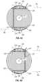
- FIGS. 6 A-Cillustrate embodiments of co-located antennas.
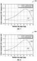
- FIG. 7illustrates a graph showing measured signal responses due to an anisotropic formation with and without measurement compensation.
- FIG. 8illustrates a graph showing measured signal responses due to an anisotropic formation with and without measurement compensation.
- FIG. 9illustrates a fidelity function related to an embodiment of data binning methods.
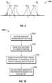
- FIG. 10illustrates a flowchart showing an embodiment of a data binning method.
- a downhole resistivity measuring tool suitable for use in any downhole environmentis disclosed.
- a drill bitis secured to the lower end of the drill collar measurement tubular for drilling a rock formation.
- the measurement tubularmay also include a resistivity measuring tool, communications package, and other downhole measurement tools to measure, for example, the acoustic velocity, the natural radiation, and the density of the formation surrounding the wellbore.
- the resistivity measuring tool disclosedmay be used both when the measurement tubular is rotating, slowly rotating, or not rotating.
- the communications packagecommunicates between the electromagnetic resistivity tool and other downhole measurement tools and a surface control system by any means.
- the communications packagemay use mud pulse telemetry and electrical telemetry techniques for communicating with a surface control system.
- the measurement toolincludes a sensor configured to measure the angular position of the tool body relative to the wellbore.
- Resistivity measuring toolsuse an electric coil to generate an alternating current loop in the formation by induction.
- the alternating current loopin turn, induces a voltage signal in a receiving coil located elsewhere in the tool.
- the voltage signal induced in the receiving coilis related to a parameter of the formation.
- Multiple transmitting and receiving coilsmay be used to focus formation current loops both radially (depth of investigation) and axially (vertical resolution).
- transverserefers to a magnetic moment, created by electrical current in a wire loop, having a direction orthogonal or substantially orthogonal relative to a longitudinal axis of the tool body.
- Axialrefers to a magnetic moment, created by electrical current in a wire loop, having a direction aligned or substantially aligned or parallel with a longitudinal axis of the tool body.
- the Z-axispoints along a longitudinal axis of the tool body.
- the X-axisfalls in a gravity plane containing the Z-axis.
- nine different combinations of transmitter and receiver antennasare possible: XX, XY, XZ, YX, YY, YZ, ZX, ZY, and ZZ, where the first letter indicates the orientation of the transmitter antenna and the second letter the orientation of the receiver antenna.
- Those combinationsprovide means to image the formation around a borehole.
- the XZ, ZX, YZ, and ZY components or their combinationsprovide the most useful azimuthal resistivity measurement for resolving an adjacent boundary or other geological features around a wellbore.
- FIGS. 1 A-Cillustrate embodiments of a resistivity measuring tool 100 including a transverse receiving antenna 120 and an axial transmitting antenna 110 .
- the axial transmitting antenna 110may be placed in either the uphole direction or the downhole direction relative to the transverse receiving antenna 120 .
- the receiving antenna 120is spaced apart from the transmitting antenna 110 at a predefined distance. The direction of the magnetic moment of the axial transmitting antenna 110 remains substantially unchanged as the measurement tool 100 rotates, whereas that of the transverse receiving antenna 120 rotates with the tool 100 .
- a current(e.g., alternating) is driven to the axial transmitting antenna 110 (also known as firing the antenna) at moments controlled by a microcontroller (not shown) of the tool to transmit electromagnetic waves into the surrounding medium at a selected frequency.
- the transmitted signalwhen encountering a resistivity boundary near the borehole, is reflected back and received by the transverse receiving antenna 120 .
- the detected voltage signalis recorded at one or more tool face angles as the tool rotates.
- the measurement toolincludes a sensor 102 configured to measure the angular position of the tool body relative to the wellbore (e.g., tool face angles).
- the sensor 102may be an accelerometer, a magnetometer, a gyro, or any other known sensor or sensor combination. If multiple transverse receiving antennas are used, the reflected electromagnetic wave may be detected simultaneously by the receiving antennas.
- FIGS. 1 B and 1 Cillustrate embodiments of a resistivity measuring tool 100 including a transverse receiving antenna 120 and a pair of symmetrical ( FIG. 1 B ) or asymmetrical ( FIG. 1 C ) axial transmitting antennas 110 .
- the pair of axial transmitting antennas 110may be energized sequentially or simultaneously as explained later.
- a formation resistivity anisotropy effect on the azimuthal measurementmay be reduced or removed, leaving the processed response largely sensitive to an adjacent bed boundary.
- the signals generated by the two axial transmitting antennas 110may be processed to remove or reduce the bed boundary effect and enhance the formation resistivity anisotropy effect.
- FIGS. 2 A and 2 Billustrate an embodiment of a resistivity measuring tool 100 .
- Multiple transverse receiving antennas 120are located around a circumference of the tool body 105 and separated by varying angles in the azimuthal direction, preferably 90 degrees in the azimuthal direction, although a different separation angle may also be used.
- two transverse antennasmay be separated by at least about 30 degrees, at least about 45 degrees, or at least about 60 degrees.
- Transverse receiving antennasare preferably located at substantially the same longitudinal position (e.g., along the Z-axis) on the tool axis but may be located at different longitudinal positions as well.
- One or more axial transmitting antennas 110are preferably placed longitudinally on opposite sides of the receiving antenna(s) 120 , although they may also be placed on the same side of the receiving antenna(s) 120 . When more than one axial transmitting antennas 110 are used, they may be fired sequentially or simultaneously. The measured signals due to the two transmitting antennas 110 may be processed to either remove or enhance the formation resistivity anisotropy effect, discussed in greater detail below.
- the resistivity measuring tool having multiple transverse receiving antennas azimuthally-spaced around the tool bodymay be more preferably used to measure formation resistivity when the tool is slowly rotating or not rotating.
- FIG. 3illustrates an embodiment of transverse antenna components.
- An antenna pocket 122is formed (e.g., machined, molded, etc.) near an outer surface of a drill collar body 105 .
- the pocket 122extends radially inward from the outer surface of the drill collar body to a maximum radial depth of one half a diameter of the tool body.
- the pocketmay be at least 0.25 inches deep, or up to 0.5 inches deep, or up to about one inch deep, or deeper.
- the pocket 122may be any shape including square, rectangle, circle, ellipse or other shapes. In the case of a square or rectangle pocket, the corners of the pocket may be smoothed to reduce stress accumulation around the corners.
- An antenna body 124is configured to substantially correspond in shape with and to fit within the pocket 122 .
- the antenna body 124may be made of any non-conducting material, including but not limited to as PEEK, fiberglass, or ceramic.
- An antenna wire 126is wound around the antenna body 124 such that the wire 126 extends substantially along the longitudinal direction (Z-axis) of the tool axis 101 .
- One or multiple turns of wiremay be wound around the antenna body 124 .
- wire grooves 125may be formed on the outer surface of the antenna body 124 .
- the wire 126may be insulated with Teflon or other non-conducting material to prevent short-circuiting between turns and from being exposed to drilling fluids.
- the antenna body 126 with the wound antenna wire 125is inserted into the antenna pocket 122 such that the moment of the antenna points in a transversal direction.
- the ends of the antenna wire 125exit the antenna pocket 122 to a nearby pocket (not shown) formed in the collar body 105 where a preamplifier may be placed to amplify the received signal before the signal is fed to an electronic board (not shown).
- An antenna shield 128may be placed over the antenna body 124 after it is inserted within the antenna pocket 122 .
- the antenna shieldis configured to sit flush with an outer surface of the collar body 105 .
- the antenna shield 128may be made of the same material as the collar body 105 , or a different, preferably harder, material.
- the antenna shield and collar bodymay be made of stellite.
- One or more openings 130may be formed in the antenna shield 128 to allow electromagnetic energy to pass through. The openings 130 are preferably aligned in the azimuthal direction.
- the antenna shield 128may be attached to the collar body 105 either with bolts or by welding or other means.
- Non-conducting, abrasion-resistant materials, or potting materialmay be used to fill any remaining voids or cavities within the antenna pocket 122 , after the antenna body 124 is inserted and the antenna shield 128 is attached, for further protection of the antenna wire 126 .
- the potting materialmay be mixed with magnetic materials so that the mixture has a relative magnetic permeability greater than 1.
- Such a transversal antennamay be referred to as an “elemental” transverse antenna.
- the shield openingsextend substantially along the circumferential direction, they may be subject to wear and tear during drilling. To help protect the potting material from being damaged or worn out, the shield openings may be narrow.
- curved openingsmay be used instead of straight openings. Each curved opening is preferably symmetric with respect to the center point of the opening.
- FIGS. 4 A-Dillustrate cross-section views of a collar body 105 having a pair of transverse elemental antennas 120 combined to form a composite transverse antenna. Any number of composite transverse antenna configurations may be formed.
- FIG. 4 Aillustrates an antenna body 124 and antenna wire winding 126 within a pocket 122 and covered by an antenna shield 128 , forming a transverse elemental antenna 120 .
- Current “I”flows in the antenna wire winding 126 in a direction shown by the arrows to generate a transverse magnetic moment M T substantially orthogonal to the tool body axis.
- FIG. 4 Billustrates a pair of transverse elemental antennas 120 disposed opposite each other on the collar body 105 and connected to form a composite transverse antenna.
- the transverse elemental antennas 120may be connected by a wire 121 of any diameter that extends from one transverse antenna to the other.
- the connecting wire 121may be disposed within the collar body 105 for damage protection, for example, extending through a drilled hole in the collar body 105 starting from one transverse elemental antenna 120 and ending at the second transverse elemental antenna 120 .
- a groovemay be machined on an outer surface of the collar body 105 , the wire 121 disposed within the groove running between the two transverse antennas, and the groove welded for mechanical protection.
- Yet other means of wire connection between two transverse elemental antennasare possible. For instance, the wire from each transverse elemental antenna may exit directly to an adjacent electronics board for signal communication. In this case, the pair of transverse elemental antennas may be connected indirectly through the electronics board.
- the pair of transverse elemental antennas 120may be connected or coupled in different ways to generate different combinations of transverse magnetic moments.
- FIG. 4 Billustrates transverse elemental antennas 120 , with currents I flowing in the antenna wire windings 126 in directions shown by the arrows, which generate transverse magnetic moments M T in the same transverse direction.
- FIG. 4 Cillustrates transverse elemental antennas 120 , with currents I flowing in the antenna wire windings 126 in direction shown by the arrows, which generate transverse magnetic moments M T in opposite transverse directions.
- a composite transverse antenna in this configurationwill not produce any significant transverse magnetic moment component (e.g., a composite transverse moment ⁇ 0). Rather, the resulting magnetic moments may resemble a quadrupole.
- An electrical current flowing in the tool's longitudinal directionwill produce a magnetic field circulating around the collar.
- the magnetic fields on the opposite sides of the collarwill point to opposite azimuthal directions when viewed in a Cartesian coordinate system, which will produce a response in the quadrupole antenna.
- FIG. 4 Dillustrates transverse elemental antennas 120 , with currents I flowing in the antenna wire windings 126 in directions shown by the arrows, which generate transverse magnetic moments M T in the same transverse direction, similar to FIG. 4 B .
- FIG. 5illustrates an embodiment of axial antenna components.
- An antenna groove 112may be formed in an outer surface of the tool body 105 .
- the width of the antenna groove 112may be at least one-half inch or up to eight inches or greater, but preferably between one inch and six inches measured along the longitudinal direction of the collar.
- a depth of the antenna groove 112may be at least 0.05 inches, at least 0.1 inches, at least 0.25 inches, at least 0.5 inches, at least one inch, or greater.
- a wire groove 114may be formed in an outer surface and near the center of the antenna groove 112 .
- the wire groove 114should be wide and deep enough to hold one or multiple turns of antenna wire 115 . Individual wire ways may also be created to hold each turn of wire in place.
- Longitudinal slots 116may be formed in an outer surface of the antenna groove 112 for passage of electromagnetic wave energy, and may be referred to as passage slots.
- the passage slots 116may be at least 0.25 inches deep, or at least 0.5 inches deep, or at least one inch deep, depending on the size of the collar.
- the passage slots 116may be separated from each other by at least approximately 0.25 inches, or at least 0.5 inches, or at least one inch, or at least two inches, or greater.
- One or multiple turns of antenna wire 115may be disposed in the wire groove 114 .
- the antenna wire 115may exit the antenna groove through pressure sealed connectors to a pressure-sealed pocket (not shown) near the antenna groove 112 .
- An antenna shield 118may be placed on top of the antenna groove 112 to cover the antenna wire.
- the antenna shield 118may be made of the same material as the collar body 105 or a different, preferably harder, material (e.g., stellite) to protect the antenna wire from being damaged during drilling.
- the antenna shield 118may include two or more cylindrical pieces, each having multiple slots 119 formed within.
- the shield slots 119may be aligned with the passage slots 116 formed in the antenna groove 112 .
- the shield slots 119may be at least 0.05 inches wide, or at least 0.1 inches wide, or at least 0.5 inches wide, or at least one inch wide, but are preferably within 0.1 to 0.5 inches wide and do not have to be the same width as the underneath passage slots.
- the thickness of the shieldmay be at least 0.05 inches, or at least 0.1 inch, or at least 0.25 inches, or at least 0.5 inches, or at least one inch, or greater.
- the shield 118may be secured or locked to the collar body 105 either through welding or by bolts.
- the antenna bodymay be vacuumed and potted with non-conducting material for integrity and damage protection.
- the surface of the antennamay be polished to remove any outstanding material.
- FIGS. 6 A-Cillustrate embodiments of co-located antennas in the drill collar body.
- FIG. 6 Aillustrates an embodiment of co-located transverse antennas, each including a pair of transverse elemental antennas 120 connected as discussed in reference to FIGS. 4 A-D .
- the pairs of transverse antennasgenerate magnetic moments M T in the same direction, although any of the composite transverse antenna arrangements may be configured.
- Connecting wires 121 and wire ways between the pairs of transverse elemental antennas 120preferably do not intercept, and each transverse elemental antenna 120 transmits or receives electromagnetic energy independently.
- FIG. 6 Billustrates an embodiment of co-located transverse elemental antennas 120 and axial antennas 110 .
- the pair of transverse antennas 120generate magnetic moments M T in the same direction, although any of the composite transverse antenna arrangements may be configured.
- the pair of axial antennas 110generate magnetic moments M A in either direction.
- the axial antenna 110includes two axial elemental antennas spaced apart by 180 degrees in the azimuthal direction and connected by a wire way for wire passage 121 .
- the wire wayspreferably do not intercept each other.
- the axial antennamay include a single axial antenna, in which case no wire way will be needed.
- azimuthal resistivity measurementswith and without tool rotation are disclosed.
- Equation (2)-(4)e 1 , e 2 , . . . e n are measurement errors, and the equations may be solved in the least-square sense which is well known.
- multiple transverse antennasare used to generate independent measurements at different tool face angles.
- Equations (5)-(6)may be solved for A 0 and ⁇ 0 using a least squares methods.
- the magnetic moments generated by the two transversal antennasare assumed to be orthogonal to each other, although not necessary.
- the two transverse elemental antennasmay be separated in the azimuthal direction by any angle between 0° and 360°.
- equations (5)-(6)becomes:
- a 1A 0 cos( ⁇ 1 + ⁇ 0 )+ e 1 (7)
- a 2A 0 cos( ⁇ 1 + ⁇ + ⁇ 0 )+ e 2 (8)
- both A 0 and ⁇ 0may be computed as:
- multiple transverse elemental antennasare used that are located at substantially the same longitudinal position on the tool axis, it is possible to form a virtual transversal antenna by combining the multiple transversal antennas.
- the combinationmay be done either by electrically connecting the antennas together or by adding their responses together, examples of which were discussed in reference to FIGS. 4 A-D .
- combined antennas or signals over individual antennas or signalsmay lead to better noise rejection and improved signal-to-noise ratios. And, if one of the antennas fails, the combined signal will still be usable.
- Signals from multiple transverse elemental receiving antennasmay be acquired simultaneously when a transmitting antenna fires.
- the signalsmay also be acquired sequentially as a transmitting antenna fires, regardless of tool rotation.
- the tool face anglewill be recorded by a sensor while recording the signals.
- the signalsare associated with the tool face measurements in computing a formation parameter of interest.
- measurements from two transverse (e.g., X and Y) elemental receiving antennas as a function of tool face anglewill resemble each other, which provides data redundancy. Combining a larger set of measurements may be used for subsequent processing and interpretation, while independently processing measurements from each transverse elemental antenna may be used for quality control purposes, among others.
- Cross-component antenna arrangementse.g., an axial transmitting antenna and a transverse elemental receiving antenna
- detection and resolution of adjacent bed boundaries using such cross-component antenna arrangementsmay oftentimes be affected by formation resistivity anisotropy (e.g., directionally dependent formation properties). That is, formation resistivity anisotropy may produce an anomalous signal similar to that produced by an adjacent bed boundary.
- formation resistivity anisotropye.g., directionally dependent formation properties
- V zxM T ⁇ M R ⁇ I 4 ⁇ ⁇ ⁇ L 3 [ cos ⁇ ⁇ sin ⁇ ⁇ ⁇ i ⁇ k h ⁇ L ⁇ ( e ik h ⁇ L - e ik h ⁇ ⁇ ⁇ L ) ] ( 14 )
- M T and M Rare the effective areas of the transmitting and receiving antennas, respectively, I is the driving current in the transmitting antenna, and ⁇ is the relative dip angle of the formation relative to the tool axis. If the resistivity anisotropy is produced by lamination of thin beds of different resistivity values, the relative dip angle ⁇ will be 90 degrees if the wellbore (or tool axis) is parallel to the bedding planes. V zx will be nonzero as long as the relative dip angle ⁇ is different from 0 or 90 degrees. As determined from equation (14), the cross-component signal V zx will remain the same if the relative dip angle changes by 180 degrees.
- an axial transmitting antenna located longitudinally on one side of the receiving antennawill produce the same response as if the transmitting antenna is moved to the other side of the receiving antenna at a symmetrical position and driven with the same driving current.
- a signal response due to an anisotropic formationmay be removed by subtracting the responses generated by two longitudinally symmetrical transmitting antennas.
- the responses produced at an adjacent bed boundary due to two longitudinally symmetrical transmitting antennaswill have opposite signs if the axial magnetic moments of the transmitting antennas point in the same longitudinally direction. Hence, subtracting the two responses from each other will enhance the bed boundary response.
- a method of data acquisitionfor suppressing certain formation parameters while amplifying others, which includes firing two transmitting antennas at least substantially simultaneously.
- Currentsmay be driven simultaneously to two transmitting antennas for generating axial magnetic moments in opposite directions, thereby inducing a voltage signal in the wire winding of the receiving antenna related to a parameter of an adjacent formation bed boundary (and reducing or cancelling the formation resistivity anisotropy effect).
- currentsmay be driven simultaneously to two transmitting antennas for generating axial magnetic moments in the same direction, thereby inducing a voltage signal in the wire winding of the receiving antenna related to a parameter of formation resistivity anisotropy (and reducing or cancelling the bed boundary effect).
- Simultaneously driving currents to the two transmitting antennasproduces a stronger signal and greater signal-to-noise ratio (SNR) than sequentially driving currents to transmitting antennas at the same power input.
- SNRsignal-to-noise ratio
- V 1V 0 ⁇ P R ( 18 )
- the total signal levelis calculated by:
- V 1V 0 ⁇ 2 ⁇ P R ( 20 )
- the corresponding SNRis calculated by:
- the SNR for simultaneous acquisitionis increased by a factor of ⁇ square root over (2) ⁇ over sequential acquisition for the same input power.
- the SNR for each sectorwill be less than that for the entire data combined.
- the relative gain in the SNR for each sector with simultaneous acquisitionwill remain the same as compared to sequential acquisition.
- the two antennaspreferably have the same effective cross-sectional area and are driven with currents of the same magnitude. If they have different effective cross-sectional areas, the driving currents then must be adjusted such that the products of the effective cross-sectional area and the driving current are the same.
- the two transmitting antennasare substantially equally spaced apart from the receiving antenna(s).
- additional methods for compensating for formation anisotropy effectare disclosed.
- the two signalsmay be measured, with either sequential data acquisition or simultaneous data acquisition, and subtracted. Subtracting the signals may work if the coil spacing is small. As an example, coil spacing may be less than ten inches or less than twenty inches. In other examples, coil spacing may be twenty inches or greater.
- FIG. 7illustrates a graph 700 showing signal responses due to an anisotropic formation, an uncompensated signal response 702 and compensated signal response 704 using the first method.
- the compensated signalis defined as:
- V zx Comp1 2 ⁇ ( V z ⁇ x ⁇ 1 - V z ⁇ x ⁇ 2 ) ( 22 )
- a coefficient of 1 ⁇ 2is included so that after the compensation the bed boundary response remains the same (if the bed boundary is parallel to the tool axis).
- the first compensation methodreduces the anisotropy effect by a factor of approximately 9.1, which represents a great reduction in the anisotropy effect.
- equation (22)is corrected by adjusting the scaling factor L (see equation (14)) to further compensate for the formation anisotropy effect.
- the two individual signalsmay be combined as follows to produce a new compensated signal:
- V zx C ⁇ o ⁇ m ⁇ p1 L 1 3 + L 2 3 ⁇ ( V z ⁇ x ⁇ 1 ⁇ L 1 3 - V z ⁇ x ⁇ 2 ⁇ L 2 3 ) ( 23 )
- FIG. 8illustrates a graph 800 showing signal responses due to an anisotropic formation, an uncompensated signal response 802 and compensated signal response 804 using the second method according to equation (23).
- the second compensation methodreduces the anisotropy effect by a factor of approximately 16.3, nearly doubling that of the first compensation method.
- Equation (23)may also be implemented for simultaneous data acquisition. To do so, the currents in the two transmitter antennas are scaled by factors of L 1 3 /(L 1 3 +L 2 3 ) and L 2 3 /(L 1 3 +L 2 3 ), respectively.
- the anisotropy effectis directly removed from signal measurements by numerically computing the anisotropy effect using equation (14).
- the two unknown parameters Rh and ⁇may be calculated from the propagation resistivity measurements.
- the relative dip angle ⁇must be input from other sources, e.g., the well deviation angle and the known formation dip angle.
- An azimuthal resistivity measurement toolacquires data at multiple tool face angles, which may be regularly or irregularly distributed in the tool face domain, depending on the rotation speed of the tool. It is often desirable that the data acquired over a certain period of time is partitioned or “binned” into sectors.
- the uncertainty in the tool face angle measurement for each data pointmay be defined by a fidelity function g( ⁇ ).
- the fidelity functionmay be different from zero only over a finite tool face angle range.
- the fidelity functionmay be assumed to be the same for all data points, although this is not necessary.
- Three scenariosmay occur: (1) the fidelity function associated with a data point is contained entirely within a sector, (2) the fidelity function is partly contained in a sector, and (3) the fidelity function is completely outside a sector. Equation (24) best applies to cases where the data points are associated with evenly distributed tool face angles. Mathematically, this may be expressed as:
- D kis the binned data for the k-th sector
- a fidelity function for binning datamust consider the sensor response characteristics and other hardware and software factors. If the sensor accuracy follows a Gaussian distribution, then the fidelity function may reasonably be taken as the Gaussian function. Binning methods disclosed herein provide that any data points close to the boundary between two adjacent sectors contribute to the binned values of both adjacent sectors. That is, when a data point resides on the boundary between two adjacent sectors, methods disclosed split the data value into the two adjacent sectors. When a data point falls in one sector but is within a range of uncertainty to the sector border with an adjacent sector, the data point will be assigned to both adjacent sectors with different weights, yielding a smooth transition between the two sectors. For example, the range of uncertainty may be within at least one degree of the tool face angle, or at least within three degrees of the tool face angle, or at least within five degrees of the tool face angle, or greater.
- FIG. 9illustrates a plot 900 showing data points with associated fidelity functions.
- four data points (1, 2, 3, and 4)are illustrated along with their respective fidelity functions g( ⁇ ).
- a weighted average valueis to be computed and assigned to a sector starting at a tool face angle ⁇ k ⁇ 1 and ending at the tool face angle ⁇ k .
- Data points 1 and 4are close to the sector lines and their respective fidelity function curves cross the left and right sector lines, respectively.
- Data points 2 and 3have their respective fidelity functions fully contained between the two sector lines. As a result, data points 1 and 4 make full contributions to the average data value assigned to the sector, whereas data points 2 and 3 make full contributions.
- the weight for each data pointsis calculated from equations (27)-(29).
- FIG. 10illustrates a flow chart showing steps of binning methods disclosed herein.
- Step ( 1002 )indicates partitioning resistivity information acquired at multiple tool body angles into M number of sectors.
- Step ( 1004 )indicates defining each data point of the resistivity information by a fidelity function g( ⁇ ).
- Step ( 1006 )indicates assigning to each data point a weight for each of the M number of sectors, wherein the weight is proportional to an integral of the fidelity function g( ⁇ ) over the sector.
- Step ( 1008 )indicates adding the data points weighted by their respective weights for each of the M sectors.
- Data pointswill generally be unevenly distributed in tool face angles and should be assigned with tool-face dependent weights in computing a binned value.
- the data weight for the i-th data pointmay be computed as:
- the binned data valueis then calculated as:
Landscapes
- Engineering & Computer Science (AREA)
- Life Sciences & Earth Sciences (AREA)
- Physics & Mathematics (AREA)
- Geology (AREA)
- Environmental & Geological Engineering (AREA)
- General Life Sciences & Earth Sciences (AREA)
- Remote Sensing (AREA)
- Mining & Mineral Resources (AREA)
- Geophysics (AREA)
- General Physics & Mathematics (AREA)
- Electromagnetism (AREA)
- Fluid Mechanics (AREA)
- Geochemistry & Mineralogy (AREA)
- Theoretical Computer Science (AREA)
- Databases & Information Systems (AREA)
- General Engineering & Computer Science (AREA)
- Data Mining & Analysis (AREA)
- Computational Linguistics (AREA)
- Geophysics And Detection Of Objects (AREA)
- Measurement Of Resistance Or Impedance (AREA)
- Arrangements For Transmission Of Measured Signals (AREA)
Abstract
Description
A(ϕ)=A0cos(ϕ+ϕ0) (1)
- where A0is the maximum (in the absolute value) value of the azimuthal signal when the transversal receiver antenna points toward the boundary, i.e., at the tool face angle ϕ0and ϕ is tool face angle. In equation (1), A0depends on the resistivities of both the near and the remote beds, distance to the boundary, coil spacing, frequency, antenna moments, and the driving current in the transmitting antenna. Solving equation (1) for A0and ϕ0requires at least two independent measurements, which may be accomplished by taking measurements at two or more distinct tool face angles. It may be expressed as:
A1=A0cos(ϕ1+ϕ0)+e1 (2)
A2=A0cos(ϕ2+ϕ0)+e2 (3)
An=A0cos(ϕn+ϕ0)+en (4)
- where A0is the maximum (in the absolute value) value of the azimuthal signal when the transversal receiver antenna points toward the boundary, i.e., at the tool face angle ϕ0and ϕ is tool face angle. In equation (1), A0depends on the resistivities of both the near and the remote beds, distance to the boundary, coil spacing, frequency, antenna moments, and the driving current in the transmitting antenna. Solving equation (1) for A0and ϕ0requires at least two independent measurements, which may be accomplished by taking measurements at two or more distinct tool face angles. It may be expressed as:
A1=A0cos(ϕ1+ϕ0)+e1 (5)
A2=A0cos(ϕ1+90+ϕ0)+e2=A0sin(ϕ1+ϕ0)+e2 (6)
A1=A0cos(ϕ1+ϕ0)+e1 (7)
A2=A0cos(ϕ1+Δϕ+ϕ0)+e2 (8)
- where Δϕ is the azimuthal angle separation between the two antennas.
A=A1cos(ϕ+ϕ0)+A2cos(ϕ+Δϕ+ϕ0)=Bcos(ϕ+ϕ′) (11)
- is another cosine function of the tool face angle. In the above,
P=I2R (16)
- where R is the total resistance of the antenna, i.e., the sum of the antenna wire resistance and the antenna radiation resistance. Noise in the received signal may be assumed to be random and stacking of data will result in reduction in noise according to:
n=cn0/√{square root over (t)} (17)
where n0is the noise level without any stacking, t is the acquisition time, and c is a proportionality constant. For sequential acquisition, the signal level is calculated by:
- where R is the total resistance of the antenna, i.e., the sum of the antenna wire resistance and the antenna radiation resistance. Noise in the received signal may be assumed to be random and stacking of data will result in reduction in noise according to:
Claims (18)
Priority Applications (2)
| Application Number | Priority Date | Filing Date | Title |
|---|---|---|---|
| US17/322,165US12241358B2 (en) | 2013-06-12 | 2021-05-17 | Apparatus and methods for making azimuthal resistivity measurements |
| US18/090,209US20230135986A1 (en) | 2013-06-12 | 2022-12-28 | Systems and methods for an array of different downhole sensors in a single tool body |
Applications Claiming Priority (8)
| Application Number | Priority Date | Filing Date | Title |
|---|---|---|---|
| US201361834272P | 2013-06-12 | 2013-06-12 | |
| US14/303,232US9268053B2 (en) | 2013-06-12 | 2014-06-12 | Apparatus and methods for making azimuthal resistivity measurements |
| US14/993,165US9645276B2 (en) | 2013-06-12 | 2016-01-12 | Apparatus and methods for making azimuthal resistivity measurements |
| US15/466,507US9767153B2 (en) | 2013-06-12 | 2017-03-22 | Apparatus and methods for making azimuthal resistivity measurements |
| US15/696,543US9952347B2 (en) | 2013-06-12 | 2017-09-06 | Apparatus and methods for making azimuthal resistivity measurements |
| US15/920,034US10253614B2 (en) | 2013-06-12 | 2018-03-13 | Apparatus and methods for making azimuthal resistivity measurements |
| US16/379,261US11008850B2 (en) | 2013-06-12 | 2019-04-09 | Apparatus and methods for making azimuthal resistivity measurements |
| US17/322,165US12241358B2 (en) | 2013-06-12 | 2021-05-17 | Apparatus and methods for making azimuthal resistivity measurements |
Related Parent Applications (1)
| Application Number | Title | Priority Date | Filing Date |
|---|---|---|---|
| US16/379,261ContinuationUS11008850B2 (en) | 2013-06-12 | 2019-04-09 | Apparatus and methods for making azimuthal resistivity measurements |
Related Child Applications (1)
| Application Number | Title | Priority Date | Filing Date |
|---|---|---|---|
| US18/090,209Continuation-In-PartUS20230135986A1 (en) | 2013-06-12 | 2022-12-28 | Systems and methods for an array of different downhole sensors in a single tool body |
Publications (2)
| Publication Number | Publication Date |
|---|---|
| US20210277764A1 US20210277764A1 (en) | 2021-09-09 |
| US12241358B2true US12241358B2 (en) | 2025-03-04 |
Family
ID=52018681
Family Applications (10)
| Application Number | Title | Priority Date | Filing Date |
|---|---|---|---|
| US14/303,232ActiveUS9268053B2 (en) | 2013-06-12 | 2014-06-12 | Apparatus and methods for making azimuthal resistivity measurements |
| US14/993,165Expired - Fee RelatedUS9645276B2 (en) | 2013-06-12 | 2016-01-12 | Apparatus and methods for making azimuthal resistivity measurements |
| US15/466,507Expired - Fee RelatedUS9767153B2 (en) | 2013-06-12 | 2017-03-22 | Apparatus and methods for making azimuthal resistivity measurements |
| US15/696,543ActiveUS9952347B2 (en) | 2013-06-12 | 2017-09-06 | Apparatus and methods for making azimuthal resistivity measurements |
| US15/920,034Active2034-06-22US10253614B2 (en) | 2013-06-12 | 2018-03-13 | Apparatus and methods for making azimuthal resistivity measurements |
| US15/937,459ActiveUS10072490B1 (en) | 2013-06-12 | 2018-03-27 | Boundary tracking control module for rotary steerable systems |
| US16/126,485ActiveUS10648319B2 (en) | 2013-06-12 | 2018-09-10 | Boundary tracking control module for rotary steerable systems |
| US16/379,261ActiveUS11008850B2 (en) | 2013-06-12 | 2019-04-09 | Apparatus and methods for making azimuthal resistivity measurements |
| US16/790,384ActiveUS11098572B2 (en) | 2013-06-12 | 2020-02-13 | Boundary tracking control module for rotary steerable systems |
| US17/322,165Active2034-09-18US12241358B2 (en) | 2013-06-12 | 2021-05-17 | Apparatus and methods for making azimuthal resistivity measurements |
Family Applications Before (9)
| Application Number | Title | Priority Date | Filing Date |
|---|---|---|---|
| US14/303,232ActiveUS9268053B2 (en) | 2013-06-12 | 2014-06-12 | Apparatus and methods for making azimuthal resistivity measurements |
| US14/993,165Expired - Fee RelatedUS9645276B2 (en) | 2013-06-12 | 2016-01-12 | Apparatus and methods for making azimuthal resistivity measurements |
| US15/466,507Expired - Fee RelatedUS9767153B2 (en) | 2013-06-12 | 2017-03-22 | Apparatus and methods for making azimuthal resistivity measurements |
| US15/696,543ActiveUS9952347B2 (en) | 2013-06-12 | 2017-09-06 | Apparatus and methods for making azimuthal resistivity measurements |
| US15/920,034Active2034-06-22US10253614B2 (en) | 2013-06-12 | 2018-03-13 | Apparatus and methods for making azimuthal resistivity measurements |
| US15/937,459ActiveUS10072490B1 (en) | 2013-06-12 | 2018-03-27 | Boundary tracking control module for rotary steerable systems |
| US16/126,485ActiveUS10648319B2 (en) | 2013-06-12 | 2018-09-10 | Boundary tracking control module for rotary steerable systems |
| US16/379,261ActiveUS11008850B2 (en) | 2013-06-12 | 2019-04-09 | Apparatus and methods for making azimuthal resistivity measurements |
| US16/790,384ActiveUS11098572B2 (en) | 2013-06-12 | 2020-02-13 | Boundary tracking control module for rotary steerable systems |
Country Status (4)
| Country | Link |
|---|---|
| US (10) | US9268053B2 (en) |
| EP (1) | EP3008497B1 (en) |
| CA (1) | CA2915348C (en) |
| WO (1) | WO2014201297A2 (en) |
Families Citing this family (29)
| Publication number | Priority date | Publication date | Assignee | Title |
|---|---|---|---|---|
| WO2013048375A1 (en)* | 2011-09-27 | 2013-04-04 | Halliburton Energy Services, Inc. | Systems and methods of robust determination of boundaries |
| MX348211B (en)* | 2012-06-29 | 2017-06-05 | Halliburton Energy Services Inc | Multi - axial induction borehole imager. |
| CA2876326A1 (en)* | 2012-06-29 | 2014-01-03 | Halliburton Energy Services, Inc. | Full tensor micro-impedance imaging |
| US11326437B2 (en)* | 2013-06-12 | 2022-05-10 | Well Resolutions Technology | Universal bottomhole assembly node (UBHAN) providing communications to and from rotary steerable systems (RSS) and real time azimuthal resistivity imaging for geosteering and pressure while drilling (FWD) for well control |
| WO2014201297A2 (en) | 2013-06-12 | 2014-12-18 | Well Resolutions Technology | Apparatus and methods for making azimuthal resistivity measurements |
| US10830039B2 (en)* | 2014-04-03 | 2020-11-10 | Baker Hughes Holdings Llc | Downhole tri-axial induction electromagnetic tool |
| US10431883B2 (en)* | 2014-09-07 | 2019-10-01 | Schlumberger Technology Corporation | Antenna system for downhole tool |
| US10386528B2 (en)* | 2015-09-14 | 2019-08-20 | Schlumberger Technology Corporation | Method for estimating formation dip azimuth and eccentering azimuth |
| US10261209B2 (en)* | 2016-02-29 | 2019-04-16 | China Petroleum & Chemical Corporation | Near-bit ultradeep measurement system for geosteering and formation evaluation |
| US10087738B2 (en) | 2016-06-21 | 2018-10-02 | Probe Technology Services, Inc. | Electromagnetic casing inspection tool with azimuthal sensitivity |
| CN106089194B (en)* | 2016-08-22 | 2023-04-28 | 上海神开石油测控技术有限公司 | Apparatus and method for formation interface measurement while drilling using azimuthal resistivity |
| US10365391B2 (en) | 2016-09-09 | 2019-07-30 | Well Resolutions Technology | Apparatus and methods for making azimuthal resistivity measurements with off-set directional antennas |
| US11149538B2 (en) | 2018-03-01 | 2021-10-19 | Baker Hughes, A Ge Company, Llc | Systems and methods for determining bending of a drilling tool, the drilling tool having electrical conduit |
| JPWO2019172307A1 (en)* | 2018-03-09 | 2021-03-11 | パイオニア株式会社 | Reflector with actuator, optical scanning device, and mirror actuator |
| US11086046B2 (en)* | 2018-04-27 | 2021-08-10 | Maxwell Dynamics, Inc. | System and method for the calibration of azimuthal resistivity logging tools |
| GB2586714B (en)* | 2018-06-12 | 2022-10-12 | Halliburton Energy Services Inc | Molded composite inner liner for metallic sleeves |
| FR3084692B1 (en)* | 2018-08-02 | 2022-01-07 | Vallourec Oil & Gas France | DATA ACQUISITION AND COMMUNICATION DEVICE BETWEEN COLUMNS OF OIL OR GAS WELLS |
| CN109322660B (en)* | 2018-08-13 | 2021-11-12 | 中国石油天然气集团有限公司 | Signal excitation device of horizontal main ground stress direction measurement while drilling system |
| CN109083603B (en)* | 2018-09-19 | 2020-04-21 | 邹城兖矿泰德工贸有限公司 | Rotary tool wear-resistant guide pipe |
| US12163425B2 (en)* | 2020-03-13 | 2024-12-10 | Baker Hughes Oilfield Operations Llc | Automated geosteering based on a distance to oil-water contact |
| CN115726773B (en)* | 2021-08-30 | 2024-11-22 | 中国石油化工股份有限公司 | A device and method for measuring resistivity of formations during drilling |
| US12163417B1 (en) | 2022-01-12 | 2024-12-10 | Schlumberger Tehcnology Corporation | Integrated drilling system |
| US20230313663A1 (en)* | 2022-03-31 | 2023-10-05 | Baker Hughes Oilfield Operations Llc | Automated reservoir navigation |
| CN114658414B (en)* | 2022-03-31 | 2024-08-02 | 河南理工大学 | Lower hole detection method of drilling television control system and drilling television monitoring equipment |
| CN116856920B (en)* | 2023-07-06 | 2024-04-02 | 中国科学院地质与地球物理研究所 | A method for using a drilling azimuth electromagnetic wave resistivity instrument and an instrument |
| US12392923B2 (en)* | 2023-08-14 | 2025-08-19 | Halliburton Energy Services, Inc. | Resistivity logging in sliding mode |
| CN119616457B (en)* | 2023-09-14 | 2025-09-26 | 中国石油化工股份有限公司 | Logging while drilling device |
| US12291966B1 (en)* | 2023-11-06 | 2025-05-06 | Schlumberger Technology Corporation | Systems and methods for ranging and tracking while drilling multiple geological wells |
| CN118347619B (en)* | 2024-06-18 | 2024-08-20 | 泰坦(绵阳)能源技术有限公司 | Rotary guiding pushing force precision testing method and system |
Citations (91)
| Publication number | Priority date | Publication date | Assignee | Title |
|---|---|---|---|---|
| US4636731A (en) | 1984-12-31 | 1987-01-13 | Texaco Inc. | Propagation anisotropic well logging system and method |
| US5491488A (en) | 1992-06-11 | 1996-02-13 | Baker Hughes Incorporated | Electromagnetic propagation tool using magnetic dipole antennas |
| US5757191A (en) | 1994-12-09 | 1998-05-26 | Halliburton Energy Services, Inc. | Virtual induction sonde for steering transmitted and received signals |
| US6068394A (en) | 1995-10-12 | 2000-05-30 | Industrial Sensors & Instrument | Method and apparatus for providing dynamic data during drilling |
| US6084052A (en) | 1998-02-19 | 2000-07-04 | Schlumberger Technology Corporation | Use of polyaryletherketone-type thermoplastics in downhole tools |
| US6100696A (en)* | 1998-01-09 | 2000-08-08 | Sinclair; Paul L. | Method and apparatus for directional measurement of subsurface electrical properties |
| US6163155A (en) | 1999-01-28 | 2000-12-19 | Dresser Industries, Inc. | Electromagnetic wave resistivity tool having a tilted antenna for determining the horizontal and vertical resistivities and relative dip angle in anisotropic earth formations |
| US6297639B1 (en) | 1999-12-01 | 2001-10-02 | Schlumberger Technology Corporation | Method and apparatus for directional well logging with a shield having sloped slots |
| US6351127B1 (en)* | 1999-12-01 | 2002-02-26 | Schlumberger Technology Corporation | Shielding method and apparatus for selective attenuation of an electromagnetic energy field component |
| US20020105333A1 (en) | 2000-09-02 | 2002-08-08 | Amini Bijan K. | Measurements of electrical properties through non magneticially permeable metals using directed magnetic beams and magnetic lenses |
| US6476609B1 (en) | 1999-01-28 | 2002-11-05 | Dresser Industries, Inc. | Electromagnetic wave resistivity tool having a tilted antenna for geosteering within a desired payzone |
| US20020167418A1 (en) | 2001-05-09 | 2002-11-14 | Goswami Jaideva C. | Steerable transceiver unit for downhole data acquisition in a formation |
| US6483310B1 (en)* | 1999-11-22 | 2002-11-19 | Scientific Drilling International | Retrievable, formation resistivity tool, having a slotted collar |
| US6509738B1 (en) | 2000-07-14 | 2003-01-21 | Schlumberger Technology Corporation | Electromagnetic induction well logging instrument having azimuthally sensitive response |
| US6577129B1 (en) | 2002-01-19 | 2003-06-10 | Precision Drilling Technology Services Group Inc. | Well logging system for determining directional resistivity using multiple transmitter-receiver groups focused with magnetic reluctance material |
| US20030184488A1 (en) | 2002-03-29 | 2003-10-02 | Smith David L. | Simplified antenna structures for logging tools |
| US6646441B2 (en) | 2002-01-19 | 2003-11-11 | Precision Drilling Technology Services Group Inc. | Well logging system for determining resistivity using multiple transmitter-receiver groups operating at three frequencies |
| US6690170B2 (en) | 2002-03-29 | 2004-02-10 | Schlumberger Technology Corporation | Antenna structures for electromagnetic well logging tools |
| US6703837B1 (en) | 2000-09-15 | 2004-03-09 | Precision Drilling Technology Services Group, Inc. | Wellbore resistivity tool with simultaneous multiple frequencies |
| US20040123655A1 (en) | 2002-09-09 | 2004-07-01 | Baker Hughes Incorporated | Azimuthal resistivity using a non-directional device |
| US20050006090A1 (en)* | 2003-07-08 | 2005-01-13 | Baker Hughes Incorporated | Electrical imaging in conductive and non-conductive mud |
| US20050087367A1 (en) | 2002-04-19 | 2005-04-28 | Hutchinson Mark W. | System and method for interpreting drilling data |
| US20050099184A1 (en) | 2001-06-03 | 2005-05-12 | Halliburton Energy Services, Inc. | Method and apparatus using one or more toroids to measure electrical anisotropy |
| US20050189945A1 (en)* | 2004-02-09 | 2005-09-01 | Arcady Reiderman | Method and apparatus of using magnetic material with residual magnetization in transient electromagnetic measurement |
| US20050212520A1 (en)* | 2004-03-29 | 2005-09-29 | Homan Dean M | Subsurface electromagnetic measurements using cross-magnetic dipoles |
| US6969994B2 (en) | 2001-09-26 | 2005-11-29 | Schlumberger Technology Corporation | Directional electromagnetic measurements insensitive to dip and anisotropy |
| US7057392B2 (en) | 2002-09-06 | 2006-06-06 | Baker Hughes Incorporated | Method and apparatus for directional resistivity measurement while drilling |
| US20060125479A1 (en)* | 2002-03-04 | 2006-06-15 | Baker Hughes Incorporated | Method for signal enhancement in azimuthal propagation resistivity while drilling |
| US20060157277A1 (en) | 2002-09-25 | 2006-07-20 | Halliburton Energy Services, Inc. | Method and system of controlling drilling direction using directionally sensitive resistivity readings |
| US20060290529A1 (en) | 2005-06-23 | 2006-12-28 | Flanagan William D | Apparatus and method for providing communication between a probe and a sensor |
| US7327145B2 (en) | 2004-03-01 | 2008-02-05 | Pathfinder Energy Services, Inc. | Azimuthally focused electromagnetic measurement tool |
| US20080053707A1 (en) | 2006-06-02 | 2008-03-06 | Schlumberger Technology Corporation | System and method for reducing the borehole gap for downhole formation testing sensors |
| US20080074336A1 (en) | 2006-09-25 | 2008-03-27 | Baker Hughes Incorporated | Resistivity tools with collocated antennas |
| US7382135B2 (en) | 2003-05-22 | 2008-06-03 | Schlumberger Technology Corporation | Directional electromagnetic wave resistivity apparatus and method |
| US7394257B2 (en) | 2005-03-30 | 2008-07-01 | Schlumberger Technology Corporation | Modular downhole tool system |
| US20080158082A1 (en) | 2006-11-15 | 2008-07-03 | Baker Hughes Incorporated | Multipole antennae for logging-while-drilling resistivity measurements |
| US20080224707A1 (en) | 2007-03-12 | 2008-09-18 | Precision Energy Services, Inc. | Array Antenna for Measurement-While-Drilling |
| US7471088B2 (en) | 2004-12-13 | 2008-12-30 | Baker Hughes Incorporated | Elimination of the anisotropy effect in LWD azimuthal resistivity tool data |
| US7483793B2 (en) | 2005-07-27 | 2009-01-27 | Baker Hughes Incorporated | Method of generating a deep resistivity image in LWD measurements |
| US7536261B2 (en) | 2005-04-22 | 2009-05-19 | Schlumberger Technology Corporation | Anti-symmetrized electromagnetic measurements |
| US20090278543A1 (en) | 2007-01-29 | 2009-11-12 | Halliburton Energy Services, Inc. | Systems and Methods Having Radially Offset Antennas for Electromagnetic Resistivity Logging |
| US7619540B2 (en) | 2003-10-27 | 2009-11-17 | Schlumberger Technology Corporation | Apparatus and methods for determining isotropic and anisotropic formation resistivity in the presence of invasion |
| US20090295393A1 (en) | 2008-05-29 | 2009-12-03 | Baker Hughes Incorporated | Octupole Induction Sensors for Resistivity Imaging in Non-Conductive Muds |
| US20090302847A1 (en)* | 2006-09-15 | 2009-12-10 | Sergey Knizhnik | Multi-axial antenna and method for use in downhole tools |
| US20090301781A1 (en)* | 2008-06-09 | 2009-12-10 | Baker Hughes Incorporated | Apparatus and system for geosteering and formation evaluation utilizing improved antennas |
| US7659722B2 (en) | 1999-01-28 | 2010-02-09 | Halliburton Energy Services, Inc. | Method for azimuthal resistivity measurement and bed boundary detection |
| US7669668B2 (en) | 2004-12-01 | 2010-03-02 | Schlumberger Technology Corporation | System, apparatus, and method of conducting measurements of a borehole |
| US20100097067A1 (en)* | 2007-04-27 | 2010-04-22 | Synder Jr Harold L | Externally Guided and Directed Field Induction Resistivity Tool |
| US20100117855A1 (en) | 2008-11-10 | 2010-05-13 | Sinclair Paul L | Azimuthally sensitive resistivity logging tool |
| US7723991B2 (en) | 2007-10-02 | 2010-05-25 | Baker Hughes Incorporated | Apparatus and method for azimuthal MWD resistivity imaging at multiple depths of investigation |
| US20100244842A1 (en) | 2009-03-24 | 2010-09-30 | Smith International, Inc. | Apparatus and method for removing anisotropy effect from directional resistivity measurements |
| US20100244841A1 (en) | 2009-03-24 | 2010-09-30 | Smith International, Inc. | Non-planar antennae for directional resistivity logging |
| US20100277176A1 (en) | 2009-05-04 | 2010-11-04 | Homan Dean M | Logging tool having shielded triaxial antennas |
| US20100286916A1 (en) | 2009-05-08 | 2010-11-11 | Smith International, Inc. | Directional resistivity imaging using harmonic representations |
| US20100295547A1 (en)* | 2007-02-19 | 2010-11-25 | Hall David R | Downhole Resistivity Receiver with Canceling Element |
| US7848887B2 (en) | 2004-04-21 | 2010-12-07 | Schlumberger Technology Corporation | Making directional measurements using a rotating and non-rotating drilling apparatus |
| US7888940B2 (en) | 2007-02-19 | 2011-02-15 | Schlumberger Technology Corporation | Induction resistivity cover |
| US20110057656A1 (en) | 2009-09-10 | 2011-03-10 | Smith International, Inc. | Drilling System for Making LWD Measurements Ahead of the Bit |
| US7912648B2 (en) | 2007-10-02 | 2011-03-22 | Baker Hughes Incorporated | Method and apparatus for imaging bed boundaries using azimuthal propagation resistivity measurements |
| US20110074428A1 (en) | 2009-09-29 | 2011-03-31 | Smith International, Inc. | Apparatus and Method for Downhole Electromagnetic Measurement While Drilling |
| US20110074427A1 (en)* | 2009-09-28 | 2011-03-31 | Smith International, Inc. | Directional Resistivity Antenna Shield |
| US20110084698A1 (en) | 2009-10-08 | 2011-04-14 | Precision Energy Services, Inc. | Steerable magnetic dipole antenna for measurement while drilling applications |
| US20110084699A1 (en) | 2009-10-08 | 2011-04-14 | Precision Energy Services, Inc. | Steerable magnetic dipole antenna for measurement-while-drilling applications |
| US20110084697A1 (en) | 2009-10-08 | 2011-04-14 | Precision Energy Services, Inc. | Steerable magnetic dipole antenna for measurement while drilling applications |
| US20110161009A1 (en) | 2009-12-31 | 2011-06-30 | Smith International, Inc. | Binning method for borehole imaging |
| US7990153B2 (en) | 2009-05-11 | 2011-08-02 | Smith International, Inc. | Compensated directional resistivity measurements |
| US7991555B2 (en) | 2008-07-30 | 2011-08-02 | Schlumberger Technology Corporation | Electromagnetic directional measurements for non-parallel bed formations |
| US20110187373A1 (en) | 2009-10-08 | 2011-08-04 | Precision Energy Services, Inc. | Steerable magnetic dipole antenna for measurement-while-drilling applications |
| US20110238312A1 (en) | 2009-05-04 | 2011-09-29 | Jean Seydoux | Directional resistivity measurement for well placement and formation evaluation |
| US20110308794A1 (en) | 2010-06-22 | 2011-12-22 | Halliburton Energy Services, Inc. | Real Time Determination of Casing Location and Distance with Tilted Antenna Measurement |
| US8085050B2 (en) | 2007-03-16 | 2011-12-27 | Halliburton Energy Services, Inc. | Robust inversion systems and methods for azimuthally sensitive resistivity logging tools |
| US8159227B2 (en) | 2009-05-11 | 2012-04-17 | Smith International Inc. | Methods for making directional resistivity measurements |
| US20120209528A1 (en) | 2011-02-10 | 2012-08-16 | Baker Hughes Incorporated | Inversion-Based Method to Correct for the Pipe Residual Signal in Transient MWD Measurements |
| US20130038332A1 (en) | 2011-08-10 | 2013-02-14 | Scientific Drilling International, Inc. | Short Range Data Transmission In A Borehole |
| US20130046474A1 (en) | 2010-07-16 | 2013-02-21 | Haliburton Energy Services, Inc. | Efficient Inversion Systems and Methods for Directionally-Sensitive Resistivity Logging Tools |
| US20130168081A1 (en) | 2011-12-29 | 2013-07-04 | Schlumberger Technology Corporation | Wireless Two-Way Communication For Downhole Tools |
| US20130226459A1 (en) | 2012-02-24 | 2013-08-29 | Baker Hughes Incorporated | Bending correction for deep reading azimuthal propagation resistivity |
| US20130234717A1 (en) | 2010-08-26 | 2013-09-12 | Schlumberger Technology Corporation | Apparatus And Method For Microresistivity Imaging In Nonconductive Drilling Fluid |
| US20130241561A1 (en) | 2012-03-19 | 2013-09-19 | Baker Hughes Incorporated | Induction logging signals and antenna systems |
| US20130261975A1 (en) | 2012-03-27 | 2013-10-03 | Schlumberger Technology Corporation | Anisotropy Processing In Low Angle Wells |
| US20130320985A1 (en) | 2012-06-05 | 2013-12-05 | Ce Liu | Apparatus and method for directional resistivity measurement while drilling using an antenna with a joint-coil structure |
| US20140285205A1 (en) | 2013-03-22 | 2014-09-25 | Oliden Technology, Llc | Well logging apparatus and system |
| US20140312906A1 (en) | 2013-04-23 | 2014-10-23 | Baker Hughes Incorporated | Fractal shaped antenna for downhole logging |
| US20140368380A1 (en) | 2012-06-15 | 2014-12-18 | Thales | Satellite radio navigation system with remote architecture |
| US20140368200A1 (en)* | 2013-06-18 | 2014-12-18 | Well Resolutions Technology | Modular resistivity sensor for downhole measurement while drilling |
| US20140368197A1 (en) | 2013-06-12 | 2014-12-18 | Well Resolutions Technology | Apparatus and methods for making azimuthal resistivity measurements |
| US20150240582A1 (en) | 2014-02-21 | 2015-08-27 | Weatherford/Lamb, Inc. | Continuous flow system for drilling oil and gas wells |
| US20150293254A1 (en)* | 2014-04-11 | 2015-10-15 | Well Resolutions Technology | Apparatus and method for downhole resistivity measurements |
| US20150345283A1 (en) | 2012-12-07 | 2015-12-03 | Evolution Engineering Inc. | Back up directional and inclination sensors and method of operating same |
| US20160230546A1 (en) | 2015-02-10 | 2016-08-11 | Pulse Directional Technologies, Inc. | At-bit downhole sensor and transmitter |
| US20180074219A1 (en) | 2016-09-09 | 2018-03-15 | Well Resolutions Technology | Apparatus and methods for making azimuthal resistivity measurements with off-set directional antennas |
Family Cites Families (42)
| Publication number | Priority date | Publication date | Assignee | Title |
|---|---|---|---|---|
| US4899112A (en)* | 1987-10-30 | 1990-02-06 | Schlumberger Technology Corporation | Well logging apparatus and method for determining formation resistivity at a shallow and a deep depth |
| GB9204910D0 (en)* | 1992-03-05 | 1992-04-22 | Ledge 101 Ltd | Downhole tool |
| US6467557B1 (en)* | 1998-12-18 | 2002-10-22 | Western Well Tool, Inc. | Long reach rotary drilling assembly |
| US6234259B1 (en)* | 1999-05-06 | 2001-05-22 | Vector Magnetics Inc. | Multiple cam directional controller for steerable rotary drill |
| US6427783B2 (en)* | 2000-01-12 | 2002-08-06 | Baker Hughes Incorporated | Steerable modular drilling assembly |
| US6438495B1 (en) | 2000-05-26 | 2002-08-20 | Schlumberger Technology Corporation | Method for predicting the directional tendency of a drilling assembly in real-time |
| US20010052428A1 (en)* | 2000-06-15 | 2001-12-20 | Larronde Michael L. | Steerable drilling tool |
| GB2406344B (en)* | 2003-07-01 | 2007-01-03 | Pathfinder Energy Services Inc | Drill string rotation encoding |
| US7287604B2 (en)* | 2003-09-15 | 2007-10-30 | Baker Hughes Incorporated | Steerable bit assembly and methods |
| US7385400B2 (en)* | 2004-03-01 | 2008-06-10 | Pathfinder Energy Services, Inc. | Azimuthally sensitive receiver array for an electromagnetic measurement tool |
| US7027926B2 (en)* | 2004-04-19 | 2006-04-11 | Pathfinder Energy Services, Inc. | Enhanced measurement of azimuthal dependence of subterranean parameters |
| US8736270B2 (en)* | 2004-07-14 | 2014-05-27 | Schlumberger Technology Corporation | Look ahead logging system |
| US7786733B2 (en)* | 2004-07-14 | 2010-08-31 | Schlumberger Technology Corporation | Apparatus and system for well placement and reservoir characterization |
| US7222681B2 (en)* | 2005-02-18 | 2007-05-29 | Pathfinder Energy Services, Inc. | Programming method for controlling a downhole steering tool |
| US7436184B2 (en)* | 2005-03-15 | 2008-10-14 | Pathfinder Energy Services, Inc. | Well logging apparatus for obtaining azimuthally sensitive formation resistivity measurements |
| US7426967B2 (en)* | 2005-11-14 | 2008-09-23 | Pathfinder Energy Services, Inc. | Rotary steerable tool including drill string rotation measurement apparatus |
| US7571643B2 (en)* | 2006-06-15 | 2009-08-11 | Pathfinder Energy Services, Inc. | Apparatus and method for downhole dynamics measurements |
| US8593147B2 (en)* | 2006-08-08 | 2013-11-26 | Halliburton Energy Services, Inc. | Resistivity logging with reduced dip artifacts |
| US7957946B2 (en) | 2007-06-29 | 2011-06-07 | Schlumberger Technology Corporation | Method of automatically controlling the trajectory of a drilled well |
| US7950473B2 (en)* | 2008-11-24 | 2011-05-31 | Smith International, Inc. | Non-azimuthal and azimuthal formation evaluation measurement in a slowly rotating housing |
| BRPI0822137B1 (en)* | 2008-12-16 | 2018-10-09 | Halliburton Energy Serv Inc | hole bottom set and profiling method |
| WO2011043851A1 (en)* | 2009-10-05 | 2011-04-14 | Halliburton Energy Services, Inc. | Deep evaluation of resistive anomalies in borehole environments |
| US20120186873A1 (en)* | 2009-10-05 | 2012-07-26 | Halliburton Energy Services, Inc. | Well drilling method utilizing real time response to ahead of bit measurements |
| RU2542026C2 (en)* | 2009-10-20 | 2015-02-20 | Шлюмбергер Текнолоджи Б.В. | Method to determine features of beds, realisation of navigation of drilling trajectories and placement of wells with regard to underground drill wells |
| GB2476653A (en) | 2009-12-30 | 2011-07-06 | Wajid Rasheed | Tool and Method for Look-Ahead Formation Evaluation in advance of the drill-bit |
| US9273517B2 (en) | 2010-08-19 | 2016-03-01 | Schlumberger Technology Corporation | Downhole closed-loop geosteering methodology |
| EP3410160A1 (en)* | 2011-04-18 | 2018-12-05 | Halliburton Energy Services Inc. | Method for real-time downhole processing and detection of bed boundary for geosteering application |
| US9404355B2 (en) | 2011-07-22 | 2016-08-02 | Schlumberger Technology Corporation | Path tracking for directional drilling as applied to attitude hold and trajectory following |
| US9022141B2 (en) | 2011-11-20 | 2015-05-05 | Schlumberger Technology Corporation | Directional drilling attitude hold controller |
| US9540922B2 (en)* | 2012-03-29 | 2017-01-10 | Schlumberger Technology Corporation | Electromagnetic method for obtaining dip azimuth angle |
| US9206644B2 (en)* | 2012-09-24 | 2015-12-08 | Schlumberger Technology Corporation | Positive displacement motor (PDM) rotary steerable system (RSS) and apparatus |
| US11326437B2 (en)* | 2013-06-12 | 2022-05-10 | Well Resolutions Technology | Universal bottomhole assembly node (UBHAN) providing communications to and from rotary steerable systems (RSS) and real time azimuthal resistivity imaging for geosteering and pressure while drilling (FWD) for well control |
| US9851465B2 (en)* | 2013-06-18 | 2017-12-26 | Well Resolutions Technology | Apparatus and methods for communicating downhole data |
| US10370963B2 (en)* | 2013-09-30 | 2019-08-06 | Schlumberger Technology Corporation | Method for selecting bed boundaries and log squaring using electromagnetic measurements |
| US20150144401A1 (en)* | 2013-11-27 | 2015-05-28 | Smith International, Inc. | Hydraulically actuated tool with electrical throughbore |
| US9850712B2 (en) | 2013-12-12 | 2017-12-26 | Schlumberger Technology Corporation | Determining drilling state for trajectory control |
| US10161196B2 (en)* | 2014-02-14 | 2018-12-25 | Halliburton Energy Services, Inc. | Individually variably configurable drag members in an anti-rotation device |
| WO2016018231A1 (en)* | 2014-07-28 | 2016-02-04 | Halliburton Energy Services, Inc. | Detecting and remediating downhole excessive pressure condition |
| US9797204B2 (en)* | 2014-09-18 | 2017-10-24 | Halliburton Energy Services, Inc. | Releasable locking mechanism for locking a housing to a drilling shaft of a rotary drilling system |
| US10520639B2 (en)* | 2016-02-19 | 2019-12-31 | China Petroleum & Chemical Corporation | System for geosteering and formation evaluation utilizing near-bit sensors |
| US10261209B2 (en)* | 2016-02-29 | 2019-04-16 | China Petroleum & Chemical Corporation | Near-bit ultradeep measurement system for geosteering and formation evaluation |
| US10746009B2 (en)* | 2016-06-02 | 2020-08-18 | Baker Hughes, A Ge Company, Llc | Depth-based borehole trajectory control |
- 2014
- 2014-06-12WOPCT/US2014/042192patent/WO2014201297A2/enactiveApplication Filing
- 2014-06-12USUS14/303,232patent/US9268053B2/enactiveActive
- 2014-06-12CACA2915348Apatent/CA2915348C/enactiveActive
- 2014-06-12EPEP14811280.8Apatent/EP3008497B1/enactiveActive
- 2016
- 2016-01-12USUS14/993,165patent/US9645276B2/ennot_activeExpired - Fee Related
- 2017
- 2017-03-22USUS15/466,507patent/US9767153B2/ennot_activeExpired - Fee Related
- 2017-09-06USUS15/696,543patent/US9952347B2/enactiveActive
- 2018
- 2018-03-13USUS15/920,034patent/US10253614B2/enactiveActive
- 2018-03-27USUS15/937,459patent/US10072490B1/enactiveActive
- 2018-09-10USUS16/126,485patent/US10648319B2/enactiveActive
- 2019
- 2019-04-09USUS16/379,261patent/US11008850B2/enactiveActive
- 2020
- 2020-02-13USUS16/790,384patent/US11098572B2/enactiveActive
- 2021
- 2021-05-17USUS17/322,165patent/US12241358B2/enactiveActive
Patent Citations (113)
| Publication number | Priority date | Publication date | Assignee | Title |
|---|---|---|---|---|
| US4636731A (en) | 1984-12-31 | 1987-01-13 | Texaco Inc. | Propagation anisotropic well logging system and method |
| US5491488A (en) | 1992-06-11 | 1996-02-13 | Baker Hughes Incorporated | Electromagnetic propagation tool using magnetic dipole antennas |
| US5757191A (en) | 1994-12-09 | 1998-05-26 | Halliburton Energy Services, Inc. | Virtual induction sonde for steering transmitted and received signals |
| US6068394A (en) | 1995-10-12 | 2000-05-30 | Industrial Sensors & Instrument | Method and apparatus for providing dynamic data during drilling |
| US6100696A (en)* | 1998-01-09 | 2000-08-08 | Sinclair; Paul L. | Method and apparatus for directional measurement of subsurface electrical properties |
| US6084052A (en) | 1998-02-19 | 2000-07-04 | Schlumberger Technology Corporation | Use of polyaryletherketone-type thermoplastics in downhole tools |
| US8085049B2 (en) | 1999-01-28 | 2011-12-27 | Halliburton Energy Services, Inc. | Electromagnetic wave resistivity tool having a tilted antenna for geosteering within a desired payzone |
| US20100123462A1 (en) | 1999-01-28 | 2010-05-20 | Halliburton Energy Services, Inc. | Electromagnetic Wave Resistivity Tool Having a Tilted Antenna for Geosteering within a Desired Payzone |
| US7138803B2 (en) | 1999-01-28 | 2006-11-21 | Halliburton Energy Services, Inc. | Electromagnetic wave resistivity tool having a tilted antenna for geosteering within a desired payzone |
| US7557580B2 (en) | 1999-01-28 | 2009-07-07 | Halliburton Energy Services, Inc. | Electromagnetic wave resistivity tool having a tilted antenna for geosteering within a desired payzone |
| US6911824B2 (en) | 1999-01-28 | 2005-06-28 | Halliburton Energy Services, Inc. | Electromagnetic wave resistivity tool having a tilted antenna for geosteering within a desired payzone |
| US6476609B1 (en) | 1999-01-28 | 2002-11-05 | Dresser Industries, Inc. | Electromagnetic wave resistivity tool having a tilted antenna for geosteering within a desired payzone |
| US7265552B2 (en) | 1999-01-28 | 2007-09-04 | Halliburton Energy Services, Inc. | Electromagnetic wave resistivity tool having a tilted antenna for geosteering within a desired payzone |
| US7948238B2 (en) | 1999-01-28 | 2011-05-24 | Halliburton Energy Services, Inc. | Electromagnetic wave resistivity tool having a tilted antenna for determining properties of earth formations |
| US7557579B2 (en) | 1999-01-28 | 2009-07-07 | Halliburton Energy Services, Inc. | Electromagnetic wave resistivity tool having a tilted antenna for determining the horizontal and vertical resistivities and relative dip angle in anisotropic earth formations |
| US7659722B2 (en) | 1999-01-28 | 2010-02-09 | Halliburton Energy Services, Inc. | Method for azimuthal resistivity measurement and bed boundary detection |
| US7019528B2 (en) | 1999-01-28 | 2006-03-28 | Halliburton Energy Services, Inc. | Electromagnetic wave resistivity tool having a tilted antenna for geosteering within a desired payzone |
| US6163155A (en) | 1999-01-28 | 2000-12-19 | Dresser Industries, Inc. | Electromagnetic wave resistivity tool having a tilted antenna for determining the horizontal and vertical resistivities and relative dip angle in anisotropic earth formations |
| US6483310B1 (en)* | 1999-11-22 | 2002-11-19 | Scientific Drilling International | Retrievable, formation resistivity tool, having a slotted collar |
| US6297639B1 (en) | 1999-12-01 | 2001-10-02 | Schlumberger Technology Corporation | Method and apparatus for directional well logging with a shield having sloped slots |
| US6380744B2 (en) | 1999-12-01 | 2002-04-30 | Schlumberger Technology Corporation | Shielding apparatus for selective attenuation of an electromagnetic energy field component |
| US6351127B1 (en)* | 1999-12-01 | 2002-02-26 | Schlumberger Technology Corporation | Shielding method and apparatus for selective attenuation of an electromagnetic energy field component |
| US6509738B1 (en) | 2000-07-14 | 2003-01-21 | Schlumberger Technology Corporation | Electromagnetic induction well logging instrument having azimuthally sensitive response |
| US20020105333A1 (en) | 2000-09-02 | 2002-08-08 | Amini Bijan K. | Measurements of electrical properties through non magneticially permeable metals using directed magnetic beams and magnetic lenses |
| US6703837B1 (en) | 2000-09-15 | 2004-03-09 | Precision Drilling Technology Services Group, Inc. | Wellbore resistivity tool with simultaneous multiple frequencies |
| US20020167418A1 (en) | 2001-05-09 | 2002-11-14 | Goswami Jaideva C. | Steerable transceiver unit for downhole data acquisition in a formation |
| US20050099184A1 (en) | 2001-06-03 | 2005-05-12 | Halliburton Energy Services, Inc. | Method and apparatus using one or more toroids to measure electrical anisotropy |
| US6969994B2 (en) | 2001-09-26 | 2005-11-29 | Schlumberger Technology Corporation | Directional electromagnetic measurements insensitive to dip and anisotropy |
| US6646441B2 (en) | 2002-01-19 | 2003-11-11 | Precision Drilling Technology Services Group Inc. | Well logging system for determining resistivity using multiple transmitter-receiver groups operating at three frequencies |
| US6577129B1 (en) | 2002-01-19 | 2003-06-10 | Precision Drilling Technology Services Group Inc. | Well logging system for determining directional resistivity using multiple transmitter-receiver groups focused with magnetic reluctance material |
| US7375530B2 (en) | 2002-03-04 | 2008-05-20 | Baker Hughes Incorporated | Method for signal enhancement in azimuthal propagation resistivity while drilling |
| US20060125479A1 (en)* | 2002-03-04 | 2006-06-15 | Baker Hughes Incorporated | Method for signal enhancement in azimuthal propagation resistivity while drilling |
| US20030184488A1 (en) | 2002-03-29 | 2003-10-02 | Smith David L. | Simplified antenna structures for logging tools |
| US6690170B2 (en) | 2002-03-29 | 2004-02-10 | Schlumberger Technology Corporation | Antenna structures for electromagnetic well logging tools |
| US20050087367A1 (en) | 2002-04-19 | 2005-04-28 | Hutchinson Mark W. | System and method for interpreting drilling data |
| US7414407B2 (en) | 2002-09-06 | 2008-08-19 | Baker Hughes Incorporated | Method and apparatus for directional resistivity measurement while drilling |
| US7057392B2 (en) | 2002-09-06 | 2006-06-06 | Baker Hughes Incorporated | Method and apparatus for directional resistivity measurement while drilling |
| US20040123655A1 (en) | 2002-09-09 | 2004-07-01 | Baker Hughes Incorporated | Azimuthal resistivity using a non-directional device |
| US7345487B2 (en) | 2002-09-25 | 2008-03-18 | Halliburton Energy Services, Inc. | Method and system of controlling drilling direction using directionally sensitive resistivity readings |
| US20060157277A1 (en) | 2002-09-25 | 2006-07-20 | Halliburton Energy Services, Inc. | Method and system of controlling drilling direction using directionally sensitive resistivity readings |
| US7382135B2 (en) | 2003-05-22 | 2008-06-03 | Schlumberger Technology Corporation | Directional electromagnetic wave resistivity apparatus and method |
| US20050006090A1 (en)* | 2003-07-08 | 2005-01-13 | Baker Hughes Incorporated | Electrical imaging in conductive and non-conductive mud |
| US7619540B2 (en) | 2003-10-27 | 2009-11-17 | Schlumberger Technology Corporation | Apparatus and methods for determining isotropic and anisotropic formation resistivity in the presence of invasion |
| US20050189945A1 (en)* | 2004-02-09 | 2005-09-01 | Arcady Reiderman | Method and apparatus of using magnetic material with residual magnetization in transient electromagnetic measurement |
| US7327145B2 (en) | 2004-03-01 | 2008-02-05 | Pathfinder Energy Services, Inc. | Azimuthally focused electromagnetic measurement tool |
| US20050212520A1 (en)* | 2004-03-29 | 2005-09-29 | Homan Dean M | Subsurface electromagnetic measurements using cross-magnetic dipoles |
| US7848887B2 (en) | 2004-04-21 | 2010-12-07 | Schlumberger Technology Corporation | Making directional measurements using a rotating and non-rotating drilling apparatus |
| US7669668B2 (en) | 2004-12-01 | 2010-03-02 | Schlumberger Technology Corporation | System, apparatus, and method of conducting measurements of a borehole |
| US7471088B2 (en) | 2004-12-13 | 2008-12-30 | Baker Hughes Incorporated | Elimination of the anisotropy effect in LWD azimuthal resistivity tool data |
| US7394257B2 (en) | 2005-03-30 | 2008-07-01 | Schlumberger Technology Corporation | Modular downhole tool system |
| US7536261B2 (en) | 2005-04-22 | 2009-05-19 | Schlumberger Technology Corporation | Anti-symmetrized electromagnetic measurements |
| US20060290529A1 (en) | 2005-06-23 | 2006-12-28 | Flanagan William D | Apparatus and method for providing communication between a probe and a sensor |
| US7483793B2 (en) | 2005-07-27 | 2009-01-27 | Baker Hughes Incorporated | Method of generating a deep resistivity image in LWD measurements |
| US7894990B2 (en) | 2005-07-27 | 2011-02-22 | Baker Hughes Incorporated | Method of generating a deep resistivity image in LWD measurements |
| US20080053707A1 (en) | 2006-06-02 | 2008-03-06 | Schlumberger Technology Corporation | System and method for reducing the borehole gap for downhole formation testing sensors |
| US20090302847A1 (en)* | 2006-09-15 | 2009-12-10 | Sergey Knizhnik | Multi-axial antenna and method for use in downhole tools |
| US20080074336A1 (en) | 2006-09-25 | 2008-03-27 | Baker Hughes Incorporated | Resistivity tools with collocated antennas |
| US20080158082A1 (en) | 2006-11-15 | 2008-07-03 | Baker Hughes Incorporated | Multipole antennae for logging-while-drilling resistivity measurements |
| US20090278543A1 (en) | 2007-01-29 | 2009-11-12 | Halliburton Energy Services, Inc. | Systems and Methods Having Radially Offset Antennas for Electromagnetic Resistivity Logging |
| US8890531B2 (en) | 2007-01-29 | 2014-11-18 | Halliburton Energy Services, Inc. | Systems and methods having pot core antennas for electromagnetic resistivity logging |
| US20100295547A1 (en)* | 2007-02-19 | 2010-11-25 | Hall David R | Downhole Resistivity Receiver with Canceling Element |
| US20110068797A1 (en) | 2007-02-19 | 2011-03-24 | Schlumberger Technology Corporation | Logging tool with independently energizable transmitters |
| US7888940B2 (en) | 2007-02-19 | 2011-02-15 | Schlumberger Technology Corporation | Induction resistivity cover |
| US20080224707A1 (en) | 2007-03-12 | 2008-09-18 | Precision Energy Services, Inc. | Array Antenna for Measurement-While-Drilling |
| US8085050B2 (en) | 2007-03-16 | 2011-12-27 | Halliburton Energy Services, Inc. | Robust inversion systems and methods for azimuthally sensitive resistivity logging tools |
| US20100097067A1 (en)* | 2007-04-27 | 2010-04-22 | Synder Jr Harold L | Externally Guided and Directed Field Induction Resistivity Tool |
| US7912648B2 (en) | 2007-10-02 | 2011-03-22 | Baker Hughes Incorporated | Method and apparatus for imaging bed boundaries using azimuthal propagation resistivity measurements |
| US7723991B2 (en) | 2007-10-02 | 2010-05-25 | Baker Hughes Incorporated | Apparatus and method for azimuthal MWD resistivity imaging at multiple depths of investigation |
| US20090295393A1 (en) | 2008-05-29 | 2009-12-03 | Baker Hughes Incorporated | Octupole Induction Sensors for Resistivity Imaging in Non-Conductive Muds |
| US20090301781A1 (en)* | 2008-06-09 | 2009-12-10 | Baker Hughes Incorporated | Apparatus and system for geosteering and formation evaluation utilizing improved antennas |
| US7991555B2 (en) | 2008-07-30 | 2011-08-02 | Schlumberger Technology Corporation | Electromagnetic directional measurements for non-parallel bed formations |
| US20100117855A1 (en) | 2008-11-10 | 2010-05-13 | Sinclair Paul L | Azimuthally sensitive resistivity logging tool |
| US20100244842A1 (en) | 2009-03-24 | 2010-09-30 | Smith International, Inc. | Apparatus and method for removing anisotropy effect from directional resistivity measurements |
| US8089268B2 (en) | 2009-03-24 | 2012-01-03 | Smith International, Inc. | Apparatus and method for removing anisotropy effect from directional resistivity measurements |
| US20100244841A1 (en) | 2009-03-24 | 2010-09-30 | Smith International, Inc. | Non-planar antennae for directional resistivity logging |
| US20110238312A1 (en) | 2009-05-04 | 2011-09-29 | Jean Seydoux | Directional resistivity measurement for well placement and formation evaluation |
| US20100277176A1 (en) | 2009-05-04 | 2010-11-04 | Homan Dean M | Logging tool having shielded triaxial antennas |
| US20100286916A1 (en) | 2009-05-08 | 2010-11-11 | Smith International, Inc. | Directional resistivity imaging using harmonic representations |
| US7990153B2 (en) | 2009-05-11 | 2011-08-02 | Smith International, Inc. | Compensated directional resistivity measurements |
| US8159227B2 (en) | 2009-05-11 | 2012-04-17 | Smith International Inc. | Methods for making directional resistivity measurements |
| US20110057656A1 (en) | 2009-09-10 | 2011-03-10 | Smith International, Inc. | Drilling System for Making LWD Measurements Ahead of the Bit |
| US20110074427A1 (en)* | 2009-09-28 | 2011-03-31 | Smith International, Inc. | Directional Resistivity Antenna Shield |
| US20110074428A1 (en) | 2009-09-29 | 2011-03-31 | Smith International, Inc. | Apparatus and Method for Downhole Electromagnetic Measurement While Drilling |
| US20110084697A1 (en) | 2009-10-08 | 2011-04-14 | Precision Energy Services, Inc. | Steerable magnetic dipole antenna for measurement while drilling applications |
| US20110187373A1 (en) | 2009-10-08 | 2011-08-04 | Precision Energy Services, Inc. | Steerable magnetic dipole antenna for measurement-while-drilling applications |
| US20110084699A1 (en) | 2009-10-08 | 2011-04-14 | Precision Energy Services, Inc. | Steerable magnetic dipole antenna for measurement-while-drilling applications |
| US20110084698A1 (en) | 2009-10-08 | 2011-04-14 | Precision Energy Services, Inc. | Steerable magnetic dipole antenna for measurement while drilling applications |
| US20110161009A1 (en) | 2009-12-31 | 2011-06-30 | Smith International, Inc. | Binning method for borehole imaging |
| US20110308794A1 (en) | 2010-06-22 | 2011-12-22 | Halliburton Energy Services, Inc. | Real Time Determination of Casing Location and Distance with Tilted Antenna Measurement |
| US8749243B2 (en)* | 2010-06-22 | 2014-06-10 | Halliburton Energy Services, Inc. | Real time determination of casing location and distance with tilted antenna measurement |
| US20130046474A1 (en) | 2010-07-16 | 2013-02-21 | Haliburton Energy Services, Inc. | Efficient Inversion Systems and Methods for Directionally-Sensitive Resistivity Logging Tools |
| US20130234717A1 (en) | 2010-08-26 | 2013-09-12 | Schlumberger Technology Corporation | Apparatus And Method For Microresistivity Imaging In Nonconductive Drilling Fluid |
| US20120209528A1 (en) | 2011-02-10 | 2012-08-16 | Baker Hughes Incorporated | Inversion-Based Method to Correct for the Pipe Residual Signal in Transient MWD Measurements |
| US20130038332A1 (en) | 2011-08-10 | 2013-02-14 | Scientific Drilling International, Inc. | Short Range Data Transmission In A Borehole |
| US20130168081A1 (en) | 2011-12-29 | 2013-07-04 | Schlumberger Technology Corporation | Wireless Two-Way Communication For Downhole Tools |
| US20130226459A1 (en) | 2012-02-24 | 2013-08-29 | Baker Hughes Incorporated | Bending correction for deep reading azimuthal propagation resistivity |
| US20130241561A1 (en) | 2012-03-19 | 2013-09-19 | Baker Hughes Incorporated | Induction logging signals and antenna systems |
| US20130261975A1 (en) | 2012-03-27 | 2013-10-03 | Schlumberger Technology Corporation | Anisotropy Processing In Low Angle Wells |
| US20130320985A1 (en) | 2012-06-05 | 2013-12-05 | Ce Liu | Apparatus and method for directional resistivity measurement while drilling using an antenna with a joint-coil structure |
| US20140368380A1 (en) | 2012-06-15 | 2014-12-18 | Thales | Satellite radio navigation system with remote architecture |
| US20150345283A1 (en) | 2012-12-07 | 2015-12-03 | Evolution Engineering Inc. | Back up directional and inclination sensors and method of operating same |
| US20140285205A1 (en) | 2013-03-22 | 2014-09-25 | Oliden Technology, Llc | Well logging apparatus and system |
| US20140312906A1 (en) | 2013-04-23 | 2014-10-23 | Baker Hughes Incorporated | Fractal shaped antenna for downhole logging |
| US9268053B2 (en) | 2013-06-12 | 2016-02-23 | Well Resolutions Technology | Apparatus and methods for making azimuthal resistivity measurements |
| US20140368197A1 (en) | 2013-06-12 | 2014-12-18 | Well Resolutions Technology | Apparatus and methods for making azimuthal resistivity measurements |
| US20190234196A1 (en)* | 2013-06-12 | 2019-08-01 | Well Resolutions Technology | Apparatus and methods for making azimuthal resistivity measurements |
| US11008850B2 (en)* | 2013-06-12 | 2021-05-18 | Well Resolutions Technology | Apparatus and methods for making azimuthal resistivity measurements |
| US20140368200A1 (en)* | 2013-06-18 | 2014-12-18 | Well Resolutions Technology | Modular resistivity sensor for downhole measurement while drilling |
| US20150240582A1 (en) | 2014-02-21 | 2015-08-27 | Weatherford/Lamb, Inc. | Continuous flow system for drilling oil and gas wells |
| US20150293254A1 (en)* | 2014-04-11 | 2015-10-15 | Well Resolutions Technology | Apparatus and method for downhole resistivity measurements |
| US20160230546A1 (en) | 2015-02-10 | 2016-08-11 | Pulse Directional Technologies, Inc. | At-bit downhole sensor and transmitter |
| US20180074219A1 (en) | 2016-09-09 | 2018-03-15 | Well Resolutions Technology | Apparatus and methods for making azimuthal resistivity measurements with off-set directional antennas |
| US10365391B2 (en) | 2016-09-09 | 2019-07-30 | Well Resolutions Technology | Apparatus and methods for making azimuthal resistivity measurements with off-set directional antennas |
Non-Patent Citations (5)
| Title |
|---|
| Extended European Search Report dated Jan. 9, 2017 issued in EP 14811280 [cited in parent U.S. Appl. No. 14/993,165, filed Jan. 12, 2016). |
| International Search Report and Written Opinion dated Feb. 23, 2024 issued in PCT/US2023/086198. |
| Int'l Search Report and Written Opinion (PCT/US2014/042192), dated Dec. 22, 2014 (cited in Parent U.S. Appl. No. 14/303,232, filed Jun. 12, 2014. |
| Non-Final Office Action dated Aug. 28, 2024 issued in U.S. Appl. No. 18/090,209. |
| Non-Final Office Action dated Dec. 8, 2023 issued in U.S. Appl. No. 18/090,209. |
Also Published As
| Publication number | Publication date |
|---|---|
| US10072490B1 (en) | 2018-09-11 |
| US20160124107A1 (en) | 2016-05-05 |
| WO2014201297A2 (en) | 2014-12-18 |
| US20170193050A1 (en) | 2017-07-06 |
| US20190010798A1 (en) | 2019-01-10 |
| US11098572B2 (en) | 2021-08-24 |
| US20170371063A1 (en) | 2017-12-28 |
| US20180258751A1 (en) | 2018-09-13 |
| US10253614B2 (en) | 2019-04-09 |
| US9767153B2 (en) | 2017-09-19 |
| US20180203152A1 (en) | 2018-07-19 |
| US20190234196A1 (en) | 2019-08-01 |
| US20140368197A1 (en) | 2014-12-18 |
| US20200182037A1 (en) | 2020-06-11 |
| US9268053B2 (en) | 2016-02-23 |
| EP3008497A2 (en) | 2016-04-20 |
| EP3008497A4 (en) | 2017-02-15 |
| US9952347B2 (en) | 2018-04-24 |
| CA2915348C (en) | 2023-05-02 |
| WO2014201297A3 (en) | 2015-02-26 |
| US9645276B2 (en) | 2017-05-09 |
| US20210277764A1 (en) | 2021-09-09 |
| CA2915348A1 (en) | 2014-12-18 |
| US10648319B2 (en) | 2020-05-12 |
| EP3008497B1 (en) | 2021-03-17 |
| US11008850B2 (en) | 2021-05-18 |
Similar Documents
| Publication | Publication Date | Title |
|---|---|---|
| US12241358B2 (en) | Apparatus and methods for making azimuthal resistivity measurements | |
| US11466565B2 (en) | Modular resistivity sensor for downhole measurement while drilling | |
| US7663372B2 (en) | Resistivity tools with collocated antennas | |
| US7150316B2 (en) | Method of eliminating conductive drill parasitic influence on the measurements of transient electromagnetic components in MWD tools | |
| US7501829B2 (en) | Extra bucking coils as an alternative way to balance induction arrays | |
| US7778778B2 (en) | Correction of multi-component measurements for tool eccentricity in deviated wells | |
| US7629791B2 (en) | Method and apparatus for making multi-component measurements in deviated wells | |
| EP2367029A2 (en) | Directional resistivity measurements for well placement and formation evaluation | |
| US11073013B2 (en) | Electric dipole surface antenna configurations for electromagnetic wellbore instrument telemetry | |
| US8417455B2 (en) | Triaxial antenna electromagnetic measurements | |
| US20090295393A1 (en) | Octupole Induction Sensors for Resistivity Imaging in Non-Conductive Muds | |
| US9429675B2 (en) | Anisotropy processing in low angle wells | |
| BRPI0716869B1 (en) | APPARATUS AND METHOD FOR ASSESSING GROUND TRAINING AND COMPUTER-READABLE MEANS FOR USE WITH APPARATUS FOR ASSESSING GROUND TRAINING | |
| US20230135986A1 (en) | Systems and methods for an array of different downhole sensors in a single tool body | |
| WO2024145453A1 (en) | Systems and methods for an array of different downhole sensors in a single tool body |
Legal Events
| Date | Code | Title | Description |
|---|---|---|---|
| FEPP | Fee payment procedure | Free format text:ENTITY STATUS SET TO UNDISCOUNTED (ORIGINAL EVENT CODE: BIG.); ENTITY STATUS OF PATENT OWNER: SMALL ENTITY | |
| FEPP | Fee payment procedure | Free format text:ENTITY STATUS SET TO SMALL (ORIGINAL EVENT CODE: SMAL); ENTITY STATUS OF PATENT OWNER: SMALL ENTITY | |
| STPP | Information on status: patent application and granting procedure in general | Free format text:DOCKETED NEW CASE - READY FOR EXAMINATION | |
| STPP | Information on status: patent application and granting procedure in general | Free format text:NON FINAL ACTION MAILED | |
| STPP | Information on status: patent application and granting procedure in general | Free format text:RESPONSE TO NON-FINAL OFFICE ACTION ENTERED AND FORWARDED TO EXAMINER | |
| STPP | Information on status: patent application and granting procedure in general | Free format text:FINAL REJECTION MAILED | |
| AS | Assignment | Owner name:WELL RESOLUTIONS TECHNOLOGY, TEXAS Free format text:ASSIGNMENT OF ASSIGNORS INTEREST;ASSIGNOR:WANG, TSILI;REEL/FRAME:063622/0654 Effective date:20160310 | |
| STPP | Information on status: patent application and granting procedure in general | Free format text:AMENDMENT AFTER NOTICE OF APPEAL | |
| STPP | Information on status: patent application and granting procedure in general | Free format text:NON FINAL ACTION MAILED | |
| STPP | Information on status: patent application and granting procedure in general | Free format text:RESPONSE TO NON-FINAL OFFICE ACTION ENTERED AND FORWARDED TO EXAMINER | |
| STPP | Information on status: patent application and granting procedure in general | Free format text:FINAL REJECTION MAILED | |
| STPP | Information on status: patent application and granting procedure in general | Free format text:RESPONSE AFTER FINAL ACTION FORWARDED TO EXAMINER | |
| STPP | Information on status: patent application and granting procedure in general | Free format text:NOTICE OF ALLOWANCE MAILED -- APPLICATION RECEIVED IN OFFICE OF PUBLICATIONS | |
| STPP | Information on status: patent application and granting procedure in general | Free format text:PUBLICATIONS -- ISSUE FEE PAYMENT VERIFIED | |
| STCF | Information on status: patent grant | Free format text:PATENTED CASE |