US12240619B2 - Torque balancing for hybrid electric propulsion systems and aircraft utilizing hybrid electric propulsion systems - Google Patents
Torque balancing for hybrid electric propulsion systems and aircraft utilizing hybrid electric propulsion systemsDownload PDFInfo
- Publication number
- US12240619B2 US12240619B2US16/706,449US201916706449AUS12240619B2US 12240619 B2US12240619 B2US 12240619B2US 201916706449 AUS201916706449 AUS 201916706449AUS 12240619 B2US12240619 B2US 12240619B2
- Authority
- US
- United States
- Prior art keywords
- torque
- electric motor
- heat engine
- total
- air mover
- Prior art date
- Legal status (The legal status is an assumption and is not a legal conclusion. Google has not performed a legal analysis and makes no representation as to the accuracy of the status listed.)
- Active, expires
Links
Images


Classifications
- B—PERFORMING OPERATIONS; TRANSPORTING
- B64—AIRCRAFT; AVIATION; COSMONAUTICS
- B64D—EQUIPMENT FOR FITTING IN OR TO AIRCRAFT; FLIGHT SUITS; PARACHUTES; ARRANGEMENT OR MOUNTING OF POWER PLANTS OR PROPULSION TRANSMISSIONS IN AIRCRAFT
- B64D27/00—Arrangement or mounting of power plants in aircraft; Aircraft characterised by the type or position of power plants
- B64D27/02—Aircraft characterised by the type or position of power plants
- B64D27/10—Aircraft characterised by the type or position of power plants of gas-turbine type
- B64D27/12—Aircraft characterised by the type or position of power plants of gas-turbine type within, or attached to, wings
- B—PERFORMING OPERATIONS; TRANSPORTING
- B60—VEHICLES IN GENERAL
- B60W—CONJOINT CONTROL OF VEHICLE SUB-UNITS OF DIFFERENT TYPE OR DIFFERENT FUNCTION; CONTROL SYSTEMS SPECIALLY ADAPTED FOR HYBRID VEHICLES; ROAD VEHICLE DRIVE CONTROL SYSTEMS FOR PURPOSES NOT RELATED TO THE CONTROL OF A PARTICULAR SUB-UNIT
- B60W10/00—Conjoint control of vehicle sub-units of different type or different function
- B60W10/04—Conjoint control of vehicle sub-units of different type or different function including control of propulsion units
- B—PERFORMING OPERATIONS; TRANSPORTING
- B64—AIRCRAFT; AVIATION; COSMONAUTICS
- B64D—EQUIPMENT FOR FITTING IN OR TO AIRCRAFT; FLIGHT SUITS; PARACHUTES; ARRANGEMENT OR MOUNTING OF POWER PLANTS OR PROPULSION TRANSMISSIONS IN AIRCRAFT
- B64D27/00—Arrangement or mounting of power plants in aircraft; Aircraft characterised by the type or position of power plants
- B64D27/02—Aircraft characterised by the type or position of power plants
- B64D27/10—Aircraft characterised by the type or position of power plants of gas-turbine type
- B—PERFORMING OPERATIONS; TRANSPORTING
- B64—AIRCRAFT; AVIATION; COSMONAUTICS
- B64D—EQUIPMENT FOR FITTING IN OR TO AIRCRAFT; FLIGHT SUITS; PARACHUTES; ARRANGEMENT OR MOUNTING OF POWER PLANTS OR PROPULSION TRANSMISSIONS IN AIRCRAFT
- B64D27/00—Arrangement or mounting of power plants in aircraft; Aircraft characterised by the type or position of power plants
- B64D27/02—Aircraft characterised by the type or position of power plants
- B64D27/24—Aircraft characterised by the type or position of power plants using steam or spring force
- B—PERFORMING OPERATIONS; TRANSPORTING
- B64—AIRCRAFT; AVIATION; COSMONAUTICS
- B64D—EQUIPMENT FOR FITTING IN OR TO AIRCRAFT; FLIGHT SUITS; PARACHUTES; ARRANGEMENT OR MOUNTING OF POWER PLANTS OR PROPULSION TRANSMISSIONS IN AIRCRAFT
- B64D27/00—Arrangement or mounting of power plants in aircraft; Aircraft characterised by the type or position of power plants
- B64D27/02—Aircraft characterised by the type or position of power plants
- B64D27/30—Aircraft characterised by electric power plants
- B64D27/33—Hybrid electric aircraft
- B—PERFORMING OPERATIONS; TRANSPORTING
- B64—AIRCRAFT; AVIATION; COSMONAUTICS
- B64D—EQUIPMENT FOR FITTING IN OR TO AIRCRAFT; FLIGHT SUITS; PARACHUTES; ARRANGEMENT OR MOUNTING OF POWER PLANTS OR PROPULSION TRANSMISSIONS IN AIRCRAFT
- B64D31/00—Power plant control systems; Arrangement of power plant control systems in aircraft
- B64D31/02—Initiating means
- B64D31/06—Initiating means actuated automatically
- B64D31/12—Initiating means actuated automatically for equalising or synchronising power plants
- B—PERFORMING OPERATIONS; TRANSPORTING
- B64—AIRCRAFT; AVIATION; COSMONAUTICS
- B64D—EQUIPMENT FOR FITTING IN OR TO AIRCRAFT; FLIGHT SUITS; PARACHUTES; ARRANGEMENT OR MOUNTING OF POWER PLANTS OR PROPULSION TRANSMISSIONS IN AIRCRAFT
- B64D31/00—Power plant control systems; Arrangement of power plant control systems in aircraft
- B64D31/16—Power plant control systems; Arrangement of power plant control systems in aircraft for electric power plants
- B64D31/18—Power plant control systems; Arrangement of power plant control systems in aircraft for electric power plants for hybrid-electric power plants
- F—MECHANICAL ENGINEERING; LIGHTING; HEATING; WEAPONS; BLASTING
- F02—COMBUSTION ENGINES; HOT-GAS OR COMBUSTION-PRODUCT ENGINE PLANTS
- F02C—GAS-TURBINE PLANTS; AIR INTAKES FOR JET-PROPULSION PLANTS; CONTROLLING FUEL SUPPLY IN AIR-BREATHING JET-PROPULSION PLANTS
- F02C6/00—Plural gas-turbine plants; Combinations of gas-turbine plants with other apparatus; Adaptations of gas-turbine plants for special use
- F02C6/20—Adaptations of gas-turbine plants for driving vehicles
- F02C6/206—Adaptations of gas-turbine plants for driving vehicles the vehicles being airscrew driven
- F—MECHANICAL ENGINEERING; LIGHTING; HEATING; WEAPONS; BLASTING
- F02—COMBUSTION ENGINES; HOT-GAS OR COMBUSTION-PRODUCT ENGINE PLANTS
- F02C—GAS-TURBINE PLANTS; AIR INTAKES FOR JET-PROPULSION PLANTS; CONTROLLING FUEL SUPPLY IN AIR-BREATHING JET-PROPULSION PLANTS
- F02C7/00—Features, components parts, details or accessories, not provided for in, or of interest apart form groups F02C1/00 - F02C6/00; Air intakes for jet-propulsion plants
- F02C7/22—Fuel supply systems
- F—MECHANICAL ENGINEERING; LIGHTING; HEATING; WEAPONS; BLASTING
- F02—COMBUSTION ENGINES; HOT-GAS OR COMBUSTION-PRODUCT ENGINE PLANTS
- F02C—GAS-TURBINE PLANTS; AIR INTAKES FOR JET-PROPULSION PLANTS; CONTROLLING FUEL SUPPLY IN AIR-BREATHING JET-PROPULSION PLANTS
- F02C9/00—Controlling gas-turbine plants; Controlling fuel supply in air- breathing jet-propulsion plants
- F02C9/26—Control of fuel supply
- F02C9/42—Control of fuel supply specially adapted for the control of two or more plants simultaneously
- F—MECHANICAL ENGINEERING; LIGHTING; HEATING; WEAPONS; BLASTING
- F02—COMBUSTION ENGINES; HOT-GAS OR COMBUSTION-PRODUCT ENGINE PLANTS
- F02K—JET-PROPULSION PLANTS
- F02K5/00—Plants including an engine, other than a gas turbine, driving a compressor or a ducted fan
- B—PERFORMING OPERATIONS; TRANSPORTING
- B64—AIRCRAFT; AVIATION; COSMONAUTICS
- B64D—EQUIPMENT FOR FITTING IN OR TO AIRCRAFT; FLIGHT SUITS; PARACHUTES; ARRANGEMENT OR MOUNTING OF POWER PLANTS OR PROPULSION TRANSMISSIONS IN AIRCRAFT
- B64D27/00—Arrangement or mounting of power plants in aircraft; Aircraft characterised by the type or position of power plants
- B64D27/02—Aircraft characterised by the type or position of power plants
- B64D27/026—Aircraft characterised by the type or position of power plants comprising different types of power plants, e.g. combination of a piston engine and a gas-turbine
- B—PERFORMING OPERATIONS; TRANSPORTING
- B64—AIRCRAFT; AVIATION; COSMONAUTICS
- B64D—EQUIPMENT FOR FITTING IN OR TO AIRCRAFT; FLIGHT SUITS; PARACHUTES; ARRANGEMENT OR MOUNTING OF POWER PLANTS OR PROPULSION TRANSMISSIONS IN AIRCRAFT
- B64D27/00—Arrangement or mounting of power plants in aircraft; Aircraft characterised by the type or position of power plants
- B64D27/02—Aircraft characterised by the type or position of power plants
- B64D27/30—Aircraft characterised by electric power plants
- B64D27/31—Aircraft characterised by electric power plants within, or attached to, wings
- F—MECHANICAL ENGINEERING; LIGHTING; HEATING; WEAPONS; BLASTING
- F05—INDEXING SCHEMES RELATING TO ENGINES OR PUMPS IN VARIOUS SUBCLASSES OF CLASSES F01-F04
- F05D—INDEXING SCHEME FOR ASPECTS RELATING TO NON-POSITIVE-DISPLACEMENT MACHINES OR ENGINES, GAS-TURBINES OR JET-PROPULSION PLANTS
- F05D2270/00—Control
- F05D2270/30—Control parameters, e.g. input parameters
- F05D2270/335—Output power or torque
- Y—GENERAL TAGGING OF NEW TECHNOLOGICAL DEVELOPMENTS; GENERAL TAGGING OF CROSS-SECTIONAL TECHNOLOGIES SPANNING OVER SEVERAL SECTIONS OF THE IPC; TECHNICAL SUBJECTS COVERED BY FORMER USPC CROSS-REFERENCE ART COLLECTIONS [XRACs] AND DIGESTS
- Y02—TECHNOLOGIES OR APPLICATIONS FOR MITIGATION OR ADAPTATION AGAINST CLIMATE CHANGE
- Y02T—CLIMATE CHANGE MITIGATION TECHNOLOGIES RELATED TO TRANSPORTATION
- Y02T50/00—Aeronautics or air transport
- Y02T50/60—Efficient propulsion technologies, e.g. for aircraft
Definitions
- This disclosurerelates to aircraft and engines therefor, and more particularly to hybrid electric aircraft engines.
- Aircraft enginesvary in efficiency and function over a plurality of parameters, such as thrust requirements, air temperature, air speed, altitude, and the like. Aircraft require the most thrust at takeoff, wherein the demand for engine power is the heaviest. However, during the remainder of the mission, the aircraft engines often do not require as much thrust as during takeoff. The size and weight of the engines allows them to produce the power needed for takeoff, however after take-off the engines are in effect over-sized for the relatively low power required to produce thrust for cruising in level flight.
- a hybrid electric engine control moduleconfigured to be operatively connected to a hybrid electric aircraft powerplant having a heat engine system and an electric motor system to control a torque output from each of the heat engine system and the electric motor system.
- the ECUcan be configured to receive a torque command and split output power between the electric motor system and the heat engine system. Additionally and/or alternatively, the ECU can be configured to balance a total torque against a second total torque of a second aircraft powerplant.
- the ECUcan include a torque splitting module configured to receive a total torque value, and determine a torque split of the total torque value between the electric motor system and the heat engine system.
- the torque splitting modulecan be configured to control the electric motor system and the heat engine system to produce the total torque value in accordance with the determined torque split.
- the ECUcan include a total torque module configured to receive one or more input values including at least a power lever setting, determine the total torque value as a function of the one or more input values, and output the total torque value to the torque splitting module.
- the one or more input valuescan further include at least one of an altitude, a total temperature, a condition lever setting, and/or the second total torque of the second aircraft powerplant.
- the total torque modulecan be configured to determine a total torque value using a locally stored torque map to match or approximate the second total torque of the second aircraft powerplant at a same power lever setting.
- the ECUcan include a torque rate limit module configured to match or approximate a rate of torque change to the second aircraft powerplant to match or approximate dynamic response of the second aircraft powerplant.
- the ECUcan include a fuel flow control module configured to control fuel flow in the heat engine system to control torque output of the heat engine system as a function of heat engine torque value (Qh) output by the torque splitting module.
- the torque splitting modulecan be configured to output an electric motor torque value (Qe) to a motor control module (MC) of the electric motor system.
- the MCis configured to control an electric motor of the electric motor system as a function of the Qe.
- a hybrid electric aircraft powerplant systemcan include a heat engine system configured to provide torque to an air mover, an electric motor system configured to provide torque to the air mover in addition to and/or independently of the heat engine system, and a hybrid electric engine control module (ECU) operatively connected to the heat engine system and the electric motor system to control a torque output from each of the heat engine system and the electric motor system.
- the ECUcan be and/or include any suitable embodiment of an ECU disclosed herein (e.g., as described above).
- the systemcan include a fuel flow control module configured to receive a heat engine torque value (Qh) output by the torque splitting module and to control fuel flow in the heat engine system to control torque output of the heat engine system as a function of the Qh output by the torque splitting module.
- the systemcan include a motor control module (MC) configured to control an electric motor of the electric motor system as a function of the Qe.
- MCmotor control module
- a computer implemented hybrid electric aircraft powerplant control methodcan include receiving one or more power input values including at least a power lever command, determining a total torque demand based on the one or more power input values to create a total torque value, and splitting the total torque value into an electric motor torque value and heat engine torque value.
- the methodcan include controlling an electric motor system as a function of the electric motor torque value and controlling a heat engine system as a function of the heat engine torque value to cause the powerplant to meet the total torque demand.
- the methodcan include matching or approximating the total torque value to a second total torque of a second aircraft powerplant at a same power setting.
- the methodcan include controlling torque change rate to match or approximate a second torque change rate of a second aircraft powerplant.
- the one or more power input valuesfurther include at least one of an altitude, a total temperature, a condition lever setting, and/or the second total torque of the second aircraft powerplant, for example.
- FIG. 1is a schematic diagram of an embodiment of a hybrid electric powerplant system in accordance with this disclosure
- FIG. 2is a schematic diagram of an embodiment of the hybrid electric powerplant system of FIG. 1 , shown having an embodiment of an engine control module (ECU) in accordance with this disclosure; and
- ECUengine control module
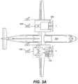
- FIG. 3 Ais a schematic diagram of an aircraft having a hybrid electric powerplant system and a heat engine powerplant system
- FIG. 3 Bis a schematic diagram of an aircraft having two hybrid electric powerplant systems.
- FIG. 1an illustrative view of an embodiment of a powerplant system in accordance with the disclosure is shown in FIG. 1 and is designated generally by reference character 100 .
- FIGS. 2 - 3 BOther embodiments and/or aspects of this disclosure are shown in FIGS. 2 - 3 B .
- a hybrid electric aircraft powerplant (HEP) system 100can include a heat engine system 101 configured to provide torque to an air mover 103 (e.g., a propeller, fan, or any other suitable propulsion device).
- the heat engine of the HEP 100can be a heat engine of any type, e.g., a gas turbine, spark ignited, diesel, rotary, or reciprocating engine of any fuel type and with any configuration.
- Any suitable heat engine systemcan include any suitable turbomachinery elements, either turbocharger, turbosupercharger, supercharger, and exhaust recovery turbo compounding, either mechanically, electrically, hydraulically or pneumatically driven, for example.
- An example of a rotary engine suitable for this applicationis disclosed in U.S. Pat. No. 10,145,291, the disclosure of which is herein incorporated by reference in its entirety.
- the powerplant system 100can also include an electric motor system 105 configured to provide torque to the air mover 103 in addition to and/or independently of the heat engine system 101 .
- the electric motor system 105 and the heat engine system 101can be sized and configured to produce any amount of total horsepower (e.g., 2000 horsepower total, 1000 horsepower each).
- the electric motor system 105can include any suitable components as appreciated by those having ordinary skill in the art in view of this disclosure (e.g., an electric motor, an electrical supply subsystem including a battery and a battery management system).
- the system 100can include a hybrid electric engine control module (ECU) 107 operatively connected to the heat engine system 101 and the electric motor system 105 to control a torque output from each of the heat engine system 101 and the electric motor system 105 .
- the ECU 107can be and/or include any suitable embodiment of an ECU disclosed herein.
- the ECU 107can be configured to receive a torque command (e.g., a power lever angle from a power lever (PLA) 109 and/or other module) and split output power between the electric motor system 105 and the heat engine system 101 .
- the ECU 107can be configured to balance a total torque against a second total torque of a second aircraft powerplant 300 (e.g., as shown in FIG.
- the ECU 107can additionally and/or alternatively be configured to receive any suitable sensor measurements or status information (e.g., rotor speed, temperature, and pressure at various engine stations, battery state of charge, etc.) for processing the splitting of output power.
- the torque splitcan be an adaptive split that changes in real-time as a function of one or more parameters (e.g., battery state of charge, torque command, sensor information, etc.).
- the torque splitting logicmay use parameters that are not directly measured and may need to be synthesized in some way (e.g. temperature or pressure at various engine stations). In certain embodiments, the torque split calculation may account for various operational constraints of the heat engine system, electrical machinery, and/or energy storage, or example.
- the ECU 107can include a torque splitting module 211 configured to receive a total torque value (e.g., Qtot as shown in FIG. 2 from a total torque module 213 or directly from the PLA 109 based on a setting of the PLA 109 , for example).
- the ECUcan be configured to determine a torque split of the total torque value between the electric motor system 105 and the heat engine system 101 .
- the torque splitting module 211can be configured to control (e.g., directly or indirectly) the electric motor system 105 and the heat engine system 101 to produce the total torque value in accordance with the determined torque split (e.g., while meeting transient and steady-state operational constraints for the heat engine, electrical motor, and battery subsystem).
- the torque splitting module 211can output a smaller Qe (e.g., 500 electric horsepower) and maintain a maximum Qh (e.g., 1000 horsepower).
- the torque splitting module 211can be configured to output a Qe value of zero, thereby causing the heat engine system 101 to produce all required power which can conserve battery for situations where greater than maximum Qh is required (e.g., climb, go around).
- the electric motor system 105 or the heat engine system 101may not be able to provide a normal share of power in accordance with the torque split, e.g., due to reaching an operational limit (e.g., such as a temperature or pressure limit).
- a torque split in cruisemay be commanding full power from the heat engine system 101 (e.g., 1000 horsepower from heat engine) and less or no power from the electric motor system (e.g., 0 horsepower), but due to transient maneuver or condition, the power output of the heat engine system 101 is briefly limited (e.g., for about 1 minute or less) either by the system or by the condition (e.g., heat engine system horsepower drops to 950 HP).
- the ECU 107can determine that total commanded torque is not available under the existing torque split and the torque splitting module can cause the electric motor system 105 to make up for the transient loss in horsepower from the heat engine system 101 (e.g., by providing 50 horsepower from the electric motor system 105 ) thereby maintaining the commanded total torque value.
- the reverse scenariocan also be employed in certain embodiments where the heat engine system 101 can compensate for the electric motor system 105 .
- the torque splitting module 211can additionally or alternatively be configured to split torque as a function of a manual input from a pilot.
- a manual input lever for selecting an amount of electric power to be utilizedcan be used by a pilot. Any suitable manual control is contemplated herein.
- the ECU 107can include a total torque module 213 configured to receive one or more input values including at least a power lever setting, e.g., from the PLA 109 .
- the total torque module 213can be configured to determine the total torque value (Qtot) as a function of the one or more input values and output the total torque value to the torque splitting module 211 .
- the one or more input valuescan further include at least one of an altitude, a total temperature, air density, a condition lever (CLA) 110 setting, and/or the second total torque of the second aircraft powerplant. Any other suitable input values for determining total torque is contemplated herein.
- the hybrid electric powerplant system 100can be utilized on a multiengine aircraft 350 (e.g., a retrofit Bombardier Dash-8).
- the aircraft 350may utilize a traditional powerplant (e.g., a turbomachine).
- the total torque module 213can be configured to determine a total torque value using a locally stored torque map (e.g., as shown) to match or approximate the second total torque of the second aircraft powerplant 300 at a same power lever setting.
- an actual second total torque valuecan be provided to the total torque module 213 (e.g., from a torque sensor or other control unit) on the second powerplant 300 such that the actual second torque can be used by the total torque module 213 to determine the total torque value Qtot.
- Any other suitable data from any other suitable sourcecan be utilized to allow the total torque module 213 to match or approximate the total torque of the second aircraft powerplant to reduce or eliminate asymmetric thrust.
- the ECU 107can include a torque rate limit module 215 configured to match or approximate a rate of torque change to the second aircraft powerplant 300 to match or approximate dynamic response of the second aircraft powerplant 300 .
- the torque rate limit module 215can limit torque increase and/or decrease as a function of any suitable data and/or inputs (e.g., based on the one or more input values and stored data such as a look up table).
- the hybrid electric powerplant system 100is used in a multiengine aircraft that also has a second powerplant 300 that is a traditional powerplant (e.g., a turbomachine)
- the second powerplantmay respond slower to PLA 309 setting changes than the hybrid electric aircraft powerplant system 100 responds to PLA 109 setting changes.
- the torque rate limit module 215can control the time of increase or decrease of the total torque value that is provided to the torque splitting module 211 when there is a change in total torque value output by the total torque module 213 .
- the torque rate limit module 215can receive the PLA setting and rate-limit the PLA setting change into the total torque module 213 . Any other suitable way of rate limiting is contemplated herein.
- Embodiments of a HEP disclosed hereinare applicable to any suitable propulsion system distribution (e.g., single engine, multiengine).
- a single engine aircraftcan include a single HEP 100 . While certain embodiments shown, e.g., as in FIG. 3 A , show a single HEP 100 and a single traditional powerplant 300 , it is contemplated that more than two powerplants can be used on an aircraft. It is also contemplated that both powerplants in a dual powerplant system (e.g., as shown in FIG. 3 B ) can be a HEP, e.g., HEP 100 as disclosed herein.
- Any suitable number (e.g., all) of powerplants in a system having a plurality of powerplantscan be a HEP, e.g., HEP 100 as disclosed herein.
- One or multiple enginescan be the same HEP or a different HEP or different full combustion or different full electric, or any combinations thereof.
- Any suitable control scheme for a single or multi HEP systemis contemplated herein (e.g., a power setting map), e.g., similar to and/or the same as disclosed above.
- Certain embodimentsmay provide a recharge function which may require coordination of the ECU 107 , electric motor controller MC and the battery management system BMS.
- rechargecan be done at any point where power demand is below 100% heat engine power, for example.
- the heat enginecan be oversized to provide recharge capability at cruise, for example.
- aircraft speedcan be reduced slighted (e.g., about 10 kts, about 10% power, or any suitable amount reduction) so the battery can be recharged without the engine being oversized by flying slower and using the freed power to recharge.
- Regenerationcan also be implemented during certain portions of the descent flight leg, for example. Regeneration during descent can allow downsizing of the battery without loss of mission fuel burn reduction due to heat engine recharge, which burns fuel.
- Embodimentsallow torque splitting to match one or more other aircraft engines in takeoff and climb operations, and throttling back of heat engine (e.g., combustion) power may only occur at level or descending flight conditions or slower climb rate.
- Embodimentscan manage the electric energy to climb up to altitude.
- the BMScan know how much energy is left and monitor the storage/discharge.
- Embodimentscan measure remaining battery, make calculations on impact to flight, and adjust power output of the electric motor system accordingly. Any suitable sensors, sources, and data calculation to provide this information is contemplated herein (e.g., one or more sensors connected to the ECU 107 and/or BMS 225 ).
- Embodimentscan calculate and display the maximum altitude, or the maximum climb rate that can be achieved with current energy storage (e.g., based on a fixed correlation, or based on additionally on one or more flight variables, e.g., as density altitude, selected airspeed, or any other suitable factors).
- Certain embodimentscan regenerate electricity in any suitable manner (e.g., by windmilling the propeller and/or by recharge in cruise if the heat engine is sized to be large enough to both cruise at a desired speed and provide enough excess energy to charge the battery).
- a pilotmay have the option to reduce airspeed and use excess heat engine power to charge the battery.
- the ECUcan command recharge of the battery in at least one portion of flight when excess power is available.
- Any module disclosed hereincan include any suitable hardware (e.g., circuitry, microprocessor, etc.) and/or software (e.g., any suitable computer code) configured to perform one or more disclosed functions of the respective module.
- any module disclosed hereincan be at least partially commonly hosted and/or integral with or at least partially separate from any other module disclosed herein as appreciated by those having ordinary skill in the art in view of this disclosure.
- embodimentscan include a separate torque split module that implements the torque split and a separate engine control module that controls the thermal engine.
- thecan be hosted together in any suitable manner (e.g., on the same hardware and/or software).
- the electric motor system 105can include any suitable components (e.g., electric motor 221 , a battery 223 , a battery management system 225 ), and can be configured to supply any suitable type of power supply (e.g., 3 phase as shown).
- the heat engine system 101can include any suitable type of heat engine.
- the powerplant system 100can include a combining gear box 227 configured to combine the outputs of the electric motor system 105 and the heat engine system 101 to combine torque to the air mover 103 .
- any other suitable components for the hybrid power plant system 100is contemplated herein (e.g., a reduction gear box 229 , a propeller control unit, a propeller).
- leveris not limited to a physical lever, and includes any suitable control structure.
- certain embodiments of leverscan include a dial, a digital interface, or any other suitable control for use by a pilot in commanding inputs.
- a computer implemented hybrid electric aircraft powerplant control methodcan include receiving one or more power input values including at least a power lever command, determining a total torque demand based on the one or more power input values to create a total torque value, and splitting the total torque value into an electric motor torque value and heat engine torque value.
- the methodcan include controlling an electric motor system as a function of the electric motor torque value and controlling a heat engine system as a function of the heat engine torque value to cause the powerplant to meet the total torque demand.
- an aircraft 350can have a hybrid-electric powerplant system as disclosed above in place of a traditional powerplant, and a second powerplant that is a traditional powerplant.
- Embodimentscan include propulsion delivered by a propeller driven by both an electric motor system and a heat engine system.
- Certain embodimentsinclude 50/50 power split between the electric motor and heat engine power lanes (such that each engine/motor provides the same maximum power). Any other power split is contemplated herein.
- the electric motor control modulecan selectively provide energy from the battery to the electric motor.
- the batterycan be located in the aircraft cabin, for example.
- the battery, the BMS system and motor control modulecan be located in the cabin.
- a high voltage (e.g., about 1 kV) AC distribution systemcan transmit electrical power from the motor control module to the electric motor that is mechanically parallel with the heat engine.
- the propeller condition lever (CLA)can control the propeller control unit (PCU) as appreciated by those having ordinary skill in the art.
- the CLA commandmay be optionally read by the ECU.
- the ECUcan be the master Power Management System (PMS) and can control the total power request and limits as well as torque split between the heat engine and the electric motor.
- PMSmaster Power Management System
- Embodiments of an ECUcan calculate the total torque demand for the HEP based on the PLA power demand and flight operating conditions to mimic a traditional engine (e.g., turbomachine) steady response and transient torque response.
- the ECUcan then calculate the torque split between the heat engine and the electric motor.
- the torque splitmay include electric compensation during a transient or limited power condition (e.g., temperature, boost compressor running line) of the heat engine.
- the ECUcan then send the electric torque command to the electric motor control module via any suitable communication pathway (e.g., a digital communication link).
- the motor control modulethen command proper AC voltage and current to the electric motor.
- the raw PLA setting inputcan also be read by the motor control module for health assessment of the ECU and for direct control based on the PLA settings in certain degraded operational modes (e.g., wherein ECU is not functional).
- Embodimentscan balance torque between two powerplants on aircraft (e.g., a combination of one or more HEP and one or more traditional engines) such that either the HEP matches sensed torque output of a traditional engine, or calculates what torque setting should be to match or approximate the traditional engine torque (e.g., based on throttle inputs, altitude, etc.).
- Embodimentscan balance torque between two or more HEP powerplants (e.g., as shown in FIG. 3 B ), or any other suitable combination of at least one HEP powerplant and at least one of any other type of powerplant (e.g., a turbomachine, piston, hybrid, full electric).
- Embodimentsinclude a torque rate limiter for when power lever is moved since the HEP system achieves torque faster than a traditional engine (e.g., a turbomachine) to slow torque changes to match or approximate torque changes of the traditional engine.
- a traditional enginee.g., a turbomachine
- Embodiments as disclosed hereinprovide fuel use reduction among other benefits.
- a computer readable storage mediummay be any tangible medium that can contain, or store a program for use by or in connection with an instruction execution system, apparatus, or device.
- a computer readable signal mediummay include a propagated data signal with computer readable program code embodied therein, for example, in baseband or as part of a carrier wave. Such a propagated signal may take any of a variety of forms, including, but not limited to, electro-magnetic, optical, or any suitable combination thereof.
- a computer readable signal mediummay be any computer readable medium that is not a computer readable storage medium and that can communicate, propagate, or transport a program for use by or in connection with an instruction execution system, apparatus, or device.
- Program code embodied on a computer readable mediummay be transmitted using any appropriate medium, including but not limited to wireless, wireline, optical fiber cable, RF, etc., or any suitable combination of the foregoing.
- Computer program code for carrying out operations for aspects of this disclosuremay be written in any combination of one or more programming languages, including an object oriented programming language such as Java, Smalltalk, C++ or the like and conventional procedural programming languages, such as the “C” programming language or similar programming languages.
- the program codemay execute entirely on the user's computer, partly on the user's computer, as a stand-alone software package, partly on the user's computer and partly on a remote computer or entirely on the remote computer or server.
- the remote computermay be connected to the user's computer through any type of network, including a local area network (LAN) or a wide area network (WAN), or the connection may be made to an external computer (for example, through the Internet using an Internet Service Provider).
- LANlocal area network
- WANwide area network
- Internet Service Providerfor example, AT&T, MCI, Sprint, EarthLink, MSN, GTE, etc.
- These computer program instructionsmay also be stored in a computer readable medium that can direct a computer, other programmable data processing apparatus, or other devices to function in a particular manner, such that the instructions stored in the computer readable medium produce an article of manufacture including instructions which implement the function/act specified in the flowchart and/or block diagram block or blocks.
- the computer program instructionsmay also be loaded onto a computer, other programmable data processing apparatus, or other devices to cause a series of operational steps to be performed on the computer, other programmable apparatus or other devices to produce a computer implemented process such that the instructions which execute on the computer or other programmable apparatus provide processes for implementing the functions/acts specified herein.
- any numerical values disclosed hereincan be exact values or can be values within a range. Further, any terms of approximation (e.g., “about”, “approximately”, “around”) used in this disclosure can mean the stated value within a range. For example, in certain embodiments, the range can be within (plus or minus) 20%, or within 10%, or within 5%, or within 2%, or within any other suitable percentage or number as appreciated by those having ordinary skill in the art (e.g., for known tolerance limits or error ranges).
Landscapes
- Engineering & Computer Science (AREA)
- Chemical & Material Sciences (AREA)
- Combustion & Propulsion (AREA)
- Aviation & Aerospace Engineering (AREA)
- Mechanical Engineering (AREA)
- General Engineering & Computer Science (AREA)
- Transportation (AREA)
- Combined Controls Of Internal Combustion Engines (AREA)
Abstract
Description
Claims (19)
Priority Applications (1)
| Application Number | Priority Date | Filing Date | Title |
|---|---|---|---|
| US16/706,449US12240619B2 (en) | 2019-03-01 | 2019-12-06 | Torque balancing for hybrid electric propulsion systems and aircraft utilizing hybrid electric propulsion systems |
Applications Claiming Priority (2)
| Application Number | Priority Date | Filing Date | Title |
|---|---|---|---|
| US201962812657P | 2019-03-01 | 2019-03-01 | |
| US16/706,449US12240619B2 (en) | 2019-03-01 | 2019-12-06 | Torque balancing for hybrid electric propulsion systems and aircraft utilizing hybrid electric propulsion systems |
Publications (2)
| Publication Number | Publication Date |
|---|---|
| US20200277073A1 US20200277073A1 (en) | 2020-09-03 |
| US12240619B2true US12240619B2 (en) | 2025-03-04 |
Family
ID=72236524
Family Applications (1)
| Application Number | Title | Priority Date | Filing Date |
|---|---|---|---|
| US16/706,449Active2041-08-18US12240619B2 (en) | 2019-03-01 | 2019-12-06 | Torque balancing for hybrid electric propulsion systems and aircraft utilizing hybrid electric propulsion systems |
Country Status (4)
| Country | Link |
|---|---|
| US (1) | US12240619B2 (en) |
| EP (1) | EP3931096B1 (en) |
| CA (1) | CA3132285A1 (en) |
| WO (1) | WO2020180367A1 (en) |
Families Citing this family (10)
| Publication number | Priority date | Publication date | Assignee | Title |
|---|---|---|---|---|
| US11794917B2 (en)* | 2020-05-15 | 2023-10-24 | Pratt & Whitney Canada Corp. | Parallel control loops for hybrid electric aircraft |
| US11827372B2 (en)* | 2020-05-15 | 2023-11-28 | Pratt & Whitney Canada Corp. | Engine characteristics matching |
| US11649038B2 (en)* | 2020-07-10 | 2023-05-16 | Pratt & Whitney Canada Corp. | Hybrid electric powerplant (HEP) control architecture |
| US20230257128A1 (en)* | 2022-02-11 | 2023-08-17 | Pratt & Whitney Canada Corp. | Hybrid-Electric Aircraft Propulsion System and Method for Operating the Same |
| US12139268B2 (en) | 2022-06-21 | 2024-11-12 | Pratt & Whitney Canada Corp. | Adjusting aircraft powerplant power split to control powerplant vibrations |
| US12091179B2 (en)* | 2022-08-26 | 2024-09-17 | General Electric Company | Aircrafts, systems, and methods for providing constant torque on takeoff |
| FR3146168A1 (en)* | 2023-02-28 | 2024-08-30 | Safran Aircraft Engines | Method for controlling the hybridization rate of a hybridized turbomachine |
| US12296941B2 (en) | 2023-05-12 | 2025-05-13 | Pratt & Whitney Canada Corp. | System and method for controlling a propulsor for a hybrid-electric aircraft propulsion system |
| US12006035B1 (en)* | 2023-05-30 | 2024-06-11 | Archer Aviation, Inc. | Systems and methods for flight control of EVTOL aircraft |
| FR3154455B1 (en)* | 2023-10-18 | 2025-09-05 | Safran Aircraft Engines | CONTROL SYSTEM FOR A HYBRID TURBOMACHINE BY OBSERVER WITH RECONFIGURATION BY CONTROL SATURATION DETECTION |
Citations (225)
| Publication number | Priority date | Publication date | Assignee | Title |
|---|---|---|---|---|
| US4204401A (en)* | 1976-07-19 | 1980-05-27 | The Hydragon Corporation | Turbine engine with exhaust gas recirculation |
| US6179072B1 (en) | 1999-10-13 | 2001-01-30 | Deere & Company | Supplemental charge for hydrostatic steering system |
| US6198183B1 (en) | 1998-04-18 | 2001-03-06 | Daimlerchrysler Ag | Integrated electric drive unit including an electric motor and an electronic control and monitoring module |
| US6335581B1 (en) | 1999-05-20 | 2002-01-01 | Mannesmann Vdo Ag | Electric motor intended for use in an aggressive medium |
| US6427441B2 (en) | 2000-01-04 | 2002-08-06 | Sauer-Danfoss Inc. | Hydrostatic vehicle drive with control device and control device for hydrostatic drives |
| US6537047B2 (en) | 2000-02-15 | 2003-03-25 | Frank H. Walker | Reversible variable displacement hydraulic pump and motor |
| US6692395B2 (en) | 2002-02-25 | 2004-02-17 | Deere & Company | Transmisson for power take-off |
| US20050178893A1 (en) | 2003-02-28 | 2005-08-18 | Miller Donald C. | Continuously variable transmission |
| US20050258306A1 (en) | 2004-05-24 | 2005-11-24 | The Boeing Company | Delta-winged hybrid airship |
| US20060016196A1 (en) | 2004-07-21 | 2006-01-26 | Epstein Stanley W | Onboard supplemental power system at varying high altitudes |
| US20060016197A1 (en) | 2004-07-21 | 2006-01-26 | Epstein Stanley W | Onboard supplemental power system at varying high altitudes |
| US20060056971A1 (en) | 2004-09-10 | 2006-03-16 | D Anna Frank P | Swashplate and pitch link arrangement for a coaxial counter rotating rotor system |
| US7022042B2 (en) | 2004-01-27 | 2006-04-04 | Yakov Fleytman | Epicyclic gear train |
| US7098569B2 (en) | 2004-07-30 | 2006-08-29 | Ballard Power Systems Corporation | Rotor assembly for a permanent magnet power electric machine |
| JP2006231974A (en) | 2005-02-22 | 2006-09-07 | Shimadzu Corp | Air conditioner for aircraft |
| JP2006270778A (en) | 2005-03-25 | 2006-10-05 | Denso Corp | Onboard wireless communication apparatus |
| JP2006290187A (en) | 2005-04-12 | 2006-10-26 | Nissan Motor Co Ltd | Hybrid drive device for vehicle |
| US20060237583A1 (en) | 2005-04-21 | 2006-10-26 | The Boeing Company | Combined fuel cell aircraft auxiliary power unit and environmental control system |
| KR20070039699A (en) | 2005-10-10 | 2007-04-13 | 박명구 | Complex continuous multi power train |
| JP2007137423A (en) | 1997-12-10 | 2007-06-07 | Franco Capanna | System converting vertical take-off type and self-sustained horizontal flight type aircraft into self-sustained horizontal flight, vertical taking-off/landing and hybrid integration type aircraft |
| US7247967B2 (en) | 2004-08-09 | 2007-07-24 | A. O. Smith Corporation | Electric motor having a stator |
| US20070170307A1 (en) | 2004-03-05 | 2007-07-26 | Industria Helicat Y Alas Giratorias, S.L. | Convertible aircraft operating method |
| WO2007086213A1 (en) | 2006-01-27 | 2007-08-02 | Toyota Jidosha Kabushiki Kaisha | Vehicle and its control method |
| US20070264124A1 (en) | 2005-12-23 | 2007-11-15 | Eurocopter Deutschland Gmbh | Highly extensible power and/or signal transmission cable as well as rotor blade with such a cable |
| US7303497B1 (en) | 2002-03-11 | 2007-12-04 | Insight3D, Inc. | Dual-input differential planetary gear transmission |
| US7316629B2 (en) | 2004-10-26 | 2008-01-08 | Aisin Aw Co., Ltd. | Planetary gear apparatus |
| US7345398B2 (en) | 2005-06-20 | 2008-03-18 | Kurz-Kasch, Inc. | Electric motor stator |
| US20080141921A1 (en) | 2006-10-06 | 2008-06-19 | Mitja Victor Hinderks | Reciprocating devices |
| US20080145221A1 (en) | 2006-12-14 | 2008-06-19 | Sikorksy Aircraft Corporation | Hybrid actuator for helicopter rotor blade control flaps |
| US7398946B1 (en) | 2004-10-04 | 2008-07-15 | United States Of America As Represented By The Secretary Of The Air Force | Power line sentry charging |
| US7418820B2 (en) | 2002-05-16 | 2008-09-02 | Mhl Global Corporation Inc. | Wind turbine with hydraulic transmission |
| KR20080086714A (en) | 2007-03-23 | 2008-09-26 | (주)하이게인안테나 | Low altitude radar antenna |
| US20080275597A1 (en)* | 2006-06-19 | 2008-11-06 | Eurocopter | Balancing the power of two turboshaft engines of an aircraft |
| KR20080005377U (en) | 2007-05-09 | 2008-11-13 | 서원영 | Automatic charging system using self power generation. |
| US7471026B2 (en) | 2006-03-13 | 2008-12-30 | Isca Innovatons, Llc | Brushless electric motor |
| JP4215012B2 (en) | 2005-03-15 | 2009-01-28 | トヨタ自動車株式会社 | Hybrid vehicle and control method thereof |
| US20090050103A1 (en) | 2006-09-11 | 2009-02-26 | The Scuderi Group, Llc | Split-cycle aircraft engine |
| US7503173B2 (en) | 2005-02-08 | 2009-03-17 | Parker-Hannifin Corporation | Control devices for swashplate type variable displacement piston pump |
| BRMU8701724U2 (en) | 2007-10-19 | 2009-06-09 | Alfredo Pintarelli | self-rotating power generator system on rotary-wing aircraft |
| US20090229897A1 (en) | 2008-03-12 | 2009-09-17 | Toyota Jidosha Kabushiki Kaisha | Engine control system |
| JP2009534928A (en) | 2006-04-18 | 2009-09-24 | インターデイジタル テクノロジー コーポレーション | Method and apparatus for implementing H-ARQ in a MIMO wireless communication system |
| KR20090110373A (en) | 2007-02-09 | 2009-10-21 | 란세스 도이치란트 게엠베하 | Lightweight element of hybrid structure |
| US7726426B2 (en) | 2003-02-21 | 2010-06-01 | Lockheed Martin Corporation | Hub drive and method of using same |
| EP2226487A2 (en) | 2009-03-02 | 2010-09-08 | Rolls-Royce plc | Variable drive gas turbine engine |
| US20100264724A1 (en) | 2009-04-15 | 2010-10-21 | Hamilton Sundstrand Corporation | Integrated power until as energy storage device for electrical power system |
| US7827787B2 (en) | 2007-12-27 | 2010-11-09 | Deere & Company | Hydraulic system |
| US20100285747A1 (en) | 2008-05-19 | 2010-11-11 | Airbus Operations Gmbh | Hybrid transmitter for non-contact energy and data transmission |
| US7867122B2 (en) | 2006-09-26 | 2011-01-11 | Epi-Energy Ltd. | Power transmission system with continuously variable speed control |
| WO2011005066A2 (en) | 2009-03-17 | 2011-01-13 | Halieurop Sa | Hybrid multimodal fishery built into small pelagic areas |
| BRPI0702882A2 (en) | 2006-02-01 | 2011-03-15 | Toyota Motor Co Ltd | power output device, vehicle including power output device, and control unit and method for power output device |
| KR20110032973A (en) | 2009-09-24 | 2011-03-30 | 최억만 | Wind power generator and battery replacement method (hybrid car) |
| JP2011516334A (en) | 2008-04-01 | 2011-05-26 | ゼロ・エミッション・システムズ・インコーポレーテッド | Vehicle switching while in electric traction mode |
| US7958725B2 (en) | 2008-05-21 | 2011-06-14 | Caterpillar Inc. | Drivetrain system having simultaneous displacement control |
| EP2332235A2 (en) | 2008-10-08 | 2011-06-15 | Pro Diskus AG | Rotor-shaft arrangement for an electric motor |
| KR20110087661A (en) | 2010-01-27 | 2011-08-03 | 박경섭 | Green Energy Hybrid Helicopter |
| US20110215584A1 (en) | 2010-03-08 | 2011-09-08 | Brennan Mikael Prokopich | Air / wind tunnel powered turbine, electric power recharging system |
| WO2011107718A1 (en) | 2010-03-05 | 2011-09-09 | Eric Chantriaux | Rotary- or fixed-wing aircraft provided with a distributed electric engine unit |
| US20110236218A1 (en) | 2010-03-24 | 2011-09-29 | David Everett Russ | Hybrid ram air turbine |
| US20110243566A1 (en) | 2010-04-01 | 2011-10-06 | The Boeing Company | Optical fiber interface system and connector |
| US20110256973A1 (en) | 2008-12-09 | 2011-10-20 | Mtu Friedrichshafen Gmbh | Drive train with a first electric motor and a planetary gear mechanism as well as wind energy plants, gas turbines and water turbines and vehicles that have this drive train |
| US20110266995A1 (en) | 2010-04-28 | 2011-11-03 | Lockheed Martin Corporation | Radio frequency power transmission system |
| WO2011144188A1 (en) | 2010-05-17 | 2011-11-24 | Hyon Engineering Gmbh | Internal combustion engine |
| BRPI0622106A2 (en) | 2006-10-05 | 2011-12-20 | Hinderks M V | fluid processing device, aircraft, vessel, and continuously variable ratio transmission |
| US20120025032A1 (en) | 2010-07-08 | 2012-02-02 | Eurocopter | Electrical architecture for a rotary wing aircraft with a hybrid power plant |
| US20120137684A1 (en) | 2010-12-02 | 2012-06-07 | Or Yogev | Solar augmented wind turbine for stable & dispatchable utility scale power generation |
| US20120168557A1 (en) | 2010-11-02 | 2012-07-05 | Borealis Technical Limited | Integrated Aircraft Ground Navigation Control System |
| US8217544B2 (en) | 2009-02-06 | 2012-07-10 | Denso Corporation | Motor-generator having stator and inner and outer rotors |
| JP4973256B2 (en) | 2007-03-15 | 2012-07-11 | トヨタ自動車株式会社 | Vehicle and control method thereof |
| EP2478608A2 (en) | 2009-09-18 | 2012-07-25 | National Renewable Energy Centre Limited | A power collection and distribution system |
| US20120227389A1 (en) | 2008-04-16 | 2012-09-13 | Hinderks M V | Reciprocating machine & other devices |
| US20120239228A1 (en) | 1998-04-03 | 2012-09-20 | Rockwell Collins Control Technologies, Inc. | Apparatus and method for controlling power generation system |
| BRPI1104839A2 (en) | 2011-11-25 | 2012-11-20 | Barros Marcelo Monteiro De | energy wind turbine for electric and hybrid vehicles |
| US20120327921A1 (en) | 2010-01-14 | 2012-12-27 | Airbus Operations Gmbh | Device for providing radiofrequency signal connections |
| KR20120140229A (en) | 2012-12-04 | 2012-12-28 | 허동범 | Hvbrid wind generator |
| US8342995B2 (en) | 2007-11-01 | 2013-01-01 | Ducere Holdings (Pty) Limited | Drive arrangement with open loop hydraulic mechanism operable as a pump or a motor |
| KR20130006379A (en) | 2011-07-07 | 2013-01-16 | 아스트리움 게엠베하 | Radar system with synthetic aperture |
| US20130026304A1 (en) | 2011-07-29 | 2013-01-31 | Agustawestland S.P.A. | Convertiplane |
| US8382635B2 (en) | 2008-09-11 | 2013-02-26 | Alfredo Tampieri | Epicyclic reduction gear device with balanced planet wheels |
| US20130082135A1 (en) | 2011-09-29 | 2013-04-04 | Eurocopter | Hybrid aircraft having a rotary wing |
| US8435156B2 (en) | 2001-07-06 | 2013-05-07 | Sew-Eurodrove GmbH & Co. KG | Kit for a series of planetary gears, planet carrier and drive |
| US20130119841A1 (en) | 2011-11-16 | 2013-05-16 | Oleg Graf | Baggage compartment for an aircraft and aircraft having the baggage compartment |
| US8446121B1 (en) | 2010-11-19 | 2013-05-21 | The Boeing Company | High performance actuator motor |
| KR101277645B1 (en) | 2011-11-14 | 2013-06-21 | 인하대학교 산학협력단 | Hybrid Electric Power Generation System Using Photovoltaics and Wind Power |
| US8471429B2 (en) | 2009-04-07 | 2013-06-25 | GM Global Technology Operations LLC | Isolator ring for an electric motor |
| US20130168489A1 (en) | 2012-01-04 | 2013-07-04 | James William McIntee | Roadable, Adaptable-Modular, Multiphibious-Amphibious Ground Effect or Flying, Car-Boat-Plane or Surface-Effect Motorcycle |
| US20130181088A1 (en) | 2011-07-18 | 2013-07-18 | Airbus Operations, S.L. | Aircraft versatile power system |
| US8495870B2 (en) | 2009-03-19 | 2013-07-30 | Kubota Corporation | Work machine |
| US20130227950A1 (en) | 2012-03-05 | 2013-09-05 | Embry-Riddle Aeronautical University, Inc. | Hybrid assembly for an aircraft |
| US8531076B2 (en) | 2011-05-17 | 2013-09-10 | GM Global Technology Operations LLC | Stator for an electric motor |
| US8535197B2 (en) | 2010-05-12 | 2013-09-17 | Enerflex Ltd. | Speed changer assembly |
| JP2013193533A (en) | 2012-03-19 | 2013-09-30 | Toyota Motor Corp | Hybrid vehicle |
| US20130287574A1 (en) | 2012-04-26 | 2013-10-31 | Henning Ebbesen | Wind turbine |
| US20130300120A1 (en) | 2012-05-08 | 2013-11-14 | David J. Podrog | Hafnium turbine engine and method of operation |
| US8584452B2 (en) | 2009-09-04 | 2013-11-19 | Lloydco Llc | Infinitely-variable, hydro-mechanical transmission using fixed displacement pumps and motors |
| US8596054B2 (en) | 2009-05-01 | 2013-12-03 | Atlas Copco Drilling Solutions, Inc. | Absorber-replenisher in a hydrostatic circuit |
| US20130341934A1 (en) | 2009-08-24 | 2013-12-26 | Eiji Kawanishi | Hybrid power generator coupled to gravity power generator using balance which has pressure load device |
| KR20130142491A (en) | 2012-06-19 | 2013-12-30 | 주식회사 엘지화학 | Electric power transportation system and method of electric power transport using the same |
| US8621860B2 (en) | 2010-10-22 | 2014-01-07 | Cnh America Llc | Control system for work vehicle |
| US8622859B2 (en) | 2009-06-10 | 2014-01-07 | Czero Holding Company, Llc | Systems and methods for hybridization of a motor vehicle using hydraulic components |
| US20140010652A1 (en) | 2012-07-09 | 2014-01-09 | Mcmaster University | Hybrid powertrain system |
| US20140027568A1 (en) | 2012-07-26 | 2014-01-30 | Airbus Operations Gmbh | Method for generating hydraulic power in an aircraft, use of a hybrid power control unit and drive system |
| JP5415400B2 (en) | 2007-03-21 | 2014-02-12 | クゥアルコム・インコーポレイテッド | H-ARQ acknowledgment detection confirmation by data combination and re-decoding |
| US8660761B2 (en) | 2011-11-23 | 2014-02-25 | Caterpillar Inc. | Method of effecting simultaneous displacement changes in hydrostatic drive machine |
| US20140054411A1 (en) | 2012-08-27 | 2014-02-27 | Eurocopter | Method of assisting a pilot of a single-engined rotary wing aircraft during a stage of flight in autorotation |
| US8663047B2 (en) | 2008-07-25 | 2014-03-04 | Voith Patent Gmbh | Superimposed transmission having coupling shafts |
| US20140117148A1 (en) | 2012-10-29 | 2014-05-01 | Eurocopter | Method of managing an engine failure on a multi-engined aircraft having a hybrid power plant |
| JP2014076771A (en) | 2012-10-12 | 2014-05-01 | Eiji Kawanishi | Vertical propulsion unit of ship |
| US8747267B2 (en) | 2008-07-10 | 2014-06-10 | Rochester Institute Of Technology | Gear-based continuously variable transmission systems and methods thereof |
| WO2014108125A1 (en) | 2013-01-10 | 2014-07-17 | Malte Schwarze | Low-noise, high-efficiency aircraft |
| US20140203739A1 (en) | 2011-09-04 | 2014-07-24 | Eric Chantriaux | Aircraft comprising a distributed electric power unit with free wheels |
| WO2014134506A1 (en) | 2013-03-01 | 2014-09-04 | VORA Inc. | Lubricating compositions and methods of use thereof |
| US20140248168A1 (en) | 2011-04-09 | 2014-09-04 | Eric Chantriaux | Electromagnetic power transmission for a rotary-wing aircraft or a fixed-wing aircraft |
| JP2014159255A (en) | 2013-02-20 | 2014-09-04 | Toyota Motor Corp | Control device for hybrid vehicle |
| KR101438289B1 (en) | 2012-12-24 | 2014-09-11 | 박갑선 | Altitude information obtention system using a complex navigation equipment |
| US20140283519A1 (en) | 2013-03-25 | 2014-09-25 | Airbus Helicopters | Rotary wing aircraft with a hybrid power plant |
| US20140318132A1 (en) | 2013-04-09 | 2014-10-30 | David J. Podrog | Hafnium turbine engine and method of operation |
| US8915812B2 (en) | 2008-02-08 | 2014-12-23 | Mali Holding Ag | Hydrostatically power-splitting transmission |
| US20150028594A1 (en) | 2012-07-19 | 2015-01-29 | Eurocopter | Reversible electrical machine for an aircraft |
| US8943820B2 (en) | 2009-12-09 | 2015-02-03 | Caterpillar Inc. | Method for controlling a pump and motor system |
| US8967532B2 (en) | 2010-09-16 | 2015-03-03 | Airbus Helicopters | Rotary wing aircraft provided with propulsion means, and a method applied by said aircraft |
| EP2238362B1 (en) | 2008-01-07 | 2015-03-11 | Bell Helicopter Textron Inc. | Rotorcraft with housing assembly having improved bearing liner |
| US20150076949A1 (en) | 2013-09-16 | 2015-03-19 | Abuanthony Abdul Alim | First open thermodynamic system for electric vehicles : that use the kinetic energy of any vehicle for electric production |
| US20150083852A1 (en) | 2013-09-24 | 2015-03-26 | The Boeing Company | Variable camber flap system and method |
| JP2015077089A (en) | 2013-10-16 | 2015-04-23 | 株式会社クボタ | Series hybrid combine |
| JP2015077091A (en) | 2013-10-16 | 2015-04-23 | 株式会社クボタ | Combine |
| US9039566B2 (en) | 2011-12-05 | 2015-05-26 | Schaeffler Technologies AG & Co. KG | Planetary roller gear drive |
| US20150151844A1 (en) | 2012-06-12 | 2015-06-04 | Siemens Aktiengesellschaft | Hybrid aircraft |
| US9051996B2 (en) | 2011-07-07 | 2015-06-09 | Schaeffler Technologies AG & Co. KG | Planetary gear unit |
| WO2015107368A1 (en) | 2014-01-20 | 2015-07-23 | Mira Limited | A power unit and a vehicle |
| JP2015137092A (en) | 2014-01-20 | 2015-07-30 | 憲太 安田 | Parallel hybrid multi-rotor aircraft |
| US9096230B2 (en) | 2011-11-01 | 2015-08-04 | Caterpillar Paving Products Inc. | Hystat drive system having coasting functionality |
| US9102223B2 (en) | 2008-05-20 | 2015-08-11 | Torotrak (Development) Limited | Energy recovery system for a vehicle driveline |
| US9109682B2 (en) | 2013-12-31 | 2015-08-18 | Hyundai Motor Company | Power transmission apparatus for vehicle |
| US20150274306A1 (en) | 2014-03-27 | 2015-10-01 | United Technologies Corporation | Hybrid drive for gas turbine engine |
| WO2015145036A1 (en) | 2014-03-27 | 2015-10-01 | Turbomeca | Alternative method for re-starting a helicopter turboshaft engine on standby, and multi-engine helicopter propulsion system allowing such a method to be performed |
| US20150311755A1 (en) | 2012-12-05 | 2015-10-29 | Eads Deutschland Gmbh | Wireless Remote Energy Supply for Unmanned Aerial Vehicles |
| KR101572184B1 (en) | 2014-04-15 | 2015-11-26 | 이승호 | vhf array radar antenna system |
| US9206885B2 (en) | 2013-12-31 | 2015-12-08 | Deere & Company | Multi-mode infinitely variable transmission |
| US9212625B2 (en) | 2010-11-19 | 2015-12-15 | Rudolph Allen SHELLEY | Hybrid gas turbine propulsion system |
| US20160010589A1 (en) | 2014-07-09 | 2016-01-14 | Rolls-Royce Plc | Two-part gas turbine engine |
| US20160016670A1 (en) | 2014-07-17 | 2016-01-21 | Airbus Helicopters | Electrical architecture for an aircraft, an aircraft, and a method of using it |
| US9261182B2 (en) | 2011-03-31 | 2016-02-16 | Kubota Corporation | Shift power transmission apparatus and travel power transmission device |
| JP5867219B2 (en) | 2012-03-23 | 2016-02-24 | トヨタ自動車株式会社 | Hybrid vehicle |
| US20160076446A1 (en) | 2014-09-17 | 2016-03-17 | Airbus Operations S.L. | Aircraft hybrid engine |
| US9303727B2 (en) | 2012-09-21 | 2016-04-05 | Robert Bosch Gmbh | Planetary transmission |
| US9343939B2 (en) | 2010-12-23 | 2016-05-17 | General Electric Company | Electric motor structure to minimize electro-magnetic interference |
| WO2016074600A1 (en) | 2014-11-11 | 2016-05-19 | 冯春魁 | Vehicle operation monitoring, overseeing, data processing and overload monitoring method and system |
| US9401631B2 (en) | 2012-10-19 | 2016-07-26 | Taco, Inc. | Brushless DC motor with permanent magnet rotor |
| US20160218930A1 (en) | 2015-01-22 | 2016-07-28 | Thales | Hybrid architecture for avionics data transmission and corresponding system |
| US9447858B2 (en) | 2011-11-14 | 2016-09-20 | Cnh Industrial America Llc | Hydro-mechanical continuously variable transmission for producing high torque output |
| KR101659783B1 (en) | 2015-06-05 | 2016-09-26 | 김현기 | Hybrid type concrete foundation of offshore wind turbine using composite of concrete and steel sleevee and fabrication method thereof |
| US9458864B2 (en) | 2012-07-25 | 2016-10-04 | The Ritsumeikan Trust | Hydraulic drive circuit |
| US20160305470A1 (en) | 2015-04-16 | 2016-10-20 | Airbus Helicopters Deutschland GmbH | Hybrid metal-composite drive shaft unit and method of manufacturing same |
| KR20160143599A (en) | 2016-09-20 | 2016-12-14 | 김현기 | Hybrid type concrete foundation of offshore wind turbine using composite of concrete and steel sleevee and fabrication method thereof |
| KR20170004299A (en) | 2015-07-02 | 2017-01-11 | 김용현 | Car loss wind energe take adventage of hybrid car battery an electric generator running driving gear |
| US9546468B2 (en) | 2011-12-27 | 2017-01-17 | Doosan Infracore Co., Ltd. | Hydraulic system of construction machine |
| US20170016399A1 (en) | 2014-03-27 | 2017-01-19 | Safran Helicopter Engines | Method for assisting a turboshaft engine in standby of a multiple-engine helicopter, and architecture of a propulsion system of a helicopter comprising at least one turboshaft engine that can be in standby |
| US20170016398A1 (en) | 2014-03-27 | 2017-01-19 | Safran Helicopter Engines | Hydraulic device for emergency starting a turbine engine, propulsion system of a multi-engine helicopter provided with one such device, and corresponding helicopter |
| US9551400B2 (en) | 2012-09-14 | 2017-01-24 | Toyota Jidosha Kabushiki Kaisha | Power transmission device of hybrid vehicle and hybrid system |
| KR101713800B1 (en) | 2015-06-15 | 2017-03-08 | 권오병 | Hybrid drive apparatus of aircraft |
| US20170072755A1 (en) | 2002-10-01 | 2017-03-16 | Andrew H B Zhou | Amphibious vertical takeoff and landing (vtol) unmanned device with ai (artificial intelligence) data processing mobile and wearable applications apparatus, same as jet drone, jet flying car, private vtol jet, personal jet aircraft with gsp vtol jet engines and self-jet charged and solar cells powered hybrid super jet electrical car all in one (electricity/fuel) |
| US20170096233A1 (en) | 2014-03-27 | 2017-04-06 | Safran Helicopter Engines | Architecture of a multi-engine helicopter propulsion system and corresponding helicopter |
| JP2017074804A (en) | 2015-10-13 | 2017-04-20 | フジ・インバック株式会社 | Multi-rotor helicopter |
| US20170152055A1 (en) | 2014-03-27 | 2017-06-01 | Safran Helicopter Engines | Architecture of a multiple-engine helicopter propulsion system, and corresponding helicopter |
| US20170159574A1 (en) | 2015-12-04 | 2017-06-08 | General Electric Company | Adaptive Engine Model Torque Splitting Optimization |
| US9683585B2 (en) | 2011-08-24 | 2017-06-20 | Komatsu Ltd. | Hydraulic drive system |
| WO2017114643A1 (en) | 2015-12-30 | 2017-07-06 | Siemens Aktiengesellschaft | Redundant electric drive system for driving a propulsion means for an aircraft, and method for driving the propulsion means |
| US20170203839A1 (en) | 2016-01-15 | 2017-07-20 | Aurora Flight Sciences Corporation | Hybrid Propulsion Vertical Take-Off and Landing Aircraft |
| US9735638B2 (en) | 2013-02-27 | 2017-08-15 | Wittenstein Se | Magnet carrier |
| US20170241347A1 (en) | 2014-10-20 | 2017-08-24 | Safran Helicopter Engines | Removable Pack for Reactivating a Turboshaft Engine, Architecture for a Multi-Engine System for Propelling a Helicopter, provided with such a Pack, and Corresponding Helicopter |
| US20170240273A1 (en) | 2016-02-24 | 2017-08-24 | Melville Yuen | Fixed-wing vtol aircraft with rotors on outriggers |
| JP2017150665A (en) | 2012-06-26 | 2017-08-31 | エルリコン・グラツィアーノ・ソシエタ・ペル・アチオニOerlikon Graziano S.P.A. | Hybrid transmission device for motor vehicle |
| JP6199496B2 (en) | 2013-12-23 | 2017-09-20 | クアルコム,インコーポレイテッド | Discard hybrid automatic repeat request (HARQ) process |
| JP2017165131A (en) | 2016-03-14 | 2017-09-21 | トヨタ自動車株式会社 | Control device for hybrid vehicle |
| US20170284408A1 (en) | 2016-03-14 | 2017-10-05 | Safran Aircraft Engines | Supply of air to an air-conditioning circuit of an aircraft cabin |
| JP6213494B2 (en) | 2015-02-18 | 2017-10-18 | トヨタ自動車株式会社 | Hybrid vehicle |
| US20170305541A1 (en) | 2014-10-13 | 2017-10-26 | Safran Helicopter Engines | Architecture for a propulsion system of a helicopter including a hybrid turboshaft engine and a system for reactivating said hybrid turboshaft engine |
| KR101797011B1 (en) | 2016-06-14 | 2017-11-13 | 주식회사 에이치앤티 | Power plant device of small aircraft and drone having the same |
| US20170328282A1 (en) | 2016-05-13 | 2017-11-16 | The Boeing Company | Hybrid aircraft turbine engine starting system and method |
| US20170327241A1 (en)* | 2016-04-27 | 2017-11-16 | Pratt & Whitney Canada Corp. | Power plant management system for dual engine helicopter in single engine operation mode |
| JP2017534514A (en) | 2014-10-08 | 2017-11-24 | エアロモバイル, エス.アール.オー. | Direction control system and method for hybrid air and ground transportation vehicles |
| US20170370344A1 (en) | 2013-07-11 | 2017-12-28 | Edouard KASSIANOFF | Pulsed locomotor |
| US20180002025A1 (en) | 2016-07-01 | 2018-01-04 | United Technologies Corporation | Aircraft including parallel hybrid gas turbine electric propulsion system |
| US20180003071A1 (en) | 2016-07-01 | 2018-01-04 | United Technologies Corporation | High efficiency aircraft parallel hybrid gas turbine electric propulsion system |
| US20180003072A1 (en) | 2016-07-01 | 2018-01-04 | United Technologies Corporation | Descent operation for an aircraft parallel hybrid gas turbine electric propulsion system |
| US20180003109A1 (en) | 2016-07-01 | 2018-01-04 | United Technologies Corporation | Power system for aircraft parallel hybrid gas turbine electric propulsion system |
| WO2018044757A1 (en) | 2016-08-29 | 2018-03-08 | BINGHAM, Robert A. | Multi-hybrid aircraft engine |
| EP3292041A1 (en) | 2015-05-07 | 2018-03-14 | Schottel GmbH | Marine propulsion system |
| US20180118335A1 (en) | 2016-10-31 | 2018-05-03 | Lockheed Martin Corporation | Magnetic Orientation Detent with Motor Assist |
| US9963855B2 (en) | 2011-08-12 | 2018-05-08 | Eaton Intelligent Power Limited | Method and apparatus for recovering inertial energy |
| US20180127103A1 (en) | 2015-10-12 | 2018-05-10 | Codrin-Gruie Cantemir | Fully Integrated Hybrid Electric Jet Engine |
| US9976437B2 (en) | 2006-08-15 | 2018-05-22 | United Technologies Corporation | Epicyclic gear train |
| EP3327527A1 (en) | 2016-11-25 | 2018-05-30 | SMS Group GmbH | Unmanned vehicles for data acquisition in industrial facilities |
| EP3327526A1 (en) | 2016-11-25 | 2018-05-30 | SMS Group GmbH | Unmanned vehicles for process monitoring in industrial facilities |
| WO2018106137A2 (en) | 2016-11-17 | 2018-06-14 | Liviu Grigorian Giurca | Distributed electric propulsion system and vertical take-off and landing aircraft |
| US10000275B2 (en) | 2014-05-20 | 2018-06-19 | Mecaer Aviation Group S.P.A. | Aircraft hybrid flight control system |
| US20180194483A1 (en) | 2015-04-15 | 2018-07-12 | Johann Schwõller | Electric Drive for an Aircraft and Hybrid System for an Aircraft |
| US10024341B2 (en) | 2013-01-30 | 2018-07-17 | Parker-Hannifin Corporation | Hydraulic hybrid swing drive system for excavators |
| EP3350895A1 (en) | 2015-10-19 | 2018-07-25 | Siemens Aktiengesellschaft | Energy transmission apparatus for a vehicle |
| US20180230844A1 (en) | 2017-02-10 | 2018-08-16 | General Electric Company | Propulsion System for an Aircraft |
| JP6376042B2 (en) | 2015-05-29 | 2018-08-22 | トヨタ自動車株式会社 | Control device for hybrid vehicle |
| US20180251226A1 (en) | 2017-03-02 | 2018-09-06 | Bell Helicopter Textron Inc. | Hybrid propulsion drive train system for tiltrotor aircraft |
| US20180252115A1 (en) | 2016-01-19 | 2018-09-06 | Hamilton Sundstrand Corporation | Electrical power generation system for a directed energy weapon and method |
| US20180265206A1 (en) | 2017-03-17 | 2018-09-20 | Hamilton Sundstrand Corporation | Variable speed ac bus powered tail cone boundary layer ingestion thruster |
| US20180266329A1 (en) | 2017-03-15 | 2018-09-20 | The Boeing Company | Hybrid drive system for transferring power from a gas turbine engine of an aircraft |
| JP6397447B2 (en) | 2012-03-07 | 2018-09-26 | アップル インコーポレイテッドApple Inc. | Method and apparatus for interference coordination transmission and reception in a wireless network |
| US20180273197A1 (en) | 2017-03-21 | 2018-09-27 | Textron Aviation Inc. | Hybrid auxiliary power unit for aircraft |
| US10086946B1 (en) | 2017-04-03 | 2018-10-02 | Hamilton Sundstrand Corporation | Hybrid third air condition pack |
| US20180291807A1 (en) | 2017-04-05 | 2018-10-11 | Ge Aviation Systems Llc | Systems and methods of power allocation for hybrid electric architecture |
| WO2018191769A1 (en) | 2017-04-18 | 2018-10-25 | Pascal Chretien | Electric drive train and method for feeding an electric drive train |
| US10122227B1 (en) | 2017-06-20 | 2018-11-06 | Kitty Hawk Corporation | Skewed halbach array rotor |
| US20180319483A1 (en) | 2017-05-05 | 2018-11-08 | Hamilton Sundstrand Corporation | Method to measure aircraft high-lift system brake response time |
| WO2018211227A1 (en) | 2017-05-19 | 2018-11-22 | Safran | Hybrid propulsion architecture for an aircraft comprising a motor with two reversible electric machines mounted on two shafts |
| EP3405654A1 (en) | 2016-05-02 | 2018-11-28 | Siemens Aktiengesellschaft | Drive system for aircraft comprising electrical generator |
| JP6430885B2 (en) | 2015-04-24 | 2018-11-28 | ヒンダークス,ミトジャ,ビクター | New reciprocating machines and other equipment |
| US20180339786A1 (en) | 2017-05-23 | 2018-11-29 | Pratt & Whitney Canada Corp. | Engine assembly with a dedicated voltage bus |
| JP6433492B2 (en) | 2013-07-04 | 2018-12-05 | エドゥアール ボネフューBONNEFOUS, Edouard | Spherical chamber two-cycle internal combustion engine |
| US20180346139A1 (en)* | 2017-06-06 | 2018-12-06 | Airbus Sas | Method of management and architecture of a hybrid propulsion system |
| US20180346111A1 (en) | 2017-06-01 | 2018-12-06 | Karem Aircraft, Inc. | Use of individual blade control on a propeller or rotor in axial flight for the purpose of aerodynamic braking and power response modulation |
| US20180354635A1 (en)* | 2017-06-09 | 2018-12-13 | General Electric Company | Propulsion system for an aircraft |
| US20190002115A1 (en) | 2017-05-17 | 2019-01-03 | General Electric Company | Hybrid-electric propulsion system for an aircraft |
| EP3423354A1 (en) | 2016-02-29 | 2019-01-09 | Liebherr-Aerospace Toulouse SAS | System comprising a hybrid air conditioning unit for an aircraft cabin |
| US10183744B2 (en) | 2016-02-10 | 2019-01-22 | Lockheed Martin Corporation | Magnetic orientation detent |
| US10287917B2 (en) | 2013-05-09 | 2019-05-14 | United Technologies Corporation | Turbofan engine front section |
| US10374477B2 (en) | 2017-03-17 | 2019-08-06 | General Electric Company | Electric machine with separable magnet carrier |
Family Cites Families (1)
| Publication number | Priority date | Publication date | Assignee | Title |
|---|---|---|---|---|
| US10569759B2 (en)* | 2017-06-30 | 2020-02-25 | General Electric Company | Propulsion system for an aircraft |
- 2019
- 2019-12-06USUS16/706,449patent/US12240619B2/enactiveActive
- 2019-12-06CACA3132285Apatent/CA3132285A1/enactivePending
- 2019-12-06WOPCT/US2019/065060patent/WO2020180367A1/ennot_activeCeased
- 2019-12-06EPEP19918266.8Apatent/EP3931096B1/enactiveActive
Patent Citations (226)
| Publication number | Priority date | Publication date | Assignee | Title |
|---|---|---|---|---|
| US4204401A (en)* | 1976-07-19 | 1980-05-27 | The Hydragon Corporation | Turbine engine with exhaust gas recirculation |
| JP2007137423A (en) | 1997-12-10 | 2007-06-07 | Franco Capanna | System converting vertical take-off type and self-sustained horizontal flight type aircraft into self-sustained horizontal flight, vertical taking-off/landing and hybrid integration type aircraft |
| US20120239228A1 (en) | 1998-04-03 | 2012-09-20 | Rockwell Collins Control Technologies, Inc. | Apparatus and method for controlling power generation system |
| US6198183B1 (en) | 1998-04-18 | 2001-03-06 | Daimlerchrysler Ag | Integrated electric drive unit including an electric motor and an electronic control and monitoring module |
| US6335581B1 (en) | 1999-05-20 | 2002-01-01 | Mannesmann Vdo Ag | Electric motor intended for use in an aggressive medium |
| US6179072B1 (en) | 1999-10-13 | 2001-01-30 | Deere & Company | Supplemental charge for hydrostatic steering system |
| US6427441B2 (en) | 2000-01-04 | 2002-08-06 | Sauer-Danfoss Inc. | Hydrostatic vehicle drive with control device and control device for hydrostatic drives |
| US6537047B2 (en) | 2000-02-15 | 2003-03-25 | Frank H. Walker | Reversible variable displacement hydraulic pump and motor |
| US8435156B2 (en) | 2001-07-06 | 2013-05-07 | Sew-Eurodrove GmbH & Co. KG | Kit for a series of planetary gears, planet carrier and drive |
| US6692395B2 (en) | 2002-02-25 | 2004-02-17 | Deere & Company | Transmisson for power take-off |
| US7303497B1 (en) | 2002-03-11 | 2007-12-04 | Insight3D, Inc. | Dual-input differential planetary gear transmission |
| US7418820B2 (en) | 2002-05-16 | 2008-09-02 | Mhl Global Corporation Inc. | Wind turbine with hydraulic transmission |
| US20170072755A1 (en) | 2002-10-01 | 2017-03-16 | Andrew H B Zhou | Amphibious vertical takeoff and landing (vtol) unmanned device with ai (artificial intelligence) data processing mobile and wearable applications apparatus, same as jet drone, jet flying car, private vtol jet, personal jet aircraft with gsp vtol jet engines and self-jet charged and solar cells powered hybrid super jet electrical car all in one (electricity/fuel) |
| US7726426B2 (en) | 2003-02-21 | 2010-06-01 | Lockheed Martin Corporation | Hub drive and method of using same |
| US20050178893A1 (en) | 2003-02-28 | 2005-08-18 | Miller Donald C. | Continuously variable transmission |
| US7022042B2 (en) | 2004-01-27 | 2006-04-04 | Yakov Fleytman | Epicyclic gear train |
| US20070170307A1 (en) | 2004-03-05 | 2007-07-26 | Industria Helicat Y Alas Giratorias, S.L. | Convertible aircraft operating method |
| US20050258306A1 (en) | 2004-05-24 | 2005-11-24 | The Boeing Company | Delta-winged hybrid airship |
| US20060016197A1 (en) | 2004-07-21 | 2006-01-26 | Epstein Stanley W | Onboard supplemental power system at varying high altitudes |
| US20060016196A1 (en) | 2004-07-21 | 2006-01-26 | Epstein Stanley W | Onboard supplemental power system at varying high altitudes |
| US7098569B2 (en) | 2004-07-30 | 2006-08-29 | Ballard Power Systems Corporation | Rotor assembly for a permanent magnet power electric machine |
| US7247967B2 (en) | 2004-08-09 | 2007-07-24 | A. O. Smith Corporation | Electric motor having a stator |
| US20060056971A1 (en) | 2004-09-10 | 2006-03-16 | D Anna Frank P | Swashplate and pitch link arrangement for a coaxial counter rotating rotor system |
| US7398946B1 (en) | 2004-10-04 | 2008-07-15 | United States Of America As Represented By The Secretary Of The Air Force | Power line sentry charging |
| US7316629B2 (en) | 2004-10-26 | 2008-01-08 | Aisin Aw Co., Ltd. | Planetary gear apparatus |
| US7503173B2 (en) | 2005-02-08 | 2009-03-17 | Parker-Hannifin Corporation | Control devices for swashplate type variable displacement piston pump |
| JP2006231974A (en) | 2005-02-22 | 2006-09-07 | Shimadzu Corp | Air conditioner for aircraft |
| JP4215012B2 (en) | 2005-03-15 | 2009-01-28 | トヨタ自動車株式会社 | Hybrid vehicle and control method thereof |
| JP2006270778A (en) | 2005-03-25 | 2006-10-05 | Denso Corp | Onboard wireless communication apparatus |
| JP2006290187A (en) | 2005-04-12 | 2006-10-26 | Nissan Motor Co Ltd | Hybrid drive device for vehicle |
| US20060237583A1 (en) | 2005-04-21 | 2006-10-26 | The Boeing Company | Combined fuel cell aircraft auxiliary power unit and environmental control system |
| US7345398B2 (en) | 2005-06-20 | 2008-03-18 | Kurz-Kasch, Inc. | Electric motor stator |
| KR20070039699A (en) | 2005-10-10 | 2007-04-13 | 박명구 | Complex continuous multi power train |
| US20070264124A1 (en) | 2005-12-23 | 2007-11-15 | Eurocopter Deutschland Gmbh | Highly extensible power and/or signal transmission cable as well as rotor blade with such a cable |
| WO2007086213A1 (en) | 2006-01-27 | 2007-08-02 | Toyota Jidosha Kabushiki Kaisha | Vehicle and its control method |
| BRPI0702882A2 (en) | 2006-02-01 | 2011-03-15 | Toyota Motor Co Ltd | power output device, vehicle including power output device, and control unit and method for power output device |
| US7471026B2 (en) | 2006-03-13 | 2008-12-30 | Isca Innovatons, Llc | Brushless electric motor |
| JP2009534928A (en) | 2006-04-18 | 2009-09-24 | インターデイジタル テクノロジー コーポレーション | Method and apparatus for implementing H-ARQ in a MIMO wireless communication system |
| US20080275597A1 (en)* | 2006-06-19 | 2008-11-06 | Eurocopter | Balancing the power of two turboshaft engines of an aircraft |
| US9976437B2 (en) | 2006-08-15 | 2018-05-22 | United Technologies Corporation | Epicyclic gear train |
| US20090050103A1 (en) | 2006-09-11 | 2009-02-26 | The Scuderi Group, Llc | Split-cycle aircraft engine |
| US7867122B2 (en) | 2006-09-26 | 2011-01-11 | Epi-Energy Ltd. | Power transmission system with continuously variable speed control |
| BRPI0622106A2 (en) | 2006-10-05 | 2011-12-20 | Hinderks M V | fluid processing device, aircraft, vessel, and continuously variable ratio transmission |
| US20080141921A1 (en) | 2006-10-06 | 2008-06-19 | Mitja Victor Hinderks | Reciprocating devices |
| US20080145221A1 (en) | 2006-12-14 | 2008-06-19 | Sikorksy Aircraft Corporation | Hybrid actuator for helicopter rotor blade control flaps |
| KR20090110373A (en) | 2007-02-09 | 2009-10-21 | 란세스 도이치란트 게엠베하 | Lightweight element of hybrid structure |
| JP4973256B2 (en) | 2007-03-15 | 2012-07-11 | トヨタ自動車株式会社 | Vehicle and control method thereof |
| JP5415400B2 (en) | 2007-03-21 | 2014-02-12 | クゥアルコム・インコーポレイテッド | H-ARQ acknowledgment detection confirmation by data combination and re-decoding |
| KR20080086714A (en) | 2007-03-23 | 2008-09-26 | (주)하이게인안테나 | Low altitude radar antenna |
| KR20080005377U (en) | 2007-05-09 | 2008-11-13 | 서원영 | Automatic charging system using self power generation. |
| BRMU8701724U2 (en) | 2007-10-19 | 2009-06-09 | Alfredo Pintarelli | self-rotating power generator system on rotary-wing aircraft |
| US8342995B2 (en) | 2007-11-01 | 2013-01-01 | Ducere Holdings (Pty) Limited | Drive arrangement with open loop hydraulic mechanism operable as a pump or a motor |
| US7827787B2 (en) | 2007-12-27 | 2010-11-09 | Deere & Company | Hydraulic system |
| EP2238362B1 (en) | 2008-01-07 | 2015-03-11 | Bell Helicopter Textron Inc. | Rotorcraft with housing assembly having improved bearing liner |
| US8915812B2 (en) | 2008-02-08 | 2014-12-23 | Mali Holding Ag | Hydrostatically power-splitting transmission |
| US20090229897A1 (en) | 2008-03-12 | 2009-09-17 | Toyota Jidosha Kabushiki Kaisha | Engine control system |
| JP2011516334A (en) | 2008-04-01 | 2011-05-26 | ゼロ・エミッション・システムズ・インコーポレーテッド | Vehicle switching while in electric traction mode |
| US20120227389A1 (en) | 2008-04-16 | 2012-09-13 | Hinderks M V | Reciprocating machine & other devices |
| US20100285747A1 (en) | 2008-05-19 | 2010-11-11 | Airbus Operations Gmbh | Hybrid transmitter for non-contact energy and data transmission |
| US9102223B2 (en) | 2008-05-20 | 2015-08-11 | Torotrak (Development) Limited | Energy recovery system for a vehicle driveline |
| US7958725B2 (en) | 2008-05-21 | 2011-06-14 | Caterpillar Inc. | Drivetrain system having simultaneous displacement control |
| US8747267B2 (en) | 2008-07-10 | 2014-06-10 | Rochester Institute Of Technology | Gear-based continuously variable transmission systems and methods thereof |
| US8663047B2 (en) | 2008-07-25 | 2014-03-04 | Voith Patent Gmbh | Superimposed transmission having coupling shafts |
| US8382635B2 (en) | 2008-09-11 | 2013-02-26 | Alfredo Tampieri | Epicyclic reduction gear device with balanced planet wheels |
| EP2332235A2 (en) | 2008-10-08 | 2011-06-15 | Pro Diskus AG | Rotor-shaft arrangement for an electric motor |
| US20110256973A1 (en) | 2008-12-09 | 2011-10-20 | Mtu Friedrichshafen Gmbh | Drive train with a first electric motor and a planetary gear mechanism as well as wind energy plants, gas turbines and water turbines and vehicles that have this drive train |
| US8217544B2 (en) | 2009-02-06 | 2012-07-10 | Denso Corporation | Motor-generator having stator and inner and outer rotors |
| EP2226487A2 (en) | 2009-03-02 | 2010-09-08 | Rolls-Royce plc | Variable drive gas turbine engine |
| WO2011005066A2 (en) | 2009-03-17 | 2011-01-13 | Halieurop Sa | Hybrid multimodal fishery built into small pelagic areas |
| US8495870B2 (en) | 2009-03-19 | 2013-07-30 | Kubota Corporation | Work machine |
| US8471429B2 (en) | 2009-04-07 | 2013-06-25 | GM Global Technology Operations LLC | Isolator ring for an electric motor |
| US20100264724A1 (en) | 2009-04-15 | 2010-10-21 | Hamilton Sundstrand Corporation | Integrated power until as energy storage device for electrical power system |
| US8596054B2 (en) | 2009-05-01 | 2013-12-03 | Atlas Copco Drilling Solutions, Inc. | Absorber-replenisher in a hydrostatic circuit |
| US8622859B2 (en) | 2009-06-10 | 2014-01-07 | Czero Holding Company, Llc | Systems and methods for hybridization of a motor vehicle using hydraulic components |
| US20130341934A1 (en) | 2009-08-24 | 2013-12-26 | Eiji Kawanishi | Hybrid power generator coupled to gravity power generator using balance which has pressure load device |
| US8584452B2 (en) | 2009-09-04 | 2013-11-19 | Lloydco Llc | Infinitely-variable, hydro-mechanical transmission using fixed displacement pumps and motors |
| EP2478608A2 (en) | 2009-09-18 | 2012-07-25 | National Renewable Energy Centre Limited | A power collection and distribution system |
| KR20110032973A (en) | 2009-09-24 | 2011-03-30 | 최억만 | Wind power generator and battery replacement method (hybrid car) |
| US8943820B2 (en) | 2009-12-09 | 2015-02-03 | Caterpillar Inc. | Method for controlling a pump and motor system |
| US20120327921A1 (en) | 2010-01-14 | 2012-12-27 | Airbus Operations Gmbh | Device for providing radiofrequency signal connections |
| KR20110087661A (en) | 2010-01-27 | 2011-08-03 | 박경섭 | Green Energy Hybrid Helicopter |
| WO2011107718A1 (en) | 2010-03-05 | 2011-09-09 | Eric Chantriaux | Rotary- or fixed-wing aircraft provided with a distributed electric engine unit |
| US20110215584A1 (en) | 2010-03-08 | 2011-09-08 | Brennan Mikael Prokopich | Air / wind tunnel powered turbine, electric power recharging system |
| US20110236218A1 (en) | 2010-03-24 | 2011-09-29 | David Everett Russ | Hybrid ram air turbine |
| US20110243566A1 (en) | 2010-04-01 | 2011-10-06 | The Boeing Company | Optical fiber interface system and connector |
| US20110266995A1 (en) | 2010-04-28 | 2011-11-03 | Lockheed Martin Corporation | Radio frequency power transmission system |
| US8535197B2 (en) | 2010-05-12 | 2013-09-17 | Enerflex Ltd. | Speed changer assembly |
| WO2011144188A1 (en) | 2010-05-17 | 2011-11-24 | Hyon Engineering Gmbh | Internal combustion engine |
| US20120025032A1 (en) | 2010-07-08 | 2012-02-02 | Eurocopter | Electrical architecture for a rotary wing aircraft with a hybrid power plant |
| US8967532B2 (en) | 2010-09-16 | 2015-03-03 | Airbus Helicopters | Rotary wing aircraft provided with propulsion means, and a method applied by said aircraft |
| US8621860B2 (en) | 2010-10-22 | 2014-01-07 | Cnh America Llc | Control system for work vehicle |
| US20120168557A1 (en) | 2010-11-02 | 2012-07-05 | Borealis Technical Limited | Integrated Aircraft Ground Navigation Control System |
| US8446121B1 (en) | 2010-11-19 | 2013-05-21 | The Boeing Company | High performance actuator motor |
| US8710786B1 (en) | 2010-11-19 | 2014-04-29 | The Boeing Company | High performance actuator motor |
| US9212625B2 (en) | 2010-11-19 | 2015-12-15 | Rudolph Allen SHELLEY | Hybrid gas turbine propulsion system |
| US20120137684A1 (en) | 2010-12-02 | 2012-06-07 | Or Yogev | Solar augmented wind turbine for stable & dispatchable utility scale power generation |
| US9343939B2 (en) | 2010-12-23 | 2016-05-17 | General Electric Company | Electric motor structure to minimize electro-magnetic interference |
| US9261182B2 (en) | 2011-03-31 | 2016-02-16 | Kubota Corporation | Shift power transmission apparatus and travel power transmission device |
| US20140248168A1 (en) | 2011-04-09 | 2014-09-04 | Eric Chantriaux | Electromagnetic power transmission for a rotary-wing aircraft or a fixed-wing aircraft |
| US8531076B2 (en) | 2011-05-17 | 2013-09-10 | GM Global Technology Operations LLC | Stator for an electric motor |
| US9051996B2 (en) | 2011-07-07 | 2015-06-09 | Schaeffler Technologies AG & Co. KG | Planetary gear unit |
| KR20130006379A (en) | 2011-07-07 | 2013-01-16 | 아스트리움 게엠베하 | Radar system with synthetic aperture |
| US20130181088A1 (en) | 2011-07-18 | 2013-07-18 | Airbus Operations, S.L. | Aircraft versatile power system |
| US20130026304A1 (en) | 2011-07-29 | 2013-01-31 | Agustawestland S.P.A. | Convertiplane |
| US9963855B2 (en) | 2011-08-12 | 2018-05-08 | Eaton Intelligent Power Limited | Method and apparatus for recovering inertial energy |
| US9683585B2 (en) | 2011-08-24 | 2017-06-20 | Komatsu Ltd. | Hydraulic drive system |
| US20140203739A1 (en) | 2011-09-04 | 2014-07-24 | Eric Chantriaux | Aircraft comprising a distributed electric power unit with free wheels |
| US20130082135A1 (en) | 2011-09-29 | 2013-04-04 | Eurocopter | Hybrid aircraft having a rotary wing |
| US9096230B2 (en) | 2011-11-01 | 2015-08-04 | Caterpillar Paving Products Inc. | Hystat drive system having coasting functionality |
| KR101277645B1 (en) | 2011-11-14 | 2013-06-21 | 인하대학교 산학협력단 | Hybrid Electric Power Generation System Using Photovoltaics and Wind Power |
| US9447858B2 (en) | 2011-11-14 | 2016-09-20 | Cnh Industrial America Llc | Hydro-mechanical continuously variable transmission for producing high torque output |
| US20130119841A1 (en) | 2011-11-16 | 2013-05-16 | Oleg Graf | Baggage compartment for an aircraft and aircraft having the baggage compartment |
| US8660761B2 (en) | 2011-11-23 | 2014-02-25 | Caterpillar Inc. | Method of effecting simultaneous displacement changes in hydrostatic drive machine |
| BRPI1104839A2 (en) | 2011-11-25 | 2012-11-20 | Barros Marcelo Monteiro De | energy wind turbine for electric and hybrid vehicles |
| US9039566B2 (en) | 2011-12-05 | 2015-05-26 | Schaeffler Technologies AG & Co. KG | Planetary roller gear drive |
| US9546468B2 (en) | 2011-12-27 | 2017-01-17 | Doosan Infracore Co., Ltd. | Hydraulic system of construction machine |
| US20130168489A1 (en) | 2012-01-04 | 2013-07-04 | James William McIntee | Roadable, Adaptable-Modular, Multiphibious-Amphibious Ground Effect or Flying, Car-Boat-Plane or Surface-Effect Motorcycle |
| US20130227950A1 (en) | 2012-03-05 | 2013-09-05 | Embry-Riddle Aeronautical University, Inc. | Hybrid assembly for an aircraft |
| JP6397447B2 (en) | 2012-03-07 | 2018-09-26 | アップル インコーポレイテッドApple Inc. | Method and apparatus for interference coordination transmission and reception in a wireless network |
| JP2013193533A (en) | 2012-03-19 | 2013-09-30 | Toyota Motor Corp | Hybrid vehicle |
| JP5867219B2 (en) | 2012-03-23 | 2016-02-24 | トヨタ自動車株式会社 | Hybrid vehicle |
| US20130287574A1 (en) | 2012-04-26 | 2013-10-31 | Henning Ebbesen | Wind turbine |
| US20130300120A1 (en) | 2012-05-08 | 2013-11-14 | David J. Podrog | Hafnium turbine engine and method of operation |
| US20150151844A1 (en) | 2012-06-12 | 2015-06-04 | Siemens Aktiengesellschaft | Hybrid aircraft |
| KR20130142491A (en) | 2012-06-19 | 2013-12-30 | 주식회사 엘지화학 | Electric power transportation system and method of electric power transport using the same |
| JP2017150665A (en) | 2012-06-26 | 2017-08-31 | エルリコン・グラツィアーノ・ソシエタ・ペル・アチオニOerlikon Graziano S.P.A. | Hybrid transmission device for motor vehicle |
| US20140010652A1 (en) | 2012-07-09 | 2014-01-09 | Mcmaster University | Hybrid powertrain system |
| US20150028594A1 (en) | 2012-07-19 | 2015-01-29 | Eurocopter | Reversible electrical machine for an aircraft |
| US9458864B2 (en) | 2012-07-25 | 2016-10-04 | The Ritsumeikan Trust | Hydraulic drive circuit |
| US20140027568A1 (en) | 2012-07-26 | 2014-01-30 | Airbus Operations Gmbh | Method for generating hydraulic power in an aircraft, use of a hybrid power control unit and drive system |
| US20140054411A1 (en) | 2012-08-27 | 2014-02-27 | Eurocopter | Method of assisting a pilot of a single-engined rotary wing aircraft during a stage of flight in autorotation |
| US9551400B2 (en) | 2012-09-14 | 2017-01-24 | Toyota Jidosha Kabushiki Kaisha | Power transmission device of hybrid vehicle and hybrid system |
| US9303727B2 (en) | 2012-09-21 | 2016-04-05 | Robert Bosch Gmbh | Planetary transmission |
| JP2014076771A (en) | 2012-10-12 | 2014-05-01 | Eiji Kawanishi | Vertical propulsion unit of ship |
| US9401631B2 (en) | 2012-10-19 | 2016-07-26 | Taco, Inc. | Brushless DC motor with permanent magnet rotor |
| US20140117148A1 (en) | 2012-10-29 | 2014-05-01 | Eurocopter | Method of managing an engine failure on a multi-engined aircraft having a hybrid power plant |
| KR20120140229A (en) | 2012-12-04 | 2012-12-28 | 허동범 | Hvbrid wind generator |
| US20150311755A1 (en) | 2012-12-05 | 2015-10-29 | Eads Deutschland Gmbh | Wireless Remote Energy Supply for Unmanned Aerial Vehicles |
| KR101438289B1 (en) | 2012-12-24 | 2014-09-11 | 박갑선 | Altitude information obtention system using a complex navigation equipment |
| WO2014108125A1 (en) | 2013-01-10 | 2014-07-17 | Malte Schwarze | Low-noise, high-efficiency aircraft |
| US10024341B2 (en) | 2013-01-30 | 2018-07-17 | Parker-Hannifin Corporation | Hydraulic hybrid swing drive system for excavators |
| JP2014159255A (en) | 2013-02-20 | 2014-09-04 | Toyota Motor Corp | Control device for hybrid vehicle |
| US9735638B2 (en) | 2013-02-27 | 2017-08-15 | Wittenstein Se | Magnet carrier |
| WO2014134506A1 (en) | 2013-03-01 | 2014-09-04 | VORA Inc. | Lubricating compositions and methods of use thereof |
| US20140283519A1 (en) | 2013-03-25 | 2014-09-25 | Airbus Helicopters | Rotary wing aircraft with a hybrid power plant |
| US20140318132A1 (en) | 2013-04-09 | 2014-10-30 | David J. Podrog | Hafnium turbine engine and method of operation |
| US10287917B2 (en) | 2013-05-09 | 2019-05-14 | United Technologies Corporation | Turbofan engine front section |
| JP6433492B2 (en) | 2013-07-04 | 2018-12-05 | エドゥアール ボネフューBONNEFOUS, Edouard | Spherical chamber two-cycle internal combustion engine |
| US20170370344A1 (en) | 2013-07-11 | 2017-12-28 | Edouard KASSIANOFF | Pulsed locomotor |
| US20150076949A1 (en) | 2013-09-16 | 2015-03-19 | Abuanthony Abdul Alim | First open thermodynamic system for electric vehicles : that use the kinetic energy of any vehicle for electric production |
| US20150083852A1 (en) | 2013-09-24 | 2015-03-26 | The Boeing Company | Variable camber flap system and method |
| JP2015077089A (en) | 2013-10-16 | 2015-04-23 | 株式会社クボタ | Series hybrid combine |
| JP2015077091A (en) | 2013-10-16 | 2015-04-23 | 株式会社クボタ | Combine |
| JP6199496B2 (en) | 2013-12-23 | 2017-09-20 | クアルコム,インコーポレイテッド | Discard hybrid automatic repeat request (HARQ) process |
| US9109682B2 (en) | 2013-12-31 | 2015-08-18 | Hyundai Motor Company | Power transmission apparatus for vehicle |
| US9206885B2 (en) | 2013-12-31 | 2015-12-08 | Deere & Company | Multi-mode infinitely variable transmission |
| JP2015137092A (en) | 2014-01-20 | 2015-07-30 | 憲太 安田 | Parallel hybrid multi-rotor aircraft |
| WO2015107368A1 (en) | 2014-01-20 | 2015-07-23 | Mira Limited | A power unit and a vehicle |
| US20150274306A1 (en) | 2014-03-27 | 2015-10-01 | United Technologies Corporation | Hybrid drive for gas turbine engine |
| US20170016399A1 (en) | 2014-03-27 | 2017-01-19 | Safran Helicopter Engines | Method for assisting a turboshaft engine in standby of a multiple-engine helicopter, and architecture of a propulsion system of a helicopter comprising at least one turboshaft engine that can be in standby |
| US20170016398A1 (en) | 2014-03-27 | 2017-01-19 | Safran Helicopter Engines | Hydraulic device for emergency starting a turbine engine, propulsion system of a multi-engine helicopter provided with one such device, and corresponding helicopter |
| WO2015145036A1 (en) | 2014-03-27 | 2015-10-01 | Turbomeca | Alternative method for re-starting a helicopter turboshaft engine on standby, and multi-engine helicopter propulsion system allowing such a method to be performed |
| US20170096233A1 (en) | 2014-03-27 | 2017-04-06 | Safran Helicopter Engines | Architecture of a multi-engine helicopter propulsion system and corresponding helicopter |
| US20170152055A1 (en) | 2014-03-27 | 2017-06-01 | Safran Helicopter Engines | Architecture of a multiple-engine helicopter propulsion system, and corresponding helicopter |
| KR101572184B1 (en) | 2014-04-15 | 2015-11-26 | 이승호 | vhf array radar antenna system |
| US10000275B2 (en) | 2014-05-20 | 2018-06-19 | Mecaer Aviation Group S.P.A. | Aircraft hybrid flight control system |
| US20160010589A1 (en) | 2014-07-09 | 2016-01-14 | Rolls-Royce Plc | Two-part gas turbine engine |
| US20160016670A1 (en) | 2014-07-17 | 2016-01-21 | Airbus Helicopters | Electrical architecture for an aircraft, an aircraft, and a method of using it |
| US20160076446A1 (en) | 2014-09-17 | 2016-03-17 | Airbus Operations S.L. | Aircraft hybrid engine |
| JP2017534514A (en) | 2014-10-08 | 2017-11-24 | エアロモバイル, エス.アール.オー. | Direction control system and method for hybrid air and ground transportation vehicles |
| US20170305541A1 (en) | 2014-10-13 | 2017-10-26 | Safran Helicopter Engines | Architecture for a propulsion system of a helicopter including a hybrid turboshaft engine and a system for reactivating said hybrid turboshaft engine |
| US20170241347A1 (en) | 2014-10-20 | 2017-08-24 | Safran Helicopter Engines | Removable Pack for Reactivating a Turboshaft Engine, Architecture for a Multi-Engine System for Propelling a Helicopter, provided with such a Pack, and Corresponding Helicopter |
| WO2016074600A1 (en) | 2014-11-11 | 2016-05-19 | 冯春魁 | Vehicle operation monitoring, overseeing, data processing and overload monitoring method and system |
| US20160218930A1 (en) | 2015-01-22 | 2016-07-28 | Thales | Hybrid architecture for avionics data transmission and corresponding system |
| JP6213494B2 (en) | 2015-02-18 | 2017-10-18 | トヨタ自動車株式会社 | Hybrid vehicle |
| US20180194483A1 (en) | 2015-04-15 | 2018-07-12 | Johann Schwõller | Electric Drive for an Aircraft and Hybrid System for an Aircraft |
| US20160305470A1 (en) | 2015-04-16 | 2016-10-20 | Airbus Helicopters Deutschland GmbH | Hybrid metal-composite drive shaft unit and method of manufacturing same |
| JP6430885B2 (en) | 2015-04-24 | 2018-11-28 | ヒンダークス,ミトジャ,ビクター | New reciprocating machines and other equipment |
| EP3292041A1 (en) | 2015-05-07 | 2018-03-14 | Schottel GmbH | Marine propulsion system |
| JP6376042B2 (en) | 2015-05-29 | 2018-08-22 | トヨタ自動車株式会社 | Control device for hybrid vehicle |
| KR101659783B1 (en) | 2015-06-05 | 2016-09-26 | 김현기 | Hybrid type concrete foundation of offshore wind turbine using composite of concrete and steel sleevee and fabrication method thereof |
| KR101713800B1 (en) | 2015-06-15 | 2017-03-08 | 권오병 | Hybrid drive apparatus of aircraft |
| KR20170004299A (en) | 2015-07-02 | 2017-01-11 | 김용현 | Car loss wind energe take adventage of hybrid car battery an electric generator running driving gear |
| US20180127103A1 (en) | 2015-10-12 | 2018-05-10 | Codrin-Gruie Cantemir | Fully Integrated Hybrid Electric Jet Engine |
| JP2017074804A (en) | 2015-10-13 | 2017-04-20 | フジ・インバック株式会社 | Multi-rotor helicopter |
| EP3350895A1 (en) | 2015-10-19 | 2018-07-25 | Siemens Aktiengesellschaft | Energy transmission apparatus for a vehicle |
| US20170159574A1 (en) | 2015-12-04 | 2017-06-08 | General Electric Company | Adaptive Engine Model Torque Splitting Optimization |
| WO2017114643A1 (en) | 2015-12-30 | 2017-07-06 | Siemens Aktiengesellschaft | Redundant electric drive system for driving a propulsion means for an aircraft, and method for driving the propulsion means |
| US20170203839A1 (en) | 2016-01-15 | 2017-07-20 | Aurora Flight Sciences Corporation | Hybrid Propulsion Vertical Take-Off and Landing Aircraft |
| US20180252115A1 (en) | 2016-01-19 | 2018-09-06 | Hamilton Sundstrand Corporation | Electrical power generation system for a directed energy weapon and method |
| US10183744B2 (en) | 2016-02-10 | 2019-01-22 | Lockheed Martin Corporation | Magnetic orientation detent |
| US20170240273A1 (en) | 2016-02-24 | 2017-08-24 | Melville Yuen | Fixed-wing vtol aircraft with rotors on outriggers |
| EP3423354A1 (en) | 2016-02-29 | 2019-01-09 | Liebherr-Aerospace Toulouse SAS | System comprising a hybrid air conditioning unit for an aircraft cabin |
| US20170284408A1 (en) | 2016-03-14 | 2017-10-05 | Safran Aircraft Engines | Supply of air to an air-conditioning circuit of an aircraft cabin |
| JP2017165131A (en) | 2016-03-14 | 2017-09-21 | トヨタ自動車株式会社 | Control device for hybrid vehicle |
| US20170327241A1 (en)* | 2016-04-27 | 2017-11-16 | Pratt & Whitney Canada Corp. | Power plant management system for dual engine helicopter in single engine operation mode |
| EP3405654A1 (en) | 2016-05-02 | 2018-11-28 | Siemens Aktiengesellschaft | Drive system for aircraft comprising electrical generator |
| US20170328282A1 (en) | 2016-05-13 | 2017-11-16 | The Boeing Company | Hybrid aircraft turbine engine starting system and method |
| KR101797011B1 (en) | 2016-06-14 | 2017-11-13 | 주식회사 에이치앤티 | Power plant device of small aircraft and drone having the same |
| US20180003071A1 (en) | 2016-07-01 | 2018-01-04 | United Technologies Corporation | High efficiency aircraft parallel hybrid gas turbine electric propulsion system |
| US20180003072A1 (en) | 2016-07-01 | 2018-01-04 | United Technologies Corporation | Descent operation for an aircraft parallel hybrid gas turbine electric propulsion system |
| US20180003109A1 (en) | 2016-07-01 | 2018-01-04 | United Technologies Corporation | Power system for aircraft parallel hybrid gas turbine electric propulsion system |
| US20180002025A1 (en) | 2016-07-01 | 2018-01-04 | United Technologies Corporation | Aircraft including parallel hybrid gas turbine electric propulsion system |
| WO2018044757A1 (en) | 2016-08-29 | 2018-03-08 | BINGHAM, Robert A. | Multi-hybrid aircraft engine |
| KR20160143599A (en) | 2016-09-20 | 2016-12-14 | 김현기 | Hybrid type concrete foundation of offshore wind turbine using composite of concrete and steel sleevee and fabrication method thereof |
| US20180118335A1 (en) | 2016-10-31 | 2018-05-03 | Lockheed Martin Corporation | Magnetic Orientation Detent with Motor Assist |
| WO2018106137A2 (en) | 2016-11-17 | 2018-06-14 | Liviu Grigorian Giurca | Distributed electric propulsion system and vertical take-off and landing aircraft |
| EP3327526A1 (en) | 2016-11-25 | 2018-05-30 | SMS Group GmbH | Unmanned vehicles for process monitoring in industrial facilities |
| EP3327527A1 (en) | 2016-11-25 | 2018-05-30 | SMS Group GmbH | Unmanned vehicles for data acquisition in industrial facilities |
| US20180230844A1 (en) | 2017-02-10 | 2018-08-16 | General Electric Company | Propulsion System for an Aircraft |
| US20180251226A1 (en) | 2017-03-02 | 2018-09-06 | Bell Helicopter Textron Inc. | Hybrid propulsion drive train system for tiltrotor aircraft |
| US20180266329A1 (en) | 2017-03-15 | 2018-09-20 | The Boeing Company | Hybrid drive system for transferring power from a gas turbine engine of an aircraft |
| US20180265206A1 (en) | 2017-03-17 | 2018-09-20 | Hamilton Sundstrand Corporation | Variable speed ac bus powered tail cone boundary layer ingestion thruster |
| US10374477B2 (en) | 2017-03-17 | 2019-08-06 | General Electric Company | Electric machine with separable magnet carrier |
| US20180273197A1 (en) | 2017-03-21 | 2018-09-27 | Textron Aviation Inc. | Hybrid auxiliary power unit for aircraft |
| US10086946B1 (en) | 2017-04-03 | 2018-10-02 | Hamilton Sundstrand Corporation | Hybrid third air condition pack |
| US20180291807A1 (en) | 2017-04-05 | 2018-10-11 | Ge Aviation Systems Llc | Systems and methods of power allocation for hybrid electric architecture |
| WO2018191769A1 (en) | 2017-04-18 | 2018-10-25 | Pascal Chretien | Electric drive train and method for feeding an electric drive train |
| US20180319483A1 (en) | 2017-05-05 | 2018-11-08 | Hamilton Sundstrand Corporation | Method to measure aircraft high-lift system brake response time |
| US20190002115A1 (en) | 2017-05-17 | 2019-01-03 | General Electric Company | Hybrid-electric propulsion system for an aircraft |
| WO2018211227A1 (en) | 2017-05-19 | 2018-11-22 | Safran | Hybrid propulsion architecture for an aircraft comprising a motor with two reversible electric machines mounted on two shafts |
| US20180339786A1 (en) | 2017-05-23 | 2018-11-29 | Pratt & Whitney Canada Corp. | Engine assembly with a dedicated voltage bus |
| US20180346111A1 (en) | 2017-06-01 | 2018-12-06 | Karem Aircraft, Inc. | Use of individual blade control on a propeller or rotor in axial flight for the purpose of aerodynamic braking and power response modulation |
| US20180346139A1 (en)* | 2017-06-06 | 2018-12-06 | Airbus Sas | Method of management and architecture of a hybrid propulsion system |
| US20180354635A1 (en)* | 2017-06-09 | 2018-12-13 | General Electric Company | Propulsion system for an aircraft |
| US10122227B1 (en) | 2017-06-20 | 2018-11-06 | Kitty Hawk Corporation | Skewed halbach array rotor |
Non-Patent Citations (1)
| Title |
|---|
| PCT International Search Report and Written Opinion dated Apr. 2, 2020, issued during the prosecution of PCT International Application No. PCT/US2019/065060. |
Also Published As
| Publication number | Publication date |
|---|---|
| WO2020180367A1 (en) | 2020-09-10 |
| CA3132285A1 (en) | 2020-09-10 |
| EP3931096B1 (en) | 2025-01-29 |
| EP3931096A4 (en) | 2022-11-23 |
| US20200277073A1 (en) | 2020-09-03 |
| EP3931096A1 (en) | 2022-01-05 |
Similar Documents
| Publication | Publication Date | Title |
|---|---|---|
| US11713129B2 (en) | Normal mode operation of hybrid electric propulsion systems | |
| US11999495B2 (en) | Degraded mode operation of hybrid electric propulsion systems | |
| US12240619B2 (en) | Torque balancing for hybrid electric propulsion systems and aircraft utilizing hybrid electric propulsion systems | |
| US11649038B2 (en) | Hybrid electric powerplant (HEP) control architecture | |
| EP3950506B1 (en) | Aircraft parallel hybrid propulsion system | |
| US10797628B2 (en) | Gas turbine engine and electrical system | |
| EP3770399A1 (en) | Asymmetric hybrid aircraft idle | |
| CA2902461C (en) | Hybrid turbo electric aero-propulsion system control | |
| US6171055B1 (en) | Single lever power controller for manned and unmanned aircraft | |
| US20190345837A1 (en) | Hybrid electric aircraft propulsion system | |
| Kratz et al. | A control strategy for turbine electrified energy management | |
| US11852084B2 (en) | Method of optimizing the noise generated in flight by a rotorcraft | |
| US12060834B2 (en) | Hybrid electric idle and braking for an aircraft | |
| US11465518B2 (en) | Charging scheme for electric propulsion systems | |
| US20230312115A1 (en) | Aircraft powerplant(s) for an aircraft with electric machine controlled propulsor speed | |
| EP4253250B1 (en) | Method and system for reducing noise of hybrid power plant | |
| US12291995B2 (en) | Hybrid electric single engine descent power extraction control | |
| Donateo et al. | Control oriented modelling of a turboshaft engine for hybrid electric urban air-mobility | |
| Simon et al. | Control technology needs for electrified aircraft propulsion systems | |
| CA3132260A1 (en) | Aircraft propulsion system having hybrid-electric powerplant and combustion powerplant | |
| EP4497688A2 (en) | Aircraft hybrid electric propulsion and attitude controller |
Legal Events
| Date | Code | Title | Description |
|---|---|---|---|
| FEPP | Fee payment procedure | Free format text:ENTITY STATUS SET TO UNDISCOUNTED (ORIGINAL EVENT CODE: BIG.); ENTITY STATUS OF PATENT OWNER: LARGE ENTITY | |
| STPP | Information on status: patent application and granting procedure in general | Free format text:DOCKETED NEW CASE - READY FOR EXAMINATION | |
| STPP | Information on status: patent application and granting procedure in general | Free format text:NON FINAL ACTION MAILED | |
| STPP | Information on status: patent application and granting procedure in general | Free format text:RESPONSE TO NON-FINAL OFFICE ACTION ENTERED AND FORWARDED TO EXAMINER | |
| STPP | Information on status: patent application and granting procedure in general | Free format text:FINAL REJECTION MAILED | |
| STPP | Information on status: patent application and granting procedure in general | Free format text:ADVISORY ACTION MAILED | |
| AS | Assignment | Owner name:PRATT & WHITNEY CANADA CORP., CANADA Free format text:ASSIGNMENT OF ASSIGNORS INTEREST;ASSIGNORS:THOMASSIN, JEAN;PEKOVIC, TATJANA, MS.;SIGNING DATES FROM 20190911 TO 20190927;REEL/FRAME:062312/0561 | |
| STPP | Information on status: patent application and granting procedure in general | Free format text:FINAL REJECTION MAILED | |
| STPP | Information on status: patent application and granting procedure in general | Free format text:ADVISORY ACTION MAILED | |
| STPP | Information on status: patent application and granting procedure in general | Free format text:DOCKETED NEW CASE - READY FOR EXAMINATION | |
| STPP | Information on status: patent application and granting procedure in general | Free format text:NON FINAL ACTION MAILED | |
| STPP | Information on status: patent application and granting procedure in general | Free format text:RESPONSE TO NON-FINAL OFFICE ACTION ENTERED AND FORWARDED TO EXAMINER | |
| STPP | Information on status: patent application and granting procedure in general | Free format text:FINAL REJECTION MAILED | |
| STPP | Information on status: patent application and granting procedure in general | Free format text:ADVISORY ACTION MAILED | |
| STPP | Information on status: patent application and granting procedure in general | Free format text:DOCKETED NEW CASE - READY FOR EXAMINATION | |
| STPP | Information on status: patent application and granting procedure in general | Free format text:NON FINAL ACTION MAILED | |
| STPP | Information on status: patent application and granting procedure in general | Free format text:RESPONSE TO NON-FINAL OFFICE ACTION ENTERED AND FORWARDED TO EXAMINER | |
| STPP | Information on status: patent application and granting procedure in general | Free format text:FINAL REJECTION MAILED | |
| STPP | Information on status: patent application and granting procedure in general | Free format text:RESPONSE AFTER FINAL ACTION FORWARDED TO EXAMINER | |
| STPP | Information on status: patent application and granting procedure in general | Free format text:NOTICE OF ALLOWANCE MAILED -- APPLICATION RECEIVED IN OFFICE OF PUBLICATIONS | |
| STPP | Information on status: patent application and granting procedure in general | Free format text:PUBLICATIONS -- ISSUE FEE PAYMENT VERIFIED | |
| STCF | Information on status: patent grant | Free format text:PATENTED CASE |