US12239579B2 - Headworn supports with passive venting and removable lens - Google Patents
Headworn supports with passive venting and removable lensDownload PDFInfo
- Publication number
- US12239579B2 US12239579B2US16/708,140US201916708140AUS12239579B2US 12239579 B2US12239579 B2US 12239579B2US 201916708140 AUS201916708140 AUS 201916708140AUS 12239579 B2US12239579 B2US 12239579B2
- Authority
- US
- United States
- Prior art keywords
- lens
- frame
- support
- unitary
- headworn
- Prior art date
- Legal status (The legal status is an assumption and is not a legal conclusion. Google has not performed a legal analysis and makes no representation as to the accuracy of the status listed.)
- Active, expires
Links
Images


Classifications
- A—HUMAN NECESSITIES
- A61—MEDICAL OR VETERINARY SCIENCE; HYGIENE
- A61F—FILTERS IMPLANTABLE INTO BLOOD VESSELS; PROSTHESES; DEVICES PROVIDING PATENCY TO, OR PREVENTING COLLAPSING OF, TUBULAR STRUCTURES OF THE BODY, e.g. STENTS; ORTHOPAEDIC, NURSING OR CONTRACEPTIVE DEVICES; FOMENTATION; TREATMENT OR PROTECTION OF EYES OR EARS; BANDAGES, DRESSINGS OR ABSORBENT PADS; FIRST-AID KITS
- A61F9/00—Methods or devices for treatment of the eyes; Devices for putting in contact-lenses; Devices to correct squinting; Apparatus to guide the blind; Protective devices for the eyes, carried on the body or in the hand
- A61F9/02—Goggles
- A61F9/025—Special attachment of screens, e.g. hinged, removable; Roll-up protective layers
- A—HUMAN NECESSITIES
- A61—MEDICAL OR VETERINARY SCIENCE; HYGIENE
- A61F—FILTERS IMPLANTABLE INTO BLOOD VESSELS; PROSTHESES; DEVICES PROVIDING PATENCY TO, OR PREVENTING COLLAPSING OF, TUBULAR STRUCTURES OF THE BODY, e.g. STENTS; ORTHOPAEDIC, NURSING OR CONTRACEPTIVE DEVICES; FOMENTATION; TREATMENT OR PROTECTION OF EYES OR EARS; BANDAGES, DRESSINGS OR ABSORBENT PADS; FIRST-AID KITS
- A61F9/00—Methods or devices for treatment of the eyes; Devices for putting in contact-lenses; Devices to correct squinting; Apparatus to guide the blind; Protective devices for the eyes, carried on the body or in the hand
- A61F9/02—Goggles
- A61F9/026—Paddings; Cushions; Fittings to the face
- A—HUMAN NECESSITIES
- A61—MEDICAL OR VETERINARY SCIENCE; HYGIENE
- A61F—FILTERS IMPLANTABLE INTO BLOOD VESSELS; PROSTHESES; DEVICES PROVIDING PATENCY TO, OR PREVENTING COLLAPSING OF, TUBULAR STRUCTURES OF THE BODY, e.g. STENTS; ORTHOPAEDIC, NURSING OR CONTRACEPTIVE DEVICES; FOMENTATION; TREATMENT OR PROTECTION OF EYES OR EARS; BANDAGES, DRESSINGS OR ABSORBENT PADS; FIRST-AID KITS
- A61F9/00—Methods or devices for treatment of the eyes; Devices for putting in contact-lenses; Devices to correct squinting; Apparatus to guide the blind; Protective devices for the eyes, carried on the body or in the hand
- A61F9/02—Goggles
- A61F9/028—Ventilation means
- A—HUMAN NECESSITIES
- A61—MEDICAL OR VETERINARY SCIENCE; HYGIENE
- A61F—FILTERS IMPLANTABLE INTO BLOOD VESSELS; PROSTHESES; DEVICES PROVIDING PATENCY TO, OR PREVENTING COLLAPSING OF, TUBULAR STRUCTURES OF THE BODY, e.g. STENTS; ORTHOPAEDIC, NURSING OR CONTRACEPTIVE DEVICES; FOMENTATION; TREATMENT OR PROTECTION OF EYES OR EARS; BANDAGES, DRESSINGS OR ABSORBENT PADS; FIRST-AID KITS
- A61F9/00—Methods or devices for treatment of the eyes; Devices for putting in contact-lenses; Devices to correct squinting; Apparatus to guide the blind; Protective devices for the eyes, carried on the body or in the hand
- A61F9/02—Goggles
- A61F9/029—Additional functions or features, e.g. protection for other parts of the face such as ears, nose or mouth; Screen wipers or cleaning devices
- G—PHYSICS
- G02—OPTICS
- G02C—SPECTACLES; SUNGLASSES OR GOGGLES INSOFAR AS THEY HAVE THE SAME FEATURES AS SPECTACLES; CONTACT LENSES
- G02C1/00—Assemblies of lenses with bridges or browbars
- G02C1/04—Bridge or browbar secured to or integral with partial rims, e.g. with partially-flexible rim for holding lens
- G—PHYSICS
- G02—OPTICS
- G02C—SPECTACLES; SUNGLASSES OR GOGGLES INSOFAR AS THEY HAVE THE SAME FEATURES AS SPECTACLES; CONTACT LENSES
- G02C11/00—Non-optical adjuncts; Attachment thereof
- G02C11/08—Anti-misting means, e.g. ventilating, heating; Wipers
- G—PHYSICS
- G02—OPTICS
- G02C—SPECTACLES; SUNGLASSES OR GOGGLES INSOFAR AS THEY HAVE THE SAME FEATURES AS SPECTACLES; CONTACT LENSES
- G02C3/00—Special supporting arrangements for lens assemblies or monocles
- G02C3/02—Arrangements for supporting by headgear
- G—PHYSICS
- G02—OPTICS
- G02C—SPECTACLES; SUNGLASSES OR GOGGLES INSOFAR AS THEY HAVE THE SAME FEATURES AS SPECTACLES; CONTACT LENSES
- G02C9/00—Attaching auxiliary optical parts
- G—PHYSICS
- G02—OPTICS
- G02C—SPECTACLES; SUNGLASSES OR GOGGLES INSOFAR AS THEY HAVE THE SAME FEATURES AS SPECTACLES; CONTACT LENSES
- G02C2200/00—Generic mechanical aspects applicable to one or more of the groups G02C1/00 - G02C5/00 and G02C9/00 - G02C13/00 and their subgroups
- G02C2200/08—Modular frames, easily exchangeable frame parts and lenses
Definitions
- the retention assemblycomprises a door configured to be actuatable independent of the at least one earstem when the at least one earstem is folded behind the frame.
- the retention assemblyfurther comprises a protrusion configured to be inserted through a locking receptacle in the retention assembly when the retention assembly secures the lens to the frame.
- the door of the retention assemblyis configured to transition from open to closed to secure the lens to the frame when the earstem transitions from a folded position behind the frame to an extended position.
- FIGS. 1 A- 1 Cillustrate front perspective views of example embodiments of eyewear.
- FIG. 7illustrates a partial view of a passive retention mechanism near a midline of a frame for a lens.
- FIG. 8illustrates a view of a lens situated in a frame having an active retention mechanism on a lateral portion of the frame.
- FIGS. 9 A- 9 Dillustrate several views of an active retention mechanism of a frame securing a lens to the frame.
- FIGS. 11 A and 11 Brespectively illustrate front elevational and from perspective views of an example kit having an eyewear frame, a goggle frame, and a lens compatible with both the eyewear frame and the goggle frame.
- FIGS. 12 A and 12 Billustrate views of the example kit of FIGS. 11 A and 11 B assembled into an eyeglass and into a goggle.
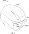
- FIG. 13illustrates a view of a helmet having a portion of a lens that is unsupported forming a gap between the lens and a brim of the helmet.
- any elements of the disclosuremay be used in any type of eyewear system.
- any elements of the disclosuremay be used in any headworn support (i.e., a head worn article that can support one or more lenses in the wearer's field of view).
- headworn supportscan include, but are not limited to, helmets, face masks, balaclavas, and breaching shields.
- embodiments disclosed hereincan be used with eyewear that have removable and replaceable lenses, embodiments are also contemplated in which the eyewear are not intended to provide for removable or replaceable lenses.
- some embodimentsare illustrated with lenses having “cylindrical” or “spherical” front and rear surfaces (surfaces which conform substantially to a portion of the surface of a sphere or cylinder, respectively), it will be understood by those having ordinary skill in the art that, in some embodiments, lenses having different surface geometries can be used.
- lenses of many front elevational shapes and orientations in the as-worn positioncan be used, beyond those illustrated herein.
- either the front or rear surface of a lensmay conform to the surface of a toroidal or other aspheric geometry.
- Any feature, structure, function, material, method, or step disclosed and/or illustrated in this specificationcan be used by itself or with or instead of any other feature, structure, function, material, method, or step disclosed and/or illustrated elsewhere in this specification.
- Each portion of this specificationis contemplated to be interchangeable and no portion is indispensable or essential.
- head worn supports with lensesare configured to provide desired optical functionality for a wearer.
- These headworn supportsmay also be used to intercept light, wind, dust, etc. from directly in front of the wearer and peripherally along the sides.
- the lens or lensescan become clouded through condensation on the inner surface of the lens (e.g., the surface nearest the face of the user), reducing the wearers visibility and/or degrading the optical performance of the lens.
- the head worn supportcan be configured to be vented using active or passive means. Venting can increase air flow at the inner surface or region of the lens and between the lens and the user, thereby reducing condensation.
- holes or other passagewaysmay be introduced into the structures of the headworn support, such as frames, and/or lenses to provide a path for air to travel from one side of the headworn support (e.g., an exterior region) to the other (e.g., an interior region) to increase air flow.
- one side of the headworn supporte.g., an exterior region
- the othere.g., an interior region
- thismay have the undesirable effect of allowing light to pass through such passageways into the eye of the user and/or allowing particles, dust, or debris through the holes to contact the user around the eye.
- headworn supportssuch as eyewear
- Some examples of headworn supports, such as eyewear, disclosed hereinare configured to provide passive venting by providing one or more pathways between a lens and a frame and/or by providing a smooth rear profile to allow a laminar flow of air on a posterior surface of the lens.
- the one or more passive-venting pathwaysprovide a tortuous path between a frame and a lens of the headworn support to the eye of a wearer (e.g., they do not provide a direct path to the eye of the wearer from an exterior region).
- the headworn support provided hereincan provide venting while reducing or preventing unwanted light, wind, particles, or other debris from contacting the eye of the user.
- a headworn supportsuch as an eyewear
- a headworn supportsuch as an eyewear
- the gapis configured so that there is a tortuous path between the frame and the lens (e.g., there is no direct path between the frame and the lens to the eye of the user).
- the headworn supportcan be configured to position the lens near the face of the user so that there is no direct path for light to travel to the eye of the user from the top of the headworn support.
- the frame of the headworn supportcan be configured so that a portion of a posterior surface of the frame does not extend rearward from a posterior extension of the posterior lens surface.
- the frame of the head worn supportcan be configured so that a portion of the posterior surface of the frame extends rearward of from the posterior extension of the posterior lens surface, where the extension is less than or equal to about 4 mm, less than or equal to about 3.8 mm, less than or equal to about 3.5 mm, less than or equal to about 3.3 mm, less than or equal to about 3 mm, less than or equal to about 2.6 mm, less than or equal to about 2.25 mm, or less than or equal to about 2 mm.
- the extensioncan be less than or equal to about 3.2 ⁇ a center thickness of the lens, less than or equal to about 3 ⁇ the center thickness of the lens, less than or equal to about 2.5 ⁇ the center thickness of the lens, less than or equal to about 2 ⁇ the center thickness of the lens, less than or equal to about 1.5 ⁇ the center thickness of the lens, less than or equal to about 1 ⁇ the center thickness of the lens, or less than or equal to about 0.67 ⁇ the center thickness of the lens.
- the portion of the frame that either does not extend past the posterior extension or that extends less than the stated distance past the posterior extensioncan have a total length that is at least 25% of the total chord length of the lens, al least 40% of the total chord length of the lens, at least 50% of the total chord length of the lens, at least 25% and/or less than or equal to about 80% of the total chord length of the lens, at least 35%, and/or less than or equal to about 70% of the total chord length of the lens, or al least 45% and/or less than or equal to about 60% of the total chord length of the lens.
- this structure and/or other structurescan produce laminar flow of air between the lens and the face of the user that can increase ventilation as compared to headworn supports having a frame that extends past the lens in the posterior direction towards the face of the user, thereby introducing turbulence into the flow of air.
- This featuremay be particularly advantageous for headworn supports, such as eyewear and face masks, that generally conform to the shape of the face of the wearer because with such headworn supports there is typically less space between the face of the wearer and the lens. Where there is less space, airflow may be reduced, resulting in reduced venting of the lens and potentially increasing condensation on the lens compared to lenses that are generally positioned away from the face from a wearer.
- a headworn supportsuch as an eyewear
- an interchangeable lensconfigured to be used with eyeglasses and/or with goggles.
- the frame of the eyeglassescan be semi-rimless and the lens can be secured to the frame using active and passive retention systems.
- the eyeglassescan include earstems to secure the eyeglasses in place on the head of the wearer so that the front frame does not contact the face of the wearer.
- This same lenscan be removed from the frame of the eyeglasses and secured in a goggle frame.
- the gogglecan have full orbitals and can be configured to contact a face of the user, using, a bead strap to secure it in place.
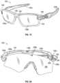
- FIGS. 1 A- 1 Cillustrate front perspective views of example embodiments of eyewear, such as eyeglass 100 .
- FIG. 1 Aillustrates an eyeglass 100 with a unitary lens 108
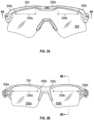
- FIGS. 1 B and 1 Cillustrate eyeglass 100 with dual lenses 108 a . 108 b
- FIGS. 1 A and 1 Billustrate eyeglass 100 with partial orbitals (e.g., a frame 104 of the eyeglass 100 does not extend entirely around the lens 108 )
- FIG. 1 Cillustrates eyeglass 100 with full orbitals (e.g., a frame 104 of the eyeglass extends entirely around the lenses 108 a , 108 b ).
- the passive venting systems and interchangeable lens designs described hereincan be applied to embodiments of eyeglasses with unitary lenses, dual lenses, partial orbitals, and full orbitals as well as other types of eyewear such as, but not limited to, goggles.
- the passive venting systems and interchangeable lens designs described hereincan be applied to other types of headworn supports such as, but not limited to, helmets, face masks, balaclavas, and breaching shields.
- the eyeglass 100comprises a pair of ear stems 102 a , 102 b , a frame 104 , retention components 106 , and a lens 108 .
- the eyeglass 100is configured such that the frame 104 and the lens 108 form a gap above the eyes of the user (e.g., around a plane that is generally parallel to the longitudinal or midsagittal plane and that intersects the eye of the user and the frame 104 and lens 108 ) as shown, for example, in FIGS. 3 A- 5 B . As illustrated, these gaps are not visible when looking at the eyeglass 100 from the front.
- the eyeglass 100provides an optically blind venting system, which can refer to a venting system that is not readily visible when viewing the eyeglass 100 straight on.
- the eyeglass 100can be configured such that the lens 108 can be removed and replaced. However, in some embodiments, the lens 108 may not be removable or replaceable.
- the eyeglass 100can include nose piece 110 attached to the lens 108 to nest on a nose of the wearer when in use.
- the lens 108 or lenses 108 a . 108 b 102 bcan be plano lenses (e.g., not curved).
- the lens 108 or lenses 108 a , 108 b 102 bcan be linear (not curved) along a vertical plane (e.g., cylindrical or frusto-conical lens geometry).
- the lens 108 or lenses 108 a . 108 bcan be aligned substantially parallel with the vertical axis such that the line of sight is substantially normal to the anterior surface and the posterior surface of the lens.
- the lens 108 or lenses 108 a . 108 bare angled downward such that a line normal to the lens is offset from the straight ahead normal line of sight by an angle ⁇ .
- the angle ⁇ of off setcan be greater than about 0° and/or less than about 30°, or greater than about 10° and/or less than about 20°, or about 15°, although other angles ⁇ outside of these ranges may also be used.
- Various cylindrically shaped lensesmay be used.
- the anterior surface and/or the posterior surface of the lens 108 or lenses 108 a . 108 bcan conform to the surface of a right circular cylinder such that the radius of curvature along the horizontal axis is substantially uniform.
- An elliptical cylindercan be used to provide lenses that have non-uniform curvature in the horizontal direction.
- a lensmay be more curved near its lateral edge than its medial edge.
- an oblique (non-right) cylindercan be used, for example, to provide a lens that is angled in the vertical direction.
- the retention components 106can be configured to removably secure the lens 108 to the frame 104 , thereby allowing the wearer to interchange the lens 108 of the eyeglass 100 .
- the lens 108can be interchanged for a different lens if the lens 108 becomes damaged or dirty
- the lens KBcan be interchanged for a different lens having different optical properties depending on the conditions of use.
- the retention components 106can be configured to retain the lens 108 on the frame 104 in the event of impact to the lens 108 (e.g., a ballistic impact).
- the passive and/or active retention mechanism(s) 106can be disposed along any portion of the boundary between the lens 104 and the frame 108 .
- the unitary lens 108has a passive lateral connector, a passive medial connector, and an active lateral connector, as detailed further below.
- the lens 108 and the frame KMcan be configured to not contact one another.
- the space between the lens 108 and the frame 104can provide for passive venting of the lens 108 .
- the extensioncan be less than or equal to about 3.2 ⁇ a center thickness of the lens 108 , less than or equal to about 3 ⁇ the center thickness of the lens 108 , less than or equal to about 2.5 ⁇ the center thickness of the lens 108 , less than or equal to about 2 ⁇ the center thickness of the lens 108 , less than or equal to about 1.5 ⁇ the center thickness of the lens 108 , less than or equal to about 1 ⁇ the center thickness of the lens 108 , or less than or equal to about 0.67 ⁇ the center thickness of the lens 108 .
- the configuration of the posterior surface of the lens 108 and the posterior location and/or shape of the frame 104can cooperate to facilitate a laminar flow of air across the posterior surface of the lens 108 to assist in venting the lens 108 .
- the 108 bcan be configured such that there are gaps between the lens 108 a , 108 b and the frame 104 at any of a variety of locations around the frame 104 , such as the orbitals. For example, gaps can exist above the eyes of the wearer, below the eyes of the wearer, and/or lateral of the eyes of the wearer as shown for example, in FIGS. 3 A- 5 B . Additionally, for the eyeglass 100 with full orbitals, the posterior surface of the frame 104 can be configured to not extend rearward of the posterior extension of the posterior surface of the lens 108 a . 108 b or to extend less than the stated distances rearward of this posterior extension, where the posterior extension of the lens can be made in any direction (e.g., vertically upward, vertically downward, horizontally, or any combination of these).
- the lenscan comprise one or more surfaces, edges, or structures that can be engaged by the lens retention mechanisms 106 of the frame 104 .
- the lens retention mechanism(s) 106can comprise one or more active and/or passive engagement mechanisms such as those described herein.
- a stationary or passive lens retention mechanismcan be formed between a complementary retention surf ace carried by the frame 104 and a retention surface of the lens 108 , such as the edge of a slot, notch, projection or aperture hieing generally away from the frame 104 to provide an interference fit.
- the retention mechanism 106 ccan be an active retention mechanism.
- the retention mechanism 106 ccan include a rotating door 202 and a protrusion 204 , the protrusion being configured to pass through a locking receptacle 206 on the frame 104 .
- the protrusion 204can engage with the locking receptacle 206 on a lateral side of the frame 104 .
- the protrusion 204can comprise a protruding element attached to the door 202 which is rotatably movable between a first position in which the lens 508 may be freely positioned within or removed from the retention mechanism 106 c , and a second position in which the lens 108 is locked within the retention mechanism 106 c.
- the retention mechanisms 106 a , 106 bcan generally be passive mechanisms that receive projections 208 a . 208 b of the lens 108 such that the projections 208 a , 208 b are seated in the corresponding recesses formed by opposing walls of the retention mechanisms 106 a . 106 b .
- the lens 108can be slid into place by pressing the projections 208 a . 208 b into the corresponding recesses or openings of the retention mechanisms 106 a , 106 b .
- the lens 108can be generally fitted into and retained within the retention mechanisms 106 a , 106 b in the frame 104 without also contacting other portions of the frame 104 .
- such an arrangementcan provide passive venting through the gap formed between the portions of the lens 108 not in contact with the retention mechanisms 106 a - 106 c and not in contact with the frame 104 .
- the first engagement portion 208 a of the lens 108When fitted onto the frame 104 , the first engagement portion 208 a of the lens 108 , comprising a laterally extending projection, can be seated within a groove or slot on the frame 104 formed by opposing walls of the retention mechanism 106 a .
- the second engagement portion 208 b of the lens 108comprising an angled projection, can be sealed within a groove on the frame 104 formed by opposing walls within the retention mechanism 106 b .
- the first and second engagement portions 208 a , 208 bcan have different configurations and may be recesses, for example.
- the retention mechanismscan have different configurations and may be projections, for example.
- passive retention mechanisms and corresponding features of the lens 108can have a variety of configurations, including recesses, surface contours, cutouts, projections, slots, apertures, and other such surface structures and may be formed in a variety of shapes and/or sizes.
- the retention mechanisms 106 a , 106 bare shown as a single aperture, but can be formed as a plurality of apertures.
- FIGS. 3 A and 3 Billustrate front elevational views of example eyewear, such as eyeglass 300 having a portion of a lens 308 that is unsupported forming gaps 309 a , 309 b between the lens 308 and a frame 304 of the eyeglass 300 .
- the eyeglass 300can incorporate the features and structures of eyeglass 100 .
- the gap 309 acan be formed on a first side of the frame 304 and the gap 309 b can be formed on a second side of the frame 304 .
- the gap 309 a and 309 bcan be combined into a single, continuous gap.
- the gaps 309 a , 309 bcan be configured to allow air to flow around the lens 308 .
- the gaps 309 a . 309 ballow air to pass between the interior of the eyeglass 300 and the surrounding area.
- the gaps 309 a , 309 bcan be located at or near the eyes of a user (e.g., above an area defined by a plane that is parallel to the longitudinal or mid-sagittal plane and that intersects an eye of the user). As shown in the illustrated embodiment, the gaps 309 a , 309 b are each continuous throughout its length.
- gaps 309 a , 309 bcan be further divided into more sub-gaps such that gaps 309 a and/or 309 b are not continuous throughout their lengths. These sub-gaps can be formed, for example, where there are additional contact points between the contact points 306 a , 306 b , and/or 306 c such that the frame 304 and the lens 308 can be configured to be spaced apart from one another at various locations.
- one or both gaps 309 a , 309 bcan be divided into two sub-gaps, three sub-gaps, four sub-gaps, five sub-gaps, six sub-gaps, or more.
- one or both gaps 309 a . 309 bcan be divided into at least two sub-gaps, at least three sub-gaps, al least four sub-gaps, al least five sub-gaps, at least six sub-gaps, or more.
- the gaps 309 a , 309 bcomprise about half of the total length of the upper edge of the lens 308 .
- the total length of the upper edge of the lens 308can be the chord length of the upper edge of the lens 308 and the total length of the gaps 309 a , 309 b can be chord lengths of the gaps 309 a , 309 b .
- an upper edge of the lens 308may have a total chord length of about 170 mm and the total chord length of the gaps 309 a , 309 b can be about 85 mm with each gap 309 a having a continuous chord length of about 425 mm.
- the total length or extent of the gaps(e.g., including sub-gaps) can be larger or smaller than this.
- the total chord length of the gaps 309 a , 309 b relative to the total chord length of the lens 308can be at least about 25%, at least about 40%, at least about 50%, at least about 25% and less than and/or equal to about 80%, at least about 35% and less than and/or equal to about 70%, or at least about 45% and less than and/or equal to about 60%.
- the gaps 309 at the upper edge of the lens 308 and the gaps between the lens 308 and the face of the user at the bottom of the eyeglass 300can cooperate to produce a chimney effect that draws fresh air into an interior region of the eyeglass 300 from the bottom and expels air from the interior region of the eyeglass 300 from the top thereof.
- the total length of the upper edge of the lens 308can be the perimeter length (i.e., measured along the periphery), such as the are length, of the upper edge of the lens 308 and the total length of the gaps 309 a , 309 b can be the perimeter lengths, such as the arc lengths, of the gaps 309 a . 309 b . Accordingly, it is to be understood that any of the ratios and dimensioned above can be with respect to the perimeter lengths. In instances where the term “total length” is used, it should be understood that either the chord length or the perimeter length can be used.
- the gaps 309 a , 309 bare generally hidden from view as the frame 304 serves to block a view of the gaps 309 a , 309 b .
- the gaps 309 a . 309 bare part of an optically blind venting system, or a venting system that includes gaps that are not visible when viewed straight on from a distance that is greater than or equal to about the width of the lens.
- the gaps 309 aare part of an optically blind venting system, or a venting system that includes gaps that are not visible when viewed straight on from a distance that is greater than or equal to about the width of the lens.
- gaps 309 a , 309 bare not visible when viewed straight on from about a foot or so away from the eyeglass 300
- only a portion of gaps 309 a , 309 bmay be visible when viewed straight on from a distance that is greater than or equal to about the width of the lens, such that the gaps 309 a , 309 b are part of a primarily optically blind venting system.
- the visible portion of the gaps 309 a . 309 bmay be less than or equal to about 10%, of the total venting area defined between the upper edge 307 of the lens 308 and the lower edge of the frame 304 .
- the visible portion of the gaps 309 a . 309 bmay be less than or equal to about 20%, less than or equal to about 30%, less than equal to about 40%, of the total venting area defined between the upper edge 307 of the lens 308 and the lower edge of the frame 304
- the eyeglass 300can have multiple contact points where the frame 304 contacts the lens 308 . These contact points can provide structural support and can be referred to as attachment points.
- the contact points 306 a - 306 dcan be attachment points because they provide structural support to the lens 308 or lenses 308 a . 308 b .
- the gaps 309 a , 309 bcan be made up of a number of sub-gaps between contact points.
- the total gap length(e.g., the length of the gap 309 a or 309 b ) can be the sum of the lengths of each sub-gap making up the gap 309 a or 309 b.
- FIG. 4 Aillustrates a partial top view of the example eyeglass 300 illustrated in FIG. 3 A .
- FIG. 4 Aillustrates the passive retention mechanism 106 b interacting with the protrusion 305 of the lens 308 .
- the upper edge 307 of the lens 308is spaced apart from the frame 304 when the lens 308 is secured to the frame.
- the gaps 309 a , 309 bcan be more clearly seen in this view.
- FIG. 4 Billustrates a partial side view of the example eyeglass 300 illustrated in FIG. 3 B .
- the following disclosureapplies to both unitary lens embodiments and dual lens embodiments. Accordingly, the disclosure is provided with respect to a line of sight of a user rather than describing the eyeglass as a whole.
- FIG. 4 Billustrates the gap 309 b between the frame 304 and the lens 308 b when the lens 308 b is secured to the eyeglass 300 .
- a posterior extension 310e.g., a plane, a line, a curved surface, or a curved line
- This posterior extension 310can define an imaginary plane, line, curve, or curved surface.
- a posterior surface of the frame 304can be configured to extend rearward of the posterior extension 310 with a distance.
- the distance, Dfcan be defined in terms of the lens center thickness.
- the lens 308can have a center thickness that is at least about 1.25 mm and/or less than or equal to about 0.3.5 mm, at least about 1.5 mm and/or less than or equal to about 3 mm, or at least about 1.9 mm and/or less than or equal to about 2.7 mm.
- the rearward extension of the frame 304 , Dfcan be less than or equal to about 3.2 ⁇ the center thickness of the lens 308 , less than or equal to about 3 ⁇ the center thickness of the lens 308 , less than or equal to about 2.5 ⁇ the center thickness of the lens 308 , less than or equal to about 2 ⁇ the center thickness of the lens 308 , less than or equal to about 1.5 ⁇ the center thickness of the lens 308 , less than or equal to about 1 ⁇ the center thickness of the lens 308 , or less than or equal to about 0.67 ⁇ the center thickness of the lens 308 .
- the posterior surface of the frame 304is configured to not extend rearward of the posterior extension 310 (e.g., the posterior extension 310 does not intersect the frame 304 or Df ⁇ 0).
- the posterior extension 310generally extends the shape of the posterior surface of the lens 308 wherein the lens 308 can be piano or can conform to a curved shape such as, for example and without limitation, a spherical shape, a right circular cylinder, a frusto-conical shape, a toroid, an elliptic cylinder, an ellipsoid, an ellipsoid of revolution, other asphere or any of a number of other three dimensional shapes described elsewhere herein.
- the eyeglass 300can reduce condensation by allowing air flow to form a laminar flow. This can be contrasted with a frame that extends significantly rearward of a posterior extension of a lens which could cause turbulent air flow, reducing the flow of air and thereby reducing the anti-fogging characteristics of the eyeglass.
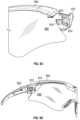
- FIGS. 5 A and 5 Billustrate partial views of a lens 508 and a frame 504 with respect to an eye of a user to illustrate venting angles and illumination angles.
- FIG. 5 Aillustrates a cross-section of the frame 504 above an eye of a user.
- the location and configuration of the frame 504 at that locationcan be configured so that there is a tortuous path to the user's eye (e.g., there is no direct path for light to travel to the user's eye without first passing through the lens 508 ). This may be advantageous to reduce or prevent undesirable stray light from entering the user's vision.
- the angle from the user's eye to the edge of the frame 504can be referred to as the illumination angle, ⁇ A .
- the illumination anglecan be less than or equal to about 48 degrees. In some embodiments, the illumination angle can be at least about 40 degrees and/or less than or equal to about 55 degrees, al least about 44 degrees and/or less than or equal to about 52 degrees, or at least about 46 degrees and/or less than or equal to about 50 degrees.
- the frame 504 and lens 508can be configured to be relatively close to the face of the wearer so that light cannot travel in a straight line to the user's eye from above the user's eye without first travelling through the lens 508 .
- features of the frame 504can be used in any type of eyewear including, but not limited to, a unitary lens eyeglass, a dual lens eyeglass, an eyeglass with partial orbital, an eyeglass with full orbitals, and a goggle.
- features of the frame 504can be used with any other type of head worn support including, but not limited to, helmets, face masks, balaclavas, and breaching shields.
- the illumination anglecan also refer to angles that are below the horizon as well as angles that extend temporally relative to a plane parallel to the longitudinal or mid-sagittal plane.
- the frame 504can be configured to provide illumination angles that in turn allow a desirable amount of peripheral vision to the wearer.
- the frame 504 and lens 508can be configured to provide each eye a field of view that at least covers a circle having a radius greater than or equal to about 20 mm centered on a horizontal centerline and that is about 32 mm from the vertical centerline as measured at the lens 508 .
- FIG. 5 Billustrates a close-up view of the cross-section of the frame 504 above an eye of the user.
- the gap between the lens 508 and the frame 504is configured to be at least about 1 mm wide (e.g., d 1 and d 2 are about 1 mm).
- the gaps d 1 and d 2can be at least about 0.5 mm and/or less than or equal to about 3 mm, at least about 0.7 mm and/or less than or equal to about 2, mm at least about 0.8 mm and/or less than or equal to about 12 mm.
- the gap d1can be formed between a posterior surface 506 of frame 504 (the posterior surface 506 facing toward a wearer's head in an as-worn position) and an interior surface of lens 508 facing away from the wear's head in an as-worn position.
- the venting angle, ⁇ Vcan be defined as the angle from the horizon for a direct path through the gap formed by the frame 504 and the lens 508 .
- the venting angleis al least about 32 degrees, in various implementations, the venting angle can be greater than 0 (e.g., where positive angles are angles measured vertically upward from horizontal).
- the venting anglecan be at least about 5 degrees and/or less than or equal to about 60 degrees, at least about 10 degrees and/or less than or equal to about 50 degrees, or at least about 20 degrees and/or less than or equal to about 40 degrees. Because this angle is positive, debris, particles, and dust will be directed away from the eyes of the user. Similarly, because this angle is positive, there is no direct path through the gap to the eye of the user.
- the venting angle and illumination angle formed by the lens 508 and the frame 504cooperate to increase passive venting and reduce stray light and particulates at the user's eye.
- the gapcan increase air flow across the posterior surface of the lens 508 while the frame 504 mid lens 508 act to protect the user's eyes from light and debris.
- FIG. 6illustrates a partial view of a lateral passive retention mechanism 606 of a frame 604 for a lens 608 .
- the lens 608can include a protrusion 602 that is configured to seat within a receptacle 606 formed in the frame 604 of eyewear, such as the illustrated eyeglass.
- This lateral retention mechanismcan act to align and to secure the lens 608 in the eyewear, allowing for a single active retention mechanism, described herein with reference to FIGS. 9 A to 9 D .
- FIG. 7illustrates a partial view of a passive retention mechanism 706 near a midline of a frame 704 for a lens 708 .
- the lens 708can include an angled protrusion 702 that is configured to sit within a groove 706 formed within the frame 704 .
- This midline retention mechanismprovides additional support and aligns the lens 708 when the lens is in use and when the lens is installed.
- FIG. 8illustrates a view of a lens 808 situated in a frame 804 having an active retention mechanism 806 on a lateral portion of the frame 804 .
- the passive retention mechanismsact to align the lens 808 so that the protrusion 802 is properly situated to allow the active retention mechanism, described heroin with reference to FIGS. 9 A to 9 D , to lock the lens 808 in place relative to the frame 804 .
- the framecan include one or more contact points where the frame makes contact with the lens.
- One or more of these contact pointscan be attachment points, or points where the frame provides structural support to the lens (e.g., through an interference fit).
- An attachment pointcan be an active attachment point (e.g., an active retention mechanism) or a passive attachment point (e.g., a passive retention mechanism).
- the framecan include one or more passive attachment points and/or one or more active attachment points.
- the attachment pointscan be the only locations where the lens contacts the frame of an eyewear.
- portions of the frame between the contact pointsdo not contact the frame and form a gap between the frame and the lens to provide passive venting for the eyewear, as described elsewhere herein.
- FIGS. 9 A- 9 Dillustrate several views of an active retention mechanism of a frame 904 securing a lens 908 to the frame 904 .
- the active retention mechanismincludes a door 912 , a projection 914 , and a hinge that allows the door to pivot or otherwise move, wherein the door is configured to have a contour that matches the frame 904 and the earstem 902 , to provide an aesthetically pleasing configuration when locked.
- the lens 908includes the protrusion 910 that slides or otherwise moves into place when the lens is properly sealed in the passive retention mechanisms described herein, and as illustrated in the transition from FIG. 9 B to FIG. 9 C .
- the door 912can transition to a closed state from an open state so that the projection 914 engages with the receptacle 916 . This is shown in the transition from FIG. 9 C to FIG. 9 D , which shows a near view of the active retention mechanism locked in place.
- the earstem 902can rotate freely from a folded state (e.g., approximately parallel to the frame 904 ) to an extended state (e.g., approximately perpendicular to the frame 904 ).
- This configurationprovides a dual hinge action, wherein the door 912 has a first hinge around which it pivots and the earstem has a second hinge around which it pivots.
- the earstem 902can rotate without disengaging the active retention mechanism.
- the earstem 902is in the extended position, the door is prevented from opening. In this way, the active retention mechanism can be made to be locked so as to prevent the lens 908 from being accidentally removed from the frame 904 .
- the earstem 902can be used to assist in locking the active retention mechanism in place to secure the lens 908 .
- Some embodiments described hereincan advantageously securely retain the lens relative to the frame while generally providing passive venting capabilities along with desirable optical characteristics.
- the lenscan be secured to and/or supported by the frame in a manner that generally preserves the as-molded geometry of the lens while preventing stray light from entering the user's eye. This can be accomplished while providing gaps between the frame and the lens to provide venting.
- Some embodiments disclosed hereincan advantageously provide an eyeglass or goggle in which the lens and/or ear stems can be easily removed and replaced by the wearer while enabling the wearer to mount the lens and providing superior ballistic resistance and lens stability.
- FIGS. 10 A- 10 Dillustrate several views of an example goggle 1000 configured to be used with embodiments of the lenses described herein.
- the goggle 1000is configured to receive the lens 1008 within a support structure, such as a goggle frame 1004 .
- the lens 1008comprises an arcuate unitary lens which extends across both of the wearer's right and left eye fields of view.
- the lens 1008is supported by the frame 1004 wherein the frame 1004 is configured to surround the lens 1008 and configured to contact the head of a user.
- the lens 1008 and the frame 1004are both configured with a downwardly concave indent or nosepiece opening for receiving the nose.
- the rear surface of the frame 1004is covered with a foam component 1005 or other compressible material, and is adapted to contact the wearer's face. Further, the elastic strap 1001 is connected to the opposing sides or ends of the frame 1004 so that the wearer can fit and wear the goggle on their bead.
- the surface of the foam component 1005 or other compressible material disposed at the rear of the goggle 1000makes contact with the wearer's face.
- This wearer-contacting surfacehas a radius of curvature in the horizontal plane that is adapted to conform from side to side of the wearer's face.
- the wearercan position the goggle frame 1004 onto her face and adjust the elastic strap 1001 around the back of her head in order to firmly, but comfortably secure the goggle frame 1004 in place.
- the foam component 1005is intended to contact the wearer's face and allow the goggle 1000 to conform to the surface of the wearer's face.
- the goggle frame 1004can be rigid or semi-rigid.
- the goggle frame 1004can be pliable and flexible to allow the lens 1008 to be easily inserted and removed.
- the goggle frame 1004can include a groove or channel 1012 around an interior portion of the goggle frame 1004 to provide a guide for the lens 1008 .
- the lens 1008can be positioned within the groove or channel 1012 structure, wherein the groove or channel 1012 structure includes one or more features that act as passive retention mechanisms to secure the lens in place during use.
- the goggle frame 1004can be worn on the head of the user without the lens 1008 , if so desired.
- FIG. 10 Dillustrates a cress-sectional side view of the goggle 1000 .
- the lens 1008 of the goggle 1000is mounted in the goggle frame 1004 with the features that allow it to be secured in an eyeglass frame acting to secure it in the goggle frame.
- the lens 1008can include protrusion 1010 configured to sit within a passive retention mechanism 1006 of the goggle frame 1004 .
- the interchangeable lens structure 1008can provide at least one interconnection point or engagement section 1010 between the lens 1008 and the retention mechanism 1006 where the lens 1008 is secured to the goggle frame 1004 .
- the interchangeable lens structure 1010can comprise one or more stationary structures, which can be used in combination to retain the lens 1008 in a mounted position within the goggle 1004 .
- Other examples of an interchangeable lens structure 1008 with a goggle frame 1004are provided in U.S. Pat. No. 8,800,067, issued Aug. 12, 2014, entitled “Eyewear with Interchangeable Lens Mechanism.” the entirety of which is incorporated herein by reference.
- the goggle frame 1004can incorporate a passive venting system.
- the goggle frame 1004can include structures, such us gaps, similar to those described above in connection with frames 104 , 304 .
- the gapscan be generally hidden from view as the frame 1004 serves to block a view of the gaps.
- the gapscan be part of an optically blind venting system, or a venting system that includes gaps that are not visible when viewed straight on from a reasonable distance (e.g., about a foot or so away from the goggle 1000 ).
- a reasonable distancee.g., about a foot or so away from the goggle 1000
- only a portion of gapsmay be visible when viewed straight on from a reasonable distance such that the gaps 309 a . 309 b are part of a primarily optically blind venting system.
- FIG. 13illustrates a perspective view of an example helmet 1300 configured to be used with a lens 1308 and which incorporates the passive venting features described above.
- the helmet 1300is configured to receive the lens 1308 within a support structure, such as a brow 1305 of a helmet frame 1304 .
- the lens 1308comprises an arcuate unitary lens which extends across both of the wearer's right and left eye fields of view.
- a portion of the helmet frame 1304can include a pliable and flexible portion to allow the lens 1308 to be easily inserted and removed.
- the brow 1305can include a groove 1306 around an interior portion of the brow 1305 to provide a guide for the lens 1308 .
- the lens 1308can be positioned within the groove 1306 structure, wherein the groove 1306 structure includes one or more features that act as passive retention mechanisms to secure the lens in place during use.
- the helmet frame 1304can be worn on the head of the user without the lens 1308 , if so desired.
- the lenses described hereincan be interchangeably used with a variety of different bead worn supports each having a different structure and function including, but not limited to, helmets, face masks, balaclavas, breaching shields, and eyewear such as eyeglasses and goggles.
- the same lenscan be interchangeably used with a helmet, goggles, and/or an eyeglass.
- a particular lenscan be utilized with any other combination of two or more different headworn supports. This can beneficially allow the wearer to utilize a single lens with a variety of different headworn supports depending on the particular activity. For example, the wearer may utilize the lens with a cycling helmet when biking and switch the lens onto an eyeglass when off the bike. In some instances, the wearer may later switch the lens from the eyeglass and onto a snow helmet, goggle, or balaclava for skiing.
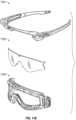
- FIGS. 11 A and 11 Brespectively illustrate front elevational and front perspective views of an example kit having an eyeglass frame 1101 , a goggle frame 1103 , and a lens 1102 compatible with both the eyeglass frame and the goggle frame.
- the lens 1102can be a unitary lens, as illustrated, or it can be two or more lenses. As described herein, the same lens 1102 can be configured to be secured to the eyeglass frame 1101 and the goggle frame 1103 using complementary but different retention mechanisms. In some embodiments, each of the eyeglass frame 1101 and the goggle frame 1103 can be independently worn without the lens 1102 .
- FIGS. 12 A and 12 Billustrate views of the example kit of FIGS.
- the eyeglass 1201can be formed by securing the lens 1102 to the eyeglass frame 1101 and the goggle 1202 can be formed by securing the lens 1102 to the goggle frame 1103 , wherein the eyeglass frame 1101 and the goggle frame 1103 do not share any components from the kit when forming the eyeglass 1201 and the goggle 1202 .
- the lens 1102is secured to the eyeglass frame 1101 .
- the eyewearsuch as eyeglasses described herein, can conform to the American National Standard for Occupational and Educational Personal Eye and Face Protection Devices standard ANSI/ISEA Z87.1-2010.
- the eyewearcan be configured to resist impact from a 6.35 mm (0.25 in.) diameter steel ball traveling at about 150 ft/s. In such a situation, the eyewear can be configured to prevent contact of the ball with the eye of a user.
- the eyewear disclosed hereincan conform to the Performance Specification for the Military Combat Eye Protection (MCEP) System standard MIL-PRT-32432(GL).
- the eyewearcan be configured to resist impact from a .15 caliber, 5.85 grain, T37 shaped projectile (e.g., a cylindrical-shaped, chamfered-edge fragment) at 640 to 660 ft/sec (e.g., about 650 ft/sec) at normal incidence to the primary lens without cracking, fracturing, or shattering, without being penetrated, or without having one or more fragments dislodging, etc.
- T37 shaped projectilee.g., a cylindrical-shaped, chamfered-edge fragment
- 660 ft/sece.g., about 650 ft/sec
- Conditional language used hereinsuch as, among others, “can,” “could,” “might,” “may,” “e.g.,” and the like, unless specifically slated otherwise, or otherwise understood within the context as used, is generally intended to convey that certain embodiments include, while other embodiments do not include, certain features, elements and/or steps. Thus, such conditional language is not generally intended to imply that features, elements and/or steps are in any way required for one or more embodiments or that one or more embodiments necessarily include logic for deciding, with or without other input or prompting, whether these features, elements and/or steps are included or are to be performed in any particular embodiment.
- Disjunctive languagesuch as the phrase “at least one of X, Y, Z” unless specifically stated otherwise, is otherwise understood with the context as used in general to present that an item, term, etc., may be either X, Y, or Z, or any combination thereof (e.g., X, Y, and/or Z). Thus, such disjunctive language is not generally intended to, and should not, imply that certain embodiments require at least one of X, at least one of Y, or at least one of Z to each be present.
Landscapes
- Health & Medical Sciences (AREA)
- Ophthalmology & Optometry (AREA)
- Physics & Mathematics (AREA)
- General Health & Medical Sciences (AREA)
- Engineering & Computer Science (AREA)
- Biomedical Technology (AREA)
- Heart & Thoracic Surgery (AREA)
- Vascular Medicine (AREA)
- Life Sciences & Earth Sciences (AREA)
- Animal Behavior & Ethology (AREA)
- Public Health (AREA)
- Veterinary Medicine (AREA)
- Optics & Photonics (AREA)
- General Physics & Mathematics (AREA)
- Otolaryngology (AREA)
- Eyeglasses (AREA)
Abstract
Description
Claims (33)
Priority Applications (1)
| Application Number | Priority Date | Filing Date | Title |
|---|---|---|---|
| US16/708,140US12239579B2 (en) | 2015-10-09 | 2019-12-09 | Headworn supports with passive venting and removable lens |
Applications Claiming Priority (3)
| Application Number | Priority Date | Filing Date | Title |
|---|---|---|---|
| US201562239740P | 2015-10-09 | 2015-10-09 | |
| US15/288,272US10687981B2 (en) | 2015-10-09 | 2016-10-07 | Headworn supports with passive venting and removable lens |
| US16/708,140US12239579B2 (en) | 2015-10-09 | 2019-12-09 | Headworn supports with passive venting and removable lens |
Related Parent Applications (1)
| Application Number | Title | Priority Date | Filing Date |
|---|---|---|---|
| US15/288,272ContinuationUS10687981B2 (en) | 2015-10-09 | 2016-10-07 | Headworn supports with passive venting and removable lens |
Publications (2)
| Publication Number | Publication Date |
|---|---|
| US20200113738A1 US20200113738A1 (en) | 2020-04-16 |
| US12239579B2true US12239579B2 (en) | 2025-03-04 |
Family
ID=57218990
Family Applications (2)
| Application Number | Title | Priority Date | Filing Date |
|---|---|---|---|
| US15/288,272Active2037-08-19US10687981B2 (en) | 2015-10-09 | 2016-10-07 | Headworn supports with passive venting and removable lens |
| US16/708,140Active2038-02-06US12239579B2 (en) | 2015-10-09 | 2019-12-09 | Headworn supports with passive venting and removable lens |
Family Applications Before (1)
| Application Number | Title | Priority Date | Filing Date |
|---|---|---|---|
| US15/288,272Active2037-08-19US10687981B2 (en) | 2015-10-09 | 2016-10-07 | Headworn supports with passive venting and removable lens |
Country Status (4)
| Country | Link |
|---|---|
| US (2) | US10687981B2 (en) |
| EP (1) | EP3360006A1 (en) |
| JP (1) | JP6773288B2 (en) |
| WO (1) | WO2017062813A1 (en) |
Families Citing this family (58)
| Publication number | Priority date | Publication date | Assignee | Title |
|---|---|---|---|---|
| US9241833B2 (en) | 2012-08-31 | 2016-01-26 | Oakley, Inc. | Eyewear having multiple ventilation states |
| US10716708B2 (en)* | 2013-01-25 | 2020-07-21 | 100% Speedlab, Llc | Protective eyewear systems and methods |
| WO2015148770A1 (en) | 2014-03-27 | 2015-10-01 | Oakley, Inc. | Mounting mechanism for eyewear |
| EP3387485B1 (en) | 2015-12-08 | 2025-05-07 | Oakley, Inc. | Eyewear traction devices and methods |
| US10359642B2 (en) | 2016-04-22 | 2019-07-23 | Oakley, Inc. | Mounting mechanism for eyewear |
| CA172500S (en)* | 2016-07-14 | 2017-08-29 | Xiamen Prosun Trading Co Ltd | Glasses |
| USD821486S1 (en) | 2016-11-01 | 2018-06-26 | Oakley, Inc. | Set of eyeglass components |
| USD818522S1 (en) | 2016-11-01 | 2018-05-22 | Oakley, Inc. | Pair of eyeglasses |
| USD810183S1 (en) | 2016-11-01 | 2018-02-13 | Oakley, Inc. | Eyeglass component |
| USD846626S1 (en)* | 2017-01-27 | 2019-04-23 | Henrik Stenson Eyewear Sweden Ab | Pair of sunglasses |
| USD832910S1 (en)* | 2017-02-01 | 2018-11-06 | Milner Sports, LLC | Eyewear |
| USD857787S1 (en)* | 2017-02-01 | 2019-08-27 | Milner Sports, LLC | Eyewear |
| USD870191S1 (en)* | 2017-03-17 | 2019-12-17 | Tifosi Optics, Inc. | Sport glasses |
| USD931931S1 (en)* | 2017-04-20 | 2021-09-28 | Tifosi Optics, Inc. | Sport glasses |
| USD835178S1 (en)* | 2017-05-22 | 2018-12-04 | Milner Sports, LLC | Eyewear |
| USD835180S1 (en)* | 2017-05-22 | 2018-12-04 | Milner Sports, LLC | Eyewear |
| USD831732S1 (en)* | 2017-05-22 | 2018-10-23 | Milner Sports, LLC | Eyewear |
| USD845380S1 (en)* | 2017-06-12 | 2019-04-09 | Brent Sheldon | Eyewear |
| USD837871S1 (en) | 2017-09-01 | 2019-01-08 | Roka Sports, Inc. | Sport eyeglasses |
| WO2019075089A1 (en) | 2017-10-11 | 2019-04-18 | Roka Sports, Inc. | Eyeglasses with interchangeable lenses |
| USD842365S1 (en)* | 2017-10-13 | 2019-03-05 | Oakley, Inc. | Eyeglasses |
| USD842364S1 (en)* | 2017-10-13 | 2019-03-05 | Oakley, Inc. | Eyeglasses |
| USD842363S1 (en)* | 2017-10-13 | 2019-03-05 | Oakley, Inc. | Eyeglasses |
| MX2020004439A (en)* | 2017-10-19 | 2021-01-08 | Andrew Farmer | Interchangeable eyewear system. |
| USD861061S1 (en)* | 2017-11-15 | 2019-09-24 | Tifosi Optics, Inc. | Sport glasses |
| USD849823S1 (en)* | 2018-03-13 | 2019-05-28 | Roka Sports, Inc. | Sport eyeglasses |
| USD849825S1 (en) | 2018-03-13 | 2019-05-28 | Roka Sports, Inc. | Sport eyeglasses |
| USD870802S1 (en)* | 2018-03-28 | 2019-12-24 | Roka Sports, Inc. | Sport eyeglasses |
| USD912722S1 (en) | 2018-04-06 | 2021-03-09 | Roka Sports, Inc. | Snap-in nose pads for eyewear |
| USD871497S1 (en)* | 2018-04-06 | 2019-12-31 | Roka Sports, Inc | Eyeglass temples |
| US11314105B2 (en) | 2018-07-26 | 2022-04-26 | Oakley, Inc. | Lens for eyewear and other headworn supports having improved optics |
| USD880573S1 (en)* | 2018-08-22 | 2020-04-07 | Guangzhou Jubao Sports Co., Ltd. | Goggles |
| US12298519B2 (en) | 2018-09-24 | 2025-05-13 | Apple Inc. | Display system with interchangeable lens |
| USD912128S1 (en)* | 2018-10-25 | 2021-03-02 | Guangzhou Julong Sports Co., Ltd. | Goggle |
| USD886893S1 (en)* | 2018-11-02 | 2020-06-09 | Guangzhou Jubao Sports Co., Ltd. | Goggle |
| EP3646829B1 (en)* | 2018-11-05 | 2025-05-07 | Smith Sport Optics, Inc. | Goggle lens with compound curvature for downward field of view enhancement |
| USD892205S1 (en)* | 2019-01-18 | 2020-08-04 | Reyewear Acquisition, Inc. | Eyewear brow bar |
| USD892201S1 (en)* | 2019-01-18 | 2020-08-04 | Reyewear Acquisition, Inc. | Eyewear |
| USD936134S1 (en)* | 2019-01-18 | 2021-11-16 | Revision Military Inc. | Eyewear |
| USD903748S1 (en)* | 2019-01-29 | 2020-12-01 | Aiping Zhang | Goggle |
| USD933737S1 (en)* | 2019-02-21 | 2021-10-19 | Leatt Corporation | Goggles |
| CN217360473U (en) | 2019-02-22 | 2022-09-02 | 欧科蕾公司 | Rimless spectacle lens and rimless spectacle |
| USD915499S1 (en)* | 2019-04-12 | 2021-04-06 | 100% Speedlab, Llc | Goggles |
| USD895717S1 (en)* | 2019-04-26 | 2020-09-08 | Guangzhou Julong Sports Co., Ltd. | Goggle |
| USD900207S1 (en)* | 2019-05-31 | 2020-10-27 | Mei-Chu Chen | Eyeglass frame |
| USD896304S1 (en)* | 2019-05-31 | 2020-09-15 | Mei-Chu Chen | Eyeglass frame |
| KR102723835B1 (en)* | 2019-06-21 | 2024-10-31 | 애플 인크. | Display and vision correction system with removable lenses |
| USD912721S1 (en) | 2019-07-24 | 2021-03-09 | Roka Sports Inc. | Sport eyeglasses |
| USD935516S1 (en)* | 2019-11-03 | 2021-11-09 | Deyue Gu | Cycling sunglasses |
| US11428765B2 (en)* | 2019-11-05 | 2022-08-30 | Quality Electrodynamics, Llc | MRI head coil comprising an open shield |
| USD954797S1 (en)* | 2020-05-11 | 2022-06-14 | Huaisheng Wu | Sunglasses |
| US11903432B2 (en) | 2020-06-18 | 2024-02-20 | Julia BORNSTEIN | Face shield integration with eyewear |
| US11206882B1 (en)* | 2020-06-18 | 2021-12-28 | Julia BORNSTEIN | Face shield integration with eyewear |
| US11910853B2 (en) | 2020-06-18 | 2024-02-27 | Julia BORNSTEIN | Face shield integration with eyewear |
| US12085783B2 (en)* | 2020-07-24 | 2024-09-10 | Ocuclips Llc. | Eyewear affixable cushion |
| TWI734580B (en)* | 2020-08-10 | 2021-07-21 | 王智弘 | Lens foot connecting structure |
| US20220206321A1 (en)* | 2020-12-30 | 2022-06-30 | Yi-Ping Tung | Eyeglass lens replacement assembly |
| USD1084106S1 (en)* | 2023-11-21 | 2025-07-15 | 100% Speedlab, Llc | Eyewear |
Citations (432)
| Publication number | Priority date | Publication date | Assignee | Title |
|---|---|---|---|---|
| US245268A (en) | 1881-08-09 | Frame for eyeglasses | ||
| US1206457A (en) | 1916-06-03 | 1916-11-28 | Silas B Mills | Spectacles or other vision-glasses. |
| US1308477A (en) | 1919-07-01 | William m | ||
| US1588775A (en) | 1924-07-30 | 1926-06-15 | American Optical Corp | Eye protector |
| US1839386A (en) | 1927-07-11 | 1932-01-05 | Fischer Charles | Goggles |
| US1910456A (en) | 1929-05-02 | 1933-05-23 | American Optical Corp | Goggles |
| US1918954A (en) | 1927-10-18 | 1933-07-18 | American Optical Corp | Goggle |
| US1942393A (en) | 1927-06-15 | 1934-01-09 | American Optical Corp | Aviator's goggles |
| US1943910A (en) | 1927-06-15 | 1934-01-16 | American Optical Corp | Goggles |
| US2042400A (en) | 1934-08-14 | 1936-05-26 | Victor R Hon | Optical clasp |
| GB468443A (en) | 1936-01-03 | 1937-07-05 | Frank Layton Grier | Improvements in or relating to nose pads for eyeglasses |
| US2098512A (en) | 1933-08-01 | 1937-11-09 | Bay State Optical Co | Eyeglass construction |
| GB512419A (en) | 1938-02-01 | 1939-09-15 | Twinco Ltd | Improvements in or relating to the manufacture of spectacles and goggles |
| US2391361A (en) | 1943-09-11 | 1945-12-18 | Watchemoket Optical Co Inc | Goggle |
| US2443422A (en) | 1945-07-03 | 1948-06-15 | Julius E Hansen | Goggles |
| US2504157A (en) | 1943-09-23 | 1950-04-18 | Lapin Products Inc | Molded plastic sunglasses and the like |
| US2556847A (en) | 1949-05-27 | 1951-06-12 | Anglo Iranian Oil Co Ltd | Eyeshield |
| US2571704A (en) | 1948-09-17 | 1951-10-16 | American Optical Corp | Ophthalmic mounting |
| US2610323A (en) | 1950-07-28 | 1952-09-16 | American Optical Corp | Fage protective device |
| US2652746A (en) | 1950-12-11 | 1953-09-22 | Shanks Robert Randolph | Eyeglasses frame with detachably mounted lenses |
| US2671379A (en) | 1950-08-23 | 1954-03-09 | Polaroid Corp | Ophthalmic mounting |
| FR1126329A (en) | 1955-06-21 | 1956-11-20 | Dolomit | Eyeglass frame for the sun and for sight |
| US2799862A (en) | 1954-07-19 | 1957-07-23 | American Optical Corp | Eye protective means |
| FR1290346A (en) | 1961-03-03 | 1962-04-13 | Eyeglass frame improvements | |
| US3084595A (en) | 1960-01-11 | 1963-04-09 | Leon W Watts | Frame for eyeglasses |
| US3214767A (en) | 1962-12-20 | 1965-11-02 | Chicago Eye Shield Company | Face shield |
| US3229303A (en) | 1963-07-16 | 1966-01-18 | Renauld International Inc | Sportsman's goggle |
| US3233250A (en) | 1963-07-16 | 1966-02-08 | Renauld International Inc | Ski shield |
| US3383707A (en) | 1966-05-03 | 1968-05-21 | Bachmann Bros Inc | Flip-up sunglass construction |
| US3395964A (en) | 1964-04-03 | 1968-08-06 | Rene Nieder Dit Chartrice | Spectacle mounting with biased nose bridge and temple pieces |
| US3552840A (en) | 1968-09-16 | 1971-01-05 | Lorna R Braget | Eyeglass frame construction for removable lenses |
| FR2088866A5 (en) | 1970-04-28 | 1972-01-07 | Plastinax | |
| US3659931A (en) | 1970-08-03 | 1972-05-02 | Philip J Allen | Eye glass lens adjuster |
| US3691565A (en) | 1970-11-25 | 1972-09-19 | Omnitech Inc | Flight deck goggle |
| US3826564A (en) | 1970-11-02 | 1974-07-30 | Spector G | Eye glass frame for replaceable lenses |
| US3829201A (en) | 1973-06-28 | 1974-08-13 | Hilsinger Corp | Cushioning mount for a lens in the rim of an ophthalmic mounting |
| US3901589A (en) | 1974-07-08 | 1975-08-26 | American Cyanamid Co | Clip-on flip-up goggles |
| US3931646A (en) | 1974-06-26 | 1976-01-13 | American Optical Corporation | Double lens goggle |
| US4023214A (en) | 1976-05-17 | 1977-05-17 | Arthur Waldherr | Means for holding eyeglasses within a scuba mask |
| US4056853A (en) | 1975-05-26 | 1977-11-08 | K.D. Ottica S.N.C. | System for locking, in an easily disengageable manner, the lenses to eyeglasses, sportive swimming goggles or diving masks and similar general sportive articles, and the resulting articles |
| US4153347A (en) | 1977-06-08 | 1979-05-08 | Myer C Randolph | Eyeglass frames with removable, interchangeable lenses, rims and temple pieces |
| US4176921A (en) | 1977-06-03 | 1979-12-04 | Carrera International Corporation | Eyeglasses having removable lenses |
| US4178080A (en) | 1977-08-30 | 1979-12-11 | Elder Eugene E | Adjustable nose piece assembly for eyeglasses |
| US4264987A (en) | 1978-11-02 | 1981-05-05 | Runckel John L | Goggles |
| JPS5666915A (en) | 1979-10-17 | 1981-06-05 | Krautkraemer Gmbh | Method and circuit for varying gain of amplifier |
| JPS56126611A (en) | 1980-03-12 | 1981-10-03 | Hanken Seisakusho:Kk | Muffler |
| US4304469A (en) | 1980-02-25 | 1981-12-08 | Solomon Charles I | Eyeglass frame having removable lenses |
| US4314814A (en) | 1979-01-30 | 1982-02-09 | Essilor International, Cie Generale D'optique | Method of and apparatus for decorating substrates |
| US4331393A (en) | 1974-11-21 | 1982-05-25 | Bradley Jr James B | Ophthalmic fitting set and method |
| US4340282A (en) | 1979-10-13 | 1982-07-20 | Mamoru Murakami | Lens securing device |
| JPS57176119A (en) | 1981-04-24 | 1982-10-29 | Kyoraku Co Ltd | Manufacture of hollow material with decorative skin |
| US4357080A (en) | 1980-02-25 | 1982-11-02 | Sol-Optics, Inc. | Eyeglass frame having removable lens |
| JPS5979827A (en) | 1982-10-29 | 1984-05-09 | Hitachi Micro Comput Eng Ltd | Knocking detection system for engine |
| JPS59104127A (en) | 1982-12-07 | 1984-06-15 | Nippon Telegr & Teleph Corp <Ntt> | Formation of fine pattern |
| US4471496A (en) | 1983-06-27 | 1984-09-18 | Cabot Corporation | Articulated earmuff-to-headband attachment construction |
| US4515448A (en) | 1983-03-28 | 1985-05-07 | Oakley, Inc. | Sunglasses |
| JPS6094624A (en) | 1983-10-04 | 1985-05-27 | チンザー・テクステイルマシイネン・ゲゼルシヤフト・ミト・ベシユレンクテル・ハフツング | Mechanism for ring fine spinning frame and ring yarn twister |
| US4527291A (en) | 1983-02-01 | 1985-07-09 | Uvex Winter Optik Gmbh | Safety goggles, in particular for work use |
| JPS60143420A (en) | 1983-12-29 | 1985-07-29 | Fuji Photo Film Co Ltd | Inspecting method of magnetic head |
| JPS60146218A (en) | 1983-12-19 | 1985-08-01 | ソシエテ アノニム エシロール インタナシヨナル シ ジエネラル ドオプテイツク | Spectacles frame and support structural body for front to bemounted thereon |
| JPS61160422A (en) | 1984-12-27 | 1986-07-21 | Nitto Boseki Co Ltd | Method for infusible treatment of pitch fiber |
| US4616367A (en) | 1984-11-14 | 1986-10-14 | Jean Jr Joseph A | Headband with detachable lenses |
| JPS623774Y2 (en) | 1982-12-27 | 1987-01-28 | ||
| GB2181859A (en) | 1985-09-27 | 1987-04-29 | Morris Goldschmidt | Spectacles with manually replaceable lenses |
| US4662966A (en) | 1984-09-26 | 1987-05-05 | Nissha Printing Co. Ltd. | Apparatus for transfer printing |
| US4670084A (en) | 1983-06-20 | 1987-06-02 | David Durand | Apparatus for applying a dye image to a member |
| US4674851A (en) | 1985-01-11 | 1987-06-23 | Jannard James H | Removable multi-component sunglasses |
| US4686712A (en) | 1986-09-11 | 1987-08-18 | Spiva Lowell E | Goggle mounting system |
| US4715702A (en) | 1986-10-20 | 1987-12-29 | Dillon Stephen M | Decorative lens |
| US4730915A (en) | 1985-01-11 | 1988-03-15 | Oakley, Inc. | Detachable component sunglasses |
| US4747681A (en) | 1985-05-20 | 1988-05-31 | Brower Arthur B | Traction strip for eyewear |
| GB2199155A (en) | 1986-09-22 | 1988-06-29 | Morris Goldschmidt | Spectacles with manually replaceable lenses having split rims |
| US4759622A (en) | 1985-08-05 | 1988-07-26 | Optyl Eyewear Fashion International Corporation | Eyeglasses with exchangeable lenses |
| US4813775A (en) | 1987-12-04 | 1989-03-21 | Kaksonen Pirjo M | Eyeglass frames |
| US4822158A (en) | 1987-06-30 | 1989-04-18 | Optyl Eyewear Fashion International Corporation | Eyeglasses with removable lens assembly |
| US4843655A (en) | 1987-12-15 | 1989-07-04 | Alpina Int'l Sport + Optik-Vertriebs-Gmbh | Protective goggles |
| FR2626682A1 (en) | 1989-01-31 | 1989-08-04 | Mugnier Marc | Positioning hinges suitable for spectacle frames |
| US4859048A (en) | 1985-01-11 | 1989-08-22 | Oakley, Inc. | Cylindrical lens for sunglasses |
| US4867550A (en) | 1985-01-11 | 1989-09-19 | Oakley, Inc. | Toroidal lens for sunglasses |
| US4878749A (en) | 1988-06-29 | 1989-11-07 | Mcgee James E | Protective eyewear with interchangeable decorative frames |
| US4901374A (en) | 1988-04-22 | 1990-02-20 | Prolens | Face shield |
| US4951322A (en) | 1989-09-27 | 1990-08-28 | Lin David J T | Detachable mono-glass sports goggles |
| JPH02240360A (en) | 1989-03-14 | 1990-09-25 | Sekisui Chem Co Ltd | Eaves structure |
| US4978209A (en) | 1988-04-27 | 1990-12-18 | Nikon Corporation | Hinge for spectacle frame |
| US4983030A (en) | 1987-10-08 | 1991-01-08 | Up To Date, Inc. | Retaining mechanism for eyeglasses having interchangeable lenses |
| US5007727A (en) | 1990-02-26 | 1991-04-16 | Alan Kahaney | Combination prescription lens and sunglasses assembly |
| US5016293A (en) | 1990-07-25 | 1991-05-21 | Brett Lickle | Air induction system for goggle |
| US5048944A (en) | 1987-06-30 | 1991-09-17 | Optyl Eyewear Fashion International Corporation | Eyeglasses with removable lens assembly |
| US5056163A (en) | 1990-05-15 | 1991-10-15 | Chou Chih T | Sweat-absorbing strip for sport goggles |
| US5069541A (en) | 1988-08-02 | 1991-12-03 | Hellberg International Limited | Rigid framed safety goggles having replaceable lens |
| EP0495767A1 (en) | 1991-01-17 | 1992-07-22 | SILHOUETTE INTERNATIONAL GESELLSCHAFT m.b.H. | Hinge between temple and frame of spectacles |
| EP0496292A1 (en) | 1991-01-21 | 1992-07-29 | KILLER LOOP S.p.A. | Spectacle frame with detachable elements |
| US5144344A (en) | 1989-05-25 | 1992-09-01 | Sony Corporation | Spectacles for stereoscopic pictures |
| US5170502A (en) | 1990-08-23 | 1992-12-15 | Uvex Winter Optical, Inc. | Protective eyewear assembly |
| US5182587A (en) | 1988-11-18 | 1993-01-26 | Murai Co., Ltd. | Eyeglass frame having antirotation connection |
| US5182586A (en) | 1990-01-26 | 1993-01-26 | Moda Solaris S.P.A. | Sunglasses structure |
| US5191364A (en) | 1989-09-11 | 1993-03-02 | Kopfer Rudolph J | Protective eyewear for use in sports and the like |
| US5208614A (en) | 1990-11-30 | 1993-05-04 | Oakley, Inc. | Concavely indented lenses for eyeware |
| FR2684292A1 (en) | 1991-11-29 | 1993-06-04 | Cebe International Sa | Mask-goggles for protecting the eyes |
| US5257050A (en) | 1991-06-01 | 1993-10-26 | Uvex Winter Optik Gmbh | Goggles, especially protective goggles for workers |
| US5270743A (en) | 1991-01-17 | 1993-12-14 | Silhouette International Gesellschaft Mbh | Eyeglass frame |
| US5291230A (en) | 1992-11-17 | 1994-03-01 | Bradley James B | Ophthalmic device includes a detachable nosepiece |
| US5308426A (en) | 1991-11-26 | 1994-05-03 | Claveau Jean Noel | Process of decoration by sublimation |
| US5357292A (en) | 1992-05-26 | 1994-10-18 | Uvex Safety, Llc | Eyeglasses with adjustable temple inclination |
| US5359370A (en) | 1992-11-12 | 1994-10-25 | Mugnier Design | Multi-component eyewear |
| GB2278459A (en) | 1993-05-25 | 1994-11-30 | James H Jannard | Peripheral zone surface modified lens |
| US5373331A (en) | 1993-02-03 | 1994-12-13 | Vallalla; Rosalie G. | Eyeglass and lens interchange structure |
| WO1994029763A1 (en) | 1993-06-07 | 1994-12-22 | Bausch & Lomb Incorporated | Hinge system for eyewear |
| US5379463A (en) | 1992-07-24 | 1995-01-10 | Hubert Greenway | Facial shield, particularly for protection from the sun |
| JPH0732628A (en) | 1993-07-26 | 1995-02-03 | Matsushita Electric Ind Co Ltd | Recording device |
| US5387949A (en) | 1992-01-29 | 1995-02-07 | Oakley, Inc. | Eyeglass connection device |
| US5390369A (en) | 1992-05-11 | 1995-02-21 | Scorpion Sunglasses, Inc. | Multi-functional protective eyewear |
| JPH0764028A (en) | 1993-07-31 | 1995-03-10 | Seijin Sai | Temple-lever type opening/closing lens replacing spectacle accessory |
| US5400089A (en) | 1992-09-04 | 1995-03-21 | Essilor International Cie Generale D'optique | Eyeglass frame with improved securement of lenses therein |
| US5410763A (en) | 1993-02-11 | 1995-05-02 | Etablissments Bolle | Eyeshield with detachable components |
| US5412438A (en) | 1991-09-18 | 1995-05-02 | Etablissements Bolle' S.N.C. | Sunglasses with detachable prescription eyeglasses |
| US5418580A (en) | 1994-05-05 | 1995-05-23 | Larry L. Sondrol | Interchangeable lens eyeglasses with pivoting temple release mechanism |
| JPH07140423A (en) | 1993-11-22 | 1995-06-02 | Aichi Steel Works Ltd | Spectacles |
| US5423092A (en) | 1991-08-23 | 1995-06-13 | Axe Co., Ltd. | Goggles and sunglasses |
| US5428407A (en) | 1993-12-15 | 1995-06-27 | Crews Inc | Prescription lens attachable to safety glasses |
| JPH07234385A (en) | 1994-02-21 | 1995-09-05 | Yasuhiro Okada | Spectacle frame |
| US5455639A (en) | 1993-10-29 | 1995-10-03 | Wgm Safety Corp. | Protective eyewear with replaceable lens |
| US5467148A (en) | 1993-11-08 | 1995-11-14 | Bausch & Lomb Incorporated | Eyewear having interchangeable lenses |
| JP3021121U (en) | 1995-07-29 | 1996-02-16 | 資生眼鏡株式会社 | Glasses frame vine |
| US5493348A (en) | 1995-02-22 | 1996-02-20 | Crews, Inc. | Means for mounting a prescription lens accessory onto a pair of glasses |
| JPH0862544A (en) | 1994-08-24 | 1996-03-08 | Yamaoka Kanagata Seisakusho:Kk | Assembled universal spectacles |
| US5536828A (en) | 1993-11-03 | 1996-07-16 | Wisconsin Alumni Research Foundation | (E)-20 (22)-dehydrodiels-alder compounds |
| US5541674A (en) | 1995-04-04 | 1996-07-30 | Oakley, Inc. | Dimensionally Stable eyewear |
| US5550599A (en) | 1994-01-10 | 1996-08-27 | Oakley, Inc. | Surface modified lens |
| US5576775A (en) | 1995-06-09 | 1996-11-19 | Etablissements Bolle S.N.C. | Eyeglasses with controlled ventilation frame and lens |
| US5583583A (en) | 1995-11-29 | 1996-12-10 | Wilson; Ken | Metal frame sunglasses and method of making the same |
| US5587747A (en) | 1994-03-22 | 1996-12-24 | Gargoyles, Inc. | Interchangeable eyeglass lens system |
| US5602603A (en) | 1995-12-22 | 1997-02-11 | Bondet; Pierre N. | Eyeglasses having interchangeable lenses and attachment clips |
| US5610668A (en) | 1995-11-28 | 1997-03-11 | Spy Optic, Inc. | Fog-resistant sunglasses incorporating ventilation channels |
| US5617588A (en) | 1995-03-16 | 1997-04-08 | Uvex Safety, Inc. | Snap together protective goggle construction with toric lens |
| US5619287A (en) | 1995-01-23 | 1997-04-08 | Tseng; Liang-Chin | Eyeglasses with a replaceable sunshade |
| US5638145A (en) | 1996-02-29 | 1997-06-10 | Oakley, Inc. | Vented eyeglass lens |
| WO1997021135A1 (en) | 1995-12-05 | 1997-06-12 | The Beta Group | Hinge connection for eyeglass frame |
| US5641372A (en) | 1990-07-18 | 1997-06-24 | Nissha Printing Co., Ltd. | Transferring apparatus and transferring method |
| US5648832A (en) | 1995-12-05 | 1997-07-15 | Oakley, Inc. | Decentered noncorrective lens for eyewear |
| US5652954A (en) | 1995-12-21 | 1997-08-05 | Itech Sport Products Inc. | Pivotal eye protection shield for headgear |
| US5657106A (en) | 1995-11-03 | 1997-08-12 | Crews, Inc. | Safety goggle assembly including corrective lenses |
| US5685022A (en) | 1995-09-14 | 1997-11-11 | Essman; David W. | Renewable eye protective goggle assembly |
| WO1997041815A1 (en) | 1996-05-09 | 1997-11-13 | Shalon Chemical Industries Ltd. | Protective goggles |
| US5708489A (en) | 1995-04-04 | 1998-01-13 | Oakley, Inc. | Articulated eyeglass frame |
| US5727251A (en) | 1994-07-25 | 1998-03-17 | Mfd Enterprises, Inc. | Headband magnifier |
| US5752280A (en) | 1993-12-13 | 1998-05-19 | Itech Sport Products, Inc. | Eye protection device for headgear |
| US5760866A (en) | 1996-08-07 | 1998-06-02 | David Wedeck | Eyeglass frame adapted to removal and insertion of lenses |
| US5765223A (en) | 1996-06-04 | 1998-06-16 | Mccausland; Mary L. | Face shield |
| US5768716A (en) | 1994-09-02 | 1998-06-23 | Porsche Design Gmbh | Goggles, in particular for sports and/or leisure wear |
| US5790230A (en) | 1996-02-16 | 1998-08-04 | Sved; Robert | Combination eyeglass assembly of sport or safety glasses with detachable prescription lenses |
| US5793463A (en) | 1996-12-16 | 1998-08-11 | Pareto Corporation | Universal attachment with moveable sideshields for eyeglasses |
| US5796461A (en) | 1995-11-22 | 1998-08-18 | Uvex Safety, Inc. | Protective eyeglass assembly |
| US5798017A (en) | 1994-06-30 | 1998-08-25 | Claveau; Jean-Noel | Device for sublimating a decoration on the surface of an object of whatsoever shape |
| US5805261A (en) | 1995-04-04 | 1998-09-08 | Oakley, Inc. | Biased eyeglass frames |
| JPH10239642A (en) | 1997-02-26 | 1998-09-11 | Alexander Grendelmeier | Spectacles having detachable protective shield |
| US5809580A (en) | 1996-12-20 | 1998-09-22 | Bausch & Lomb Incorporated | Multi-sport goggle with interchangeable strap and tear-off lens system |
| US5815235A (en) | 1997-07-09 | 1998-09-29 | John L. Runckel Trust | Ski goggles with pivotal frame members for interchanging lenses |
| US5841506A (en) | 1996-05-08 | 1998-11-24 | Ozmix, Inc. | Superimposable eyeglasses |
| US5862529A (en) | 1996-01-23 | 1999-01-26 | Springuard Technology Group Inc | Device for protecting face and eyes against projectile impact |
| US5898468A (en) | 1995-11-28 | 1999-04-27 | Spy Optic, Inc. | Fog-resistant sunglasses incorporating ventilation channels |
| US5898469A (en) | 1998-05-20 | 1999-04-27 | Chiang Heng Trading Co., Ltd. | Mono-lens eyeglasses |
| US5903331A (en) | 1997-10-08 | 1999-05-11 | Mao Lin Enterprise Co., Ltd. | Eyeglasses comprising frame unit and snap fitted lens unit |
| US5914767A (en) | 1996-08-07 | 1999-06-22 | David Wedeck | Eyeglass frame adapted to removal and insertion of lenses |
| US5929963A (en) | 1996-09-25 | 1999-07-27 | Smith Sport Optic, Inc. | Corrective lens system and support apparatus for use with protective eyewear devices |
| US5956116A (en) | 1997-05-30 | 1999-09-21 | Eiko Ishiyama | Frame for eyeglasses |
| US5956115A (en) | 1997-10-06 | 1999-09-21 | Etablissements Bolle' S.N.C. | Sport glasses |
| US5971536A (en) | 1998-03-16 | 1999-10-26 | Chiu; Hsiu-Wen | Eyeglass frame having apparatus for removably securing lenses thereto |
| US5971538A (en) | 1998-10-30 | 1999-10-26 | Hewlett-Packard Company | Articulated nose bridge for head mounted display |
| US5987702A (en) | 1997-05-29 | 1999-11-23 | Luxottica Leasing S.P.A. | Connecting device, particularly for eyeglasses |
| WO1999064918A1 (en) | 1998-06-12 | 1999-12-16 | Luxottica Leasing S.P.A. | Eyewear with replaceable lens system |
| US6007199A (en) | 1999-02-02 | 1999-12-28 | Yang; Tien | Eyeglasses with detachable bows |
| US6009564A (en) | 1998-06-24 | 2000-01-04 | Oakley, Inc. | Optically corrected goggle |
| US6047410A (en) | 1998-08-03 | 2000-04-11 | Eye Safety Systems, Inc. | Goggle frame and attachment system |
| US6056399A (en) | 1997-01-29 | 2000-05-02 | Oakley, Inc. | Interchangeable nosepiece system |
| US6062688A (en) | 1998-08-04 | 2000-05-16 | Vinas; Joseph F. | Detachable eyeglass foam shield |
| US6086199A (en) | 1999-03-03 | 2000-07-11 | Nike, Inc. | Eyewear with removable lenses and method of removably mounting lenses in eyewear |
| USD428620S (en) | 1997-05-19 | 2000-07-25 | Thawatchai Maturaporn | Eye shield |
| US6094751A (en) | 1998-07-13 | 2000-08-01 | John R. Gregory | Goggle with replaceable seal |
| US6098204A (en) | 1994-03-24 | 2000-08-08 | Arnette Optical Illusions, Inc. | Ski goggles for use with an insulating hood |
| US6102033A (en) | 1998-03-10 | 2000-08-15 | 3M Innovative Properties Company | Attachment system for replacement helmet respirator lens |
| US6105177A (en) | 1997-12-26 | 2000-08-22 | Paulson Manufacturing Corp. | Protective goggles |
| US6119279A (en) | 1999-01-07 | 2000-09-19 | Sharp Plastics Manufacturing Ltd. | Swim goggles with twistable nosebridge |
| US6138286A (en) | 1999-04-14 | 2000-10-31 | Scott Usa, Inc. | Goggle having a tinted plastic lens |
| US6193367B1 (en) | 2000-03-01 | 2001-02-27 | Jannack Corporation | Quick release glasses lens |
| US6206519B1 (en) | 2000-05-08 | 2001-03-27 | Mao Lin Enterprise Co., Ltd. | Eyeglasses assembly including a removable auxiliary eyeglasses unit |
| FR2800173A1 (en) | 1999-10-21 | 2001-04-27 | Royal Plastic | Spectacle frame has hinged bridge-piece which can be opened to allow lenses to be removed, replaced or changed |
| US6224209B1 (en) | 2000-04-25 | 2001-05-01 | Wu Meihua Chen | Eyeglasses frame allowing replacement of lenses |
| US6231181B1 (en) | 2000-03-23 | 2001-05-15 | Qr Spex, Inc. | Exchangeable eyeglass temple pieces utilizing quick-connect attachment |
| US6231179B1 (en) | 1999-10-23 | 2001-05-15 | Suk Jae Lee | Method and device for coupling spectacles and clip-on sun-shades with each other |
| US6233342B1 (en) | 2000-06-29 | 2001-05-15 | Pan-Optx, Inc. | Sunglasses with adjustable ventilation |
| US6244705B1 (en) | 1999-06-28 | 2001-06-12 | Donald L. Ledbetter | Auxiliary corrective eyeglasses for use with primary eyeglasses |
| US6260964B1 (en) | 1998-05-07 | 2001-07-17 | Lindberg A/S | Clip-on shield for spectacles and a combination of a removable shield and a pair of spectacles |
| US6273564B1 (en) | 1996-08-07 | 2001-08-14 | David Wedeck | eyeglass frame for removal and insertion of lenses |
| US6276794B1 (en) | 2000-08-31 | 2001-08-21 | Herman Chiang | Swimming goggles |
| US6282727B1 (en) | 1999-07-13 | 2001-09-04 | Arthur Charles Lindahl | Sports eye wear with detachable goggle members |
| US6290354B1 (en) | 2000-04-04 | 2001-09-18 | G Safran Corp. | Corrective eyewear attachment and method |
| US6296357B1 (en) | 1997-10-13 | 2001-10-02 | Bline Optic, S.R.L. | Clamping device for spectacle lenses |
| USD452522S1 (en) | 2001-03-19 | 2001-12-25 | Grace Chiou | Frame of eyeglasses |
| US6349422B1 (en) | 1992-07-24 | 2002-02-26 | Hubert Greenway | Facial shield, particularly for protection from the sun |
| US6357873B1 (en) | 1998-08-31 | 2002-03-19 | Silhouette International Schmied Gmbh & Co. Kg | Positive-fit connection between a metallic link and an injection-moulded plastic part notably for spectacles |
| US6375321B1 (en) | 1999-10-23 | 2002-04-23 | Suk Jae Lee | Method and device for coupling spectacles and clip-on sunshades with each other |
| US6386703B1 (en) | 2001-03-02 | 2002-05-14 | Jih-Hsing Huang | Sunglasses combinable easily and quickly with a pair of near-sight eyeglasses |
| US6386704B1 (en) | 2001-02-09 | 2002-05-14 | Huei-Min Wu | Sunglasses |
| US6428165B1 (en) | 2001-09-07 | 2002-08-06 | John C. Rivera | Interchangeable lens eyeglass system with interchangeable nosepiece |
| JP2002228986A (en) | 2001-02-02 | 2002-08-14 | Hasegawa Gankyo Kk | Fingertip attachable and detachable spectacles |
| US6464353B1 (en) | 1998-10-12 | 2002-10-15 | Silhouette International Schmied Ag | Inclination hinge for the bow of a pair of eyeglasses |
| US6474812B1 (en) | 2001-09-19 | 2002-11-05 | Kyung-Nam Kim | Structure for assembling auxiliary spectacles with main spectacles by means of magnetic clips |
| US6477717B1 (en) | 2000-10-10 | 2002-11-12 | Q.D.S. Injection Molding, Inc. | Swim mask having virtual buckle pivot point |
| US6502937B2 (en) | 2000-05-03 | 2003-01-07 | Stanley Schleger | Eyewear with prescription lens inserts |
| US6533412B1 (en) | 2002-07-22 | 2003-03-18 | Navajo Manufacturing Company, Inc. | Interchangeable eyeglass lens system and method |
| US6540351B1 (en) | 2001-10-18 | 2003-04-01 | Eye-Systems Gmbh | Arrangement comprising an endpiece, a temple headpiece and a hinge for spectacles |
| US6543895B2 (en) | 2000-07-28 | 2003-04-08 | Seiji Fukai | Frame for eyeglasses |
| US20030067584A1 (en) | 2001-10-05 | 2003-04-10 | Stefano Mauri | Spectacle frame |
| US6550912B2 (en) | 2001-05-03 | 2003-04-22 | Nico S.R.L. | Spectacles with additional removable lens or lenses |
| US6550914B1 (en) | 2001-10-26 | 2003-04-22 | Pan-Optx, Inc. | Eyewear with filtered ventilation |
| US6561647B1 (en) | 2002-04-25 | 2003-05-13 | High Rainbow Ent. Co., Ltd. | One-piece lens and frame assembly |
| US6564804B2 (en) | 2001-03-26 | 2003-05-20 | Robert G. Salatka | Face shield and face shield support assembly |
| US20030188376A1 (en) | 2002-04-03 | 2003-10-09 | John Dondero | Goggle for protecting eyes with a movable vent cover and methods for using |
| US6637877B1 (en) | 2002-08-09 | 2003-10-28 | Gentex Corporation | Eyewear for ballistic and light protection |
| US6641263B2 (en) | 2001-08-14 | 2003-11-04 | Joel William Olney | Sunglasses with removable sealing member |
| USD485570S1 (en) | 2003-04-28 | 2004-01-20 | Irene Corporation | Eyeglasses |
| EP1382989A1 (en) | 2002-07-17 | 2004-01-21 | Architectures | Spectacles frame with flexible strap lens retainers |
| US20040025232A1 (en)* | 2002-08-09 | 2004-02-12 | Hartley Scott M. | Eyewear for ballistic and light protection |
| US6702439B1 (en) | 2002-08-22 | 2004-03-09 | Jung I. Lee | Clip on eyeware with spring hinge |
| US6712465B1 (en) | 2003-04-30 | 2004-03-30 | Irene Corporation | Eyeglasses having additional, replaceable lenses |
| US6715157B2 (en) | 2002-08-20 | 2004-04-06 | Spy Optic, Inc. | Sports goggles |
| US6718561B2 (en) | 2001-04-30 | 2004-04-13 | John Dondero | Goggle for protecting eyes with a movable lens and methods for using the goggle |
| US20040083540A1 (en) | 2001-04-30 | 2004-05-06 | John Dondero | Goggle for protecting eyes with movable single-eye lenses and methods for using the goggle |
| US6732383B2 (en) | 2001-12-03 | 2004-05-11 | The Burton Corporation | Goggle with side arm for wearing with a helmet |
| US6742890B1 (en) | 2003-08-26 | 2004-06-01 | Megasafe Products, Inc. | Mounting structure for lenses and a frame of an eyeglasses |
| US6742891B2 (en) | 2002-09-19 | 2004-06-01 | High Rainbow Ent. Co., Ltd. | Coupling system for securing a one-piece lens to temples |
| US6749299B1 (en) | 2003-09-03 | 2004-06-15 | Sun Sight Glasses Co., Ltd. | Auxiliary frame for eyeglasses |
| EP1428061A1 (en) | 2001-02-23 | 2004-06-16 | Cabot Safety Intermediate Corporation | Eyewear |
| US20040139532A1 (en) | 2003-01-21 | 2004-07-22 | Parks Gerald R. | Lens assembly parts and assemblies therefrom |
| US20040141146A1 (en) | 2001-02-23 | 2004-07-22 | Luc Blanchette | Eyewear |
| US20040141147A1 (en) | 2001-02-23 | 2004-07-22 | Raymond Cyr | Eyewear |
| US20040160570A1 (en) | 2003-02-19 | 2004-08-19 | Jonathan Sceats Eyewear Pty. Limited | Eyewear with interchangable temples |
| US6783235B1 (en) | 2004-01-21 | 2004-08-31 | Gazelle Corporation | Fog-free protective glasses |
| US6793336B2 (en) | 2001-07-26 | 2004-09-21 | Kbc America, Inc. | Ventilated glasses with a removable pad |
| US6804835B2 (en) | 2002-01-25 | 2004-10-19 | Terry Chou | Lens/frame assembly for swimming goggles |
| US6834951B2 (en) | 2002-08-12 | 2004-12-28 | Yiling Xie | Spectacles set with detachable magnetic shelter frame |
| US6854845B1 (en) | 2003-02-07 | 2005-02-15 | Donna Goldman | Eyeglasses with retention clip |
| US6857738B1 (en) | 2003-09-17 | 2005-02-22 | Nelson David Bove | Spectacles |
| US6863394B1 (en) | 2004-06-14 | 2005-03-08 | Glendia Nelson | Ornamental attachment for a pair of eyeglasses |
| US6863395B1 (en) | 2003-12-29 | 2005-03-08 | Irene Corporation | Eyeglasses having detachable lenses |
| JP2005067551A (en) | 2003-08-27 | 2005-03-17 | Inoac Corp | Console box |
| US20050070434A1 (en) | 2001-03-29 | 2005-03-31 | Fresco Plastics Llc | Method and apparatus for continuously forming dye sublimation images in solid substrates |
| US6877169B2 (en) | 2001-08-10 | 2005-04-12 | Jean-Noel Acquaviva | Windbreak eye shield |
| US20050105041A1 (en) | 2003-10-02 | 2005-05-19 | Ira Lerner | Interchangeable eyewear assembly |
| US20050132478A1 (en) | 2003-12-03 | 2005-06-23 | Canavan Richard W. | Detachable and rotatable clip |
| US20050160521A1 (en) | 2004-01-23 | 2005-07-28 | K2, Inc. | Sport goggle with side vent for improved ventilation |
| US6926403B2 (en) | 2001-07-26 | 2005-08-09 | Kbc America, Inc. | Half-jacket eyewear with removable dust shield |
| US6926404B2 (en) | 2000-10-25 | 2005-08-09 | Owoay | Spectacles with interchangeable lenses |
| USD508255S1 (en) | 2003-11-24 | 2005-08-09 | Sun Sight Glasses Co., Ltd. | Eyeglass frame |
| US6929364B1 (en) | 1995-04-04 | 2005-08-16 | Oakley, Inc. | Contoured metal eyeglass frames |
| US6928663B1 (en) | 2004-04-30 | 2005-08-16 | Bushnell Performance Optics | Goggle clip |
| US6938277B2 (en) | 1999-07-13 | 2005-09-06 | Arthur Charles Lindahl | Removable eyewear member |
| US6942338B2 (en) | 2003-11-03 | 2005-09-13 | Sun Hing Optical Manufactory Limited | Spectacle frame having user-replaceable arm |
| US6953247B1 (en) | 2003-10-03 | 2005-10-11 | Duffy Charles J | Dive mask system |
| US6959988B1 (en) | 2004-08-04 | 2005-11-01 | Brent Sheldon | Eyewear having detachable lens retaining member |
| US6964477B1 (en) | 2005-04-12 | 2005-11-15 | Irene Corporation | Mechanism for fastening lenses to eyeglass frame |
| US6964067B1 (en) | 2004-04-22 | 2005-11-15 | Utopia Optics International, Inc. | Hinged goggle |
| USD511540S1 (en) | 2004-05-03 | 2005-11-15 | Sun Sight Glasses Co., Ltd. | Eyeglass frame |
| US6969170B1 (en) | 2004-08-17 | 2005-11-29 | Greg Smith | Auxiliary lens assembly with spring-loaded attachment to primary lens assembly |
| US6969171B2 (en) | 2003-06-25 | 2005-11-29 | Dioptics Medical Products, Inc. | Light-blocking air vents for eyewear |
| US20050270477A1 (en) | 2004-06-02 | 2005-12-08 | Bacou-Dalloz Eye & Face Protection | Adjustable length upper frame member for eyeglasses |
| US20050268385A1 (en) | 2004-04-22 | 2005-12-08 | Utopia Optics International, Inc. | Vented eyewear |
| USD513033S1 (en) | 2004-05-03 | 2005-12-20 | Sun Sight Glasses Co., Ltd. | Eyeglass frame |
| US20050286013A1 (en) | 2004-06-23 | 2005-12-29 | Aylor Robert B | Eyewear |
| US6991333B2 (en)* | 2004-02-12 | 2006-01-31 | Nike, Inc. | Eyewear with replaceable lens |
| US7000263B2 (en) | 2002-01-09 | 2006-02-21 | Smith Optics, Inc. | Pivotable strap-buckle assembly |
| US7003802B2 (en) | 2001-04-23 | 2006-02-28 | Jt Usa, Llc | Face mask with detachable eye shield |
| US20060048289A1 (en) | 2004-08-18 | 2006-03-09 | Qds Injection Molding Llc | Goggles with changeable lenses |
| US7029114B2 (en) | 2004-09-03 | 2006-04-18 | E'lite Optik U.S. L.P. | Eyewear assembly with auxiliary frame and lens assembly |
| US7036152B2 (en) | 2003-09-12 | 2006-05-02 | Opticos S.R.L. | Anti-fog visors assembly |
| US7036927B2 (en) | 2004-04-08 | 2006-05-02 | Kopfer Rudolph J | Face foam free protective eyewear with inner liner and vent |
| US20060119790A1 (en) | 2004-12-08 | 2006-06-08 | Chiang-Tung Tsai | Eyeglasses with a lens member easily mountable to and removable from a frame member |
| DE102004058631A1 (en) | 2004-12-04 | 2006-06-08 | Ludwig Rosenberger | Spectacle frame has special glass attachment wherein spectacle framework is closed after insertion of the glass with special clamp lock |
| US7091634B2 (en) | 2001-07-26 | 2006-08-15 | Kbc America, Inc. | Half-jacket eyewear with removable dust shield |
| US20060179554A1 (en) | 2005-02-14 | 2006-08-17 | Spy Optic, Inc. | Goggle with removable foam lining |
| US20060191062A1 (en) | 2004-08-30 | 2006-08-31 | Pasquale Matera | Goggle lens interchange system |
| US20060238700A1 (en) | 2003-05-08 | 2006-10-26 | Paola Del Vecchio | Eye glasses with lightened frame and process for making them |
| US20060250571A1 (en) | 2004-09-10 | 2006-11-09 | Li Xin L | Spectacle set with multiple decorative frame |
| US20060256281A1 (en) | 2004-12-03 | 2006-11-16 | Li Xin L | Spectacles set with decorative frame |
| US7137426B2 (en) | 2001-03-14 | 2006-11-21 | Key-Tech Inc. | Apparatus with multi-directional radiation emitters for printing a dye image onto a three dimensional object |
| US7137700B2 (en) | 2003-03-20 | 2006-11-21 | Liberty Sport, Inc. | Impact resistant eyewear frame assembly having a split frame and fastener reinforcement |
| US7150525B1 (en) | 2006-05-04 | 2006-12-19 | Win-Lin Yang | Easily assembled and detached eyeglass |
| US20060283555A1 (en) | 2005-02-28 | 2006-12-21 | Cary Green | Mug wrap |
| US20070006425A1 (en) | 2005-07-05 | 2007-01-11 | Woodbury Clyde A | Eyeglass clip |
| US7163289B2 (en) | 2005-02-03 | 2007-01-16 | Transframe Limited Liability Company | Eyeglass frame adapted for the removal and insertion of lenses |
| US20070024806A1 (en) | 2005-05-17 | 2007-02-01 | Jonathan Blanshay | Protective eyewear including auxiliary lenses |
| US20070033718A1 (en) | 2005-08-12 | 2007-02-15 | Titan Lin | Goggles structure |
| USD537097S1 (en) | 2004-10-07 | 2007-02-20 | Protective Optics, Inc. | Eyewear with removable insert |
| USD537860S1 (en) | 2004-10-07 | 2007-03-06 | Protective Optics, Inc. | Eyewear with removable insert |
| US7192134B2 (en) | 2005-04-25 | 2007-03-20 | Irene Corporation | Eyeglasses with auxiliary eyeglasses |
| US7200875B2 (en) | 2001-11-06 | 2007-04-10 | John Dondero | Goggle for protecting eyes with movable lenses and methods for making and using the goggle |
| US7204589B2 (en) | 2005-03-11 | 2007-04-17 | North Safety Products Europe B.V. | Adjustable prescription lens insert for safety eyewear |
| US20070091253A1 (en) | 2005-10-17 | 2007-04-26 | Kuo-Lung Chao | Combination of eyeglasses and attachment glasses |
| WO2007049070A1 (en) | 2005-10-24 | 2007-05-03 | Peter John Hoggard | Method & apparatus for sublimation printing |
| US20070109490A1 (en) | 2005-11-14 | 2007-05-17 | Nike, Inc. | Eyewear with clip-on frame and lens |
| US7219992B1 (en) | 2006-07-05 | 2007-05-22 | Szu-Miao Wu | Eyeglasses |
| US7219993B1 (en) | 2005-11-25 | 2007-05-22 | Ching-Hae Chiou | Eyeglasses with lenses changeable |
| US7222958B1 (en) | 2006-01-13 | 2007-05-29 | Ching-Hae Chiou | Eyeglass frame with replaceable lenses |
| US7234808B2 (en) | 2004-12-08 | 2007-06-26 | Uvex Arbeitsschutz Gmbh | Glasses, in particular industrial safety glasses |
| US7237891B2 (en) | 2003-11-27 | 2007-07-03 | Kbc America, Inc. | Eyewear with removable shield |
| US20070153230A1 (en) | 2005-12-30 | 2007-07-05 | Musal Michael J | Lens Replacement System |
| US7241007B2 (en) | 2004-06-01 | 2007-07-10 | Cody Thomas P | Convertible eyewear |
| US7244022B2 (en) | 2002-08-22 | 2007-07-17 | Jung I. Lee | Clip on eyeware with spring hinge |
| US20070182916A1 (en) | 2005-05-17 | 2007-08-09 | Jonathan Blanshay | Protective eyewear including auxiliary lenses |
| US7261410B1 (en) | 2006-06-21 | 2007-08-28 | Chih-Ming Chen | Buckle device for frameless eyeglasses |
| EP1830221A1 (en) | 2006-03-02 | 2007-09-05 | Hsueh Yu Huang | Eyeglasses With A Wireless Transceiver System |
| US7267434B2 (en) | 2004-03-23 | 2007-09-11 | Dioptics Medical Products, Inc. | Eyeglasses and method of manufacture thereof |
| US20070240812A1 (en) | 2004-10-06 | 2007-10-18 | Giovanni Bortolato | Process and Equipment for Continuous Decoration of Structural Shapes by Sublimation |
| US20070261782A1 (en) | 2006-05-09 | 2007-11-15 | Frye Robert D | Method for sublimating a decoration on the surface of an object |
| US7296887B1 (en) | 2006-09-12 | 2007-11-20 | A Plus La Mode International, Inc. | Windproof glasses |
| US7328999B2 (en) | 2003-08-06 | 2008-02-12 | Zelman Gary M | Eyeglasses having magnetically coupled primary lens frame and auxiliary lens frame |
| US20080036961A1 (en) | 2006-08-08 | 2008-02-14 | Qingshan Zhou | Clip-on frames or lenses with a hybrid attachment-detachment mechanism |
| US7347545B1 (en) | 2006-10-05 | 2008-03-25 | Oakley, Inc. | Sports-specific shield |
| US20080072365A1 (en) | 2006-09-15 | 2008-03-27 | Cressi-Sub S.P.A. | Space-saving scuba diving mask |
| US20080094567A1 (en) | 2004-08-16 | 2008-04-24 | Kbc America, Inc. | Multi-purpose eyeglasses |
| US7364287B2 (en) | 2006-01-31 | 2008-04-29 | Lee Suk-Jae | Pivotally openable type spectacles and sunshade-clip assembly |
| US7370961B2 (en) | 2003-10-02 | 2008-05-13 | Ira Lerner | Interchangeable eyewear assembly |
| US7384141B2 (en) | 2006-05-03 | 2008-06-10 | Gary Martin Zelman | Auxiliary and primary eyewear with easy release snap connection |
| US20080137028A1 (en) | 2006-12-06 | 2008-06-12 | Bell Sports, Inc. | Partially Entrapped Frame Having a Removable Lens |
| US7390086B2 (en) | 2002-05-24 | 2008-06-24 | Lee Jung I | Clip on eyeware with insertable member |
| US20080155736A1 (en) | 2006-12-28 | 2008-07-03 | Roy Paulson | Goggle lense engagement system |
| US7396124B1 (en) | 2007-02-13 | 2008-07-08 | Day Sun Industrial Corp. | Positioning structure for auxiliary eyeglasses |
| US7407281B2 (en) | 2000-12-27 | 2008-08-05 | Madmix Japan Co., Ltd. | Windshield eyeglasses, windshields for eyeglasses and method for wind shielding in eyeglasses |
| US20080198323A1 (en) | 2007-02-15 | 2008-08-21 | Siu Yu | Rimless spectacles |
| US7425065B2 (en) | 2007-01-04 | 2008-09-16 | Protective Optics, Inc. | Eyewear with releasable, adjustable nosepiece |
| US7431453B2 (en) | 2003-03-19 | 2008-10-07 | Ophthalmic Engineering Pty Ltd | Modular eyewear system |
| US7434929B2 (en) | 2004-09-24 | 2008-10-14 | Todd Jackson | Sweat liner for glasses |
| WO2008125743A1 (en) | 2007-04-12 | 2008-10-23 | Plusoptic Ltd | Means of rapid fixation for spectacle side-piece |
| US20080266515A1 (en) | 2007-04-30 | 2008-10-30 | Mei-Yueh Hou | Multifunctional glasses |
| US7452069B2 (en) | 2005-05-12 | 2008-11-18 | Lipawsky Steven R | Eyeframe with interchangeable lenspieces held by magnetic closure and interchangeable lens system |
| US20080304005A1 (en) | 2006-01-13 | 2008-12-11 | Dichiara Carmine S | Eyewear Frames With Mechanical Lock Lens Attachments |
| US20080301858A1 (en) | 2007-06-06 | 2008-12-11 | Tzu-Feng Wang-Lee | Protective Goggle Assembly |
| US20090007388A1 (en) | 2007-07-05 | 2009-01-08 | Villeneuve Bruce W | Magnetic shirt pocket eyeglass retaining clip system |
| US20090015784A1 (en) | 2007-07-13 | 2009-01-15 | Nike, Inc. | Eyewear with Retaining Assembly |
| US7478906B2 (en) | 2005-10-28 | 2009-01-20 | Fielding Jr Jerry | Eyewear with adjustable retention strap |
| US20090019620A1 (en) | 2007-07-18 | 2009-01-22 | Native Eyewear, Inc. | Goggles with interchangeable lens |
| US7481529B1 (en) | 2007-09-25 | 2009-01-27 | Chih-Ming Chen | Assembling structure for glasses |
| US20090038059A1 (en) | 2007-08-09 | 2009-02-12 | Mcneal Joseph R | Goggle lens attachment system and method |
| US20090038057A1 (en) | 2007-08-06 | 2009-02-12 | Tews Erik H | Helmet with Improved Shield Mount and Precision Shield Control |
| US20090066906A1 (en) | 2007-09-12 | 2009-03-12 | Chih-Chang Huang | Eyeglasses structure |
| US20090079931A1 (en) | 2007-09-21 | 2009-03-26 | Shun-Tien Yang | Eyeglasses with a detachable auxiliary support |
| EP2042910A1 (en) | 2007-09-28 | 2009-04-01 | Wilhelm Anger | Connecting element for frameless spectacles |
| US7520604B2 (en) | 2004-08-16 | 2009-04-21 | Kbc America, Inc. | Multi-purpose eyeglasses |
| US7520605B1 (en) | 2008-03-10 | 2009-04-21 | Chih-Ming Chen | Eyewear with magnetic connection between lenses and frame |
| US7520217B2 (en) | 2005-02-02 | 2009-04-21 | Design Imaging, Llc | Method and system for printing onto a deformable cast polymer article |
| US7526813B2 (en) | 2004-01-29 | 2009-05-05 | Yamamoto Kogaku Co., Ltd. | Goggles |
| US20090122254A1 (en) | 2006-04-27 | 2009-05-14 | Vereniging Voor Christelijk Hoger Onderwijs, Wetenshappelijk Onderzoek En Patientenzorg | Glasses |
| US20090151037A1 (en) | 2007-12-16 | 2009-06-18 | Roger Wen Yi Hsu | Eye protection device comprising a soft sponge with vinyl coating insert member |
| JP2009139921A (en) | 2007-07-24 | 2009-06-25 | Anger Wilhelm | Method of manufacturing rimless spectacles and mask suited for use in the same method |
| US7553013B2 (en) | 2007-09-21 | 2009-06-30 | York Tsai | Eyeglasses having quick lens release feature |
| US7563341B2 (en) | 2003-06-26 | 2009-07-21 | Key-Tech, Inc. | Method for thermally printing a dye image onto a three dimensional object using flexible heating elements |
| EP2090921A1 (en) | 2008-02-18 | 2009-08-19 | Wilhelm Anger | Method for manufacturing rimless spectacles and suitable mask for use in their production |
| US20090217444A1 (en) | 2008-02-28 | 2009-09-03 | Chen-Lieh Pan | Diving mask |
| US7585072B1 (en) | 2008-09-05 | 2009-09-08 | Jiann Lih Optical Co., Ltd. | Nose pad for eyeglasses |
| US7585073B2 (en) | 2003-10-28 | 2009-09-08 | Venetian Holdings, Llc. | Baby and toddler sunglasses |
| US20090225271A1 (en) | 2008-03-07 | 2009-09-10 | Ramak Radmard | Eyeglasses |
| US7604346B2 (en) | 2007-03-08 | 2009-10-20 | Day Sun Industrial Corp. | Protective glasses assembly |
| US20090300830A1 (en) | 2008-06-05 | 2009-12-10 | Mage Jerome J M | Goggle with removable lens |
| US20090313746A1 (en) | 2008-06-20 | 2009-12-24 | T-Link Ppe Ltd. | Safety goggles structure |
| US20090323015A1 (en) | 2007-02-15 | 2009-12-31 | Siu Yu | Spectacles |
| WO2010021419A1 (en) | 2008-08-22 | 2010-02-25 | Sung Kyun Lee | Glasses with length-adjustable temples |
| US7681257B1 (en) | 2005-11-29 | 2010-03-23 | Jt Sports, Llc | Rotating lens locking device |
| US7703913B2 (en) | 2008-06-26 | 2010-04-27 | High Rainbow Ent. Co., Ltd. | Eyeglasses |
| USD615580S1 (en) | 2009-10-08 | 2010-05-11 | Oakley, Inc. | Eyeglass frame and eyeglass components |
| US7712894B2 (en) | 2008-05-09 | 2010-05-11 | York Tsai | Eye gear having quick-release frame coupling blocks |
| US7712896B1 (en) | 2008-09-12 | 2010-05-11 | High Rainbow Ent. Co., Ltd. | Eyeglasses and assembly method thereof |
| USD616485S1 (en) | 2009-11-13 | 2010-05-25 | Eye Safety Systems, Inc. | Eyeglass and eyeglass components |
| US7725959B2 (en) | 2007-06-06 | 2010-06-01 | Jiann Lih Optical Co., Ltd. | Protective goggles |
| US20100186153A1 (en) | 2009-01-23 | 2010-07-29 | Oakley, Inc. | Controlled deflection goggle |
| US7771043B2 (en) | 2006-04-28 | 2010-08-10 | Kimberly-Clark Worldwide, Inc. | Eyewear with enhanced air flow and/or absorption features |
| US7780810B2 (en) | 2007-07-16 | 2010-08-24 | RD & L Unique Products, LLC | Adhesion device for applying and releasing biomimetic microstructure adhesive from a contact surface |
| US20100231849A1 (en) | 2009-02-06 | 2010-09-16 | Gabriel Matheus Maria Barlag | Eyewear with wire frame threaded through lenses |
| US20100231850A1 (en) | 2009-03-02 | 2010-09-16 | Sperian Eye & Face Protection, Inc. | Safety eyewear |
| JP2010224130A (en) | 2009-03-23 | 2010-10-07 | Koji Yamamoto | Assembling-type eye glasses frame |
| USD629035S1 (en) | 2010-08-04 | 2010-12-14 | Oakley, Inc. | Goggle |
| US7850301B2 (en) | 2006-01-13 | 2010-12-14 | Liberty Sport, Inc. | Eyewear frames with magnetic lens attachements |
| US20110001921A1 (en)* | 2006-11-30 | 2011-01-06 | Pasquale Matera | Eyewear device and method of making the same |
| US7887181B1 (en) | 2009-11-15 | 2011-02-15 | Chun-Nan Chen | Eyeglass structure with detachable viewing lens |
| US7908668B2 (en) | 2005-02-15 | 2011-03-22 | 3M Svenska Aktiebolag | Safety eyewear |
| CN201780416U (en) | 2010-06-21 | 2011-03-30 | 夏衡军 | Spectacle frame hook lever pressure elastic mechanism |
| US7954942B2 (en) | 2008-07-03 | 2011-06-07 | Oakley, Inc. | Floating lens mounting system |
| USD639845S1 (en) | 2010-10-05 | 2011-06-14 | Silhouette International Schmied Ag | Eyeglasses |
| USD640727S1 (en) | 2008-10-30 | 2011-06-28 | Oakley, Inc. | Eyeglass and eyeglass component |
| USD640725S1 (en) | 2010-08-25 | 2011-06-28 | Oakley, Inc. | Eyeglass and eyeglass component |
| US20110170049A1 (en) | 2010-01-14 | 2011-07-14 | Chih-Ming Chen | Eyeglasses |
| US20110194065A1 (en) | 2009-01-09 | 2011-08-11 | Oakley, Inc. | Eyewear with enhanced ballistic resistance |
| WO2011117909A1 (en) | 2010-03-24 | 2011-09-29 | 株式会社シャルマン | Glasses |
| US8028350B2 (en) | 2007-12-31 | 2011-10-04 | Pan-Optx, Inc. | Adjustable eyecup eyewear and methods of use |
| US20110242479A1 (en) | 2008-03-07 | 2011-10-06 | Ramak Radmard | Eyeglasses |
| US20110258758A1 (en) | 2010-04-22 | 2011-10-27 | Salomon S.A.S. | Protective mask for the practice of outdoor sports |
| US20110279771A1 (en) | 2010-05-11 | 2011-11-17 | Lin Yun Chen | Eyeglasses with snap-fitted lenses |
| USD649178S1 (en) | 2011-01-18 | 2011-11-22 | Oakley, Inc. | Goggle |
| USD653698S1 (en) | 2011-01-18 | 2012-02-07 | Oakley, Inc. | Eyeglass frame |
| USD653697S1 (en) | 2011-01-18 | 2012-02-07 | Oakley, Inc. | Eyeglass |
| JP2012509497A (en) | 2008-11-17 | 2012-04-19 | リパウスキー,スティーブン,アール. | Interchangeable lens piece held by a magnetic closure and spectacle frame having an interchangeable lens system |
| USD659180S1 (en) | 2011-10-05 | 2012-05-08 | Oakley, Inc. | Eyeglass |
| US20120127421A1 (en) | 2010-11-23 | 2012-05-24 | High Rainbow Ent. Co., Ltd. | Eyeglass frame/one-piece lens with a soft sleeving element |
| US8192015B2 (en) | 2009-01-09 | 2012-06-05 | Oakley, Inc. | Eyeglass with enhanced ballistic resistance |
| US8235523B2 (en) | 2009-11-26 | 2012-08-07 | All-Logic Int. Co., Ltd. | Eye covering |
| US20120218507A1 (en)* | 2010-03-19 | 2012-08-30 | Oakley, Inc. | Eyewear with rigid lens support |
| US20120255104A1 (en) | 2010-01-08 | 2012-10-11 | Scott Sports Sa | Face fit adjustment system |
| US20120257159A1 (en) | 2011-04-08 | 2012-10-11 | Silver Max A | Side arm release system for eyeglass frame with changeable temple pieces |
| US20120308743A1 (en)* | 2011-04-22 | 2012-12-06 | Rivera Iii Seferino | Sefe Visor |
| US20130019374A1 (en) | 2011-01-04 | 2013-01-24 | Schwartz Alan N | Gel-based seals and fixation devices and associated systems and methods |
| USD675666S1 (en) | 2012-01-31 | 2013-02-05 | Oakley, Inc. | Eyeglass |
| US8414119B2 (en) | 2011-06-13 | 2013-04-09 | Day Sun Industrial Corp. | Eyeglass frame assembly adaptable to lenses of different curvatures |
| US8424474B2 (en) | 2009-06-19 | 2013-04-23 | Under Armour, Inc. | Nanoadhesion structures for sporting gear |
| US20130104300A1 (en) | 2011-10-31 | 2013-05-02 | Korea Ogk Co., Ltd. | Device for detachably fixing lens on goggles |
| WO2013154582A1 (en) | 2012-04-13 | 2013-10-17 | Nanogriptech, Llc | Method of molding simple or complex micro and/or nanopatterned features on both planar or non-planar molded objects and surfaces and the molded objects produced using same |
| US20140043682A1 (en)* | 2010-10-21 | 2014-02-13 | Patrick Hussey | Flip Up Interchangeable System |
| US20140063438A1 (en) | 2012-08-31 | 2014-03-06 | Oakley, Inc. | Eyewear having multiple ventilation states |
| KR20140027745A (en) | 2012-08-27 | 2014-03-07 | 전명희 | Temple exchange device for glasses |
| US8668330B2 (en) | 2010-08-13 | 2014-03-11 | Oakley, Inc. | Eyewear with lens retention mechanism |
| US20140078460A1 (en) | 2012-09-18 | 2014-03-20 | Jung-Shih Chang | Eyeglasses and clipping device therefor |
| US20140218677A1 (en)* | 2013-02-07 | 2014-08-07 | Lin Yuan Chen | Eye-lens device |
| WO2014124352A1 (en) | 2013-02-08 | 2014-08-14 | Nanogriptech, Inc. | The design of microfibers with mushroom-shaped tips for optimal adhesion |
| US9122078B2 (en) | 2011-12-01 | 2015-09-01 | Oakley, Inc. | Releasable earstem mounting mechanism for eyewear |
| WO2015148770A1 (en) | 2014-03-27 | 2015-10-01 | Oakley, Inc. | Mounting mechanism for eyewear |
| US9188792B2 (en) | 2011-09-22 | 2015-11-17 | Oakley, Inc. | Mounting mechanism for eyewear |
| US9256080B2 (en)* | 2011-11-08 | 2016-02-09 | Tifosi Optics Inc. | Receptor and lock for glasses with removable lenses |
| US9261711B1 (en)* | 2014-12-20 | 2016-02-16 | Hwa Meei Optical Co., Ltd. | Eyeglasses with replaceable lenses |
| US9279999B1 (en)* | 2014-11-07 | 2016-03-08 | Hwa Meei Optical Co., Ltd. | Glasses capable of replacing lenses and temples |
| US9561684B2 (en)* | 2011-04-22 | 2017-02-07 | Seferino Rivera, III | System and method for varying hologram visibility |
| US20170160563A1 (en) | 2015-12-07 | 2017-06-08 | Oakley, Inc. | Eyewear retention devices and methods |
| US20170160562A1 (en) | 2015-12-08 | 2017-06-08 | Oakley, Inc. | Eyewear traction devices and methods |
| US9833032B2 (en)* | 2014-03-07 | 2017-12-05 | Bell Sports, Inc. | Multi-body helmet construction with shield mounting |
Family Cites Families (2)
| Publication number | Priority date | Publication date | Assignee | Title |
|---|---|---|---|---|
| JPH0758892B2 (en) | 1988-07-06 | 1995-06-21 | 三菱電機株式会社 | Digital pulse width modulation circuit |
| US20020039928A1 (en) | 2000-04-10 | 2002-04-04 | Spurgeon Stephen L. | Decorative bowling ball and method therefor |
- 2016
- 2016-10-07USUS15/288,272patent/US10687981B2/enactiveActive
- 2016-10-07EPEP16788847.8Apatent/EP3360006A1/enactivePending
- 2016-10-07WOPCT/US2016/056065patent/WO2017062813A1/ennot_activeCeased
- 2016-10-07JPJP2018518503Apatent/JP6773288B2/enactiveActive
- 2019
- 2019-12-09USUS16/708,140patent/US12239579B2/enactiveActive
Patent Citations (509)
| Publication number | Priority date | Publication date | Assignee | Title |
|---|---|---|---|---|
| US1308477A (en) | 1919-07-01 | William m | ||
| US245268A (en) | 1881-08-09 | Frame for eyeglasses | ||
| US1206457A (en) | 1916-06-03 | 1916-11-28 | Silas B Mills | Spectacles or other vision-glasses. |
| US1588775A (en) | 1924-07-30 | 1926-06-15 | American Optical Corp | Eye protector |
| US1942393A (en) | 1927-06-15 | 1934-01-09 | American Optical Corp | Aviator's goggles |
| US1943910A (en) | 1927-06-15 | 1934-01-16 | American Optical Corp | Goggles |
| US1839386A (en) | 1927-07-11 | 1932-01-05 | Fischer Charles | Goggles |
| US1918954A (en) | 1927-10-18 | 1933-07-18 | American Optical Corp | Goggle |
| US1910456A (en) | 1929-05-02 | 1933-05-23 | American Optical Corp | Goggles |
| US2098512A (en) | 1933-08-01 | 1937-11-09 | Bay State Optical Co | Eyeglass construction |
| US2042400A (en) | 1934-08-14 | 1936-05-26 | Victor R Hon | Optical clasp |
| GB468443A (en) | 1936-01-03 | 1937-07-05 | Frank Layton Grier | Improvements in or relating to nose pads for eyeglasses |
| GB512419A (en) | 1938-02-01 | 1939-09-15 | Twinco Ltd | Improvements in or relating to the manufacture of spectacles and goggles |
| US2391361A (en) | 1943-09-11 | 1945-12-18 | Watchemoket Optical Co Inc | Goggle |
| US2504157A (en) | 1943-09-23 | 1950-04-18 | Lapin Products Inc | Molded plastic sunglasses and the like |
| US2443422A (en) | 1945-07-03 | 1948-06-15 | Julius E Hansen | Goggles |
| US2571704A (en) | 1948-09-17 | 1951-10-16 | American Optical Corp | Ophthalmic mounting |
| US2556847A (en) | 1949-05-27 | 1951-06-12 | Anglo Iranian Oil Co Ltd | Eyeshield |
| US2610323A (en) | 1950-07-28 | 1952-09-16 | American Optical Corp | Fage protective device |
| US2671379A (en) | 1950-08-23 | 1954-03-09 | Polaroid Corp | Ophthalmic mounting |
| US2652746A (en) | 1950-12-11 | 1953-09-22 | Shanks Robert Randolph | Eyeglasses frame with detachably mounted lenses |
| US2799862A (en) | 1954-07-19 | 1957-07-23 | American Optical Corp | Eye protective means |
| FR1126329A (en) | 1955-06-21 | 1956-11-20 | Dolomit | Eyeglass frame for the sun and for sight |
| US3084595A (en) | 1960-01-11 | 1963-04-09 | Leon W Watts | Frame for eyeglasses |
| FR1290346A (en) | 1961-03-03 | 1962-04-13 | Eyeglass frame improvements | |
| US3214767A (en) | 1962-12-20 | 1965-11-02 | Chicago Eye Shield Company | Face shield |
| US3229303A (en) | 1963-07-16 | 1966-01-18 | Renauld International Inc | Sportsman's goggle |
| US3233250A (en) | 1963-07-16 | 1966-02-08 | Renauld International Inc | Ski shield |
| US3395964A (en) | 1964-04-03 | 1968-08-06 | Rene Nieder Dit Chartrice | Spectacle mounting with biased nose bridge and temple pieces |
| US3383707A (en) | 1966-05-03 | 1968-05-21 | Bachmann Bros Inc | Flip-up sunglass construction |
| US3552840A (en) | 1968-09-16 | 1971-01-05 | Lorna R Braget | Eyeglass frame construction for removable lenses |
| FR2088866A5 (en) | 1970-04-28 | 1972-01-07 | Plastinax | |
| US3659931A (en) | 1970-08-03 | 1972-05-02 | Philip J Allen | Eye glass lens adjuster |
| US3826564A (en) | 1970-11-02 | 1974-07-30 | Spector G | Eye glass frame for replaceable lenses |
| US3691565A (en) | 1970-11-25 | 1972-09-19 | Omnitech Inc | Flight deck goggle |
| US3829201A (en) | 1973-06-28 | 1974-08-13 | Hilsinger Corp | Cushioning mount for a lens in the rim of an ophthalmic mounting |
| US3931646A (en) | 1974-06-26 | 1976-01-13 | American Optical Corporation | Double lens goggle |
| US3901589A (en) | 1974-07-08 | 1975-08-26 | American Cyanamid Co | Clip-on flip-up goggles |
| US4331393A (en) | 1974-11-21 | 1982-05-25 | Bradley Jr James B | Ophthalmic fitting set and method |
| US4056853A (en) | 1975-05-26 | 1977-11-08 | K.D. Ottica S.N.C. | System for locking, in an easily disengageable manner, the lenses to eyeglasses, sportive swimming goggles or diving masks and similar general sportive articles, and the resulting articles |
| US4023214A (en) | 1976-05-17 | 1977-05-17 | Arthur Waldherr | Means for holding eyeglasses within a scuba mask |
| US4176921A (en) | 1977-06-03 | 1979-12-04 | Carrera International Corporation | Eyeglasses having removable lenses |
| US4153347A (en) | 1977-06-08 | 1979-05-08 | Myer C Randolph | Eyeglass frames with removable, interchangeable lenses, rims and temple pieces |
| US4178080A (en) | 1977-08-30 | 1979-12-11 | Elder Eugene E | Adjustable nose piece assembly for eyeglasses |
| US4264987A (en) | 1978-11-02 | 1981-05-05 | Runckel John L | Goggles |
| US4314814A (en) | 1979-01-30 | 1982-02-09 | Essilor International, Cie Generale D'optique | Method of and apparatus for decorating substrates |
| US4340282A (en) | 1979-10-13 | 1982-07-20 | Mamoru Murakami | Lens securing device |
| JPS5666915A (en) | 1979-10-17 | 1981-06-05 | Krautkraemer Gmbh | Method and circuit for varying gain of amplifier |
| US4357080A (en) | 1980-02-25 | 1982-11-02 | Sol-Optics, Inc. | Eyeglass frame having removable lens |
| US4304469A (en) | 1980-02-25 | 1981-12-08 | Solomon Charles I | Eyeglass frame having removable lenses |
| JPS56126611A (en) | 1980-03-12 | 1981-10-03 | Hanken Seisakusho:Kk | Muffler |
| JPS57176119A (en) | 1981-04-24 | 1982-10-29 | Kyoraku Co Ltd | Manufacture of hollow material with decorative skin |
| JPS5979827A (en) | 1982-10-29 | 1984-05-09 | Hitachi Micro Comput Eng Ltd | Knocking detection system for engine |
| JPS59104127A (en) | 1982-12-07 | 1984-06-15 | Nippon Telegr & Teleph Corp <Ntt> | Formation of fine pattern |
| JPS623774Y2 (en) | 1982-12-27 | 1987-01-28 | ||
| US4527291A (en) | 1983-02-01 | 1985-07-09 | Uvex Winter Optik Gmbh | Safety goggles, in particular for work use |
| US4515448A (en) | 1983-03-28 | 1985-05-07 | Oakley, Inc. | Sunglasses |
| US4670084A (en) | 1983-06-20 | 1987-06-02 | David Durand | Apparatus for applying a dye image to a member |
| US4471496A (en) | 1983-06-27 | 1984-09-18 | Cabot Corporation | Articulated earmuff-to-headband attachment construction |
| JPS6094624A (en) | 1983-10-04 | 1985-05-27 | チンザー・テクステイルマシイネン・ゲゼルシヤフト・ミト・ベシユレンクテル・ハフツング | Mechanism for ring fine spinning frame and ring yarn twister |
| JPS60146218A (en) | 1983-12-19 | 1985-08-01 | ソシエテ アノニム エシロール インタナシヨナル シ ジエネラル ドオプテイツク | Spectacles frame and support structural body for front to bemounted thereon |
| US4632526A (en) | 1983-12-19 | 1986-12-30 | Essilor International (Campagnie Generale d'Optique) | Support structure for a spectacles frame and front intended to be adapted thereto |
| JPS60143420A (en) | 1983-12-29 | 1985-07-29 | Fuji Photo Film Co Ltd | Inspecting method of magnetic head |
| US4662966A (en) | 1984-09-26 | 1987-05-05 | Nissha Printing Co. Ltd. | Apparatus for transfer printing |
| US4616367A (en) | 1984-11-14 | 1986-10-14 | Jean Jr Joseph A | Headband with detachable lenses |
| JPS61160422A (en) | 1984-12-27 | 1986-07-21 | Nitto Boseki Co Ltd | Method for infusible treatment of pitch fiber |
| US4730915A (en) | 1985-01-11 | 1988-03-15 | Oakley, Inc. | Detachable component sunglasses |
| US4674851A (en) | 1985-01-11 | 1987-06-23 | Jannard James H | Removable multi-component sunglasses |
| US4859048A (en) | 1985-01-11 | 1989-08-22 | Oakley, Inc. | Cylindrical lens for sunglasses |
| US4867550A (en) | 1985-01-11 | 1989-09-19 | Oakley, Inc. | Toroidal lens for sunglasses |
| US4747681A (en) | 1985-05-20 | 1988-05-31 | Brower Arthur B | Traction strip for eyewear |
| US4759622A (en) | 1985-08-05 | 1988-07-26 | Optyl Eyewear Fashion International Corporation | Eyeglasses with exchangeable lenses |
| GB2181859A (en) | 1985-09-27 | 1987-04-29 | Morris Goldschmidt | Spectacles with manually replaceable lenses |
| US4686712A (en) | 1986-09-11 | 1987-08-18 | Spiva Lowell E | Goggle mounting system |
| GB2199155A (en) | 1986-09-22 | 1988-06-29 | Morris Goldschmidt | Spectacles with manually replaceable lenses having split rims |
| US4715702A (en) | 1986-10-20 | 1987-12-29 | Dillon Stephen M | Decorative lens |
| US4822158A (en) | 1987-06-30 | 1989-04-18 | Optyl Eyewear Fashion International Corporation | Eyeglasses with removable lens assembly |
| US5048944A (en) | 1987-06-30 | 1991-09-17 | Optyl Eyewear Fashion International Corporation | Eyeglasses with removable lens assembly |
| US4983030A (en) | 1987-10-08 | 1991-01-08 | Up To Date, Inc. | Retaining mechanism for eyeglasses having interchangeable lenses |
| US4813775A (en) | 1987-12-04 | 1989-03-21 | Kaksonen Pirjo M | Eyeglass frames |
| US4843655A (en) | 1987-12-15 | 1989-07-04 | Alpina Int'l Sport + Optik-Vertriebs-Gmbh | Protective goggles |
| US4901374A (en) | 1988-04-22 | 1990-02-20 | Prolens | Face shield |
| US4978209A (en) | 1988-04-27 | 1990-12-18 | Nikon Corporation | Hinge for spectacle frame |
| US4878749A (en) | 1988-06-29 | 1989-11-07 | Mcgee James E | Protective eyewear with interchangeable decorative frames |
| US5069541A (en) | 1988-08-02 | 1991-12-03 | Hellberg International Limited | Rigid framed safety goggles having replaceable lens |
| US5182587A (en) | 1988-11-18 | 1993-01-26 | Murai Co., Ltd. | Eyeglass frame having antirotation connection |
| FR2626682A1 (en) | 1989-01-31 | 1989-08-04 | Mugnier Marc | Positioning hinges suitable for spectacle frames |
| JPH02240360A (en) | 1989-03-14 | 1990-09-25 | Sekisui Chem Co Ltd | Eaves structure |
| US5144344A (en) | 1989-05-25 | 1992-09-01 | Sony Corporation | Spectacles for stereoscopic pictures |
| US5191364A (en) | 1989-09-11 | 1993-03-02 | Kopfer Rudolph J | Protective eyewear for use in sports and the like |
| US4951322A (en) | 1989-09-27 | 1990-08-28 | Lin David J T | Detachable mono-glass sports goggles |
| US5182586A (en) | 1990-01-26 | 1993-01-26 | Moda Solaris S.P.A. | Sunglasses structure |
| US5007727A (en) | 1990-02-26 | 1991-04-16 | Alan Kahaney | Combination prescription lens and sunglasses assembly |
| US5056163A (en) | 1990-05-15 | 1991-10-15 | Chou Chih T | Sweat-absorbing strip for sport goggles |
| US5641372A (en) | 1990-07-18 | 1997-06-24 | Nissha Printing Co., Ltd. | Transferring apparatus and transferring method |
| US5016293A (en) | 1990-07-25 | 1991-05-21 | Brett Lickle | Air induction system for goggle |
| US5170502A (en) | 1990-08-23 | 1992-12-15 | Uvex Winter Optical, Inc. | Protective eyewear assembly |
| US5208614A (en) | 1990-11-30 | 1993-05-04 | Oakley, Inc. | Concavely indented lenses for eyeware |
| EP0495767A1 (en) | 1991-01-17 | 1992-07-22 | SILHOUETTE INTERNATIONAL GESELLSCHAFT m.b.H. | Hinge between temple and frame of spectacles |
| US5270743A (en) | 1991-01-17 | 1993-12-14 | Silhouette International Gesellschaft Mbh | Eyeglass frame |
| EP0496292A1 (en) | 1991-01-21 | 1992-07-29 | KILLER LOOP S.p.A. | Spectacle frame with detachable elements |
| US5257050A (en) | 1991-06-01 | 1993-10-26 | Uvex Winter Optik Gmbh | Goggles, especially protective goggles for workers |
| US5423092A (en) | 1991-08-23 | 1995-06-13 | Axe Co., Ltd. | Goggles and sunglasses |
| US5412438A (en) | 1991-09-18 | 1995-05-02 | Etablissements Bolle' S.N.C. | Sunglasses with detachable prescription eyeglasses |
| US5308426A (en) | 1991-11-26 | 1994-05-03 | Claveau Jean Noel | Process of decoration by sublimation |
| US5308426C1 (en) | 1991-11-26 | 2001-10-09 | Kolorfusion International Inc | Process of decoration by sublimation |
| FR2684292A1 (en) | 1991-11-29 | 1993-06-04 | Cebe International Sa | Mask-goggles for protecting the eyes |
| US5387949A (en) | 1992-01-29 | 1995-02-07 | Oakley, Inc. | Eyeglass connection device |
| US5390369A (en) | 1992-05-11 | 1995-02-21 | Scorpion Sunglasses, Inc. | Multi-functional protective eyewear |
| US5357292A (en) | 1992-05-26 | 1994-10-18 | Uvex Safety, Llc | Eyeglasses with adjustable temple inclination |
| US6349422B1 (en) | 1992-07-24 | 2002-02-26 | Hubert Greenway | Facial shield, particularly for protection from the sun |
| US5379463A (en) | 1992-07-24 | 1995-01-10 | Hubert Greenway | Facial shield, particularly for protection from the sun |
| US5400089A (en) | 1992-09-04 | 1995-03-21 | Essilor International Cie Generale D'optique | Eyeglass frame with improved securement of lenses therein |
| US5359370A (en) | 1992-11-12 | 1994-10-25 | Mugnier Design | Multi-component eyewear |
| US5291230A (en) | 1992-11-17 | 1994-03-01 | Bradley James B | Ophthalmic device includes a detachable nosepiece |
| US5373331A (en) | 1993-02-03 | 1994-12-13 | Vallalla; Rosalie G. | Eyeglass and lens interchange structure |
| US5410763A (en) | 1993-02-11 | 1995-05-02 | Etablissments Bolle | Eyeshield with detachable components |
| GB2278459A (en) | 1993-05-25 | 1994-11-30 | James H Jannard | Peripheral zone surface modified lens |
| US5963293A (en) | 1993-05-25 | 1999-10-05 | Oakley, Inc. | Surface modified lens |
| EP0702803A1 (en) | 1993-06-07 | 1996-03-27 | BAUSCH & LOMB INCORPORATED | Hinge system for eyewear |
| WO1994029763A1 (en) | 1993-06-07 | 1994-12-22 | Bausch & Lomb Incorporated | Hinge system for eyewear |
| US5418581A (en) | 1993-06-07 | 1995-05-23 | Bausch & Lomb Incorporated | Hinge system for eyewear |
| JPH0732628A (en) | 1993-07-26 | 1995-02-03 | Matsushita Electric Ind Co Ltd | Recording device |
| JPH0764028A (en) | 1993-07-31 | 1995-03-10 | Seijin Sai | Temple-lever type opening/closing lens replacing spectacle accessory |
| US5455639A (en) | 1993-10-29 | 1995-10-03 | Wgm Safety Corp. | Protective eyewear with replaceable lens |
| US5536828A (en) | 1993-11-03 | 1996-07-16 | Wisconsin Alumni Research Foundation | (E)-20 (22)-dehydrodiels-alder compounds |
| US5467148A (en) | 1993-11-08 | 1995-11-14 | Bausch & Lomb Incorporated | Eyewear having interchangeable lenses |
| JPH07140423A (en) | 1993-11-22 | 1995-06-02 | Aichi Steel Works Ltd | Spectacles |
| US5752280A (en) | 1993-12-13 | 1998-05-19 | Itech Sport Products, Inc. | Eye protection device for headgear |
| US5608470A (en) | 1993-12-15 | 1997-03-04 | Crews, Inc. | Prescription lens attachable to safety glasses |
| US5428407A (en) | 1993-12-15 | 1995-06-27 | Crews Inc | Prescription lens attachable to safety glasses |
| US5550599A (en) | 1994-01-10 | 1996-08-27 | Oakley, Inc. | Surface modified lens |
| JPH07234385A (en) | 1994-02-21 | 1995-09-05 | Yasuhiro Okada | Spectacle frame |
| US5587747A (en) | 1994-03-22 | 1996-12-24 | Gargoyles, Inc. | Interchangeable eyeglass lens system |
| US6098204A (en) | 1994-03-24 | 2000-08-08 | Arnette Optical Illusions, Inc. | Ski goggles for use with an insulating hood |
| US5418580A (en) | 1994-05-05 | 1995-05-23 | Larry L. Sondrol | Interchangeable lens eyeglasses with pivoting temple release mechanism |
| US5798017A (en) | 1994-06-30 | 1998-08-25 | Claveau; Jean-Noel | Device for sublimating a decoration on the surface of an object of whatsoever shape |
| US5727251A (en) | 1994-07-25 | 1998-03-17 | Mfd Enterprises, Inc. | Headband magnifier |
| JPH0862544A (en) | 1994-08-24 | 1996-03-08 | Yamaoka Kanagata Seisakusho:Kk | Assembled universal spectacles |
| US5768716A (en) | 1994-09-02 | 1998-06-23 | Porsche Design Gmbh | Goggles, in particular for sports and/or leisure wear |
| US5619287A (en) | 1995-01-23 | 1997-04-08 | Tseng; Liang-Chin | Eyeglasses with a replaceable sunshade |
| US5493348A (en) | 1995-02-22 | 1996-02-20 | Crews, Inc. | Means for mounting a prescription lens accessory onto a pair of glasses |
| US5617588A (en) | 1995-03-16 | 1997-04-08 | Uvex Safety, Inc. | Snap together protective goggle construction with toric lens |
| US6106116A (en) | 1995-04-04 | 2000-08-22 | Oakley, Inc. | Biased eyeglass frames |
| US6929364B1 (en) | 1995-04-04 | 2005-08-16 | Oakley, Inc. | Contoured metal eyeglass frames |
| US5805261A (en) | 1995-04-04 | 1998-09-08 | Oakley, Inc. | Biased eyeglass frames |
| US5541674A (en) | 1995-04-04 | 1996-07-30 | Oakley, Inc. | Dimensionally Stable eyewear |
| US7222959B2 (en) | 1995-04-04 | 2007-05-29 | Oakley, Inc. | Contoured metal eyeglass frames |
| US7686449B2 (en) | 1995-04-04 | 2010-03-30 | Oakley, Inc. | Eyewear retention system and method |
| US5708489A (en) | 1995-04-04 | 1998-01-13 | Oakley, Inc. | Articulated eyeglass frame |
| US5576775A (en) | 1995-06-09 | 1996-11-19 | Etablissements Bolle S.N.C. | Eyeglasses with controlled ventilation frame and lens |
| JP3021121U (en) | 1995-07-29 | 1996-02-16 | 資生眼鏡株式会社 | Glasses frame vine |
| US5685022A (en) | 1995-09-14 | 1997-11-11 | Essman; David W. | Renewable eye protective goggle assembly |
| US5657106A (en) | 1995-11-03 | 1997-08-12 | Crews, Inc. | Safety goggle assembly including corrective lenses |
| US5796461A (en) | 1995-11-22 | 1998-08-18 | Uvex Safety, Inc. | Protective eyeglass assembly |
| US5610668A (en) | 1995-11-28 | 1997-03-11 | Spy Optic, Inc. | Fog-resistant sunglasses incorporating ventilation channels |
| US5898468A (en) | 1995-11-28 | 1999-04-27 | Spy Optic, Inc. | Fog-resistant sunglasses incorporating ventilation channels |
| US5583583A (en) | 1995-11-29 | 1996-12-10 | Wilson; Ken | Metal frame sunglasses and method of making the same |
| US5969789A (en) | 1995-12-05 | 1999-10-19 | Oakley, Inc. | Decentered noncorrective lens for eyewear |
| WO1997021135A1 (en) | 1995-12-05 | 1997-06-12 | The Beta Group | Hinge connection for eyeglass frame |
| US5689323A (en) | 1995-12-05 | 1997-11-18 | Oakley, Inc. | Decentered noncorrective lens for eyewear |
| US6168271B1 (en) | 1995-12-05 | 2001-01-02 | Oakley, Inc. | Decentered noncorrective lens for eyewear |
| US6010217A (en) | 1995-12-05 | 2000-01-04 | Oakley, Inc. | Optically corrected shield for safety helmet |
| US6010218A (en) | 1995-12-05 | 2000-01-04 | Oakley, Inc. | Decentered noncorrective lens for eyewear |
| US5648832A (en) | 1995-12-05 | 1997-07-15 | Oakley, Inc. | Decentered noncorrective lens for eyewear |
| US5652954A (en) | 1995-12-21 | 1997-08-05 | Itech Sport Products Inc. | Pivotal eye protection shield for headgear |
| US5602603A (en) | 1995-12-22 | 1997-02-11 | Bondet; Pierre N. | Eyeglasses having interchangeable lenses and attachment clips |
| US5862529A (en) | 1996-01-23 | 1999-01-26 | Springuard Technology Group Inc | Device for protecting face and eyes against projectile impact |
| US5790230A (en) | 1996-02-16 | 1998-08-04 | Sved; Robert | Combination eyeglass assembly of sport or safety glasses with detachable prescription lenses |
| US5638145A (en) | 1996-02-29 | 1997-06-10 | Oakley, Inc. | Vented eyeglass lens |
| US5841506A (en) | 1996-05-08 | 1998-11-24 | Ozmix, Inc. | Superimposable eyeglasses |
| US5802622A (en) | 1996-05-09 | 1998-09-08 | Shalon Chemical Industries Ltd. | Protective goggles |
| WO1997041815A1 (en) | 1996-05-09 | 1997-11-13 | Shalon Chemical Industries Ltd. | Protective goggles |
| US5765223A (en) | 1996-06-04 | 1998-06-16 | Mccausland; Mary L. | Face shield |
| US5760866A (en) | 1996-08-07 | 1998-06-02 | David Wedeck | Eyeglass frame adapted to removal and insertion of lenses |
| US5914767A (en) | 1996-08-07 | 1999-06-22 | David Wedeck | Eyeglass frame adapted to removal and insertion of lenses |
| US6273564B1 (en) | 1996-08-07 | 2001-08-14 | David Wedeck | eyeglass frame for removal and insertion of lenses |
| US5929963A (en) | 1996-09-25 | 1999-07-27 | Smith Sport Optic, Inc. | Corrective lens system and support apparatus for use with protective eyewear devices |
| US5793463A (en) | 1996-12-16 | 1998-08-11 | Pareto Corporation | Universal attachment with moveable sideshields for eyeglasses |
| US5809580A (en) | 1996-12-20 | 1998-09-22 | Bausch & Lomb Incorporated | Multi-sport goggle with interchangeable strap and tear-off lens system |
| US6056399A (en) | 1997-01-29 | 2000-05-02 | Oakley, Inc. | Interchangeable nosepiece system |
| US6250756B1 (en) | 1997-01-29 | 2001-06-26 | Oakley, Inc. | Biased eyeglass frames |
| JPH10239642A (en) | 1997-02-26 | 1998-09-11 | Alexander Grendelmeier | Spectacles having detachable protective shield |
| USD428620S (en) | 1997-05-19 | 2000-07-25 | Thawatchai Maturaporn | Eye shield |
| US5987702A (en) | 1997-05-29 | 1999-11-23 | Luxottica Leasing S.P.A. | Connecting device, particularly for eyeglasses |
| US5956116A (en) | 1997-05-30 | 1999-09-21 | Eiko Ishiyama | Frame for eyeglasses |
| US5815235A (en) | 1997-07-09 | 1998-09-29 | John L. Runckel Trust | Ski goggles with pivotal frame members for interchanging lenses |
| US5956115A (en) | 1997-10-06 | 1999-09-21 | Etablissements Bolle' S.N.C. | Sport glasses |
| US5903331A (en) | 1997-10-08 | 1999-05-11 | Mao Lin Enterprise Co., Ltd. | Eyeglasses comprising frame unit and snap fitted lens unit |
| US6296357B1 (en) | 1997-10-13 | 2001-10-02 | Bline Optic, S.R.L. | Clamping device for spectacle lenses |
| US6131246A (en) | 1997-12-26 | 2000-10-17 | Paulson Manufacturing Corporation | Pivoting clip |
| US6105177A (en) | 1997-12-26 | 2000-08-22 | Paulson Manufacturing Corp. | Protective goggles |
| US6102033A (en) | 1998-03-10 | 2000-08-15 | 3M Innovative Properties Company | Attachment system for replacement helmet respirator lens |
| US5971536A (en) | 1998-03-16 | 1999-10-26 | Chiu; Hsiu-Wen | Eyeglass frame having apparatus for removably securing lenses thereto |
| US6260964B1 (en) | 1998-05-07 | 2001-07-17 | Lindberg A/S | Clip-on shield for spectacles and a combination of a removable shield and a pair of spectacles |
| US5898469A (en) | 1998-05-20 | 1999-04-27 | Chiang Heng Trading Co., Ltd. | Mono-lens eyeglasses |
| WO1999064918A1 (en) | 1998-06-12 | 1999-12-16 | Luxottica Leasing S.P.A. | Eyewear with replaceable lens system |
| US6009564A (en) | 1998-06-24 | 2000-01-04 | Oakley, Inc. | Optically corrected goggle |
| US6094751A (en) | 1998-07-13 | 2000-08-01 | John R. Gregory | Goggle with replaceable seal |
| US6047410A (en) | 1998-08-03 | 2000-04-11 | Eye Safety Systems, Inc. | Goggle frame and attachment system |
| US6062688A (en) | 1998-08-04 | 2000-05-16 | Vinas; Joseph F. | Detachable eyeglass foam shield |
| US6357873B1 (en) | 1998-08-31 | 2002-03-19 | Silhouette International Schmied Gmbh & Co. Kg | Positive-fit connection between a metallic link and an injection-moulded plastic part notably for spectacles |
| US6464353B1 (en) | 1998-10-12 | 2002-10-15 | Silhouette International Schmied Ag | Inclination hinge for the bow of a pair of eyeglasses |
| US5971538A (en) | 1998-10-30 | 1999-10-26 | Hewlett-Packard Company | Articulated nose bridge for head mounted display |
| US6119279A (en) | 1999-01-07 | 2000-09-19 | Sharp Plastics Manufacturing Ltd. | Swim goggles with twistable nosebridge |
| US6007199A (en) | 1999-02-02 | 1999-12-28 | Yang; Tien | Eyeglasses with detachable bows |
| US6086199A (en) | 1999-03-03 | 2000-07-11 | Nike, Inc. | Eyewear with removable lenses and method of removably mounting lenses in eyewear |
| JP2002540895A (en) | 1999-04-14 | 2002-12-03 | スコット ユーエスエイ インコーポレイテッド | Goggles with tinted plastic lens |
| US6138286A (en) | 1999-04-14 | 2000-10-31 | Scott Usa, Inc. | Goggle having a tinted plastic lens |
| US6244705B1 (en) | 1999-06-28 | 2001-06-12 | Donald L. Ledbetter | Auxiliary corrective eyeglasses for use with primary eyeglasses |
| US7594280B2 (en) | 1999-07-13 | 2009-09-29 | Arthur Charles Lindahl | Removable eyewear member |
| US6282727B1 (en) | 1999-07-13 | 2001-09-04 | Arthur Charles Lindahl | Sports eye wear with detachable goggle members |
| US6938277B2 (en) | 1999-07-13 | 2005-09-06 | Arthur Charles Lindahl | Removable eyewear member |
| FR2800173A1 (en) | 1999-10-21 | 2001-04-27 | Royal Plastic | Spectacle frame has hinged bridge-piece which can be opened to allow lenses to be removed, replaced or changed |
| US6375321B1 (en) | 1999-10-23 | 2002-04-23 | Suk Jae Lee | Method and device for coupling spectacles and clip-on sunshades with each other |
| US6231179B1 (en) | 1999-10-23 | 2001-05-15 | Suk Jae Lee | Method and device for coupling spectacles and clip-on sun-shades with each other |
| US6193367B1 (en) | 2000-03-01 | 2001-02-27 | Jannack Corporation | Quick release glasses lens |
| JP2003536093A (en) | 2000-03-23 | 2003-12-02 | キューアール・スペックス・インコーポレイテッド | Replaceable Eyeglass Temple Parts Using Quick Connect Mounting |
| US6231181B1 (en) | 2000-03-23 | 2001-05-15 | Qr Spex, Inc. | Exchangeable eyeglass temple pieces utilizing quick-connect attachment |
| US6290354B1 (en) | 2000-04-04 | 2001-09-18 | G Safran Corp. | Corrective eyewear attachment and method |
| US6224209B1 (en) | 2000-04-25 | 2001-05-01 | Wu Meihua Chen | Eyeglasses frame allowing replacement of lenses |
| US6502937B2 (en) | 2000-05-03 | 2003-01-07 | Stanley Schleger | Eyewear with prescription lens inserts |
| US6206519B1 (en) | 2000-05-08 | 2001-03-27 | Mao Lin Enterprise Co., Ltd. | Eyeglasses assembly including a removable auxiliary eyeglasses unit |
| US6233342B1 (en) | 2000-06-29 | 2001-05-15 | Pan-Optx, Inc. | Sunglasses with adjustable ventilation |
| US6543895B2 (en) | 2000-07-28 | 2003-04-08 | Seiji Fukai | Frame for eyeglasses |
| US6276794B1 (en) | 2000-08-31 | 2001-08-21 | Herman Chiang | Swimming goggles |
| US6477717B1 (en) | 2000-10-10 | 2002-11-12 | Q.D.S. Injection Molding, Inc. | Swim mask having virtual buckle pivot point |
| US6926404B2 (en) | 2000-10-25 | 2005-08-09 | Owoay | Spectacles with interchangeable lenses |
| US7407281B2 (en) | 2000-12-27 | 2008-08-05 | Madmix Japan Co., Ltd. | Windshield eyeglasses, windshields for eyeglasses and method for wind shielding in eyeglasses |
| JP2002228986A (en) | 2001-02-02 | 2002-08-14 | Hasegawa Gankyo Kk | Fingertip attachable and detachable spectacles |
| US6386704B1 (en) | 2001-02-09 | 2002-05-14 | Huei-Min Wu | Sunglasses |
| US20040141146A1 (en) | 2001-02-23 | 2004-07-22 | Luc Blanchette | Eyewear |
| US6994434B2 (en) | 2001-02-23 | 2006-02-07 | Cabot Safety Intermediate Corp. | Eyewear with lens hinge |
| US6908193B2 (en) | 2001-02-23 | 2005-06-21 | Cabot Safety Intermediate Corporation | Eyewear |
| US20040141147A1 (en) | 2001-02-23 | 2004-07-22 | Raymond Cyr | Eyewear |
| EP1428061A1 (en) | 2001-02-23 | 2004-06-16 | Cabot Safety Intermediate Corporation | Eyewear |
| US6386703B1 (en) | 2001-03-02 | 2002-05-14 | Jih-Hsing Huang | Sunglasses combinable easily and quickly with a pair of near-sight eyeglasses |
| US7267737B2 (en) | 2001-03-14 | 2007-09-11 | Key-Tech, Inc. | Method for printing a dye image onto a three dimensional object |
| US7137426B2 (en) | 2001-03-14 | 2006-11-21 | Key-Tech Inc. | Apparatus with multi-directional radiation emitters for printing a dye image onto a three dimensional object |
| USD452522S1 (en) | 2001-03-19 | 2001-12-25 | Grace Chiou | Frame of eyeglasses |
| US6564804B2 (en) | 2001-03-26 | 2003-05-20 | Robert G. Salatka | Face shield and face shield support assembly |
| US20050070434A1 (en) | 2001-03-29 | 2005-03-31 | Fresco Plastics Llc | Method and apparatus for continuously forming dye sublimation images in solid substrates |
| US7003802B2 (en) | 2001-04-23 | 2006-02-28 | Jt Usa, Llc | Face mask with detachable eye shield |
| US7039959B2 (en) | 2001-04-30 | 2006-05-09 | John Dondero | Goggle for protecting eyes with movable single-eye lenses and methods for using the goggle |
| US6718561B2 (en) | 2001-04-30 | 2004-04-13 | John Dondero | Goggle for protecting eyes with a movable lens and methods for using the goggle |
| US20040083540A1 (en) | 2001-04-30 | 2004-05-06 | John Dondero | Goggle for protecting eyes with movable single-eye lenses and methods for using the goggle |
| US6550912B2 (en) | 2001-05-03 | 2003-04-22 | Nico S.R.L. | Spectacles with additional removable lens or lenses |
| US6926403B2 (en) | 2001-07-26 | 2005-08-09 | Kbc America, Inc. | Half-jacket eyewear with removable dust shield |
| US7091634B2 (en) | 2001-07-26 | 2006-08-15 | Kbc America, Inc. | Half-jacket eyewear with removable dust shield |
| US6817709B2 (en) | 2001-07-26 | 2004-11-16 | Kbc America Inc. | Ventilated glasses with a removable pad |
| US6793336B2 (en) | 2001-07-26 | 2004-09-21 | Kbc America, Inc. | Ventilated glasses with a removable pad |
| US6877169B2 (en) | 2001-08-10 | 2005-04-12 | Jean-Noel Acquaviva | Windbreak eye shield |
| US7278733B2 (en) | 2001-08-14 | 2007-10-09 | Panoptx, Inc. | Sunglasses with removable sealing member |
| US6641263B2 (en) | 2001-08-14 | 2003-11-04 | Joel William Olney | Sunglasses with removable sealing member |
| US7083276B2 (en) | 2001-08-14 | 2006-08-01 | Panoptx, Inc. | Sunglasses with removable sealing member |
| US6786592B2 (en) | 2001-09-07 | 2004-09-07 | John C. Rivera | Interchangeable lens eyeglass system with interchangeable nosepiece |
| US20030048405A1 (en) | 2001-09-07 | 2003-03-13 | Rivera John C. | Interchangeable lens eyeglass system with interchangeable nosepiece |
| US6428165B1 (en) | 2001-09-07 | 2002-08-06 | John C. Rivera | Interchangeable lens eyeglass system with interchangeable nosepiece |
| WO2003023495A2 (en) | 2001-09-07 | 2003-03-20 | Rivera John C | Interchangeable lens eyeglass system with interchangeable nosepiece |
| US6474812B1 (en) | 2001-09-19 | 2002-11-05 | Kyung-Nam Kim | Structure for assembling auxiliary spectacles with main spectacles by means of magnetic clips |
| US20030067584A1 (en) | 2001-10-05 | 2003-04-10 | Stefano Mauri | Spectacle frame |
| US6575570B2 (en) | 2001-10-05 | 2003-06-10 | M.M. Evolution S.R.L. | Spectacle frame |
| US6540351B1 (en) | 2001-10-18 | 2003-04-01 | Eye-Systems Gmbh | Arrangement comprising an endpiece, a temple headpiece and a hinge for spectacles |
| US6550914B1 (en) | 2001-10-26 | 2003-04-22 | Pan-Optx, Inc. | Eyewear with filtered ventilation |
| US7200875B2 (en) | 2001-11-06 | 2007-04-10 | John Dondero | Goggle for protecting eyes with movable lenses and methods for making and using the goggle |
| US6732383B2 (en) | 2001-12-03 | 2004-05-11 | The Burton Corporation | Goggle with side arm for wearing with a helmet |
| US7000263B2 (en) | 2002-01-09 | 2006-02-21 | Smith Optics, Inc. | Pivotable strap-buckle assembly |
| US6804835B2 (en) | 2002-01-25 | 2004-10-19 | Terry Chou | Lens/frame assembly for swimming goggles |
| US20030188376A1 (en) | 2002-04-03 | 2003-10-09 | John Dondero | Goggle for protecting eyes with a movable vent cover and methods for using |
| US6561647B1 (en) | 2002-04-25 | 2003-05-13 | High Rainbow Ent. Co., Ltd. | One-piece lens and frame assembly |
| US7390086B2 (en) | 2002-05-24 | 2008-06-24 | Lee Jung I | Clip on eyeware with insertable member |
| EP1382989A1 (en) | 2002-07-17 | 2004-01-21 | Architectures | Spectacles frame with flexible strap lens retainers |
| US6533412B1 (en) | 2002-07-22 | 2003-03-18 | Navajo Manufacturing Company, Inc. | Interchangeable eyeglass lens system and method |
| US6923537B2 (en) | 2002-08-09 | 2005-08-02 | Gentex Corporation | Eyewear for ballistic and light protection |
| US20040025232A1 (en)* | 2002-08-09 | 2004-02-12 | Hartley Scott M. | Eyewear for ballistic and light protection |
| US6637877B1 (en) | 2002-08-09 | 2003-10-28 | Gentex Corporation | Eyewear for ballistic and light protection |
| US6834951B2 (en) | 2002-08-12 | 2004-12-28 | Yiling Xie | Spectacles set with detachable magnetic shelter frame |
| US6715157B2 (en) | 2002-08-20 | 2004-04-06 | Spy Optic, Inc. | Sports goggles |
| US7244022B2 (en) | 2002-08-22 | 2007-07-17 | Jung I. Lee | Clip on eyeware with spring hinge |
| US6702439B1 (en) | 2002-08-22 | 2004-03-09 | Jung I. Lee | Clip on eyeware with spring hinge |
| US6742891B2 (en) | 2002-09-19 | 2004-06-01 | High Rainbow Ent. Co., Ltd. | Coupling system for securing a one-piece lens to temples |
| US6948813B2 (en) | 2003-01-21 | 2005-09-27 | Dye Precision, Inc. | Lens assembly parts and assemblies therefrom |
| US20040139532A1 (en) | 2003-01-21 | 2004-07-22 | Parks Gerald R. | Lens assembly parts and assemblies therefrom |
| US6854845B1 (en) | 2003-02-07 | 2005-02-15 | Donna Goldman | Eyeglasses with retention clip |
| US20040160570A1 (en) | 2003-02-19 | 2004-08-19 | Jonathan Sceats Eyewear Pty. Limited | Eyewear with interchangable temples |
| US7431453B2 (en) | 2003-03-19 | 2008-10-07 | Ophthalmic Engineering Pty Ltd | Modular eyewear system |
| US7137700B2 (en) | 2003-03-20 | 2006-11-21 | Liberty Sport, Inc. | Impact resistant eyewear frame assembly having a split frame and fastener reinforcement |
| USD485570S1 (en) | 2003-04-28 | 2004-01-20 | Irene Corporation | Eyeglasses |
| US6712465B1 (en) | 2003-04-30 | 2004-03-30 | Irene Corporation | Eyeglasses having additional, replaceable lenses |
| US20060238700A1 (en) | 2003-05-08 | 2006-10-26 | Paola Del Vecchio | Eye glasses with lightened frame and process for making them |
| US6969171B2 (en) | 2003-06-25 | 2005-11-29 | Dioptics Medical Products, Inc. | Light-blocking air vents for eyewear |
| US7563341B2 (en) | 2003-06-26 | 2009-07-21 | Key-Tech, Inc. | Method for thermally printing a dye image onto a three dimensional object using flexible heating elements |
| US7328999B2 (en) | 2003-08-06 | 2008-02-12 | Zelman Gary M | Eyeglasses having magnetically coupled primary lens frame and auxiliary lens frame |
| US6742890B1 (en) | 2003-08-26 | 2004-06-01 | Megasafe Products, Inc. | Mounting structure for lenses and a frame of an eyeglasses |
| JP2005067551A (en) | 2003-08-27 | 2005-03-17 | Inoac Corp | Console box |
| US6749299B1 (en) | 2003-09-03 | 2004-06-15 | Sun Sight Glasses Co., Ltd. | Auxiliary frame for eyeglasses |
| US7036152B2 (en) | 2003-09-12 | 2006-05-02 | Opticos S.R.L. | Anti-fog visors assembly |
| US6857738B1 (en) | 2003-09-17 | 2005-02-22 | Nelson David Bove | Spectacles |
| US7370961B2 (en) | 2003-10-02 | 2008-05-13 | Ira Lerner | Interchangeable eyewear assembly |
| US20050105041A1 (en) | 2003-10-02 | 2005-05-19 | Ira Lerner | Interchangeable eyewear assembly |
| US6953247B1 (en) | 2003-10-03 | 2005-10-11 | Duffy Charles J | Dive mask system |
| US7585073B2 (en) | 2003-10-28 | 2009-09-08 | Venetian Holdings, Llc. | Baby and toddler sunglasses |
| US6942338B2 (en) | 2003-11-03 | 2005-09-13 | Sun Hing Optical Manufactory Limited | Spectacle frame having user-replaceable arm |
| USD508255S1 (en) | 2003-11-24 | 2005-08-09 | Sun Sight Glasses Co., Ltd. | Eyeglass frame |
| US7237891B2 (en) | 2003-11-27 | 2007-07-03 | Kbc America, Inc. | Eyewear with removable shield |
| US20050132478A1 (en) | 2003-12-03 | 2005-06-23 | Canavan Richard W. | Detachable and rotatable clip |
| US6863395B1 (en) | 2003-12-29 | 2005-03-08 | Irene Corporation | Eyeglasses having detachable lenses |
| US6783235B1 (en) | 2004-01-21 | 2004-08-31 | Gazelle Corporation | Fog-free protective glasses |
| US20050160521A1 (en) | 2004-01-23 | 2005-07-28 | K2, Inc. | Sport goggle with side vent for improved ventilation |
| US7526813B2 (en) | 2004-01-29 | 2009-05-05 | Yamamoto Kogaku Co., Ltd. | Goggles |
| US6991333B2 (en)* | 2004-02-12 | 2006-01-31 | Nike, Inc. | Eyewear with replaceable lens |
| US7267434B2 (en) | 2004-03-23 | 2007-09-11 | Dioptics Medical Products, Inc. | Eyeglasses and method of manufacture thereof |
| US7036927B2 (en) | 2004-04-08 | 2006-05-02 | Kopfer Rudolph J | Face foam free protective eyewear with inner liner and vent |
| US7058991B2 (en) | 2004-04-22 | 2006-06-13 | Utopia Optics International, Inc. | Vented eyewear |
| US6964067B1 (en) | 2004-04-22 | 2005-11-15 | Utopia Optics International, Inc. | Hinged goggle |
| US20050268385A1 (en) | 2004-04-22 | 2005-12-08 | Utopia Optics International, Inc. | Vented eyewear |
| US6928663B1 (en) | 2004-04-30 | 2005-08-16 | Bushnell Performance Optics | Goggle clip |
| USD511540S1 (en) | 2004-05-03 | 2005-11-15 | Sun Sight Glasses Co., Ltd. | Eyeglass frame |
| USD513033S1 (en) | 2004-05-03 | 2005-12-20 | Sun Sight Glasses Co., Ltd. | Eyeglass frame |
| US7241007B2 (en) | 2004-06-01 | 2007-07-10 | Cody Thomas P | Convertible eyewear |
| WO2005119343A2 (en) | 2004-06-02 | 2005-12-15 | Bacou-Dalloz Eye & Face Protection, Inc. | Nosed pad assembly for eyeglasses |
| US20050270477A1 (en) | 2004-06-02 | 2005-12-08 | Bacou-Dalloz Eye & Face Protection | Adjustable length upper frame member for eyeglasses |
| US6863394B1 (en) | 2004-06-14 | 2005-03-08 | Glendia Nelson | Ornamental attachment for a pair of eyeglasses |
| US20050286013A1 (en) | 2004-06-23 | 2005-12-29 | Aylor Robert B | Eyewear |
| US6959988B1 (en) | 2004-08-04 | 2005-11-01 | Brent Sheldon | Eyewear having detachable lens retaining member |
| US7520604B2 (en) | 2004-08-16 | 2009-04-21 | Kbc America, Inc. | Multi-purpose eyeglasses |
| US20080094567A1 (en) | 2004-08-16 | 2008-04-24 | Kbc America, Inc. | Multi-purpose eyeglasses |
| US6969170B1 (en) | 2004-08-17 | 2005-11-29 | Greg Smith | Auxiliary lens assembly with spring-loaded attachment to primary lens assembly |
| US20060048289A1 (en) | 2004-08-18 | 2006-03-09 | Qds Injection Molding Llc | Goggles with changeable lenses |
| US7100215B2 (en) | 2004-08-18 | 2006-09-05 | Qds Injection Molding Llc | Goggles with changeable lenses |
| US7810174B2 (en) | 2004-08-30 | 2010-10-12 | Pasquale Matera | Goggle lens interchange system |
| US20060191062A1 (en) | 2004-08-30 | 2006-08-31 | Pasquale Matera | Goggle lens interchange system |
| US7029114B2 (en) | 2004-09-03 | 2006-04-18 | E'lite Optik U.S. L.P. | Eyewear assembly with auxiliary frame and lens assembly |
| US20060250571A1 (en) | 2004-09-10 | 2006-11-09 | Li Xin L | Spectacle set with multiple decorative frame |
| US7434929B2 (en) | 2004-09-24 | 2008-10-14 | Todd Jackson | Sweat liner for glasses |
| US20070240812A1 (en) | 2004-10-06 | 2007-10-18 | Giovanni Bortolato | Process and Equipment for Continuous Decoration of Structural Shapes by Sublimation |
| USD537097S1 (en) | 2004-10-07 | 2007-02-20 | Protective Optics, Inc. | Eyewear with removable insert |
| USD537860S1 (en) | 2004-10-07 | 2007-03-06 | Protective Optics, Inc. | Eyewear with removable insert |
| US20060256281A1 (en) | 2004-12-03 | 2006-11-16 | Li Xin L | Spectacles set with decorative frame |
| DE102004058631A1 (en) | 2004-12-04 | 2006-06-08 | Ludwig Rosenberger | Spectacle frame has special glass attachment wherein spectacle framework is closed after insertion of the glass with special clamp lock |
| US7090346B2 (en) | 2004-12-08 | 2006-08-15 | Chiang-Tung Tsai | Eyeglasses with a lens member easily mountable to and removable from a frame member |
| US7234808B2 (en) | 2004-12-08 | 2007-06-26 | Uvex Arbeitsschutz Gmbh | Glasses, in particular industrial safety glasses |
| US20060119790A1 (en) | 2004-12-08 | 2006-06-08 | Chiang-Tung Tsai | Eyeglasses with a lens member easily mountable to and removable from a frame member |
| US7520217B2 (en) | 2005-02-02 | 2009-04-21 | Design Imaging, Llc | Method and system for printing onto a deformable cast polymer article |
| US7163289B2 (en) | 2005-02-03 | 2007-01-16 | Transframe Limited Liability Company | Eyeglass frame adapted for the removal and insertion of lenses |
| US20060179554A1 (en) | 2005-02-14 | 2006-08-17 | Spy Optic, Inc. | Goggle with removable foam lining |
| US7908668B2 (en) | 2005-02-15 | 2011-03-22 | 3M Svenska Aktiebolag | Safety eyewear |
| US20060283555A1 (en) | 2005-02-28 | 2006-12-21 | Cary Green | Mug wrap |
| US7204589B2 (en) | 2005-03-11 | 2007-04-17 | North Safety Products Europe B.V. | Adjustable prescription lens insert for safety eyewear |
| US6964477B1 (en) | 2005-04-12 | 2005-11-15 | Irene Corporation | Mechanism for fastening lenses to eyeglass frame |
| US7192134B2 (en) | 2005-04-25 | 2007-03-20 | Irene Corporation | Eyeglasses with auxiliary eyeglasses |
| US7452069B2 (en) | 2005-05-12 | 2008-11-18 | Lipawsky Steven R | Eyeframe with interchangeable lenspieces held by magnetic closure and interchangeable lens system |
| US20070024806A1 (en) | 2005-05-17 | 2007-02-01 | Jonathan Blanshay | Protective eyewear including auxiliary lenses |
| US20070182916A1 (en) | 2005-05-17 | 2007-08-09 | Jonathan Blanshay | Protective eyewear including auxiliary lenses |
| US7648233B2 (en) | 2005-05-17 | 2010-01-19 | Revision Eyewear, Inc. | Protective eyewear including auxiliary lenses |
| US20070006425A1 (en) | 2005-07-05 | 2007-01-11 | Woodbury Clyde A | Eyeglass clip |
| US7343631B2 (en) | 2005-08-12 | 2008-03-18 | Gazelle Corporation | Goggles structure |
| US20070033718A1 (en) | 2005-08-12 | 2007-02-15 | Titan Lin | Goggles structure |
| US20070091253A1 (en) | 2005-10-17 | 2007-04-26 | Kuo-Lung Chao | Combination of eyeglasses and attachment glasses |
| WO2007049070A1 (en) | 2005-10-24 | 2007-05-03 | Peter John Hoggard | Method & apparatus for sublimation printing |
| US7478906B2 (en) | 2005-10-28 | 2009-01-20 | Fielding Jr Jerry | Eyewear with adjustable retention strap |
| US7452068B2 (en) | 2005-11-14 | 2008-11-18 | Nike, Inc. | Eyewear with clip-on frame and lens |
| US20070109490A1 (en) | 2005-11-14 | 2007-05-17 | Nike, Inc. | Eyewear with clip-on frame and lens |
| US20070121059A1 (en) | 2005-11-25 | 2007-05-31 | Ching-Hae Chiou | Eyeglasses with lenses changeable |
| US7219993B1 (en) | 2005-11-25 | 2007-05-22 | Ching-Hae Chiou | Eyeglasses with lenses changeable |
| US7681257B1 (en) | 2005-11-29 | 2010-03-23 | Jt Sports, Llc | Rotating lens locking device |
| EP1810648A1 (en) | 2005-12-30 | 2007-07-25 | Bell Sports, Inc. | Lens replacement system for eyewear |
| US20070153230A1 (en) | 2005-12-30 | 2007-07-05 | Musal Michael J | Lens Replacement System |
| US20080304005A1 (en) | 2006-01-13 | 2008-12-11 | Dichiara Carmine S | Eyewear Frames With Mechanical Lock Lens Attachments |
| US7850301B2 (en) | 2006-01-13 | 2010-12-14 | Liberty Sport, Inc. | Eyewear frames with magnetic lens attachements |
| US7222958B1 (en) | 2006-01-13 | 2007-05-29 | Ching-Hae Chiou | Eyeglass frame with replaceable lenses |
| US7364287B2 (en) | 2006-01-31 | 2008-04-29 | Lee Suk-Jae | Pivotally openable type spectacles and sunshade-clip assembly |
| EP1830221A1 (en) | 2006-03-02 | 2007-09-05 | Hsueh Yu Huang | Eyeglasses With A Wireless Transceiver System |
| US20090122254A1 (en) | 2006-04-27 | 2009-05-14 | Vereniging Voor Christelijk Hoger Onderwijs, Wetenshappelijk Onderzoek En Patientenzorg | Glasses |
| US7771043B2 (en) | 2006-04-28 | 2010-08-10 | Kimberly-Clark Worldwide, Inc. | Eyewear with enhanced air flow and/or absorption features |
| US7384141B2 (en) | 2006-05-03 | 2008-06-10 | Gary Martin Zelman | Auxiliary and primary eyewear with easy release snap connection |
| US7441889B2 (en) | 2006-05-03 | 2008-10-28 | Gary Martin Zelman | Auxiliary and primary eyewear with easy release snap connection |
| US7150525B1 (en) | 2006-05-04 | 2006-12-19 | Win-Lin Yang | Easily assembled and detached eyeglass |
| US20070261782A1 (en) | 2006-05-09 | 2007-11-15 | Frye Robert D | Method for sublimating a decoration on the surface of an object |
| US7261410B1 (en) | 2006-06-21 | 2007-08-28 | Chih-Ming Chen | Buckle device for frameless eyeglasses |
| US7219992B1 (en) | 2006-07-05 | 2007-05-22 | Szu-Miao Wu | Eyeglasses |
| US20080036961A1 (en) | 2006-08-08 | 2008-02-14 | Qingshan Zhou | Clip-on frames or lenses with a hybrid attachment-detachment mechanism |
| US7296887B1 (en) | 2006-09-12 | 2007-11-20 | A Plus La Mode International, Inc. | Windproof glasses |
| US20080072365A1 (en) | 2006-09-15 | 2008-03-27 | Cressi-Sub S.P.A. | Space-saving scuba diving mask |
| US7594723B2 (en) | 2006-10-05 | 2009-09-29 | Oakley, Inc. | Sports-specific shield |
| US20080129952A1 (en)* | 2006-10-05 | 2008-06-05 | Oakley, Inc. | Sports-specific shield |
| US7347545B1 (en) | 2006-10-05 | 2008-03-25 | Oakley, Inc. | Sports-specific shield |
| US20110001921A1 (en)* | 2006-11-30 | 2011-01-06 | Pasquale Matera | Eyewear device and method of making the same |
| US7497569B2 (en) | 2006-12-06 | 2009-03-03 | Bell Sports, Inc. | Partially entrapped frame having a removable lens |
| US20080137028A1 (en) | 2006-12-06 | 2008-06-12 | Bell Sports, Inc. | Partially Entrapped Frame Having a Removable Lens |
| US20080155736A1 (en) | 2006-12-28 | 2008-07-03 | Roy Paulson | Goggle lense engagement system |
| US7425065B2 (en) | 2007-01-04 | 2008-09-16 | Protective Optics, Inc. | Eyewear with releasable, adjustable nosepiece |
| US7396124B1 (en) | 2007-02-13 | 2008-07-08 | Day Sun Industrial Corp. | Positioning structure for auxiliary eyeglasses |
| US20090323015A1 (en) | 2007-02-15 | 2009-12-31 | Siu Yu | Spectacles |
| US20080198323A1 (en) | 2007-02-15 | 2008-08-21 | Siu Yu | Rimless spectacles |
| US7658492B2 (en) | 2007-02-15 | 2010-02-09 | Siu Yu | Rimless spectacles |
| US7604346B2 (en) | 2007-03-08 | 2009-10-20 | Day Sun Industrial Corp. | Protective glasses assembly |
| US20100201937A1 (en) | 2007-04-12 | 2010-08-12 | Plusoptic Ltd | Quick-connect attachment for eyeglass temple piece |
| WO2008125743A1 (en) | 2007-04-12 | 2008-10-23 | Plusoptic Ltd | Means of rapid fixation for spectacle side-piece |
| US20080266515A1 (en) | 2007-04-30 | 2008-10-30 | Mei-Yueh Hou | Multifunctional glasses |
| US20080301858A1 (en) | 2007-06-06 | 2008-12-11 | Tzu-Feng Wang-Lee | Protective Goggle Assembly |
| US7725959B2 (en) | 2007-06-06 | 2010-06-01 | Jiann Lih Optical Co., Ltd. | Protective goggles |
| US20090007388A1 (en) | 2007-07-05 | 2009-01-08 | Villeneuve Bruce W | Magnetic shirt pocket eyeglass retaining clip system |
| US7556373B2 (en) | 2007-07-13 | 2009-07-07 | Nike, Inc. | Eyewear with retaining assembly |
| US20090015784A1 (en) | 2007-07-13 | 2009-01-15 | Nike, Inc. | Eyewear with Retaining Assembly |
| US7780810B2 (en) | 2007-07-16 | 2010-08-24 | RD & L Unique Products, LLC | Adhesion device for applying and releasing biomimetic microstructure adhesive from a contact surface |
| US20090019620A1 (en) | 2007-07-18 | 2009-01-22 | Native Eyewear, Inc. | Goggles with interchangeable lens |
| US7856673B2 (en) | 2007-07-18 | 2010-12-28 | Cross Optical Group, Inc. | Goggles with interchangeable lens |
| JP2009139921A (en) | 2007-07-24 | 2009-06-25 | Anger Wilhelm | Method of manufacturing rimless spectacles and mask suited for use in the same method |
| US20090044317A1 (en) | 2007-08-06 | 2009-02-19 | Tews Erik H | Helmet with Improved Shield Mount and Precision Shield Control |
| US20090038057A1 (en) | 2007-08-06 | 2009-02-12 | Tews Erik H | Helmet with Improved Shield Mount and Precision Shield Control |
| US8316470B2 (en) | 2007-08-09 | 2012-11-27 | Smith Optics, Inc. | Eyewear lens attachment system and method |
| US20090038059A1 (en) | 2007-08-09 | 2009-02-12 | Mcneal Joseph R | Goggle lens attachment system and method |
| US20130083285A1 (en) | 2007-08-09 | 2013-04-04 | Smith Optics, Inc. | Eyewear lens attachment system and method |
| US20090066906A1 (en) | 2007-09-12 | 2009-03-12 | Chih-Chang Huang | Eyeglasses structure |
| US20090079931A1 (en) | 2007-09-21 | 2009-03-26 | Shun-Tien Yang | Eyeglasses with a detachable auxiliary support |
| US7553013B2 (en) | 2007-09-21 | 2009-06-30 | York Tsai | Eyeglasses having quick lens release feature |
| US7481529B1 (en) | 2007-09-25 | 2009-01-27 | Chih-Ming Chen | Assembling structure for glasses |
| EP2042910A1 (en) | 2007-09-28 | 2009-04-01 | Wilhelm Anger | Connecting element for frameless spectacles |
| US8307466B2 (en) | 2007-12-16 | 2012-11-13 | Roger Wen Yi Hsu | Eye protection device comprising a soft sponge with vinyl coating insert member |
| US20090151037A1 (en) | 2007-12-16 | 2009-06-18 | Roger Wen Yi Hsu | Eye protection device comprising a soft sponge with vinyl coating insert member |
| US8028350B2 (en) | 2007-12-31 | 2011-10-04 | Pan-Optx, Inc. | Adjustable eyecup eyewear and methods of use |
| EP2090921A1 (en) | 2008-02-18 | 2009-08-19 | Wilhelm Anger | Method for manufacturing rimless spectacles and suitable mask for use in their production |
| US20090217444A1 (en) | 2008-02-28 | 2009-09-03 | Chen-Lieh Pan | Diving mask |
| US20090225271A1 (en) | 2008-03-07 | 2009-09-10 | Ramak Radmard | Eyeglasses |
| US20110242479A1 (en) | 2008-03-07 | 2011-10-06 | Ramak Radmard | Eyeglasses |
| US7520605B1 (en) | 2008-03-10 | 2009-04-21 | Chih-Ming Chen | Eyewear with magnetic connection between lenses and frame |
| US7712894B2 (en) | 2008-05-09 | 2010-05-11 | York Tsai | Eye gear having quick-release frame coupling blocks |
| US20090300830A1 (en) | 2008-06-05 | 2009-12-10 | Mage Jerome J M | Goggle with removable lens |
| US20090313746A1 (en) | 2008-06-20 | 2009-12-24 | T-Link Ppe Ltd. | Safety goggles structure |
| US7703913B2 (en) | 2008-06-26 | 2010-04-27 | High Rainbow Ent. Co., Ltd. | Eyeglasses |
| US7954942B2 (en) | 2008-07-03 | 2011-06-07 | Oakley, Inc. | Floating lens mounting system |
| US8408695B2 (en) | 2008-07-03 | 2013-04-02 | Oakley, Inc. | Floating lens mounting system |
| US8911076B2 (en) | 2008-07-03 | 2014-12-16 | Oakley, Inc. | Floating lens mounting system |
| WO2010021419A1 (en) | 2008-08-22 | 2010-02-25 | Sung Kyun Lee | Glasses with length-adjustable temples |
| US7585072B1 (en) | 2008-09-05 | 2009-09-08 | Jiann Lih Optical Co., Ltd. | Nose pad for eyeglasses |
| US7712896B1 (en) | 2008-09-12 | 2010-05-11 | High Rainbow Ent. Co., Ltd. | Eyeglasses and assembly method thereof |
| USD646708S1 (en) | 2008-10-30 | 2011-10-11 | Oakley, Inc. | Eyeglass and eyeglass component |
| USD640727S1 (en) | 2008-10-30 | 2011-06-28 | Oakley, Inc. | Eyeglass and eyeglass component |
| JP2012509497A (en) | 2008-11-17 | 2012-04-19 | リパウスキー,スティーブン,アール. | Interchangeable lens piece held by a magnetic closure and spectacle frame having an interchangeable lens system |
| US8746877B2 (en) | 2009-01-09 | 2014-06-10 | Oakley, Inc. | Eyewear with enhanced ballistic resistance |
| US8469510B2 (en)* | 2009-01-09 | 2013-06-25 | Oakley, Inc. | Eyewear with enhanced ballistic resistance |
| US8534830B2 (en) | 2009-01-09 | 2013-09-17 | Oakley, Inc. | Eyeglass with enhanced ballistic resistance |
| US20110194065A1 (en) | 2009-01-09 | 2011-08-11 | Oakley, Inc. | Eyewear with enhanced ballistic resistance |
| US8192015B2 (en) | 2009-01-09 | 2012-06-05 | Oakley, Inc. | Eyeglass with enhanced ballistic resistance |
| US20100186153A1 (en) | 2009-01-23 | 2010-07-29 | Oakley, Inc. | Controlled deflection goggle |
| US20100231849A1 (en) | 2009-02-06 | 2010-09-16 | Gabriel Matheus Maria Barlag | Eyewear with wire frame threaded through lenses |
| US20100231850A1 (en) | 2009-03-02 | 2010-09-16 | Sperian Eye & Face Protection, Inc. | Safety eyewear |
| JP2010224130A (en) | 2009-03-23 | 2010-10-07 | Koji Yamamoto | Assembling-type eye glasses frame |
| US8424474B2 (en) | 2009-06-19 | 2013-04-23 | Under Armour, Inc. | Nanoadhesion structures for sporting gear |
| USD622304S1 (en) | 2009-10-08 | 2010-08-24 | Oakley, Inc. | Eyeglass component |
| USD615580S1 (en) | 2009-10-08 | 2010-05-11 | Oakley, Inc. | Eyeglass frame and eyeglass components |
| USD622303S1 (en) | 2009-11-13 | 2010-08-24 | Oakley, Inc. | Eyeglass frame |
| USD616485S1 (en) | 2009-11-13 | 2010-05-25 | Eye Safety Systems, Inc. | Eyeglass and eyeglass components |
| US7887181B1 (en) | 2009-11-15 | 2011-02-15 | Chun-Nan Chen | Eyeglass structure with detachable viewing lens |
| US8235523B2 (en) | 2009-11-26 | 2012-08-07 | All-Logic Int. Co., Ltd. | Eye covering |
| US20120255104A1 (en) | 2010-01-08 | 2012-10-11 | Scott Sports Sa | Face fit adjustment system |
| US20110170049A1 (en) | 2010-01-14 | 2011-07-14 | Chih-Ming Chen | Eyeglasses |
| US20120218507A1 (en)* | 2010-03-19 | 2012-08-30 | Oakley, Inc. | Eyewear with rigid lens support |
| US8881316B2 (en) | 2010-03-19 | 2014-11-11 | Oakley, Inc. | Eyewear with rigid lens support |
| US8661562B2 (en) | 2010-03-19 | 2014-03-04 | Oakley, Inc. | Eyewear with rigid lens support |
| US8850626B2 (en) | 2010-03-19 | 2014-10-07 | Oakley, Inc. | Eyewear with enhanced pressure distribution |
| US8800067B2 (en) | 2010-03-19 | 2014-08-12 | Oakley, Inc. | Eyewear with interchangeable lens mechanism |
| WO2011117909A1 (en) | 2010-03-24 | 2011-09-29 | 株式会社シャルマン | Glasses |
| US20110258758A1 (en) | 2010-04-22 | 2011-10-27 | Salomon S.A.S. | Protective mask for the practice of outdoor sports |
| US20110279771A1 (en) | 2010-05-11 | 2011-11-17 | Lin Yun Chen | Eyeglasses with snap-fitted lenses |
| CN201780416U (en) | 2010-06-21 | 2011-03-30 | 夏衡军 | Spectacle frame hook lever pressure elastic mechanism |
| USD629035S1 (en) | 2010-08-04 | 2010-12-14 | Oakley, Inc. | Goggle |
| US8668330B2 (en) | 2010-08-13 | 2014-03-11 | Oakley, Inc. | Eyewear with lens retention mechanism |
| USD640725S1 (en) | 2010-08-25 | 2011-06-28 | Oakley, Inc. | Eyeglass and eyeglass component |
| USD639845S1 (en) | 2010-10-05 | 2011-06-14 | Silhouette International Schmied Ag | Eyeglasses |
| US20140043682A1 (en)* | 2010-10-21 | 2014-02-13 | Patrick Hussey | Flip Up Interchangeable System |
| US20120127421A1 (en) | 2010-11-23 | 2012-05-24 | High Rainbow Ent. Co., Ltd. | Eyeglass frame/one-piece lens with a soft sleeving element |
| US20130019374A1 (en) | 2011-01-04 | 2013-01-24 | Schwartz Alan N | Gel-based seals and fixation devices and associated systems and methods |
| USD649178S1 (en) | 2011-01-18 | 2011-11-22 | Oakley, Inc. | Goggle |
| USD653698S1 (en) | 2011-01-18 | 2012-02-07 | Oakley, Inc. | Eyeglass frame |
| USD653697S1 (en) | 2011-01-18 | 2012-02-07 | Oakley, Inc. | Eyeglass |
| US20120257159A1 (en) | 2011-04-08 | 2012-10-11 | Silver Max A | Side arm release system for eyeglass frame with changeable temple pieces |
| US20120308743A1 (en)* | 2011-04-22 | 2012-12-06 | Rivera Iii Seferino | Sefe Visor |
| US9561684B2 (en)* | 2011-04-22 | 2017-02-07 | Seferino Rivera, III | System and method for varying hologram visibility |
| US8414119B2 (en) | 2011-06-13 | 2013-04-09 | Day Sun Industrial Corp. | Eyeglass frame assembly adaptable to lenses of different curvatures |
| US9188792B2 (en) | 2011-09-22 | 2015-11-17 | Oakley, Inc. | Mounting mechanism for eyewear |
| USD659180S1 (en) | 2011-10-05 | 2012-05-08 | Oakley, Inc. | Eyeglass |
| US20130104300A1 (en) | 2011-10-31 | 2013-05-02 | Korea Ogk Co., Ltd. | Device for detachably fixing lens on goggles |
| US9256080B2 (en)* | 2011-11-08 | 2016-02-09 | Tifosi Optics Inc. | Receptor and lock for glasses with removable lenses |
| US9122078B2 (en) | 2011-12-01 | 2015-09-01 | Oakley, Inc. | Releasable earstem mounting mechanism for eyewear |
| USD675666S1 (en) | 2012-01-31 | 2013-02-05 | Oakley, Inc. | Eyeglass |
| WO2013154582A1 (en) | 2012-04-13 | 2013-10-17 | Nanogriptech, Llc | Method of molding simple or complex micro and/or nanopatterned features on both planar or non-planar molded objects and surfaces and the molded objects produced using same |
| KR20140027745A (en) | 2012-08-27 | 2014-03-07 | 전명희 | Temple exchange device for glasses |
| US20170095371A1 (en) | 2012-08-31 | 2017-04-06 | Oakley, Inc. | Eyewear having multiple ventilation states |
| US9463117B2 (en) | 2012-08-31 | 2016-10-11 | Oakley, Inc. | Eyewear having multiple ventilation states |
| US9717631B2 (en) | 2012-08-31 | 2017-08-01 | Oakley, Inc. | Eyewear having multiple ventilation states |
| US20140063437A1 (en) | 2012-08-31 | 2014-03-06 | Oakley, Inc. | Eyewear having multiple ventilation states |
| US20140059747A1 (en) | 2012-08-31 | 2014-03-06 | Oakley, Inc. | Eyewear having multiple ventilation states |
| US20140063438A1 (en) | 2012-08-31 | 2014-03-06 | Oakley, Inc. | Eyewear having multiple ventilation states |
| US9192520B2 (en) | 2012-08-31 | 2015-11-24 | Oakley, Inc. | Eyewear having multiple ventilation states |
| US9241833B2 (en) | 2012-08-31 | 2016-01-26 | Oakley, Inc. | Eyewear having multiple ventilation states |
| US20140078460A1 (en) | 2012-09-18 | 2014-03-20 | Jung-Shih Chang | Eyeglasses and clipping device therefor |
| US20140218677A1 (en)* | 2013-02-07 | 2014-08-07 | Lin Yuan Chen | Eye-lens device |
| US9016855B2 (en)* | 2013-02-07 | 2015-04-28 | Lin Yuan Chen | Eye-lens device |
| WO2014124352A1 (en) | 2013-02-08 | 2014-08-14 | Nanogriptech, Inc. | The design of microfibers with mushroom-shaped tips for optimal adhesion |
| US9833032B2 (en)* | 2014-03-07 | 2017-12-05 | Bell Sports, Inc. | Multi-body helmet construction with shield mounting |
| US20160216533A1 (en) | 2014-03-27 | 2016-07-28 | Oakley, Inc. | Mounting mechanism for eyewear |
| WO2015148770A1 (en) | 2014-03-27 | 2015-10-01 | Oakley, Inc. | Mounting mechanism for eyewear |
| US9279999B1 (en)* | 2014-11-07 | 2016-03-08 | Hwa Meei Optical Co., Ltd. | Glasses capable of replacing lenses and temples |
| US9261711B1 (en)* | 2014-12-20 | 2016-02-16 | Hwa Meei Optical Co., Ltd. | Eyeglasses with replaceable lenses |
| US20170160563A1 (en) | 2015-12-07 | 2017-06-08 | Oakley, Inc. | Eyewear retention devices and methods |
| US9709817B2 (en) | 2015-12-07 | 2017-07-18 | Oakley, Inc. | Eyewear retention devices and methods |
| US20170160562A1 (en) | 2015-12-08 | 2017-06-08 | Oakley, Inc. | Eyewear traction devices and methods |
Non-Patent Citations (8)
| Title |
|---|
| "ESS Interchangeable Component Eyeshield (ICE) Tactical LE Safety Sunglasses 740-0007 Apparel Application: Performance, w/ Free Shipping." OpticsPlanet, May 18, 2013, https://www.opticsplanet.com/ess-ice-sunglasses-tactical.html (Year: 2013).* |
| "XSG Ballistic Goggle Kit with Interchangeable Lenses: Gray, Amber, Clear." Blasters Tool & Supply Co., Inc, Dec. 22, 2010, https://www.blasterstool.com/ballisticgogglekitwithinterchangablelenses.aspx. (Year: 2010).* |
| Invitation to Pay Additional Fees in PCT/US2016/056065, dated Jan. 20, 2017; 9 pages. |
| Japanese Search Report from related Japanese Patent Application No. 2018-518503 with English-language Translation Attached, issued Jun. 25, 2019; 75 pages. |
| Oakley Wind Jacket, released at least as early as Aug. 30, 2011. |
| Partial International Search Report in PCT/US2016/056065, dated Jan. 20, 2017. |
| Pivlock V2—Smith Optics Elite, dated Nov. 7, 2013, available at: https://www.youtube.com/watch?v=WIVQVm01xOg. |
| Search Report and Written Opinion in PCT/US2016/056065, dated Mar. 16, 2017; 24 pages. |
Also Published As
| Publication number | Publication date |
|---|---|
| US20170100287A1 (en) | 2017-04-13 |
| US20200113738A1 (en) | 2020-04-16 |
| EP3360006A1 (en) | 2018-08-15 |
| JP2019500068A (en) | 2019-01-10 |
| JP6773288B2 (en) | 2020-10-21 |
| US10687981B2 (en) | 2020-06-23 |
| WO2017062813A1 (en) | 2017-04-13 |
Similar Documents
| Publication | Publication Date | Title |
|---|---|---|
| US12239579B2 (en) | Headworn supports with passive venting and removable lens | |
| CA2258940C (en) | Hingeless eyeglass frame and vented eyeglass | |
| US5969787A (en) | Eyewear with browbar ventilation and detachable temples | |
| JP4092419B2 (en) | Aspheric Plano Eyewear | |
| CA1130504A (en) | Safety spectacles | |
| US4391498A (en) | Spectacle frame | |
| US4240718A (en) | Sports spectacle structure | |
| US7182460B2 (en) | Radically shaped lenses and goggle assemblies and glasses employing same | |
| CN100538442C (en) | Light-tight air hole of goggles | |
| US7448750B2 (en) | Quadrilateral lens | |
| US5956115A (en) | Sport glasses | |
| US20060072065A1 (en) | Eyecup for glasses | |
| US5648831A (en) | Asymmetrical eyewear | |
| CN111743258B (en) | Helmet assembly and method with eyeglass and air deflector system | |
| US8029131B2 (en) | Invertible eyewear | |
| CN101354483A (en) | Spectacle frame with special-shaped lens limited by single-shaped bracket surface | |
| WO1997021138A9 (en) | Optically corrected shield for safety helmet | |
| CA1169280A (en) | Spectacle frame |
Legal Events
| Date | Code | Title | Description |
|---|---|---|---|
| AS | Assignment | Owner name:OAKLEY, INC., CALIFORNIA Free format text:ASSIGNMENT OF ASSIGNORS INTEREST;ASSIGNORS:CALILUNG, RYAN ANTHONY;HERONEN, NATHAN EINO;OLDHAM, STEVEN G.;AND OTHERS;SIGNING DATES FROM 20161003 TO 20161007;REEL/FRAME:051222/0219 | |
| FEPP | Fee payment procedure | Free format text:ENTITY STATUS SET TO UNDISCOUNTED (ORIGINAL EVENT CODE: BIG.); ENTITY STATUS OF PATENT OWNER: LARGE ENTITY | |
| STPP | Information on status: patent application and granting procedure in general | Free format text:DOCKETED NEW CASE - READY FOR EXAMINATION | |
| STPP | Information on status: patent application and granting procedure in general | Free format text:NON FINAL ACTION MAILED | |
| STPP | Information on status: patent application and granting procedure in general | Free format text:RESPONSE TO NON-FINAL OFFICE ACTION ENTERED AND FORWARDED TO EXAMINER | |
| STPP | Information on status: patent application and granting procedure in general | Free format text:FINAL REJECTION MAILED | |
| STPP | Information on status: patent application and granting procedure in general | Free format text:RESPONSE AFTER FINAL ACTION FORWARDED TO EXAMINER | |
| STPP | Information on status: patent application and granting procedure in general | Free format text:ADVISORY ACTION MAILED | |
| STPP | Information on status: patent application and granting procedure in general | Free format text:DOCKETED NEW CASE - READY FOR EXAMINATION | |
| STPP | Information on status: patent application and granting procedure in general | Free format text:NON FINAL ACTION MAILED | |
| STPP | Information on status: patent application and granting procedure in general | Free format text:RESPONSE TO NON-FINAL OFFICE ACTION ENTERED AND FORWARDED TO EXAMINER | |
| STPP | Information on status: patent application and granting procedure in general | Free format text:FINAL REJECTION MAILED | |
| STPP | Information on status: patent application and granting procedure in general | Free format text:RESPONSE AFTER FINAL ACTION FORWARDED TO EXAMINER | |
| STPP | Information on status: patent application and granting procedure in general | Free format text:NOTICE OF ALLOWANCE MAILED -- APPLICATION RECEIVED IN OFFICE OF PUBLICATIONS | |
| ZAAB | Notice of allowance mailed | Free format text:ORIGINAL CODE: MN/=. | |
| STPP | Information on status: patent application and granting procedure in general | Free format text:PUBLICATIONS -- ISSUE FEE PAYMENT RECEIVED | |
| STPP | Information on status: patent application and granting procedure in general | Free format text:PUBLICATIONS -- ISSUE FEE PAYMENT VERIFIED | |
| STPP | Information on status: patent application and granting procedure in general | Free format text:PUBLICATIONS -- ISSUE FEE PAYMENT VERIFIED | |
| STCF | Information on status: patent grant | Free format text:PATENTED CASE | |
| CC | Certificate of correction |