US12239550B2 - Joint replacement alignment guides, systems and methods of use and assembly - Google Patents
Joint replacement alignment guides, systems and methods of use and assemblyDownload PDFInfo
- Publication number
- US12239550B2 US12239550B2US17/812,074US202217812074AUS12239550B2US 12239550 B2US12239550 B2US 12239550B2US 202217812074 AUS202217812074 AUS 202217812074AUS 12239550 B2US12239550 B2US 12239550B2
- Authority
- US
- United States
- Prior art keywords
- housing
- translating
- opening
- translating mechanism
- extending
- Prior art date
- Legal status (The legal status is an assumption and is not a legal conclusion. Google has not performed a legal analysis and makes no representation as to the accuracy of the status listed.)
- Active, expires
Links
- 238000000034methodMethods0.000titleclaimsabstractdescription86
- 230000007246mechanismEffects0.000claimsabstractdescription127
- 230000008878couplingEffects0.000claimsdescription68
- 238000010168coupling processMethods0.000claimsdescription68
- 238000005859coupling reactionMethods0.000claimsdescription68
- 210000002303tibiaAnatomy0.000claimsdescription33
- 230000000717retained effectEffects0.000claims2
- 210000003423ankleAnatomy0.000description21
- 239000007943implantSubstances0.000description9
- 238000002271resectionMethods0.000description9
- 210000000988bone and boneAnatomy0.000description7
- 210000000544articulatio talocruralisAnatomy0.000description5
- 210000002683footAnatomy0.000description5
- 210000002414legAnatomy0.000description3
- 238000012986modificationMethods0.000description3
- 230000004048modificationEffects0.000description3
- 238000001356surgical procedureMethods0.000description3
- 238000010408sweepingMethods0.000description3
- 210000004233talusAnatomy0.000description3
- 230000004075alterationEffects0.000description2
- 230000008901benefitEffects0.000description2
- 210000003484anatomyAnatomy0.000description1
- 238000011882arthroplastyMethods0.000description1
- 238000002513implantationMethods0.000description1
- 210000001699lower legAnatomy0.000description1
- 238000012829orthopaedic surgeryMethods0.000description1
- 238000004513sizingMethods0.000description1
- 125000006850spacer groupChemical group0.000description1
Images


Classifications
- A—HUMAN NECESSITIES
- A61—MEDICAL OR VETERINARY SCIENCE; HYGIENE
- A61F—FILTERS IMPLANTABLE INTO BLOOD VESSELS; PROSTHESES; DEVICES PROVIDING PATENCY TO, OR PREVENTING COLLAPSING OF, TUBULAR STRUCTURES OF THE BODY, e.g. STENTS; ORTHOPAEDIC, NURSING OR CONTRACEPTIVE DEVICES; FOMENTATION; TREATMENT OR PROTECTION OF EYES OR EARS; BANDAGES, DRESSINGS OR ABSORBENT PADS; FIRST-AID KITS
- A61F2/00—Filters implantable into blood vessels; Prostheses, i.e. artificial substitutes or replacements for parts of the body; Appliances for connecting them with the body; Devices providing patency to, or preventing collapsing of, tubular structures of the body, e.g. stents
- A61F2/02—Prostheses implantable into the body
- A61F2/30—Joints
- A61F2/46—Special tools for implanting artificial joints
- A61F2/4603—Special tools for implanting artificial joints for insertion or extraction of endoprosthetic joints or of accessories thereof
- A61F2/4606—Special tools for implanting artificial joints for insertion or extraction of endoprosthetic joints or of accessories thereof of wrists or ankles; of hands, e.g. fingers; of feet, e.g. toes
- A—HUMAN NECESSITIES
- A61—MEDICAL OR VETERINARY SCIENCE; HYGIENE
- A61B—DIAGNOSIS; SURGERY; IDENTIFICATION
- A61B17/00—Surgical instruments, devices or methods
- A61B17/14—Surgical saws
- A61B17/15—Guides therefor
- A—HUMAN NECESSITIES
- A61—MEDICAL OR VETERINARY SCIENCE; HYGIENE
- A61B—DIAGNOSIS; SURGERY; IDENTIFICATION
- A61B17/00—Surgical instruments, devices or methods
- A61B17/56—Surgical instruments or methods for treatment of bones or joints; Devices specially adapted therefor
- A61B17/58—Surgical instruments or methods for treatment of bones or joints; Devices specially adapted therefor for osteosynthesis, e.g. bone plates, screws or setting implements
- A61B17/68—Internal fixation devices, including fasteners and spinal fixators, even if a part thereof projects from the skin
- A61B17/72—Intramedullary devices, e.g. pins or nails
- A61B17/7291—Intramedullary devices, e.g. pins or nails for small bones, e.g. in the foot, ankle, hand or wrist
- A—HUMAN NECESSITIES
- A61—MEDICAL OR VETERINARY SCIENCE; HYGIENE
- A61F—FILTERS IMPLANTABLE INTO BLOOD VESSELS; PROSTHESES; DEVICES PROVIDING PATENCY TO, OR PREVENTING COLLAPSING OF, TUBULAR STRUCTURES OF THE BODY, e.g. STENTS; ORTHOPAEDIC, NURSING OR CONTRACEPTIVE DEVICES; FOMENTATION; TREATMENT OR PROTECTION OF EYES OR EARS; BANDAGES, DRESSINGS OR ABSORBENT PADS; FIRST-AID KITS
- A61F2/00—Filters implantable into blood vessels; Prostheses, i.e. artificial substitutes or replacements for parts of the body; Appliances for connecting them with the body; Devices providing patency to, or preventing collapsing of, tubular structures of the body, e.g. stents
- A61F2/02—Prostheses implantable into the body
- A61F2/30—Joints
- A61F2/42—Joints for wrists or ankles; for hands, e.g. fingers; for feet, e.g. toes
- A61F2/4202—Joints for wrists or ankles; for hands, e.g. fingers; for feet, e.g. toes for ankles
- A—HUMAN NECESSITIES
- A61—MEDICAL OR VETERINARY SCIENCE; HYGIENE
- A61F—FILTERS IMPLANTABLE INTO BLOOD VESSELS; PROSTHESES; DEVICES PROVIDING PATENCY TO, OR PREVENTING COLLAPSING OF, TUBULAR STRUCTURES OF THE BODY, e.g. STENTS; ORTHOPAEDIC, NURSING OR CONTRACEPTIVE DEVICES; FOMENTATION; TREATMENT OR PROTECTION OF EYES OR EARS; BANDAGES, DRESSINGS OR ABSORBENT PADS; FIRST-AID KITS
- A61F2/00—Filters implantable into blood vessels; Prostheses, i.e. artificial substitutes or replacements for parts of the body; Appliances for connecting them with the body; Devices providing patency to, or preventing collapsing of, tubular structures of the body, e.g. stents
- A61F2/02—Prostheses implantable into the body
- A61F2/30—Joints
- A61F2/46—Special tools for implanting artificial joints
- A—HUMAN NECESSITIES
- A61—MEDICAL OR VETERINARY SCIENCE; HYGIENE
- A61B—DIAGNOSIS; SURGERY; IDENTIFICATION
- A61B17/00—Surgical instruments, devices or methods
- A61B17/16—Instruments for performing osteoclasis; Drills or chisels for bones; Trepans
- A61B17/17—Guides or aligning means for drills, mills, pins or wires
- A61B17/1739—Guides or aligning means for drills, mills, pins or wires specially adapted for particular parts of the body
- A61B17/1775—Guides or aligning means for drills, mills, pins or wires specially adapted for particular parts of the body for the foot or ankle
- A—HUMAN NECESSITIES
- A61—MEDICAL OR VETERINARY SCIENCE; HYGIENE
- A61B—DIAGNOSIS; SURGERY; IDENTIFICATION
- A61B17/00—Surgical instruments, devices or methods
- A61B17/56—Surgical instruments or methods for treatment of bones or joints; Devices specially adapted therefor
- A61B17/58—Surgical instruments or methods for treatment of bones or joints; Devices specially adapted therefor for osteosynthesis, e.g. bone plates, screws or setting implements
- A61B17/68—Internal fixation devices, including fasteners and spinal fixators, even if a part thereof projects from the skin
- A61B2017/681—Alignment, compression, or distraction mechanisms
- A—HUMAN NECESSITIES
- A61—MEDICAL OR VETERINARY SCIENCE; HYGIENE
- A61F—FILTERS IMPLANTABLE INTO BLOOD VESSELS; PROSTHESES; DEVICES PROVIDING PATENCY TO, OR PREVENTING COLLAPSING OF, TUBULAR STRUCTURES OF THE BODY, e.g. STENTS; ORTHOPAEDIC, NURSING OR CONTRACEPTIVE DEVICES; FOMENTATION; TREATMENT OR PROTECTION OF EYES OR EARS; BANDAGES, DRESSINGS OR ABSORBENT PADS; FIRST-AID KITS
- A61F2/00—Filters implantable into blood vessels; Prostheses, i.e. artificial substitutes or replacements for parts of the body; Appliances for connecting them with the body; Devices providing patency to, or preventing collapsing of, tubular structures of the body, e.g. stents
- A61F2/02—Prostheses implantable into the body
- A61F2/30—Joints
- A61F2/46—Special tools for implanting artificial joints
- A61F2/4603—Special tools for implanting artificial joints for insertion or extraction of endoprosthetic joints or of accessories thereof
- A61F2002/4625—Special tools for implanting artificial joints for insertion or extraction of endoprosthetic joints or of accessories thereof with relative movement between parts of the instrument during use
- A61F2002/4628—Special tools for implanting artificial joints for insertion or extraction of endoprosthetic joints or of accessories thereof with relative movement between parts of the instrument during use with linear motion along or rotating motion about an axis transverse to the instrument axis or to the implantation direction, e.g. clamping
- A—HUMAN NECESSITIES
- A61—MEDICAL OR VETERINARY SCIENCE; HYGIENE
- A61F—FILTERS IMPLANTABLE INTO BLOOD VESSELS; PROSTHESES; DEVICES PROVIDING PATENCY TO, OR PREVENTING COLLAPSING OF, TUBULAR STRUCTURES OF THE BODY, e.g. STENTS; ORTHOPAEDIC, NURSING OR CONTRACEPTIVE DEVICES; FOMENTATION; TREATMENT OR PROTECTION OF EYES OR EARS; BANDAGES, DRESSINGS OR ABSORBENT PADS; FIRST-AID KITS
- A61F2/00—Filters implantable into blood vessels; Prostheses, i.e. artificial substitutes or replacements for parts of the body; Appliances for connecting them with the body; Devices providing patency to, or preventing collapsing of, tubular structures of the body, e.g. stents
- A61F2/02—Prostheses implantable into the body
- A61F2/30—Joints
- A61F2/46—Special tools for implanting artificial joints
- A61F2002/4687—Mechanical guides for implantation instruments
Definitions
- the present disclosurerelates generally to general, podiatric, and orthopaedic surgery related to joint deformities. More specifically, but not exclusively, the present disclosure relates to guides, devices, instruments, systems and methods for maintaining, correcting and/or resurfacing joint surfaces.
- Total ankle replacementis a surgical procedure to replace deformed and/or damaged articular surfaces of the human ankle joint with a prosthetic joint while preserving the functional range of motion (ROM) of the ankle joint.
- Achieving a stable replacement ankle joint that provides for full articulation/motioncan be difficult with currently available TAR surgical procedures and instruments.
- the currently available systemsmay not provide for proper sizing and positioning, orientating, aligning of the tibial component with respect to the distal end of a tibia, of the talus component with respect to the proximal end of a talus, or of the insert or spacer therebetween.
- the present disclosureis directed toward implants, devices and methods for use in maintaining, correcting and/or resurfacing joint surfaces.
- an alignment guide systemincluding a first translation mechanism, a second translation mechanism coupled to the first translation mechanism, a tower coupled to a superior surface of the second translation mechanism, and a third translation mechanism coupled to the tower.
- the methodincludes obtaining a first translation mechanism, a second translation mechanism, a third translation mechanism, and a tower system.
- the methodalso includes coupling the first translation mechanism to the second translation mechanism and coupling the tower system to the second translation mechanism.
- the methodincludes coupling the third translation mechanism to the tower system.
- the methodincludes obtaining an alignment guide system.
- the alignment guide systemincludes a first translation mechanism, a second translation mechanism coupled to the first translation mechanism, a tower coupled to a superior surface of the second translation mechanism, and a third translation mechanism coupled to the tower.
- the methodalso includes coupling the alignment guide system to a patient's tibia.
- the methodfurther includes translating the alignment guide system in at least one of a medial-lateral direction, a distal-proximal direction, and a varus-valgus direction.
- kitsincluding a plurality of alignment guide systems as well as alignment attachments, resection attachments and the like for the performing a TAR procedure.
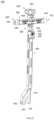
- FIG. 1is a first perspective view of a tibia alignment guide, in accordance with an aspect of the present disclosure
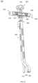
- FIG. 2is a second perspective view of the tibia alignment guide of FIG. 1 , in accordance with an aspect of the present disclosure
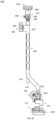
- FIG. 3is a first side view of the tibia alignment guide of FIG. 1 , in accordance with an aspect of the present disclosure
- FIG. 4is a second side view of the tibia alignment guide of FIG. 1 , in accordance with an aspect of the present disclosure
- FIG. 5is a first end view of the tibia alignment guide of FIG. 1 , in accordance with an aspect of the present disclosure
- FIG. 6is a second end view of the tibia alignment guide of FIG. 1 , in accordance with an aspect of the present disclosure
- FIG. 7is a superior view of the tibia alignment guide of FIG. 1 , in accordance with an aspect of the present disclosure
- FIG. 8is an inferior view of the tibia alignment guide of FIG. 1 , in accordance with an aspect of the present disclosure
- FIG. 9is a first perspective view of a first translation mechanism, a second translation mechanism and a coupling member of the tibia alignment guide of FIG. 1 , in accordance with an aspect of the present disclosure
- FIG. 10is a second perspective view of the first translation mechanism, the second translation mechanism and the coupling member of FIG. 9 , in accordance with an aspect of the present disclosure
- FIG. 11is a first side view of the first translation mechanism, the second translation mechanism and the coupling member of FIG. 9 , in accordance with an aspect of the present disclosure
- FIG. 12is a second side view of the first translation mechanism, the second translation mechanism and the coupling member of FIG. 9 , in accordance with an aspect of the present disclosure
- FIG. 13is a first end view of the first translation mechanism, the second translation mechanism and the coupling member of FIG. 9 , in accordance with an aspect of the present disclosure
- FIG. 14is a second end view of the first translation mechanism, the second translation mechanism and the coupling member of FIG. 9 , in accordance with an aspect of the present disclosure
- FIG. 15is an exploded, first perspective view of the first translation mechanism, the second translation mechanism and the coupling member of FIG. 9 , in accordance with an aspect of the present disclosure
- FIG. 16is an exploded, second perspective view of the first translation mechanism, the second translation mechanism and the coupling member of FIG. 9 , in accordance with an aspect of the present disclosure
- FIG. 17is an exploded, first side view of the first translation mechanism, the second translation mechanism and the coupling member of FIG. 9 , in accordance with an aspect of the present disclosure
- FIG. 18is an exploded, second side view of the first translation mechanism, the second translation mechanism and the coupling member of FIG. 9 , in accordance with an aspect of the present disclosure
- FIG. 19is an exploded, first end view of the first translation mechanism, the second translation mechanism and the coupling member of FIG. 9 , in accordance with an aspect of the present disclosure
- FIG. 20is an exploded, second end view of the first translation mechanism, the second translation mechanism and the coupling member of FIG. 9 , in accordance with an aspect of the present disclosure
- FIG. 21is a first perspective view of a tower system of the tibia alignment guide of FIG. 1 , in accordance with an aspect of the present disclosure
- FIG. 23is an exploded, first side view of the tower system of FIG. 21 , in accordance with an aspect of the present disclosure
- FIG. 26is an exploded, second perspective view of the tower system of FIG. 21 , in accordance with an aspect of the present disclosure
- FIG. 31is a first side view of the tibia alignment guide of FIG. 29 , in accordance with an aspect of the present disclosure
- FIG. 38is a perspective view of a third translation mechanism fastener of the tibia alignment guide of FIG. 29 , in accordance with an aspect of the present disclosure.
- FIG. 39is a perspective view of a coupling member knob of the tibia alignment guide of FIG. 29 , in accordance with an aspect of the present disclosure.
- guides, devices, instruments, systems, and methods for maintaining, correcting and/or resurfacing joint surfacesare discussed.
- positions or directionsmay be used herein with reference to anatomical structures or surfaces.
- the bones of the foot, ankle and lower legmay be used to describe the surfaces, positions, directions or orientations of the devices, systems, instrumentation and methods.
- the devices, systems, instrumentation and methods, and the aspects, components, features and the like thereof, disclosed hereinare described with respect to one side of the body for brevity purposes.
- the devices, systems, instrumentation and methods, and the aspects, components, features and the like thereof, described and/or illustrated hereinmay be changed, varied, modified, reconfigured or otherwise altered for use or association with another side of the body for a same or similar purpose without departing from the spirit and scope of the disclosure.
- the devices, systems, instrumentation and methods, and the aspects, components, features and the like thereof, described herein with respect to the right legmay be mirrored so that they likewise function with the left leg.
- the total ankle replacement proceduremay include, for example, an alignment procedure, an initial resection procedure, a trialing and chamfer resection procedure, a final trialing and peg preparation procedure, and an implantation procedure.
- a first alignment guide or tibia alignment guide 100is shown in FIGS. 1 - 28 .
- the alignment guide or full alignment guide 100includes a first translation mechanism or medial-lateral adjustment member 110 , a second translation mechanism or distal-proximal adjustment member 170 , a third translation mechanism or varus-valgus adjustment member 440 , and a tower 400 coupled to the third translation mechanism 440 on a first end and the second translation mechanism 170 on a second end.
- the second translation mechanism 170is movably coupled to the first translation mechanism 110 by distal-proximal translating members 150 , 160 .
- the first translation mechanism 110includes a housing 112 , a fastening member, fastener, or screw 130 received within the housing 112 , and a coupling member or cap 140 secured to the fastening member 130 .
- the housing 112may include a first opening 114 positioned at a first end and extending into the housing 112 and a second opening 116 positioned at a second end and extending into the housing 112 .
- the first opening 114may be aligned with the second opening 116 to receive the fastening member 130 .
- the housing 112may further include a cavity 118 extending into the housing 112 from a bottom or distal surface. The cavity 118 may intersect with the first opening 114 of the second opening 116 .
- the cavity 118may also receive a portion of the fastening member 130 when the first translation member 110 is assembled.
- the housing 112may include at least one window 120 extending from a first side of the housing 112 into the cavity 118 .
- the at least one window 120is two windows 120 , although alternative numbers of windows 120 are also contemplated and may include, for example, one or more windows 120 .
- the housing 112may also include a plurality of dimension markings 122 positioned along at least a portion of the first side of the housing 112 .
- the housing 112includes a foot or extension member 124 extending away from a second side of the housing 112 .
- the locking opening 134may be positioned, for example, perpendicular to a longitudinal axis of the fastening member 130 .
- the locking opening 134may be, for example, sized and shaped or configured to receive a pin or locking member 146 .
- the shaft portion 132is threaded from the head portion 136 toward the second end and includes a non-threaded section near the second end of the shaft portion 132 .
- the coupling member 140may include a through hole 142 extending from a first end to a second end.
- the coupling member 140may also include a locking opening 144 extending from a side of the coupling member 140 into the through hole 142 .
- the locking opening 144may be, for example, generally perpendicular to the through hole 142 .
- the locking opening 144may receive a pin or locking member 146 to secure the coupling member 140 to the fastening member 130 .
- the alignment guide 100may also include a first distal-proximal translating member 150 and a second distal-proximal translating member 160 , as shown in at least FIGS. 15 - 20 .
- the first translating member 150may include a body 152 with a first opening or securement opening 154 positioned at a distal end of the body 152 .
- the first opening 154may extend through the body 152 from a first side to a second side.
- the first translating member 150may include a groove 156 positioned around the body 152 between a midpoint of the body 152 and the proximal end of the body 152 .
- the first translating member 150may also include a plurality of teeth 158 extending along at least a portion of the length or in the direction of the longitudinal axis of the body 152 from the first end to the second end.
- the first translating member 150may also include a plurality of dimension markings 159 positioned along at least a portion of the length or in the direction of the longitudinal axis of the body 152 .
- the second translating member 160may include a body 162 with a first opening or securement opening 164 positioned at a distal end of the body 152 .
- the second translating member 160may include a groove 166 positioned around the body 162 between a midpoint of the body 162 and the proximal end of the body 162 .
- the second translating member 160may also include a plurality of dimension markings 168 positioned along at least a portion of the length or in the direction of the longitudinal axis of the body 162 .
- the first translation mechanism 110also includes the coupling member 240 .
- the coupling member 240includes a base 242 , a securement fastener or telescoping rod knob 274 received within the coupling member 240 , and a drive member 276 rotatably coupled to the base 242 of the coupling member 240 .
- the base 242may include a through hole 244 extending into the base 242 from a first side.
- the base 242may also include a channel 246 extending into the base 242 from a bottom surface.
- the channel 246may include a female dovetail portion or receiving member 248 .
- the receiving member 248may include a first protrusion 250 positioned on a first side of the bottom surface and a second protrusion 252 positioned on a second side of the bottom surface.
- the channel 246may include an opening at the bottom surface that may be, for example, smaller than the width of the interior top surface of the channel 246 .
- the channel 246may have angled side surfaces as the channel 246 extends into the base 242 .
- the base 242may include at least one window 254 extending from the first end into the channel 246 and at least one window 254 extending from the second end into the channel 246 .
- the base 242may also include a locking pin opening 256 extending from the first end to the second end, for example, between the two windows 254 .
- the base 242may further include an engagement pin opening 258 extending into the base 242 from the first end.
- a locking member or indicator member 260may extend away from a top surface of the base 242 on the first side, as shown in FIGS. 15 - 20 .
- the locking member 260may include a through hole 262 extending from the first side toward the second side of the base 242 .
- the locking member 260may include a pointer 264 extending away from a top surface of the locking member 260 .
- the pointer 264may have, for example, a generally triangular shape or alternative shape which terminates in a point.
- the locking member 260may include a locking pin opening 266 extending between the first end and the second end and positioned near a top surface of the locking member 260 .
- the locking pin opening 266may extend through the locking member 260 , for example, perpendicular or generally perpendicular to the through hole 262 .
- a translating protrusion 270may also extend away from a top surface of the base 242 adjacent to the locking member 260 .
- the translating protrusion 270may include a through hole or threaded hole 272 extending between the first end and the second end.
- the locking member 260may be spaced apart from the translating protrusion 270 to form a channel and the channel may be, for example, sized and shaped or configured to receive a side of the housing 112 .
- the securement fastener 274may include, for example, a head portion with a drive feature and a shaft portion extending away from a second end of the head portion.
- the shaft portionmay be, for example, threaded along at least a portion of its length.
- the drive member 276may include a shaft 278 and a first groove 280 .
- the first groove 280may be, for example, inset into the shaft 278 and may extend around at least a portion of the circumference of the shaft 278 .
- the drive member 276may also include a drive shaft 282 with a drive opening 284 at a first end of the drive member 276 .
- the drive shaft 282may have, for example, a diameter smaller than the diameter of the shaft 278 .
- the head portion 286may be coupled to the second end of the drive member 276 and there may be a second groove 288 positioned between shaft 278 and the head portion 286 .
- the drive member 276may further include a locking pin opening 290 extending through the drive member 276 and positioned within the second groove 288 .
- the second translation mechanism, distal-proximal adjustment member, or gearbox 170may include a housing 172 , a coupling fastener or internal-external adjustment screw 202 , a locking fastener 204 , a drive member 212 , an engagement member 218 , and a locking cap 226 .
- the housing 172may include a base 174 with a first extension member or proximal extension member 190 extending away from a top surface of the base 174 and a second extension member or distal extension member 200 extending away from a bottom surface of the base 174 .
- the base 174may also include a fastener hole 176 positioned near the second end of the housing 172 and a fastener hole or locking hole 192 extending at least partially through the first extension member 190 from a first side into a coupling hole or recess 196 .
- the base 174may also include a locking pin hole 178 positioned between the fastener hole 136 and the locking hole 192 .
- the base 174may further include a through hole or alignment pin hole 180 extending through the base 174 from a first side to a second side.
- the through hole 180may have, for example, an oval or elliptical shape.
- the through hole 180may be positioned below the fastener hole 192 .
- the base 174may also include a tool opening 182 positioned near the first end of the base 174 .
- the locking cap opening 184may extend into the base 174 from a second side and engage or overlap with the tool opening 182 .
- the locking cap opening 184may have, for example, a diameter larger than the diameter of the tool opening 182 .
- the locking cap opening 184may be, for example, threaded to receive a fastener 226 .
- the housing 172may also include the cavity 186 positioned within the base 174 .
- the housing 172may further include an enlarged opening or keyhole portion 188 extending through the base 174 and the distal extension member 200 .
- the enlarged opening 188may extend from the top surface of the base 174 into and through the cavity 186 .
- the locking cap opening 184may extend from a second side of the base 174 into the cavity 186 .
- the housing 172may also include a locking pin hole 194 extending through the first extension member 190 in a medial-lateral direction from the first end toward the second end.
- the first extension member 190may also include the coupling hole 196 extending into the first extension member 190 from a superior or top surface.
- the coupling hole 196may be, for example, a circular or a round recess or alternatively shaped recess corresponding to the shape of the stem 410 of the tower system 400 .
- the first extension member 190may also include two threaded recesses 198 positioned on opposite sides of the coupling hole 196 .
- the threaded recesses 198may be configured or sized and shaped to receive a first alignment pin 206 and a second alignment pin 208 .
- the alignment pins 206 , 208 when insertedmay have a portion of the pins 206 , 208 extending above the superior or top surface of the first extension member 190 to engage a bottom surface of the housing 340 of the coupling member 300 .
- the second extension member or distal extension member 200may extend away from an inferior or bottoms surface, as well as between the first end and the second end of the base member 174 .
- the cavity 186may extend through the base 174 as well as the second extension member 200 from a top surface to a bottom surface of the housing 172 .
- the cavity 186may be positioned near a first end of the housing 172 .
- the housing 172may also include a through hole 187 positioned near a second end of the housing 172 .
- the through hole 187may extend through the base 174 as well as the second extension member 200 from the top surface to the bottom surface of the housing 172 .
- the cavity 186 and the through hole 187may be, for example, configured or sized and shaped to receive the first translating member 150 and the second translating member 160 , respectively.
- the second translation mechanism 170may also include a coupling fastener or internal external adjustment screw 202 for engagement with the fastener hole 192 of the housing 172 , as shown in at least FIGS. 15 - 20 .
- the second translation mechanism 170may include a locking fastener 204 received within the fastener hole 176 .
- the fastener hole 176extends into the through hole 187 to enable the locking fastener 204 to engage the second translating member 160 and secure the second translating member 160 at a desired height.
- the second translation mechanism 170may also include a drive member 212 with a first portion including a drive opening 214 at a first end and a driveshaft 216 extending away from the first portion to the second end.
- the driveshaft 216may engage or be received within a through hole 224 of an engagement member 218 .
- the engagement member 218may also include a body or shaft 220 and a plurality of teeth 222 extending around the circumference of the exterior surface of the body 220 .
- the plurality of teeth 222may extend along only a portion of the length of the body 220 between a first end and second end of the engagement member 218 .
- the plurality of teeth 222may be, for example, configured or sized and shaped to engage the plurality of teeth 158 of the first translating member 150 .
- the through hole 224may extend through the body 220 along the entire length of the engagement member 218 .
- the driveshaft 216may extend completely through the through hole 224 to engage the locking cap 226 .
- a washermay be positioned between the engagement member 218 and the locking cap 226 when assembled with the drive member 212 .
- the locking cap 226may include a body 228 and a through hole 230 extending through the body 228 from the first end to a second end.
- the locking cap 226may also include recesses or drive features 232 inset into the first end and the second end of the body 228 .
- the locking cap 226may include threads 234 along the exterior circumference between the first end and the second end of the body 228 .
- the threads 234may be, for example, configured or sized and shaped to engage the locking cap opening 184 .
- the coupling member 300may include a housing 340 , an alignment pin housing 302 , and a securement knob 330 .
- the alignment pin housing 302is received within a through hole 344 of the housing 340 and secured together with a locking pin 354 .
- the securement knob 330is received within a through hole or threaded hole 318 of the alignment pin housing 302 to secure the coupling member 300 to a pin, for example, a pin 108 .
- the housing 340may include a base 342 with a through hole 344 .
- the base 342may have, for example, a generally square or rectangular shape, although other shapes are also contemplated.
- the base 342may also include a through hole 346 extending through the two sides of the base 342 for receiving a pin 354 to couple the alignment pin housing 302 to the base 342 .
- the housing 340may also include a stem 356 extending away from an inferior or bottom surface of the base 342 .
- the stem 356may include a groove 358 extending around at least a portion of the circumference of the stem 356 .
- the stem 356may also include a through hole 360 extending through the stem 356 .
- the through hole 360may be, for example, configured or sized and shaped to receive a fastener 202 to secure the housing 340 to the housing 172 .
- the housing 340may further include a proximal coupling protrusion 350 extending away from a superior or top surface of the base 342 .
- the coupling protrusion 350may include, for example, tabs 352 extending away from the exterior, side surface of the coupling protrusion 350 or a pin 352 extending through the coupling protrusion 350 to assist with engagement of the coupling member with the tower portion 400 .
- the alignment pin housing 302includes a base 304 , which may be, for example, “L” shaped.
- the housing 302may also include at least one pin hole 316 extending into the base 304 from a first side to a second side. As shown, the at least one pin hole 316 may be, for example, three pin holes 316 positioned adjacent to each other in a generally linear arrangement.
- the housing 302may also include a through hole 318 extending through the base 304 from a first end to a second end. The through hole 318 may be, for example, positioned perpendicular to the at least one pin hole 316 .
- the housing 302may include pin holes 322 , 326 for receiving locking pins, such as, pin 328 to secure the securement knob 330 and pins (not shown) to the housing 302 .
- the pin hole 322may extend through the base 304 from a first end to a second end near a posterior surface.
- the pin hole 326may extend through the base 304 from a superior surface to an inferior surface and positioned near the second end and the anterior surface.
- the securement knob 330includes a head or drive portion 332 and a stem or shaft 334 extending away from a bottom surface of the head portion 332 .
- the shaft 334may include a threaded portion 336 extending along at least a portion of the length of the shaft 334 .
- the threaded portion 336may be, for example, configured or sized and shaped to be inserted into the through hole 318 .
- the securement knob 330may also include a drive feature 338 inset into the first end of the head 332 of the knob 330 .
- the tower 400may include a coupling rod 410 , which may be received within a tower base 420 to couple the second translation mechanism 170 to the third translation mechanism or varus-valgus adjustment member 440 .
- the rod 410may include a first end 412 and a second end 414 .
- the first end 412includes an opening 416 for coupling to the third adjustment member 440 .
- the tower base 420may couple to the coupling member 300 on a distal end.
- the tower base 420may include a coupling opening 424 for receiving the proximal coupling protrusion 350 and a securement pin opening 430 on a first end for receiving the tabs 352 of the coupling member 300 .
- the second end of the tower base 420may include a securement protrusion with an opening 422 extending into the base 420 along the longitudinal axis of the base 420 .
- the second endmay also include a first or threaded opening 426 and a second opening 428 for coupling the tower base 420 to the third translation mechanism 440 .
- the threaded opening 426may be, for example, sized and shaped or configured to receive a knob 432 .
- the knob 432may be, for example, the same or similar to knob 520 .
- the third translation mechanism 440may include a housing 450 with a first opening 452 at a first end, a second opening 454 at a second end and a cavity 456 extending into the housing 450 from a bottom surface and engaging or overlapping the through hole created by the first and second openings 452 , 454 .
- the third translation mechanism 440may also include a fastening member 470 , a cap 442 , and a knob 520 .
- the fastening member 470which may be the same or similar to fastening member 130 , which will not be described again here, in detail, for brevity sake.
- the fastening member 470may include a shaft portion 472 and a head portion 476 , which may be the same or similar to the shaft portion 132 and the head portion 136 of the fastening member 130 .
- the head portion 476may include a drive opening 478 , which may be the same or similar to the drive opening 138 .
- the shaft portion 472may include a locking opening 474 , which may be the same or similar to the locking opening 134 .
- the coupling member 442may be the same or similar to the coupling member 140 .
- the coupling member 442may include a through hole 444 and a locking opening 446 , which may be the same or similar to the through hole 142 and locking opening 144 .
- the locking opening 446may receive a pin or locking member, such as the pin or locking member 146 , to secure the coupling member 442 to the fastening member 470 .
- the fastening member 470may be inserted through the first opening 452 , cavity 456 , and second opening 454 and extend at least partially beyond the second end.
- the portion of the fastening member 470 extending out of the second end of the housing 450may couple to the cap 442 .
- the third translation mechanism 440may be coupled to the base 420 by a hinge member 480 , 490 .
- the first hinge member 480may include a base 482 with an opening 488 extending through the base 482 from a first end to a second end.
- the opening 488may be, for example, sized and shaped or configured to receive a portion of the fastening member 470 .
- the first hinge member 480may also include a coupling protrusion 484 with a through hole 486 extending through the coupling protrusion 484 from a first end to a second end.
- the second hinge member 490may include a first arm member 494 and a second arm member 496 extending toward a superior end of the second hinge member 490 .
- the first arm member 494is spaced apart from and parallel to the second arm member 496 forming a channel 498 between the arm members 494 , 496 .
- the channel 498may receive the coupling protrusion 484 of the first hinge member 480 of the third translation mechanism 440 .
- a fastener 510may be inserted through the first arm member 494 , the coupling protrusion 484 , and the second arm member 496 to rotatably couple the first hinge member 480 to the second hinge member 490 .
- the third translation mechanism 440may allow the user to adjust the varus-valgus alignment as it rotates about the hinge members 480 , 490 .
- the third translation mechanism 440may also include a proximal protrusion 458 extending away from a superior or top surface of the housing 450 .
- the proximal protrusion 458includes an opening extending into the protrusion 458 from the superior surface. The opening may receive a locking knob 520 .
- the locking knob 520may include a head or drive portion 522 and a stem or shaft 526 extending away from a bottom surface of the head portion 522 .
- the shaft 526may include a threaded portion 528 extending along at least a portion of the length of the shaft 526 .
- the threaded portion 528may be, for example, configured or sized and shaped to be inserted into the opening in the proximal protrusion 458 .
- the locking knob 520may also include a drive feature 524 inset into the first end of the head 522 of the knob 520 .
- the first translation mechanism 110may be assembled by, for example, inserting the translating protrusion 270 into the channel 246 of the base 242 .
- the securement fastener 274may be inserted through, for example, the through hole 262 to engage the first side of the housing 112 .
- the drive member 276may be inserted into the through hole 244 and an engagement pin (not shown) may be inserted through the engagement pin hole 258 until the engagement pin engages the groove 288 in the drive member 276 .
- the fastening member 130may be inserted into the first opening 114 , through the cavity 118 and the through hole 272 of the translating protrusion 270 , and a portion of the fastening member 130 may extend out of the second opening 116 .
- the through hole 142 of the coupling member 140may receive the portion of the fastening member 130 extending out of the second opening 116 .
- a pin 146may be inserted into the locking opening 144 of the coupling member 140 and through the locking opening 134 of the fastening member 130 to retain the threaded portion of the shaft portion 132 within the cavity 118 of the housing 112 .
- a distal end of the first translating member 150may be inserted into the first recess 126 and a locking pin or locking member 148 may be inserted through the extension member 124 and the first opening 154 to secure the first translating member 150 to the extension member 124 of the housing 112 .
- the distal end of the second translating member 160may be inserted into the second recess 128 and a locking pin 148 may be inserted through the extension member 124 and second opening 164 to secure the second translating member 160 to the extension member 124 of the housing 112 .
- the second translation mechanism 170may be aligned with and slid onto the translating members 150 , 160 .
- the first translating member 150may be received within the cavity 186 of the housing 172 and a plurality of teeth 158 may engage the plurality of teeth 222 of the engagement member 218 to allow for the housing 172 to translate with respect to the coupled first translation mechanism 110 and coupling member 240 .
- the engagement member 218will be positioned within the cavity 186 .
- the drive member 212will be coupled to the engagement member 218 to allow for rotation of the drive member 212 from a first side to be translated to rotation of the engagement member 218 .
- the locking cap 226may also be inserted into the locking cap opening 184 to engage the second end of the drive member 212 and retain the engagement member 218 within the cavity 186 .
- the second translating member 160may be inserted into the through hole 187 when the locking fastener 204 is positioned in an unlocked or first position. In use the locking fastener 204 may be moved to secure the second translating member 160 when the desired proximal distal position is achieved in a locked or second position.
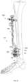
- the alignment guide 100is positioned on a patient's tibia 102 with at least two pins 108 and aligned with the ankle joint 106 to allow for a TAR procedure to be performed on the tibia 102 and the talus 104 .
- At least one first pin 108may be positioned at the distal end of the alignment guide 100 and extend through at least one of the first translation mechanism 110 and the second translation mechanism 170 and a second pin 108 (not shown) may be inserted through the third translation mechanism 300 .
- the first translation mechanism 110may be used to achieve medial-lateral adjustment
- the second translation mechanism 170may be used to achieve distal-proximal adjustment
- the third translation mechanism 440may be used to achieve varus-valgus adjustment.
- the surgical methodmay be as described in greater detail in U.S. Provisional Application No. 62/899,460, entitled Total Ankle Replacement Surgical Method, which is hereby incorporated by reference in its entirety.
- the alignment guide 100may be coupled to various resection guides.
- the resection guides and resection instrumentsmay be as described in greater detail in U.S. Provisional Application No. 62/898,615, entitled Resection Guides, Sweeping Reamers, and Methods for Use in Total Ankle Replacement, which is hereby incorporated by reference in its entirety.
- the alignment guide 100may be used with additional instruments for the TAR procedure.
- the alignment guide 100may be used with, for example, other alignment instruments such as a joint line pointer and additional alignment instruments, which are described in greater detail in U.S. Provisional Application No. 62/899,655, entitled Alignment Instruments and Methods for Use in Total Ankle Replacement, which is hereby incorporated by reference in its entirety.
- the second alignment guide 600may include components that are the same or similar to the first alignment guide 100 , described in greater detail above.
- the alignment guide or full alignment guide 600includes a first translation mechanism or medial-lateral adjustment member 110 , a second translation mechanism or distal-proximal adjustment member 170 , a third translation mechanism or varus-valgus adjustment member 300 , and a tower 620 coupled to the third translation mechanism 440 on a first end and the second translation mechanism 170 on a second end.
- the second translation mechanism 170is movably coupled to the first translation mechanism 110 by distal-proximal translating members 150 , 160 .
- the third translation mechanism 440is moveably coupled to the second translation mechanism 170 by the tower 620 .
- the first and second translation mechanisms 110 , 170may be as described and shown in greater detail in U.S. Provisional Application No. 62/899,703, entitled Joint Replacement Alignment Guides, Systems and Methods of Use and Assembly, which is hereby incorporated by reference in its entirety.
- the tower 620may be, for example, similar to the tower 420 , as described in greater detail with respect to guide 100 and which will not be described again here for brevity sake.
- the tower 620may include, for example, more windows or openings 632 , as shown in FIGS. 29 - 34 , than included in tower 420 .
- the tower 620also includes a first or threaded opening 426 and a second opening 428 for coupling the tower base 620 to the third translation mechanism 440 .
- the threaded opening 426may be, for example, sized and shaped or configured to receive a knob 530 .
- the knob 530may be, for example, the similar to knob 432 .
- the knob 530may include a head or drive portion 532 and a stem or shaft 534 extending away from a bottom surface of the head portion 532 , as shown in FIG. 36 .
- the shaft 534may include a threaded portion 536 extending along at least a portion of the length of the shaft 534 .
- the threaded portion 536may be, for example, configured or sized and shaped to be inserted into the opening 426 in the tower 620 .
- the locking knob 530may also include a drive feature 538 inset into the first end of the head 532 of the knob 530 .
- the locking knob 530may further include at least one opening 652 extending into the head portion 532 from an exterior surface.
- the at least one opening 652may be, for example, one or more openings 652 positioned around the circumference of the head portion 532 . If two openings 652 are positioned on alternative sides of the head portion 532 , the two openings 652 may form a through hole extending across the entire head portion 532 .
- the at least one opening 652may be, for example, sized and shaped or configured to receive a tool to assist with rotating the knob 530 .
- the locking knob 530may also include a recess 654 extending into the head portion 532 from a superior or top surface.
- the alignment guide 600may also include an alternative locking knob 520 and an alternative securement knob 330 .
- the alternative locking knob 520also includes at least one opening 650 extending into the head portion 522 from an exterior surface.
- the at least one opening 650may be, for example, one or more openings 650 positioned around the circumference of the head portion 522 . If two openings 650 are positioned on alternative sides of the head portion 522 , the two openings 650 may form a through hole extending across the entire head portion 522 .
- the at least one opening 652may be, for example, sized and shaped or configured to receive a tool to assist with rotating the knob 530 .
- the locking knob 530may also include a recess 654 extending into the head portion 532 from a superior or top surface, as shown in FIG. 36 .
- the alternative securement knob 330also includes at least one opening 666 extending into the head portion 332 from an exterior surface, as shown in FIG. 39 .
- the at least one opening 666may be, for example, one or more openings 666 positioned around the circumference of the head portion 332 . If two openings 666 are positioned on alternative sides of the head portion 332 , the two openings 666 may form a through hole extending across the entire head portion 332 .
- the at least one opening 666may be, for example, sized and shaped or configured to receive a tool to assist with rotating the knob 330 .
- the alignment guide 600may also include an alternative head portion 640 of the fastening mechanism 470 and an alternative cap 442 .
- the head portion 640 of the fastening mechanism 470may include a drive feature 642 extending into the head portion 640 from a first end.
- the head portion 640may also include grooves 644 positioned around the circumference of the head portion 640 .
- the alternative cap 442may also include grooves 644 positioned around the circumference of the head portion 442 .
- the alignment guide 600further includes a plurality of dimension markings 464 positioned along at least a portion of the first side of the housing 450 between the first end and the second end.
- the alignment guide 600may further include a locking knob 665 .
- the locking knob 665may be inserted into an opening (not shown) in housing 450 .
- the openingmay be positioned near a second end of the housing 450 .
- the locking knob 665may extend into at least one of the second opening 454 or cavity 456 to engage the fastening member 470 .
- the locking knob 665may, for example, engage the fastening member 470 to prevent further rotation once the desired position is achieved.
- implantsmay be replaced by alternative component(s) or feature(s), such as those disclosed in another embodiment, which serve the same, equivalent or similar purpose as known by those skilled in the art to achieve the same, equivalent or similar results by such alternative component(s) or feature(s) to provide a similar function for the intended purpose.
- the implantsmay include more or fewer components or features than the embodiments as described and illustrated herein. For example, the components and features of FIGS. 1 - 28 and FIGS.
- alignment guides 100 , 600may be used in alternative combinations as would be modified or altered by one of skill in the art. Accordingly, this detailed description of the currently-preferred embodiments is to be taken in an illustrative, as opposed to limiting of the disclosure.
- a method or device that “comprises,” “has,” “includes,” or “contains” one or more steps or elementspossesses those one or more steps or elements, but is not limited to possessing only those one or more steps or elements.
- a step of a method or an element of a device that “comprises,” “has,” “includes,” or “contains” one or more featurespossesses those one or more features, but is not limited to possessing only those one or more features.
- a device or structure that is configured in a certain wayis configured in at least that way, but may also be configured in ways that are not listed.
Landscapes
- Health & Medical Sciences (AREA)
- Life Sciences & Earth Sciences (AREA)
- Orthopedic Medicine & Surgery (AREA)
- Surgery (AREA)
- Animal Behavior & Ethology (AREA)
- General Health & Medical Sciences (AREA)
- Veterinary Medicine (AREA)
- Engineering & Computer Science (AREA)
- Biomedical Technology (AREA)
- Heart & Thoracic Surgery (AREA)
- Public Health (AREA)
- Oral & Maxillofacial Surgery (AREA)
- Transplantation (AREA)
- Medical Informatics (AREA)
- Molecular Biology (AREA)
- Nuclear Medicine, Radiotherapy & Molecular Imaging (AREA)
- Cardiology (AREA)
- Vascular Medicine (AREA)
- Dentistry (AREA)
- Physical Education & Sports Medicine (AREA)
- Neurology (AREA)
- Surgical Instruments (AREA)
- Prostheses (AREA)
- Lining Or Joining Of Plastics Or The Like (AREA)
Abstract
Description
Claims (18)
Priority Applications (2)
| Application Number | Priority Date | Filing Date | Title |
|---|---|---|---|
| US17/812,074US12239550B2 (en) | 2018-12-13 | 2022-07-12 | Joint replacement alignment guides, systems and methods of use and assembly |
| US19/069,960US20250195240A1 (en) | 2018-12-13 | 2025-03-04 | Joint replacement alignment guides, systems and methods of use and assembly |
Applications Claiming Priority (7)
| Application Number | Priority Date | Filing Date | Title |
|---|---|---|---|
| US201862779436P | 2018-12-13 | 2018-12-13 | |
| US201962899703P | 2019-09-12 | 2019-09-12 | |
| US201962899740P | 2019-09-12 | 2019-09-12 | |
| US201962899655P | 2019-09-12 | 2019-09-12 | |
| PCT/US2019/066393WO2020124044A1 (en) | 2018-12-13 | 2019-12-13 | Joint replacement alignment guides, systems and methods of use and assembly |
| US17/304,056US11382765B2 (en) | 2018-12-13 | 2021-06-14 | Joint replacement alignment guides, systems and methods of use and assembly |
| US17/812,074US12239550B2 (en) | 2018-12-13 | 2022-07-12 | Joint replacement alignment guides, systems and methods of use and assembly |
Related Parent Applications (1)
| Application Number | Title | Priority Date | Filing Date |
|---|---|---|---|
| US17/304,056ContinuationUS11382765B2 (en) | 2018-12-13 | 2021-06-14 | Joint replacement alignment guides, systems and methods of use and assembly |
Related Child Applications (1)
| Application Number | Title | Priority Date | Filing Date |
|---|---|---|---|
| US19/069,960ContinuationUS20250195240A1 (en) | 2018-12-13 | 2025-03-04 | Joint replacement alignment guides, systems and methods of use and assembly |
Publications (2)
| Publication Number | Publication Date |
|---|---|
| US20220339005A1 US20220339005A1 (en) | 2022-10-27 |
| US12239550B2true US12239550B2 (en) | 2025-03-04 |
Family
ID=71075703
Family Applications (5)
| Application Number | Title | Priority Date | Filing Date |
|---|---|---|---|
| US17/304,046ActiveUS11304823B2 (en) | 2018-12-13 | 2021-06-14 | Joint replacement alignment guides, systems and methods of use and assembly |
| US17/304,056ActiveUS11382765B2 (en) | 2018-12-13 | 2021-06-14 | Joint replacement alignment guides, systems and methods of use and assembly |
| US17/659,411PendingUS20220233332A1 (en) | 2018-12-13 | 2022-04-15 | Joint replacement alignment guides, systems and methods of use and assembly |
| US17/812,074Active2040-06-12US12239550B2 (en) | 2018-12-13 | 2022-07-12 | Joint replacement alignment guides, systems and methods of use and assembly |
| US19/069,960PendingUS20250195240A1 (en) | 2018-12-13 | 2025-03-04 | Joint replacement alignment guides, systems and methods of use and assembly |
Family Applications Before (3)
| Application Number | Title | Priority Date | Filing Date |
|---|---|---|---|
| US17/304,046ActiveUS11304823B2 (en) | 2018-12-13 | 2021-06-14 | Joint replacement alignment guides, systems and methods of use and assembly |
| US17/304,056ActiveUS11382765B2 (en) | 2018-12-13 | 2021-06-14 | Joint replacement alignment guides, systems and methods of use and assembly |
| US17/659,411PendingUS20220233332A1 (en) | 2018-12-13 | 2022-04-15 | Joint replacement alignment guides, systems and methods of use and assembly |
Family Applications After (1)
| Application Number | Title | Priority Date | Filing Date |
|---|---|---|---|
| US19/069,960PendingUS20250195240A1 (en) | 2018-12-13 | 2025-03-04 | Joint replacement alignment guides, systems and methods of use and assembly |
Country Status (6)
| Country | Link |
|---|---|
| US (5) | US11304823B2 (en) |
| EP (2) | EP3893771A4 (en) |
| AU (2) | AU2019397555B2 (en) |
| CA (3) | CA3235323A1 (en) |
| WO (2) | WO2020124055A1 (en) |
| ZA (1) | ZA202309167B (en) |
Families Citing this family (5)
| Publication number | Priority date | Publication date | Assignee | Title |
|---|---|---|---|---|
| WO2020124055A1 (en)* | 2018-12-13 | 2020-06-18 | Paragon 28, Inc. | Joint replacement alignment guides, systems and methods of use and assembly |
| CN113197616B (en)* | 2021-05-12 | 2022-07-19 | 北京市春立正达医疗器械股份有限公司 | Auxiliary device for ankle joint osteotomy |
| US11963688B2 (en)* | 2021-11-20 | 2024-04-23 | Panorthopaedics, Inc. | Device adapted for lateral engagement of an elongated member |
| AU2023262570A1 (en)* | 2022-04-26 | 2024-12-12 | Paragon 28, Inc. | Orthopedic instruments |
| US12433532B2 (en)* | 2022-06-02 | 2025-10-07 | Wright Medical Technology, Inc. | Flexion/extension surgical guides and methods of using the same |
Citations (71)
| Publication number | Priority date | Publication date | Assignee | Title |
|---|---|---|---|---|
| US3710473A (en) | 1971-06-28 | 1973-01-16 | Caterpillar Tractor Co | Method of manufacturing a heat exchanger |
| US3750652A (en) | 1971-03-05 | 1973-08-07 | J Sherwin | Knee retractor |
| US4899761A (en) | 1988-03-31 | 1990-02-13 | Brown Mark D | Apparatus and method for measuring spinal instability |
| FR2700462A1 (en) | 1993-01-19 | 1994-07-22 | Medimplant | Guide instrument for making holes for foot joint implant |
| US5429121A (en) | 1991-03-20 | 1995-07-04 | Per Jettman | Surgical retractor |
| US5628750A (en) | 1995-06-30 | 1997-05-13 | U.S. Medical Products, Inc. | Tibial resection guide alignment apparatus and method |
| US6241729B1 (en) | 1998-04-09 | 2001-06-05 | Sdgi Holdings, Inc. | Method and instrumentation for posterior interbody fusion |
| US6261296B1 (en) | 1998-10-02 | 2001-07-17 | Synthes U.S.A. | Spinal disc space distractor |
| US6267762B1 (en) | 1999-04-01 | 2001-07-31 | Aesculap | Device for the positioning of a proximal extremity of a tibia against a cutting guide including an adjusting handle |
| EP1260183A2 (en) | 2001-05-21 | 2002-11-27 | NEMCO Medical Ltd. | Femoral knee saw guide and method |
| US6551316B1 (en) | 2001-03-02 | 2003-04-22 | Beere Precision Medical Instruments, Inc. | Selective compression and distraction instrument |
| US20030105467A1 (en) | 2001-11-30 | 2003-06-05 | Ralph James D. | Distraction instrument for use in anterior cervical fixation surgery |
| US20030225416A1 (en) | 2002-05-21 | 2003-12-04 | Bonvallet Todd C. | Instruments and techniques for separating bony structures |
| US6673116B2 (en) | 1999-10-22 | 2004-01-06 | Mark A. Reiley | Intramedullary guidance systems and methods for installing ankle replacement prostheses |
| JP2004130109A (en) | 2002-08-26 | 2004-04-30 | Depuy Products Inc | Foot joint fixation guide and method therefor |
| US6739068B1 (en) | 2003-01-06 | 2004-05-25 | Pilling Weck Incorporated | Pliers with jaw spacing and load measuring readings |
| US20050049603A1 (en) | 2002-07-23 | 2005-03-03 | Ortho Development Corporation | Knee balancing block |
| WO2005048851A1 (en) | 2003-11-14 | 2005-06-02 | Smith & Nephew, Inc. | Adjustable surgical cutting systems |
| US7025790B2 (en) | 2002-06-27 | 2006-04-11 | Concepts In Medicine Iii, L.L.C. | Ankle joint prosthesis and its method of implantation |
| US20060142870A1 (en) | 2004-08-19 | 2006-06-29 | Shawn Robinson | Modular total ankle prosthesis apparatuses, systems and methods, and systems and methods for bone resection and prosthetic implantation |
| US20060247646A1 (en) | 2005-04-28 | 2006-11-02 | Bihary Diane L | Finely adjustable resection assembly |
| US7153281B2 (en) | 2002-10-30 | 2006-12-26 | Mekanika, Inc | Apparatus and method for measuring instability of a motion segment unit of a spine |
| US20070073405A1 (en) | 2005-09-29 | 2007-03-29 | Dominique Verhulst | Motion segment repair system |
| US20070173858A1 (en) | 2001-06-14 | 2007-07-26 | Alexandria Research Technologies, Llc | Apparatus and Method for Sculpting the Surface of a Joint |
| US20070270783A1 (en) | 2004-06-22 | 2007-11-22 | Lukas Zumsteg | Device for Placing or Removing Joints or Joints Sockets |
| US20080082169A1 (en) | 2006-09-28 | 2008-04-03 | Gittings Darin C | Tool systems for implanting prosthetic intervertebral discs |
| US20090209964A1 (en) | 2006-06-14 | 2009-08-20 | Jean-Claude Yeung | Trephine designed for removal of a bone core and equipped with a device guiding it inside the bone and combining a drill bit and tubular cutting tool |
| US7601154B2 (en) | 2005-04-18 | 2009-10-13 | Uni-Knee, Llc | Unicondylar knee instrument system |
| US20090312807A1 (en) | 2008-06-13 | 2009-12-17 | The Foundry, Llc | Methods and apparatus for joint distraction |
| US7744601B2 (en) | 2001-11-28 | 2010-06-29 | Wright Medical Technology, Inc. | Instrumentation for minimally invasive unicompartmental knee replacement |
| US20100217338A1 (en) | 2009-02-24 | 2010-08-26 | Wright Medical Technology, Inc. | Patient Specific Surgical Guide Locator and Mount |
| US20110208093A1 (en) | 2010-01-21 | 2011-08-25 | OrthAlign, Inc. | Systems and methods for joint replacement |
| US20110218543A1 (en) | 2009-07-24 | 2011-09-08 | OrthAlign, Inc. | Systems and methods for joint replacement |
| US8092465B2 (en) | 2006-06-09 | 2012-01-10 | Biomet Manufacturing Corp. | Patient specific knee alignment guide and associated method |
| US20120053592A1 (en) | 2010-08-27 | 2012-03-01 | Greatbatch Medical S.A. | Offset Cup Impactor With a Grasping Plate for Double Mobility Implants |
| US20120101504A1 (en) | 2010-10-22 | 2012-04-26 | Zimmer, Inc. | Flexible attachment for an extramedullary surgical instrument |
| US20120130376A1 (en) | 2008-06-25 | 2012-05-24 | Small Bone Innovations, Inc. | Surgical instrumentation and methods of use for implanting a prosthesis |
| US20120130434A1 (en) | 2009-02-24 | 2012-05-24 | Wright Medical Technology, Inc. | Orthopedic surgical guide |
| US20120232558A1 (en) | 2011-03-07 | 2012-09-13 | Sascha Berberich | Medical Puncturing Device |
| US20120259335A1 (en) | 2005-05-20 | 2012-10-11 | Smith & Nephew, Inc. | Patello-femoral joint implant and instrumentation |
| US20120271314A1 (en) | 2009-02-24 | 2012-10-25 | Wright Medical Technology, Inc. | Orthopedic surgical guide |
| CN102770067A (en) | 2009-11-20 | 2012-11-07 | 膝部创造物有限责任公司 | Coordinate mapping system for joint treatment |
| US20130085499A1 (en) | 2009-04-13 | 2013-04-04 | George John Lian | Custom Radiographically Designed Cutting Guides and Instruments for Use in Total Ankle Replacement Surgery |
| US8439951B2 (en) | 2006-11-30 | 2013-05-14 | Paradigm Spine, Llc | Interlaminar-interspinous vertebral stabilization system |
| US20140018931A1 (en) | 2012-07-10 | 2014-01-16 | Zimmer, Inc. | Attachments for orthopedic implants |
| US20140128979A1 (en) | 2011-11-15 | 2014-05-08 | Baxano Surgical, Inc. | Implants for Spinal Therapy |
| US20140163563A1 (en) | 2012-12-12 | 2014-06-12 | Wright Medical Technology, Inc. | Instrument for intra-operative implant templating using fluoroscopy |
| US20140336658A1 (en) | 2012-12-27 | 2014-11-13 | Wright Medical Technology, Inc. | Ankle replacement system and method |
| US8979866B2 (en) | 2012-07-30 | 2015-03-17 | Wright Medical Technology, Inc. | Surgical tool |
| US20150182273A1 (en) | 2012-12-27 | 2015-07-02 | Wright Medical Technology, Inc. | Ankle replacement system and method |
| US20150265265A1 (en) | 2014-03-19 | 2015-09-24 | Warsaw Orthopedic, Inc. | Surgical instrumentation and method |
| US20150282952A1 (en) | 2009-05-19 | 2015-10-08 | DePuy Synthes Product, Inc. | Dynamic trial implants |
| US20150305753A1 (en) | 2012-12-27 | 2015-10-29 | Wright Medical Technology, Inc. | Ankle replacement system and method |
| US9220518B2 (en) | 2012-05-08 | 2015-12-29 | Zimmer, Inc. | Porous spacers, instruments, and methods for foot and ankle fusion |
| US20160074053A1 (en) | 2010-08-11 | 2016-03-17 | Biomet Manufacturing, Llc. | Ligament balancer and drill guide |
| US9351773B2 (en) | 2004-07-02 | 2016-05-31 | DePuy Synthes Products, Inc. | Compressor-distractor |
| US9402640B2 (en) | 2012-12-12 | 2016-08-02 | Wright Medical Technology, Inc. | Alignment guide with embedded features for intra-operative fluoro-checks |
| US20160278754A1 (en) | 2015-03-24 | 2016-09-29 | Omnilife Science, Inc. | Orthopedic joint distraction device |
| US9480571B2 (en) | 2012-12-27 | 2016-11-01 | Wright Medical Technology, Inc. | Ankle replacement system and method |
| US20170079670A1 (en) | 2001-03-05 | 2017-03-23 | Puget Bioventures Llc | Method and apparatus for femoral resection alignment |
| WO2017164862A1 (en) | 2016-03-23 | 2017-09-28 | Wright Medical Technology, Inc | Fixation apparatus and method for total ankle replacement |
| US20180146970A1 (en) | 2012-12-27 | 2018-05-31 | Wright Medical Technology, Inc. | Ankle replacement system and method |
| US20180177513A1 (en) | 2015-03-13 | 2018-06-28 | Wright Medical Technology, Inc. | Patient-specific surgical devices, systems, and methods |
| US10058335B2 (en) | 2013-02-07 | 2018-08-28 | Snu R&Db Foundation | Modularized patient-specific registration guide and system using same |
| US20180263639A1 (en) | 2012-12-27 | 2018-09-20 | Wright Medical Technology, Inc. | Ankle replacement system and method |
| US20180280038A1 (en) | 2015-03-25 | 2018-10-04 | E. Marlowie Goble | Knee instruments and methods |
| WO2019091537A1 (en) | 2017-11-13 | 2019-05-16 | Hafez Mahmoud Alm El Din | A three-in-one patient-specific template for usage in ankle replacement surgeries |
| WO2020124047A1 (en) | 2018-12-13 | 2020-06-18 | Paragon 28, Inc. | Distractors having attachable paddles, impaction devices, and methods for use in total ankle replacement |
| WO2020124052A1 (en) | 2018-12-13 | 2020-06-18 | Paragon 28, Inc. | Instruments, guides and related methods for total ankle replacement |
| WO2020124056A1 (en) | 2018-12-13 | 2020-06-18 | Paragon 28, Inc. | Total ankle replacement surgical method |
| WO2020123295A1 (en) | 2018-12-13 | 2020-06-18 | Paragon 28, Inc. | Resection guides, sweeping reamers, and methods for use in total ankle replacement |
Family Cites Families (16)
| Publication number | Priority date | Publication date | Assignee | Title |
|---|---|---|---|---|
| US4893619A (en)* | 1988-02-04 | 1990-01-16 | Intermedics Orthopedics, Inc. | Humeral osteotomy guide |
| US5540696A (en)* | 1995-01-06 | 1996-07-30 | Zimmer, Inc. | Instrumentation for use in orthopaedic surgery |
| US6030391A (en)* | 1998-10-26 | 2000-02-29 | Micropure Medical, Inc. | Alignment gauge for metatarsophalangeal fusion surgery |
| US7029477B2 (en)* | 2002-12-20 | 2006-04-18 | Zimmer Technology, Inc. | Surgical instrument and positioning method |
| US7309339B2 (en)* | 2003-02-04 | 2007-12-18 | Howmedica Osteonics Corp. | Apparatus for aligning an instrument during a surgical procedure |
| US7641661B2 (en)* | 2003-12-26 | 2010-01-05 | Zimmer Technology, Inc. | Adjustable resection guide |
| US7938833B2 (en)* | 2006-11-14 | 2011-05-10 | Howmedica Osteonics Corp. | Adjustable resection guide |
| US20090234360A1 (en)* | 2006-12-12 | 2009-09-17 | Vladimir Alexander | Laser assisted total joint arthroplasty |
| AU2008274854B2 (en)* | 2007-07-09 | 2013-09-26 | Orthosoft Ulc | Universal positioning device for orthopedic surgery and method of use thereof |
| AU2009273863B2 (en)* | 2008-07-24 | 2014-12-18 | OrthAlign, Inc. | Systems and methods for joint replacement |
| GB2480846B (en)* | 2010-06-03 | 2017-04-19 | Biomet Uk Healthcare Ltd | Guiding tool |
| US10213219B2 (en)* | 2015-06-16 | 2019-02-26 | Arthrex, Inc. | Targeting guide assembly |
| US11446072B2 (en)* | 2017-10-10 | 2022-09-20 | DePuy Synthes Products, Inc. | Self-retaining nail to insertion handle interface |
| US10729453B2 (en)* | 2018-08-22 | 2020-08-04 | Wright Medical Technology, Inc. | Guidance system for hallux valgus correction |
| WO2020117327A1 (en)* | 2018-12-03 | 2020-06-11 | Wright Medical Technology, Inc. | Minimally invasive guides and cutting instruments |
| WO2020124055A1 (en)* | 2018-12-13 | 2020-06-18 | Paragon 28, Inc. | Joint replacement alignment guides, systems and methods of use and assembly |
- 2019
- 2019-12-13WOPCT/US2019/066408patent/WO2020124055A1/ennot_activeCeased
- 2019-12-13AUAU2019397555Apatent/AU2019397555B2/enactiveActive
- 2019-12-13CACA3235323Apatent/CA3235323A1/enactivePending
- 2019-12-13AUAU2019395281Apatent/AU2019395281B2/enactiveActive
- 2019-12-13CACA3122574Apatent/CA3122574C/enactiveActive
- 2019-12-13EPEP19895908.2Apatent/EP3893771A4/enactivePending
- 2019-12-13WOPCT/US2019/066393patent/WO2020124044A1/ennot_activeCeased
- 2019-12-13CACA3122557Apatent/CA3122557A1/enactivePending
- 2019-12-13EPEP19895132.9Apatent/EP3893770A4/enactivePending
- 2021
- 2021-06-14USUS17/304,046patent/US11304823B2/enactiveActive
- 2021-06-14USUS17/304,056patent/US11382765B2/enactiveActive
- 2022
- 2022-04-15USUS17/659,411patent/US20220233332A1/enactivePending
- 2022-07-12USUS17/812,074patent/US12239550B2/enactiveActive
- 2023
- 2023-09-29ZAZA2023/09167Apatent/ZA202309167B/enunknown
- 2025
- 2025-03-04USUS19/069,960patent/US20250195240A1/enactivePending
Patent Citations (82)
| Publication number | Priority date | Publication date | Assignee | Title |
|---|---|---|---|---|
| US3750652A (en) | 1971-03-05 | 1973-08-07 | J Sherwin | Knee retractor |
| US3710473A (en) | 1971-06-28 | 1973-01-16 | Caterpillar Tractor Co | Method of manufacturing a heat exchanger |
| US4899761A (en) | 1988-03-31 | 1990-02-13 | Brown Mark D | Apparatus and method for measuring spinal instability |
| US5429121A (en) | 1991-03-20 | 1995-07-04 | Per Jettman | Surgical retractor |
| FR2700462A1 (en) | 1993-01-19 | 1994-07-22 | Medimplant | Guide instrument for making holes for foot joint implant |
| US5628750A (en) | 1995-06-30 | 1997-05-13 | U.S. Medical Products, Inc. | Tibial resection guide alignment apparatus and method |
| US6241729B1 (en) | 1998-04-09 | 2001-06-05 | Sdgi Holdings, Inc. | Method and instrumentation for posterior interbody fusion |
| US6261296B1 (en) | 1998-10-02 | 2001-07-17 | Synthes U.S.A. | Spinal disc space distractor |
| US20010029377A1 (en) | 1998-10-02 | 2001-10-11 | Synthes U.S.A. | Spinal disc space distractor |
| US6267762B1 (en) | 1999-04-01 | 2001-07-31 | Aesculap | Device for the positioning of a proximal extremity of a tibia against a cutting guide including an adjusting handle |
| US6875236B2 (en) | 1999-10-22 | 2005-04-05 | Advanced Total Ankles, Inc. | Intramedullary guidance systems and methods for installing ankle replacement prostheses |
| US6673116B2 (en) | 1999-10-22 | 2004-01-06 | Mark A. Reiley | Intramedullary guidance systems and methods for installing ankle replacement prostheses |
| US6551316B1 (en) | 2001-03-02 | 2003-04-22 | Beere Precision Medical Instruments, Inc. | Selective compression and distraction instrument |
| US20170079670A1 (en) | 2001-03-05 | 2017-03-23 | Puget Bioventures Llc | Method and apparatus for femoral resection alignment |
| EP1260183A2 (en) | 2001-05-21 | 2002-11-27 | NEMCO Medical Ltd. | Femoral knee saw guide and method |
| US20070173858A1 (en) | 2001-06-14 | 2007-07-26 | Alexandria Research Technologies, Llc | Apparatus and Method for Sculpting the Surface of a Joint |
| US7744601B2 (en) | 2001-11-28 | 2010-06-29 | Wright Medical Technology, Inc. | Instrumentation for minimally invasive unicompartmental knee replacement |
| US20030105467A1 (en) | 2001-11-30 | 2003-06-05 | Ralph James D. | Distraction instrument for use in anterior cervical fixation surgery |
| US20030225416A1 (en) | 2002-05-21 | 2003-12-04 | Bonvallet Todd C. | Instruments and techniques for separating bony structures |
| US7025790B2 (en) | 2002-06-27 | 2006-04-11 | Concepts In Medicine Iii, L.L.C. | Ankle joint prosthesis and its method of implantation |
| US20050049603A1 (en) | 2002-07-23 | 2005-03-03 | Ortho Development Corporation | Knee balancing block |
| JP2004130109A (en) | 2002-08-26 | 2004-04-30 | Depuy Products Inc | Foot joint fixation guide and method therefor |
| US7153281B2 (en) | 2002-10-30 | 2006-12-26 | Mekanika, Inc | Apparatus and method for measuring instability of a motion segment unit of a spine |
| US6739068B1 (en) | 2003-01-06 | 2004-05-25 | Pilling Weck Incorporated | Pliers with jaw spacing and load measuring readings |
| WO2005048851A1 (en) | 2003-11-14 | 2005-06-02 | Smith & Nephew, Inc. | Adjustable surgical cutting systems |
| US20070270783A1 (en) | 2004-06-22 | 2007-11-22 | Lukas Zumsteg | Device for Placing or Removing Joints or Joints Sockets |
| US9351773B2 (en) | 2004-07-02 | 2016-05-31 | DePuy Synthes Products, Inc. | Compressor-distractor |
| US20060142870A1 (en) | 2004-08-19 | 2006-06-29 | Shawn Robinson | Modular total ankle prosthesis apparatuses, systems and methods, and systems and methods for bone resection and prosthetic implantation |
| US7601154B2 (en) | 2005-04-18 | 2009-10-13 | Uni-Knee, Llc | Unicondylar knee instrument system |
| US20060247646A1 (en) | 2005-04-28 | 2006-11-02 | Bihary Diane L | Finely adjustable resection assembly |
| US20120259335A1 (en) | 2005-05-20 | 2012-10-11 | Smith & Nephew, Inc. | Patello-femoral joint implant and instrumentation |
| US20070073405A1 (en) | 2005-09-29 | 2007-03-29 | Dominique Verhulst | Motion segment repair system |
| US8092465B2 (en) | 2006-06-09 | 2012-01-10 | Biomet Manufacturing Corp. | Patient specific knee alignment guide and associated method |
| US20090209964A1 (en) | 2006-06-14 | 2009-08-20 | Jean-Claude Yeung | Trephine designed for removal of a bone core and equipped with a device guiding it inside the bone and combining a drill bit and tubular cutting tool |
| US20080082169A1 (en) | 2006-09-28 | 2008-04-03 | Gittings Darin C | Tool systems for implanting prosthetic intervertebral discs |
| US8439951B2 (en) | 2006-11-30 | 2013-05-14 | Paradigm Spine, Llc | Interlaminar-interspinous vertebral stabilization system |
| US20090312807A1 (en) | 2008-06-13 | 2009-12-17 | The Foundry, Llc | Methods and apparatus for joint distraction |
| US20160135815A1 (en) | 2008-06-25 | 2016-05-19 | Stryker European Holdings I, Llc | Surgical instrumentation and methods of use for implanting a prosthesis |
| US20120130376A1 (en) | 2008-06-25 | 2012-05-24 | Small Bone Innovations, Inc. | Surgical instrumentation and methods of use for implanting a prosthesis |
| US20120130434A1 (en) | 2009-02-24 | 2012-05-24 | Wright Medical Technology, Inc. | Orthopedic surgical guide |
| US20180317940A1 (en) | 2009-02-24 | 2018-11-08 | Microport Orthopedics Holdings Inc. | Orthopedic surgical guide |
| US20100217338A1 (en) | 2009-02-24 | 2010-08-26 | Wright Medical Technology, Inc. | Patient Specific Surgical Guide Locator and Mount |
| CN102405024A (en) | 2009-02-24 | 2012-04-04 | 瑞特医疗技术公司 | Patient-specific surgical guide positioners and mounts |
| US20120271314A1 (en) | 2009-02-24 | 2012-10-25 | Wright Medical Technology, Inc. | Orthopedic surgical guide |
| US20130085499A1 (en) | 2009-04-13 | 2013-04-04 | George John Lian | Custom Radiographically Designed Cutting Guides and Instruments for Use in Total Ankle Replacement Surgery |
| US20150282952A1 (en) | 2009-05-19 | 2015-10-08 | DePuy Synthes Product, Inc. | Dynamic trial implants |
| US20110218543A1 (en) | 2009-07-24 | 2011-09-08 | OrthAlign, Inc. | Systems and methods for joint replacement |
| US20180168826A1 (en) | 2009-07-24 | 2018-06-21 | OrthAlign, Inc. | Systems and methods for joint replacement |
| CN102770067A (en) | 2009-11-20 | 2012-11-07 | 膝部创造物有限责任公司 | Coordinate mapping system for joint treatment |
| US20110208093A1 (en) | 2010-01-21 | 2011-08-25 | OrthAlign, Inc. | Systems and methods for joint replacement |
| US20160074053A1 (en) | 2010-08-11 | 2016-03-17 | Biomet Manufacturing, Llc. | Ligament balancer and drill guide |
| US20120053592A1 (en) | 2010-08-27 | 2012-03-01 | Greatbatch Medical S.A. | Offset Cup Impactor With a Grasping Plate for Double Mobility Implants |
| US20120101504A1 (en) | 2010-10-22 | 2012-04-26 | Zimmer, Inc. | Flexible attachment for an extramedullary surgical instrument |
| US20120232558A1 (en) | 2011-03-07 | 2012-09-13 | Sascha Berberich | Medical Puncturing Device |
| US20140128979A1 (en) | 2011-11-15 | 2014-05-08 | Baxano Surgical, Inc. | Implants for Spinal Therapy |
| US9220518B2 (en) | 2012-05-08 | 2015-12-29 | Zimmer, Inc. | Porous spacers, instruments, and methods for foot and ankle fusion |
| US20140018931A1 (en) | 2012-07-10 | 2014-01-16 | Zimmer, Inc. | Attachments for orthopedic implants |
| US8979866B2 (en) | 2012-07-30 | 2015-03-17 | Wright Medical Technology, Inc. | Surgical tool |
| US20140163563A1 (en) | 2012-12-12 | 2014-06-12 | Wright Medical Technology, Inc. | Instrument for intra-operative implant templating using fluoroscopy |
| US9402640B2 (en) | 2012-12-12 | 2016-08-02 | Wright Medical Technology, Inc. | Alignment guide with embedded features for intra-operative fluoro-checks |
| US20140336658A1 (en) | 2012-12-27 | 2014-11-13 | Wright Medical Technology, Inc. | Ankle replacement system and method |
| US20150182273A1 (en) | 2012-12-27 | 2015-07-02 | Wright Medical Technology, Inc. | Ankle replacement system and method |
| US9480571B2 (en) | 2012-12-27 | 2016-11-01 | Wright Medical Technology, Inc. | Ankle replacement system and method |
| US20150305753A1 (en) | 2012-12-27 | 2015-10-29 | Wright Medical Technology, Inc. | Ankle replacement system and method |
| US20180263639A1 (en) | 2012-12-27 | 2018-09-20 | Wright Medical Technology, Inc. | Ankle replacement system and method |
| US9907561B2 (en) | 2012-12-27 | 2018-03-06 | Wright Medical Technologies, Inc. | Ankle replacement system and method |
| US9918724B2 (en) | 2012-12-27 | 2018-03-20 | Wright Medical Technology, Inc. | Ankle replacement system and method |
| US9974588B2 (en) | 2012-12-27 | 2018-05-22 | Wright Medical Technology, Inc. | Ankle replacement system and method |
| US20180146970A1 (en) | 2012-12-27 | 2018-05-31 | Wright Medical Technology, Inc. | Ankle replacement system and method |
| US20180243023A1 (en) | 2012-12-27 | 2018-08-30 | Wright Medical Technology, Inc. | Ankle replacement system and method |
| US20180177511A1 (en) | 2012-12-27 | 2018-06-28 | Wright Medical Technology, Inc. | Ankle replacement system and method |
| US10058335B2 (en) | 2013-02-07 | 2018-08-28 | Snu R&Db Foundation | Modularized patient-specific registration guide and system using same |
| US20150265265A1 (en) | 2014-03-19 | 2015-09-24 | Warsaw Orthopedic, Inc. | Surgical instrumentation and method |
| US20180177513A1 (en) | 2015-03-13 | 2018-06-28 | Wright Medical Technology, Inc. | Patient-specific surgical devices, systems, and methods |
| US20160278754A1 (en) | 2015-03-24 | 2016-09-29 | Omnilife Science, Inc. | Orthopedic joint distraction device |
| US20180280038A1 (en) | 2015-03-25 | 2018-10-04 | E. Marlowie Goble | Knee instruments and methods |
| WO2017164862A1 (en) | 2016-03-23 | 2017-09-28 | Wright Medical Technology, Inc | Fixation apparatus and method for total ankle replacement |
| WO2019091537A1 (en) | 2017-11-13 | 2019-05-16 | Hafez Mahmoud Alm El Din | A three-in-one patient-specific template for usage in ankle replacement surgeries |
| WO2020124047A1 (en) | 2018-12-13 | 2020-06-18 | Paragon 28, Inc. | Distractors having attachable paddles, impaction devices, and methods for use in total ankle replacement |
| WO2020124052A1 (en) | 2018-12-13 | 2020-06-18 | Paragon 28, Inc. | Instruments, guides and related methods for total ankle replacement |
| WO2020124056A1 (en) | 2018-12-13 | 2020-06-18 | Paragon 28, Inc. | Total ankle replacement surgical method |
| WO2020123295A1 (en) | 2018-12-13 | 2020-06-18 | Paragon 28, Inc. | Resection guides, sweeping reamers, and methods for use in total ankle replacement |
Non-Patent Citations (2)
| Title |
|---|
| Extended European Search Report for European Application No. 19895908.2, Oct. 12, 2022, 7 pages. |
| Schweitzer et al., Total Ankle Arthroplasty with a Modern Fixed-Bearing System: The Salto Talaris Prosthesis, JBJS Essential Surgical Techniques, retrieved from the internet at https://www.ncbi.nlm.nih.gov/pmc/articles/PMC6407948/pdf/jbjsest-3-e18.pdf, 9 pages, 2013. |
Also Published As
| Publication number | Publication date |
|---|---|
| WO2020124055A1 (en) | 2020-06-18 |
| US20220233332A1 (en) | 2022-07-28 |
| EP3893770A1 (en) | 2021-10-20 |
| AU2019395281A1 (en) | 2021-07-29 |
| EP3893771A1 (en) | 2021-10-20 |
| CA3122574C (en) | 2024-05-21 |
| US11382765B2 (en) | 2022-07-12 |
| US20220339005A1 (en) | 2022-10-27 |
| WO2020124044A1 (en) | 2020-06-18 |
| US20250195240A1 (en) | 2025-06-19 |
| AU2019395281B2 (en) | 2025-07-24 |
| AU2019397555B2 (en) | 2025-07-31 |
| AU2019397555A1 (en) | 2021-07-29 |
| EP3893771A4 (en) | 2022-11-09 |
| CA3235323A1 (en) | 2020-06-18 |
| US20210298918A1 (en) | 2021-09-30 |
| CA3122574A1 (en) | 2020-06-18 |
| EP3893770A4 (en) | 2022-10-19 |
| CA3122557A1 (en) | 2020-06-18 |
| ZA202309167B (en) | 2024-08-28 |
| US11304823B2 (en) | 2022-04-19 |
| US20210298919A1 (en) | 2021-09-30 |
Similar Documents
| Publication | Publication Date | Title |
|---|---|---|
| US12239550B2 (en) | Joint replacement alignment guides, systems and methods of use and assembly | |
| US11272944B2 (en) | Resection guides, sweeping reamers, and methods for use in total ankle replacement | |
| US10357255B2 (en) | Globalized total knee instrumentation | |
| US11141174B1 (en) | Patient specific instruments and methods of use | |
| US8128630B2 (en) | Tibial augmentation guide | |
| US20040153084A1 (en) | Resection guide alignment apparatus | |
| WO2020123899A1 (en) | Alignment instruments and methods for use in total ankle replacement | |
| US20240216145A1 (en) | Implants, instruments, systems, and methods of using | |
| US12178722B2 (en) | Trial insert assembly | |
| WO2025111347A1 (en) | Right angle drill, instrumentation, system and methods of use and assembly | |
| WO2025064874A1 (en) | Right angle drill, instrumentation, system and methods of use and assembly |
Legal Events
| Date | Code | Title | Description |
|---|---|---|---|
| FEPP | Fee payment procedure | Free format text:ENTITY STATUS SET TO UNDISCOUNTED (ORIGINAL EVENT CODE: BIG.); ENTITY STATUS OF PATENT OWNER: SMALL ENTITY | |
| FEPP | Fee payment procedure | Free format text:ENTITY STATUS SET TO SMALL (ORIGINAL EVENT CODE: SMAL); ENTITY STATUS OF PATENT OWNER: SMALL ENTITY | |
| STPP | Information on status: patent application and granting procedure in general | Free format text:DOCKETED NEW CASE - READY FOR EXAMINATION | |
| AS | Assignment | Owner name:MIDCAP FUNDING IV TRUST, MARYLAND Free format text:SECURITY AGREEMENT SUPPLEMENT (REVOLVING));ASSIGNORS:PARAGON 28, INC.;PARAGON ADVANCED TECHNOLOGIES, INC.;REEL/FRAME:062354/0016 Effective date:20221209 Owner name:MIDCAP FINANCIAL TRUST, MARYLAND Free format text:SECURITY AGREEMENT SUPPLEMENT (TERM);ASSIGNORS:PARAGON 28, INC.;PARAGON ADVANCED TECHNOLOGIES, INC.;REEL/FRAME:062354/0006 Effective date:20221209 | |
| AS | Assignment | Owner name:ARES CAPITAL CORPORATION, NEW YORK Free format text:SECURITY INTEREST;ASSIGNORS:PARAGON 28, INC.;PARAGON ADVANCED TECHNOLOGIES, INC.;REEL/FRAME:065448/0214 Effective date:20231102 | |
| AS | Assignment | Owner name:PARAGON ADVANCED TECHNOLOGIES, INC., COLORADO Free format text:RELEASE OF INTELLECTUAL PROPERTY SECURITY INTEREST AT REEL/FRAME NO. 62354/0006;ASSIGNOR:MIDCAP FINANCIAL TRUST, AS AGENT;REEL/FRAME:065548/0313 Effective date:20231102 Owner name:PARAGON 28, INC., COLORADO Free format text:RELEASE OF INTELLECTUAL PROPERTY SECURITY INTEREST AT REEL/FRAME NO. 62354/0006;ASSIGNOR:MIDCAP FINANCIAL TRUST, AS AGENT;REEL/FRAME:065548/0313 Effective date:20231102 | |
| AS | Assignment | Owner name:PARAGON ADVANCED TECHNOLOGIES, INC., COLORADO Free format text:RELEASE OF INTELLECTUAL PROPERTY SECURITY INTEREST AT REEL/FRAME NO. 62354/0016;ASSIGNOR:MIDCAP FUNDING IV TRUST, AS AGENT;REEL/FRAME:065548/0364 Effective date:20231102 Owner name:PARAGON 28, INC., COLORADO Free format text:RELEASE OF INTELLECTUAL PROPERTY SECURITY INTEREST AT REEL/FRAME NO. 62354/0016;ASSIGNOR:MIDCAP FUNDING IV TRUST, AS AGENT;REEL/FRAME:065548/0364 Effective date:20231102 | |
| STPP | Information on status: patent application and granting procedure in general | Free format text:NON FINAL ACTION MAILED | |
| STPP | Information on status: patent application and granting procedure in general | Free format text:RESPONSE TO NON-FINAL OFFICE ACTION ENTERED AND FORWARDED TO EXAMINER | |
| STPP | Information on status: patent application and granting procedure in general | Free format text:NOTICE OF ALLOWANCE MAILED -- APPLICATION RECEIVED IN OFFICE OF PUBLICATIONS | |
| STPP | Information on status: patent application and granting procedure in general | Free format text:PUBLICATIONS -- ISSUE FEE PAYMENT VERIFIED | |
| STPP | Information on status: patent application and granting procedure in general | Free format text:PUBLICATIONS -- ISSUE FEE PAYMENT VERIFIED | |
| STCF | Information on status: patent grant | Free format text:PATENTED CASE | |
| AS | Assignment | Owner name:PARAGON ADVANCED TECHNOLOGIES, INC., COLORADO Free format text:RELEASE BY SECURED PARTY;ASSIGNOR:ARES CAPITAL CORPORATION;REEL/FRAME:070908/0038 Effective date:20250421 Owner name:PARAGON 28, INC., COLORADO Free format text:RELEASE BY SECURED PARTY;ASSIGNOR:ARES CAPITAL CORPORATION;REEL/FRAME:070908/0038 Effective date:20250421 |