US12239538B2 - System and method for treatment and prevention of periprosthetic joint infections - Google Patents
System and method for treatment and prevention of periprosthetic joint infectionsDownload PDFInfo
- Publication number
- US12239538B2 US12239538B2US17/401,843US202117401843AUS12239538B2US 12239538 B2US12239538 B2US 12239538B2US 202117401843 AUS202117401843 AUS 202117401843AUS 12239538 B2US12239538 B2US 12239538B2
- Authority
- US
- United States
- Prior art keywords
- spacer
- implant
- fluid
- outlets
- shoulder
- Prior art date
- Legal status (The legal status is an assumption and is not a legal conclusion. Google has not performed a legal analysis and makes no representation as to the accuracy of the status listed.)
- Active, expires
Links
Images


Classifications
- A—HUMAN NECESSITIES
- A61—MEDICAL OR VETERINARY SCIENCE; HYGIENE
- A61F—FILTERS IMPLANTABLE INTO BLOOD VESSELS; PROSTHESES; DEVICES PROVIDING PATENCY TO, OR PREVENTING COLLAPSING OF, TUBULAR STRUCTURES OF THE BODY, e.g. STENTS; ORTHOPAEDIC, NURSING OR CONTRACEPTIVE DEVICES; FOMENTATION; TREATMENT OR PROTECTION OF EYES OR EARS; BANDAGES, DRESSINGS OR ABSORBENT PADS; FIRST-AID KITS
- A61F2/00—Filters implantable into blood vessels; Prostheses, i.e. artificial substitutes or replacements for parts of the body; Appliances for connecting them with the body; Devices providing patency to, or preventing collapsing of, tubular structures of the body, e.g. stents
- A61F2/02—Prostheses implantable into the body
- A61F2/30—Joints
- A61F2/30721—Accessories
- A61F2/30724—Spacers for centering an implant in a bone cavity, e.g. in a cement-receiving cavity
- A—HUMAN NECESSITIES
- A61—MEDICAL OR VETERINARY SCIENCE; HYGIENE
- A61F—FILTERS IMPLANTABLE INTO BLOOD VESSELS; PROSTHESES; DEVICES PROVIDING PATENCY TO, OR PREVENTING COLLAPSING OF, TUBULAR STRUCTURES OF THE BODY, e.g. STENTS; ORTHOPAEDIC, NURSING OR CONTRACEPTIVE DEVICES; FOMENTATION; TREATMENT OR PROTECTION OF EYES OR EARS; BANDAGES, DRESSINGS OR ABSORBENT PADS; FIRST-AID KITS
- A61F2/00—Filters implantable into blood vessels; Prostheses, i.e. artificial substitutes or replacements for parts of the body; Appliances for connecting them with the body; Devices providing patency to, or preventing collapsing of, tubular structures of the body, e.g. stents
- A61F2/02—Prostheses implantable into the body
- A61F2/30—Joints
- A61F2/32—Joints for the hip
- A61F2/34—Acetabular cups
- A—HUMAN NECESSITIES
- A61—MEDICAL OR VETERINARY SCIENCE; HYGIENE
- A61F—FILTERS IMPLANTABLE INTO BLOOD VESSELS; PROSTHESES; DEVICES PROVIDING PATENCY TO, OR PREVENTING COLLAPSING OF, TUBULAR STRUCTURES OF THE BODY, e.g. STENTS; ORTHOPAEDIC, NURSING OR CONTRACEPTIVE DEVICES; FOMENTATION; TREATMENT OR PROTECTION OF EYES OR EARS; BANDAGES, DRESSINGS OR ABSORBENT PADS; FIRST-AID KITS
- A61F2/00—Filters implantable into blood vessels; Prostheses, i.e. artificial substitutes or replacements for parts of the body; Appliances for connecting them with the body; Devices providing patency to, or preventing collapsing of, tubular structures of the body, e.g. stents
- A61F2/02—Prostheses implantable into the body
- A61F2/30—Joints
- A61F2/32—Joints for the hip
- A61F2/36—Femoral heads ; Femoral endoprostheses
- A61F2/3609—Femoral heads or necks; Connections of endoprosthetic heads or necks to endoprosthetic femoral shafts
- A—HUMAN NECESSITIES
- A61—MEDICAL OR VETERINARY SCIENCE; HYGIENE
- A61F—FILTERS IMPLANTABLE INTO BLOOD VESSELS; PROSTHESES; DEVICES PROVIDING PATENCY TO, OR PREVENTING COLLAPSING OF, TUBULAR STRUCTURES OF THE BODY, e.g. STENTS; ORTHOPAEDIC, NURSING OR CONTRACEPTIVE DEVICES; FOMENTATION; TREATMENT OR PROTECTION OF EYES OR EARS; BANDAGES, DRESSINGS OR ABSORBENT PADS; FIRST-AID KITS
- A61F2/00—Filters implantable into blood vessels; Prostheses, i.e. artificial substitutes or replacements for parts of the body; Appliances for connecting them with the body; Devices providing patency to, or preventing collapsing of, tubular structures of the body, e.g. stents
- A61F2/02—Prostheses implantable into the body
- A61F2/30—Joints
- A61F2/38—Joints for elbows or knees
- A61F2/389—Tibial components
- A—HUMAN NECESSITIES
- A61—MEDICAL OR VETERINARY SCIENCE; HYGIENE
- A61F—FILTERS IMPLANTABLE INTO BLOOD VESSELS; PROSTHESES; DEVICES PROVIDING PATENCY TO, OR PREVENTING COLLAPSING OF, TUBULAR STRUCTURES OF THE BODY, e.g. STENTS; ORTHOPAEDIC, NURSING OR CONTRACEPTIVE DEVICES; FOMENTATION; TREATMENT OR PROTECTION OF EYES OR EARS; BANDAGES, DRESSINGS OR ABSORBENT PADS; FIRST-AID KITS
- A61F2/00—Filters implantable into blood vessels; Prostheses, i.e. artificial substitutes or replacements for parts of the body; Appliances for connecting them with the body; Devices providing patency to, or preventing collapsing of, tubular structures of the body, e.g. stents
- A61F2/02—Prostheses implantable into the body
- A61F2/30—Joints
- A61F2/40—Joints for shoulders
- A61F2/4014—Humeral heads or necks; Connections of endoprosthetic heads or necks to endoprosthetic humeral shafts
- A—HUMAN NECESSITIES
- A61—MEDICAL OR VETERINARY SCIENCE; HYGIENE
- A61F—FILTERS IMPLANTABLE INTO BLOOD VESSELS; PROSTHESES; DEVICES PROVIDING PATENCY TO, OR PREVENTING COLLAPSING OF, TUBULAR STRUCTURES OF THE BODY, e.g. STENTS; ORTHOPAEDIC, NURSING OR CONTRACEPTIVE DEVICES; FOMENTATION; TREATMENT OR PROTECTION OF EYES OR EARS; BANDAGES, DRESSINGS OR ABSORBENT PADS; FIRST-AID KITS
- A61F2/00—Filters implantable into blood vessels; Prostheses, i.e. artificial substitutes or replacements for parts of the body; Appliances for connecting them with the body; Devices providing patency to, or preventing collapsing of, tubular structures of the body, e.g. stents
- A61F2/02—Prostheses implantable into the body
- A61F2/30—Joints
- A61F2/40—Joints for shoulders
- A61F2/4059—Humeral shafts
- A—HUMAN NECESSITIES
- A61—MEDICAL OR VETERINARY SCIENCE; HYGIENE
- A61M—DEVICES FOR INTRODUCING MEDIA INTO, OR ONTO, THE BODY; DEVICES FOR TRANSDUCING BODY MEDIA OR FOR TAKING MEDIA FROM THE BODY; DEVICES FOR PRODUCING OR ENDING SLEEP OR STUPOR
- A61M1/00—Suction or pumping devices for medical purposes; Devices for carrying-off, for treatment of, or for carrying-over, body-liquids; Drainage systems
- A61M1/90—Negative pressure wound therapy devices, i.e. devices for applying suction to a wound to promote healing, e.g. including a vacuum dressing
- A—HUMAN NECESSITIES
- A61—MEDICAL OR VETERINARY SCIENCE; HYGIENE
- A61F—FILTERS IMPLANTABLE INTO BLOOD VESSELS; PROSTHESES; DEVICES PROVIDING PATENCY TO, OR PREVENTING COLLAPSING OF, TUBULAR STRUCTURES OF THE BODY, e.g. STENTS; ORTHOPAEDIC, NURSING OR CONTRACEPTIVE DEVICES; FOMENTATION; TREATMENT OR PROTECTION OF EYES OR EARS; BANDAGES, DRESSINGS OR ABSORBENT PADS; FIRST-AID KITS
- A61F2/00—Filters implantable into blood vessels; Prostheses, i.e. artificial substitutes or replacements for parts of the body; Appliances for connecting them with the body; Devices providing patency to, or preventing collapsing of, tubular structures of the body, e.g. stents
- A61F2/02—Prostheses implantable into the body
- A61F2/30—Joints
- A61F2002/30001—Additional features of subject-matter classified in A61F2/28, A61F2/30 and subgroups thereof
- A61F2002/30003—Material related properties of the prosthesis or of a coating on the prosthesis
- A61F2002/3006—Properties of materials and coating materials
- A—HUMAN NECESSITIES
- A61—MEDICAL OR VETERINARY SCIENCE; HYGIENE
- A61F—FILTERS IMPLANTABLE INTO BLOOD VESSELS; PROSTHESES; DEVICES PROVIDING PATENCY TO, OR PREVENTING COLLAPSING OF, TUBULAR STRUCTURES OF THE BODY, e.g. STENTS; ORTHOPAEDIC, NURSING OR CONTRACEPTIVE DEVICES; FOMENTATION; TREATMENT OR PROTECTION OF EYES OR EARS; BANDAGES, DRESSINGS OR ABSORBENT PADS; FIRST-AID KITS
- A61F2/00—Filters implantable into blood vessels; Prostheses, i.e. artificial substitutes or replacements for parts of the body; Appliances for connecting them with the body; Devices providing patency to, or preventing collapsing of, tubular structures of the body, e.g. stents
- A61F2/02—Prostheses implantable into the body
- A61F2/30—Joints
- A61F2002/30001—Additional features of subject-matter classified in A61F2/28, A61F2/30 and subgroups thereof
- A61F2002/30316—The prosthesis having different structural features at different locations within the same prosthesis; Connections between prosthetic parts; Special structural features of bone or joint prostheses not otherwise provided for
- A61F2002/30329—Connections or couplings between prosthetic parts, e.g. between modular parts; Connecting elements
- A61F2002/30331—Connections or couplings between prosthetic parts, e.g. between modular parts; Connecting elements made by longitudinally pushing a protrusion into a complementarily-shaped recess, e.g. held by friction fit
- A61F2002/30332—Conically- or frustoconically-shaped protrusion and recess
- A—HUMAN NECESSITIES
- A61—MEDICAL OR VETERINARY SCIENCE; HYGIENE
- A61F—FILTERS IMPLANTABLE INTO BLOOD VESSELS; PROSTHESES; DEVICES PROVIDING PATENCY TO, OR PREVENTING COLLAPSING OF, TUBULAR STRUCTURES OF THE BODY, e.g. STENTS; ORTHOPAEDIC, NURSING OR CONTRACEPTIVE DEVICES; FOMENTATION; TREATMENT OR PROTECTION OF EYES OR EARS; BANDAGES, DRESSINGS OR ABSORBENT PADS; FIRST-AID KITS
- A61F2/00—Filters implantable into blood vessels; Prostheses, i.e. artificial substitutes or replacements for parts of the body; Appliances for connecting them with the body; Devices providing patency to, or preventing collapsing of, tubular structures of the body, e.g. stents
- A61F2/02—Prostheses implantable into the body
- A61F2/30—Joints
- A61F2002/30001—Additional features of subject-matter classified in A61F2/28, A61F2/30 and subgroups thereof
- A61F2002/30667—Features concerning an interaction with the environment or a particular use of the prosthesis
- A61F2002/30672—Features concerning an interaction with the environment or a particular use of the prosthesis temporary
- A—HUMAN NECESSITIES
- A61—MEDICAL OR VETERINARY SCIENCE; HYGIENE
- A61F—FILTERS IMPLANTABLE INTO BLOOD VESSELS; PROSTHESES; DEVICES PROVIDING PATENCY TO, OR PREVENTING COLLAPSING OF, TUBULAR STRUCTURES OF THE BODY, e.g. STENTS; ORTHOPAEDIC, NURSING OR CONTRACEPTIVE DEVICES; FOMENTATION; TREATMENT OR PROTECTION OF EYES OR EARS; BANDAGES, DRESSINGS OR ABSORBENT PADS; FIRST-AID KITS
- A61F2/00—Filters implantable into blood vessels; Prostheses, i.e. artificial substitutes or replacements for parts of the body; Appliances for connecting them with the body; Devices providing patency to, or preventing collapsing of, tubular structures of the body, e.g. stents
- A61F2/02—Prostheses implantable into the body
- A61F2/30—Joints
- A61F2002/30001—Additional features of subject-matter classified in A61F2/28, A61F2/30 and subgroups thereof
- A61F2002/30667—Features concerning an interaction with the environment or a particular use of the prosthesis
- A61F2002/30677—Means for introducing or releasing pharmaceutical products, e.g. antibiotics, into the body
- A—HUMAN NECESSITIES
- A61—MEDICAL OR VETERINARY SCIENCE; HYGIENE
- A61F—FILTERS IMPLANTABLE INTO BLOOD VESSELS; PROSTHESES; DEVICES PROVIDING PATENCY TO, OR PREVENTING COLLAPSING OF, TUBULAR STRUCTURES OF THE BODY, e.g. STENTS; ORTHOPAEDIC, NURSING OR CONTRACEPTIVE DEVICES; FOMENTATION; TREATMENT OR PROTECTION OF EYES OR EARS; BANDAGES, DRESSINGS OR ABSORBENT PADS; FIRST-AID KITS
- A61F2/00—Filters implantable into blood vessels; Prostheses, i.e. artificial substitutes or replacements for parts of the body; Appliances for connecting them with the body; Devices providing patency to, or preventing collapsing of, tubular structures of the body, e.g. stents
- A61F2/02—Prostheses implantable into the body
- A61F2/30—Joints
- A61F2/30767—Special external or bone-contacting surface, e.g. coating for improving bone ingrowth
- A61F2/30771—Special external or bone-contacting surface, e.g. coating for improving bone ingrowth applied in original prostheses, e.g. holes or grooves
- A61F2002/30772—Apertures or holes, e.g. of circular cross section
- A61F2002/30784—Plurality of holes
- A—HUMAN NECESSITIES
- A61—MEDICAL OR VETERINARY SCIENCE; HYGIENE
- A61F—FILTERS IMPLANTABLE INTO BLOOD VESSELS; PROSTHESES; DEVICES PROVIDING PATENCY TO, OR PREVENTING COLLAPSING OF, TUBULAR STRUCTURES OF THE BODY, e.g. STENTS; ORTHOPAEDIC, NURSING OR CONTRACEPTIVE DEVICES; FOMENTATION; TREATMENT OR PROTECTION OF EYES OR EARS; BANDAGES, DRESSINGS OR ABSORBENT PADS; FIRST-AID KITS
- A61F2/00—Filters implantable into blood vessels; Prostheses, i.e. artificial substitutes or replacements for parts of the body; Appliances for connecting them with the body; Devices providing patency to, or preventing collapsing of, tubular structures of the body, e.g. stents
- A61F2/02—Prostheses implantable into the body
- A61F2/30—Joints
- A61F2/40—Joints for shoulders
- A61F2/4014—Humeral heads or necks; Connections of endoprosthetic heads or necks to endoprosthetic humeral shafts
- A61F2002/4018—Heads or epiphyseal parts of humerus
- A61F2002/4022—Heads or epiphyseal parts of humerus having a concave shape, e.g. hemispherical cups
- A—HUMAN NECESSITIES
- A61—MEDICAL OR VETERINARY SCIENCE; HYGIENE
- A61F—FILTERS IMPLANTABLE INTO BLOOD VESSELS; PROSTHESES; DEVICES PROVIDING PATENCY TO, OR PREVENTING COLLAPSING OF, TUBULAR STRUCTURES OF THE BODY, e.g. STENTS; ORTHOPAEDIC, NURSING OR CONTRACEPTIVE DEVICES; FOMENTATION; TREATMENT OR PROTECTION OF EYES OR EARS; BANDAGES, DRESSINGS OR ABSORBENT PADS; FIRST-AID KITS
- A61F2/00—Filters implantable into blood vessels; Prostheses, i.e. artificial substitutes or replacements for parts of the body; Appliances for connecting them with the body; Devices providing patency to, or preventing collapsing of, tubular structures of the body, e.g. stents
- A61F2/02—Prostheses implantable into the body
- A61F2/30—Joints
- A61F2/40—Joints for shoulders
- A61F2/4081—Glenoid components, e.g. cups
- A61F2002/4085—Glenoid components, e.g. cups having a convex shape, e.g. hemispherical heads
Definitions
- Biofilm-encapsulated bacteriarequire minimum biofilm eradication concentrations (MBEC) of antibiotics that are several orders of magnitude (100 to 1000 ⁇ ) above the minimum inhibitory concentrations (MIC) sufficient to eradicate planktonic bacteria.
- MBECbiofilm eradication concentrations
- MICminimum inhibitory concentrations
- a hip spacercomprising a body comprising a fluid inlet; a fluid outlet; and a femoral head aperture.
- a hip spacer systemcomprising: the hip spacer; and a catheter in fluidic communication with the inlet of the hip spacer.
- a hip spacer platformcomprising: the hip spacer system; and a pump in fluidic communication with the catheter and the fluid outlet of the hip spacer.
- a hip spacing kitcomprising: two or more sizes of the hip spacer system; and a pump in fluidic communication with the catheter and the fluid outlet of the hip spacer.
- a knee spacercomprising a body comprising a fluid inlet and a fluid outlet.
- a knee spacer systemcomprising: the knee spacer; and a catheter in fluidic communication with the inlet of the knee spacer.
- a knee spacer platformcomprising: the knee spacer system; and a pump in fluidic communication with the catheter and the fluid outlet of the knee spacer.
- a knee spacing kitcomprising: two or more sizes of the knee spacer system; and a pump in fluidic communication with the catheter and the fluid outlet of the knee spacer.
- a shoulder spacercomprising a body comprising a fluid inlet and a fluid outlet.
- a shoulder spacer systemcomprising: the shoulder spacer; and a catheter in fluidic communication with the inlet of the shoulder spacer.
- a shoulder spacer platformcomprising: the shoulder spacer system; and a pump in fluidic communication with the catheter and the fluid outlet of the shoulder spacer.
- a shoulder spacing kitcomprising: two or more sizes of the shoulder spacer system; and a pump in fluidic communication with the catheter and the fluid outlet of the shoulder spacer.
- Also provided hereinis a method of treating periprosthetic joint infection, the method comprising: providing one of: a hip spacer platform as disclosed herein; a knee spacer platform as disclosed herein; and a shoulder (or reverse shoulder) spacer platform disclosed herein; supplying a medication to the pump to irrigate a location of the joint infection over a period of time.
- embodiments of the present inventionencompass spacer platform systems and methods for treating a patient presenting with an acute periprosthetic joint infection of a joint.
- Exemplary spacer platformscan include a spacer system having a spacer and a catheter, where the spacer and catheter are configured for detachable coupling.
- a spacer platformcan also include a pump assembly that is configured for coupling with the catheter.
- the spaceris configured for placement between a first implant and a second implant of a permanent joint prosthesis, where the first implant secured with a first bone of the joint and the second implant secured with a second bone of the joint.
- the spacerincludes a first surface configured for articulating engagement with the first implant, a second surface configured for fixed engagement with the second implant, an exposed surface disposed between the first surface and the second surface, and an inlet configured to receive a treatment fluid.
- the first surfaceincludes a first plurality of outlets in fluid connection with the inlet and the exposed surface includes a second plurality of outlets in fluid communication with the inlet, such that treatment fluid delivered into the inlet can flow out through the first plurality of outlets and to the first implant and out through the second plurality of outlets and into a joint space between the first implant and the second implant.
- the spacer systemis a hip spacer system, the joint is a hip joint, the first implant is an acetabular cup, and the second implant is a femoral stem.
- the spacer systemis a knee spacer system, the joint is a knee joint, the first implant is a femoral implant, and the second implant is a tibial implant.
- the spacer systemis a shoulder spacer system, the joint is a shoulder joint, the first implant is a glenoid implant, and the second implant is a humeral stem.
- the second surface of the spacerincludes a plurality of fluted channels. In some instances, at least one of the fluted channels includes a plurality of fluid outlets.
- the plurality of fluted channelsare arrayed about a center axis of the spacer. In some instances, the plurality of fluted channels enable fluid flow under the spacer, between the spacer and the second implant. In some instances, the spacer is undersized relative to the first implant.
- the spacercomprises a biocompatible polymer such as low-density polyethylene (LDPE), high-density polyethylene (HDPE), polypropylene (PP), polyvinyl chloride (PVC) polystyrene (PS) nylon, polytetrafluoroethylene, a thermoplastic polyurethane (TPU), acetyl copolymer, silicone, polyether ether ketone (PEEK), a polyurethane, a biocompatible elastomer, or ultrahigh molecular weight polyethylene (UHMWPE).
- LDPElow-density polyethylene
- HDPEhigh-density polyethylene
- PPpolypropylene
- PVCpolyvinyl chloride
- PSpolystyrene
- TPUthermoplastic polyurethane
- TPUthermoplastic polyurethane
- PEEKpolyether ether ketone
- UHMWPEultrahigh molecular weight polyethylene
- embodiments of the present inventionencompass methods for treating a patient presenting with an acute periprosthetic joint infection of a joint.
- Exemplary methodscan include removing one or more prosthetic components disposed between a first implant of secured with a first bone of the joint and a second implant secured with a second bone of the joint, placing a spacer of a spacer system between the first implant and the second implant, the spacer system having the spacer, a catheter, and a pump assembly, where the spacer and catheter are configured for detachable coupling, and where the pump assembly is configured for coupling with the catheter.
- Methodscan also include delivering a treatment fluid from the pump, through the catheter, into an inlet of the spacer, and out through a first plurality of outlets at a first surface of the spacer to the first implant, and out through a second plurality of outlets at an exposed surface of the spacer and into a joint space between the first implant and the second implant.
- the spacer systemis a hip spacer system
- the jointis a hip joint
- the first implantis an acetabular cup
- the second implantis a femoral stem.
- the spacer systemis a knee spacer system
- the jointis a knee joint
- the first implantis a femoral implant
- the second implantis a tibial implant.
- the spacer systemis a shoulder spacer system
- the jointis a shoulder joint
- the first implantis a glenoid implant
- the second implantis a humeral stem.
- the second surface of the spacerincludes a plurality of fluted channels.
- at least one of the fluted channelsincludes a plurality of fluid outlets.
- the plurality of fluted channelsare arrayed about a center axis of the spacer.
- the spaceris undersized relative to the first implant.
- the spacerincludes a biocompatible polymer such as low-density polyethylene (LDPE), high-density polyethylene (HDPE), polypropylene (PP), polyvinyl chloride (PVC) polystyrene (PS) nylon, polytetrafluoroethylene, a thermoplastic polyurethane (TPU), acetyl copolymer, silicone, polyether ether ketone (PEEK), a polyurethane, a biocompatible elastomer, or an ultrahigh molecular weight polyethylene (UHMWPE).
- the pump assemblyis a negative pressure wound therapy pump assembly.
- embodiments of the present inventionencompass methods of treating a patient presenting with an acute periprosthetic joint infection of a joint, where methods may include removing one or more prosthetic components disposed between a first implant of secured with a first bone of the joint and a second implant secured with a second bone of the joint, and placing a spacer of a spacer system between the first implant and the second implant.
- the spacer systemcan include the spacer, a catheter, and a pump assembly, and the spacer and catheter can be configured for detachable coupling.
- the pump assemblycan be configured for coupling with the catheter.
- Methodsmay also include delivering an antibiotic treatment fluid from the pump, through the catheter, into an inlet of the spacer, and out through a first plurality of outlets at a first surface of the spacer to the first implant, out through a second plurality of outlets at an exposed surface of the spacer and into a joint space between the first implant and the second implant, and out through a third plurality of outlets at a second surface of the spacer, the third plurality of outlets disposed within one or more fluted channels of the second surface so as to provide fluid flow between the spacer and the second implant.
- the antibiotic treatment fluidis provided continuously or periodically to the patient over a treatment period of 7 days or more.
- the catheterremains attached with the spacer throughout the treatment period.
- embodiments of the present inventionencompass spacer platforms for treating a patient presenting with an acute periprosthetic joint infection of a joint
- spacer platformscan include a spacer system having a spacer and a catheter, and where the spacer and catheter are configured for detachable coupling.
- a pump assemblythat is configured for coupling with the catheter to deliver a treatment fluid to the joint.
- the spacerincludes a first surface configured for articulating engagement with the first implant, a second surface configured for fixed engagement with the second implant, an exposed surface disposed between the first surface and the second surface, and an inlet configured to receive the treatment fluid.
- the spaceris configured with a plurality of outlets to deliver the treatment fluid into the joint.
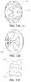
- FIG. 1shows a front-view illustration of an exemplary hip antibiotic irrigation platform, per an embodiment herein;
- FIG. 2shows a front-view illustration of an exemplary hip antibiotic irrigation system installed about a human hip joint, per an embodiment herein;
- FIG. 3 Ashows a front-view illustration of an exemplary hip spacer system, per an embodiment herein;
- FIG. 3 Bshows a cross-sectioned front-view illustration of an exemplary hip spacer system, per an embodiment herein;
- FIG. 4 Ashows a top-view illustration of an exemplary hip spacer, per an embodiment herein;
- FIG. 4 Bshows a front-view illustration of an exemplary hip spacer, per an embodiment herein;
- FIG. 4 Cshows a bottom-view illustration of an exemplary hip spacer, per an embodiment herein;
- FIG. 4 Dshows a cross-sectioned front-view illustration of an exemplary hip spacer, per an embodiment herein;
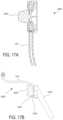
- FIG. 5 Ashows a front-left perspective illustration of an exemplary hip spacer system coupled to a femoral stem, per an embodiment herein;
- FIG. 5 Bshows a front-view illustration of an exemplary hip spacer system coupled to a femoral stem, per an embodiment herein;
- FIGS. 5 C to 5 Kdepict aspects of exemplary hip spacer systems, according to embodiments of the present invention.
- FIG. 6shows a front-view illustration of an exemplary knee antibiotic irrigation platform, per an embodiment herein;
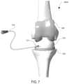
- FIG. 7shows a front-view illustration of an exemplary knee antibiotic irrigation system installed about a human knee joint, per an embodiment herein;
- FIG. 8 Ashows a front-top perspective illustration of an exemplary knee spacer system coupled to a femoral stem, per an embodiment herein;
- FIG. 8 Bshows a front-top-left perspective view illustration of an exemplary knee spacer system coupled to a femoral stem, per an embodiment herein;
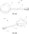
- FIG. 9 Ashows a front-view illustration of an exemplary knee spacer, per an embodiment herein;
- FIG. 9 Bshows a bottom cross-sectioned view illustration of an exemplary knee spacer, per an embodiment herein;
- FIG. 9 Cshows a front cross-sectioned view illustration of an exemplary knee spacer, per an embodiment herein;
- FIG. 10 Ashows a front-view illustration of an exemplary knee spacer disposed between a femoral implant and a tibial implant
- FIGS. 10 B and 10 Cdepict aspects of exemplary knee spacer systems, according to embodiments of the present invention.
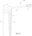
- FIG. 11shows a front-top perspective illustration of an exemplary shoulder spacer system, per an embodiment herein;
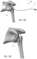
- FIG. 12 Ashows a back-view illustration of an exemplary shoulder spacer, per an embodiment herein;
- FIG. 12 Bshows a left-view illustration of an exemplary shoulder spacer, per an embodiment herein;
- FIG. 12 Cshows a front-view illustration of an exemplary shoulder spacer, per an embodiment herein;
- FIGS. 12 D and 12 Edepict aspects of exemplary shoulder spacer systems, according to embodiments of the present invention.
- FIG. 13 Ashows a top-left perspective view illustration of a humeral head of an exemplary shoulder spacer, per an embodiment herein;
- FIG. 13 Bshows a bottom-right perspective view illustration of a humeral head of an exemplary shoulder spacer, per an embodiment herein;
- FIG. 13 Cshows a detailed left cross-sectioned view illustration of an inlet of a humeral head of an exemplary shoulder spacer, per an embodiment herein;
- FIGS. 14 A to 14 Ddepict aspects of exemplary shoulder spacer systems, according to embodiments of the present invention.
- FIG. 15depicts aspects of exemplary shoulder spacer systems, according to embodiments of the present invention.
- FIGS. 16 A and 16 Billustrate aspects of exemplary reverse shoulder spacer systems, according to embodiments of the present invention
- FIGS. 17 A and 17 Billustrate aspects of exemplary reverse shoulder spacer systems, according to embodiments of the present invention.
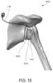
- FIG. 18depicts aspects of exemplary reverse shoulder spacer systems, according to embodiments of the present invention.
- FIG. 19illustrates aspects of exemplary treatment methods, according to embodiments of the present invention.
- periprosthetic joint infectionmay include a two-stage exchange arthroplasty: surgical removal of the infected implant, aggressive debridement and two-stage exchange arthroplasty with administration of systemic antibiotics.
- Stage 1 of the procedureincludes removal of the infected prosthesis and implantation of a temporary antibiotic impregnated cement spacer with adjuvant administration of systemic antibiotic therapy as needed, typically for a period of at least 6 weeks.
- Stage 2 of the procedureis performed when patients are considered infection free and includes removal of the temporary spacer and implantation of a new permanent prosthesis. Irrigation, and irrigation and debridement with implant retention, is an attractive alternative due to decreased patient morbidity associated with resection arthroplasty.
- DAIRDebridement, Antibiotics and Implant Retention
- biofilm formation in minutes to hoursmay contribute to the limited success of implant retention treatments, as biofilm may already be attached to the retained implants even in acute cases, allowing continued dispersion of bacteria from the biofilm remaining after the irrigation and debridement procedure.
- Continuous local antibiotic irrigation delivered by systems and methods disclosed hereinhave the potential to eradicate any remaining biofilm on retained implants after irrigation and debridement, significantly improving success rate of implant retention strategies for treating PJI.
- Such approachescan involve a spacer that is placed between permanent implants of a prosthesis, for a temporary period of time.
- permanent implantsmay not yet be infected between the implant and the bone, during the first 2-4 weeks following their implantation. Such implants remain well-fixed in bone.
- the infectioncan be treated without removing the two permanent implants by placing a spacer therebetween temporarily, while temporarily irrigating the surrounding soft tissue to achieve certain clinical advantages.
- the surgeonmay remove certain modular components of the prosthetic implant system, and replace them with an interpositional spacer as disclosed herein, for a period of time (e.g. having a duration within a range from about 3 days to about 3 weeks). Following the irrigation treatment period, the interpositional spacer can then be removed, and replaced with one or more permanent prosthetic replacement components.
- Interpositional spacers(and related systems and methods) as disclosed herein are well suited for use in treating patients presenting with acute periprosthetic joint infection (PJI), for example as part of a Debridement, Antibiotics and Implant Retention (DAIR) procedure.
- PJIacute periprosthetic joint infection
- DAIRImplant Retention
- a hip spacer platform 100comprising a hip spacer system 100 A ( FIG. 2 ) and a negative pressure wound therapy pump 130 .
- the instant disclosureis not limited to a NPWT pump, and that any infusion and vacuum pump may be used.
- embodimentsencompass hip spacer platforms which include a vacuum pump with gravity infusion.
- the hip spacer system 100 Acomprises a hip spacer 110 and a catheter 120 .
- the hip spacer 110comprises a fluid inlet 111 , one or more fluid outlets 112 , and a femoral head aperture 113 .
- the catheter 120is in fluidic communication with the fluid inlet 111 of the hip spacer 110 .
- the negative pressure wound therapy (NPWT) pump 130is in fluidic communication with the catheter 120 and the fluid outlet(s) 112 of the hip spacer 110 .
- the catheter 120is coupled to the NPWT pump via a connection 121 .
- a hip spacing kitcomprising two or more sizes of the hip spacer system 100 A and the negative pressure wound therapy pump 130 (or any infusion and vacuum pump), so as to accommodate various patient anatomies.
- a hip spacer platform or hip spacing kitmay or may not include a NPWT pump.
- the hip spacer 110comprises a single fluid inlet 111 and a plurality of fluid outlets 112 .
- the hip spacer 110comprises 1, 2, 3, 4, 5, 6, 7, 8, 9, 10, or more fluid inlets 111 .
- the hip spacer 110comprises 1, 2, 3, 4, 5, 6, 8, 10, 15, 20, 25, 30, 35, 40, 45, 50, 55, 60, 65, 70, 75, 80 or more fluid outlets 112 .
- an inner diameter of the fluid inlet 111is equal to an inner diameter of the fluid outlet(s) 112 .
- an inner diameter of the fluid inlet 111is greater than an inner diameter of the fluid outlet(s) 112 . In some embodiments, an inner diameter of the fluid inlet 111 is less an inner diameter of the fluid outlet(s) 112 . In some embodiments, the location of the fluid inlet 111 is specified to be closer to a standard incision location.
- the fluid inlet 111is in fluidic communication with the fluid outlets 112 via an inlet channel 116 and one or more outlet channels 115 .
- each outlet channel 115corresponds to a fluid outlet 112 .
- one or more outlet channels 115each correspond to one or more fluid outlets 112 .
- the outlet channels 115are configured in a polar array about a center of the hip spacer 110 .
- the fluid outlets 112are arranged in a polar array about a center of the hip spacer 110 .
- the fluid outlets 112are arranged in a polar array about a center of the hip spacer 110 in a series of radial and circular axes, wherein the radial axes intersect and wherein the circular axes are concentric.
- the hip spacer 110comprises 2, 4, 6, 8, 10, 12, 14, 16, 18, 20, 22, 24 or more radial axes.
- the hip spacer 110comprises 2, 4, 6, 8, 10, 12, 14, 16, 18, 20, 22, 24 or more circular axes.
- the fluid outlets 112are evenly arrayed about the hip spacer 110 .
- the outlet channels 112may be unevenly arrayed about the hip spacer 110 .
- the fluid outlets 112are arranged in a rectilinear array. Further, in some embodiments, as shown, the inlet channel 116 and each of the outlet channels 115 intersect. In some embodiments, the inlet channel 116 and each of the outlet channels 115 intersect at a center axis of the hip spacer 110 . In some embodiments, two or more of the fluid outlets 112 are concentric. In some embodiments, per FIGS. 4 D, 5 A and 5 B , the hip spacer 110 mates with a retained femoral implant 140 (e.g., femoral stem in FIG. 5 A , femoral head in FIG. 5 B ).
- a retained femoral implant 140e.g., femoral stem in FIG. 5 A , femoral head in FIG. 5 B ).
- the femoral head aperture 113 of the hip spacer 110mates with the retained femoral implant 140 .
- the hip spacer 110articulates about the retained femoral implant 140 .
- the femoral head aperture 113has a concave hemispherical shape.
- the hip spacer 110is disposed about a femoral head. Further as shown, the hip spacer 110 comprises a single uniform body. Alternatively, in some embodiments, the hip spacer 110 comprises two or more bodies that are removably coupled.
- the total volume defined by the outlet channels 115is less than the volume of a bolus or discrete amount of medicament or fluid delivered therethrough (which may be part of a periodic delivery regimen).
- the total volume defined by the outlet channels 115can be minimized so that antibiotics or other fluids administered to the patient via the spacer are not retained by the spacer, and hence the spacer does not operate as a reservoir.
- This approachcan maximize the amount of fluid that is delivered or exiting the spacer, and minimize the amount of fluid that is retained within the spacer.
- the total volume defined by the outlet channelscan be less than 50 cc.
- This principle regarding total volume of outlet channelscan also apply to knee spacer and/or shoulder spacer embodiments disclosed herein.
- the catheteris removably coupled to the fluid inlet 111 of the hip spacer 110 .
- the fluid inlet 111 of the hip spacer 110comprises a luer taper, a barb fitting, or both to removably couple to the catheter.
- the fluid inlet 111 of the hip spacer 110is configured to couple to the catheter intra-operatively.
- the catheteris permanently coupled to the fluid inlet 111 of the hip spacer 110 .
- the hip spacer system 100 Afurther comprises a sterile packaging enclosing the hip spacer 110 .
- the sterile packagingcomprises a double sterile barrier for introduction into the sterile field.
- the hip spaceris configured to be positioned between the femoral head and acetabular cup of a permanent hip prosthesis. In some embodiments, the hip spacer is configured to be positioned between the femoral stem and acetabular cup of a permanent hip prosthesis with the prosthetic femoral removed. In both cases, the hip spacer has an additional function of protecting the surfaces of the prosthetic components during irrigation or treatment.
- Outlets 112 Bcan facilitate the flow of treatment fluid to joint space between the first and second implants ( 20 , 30 ).
- Hip spacer 110can also include outlets which facilitate the flow of treatment fluid to spaces between the spacer and the second implant 30 , and such flow may also be facilitated by the presence of fluted channels on the underside of the spacer.
- the hip spacer 110can be used in a situation where the original prosthetic included a metal cup or shell which is attached with the acetabular bone, a liner (e.g.
- hip spacer 110which is shown as less than hemispherical
- the hip spacer 110 depicted in FIG. 3 Acan be used when the stem and spherical head of the original prosthetic are retained, and only the liner or liner and cup are removed.
- a hip spacer system 100 Acan include a hip spacer 110 and a catheter 120 .
- the hip spacer 100can be coupled with a retained femoral stem 30 and acetabular cup 20 of a permanent hip prosthesis.
- acetabular cup 20includes one or more fluid outlets or apertures 22 whereby fluid provided via the spacer 110 can flow therethrough and toward acetabular bone.
- Spacer 100includes a first surface 102 configured for articulating engagement with the first implant 20 , a second surface 104 configured for fixed engagement with the second implant 30 , and an exposed surface 106 disposed between the first surface 102 and the second surface 104 . As shown in FIG.
- hip spacer system 100 Acan include a hip spacer 110 and a catheter 120 , and as shown in the cross-section view of FIG. 5 G , surfaces of the spacer 110 can include apertures 112 A and 112 B through which treatment fluid may flow. As shown in the top view of FIG. 5 H , the cross-section view of FIG. 5 I , the side view of FIG. 5 J , and/or the bottom view of FIG. 5 K , a hip spacer 110 can include apertures 112 A and 112 B through which treatment fluid may flow.
- a knee spacer platform 200comprising a knee spacer system 200 A ( FIG. 7 ) and a negative pressure wound therapy pump 130 .
- the instant disclosureis not limited to a NPWT pump, and that any infusion and vacuum pump may be used.
- embodimentsencompass knee spacer platforms which include a vacuum pump with gravity infusion.
- the knee spacer system 200 Acomprises a knee spacer 210 and a catheter 120 .
- the knee spacer 210comprises a fluid inlet 211 , one or more fluid outlets 212 , and a femoral component post 213 .
- the catheter 120is in fluidic communication with the fluid inlet 211 of the knee spacer 210 .
- the negative pressure wound therapy pump 130is in fluidic communication with the catheter 120 and the fluid outlet(s) 212 of the knee spacer 210 .
- the catheter 120is coupled to the NPWT pump via a connection 121 .
- a knee spacing kitcomprising two or more sizes of the knee spacer system and the negative pressure wound therapy pump (or any infusion and vacuum pump), so as to accommodate various patient anatomies.
- a knee spacer platform or knee spacing kitmay or may not include a NPWT pump.
- a knee spacer platform 200comprising a knee spacer system 200 A and a negative pressure wound therapy pump 130 .
- the knee spacer system 200 Acomprises a knee spacer 210 and a catheter 120 .
- the knee spacer 210comprises a fluid inlet 211 , a fluid outlet 212 , and a femoral component post 213 .
- the catheter 120is in fluidic communication with the fluid inlet 211 of the knee spacer 210 .
- the negative pressure wound therapy pump 130is in fluidic communication with the catheter 120 and the fluid outlet 212 of the knee spacer 210 .
- the location of the fluid inlet 211is specified to be closer to a standard incision location.
- the knee spacer 210comprises a plurality of fluid outlets 212 arranged in a polar array arranged about a center of the knee spacer 210 .
- the knee spacer 210comprises 2, 4, 6, 8, 10, 12, 14, 16, 18, 20, 22, 24 or more fluid outlets 212 .
- the fluid inlet 211is arranged between two consecutive fluid outlets 212 .
- the fluid outlets 212are arranged in a rectilinear array.
- an inner diameter of the fluid inlet 211is equal to an inner diameter of the fluid outlet(s) 212 .
- an inner diameter of the fluid inlet 211is greater than an inner diameter of the fluid outlet(s) 212 . In some embodiments, an inner diameter of the fluid inlet 211 is less an inner diameter of the fluid outlet(s) 212 .
- the fluid inlet 211is in fluidic communication with the fluid outlets 212 via an inlet channel 216 and one or more outlet channels 215 .
- each outlet channel 215corresponds to a fluid outlet 212 .
- one or more outlet channels 215each correspond to one or more fluid outlets 212 .
- the inlet channel 216 and each of the outlet channels 215intersect. In some embodiments, the inlet channel 216 and each of the outlet channels 215 intersect at a center axis of the knee spacer 210 .
- the knee spacer 210mates with a femoral component 240 and a tibial tray 250 .
- a femoral component post 213 of the knee spacer 210mates with the femoral component 240 .
- the knee spacer 210articulates about the retained femoral component 240 .
- the femoral component post 213is symmetric about a plane.
- a first surface 214 of the femoral component post 213has a rounded outer edge.
- the first surface 214 of the femoral component post 213comprises a single uninterrupted surface.
- the knee spacer 210comprises a single uniform body. Alternatively, in some embodiments, the knee spacer 210 comprises two or more bodies that are removably coupled.
- the catheteris removably coupled to the fluid inlet 211 of the knee spacer 210 .
- the fluid inlet 211 of the knee spacer 210comprises a luer taper, a barb fitting, or both to removably couple to the catheter.
- the fluid inlet 211 of the knee spacer 210is configured to couple to the catheter intra-operatively.
- the catheteris permanently coupled to the fluid inlet 211 of the knee spacer 210 .
- the knee spacer system 200 Afurther comprises a sterile packaging enclosing the knee spacer 210 .
- the sterile packagingcomprises a double sterile barrier for introduction into the sterile field.
- the knee spacer platform 200is configured to be implanted during a short-period of time.
- the knee spacer 210provides local irrigation, drug administration, or both.
- the fluid inlet 211 and the fluid outlet(s) 212 of the knee spacer 210provide local irrigation, drug administration, or both.
- the knee spacer 210is made of a biocompatible polymer.
- the biocompatible polymeris a synthetic polymer.
- the synthetic polymeris low-density polyethylene (LDPE), high-density polyethylene (HDPE), polypropylene (PP), polyvinyl chloride (PVC) polystyrene (PS) nylon, polytetrafluoroethylene, or a thermoplastic polyurethane (TPU).
- a biocompatible polymeris acetyl copolymer (e.g. Delrin® or Celcon®), silicone, polyether ether ketone (PEEK), a polyurethane, including a flexible polyurethane, a biocompatible elastomer, or a ultrahigh molecular weight polyethylene (UHMWPE).
- the knee spacer 210is at least partially rigid. In some embodiments, the knee spacer 210 is at least partially flexible. In some embodiments, at least a portion of the knee spacer 210 has a modulus of elasticity of about 1 GPa to about 300 GPa.
- the knee spaceris configured to be positioned between the tibial and femoral components of a permanent knee prosthesis.
- the knee spacerhas an additional function of protecting the surfaces of the prosthetic components during irrigation or treatment.
- a knee spacer system 200 Acan include a knee spacer 210 and a catheter 120 .
- the knee spacer 210can be coupled with a retained femoral component and tibial component of a permanent knee prosthesis.
- the femoral componentcan include one or more fluid outlets or apertures whereby fluid provided via the spacer 210 can flow therethrough and toward femoral bone.
- the tibial componentcan include one or more fluid outlets or apertures whereby fluid provided via the spacer 210 can flow therethrough and toward tibial bone.
- Spacer 210includes a first surface 217 configured for articulating engagement with a first implant (e.g.
- a knee spacer 210can include outlets through which treatment fluid may flow.
- first surface 217can include outlets 217 A through which treatment fluid may flow toward a femoral implant
- second surface 218can include outlets 218 A through which treatment fluid may flow toward a tibial implant
- exposed surface 219can include outlets 219 A through which treatment fluid may flow into a joint space between the femoral implant and the tibial implant, for example to treat the nearby soft tissue.
- a shoulder spacer platformcomprising a shoulder spacer system (e.g. 300 A or 300 B) and a negative pressure wound therapy pump as described herein 130 .
- a shoulder spacer systeme.g. 300 A or 300 B
- a negative pressure wound therapy pumpas described herein 130 .
- the instant disclosureis not limited to a NPWT pump, and that any infusion and vacuum pump may be used.
- embodimentsencompass shoulder spacer platforms which include a vacuum pump with gravity infusion.
- the shoulder spacer system 300 Acomprises a shoulder spacer 310 and a catheter 120 .
- an interpositional spacere.g. for placement between two implanted prosthetic components
- shoulder spacer 310 of FIG. 11would not be placed between two implanted prosthetics (e.g. between a humeral stem and a glenoid component of a shoulder prosthesis), because shoulder spacer 310 includes humeral stem 330 .
- the humeral head 320is removably coupled to the humeral stem 330 .
- the humeral head 320is coupled to the humeral stem 330 via a tapered connection, a dovetail connection, a threaded connection, a flanged connection, a snap buckle, a winged nut, or any other coupling mechanism.
- the coupling mechanismallows for offset adjustments. Such embodiments allow for reduced inventory and better patient matching.
- shoulder spacer 310 depicted in FIG. 11can be used to replace a permanent shoulder prosthetic implant.
- shoulder spacer 310 depicted in FIGS. 12 A to 12 Ccan be used to replace a permanent shoulder prosthetic implant.
- shoulder spacer 310can be used in conjunction with a permanent glenoid prosthetic implant, such as implant 60 depicted in FIG. 14 D .
- shoulder spacer 310 or shoulder spacer system 300 Acan include any one or more features of the devices or can be configured to perform any one or more of the treatment method aspects of those disclosed in U.S. Provisional Patent Application Nos. 61/208,540 filed Feb. 25, 2009 or 62/180,986 filed Jun. 17, 2015, or in U.S. Patent Publication Nos. 2010/0217401 or 2016/0367371. The content of each of these filings is incorporated herein by reference.
- the shoulder spacer 310comprises a fluid inlet 311 as shown in FIG. 12 A .
- a shoulder spacer 350 as shown in FIG. 13 Ccan include a fluid inlet 311 A.
- the shoulder spacer 310comprises one or more head fluid outlets 312 .
- a shoulder spacer 350 as shown in FIG. 13 Bcan include one or more fluid outlets 312 A.
- the catheter 120is in fluidic communication with the fluid inlet 311 of the shoulder spacer 310 (or with inlet 311 A of shoulder spacer 350 ).
- the negative pressure wound therapy pump 130is in fluidic communication with the catheter 120 , and the fluid outlet(s) 313 .
- the catheter 120is coupled to the NPWT pump via a connection 121 .
- the location of the fluid inlet 311 (or 311 A)is specified to be closer to a standard incision location.
- a shoulder spacing kitcomprising two or more sizes of the shoulder spacer system and the negative pressure wound therapy pump (or any infusion and vacuum pump), so as to accommodate various patient anatomies.
- a shoulder spacer platform or shoulder spacing kitmay or may not include a NPWT pump.
- a humeral head or surfacecan include a plurality of fluid outlets 312 or 312 A, respectively, arranged in a polar array about a center of the humeral head 320 or spacer 350 , respectively.
- the humeral head 320 or shoulder spacer 350comprises 2, 4, 6, 8, 10, 12, 14, 16, 18, 20, 22, 24 or more fluid outlets 312 or 312 A, respectively.
- the fluid outlets 312 or 312 Aare arranged in a rectilinear array.
- an inner diameter of the fluid inlet 311 or 311 Ais equal to an inner diameter of the fluid outlet(s) 312 or 312 A, respectively. In some embodiments, an inner diameter of the fluid inlet 311 or 311 A is greater than an inner diameter of the fluid outlet(s) 312 or 312 A, respectively. In some embodiments, an inner diameter of the fluid inlet 311 or 311 A is less than an inner diameter of the fluid outlet 312 ( s ) or 312 A(s), respectively. In some embodiments, the fluid inlet 311 or 311 A is in fluidic communication with the fluid outlets 312 or 312 A, respectively, via an inlet channel and one or more outlet channels.
- each outlet channelcorresponds to a fluid outlet 312 or 312 A. In some embodiments, one or more outlet channels each correspond to one or more fluid outlets 312 or 312 A. In some embodiments, the inlet channel and each of the outlet channels intersect. In some embodiments, the inlet channel and each of the outlet channels intersect at a center axis of the shoulder spacer 310 (or stem thereof) or shoulder spacer 350 .
- an interpositional shoulder spacer 350comprises one or more fluted channels 314 as depicted in FIG. 13 B .
- the one or more fluted channels 314are arrayed about a center axis of the shoulder spacer 350 .
- the shoulder spacer 350comprises 1, 2, 3, 4, 5, 6, 7, 8, 9, 10, or more fluted channels 314 arrayed about the shoulder spacer 350 .
- one of more of the fluted channels 314may include one or more fluid outlets.
- the fluted channels 314enable fluid flow under the shoulder spacer 350 , between the shoulder spacer 350 and the humeral stem.
- the shoulder spacer 350is undersized to allow fluid flow thereover.
- shoulder spacer 310may include one or more similar fluted channels having one or more properties of the fluted channels 314 described here. It is also understood that hip spacer 110 and knee spacer 210 may include one or more similar fluted channels having one or more properties of the fluted channels 314 described here.
- the humeral stem 330comprises an elongate body having a longitudinal axis 310 A, wherein the humeral stem 330 comprises a first end 331 and a second end 332 opposite the first end. The second, or distal, end 332 may be disposed in the medullary canal of a bone.
- the humeral stem 330can vary in size and/or longitudinal length.
- the humeral stem 330comprises a stem channel extending between the first end 331 and the second end 332 .
- the stem channelis configured to deliver fluid to the medullary canal via the one or more stem fluid outlets 313 .
- the humeral stem 330comprises a plurality of protrusions 340 , protruding radially outward from a center axis of the humeral stem 330 .
- the plurality of protrusions 340may comprise any number of protrusions having any appropriate shape, size, or configuration to engage the medullary canal in a stable fashion.
- the protrusionsmay comprise elongate fins extending along the longitudinal length of the humeral stem 330 .
- the plurality of protrusions 340may comprise four fins, spaced equally at about 90° about the longitudinal axis 310 A of the humeral stem 330 .
- the plurality of protrusions 340 and the humeral stem 330may be formed separately and coupled together. Alternatively or in combination, the plurality of protrusions 340 may be formed by removing material from the humeral stem 330 , such that the plurality of protrusions and the humeral stem 330 are formed as a single member. Adjacent protrusions 340 may define one or more fluted regions 341 therebetween, wherein the fluted regions 341 are radially recessed compared to the protrusions 340 . The fluted regions 341 may form a concave recessed region between adjacent protrusions 340 .
- the plurality of protrusions 340 and fluted regions 341can be configured to minimize the surface area of the humeral stem 330 contacting the bone lining the medullary canal, such that the area of the bone flush with fluid being delivered via the fluid inlet 311 may be maximized.
- the plurality of protrusions 340 and fluted regions 341can be configured such that less than 50% of the surface area of the humeral stem 330 is in contact with the bone lining the medullary canal.
- thisis not intended to be limiting and one of skill in the art will appreciate that any percentage of the surface area of the humeral stem 330 may contact the bone.
- the humeral stem 330comprises a plurality of identical fluted regions 341 defined by a plurality of elongate fins 340 , distributed symmetrically about the longitudinal axis 310 A of the humeral stem 330 .
- a plurality of fluted regions 341may be distributed asymmetrically about the longitudinal axis of the humeral stem 330 , and/or may have different shapes or sizes.
- the humeral stem 330comprises fluted regions 341 to allow for fluid flow in the medullary canal, allow for fluid flow between medullary canal and the joint space where a NPWT sponge will be.
- the plurality of stem fluid outlets 313are in fluid communication with the internal channel of the humeral stem 330 .
- the plurality of stem fluid outlets 313may be configured to deliver the fluid, distributed through the humeral stem 330 internal channel, to the medullary canal, as well as adjacent tissue including the joint.
- the plurality of stem fluid outlets 313may be disposed in one or more fluted regions 341 , so as to deliver the fluid to the area of the bone not in contact with the humeral stem 330 .
- the plurality of stem fluid outletsmay comprise any number of outlet holes having any appropriate size, shape, or distribution.
- the plurality of outlet holesmay include a plurality of equally sized and spaced holes that extend axially along a line substantially parallel to the longitudinal axis 310 A of the humeral stem 330 .
- the plurality of outlet holesmay be arranged in various configurations.
- the plurality of outlet holesmay comprise holes having an identical shape and/or size, or holes having various shapes and/or sizes. Varying the hole size may allow further fluid control of the fluid as it exits different regions of the humeral stem 330 .
- the humeral stem 330may be tapered to fit the medullary canal.
- the humeral stem 330 and/or the plurality of protrusions 340may be tapered from the first end 331 to the second end 332 , as shown, so as to have a smaller radial cross-sectional area at the second end than at the first end.
- the tapermay comprise a gradual taper, wherein the extent of the taper may be preferably in a range from about 0.1° to about 10°, more preferably about 0.5° to about 5°, and even more preferably about 1° to about 5°, or about 1° to about 4°, or about 2° or about 3°.
- the tapermay be adjusted to accommodate a medullary canal of a specific type of bone.
- the catheteris removably coupled to the fluid inlet 311 of the shoulder spacer 310 .
- the fluid inlet 311 of the shoulder spacer 310comprises a luer taper, a barb fitting, or both to removably couple to the catheter.
- the fluid inlet 311 of the shoulder spacer 310is configured to couple to the catheter intra-operatively.
- the catheteris permanently coupled to the fluid inlet 311 of the shoulder spacer 310 .
- the shoulder spacer system 300 Afurther comprises a sterile packaging enclosing the shoulder spacer 310 .
- the sterile packagingcomprises a double sterile barrier for introduction into the sterile field.
- the shoulder spacer platformis configured to be implanted during a short-period of time.
- the shoulder spacer 310provides local irrigation, drug administration, or both.
- the fluid inlet 311 and the fluid outlet(s) 312 of the shoulder spacer 310provide local irrigation, drug administration, or both.
- the shoulder spacer 310is made of a biocompatible polymer.
- the biocompatible polymeris a synthetic polymer.
- the synthetic polymeris low-density polyethylene (LDPE), high-density polyethylene (HDPE), polypropylene (PP), polyvinyl chloride (PVC) polystyrene (PS) nylon, polytetrafluoroethylene, or a thermoplastic polyurethane (TPU).
- a biocompatible polymeris acetyl copolymer (e.g. Delrin® or Celcon®), silicone, polyether ether ketone (PEEK), a polyurethane, including a flexible polyurethane, a biocompatible elastomer, or a ultrahigh molecular weight polyethylene (UHMWPE).
- the shoulder spacer 310 or shoulder spacer 350is at least partially rigid. In some embodiments, the shoulder spacer 310 or shoulder spacer 350 is at least partially flexible. In some embodiments, at least a portion of the shoulder spacer 310 or shoulder spacer 350 has a modulus of elasticity of about 1 GPa to about 300 GPa.
- the shoulder spacing kitcomprises two or more sizes of the shoulder spacer 310 , two or more sizes of the humeral stem 330 , or both. In some embodiments, the shoulder spacing kit comprises two or more sizes of the shoulder spacer 350 .
- the shoulder spacer 350is configured to be positioned between the humeral stem and glenoid components of a permanent shoulder prosthesis.
- the shoulder spacerhas an additional function of protecting the surfaces of the prosthetic components during an irrigation or treatment period.
- the shoulder spacer 310is configured to be positioned adjacent a glenoid component of a permanent shoulder prosthesis.
- FIG. 12 Ddepicts shoulder spacer system 300 A engaged with a glenoid bone and a humerus bone of a patient.
- Shoulder spacer system 300 Aincludes a shoulder spacer 310 and a catheter 120 .
- FIG. 12 Edepicts shoulder spacer 350 engaged with a glenoid bone and a humerus bone of a patient.
- the shoulder spacer system 300 Bcomprises a shoulder spacer 350 and a catheter 120 .
- shoulder spacer 350includes a protrusion 352 which can engage a permanent prosthetic component, such as a humeral stem prosthetic component.
- a shoulder spacer 350can be placed between a glenoid implant and a humeral implant of a permanent prosthesis.
- Fluid outletsmay be positioned all over the shoulder spacer.
- fluid outlets 352 Amay be on the spacer surface that contacts the glenoid implant prosthetic component.
- antibiotic or other materialscan be provided into the glenoid implant 60 , which itself may have holes in it, so as to facilitate the flow or delivery of antibiotic or other materials to glenoid bone.
- Fluid outletsmay be on the exposed surface of the spacer 350 . Such outlets can facilitate the flow of treatment fluid to joint space between the first and second implants.
- Shoulder spacer 350can also include outlets 352 C which facilitate the flow of treatment fluid to spaces between the spacer and the second implant (e.g. humeral stem 70 ), and such flow may also be facilitated by the presence of fluted channels on the underside of the spacer.
- the shoulder spacer 350can be used in a situation where the original prosthetic (e.g.
- glenoid component 60included a metal cup or shell which is attached with the glenoid bone, a liner (e.g. plastic) which is disposed within the metal cup or shell, a spherical head which articulates against or otherwise engages the liner, and stem or trunnion which is coupled with the spherical head or ball, and the surgical procedure involves removing the liner and spherical head, and temporarily inserting therefore the shoulder spacer 350 (e.g. while retaining the cup/shell of the glenoid component 60 ).
- the shoulder spacer 350 depicted in FIG. 12 Dcan be used when the stem and spherical head of the original prosthetic are retained, and only the liner or liner and cup are removed.
- the shoulder spacer 350 of FIGS. 12 D and 14 Dmay be the same, where shoulder spacer 350 of FIG. 12 D is used when the glenoid prosthetic component is removed, and shoulder spacer 350 of FIG. 14 D is used when the glenoid prosthetic component 60 is retained.
- a shoulder spacercan be used when a spherical head of the humeral prosthetic implant is retained.
- a shoulder spacercan be used when a spherical head of the humeral prosthetic implant is removed.
- FIG. 15depicts aspects of a shoulder spacer 350 according to embodiments of the present invention.
- shoulder spacer 350can be engaged with a glenoid implant component 60 and a humeral implant component 70 of a previously implanted prosthesis.
- glenoid component 60includes one or more holes or apertures 62 whereby fluid provided via the spacer 350 can flow therethrough and toward glenoid bone.
- FIGS. 16 A and 16 Billustrate aspects of an exemplary reverse shoulder spacer system 300 C.
- reverse shoulder spacer system 300 Cincludes a reverse shoulder spacer 350 C and a catheter 120 .
- Reverse shoulder spacer 350 Cincludes a first surface 317 C configured for articulating engagement with a first implant (e.g. glenoid implant), a second surface 318 C configured for fixed engagement with a second implant (e.g. humeral implant), and an exposed surface 319 C disposed between the first surface 317 C and the second surface 318 C.
- a reverse shoulder spacer 350 Ccan include outlets through which treatment fluid may flow.
- first surface 317 Ccan include outlets 317 A through which treatment fluid may flow toward a glenoid implant
- second surface 318 Ccan include outlets 318 A through which treatment fluid may flow toward a humeral implant
- exposed surface 319 Ccan include outlets 319 A through which treatment fluid may flow into a joint space between the glenoid implant and the humeral implant, for example to treat the nearby soft tissue.
- FIGS. 17 A and 17 Billustrate aspects of an exemplary reverse shoulder spacer system 300 C.
- reverse shoulder spacer system 300 Cincludes a reverse shoulder spacer 350 C and a catheter 120 .
- reverse shoulder spacer 350 Cincludes a first surface configured for articulating engagement with a first implant (e.g. glenoid implant 360 C), a second surface configured for fixed engagement with a second implant (e.g. humeral implant 370 C), and an exposed surface 319 C disposed between the first surface and the second surface.
- a reverse shoulder spacer 350 Ccan include outlets through which treatment fluid may flow.
- first surfacecan include outlets through which treatment fluid may flow toward a glenoid implant 360 C
- second surfacecan include outlets through which treatment fluid may flow toward a humeral implant 370 C
- exposed surface 319 Ccan include outlets through which treatment fluid may flow into a joint space between the glenoid implant 360 C and the humeral implant 370 C, for example to treat the nearby soft tissue.
- FIG. 18depicts aspects of a reverse shoulder spacer system 300 C, according to embodiments of the present invention.
- the reverse shoulder spacer system 300 Cincludes a reverse shoulder spacer 350 C and a catheter 120 .
- the reverse shoulder spacer 350 Ccan engage a retained glenoid implant 360 C which is attached with a glenoid bone.
- the reverse shoulder spacer 350 Ccan also engage a retained humeral implant 370 C which is attached with a humerus bone.
- kits for treating periprosthetic joint infectioncomprising: providing one of: the hip spacer platform, the knee spacer platform, and the shoulder spacer platform; and supplying a medication to the pump to irrigate a location of the joint infection over a period of time.
- the medicationis supplied continuously over a period of time.
- the medicationis supplied intermittently over a period of time.
- the medicationis removed by applying negative pressure continuously to the site of joint infection.
- the medicationis removed by applying negative pressure intermittently over a period of time.
- the medicationcomprises a broad spectrum of antibiotics. In some embodiments, the medication comprises tobramycin sulfate, vancomycin HCl, or both. In some embodiments, the medication comprises tobramycin sulfate for a first period of time and vancomycin HCl for a second period of time. In some embodiments, the period of time is about 1, 2, 3, 4, 5, 6, 7, 8, 9, 10, 11, 12, 13, 14 or more days.
- FIG. 19depicts aspects of an exemplary method 1900 for treating a patient presenting with an acute periprosthetic joint infection of a joint, according to embodiments of the present invention.
- the method 1900can include removing one or more components of a permanent joint prosthesis, as depicted in step 1910 .
- a removal stepmay include removing one or more prosthetic components disposed between a first implant secured with a first bone of the joint and a second implant secured with a second bone of the joint.
- Methodsmay also include engaging a spacer of a spacer system with one or more remaining components of the permanent joint prosthesis, as depicted in step 1920 .
- the spacer systemincludes the spacer, a catheter, and a pump assembly.
- the spacer and catheterare configured for detachable coupling.
- the pump assemblyis configured for coupling with the catheter.
- Methodsmay also include delivering a treatment fluid from the pump assembly, through the catheter, and through the spacer, for administration to the joint, as depicted in step 1930 .
- the delivery step 1930can include delivering an antibiotic treatment fluid from the pump, through the catheter, into an inlet of the spacer.
- the fluidcan flow out through a first plurality of outlets at a first surface of the spacer to the first implant, out through a second plurality of outlets at an exposed surface of the spacer and into a joint space between the first implant and the second implant, and out through a third plurality of outlets at a second surface of the spacer.
- the third plurality of outletscan be disposed within one or more fluted channels of the second surface so as to provide fluid flow between the spacer and the second implant.
- the antibiotic treatment fluidis provided continuously or periodically to the patient over a treatment period of 7 days or more, and the catheter remains attached with the spacer throughout the treatment period
- the term “about” in some casesrefers to an amount that is approximately the stated amount.
- the term “about” in reference to a percentagerefers to an amount that is greater or less the stated percentage by 10%, 5%, or 1%, including increments therein.
- each of the expressions “at least one of A, B and C”, “at least one of A, B, or C”, “one or more of A, B, and C”, “one or more of A, B, or C” and “A, B, and/or C”means A alone, B alone, C alone, A and B together, A and C together, B and C together, or A, B and C together.
Landscapes
- Health & Medical Sciences (AREA)
- Orthopedic Medicine & Surgery (AREA)
- Heart & Thoracic Surgery (AREA)
- General Health & Medical Sciences (AREA)
- Life Sciences & Earth Sciences (AREA)
- Veterinary Medicine (AREA)
- Engineering & Computer Science (AREA)
- Biomedical Technology (AREA)
- Public Health (AREA)
- Vascular Medicine (AREA)
- Animal Behavior & Ethology (AREA)
- Oral & Maxillofacial Surgery (AREA)
- Cardiology (AREA)
- Transplantation (AREA)
- Physical Education & Sports Medicine (AREA)
- Anesthesiology (AREA)
- Hematology (AREA)
- Prostheses (AREA)
- Pharmaceuticals Containing Other Organic And Inorganic Compounds (AREA)
Abstract
Description
Claims (14)
Priority Applications (6)
| Application Number | Priority Date | Filing Date | Title |
|---|---|---|---|
| US17/401,843US12239538B2 (en) | 2020-08-13 | 2021-08-13 | System and method for treatment and prevention of periprosthetic joint infections |
| PCT/US2021/045933WO2022036211A1 (en) | 2020-08-13 | 2021-08-13 | System and method for treatment and prevention of periprosthetic joint infections |
| JP2023509692AJP2023538305A (en) | 2020-08-13 | 2021-08-13 | Systems and methods for the treatment and prevention of periprosthetic joint infections |
| CA3187924ACA3187924A1 (en) | 2020-08-13 | 2021-08-13 | System and method for treatment and prevention of periprosthetic joint infections |
| AU2021326539AAU2021326539A1 (en) | 2020-08-13 | 2021-08-13 | System and method for treatment and prevention of periprosthetic joint infections |
| US19/043,036US20250268717A1 (en) | 2020-08-13 | 2025-01-31 | System and method for treatment and prevention of periprosthetic joint infections |
Applications Claiming Priority (2)
| Application Number | Priority Date | Filing Date | Title |
|---|---|---|---|
| US202063065413P | 2020-08-13 | 2020-08-13 | |
| US17/401,843US12239538B2 (en) | 2020-08-13 | 2021-08-13 | System and method for treatment and prevention of periprosthetic joint infections |
Related Child Applications (1)
| Application Number | Title | Priority Date | Filing Date |
|---|---|---|---|
| US19/043,036DivisionUS20250268717A1 (en) | 2020-08-13 | 2025-01-31 | System and method for treatment and prevention of periprosthetic joint infections |
Publications (2)
| Publication Number | Publication Date |
|---|---|
| US20220047392A1 US20220047392A1 (en) | 2022-02-17 |
| US12239538B2true US12239538B2 (en) | 2025-03-04 |
Family
ID=80224609
Family Applications (2)
| Application Number | Title | Priority Date | Filing Date |
|---|---|---|---|
| US17/401,843Active2043-04-24US12239538B2 (en) | 2020-08-13 | 2021-08-13 | System and method for treatment and prevention of periprosthetic joint infections |
| US19/043,036PendingUS20250268717A1 (en) | 2020-08-13 | 2025-01-31 | System and method for treatment and prevention of periprosthetic joint infections |
Family Applications After (1)
| Application Number | Title | Priority Date | Filing Date |
|---|---|---|---|
| US19/043,036PendingUS20250268717A1 (en) | 2020-08-13 | 2025-01-31 | System and method for treatment and prevention of periprosthetic joint infections |
Country Status (7)
| Country | Link |
|---|---|
| US (2) | US12239538B2 (en) |
| EP (1) | EP4196056A4 (en) |
| JP (1) | JP2023538305A (en) |
| CN (1) | CN116096328A (en) |
| AU (1) | AU2021326539A1 (en) |
| CA (1) | CA3187924A1 (en) |
| WO (1) | WO2022036211A1 (en) |
Families Citing this family (1)
| Publication number | Priority date | Publication date | Assignee | Title |
|---|---|---|---|---|
| US11819415B2 (en)* | 2021-04-02 | 2023-11-21 | Arthrex, Inc. | Orthopaedic implant systems including internal networks and methods of repair |
Citations (148)
| Publication number | Priority date | Publication date | Assignee | Title |
|---|---|---|---|---|
| US3648294A (en) | 1969-02-08 | 1972-03-14 | Esfandiar Shahrestani | Endoprostheses, especially for hip joints |
| US4274163A (en) | 1979-07-16 | 1981-06-23 | The Regents Of The University Of California | Prosthetic fixation technique |
| US4399814A (en) | 1981-04-27 | 1983-08-23 | Massachusetts Institute Of Technology | Method and apparatus for pressure-coated bones |
| US4488549A (en) | 1981-08-25 | 1984-12-18 | University Of Exeter | Pressurization of cement in bones |
| US4653487A (en) | 1986-01-29 | 1987-03-31 | Maale Gerhard E | Intramedullary rod assembly for cement injection system |
| US4711233A (en) | 1985-06-26 | 1987-12-08 | Brown Byron L | Method and apparatus for cementing an acetabular cup to an acetabulum |
| DE3704089A1 (en) | 1987-02-10 | 1988-08-25 | Claus Fahrer | Heterologous implant |
| US4888024A (en) | 1985-11-08 | 1989-12-19 | Powlan Roy Y | Prosthetic device and method of fixation within the medullary cavity of bones |
| US4892550A (en) | 1985-12-30 | 1990-01-09 | Huebsch Donald L | Endoprosthesis device and method |
| US5116377A (en) | 1989-04-15 | 1992-05-26 | Bristol-Myers Squibb Company | Cementable hip prosthesis |
| US5133767A (en) | 1989-10-12 | 1992-07-28 | Sulzer Brothers Limited | Prosthesis having a deformable implant surface |
| US5133772A (en) | 1990-01-17 | 1992-07-28 | Osteonics Corporation | Femoral implant for hip arthroplasty |
| US5133771A (en) | 1990-12-05 | 1992-07-28 | University Of British Columbia | Flexible mold for forming composite of a hip replacement component and a bone cement sleeve |
| US5156606A (en) | 1988-10-11 | 1992-10-20 | Zimmer, Inc. | Method and apparatus for removing pre-placed prosthetic joints and preparing for their replacement |
| US5290291A (en) | 1992-03-16 | 1994-03-01 | Hall Surgical, Division Of Zimmer, Inc. | Method for implant removal |
| US5340362A (en) | 1991-10-16 | 1994-08-23 | Carbone John J | Method and apparatus for cementing intramedullary bone prosthesis |
| US5370698A (en) | 1992-04-16 | 1994-12-06 | Clemson University | Isoelastic implants with improved anchorage means |
| US5376123A (en) | 1989-12-07 | 1994-12-27 | Ao-Forschungsinstitut Davos | Adaptable stem for endoprosthesis |
| US5433718A (en) | 1992-08-20 | 1995-07-18 | Brinker; Mark | Antibiotic eluding intramedullary nail apparatus |
| EP0692226A1 (en) | 1994-07-12 | 1996-01-17 | Laboratoire Perouse Implant | Endoprothesis and corresponding prosthetic device |
| US5501687A (en) | 1992-11-20 | 1996-03-26 | Sulzer Medizinaltechnik Ag | Body for distributing bone cement for the anchoring of implants |
| US5514137A (en) | 1993-12-06 | 1996-05-07 | Coutts; Richard D. | Fixation of orthopedic devices |
| US5549702A (en) | 1994-10-25 | 1996-08-27 | Smith & Nephew Richards Inc. | Flexible orthopaedic stem apparatus |
| US5554111A (en) | 1995-03-16 | 1996-09-10 | Mayo Foundation For Medical Education & Research | Bone cleaning and drying system |
| US5562736A (en) | 1994-10-17 | 1996-10-08 | Raymedica, Inc. | Method for surgical implantation of a prosthetic spinal disc nucleus |
| US5571204A (en) | 1994-07-14 | 1996-11-05 | Merck Patent Gesellschaft Mit Beschrankter Haftung | Femoral prosthesis |
| US5681289A (en) | 1995-08-14 | 1997-10-28 | Medicinelodge Inc. | Chemical dispensing system |
| US5683472A (en) | 1995-12-29 | 1997-11-04 | Johnson & Johnson Professional, Inc. | Femoral stem attachment for a modular knee prosthesis |
| US5693099A (en) | 1991-07-11 | 1997-12-02 | Haerle; Anton | Endoprosthesis |
| US5702446A (en) | 1992-11-09 | 1997-12-30 | Board Of Regents, The University Of Texas System | Bone prosthesis |
| NZ279442A (en) | 1994-01-26 | 1998-02-26 | Mark A Reiley | Bone treatment device; inflatable balloon for insertion into a bone; balloon details |
| US5725596A (en) | 1992-11-20 | 1998-03-10 | Burke; Dennis W. | Clamp for use with a bone prosthesis |
| US5741265A (en) | 1996-02-21 | 1998-04-21 | Chan; Kwan-Ho | Bone canal pressurizer |
| US5755811A (en) | 1995-08-25 | 1998-05-26 | Zimmer, Inc. | Prosthetic implant with fins |
| DE19722359A1 (en) | 1997-05-28 | 1998-12-03 | Dynamit Nobel Ag | Press-rolling device and method for producing ring gears with two internal gears |
| DE19722389A1 (en) | 1997-05-28 | 1998-12-10 | Eska Implants Gmbh & Co | Modular arthrodesic knee joint |
| US5871484A (en) | 1995-11-09 | 1999-02-16 | General Orthopedics | Apparatus and method for administering a biologically active substance to a bone |
| US5916269A (en)* | 1996-06-03 | 1999-06-29 | Depuy Orthopaedics, Inc. | Wear reduced acetabular component |
| US5954771A (en) | 1993-02-16 | 1999-09-21 | Wright Medical Technology, Inc. | Dual fixation prosthesis |
| US5980573A (en) | 1997-05-12 | 1999-11-09 | Shaffner; Richard L. | Method and apparatus for fighting infection and maintaining joint spacing in a prosthesis implant area |
| US6066154A (en) | 1994-01-26 | 2000-05-23 | Kyphon Inc. | Inflatable device for use in surgical protocol relating to fixation of bone |
| US6106495A (en) | 1998-05-20 | 2000-08-22 | Howmedica Inc. | Methods and apparatus for delivering antibiotic powders into the femoral canal for the reduction of orthopaedic sepsis during total hip arthroplasty |
| US6113639A (en) | 1999-03-23 | 2000-09-05 | Raymedica, Inc. | Trial implant and trial implant kit for evaluating an intradiscal space |
| US6132674A (en) | 1995-10-12 | 2000-10-17 | Bristol-Myers Squibb Company | Method of making an orthopaedic implant having a porous surface |
| US6155812A (en) | 1998-07-15 | 2000-12-05 | Biomet, Inc | Cement mold for a temporary implant |
| US6217619B1 (en) | 1997-12-05 | 2001-04-17 | GMT GESELLSCHAFT FüR MEDIZINISCHE TECHNIK MBH | Endoprosthesis for a least partial replacement of a tibia |
| US6248110B1 (en) | 1994-01-26 | 2001-06-19 | Kyphon, Inc. | Systems and methods for treating fractured or diseased bone using expandable bodies |
| ITVI20000025U1 (en) | 2000-04-07 | 2001-10-07 | Tecres Spa | TEMPORARY SPACER DEVICE FOR SURGICAL TREATMENT OF THE KNEE |
| US20010051831A1 (en) | 1998-08-14 | 2001-12-13 | Subba Rao Goli Venkata | Modular hip implant with shock absorption system |
| US6361780B1 (en) | 1998-11-12 | 2002-03-26 | Cardiac Pacemakers, Inc. | Microporous drug delivery system |
| US6361731B1 (en) | 1998-07-15 | 2002-03-26 | Biomet, Inc. | Method of forming a temporary implant |
| US6447514B1 (en) | 2000-03-07 | 2002-09-10 | Zimmer | Polymer filled hip fracture fixation device |
| US20020143402A1 (en) | 1995-09-04 | 2002-10-03 | Limber Ltd. | Hip joint prostheses |
| US20020169507A1 (en) | 2000-12-14 | 2002-11-14 | David Malone | Interbody spine fusion cage |
| US20030060891A1 (en) | 2001-09-27 | 2003-03-27 | Shah Mrugesh K. | Hip replacement system having fat lubricant |
| WO2003037166A2 (en) | 2001-11-01 | 2003-05-08 | Boyd Lawrence M | Devices and methods for the restoration of a spinal disc |
| US20030097184A1 (en) | 2001-11-21 | 2003-05-22 | Naoto Mitsugi | Stem of artificial hip joint |
| US6589281B2 (en) | 2001-01-16 | 2003-07-08 | Edward R. Hyde, Jr. | Transosseous core approach and instrumentation for joint replacement and repair |
| US20030187513A1 (en) | 2002-03-26 | 2003-10-02 | Durniak Todd D. | System and method for delivering biological materials to a prosthesis implantation site |
| US6679890B2 (en) | 2001-08-28 | 2004-01-20 | Joseph Y. Margulies | Method and apparatus for augmentation of the femoral neck |
| US20040036189A1 (en) | 2002-03-13 | 2004-02-26 | Ensign Michael D. | Disposable knee mold |
| US6740090B1 (en) | 2000-02-16 | 2004-05-25 | Trans1 Inc. | Methods and apparatus for forming shaped axial bores through spinal vertebrae |
| US6740120B1 (en) | 1996-08-13 | 2004-05-25 | James B. Grimes | Bone prosthesis and method of Access |
| US20040111162A1 (en) | 2002-12-05 | 2004-06-10 | Southworth Carleton B. | Apparatus and method for advancing synovial fluid in a prosthetic joint |
| US6783515B1 (en) | 1999-09-30 | 2004-08-31 | Arthrocare Corporation | High pressure delivery system |
| US20040193268A1 (en) | 2003-03-31 | 2004-09-30 | Hazebrouck Stephen A. | Intercalary prosthesis, kit and method |
| US20050004680A1 (en) | 2003-07-03 | 2005-01-06 | Joseph Saladino | Femoral head assembly with variable offset |
| US20050021084A1 (en) | 2003-05-19 | 2005-01-27 | Lu William Weijia | Bone treatment device and method |
| WO2005006938A2 (en) | 2003-07-18 | 2005-01-27 | Technion Research & Development Foundation Ltd. | Anti-microbial medical implants and uses thereof |
| US20050107794A1 (en) | 2003-03-31 | 2005-05-19 | Hazebrouck Stephen A. | Orthopaedic spacer |
| US6899716B2 (en) | 2000-02-16 | 2005-05-31 | Trans1, Inc. | Method and apparatus for spinal augmentation |
| US20050187555A1 (en) | 2004-02-24 | 2005-08-25 | Biedermann Motech Gmbh | Bone anchoring element |
| US6969404B2 (en) | 1999-10-08 | 2005-11-29 | Ferree Bret A | Annulus fibrosis augmentation methods and apparatus |
| US20050277936A1 (en) | 2004-06-11 | 2005-12-15 | Mark Siravo | Intramedullary rod with spiraling flutes |
| US20060004431A1 (en) | 2004-07-01 | 2006-01-05 | Fuller Thomas A | Prophylactic bactericidal implant |
| US20060014120A1 (en) | 2004-07-16 | 2006-01-19 | Sapian Schubert L | Biofunctional dental implant |
| US6989033B1 (en) | 1992-09-17 | 2006-01-24 | Karlheinz Schmidt | Implant for recreating verterbrae and tubular bones |
| US20060030945A1 (en) | 2004-08-05 | 2006-02-09 | Wright Abraham P | Modular orthopaedic implant system with multi-use stems |
| US20060093646A1 (en) | 2004-10-28 | 2006-05-04 | Cima Michael J | Orthopedic and dental implant devices providing controlled drug delivery |
| US7112205B2 (en) | 2003-06-17 | 2006-09-26 | Boston Scientific Scimed, Inc. | Apparatus and methods for delivering compounds into vertebrae for vertebroplasty |
| US7141053B2 (en) | 2001-11-28 | 2006-11-28 | Wright Medical Technology, Inc. | Methods of minimally invasive unicompartmental knee replacement |
| US7141067B2 (en) | 2003-03-31 | 2006-11-28 | Depuy Products, Inc. | Intercalary implant |
| US20070005142A1 (en) | 2005-06-30 | 2007-01-04 | Rhodes James M | Tibial insert and associated surgical method |
| US20070016163A1 (en) | 2005-06-28 | 2007-01-18 | Microchips, Inc. | Medical and dental implant devices for controlled drug delivery |
| US20070088442A1 (en) | 2005-10-14 | 2007-04-19 | Microchips, Inc. | Passive wear-indicating sensor for implantable prosthetic device |
| WO2007047420A2 (en) | 2005-10-13 | 2007-04-26 | Synthes (U.S.A.) | Drug-impregnated encasement |
| US7211113B2 (en) | 2004-05-18 | 2007-05-01 | Lev Zelener | Hip prosthesis |
| US7217260B2 (en) | 2001-01-31 | 2007-05-15 | The Procter & Gamble Co. | Absorbent article with tension-dividing side panels |
| US20070110804A1 (en) | 2003-06-20 | 2007-05-17 | Royer Biomedical, Inc. | Drug polymer complexes |
| US7250055B1 (en) | 2003-08-26 | 2007-07-31 | Biomet Manufacturing Corp. | Method and apparatus for cement delivering buttress pin |
| US20070179609A1 (en) | 2006-01-27 | 2007-08-02 | Medicinelodge, Inc. | Therapeutic agent eluding implant with percutaneous supply |
| US7255713B2 (en) | 2003-12-18 | 2007-08-14 | Malek Michel H | Systems and methods for agent delivery |
| US7427296B2 (en) | 2003-11-14 | 2008-09-23 | Richard Parker Evans | Total knee joint mold and methods |
| US20090069899A1 (en) | 2007-09-11 | 2009-03-12 | Howmedica Osteonics Corp. | Antibiotic bone cement spacer |
| US7534240B1 (en) | 1999-04-02 | 2009-05-19 | Kci Licensing, Inc. | Negative pressure wound therapy system with provision for introduction of an agent |
| US20090130167A1 (en) | 2007-09-26 | 2009-05-21 | Microchips, Inc. | Drug Delivery Device and Method for Use with Prosthetic Device Implantation |
| US7641698B1 (en) | 2004-06-04 | 2010-01-05 | Biomet Manufacturing Corp. | Modular hip joint implant |
| US20100042213A1 (en) | 2008-08-13 | 2010-02-18 | Nebosky Paul S | Drug delivery implants |
| US20100042214A1 (en)* | 2008-08-13 | 2010-02-18 | Nebosky Paul S | Drug delivery implants |
| US20100042215A1 (en) | 2008-08-13 | 2010-02-18 | Stalcup Gregory C | Orthopaedic implant |
| US20100042167A1 (en) | 2008-08-13 | 2010-02-18 | Nebosky Paul S | Orthopaedic screws |
| WO2010080667A1 (en) | 2008-12-31 | 2010-07-15 | Kci Licensing, Inc. | Manifolds, systems, and methods for administering reduced pressure to a subcutaneous tissue site |
| US20100217401A1 (en) | 2009-02-25 | 2010-08-26 | De Beaubien Brian C | Antibiotic delivery system and method for treating an infected synovial joint during re-implantation of an orthopedic prosthesis |
| US20100292803A1 (en) | 2009-05-17 | 2010-11-18 | The Board Of Trustees Of The Leland Stanford Junior University | Compositions and methods for forming and clinically utilizing articulating spacing devices |
| US7862619B2 (en) | 2005-08-05 | 2011-01-04 | Vot, Llc | Knee joint prosthesis |
| US20110015754A1 (en)* | 2009-07-16 | 2011-01-20 | Teknimed | Articular implant comprising at least two cavities |
| US7914585B2 (en) | 2003-01-17 | 2011-03-29 | Waldemar Link Gmbh & Co. Kg | Hip prosthesis including a shaft to be inserted into the femur |
| US20110208315A1 (en) | 2008-09-02 | 2011-08-25 | Merete Medical Gmbh | Knee Arthrodesis Implant |
| US20110218644A1 (en) | 2010-03-05 | 2011-09-08 | Biomet Manufacturing Corp. | Drug delivery and diagnostic system for orthopedic implants |
| US20110236501A1 (en) | 2007-09-05 | 2011-09-29 | Vanderbilt University | Injectable dual delivery allograph bone/polymer composite for treatment of open fractures |
| US8038682B2 (en) | 2004-08-17 | 2011-10-18 | Boston Scientific Scimed, Inc. | Apparatus and methods for delivering compounds into vertebrae for vertebroplasty |
| JP2012500056A (en) | 2008-08-13 | 2012-01-05 | スメド−ティーエイ/ティーディー・エルエルシー | Drug delivery implants |
| WO2012030331A1 (en) | 2010-09-01 | 2012-03-08 | Smith & Nephew Orthopaedics Ag | Fluent material delivery implant |
| US20120109303A1 (en) | 2010-10-28 | 2012-05-03 | Warsaw Orthopedic, Inc. | Implant assemblies, devices and methods for providing stabilization between first and second vertebrae |
| DE102010052914A1 (en) | 2010-11-30 | 2012-05-31 | Fraunhofer-Gesellschaft zur Förderung der angewandten Forschung e.V. | Endoprosthesis, useful e.g. endoscopy and transport of bone cement or a medicament, comprises base body made of biocompatible material and at least one channel and/or at least one cavity located within the base body |
| US20130041472A1 (en) | 2011-07-19 | 2013-02-14 | Illuminoss Medical, Inc. | Systems and Methods for Joint Stabilization |
| WO2013041906A1 (en) | 2011-09-19 | 2013-03-28 | Tecres S.P.A. | Modular spacer device for the treatment of infections of the prosthesis of the human limbs |
| US20130158595A1 (en) | 2008-09-04 | 2013-06-20 | Curaseal Inc. | Enteric fistula treatment devices |
| US20130209522A1 (en) | 2012-02-06 | 2013-08-15 | University Of Utah Research Foundation | Drug Release from a Polymer-Controlled Local Antibiotic Delivery System Using a Degradable Bone Graft |
| US20130218100A1 (en) | 2012-02-16 | 2013-08-22 | David Armbruster | Drug Eluting Insert for Implantable Body |
| US8529532B2 (en) | 2007-03-14 | 2013-09-10 | The Board Of Trustees Of The Leland Stanford Junior University | Reduced pressure therapy devices |
| US20130237908A1 (en) | 2012-03-09 | 2013-09-12 | Boston Scientific Scimed, Inc. | Sponge-like left atrial occlusion device and related methods of use |
| US8579985B2 (en) | 2006-12-07 | 2013-11-12 | Ihip Surgical, Llc | Method and apparatus for hip replacement |
| US8608802B2 (en) | 2009-11-20 | 2013-12-17 | Zimmer Knee Creations, Inc. | Implantable devices for subchondral treatment of joint pain |
| US8652216B2 (en) | 2008-05-02 | 2014-02-18 | Cook Biotech Incorporated | Self deploying implant in needle |
| US8673018B2 (en) | 2010-02-05 | 2014-03-18 | AMx Tek LLC | Methods of using water-soluble inorganic compounds for implants |
| US8685432B2 (en) | 2008-03-25 | 2014-04-01 | University Of Utah Research Foundation | Controlled release tissue graft combination biomaterials |
| US8721520B2 (en) | 2008-11-25 | 2014-05-13 | Attenuex Technologies, Inc. | Inflatable implant delivery system and method |
| US20140194810A1 (en) | 2013-01-10 | 2014-07-10 | The Cleveland Clinic Foundation | Deployable joint infection treatment system |
| JP2014176714A (en) | 2008-12-31 | 2014-09-25 | Kci Licensing Inc | Systems for inducing fluid flow to stimulate tissue growth |
| US8974538B2 (en) | 2013-03-15 | 2015-03-10 | Steven M. Teeny | Orthopedic spacer |
| US9173742B2 (en) | 2008-08-06 | 2015-11-03 | Tecres S.P.A. | Modular spacer device for the treatment of prosthesis infections |
| US20160199190A1 (en) | 2015-01-14 | 2016-07-14 | Stryker European Holdings I, Llc | Spinal implant with fluid delivery capabilities |
| US20160367371A1 (en)* | 2015-06-17 | 2016-12-22 | Joint Purification Systems Llc | Total joint replacement infection control devices and methods |
| US9707008B2 (en) | 2013-01-10 | 2017-07-18 | The Cleveland Clinic Foundation | Systems and methods for treating post-operative infections |
| US20170354507A1 (en)* | 2016-06-10 | 2017-12-14 | Jared Ruben Hillel FORAN | Antibiotic dispensing spacer apparatus and method for infected total knee arthroplasty |
| US9925363B2 (en) | 2015-02-16 | 2018-03-27 | Augusto Magagnoli | Spacer device for treatment of an infected seat of the human body |
| US20190290834A1 (en) | 2018-03-21 | 2019-09-26 | Heraeus Medical Gmbh | Knee spacer system with irrigation device |
| US20190290833A1 (en) | 2018-03-21 | 2019-09-26 | Heraeus Medical Gmbh | Femoral hip joint spacer with irrigation device |
| WO2019226805A1 (en) | 2018-05-22 | 2019-11-28 | West Virginia University | Selective targeted release |
| US10624794B2 (en) | 2018-02-12 | 2020-04-21 | Healyx Labs, Inc. | Negative pressure wound therapy systems, devices, and methods |
| US20200222196A1 (en) | 2019-01-16 | 2020-07-16 | Heraeus Medical Gmbh | Femoral hip joint spacer with irrigation device |
| US20200330660A1 (en) | 2017-08-23 | 2020-10-22 | Cor Medical Ventures LLC | Post-operative surgical site wound treatment and method for device removal |
| US20200330661A1 (en) | 2013-10-21 | 2020-10-22 | Smith & Nephew, Inc. | Negative pressure wound closure device |
| US20200360578A1 (en) | 2009-09-30 | 2020-11-19 | Lohmann & Rauscher Gmbh & Co., Kg | Vacuum sponge drainage |
| US20210069409A1 (en) | 2019-09-05 | 2021-03-11 | Forcast Orthopedics, Inc. | Implantable externally driven fluid delivery system |
| US20210386942A1 (en) | 2018-12-13 | 2021-12-16 | Clyra Medical Technologies, Inc. | Systems and methods for reducing contaminants in a portion of a patient |
| US20220249238A1 (en) | 2019-07-11 | 2022-08-11 | Waldemar Link Gmbh & Co. Kg | Joint implant for administering a pharmaceutical product |
- 2021
- 2021-08-13CNCN202180055667.XApatent/CN116096328A/enactivePending
- 2021-08-13JPJP2023509692Apatent/JP2023538305A/enactivePending
- 2021-08-13EPEP21856784.0Apatent/EP4196056A4/enactivePending
- 2021-08-13WOPCT/US2021/045933patent/WO2022036211A1/ennot_activeCeased
- 2021-08-13CACA3187924Apatent/CA3187924A1/enactivePending
- 2021-08-13AUAU2021326539Apatent/AU2021326539A1/enactivePending
- 2021-08-13USUS17/401,843patent/US12239538B2/enactiveActive
- 2025
- 2025-01-31USUS19/043,036patent/US20250268717A1/enactivePending
Patent Citations (201)
| Publication number | Priority date | Publication date | Assignee | Title |
|---|---|---|---|---|
| US3648294A (en) | 1969-02-08 | 1972-03-14 | Esfandiar Shahrestani | Endoprostheses, especially for hip joints |
| US4274163A (en) | 1979-07-16 | 1981-06-23 | The Regents Of The University Of California | Prosthetic fixation technique |
| US4399814A (en) | 1981-04-27 | 1983-08-23 | Massachusetts Institute Of Technology | Method and apparatus for pressure-coated bones |
| US4488549A (en) | 1981-08-25 | 1984-12-18 | University Of Exeter | Pressurization of cement in bones |
| US4711233A (en) | 1985-06-26 | 1987-12-08 | Brown Byron L | Method and apparatus for cementing an acetabular cup to an acetabulum |
| US4888024A (en) | 1985-11-08 | 1989-12-19 | Powlan Roy Y | Prosthetic device and method of fixation within the medullary cavity of bones |
| US4892550A (en) | 1985-12-30 | 1990-01-09 | Huebsch Donald L | Endoprosthesis device and method |
| US4653487A (en) | 1986-01-29 | 1987-03-31 | Maale Gerhard E | Intramedullary rod assembly for cement injection system |
| DE3704089A1 (en) | 1987-02-10 | 1988-08-25 | Claus Fahrer | Heterologous implant |
| US5156606A (en) | 1988-10-11 | 1992-10-20 | Zimmer, Inc. | Method and apparatus for removing pre-placed prosthetic joints and preparing for their replacement |
| US5116377A (en) | 1989-04-15 | 1992-05-26 | Bristol-Myers Squibb Company | Cementable hip prosthesis |
| US5133767A (en) | 1989-10-12 | 1992-07-28 | Sulzer Brothers Limited | Prosthesis having a deformable implant surface |
| US5376123A (en) | 1989-12-07 | 1994-12-27 | Ao-Forschungsinstitut Davos | Adaptable stem for endoprosthesis |
| US5133772A (en) | 1990-01-17 | 1992-07-28 | Osteonics Corporation | Femoral implant for hip arthroplasty |
| US5133772B1 (en) | 1990-01-17 | 1997-08-05 | Osteonics Corp | Femoral implant for hip arthroplasty |
| US5133771A (en) | 1990-12-05 | 1992-07-28 | University Of British Columbia | Flexible mold for forming composite of a hip replacement component and a bone cement sleeve |
| US5693099A (en) | 1991-07-11 | 1997-12-02 | Haerle; Anton | Endoprosthesis |
| US5340362A (en) | 1991-10-16 | 1994-08-23 | Carbone John J | Method and apparatus for cementing intramedullary bone prosthesis |
| US5290291A (en) | 1992-03-16 | 1994-03-01 | Hall Surgical, Division Of Zimmer, Inc. | Method for implant removal |
| US5370698A (en) | 1992-04-16 | 1994-12-06 | Clemson University | Isoelastic implants with improved anchorage means |
| US5433718A (en) | 1992-08-20 | 1995-07-18 | Brinker; Mark | Antibiotic eluding intramedullary nail apparatus |
| US5618286A (en) | 1992-08-20 | 1997-04-08 | Brinker; Mark | Antibiotic eluding intramedullary nail apparatus |
| US6989033B1 (en) | 1992-09-17 | 2006-01-24 | Karlheinz Schmidt | Implant for recreating verterbrae and tubular bones |
| US5702446A (en) | 1992-11-09 | 1997-12-30 | Board Of Regents, The University Of Texas System | Bone prosthesis |
| US5501687A (en) | 1992-11-20 | 1996-03-26 | Sulzer Medizinaltechnik Ag | Body for distributing bone cement for the anchoring of implants |
| US5725596A (en) | 1992-11-20 | 1998-03-10 | Burke; Dennis W. | Clamp for use with a bone prosthesis |
| US5954771A (en) | 1993-02-16 | 1999-09-21 | Wright Medical Technology, Inc. | Dual fixation prosthesis |
| US5514137A (en) | 1993-12-06 | 1996-05-07 | Coutts; Richard D. | Fixation of orthopedic devices |
| US6981981B2 (en) | 1994-01-26 | 2006-01-03 | Kyphon Inc. | Inflatable device for use in surgical protocol relating to fixation of bone |
| NZ279442A (en) | 1994-01-26 | 1998-02-26 | Mark A Reiley | Bone treatment device; inflatable balloon for insertion into a bone; balloon details |
| US5827289A (en) | 1994-01-26 | 1998-10-27 | Reiley; Mark A. | Inflatable device for use in surgical protocols relating to treatment of fractured or diseased bones |
| US6423083B2 (en) | 1994-01-26 | 2002-07-23 | Kyphon Inc. | Inflatable device for use in surgical protocol relating to fixation of bone |
| US6248110B1 (en) | 1994-01-26 | 2001-06-19 | Kyphon, Inc. | Systems and methods for treating fractured or diseased bone using expandable bodies |
| US6235043B1 (en) | 1994-01-26 | 2001-05-22 | Kyphon, Inc. | Inflatable device for use in surgical protocol relating to fixation of bone |
| US6066154A (en) | 1994-01-26 | 2000-05-23 | Kyphon Inc. | Inflatable device for use in surgical protocol relating to fixation of bone |
| EP0692226A1 (en) | 1994-07-12 | 1996-01-17 | Laboratoire Perouse Implant | Endoprothesis and corresponding prosthetic device |
| US5571204A (en) | 1994-07-14 | 1996-11-05 | Merck Patent Gesellschaft Mit Beschrankter Haftung | Femoral prosthesis |
| US5562736A (en) | 1994-10-17 | 1996-10-08 | Raymedica, Inc. | Method for surgical implantation of a prosthetic spinal disc nucleus |
| US5549702A (en) | 1994-10-25 | 1996-08-27 | Smith & Nephew Richards Inc. | Flexible orthopaedic stem apparatus |
| US5554111A (en) | 1995-03-16 | 1996-09-10 | Mayo Foundation For Medical Education & Research | Bone cleaning and drying system |
| US5681289A (en) | 1995-08-14 | 1997-10-28 | Medicinelodge Inc. | Chemical dispensing system |
| US5755811A (en) | 1995-08-25 | 1998-05-26 | Zimmer, Inc. | Prosthetic implant with fins |
| US20020143402A1 (en) | 1995-09-04 | 2002-10-03 | Limber Ltd. | Hip joint prostheses |
| US6132674A (en) | 1995-10-12 | 2000-10-17 | Bristol-Myers Squibb Company | Method of making an orthopaedic implant having a porous surface |
| US6544472B1 (en) | 1995-10-12 | 2003-04-08 | Zimmer, Inc. | Method of making an orthopaedic implant having a porous surface |
| US5871484A (en) | 1995-11-09 | 1999-02-16 | General Orthopedics | Apparatus and method for administering a biologically active substance to a bone |
| US5683472A (en) | 1995-12-29 | 1997-11-04 | Johnson & Johnson Professional, Inc. | Femoral stem attachment for a modular knee prosthesis |
| US5741265A (en) | 1996-02-21 | 1998-04-21 | Chan; Kwan-Ho | Bone canal pressurizer |
| US5916269A (en)* | 1996-06-03 | 1999-06-29 | Depuy Orthopaedics, Inc. | Wear reduced acetabular component |
| US6740120B1 (en) | 1996-08-13 | 2004-05-25 | James B. Grimes | Bone prosthesis and method of Access |
| US5980573A (en) | 1997-05-12 | 1999-11-09 | Shaffner; Richard L. | Method and apparatus for fighting infection and maintaining joint spacing in a prosthesis implant area |
| DE19722359A1 (en) | 1997-05-28 | 1998-12-03 | Dynamit Nobel Ag | Press-rolling device and method for producing ring gears with two internal gears |
| DE19722389A1 (en) | 1997-05-28 | 1998-12-10 | Eska Implants Gmbh & Co | Modular arthrodesic knee joint |
| US6217619B1 (en) | 1997-12-05 | 2001-04-17 | GMT GESELLSCHAFT FüR MEDIZINISCHE TECHNIK MBH | Endoprosthesis for a least partial replacement of a tibia |
| US6106495A (en) | 1998-05-20 | 2000-08-22 | Howmedica Inc. | Methods and apparatus for delivering antibiotic powders into the femoral canal for the reduction of orthopaedic sepsis during total hip arthroplasty |
| US6361731B1 (en) | 1998-07-15 | 2002-03-26 | Biomet, Inc. | Method of forming a temporary implant |
| US6155812A (en) | 1998-07-15 | 2000-12-05 | Biomet, Inc | Cement mold for a temporary implant |
| US6336941B1 (en) | 1998-08-14 | 2002-01-08 | G. V. Subba Rao | Modular hip implant with shock absorption system |
| US20010051831A1 (en) | 1998-08-14 | 2001-12-13 | Subba Rao Goli Venkata | Modular hip implant with shock absorption system |
| US6361780B1 (en) | 1998-11-12 | 2002-03-26 | Cardiac Pacemakers, Inc. | Microporous drug delivery system |
| US20040193281A1 (en) | 1999-02-19 | 2004-09-30 | Grimes James B. | Bone prosthesis and method of implantation |
| US6113639A (en) | 1999-03-23 | 2000-09-05 | Raymedica, Inc. | Trial implant and trial implant kit for evaluating an intradiscal space |
| US7534240B1 (en) | 1999-04-02 | 2009-05-19 | Kci Licensing, Inc. | Negative pressure wound therapy system with provision for introduction of an agent |
| US6783515B1 (en) | 1999-09-30 | 2004-08-31 | Arthrocare Corporation | High pressure delivery system |
| US7048743B2 (en) | 1999-09-30 | 2006-05-23 | Arthrocare Corporation | Methods for delivering tissue implant material with a high pressure applicator |
| US6969404B2 (en) | 1999-10-08 | 2005-11-29 | Ferree Bret A | Annulus fibrosis augmentation methods and apparatus |
| US6921403B2 (en) | 2000-02-16 | 2005-07-26 | Trans1 Inc. | Method and apparatus for spinal distraction and fusion |
| US6899716B2 (en) | 2000-02-16 | 2005-05-31 | Trans1, Inc. | Method and apparatus for spinal augmentation |
| US6740090B1 (en) | 2000-02-16 | 2004-05-25 | Trans1 Inc. | Methods and apparatus for forming shaped axial bores through spinal vertebrae |
| US6447514B1 (en) | 2000-03-07 | 2002-09-10 | Zimmer | Polymer filled hip fracture fixation device |
| US7601176B2 (en) | 2000-04-07 | 2009-10-13 | Tecres S.P.A. | Disposable articulated spacing device for surgical treatment of joints of the human body |
| ITVI20000025U1 (en) | 2000-04-07 | 2001-10-07 | Tecres Spa | TEMPORARY SPACER DEVICE FOR SURGICAL TREATMENT OF THE KNEE |
| US20020169507A1 (en) | 2000-12-14 | 2002-11-14 | David Malone | Interbody spine fusion cage |
| US20040225360A1 (en) | 2000-12-14 | 2004-11-11 | Malone David G. | Devices and methods for facilitating controlled bone growth or repair |
| US6589281B2 (en) | 2001-01-16 | 2003-07-08 | Edward R. Hyde, Jr. | Transosseous core approach and instrumentation for joint replacement and repair |
| US20070123835A1 (en) | 2001-01-31 | 2007-05-31 | The Procter & Gamble Company | Absorbent article with tension-dividing side panels |
| US7217260B2 (en) | 2001-01-31 | 2007-05-15 | The Procter & Gamble Co. | Absorbent article with tension-dividing side panels |
| US6679890B2 (en) | 2001-08-28 | 2004-01-20 | Joseph Y. Margulies | Method and apparatus for augmentation of the femoral neck |
| US6692529B2 (en) | 2001-09-27 | 2004-02-17 | Mrugesh K. Shah | Hip replacement system having fat lubricant |
| US20030060891A1 (en) | 2001-09-27 | 2003-03-27 | Shah Mrugesh K. | Hip replacement system having fat lubricant |
| US7601157B2 (en) | 2001-11-01 | 2009-10-13 | Spine Wave, Inc. | Devices and methods for the restoration of a spinal disc |
| WO2003037166A2 (en) | 2001-11-01 | 2003-05-08 | Boyd Lawrence M | Devices and methods for the restoration of a spinal disc |
| US20030097184A1 (en) | 2001-11-21 | 2003-05-22 | Naoto Mitsugi | Stem of artificial hip joint |
| US6942702B2 (en) | 2001-11-21 | 2005-09-13 | Tomihisa Koshino | Stem of artificial hip joint |
| US7141053B2 (en) | 2001-11-28 | 2006-11-28 | Wright Medical Technology, Inc. | Methods of minimally invasive unicompartmental knee replacement |
| US6942475B2 (en) | 2002-03-13 | 2005-09-13 | Ortho Development Corporation | Disposable knee mold |
| US20040036189A1 (en) | 2002-03-13 | 2004-02-26 | Ensign Michael D. | Disposable knee mold |
| US7429346B2 (en) | 2002-03-13 | 2008-09-30 | Ortho Development Corporation | Method of forming a temporary prosthetic joint using a disposable mold |
| US20030187513A1 (en) | 2002-03-26 | 2003-10-02 | Durniak Todd D. | System and method for delivering biological materials to a prosthesis implantation site |
| US6979336B2 (en) | 2002-03-26 | 2005-12-27 | Depuy Orthopaedics, Inc. | System and method for delivering biological materials to a prosthesis implantation site |
| US20040111162A1 (en) | 2002-12-05 | 2004-06-10 | Southworth Carleton B. | Apparatus and method for advancing synovial fluid in a prosthetic joint |
| US7914585B2 (en) | 2003-01-17 | 2011-03-29 | Waldemar Link Gmbh & Co. Kg | Hip prosthesis including a shaft to be inserted into the femur |
| US20040193268A1 (en) | 2003-03-31 | 2004-09-30 | Hazebrouck Stephen A. | Intercalary prosthesis, kit and method |
| US20050107794A1 (en) | 2003-03-31 | 2005-05-19 | Hazebrouck Stephen A. | Orthopaedic spacer |
| US7141067B2 (en) | 2003-03-31 | 2006-11-28 | Depuy Products, Inc. | Intercalary implant |
| US20050021084A1 (en) | 2003-05-19 | 2005-01-27 | Lu William Weijia | Bone treatment device and method |
| US7112205B2 (en) | 2003-06-17 | 2006-09-26 | Boston Scientific Scimed, Inc. | Apparatus and methods for delivering compounds into vertebrae for vertebroplasty |
| US20070110804A1 (en) | 2003-06-20 | 2007-05-17 | Royer Biomedical, Inc. | Drug polymer complexes |
| JP2005028129A (en) | 2003-07-03 | 2005-02-03 | Centerpulse Orthopedics Inc | Femoral head assembly with variable offset |
| US7306629B2 (en) | 2003-07-03 | 2007-12-11 | Zimmer, Inc. | Femoral head assembly with variable offset |
| US20050004680A1 (en) | 2003-07-03 | 2005-01-06 | Joseph Saladino | Femoral head assembly with variable offset |
| WO2005006938A2 (en) | 2003-07-18 | 2005-01-27 | Technion Research & Development Foundation Ltd. | Anti-microbial medical implants and uses thereof |
| US20060121083A1 (en) | 2003-07-18 | 2006-06-08 | Technion Research & Development Foundation Ltd. | Anti-microbial medical implants and uses thereof |
| US7250055B1 (en) | 2003-08-26 | 2007-07-31 | Biomet Manufacturing Corp. | Method and apparatus for cement delivering buttress pin |
| US8097039B2 (en) | 2003-11-14 | 2012-01-17 | Richard Parker Evans | Total knee joint mold and methods |
| US7427296B2 (en) | 2003-11-14 | 2008-09-23 | Richard Parker Evans | Total knee joint mold and methods |
| US7255713B2 (en) | 2003-12-18 | 2007-08-14 | Malek Michel H | Systems and methods for agent delivery |
| US20050187555A1 (en) | 2004-02-24 | 2005-08-25 | Biedermann Motech Gmbh | Bone anchoring element |
| US7211113B2 (en) | 2004-05-18 | 2007-05-01 | Lev Zelener | Hip prosthesis |
| US7641698B1 (en) | 2004-06-04 | 2010-01-05 | Biomet Manufacturing Corp. | Modular hip joint implant |
| US20100114324A1 (en) | 2004-06-04 | 2010-05-06 | Biomet Manufacturing Corp. | Modular Hip Joint Implant |
| US7771428B2 (en) | 2004-06-11 | 2010-08-10 | Synthes Usa, Llc | Intramedullary rod with spiraling flutes |
| US20050277936A1 (en) | 2004-06-11 | 2005-12-15 | Mark Siravo | Intramedullary rod with spiraling flutes |
| US20060004431A1 (en) | 2004-07-01 | 2006-01-05 | Fuller Thomas A | Prophylactic bactericidal implant |
| US7300282B2 (en) | 2004-07-16 | 2007-11-27 | Sapian Schubert L | Biofunctional dental implant |
| US20060014120A1 (en) | 2004-07-16 | 2006-01-19 | Sapian Schubert L | Biofunctional dental implant |
| US20060030945A1 (en) | 2004-08-05 | 2006-02-09 | Wright Abraham P | Modular orthopaedic implant system with multi-use stems |
| US8366782B2 (en) | 2004-08-05 | 2013-02-05 | Depuy Products, Inc. | Modular orthopaedic implant system with multi-use stems |
| US8038682B2 (en) | 2004-08-17 | 2011-10-18 | Boston Scientific Scimed, Inc. | Apparatus and methods for delivering compounds into vertebrae for vertebroplasty |
| US20060093646A1 (en) | 2004-10-28 | 2006-05-04 | Cima Michael J | Orthopedic and dental implant devices providing controlled drug delivery |
| US20070016163A1 (en) | 2005-06-28 | 2007-01-18 | Microchips, Inc. | Medical and dental implant devices for controlled drug delivery |
| US7572293B2 (en) | 2005-06-30 | 2009-08-11 | Depuy Products, Inc. | Tibial insert and associated surgical method |
| US8135466B2 (en) | 2005-06-30 | 2012-03-13 | Argentumcidalelectrics, Inc. | Prophylactic bactericidal implant |
| US20070005142A1 (en) | 2005-06-30 | 2007-01-04 | Rhodes James M | Tibial insert and associated surgical method |
| US7862619B2 (en) | 2005-08-05 | 2011-01-04 | Vot, Llc | Knee joint prosthesis |
| KR101377900B1 (en) | 2005-10-13 | 2014-03-27 | 신세스 게엠바하 | Drug-impregnated encasement |
| WO2007047420A2 (en) | 2005-10-13 | 2007-04-26 | Synthes (U.S.A.) | Drug-impregnated encasement |
| US20130289621A1 (en) | 2005-10-13 | 2013-10-31 | Synthes Usa | Drug-Impregnated Encasement |
| US20070088442A1 (en) | 2005-10-14 | 2007-04-19 | Microchips, Inc. | Passive wear-indicating sensor for implantable prosthetic device |
| US20070179609A1 (en) | 2006-01-27 | 2007-08-02 | Medicinelodge, Inc. | Therapeutic agent eluding implant with percutaneous supply |
| US8579985B2 (en) | 2006-12-07 | 2013-11-12 | Ihip Surgical, Llc | Method and apparatus for hip replacement |
| US8529532B2 (en) | 2007-03-14 | 2013-09-10 | The Board Of Trustees Of The Leland Stanford Junior University | Reduced pressure therapy devices |
| US20110236501A1 (en) | 2007-09-05 | 2011-09-29 | Vanderbilt University | Injectable dual delivery allograph bone/polymer composite for treatment of open fractures |
| US20090069899A1 (en) | 2007-09-11 | 2009-03-12 | Howmedica Osteonics Corp. | Antibiotic bone cement spacer |
| US7842095B2 (en) | 2007-09-11 | 2010-11-30 | Howmedica Osteonics Corp. | Antibiotic bone cement spacer |
| US20090130167A1 (en) | 2007-09-26 | 2009-05-21 | Microchips, Inc. | Drug Delivery Device and Method for Use with Prosthetic Device Implantation |
| US8685432B2 (en) | 2008-03-25 | 2014-04-01 | University Of Utah Research Foundation | Controlled release tissue graft combination biomaterials |
| US8652216B2 (en) | 2008-05-02 | 2014-02-18 | Cook Biotech Incorporated | Self deploying implant in needle |
| US9173742B2 (en) | 2008-08-06 | 2015-11-03 | Tecres S.P.A. | Modular spacer device for the treatment of prosthesis infections |
| EP2326287B1 (en) | 2008-08-06 | 2016-05-18 | Tecres S.P.A. | Modular spacer device for treatment of arthro-prothesis infections |
| US9795486B2 (en) | 2008-08-06 | 2017-10-24 | Tecres S.P.A. | Modular spacer device for the treatment of prosthesis infections |
| JP2012500056A (en) | 2008-08-13 | 2012-01-05 | スメド−ティーエイ/ティーディー・エルエルシー | Drug delivery implants |
| US20100042167A1 (en) | 2008-08-13 | 2010-02-18 | Nebosky Paul S | Orthopaedic screws |
| US20100042213A1 (en) | 2008-08-13 | 2010-02-18 | Nebosky Paul S | Drug delivery implants |
| US20100042214A1 (en)* | 2008-08-13 | 2010-02-18 | Nebosky Paul S | Drug delivery implants |
| US20100042215A1 (en) | 2008-08-13 | 2010-02-18 | Stalcup Gregory C | Orthopaedic implant |
| US8475505B2 (en) | 2008-08-13 | 2013-07-02 | Smed-Ta/Td, Llc | Orthopaedic screws |
| US20150038941A1 (en) | 2008-08-13 | 2015-02-05 | Smed-Ta/Td, Llc | Drug delivery implants |
| WO2010019781A1 (en) | 2008-08-13 | 2010-02-18 | Smed-Ta/Td, Llc | Drug delivery implants |
| US20110208315A1 (en) | 2008-09-02 | 2011-08-25 | Merete Medical Gmbh | Knee Arthrodesis Implant |
| US8496711B2 (en) | 2008-09-02 | 2013-07-30 | Merete Medical Gmbh | Knee arthrodesis implant |
| US20130158595A1 (en) | 2008-09-04 | 2013-06-20 | Curaseal Inc. | Enteric fistula treatment devices |
| US8721520B2 (en) | 2008-11-25 | 2014-05-13 | Attenuex Technologies, Inc. | Inflatable implant delivery system and method |
| JP2014176714A (en) | 2008-12-31 | 2014-09-25 | Kci Licensing Inc | Systems for inducing fluid flow to stimulate tissue growth |
| WO2010080667A1 (en) | 2008-12-31 | 2010-07-15 | Kci Licensing, Inc. | Manifolds, systems, and methods for administering reduced pressure to a subcutaneous tissue site |
| US20130211334A1 (en) | 2009-02-25 | 2013-08-15 | Brian C. de Beaubien | Antibiotic delivery system for treating an infected synovial joint during re-implantation of an orthopedic prosthesis |
| USRE46283E1 (en) | 2009-02-25 | 2017-01-24 | Joint Purification Systems Llc | Antibiotic delivery system and method for treating an infected synovial joint during re-implantation of an orthopedic prosthesis |
| US20130211369A1 (en) | 2009-02-25 | 2013-08-15 | Brian C. de Beaubien | Antibiotic delivery system and method for treating an infected synovial joint during re-implantation of an orthopedic prosthesis |
| USRE46669E1 (en) | 2009-02-25 | 2018-01-16 | Joint Purification Systems Llc | Antibiotic delivery system and method for treating an infected synovial joint during re-implantation of an orthopedic prosthesis |
| US20100217401A1 (en) | 2009-02-25 | 2010-08-26 | De Beaubien Brian C | Antibiotic delivery system and method for treating an infected synovial joint during re-implantation of an orthopedic prosthesis |
| US8454706B2 (en) | 2009-02-25 | 2013-06-04 | Brian C. de Beaubien | Antibiotic delivery system and method for treating an infected synovial joint during re-implantation of an orthopedic prosthesis |
| US8388881B2 (en) | 2009-05-17 | 2013-03-05 | The Board Of Trustees Of The Leland Stanford Junior University | Method forming a one-piece articulating spacing device for a knee joint |
| US20100292803A1 (en) | 2009-05-17 | 2010-11-18 | The Board Of Trustees Of The Leland Stanford Junior University | Compositions and methods for forming and clinically utilizing articulating spacing devices |
| US20110015754A1 (en)* | 2009-07-16 | 2011-01-20 | Teknimed | Articular implant comprising at least two cavities |
| US20200360578A1 (en) | 2009-09-30 | 2020-11-19 | Lohmann & Rauscher Gmbh & Co., Kg | Vacuum sponge drainage |
| US8608802B2 (en) | 2009-11-20 | 2013-12-17 | Zimmer Knee Creations, Inc. | Implantable devices for subchondral treatment of joint pain |
| US8673018B2 (en) | 2010-02-05 | 2014-03-18 | AMx Tek LLC | Methods of using water-soluble inorganic compounds for implants |
| US8500819B2 (en) | 2010-03-05 | 2013-08-06 | Biomet Manufacturing, Llc | Drug delivery and diagnostic system for orthopedic implants |
| US20110218644A1 (en) | 2010-03-05 | 2011-09-08 | Biomet Manufacturing Corp. | Drug delivery and diagnostic system for orthopedic implants |
| WO2012030331A1 (en) | 2010-09-01 | 2012-03-08 | Smith & Nephew Orthopaedics Ag | Fluent material delivery implant |
| US20120109303A1 (en) | 2010-10-28 | 2012-05-03 | Warsaw Orthopedic, Inc. | Implant assemblies, devices and methods for providing stabilization between first and second vertebrae |
| DE102010052914A1 (en) | 2010-11-30 | 2012-05-31 | Fraunhofer-Gesellschaft zur Förderung der angewandten Forschung e.V. | Endoprosthesis, useful e.g. endoscopy and transport of bone cement or a medicament, comprises base body made of biocompatible material and at least one channel and/or at least one cavity located within the base body |
| US20130041472A1 (en) | 2011-07-19 | 2013-02-14 | Illuminoss Medical, Inc. | Systems and Methods for Joint Stabilization |
| WO2013041906A1 (en) | 2011-09-19 | 2013-03-28 | Tecres S.P.A. | Modular spacer device for the treatment of infections of the prosthesis of the human limbs |
| WO2013059609A1 (en) | 2011-10-19 | 2013-04-25 | Illuminoss Medical, Inc. | Systems and methods for joint stabilization |
| CN104168857A (en) | 2011-12-22 | 2014-11-26 | iHip手术有限公司 | Method and apparatus for hip replacement |
| US20130209522A1 (en) | 2012-02-06 | 2013-08-15 | University Of Utah Research Foundation | Drug Release from a Polymer-Controlled Local Antibiotic Delivery System Using a Degradable Bone Graft |
| US20130218100A1 (en) | 2012-02-16 | 2013-08-22 | David Armbruster | Drug Eluting Insert for Implantable Body |
| US20130237908A1 (en) | 2012-03-09 | 2013-09-12 | Boston Scientific Scimed, Inc. | Sponge-like left atrial occlusion device and related methods of use |
| US20140194810A1 (en) | 2013-01-10 | 2014-07-10 | The Cleveland Clinic Foundation | Deployable joint infection treatment system |
| US9707008B2 (en) | 2013-01-10 | 2017-07-18 | The Cleveland Clinic Foundation | Systems and methods for treating post-operative infections |
| US8974538B2 (en) | 2013-03-15 | 2015-03-10 | Steven M. Teeny | Orthopedic spacer |
| US20200330661A1 (en) | 2013-10-21 | 2020-10-22 | Smith & Nephew, Inc. | Negative pressure wound closure device |
| US20160199190A1 (en) | 2015-01-14 | 2016-07-14 | Stryker European Holdings I, Llc | Spinal implant with fluid delivery capabilities |
| US9925363B2 (en) | 2015-02-16 | 2018-03-27 | Augusto Magagnoli | Spacer device for treatment of an infected seat of the human body |
| US20160367371A1 (en)* | 2015-06-17 | 2016-12-22 | Joint Purification Systems Llc | Total joint replacement infection control devices and methods |
| US10433965B2 (en) | 2015-06-17 | 2019-10-08 | Joint Purification Systems Llc | Total joint replacement infection control devices and methods |
| US20200038191A1 (en) | 2015-06-17 | 2020-02-06 | Joint Purification Systems Llc | Total joint replacement infection control devices and methods |
| US10265182B2 (en) | 2016-06-10 | 2019-04-23 | Forcast Orthopedics, Inc. | Antibiotic dispensing spacer apparatus and method for infected total knee arthroplasty |
| US20170354507A1 (en)* | 2016-06-10 | 2017-12-14 | Jared Ruben Hillel FORAN | Antibiotic dispensing spacer apparatus and method for infected total knee arthroplasty |
| US20200330660A1 (en) | 2017-08-23 | 2020-10-22 | Cor Medical Ventures LLC | Post-operative surgical site wound treatment and method for device removal |
| US10624794B2 (en) | 2018-02-12 | 2020-04-21 | Healyx Labs, Inc. | Negative pressure wound therapy systems, devices, and methods |
| US20200323695A1 (en) | 2018-02-12 | 2020-10-15 | Healyx Labs, Inc. | Negative pressure wound therapy systems, devices, and methods |
| US20190290833A1 (en) | 2018-03-21 | 2019-09-26 | Heraeus Medical Gmbh | Femoral hip joint spacer with irrigation device |
| US20190290834A1 (en) | 2018-03-21 | 2019-09-26 | Heraeus Medical Gmbh | Knee spacer system with irrigation device |
| WO2019226805A1 (en) | 2018-05-22 | 2019-11-28 | West Virginia University | Selective targeted release |
| US20210085467A1 (en) | 2018-05-22 | 2021-03-25 | West Virginia University | Selective targeted release |
| US20210386942A1 (en) | 2018-12-13 | 2021-12-16 | Clyra Medical Technologies, Inc. | Systems and methods for reducing contaminants in a portion of a patient |
| US20200222196A1 (en) | 2019-01-16 | 2020-07-16 | Heraeus Medical Gmbh | Femoral hip joint spacer with irrigation device |
| US20220249238A1 (en) | 2019-07-11 | 2022-08-11 | Waldemar Link Gmbh & Co. Kg | Joint implant for administering a pharmaceutical product |
| US20210069409A1 (en) | 2019-09-05 | 2021-03-11 | Forcast Orthopedics, Inc. | Implantable externally driven fluid delivery system |
Non-Patent Citations (30)
Also Published As
| Publication number | Publication date |
|---|---|
| AU2021326539A1 (en) | 2023-03-02 |
| WO2022036211A1 (en) | 2022-02-17 |
| EP4196056A1 (en) | 2023-06-21 |
| JP2023538305A (en) | 2023-09-07 |
| US20250268717A1 (en) | 2025-08-28 |
| US20220047392A1 (en) | 2022-02-17 |
| CA3187924A1 (en) | 2022-02-17 |
| EP4196056A4 (en) | 2024-09-11 |
| CN116096328A (en) | 2023-05-09 |
Similar Documents
| Publication | Publication Date | Title |
|---|---|---|
| US12383404B2 (en) | Total joint replacement infection control devices and methods | |
| USRE50051E1 (en) | Antibiotic delivery system and method for treating an infected synovial joint during re-implantation of an orthopedic prosthesis | |
| US20250268717A1 (en) | System and method for treatment and prevention of periprosthetic joint infections | |
| US20210085467A1 (en) | Selective targeted release | |
| US12310854B2 (en) | Orthopaedic implant to administer a medical substance |
Legal Events
| Date | Code | Title | Description |
|---|---|---|---|
| FEPP | Fee payment procedure | Free format text:ENTITY STATUS SET TO UNDISCOUNTED (ORIGINAL EVENT CODE: BIG.); ENTITY STATUS OF PATENT OWNER: SMALL ENTITY | |
| FEPP | Fee payment procedure | Free format text:ENTITY STATUS SET TO SMALL (ORIGINAL EVENT CODE: SMAL); ENTITY STATUS OF PATENT OWNER: SMALL ENTITY | |
| STPP | Information on status: patent application and granting procedure in general | Free format text:DOCKETED NEW CASE - READY FOR EXAMINATION | |
| AS | Assignment | Owner name:WESTERN ALLIANCE BANK, ARIZONA Free format text:SECURITY INTEREST;ASSIGNOR:OSTEAL THERAPEUTICS, INC.;REEL/FRAME:060419/0012 Effective date:20220628 | |
| STPP | Information on status: patent application and granting procedure in general | Free format text:NON FINAL ACTION MAILED | |
| STPP | Information on status: patent application and granting procedure in general | Free format text:RESPONSE TO NON-FINAL OFFICE ACTION ENTERED AND FORWARDED TO EXAMINER | |
| AS | Assignment | Owner name:OSTEAL THERAPEUTICS, INC., TEXAS Free format text:ASSIGNMENT OF ASSIGNORS INTEREST;ASSIGNORS:DE BEAUBIEN, BRIAN;PAGANELLI, JUDE;PFLASTER, DANIEL;AND OTHERS;SIGNING DATES FROM 20240412 TO 20240416;REEL/FRAME:067123/0191 | |
| STPP | Information on status: patent application and granting procedure in general | Free format text:NON FINAL ACTION MAILED | |
| STPP | Information on status: patent application and granting procedure in general | Free format text:RESPONSE TO NON-FINAL OFFICE ACTION ENTERED AND FORWARDED TO EXAMINER | |
| STPP | Information on status: patent application and granting procedure in general | Free format text:NOTICE OF ALLOWANCE MAILED -- APPLICATION RECEIVED IN OFFICE OF PUBLICATIONS | |
| STPP | Information on status: patent application and granting procedure in general | Free format text:PUBLICATIONS -- ISSUE FEE PAYMENT VERIFIED | |
| STCF | Information on status: patent grant | Free format text:PATENTED CASE |